RU2644274C2 - Flexible drive element - Google Patents
Flexible drive element Download PDFInfo
- Publication number
- RU2644274C2 RU2644274C2 RU2015102669A RU2015102669A RU2644274C2 RU 2644274 C2 RU2644274 C2 RU 2644274C2 RU 2015102669 A RU2015102669 A RU 2015102669A RU 2015102669 A RU2015102669 A RU 2015102669A RU 2644274 C2 RU2644274 C2 RU 2644274C2
- Authority
- RU
- Russia
- Prior art keywords
- end effector
- drive
- shaft
- surgical instrument
- jaw
- Prior art date
Links
Images


Classifications
-
- A—HUMAN NECESSITIES
- A61—MEDICAL OR VETERINARY SCIENCE; HYGIENE
- A61B—DIAGNOSIS; SURGERY; IDENTIFICATION
- A61B17/00—Surgical instruments, devices or methods, e.g. tourniquets
- A61B17/068—Surgical staplers, e.g. containing multiple staples or clamps
- A61B17/072—Surgical staplers, e.g. containing multiple staples or clamps for applying a row of staples in a single action, e.g. the staples being applied simultaneously
- A61B17/07207—Surgical staplers, e.g. containing multiple staples or clamps for applying a row of staples in a single action, e.g. the staples being applied simultaneously the staples being applied sequentially
-
- A—HUMAN NECESSITIES
- A61—MEDICAL OR VETERINARY SCIENCE; HYGIENE
- A61B—DIAGNOSIS; SURGERY; IDENTIFICATION
- A61B18/00—Surgical instruments, devices or methods for transferring non-mechanical forms of energy to or from the body
- A61B18/04—Surgical instruments, devices or methods for transferring non-mechanical forms of energy to or from the body by heating
- A61B18/12—Surgical instruments, devices or methods for transferring non-mechanical forms of energy to or from the body by heating by passing a current through the tissue to be heated, e.g. high-frequency current
- A61B18/14—Probes or electrodes therefor
- A61B18/1442—Probes having pivoting end effectors, e.g. forceps
- A61B18/1445—Probes having pivoting end effectors, e.g. forceps at the distal end of a shaft, e.g. forceps or scissors at the end of a rigid rod
-
- A—HUMAN NECESSITIES
- A61—MEDICAL OR VETERINARY SCIENCE; HYGIENE
- A61B—DIAGNOSIS; SURGERY; IDENTIFICATION
- A61B17/00—Surgical instruments, devices or methods, e.g. tourniquets
- A61B17/068—Surgical staplers, e.g. containing multiple staples or clamps
- A61B17/072—Surgical staplers, e.g. containing multiple staples or clamps for applying a row of staples in a single action, e.g. the staples being applied simultaneously
-
- A—HUMAN NECESSITIES
- A61—MEDICAL OR VETERINARY SCIENCE; HYGIENE
- A61B—DIAGNOSIS; SURGERY; IDENTIFICATION
- A61B17/00—Surgical instruments, devices or methods, e.g. tourniquets
- A61B17/04—Surgical instruments, devices or methods, e.g. tourniquets for suturing wounds; Holders or packages for needles or suture materials
- A61B17/06—Needles ; Sutures; Needle-suture combinations; Holders or packages for needles or suture materials
- A61B17/062—Needle manipulators
-
- A—HUMAN NECESSITIES
- A61—MEDICAL OR VETERINARY SCIENCE; HYGIENE
- A61B—DIAGNOSIS; SURGERY; IDENTIFICATION
- A61B17/00—Surgical instruments, devices or methods, e.g. tourniquets
- A61B17/28—Surgical forceps
- A61B17/29—Forceps for use in minimally invasive surgery
-
- A—HUMAN NECESSITIES
- A61—MEDICAL OR VETERINARY SCIENCE; HYGIENE
- A61B—DIAGNOSIS; SURGERY; IDENTIFICATION
- A61B34/00—Computer-aided surgery; Manipulators or robots specially adapted for use in surgery
- A61B34/30—Surgical robots
-
- A—HUMAN NECESSITIES
- A61—MEDICAL OR VETERINARY SCIENCE; HYGIENE
- A61B—DIAGNOSIS; SURGERY; IDENTIFICATION
- A61B34/00—Computer-aided surgery; Manipulators or robots specially adapted for use in surgery
- A61B34/30—Surgical robots
- A61B34/35—Surgical robots for telesurgery
-
- A—HUMAN NECESSITIES
- A61—MEDICAL OR VETERINARY SCIENCE; HYGIENE
- A61B—DIAGNOSIS; SURGERY; IDENTIFICATION
- A61B34/00—Computer-aided surgery; Manipulators or robots specially adapted for use in surgery
- A61B34/30—Surgical robots
- A61B34/37—Master-slave robots
-
- A—HUMAN NECESSITIES
- A61—MEDICAL OR VETERINARY SCIENCE; HYGIENE
- A61B—DIAGNOSIS; SURGERY; IDENTIFICATION
- A61B17/00—Surgical instruments, devices or methods, e.g. tourniquets
- A61B17/00234—Surgical instruments, devices or methods, e.g. tourniquets for minimally invasive surgery
- A61B2017/00292—Surgical instruments, devices or methods, e.g. tourniquets for minimally invasive surgery mounted on or guided by flexible, e.g. catheter-like, means
- A61B2017/003—Steerable
- A61B2017/00305—Constructional details of the flexible means
- A61B2017/00314—Separate linked members
-
- A—HUMAN NECESSITIES
- A61—MEDICAL OR VETERINARY SCIENCE; HYGIENE
- A61B—DIAGNOSIS; SURGERY; IDENTIFICATION
- A61B17/00—Surgical instruments, devices or methods, e.g. tourniquets
- A61B17/00234—Surgical instruments, devices or methods, e.g. tourniquets for minimally invasive surgery
- A61B2017/00353—Surgical instruments, devices or methods, e.g. tourniquets for minimally invasive surgery one mechanical instrument performing multiple functions, e.g. cutting and grasping
-
- A—HUMAN NECESSITIES
- A61—MEDICAL OR VETERINARY SCIENCE; HYGIENE
- A61B—DIAGNOSIS; SURGERY; IDENTIFICATION
- A61B17/00—Surgical instruments, devices or methods, e.g. tourniquets
- A61B2017/00367—Details of actuation of instruments, e.g. relations between pushing buttons, or the like, and activation of the tool, working tip, or the like
- A61B2017/00398—Details of actuation of instruments, e.g. relations between pushing buttons, or the like, and activation of the tool, working tip, or the like using powered actuators, e.g. stepper motors, solenoids
-
- A—HUMAN NECESSITIES
- A61—MEDICAL OR VETERINARY SCIENCE; HYGIENE
- A61B—DIAGNOSIS; SURGERY; IDENTIFICATION
- A61B17/00—Surgical instruments, devices or methods, e.g. tourniquets
- A61B2017/00477—Coupling
-
- A—HUMAN NECESSITIES
- A61—MEDICAL OR VETERINARY SCIENCE; HYGIENE
- A61B—DIAGNOSIS; SURGERY; IDENTIFICATION
- A61B17/00—Surgical instruments, devices or methods, e.g. tourniquets
- A61B2017/00681—Aspects not otherwise provided for
- A61B2017/00734—Aspects not otherwise provided for battery operated
-
- A—HUMAN NECESSITIES
- A61—MEDICAL OR VETERINARY SCIENCE; HYGIENE
- A61B—DIAGNOSIS; SURGERY; IDENTIFICATION
- A61B17/00—Surgical instruments, devices or methods, e.g. tourniquets
- A61B2017/00831—Material properties
- A61B2017/00858—Material properties high friction, non-slip
-
- A—HUMAN NECESSITIES
- A61—MEDICAL OR VETERINARY SCIENCE; HYGIENE
- A61B—DIAGNOSIS; SURGERY; IDENTIFICATION
- A61B17/00—Surgical instruments, devices or methods, e.g. tourniquets
- A61B17/28—Surgical forceps
- A61B17/2812—Surgical forceps with a single pivotal connection
- A61B17/282—Jaws
- A61B2017/2825—Inserts of different material in jaws
-
- A—HUMAN NECESSITIES
- A61—MEDICAL OR VETERINARY SCIENCE; HYGIENE
- A61B—DIAGNOSIS; SURGERY; IDENTIFICATION
- A61B17/00—Surgical instruments, devices or methods, e.g. tourniquets
- A61B17/28—Surgical forceps
- A61B17/29—Forceps for use in minimally invasive surgery
- A61B2017/2901—Details of shaft
- A61B2017/2902—Details of shaft characterized by features of the actuating rod
- A61B2017/2903—Details of shaft characterized by features of the actuating rod transferring rotary motion
-
- A—HUMAN NECESSITIES
- A61—MEDICAL OR VETERINARY SCIENCE; HYGIENE
- A61B—DIAGNOSIS; SURGERY; IDENTIFICATION
- A61B17/00—Surgical instruments, devices or methods, e.g. tourniquets
- A61B17/28—Surgical forceps
- A61B17/29—Forceps for use in minimally invasive surgery
- A61B2017/2901—Details of shaft
- A61B2017/2905—Details of shaft flexible
-
- A—HUMAN NECESSITIES
- A61—MEDICAL OR VETERINARY SCIENCE; HYGIENE
- A61B—DIAGNOSIS; SURGERY; IDENTIFICATION
- A61B17/00—Surgical instruments, devices or methods, e.g. tourniquets
- A61B17/28—Surgical forceps
- A61B17/29—Forceps for use in minimally invasive surgery
- A61B2017/2926—Details of heads or jaws
- A61B2017/2927—Details of heads or jaws the angular position of the head being adjustable with respect to the shaft
- A61B2017/2929—Details of heads or jaws the angular position of the head being adjustable with respect to the shaft with a head rotatable about the longitudinal axis of the shaft
-
- A—HUMAN NECESSITIES
- A61—MEDICAL OR VETERINARY SCIENCE; HYGIENE
- A61B—DIAGNOSIS; SURGERY; IDENTIFICATION
- A61B17/00—Surgical instruments, devices or methods, e.g. tourniquets
- A61B17/28—Surgical forceps
- A61B17/29—Forceps for use in minimally invasive surgery
- A61B2017/2926—Details of heads or jaws
- A61B2017/2932—Transmission of forces to jaw members
- A61B2017/2933—Transmission of forces to jaw members camming or guiding means
-
- A—HUMAN NECESSITIES
- A61—MEDICAL OR VETERINARY SCIENCE; HYGIENE
- A61B—DIAGNOSIS; SURGERY; IDENTIFICATION
- A61B17/00—Surgical instruments, devices or methods, e.g. tourniquets
- A61B17/28—Surgical forceps
- A61B17/29—Forceps for use in minimally invasive surgery
- A61B2017/2926—Details of heads or jaws
- A61B2017/2932—Transmission of forces to jaw members
- A61B2017/2943—Toothed members, e.g. rack and pinion
-
- A—HUMAN NECESSITIES
- A61—MEDICAL OR VETERINARY SCIENCE; HYGIENE
- A61B—DIAGNOSIS; SURGERY; IDENTIFICATION
- A61B17/00—Surgical instruments, devices or methods, e.g. tourniquets
- A61B17/32—Surgical cutting instruments
- A61B17/320016—Endoscopic cutting instruments, e.g. arthroscopes, resectoscopes
- A61B17/32002—Endoscopic cutting instruments, e.g. arthroscopes, resectoscopes with continuously rotating, oscillating or reciprocating cutting instruments
- A61B2017/320032—Details of the rotating or oscillating shaft, e.g. using a flexible shaft
-
- A—HUMAN NECESSITIES
- A61—MEDICAL OR VETERINARY SCIENCE; HYGIENE
- A61B—DIAGNOSIS; SURGERY; IDENTIFICATION
- A61B18/00—Surgical instruments, devices or methods for transferring non-mechanical forms of energy to or from the body
- A61B18/04—Surgical instruments, devices or methods for transferring non-mechanical forms of energy to or from the body by heating
- A61B18/12—Surgical instruments, devices or methods for transferring non-mechanical forms of energy to or from the body by heating by passing a current through the tissue to be heated, e.g. high-frequency current
- A61B18/14—Probes or electrodes therefor
- A61B18/1442—Probes having pivoting end effectors, e.g. forceps
- A61B2018/1452—Probes having pivoting end effectors, e.g. forceps including means for cutting
- A61B2018/1455—Probes having pivoting end effectors, e.g. forceps including means for cutting having a moving blade for cutting tissue grasped by the jaws
-
- A—HUMAN NECESSITIES
- A61—MEDICAL OR VETERINARY SCIENCE; HYGIENE
- A61B—DIAGNOSIS; SURGERY; IDENTIFICATION
- A61B34/00—Computer-aided surgery; Manipulators or robots specially adapted for use in surgery
- A61B34/30—Surgical robots
- A61B2034/302—Surgical robots specifically adapted for manipulations within body cavities, e.g. within abdominal or thoracic cavities
-
- A—HUMAN NECESSITIES
- A61—MEDICAL OR VETERINARY SCIENCE; HYGIENE
- A61B—DIAGNOSIS; SURGERY; IDENTIFICATION
- A61B34/00—Computer-aided surgery; Manipulators or robots specially adapted for use in surgery
- A61B34/30—Surgical robots
- A61B2034/305—Details of wrist mechanisms at distal ends of robotic arms
- A61B2034/306—Wrists with multiple vertebrae
Landscapes
- Health & Medical Sciences (AREA)
- Surgery (AREA)
- Life Sciences & Earth Sciences (AREA)
- Engineering & Computer Science (AREA)
- General Health & Medical Sciences (AREA)
- Public Health (AREA)
- Heart & Thoracic Surgery (AREA)
- Medical Informatics (AREA)
- Molecular Biology (AREA)
- Animal Behavior & Ethology (AREA)
- Nuclear Medicine, Radiotherapy & Molecular Imaging (AREA)
- Biomedical Technology (AREA)
- Veterinary Medicine (AREA)
- Robotics (AREA)
- Ophthalmology & Optometry (AREA)
- Physics & Mathematics (AREA)
- Plasma & Fusion (AREA)
- Otolaryngology (AREA)
- Surgical Instruments (AREA)
- Manipulator (AREA)
Abstract
Description
Предпосылки создания изобретенияBACKGROUND OF THE INVENTION
За многие годы были разработаны разнообразные минимально инвазивные роботизированные (или «дистанционные хирургические») системы для повышения манипуляционных возможностей при хирургии, а также для того чтобы хирург мог работать с пациентом интуитивно понятным способом. Многие такие системы описаны в следующих патентах США, каждый из которых полностью включен в настоящий документ путем ссылки: патент США № 5,792,135, озаглавленный «Шарнирно повернутый хирургический инструмент для выполнения минимально инвазивных хирургических операций с повышенными манипуляционными возможностями и чувствительностью», патент США № 6,231,565, озаглавленный «Роботизированный манипулятор DLUS для выполнения хирургических задач», патент США № 6,783,524, озаглавленный «Роботизированный хирургический инструмент с прибором для ультразвукового прижигания и резки», патент США № 6,364,888, озаглавленный «Выравнивание главной и ведомой части в минимально инвазивном хирургическом приборе», патент США № 7,524,320, озаглавленный «Система взаимодействия механического активатора для роботизированных хирургических инструментов», патент США № 7,691,098, озаглавленный «Запястный механизм для присоединения к платформе», патент США № 7,806,891, озаглавленный «Повторная установка и переориентация отношения типа главный/ведомый при минимально инвазивной дистанционной хирургии», и патент США № 7,824,401, озаглавленный «Хирургический инструмент с запястными монополярными электрохирургическими концевыми эффекторами». Однако многие такие системы ранее были неспособны развивать диапазон усилий, необходимых для эффективного разрезания и сшивания ткани. Кроме того, существующие роботизированные хирургические системы ограничены по числу разных типов хирургических устройств, с которыми они могут работать. Over the years, a variety of minimally invasive robotic (or “remote surgical”) systems have been developed to increase the manipulative capabilities of surgery, as well as to enable the surgeon to work with the patient in an intuitive way. Many such systems are described in the following US patents, all of which are fully incorporated herein by reference: US Patent No. 5,792,135, entitled "Articulated Surgical Instrument for Minimally Invasive Surgery with Increased Manipulation Capabilities and Sensitivity", US Patent No. 6,231,565, entitled “DLUS Robotic Manipulator for Surgical Applications,” US Patent No. 6,783,524, entitled “Robotic Surgical Instrument with Ultrasound Device” cauterization and cutting, "US patent No. 6,364,888, entitled" Alignment of the main and driven parts in a minimally invasive surgical device ", US patent No. 7,524,320, entitled" Interaction system of a mechanical activator for robotic surgical instruments ", US patent No. 7,691,098, entitled" Carpal mechanism for attaching to the platform ", US patent No. 7,806,891, entitled" Reinstallation and reorientation of the relationship of the type of master / follower with minimally invasive distance surgery ", and US patent № 7,824,401, entitled "Surgical instrument with carpal monopolar electrosurgical end effector." However, many such systems were previously unable to develop the range of forces needed to effectively cut and stitch tissue. In addition, existing robotic surgical systems are limited in the number of different types of surgical devices with which they can operate.
КРАТКОЕ ОПИСАНИЕ ЧЕРТЕЖЕЙBRIEF DESCRIPTION OF THE DRAWINGS
Особенности и преимущества настоящего изобретения, а также способ их достижения станут более очевидны, а само изобретение станет более понятным после ознакомления со следующим описанием примеров осуществления настоящего изобретения в совокупности с сопроводительными чертежами.Features and advantages of the present invention, as well as a method of achieving them, will become more apparent, and the invention itself will become more apparent after reading the following description of embodiments of the present invention in conjunction with the accompanying drawings.
Различные примеры осуществления описаны в настоящем документе на примерах в сочетании со следующими фигурами.Various embodiments are described herein by way of examples in conjunction with the following figures.
На ФИГ. 1 представлен вид в перспективе одного варианта осуществления роботизированного контроллера.In FIG. 1 is a perspective view of one embodiment of a robotic controller.
На ФИГ. 2 представлен вид в перспективе роботизированного штатива хирургической руки-манипулятора/манипулятора роботизированной системы, функционально поддерживающей множество вариантов осуществления хирургических инструментов.In FIG. 2 is a perspective view of a robotic tripod of a surgical manipulator arm / manipulator of a robotic system functionally supporting a plurality of surgical instrument embodiments.
На ФИГ. 3 представлен вид сбоку одного варианта осуществления роботизированного штатива хирургической руки-манипулятора/манипулятора, показанного на ФИГ. 2.In FIG. 3 is a side view of one embodiment of a robotic tripod of a surgical arm / manipulator shown in FIG. 2.
На ФИГ. 4 представлен вид в перспективе структуры штатива с позиционирующими рычажными механизмами для функциональной поддержки роботизированных манипуляторов, которые можно использовать с различными вариантами осуществления хирургических инструментов.In FIG. 4 is a perspective view of a tripod structure with positioning linkage mechanisms for functional support of robotic manipulators that can be used with various embodiments of surgical instruments.
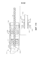
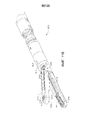
На ФИГ. 5 представлен вид в перспективе варианта осуществления хирургического инструмента и варианта осуществления концевого эффектора.In FIG. 5 is a perspective view of an embodiment of a surgical instrument and an embodiment of an end effector.
На ФИГ. 6 представлен вид в перспективе одного варианта осуществления электрохирургического инструмента, находящегося в электрической связи с генератором. In FIG. 6 is a perspective view of one embodiment of an electrosurgical instrument in electrical communication with a generator.
На ФИГ. 7 представлен вид в перспективе одного варианта осуществления концевого эффектора хирургического инструмента, показанного на ФИГ. 6, с открытыми элементами бранши и с дистальным концом перемещаемого по оси элемента в оттянутом положении. In FIG. 7 is a perspective view of one embodiment of an end effector of a surgical instrument shown in FIG. 6, with open jaw elements and with the distal end of the axially displaceable element in the drawn position.
На ФИГ. 8 представлен вид в перспективе одного варианта осуществления концевого эффектора хирургического инструмента, показанного на ФИГ. 6, с закрытыми элементами бранши и с дистальным концом перемещаемого по оси элемента в частично продвинутом положении. In FIG. 8 is a perspective view of one embodiment of an end effector of a surgical instrument shown in FIG. 6, with closed jaw elements and with the distal end of the axis-moving element in a partially advanced position.
На ФИГ. 9 представлен вид в перспективе одного варианта осуществления перемещаемого по оси элемента хирургического инструмента, показанного на ФИГ. 6. In FIG. 9 is a perspective view of one embodiment of an axis-moving element of a surgical instrument shown in FIG. 6.
На ФИГ. 10 представлен вид в сечении одного варианта осуществления электрохирургического концевого эффектора хирургического инструмента, показанного на ФИГ. 6. In FIG. 10 is a sectional view of one embodiment of the electrosurgical end effector of a surgical instrument shown in FIG. 6.
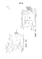
На ФИГ. 11 представлен общий вид с пространственным разделением компонентов одного варианта осуществления адаптера и держателя инструмента для прикрепления различных вариантов хирургического инструмента к роботизированной системеIn FIG. 11 is a perspective view of the spatial separation of the components of one embodiment of the adapter and tool holder for attaching various surgical instrument variants to a robotic system.
На ФИГ. 12 представлен вид сбоку одного варианта осуществления адаптера, показанного на ФИГ. 11.In FIG. 12 is a side view of one embodiment of the adapter shown in FIG. eleven.
На ФИГ. 13 представлен вид снизу одного варианта осуществления адаптера, показанного на ФИГ. 11.In FIG. 13 is a bottom view of one embodiment of the adapter shown in FIG. eleven.
На ФИГ. 14 представлен вид сверху одного варианта осуществления адаптера, показанного на ФИГ. 11 и 12.In FIG. 14 is a top view of one embodiment of the adapter shown in FIG. 11 and 12.
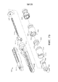
На ФИГ. 15 представлен частичный вид снизу в перспективе одного варианта осуществления хирургического инструмента.In FIG. 15 is a partial bottom perspective view of one embodiment of a surgical instrument.
На ФИГ. 16 представлен вид спереди в перспективе одного варианта осуществления части хирургического инструмента, причем некоторые элементы для ясности не показаны.In FIG. 16 is a front perspective view of one embodiment of a portion of a surgical instrument, with some elements not shown for clarity.
На ФИГ. 17 представлен вид сзади в перспективе тыльной стороны одного варианта осуществления хирургического инструмента, показанного на ФИГ. 16.In FIG. 17 is a rear perspective view of the back of one embodiment of a surgical instrument shown in FIG. 16.
На ФИГ. 18 представлен вид сверху одного варианта осуществления хирургического инструмента, показанного на ФИГ. 16 и 17.In FIG. 18 is a top view of one embodiment of a surgical instrument shown in FIG. 16 and 17.
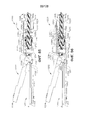
На ФИГ. 19 представлен частичный вид сверху одного варианта осуществления хирургического инструмента, показанного на ФИГ. 16-18, причем приводная шестерня с возможностью ручной активации находится в неактивированном положении.In FIG. 19 is a partial top view of one embodiment of a surgical instrument shown in FIG. 16-18, and the drive gear with the possibility of manual activation is in the inactive position.
На ФИГ. 20 представлен другой частичный вид сверху одного варианта осуществления хирургического инструмента, показанного на ФИГ. 16-19, причем приводная шестерня с возможностью ручной активации находится в первично активированном положении.In FIG. 20 is another partial top view of one embodiment of a surgical instrument shown in FIG. 16-19, and the drive gear with the possibility of manual activation is in the initially activated position.
На ФИГ. 21 представлен другой частичный вид сверху одного варианта осуществления хирургического инструмента, показанного на ФИГ. 16-20, причем приводная шестерня с возможностью ручной активации находится в активированном положении.In FIG. 21 is another partial top view of one embodiment of a surgical instrument shown in FIG. 16-20, and the drive gear with the possibility of manual activation is in the activated position.
На ФИГ. 22 представлен вид сзади в перспективе другого варианта осуществления хирургического инструмента.In FIG. 22 is a rear perspective view of another embodiment of a surgical instrument.
На ФИГ. 23 представлен вид сбоку в вертикальной проекции одного варианта осуществления хирургического инструмента, показанного на ФИГ. 22. In FIG. 23 is a side elevational view of one embodiment of a surgical instrument shown in FIG. 22.
На ФИГ. 24 представлен вид в поперечном сечении одного варианта осуществления части шарнирного сочленения и концевого эффектора.In FIG. 24 is a cross-sectional view of one embodiment of an articulated portion and an end effector.
На ФИГ. 24A представлен один вариант осуществления узла стержня и шарнирного сочленения, показанного на ФИГ. 24, на котором показаны соединения между дистальными секциями кабелей и проксимальными частями кабелей. In FIG. 24A shows one embodiment of a rod assembly and articulation shown in FIG. 24, which shows the connections between the distal cable sections and the proximal cable portions.
На ФИГ. 25 представлен общий вид с пространственным разделением компонентов одного варианта осуществления части шарнирного сочленения и концевого эффектора, показанного на ФИГ. 24.In FIG. 25 is a perspective view of the spatial separation of the components of one embodiment of the articulated portion and the end effector shown in FIG. 24.
На ФИГ. 26 представлен частичный вид в поперечном сечении в перспективе одного варианта осуществления частей шарнирного сочленения и концевого эффектора, показанных на ФИГ. 25.In FIG. 26 is a partial cross-sectional perspective view of one embodiment of the articulated portions and end effector shown in FIG. 25.
На ФИГ. 27 представлен частичный вид в перспективе варианта осуществления концевого эффектора и узла приводного стержня.In FIG. 27 is a partial perspective view of an embodiment of an end effector and a drive rod assembly.
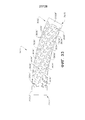
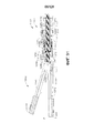
На ФИГ. 28 представлен частичный вид сбоку одного варианта осуществления узла приводного стержня.In FIG. 28 is a partial side view of one embodiment of a drive rod assembly.
На ФИГ. 29 представлен вид в перспективе одного варианта осуществления узла приводного стержня.In FIG. 29 is a perspective view of one embodiment of a drive rod assembly.
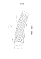
На ФИГ. 30 представлен вид сбоку одного варианта осуществления узла приводного стержня, показанного на ФИГ. 29.In FIG. 30 is a side view of one embodiment of a drive rod assembly shown in FIG. 29.
На ФИГ. 31 представлен вид в перспективе одного варианта осуществления составного узла приводного стержня.In FIG. 31 is a perspective view of one embodiment of a composite assembly of a drive shaft.
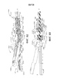
На ФИГ. 32 представлен вид сбоку одного варианта осуществления составного узла приводного стержня, показанного на ФИГ. 31.In FIG. 32 is a side view of one embodiment of a composite assembly of a drive shaft shown in FIG. 31.
На ФИГ. 33 представлен другой вид одного варианта осуществления узла приводного стержня, показанного на ФИГ. 29 и 30, предполагающего дугообразную или «изогнутую» конфигурацию.In FIG. 33 is another view of one embodiment of a drive rod assembly shown in FIG. 29 and 30, suggesting an arched or “curved” configuration.
На ФИГ. 33A представлен вид сбоку одного варианта осуществления узла приводного стержня, предполагающего дугообразную или «изогнутую» конфигурацию.In FIG. 33A is a side view of one embodiment of a drive rod assembly assuming an arcuate or “curved” configuration.
На ФИГ. 33B представлен вид сбоку одного варианта осуществления другого узла приводного стержня, предполагающего дугообразную или «изогнутую» конфигурацию. In FIG. 33B is a side view of one embodiment of another drive rod assembly assuming an arcuate or “curved” configuration.
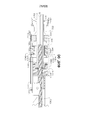
На ФИГ. 34 представлен вид в перспективе части другого варианта осуществления узла приводного стержня.In FIG. 34 is a perspective view of part of another embodiment of a drive rod assembly.
На ФИГ. 35 представлен вид сверху варианта осуществления узла приводного стержня, показанного на ФИГ. 34. In FIG. 35 is a top view of an embodiment of a drive rod assembly shown in FIG. 34.
На ФИГ. 36 представлен другой вид в перспективе варианта осуществления узла приводного стержня, показанного на ФИГ. 34 и 35, в дугообразной конфигурации.In FIG. 36 is another perspective view of an embodiment of a drive shaft assembly shown in FIG. 34 and 35, in an arched configuration.
На ФИГ. 37 представлен вид сверху варианта осуществления узла приводного стержня, показанного на ФИГ. 36.In FIG. 37 is a plan view of an embodiment of a drive rod assembly shown in FIG. 36.
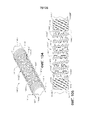
На ФИГ. 38 представлен вид в перспективе другого варианта осуществления узла приводного стержня.In FIG. 38 is a perspective view of another embodiment of a drive shaft assembly.
На ФИГ. 39 представлен другой вид в перспективе варианта осуществления приводного узла стержня, показанного на ФИГ. 38, в дугообразной конфигурации.In FIG. 39 is another perspective view of an embodiment of a shaft drive assembly shown in FIG. 38, in an arcuate configuration.
На ФИГ. 40 представлен вид сверху варианта осуществления узла приводного стержня, показанного на ФИГ. 38 и 39.In FIG. 40 is a plan view of an embodiment of a drive rod assembly shown in FIG. 38 and 39.
На ФИГ. 41 представлен вид в поперечном сечении варианта осуществления узла приводного стержня, показанного на ФИГ. 40.In FIG. 41 is a cross-sectional view of an embodiment of a drive shaft assembly shown in FIG. 40.
На ФИГ. 42 представлен частичный вид в поперечном сечении другого варианта осуществления узла приводного стержня.In FIG. 42 is a partial cross-sectional view of another embodiment of a drive rod assembly.
На ФИГ. 43 представлен другой вид в поперечном сечении варианта осуществления узла приводного стержня, показанного на ФИГ. 42.In FIG. 43 is another cross-sectional view of an embodiment of a drive rod assembly shown in FIG. 42.
На ФИГ. 44 представлен другой вид в поперечном сечении части другого варианта осуществления узла приводного стержня.In FIG. 44 is another cross-sectional view of part of another embodiment of a drive rod assembly.
На ФИГ. 45 представлен другой вид в поперечном сечении одного варианта осуществления узла приводного стержня, показанного на ФИГ. 44. In FIG. 45 is another cross-sectional view of one embodiment of a drive rod assembly shown in FIG. 44.
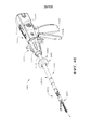
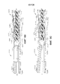
На ФИГ. 46 представлен вид в перспективе другого варианта осуществления хирургического инструмента.In FIG. 46 is a perspective view of another embodiment of a surgical instrument.
На ФИГ. 47 представлен вид в поперечном сечении в перспективе варианта хирургического инструмента, показанного на ФИГ. 46.In FIG. 47 is a cross-sectional perspective view of a variant of the surgical instrument shown in FIG. 46.
На ФИГ. 48 представлен вид в поперечном сечении в перспективе части одного варианта осуществления системы шарнира.In FIG. 48 is a perspective cross-sectional view of part of one embodiment of a hinge system.
На ФИГ. 49 представлен вид в поперечном сечении одного варианта осуществления системы шарнира, показанной на ФИГ. 48, в нейтральном положении.In FIG. 49 is a cross-sectional view of one embodiment of a hinge system shown in FIG. 48, in the neutral position.
На ФИГ. 50 представлен другой вид в поперечном сечении одного варианта осуществления системы шарнира, показанной на ФИГ. 48 и 49, в шарнирно повернутом положении.In FIG. 50 is another cross-sectional view of one embodiment of the hinge system shown in FIG. 48 and 49, in a pivotally rotated position.
На ФИГ. 51 представлен вид сбоку в вертикальной проекции части одного варианта осуществления хирургического инструмента, показанного на ФИГ. 46-47, причем его части опущены для ясности.In FIG. 51 is a side elevational view of a portion of one embodiment of a surgical instrument shown in FIG. 46-47, with parts thereof omitted for clarity.
На ФИГ. 52 представлен вид сзади в перспективе части одного варианта осуществления хирургического инструмента, показанного на ФИГ. 46-47, причем его части опущены для ясности.In FIG. 52 is a rear perspective view of a portion of one embodiment of a surgical instrument shown in FIG. 46-47, with parts thereof omitted for clarity.
На ФИГ. 53 представлен вид сзади в вертикальной проекции части одного варианта осуществления хирургического инструмента, показанного на ФИГ. 46-47, причем его части опущены для ясности.In FIG. 53 is a rear elevational view of a portion of one embodiment of a surgical instrument shown in FIG. 46-47, with parts thereof omitted for clarity.
На ФИГ. 54 представлен вид спереди в перспективе части одного варианта осуществления хирургического инструмента, показанного на ФИГ. 46-47, причем его части опущены для ясности.In FIG. 54 is a front perspective view of part of one embodiment of a surgical instrument shown in FIG. 46-47, with parts thereof omitted for clarity.
На ФИГ. 55 представлен вид сбоку в вертикальной проекции части варианта осуществления хирургического инструмента, показанного на ФИГ. 46-47, причем его части опущены для ясности.In FIG. 55 is a side elevational view of a portion of an embodiment of the surgical instrument shown in FIG. 46-47, with parts thereof omitted for clarity.
На ФИГ. 56 представлен общий вид с пространственным разделением компонентов примера осуществления реверсирующей системы хирургического инструмента, показанного на ФИГ. 46-47.In FIG. 56 is a perspective, exploded view of the components of an embodiment of a reversing system of a surgical instrument shown in FIG. 46-47.
На ФИГ. 57 представлен вид в перспективе варианта осуществления плеча рычага реверсирующей системы, показанной на ФИГ. 56.In FIG. 57 is a perspective view of an embodiment of a lever arm of a reversing system shown in FIG. 56.
На ФИГ. 58 представлен вид в перспективе кнопки оттягивания скальпеля одного варианта осуществления реверсирующей системы, показанной на ФИГ. 56.In FIG. 58 is a perspective view of a scalpel pull button of one embodiment of the reversing system shown in FIG. 56.
На ФИГ. 59 представлен вид в перспективе части варианта осуществления хирургического инструмента, показанного на ФИГ. 46-47, причем его части опущены для ясности, с плечом рычага, выполненным с возможностью активируемого зацепления с реверсирующей шестерней.In FIG. 59 is a perspective view of part of an embodiment of a surgical instrument shown in FIG. 46-47, and its parts are omitted for clarity, with a lever arm configured to engage with the reversing gear.
На ФИГ. 60 представлен вид в перспективе части варианта осуществления хирургического инструмента, показанного на ФИГ. 46-47, причем его части опущены для ясности, с плечом рычага, находящимся в неактивированном положении.In FIG. 60 is a perspective view of part of an embodiment of a surgical instrument shown in FIG. 46-47, and parts thereof are omitted for clarity, with a lever arm in an inactive position.
На ФИГ. 61 представлен другой вид в перспективе части варианта осуществления хирургического инструмента, показанного на ФИГ. 46-47, причем его части опущены для ясности, с плечом рычага, выполненным с возможностью активируемого зацепления с реверсирующей шестерней.In FIG. 61 is another perspective view of part of an embodiment of the surgical instrument shown in FIG. 46-47, and its parts are omitted for clarity, with a lever arm configured to engage with the reversing gear.
На ФИГ. 62 представлен вид сбоку в вертикальной проекции части узла рукоятки варианта осуществления хирургического инструмента, показанного на ФИГ. 46-47, с узлом кнопки переключения передачи, перемещенным в положение, приводящее к повороту концевого эффектора при активации узла приводного стержня. In FIG. 62 is a side elevational view of a portion of a handle assembly of an embodiment of the surgical instrument shown in FIG. 46-47, with the gear shift button assembly moved to a position leading to rotation of the end effector when the drive shaft assembly is activated.
На ФИГ. 63 представлен другой вид сбоку в вертикальной проекции части узла рукоятки одного варианта осуществления хирургического инструмента, показанного на ФИГ. 46-47, с узлом кнопки переключения передачи, перемещенным в другое положение, приводящее к активации пускового элемента в концевом эффекторе при активации узла приводного стержня.In FIG. 63 is another side elevational view of a portion of a handle assembly of one embodiment of a surgical instrument shown in FIG. 46-47, with the gear shift button assembly moved to a different position, leading to activation of the trigger element in the end effector when the drive shaft assembly is activated.
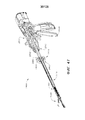
На ФИГ. 64 представлен вид в перспективе одного варианта осуществления многоосевого шарнирного и поворотного хирургического инструмента.In FIG. 64 is a perspective view of one embodiment of a multi-axis articulated and rotary surgical instrument.
На ФИГ. 65 представлен вид в перспективе с пространственным разделением различных компонентов одного варианта осуществления хирургического инструмента, показанного на ФИГ. 64.In FIG. 65 is a perspective view with a spatial separation of the various components of one embodiment of the surgical instrument shown in FIG. 64.
На ФИГ. 66 представлен частичный вид в поперечном сечении в перспективе одного варианта осуществления хирургического инструмента, показанного на ФИГ. 64, на котором показан поворотный приводной стержень, зацепленный с поворотной приводной гайкой для инициирования поступательного перемещения двутаврового элемента и закрытия узла браншей концевого эффектора.In FIG. 66 is a partial cross-sectional perspective view of one embodiment of a surgical instrument shown in FIG. 64, which shows a pivoting drive rod engaged with a pivoting drive nut to initiate a translational movement of the I-member and close the jaw assembly of the end effector.
На ФИГ. 67 представлен вид в поперечном сечении в перспективе одного варианта осуществления хирургического инструмента, показанного на ФИГ. 64, на котором показан поворотный приводной стержень, зацепленный с поворотной приводной гайкой для инициирования поступательного перемещения двутаврового элемента и закрытия узла браншей концевого эффектора.In FIG. 67 is a cross-sectional perspective view of one embodiment of a surgical instrument shown in FIG. 64, which shows a pivoting drive rod engaged with a pivoting drive nut to initiate a translational movement of the I-member and close the jaw assembly of the end effector.
На ФИГ. 68 представлен частичный вид в поперечном сечении в перспективе одного варианта осуществления хирургического инструмента, показанного на ФИГ. 64, на котором показан поворотный приводной стержень, зацепленный с соединителем стержня для инициирования поворота концевого эффектора.In FIG. 68 is a partial cross-sectional perspective view of one embodiment of a surgical instrument shown in FIG. 64, which shows a pivoting drive rod engaged with a rod connector to initiate rotation of the end effector.
На ФИГ. 69 представлен вид сбоку в поперечном сечении одного варианта осуществления хирургического инструмента, показанного на ФИГ. 64, на котором показан узел браншей концевого эффектора в открытом положении, с двутавровым элементом, находящимся в проксимально оттянутом положении, и поворотным приводным стержнем в зацеплении с поворотной приводной гайкой для инициирования поступательного перемещения двутаврового элемента и закрытия узла браншей концевого эффектора.In FIG. 69 is a cross-sectional side view of one embodiment of a surgical instrument shown in FIG. 64, which shows the end effector jaw assembly in the open position, with the I-member in the proximal drawn position, and the pivoting drive rod meshed with the pivoting drive nut to initiate translational movement of the I-member and closing the end effector junction assembly.
На ФИГ. 70 представлен вид сбоку в поперечном сечении одного варианта осуществления хирургического инструмента, показанного на ФИГ. 64, на котором показан узел браншей концевого эффектора в закрытом положении, с двутавровым элементом, находящимся в дистально продвинутом положении, и поворотным приводным стержнем в зацеплении с поворотной приводной гайкой для инициирования поступательного перемещения двутаврового элемента и открытия узла браншей концевого эффектора.In FIG. 70 is a cross-sectional side view of one embodiment of a surgical instrument shown in FIG. 64, which shows the end effector jaw assembly in the closed position, with the I-member located in the distally advanced position, and the pivoting drive rod meshed with the pivoting drive nut to initiate translational movement of the I-member and opening the end effector junction assembly.
На ФИГ. 71 представлен вид сбоку в поперечном сечении одного варианта осуществления хирургического инструмента, показанного на ФИГ. 64, на котором показан узел браншей концевого эффектора в открытом положении, с двутавровым элементом, находящимся проксимально оттянутом положении, и поворотным приводным стержнем в зацеплении с соединителем стержня для инициирования поворота концевого эффектора.In FIG. 71 is a side cross-sectional view of one embodiment of a surgical instrument shown in FIG. 64, which shows the end effector jaw assembly in the open position, with an I-beam in the proximal drawn position, and the pivoting drive rod meshed with the rod connector to initiate rotation of the end effector.
На ФИГ. 72 представлен вид сбоку в поперечном сечении одного варианта осуществления хирургического инструмента, показанного на ФИГ. 64, на котором показан узел браншей концевого эффектора в закрытом положении, с двутавровым элементом, находящимся в дистально продвинутом положении, и поворотным приводным стержнем в зацеплении с соединителем стержня для инициирования поворота концевого эффектора.In FIG. 72 is a cross-sectional side view of one embodiment of a surgical instrument shown in FIG. 64, which shows the end effector jaw assembly in the closed position, with the I-member in the distally advanced position, and the rotary drive rod meshed with the rod connector to initiate rotation of the end effector.
На ФИГ. 73 и 74 представлены подробные виды сбоку в поперечном сечении одного варианта осуществления хирургического инструмента, показанного на ФИГ. 64, на которых показано зацепление криволинейных поверхностей двутаврового элемента с поверхностями упора первого элемента бранши для перемещения первого элемента бранши относительно второго элемента бранши между открытым положением и закрытым положением.In FIG. 73 and 74 are detailed cross-sectional side views of one embodiment of the surgical instrument shown in FIG. 64 showing the engagement of the curved surfaces of the I-beam with the abutment surfaces of the first jaw element to move the first jaw element relative to the second jaw element between the open position and the closed position.
На ФИГ. 75 представлен вид с пространственным разделением компонентов, содержащий вариант осуществления многоосевого шарнирного и поворотного хирургического инструмента, содержащего механизм блокировки головки.In FIG. 75 is an exploded view of a component comprising an embodiment of a multi-axis articulated and rotary surgical instrument comprising a head lock mechanism.
На ФИГ. 76 представлен вид с пространственным разделением компонентов шлицевого замка одного варианта осуществления механизма блокировки головки хирургического инструмента, показанного на ФИГ. 75.In FIG. 76 is an exploded view of the components of a spline lock of one embodiment of a head lock mechanism of a surgical instrument shown in FIG. 75.
На ФИГ. 77 представлен вид сбоку в поперечном сечении одного варианта осуществления хирургического инструмента, показанного на ФИГ. 75, на котором показан узел браншей концевого эффектора в открытом положении с двутавровым элементом, находящимся в проксимально оттянутом положении, и поворотным приводным стержнем в зацеплении с поворотной приводной гайкой для инициирования поступательного перемещения двутаврового элемента и закрытия узла браншей концевого эффектора, а также с зацепленным шлицевым замком, предотвращающим поворот концевого эффектора.In FIG. 77 is a side cross-sectional view of one embodiment of a surgical instrument shown in FIG. 75, which shows the end effector jaw assembly in the open position with the I-member in the proximal drawn position and the pivoting drive rod meshed with the pivoting drive nut to initiate translational movement of the I-member and closing the end effector jaw assembly, as well as with the engaged slotted the lock preventing rotation of the end effector.
На ФИГ. 78 представлен вид сбоку в поперечном сечении одного варианта осуществления хирургического инструмента, показанного на ФИГ. 75, на котором показан узел браншей концевого эффектора в закрытом положении с двутавровым элементом, находящимся в дистально продвинутом положении, и поворотным приводным стержнем в зацеплении с поворотной приводной гайкой для инициирования поступательного перемещения двутаврового элемента и открытия узла браншей концевого эффектора, а также с зацепленным шлицевым замком, предотвращающим поворот концевого эффектора.In FIG. 78 is a side cross-sectional view of one embodiment of a surgical instrument shown in FIG. 75, which shows the end effector jaw assembly in a closed position with an I-member located in a distally advanced position and the rotary drive rod meshed with the rotary drive nut to initiate translational movement of the I-member and open the end effector jaw assembly, as well as with the engaged slotted the lock preventing rotation of the end effector.
На ФИГ. 79 представлен вид сбоку в поперечном сечении одного варианта осуществления хирургического инструмента, показанного на ФИГ. 75, на котором показан узел браншей концевого эффектора в открытом положении, с двутавровым элементом, находящимся в проксимально оттянутом положении, и поворотным приводным стержнем в зацеплении с соединителем стержня для инициирования поворота концевого эффектора, а также расцепленным шлицевым замком, позволяющим поворот концевого эффектора.In FIG. 79 is a cross-sectional side view of one embodiment of a surgical instrument shown in FIG. 75, which shows the end effector jaw assembly in the open position, with the I-beam in the proximal drawn position, and the rotary drive rod meshed with the rod connector to initiate the end effector rotation, as well as an unlocked slot lock allowing the end effector to rotate.
На ФИГ. 80 представлен вид сбоку в поперечном сечении одного варианта осуществления хирургического инструмента, показанного на ФИГ. 64, на котором показан узел браншей концевого эффектора в закрытом положении, с двутавровым элементом, находящимся в дистально продвинутом положении, и поворотным приводным стержнем в зацеплении с соединителем стержня для инициирования поворота концевого эффектора, а также расцепленным шлицевым замком, позволяющим поворот концевого эффектора.In FIG. 80 is a cross-sectional side view of one embodiment of a surgical instrument shown in FIG. 64, which shows the end effector jaw assembly in the closed position, with the I-beam in the distally advanced position, and the rotary drive rod meshed with the rod connector to initiate the end effector rotation, as well as an unlocked spline lock allowing rotation of the end effector.
На ФИГ. 81 представлен подробный вид сбоку в поперечном сечении одного варианта осуществления хирургического инструмента, показанного на ФИГ. 80. In FIG. 81 is a detailed cross-sectional side view of one embodiment of the surgical instrument shown in FIG. 80.
На ФИГ. 82 представлен подробный вид сбоку в поперечном сечении одного варианта осуществления хирургического инструмента, показанного на ФИГ. 78.In FIG. 82 is a detailed cross-sectional side view of one embodiment of the surgical instrument shown in FIG. 78.
На ФИГ. 83 представлен вид в поперечном сечении в перспективе хирургического инструмента, имеющего первый и второй элементы бранши, в соответствии с некоторыми вариантами осуществления, описанными в настоящем документе.In FIG. 83 is a perspective cross-sectional view of a surgical instrument having first and second jaw elements, in accordance with some embodiments described herein.
На ФИГ. 84 представлен вид в перспективе закрывающей гайки одного варианта осуществления хирургического инструмента, показанного на ФИГ. 83.In FIG. 84 is a perspective view of a closure nut of one embodiment of the surgical instrument shown in FIG. 83.
На ФИГ. 85 представлен вид в поперечном сечении в вертикальной проекции одного варианта осуществления хирургического инструмента, показанного на ФИГ. 83, причем первый элемент бранши и второй элемент бранши находятся по меньшей мере в частично открытом положении, и причем поворотный приводной стержень функционально расцеплен с поворотной приводной гайкой.In FIG. 85 is a cross-sectional elevational view of one embodiment of the surgical instrument shown in FIG. 83, wherein the first jaw element and the second jaw element are at least partially open, and the pivot drive shaft is operatively disengaged from the pivot drive nut.
На ФИГ. 86 представлен вид в поперечном сечении в вертикальной проекции одного варианта осуществления хирургического инструмента, показанного на ФИГ. 83, причем первый элемент бранши и второй элемент бранши находятся по меньшей мере в частично открытом положении, и причем поворотный приводной стержень функционально зацеплен с поворотной приводной гайкой.In FIG. 86 is a cross-sectional elevational view of one embodiment of a surgical instrument shown in FIG. 83, wherein the first jaw element and the second jaw element are at least partially open, and wherein the rotary drive shaft is operatively engaged with the rotary drive nut.
На ФИГ. 87 представлен вид в поперечном сечении в вертикальной проекции одного варианта осуществления хирургического инструмента, показанного на ФИГ. 83, причем первый элемент бранши и второй элемент бранши находятся по меньшей мере в частично закрытом положении, и причем поворотный приводной стержень функционально зацеплен с поворотной приводной гайкой, и причем закрывающая гайка функционально расцеплена с поворотной приводной гайкой.In FIG. 87 is a cross-sectional elevational view of one embodiment of a surgical instrument shown in FIG. 83, wherein the first jaw element and the second jaw element are at least partially closed, and the pivot drive shaft is operatively engaged with the pivot drive nut, and the closure nut is functionally disengaged from the pivot drive nut.
На ФИГ. 88 представлен вид в поперечном сечении в вертикальной проекции одного варианта осуществления хирургического инструмента, показанного на ФИГ. 83, причем первый элемент бранши и второй элемент бранши находятся по меньшей мере в частично закрытом положении, и причем поворотный приводной стержень функционально зацеплен с поворотной приводной гайкой, и причем двутавровый элемент по меньшей мере частично выдвинут.In FIG. 88 is a cross-sectional elevational view of one embodiment of a surgical instrument shown in FIG. 83, wherein the first jaw element and the second jaw element are at least partially closed, and the pivot drive shaft is operatively engaged with the pivot drive nut, and the I-element is at least partially extended.
На ФИГ. 89 представлен вид в поперечном сечении в вертикальной проекции одного варианта осуществления хирургического инструмента, показанного на ФИГ. 83, причем первый элемент бранши и второй элемент бранши находятся по меньшей мере в частично закрытом положении, и причем поворотный приводной стержень функционально зацеплен с поворотной приводной гайкой, и причем двутавровый элемент по меньшей мере частично оттянут.In FIG. 89 is a cross-sectional elevational view of one embodiment of a surgical instrument shown in FIG. 83, wherein the first jaw element and the second jaw element are at least partially closed, and the pivot drive shaft is operatively engaged with the pivot drive nut, and the I-beam is at least partially pulled.
На ФИГ. 90 представлен вид в поперечном сечении в вертикальной проекции одного варианта осуществления хирургического инструмента, показанного на ФИГ. 83, причем первый элемент бранши и второй элемент бранши находятся по меньшей мере в частично закрытом положении, и причем поворотный приводной стержень функционально зацеплен с поворотной приводной гайкой, и причем двутавровый элемент по меньшей мере частично оттянут.In FIG. 90 is a cross-sectional elevational view of one embodiment of a surgical instrument shown in FIG. 83, wherein the first jaw element and the second jaw element are at least partially closed, and the pivot drive shaft is operatively engaged with the pivot drive nut, and the I-beam is at least partially pulled.
На ФИГ. 91 представлен вид в поперечном сечении в вертикальной проекции одного варианта осуществления хирургического инструмента, показанного на ФИГ. 83, причем первый элемент бранши и второй элемент бранши находятся по меньшей мере в частично открытом положении, и причем поворотный приводной стержень функционально зацеплен с поворотной приводной гайкой, и причем закрывающая гайка функционально зацеплена с поворотной приводной гайкой.In FIG. 91 is a cross-sectional elevational view of one embodiment of a surgical instrument shown in FIG. 83, wherein the first jaw element and the second jaw element are at least partially open, and the pivot drive shaft is operatively engaged with the pivot drive nut, and wherein the closure nut is functionally engaged with the pivot drive nut.
На ФИГ. 92 представлен вид в поперечном сечении в перспективе хирургического инструмента, имеющего первый и второй элементы бранши, в соответствии с некоторыми вариантами осуществления, описанными в настоящем документе.In FIG. 92 is a perspective cross-sectional view of a surgical instrument having first and second jaw elements, in accordance with some of the embodiments described herein.
На ФИГ. 93 представлен вид в поперечном сечении в вертикальной проекции одного варианта осуществления хирургического инструмента, показанного на ФИГ. 92, причем первый элемент бранши и второй элемент бранши находятся по меньшей мере в частично открытом положении, и причем поворотный приводной стержень функционально зацеплен со шлицевой соединительной частью корпуса привода концевого эффектора.In FIG. 93 is a cross-sectional elevational view of one embodiment of a surgical instrument shown in FIG. 92, wherein the first jaw element and the second jaw element are in at least partially open position, and wherein the rotary drive shaft is operatively engaged with the spline connecting portion of the end effector drive housing.
На ФИГ. 94 представлен вид в поперечном сечении в вертикальной проекции одного варианта осуществления хирургического инструмента, показанного на ФИГ. 92, причем первый элемент бранши и второй элемент бранши находятся по меньшей мере в частично закрытом положении, и причем поворотный приводной стержень функционально зацеплен со шлицевой соединительной частью цилиндрического кулачка.In FIG. 94 is a cross-sectional elevational view of one embodiment of a surgical instrument shown in FIG. 92, wherein the first jaw element and the second jaw element are in at least partially closed position, and the rotary drive shaft is operatively engaged with the spline connecting portion of the cylindrical cam.
На ФИГ. 95 представлен вид в поперечном сечении в вертикальной проекции одного варианта осуществления хирургического инструмента, показанного на ФИГ. 92, причем первый элемент бранши и второй элемент бранши находятся по меньшей мере в частично закрытом положении, и причем поворотный приводной стержень функционально не зацеплен с какими-либо шлицевыми соединительными частями. In FIG. 95 is a cross-sectional elevational view of one embodiment of a surgical instrument shown in FIG. 92, wherein the first jaw element and the second jaw element are in at least partially closed position, and wherein the rotary drive shaft is not operably engaged with any spline connecting parts.
На ФИГ. 96 представлен вид в поперечном сечении в вертикальной проекции одного варианта осуществления хирургического инструмента, показанного на ФИГ. 92, причем первый элемент бранши и второй элемент бранши находятся по меньшей мере в частично закрытом положении, и причем поворотный приводной стержень функционально зацеплен со шлицевой соединительной частью поворотной приводной гайки.In FIG. 96 is a cross-sectional elevational view of one embodiment of the surgical instrument shown in FIG. 92, wherein the first jaw element and the second jaw element are at least partially closed, and wherein the rotary drive shaft is operatively engaged with the spline connecting portion of the rotary drive nut.
На ФИГ. 97 представлен вид в перспективе концевого эффектора и шарнирного сочленения хирургического инструмента в соответствии по меньшей мере с одним вариантом осуществления, на котором части удалены для целей иллюстрации.In FIG. 97 is a perspective view of an end effector and articulation of a surgical instrument in accordance with at least one embodiment in which parts are removed for illustration purposes.
На ФИГ. 98 представлен подробный вид приводного стержня в соответствии по меньшей мере с одним вариантом осуществления, выполненного с возможностью поступательного перемещения внутри концевого эффектора и шарнирного сочленения, показанного на ФИГ. 97.In FIG. 98 is a detailed view of the drive rod in accordance with at least one embodiment configured to translate within the end effector and articulated joint shown in FIG. 97.
На ФИГ. 99 представлен вид в перспективе приводного стержня в соответствии по меньшей мере с одним альтернативным вариантом осуществления.In FIG. 99 is a perspective view of a drive shaft in accordance with at least one alternative embodiment.
На ФИГ. 100 представлен вид в вертикальной проекции одного варианта осуществления приводного стержня, показанного на ФИГ. 99.In FIG. 100 is a perspective view of one embodiment of a drive shaft shown in FIG. 99.
На ФИГ. 101 представлен вид в вертикальной проекции одного варианта осуществления приводного стержня, показанного на ФИГ. 99, показанного в шарнирно повернутом положении.In FIG. 101 is a perspective view of one embodiment of a drive shaft shown in FIG. 99, shown in a pivotally rotated position.
На ФИГ. 102 представлен вид в перспективе узла приводного стержня, содержащего приводную трубку и резьбу, направленную вокруг приводной трубки, в соответствии по меньшей мере с одним альтернативным вариантом осуществления.In FIG. 102 is a perspective view of a drive rod assembly comprising a drive tube and a thread directed around the drive tube in accordance with at least one alternative embodiment.
На ФИГ. 103 представлен вид в вертикальной проекции одного варианта осуществления узла приводного стержня, показанного на ФИГ. 102.In FIG. 103 is a perspective view of one embodiment of a drive rod assembly shown in FIG. 102.
На ФИГ. 104 представлен вид в перспективе узла приводного стержня, содержащего приводную трубку, резьбу, направленную вокруг приводной трубки, и внутренний сердечник, направленный сквозь приводную трубку, в соответствии по меньшей мере с одним альтернативным вариантом осуществления.In FIG. 104 is a perspective view of a drive rod assembly comprising a drive tube, a thread directed around the drive tube, and an inner core directed through the drive tube, in accordance with at least one alternative embodiment.
На ФИГ. 105 представлен вид в вертикальной проекции одного варианта осуществления узла приводного стержня, показанного на ФИГ. 104.In FIG. 105 is a perspective view of one embodiment of a drive rod assembly shown in FIG. 104.
На ФИГ. 106 представлен вид в перспективе хирургического инструмента, имеющего первый и второй элементы бранши, в соответствии с некоторыми вариантами осуществления, описанными в настоящем документе.In FIG. 106 is a perspective view of a surgical instrument having first and second jaw elements, in accordance with some embodiments described herein.
На ФИГ. 107 представлен вид в разрезе дистальных частей одного варианта осуществления первого и второго элементов бранши хирургического концевого инструмента, показанного на ФИГ. 106.In FIG. 107 is a cross-sectional view of the distal parts of one embodiment of the first and second jaw elements of the surgical end instrument shown in FIG. 106.
На ФИГ. 108 представлен вид в перспективе хирургического концевого эффектора и узла стержня в соответствии с некоторыми вариантами осуществления, описанными в настоящем документе. In FIG. 108 is a perspective view of a surgical end effector and rod assembly in accordance with some embodiments described herein.
На ФИГ. 109 представлен вид в перспективе элемента бранши хирургического концевого эффектора в соответствии с некоторыми вариантами осуществления, описанными в настоящем документе.In FIG. 109 is a perspective view of a jaw element of a surgical end effector in accordance with some embodiments described herein.
На ФИГ. 110 представлен вид в поперечном сечении хирургического эффектора, отсоединенного от узла стержня, в соответствии с некоторыми вариантами осуществления, описанными в настоящем документе.In FIG. 110 is a cross-sectional view of a surgical effector detached from a shaft assembly in accordance with some embodiments described herein.
На ФИГ. 111 представлен вид в поперечном сечении хирургического эффектора, прикрепленного к узлу стержня, в соответствии с некоторыми вариантами осуществления, описанными в настоящем документе.In FIG. 111 is a cross-sectional view of a surgical effector attached to a shaft assembly in accordance with some embodiments described herein.
На ФИГ. 112 представлен вид в перспективе множества взаимозаменяемых хирургических концевых эффекторов в соответствии с некоторыми вариантами осуществления, описанными в настоящем документе.In FIG. 112 is a perspective view of a plurality of interchangeable surgical end effectors in accordance with some embodiments described herein.
На ФИГ. 113 представлен вид в перспективе хирургического концевого эффектора, включая вид в поперечном сечении элемента бранши, в соответствии с некоторыми вариантами осуществления, описанными в настоящем документе.In FIG. 113 is a perspective view of a surgical end effector, including a cross-sectional view of a jaw element, in accordance with some of the embodiments described herein.
На ФИГ. 114 представлен вид в поперечном сечении хирургического эффектора, отсоединенного от узла стержня, в соответствии с некоторыми вариантами осуществления, описанными в настоящем документе. In FIG. 114 is a cross-sectional view of a surgical effector detached from a shaft assembly in accordance with some embodiments described herein.
На ФИГ. 115 представлен вид в поперечном сечении хирургического эффектора, прикрепленного к узлу стержня, в соответствии с некоторыми вариантами осуществления, описанными в настоящем документе.In FIG. 115 is a cross-sectional view of a surgical effector attached to a shaft assembly in accordance with some embodiments described herein.
На ФИГ. 116 представлен вид в перспективе хирургического концевого эффектора, имеющего первый элемент бранши и второй элемент бранши, в соответствии с некоторыми вариантами осуществления, описанными в настоящем документе.In FIG. 116 is a perspective view of a surgical end effector having a first jaw element and a second jaw element, in accordance with some of the embodiments described herein.
На ФИГ. 117 представлен другой вид в перспективе хирургического концевого эффектора, показанного на ФИГ. 116, включая вид в поперечном сечении в перспективе элемента бранши, в соответствии с некоторыми вариантами осуществления, описанными в настоящем документе.In FIG. 117 is a different perspective view of the surgical end effector shown in FIG. 116, including a cross-sectional perspective view of a jaw element, in accordance with some embodiments described herein.
На ФИГ. 118 представлен вид в поперечном сечении первого элемента бранши и второго элемента бранши хирургического концевого эффектора в соответствии с некоторыми вариантами осуществления, описанными в настоящем документе.In FIG. 118 is a cross-sectional view of a first jaw element and a second jaw element of a surgical end effector in accordance with some embodiments described herein.
На ФИГ. 119 представлен вид в поперечном сечении первого элемента бранши и второго элемента бранши хирургического концевого эффектора в соответствии с некоторыми вариантами осуществления, описанными в настоящем документе.In FIG. 119 is a cross-sectional view of a first jaw element and a second jaw element of a surgical end effector in accordance with some embodiments described herein.
На ФИГ. 120 представлен вид в перспективе первого элемента бранши и второго элемента бранши хирургического концевого эффектора в соответствии с некоторыми вариантами осуществления, описанными в настоящем документе. In FIG. 120 is a perspective view of a first jaw element and a second jaw element of a surgical end effector in accordance with some embodiments described herein.
На ФИГ. 121 представлен вид в перспективе дистальной части элемента бранши хирургического концевого эффектора в соответствии с некоторыми вариантами осуществления, описанными в настоящем документе.In FIG. 121 is a perspective view of a distal portion of a jaw member of a surgical end effector in accordance with some embodiments described herein.
На ФИГ. 122 представлен вид сверху захватной части в соответствии с некоторыми вариантами осуществления, описанными в настоящем документе.In FIG. 122 is a plan view of a gripping portion in accordance with some embodiments described herein.
На ФИГ. 123 представлен вид сверху захватной части в соответствии с некоторыми вариантами осуществления, описанными в настоящем документе.In FIG. 123 is a plan view of a gripping portion in accordance with some embodiments described herein.
На ФИГ. 124 представлен вид сверху захватной части в соответствии с некоторыми вариантами осуществления, описанными в настоящем документе.In FIG. 124 is a plan view of a gripping portion in accordance with some embodiments described herein.
На ФИГ. 125 представлен вид сверху захватной части в соответствии с некоторыми вариантами осуществления, описанными в настоящем документе.In FIG. 125 is a plan view of a gripping portion in accordance with some embodiments described herein.
На ФИГ. 126 представлен вид сверху захватной части в соответствии с некоторыми вариантами осуществления, описанными в настоящем документе.In FIG. 126 is a plan view of a gripping portion in accordance with some embodiments described herein.
На ФИГ. 127 представлен вид сверху захватной части в соответствии с некоторыми вариантами осуществления, описанными в настоящем документе.In FIG. 127 is a plan view of a gripping portion in accordance with some embodiments described herein.
На ФИГ. 128 представлен вид сверху захватной части в соответствии с некоторыми вариантами осуществления, описанными в настоящем документе.In FIG. 128 is a plan view of a gripping portion in accordance with some embodiments described herein.
На ФИГ. 129 представлен вид сверху захватной части в соответствии с некоторыми вариантами осуществления, описанными в настоящем документе. In FIG. 129 is a plan view of a gripping portion in accordance with some embodiments described herein.
На ФИГ. 130 представлен вид сверху захватной части в соответствии с некоторыми вариантами осуществления, описанными в настоящем документе.In FIG. 130 is a plan view of a gripping portion in accordance with some embodiments described herein.
На ФИГ. 131 представлен вид сверху захватной части в соответствии с некоторыми вариантами осуществления, описанными в настоящем документе.In FIG. 131 is a plan view of a gripping portion in accordance with some embodiments described herein.
На ФИГ. 132 представлен вид в перспективе одного варианта осуществления концевого эффектора, имеющего первый и второй элементы бранши в открытом положении и наклоненные контактирующие с тканью поверхности, проходящие по существу по всей длине элементов бранши.In FIG. 132 is a perspective view of one embodiment of an end effector having first and second jaw elements in an open position and inclined tissue contact surfaces extending substantially along the entire length of the jaw elements.
На ФИГ. 133 представлен другой вид в перспективе одного варианта осуществления концевого эффектора, показанного на ФИГ. 132, причем первый и второй элементы бранши находятся в закрытом положении.In FIG. 133 is another perspective view of one embodiment of the end effector shown in FIG. 132, the first and second jaw elements being in the closed position.
На ФИГ. 134 представлен вид спереди одного варианта осуществления концевого эффектора, показанного на ФИГ. 133.In FIG. 134 is a front view of one embodiment of the end effector shown in FIG. 133.
На ФИГ. 135 представлен вид в поперечном сечении одного варианта осуществления концевого эффектора, показанного на ФИГ. 134.In FIG. 135 is a cross-sectional view of one embodiment of an end effector shown in FIG. 134.
На ФИГ. 136 представлен вид сбоку одного варианта осуществления концевого эффектора, показанного на ФИГ. 132.In FIG. 136 is a side view of one embodiment of the end effector shown in FIG. 132.
На ФИГ. 137 представлен вид сбоку одного варианта осуществления концевого эффектора, показанного на ФИГ. 133.In FIG. 137 is a side view of one embodiment of the end effector shown in FIG. 133.
На ФИГ. 138 представлена принципиальная схема, на которой показан вид спереди одного варианта осуществления концевого эффектора, имеющего первый и второй элементы бранши, причем каждый элемент бранши имеет две наклоненные под противоположными углами контактирующие с тканью поверхности.In FIG. 138 is a schematic diagram showing a front view of one embodiment of an end effector having first and second jaw elements, each jaw element having two surfaces contacting the tissue inclined at opposite angles.
На ФИГ. 139 представлен вид в перспективе одного варианта осуществления концевого эффектора, имеющего первый и второй элементы бранши в открытом положении, и наклоненные контактирующие с тканью поверхности, проходящие вдоль части длины элементов бранши.In FIG. 139 is a perspective view of one embodiment of an end effector having first and second jaw elements in an open position and inclined tissue contact surfaces extending along a portion of the length of the jaw elements.
На ФИГ. 140 представлен другой вид в перспективе одного варианта осуществления концевого эффектора, показанного на ФИГ. 139.In FIG. 140 is another perspective view of one embodiment of the end effector shown in FIG. 139.
На ФИГ. 141 представлен вид в перспективе одного варианта осуществления концевого эффектора, имеющего первый и второй элементы бранши в открытом положении, наклоненные контактирующие с тканью поверхности, проходящие вдоль части длины элементов бранши, и электроды, расположенные между двумя наклоненными и контактирующими с тканью поверхностями на втором элементе бранши. In FIG. 141 is a perspective view of one embodiment of an end effector having the first and second jaw elements in an open position, inclined tissue-contacting surfaces extending along part of the length of the jaw elements, and electrodes located between two tilted and tissue-contacting surfaces on the second jaw element .
На ФИГ. 142 представлен вид в поперечном сечении одного варианта осуществления концевого эффектора, имеющего первый и второй элементы бранши в закрытом положении, и захватывающего ткань между элементами бранши, причем первый и второй элементы бранши имеют наклоненные под противоположными углам контактирующие с тканью поверхности.In FIG. 142 is a cross-sectional view of one embodiment of an end effector having the first and second jaw elements in the closed position and gripping the fabric between the jaw elements, the first and second jaw elements having tissue surfaces that are inclined at opposite angles.
На ФИГ. 143 представлен вид в поперечном сечении одного варианта осуществления концевого эффектора и узла стержня, показанного на ФИГ. 64-82, на котором показан пример установки узла поворотного электрода.In FIG. 143 is a cross-sectional view of one embodiment of an end effector and a rod assembly shown in FIG. 64-82, which shows an example of installation of the rotary electrode assembly.
На ФИГ. 144 представлен вид с пространственным разделением компонентов одного варианта осуществления концевого эффектора и узла стержня, показанного на ФИГ. 143, на котором показан узел поворотного электрода в установленном и разобранном виде. In FIG. 144 is an exploded view of the components of one embodiment of the end effector and the rod assembly shown in FIG. 143, which shows the rotary electrode assembly in an installed and disassembled form.
На ФИГ. 145 представлен вид в поперечном сечении одного варианта осуществления концевого эффектора и узла стержня, показанного на ФИГ. 143, на котором показан узел поворотного электрода с поворотной приводной головкой в проксимальном положении. In FIG. 145 is a cross-sectional view of one embodiment of an end effector and a rod assembly shown in FIG. 143, which shows the rotary electrode assembly with the rotary drive head in a proximal position.
На ФИГ. 146 представлен вид в поперечном сечении одного варианта осуществления концевого эффектора и узла стержня, показанного на ФИГ. 143, на котором показан узел поворотного электрода с поворотной приводной головкой в дистальном положении. In FIG. 146 is a cross-sectional view of one embodiment of an end effector and a rod assembly shown in FIG. 143, which shows the rotary electrode assembly with the rotary drive head in a distal position.
На ФИГ. 147-148 представлены виды в поперечном сечении одного варианта осуществления концевого эффектора и узла стержня, показанного на ФИГ. 143, где продольная длина внешнего контакта выбрана таким образом, чтобы узел поворотного соединителя альтернативно устанавливал и разрывал электрическое соединение, ограниченное посредством продольного положения щеточного узла. In FIG. 147-148 are cross-sectional views of one embodiment of an end effector and a rod assembly shown in FIG. 143, where the longitudinal length of the external contact is selected so that the rotary connector assembly alternatively establishes and breaks the electrical connection limited by the longitudinal position of the brush assembly.
На ФИГ. 149-150 представлен один вариант осуществления концевого эффектора и узла стержня, показанного на ФИГ. 143, на котором показана конфигурация, включающая две проводниковые части и соединительный узел между концевым эффектором и узлом стержня. In FIG. 149-150, one embodiment of an end effector and a rod assembly shown in FIG. 143, which shows a configuration including two conductive parts and a connecting assembly between the end effector and the shaft assembly.
На ФИГ. 151 представлен вид в поперечном сечении одного варианта осуществления концевого эффектора и узла стержня, на котором показана другая ситуация, в которой может использоваться узел поворотного соединителя. In FIG. 151 is a cross-sectional view of one embodiment of an end effector and a rod assembly, showing another situation in which a rotary connector assembly may be used.
На ФИГ. 152 представлен вид в поперечном сечении одного варианта осуществления концевого эффектора и узла стержня, показанного на ФИГ. 83-91, на котором показан другой пример установки узла поворотного электрода. In FIG. 152 is a cross-sectional view of one embodiment of an end effector and a rod assembly shown in FIG. 83-91, which shows another example of the installation of the node rotary electrode.
На ФИГ. 153 показан один вариант осуществления концевого эффектора, который может применяться с различными хирургическими инструментами, включая описанные в настоящем документе. In FIG. 153 shows one embodiment of an end effector that can be used with various surgical instruments, including those described herein.
На ФИГ. 154 показан один вариант осуществления концевого эффектора, показанного на ФИГ. 153, на котором показана контактирующая с тканью часть, расположенная смежно с продольным каналом второго элемента бранши концевого эффектора. In FIG. 154 shows one embodiment of an end effector shown in FIG. 153, which shows a tissue-contacting portion adjacent to a longitudinal channel of a second end effector branch member.
На ФИГ. 155 показан один вариант осуществления концевого эффектора, показанного на ФИГ. 153, с осевым сечением вдоль средней линии первого элемента бранши, на котором показана контактирующая с тканью часть, расположенная смежно с продольным каналом первого элемента бранши. In FIG. 155 shows one embodiment of the end effector shown in FIG. 153, with an axial section along the midline of the first jaw element, which shows a portion in contact with tissue located adjacent to the longitudinal channel of the first jaw element.
На ФИГ. 156 представлен вид в перспективе одного варианта осуществления концевого эффектора, показанного на ФИГ. 153, в открытом положении. In FIG. 156 is a perspective view of one embodiment of the end effector shown in FIG. 153, in the open position.
На ФИГ. 157 представлен вид сверху одного варианта осуществления второго элемента бранши, подходящего для применения с концевым эффектором, показанным на ФИГ. 153. In FIG. 157 is a top view of one embodiment of a second jaw element suitable for use with the end effector shown in FIG. 153.
На ФИГ. 158 представлен вид снизу одного варианта осуществления первого элемента бранши, подходящего для применения с концевым эффектором, показанным на ФИГ. 153. In FIG. 158 is a bottom view of one embodiment of a first jaw element suitable for use with the end effector shown in FIG. 153.
На ФИГ. 159 представлен вид спереди в поперечном сечении другого варианта осуществления концевого эффектора, показанного на ФИГ. 153, в закрытом положении. In FIG. 159 is a front cross-sectional view of another embodiment of an end effector shown in FIG. 153 in the closed position.
На ФИГ. 160-165 представлены виды сбоку в поперечном сечении различных вариантов осуществления концевого эффектора, показанного на ФИГ. 153. In FIG. 160-165 are side cross-sectional views of various embodiments of the end effector shown in FIG. 153.
На ФИГ. 166 представлен другой вариант осуществления второго элемента бранши, подходящего для применения с концевым эффектором, показанным на ФИГ. 153, в закрытом положении, удерживающего хирургический инструмент. In FIG. 166 shows another embodiment of a second jaw element suitable for use with the end effector shown in FIG. 153, in the closed position, holding the surgical instrument.
На ФИГ. 167 показан один вариант осуществления второго элемента бранши, подходящего для применения с концевым эффектором, показанным на ФИГ. 153. In FIG. 167 shows one embodiment of a second jaw element suitable for use with the end effector shown in FIG. 153.
На ФИГ. 168 представлен другой вариант осуществления второго элемента бранши, подходящий для применения с концевым эффектором, показанным на ФИГ. 153. In FIG. 168 shows another embodiment of a second jaw element suitable for use with the end effector shown in FIG. 153.
ПОДРОБНОЕ ОПИСАНИЕDETAILED DESCRIPTION
Заявителю настоящей заявки также принадлежат следующие заявки на патенты, поданные в тот же день, каждая из которых полностью включена в настоящий документ путем ссылки.The applicant of the present application also owns the following patent applications filed on the same day, each of which is incorporated herein by reference in its entirety.
1. Заявка на патент США сер. № _____________, озаглавленная «Многофункциональное хирургическое устройство с электропитанием с внешними рассекающими элементами» (досье патентного поверенного № END7132USNP/120136).1. US Patent Application Ser. No. _____________, entitled “Multifunctional surgical device with electrical power with external dissecting elements” (dossier of the patent attorney No. END7132USNP / 120136).
2. Заявка на патент США сер. № _____________, озаглавленная «Соединительные конфигурации для прикрепления хирургических концевых эффекторов к приводным системам для них» (досье патентного поверенного № END7133USNP/120137).2. US Patent Application Ser. No. _____________, entitled “Connecting configurations for attaching surgical end effectors to their drive systems” (Patent Attorney File No. END7133USNP / 120137).
3. Заявка на патент США сер. № _____________, озаглавленная «Поворотная закрывающая конфигурация с возможностью активации для хирургического концевого эффектора» (досье патентного поверенного № END7134USNP/120138).3. US Patent Application Ser. No. _____________, entitled “Rotary closing configuration with activation capability for a surgical end effector” (Patent Attorney File No. END7134USNP / 120138).
4. Заявка на патент США сер. № _____________, озаглавленная «Хирургические концевые эффекторы, имеющие наклоненные контактирующие с тканью поверхности» (досье патентного поверенного № END7135USNP/120139).4. US Patent Application Ser. No. _____________, entitled “Surgical end effectors having inclined surfaces in contact with tissue” (Patent Attorney File No. END7135USNP / 120139).
5. Заявка на патент США сер. № _____________, озаглавленная «Соединительная конфигурация взаимозаменяемого концевого эффектора» (досье патентного поверенного № END7136USNP/120140).5. US Patent Application Ser. No. _____________, entitled “Connecting configuration of an interchangeable end effector” (Patent Attorney File No. END7136USNP / 120140).
6. Заявка на патент США сер. № _____________, озаглавленная «Конфигурации браншей и электродов хирургического концевого эффектора» (досье патентного поверенного № END7137USNP/120141).6. US Patent Application Ser. No. _____________, entitled “Configurations of jaws and electrodes of the surgical end effector” (dossier of the patent attorney No. END7137USNP / 120141).
7. Заявка на патент США сер. № _____________, озаглавленная «Многоосевые шарнирные и поворотные хирургические инструменты» (досье патентного поверенного № END7138USNP/120142).7. US Patent Application Ser. No. _____________, entitled “Multi-axis Articulated and Rotary Surgical Instruments” (Patent Attorney File No. END7138USNP / 120142).
8. Заявка на патент США сер. № _____________, озаглавленная «Конфигурации дифференциальной блокировки для поворотных хирургических инструментов с электропитанием» (досье патентного поверенного № END7139USNP/120143).8. US Patent Application Ser. No. _____________, entitled “Differential Lock Configurations for Power-Operated Rotary Surgical Instruments” (Patent Attorney File No. END7139USNP / 120143).
9. Заявка на патент США сер. № _____________, озаглавленная «Взаимозаменяемый клипсонакладыватель» (досье патентного поверенного № END7140USNP/120144).9. US Patent Application Ser. No. _____________, entitled “Interchangeable clip-ons” (Patent Attorney Dossier No. END7140USNP / 120144).
10. Заявка на патент США сер. № _____________, озаглавленная «Конфигурации блокировки пусковой системы для хирургических инструментов» (досье патентного поверенного № END7141USNP/120145).10. US Patent Application Ser. No. _____________, entitled “Launch System Lock Configurations for Surgical Instruments” (Patent Attorney File No. END7141USNP / 120145).
11. Заявка на патент США сер. № _____________, озаглавленная «Узлы поворотного приводного стержня для хирургических инструментов с шарнирно поворачиваемыми концевыми эффекторами» (досье патентного поверенного № END7142USNP/120146).11. US Patent Application Ser. No. _____________, entitled “Swivel Drive Rod Assemblies for Surgical Instruments with Swivel End Effectors” (Patent Attorney File No. END7142USNP / 120146).
12. Заявка на патент США сер. № _____________, озаглавленная «Поворотные приводные конфигурации для хирургических инструментов» (досье патентного поверенного № END7143USNP/120147).12. US Patent Application Ser. No. _____________, entitled “Rotary Drive Configurations for Surgical Instruments” (Patent Attorney File No. END7143USNP / 120147).
13. Заявка на патент США сер. № _____________, озаглавленная «Роботизированное хирургическое устройство с электропитанием с реверсирующей системой и возможностью ручной активации» (досье патентного поверенного № END7144USNP/120148).13. US Patent Application Ser. No. _____________, entitled “Robotic surgical device with electrical power with a reversing system and the possibility of manual activation” (dossier of the patent attorney No. END7144USNP / 120148).
14. Заявка на патент США сер. № ___________, озаглавленная «Сменная кассета с клипсами для клипсонакладывателя» (досье патентного поверенного № END7145USNP/120149).14. US Patent Application Ser. No. ___________, entitled “Replaceable cassette with clips for clip-on attachments” (dossier of patent attorney No. END7145USNP / 120149).
15. Заявка на патент США сер. № _____________, озаглавленная «Блокировка пустой кассеты с клипсами» (досье патентного поверенного № END7146USNP/120150).15. US Patent Application Ser. No. _____________, entitled “Locking an Empty Cassette with Clips” (Patent Attorney File No. END7146USNP / 120150).
16. Заявка на патент США сер. № _____________, озаглавленная «Система хирургического инструмента, включающая сменные концевые эффекторы» (досье патентного поверенного № END7147USNP/120151).16. US Patent Application Ser. No. _____________, entitled “Surgical Instrument System Including Interchangeable End Effectors” (Patent Attorney File No. END7147USNP / 120151).
17. Заявка на патент США сер. № _____________, озаглавленная «Поворотные опорно-соединительные узлы для соединения первой части хирургического инструмента со второй частью хирургического инструмента» (досье патентного поверенного № END7148USNP/120152).17. US Patent Application Ser. No. _____________, entitled "Swivel support and connecting nodes for connecting the first part of the surgical instrument to the second part of the surgical instrument" (dossier of the patent attorney No. END7148USNP / 120152).
18. Заявка на патент США сер. № _____________, озаглавленная «Электродные соединения для хирургических инструментов с поворотным приводом» (досье патентного поверенного № END7149USNP/120153).18. US Patent Application Ser. No. _____________, entitled “Electrode Connections for Surgical Instruments with Rotary Drive” (Patent Attorney File No. END7149USNP / 120153).
Заявителю также принадлежат следующие заявки на патенты, каждая из которых полностью включена в настоящий документ путем ссылки:The applicant also owns the following patent applications, each of which is fully incorporated herein by reference:
- заявка на патент США сер. № 13/118,259, озаглавленная «Хирургический инструмент с беспроводной связью между блоком управления роботизированной системы и удаленным датчиком», публикация заявки на патент США № 2011-0295270 A1;- US patent application Ser. No. 13 / 118,259, entitled “Surgical Instrument with Wireless Communication Between a Robotic System Control Unit and a Remote Sensor”, US Patent Application Publication No. 2011-0295270 A1;
- заявка на патент США сер. № 13/118,210, озаглавленная «Одноразовый модуль загрузки с приводом от двигателя и роботизированным управлением», публикация заявки на патент США № 2011-0290855 A1;- US patent application Ser. No. 13 / 118,210, entitled "Disposable loading module with a motor-driven drive and robotic control", publication of patent application US No. 2011-0290855 A1;
- заявка на патент США сер. № 13/118,194, озаглавленная «Эндоскопический канал доступа с роботизированным управлением», публикация заявки на патент США № 2011-0295242;- US patent application Ser. No. 13 / 118.194, entitled “Endoscopic Access Channel with Robotic Control”, US Patent Application Publication No. 2011-0295242;
- заявка на патент США сер. № 13/118,253, озаглавленная «Хирургический инструмент с роботизированным управлением и электроприводом», публикация заявки на патент США № 2011-0295269 A1;- US patent application Ser. No. 13 / 118,253, entitled "Surgical Instrument with Robotic Control and Electric Drive", US Patent Application Publication No. 2011-0295269 A1;
- заявка на патент США сер. № 13/118,278, озаглавленная «Хирургические сшивающие устройства с роботизированным управлением, которые образуют сформированные скобы, имеющие разную длину», публикация заявки на патент США № 2011-0290851 A1; - US patent application Ser. No. 13 / 118,278, entitled "Surgical staplers with robotic control that form molded staples having different lengths", US Patent Application Publication No. 2011-0290851 A1;
- заявка на патент США сер. № 13/118,190, озаглавленная «Режущий и сшивающий инструмент с роботизированным управлением и электроприводом», публикация заявки на патент США № 2011-0288573 A1;- US patent application Ser. No. 13 / 118,190, entitled “Cutting and Stapling Tools with Robotic Control and Electric Drive”, US Patent Application Publication No. 2011-0288573 A1;
- заявка на патент США сер. № 13/118,223, озаглавленная «Стержневые поворотные приводные системы с роботизированным управлением для хирургических инструментов», публикация заявки на патент США № 2011-0290854 A1;- US patent application Ser. No. 13 / 118,223, entitled "Robotic Controlled Rotary Rod Drive Systems for Surgical Instruments", US Patent Application Publication No. 2011-0290854 A1;
- заявка на патент США сер. № 13/118,263, озаглавленная «Хирургический инструмент с записывающими функциями и роботизированным управлением», публикация заявки на патент США № 2011-0295295 A1;- US patent application Ser. No. 13 / 118.263, entitled “Surgical Instrument with Recording Functions and Robotic Control”, US Patent Application Publication No. 2011-0295295 A1;
- заявка на патент США сер. № 13/118,272, озаглавленная «Хирургический инструмент с роботизированным управлением и функциями обратной связи по усилию», публикация заявки на патент США № 2011-0290856 A1; - US patent application Ser. No. 13 / 118.272, entitled “Surgical Instrument with Robotic Control and Force Feedback Functions,” US Patent Application Publication No. 2011-0290856 A1;
- заявка на патент США сер. № 13/118,246, озаглавленная «Хирургический инструмент с трехрогим элементом шкива и роботизированным управлением», публикация заявки на патент США № 2011-0290853 A1; и- US patent application Ser. No. 13 / 118,246, entitled "Surgical Instrument with a Three-Horn Pulley Element and Robotic Control", US Patent Application Publication No. 2011-0290853 A1; and
- заявка на патент США сер. № 13/118,241, озаглавленная «Хирургические сшивающие инструменты с поворачиваемыми конфигурациями для размещения скоб».- US patent application Ser. No. 13 / 118,241, entitled “Surgical stapling instruments with rotatable configurations for stapling”.
Для более полного понимания принципов структуры, работы, производства и применения устройств и способов, описанных в настоящем документе, ниже представлено описание определенных примеров осуществления. Один или более примеров данных примеров осуществления проиллюстрированы сопроводительными чертежами. Специалистам в данной области будет понятно, что устройства и способы, подробно описанные в настоящем документе и проиллюстрированные сопроводительными чертежами, представляют собой не имеющие ограничительного характера примеры осуществления и что объем различных примеров осуществления настоящего изобретения определяется только посредством пунктов формулы изобретения. Особенности, проиллюстрированные или описанные применительно к одному примеру осуществления, можно комбинировать с особенностями других примеров осуществления. Предполагается, что объем настоящего изобретения включает такие модификации и изменения. For a more complete understanding of the principles of the structure, operation, production and use of the devices and methods described herein, the following is a description of certain embodiments. One or more examples of these embodiments are illustrated in the accompanying drawings. Those skilled in the art will understand that the devices and methods described in detail herein and illustrated in the accompanying drawings are non-limiting embodiments and that the scope of various embodiments of the present invention is determined only by the claims. Features illustrated or described with reference to one embodiment may be combined with features of other embodiments. It is intended that the scope of the present invention include such modifications and variations.
На ФИГ. 1 представлен главный контроллер 12, который используется в связи с ведомым штативом роботизированного манипулятора 20 типа, представленного на ФИГ. 2. Главный контроллер 12 и ведомый штатив роботизированного манипулятора 20, а также их соответствующие компоненты и системы управления в совокупности в настоящем документе называются роботизированной системой 10. Примеры таких систем и устройств описаны в патенте США № 7,524,320, который включен в настоящий документ путем ссылки. Таким образом, в настоящем документе не будут подробно описаны различные подробности таких устройств помимо тех, которые могут быть необходимы для понимания различных примеров осуществления, описанных в настоящем документе. Как известно, главный контроллер 12 по существу включает главные контроллеры (по существу представлены как элемент 14 на ФИГ. 1), которые захватывает хирург и которыми он манипулирует в пространстве, наблюдая за процедурой посредством стереоскопического дисплея 16. Главные контроллеры 12 по существу содержат ручные устройства ввода, которые предпочтительно перемещаются с множеством степеней свободы и которые часто дополнительно имеют рукоятку с возможностью активации для активации инструментов (например, для закрытия браншей зажима, приложения электрического потенциала к электроду и т.п.).In FIG. 1 shows the main controller 12, which is used in connection with the slave stand of the type
Как показано на ФИГ. 2, в одной форме роботизированный штатив манипулятора 20 выполнен с возможностью активации множества хирургических инструментов, по существу обозначенных как 30. Различные роботизированные хирургические системы и способы, использующие главный контроллер и роботизированный штатив манипулятора, описаны в патенте США № 6,132,368, озаглавленном «Многокомпонентная система и способ дистанционного восприятия из рабочей зоны», полное описание которого включено в настоящее описание путем ссылки. Как показано на фигуре, роботизированный штатив манипулятора 20 включает основание 22, на котором в показанном варианте осуществления поддерживаются три хирургических инструмента 30. Каждый из хирургических инструментов 30 поддерживается рядом рычажных механизмов, шарнирно поворачиваемых вручную (по существу их называют настраиваемыми соединениями 32), и роботизированным манипулятором 34. Данные структуры в настоящем документе показаны с защитными чехлами, направленными на большую часть роботизированного рычажного механизма. Данные защитные чехлы могут быть необязательными и могут быть ограничены в размерах или полностью устранены для минимизации инерции, с которой сталкиваются сервомеханизмы, используемые для манипулирования такими устройствами, для ограничения объема перемещающихся компонентов, чтобы избежать столкновения, а также для ограничения общего веса штатива 20. Штатив 20 по существу имеет размеры, подходящие для транспортировки штатива 20 между операционными. Как правило, штатив 20 выполнен с возможностью прохода через стандартные двери операционной и помещения в стандартные лифты больниц. Штатив 20 будет предпочтительно иметь соответствующий вес и включать колесную систему (или другое средство транспортировки), которая позволит одному человеку располагать штатив 20 смежно с операционным столом.As shown in FIG. 2, in one form, the robotic arm of a
Как показано на ФИГ. 3, роботизированные манипуляторы 34 включают рычажной механизм 38, который ограничивает перемещение хирургического инструмента 30. Рычажный механизм 38 включает жесткие звенья, соединенные вместе посредством поворотных соединений в параллелограммной конфигурации, так что хирургический инструмент 30 поворачивается вокруг точки в пространстве 40, как более полно описано в патенте США № 5,817,084, полное описание которого включено в настоящий документ путем ссылки. Параллелограммная конфигурация ограничивает поворот вокруг оси 40a, иногда называемой горизонтальной осью поворота. Звенья, поддерживающие параллелограммный рычажной механизм, шарнирно установлены в настраиваемые соединения 32 (ФИГ. 2) таким образом, что хирургический инструмент 30 дополнительно поворачивается вокруг оси 40b, иногда называемой вертикальной осью поворота. Горизонтальная и вертикальная оси поворота 40a, 40b пересекаются в удаленном центре 42, выровненном вдоль стержня 44 хирургического инструмента 30. Хирургический инструмент 30 может иметь дополнительные степени свободы, поддерживаемые манипулятором 50, включая скользящее движение хирургического инструмента 30 вдоль продольной оси инструмента LT-LT. Когда хирургический инструмент 30 скользит вдоль оси инструмента LT-LT относительно манипулятора 50 (стрелка 40c), удаленный центр 42 остается неподвижным относительно основания 52 манипулятора 50. Таким образом, весь манипулятор по существу перемещается для изменения положения удаленного центра 42. Рычажной механизм 54 манипулятора 50 приводится в движение посредством ряда двигателей 56. Данные двигатели активно перемещают рычажной механизм 54 в ответ на команды, поступающие от процессора системы управления. Двигатели 56 также используют при манипуляциях хирургическим инструментом 30. Альтернативная структура настраиваемых соединений показана на ФИГ. 4. В данном варианте осуществления хирургический инструмент 30 поддерживается альтернативной структурой манипулятора 50' между двумя инструментами манипуляции тканью.As shown in FIG. 3, the
Другие варианты осуществления могут включать широкий спектр альтернативных роботизированных структур, включая те, которые описаны в патенте США № 5,878,193, озаглавленном «Автоматизированная эндоскопическая система для оптимального расположения», полное описание которого включено в настоящий документ путем ссылки. Кроме того, в то время как передача данных между роботизированным компонентом и процессором роботизированной хирургической системы описана со ссылкой на обмен данными между хирургическим инструментом 30 и главным контроллером 12, аналогичная связь может происходить между схемой манипулятора, настраиваемым соединением, эндоскопом или другим устройством захвата изображения или т.п. и процессором роботизированной хирургической системы для проверки совместимости компонентов, компонентной идентификации компонентов, компонентной калибровки (например, смещения или т.п.) соединения, подтверждения соединения компонента с роботизированной хирургической системой или т.п.Other embodiments may include a wide variety of alternative robotic structures, including those described in US Pat. No. 5,878,193, entitled “Automated Endoscopic System for Optimal Positioning,” the entire disclosure of which is incorporated herein by reference. In addition, while data transfer between the robotic component and the processor of the robotic surgical system is described with reference to the exchange of data between the
Хирургический инструмент 100, надлежащим образом адаптированный для применения в роботизированной системе 10, показан на ФИГ. 5-6. На ФИГ. 5 представлен дополнительный вариант осуществления хирургического инструмента 100 и электрохирургического концевого эффектора 3000. Как представлено на ФИГ. 5, хирургический инструмент 100 включает электрохирургический концевой эффектор 3000. Электрохирургический концевой эффектор 3000 может использовать электрическую энергию для лечения и/или разрушения ткани. Электрохирургический концевой эффектор 3000 по существу содержит первый и второй элементы бранши 3008A, 3008B, которые могут быть прямыми, как показано на ФИГ. 6-10, или изогнутыми, как показано на различных других фигурах, описанных в настоящем документе. Один или оба элемента бранши 3008A, 3008B по существу содержат различные электроды для подачи энергии на ткань для электрохирургии. Хирургический инструмент 100 по существу включает узел удлиненного стержня 200, функционально соединенный с манипулятором 50 посредством монтажной части инструмента, по существу обозначенной как элемент 300. Электрохирургические инструменты (например, хирургические инструменты, которые включают электрохирургический концевой эффектор, такие как инструмент 100 и концевой эффектор 3000) можно использовать в любом подходящем типе хирургических процедур, включая, например, открытую, лапароскопическую, эндоскопическую процедуру и т.п. A
По существу электрохирургические инструменты содержат один или более электродов для подачи электрического тока. Электроды могут располагаться вплотную к ткани и/или относительно ткани таким образом, чтобы электрический ток мог проходить сквозь ткань. Электрический ток может генерировать тепло в ткани, которое, в свою очередь, вызывает образование в ткани и/или между тканями одного или более гемостатических уплотнений. Например, нагревание ткани электрическим током может вызывать по меньшей мере частичную денатурацию белков в ткани. Такие белки, как, например, коллаген, могут денатурировать с образованием белковоподобной амальгамы, которая смешивается, сливается или «сплавляется» при ренатурации белка. По мере того как обработанная область со временем заживает, данная биологическая «спайка» может рассасываться в течение проходящего в организме процесса заживления раны. Essentially electrosurgical instruments contain one or more electrodes for supplying electric current. The electrodes can be placed close to the fabric and / or relative to the fabric so that an electric current can pass through the fabric. An electric current can generate heat in the tissue, which in turn causes one or more hemostatic seals to form in the tissue and / or between the tissues. For example, heating a tissue with electric current can cause at least partial denaturation of proteins in the tissue. Proteins such as collagen, for example, can denature with the formation of a protein-like amalgam, which mixes, fuses or “fuses” during protein renaturation. As the treated area heals over time, this biological “adhesion” can dissolve during the wound healing process taking place in the body.
Электрическая энергия, подаваемая электрохирургическими инструментами, может иметь любую подходящую форму, включая, например, постоянный или переменный ток. Например, электрическая энергия может представлять собой высокочастотный переменный ток, такой как радиочастотная (РЧ) энергия. РЧ-энергия может включать энергию в диапазоне от 300 килогерц (кГц) до 1 мегагерца (МГц). При воздействии на ткань РЧ-энергия может вызывать возмущение ионов, повышая температуру ткани. Кроме того, РЧ-энергия может обеспечивать отчетливую границу между затронутой тканью и прочей окружающей тканью, что позволяет хирургам работать с высоким уровнем точности и контроля. Низкая рабочая температура РЧ-энергии позволяет хирургам удалять, стягивать или формовать мягкую ткань при одновременной герметизации кровеносных сосудов. РЧ-энергия особенно хорошо работает на соединительной ткани, которая преимущественно образована из коллагена и стягивается при приведении в контакт с высокой температурой.The electrical energy supplied by electrosurgical instruments may take any suitable form, including, for example, direct or alternating current. For example, electrical energy may be high frequency alternating current, such as radio frequency (RF) energy. RF energy can include energy in the range from 300 kilohertz (kHz) to 1 megahertz (MHz). When exposed to tissue, RF energy can cause ion disturbance, increasing tissue temperature. In addition, RF energy can provide a clear boundary between the affected tissue and other surrounding tissue, allowing surgeons to work with a high level of accuracy and control. The low working temperature of RF energy allows surgeons to remove, tighten, or shape soft tissue while sealing blood vessels. RF energy works especially well on connective tissue, which is predominantly formed from collagen and contracts when brought into contact with high temperature.
В определенных конфигурациях некоторые биполярные (например, двухэлектродные) электрохирургические инструменты могут содержать противоположные первый и второй элементы бранши, где лицевая поверхность каждой бранши может содержать токовый контур и/или электрод. В процессе применения ткань можно захватить между лицевыми поверхностями браншей таким образом, чтобы электрический ток мог проходить между электродами в противоположных элементах бранши и сквозь ткань, расположенную между ними. Такие инструменты смогут коагулировать, герметизировать или «сплавлять» различные типы тканей, такие как анатомические структуры, имеющие стенки с неравномерным или толстым волокнистым содержимым, пучки разнородных анатомических структур, по существу толстые анатомические структуры и/или ткани с толстыми соединительнотканными слоями, такие как кровеносные сосуды большого диаметра. Некоторые варианты осуществления могут включать скальпель или режущий край для рассечения ткани, например, в течение процесса применения энергии для электрохирургии или после него. В случае рассечения и герметизации кровеносных сосудов большого диаметра может потребоваться высокопрочная спайка ткани сразу же после лечения. In certain configurations, some bipolar (e.g., two-electrode) electrosurgical instruments may contain opposing first and second jaw elements, where the front surface of each jaw may contain a current loop and / or electrode. In the process of application, the tissue can be captured between the front surfaces of the branches so that an electric current can pass between the electrodes in the opposite elements of the branches and through the fabric located between them. Such instruments will be able to coagulate, seal, or fuse various types of tissues, such as anatomical structures having walls with uneven or thick fibrous contents, bundles of heterogeneous anatomical structures, essentially thick anatomical structures and / or tissues with thick connective tissue layers, such as blood vessels of large diameter. Some embodiments may include a scalpel or incisor for dissecting tissue, for example, during or after electrosurgery. In the case of dissection and sealing of blood vessels of large diameter, high-strength adhesion of the tissue immediately after treatment may be required.
На ФИГ. 6 представлен вид в перспективе одного варианта осуществления электрохирургического инструмента 100 в электрической связи с генератором 3002. Электрохирургический инструмент 100 в сочетании с генератором 3002 может быть выполнен с возможностью подачи энергии, такой как электрическая энергия, ультразвуковая энергия и/или тепловая энергия, к ткани пациента. В показанном варианте осуществления и в функционально аналогичных вариантах осуществления генератор 3002 соединен с электрохирургическим инструментом 100 посредством подходящего передающего носителя, такого как кабель 3010. В одном варианте осуществления генератор 3002 соединен с контроллером, таким как, например, блок управления 3004. В различных вариантах осуществления блок управления 3004 может быть выполнен заодно с генератором 3002 или может представлять собой модуль или устройство с отдельной схемой, электрически соединенные с генератором 3002 (данный вариант показан пунктиром). Хотя в описанном в настоящий момент варианте осуществления генератор 3002 показан отдельно от электрохирургического инструмента 100, в одном варианте осуществления генератор 3002 (и/или блок управления 3004) может быть выполнен заодно с электрохирургическим инструментом 100 с образованием единой электрохирургической системы. Например, в некоторых вариантах осуществления генератор или эквивалентная схема может находиться внутри монтажной части для инструмента 300 и/или внутри рукоятки в подходящих ручных вариантах осуществления (как описано в настоящем документе).In FIG. 6 is a perspective view of one embodiment of an
Генератор 3002 может содержать устройство ввода 3006, размещенное, на передней панели пульта управления генератора 3002. Устройство ввода 3006 может содержать любое подходящее устройство, генерирующее сигналы, подходящие для программирования работы генератора 3002, такое как, например, клавиатура или порт ввода. В одном варианте осуществления генератор 3002 можно соединить с различными электродами в первом элементе бранши 3008A и втором элементе бранши 3008B. Кабель 3010, соединяющий монтажную часть для инструмента 300 с генератором 3002, может содержать множество электрических проводников для подведения электрической энергии к положительному (+) и отрицательному (-) электродам электрохирургического инструмента 100. Блок управления 3004 можно использовать для активации генератора 3002, который может функционировать в качестве источника энергии. В различных вариантах осуществления генератор 3002 может содержать, например, источник РЧ-излучения, источник ультразвука, источник постоянного тока и/или источник электрической энергии любого другого подходящего типа.The
В различных вариантах осуществления хирургический инструмент 100 может содержать по меньшей мере один соединитель системы подачи 3012 и по меньшей мере один обратный проводник 3014, причем ток может подаваться к электрохирургическому инструменту 100 посредством соединителя системы подачи 3012, причем ток может течь обратно к генератору 3002 посредством обратного проводника 3014. В различных вариантах осуществления соединитель системы подачи 3012 и обратный проводник 3014 могут содержать изолированные провода и/или любой другой подходящий тип проводника. В некоторых вариантах осуществления, как описано ниже, соединитель системы подачи 3012 и возвратный проводник 3014 могут входить в состав и/или могут содержать кабель 3010, направленный между или по меньшей мере частично между генератором 3002 и концевым эффектором 3000 электрохирургического инструмента 100. В любом случае генератор 3002 может быть выполнен с возможностью приложения достаточного дифференциала напряжения между соединителем системы подачи 3012 и обратным проводником 3014, чтобы через концевой эффектор 3000 проходил достаточный ток. In various embodiments, the
Электрохирургический концевой эффектор 3000 можно выполнить с возможностью захвата и рассечения ткани и для одновременного сплавления захваченной ткани путем управляемой подачи энергии (например, РЧ-энергии). На ФИГ. 7 показан один вариант осуществления электрохирургического концевого эффектора 300 с открытыми элементами бранши 3008A, 3008B и выполненным с возможностью осевого перемещения элементом 3016 в проксимально оттянутом положении. На ФИГ. 8 показан один вариант осуществления электрохирургического концевого эффектора 300 с закрытыми элементами бранши 3008A, 3008B и выполненным с возможностью осевого перемещения элементом 3016 в частично продвинутом положении. The
В процессе применения элементы бранши 3008A, 3008B закрываются, таким образом захватывая или зацепляя ткань вокруг продольной оси инструмента LT-LT, образованной перемещаемым по оси элементом 3016 (или его дистальной частью). Первый элемент бранши 3008A и второй элемент бранши 3008B также могут оказывать сжимающее усилие на ткань. В некоторых вариантах осуществления удлиненный стержень 200, вместе с первым элементом бранши 3008A и вторым элементом бранши 3008B, может поворачиваться на полный оборот 360°, как показано стрелкой 3018 (см. ФИГ. 8), относительно монтажной части для инструмента 300. During use, the
Каждый из первого элемента бранши 3008A и второго элемента бранши 3008B может содержать удлиненный паз или канал 3020A и 3020B (ФИГ. 7) соответственно, расположенные снаружи вдоль их соответствующих средних частей. Кроме того, каждый из первого элемента бранши 3008A и второго элемента бранши 3008B может содержать захватывающие ткань элементы, такие как зубцы 3022, расположенные на внутренних частях первого элемента бранши 3008A и второго элемента бранши 3008B. Нижний элемент бранши 3008B может образовывать корпус бранши с поверхностью для подачи энергии или электродом 3024B. Например, электрод 3024B может находиться в электрической связи с генератором 3002 посредством соединителя системы подачи 3012. Поверхность для подачи энергии 3024A на верхнем первом элементе бранши 3008 может образовывать возвратный контур для энергии при электрохирургии. Например, поверхность для подачи энергии 3024A может находиться в электрической связи с обратным проводником 3014. В показанном варианте осуществления и в функционально аналогичных вариантах осуществления другие проводящие части хирургического инструмента 100, включая, например, элементы бранши 3008A, 3008B, стержень 200 и т.п., могут образовывать весь возвратный контур или его часть. В настоящем документе описаны различные конфигурации электродов и различные конфигурации для соединения поверхностей для подачи энергии 3024A, 3024B с проводниками 3012, 3014. Кроме того, следует понимать, что подающий электрод 3024B может находиться на нижнем элементе бранши 3008B, как показано на фигуре, или на верхнем элементе бранши 3008A. Each of the
Дистальное и проксимальное поступательное перемещение перемещаемого по оси элемента 3016 можно использовать для открытия и закрытия элементов бранши 3008A, 3008B и для рассечения ткани, удерживаемой между ними. На ФИГ. 9 представлен вид в перспективе одного варианта осуществления перемещаемого по оси элемента 3016 хирургического инструмента 100. Перемещаемый по оси элемент 3016 может содержать одну или более частей, но в любом случае он может быть выполнен с возможностью перемещения или поступательного перемещения относительно удлиненного стержня 200 и/или элементов бранши 3008A, 3008B. Кроме того, по меньшей мере в одном варианте осуществления перемещаемый по оси элемент 3016 может быть получен из упрочненной осаждением нержавеющей стали 17-4. Дистальный конец перемещаемого по оси элемента 3016 может содержать снабженный двутавровый элемент с фланцами, выполненный с возможностью скольжения внутри каналов 3020AA и 3020B в элементах бранши 3008A и 3008B. Перемещаемый по оси элемент 3016 может скользить внутри каналов 3020A, 3020B, открывая и закрывая первый элемент бранши 3008A и второй элемент бранши 3008B. Дистальный конец перемещаемого по оси элемента 3016 также может содержать верхний фланец, или c-образную часть 3016A, и нижний фланец, или c-образную часть 3016B. Фланцы 3016A и 3016B соответственно образуют внутренние криволинейные поверхности 3026A и 3026B для зацепления обращенных наружу поверхностей первого элемента бранши 3008A и второго элемента бранши 3008B. Открытие-закрытие элементов бранши 3008A и 3008B может прилагать очень сильное сжимающее усилие к ткани благодаря использованию кулачковых механизмов, которые могут включать перемещаемый по оси двутавровый элемент 3016 и обращенные наружу поверхности 3028A, 3028B элементов бранши 3008A, 3008B. The distal and proximal translational movement of the axis-moving
Более конкретно, как показано на ФИГ. 7-9, внутренние криволинейные поверхности 3026А и 3026B дистального конца перемещаемого по оси элемента 3016 в совокупности могут быть выполнены с возможностью скользящего зацепления с первой обращенной наружу поверхностью 3028A и второй обращенной наружу поверхностью 3028B первого элемента бранши 3008A и второго элемента бранши 3008B соответственно. Канал 3020A в первом элементе бранши 3008A и канал 3020B во втором элементе бранши 3008B могут быть выполнены по форме и размеру с возможностью обеспечивать движение перемещаемого по оси элемента 3016, который может содержать режущий ткань элемент 3030, например, содержащий острый дистальный край. На ФИГ. 8, например, представлен дистальный конец перемещаемого по оси элемента 3016, продвинутого по меньшей мере частично через каналы 3020A и 3020B (ФИГ. 7). Продвижение перемещаемого по оси элемента 3016 может закрывать концевой эффектор 3000, находящийся в открытой конфигурации, показанной на ФИГ. 7. В закрытом положении, показанном на ФИГ. 8, верхний первый элемент бранши 3008A и нижний второй элемент бранши 3008B образуют зазор или расстояние D между первой поверхностью для подачи энергии 3024A и второй поверхностью для подачи энергии 3024B первого элемента бранши 3008A и второго элемента бранши 3008B соответственно. В различных вариантах осуществления расстояние D может составлять, например, от приблизительно 0,001 см до приблизительно 0,10 см (от приблизительно 0,0005 дюйма до приблизительно 0,040 дюйма), а в некоторых вариантах осуществления, например, от приблизительно 0,003 см до приблизительно 0,025 см (от приблизительно 0,001 дюйма до приблизительно 0,010 дюйма). Кроме того, края первой поверхности для подачи энергии 3024A и второй поверхности для подачи энергии 3024B могут быть скруглены для предотвращения рассечения ткани. More specifically, as shown in FIG. 7-9, the inner
На ФИГ. 10 представлен вид в разрезе одного варианта осуществления концевого эффектора 3000 хирургического инструмента 100. Зацепляющая или контактирующая с тканью поверхность 3024B нижнего элемента бранши 3008B выполнена с возможностью подачи энергии к ткани, по меньшей мере частично, через кондуктивно-резистивный матрикс, такой как корпус с переменным, обладающим положительным температурным коэффициентом (ПТК) сопротивлением, как более подробно описано ниже. По меньшей мере на одном из верхнего и нижнего элемента бранши 3008A, 3008B может располагаться по меньшей мере один электрод 3032, выполненный с возможностью подачи энергии от генератора 3002 к захваченной ткани. На захватывающей или контактирующей с тканью поверхности 3024A верхнего элемента бранши 3008A может располагаться аналогичный кондуктивно-резистивный матрикс (т.е. материал с ПТК), или в некоторых вариантах осуществления поверхность может представлять собой, например, проводящий электрод или изолирующий слой. В альтернативном варианте осуществления на зацепляющих поверхностях элементов бранши могут располагаться любые компоненты для подачи энергии, описанные в патенте США № 6,773,409, поданном 22 октября 2001 г., озаглавленном «СТРУКТУРА ЭЛЕКТРОХИРУРГИЧЕСКИХ БРАНШЕЙ ДЛЯ КОНТРОЛИРУЕМОЙ ПОДАЧИ ЭНЕРГИИ», описание которого полностью включено в настоящий документ путем ссылки. In FIG. 10 is a cross-sectional view of one embodiment of the
Каждая из первой подающей энергию поверхности 3024A и второй подающей энергию поверхности 3024B может находиться в электрической связи с генератором 3002. Первая поверхность для подачи энергии 3024A и вторая поверхность для подачи энергии 3024B могут быть выполнены с возможностью приведения в контакт с тканью и подачи электрической энергии к захваченной ткани, обеспечивая герметизацию или сварку ткани. Блок управления 3004 регулирует электрическую энергию, подаваемую электрическим генератором 3002, который, в свою очередь, подает энергию для электрохирургии к первой поверхности для подачи энергии 3024A и второй поверхности для подачи энергии 3024B. Подачу энергии можно инициировать любым подходящим способом (например, при активации роботизированной системы 10). В одном варианте осуществления энергию на электрохирургический инструмент 100 можно подавать с генератора 3002 ножной педалью 3034 (ФИГ. 6). При активации ножная педаль 3034, например, активирует генератор 3002, который подает электрическую энергию на концевой эффектор 3000. Блок управления 3004 может регулировать мощность, создаваемую генератором 3002 в течение процесса активации. Хотя ножная педаль 3034 является подходящей во многих ситуациях, можно использовать и другие подходящие типы переключателей. Each of the first energy-supplying
Как указано выше, энергия для электрохирургии, подаваемая электрическим генератором 3002 и регулируемая или иным образом контролируемая блоком управления 3004, может представлять собой радиочастотную (РЧ) энергию или другие подходящие формы электрической энергии. Кроме того, одна или обе противоположные поверхности для подачи энергии 3024A и 3024B могут иметь корпуса с переменным, обладающим положительным температурным коэффициентом (ПТК) сопротивлением, которые находятся в электрической связи с генератором 3002 и блоком управления 3004. Дополнительная информация относительно электрохирургических концевых эффекторов, механизмов закрытия браншей и электрохирургических поверхностей для подачи энергии описана в следующих патентах США и опубликованных заявках на патент: патенты США №№ 7,087,054; 7,083,619; 7,070,597; 7,041,102; 7,011,657; 6,929,644; 6,926,716; 6,913,579; 6,905,497; 6,802,843; 6,770,072; 6,656,177; 6,533,784 и 6,500,176, а также опубликованные заявки на патент США №№ 2010/0036370 и 2009/0076506, все из которых полностью включены в настоящий документ путем ссылки и являются частью настоящего описания.As indicated above, the energy for electrosurgery supplied by the
В одном варианте осуществления генератор 3002 можно реализовать в виде электрохирургического блока (ESU), способного подавать мощность, достаточную для осуществления биполярной электрохирургии с использованием радиочастотной (РЧ) энергии. В одном варианте осуществления ESU может представлять собой биполярное устройство ERBE ICC 350, доступное в продаже от компании ERBE USA, Inc., г. Мариетта, штат Джорджия. В некоторых вариантах осуществления, например, при применении в биполярной электрохирургии, можно использовать хирургический инструмент, имеющий активный электрод и обратный электрод, причем активный и обратный электроды могут быть расположены вплотную, смежно и/или в электрическом контакте с обрабатываемой тканью, чтобы ток мог идти от активного электрода через корпуса с положительным температурным коэффициентом (ПТК) и к обратному электроду через ткань. Таким образом, в различных вариантах осуществления электрохирургическая система 150 может содержать подающий контур и возвратный контур, причем захваченная ткань для обработки входит в данную схему или замыкает ее. В одном варианте осуществления генератор 3002 может представлять собой монополярный РЧ-блок ESU, а электрохирургический инструмент 100 может содержать монополярный концевой эффектор 3000, в который интегрированы один или более активных электродов. В такой системе для генератора 3002 может потребоваться обратная пластина, находящаяся в тесном контакте с пациентом в месте, удаленном от операционного поля, и/или другой подходящий возвратный контур. Обратная пластина может быть соединена с генератором 3002 посредством кабеля. In one embodiment,
В процессе эксплуатации электрохирургического инструмента 100 врач по существу захватывает ткань, подает энергию на захваченную ткань для образования сплавления или уплотнения (например, путем активации кнопки 214 и/или педали 216) и затем выталкивает режущий ткань элемент 3030 на дистальном конце перемещаемого по оси элемента 3016 сквозь захваченную ткань. В соответствии с различными вариантами осуществления поступательное перемещение перемещаемого по оси элемента 3016 может проводиться в заданном темпе или иным образом контролироваться, чтобы движение перемещаемого по оси элемента 3016 проходило с подходящей скоростью. При контроле скорости движения повышается вероятность того, что захваченная ткань будет герметизирована надлежащим и функциональным образом перед ее рассечением режущим элементом 3030. During the operation of the
В случае варианта осуществления, представленного на ФИГ. 11-15, монтажная часть для инструмента 300 включает монтажную пластину для инструмента 304, которая функционально поддерживает множество (четыре показаны на ФИГ. 15) поворачиваемых корпусных частей, ведомых дисков или элементов 306, каждый из которых включает пару штифтов 308, которые направлены от поверхности ведомого элемента 306. Один штифт 308 расположен ближе к оси поворота каждого ведомого элемента 306, чем другой штифт 308 того же ведомого элемента 306, что позволяет обеспечить выравнивание ведомого элемента 306 под положительным углом. Стыковочный элемент 302 может включать адаптерную часть 310, которая выполнена с возможностью монтажного зацепления монтажной пластины 304, как дополнительно описано ниже. Показанная адаптерная часть 310 включает совокупность контактных соединительных штифтов 312 (ФИГ. 13), которые могут быть соединены с устройством памяти печатной платой, находящейся внутри монтажной части 300. Хотя стыковочный элемент 302 описан применительно к механическим, электрическим и магнитным соединительным элементам, следует понимать, что в других вариантах осуществления можно использовать различные формы телеметрии, включая инфракрасную, индуктивную связь или т.п.In the case of the embodiment shown in FIG. 11-15, the mounting portion for the
Как представлено на ФИГ. 11-14, адаптерная часть 310 по существу включает сторону инструмента 314 и сторону держателя 316. На плавающей пластине 318, которая имеет ограниченный диапазон перемещения по отношению к окружающей структуре адаптера перпендикулярно к основным поверхностям адаптера 310, установлено множество поворачиваемых элементов 320. Осевое перемещение плавающей пластины 318 позволяет отсоединять поворачиваемые элементы 320 от монтажной части для инструмента 300 при активации рычагов или других конструкций фиксаторов вдоль сторон корпуса монтажной части для инструмента (не показана). В других вариантах осуществления можно использовать другие механизмы/конфигурации для разъемного соединения монтажной части для инструмента 300 с адаптером 310. В вариантах осуществления, представленных на ФИГ. 11-15, поворачиваемые элементы 320 упруго установлены на плавающей пластине 318 с помощью упругих радиальных элементов, которые выступают зубцами по окружности поворачиваемых элементов 320. Поворачиваемые элементы 320 могут перемещаться по оси относительно пластины 318, отклоняя данные упругие структуры. В первом осевом положении (к стороне инструмента 314) поворачиваемые элементы 320 могут свободно поворачиваться без ограничения угла поворота. Однако при перемещении поворачиваемых элементов 320 по оси к стороне инструмента 314 язычки 322 (радиально направленные от поворачиваемых элементов 320) латерально зацепляют стопоры на плавающих пластинах таким образом, чтобы ограничивать угол поворота поворачиваемых элементов 320 вокруг их осей. Данный ограниченный поворот можно использовать для того, чтобы зацепить поворачиваемые элементы 320 с приводными штифтами 332 соответствующей части держателя инструмента 330 роботизированной системы 10, когда приводные штифты 332 будут толкать поворачиваемые элементы 320 в положение с ограниченным углом поворота, пока штифты 332 не выровняются с отверстиями 334' (и не пройдут вовнутрь). Отверстия 334 на стороне инструмента 314 и отверстия 334’ на стороне держателя 316 поворачиваемых элементов 320 выполнены с возможностью точного выравнивания приводных элементов 306 (ФИГ. 15) монтажной части для инструмента 300 с приводными элементами 336 держателя инструмента 330. Как описано выше в отношении внутренних и внешних штифтов 308 ведомых элементов 306, отверстия 304, 304' находятся на отличающихся расстояниях от оси поворота соответствующих поворачиваемых элементов 306 таким образом, чтобы не произошло выравнивание под углом 180 градусов от предполагаемого положения. Кроме того, каждое из отверстий 304 можно слегка радиально удлинить таким образом, чтобы они могли надлежащим образом принимать штифты 308, в кольцевой ориентации. Это позволяет штифтам 308 радиально скользить внутри отверстий 334, 334' и допускать некоторое осевое отсутствие выравнивания между инструментом 100 и держателем инструмента 330, сводя к минимуму любое угловое смещение и зазор между приводным и ведомым элементами. Отверстия 334 на стороне инструмента 314 могут быть смещены приблизительно на 90 градусов от отверстий 334' (показаны пунктирными линиями) на стороне держателя 316, как лучше всего показано на ФИГ. 14.As represented in FIG. 11-14, the
В варианте осуществления, показанном на ФИГ. 11-15, совокупность соединительных контактных штифтов 340, размещенных на стороне держателя 316 адаптера 310 и на стороне инструмента 314 адаптера 310, включает пазы 342 (ФИГ. 14) для введения совокупности штифтов (не показана) из монтажной части для инструмента 300. Наряду с передачей электрических сигналов между хирургическим инструментом 100 и держателем инструмента 330, по меньшей мере некоторые из данных электрических соединений могут быть соединены с устройством памяти адаптера 344 (ФИГ. 13) печатной платой адаптера 310.In the embodiment shown in FIG. 11-15, a plurality of connecting
В варианте осуществления, представленном на ФИГ. 11-15, используется отсоединяемая конфигурация фиксатора 346 для разъемного прикрепления адаптера 310 к держателю инструмента 330. При использовании в настоящем документе термин «узел привода инструмента» в контексте роботизированной системы 10 относится по меньшей мере к адаптеру 310 и держателю инструмента 330, которые в совокупности по существу обозначены элементом 110 на ФИГ. 11. Как показано на ФИГ. 11, держатель инструмента 330 включает конфигурацию первого фиксирующего штифта 337, размер которого позволяет ему приниматься в соответствующие пазы захватных скоб 311, находящихся в адаптере 310. Кроме того, держатель инструмента 330 дополнительно содержит вторые защелкивающиеся штифты 338, размер которых позволяет им удерживаться в соответствующих пазах захватных скоб 313 в адаптере 310. См. ФИГ. 11. Узел фиксатора 315 поддерживается с возможностью перемещения на адаптере 310 и имеет пару захватных скоб 317, образованных в нем, которые могут смещаться из первого защелкнутого положения, в котором защелкивающиеся штифты 338 удерживаются в соответствующих захватных скобах 313, в незащелкнутое положение, в котором захваты 317 выровнены со скобами 313, что позволяет вставить или извлечь вторые защелкивающиеся штифты 338 в захватные скобы 313 или из них. Для смещения узла фиксатора в защелкнутое положение используют пружину или пружины (не показаны). Выступ на стороне инструмента 314 адаптера 310 предусматривает скользящее введение латерально направленных язычков на корпусе для монтажа инструмента (не показано).In the embodiment shown in FIG. 11-15, the detachable configuration of the
Как показано на ФИГ. 5 и 16-21, монтажная часть для инструмента 300 служит функциональной поддержкой для множества приводных систем для генерирования различных форм управляющих движений, необходимых для работы конкретного типа концевого эффектора, соединенного с дистальным концом узла удлиненного стержня 200. Как показано на ФИГ. 5 и 16-21, монтажная часть для инструмента 300 содержит первую приводную систему, по существу обозначенную элементом 350, которая выполнена с возможностью приема соответствующего «первого» поворотного выходного движения от узла привода инструмента 110 роботизированной системы 10 и преобразования данного первого поворотного выходного движения в первое поворотное управляющее движение, сообщаемое хирургическому концевому эффектору. В показанном варианте осуществления первое поворотное управляющее движение применяется для поворота узла удлиненного стержня 200 (и хирургического концевого эффектора 3000) вокруг продольной оси инструмента LT-LT.As shown in FIG. 5 and 16-21, the mounting portion for the
В варианте осуществления, показанном на ФИГ. 5 и 16-18, первая приводная система 350 включает сегмент трубчатой шестерни 354, сформированный (или прикрепленный) на проксимальном конце 208 проксимального сегмента трубки 202 узла удлиненного стержня 200. Проксимальный конец 208 проксимального сегмента трубки 202 поддерживается с возможностью поворота на монтажной пластине для инструмента 304 монтажной части для инструмента 300 при помощи переднего опорного кармана 352, установленного на монтажной пластине для инструмента 304. См. ФИГ. 16. Сегмент трубчатой шестерни 354 поддерживается в зубчатом зацеплении с узлом первой поворотной шестерни 360, функционально поддерживаемой на монтажной пластине для инструмента 304. Как показано на ФИГ. 16, узел поворотной шестерни 360 содержит первую поворотную приводную шестерню 362, соединенную с соответствующим первым из ведомых дисков или элементов 306 на стороне держателя 316 монтажной пластины для инструмента 304, когда монтажная часть для инструмента 300 соединена с узлом привода инструмента 110. См. ФИГ. 15. Узел поворотной шестерни 360 дополнительно содержит первую поворотную ведомую шестерню 364, которая поддерживается с возможностью поворота на монтажной пластине для инструмента 304. Первая поворотная ведомая шестерня 364 находится в зубчатом зацеплении со второй поворотной ведомой шестерней 366, которая, в свою очередь, находится в зубчатом зацеплении с сегментом трубчатой шестерни 354. Сообщение первого поворотного выходного движения от узла привода инструмента 110 роботизированной системы 10 соответствующему ведомому элементу 306 вызывает поворот поворотной приводной шестерни 362. Поворот поворотной приводной шестерни 362 в конечном итоге приведет к повороту узла удлиненного стержня 200 (и хирургического концевого эффектора 3000) вокруг продольной оси инструмента LT-LT (показано стрелкой R на ФИГ. 5). Следует понимать, что сообщение поворотного выходного движения от узла привода инструмента 110 в одном направлении приведет к повороту узла удлиненного стержня 200 и хирургического концевого эффектора 3000 вокруг продольной оси инструмента LT-LT в первом направлении поворота, а сообщение поворотного выходного движения в противоположном направлении приведет к повороту узла удлиненного стержня 200 и хирургического концевого эффектора 3000 во втором направлении поворота, противоположном первому направлению поворота.In the embodiment shown in FIG. 5 and 16-18, the
В варианте осуществления, показанном на ФИГ. 5 и 16-21, монтажная часть для инструмента 300 дополнительно включает вторую приводную систему, по существу обозначенную элементом 370, которая выполнена с возможностью приема соответствующего «второго» поворотного выходного движения от узла привода инструмента 110 роботизированной системы 10, и преобразования данного второго поворотного выходного движения во второе поворотное управляющее движение, сообщаемое хирургическому концевому эффектору. Вторая приводная система 370 включает вторую поворотную приводную шестерню 372, соединенную с соответствующим вторым из ведомых дисков или элементов 306 на стороне держателя 316 на монтажной пластине для инструмента 304, когда монтажная часть для инструмента 300 соединена с узлом привода инструмента 110. См. ФИГ. 15. Вторая приводная система 370 дополнительно содержит первую поворотную ведомую шестерню 374, которая поддерживается с возможностью поворота на монтажной пластине для инструмента 304. Первая поворотная ведомая шестерня 374 находится в зубчатом зацеплении с шестерней стержня 376, установленной на проксимальном сегменте приводного стержня 380 с возможностью перемещения, но без возможности поворота. В показанном варианте осуществления шестерня стержня 376 установлена без возможности поворота на проксимальном сегменте приводного стержня 380 при помощи ряда осевых шпоночных пазов 384, которые позволяют шестерне стержня 376 перемещаться вдоль оси по проксимальному сегменту приводного стержня 380, когда она прикреплена к нему без возможности поворота. Поворот проксимального сегмента приводного стержня 380 приводит к передаче второго поворотного управляющего движения на хирургический концевой эффектор 3000.In the embodiment shown in FIG. 5 and 16-21, the mounting portion for the
Вторая приводная система 370 в варианте осуществления, показанном на ФИГ. 5 и 16-21, включает сдвигающую систему 390 для избирательного осевого смещения проксимального сегмента приводного стержня 380, которая переводит шестерню стержня 376 в зубчатое зацепление с первой поворотной ведомой шестерней 374 и из него. Например, как показано на ФИГ. 16-18, проксимальный сегмент приводного стержня 380 поддерживается во втором опорном кармане 382, прикрепленном к монтажной пластине для инструмента 304, таким образом, что проксимальный сегмент приводного стержня 380 способен перемещаться по оси и поворачиваться относительно второго опорного кармана 382. По меньшей мере в одной форме сдвигающая система 390 дополнительно включает направляющую траверсу сдвигателя 392, поддерживаемую с возможностью скольжения на монтажной пластине для инструмента 304. Проксимальный сегмент приводного стержня 380 поддерживается в направляющей траверсе сдвигателя 392 и имеет на себе пару колец 386, расположенных таким образом, чтобы смещение направляющей траверсы сдвигателя 392 на монтажной пластине для инструмента 304 приводило к осевому перемещению проксимального сегмента приводного стержня 380. По меньшей мере в одной форме сдвигающая система 390 дополнительно включает соленоид сдвигателя 394, функционально взаимодействующий с направляющей траверсой сдвигателя 392. Соленоид сдвигателя 394 принимает управляющее питание от роботизированного контроллера 12 таким образом, чтобы при активации соленоида сдвигателя 394 направляющая траверса сдвигателя 392 перемещалась в дистальном направлении DD.The
В показанном варианте осуществления пружина стержня 396 установлена на проксимальном сегменте приводного стержня 380 между шестерней стержня 376 и вторым опорным карманом 382 с целью смещения шестерни стержня 376 в проксимальном направлении PD и введения ее в зубчатое зацепление с первой поворотной ведомой шестерней 374. См. ФИГ. 16, 18 и 19. Поворот второй поворотной приводной шестерни 372 в ответ на поворотные выходные движения, генерируемые роботизированной системой 10, в конечном итоге приводит к повороту проксимального сегмента приводного стержня 380 и других связанных с ним компонентов приводного стержня (узел приводного стержня 388) вокруг продольной оси LT-LT. Следует понимать, что сообщение поворотного выходного движения от узла привода инструмента 110 в одном направлении приведет к повороту проксимального сегмента приводного стержня 380 и в конечном счете других связанных с ним компонентов в первом направлении, а сообщение поворотного выходного движения в противоположном направлении приведет к повороту проксимального сегмента приводного стержня 380 во втором направлении, противоположном первому направлению. Когда необходимо сместить проксимальный сегмент приводного стержня 380 в дистальном направлении DD, как более подробно описано ниже, роботизированный контроллер 12 активизирует соленоид сдвигателя 390, смещая направляющую траверсу сдвигателя 392 в дистальном направлении DD. В некоторых вариантах осуществления соленоид сдвигателя 390 может быть способен смещать проксимальный сегмент приводного стержня 380 между более чем двумя продольными положениями. Например, в некоторых вариантах осуществления, таких как описанные в настоящем документе применительно к ФИГ. 83-96, можно использовать поворотный приводной стержень (например, соединенный с проксимальным сегментом приводного стержня 380) в более чем двух продольных положениях. In the embodiment shown, the spring of the
На ФИГ. 22-23 представлен другой вариант осуществления, в котором используются те же компоненты, что и в варианте осуществления, показанном на ФИГ. 5 и 16-21, за исключением того, что в данном варианте используется питающийся от аккумуляторной батареи приводной двигатель 400, подающий поворотные движения на проксимальный сегмент приводного стержня 380. Такая конфигурация позволяет монтажной части для инструмента генерировать более сильные поворотные выходные движения и крутящий момент, что может быть благоприятным решением при использовании разных форм концевых эффекторов. Как показано на данных фигурах, двигатель 400 прикреплен к монтажной пластине инструмента 304 при помощи опорной конструкции 402 таким образом, чтобы ведущая шестерня 404, соединенная с двигателем 400, удерживалась в зубчатом зацеплении с шестерней стержня 376. В варианте осуществления, показанном на ФИГ. 22-23, опорная конструкция 402 выполнена с возможностью съемного зацепления с фиксирующими прорезями 303, образованными в монтажной пластине для инструмента 304, которые выполнены с возможностью упрощения прикрепления корпусного элемента (не показан) к монтажной пластине 304, если двигатель 400 не используется. Таким образом, чтобы использовать двигатель 400, врач снимает корпус с монтажной пластины для инструмента 304 и вставляет ножки 403 опорной конструкции в фиксирующие прорези 303 в монтажной пластине для инструмента 304. Проксимальный сегмент приводного стержня 380 и другие связанные с ним компоненты приводного стержня поворачиваются вокруг продольной оси LT-LT посредством подачи питания на двигатель 400. Как показано на фигуре, двигатель 400 получает питание от аккумуляторной батареи. Однако в такой конфигурации двигатель 400 взаимодействует с роботизированным контроллером 12 таким образом, чтобы роботизированная система 10 управляла активацией двигателя 400. В альтернативных вариантах осуществления двигатель 400 активируется вручную переключателем (не показан), установленным на самом двигателе 400 или на монтажной части для инструмента 300. В других вариантах осуществления двигатель 400 может принимать питание и сигналы управления от роботизированной системы.In FIG. 22-23, another embodiment is presented in which the same components are used as in the embodiment shown in FIG. 5 and 16-21, except that in this embodiment, a battery-powered
Вариант осуществления, показанный на ФИГ. 5 и 16-21, включает активируемую вручную реверсирующую систему, по существу обозначенную элементом 410, для ручного сообщения обратного поворотного движения проксимальному сегменту приводного стержня 380 в том случае, если двигатель выйдет из строя или произойдет сбой или утрата питания роботизированной системы. Такая активируемая вручную реверсирующая система 410 может быть особенно подходящим решением, например, если узел приводного стержня 388 окажется зажатым или иным способом заблокированным таким образом, что поворот компонентов приводного стержня в обратном направлении только под воздействием двигателя станет невозможен. В показанном варианте осуществления механически активируемая реверсирующая система 410 включает узел приводных шестерен 412, способный к избирательному зацеплению со второй поворотной ведомой шестерней 376 и к ручной активации с сообщением реверсирующего поворотного движения проксимальному сегменту приводного стержня 380. Узел приводных шестерен 412 включает реверсирующую шестерню 414, которая установлена с возможностью перемещения на монтажной пластине для инструмента 304. Реверсирующая шестерня 414 установлена на поворотном стержне 416, установленном с возможностью перемещения на монтажной пластине для инструмента 304 через паз 418. См. ФИГ. 17. В варианте осуществления, показанном на ФИГ. 5 и 16-21, активируемая вручную реверсирующая система 410 дополнительно включает активируемую вручную приводную шестерню 420, которая включает корпусную часть 422, которая имеет дугообразный сегмент шестерни 424, образованный на ней. Корпусная часть 422 шарнирно соединена с монтажной пластиной для инструмента 304 для избирательного поворотного движения вокруг оси активатора A-A (ФИГ. 16), по существу перпендикулярной монтажной пластине для инструмента 304.The embodiment shown in FIG. 5 and 16-21, includes a manually activated reversing system, essentially designated by
На ФИГ. 16-19 представлена активируемая вручную реверсирующая система 410 в первом неактивированном положении. В одном примере формы на корпусной части 422 образована или иным образом прикреплена часть рукоятки активатора 426. Часть рукоятки 426 активатора имеет такой размер относительно монтажной пластины для инструмента 304, чтобы между частью рукоятки 426 и монтажной пластиной для инструмента 304 возникало небольшое взаимодействие, удерживающее часть рукоятки 426 в первом неактивированном положении. Однако когда врачу необходимо вручную активировать узел приводных шестерен 412, он может легко преодолеть это сопротивление, сообщив поворотное движение части рукоятки 426. Как показано на ФИГ. 16-19, когда узел приводных шестерен 412 находится в первом неактивированном положении, дугообразный сегмент шестерни 424 выведен из зубчатого зацепления с реверсирующей шестерней 414. Когда врачу необходимо сообщить обратное поворотное движение проксимальному сегменту приводного стержня 380, он начинает сообщать поворотное одностороннее движение приводной шестерне 420. Когда приводная шестерня 420 начинает поворачиваться вокруг оси активации A-A, часть ее основной части 422 входит в контакт с частью реверсирующей шестерни 414 и перемещает реверсирующую шестерню 414 по оси в дистальном направлении DD, выводя приводную шестерню стержня 376 из зубчатого зацепления с первой поворотной ведомой шестерней 374 второй приводной системы 370. См. ФИГ. 20. При повороте приводной шестерни 420 дугообразный сегмент шестерни 424 зубчатым образом зацепляет реверсирующую шестерню 414. Продолжающееся одностороннее движение приводной шестерни 420 приводит к сообщению обратного поворотного движения приводной шестерне стержня 376 и в конечном счете проксимальному сегменту приводного стержня 380. Врач может продолжать одностороннее движение узла приводных шестерен 412 столько, сколько это необходимо для полного освобождения или обратного движения связанного(-ых) с ним компонента(-ов) концевого эффектора. После того как желаемое количество обратного поворотного движения было сообщено проксимальному сегменту приводного стержня 380, врач возвращает приводную шестерню 420 в исходное или неактивированное положение, в котором дугообразный сегмент шестерни 416 выведен из зубчатого зацепления с приводной шестерней стержня 376. В данном положении пружина стержня 396 снова смещает шестерню стержня 376 в зубчатое зацепление с первой поворотной ведомой шестерней 374 второй приводной системы 370.In FIG. 16-19 show a manually activated reversing
В процессе применения врач может подавать управляющие команды на контроллер или блок управления роботизированной системы 10, которая «роботизированно генерирует» выходные движения, которые в конечном итоге передаются на различные компоненты второй приводной системы 370. В настоящем документе термины «роботизированно генерирует» или «роботизированно сгенерированный» обозначают создание движений путем подачи питания и сигналов управления на двигатели роботизированной системы и другие приводные компоненты с электропитанием. Данный термин отличается от термина «активируемый вручную», который обозначает действия, предпринимаемые врачом, приводящие к созданию управляющих движений, независимых от движений, создаваемых работающими двигателями роботизированной системы. Сообщение роботизированно сгенерированных управляющих движений второй приводной системе в первом направлении приводит к сообщению первого поворотного приводного движения узлу приводного стержня 388. Когда узел приводного стержня 388 поворачивается в первом направлении поворота, подвижный по оси элемент 3016 приводится в движение в дистальном направлении DD из его исходного положения к его конечному положению в концевом эффекторе 3000, например, как описано в настоящем документе применительно к ФИГ. 64-96. Сообщение роботизированно сгенерированных управляющих движений второй приводной системе во втором направлении приводит к сообщению второго поворотного приводного движения узлу приводного стержня 388. Когда узел приводного стержня 388 поворачивается во втором направлении поворота, подвижный по оси элемент 3016 приводится в движение в проксимальном направлении PD из конечного положения к исходному положению в концевом эффекторе 3000. Когда врачу необходимо вручную сообщить поворотное управляющее движение узлу приводного стержня 388, узел приводного стержня 388 поворачивают во втором направлении поворота, в результате чего пусковой элемент (например, поступательно перемещаемый по оси элемент 3016) перемещается в проксимальном направлении PD в концевом эффекторе. Другие варианты осуществления, содержащие те же компоненты, выполнены таким образом, чтобы ручное сообщение поворотного управляющего движения узлу приводного стержня могло воздействовать на узел приводного стержня так, чтобы он поворачивался в первом направлении поворота, и это можно использовать для того, чтобы помочь роботизированно сгенерированным управляющим движениям продвинуть подвижный по оси элемент 3016 в дистальном направлении. During use, the physician may issue control commands to the controller or control unit of the
Узел приводного стержня, который используется для пуска, закрытия и поворота концевого эффектора, можно активировать и смещать вручную, что позволяет освободить и извлечь концевой эффектор из операционного поля, а также из брюшной полости даже в случае отказа двигателя(-лей), перебоев питания роботизированной системы и прочих отказов электроники. Активация части рукоятки 426 приводит к ручному созданию активирующих или управляющих усилий, которые прилагаются к узлу приводного стержня 388’ при помощи различных компонентов активируемой вручную реверсирующей системы 410. Если часть рукоятки 426 находится в неактивированном положении, она смещается из активируемого зацепления с реверсирующей шестерней 414. Когда часть рукоятки 426 начинают активировать, она снова смещается в активируемое зацепление. Рукоятка 426 выполнена с возможностью повторения активации столько раз, сколько необходимо для полного освобождения подвижного по оси элемента 3016 и концевого эффектора 3000.The drive rod assembly, which is used to start, close and rotate the end effector, can be manually activated and displaced, which allows you to release and remove the end effector from the surgical field, as well as from the abdominal cavity even in the event of engine (s) failure, power failure of the robotic systems and other electronics failures. The activation of part of the
Как показано на ФИГ. 5 и 16-21, монтажная часть для инструмента 300 включает третью приводную систему 430, которая выполнена с возможностью приема соответствующего «третьего» поворотного выходного движения от узла привода инструмента 110 роботизированной системы 10 и преобразования данного третьего поворотного выходного движения в третье поворотное управляющее движение. Третья приводная система 430 включает шкив третьего привода 432, соединенный с соответствующим третьим из ведомых дисков или элементов 306 на стороне держателя 316 на монтажной пластине для инструмента 304, когда монтажная часть для инструмента 300 соединена с узлом привода инструмента 110. См. ФИГ. 15. Шкив третьего привода 432 выполнен с возможностью сообщения третьего поворотного управляющего движения (в ответ на соответствующие поворотные выходные движения, сообщенные ему роботизированной системой 10) соответствующему кабелю третьего привода 434, который можно использовать для сообщения различных управляющих или манипуляционных движений концевому эффектору, функционально соединенному с узлом стержня 200. Как преимущественно показано на ФИГ. 16-17, кабель третьего привода 434 охватывает шпиндельный узел третьего привода 436. Шпиндельный узел третьего привода 436 шарнирно установлен на монтажной пластине для инструмента 304, и между шпиндельным узлом третьего привода 436 и монтажной пластиной для инструмента 304 установлена третья натяжная пружина 438, чтобы сохранялся требуемый уровень натяжения кабеля третьего привода 434. Как показано на фигурах, торцевая часть 434A кабеля третьего привода 434 проходит вокруг верхней части сложного блока 440, прикрепленного к монтажной пластине для инструмента 304, а торцевая часть кабеля 434B проходит вокруг шпули или стойки 442 сложного блока 440. Следует понимать, что сообщение третьего поворотного выходного движения от узла привода инструмента 110 в одном направлении вызовет поворот шкива третьего привода 432 в первом направлении, в результате чего торцевые части кабеля 434A и 434B будут перемещаться в противоположных направлениях, сообщая управляющие движения концевому эффектору 3000 или узлу удлиненного стержня 200, как более подробно описано ниже. Таким образом, при повороте шкива третьего привода 432 в первом направлении поворота торцевая часть кабеля 434A перемещается в дистальном направлении DD, а торцевая часть кабеля 434B перемещается в проксимальном направлении PD. При повороте шкива третьего привода 432 в противоположном направлении поворота торцевая часть кабеля 434A перемещается в проксимальном направлении PD, а торцевая часть кабеля 434B перемещается в дистальном направлении DD. As shown in FIG. 5 and 16-21, the mounting portion for the
Монтажная часть для инструмента 300, показанная на ФИГ. 5 и 16-21, включает четвертую приводную систему 450, которая выполнена с возможностью приема соответствующего «четвертого» поворотного выходного движения от узла привода инструмента 110 роботизированной системы 10 и преобразования данного четвертого поворотного выходного движения в четвертое поворотное управляющее движение. Четвертая приводная система 450 содержит шкив четвертого привода 452, соединенный с соответствующим четвертым из ведомых дисков, или элементов 306, на стороне держателя 316 на монтажной пластине для инструмента 304, монтажная часть для инструмента 300 соединена с узлом привода инструмента 110. См. ФИГ. 15. Шкив четвертого привода 452 выполнен с возможностью сообщения четвертого поворотного управляющего движения (в ответ на соответствующие поворотные выходные движения, сообщенные ему роботизированной системой 10) соответствующему кабелю четвертого привода 454, который можно использовать для сообщения различных управляющих или манипуляционных движений концевому эффектору, функционально соединенному с узлом стержня 200. Как преимущественно показано на ФИГ. 16-17, кабель четвертого привода 454 проходит вокруг шпиндельного узла четвертого привода 456. Шпиндельный узел четвертого привода 456 шарнирно установлен на монтажной пластине для инструмента 304, и между узлом шпинделя четвертого привода 456 и монтажной пластиной для инструмента 304 установлена четвертая натяжная пружина 458, чтобы сохранялся требуемый уровень натяжения кабеля четвертого привода 454. Торцевая часть 454A кабеля четвертого привода 454 проходит вокруг нижней части сложного блока 440, прикрепленного к монтажной пластине для инструмента 304, а торцевая часть кабеля 454B проходит вокруг шпули или четвертой стойки 462 сложного блока 440. Следует понимать, что сообщение поворотного выходного движения от узла привода инструмента 110 в одном направлении приведет к повороту шкива четвертого привода 452 в первом направлении, в результате чего торцевые части кабеля 454A и 454B будут перемещаться в противоположных направлениях, сообщая управляющие движения концевому эффектору или узлу удлиненного стержня 200, как более подробно описано ниже. Таким образом, при повороте шкива четвертого привода 434 в первом направлении поворота торцевая часть кабеля 454A перемещается в дистальном направлении DD, а торцевая часть кабеля 454B перемещается в проксимальном направлении PD. При повороте шкива четвертого привода 452 в противоположном направлении поворота торцевая часть кабеля 454A перемещается в проксимальном направлении PD, а торцевая часть кабеля 454B перемещается в дистальном направлении DD.The mounting part for the
Хирургический инструмент 100, показанный на ФИГ. 5-6, включает шарнирное сочленение 3500. В таком варианте осуществления третья приводная система 430 может также называться «первой системой привода шарнира», а четвертая приводная система 450 может называться «второй системой привода шарнира». Аналогично кабель третьего привода 434 может называться «первым проксимальным кабелем шарнира», а кабель четвертого привода 454 может называться «вторым проксимальным кабелем шарнира».
Монтажная часть для инструмента 300 варианта осуществления, показанного на ФИГ. 5 и 16-21, включает пятую приводную систему, по существу обозначенную элементом 470, которая выполнена с возможностью осевого перемещения узла приводного штока 490. Узел приводного штока 490 включает проксимальный сегмент приводного штока 492, проходящий через проксимальный сегмент приводного стержня 380, и узел приводного стержня 388. См. ФИГ. 18. Пятая приводная система 470 включает приводную направляющую траверсу с возможностью перемещения 472, которая поддерживается с возможностью скольжения на монтажной пластине для инструмента 304. Проксимальный сегмент приводного штока 492 поддерживается в приводной направляющей траверсе 372 и имеет на себе пару шаровых ограничителей 394, расположенных таким образом, чтобы смещение приводной направляющей траверсы 372 на монтажной пластине для инструмента 304 приводило к осевому перемещению проксимального сегмента приводного штока 492. По меньшей мере в одном примере формы пятая приводная система 370 дополнительно включает приводной соленоид 474, функционально взаимодействующий с приводной направляющей траверсой 472. Приводной соленоид 474 принимает управляющее питание от роботизированного контроллера 12. В результате активации приводного соленоида 474 в первом направлении узел приводного штока 490 будет перемещаться в дистальном направлении DD, а в результате активации приводного соленоида 474 во втором направлении узел приводного штока 490 будет перемещаться в проксимальном направлении PD. Как показано на ФИГ. 5, концевой эффектор 3000 включает элементы бранши, выполненные с возможностью перемещения между открытым и закрытым положениями при сообщении осевых закрывающих движений закрывающей системе. В варианте осуществления, представленном на ФИГ. 5 и 16-21, пятая приводная система 470 используется для генерирования таких закрывающих движений. Таким образом, пятая приводная система 470 также может называться «закрывающим шкивом». The mounting portion for the
Хирургический инструмент 100, представленный на ФИГ. 5 и 16-21, включает шарнирное сочленение 3500, которое, действуя совместно с третьей и четвертой приводными системами 430, 450 соответственно, шарнирно поворачивает концевой эффектор 3000 вокруг продольной оси инструмента LT. Шарнирное сочленение 3500 включает проксимальную гнездовую трубку 3502, прикрепленную к дистальному концу 233 дистальной части внешней трубки 231 и образующую в ней проксимальное шаровое гнездо 3504. См. ФИГ. 24. Внутри проксимального шарового гнезда 3504 подвижно размещен проксимальный шаровой элемент 3506. Как показано на ФИГ. 24, проксимальный шаровой элемент 3506 имеет центральный канал для привода 3508, позволяющий дистальному сегменту приводного стержня 3740 проходить через него. Кроме того, проксимальный шаровой элемент 3506 имеет в себе четыре шарнирных канала 3510, способствующие прохождению через них дистальных сегментов кабелей 444, 445, 446, 447. В различных вариантах осуществления дистальные сегменты кабелей 444, 445, 446, 447 могут быть напрямую или опосредованно соединены с проксимальными торцевыми частями кабелей 434A, 434B, 454A, 454B соответственно, например, как показано на ФИГ. 24A. Как дополнительно показано на ФИГ. 24, шарнирное сочленение 3500 дополнительно включает сегмент промежуточной шарнирной трубки 3512, который имеет образованное в нем промежуточное шаровое гнездо 3514. Промежуточное шаровое гнездо 3514 выполнено с возможностью подвижного поддержания в нем шара 3522 концевого эффектора, образованного на соединительной трубке концевого эффектора 3520. Дистальные сегменты кабелей 444, 445, 446, 447 проходят сквозь каналы для кабелей 3524 в шаровом элементе 3522 концевого эффектора и прикрепляются к нему утолщениями 3526, которые принимают соответствующие каналы 3528 в шаре 3522 концевого эффектора. Можно использовать и другие конфигурации прикрепления дистальных сегментов кабелей 444, 445, 446, 447 к шару 3522 концевого эффектора.A
На ФИГ. 25 и 26 представлен новый и уникальный поворотный опорно-соединительный узел, по существу обозначенный элементом 3540. Показанный поворотный опорно-соединительный узел 3540 включает соединительную часть 4012 корпуса привода концевого эффектора 4010, которая имеет по существу цилиндрическую форму. По периметру цилиндрической соединительной части 4012 образована первая кольцеобразная канавка 4014. Поворотный опорно-соединительный узел 3540 дополнительно содержит дистальную гнездовую часть 3530, образованную в соединительной трубке концевого эффектора 3520, как показано на ФИГ. 25 и 26. Дистальная гнездовая часть 3530 имеет такой размер относительно цилиндрической соединительной части 4012, что соединительная часть 4012 может свободно поворачиваться внутри гнездовой части 3530. Во внутренней стенке 3531 дистальной гнездовой части 3530 образована вторая кольцеобразная канавка 3532. В дистальной гнездовой части 3530 предусмотрено окошко 3533, сообщающееся в ней со второй кольцеобразной канавкой 3532. Как показано на ФИГ. 25 и 26, поворотный опорно-соединительный узел 3540 дополнительно включает кольцеобразный подшипник 3534. В различных примерах осуществления кольцеобразный подшипник 3534 представляет собой способное к пластической деформации по существу круглое кольцо, имеющее в себе вырез 3535. Вырез формирует свободные концы 3536, 3537 в кольцеобразном подшипнике 3534. Как показано на ФИГ. 25, кольцеобразный подшипник 3534 имеет в своем естественном, недеформированном состоянии по существу кольцевую форму.In FIG. 25 and 26, a new and unique pivoting support connecting assembly substantially designated by
Чтобы соединить хирургический концевой эффектор 3000 (например, первую часть хирургического инструмента) с шарнирным сочленением 3500 (например, второй частью хирургического инструмента), часть цилиндрического соединителя 4012 вставляют в дистальную гнездовую часть 3530, приводя вторую кольцеобразную канавку 3532 по существу в совмещение с первой кольцеобразной канавкой 4014. Затем один из свободных концов 3536, 3537 кольцеобразного подшипника вставляют в совмещенные кольцеобразные канавки 4014, 3532 сквозь окошко 3533 в дистальной гнездовой части 3530 соединительной трубки концевого эффектора 3520. Для обеспечения простоты вставки окошко или отверстии 3533 имеет сужающуюся поверхность 3538, образованную на нем. См. ФИГ. 25. Кольцеобразный подшипник 3534 по существу поворачивают на место, и поскольку он стремится к формированию круга или кольца, после установки он не будет стремиться выйти сквозь окошко 3533. После вставки кольцеобразного подшипника 3534 в совмещенные кольцеобразные канавки 4014, 3532 соединительная трубка концевого эффектора 3520 будет присоединена с возможностью поворота к соединительной части 4012 корпуса привода концевого эффектора 4010. Такая конфигурация дает корпусу привода концевого эффектора 4010 возможность поворачиваться вокруг продольной оси инструмента LT-LT относительно соединительной трубки концевого эффектора 3520. Кольцеобразный подшипник 3534 становится рабочей поверхностью, на которой затем будет поворачиваться корпус привода концевого эффектора 4010. Любая боковая нагрузка будет стремиться деформировать кольцеобразный подшипник 3534, который поддерживается и находится внутри двух соединенных друг с другом канавок 4014, 3532, предотвращающих повреждение кольцеобразного подшипника 3534. Будет очевидно, что такой простой и эффективный соединительный узел, содержащий кольцеобразный подшипник 3534, образует очень гладкий стыковочный элемент между поворачиваемыми частями 4010, 3530. Если в течение сборки один из свободных концов 3536, 3537 выйдет из окошка 3533 (см., например, ФИГ. 26), то поворотный опорно-соединительный узел 3540 можно разобрать, вытащив кольцеобразный подшипник 3532 наружу через окошко 3533. Поворотный опорно-соединительный узел 3540 предусматривает легкую сборку и производство, а также обеспечивает хорошую поддержку концевому эффектору и позволяет проводить с ним поворотные манипуляционные движения. To connect the surgical end effector 3000 (e.g., the first part of the surgical instrument) to the articulated joint 3500 (e.g., the second part of the surgical instrument), the portion of the
Шарнирное сочленение 3500 обеспечивает шарнирный поворот концевого эффектора 3000 вокруг продольной оси инструмента LT. Например, если необходимо шарнирно повернуть концевой эффектор 3000 в первом направлении FD, как показано на ФИГ. 5, роботизированная система 10 может активировать третью приводную систему 430, так чтобы шпиндельный узел третьего привода 436 (ФИГ. 16-18) поворачивался в первом направлении, тем самым перемещая проксимальную торцевую часть кабеля 434A и в конечном счете дистальный сегмент кабеля 444 в проксимальном направлении PD, а также ослабляя проксимальную торцевую часть кабеля 434B и дистальный сегмент кабеля 445, таким образом вызывая поворот шара 3522 концевого эффектора внутри гнезда 3514. Аналогично, чтобы повернуть концевой эффектор 3000 во втором направлении SD, противоположном первому направлению, роботизированная система 10 может активировать третью приводную систему 430 так, чтобы шпиндельный узел третьего привода 436 поворачивался во втором направлении, таким образом перемещая проксимальную торцевую часть кабеля 434В и в конечном счете дистальный сегмент кабеля 445 в проксимальном направлении PD и ослабляя проксимальную торцевую часть кабеля 434А и дистальный сегмент кабеля 444, таким образом вызывая поворот шара 3522 концевого эффектора внутри гнезда 3514. Если необходимо повернуть концевой эффектор 3000 в третьем направлении TD, как показано на ФИГ. 5, роботизированная система 10 может активировать четвертую приводную систему 450 так, чтобы шпиндельный узел четвертого привода 456 поворачивался в третьем направлении, таким образом перемещая проксимальную торцевую часть кабеля 454A и в конечном счете дистальный сегмент кабеля 446 в проксимальном направлении PD и ослабляя проксимальную торцевую часть кабеля 454B и дистальный сегмент кабеля 447, таким образом вызывая поворот шара 3522 концевого эффектора внутри гнезда 3514. Аналогично, чтобы повернуть концевой эффектор 3000 в четвертом направлении FTH, противоположном третьему направлению TD, роботизированная система 10 может активировать четвертую приводную систему 450 так, чтобы шпиндельный узел четвертого привода 456 поворачивался в четвертом направлении, таким образом перемещая проксимальную торцевую часть кабеля 454В и в конечном счете дистальный сегмент кабеля 447 в проксимальном направлении PD и ослабляя проксимальную торцевую часть кабеля 454А и дистальный сегмент кабеля 446, таким образом вызывая поворот шара 3522 концевого эффектора внутри гнезда 3514.The articulated joint 3500 provides articulated rotation of the
В варианте осуществления, показанном на ФИГ. 5 и 16-21, применяются поворотные и продольные движения, которые в целях активации передаются от монтажной части для инструмента 300 через узел удлиненного стержня. Узел приводного стержня, использованный для передачи таких поворотных и продольных движений (например, крутящих, натягивающих и сжимающих движений) к концевому эффектору, является относительно гибким, чтобы обеспечивать поворот концевого эффектора вокруг шарнирного сочленения. На ФИГ. 27-28 представлен альтернативный узел приводного стержня 3600, который можно использовать в сочетании с вариантом осуществления, показанным на ФИГ. 5 и 16-21, или с другими вариантами осуществления. В варианте осуществления, представленном на ФИГ. 5, проксимальный сегмент приводного стержня 380 представляет собой сегмент узла приводного стержня 3600, а дистальный сегмент приводного стержня 3740 аналогичным образом представляет собой другой сегмент узла приводного стержня 3600. Узел приводного стержня 3600 включает приводную трубку 3602, имеющую ряд вырезанных в ней кольцевых соединительных сегментов 3604. В представленном варианте осуществления приводная трубка 3602 содержит дистальную часть проксимального сегмента приводного стержня 380. Например, узел стержня 3600, а также узлы стержня 3600´, 3600´´, описанные в настоящем документе применительно к ФИГ. 27-45, могут являться компонентами и/или могут быть механические соединены с различными поворотными приводными стержнями, описанными в настоящем документе, включая, например, поворотные приводные стержни 680, 1270, 1382 и т.п. In the embodiment shown in FIG. 5 and 16-21, rotational and longitudinal movements are applied, which, for activation, are transmitted from the mounting part for the
Приводная трубка 3602 представляет собой полую металлическую трубку (из нержавеющей стали, титана и т.п.), содержащую ряд образованных в ней кольцевых соединительных сегментов 3604. Кольцевые соединительные сегменты 3604 содержат множество неплотно соединенных фигур типа «ласточкин хвост» 3606, которые, например, вырезаны в приводной трубке 3602 лазером, а также служат для облегчения гибкого перемещения между соседними соединительными сегментами 3604. См. ФИГ. 28. Такая лазерная резка заготовки трубки позволяет получить гибкую полую приводную трубку, которую можно использовать при сжимании, натягивании и скручивании. В такой конфигурации используют полные диаметральные вырезы, которые соединяются со смежной частью в конфигурации, аналогичной частям пазла. Данные вырезы повторяются по длине полой трубки в ряд, иногда с поворотом для изменения характеристик натяжения или скручивания.The
На ФИГ. 29-33 представлен альтернативный пример микрокольцевых соединительных сегментов 3604’, содержащих в себе множество вырезанных лазером фигур 3606’, приблизительно напоминающих неплотно соединенные противоположные Т-образные и T-образные формы с прорезью. Кольцевые соединительные сегменты 3604, 3604’ по существу содержат множество микрошарнирных скручиваемых соединений. Таким образом, каждый соединительный сегмент 3604, 3604’ может передавать крутящий момент, способствуя относительному шарнирному повороту между каждым кольцевым соединительным сегментом. Как показано на ФИГ. 29-30, соединительный сегмент 3604D’ на дистальном конце 3603 приводной трубки 3602 содержит часть дистального опорного кольца 3608D, которое обеспечивает прикрепление к другим компонентам привода, активирующего концевой эффектор, или к частям соединения с возможностью быстрой сборки и т.п., а соединительный сегмент 3604P’ на проксимальном конце 605 приводной трубки 3602 содержит часть проксимального опорного кольца 3608P’, обеспечивающего прикрепление к другим проксимальным компонентам привода или к частям соединения с возможностью быстрой сборки.In FIG. Figures 29-33 show an alternative example of 3604 ’micro-ring connecting segments containing a plurality of laser-
Диапазон движений между стыками в каждом конкретном узле приводного стержня 3600 можно увеличить, увеличив расстояние между лазерными вырезами. Например, чтобы соединительные сегменты 3604’ оставались соединенными друг с другом, и при этом существенно не снижалась способность приводной трубки к совершению желаемого диапазона движений, используют вторичный ограничительный элемент 3610. В варианте осуществления, показанном на ФИГ. 31-32, вторичный ограничительный элемент 3610 содержит пружину 3612 или иной спирально извитой элемент. В различных примерах осуществления дистальный конец 3614 пружины 3612 соответствует части дистального опорного кольца 3608D и имеет более тугую намотку, чем центральная часть 3616 пружины 3612. Аналогично проксимальный конец 618 пружины 3612 имеет более тугую намотку, чем центральная часть 3616 пружины 3612. В других вариантах осуществления ограничительный элемент 3610, установленный на приводную трубку 3602, имеет желаемый шаг, так что ограничительный элемент также функционирует, например, в качестве гибкой приводной резьбы для резьбового зацепления с другими резьбовыми управляющими компонентами на концевом эффекторе и/или на системе управления. Также следует понимать, что ограничительный элемент можно установить таким образом, чтобы он имел изменяемый шаг в целях передачи желаемых поворотных управляющих движений при повороте узла приводного стержня. Например, конфигурацию ограничительного элемента с изменяемым шагом можно использовать для усиления открывающих/закрывающих и пусковых движений, что будет более благоприятным решением, чем изменение числа линейных тактов при одном и том же поворотном движении. В других вариантах осуществления узел приводного стержня, например, содержит резьбу с изменяемым шагом на полом гибком приводном стержне, который можно толкать или тянуть в пределах 90-градусного изгиба. В других вариантах осуществления вторичный ограничительный элемент представляет собой эластомерную трубку или покрытие 3611, нанесенное на внешнюю поверхность или периметр приводной трубки 3602, как показано на ФИГ. 33А. Например, в другом варианте осуществления эластомерную трубку или покрытие 3611’ вводят в полый канал 613, образованный внутри приводной трубки 3602, как показано на ФИГ. 33B.The range of motion between the joints in each specific node of the
Такие конфигурации приводного стержня представляют собой композитную скручивающуюся приводную ось, обеспечивающую прекрасную передачу нагрузки и желаемый диапазон осевых шарнирных поворотов. См., например, ФИГ. 33 и 33A-33B. Таким образом, данные композитные узлы приводного стержня обеспечивают широкий диапазон движения при сохранении способности к передаче крутящего момента в обоих направлениях, а также передачу натяжных и сжимающих управляющих движений через них. Кроме того, полый характер таких конфигураций приводного стержня позволяет проводить через них другие управляющие компоненты при обеспечении улучшенной нагрузки по натяжению. Например, некоторые другие варианты осуществления включают гибкий внутренний кабель, который проходит через узел приводного стержня, который помогает выровнять соединительные сегменты и обеспечить возможность сообщения натягивающих движений сквозь узел приводного стержня. Более того, такие конфигурации приводного стержня относительно просты в производстве и сборке. Such drive shaft configurations are a composite twist drive axis providing excellent load transfer and the desired range of axial articulation. See, for example, FIG. 33 and 33A-33B. Thus, these composite drive rod assemblies provide a wide range of motion while maintaining the ability to transmit torque in both directions, as well as transmit tension and compressive control movements through them. In addition, the hollow nature of such drive rod configurations allows other control components to be passed through them while providing improved tension loading. For example, some other embodiments include a flexible internal cable that runs through the drive rod assembly, which helps align alignment segments and allow pulling movements to communicate through the drive rod assembly. Moreover, such drive rod configurations are relatively easy to manufacture and assemble.
На ФИГ. 34-37 представлен сегмент 3620 узла приводного стержня 3600’. Данный вариант осуществления включает соединительные сегменты 3622, 3624, вырезанные лазером из материала заготовки трубки (например, нержавеющей стали, титана, полимера и т.п.). Соединительные сегменты 3622, 3624 остаются неплотно соединенными вместе, поскольку вырезы 3626 расположены радиально и несколько сужаются. Например, каждая из утолщенных частей 3628 имеет на внешнем периметре сужающуюся часть 3629, которую принимает гнездо 3630, имеющее сужающуюся часть на внутренней стенке. См., например, ФИГ. 35 и 37. Таким образом, для прикрепления соединительных сегментов 3622, 3624 не требуется никакой сборки. Как можно видеть на указанных фигурах, соединительный сегмент 3622 содержит противоположные поворотные утолщенные части 3628, которые вырезаны на обоих его концах и шарнирно принимаются в соответствующие гнезда 3630, образованные в смежных соединительных сегментах 3624.In FIG. 34-37 shows a
На ФИГ. 34-37 представлен небольшой сегмент узла приводного стержня 3600’. Специалистам в данной области будет очевидно, что утолщения/гнезда могут быть вырезаны по всей длине узла приводного стержня. Таким образом, соединительные сегменты 3624 могут содержать вырезанные в них противоположные гнезда 3630, обеспечивающие создание рычажного механизма с соседними соединительными сегментами 3622 по длине узла приводного стержня 3600’. Кроме того, соединительные сегменты 3624 могут иметь наклоненную торцевую часть 3632, вырезанную в них для обеспечения шарнирного поворота соединительных сегментов 3624 относительно соединительных сегментов 3622, как показано на ФИГ. 36-37. В представленном варианте осуществления каждое утолщение 3628 имеет ограничитель поворота 3634, выполненный с возможностью приведения в контакт с соответствующим ограничителем поворота 3636, образованном в соединительном сегменте 3622. См. ФИГ. 36-37. Другие варианты осуществления, во всем прочем идентичные сегменту 3620, не снабжены ограничителями поворота 3634 и ограничителями хода 3636.In FIG. 34-37 shows a small segment of a 3600 ’drive shaft assembly. It will be apparent to those skilled in the art that thickenings / sockets can be cut along the entire length of the drive shaft assembly. Thus, the connecting
Как указано выше, диапазон движений между соединениями в каждом конкретном узле приводного стержня можно увеличить, увеличив интервал между лазерными вырезами. В таких вариантах осуществления, чтобы соединительные сегменты 3622, 3624 оставались соединенными друг с другом, и при этом существенно не снижалась способность приводной трубки к совершению заданного диапазона движений, используют вторичный ограничительный элемент в форме эластомерной гильзы или покрытия 3640. В других вариантах осуществления можно использовать другие формы ограничительных элементов, описанных в настоящем документе, и эквивалентные им структуры. Как показано на ФИГ. 34, соединительные сегменты 3622, 3624 способны поворачиваться вокруг осей поворота PA-PA, образованных шарнирными утолщениями 3628 и соответствующими гнездами 3630. Для обеспечения расширенного диапазона шарнирного поворота узел приводного стержня 3600’ можно поворачивать вокруг оси инструмента TL-TL при повороте вокруг осей шарниров PA-PA. As indicated above, the range of motion between the joints in each particular node of the drive rod can be increased by increasing the interval between the laser cutouts. In such embodiments, so that the connecting
На ФИГ. 38-43 представлен сегмент 3640 другого узла приводного стержня 3600”. Узел приводного стержня 3600” представляет собой многосегментную приводную систему, которая включает множество сцепленных соединительных сегментов 3642, образующих гибкую полую приводную трубку 3602”. Соединительный сегмент 3642 включает шаровую соединительную часть 3644 и гнездовую часть 3648. Каждый соединительный сегмент 3642 можно произвести, например, при помощи литьевого прессования из металла MIM из нержавеющей стали марок 17-4, 17-7, 420. Другие варианты осуществления можно произвести из нержавеющей стали марок 300 или 400, алюминия 6065 или 7071 или из титана. Другие варианты осуществления можно, например, отлить из пластика, содержащего или не содержащего наполнитель из нейлона, ультема, АБС-пластика, поликарбоната или полиэтилена. Как показано на фигурах, шаровой соединитель 3644 имеет шестигранную форму. Таким образом, шаровой соединитель 3644 имеет шесть дугообразных поверхностей 3646, образованных на нем, и выполнен с возможностью принятия с возможностью поворота в имеющие соответствующую форму гнезда 3650. Каждое гнездо 3650 имеет шестигранную внешнюю часть 3652, образованную шестью плоскими поверхностями 3654, и внутреннюю часть 3656 радиальной формы. См. ФИГ. 41. Все соединительные сегменты 3642 имеют идентичную конструкцию, за исключением того, что гнездовые части последних соединительных сегментов, формирующих дистальный и проксимальный концы узла приводного стержня 3600, могут быть выполнены с возможностью функционального соединения с соответствующими управляющими компонентами. Каждый шаровой соединитель 3644 имеет в себе полый канал 3645, и они в совокупности образуют проход 3603 через полую гибкую приводную трубку 3602”. In FIG. 38-43,
Как показано на ФИГ. 42 и 43, сцепленные соединительные сегменты 3642 находятся внутри ограничительного элемента 3660, который представляет собой трубку или гильзу, произведенного, например, из гибкого полимерного материала. На ФИГ. 44 представлен гибкий внутренний элемент-сердечник 3662, направленный сквозь соединенные друг с другом соединительные сегменты 3642. Внутренний элемент-сердечник 3662 представляет собой твердый элемент, произведенный из полимерного материала, или полую трубку или гильзу, произведенную из гибкого полимерного материала. На ФИГ. 45 представлен другой вариант осуществления, в котором используются как ограничительный элемент 3660, так и внутренний элемент-сердечник 3662.As shown in FIG. 42 and 43, the interlocked connecting
Узел приводного стержня 3600” обеспечивает передачу поворотного и поступательного движения через шарнирное сочленение изменяемого радиуса. Полое строение узла приводного стержня 3600” оставляет место для дополнительных управляющих компонентов или тянущего элемента (например, гибкого кабеля), обеспечивающих передачу натягивающих или сжимающих нагрузок. Однако в других вариантах осуществления соединительные сегменты 3624 не предусматривают наличие полого канала в узле приводного стержня. В таких вариантах осуществления, например, шаровая соединительная часть является сплошной. Поворотное движение поступательно перемещается посредством краев шестигранных поверхностей. Более жесткие допустимые отклонения могут обеспечивать передачу больших усилий. При использовании кабеля или иного натяжного элемента, проходящего через центральную линию узла приводного стержня 3600”, весь узел приводного стержня 3600” можно поворачивать в изогнутом, продвинутом или втянутом виде без ограничений диапазона движений. Например, узел приводного стержня 3600” может образовывать дугообразную приводную траекторию, прямую приводную траекторию, извитую приводную траекторию и т.п.The 3600 ”drive shaft assembly provides rotary and translational motion transmission through a swivel joint of variable radius. The hollow structure of the 3600 ”drive rod assembly leaves room for additional control components or a pulling element (for example, a flexible cable) to transmit tensile or compressive loads. However, in other embodiments, the connecting
Хотя различные варианты осуществления, описанные в настоящем документе, выполнены с возможностью функционального взаимодействия и по меньшей мере частичной активации роботизированной системой, различные концевые эффекторы и компоненты удлиненного стержня, описанные в настоящем документе, можно эффективно применять и в сочетании с портативными инструментами. Например, на ФИГ. 46-47 представлен портативный хирургический инструмент 2400, в котором можно использовать различные компоненты и системы, описанные выше, для функциональной активации присоединенного к нему электрохирургического концевого эффектора 3000. Следует понимать, что портативный хирургический инструмент 2400 может содержать и/или может быть электрически соединен с генератором, таким как генератор 3002, который генерирует электрохирургический управляющий сигнал, приводящий в действие концевой эффектор 300. В примере осуществления, представленном на ФИГ. 46-47, используется соединение с возможностью быстрой разборки 2210 для соединения концевого эффектора 3000 с узлом удлиненного стержня 2402. Например, соединение с возможностью быстрой разборки 2210 может предусматривать отделение концевого эффектора 3000 способом, описанным в настоящем документе применительно к ФИГ. 106-115. Для обеспечения шарнирного поворота концевого эффектора 3000 вокруг шарнирного сочленения 3500 проксимальная часть узла удлиненного стержня 2402 включает пример активируемого вручную привода шарнира 2410.Although the various embodiments described herein are operable to interact and at least partially be activated by a robotic system, the various end effectors and elongated rod components described herein can also be effectively used in combination with portable tools. For example, in FIG. 46-47, a portable
Как показано на ФИГ. 48-50, по меньшей мере в одном примере формы привод шарнира 2410 включает четыре подвижных по оси ползунка шарнира, которые подвижно установлены на проксимальном сегменте приводного стержня 380’ между проксимальным сегментом внешней трубки 2214 и проксимальным сегментом приводного стержня 380’. Например, сегмент кабеля шарнира 434A’ прикреплен к первому ползунку шарнира 2420, содержащему выступающий из него первый шток активатора шарнира 2422. Сегмент кабеля шарнира 434B’ прикреплен ко второму ползунку шарнира 2430, диаметрально противоположному первому ползунку шарнира 2420. Второй ползунок шарнира 2430 содержит второй выступающий из него шток активатора шарнира 2432. Сегмент кабеля шарнира 454A’ прикреплен к третьему ползунку шарнира 2440, содержащему выступающий из него третий шток активатора шарнира 2442. Сегмент кабеля шарнира 454B’ прикреплен к четвертому ползунку шарнира 2450, диаметрально противоположному третьему ползунку шарнира 2440. Четвертый шток активатора шарнира 2452 выступает из четвертого ползунка шарнира 2450. Штоки активатора шарнира 2422, 2432, 2442, 2452 обеспечивают сообщение узлом кольца шарнира 2460 движений по управлению шарниром ползункам шарнира 2420, 2430, 2440, 2450 соответственно.As shown in FIG. 48-50, in at least one shape example, the
Как показано на ФИГ. 48, штоки активатора шарнира 2422, 2432, 2442, 2452 подвижно проходят через монтажный шар 2470, установленный на одной оси с проксимальным сегментом внешней трубки 2404. По меньшей мере в одном варианте осуществления монтажный шар 2470 можно произвести сегментами, которые прикрепляются друг к другу соответствующими конфигурациями крепления (например, сваркой, адгезивом, шурупами и т.п.). Как показано на ФИГ. 50, штоки активатора шарнира 2422 и 2432 проходят через пазы 2472 в проксимальном сегменте внешней трубки 2404 и пазы 2474 в монтажном шаре 2470, позволяя перемещать по оси относительно них ползунки шарнира 2420, 2430. Хотя это и не показано на фигурах, штоки активатора шарнира 2442, 2452 проходят сквозь аналогичные пазы 2472, 2474 в проксимальном сегменте внешней трубки 2404 и в монтажном шаре 2470. Каждый из штоков активатора шарнира 2422, 2432, 2442, 2452 выступает из соответствующих пазов 2474 в монтажном шаре 2470, и это позволяет им функционально приниматься внутрь соответствующих монтажных гнезд 2466 узла кольца шарнира 2460. См. ФИГ. 49.As shown in FIG. 48, the
По меньшей мере в одном примере формы узел кольца шарнира 2460 произведен из пары кольцевых сегментов 2480, 2490, соединенных друг с другом, например, путем сварки, адгезива, защелок, винтов и т.п., с образованием узла кольца шарнира 2460. Кольцевые сегменты 2480, 2490 в совокупности образуют монтажные гнезда 2466. Каждый из штоков активатора шарнира имеет монтажный шар 2468, образованный на нем, каждый из которых выполнен с возможностью приема с возможностью перемещения в соответствующее монтажное гнездо 2466 узла кольца шарнира 2460.In at least one shape example, the
В различных вариантах осуществления привод шарнира 2410 может дополнительно включать вариант осуществления системы блокировки 2486, выполненной с возможностью удержания узла кольца шарнира 2460 в активированном положении. По меньшей мере в одном примере формы система блокировки 2486 содержит множество блокирующих отворотов, образованных на узле кольца шарнира 2460. Например, кольцевые сегменты 2480, 2490 могут быть произведены из какого-либо гибкого полимера или резиноподобного материала. Кольцевой сегмент 2480 содержит ряд образованных в нем гибких проксимальных блокирующих отворотов 2488, а кольцевой сегмент 2490 содержит ряд образованных в нем гибких дистальных блокирующих отворотов 2498. Каждый блокирующий отворот 2388 имеет по меньшей мере один блокирующий стопор 2389, образованный на нем, и каждый блокирующий отворот 2398 имеет на нем по меньшей мере один блокирующий стопор 2399. Блокирующие стопоры 2389, 2399 могут функционировать таким образом, чтобы обеспечить достаточное блокирующее трение о шар шарнира, чтобы шар шарнира удерживался в определенном положении. В других вариантах осуществления блокирующие стопоры 2389, 2390 выполнены с возможностью соединительного зацепления с различными блокирующими лунками, образованными по внешнему периметру монтажного шара 2470.In various embodiments, the
Работа привода шарнира 2410 показана на ФИГ. 49 и 50. На ФИГ. 49 показан привод шарнира 2410 в не повернутом шарнирно положении. На ФИГ. 50 врач вручную отклоняет узел кольца шарнира 2460, в результате чего ползунок шарнира 2420 перемещается по оси в дистальном направлении DD, таким образом дистально продвигая сегмент кабеля шарнира 434A’. Такое перемещение узла кольца шарнира 2460 также приводит к осевому перемещению ползунка шарнира 2430 в проксимальном направлении, в результате чего кабель шарнира 434B оттягивается в проксимальном направлении. Такое проталкивание и оттягивание сегментов кабеля шарнира 434A’, 434B’ приводит к шарнирному повороту концевого эффектора 3000 относительно продольной оси инструмента LT-LT таким образом, как это было описано выше. Чтобы изменить направление шарнирного поворота на обратное, врач просто меняет ориентацию узла кольца шарнира 2460 на противоположную, в результате чего ползунок шарнира 2430 будет перемещаться в дистальном направлении DD, а ползунок шарнира 2420 будет перемещаться в проксимальном направлении PD. Узел кольца шарнира 2460 можно аналогичным образом активировать, чтобы сообщить желаемые толкающие или тянущие движения сегментам кабеля шарнира 454A’, 454B’. Трение, возникающее между блокирующими стопорами 2389, 2399 и внешней поверхностью монтажного шара, используется для того, чтобы удерживать привод шарнира 2410 в определенном положении после того, как концевой эффектор 3000 будет шарнирно повернут в желаемое положение. В альтернативных примерах осуществления, если блокирующие стопоры 2389, 2399 расположены так, чтобы приниматься в соответствующие блокирующие лунки в монтажном шаре, монтажный шар будет удерживаться в определенном положении.The operation of the
В показанном и других примерах осуществления узел удлиненного стержня 2402 функционально взаимодействует с узлом рукоятки 2500. Пример осуществления узла рукоятки 2500 содержит пару сегментов корпуса рукоятки 2502, 2504, соединенных друг с другом с образованием корпуса для различных приводных компонентов и систем, как более подробно описано ниже. См., например, ФИГ. 46. Сегменты корпуса рукоятки 2502, 2504 могут соединяться винтами, защелками, адгезивом и т.п. Соединенные вместе сегменты корпуса рукоятки 2502, 2504 могут образовывать узел рукоятки 2500, который включает пистолетную рукоятку 2506.In the shown and other embodiments, the
Для обеспечения избирательного поворота концевого эффектора 3000 вокруг продольной оси инструмента LT=LT узел удлиненного стержня 2402 может взаимодействовать с первой приводной системой, по существу обозначенной элементом 2510. Приводная система 2510 включает активируемую вручную поворотную форсунку 2512, поддерживаемую с возможностью поворота на узле рукоятки 2500 таким образом, чтобы ее можно было поворачивать относительно узла рукоятки, а также перемещать по оси между заблокированным положением и разблокированным положением.To provide selective rotation of the
Хирургический инструмент 2400 может включать закрывающую систему 3670. Закрывающую систему 3670 можно использовать в некоторых вариантах осуществления для реализации дистального и проксимального движения в узле удлиненного стержня 2402 и концевом эффекторе 3000. Например, в некоторых вариантах осуществления закрывающая система 3670 может перемещать подвижный по оси элемент, такой как элемент 3016. Например, закрывающую систему 3670 можно использовать для поступательного перемещения подвижного по оси элемента 3016 вместо различных поворотных приводных стержней, описанных в настоящем документе применительно к ФИГ. 64-82, 83-91 и 92-96. В данном примере осуществления закрывающая система 3670 активируется закрывающим спусковым механизмом 2530, установленным шарнирно на узле рамы рукоятки 2520, который поддерживается внутри сегментов корпуса рукоятки 2502, 2504. Закрывающий спусковой механизм 2530 включает активирующую часть 2532, шарнирно установленную на шарнирном штифте 2531, который поддерживается внутри узла рамы рукоятки 2520. См. ФИГ. 51. Такой пример конфигурации обеспечивает поворотное движение в направлении к и от пистолетной рукоятки 2506 узла рукоятки 2500. Как показано на ФИГ. 51, закрывающий спусковой механизм 2530 включает закрывающее звено 2534, соединенное с первым поворотным звеном и узлом шестерни 3695 закрывающей проволокой 2535. Таким образом, при повороте закрывающего спускового механизма 2530 к пистолетной рукоятке 2506 узла рукоятки 2500 в активированное положение закрывающее звено 2534 и закрывающая проволока 2535 приводят к тому, что первое поворотное звено и узел шестерни 3695 перемещаются в дистальном направлении DD, вызывая дистальное движение в стержне и, в некоторых вариантах осуществления, в концевом эффекторе.
Хирургический инструмент 2400 может дополнительно включать систему блокировки закрывающего спускового механизма 2536, которая удерживает закрывающий спусковой механизм в активированном положении. По меньшей мере в одном примере формы система блокировки закрывающего спускового механизма 2536 включает элемент блокировки закрытия 2538, шарнирно соединенный с узлом рамы рукоятки 2520. Как показано на ФИГ. 52 и 53, элемент блокировки закрытия 2538 имеет образованное на нем блокирующее плечо 2539, выполненное с возможностью перемещения поверх дугообразной части 2537 закрывающего звена 2532 при инициировании перемещения закрывающего спускового механизма 2530 к пистолетной рукоятке 2506. После поворота закрывающего спускового механизма 2530 в полностью активированное положение блокирующее плечо 2539 падает за торец закрывающего звена 2532 и позволяет закрывающему спусковому механизму 2530 вернуться в неактивированное положение. Таким образом, можно зафиксировать дистальное движение, поступательно переданное по узлу стержня к концевому эффектору. Чтобы позволить закрывающему спусковому механизму 2530 вернуться в неактивированное положение, врач просто поворачивает элемент блокировки закрытия 2538 до тех пор, пока его блокирующее плечо 2539 не расцепится с торцом закрывающего звена 2532, тем самым позволяя закрывающему звену 2532 перейти в неактивированное положение.
Закрывающий спусковой механизм 2532 возвращается в неактивированное положение при помощи системы возврата 2540 закрывающего механизма. Например, как показано на ФИГ. 51, один пример формы системы возврата закрывающего спускового механизма 2540 включает скользящий элемент закрывающего спускового механизма 2542, соединенный с закрывающим звеном 2534 направляющей траверсой 2544 закрывающего спускового механизма. Скользящий элемент закрывающего спускового механизма 2542 поддерживается с возможностью скольжения в полости 2522 для скользящего элемента узла рамы рукоятки 2520. Пружина возврата 2546 закрывающего спускового механизма расположена внутри полости 2520 для скользящего элемента и прилагает смещающее усилие к скользящему элементу 2542 закрывающего спускового механизма. Таким образом, когда врач активирует закрывающий спусковой механизм 2530, направляющая траверса 2544 закрывающего спускового механизма перемещает скользящий элемент закрывающего спускового механизма 2542 в дистальном направлении DD, сжимая пружину возврата 2546 закрывающего спускового механизма. При расцеплении системы блокировки закрывающего механизма 2536 и отпускании закрывающего спускового механизма 2530 пружина возврата закрывающего механизма 2546 перемещает скользящий элемент закрывающего механизма 2542 в проксимальном направлении PD, тем самым поворачивая закрывающий спусковой механизм 2530 в исходное неактивированное положение.The
В хирургическом инструменте 2400 также можно использовать любые различные примеры узлов приводного стержня, описанные выше. По меньшей мере в одном примере формы в хирургическом инструменте 2400 используется вторая приводная система 2550, сообщающая поворотные управляющие движения проксимальному узлу приводного стержня 380’. См. ФИГ. 55. Вторая приводная система 2550 может включать узел двигателя 2552, который функционально поддерживается в пистолетной рукоятке 2506. Узел двигателя 2552 может получать питание от батареи 2554, съемно прикрепленной к узлу рукоятки 2500, или от источника переменного тока. Вторая приводная шестерня 2556 функционально соединена с приводным стержнем 2555 узла двигателя 2552. Вторая приводная шестерня 2556 поддерживается в зубчатом зацеплении со второй поворотной ведомой шестерней 2558, прикрепленной к проксимальному сегменту приводного стержня 380’ узла приводного стержня. Например, по меньшей мере в одной форме вторая приводная шестерня 2556 также может перемещаться по оси на приводном стержне двигателя 2555 относительно узла двигателя 2552 в направлениях, обозначенных стрелкой U на ФИГ. 55. Смещающий элемент, например, спиральная пружина 2560 или аналогичный элемент, расположен между второй приводной шестерней 2556 и корпусом двигателя 2553, и предназначен для того, чтобы смещать вторую приводную шестерню 2556 на приводном стержне двигателя 2555 в зубчатое зацепление с первым сегментом шестерни 2559 на второй ведомой шестерне 2558.In the
Вторая приводная система 2550 может дополнительно включать узел пускового крючка 2570, который прикреплен с возможностью перемещения, например, шарнирно прикреплен к узлу рамы рукоятки 2520. По меньшей мере в одном примере формы, например, узел пускового крючка 2570 включает первый крючок поворотного привода 2572, который взаимодействует с соответствующим переключателем/контактом (не показан), находящимся в электрической связи с узлом двигателя 2552, активация которого приводит к тому, что узел двигателя 2552 сообщает первое поворотное приводное движение второй ведомой шестерне 2558. Кроме того, узел пускового крючка 2570 дополнительно включает крючок привода оттягивания 2574, способный поворачиваться относительно первого крючка поворотного привода. Крючок привода оттягивания 2574 функционально взаимодействует с переключателем/контактом (не показан), находящимся в электрической связи с узлом двигателя 2552, активация которого приводит к тому, что узел двигателя 2552 сообщает второе поворотное приводное движение второй ведомой шестерне 2558. Первое поворотное приводное движение приведет к повороту узла приводного стержня и к тому, что приводной стержень инструмента в концевом эффекторе будет воздействовать на пусковой элемент так, чтобы он дистально перемещался в концевом эффекторе 3000. С другой стороны, второе поворотное приводное движение является противоположным первому поворотному приводному движению, и оно в конечном счете приведет к повороту узла приводного стержня и приводного стержня инструмента в направлении поворота, приводящем к проксимальному перемещению или оттягиванию пускового элемента в концевом эффекторе 3000. The
Показанный вариант осуществления также включает активируемый вручную элемент безопасности 2580, шарнирно прикрепленный к активирующей части закрывающего спускового механизма 2532 и способный избирательно поворачиваться между первым «безопасным» положением, в котором элемент безопасности 2580 физически препятствует поворотному движению узла пускового крючка 2570, и вторым, «выключенным» положением, при котором врач может свободно поворачивать узел пускового крючка 2570. Как показано на ФИГ. 51, в активирующей части закрывающего пускового механизма 2532 предусмотрена первая лунка 2582, соответствующая первому положению элемента безопасности 2580. Когда элемент безопасности 2580 находится в первом положении, стопор (не показан) на элементе безопасности 2580 принимает первая лунка 2582. Также в активирующей части закрывающего спускового механизма 2532 предусмотрена вторая лунка 2584, соответствующая второму положению элемента безопасности 2580. Когда элемент безопасности 2580 находится во втором положении, стопор на элементе безопасности 2580 принимает вторая лунка 2582.The embodiment shown also includes a manually activated
По меньшей мере в некоторых примерах форм хирургический инструмент 2400 может включать реверсирующую систему с механической активацией, по существу обозначенную элементом 2590, для механического сообщения обратного поворотного движения проксимальному сегменту приводного стержня 380’ при выходе из строя узла двигателя 2552 или прекращении или перебое питания. Такая механическая реверсирующая система 2590 может быть особенно подходящим решением, например, если компоненты системы приводного стержня, функционально связанные с проксимальным сегментом приводного стержня 380’, окажутся зажаты или иным способом заблокированы таким образом, что поворот компонентов приводного стержня в обратном направлении только под воздействием двигателя станет невозможен. По меньшей мере в одном примере формы реверсирующая система с механической активацией 2590 включает реверсирующую шестерню 2592, установленную с возможностью поворота на стержне 2524A, выполненном на узле рамы рукоятки 2520, находящуюся в зубчатом зацеплении со вторым сегментом шестерни 2562 на второй ведомой шестерне 2558. См. ФИГ. 53. Таким образом, реверсирующая шестерня 2592 свободно поворачивается на стержне 2524A, когда вторая ведомая шестерня 2558 поворачивает проксимальный сегмент приводного стержня 380’ узла приводного стержня.In at least some form examples, the
В различных примерах форм механическая реверсирующая система 2590 дополнительно включает активируемый вручную шкив 2594 в форме плеча рычага 2596. Как показано на ФИГ. 56 и 57, плечо рычага 2596 включает направляющую траверсу 2597, имеющую удлиненные пазы 2598 через нее. Стержень 2524A проходит сквозь паз 2598A, а второй противоположный стержень 2598B, образованный на узле корпуса рукоятки 2520, проходит сквозь другой удлиненный паз, прикрепляя с возможностью перемещения к узлу корпуса плечо рычага 2596. Кроме того, плечо рычага 2596 имеет пластину активатора 2597, образованную на нем, которая может зубчатым образом зацеплять реверсирующую шестерню 2592. Предусмотрен стопор или зацеп, который удерживает плечо рычага 2596 в неактивированном положении до тех пор, пока врач не приложит достаточного усилия для его активации. Это предотвращает случайную активацию в перевернутом состоянии. В других вариантах осуществления можно использовать пружину, смещающую плечо рычага в неактивированное состояние. В различных примерах осуществления механическая реверсирующая система 2590 дополнительно включает кнопку оттягивания скальпеля 2600, подвижно удерживаемую в узле рамы рукоятки 2520. Как показано на ФИГ. 56 и 57, кнопка оттягивания скальпеля 2600 включает расцепляющую кромку 2602, выполненную с возможностью зацепления со второй приводной шестерней 2556. Кнопка оттягивания скальпеля 2600 сдвигается в расцепленное положение пружиной оттягивания скальпеля 2604. В расцепленном положении расцепляющая кромка 2602 смещена из зацепления со второй приводной шестерней 2556. Таким образом, до тех пор пока врачу не понадобится активировать механическую реверсирующую систему 2590 путем нажатия кнопки оттягивания скальпеля 2600, вторая приводная шестерня 2556 будет находиться в зубчатом зацеплении с первым сегментом шестерни 2559 второй ведомой шестерни 2558.In various examples of forms, the mechanical reversing
Когда врачу необходимо сообщить обратное поворотное приводное движение проксимальному сегменту приводного стержня 380’, врач нажимает кнопку оттягивания скальпеля 2600 и расцепляет первый сегмент шестерни 2559 на второй ведомой шестерне 2558 со второй приводной шестерней 2556. После этого врач начинает сообщать поворотное одностороннее движение активируемому вручную шкиву 2594, в результате чего находящаяся на нем пластина шестерни 2597 двигает реверсирующую шестерню 2592. Реверсирующая шестерня 2592 находится в зубчатом зацеплении со вторым сегментом шестерни 2562 на второй ведомой шестерне 2558. Продолжающееся одностороннее движение активируемого вручную шкива 2594 приводит к сообщению обратного поворотного движения второму сегменту шестерни 2562 и в конечном счете проксимальному сегменту приводного стержня 380'. Врач может продолжать одностороннее движение шкива 2594 столько, сколько это необходимо для полного освобождения или обратного движения связанного(-ых) с ним компонента(-ов) концевого эффектора. После сообщения необходимого количества обратного поворотного движения проксимальному сегменту приводного стержня 380’ врач отпускает кнопку оттягивания скальпеля 2600 и шкив 2594 в их соответствующие исходные или неактивированные положения, в которых пластина 2597 выведена из зацепления с реверсирующей шестерней 2592 и вторая приводная шестерня 2556 снова находится в зубчатом зацеплении с первым сегментом шестерни 2559 на второй ведомой шестерне 2558.When the doctor needs to inform the reverse rotary drive movement to the proximal segment of the drive shaft 380 ', the doctor presses the pull button of the
Хирургический инструмент 2400 также можно использовать с электрохирургическим концевым эффектором, содержащим различные поворотные приводные компоненты, которые по-разному приводятся в движение поворотным приводным стержнем, находящимся в разных осевых положениях. Примеры таких концевых эффекторов и приводных механизмов описаны в настоящем документе применительно к ФИГ. 64-82, 83-91 и 92-96. В хирургическом инструменте 2400 можно использовать сдвигающую систему 2610 для избирательного осевого смещения проксимального сегмента приводного стержня 380’, которая переводит шестерню стержня 376 в зубчатое зацепление с первой поворотной ведомой шестерней 374 и из него. Например, проксимальный сегмент приводного стержня 380’ поддерживается с возможностью перемещения в узле рамы рукоятки 2520 таким образом, что проксимальный сегмент приводного стержня 380’ может перемещаться в нем по оси и поворачиваться. По меньшей мере в одном примере формы сдвигающая система 2610 дополнительно включает направляющую траверсу сдвигателя 2612, поддерживаемую с возможностью скольжения в узле рамы рукоятки 2520. См. ФИГ. 51 и 54. Проксимальный сегмент приводного стержня 380’ имеет на себе пару колец 386 (показаны на ФИГ. 51 и 55), расположенных таким образом, чтобы смещение направляющей траверсы сдвигателя 2612 в узле рамы рукоятки 2520 приводило к осевому перемещению проксимального сегмента приводного стержня 380’. По меньшей мере в одной форме сдвигающая система 2610 дополнительно включает узел кнопки сдвигателя 2614, который функционально взаимодействует с направляющей траверсой сдвигателя 2612 и проходит сквозь паз 2505 в сегменте корпуса рукоятки 2504 узла рукоятки 2500. См. ФИГ. 62 и 63. Пружина сдвигателя 2616 установлена с узлом рамы рукоятки 2520 таким образом, что зацепляется с проксимальным сегментом приводного стержня 380’. См. ФИГ. 54 и 61. Пружина 2616 выполнена с возможностью обеспечивать врачу слышимый щелчок и тактильную обратную связь при скользящем перемещении узла кнопки сдвигателя 2614 между первым осевым положением, показанным на ФИГ. 62, в котором поворот узла приводного стержня приводит к повороту концевого эффектора 3000 вокруг продольной оси инструмента LT-LT относительно шарнирного сочленения 3500 (показано на ФИГ. 67), и вторым осевым положением, показанным на ФИГ. 63, в котором поворот узла приводного стержня приводит к осевому перемещению пускового элемента в концевом эффекторе (показано на ФИГ. 66). Таким образом, такая конфигурация позволяет врачу легко изменять с возможностью скольжения положение кнопки узла кнопки сдвигателя 2614, удерживая при этом узел рукоятки 2500. В некоторых вариантах осуществления узел кнопки сдвигателя 2500 может иметь более двух осевых положений, соответствующих более чем двум желаемым осевым положениям поворотного приводного стержня. Примеры таких хирургических инструментов представлены в настоящем документе применительно к ФИГ. 83-91 и 92-96. The 2400 surgical instrument can also be used with an electrosurgical end effector containing various rotary drive components that are driven differently by a rotary drive shaft in different axial positions. Examples of such end effectors and drive mechanisms are described herein with reference to FIG. 64-82, 83-91 and 92-96. In
Как показано на ФИГ. 64-72, многоосевой шарнирный и поворотный хирургический инструмент 600 содержит концевой эффектор 550, содержащий первый элемент бранши 602A и второй элемент бранши 602B. Первый элемент бранши 602A выполнен с возможностью перемещения относительно второго элемента бранши 602B между открытым положением (ФИГ. 64, 66-69, 71) и закрытым положением (ФИГ. 70 и 72) с зажатием ткани между первым элементом бранши 602A и вторым элементом бранши 602B. Хирургический инструмент 600 выполнен с возможностью независимого шарнирного поворота в шарнирном сочленении 640 в вертикальном направлении (обозначенном V на ФИГ. 64 и 66-72) и в горизонтальном направлении (обозначенном H на ФИГ. 64 и 65-68). Шарнирное сочленение 640 можно активировать способами, аналогичными описанным выше применительно к ФИГ. 24-26. Хирургический инструмент 600 выполнен с возможностью независимого поворота вокруг поворотного соединения головки 645 в продольном направлении (обозначенном H на ФИГ. 64 и 66-72). Концевой эффектор 550 содержит двутавровый элемент 620 и узел браншей 555, содержащий первый элемент бранши 602A, второй элемент бранши 602B, проксимальную часть 603 второго элемента бранши 602B и поворотную приводную гайку 606, установленную в проксимальной части 603. Двутавровый элемент 620 и узел браншей 555 может работать так, как описано в настоящем документе, и аналогично тому, что описано выше применительно к перемещаемому в осевом направлении элементу 3016 и описанным выше элементам бранши 3008A, 3008B. As shown in FIG. 64-72, the multi-axis articulated and rotary
Концевой эффектор 550 соединен с узлом стержня 560, содержащим корпус привода концевого эффектора 608, соединительную трубку концевого эффектора 610, сегмент промежуточной шарнирной трубки 616 и дистальную часть внешней трубки 642. Концевой эффектор 550 и узел стержня 560 вместе образуют хирургический инструмент 600. Концевой эффектор 550 можно съемно соединить с корпусом привода концевого эффектора 608 с использованием механизма, описанного, например, применительно к ФИГ. 106-115. Соединительная трубка концевого эффектора 610 содержит цилиндрическую часть 612 и шаровой элемент 614. Корпус привода концевого эффектора 608 соединяется с цилиндрической частью 612 соединительной трубки концевого эффектора 610 через поворотное соединение головки 645. Концевой эффектор 550 и корпус концевого эффектора 608 вместе образуют головку 556 хирургического инструмента 600. Головка 556 хирургического инструмента 600 может независимо поворачиваться вокруг поворотного соединения головки 645, как более подробно описано ниже. The
Сегмент промежуточной шарнирной трубки 616 содержит шаровой элемент 618 и шаровое гнездо 619. Соединительная трубка концевого эффектора 610 соединена с сегментом промежуточной шарнирной трубки 616 при помощи шаро-гнездового соединения, образуемого взаимным зацеплением шарового элемента 614 соединительной трубки концевого эффектора 610 с шаровым гнездом 619 сегмента промежуточной шарнирной трубки 616. Сегмент промежуточной шарнирной трубки 616 соединен с дистальной частью внешней трубки 642 при помощи шаро-гнездового соединения, образуемого взаимным зацеплением шарового элемента 618 сегмента промежуточной шарнирной трубки 616 с шаровым гнездом дистальной части внешней трубки 642. Шарнирное сочленение 640 содержит соединительную трубку концевого эффектора 610, сегмент промежуточной шарнирной трубки 616 и дистальную часть внешней трубки 642. Независимый вертикальный и/или горизонтальный шарнирный поворот хирургического инструмента 600 вокруг шарнирного сочленения 640 можно инициировать, например, с использованием независимо активируемых сегментов кабеля, таких как 444, 445, 446, 447, описанных выше в настоящем документе, соединенных с шаровым элементом 614 соединительной трубки концевого эффектора 610. Данная независимая шарнирная функциональность описана, например, применительно к ФИГ. 24, 24A и 25. Роботизированные и портативные устройства, предоставляющие врачу возможность выполнить шарнирный поворот, описаны, например, применительно к ФИГ. 6, 16-21 и 46-50. The segment of the
Перемещение первого элемента бранши 602A относительно второго элемента бранши 602B между открытым положением (ФИГ. 64, 66-69 и 71) и закрытым положением (ФИГ. 70 и 72) можно инициировать при помощи подходящего закрывающего исполнительного механизма. Как показано на ФИГ. 73 и 74, закрытие узла браншей 555 можно инициировать путем поступательного перемещения двутаврового элемента 620. Двутавровый элемент 620 содержит первый фланец двутаврового элемента 622A и второй фланец двутаврового элемента 622B. Первый фланец двутаврового элемента 622A и второй фланец двутаврового элемента 622B соединены промежуточной частью 624. Промежуточная часть 624 двутаврового элемента 620 содержит режущий элемент 625, выполненный с возможностью рассечения ткани, зажатой между первым элементом бранши 602A и вторым элементом бранши 602B, когда узел браншей 555 находится в закрытом положении. Двутавровый элемент 620 выполнен с возможностью поступательного перемещения внутри первого канала 601A в первом элементе бранши 602A и внутри второго канала 601B во втором элементе бранши 602B. Первый канал 601A содержит фланец первого канала 605A, а второй канал 601B содержит фланец второго канала 605B. Первый фланец двутаврового элемента 622A может образовывать первую криволинейную поверхность 626A, а второй фланец двутаврового элемента 622B может образовывать вторую криволинейную поверхность 626B. Первая и вторая криволинейные поверхности 626A и 626B могут зацеплять с возможностью скольжения направленные наружу противоположные поверхности фланцев первого и второго каналов 605A и 605B соответственно. Более конкретно, первая криволинейная поверхность 626A может иметь подходящий профиль, выполненный с возможностью скользящего зацепления с противоположной поверхностью фланца первого канала 605A первого элемента бранши 602A, и аналогично вторая криволинейная поверхность 626B может иметь подходящий профиль, выполненный с возможностью скользящего зацепления с противоположной поверхностью фланца второго канала 605B второго элемента бранши 602B таким образом, что при дистальном продвижении двутаврового элемента 620 криволинейные поверхности 626A и 626B будут взаимодействовать и поднимать кулачком первый элемент бранши 602A ко второму элементу бранши 602B, а также перемещать узел браншей 555 из открытого положения в закрытое положение, как показано стрелкой 629 на ФИГ. 74.The movement of the first element of the
На ФИГ. 73 представлен двутавровый элемент 620, находящийся в крайнем проксимальном положении, и узел браншей 555, находящийся в открытом положении. В положении, показанном на ФИГ. 73, первая криволинейная поверхность 626A зацепляет проксимальную часть дугообразной поверхности упора 628, которая механически удерживает первый элемент бранши 602A в открытом состоянии относительно второго элемента бранши 602B (ФИГ. 69 и 71). Дистальное перемещение двутаврового элемента 620 в продольном направлении (обозначенном L на ФИГ. 64 и 66-74) приводит к скользящему зацеплению первой криволинейной поверхности 626A с длинной стороной дугообразной поверхности упора 628, в результате чего первый элемент бранши 602A поднимается кулачком ко второму элементу бранши 602B до тех пор, пока первая криволинейная поверхность 626A не зацепит дистальную часть дугообразной поверхности упора 628. После дистального поступательного перемещения двутаврового элемента 620 на предварительно заданное расстояние первая криволинейная поверхность 626A зацепляет дистальную часть дугообразной поверхности упора 628, и узел браншей оказывается в закрытом положении (ФИГ. 74). Затем двутавровый элемент 620 можно дополнительно дистально поступательно перемещать для рассечения ткани, зажатой между первым элементом бранши 602A и вторым элементом бранши 602B в закрытом положении.In FIG. 73 illustrates an I-
В течение дистального поступательного перемещения двутаврового элемента 620 после закрытия узла браншей первая и вторая криволинейные поверхности 626A и 626B первого и второго фланцев двутаврового элемента 622A и 622B зацепляют с возможностью скольжения противоположные поверхности фланцев первого и второго каналов 605A и 605B соответственно. Таким образом, двутавровый элемент дистально продвигается по первому и второму каналам 601A и 601B первого и второго элементов бранши 602A и 602B.During the distal translational movement of the I-
Дистальный, или ведущий, конец двутаврового элемента 620 содержит режущий элемент 625, который может представлять собой острую кромку или скальпель, выполненный с возможностью разрезания зажатой ткани в течение такта дистального поступательного перемещения двутаврового элемента, в результате чего происходит рассечение ткани. Как показано на ФИГ. 72 и 70, двутавровый элемент 620 показан в крайнем дистальном положении после завершения такта дистального поступательного перемещения. После такта дистального поступательного перемещения двутавровый элемент 620 можно проксимально оттянуть назад в продольное положение, показанное на ФИГ. 74, в котором узел браншей остается закрытым и зажимающим рассеченную ткань между первым элементом бранши 602A и вторым элементом бранши 602B. Дополнительное оттягивание двутаврового элемента в крайнее проксимальное положение (ФИГ. 69, 71, и 73) приведет к зацеплению первой криволинейной поверхности 626A с проксимальной частью поверхности упора 628, в результате чего первый элемент бранши 602A будет поднят кулачком от второго элемента бранши 602B с открытием узла браншей 555.The distal or leading end of the I-
До, в течение или после продвижения двутаврового элемента 620 сквозь ткань, зажатую между первым элементом бранши 602A и вторым элементом бранши 602B, можно подать электрический ток на электроды, размещенные в первом и/или втором элементах бранши 602A и 602B, чтобы соединить/сплавить ткань, как более подробно описано в настоящем документе. Например, электроды могут быть выполнены с возможностью подачи РЧ-энергии на ткань, зажатую между первым элементом бранши 602A и вторым элементом бранши 602B, находящимися в закрытом положении, для соединения/спайки ткани.Before, during or after the I-
Дистальное и проксимальное поступательное перемещение двутаврового элемента 620 между проксимальным оттянутым положением (ФИГ. 64, 66-69, 71, и 73), промежуточным положением (ФИГ. 74) и дистальным продвинутым положением (ФИГ. 70 и 72) можно выполнять при помощи подходящего исполнительного механизма осуществления поступательного перемещения. Как показано на ФИГ. 65-72, двутавровый элемент 620 соединен с резьбовым поворотным приводным элементом 604. На резьбовой поворотный приводной элемент 604 навинчена резьбовая поворотная приводная гайка 606. Резьбовая поворотная приводная гайка 606 установлена в проксимальной части 603 второго элемента бранши 602B. Резьбовая поворотная приводная гайка 606 механически ограничена в своем поступательном перемещении в любом направлении, но резьбовая поворотная приводная гайка 606 может поворачиваться внутри проксимальной части 603 второго элемента бранши 602B. Следовательно, учитывая резьбовое зацепление поворотной приводной гайки 606 и резьбового поворотного приводного элемента 604, поворотное движение поворотной приводной гайки 606 преобразуется в поступательное движение резьбового поворотного приводного элемента 604 в продольном направлении и, в свою очередь, в поступательное движение двутаврового элемента 620 в продольном направлении.The distal and proximal translational movement of the I-
Резьбовой поворотный приводной элемент 604 ввинчен в поворотную приводную гайку 606 и находится внутри просвета поворотного приводного стержня 630. Резьбовой поворотный приводной элемент 604 не прикреплен к поворотному приводному стержню 630 и не соединен с ним. Резьбовой поворотный приводной элемент 604 может свободно перемещаться внутри просвета поворотного приводного стержня 630 и будет поступательно перемещаться в просвете поворотного приводного стержня 630 при приведении в движение посредством поворота поворотной приводной гайки 606. Поворотный приводной стержень 630, содержащий резьбовой поворотный приводной элемент 604, который находится внутри просвета поворотного приводного стержня 630, образует концентрический узел поворотного приводного стержня/винта, находящийся в просвете узла стержня 560. The threaded
Как показано на ФИГ. 65, корпус привода концевого эффектора 608, соединительная трубка концевого эффектора 610 и сегмент промежуточной шарнирной трубки 616, которые вместе образуют узел стержня 560, имеют сквозные просветы, и, следовательно, узел стержня имеет просвет, как показано на ФИГ. 66-68. Как также показано на ФИГ. 66-68, концентрический узел поворотного приводного стержня и резьбового поворотного приводного элемента размещен внутри просвета узла стержня 560 и проходит сквозь корпус привода концевого эффектора 608, соединительную трубку концевого эффектора 610 и сегмент промежуточной шарнирной трубки 616. Хотя это не показано на ФИГ. 66-68, сквозь просвет дистальной части внешней трубки 642 проходит по меньшей мере поворотный приводной стержень 630, который функционально соединен с приводным механизмом, обеспечивающим поворотное и поступательное движение по оси поворотного приводного стержня 630. Например, в некоторых вариантах осуществления хирургический инструмент 600 можно функционально соединять при помощи узла стержня 560 с роботизированной хирургической системой, обеспечивающей поворотное движение и поступательное движение по оси поворотного приводного стержня 630, такой как роботизированные хирургические системы, описанные применительно к ФИГ. 5 и 16-21. Например, поворотный приводной стержень 630 может функционально соединяться через узел стержня 560 с проксимальным сегментом приводного стержня 380, описанным выше в настоящем документе. Также в некоторых вариантах осуществления хирургический инструмент 600 можно использовать в сочетании с портативным хирургическим устройством, таким как устройство, описанное выше в настоящем документе применительно к ФИГ. 46-63. Например, поворотный приводной стержень 630 может функционально соединяться через узел стержня 560 с проксимальным сегментом приводного стержня 380´, описанным выше в настоящем документе. As shown in FIG. 65, the drive housing of the
Поворотный приводной стержень 630 содержит поворотную приводную головку 632. Поворотная приводная головка 632 содержит гнездовую шестигранную соединительную часть 634 на дистальной стороне поворотной приводной головки 632, и поворотная приводная головка 632 содержит штифтовую шестигранную соединительную часть 636 на проксимальной стороне поворотной приводной головки 632. Дистальная гнездовая шестигранная соединительная часть 634 поворотной приводной головки 632 выполнена с возможностью механического зацепления со штифтовой шестигранной соединительной частью 607 поворотной приводной гайки 606, размещенной на проксимальной стороне поворотной приводной гайки 606. Проксимальная штифтовая шестигранная соединительная часть 636 поворотной приводной головки 632 выполнена с возможностью механического зацепления с гнездовой шестигранной соединительной частью 609 корпуса привода концевого эффектора 608. The
Как показано на ФИГ. 66, 67, 69 и 70, поворотный приводной стержень 630 показан в крайнем дистальном осевом положении, в котором гнездовая шестигранная соединительная часть 634 поворотной приводной головки 632 находится в механическом зацеплении со штифтовой шестигранной соединительной частью 607 поворотной приводной гайки 606. В данной конфигурации поворот поворотного приводного стержня 630 инициирует поворот поворотной приводной гайки 606, который инициирует поступательное перемещение резьбового поворотного приводного элемента 604, который инициирует поступательное перемещение двутаврового элемента 620. Резьба резьбового поворотного приводного элемента 604 и поворотной приводной гайки 606 может быть ориентирована таким образом, чтобы дистальное или проксимальное поступательное перемещение резьбового поворотного приводного элемента 604 и двутаврового элемента 620 инициировалось поворотом поворотного приводного стержня 630 по часовой стрелке или против часовой стрелки. Таким образом, направление, скорость и продолжительность поворота поворотного приводного стержня 630 можно контролировать, управляя направлением, скоростью и величиной продольного поступательного перемещения двутаврового элемента 620 и, следовательно, закрытием и открытием узла браншей и тактом рассечения двутаврового элемента вдоль первого и второго каналов 601A и 601B, как описано выше.As shown in FIG. 66, 67, 69, and 70, the
Например, как показано на ФИГ. 69, поворот поворотного приводного стержня 630 по часовой стрелке (если смотреть от проксимальной к дистальной стороне) инициирует поворот по часовой стрелке поворотной приводной гайки 606, который инициирует дистальное поступательное перемещение резьбового поворотного приводного элемента 604, которое инициирует дистальное поступательное перемещение двутаврового элемента 620, которое инициирует закрытие узла браншей и дистальный такт рассечения двутавровым элементом 620/режущим элементом 625. Как показано на ФИГ. 70, поворот поворотного приводного стержня 630 против часовой стрелки (если смотреть от проксимальной к дистальной стороне) инициирует поворот против часовой стрелки поворотной приводной гайки 606, который инициирует проксимальное поступательное перемещение резьбового поворотного приводного элемента 604, которое инициирует проксимальное поступательное перемещение двутаврового элемента 620, которое инициирует проксимальный возвратный такт двутаврового элемента 620 или режущего элемента 625 и открытие узла браншей. Таким образом, поворотный приводной стержень 630 можно применять для независимой активации открытия и закрытия узла браншей и проксимально-дистального такта двутаврового элемента 620 или режущего элемента 625.For example, as shown in FIG. 69, turning the
Как показано на ФИГ. 68, 71 и 72, поворотный приводной стержень 630 показан в крайнем проксимальном осевом положении, в котором штифтовая шестигранная соединительная часть 636 поворотной приводной головки 632 механически зацеплен с гнездовой шестигранной соединительной частью 609 корпуса привода концевого эффектора 608. В данной конфигурации поворот поворотного приводного стержня 630 инициирует поворот головки 556 хирургического инструмента 600 вокруг поворотного соединения 645, включая поворот концевого эффектора 550 и корпуса привода концевого эффектора 608. В данной конфигурации часть хирургического инструмента 600, дистальная к поворотному соединению головки 645 (т.е. части головки 556 хирургического инструмента 600, содержащей концевой эффектор 550 и корпус привода концевого эффектора 608), поворачивается вместе с поворотом поворотного приводного стержня 630, а часть хирургического инструмента, проксимальная к поворотному соединению головки 645 (например, соединительная трубка 610 концевого эффектора, сегмент промежуточной шарнирной трубки 616 и дистальная часть внешней трубки 642), не поворачивается вместе с поворотом поворотного приводного стержня 630. Следует понимать, что желательная скорость поворота поворотного приводного стержня 630 для работы поворотной приводной гайки 606 может быть больше, чем желательная скорость поворота головки 556. Например, поворотный приводной стержень 630 может приводиться в движение двигателем (не показан), выполненным с возможностью развивать разные скорости поворота. As shown in FIG. 68, 71, and 72, the
Например, как показано на ФИГ. 71, поворот поворотного приводного стержня 630 по часовой стрелке (если смотреть от проксимальной к дистальной стороне) инициирует поворот по часовой стрелке концевого эффектора 550 и корпуса привода концевого эффектора 608 (т.е. части головки 556 хирургического инструмента 600) при открытом узле браншей 555. Поворот поворотного приводного стержня 630 против часовой стрелки (если смотреть от проксимальной к дистальной стороне) инициирует поворот против часовой стрелки концевого эффектора 550 и корпуса привода концевого эффектора 608 при открытом узле браншей 555. Как показано на ФИГ. 72, поворот поворотного приводного стержня 630 по часовой стрелке (если смотреть от проксимальной к дистальной стороне) инициирует поворот по часовой стрелке концевого эффектора 550 и корпуса привода концевого эффектора 608 при закрытом узле браншей 555. Поворот поворотного приводного стержня 630 против часовой стрелки (если смотреть от проксимальной к дистальной стороне) инициирует поворот против часовой стрелки концевого эффектора 550 и корпуса привода концевого эффектора 608 при закрытом узле браншей 555. Хотя это не показано на фигурах, следует понимать, что двутавровый элемент 620 может размещаться в промежуточном положении, где узел браншей закрыт, но двутавровый элемент не продвинут в крайнее дистальное положение (см., например, ФИГ. 74), когда поворотный приводной стержень 630 находится в крайнем проксимальном осевом положении, а штифтовая шестигранная соединительная часть 636 поворотной приводной головки 632 механически зацеплена с гнездовой шестигранной соединительной частью 609 корпуса привода концевого эффектора 608 для инициирования поворота головки хирургического инструмента.For example, as shown in FIG. 71, turning the
Таким образом, поворотный приводной стержень 630 можно использовать для независимой активации открытия и закрытия узла браншей, проксимально-дистального такта рассечения двутавровым элементом 620/режущим элементом 625 и поворота головки 556 хирургического инструмента 600d.Thus, the
В различных вариантах осуществления хирургический инструмент может содержать концевой эффектор, первый исполнительный механизм и второй исполнительный механизм. Хирургический инструмент также может содержать элемент сцепления, выполненный с возможностью избирательного зацепления и передачи поворотного движения на первый исполнительный механизм или на второй исполнительный механизм. Например, в различных вариантах осуществления элемент сцепления может содержать поворотный приводной стержень, содержащий поворотную приводную головку, как описано, например, применительно к ФИГ. 64-72. В различных вариантах осуществления первый исполнительный механизм может содержать двутавровый элемент, соединенный с резьбовым поворотным приводным элементом, ввернутым в поворотную приводную гайку, как описано, например, применительно к ФИГ. 64-74, причем двутавровый элемент, резьбовой поворотный приводной элемент и поворотная приводная гайка выполнены с возможностью активации закрытия и открытия узла браншей и/или поступательного перемещения режущего элемента. В различных вариантах осуществления второй исполнительный механизм может содержать соединительную часть стержня, описанную, например, применительно к ФИГ. 64-72, причем соединительная часть стержня выполнена с возможностью активации поворота головки хирургического инструмента.In various embodiments, the surgical instrument may comprise an end effector, a first actuator, and a second actuator. The surgical instrument may also include a clutch element configured to selectively engage and transmit rotary motion to the first actuator or to the second actuator. For example, in various embodiments, the clutch member may comprise a pivot drive shaft comprising a pivot drive head, as described, for example, with reference to FIG. 64-72. In various embodiments, the first actuator may comprise an I-element coupled to a threaded rotary drive element screwed into the rotary drive nut, as described, for example, with reference to FIG. 64-74, wherein the I-beam, the threaded rotary drive element and the rotary drive nut are configured to activate closing and opening the jaw assembly and / or translational movement of the cutting element. In various embodiments, the implementation of the second actuator may include a connecting part of the rod, described, for example, in relation to FIG. 64-72, and the connecting part of the rod is configured to activate the rotation of the head of a surgical instrument.
В различных вариантах осуществления хирургический инструмент может содержать концевой эффектор, содержащий первый элемент бранши, второй элемент бранши и первый исполнительный механизм, выполненный с возможностью перемещения первого элемента бранши относительно второго элемента бранши между открытым положением и закрытым положением. Хирургический инструмент также может содержать узел стержня, проксимальный к хирургическому концевому эффектору. Хирургический инструмент также может содержать поворотный приводной стержень. Поворотный приводной стержень может быть выполнен с возможностью передачи поворотных движений, а также со способностью избирательного перемещения между первым положением и вторым положением относительно узла стержня. Поворотный приводной стержень может быть выполнен с возможностью зацепления и избирательной передачи поворотных движений на первый исполнительный механизм в первом положении, и поворотный приводной стержень может быть выполнен с возможностью расцепляться с исполнительным механизмом во втором положении. Например, в различных вариантах осуществления первый исполнительный механизм может содержать двутавровый элемент, соединенный с резьбовым поворотным приводным элементом, ввернутым в поворотную приводную гайку, как описано, например, применительно к ФИГ. 64-74, причем двутавровый элемент, резьбовой поворотный приводной элемент и поворотная приводная гайка выполнены с возможностью активации закрытия и открытия узла браншей, когда поворотный приводной стержень зацепляется и избирательно передает поворотное движение на приводную гайку.In various embodiments, the surgical instrument may comprise an end effector comprising a first jaw element, a second jaw element and a first actuator configured to move the first jaw element relative to the second jaw element between the open position and the closed position. The surgical instrument may also comprise a rod assembly proximal to the surgical end effector. The surgical instrument may also comprise a rotatable drive shaft. The rotary drive rod can be configured to transmit rotary movements, as well as with the ability to selectively move between the first position and the second position relative to the node of the rod. The rotary drive shaft may be configured to engage and selectively transmit rotary movements to the first actuator in the first position, and the rotary drive rod may be configured to disengage from the actuator in the second position. For example, in various embodiments, the first actuator may comprise an I-element connected to a threaded rotary drive element screwed into the rotary drive nut, as described, for example, with reference to FIG. 64-74, wherein the I-beam, the threaded rotary drive element, and the rotary drive nut are configured to activate closing and opening the jaw assembly when the rotary drive shaft engages and selectively transmits the rotational movement to the drive nut.
В различных вариантах осуществления хирургический инструмент может содержать хирургический концевой эффектор, содержащий первый элемент бранши, второй элемент бранши и закрывающий механизм, выполненный с возможностью перемещения первого элемента бранши относительно второго элемента бранши между открытым положением и закрытым положением. Хирургический инструмент также может содержать узел стержня, проксимальный к хирургическому концевому эффектору, причем хирургический концевой эффектор выполнен с возможностью поворота относительно узла стержня. Хирургический инструмент также может содержать поворотный приводной стержень, выполненный с возможностью передачи поворотных движений, причем поворотный приводной стержень выполнен с возможностью избирательно перемещаться по оси между первым положением и вторым положением относительно узла стержня, причем поворотный приводной стержень выполнен с возможностью сообщения поворотных движений закрывающему механизму в первом осевом положении, и причем поворотный приводной стержень выполнен с возможностью сообщения поворотных движений хирургическому концевому эффектору во втором осевом положении. Например, в различных вариантах осуществления первое осевое положение может соответствовать ситуации, когда поворотный приводной стержень находится в крайнем дистальном осевом положении, в котором поворотная приводная головка механически зацеплена с поворотной приводной гайкой, как описано, например, применительно к ФИГ. 64-72. В различных вариантах осуществления второе осевое положение может соответствовать ситуации, когда поворотный приводной стержень находится в крайнем проксимальном осевом положении, в котором поворотная приводная головка механически зацеплена с соединительной частью элемента стержня, как описано, например, применительно к ФИГ. 64-72.In various embodiments, the surgical instrument may comprise a surgical end effector comprising a first jaw element, a second jaw element and a closing mechanism configured to move the first jaw element relative to the second jaw element between the open position and the closed position. The surgical instrument may also comprise a rod assembly proximal to the surgical end effector, wherein the surgical end effector is rotatable relative to the rod assembly. The surgical instrument may also comprise a pivoting drive shaft adapted to transmit rotary movements, the pivoting drive shaft being able to selectively move axially between a first position and a second position relative to the rod assembly, the pivoting drive shaft being configured to communicate pivotal movements to the closing mechanism in the first axial position, and wherein the rotary drive shaft is configured to communicate rotary movements surgical end effector in the second axial position. For example, in various embodiments, the first axial position may correspond to a situation where the rotary drive shaft is in an extreme distal axial position in which the rotary drive head is mechanically engaged with the rotary drive nut, as described, for example, with reference to FIG. 64-72. In various embodiments, the second axial position may correspond to a situation where the rotary drive shaft is in an extreme proximal axial position in which the rotary drive head is mechanically engaged with the connecting portion of the rod element, as described, for example, with reference to FIG. 64-72.
В различных вариантах осуществления хирургический инструмент, содержащий концевой эффектор, первый исполнительный механизм и второй исполнительный механизм, может дополнительно содержать механизм блокировки головки. Например, как показано на ФИГ. 75-82, многоосевой шарнирный и поворотный хирургический инструмент 650 содержит концевой эффектор 570, узел стержня 580 и механизм блокировки головки 590. Концевой эффектор 570 содержит первый элемент бранши 652A и второй элемент бранши 652B. Первый элемент бранши 602A может перемещаться относительно второго элемента бранши 602B между открытым положением (ФИГ. 77 и 79) и закрытым положением (ФИГ. 78 и 80) с зажатием ткани между первым элементом бранши 652A и вторым элементом бранши 652B. Хирургический инструмент 650 выполнен с возможностью независимого шарнирного поворота вокруг шарнирного сочленения в вертикальном направлении и в горизонтальном направлении аналогично хирургическому инструменту 600, показанному на ФИГ. 64-72. Хирургический инструмент 650 также выполнен с возможностью независимого поворота вокруг поворотного соединения головки аналогично хирургическому инструменту 600, показанному на ФИГ. 64-72. Концевой эффектор 570 содержит двутавровый элемент 670 и узел браншей 575, содержащий первый элемент бранши 652A, второй элемент бранши 652B, проксимальную часть 653 второго элемента бранши 652B и поворотную приводную гайку 656, установленную в проксимальной части 653.In various embodiments, a surgical instrument comprising an end effector, a first actuator, and a second actuator may further comprise a head lock mechanism. For example, as shown in FIG. 75-82, the multi-axis articulated and rotary
Концевой эффектор 570 соединен с узлом стержня 580, содержащим корпус привода концевого эффектора 658, соединительную трубку концевого эффектора 660, сегмент промежуточной шарнирной трубки 666 и элемент стержня хирургического инструмента (не показан). Концевой эффектор 570 и узел стержня 580 вместе образуют хирургический инструмент 650. Концевой эффектор 570 можно съемно соединить с корпусом привода концевого эффектора 658 с использованием механизма, описанного, например, применительно к ФИГ. 106-115. Корпус привода концевого эффектора 608 соединен с соединительной трубкой концевого эффектора 660 через поворотное соединение головки. Концевой эффектор 570 и корпус концевого эффектора 658 вместе образуют головку 578 хирургического инструмента 650. Головка 578 хирургического инструмента 650 может независимо поворачиваться вокруг поворотного соединения головки, как более подробно описано применительно к ФИГ. 64-72, где показан хирургический инструмент 600.The
Соединительная трубка концевого эффектора 660 соединена с сегментом промежуточной шарнирной трубки 666 при помощи шаро-гнездового соединения, образованного взаимным зацеплением шарового элемента соединительной трубки концевого эффектора 660 и шаровым гнездом сегмента промежуточной шарнирной трубки 666. Сегмент промежуточной шарнирной трубки 666 соединен с элементом стержня хирургического инструмента при помощи шаро-гнездового соединения, образованного взаимным зацеплением шарового элемента сегмента промежуточной шарнирной трубки 616 с шаровым гнездом элемента стержня хирургического инструмента. Шарнирное сочленение содержит соединительную трубку концевого эффектора 660, сегмент промежуточной шарнирной трубки 666 и элемент стержня хирургического инструмента. Независимый вертикальный и/или горизонтальный шарнирный поворот хирургического инструмента 650 вокруг шарнирного сочленения можно инициировать, например, с использованием независимо активируемых сегментов кабеля, соединенных с шаровым элементом соединительной трубки концевого эффектора 660. Данная независимая шарнирная функциональность описана, например, применительно к ФИГ. 24-25. Роботизированные и портативные устройства, предоставляющие врачу возможность выполнить шарнирный поворот, описаны, например, применительно к ФИГ. 6, 16-21 и 46-50. The connecting tube of the
Перемещение первого элемента бранши 652A относительно второго элемента бранши 652B инициируется с использованием того же исполнительного механизма, который описан выше применительно к ФИГ. 73 и 74. Дистальное и проксимальное поступательное перемещение двутаврового элемента 670 между проксимальным оттянутым положением (ФИГ. 77 и 79), промежуточным положением (ФИГ. 74) и дистальным продвинутым положением (ФИГ. 78 и 80) можно выполнять при помощи подходящего исполнительного механизма осуществления поступательного перемещения. Как показано на ФИГ. 75-80, двутавровый элемент 670 соединен с резьбовым поворотным приводным элементом 654. На резьбовой поворотный приводной элемент 654 навинчена резьбовая поворотная приводная гайка 656. Резьбовая поворотная приводная гайка 656 установлена в проксимальной части 653 второго элемента бранши 652B. Резьбовая поворотная приводная гайка 656 механически ограничена в своем поступательном перемещении в любом направлении, но может поворачиваться внутри проксимальной части 653 второго элемента бранши 652B. Следовательно, учитывая резьбовое зацепление поворотной приводной гайки 656 и резьбового поворотного приводного элемента 654, поворотное движение поворотной приводной гайки 656 преобразуется в поступательное движение резьбового поворотного приводного элемента 654 в продольном направлении и в свою очередь в поступательное движение двутаврового элемента 670 в продольном направлении.The movement of the first element of the
Резьбовой поворотный приводной элемент 654 ввинчен в поворотную приводную гайку 656 и находится внутри просвета поворотного приводного стержня 680. Резьбовой поворотный приводной элемент 654 не прикреплен к поворотному приводному стержню 680 и не соединен с ним. Резьбовой поворотный приводной элемент 654 может свободно перемещаться внутри просвета поворотного приводного стержня 680 и будет поступательно перемещаться в просвете поворотного приводного стержня 680 при приведении в движение посредством поворота поворотной приводной гайки 656. Поворотный приводной стержень 680, содержащий резьбовой поворотный приводной элемент 654, который размещен внутри просвета поворотного приводного стержня 680, образует концентрический узел поворотного приводного стержня/винта, размещенный в просвете узла стержня 580.The threaded
Как показано на ФИГ. 77-80, концентрический узел поворотного приводного стержня/винта размещен внутри просвета узла стержня 560 и проходит сквозь корпус привода концевого эффектора 658, соединительную трубку концевого эффектора 660 и сегмент промежуточной шарнирной трубки 666. Хотя это не показано на ФИГ. 77-80, сквозь просвет элемента стержня хирургического инструмента проходит по меньшей мере поворотный приводной стержень 680, который функционально соединен с приводным механизмом, обеспечивающим поворотное движение и поступательное движение по оси поворотного приводного стержня 680. Например, в некоторых вариантах осуществления хирургический инструмент 650 можно функционально соединять при помощи узла стержня 580 с роботизированной хирургической системой, обеспечивающей поворотное движение и поступательное движение по оси поворотного приводного стержня 680, такой как, например, роботизированные хирургические системы, описанные применительно к ФИГ. 5 и 16-21. Например, в некоторых вариантах осуществления хирургический инструмент 650 можно функционально соединять при помощи узла стержня 580 с портативным хирургическим устройством, обеспечивающим поворотное движение и поступательное движение по оси поворотного приводного стержня 680, таким как портативные хирургические устройства, описанные применительно к ФИГ. 46-63. В некоторых вариантах осуществления резьбовой поворотный приводной элемент 654 имеет длину, которая меньше длины поворотного приводного стержня 680, и, следовательно, находится только внутри дистальной части поворотного приводного стержня 680.As shown in FIG. 77-80, a concentric rotary drive rod / screw assembly is located inside the lumen of the
Резьбовой поворотный приводной элемент 654 и поворотный приводной стержень 680 являются гибкими, в результате чего части резьбового поворотного приводного элемента 654 и поворотного приводного стержня 680, размещенные в шарнирном сочленении, могут изгибаться без повреждения или потери функциональности в течение независимого шарнирного поворота хирургического инструмента 650 вокруг шарнирного сочленения. Примеры конфигураций поворотного приводного стержня 680 представлены в настоящем документе применительно к ФИГ. 28-45. The threaded
Поворотный приводной стержень 680 содержит поворотную приводную головку 682. Поворотная приводная головка 682 содержит гнездовую шестигранную соединительную часть 684 на дистальной стороне поворотной приводной головки 682, и поворотная приводная головка 682 содержит штифтовую шестигранную соединительную часть 686 на проксимальной стороне поворотной приводной головки 682. Дистальная гнездовая шестигранная соединительная часть 684 поворотной приводной головки 682 выполнена с возможностью механического зацепления со штифтовой шестигранной соединительной частью 657 поворотной приводной гайки 656, которая размещена на проксимальной стороне поворотной приводной гайки 656. Проксимальная штифтовая шестигранная соединительная часть 686 поворотной приводной головки 682 выполнена с возможностью механического зацепления с гнездовой шестигранной соединительной частью 659 корпуса привода концевого эффектора 658.The
Как показано на ФИГ. 77 и 78, поворотный приводной стержень 680 показан в крайнем дистальном осевом положении, в котором гнездовая шестигранная соединительная часть 684 поворотной приводной головки 682 механически зацеплена со штифтовой шестигранной соединительной частью 657 поворотной приводной гайки 656. В данной конфигурации поворот поворотного приводного стержня 680 инициирует поворот поворотной приводной гайки 656, которая инициирует поступательное перемещение резьбового поворотного приводного элемента 654, который инициирует поступательное перемещение двутаврового элемента 670. Как показано на ФИГ. 79 и 80, поворотный приводной стержень 680 показан в крайнем проксимальном осевом положении, в котором штифтовая шестигранная соединительная часть 686 поворотной приводной головки 682 находится в механическом зацеплении с гнездовой шестигранной соединительной частью 659 корпуса привода концевого эффектора 658. В данной конфигурации поворот поворотного приводного стержня 680 инициирует поворот головки 578 хирургического инструмента 650 вокруг поворотного соединения, включая поворот концевого эффектора 570 и корпуса привода концевого эффектора 658.As shown in FIG. 77 and 78, the
Поворотный приводной стержень 680 содержит шлицевой замок 690. Шлицевой замок 690 соединен с поворотным приводным стержнем 680 при помощи фланцев стержня 685. Шлицевой замок 690 механически ограничен в поступательном перемещении в любом направлении поворотным приводным стержнем 680 и фланцами стержня 685, но шлицевой замок 690 может свободно поворачиваться вокруг поворотного приводного стержня 680. Шлицевой замок 690 содержит шлицы 692, расположенные по окружности внешней поверхности шлицевого замка 690 и ориентированные коаксиально узлу стержня 580. Как показано на ФИГ. 75 и 76, шлицевой замок 690 размещен в поворотном соединении, образованном путем соединения корпуса привода концевого эффектора 658 и соединительной трубкой концевого эффектора 660. Корпус привода концевого эффектора 658 содержит шлицевую соединительную часть 694, содержащую шлицы 696, расположенные по окружности внутренней поверхности корпуса привода концевого эффектора 658 и ориентированные коаксиально узлу стержня 580. Соединительная трубка концевого эффектора 660 содержит шлицевую соединительную часть 662, содержащую шлицы 664, расположенные по окружности внутренней поверхности соединительной трубки концевого эффектора 660 и ориентированные коаксиально узлу стержня 580. The
Шлицы 692, 696 и 664 шлицевого замка 690, корпуса привода концевого эффектора 658 и соединительной трубки концевого эффектора 660 соответственно выполнены с возможностью механического зацепления друг с другом, когда поворотный приводной стержень 680 находится в крайнем дистальном осевом положении, в котором гнездовая шестигранная соединительная часть 684 поворотной приводной головки 682 механически зацеплена со штифтовой шестигранной соединительной частью 657 поворотной приводной гайки 656 и обеспечивает поворот поворотной приводной гайки 656 и поступательное перемещение резьбового поворотного приводного элемента 654 и двутаврового элемента 670 (ФИГ. 77, 78 и 82). Механическое зацепление соответствующих шлицов 692, 696 и 664 фиксирует корпус привода концевого эффектора 658 в определенном положении относительно соединительной трубки концевого эффектора 660, таким образом блокируя поворотное соединение и препятствуя повороту головки 578 хирургического инструмента 650. Поскольку шлицевой замок 690 может свободно поворачиваться вокруг поворотного приводного стержня 680, механическое зацепление соответствующих шлицов 692, 696 и 664 не мешает поворотному приводному стержню 680 активировать поворотную приводную гайку 656, резьбовой поворотный приводной элемент 654 и двутавровый элемент 670.The
Когда поворотный приводной стержень 680 находится в крайнем проксимальном осевом положении, в котором штифтовая шестигранная соединительная часть 686 поворотной приводной головки 682 механически зацеплен с гнездовой шестигранной стержневой соединительной частью 659 корпуса привода концевого эффектора 658 для обеспечения поворота головки 578 хирургического инструмента 650, шлицевой замок 690 полностью оттягивается в просвет соединительной трубки концевого эффектора 660, и шлицевой замок 690 полностью расцепляется со шлицевой соединительной частью 694 корпуса привода концевого эффектора 658. (См. ФИГ. 79, 80 и 81). В данной конфигурации шлицы 692 шлицевого замка 690 и шлицы 664 соединительной трубки концевого эффектора 660 полностью зацеплены, а шлицы 692 шлицевого замка 690 и шлицы 696 корпуса привода концевого эффектора 658 полностью расцеплены. Механическое расцепление шлицов 692 шлицевого замка 690 и шлицов 696 корпуса привода концевого эффектора 658, когда поворотный приводной стержень 680 находится в крайнем проксимальном осевом положении, отсоединяет корпус привода концевого эффектора 658 от соединительной трубки концевого эффектора 660, таким образом происходит разблокировка поворотного соединения и осуществляется поворот головки 578 хирургического инструмента 650. Поскольку шлицевой замок 690 может свободно поворачиваться вокруг поворотного приводного стержня 680, механическое зацепление шлицов 692 шлицевого замка 690 и шлицов 664 соединительной трубки концевого эффектора 660 не мешает поворотному приводному стержню 680 инициировать поворот головки 578 хирургического инструмента 650.When the
Механизм блокировки головки 590 препятствует повороту головки 578 хирургического инструмента 650, когда поворотный приводной стержень 680 находится в крайнем дистальном осевом положении, и зацепляет поворотную приводную гайку 656, чтобы активировать закрывающий механизм для браншей и/или механизм поступательного перемещения двутаврового элемента, как описано выше (ФИГ. 77, 78, и 82). Механизм блокировки головки 590 обеспечивает свободный поворот головки 578 хирургического инструмента 650, когда поворотный приводной стержень 680 находится в крайнем проксимальном осевом положении, зацепляя соединительную часть 659 корпуса привода концевого эффектора 658, чтобы инициировать поворот головки, как описано выше (ФИГ 79, 80, и 81).The locking mechanism of the
Например, как показано на ФИГ. 77 и 78, поворот поворотного приводного стержня 680 инициирует поворот поворотной приводной гайки 656, которая инициирует дистальное или проксимальное поступательное перемещение резьбового поворотного приводного элемента 654 (в зависимости от направления поворота поворотного приводного стержня 680), что инициирует дистальное или проксимальное поступательное перемещение двутаврового элемента 670, что инициирует закрытие и открытие узла браншей 575 и осуществление дистального или проксимального тактов рассечения двутавровым элементом 670/режущим элементом 675. Одновременно шлицевой замок 690 зацепляет как корпус привода концевого эффектора 658, так и соединительную трубку концевого эффектора 660, предотвращая ненужный поворот головки.For example, as shown in FIG. 77 and 78, pivoting the
Например, как показано на ФИГ. 79 и 80, поворот поворотного приводного стержня 680 инициирует поворот корпуса привода концевого эффектора 658, который инициирует поворот концевого эффектора 570. Одновременно шлицевой замок 690 расцепляет корпус привода концевого эффектора 658 и не препятствует повороту головки. Таким образом, поворотный приводной стержень 680 можно использовать для независимой активации открытия и закрытия узла браншей 575, проксимально-дистального такта рассечения двутавровым элементом 670/режущим элементом 675 и поворота головки 578 хирургического инструмента 650For example, as shown in FIG. 79 and 80, the rotation of the
В различных вариантах осуществления концевой эффектор, такой как концевые эффекторы 550 и 570, показанные на ФИГ. 64-82, может содержать первый и второй элементы бранши, которые содержат первую и вторую дистальные текстурированные части соответственно. Первая и вторая дистальные текстурированные части первого и второго элементов бранши концевого эффектора могут быть расположены напротив друг друга и могут обеспечивать концевому эффектору, кроме возможности захвата ткани, например, в течение операций по рассечению, возможность захвата хирургических инструментов, например, игл для сшивания ткани, их пропускания и/или манипулирования ими. В некоторых вариантах осуществления дистальные текстурированные части также могут представлять собой электроды, например, выполненные с возможностью подачи РЧ-энергии на ткань в течение операций по рассечению. Данная функциональность захвата, пропускания, манипулирования и/или рассечения описана, например, применительно к ФИГ. 153-168.In various embodiments, an end effector, such as
В различных вариантах осуществления концевой эффектор, такой как концевые эффекторы 550 и 570, показанные на ФИГ. 64-82, может содержать первый и второй элементы бранши, которые содержат первую и вторую захватные части, расположенные на обращенных наружу поверхностях первого и второго элементов бранши. Первая и вторая захватные части первого и второго элементов бранши концевого эффектора могут способствовать рассечению ткани, как описано, например, применительно к ФИГ. 116-131. In various embodiments, an end effector, such as
В различных вариантах осуществления концевой эффектор, такой как концевые эффекторы 550 и 570, показанные на ФИГ. 64-82, может содержать по меньшей мере один электрод, расположенный по меньшей мере на одной контактирующей с тканью поверхности по меньшей мере одного элемента бранши. Электроды, например, могут быть выполнены с возможностью подачи РЧ-энергии на ткань, зажатую между элементами бранши, находящимися в закрытом положении, для соединения/спайки ткани, которая в некоторых вариантах осуществления также может рассекаться путем поступательного перемещения двутаврового элемента, содержащего режущий элемент. В некоторых вариантах осуществления второй элемент бранши также может содержать смещенный электрод, размещенный на дистальном кончике элемента бранши, причем электрод выполнен с возможностью подачи РЧ-энергии на ткань, например, в течение операций по рассечению. Такая функциональность электрода описана, например, применительно к ФИГ. 153-168.In various embodiments, an end effector, such as
В различных вариантах осуществления концевой эффектор, такой как концевые эффекторы 550 и 570, показанные на ФИГ. 64-82, может содержать элементы бранши, содержащие наклоненные контактирующие с тканью поверхности, как описано, например, применительно к ФИГ. 132-142.In various embodiments, an end effector, such as
Как показано на ФИГ. 83-91, многоосевой шарнирный и поворотный хирургический инструмент 1200 содержит концевой эффектор 1202, включающий узел браншей 1211, содержащий первый элемент бранши 1204 и второй элемент бранши 1206. Первый элемент бранши 1204 выполнен с возможностью перемещения относительно второго элемента бранши 1206 между открытым положением и закрытым положением с зажатием ткани между первым элементом бранши 1204 и вторым элементом бранши 1206. Хирургический инструмент 1200 выполнен с возможностью независимого шарнирного поворота вокруг шарнирного сочленения 1208. Как описано выше, хирургический инструмент 1200 также выполнен с возможностью независимого поворота вокруг поворотного соединения головки 1210. Как преимущественно показано на ФИГ. 83, концевой эффектор 1202 дополнительно содержит проксимальную стержневую часть 1212.As shown in FIG. 83-91, the multi-axis articulated and rotary
Концевой эффектор 1202 соединен с узлом стержня 1214, содержащим корпус привода концевого эффектора 1216, соединительную трубку концевого эффектора 1218, сегмент промежуточной шарнирной трубки 1220 и дистальную часть внешней трубки (не показаны на ФИГ. 83-91). Концевой эффектор 1202 и узел стержня 1214 вместе могут образовывать хирургический инструмент 1200. Концевой эффектор 1202 можно съемно соединить с корпусом привода концевого эффектора 1216 с использованием механизма, описанного, например, применительно к ФИГ. 106-115. Соединительная трубка концевого эффектора 1218 содержит цилиндрическую часть 1222 и шаровую часть 1224. Корпус привода концевого эффектора 1216 соединен с цилиндрической частью 1222 соединительной трубки концевого эффектора 1218 через поворотное соединение головки 1210. Концевой эффектор 1202 и корпус концевого эффектора 1216 вместе образуют головку хирургического инструмента 1200. Головка хирургического инструмента 1200 может независимо поворачиваться вокруг поворотного соединения головки 1210.The
Как преимущественно показано на ФИГ. 85-87, хирургический инструмент 1200 может включать закрывающий механизм 1226 для перемещения первого элемента бранши 1204 относительно второго элемента бранши 1206 между открытым положением (ФИГ. 86) и закрытым положением (ФИГ. 87). Как показано на ФИГ. 83, первый элемент бранши 1204 может включать первые монтажные отверстия 1228, а второй элемент бранши 1206 может включать вторые монтажные отверстия (не показаны на ФИГ. 83-91). Первый элемент бранши 1204 может располагаться относительно второго элемента бранши 1206 таким образом, чтобы шарнирный палец или цапфа (не показан на ФИГ. 83-91) проходил сквозь первые монтажные отверстия 1228 первого элемента бранши 1204 и вторые монтажные отверстия второго элемента бранши 1206, шарнирно соединяя первый элемент бранши 1204 со вторым элементом бранши 1206. Другие подходящие средства для соединения первого элемента бранши 1204 и второго элемента бранши 1206 также входят в объем настоящего описания. As predominantly shown in FIG. 85-87, the
Как показано на ФИГ. 83-91, закрывающий механизм 1226 может представлять собой рычажный механизм, который может содержать первое звено 1230 и второе звено (не показаны на ФИГ. 83-91). Закрывающий механизм 1226 также может содержать закрывающий шкив, например, имеющий форму закрывающей гайки 1232. Закрывающая гайка 1232 (ФИГ. 84) может по меньшей мере частично располагаться внутри корпуса привода концевого эффектора 1216. В процессе применения закрывающая гайка 1232 может поступательно перемещаться по оси между первым положением (ФИГ. 86) и вторым положением (ФИГ. 87) относительно корпуса привода 1216 концевого эффектора и может включать первое плечо 1234 и второе плечо 1236. Как преимущественно показано на ФИГ. 84, первое плечо 1234 и второе плечо 1236 могут дистально выступать из дистальной части 1238 закрывающей гайки 1232, причем первое плечо 1234 может содержать первое отверстие 1240, причем первое плечо 1234 может шарнирно соединяться с первым звеном 1230 первым штифтом 1242, проходящим сквозь первое отверстие 1240. Аналогично второе плечо 1236 может содержать второе отверстие 1244, причем второе плечо 1236 может шарнирно соединяться со вторым звеном вторым штифтом (не показан на ФИГ. 83-91), проходящим сквозь второе отверстие 1244. Первое звено 1230 и второе звено (не показаны на ФИГ. 83-91) также шарнирно соединены с первым элементом бранши 1204 таким образом, что при дистальном продвижении закрывающей гайки 1232 из первого положения (ФИГ. 86) во второе положение (ФИГ. 87) первый элемент бранши 1204 будет поворачиваться относительно второго элемента бранши 1206 к закрытому положению. Соответственно, когда закрывающую гайку 1232 проксимально оттягивают из второго положения (ФИГ. 89) в первое положение (ФИГ. 91), первый элемент бранши 1204 поворачивается относительно второго элемента бранши 1206 к открытому положению. На ФИГ. 85 представлена закрывающая гайка 1232 в первом положении и узел браншей 1211 в открытом положении. На ФИГ. 87 представлена закрывающая гайка 1232 во втором положении и узел браншей 1211 в закрытом положении. Однако поворот закрывающей гайки 1232 относительно корпуса привода концевого эффектора 1316 может быть ограничен фиксирующим элементом, например, упирающимся в корпус привода концевого эффектора 11316.As shown in FIG. 83-91, the
Как показано на ФИГ. 83-91, хирургический инструмент 1200 может включать пусковой механизм 1246 с подходящим пусковым приводом. Пусковой механизм 1246 может включать двутавровый элемент 1247, резьбовой приводной элемент 1248 и резьбовую поворотную приводную гайку 1250. Двутавровый элемент 1247 может содержать первый фланец двутаврового элемента 1252 и второй фланец двутаврового элемента 1254. Двутавровый элемент 1247 может работать аналогично описанному выше применительно к перемещаемому по оси элементу 3016, описанному выше в настоящем документе. Например, первый фланец двутаврового элемента 1252 и второй фланец двутаврового элемента 1254 соединены промежуточной частью 1256. Промежуточная часть 1256 двутаврового элемента 1247 может содержать режущий элемент 1258 на своем дистальном или ведущем конце. Двутавровый элемент 1247 выполнен с возможностью поступательного перемещения внутри первого канала 1260 в первом элементе бранши 1204 и внутри второго канала 1262 во втором элементе бранши 1206. На ФИГ. 84 представлен двутавровый элемент 1247, находящийся в крайнем проксимальном положении, и узел браншей 1211, находящийся в открытом положении. Двутавровый элемент 1247 можно дистально поступательно перемещать для рассечения режущим элементом 1258 ткани, зажатой между первым элементом бранши 1204 и вторым элементом бранши 1206 в закрытомAs shown in FIG. 83-91,
положении. Режущий элемент 1258, который может содержать, например, острый край или скальпель, выполнен с возможностью разрезания зажатой ткани в течение дистального поступательного перемещения (пускового такта) двутаврового элемента 1247, в результате чего происходит рассечение ткани. На ФИГ. 88 двутавровый элемент 1247 показан в крайнем дистальном положении после завершения пускового такта. position. The
До, в течение или после продвижения двутаврового элемента 1247 сквозь ткань, зажатую между первым элементом бранши 1204 и вторым элементом бранши 1206, можно подать электрический ток на электроды, размещенные в первом элементе бранши 1204 и/или втором элементе бранши 1206, чтобы соединить/сплавить ткань, как более подробно описано в настоящем документе. Например, электроды могут быть выполнены с возможностью подачи РЧ-энергии на ткань, зажатую между первым элементом бранши 1204 и вторым элементом бранши 1206, находящимися в закрытом положении, для соединения/спайки ткани.Before, during or after the I-
Дистальное и проксимальное поступательное перемещение двутаврового элемента 1247 между оттянутым проксимальным положением и продвинутым дистальным положением может осуществляться подходящим пусковым механизмом 1246. Как показано на ФИГ. 83-91, двутавровый элемент 1247 соединен с резьбовым приводным элементом 1248, причем резьбовая поворотная приводная гайка 1250 находится в резьбовом зацеплении с резьбовым приводным элементом 1248. Как преимущественно показано на ФИГ. 83, резьбовая поворотная приводная гайка 1250 расположена внутри корпуса привода концевого эффектора 1216 и проксимальна к закрывающей гайке 1232 между проксимальным кольцевым фланцем 1264 и дистальным кольцевым фланцем 1266. Резьбовая поворотная приводная гайка 1250 механически ограничена в поступательном перемещении в любом направлении, но может поворачиваться внутри корпуса привода концевого эффектора 1216 вокруг центральной оси A. Следовательно, учитывая резьбовое зацепление поворотной приводной гайки 1250 и резьбового приводного элемента 1248, поворотное движение поворотной приводной гайки 1250 преобразуется в поступательное движение резьбового приводного элемента 1248 вдоль центральной оси А и, в свою очередь, в поступательное движение двутаврового элемента 1247 вдоль центральной оси А.The distal and proximal translational movement of the I-
Резьбовой приводной элемент 1248 ввинчен в поворотную приводную гайку 1250 и размещен по меньшей мере частично внутри просвета 1268 поворотного приводного стержня 1270. Резьбовой приводной элемент 1248 не прикреплен к поворотному приводному стержню 1270 и не соединен с ним. В процессе применения резьбовой приводной элемент 1248 может свободно перемещаться внутри просвета поворотного приводного стержня 1270 и будет поступательно перемещаться в просвете поворотного приводного стержня 1270 при приведении в движение посредством поворота поворотной приводной гайки 1250. Поворотный приводной стержень 1270 и резьбовой приводной элемент 1248 образуют концентрический узел поворотного приводного стержня/винта, расположенный в узле стержня 1214. Кроме того, резьбовой приводной элемент 1248 дистально проходит сквозь просвет 1272 закрывающей гайки 1232. Аналогично указанному выше резьбовой приводной элемент 1248 может свободно перемещаться внутри просвета 1272 закрывающей гайки 1232, и, в результате, резьбовой пусковой элемент 1248 будет поступательно перемещаться внутри просвета 1272 закрывающей гайки 1232 при приведении в движение посредством поворота поворотной приводной гайки 1250. The threaded
Как показано на ФИГ. 83-91, поворотная приводная гайка 1250 может содержать резьбовую дистальную часть 1274. Закрывающая гайка 1232 может содержать резьбовую проксимальную часть 1276. Резьбовая дистальная часть 1274 поворотной приводной гайки 1250 и резьбовая проксимальная часть 1276 закрывающей гайки 1232 образуют резьбовое зацепление. Как описано выше, резьбовая поворотная приводная гайка 1250 механически ограничена в поступательном перемещении в любом направлении, но может поворачиваться внутри корпуса привода концевого эффектора 1216 вокруг центральной оси A. Следовательно, учитывая резьбовое зацепление поворотной приводной гайки 1250 и закрывающей гайки 1232, поворотное движение поворотной приводной гайки 1250 преобразуется в поступательное движение закрывающей гайки 1232 вдоль центральной оси A и, в свою очередь, в поворотное движение узла браншей 1211.As shown in FIG. 83-91, the
Как показано на ФИГ. 83, корпус привода концевого эффектора 1216, соединительная трубка концевого эффектора 1218 и сегмент промежуточной шарнирной трубки 1220, которые вместе образуют узел стержня 1214, имеют сквозные просветы, и, следовательно, узел стержня 1214 содержит просвет, проходящий в продольном направлении через них, как показано на ФИГ. 83 и 85-91. Как также представлено на ФИГ. 83 и 85-91, концентрический узел поворотного приводного стержня/резьбового приводного элемента размещен внутри просвета узла стержня 1214 и проходит сквозь корпус привода концевого эффектора 1216, соединительную трубку концевого эффектора 1218 и сегмент промежуточной шарнирной трубки 1220. Хотя это не показано на ФИГ. 83-91, сквозь просвет узла стержня 1214 проходит по меньшей мере поворотный приводной стержень 1270, который функционально соединен с приводным механизмом, обеспечивающим поворотное движение и поступательное движение по оси поворотного приводного стержня 1270. Например, в некоторых вариантах осуществления хирургический инструмент 1200 можно функционально соединять при помощи узла стержня 1214 с роботизированной хирургической системой, обеспечивающей поворотное движение и поступательное движение по оси поворотного приводного стержня 1270, такой как, например, роботизированные хирургические системы, описанные применительно к ФИГ. 5 и 16-21. Например, поворотный приводной стержень 1270 может соединяться через узел стержня с проксимальным сегментом приводного стержня 380, описанным выше в настоящем документе. Например, в некоторых вариантах осуществления хирургический инструмент 1200 может функционально соединяться через узел стержня 1214 с поворотным хирургическим устройством, таким как устройство, описанное выше в настоящем документе применительно к ФИГ. 46-63. Например, поворотный приводной стержень 1270 может функционально соединяться через узел стержня 560 с проксимальным сегментом приводного стержня 380´, описанным выше в настоящем документе. As shown in FIG. 83, the drive housing of the
В некоторых вариантах осуществления резьбовой поворотный приводной элемент 1248, например, имеет длину, которая меньше длины поворотного приводного стержня 1270, и, следовательно, находится только внутри дистальной части поворотного приводного стержня 1270. Резьбовой приводной элемент 1248 и поворотный приводной стержень 1270 могут быть гибкими, в результате чего резьбовой приводной элемент 1248 и поворотный приводной стержень 1270 могут изгибаться без повреждения или потери функциональности в течение шарнирного поворота хирургического инструмента 1200 вокруг шарнирного сочленения 1208. In some embodiments, the threaded
Как более подробно описано в других разделах настоящего описания, поворотный приводной стержень 1270 может содержать поворотную приводную головку 1278. Поворотная приводная головка 1278 содержит гнездовую шестигранную соединительную часть 1280 на дистальной стороне поворотной приводной головки 1278, и поворотная приводная головка 1278 содержит штифтовую шестигранную соединительную часть 1282 на проксимальной стороне поворотной приводной головки 1278. Дистальная гнездовая шестигранная соединительная часть 1280 поворотной приводной головки 1278 выполнена с возможностью механического зацепления со штифтовой шестигранной соединительной частью 1284 поворотной приводной гайки 1250, размещенной на проксимальной стороне поворотной приводной гайки 1250. Как описано в других разделах, проксимальная штифтовая шестигранная соединительная часть 1282 поворотной приводной головки 1278 выполнена с возможностью механического зацепления с гнездовой шестигранной соединительной частью 1286 корпуса привода концевого эффектора 1216 для поворота концевого эффектора 1202 вокруг центральной оси А. As described in more detail in other sections of the present description, the
Как показано на ФИГ. 85, поворотный приводной стержень 1270 показан в крайнем проксимальном осевом положении, в котором шестигранная соединительная часть 1282 поворотной приводной головки 1278 механически зацеплена с гнездовой шестигранной соединительной частью корпуса привода концевого эффектора 1216. В данной конфигурации поворот поворотного приводного стержня 1270 вызывает поворот головки хирургического инструмента 1200 вокруг поворотного соединения головки 1210, включая поворот концевого эффектора 1202 и корпуса привода концевого эффектора 1216. В данной конфигурации часть хирургического инструмента 1200, дистальная к поворотному соединению головки 1210 (например, части головки), поворачивается с поворотом поворотного приводного стержня 1270, а часть хирургического инструмента 1200, проксимальная к поворотному соединению головки 1210, не поворачивается с поворотом поворотного приводного стержня 1270. Пример поворотного соединения головки 1210 описан применительно к ФИГ. 64-82, 83-91 и 92-96. Другие подходящие методики и средства для поворота концевого эффектора 1202 относительно узла стержня 1214 входят в объем настоящего описания. Следует понимать, что желательная скорость поворота поворотного приводного стержня 1270 для работы поворотной приводной гайки 1250 может быть больше желательной скорости поворота головки. Например, поворотный приводной стержень 1270 может приводиться в движение двигателем (не показан), способным развивать разные скорости поворота. As shown in FIG. 85, the
Резьба резьбового приводного элемента 1248 и поворотной приводной гайки 1250 может быть ориентирована таким образом, чтобы дистальное или проксимальное поступательное перемещение резьбового приводного элемента 1248 и двутаврового элемента 1247 вызывало поворот поворотного приводного стержня 1270 по часовой стрелке или против часовой стрелки. Иными словами, поворотный приводной стержень 1270 и поворотная приводная гайка 1250 могут поворачиваться в первом направлении для продвижения резьбового приводного элемента 1248 в дистальном направлении и, соответственно, могут поворачиваться во втором, противоположном, направлении, для проксимального оттягивания резьбового приводного элемента 1248. Шаг и/или количество ниток резьбы резьбового приводного элемента 1248 и резьбы поворотной приводной гайки 1250 можно выбирать так, чтобы управлять скоростью и/или продолжительностью поворота поворотной приводной гайки 1250 и, в свою очередь, поступательным перемещением резьбового приводного элемента 1248. Таким образом, можно контролировать направление, скорость и продолжительность поворота поворотного приводного стержня 1270, управляя направлением, скоростью и величиной продольного поступательного перемещения двутаврового элемента 1247 вдоль первого канала 1260 и второго канала 1262, как описано выше.The threads of the threaded
Аналогично указанному выше ориентацию резьбы резьбовой дистальной части 1274 поворотной приводной гайки 1250 и резьбы резьбовой проксимальной части 1276 закрывающей гайки 1232 можно выбрать таким образом, чтобы поворот поворотного приводного стержня 1270 по часовой стрелке или против часовой стрелки вызывал дистальное или проксимальное поступательное перемещение закрывающей гайки 1232 и, в свою очередь, закрытие или открытие узла браншей 1211. Иными словами, резьбовая дистальная часть 1274 может поворачиваться в первом направлении для дистального продвижения резьбовой проксимальной части 1276 и, соответственно, поворачиваться во втором, противоположном, направлении, для проксимального оттягивания резьбовой проксимальной части 1276. Шаг и/или количество витков резьбы резьбовой дистальной части 1274 резьбового приводного элемента 1248 и резьбы резьбовой проксимальной части 1276 закрывающей гайки 1232 можно выбирать так, чтобы управлять скоростью и/или продолжительностью поворота поворотной приводной гайки 1250 и поступательным перемещением закрывающей гайки 1232. Таким образом, можно контролировать направление, скорость и продолжительность поворота поворотного приводного стержня 1270, управляя направлением, скоростью и величиной поворота узла браншей 1211.Similar to the above orientation, the threads of the threaded
Как показано на ФИГ. 86-88, поворотный приводной стержень 1270 показан в полностью выдвинутом дистальном осевом положении, в котором гнездовая шестигранная соединительная часть 1280 поворотной приводной головки 1278 механически зацепляет штифтовую шестигранную соединительную часть 1284 поворотной приводной гайки 1250. В данной конфигурации поворот поворотного приводного стержня 1270 в первом направлении (например, по часовой стрелке) вокруг центральной оси A начинает пусковой такт, вызывая поворот поворотной приводной гайки 1250 в первом направлении. Поворот поворотной приводной гайки приводит к продвижению резьбового приводного элемента 1248, который в свою очередь дистально продвигает двутавровый элемент 1247. Одновременно поворот поворотной приводной гайки 1250 дистально продвигает закрывающую гайку 1232, в результате чего закрывается узел браншей 1211. Закрывающая гайка 1232 и резьбовой приводной элемент 1248 дистально продвигаются до тех пор, пока закрывающая гайка 1232 не расцепится из резьбового зацепления с поворотной приводной гайкой 1250, как показано на ФИГ. 88. Иными словами, закрывающую гайку 1232 можно дистально продвигать до тех пор, пока нитки резьбы резьбовой дистальной части 1274 поворотной приводной гайки 1250 более не будут зацеплены за счет резьбы с нитками резьбы резьбовой проксимальной части 1276 закрывающей гайки 1232. Таким образом, дополнительный поворот поворотной приводной гайки 1250 в первом направлении более не будет приводить к дистальному продвижению закрывающей гайки 1232. В течение оставшейся части пускового такта закрывающая гайка 1232 не будет работать. Дополнительный поворот поворотной приводной гайки 1250 в том же направлении продолжит дистальное продвижение резьбового приводного элемента 1248, который продолжит дистальное продвижение двутаврового элемента 1247 в течение оставшейся части пускового такта. As shown in FIG. 86-88, the
Хирургический инструмент 1200 может содержать смещающий элемент 1288, например, спиральную пружину и/или пружинную шайбу, расположенный по меньшей мере частично вокруг резьбовой дистальной части 1274 поворотной приводной гайки 1250. Как показано на ФИГ. 86, смещающий элемент 1288 может включать проксимальный конец, упирающийся в дистальный кольцевой фланец 1266 корпуса привода концевого эффектора 1216, и дистальный конец, упирающийся в проксимальный конец 1290 закрывающей гайки 1232. После того как закрывающая гайка 1232 выйдет из резьбового зацепления с поворотной приводной гайкой 1250, смещающий элемент 1288 может не позволять закрывающей гайке 1232 повторно зацепляться с поворотной приводной гайкой 1250, толкая закрывающую гайку 1232 дистально по оси вдоль центральной оси A, пока дистальная часть 1238 закрывающей гайки 1232 не упрется в пограничную стенку 1294 проксимальной стержневой части 1212 концевого эффектора 1202. Смещающий элемент 1288 также гарантирует, что узел браншей 1211 останется под положительным закрывающим давлением, обеспечиваемым прижиманием закрывающей гайки 1232 к пограничной стенке 1294 проксимальной стержневой части 1212 концевого эффектора 1202 по мере дистального продвижения двутаврового элемента 1247 через закрытый узел браншей 1211.
Как преимущественно показано на ФИГ. 84, закрывающая гайка 1232 может содержать кулачковый элемент 1296, дистально проходящий от закрывающей гайки 1232. Как преимущественно показано на ФИГ. 87, кулачковый элемент 1296 может проходить через отверстие 1298 в пограничной стенке 1294 проксимальной стержневой части 1212 концевого эффектора 1202, когда дистальная часть 1238 закрывающей гайки 1232 упирается в пограничную стенку 1294 проксимальной стержневой части 1212 концевого эффектора 1202 под положительным давлением, обеспечиваемым смещающим элементом 1288. As predominantly shown in FIG. 84, the
Как показано на ФИГ. 88, поворотный приводной стержень 1270 показан в полностью выдвинутом дистальном осевом положении, в котором гнездовая шестигранная соединительная часть 1280 поворотной приводной головки 1278 механически зацепляет штифтовую шестигранную соединительную часть 1284 поворотной приводной гайки 1250. В данной конфигурации поворот поворотного приводного стержня 1270 во втором направлении, противоположном первому направлению (например, против часовой стрелки), начинает обратный такт, вызывая поворот в противоположном направлении поворотной приводной гайки 1250, которая оттягивает резьбовой приводной элемент 1248, который в свою очередь оттягивает двутавровый элемент 1247. По меньшей мере в течение исходной фазы обратного такта закрывающая гайка 1232 расцепляется с поворотной приводной гайкой 1250. Однако по мере оттягивания двутаврового элемента 1247 данный двутавровый элемент 1247 может зацеплять кулачковый элемент 1296 закрывающей гайки 1232. Дополнительное оттягивание двутаврового элемента 1247 может одновременно открывать узел браншей 1211, толкая закрывающую гайку 1232 проксимально вдоль оси A к поворотной приводной гайке 1250. Чтобы двутавровый элемент 1247 мог толкнуть закрывающую гайку 1232 в проксимальном направлении, двутавровый элемент 1247 должен сжать смещающий элемент 1288. По мере оттягивания двутаврового элемента 1247 двутавровый элемент 1247 может проксимально толкать закрывающую гайку 1232 до тех пор, пока закрывающая гайка не вернется в резьбовое зацепление с поворотной приводной гайкой 1250. В данный момент поворотная приводная гайка 1250 может начать тянуть закрывающую гайку 1232 в проксимальном направлении из-за возникшего между ними резьбового зацепления. По мере проксимального оттягивания закрывающей гайки 1232 первое звено 1230 и второе звено вызывают открытие узла браншей 1211. Оттягивание двутаврового элемента 1247 и открытие узла браншей 1211 продолжаются одновременно в течение оставшейся части обратного такта.As shown in FIG. 88, the
Последовательность событий, вызывающих закрытие узла браншей 1211, полное продвижение двутаврового элемента 1247, полное оттягивание двутаврового элемента 1247 и открытие узла браншей 1211, представлена в хронологическом порядке на ФИГ. 85-91. На ФИГ. 85 показан узел браншей 1211 в полностью открытом положении, двутавровый элемент 1247 в полностью оттянутом положении и поворотный приводной стержень 1270 в полностью оттянутом положении по оси, причем гнездовая шестигранная соединительная часть 1280 поворотной приводной головки 1278 расцеплена со штифтовой шестигранной соединительной частью 1284 поворотной приводной гайки 1250. Как также показано на ФИГ. 86, в первой фазе эксплуатации поворотный приводной стержень 1270 продвигается по оси, механически зацепляя гнездовую шестигранную соединительную часть 1280 поворотной приводной головки 1278 со штифтовой шестигранной соединительной частью 1284 поворотной приводной гайки 1250. Как также показано на ФИГ. 86, поворот поворотного приводного стержня 1270 в первом направлении (например, по часовой стрелке) вокруг центральной оси A вызывает поворот поворотной приводной гайки 1250 в первом направлении. Закрывающая гайка 1232 и резьбовой приводной элемент 1248 одновременно дистально продвигаются в результате поворота поворотной приводной гайки 1250 в первом направлении. В свою очередь закрытие узла браншей 1211 и исходное продвижение двутаврового элемента 1247 происходят одновременно в течение первой фазы эксплуатации. Во второй фазе эксплуатации, как показано на ФИГ. 87, закрывающая гайка 1232 расцеплена из резьбового зацепления с поворотной приводной гайкой 1250. В течение оставшейся части второй фазы эксплуатации поворотная приводная гайка 1250 продолжает продвигать резьбовой приводной элемент 1248 независимо от закрывающей гайки 1232. Таким образом, как преимущественно показано на ФИГ. 88, узел браншей 1211 остается закрытым, а двутавровый элемент 1247 продолжает продвигаться до конца второй фазы эксплуатации. The sequence of events that cause the closure of the
В третьей фазе эксплуатации, как показано на ФИГ. 89, поворотный приводной стержень 1270 поворачивается во втором направлении, противоположном первому направлению, что вызывает поворот поворотной приводной гайки 1250 во втором направлении. В третьей фазе эксплуатации закрывающая гайка 1232 расцепляется с поворотной приводной гайкой 1250. Поворот поворотной приводной гайки 1250 оттягивает резьбовой приводной элемент 1248 независимо от закрывающей гайки 1232. Таким образом, узел браншей 1211 остается закрытым, а двутавровый элемент 1247 оттягивается под воздействием поворота поворотного привода. В четвертой фазе эксплуатации, как преимущественно показано на ФИГ. 90, поворотная приводная гайка 1250 продолжает поворот во втором направлении, тем самым оттягивая резьбовой приводной элемент 1248, который оттягивает двутавровый элемент 1247 до тех пор, пока двутавровый элемент 1247 не зацепит кулачковый элемент 1296 закрывающей гайки 1232. Дополнительное оттягивание двутаврового элемента 1247 может одновременно открывать узел браншей 1211, проксимально толкая закрывающую гайку 1232 по оси A к поворотной приводной гайке 1250, сжимая смещающий элемент 1288. Как преимущественно показано на ФИГ. 91, двутавровый элемент 1247 может продолжать проксимально толкать закрывающую гайку 1232 до тех пор, пока не возникнет резьбовое зацепление между закрывающей гайкой и поворотной приводной гайкой 1250. Оттягивание двутаврового элемента 1247 и открытие узла браншей 1211 продолжаются одновременно в течение оставшейся части четвертой фазы эксплуатации.In the third phase of operation, as shown in FIG. 89, the
Как показано на ФИГ. 92-96, многоосевой шарнирный и поворотный хирургический инструмент 1300 содержит концевой эффектор 1302, включающий узел браншей 1311, содержащий первый элемент бранши 1304 и второй элемент бранши 1306. Первый элемент бранши 1304 выполнен с возможностью перемещения относительно второго элемента бранши 1306 между открытым положением и закрытым положением с зажатием ткани между первым элементом бранши 1304 и вторым элементом бранши 1306. Хирургический инструмент 1300 выполнен с возможностью независимо шарнирно поворачиваться вокруг шарнирного сочленения 1308. Как описано выше, хирургический инструмент 1300 также выполнен с возможностью независимо поворачиваться вокруг поворотного соединения головки 1310. As shown in FIG. 92-96, the multi-axis articulated and rotary
Концевой эффектор 1302 соединен с узлом стержня 1314, содержащим корпус привода концевого эффектора 1316, соединительную трубку концевого эффектора 1318, сегмент промежуточной шарнирной трубки 1320 и дистальную часть внешней трубки (не показаны на ФИГ. 92-96). Концевой эффектор 1302 и узел стержня 1314 вместе могут образовывать хирургический инструмент 1300. Концевой эффектор 1302 можно съемно соединить с корпусом привода концевого эффектора 1316 с использованием механизма, описанного, например, применительно к ФИГ. 106-115. Соединительная трубка концевого эффектора 1318 содержит цилиндрическую часть 1322 и шаровую часть 1324. Корпус привода концевого эффектора 1316 соединен с цилиндрической частью 1322 соединительной трубки концевого эффектора 1318 через поворотное соединение головки 1310. Концевой эффектор 1302 и корпус концевого эффектора 1316 вместе образуют головку хирургического инструмента 1300. Головка хирургического инструмента 1300 может независимо поворачиваться вокруг поворотного соединения головки 1310.The
Как преимущественно показано на ФИГ. 92, хирургический инструмент 1300 может включать закрывающий механизм 1326 для перемещения первого элемента бранши 1304 относительно второго элемента бранши 1306 между открытым положением (ФИГ. 93) и закрытым положением (ФИГ. 94). Как показано на ФИГ. 83, первый элемент бранши 1304 может включать первые монтажные отверстия 1328, а второй элемент бранши 1306 может включать вторые монтажные отверстия (не показаны на ФИГ. 92-96). Первый элемент бранши 1304 может располагаться относительно второго элемента бранши 1306 таким образом, чтобы шарнирный палец или цапфа (не показан на ФИГ. 92-96) проходил через первые монтажные отверстия 1328 первого элемента бранши 1304 и вторые монтажные отверстия второго элемента бранши 1306, шарнирно соединяя первый элемент бранши 1304 со вторым элементом бранши 1306. Другие подходящие средства для соединения первого элемента бранши 1304 и второго элемента бранши 1306 входят в объем настоящего описания. As predominantly shown in FIG. 92, the
Как показано на ФИГ. 92-96, закрывающий механизм может содержать закрывающее звено 1330, которое поступательно перемещается в осевом направлении относительно корпуса привода концевого эффектора 1316 между первым положением и вторым положением. Закрывающее звено 1330 может содержать дистальный конец 1332 и проксимальный конец 1334. Дистальный конец 1332 может шарнирно соединяться с проксимальной частью 1336 первого элемента бранши 1304 таким образом, что при поступательном перемещении закрывающего звена 1330 между первым положением и вторым положением первый элемент бранши 1304 перемещается относительно второго элемента бранши 1306 между открытым и закрытым положением. As shown in FIG. 92-96, the closing mechanism may include a
Как показано на ФИГ. 92-96, закрывающий механизм 1328 также может содержать закрывающий шкив, например, в форме цилиндрического кулачка 1338. Цилиндрический кулачок 1338 может быть расположен внутри корпуса привода концевого эффектора 1316. Цилиндрический кулачок 1338 может иметь по существу цилиндрическую форму с просветом 1340 через него. Цилиндрический кулачок 1338 может включать первый дугообразный желоб 1346 и второй дугообразный желоб 1348, которые выполнены в его периферической поверхности. Первый дугообразный желоб 1346 может приниматься в первый штифт 1350, проходящий от корпуса привода концевого эффектора 1316. Второй дугообразный желоб 1348 может приниматься во второй штифт (не показан на ФИГ. 92-96), проходящий от корпуса привода концевого эффектора 1316. Первый штифт 1350 и второй штифт (не показан на ФИГ. 92-96) могут отходить от противоположных сторон окружности внутренней стенки корпуса привода концевого эффектора 1316. Цилиндрический кулачок 1338 может поворачиваться вокруг центральной оси A, причем при повороте цилиндрического кулачка 1338 вокруг центральной оси A первый штифт 1350 проходит вдоль первого дугообразного желоба 1346, а второй штифт проходит вдоль второго дугообразного желоба 1348, тем самым поступательно перемещая цилиндрический кулачок 1338 вдоль центральной оси A. В результате поворотное движение цилиндрического кулачка 1338 преобразуется в осевое движение закрывающего звена 1330. Иными словами, поворот цилиндрического кулачка 1338 в первом направлении (например, по часовой стрелке) вокруг центральной оси A может приводить к продвижению цилиндрического кулачка 1338 по оси в дистальном направлении. Соответственно, поворот цилиндрического кулачка 1338 во втором направлении, противоположном первому направлению (например, против часовой стрелки), может приводить к оттягиванию цилиндрического кулачка 1338 проксимально по оси вдоль центральной оси А. As shown in FIG. 92-96, the
Как показано на ФИГ. 92-96, проксимальный конец 1334 закрывающего звена 1330 может функционально зацепляться с цилиндрическим кулачком 1338 таким образом, что продвижение цилиндрического кулачка 1338 по оси может вызывать перемещение закрывающего звена 1330 по оси и в свою очередь закрытие узла браншей 1311. Аналогично проксимальное оттягивание цилиндрического кулачка 1338 может приводить к оттягиванию закрывающего звена 1330, в результате чего может открываться узел браншей 1311. Как показано на ФИГ. 92-96, цилиндрический кулачок 1338 может включать продольную выемку 1354 на внешней стенке в дистальной части цилиндрического кулачка 1338. Проксимальный конец закрывающего звена 1330 может содержать соединительный элемент 1356. Соединительный элемент 1356 может функционально зацепляться с цилиндрическим кулачком 1338 вдоль выемки 1354. В результате, цилиндрический кулачок 1338 может поступательно передавать движения по оси на закрывающее звено 1330 через соединительный элемент 1356. As shown in FIG. 92-96, the
Как преимущественно показано на ФИГ. 92, хирургический инструмент 1300 может включать пусковой механизм 1358. Пусковой механизм 1358 может включать двутавровый элемент 1360, резьбовой приводной элемент 1362 и резьбовую поворотную приводную гайку 1364. Двутавровый элемент 1360 может функционировать аналогично элементу 3016, выполненному с возможностью перемещения по оси, описанному выше в настоящем документе, и может содержать первый фланец двутаврового элемента 1367 и второй фланец двутаврового элемента 1368. Первый фланец двутаврового элемента 1367 и второй фланец двутаврового элемента 1368 соединены промежуточной частью 1370. Промежуточная часть 1370 двутаврового элемента 1360 может содержать режущий элемент 1372, который может содержать, например, острый край или лезвие, способное рассекать ткань, зажатую между первым элементом бранши 1304 и вторым элементом бранши 1306, когда узел браншей 1311 находится в закрытом положении. Двутавровый элемент 1360 может поступательно дистально перемещаться внутри первого канала (не показан на ФИГ. 92-96), выполненного в первом элементе бранши 1304, и внутри второго канала 1376, выполненного во втором элементе бранши 1306, разрезая захваченную ткань в течение такта дистального поступательного перемещения (пускового такта). На ФИГ. 96 двутавровый элемент 1360 показан после завершения пускового такта. As predominantly shown in FIG. 92, the
До, в течение или после продвижения двутаврового элемента 1360 сквозь ткань, зажатую между первым элементом бранши 1304 и вторым элементом бранши 1306, можно подать электрический ток на электроды 1378, размещенные в первом элементе бранши 1304 и/или втором элементе бранши 1306, чтобы соединить/сплавить ткань, как более подробно описано в настоящем документе. Например, электроды 1378 могут быть выполнены с возможностью подачи РЧ-энергии на ткань, зажатую между первым элементом бранши 1304 и вторым элементом бранши 1306, находящимися в закрытом положении, для соединения/спайки ткани.Before, during or after the I-
Дистальное и проксимальное поступательное перемещение двутаврового элемента 1360 между проксимально оттянутым положением и дистально продвинутым положением может осуществляться подходящим пусковым механизмом 1358. Как показано на ФИГ. 92-96, двутавровый элемент 1360 соединен с резьбовым приводным элементом 1362, причем резьбовой приводной элемент 1362 за счет резьбы зацеплен с поворотной приводной гайкой 1364. Резьбовая поворотная приводная гайка 1364 расположена внутри корпуса привода концевого эффектора 1316, дистально к цилиндрическому кулачку 1338, между проксимальным кольцевым фланцем 1339A и дистальным кольцевым фланцем 1339B. Резьбовая поворотная приводная гайка 1364 механически ограничена в поступательном перемещении в любом направлении, но может поворачиваться внутри корпуса привода концевого эффектора 1316. Следовательно, учитывая резьбовое зацепление поворотной приводной гайки 1364 и резьбового приводного элемента 1362, поворотное движение поворотной приводной гайки 1364 преобразуется в поступательное движение резьбового приводного элемента 1362 вдоль центральной оси А и, в свою очередь, в поступательное движение двутаврового элемента 1360 вдоль центральной оси А.The distal and proximal translational movement of the I-
Резьбовой приводной элемент 1362 ввинчен в поворотную приводную гайку 1364 и по меньшей мере частично размещен внутри просвета 1381 поворотного приводного стержня 1382. Резьбовой приводной элемент 1362 не прикреплен к поворотному приводному стержню 1382 и не соединен с ним. Резьбовой приводной элемент 1362 может свободно перемещаться внутри просвета 1381 поворотного приводного стержня 1382 и будет поступательно перемещаться в просвете 1381 поворотного приводного стержня 1382 при приведении в движение посредством поворота поворотной приводной гайки 1364. Поворотный приводной стержень 1382 и резьбовой приводной элемент 1362 образуют концентрический узел поворотного приводного стержня/резьбового приводного элемента, размещенный в узле стержня 1314. Кроме того, резьбовой приводной элемент 1362 проходит дистально сквозь просвет 1384 цилиндрического кулачка 1338, причем резьбовой приводной элемент 1362 может свободно перемещаться внутри просвета 1384 цилиндрического кулачка 1338 и будет поступательно перемещаться внутри просвета 1384 цилиндрического кулачка 1338 при приведении резьбового приводного элемента в движение посредством поворота поворотной приводной гайки 1364. The threaded
Как показано на ФИГ. 92, корпус привода концевого эффектора 1316, соединительная трубка концевого эффектора 1318 и сегмент промежуточной шарнирной трубки 1320, которые вместе образуют узел стержня 1314, имеют просветы, проходящие через них. В результате узел стержня 1314 может иметь просвет, проходящий через него, как показано на ФИГ. 92-96. Как также показано на ФИГ. 92-96, концентрический узел поворотного приводного стержня/резьбового приводного элемента размещен в просвете узла стержня 1314 и проходит сквозь корпус привода концевого эффектора 1316, соединительную трубку концевого эффектора 1318 и сегмент промежуточной шарнирной трубки 1320. Хотя это не показано на ФИГ. 92-96, сквозь просвет узла стержня 1314 проходит по меньшей мере поворотный приводной стержень 1382, который функционально соединен с приводным механизмом, обеспечивающим поворотное и/или продольное поступательное движение поворотного приводного стержня 1382. Например, в некоторых вариантах осуществления хирургический инструмент 1300 можно функционально соединять при помощи узла стержня 1314 к роботизированной хирургической системе, обеспечивающей поворотное движение и/или осевое поступательное движение поворотного приводного стержня 1382, например, к роботизированным хирургическим системам, описанным применительно к ФИГ. 5 и 16-21. Например, поворотный приводной стержень 1382 может функционально соединяться через узел стержня 1314 с проксимальным сегментом приводного стержня 380, описанным выше в настоящем документе. Также, в некоторых вариантах осуществления хирургический инструмент 1300 можно использовать в сочетании с портативным хирургическим устройством, например, устройством, описанным выше в настоящем документе применительно к ФИГ. 46-63. Например, поворотный приводной стержень 1382 может функционально соединяться через узел стержня 1314 с проксимальным сегментом приводного стержня 380´, описанным выше в настоящем документе. As shown in FIG. 92, the drive housing of the
В некоторых вариантах осуществления резьбовой поворотный приводной элемент 1362, например, имеет длину, которая меньше длины поворотного приводного стержня 1382, и, следовательно, находится внутри лишь дистальной части поворотного приводного стержня 1382. Резьбовой приводной элемент 1362 и поворотный приводной стержень 1382 могут быть гибкими, в результате чего резьбовой приводной элемент 1362 и поворотный приводной стержень 1382 могут изгибаться без повреждения или потери функциональности в течение шарнирного поворота хирургического инструмента 1300 вокруг шарнирного сочленения 1308. In some embodiments, the threaded
Поворотный приводной стержень 1382 может содержать поворотную приводную головку 1386. Поворотная приводная головка 1386 может содержать элементы-шлицы 1388, расположенные по окружности внешней поверхности поворотной приводной головки 1386 и ориентированные коаксиально узлу стержня 1314. Корпус привода концевого эффектора 1316 может содержать шлицевую соединительную часть 1390, содержащую шлицы 1392, расположенные по окружности на внутренней стенке корпуса привода концевого эффектора 1316 и ориентированные коаксиально узлу стержня 1314. Цилиндрический кулачок 1338 может содержать шлицевую соединительную часть 1394, содержащую шлицы 1396, расположенные по окружности на внутренней стенке цилиндрического кулачка 1338 и ориентированные коаксиально узлу стержня 1314. Поворотная приводная гайка 1364 может также содержать шлицевую соединительную часть 1397, содержащую шлицы 1398, расположенные по окружности на внутренней стенке поворотной приводной гайки 1364 и ориентированные коаксиально узлу стержня 1314. Как показано на ФИГ. 93, поворотный приводной стержень 1382 можно избирательно оттягивать проксимально, в результате чего поворотная приводная головка 1386 функционально зацепляет шлицевую соединительную часть 1390 корпуса привода концевого эффектора 1316. В данной конфигурации поворот поворотного приводного стержня 1382 вызывает поворот головки хирургического инструмента 1300 вокруг поворотного соединения головки 1310, включая поворот концевого эффектора 1302 и корпуса привода концевого эффектора 1316. В данной конфигурации часть хирургического инструмента 1300, дистальная к поворотному соединению головки 1310, поворачивается вместе с поворотным приводным стержнем 1382, а часть хирургического инструмента 1300, проксимальная к поворотному соединению головки 1310, не поворачивается вместе с поворотным приводным стержнем 1382. Пример поворотного соединения головки 1310 описан применительно к ФИГ. 64-82, 83-91 и 92-96. Другие подходящие методики и средства для поворота концевого эффектора 1302 относительно узла стержня 1314 входят в объем настоящего описания. Следует понимать, что желательная скорость поворота поворотного приводного стержня 1382 для работы поворотной приводной гайки 1364 может быть больше желательной скорости поворота головки. Например, поворотный приводной стержень 1270 может приводиться в движение двигателем (не показан), способным развивать разные скорости поворота. The
Как показано на ФИГ. 94, поворотный приводной стержень 1382 можно избирательно дистально продвигать, в результате чего поворотная приводная головка 1386 функционально зацепляется со шлицевой соединительной частью 1394 цилиндрического кулачка 1338. В данной конфигурации поворот поворотного приводного стержня 1382 вызывает поворот цилиндрического кулачка 1338. Как описано выше, поворот цилиндрического кулачка 1338 вызывает осевые движения закрывающего звена 1330. Таким образом, поворот поворотного приводного стержня 1382 в первом направлении (например, по часовой стрелке) вокруг центральной оси A может вызывать дистальное продвижение закрывающего звена 1330 вдоль центральной оси A, что может приводить к закрытию узла браншей 1311. Альтернативно поворот поворотного приводного стержня 1382 во втором направлении, противоположном первому направлению (например, против часовой стрелки), может вызывать проксимальное оттягивание закрывающего звена 1330 вдоль центральной оси A, что в свою очередь может приводить к открытию узла браншей 1311. As shown in FIG. 94, the
Как показано на ФИГ. 95, поворотный приводной стержень 1382 можно избирательно дистально продвигать, проводя поворотную приводную головку 1386 сквозь просвет цилиндрического кулачка 1338 в пространство 1399 в корпусе привода концевого эффектора 1316 между цилиндрическим кулачком 1338 и поворотной приводной гайкой 1364, причем поворотная приводная головка 1386 не находится в функциональном зацеплении с какими-либо шлицевыми соединительными частями. Поворотный приводной стержень 1382 затем можно дополнительно дистально продвигать, в результате чего поворотная приводная головка 1386 функционально зацепляет шлицевую соединительную часть 1397 поворотной приводной гайки 1364, как показано на ФИГ. 96. В данной конфигурации поворот поворотного приводного стержня 1382 вызывает поворот поворотной приводной гайки 1364. Как описано выше, поворот поворотной приводной гайки 1364 вызывает осевые движения резьбового приводного элемента 1362. Таким образом, поворот поворотного приводного стержня 1382 в первом направлении (например, по часовой стрелке) вокруг центральной оси A может вызывать дистальное продвижение резьбового приводного элемента 1362 вдоль центральной оси A, что в свою очередь может привести к дистальному продвижению двутаврового элемента 1360. Альтернативно поворот поворотного приводного стержня 1382 во втором направлении (например, по часовой стрелке), противоположном первому направлению, может вызывать проксимальное оттягивание резьбового приводного элемента 1362, что в свою очередь может приводить к оттягиванию двутаврового элемента 1360 проксимально.As shown in FIG. 95, the
Последовательность событий, вызывающих закрытие узла браншей 1311, полное продвижение двутаврового элемента 1360, полное оттягивание двутаврового элемента 1360 и открытие узла браншей 1311, представлена в хронологическом порядке на ФИГ. 93-96. На ФИГ. 93 показан узел браншей 1311 в полностью открытом положении, двутавровый элемент 1360 в полностью оттянутом положении и поворотный приводной стержень 1382 в оттянутом осевом положении, причем поворотная приводная головка 1386 функционально зацепляет шлицевую соединительную часть 1390 корпуса привода концевого эффектора 1316. В первой фазе эксплуатации поворотный приводной стержень 1382 поворачивается, чтобы повернуть концевой эффектор 1302, придавая ему соответствующую ориентацию, например, относительно кровеносного сосуда. Во второй фазе эксплуатации поворотный приводной стержень 1382 продвигают по оси, в результате чего поворотная приводная головка 1386 функционально зацепляет шлицевую соединительную часть 1394 цилиндрического кулачка 1338. В данной конфигурации поворотный приводной стержень 1382 может поворачиваться в первом направлении (например, по часовой стрелке) вокруг центрально оси A, чтобы закрыть узел браншей 1311 вокруг кровеносного сосуда. Электроды 1378 в первом элементе бранши 1304 и втором элементе бранши 1306 можно активировать для герметизации кровеносного сосуда. В третьей фазе эксплуатации поворотный приводной стержень 1382 можно продвинуть по оси, в результате чего поворотная приводная головка 1386 функционально зацепляет шлицевую соединительную часть 1397 поворотной приводной гайки 1364. В данной конфигурации поворотный приводной стержень 1382 может поворачиваться в первом направлении вокруг центральной оси A (например, по часовой стрелке), продвигая двутавровый элемент 1360 и тем самым рассекая закрытый кровеносный сосуд. В четвертой фазе эксплуатации поворотный приводной стержень 1382 может поворачиваться во втором направлении (например, против часовой стрелки), противоположном первому направлению, оттягивая двутавровый элемент 1360. The sequence of events that cause the closure of the
В пятой фазе эксплуатации поворотный приводной стержень 1382 оттягивают по оси, в результате чего поворотная приводная головка 1386 функционально зацепляет шлицевую соединительную часть 1394 цилиндрического кулачка 1338. В данной конфигурации поворотный приводной стержень 1382 может поворачиваться во втором направлении (например, против часовой стрелки), противоположном первому направлению, чтобы снова открыть узел браншей 1311, тем самым освобождая герметизированный разрезанный кровеносной сосуд. In the fifth phase of operation, the
Как описано выше, в хирургическом инструменте можно использовать приводную систему для поступательного дистального перемещения приводного элемента внутри концевого эффектора хирургического инструмента, чтобы, например, продвинуть режущий элемент внутри концевого эффектора и чтобы переместить приводную трубку проксимально, оттягивая приводную трубку и/или режущий элемент. На ФИГ. 97 и 98 представлен пример узла приводного стержня 1400, который можно использовать в сочетании с концевым эффектором 1420 и/или любыми концевыми эффекторами, описанными в настоящем документе. Например, узел приводного стержня 1400 (а также узел 1400´) может соответствовать различным резьбовым поворотным приводным элементам, описанным в настоящем документе, включая, например, резьбовые поворотные приводные элементы 604, 654, 1040, 1248, 1364 и т.п. В дополнение к описанному выше, узел приводного стержня 1400 можно дистально продвинуть, чтобы повернуть элемент бранши 1422 концевого эффектора 1420 из закрытого положения в открытое положение, как показано на ФИГ. 97, и продвинуть режущий элемент между элементом бранши 1422 и элементом бранши 1424, находящимся напротив элемента бранши 1422. В одном примере формы узел приводного стержня 1400 включает приводной элемент, или трубку, 1402, который может содержать ряд вырезанных в нем кольцевых соединительных сегментов 1404. As described above, in the surgical instrument, a drive system can be used to translate the distal drive element within the end effector of the surgical instrument, for example, to advance the cutting element inside the end effector and to move the drive tube proximally by pulling the drive tube and / or cutting element. In FIG. 97 and 98 show an example of a
В различных примерах осуществления приводной элемент 1402 может представлять собой полую металлическую трубку, образованную, например, из нержавеющей стали, титана и/или любого другого подходящего материала, который имеет ряд образованных в ней кольцевых соединительных сегментов 1404. В по меньшей мере в одном варианте осуществления кольцевые соединительные сегменты 1404 могут содержать множество неплотно соединенных фигур типа «ласточкин хвост» 1406, которые, например, вырезаны в приводном элементе 1402 лазером и служат для облегчения гибкого перемещения между соседними соединительными сегментами 1404. Такая лазерная резка заготовки трубки позволяет получить гибкую полую приводную трубку, которую можно использовать при сжимании, натягивании и/или скручивании. В такой конфигурации можно использовать полные диаметральные вырезы, которые соединяются со смежной частью в конфигурации, аналогично частям пазла. Данные вырезы повторяются по длине полой трубки в ряд, иногда с поворотом для изменения характеристик натяжения или скручивания. В дополнение к описанному выше, соединенные в «ласточкин хвост» фигуры 1406 являются лишь одним примером осуществления, и в различных ситуациях приводной элемент 1402 может содержать любой подходящий ряд шарнирных сочленений, содержащих соединенные друг с другом выступы и выемки приводного элемента. В различных ситуациях приводной элемент 1402 может содержать решетку шарнирных сочленений, содержащую функционально зацепленные выступы и выемки, которые могут соединяться друг с другом для передачи между ними линейного и/или поворотного движений. В некотором смысле в различных вариантах осуществления приводной элемент 1402 может содержать несколько или множество шарнирных соединений, образованных в корпусе приводного элемента 1402. Приводной элемент 1402 может включать множество шарнирных сочленений, характерных для корпуса приводного элемента 1402.In various embodiments, the
В дополнение к описанному выше, приводной элемент 1402 может дистально выталкиваться, так чтобы продольная сила передавалась через приводной элемент 1402 и к режущему элементу, например, функционально соединенному с дистальным концом приводного элемента 1402. Соответственно, приводной элемент 1402 может проксимально оттягиваться таким образом, чтобы продольная сила передавалась через приводной элемент 1402 к режущему элементу. Соединенные друг с другом фигуры типа «ласточкин хвост» 1406 могут быть выполнены с возможностью передачи продольного толкающего или тянущего усилия между соединительными сегментами 1404 независимо от того, выровнены ли соединительные сегменты 1404 в продольном направлении, как показано на ФИГ. 98, и/или повернуты относительно друг друга для приспособления к повороту шарнирного сочленения 1430, которое поворотно соединяет концевой эффектор 1420 со стержнем хирургического инструмента. Более конкретно, в дополнение к описанному выше, шарнирное сочленение 1430 может содержать один или более шарнирных сегментов 1434, способных перемещаться относительно друг друга и позволять концевому эффектору 1420 поворачиваться, причем для приспособления к относительному перемещению сегментов шарнирного сочленения 1434 соединительные сегменты 1404 приводного элемента 1402 могут поворачиваться или смещаться относительно друг друга. По меньшей мере в варианте осуществления, показанном на ФИГ. 97, шарнирные соединительные сегменты 1434 могут образовывать канал 1435, проходящий через них, выполненный с возможностью плотного приема приводной трубки 1402 и ограничения существенных поперечных перемещений между соединительными сегментами 1404 при одновременном обеспечении достаточного относительного перемещения между соединительными сегментами 1404, когда шарнирное сочленение 1430 шарнирно повернуто. На ФИГ. 99-101 представлен альтернативный пример микрокольцевых соединительных сегментов 1404’ приводного элемента 1402’, содержащих в себе множество вырезанных лазером фигур 1406’, приблизительно напоминающих, например, неплотно соединенные противоположные Т-образные и T-образные с прорезью формы. Вырезанные лазером фигуры 1406’ также могут, например, приблизительно напоминать неплотно соединенные противоположные L-образные и L-образные с прорезью формы. Кольцевые соединительные сегменты 1404, 1404’ могут по существу содержать множество микрошарнирных скручиваемых соединений. Таким образом, каждый соединительный сегмент 1404, 1404’ может передавать крутящий момент, способствуя по меньшей мере относительному шарнирному повороту между каждым кольцевым соединительным сегментом. Как показано на ФИГ. 99 и 100, соединительный сегмент 1404D’ на дистальном конце 1403’ приводного элемента 1402’ имеет часть дистального опорного кольца 1408D’, которое облегчает прикрепление к другим приводным компонентам, инициирующим работу концевого эффектора. Аналогично соединительный сегмент 1404P’ на проксимальном конце 1405’ приводного элемента 1402’ имеет часть проксимального опорного кольца 1408P’, которое облегчает прикрепление к другим приводным компонентам или, например, к частям соединения с возможностью быстрой сборки.In addition to the above, the
Диапазон движений между стыками в каждом конкретном соединительном сегменте 1404’ можно увеличить путем увеличения расстояния между лазерными вырезами. Однако в различных ситуациях количество и/или плотность лазерных вырезов в любой конкретной области приводного элемента 1402’ может обуславливать особенную гибкость приводного элемента 1402’ в данной области. Чтобы соединительные сегменты 1404’ оставались соединенными и при этом существенно не снижалась способность приводной трубки к совершению желаемого диапазона движений, можно использовать вторичный ограничительный элемент для ограничения или предотвращения расширения соединительных сегментов 1404’ наружу. В варианте осуществления, показанном на ФИГ. 102-103, вторичный ограничительный элемент 1410 содержит пружину 1412 или иной спирально извитой элемент. В различных примерах осуществления дистальный конец 1414 пружины 1412 может соответствовать части дистального опорного кольца 1408D и быть прикрепленным к нему, и он может иметь более тугую намотку, чем центральная часть 1416 пружины 1412. Аналогично проксимальный конец 1418 пружины 1412 может соответствовать части проксимального кольца 1408P’ и быть прикрепленным к нему, и он может иметь более тугую намотку, чем центральная часть 1416 пружины 1412. Вследствие такой более тугой намотки дистальный конец 1414 и/или проксимальный конец 1418 может содержать витки, расположенные более плотно, чем витки в центральной части 1416. Иными словами, количество витков на единицу длины в дистальном конце 1414 и/или в проксимальном конце 1418 может быть больше количества витков на единицу длины в центральной части 1416. В любом случае пружина 1412 может образовывать продольное отверстие 1413, в котором, например, может располагаться приводной элемент 1402’ и/или приводной элемент 1402. Продольное отверстие 1413 и приводной элемент 1402’ могут быть выполнены по форме и размеру таким образом, чтобы приводной элемент 1402’ плотно принимался продольным отверстием 1413, причем в различных вариантах осуществления витки пружины 1412 способны ограничивать перемещение соединительных сегментов 1404’ наружу, так чтобы соединительные сегменты 1404’ не отсоединялись друг от друга при их повороте относительно друг друга. Как описано выше, дистальный конец 1414 пружины 1412 может быть неподвижно установлен на дистальном конце 1403’ приводного элемента 1402’, а проксимальный конец 1418 пружины 1412 может быть неподвижно установлен на проксимальном конце 1405’ приводного элемента 1402’, причем перемещение дистального конца трубки 1403’ может перемещать дистальный конец пружины 1414, соответственно, перемещение проксимального конца трубки 1405’ может перемещать проксимальный конец пружины 1418. В различных ситуациях концы пружины 1414 и 1418 могут быть, например, припаяны к концам трубки 1403’ и 1405’ соответственно. По меньшей мере в представленном варианте осуществления витки центральной части 1416 могут не быть неподвижно установлены на приводном элементе 1402’. По меньшей мере в одном таком варианте осуществления приводной элемент 1402’ может быть выполнен с возможностью по меньшей мере частичного шарнирного поворота внутри витков центральной части 1416 до тех пор, пока приводной элемент 1402’ не войдет в контакт с витками, причем витки могут быть выполнены с возможностью по меньшей мере частичного расширения или смещения для приспособления к боковому перемещению приводного элемента 1402’. В других различных вариантах осуществления по меньшей мере некоторые части витков центральной области 1416 могут быть неподвижно установлены, например, за счет пайки, на приводном элементе 1402’.The range of motion between the joints in each particular connecting segment 1404 ’can be increased by increasing the distance between the laser cutouts. However, in various situations, the number and / or density of laser cutouts in any particular area of the drive element 1402 ’may cause particular flexibility to the drive element 1402’ in this area. In order for the connecting segments 1404 ’to remain connected while not substantially reducing the drive tube's ability to perform the desired range of motion, a secondary restriction element can be used to limit or prevent the connecting segments 1404’ from expanding outward. In the embodiment shown in FIG. 102-103, the secondary
В дополнение к описанному выше, на приводную трубку 1402’ может быть установлен ограничительный элемент 1410 с заданным шагом, так что ограничительный элемент 1410 также функционирует, например, в качестве гибкой приводной резьбы 1440 для резьбового зацепления с другими резьбовыми приводными компонентами на концевом эффекторе и/или на системе управления, как описано выше. Приводной элемент 1402’ может быть ограничен в повороте вокруг своей продольной оси, причем когда резьбовой входной элемент привода зацепляет резьбу 1440 и поворачивается двигателем в первом направлении, приводной элемент 1402’, например, может дистально продвигаться внутри концевого эффектора 1420. Соответственно, когда резьбовой входной элемент привода, зацепляющий резьбу 1440, поворачивается во втором, противоположном, направлении, приводной элемент 1402’ может оттягиваться дистально. Следует понимать, что ограничительный элемент 1410 может быть установлен таким образом, чтобы резьба 1440 имела постоянный или по меньшей мере по существу постоянный шаг по всей своей длине. В таких вариантах осуществления приводной элемент 1402’ можно продвигать и/или оттягивать с постоянной или по меньшей мере по существу постоянной скоростью при заданной скорости поворота резьбового входного элемента привода. Следует понимать, что ограничительный элемент 1410 может быть установлен таким образом, чтобы резьба 1440 имела переменный шаг или шаг, изменяющийся по длине приводного элемента 1402’. Например, конфигурацию ограничительного элемента 1410 с переменным шагом можно использовать для замедления приводного узла 1400’ или ускорения приводного узла 1400’ в течение определенных частей пускового такта, осуществляемого приводным узлом 1400’. Например, первая часть резьбы 1440 может иметь первый шаг, который меньше шага второй части резьбы 1440, причем первый шаг может, например, приводить в движение закрывающий элемент с первой скоростью, а вторая часть может приводить в движение закрывающий элемент со второй скоростью. По меньшей мере в некоторых формах узел приводного стержня, например, содержит резьбу с изменяемым шагом на полом гибком приводном стержне, который можно толкать или тянуть, например, в пределах 90-градусного изгиба или более. In addition to the above, a predetermined
Как описано выше, приводной элемент 1402’ может быть ограничен в повороте вокруг своей продольной оси. Более того, весь узел приводного стержня 1400’ может быть ограничен в повороте вокруг своей продольной оси. В различных вариантах осуществления приводной элемент 1402’ может содержать продольный паз, образованный в нем, который может зацеплять один или более выступов, которые могут, например, отходить вовнутрь от концевого эффектора 1420 и/или шарнирных соединительных элементов 1434 в продольный паз. Такая конфигурация продольного паза и выступов может быть выполнена с возможностью предотвращать или по меньшей мере ограничивать поворот узла приводного стержня 1400’ вокруг его продольной оси. В соответствии с настоящим документом продольная ось узла приводного стержня 1400’ и/или приводного элемента 1402’ может проходить вдоль центра узла приводного стержня 1400’ независимо от того, находится ли узел приводного стержня 1400’ в прямой конфигурации или изогнутой конфигурации. Таким образом, траектория и направление продольной оси узла приводного стержня 1400’ может изменяться при повороте концевого эффектора 1420 и узла приводного стержня 1400’, приспосабливаясь к повороту концевого эффектора 1420. В дополнение к описанному выше, приводной элемент 1402’ может быть неподвижно установлен на режущем элементе, находящемся внутри концевого эффектора 1420, или проходить проксимально от него. Как описано в настоящем документе, режущий элемент может плотно приниматься различными пазами и/или каналами, выполненными в концевом эффекторе, что не дает режущему элементу и проходящему от него узлу приводного стержня 1400’ поворачиваться или по меньшей мере существенно поворачиваться вокруг своей продольной оси. Хотя продольная ось узла приводного стержня 1400’ может быть образована приводным элементом 1402’, продольная ось может быть образована пружиной 1412. По меньшей мере в одном таком варианте осуществления продольную ось узла приводного стержня 1400’ может образовывать траектория, проходящая через центр пружинного кольца. В любом случае узел приводного стержня 1400’ может быть ограничен в повороте вокруг своей продольной оси.As described above, the drive element 1402 ’may be limited in rotation about its longitudinal axis. Moreover, the entire assembly of the drive shaft 1400 ’may be limited in rotation about its longitudinal axis. In various embodiments, the drive member 1402 ’may comprise a longitudinal groove formed therein, which may engage one or more protrusions, which may, for example, extend inward from the
Как показано на ФИГ. 104 и 105, узел приводного стержня 1400’ может содержать внутренний ограничительный элемент, такой как гибкий сердечник 1417, выполненный с возможностью ограничения или предотвращения направленного вовнутрь перемещения или сжатия соединительных сегментов 1404’ приводного элемента 1402’. Приводной элемент 1402’ может образовывать внутреннюю продольную полость 1415, выполненную с возможностью плотно принимать гибкий сердечник 1417. По меньшей мере в одном таком варианте осуществления внутренняя полость 1415, образованная в приводном элементе 1402’, может содержать диаметр или ширину, которые равны или по меньшей мере по существу равны диаметру или ширине гибкого сердечника 1417. В различных ситуациях в течение шарнирного поворота концевого эффектора 1420 части соединительных сегментов 1404’ могут, например, отклоняться или смещаться вовнутрь к гибкому сердечнику 1417, причем, когда соединительные сегменты 1404’ приводятся в контакт с гибким сердечником 1417, сердечник 1417 может тормозить направленное вовнутрь перемещение соединительных сегментов 1404’ и предотвращать сжатие приводного элемента 1402’ вовнутрь. Гибкий сердечник 1417 может быть установлен по меньшей мере на некоторых частях приводного элемента 1402’, таких как его дистальный конец 1408D’ и/или его проксимальный конец 1408P’. В некоторых вариантах осуществления гибкий сердечник 1417 может не быть неподвижно установлен на приводном элементе 1402’, причем в таких вариантах осуществления гибкий сердечник 1417 может удерживаться на месте приводным элементом 1402’. В любом случае гибкий сердечник 1417 может быть достаточно гибким, чтобы позволить узлу приводного стержня 1400’ сгибаться или шарнирно поворачиваться в той мере, чтобы передавать приложенное к нему толкающее или тянущее усилие, как описано выше. As shown in FIG. 104 and 105, the drive rod assembly 1400 ’may comprise an internal restriction element, such as a
Как описано выше, узел стержня 1400’ может, например, быть выполнен с возможностью изгибания или разгибания для приспособления к шарнирному повороту концевого эффектора 1420 вокруг шарнирного сочленения 1430. Приводной элемент 1402’, гибкий сердечник 1417 и/или пружина 1412 могут быть упругими таким образом, чтобы узел стержня 1400’, например, мог возвращаться в исходную продольную конфигурацию. В различных ситуациях концевой эффектор 1420 может поворачиваться из его шарнирно повернутого положения обратно в его продольное или прямое положение, и таким образом узел стержня 1400’ может быть выполнен с возможностью изгибания или разгибания для приспособления к возврату концевого эффектора 1420 в исходное положение.As described above, the
Как показано на ФИГ. 106-108, хирургический инструмент 1000 может включать хирургический концевой эффектор 1001 и узел стержня 1003. Хирургический концевой эффектор 1001 может быть выполнен с возможностью выполнения хирургических операций в результате сообщения ему приводных движений. Узел стержня 1003 может быть выполнен с возможностью передачи таких приводных движений на хирургический концевой эффектор 1001. Хирургический концевой эффектор 1001 может включать первый элемент бранши 1002 и второй элемент бранши 1004. Первый элемент бранши 1002 может быть выполнен с возможностью перемещения относительно второго элемента бранши 1004 между первым положением и вторым положением. Альтернативно первый элемент бранши 1002 и второй элемент бранши 1004 могут быть выполнены с возможностью перемещения относительно друг друга между первым положением и вторым положением. Первое положение может быть открытым положением, а второе положение может быть закрытым положением. As shown in FIG. 106-108, the
Как показано на ФИГ. 106-108, первый элемент бранши 1002 может перемещаться шарнирно относительно второго элемента бранши 1004 между первым положением и вторым положением. Как показано на ФИГ. 108, первый элемент бранши 1002 может включать монтажные отверстия (не показаны), и второй элемент бранши 1004 может включать монтажные отверстия 1008. Первый элемент бранши 1002 может располагаться относительно второго элемента бранши 1004 таким образом, чтобы шарнирный палец или цапфа (не показан) вставлялись через монтажные отверстия первого элемента бранши 1002 и монтажные отверстия 1008 второго элемента бранши 1004 шарнирно соединяли первый элемент бранши 1002 со вторым элементом бранши 1004. Другие подходящие средства для соединения первого элемента бранши 1002 и второго элемента бранши 1004 также входят в объем настоящего описания.As shown in FIG. 106-108, the
Как показано на ФИГ. 106-108, хирургический концевой эффектор 1001 можно выполнить с возможностью выполнения множества функций. Например, хирургический концевой эффектор 1001 может включать захватные части 1010, расположенные на внешних поверхностях первого элемента бранши 1002 и/или второго элемента бранши 1004. Захватные части 1010 могут быть выполнены с возможностью приведения в контакт с тканью и резкого ее рассечения. Подходящие захватные части 1010 описаны, например, применительно к ФИГ. 116-131. Хирургический концевой эффектор 1001 также может включать наклоненные поверхности зацепления ткани 1012 для рассечения ткани. Подходящие наклоненные поверхности зацепления ткани 1012 описаны, например, применительно к ФИГ. 132-142. Первый элемент бранши 1002 может включать внутреннюю поверхность 1014, и второй элемент бранши 1004 может включать внутреннюю поверхность 1016. Первая 1014 и вторая 1016 внутренние поверхности могут быть выполнены с возможностью захвата, пропускания и/или манипулирования тканью и/или хирургическими инструментами, такими как иглы 1015 для сшивания ткани. Такая функциональность захвата, пропускания и/или манипулирования описана, например, применительно к ФИГ. 153-168. Кроме того, хирургический концевой эффектор 1001 также может включать электроды 1017 и/или другие электрически активные поверхности для герметизации кровеносных сосудов в течение хирургического вмешательства. Электроды 1017 могут быть выполнены с возможностью подачи радиочастотной (РЧ) энергии на ткань, зажатую между первым элементом бранши 1002 и вторым элементом бранши 1004, находящимися в закрытом положении, для соединения/спайки ткани, которую можно рассечь поступательным перемещением режущего элемента 1018. Подходящие электроды описаны, например, применительно к ФИГ. 153-168. As shown in FIG. 106-108, the
Как показано на ФИГ. 108-111, хирургический концевой эффектор 1001 может быть разъемно прикреплен к узлу стержня 1003. Оператор или хирург может прикрепить хирургический концевой эффектор 1001 к узлу стержня 1003 для выполнения хирургического вмешательства. В варианте осуществления, представленном на ФИГ. 108, узел стержня 1003 включает соединительную конфигурацию в форме конфигурации, или соединения, с возможностью быстрой сборки 1019, облегчающую быстрое прикрепление дистальной стержневой части 1020 узла стержня 1003 к проксимальной стержневой части 1022 хирургического концевого эффектора 1001. Соединение с возможностью быстрой сборки 1019 может способствовать быстрому прикреплению и отсоединению множества передаточных компонентов, обеспечивающих передачу управляющих движений от источника приводных движений к функционально соединенному с ним концевому эффектору.As shown in FIG. 108-111, the
Как показано на ФИГ. 112, хирургический концевой эффектор 1001 можно заменить на другие хирургические концевые эффекторы, подходящие для применения с узлом стержня 1003. Например, хирургический концевой эффектор 1001 можно отсоединить от узла стержня 1003, а второй хирургический концевой эффектор 1024 можно прикрепить к узлу стержня 1003. В другом примере второй хирургический концевой эффектор 1024 можно заменить третьим хирургическим концевым эффектором 1026. Хирургические концевые эффекторы 1001, 1024 и 1026 могут включать общие передаточные компоненты, находящиеся в функциональном зацеплении с соответствующими частями узла стержня 1003. Однако каждый из хирургических концевых эффекторов 1001, 1024 и 1026 может включать уникальные функциональные особенности, подходящие для определенных хирургических задач.As shown in FIG. 112, the
Хирургический концевой эффектор 1001 может включать исполнительный механизм. Исполнительный механизм может содержать закрывающий механизм для перемещения первого элемента бранши 1002 относительно второго элемента бранши 1004. Исполнительный механизм может содержать пусковой механизм для рассечения ткани, зажатой между первым элементом бранши 1002 и вторым элементом бранши 1004. Закрытие и пуск могут осуществляться отдельными механизмами, которые могут приводиться в движение по отдельности или одновременно. В альтернативном варианте осуществления закрытие и пуск могут осуществляться одним и тем же механизмом. Подходящие закрывающие механизмы и подходящие пусковые механизмы описаны, например, применительно к ФИГ. 64-82, 83-91 и 92-96.
На ФИГ. 113 показан исполнительный механизм 1028. Исполнительный механизм может включать совершающий возвратно-поступательные движения элемент 1030. Совершающий возвратно-поступательные движения элемент 1030 может содержать криволинейный паз 1032, выполненный с возможностью приема штифта криволинейного сечения 1034, соединенного с первым элементом бранши 1002. Дистальное и проксимальное перемещение совершающего возвратно-поступательные движения элемента 1030 может воздействовать на штифт криволинейного сечения 1032 так, чтобы тот поступательно перемещался внутри криволинейного паза 1034, что в свою очередь может вызывать поворот первого элемента бранши 1002 из открытого положения (например, проксимального положения совершающего возвратно-поступательные движения элемента 1030) в закрытое положение (например, дистальное положение совершающего возвратно-поступательные движения элемента 1030). В вариантах осуществления, в которых первый 1002 и второй 1004 элементы бранши выполнены с возможностью перемещения, оба элемента бранши 1002 и 1004 могут содержать штифт криволинейного сечения, и совершающий возвратно-поступательные движения элемент 1030 может содержать пару криволинейных пазов или желобов. Совершающий возвратно-поступательные движения элемент 1030 может представлять собой двутавровый элемент, выполненный с возможностью скольжения по элементам бранши 1002 и 1004 для закрытия элементов бранши 1002 и 1004 и/или для создания сжимающего усилия, обеспечивающего сведение элементов бранши 1002 и 1004 друг с другом. Совершающий возвратно-поступательные движения элемент 1030 может включать режущее лезвие 1036. Режущее лезвие 1036 можно прикрепить к совершающему возвратно-поступательные движения элементу 1030 и расположить таким образом, чтобы его можно было выдвигать и оттягивать вместе с совершающим возвратно-поступательные движения элементом 1030. Режущий элемент может выдвигаться для рассечения ткани или материала, находящегося между элементами бранши 1002 и 1004.In FIG. 113, an
Как показано на ФИГ. 108-111, исполнительный механизм 1028 может включать поворотную приводную гайку 1038 и резьбовой поворотный приводной элемент 1040. Поворотный приводной элемент 1040 может проходить проксимально от совершающего возвратно-поступательные движения элемента 1030. Совершающий возвратно-поступательные движения элемент 1030 и поворотный приводной элемент 1040 могут быть образованы заодно как один элемент. Альтернативно совершающий возвратно-поступательные движения элемент 1030 и поворотный приводной элемент 1040 можно образовать по отдельности и соединить сваркой. Можно использовать и другие методики для соединения совершающего возвратно-поступательные движения элемента 1030 и поворотного приводного элемента 1040, и они входят в объем настоящего описания. Поворотная приводная гайка 1038 может быть функционально поддерживаемой внутри проксимальной стержневой части 1022 хирургического концевого эффектора 1001, которая отходит проксимально относительно элементов бранши 1002 и 1004. Поворотная приводная гайка 1038 может поворачиваться вокруг центральной оси, проходящей через проксимальную стержневую часть 1022, например, как описано выше в настоящем документе. Поворотный приводной элемент 1040 может проходить проксимально от совершающего возвратно-поступательные движения элемента 1030 вдоль центральной оси через поворотную приводную гайку 1038. Поворотная приводная гайка 1038 и поворотный приводной стержень 1040 могут соединяться друг с другом в конфигурацию таким образом, что поворот поворотной приводной гайки 1038 вокруг центральной оси в одном направлении (например, по часовой стрелке) может продвигать поворотный приводной элемент 1040, а поворот поворотной приводной гайки 1038 вокруг центральной оси в противоположном направлении (например, против часовой стрелки) может оттягивать поворотный приводной элемент 1040. Данный исполнительный механизм и другие подходящие исполнительные механизмы описаны, например, применительно к ФИГ. 64-82, 83-91 и 92-96.As shown in FIG. 108-111, the
Как показано на ФИГ. 108-111, хирургический инструмент 1000 может включать поворотный приводной стержень 1042, продольно размещенный внутри узла стержня 1003. Поворотный приводной стержень 1042 может включать поворотную приводную головку 1044 на своей дистальной части. Поворотная приводная гайка 1038 может содержать активирующий соединитель 1046 для соединения с поворотной приводной головкой 1044 в конфигурацию таким образом, чтобы, когда соединение установлено, поворотная приводная головка 1044 могла передавать поворотные движения на активирующий соединитель 1046. Поворотный приводной стержень 1042 может избирательно перемещаться по оси между множеством отдельных положений. Например, поворотный приводной стержень 1042 можно выдвигать по оси, в результате чего поворотная приводная головка 1044 функционально зацепляет активирующий соединитель 1046, как показано на ФИГ. 111. Альтернативно поворотный приводной стержень 1042 можно оттягивать по оси, расцепляя поворотную приводную головку 1044 с активирующим соединителем 1046. Такая конфигурация позволяет быстро и эффективно прикреплять и отсоединять множество хирургических эффекторов к узлу стержня 1003 и от него. As shown in FIG. 108-111, the
На ФИГ. 108-110 хирургический концевой эффектор 1001 отсоединен от узла стержня 1003. Проксимальная стержневая часть 1022 хирургического концевого эффектора 1001 расцеплена с дистальной стержневой частью 1020 узла стержня 1003. Как показано на ФИГ. 108, проксимальная стержневая часть 1022 хирургического концевого эффектора 1001 может включать в себя сужающийся конец для соединения в конфигурацию с воронкообразным концом дистальной стержневой части 1020 узла стержня 1003. Поворотный приводной стержень 1042 может включать полую дистальную часть, которая проходит дистально вдоль центральной оси сквозь поворотную приводную головку 1044 и заканчивается у ее дистального отверстия. В полую дистальную часть может приниматься проксимальная часть поворотного приводного элемента 1040, при прикреплении хирургического концевого эффектора 1001 к узлу стержня 1003. Поворотный приводной элемент 1040 может свободно поворачиваться внутри полой дистальной части поворотного приводного стержня 1042. Как показано на ФИГ. 110, хирургический концевой эффектор 1001 прикрепляют к узлу стержня 1003, просто вставляя проксимальную часть поворотного приводного элемента 1040 в полую часть поворотного приводного стержня 1042 и вводя суженный конец проксимальной стержневой части 1022 хирургического концевого эффектора 1001 в соединение с воронкообразным концом дистальной стержневой части 1020 узла стержня 1003. Как показано на ФИГ. 111, после прикрепления хирургического концевого эффектора 1001 к узлу стержня 1003 поворотный приводной стержень 1042 можно продвинуть, в результате чего поворотная приводная головка 1044 функционально зацепляет активирующий соединитель 1046 для передачи поворотных движений на поворотную приводную гайку 1038. Другие средства и методики для разъемного прикрепления хирургического концевого эффектора 1001 к узлу стержня 1003 также предусмотрены и входят в объем настоящего описания.In FIG. 108-110, the
Как показано на ФИГ. 108-110, проксимальная стержневая часть 1022 хирургического концевого эффектора 1001 и дистальная стержневая часть 1020 узла стержня 1003 могут иметь выравнивающие элементы, обеспечивающие надлежащее выравнивание хирургического концевого эффектора 1001 и узла стержня 1003 при прикреплении. В примере осуществления, показанном на ФИГ. 108, проксимальная стержневая часть 1022 хирургического концевого эффектора 1001 включает шпонку 1048, а дистальная стержневая часть 1020 узла стержня 1003 может включать паз 1050 для приема шпонки. Другие средства выравнивания и методики для выравнивания хирургического концевого эффектора 1001 по узлу стержня 1003 также предусмотрены и входят в объем настоящего описания. As shown in FIG. 108-110, the
Как показано на ФИГ. 114, хирургический концевой эффектор 1001 может включать исполнительный механизм, в котором пуск и закрытие осуществляются по отдельности. Данный исполнительный механизм и другие подходящие исполнительные механизмы описаны, например, применительно к ФИГ. 83-91 и 92-96. В примере осуществления, как показано на ФИГ. 114, хирургический концевой эффектор 1001 содержит закрывающий механизм 1052 и пусковой механизм 1054, которые приводятся в движение по отдельности. Закрывающий механизм 1052 включает закрывающий шкив 1056, а пусковой механизм 1054 включает пусковой привод 1058. Как описано выше, хирургический концевой эффектор 1001 можно разъемно прикрепить к узлу стержня 1003. Как показано на ФИГ. 114, проксимальную стержневую часть 1022 хирургического концевого эффектора 1001 можно отсоединить от дистальной стержневой части 1020 узла стержня 1003. После прикрепления проксимальной стержневой части 1022 хирургического концевого эффектора 1001 к дистальной стержневой части 1020 узла стержня 1003 привод стержня 1042 можно дистально выдвинуть в первое отдельное положение для функционального зацепления с закрывающим шкивом 1056. В альтернативном варианте осуществления привод стержня можно дистально выдвинуть во второе отдельное положение, дистальное к первому отдельному положению, для функционального зацепления с пусковым приводом 1058. As shown in FIG. 114, the
Как показано на ФИГ. 115, хирургический инструмент 1000 может включать шарнирное сочленение 1060 для шарнирного поворота хирургического концевого эффектора 1001 вокруг продольной оси инструмента LT. В данном примере осуществления шарнирное сочленение 1060 расположено проксимально к дистальной части 1020 узла стержня 1003. Шарнирное сочленение 1060 шарнирно поворачивает дистальную часть 1020 узла стержня 1003. Когда проксимальная часть 1022 хирургического концевого эффектора 1001 прикреплена к дистальной части 1020 узла стержня 1003, шарнирный поворот дистальной части 1020 узла стержня 1003 вызоветшарнирный поворот хирургического концевого эффектора 1003. As shown in FIG. 115, the
В примере осуществления, как показано на ФИГ. 115, шарнирное сочленение 1060 включает проксимальную гнездовую трубку 1062, прикрепленную к узлу стержня 1003, и образует в нем проксимальное шаровое гнездо. См. ФИГ. 115. Внутри проксимального шарового гнезда подвижно герметизирован проксимальный шаровой элемент 1064. Как показано на ФИГ. 115, проксимальный шаровой элемент 1064 имеет центральный канал для привода, позволяющий поворотному приводному стержню 1042 проходить через него. Кроме того, проксимальный шаровой элемент 1064 имеет в себе четыре шарнирных канала, способствующие введению через них четырех дистальных кабелей 1066. Как также показано на ФИГ. 115, шарнирное сочленение 1060 дополнительно включает сегмент промежуточной шарнирной трубки 1068, который имеет образованное в нем промежуточное шаровое гнездо. Промежуточное шаровое гнездо выполнено с возможностью подвижного поддерживания в нем дистального шарового элемента 1070, образованного на дистальной соединительной трубке 1072. Кабели 1066 проходят через каналы для кабелей, образованные в дистальном шаровом элементе 1070, и прикрепляются к нему утолщениями 1074. Другие способы прикрепления, подходящие для прикрепления кабелей к шару 1070 концевого эффектора, входят в объем настоящего описания. In an embodiment, as shown in FIG. 115, the
Как показано на ФИГ. 116-120, хирургический инструмент 900 может включать хирургический концевой эффектор, проходящий от узла стержня 903. Хирургический концевой эффектор 901 может быть выполнен с возможностью выполнения хирургических операций в результате сообщения ему приводных движений. Хирургический концевой эффектор 901 включает первый элемент бранши 902 и второй элемент бранши 904. Первый элемент бранши 902 может быть выполнен с возможностью перемещения относительно второго элемента бранши 904 между первым положением и вторым положением. В альтернативном варианте осуществления первый элемент бранши 902 и второй элемент бранши 904 могут быть выполнены с возможностью перемещения относительно друг друга между первым положением и вторым положением. Первое положение может быть открытым положением, а второе положение может быть закрытым положением. As shown in FIG. 116-120, the
Как показано на ФИГ. 116-120, первый элемент бранши 902 может перемещаться шарнирно относительно второго элемента бранши 904 между открытым положением и закрытым положением. Как показано на ФИГ. 120, первый элемент бранши 902 может включать монтажные отверстия 906, а второй элемент бранши 904 может включать монтажные отверстия 908. Первый элемент бранши 902 может располагаться относительно второго элемента бранши 904 таким образом, чтобы шарнирный палец или цапфа (не показан) вставлялся через монтажные отверстия 906 первого элемента бранши 902 и монтажные отверстия 908 второго элемента бранши 904, шарнирно соединяя первый элемент бранши 902 со вторым элементом бранши 904. Другие подходящие средства для соединения первого элемента бранши 902 со вторым элементом бранши 904 входят в объем настоящего описания.As shown in FIG. 116-120, the
Как показано на ФИГ. 116-120, хирургический концевой эффектор 901 можно выполнить с возможностью выполнения множества функций. Например, хирургический концевой эффектор 901 может включать наклоненные поверхности зацепления ткани 910 для рассечения ткани. Подходящие поверхности зацепления ткани 910 описаны, например, применительно к ФИГ. 132-142. Первый элемент бранши 902 может включать внутреннюю поверхность 912, а второй элемент бранши 904 может включать внутреннюю поверхность 914. Первая внутренняя поверхность 912 и вторая внутренняя поверхность 914 могут быть выполнены с возможностью захвата, пропускания и/или манипулирования тканью и/или хирургическими инструментами, такими как иглы 915 для сшивания ткани. Такая функциональность захвата, пропускания и/или манипулирования описана, например, применительно к ФИГ. 153-168. As shown in FIG. 116-120,
Как показано на ФИГ. 116-120, хирургический концевой эффектор 901 также может включать электроды 916 и/или другие электрически активные поверхности для герметизации кровеносных сосудов в течение хирургического вмешательства. Электроды 916 могут быть выполнены с возможностью подачи радиочастотной (РЧ) энергии на ткань, зажатую между первым элементом бранши 902 и вторым элементом бранши 904, находящимися в закрытом положении, для соединения/спайки ткани, которую можно рассечь поступательным перемещением режущего элемента. Подходящие электроды 916 описаны, например, применительно к ФИГ. 6-10 и ФИГ. 153-168. Хирургический концевой эффектор 901 может быть разъемно прикреплен к узлу стержня 903. Оператор или хирург может прикрепить хирургический концевой эффектор 901 к узлу стержня 903 для выполнения хирургического вмешательства. Подходящие методики и механизмы разъемного прикрепления хирургического концевого эффектора 901 к узлу стержня 903 описаны, например, применительно к ФИГ. 106-115. As shown in FIG. 116-120, the
Как показано на ФИГ. 116-120, хирургический концевой эффектор 901 может включать исполнительный механизм. Исполнительный механизм может содержать закрывающий механизм для перемещения первого элемента бранши относительно второго элемента бранши. Исполнительный механизм может содержать пусковой механизм для рассечения ткани, захваченной между первым элементом бранши и вторым элементом бранши. Закрытие и пуск могут осуществляться отдельными механизмами, которые могут приводиться в движение по отдельности или одновременно. В альтернативном варианте осуществления закрытие и пуск могут осуществляться одним и тем же механизмом. Подходящие закрывающие механизмы и подходящие пусковые механизмы описаны, например, применительно к ФИГ. 64-82, 83-91 и 92-96. As shown in FIG. 116-120,
На ФИГ. 117 показан пример исполнительного механизма 920. Исполнительный механизм 920 может содержать совершающий возвратно-поступательные движения элемент 918, аналогичный подвижному по оси элементу 3016, описанному выше в настоящем документе. Совершающий возвратно-поступательные движения элемент 918 или его штифт криволинейного сечения 924 может приниматься в криволинейный паз 922. Дистальное и проксимальное перемещение совершающего возвратно-поступательные движения элемента 918 может воздействовать на штифт криволинейного сечения 924 так, чтобы он поступательно перемещался внутри криволинейного паза 922, что в свою очередь может вызывать поворот первого элемента бранши 902 из открытого положения (например, проксимального положения совершающего возвратно-поступательные движения элемента 918) в закрытое положение (например, дистальное положение совершающего возвратно-поступательные движения элемента 918). В вариантах осуществления, в которых и первый 902 и второй 904 элементы бранши выполнены с возможностью перемещения, оба элемента бранши могут содержать криволинейный паз 922, и совершающий возвратно-поступательные движения элемент 918 может содержать пару штифтов криволинейного сечения. Совершающий возвратно-поступательные движения элемент 918 может представлять собой двутавровый элемент, выполненный с возможностью скольжения по первому элементу бранши 902 и второму элементу бранши 904 для закрытия первого элемента бранши 902 и второго элемента бранши 904 и/или для создания сжимающего усилия, обеспечивающего сведение вместе первого элемента бранши 902 и второго элемента бранши 904. Совершающий возвратно-поступательные движения элемент 918 может включать режущее лезвие 926. Режущее лезвие 926 можно прикрепить к совершающему возвратно-поступательные движения элементу 918 и расположить таким образом, чтобы его можно было выдвигать и оттягивать вместе с совершающим возвратно-поступательные движения элементом 918. Режущее лезвие 926 может выдвигаться для рассечения ткани или материала, находящегося между первым элементом бранши 902 и вторым элементом бранши 904.In FIG. 117, an
Как показано на ФИГ. 116-120, первый элемент бранши 902 может включать внешнюю поверхность 928. Внешняя поверхность первого элемента бранши 902 может включать первую захватывающую ткань часть 930. Второй элемент бранши 904 также может включать внешнюю поверхность 932. Внешняя поверхность 932 второго элемента бранши 904 может включать захватывающую ткань часть 934. Первая захватывающая ткань часть 930 и вторая захватывающая ткань часть 934 могут захватывать ткань путем приведения их в контакт и временного адгезивного прикрепления к ткани. Первая захватывающая ткань часть 930 и вторая захватывающая ткань часть 934 могут входить в контакт с тканью и резко рассекать ее, когда первый элемент бранши 902 и второй элемент бранши 904 перемещаются относительно друг друга из закрытого положения в открытое положение.As shown in FIG. 116-120, the
В одном примере осуществления хирургический концевой эффектор 901 можно использовать в течение хирургического вмешательства для рассечения ткани. Например, первая захватывающая часть 930 и вторая захватывающая часть 934 могут входить в контакт и временно адгезивно прикрепляться к первой и второй частям ткани (не показаны) соответственно таким образом, что при перемещении первого элемента бранши 902 относительно второго элемента бранши 904 из закрытого положения в открытое положение первая часть ткани отделяется от второй части ткани по лицевым поверхностям при существенном сохранении местно-региональной архитектуры и структурной целостности сосудов и нервов. Первая захватывающая часть 930 и вторая захватывающая часть 934 могут быть выполнены с возможностью создания операционного пространства в течение хирургического вмешательства, резко разделяя (рассекая) слои ткани при перемещении первого элемента бранши 902 относительно второго элемента бранши 904.In one embodiment, the
Как показано на ФИГ. 121, первая захватывающая часть 930 и вторая захватывающая часть 934 могут быть образованы на дистальных частях внешних поверхностей 928 и 932 первого и второго элементов бранши 902 и 904 путем нанесения покрытия. В одном варианте осуществления первая и вторая захватывающие части 930 и 934 прикреплены к внешним поверхностям 928 и 932 соответствующих элементов бранши при помощи адгезива. В одном варианте осуществления первая и вторая захватывающие части 930 и 934 запрессованы в дистальные части внешних поверхностей 928 и 932. Другие методики и средства для прикрепления или формирования захватывающей части на внешней поверхности входят в объем настоящего описания. As shown in FIG. 121, the first
Первая и вторая захватывающие части 930 и 934 могут включать материалы с высоким коэффициентом трения, чтобы захватывать ткань при скольжении ткани относительно первого и второго элементов бранши 902 и 904 при перемещении первого и второго элементов бранши 902 и 904 относительно друг друга в открытое положение, тем самым отделяя (рассекая) слои ткани по лицевым плоскостям при существенном сохранении локально-региональной архитектуры и структурной целостности сосудов и нервов. Примеры материалов с высоким коэффициентом трения, которые можно использовать для образования первой и второй захватывающих частей 930 и 934, включают, без ограничений, эластомеры на силиконовой основе, термопластичные эластомеры (ТПЭ) на стироловой основе, полиизопрен, полиэтилен низкой плотности, полипропилен, сантопрен, силикон, полиуретан, натуральный каучук, изопласт, жидкокристаллический полимер (LCP) и т.п. The first and second
Первая и вторая захватывающие части 930 и 934 могут включать полужесткий материал, достаточно гибкий, чтобы сгибаться без смещения при контакте с тканью. Первая и вторая захватывающие части 930 и 934 могут включать неаллергенный биосовместимый материал. В одном варианте осуществления первая и вторая захватывающие части 930 и 934 могут содержать материал с низким модулем упругости и высокой пластической деформацией, такой как эластомер. Примеры подходящих эластомеров включают, без ограничений, эластомеры на силиконовой основе, термопластичные эластомеры (ТПЭ) на стироловой основе, полиизопрен, полиэтилен низкой плотности, полипропилен, сантопрен, силикон, полиуретан, натуральный каучук, изопласт, жидкокристаллический полимер (LCP) и т.п. The first and second
Как показано на ФИГ. 116-120, первая и вторая захватывающие части 930 и 934 могут включать захватывающие элементы 936. Захватывающие элементы 936 могут быть достаточно гибкими, чтобы сгибаться без смещения при контакте с тканью. Захватывающие элементы 936 могут иметь форму выступов 938. По меньшей мере в одном варианте осуществления захватывающие элементы 936 могут иметь форму углублений 940.As shown in FIG. 116-120, the first and second
Как показано на ФИГ. 121-126, захватывающие элементы 936 могут располагаться в виде обеспечивающего захват рисунка 942. Обеспечивающий захват рисунок 942 может содержать множество выступов 938. Обеспечивающий захват рисунок может содержать множество углублений 940. По меньшей мере в одном варианте осуществления, как показано на ФИГ. 127, обеспечивающий захват рисунок 942 может содержать множество перемежающихся выступов 938 и углублений 940. В одном варианте осуществления, как показано на ФИГ. 123, обеспечивающий захват рисунок 942 может включать четыре выступа 938. As shown in FIG. 121-126, the
Как показано на ФИГ. 128, обеспечивающий захват рисунок 942 может содержать несколько выступов 940, расположенных по кругу. Возможны и другие варианты расположения, которые входят в объем настоящего описания. Как показано на ФИГ. 122, обеспечивающий захват рисунок 942 может включать множество выступов 938, расположенных множеством рядов, причем каждый ряд включает множество выступов 938, выровненных по длине ряда. Каждый ряд может включать перемежающиеся выступы 938 и углубления 940.As shown in FIG. 128, providing capture figure 942 may contain
Как показано на ФИГ. 123-128, обеспечивающий захват рисунок 942 может включать вертикальные выступы 938, проходящие горизонтально от захватывающей части 930. Как показано на фигуре, вертикальные выступы 938 могут проходить в противоположных направлениях. В некоторых вариантах осуществления, как показано на ФИГ. 124, выступы 938 могут проходить параллельными рядами. По меньшей мере в одном варианте осуществления, как показано на ФИГ. 125, обеспечивающий захват рисунок 942 включает первое множество параллельных выступов 938a и второе множество параллельных выступов 938b, причем первое множество 938a расположено под углом относительно второго множества 938b. По меньшей мере в одном варианте осуществления, как показано на ФИГ. 125, обеспечивающий захват рисунок 930 может представлять собой рисунок-елочку.As shown in FIG. 123-128
Как показано на ФИГ. 129-131, обеспечивающий захват рисунок 942 может иметь вертикальные выступы 938, нелинейно проходящие горизонтально от захватывающей части 930. Например, как показано на ФИГ. 129, нелинейные выступы 938 могут проходить зигзагом. В некоторых вариантах осуществления, как показано на ФИГ. 130 и 131, нелинейные выступы 938 могут проходить параллельными рядами. В некоторых вариантах осуществления, как показано на ФИГ. 130 и 131, нелинейно расположенные выступы 938 могут проходить в противоположных направлениях. As shown in FIG. 129-131 providing a
Как показано на ФИГ. 132-137, концевой эффектор 500 содержит первый элемент бранши 502A и второй элемент бранши 502B. Первый элемент бранши 502A выполнен с возможностью перемещения относительно второго элемента бранши 502B между открытым положением (ФИГ. 132 и 136) и закрытым положением (ФИГ. 133, 134 и 137) с зажатием ткани между первым элементом бранши 502A и вторым элементом бранши 502B. Первый элемент бранши 502A содержит наклоненные контактирующие с тканью поверхности 504A и 506A. Второй элемент бранши 502B содержит наклоненные контактирующие с тканью поверхности 504B и 506B. Первый элемент бранши 502A содержит первую наклоненную под положительным углом контактирующую с тканью поверхность 504A и первую наклоненную под отрицательным углом контактирующую с тканью поверхность 506A. Второй элемент бранши 502B содержит вторую наклоненную под положительным углом контактирующую с тканью поверхность 504B и вторую наклоненную под отрицательным углом контактирующую с тканью поверхность 506B.As shown in FIG. 132-137, the
При использовании в настоящем документе термины «наклоненный под положительным углом» и «наклоненный под отрицательным углом» обозначают направление, в котором наклонена контактирующая с тканью поверхность относительно корпуса элемента бранши, содержащего контактирующую с тканью поверхность и зажимную плоскость элемента бранши. На ФИГ. 138 первый элемент бранши 502A' и второй элемент бранши 502B' показаны в закрытом положении, например, для зажатия ткани между противоположными элементами бранши 502A' и 502B'. Закрытое положение аналогично закрытому положению, показанному на ФИГ. 133, 134, 135, 137 и 142. Первый элемент бранши 502A' содержит корпус первой бранши 503A', первый захватывающий ткань элемент 507A' и первую зажимную плоскость 505A. Второй элемент бранши 502B' содержит корпус второй бранши 503B', второй захватывающий ткань элемент 507B' и вторую зажимную плоскость 505B. По существу захватывающие ткань элементы и зажимные плоскости элементов бранши концевого эффектора имеют противоположную ориентацию, когда элементы бранши находятся в закрытом положении, чтобы зажать ткань между противоположными элементами бранши.As used herein, the terms “inclined at a positive angle” and “inclined at a negative angle” denote the direction in which the tissue-contacting surface is inclined with respect to the body of the jaw member containing the tissue-contacting surface and the clamping plane of the jaw element. In FIG. 138, the
Первый элемент бранши 502A' содержит первую наклоненную под положительным углом контактирующую с тканью поверхность 504A', формирующую угол (α) с первой зажимной плоскостью 505A и направленную от корпуса первой бранши 503A' на периферии первого захватывающего ткань элемента 507A' первого элемента бранши 502A'. Первый элемент бранши 502A' содержит первую наклоненную под отрицательным углом контактирующую с тканью поверхность 506A', формирующую угол (α) с первой зажимной плоскостью 505A и направленную к корпусу первой бранши 503A' на периферии первого захватывающего ткань элемента 507A' первого элемента бранши 502A'. The
Соответственно, при использовании в настоящем документе термин «наклоненный под положительным углом» обозначает контактирующие с тканью поверхности, которые отклоняются от зажимной плоскости и наклонены в направлении от корпуса бранши на периферии захватывающей ткань части элемента бранши, содержащего наклоненную под положительным углом контактирующую с тканью поверхность. Аналогично при использовании в настоящем документе термин «наклоненный под отрицательным углом» обозначает контактирующие с тканью поверхности, которые отклоняются от зажимной плоскости и наклонены к корпусу бранши на периферии захватывающей ткань части элемента бранши, содержащего наклоненную под отрицательным углом контактирующую с тканью поверхность. Accordingly, as used herein, the term “inclined at a positive angle” refers to tissue-contacting surfaces that deviate from the clamping plane and tilted away from the jaw body on the periphery of the tissue-gripping portion of the jaw element containing the tissue-contacting surface inclined at a positive angle. Similarly, as used herein, the term “inclined at a negative angle” refers to tissue-contacting surfaces that deflect from the clamping plane and are inclined toward the jaw body at the periphery of the tissue-gripping portion of the jaw element containing the tissue-contacting surface at a negative angle.
Таким образом, второй элемент бранши 502B' содержит вторую наклоненную под положительным углом контактирующую с тканью поверхность 504B', формирующую угол (α) со второй зажимной плоскостью 505B и направленную от корпуса второй бранши 503B' на периферии второго захватывающего ткань элемента 507B' второго элемента бранши 502B'. Второй элемент бранши 502B' содержит вторую наклоненную под отрицательным углом контактирующую с тканью поверхность 506A', формирующую угол (α) со второй зажимной плоскостью 505B и направленную к корпусу второй бранши 503B' на периферии второго захватывающего ткань элемента 507B' второго элемента бранши 502B'.Thus, the
Как также показано на ФИГ. 132-134, первый элемент бранши 502A содержит корпус первой бранши 503A и первый захватывающий ткань элемент 507A, а второй элемент бранши 502B содержит корпус второй бранши 503B и второй захватывающий ткань элемент 507B. Первая наклоненная под положительным углом контактирующая с тканью поверхность 504A первого элемента бранши 502A наклонена от корпуса первой бранши 503A на периферии первого захватывающего ткань элемента 507A. Первая наклоненная под отрицательным углом контактирующая с тканью поверхность 506A первого элемента бранши 502A наклонена к корпусу первой бранши 503A на периферии первого захватывающего ткань элемента 507A. Вторая наклоненная под положительным углом контактирующая с тканью поверхность 504B второго элемента бранши 502B наклонена от корпуса второй бранши 503B на периферии второго захватывающего ткань элемента 507B. Вторая наклоненная под отрицательным углом контактирующая с тканью поверхность 506B второго элемента бранши 502B наклонена к корпусу второй бранши 503B на периферии второго захватывающего ткань элемента 507B.As also shown in FIG. 132-134, the
Когда первый элемент бранши 502A и второй элемент бранши 502B находятся в закрытом положении, зажимая ткань между первым и вторым элементами бранши, первая наклоненная под положительным углом контактирующая с тканью поверхность 504A расположена напротив второй наклоненной под отрицательным углом контактирующей с тканью поверхности 506B. Когда первый элемент бранши 502A и второй элемент бранши 502B находятся в закрытом положении, зажимая ткань между первым и вторым элементами бранши, первая наклоненная под отрицательным углом контактирующая с тканью поверхность 506A расположена напротив второй наклоненной под положительным углом контактирующей с тканью поверхности 504B.When the
Как показано на ФИГ. 132-133 и 136-137, первая наклоненная под положительным углом контактирующая с тканью поверхность 504A и первая наклоненная под отрицательным углом контактирующая с тканью поверхность 506A расположены по существу вдоль всей длины первого элемента бранши 502A. Вторая наклоненная под положительным углом контактирующая с тканью поверхность 504B и вторая наклоненная под отрицательным углом контактирующая с тканью поверхность 506B расположены по существу вдоль всей длины второго элемента бранши 502B.As shown in FIG. 132-133 and 136-137, the first positively angled
Концевой эффектор 500 содержит двутавровый элемент 508, который в некоторых вариантах осуществления может выполнять функцию закрывающего элемента и/или разрезающего ткань элемента. Двутавровый элемент 508 может работать так, как описано выше в данном документе применительно к перемещаемому по оси элементу 3016, описанному выше в настоящем документе. Двутавровый элемент 508 может быть выполнен по форме и размеру таким образом, чтобы по меньшей мере частичной вставляться в каналы в первом элементе бранши 502A и втором элементе бранши 502B. Двутавровый элемент 508 может функционально поступательно перемещаться вдоль каналов в первом элементе бранши 502A и втором элементе бранши 502B, например, между первым, проксимально оттянутым положением, соответствующим открытому положению элементов бранши 502A и 502B, и вторым, дистально продвинутым положением, соответствующим закрытому положению элементов бранши 502A и 502B. Таким образом, например, двутавровый элемент 508 может быть выполнен с возможностью функционального поступательного перемещения внутри каналов первого и второго элементов бранши 502A и 502B с закрытием элементов бранши под воздействием кулачка и/или с продвижением режущего элемента через первый и второй захватывающие ткань элементы 507A и 507B для рассечения ткани, зажатой между первым и вторым элементами бранши 502A и 502B. The
Перемещение первого элемента бранши 502A относительно второго элемента бранши 502B между открытым положением (ФИГ. 132 и 136) и закрытым положением (ФИГ. 133, 134 и 137) с зажатием ткани между первым элементом бранши 502A и вторым элементом бранши 502B можно инициировать с помощью подходящего закрывающего исполнительного механизма. Поступательное перемещение двутаврового элемента между оттянутым положением и продвинутым положением можно инициировать при помощи подходящего исполнительного механизма осуществления поступательного перемещения. Подходящие закрывающие исполнительные механизмы и подходящие исполнительные механизмы осуществления поступательного перемещения описаны, например, применительно к ФИГ. 64-82, 83-91 и 92-96.The movement of the first element of the
Как показано на ФИГ. 139 и 140, концевой эффектор 510 содержит первый элемент бранши 512A и второй элемент бранши 512B. Первый элемент бранши 512A может быть выполнен с возможностью перемещения относительно второго элемента бранши 512B между открытым положением (ФИГ. 139 и 140) и закрытым положением (не показано) с зажатием ткани между первым элементом бранши 512A и вторым элементом бранши 512B. Первый элемент бранши 512A содержит наклоненные контактирующие с тканью поверхности 514A и 516A. Второй элемент бранши 512B содержит наклоненные контактирующие с тканью поверхности 514B и 516B. Первый элемент бранши 512A содержит первую наклоненную под положительным углом контактирующую с тканью поверхность 514A и первую наклоненную под отрицательным углом контактирующую с тканью поверхность 516A. Второй элемент бранши 512B содержит вторую наклоненную под положительным углом контактирующую с тканью поверхность 514B и вторую наклоненную под отрицательным углом контактирующую с тканью поверхность 516B.As shown in FIG. 139 and 140, the
Первый элемент бранши 512A содержит корпус первой бранши 513A и первый захватывающий ткань элемент 517A, а второй элемент бранши 512B содержит корпус второй бранши 513B и второй захватывающий ткань элемент 517B. Первая наклоненная под положительным углом контактирующая с тканью поверхность 514A первого элемента бранши 512A наклонена от корпуса первой бранши 513A на периферии первого захватывающего ткань элемента 517A. Первая наклоненная под отрицательным углом контактирующая с тканью поверхность 516A первого элемента бранши 512A наклонена к корпусу первой бранши 513A на периферии первого захватывающего ткань элемента 517A. Вторая наклоненная под положительным углом контактирующая с тканью поверхность 514B второго элемента бранши 512B наклонена от корпуса второй бранши 513B на периферии второго захватывающего ткань элемента 517B. Вторая наклоненная под отрицательным углом контактирующая с тканью поверхность 516B второго элемента бранши 512B наклонена к корпусу второй бранши 513B на периферии второго захватывающего ткань элемента 517B.The
Когда первый элемент бранши 512A и второй элемент бранши 512B находятся в закрытом положении, зажимая ткань между первым и вторым элементами бранши, первая наклоненная под положительным углом контактирующая с тканью поверхность 514A расположена напротив второй наклоненной под отрицательным углом контактирующей с тканью поверхности 516B. Когда первый элемент бранши 512A и второй элемент бранши 512B находятся в закрытом положении, зажимая ткань между первым и вторым элементами бранши, первая наклоненная под отрицательным углом контактирующая с тканью поверхность 516A расположена напротив второй наклоненной под положительным углом контактирующей с тканью поверхности 514B.When the
Первая наклоненная под положительным углом контактирующая с тканью поверхность 514A расположена вдоль проксимальной части длины первого элемента бранши 512A. Вторая наклоненная под положительным углом контактирующая с тканью поверхность 514B расположена вдоль проксимальной части длины второго элемента бранши 512B. Первая наклоненная под отрицательным углом контактирующая с тканью поверхность 516A расположена по существу вдоль всей длины первого элемента бранши 512A. Вторая наклоненная под отрицательным углом контактирующая с тканью поверхность 516B расположена по существу вдоль всей длины второго элемента бранши 502B.The first tissue-contacting
Концевой эффектор 510 содержит двутавровый элемент 518, который в некоторых вариантах осуществления может выполнять функцию закрывающего элемента и/или разрезающего ткань элемента. Двутавровый элемент 518 может быть выполнен по форме и размеру таким образом, чтобы по меньшей мере частично вставляться в каналы в первом элементе бранши 512A и втором элементе бранши 512B. Двутавровый элемент 518 может поступательно перемещаться вдоль каналов в первом элементе бранши 512A и втором элементе бранши 512B, например, между первым, проксимально оттянутым положением, соответствующим открытому положению элементов бранши 512A и 512B, и вторым, дистально продвинутым положением, соответствующим закрытому положению элементов бранши 512A и 512B. Таким образом, например, двутавровый элемент 518 может быть выполнен с возможностью функционального поступательного перемещения внутри каналов первого и второго элементов бранши 512A и 512B с закрытием элементов бранши под воздействием кулачка и/или с продвижением режущего элемента через первый и второй захватывающие ткань элементы 517A и 517B для рассечения ткани, зажатой между первым и вторым элементами бранши 512A и 512B. The
Перемещение первого элемента бранши 512A относительно второго элемента бранши 512B между открытым положением (ФИГ. 139 и 140) и закрытым положением (не показано) с зажатием ткани между первым элементом бранши 512A и вторым элементом бранши 512B можно инициировать с помощью подходящего закрывающего исполнительного механизма. Поступательное перемещение двутаврового элемента между оттянутым положением и продвинутым положением можно инициировать при помощи подходящего исполнительного механизма осуществления поступательного перемещения. Подходящие закрывающие исполнительные механизмы и подходящие исполнительные механизмы осуществления поступательного перемещения описаны, например, применительно к ФИГ. 64-82, 83-91 и 92-96.The movement of the first element of the
Первый элемент бранши 512A и второй элемент бранши 512B содержат первую дистальную текстурированную часть 519A и вторую дистальную текстурированную часть 519B соответственно. Первая дистальная текстурированная часть 519A первого элемента бранши 512A расположена дистально и непосредственно смежно с проксимальным захватывающим ткань элементом 517A первого элемента бранши 512A, содержащего первую наклоненную под положительным углом контактирующую с тканью поверхность 514A. Первая наклоненная под положительным углом контактирующая с тканью поверхность 514A не проходит дистально вдоль длины первого элемента бранши 512A в первую дистальную текстурированную часть 519A. Вторая дистальная текстурированная часть 519B второго элемента бранши 512B расположена дистально и непосредственно смежно относительно проксимального захватывающего ткань элемента 517B второго элемента бранши 512B, содержащего вторую наклоненную под положительным углом контактирующую с тканью поверхность 514B. Вторая наклоненная под положительным углом контактирующая с тканью поверхность 514B не проходит дистально вдоль длины второго элемента бранши 512B во вторую дистальную текстурированную часть 519B. Первая и вторая дистальные текстурированные части 519A и 519B первого и второго элементов бранши 512A и 512B могут быть расположены напротив друг друга и могут обеспечивать концевому эффектору 510 возможность захвата, пропускания и/или манипулирования хирургическими инструментами, такими как, например, иглы для сшивания ткани, наряду с возможностью зажимания ткани, например, в течение операций по рассечению. Данная функциональность захвата, пропускания и/или манипулирования описана, например, применительно к ФИГ. 116-131 и 154-164.The
Первый элемент бранши 512A и второй элемент бранши 512B содержат первую захватывающую часть 521A и вторую захватывающую часть 521B соответственно. Первая захватывающая часть 521A расположена на направленной наружу поверхности первого элемента бранши 512A, и вторая захватывающая часть 521B расположена на направленной наружу поверхности второго элемента бранши 512B. Захватывающие части 521A и 521B могут способствовать рассечению ткани, например, как описано применительно к ФИГ. 116-131 и 154-164.The
На ФИГ. 141 представлен вид в перспективе концевого эффектора 510', аналогичного концевому эффектору 510, представленному на ФИГ. 139 и 140, но содержащего электроды 522, расположенные во втором захватывающем ткань элементе 517B второго элемента бранши 516B и находящиеся между второй наклоненной под положительным углом контактирующей с тканью поверхностью 514B и второй наклоненной под отрицательным углом контактирующей с тканью поверхностью 516B. Электроды 522 могут быть выполнены с возможностью подачи РЧ-энергии на ткань, зажатую между первым элементом бранши 512A и вторым элементом бранши 512B, находящимися в закрытом положении, для соединения/спайки ткани, которую можно рассечь поступательным перемещением двутаврового элемента 518, содержащего режущий элемент. Хотя на ФИГ. 141 представлены два электрода 522, следует понимать, что концевой эффектор в соответствии с вариантами осуществления, описанными в настоящем документе, может содержать по меньшей мере один или более электродов, имеющих любую подходящую форму и ориентацию, например, описанные в настоящем документе. Второй элемент бранши 516B также содержит смещенный электрод 524 на дистальном кончике 525, выполненном с возможностью подачи РЧ-энергии на ткань, например, в течение операций по рассечению. В некоторых вариантах осуществления первая дистальная текстурированная часть 519A и вторая дистальная текстурированная часть 519B также могут представлять собой электроды, например, выполненные с возможностью подачи РЧ-энергии на ткань в течение операций по рассечению. Данная функциональность электрода описана, например, применительно к ФИГ. 154-164. In FIG. 141 is a perspective view of an end effector 510 'similar to an
Как показано на ФИГ. 142, концевой эффектор 530 содержит первый элемент бранши 532A и второй элемент бранши 532B, которые представлены в закрытом положении, с тканью 545, зажатой между элементами бранши. Первый элемент бранши 532A содержит первую наклоненную под положительным углом контактирующую с тканью поверхность 534A и первую наклоненную под отрицательным углом контактирующую с тканью поверхность 536A. Второй элемент бранши 532B содержит вторую наклоненную под положительным углом контактирующую с тканью поверхность 534B и вторую наклоненную под отрицательным углом контактирующую с тканью поверхность 536B. Ткань 545 физически контактирует с наклоненными под углом контактирующими с тканью поверхностями 534A, 534B, 536A и 536B. Физический контакт между тканью 545 и наклоненными контактирующими с тканью поверхностями 534A, 534B, 536A и 536B зажимает ткань 545 между первым элементом бранши 532A и вторым элементом бранши 532B. Как показано на ФИГ. 142, при зажатии ткани между первым элементом бранши 532A и вторым элементом бранши 532B ткань 545 сдавливается между противоположными друг другу контактирующими с тканью поверхностями 536A и 534B, а также между противоположными друг другу контактирующими с тканью поверхностями 534A и 536B, в результате обеспечивается извилистая деформация сжатой ткани 545. Извилистая деформация улучшает зажимное воздействие концевого эффектора 530 на ткань 545, что в свою очередь улучшает спайку/слияние ткани 545 и/или разрезание ткани 545. Ткань 545 можно соединить/сплавить, например, путем применения РЧ-энергии через электроды 542, находящиеся в захватывающем ткань элементе второго элемента бранши 532B, размещенные между второй наклоненной под положительным углом контактирующей с тканью поверхностью 534B и второй наклоненной под отрицательным углом контактирующей с тканью поверхностью 536B. Ткань 545 можно рассекать, например, путем поступательного перемещения двутаврового элемента 538, поступательно перемещающего режущий элемент 541 сквозь зажатую ткань 545.As shown in FIG. 142,
В некоторых вариантах осуществления концевой эффектор может содержать первый элемент бранши, который содержит первую наклоненную под положительным углом контактирующую с тканью поверхность и первую наклоненную под отрицательным углом контактирующую с тканью поверхность, а также второй элемент бранши, который содержит вторую наклоненную под положительным углом контактирующую с тканью поверхность и вторую наклоненную под отрицательным углом контактирующую с тканью поверхность. Наклоненные контактирующие с тканью поверхности могут образовывать углы (α) относительно зажимной плоскости, как описано, например, применительно к ФИГ. 138. Величина угла (α) между контактирующей с тканью поверхностью и зажимной плоскостью может находиться в диапазоне от 5 до 85 градусов или в любом входящем в него диапазоне, как например, от 10 до 80 градусов, от 20 до 70 градусов, от 30 до 60 градусов, от 40 до 50 градусов, от 25 до 50 градусов или от 30 до 45 градусов.In some embodiments, the end effector may comprise a first jaw element that comprises a first tissue-inclined surface positively angled and a first tissue-contacted negative angle inclined surface, and a second jaw element that contains a second tissue-positive contact angled the surface and the second inclined at a negative angle in contact with the fabric surface. The inclined tissue-contacting surfaces may form angles (α) with respect to the clamping plane, as described, for example, with reference to FIG. 138. The angle (α) between the surface in contact with the fabric and the clamping plane can be in the range from 5 to 85 degrees or in any range included in it, such as from 10 to 80 degrees, from 20 to 70 degrees, from 30 to 60 degrees, 40 to 50 degrees, 25 to 50 degrees, or 30 to 45 degrees.
В некоторых вариантах осуществления наклоненные контактирующие с тканью поверхности могут независимо образовывать углы к соответствующим зажимным плоскостям. Угол, образованный наклоненными контактирующими с тканью поверхностями, в данном концевом эффекторе может быть, по существу, одинаковым или отличающимся. Например, две противоположные наклоненные контактирующие с тканью поверхности (например, первая наклоненная под положительным углом контактирующая с тканью поверхность и противоположная ей вторая наклоненная под отрицательным углом контактирующая с тканью поверхность) могут образовывать общий угол (α1) относительно соответствующих зажимных плоскостей, а две другие противоположные наклоненные контактирующие с тканью поверхности (например, первая наклоненная под отрицательным углом контактирующая с тканью поверхность и противоположная ей вторая наклоненная под положительным углом контактирующая с тканью поверхность) могут образовывать общий угол (α2) относительно соответствующих зажимных плоскостей, причем |α1|≠|α2|.In some embodiments, the implementation of the inclined in contact with the tissue surface can independently form corners to the respective clamping planes. The angle formed by the inclined surfaces in contact with the tissue in this end effector can be substantially the same or different. For example, two opposed inclined tissue-contacting surfaces (for example, a first surface inclined at a positive angle, contacting the tissue and a second surface inclined at a negative angle, contacting the tissue) can form a common angle (α 1 ) relative to the respective clamping planes, and the other two opposite inclined tissue-contacting surfaces (for example, a first tissue-contacting surface inclined at a negative angle and a counter zhnaya s second inclined at a positive angle with the tissue contacting surface) may form a total angle (α 2) relative to the respective clamping planes, wherein | α 1 | ≠ | α 2 |.
В некоторых вариантах осуществления наклоненная контактирующая с тканью поверхность может проходить заданное расстояние перпендикулярно соответствующей зажимной плоскости, совпадающей с горизонтальной контактирующей с тканью частью элемента бранши. Например, как показано на ФИГ. 138, первая наклоненная под положительным углом контактирующая с тканью поверхность 504A' проходит некоторое расстояние перпендикулярно первой зажимной плоскости 505A, и вторая наклоненная под положительным углом контактирующая с тканью поверхность 504B' проходит некоторое расстояние перпендикулярно второй зажимной плоскости 505B. Аналогично первая наклоненная под отрицательным углом контактирующая с тканью поверхность 506A' проходит некоторое расстояние перпендикулярно первой зажимной плоскости 505A, и вторая наклоненная под отрицательным углом контактирующая с тканью поверхность 506B' проходит некоторое расстояние перпендикулярно второй зажимной плоскости 505B. В некоторых вариантах осуществления наклоненная контактирующая с тканью поверхность может проходить перпендикулярно соответствующей зажимной плоскости на расстояние в диапазоне от 0,064 см до 0,64 см (от 0,025 дюйма до 0,25 дюйма) или в любом входящем в него поддиапазоне, таком как, например, от 0,064 см до 0,025 см (от 0,025 дюйма до 0,01 дюйма) или от 0,064 см до 0,1 см (от 0,025 дюйма до 0,05 дюйма).In some embodiments, the tilted tissue-contacting surface may extend a predetermined distance perpendicular to the corresponding clamping plane, coinciding with the horizontal tissue-contacting portion of the jaw element. For example, as shown in FIG. 138, the first positively angled
Хотя наклоненные контактирующие с тканью поверхности, показанные на ФИГ. 132-142, показаны в виде плоских поверхностей, следует понимать, что в некоторых вариантах осуществления наклоненные контактирующие с тканью поверхности могут представлять собой изогнутые поверхности или комбинацию плоских и изогнутых поверхностей. Although the inclined tissue-contacting surfaces shown in FIG. 132-142, shown as flat surfaces, it should be understood that in some embodiments, the inclined tissue-contacting surfaces may be curved surfaces or a combination of flat and curved surfaces.
В некоторых вариантах осуществления концевые эффекторы, содержащие наклоненные контактирующие с тканью поверхности, могут быть выполнены с возможностью функционального соединения с роботизированными хирургическими системами, например, роботизированными хирургическими системами, описанными применительно к ФИГ. 1-45. В некоторых вариантах осуществления концевые эффекторы, содержащие наклоненные контактирующие с тканью поверхности, могут быть выполнены с возможностью функционального соединения с портативными хирургическими устройствами, например, портативными хирургическими устройствами, описанными применительно к ФИГ. 46-63. In some embodiments, end effectors comprising inclined tissue-contacting surfaces can be operatively connected to robotic surgical systems, for example, robotic surgical systems described in connection with FIG. 1-45. In some embodiments, end effectors comprising inclined tissue-contacting surfaces can be operatively connected to portable surgical devices, for example, portable surgical devices described in connection with FIG. 46-63.
Наклоненные контактирующие с тканью поверхности, описанные применительно к ФИГ. 132-142, обеспечивают различные преимущества для хирургических эффекторов, выполненных с возможностью захвата/зажима ткани, соединения/спайки ткани, рассечения ткани и любых комбинаций данных операций. Например, в некоторых вариантах осуществления, как показано на ФИГ. 132-142, наклоненные под положительным углом контактирующие с тканью поверхности выполнены заодно с внешними поверхностями элементов бранши (т.е. выполнены из одной части материала). По существу наклоненные под положительным углом контактирующие с тканью поверхности обеспечивают более широкую структуру элемента бранши в направлении его толщины (обозначено измерением T на ФИГ. 141 и 142). Более широкая структура элемента бранши повышает прочность и жесткость элементов бранши, что позволяет прилагать повышенную захватывающую/зажимающую нагрузку к ткани. В некоторых вариантах осуществления, например, более широкая структура элемента бранши, обеспечиваемая наклоненными под положительным углом контактирующими с тканью поверхностями, может увеличивать момент инерции элементов бранши на 20-30% по сравнению с элементами бранши, имеющими параллельные друг другу контактирующие с тканью поверхности. Увеличенный момент инерции может обеспечить улучшение параметров зоны сплавления при соединении и прижигании ткани, зажатой в концевом эффекторе, содержащем наклоненные контактирующие с тканью поверхности, обеспечивая более фокусированную зону для поступления РЧ-энергии и сплавления ткан.Inclined tissue-contacting surfaces described with reference to FIG. 132-142, provide various advantages for surgical effectors capable of gripping / clamping tissue, joining / soldering tissue, dissecting tissue, and any combination of these operations. For example, in some embodiments, implementation, as shown in FIG. 132-142, the surfaces contacting the fabric inclined at a positive angle are made integrally with the external surfaces of the jaw elements (i.e., are made of one part of the material). Essentially tilted at a positive angle in contact with the tissue surface provides a wider structure of the jaw element in the direction of its thickness (indicated by the measurement of T in FIG. 141 and 142). The wider structure of the jaw element increases the strength and stiffness of the jaw elements, which makes it possible to apply an increased gripping / clamping load to the fabric. In some embodiments, for example, the wider structure of the jaw element provided by the surfaces tilted in contact with the tissue at a positive angle can increase the moment of inertia of the jaw elements by 20-30% compared with jaw elements having surfaces that are parallel to each other in contact with the tissue. An increased moment of inertia can provide an improvement in the parameters of the fusion zone when connecting and cauterizing tissue clamped in an end effector containing inclined surfaces in contact with the tissue, providing a more focused zone for the input of RF energy and fusion of the tissue.
Любые электрохирургические инструменты, описанные в настоящем документе, могут получать питание с использованием токовых контуров, идущих от генератора или другого источника сигналов (например, генератора 3002), по проводникам, таким как подающий 3012 и возвратный 3014 проводники (см. ФИГ. 6), через узел стержня к электроду или к электродам. Внутри узла стержня токовые контуры могут быть представлены проводами, проходящими сквозь узел стержня. Однако провода должны быть выполнены с возможностью предотвращения сгибания, скручивания или иной деформации в различных шарнирных и поворотных соединениях инструментов, включая шарнирное сочленение 3500, описанное в настоящем документе. В показанных вариантах осуществления в электрохирургическом инструменте компоненты узла стержня можно использовать в качестве токовых контуров для подачи питания к электрохирургическим электродам. Это позволяет устранить необходимость в проводах, а также упростить шарнирный поворот и поворот хирургического инструмента. Any electrosurgical instruments described herein can be powered using current circuits coming from a generator or other signal source (e.g., generator 3002) through conductors such as
В представленных вариантах осуществления можно использовать узел поворотного соединителя, чтобы поворотный приводной стержень или другие компоненты узла стержня могли обеспечить токовый контур между генератором и концевым эффектором и/или его электродами. Поворотный соединитель может быть выполнен с возможностью сохранения соединения между запитанным токовым контуром и концевым эффектором, несмотря на поворот стержня и/или концевого эффектора. В биполярных конфигурациях возвратный контур можно образовать проводящими компонентами стержня и концевого эффектора, такими как, например, оболочка стержня, двутаврового элемента или иного скальпеля, части различных элементов бранши и т.п., как описано в настоящем документе.In the present embodiments, a rotary connector assembly can be used so that the rotary drive rod or other components of the rod assembly can provide a current path between the generator and the end effector and / or its electrodes. The swivel connector may be configured to maintain the connection between the energized current loop and the end effector, despite the rotation of the rod and / or end effector. In bipolar configurations, the return loop can be formed by the conductive components of the shaft and the end effector, such as, for example, the shell of the shaft, I-beam or other scalpel, parts of various jaw elements and the like, as described herein.
На ФИГ. 143-146 представлен один вариант осуществления узла поворотного соединителя 1100, установленного в концевом эффекторе 550 и узле стержня 560, как описано в настоящем документе применительно к ФИГ. 64-81. На ФИГ. 143 представлен вид в поперечном сечении одного варианта осуществления концевого эффектора 550 и узла стержня 560, показывающий пример установки узла поворотного электрода 1100. На ФИГ. 144 представлен вид с пространственным разделением компонентов одного варианта осуществления концевого эффектора 550 и узла стержня 560, показывающий поворотный узел электродов 1100, установленный на поворотном приводном стержне 630 (обозначен номерами 1100´, 1102´, 1104´), и в разобранном виде (обозначен номерами 1100, 1102, 1104). На ФИГ. 145 представлен вид в поперечном сечении одного варианта осуществления концевого эффектора 550 и узла стержня 560, показывающий узел 1100 поворотного электрода с поворотной приводной головкой 632 в проксимальном положении. На ФИГ. 146 представлен вид в поперечном сечении одного варианта осуществления концевого эффектора 550 и узла стержня 560, показывающий узел 1100 поворотного электрода с поворотной приводной головкой 632 в дистальном положении. In FIG. 143-146 show one embodiment of a
Поворотный электродный узел 1100 может располагаться внутри корпуса привода концевого эффектора 608 и может содержать внешний контакт 1102 и внутренний контакт 1103. Внешний контакт 1102 может быть расположен вокруг внутренней стенки корпуса привода концевого эффектора 608. В показанном варианте осуществления и в функционально аналогичных вариантах осуществления внешний контакт 1102 может иметь форму цилиндра или иной фигуры вращения. Внешний контакт 1102 может находиться в электрической связи с одним или более электродами 1112 в концевом эффекторе 550 посредством одного или более проводов, таких как провода 1110. Провод 1110 может физически контактировать с внешним контактом 1102 и может проходить сквозь нижний элемент бранши 602B к электроду 1112, как показано на фигуре. Провод 1110 может быть присоединен к электроду 1112 любым подходящим способом, включая, например, пайку или иное аналогичное соединение. Например, можно использовать множество запитанных энергией электродов, где к каждому электроду подходит один провод 1110. В показанном варианте осуществления провод 1110 может быть изолированным, чтобы избежать электрического контакта с другими частями концевого эффектора 550 и узла стержня 560. The
Внутренний контакт 1103 может быть физически соединен с поворотным приводным стержнем 630, например, проксимально относительно шестигранной соединительной части 634, как показано на фигуре. Внутренний контакт 1103 может иметь электрический контакт с внешним контактом 1102. Например, внутренний контакт 1103 может физически контактировать с внешним контактом 1102. В показанном варианте осуществления и в функционально аналогичных вариантах осуществления внутренний контакт 1103 может удерживаться в электрическом контакте с внешним контактом 1102 при повороте поворотного приводного стержня 630 и/или концевого эффектора 560. Например, внешний контакт 1102 может представлять собой фигуру вращения, в результате чего внутренний контакт 1103 будет находиться в физическом контакте с контактом 1102 при повороте поворотного приводного стержня 630.The
В показанном варианте осуществления и в функционально аналогичных вариантах осуществления внутренний контакт 1103 также может иметь форму фигуры вращения. Например, как показано на фигуре, внутренний контакт 1103 может содержать кольцевую щетку 1104 и желобчатый проводник 1106. Желобчатый проводник 1106 может располагаться вокруг поворотного приводного стержня 630 проксимально относительно шестигранной соединительной части 634. Желобчатый проводник 1106 может образовывать желоб 1107, в который принимается кольцевая щетка 1104. Кольцевая щетка 1104 может иметь диаметр, который больше диаметра желоба 1107. В показанном варианте осуществления и в функционально аналогичных вариантах осуществления в кольцевой щетке 1104 может быть выполнен паз 1105. Например, паз 1105 может позволять увеличивать и уменьшать диаметр кольцевой щетки 1104. Например, диаметр кольцевой щетки 1104 можно увеличить, чтобы ее можно было поместить на оставшуюся часть желобчатого проводника 1106 и вставить в паз 1107. Кроме того, после установки внутреннего контакта 1103 внутрь внешнего контакта 1102 его диаметр можно уменьшить Таким образом, склонность кольцевой щетки 1104 восстанавливать исходный диаметр может вызывать то, что кольцевая щетка 1104 будет прилагать направленное наружу усилие к внешнему контакту 1102, способствуя удержанию кольцевой щетки 1104 и внешнего контакта 1102 в физическом и электрическом контакте друг с другом.In the shown embodiment and in functionally similar embodiments, the
Внутренний контакт 1103 может находиться в электрической связи с подходящим компонентом стержня, тем самым замыкая токовый контур от электрода 1112 к генератору, например, генератору 3002, описанному выше в настоящем документе применительно к ФИГ. 6, и/или внутреннему генератору. В показанном варианте осуществления внутренний контакт 1103 и особенно желобчатый проводник 1106 находятся в физическом и электрическом контакте со спиральным проволочным компонентом 1114, намотанным вокруг поворотного приводного стержня 630. Спиральный проволочный компонент 1114 может проходить проксимально сквозь стержень, где он может быть прямо или опосредованно соединен с генератором. Как описано в настоящем документе, спиральный проволочный компонент 1114 также может функционировать в качестве пружины, обеспечивая жесткость поворотного приводного стержня 630 рядом с шарнирным сочленением, например, как описано в настоящем документе применительно к ФИГ. 31-31 и пружине 3612. В некоторых вариантах осуществления поворотный приводной стержень 630 может содержать внешнюю изолированную гильзу. Внутренний контакт 1103 может находиться в электрической связи с внешней изолированной гильзой наряду или вместо соединения со спиральным проволочным компонентом 1114. Пример изолированной гильзы 1166 описан в настоящем документе применительно к ФИГ. 151. Другим примером потенциальной изолированной гильзы является ограничительный элемент 3660, описанный выше в настоящем документе применительно к ФИГ. 45.The
В показанном варианте осуществления возвратный контур от электрода 1112 может быть образован различными компонентам концевого эффектора 550 и узла стержня 560, включая, например, элементы бранши 602A, 602B, корпус привода концевого эффектора 608 и другие элементы стержня, проходящие проксимально. Соответственно, части запитанного энергией токового контура могут быть электрически изолированы от других компонентов концевого эффектора 550 и узла стержня 560. Например, как описано выше, провод 1110 между внешним контактом 1102 и электродом 1112 может быть окружен электрическим изолятором 1111, как показано на фигуре. Кроме того, внешний контакт 1102 и внутренний контакт 1103 могут быть изолированы от других компонентов концевого эффектора 550 и узла стержня 560. Например, изолятор 1118 может быть расположен так, чтобы электрически изолировать внешний контакт 1102 от корпуса привода концевого эффектора 608. Изолятор 1116 может быть расположен так, чтобы изолировать внешний контакт 1102 и внутренний контакт 1103 от поворотного приводного стержня 630. Изолятор 1118 может представлять собой дополнительный компонент или в некоторых случаях может быть выполнен в виде покрытия из тефлона или иного изолирующего покрытия. Как показано на ФИГ. 145-146, изолятор 1116 может проходить проксимально, также изолируя спиральный проволочный компонент 1114 как от поворотного приводного стержня 630, так и от других компонентов узла стержня 560, например, от корпуса привода концевого эффектора 608.In the shown embodiment, the return loop from
В варианте осуществления, представленном на ФИГ. 145-146, внешний контакт 1102 может выдвигаться проксимально и дистально, так что электрический контакт между внешним контактом 1102 и внутренним контактом 1103 сохраняется при нахождении поворотного приводного стержня 630 и поворотной приводной головки 632 в различных проксимальных и дистальных положениях. Например, как показано на ФИГ. 145, поворотный приводной стержень 630 и поворотная приводная головка 632 оттягиваются проксимально, так что штифтовая шестигранная соединительная часть 636 головки приводного стержня 632 принимается гнездовой шестигранной соединительной частью 609 корпуса привода концевого эффектора 608. В данном положении поворот поворотного приводного стержня 630 может вызывать поворот корпуса привода концевого эффектора 608 и концевого эффектора 550, как описано в настоящем документе. Кроме того, как показано на ФИГ. 145, внутренний контакт 1103 может находиться в физическом и электрическом контакте с внешним контактом 1102. Как показано на ФИГ. 146, поворотный приводной стержень 630 и поворотная приводная головка 632 толкаются дистально, так что штифтовая шестигранная соединительная часть 634 поворотной приводной головки 632 принимает резьбовую поворотную приводную гайку 606. В данном положении поворот поворотного приводного стержня 630 может вызывать поворот резьбовой поворотной приводной гайки 606, который в свою очередь вызывает поворот резьбового поворотного приводного элемента 604 и дистальное и/или проксимальное поступательное перемещение двутаврового элемента 620. Кроме того, как показано на ФИГ. 146, внутренний контакт 1103 может находиться в физическом и электрическом контакте с внешним контактом 1102. In the embodiment shown in FIG. 145-146, the
На ФИГ. 147-148 представлены виды в поперечном сечении одного варианта осуществления концевого эффектора 550 и узла стержня 560, где продольная длина внешнего контакта 1108 выбрана таким образом, чтобы узел поворотного соединителя 1100 попеременно устанавливал и разрывал электрический контакт, ограниченный продольным положением внутреннего контакта 1103. Например, как показано на ФИГ. 147, поворотный приводной стержень 630 и поворотная приводная головка 632 располагаются проксимально, так что штифтовая шестигранная соединительная часть 636 принимается гнездовой шестигранной соединительной частью 609 дистальной части стержня 608. Как показано на фигуре, внутренний контакт 1103 (и, в частности, кольцевая щетка 1104) может приводиться в контакт не с контактом 1102, а с изолятором 1108. Таким образом, когда поворотный приводной стержень 630 и поворотная приводная головка 632 находятся в проксимальном положении, показанном на ФИГ. 147, не может образоваться электрическая связь между электродом 1112 и генератором. Когда поворотный приводной стержень 630 и поворотная приводная головка 632 расположены дистально и входят в контакт с резьбовой приводной гайкой 606, как показано на ФИГ. 148, внутренний контакт 1103 может входить в электрический (и физический) контакт с контактом 1102, замыкая токовый контур между электродом 1112 и генератором. Конфигурацию, показанную на ФИГ. 147-148, можно использовать в различных ситуациях. Например, может быть нежелательно, чтобы при открытых элементах бранши 602A, 602B на электрод 1112 подавалось питание. В показанном варианте осуществления элементы бранши 602A, 602B закрываются поворотным приводным стержнем 630, когда стержень 630 расположен дистально (ФИГ. 148) и не закрываются, когда стержень 630 расположен проксимально (ФИГ. 147). Соответственно, в конфигурации, показанной на ФИГ. 147-148, токовый контур от генератора к электроду 1112 замыкается только тогда, когда поворотный приводной стержень 630 и поворотная приводная головка 632 расположены дистально. In FIG. 147-148 are cross-sectional views of one embodiment of an
В некоторых вариантах осуществления, описанных в настоящем документе, концевой эффектор 550 может быть выполнен с возможностью извлечения из корпуса привода концевого эффектора 608 и, например, замены на другие концевые эффекторы (не показаны). Примеры механизмов для осуществления взаимозаменяемых электродов представлены в настоящем документе применительно к ФИГ. 106-115. В таких вариантах осуществления провод 1110 может содержать часть концевого эффектора и часть стержня, связанные соединительным узлом. На ФИГ. 149-150 представлен один вариант осуществления концевого эффектора 550 и узла стержня 560, показывающий конфигурацию с частями провода 1130, 1132 и соединительным узлом 1120. Например, как показано на ФИГ. 149-150 и как описано в настоящем документе, проксимальная часть 603 элемента бранши 602B может приниматься внутрь корпуса привода концевого эффектора 608. На ФИГ. 149 проксимальная часть 603 элемента бранши 602B показана внутри корпуса привода концевого эффектора 608, и на ФИГ. 150 она показана отделенной от корпуса привода концевого эффектора 608. Соединительный узел 1120 может содержать находящийся на стороне концевого эффектора провод 1122 и находящийся на стороне стержня провод 1124. Соответствующие провода могут входить в физический и электрический контакт друг с другом при принятии проксимальной части 603 в дистальную часть стержня 608, как показано на ФИГ. 149. В различных вариантах осуществления соединительный узел 1120 может быть выполнен с возможностью сохранения электрической изоляции запитанного токового контура от других компонентов концевого эффектора 550 и стержня 560. Например, с помощью изоляции 1126, 1128 можно электрически изолировать соединительные провода 1122, 1124. В показанном варианте осуществления и в функционально аналогичных вариантах осуществления изоляция 1126, 1128 может иметь форму пластиковых или других изолирующих усаживаемых трубок, установленных по всей длине или части длины проводов 1122, 1124. В некоторых вариантах осуществления изоляция 1126, 1128 может представлять собой покрытие из тефлона или другое изолирующее покрытие, нанесенное на участки проводов 1122, 1124 и/или на окружающий материал. In some embodiments described herein,
На ФИГ. 151 представлен вид в поперечном сечении альтернативного варианта осуществления концевого эффектора 1140 и узла стержня 1142, показывающий другую ситуацию, в которой можно использовать узел 1147 поворотного соединителя. Концевой эффектор 1140 может содержать элементы бранши 1146A, 1146B, функционирующие аналогично элементам бранши 3008A, 3008B, 602A, 602B и т.п., описанным выше в настоящем документе. Например, элементы бранши 1146A, 1146B можно активировать двутавровым элементом 1156, который в показанном варианте осуществления может содержать режущий край 1148 для разрезания ткани между элементами бранши 1146A, 1146B. Двутавровый элемент 1156 может приводиться в движение дистально и проксимально путем поворота резьбового стержня двутаврового элемента 1154. Стержень двутаврового элемента 1154 может активироваться главным приводным стержнем 1149. Например, главный приводной стержень 1149 может быть соединен с шестерней 1150. Шестерня 1150 может быть механически соединена с шестерней 1152, которая соединена со стержнем двутаврового элемента 1154, как показано на фигуре. In FIG. 151 is a cross-sectional view of an alternative embodiment of the
Концевой эффектор 1140 может содержать электрод 1158, функционирующий аналогично электроду 1112 и т.п., описанному выше в настоящем документе. Изолированный провод 1160 может быть электрически соединен с электродом 1158 и может проходить проксимально к внешнему контакту 1162. Внешний контакт 1162 может находиться на внутренней стенке элемента стержня 1141 аналогично тому, как контакт 1102 соединяется с внутренней стенкой 1108 корпуса привода концевого эффектора 608. Внутренний контакт 1164 (например, щетка) может располагаться вокруг главного приводного стержня 1149 таким образом, что щетка 1164 будет иметь электрический контакт с контактом 1162. Щетка 1164 также может иметь электрический контакт с проводящей гильзой 1166, расположенной вокруг главного приводного стержня 1149. Гильза 1166 может быть электрически изолирована от главного приводного стержня 1149 и от оставшейся части стержня 1142, например, изоляторами 1168, 1170. The
Следует понимать, что поворотный узел электрода 1100 можно использовать с любыми вариантами осуществления концевого эффектора и/или узла стержня, описанными в настоящем документе. Например, на ФИГ. 152 представлен вид в поперечном сечении одного варианта осуществления концевого эффектора и узла стержня, показанных на ФИГ. 83-91, показывающий другой пример установки узла 1100 поворотного электрода, включающего внешний контакт 1102 и внутренний контакт 1103, как описано в настоящем документе. It should be understood that the
На ФИГ. 153-168 представлены различные варианты осуществления электрохирургического концевого эффектора 700, содержащего проксимальную зону обработки ткани 706 и дистальную зону обработки ткани 708. В проксимальной зоне обработки ткани 706 для обработки ткани используются различные электроды и режущие края, например, как описано выше в настоящем документе применительно к концевому эффектору 3000, показанному на ФИГ. 6-10. Обработка, выполняемая в проксимальной зоне обработки ткани 706, может включать, например, зажатие, захват, рассечение, коагуляцию, спайку и т.п. Дистальная зона обработки ткани 708 также может содержать один или более электродов 742 и может использоваться для осуществления обработки ткани, а в некоторых вариантах осуществления - для выполнения других хирургических задач, таких как, захват и манипулирование шовными иглами и/или другими хирургическими инструментами. In FIG. 153-168 illustrate various embodiments of an
На ФИГ. 153 представлен один вариант осуществления концевого эффектора 700. Концевой эффектор 700 можно использовать с различными хирургическими инструментами, включая описанные в настоящем документе. Как показано на фигуре, концевой эффектор 700 содержит первый элемент бранши 720 и второй элемент бранши 710. Первый элемент бранши 720 может быть выполнен с возможностью перемещения относительно второго элемента бранши 1004 между открытыми положениями (показаны на ФИГ. 153-156) и закрытыми положениями (показаны на ФИГ. 166 и 165). Например, элементы бранши 720, 710 могут поворотно прикрепляться к точке поворота 702. Элементы бранши 710, 720 могут быть изогнуты относительно продольной оси инструмента LT, как показано на фигуре. В некоторых вариантах осуществления элементы бранши 710, 720 могут быть прямыми, как показано применительно к элементам бранши 3008A, 3008B, представленным на ФИГ. 6-8. В процессе применения концевой эффектор 700 можно переводить из открытого положения в закрытое положение для захвата ткани между элементами бранши 720, 710. Ткань, захваченная между элементами бранши 720, 710, может зажиматься и зацепляться вдоль частей элементов бранши 710,720 с целью применения одного или более видов обработки, таких как рассечение, спайка, иссечение и прижигание электрическим током. In FIG. 153 shows one embodiment of an
Проксимальная зона обработки ткани 706 концевого эффектора 700 может осуществлять обработку способом, аналогичным описанному выше применительно к концевому эффектору 3000. Ткань между элементами бранши 720, 710 в проксимальной зоне обработки можно зафиксировать на месте, например, при помощи зубцов 734a, 734b. См., например, ФИГ. 154-159. В проксимальной зоне обработки ткани 706 каждый из элементов бранши 720, 710 может образовывать соответствующие продольные каналы 812, 810. Двутавровый элемент 820 (ФИГ. 155 и 159) может перемещаться дистально и проксимально внутри продольных каналов 812, 810, например, как описано выше в настоящем документе применительно к концевому эффектору 3000 и выполненному с возможностью перемещения по оси элементу 3016. В некоторых вариантах осуществления дистальное и проксимальное поступательное перемещение двутаврового элемента 820 также может обеспечивать поступательное перемещение элементов бранши 720, 710 между открытым и закрытым положениями. Например, двутавровый элемент 820 может содержать фланцы, расположенные так, чтобы они контактировали с криволинейными поверхностями соответствующих элементов бранши 720, 710 аналогично тому, как фланцы 3016A, 3016B контактируют с криволинейными поверхностями 3026A, 3026B в варианте осуществления, описанном применительно к ФИГ. 6-10. Двутавровый элемент 820 также может образовывать дистально направленный режущий элемент 822, который может рассекать ткань между элементами бранши 720, 710 при дистальном продвижении двутаврового элемента 820. В некоторых вариантах осуществления элементы бранши 720, 710 могут содержать контактирующие с тканью поверхности 730a, 730b, 732a, 732b, аналогичные контактирующим с тканью поверхностям 504A, 504B, 506A, 506B, описанным выше в настоящем документе применительно к ФИГ. 132-137. The proximal
Проксимальная зона обработки ткани 706 может дополнительно содержать различные электроды и/или токовые контуры для подачи электрохирургической (РЧ) энергии и/или другой энергии к ткани. Второй элемент бранши 710 может содержать подающий электрод 848, расположенный вокруг канала 810. См., например, ФИГ. 153-155 и 157. Подающий электрод 848 может находиться в электрической связи с генератором, подающим РЧ-энергию, например, генератором 3002, описанным выше в настоящем документе. Например, подающий электрод 848 может быть соединен с одним или более подающими соединительными проводами 846. Подающие соединительные провода 846 могут проходить дистально сквозь узел стержня к стыковочному элементу инструмента 302 и/или к рукоятке 2500 и в конечном счете к генератору, такому как генератор 3002 или внутренний генератор, как описано в настоящем документе. Подающий электрод 848 может быть электрически изолирован от других элементов концевого эффектора 700. Например, как показано на ФИГ. 10, подающий электрод (обозначенный на любой стороне канала 810 номерами 848a и 848b) может располагаться на изолирующем слое 844 (также обозначенном на любой стороне канала 810 номерами 844a, 844b). Изолирующий слой 844 можно получить из любого подходящего изолирующего материала, такого как керамика, тефлон и т.п. В некоторых вариантах осуществления изолирующий слой 844 можно нанести в виде покрытия на элемент бранши 810. Подающий электрод 848 может работать в сочетании с возвратным контуром, подавая РЧ-энергию к ткани, например, ткани 762, показанной на ФИГ. 159. Ток, подаваемый подающим электродом 848, может проходить через ткань 762 и возвращаться к генератору по возвратному контуру. Возвратный контур может содержать различные электрически проводящие элементы концевого эффектора 700. Например, в некоторых вариантах осуществления возвратный контур может содержать корпуса первого и второго элементов бранши 720, 710, двутавровый элемент 820, контактирующие с тканью поверхности 730a, 730b, 732a, 732b и т.п. The proximal
В показанных вариантах осуществления подающий электрод 848 выведен из возвратного контура. Например, подающий электрод 848 расположен таким образом, что, когда элементы бранши 720, 710 находятся в закрытом положении, показанном на ФИГ. 159, электрод 848 не находится в электрическом контакте (например, физическом контакте) с проводящими частями концевого эффектора 700, которые могут функционировать как возвратный контур для РЧ-тока. Например, первый элемент бранши 720 может содержать противоположный элемент 878 (обозначенный на ФИГ. 159 номерами 878a и 878b на любой стороне канала 812), расположенный напротив электрода 848 таким образом, что при закрытии элементов бранши 720, 710 электрод 848 входит в непосредственный контакт только с противоположным элементом 878 и ни с какими другими частями концевого эффектора 700. Противоположный элемент 878 может быть электроизолирующим. Таким образом, существует возможность закрытия элементов бранши 720, 710 без короткого замыкания подающего электрода 848 на возвратный контур. В некоторых вариантах осуществления противоположный элемент 878 может быть избирательно изолирующим. Например, противоположный элемент 878 может иметь корпус с положительным температурным коэффициентом (ПТК), как описано выше, который является проводящим при температуре ниже пороговой (например, приблизительно 100°C) и изолирующим при более высоких температурах. Таким образом противоположный элемент 878 может образовывать часть возвратного контура, но только до тех пор, пока его температура не превысит пороговую температуру. Например, если произойдет короткое замыкание подающего электрода 848 на противоположный элемент 878, содержащий материал с ПТК или аналогичный материал, температура противоположного элемента 878 быстро поднимется выше порогового значения, в результате чего короткое замыкание будет разорвано. In the embodiments shown, the
Дистальная зона обработки ткани 708 может образовывать дистальные захватывающие поверхности 790a, 790b, расположенные на элементах бранши 710, 720 соответственно. Дистальные захватывающие поверхности 790a, 790b могут располагаться дистально относительно проксимальной зоны обработки 706. Дистальные захватывающие поверхности 790a, 790b в некоторых вариантах осуществления могут быть выполнены с возможностью захватывать и удерживать ткань. Например, дистальные захватывающие поверхности 790a, 790b могут содержать захватывающие элементы 741 для увеличения трения между захватывающими поверхностями 790a, 790b и тканью и/или хирургическими инструментами, как описано ниже в настоящем документе. Захватывающие элементы 741 могут иметь любую подходящую текстуру, образованную поверхностями 790a, 790b, увеличивающее трение покрытие, нанесенное на поверхности 790a, 790b и т.п. The distal
В некоторых вариантах осуществления дистальная зона обработки ткани 708 также может быть выполнена с возможностью подачи монополярной и/или биполярной электрохирургической (например, РЧ) энергии. Например, поверхность 790a может представлять собой и/или содержать дистальный подающий электрод 742. Например, поверхность 790a сама по себе может быть образована из проводящего материала и, следовательно, может представлять собой дистальный подающий электрод 742. В некоторых вариантах осуществления, как описано в настоящем документе, проводящий электрод 742 может содержать проводящий материал, соединенный с изолирующим слоем 845. Изолирующий слой 845 может представлять собой слой диэлектрика и/или покрытие, нанесенное на элемент бранши 710. Дистальный подающий электрод 742 может находиться в электрическом контакте с генератором, таким как генератор 3002, описанный выше в настоящем документе, и/или с внутренним генератором. В некоторых вариантах осуществления дистальный подающий электрод 742 может находиться в электрическом контакте с подающим электродом 848 проксимальной зоны обработки ткани 706. Таким образом, дистальный подающий электрод 742 может получать питание при подаче энергии на проксимальный подающий электрод 848. В некоторых вариантах осуществления дистальный подающий электрод 742 может получать питание независимо от проксимального подающего электрода 848. Например, дистальный подающий электрод 742 может быть соединен с генератором посредством особой питающей линии (не показана). In some embodiments, the distal
Возвратный контур для электрической энергии, подаваемой дистальным подающим электродом 742, также может содержать любую подходящую проводящую часть концевого эффектора, включая, например, элемент бранши 710, элемент бранши 720, двутавровый элемент 820 и т.п. В некоторых вариантах осуществления дистальная захватывающая поверхность 790b также может образовывать дистальный возвратный электрод 748, который может представлять собой часть возвратного контура от дистального подающего электрода 742. Например, дистальный возвратный электрод 748 может находиться в электрическом контакте с элементом бранши 720, которая в свою очередь может находиться в электрическом контакте с генератором, таком как генератор 3000. Дистальный возвратный электрод 748 может быть образован любым подходящим способом. Например, поверхность 790b может быть проводящей, тем самым формируя электрод 748. В некоторых вариантах осуществления проводящий материал можно нанести на поверхность 790b, где проводящий материал образует электрод 748. The return loop for electrical energy supplied by the
В показанных вариантах осуществления дистальный подающий электрод 742 выполнен без смещения. Например, дистальный подающий электрод 742 выровнен с возвратным электродом 748. Соответственно, концевой эффектор 700 может быть выполнен таким образом, чтобы дистальный подающий электрод 742 не входил в контакт с возвратным электродом 748, когда элементы бранши 720, 710 находятся в закрытом положении. Например, когда элементы бранши 720, 710 находятся в закрытом положении, между дистальным подающим электродом 742 и дистальным возвратным электродом 748 может присутствовать зазор 780. Данный зазор 780 показан на ФИГ. 160, 161, 162, 163, 164 и 165. In the shown embodiments, the implementation of the
В различных вариантах осуществления зазор 780 может образовываться вследствие размеров (например, толщины) различных компонентов проксимальной зоны обработки ткани 706. Например, когда противоположный элемент 878 и проксимальный подающий электрод 848 могут проходить к оси LT так, что при физическом контакте электрода 848 и элемента 878 (например, при закрытом положении элементов бранши 720, 710) дистальные захватывающие поверхности 790a,b не находятся в физическом контакте друг с другом. Для достижения данного результата можно использовать любую подходящую комбинацию противоположного элемента 878, подающего электрода 848 и изолирующего слоя 844. In various embodiments, a
Как показано на ФИГ. 160, 163 и 164, изолирующий слой 844 и изолирующий слой 845 могут быть непрерывными (например, образовывать непрерывный изолирующий слой). Аналогично проксимальный подающий электрод 848 и дистальный подающий электрод 742 могут быть непрерывными (образовывать непрерывный электрод). На фигуре также показан противоположный элемент 878. Как показано на фигуре, электрод 848 (например, часть непрерывного электрода в проксимальной зоне 706) имеет большую толщину, чем электрод 742. Соответственно, при контакте электрода 848 с противоположным элементом 878 толщина электрода 848 может позволять дистальным захватывающим поверхностям 790a,b контактировать друг с другом, в результате чего формируется зазор 780. На ФИГ. 161 представлен альтернативный вариант осуществления концевого эффектора 700, где электрод 742 и электрод 848 имеют одинаковую толщину. Однако толщину противоположного элемента 878 выбирают таким образом, чтобы при контакте электрода 848 с противоположным элементом 878 дистальные захватывающие поверхности 790a,b не контактировали друг с другом, в результате чего формируется зазор 780. На ФИГ. 162 представлен другой вариант осуществления, где изолирующий слой 844 имеет большую толщину, чем изолирующий слой 845, в результате чего предотвращается контакт между дистальными захватывающими поверхностями 790a, b, а также формируется зазор 780. As shown in FIG. 160, 163 and 164, the insulating
В некоторых вариантах осуществления дистальный подающий электрод 742 может проходить дистально до части дистального края 886 элемента бранши 710. Например, на ФИГ. 153 представлена дистальная часть электрода 744. Врач может использовать дистальную часть электрода 744 для подачи электрохирургической энергии к ткани, которая не обязательно находится между элементами бранши 720, 710. В некоторых вариантах осуществления дистальную часть электрода 744 можно использовать для осуществления биполярного и/или монополярного прижигания. В биполярных вариантах осуществления в дистальной части электрода 744 можно использовать возвратный контур, аналогичный возвратным контурам, описанным в настоящем документе. В некоторых вариантах осуществления соответствующие элементы бранши могут содержать внешние углубления и/или выступы 800, 802, аналогичные выступам, описанным в настоящем документе применительно к ФИГ. 116-131. Углубления и/или выступы 800, 802 могут быть проводными и могут образовывать возможные возвратные контуры для тока, проходящего через дистальную часть электрода 744. В некоторых вариантах осуществления, в которых присутствует дистальная часть электрода 744, изолирующий слой 845 может проходить дистально под дистальной частью электрода, как показано на ФИГ. 164. In some embodiments, the implementation of the
Следует понимать, что длина соответствующих зон обработки ткани 706, 708 в разных вариантах реализации может варьироваться. Например, на ФИГ. 165 представлен вариант осуществления, в котором дистальная зона обработки ткани 708 относительно короче зоны 708, показанной на других фигурах. Например, как показано на ФИГ. 165, дистальная зона обработки ткани 708 проходит проксимально на меньшее расстояние от дистального кончика концевого эффектора 700, чем зоны 708, показанные на других фигурах. It should be understood that the length of the respective processing zones of the
В некоторых вариантах осуществления дистальную зону обработки ткани 708 можно использовать в качестве обычного хирургического зажима. Например, дистальные захватывающие поверхности 790a,b можно использовать для захвата и манипулирования тканью. Также в некоторых вариантах осуществления дистальные захватывающие поверхности 790a,b можно использовать для захвата и манипулирования искусственными хирургическими инструментами, такими как иглы, зажимы, скобы и т.п. Например, на ФИГ. 160, 161, 162 и 163 показан хирургический инструмент 896, зафиксированный между дистальными захватывающими поверхностями 790a,b. На ФИГ. 160, 161 и 162 хирургический инструмент 896 имеет круглое поперечное сечение (например, шовная игла). На ФИГ. 163 хирургический инструмент 896 имеет некруглое поперечное сечение (например, задний конец шовной иглы, зажим и т.п.). При использовании в качестве зажима дистальная зона обработки 708 может подавать или не подавать электрохирургическую энергию на объекты между обращенными к ткани поверхностями 790a,b. Например, может быть нежелательно подавать электрохирургическую энергию на иглу или иной хирургический инструмент. In some embodiments, the distal
Следует понимать, что, как описано выше, некоторые компоненты проксимальной зоны обработки ткани 706 могут быть общими и/или могут едиными с некоторыми компонентами дистальной зоны обработки ткани 708. Например, на ФИГ. 167 представлен один вариант осуществления элемента бранши 710 с удаленными электродами 878, 742 для иллюстрации изолирующих слоев 845, 844. Как показано на фигуре, изолирующие слои 845, 844 образуют общий непрерывный слой 899. Дистальная часть непрерывного слоя 899 может образовывать изолирующий слой 845, тогда как проксимальная часть изолирующего слоя 899 может образовывать изолирующий слой 844. Как показано на фигуре, изолирующий слой 844 образует прорезь 897, соответствующую каналу 810, так чтобы двутавровый элемент 820 мог проходить по каналу 810 без вхождения в контакт с непрерывным слоем 899. Также как показано на фигуре, изолирующий слой 845 имеет дистальную часть 843, проходящую над частью дистального конца 886 элемента бранши 710. Например, дистальная часть 843 может располагаться под дистальной частью электрода 744. It should be understood that, as described above, some components of the proximal
На ФИГ. 166 представлен вариант осуществления элемента бранши 710, как показано на ФИГ. 167, с установленными электродами 742, 848. Как показано на фигуре, проксимальный подающий электрод может содержать области 850a, 850b, 850c. Области 850a и 850b расположены на любой стороне канала 810. Область 850c расположена дистально относительно самой дистальной части канала 810. На ФИГ. 168 представлен альтернативный вариант осуществления, в котором отсутствует третья область 850c. Соответственно, первая и вторая области 850a, 850b электрода 848 проходят дистально до дистального подающего электрода 742. In FIG. 166 shows an embodiment of a
Не имеющие ограничительного характера примерыNon-restrictive Examples
В различных вариантах осуществления хирургический инструмент может содержать концевой эффектор и узел стержня, проксимальный к концевому эффектору. Концевой эффектор содержит первый элемент бранши, второй элемент бранши и закрывающий механизм, выполненный с возможностью перемещения первого элемента бранши относительно второго элемента бранши между открытым положением и закрытым положением. Узел стержня содержит шарнирное сочленение, выполненное с возможностью независимого шарнирного поворота концевого эффектора в вертикальном направлении и в горизонтальном направлении. Хирургический инструмент также содержит по меньшей мере один активный электрод, расположенный по меньшей мере на одном из первого элемента бранши и второго элемента бранши. По меньшей мере один активный электрод выполнен с возможностью подачи РЧ-энергии к ткани, размещенной между первым элементом бранши и вторым элементом бранши в закрытом положении.In various embodiments, the surgical instrument may comprise an end effector and a rod assembly proximal to the end effector. The end effector comprises a first jaw element, a second jaw element and a closing mechanism adapted to move the first jaw element relative to the second jaw element between the open position and the closed position. The rod assembly comprises a hinge joint capable of independently pivotally turning the end effector in the vertical direction and in the horizontal direction. The surgical instrument also comprises at least one active electrode located on at least one of the first jaw element and the second jaw element. At least one active electrode is configured to supply RF energy to tissue located between the first jaw element and the second jaw element in the closed position.
В различных вариантах осуществления хирургический инструмент может содержать концевой эффектор и узел стержня, проксимальный к концевому эффектору. Концевой эффектор содержит первый элемент бранши, второй элемент бранши и закрывающий механизм, выполненный с возможностью перемещения первого элемента бранши относительно второго элемента бранши между открытым положением и закрытым положением. Узел стержня содержит поворотное соединение головки, выполненное с возможностью независимого поворота концевого эффектора. Хирургический инструмент также содержит по меньшей мере один активный электрод, расположенный по меньшей мере на одном из первого элемента бранши и второго элемента бранши. По меньшей мере один активный электрод выполнен с возможностью подачи РЧ-энергии к ткани, размещенной между первым элементом бранши и вторым элементом бранши в закрытом положении.In various embodiments, the surgical instrument may comprise an end effector and a rod assembly proximal to the end effector. The end effector comprises a first jaw element, a second jaw element and a closing mechanism adapted to move the first jaw element relative to the second jaw element between the open position and the closed position. The node of the rod contains a rotary connection of the head, made with the possibility of independent rotation of the end effector. The surgical instrument also comprises at least one active electrode located on at least one of the first jaw element and the second jaw element. At least one active electrode is configured to supply RF energy to tissue located between the first jaw element and the second jaw element in the closed position.
Хирургический инструмент может содержать концевой эффектор, содержащий первый элемент бранши, второй элемент бранши и закрывающий механизм, выполненный с возможностью перемещения первого элемента бранши относительно второго элемента бранши между открытым положением и закрытым положением. Хирургический инструмент дополнительно содержит узел стержня, проксимальный к хирургическому концевому эффектору, причем хирургический концевой эффектор выполнен с возможностью поворота относительно узла стержня, и причем поворотный приводной стержень выполнен с возможностью передавать поворотные движения. Поворотный приводной стержень способен избирательно перемещаться по оси между первым положением и вторым положением относительно узла стержня, причем поворотный приводной стержень выполнен с возможностью сообщения поворотных движений закрывающему механизму в первом осевом положении и причем поворотный приводной стержень выполнен с возможностью сообщения поворотных движений концевому эффектору во втором осевом положении. Кроме того, закрывающий механизм хирургического инструмента содержит двутавровый элемент, выполненный с возможностью поступательного перемещения в осевом направлении для поднятия кулачком первого элемента бранши ко второму элементу бранши. Двутавровый элемент соединяется с резьбовым поворотным приводным элементом, соединенным с поворотной приводной гайкой, причем поворотный приводной стержень выполнен с возможностью зацепления с поворотной приводной гайкой для передачи поворотных движений на поворотную приводную гайку. Поворотные движения поворотной приводной гайки инициируют поступательное перемещение резьбового поворотного приводного элемента и двутаврового элемента в осевом направлении. Более того, первый элемент бранши и второй элемент бранши содержат каналы, выполненные с возможностью скользящего зацепления с двутавровым элементом, причем поворотные движения поворотной приводной гайки инициируют поступательное перемещение двутаврового элемента в каналах между проксимально оттянутым положением и дистально продвинутым положением.The surgical instrument may include an end effector comprising a first jaw element, a second jaw element and a closing mechanism configured to move the first jaw element relative to the second jaw element between the open position and the closed position. The surgical instrument further comprises a rod assembly proximal to the surgical end effector, wherein the surgical end effector is rotatable relative to the rod assembly, and wherein the rotary drive rod is configured to transmit rotary movements. The rotary drive rod is capable of selectively moving axially between the first position and the second position relative to the rod assembly, wherein the rotary drive rod is configured to communicate rotary movements to the closing mechanism in the first axial position and wherein the rotary drive rod is configured to communicate rotary movements to the end effector in the second axial position. In addition, the closing mechanism of the surgical instrument contains an I-beam element, made with the possibility of translational movement in the axial direction for raising the cam of the first element of the jaw to the second element of the jaw. The I-beam is connected to a threaded rotary drive element connected to the rotary drive nut, the rotary drive shaft being adapted to engage the rotary drive nut to transmit rotary movements to the rotary drive nut. The pivoting movements of the pivoting drive nut initiate the translational movement of the threaded pivoting drive element and the I-member in the axial direction. Moreover, the first jaw element and the second jaw element contain channels that are slidably engaged with the I-element, wherein the pivoting movements of the rotary drive nut initiate translational movement of the I-element in the channels between the proximal drawn position and the distally advanced position.
Хирургический инструмент может содержать концевой эффектор, содержащий первый элемент бранши, второй элемент бранши и первый исполнительный механизм, выполненный с возможностью перемещения первого элемента бранши относительно второго элемента бранши между открытым положением и закрытым положением. Хирургический инструмент дополнительно содержит узел стержня, проксимальный к хирургическому концевому эффектору, и поворотный приводной стержень, выполненный с возможностью передавать поворотные движения. Поворотный приводной стержень выполнен с возможностью избирательного перемещения между первым положением и вторым положением относительно узла стержня, причем поворотный приводной стержень выполнен с возможностью зацепления и избирательной передачи поворотных движений на первый исполнительный механизм в первом положении и причем поворотный приводной стержень выполнен с возможностью расцепления с исполнительным механизмом во втором положении. Кроме того, первый исполнительный механизм содержит двутавровый элемент, выполненный с возможностью поступательного перемещения в осевом направлении для поднятия кулачком первого элемента бранши ко второму элементу бранши, причем двутавровый элемент соединен с резьбовым поворотным приводным элементом, который соединен с поворотной приводной гайкой, причем поворотный приводной стержень выполнен с возможностью зацепления с поворотной приводной гайкой для передачи поворотных движений на поворотную приводную гайку и причем поворотные движения поворотной приводной гайки инициируют поступательное перемещение резьбового поворотного приводного элемента и двутаврового элемента в осевом направлении. Более того, первый элемент бранши и второй элемент бранши содержат каналы, выполненные с возможностью скользящего зацепления с двутавровым элементом, и причем поворотные движения поворотной приводной гайки инициируют поступательное перемещение двутаврового элемента в каналах между проксимально оттянутым положением и дистально продвинутым положением.The surgical instrument may comprise an end effector comprising a first jaw element, a second jaw element and a first actuator configured to move the first jaw element relative to the second jaw element between the open position and the closed position. The surgical instrument further comprises a rod assembly proximal to the surgical end effector and a rotatable drive rod configured to transmit rotary movements. The rotary drive rod is selectively movable between the first position and the second position relative to the rod assembly, the rotary drive rod being able to engage and selectively transmit rotary movements to the first actuator in the first position, and the rotary drive rod is operable to disengage from the actuator in the second position. In addition, the first actuator comprises an I-beam element that is movable axially for raising the first jaw element with the cam to the second jaw element, the I-element being connected to a threaded rotary drive element that is connected to the rotary drive nut, the rotary drive shaft made with the possibility of engagement with a rotary drive nut to transmit rotary movements to the rotary drive nut and e movements of the rotary drive nut initiate the translational movement of the threaded rotary drive element and the I-member in the axial direction. Moreover, the first jaw element and the second jaw element contain channels that are slidably engageable with the I-member, and wherein the pivoting movements of the rotary drive nut initiate translational movement of the I-member in the channels between the proximal extended position and the distally advanced position.
Хирургический инструмент может содержать концевой эффектор, содержащий первый элемент бранши и второй элемент бранши, причем первый элемент бранши выполнен с возможностью перемещения относительно второго элемента бранши между открытым положением и закрытым положением. Хирургический инструмент также содержит первый и второй исполнительные механизмы и элемент сцепления, выполненный с возможностью избирательного зацепления и передачи поворотного движения на первый или второй исполнительный механизм. Кроме того, первый исполнительный механизм содержит двутавровый элемент, выполненный с возможностью поступательного перемещения в осевом направлении для поднятия кулачком первого элемента бранши ко второму элементу бранши, причем двутавровый элемент соединен с резьбовым поворотным приводным элементом, который соединен с поворотной приводной гайкой, причем элемент сцепления выполнен с возможностью зацепления с поворотной приводной гайкой для передачи поворотных движений на поворотную приводную гайку и причем поворотные движения поворотной приводной гайки инициируют поступательное перемещение резьбового поворотного приводного элемента и двутаврового элемента в осевом направлении. Более того, первый элемент бранши и второй элемент бранши содержат каналы, выполненные с возможностью скользящего зацепления с двутавровым элементом, и причем поворотные движения поворотной приводной гайки инициируют поступательное перемещение двутаврового элемента в каналах между проксимально оттянутым положением и дистально продвинутым положением.The surgical instrument may comprise an end effector comprising a first jaw element and a second jaw element, wherein the first jaw element is movable relative to the second jaw element between the open position and the closed position. The surgical instrument also comprises first and second actuators and a clutch member configured to selectively engage and transmit rotary motion to the first or second actuator. In addition, the first actuator includes an I-element, made with the possibility of translational movement in the axial direction to raise the cam of the first jaw element to the second jaw element, the I-element being connected to a threaded rotary drive element, which is connected to the rotary drive nut, and the clutch element is made with the possibility of engagement with a rotary drive nut for transmitting rotary movements to a rotary drive nut and wherein rotary movements portal drive nut initiate translational movement of the rotary drive of the threaded member and I-member in the axial direction. Moreover, the first jaw element and the second jaw element contain channels that are slidably engageable with the I-member, and wherein the pivoting movements of the rotary drive nut initiate translational movement of the I-member in the channels between the proximal extended position and the distally advanced position.
Хирургический инструмент может содержать взаимозаменяемый концевой эффектор, узел рукоятки и узел стержня. Взаимозаменяемый концевой эффектор включает первый элемент бранши, содержащий первый электрод, а также второй элемент бранши, содержащий второй электрод. Первый элемент бранши выполнен с возможностью перемещения относительно второго элемента бранши между первым положением и вторым положением. Узел рукоятки проксимален к указанному хирургическому концевому эффектору. Узел стержня проходит между узлом рукоятки и взаимозаменяемым концевым эффектором. Узел стержня содержит поворотный приводной стержень, выполненный с возможностью передачи поворотных движений. Поворотный приводной стержень выполнен с возможностью избирательного перемещения по оси относительно узла стержня между множеством отдельных положений. Соединительная конфигурация может разъемно прикреплять взаимозаменяемый концевой эффектор к узлу стержня.A surgical instrument may comprise an interchangeable end effector, a handle assembly, and a shaft assembly. An interchangeable end effector includes a first jaw element containing a first electrode, and a second jaw element containing a second electrode. The first jaw element is movable relative to the second jaw element between the first position and the second position. The handle assembly is proximal to the indicated surgical end effector. The rod assembly extends between the handle assembly and the interchangeable end effector. The node of the rod contains a rotary drive rod, made with the possibility of transmitting rotary movements. The rotatable drive rod is arranged to selectively move axially relative to the rod assembly between a plurality of individual positions. The connecting configuration can detachably attach an interchangeable end effector to the shaft assembly.
Хирургический инструмент может содержать взаимозаменяемый концевой эффектор, узел рукоятки и узел стержня. Взаимозаменяемый концевой эффектор может содержать первый элемент бранши, включающий первый электрод, второй элемент бранши, включающий второй электрод, закрывающий механизм, выполненный с возможностью перемещения первого элемента бранши относительно второго элемента бранши между первым положением и вторым положением, и активирующий шкив, выполненный с возможностью управлять закрывающим механизмом. Узел стержня проксимален к взаимозаменяемому концевому эффектору и содержит поворотный приводной стержень, выполненный с возможностью передавать поворотные движения активирующему шкиву. Соединительная конфигурация может разъемно прикреплять взаимозаменяемый концевой эффектор к узлу стержня.A surgical instrument may comprise an interchangeable end effector, a handle assembly, and a shaft assembly. The interchangeable end effector may comprise a first jaw element including a first electrode, a second jaw element including a second electrode, a closing mechanism configured to move the first jaw element relative to the second jaw element between the first position and the second position, and an activating pulley configured to control closing mechanism. The node of the rod is proximal to the interchangeable end effector and contains a rotary drive rod, configured to transmit rotary movements to the activating pulley. The connecting configuration can detachably attach an interchangeable end effector to the shaft assembly.
Хирургический инструмент может содержать взаимозаменяемый концевой эффектор, узел рукоятки и узел стержня. Концевой эффектор содержит первый элемент бранши, включающий первый электрод, второй элемент бранши, включающий второй электрод, закрывающий механизм, выполненный с возможностью перемещения первого элемента бранши относительно второго элемента бранши между первым положением и вторым положением, и активирующий шкив, выполненный с возможностью управлять закрывающим механизмом. Узел стержня проксимален к взаимозаменяемому концевому эффектору и содержит поворотный приводной стержень, выполненный с возможностью передавать поворотные движения. Взаимозаменяемый концевой эффектор разъемно прикрепляется к узлу стержня. Поворотный приводной стержень выполнен с возможностью избирательного продвижения по оси для функционального зацепления и передачи поворотных движений на активирующий шкив. A surgical instrument may comprise an interchangeable end effector, a handle assembly, and a shaft assembly. The end effector comprises a first jaw element including a first electrode, a second jaw element including a second electrode, a closing mechanism configured to move the first jaw element relative to the second jaw element between the first position and the second position, and an activating pulley configured to control the closing mechanism . The node of the rod is proximal to the interchangeable end effector and contains a rotary drive rod, configured to transmit rotary movements. The interchangeable end effector is detachably attached to the shaft assembly. The rotary drive shaft is configured to selectively advance along the axis for functional engagement and transmit rotary movements to the activating pulley.
Хирургический концевой эффектор может содержать первый элемент бранши и второй элемент бранши. На дистальной части первого элемента бранши находится внешняя поверхность. На дистальной части второго элемента бранши находится внешняя поверхность. Первый элемент бранши выполнен с возможностью перемещения относительно второго элемента бранши между первым положением и вторым положением. По меньшей мере одна из внешних поверхностей первого и второго элементов бранши содержит захватывающую ткань часть.The surgical end effector may comprise a first jaw element and a second jaw element. On the distal part of the first jaw element is the outer surface. On the distal part of the second jaw element is the outer surface. The first jaw element is movable relative to the second jaw element between the first position and the second position. At least one of the outer surfaces of the first and second jaw elements comprises a tissue-capturing portion.
Хирургический инструмент может содержать хирургический концевой эффектор, узел рукоятки и приводной стержень. Хирургический концевой эффектор содержит первый элемент бранши с внешней поверхностью на ее дистальном конце и второй элемент бранши с внешней поверхностью на ее дистальном конце. Первый элемент бранши выполнен с возможностью перемещения относительно второго элемента бранши между первым положением и вторым положением. По меньшей мере одна из внешних поверхностей первого и второго элементов бранши содержит захватывающую ткань часть. Узел рукоятки проксимален к указанному хирургическому концевому эффектору. Приводной стержень проходит между указанным хирургическим концевым эффектором и указанным узлом рукоятки и выполнен с возможностью перемещения первой бранши относительно второй бранши между первым положением и вторым положением в ответ на активирующие движения в рукоятке.A surgical instrument may include a surgical end effector, a handle assembly, and a drive shaft. The surgical end effector comprises a first jaw element with an outer surface at its distal end and a second jaw element with an outer surface at its distal end. The first jaw element is movable relative to the second jaw element between the first position and the second position. At least one of the outer surfaces of the first and second jaw elements comprises a tissue-capturing portion. The handle assembly is proximal to the indicated surgical end effector. The drive rod extends between the specified surgical end effector and the specified handle assembly and is configured to move the first jaw relative to the second jaw between the first position and the second position in response to activating movements in the handle.
Хирургический инструмент может содержать исполнительную систему, хирургический концевой эффектор и узел стержня. Исполнительная система предназначена для избирательного генерирования множества управляющих движений. Хирургический концевой эффектор функционально соединен с указанной исполнительной системой и содержит первый элемент бранши и второй элемент бранши. На дистальной части первого элемента бранши находится внешняя поверхность. На дистальной части второго элемента бранши находится внешняя поверхность. Первый элемент бранши поддерживается с возможностью перемещения относительно второго элемента бранши между открытым положением и закрытым положением в ответ на закрывающие движения, генерируемые указанной исполнительной системой. По меньшей мере одна из внешних поверхностей первого и второго элементов бранши содержит адгезивно прикрепленную к ткани часть. Узел стержня предназначен для передачи указанного множества управляющих движений к хирургическому концевому эффектору. A surgical instrument may comprise an actuator system, a surgical end effector, and a shaft assembly. The executive system is designed to selectively generate multiple control movements. The surgical end effector is operatively connected to said actuator system and comprises a first jaw element and a second jaw element. On the distal part of the first jaw element is the outer surface. On the distal part of the second jaw element is the outer surface. The first jaw element is supported to move relative to the second jaw element between the open position and the closed position in response to closing movements generated by said actuating system. At least one of the outer surfaces of the first and second jaw elements comprises a portion adherently attached to the tissue. The node of the rod is designed to transmit the specified set of control movements to the surgical end effector.
Концевой эффектор может содержать первый элемент бранши и второй элемент бранши. Первый элемент бранши может перемещаться относительно второго элемента бранши между открытым положением и закрытым положением. Первый элемент бранши содержит первую наклоненную под положительным углом контактирующую с тканью поверхность. Второй элемент бранши содержит вторую наклоненную под положительным углом контактирующую с тканью поверхность. По меньшей мере один из первого элемента бранши и второго элемента бранши содержит по меньшей мере один активный электрод, расположенный на элементе бранши смежно с наклоненной под положительным углом контактирующей с тканью поверхностью. По меньшей мере один активный электрод выполнен с возможностью подачи РЧ-энергии к ткани, размещенной между первым элементом бранши и вторым элементом бранши в закрытом положении.The end effector may comprise a first jaw element and a second jaw element. The first jaw element can move relative to the second jaw element between the open position and the closed position. The first jaw element comprises a first surface that is inclined at a positive angle and in contact with the tissue. The second jaw element contains a second surface that is inclined at a positive angle and in contact with the tissue. At least one of the first jaw element and the second jaw element contains at least one active electrode located on the jaw element adjacent to a tissue contacting surface inclined at a positive angle. At least one active electrode is configured to supply RF energy to tissue located between the first jaw element and the second jaw element in the closed position.
Концевой эффектор может содержать первый элемент бранши и второй элемент бранши. Первый элемент бранши может перемещаться относительно второго элемента бранши между открытым положением и закрытым положением. Первый элемент бранши содержит первую наклоненную под положительным углом контактирующую с тканью поверхность и первую наклоненную под отрицательным углом контактирующую с тканью поверхность. Второй элемент бранши содержит вторую наклоненную под положительным углом контактирующую с тканью поверхность и вторую наклоненную под отрицательным углом контактирующую с тканью поверхность. Первая наклоненная под положительным углом контактирующая с тканью поверхность расположена напротив второй наклоненной под отрицательным углом контактирующей с тканью поверхности, когда первый и второй элементы бранши находятся в закрытом положении. Первая наклоненная под отрицательным углом контактирующая с тканью поверхность расположена напротив второй наклоненной под отрицательным углом контактирующей с тканью поверхности, когда первый и второй элементы бранши находятся в закрытом положении.The end effector may comprise a first jaw element and a second jaw element. The first jaw element can move relative to the second jaw element between the open position and the closed position. The first jaw element comprises a first tissue contacting surface inclined at a positive angle and a first tissue contacting surface inclined at a negative angle. The second jaw element comprises a second tissue contacting surface inclined at a positive angle and a second tissue contacting surface inclined at a negative angle. The first tissue-contacting surface inclined at a positive angle is opposite the second tissue-contacting surface at a negative angle when the first and second jaw elements are in the closed position. The first tissue contacted surface at a negative angle is opposite the second tissue contacted surface at a negative angle when the first and second jaw elements are in the closed position.
Концевой эффектор может содержать первый элемент бранши и второй элемент бранши. Первый элемент бранши может перемещаться относительно второго элемента бранши между открытым положением и закрытым положением. Первый элемент бранши содержит первую проксимальную контактирующую с тканью часть, первую дистальную текстурированную часть, расположенную смежно с первой проксимальной контактирующей с тканью частью, первую наклоненную под положительным углом контактирующую с тканью поверхность, расположенную вдоль первой проксимальной контактирующей с тканью части и по меньшей мере один первый электрод, размещенный в первой проксимальной контактирующей с тканью части смежно с первой наклоненной под положительным углом контактирующей с тканью поверхностью. Второй элемент бранши содержит вторую проксимальную контактирующую с тканью часть, вторую дистальную текстурированную часть, смежную со второй проксимальной контактирующей с тканью частью, вторую наклоненную под положительным углом контактирующую с тканью поверхность, расположенную вдоль второй проксимальной контактирующей с тканью части, и по меньшей мере один второй электрод, размещенный во второй проксимальной контактирующей с тканью части смежно со второй наклоненной под положительным углом контактирующей с тканью поверхностью. По меньшей мере один первый электрод и по меньшей мере один второй электрод находятся в биполярной конфигурации с возможностью подачи РЧ-энергии к ткани, размещенной между первым элементом бранши и вторым элементом бранши в закрытом положении.The end effector may comprise a first jaw element and a second jaw element. The first jaw element can move relative to the second jaw element between the open position and the closed position. The first jaw element comprises a first proximal tissue-contacting part, a first distal textured part adjacent to the first proximal tissue-contacting part, a first tissue-contacting surface inclined at a positive angle, located along the first proximal tissue-contacting part, and at least one first an electrode located in the first proximal tissue-contacting portion adjacent to the first tissue-contacting inclined at a positive angle by the upper hand. The second jaw element comprises a second proximal tissue-contacting part, a second distal textured part adjacent to the second proximal tissue-contacting part, a second tissue-contacting surface inclined at a positive angle, located along the second proximal tissue-contacting part, and at least one second an electrode placed in a second proximal tissue-contacting portion adjacent to a second tissue-contacting surface inclined at a positive angle Yu. At least one first electrode and at least one second electrode are in a bipolar configuration with the possibility of supplying RF energy to tissue located between the first jaw element and the second jaw element in the closed position.
Хирургический инструмент может содержать концевой эффектор. Концевой эффектор может содержать первый и второй элементы бранши, узел стержня, поворачиваемый приводной стержень, первый электрический контакт и второй электрический контакт. Первый и второй элементы бранши выполнены с возможностью поворота относительно друг друга из открытого положения в закрытое положение. Электрод расположен на первом элементе бранши. Узел стержня, проходящий проксимально от концевого эффектора, является частично полым и образует внутреннюю стенку. Поворачиваемый приводной стержень проходит проксимально внутри узла стержня. Первый электрический контакт соединен с внутренней стенкой узла стержня и расположен по меньшей мере вокруг части приводного стержня. Второй электрический контакт соединен с приводным стержнем и может поворачиваться вместе с ним. Второй электрический контакт расположен с возможностью электрической связи с первым электрическим контактом при повороте приводного стержня. A surgical instrument may include an end effector. The end effector may comprise first and second jaw elements, a rod assembly, a rotatable drive rod, a first electrical contact and a second electrical contact. The first and second jaw elements are rotatable relative to each other from an open position to a closed position. The electrode is located on the first jaw element. The rod assembly extending proximally from the end effector is partially hollow and forms an inner wall. The rotatable drive shaft extends proximally inside the shaft assembly. The first electrical contact is connected to the inner wall of the rod assembly and is located at least around a portion of the drive rod. The second electrical contact is connected to the drive rod and can be rotated with it. The second electrical contact is electrically connected to the first electrical contact when the drive rod is rotated.
Хирургический концевой эффектор для применения с хирургическим инструментом может содержать первый элемент бранши и второй элемент бранши. Второй элемент бранши может поворачиваться относительно первого элемента бранши из первого открытого положения в закрытое положение, причем в закрытом положении первый и второй элементы бранши по существу параллельны. Второй элемент бранши содержит смещенный проксимальный подающий электрод и дистальный подающий электрод. Смещенный проксимальный подающий электрод расположен так, чтобы входить в контакт с противоположным элементом первого элемента бранши, когда первый и второй элементы бранши находятся в закрытом положении. Дистальный подающий электрод расположен дистально относительно смещенного проксимального электрода и выровнен с проводящей поверхностью первого элемента бранши, когда первый и второй элементы бранши находятся в закрытом положении. Когда первый и второй элементы бранши находятся в закрытом положении, проксимальный подающий электрод контактирует с противоположным элементом, а дистальный подающий электрод не контактирует с проводящей поверхностью первого элемента бранши. A surgical end effector for use with a surgical instrument may comprise a first jaw element and a second jaw element. The second jaw element can rotate relative to the first jaw element from the first open position to the closed position, wherein in the closed position the first and second jaw elements are substantially parallel. The second jaw element comprises a biased proximal feed electrode and a distal feed electrode. The biased proximal feed electrode is positioned to come into contact with the opposite element of the first jaw element when the first and second jaw elements are in the closed position. The distal feed electrode is located distally relative to the offset proximal electrode and aligned with the conductive surface of the first jaw element when the first and second jaw elements are in the closed position. When the first and second jaw elements are in the closed position, the proximal delivery electrode is in contact with the opposite element, and the distal supply electrode is not in contact with the conductive surface of the first jaw element.
Хирургический концевой эффектор для применения с хирургическим инструментом, может содержать первый и второй элементы бранши, выполненные с возможностью поворота из первого открытого положения в закрытое положение. Первый и второй элементы бранши образуют проксимальную зону обработки ткани и дистальную зону обработки ткани. Второй элемент бранши содержит в проксимальной зоне обработки ткани смещенный проксимальный подающий электрод, расположенный таким образом, чтобы, когда элементы бранши находятся в закрытом положении, проксимальный подающий электрод находился в физическом контакте с первым элементом бранши и не находился в электрическом контакте с первым элементом бранши. Второй элемент бранши дополнительный содержит в дистальной зоне обработки ткани дистальный подающий электрод, расположенный таким образом, чтобы, когда элементы бранши находятся в закрытом положении, дистальный подающий электрод был выровнен с проводящей поверхностью первого элемента бранши. Когда элементы бранши находятся в закрытом положении, элементы бранши образуют физический зазор между дистальным подающим электродом и проводящей поверхностью первого элемента бранши. A surgical end effector for use with a surgical instrument may comprise first and second jaw elements rotatable from a first open position to a closed position. The first and second jaw elements form the proximal tissue processing zone and the distal tissue processing zone. The second jaw element contains in the proximal tissue processing zone a biased proximal delivery electrode located so that when the jaw elements are in the closed position, the proximal delivery electrode is in physical contact with the first jaw element and is not in electrical contact with the first jaw element. The second jaw element further comprises in the distal tissue processing zone a distal feeding electrode arranged so that when the jaw elements are in the closed position, the distal feeding electrode is aligned with the conductive surface of the first jaw element. When the jaw elements are in the closed position, the jaw elements form a physical gap between the distal feed electrode and the conductive surface of the first jaw element.
Устройства, описанные в настоящем документе, могут быть выполнены с возможностью утилизации после однократного применения, или они могут быть выполнены с возможностью применения множество раз. Однако в любом случае после по меньшей мере одного применения устройство можно применять повторно после восстановления. Восстановление может включать любую комбинацию этапов разборки устройства, после которого выполняется очистка или замена конкретных частей с последующей повторной сборкой. В частности, можно разобрать устройство и избирательно заменить или удалить в любой комбинации любой ряд конкретных частей или частей устройства. После очистки и/или замены конкретных частей устройство можно повторно собрать для последующего применения в центрах по восстановлению или хирургической командой непосредственно перед хирургическим вмешательством. Специалистам в данной области будет очевидно, что при восстановлении устройства можно использовать различные методики разборки, очистки/замены и повторной сборки. Применение таких методик, а также полученное в результате подготовленное к повторному применению устройство входят в объем настоящей заявки.The devices described herein can be disposed of after a single use, or they can be implemented many times. However, in any case, after at least one application, the device can be reused after restoration. Recovery may include any combination of the steps of disassembling the device, after which cleaning or replacement of specific parts is carried out, followed by reassembly. In particular, it is possible to disassemble the device and selectively replace or remove in any combination any number of specific parts or parts of the device. After cleaning and / or replacing specific parts, the device can be reassembled for subsequent use in recovery centers or by a surgical team immediately before surgery. It will be apparent to those skilled in the art that various techniques for disassembling, cleaning / replacing, and reassembling can be used in rebuilding a device. The use of such techniques, as well as the resulting device prepared for reuse, are included in the scope of this application.
Хотя настоящее изобретение описано в настоящем документе применительно к определенным описанным примерам осуществления, к данным примерам осуществления можно применить различные вариации и модификации. Например, можно использовать различные виды концевых эффекторов. Также для определенных компонентов, для которых описаны материалы, можно использовать другие материалы. Представленное выше описание и следующая формула изобретения охватывают все такие модификации и вариации.Although the present invention is described herein with reference to the specific described embodiments, various variations and modifications can be applied to these embodiments. For example, various types of end effectors can be used. Also, for certain components for which the materials are described, other materials may be used. The above description and the following claims cover all such modifications and variations.
Любой патент, публикация или другой материал описания, который полностью или частично включен в настоящий документ путем ссылки, является неотъемлемой частью данного документа в той степени, в которой он не противоречит существующим определениям, утверждениям или другим материалам описания, представленным в настоящем описании. Таким образом, описание, в прямой форме представленное в настоящем документе, в той мере, в которой это необходимо, превалирует над любой информацией, противоречащей материалу, включенному в настоящий документ путем ссылки. Любой материал или его часть, которая включена в настоящий документ путем ссылки, но которая противоречит существующим определениям, положениям или информации описания, представленной в настоящем документе, включена в данный документ только в той мере, в которой между существующим материалом описания и настоящим документом не возникает противоречий.Any patent, publication, or other description material that is fully or partially incorporated herein by reference is an integral part of this document to the extent that it does not contradict the existing definitions, statements or other description materials presented in this description. Thus, the description, expressly presented in this document, to the extent that it is necessary, prevails over any information that contradicts the material included in this document by reference. Any material or part thereof that is incorporated herein by reference, but which contradicts existing definitions, provisions, or description information provided herein, is included in this document only to the extent that it does not arise between the existing description material and this document contradictions.
Claims (44)
Applications Claiming Priority (4)
| Application Number | Priority Date | Filing Date | Title |
|---|---|---|---|
| US13/536,288 US20140005718A1 (en) | 2012-06-28 | 2012-06-28 | Multi-functional powered surgical device with external dissection features |
| US13/536,271 US9204879B2 (en) | 2012-06-28 | 2012-06-28 | Flexible drive member |
| US13/536,271 | 2012-06-28 | ||
| PCT/US2013/046718 WO2014004235A1 (en) | 2012-06-28 | 2013-06-20 | Flexible drive member |
Publications (2)
| Publication Number | Publication Date |
|---|---|
| RU2015102669A RU2015102669A (en) | 2016-08-20 |
| RU2644274C2 true RU2644274C2 (en) | 2018-02-08 |
Family
ID=62185901
Family Applications (2)
| Application Number | Title | Priority Date | Filing Date |
|---|---|---|---|
| RU2015102539A RU2643402C2 (en) | 2012-06-28 | 2013-06-20 | Multifunctional surgical device with electric power supply with external dissecting elements |
| RU2015102669A RU2644274C2 (en) | 2012-06-28 | 2013-06-20 | Flexible drive element |
Family Applications Before (1)
| Application Number | Title | Priority Date | Filing Date |
|---|---|---|---|
| RU2015102539A RU2643402C2 (en) | 2012-06-28 | 2013-06-20 | Multifunctional surgical device with electric power supply with external dissecting elements |
Country Status (7)
| Country | Link |
|---|---|
| US (3) | US20140005718A1 (en) |
| EP (4) | EP3574855B1 (en) |
| JP (2) | JP6266609B2 (en) |
| CN (2) | CN104582601B (en) |
| BR (2) | BR112014032754A2 (en) |
| RU (2) | RU2643402C2 (en) |
| WO (2) | WO2014004235A1 (en) |
Cited By (1)
| Publication number | Priority date | Publication date | Assignee | Title |
|---|---|---|---|---|
| RU2780379C1 (en) * | 2019-04-02 | 2022-09-22 | Сцивита Медикал Текнолоджи Ко., Лтд. | Endoscope |
Families Citing this family (938)
| Publication number | Priority date | Publication date | Assignee | Title |
|---|---|---|---|---|
| US11229472B2 (en) | 2001-06-12 | 2022-01-25 | Cilag Gmbh International | Modular battery powered handheld surgical instrument with multiple magnetic position sensors |
| US20070084897A1 (en) | 2003-05-20 | 2007-04-19 | Shelton Frederick E Iv | Articulating surgical stapling instrument incorporating a two-piece e-beam firing mechanism |
| US9060770B2 (en) | 2003-05-20 | 2015-06-23 | Ethicon Endo-Surgery, Inc. | Robotically-driven surgical instrument with E-beam driver |
| US8182501B2 (en) | 2004-02-27 | 2012-05-22 | Ethicon Endo-Surgery, Inc. | Ultrasonic surgical shears and method for sealing a blood vessel using same |
| US11896225B2 (en) | 2004-07-28 | 2024-02-13 | Cilag Gmbh International | Staple cartridge comprising a pan |
| US8215531B2 (en) | 2004-07-28 | 2012-07-10 | Ethicon Endo-Surgery, Inc. | Surgical stapling instrument having a medical substance dispenser |
| AU2005295010B2 (en) | 2004-10-08 | 2012-05-31 | Ethicon Endo-Surgery, Inc. | Ultrasonic surgical instrument |
| US8496647B2 (en) | 2007-12-18 | 2013-07-30 | Intuitive Surgical Operations, Inc. | Ribbed force sensor |
| US20070194079A1 (en) | 2005-08-31 | 2007-08-23 | Hueil Joseph C | Surgical stapling device with staple drivers of different height |
| US9237891B2 (en) | 2005-08-31 | 2016-01-19 | Ethicon Endo-Surgery, Inc. | Robotically-controlled surgical stapling devices that produce formed staples having different lengths |
| US11484312B2 (en) | 2005-08-31 | 2022-11-01 | Cilag Gmbh International | Staple cartridge comprising a staple driver arrangement |
| US10159482B2 (en) | 2005-08-31 | 2018-12-25 | Ethicon Llc | Fastener cartridge assembly comprising a fixed anvil and different staple heights |
| US8991676B2 (en) | 2007-03-15 | 2015-03-31 | Ethicon Endo-Surgery, Inc. | Surgical staple having a slidable crown |
| US11246590B2 (en) | 2005-08-31 | 2022-02-15 | Cilag Gmbh International | Staple cartridge including staple drivers having different unfired heights |
| US7669746B2 (en) | 2005-08-31 | 2010-03-02 | Ethicon Endo-Surgery, Inc. | Staple cartridges for forming staples having differing formed staple heights |
| US7934630B2 (en) | 2005-08-31 | 2011-05-03 | Ethicon Endo-Surgery, Inc. | Staple cartridges for forming staples having differing formed staple heights |
| US20070191713A1 (en) | 2005-10-14 | 2007-08-16 | Eichmann Stephen E | Ultrasonic device for cutting and coagulating |
| US20070106317A1 (en) | 2005-11-09 | 2007-05-10 | Shelton Frederick E Iv | Hydraulically and electrically actuated articulation joints for surgical instruments |
| US8628518B2 (en) | 2005-12-30 | 2014-01-14 | Intuitive Surgical Operations, Inc. | Wireless force sensor on a distal portion of a surgical instrument and method |
| US7621930B2 (en) | 2006-01-20 | 2009-11-24 | Ethicon Endo-Surgery, Inc. | Ultrasound medical instrument having a medical ultrasonic blade |
| US20120292367A1 (en) | 2006-01-31 | 2012-11-22 | Ethicon Endo-Surgery, Inc. | Robotically-controlled end effector |
| US7753904B2 (en) | 2006-01-31 | 2010-07-13 | Ethicon Endo-Surgery, Inc. | Endoscopic surgical instrument with a handle that can articulate with respect to the shaft |
| US8186555B2 (en) | 2006-01-31 | 2012-05-29 | Ethicon Endo-Surgery, Inc. | Motor-driven surgical cutting and fastening instrument with mechanical closure system |
| US8708213B2 (en) | 2006-01-31 | 2014-04-29 | Ethicon Endo-Surgery, Inc. | Surgical instrument having a feedback system |
| US7845537B2 (en) | 2006-01-31 | 2010-12-07 | Ethicon Endo-Surgery, Inc. | Surgical instrument having recording capabilities |
| US9861359B2 (en) | 2006-01-31 | 2018-01-09 | Ethicon Llc | Powered surgical instruments with firing system lockout arrangements |
| US11278279B2 (en) | 2006-01-31 | 2022-03-22 | Cilag Gmbh International | Surgical instrument assembly |
| US11793518B2 (en) | 2006-01-31 | 2023-10-24 | Cilag Gmbh International | Powered surgical instruments with firing system lockout arrangements |
| US11224427B2 (en) | 2006-01-31 | 2022-01-18 | Cilag Gmbh International | Surgical stapling system including a console and retraction assembly |
| US20110295295A1 (en) | 2006-01-31 | 2011-12-01 | Ethicon Endo-Surgery, Inc. | Robotically-controlled surgical instrument having recording capabilities |
| US8820603B2 (en) | 2006-01-31 | 2014-09-02 | Ethicon Endo-Surgery, Inc. | Accessing data stored in a memory of a surgical instrument |
| US20110024477A1 (en) | 2009-02-06 | 2011-02-03 | Hall Steven G | Driven Surgical Stapler Improvements |
| US20110006101A1 (en) | 2009-02-06 | 2011-01-13 | EthiconEndo-Surgery, Inc. | Motor driven surgical fastener device with cutting member lockout arrangements |
| US8992422B2 (en) | 2006-03-23 | 2015-03-31 | Ethicon Endo-Surgery, Inc. | Robotically-controlled endoscopic accessory channel |
| US8236010B2 (en) | 2006-03-23 | 2012-08-07 | Ethicon Endo-Surgery, Inc. | Surgical fastener and cutter with mimicking end effector |
| US8322455B2 (en) | 2006-06-27 | 2012-12-04 | Ethicon Endo-Surgery, Inc. | Manually driven surgical cutting and fastening instrument |
| US10130359B2 (en) | 2006-09-29 | 2018-11-20 | Ethicon Llc | Method for forming a staple |
| US8485412B2 (en) | 2006-09-29 | 2013-07-16 | Ethicon Endo-Surgery, Inc. | Surgical staples having attached drivers and stapling instruments for deploying the same |
| US10568652B2 (en) | 2006-09-29 | 2020-02-25 | Ethicon Llc | Surgical staples having attached drivers of different heights and stapling instruments for deploying the same |
| US11980366B2 (en) | 2006-10-03 | 2024-05-14 | Cilag Gmbh International | Surgical instrument |
| US8684253B2 (en) | 2007-01-10 | 2014-04-01 | Ethicon Endo-Surgery, Inc. | Surgical instrument with wireless communication between a control unit of a robotic system and remote sensor |
| US8459520B2 (en) | 2007-01-10 | 2013-06-11 | Ethicon Endo-Surgery, Inc. | Surgical instrument with wireless communication between control unit and remote sensor |
| US11291441B2 (en) | 2007-01-10 | 2022-04-05 | Cilag Gmbh International | Surgical instrument with wireless communication between control unit and remote sensor |
| US8652120B2 (en) | 2007-01-10 | 2014-02-18 | Ethicon Endo-Surgery, Inc. | Surgical instrument with wireless communication between control unit and sensor transponders |
| US20080169332A1 (en) | 2007-01-11 | 2008-07-17 | Shelton Frederick E | Surgical stapling device with a curved cutting member |
| US11039836B2 (en) | 2007-01-11 | 2021-06-22 | Cilag Gmbh International | Staple cartridge for use with a surgical stapling instrument |
| US8142461B2 (en) | 2007-03-22 | 2012-03-27 | Ethicon Endo-Surgery, Inc. | Surgical instruments |
| US8057498B2 (en) | 2007-11-30 | 2011-11-15 | Ethicon Endo-Surgery, Inc. | Ultrasonic surgical instrument blades |
| US8911460B2 (en) | 2007-03-22 | 2014-12-16 | Ethicon Endo-Surgery, Inc. | Ultrasonic surgical instruments |
| US8226675B2 (en) | 2007-03-22 | 2012-07-24 | Ethicon Endo-Surgery, Inc. | Surgical instruments |
| US8893946B2 (en) | 2007-03-28 | 2014-11-25 | Ethicon Endo-Surgery, Inc. | Laparoscopic tissue thickness and clamp load measuring devices |
| US8931682B2 (en) | 2007-06-04 | 2015-01-13 | Ethicon Endo-Surgery, Inc. | Robotically-controlled shaft based rotary drive systems for surgical instruments |
| US11672531B2 (en) | 2007-06-04 | 2023-06-13 | Cilag Gmbh International | Rotary drive systems for surgical instruments |
| US8308040B2 (en) | 2007-06-22 | 2012-11-13 | Ethicon Endo-Surgery, Inc. | Surgical stapling instrument with an articulatable end effector |
| US7753245B2 (en) | 2007-06-22 | 2010-07-13 | Ethicon Endo-Surgery, Inc. | Surgical stapling instruments |
| US11849941B2 (en) | 2007-06-29 | 2023-12-26 | Cilag Gmbh International | Staple cartridge having staple cavities extending at a transverse angle relative to a longitudinal cartridge axis |
| US8808319B2 (en) | 2007-07-27 | 2014-08-19 | Ethicon Endo-Surgery, Inc. | Surgical instruments |
| US8523889B2 (en) | 2007-07-27 | 2013-09-03 | Ethicon Endo-Surgery, Inc. | Ultrasonic end effectors with increased active length |
| US8882791B2 (en) | 2007-07-27 | 2014-11-11 | Ethicon Endo-Surgery, Inc. | Ultrasonic surgical instruments |
| US9044261B2 (en) | 2007-07-31 | 2015-06-02 | Ethicon Endo-Surgery, Inc. | Temperature controlled ultrasonic surgical instruments |
| US8512365B2 (en) | 2007-07-31 | 2013-08-20 | Ethicon Endo-Surgery, Inc. | Surgical instruments |
| US8430898B2 (en) | 2007-07-31 | 2013-04-30 | Ethicon Endo-Surgery, Inc. | Ultrasonic surgical instruments |
| JP2010540186A (en) | 2007-10-05 | 2010-12-24 | エシコン・エンド−サージェリィ・インコーポレイテッド | Ergonomic surgical instrument |
| US10271844B2 (en) * | 2009-04-27 | 2019-04-30 | Covidien Lp | Surgical stapling apparatus employing a predictive stapling algorithm |
| US10010339B2 (en) | 2007-11-30 | 2018-07-03 | Ethicon Llc | Ultrasonic surgical blades |
| US8561473B2 (en) | 2007-12-18 | 2013-10-22 | Intuitive Surgical Operations, Inc. | Force sensor temperature compensation |
| US8561870B2 (en) | 2008-02-13 | 2013-10-22 | Ethicon Endo-Surgery, Inc. | Surgical stapling instrument |
| US8758391B2 (en) | 2008-02-14 | 2014-06-24 | Ethicon Endo-Surgery, Inc. | Interchangeable tools for surgical instruments |
| US11986183B2 (en) | 2008-02-14 | 2024-05-21 | Cilag Gmbh International | Surgical cutting and fastening instrument comprising a plurality of sensors to measure an electrical parameter |
| US8573465B2 (en) | 2008-02-14 | 2013-11-05 | Ethicon Endo-Surgery, Inc. | Robotically-controlled surgical end effector system with rotary actuated closure systems |
| US7866527B2 (en) | 2008-02-14 | 2011-01-11 | Ethicon Endo-Surgery, Inc. | Surgical stapling apparatus with interlockable firing system |
| US7819298B2 (en) | 2008-02-14 | 2010-10-26 | Ethicon Endo-Surgery, Inc. | Surgical stapling apparatus with control features operable with one hand |
| US9179912B2 (en) | 2008-02-14 | 2015-11-10 | Ethicon Endo-Surgery, Inc. | Robotically-controlled motorized surgical cutting and fastening instrument |
| US8657174B2 (en) | 2008-02-14 | 2014-02-25 | Ethicon Endo-Surgery, Inc. | Motorized surgical cutting and fastening instrument having handle based power source |
| RU2493788C2 (en) | 2008-02-14 | 2013-09-27 | Этикон Эндо-Серджери, Инк. | Surgical cutting and fixing instrument, which has radio-frequency electrodes |
| US8636736B2 (en) | 2008-02-14 | 2014-01-28 | Ethicon Endo-Surgery, Inc. | Motorized surgical cutting and fastening instrument |
| US20130153641A1 (en) | 2008-02-15 | 2013-06-20 | Ethicon Endo-Surgery, Inc. | Releasable layer of material and surgical end effector having the same |
| US20090206131A1 (en) | 2008-02-15 | 2009-08-20 | Ethicon Endo-Surgery, Inc. | End effector coupling arrangements for a surgical cutting and stapling instrument |
| US11272927B2 (en) | 2008-02-15 | 2022-03-15 | Cilag Gmbh International | Layer arrangements for surgical staple cartridges |
| US8058771B2 (en) | 2008-08-06 | 2011-11-15 | Ethicon Endo-Surgery, Inc. | Ultrasonic device for cutting and coagulating with stepped output |
| US9089360B2 (en) | 2008-08-06 | 2015-07-28 | Ethicon Endo-Surgery, Inc. | Devices and techniques for cutting and coagulating tissue |
| US7832612B2 (en) | 2008-09-19 | 2010-11-16 | Ethicon Endo-Surgery, Inc. | Lockout arrangement for a surgical stapler |
| PL3476312T3 (en) | 2008-09-19 | 2024-03-11 | Ethicon Llc | Surgical stapler with apparatus for adjusting staple height |
| US9386983B2 (en) | 2008-09-23 | 2016-07-12 | Ethicon Endo-Surgery, Llc | Robotically-controlled motorized surgical instrument |
| US8210411B2 (en) | 2008-09-23 | 2012-07-03 | Ethicon Endo-Surgery, Inc. | Motor-driven surgical cutting instrument |
| US11648005B2 (en) | 2008-09-23 | 2023-05-16 | Cilag Gmbh International | Robotically-controlled motorized surgical instrument with an end effector |
| US9005230B2 (en) | 2008-09-23 | 2015-04-14 | Ethicon Endo-Surgery, Inc. | Motorized surgical instrument |
| US9339342B2 (en) | 2008-09-30 | 2016-05-17 | Intuitive Surgical Operations, Inc. | Instrument interface |
| US9259274B2 (en) | 2008-09-30 | 2016-02-16 | Intuitive Surgical Operations, Inc. | Passive preload and capstan drive for surgical instruments |
| US8608045B2 (en) | 2008-10-10 | 2013-12-17 | Ethicon Endo-Sugery, Inc. | Powered surgical cutting and stapling apparatus with manually retractable firing system |
| US8517239B2 (en) | 2009-02-05 | 2013-08-27 | Ethicon Endo-Surgery, Inc. | Surgical stapling instrument comprising a magnetic element driver |
| US8444036B2 (en) | 2009-02-06 | 2013-05-21 | Ethicon Endo-Surgery, Inc. | Motor driven surgical fastener device with mechanisms for adjusting a tissue gap within the end effector |
| WO2010090940A1 (en) | 2009-02-06 | 2010-08-12 | Ethicon Endo-Surgery, Inc. | Driven surgical stapler improvements |
| US9700339B2 (en) | 2009-05-20 | 2017-07-11 | Ethicon Endo-Surgery, Inc. | Coupling arrangements and methods for attaching tools to ultrasonic surgical instruments |
| US8650728B2 (en) | 2009-06-24 | 2014-02-18 | Ethicon Endo-Surgery, Inc. | Method of assembling a transducer for a surgical instrument |
| US8663220B2 (en) | 2009-07-15 | 2014-03-04 | Ethicon Endo-Surgery, Inc. | Ultrasonic surgical instruments |
| US11090104B2 (en) | 2009-10-09 | 2021-08-17 | Cilag Gmbh International | Surgical generator for ultrasonic and electrosurgical devices |
| US9168054B2 (en) | 2009-10-09 | 2015-10-27 | Ethicon Endo-Surgery, Inc. | Surgical generator for ultrasonic and electrosurgical devices |
| US8956349B2 (en) | 2009-10-09 | 2015-02-17 | Ethicon Endo-Surgery, Inc. | Surgical generator for ultrasonic and electrosurgical devices |
| US10441345B2 (en) | 2009-10-09 | 2019-10-15 | Ethicon Llc | Surgical generator for ultrasonic and electrosurgical devices |
| USRE47996E1 (en) | 2009-10-09 | 2020-05-19 | Ethicon Llc | Surgical generator for ultrasonic and electrosurgical devices |
| US10172669B2 (en) | 2009-10-09 | 2019-01-08 | Ethicon Llc | Surgical instrument comprising an energy trigger lockout |
| US8220688B2 (en) | 2009-12-24 | 2012-07-17 | Ethicon Endo-Surgery, Inc. | Motor-driven surgical cutting instrument with electric actuator directional control assembly |
| US8851354B2 (en) | 2009-12-24 | 2014-10-07 | Ethicon Endo-Surgery, Inc. | Surgical cutting instrument that analyzes tissue thickness |
| US8608046B2 (en) | 2010-01-07 | 2013-12-17 | Ethicon Endo-Surgery, Inc. | Test device for a surgical tool |
| US8486096B2 (en) | 2010-02-11 | 2013-07-16 | Ethicon Endo-Surgery, Inc. | Dual purpose surgical instrument for cutting and coagulating tissue |
| US8469981B2 (en) | 2010-02-11 | 2013-06-25 | Ethicon Endo-Surgery, Inc. | Rotatable cutting implement arrangements for ultrasonic surgical instruments |
| US8579928B2 (en) | 2010-02-11 | 2013-11-12 | Ethicon Endo-Surgery, Inc. | Outer sheath and blade arrangements for ultrasonic surgical instruments |
| US8951272B2 (en) | 2010-02-11 | 2015-02-10 | Ethicon Endo-Surgery, Inc. | Seal arrangements for ultrasonically powered surgical instruments |
| US8961547B2 (en) | 2010-02-11 | 2015-02-24 | Ethicon Endo-Surgery, Inc. | Ultrasonic surgical instruments with moving cutting implement |
| US8834518B2 (en) | 2010-04-12 | 2014-09-16 | Ethicon Endo-Surgery, Inc. | Electrosurgical cutting and sealing instruments with cam-actuated jaws |
| US8685020B2 (en) | 2010-05-17 | 2014-04-01 | Ethicon Endo-Surgery, Inc. | Surgical instruments and end effectors therefor |
| GB2480498A (en) | 2010-05-21 | 2011-11-23 | Ethicon Endo Surgery Inc | Medical device comprising RF circuitry |
| US8795327B2 (en) | 2010-07-22 | 2014-08-05 | Ethicon Endo-Surgery, Inc. | Electrosurgical instrument with separate closure and cutting members |
| US9192431B2 (en) | 2010-07-23 | 2015-11-24 | Ethicon Endo-Surgery, Inc. | Electrosurgical cutting and sealing instrument |
| US8783543B2 (en) | 2010-07-30 | 2014-07-22 | Ethicon Endo-Surgery, Inc. | Tissue acquisition arrangements and methods for surgical stapling devices |
| US8360296B2 (en) | 2010-09-09 | 2013-01-29 | Ethicon Endo-Surgery, Inc. | Surgical stapling head assembly with firing lockout for a surgical stapler |
| US8632525B2 (en) | 2010-09-17 | 2014-01-21 | Ethicon Endo-Surgery, Inc. | Power control arrangements for surgical instruments and batteries |
| US9289212B2 (en) | 2010-09-17 | 2016-03-22 | Ethicon Endo-Surgery, Inc. | Surgical instruments and batteries for surgical instruments |
| US8733613B2 (en) | 2010-09-29 | 2014-05-27 | Ethicon Endo-Surgery, Inc. | Staple cartridge |
| US9307989B2 (en) | 2012-03-28 | 2016-04-12 | Ethicon Endo-Surgery, Llc | Tissue stapler having a thickness compensator incorportating a hydrophobic agent |
| US11849952B2 (en) | 2010-09-30 | 2023-12-26 | Cilag Gmbh International | Staple cartridge comprising staples positioned within a compressible portion thereof |
| US11298125B2 (en) | 2010-09-30 | 2022-04-12 | Cilag Gmbh International | Tissue stapler having a thickness compensator |
| US9364233B2 (en) | 2010-09-30 | 2016-06-14 | Ethicon Endo-Surgery, Llc | Tissue thickness compensators for circular surgical staplers |
| US9517063B2 (en) | 2012-03-28 | 2016-12-13 | Ethicon Endo-Surgery, Llc | Movable member for use with a tissue thickness compensator |
| US9314246B2 (en) | 2010-09-30 | 2016-04-19 | Ethicon Endo-Surgery, Llc | Tissue stapler having a thickness compensator incorporating an anti-inflammatory agent |
| US9320523B2 (en) | 2012-03-28 | 2016-04-26 | Ethicon Endo-Surgery, Llc | Tissue thickness compensator comprising tissue ingrowth features |
| US9629814B2 (en) | 2010-09-30 | 2017-04-25 | Ethicon Endo-Surgery, Llc | Tissue thickness compensator configured to redistribute compressive forces |
| US9204880B2 (en) | 2012-03-28 | 2015-12-08 | Ethicon Endo-Surgery, Inc. | Tissue thickness compensator comprising capsules defining a low pressure environment |
| US9277919B2 (en) | 2010-09-30 | 2016-03-08 | Ethicon Endo-Surgery, Llc | Tissue thickness compensator comprising fibers to produce a resilient load |
| US9220501B2 (en) | 2010-09-30 | 2015-12-29 | Ethicon Endo-Surgery, Inc. | Tissue thickness compensators |
| US10945731B2 (en) | 2010-09-30 | 2021-03-16 | Ethicon Llc | Tissue thickness compensator comprising controlled release and expansion |
| EP2621356B1 (en) | 2010-09-30 | 2018-03-07 | Ethicon LLC | Fastener system comprising a retention matrix and an alignment matrix |
| US20120080498A1 (en) | 2010-09-30 | 2012-04-05 | Ethicon Endo-Surgery, Inc. | Curved end effector for a stapling instrument |
| US9301752B2 (en) | 2010-09-30 | 2016-04-05 | Ethicon Endo-Surgery, Llc | Tissue thickness compensator comprising a plurality of capsules |
| US8893949B2 (en) | 2010-09-30 | 2014-11-25 | Ethicon Endo-Surgery, Inc. | Surgical stapler with floating anvil |
| US9168038B2 (en) | 2010-09-30 | 2015-10-27 | Ethicon Endo-Surgery, Inc. | Staple cartridge comprising a tissue thickness compensator |
| US9351730B2 (en) | 2011-04-29 | 2016-05-31 | Ethicon Endo-Surgery, Llc | Tissue thickness compensator comprising channels |
| US11812965B2 (en) | 2010-09-30 | 2023-11-14 | Cilag Gmbh International | Layer of material for a surgical end effector |
| US9332974B2 (en) | 2010-09-30 | 2016-05-10 | Ethicon Endo-Surgery, Llc | Layered tissue thickness compensator |
| US9282962B2 (en) | 2010-09-30 | 2016-03-15 | Ethicon Endo-Surgery, Llc | Adhesive film laminate |
| US8695866B2 (en) | 2010-10-01 | 2014-04-15 | Ethicon Endo-Surgery, Inc. | Surgical instrument having a power control circuit |
| US8979890B2 (en) | 2010-10-01 | 2015-03-17 | Ethicon Endo-Surgery, Inc. | Surgical instrument with jaw member |
| US9113883B2 (en) | 2011-03-14 | 2015-08-25 | Ethicon Endo-Surgery, Inc. | Collapsible anvil plate assemblies for circular surgical stapling devices |
| DE102011001973A1 (en) * | 2011-04-12 | 2012-10-18 | Aesculap Ag | control device |
| BR112013027794B1 (en) | 2011-04-29 | 2020-12-15 | Ethicon Endo-Surgery, Inc | CLAMP CARTRIDGE SET |
| US9072535B2 (en) | 2011-05-27 | 2015-07-07 | Ethicon Endo-Surgery, Inc. | Surgical stapling instruments with rotatable staple deployment arrangements |
| US11207064B2 (en) | 2011-05-27 | 2021-12-28 | Cilag Gmbh International | Automated end effector component reloading system for use with a robotic system |
| US9089353B2 (en) | 2011-07-11 | 2015-07-28 | Board Of Regents Of The University Of Nebraska | Robotic surgical devices, systems, and related methods |
| US9259265B2 (en) | 2011-07-22 | 2016-02-16 | Ethicon Endo-Surgery, Llc | Surgical instruments for tensioning tissue |
| US9044243B2 (en) | 2011-08-30 | 2015-06-02 | Ethcon Endo-Surgery, Inc. | Surgical cutting and fastening device with descendible second trigger arrangement |
| US9198661B2 (en) | 2011-09-06 | 2015-12-01 | Ethicon Endo-Surgery, Inc. | Stapling instrument comprising a plurality of staple cartridges stored therein |
| US9050084B2 (en) | 2011-09-23 | 2015-06-09 | Ethicon Endo-Surgery, Inc. | Staple cartridge including collapsible deck arrangement |
| US20130123776A1 (en) | 2011-10-24 | 2013-05-16 | Ethicon Endo-Surgery, Inc. | Battery shut-off algorithm in a battery powered device |
| WO2013119545A1 (en) | 2012-02-10 | 2013-08-15 | Ethicon-Endo Surgery, Inc. | Robotically controlled surgical instrument |
| US9044230B2 (en) | 2012-02-13 | 2015-06-02 | Ethicon Endo-Surgery, Inc. | Surgical cutting and fastening instrument with apparatus for determining cartridge and firing motion status |
| US9078653B2 (en) | 2012-03-26 | 2015-07-14 | Ethicon Endo-Surgery, Inc. | Surgical stapling device with lockout system for preventing actuation in the absence of an installed staple cartridge |
| JP6305979B2 (en) | 2012-03-28 | 2018-04-04 | エシコン・エンド−サージェリィ・インコーポレイテッドEthicon Endo−Surgery,Inc. | Tissue thickness compensator with multiple layers |
| RU2644272C2 (en) | 2012-03-28 | 2018-02-08 | Этикон Эндо-Серджери, Инк. | Limitation node with tissue thickness compensator |
| BR112014024098B1 (en) | 2012-03-28 | 2021-05-25 | Ethicon Endo-Surgery, Inc. | staple cartridge |
| US9198662B2 (en) | 2012-03-28 | 2015-12-01 | Ethicon Endo-Surgery, Inc. | Tissue thickness compensator having improved visibility |
| US9237921B2 (en) | 2012-04-09 | 2016-01-19 | Ethicon Endo-Surgery, Inc. | Devices and techniques for cutting and coagulating tissue |
| US9439668B2 (en) | 2012-04-09 | 2016-09-13 | Ethicon Endo-Surgery, Llc | Switch arrangements for ultrasonic surgical instruments |
| US9241731B2 (en) | 2012-04-09 | 2016-01-26 | Ethicon Endo-Surgery, Inc. | Rotatable electrical connection for ultrasonic surgical instruments |
| US9724118B2 (en) | 2012-04-09 | 2017-08-08 | Ethicon Endo-Surgery, Llc | Techniques for cutting and coagulating tissue for ultrasonic surgical instruments |
| US9226766B2 (en) | 2012-04-09 | 2016-01-05 | Ethicon Endo-Surgery, Inc. | Serial communication protocol for medical device |
| EP3845190B1 (en) | 2012-05-01 | 2023-07-12 | Board of Regents of the University of Nebraska | Single site robotic device and related systems |
| US11871901B2 (en) | 2012-05-20 | 2024-01-16 | Cilag Gmbh International | Method for situational awareness for surgical network or surgical network connected device capable of adjusting function based on a sensed situation or usage |
| US9101358B2 (en) | 2012-06-15 | 2015-08-11 | Ethicon Endo-Surgery, Inc. | Articulatable surgical instrument comprising a firing drive |
| US9364220B2 (en) * | 2012-06-19 | 2016-06-14 | Covidien Lp | Apparatus for endoscopic procedures |
| US11202631B2 (en) | 2012-06-28 | 2021-12-21 | Cilag Gmbh International | Stapling assembly comprising a firing lockout |
| US9289256B2 (en) | 2012-06-28 | 2016-03-22 | Ethicon Endo-Surgery, Llc | Surgical end effectors having angled tissue-contacting surfaces |
| US9649111B2 (en) | 2012-06-28 | 2017-05-16 | Ethicon Endo-Surgery, Llc | Replaceable clip cartridge for a clip applier |
| US9101385B2 (en) | 2012-06-28 | 2015-08-11 | Ethicon Endo-Surgery, Inc. | Electrode connections for rotary driven surgical tools |
| US20140005718A1 (en) | 2012-06-28 | 2014-01-02 | Ethicon Endo-Surgery, Inc. | Multi-functional powered surgical device with external dissection features |
| US20140005640A1 (en) | 2012-06-28 | 2014-01-02 | Ethicon Endo-Surgery, Inc. | Surgical end effector jaw and electrode configurations |
| US9028494B2 (en) | 2012-06-28 | 2015-05-12 | Ethicon Endo-Surgery, Inc. | Interchangeable end effector coupling arrangement |
| JP6290201B2 (en) | 2012-06-28 | 2018-03-07 | エシコン・エンド−サージェリィ・インコーポレイテッドEthicon Endo−Surgery,Inc. | Lockout for empty clip cartridge |
| US9119657B2 (en) | 2012-06-28 | 2015-09-01 | Ethicon Endo-Surgery, Inc. | Rotary actuatable closure arrangement for surgical end effector |
| US9125662B2 (en) | 2012-06-28 | 2015-09-08 | Ethicon Endo-Surgery, Inc. | Multi-axis articulating and rotating surgical tools |
| US9561038B2 (en) | 2012-06-28 | 2017-02-07 | Ethicon Endo-Surgery, Llc | Interchangeable clip applier |
| BR112014032776B1 (en) | 2012-06-28 | 2021-09-08 | Ethicon Endo-Surgery, Inc | SURGICAL INSTRUMENT SYSTEM AND SURGICAL KIT FOR USE WITH A SURGICAL INSTRUMENT SYSTEM |
| US9226751B2 (en) | 2012-06-28 | 2016-01-05 | Ethicon Endo-Surgery, Inc. | Surgical instrument system including replaceable end effectors |
| US20140001231A1 (en) | 2012-06-28 | 2014-01-02 | Ethicon Endo-Surgery, Inc. | Firing system lockout arrangements for surgical instruments |
| US20140005705A1 (en) | 2012-06-29 | 2014-01-02 | Ethicon Endo-Surgery, Inc. | Surgical instruments with articulating shafts |
| US9072536B2 (en) | 2012-06-28 | 2015-07-07 | Ethicon Endo-Surgery, Inc. | Differential locking arrangements for rotary powered surgical instruments |
| US9226767B2 (en) | 2012-06-29 | 2016-01-05 | Ethicon Endo-Surgery, Inc. | Closed feedback control for electrosurgical device |
| US9283045B2 (en) | 2012-06-29 | 2016-03-15 | Ethicon Endo-Surgery, Llc | Surgical instruments with fluid management system |
| US9326788B2 (en) | 2012-06-29 | 2016-05-03 | Ethicon Endo-Surgery, Llc | Lockout mechanism for use with robotic electrosurgical device |
| US9198714B2 (en) | 2012-06-29 | 2015-12-01 | Ethicon Endo-Surgery, Inc. | Haptic feedback devices for surgical robot |
| US9393037B2 (en) | 2012-06-29 | 2016-07-19 | Ethicon Endo-Surgery, Llc | Surgical instruments with articulating shafts |
| US20140005702A1 (en) | 2012-06-29 | 2014-01-02 | Ethicon Endo-Surgery, Inc. | Ultrasonic surgical instruments with distally positioned transducers |
| US9820768B2 (en) | 2012-06-29 | 2017-11-21 | Ethicon Llc | Ultrasonic surgical instruments with control mechanisms |
| US9408622B2 (en) | 2012-06-29 | 2016-08-09 | Ethicon Endo-Surgery, Llc | Surgical instruments with articulating shafts |
| US9351754B2 (en) | 2012-06-29 | 2016-05-31 | Ethicon Endo-Surgery, Llc | Ultrasonic surgical instruments with distally positioned jaw assemblies |
| WO2014025399A1 (en) | 2012-08-08 | 2014-02-13 | Board Of Regents Of The University Of Nebraska | Robotic surgical devices, systems, and related methods |
| JP6275727B2 (en) | 2012-09-28 | 2018-02-07 | エシコン・エンド−サージェリィ・インコーポレイテッドEthicon Endo−Surgery,Inc. | Multifunctional bipolar forceps |
| US9386985B2 (en) | 2012-10-15 | 2016-07-12 | Ethicon Endo-Surgery, Llc | Surgical cutting instrument |
| US10201365B2 (en) * | 2012-10-22 | 2019-02-12 | Ethicon Llc | Surgeon feedback sensing and display methods |
| US9095367B2 (en) | 2012-10-22 | 2015-08-04 | Ethicon Endo-Surgery, Inc. | Flexible harmonic waveguides/blades for surgical instruments |
| US20140135804A1 (en) | 2012-11-15 | 2014-05-15 | Ethicon Endo-Surgery, Inc. | Ultrasonic and electrosurgical devices |
| US9522003B2 (en) | 2013-01-14 | 2016-12-20 | Intuitive Surgical Operations, Inc. | Clamping instrument |
| US9782187B2 (en) | 2013-01-18 | 2017-10-10 | Covidien Lp | Adapter load button lockout |
| US10918364B2 (en) | 2013-01-24 | 2021-02-16 | Covidien Lp | Intelligent adapter assembly for use with an electromechanical surgical system |
| US9386984B2 (en) | 2013-02-08 | 2016-07-12 | Ethicon Endo-Surgery, Llc | Staple cartridge comprising a releasable cover |
| MX368026B (en) | 2013-03-01 | 2019-09-12 | Ethicon Endo Surgery Inc | Articulatable surgical instruments with conductive pathways for signal communication. |
| RU2669463C2 (en) | 2013-03-01 | 2018-10-11 | Этикон Эндо-Серджери, Инк. | Surgical instrument with soft stop |
| US9398911B2 (en) | 2013-03-01 | 2016-07-26 | Ethicon Endo-Surgery, Llc | Rotary powered surgical instruments with multiple degrees of freedom |
| US20140263552A1 (en) | 2013-03-13 | 2014-09-18 | Ethicon Endo-Surgery, Inc. | Staple cartridge tissue thickness sensor system |
| US9629629B2 (en) | 2013-03-14 | 2017-04-25 | Ethicon Endo-Surgey, LLC | Control systems for surgical instruments |
| US9808244B2 (en) | 2013-03-14 | 2017-11-07 | Ethicon Llc | Sensor arrangements for absolute positioning system for surgical instruments |
| US10226273B2 (en) | 2013-03-14 | 2019-03-12 | Ethicon Llc | Mechanical fasteners for use with surgical energy devices |
| US9241728B2 (en) | 2013-03-15 | 2016-01-26 | Ethicon Endo-Surgery, Inc. | Surgical instrument with multiple clamping mechanisms |
| CN105142556B (en) | 2013-03-15 | 2019-01-08 | 捷锐士阿希迈公司(以奥林巴斯美国外科技术名义) | Bias surgical clamp |
| EP2974684B1 (en) | 2013-03-15 | 2017-08-30 | Gyrus ACMI, Inc. | Combination electrosurgical device |
| EP3158963B1 (en) | 2013-03-15 | 2020-05-20 | Gyrus ACMI, Inc. D.B.A. Olympus Surgical Technologies America | Combination electrosurgical device |
| JP2016510633A (en) | 2013-03-15 | 2016-04-11 | ジャイラス エーシーエムアイ インク | Electrosurgical instrument |
| CN104994802B (en) | 2013-03-15 | 2017-09-08 | 捷锐士阿希迈公司(以奥林巴斯美国外科技术名义) | Combine electrosurgery device |
| US9795384B2 (en) | 2013-03-27 | 2017-10-24 | Ethicon Llc | Fastener cartridge comprising a tissue thickness compensator and a gap setting element |
| US9572577B2 (en) | 2013-03-27 | 2017-02-21 | Ethicon Endo-Surgery, Llc | Fastener cartridge comprising a tissue thickness compensator including openings therein |
| US9332984B2 (en) | 2013-03-27 | 2016-05-10 | Ethicon Endo-Surgery, Llc | Fastener cartridge assemblies |
| US9867612B2 (en) | 2013-04-16 | 2018-01-16 | Ethicon Llc | Powered surgical stapler |
| BR112015026109B1 (en) | 2013-04-16 | 2022-02-22 | Ethicon Endo-Surgery, Inc | surgical instrument |
| KR20140129702A (en) * | 2013-04-30 | 2014-11-07 | 삼성전자주식회사 | Surgical robot system and method for controlling the same |
| US9574644B2 (en) | 2013-05-30 | 2017-02-21 | Ethicon Endo-Surgery, Llc | Power module for use with a surgical instrument |
| US10085746B2 (en) * | 2013-06-28 | 2018-10-02 | Covidien Lp | Surgical instrument including rotating end effector and rotation-limiting structure |
| JP6479790B2 (en) | 2013-07-17 | 2019-03-06 | ボード オブ リージェンツ オブ ザ ユニバーシティ オブ ネブラスカ | Robotic surgical device, system and related methods |
| JP6674377B2 (en) | 2013-08-15 | 2020-04-01 | インテュイティブ サージカル オペレーションズ, インコーポレイテッド | Apparatus with proximal and distal driven discs |
| US10550918B2 (en) | 2013-08-15 | 2020-02-04 | Intuitive Surgical Operations, Inc. | Lever actuated gimbal plate |
| EP3708105B1 (en) | 2013-08-15 | 2022-02-09 | Intuitive Surgical Operations, Inc. | Preloaded surgical instrument interface |
| RU2678363C2 (en) | 2013-08-23 | 2019-01-28 | ЭТИКОН ЭНДО-СЕРДЖЕРИ, ЭлЭлСи | Firing member retraction devices for powered surgical instruments |
| US20150053743A1 (en) | 2013-08-23 | 2015-02-26 | Ethicon Endo-Surgery, Inc. | Error detection arrangements for surgical instrument assemblies |
| US9814514B2 (en) | 2013-09-13 | 2017-11-14 | Ethicon Llc | Electrosurgical (RF) medical instruments for cutting and coagulating tissue |
| DE102013110216A1 (en) * | 2013-09-17 | 2015-03-19 | gomtec GmbH | End effector for a surgical instrument and surgical instrument with an end effector |
| US9265926B2 (en) | 2013-11-08 | 2016-02-23 | Ethicon Endo-Surgery, Llc | Electrosurgical devices |
| GB2521228A (en) | 2013-12-16 | 2015-06-17 | Ethicon Endo Surgery Inc | Medical device |
| GB2521229A (en) | 2013-12-16 | 2015-06-17 | Ethicon Endo Surgery Inc | Medical device |
| US9642620B2 (en) | 2013-12-23 | 2017-05-09 | Ethicon Endo-Surgery, Llc | Surgical cutting and stapling instruments with articulatable end effectors |
| US9839428B2 (en) | 2013-12-23 | 2017-12-12 | Ethicon Llc | Surgical cutting and stapling instruments with independent jaw control features |
| US9763662B2 (en) | 2013-12-23 | 2017-09-19 | Ethicon Llc | Fastener cartridge comprising a firing member configured to directly engage and eject fasteners from the fastener cartridge |
| US20150173756A1 (en) | 2013-12-23 | 2015-06-25 | Ethicon Endo-Surgery, Inc. | Surgical cutting and stapling methods |
| US9724092B2 (en) | 2013-12-23 | 2017-08-08 | Ethicon Llc | Modular surgical instruments |
| US9681870B2 (en) | 2013-12-23 | 2017-06-20 | Ethicon Llc | Articulatable surgical instruments with separate and distinct closing and firing systems |
| US9795436B2 (en) | 2014-01-07 | 2017-10-24 | Ethicon Llc | Harvesting energy from a surgical generator |
| WO2015110937A2 (en) * | 2014-01-24 | 2015-07-30 | Koninklijke Philips N.V. | Sensorless force control for transeopagel echocardiography probe |
| US9962161B2 (en) | 2014-02-12 | 2018-05-08 | Ethicon Llc | Deliverable surgical instrument |
| BR112016019387B1 (en) | 2014-02-24 | 2022-11-29 | Ethicon Endo-Surgery, Llc | SURGICAL INSTRUMENT SYSTEM AND FASTENER CARTRIDGE FOR USE WITH A SURGICAL FIXING INSTRUMENT |
| US9693777B2 (en) | 2014-02-24 | 2017-07-04 | Ethicon Llc | Implantable layers comprising a pressed region |
| EP3119314B1 (en) | 2014-03-17 | 2020-05-06 | Intuitive Surgical Operations, Inc. | System and method for breakaway clutching in an articulated arm |
| WO2015142933A1 (en) | 2014-03-17 | 2015-09-24 | Intuitive Surgical Operations, Inc. | Guided setup for teleoperated medical device |
| KR102332119B1 (en) * | 2014-03-17 | 2021-11-29 | 인튜어티브 서지컬 오퍼레이션즈 인코포레이티드 | Automated structure with pre-established arm positions in a teleoperated medical system |
| CN106132342B (en) * | 2014-03-17 | 2019-09-13 | 直观外科手术操作公司 | Latch of the surgical operating instrument fixed to actuator will be remotely operated |
| US9554854B2 (en) | 2014-03-18 | 2017-01-31 | Ethicon Endo-Surgery, Llc | Detecting short circuits in electrosurgical medical devices |
| US9559366B2 (en) * | 2014-03-20 | 2017-01-31 | Versa Power Systems Ltd. | Systems and methods for preventing chromium contamination of solid oxide fuel cells |
| US9804618B2 (en) | 2014-03-26 | 2017-10-31 | Ethicon Llc | Systems and methods for controlling a segmented circuit |
| US10004497B2 (en) | 2014-03-26 | 2018-06-26 | Ethicon Llc | Interface systems for use with surgical instruments |
| US20150272582A1 (en) | 2014-03-26 | 2015-10-01 | Ethicon Endo-Surgery, Inc. | Power management control systems for surgical instruments |
| BR112016021943B1 (en) | 2014-03-26 | 2022-06-14 | Ethicon Endo-Surgery, Llc | SURGICAL INSTRUMENT FOR USE BY AN OPERATOR IN A SURGICAL PROCEDURE |
| US9913642B2 (en) | 2014-03-26 | 2018-03-13 | Ethicon Llc | Surgical instrument comprising a sensor system |
| US10092310B2 (en) | 2014-03-27 | 2018-10-09 | Ethicon Llc | Electrosurgical devices |
| US10463421B2 (en) | 2014-03-27 | 2019-11-05 | Ethicon Llc | Two stage trigger, clamp and cut bipolar vessel sealer |
| US10524852B1 (en) | 2014-03-28 | 2020-01-07 | Ethicon Llc | Distal sealing end effector with spacers |
| US9737355B2 (en) | 2014-03-31 | 2017-08-22 | Ethicon Llc | Controlling impedance rise in electrosurgical medical devices |
| US9913680B2 (en) | 2014-04-15 | 2018-03-13 | Ethicon Llc | Software algorithms for electrosurgical instruments |
| US9844369B2 (en) | 2014-04-16 | 2017-12-19 | Ethicon Llc | Surgical end effectors with firing element monitoring arrangements |
| JP6532889B2 (en) | 2014-04-16 | 2019-06-19 | エシコン エルエルシーEthicon LLC | Fastener cartridge assembly and staple holder cover arrangement |
| JP6636452B2 (en) | 2014-04-16 | 2020-01-29 | エシコン エルエルシーEthicon LLC | Fastener cartridge including extension having different configurations |
| JP6612256B2 (en) | 2014-04-16 | 2019-11-27 | エシコン エルエルシー | Fastener cartridge with non-uniform fastener |
| US20150297225A1 (en) | 2014-04-16 | 2015-10-22 | Ethicon Endo-Surgery, Inc. | Fastener cartridges including extensions having different configurations |
| US10426476B2 (en) | 2014-09-26 | 2019-10-01 | Ethicon Llc | Circular fastener cartridges for applying radially expandable fastener lines |
| US9757186B2 (en) | 2014-04-17 | 2017-09-12 | Ethicon Llc | Device status feedback for bipolar tissue spacer |
| US10080552B2 (en) * | 2014-04-21 | 2018-09-25 | Covidien Lp | Adapter assembly with gimbal for interconnecting electromechanical surgical devices and surgical loading units, and surgical systems thereof |
| US10045781B2 (en) | 2014-06-13 | 2018-08-14 | Ethicon Llc | Closure lockout systems for surgical instruments |
| US9700333B2 (en) | 2014-06-30 | 2017-07-11 | Ethicon Llc | Surgical instrument with variable tissue compression |
| US9730694B2 (en) * | 2014-07-01 | 2017-08-15 | Covidien Lp | Loading unit including shipping assembly |
| DE102014009891B4 (en) * | 2014-07-04 | 2022-05-05 | Abb Schweiz Ag | instrument |
| US10285724B2 (en) | 2014-07-31 | 2019-05-14 | Ethicon Llc | Actuation mechanisms and load adjustment assemblies for surgical instruments |
| KR102478907B1 (en) | 2014-08-15 | 2022-12-19 | 인튜어티브 서지컬 오퍼레이션즈 인코포레이티드 | A surgical system with variable entry guide configurations |
| JP6448762B2 (en) | 2014-08-20 | 2019-01-09 | ジャイラス エーシーエムアイ インク | Reconfigurable electrosurgical device |
| US9877776B2 (en) | 2014-08-25 | 2018-01-30 | Ethicon Llc | Simultaneous I-beam and spring driven cam jaw closure mechanism |
| US10194976B2 (en) | 2014-08-25 | 2019-02-05 | Ethicon Llc | Lockout disabling mechanism |
| US10194972B2 (en) | 2014-08-26 | 2019-02-05 | Ethicon Llc | Managing tissue treatment |
| US11311294B2 (en) | 2014-09-05 | 2022-04-26 | Cilag Gmbh International | Powered medical device including measurement of closure state of jaws |
| BR112017004361B1 (en) | 2014-09-05 | 2023-04-11 | Ethicon Llc | ELECTRONIC SYSTEM FOR A SURGICAL INSTRUMENT |
| US10016199B2 (en) | 2014-09-05 | 2018-07-10 | Ethicon Llc | Polarity of hall magnet to identify cartridge type |
| US10105142B2 (en) | 2014-09-18 | 2018-10-23 | Ethicon Llc | Surgical stapler with plurality of cutting elements |
| CN107427300B (en) | 2014-09-26 | 2020-12-04 | 伊西康有限责任公司 | Surgical suture buttress and buttress material |
| US11523821B2 (en) | 2014-09-26 | 2022-12-13 | Cilag Gmbh International | Method for creating a flexible staple line |
| US10076325B2 (en) | 2014-10-13 | 2018-09-18 | Ethicon Llc | Surgical stapling apparatus comprising a tissue stop |
| EP3009104B1 (en) * | 2014-10-14 | 2019-11-20 | St. Jude Medical, Cardiology Division, Inc. | Flexible catheter and methods of forming same |
| US9924944B2 (en) | 2014-10-16 | 2018-03-27 | Ethicon Llc | Staple cartridge comprising an adjunct material |
| US10517594B2 (en) | 2014-10-29 | 2019-12-31 | Ethicon Llc | Cartridge assemblies for surgical staplers |
| US11141153B2 (en) | 2014-10-29 | 2021-10-12 | Cilag Gmbh International | Staple cartridges comprising driver arrangements |
| US11504192B2 (en) | 2014-10-30 | 2022-11-22 | Cilag Gmbh International | Method of hub communication with surgical instrument systems |
| US9844376B2 (en) | 2014-11-06 | 2017-12-19 | Ethicon Llc | Staple cartridge comprising a releasable adjunct material |
| US10639092B2 (en) | 2014-12-08 | 2020-05-05 | Ethicon Llc | Electrode configurations for surgical instruments |
| US10736636B2 (en) | 2014-12-10 | 2020-08-11 | Ethicon Llc | Articulatable surgical instrument system |
| US9844374B2 (en) | 2014-12-18 | 2017-12-19 | Ethicon Llc | Surgical instrument systems comprising an articulatable end effector and means for adjusting the firing stroke of a firing member |
| US9987000B2 (en) | 2014-12-18 | 2018-06-05 | Ethicon Llc | Surgical instrument assembly comprising a flexible articulation system |
| US10085748B2 (en) | 2014-12-18 | 2018-10-02 | Ethicon Llc | Locking arrangements for detachable shaft assemblies with articulatable surgical end effectors |
| MX2017008108A (en) | 2014-12-18 | 2018-03-06 | Ethicon Llc | Surgical instrument with an anvil that is selectively movable about a discrete non-movable axis relative to a staple cartridge. |
| US9844375B2 (en) | 2014-12-18 | 2017-12-19 | Ethicon Llc | Drive arrangements for articulatable surgical instruments |
| US10245027B2 (en) | 2014-12-18 | 2019-04-02 | Ethicon Llc | Surgical instrument with an anvil that is selectively movable about a discrete non-movable axis relative to a staple cartridge |
| US10117649B2 (en) | 2014-12-18 | 2018-11-06 | Ethicon Llc | Surgical instrument assembly comprising a lockable articulation system |
| US10188385B2 (en) | 2014-12-18 | 2019-01-29 | Ethicon Llc | Surgical instrument system comprising lockable systems |
| US9848937B2 (en) | 2014-12-22 | 2017-12-26 | Ethicon Llc | End effector with detectable configurations |
| KR101700613B1 (en) * | 2014-12-22 | 2017-01-31 | 이메드 주식회사 | Elastic Member Having Multi Compression-Resistance Section and Ultrasonic Wave Surgery Apparatus Having the Same |
| US10159524B2 (en) | 2014-12-22 | 2018-12-25 | Ethicon Llc | High power battery powered RF amplifier topology |
| US10111699B2 (en) | 2014-12-22 | 2018-10-30 | Ethicon Llc | RF tissue sealer, shear grip, trigger lock mechanism and energy activation |
| US10092348B2 (en) | 2014-12-22 | 2018-10-09 | Ethicon Llc | RF tissue sealer, shear grip, trigger lock mechanism and energy activation |
| GB2534147B (en) * | 2015-01-14 | 2018-11-14 | Gyrus Medical Ltd | Manufacturing electrosurgical instruments |
| US10245095B2 (en) | 2015-02-06 | 2019-04-02 | Ethicon Llc | Electrosurgical instrument with rotation and articulation mechanisms |
| US10245028B2 (en) | 2015-02-27 | 2019-04-02 | Ethicon Llc | Power adapter for a surgical instrument |
| US10180463B2 (en) | 2015-02-27 | 2019-01-15 | Ethicon Llc | Surgical apparatus configured to assess whether a performance parameter of the surgical apparatus is within an acceptable performance band |
| US11154301B2 (en) | 2015-02-27 | 2021-10-26 | Cilag Gmbh International | Modular stapling assembly |
| US9993258B2 (en) | 2015-02-27 | 2018-06-12 | Ethicon Llc | Adaptable surgical instrument handle |
| US10441279B2 (en) | 2015-03-06 | 2019-10-15 | Ethicon Llc | Multiple level thresholds to modify operation of powered surgical instruments |
| US9901342B2 (en) | 2015-03-06 | 2018-02-27 | Ethicon Endo-Surgery, Llc | Signal and power communication system positioned on a rotatable shaft |
| US9924961B2 (en) | 2015-03-06 | 2018-03-27 | Ethicon Endo-Surgery, Llc | Interactive feedback system for powered surgical instruments |
| US9808246B2 (en) | 2015-03-06 | 2017-11-07 | Ethicon Endo-Surgery, Llc | Method of operating a powered surgical instrument |
| US9895148B2 (en) | 2015-03-06 | 2018-02-20 | Ethicon Endo-Surgery, Llc | Monitoring speed control and precision incrementing of motor for powered surgical instruments |
| US9993248B2 (en) | 2015-03-06 | 2018-06-12 | Ethicon Endo-Surgery, Llc | Smart sensors with local signal processing |
| US10245033B2 (en) | 2015-03-06 | 2019-04-02 | Ethicon Llc | Surgical instrument comprising a lockable battery housing |
| US10617412B2 (en) | 2015-03-06 | 2020-04-14 | Ethicon Llc | System for detecting the mis-insertion of a staple cartridge into a surgical stapler |
| US10045776B2 (en) | 2015-03-06 | 2018-08-14 | Ethicon Llc | Control techniques and sub-processor contained within modular shaft with select control processing from handle |
| US10687806B2 (en) | 2015-03-06 | 2020-06-23 | Ethicon Llc | Adaptive tissue compression techniques to adjust closure rates for multiple tissue types |
| US10052044B2 (en) | 2015-03-06 | 2018-08-21 | Ethicon Llc | Time dependent evaluation of sensor data to determine stability, creep, and viscoelastic elements of measures |
| JP2020121162A (en) | 2015-03-06 | 2020-08-13 | エシコン エルエルシーEthicon LLC | Time dependent evaluation of sensor data to determine stability element, creep element and viscoelastic element of measurement |
| US10342602B2 (en) | 2015-03-17 | 2019-07-09 | Ethicon Llc | Managing tissue treatment |
| US10321950B2 (en) | 2015-03-17 | 2019-06-18 | Ethicon Llc | Managing tissue treatment |
| US10595929B2 (en) | 2015-03-24 | 2020-03-24 | Ethicon Llc | Surgical instruments with firing system overload protection mechanisms |
| US10433844B2 (en) * | 2015-03-31 | 2019-10-08 | Ethicon Llc | Surgical instrument with selectively disengageable threaded drive systems |
| US10314638B2 (en) | 2015-04-07 | 2019-06-11 | Ethicon Llc | Articulating radio frequency (RF) tissue seal with articulating state sensing |
| US10117702B2 (en) | 2015-04-10 | 2018-11-06 | Ethicon Llc | Surgical generator systems and related methods |
| US10130410B2 (en) | 2015-04-17 | 2018-11-20 | Ethicon Llc | Electrosurgical instrument including a cutting member decouplable from a cutting member trigger |
| US9872725B2 (en) | 2015-04-29 | 2018-01-23 | Ethicon Llc | RF tissue sealer with mode selection |
| WO2016187006A1 (en) * | 2015-05-15 | 2016-11-24 | Intuitive Surgical Operations, Inc. | System and method for minimally invasive cutting instrument operation |
| US10034684B2 (en) | 2015-06-15 | 2018-07-31 | Ethicon Llc | Apparatus and method for dissecting and coagulating tissue |
| US11020140B2 (en) | 2015-06-17 | 2021-06-01 | Cilag Gmbh International | Ultrasonic surgical blade for use with ultrasonic surgical instruments |
| JP6882204B2 (en) | 2015-06-18 | 2021-06-02 | エシコン エルエルシーEthicon LLC | Dual joint motion drive system configuration for joint motion surgical instruments |
| US10052102B2 (en) | 2015-06-18 | 2018-08-21 | Ethicon Llc | Surgical end effectors with dual cam actuated jaw closing features |
| US10034704B2 (en) | 2015-06-30 | 2018-07-31 | Ethicon Llc | Surgical instrument with user adaptable algorithms |
| US10898256B2 (en) | 2015-06-30 | 2021-01-26 | Ethicon Llc | Surgical system with user adaptable techniques based on tissue impedance |
| US10357303B2 (en) | 2015-06-30 | 2019-07-23 | Ethicon Llc | Translatable outer tube for sealing using shielded lap chole dissector |
| US11129669B2 (en) | 2015-06-30 | 2021-09-28 | Cilag Gmbh International | Surgical system with user adaptable techniques based on tissue type |
| US10765470B2 (en) | 2015-06-30 | 2020-09-08 | Ethicon Llc | Surgical system with user adaptable techniques employing simultaneous energy modalities based on tissue parameters |
| US11051873B2 (en) | 2015-06-30 | 2021-07-06 | Cilag Gmbh International | Surgical system with user adaptable techniques employing multiple energy modalities based on tissue parameters |
| US10154852B2 (en) | 2015-07-01 | 2018-12-18 | Ethicon Llc | Ultrasonic surgical blade with improved cutting and coagulation features |
| CN114027986A (en) | 2015-08-03 | 2022-02-11 | 内布拉斯加大学董事会 | Robotic surgical device system and related methods |
| US10835249B2 (en) | 2015-08-17 | 2020-11-17 | Ethicon Llc | Implantable layers for a surgical instrument |
| US10098642B2 (en) | 2015-08-26 | 2018-10-16 | Ethicon Llc | Surgical staples comprising features for improved fastening of tissue |
| CN108348233B (en) | 2015-08-26 | 2021-05-07 | 伊西康有限责任公司 | Surgical staple strip for allowing changing staple characteristics and achieving easy cartridge loading |
| MX2022009705A (en) | 2015-08-26 | 2022-11-07 | Ethicon Llc | Surgical staples comprising hardness variations for improved fastening of tissue. |
| US10463366B2 (en) * | 2015-08-31 | 2019-11-05 | Ethicon Llc | Adjunct materials for delivery to liver tissue |
| US10251648B2 (en) | 2015-09-02 | 2019-04-09 | Ethicon Llc | Surgical staple cartridge staple drivers with central support features |
| MX2022006189A (en) | 2015-09-02 | 2022-06-16 | Ethicon Llc | Surgical staple configurations with camming surfaces located between portions supporting surgical staples. |
| US10085751B2 (en) | 2015-09-23 | 2018-10-02 | Ethicon Llc | Surgical stapler having temperature-based motor control |
| US10363036B2 (en) | 2015-09-23 | 2019-07-30 | Ethicon Llc | Surgical stapler having force-based motor control |
| US10238386B2 (en) | 2015-09-23 | 2019-03-26 | Ethicon Llc | Surgical stapler having motor control based on an electrical parameter related to a motor current |
| US10327769B2 (en) | 2015-09-23 | 2019-06-25 | Ethicon Llc | Surgical stapler having motor control based on a drive system component |
| US10105139B2 (en) | 2015-09-23 | 2018-10-23 | Ethicon Llc | Surgical stapler having downstream current-based motor control |
| US10076326B2 (en) | 2015-09-23 | 2018-09-18 | Ethicon Llc | Surgical stapler having current mirror-based motor control |
| US10299878B2 (en) | 2015-09-25 | 2019-05-28 | Ethicon Llc | Implantable adjunct systems for determining adjunct skew |
| US11890015B2 (en) | 2015-09-30 | 2024-02-06 | Cilag Gmbh International | Compressible adjunct with crossing spacer fibers |
| US10524788B2 (en) | 2015-09-30 | 2020-01-07 | Ethicon Llc | Compressible adjunct with attachment regions |
| US10980539B2 (en) | 2015-09-30 | 2021-04-20 | Ethicon Llc | Implantable adjunct comprising bonded layers |
| US10271849B2 (en) | 2015-09-30 | 2019-04-30 | Ethicon Llc | Woven constructs with interlocked standing fibers |
| US10687884B2 (en) | 2015-09-30 | 2020-06-23 | Ethicon Llc | Circuits for supplying isolated direct current (DC) voltage to surgical instruments |
| US10441371B2 (en) * | 2015-10-02 | 2019-10-15 | Vanderbilt University | Concentric tube robot |
| US10271831B2 (en) * | 2015-10-06 | 2019-04-30 | Boston Scientific Scimed, Inc. | Control assemblies for medical devices and related methods of use |
| US10959771B2 (en) | 2015-10-16 | 2021-03-30 | Ethicon Llc | Suction and irrigation sealing grasper |
| US10595930B2 (en) | 2015-10-16 | 2020-03-24 | Ethicon Llc | Electrode wiping surgical device |
| US10542992B2 (en) * | 2015-10-19 | 2020-01-28 | Covidien Lp | Loading unit with stretchable bushing |
| US10959806B2 (en) | 2015-12-30 | 2021-03-30 | Ethicon Llc | Energized medical device with reusable handle |
| US10179022B2 (en) | 2015-12-30 | 2019-01-15 | Ethicon Llc | Jaw position impedance limiter for electrosurgical instrument |
| US10265068B2 (en) | 2015-12-30 | 2019-04-23 | Ethicon Llc | Surgical instruments with separable motors and motor control circuits |
| US10292704B2 (en) | 2015-12-30 | 2019-05-21 | Ethicon Llc | Mechanisms for compensating for battery pack failure in powered surgical instruments |
| US10368865B2 (en) | 2015-12-30 | 2019-08-06 | Ethicon Llc | Mechanisms for compensating for drivetrain failure in powered surgical instruments |
| US10575892B2 (en) | 2015-12-31 | 2020-03-03 | Ethicon Llc | Adapter for electrical surgical instruments |
| US10842523B2 (en) | 2016-01-15 | 2020-11-24 | Ethicon Llc | Modular battery powered handheld surgical instrument and methods therefor |
| US11129670B2 (en) | 2016-01-15 | 2021-09-28 | Cilag Gmbh International | Modular battery powered handheld surgical instrument with selective application of energy based on button displacement, intensity, or local tissue characterization |
| US10716615B2 (en) | 2016-01-15 | 2020-07-21 | Ethicon Llc | Modular battery powered handheld surgical instrument with curved end effectors having asymmetric engagement between jaw and blade |
| US11229471B2 (en) | 2016-01-15 | 2022-01-25 | Cilag Gmbh International | Modular battery powered handheld surgical instrument with selective application of energy based on tissue characterization |
| CN108882932B (en) | 2016-02-09 | 2021-07-23 | 伊西康有限责任公司 | Surgical instrument with asymmetric articulation configuration |
| US11213293B2 (en) | 2016-02-09 | 2022-01-04 | Cilag Gmbh International | Articulatable surgical instruments with single articulation link arrangements |
| US10245030B2 (en) | 2016-02-09 | 2019-04-02 | Ethicon Llc | Surgical instruments with tensioning arrangements for cable driven articulation systems |
| US10398439B2 (en) * | 2016-02-10 | 2019-09-03 | Covidien Lp | Adapter, extension, and connector assemblies for surgical devices |
| US10258331B2 (en) | 2016-02-12 | 2019-04-16 | Ethicon Llc | Mechanisms for compensating for drivetrain failure in powered surgical instruments |
| US10448948B2 (en) | 2016-02-12 | 2019-10-22 | Ethicon Llc | Mechanisms for compensating for drivetrain failure in powered surgical instruments |
| US11224426B2 (en) | 2016-02-12 | 2022-01-18 | Cilag Gmbh International | Mechanisms for compensating for drivetrain failure in powered surgical instruments |
| US10555769B2 (en) | 2016-02-22 | 2020-02-11 | Ethicon Llc | Flexible circuits for electrosurgical instrument |
| EP3426176B1 (en) * | 2016-03-07 | 2020-10-07 | Ethicon LLC | Robotic bi-polar instruments |
| US11284890B2 (en) | 2016-04-01 | 2022-03-29 | Cilag Gmbh International | Circular stapling system comprising an incisable tissue support |
| US10357246B2 (en) | 2016-04-01 | 2019-07-23 | Ethicon Llc | Rotary powered surgical instrument with manually actuatable bailout system |
| US10617413B2 (en) | 2016-04-01 | 2020-04-14 | Ethicon Llc | Closure system arrangements for surgical cutting and stapling devices with separate and distinct firing shafts |
| US10456140B2 (en) | 2016-04-01 | 2019-10-29 | Ethicon Llc | Surgical stapling system comprising an unclamping lockout |
| US10314582B2 (en) | 2016-04-01 | 2019-06-11 | Ethicon Llc | Surgical instrument comprising a shifting mechanism |
| JP6942720B2 (en) * | 2016-04-01 | 2021-09-29 | エシコン エルエルシーEthicon LLC | Replaceable surgical tool assembly with surgical end effectors that can selectively rotate around the shaft axis |
| US10492783B2 (en) | 2016-04-15 | 2019-12-03 | Ethicon, Llc | Surgical instrument with improved stop/start control during a firing motion |
| US10456137B2 (en) | 2016-04-15 | 2019-10-29 | Ethicon Llc | Staple formation detection mechanisms |
| US10335145B2 (en) | 2016-04-15 | 2019-07-02 | Ethicon Llc | Modular surgical instrument with configurable operating mode |
| US11607239B2 (en) | 2016-04-15 | 2023-03-21 | Cilag Gmbh International | Systems and methods for controlling a surgical stapling and cutting instrument |
| US10357247B2 (en) | 2016-04-15 | 2019-07-23 | Ethicon Llc | Surgical instrument with multiple program responses during a firing motion |
| US10828028B2 (en) | 2016-04-15 | 2020-11-10 | Ethicon Llc | Surgical instrument with multiple program responses during a firing motion |
| US10426467B2 (en) | 2016-04-15 | 2019-10-01 | Ethicon Llc | Surgical instrument with detection sensors |
| US10405859B2 (en) | 2016-04-15 | 2019-09-10 | Ethicon Llc | Surgical instrument with adjustable stop/start control during a firing motion |
| US11179150B2 (en) | 2016-04-15 | 2021-11-23 | Cilag Gmbh International | Systems and methods for controlling a surgical stapling and cutting instrument |
| US11317917B2 (en) | 2016-04-18 | 2022-05-03 | Cilag Gmbh International | Surgical stapling system comprising a lockable firing assembly |
| US10368867B2 (en) | 2016-04-18 | 2019-08-06 | Ethicon Llc | Surgical instrument comprising a lockout |
| US20170296173A1 (en) | 2016-04-18 | 2017-10-19 | Ethicon Endo-Surgery, Llc | Method for operating a surgical instrument |
| US10856934B2 (en) | 2016-04-29 | 2020-12-08 | Ethicon Llc | Electrosurgical instrument with electrically conductive gap setting and tissue engaging members |
| US10646269B2 (en) | 2016-04-29 | 2020-05-12 | Ethicon Llc | Non-linear jaw gap for electrosurgical instruments |
| US10485607B2 (en) | 2016-04-29 | 2019-11-26 | Ethicon Llc | Jaw structure with distal closure for electrosurgical instruments |
| US10987156B2 (en) | 2016-04-29 | 2021-04-27 | Ethicon Llc | Electrosurgical instrument with electrically conductive gap setting member and electrically insulative tissue engaging members |
| US10702329B2 (en) | 2016-04-29 | 2020-07-07 | Ethicon Llc | Jaw structure with distal post for electrosurgical instruments |
| US10456193B2 (en) | 2016-05-03 | 2019-10-29 | Ethicon Llc | Medical device with a bilateral jaw configuration for nerve stimulation |
| WO2017201310A1 (en) | 2016-05-18 | 2017-11-23 | Virtual Incision Corporation | Robotic surgicla devices, systems and related methods |
| US20170340325A1 (en) * | 2016-05-31 | 2017-11-30 | Covidien Lp | Endoscopic reposable surgical clip applier |
| JP6957532B2 (en) | 2016-06-24 | 2021-11-02 | エシコン エルエルシーEthicon LLC | Staple cartridges including wire staples and punched staples |
| US10675024B2 (en) | 2016-06-24 | 2020-06-09 | Ethicon Llc | Staple cartridge comprising overdriven staples |
| USD822206S1 (en) | 2016-06-24 | 2018-07-03 | Ethicon Llc | Surgical fastener |
| USD826405S1 (en) | 2016-06-24 | 2018-08-21 | Ethicon Llc | Surgical fastener |
| USD847989S1 (en) | 2016-06-24 | 2019-05-07 | Ethicon Llc | Surgical fastener cartridge |
| USD850617S1 (en) | 2016-06-24 | 2019-06-04 | Ethicon Llc | Surgical fastener cartridge |
| US10245064B2 (en) | 2016-07-12 | 2019-04-02 | Ethicon Llc | Ultrasonic surgical instrument with piezoelectric central lumen transducer |
| US10893883B2 (en) | 2016-07-13 | 2021-01-19 | Ethicon Llc | Ultrasonic assembly for use with ultrasonic surgical instruments |
| CN109414300B (en) | 2016-07-14 | 2021-11-09 | 直观外科手术操作公司 | Instrument flushing system |
| WO2018013298A1 (en) | 2016-07-14 | 2018-01-18 | Intuitive Surgical Operations, Inc. | Geared grip actuation for medical instruments |
| WO2018013316A1 (en) | 2016-07-14 | 2018-01-18 | Intuitive Surgical Operations, Inc. | Geared roll drive for medical instrument |
| US11890070B2 (en) | 2016-07-14 | 2024-02-06 | Intuitive Surgical Operations, Inc. | Instrument release |
| KR102543919B1 (en) * | 2016-07-14 | 2023-06-16 | 인튜어티브 서지컬 오퍼레이션즈 인코포레이티드 | Multi-cable medical instrument |
| US10842522B2 (en) | 2016-07-15 | 2020-11-24 | Ethicon Llc | Ultrasonic surgical instruments having offset blades |
| WO2018016529A1 (en) * | 2016-07-20 | 2018-01-25 | テルモ株式会社 | Long medical object |
| US10376305B2 (en) | 2016-08-05 | 2019-08-13 | Ethicon Llc | Methods and systems for advanced harmonic energy |
| US10285723B2 (en) | 2016-08-09 | 2019-05-14 | Ethicon Llc | Ultrasonic surgical blade with improved heel portion |
| US10045827B2 (en) | 2016-08-16 | 2018-08-14 | Ethicon Llc | Methods, systems, and devices for limiting torque in robotic surgical tools |
| US10398517B2 (en) | 2016-08-16 | 2019-09-03 | Ethicon Llc | Surgical tool positioning based on sensed parameters |
| US10675103B2 (en) * | 2016-08-16 | 2020-06-09 | Ethicon Llc | Robotics communication and control |
| US10111719B2 (en) | 2016-08-16 | 2018-10-30 | Ethicon Llc | Control of the rate of actuation of tool mechanism based on inherent parameters |
| US10813703B2 (en) | 2016-08-16 | 2020-10-27 | Ethicon Llc | Robotic surgical system with energy application controls |
| US11246670B2 (en) | 2016-08-16 | 2022-02-15 | Cilag Gmbh International | Modular surgical robotic tool |
| US10531929B2 (en) | 2016-08-16 | 2020-01-14 | Ethicon Llc | Control of robotic arm motion based on sensed load on cutting tool |
| US10537399B2 (en) | 2016-08-16 | 2020-01-21 | Ethicon Llc | Surgical tool positioning based on sensed parameters |
| US10182875B2 (en) | 2016-08-16 | 2019-01-22 | Ethicon Llc | Robotic visualization and collision avoidance |
| US10363035B2 (en) | 2016-08-16 | 2019-07-30 | Ethicon Llc | Stapler tool with rotary drive lockout |
| US10687904B2 (en) | 2016-08-16 | 2020-06-23 | Ethicon Llc | Robotics tool exchange |
| US10736702B2 (en) | 2016-08-16 | 2020-08-11 | Ethicon Llc | Activating and rotating surgical end effectors |
| US9968412B2 (en) | 2016-08-16 | 2018-05-15 | Ethicon Endo-Surgery, Llc | Methods, systems, and devices for controlling a motor of a robotic surgical system |
| US10849698B2 (en) | 2016-08-16 | 2020-12-01 | Ethicon Llc | Robotics tool bailouts |
| US10993760B2 (en) | 2016-08-16 | 2021-05-04 | Ethicon, Llc | Modular surgical robotic tool |
| US10433925B2 (en) | 2016-08-16 | 2019-10-08 | Ethicon Llc | Sterile barrier for robotic surgical system |
| US10709511B2 (en) | 2016-08-16 | 2020-07-14 | Ethicon Llc | Control of jaw or clamp arm closure in concert with advancement of device |
| US10478256B2 (en) * | 2016-08-16 | 2019-11-19 | Ethicon Llc | Robotics tool bailouts |
| US10016246B2 (en) | 2016-08-16 | 2018-07-10 | Ethicon Llc | Methods, systems, and devices for controlling a motor of a robotic surgical system |
| US10413373B2 (en) * | 2016-08-16 | 2019-09-17 | Ethicon, Llc | Robotic visualization and collision avoidance |
| US10231775B2 (en) | 2016-08-16 | 2019-03-19 | Ethicon Llc | Robotic surgical system with tool lift control |
| US10390895B2 (en) | 2016-08-16 | 2019-08-27 | Ethicon Llc | Control of advancement rate and application force based on measured forces |
| US9956050B2 (en) | 2016-08-16 | 2018-05-01 | Ethicon Endo-Surgery, Llc | Methods, systems, and devices for controlling a motor of a robotic surgical system |
| US9943377B2 (en) | 2016-08-16 | 2018-04-17 | Ethicon Endo-Surgery, Llc | Methods, systems, and devices for causing end effector motion with a robotic surgical system |
| USD847990S1 (en) | 2016-08-16 | 2019-05-07 | Ethicon Llc | Surgical instrument |
| US10548673B2 (en) | 2016-08-16 | 2020-02-04 | Ethicon Llc | Surgical tool with a display |
| US10080622B2 (en) | 2016-08-16 | 2018-09-25 | Ethicon Llc | Robotics tool bailouts |
| US11020192B2 (en) * | 2016-08-24 | 2021-06-01 | Intuitive Surgical Operations, Inc. | Computer-assisted tele-operated surgery systems and methods |
| US10736649B2 (en) | 2016-08-25 | 2020-08-11 | Ethicon Llc | Electrical and thermal connections for ultrasonic transducer |
| US10952759B2 (en) | 2016-08-25 | 2021-03-23 | Ethicon Llc | Tissue loading of a surgical instrument |
| US10751117B2 (en) | 2016-09-23 | 2020-08-25 | Ethicon Llc | Electrosurgical instrument with fluid diverter |
| CN115349951A (en) | 2016-11-21 | 2022-11-18 | 直观外科手术操作公司 | Medical instrument with constant cable length |
| US10603064B2 (en) | 2016-11-28 | 2020-03-31 | Ethicon Llc | Ultrasonic transducer |
| US11266430B2 (en) | 2016-11-29 | 2022-03-08 | Cilag Gmbh International | End effector control and calibration |
| US10588704B2 (en) * | 2016-12-09 | 2020-03-17 | Ethicon Llc | Surgical tool and robotic surgical system interfaces |
| US10433920B2 (en) | 2016-12-09 | 2019-10-08 | Ethicon Llc | Surgical tool and robotic surgical system interfaces |
| US10149727B2 (en) | 2016-12-09 | 2018-12-11 | Ethicon Llc | Surgical tool and robotic surgical system interfaces |
| US10149732B2 (en) | 2016-12-09 | 2018-12-11 | Ethicon Llc | Surgical tool and robotic surgical system interfaces |
| US10405932B2 (en) | 2016-12-20 | 2019-09-10 | Ethicon Llc | Robotic endocutter drivetrain with bailout and manual opening |
| US10398460B2 (en) | 2016-12-20 | 2019-09-03 | Ethicon Llc | Robotic endocutter drivetrain with bailout and manual opening |
| US10835245B2 (en) | 2016-12-21 | 2020-11-17 | Ethicon Llc | Method for attaching a shaft assembly to a surgical instrument and, alternatively, to a surgical robot |
| US11419606B2 (en) | 2016-12-21 | 2022-08-23 | Cilag Gmbh International | Shaft assembly comprising a clutch configured to adapt the output of a rotary firing member to two different systems |
| US20180168615A1 (en) | 2016-12-21 | 2018-06-21 | Ethicon Endo-Surgery, Llc | Method of deforming staples from two different types of staple cartridges with the same surgical stapling instrument |
| US10813638B2 (en) | 2016-12-21 | 2020-10-27 | Ethicon Llc | Surgical end effectors with expandable tissue stop arrangements |
| JP7062664B2 (en) * | 2016-12-21 | 2022-05-06 | エシコン エルエルシー | Surgical staple fasteners that allow joint movement |
| US10687810B2 (en) | 2016-12-21 | 2020-06-23 | Ethicon Llc | Stepped staple cartridge with tissue retention and gap setting features |
| US20180168650A1 (en) | 2016-12-21 | 2018-06-21 | Ethicon Endo-Surgery, Llc | Connection portions for disposable loading units for surgical stapling instruments |
| BR112019012233A2 (en) * | 2016-12-21 | 2019-11-05 | Ethicon Llc | surgical end actuators and firing members thereof |
| JP7010956B2 (en) | 2016-12-21 | 2022-01-26 | エシコン エルエルシー | How to staple tissue |
| US11684367B2 (en) | 2016-12-21 | 2023-06-27 | Cilag Gmbh International | Stepped assembly having and end-of-life indicator |
| MX2019007539A (en) * | 2016-12-21 | 2019-10-30 | Ethicon Llc | Closure member arrangements for surgical instruments. |
| US10426471B2 (en) | 2016-12-21 | 2019-10-01 | Ethicon Llc | Surgical instrument with multiple failure response modes |
| US10856868B2 (en) | 2016-12-21 | 2020-12-08 | Ethicon Llc | Firing member pin configurations |
| US10588632B2 (en) | 2016-12-21 | 2020-03-17 | Ethicon Llc | Surgical end effectors and firing members thereof |
| US20180168625A1 (en) | 2016-12-21 | 2018-06-21 | Ethicon Endo-Surgery, Llc | Surgical stapling instruments with smart staple cartridges |
| US10695055B2 (en) | 2016-12-21 | 2020-06-30 | Ethicon Llc | Firing assembly comprising a lockout |
| US10945727B2 (en) | 2016-12-21 | 2021-03-16 | Ethicon Llc | Staple cartridge with deformable driver retention features |
| BR112019011947A2 (en) | 2016-12-21 | 2019-10-29 | Ethicon Llc | surgical stapling systems |
| US10993715B2 (en) | 2016-12-21 | 2021-05-04 | Ethicon Llc | Staple cartridge comprising staples with different clamping breadths |
| US11090048B2 (en) | 2016-12-21 | 2021-08-17 | Cilag Gmbh International | Method for resetting a fuse of a surgical instrument shaft |
| US10568624B2 (en) | 2016-12-21 | 2020-02-25 | Ethicon Llc | Surgical instruments with jaws that are pivotable about a fixed axis and include separate and distinct closure and firing systems |
| US10888322B2 (en) | 2016-12-21 | 2021-01-12 | Ethicon Llc | Surgical instrument comprising a cutting member |
| US10603036B2 (en) | 2016-12-21 | 2020-03-31 | Ethicon Llc | Articulatable surgical instrument with independent pivotable linkage distal of an articulation lock |
| US11134942B2 (en) | 2016-12-21 | 2021-10-05 | Cilag Gmbh International | Surgical stapling instruments and staple-forming anvils |
| CN110099619B (en) | 2016-12-21 | 2022-07-15 | 爱惜康有限责任公司 | Lockout device for surgical end effector and replaceable tool assembly |
| US10682138B2 (en) | 2016-12-21 | 2020-06-16 | Ethicon Llc | Bilaterally asymmetric staple forming pocket pairs |
| US10893864B2 (en) | 2016-12-21 | 2021-01-19 | Ethicon | Staple cartridges and arrangements of staples and staple cavities therein |
| US11033325B2 (en) | 2017-02-16 | 2021-06-15 | Cilag Gmbh International | Electrosurgical instrument with telescoping suction port and debris cleaner |
| US10357321B2 (en) | 2017-02-24 | 2019-07-23 | Intuitive Surgical Operations, Inc. | Splayed cable guide for a medical instrument |
| US10799284B2 (en) | 2017-03-15 | 2020-10-13 | Ethicon Llc | Electrosurgical instrument with textured jaws |
| US11076926B2 (en) | 2017-03-21 | 2021-08-03 | Intuitive Surgical Operations, Inc. | Manual release for medical device drive system |
| US11497546B2 (en) | 2017-03-31 | 2022-11-15 | Cilag Gmbh International | Area ratios of patterned coatings on RF electrodes to reduce sticking |
| WO2018216204A1 (en) * | 2017-05-26 | 2018-11-29 | オリンパス株式会社 | Master-slave manipulator and method for controlling same |
| US10307170B2 (en) | 2017-06-20 | 2019-06-04 | Ethicon Llc | Method for closed loop control of motor velocity of a surgical stapling and cutting instrument |
| USD879808S1 (en) | 2017-06-20 | 2020-03-31 | Ethicon Llc | Display panel with graphical user interface |
| US11090046B2 (en) | 2017-06-20 | 2021-08-17 | Cilag Gmbh International | Systems and methods for controlling displacement member motion of a surgical stapling and cutting instrument |
| US10888321B2 (en) | 2017-06-20 | 2021-01-12 | Ethicon Llc | Systems and methods for controlling velocity of a displacement member of a surgical stapling and cutting instrument |
| US10813639B2 (en) | 2017-06-20 | 2020-10-27 | Ethicon Llc | Closed loop feedback control of motor velocity of a surgical stapling and cutting instrument based on system conditions |
| US10779820B2 (en) | 2017-06-20 | 2020-09-22 | Ethicon Llc | Systems and methods for controlling motor speed according to user input for a surgical instrument |
| US11071554B2 (en) | 2017-06-20 | 2021-07-27 | Cilag Gmbh International | Closed loop feedback control of motor velocity of a surgical stapling and cutting instrument based on magnitude of velocity error measurements |
| US10646220B2 (en) | 2017-06-20 | 2020-05-12 | Ethicon Llc | Systems and methods for controlling displacement member velocity for a surgical instrument |
| US10881399B2 (en) | 2017-06-20 | 2021-01-05 | Ethicon Llc | Techniques for adaptive control of motor velocity of a surgical stapling and cutting instrument |
| US10327767B2 (en) | 2017-06-20 | 2019-06-25 | Ethicon Llc | Control of motor velocity of a surgical stapling and cutting instrument based on angle of articulation |
| US11517325B2 (en) | 2017-06-20 | 2022-12-06 | Cilag Gmbh International | Closed loop feedback control of motor velocity of a surgical stapling and cutting instrument based on measured displacement distance traveled over a specified time interval |
| US11653914B2 (en) | 2017-06-20 | 2023-05-23 | Cilag Gmbh International | Systems and methods for controlling motor velocity of a surgical stapling and cutting instrument according to articulation angle of end effector |
| US10390841B2 (en) | 2017-06-20 | 2019-08-27 | Ethicon Llc | Control of motor velocity of a surgical stapling and cutting instrument based on angle of articulation |
| US10624633B2 (en) | 2017-06-20 | 2020-04-21 | Ethicon Llc | Systems and methods for controlling motor velocity of a surgical stapling and cutting instrument |
| US10368864B2 (en) | 2017-06-20 | 2019-08-06 | Ethicon Llc | Systems and methods for controlling displaying motor velocity for a surgical instrument |
| US10881396B2 (en) | 2017-06-20 | 2021-01-05 | Ethicon Llc | Surgical instrument with variable duration trigger arrangement |
| US11382638B2 (en) | 2017-06-20 | 2022-07-12 | Cilag Gmbh International | Closed loop feedback control of motor velocity of a surgical stapling and cutting instrument based on measured time over a specified displacement distance |
| US10980537B2 (en) | 2017-06-20 | 2021-04-20 | Ethicon Llc | Closed loop feedback control of motor velocity of a surgical stapling and cutting instrument based on measured time over a specified number of shaft rotations |
| USD879809S1 (en) | 2017-06-20 | 2020-03-31 | Ethicon Llc | Display panel with changeable graphical user interface |
| USD890784S1 (en) | 2017-06-20 | 2020-07-21 | Ethicon Llc | Display panel with changeable graphical user interface |
| US11324503B2 (en) | 2017-06-27 | 2022-05-10 | Cilag Gmbh International | Surgical firing member arrangements |
| US10772629B2 (en) | 2017-06-27 | 2020-09-15 | Ethicon Llc | Surgical anvil arrangements |
| US11266405B2 (en) | 2017-06-27 | 2022-03-08 | Cilag Gmbh International | Surgical anvil manufacturing methods |
| US10993716B2 (en) | 2017-06-27 | 2021-05-04 | Ethicon Llc | Surgical anvil arrangements |
| US10856869B2 (en) | 2017-06-27 | 2020-12-08 | Ethicon Llc | Surgical anvil arrangements |
| US11141154B2 (en) | 2017-06-27 | 2021-10-12 | Cilag Gmbh International | Surgical end effectors and anvils |
| USD906355S1 (en) | 2017-06-28 | 2020-12-29 | Ethicon Llc | Display screen or portion thereof with a graphical user interface for a surgical instrument |
| US11246592B2 (en) | 2017-06-28 | 2022-02-15 | Cilag Gmbh International | Surgical instrument comprising an articulation system lockable to a frame |
| US10765427B2 (en) | 2017-06-28 | 2020-09-08 | Ethicon Llc | Method for articulating a surgical instrument |
| US11020114B2 (en) | 2017-06-28 | 2021-06-01 | Cilag Gmbh International | Surgical instruments with articulatable end effector with axially shortened articulation joint configurations |
| US11298128B2 (en) | 2017-06-28 | 2022-04-12 | Cilag Gmbh International | Surgical system couplable with staple cartridge and radio frequency cartridge, and method of using same |
| USD854151S1 (en) | 2017-06-28 | 2019-07-16 | Ethicon Llc | Surgical instrument shaft |
| US10603117B2 (en) | 2017-06-28 | 2020-03-31 | Ethicon Llc | Articulation state detection mechanisms |
| US11484310B2 (en) | 2017-06-28 | 2022-11-01 | Cilag Gmbh International | Surgical instrument comprising a shaft including a closure tube profile |
| US11259805B2 (en) | 2017-06-28 | 2022-03-01 | Cilag Gmbh International | Surgical instrument comprising firing member supports |
| USD851762S1 (en) | 2017-06-28 | 2019-06-18 | Ethicon Llc | Anvil |
| US11564686B2 (en) | 2017-06-28 | 2023-01-31 | Cilag Gmbh International | Surgical shaft assemblies with flexible interfaces |
| USD869655S1 (en) | 2017-06-28 | 2019-12-10 | Ethicon Llc | Surgical fastener cartridge |
| US10716614B2 (en) | 2017-06-28 | 2020-07-21 | Ethicon Llc | Surgical shaft assemblies with slip ring assemblies with increased contact pressure |
| EP4070740A1 (en) | 2017-06-28 | 2022-10-12 | Cilag GmbH International | Surgical instrument comprising selectively actuatable rotatable couplers |
| US10211586B2 (en) | 2017-06-28 | 2019-02-19 | Ethicon Llc | Surgical shaft assemblies with watertight housings |
| US10903685B2 (en) | 2017-06-28 | 2021-01-26 | Ethicon Llc | Surgical shaft assemblies with slip ring assemblies forming capacitive channels |
| US10258418B2 (en) | 2017-06-29 | 2019-04-16 | Ethicon Llc | System for controlling articulation forces |
| US10398434B2 (en) | 2017-06-29 | 2019-09-03 | Ethicon Llc | Closed loop velocity control of closure member for robotic surgical instrument |
| US10898183B2 (en) | 2017-06-29 | 2021-01-26 | Ethicon Llc | Robotic surgical instrument with closed loop feedback techniques for advancement of closure member during firing |
| US11007022B2 (en) | 2017-06-29 | 2021-05-18 | Ethicon Llc | Closed loop velocity control techniques based on sensed tissue parameters for robotic surgical instrument |
| US10932772B2 (en) | 2017-06-29 | 2021-03-02 | Ethicon Llc | Methods for closed loop velocity control for robotic surgical instrument |
| US10820920B2 (en) | 2017-07-05 | 2020-11-03 | Ethicon Llc | Reusable ultrasonic medical devices and methods of their use |
| US10925630B2 (en) | 2018-06-19 | 2021-02-23 | Ethicon Llc | Surgical devices and systems with rotating end effector assemblies having an ultrasonic blade |
| US10582945B2 (en) * | 2018-03-20 | 2020-03-10 | Ethicon Llc | Surgical devices and systems with rotating end effector assemblies having an ultrasonic blade |
| US11033293B2 (en) | 2017-07-19 | 2021-06-15 | Cilag Gmbh International | Ultrasonic transducer to blade acoustic coupling, connections, and configurations |
| US11974742B2 (en) | 2017-08-03 | 2024-05-07 | Cilag Gmbh International | Surgical system comprising an articulation bailout |
| US11304695B2 (en) | 2017-08-03 | 2022-04-19 | Cilag Gmbh International | Surgical system shaft interconnection |
| US11471155B2 (en) | 2017-08-03 | 2022-10-18 | Cilag Gmbh International | Surgical system bailout |
| US11944300B2 (en) | 2017-08-03 | 2024-04-02 | Cilag Gmbh International | Method for operating a surgical system bailout |
| US11172928B2 (en) | 2017-08-29 | 2021-11-16 | Cilag Gmbh International | Endocutter control system |
| US10856928B2 (en) | 2017-08-29 | 2020-12-08 | Ethicon Llc | Electrically-powered surgical systems |
| US11013528B2 (en) | 2017-08-29 | 2021-05-25 | Ethicon Llc | Electrically-powered surgical systems providing fine clamping control during energy delivery |
| US10470758B2 (en) | 2017-08-29 | 2019-11-12 | Ethicon Llc | Suturing device |
| US10835310B2 (en) | 2017-08-29 | 2020-11-17 | Ethicon Llc | Electrically-powered surgical systems |
| US10925682B2 (en) | 2017-08-29 | 2021-02-23 | Ethicon Llc | Electrically-powered surgical systems employing variable compression during treatment |
| US10888370B2 (en) | 2017-08-29 | 2021-01-12 | Ethicon Llc | Methods, systems, and devices for controlling electrosurgical tools |
| US11504126B2 (en) | 2017-08-29 | 2022-11-22 | Cilag Gmbh International | Control system for clip applier |
| US10485527B2 (en) | 2017-08-29 | 2019-11-26 | Ethicon Llc | Control system for clip applier |
| US10912567B2 (en) | 2017-08-29 | 2021-02-09 | Ethicon Llc | Circular stapler |
| US10898219B2 (en) | 2017-08-29 | 2021-01-26 | Ethicon Llc | Electrically-powered surgical systems for cutting and welding solid organs |
| US10905417B2 (en) | 2017-08-29 | 2021-02-02 | Ethicon Llc | Circular stapler |
| US10548601B2 (en) | 2017-08-29 | 2020-02-04 | Ethicon Llc | Control system for clip applier |
| US11160602B2 (en) | 2017-08-29 | 2021-11-02 | Cilag Gmbh International | Control of surgical field irrigation |
| US10932808B2 (en) | 2017-08-29 | 2021-03-02 | Ethicon Llc | Methods, systems, and devices for controlling electrosurgical tools |
| US10675082B2 (en) | 2017-08-29 | 2020-06-09 | Ethicon Llc | Control of surgical field irrigation by electrosurgical tool |
| US10905421B2 (en) * | 2017-08-29 | 2021-02-02 | Ethicon Llc | Electrically-powered surgical box staplers |
| US10881403B2 (en) | 2017-08-29 | 2021-01-05 | Ethicon Llc | Endocutter control system |
| US10912581B2 (en) | 2017-08-29 | 2021-02-09 | Ethicon Llc | Electrically-powered surgical systems with articulation-compensated ultrasonic energy delivery |
| US10905493B2 (en) | 2017-08-29 | 2021-02-02 | Ethicon Llc | Methods, systems, and devices for controlling electrosurgical tools |
| US10695060B2 (en) | 2017-09-01 | 2020-06-30 | RevMedica, Inc. | Loadable power pack for surgical instruments |
| US10966720B2 (en) | 2017-09-01 | 2021-04-06 | RevMedica, Inc. | Surgical stapler with removable power pack |
| US11331099B2 (en) | 2017-09-01 | 2022-05-17 | Rev Medica, Inc. | Surgical stapler with removable power pack and interchangeable battery pack |
| WO2019067763A1 (en) | 2017-09-27 | 2019-04-04 | Virtual Incision Corporation | Robotic Surgical Devices with Tracking Camera Technology and Related Systems and Methods |
| US10743872B2 (en) | 2017-09-29 | 2020-08-18 | Ethicon Llc | System and methods for controlling a display of a surgical instrument |
| US11033323B2 (en) | 2017-09-29 | 2021-06-15 | Cilag Gmbh International | Systems and methods for managing fluid and suction in electrosurgical systems |
| US10765429B2 (en) | 2017-09-29 | 2020-09-08 | Ethicon Llc | Systems and methods for providing alerts according to the operational state of a surgical instrument |
| US11490951B2 (en) | 2017-09-29 | 2022-11-08 | Cilag Gmbh International | Saline contact with electrodes |
| USD907648S1 (en) | 2017-09-29 | 2021-01-12 | Ethicon Llc | Display screen or portion thereof with animated graphical user interface |
| USD917500S1 (en) | 2017-09-29 | 2021-04-27 | Ethicon Llc | Display screen or portion thereof with graphical user interface |
| US10796471B2 (en) | 2017-09-29 | 2020-10-06 | Ethicon Llc | Systems and methods of displaying a knife position for a surgical instrument |
| US10729501B2 (en) | 2017-09-29 | 2020-08-04 | Ethicon Llc | Systems and methods for language selection of a surgical instrument |
| US11399829B2 (en) | 2017-09-29 | 2022-08-02 | Cilag Gmbh International | Systems and methods of initiating a power shutdown mode for a surgical instrument |
| US11484358B2 (en) | 2017-09-29 | 2022-11-01 | Cilag Gmbh International | Flexible electrosurgical instrument |
| USD907647S1 (en) | 2017-09-29 | 2021-01-12 | Ethicon Llc | Display screen or portion thereof with animated graphical user interface |
| US10624708B2 (en) * | 2017-10-26 | 2020-04-21 | Ethicon Llc | Auto cable tensioning system |
| US10624709B2 (en) * | 2017-10-26 | 2020-04-21 | Ethicon Llc | Robotic surgical tool with manual release lever |
| US10987104B2 (en) * | 2017-10-30 | 2021-04-27 | Covidien Lp | Apparatus for endoscopic procedures |
| US11911045B2 (en) | 2017-10-30 | 2024-02-27 | Cllag GmbH International | Method for operating a powered articulating multi-clip applier |
| US11317919B2 (en) | 2017-10-30 | 2022-05-03 | Cilag Gmbh International | Clip applier comprising a clip crimping system |
| US11291510B2 (en) | 2017-10-30 | 2022-04-05 | Cilag Gmbh International | Method of hub communication with surgical instrument systems |
| US11510741B2 (en) | 2017-10-30 | 2022-11-29 | Cilag Gmbh International | Method for producing a surgical instrument comprising a smart electrical system |
| US11311342B2 (en) | 2017-10-30 | 2022-04-26 | Cilag Gmbh International | Method for communicating with surgical instrument systems |
| US11090075B2 (en) | 2017-10-30 | 2021-08-17 | Cilag Gmbh International | Articulation features for surgical end effector |
| US11229436B2 (en) | 2017-10-30 | 2022-01-25 | Cilag Gmbh International | Surgical system comprising a surgical tool and a surgical hub |
| US11801098B2 (en) | 2017-10-30 | 2023-10-31 | Cilag Gmbh International | Method of hub communication with surgical instrument systems |
| US11413042B2 (en) | 2017-10-30 | 2022-08-16 | Cilag Gmbh International | Clip applier comprising a reciprocating clip advancing member |
| US11134944B2 (en) | 2017-10-30 | 2021-10-05 | Cilag Gmbh International | Surgical stapler knife motion controls |
| US11602366B2 (en) | 2017-10-30 | 2023-03-14 | Cilag Gmbh International | Surgical suturing instrument configured to manipulate tissue using mechanical and electrical power |
| US11564756B2 (en) | 2017-10-30 | 2023-01-31 | Cilag Gmbh International | Method of hub communication with surgical instrument systems |
| US10779903B2 (en) | 2017-10-31 | 2020-09-22 | Ethicon Llc | Positive shaft rotation lock activated by jaw closure |
| US10842490B2 (en) | 2017-10-31 | 2020-11-24 | Ethicon Llc | Cartridge body design with force reduction based on firing completion |
| US10667834B2 (en) | 2017-11-02 | 2020-06-02 | Gyrus Acmi, Inc. | Bias device for biasing a gripping device with a shuttle on a central body |
| US11298801B2 (en) | 2017-11-02 | 2022-04-12 | Gyrus Acmi, Inc. | Bias device for biasing a gripping device including a central body and shuttles on the working arms |
| US11383373B2 (en) | 2017-11-02 | 2022-07-12 | Gyms Acmi, Inc. | Bias device for biasing a gripping device by biasing working arms apart |
| US10675107B2 (en) | 2017-11-15 | 2020-06-09 | Intuitive Surgical Operations, Inc. | Surgical instrument end effector with integral FBG |
| EP3723651A4 (en) | 2017-12-14 | 2021-09-22 | Intuitive Surgical Operations, Inc. | Medical tools having tension bands |
| US10743875B2 (en) | 2017-12-15 | 2020-08-18 | Ethicon Llc | Surgical end effectors with jaw stiffener arrangements configured to permit monitoring of firing member |
| US11006955B2 (en) | 2017-12-15 | 2021-05-18 | Ethicon Llc | End effectors with positive jaw opening features for use with adapters for electromechanical surgical instruments |
| US10743874B2 (en) | 2017-12-15 | 2020-08-18 | Ethicon Llc | Sealed adapters for use with electromechanical surgical instruments |
| US10869666B2 (en) | 2017-12-15 | 2020-12-22 | Ethicon Llc | Adapters with control systems for controlling multiple motors of an electromechanical surgical instrument |
| US10779826B2 (en) | 2017-12-15 | 2020-09-22 | Ethicon Llc | Methods of operating surgical end effectors |
| US10966718B2 (en) | 2017-12-15 | 2021-04-06 | Ethicon Llc | Dynamic clamping assemblies with improved wear characteristics for use in connection with electromechanical surgical instruments |
| US10828033B2 (en) | 2017-12-15 | 2020-11-10 | Ethicon Llc | Handheld electromechanical surgical instruments with improved motor control arrangements for positioning components of an adapter coupled thereto |
| US11197670B2 (en) | 2017-12-15 | 2021-12-14 | Cilag Gmbh International | Surgical end effectors with pivotal jaws configured to touch at their respective distal ends when fully closed |
| US11033267B2 (en) | 2017-12-15 | 2021-06-15 | Ethicon Llc | Systems and methods of controlling a clamping member firing rate of a surgical instrument |
| US11071543B2 (en) | 2017-12-15 | 2021-07-27 | Cilag Gmbh International | Surgical end effectors with clamping assemblies configured to increase jaw aperture ranges |
| US10779825B2 (en) | 2017-12-15 | 2020-09-22 | Ethicon Llc | Adapters with end effector position sensing and control arrangements for use in connection with electromechanical surgical instruments |
| US10687813B2 (en) | 2017-12-15 | 2020-06-23 | Ethicon Llc | Adapters with firing stroke sensing arrangements for use in connection with electromechanical surgical instruments |
| US10729509B2 (en) | 2017-12-19 | 2020-08-04 | Ethicon Llc | Surgical instrument comprising closure and firing locking mechanism |
| US11020112B2 (en) | 2017-12-19 | 2021-06-01 | Ethicon Llc | Surgical tools configured for interchangeable use with different controller interfaces |
| US10835330B2 (en) | 2017-12-19 | 2020-11-17 | Ethicon Llc | Method for determining the position of a rotatable jaw of a surgical instrument attachment assembly |
| USD910847S1 (en) | 2017-12-19 | 2021-02-16 | Ethicon Llc | Surgical instrument assembly |
| US11045270B2 (en) | 2017-12-19 | 2021-06-29 | Cilag Gmbh International | Robotic attachment comprising exterior drive actuator |
| US10716565B2 (en) | 2017-12-19 | 2020-07-21 | Ethicon Llc | Surgical instruments with dual articulation drivers |
| US11129680B2 (en) | 2017-12-21 | 2021-09-28 | Cilag Gmbh International | Surgical instrument comprising a projector |
| US11751867B2 (en) | 2017-12-21 | 2023-09-12 | Cilag Gmbh International | Surgical instrument comprising sequenced systems |
| US11076853B2 (en) | 2017-12-21 | 2021-08-03 | Cilag Gmbh International | Systems and methods of displaying a knife position during transection for a surgical instrument |
| US11311290B2 (en) | 2017-12-21 | 2022-04-26 | Cilag Gmbh International | Surgical instrument comprising an end effector dampener |
| US11257589B2 (en) | 2017-12-28 | 2022-02-22 | Cilag Gmbh International | Real-time analysis of comprehensive cost of all instrumentation used in surgery utilizing data fluidity to track instruments through stocking and in-house processes |
| US11529187B2 (en) | 2017-12-28 | 2022-12-20 | Cilag Gmbh International | Surgical evacuation sensor arrangements |
| US11864728B2 (en) | 2017-12-28 | 2024-01-09 | Cilag Gmbh International | Characterization of tissue irregularities through the use of mono-chromatic light refractivity |
| US11376002B2 (en) | 2017-12-28 | 2022-07-05 | Cilag Gmbh International | Surgical instrument cartridge sensor assemblies |
| US11786251B2 (en) | 2017-12-28 | 2023-10-17 | Cilag Gmbh International | Method for adaptive control schemes for surgical network control and interaction |
| US11559308B2 (en) | 2017-12-28 | 2023-01-24 | Cilag Gmbh International | Method for smart energy device infrastructure |
| US11419667B2 (en) | 2017-12-28 | 2022-08-23 | Cilag Gmbh International | Ultrasonic energy device which varies pressure applied by clamp arm to provide threshold control pressure at a cut progression location |
| US10849697B2 (en) | 2017-12-28 | 2020-12-01 | Ethicon Llc | Cloud interface for coupled surgical devices |
| US11317937B2 (en) | 2018-03-08 | 2022-05-03 | Cilag Gmbh International | Determining the state of an ultrasonic end effector |
| US11844579B2 (en) | 2017-12-28 | 2023-12-19 | Cilag Gmbh International | Adjustments based on airborne particle properties |
| US11432885B2 (en) | 2017-12-28 | 2022-09-06 | Cilag Gmbh International | Sensing arrangements for robot-assisted surgical platforms |
| US11464535B2 (en) | 2017-12-28 | 2022-10-11 | Cilag Gmbh International | Detection of end effector emersion in liquid |
| US11903601B2 (en) | 2017-12-28 | 2024-02-20 | Cilag Gmbh International | Surgical instrument comprising a plurality of drive systems |
| US20190201087A1 (en) | 2017-12-28 | 2019-07-04 | Ethicon Llc | Smoke evacuation system including a segmented control circuit for interactive surgical platform |
| US11304699B2 (en) | 2017-12-28 | 2022-04-19 | Cilag Gmbh International | Method for adaptive control schemes for surgical network control and interaction |
| US11045591B2 (en) | 2017-12-28 | 2021-06-29 | Cilag Gmbh International | Dual in-series large and small droplet filters |
| US11234756B2 (en) | 2017-12-28 | 2022-02-01 | Cilag Gmbh International | Powered surgical tool with predefined adjustable control algorithm for controlling end effector parameter |
| US20190201146A1 (en) | 2017-12-28 | 2019-07-04 | Ethicon Llc | Safety systems for smart powered surgical stapling |
| US11291495B2 (en) | 2017-12-28 | 2022-04-05 | Cilag Gmbh International | Interruption of energy due to inadvertent capacitive coupling |
| US10892899B2 (en) | 2017-12-28 | 2021-01-12 | Ethicon Llc | Self describing data packets generated at an issuing instrument |
| US11969216B2 (en) | 2017-12-28 | 2024-04-30 | Cilag Gmbh International | Surgical network recommendations from real time analysis of procedure variables against a baseline highlighting differences from the optimal solution |
| US11857152B2 (en) | 2017-12-28 | 2024-01-02 | Cilag Gmbh International | Surgical hub spatial awareness to determine devices in operating theater |
| US10943454B2 (en) | 2017-12-28 | 2021-03-09 | Ethicon Llc | Detection and escalation of security responses of surgical instruments to increasing severity threats |
| US11678881B2 (en) | 2017-12-28 | 2023-06-20 | Cilag Gmbh International | Spatial awareness of surgical hubs in operating rooms |
| US11419630B2 (en) | 2017-12-28 | 2022-08-23 | Cilag Gmbh International | Surgical system distributed processing |
| US11423007B2 (en) | 2017-12-28 | 2022-08-23 | Cilag Gmbh International | Adjustment of device control programs based on stratified contextual data in addition to the data |
| US11304720B2 (en) | 2017-12-28 | 2022-04-19 | Cilag Gmbh International | Activation of energy devices |
| US11273001B2 (en) | 2017-12-28 | 2022-03-15 | Cilag Gmbh International | Surgical hub and modular device response adjustment based on situational awareness |
| US20190201042A1 (en) | 2017-12-28 | 2019-07-04 | Ethicon Llc | Determining the state of an ultrasonic electromechanical system according to frequency shift |
| US11266468B2 (en) | 2017-12-28 | 2022-03-08 | Cilag Gmbh International | Cooperative utilization of data derived from secondary sources by intelligent surgical hubs |
| US11659023B2 (en) | 2017-12-28 | 2023-05-23 | Cilag Gmbh International | Method of hub communication |
| US10944728B2 (en) | 2017-12-28 | 2021-03-09 | Ethicon Llc | Interactive surgical systems with encrypted communication capabilities |
| US11896322B2 (en) | 2017-12-28 | 2024-02-13 | Cilag Gmbh International | Sensing the patient position and contact utilizing the mono-polar return pad electrode to provide situational awareness to the hub |
| US20190201113A1 (en) | 2017-12-28 | 2019-07-04 | Ethicon Llc | Controls for robot-assisted surgical platforms |
| US11109866B2 (en) | 2017-12-28 | 2021-09-07 | Cilag Gmbh International | Method for circular stapler control algorithm adjustment based on situational awareness |
| US11364075B2 (en) | 2017-12-28 | 2022-06-21 | Cilag Gmbh International | Radio frequency energy device for delivering combined electrical signals |
| US11278281B2 (en) | 2017-12-28 | 2022-03-22 | Cilag Gmbh International | Interactive surgical system |
| US11051876B2 (en) | 2017-12-28 | 2021-07-06 | Cilag Gmbh International | Surgical evacuation flow paths |
| US11602393B2 (en) | 2017-12-28 | 2023-03-14 | Cilag Gmbh International | Surgical evacuation sensing and generator control |
| US11446052B2 (en) | 2017-12-28 | 2022-09-20 | Cilag Gmbh International | Variation of radio frequency and ultrasonic power level in cooperation with varying clamp arm pressure to achieve predefined heat flux or power applied to tissue |
| US11633237B2 (en) | 2017-12-28 | 2023-04-25 | Cilag Gmbh International | Usage and technique analysis of surgeon / staff performance against a baseline to optimize device utilization and performance for both current and future procedures |
| US11100631B2 (en) | 2017-12-28 | 2021-08-24 | Cilag Gmbh International | Use of laser light and red-green-blue coloration to determine properties of back scattered light |
| US11284936B2 (en) | 2017-12-28 | 2022-03-29 | Cilag Gmbh International | Surgical instrument having a flexible electrode |
| US11571234B2 (en) | 2017-12-28 | 2023-02-07 | Cilag Gmbh International | Temperature control of ultrasonic end effector and control system therefor |
| US10758310B2 (en) | 2017-12-28 | 2020-09-01 | Ethicon Llc | Wireless pairing of a surgical device with another device within a sterile surgical field based on the usage and situational awareness of devices |
| US11069012B2 (en) | 2017-12-28 | 2021-07-20 | Cilag Gmbh International | Interactive surgical systems with condition handling of devices and data capabilities |
| US11076921B2 (en) | 2017-12-28 | 2021-08-03 | Cilag Gmbh International | Adaptive control program updates for surgical hubs |
| US10892995B2 (en) | 2017-12-28 | 2021-01-12 | Ethicon Llc | Surgical network determination of prioritization of communication, interaction, or processing based on system or device needs |
| US10966791B2 (en) | 2017-12-28 | 2021-04-06 | Ethicon Llc | Cloud-based medical analytics for medical facility segmented individualization of instrument function |
| US11937769B2 (en) | 2017-12-28 | 2024-03-26 | Cilag Gmbh International | Method of hub communication, processing, storage and display |
| US11304763B2 (en) | 2017-12-28 | 2022-04-19 | Cilag Gmbh International | Image capturing of the areas outside the abdomen to improve placement and control of a surgical device in use |
| US11253315B2 (en) | 2017-12-28 | 2022-02-22 | Cilag Gmbh International | Increasing radio frequency to create pad-less monopolar loop |
| US11179208B2 (en) | 2017-12-28 | 2021-11-23 | Cilag Gmbh International | Cloud-based medical analytics for security and authentication trends and reactive measures |
| US11589888B2 (en) | 2017-12-28 | 2023-02-28 | Cilag Gmbh International | Method for controlling smart energy devices |
| US11818052B2 (en) | 2017-12-28 | 2023-11-14 | Cilag Gmbh International | Surgical network determination of prioritization of communication, interaction, or processing based on system or device needs |
| US11576677B2 (en) | 2017-12-28 | 2023-02-14 | Cilag Gmbh International | Method of hub communication, processing, display, and cloud analytics |
| US11096693B2 (en) | 2017-12-28 | 2021-08-24 | Cilag Gmbh International | Adjustment of staple height of at least one row of staples based on the sensed tissue thickness or force in closing |
| US11166772B2 (en) | 2017-12-28 | 2021-11-09 | Cilag Gmbh International | Surgical hub coordination of control and communication of operating room devices |
| US10987178B2 (en) | 2017-12-28 | 2021-04-27 | Ethicon Llc | Surgical hub control arrangements |
| US11464559B2 (en) | 2017-12-28 | 2022-10-11 | Cilag Gmbh International | Estimating state of ultrasonic end effector and control system therefor |
| US11311306B2 (en) | 2017-12-28 | 2022-04-26 | Cilag Gmbh International | Surgical systems for detecting end effector tissue distribution irregularities |
| US11213359B2 (en) | 2017-12-28 | 2022-01-04 | Cilag Gmbh International | Controllers for robot-assisted surgical platforms |
| US11324557B2 (en) | 2017-12-28 | 2022-05-10 | Cilag Gmbh International | Surgical instrument with a sensing array |
| US11832899B2 (en) | 2017-12-28 | 2023-12-05 | Cilag Gmbh International | Surgical systems with autonomously adjustable control programs |
| US11026751B2 (en) | 2017-12-28 | 2021-06-08 | Cilag Gmbh International | Display of alignment of staple cartridge to prior linear staple line |
| US11559307B2 (en) | 2017-12-28 | 2023-01-24 | Cilag Gmbh International | Method of robotic hub communication, detection, and control |
| US11147607B2 (en) | 2017-12-28 | 2021-10-19 | Cilag Gmbh International | Bipolar combination device that automatically adjusts pressure based on energy modality |
| US11132462B2 (en) | 2017-12-28 | 2021-09-28 | Cilag Gmbh International | Data stripping method to interrogate patient records and create anonymized record |
| US11304745B2 (en) | 2017-12-28 | 2022-04-19 | Cilag Gmbh International | Surgical evacuation sensing and display |
| US11389164B2 (en) | 2017-12-28 | 2022-07-19 | Cilag Gmbh International | Method of using reinforced flexible circuits with multiple sensors to optimize performance of radio frequency devices |
| US11771487B2 (en) | 2017-12-28 | 2023-10-03 | Cilag Gmbh International | Mechanisms for controlling different electromechanical systems of an electrosurgical instrument |
| US11202570B2 (en) | 2017-12-28 | 2021-12-21 | Cilag Gmbh International | Communication hub and storage device for storing parameters and status of a surgical device to be shared with cloud based analytics systems |
| US11666331B2 (en) | 2017-12-28 | 2023-06-06 | Cilag Gmbh International | Systems for detecting proximity of surgical end effector to cancerous tissue |
| US11832840B2 (en) | 2017-12-28 | 2023-12-05 | Cilag Gmbh International | Surgical instrument having a flexible circuit |
| US11744604B2 (en) | 2017-12-28 | 2023-09-05 | Cilag Gmbh International | Surgical instrument with a hardware-only control circuit |
| US11056244B2 (en) | 2017-12-28 | 2021-07-06 | Cilag Gmbh International | Automated data scaling, alignment, and organizing based on predefined parameters within surgical networks |
| US11969142B2 (en) | 2017-12-28 | 2024-04-30 | Cilag Gmbh International | Method of compressing tissue within a stapling device and simultaneously displaying the location of the tissue within the jaws |
| US11896443B2 (en) | 2017-12-28 | 2024-02-13 | Cilag Gmbh International | Control of a surgical system through a surgical barrier |
| US11410259B2 (en) | 2017-12-28 | 2022-08-09 | Cilag Gmbh International | Adaptive control program updates for surgical devices |
| US11160605B2 (en) | 2017-12-28 | 2021-11-02 | Cilag Gmbh International | Surgical evacuation sensing and motor control |
| US11786245B2 (en) | 2017-12-28 | 2023-10-17 | Cilag Gmbh International | Surgical systems with prioritized data transmission capabilities |
| US11308075B2 (en) | 2017-12-28 | 2022-04-19 | Cilag Gmbh International | Surgical network, instrument, and cloud responses based on validation of received dataset and authentication of its source and integrity |
| US11424027B2 (en) | 2017-12-28 | 2022-08-23 | Cilag Gmbh International | Method for operating surgical instrument systems |
| US11540855B2 (en) | 2017-12-28 | 2023-01-03 | Cilag Gmbh International | Controlling activation of an ultrasonic surgical instrument according to the presence of tissue |
| US10695081B2 (en) | 2017-12-28 | 2020-06-30 | Ethicon Llc | Controlling a surgical instrument according to sensed closure parameters |
| US10932872B2 (en) | 2017-12-28 | 2021-03-02 | Ethicon Llc | Cloud-based medical analytics for linking of local usage trends with the resource acquisition behaviors of larger data set |
| CN111770816B (en) | 2018-01-05 | 2023-11-03 | 内布拉斯加大学董事会 | Single arm robotic device with compact joint design and related systems and methods |
| US11497567B2 (en) | 2018-02-08 | 2022-11-15 | Intuitive Surgical Operations, Inc. | Jointed control platform |
| US11118661B2 (en) | 2018-02-12 | 2021-09-14 | Intuitive Surgical Operations, Inc. | Instrument transmission converting roll to linear actuation |
| US20200390512A1 (en) * | 2018-02-21 | 2020-12-17 | Intuitive Surgical Operations, Inc. | Systems and methods for automatic grip adjustment during energy delivery |
| EP3761897A4 (en) | 2018-03-07 | 2021-11-24 | Intuitive Surgical Operations, Inc. | Low-friction, small profile medical tools having easy-to-assemble components |
| EP3761895A4 (en) | 2018-03-07 | 2021-11-24 | Intuitive Surgical Operations, Inc. | Low-friction medical tools having roller-assisted tension members |
| US11986233B2 (en) | 2018-03-08 | 2024-05-21 | Cilag Gmbh International | Adjustment of complex impedance to compensate for lost power in an articulating ultrasonic device |
| US11259830B2 (en) | 2018-03-08 | 2022-03-01 | Cilag Gmbh International | Methods for controlling temperature in ultrasonic device |
| US11344326B2 (en) | 2018-03-08 | 2022-05-31 | Cilag Gmbh International | Smart blade technology to control blade instability |
| US11471156B2 (en) | 2018-03-28 | 2022-10-18 | Cilag Gmbh International | Surgical stapling devices with improved rotary driven closure systems |
| US20190298353A1 (en) * | 2018-03-28 | 2019-10-03 | Ethicon Llc | Surgical stapling devices with asymmetric closure features |
| US11219453B2 (en) | 2018-03-28 | 2022-01-11 | Cilag Gmbh International | Surgical stapling devices with cartridge compatible closure and firing lockout arrangements |
| US10973520B2 (en) | 2018-03-28 | 2021-04-13 | Ethicon Llc | Surgical staple cartridge with firing member driven camming assembly that has an onboard tissue cutting feature |
| US11096688B2 (en) | 2018-03-28 | 2021-08-24 | Cilag Gmbh International | Rotary driven firing members with different anvil and channel engagement features |
| US11207067B2 (en) | 2018-03-28 | 2021-12-28 | Cilag Gmbh International | Surgical stapling device with separate rotary driven closure and firing systems and firing member that engages both jaws while firing |
| US11278280B2 (en) | 2018-03-28 | 2022-03-22 | Cilag Gmbh International | Surgical instrument comprising a jaw closure lockout |
| US11090047B2 (en) | 2018-03-28 | 2021-08-17 | Cilag Gmbh International | Surgical instrument comprising an adaptive control system |
| US11259806B2 (en) | 2018-03-28 | 2022-03-01 | Cilag Gmbh International | Surgical stapling devices with features for blocking advancement of a camming assembly of an incompatible cartridge installed therein |
| US11166716B2 (en) | 2018-03-28 | 2021-11-09 | Cilag Gmbh International | Stapling instrument comprising a deactivatable lockout |
| WO2019199827A1 (en) | 2018-04-10 | 2019-10-17 | Intuitive Surgical Operations, Inc. | Articulable medical devices having flexible wire routing |
| WO2019227032A1 (en) | 2018-05-25 | 2019-11-28 | Intuitive Surgical Operations, Inc. | Fiber bragg grating end effector force sensor |
| US11304703B2 (en) * | 2018-05-25 | 2022-04-19 | Covidien Lp | Ligation clip removal device |
| US11259798B2 (en) | 2018-07-16 | 2022-03-01 | Intuitive Surgical Operations, Inc. | Medical devices having tissue grasping surfaces and features for manipulating surgical needles |
| CN112423691A (en) * | 2018-07-17 | 2021-02-26 | 直观外科手术操作公司 | Surgical instrument with reduced capacitance, related apparatus, and related methods |
| US11612447B2 (en) | 2018-07-19 | 2023-03-28 | Intuitive Surgical Operations, Inc. | Medical devices having three tool members |
| US11291440B2 (en) | 2018-08-20 | 2022-04-05 | Cilag Gmbh International | Method for operating a powered articulatable surgical instrument |
| USD914878S1 (en) | 2018-08-20 | 2021-03-30 | Ethicon Llc | Surgical instrument anvil |
| US10779821B2 (en) | 2018-08-20 | 2020-09-22 | Ethicon Llc | Surgical stapler anvils with tissue stop features configured to avoid tissue pinch |
| US10842492B2 (en) | 2018-08-20 | 2020-11-24 | Ethicon Llc | Powered articulatable surgical instruments with clutching and locking arrangements for linking an articulation drive system to a firing drive system |
| US11253256B2 (en) | 2018-08-20 | 2022-02-22 | Cilag Gmbh International | Articulatable motor powered surgical instruments with dedicated articulation motor arrangements |
| US11207065B2 (en) | 2018-08-20 | 2021-12-28 | Cilag Gmbh International | Method for fabricating surgical stapler anvils |
| US10912559B2 (en) | 2018-08-20 | 2021-02-09 | Ethicon Llc | Reinforced deformable anvil tip for surgical stapler anvil |
| US11039834B2 (en) | 2018-08-20 | 2021-06-22 | Cilag Gmbh International | Surgical stapler anvils with staple directing protrusions and tissue stability features |
| US11083458B2 (en) | 2018-08-20 | 2021-08-10 | Cilag Gmbh International | Powered surgical instruments with clutching arrangements to convert linear drive motions to rotary drive motions |
| US11045192B2 (en) | 2018-08-20 | 2021-06-29 | Cilag Gmbh International | Fabricating techniques for surgical stapler anvils |
| US10856870B2 (en) | 2018-08-20 | 2020-12-08 | Ethicon Llc | Switching arrangements for motor powered articulatable surgical instruments |
| US11324501B2 (en) | 2018-08-20 | 2022-05-10 | Cilag Gmbh International | Surgical stapling devices with improved closure members |
| US11213287B2 (en) | 2018-11-15 | 2022-01-04 | Intuitive Surgical Operations, Inc. | Support apparatus for a medical retractor device |
| US11291514B2 (en) | 2018-11-15 | 2022-04-05 | Intuitive Surgical Operations, Inc. | Medical devices having multiple blades and methods of use |
| EP3908171A4 (en) | 2019-01-07 | 2022-09-14 | Virtual Incision Corporation | Robotically assisted surgical system and related devices and methods |
| US11357503B2 (en) | 2019-02-19 | 2022-06-14 | Cilag Gmbh International | Staple cartridge retainers with frangible retention features and methods of using same |
| US11464511B2 (en) | 2019-02-19 | 2022-10-11 | Cilag Gmbh International | Surgical staple cartridges with movable authentication key arrangements |
| US11317915B2 (en) | 2019-02-19 | 2022-05-03 | Cilag Gmbh International | Universal cartridge based key feature that unlocks multiple lockout arrangements in different surgical staplers |
| US11291444B2 (en) | 2019-02-19 | 2022-04-05 | Cilag Gmbh International | Surgical stapling assembly with cartridge based retainer configured to unlock a closure lockout |
| US11369377B2 (en) | 2019-02-19 | 2022-06-28 | Cilag Gmbh International | Surgical stapling assembly with cartridge based retainer configured to unlock a firing lockout |
| US11696761B2 (en) | 2019-03-25 | 2023-07-11 | Cilag Gmbh International | Firing drive arrangements for surgical systems |
| US11147553B2 (en) | 2019-03-25 | 2021-10-19 | Cilag Gmbh International | Firing drive arrangements for surgical systems |
| US11147551B2 (en) | 2019-03-25 | 2021-10-19 | Cilag Gmbh International | Firing drive arrangements for surgical systems |
| US11172929B2 (en) | 2019-03-25 | 2021-11-16 | Cilag Gmbh International | Articulation drive arrangements for surgical systems |
| CN110772329B (en) * | 2019-04-25 | 2021-06-01 | 深圳市精锋医疗科技有限公司 | Surgical instrument |
| CN110772335B (en) * | 2019-04-25 | 2021-06-01 | 深圳市精锋医疗科技有限公司 | Surgical instrument |
| US11426251B2 (en) | 2019-04-30 | 2022-08-30 | Cilag Gmbh International | Articulation directional lights on a surgical instrument |
| US11452528B2 (en) | 2019-04-30 | 2022-09-27 | Cilag Gmbh International | Articulation actuators for a surgical instrument |
| US11471157B2 (en) | 2019-04-30 | 2022-10-18 | Cilag Gmbh International | Articulation control mapping for a surgical instrument |
| US11253254B2 (en) | 2019-04-30 | 2022-02-22 | Cilag Gmbh International | Shaft rotation actuator on a surgical instrument |
| US11432816B2 (en) | 2019-04-30 | 2022-09-06 | Cilag Gmbh International | Articulation pin for a surgical instrument |
| US11648009B2 (en) | 2019-04-30 | 2023-05-16 | Cilag Gmbh International | Rotatable jaw tip for a surgical instrument |
| US11903581B2 (en) | 2019-04-30 | 2024-02-20 | Cilag Gmbh International | Methods for stapling tissue using a surgical instrument |
| US11628020B2 (en) | 2019-06-19 | 2023-04-18 | Virtuoso Surgical, Inc. | Insertable robot for minimally invasive surgery |
| USD964564S1 (en) | 2019-06-25 | 2022-09-20 | Cilag Gmbh International | Surgical staple cartridge retainer with a closure system authentication key |
| USD950728S1 (en) | 2019-06-25 | 2022-05-03 | Cilag Gmbh International | Surgical staple cartridge |
| USD952144S1 (en) | 2019-06-25 | 2022-05-17 | Cilag Gmbh International | Surgical staple cartridge retainer with firing system authentication key |
| US11607278B2 (en) | 2019-06-27 | 2023-03-21 | Cilag Gmbh International | Cooperative robotic surgical systems |
| US11369443B2 (en) | 2019-06-27 | 2022-06-28 | Cilag Gmbh International | Method of using a surgical modular robotic assembly |
| US11013569B2 (en) | 2019-06-27 | 2021-05-25 | Cilag Gmbh International | Surgical systems with interchangeable motor packs |
| US11413102B2 (en) | 2019-06-27 | 2022-08-16 | Cilag Gmbh International | Multi-access port for surgical robotic systems |
| US11547468B2 (en) | 2019-06-27 | 2023-01-10 | Cilag Gmbh International | Robotic surgical system with safety and cooperative sensing control |
| US11399906B2 (en) | 2019-06-27 | 2022-08-02 | Cilag Gmbh International | Robotic surgical system for controlling close operation of end-effectors |
| US11376083B2 (en) | 2019-06-27 | 2022-07-05 | Cilag Gmbh International | Determining robotic surgical assembly coupling status |
| US11278362B2 (en) | 2019-06-27 | 2022-03-22 | Cilag Gmbh International | Surgical instrument drive systems |
| US11207146B2 (en) | 2019-06-27 | 2021-12-28 | Cilag Gmbh International | Surgical instrument drive systems with cable-tightening system |
| US11612445B2 (en) | 2019-06-27 | 2023-03-28 | Cilag Gmbh International | Cooperative operation of robotic arms |
| US11376082B2 (en) | 2019-06-27 | 2022-07-05 | Cilag Gmbh International | Robotic surgical system with local sensing of functional parameters based on measurements of multiple physical inputs |
| US11723729B2 (en) | 2019-06-27 | 2023-08-15 | Cilag Gmbh International | Robotic surgical assembly coupling safety mechanisms |
| US11638587B2 (en) | 2019-06-28 | 2023-05-02 | Cilag Gmbh International | RFID identification systems for surgical instruments |
| US11376098B2 (en) | 2019-06-28 | 2022-07-05 | Cilag Gmbh International | Surgical instrument system comprising an RFID system |
| US11771419B2 (en) | 2019-06-28 | 2023-10-03 | Cilag Gmbh International | Packaging for a replaceable component of a surgical stapling system |
| US11464601B2 (en) | 2019-06-28 | 2022-10-11 | Cilag Gmbh International | Surgical instrument comprising an RFID system for tracking a movable component |
| US11660163B2 (en) | 2019-06-28 | 2023-05-30 | Cilag Gmbh International | Surgical system with RFID tags for updating motor assembly parameters |
| US11246678B2 (en) | 2019-06-28 | 2022-02-15 | Cilag Gmbh International | Surgical stapling system having a frangible RFID tag |
| US11224497B2 (en) | 2019-06-28 | 2022-01-18 | Cilag Gmbh International | Surgical systems with multiple RFID tags |
| US11497492B2 (en) | 2019-06-28 | 2022-11-15 | Cilag Gmbh International | Surgical instrument including an articulation lock |
| US11523822B2 (en) | 2019-06-28 | 2022-12-13 | Cilag Gmbh International | Battery pack including a circuit interrupter |
| US11399837B2 (en) | 2019-06-28 | 2022-08-02 | Cilag Gmbh International | Mechanisms for motor control adjustments of a motorized surgical instrument |
| US11298132B2 (en) | 2019-06-28 | 2022-04-12 | Cilag GmbH Inlernational | Staple cartridge including a honeycomb extension |
| US11291451B2 (en) | 2019-06-28 | 2022-04-05 | Cilag Gmbh International | Surgical instrument with battery compatibility verification functionality |
| US11051807B2 (en) | 2019-06-28 | 2021-07-06 | Cilag Gmbh International | Packaging assembly including a particulate trap |
| US11627959B2 (en) | 2019-06-28 | 2023-04-18 | Cilag Gmbh International | Surgical instruments including manual and powered system lockouts |
| US11241235B2 (en) | 2019-06-28 | 2022-02-08 | Cilag Gmbh International | Method of using multiple RFID chips with a surgical assembly |
| US11426167B2 (en) | 2019-06-28 | 2022-08-30 | Cilag Gmbh International | Mechanisms for proper anvil attachment surgical stapling head assembly |
| US11553971B2 (en) | 2019-06-28 | 2023-01-17 | Cilag Gmbh International | Surgical RFID assemblies for display and communication |
| US11684434B2 (en) | 2019-06-28 | 2023-06-27 | Cilag Gmbh International | Surgical RFID assemblies for instrument operational setting control |
| US11219455B2 (en) | 2019-06-28 | 2022-01-11 | Cilag Gmbh International | Surgical instrument including a lockout key |
| US11259803B2 (en) | 2019-06-28 | 2022-03-01 | Cilag Gmbh International | Surgical stapling system having an information encryption protocol |
| US11298127B2 (en) | 2019-06-28 | 2022-04-12 | Cilag GmbH Interational | Surgical stapling system having a lockout mechanism for an incompatible cartridge |
| US11478241B2 (en) | 2019-06-28 | 2022-10-25 | Cilag Gmbh International | Staple cartridge including projections |
| US11344309B2 (en) | 2019-07-05 | 2022-05-31 | Covidien Lp | Circular stapling instruments |
| WO2021016006A1 (en) | 2019-07-19 | 2021-01-28 | RevMedica, Inc. | Surgical stapler with removable power pack |
| CN110379218B (en) * | 2019-07-19 | 2021-12-21 | 闪创(山东)教育科技有限公司 | Auxiliary teaching robot with reed plate head protection |
| US11202686B2 (en) * | 2019-08-21 | 2021-12-21 | Ethicon LLC. | Manual knife bailout monitoring using inductive coupling |
| US11234698B2 (en) | 2019-12-19 | 2022-02-01 | Cilag Gmbh International | Stapling system comprising a clamp lockout and a firing lockout |
| US11559304B2 (en) | 2019-12-19 | 2023-01-24 | Cilag Gmbh International | Surgical instrument comprising a rapid closure mechanism |
| US11504122B2 (en) | 2019-12-19 | 2022-11-22 | Cilag Gmbh International | Surgical instrument comprising a nested firing member |
| US11529137B2 (en) | 2019-12-19 | 2022-12-20 | Cilag Gmbh International | Staple cartridge comprising driver retention members |
| US11529139B2 (en) | 2019-12-19 | 2022-12-20 | Cilag Gmbh International | Motor driven surgical instrument |
| US11931033B2 (en) | 2019-12-19 | 2024-03-19 | Cilag Gmbh International | Staple cartridge comprising a latch lockout |
| US11701111B2 (en) | 2019-12-19 | 2023-07-18 | Cilag Gmbh International | Method for operating a surgical stapling instrument |
| US11607219B2 (en) | 2019-12-19 | 2023-03-21 | Cilag Gmbh International | Staple cartridge comprising a detachable tissue cutting knife |
| US11291447B2 (en) | 2019-12-19 | 2022-04-05 | Cilag Gmbh International | Stapling instrument comprising independent jaw closing and staple firing systems |
| US11464512B2 (en) | 2019-12-19 | 2022-10-11 | Cilag Gmbh International | Staple cartridge comprising a curved deck surface |
| US11844520B2 (en) | 2019-12-19 | 2023-12-19 | Cilag Gmbh International | Staple cartridge comprising driver retention members |
| US11304696B2 (en) | 2019-12-19 | 2022-04-19 | Cilag Gmbh International | Surgical instrument comprising a powered articulation system |
| US11911032B2 (en) | 2019-12-19 | 2024-02-27 | Cilag Gmbh International | Staple cartridge comprising a seating cam |
| US11576672B2 (en) | 2019-12-19 | 2023-02-14 | Cilag Gmbh International | Surgical instrument comprising a closure system including a closure member and an opening member driven by a drive screw |
| US11446029B2 (en) | 2019-12-19 | 2022-09-20 | Cilag Gmbh International | Staple cartridge comprising projections extending from a curved deck surface |
| US11696776B2 (en) * | 2019-12-30 | 2023-07-11 | Cilag Gmbh International | Articulatable surgical instrument |
| US11660089B2 (en) | 2019-12-30 | 2023-05-30 | Cilag Gmbh International | Surgical instrument comprising a sensing system |
| US11974801B2 (en) | 2019-12-30 | 2024-05-07 | Cilag Gmbh International | Electrosurgical instrument with flexible wiring assemblies |
| US11937866B2 (en) | 2019-12-30 | 2024-03-26 | Cilag Gmbh International | Method for an electrosurgical procedure |
| US11937863B2 (en) | 2019-12-30 | 2024-03-26 | Cilag Gmbh International | Deflectable electrode with variable compression bias along the length of the deflectable electrode |
| US11707318B2 (en) | 2019-12-30 | 2023-07-25 | Cilag Gmbh International | Surgical instrument with jaw alignment features |
| US11950797B2 (en) | 2019-12-30 | 2024-04-09 | Cilag Gmbh International | Deflectable electrode with higher distal bias relative to proximal bias |
| US11779387B2 (en) | 2019-12-30 | 2023-10-10 | Cilag Gmbh International | Clamp arm jaw to minimize tissue sticking and improve tissue control |
| US11759251B2 (en) | 2019-12-30 | 2023-09-19 | Cilag Gmbh International | Control program adaptation based on device status and user input |
| US11786291B2 (en) | 2019-12-30 | 2023-10-17 | Cilag Gmbh International | Deflectable support of RF energy electrode with respect to opposing ultrasonic blade |
| US20210196359A1 (en) | 2019-12-30 | 2021-07-01 | Ethicon Llc | Electrosurgical instruments with electrodes having energy focusing features |
| US11452525B2 (en) | 2019-12-30 | 2022-09-27 | Cilag Gmbh International | Surgical instrument comprising an adjustment system |
| US11944366B2 (en) | 2019-12-30 | 2024-04-02 | Cilag Gmbh International | Asymmetric segmented ultrasonic support pad for cooperative engagement with a movable RF electrode |
| US11911063B2 (en) | 2019-12-30 | 2024-02-27 | Cilag Gmbh International | Techniques for detecting ultrasonic blade to electrode contact and reducing power to ultrasonic blade |
| US11812957B2 (en) | 2019-12-30 | 2023-11-14 | Cilag Gmbh International | Surgical instrument comprising a signal interference resolution system |
| US11986201B2 (en) | 2019-12-30 | 2024-05-21 | Cilag Gmbh International | Method for operating a surgical instrument |
| US11779329B2 (en) | 2019-12-30 | 2023-10-10 | Cilag Gmbh International | Surgical instrument comprising a flex circuit including a sensor system |
| CN111134740B (en) * | 2020-01-07 | 2022-02-22 | 深圳市精锋医疗科技股份有限公司 | Method for connecting surgical instrument and driving device, slave operation device, and surgical robot |
| USD975278S1 (en) | 2020-06-02 | 2023-01-10 | Cilag Gmbh International | Staple cartridge |
| USD976401S1 (en) | 2020-06-02 | 2023-01-24 | Cilag Gmbh International | Staple cartridge |
| USD966512S1 (en) | 2020-06-02 | 2022-10-11 | Cilag Gmbh International | Staple cartridge |
| USD974560S1 (en) | 2020-06-02 | 2023-01-03 | Cilag Gmbh International | Staple cartridge |
| USD967421S1 (en) | 2020-06-02 | 2022-10-18 | Cilag Gmbh International | Staple cartridge |
| USD975851S1 (en) | 2020-06-02 | 2023-01-17 | Cilag Gmbh International | Staple cartridge |
| USD975850S1 (en) | 2020-06-02 | 2023-01-17 | Cilag Gmbh International | Staple cartridge |
| US11766302B2 (en) * | 2020-06-22 | 2023-09-26 | Cilag Gmbh International | Robotic surgical tool with pivotable transmission linkage on translating carriage |
| US11638582B2 (en) | 2020-07-28 | 2023-05-02 | Cilag Gmbh International | Surgical instruments with torsion spine drive arrangements |
| WO2022049644A1 (en) * | 2020-09-01 | 2022-03-10 | オリンパス株式会社 | Treatment tool and treatment system |
| US11517390B2 (en) | 2020-10-29 | 2022-12-06 | Cilag Gmbh International | Surgical instrument comprising a limited travel switch |
| USD980425S1 (en) | 2020-10-29 | 2023-03-07 | Cilag Gmbh International | Surgical instrument assembly |
| US11931025B2 (en) | 2020-10-29 | 2024-03-19 | Cilag Gmbh International | Surgical instrument comprising a releasable closure drive lock |
| US11534259B2 (en) | 2020-10-29 | 2022-12-27 | Cilag Gmbh International | Surgical instrument comprising an articulation indicator |
| US11779330B2 (en) | 2020-10-29 | 2023-10-10 | Cilag Gmbh International | Surgical instrument comprising a jaw alignment system |
| US11844518B2 (en) | 2020-10-29 | 2023-12-19 | Cilag Gmbh International | Method for operating a surgical instrument |
| US11896217B2 (en) | 2020-10-29 | 2024-02-13 | Cilag Gmbh International | Surgical instrument comprising an articulation lock |
| USD1013170S1 (en) | 2020-10-29 | 2024-01-30 | Cilag Gmbh International | Surgical instrument assembly |
| US11452526B2 (en) | 2020-10-29 | 2022-09-27 | Cilag Gmbh International | Surgical instrument comprising a staged voltage regulation start-up system |
| US11617577B2 (en) | 2020-10-29 | 2023-04-04 | Cilag Gmbh International | Surgical instrument comprising a sensor configured to sense whether an articulation drive of the surgical instrument is actuatable |
| US11717289B2 (en) | 2020-10-29 | 2023-08-08 | Cilag Gmbh International | Surgical instrument comprising an indicator which indicates that an articulation drive is actuatable |
| US11737751B2 (en) | 2020-12-02 | 2023-08-29 | Cilag Gmbh International | Devices and methods of managing energy dissipated within sterile barriers of surgical instrument housings |
| US11653920B2 (en) | 2020-12-02 | 2023-05-23 | Cilag Gmbh International | Powered surgical instruments with communication interfaces through sterile barrier |
| US11944296B2 (en) | 2020-12-02 | 2024-04-02 | Cilag Gmbh International | Powered surgical instruments with external connectors |
| US11627960B2 (en) | 2020-12-02 | 2023-04-18 | Cilag Gmbh International | Powered surgical instruments with smart reload with separately attachable exteriorly mounted wiring connections |
| US11653915B2 (en) | 2020-12-02 | 2023-05-23 | Cilag Gmbh International | Surgical instruments with sled location detection and adjustment features |
| US11678882B2 (en) | 2020-12-02 | 2023-06-20 | Cilag Gmbh International | Surgical instruments with interactive features to remedy incidental sled movements |
| US11890010B2 (en) | 2020-12-02 | 2024-02-06 | Cllag GmbH International | Dual-sided reinforced reload for surgical instruments |
| US11849943B2 (en) | 2020-12-02 | 2023-12-26 | Cilag Gmbh International | Surgical instrument with cartridge release mechanisms |
| US11744581B2 (en) | 2020-12-02 | 2023-09-05 | Cilag Gmbh International | Powered surgical instruments with multi-phase tissue treatment |
| US11744583B2 (en) | 2021-02-26 | 2023-09-05 | Cilag Gmbh International | Distal communication array to tune frequency of RF systems |
| US11696757B2 (en) | 2021-02-26 | 2023-07-11 | Cilag Gmbh International | Monitoring of internal systems to detect and track cartridge motion status |
| US11701113B2 (en) | 2021-02-26 | 2023-07-18 | Cilag Gmbh International | Stapling instrument comprising a separate power antenna and a data transfer antenna |
| US11730473B2 (en) | 2021-02-26 | 2023-08-22 | Cilag Gmbh International | Monitoring of manufacturing life-cycle |
| US11812964B2 (en) | 2021-02-26 | 2023-11-14 | Cilag Gmbh International | Staple cartridge comprising a power management circuit |
| US11751869B2 (en) | 2021-02-26 | 2023-09-12 | Cilag Gmbh International | Monitoring of multiple sensors over time to detect moving characteristics of tissue |
| US11925349B2 (en) | 2021-02-26 | 2024-03-12 | Cilag Gmbh International | Adjustment to transfer parameters to improve available power |
| US11980362B2 (en) | 2021-02-26 | 2024-05-14 | Cilag Gmbh International | Surgical instrument system comprising a power transfer coil |
| US11749877B2 (en) | 2021-02-26 | 2023-09-05 | Cilag Gmbh International | Stapling instrument comprising a signal antenna |
| US11950779B2 (en) | 2021-02-26 | 2024-04-09 | Cilag Gmbh International | Method of powering and communicating with a staple cartridge |
| US11723657B2 (en) | 2021-02-26 | 2023-08-15 | Cilag Gmbh International | Adjustable communication based on available bandwidth and power capacity |
| US11793514B2 (en) | 2021-02-26 | 2023-10-24 | Cilag Gmbh International | Staple cartridge comprising sensor array which may be embedded in cartridge body |
| US11950777B2 (en) | 2021-02-26 | 2024-04-09 | Cilag Gmbh International | Staple cartridge comprising an information access control system |
| US11826012B2 (en) | 2021-03-22 | 2023-11-28 | Cilag Gmbh International | Stapling instrument comprising a pulsed motor-driven firing rack |
| US11826042B2 (en) | 2021-03-22 | 2023-11-28 | Cilag Gmbh International | Surgical instrument comprising a firing drive including a selectable leverage mechanism |
| US11806011B2 (en) | 2021-03-22 | 2023-11-07 | Cilag Gmbh International | Stapling instrument comprising tissue compression systems |
| US11759202B2 (en) | 2021-03-22 | 2023-09-19 | Cilag Gmbh International | Staple cartridge comprising an implantable layer |
| US11723658B2 (en) | 2021-03-22 | 2023-08-15 | Cilag Gmbh International | Staple cartridge comprising a firing lockout |
| US11717291B2 (en) | 2021-03-22 | 2023-08-08 | Cilag Gmbh International | Staple cartridge comprising staples configured to apply different tissue compression |
| US11737749B2 (en) | 2021-03-22 | 2023-08-29 | Cilag Gmbh International | Surgical stapling instrument comprising a retraction system |
| US11849944B2 (en) | 2021-03-24 | 2023-12-26 | Cilag Gmbh International | Drivers for fastener cartridge assemblies having rotary drive screws |
| US11849945B2 (en) | 2021-03-24 | 2023-12-26 | Cilag Gmbh International | Rotary-driven surgical stapling assembly comprising eccentrically driven firing member |
| US11896219B2 (en) | 2021-03-24 | 2024-02-13 | Cilag Gmbh International | Mating features between drivers and underside of a cartridge deck |
| US11744603B2 (en) | 2021-03-24 | 2023-09-05 | Cilag Gmbh International | Multi-axis pivot joints for surgical instruments and methods for manufacturing same |
| US11896218B2 (en) | 2021-03-24 | 2024-02-13 | Cilag Gmbh International | Method of using a powered stapling device |
| US11857183B2 (en) | 2021-03-24 | 2024-01-02 | Cilag Gmbh International | Stapling assembly components having metal substrates and plastic bodies |
| US11832816B2 (en) | 2021-03-24 | 2023-12-05 | Cilag Gmbh International | Surgical stapling assembly comprising nonplanar staples and planar staples |
| US11793516B2 (en) | 2021-03-24 | 2023-10-24 | Cilag Gmbh International | Surgical staple cartridge comprising longitudinal support beam |
| US11944336B2 (en) | 2021-03-24 | 2024-04-02 | Cilag Gmbh International | Joint arrangements for multi-planar alignment and support of operational drive shafts in articulatable surgical instruments |
| US11903582B2 (en) | 2021-03-24 | 2024-02-20 | Cilag Gmbh International | Leveraging surfaces for cartridge installation |
| US11786243B2 (en) | 2021-03-24 | 2023-10-17 | Cilag Gmbh International | Firing members having flexible portions for adapting to a load during a surgical firing stroke |
| US11786239B2 (en) | 2021-03-24 | 2023-10-17 | Cilag Gmbh International | Surgical instrument articulation joint arrangements comprising multiple moving linkage features |
| US11857184B2 (en) | 2021-04-30 | 2024-01-02 | Cilag Gmbh International | Surgical instrument comprising a rotation-driven and translation-driven tissue cutting knife |
| US20220346784A1 (en) * | 2021-04-30 | 2022-11-03 | Cilag Gmbh International | Surgical instrument comprising a closure bar and a firing bar |
| US11944295B2 (en) | 2021-04-30 | 2024-04-02 | Cilag Gmbh International | Surgical instrument comprising end effector with longitudinal sealing step |
| US11918275B2 (en) | 2021-04-30 | 2024-03-05 | Cilag Gmbh International | Electrosurgical adaptation techniques of energy modality for combination electrosurgical instruments based on shorting or tissue impedance irregularity |
| US20220378426A1 (en) | 2021-05-28 | 2022-12-01 | Cilag Gmbh International | Stapling instrument comprising a mounted shaft orientation sensor |
| US11931026B2 (en) | 2021-06-30 | 2024-03-19 | Cilag Gmbh International | Staple cartridge replacement |
| CN113558768B (en) * | 2021-06-30 | 2022-09-09 | 极限人工智能有限公司 | Operation mechanical arm and operation device |
| US11974829B2 (en) | 2021-06-30 | 2024-05-07 | Cilag Gmbh International | Link-driven articulation device for a surgical device |
| US20230100698A1 (en) | 2021-09-29 | 2023-03-30 | Cilag Gmbh International | Methods for Controlling Cooperative Surgical Instruments |
| US11957337B2 (en) | 2021-10-18 | 2024-04-16 | Cilag Gmbh International | Surgical stapling assembly with offset ramped drive surfaces |
| US11980363B2 (en) | 2021-10-18 | 2024-05-14 | Cilag Gmbh International | Row-to-row staple array variations |
| US11877745B2 (en) | 2021-10-18 | 2024-01-23 | Cilag Gmbh International | Surgical stapling assembly having longitudinally-repeating staple leg clusters |
| US11937816B2 (en) | 2021-10-28 | 2024-03-26 | Cilag Gmbh International | Electrical lead arrangements for surgical instruments |
| US11957342B2 (en) | 2021-11-01 | 2024-04-16 | Cilag Gmbh International | Devices, systems, and methods for detecting tissue and foreign objects during a surgical operation |
| GB2617395A (en) * | 2022-04-08 | 2023-10-11 | Cmr Surgical Ltd | Robotic surgical instrument |
Citations (5)
| Publication number | Priority date | Publication date | Assignee | Title |
|---|---|---|---|---|
| US20020010485A1 (en) * | 2000-06-02 | 2002-01-24 | John Griego | Medical device having linear to rotation control |
| US6921397B2 (en) * | 2003-05-27 | 2005-07-26 | Cardia, Inc. | Flexible delivery device |
| US20110174099A1 (en) * | 2009-12-02 | 2011-07-21 | Ross Adam J | Adapters for use between surgical handle assembly and surgical end effector |
| US20110295269A1 (en) * | 2008-09-23 | 2011-12-01 | Ethicon Endo-Surgery, Inc. | Robotically-controlled motorized surgical instrument |
| RU2435533C2 (en) * | 2004-07-28 | 2011-12-10 | Этикон Эндо-Серджери, Инк. | Surgical insrument for application of staples, which contains guide of brought into action by electroactive polymer starting rod, passing through hinged connection |
Family Cites Families (4663)
| Publication number | Priority date | Publication date | Assignee | Title |
|---|---|---|---|---|
| US1306107A (en) | 1919-06-10 | Assigotob to amebxcak | ||
| US1314601A (en) | 1919-09-02 | Flexible shaft | ||
| DE273689C (en) | 1913-08-07 | 1914-05-08 | ||
| US2001A (en) * | 1841-03-12 | Sawmill | ||
| US60052A (en) | 1866-11-27 | Dewey phillips | ||
| US66052A (en) | 1867-06-25 | smith | ||
| US662587A (en) | 1900-05-18 | 1900-11-27 | Charles Chandler Blake | Insulated support for electric conductors. |
| US670748A (en) | 1900-10-25 | 1901-03-26 | Paul Weddeler | Flexible shafting. |
| US719487A (en) | 1901-09-16 | 1903-02-03 | William E Minor | Dilator. |
| US804229A (en) | 1904-07-27 | 1905-11-14 | Thomas C Hutchinson | Forceps and the like. |
| US951393A (en) | 1909-04-06 | 1910-03-08 | John N Hahn | Staple. |
| FR459743A (en) | 1912-09-14 | 1913-11-12 | Bariquant Et Marre Des Atel | Flexible transmission |
| US1188721A (en) | 1915-05-05 | 1916-06-27 | Frank Bittner | Pipe-wrench. |
| US1677337A (en) | 1924-09-27 | 1928-07-17 | Thomas E Grove | Antrum drill |
| US1849427A (en) | 1927-10-17 | 1932-03-15 | Westminster Tool And Electric | Handle of tools driven by flexible shafts |
| US1794907A (en) | 1929-07-19 | 1931-03-03 | Joseph N Kelly | Worm and gear |
| US1944116A (en) | 1930-05-26 | 1934-01-16 | Edward A Stratman | Lever locking device |
| US1954048A (en) | 1931-01-06 | 1934-04-10 | Jeffrey Mfg Co | Tool holder |
| US2037727A (en) | 1934-12-27 | 1936-04-21 | United Shoe Machinery Corp | Fastening |
| US2132295A (en) | 1937-05-05 | 1938-10-04 | Hawkins Earl | Stapling device |
| US2211117A (en) | 1937-09-06 | 1940-08-13 | Rieter Joh Jacob & Cie Ag | Device for drawing rovings in speeders and spinning machines |
| US2161632A (en) | 1937-12-20 | 1939-06-06 | Martin L Nattenheimer | Fastening device |
| US2214870A (en) | 1938-08-10 | 1940-09-17 | William J West | Siding cutter |
| US2224882A (en) | 1939-08-01 | 1940-12-17 | Herbert G Peck | Umbrella |
| US2329440A (en) | 1941-04-02 | 1943-09-14 | Bocjl Corp | Fastener |
| US2318379A (en) | 1941-04-17 | 1943-05-04 | Walter S Davis | Suture package |
| US2406389A (en) | 1942-11-30 | 1946-08-27 | Lee Engineering Res Corp | Electric motor |
| US2377581A (en) | 1944-03-09 | 1945-06-05 | Matthew J Shaffrey | Divided nut construction |
| US2441096A (en) | 1944-09-04 | 1948-05-04 | Singer Mfg Co | Control means for portable electric tools |
| US2448741A (en) | 1945-04-25 | 1948-09-07 | American Cystoscope Makers Inc | Endoscopic surgical instrument |
| US2578686A (en) | 1945-04-27 | 1951-12-18 | Tubing Appliance Co Inc | Open-sided-socket ratchet wrench |
| US2450527A (en) | 1945-10-27 | 1948-10-05 | P & V Quicklocking Co | Semiautomatic coupling |
| US2507872A (en) | 1946-01-18 | 1950-05-16 | Unsinger Ap Corp | Implement or toolholder |
| US2526902A (en) | 1947-07-31 | 1950-10-24 | Norman C Rublee | Insulating staple |
| US2527256A (en) | 1947-11-07 | 1950-10-24 | Earle R Jackson | Connector for brushes, brooms, and the like |
| FR999646A (en) | 1949-11-16 | 1952-02-04 | Cable clamp device | |
| US2742955A (en) | 1951-01-13 | 1956-04-24 | Richard A Dominguez | Collapsible seat structure |
| US2638901A (en) | 1951-07-30 | 1953-05-19 | Everett D Sugarbaker | Surgical clamp |
| US2701489A (en) | 1951-09-12 | 1955-02-08 | Leonard C Osborn | Cam-actuated slidable jaw wrench |
| US2674149A (en) | 1952-03-01 | 1954-04-06 | Jerry S Benson | Multiple pronged fastener device with spreading means |
| US2711461A (en) | 1953-12-24 | 1955-06-21 | Singer Mfg Co | Portable electric tool handle assemblies |
| US2804848A (en) | 1954-09-30 | 1957-09-03 | Chicago Pneumatic Tool Co | Drilling apparatus |
| FR1112936A (en) | 1954-10-20 | 1956-03-20 | Electric motor and three-speed control enclosed in a sheath | |
| US2887004A (en) | 1954-11-04 | 1959-05-19 | William H Stewart | Staple having flat depressed head with reinforcing ridge |
| US2808482A (en) | 1956-04-12 | 1957-10-01 | Miniature Switch Corp | Toggle switch construction |
| US2853074A (en) | 1956-06-15 | 1958-09-23 | Edward A Olson | Stapling instrument for surgical purposes |
| US3060972A (en) | 1957-08-22 | 1962-10-30 | Bausch & Lomb | Flexible tube structures |
| US3972734A (en) | 1957-12-27 | 1976-08-03 | Catalyst Research Corporation | Thermal deferred action battery |
| US2959974A (en) | 1958-05-28 | 1960-11-15 | Melvin H Emrick | Forward and reverse friction drive tapping attachment |
| DE1775926U (en) | 1958-06-11 | 1958-10-16 | Rudolf W Dipl Ing Ihmig | BALLPOINT REFILL. |
| US2957353A (en) | 1958-08-26 | 1960-10-25 | Teleflex Inc | Connector |
| US3032769A (en) | 1959-08-18 | 1962-05-08 | John R Palmer | Method of making a bracket |
| US3078465A (en) | 1959-09-09 | 1963-02-26 | Bobrov Boris Sergueevitch | Instrument for stitching gastric stump |
| US3080564A (en) | 1959-09-10 | 1963-03-12 | Strekopitov Alexey Alexeevich | Instrument for stitching hollow organs |
| GB939929A (en) | 1959-10-30 | 1963-10-16 | Vasilii Fedotovich Goodov | Instrument for stitching blood vessels, intestines, bronchi and other soft tissues |
| US3079606A (en) | 1960-01-04 | 1963-03-05 | Bobrov Boris Sergeevich | Instrument for placing lateral gastrointestinal anastomoses |
| US3075062A (en) | 1960-02-02 | 1963-01-22 | J B T Instr Inc | Toggle switch |
| US4034143A (en) | 1960-02-24 | 1977-07-05 | Catalyst Research Corporation | Thermal deferred action battery with interconnecting, foldable electrodes |
| SU143738A1 (en) | 1960-06-15 | 1960-11-30 | А.А. Стрекопытов | Method of suturing lung tissue by double-sided immersion sutures |
| US3204731A (en) | 1961-05-26 | 1965-09-07 | Gardner Denver Co | Positive engaging jaw clutch or brake |
| US3196869A (en) | 1962-06-13 | 1965-07-27 | William M Scholl | Buttress pad and method of making the same |
| US3166072A (en) | 1962-10-22 | 1965-01-19 | Jr John T Sullivan | Barbed clips |
| US3180236A (en) | 1962-12-20 | 1965-04-27 | Beckett Harcum Co | Fluid motor construction |
| US3266494A (en) | 1963-08-26 | 1966-08-16 | Possis Machine Corp | Powered forceps |
| US3317105A (en) | 1964-03-25 | 1967-05-02 | Niiex Khirurgicheskoi Apparatu | Instrument for placing lateral intestinal anastomoses |
| US3269630A (en) | 1964-04-30 | 1966-08-30 | Fleischer Harry | Stapling instrument |
| US3269631A (en) | 1964-06-19 | 1966-08-30 | Takaro Timothy | Surgical stapler |
| US3359978A (en) | 1964-10-26 | 1967-12-26 | Jr Raymond M Smith | Guide needle for flexible catheters |
| US3317103A (en) | 1965-05-03 | 1967-05-02 | Cullen | Apparatus for handling hose or similar elongate members |
| US3275211A (en) | 1965-05-10 | 1966-09-27 | United States Surgical Corp | Surgical stapler with replaceable cartridge |
| US3357296A (en) | 1965-05-14 | 1967-12-12 | Keuneth W Lefever | Staple fastener |
| US3726755A (en) | 1966-09-29 | 1973-04-10 | Owens Corning Fiberglass Corp | High-strength foam material |
| US3509629A (en) | 1966-10-01 | 1970-05-05 | Mitsubishi Electric Corp | Portable and adjustable contra-angle dental instrument |
| US3490675A (en) | 1966-10-10 | 1970-01-20 | United States Surgical Corp | Instrument for placing lateral gastrointestinal anastomoses |
| US3494533A (en) | 1966-10-10 | 1970-02-10 | United States Surgical Corp | Surgical stapler for stitching body organs |
| GB1210522A (en) | 1966-10-10 | 1970-10-28 | United States Surgical Corp | Instrument for placing lateral gastro-intestinal anastomoses |
| US3377893A (en) | 1967-03-06 | 1968-04-16 | John A. Shorb | Wrench having pivoted jaws adjustable by a lockable exterior camming sleeve |
| US3499591A (en) | 1967-06-23 | 1970-03-10 | United States Surgical Corp | Instrument for placing lateral gastro-intestinal anastomoses |
| US3480193A (en) | 1967-09-15 | 1969-11-25 | Robert E Ralston | Power-operable fastener applying device |
| DE1791114B1 (en) | 1967-09-19 | 1971-12-02 | Vnii Chirurgitscheskoj Apparat | Surgical device for stapling tissues |
| US3503396A (en) * | 1967-09-21 | 1970-03-31 | American Hospital Supply Corp | Atraumatic surgical clamp |
| GB1217159A (en) | 1967-12-05 | 1970-12-31 | Coventry Gauge & Tool Co Ltd | Torque limiting device |
| US3583393A (en) | 1967-12-26 | 1971-06-08 | Olympus Optical Co | Bendable tube assembly |
| JPS4711908Y1 (en) | 1968-01-18 | 1972-05-02 | ||
| DE1775926A1 (en) | 1968-08-28 | 1972-01-27 | Ver Deutsche Metallwerke Ag | Verfaerkungen for plastic Bowden cable guide hoses without wire reinforcement |
| US3568675A (en) | 1968-08-30 | 1971-03-09 | Clyde B Harvey | Fistula and penetrating wound dressing |
| US3551987A (en) | 1968-09-12 | 1971-01-05 | Jack E Wilkinson | Stapling clamp for gastrointestinal surgery |
| US3640317A (en) | 1969-03-21 | 1972-02-08 | Jack Panfili | Clip for closing fragile stuffed casings |
| US3572159A (en) | 1969-06-12 | 1971-03-23 | Teleflex Inc | Motion transmitting remote control assembly |
| US3643851A (en) | 1969-08-25 | 1972-02-22 | United States Surgical Corp | Skin stapler |
| US3688966A (en) | 1969-11-10 | 1972-09-05 | Spotnails | Magazine and feed assembly for a fastener-driving tool |
| US3709221A (en) | 1969-11-21 | 1973-01-09 | Pall Corp | Microporous nonadherent surgical dressing |
| US3598943A (en) | 1969-12-01 | 1971-08-10 | Illinois Tool Works | Actuator assembly for toggle switch |
| US3744495A (en) | 1970-01-02 | 1973-07-10 | M Johnson | Method of securing prolapsed vagina in cattle |
| US3608549A (en) | 1970-01-15 | 1971-09-28 | Merrill Edward Wilson | Method of administering drugs and capsule therefor |
| US3662939A (en) | 1970-02-26 | 1972-05-16 | United States Surgical Corp | Surgical stapler for skin and fascia |
| FR2084475A5 (en) | 1970-03-16 | 1971-12-17 | Brumlik George | |
| US3618842A (en) | 1970-03-20 | 1971-11-09 | United States Surgical Corp | Surgical stapling cartridge with cylindrical driving cams |
| US3902247A (en) | 1970-05-15 | 1975-09-02 | Siemens Ag | Device for operating dental hand pieces |
| US3638652A (en) | 1970-06-01 | 1972-02-01 | James L Kelley | Surgical instrument for intraluminal anastomosis |
| US3695646A (en) | 1970-06-18 | 1972-10-03 | Metal Matic Inc | Ball and socket pipe joint with clip spring |
| US3661666A (en) | 1970-08-06 | 1972-05-09 | Philip Morris Inc | Method for making swab applicators |
| US3650453A (en) | 1970-08-13 | 1972-03-21 | United States Surgical Corp | Staple cartridge with drive belt |
| US3740994A (en) | 1970-10-13 | 1973-06-26 | Surgical Corp | Three stage medical instrument |
| US3837555A (en) | 1970-12-14 | 1974-09-24 | Surgical Corp | Powering instrument for stapling skin and fascia |
| US3717294A (en) | 1970-12-14 | 1973-02-20 | Surgical Corp | Cartridge and powering instrument for stapling skin and fascia |
| US3799151A (en) | 1970-12-21 | 1974-03-26 | Olympus Optical Co | Controllably bendable tube of an endoscope |
| US3727904A (en) | 1971-03-12 | 1973-04-17 | E Gabbey | Concentricity coil for screw threads |
| US3746002A (en) | 1971-04-29 | 1973-07-17 | J Haller | Atraumatic surgical clamp |
| US3836171A (en) | 1971-07-07 | 1974-09-17 | Tokai Rika Co Ltd | Safety belt locking device |
| CA960189A (en) | 1971-07-12 | 1974-12-31 | Hilti Aktiengesellschaft | Nail holder assembly |
| US3752161A (en) | 1971-08-02 | 1973-08-14 | Minnesota Mining & Mfg | Fluid operated surgical tool |
| US3747692A (en) | 1971-08-30 | 1973-07-24 | Parrott Bell Seltzer Park & Gi | Stonesetter{40 s hand tool |
| US3851196A (en) | 1971-09-08 | 1974-11-26 | Xynetics Inc | Plural axis linear motor structure |
| US3747603A (en) | 1971-11-03 | 1973-07-24 | B Adler | Cervical dilators |
| US3883624A (en) | 1971-11-18 | 1975-05-13 | Grandview Ind Limited | Recovery and utilization of scrap in production of foamed thermoplastic polymeric products |
| US3734207A (en) | 1971-12-27 | 1973-05-22 | M Fishbein | Battery powered orthopedic cutting tool |
| US3940844A (en) | 1972-02-22 | 1976-03-02 | Pci Group, Inc. | Method of installing an insulating sleeve on a staple |
| US3751902A (en) | 1972-02-22 | 1973-08-14 | Emhart Corp | Apparatus for installing insulation on a staple |
| US4198734A (en) | 1972-04-04 | 1980-04-22 | Brumlik George C | Self-gripping devices with flexible self-gripping means and method |
| GB1339394A (en) | 1972-04-06 | 1973-12-05 | Vnii Khirurgicheskoi Apparatur | Dies for surgical stapling instruments |
| US3819100A (en) | 1972-09-29 | 1974-06-25 | United States Surgical Corp | Surgical stapling instrument |
| USRE28932E (en) | 1972-09-29 | 1976-08-17 | United States Surgical Corporation | Surgical stapling instrument |
| US3892228A (en) | 1972-10-06 | 1975-07-01 | Olympus Optical Co | Apparatus for adjusting the flexing of the bending section of an endoscope |
| US3821919A (en) | 1972-11-10 | 1974-07-02 | Illinois Tool Works | Staple |
| US3959879A (en) | 1973-02-26 | 1976-06-01 | Rockwell International Corporation | Electrically powered grass trimmer |
| US3944163A (en) | 1973-03-24 | 1976-03-16 | Kabushiki Kaisha Tokai Rika Denki Seisakusho | Seat belt retractor |
| US3808452A (en) | 1973-06-04 | 1974-04-30 | Gte Automatic Electric Lab Inc | Power supply system having redundant d. c. power supplies |
| SU511939A1 (en) | 1973-07-13 | 1976-04-30 | Центральная Научно-Исследовательская Лаборатория При 4-М Главном Управлении | Apparatus for imposing arcuate suture on the greater curvature of the stomach |
| JPS5033988U (en) | 1973-07-21 | 1975-04-11 | ||
| US3885491A (en) | 1973-12-21 | 1975-05-27 | Illinois Tool Works | Locking staple |
| JPS543B2 (en) | 1974-02-28 | 1979-01-05 | ||
| US3952747A (en) | 1974-03-28 | 1976-04-27 | Kimmell Jr Garman O | Filter and filter insertion instrument |
| US3863639A (en) | 1974-04-04 | 1975-02-04 | Richard N Kleaveland | Disposable visceral retainer |
| CA1015829A (en) | 1974-05-23 | 1977-08-16 | Kurt Pokrandt | Current sensing circuitry |
| US4169990A (en) | 1974-06-24 | 1979-10-02 | General Electric Company | Electronically commutated motor |
| US3894174A (en) | 1974-07-03 | 1975-07-08 | Emhart Corp | Insulated staple and method of making the same |
| DE2442260A1 (en) | 1974-09-04 | 1976-03-18 | Bosch Gmbh Robert | CRAFT MACHINE |
| US3955581A (en) | 1974-10-18 | 1976-05-11 | United States Surgical Corporation | Three-stage surgical instrument |
| DE2530261C2 (en) | 1974-10-22 | 1986-10-23 | Asea S.p.A., Mailand/Milano | Programming device for a manipulator |
| US4129059A (en) | 1974-11-07 | 1978-12-12 | Eck William F Van | Staple-type fastener |
| US3950686A (en) | 1974-12-11 | 1976-04-13 | Trw Inc. | Series redundant drive system |
| GB1491083A (en) | 1975-03-19 | 1977-11-09 | Newage Kitchens Ltd | Joint assemblies |
| US4108211A (en) | 1975-04-28 | 1978-08-22 | Fuji Photo Optical Co., Ltd. | Articulated, four-way bendable tube structure |
| SU566574A1 (en) | 1975-05-04 | 1977-07-30 | Всесоюзный научно-исследовательский и испытательный институт медицинской техники | Apparatus for applying linear agraffe suture on organs and tissue |
| US4185701A (en) | 1975-05-19 | 1980-01-29 | Sps Technologies, Inc. | Tightening apparatus |
| US4060089A (en) | 1975-09-03 | 1977-11-29 | United States Surgical Corporation | Surgical fastening method and device therefor |
| US4027746A (en) | 1975-09-05 | 1977-06-07 | Shimano Industrial Company, Limited | Center-pull type caliper brake for a bicycle |
| US4085337A (en) | 1975-10-07 | 1978-04-18 | Moeller Wolfgang W | Electric drill multi-functional apparatus |
| DE2628508A1 (en) | 1976-06-25 | 1977-12-29 | Hilti Ag | SWIVEL NUT WITH TWO U-SHAPED DISCS |
| US4054108A (en) | 1976-08-02 | 1977-10-18 | General Motors Corporation | Internal combustion engine |
| US4100820A (en) | 1976-09-13 | 1978-07-18 | Joel Evett | Shift lever and integral handbrake apparatus |
| US4127227A (en) | 1976-10-08 | 1978-11-28 | United States Surgical Corporation | Wide fascia staple cartridge |
| AU518664B2 (en) | 1976-10-08 | 1981-10-15 | K. Jarvik Robert | Surgical' clip applicator |
| US4226242A (en) | 1977-09-13 | 1980-10-07 | United States Surgical Corporation | Repeating hemostatic clip applying instruments and multi-clip cartridges therefor |
| SU674747A1 (en) | 1976-11-24 | 1979-07-25 | Всесоюзный научно-исследовательский и испытательный институт медицинской техники | Apparatus for mechanical suturing of tissues |
| FR2446509A1 (en) | 1977-04-29 | 1980-08-08 | Garret Roger | PROGRAMMER |
| SU728848A1 (en) | 1977-05-24 | 1980-04-25 | Всесоюзный научно-исследовательский и испытательный институт медицинской техники | Surgical suturing arrangement |
| US4304236A (en) | 1977-05-26 | 1981-12-08 | United States Surgical Corporation | Stapling instrument having an anvil-carrying part of particular geometric shape |
| US4573468A (en) | 1977-05-26 | 1986-03-04 | United States Surgical Corporation | Hollow body organ stapling instrument and disposable cartridge employing relief vents |
| US4135517A (en) | 1977-07-21 | 1979-01-23 | Minnesota Mining And Manufacturing Company | Femoral prosthesis trial fitting device |
| CA1124605A (en) | 1977-08-05 | 1982-06-01 | Charles H. Klieman | Surgical stapler |
| US4452376A (en) | 1977-08-05 | 1984-06-05 | Charles H. Klieman | Hemostatic clip applicator |
| USD261356S (en) | 1977-09-07 | 1981-10-20 | Ofrex Group Limited | Strip of insulated cable clips |
| US5133727A (en) | 1990-05-10 | 1992-07-28 | Symbiosis Corporation | Radial jaw biopsy forceps |
| US6264617B1 (en) | 1977-09-12 | 2001-07-24 | Symbiosis Corporation | Radial jaw biopsy forceps |
| US4154122A (en) | 1977-09-16 | 1979-05-15 | Severin Hubert J | Hand-powered tool |
| US4106620A (en) | 1977-10-03 | 1978-08-15 | Brimmer Frances M | Surgical blade dispenser |
| US4241861A (en) | 1977-12-20 | 1980-12-30 | Fleischer Harry N | Scissor-type surgical stapler |
| US4900303A (en) | 1978-03-10 | 1990-02-13 | Lemelson Jerome H | Dispensing catheter and method |
| US4190042A (en) | 1978-03-16 | 1980-02-26 | Manfred Sinnreich | Surgical retractor for endoscopes |
| US4321002A (en) | 1978-03-27 | 1982-03-23 | Minnesota Mining And Manufacturing Company | Medical stapling device |
| US4207898A (en) | 1978-03-27 | 1980-06-17 | Senco Products, Inc. | Intralumenal anastomosis surgical stapling instrument |
| US4274304A (en) | 1978-03-29 | 1981-06-23 | Cooper Industries, Inc. | In-line reversing mechanism |
| US4198982A (en) | 1978-03-31 | 1980-04-22 | Memorial Hospital For Cancer And Allied Diseases | Surgical stapling instrument and method |
| SU1036324A1 (en) | 1978-03-31 | 1983-08-23 | Всесоюзный научно-исследовательский и испытательный институт медицинской техники | Surgical suturing device |
| GB2024012B (en) | 1978-04-10 | 1982-07-28 | Johnson & Johnson | Oxygen-generating surgical dressing |
| US4180285A (en) | 1978-05-11 | 1979-12-25 | Reneau Bobby J | Articulated ball connector for use with pipeline |
| DE2839990C2 (en) | 1978-09-14 | 1980-05-14 | Audi Nsu Auto Union Ag, 7107 Neckarsulm | Method for remelt hardening the surface of a workpiece rotating about its axis of rotation, which surface is at a different distance from the axis of rotation |
| US4321746A (en) | 1978-11-01 | 1982-03-30 | White Consolidated Industries, Inc. | Tool changer for vertical boring machine |
| SU886897A1 (en) | 1978-12-25 | 1981-12-07 | Всесоюзный Научно-Исследовательский Институт Медицинской Техники | Surgical apparatus for applying side gastroenterostomy |
| SE419421B (en) | 1979-03-16 | 1981-08-03 | Ove Larson | RESIDENTIAL ARM IN SPECIAL ROBOT ARM |
| SU886900A1 (en) | 1979-03-26 | 1981-12-07 | Всесоюзный научно-исследовательский и испытательный институт медицинской техники | Surgical apparatus for applying line sutures |
| US4340331A (en) | 1979-03-26 | 1982-07-20 | Savino Dominick J | Staple and anviless stapling apparatus therefor |
| JPS55138634A (en) | 1979-04-16 | 1980-10-29 | Kansai Electric Power Co Inc:The | Fault diagnosis apparatus of apparatus |
| US4512038A (en) | 1979-04-27 | 1985-04-23 | University Of Medicine And Dentistry Of New Jersey | Bio-absorbable composite tissue scaffold |
| US4261244A (en) | 1979-05-14 | 1981-04-14 | Senco Products, Inc. | Surgical staple |
| US4274398A (en) | 1979-05-14 | 1981-06-23 | Scott Jr Frank B | Surgical retractor utilizing elastic tubes frictionally held in spaced notches |
| US4289131A (en) | 1979-05-17 | 1981-09-15 | Ergo Instruments, Inc. | Surgical power tool |
| US4272662A (en) | 1979-05-21 | 1981-06-09 | C & K Components, Inc. | Toggle switch with shaped wire spring contact |
| US4275813A (en) | 1979-06-04 | 1981-06-30 | United States Surgical Corporation | Coherent surgical staple array |
| US4272002A (en) | 1979-07-23 | 1981-06-09 | Lawrence M. Smith | Internal surgical stapler |
| US4296654A (en) | 1979-08-20 | 1981-10-27 | Mercer Albert E | Adjustable angled socket wrench extension |
| US4250436A (en) | 1979-09-24 | 1981-02-10 | The Singer Company | Motor braking arrangement and method |
| US4357940A (en) | 1979-12-13 | 1982-11-09 | Detroit Neurosurgical Foundation | Tissue pneumatic separator structure |
| SU1022703A1 (en) | 1979-12-20 | 1983-06-15 | Всесоюзный научно-исследовательский и испытательный институт медицинской техники | Device for correcting and fixing vertebral column of patients ill with scoliosis surgical apparatus for applying compression sutures |
| CA1205525A (en) | 1980-02-01 | 1986-06-03 | Russell H. Taggart | Current detector |
| US4278091A (en) | 1980-02-01 | 1981-07-14 | Howmedica, Inc. | Soft tissue retainer for use with bone implants, especially bone staples |
| US4376380A (en) | 1980-02-05 | 1983-03-15 | John D. Brush & Co., Inc. | Combination lock |
| US4429695A (en) | 1980-02-05 | 1984-02-07 | United States Surgical Corporation | Surgical instruments |
| AU534210B2 (en) | 1980-02-05 | 1984-01-12 | United States Surgical Corporation | Surgical staples |
| JPS56112235A (en) | 1980-02-07 | 1981-09-04 | Vnii Ispytatel Med Tech | Surgical suturing implement for suturing staple |
| US4368731A (en) | 1980-02-12 | 1983-01-18 | Schramm Heinrich W | Pistol-type syringe |
| US4396139A (en) | 1980-02-15 | 1983-08-02 | Technalytics, Inc. | Surgical stapling system, apparatus and staple |
| US4317451A (en) | 1980-02-19 | 1982-03-02 | Ethicon, Inc. | Plastic surgical staple |
| US4312363A (en) | 1980-02-26 | 1982-01-26 | Senco Products, Inc. | Surgical tissue thickness measuring instrument |
| US4319576A (en) | 1980-02-26 | 1982-03-16 | Senco Products, Inc. | Intralumenal anastomosis surgical stapling instrument |
| US4361057A (en) | 1980-02-28 | 1982-11-30 | John Sigan | Handlebar adjusting device |
| US4289133A (en) | 1980-02-28 | 1981-09-15 | Senco Products, Inc. | Cut-through backup washer for the scalpel of an intraluminal surgical stapling instrument |
| US4296881A (en) | 1980-04-03 | 1981-10-27 | Sukoo Lee | Surgical stapler using cartridge |
| US4428376A (en) | 1980-05-02 | 1984-01-31 | Ethicon Inc. | Plastic surgical staple |
| US4331277A (en) | 1980-05-23 | 1982-05-25 | United States Surgical Corporation | Self-contained gas powered surgical stapler |
| US5445604A (en) | 1980-05-22 | 1995-08-29 | Smith & Nephew Associated Companies, Ltd. | Wound dressing with conformable elastomeric wound contact layer |
| US4380312A (en) | 1980-07-17 | 1983-04-19 | Minnesota Mining And Manufacturing Company | Stapling tool |
| US4606343A (en) * | 1980-08-18 | 1986-08-19 | United States Surgical Corporation | Self-powered surgical fastening instrument |
| US4328839A (en) * | 1980-09-19 | 1982-05-11 | Drilling Development, Inc. | Flexible drill pipe |
| US4353371A (en) | 1980-09-24 | 1982-10-12 | Cosman Eric R | Longitudinally, side-biting, bipolar coagulating, surgical instrument |
| DE3036217C2 (en) | 1980-09-25 | 1986-12-18 | Siemens AG, 1000 Berlin und 8000 München | Remote-controlled medical device |
| US4349028A (en) | 1980-10-03 | 1982-09-14 | United States Surgical Corporation | Surgical stapling apparatus having self-contained pneumatic system for completing manually initiated motion sequence |
| AU542936B2 (en) | 1980-10-17 | 1985-03-28 | United States Surgical Corporation | Self centering staple |
| JPS5778844A (en) | 1980-11-04 | 1982-05-17 | Kogyo Gijutsuin | Lasre knife |
| US4500024A (en) | 1980-11-19 | 1985-02-19 | Ethicon, Inc. | Multiple clip applier |
| US4430997A (en) | 1980-11-19 | 1984-02-14 | Ethicon, Inc. | Multiple clip applier |
| US4347450A (en) | 1980-12-10 | 1982-08-31 | Colligan Wallace M | Portable power tool |
| SU1235495A1 (en) | 1980-12-29 | 1986-06-07 | Всесоюзный научно-исследовательский и испытательный институт медицинской техники | Apparatus for placing compression anastomoses |
| US4451743A (en) | 1980-12-29 | 1984-05-29 | Citizen Watch Company Limited | DC-to-DC Voltage converter |
| US4382326A (en) | 1981-01-19 | 1983-05-10 | Minnesota Mining & Manufacturing Company | Staple supporting and staple removing strip |
| US4409057A (en) | 1981-01-19 | 1983-10-11 | Minnesota Mining & Manufacturing Company | Staple supporting and removing strip |
| US4348603A (en) | 1981-01-29 | 1982-09-07 | Black & Decker Inc. | Printed-circuit board and trigger-switch arrangement for a portable electric tool |
| FR2499395A1 (en) | 1981-02-10 | 1982-08-13 | Amphoux Andre | DEFORMABLE CONDUIT SUCH AS GAS FLUID SUCTION ARM |
| FR2499782A1 (en) | 1981-02-11 | 1982-08-13 | Faiveley Sa | METHOD FOR ADJUSTING THE POWER SUPPLY OF A DC MOTOR AND DEVICE FOR IMPLEMENTING SAID METHOD |
| US4379457A (en) | 1981-02-17 | 1983-04-12 | United States Surgical Corporation | Indicator for surgical stapler |
| US4350151A (en) | 1981-03-12 | 1982-09-21 | Lone Star Medical Products, Inc. | Expanding dilator |
| SU1009439A1 (en) | 1981-03-24 | 1983-04-07 | Предприятие П/Я Р-6094 | Surgical suturing device for application of anastomosis on digestive tract |
| US4526174A (en) | 1981-03-27 | 1985-07-02 | Minnesota Mining And Manufacturing Company | Staple and cartridge for use in a tissue stapling device and a tissue closing method |
| SU982676A1 (en) | 1981-04-07 | 1982-12-23 | Всесоюзный научно-исследовательский и испытательный институт медицинской техники | Surgical cramp |
| DE3115192C2 (en) | 1981-04-15 | 1983-05-19 | Christian Prof. Dr.med. 2400 Lübeck Krüger | Medical instrument |
| US4406621A (en) | 1981-05-04 | 1983-09-27 | Young Dental Manufacturing Company, Inc. | Coupling ensemble for dental handpiece |
| US4383634A (en) | 1981-05-26 | 1983-05-17 | United States Surgical Corporation | Surgical stapler apparatus with pivotally mounted actuator assemblies |
| JPS57211361A (en) | 1981-06-23 | 1982-12-25 | Terumo Corp | Liquid injecting apparatus |
| US4485816A (en) | 1981-06-25 | 1984-12-04 | Alchemia | Shape-memory surgical staple apparatus and method for use in surgical suturing |
| FR2509490B1 (en) | 1981-07-09 | 1985-02-22 | Tractel Sa | RELEASE MECHANISM FOR TRACTION EQUIPMENT ACTING ON A CABLE THROUGH IT |
| US4486928A (en) | 1981-07-09 | 1984-12-11 | Magnavox Government And Industrial Electronics Company | Apparatus for tool storage and selection |
| US4373147A (en) | 1981-07-23 | 1983-02-08 | General Signal Corporation | Torque compensated electric motor |
| US4475679A (en) | 1981-08-07 | 1984-10-09 | Fleury Jr George J | Multi-staple cartridge for surgical staplers |
| US4417890A (en) | 1981-08-17 | 1983-11-29 | Baxter Travenol Laboratories, Inc. | Antibacterial closure |
| US4632290A (en) | 1981-08-17 | 1986-12-30 | United States Surgical Corporation | Surgical stapler apparatus |
| US4576167A (en) | 1981-09-03 | 1986-03-18 | United States Surgical Corporation | Surgical stapler apparatus with curved shaft |
| US4461305A (en) | 1981-09-04 | 1984-07-24 | Cibley Leonard J | Automated biopsy device |
| JPS5844033A (en) | 1981-09-11 | 1983-03-14 | 富士写真光機株式会社 | Adaptor type treating tool introducing apparatus for endoscope |
| JPS5861747A (en) | 1981-10-08 | 1983-04-12 | 馬渕 健一 | Beauty tool |
| US4402445A (en) | 1981-10-09 | 1983-09-06 | United States Surgical Corporation | Surgical fastener and means for applying same |
| EP0077526B1 (en) | 1981-10-15 | 1987-09-16 | Olympus Optical Co., Ltd. | Endoscope system with an electric bending mechanism |
| US4809695A (en) | 1981-10-21 | 1989-03-07 | Owen M. Gwathmey | Suturing assembly and method |
| US4416276A (en) | 1981-10-26 | 1983-11-22 | Valleylab, Inc. | Adaptive, return electrode monitoring system |
| US4415112A (en) | 1981-10-27 | 1983-11-15 | United States Surgical Corporation | Surgical stapling assembly having resiliently mounted anvil |
| JPS5878639A (en) | 1981-11-04 | 1983-05-12 | オリンパス光学工業株式会社 | Endoscope |
| US4423456A (en) | 1981-11-13 | 1983-12-27 | Medtronic, Inc. | Battery reversal protection |
| JPS5887494U (en) | 1981-12-05 | 1983-06-14 | 株式会社モリタ製作所 | Speed control device for small medical motors |
| US4442964A (en) | 1981-12-07 | 1984-04-17 | Senco Products, Inc. | Pressure sensitive and working-gap controlled surgical stapling instrument |
| US4448194A (en) | 1982-02-03 | 1984-05-15 | Ethicon, Inc. | Full stroke compelling mechanism for surgical instrument with drum drive |
| US4586502A (en) | 1982-02-03 | 1986-05-06 | Ethicon, Inc. | Surgical instrument actuator with non-collinear hydraulic pistons |
| US4724840A (en) | 1982-02-03 | 1988-02-16 | Ethicon, Inc. | Surgical fastener applier with rotatable front housing and laterally extending curved needle for guiding a flexible pusher |
| US4471781A (en) | 1982-02-03 | 1984-09-18 | Ethicon, Inc. | Surgical instrument with rotatable front housing and latch mechanism |
| US4471780A (en) | 1982-02-05 | 1984-09-18 | Ethicon, Inc. | Multiple ligating clip applier instrument |
| US4480641A (en) | 1982-02-05 | 1984-11-06 | Ethicon, Inc. | Tip configuration for a ligating clip applier |
| US4478220A (en) | 1982-02-05 | 1984-10-23 | Ethicon, Inc. | Ligating clip cartridge |
| DE3204532C2 (en) | 1982-02-10 | 1983-12-08 | B. Braun Melsungen Ag, 3508 Melsungen | Surgical skin staple |
| SU1114405A1 (en) | 1982-02-23 | 1984-09-23 | Всесоюзный научно-исследовательский и испытательный институт медицинской техники | Surgical suturing apparatus for placing compression anastomoses on the organs of digestive tract |
| DE3210466A1 (en) | 1982-03-22 | 1983-09-29 | Peter Dipl.-Kfm. Dr. 6230 Frankfurt Gschaider | Method and device for carrying out handling processes |
| USD278081S (en) | 1982-04-02 | 1985-03-19 | United States Surgical Corporation | Linear anastomosis surgical staple cartridge |
| US4408692A (en) | 1982-04-12 | 1983-10-11 | The Kendall Company | Sterile cover for instrument |
| US4664305A (en) | 1982-05-04 | 1987-05-12 | Blake Joseph W Iii | Surgical stapler |
| US4473077A (en) | 1982-05-28 | 1984-09-25 | United States Surgical Corporation | Surgical stapler apparatus with flexible shaft |
| US4485817A (en) | 1982-05-28 | 1984-12-04 | United States Surgical Corporation | Surgical stapler apparatus with flexible shaft |
| US4467805A (en) | 1982-08-25 | 1984-08-28 | Mamoru Fukuda | Skin closure stapling device for surgical procedures |
| US4488523A (en) | 1982-09-24 | 1984-12-18 | United States Surgical Corporation | Flexible, hydraulically actuated device for applying surgical fasteners |
| FR2534801A1 (en) | 1982-10-21 | 1984-04-27 | Claracq Michel | DEVICE FOR PARTIALLY OCCLUDING A VESSEL, PARTICULARLY OF THE CAUDAL CAVE VEIN, AND CONSTITUENT PART THEREOF |
| US4604786A (en) | 1982-11-05 | 1986-08-12 | The Grigoleit Company | Method of making a composite article including a body having a decorative metal plate attached thereto |
| US4790225A (en) | 1982-11-24 | 1988-12-13 | Panduit Corp. | Dispenser of discrete cable ties provided on a continuous ribbon of cable ties |
| US4676245A (en) | 1983-02-09 | 1987-06-30 | Mamoru Fukuda | Interlocking surgical staple assembly |
| JPS59163608A (en) | 1983-03-08 | 1984-09-14 | Hitachi Koki Co Ltd | Jigsaw |
| JPS59168848A (en) | 1983-03-11 | 1984-09-22 | エチコン・インコ−ポレ−テツド | Antiseptic surgical apparatus made of nonmetal having affinity to organism |
| US4652820A (en) | 1983-03-23 | 1987-03-24 | North American Philips Corporation | Combined position sensor and magnetic motor or bearing |
| US4556058A (en) | 1983-08-17 | 1985-12-03 | United States Surgical Corporation | Apparatus for ligation and division with fixed jaws |
| US4506671A (en) | 1983-03-30 | 1985-03-26 | United States Surgical Corporation | Apparatus for applying two-part surgical fasteners |
| US4569346A (en) | 1983-03-30 | 1986-02-11 | United States Surgical Corporation | Safety apparatus for surgical occluding and cutting device |
| US4530357A (en) | 1983-04-18 | 1985-07-23 | Pawloski James A | Fluid actuated orthopedic tool |
| GB2138298B (en) | 1983-04-21 | 1986-11-05 | Hundon Forge Ltd | Pellet implanter |
| US4522327A (en) | 1983-05-18 | 1985-06-11 | United States Surgical Corporation | Surgical fastener applying apparatus |
| US4527724A (en) | 1983-06-10 | 1985-07-09 | Senmed, Inc. | Disposable linear surgical stapling instrument |
| US4531522A (en) | 1983-06-20 | 1985-07-30 | Ethicon, Inc. | Two-piece tissue fastener with locking top and method for applying same |
| US4573469A (en) | 1983-06-20 | 1986-03-04 | Ethicon, Inc. | Two-piece tissue fastener with coinable leg staple and retaining receiver and method and instrument for applying same |
| US4548202A (en) | 1983-06-20 | 1985-10-22 | Ethicon, Inc. | Mesh tissue fasteners |
| US4693248A (en) | 1983-06-20 | 1987-09-15 | Ethicon, Inc. | Two-piece tissue fastener with deformable retaining receiver |
| US4532927A (en) | 1983-06-20 | 1985-08-06 | Ethicon, Inc. | Two-piece tissue fastener with non-reentry bent leg staple and retaining receiver |
| GR81919B (en) | 1983-06-20 | 1984-12-12 | Ethicon Inc | |
| DE3325282C2 (en) | 1983-07-13 | 1986-09-25 | Howmedica International, Inc., 2301 Schönkirchen | Procedure for charging an accumulator |
| SU1175891A1 (en) | 1983-08-16 | 1985-08-30 | Предприятие П/Я А-7840 | Device for moulding articles |
| US4944443A (en) | 1988-04-22 | 1990-07-31 | Innovative Surgical Devices, Inc. | Surgical suturing instrument and method |
| US4669647A (en) | 1983-08-26 | 1987-06-02 | Technalytics, Inc. | Surgical stapler |
| US4667674A (en) | 1983-10-04 | 1987-05-26 | United States Surgical Corporation | Surgical fastener exhibiting improved hemostasis |
| US4530453A (en) | 1983-10-04 | 1985-07-23 | United States Surgical Corporation | Surgical fastener applying apparatus |
| US4589416A (en) | 1983-10-04 | 1986-05-20 | United States Surgical Corporation | Surgical fastener retainer member assembly |
| US4505414A (en) | 1983-10-12 | 1985-03-19 | Filipi Charles J | Expandable anvil surgical stapler |
| US4610383A (en) | 1983-10-14 | 1986-09-09 | Senmed, Inc. | Disposable linear surgical stapler |
| US4571213A (en) | 1983-11-17 | 1986-02-18 | Nikko Co., Ltd. | Direction-converting device for a toy car |
| US4565109A (en) | 1983-12-27 | 1986-01-21 | Tsay Chi Chour | Instantaneous direction changing rotation mechanism |
| US4576165A (en) | 1984-01-23 | 1986-03-18 | United States Surgical Corporation | Surgical ligation and cutting device with safety means |
| US4635638A (en) | 1984-02-07 | 1987-01-13 | Galil Advanced Technologies Ltd. | Power-driven gripping tool particularly useful as a suturing device |
| US4589870A (en) | 1984-02-21 | 1986-05-20 | Indicon, Inc. | Incremental actuator for syringe |
| USD287278S (en) | 1984-02-21 | 1986-12-16 | Senmed, Inc. | Flexible surgical stapler |
| JPS60137406U (en) | 1984-02-24 | 1985-09-11 | シ−アイ化成株式会社 | magnetic sheet |
| US4600037A (en) * | 1984-03-19 | 1986-07-15 | Texas Eastern Drilling Systems, Inc. | Flexible drill pipe |
| US4612933A (en) | 1984-03-30 | 1986-09-23 | Senmed, Inc. | Multiple-load cartridge assembly for a linear surgical stapling instrument |
| US4619391A (en) | 1984-04-18 | 1986-10-28 | Acme United Corporation | Surgical stapling instrument |
| US4607638A (en) | 1984-04-20 | 1986-08-26 | Design Standards Corporation | Surgical staples |
| JPS60232124A (en) | 1984-05-04 | 1985-11-18 | 旭光学工業株式会社 | Curving operation apparatus of endoscope |
| US4894051A (en) | 1984-05-14 | 1990-01-16 | Surgical Systems & Instruments, Inc. | Atherectomy system with a biasing sleeve and method of using the same |
| US5002553A (en) | 1984-05-14 | 1991-03-26 | Surgical Systems & Instruments, Inc. | Atherectomy system with a clutch |
| US4628636A (en) | 1984-05-18 | 1986-12-16 | Holmes-Hally Industries, Inc. | Garage door operator mechanism |
| US5464013A (en) | 1984-05-25 | 1995-11-07 | Lemelson; Jerome H. | Medical scanning and treatment system and method |
| US4781186A (en) | 1984-05-30 | 1988-11-01 | Devices For Vascular Intervention, Inc. | Atherectomy device having a flexible housing |
| GB8417562D0 (en) | 1984-07-10 | 1984-08-15 | Surgical Design Services | Fasteners |
| US4741336A (en) | 1984-07-16 | 1988-05-03 | Ethicon, Inc. | Shaped staples and slotted receivers (case VII) |
| US4585153A (en) | 1984-07-16 | 1986-04-29 | Ethicon, Inc. | Surgical instrument for applying two-piece fasteners comprising frictionally held U-shaped staples and receivers (Case III) |
| IN165375B (en) | 1984-07-16 | 1989-10-07 | Ethicon Inc | |
| US4591085A (en) | 1984-07-16 | 1986-05-27 | Ethicon, Inc. | Surgical instrument for applying fasteners, said instrument having an improved trigger interlocking mechanism (Case VI) |
| US4605004A (en) | 1984-07-16 | 1986-08-12 | Ethicon, Inc. | Surgical instrument for applying fasteners said instrument including force supporting means (case IV) |
| US4607636A (en) | 1984-07-16 | 1986-08-26 | Ethicon, Inc. | Surgical instrument for applying fasteners having tissue locking means for maintaining the tissue in the instrument while applying the fasteners (case I) |
| DE3427329A1 (en) | 1984-07-25 | 1986-01-30 | Mannesmann Kienzle GmbH, 7730 Villingen-Schwenningen | METHOD FOR POSITIONING A SWITCH ASSOCIATED WITH A SPEED LIMITER |
| US4655222A (en) | 1984-07-30 | 1987-04-07 | Ethicon, Inc. | Coated surgical staple |
| US4671445A (en) | 1984-08-09 | 1987-06-09 | Baxter Travenol Laboratories, Inc. | Flexible surgical stapler assembly |
| US4754909A (en) | 1984-08-09 | 1988-07-05 | Barker John M | Flexible stapler |
| US4589582A (en) | 1984-08-23 | 1986-05-20 | Senmed, Inc. | Cartridge and driver assembly for a surgical stapling instrument |
| US4560915A (en) | 1984-08-23 | 1985-12-24 | Wen Products, Inc. | Electronic charging circuit for battery operated appliances |
| IL73079A (en) * | 1984-09-26 | 1989-01-31 | Porat Michael | Gripper means for medical instruments |
| USD286180S (en) | 1984-10-16 | 1986-10-14 | United States Surgical Corporation | Surgical fastener |
| US4566620A (en) | 1984-10-19 | 1986-01-28 | United States Surgical Corporation | Articulated surgical fastener applying apparatus |
| US4608981A (en) | 1984-10-19 | 1986-09-02 | Senmed, Inc. | Surgical stapling instrument with staple height adjusting mechanism |
| US4767044A (en) | 1984-10-19 | 1988-08-30 | United States Surgical Corporation | Surgical fastener applying apparatus |
| US4605001A (en) | 1984-10-19 | 1986-08-12 | Senmed, Inc. | Surgical stapling instrument with dual staple height mechanism |
| US4580712A (en) | 1984-10-19 | 1986-04-08 | United States Surgical Corporation | Surgical fastener applying apparatus with progressive application of fastener |
| US4633861A (en) | 1984-10-19 | 1987-01-06 | Senmed, Inc. | Surgical stapling instrument with jaw clamping mechanism |
| US4633874A (en) | 1984-10-19 | 1987-01-06 | Senmed, Inc. | Surgical stapling instrument with jaw latching mechanism and disposable staple cartridge |
| US4573622A (en) | 1984-10-19 | 1986-03-04 | United States Surgical Corporation | Surgical fastener applying apparatus with variable fastener arrays |
| US4787387A (en) | 1984-11-08 | 1988-11-29 | American Cyanamid Company | Surgical closure element |
| US4949707A (en) | 1984-11-08 | 1990-08-21 | Minnesota Scientific, Inc. | Retractor apparatus |
| US4646722A (en) | 1984-12-10 | 1987-03-03 | Opielab, Inc. | Protective endoscope sheath and method of installing same |
| US4828542A (en) | 1986-08-29 | 1989-05-09 | Twin Rivers Engineering | Foam substrate and micropackaged active ingredient particle composite dispensing materials |
| SU1271497A1 (en) | 1985-01-07 | 1986-11-23 | Научно-производственное объединение "Мединструмент" | Apparatus for bringing together the wound edges |
| US4671278A (en) | 1985-01-14 | 1987-06-09 | Thomas J. Fogarty | Scalp hemostatic clip and dispenser therefor |
| US4641076A (en) | 1985-01-23 | 1987-02-03 | Hall Surgical-Division Of Zimmer, Inc. | Method and apparatus for sterilizing and charging batteries |
| US4705038A (en) | 1985-01-23 | 1987-11-10 | Dyonics, Inc. | Surgical system for powered instruments |
| US4643173A (en) | 1985-01-29 | 1987-02-17 | Bell John H | Heated traction belt |
| JPS61129692U (en) | 1985-02-02 | 1986-08-14 | ||
| US4569469A (en) | 1985-02-15 | 1986-02-11 | Minnesota Mining And Manufacturing Company | Bone stapler cartridge |
| JPS61209647A (en) | 1985-03-14 | 1986-09-17 | 須广 久善 | Incision opening retractor for connecting blood vessel |
| JPS635697Y2 (en) | 1985-04-04 | 1988-02-17 | ||
| JPS61235446A (en) | 1985-04-11 | 1986-10-20 | Karupu Kogyo Kk | Jacket tube for industrial robot |
| SU1377052A1 (en) | 1985-04-17 | 1988-02-28 | Всесоюзный онкологический научный центр | Arrangement for connecting hollow organs |
| US4833937A (en) | 1985-04-22 | 1989-05-30 | Shimano Industrial Company Limited | Adjusting device for a control cable for a bicycle |
| US4807628A (en) | 1985-04-26 | 1989-02-28 | Edward Weck & Company, Inc. | Method and apparatus for storing, dispensing, and applying surgical staples |
| DE3515659C1 (en) | 1985-05-02 | 1986-08-28 | Goetze Ag, 5093 Burscheid | Piston ring |
| US4671280A (en) | 1985-05-13 | 1987-06-09 | Ethicon, Inc. | Surgical fastening device and method for manufacture |
| US4642618A (en) | 1985-07-23 | 1987-02-10 | Ibm Corporation | Tool failure detector |
| US5012411A (en) | 1985-07-23 | 1991-04-30 | Charles J. Policastro | Apparatus for monitoring, storing and transmitting detected physiological information |
| US4665916A (en) | 1985-08-09 | 1987-05-19 | United States Surgical Corporation | Surgical stapler apparatus |
| US4643731A (en) | 1985-08-16 | 1987-02-17 | Alza Corporation | Means for providing instant agent from agent dispensing system |
| US4750488A (en) | 1986-05-19 | 1988-06-14 | Sonomed Technology, Inc. | Vibration apparatus preferably for endoscopic ultrasonic aspirator |
| US4750902A (en) | 1985-08-28 | 1988-06-14 | Sonomed Technology, Inc. | Endoscopic ultrasonic aspirators |
| US4728020A (en) | 1985-08-30 | 1988-03-01 | United States Surgical Corporation | Articulated surgical fastener applying apparatus |
| SE457228B (en) | 1985-09-10 | 1988-12-12 | Vnii Ispytatel Med Tech | SURGICAL INSTRUMENT FOR APPLICATION OF LINERABLE HANGING SEWINGS |
| SU1377053A1 (en) | 1985-10-02 | 1988-02-28 | В. Г. Сахаутдинов, Р. А. Талипов, Р. М. Халиков и 3. X. Гарифуллин | Surgical suturing apparatus |
| US4610250A (en) | 1985-10-08 | 1986-09-09 | United States Surgical Corporation | Two-part surgical fastener for fascia wound approximation |
| US4715520A (en) | 1985-10-10 | 1987-12-29 | United States Surgical Corporation | Surgical fastener applying apparatus with tissue edge control |
| US4721099A (en) | 1985-10-30 | 1988-01-26 | Kabushiki Kaisha Machida Seisakusho | Operating mechanism for bendable section of endoscope |
| DE3671185D1 (en) | 1985-12-06 | 1990-06-21 | Desoutter Ltd | TWO-SPEED TRANSMISSION. |
| SU1333319A2 (en) | 1985-12-10 | 1987-08-30 | Петрозаводский государственный университет им.О.В.Куусинена | Suture appliance for hollow organs |
| US4634419A (en) | 1985-12-13 | 1987-01-06 | Cooper Lasersonics, Inc. | Angulated ultrasonic surgical handpieces and method for their production |
| USD297764S (en) | 1985-12-18 | 1988-09-20 | Ethicon, Inc. | Surgical staple cartridge |
| US4679719A (en) | 1985-12-27 | 1987-07-14 | Senco Products, Inc. | Electronic control for a pneumatic fastener driving tool |
| USD286442S (en) | 1985-12-31 | 1986-10-28 | United States Surgical Corporation | Surgical fastener |
| US4763669A (en) | 1986-01-09 | 1988-08-16 | Jaeger John C | Surgical instrument with adjustable angle of operation |
| US4728876A (en) | 1986-02-19 | 1988-03-01 | Minnesota Mining And Manufacturing Company | Orthopedic drive assembly |
| US4672964A (en) | 1986-02-21 | 1987-06-16 | Dee Robert N | Scalpel with universally adjustable blade |
| US4662555A (en) | 1986-03-11 | 1987-05-05 | Edward Weck & Company, Inc. | Surgical stapler |
| US4675944A (en) | 1986-03-17 | 1987-06-30 | Wells Daryl F | Pneumatic meat saw |
| US4700703A (en) | 1986-03-27 | 1987-10-20 | Semion Resnick | Cartridge assembly for a surgical stapling instrument |
| US4903697A (en) | 1986-03-27 | 1990-02-27 | Semion Resnick | Cartridge assembly for a surgical stapling instrument |
| US4909789A (en) | 1986-03-28 | 1990-03-20 | Olympus Optical Co., Ltd. | Observation assisting forceps |
| US4827911A (en) | 1986-04-02 | 1989-05-09 | Cooper Lasersonics, Inc. | Method and apparatus for ultrasonic surgical fragmentation and removal of tissue |
| US4988334A (en) | 1986-04-09 | 1991-01-29 | Valleylab, Inc. | Ultrasonic surgical system with aspiration tubulation connector |
| US4747820A (en) | 1986-04-09 | 1988-05-31 | Cooper Lasersonics, Inc. | Irrigation/aspiration manifold and fittings for ultrasonic surgical aspiration system |
| JPS62170011U (en) | 1986-04-16 | 1987-10-28 | ||
| ATE96633T1 (en) | 1986-04-21 | 1993-11-15 | Globe Control Finanz Aktienges | DEVICE FOR MAKING AN ANASTOMOSE. |
| SU1561964A1 (en) | 1986-04-24 | 1990-05-07 | Благовещенский государственный медицинский институт | Surgical suturing apparatus |
| US4691703A (en) | 1986-04-25 | 1987-09-08 | Board Of Regents, University Of Washington | Thermal cautery system |
| US4688555A (en) | 1986-04-25 | 1987-08-25 | Circon Corporation | Endoscope with cable compensating mechanism |
| FR2598905B1 (en) | 1986-05-22 | 1993-08-13 | Chevalier Jean Michel | DEVICE FOR INTERRUPTING THE CIRCULATION OF A FLUID IN A FLEXIBLE WALL CONDUIT, IN PARTICULAR A HOLLOW VISCERE AND CLIP ASSEMBLY COMPRISING THIS DEVICE |
| US4709120A (en) | 1986-06-06 | 1987-11-24 | Pearson Dean C | Underground utility equipment vault |
| USD298967S (en) | 1986-06-09 | 1988-12-13 | Ethicon, Inc. | Surgical staple cartridge |
| US5190544A (en) | 1986-06-23 | 1993-03-02 | Pfizer Hospital Products Group, Inc. | Modular femoral fixation system |
| US4744363A (en) | 1986-07-07 | 1988-05-17 | Hasson Harrith M | Intra-abdominal organ stabilizer, retractor and tissue manipulator |
| DE8620714U1 (en) | 1986-08-01 | 1986-11-20 | C. & E. Fein Gmbh & Co, 7000 Stuttgart, De | |
| US4727308A (en) | 1986-08-28 | 1988-02-23 | International Business Machines Corporation | FET power converter with reduced switching loss |
| US4743214A (en) | 1986-09-03 | 1988-05-10 | Tai Cheng Yang | Steering control for toy electric vehicles |
| US4875486A (en) | 1986-09-04 | 1989-10-24 | Advanced Techtronics, Inc. | Instrument and method for non-invasive in vivo testing for body fluid constituents |
| US4890613A (en) | 1986-09-19 | 1990-01-02 | Ethicon, Inc. | Two piece internal organ fastener |
| US4893622A (en) | 1986-10-17 | 1990-01-16 | United States Surgical Corporation | Method of stapling tubular body organs |
| US4752024A (en) | 1986-10-17 | 1988-06-21 | Green David T | Surgical fastener and surgical stapling apparatus |
| CH674058A5 (en) | 1986-10-22 | 1990-04-30 | Festo Kg | |
| US4933843A (en) | 1986-11-06 | 1990-06-12 | Storz Instrument Company | Control system for ophthalmic surgical instruments |
| JPH0418209Y2 (en) | 1986-11-14 | 1992-04-23 | ||
| JPS63147749A (en) | 1986-12-10 | 1988-06-20 | Fuji Xerox Co Ltd | Paper feeding device for electronic copying machine |
| JPH0755222B2 (en) | 1986-12-12 | 1995-06-14 | オリンパス光学工業株式会社 | Treatment tool |
| SE457680B (en) | 1987-01-15 | 1989-01-16 | Toecksfors Verkstads Ab | ELECTRONIC SWITCH INCLUDING ONE IN A MUCH MOVABLE MANUAL |
| US4832158A (en) | 1987-01-20 | 1989-05-23 | Delaware Capital Formation, Inc. | Elevator system having microprocessor-based door operator |
| US4865030A (en) | 1987-01-21 | 1989-09-12 | American Medical Systems, Inc. | Apparatus for removal of objects from body passages |
| WO1988006021A1 (en) | 1987-02-10 | 1988-08-25 | Vaso Products Australia Pty. Limited | Venous cuff applicator, cartridge and cuff |
| US4873977A (en) | 1987-02-11 | 1989-10-17 | Odis L. Avant | Stapling method and apparatus for vesicle-urethral re-anastomosis following retropubic prostatectomy and other tubular anastomosis |
| US4719917A (en) | 1987-02-17 | 1988-01-19 | Minnesota Mining And Manufacturing Company | Surgical staple |
| US5217478A (en) | 1987-02-18 | 1993-06-08 | Linvatec Corporation | Arthroscopic surgical instrument drive system |
| DE3807004A1 (en) | 1987-03-02 | 1988-09-15 | Olympus Optical Co | ULTRASONIC TREATMENT DEVICE |
| DE3709067A1 (en) | 1987-03-19 | 1988-09-29 | Ewald Hensler | Medical, especially surgical, instrument |
| US4730726A (en) | 1987-04-21 | 1988-03-15 | United States Surgical Corporation | Sealed sterile package |
| US4777780A (en) | 1987-04-21 | 1988-10-18 | United States Surgical Corporation | Method for forming a sealed sterile package |
| SU1443874A1 (en) | 1987-04-23 | 1988-12-15 | Всесоюзный научно-исследовательский и испытательный институт медицинской техники | Surgical apparatus for applying compression anastomoses |
| JPS63270040A (en) | 1987-04-28 | 1988-11-08 | Haruo Takase | Suturing method and device in surgical operation |
| US4941623A (en) | 1987-05-12 | 1990-07-17 | United States Surgical Corporation | Stapling process and device for use on the mesentery of the abdomen |
| US5542949A (en) | 1987-05-14 | 1996-08-06 | Yoon; Inbae | Multifunctional clip applier instrument |
| US4928699A (en) | 1987-05-18 | 1990-05-29 | Olympus Optical Co., Ltd. | Ultrasonic diagnosis device |
| US4838859A (en) | 1987-05-19 | 1989-06-13 | Steve Strassmann | Steerable catheter |
| US5285944A (en) | 1987-05-26 | 1994-02-15 | United States Surgical Corporation | Surgical stapler apparatus |
| USD309350S (en) | 1987-06-01 | 1990-07-17 | Pfizer Hospital Products Group, Inc. | Surgical sternotomy band tightening instrument |
| US4844068A (en) | 1987-06-05 | 1989-07-04 | Ethicon, Inc. | Bariatric surgical instrument |
| US4761326A (en) | 1987-06-09 | 1988-08-02 | Precision Fabrics Group, Inc. | Foam coated CSR/surgical instrument wrap fabric |
| SU1475611A1 (en) | 1987-06-10 | 1989-04-30 | Предприятие П/Я А-3697 | Device for joining tubular organs |
| US4848637A (en) | 1987-06-11 | 1989-07-18 | Pruitt J Crayton | Staple device for use on the mesenteries of the abdomen |
| US4930503A (en) | 1987-06-11 | 1990-06-05 | Pruitt J Crayton | Stapling process and device for use on the mesenteries of the abdomen |
| US5027834A (en) | 1987-06-11 | 1991-07-02 | United States Surgical Corporation | Stapling process for use on the mesenteries of the abdomen |
| US4773420A (en) | 1987-06-22 | 1988-09-27 | U.S. Surgical Corporation | Purse string applicator |
| DE3723310A1 (en) | 1987-07-15 | 1989-01-26 | John Urquhart | PHARMACEUTICAL PREPARATION AND METHOD FOR THE PRODUCTION THEREOF |
| US4817643A (en) | 1987-07-30 | 1989-04-04 | Olson Mary Lou C | Chinese finger cuff dental floss |
| US4821939A (en) | 1987-09-02 | 1989-04-18 | United States Surgical Corporation | Staple cartridge and an anvilless surgical stapler |
| US5158567A (en) | 1987-09-02 | 1992-10-27 | United States Surgical Corporation | One-piece surgical staple |
| SU1509051A1 (en) | 1987-09-14 | 1989-09-23 | Институт прикладной физики АН СССР | Appliance for suturing organs |
| GB2209673B (en) | 1987-09-15 | 1991-06-12 | Wallace Ltd H G | Catheter and cannula assembly |
| US5025559A (en) | 1987-09-29 | 1991-06-25 | Food Industry Equipment International, Inc. | Pneumatic control system for meat trimming knife |
| US4931047A (en) | 1987-09-30 | 1990-06-05 | Cavitron, Inc. | Method and apparatus for providing enhanced tissue fragmentation and/or hemostasis |
| US5015227A (en) | 1987-09-30 | 1991-05-14 | Valleylab Inc. | Apparatus for providing enhanced tissue fragmentation and/or hemostasis |
| US4921479A (en) | 1987-10-02 | 1990-05-01 | Joseph Grayzel | Catheter sheath with longitudinal seam |
| US4805617A (en) | 1987-11-05 | 1989-02-21 | Ethicon, Inc. | Surgical fastening systems made from polymeric materials |
| US4830855A (en) | 1987-11-13 | 1989-05-16 | Landec Labs, Inc. | Temperature-controlled active agent dispenser |
| FR2622429A1 (en) | 1987-11-16 | 1989-05-05 | Blagoveschensky G | SURGICAL SUTURE APPARATUS |
| US5106627A (en) | 1987-11-17 | 1992-04-21 | Brown University Research Foundation | Neurological therapy devices |
| US5018515A (en) | 1987-12-14 | 1991-05-28 | The Kendall Company | See through absorbent dressing |
| US5062491A (en) | 1987-12-23 | 1991-11-05 | Honda Giken Kogyo Kabushiki Kaisha | Apparatus for controlling nut runner |
| US4834720A (en) | 1987-12-24 | 1989-05-30 | Becton, Dickinson And Company | Implantable port septum |
| US4951860A (en) | 1987-12-28 | 1990-08-28 | Edward Weck & Co. | Method and apparatus for storing, dispensing and applying surgical staples |
| US4819853A (en) | 1987-12-31 | 1989-04-11 | United States Surgical Corporation | Surgical fastener cartridge |
| US5100420A (en) | 1989-07-18 | 1992-03-31 | United States Surgical Corporation | Apparatus and method for applying surgical clips in laparoscopic or endoscopic procedures |
| US5084057A (en) | 1989-07-18 | 1992-01-28 | United States Surgical Corporation | Apparatus and method for applying surgical clips in laparoscopic or endoscopic procedures |
| US5030226A (en) | 1988-01-15 | 1991-07-09 | United States Surgical Corporation | Surgical clip applicator |
| US5383881A (en) | 1989-07-18 | 1995-01-24 | United States Surgical Corporation | Safety device for use with endoscopic instrumentation |
| GB8800909D0 (en) | 1988-01-15 | 1988-02-17 | Ethicon Inc | Gas powered surgical stapler |
| US5197970A (en) | 1988-01-15 | 1993-03-30 | United States Surgical Corporation | Surgical clip applicator |
| JPH01182196A (en) | 1988-01-18 | 1989-07-20 | Sanshin Ind Co Ltd | Auxiliary shift device |
| DE3805179A1 (en) | 1988-02-19 | 1989-08-31 | Wolf Gmbh Richard | DEVICE WITH A ROTATING DRIVEN SURGICAL INSTRUMENT |
| US4860644A (en) | 1988-02-29 | 1989-08-29 | Donaldson Company, Inc. | Articulatable fume exhauster trunk |
| FR2628488B1 (en) | 1988-03-14 | 1990-12-28 | Ecia Equip Composants Ind Auto | QUICK ATTACHMENT OF THE IMPROVED BAYONET TYPE |
| US4862891A (en) | 1988-03-14 | 1989-09-05 | Canyon Medical Products | Device for sequential percutaneous dilation |
| US4790314A (en) | 1988-03-16 | 1988-12-13 | Kenneth Weaver | Orifice dilator |
| US4805823A (en) | 1988-03-18 | 1989-02-21 | Ethicon, Inc. | Pocket configuration for internal organ staplers |
| US4856078A (en) | 1988-03-23 | 1989-08-08 | Zenith Electronics Corporation | DC fan speed control |
| US4880015A (en) | 1988-06-03 | 1989-11-14 | Nierman David M | Biopsy forceps |
| US4933800A (en) | 1988-06-03 | 1990-06-12 | Yang Tai Her | Motor overload detection with predetermined rotation reversal |
| JPH01313783A (en) | 1988-06-14 | 1989-12-19 | Philips Kk | Measuring circuit for capacity of battery |
| KR920001244Y1 (en) | 1988-07-06 | 1992-02-20 | 이재희 | Stapler |
| US5185717A (en) | 1988-08-05 | 1993-02-09 | Ryoichi Mori | Tamper resistant module having logical elements arranged in multiple layers on the outer surface of a substrate to protect stored information |
| US5444113A (en) | 1988-08-08 | 1995-08-22 | Ecopol, Llc | End use applications of biodegradable polymers |
| ES2011110A6 (en) | 1988-09-02 | 1989-12-16 | Lopez Hervas Pedro | Hydraulic device with flexible body for surgical anastomosts |
| CA1327424C (en) | 1988-09-16 | 1994-03-08 | James C. Armour | Compact tampon applicator |
| DE3831607A1 (en) | 1988-09-17 | 1990-03-22 | Haubold Kihlberg Gmbh | STRIKE DEVICE OPERATED BY COMPRESSED AIR WITH BLEEDING VALVE FOR THE MAIN VALVE |
| US5024671A (en) | 1988-09-19 | 1991-06-18 | Baxter International Inc. | Microporous vascular graft |
| US5071052A (en) | 1988-09-22 | 1991-12-10 | United States Surgical Corporation | Surgical fastening apparatus with activation lockout |
| US5024652A (en) | 1988-09-23 | 1991-06-18 | Dumenek Vladimir A | Ophthalmological device |
| DE3832528C1 (en) | 1988-09-24 | 1989-11-16 | Fresenius Ag, 6380 Bad Homburg, De | |
| US4869415A (en) | 1988-09-26 | 1989-09-26 | Ethicon, Inc. | Energy storage means for a surgical stapler |
| US4948327A (en) | 1988-09-28 | 1990-08-14 | Crupi Jr Theodore P | Towing apparatus for coupling to towed vehicle undercarriage |
| CA1308782C (en) | 1988-10-13 | 1992-10-13 | Gyrus Medical Limited | Screening and monitoring instrument |
| US4892244A (en) | 1988-11-07 | 1990-01-09 | Ethicon, Inc. | Surgical stapler cartridge lockout device |
| DE68924692T2 (en) | 1988-11-11 | 1996-04-25 | United States Surgical Corp | Surgical instrument. |
| US5197648A (en) | 1988-11-29 | 1993-03-30 | Gingold Bruce S | Surgical stapling apparatus |
| US4915100A (en) | 1988-12-19 | 1990-04-10 | United States Surgical Corporation | Surgical stapler apparatus with tissue shield |
| US4986808A (en) | 1988-12-20 | 1991-01-22 | Valleylab, Inc. | Magnetostrictive transducer |
| US4978333A (en) | 1988-12-20 | 1990-12-18 | Valleylab, Inc. | Resonator for surgical handpiece |
| US5098360A (en) | 1988-12-26 | 1992-03-24 | Tochigifujisangyo Kabushiki Kaisha | Differential gear with limited slip and locking mechanism |
| US5108368A (en) | 1990-01-04 | 1992-04-28 | Pilot Cardiovascular System, Inc. | Steerable medical device |
| US5111987A (en) | 1989-01-23 | 1992-05-12 | Moeinzadeh Manssour H | Semi-disposable surgical stapler |
| US5089606A (en) | 1989-01-24 | 1992-02-18 | Minnesota Mining And Manufacturing Company | Water-insoluble polysaccharide hydrogel foam for medical applications |
| US4919679A (en) | 1989-01-31 | 1990-04-24 | Osteonics Corp. | Femoral stem surgical instrument system |
| US5077506A (en) | 1989-02-03 | 1991-12-31 | Dyonics, Inc. | Microprocessor controlled arthroscopic surgical system |
| US5061269A (en) | 1989-02-07 | 1991-10-29 | Joseph J. Berke | Surgical rongeur power grip structure and method |
| EP0548998A1 (en) | 1989-02-22 | 1993-06-30 | United States Surgical Corporation | Skin fastener |
| US4930674A (en) | 1989-02-24 | 1990-06-05 | Abiomed, Inc. | Surgical stapler |
| US5186711A (en) | 1989-03-07 | 1993-02-16 | Albert Einstein College Of Medicine Of Yeshiva University | Hemostasis apparatus and method |
| US5522817A (en) | 1989-03-31 | 1996-06-04 | United States Surgical Corporation | Absorbable surgical fastener with bone penetrating elements |
| US5062563A (en) | 1989-04-10 | 1991-11-05 | United States Surgical Corporation | Fascia stapler |
| US5104397A (en) | 1989-04-14 | 1992-04-14 | Codman & Shurtleff, Inc. | Multi-position latching mechanism for forceps |
| US5038247A (en) | 1989-04-17 | 1991-08-06 | Delco Electronics Corporation | Method and apparatus for inductive load control with current simulation |
| US5119009A (en) | 1989-04-20 | 1992-06-02 | Motorola, Inc. | Lithium battery deactivator |
| US5009661A (en) | 1989-04-24 | 1991-04-23 | Michelson Gary K | Protective mechanism for surgical rongeurs |
| DE69027678T2 (en) | 1989-05-03 | 1997-02-20 | Medical Technologies Inc Enter | INSTRUMENT FOR INTRALUMINAL RELIEF OF STENOSES |
| SU1708312A1 (en) | 1989-05-16 | 1992-01-30 | Всесоюзный научно-исследовательский и испытательный институт медицинской техники | Surgical apparatus for suturing bone tissue |
| US5222976A (en) | 1989-05-16 | 1993-06-29 | Inbae Yoon | Suture devices particularly useful in endoscopic surgery |
| US4955959A (en) | 1989-05-26 | 1990-09-11 | United States Surgical Corporation | Locking mechanism for a surgical fastening apparatus |
| US5040715B1 (en) | 1989-05-26 | 1994-04-05 | United States Surgical Corp | Apparatus and method for placing staples in laparoscopic or endoscopic procedures |
| US5106008A (en) | 1989-05-26 | 1992-04-21 | United States Surgical Corporation | Locking mechanism for a surgical fastening apparatus |
| US4978049A (en) | 1989-05-26 | 1990-12-18 | United States Surgical Corporation | Three staple drive member |
| US5505363A (en) | 1989-05-26 | 1996-04-09 | United States Surgical Corporation | Surgical staples with plated anvils |
| US5413268A (en) | 1989-05-26 | 1995-05-09 | United States Surgical Corporation | Apparatus and method for placing stables in laparoscopic or endoscopic procedures |
| US5318221A (en) | 1989-05-26 | 1994-06-07 | United States Surgical Corporation | Apparatus and method for placing staples in laparoscopic or endoscopic procedures |
| US5104400A (en) | 1989-05-26 | 1992-04-14 | Impra, Inc. | Blood vessel patch |
| US5031814A (en) | 1989-05-26 | 1991-07-16 | United States Surgical Corporation | Locking mechanism for surgical fastening apparatus |
| US5035040A (en) | 1989-05-30 | 1991-07-30 | Duo-Fast Corporation | Hog ring fastener, tool and methods |
| FR2647683B1 (en) * | 1989-05-31 | 1993-02-12 | Kyocera Corp | BLOOD WATERPROOFING / COAGULATION DEVICE OUTSIDE BLOOD VESSELS |
| JPH034831A (en) | 1989-06-01 | 1991-01-10 | Toshiba Corp | Endoscope device |
| US4946067A (en) | 1989-06-07 | 1990-08-07 | Wickes Manufacturing Company | Inflation valve with actuating lever interlock |
| US4987049A (en) | 1989-07-21 | 1991-01-22 | Konica Corporation | Image-receiving element for heat transfer type dye image |
| USD327323S (en) | 1989-08-02 | 1992-06-23 | Ethicon,Inc. | Combination skin stapler and rotating head |
| US6004330A (en) | 1989-08-16 | 1999-12-21 | Medtronic, Inc. | Device or apparatus for manipulating matter |
| US4932960A (en) | 1989-09-01 | 1990-06-12 | United States Surgical Corporation | Absorbable surgical fastener |
| DE3929575A1 (en) | 1989-09-06 | 1991-03-07 | Vascomed Kathetertech | DILATATION CATHETER FOR EXTENDING BLOOD VESSELS WITH MOTOR DRIVE |
| US5155941A (en) | 1989-09-18 | 1992-10-20 | Olympus Optical Co., Ltd. | Industrial endoscope system having a rotary treatment member |
| US4965709A (en) | 1989-09-25 | 1990-10-23 | General Electric Company | Switching converter with pseudo-resonant DC link |
| US4984564A (en) | 1989-09-27 | 1991-01-15 | Frank Yuen | Surgical retractor device |
| CH677728A5 (en) | 1989-10-17 | 1991-06-28 | Bieffe Medital Sa | |
| US5264218A (en) | 1989-10-25 | 1993-11-23 | C. R. Bard, Inc. | Modifiable, semi-permeable, wound dressing |
| GB8924806D0 (en) | 1989-11-03 | 1989-12-20 | Neoligaments Ltd | Prosthectic ligament system |
| US5239981A (en) | 1989-11-16 | 1993-08-31 | Effner Biomet Gmbh | Film covering to protect a surgical instrument and an endoscope to be used with the film covering |
| US5176677A (en) | 1989-11-17 | 1993-01-05 | Sonokinetics Group | Endoscopic ultrasonic rotary electro-cauterizing aspirator |
| JPH0737603Y2 (en) | 1989-11-30 | 1995-08-30 | 晴夫 高瀬 | Surgical suture instrument |
| US5098004A (en) | 1989-12-19 | 1992-03-24 | Duo-Fast Corporation | Fastener driving tool |
| JPH0527929Y2 (en) | 1989-12-19 | 1993-07-16 | ||
| US5156609A (en) | 1989-12-26 | 1992-10-20 | Nakao Naomi L | Endoscopic stapling device and method |
| US5109722A (en) | 1990-01-12 | 1992-05-05 | The Toro Company | Self-detenting transmission shift key |
| US6033378A (en) | 1990-02-02 | 2000-03-07 | Ep Technologies, Inc. | Catheter steering mechanism |
| US5195968A (en) | 1990-02-02 | 1993-03-23 | Ingemar Lundquist | Catheter steering mechanism |
| AU7082091A (en) | 1990-02-13 | 1991-08-15 | Ethicon Inc. | Rotating head skin stapler |
| US5100042A (en) | 1990-03-05 | 1992-03-31 | United States Surgical Corporation | Surgical fastener apparatus |
| US5217457A (en) | 1990-03-15 | 1993-06-08 | Valleylab Inc. | Enhanced electrosurgical apparatus |
| US5244462A (en) | 1990-03-15 | 1993-09-14 | Valleylab Inc. | Electrosurgical apparatus |
| US5088997A (en) | 1990-03-15 | 1992-02-18 | Valleylab, Inc. | Gas coagulation device |
| US5014899A (en) | 1990-03-30 | 1991-05-14 | United States Surgical Corporation | Surgical stapling apparatus |
| SU1722476A1 (en) | 1990-04-02 | 1992-03-30 | Свердловский Филиал Научно-Производственного Объединения "Фтизиопульмонология" | Appliance for temporary occlusion of tubular organs |
| US5005754A (en) | 1990-04-04 | 1991-04-09 | Ethicon, Inc. | Bladder and mandrel for use with surgical stapler |
| US5002543A (en) | 1990-04-09 | 1991-03-26 | Bradshaw Anthony J | Steerable intramedullary fracture reduction device |
| US5343391A (en) | 1990-04-10 | 1994-08-30 | Mushabac David R | Device for obtaining three dimensional contour data and for operating on a patient and related method |
| US5124990A (en) | 1990-05-08 | 1992-06-23 | Caterpillar Inc. | Diagnostic hardware for serial datalink |
| US5613499A (en) | 1990-05-10 | 1997-03-25 | Symbiosis Corporation | Endoscopic biopsy forceps jaws and instruments incorporating same |
| US5454378A (en) | 1993-02-11 | 1995-10-03 | Symbiosis Corporation | Biopsy forceps having a detachable proximal handle and distal jaws |
| US5331971A (en) | 1990-05-10 | 1994-07-26 | Symbiosis Corporation | Endoscopic surgical instruments |
| CA2042006C (en) | 1990-05-11 | 1995-08-29 | Morito Idemoto | Surgical ultrasonic horn |
| US5086401A (en) | 1990-05-11 | 1992-02-04 | International Business Machines Corporation | Image-directed robotic system for precise robotic surgery including redundant consistency checking |
| US5290271A (en) | 1990-05-14 | 1994-03-01 | Jernberg Gary R | Surgical implant and method for controlled release of chemotherapeutic agents |
| US5116349A (en) | 1990-05-23 | 1992-05-26 | United States Surgical Corporation | Surgical fastener apparatus |
| US5396635A (en) | 1990-06-01 | 1995-03-07 | Vadem Corporation | Power conservation apparatus having multiple power reduction levels dependent upon the activity of the computer system |
| US5074454A (en) | 1990-06-04 | 1991-12-24 | Peters Ronald L | Surgical stapler |
| US5342395A (en) | 1990-07-06 | 1994-08-30 | American Cyanamid Co. | Absorbable surgical repair devices |
| NL9001564A (en) | 1990-07-09 | 1992-02-03 | Optische Ind De Oude Delft Nv | BODY CONTAINABLE TUBE EQUIPPED WITH A MANIPULATOR. |
| SU1752361A1 (en) | 1990-07-10 | 1992-08-07 | Производственное Объединение "Челябинский Тракторный Завод Им.В.И.Ленина" | Surgical sutural material |
| RU2008830C1 (en) | 1990-07-13 | 1994-03-15 | Константин Алексеевич Додонов | Electrosurgical apparatus |
| US5163598A (en) | 1990-07-23 | 1992-11-17 | Rudolph Peters | Sternum stapling apparatus |
| US5234447A (en) | 1990-08-28 | 1993-08-10 | Robert L. Kaster | Side-to-end vascular anastomotic staple apparatus |
| US5094247A (en) | 1990-08-31 | 1992-03-10 | Cordis Corporation | Biopsy forceps with handle having a flexible coupling |
| US5389102A (en) | 1990-09-13 | 1995-02-14 | United States Surgical Corporation | Apparatus and method for subcuticular stapling of body tissue |
| US5253793A (en) | 1990-09-17 | 1993-10-19 | United States Surgical Corporation | Apparatus for applying two-part surgical fasteners |
| US5156614A (en) | 1990-09-17 | 1992-10-20 | United States Surgical Corporation | Apparatus for applying two-part surgical fasteners |
| US5653373A (en) | 1990-09-17 | 1997-08-05 | United States Surgical Corporation | Arcuate apparatus for applying two-part surgical fasteners |
| US5156315A (en) | 1990-09-17 | 1992-10-20 | United States Surgical Corporation | Arcuate apparatus for applying two-part surgical fasteners |
| US5080556A (en) | 1990-09-28 | 1992-01-14 | General Electric Company | Thermal seal for a gas turbine spacer disc |
| US5104025A (en) | 1990-09-28 | 1992-04-14 | Ethicon, Inc. | Intraluminal anastomotic surgical stapler with detached anvil |
| DE484677T1 (en) | 1990-10-05 | 1993-11-25 | United States Surgical Corp | Method and device for attaching clips during laparoscopic or endoscopic procedures. |
| US5088979A (en) | 1990-10-11 | 1992-02-18 | Wilson-Cook Medical Inc. | Method for esophageal invagination and devices useful therein |
| US5042707A (en) | 1990-10-16 | 1991-08-27 | Taheri Syde A | Intravascular stapler, and method of operating same |
| USD330699S (en) | 1990-10-19 | 1992-11-03 | W. W. Cross, Inc. | Insulated staple |
| FR2668361A1 (en) | 1990-10-30 | 1992-04-30 | Mai Christian | OSTEOSYNTHESIS CLIP AND PLATE WITH SELF-RETENTIVE DYNAMIC COMPRESSION. |
| US5344454A (en) | 1991-07-24 | 1994-09-06 | Baxter International Inc. | Closed porous chambers for implanting tissue in a host |
| US5658307A (en) * | 1990-11-07 | 1997-08-19 | Exconde; Primo D. | Method of using a surgical dissector instrument |
| GB9025131D0 (en) | 1990-11-19 | 1991-01-02 | Ofrex Group Holdings Plc | Improvements in or relating to a stapling machine |
| US5129570A (en) | 1990-11-30 | 1992-07-14 | Ethicon, Inc. | Surgical stapler |
| US5470009A (en) | 1990-12-06 | 1995-11-28 | United States Surgical Corporation | Surgical fastening apparatus with locking mechanism |
| CA2055943C (en) | 1990-12-06 | 2003-09-23 | Daniel P. Rodak | Surgical fastening apparatus with locking mechanism |
| US5209747A (en) | 1990-12-13 | 1993-05-11 | Knoepfler Dennis J | Adjustable angle medical forceps |
| USRE36720E (en) | 1990-12-13 | 2000-05-30 | United States Surgical Corporation | Apparatus and method for applying latchless surgical clips |
| US5122156A (en) | 1990-12-14 | 1992-06-16 | United States Surgical Corporation | Apparatus for securement and attachment of body organs |
| US7384417B2 (en) | 1990-12-14 | 2008-06-10 | Cucin Robert L | Air-powered tissue-aspiration instrument system employing curved bipolar-type electro-cauterizing dual cannula assembly |
| WO1992010976A1 (en) | 1990-12-18 | 1992-07-09 | Minnesota Mining And Manufacturing Company | Safety device for a surgical stapler cartridge |
| US5141144A (en) | 1990-12-18 | 1992-08-25 | Minnesota Mining And Manufacturing Company | Stapler and firing device |
| US5083695A (en) | 1990-12-18 | 1992-01-28 | Minnesota Mining And Manufacturing Company | Stapler and firing device |
| CA2055985A1 (en) | 1990-12-20 | 1992-06-21 | Daniel Shichman | Fascia clip |
| US5195505A (en) | 1990-12-27 | 1993-03-23 | United States Surgical Corporation | Surgical retractor |
| US5354303A (en) | 1991-01-09 | 1994-10-11 | Endomedix Corporation | Devices for enclosing, manipulating, debulking and removing tissue through minimal incisions |
| EP0566694A1 (en) | 1991-01-09 | 1993-10-27 | EndoMedix Corporation | Method and device for intracorporeal liquidization of tissue and/or intracorporeal fragmentation of calculi during endoscopic surgical procedures |
| US5222963A (en) | 1991-01-17 | 1993-06-29 | Ethicon, Inc. | Pull-through circular anastomosic intraluminal stapler with absorbable fastener means |
| US5188111A (en) | 1991-01-18 | 1993-02-23 | Catheter Research, Inc. | Device for seeking an area of interest within a body |
| US5342385A (en) | 1991-02-05 | 1994-08-30 | Norelli Robert A | Fluid-expandable surgical retractor |
| CA2060635A1 (en) | 1991-02-12 | 1992-08-13 | Keith D'alessio | Bioabsorbable medical implants |
| DE4104755A1 (en) | 1991-02-15 | 1992-08-20 | Heidmueller Harald | SURGICAL INSTRUMENT |
| US5329923A (en) | 1991-02-15 | 1994-07-19 | Lundquist Ingemar H | Torquable catheter |
| US5168605A (en) | 1991-02-15 | 1992-12-08 | Russell Bartlett | Method and apparatus for securing a tarp |
| US5571285A (en) | 1991-02-19 | 1996-11-05 | Ethicon, Inc. | Surgical staple for insertion into tissue |
| AU1102192A (en) | 1991-02-19 | 1992-08-27 | Ethicon Inc. | Surgical staple for insertion into tissue |
| US5219111A (en) | 1991-03-11 | 1993-06-15 | Ethicon, Inc. | Pneumatically actuated linear stapling device |
| US5445155A (en) | 1991-03-13 | 1995-08-29 | Scimed Life Systems Incorporated | Intravascular imaging apparatus and methods for use and manufacture |
| US5438997A (en) | 1991-03-13 | 1995-08-08 | Sieben; Wayne | Intravascular imaging apparatus and methods for use and manufacture |
| US5336232A (en) | 1991-03-14 | 1994-08-09 | United States Surgical Corporation | Approximating apparatus for surgical jaw structure and method of using the same |
| CA2061885A1 (en) | 1991-03-14 | 1992-09-15 | David T. Green | Approximating apparatus for surgical jaw structure |
| US5170925A (en) | 1991-03-18 | 1992-12-15 | Ethicon, Inc. | Laparoscopic stapler with knife means |
| US5217453A (en) | 1991-03-18 | 1993-06-08 | Wilk Peter J | Automated surgical system and apparatus |
| SU1814161A1 (en) | 1991-03-19 | 1993-05-07 | Penzen Nii Elektronno Mekh Pri | Electric motor |
| USD338729S (en) | 1991-03-22 | 1993-08-24 | Ethicon, Inc. | Linear surgical stapler |
| US5171253A (en) | 1991-03-22 | 1992-12-15 | Klieman Charles H | Velcro-like closure system with absorbable suture materials for absorbable hemostatic clips and surgical strips |
| US5065929A (en) | 1991-04-01 | 1991-11-19 | Ethicon, Inc. | Surgical stapler with locking means |
| US5246156A (en) | 1991-09-12 | 1993-09-21 | Ethicon, Inc. | Multiple fire endoscopic stapling mechanism |
| US5470010A (en) | 1991-04-04 | 1995-11-28 | Ethicon, Inc. | Multiple fire endoscopic stapling mechanism |
| US5359993A (en) | 1992-12-31 | 1994-11-01 | Symbiosis Corporation | Apparatus for counting the number of times a medical instrument has been used |
| US5171249A (en) | 1991-04-04 | 1992-12-15 | Ethicon, Inc. | Endoscopic multiple ligating clip applier |
| US5171247A (en) | 1991-04-04 | 1992-12-15 | Ethicon, Inc. | Endoscopic multiple ligating clip applier with rotating shaft |
| JPH05226945A (en) | 1991-04-09 | 1993-09-03 | Olympus Optical Co Ltd | Voltage current conversion circuit and differential amplifier circuit having same circuit |
| JPH05208014A (en) | 1991-04-10 | 1993-08-20 | Olympus Optical Co Ltd | Treating tool |
| US5297714A (en) | 1991-04-17 | 1994-03-29 | Ethicon, Inc. | Surgical staple with modified "B" shaped configuration |
| US5339799A (en) | 1991-04-23 | 1994-08-23 | Olympus Optical Co., Ltd. | Medical system for reproducing a state of contact of the treatment section in the operation unit |
| US5257713A (en) | 1991-05-07 | 1993-11-02 | United States Surgical Corporation | Surgical fastening device |
| AU671685B2 (en) | 1991-05-14 | 1996-09-05 | United States Surgical Corporation | Surgical stapler with spent cartridge sensing and lockout means |
| US5413267A (en) | 1991-05-14 | 1995-05-09 | United States Surgical Corporation | Surgical stapler with spent cartridge sensing and lockout means |
| US5137198A (en) | 1991-05-16 | 1992-08-11 | Ethicon, Inc. | Fast closure device for linear surgical stapling instrument |
| DE4116343A1 (en) | 1991-05-18 | 1992-11-19 | Bosch Gmbh Robert | HAND-MADE ELECTRIC TOOL, ESPECIALLY DRILLING MACHINE |
| JP2581082Y2 (en) | 1991-05-24 | 1998-09-17 | 三洋電機株式会社 | Battery device |
| FI93607C (en) | 1991-05-24 | 1995-05-10 | John Koivukangas | Cutting Remedy |
| US5361752A (en) | 1991-05-29 | 1994-11-08 | Origin Medsystems, Inc. | Retraction apparatus and methods for endoscopic surgery |
| US5527264A (en) | 1991-05-29 | 1996-06-18 | Origin Medsystem, Inc. | Methods of using endoscopic inflatable retraction devices |
| US5370134A (en) | 1991-05-29 | 1994-12-06 | Orgin Medsystems, Inc. | Method and apparatus for body structure manipulation and dissection |
| US5258010A (en) | 1991-05-30 | 1993-11-02 | United States Surgical Corporation | Anvilless surgical apparatus for applying surgical fasteners |
| US5190517A (en) | 1991-06-06 | 1993-03-02 | Valleylab Inc. | Electrosurgical and ultrasonic surgical system |
| US5221036A (en) | 1991-06-11 | 1993-06-22 | Haruo Takase | Surgical stapler |
| US5190560A (en) | 1991-06-20 | 1993-03-02 | Woods John B | Instrument for ligation and castration |
| US5262678A (en) | 1991-06-21 | 1993-11-16 | Lutron Electronics Co., Inc. | Wallbox-mountable switch and dimmer |
| US5207697A (en) | 1991-06-27 | 1993-05-04 | Stryker Corporation | Battery powered surgical handpiece |
| US5268622A (en) | 1991-06-27 | 1993-12-07 | Stryker Corporation | DC powered surgical handpiece having a motor control circuit |
| US5735290A (en) * | 1993-02-22 | 1998-04-07 | Heartport, Inc. | Methods and systems for performing thoracoscopic coronary bypass and other procedures |
| US5176688A (en) | 1991-07-17 | 1993-01-05 | Perinchery Narayan | Stone extractor and method |
| US5261877A (en) | 1991-07-22 | 1993-11-16 | Dow Corning Wright | Method of performing a thrombectomy procedure |
| US5190657A (en) | 1991-07-22 | 1993-03-02 | Lydall, Inc. | Blood filter and method of filtration |
| US5173133A (en) | 1991-07-23 | 1992-12-22 | United States Surgical Corporation | Method for annealing stapler anvils |
| US5187422A (en) | 1991-07-31 | 1993-02-16 | Stryker Corporation | Charger for batteries of different type |
| US5490819A (en) | 1991-08-05 | 1996-02-13 | United States Surgical Corporation | Articulating endoscopic surgical apparatus |
| US5383888A (en) | 1992-02-12 | 1995-01-24 | United States Surgical Corporation | Articulating endoscopic surgical apparatus |
| US5391180A (en) | 1991-08-05 | 1995-02-21 | United States Surgical Corporation | Articulating endoscopic surgical apparatus |
| AU2063592A (en) | 1991-08-09 | 1993-02-11 | Emerson Electric Co. | Cordless power tool |
| US5282829A (en) | 1991-08-15 | 1994-02-01 | United States Surgical Corporation | Hollow body implants |
| GR920100358A (en) | 1991-08-23 | 1993-06-07 | Ethicon Inc | Surgical anastomosis stapling instrument. |
| US5350104A (en) | 1991-08-23 | 1994-09-27 | Ethicon, Inc. | Sealing means for endoscopic surgical anastomosis stapling instrument |
| US5333773A (en) | 1991-08-23 | 1994-08-02 | Ethicon, Inc. | Sealing means for endoscopic surgical anastomosis stapling instrument |
| US5259835A (en) | 1991-08-29 | 1993-11-09 | Tri-Point Medical L.P. | Wound closure means and method using flowable adhesive |
| US5263973A (en) | 1991-08-30 | 1993-11-23 | Cook Melvin S | Surgical stapling method |
| US5142932A (en) | 1991-09-04 | 1992-09-01 | The United States Of America As Represented By The Administrator Of The National Aeronautics And Space Administration | Flexible robotic arm |
| US5200280A (en) | 1991-09-05 | 1993-04-06 | Black & Decker Inc. | Terminal cover for a battery pack |
| IT1251206B (en) | 1991-09-18 | 1995-05-04 | Magneti Marelli Spa | ELECTRICAL SYSTEM OF A MOTOR VEHICLE, INCLUDING AT LEAST A SUPER CAPACITOR. |
| CA2075319C (en) | 1991-09-26 | 1998-06-30 | Ernie Aranyi | Handle for surgical instruments |
| US5476479A (en) | 1991-09-26 | 1995-12-19 | United States Surgical Corporation | Handle for endoscopic surgical instruments and jaw structure |
| US5431654A (en) | 1991-09-30 | 1995-07-11 | Stryker Corporation | Bone cement injector |
| US5220269A (en) | 1991-10-04 | 1993-06-15 | Innova Electronics Corporation | Power supply unit |
| US5369565A (en) | 1991-10-04 | 1994-11-29 | Innova Electronics Corp. | Modular power supply system |
| JP2817749B2 (en) | 1991-10-07 | 1998-10-30 | 三菱電機株式会社 | Laser processing equipment |
| US5697909A (en) | 1992-01-07 | 1997-12-16 | Arthrocare Corporation | Methods and apparatus for surgical cutting |
| USD348930S (en) | 1991-10-11 | 1994-07-19 | Ethicon, Inc. | Endoscopic stapler |
| USD347474S (en) | 1991-10-11 | 1994-05-31 | Ethicon, Inc. | Endoscopic stapler |
| US5275608A (en) | 1991-10-16 | 1994-01-04 | Implemed, Inc. | Generic endoscopic instrument |
| CA2075141C (en) | 1991-10-17 | 1998-06-30 | Donald A. Morin | Anvil for surgical staplers |
| US5364001A (en) | 1991-10-18 | 1994-11-15 | United States Surgical Corporation | Self contained gas powered surgical apparatus |
| US5579978A (en) | 1991-10-18 | 1996-12-03 | United States Surgical Corporation | Apparatus for applying surgical fasteners |
| ES2041610T3 (en) | 1991-10-18 | 1997-05-16 | United States Surgical Corp | APPARATUS TO APPLY SURGICAL FASTENING CLAMPS. |
| US5395312A (en) | 1991-10-18 | 1995-03-07 | Desai; Ashvin | Surgical tool |
| US5711472A (en) | 1991-10-18 | 1998-01-27 | United States Surgical Corporation | Self contained gas powered surgical apparatus |
| US5312023A (en) | 1991-10-18 | 1994-05-17 | United States Surgical Corporation | Self contained gas powered surgical apparatus |
| US5308576A (en) | 1991-10-18 | 1994-05-03 | United States Surgical Corporation | Injection molded anvils |
| US6250532B1 (en) | 1991-10-18 | 2001-06-26 | United States Surgical Corporation | Surgical stapling apparatus |
| CA2078794C (en) | 1991-10-18 | 1998-10-06 | Frank J. Viola | Locking device for an apparatus for applying surgical fasteners |
| US5326013A (en) | 1991-10-18 | 1994-07-05 | United States Surgical Corporation | Self contained gas powered surgical apparatus |
| US5474223A (en) | 1991-10-18 | 1995-12-12 | United States Surgical Corporation | Surgical fastener applying apparatus |
| US5307976A (en) | 1991-10-18 | 1994-05-03 | Ethicon, Inc. | Linear stapling mechanism with cutting means |
| US5497933A (en) | 1991-10-18 | 1996-03-12 | United States Surgical Corporation | Apparatus and method for applying surgical staples to attach an object to body tissue |
| AU660712B2 (en) | 1991-10-18 | 1995-07-06 | United States Surgical Corporation | Apparatus for applying surgical fasteners |
| US5366134A (en) | 1991-10-18 | 1994-11-22 | United States Surgical Corporation | Surgical fastening apparatus |
| US5289963A (en) | 1991-10-18 | 1994-03-01 | United States Surgical Corporation | Apparatus and method for applying surgical staples to attach an object to body tissue |
| US5397046A (en) | 1991-10-18 | 1995-03-14 | United States Surgical Corporation | Lockout mechanism for surgical apparatus |
| US5332142A (en) | 1991-10-18 | 1994-07-26 | Ethicon, Inc. | Linear stapling mechanism with cutting means |
| AU657364B2 (en) | 1991-10-18 | 1995-03-09 | United States Surgical Corporation | Self contained gas powered surgical apparatus |
| US5356064A (en) | 1991-10-18 | 1994-10-18 | United States Surgical Corporation | Apparatus and method for applying surgical staples to attach an object to body tissue |
| US5478003A (en) | 1991-10-18 | 1995-12-26 | United States Surgical Corporation | Surgical apparatus |
| CA2075227C (en) | 1991-10-18 | 2004-02-10 | Robert J. Geiste | Surgical fastening apparatus with shipping interlock |
| US5443198A (en) | 1991-10-18 | 1995-08-22 | United States Surgical Corporation | Surgical fastener applying apparatus |
| US5431322A (en) | 1991-10-18 | 1995-07-11 | United States Surgical Corporation | Self contained gas powered surgical apparatus |
| US5197649A (en) | 1991-10-29 | 1993-03-30 | The Trustees Of Columbia University In The City Of New York | Gastrointestinal endoscoptic stapler |
| EP0540461A1 (en) | 1991-10-29 | 1993-05-05 | SULZER Medizinaltechnik AG | Sterile puncturing apparatus for blood vessels with non-sterile ultrasound probe and device for preparing the apparatus |
| US5350400A (en) | 1991-10-30 | 1994-09-27 | American Cyanamid Company | Malleable, bioabsorbable, plastic staple; and method and apparatus for deforming such staple |
| ES2217252T3 (en) | 1991-10-30 | 2004-11-01 | Sherwood Services Ag | MALEABLE, BIOABSORBIBLE AND METHOD PASSIVE STAPLE AND APPARATUS TO DEFORM A CLIP OF THIS TYPE. |
| US5290310A (en) | 1991-10-30 | 1994-03-01 | Howmedica, Inc. | Hemostatic implant introducer |
| US5240163A (en) | 1991-10-30 | 1993-08-31 | American Cyanamid Company | Linear surgical stapling instrument |
| JPH05123325A (en) | 1991-11-01 | 1993-05-21 | Olympus Optical Co Ltd | Treating tool |
| US5665085A (en) | 1991-11-01 | 1997-09-09 | Medical Scientific, Inc. | Electrosurgical cutting tool |
| US5713896A (en) | 1991-11-01 | 1998-02-03 | Medical Scientific, Inc. | Impedance feedback electrosurgical system |
| US5531744A (en) | 1991-11-01 | 1996-07-02 | Medical Scientific, Inc. | Alternative current pathways for bipolar surgical cutting tool |
| US5741271A (en) | 1991-11-05 | 1998-04-21 | Nakao; Naomi L. | Surgical retrieval assembly and associated method |
| US5395034A (en) | 1991-11-07 | 1995-03-07 | American Cyanamid Co. | Linear surgical stapling instrument |
| EP0566725B1 (en) | 1991-11-08 | 2003-06-04 | Boston Scientific Limited | Ablation electrode with insulated temperature sensing elements |
| RU2069981C1 (en) | 1991-11-15 | 1996-12-10 | Ялмар Яковлевич Татти | Surgical suture appliance |
| WO1993009843A1 (en) | 1991-11-15 | 1993-05-27 | Schoendorf Erhard | Electrotherapy apparatus |
| US5173053A (en) | 1991-11-26 | 1992-12-22 | Caterpillar Inc. | Electrical connector for an electromechanical device |
| US5439467A (en) | 1991-12-03 | 1995-08-08 | Vesica Medical, Inc. | Suture passer |
| US5458579A (en) | 1991-12-31 | 1995-10-17 | Technalytics, Inc. | Mechanical trocar insertion apparatus |
| WO1993013704A1 (en) | 1992-01-09 | 1993-07-22 | Endomedix Corporation | Bi-directional miniscope |
| US5433721A (en) | 1992-01-17 | 1995-07-18 | Ethicon, Inc. | Endoscopic instrument having a torsionally stiff drive shaft for applying fasteners to tissue |
| US5383880A (en) | 1992-01-17 | 1995-01-24 | Ethicon, Inc. | Endoscopic surgical system with sensing means |
| KR0145453B1 (en) | 1992-01-21 | 1998-07-01 | 알렌 제이 | Electrosurgical trocar control device |
| ATE215430T1 (en) | 1992-01-21 | 2002-04-15 | Stanford Res Inst Int | ENDOSCOPIC SURGICAL INSTRUMENT |
| US6963792B1 (en) | 1992-01-21 | 2005-11-08 | Sri International | Surgical method |
| US5284128A (en) | 1992-01-24 | 1994-02-08 | Applied Medical Resources Corporation | Surgical manipulator |
| AU3610693A (en) | 1992-02-07 | 1993-09-03 | Nakao, Naomi | Endoscope with disposable insertion member |
| US5271543A (en) | 1992-02-07 | 1993-12-21 | Ethicon, Inc. | Surgical anastomosis stapling instrument with flexible support shaft and anvil adjusting mechanism |
| CA2128090A1 (en) | 1992-02-07 | 1993-08-19 | Emery S. Rose | Ultrasonic surgical apparatus |
| US5348259A (en) | 1992-02-10 | 1994-09-20 | Massachusetts Institute Of Technology | Flexible, articulable column |
| US5514157A (en) | 1992-02-12 | 1996-05-07 | United States Surgical Corporation | Articulating endoscopic surgical apparatus |
| WO1993015694A1 (en) | 1992-02-14 | 1993-08-19 | Board Of Regents, The University Of Texas System | Multi-phase bioerodible implant/carrier and method of manufacturing and using same |
| US5350355A (en) | 1992-02-14 | 1994-09-27 | Automated Medical Instruments, Inc. | Automated surgical instrument |
| US5626595A (en) | 1992-02-14 | 1997-05-06 | Automated Medical Instruments, Inc. | Automated surgical instrument |
| US5261922A (en) | 1992-02-20 | 1993-11-16 | Hood Larry L | Improved ultrasonic knife |
| US5282806A (en) | 1992-08-21 | 1994-02-01 | Habley Medical Technology Corporation | Endoscopic surgical instrument having a removable, rotatable, end effector assembly |
| CA2089999A1 (en) | 1992-02-24 | 1993-08-25 | H. Jonathan Tovey | Resilient arm mesh deployer |
| US5658238A (en) | 1992-02-25 | 1997-08-19 | Olympus Optical Co., Ltd. | Endoscope apparatus capable of being switched to a mode in which a curvature operating lever is returned and to a mode in which the curvature operating lever is not returned |
| US5352235A (en) | 1992-03-16 | 1994-10-04 | Tibor Koros | Laparoscopic grasper and cutter |
| GR1002537B (en) | 1992-03-30 | 1997-01-27 | Ethicon Inc. | Surgical staple for insertion into tissue. |
| US5484095A (en) | 1992-03-31 | 1996-01-16 | United States Surgical Corporation | Apparatus for endoscopically applying staples individually to body tissue |
| US5281216A (en) | 1992-03-31 | 1994-01-25 | Valleylab, Inc. | Electrosurgical bipolar treating apparatus |
| US5223675A (en) | 1992-04-02 | 1993-06-29 | Taft Anthony W | Cable fastener |
| DE4211230C2 (en) | 1992-04-03 | 1997-06-26 | Ivoclar Ag | Rechargeable light curing device |
| US5314424A (en) | 1992-04-06 | 1994-05-24 | United States Surgical Corporation | Surgical instrument locking mechanism |
| US5411481A (en) | 1992-04-08 | 1995-05-02 | American Cyanamid Co. | Surgical purse string suturing instrument and method |
| US5602449A (en) | 1992-04-13 | 1997-02-11 | Smith & Nephew Endoscopy, Inc. | Motor controlled surgical system and method having positional control |
| FR2689749B1 (en) | 1992-04-13 | 1994-07-22 | Toledano Haviv | FLEXIBLE SURGICAL STAPLING INSTRUMENT FOR CIRCULAR ANASTOMOSES. |
| US5314466A (en) | 1992-04-13 | 1994-05-24 | Ep Technologies, Inc. | Articulated unidirectional microwave antenna systems for cardiac ablation |
| US5563481A (en) | 1992-04-13 | 1996-10-08 | Smith & Nephew Endoscopy, Inc. | Brushless motor |
| WO1993020886A1 (en) | 1992-04-13 | 1993-10-28 | Ep Technologies, Inc. | Articulated systems for cardiac ablation |
| US5236440A (en) | 1992-04-14 | 1993-08-17 | American Cyanamid Company | Surgical fastener |
| DK50592A (en) | 1992-04-15 | 1993-10-16 | Jane Noeglebaek Christensen | BACENTIAL TRAINING APPARATUS |
| US5355897A (en) | 1992-04-16 | 1994-10-18 | Ethicon, Inc. | Method of performing a pyloroplasty/pylorectomy using a stapler having a shield |
| US5417203A (en) | 1992-04-23 | 1995-05-23 | United States Surgical Corporation | Articulating endoscopic surgical apparatus |
| US5443463A (en) | 1992-05-01 | 1995-08-22 | Vesta Medical, Inc. | Coagulating forceps |
| AU662407B2 (en) | 1992-05-06 | 1995-08-31 | Ethicon Inc. | Endoscopic ligation and division instrument |
| US5242457A (en) | 1992-05-08 | 1993-09-07 | Ethicon, Inc. | Surgical instrument and staples for applying purse string sutures |
| US5484451A (en) | 1992-05-08 | 1996-01-16 | Ethicon, Inc. | Endoscopic surgical instrument and staples for applying purse string sutures |
| US5211655A (en) | 1992-05-08 | 1993-05-18 | Hasson Harrith M | Multiple use forceps for endoscopy |
| US5258007A (en) | 1992-05-14 | 1993-11-02 | Robert F. Spetzler | Powered surgical instrument |
| JPH0630945A (en) | 1992-05-19 | 1994-02-08 | Olympus Optical Co Ltd | Suturing apparatus |
| US5389098A (en) | 1992-05-19 | 1995-02-14 | Olympus Optical Co., Ltd. | Surgical device for stapling and/or fastening body tissues |
| US5344059A (en) | 1992-05-19 | 1994-09-06 | United States Surgical Corporation | Surgical apparatus and anvil delivery system therefor |
| US5197966A (en) | 1992-05-22 | 1993-03-30 | Sommerkamp T Greg | Radiodorsal buttress blade plate implant for repairing distal radius fractures |
| US5192288A (en) | 1992-05-26 | 1993-03-09 | Origin Medsystems, Inc. | Surgical clip applier |
| US5906625A (en) | 1992-06-04 | 1999-05-25 | Olympus Optical Co., Ltd. | Tissue-fixing surgical instrument, tissue-fixing device, and method of fixing tissue |
| US5658300A (en) | 1992-06-04 | 1997-08-19 | Olympus Optical Co., Ltd. | Tissue fixing surgical instrument, tissue-fixing device, and method of fixing tissues |
| JPH0647050A (en) | 1992-06-04 | 1994-02-22 | Olympus Optical Co Ltd | Tissue suture and ligature device |
| US5279416A (en) | 1992-06-05 | 1994-01-18 | Edward Weck Incorporated | Ligating device cartridge with separable retainer |
| US5236424A (en) | 1992-06-05 | 1993-08-17 | Cardiac Pathways Corporation | Catheter with retractable cannula for delivering a plurality of chemicals |
| JP3442423B2 (en) | 1992-06-05 | 2003-09-02 | 積水化学工業株式会社 | Simple corset and simple corset stuck body |
| US5361902A (en) | 1992-06-05 | 1994-11-08 | Leonard Bloom | Surgical blade dispenser and disposal system for use during an operating procedure and method thereof |
| US7928281B2 (en) | 1992-06-19 | 2011-04-19 | Arizant Technologies Llc | Wound covering |
| US5263629A (en) | 1992-06-29 | 1993-11-23 | Ethicon, Inc. | Method and apparatus for achieving hemostasis along a staple line |
| US5258012A (en) | 1992-06-30 | 1993-11-02 | Ethicon, Inc. | Surgical fasteners |
| US5341807A (en) | 1992-06-30 | 1994-08-30 | American Cardiac Ablation Co., Inc. | Ablation catheter positioning system |
| US5221281A (en) | 1992-06-30 | 1993-06-22 | Valleylab Inc. | Electrosurgical tubular trocar |
| US5258009A (en) | 1992-06-30 | 1993-11-02 | American Cyanamid Company | Malleable, bioabsorbable,plastic staple having a knotted configuration; and method and apparatus for deforming such staple |
| US5368606A (en) | 1992-07-02 | 1994-11-29 | Marlow Surgical Technologies, Inc. | Endoscopic instrument system |
| US5222975A (en) | 1992-07-13 | 1993-06-29 | Lawrence Crainich | Surgical staples |
| US5360428A (en) | 1992-07-22 | 1994-11-01 | Hutchinson Jr William B | Laparoscopic instrument with electrical cutting wires |
| US5313967A (en) | 1992-07-24 | 1994-05-24 | Medtronic, Inc. | Helical guidewire |
| US5511564A (en) | 1992-07-29 | 1996-04-30 | Valleylab Inc. | Laparoscopic stretching instrument and associated method |
| US5258008A (en) | 1992-07-29 | 1993-11-02 | Wilk Peter J | Surgical stapling device and associated method |
| US5762458A (en) | 1996-02-20 | 1998-06-09 | Computer Motion, Inc. | Method and apparatus for performing minimally invasive cardiac procedures |
| US5657429A (en) | 1992-08-10 | 1997-08-12 | Computer Motion, Inc. | Automated endoscope system optimal positioning |
| US5375588A (en) | 1992-08-17 | 1994-12-27 | Yoon; Inbae | Method and apparatus for use in endoscopic procedures |
| DE4228909C2 (en) | 1992-08-28 | 1994-06-09 | Ethicon Gmbh | Endoscopic instrument for the application of ligature binders and ligature binders |
| US5630782A (en) | 1992-09-01 | 1997-05-20 | Adair; Edwin L. | Sterilizable endoscope with separable auxiliary assembly |
| WO1994005200A1 (en) | 1992-09-01 | 1994-03-17 | Adair Edwin Lloyd | Sterilizable endoscope with separable disposable tube assembly |
| CA2104345A1 (en) | 1992-09-02 | 1994-03-03 | David T. Green | Surgical clamp apparatus |
| US5368215A (en) | 1992-09-08 | 1994-11-29 | United States Surgical Corporation | Surgical apparatus and detachable anvil rod therefor |
| US5285381A (en) | 1992-09-09 | 1994-02-08 | Vanderbilt University | Multiple control-point control system and method of use |
| US5772597A (en) | 1992-09-14 | 1998-06-30 | Sextant Medical Corporation | Surgical tool end effector |
| CA2100532C (en) | 1992-09-21 | 2004-04-20 | David T. Green | Device for applying a meniscal staple |
| US5485952A (en) | 1992-09-23 | 1996-01-23 | United States Surgical Corporation | Apparatus for applying surgical fasteners |
| US5465819A (en) | 1992-09-29 | 1995-11-14 | Borg-Warner Automotive, Inc. | Power transmitting assembly |
| US5573169A (en) | 1992-10-02 | 1996-11-12 | United States Surgical Corporation | Apparatus for applying two-part surgical fasteners in laparoscopic or endoscopic procedures |
| US5423471A (en) | 1992-10-02 | 1995-06-13 | United States Surgical Corporation | Apparatus for applying two-part surgical fasteners in laparoscopic or endoscopic procedures |
| US5383460A (en) | 1992-10-05 | 1995-01-24 | Cardiovascular Imaging Systems, Inc. | Method and apparatus for ultrasound imaging and atherectomy |
| US5569161A (en) | 1992-10-08 | 1996-10-29 | Wendell V. Ebling | Endoscope with sterile sleeve |
| US5330502A (en) | 1992-10-09 | 1994-07-19 | Ethicon, Inc. | Rotational endoscopic mechanism with jointed drive mechanism |
| US5601224A (en) | 1992-10-09 | 1997-02-11 | Ethicon, Inc. | Surgical instrument |
| US5626587A (en) | 1992-10-09 | 1997-05-06 | Ethicon Endo-Surgery, Inc. | Method for operating a surgical instrument |
| US5431323A (en) | 1992-10-09 | 1995-07-11 | Ethicon, Inc. | Endoscopic surgical instrument with pivotable and rotatable staple cartridge |
| US5662662A (en) | 1992-10-09 | 1997-09-02 | Ethicon Endo-Surgery, Inc. | Surgical instrument and method |
| US5374277A (en) | 1992-10-09 | 1994-12-20 | Ethicon, Inc. | Surgical instrument |
| US5381943A (en) | 1992-10-09 | 1995-01-17 | Ethicon, Inc. | Endoscopic surgical stapling instrument with pivotable and rotatable staple cartridge |
| US5286253A (en) | 1992-10-09 | 1994-02-15 | Linvatec Corporation | Angled rotating surgical instrument |
| US5222945A (en) | 1992-10-13 | 1993-06-29 | Basnight Robert W | Hypodermic syringe with protective shield |
| US5350391A (en) | 1992-10-19 | 1994-09-27 | Benedetto Iacovelli | Laparoscopic instruments |
| US5718548A (en) | 1992-10-20 | 1998-02-17 | Clipmaster Corporation Pty Ltd | Staple assembly |
| CA2108605A1 (en) | 1992-10-21 | 1994-04-22 | Nagabhushanam Totakura | Bioabsorbable foam pledget |
| US5309927A (en) | 1992-10-22 | 1994-05-10 | Ethicon, Inc. | Circular stapler tissue retention spring method |
| US5578052A (en) | 1992-10-27 | 1996-11-26 | Koros; Tibor | Insulated laparoscopic grasper with removable shaft |
| US5259366A (en) | 1992-11-03 | 1993-11-09 | Boris Reydel | Method of using a catheter-sleeve assembly for an endoscope |
| US5409498A (en) | 1992-11-05 | 1995-04-25 | Ethicon, Inc. | Rotatable articulating endoscopic fastening instrument |
| GB2272159A (en) | 1992-11-10 | 1994-05-11 | Andreas G Constantinides | Surgical/diagnostic aid |
| IL103737A (en) | 1992-11-13 | 1997-02-18 | Technion Res & Dev Foundation | Stapler device particularly useful in medical suturing |
| US5441483A (en) | 1992-11-16 | 1995-08-15 | Avitall; Boaz | Catheter deflection control |
| US5389104A (en) | 1992-11-18 | 1995-02-14 | Symbiosis Corporation | Arthroscopic surgical instruments |
| US5346504A (en) | 1992-11-19 | 1994-09-13 | Ethicon, Inc. | Intraluminal manipulator with a head having articulating links |
| WO1994012108A1 (en) | 1992-11-30 | 1994-06-09 | Valleylab, Inc. | An ultrasonic surgical handpiece and an energy initiator to maintain the vibration and linear dynamics |
| US5372602A (en) | 1992-11-30 | 1994-12-13 | Device For Vascular Intervention, Inc. | Method of removing plaque using catheter cutter with torque control |
| US5333422A (en) | 1992-12-02 | 1994-08-02 | The United States Of America As Represented By The United States Department Of Energy | Lightweight extendable and retractable pole |
| US5400267A (en) | 1992-12-08 | 1995-03-21 | Hemostatix Corporation | Local in-device memory feature for electrically powered medical equipment |
| US5356006A (en) | 1992-12-16 | 1994-10-18 | Ethicon, Inc. | Sterile package for surgical devices |
| US5330487A (en) | 1992-12-17 | 1994-07-19 | Tfi Acquistion Corp. | Drive mechanism for surgical instruments |
| JP3042816B2 (en) | 1992-12-18 | 2000-05-22 | 矢崎総業株式会社 | Power supply connector |
| US5403312A (en) | 1993-07-22 | 1995-04-04 | Ethicon, Inc. | Electrosurgical hemostatic device |
| US5807393A (en) | 1992-12-22 | 1998-09-15 | Ethicon Endo-Surgery, Inc. | Surgical tissue treating device with locking mechanism |
| US5558671A (en) | 1993-07-22 | 1996-09-24 | Yates; David C. | Impedance feedback monitor for electrosurgical instrument |
| FR2699806B1 (en) | 1992-12-30 | 1995-03-24 | Duthoit Francois | Instrument, intended in particular to allow the extraction of pathological venous sections such as varicose veins. |
| US5313935A (en) | 1992-12-31 | 1994-05-24 | Symbiosis Corporation | Apparatus for counting the number of times a surgical instrument has been used |
| EP0604789A1 (en) | 1992-12-31 | 1994-07-06 | K. Widmann Ag | Surgical clamping element for making a purse string |
| US5236269A (en) | 1993-01-14 | 1993-08-17 | Mattel, Inc. | Battery-powered dispenser for hot melt adhesive |
| US5468253A (en) | 1993-01-21 | 1995-11-21 | Ethicon, Inc. | Elastomeric medical device |
| US5358510A (en) | 1993-01-26 | 1994-10-25 | Ethicon, Inc. | Two part surgical fastener |
| JP2857555B2 (en) | 1993-01-27 | 1999-02-17 | 三菱電機株式会社 | Electric power steering device |
| CA2114282A1 (en) | 1993-01-28 | 1994-07-29 | Lothar Schilder | Multi-layered implant |
| US5336229A (en) | 1993-02-09 | 1994-08-09 | Laparomed Corporation | Dual ligating and dividing apparatus |
| US5304204A (en) | 1993-02-09 | 1994-04-19 | Ethicon, Inc. | Receiverless surgical fasteners |
| US5383895A (en) | 1993-02-10 | 1995-01-24 | Unisurge, Inc. | Endoscopic surgical grasper and method |
| US5263937A (en) | 1993-02-11 | 1993-11-23 | Shipp John I | Trocar with profile to reduce insertion force |
| US5553624A (en) | 1993-02-11 | 1996-09-10 | Symbiosis Corporation | Endoscopic biopsy forceps jaws and instruments incorporating same |
| US5342381A (en) | 1993-02-11 | 1994-08-30 | Everest Medical Corporation | Combination bipolar scissors and forceps instrument |
| JPH06237937A (en) | 1993-02-12 | 1994-08-30 | Olympus Optical Co Ltd | Suturing device for surgery |
| US5403276A (en) | 1993-02-16 | 1995-04-04 | Danek Medical, Inc. | Apparatus for minimally invasive tissue removal |
| JPH08502438A (en) | 1993-02-22 | 1996-03-19 | ヴァリーラブ・インコーポレーテッド | Laparoscopic distraction tension retractor device and method |
| US5613937A (en) | 1993-02-22 | 1997-03-25 | Heartport, Inc. | Method of retracting heart tissue in closed-chest heart surgery using endo-scopic retraction |
| US5749968A (en) | 1993-03-01 | 1998-05-12 | Focal, Inc. | Device for priming for improved adherence of gels to substrates |
| US5643294A (en) | 1993-03-01 | 1997-07-01 | United States Surgical Corporation | Surgical apparatus having an increased range of operability |
| EP0689400A4 (en) | 1993-03-02 | 1996-08-28 | Melvin S Cook | Improved staples |
| US5342396A (en) | 1993-03-02 | 1994-08-30 | Cook Melvin S | Staples |
| US5336130A (en) | 1993-03-04 | 1994-08-09 | Metal-Fab, Inc. | Adjustable exhauster arm assembly |
| DE4306786C1 (en) | 1993-03-04 | 1994-02-10 | Wolfgang Daum | Hand-type surgical manipulator for areas hard to reach - has distal components actuated by fingers via Bowden cables |
| US5431676A (en) | 1993-03-05 | 1995-07-11 | Innerdyne Medical, Inc. | Trocar system having expandable port |
| US5397324A (en) | 1993-03-10 | 1995-03-14 | Carroll; Brendan J. | Surgical stapler instrument and method for vascular hemostasis |
| DE4308454A1 (en) | 1993-03-17 | 1994-09-22 | Ferdinand Dr Koeckerling | Surgical suture clip, in particular tobacco pouch suture clip |
| US5360305A (en) | 1993-03-19 | 1994-11-01 | Duo-Fast Corporation | Clinch staples and method of manufacturing and applying clinch staples |
| US5343382A (en) | 1993-04-05 | 1994-08-30 | Delco Electronics Corp. | Adaptive current control |
| US5312329A (en) | 1993-04-07 | 1994-05-17 | Valleylab Inc. | Piezo ultrasonic and electrosurgical handpiece |
| US5456917A (en) | 1993-04-12 | 1995-10-10 | Cambridge Scientific, Inc. | Method for making a bioerodible material for the sustained release of a medicament and the material made from the method |
| US5370645A (en) | 1993-04-19 | 1994-12-06 | Valleylab Inc. | Electrosurgical processor and method of use |
| USD352780S (en) | 1993-04-19 | 1994-11-22 | Valleylab Inc. | Combined suction, irrigation and electrosurgical handle |
| US5540375A (en) | 1993-04-20 | 1996-07-30 | United States Surgical Corporation | Endoscopic stapler |
| EP0625335B1 (en) | 1993-04-20 | 1997-11-19 | United States Surgical Corporation | Surgical stapler |
| CA2121861A1 (en) | 1993-04-23 | 1994-10-24 | William D. Fox | Mechanical morcellator |
| US5467911A (en) | 1993-04-27 | 1995-11-21 | Olympus Optical Co., Ltd. | Surgical device for stapling and fastening body tissues |
| EP0622048B1 (en) | 1993-04-27 | 1997-05-21 | American Cyanamid Company | Automatic laparoscopic ligation clip applicator |
| US5464300A (en) | 1993-04-29 | 1995-11-07 | Crainich; Lawrence | Medical instrument and coupling apparatus for same |
| US5407293A (en) | 1993-04-29 | 1995-04-18 | Crainich; Lawrence | Coupling apparatus for medical instrument |
| US5431668A (en) | 1993-04-29 | 1995-07-11 | Ethicon, Inc. | Ligating clip applier |
| EP0696179B1 (en) | 1993-04-30 | 1998-10-28 | United States Surgical Corporation | Surgical instrument having an articulated jaw structure |
| US6716232B1 (en) | 1993-04-30 | 2004-04-06 | United States Surgical Corporation | Surgical instrument having an articulated jaw structure and a detachable knife |
| US5447265A (en) | 1993-04-30 | 1995-09-05 | Minnesota Mining And Manufacturing Company | Laparoscopic surgical instrument with a mechanism for preventing its entry into the abdominal cavity once it is depleted and removed from the abdominal cavity |
| GB9309151D0 (en) | 1993-05-04 | 1993-06-16 | Zeneca Ltd | Syringes and syringe pumps |
| GB9309142D0 (en) | 1993-05-04 | 1993-06-16 | Gyrus Medical Ltd | Laparoscopic instrument |
| US5415334A (en) | 1993-05-05 | 1995-05-16 | Ethicon Endo-Surgery | Surgical stapler and staple cartridge |
| US5364003A (en) | 1993-05-05 | 1994-11-15 | Ethicon Endo-Surgery | Staple cartridge for a surgical stapler |
| US5352229A (en) | 1993-05-12 | 1994-10-04 | Marlowe Goble E | Arbor press staple and washer and method for its use |
| US5449370A (en) | 1993-05-12 | 1995-09-12 | Ethicon, Inc. | Blunt tipped ultrasonic trocar |
| DE69417229T2 (en) | 1993-05-14 | 1999-07-08 | Stanford Res Inst Int | SURGERY DEVICE |
| US6406472B1 (en) | 1993-05-14 | 2002-06-18 | Sri International, Inc. | Remote center positioner |
| US5549621A (en) | 1993-05-14 | 1996-08-27 | Byron C. Sutherland | Apparatus and method for performing vertical banded gastroplasty |
| US5791231A (en) | 1993-05-17 | 1998-08-11 | Endorobotics Corporation | Surgical robotic system and hydraulic actuator therefor |
| JPH06327684A (en) | 1993-05-19 | 1994-11-29 | Olympus Optical Co Ltd | Surgical suture instrument |
| CA2124109A1 (en) | 1993-05-24 | 1994-11-25 | Mark T. Byrne | Endoscopic surgical instrument with electromagnetic sensor |
| JP3172977B2 (en) | 1993-05-26 | 2001-06-04 | 富士重工業株式会社 | In-vehicle battery capacity meter |
| US5601604A (en) | 1993-05-27 | 1997-02-11 | Inamed Development Co. | Universal gastric band |
| US5489290A (en) | 1993-05-28 | 1996-02-06 | Snowden-Pencer, Inc. | Flush port for endoscopic surgical instruments |
| US5404870A (en) | 1993-05-28 | 1995-04-11 | Ethicon, Inc. | Method of using a transanal inserter |
| US5381649A (en) | 1993-06-04 | 1995-01-17 | Webb; Stephen A. | Medical staple forming die and punch |
| US5443197A (en) | 1993-06-16 | 1995-08-22 | United States Surgical Corporation | Locking mechanism for a skin stapler cartridge |
| RU2066128C1 (en) | 1993-06-21 | 1996-09-10 | Иван Александрович Корольков | Surgical suture appliance |
| US5409703A (en) | 1993-06-24 | 1995-04-25 | Carrington Laboratories, Inc. | Dried hydrogel from hydrophilic-hygroscopic polymer |
| US5341724A (en) | 1993-06-28 | 1994-08-30 | Bronislav Vatel | Pneumatic telescoping cylinder and method |
| US5651762A (en) | 1993-07-09 | 1997-07-29 | Bridges; Doye R. | Apparatus for holding intestines out of an operative field |
| US6063025A (en) | 1993-07-09 | 2000-05-16 | Bioenterics Corporation | Apparatus for holding intestines out of an operative field |
| GB9314391D0 (en) | 1993-07-12 | 1993-08-25 | Gyrus Medical Ltd | A radio frequency oscillator and an electrosurgical generator incorporating such an oscillator |
| US5478354A (en) | 1993-07-14 | 1995-12-26 | United States Surgical Corporation | Wound closing apparatus and method |
| DE9310601U1 (en) | 1993-07-15 | 1993-09-02 | Siemens Ag | Cassette for holding medical, in particular dental, instruments |
| DE4323815C2 (en) | 1993-07-15 | 1997-09-25 | Siemens Ag | Method and device for the hygienic preparation of medical, in particular dental, instruments |
| US5501654A (en) | 1993-07-15 | 1996-03-26 | Ethicon, Inc. | Endoscopic instrument having articulating element |
| US5805140A (en) | 1993-07-16 | 1998-09-08 | Immersion Corporation | High bandwidth force feedback interface using voice coils and flexures |
| US5792165A (en) | 1993-07-21 | 1998-08-11 | Charles H. Klieman | Endoscopic instrument with detachable end effector |
| ATE209875T1 (en) | 1993-07-21 | 2001-12-15 | Charles H Klieman | SURGICAL INSTRUMENT FOR ENDOSCOPIC AND GENERAL OPERATIONS |
| US5582617A (en) | 1993-07-21 | 1996-12-10 | Charles H. Klieman | Surgical instrument for endoscopic and general surgery |
| GR940100335A (en) | 1993-07-22 | 1996-05-22 | Ethicon Inc. | Electrosurgical device for placing staples. |
| US5810811A (en) | 1993-07-22 | 1998-09-22 | Ethicon Endo-Surgery, Inc. | Electrosurgical hemostatic device |
| US5693051A (en) | 1993-07-22 | 1997-12-02 | Ethicon Endo-Surgery, Inc. | Electrosurgical hemostatic device with adaptive electrodes |
| US5709680A (en) | 1993-07-22 | 1998-01-20 | Ethicon Endo-Surgery, Inc. | Electrosurgical hemostatic device |
| US5817093A (en) | 1993-07-22 | 1998-10-06 | Ethicon Endo-Surgery, Inc. | Impedance feedback monitor with query electrode for electrosurgical instrument |
| US5688270A (en) | 1993-07-22 | 1997-11-18 | Ethicon Endo-Surgery,Inc. | Electrosurgical hemostatic device with recessed and/or offset electrodes |
| US5372596A (en) | 1993-07-27 | 1994-12-13 | Valleylab Inc. | Apparatus for leakage control and method for its use |
| JPH079622U (en) | 1993-07-27 | 1995-02-10 | 和光化成工業株式会社 | Vehicle sun visor holder structure |
| US5441494A (en) | 1993-07-29 | 1995-08-15 | Ethicon, Inc. | Manipulable hand for laparoscopy |
| US5503320A (en) | 1993-08-19 | 1996-04-02 | United States Surgical Corporation | Surgical apparatus with indicator |
| US5447417A (en) | 1993-08-31 | 1995-09-05 | Valleylab Inc. | Self-adjusting pump head and safety manifold cartridge for a peristaltic pump |
| USD357981S (en) | 1993-09-01 | 1995-05-02 | United States Surgical Corporation | Surgical stapler |
| CH689906A5 (en) | 1993-09-16 | 2000-01-14 | Whitaker Corp | Module-like electrical contact arrangement. |
| US5441193A (en) | 1993-09-23 | 1995-08-15 | United States Surgical Corporation | Surgical fastener applying apparatus with resilient film |
| US5419766A (en) | 1993-09-28 | 1995-05-30 | Critikon, Inc. | Catheter with stick protection |
| US5405344A (en) | 1993-09-30 | 1995-04-11 | Ethicon, Inc. | Articulable socket joint assembly for an endoscopic instrument for surgical fastner track therefor |
| CA2133159A1 (en) | 1993-09-30 | 1995-03-31 | Eric J. Butterfield | Surgical instrument having improved manipulating means |
| US5542594A (en) | 1993-10-06 | 1996-08-06 | United States Surgical Corporation | Surgical stapling apparatus with biocompatible surgical fabric |
| CA2132917C (en) | 1993-10-07 | 2004-12-14 | John Charles Robertson | Circular anastomosis device |
| US5496312A (en) | 1993-10-07 | 1996-03-05 | Valleylab Inc. | Impedance and temperature generator control |
| US6210403B1 (en) | 1993-10-07 | 2001-04-03 | Sherwood Services Ag | Automatic control for energy from an electrosurgical generator |
| US5439155A (en) | 1993-10-07 | 1995-08-08 | United States Surgical Corporation | Cartridge for surgical fastener applying apparatus |
| US5725554A (en) | 1993-10-08 | 1998-03-10 | Richard-Allan Medical Industries, Inc. | Surgical staple and stapler |
| US5560532A (en) | 1993-10-08 | 1996-10-01 | United States Surgical Corporation | Apparatus and method for applying surgical staples to body tissue |
| US5562682A (en) | 1993-10-08 | 1996-10-08 | Richard-Allan Medical Industries, Inc. | Surgical Instrument with adjustable arms |
| US5487499A (en) | 1993-10-08 | 1996-01-30 | United States Surgical Corporation | Surgical apparatus for applying surgical fasteners including a counter |
| RU2098025C1 (en) | 1993-10-11 | 1997-12-10 | Аркадий Вениаминович Дубровский | Rotary device |
| US5556416A (en) | 1993-10-12 | 1996-09-17 | Valleylab, Inc. | Endoscopic instrument |
| US5724025A (en) | 1993-10-21 | 1998-03-03 | Tavori; Itzchak | Portable vital signs monitor |
| US5427298A (en) | 1993-10-28 | 1995-06-27 | Tegtmeier; C. Allen | Method and apparatus for indicating quantity of fasteners in a fastening device |
| US5571100B1 (en) | 1993-11-01 | 1998-01-06 | Gyrus Medical Ltd | Electrosurgical apparatus |
| GB9322464D0 (en) | 1993-11-01 | 1993-12-22 | Gyrus Medical Ltd | Electrosurgical apparatus |
| JP3414455B2 (en) | 1993-11-02 | 2003-06-09 | オリンパス光学工業株式会社 | Suture device |
| US5376095A (en) | 1993-11-04 | 1994-12-27 | Ethicon Endo-Surgery | Endoscopic multi-fire flat stapler with low profile |
| US5531305A (en) | 1993-11-05 | 1996-07-02 | Borg-Warner Automotive, Inc. | Synchronizer clutch assembly for multiple ratio gearing |
| US5658298A (en) | 1993-11-09 | 1997-08-19 | Inamed Development Company | Laparoscopic tool |
| US5503635A (en) | 1993-11-12 | 1996-04-02 | United States Surgical Corporation | Apparatus and method for performing compressional anastomoses |
| US5562690A (en) | 1993-11-12 | 1996-10-08 | United States Surgical Corporation | Apparatus and method for performing compressional anastomoses |
| US5449355A (en) | 1993-11-24 | 1995-09-12 | Valleylab Inc. | Retrograde tissue splitter and method |
| US5633374A (en) | 1993-11-26 | 1997-05-27 | The Upjohn Company | Pyrimidine, cyanoguanidines as K-channel blockers |
| DE4340707C2 (en) | 1993-11-30 | 1997-03-27 | Wolf Gmbh Richard | manipulator |
| US5514129A (en) | 1993-12-03 | 1996-05-07 | Valleylab Inc. | Automatic bipolar control for an electrosurgical generator |
| US5465894A (en) | 1993-12-06 | 1995-11-14 | Ethicon, Inc. | Surgical stapling instrument with articulated stapling head assembly on rotatable and flexible support shaft |
| US5405073A (en) | 1993-12-06 | 1995-04-11 | Ethicon, Inc. | Flexible support shaft assembly |
| US5543695A (en) | 1993-12-15 | 1996-08-06 | Stryker Corporation | Medical instrument with programmable torque control |
| US5743456A (en) | 1993-12-16 | 1998-04-28 | Stryker Corporation | Hand actuable surgical handpiece |
| US5470008A (en) | 1993-12-20 | 1995-11-28 | United States Surgical Corporation | Apparatus for applying surgical fasteners |
| US5422567A (en) | 1993-12-27 | 1995-06-06 | Valleylab Inc. | High frequency power measurement |
| US5564658A (en) | 1993-12-29 | 1996-10-15 | B-Line Systems, Inc. | Support system for data transmission lines |
| EP0737045A1 (en) | 1993-12-30 | 1996-10-16 | Valleylab, Inc. | Bipolar ultrasonic surgery |
| US5441191A (en) | 1993-12-30 | 1995-08-15 | Linden; Gerald E. | Indicating "staples low" in a paper stapler |
| US5782397A (en) | 1994-01-04 | 1998-07-21 | Alpha Surgical Technologies, Inc. | Stapling device |
| US5437681A (en) | 1994-01-13 | 1995-08-01 | Suturtek Inc. | Suturing instrument with thread management |
| US5382247A (en) | 1994-01-21 | 1995-01-17 | Valleylab Inc. | Technique for electrosurgical tips and method of manufacture and use |
| US5452837A (en) | 1994-01-21 | 1995-09-26 | Ethicon Endo-Surgery, Inc. | Surgical stapler with tissue gripping ridge |
| DE9490471U1 (en) | 1994-01-31 | 1996-09-26 | Valleylab Inc | Telescopic bipolar electrode for non-invasive medical procedures |
| US5465895A (en) | 1994-02-03 | 1995-11-14 | Ethicon Endo-Surgery, Inc. | Surgical stapler instrument |
| US5487500A (en) | 1994-02-03 | 1996-01-30 | Ethicon Endo-Surgery, Inc. | Surgical stapler instrument |
| US5597107A (en) | 1994-02-03 | 1997-01-28 | Ethicon Endo-Surgery, Inc. | Surgical stapler instrument |
| US5452836A (en) | 1994-02-07 | 1995-09-26 | Ethicon Endo-Surgery, Inc. | Surgical stapling instrument with improved jaw closure and staple firing actuator mechanism |
| US5527320A (en) | 1994-02-10 | 1996-06-18 | Pilling Weck Inc. | Surgical clip applying instrument |
| US5503638A (en) | 1994-02-10 | 1996-04-02 | Bio-Vascular, Inc. | Soft tissue stapling buttress |
| US5413107A (en) | 1994-02-16 | 1995-05-09 | Tetrad Corporation | Ultrasonic probe having articulated structure and rotatable transducer head |
| US5507773A (en) | 1994-02-18 | 1996-04-16 | Ethicon Endo-Surgery | Cable-actuated jaw assembly for surgical instruments |
| JPH0833642A (en) | 1994-02-25 | 1996-02-06 | Ethicon Endo Surgery Inc | Improved anvil receiving port for surgical stapler |
| WO1995023557A1 (en) | 1994-03-01 | 1995-09-08 | United States Surgical Corporation | Surgical stapler with anvil sensor and lockout |
| CA2143560C (en) | 1994-03-02 | 2007-01-16 | Mark Fogelberg | Sterile occlusion fasteners and instrument and method for their placement |
| DE9404459U1 (en) | 1994-03-16 | 1994-07-14 | Renz Chr Gmbh & Co | Device for packaging binding elements |
| CA2144211C (en) * | 1994-03-16 | 2005-05-24 | David T. Green | Surgical instruments useful for endoscopic spinal procedures |
| US5484398A (en) | 1994-03-17 | 1996-01-16 | Valleylab Inc. | Methods of making and using ultrasonic handpiece |
| JP3421117B2 (en) | 1994-03-17 | 2003-06-30 | テルモ株式会社 | Surgical instruments |
| US5561881A (en) | 1994-03-22 | 1996-10-08 | U.S. Philips Corporation | Electric toothbrush |
| RU2052979C1 (en) | 1994-03-22 | 1996-01-27 | Товарищество с ограниченной ответственностью "Дипы" ЛТД | Apparatus for application of clamping clips and magazine for suturing staples or clamping clips |
| US5472442A (en) | 1994-03-23 | 1995-12-05 | Valleylab Inc. | Moveable switchable electrosurgical handpiece |
| US5860581A (en) | 1994-03-24 | 1999-01-19 | United States Surgical Corporation | Anvil for circular stapler |
| US5541376A (en) | 1994-03-28 | 1996-07-30 | Valleylab Inc | Switch and connector |
| CA2145723A1 (en) | 1994-03-30 | 1995-10-01 | Steven W. Hamblin | Surgical stapling instrument with remotely articulated stapling head assembly on rotatable support shaft |
| US5715987A (en) | 1994-04-05 | 1998-02-10 | Tracor Incorporated | Constant width, adjustable grip, staple apparatus and method |
| US5695524A (en) | 1994-04-05 | 1997-12-09 | Tracor Aerospace, Inc. | Constant width, adjustable grip, staple apparatus and method |
| US5415335A (en) | 1994-04-07 | 1995-05-16 | Ethicon Endo-Surgery | Surgical stapler cartridge containing lockout mechanism |
| CA2144818C (en) | 1994-04-07 | 2006-07-11 | Henry Bolanos | Graduated anvil for surgical stapling instruments |
| US5653677A (en) | 1994-04-12 | 1997-08-05 | Fuji Photo Optical Co. Ltd | Electronic endoscope apparatus with imaging unit separable therefrom |
| JPH07285089A (en) | 1994-04-14 | 1995-10-31 | Mitsubishi Heavy Ind Ltd | Pentadactylic hand arm mechanism |
| US5529235A (en) | 1994-04-28 | 1996-06-25 | Ethicon Endo-Surgery, Inc. | Identification device for surgical instrument |
| US5489058A (en) | 1994-05-02 | 1996-02-06 | Minnesota Mining And Manufacturing Company | Surgical stapler with mechanisms for reducing the firing force |
| US5470007A (en) | 1994-05-02 | 1995-11-28 | Minnesota Mining And Manufacturing Company | Laparoscopic stapler with overload sensor and interlock |
| US5628446A (en) | 1994-05-05 | 1997-05-13 | United States Surgical Corporation | Self-contained powered surgical apparatus |
| US5474566A (en) | 1994-05-05 | 1995-12-12 | United States Surgical Corporation | Self-contained powered surgical apparatus |
| CA2148667A1 (en) | 1994-05-05 | 1995-11-06 | Carlo A. Mililli | Self-contained powered surgical apparatus |
| US5843021A (en) | 1994-05-09 | 1998-12-01 | Somnus Medical Technologies, Inc. | Cell necrosis apparatus |
| US5480409A (en) | 1994-05-10 | 1996-01-02 | Riza; Erol D. | Laparoscopic surgical instrument |
| US5782749A (en) | 1994-05-10 | 1998-07-21 | Riza; Erol D. | Laparoscopic surgical instrument with adjustable grip |
| US6704210B1 (en) | 1994-05-20 | 2004-03-09 | Medtronic, Inc. | Bioprothesis film strip for surgical stapler and method of attaching the same |
| USRE38335E1 (en) | 1994-05-24 | 2003-11-25 | Endius Incorporated | Surgical instrument |
| US5454827A (en) | 1994-05-24 | 1995-10-03 | Aust; Gilbert M. | Surgical instrument |
| ES2135012T3 (en) | 1994-05-30 | 1999-10-16 | Canon Kk | RECHARGEABLE BATTERIES. |
| US5814057A (en) | 1994-06-03 | 1998-09-29 | Gunze Limited | Supporting element for staple region |
| GB9411429D0 (en) | 1994-06-08 | 1994-07-27 | Seton Healthcare Group Plc | Wound dressings |
| US5553675A (en) | 1994-06-10 | 1996-09-10 | Minnesota Mining And Manufacturing Company | Orthopedic surgical device |
| US5522831A (en) | 1994-06-13 | 1996-06-04 | Dennis R. Sleister | Incising trocar and cannula assembly |
| US5473204A (en) | 1994-06-16 | 1995-12-05 | Temple; Thomas D. | Time delay switch |
| US5732872A (en) | 1994-06-17 | 1998-03-31 | Heartport, Inc. | Surgical stapling instrument |
| ES2203641T3 (en) | 1994-06-17 | 2004-04-16 | Heartport, Inc. | SURGICAL STAPLING APPARATUS. |
| US5800429A (en) | 1994-06-24 | 1998-09-01 | Somnus Medical Technologies, Inc. | Noninvasive apparatus for ablating turbinates |
| US5807376A (en) | 1994-06-24 | 1998-09-15 | United States Surgical Corporation | Apparatus and method for performing surgical tasks during laparoscopic procedures |
| US5558665A (en) | 1994-06-24 | 1996-09-24 | Archimedes Surgical, Inc. | Surgical instrument and method for intraluminal retraction of an anatomic structure |
| DE19523332C2 (en) | 1994-06-27 | 1998-05-28 | Ricoh Kk | Battery disposal and collection device |
| DE4422621C1 (en) | 1994-06-28 | 1995-08-31 | Aesculap Ag | Surgical instrument for gripping, transporting or fixing objects |
| GB9413070D0 (en) | 1994-06-29 | 1994-08-17 | Gyrus Medical Ltd | Electrosurgical apparatus |
| US5551622A (en) | 1994-07-13 | 1996-09-03 | Yoon; Inbae | Surgical stapler |
| US5833695A (en) | 1994-07-13 | 1998-11-10 | Yoon; Inbae | Surgical stapling system and method of applying staples from multiple staple cartridges |
| US5623582A (en) | 1994-07-14 | 1997-04-22 | Immersion Human Interface Corporation | Computer interface or control input device for laparoscopic surgical instrument and other elongated mechanical objects |
| US5533521A (en) | 1994-07-15 | 1996-07-09 | United States Surgical Corporation | Interchangeable tissue measuring device |
| US5629577A (en) | 1994-07-15 | 1997-05-13 | Micro Medical Devices | Miniature linear motion actuator |
| US5712460A (en) | 1994-07-19 | 1998-01-27 | Linvatec Corporation | Multi-function surgical device control system |
| US5544802A (en) | 1994-07-27 | 1996-08-13 | Crainich; Lawrence | Surgical staple and stapler device therefor |
| US5583114A (en) | 1994-07-27 | 1996-12-10 | Minnesota Mining And Manufacturing Company | Adhesive sealant composition |
| US5582907A (en) | 1994-07-28 | 1996-12-10 | Pall Corporation | Melt-blown fibrous web |
| DE9412228U1 (en) | 1994-07-28 | 1994-09-22 | Loctite Europa Eeig | Peristaltic pump for precise dosing of small amounts of liquid |
| AU694225B2 (en) | 1994-08-02 | 1998-07-16 | Ethicon Endo-Surgery, Inc. | Ultrasonic hemostatic and cutting instrument |
| RU2104671C1 (en) | 1994-08-03 | 1998-02-20 | Виктор Алексеевич Липатов | Surgical suturing device |
| US5507426A (en) | 1994-08-05 | 1996-04-16 | United States Surgical Corporation | Apparatus for applying surgical fasteners |
| US5779130A (en) | 1994-08-05 | 1998-07-14 | United States Surgical Corporation | Self-contained powered surgical apparatus |
| EP0699418A1 (en) | 1994-08-05 | 1996-03-06 | United States Surgical Corporation | Self-contained powered surgical apparatus |
| US5509916A (en) | 1994-08-12 | 1996-04-23 | Valleylab Inc. | Laser-assisted electrosurgery system |
| US5480089A (en) | 1994-08-19 | 1996-01-02 | United States Surgical Corporation | Surgical stapler apparatus with improved staple pockets |
| CA2146508C (en) | 1994-08-25 | 2006-11-14 | Robert H. Schnut | Anvil for circular stapler |
| US6120433A (en) | 1994-09-01 | 2000-09-19 | Olympus Optical Co., Ltd. | Surgical manipulator system |
| JPH08136626A (en) | 1994-09-16 | 1996-05-31 | Seiko Epson Corp | Residual capacity meter for battery, and method for calculating residual capacity of battery |
| US5609601A (en) | 1994-09-23 | 1997-03-11 | United States Surgical Corporation | Endoscopic surgical apparatus with rotation lock |
| US5569284A (en) | 1994-09-23 | 1996-10-29 | United States Surgical Corporation | Morcellator |
| US5916225A (en) | 1994-09-29 | 1999-06-29 | Surgical Sense, Inc. | Hernia mesh patch |
| DE4434864C2 (en) | 1994-09-29 | 1997-06-19 | United States Surgical Corp | Surgical staple applicator with interchangeable staple magazine |
| US5571116A (en) | 1994-10-02 | 1996-11-05 | United States Surgical Corporation | Non-invasive treatment of gastroesophageal reflux disease |
| US5685474A (en) | 1994-10-04 | 1997-11-11 | United States Surgical Corporation | Tactile indicator for surgical instrument |
| US5901895A (en) | 1994-10-05 | 1999-05-11 | United States Surgical Corporation | Articulating apparatus for applying surgical fasteners to body tissue |
| US5797538A (en) | 1994-10-05 | 1998-08-25 | United States Surgical Corporation | Articulating apparatus for applying surgical fasteners to body tissue |
| US5540374A (en) | 1994-10-06 | 1996-07-30 | Minnesota Mining And Manufacturing Company | Bone stapler cartridge |
| US5575805A (en) | 1994-10-07 | 1996-11-19 | Li Medical Technologies, Inc. | Variable tip-pressure surgical grasper |
| CA2157744C (en) | 1994-10-07 | 2005-08-23 | Charles R. Sherts | Endoscopic vascular suturing apparatus |
| EP0705571A1 (en) | 1994-10-07 | 1996-04-10 | United States Surgical Corporation | Self-contained powered surgical apparatus |
| US5571090A (en) | 1994-10-07 | 1996-11-05 | United States Surgical Corporation | Vascular suturing apparatus |
| US5718714A (en) | 1994-10-11 | 1998-02-17 | Circon Corporation | Surgical instrument with removable shaft assembly |
| CN1163558A (en) * | 1994-10-11 | 1997-10-29 | 查尔斯·H·克利曼 | Endoscopic instrument with detachable end effector |
| US5591170A (en) | 1994-10-14 | 1997-01-07 | Genesis Orthopedics | Intramedullary bone cutting saw |
| US5599852A (en) | 1994-10-18 | 1997-02-04 | Ethicon, Inc. | Injectable microdispersions for soft tissue repair and augmentation |
| US5549627A (en) * | 1994-10-21 | 1996-08-27 | Kieturakis; Maciej J. | Surgical instruments and method for applying progressive intracorporeal traction |
| AU706434B2 (en) | 1994-10-18 | 1999-06-17 | Ethicon Inc. | Injectable liquid copolymers for soft tissue repair and augmentation |
| USD381077S (en) | 1994-10-25 | 1997-07-15 | Ethicon Endo-Surgery | Multifunctional surgical stapling instrument |
| US5620454A (en) | 1994-10-25 | 1997-04-15 | Becton, Dickinson And Company | Guarded surgical scalpel |
| US5575789A (en) | 1994-10-27 | 1996-11-19 | Valleylab Inc. | Energizable surgical tool safety device and method |
| US5549637A (en) | 1994-11-10 | 1996-08-27 | Crainich; Lawrence | Articulated medical instrument |
| JPH08136628A (en) | 1994-11-11 | 1996-05-31 | Fujitsu Ltd | Device for monitoring capacity of battery |
| US5989244A (en) | 1994-11-15 | 1999-11-23 | Gregory; Kenton W. | Method of use of a sheet of elastin or elastin-based material |
| US5891558A (en) | 1994-11-22 | 1999-04-06 | Tissue Engineering, Inc. | Biopolymer foams for use in tissue repair and reconstruction |
| US5709934A (en) | 1994-11-22 | 1998-01-20 | Tissue Engineering, Inc. | Bipolymer foams having extracellular matrix particulates |
| US6206897B1 (en) | 1994-12-02 | 2001-03-27 | Ethicon, Inc. | Enhanced visualization of the latching mechanism of latching surgical devices |
| US7235089B1 (en) | 1994-12-07 | 2007-06-26 | Boston Scientific Corporation | Surgical apparatus and method |
| US5868760A (en) | 1994-12-07 | 1999-02-09 | Mcguckin, Jr.; James F. | Method and apparatus for endolumenally resectioning tissue |
| US5988479A (en) | 1994-12-13 | 1999-11-23 | United States Surgical Corporation | Apparatus for applying surgical fasteners |
| JPH08164141A (en) | 1994-12-13 | 1996-06-25 | Olympus Optical Co Ltd | Treating tool |
| US5569270A (en) | 1994-12-13 | 1996-10-29 | Weng; Edward E. | Laparoscopic surgical instrument |
| US5636779A (en) | 1994-12-13 | 1997-06-10 | United States Surgical Corporation | Apparatus for applying surgical fasteners |
| US5541489A (en) | 1994-12-15 | 1996-07-30 | Intel Corporation | Smart battery power availability feature based on battery-specific characteristics |
| US5713505A (en) | 1996-05-13 | 1998-02-03 | Ethicon Endo-Surgery, Inc. | Articulation transmission mechanism for surgical instruments |
| US5704534A (en) | 1994-12-19 | 1998-01-06 | Ethicon Endo-Surgery, Inc. | Articulation assembly for surgical instruments |
| US5632432A (en) | 1994-12-19 | 1997-05-27 | Ethicon Endo-Surgery, Inc. | Surgical instrument |
| US5492671A (en) | 1994-12-20 | 1996-02-20 | Zimmer, Inc. | Sterilization case and method of sterilization |
| GB9425781D0 (en) | 1994-12-21 | 1995-02-22 | Gyrus Medical Ltd | Electrosurgical instrument |
| US5613966A (en) | 1994-12-21 | 1997-03-25 | Valleylab Inc | System and method for accessory rate control |
| US5628743A (en) | 1994-12-21 | 1997-05-13 | Valleylab Inc. | Dual mode ultrasonic surgical apparatus |
| US5620452A (en) | 1994-12-22 | 1997-04-15 | Yoon; Inbae | Surgical clip with ductile tissue penetrating members |
| US5695494A (en) | 1994-12-22 | 1997-12-09 | Valleylab Inc | Rem output stage topology |
| AU701320B2 (en) | 1994-12-22 | 1999-01-28 | Ethicon Endo-Surgery, Inc. | Impedance feedback monitor with query electrode for electrosurgical instrument |
| US5713895A (en) | 1994-12-30 | 1998-02-03 | Valleylab Inc | Partially coated electrodes |
| US5466020A (en) | 1994-12-30 | 1995-11-14 | Valleylab Inc. | Bayonet connector for surgical handpiece |
| US6430298B1 (en) | 1995-01-13 | 2002-08-06 | Lonnie Joe Kettl | Microphone mounting structure for a sound amplifying respirator and/or bubble suit |
| CA2168404C (en) | 1995-02-01 | 2007-07-10 | Dale Schulze | Surgical instrument with expandable cutting element |
| WO1996023448A1 (en) | 1995-02-03 | 1996-08-08 | Valleylab, Inc. | Electrosurgical aspirator combined with a pencil |
| USD372086S (en) | 1995-02-03 | 1996-07-23 | Valleylab Inc. | Aspirator attachment for a surgical device |
| WO1996023536A1 (en) | 1995-02-03 | 1996-08-08 | Inbae Yoon | Cannula with distal end valve |
| DE69610723T2 (en) | 1995-02-10 | 2001-10-18 | Raymond Corp | Industrial truck with internal temperature monitoring |
| US5669907A (en) | 1995-02-10 | 1997-09-23 | Valleylab Inc. | Plasma enhanced bipolar electrosurgical system |
| US6110187A (en) | 1995-02-24 | 2000-08-29 | Heartport, Inc. | Device and method for minimizing heart displacements during a beating heart surgical procedure |
| US5695504A (en) | 1995-02-24 | 1997-12-09 | Heartport, Inc. | Devices and methods for performing a vascular anastomosis |
| US5669904A (en) | 1995-03-07 | 1997-09-23 | Valleylab Inc. | Surgical gas plasma ignition apparatus and method |
| US5735445A (en) | 1995-03-07 | 1998-04-07 | United States Surgical Corporation | Surgical stapler |
| US6213999B1 (en) | 1995-03-07 | 2001-04-10 | Sherwood Services Ag | Surgical gas plasma ignition apparatus and method |
| US5681341A (en) | 1995-03-14 | 1997-10-28 | Origin Medsystems, Inc. | Flexible lifting apparatus |
| DE19509116C2 (en) | 1995-03-16 | 2000-01-05 | Deutsch Zentr Luft & Raumfahrt | Flexible structure |
| DE19509115C2 (en) | 1995-03-16 | 1997-11-27 | Deutsche Forsch Luft Raumfahrt | Surgical device for preparing an anastomosis using minimally invasive surgical techniques |
| US5575799A (en) | 1995-03-30 | 1996-11-19 | United States Surgical Corporation | Articulating surgical apparatus |
| US5599350A (en) | 1995-04-03 | 1997-02-04 | Ethicon Endo-Surgery, Inc. | Electrosurgical clamping device with coagulation feedback |
| US5618307A (en) | 1995-04-03 | 1997-04-08 | Heartport, Inc. | Clamp assembly and method of use |
| US5619992A (en) | 1995-04-06 | 1997-04-15 | Guthrie; Robert B. | Methods and apparatus for inhibiting contamination of reusable pulse oximetry sensors |
| US6056735A (en) | 1996-04-04 | 2000-05-02 | Olympus Optical Co., Ltd. | Ultrasound treatment system |
| US6669690B1 (en) | 1995-04-06 | 2003-12-30 | Olympus Optical Co., Ltd. | Ultrasound treatment system |
| US5624452A (en) | 1995-04-07 | 1997-04-29 | Ethicon Endo-Surgery, Inc. | Hemostatic surgical cutting or stapling instrument |
| JPH10513390A (en) | 1995-04-21 | 1998-12-22 | ダブリュ.エル.ゴア アンド アソシエイツ,インコーポレイティド | Surgical pledget dispensing and feeding system |
| JPH08289895A (en) | 1995-04-21 | 1996-11-05 | Olympus Optical Co Ltd | Suture device |
| US5553765A (en) | 1995-04-28 | 1996-09-10 | Ethicon Endo-Surgery, Inc. | Surgical stapler with improved operating lever mounting arrangement |
| US5773991A (en) | 1995-05-02 | 1998-06-30 | Texas Instruments Incorporated | Motor current sense circuit using H bridge circuits |
| US5657417A (en) | 1995-05-02 | 1997-08-12 | Burndy Corporation | Control for battery powered tool |
| JP3526487B2 (en) | 1995-05-08 | 2004-05-17 | 株式会社伊垣医療設計 | Medical sutures |
| JP3795100B2 (en) | 1995-05-08 | 2006-07-12 | 株式会社伊垣医療設計 | Medical suture material |
| WO1996035464A1 (en) | 1995-05-12 | 1996-11-14 | Perkins Rodney C | Translumenal circumferential injector |
| US5540705A (en) | 1995-05-19 | 1996-07-30 | Suturtek, Inc. | Suturing instrument with thread management |
| US6123241A (en) | 1995-05-23 | 2000-09-26 | Applied Tool Development Corporation | Internal combustion powered tool |
| US5678748A (en) | 1995-05-24 | 1997-10-21 | Vir Engineering | Surgical stapler with improved safety mechanism |
| US5630540A (en) | 1995-05-24 | 1997-05-20 | United States Surgical Corporation | Surgical staple and staple drive member |
| US5628745A (en) | 1995-06-06 | 1997-05-13 | Bek; Robin B. | Exit spark control for an electrosurgical generator |
| US5720744A (en) | 1995-06-06 | 1998-02-24 | Valleylab Inc | Control system for neurosurgery |
| US5599344A (en) | 1995-06-06 | 1997-02-04 | Valleylab Inc. | Control apparatus for electrosurgical generator power output |
| AU5700796A (en) | 1995-06-06 | 1996-12-24 | Valleylab, Inc. | Power control for an electrosurgical generator |
| JPH10506564A (en) | 1995-06-06 | 1998-06-30 | ヴァリーラブ・インコーポレーテッド | Digital waveform generation for electrosurgical generators |
| US5814038A (en) | 1995-06-07 | 1998-09-29 | Sri International | Surgical manipulator for a telerobotic system |
| US5649956A (en) | 1995-06-07 | 1997-07-22 | Sri International | System and method for releasably holding a surgical instrument |
| US5614887A (en) | 1995-06-07 | 1997-03-25 | Buchbinder; Dale | Patient monitoring system and method thereof |
| US5620326A (en) | 1995-06-09 | 1997-04-15 | Simulab Corporation | Anatomical simulator for videoendoscopic surgical training |
| DE19521257C2 (en) | 1995-06-10 | 1999-01-28 | Winter & Ibe Olympus | Surgical forceps |
| FR2735350B1 (en) | 1995-06-15 | 1997-12-26 | Maurice Lanzoni | DEVICE FOR DEVELOPING EFFORTS OF A CUTTER |
| US5849011A (en) | 1995-06-19 | 1998-12-15 | Vidamed, Inc. | Medical device with trigger actuation assembly |
| BR9609421A (en) | 1995-06-23 | 1999-05-18 | Gyrus Medical Ltd | Electrosurgical instrument |
| US6015406A (en) | 1996-01-09 | 2000-01-18 | Gyrus Medical Limited | Electrosurgical instrument |
| WO1997000646A1 (en) | 1995-06-23 | 1997-01-09 | Gyrus Medical Limited | An electrosurgical instrument |
| GB9526627D0 (en) | 1995-12-29 | 1996-02-28 | Gyrus Medical Ltd | An electrosurgical instrument and an electrosurgical electrode assembly |
| US6780180B1 (en) | 1995-06-23 | 2004-08-24 | Gyrus Medical Limited | Electrosurgical instrument |
| US6293942B1 (en) | 1995-06-23 | 2001-09-25 | Gyrus Medical Limited | Electrosurgical generator method |
| GB9604770D0 (en) | 1995-06-23 | 1996-05-08 | Gyrus Medical Ltd | An electrosurgical generator and system |
| GB9600377D0 (en) | 1996-01-09 | 1996-03-13 | Gyrus Medical Ltd | Electrosurgical instrument |
| US6185356B1 (en) | 1995-06-27 | 2001-02-06 | Lumitex, Inc. | Protective cover for a lighting device |
| US6077280A (en) * | 1995-06-29 | 2000-06-20 | Thomas Jefferson University | Surgical clamp |
| US5902312A (en) | 1995-07-03 | 1999-05-11 | Frater; Dirk A. | System for mounting bolster material on tissue staplers |
| US5878607A (en) | 1995-07-06 | 1999-03-09 | Johnson & Johnson Professional, Inc. | Surgical cast cutter |
| US5752644A (en) | 1995-07-11 | 1998-05-19 | United States Surgical Corporation | Disposable loading unit for surgical stapler |
| USRE38708E1 (en) | 1995-07-11 | 2005-03-01 | United States Surgical Corporation | Disposable loading unit for surgical stapler |
| US5591187A (en) | 1995-07-14 | 1997-01-07 | Dekel; Moshe | Laparoscopic tissue retrieval device and method |
| US5706998A (en) | 1995-07-17 | 1998-01-13 | United States Surgical Corporation | Surgical stapler with alignment pin locking mechanism |
| US6447518B1 (en) * | 1995-07-18 | 2002-09-10 | William R. Krause | Flexible shaft components |
| US5749896A (en) | 1995-07-18 | 1998-05-12 | Cook; Melvin S. | Staple overlap |
| US6053922A (en) | 1995-07-18 | 2000-04-25 | Krause; William R. | Flexible shaft |
| US5702409A (en) | 1995-07-21 | 1997-12-30 | W. L. Gore & Associates, Inc. | Device and method for reinforcing surgical staples |
| US5810855A (en) | 1995-07-21 | 1998-09-22 | Gore Enterprise Holdings, Inc. | Endoscopic device and method for reinforcing surgical staples |
| US5556020A (en) | 1995-07-21 | 1996-09-17 | Hou; Chang F. | Power staple gun |
| US6023638A (en) | 1995-07-28 | 2000-02-08 | Scimed Life Systems, Inc. | System and method for conducting electrophysiological testing using high-voltage energy pulses to stun tissue |
| JP3264607B2 (en) | 1995-07-28 | 2002-03-11 | 株式会社モリタ製作所 | Motor control device for dental handpiece |
| US5810846A (en) | 1995-08-03 | 1998-09-22 | United States Surgical Corporation | Vascular hole closure |
| RU2110965C1 (en) | 1995-08-03 | 1998-05-20 | Ярослав Петрович Кулик | Apparatus for laparoscopic interventions |
| US5549583A (en) | 1995-08-04 | 1996-08-27 | Adam Spence Corporation | Surgical connector |
| US5611709A (en) | 1995-08-10 | 1997-03-18 | Valleylab Inc | Method and assembly of member and terminal |
| US5715988A (en) | 1995-08-14 | 1998-02-10 | United States Surgical Corporation | Surgical stapler with lockout mechanism |
| US5718359A (en) | 1995-08-14 | 1998-02-17 | United States Of America Surgical Corporation | Surgical stapler with lockout mechanism |
| US5839639A (en) | 1995-08-17 | 1998-11-24 | Lasersurge, Inc. | Collapsible anvil assembly and applicator instrument |
| US5931853A (en) | 1995-08-25 | 1999-08-03 | Mcewen; James A. | Physiologic tourniquet with safety circuit |
| US5762256A (en) | 1995-08-28 | 1998-06-09 | United States Surgical Corporation | Surgical stapler |
| US6032849A (en) | 1995-08-28 | 2000-03-07 | United States Surgical | Surgical stapler |
| US5782396A (en) | 1995-08-28 | 1998-07-21 | United States Surgical Corporation | Surgical stapler |
| US5574431A (en) | 1995-08-29 | 1996-11-12 | Checkpoint Systems, Inc. | Deactivateable security tag |
| US5891094A (en) | 1995-09-07 | 1999-04-06 | Innerdyne, Inc. | System for direct heating of fluid solution in a hollow body organ and methods |
| US5667526A (en) | 1995-09-07 | 1997-09-16 | Levin; John M. | Tissue retaining clamp |
| DE19534043A1 (en) | 1995-09-14 | 1997-03-20 | Carisius Christensen Gmbh Dr | Surgical machine with inductively stored electric energy driven electric motor |
| DE19534112A1 (en) | 1995-09-14 | 1997-03-20 | Wolf Gmbh Richard | Endoscopic instrument with steerable distal end |
| US5814055A (en) | 1995-09-19 | 1998-09-29 | Ethicon Endo-Surgery, Inc. | Surgical clamping mechanism |
| US5827271A (en) | 1995-09-19 | 1998-10-27 | Valleylab | Energy delivery system for vessel sealing |
| US5776130A (en) | 1995-09-19 | 1998-07-07 | Valleylab, Inc. | Vascular tissue sealing pressure control |
| US5662667A (en) | 1995-09-19 | 1997-09-02 | Ethicon Endo-Surgery, Inc. | Surgical clamping mechanism |
| US5704087A (en) | 1995-09-19 | 1998-01-06 | Strub; Richard | Dental care apparatus and technique |
| US5797959A (en) | 1995-09-21 | 1998-08-25 | United States Surgical Corporation | Surgical apparatus with articulating jaw structure |
| US5797927A (en) | 1995-09-22 | 1998-08-25 | Yoon; Inbae | Combined tissue clamping and suturing instrument |
| US5772659A (en) | 1995-09-26 | 1998-06-30 | Valleylab Inc. | Electrosurgical generator power control circuit and method |
| US5702387A (en) | 1995-09-27 | 1997-12-30 | Valleylab Inc | Coated electrosurgical electrode |
| US5732821A (en) | 1995-09-28 | 1998-03-31 | Biomet, Inc. | System for sterilizing medical devices |
| US5707392A (en) | 1995-09-29 | 1998-01-13 | Symbiosis Corporation | Hermaphroditic stamped forceps jaw for disposable endoscopic biopsy forceps and method of making the same |
| US5796188A (en) | 1995-10-05 | 1998-08-18 | Xomed Surgical Products, Inc. | Battery-powered medical instrument with power booster |
| US5804726A (en) | 1995-10-16 | 1998-09-08 | Mtd Products Inc. | Acoustic signature analysis for a noisy enviroment |
| US5809441A (en) | 1995-10-19 | 1998-09-15 | Case Corporation | Apparatus and method of neutral start control of a power transmission |
| US5653721A (en) | 1995-10-19 | 1997-08-05 | Ethicon Endo-Surgery, Inc. | Override mechanism for an actuator on a surgical instrument |
| US5697542A (en) | 1995-10-19 | 1997-12-16 | Ethicon Endo-Surgery, Inc. | Endoscopic surgical stapler with compact profile |
| US5700270A (en) | 1995-10-20 | 1997-12-23 | United States Surgical Corporation | Surgical clip applier |
| US5997552A (en) | 1995-10-20 | 1999-12-07 | United States Surgical Corporation | Meniscal fastener applying device |
| US5839369A (en) | 1995-10-20 | 1998-11-24 | Eastman Kodak Company | Method of controlled laser imaging of zirconia alloy ceramic lithographic member to provide localized melting in exposed areas |
| GB9521772D0 (en) | 1995-10-24 | 1996-01-03 | Gyrus Medical Ltd | An electrosurgical instrument |
| US5941442A (en) | 1995-10-27 | 1999-08-24 | United States Surgical | Surgical stapler |
| CA2188738A1 (en) | 1995-10-27 | 1997-04-28 | Lisa W. Heaton | Surgical stapler having interchangeable loading units |
| US5651491A (en) | 1995-10-27 | 1997-07-29 | United States Surgical Corporation | Surgical stapler having interchangeable loading units |
| US5804936A (en) | 1995-10-31 | 1998-09-08 | Smith & Nephew, Inc. | Motor controlled surgical system |
| US5827298A (en) | 1995-11-17 | 1998-10-27 | Innovasive Devices, Inc. | Surgical fastening system and method for using the same |
| US5860953A (en) | 1995-11-21 | 1999-01-19 | Catheter Imaging Systems, Inc. | Steerable catheter having disposable module and sterilizable handle and method of connecting same |
| JPH09149941A (en) | 1995-12-01 | 1997-06-10 | Tokai Rika Co Ltd | Sensor for intra-corporeal medical instrument |
| US5658281A (en) | 1995-12-04 | 1997-08-19 | Valleylab Inc | Bipolar electrosurgical scissors and method of manufacture |
| US5865638A (en) | 1995-12-21 | 1999-02-02 | Alcoa Fujikura Ltd. | Electrical connector |
| US5971916A (en) | 1995-12-27 | 1999-10-26 | Koren; Arie | Video camera cover |
| BR9612395A (en) | 1995-12-29 | 1999-07-13 | Gyrus Medical Ltd | Electrosurgical instrument and an electrosurgical electrode set |
| GB9600354D0 (en) | 1996-01-09 | 1996-03-13 | Gyrus Medical Ltd | Electrosurgical instrument |
| US6013076A (en) | 1996-01-09 | 2000-01-11 | Gyrus Medical Limited | Electrosurgical instrument |
| US6090106A (en) | 1996-01-09 | 2000-07-18 | Gyrus Medical Limited | Electrosurgical instrument |
| US5755717A (en) | 1996-01-16 | 1998-05-26 | Ethicon Endo-Surgery, Inc. | Electrosurgical clamping device with improved coagulation feedback |
| US5738648A (en) | 1996-01-23 | 1998-04-14 | Valleylab Inc | Method and apparatus for a valve and irrigator |
| US6015417A (en) | 1996-01-25 | 2000-01-18 | Reynolds, Jr.; Walker | Surgical fastener |
| DE19603889C2 (en) | 1996-02-03 | 1999-05-06 | Aesculap Ag & Co Kg | Surgical application device |
| GB9602580D0 (en) | 1996-02-08 | 1996-04-10 | Dual Voltage Ltd | Plastics flexible core |
| US5624398A (en) | 1996-02-08 | 1997-04-29 | Symbiosis Corporation | Endoscopic robotic surgical tools and methods |
| US5620289A (en) | 1996-02-09 | 1997-04-15 | Curry; Rinda M. | Colored staples |
| DE69734439T2 (en) | 1996-02-13 | 2006-07-13 | Conmed Corp. | SURGICAL ACCESSORIES |
| US5749889A (en) | 1996-02-13 | 1998-05-12 | Imagyn Medical, Inc. | Method and apparatus for performing biopsy |
| US5713128A (en) | 1996-02-16 | 1998-02-03 | Valleylab Inc | Electrosurgical pad apparatus and method of manufacture |
| US5725536A (en) | 1996-02-20 | 1998-03-10 | Richard-Allen Medical Industries, Inc. | Articulated surgical instrument with improved articulation control mechanism |
| US6010054A (en) | 1996-02-20 | 2000-01-04 | Imagyn Medical Technologies | Linear stapling instrument with improved staple cartridge |
| US6699177B1 (en) | 1996-02-20 | 2004-03-02 | Computer Motion, Inc. | Method and apparatus for performing minimally invasive surgical procedures |
| US6063095A (en) | 1996-02-20 | 2000-05-16 | Computer Motion, Inc. | Method and apparatus for performing minimally invasive surgical procedures |
| US5894843A (en) | 1996-02-20 | 1999-04-20 | Cardiothoracic Systems, Inc. | Surgical method for stabilizing the beating heart during coronary artery bypass graft surgery |
| US5855583A (en) | 1996-02-20 | 1999-01-05 | Computer Motion, Inc. | Method and apparatus for performing minimally invasive cardiac procedures |
| US6436107B1 (en) | 1996-02-20 | 2002-08-20 | Computer Motion, Inc. | Method and apparatus for performing minimally invasive surgical procedures |
| US5762255A (en) | 1996-02-20 | 1998-06-09 | Richard-Allan Medical Industries, Inc. | Surgical instrument with improvement safety lockout mechanisms |
| CA2197614C (en) | 1996-02-20 | 2002-07-02 | Charles S. Taylor | Surgical instruments and procedures for stabilizing the beating heart during coronary artery bypass graft surgery |
| US5797537A (en) | 1996-02-20 | 1998-08-25 | Richard-Allan Medical Industries, Inc. | Articulated surgical instrument with improved firing mechanism |
| US5820009A (en) | 1996-02-20 | 1998-10-13 | Richard-Allan Medical Industries, Inc. | Articulated surgical instrument with improved jaw closure mechanism |
| US5716370A (en) | 1996-02-23 | 1998-02-10 | Williamson, Iv; Warren | Means for replacing a heart valve in a minimally invasive manner |
| US5891160A (en) | 1996-02-23 | 1999-04-06 | Cardiovascular Technologies, Llc | Fastener delivery and deployment mechanism and method for placing the fastener in minimally invasive surgery |
| US5800379A (en) | 1996-02-23 | 1998-09-01 | Sommus Medical Technologies, Inc. | Method for ablating interior sections of the tongue |
| US6099537A (en) | 1996-02-26 | 2000-08-08 | Olympus Optical Co., Ltd. | Medical treatment instrument |
| DE29603447U1 (en) | 1996-02-26 | 1996-04-18 | Aesculap Ag | Drilling machine for surgical purposes |
| US5951575A (en) | 1996-03-01 | 1999-09-14 | Heartport, Inc. | Apparatus and methods for rotationally deploying needles |
| US5810721A (en) | 1996-03-04 | 1998-09-22 | Heartport, Inc. | Soft tissue retractor and method for providing surgical access |
| US5673842A (en) | 1996-03-05 | 1997-10-07 | Ethicon Endo-Surgery | Surgical stapler with locking mechanism |
| US5605272A (en) | 1996-03-12 | 1997-02-25 | Ethicon Endo-Surgery, Inc. | Trigger mechanism for surgical instruments |
| US5697543A (en) | 1996-03-12 | 1997-12-16 | Ethicon Endo-Surgery, Inc. | Linear stapler with improved firing stroke |
| US5810240A (en) | 1996-03-15 | 1998-09-22 | United States Surgical Corporation | Surgical fastener applying device |
| IL117607A0 (en) | 1996-03-21 | 1996-07-23 | Dev Of Advanced Medical Produc | Surgical stapler and method of surgical fastening |
| WO1997035533A1 (en) | 1996-03-25 | 1997-10-02 | Enrico Nicolo | Surgical mesh prosthetic material and methods of use |
| US5747953A (en) | 1996-03-29 | 1998-05-05 | Stryker Corporation | Cordless, battery operated surical tool |
| USD416089S (en) | 1996-04-08 | 1999-11-02 | Richard-Allan Medical Industries, Inc. | Endoscopic linear stapling and dividing surgical instrument |
| US5785232A (en) | 1996-04-17 | 1998-07-28 | Vir Engineering | Surgical stapler |
| US5728121A (en) | 1996-04-17 | 1998-03-17 | Teleflex Medical, Inc. | Surgical grasper devices |
| US5836503A (en) | 1996-04-22 | 1998-11-17 | United States Surgical Corporation | Insertion device for surgical apparatus |
| US6149660A (en) | 1996-04-22 | 2000-11-21 | Vnus Medical Technologies, Inc. | Method and apparatus for delivery of an appliance in a vessel |
| US6050472A (en) | 1996-04-26 | 2000-04-18 | Olympus Optical Co., Ltd. | Surgical anastomosis stapler |
| JP3791856B2 (en) | 1996-04-26 | 2006-06-28 | オリンパス株式会社 | Medical suture device |
| US6221007B1 (en) | 1996-05-03 | 2001-04-24 | Philip S. Green | System and method for endoscopic imaging and endosurgery |
| US5928137A (en) | 1996-05-03 | 1999-07-27 | Green; Philip S. | System and method for endoscopic imaging and endosurgery |
| US5741305A (en) | 1996-05-06 | 1998-04-21 | Physio-Control Corporation | Keyed self-latching battery pack for a portable defibrillator |
| DE19618291A1 (en) | 1996-05-07 | 1998-01-29 | Storz Karl Gmbh & Co | Instrument with a bendable handle |
| US5823066A (en) | 1996-05-13 | 1998-10-20 | Ethicon Endo-Surgery, Inc. | Articulation transmission mechanism for surgical instruments |
| WO1999050721A1 (en) | 1997-09-19 | 1999-10-07 | Massachusetts Institute Of Technology | Robotic apparatus |
| US5792135A (en) | 1996-05-20 | 1998-08-11 | Intuitive Surgical, Inc. | Articulated surgical instrument for performing minimally invasive surgery with enhanced dexterity and sensitivity |
| US5797900A (en) * | 1996-05-20 | 1998-08-25 | Intuitive Surgical, Inc. | Wrist mechanism for surgical instrument for performing minimally invasive surgery with enhanced dexterity and sensitivity |
| US5772379A (en) | 1996-05-24 | 1998-06-30 | Evensen; Kenneth | Self-filling staple fastener |
| JPH09323068A (en) | 1996-06-07 | 1997-12-16 | Chowa Kogyo Kk | Method for controlling phase difference of eccentric weight for excitation and mechanism for controlling the same phase |
| US6119913A (en) | 1996-06-14 | 2000-09-19 | Boston Scientific Corporation | Endoscopic stapler |
| GB2314274A (en) | 1996-06-20 | 1997-12-24 | Gyrus Medical Ltd | Electrode construction for an electrosurgical instrument |
| US5735874A (en) | 1996-06-21 | 1998-04-07 | Ethicon Endo-Surgery, Inc. | Variable position handle locking mechanism |
| US6911916B1 (en) | 1996-06-24 | 2005-06-28 | The Cleveland Clinic Foundation | Method and apparatus for accessing medical data over a network |
| US5853366A (en) | 1996-07-08 | 1998-12-29 | Kelsey, Inc. | Marker element for interstitial treatment and localizing device and method using same |
| US5782748A (en) | 1996-07-10 | 1998-07-21 | Symbiosis Corporation | Endoscopic surgical instruments having detachable proximal and distal portions |
| US5702408A (en) | 1996-07-17 | 1997-12-30 | Ethicon Endo-Surgery, Inc. | Articulating surgical instrument |
| US6440146B2 (en) | 1996-07-23 | 2002-08-27 | United States Surgical Corporation | Anastomosis instrument and method |
| US6024748A (en) | 1996-07-23 | 2000-02-15 | United States Surgical Corporation | Singleshot anastomosis instrument with detachable loading unit and method |
| US6083234A (en) | 1996-07-23 | 2000-07-04 | Surgical Dynamics, Inc. | Anastomosis instrument and method |
| US5785647A (en) | 1996-07-31 | 1998-07-28 | United States Surgical Corporation | Surgical instruments useful for spinal surgery |
| US6054142A (en) | 1996-08-01 | 2000-04-25 | Cyto Therapeutics, Inc. | Biocompatible devices with foam scaffolds |
| US6017354A (en) | 1996-08-15 | 2000-01-25 | Stryker Corporation | Integrated system for powered surgical tools |
| US5830598A (en) | 1996-08-15 | 1998-11-03 | Ericsson Inc. | Battery pack incorporating battery pack contact assembly and method |
| USD393067S (en) | 1996-08-27 | 1998-03-31 | Valleylab Inc. | Electrosurgical pencil |
| US5873885A (en) | 1996-08-29 | 1999-02-23 | Storz Instrument Company | Surgical handpiece |
| US5997528A (en) | 1996-08-29 | 1999-12-07 | Bausch & Lomb Surgical, Inc. | Surgical system providing automatic reconfiguration |
| US6065679A (en) | 1996-09-06 | 2000-05-23 | Ivi Checkmate Inc. | Modular transaction terminal |
| US6364888B1 (en) | 1996-09-09 | 2002-04-02 | Intuitive Surgical, Inc. | Alignment of master and slave in a minimally invasive surgical apparatus |
| US5730758A (en) | 1996-09-12 | 1998-03-24 | Allgeyer; Dean O. | Staple and staple applicator for use in skin fixation of catheters |
| US20050143769A1 (en) | 2002-08-19 | 2005-06-30 | White Jeffrey S. | Ultrasonic dissector |
| US5833696A (en) | 1996-10-03 | 1998-11-10 | United States Surgical Corporation | Apparatus for applying surgical clips |
| US6036667A (en) | 1996-10-04 | 2000-03-14 | United States Surgical Corporation | Ultrasonic dissection and coagulation system |
| US6109500A (en) | 1996-10-04 | 2000-08-29 | United States Surgical Corporation | Lockout mechanism for a surgical stapler |
| US5843132A (en) | 1996-10-07 | 1998-12-01 | Ilvento; Joseph P. | Self-contained, self-powered temporary intravenous pacing catheter assembly |
| US5904647A (en) * | 1996-10-08 | 1999-05-18 | Asahi Kogyo Kabushiki Kaisha | Treatment accessories for an endoscope |
| US5851179A (en) | 1996-10-10 | 1998-12-22 | Nellcor Puritan Bennett Incorporated | Pulse oximeter sensor with articulating head |
| JP3091420B2 (en) | 1996-10-18 | 2000-09-25 | 株式会社貝印刃物開発センター | Endoscope treatment tool |
| US5752965A (en) | 1996-10-21 | 1998-05-19 | Bio-Vascular, Inc. | Apparatus and method for producing a reinforced surgical fastener suture line |
| US5769892A (en) | 1996-10-22 | 1998-06-23 | Mitroflow International Inc. | Surgical stapler sleeve for reinforcing staple lines |
| US6043626A (en) | 1996-10-29 | 2000-03-28 | Ericsson Inc. | Auxiliary battery holder with multicharger functionality |
| US6162537A (en) | 1996-11-12 | 2000-12-19 | Solutia Inc. | Implantable fibers and medical articles |
| US6033105A (en) | 1996-11-15 | 2000-03-07 | Barker; Donald | Integrated bone cement mixing and dispensing system |
| US6165184A (en) | 1996-11-18 | 2000-12-26 | Smith & Nephew, Inc. | Systems methods and instruments for minimally invasive surgery |
| WO1998022030A1 (en) | 1996-11-18 | 1998-05-28 | University Of Massachusetts | Systems, methods, and instruments for minimally invasive surgery |
| US6159224A (en) | 1996-11-27 | 2000-12-12 | Yoon; Inbae | Multiple needle suturing instrument and method |
| US5993466A (en) | 1997-06-17 | 1999-11-30 | Yoon; Inbae | Suturing instrument with multiple rotatably mounted spreadable needle holders |
| FR2756574B1 (en) | 1996-11-29 | 1999-01-08 | Staubli Lyon | SELECTION DEVICE, THREE POSITION WEAPON MECHANICS AND WEAVING MACHINE EQUIPPED WITH SUCH WEAPON MECHANICS |
| US5899915A (en) | 1996-12-02 | 1999-05-04 | Angiotrax, Inc. | Apparatus and method for intraoperatively performing surgery |
| US6165188A (en) | 1996-12-02 | 2000-12-26 | Angiotrax, Inc. | Apparatus for percutaneously performing myocardial revascularization having controlled cutting depth and methods of use |
| US6162211A (en) | 1996-12-05 | 2000-12-19 | Thermolase Corporation | Skin enhancement using laser light |
| CA2224366C (en) | 1996-12-11 | 2006-10-31 | Ethicon, Inc. | Meniscal repair device |
| US9050119B2 (en) | 2005-12-20 | 2015-06-09 | Intuitive Surgical Operations, Inc. | Cable tensioning in a robotic surgical system |
| US8206406B2 (en) | 1996-12-12 | 2012-06-26 | Intuitive Surgical Operations, Inc. | Disposable sterile surgical adaptor |
| US6331181B1 (en) | 1998-12-08 | 2001-12-18 | Intuitive Surgical, Inc. | Surgical robotic tools, data architecture, and use |
| US6132368A (en) | 1996-12-12 | 2000-10-17 | Intuitive Surgical, Inc. | Multi-component telepresence system and method |
| US7963913B2 (en) | 1996-12-12 | 2011-06-21 | Intuitive Surgical Operations, Inc. | Instrument interface of a robotic surgical system |
| GB9626512D0 (en) | 1996-12-20 | 1997-02-05 | Gyrus Medical Ltd | An improved electrosurgical generator and system |
| US6063098A (en) | 1996-12-23 | 2000-05-16 | Houser; Kevin | Articulable ultrasonic surgical apparatus |
| US5966126A (en) | 1996-12-23 | 1999-10-12 | Szabo; Andrew J. | Graphic user interface for database system |
| US5849023A (en) | 1996-12-27 | 1998-12-15 | Mericle; Robert William | Disposable remote flexible drive cutting apparatus |
| US6007521A (en) | 1997-01-07 | 1999-12-28 | Bidwell; Robert E. | Drainage catheter system |
| DE19700402C2 (en) | 1997-01-08 | 1999-12-30 | Ferdinand Peer | Instrument to compensate for hand tremors when manipulating fine structures |
| US5931847A (en) | 1997-01-09 | 1999-08-03 | Ethicon Endo-Surgery, Inc. | Surgical cutting instrument with improved cutting edge |
| US6074401A (en) | 1997-01-09 | 2000-06-13 | Coalescent Surgical, Inc. | Pinned retainer surgical fasteners, instruments and methods for minimally invasive vascular and endoscopic surgery |
| US5769748A (en) | 1997-01-16 | 1998-06-23 | Hughes Electronics Corporation | Gimbal employing differential combination of offset drives |
| JPH10200699A (en) | 1997-01-16 | 1998-07-31 | Ricoh Co Ltd | Servo controller in scanner of image formation device |
| US6485667B1 (en) | 1997-01-17 | 2002-11-26 | Rayonier Products And Financial Services Company | Process for making a soft, strong, absorbent material for use in absorbent articles |
| GB2323744B (en) | 1997-01-17 | 1999-03-24 | Connell Anne O | Method of supporting unknown addresses in an interface for data transmission in an asynchronous transfer mode |
| US5784934A (en) | 1997-01-30 | 1998-07-28 | Shinano Pneumatic Industries, Inc. | Ratchet wrench with pivotable head |
| US5908402A (en) | 1997-02-03 | 1999-06-01 | Valleylab | Method and apparatus for detecting tube occlusion in argon electrosurgery system |
| US6376971B1 (en) | 1997-02-07 | 2002-04-23 | Sri International | Electroactive polymer electrodes |
| US6545384B1 (en) | 1997-02-07 | 2003-04-08 | Sri International | Electroactive polymer devices |
| US5899824A (en) | 1997-02-12 | 1999-05-04 | Accudart Corporation | Snap-fit dart and adapter |
| US5797637A (en) | 1997-02-21 | 1998-08-25 | Ervin; Scott P. | Roll mover and method of using |
| DE19707373C1 (en) | 1997-02-25 | 1998-02-05 | Storz Karl Gmbh & Co | Releasable connection of two tube shaft instruments or instrument parts |
| US5907211A (en) | 1997-02-28 | 1999-05-25 | Massachusetts Institute Of Technology | High-efficiency, large stroke electromechanical actuator |
| IT1291164B1 (en) | 1997-03-04 | 1998-12-29 | Coral Spa | UNIVERSAL DUCT FOR THE CONVEYANCE OF HARMFUL SMOKES OR GAS FROM A WORKING PLACE. |
| AU6448798A (en) | 1997-03-05 | 1998-09-22 | Trustees Of Columbia University In The City Of New York, The | Electrothermal device for sealing and joining or cutting tissue |
| US5810821A (en) | 1997-03-28 | 1998-09-22 | Biomet Inc. | Bone fixation screw system |
| DK0922435T3 (en) | 1997-03-31 | 2008-01-02 | Igaki Iryo Sekkei Kk | Suture holder for use in medical treatment |
| US6050172A (en) | 1997-04-04 | 2000-04-18 | Emhart Glass S.A. | Pneumatically operated mechanism |
| US5843169A (en) | 1997-04-08 | 1998-12-01 | Taheri; Syde A. | Apparatus and method for stapling graft material to a blood vessel wall while preserving the patency of orifices |
| US5846254A (en) | 1997-04-08 | 1998-12-08 | Ethicon Endo-Surgery, Inc. | Surgical instrument for forming a knot |
| US6033399A (en) | 1997-04-09 | 2000-03-07 | Valleylab, Inc. | Electrosurgical generator with adaptive power control |
| US6270916B1 (en) | 1997-04-10 | 2001-08-07 | Alcatel | Complete discharge device for lithium battery |
| RU2144791C1 (en) | 1997-04-14 | 2000-01-27 | Дубровский Аркадий Вениаминович | Gently sloping turning device |
| USD462758S1 (en) | 1997-04-14 | 2002-09-10 | Baxter International Inc. | Pistol grip manually operable irrigation surgical instrument |
| TW473600B (en) | 1997-04-15 | 2002-01-21 | Swagelok Co | Tube fitting, rear ferrule for a two ferrule tube fitting and ferrule for a tube fitting and a non-flared tube fitting |
| US5919198A (en) | 1997-04-17 | 1999-07-06 | Ethicon Endo-Surgery, Inc. | Disposable cartridge with drivers |
| DE29720616U1 (en) | 1997-04-18 | 1998-08-20 | Kaltenbach & Voigt | Handpiece for medical purposes, in particular for a medical or dental treatment facility, preferably for machining a tooth root canal |
| US5893878A (en) * | 1997-04-24 | 1999-04-13 | Pierce; Javin | Micro traumatic tissue manipulator apparatus |
| GB9708268D0 (en) | 1997-04-24 | 1997-06-18 | Gyrus Medical Ltd | An electrosurgical instrument |
| JPH10296660A (en) | 1997-04-25 | 1998-11-10 | Hitachi Koki Co Ltd | Battery type portable tool |
| US6157169A (en) | 1997-04-30 | 2000-12-05 | Samsung Electronics Co., Ltd. | Monitoring technique for accurately determining residual capacity of a battery |
| US5906577A (en) | 1997-04-30 | 1999-05-25 | University Of Massachusetts | Device, surgical access port, and method of retracting an incision into an opening and providing a channel through the incision |
| US6017358A (en) | 1997-05-01 | 2000-01-25 | Inbae Yoon | Surgical instrument with multiple rotatably mounted offset end effectors |
| US6037724A (en) | 1997-05-01 | 2000-03-14 | Osteomed Corporation | Electronic controlled surgical power tool |
| US6867248B1 (en) | 1997-05-12 | 2005-03-15 | Metabolix, Inc. | Polyhydroxyalkanoate compositions having controlled degradation rates |
| USH1904H (en) | 1997-05-14 | 2000-10-03 | Ethicon Endo-Surgery, Inc. | Electrosurgical hemostatic method and device |
| USH2037H1 (en) | 1997-05-14 | 2002-07-02 | David C. Yates | Electrosurgical hemostatic device including an anvil |
| US5817091A (en) | 1997-05-20 | 1998-10-06 | Medical Scientific, Inc. | Electrosurgical device having a visible indicator |
| DE19721076A1 (en) | 1997-05-20 | 1998-11-26 | Trw Repa Gmbh | Method for producing a rope section with a fastening element for a vehicle occupant restraint system, and rope section produced with this method |
| US5997952A (en) | 1997-05-23 | 1999-12-07 | The Dow Chemical Company | Fast-setting latex coating and formulations |
| US5851212A (en) | 1997-06-11 | 1998-12-22 | Endius Incorporated | Surgical instrument |
| US5899914A (en) | 1997-06-11 | 1999-05-04 | Endius Incorporated | Surgical instrument |
| US6231565B1 (en) | 1997-06-18 | 2001-05-15 | United States Surgical Corporation | Robotic arm DLUs for performing surgical tasks |
| US5947996A (en) | 1997-06-23 | 1999-09-07 | Medicor Corporation | Yoke for surgical instrument |
| US5951552A (en) | 1997-06-30 | 1999-09-14 | Ethicon Endo-Surgery, Inc. | Capacitively coupled cordless electrosurgical instrument |
| US5849020A (en) | 1997-06-30 | 1998-12-15 | Ethicon Endo-Surgery, Inc. | Inductively coupled electrosurgical instrument |
| US7021878B1 (en) | 1997-07-03 | 2006-04-04 | Trackers Company | Categorizing fasteners and construction connectors using visual identifiers |
| US6049145A (en) | 1997-07-07 | 2000-04-11 | Motorola, Inc. | Tamper proof safety circuit |
| FR2765794B1 (en) | 1997-07-11 | 1999-09-03 | Joel Bardeau | DRAINAGE DEVICE, PARTICULARLY FOR COVERING |
| US6338737B1 (en) | 1997-07-17 | 2002-01-15 | Haviv Toledano | Flexible annular stapler for closed surgery of hollow organs |
| US6923803B2 (en) | 1999-01-15 | 2005-08-02 | Gyrus Medical Limited | Electrosurgical system and method |
| US5937951A (en) | 1997-07-18 | 1999-08-17 | Ethicon Endo-Surgery, Inc. | Skin stapler with rack and pinion staple feed mechanism |
| WO1999003408A1 (en) | 1997-07-18 | 1999-01-28 | Gyrus Medical Limited | An electrosurgical instrument |
| GB9900964D0 (en) | 1999-01-15 | 1999-03-10 | Gyrus Medical Ltd | An electrosurgical system |
| US7278994B2 (en) | 1997-07-18 | 2007-10-09 | Gyrus Medical Limited | Electrosurgical instrument |
| EP0996378B1 (en) | 1997-07-18 | 2004-06-30 | Gyrus Medical Limited | An electrosurgical instrument |
| GB2327352A (en) | 1997-07-18 | 1999-01-27 | Gyrus Medical Ltd | Electrosurgical instrument |
| AU731398B2 (en) | 1997-07-18 | 2001-03-29 | Gyrus Medical Limited | An electrosurgical instrument |
| AU8572598A (en) | 1997-07-24 | 1999-02-16 | James F. Mcguckin Jr. | Stationary central tunnel dialysis catheter with optional separable sheath |
| AU8592898A (en) | 1997-07-25 | 1999-02-16 | Minnesota Innovative Technologies & Instruments Corporation (Miti) | Control device for supplying supplemental respiratory oxygen |
| US6371114B1 (en) | 1998-07-24 | 2002-04-16 | Minnesota Innovative Technologies & Instruments Corporation | Control device for supplying supplemental respiratory oxygen |
| US6532958B1 (en) | 1997-07-25 | 2003-03-18 | Minnesota Innovative Technologies & Instruments Corporation | Automated control and conservation of supplemental respiratory oxygen |
| US5948030A (en) | 1997-07-25 | 1999-09-07 | General Motors Corporation | Steering angle determaination method and apparatus |
| WO1999005167A1 (en) | 1997-07-25 | 1999-02-04 | University Of Massachusetts | Designed protein pores as components for biosensors |
| WO1999006309A2 (en) | 1997-07-29 | 1999-02-11 | Thomas & Betts International, Inc. | Improved cable tie dispensing apparatus |
| JP3811291B2 (en) | 1998-07-02 | 2006-08-16 | オリンパス株式会社 | Endoscope system |
| US5878938A (en) | 1997-08-11 | 1999-03-09 | Ethicon Endo-Surgery, Inc. | Surgical stapler with improved locking mechanism |
| US5904702A (en) | 1997-08-14 | 1999-05-18 | University Of Massachusetts | Instrument for thoracic surgical procedures |
| US6024750A (en) | 1997-08-14 | 2000-02-15 | United States Surgical | Ultrasonic curved blade |
| US6024764A (en) | 1997-08-19 | 2000-02-15 | Intermedics, Inc. | Apparatus for imparting physician-determined shapes to implantable tubular devices |
| US6083223A (en) | 1997-08-28 | 2000-07-04 | Baker; James A. | Methods and apparatus for welding blood vessels |
| AUPO889497A0 (en) | 1997-09-01 | 1997-09-25 | N.J. Phillips Pty. Limited | An applicator |
| US6267761B1 (en) | 1997-09-09 | 2001-07-31 | Sherwood Services Ag | Apparatus and method for sealing and cutting tissue |
| EP1011493B1 (en) | 1997-09-10 | 2005-03-23 | Sherwood Services AG | Bipolar instrument for vessel fusion |
| AU9478498A (en) | 1997-09-11 | 1999-03-29 | Genzyme Corporation | Articulating endoscopic implant rotator surgical apparatus and method for using same |
| US6214001B1 (en) | 1997-09-19 | 2001-04-10 | Oratec Interventions, Inc. | Electrocauterizing tool for orthopedic shave devices |
| US6017356A (en) | 1997-09-19 | 2000-01-25 | Ethicon Endo-Surgery Inc. | Method for using a trocar for penetration and skin incision |
| US20040236352A1 (en) | 1997-09-22 | 2004-11-25 | Yulun Wang | Method and apparatus for performing minimally invasive cardiac procedures |
| US5865361A (en) | 1997-09-23 | 1999-02-02 | United States Surgical Corporation | Surgical stapling apparatus |
| US5921956A (en) | 1997-09-24 | 1999-07-13 | Smith & Nephew, Inc. | Surgical instrument |
| US6173074B1 (en) | 1997-09-30 | 2001-01-09 | Lucent Technologies, Inc. | Acoustic signature recognition and identification |
| US6174318B1 (en) | 1998-04-23 | 2001-01-16 | Scimed Life Systems, Inc. | Basket with one or more moveable legs |
| DE69831342T2 (en) | 1997-10-02 | 2006-06-29 | Boston Scientific Ltd., St. Michael | DEVICE FOR INTRODUCING FIBER MATERIALS IN THE BODY |
| GB2329840C (en) | 1997-10-03 | 2007-10-05 | Johnson & Johnson Medical | Biopolymer sponge tubes |
| US7030904B2 (en) | 1997-10-06 | 2006-04-18 | Micro-Medical Devices, Inc. | Reduced area imaging device incorporated within wireless endoscopic devices |
| US5944172A (en) | 1997-10-06 | 1999-08-31 | Allen-Bradley Company, Llc | Biasing assembly for a switching device |
| US6228079B1 (en) | 1997-10-06 | 2001-05-08 | Somnus Medical Technology, Inc. | Method and apparatus for power measurement in radio frequency electro-surgical generators |
| US5984949A (en) | 1997-10-06 | 1999-11-16 | Levin; John M. | Tissue hooks and tools for applying same |
| US6206894B1 (en) | 1997-10-09 | 2001-03-27 | Ethicon Endo-Surgery, Inc. | Electrically powered needle holder to assist in suturing |
| EP1027000A4 (en) | 1997-10-09 | 2001-09-12 | Camran Nezhat | Methods and systems for organ resection |
| US5947984A (en) | 1997-10-10 | 1999-09-07 | Ethicon Endo-Surger, Inc. | Ultrasonic clamp coagulator apparatus having force limiting clamping mechanism |
| US5893835A (en) | 1997-10-10 | 1999-04-13 | Ethicon Endo-Surgery, Inc. | Ultrasonic clamp coagulator apparatus having dual rotational positioning |
| US6171316B1 (en) | 1997-10-10 | 2001-01-09 | Origin Medsystems, Inc. | Endoscopic surgical instrument for rotational manipulation |
| US6241723B1 (en) | 1997-10-15 | 2001-06-05 | Team Medical Llc | Electrosurgical system |
| US6511468B1 (en) | 1997-10-17 | 2003-01-28 | Micro Therapeutics, Inc. | Device and method for controlling injection of liquid embolic composition |
| US6224617B1 (en) | 1997-10-17 | 2001-05-01 | Angiotrax, Inc. | Methods and apparatus for defibrillating a heart refractory to electrical stimuli |
| US6117148A (en) | 1997-10-17 | 2000-09-12 | Ravo; Biagio | Intraluminal anastomotic device |
| US6142149A (en) | 1997-10-23 | 2000-11-07 | Steen; Scot Kenneth | Oximetry device, open oxygen delivery system oximetry device and method of controlling oxygen saturation |
| US5903117A (en) | 1997-10-28 | 1999-05-11 | Xomed Surgical Products, Inc. | Method and adaptor for connecting a powered surgical instrument to a medical console |
| JP4121615B2 (en) | 1997-10-31 | 2008-07-23 | オリンパス株式会社 | Endoscope |
| US6086600A (en) | 1997-11-03 | 2000-07-11 | Symbiosis Corporation | Flexible endoscopic surgical instrument for invagination and fundoplication |
| US6050996A (en) | 1997-11-12 | 2000-04-18 | Sherwood Services Ag | Bipolar electrosurgical instrument with replaceable electrodes |
| US7435249B2 (en) | 1997-11-12 | 2008-10-14 | Covidien Ag | Electrosurgical instruments which reduces collateral damage to adjacent tissue |
| US6187003B1 (en) | 1997-11-12 | 2001-02-13 | Sherwood Services Ag | Bipolar electrosurgical instrument for sealing vessels |
| US5946978A (en) | 1997-11-13 | 1999-09-07 | Shimano Inc. | Cable adjustment device |
| US6228083B1 (en) | 1997-11-14 | 2001-05-08 | Sherwood Services Ag | Laparoscopic bipolar electrosurgical instrument |
| FR2771145B1 (en) | 1997-11-19 | 2000-02-25 | Car X | FLEXIBLE SHEATH WITH BELLOWS FOR ARTICULATED JOINT AND TOOLS FOR PLACING THIS SHEATH |
| US6010513A (en) | 1997-11-26 | 2000-01-04 | Bionx Implants Oy | Device for installing a tissue fastener |
| US6273876B1 (en) * | 1997-12-05 | 2001-08-14 | Intratherapeutics, Inc. | Catheter segments having circumferential supports with axial projection |
| US6254642B1 (en) | 1997-12-09 | 2001-07-03 | Thomas V. Taylor | Perorally insertable gastroesophageal anti-reflux valve prosthesis and tool for implantation thereof |
| US6068627A (en) | 1997-12-10 | 2000-05-30 | Valleylab, Inc. | Smart recognition apparatus and method |
| US6171330B1 (en) | 1997-12-15 | 2001-01-09 | Sofradim Production | Pneumatic surgical instrument for the distribution and placement of connecting or fastening means |
| US6248116B1 (en) | 1997-12-16 | 2001-06-19 | B. Braun Celsa | Medical treatment of a diseased anatomical duct |
| US6472784B2 (en) | 1997-12-16 | 2002-10-29 | Fred N. Miekka | Methods and apparatus for increasing power of permanent magnet motors |
| US6228089B1 (en) | 1997-12-19 | 2001-05-08 | Depuy International Limited | Device for positioning and guiding a surgical instrument during orthopaedic interventions |
| EP0923907A1 (en) | 1997-12-19 | 1999-06-23 | Gyrus Medical Limited | An electrosurgical instrument |
| JPH11178833A (en) | 1997-12-24 | 1999-07-06 | Olympus Optical Co Ltd | Ultrasonic treatment implement |
| US6033427A (en) | 1998-01-07 | 2000-03-07 | Lee; Benjamin I. | Method and device for percutaneous sealing of internal puncture sites |
| US6156056A (en) | 1998-01-09 | 2000-12-05 | Ethicon, Inc. | Suture buttress |
| US6620166B1 (en) | 1998-01-09 | 2003-09-16 | Ethicon, Inc. | Suture buttress system |
| US6245081B1 (en) | 1998-01-09 | 2001-06-12 | Steven M. Bowman | Suture buttress |
| GB2336214A (en) | 1998-01-16 | 1999-10-13 | David William Taylor | Preventionof multiple use of limited use devices |
| US6096074A (en) | 1998-01-27 | 2000-08-01 | United States Surgical | Stapling apparatus and method for heart valve replacement |
| US6228454B1 (en) | 1998-02-02 | 2001-05-08 | Fort James Corporation | Sheet material having weakness zones and a system for dispensing the material |
| US6165175A (en) | 1999-02-02 | 2000-12-26 | Ethicon Endo-Surgery, Inc. | RF bipolar mesentery takedown device including improved bipolar end effector |
| US6296640B1 (en) | 1998-02-06 | 2001-10-02 | Ethicon Endo-Surgery, Inc. | RF bipolar end effector for use in electrosurgical instruments |
| US7052499B2 (en) | 1998-02-18 | 2006-05-30 | Walter Lorenz Surgical, Inc. | Method and apparatus for bone fracture fixation |
| US6645201B1 (en) | 1998-02-19 | 2003-11-11 | Curon Medical, Inc. | Systems and methods for treating dysfunctions in the intestines and rectum |
| US8414598B2 (en) | 1998-02-24 | 2013-04-09 | Hansen Medical, Inc. | Flexible instrument |
| US20020087148A1 (en) | 1998-02-24 | 2002-07-04 | Brock David L. | Flexible instrument |
| US7789875B2 (en) | 1998-02-24 | 2010-09-07 | Hansen Medical, Inc. | Surgical instruments |
| US7713190B2 (en) | 1998-02-24 | 2010-05-11 | Hansen Medical, Inc. | Flexible instrument |
| US7775972B2 (en) | 1998-02-24 | 2010-08-17 | Hansen Medical, Inc. | Flexible instrument |
| US7090683B2 (en) | 1998-02-24 | 2006-08-15 | Hansen Medical, Inc. | Flexible instrument |
| US20020120252A1 (en) | 1998-02-24 | 2002-08-29 | Brock David L. | Surgical instrument |
| US7371210B2 (en) | 1998-02-24 | 2008-05-13 | Hansen Medical, Inc. | Flexible instrument |
| US20020087048A1 (en) | 1998-02-24 | 2002-07-04 | Brock David L. | Flexible instrument |
| US6183442B1 (en) | 1998-03-02 | 2001-02-06 | Board Of Regents Of The University Of Texas System | Tissue penetrating device and methods for using same |
| US5909062A (en) | 1998-03-10 | 1999-06-01 | Krietzman; Mark Howard | Secondary power supply for use with handheld illumination devices |
| RU2141279C1 (en) | 1998-03-11 | 1999-11-20 | Кондратюк Георгий Константинович | Multipurpose attachment |
| US6099551A (en) | 1998-03-12 | 2000-08-08 | Shelhigh, Inc. | Pericardial strip and stapler assembly for dividing and sealing visceral tissues and method of use thereof |
| US7491232B2 (en) | 1998-09-18 | 2009-02-17 | Aptus Endosystems, Inc. | Catheter-based fastener implantation apparatus and methods with implantation force resolution |
| US6042601A (en) | 1998-03-18 | 2000-03-28 | United States Surgical Corporation | Apparatus for vascular hole closure |
| US6592538B1 (en) | 1998-03-20 | 2003-07-15 | New York Society For The Ruptured And Crippled Maintaining The Hospital For Special Surgery | Dynamic orthopedic braces |
| US20020025921A1 (en) | 1999-07-26 | 2002-02-28 | Petito George D. | Composition and method for growing, protecting, and healing tissues and cells |
| GB9807303D0 (en) | 1998-04-03 | 1998-06-03 | Gyrus Medical Ltd | An electrode assembly for an electrosurgical instrument |
| WO1999048430A1 (en) | 1998-03-26 | 1999-09-30 | Gyrus Medical Limited | An electrosurgical instrument |
| GB2335858A (en) | 1998-04-03 | 1999-10-06 | Gyrus Medical Ltd | Resectoscope having pivoting electrode assembly |
| US6347241B2 (en) | 1999-02-02 | 2002-02-12 | Senorx, Inc. | Ultrasonic and x-ray detectable biopsy site marker and apparatus for applying it |
| US6482217B1 (en) | 1998-04-10 | 2002-11-19 | Endicor Medical, Inc. | Neuro thrombectomy catheter |
| US6249076B1 (en) | 1998-04-14 | 2001-06-19 | Massachusetts Institute Of Technology | Conducting polymer actuator |
| US6047861A (en) | 1998-04-15 | 2000-04-11 | Vir Engineering, Inc. | Two component fluid dispenser |
| US6450989B2 (en) | 1998-04-27 | 2002-09-17 | Artemis Medical, Inc. | Dilating and support apparatus with disease inhibitors and methods for use |
| US6023641A (en) | 1998-04-29 | 2000-02-08 | Medtronic, Inc. | Power consumption reduction in medical devices employing multiple digital signal processors |
| US6003517A (en) | 1998-04-30 | 1999-12-21 | Ethicon Endo-Surgery, Inc. | Method for using an electrosurgical device on lung tissue |
| US6514252B2 (en) | 1998-05-01 | 2003-02-04 | Perfect Surgical Techniques, Inc. | Bipolar surgical instruments having focused electrical fields |
| US6030384A (en) | 1998-05-01 | 2000-02-29 | Nezhat; Camran | Bipolar surgical instruments having focused electrical fields |
| US6010520A (en) | 1998-05-01 | 2000-01-04 | Pattison; C. Phillip | Double tapered esophageal dilator |
| US6558378B2 (en) | 1998-05-05 | 2003-05-06 | Cardiac Pacemakers, Inc. | RF ablation system and method having automatic temperature control |
| US6171305B1 (en) | 1998-05-05 | 2001-01-09 | Cardiac Pacemakers, Inc. | RF ablation apparatus and method having high output impedance drivers |
| US6517566B1 (en) | 1998-05-11 | 2003-02-11 | Surgical Connections, Inc. | Devices and methods for treating e.g. urinary stress incontinence |
| US6062360A (en) | 1998-05-13 | 2000-05-16 | Brunswick Corporation | Synchronizer for a gear shift mechanism for a marine propulsion system |
| US6165929A (en) | 1998-05-18 | 2000-12-26 | Phillips Petroleum Company | Compositions that can produce polymers |
| US6261679B1 (en) | 1998-05-22 | 2001-07-17 | Kimberly-Clark Worldwide, Inc. | Fibrous absorbent material and methods of making the same |
| WO1999062415A1 (en) | 1998-05-29 | 1999-12-09 | By-Pass, Inc. | Methods and devices for vascular surgery |
| US20050283188A1 (en) | 1998-05-29 | 2005-12-22 | By-Pass, Inc. | Vascular closure device |
| US6309403B1 (en) | 1998-06-01 | 2001-10-30 | Board Of Trustees Operating Michigan State University | Dexterous articulated linkage for surgical applications |
| US6599302B2 (en) | 1998-06-10 | 2003-07-29 | Converge Medical, Inc. | Aortic aneurysm treatment systems |
| JP2000002228A (en) | 1998-06-12 | 2000-01-07 | Chuo Spring Co Ltd | Terminal end structure of pull cable |
| JP3331172B2 (en) * | 1998-06-12 | 2002-10-07 | 旭光学工業株式会社 | Endoscope foreign matter collection tool |
| US6629630B2 (en) | 1998-06-19 | 2003-10-07 | Scimed Life Systems, Inc. | Non-circular resection device and endoscope |
| US6585144B2 (en) | 1998-06-19 | 2003-07-01 | Acimed Life Systems, Inc. | Integrated surgical staple retainer for a full thickness resectioning device |
| US6601749B2 (en) | 1998-06-19 | 2003-08-05 | Scimed Life Systems, Inc. | Multi fire full thickness resectioning device |
| US6478210B2 (en) | 2000-10-25 | 2002-11-12 | Scimed Life Systems, Inc. | Method and device for full thickness resectioning of an organ |
| US6126058A (en) | 1998-06-19 | 2000-10-03 | Scimed Life Systems, Inc. | Method and device for full thickness resectioning of an organ |
| US6018227A (en) | 1998-06-22 | 2000-01-25 | Stryker Corporation | Battery charger especially useful with sterilizable, rechargeable battery packs |
| US5941890A (en) | 1998-06-26 | 1999-08-24 | Ethicon Endo-Surgery, Inc. | Implantable surgical marker |
| CA2276313C (en) | 1998-06-29 | 2008-01-29 | Ethicon Endo-Surgery, Inc. | Balanced ultrasonic blade including a plurality of balance asymmetries |
| US6309400B2 (en) | 1998-06-29 | 2001-10-30 | Ethicon Endo-Surgery, Inc. | Curved ultrasonic blade having a trapezoidal cross section |
| CA2276316C (en) | 1998-06-29 | 2008-02-12 | Ethicon Endo-Surgery, Inc. | Method of balancing asymmetric ultrasonic surgical blades |
| US6066132A (en) | 1998-06-30 | 2000-05-23 | Ethicon, Inc. | Articulating endometrial ablation device |
| US6228098B1 (en) | 1998-07-10 | 2001-05-08 | General Surgical Innovations, Inc. | Apparatus and method for surgical fastening |
| JP3806518B2 (en) | 1998-07-17 | 2006-08-09 | オリンパス株式会社 | Endoscopic treatment device |
| US6352503B1 (en) | 1998-07-17 | 2002-03-05 | Olympus Optical Co., Ltd. | Endoscopic surgery apparatus |
| US5977746A (en) | 1998-07-21 | 1999-11-02 | Stryker Corporation | Rechargeable battery pack and method for manufacturing same |
| JP2000055752A (en) | 1998-08-03 | 2000-02-25 | Kayaba Ind Co Ltd | Torque detecting device |
| EP1109497B1 (en) | 1998-08-04 | 2009-05-06 | Intuitive Surgical, Inc. | Manipulator positioning linkage for robotic surgery |
| US6818018B1 (en) | 1998-08-14 | 2004-11-16 | Incept Llc | In situ polymerizable hydrogels |
| DE19836950B4 (en) | 1998-08-17 | 2004-09-02 | Deutsches Zentrum für Luft- und Raumfahrt e.V. | Surgical instrument in the form of a suturing device |
| US6554798B1 (en) | 1998-08-18 | 2003-04-29 | Medtronic Minimed, Inc. | External infusion device with remote programming, bolus estimator and/or vibration alarm capabilities |
| US6050989A (en) | 1998-08-24 | 2000-04-18 | Linvatec Corporation | Angularly adjustable powered surgical handpiece |
| US6458147B1 (en) | 1998-11-06 | 2002-10-01 | Neomend, Inc. | Compositions, systems, and methods for arresting or controlling bleeding or fluid leakage in body tissue |
| USH2086H1 (en) | 1998-08-31 | 2003-10-07 | Kimberly-Clark Worldwide | Fine particle liquid filtration media |
| US6131790A (en) | 1998-09-02 | 2000-10-17 | Piraka; Hadi A. | Surgical stapler and cartridge |
| DE19840163A1 (en) | 1998-09-03 | 2000-03-16 | Webasto Karosseriesysteme | Drive device and method for adjusting a vehicle part |
| US6924781B1 (en) | 1998-09-11 | 2005-08-02 | Visible Tech-Knowledgy, Inc. | Smart electronic label employing electronic ink |
| FR2783429B1 (en) | 1998-09-18 | 2002-04-12 | Imedex Biomateriaux | BICOMPOSITE COLLAGENIC MATERIAL, ITS OBTAINING PROCESS AND ITS THERAPEUTIC APPLICATIONS |
| US6445530B1 (en) | 1998-09-25 | 2002-09-03 | Seagate Technology Llc | Class AB H-bridge using current sensing MOSFETs |
| JP3766552B2 (en) | 1998-10-01 | 2006-04-12 | 富士写真フイルム株式会社 | Film unit with lens with data imprinting device |
| US6262216B1 (en) | 1998-10-13 | 2001-07-17 | Affymetrix, Inc. | Functionalized silicon compounds and methods for their synthesis and use |
| US6245084B1 (en) | 1998-10-20 | 2001-06-12 | Promex, Inc. | System for controlling a motor driven surgical cutting instrument |
| ES2324479T3 (en) | 1998-10-23 | 2009-08-07 | Covidien Ag | BIPOLAR ENDOSCOPIC ELECTROCHIRURGICAL FORCEPS. |
| JP4245278B2 (en) | 1998-10-23 | 2009-03-25 | コビディエン アクチェンゲゼルシャフト | Forceps for external incision blood vessel sealing with disposable electrodes |
| US6398779B1 (en) | 1998-10-23 | 2002-06-04 | Sherwood Services Ag | Vessel sealing system |
| US7267677B2 (en) | 1998-10-23 | 2007-09-11 | Sherwood Services Ag | Vessel sealing instrument |
| US5951574A (en) | 1998-10-23 | 1999-09-14 | Ethicon Endo-Surgery, Inc. | Multiple clip applier having a split feeding mechanism |
| US7137980B2 (en) | 1998-10-23 | 2006-11-21 | Sherwood Services Ag | Method and system for controlling output of RF medical generator |
| EP1123051A4 (en) | 1998-10-23 | 2003-01-02 | Applied Med Resources | Surgical grasper with inserts and method of using same |
| US6270508B1 (en) | 1998-10-26 | 2001-08-07 | Charles H. Klieman | End effector and instrument for endoscopic and general surgery needle control |
| DE19851291A1 (en) | 1998-11-06 | 2000-01-05 | Siemens Ag | Data input unit suitable for use in operating theatre |
| US6887710B2 (en) | 1998-11-13 | 2005-05-03 | Mesosystems Technology, Inc. | Robust system for screening mail for biological agents |
| US6249105B1 (en) | 1998-11-13 | 2001-06-19 | Neal Andrews | System and method for detecting performance components of a battery pack |
| US6459926B1 (en) | 1998-11-20 | 2002-10-01 | Intuitive Surgical, Inc. | Repositioning and reorientation of master/slave relationship in minimally invasive telesurgery |
| US6398726B1 (en) | 1998-11-20 | 2002-06-04 | Intuitive Surgical, Inc. | Stabilizer for robotic beating-heart surgery |
| US6659939B2 (en) | 1998-11-20 | 2003-12-09 | Intuitive Surgical, Inc. | Cooperative minimally invasive telesurgical system |
| US6142933A (en) | 1998-11-23 | 2000-11-07 | Ethicon Endo-Surgery, Inc. | Anoscope for hemorrhoidal surgery |
| US6200330B1 (en) | 1998-11-23 | 2001-03-13 | Theodore V. Benderev | Systems for securing sutures, grafts and soft tissue to bone and periosteum |
| US6102271A (en) | 1998-11-23 | 2000-08-15 | Ethicon Endo-Surgery, Inc. | Circular stapler for hemorrhoidal surgery |
| US6167185A (en) | 1998-11-24 | 2000-12-26 | Jds Fitel Inc. | Adjustable optical attenuator |
| US7537564B2 (en) | 1998-12-01 | 2009-05-26 | Atropos Limited | Wound retractor device |
| US7125403B2 (en) | 1998-12-08 | 2006-10-24 | Intuitive Surgical | In vivo accessories for minimally invasive robotic surgery |
| US6309397B1 (en) | 1999-12-02 | 2001-10-30 | Sri International | Accessories for minimally invasive robotic surgery and methods |
| JP2000171730A (en) | 1998-12-08 | 2000-06-23 | Olympus Optical Co Ltd | Battery type portable endoscopic device |
| JP4233656B2 (en) | 1998-12-11 | 2009-03-04 | ジョンソン・エンド・ジョンソン株式会社 | Automatic anastomosis instrument and guide balloon attachable to the anastomosis instrument |
| US6828902B2 (en) | 1998-12-14 | 2004-12-07 | Soundcraft, Inc. | Wireless data input to RFID reader |
| US6126670A (en) | 1998-12-16 | 2000-10-03 | Medtronic, Inc. | Cordless surgical handpiece with disposable battery; and method |
| DE19858512C1 (en) | 1998-12-18 | 2000-05-25 | Storz Karl Gmbh & Co Kg | Bipolar medical instrument for minimally invasive surgery for endoscopic operations; has mutually insulated leads passing through tubular shaft to conductor elements on linked jaw parts |
| DE19860611C1 (en) | 1998-12-29 | 2000-03-23 | Fraunhofer Ges Forschung | Particulate polymer foam product molding process for impact resisting cushions, models, prototypes, involving shaping and microwave fusing of foam particles in evacuated bag |
| US6147135A (en) | 1998-12-31 | 2000-11-14 | Ethicon, Inc. | Fabrication of biocompatible polymeric composites |
| US6113618A (en) | 1999-01-13 | 2000-09-05 | Stryker Corporation | Surgical saw with spring-loaded, low-noise cutting blade |
| US7001380B2 (en) | 1999-01-15 | 2006-02-21 | Gyrus Medical Limited | Electrosurgical system and method |
| US20040030333A1 (en) | 1999-01-15 | 2004-02-12 | Gyrus Medical Ltd. | Electrosurgical system and method |
| US6554861B2 (en) | 1999-01-19 | 2003-04-29 | Gyrus Ent L.L.C. | Otologic prosthesis |
| US6394998B1 (en) | 1999-01-22 | 2002-05-28 | Intuitive Surgical, Inc. | Surgical tools for use in minimally invasive telesurgical applications |
| US8529588B2 (en) | 1999-01-25 | 2013-09-10 | Applied Medical Resources Corporation | Multiple clip applier apparatus and method |
| DE19905085A1 (en) | 1999-01-29 | 2000-08-03 | Black & Decker Inc N D Ges D S | Battery operated, hand-held power tool |
| US6387113B1 (en) | 1999-02-02 | 2002-05-14 | Biomet, Inc. | Method and apparatus for repairing a torn meniscus |
| US6174309B1 (en) | 1999-02-11 | 2001-01-16 | Medical Scientific, Inc. | Seal & cut electrosurgical instrument |
| DE19906191A1 (en) | 1999-02-15 | 2000-08-17 | Ingo F Herrmann | Mouldable endoscope for transmitting light and images with supplementary device has non-round cross section along longitudinal section for inserting in human or animal body opening |
| US6295888B1 (en) | 1999-02-16 | 2001-10-02 | Shimano Inc. | Gear indicator for a bicycle |
| US6083242A (en) | 1999-02-17 | 2000-07-04 | Holobeam, Inc. | Surgical staples with deformation zones of non-uniform cross section |
| US6065919A (en) | 1999-02-18 | 2000-05-23 | Peck; Philip D. | Self-tapping screw with an improved thread design |
| US6806808B1 (en) | 1999-02-26 | 2004-10-19 | Sri International | Wireless event-recording device with identification codes |
| US6666875B1 (en) | 1999-03-05 | 2003-12-23 | Olympus Optical Co., Ltd. | Surgical apparatus permitting recharge of battery-driven surgical instrument in noncontact state |
| GB9905211D0 (en) | 1999-03-05 | 1999-04-28 | Gyrus Medical Ltd | Electrosurgery system and instrument |
| US6398781B1 (en) | 1999-03-05 | 2002-06-04 | Gyrus Medical Limited | Electrosurgery system |
| US20020022836A1 (en) | 1999-03-05 | 2002-02-21 | Gyrus Medical Limited | Electrosurgery system |
| GB9905209D0 (en) | 1999-03-05 | 1999-04-28 | Gyrus Medical Ltd | Electrosurgery system |
| US6582427B1 (en) | 1999-03-05 | 2003-06-24 | Gyrus Medical Limited | Electrosurgery system |
| GB9905210D0 (en) | 1999-03-05 | 1999-04-28 | Gyrus Medical Ltd | Electrosurgical system |
| US6190386B1 (en) | 1999-03-09 | 2001-02-20 | Everest Medical Corporation | Electrosurgical forceps with needle electrodes |
| US6179776B1 (en) | 1999-03-12 | 2001-01-30 | Scimed Life Systems, Inc. | Controllable endoscopic sheath apparatus and related method of use |
| US6159146A (en) | 1999-03-12 | 2000-12-12 | El Gazayerli; Mohamed Mounir | Method and apparatus for minimally-invasive fundoplication |
| US6512360B1 (en) | 1999-03-15 | 2003-01-28 | Amiteq Co., Ltd | Self-induction-type stroke sensor |
| DE19912038C1 (en) | 1999-03-17 | 2001-01-25 | Storz Karl Gmbh & Co Kg | Handle for a medical instrument |
| JP2000271141A (en) | 1999-03-23 | 2000-10-03 | Olympus Optical Co Ltd | Operation device |
| PT1163019E (en) | 1999-03-25 | 2007-12-06 | Metabolix Inc | Medical devices and applications of polyhydroxyalkanoate polymers |
| AU4187800A (en) | 1999-03-31 | 2000-10-16 | Peter L. Rosenblatt | Systems and methods for soft tissue reconstruction |
| US6416486B1 (en) | 1999-03-31 | 2002-07-09 | Ethicon Endo-Surgery, Inc. | Ultrasonic surgical device having an embedding surface and a coagulating surface |
| US6086544A (en) | 1999-03-31 | 2000-07-11 | Ethicon Endo-Surgery, Inc. | Control apparatus for an automated surgical biopsy device |
| US6120462A (en) | 1999-03-31 | 2000-09-19 | Ethicon Endo-Surgery, Inc. | Control method for an automated surgical biopsy device |
| JP2000287987A (en) | 1999-04-01 | 2000-10-17 | Olympus Optical Co Ltd | Chargeable battery type medical treatment apparatus |
| DE19915291A1 (en) | 1999-04-03 | 2000-10-05 | Gardena Kress & Kastner Gmbh | Pipe connector comprises two connecting sections and locking sleeve which can be slid back to undo joint, sleeve and one part of the coupling having stops which fit into sockets on other part to lock connector together |
| US6228084B1 (en) | 1999-04-06 | 2001-05-08 | Kirwan Surgical Products, Inc. | Electro-surgical forceps having recessed irrigation channel |
| US6594552B1 (en) | 1999-04-07 | 2003-07-15 | Intuitive Surgical, Inc. | Grip strength with tactile feedback for robotic surgery |
| US6182673B1 (en) | 1999-04-12 | 2001-02-06 | Mike Kindermann Marketing/Vertriebs Gmbh | Dump facility for cassette sewage tanks |
| US6308089B1 (en) | 1999-04-14 | 2001-10-23 | O.B. Scientific, Inc. | Limited use medical probe |
| US6248117B1 (en) | 1999-04-16 | 2001-06-19 | Vital Access Corp | Anastomosis apparatus for use in intraluminally directed vascular anastomosis |
| US6689153B1 (en) | 1999-04-16 | 2004-02-10 | Orthopaedic Biosystems Ltd, Inc. | Methods and apparatus for a coated anchoring device and/or suture |
| JP2000304153A (en) | 1999-04-19 | 2000-11-02 | Honda Motor Co Ltd | Electromagnet actuator driving device |
| US6319510B1 (en) | 1999-04-20 | 2001-11-20 | Alayne Yates | Gum pad for delivery of medication to mucosal tissues |
| US6325805B1 (en) | 1999-04-23 | 2001-12-04 | Sdgi Holdings, Inc. | Shape memory alloy staple |
| US20050222665A1 (en) | 1999-04-23 | 2005-10-06 | Ernest Aranyi | Endovascular fastener applicator |
| US6181105B1 (en) | 1999-04-26 | 2001-01-30 | Exonix Corporation | Self contained transportable power source maintenance and charge |
| TNSN00090A1 (en) | 1999-04-26 | 2002-05-30 | Int Paper Co | A PACKAGING MACHINE |
| US6383201B1 (en) | 1999-05-14 | 2002-05-07 | Tennison S. Dong | Surgical prosthesis for repairing a hernia |
| JP4503725B2 (en) | 1999-05-17 | 2010-07-14 | オリンパス株式会社 | Endoscopic treatment device |
| AU5150600A (en) | 1999-05-18 | 2000-12-05 | Vascular Innovations, Inc. | Tissue punch |
| US6921412B1 (en) | 1999-05-18 | 2005-07-26 | Cryolife, Inc. | Self-supporting, shaped, three-dimensional biopolymeric materials and methods |
| GB9911956D0 (en) | 1999-05-21 | 1999-07-21 | Gyrus Medical Ltd | Electrosurgery system and method |
| US6547786B1 (en) | 1999-05-21 | 2003-04-15 | Gyrus Medical | Electrosurgery system and instrument |
| US6762339B1 (en) | 1999-05-21 | 2004-07-13 | 3M Innovative Properties Company | Hydrophilic polypropylene fibers having antimicrobial activity |
| GB9911954D0 (en) | 1999-05-21 | 1999-07-21 | Gyrus Medical Ltd | Electrosurgery system and instrument |
| US6454781B1 (en) | 1999-05-26 | 2002-09-24 | Ethicon Endo-Surgery, Inc. | Feedback control in an ultrasonic surgical instrument for improved tissue effects |
| DE19924311A1 (en) | 1999-05-27 | 2000-11-30 | Walter A Rau | Clip cutting device to cut body tissue and place staple on at least one side of cut line; has clamp head with staples and pressure plate part, with collagen and fibrin fleece underlay covering staples |
| GB9912627D0 (en) | 1999-05-28 | 1999-07-28 | Gyrus Medical Ltd | An electrosurgical instrument |
| US6409724B1 (en) | 1999-05-28 | 2002-06-25 | Gyrus Medical Limited | Electrosurgical instrument |
| GB9912625D0 (en) | 1999-05-28 | 1999-07-28 | Gyrus Medical Ltd | An electrosurgical generator and system |
| US8262560B2 (en) | 2001-04-20 | 2012-09-11 | Tyco Healthcare Group Lp | Imaging device for use with a surgical device |
| US8241322B2 (en) | 2005-07-27 | 2012-08-14 | Tyco Healthcare Group Lp | Surgical device |
| US6443973B1 (en) | 1999-06-02 | 2002-09-03 | Power Medical Interventions, Inc. | Electromechanical driver device for use with anastomosing, stapling, and resecting instruments |
| US6517565B1 (en) | 1999-06-02 | 2003-02-11 | Power Medical Interventions, Inc. | Carriage assembly for controlling a steering wire steering mechanism within a flexible shaft |
| US6491201B1 (en) | 2000-02-22 | 2002-12-10 | Power Medical Interventions, Inc. | Fluid delivery mechanism for use with anastomosing, stapling, and resecting instruments |
| US6264087B1 (en) | 1999-07-12 | 2001-07-24 | Powermed, Inc. | Expanding parallel jaw device for use with an electromechanical driver device |
| US6793652B1 (en) | 1999-06-02 | 2004-09-21 | Power Medical Interventions, Inc. | Electro-mechanical surgical device |
| US7951071B2 (en) | 1999-06-02 | 2011-05-31 | Tyco Healthcare Group Lp | Moisture-detecting shaft for use with an electro-mechanical surgical device |
| US6315184B1 (en) | 1999-06-02 | 2001-11-13 | Powermed, Inc. | Stapling device for use with an electromechanical driver device for use with anastomosing, stapling, and resecting instruments |
| US6716233B1 (en) | 1999-06-02 | 2004-04-06 | Power Medical Interventions, Inc. | Electromechanical driver and remote surgical instrument attachment having computer assisted control capabilities |
| US8229549B2 (en) | 2004-07-09 | 2012-07-24 | Tyco Healthcare Group Lp | Surgical imaging device |
| US7032798B2 (en) | 1999-06-02 | 2006-04-25 | Power Medical Interventions, Inc. | Electro-mechanical surgical device |
| US7695485B2 (en) | 2001-11-30 | 2010-04-13 | Power Medical Interventions, Llc | Surgical device |
| US6981941B2 (en) | 1999-06-02 | 2006-01-03 | Power Medical Interventions | Electro-mechanical surgical device |
| US8025199B2 (en) | 2004-02-23 | 2011-09-27 | Tyco Healthcare Group Lp | Surgical cutting and stapling device |
| US6223833B1 (en) | 1999-06-03 | 2001-05-01 | One World Technologies, Inc. | Spindle lock and chipping mechanism for hammer drill |
| EP1058177A1 (en) | 1999-06-04 | 2000-12-06 | Alps Electric Co., Ltd. | Input device for game machine |
| GB9913652D0 (en) | 1999-06-11 | 1999-08-11 | Gyrus Medical Ltd | An electrosurgical generator |
| SE519023C2 (en) | 1999-06-21 | 2002-12-23 | Micromuscle Ab | Catheter-borne microsurgical tool kit |
| FR2795301B1 (en) | 1999-06-25 | 2001-08-31 | Prec | ENDOSCOPIC SURGERY INSTRUMENT |
| US7637905B2 (en) | 2003-01-15 | 2009-12-29 | Usgi Medical, Inc. | Endoluminal tool deployment system |
| US6257351B1 (en) | 1999-06-29 | 2001-07-10 | Microaire Surgical Instruments, Inc. | Powered surgical instrument having locking systems and a clutch mechanism |
| US6175290B1 (en) | 1999-06-30 | 2001-01-16 | Gt Development Corporation | Contactless stalk mounted control switch |
| US6333029B1 (en) | 1999-06-30 | 2001-12-25 | Ethicon, Inc. | Porous tissue scaffoldings for the repair of regeneration of tissue |
| US6355699B1 (en) | 1999-06-30 | 2002-03-12 | Ethicon, Inc. | Process for manufacturing biomedical foams |
| US6488196B1 (en) | 1999-06-30 | 2002-12-03 | Axya Medical, Inc. | Surgical stapler and method of applying plastic staples to body tissue |
| US6306424B1 (en) | 1999-06-30 | 2001-10-23 | Ethicon, Inc. | Foam composite for the repair or regeneration of tissue |
| US6325810B1 (en) | 1999-06-30 | 2001-12-04 | Ethicon, Inc. | Foam buttress for stapling apparatus |
| US6104304A (en) | 1999-07-06 | 2000-08-15 | Conexant Systems, Inc. | Self-test and status reporting system for microcontroller-controlled devices |
| JP3293802B2 (en) | 1999-07-07 | 2002-06-17 | エスエムシー株式会社 | Chuck with position detection function |
| US6117158A (en) | 1999-07-07 | 2000-09-12 | Ethicon Endo-Surgery, Inc. | Ratchet release mechanism for hand held instruments |
| US6168605B1 (en) | 1999-07-08 | 2001-01-02 | Ethicon Endo-Surgery, Inc. | Curved laparoscopic scissor having arcs of curvature |
| JP2001035827A (en) | 1999-07-16 | 2001-02-09 | Memc Kk | High concentration ozone water, preparation method thereof and cleaning method using the same |
| RU2161450C1 (en) | 1999-07-22 | 2001-01-10 | Каншин Николай Николаевич | Surgical suturing device |
| US6402766B2 (en) | 1999-07-23 | 2002-06-11 | Ethicon, Inc. | Graft fixation device combination |
| US6436110B2 (en) | 1999-07-23 | 2002-08-20 | Ethicon, Inc. | Method of securing a graft using a graft fixation device |
| US7766924B1 (en) | 1999-07-28 | 2010-08-03 | Cardica, Inc. | System for performing anastomosis |
| US7285131B1 (en) | 1999-07-28 | 2007-10-23 | Cardica, Inc. | System for performing anastomosis |
| US7063712B2 (en) | 2001-04-27 | 2006-06-20 | Cardica, Inc. | Anastomosis method |
| US6391038B2 (en) | 1999-07-28 | 2002-05-21 | Cardica, Inc. | Anastomosis system and method for controlling a tissue site |
| US7303570B2 (en) | 1999-07-28 | 2007-12-04 | Cardica, Inc. | Anastomosis tool having a connector holder |
| US7682368B1 (en) | 1999-07-28 | 2010-03-23 | Cardica, Inc. | Anastomosis tool actuated with stored energy |
| DE19935725C2 (en) | 1999-07-29 | 2003-11-13 | Wolf Gmbh Richard | Medical instrument, especially a rectoscope |
| DE19935904C1 (en) | 1999-07-30 | 2001-07-12 | Karlsruhe Forschzent | Applicator tip of a surgical applicator for placing clips / clips for the connection of tissue |
| US6767352B2 (en) | 1999-08-03 | 2004-07-27 | Onux Medical, Inc. | Surgical suturing instrument and method of use |
| EP1200140A1 (en) | 1999-08-03 | 2002-05-02 | Smith & Nephew, Inc. | Controlled release implantable devices |
| US6788018B1 (en) | 1999-08-03 | 2004-09-07 | Intuitive Surgical, Inc. | Ceiling and floor mounted surgical robot set-up arms |
| US6527785B2 (en) | 1999-08-03 | 2003-03-04 | Onux Medical, Inc. | Surgical suturing instrument and method of use |
| IT1307263B1 (en) | 1999-08-05 | 2001-10-30 | Sorin Biomedica Cardio Spa | ANGIOPLASTIC STENT WITH RESTENOSIS ANTAGONIST ACTION, RELATED KIT AND COMPONENTS. |
| WO2001010482A1 (en) | 1999-08-05 | 2001-02-15 | Biocardia, Inc. | A system and method for delivering thermally sensitive and reverse-thermal gelation matrials |
| CN1378445B (en) | 1999-08-06 | 2013-02-06 | 得克萨斯系统大学评议会 | Drug releasing biodegradable fiber implant |
| US6358197B1 (en) | 1999-08-13 | 2002-03-19 | Enteric Medical Technologies, Inc. | Apparatus for forming implants in gastrointestinal tract and kit for use therewith |
| DE19941859C2 (en) | 1999-09-02 | 2002-06-13 | Siemens Audiologische Technik | Digital hearing aid |
| US6387092B1 (en) | 1999-09-07 | 2002-05-14 | Scimed Life Systems, Inc. | Systems and methods to identify and disable re-used single use devices based on time elapsed from first therapeutic use |
| US6611793B1 (en) | 1999-09-07 | 2003-08-26 | Scimed Life Systems, Inc. | Systems and methods to identify and disable re-use single use devices based on detecting environmental changes |
| US6237604B1 (en) | 1999-09-07 | 2001-05-29 | Scimed Life Systems, Inc. | Systems and methods for preventing automatic identification of re-used single use devices |
| AU7651900A (en) | 1999-09-09 | 2001-04-10 | Tuebingen Scientific Surgical Products Ohg | Surgical instrument for minimally invasive surgical interventions |
| US6077290A (en) | 1999-09-10 | 2000-06-20 | Tnco, Incorporated | Endoscopic instrument with removable front end |
| US6104162A (en) | 1999-09-11 | 2000-08-15 | Sainsbury; Simon R. | Method and apparatus for multi-power source for power tools |
| US7662161B2 (en) | 1999-09-13 | 2010-02-16 | Rex Medical, L.P | Vascular hole closure device |
| US7267679B2 (en) | 1999-09-13 | 2007-09-11 | Rex Medical, L.P | Vascular hole closure device |
| US6636412B2 (en) | 1999-09-17 | 2003-10-21 | Taser International, Inc. | Hand-held stun gun for incapacitating a human target |
| US7075770B1 (en) | 1999-09-17 | 2006-07-11 | Taser International, Inc. | Less lethal weapons and methods for halting locomotion |
| JP2001087272A (en) | 1999-09-24 | 2001-04-03 | Motoko Iwabuchi | Automatic suturing unit for excising living body tissue |
| US6356072B1 (en) | 1999-09-24 | 2002-03-12 | Jacob Chass | Hall effect sensor of displacement of magnetic core |
| US6358224B1 (en) | 1999-09-24 | 2002-03-19 | Tyco Healthcare Group Lp | Irrigation system for endoscopic surgery |
| CA2322061A1 (en) | 1999-10-05 | 2001-04-05 | Anil K. Nalagatla | Stapling instrument having two staple forming surfaces |
| US6325811B1 (en) | 1999-10-05 | 2001-12-04 | Ethicon Endo-Surgery, Inc. | Blades with functional balance asymmetries for use with ultrasonic surgical instruments |
| US6312435B1 (en) | 1999-10-08 | 2001-11-06 | Intuitive Surgical, Inc. | Surgical instrument with extended reach for use in minimally invasive surgery |
| IE20000835A1 (en) | 1999-10-14 | 2002-02-06 | Atropos Ltd | A retractor |
| US7887535B2 (en) | 1999-10-18 | 2011-02-15 | Covidien Ag | Vessel sealing wave jaw |
| US6320123B1 (en) | 1999-10-20 | 2001-11-20 | Steven S. Reimers | System and method for shielding electrical components from electromagnetic waves |
| US6749560B1 (en) | 1999-10-26 | 2004-06-15 | Circon Corporation | Endoscope shaft with slotted tube |
| US6780151B2 (en) | 1999-10-26 | 2004-08-24 | Acmi Corporation | Flexible ureteropyeloscope |
| US6471659B2 (en) | 1999-12-27 | 2002-10-29 | Neothermia Corporation | Minimally invasive intact recovery of tissue |
| EP1095627A1 (en) | 1999-10-27 | 2001-05-02 | Everest Medical Corporation | Electrosurgical probe for surface treatment |
| DE19951940C2 (en) | 1999-10-28 | 2001-11-29 | Karlsruhe Forschzent | Clamping device that can be used endoscopically |
| SE515391C2 (en) | 1999-11-08 | 2001-07-23 | Tagmaster Ab | Identification tag and reader with interference protection |
| DE19954497C1 (en) | 1999-11-11 | 2001-04-19 | Norbert Lemke | Electrical apparatus operating device for use in sterile area uses magnetic field device within sterile device cooperating with magnetic field sensor outside sterile area |
| US6666846B1 (en) | 1999-11-12 | 2003-12-23 | Edwards Lifesciences Corporation | Medical device introducer and obturator and methods of use |
| DE19955412A1 (en) | 1999-11-18 | 2001-05-23 | Hilti Ag | Drilling and chiseling device |
| US6558379B1 (en) | 1999-11-18 | 2003-05-06 | Gyrus Medical Limited | Electrosurgical system |
| US6324339B1 (en) | 1999-11-29 | 2001-11-27 | Eveready Battery Company, Inc. | Battery pack including input and output waveform modification capability |
| US7347849B2 (en) | 2001-05-24 | 2008-03-25 | Nxstage Medical, Inc. | Modular medical treatment replaceable component |
| US6494896B1 (en) | 1999-11-30 | 2002-12-17 | Closure Medical Corporation | Applicator for laparoscopic or endoscopic surgery |
| US20020022810A1 (en) | 1999-12-07 | 2002-02-21 | Alex Urich | Non-linear flow restrictor for a medical aspiration system |
| US6184655B1 (en) | 1999-12-10 | 2001-02-06 | Stryker Corporation | Battery charging system with internal power manager |
| US6352532B1 (en) | 1999-12-14 | 2002-03-05 | Ethicon Endo-Surgery, Inc. | Active load control of ultrasonic surgical instruments |
| US6736825B2 (en) | 1999-12-14 | 2004-05-18 | Integrated Vascular Interventional Technologies, L C (Ivit Lc) | Paired expandable anastomosis devices and related methods |
| US6428487B1 (en) | 1999-12-17 | 2002-08-06 | Ethicon Endo-Surgery, Inc. | Surgical biopsy system with remote control for selecting an operational mode |
| TW429637B (en) | 1999-12-17 | 2001-04-11 | Synergy Scientech Corp | Electrical energy storage device |
| US6432065B1 (en) | 1999-12-17 | 2002-08-13 | Ethicon Endo-Surgery, Inc. | Method for using a surgical biopsy system with remote control for selecting and operational mode |
| US6254619B1 (en) | 1999-12-28 | 2001-07-03 | Antoine Garabet | Microkeratome |
| US6197042B1 (en) | 2000-01-05 | 2001-03-06 | Medical Technology Group, Inc. | Vascular sheath with puncture site closure apparatus and methods of use |
| US6942674B2 (en) | 2000-01-05 | 2005-09-13 | Integrated Vascular Systems, Inc. | Apparatus and methods for delivering a closure device |
| RU2181566C2 (en) | 2000-01-10 | 2002-04-27 | Дубровский Аркадий Вениаминович | Controllable pivoting mechanism |
| US6361546B1 (en) | 2000-01-13 | 2002-03-26 | Endotex Interventional Systems, Inc. | Deployable recoverable vascular filter and methods for use |
| US6699214B2 (en) | 2000-01-19 | 2004-03-02 | Scimed Life Systems, Inc. | Shear-sensitive injectable delivery system |
| WO2001053154A1 (en) | 2000-01-20 | 2001-07-26 | Bioaccess, Inc. | A method and apparatus for introducing a non-sterile component into a sterile device |
| HU225908B1 (en) | 2000-01-24 | 2007-12-28 | Ethicon Endo Surgery Europe | Surgical circular stapling head |
| US6193129B1 (en) | 2000-01-24 | 2001-02-27 | Ethicon Endo-Surgery, Inc. | Cutting blade for a surgical anastomosis stapling instrument |
| DE10003020C2 (en) | 2000-01-25 | 2001-12-06 | Aesculap Ag & Co Kg | Bipolar barrel instrument |
| US6377011B1 (en) | 2000-01-26 | 2002-04-23 | Massachusetts Institute Of Technology | Force feedback user interface for minimally invasive surgical simulator and teleoperator and other similar apparatus |
| US6429611B1 (en) | 2000-01-28 | 2002-08-06 | Hui Li | Rotary and linear motor |
| DE10004264C2 (en) | 2000-02-01 | 2002-06-13 | Storz Karl Gmbh & Co Kg | Device for the intracorporeal, minimally invasive treatment of a patient |
| CA2398820C (en) | 2000-02-04 | 2009-04-07 | Imagyn Medical Technologies California, Inc. | Surgical clip applier |
| GB0223348D0 (en) | 2002-10-08 | 2002-11-13 | Gyrus Medical Ltd | A surgical instrument |
| US6758846B2 (en) | 2000-02-08 | 2004-07-06 | Gyrus Medical Limited | Electrosurgical instrument and an electrosurgery system including such an instrument |
| GB0002849D0 (en) | 2000-02-08 | 2000-03-29 | Gyrus Medical Ltd | An electrosurgical instrument and an electosurgery system including such an instrument |
| US20040068307A1 (en) | 2000-02-08 | 2004-04-08 | Gyrus Medical Limited | Surgical instrument |
| US20040181219A1 (en) | 2000-02-08 | 2004-09-16 | Gyrus Medical Limited | Electrosurgical instrument and an electrosugery system including such an instrument |
| US7963964B2 (en) | 2000-02-10 | 2011-06-21 | Santilli Albert N | Surgical clamp assembly with electrodes |
| US6756705B2 (en) | 2000-02-10 | 2004-06-29 | Tri-Tech., Inc | Linear stepper motor |
| US6306149B1 (en) | 2000-02-15 | 2001-10-23 | Microline, Inc. | Medical clip device with cyclical pusher mechanism |
| US6911033B2 (en) | 2001-08-21 | 2005-06-28 | Microline Pentax Inc. | Medical clip applying device |
| US6589164B1 (en) | 2000-02-15 | 2003-07-08 | Transvascular, Inc. | Sterility barriers for insertion of non-sterile apparatus into catheters or other medical devices |
| US6569171B2 (en) | 2001-02-28 | 2003-05-27 | Microline, Inc. | Safety locking mechanism for a medical clip device |
| DE10007919C2 (en) * | 2000-02-21 | 2003-07-17 | Wolf Gmbh Richard | Forceps for free preparation of tissue in a body cavity |
| US7770773B2 (en) | 2005-07-27 | 2010-08-10 | Power Medical Interventions, Llc | Surgical device |
| US6488197B1 (en) | 2000-02-22 | 2002-12-03 | Power Medical Interventions, Inc. | Fluid delivery device for use with anastomosing resecting and stapling instruments |
| ATE522179T1 (en) | 2000-02-22 | 2011-09-15 | Tyco Healthcare | ELECTROMECHANICAL DRIVE DEVICE AND REMOTE-CONTROLLED SURGICAL DEVICE ATTACHMENT WITH COMPUTER-ASSISTED CONTROL POSSIBILITIES |
| GB0004179D0 (en) | 2000-02-22 | 2000-04-12 | Gyrus Medical Ltd | Tissue resurfacing |
| US6533157B1 (en) | 2000-02-22 | 2003-03-18 | Power Medical Interventions, Inc. | Tissue stapling attachment for use with an electromechanical driver device |
| US6629974B2 (en) | 2000-02-22 | 2003-10-07 | Gyrus Medical Limited | Tissue treatment method |
| US7335199B2 (en) | 2000-02-22 | 2008-02-26 | Rhytec Limited | Tissue resurfacing |
| US6723091B2 (en) | 2000-02-22 | 2004-04-20 | Gyrus Medical Limited | Tissue resurfacing |
| US6348061B1 (en) | 2000-02-22 | 2002-02-19 | Powermed, Inc. | Vessel and lumen expander attachment for use with an electromechanical driver device |
| US8016855B2 (en) | 2002-01-08 | 2011-09-13 | Tyco Healthcare Group Lp | Surgical device |
| US6603050B2 (en) | 2000-02-23 | 2003-08-05 | Uxb International, Inc. | Destruction of energetic materials |
| US6582441B1 (en) | 2000-02-24 | 2003-06-24 | Advanced Bionics Corporation | Surgical insertion tool |
| US20010025183A1 (en) | 2000-02-25 | 2001-09-27 | Ramin Shahidi | Methods and apparatuses for maintaining a trajectory in sterotaxi for tracking a target inside a body |
| US6273897B1 (en) | 2000-02-29 | 2001-08-14 | Ethicon, Inc. | Surgical bettress and surgical stapling apparatus |
| US6904909B2 (en) | 2000-03-04 | 2005-06-14 | Emphasys Medical, Inc. | Methods and devices for use in performing pulmonary procedures |
| US6953461B2 (en) | 2002-05-16 | 2005-10-11 | Tissuelink Medical, Inc. | Fluid-assisted medical devices, systems and methods |
| EP1416861B1 (en) | 2000-03-06 | 2008-12-03 | Tyco Healthcare Group Lp | Apparatus for performing a bypass procedure in a digestive system |
| US6423079B1 (en) | 2000-03-07 | 2002-07-23 | Blake, Iii Joseph W | Repeating multi-clip applier |
| US6663623B1 (en) | 2000-03-13 | 2003-12-16 | Olympus Optical Co., Ltd. | Electric surgical operation apparatus |
| US6525499B2 (en) | 2000-03-15 | 2003-02-25 | Keihin Corporation | System for controlling vehicle power sliding door |
| US7819799B2 (en) | 2000-03-16 | 2010-10-26 | Immersion Medical, Inc. | System and method for controlling force applied to and manipulation of medical instruments |
| IL139788A (en) | 2000-11-20 | 2006-10-05 | Minelu Zonnenschein | Stapler for endoscopes |
| US6510854B2 (en) | 2000-03-16 | 2003-01-28 | Gyrus Medical Limited | Method of treatment of prostatic adenoma |
| CA2403013C (en) | 2000-03-16 | 2010-02-02 | Medigus Ltd. | Fundoplication apparatus and method |
| US6770070B1 (en) | 2000-03-17 | 2004-08-03 | Rita Medical Systems, Inc. | Lung treatment apparatus and method |
| DE10015398A1 (en) | 2000-03-28 | 2001-10-11 | Bosch Gmbh Robert | Electrical device, especially hand-held tool, has connection point for transfer of information via information link for evaluation in power supply unit |
| JP2001276091A (en) | 2000-03-29 | 2001-10-09 | Toshiba Corp | Medical manipulator |
| US6802822B1 (en) | 2000-03-31 | 2004-10-12 | 3M Innovative Properties Company | Dispenser for an adhesive tissue sealant having a flexible link |
| WO2001074252A2 (en) | 2000-03-31 | 2001-10-11 | Rita Medical Systems Inc. | Tissue biopsy and treatment apparatus and method |
| US6837846B2 (en) | 2000-04-03 | 2005-01-04 | Neo Guide Systems, Inc. | Endoscope having a guide tube |
| US6858005B2 (en) | 2000-04-03 | 2005-02-22 | Neo Guide Systems, Inc. | Tendon-driven endoscope and methods of insertion |
| US8888688B2 (en) | 2000-04-03 | 2014-11-18 | Intuitive Surgical Operations, Inc. | Connector device for a controllable instrument |
| WO2005018428A2 (en) | 2000-04-03 | 2005-03-03 | Neoguide Systems, Inc. | Activated polymer articulated instruments and methods of insertion |
| US6984203B2 (en) | 2000-04-03 | 2006-01-10 | Neoguide Systems, Inc. | Endoscope with adjacently positioned guiding apparatus |
| IL135571A0 (en) | 2000-04-10 | 2001-05-20 | Doron Adler | Minimal invasive surgery imaging system |
| US6517528B1 (en) | 2000-04-13 | 2003-02-11 | Scimed Life Systems, Inc. | Magnetic catheter drive shaft clutch |
| JP4716594B2 (en) | 2000-04-17 | 2011-07-06 | オリンパス株式会社 | Endoscope |
| USD445745S1 (en) | 2000-04-18 | 2001-07-31 | Honda Giken Kogyo Kabushiki Kaisha | Indicator icon for a vehicle display screen |
| US6905498B2 (en) | 2000-04-27 | 2005-06-14 | Atricure Inc. | Transmural ablation device with EKG sensor and pacing electrode |
| AU2001253654A1 (en) | 2000-04-27 | 2001-11-12 | Medtronic, Inc. | Vibration sensitive ablation apparatus and method |
| RU2187249C2 (en) | 2000-04-27 | 2002-08-20 | Общество с ограниченной ответственностью "ЭНДОМЕДИУМ+" | Surgical instrument |
| US6412639B1 (en) | 2000-04-28 | 2002-07-02 | Closure Medical Corporation | Medical procedure kit having medical adhesive |
| US6387114B2 (en) | 2000-04-28 | 2002-05-14 | Scimed Life Systems, Inc. | Gastrointestinal compression clips |
| DE10058796A1 (en) | 2000-05-09 | 2001-11-15 | Heidelberger Druckmasch Ag | Saddle stitcher with separate drives |
| FR2808674B1 (en) | 2000-05-12 | 2002-08-02 | Cie Euro Etude Rech Paroscopie | GASTROPLASTY RING WITH GRIPPED LEGS |
| US6305891B1 (en) | 2000-05-15 | 2001-10-23 | Mark S. Burlingame | Fastening device and a spacer, and a method of using the same |
| US6485503B2 (en) | 2000-05-19 | 2002-11-26 | Coapt Systems, Inc. | Multi-point tissue tension distribution device, a brow and face lift variation, and a method of tissue approximation using the device |
| US7172615B2 (en) | 2000-05-19 | 2007-02-06 | Coapt Systems, Inc. | Remotely anchored tissue fixation device |
| US7510566B2 (en) | 2000-05-19 | 2009-03-31 | Coapt Systems, Inc. | Multi-point tissue tension distribution device and method, a chin lift variation |
| US6419695B1 (en) | 2000-05-22 | 2002-07-16 | Shlomo Gabbay | Cardiac prosthesis for helping improve operation of a heart valve |
| DE10026683C2 (en) | 2000-05-30 | 2003-07-10 | Ethicon Endo Surgery Europe | Surgical stapling device |
| US6805273B2 (en) | 2002-11-04 | 2004-10-19 | Federico Bilotti | Surgical stapling instrument |
| US6527782B2 (en) | 2000-06-07 | 2003-03-04 | Sterotaxis, Inc. | Guide for medical devices |
| US6492785B1 (en) | 2000-06-27 | 2002-12-10 | Deere & Company | Variable current limit control for vehicle electric drive system |
| DE10031436A1 (en) | 2000-06-28 | 2002-01-10 | Alexander Von Fuchs | Anti-slip protection for a housing head of medical instruments |
| US6863694B1 (en) | 2000-07-03 | 2005-03-08 | Osteotech, Inc. | Osteogenic implants derived from bone |
| JP3789733B2 (en) | 2000-07-06 | 2006-06-28 | アルプス電気株式会社 | Compound operation switch |
| DE10033344B4 (en) | 2000-07-08 | 2011-04-07 | Robert Bosch Gmbh | Method and device for evaluating a sensor signal |
| US6660008B1 (en) | 2001-06-07 | 2003-12-09 | Opus Medical, Inc. | Method and apparatus for attaching connective tissues to bone using a suture anchoring device |
| JP3897962B2 (en) | 2000-07-19 | 2007-03-28 | 株式会社モリタ製作所 | Identification-type instrument body, identification-type adapter, identification-type tube, and medical device using these |
| US20100241137A1 (en) | 2000-07-20 | 2010-09-23 | Mark Doyle | Hand-actuated articulating surgical tool |
| EP1309277B1 (en) | 2000-07-20 | 2008-05-28 | Kinetic Surgical, LLC | Hand-actuated articulating surgical tool |
| AU2002224520A1 (en) | 2000-07-21 | 2002-02-05 | Atropos Limited | A cannula |
| US6447799B1 (en) | 2000-07-24 | 2002-09-10 | Joseph M. Ullman | Thromboplastic system |
| US6494882B1 (en) | 2000-07-25 | 2002-12-17 | Verimetra, Inc. | Cutting instrument having integrated sensors |
| AU2001279026B2 (en) | 2000-07-25 | 2005-12-22 | Angiodynamics, Inc. | Apparatus for detecting and treating tumors using localized impedance measurement |
| US6392854B1 (en) | 2000-07-27 | 2002-05-21 | Motorola, Inc. | Method and system for testing continuity of a motor and associated drive circuitry |
| US6746443B1 (en) | 2000-07-27 | 2004-06-08 | Intuitive Surgical Inc. | Roll-pitch-roll surgical tool |
| US6902560B1 (en) | 2000-07-27 | 2005-06-07 | Intuitive Surgical, Inc. | Roll-pitch-roll surgical tool |
| US6585664B2 (en) | 2000-08-02 | 2003-07-01 | Ethicon Endo-Surgery, Inc. | Calibration method for an automated surgical biopsy device |
| US8366787B2 (en) | 2000-08-04 | 2013-02-05 | Depuy Products, Inc. | Hybrid biologic-synthetic bioabsorbable scaffolds |
| JP5162782B2 (en) | 2000-08-07 | 2013-03-13 | 株式会社小松製作所 | Work machine display |
| JP2002054903A (en) | 2000-08-10 | 2002-02-20 | Nippon Densan Corp | Displacement detecting device |
| JP2002051974A (en) | 2000-08-14 | 2002-02-19 | Fuji Photo Optical Co Ltd | Endoscope manipulator |
| GB0020461D0 (en) | 2000-08-18 | 2000-10-11 | Oliver Crispin Consulting Ltd | Improvements in and relating to the robotic positioning of a work tool to a sensor |
| US6533723B1 (en) | 2000-08-25 | 2003-03-18 | Ge Marquette Medical Systems, Inc. | Multiple-link cable management apparatus |
| WO2002017799A1 (en) | 2000-08-30 | 2002-03-07 | Cerebral Vascular Applications Inc. | Medical instrument |
| US6767356B2 (en) | 2000-09-01 | 2004-07-27 | Angiolink Corporation | Advanced wound site management systems and methods |
| US20040093024A1 (en) | 2000-09-01 | 2004-05-13 | James Lousararian | Advanced wound site management systems and methods |
| GB0021799D0 (en) | 2000-09-05 | 2000-10-18 | Gyrus Medical Ltd | Electrosurgery system |
| AU2001288945A1 (en) | 2000-09-07 | 2002-03-22 | Eva Arkin | Fluorescent surgical device |
| ES2287155T3 (en) | 2000-09-08 | 2007-12-16 | Abbott Vascular Inc | SURGICAL STAPLER. |
| JP2002078674A (en) | 2000-09-08 | 2002-03-19 | Fuji Photo Optical Co Ltd | Curved surface structure of endoscope |
| US6712773B1 (en) | 2000-09-11 | 2004-03-30 | Tyco Healthcare Group Lp | Biopsy system |
| JP4297603B2 (en) | 2000-09-19 | 2009-07-15 | 株式会社トップ | Surgical stapler |
| WO2002024082A2 (en) | 2000-09-24 | 2002-03-28 | Medtronic Inc | Motor control system for a surgical handpiece |
| WO2002026143A1 (en) | 2000-09-27 | 2002-04-04 | Applied Medical Resources | Surgical apparatus with detachable handle assembly |
| US6755843B2 (en) | 2000-09-29 | 2004-06-29 | Olympus Optical Co., Ltd. | Endoscopic suturing device |
| JP4014792B2 (en) | 2000-09-29 | 2007-11-28 | 株式会社東芝 | manipulator |
| ATE310458T1 (en) | 2000-10-04 | 2005-12-15 | Synthes Ag | DEVICE FOR SUPPLYING AN ELECTRIC PEN WITH ELECTRICAL ENERGY |
| US7007176B2 (en) | 2000-10-10 | 2006-02-28 | Primarion, Inc. | System and method for highly phased power regulation using adaptive compensation control |
| US6817508B1 (en) | 2000-10-13 | 2004-11-16 | Tyco Healthcare Group, Lp | Surgical stapling device |
| US7407076B2 (en) | 2000-10-13 | 2008-08-05 | Tyco Healthcare Group Lp | Surgical stapling device |
| US7032799B2 (en) | 2001-10-05 | 2006-04-25 | Tyco Healthcare Group Lp | Surgical stapling apparatus and method |
| EP2305137B1 (en) | 2000-10-13 | 2012-12-26 | Covidien LP | Surgical fastener applying apparatus |
| US7334717B2 (en) | 2001-10-05 | 2008-02-26 | Tyco Healthcare Group Lp | Surgical fastener applying apparatus |
| WO2003079909A2 (en) | 2002-03-19 | 2003-10-02 | Tyco Healthcare Group, Lp | Surgical fastener applying apparatus |
| US7473221B2 (en) | 2000-10-19 | 2009-01-06 | Applied Medical Resources Corporation | Surgical access apparatus and method |
| US7485124B2 (en) | 2000-10-19 | 2009-02-03 | Ethicon Endo-Surgery, Inc. | Surgical instrument having a fastener delivery mechanism |
| US6773438B1 (en) | 2000-10-19 | 2004-08-10 | Ethicon Endo-Surgery | Surgical instrument having a rotary lockout mechanism |
| US6551333B2 (en) | 2000-10-19 | 2003-04-22 | Ethicon Endo-Surgery, Inc. | Method for attaching hernia mesh |
| US20040267310A1 (en) | 2000-10-20 | 2004-12-30 | Racenet David C | Directionally biased staple and anvil assembly for forming the staple |
| US6908472B2 (en) | 2000-10-20 | 2005-06-21 | Ethicon Endo-Surgery, Inc. | Apparatus and method for altering generator functions in an ultrasonic surgical system |
| US7273483B2 (en) | 2000-10-20 | 2007-09-25 | Ethicon Endo-Surgery, Inc. | Apparatus and method for alerting generator functions in an ultrasonic surgical system |
| US6945981B2 (en) | 2000-10-20 | 2005-09-20 | Ethicon-Endo Surgery, Inc. | Finger operated switch for controlling a surgical handpiece |
| US6500176B1 (en) | 2000-10-23 | 2002-12-31 | Csaba Truckai | Electrosurgical systems and techniques for sealing tissue |
| US7665995B2 (en) | 2000-10-23 | 2010-02-23 | Toly Christopher C | Medical training simulator including contact-less sensors |
| US6656177B2 (en) | 2000-10-23 | 2003-12-02 | Csaba Truckai | Electrosurgical systems and techniques for sealing tissue |
| US6913608B2 (en) | 2000-10-23 | 2005-07-05 | Viacor, Inc. | Automated annular plication for mitral valve repair |
| US20020188287A1 (en) | 2001-05-21 | 2002-12-12 | Roni Zvuloni | Apparatus and method for cryosurgery within a body cavity |
| US6605090B1 (en) | 2000-10-25 | 2003-08-12 | Sdgi Holdings, Inc. | Non-metallic implant devices and intra-operative methods for assembly and fixation |
| US6793661B2 (en) | 2000-10-30 | 2004-09-21 | Vision Sciences, Inc. | Endoscopic sheath assemblies having longitudinal expansion inhibiting mechanisms |
| GB0026586D0 (en) | 2000-10-31 | 2000-12-13 | Gyrus Medical Ltd | An electrosurgical system |
| US20030139741A1 (en) | 2000-10-31 | 2003-07-24 | Gyrus Medical Limited | Surgical instrument |
| FR2815842B1 (en) | 2000-10-31 | 2003-05-09 | Assist Publ Hopitaux De Paris | MECHANICAL STAPLER FOR RECTUM SURGERY |
| US6843789B2 (en) | 2000-10-31 | 2005-01-18 | Gyrus Medical Limited | Electrosurgical system |
| US6893435B2 (en) | 2000-10-31 | 2005-05-17 | Gyrus Medical Limited | Electrosurgical system |
| JP2002149860A (en) | 2000-11-07 | 2002-05-24 | Japan Institute Of Plant Maintenance | Maintenance and management method for facility in manufacturing business and maintenance and management support system |
| JP2002143078A (en) | 2000-11-08 | 2002-05-21 | Olympus Optical Co Ltd | Outside tube for endoscope |
| US6506197B1 (en) | 2000-11-15 | 2003-01-14 | Ethicon, Inc. | Surgical method for affixing a valve to a heart using a looped suture combination |
| US6749600B1 (en) | 2000-11-15 | 2004-06-15 | Impulse Dynamics N.V. | Braided splittable catheter sheath |
| US6498480B1 (en) | 2000-11-22 | 2002-12-24 | Wabash Technologies, Inc. | Magnetic non-contacting rotary transducer |
| US6520971B1 (en) | 2000-11-27 | 2003-02-18 | Scimed Life Systems, Inc. | Full thickness resection device control handle |
| US8286845B2 (en) | 2000-11-27 | 2012-10-16 | Boston Scientific Scimed, Inc. | Full thickness resection device control handle |
| US6821282B2 (en) | 2000-11-27 | 2004-11-23 | Scimed Life Systems, Inc. | Full thickness resection device control handle |
| JP2002159500A (en) | 2000-11-28 | 2002-06-04 | Koseki Ika Kk | Ligament fixing system |
| US7081114B2 (en) | 2000-11-29 | 2006-07-25 | St. Jude Medical, Atrial Fibrillation Division, Inc. | Electrophysiology/ablation catheter having lariat configuration of variable radius |
| US6398795B1 (en) | 2000-11-30 | 2002-06-04 | Scimed Life Systems, Inc. | Stapling and cutting in resectioning for full thickness resection devices |
| JP2002170622A (en) | 2000-11-30 | 2002-06-14 | Sumitomo Wiring Syst Ltd | Connector |
| US6439446B1 (en) | 2000-12-01 | 2002-08-27 | Stephen J. Perry | Safety lockout for actuator shaft |
| US6569085B2 (en) | 2001-08-16 | 2003-05-27 | Syntheon, Llc | Methods and apparatus for delivering a medical instrument over an endoscope while the endoscope is in a body lumen |
| US6588931B2 (en) | 2000-12-07 | 2003-07-08 | Delphi Technologies, Inc. | Temperature sensor with flexible circuit substrate |
| AU2002245092A1 (en) | 2000-12-08 | 2002-07-30 | Todd M. Boyce | Implant for orthopedic applications |
| CA2365376C (en) | 2000-12-21 | 2006-03-28 | Ethicon, Inc. | Use of reinforced foam implants with enhanced integrity for soft tissue repair and regeneration |
| US20020127265A1 (en) | 2000-12-21 | 2002-09-12 | Bowman Steven M. | Use of reinforced foam implants with enhanced integrity for soft tissue repair and regeneration |
| US6406440B1 (en) | 2000-12-21 | 2002-06-18 | Ethicon Endo-Surgery, Inc. | Specimen retrieval bag |
| US6852330B2 (en) | 2000-12-21 | 2005-02-08 | Depuy Mitek, Inc. | Reinforced foam implants with enhanced integrity for soft tissue repair and regeneration |
| US6599323B2 (en) | 2000-12-21 | 2003-07-29 | Ethicon, Inc. | Reinforced tissue implants and methods of manufacture and use |
| US20020185514A1 (en) | 2000-12-22 | 2002-12-12 | Shane Adams | Control module for flywheel operated hand tool |
| KR100498302B1 (en) | 2000-12-27 | 2005-07-01 | 엘지전자 주식회사 | Copacity variable motor for linear compressor |
| US6503259B2 (en) | 2000-12-27 | 2003-01-07 | Ethicon, Inc. | Expandable anastomotic device |
| US6840938B1 (en) | 2000-12-29 | 2005-01-11 | Intuitive Surgical, Inc. | Bipolar cauterizing instrument |
| US7041868B2 (en) | 2000-12-29 | 2006-05-09 | Kimberly-Clark Worldwide, Inc. | Bioabsorbable wound dressing |
| US6482200B2 (en) | 2001-01-03 | 2002-11-19 | Ronald D. Shippert | Cautery apparatus and method |
| WO2002053808A1 (en) | 2001-01-03 | 2002-07-11 | Wen Lu | Stable conjugated polymer electrochromic devices incorporating ionic liquids |
| US20020105534A1 (en) | 2001-01-04 | 2002-08-08 | Edward Balassanian | Universal media bar for controlling different types of media |
| US7037314B2 (en) | 2001-01-09 | 2006-05-02 | Armstrong David N | Multiple band ligator and anoscope system and method for using same |
| US20020133131A1 (en) | 2001-01-09 | 2002-09-19 | Krishnakumar Rangachari | Absorbent material incorporating synthetic fibers and process for making the material |
| EP1399201B1 (en) | 2001-01-11 | 2012-04-11 | Given Imaging Ltd. | Device for in-vivo procedures |
| US6439439B1 (en) | 2001-01-12 | 2002-08-27 | Telios Orthopedic Systems, Inc. | Bone cement delivery apparatus and hand-held fluent material dispensing apparatus |
| US6494885B1 (en) | 2001-01-17 | 2002-12-17 | Avtar S. Dhindsa | Endoscopic stone extraction device with rotatable basket |
| JP4121730B2 (en) | 2001-01-19 | 2008-07-23 | 富士通コンポーネント株式会社 | Pointing device and portable information device |
| US6695774B2 (en) | 2001-01-19 | 2004-02-24 | Endactive, Inc. | Apparatus and method for controlling endoscopic instruments |
| DE60227235D1 (en) | 2001-01-24 | 2008-08-07 | Tyco Healthcare | INSTRUMENT AND METHOD FOR CARRYING OUT ANASTOMOSIS |
| US6626834B2 (en) | 2001-01-25 | 2003-09-30 | Shane Dunne | Spiral scanner with electronic control |
| ATE394719T1 (en) | 2001-01-29 | 2008-05-15 | Acrobot Company Ltd | ROBOTS WITH ACTIVE LIMITATIONS |
| US20020134811A1 (en) | 2001-01-29 | 2002-09-26 | Senco Products, Inc. | Multi-mode power tool utilizing attachment |
| AU2002242071B2 (en) | 2001-01-31 | 2006-10-19 | Rex Medical, Inc. | Apparatus and method for stapling and resectioning gastro-esophageal tissue |
| US20020103494A1 (en) | 2001-01-31 | 2002-08-01 | Pacey John Allen | Percutaneous cannula delvery system for hernia patch |
| US6997931B2 (en) | 2001-02-02 | 2006-02-14 | Lsi Solutions, Inc. | System for endoscopic suturing |
| US8313496B2 (en) | 2001-02-02 | 2012-11-20 | Lsi Solutions, Inc. | System for endoscopic suturing |
| JP3939158B2 (en) | 2001-02-06 | 2007-07-04 | オリンパス株式会社 | Endoscope device |
| US6723109B2 (en) | 2001-02-07 | 2004-04-20 | Karl Storz Endoscopy-America, Inc. | Deployable surgical clamp with delivery/retrieval device and actuator |
| US6302743B1 (en) | 2001-02-09 | 2001-10-16 | Pen-Li Chiu | Electric outlet assembly with rotary receptacles |
| EP3097863A1 (en) | 2001-02-15 | 2016-11-30 | Hansen Medical, Inc. | Flexible instrument |
| AU2002251958A1 (en) | 2001-02-15 | 2002-09-04 | Brock Rogers Surgical, Inc. | Surgical master/slave system |
| US20030135204A1 (en) | 2001-02-15 | 2003-07-17 | Endo Via Medical, Inc. | Robotically controlled medical instrument with a flexible section |
| US7766894B2 (en) | 2001-02-15 | 2010-08-03 | Hansen Medical, Inc. | Coaxial catheter system |
| US7008433B2 (en) | 2001-02-15 | 2006-03-07 | Depuy Acromed, Inc. | Vertebroplasty injection device |
| US7699835B2 (en) | 2001-02-15 | 2010-04-20 | Hansen Medical, Inc. | Robotically controlled surgical instruments |
| DE10108732A1 (en) | 2001-02-23 | 2002-09-05 | Philips Corp Intellectual Pty | Device with a magnetic position sensor |
| US6533784B2 (en) | 2001-02-24 | 2003-03-18 | Csaba Truckai | Electrosurgical working end for transecting and sealing tissue |
| WO2002067798A1 (en) | 2001-02-26 | 2002-09-06 | Ntero Surgical, Inc. | System and method for reducing post-surgical complications |
| DE60115192T2 (en) | 2001-02-26 | 2006-08-10 | Ethicon, Inc. | Biocompatible composite foam |
| USD454951S1 (en) | 2001-02-27 | 2002-03-26 | Visionary Biomedical, Inc. | Steerable catheter |
| ES2328087T3 (en) | 2001-02-27 | 2009-11-06 | Tyco Healthcare Group Lp | EXTERNAL MIXING ASSEMBLY. |
| US7139016B2 (en) | 2001-02-28 | 2006-11-21 | Eastman Kodak Company | Intra-oral camera system with chair-mounted display |
| US6682527B2 (en) | 2001-03-13 | 2004-01-27 | Perfect Surgical Techniques, Inc. | Method and system for heating tissue with a bipolar instrument |
| US6582387B2 (en) | 2001-03-20 | 2003-06-24 | Therox, Inc. | System for enriching a bodily fluid with a gas |
| US20020135474A1 (en) | 2001-03-21 | 2002-09-26 | Sylliassen Douglas G. | Method and device for sensor-based power management of a consumer electronic device |
| US6802844B2 (en) | 2001-03-26 | 2004-10-12 | Nuvasive, Inc | Spinal alignment apparatus and methods |
| JP2002282269A (en) | 2001-03-28 | 2002-10-02 | Gc Corp | Pin for fixing dental tissue regenerated membrane |
| US20030181900A1 (en) | 2002-03-25 | 2003-09-25 | Long Gary L. | Endoscopic ablation system with a plurality of electrodes |
| US6861954B2 (en) | 2001-03-30 | 2005-03-01 | Bruce H. Levin | Tracking medical products with integrated circuits |
| US7097644B2 (en) | 2001-03-30 | 2006-08-29 | Ethicon Endo-Surgery, Inc. | Medical device with improved wall construction |
| US6769590B2 (en) | 2001-04-02 | 2004-08-03 | Susan E. Vresh | Luminal anastomotic device and method |
| AU2002257122B2 (en) | 2001-04-03 | 2006-09-14 | Covidien Lp | Surgical stapling device for performing circular anastomoses |
| US6605669B2 (en) | 2001-04-03 | 2003-08-12 | E. I. Du Pont De Nemours And Company | Radiation-curable coating compounds |
| JP2004525707A (en) | 2001-04-05 | 2004-08-26 | ヒースレイ、ジョン、マーティン | General field isolation rubber dam |
| US7090673B2 (en) | 2001-04-06 | 2006-08-15 | Sherwood Services Ag | Vessel sealer and divider |
| WO2002080796A1 (en) | 2001-04-06 | 2002-10-17 | Sherwood Services Ag | Vessel sealer and divider with non-conductive stop members |
| US7101371B2 (en) | 2001-04-06 | 2006-09-05 | Dycus Sean T | Vessel sealer and divider |
| DE10117597C1 (en) | 2001-04-07 | 2002-11-28 | Itt Mfg Enterprises Inc | Switch |
| US6638285B2 (en) | 2001-04-16 | 2003-10-28 | Shlomo Gabbay | Biological tissue strip and system and method to seal tissue |
| JP2002314298A (en) | 2001-04-18 | 2002-10-25 | Matsushita Electric Ind Co Ltd | Device for packaging electronic component |
| US7824401B2 (en) | 2004-10-08 | 2010-11-02 | Intuitive Surgical Operations, Inc. | Robotic tool with wristed monopolar electrosurgical end effectors |
| US6994708B2 (en) | 2001-04-19 | 2006-02-07 | Intuitive Surgical | Robotic tool with monopolar electro-surgical scissors |
| US6783524B2 (en) | 2001-04-19 | 2004-08-31 | Intuitive Surgical, Inc. | Robotic surgical tool with ultrasound cauterizing and cutting instrument |
| US20040110439A1 (en) | 2001-04-20 | 2004-06-10 | Chaikof Elliot L | Native protein mimetic fibers, fiber networks and fabrics for medical use |
| US6620111B2 (en) | 2001-04-20 | 2003-09-16 | Ethicon Endo-Surgery, Inc. | Surgical biopsy device having automatic rotation of the probe for taking multiple samples |
| EP1381321B1 (en) | 2001-04-20 | 2012-04-04 | Tyco Healthcare Group LP | Bipolar or ultrasonic surgical device |
| WO2002085254A1 (en) | 2001-04-20 | 2002-10-31 | The Research Foundation Of State University Of Newyork | Apparatus and method for fixation of vascular grafts |
| US7578825B2 (en) | 2004-04-19 | 2009-08-25 | Acumed Llc | Placement of fasteners into bone |
| MXPA03009727A (en) | 2001-04-26 | 2004-01-29 | Control Delivery Sys Inc | Sustained release drug delivery system containing codrugs. |
| US20020158593A1 (en) | 2001-04-27 | 2002-10-31 | Henderson Jeffery L. | Circuit for controlling dynamic braking of a motor shaft in a power tool |
| US20020188170A1 (en) | 2001-04-27 | 2002-12-12 | Santamore William P. | Prevention of myocardial infarction induced ventricular expansion and remodeling |
| US7225959B2 (en) | 2001-04-30 | 2007-06-05 | Black & Decker, Inc. | Portable, battery-powered air compressor for a pneumatic tool system |
| US6913579B2 (en) | 2001-05-01 | 2005-07-05 | Surgrx, Inc. | Electrosurgical working end and method for obtaining tissue samples for biopsy |
| US6535764B2 (en) | 2001-05-01 | 2003-03-18 | Intrapace, Inc. | Gastric treatment and diagnosis device and method |
| US6586898B2 (en) | 2001-05-01 | 2003-07-01 | Magnon Engineering, Inc. | Systems and methods of electric motor control |
| DE10121305A1 (en) | 2001-05-02 | 2002-12-12 | Ethicon Endo Surgery Europe | Surgical instrument |
| EP1389958B1 (en) | 2001-05-06 | 2008-10-29 | Stereotaxis, Inc. | System for advancing a catheter |
| US6503257B2 (en) | 2001-05-07 | 2003-01-07 | Ethicon Endo-Surgery, Inc. | Method for releasing buttress material attached to a surgical fastening device |
| US6592597B2 (en) | 2001-05-07 | 2003-07-15 | Ethicon Endo-Surgery, Inc. | Adhesive for attaching buttress material to a surgical fastening device |
| US6827725B2 (en) | 2001-05-10 | 2004-12-07 | Gyrus Medical Limited | Surgical instrument |
| CN100518685C (en) | 2001-05-10 | 2009-07-29 | 脉管动力股份有限公司 | RF tissue ablation apparatus and method |
| US6630047B2 (en) | 2001-05-21 | 2003-10-07 | 3M Innovative Properties Company | Fluoropolymer bonding composition and method |
| US6588277B2 (en) | 2001-05-21 | 2003-07-08 | Ethicon Endo-Surgery | Method for detecting transverse mode vibrations in an ultrasonic hand piece/blade |
| US6766957B2 (en) | 2001-05-25 | 2004-07-27 | Sony Corporation | Optical device for bar-code reading, method for manufacturing an optical device, and light projection/receiving package |
| US8740987B2 (en) | 2001-06-04 | 2014-06-03 | Warsaw Orthopedic, Inc. | Tissue-derived mesh for orthopedic regeneration |
| IES20010547A2 (en) | 2001-06-07 | 2002-12-11 | Christy Cummins | Surgical Staple |
| EP1392193B1 (en) | 2001-06-07 | 2009-12-09 | Kaltenbach & Voigt GmbH | Medical or dental instrument and/or supply unit and/or care unit for the medical or dental instrument |
| US7041068B2 (en) | 2001-06-12 | 2006-05-09 | Pelikan Technologies, Inc. | Sampling module device and method |
| US7371403B2 (en) | 2002-06-14 | 2008-05-13 | Providence Health System-Oregon | Wound dressing and method for controlling severe, life-threatening bleeding |
| EP2308391B1 (en) | 2001-06-14 | 2016-08-31 | Endoevolution, Llc | Apparatus for surgical suturing with thread management |
| DE20121753U1 (en) | 2001-06-15 | 2003-04-17 | Bema Gmbh & Co Kg Endochirurgi | Handle for a surgical instrument comprises a locking device having a sliding element attached to one handle part and axially moving in a clamping housing attached to the other handle part |
| US20030009154A1 (en) | 2001-06-20 | 2003-01-09 | Whitman Michael P. | Method and system for integrated medical tracking |
| CN100337596C (en) | 2001-06-22 | 2007-09-19 | 机能医疗干预公司 | Electro-mechanical surgical device |
| US7000911B2 (en) | 2001-06-22 | 2006-02-21 | Delaware Capital Formation, Inc. | Motor pack for automated machinery |
| US6726706B2 (en) | 2001-06-26 | 2004-04-27 | Steven Dominguez | Suture tape and method for use |
| US6817974B2 (en) | 2001-06-29 | 2004-11-16 | Intuitive Surgical, Inc. | Surgical tool having positively positionable tendon-actuated multi-disk wrist joint |
| WO2003001987A2 (en) | 2001-06-29 | 2003-01-09 | Intuitive Surgical, Inc. | Platform link wrist mechanism |
| US20050182298A1 (en) | 2002-12-06 | 2005-08-18 | Intuitive Surgical Inc. | Cardiac tissue ablation instrument with flexible wrist |
| US20060178556A1 (en) | 2001-06-29 | 2006-08-10 | Intuitive Surgical, Inc. | Articulate and swapable endoscope for a surgical robot |
| US20060199999A1 (en) | 2001-06-29 | 2006-09-07 | Intuitive Surgical Inc. | Cardiac tissue ablation instrument with flexible wrist |
| US20040243147A1 (en) | 2001-07-03 | 2004-12-02 | Lipow Kenneth I. | Surgical robot and robotic controller |
| US7607189B2 (en) * | 2004-07-14 | 2009-10-27 | Colgate-Palmolive | Oral care implement |
| CN2488482Y (en) | 2001-07-05 | 2002-05-01 | 天津市华志计算机应用有限公司 | Joint locking mechanism for mechanical arm |
| US6696814B2 (en) | 2001-07-09 | 2004-02-24 | Tyco Electronics Corporation | Microprocessor for controlling the speed and frequency of a motor shaft in a power tool |
| ES2393918T3 (en) | 2001-07-09 | 2013-01-02 | Covidien Lp | Clip or clip applier at right angles |
| US20050027307A1 (en) | 2001-07-16 | 2005-02-03 | Schwartz Herbert Eugene | Unitary surgical device and method |
| US8025896B2 (en) | 2001-07-16 | 2011-09-27 | Depuy Products, Inc. | Porous extracellular matrix scaffold and method |
| JP4201134B2 (en) | 2001-07-16 | 2008-12-24 | デピュイ・プロダクツ・インコーポレイテッド | Cartilage repair device and method |
| DE50109817D1 (en) | 2001-07-19 | 2006-06-22 | Hilti Ag | Bolt setting tool with setting depth control |
| IL144446A0 (en) | 2001-07-19 | 2002-05-23 | Prochon Biotech Ltd | Plasma protein matrices and methods for their preparation |
| US7510534B2 (en) | 2001-07-20 | 2009-03-31 | Ethicon Endo-Surgery, Inc. | Method for operating biopsy device |
| JP3646163B2 (en) | 2001-07-31 | 2005-05-11 | 国立大学法人 東京大学 | Active forceps |
| DE20112837U1 (en) | 2001-08-02 | 2001-10-04 | Aesculap Ag & Co Kg | Forceps or tweezers shaped surgical instrument |
| US7208005B2 (en) | 2001-08-06 | 2007-04-24 | The Penn State Research Foundation | Multifunctional tool and method for minimally invasive surgery |
| WO2003016829A1 (en) | 2001-08-07 | 2003-02-27 | Namiki Seimitsu Houseki Kabushiki Kaisha | Magnetic micro encoder and micro motor |
| DE60216676T2 (en) | 2001-08-07 | 2007-10-04 | Universitair Medisch Centrum Utrecht | Device for connecting a surgical device with a stable base |
| JP4215162B2 (en) | 2001-08-08 | 2009-01-28 | ストライカー・コーポレーション | Surgical cutting accessory with internal memory |
| IES20010748A2 (en) | 2001-08-09 | 2003-02-19 | Christy Cummins | Surgical Stapling Device and Method |
| DE10139153A1 (en) | 2001-08-09 | 2003-02-27 | Ingo F Herrmann | Disposable endoscope sheath |
| US6592608B2 (en) | 2001-12-07 | 2003-07-15 | Biopsy Sciences, Llc | Bioabsorbable sealant |
| JP3926119B2 (en) | 2001-08-10 | 2007-06-06 | 株式会社東芝 | Medical manipulator |
| US6705503B1 (en) | 2001-08-20 | 2004-03-16 | Tricord Solutions, Inc. | Electrical motor driven nail gun |
| US6692507B2 (en) | 2001-08-23 | 2004-02-17 | Scimed Life Systems, Inc. | Impermanent biocompatible fastener |
| US7563862B2 (en) | 2001-08-24 | 2009-07-21 | Neuren Pharmaceuticals Limited | Neural regeneration peptides and methods for their use in treatment of brain damage |
| US7344532B2 (en) | 2001-08-27 | 2008-03-18 | Gyrus Medical Limited | Electrosurgical generator and system |
| US7282048B2 (en) | 2001-08-27 | 2007-10-16 | Gyrus Medical Limited | Electrosurgical generator and system |
| GB0425051D0 (en) | 2004-11-12 | 2004-12-15 | Gyrus Medical Ltd | Electrosurgical generator and system |
| US6929641B2 (en) | 2001-08-27 | 2005-08-16 | Gyrus Medical Limited | Electrosurgical system |
| WO2004078051A2 (en) | 2001-08-27 | 2004-09-16 | Gyrus Medial Limited | Electrosurgical system |
| EP1287788B1 (en) | 2001-08-27 | 2011-04-20 | Gyrus Medical Limited | Electrosurgical system |
| US6966907B2 (en) | 2001-08-27 | 2005-11-22 | Gyrus Medical Limited | Electrosurgical generator and system |
| US6808525B2 (en) | 2001-08-27 | 2004-10-26 | Gyrus Medical, Inc. | Bipolar electrosurgical hook probe for cutting and coagulating tissue |
| US6629988B2 (en) | 2001-08-28 | 2003-10-07 | Ethicon, Inc. | Composite staple for completing an anastomosis |
| US6755338B2 (en) | 2001-08-29 | 2004-06-29 | Cerebral Vascular Applications, Inc. | Medical instrument |
| NL1018874C2 (en) | 2001-09-03 | 2003-03-05 | Michel Petronella Hub Vleugels | Surgical instrument. |
| JP2003070804A (en) | 2001-09-05 | 2003-03-11 | Olympus Optical Co Ltd | Remote medical support system |
| US6747121B2 (en) | 2001-09-05 | 2004-06-08 | Synthes (Usa) | Poly(L-lactide-co-glycolide) copolymers, methods for making and using same, and devices containing same |
| US6802843B2 (en) | 2001-09-13 | 2004-10-12 | Csaba Truckai | Electrosurgical working end with resistive gradient electrodes |
| US6799669B2 (en) | 2001-09-13 | 2004-10-05 | Siemens Vdo Automotive Corporation | Dynamic clutch control |
| US6773409B2 (en) | 2001-09-19 | 2004-08-10 | Surgrx Llc | Surgical system for applying ultrasonic energy to tissue |
| GB2379878B (en) | 2001-09-21 | 2004-11-10 | Gyrus Medical Ltd | Electrosurgical system and method |
| DE10147145C2 (en) | 2001-09-25 | 2003-12-18 | Kunz Reiner | Multi-function instrument for micro-invasive surgery |
| US6587750B2 (en) | 2001-09-25 | 2003-07-01 | Intuitive Surgical, Inc. | Removable infinite roll master grip handle and touch sensor for robotic surgery |
| US6578751B2 (en) | 2001-09-26 | 2003-06-17 | Scimed Life Systems, Inc. | Method of sequentially firing staples using springs and a rotary or linear shutter |
| JP3557186B2 (en) | 2001-09-26 | 2004-08-25 | 三洋電機株式会社 | DC-DC converter |
| DE60210111T2 (en) | 2001-09-28 | 2007-03-29 | Rita Medical Systems, Inc., Mountain View | IMPEDANCE-CONTROLLED DEVICE FOR THE ABLATION OF TISSUE |
| US7108701B2 (en) | 2001-09-28 | 2006-09-19 | Ethicon, Inc. | Drug releasing anastomosis devices and methods for treating anastomotic sites |
| SE523684C2 (en) | 2001-10-04 | 2004-05-11 | Isaberg Rapid Ab | Control device for a drive motor in a stapler |
| MXPA04003162A (en) | 2001-10-05 | 2005-01-25 | Surmodics Inc | Particle immobilized coatings and uses thereof. |
| WO2003030745A1 (en) | 2001-10-05 | 2003-04-17 | Tyco Healthcare Group Lp | Tilt top anvil for a surgical fastener device |
| US6835173B2 (en) | 2001-10-05 | 2004-12-28 | Scimed Life Systems, Inc. | Robotic endoscope |
| ES2547219T3 (en) | 2001-10-05 | 2015-10-02 | Covidien Lp | Surgical stapling device |
| US6770027B2 (en) | 2001-10-05 | 2004-08-03 | Scimed Life Systems, Inc. | Robotic endoscope with wireless interface |
| US6929644B2 (en) | 2001-10-22 | 2005-08-16 | Surgrx Inc. | Electrosurgical jaw structure for controlled energy delivery |
| US7070597B2 (en) | 2001-10-18 | 2006-07-04 | Surgrx, Inc. | Electrosurgical working end for controlled energy delivery |
| US7464847B2 (en) | 2005-06-03 | 2008-12-16 | Tyco Healthcare Group Lp | Surgical stapler with timer and feedback display |
| US7052454B2 (en) | 2001-10-20 | 2006-05-30 | Applied Medical Resources Corporation | Sealed surgical access device |
| US10285694B2 (en) | 2001-10-20 | 2019-05-14 | Covidien Lp | Surgical stapler with timer and feedback display |
| US7011657B2 (en) | 2001-10-22 | 2006-03-14 | Surgrx, Inc. | Jaw structure for electrosurgical instrument and method of use |
| US7083619B2 (en) | 2001-10-22 | 2006-08-01 | Surgrx, Inc. | Electrosurgical instrument and method of use |
| US6926716B2 (en) | 2001-11-09 | 2005-08-09 | Surgrx Inc. | Electrosurgical instrument |
| US20030216732A1 (en) | 2002-05-20 | 2003-11-20 | Csaba Truckai | Medical instrument with thermochromic or piezochromic surface indicators |
| US6905497B2 (en) | 2001-10-22 | 2005-06-14 | Surgrx, Inc. | Jaw structure for electrosurgical instrument |
| US6770072B1 (en) | 2001-10-22 | 2004-08-03 | Surgrx, Inc. | Electrosurgical jaw structure for controlled energy delivery |
| US7041102B2 (en) | 2001-10-22 | 2006-05-09 | Surgrx, Inc. | Electrosurgical working end with replaceable cartridges |
| US7125409B2 (en) | 2001-10-22 | 2006-10-24 | Surgrx, Inc. | Electrosurgical working end for controlled energy delivery |
| US20060020336A1 (en) | 2001-10-23 | 2006-01-26 | Liddicoat John R | Automated annular plication for mitral valve repair |
| US6677687B2 (en) | 2001-10-23 | 2004-01-13 | Sun Microsystems, Inc. | System for distributing power in CPCI computer architecture |
| EP1440429B1 (en) | 2001-10-23 | 2012-12-12 | Immersion Corporation | Method of using tactile feedback to deliver silent status information to a user of a handheld weapon |
| FR2831417B1 (en) | 2001-10-30 | 2004-08-06 | Eurosurgical | SURGICAL INSTRUMENT |
| JP2003135473A (en) | 2001-11-01 | 2003-05-13 | Mizuho Co Ltd | Active forceps for endoscopic surgery |
| AUPR865901A0 (en) | 2001-11-02 | 2002-01-24 | Poly Systems Pty Ltd | Projectile firing device |
| FR2832262A1 (en) | 2001-11-09 | 2003-05-16 | France Telecom | METHOD AND DEVICE FOR SUPPLYING ELECTRICAL ENERGY TO AN APPARATUS |
| US6716223B2 (en) | 2001-11-09 | 2004-04-06 | Micrus Corporation | Reloadable sheath for catheter system for deploying vasoocclusive devices |
| US8089509B2 (en) | 2001-11-09 | 2012-01-03 | Karl Storz Imaging, Inc. | Programmable camera control unit with updatable program |
| US6471106B1 (en) | 2001-11-15 | 2002-10-29 | Intellectual Property Llc | Apparatus and method for restricting the discharge of fasteners from a tool |
| US6997935B2 (en) | 2001-11-20 | 2006-02-14 | Advanced Medical Optics, Inc. | Resonant converter tuning for maintaining substantially constant phaco handpiece power under increased load |
| GB2382226A (en) | 2001-11-20 | 2003-05-21 | Black & Decker Inc | Switch mechanism for a power tool |
| US6993200B2 (en) | 2001-11-20 | 2006-01-31 | Sony Corporation | System and method for effectively rendering high dynamic range images |
| JP2003164066A (en) | 2001-11-21 | 2003-06-06 | Hitachi Koki Co Ltd | Battery pack |
| US6605078B2 (en) | 2001-11-26 | 2003-08-12 | Scimed Life Systems, Inc. | Full thickness resection device |
| DE10158246C1 (en) | 2001-11-28 | 2003-08-21 | Ethicon Endo Surgery Europe | Surgical stapling instrument |
| US6671185B2 (en) | 2001-11-28 | 2003-12-30 | Landon Duval | Intelligent fasteners |
| US20070073389A1 (en) | 2001-11-28 | 2007-03-29 | Aptus Endosystems, Inc. | Endovascular aneurysm devices, systems, and methods |
| ATE479528T1 (en) | 2001-11-29 | 2010-09-15 | Max Co Ltd | ELECTRIC STAPLER |
| US7542807B2 (en) | 2001-12-04 | 2009-06-02 | Endoscopic Technologies, Inc. | Conduction block verification probe and method of use |
| CN101584607B (en) | 2001-12-04 | 2012-06-06 | Tyco医疗健康集团 | System and method for calibrating a surgical instrument |
| US7591818B2 (en) | 2001-12-04 | 2009-09-22 | Endoscopic Technologies, Inc. | Cardiac ablation devices and methods |
| US7331968B2 (en) | 2004-06-14 | 2008-02-19 | Ethicon Endo-Surgery, Inc. | Endoscopic clip applier with threaded clip |
| US7918867B2 (en) | 2001-12-07 | 2011-04-05 | Abbott Laboratories | Suture trimmer |
| US20030114851A1 (en) | 2001-12-13 | 2003-06-19 | Csaba Truckai | Electrosurgical jaws for controlled application of clamping pressure |
| GB2383006A (en) | 2001-12-13 | 2003-06-18 | Black & Decker Inc | Mechanism for use in a power tool and a power tool including such a mechanism |
| US6723087B2 (en) | 2001-12-14 | 2004-04-20 | Medtronic, Inc. | Apparatus and method for performing surgery on a patient |
| US6974462B2 (en) | 2001-12-19 | 2005-12-13 | Boston Scientific Scimed, Inc. | Surgical anchor implantation device |
| US7122028B2 (en) | 2001-12-19 | 2006-10-17 | Allegiance Corporation | Reconfiguration surgical apparatus |
| US6939358B2 (en) | 2001-12-20 | 2005-09-06 | Gore Enterprise Holdings, Inc. | Apparatus and method for applying reinforcement material to a surgical stapler |
| EP1465555B1 (en) | 2001-12-21 | 2015-05-06 | QuickRing Medical Technologies Ltd. | Implantation system for annuloplasty rings |
| US7729742B2 (en) | 2001-12-21 | 2010-06-01 | Biosense, Inc. | Wireless position sensor |
| RU2225170C2 (en) | 2001-12-25 | 2004-03-10 | Дубровский Аркадий Вениаминович | Instrument having rotation device |
| GB0130975D0 (en) | 2001-12-27 | 2002-02-13 | Gyrus Group Plc | A surgical instrument |
| GB0425842D0 (en) | 2004-11-24 | 2004-12-29 | Gyrus Group Plc | An electrosurgical instrument |
| US6942662B2 (en) | 2001-12-27 | 2005-09-13 | Gyrus Group Plc | Surgical Instrument |
| US20060264929A1 (en) | 2001-12-27 | 2006-11-23 | Gyrus Group Plc | Surgical system |
| JP4313205B2 (en) | 2001-12-27 | 2009-08-12 | ジラス メディカル リミティド | Surgical instruments |
| US6729119B2 (en) | 2001-12-28 | 2004-05-04 | The Schnipke Family Limited Liability Company | Robotic loader for surgical stapling cartridge |
| US6913594B2 (en) | 2001-12-31 | 2005-07-05 | Biosense Webster, Inc. | Dual-function catheter handle |
| US6602252B2 (en) | 2002-01-03 | 2003-08-05 | Starion Instruments Corporation | Combined dissecting, cauterizing, and stapling device |
| US6740030B2 (en) | 2002-01-04 | 2004-05-25 | Vision Sciences, Inc. | Endoscope assemblies having working channels with reduced bending and stretching resistance |
| CN1764416A (en) | 2002-01-09 | 2006-04-26 | 新引导系统公司 | Apparatus and method for endoscopic colectomy |
| WO2003061724A2 (en) | 2002-01-16 | 2003-07-31 | Eva Corporation | Catheter hand-piece apparatus and method of using the same |
| CA2470934C (en) | 2002-01-16 | 2008-04-22 | Toyota Jidosha Kabushiki Kaisha | An apparatus and method for controlling a voltage converter |
| US6869435B2 (en) | 2002-01-17 | 2005-03-22 | Blake, Iii John W | Repeating multi-clip applier |
| US7091412B2 (en) | 2002-03-04 | 2006-08-15 | Nanoset, Llc | Magnetically shielded assembly |
| US6676660B2 (en) | 2002-01-23 | 2004-01-13 | Ethicon Endo-Surgery, Inc. | Feedback light apparatus and method for use with an electrosurgical instrument |
| DE10203282A1 (en) | 2002-01-29 | 2003-08-21 | Behrens Ag Friedrich Joh | Fasteners and process for its manufacture |
| US7530985B2 (en) | 2002-01-30 | 2009-05-12 | Olympus Corporation | Endoscopic suturing system |
| ATE500777T1 (en) | 2002-01-30 | 2011-03-15 | Tyco Healthcare | SURGICAL IMAGING DEVICE |
| US7501198B2 (en) | 2002-02-07 | 2009-03-10 | Linvatec Corporation | Sterile transfer battery container |
| WO2003068046A2 (en) | 2002-02-13 | 2003-08-21 | Applied Medical Resources Corporation | Tissue fusion/welder apparatus corporation |
| EP1336392A1 (en) | 2002-02-14 | 2003-08-20 | John S. Geis | Body vessel support and catheter system |
| US7494499B2 (en) | 2002-02-15 | 2009-02-24 | Olympus Corporation | Surgical therapeutic instrument |
| US6524180B1 (en) | 2002-02-19 | 2003-02-25 | Maury Simms | Adjustable duct assembly for fume and dust removal |
| AU2003211376A1 (en) | 2002-02-20 | 2003-09-09 | New X-National Technology K.K. | Drug administration method |
| US6646307B1 (en) | 2002-02-21 | 2003-11-11 | Advanced Micro Devices, Inc. | MOSFET having a double gate |
| US7400752B2 (en) | 2002-02-21 | 2008-07-15 | Alcon Manufacturing, Ltd. | Video overlay system for surgical apparatus |
| US7337690B1 (en) * | 2002-02-26 | 2008-03-04 | Raytheon Company | Leadscrew assembly with a wire-wound leadscrew and a spring-pin engagement of a drive nut to the leadscrew |
| US6847190B2 (en) | 2002-02-26 | 2005-01-25 | Linvatec Corporation | Method and apparatus for charging sterilizable rechargeable batteries |
| US6747300B2 (en) | 2002-03-04 | 2004-06-08 | Ternational Rectifier Corporation | H-bridge drive utilizing a pair of high and low side MOSFETs in a common insulation housing |
| US7831292B2 (en) | 2002-03-06 | 2010-11-09 | Mako Surgical Corp. | Guidance system and method for surgical procedures with improved feedback |
| USD473239S1 (en) | 2002-03-08 | 2003-04-15 | Dca Design International Limited | Portion of a display panel with a computer icon image |
| US7289139B2 (en) | 2002-03-12 | 2007-10-30 | Karl Storz Imaging, Inc. | Endoscope reader |
| GB0206208D0 (en) | 2002-03-15 | 2002-05-01 | Gyrus Medical Ltd | A surgical instrument |
| US20040052679A1 (en) | 2002-03-18 | 2004-03-18 | Root Thomas V. | Reusable instruments and related systems and methods |
| USD484243S1 (en) | 2002-03-22 | 2003-12-23 | Gyrus Ent L.L.C. | Surgical tool blade holder |
| US7247161B2 (en) | 2002-03-22 | 2007-07-24 | Gyrus Ent L.L.C. | Powered surgical apparatus, method of manufacturing powered surgical apparatus, and method of using powered surgical apparatus |
| USD478665S1 (en) | 2002-03-22 | 2003-08-19 | Gyrus Ent L.L.C. | Disposable trigger |
| USD484596S1 (en) | 2002-03-22 | 2003-12-30 | Gyrus Ent L.L.C. | Surgical tool blade holder |
| USD484595S1 (en) | 2002-03-22 | 2003-12-30 | Gyrus Ent L.L.C. | Surgical tool blade holder |
| USD484977S1 (en) | 2002-03-22 | 2004-01-06 | Gyrus Ent L.L.C. | Surgical tool blade holder |
| USD478986S1 (en) | 2002-03-22 | 2003-08-26 | Gyrus Ent L.L.C. | Surgical tool |
| JP4071642B2 (en) | 2002-03-25 | 2008-04-02 | 株式会社リコー | Paper processing apparatus and image forming system |
| US7137981B2 (en) | 2002-03-25 | 2006-11-21 | Ethicon Endo-Surgery, Inc. | Endoscopic ablation system with a distally mounted image sensor |
| US7128748B2 (en) | 2002-03-26 | 2006-10-31 | Synovis Life Technologies, Inc. | Circular stapler buttress combination |
| JP4347705B2 (en) | 2002-04-09 | 2009-10-21 | ファン キム,ジェ | Medical intestinal tract manager for stool bypass of patients with bowel surgery |
| JP2003300416A (en) | 2002-04-10 | 2003-10-21 | Kyowa Sangyo Kk | Vehicle sunvisor |
| US7070083B2 (en) | 2002-04-11 | 2006-07-04 | Tyco Healthcare Group Lp | Surgical stapling apparatus including an anvil and cartridge each having cooperating mating surfaces |
| WO2003088854A1 (en) | 2002-04-15 | 2003-10-30 | Tyco Healthcare Group, Lp | Instrument introducer |
| US7377928B2 (en) | 2002-04-15 | 2008-05-27 | Cook Biotech Incorporated | Apparatus and method for producing a reinforced surgical staple line |
| ES2622252T3 (en) | 2002-04-16 | 2017-07-06 | Covidien Lp | Surgical stapler and method |
| US7547287B2 (en) | 2002-04-19 | 2009-06-16 | Pelikan Technologies, Inc. | Method and apparatus for penetrating tissue |
| KR101205935B1 (en) | 2002-04-22 | 2012-11-28 | 마시오 마크 아우렐리오 마틴스 애브리우 | A support structure for placement on the skin at end of a brain temperature turnel |
| US6846811B2 (en) | 2002-04-22 | 2005-01-25 | Wisconsin Alumni Research Foundation | (20S) 1α-hydroxy-2α-methyl and 2β-methyl-19-nor-vitamin D3 and their uses |
| US8241308B2 (en) | 2002-04-24 | 2012-08-14 | Boston Scientific Scimed, Inc. | Tissue fastening devices and processes that promote tissue adhesion |
| US7141055B2 (en) | 2002-04-24 | 2006-11-28 | Surgical Connections, Inc. | Resection and anastomosis devices and methods |
| US7161580B2 (en) | 2002-04-25 | 2007-01-09 | Immersion Corporation | Haptic feedback using rotary harmonic moving mass |
| US8603110B2 (en) | 2002-04-25 | 2013-12-10 | Terumo Kabushiki Kaisha | Organism tissue suturing apparatus |
| US20050131390A1 (en) | 2002-04-25 | 2005-06-16 | Russell Heinrich | Surgical instruments including mems devices |
| US6692692B2 (en) | 2002-04-29 | 2004-02-17 | Eric J. Stetzel | Dental drill sterilization through application of high amperage current |
| US6969385B2 (en) | 2002-05-01 | 2005-11-29 | Manuel Ricardo Moreyra | Wrist with decoupled motion transmission |
| US7101394B2 (en) | 2002-05-02 | 2006-09-05 | Boston Scientific Scimed, Inc. | Energetically-controlled delivery of biologically active material from an implanted medical device |
| US7674270B2 (en) | 2002-05-02 | 2010-03-09 | Laparocision, Inc | Apparatus for positioning a medical instrument |
| DE60308501T2 (en) | 2002-05-08 | 2007-10-04 | Radi Medical Systems Ab | SOLUBLE MEDICAL SEALING DEVICE |
| CN1457139A (en) | 2002-05-08 | 2003-11-19 | 精工爱普生株式会社 | Stabilized voltage swtich supply with overpressure output protective circuit and electronic device |
| KR100624572B1 (en) | 2002-05-09 | 2006-09-19 | 도시유키 가메야마 | Cartridge for stapler and stapler |
| US7238195B2 (en) | 2002-05-10 | 2007-07-03 | Tyco Healthcare Group Lp | Wound closure material applicator and stapler |
| WO2003094745A1 (en) | 2002-05-10 | 2003-11-20 | Tyco Healthcare Group, Lp | Electrosurgical stapling apparatus |
| EP1503675B1 (en) | 2002-05-10 | 2010-12-15 | Tyco Healthcare Group LP | Surgical stapling apparatus having a wound closure material applicator assembly |
| US6736854B2 (en) | 2002-05-10 | 2004-05-18 | C. R. Bard, Inc. | Prosthetic repair fabric with erosion resistant edge |
| TWI237916B (en) | 2002-05-13 | 2005-08-11 | Sun Bridge Corp | Cordless device system |
| AU2003234551A1 (en) | 2002-05-13 | 2003-11-11 | Tyco Healthcare Group, Lp | Surgical stapler and disposable loading unit having different size staples |
| US20040254455A1 (en) | 2002-05-15 | 2004-12-16 | Iddan Gavriel J. | Magneic switch for use in a system that includes an in-vivo device, and method of use thereof |
| US20040158261A1 (en) | 2002-05-15 | 2004-08-12 | Vu Dinh Q. | Endoscopic device for spill-proof laparoscopic ovarian cystectomy |
| US7967839B2 (en) | 2002-05-20 | 2011-06-28 | Rocky Mountain Biosystems, Inc. | Electromagnetic treatment of tissues and cells |
| US8147421B2 (en) | 2003-01-15 | 2012-04-03 | Nuvasive, Inc. | System and methods for determining nerve direction to a surgical instrument |
| US6638297B1 (en) | 2002-05-30 | 2003-10-28 | Ethicon Endo-Surgery, Inc. | Surgical staple |
| US7056330B2 (en) | 2002-05-31 | 2006-06-06 | Ethicon Endo-Surgery, Inc. | Method for applying tissue fastener |
| US6543456B1 (en) | 2002-05-31 | 2003-04-08 | Ethicon Endo-Surgery, Inc. | Method for minimally invasive surgery in the digestive system |
| US6769594B2 (en) | 2002-05-31 | 2004-08-03 | Tyco Healthcare Group, Lp | End-to-end anastomosis instrument and method for performing same |
| US7004174B2 (en) | 2002-05-31 | 2006-02-28 | Neothermia Corporation | Electrosurgery with infiltration anesthesia |
| US6989034B2 (en) | 2002-05-31 | 2006-01-24 | Ethicon, Inc. | Attachment of absorbable tissue scaffolds to fixation devices |
| US6861142B1 (en) | 2002-06-06 | 2005-03-01 | Hills, Inc. | Controlling the dissolution of dissolvable polymer components in plural component fibers |
| ATE392998T1 (en) | 2002-06-07 | 2008-05-15 | Black & Decker Inc | POWER-DRIVEN TOOL WITH LOCKING DEVICE |
| US20050137454A1 (en) | 2002-06-13 | 2005-06-23 | Usgi Medical Corp. | Shape lockable apparatus and method for advancing an instrument through unsupported anatomy |
| US6790173B2 (en) | 2002-06-13 | 2004-09-14 | Usgi Medical, Inc. | Shape lockable apparatus and method for advancing an instrument through unsupported anatomy |
| US7166133B2 (en) | 2002-06-13 | 2007-01-23 | Kensey Nash Corporation | Devices and methods for treating defects in the tissue of a living being |
| JP4464816B2 (en) | 2002-06-14 | 2010-05-19 | パワー メディカル インターベンションズ, エルエルシー | Surgical device |
| US7717873B2 (en) | 2002-06-14 | 2010-05-18 | Mcneil-Ppc, Inc. | Applicator device for suppositories and the like |
| ES2366425T3 (en) | 2002-06-17 | 2011-10-20 | Tyco Healthcare Group Lp | ANNULAR SUPPORT STRUCTURES. |
| EP1719461B1 (en) | 2002-06-17 | 2009-06-03 | Tyco Healthcare Group Lp | Annular support structures |
| US7063671B2 (en) | 2002-06-21 | 2006-06-20 | Boston Scientific Scimed, Inc. | Electronically activated capture device |
| US6635838B1 (en) | 2002-06-24 | 2003-10-21 | Brent A. Kornelson | Switch actuating device and method of mounting same |
| RU2284160C2 (en) | 2002-06-24 | 2006-09-27 | Аркадий Вениаминович Дубровский | Device for rotating remote control instrument |
| US7112214B2 (en) | 2002-06-25 | 2006-09-26 | Incisive Surgical, Inc. | Dynamic bioabsorbable fastener for use in wound closure |
| US7699856B2 (en) | 2002-06-27 | 2010-04-20 | Van Wyk Robert A | Method, apparatus, and kit for thermal suture cutting |
| US9126317B2 (en) | 2002-06-27 | 2015-09-08 | Snap-On Incorporated | Tool apparatus system and method of use |
| GB2390024B (en) | 2002-06-27 | 2005-09-21 | Gyrus Medical Ltd | Electrosurgical system |
| US7220260B2 (en) | 2002-06-27 | 2007-05-22 | Gyrus Medical Limited | Electrosurgical system |
| US8287561B2 (en) | 2002-06-28 | 2012-10-16 | Boston Scientific Scimed, Inc. | Balloon-type actuator for surgical applications |
| AUPS322702A0 (en) | 2002-06-28 | 2002-07-18 | Cochlear Limited | Cochlear implant electrode array |
| US20040006340A1 (en) | 2002-07-02 | 2004-01-08 | Gyrus Medical, Inc. | Bipolar electrosurgical instrument for cutting, desiccating and sealing tissue |
| US7033356B2 (en) | 2002-07-02 | 2006-04-25 | Gyrus Medical, Inc. | Bipolar electrosurgical instrument for cutting desiccating and sealing tissue |
| US6932218B2 (en) | 2002-07-03 | 2005-08-23 | Monica Rich Kosann Photography Llc | Folding photo case |
| JP4405401B2 (en) | 2002-07-03 | 2010-01-27 | アボット ヴァスキュラー デヴァイシス | Surgical stapling apparatus |
| US20040006335A1 (en) | 2002-07-08 | 2004-01-08 | Garrison Lawrence L. | Cauterizing surgical saw |
| US7029439B2 (en) | 2002-07-09 | 2006-04-18 | Welch Allyn, Inc. | Medical diagnostic instrument |
| AU2003237588A1 (en) | 2002-07-11 | 2004-02-02 | Sightline Technologies Ltd. | Piston-actuated endoscopic steering system |
| US7035762B2 (en) | 2002-07-11 | 2006-04-25 | Alcatel Canada Inc. | System and method for tracking utilization data for an electronic device |
| US20040166169A1 (en) | 2002-07-15 | 2004-08-26 | Prasanna Malaviya | Porous extracellular matrix scaffold and method |
| US20040006860A1 (en) | 2002-07-15 | 2004-01-15 | Haytayan Harry M. | Method and apparatus for attaching structural components with fasteners |
| US7769427B2 (en) | 2002-07-16 | 2010-08-03 | Magnetics, Inc. | Apparatus and method for catheter guidance control and imaging |
| US7054696B2 (en) | 2002-07-18 | 2006-05-30 | Black & Decker Inc. | System and method for data retrieval in AC power tools via an AC line cord |
| AU2003261238A1 (en) | 2002-07-22 | 2004-02-09 | Aspen Aerogels, Inc. | Polyimide aerogels, carbon aerogels, and metal carbide aerogels and methods of making same |
| IL150853A0 (en) | 2002-07-22 | 2003-02-12 | Niti Medical Technologies Ltd | Imppoved intussusception and anastomosis apparatus |
| JP4046569B2 (en) | 2002-07-30 | 2008-02-13 | オリンパス株式会社 | Surgical instrument |
| US8016881B2 (en) | 2002-07-31 | 2011-09-13 | Icon Interventional Systems, Inc. | Sutures and surgical staples for anastamoses, wound closures, and surgical closures |
| WO2004011037A2 (en) | 2002-07-31 | 2004-02-05 | Tyco Heathcare Group, Lp | Tool member cover and cover deployment device |
| US7179223B2 (en) | 2002-08-06 | 2007-02-20 | Olympus Optical Co., Ltd. | Endoscope apparatus having an internal channel |
| US6969395B2 (en) | 2002-08-07 | 2005-11-29 | Boston Scientific Scimed, Inc. | Electroactive polymer actuated medical devices |
| US9271753B2 (en) | 2002-08-08 | 2016-03-01 | Atropos Limited | Surgical device |
| US6720734B2 (en) | 2002-08-08 | 2004-04-13 | Datex-Ohmeda, Inc. | Oximeter with nulled op-amp current feedback |
| EP2070487B1 (en) | 2002-08-13 | 2014-03-05 | NeuroArm Surgical, Ltd. | Microsurgical robot system |
| US6863668B2 (en) | 2002-08-16 | 2005-03-08 | Edwards Lifesciences Corporation | Articulation mechanism for medical devices |
| US20040044295A1 (en) | 2002-08-19 | 2004-03-04 | Orthosoft Inc. | Graphical user interface for computer-assisted surgery |
| EP1531750B1 (en) | 2002-08-28 | 2014-08-27 | Heribert Schmid | Dental treatment system |
| US20040044364A1 (en) | 2002-08-29 | 2004-03-04 | Devries Robert | Tissue fasteners and related deployment systems and methods |
| US6981978B2 (en) | 2002-08-30 | 2006-01-03 | Satiety, Inc. | Methods and devices for maintaining a space occupying device in a relatively fixed location within a stomach |
| US7174636B2 (en) | 2002-09-04 | 2007-02-13 | Scimed Life Systems, Inc. | Method of making an embolic filter |
| EP1542578B1 (en) | 2002-09-06 | 2012-03-21 | C.R. Bard, Inc. | External endoscopic accessory control system |
| US20040049121A1 (en) | 2002-09-06 | 2004-03-11 | Uri Yaron | Positioning system for neurological procedures in the brain |
| US6925849B2 (en) | 2002-09-10 | 2005-08-09 | Acco Brands, Inc. | Stapler anvil |
| US8298161B2 (en) | 2002-09-12 | 2012-10-30 | Intuitive Surgical Operations, Inc. | Shape-transferring cannula system and method of use |
| US6895176B2 (en) | 2002-09-12 | 2005-05-17 | General Electric Company | Method and apparatus for controlling electronically commutated motor operating characteristics |
| US7096972B2 (en) | 2002-09-17 | 2006-08-29 | Orozco Jr Efrem | Hammer drill attachment |
| JP3680050B2 (en) | 2002-09-18 | 2005-08-10 | 株式会社東芝 | Medical manipulator and control method thereof |
| GB0221707D0 (en) | 2002-09-18 | 2002-10-30 | Gyrus Medical Ltd | Electrical system |
| US8454628B2 (en) | 2002-09-20 | 2013-06-04 | Syntheon, Llc | Surgical fastener aligning instrument particularly for transoral treatment of gastroesophageal reflux disease |
| US7001408B2 (en) | 2002-09-20 | 2006-02-21 | Ethicon Endo-Surgery,Inc. | Surgical device with expandable member |
| US6814154B2 (en) | 2002-09-23 | 2004-11-09 | Wen San Chou | Power tool having automatically selective driving direction |
| US7256695B2 (en) | 2002-09-23 | 2007-08-14 | Microstrain, Inc. | Remotely powered and remotely interrogated wireless digital sensor telemetry system |
| EP1549226A4 (en) | 2002-09-26 | 2006-05-10 | Bioaccess Inc | Orthopedic medical device with unitary components |
| AU2002368279A1 (en) | 2002-09-27 | 2004-05-04 | Aesculap Ag And Co. Kg | Set of instruments for performing a surgical operation |
| RU2334451C2 (en) | 2002-09-30 | 2008-09-27 | Страйкер Ги Лтд | Endoscopic instrument with piston drive |
| US7326203B2 (en) | 2002-09-30 | 2008-02-05 | Depuy Acromed, Inc. | Device for advancing a functional element through tissue |
| US7087054B2 (en) | 2002-10-01 | 2006-08-08 | Surgrx, Inc. | Electrosurgical instrument and method of use |
| JP4049217B2 (en) | 2002-10-02 | 2008-02-20 | イーメックス株式会社 | Conductive polymer molded article and apparatus using laminate |
| US20040068161A1 (en) | 2002-10-02 | 2004-04-08 | Couvillon Lucien Alfred | Thrombolysis catheter |
| US20040068224A1 (en) | 2002-10-02 | 2004-04-08 | Couvillon Lucien Alfred | Electroactive polymer actuated medication infusion pumps |
| US6836611B2 (en) | 2002-10-03 | 2004-12-28 | J. W. Speaker Corporation | Light guide and lateral illuminator |
| US7617961B2 (en) | 2002-10-04 | 2009-11-17 | Tyco Healthcare Group Lp | Tool assembly for surgical stapling device |
| EP1915955B1 (en) | 2002-10-04 | 2011-09-21 | Tyco Healthcare Group, LP | Surgical stapler with universal articulation and tissue pre-clamp |
| EP2263562B2 (en) | 2002-10-04 | 2020-04-08 | Covidien LP | Tool assembly for a surgical stapling device |
| US7135027B2 (en) | 2002-10-04 | 2006-11-14 | Baxter International, Inc. | Devices and methods for mixing and extruding medically useful compositions |
| CA2500785C (en) | 2002-10-04 | 2011-04-26 | Philip C. Roy | Pneumatic powered surgical stapling device |
| US7276068B2 (en) | 2002-10-04 | 2007-10-02 | Sherwood Services Ag | Vessel sealing instrument with electrical cutting mechanism |
| WO2004032766A2 (en) | 2002-10-04 | 2004-04-22 | Tyco Healthcare Group Lp | Surgical stapling device |
| US7083626B2 (en) | 2002-10-04 | 2006-08-01 | Applied Medical Resources Corporation | Surgical access device with pendent valve |
| US20040070369A1 (en) | 2002-10-11 | 2004-04-15 | Makita Corporation | Adapters for battery chargers |
| US7041088B2 (en) | 2002-10-11 | 2006-05-09 | Ethicon, Inc. | Medical devices having durable and lubricious polymeric coating |
| US6958035B2 (en) | 2002-10-15 | 2005-10-25 | Dusa Pharmaceuticals, Inc | Medical device sheath apparatus and method of making and using same |
| US7023159B2 (en) | 2002-10-18 | 2006-04-04 | Black & Decker Inc. | Method and device for braking a motor |
| US8100872B2 (en) | 2002-10-23 | 2012-01-24 | Tyco Healthcare Group Lp | Medical dressing containing antimicrobial agent |
| CA2499447C (en) | 2002-10-28 | 2011-03-29 | Tyco Healthcare Group Lp | Fast curing compositions |
| JP4086621B2 (en) | 2002-10-28 | 2008-05-14 | 株式会社トップ | Surgical instrument handle structure |
| US6923093B2 (en) | 2002-10-29 | 2005-08-02 | Rizwan Ullah | Tool drive system |
| US20040085180A1 (en) | 2002-10-30 | 2004-05-06 | Cyntec Co., Ltd. | Current sensor, its production substrate, and its production process |
| US7083620B2 (en) | 2002-10-30 | 2006-08-01 | Medtronic, Inc. | Electrosurgical hemostat |
| US20090149871A9 (en) | 2002-11-01 | 2009-06-11 | Jonathan Kagan | Devices and methods for treating morbid obesity |
| US7037344B2 (en) | 2002-11-01 | 2006-05-02 | Valentx, Inc. | Apparatus and methods for treatment of morbid obesity |
| US8142515B2 (en) | 2002-11-04 | 2012-03-27 | Sofradim Production | Prosthesis for reinforcement of tissue structures |
| US20040218451A1 (en) | 2002-11-05 | 2004-11-04 | Said Joe P. | Accessible user interface and navigation system and method |
| US6884392B2 (en) | 2002-11-12 | 2005-04-26 | Minntech Corporation | Apparatus and method for steam reprocessing flexible endoscopes |
| US6951562B2 (en) | 2002-11-13 | 2005-10-04 | Ralph Fritz Zwirnmann | Adjustable length tap and method for drilling and tapping a bore in bone |
| AU2003302020B2 (en) | 2002-11-14 | 2008-01-31 | Ethicon Endo-Surgery, Inc. | Methods and devices for detecting tissue cells |
| DE10253572A1 (en) | 2002-11-15 | 2004-07-29 | Vega Grieshaber Kg | Wireless communication |
| US20050256452A1 (en) | 2002-11-15 | 2005-11-17 | Demarchi Thomas | Steerable vascular sheath |
| US7211092B2 (en) | 2002-11-19 | 2007-05-01 | Pilling Weck Incorporated | Automated-feed surgical clip applier and related methods |
| CN1486667A (en) | 2002-11-22 | 2004-04-07 | Endoscope system with disposable sheath | |
| ES2340379T3 (en) | 2002-11-22 | 2010-06-02 | Tyco Healthcare Group Lp | MEDICAL SYSTEM OF CANNES OR CANULAS. |
| US20040101822A1 (en) | 2002-11-26 | 2004-05-27 | Ulrich Wiesner | Fluorescent silica-based nanoparticles |
| DE10257760A1 (en) | 2002-11-26 | 2004-06-17 | Stefan Koscher | Surgical instrument |
| US20040102783A1 (en) | 2002-11-27 | 2004-05-27 | Sutterlin Chester E. | Powered Kerrison-like Rongeur system |
| WO2004050971A2 (en) | 2002-11-29 | 2004-06-17 | Liddicoat John R | Apparatus and method for manipulating tissue |
| US7386365B2 (en) | 2004-05-04 | 2008-06-10 | Intuitive Surgical, Inc. | Tool grip calibration for robotic surgery |
| KR100486596B1 (en) | 2002-12-06 | 2005-05-03 | 엘지전자 주식회사 | Apparatus and control method for driving of reciprocating compressor |
| KR100803798B1 (en) | 2002-12-16 | 2008-02-14 | 군제 가부시키가이샤 | Medical film |
| EP1572009A2 (en) | 2002-12-17 | 2005-09-14 | Applied Medical Resources Corporation | Surgical staple-clip and applier |
| AU2003302983A1 (en) | 2002-12-18 | 2004-07-09 | Koninklijke Philips Electronics N.V. | Magnetic position sensor |
| US20040122419A1 (en) | 2002-12-18 | 2004-06-24 | Ceramoptec Industries, Inc. | Medical device recognition system with write-back feature |
| US20040147909A1 (en) | 2002-12-20 | 2004-07-29 | Gyrus Ent L.L.C. | Surgical instrument |
| US7348763B1 (en) | 2002-12-20 | 2008-03-25 | Linvatec Corporation | Method for utilizing temperature to determine a battery state |
| US7682686B2 (en) | 2002-12-20 | 2010-03-23 | The Procter & Gamble Company | Tufted fibrous web |
| US7343920B2 (en) | 2002-12-20 | 2008-03-18 | Toby E Bruce | Connective tissue repair system |
| US7249267B2 (en) | 2002-12-21 | 2007-07-24 | Power-One, Inc. | Method and system for communicating filter compensation coefficients for a digital power control system |
| GB0230055D0 (en) | 2002-12-23 | 2003-01-29 | Gyrus Medical Ltd | Electrosurgical method and apparatus |
| US20040119185A1 (en) | 2002-12-23 | 2004-06-24 | Chen Ching Hsi | Method for manufacturing opened-cell plastic foams |
| US7131445B2 (en) | 2002-12-23 | 2006-11-07 | Gyrus Medical Limited | Electrosurgical method and apparatus |
| US6931830B2 (en) | 2002-12-23 | 2005-08-23 | Chase Liao | Method of forming a wire package |
| US20040186349A1 (en) | 2002-12-24 | 2004-09-23 | Usgi Medical Corp. | Apparatus and methods for achieving endoluminal access |
| JP4160381B2 (en) | 2002-12-27 | 2008-10-01 | ローム株式会社 | Electronic device having audio output device |
| JP2004208922A (en) | 2002-12-27 | 2004-07-29 | Olympus Corp | Medical apparatus, medical manipulator and control process for medical apparatus |
| US7914561B2 (en) | 2002-12-31 | 2011-03-29 | Depuy Spine, Inc. | Resilient bone plate and screw system allowing bi-directional assembly |
| JP2004209042A (en) | 2003-01-06 | 2004-07-29 | Olympus Corp | Ultrasonic treatment apparatus |
| GB0426648D0 (en) | 2004-12-03 | 2005-01-05 | Gyrus Medical Ltd | An electrosurgical generator |
| DE60314184T2 (en) | 2003-01-09 | 2008-01-24 | Gyrus Medical Ltd., St. Mellons | ELECTRO-SURGICAL GENERATOR |
| US7195627B2 (en) | 2003-01-09 | 2007-03-27 | Gyrus Medical Limited | Electrosurgical generator |
| US7287682B1 (en) | 2003-01-20 | 2007-10-30 | Hazem Ezzat | Surgical device and method |
| US20040143297A1 (en) | 2003-01-21 | 2004-07-22 | Maynard Ramsey | Advanced automatic external defibrillator powered by alternative and optionally multiple electrical power sources and a new business method for single use AED distribution and refurbishment |
| TWI225129B (en) | 2003-01-21 | 2004-12-11 | Honda Motor Co Ltd | Transmission |
| US6960220B2 (en) | 2003-01-22 | 2005-11-01 | Cardia, Inc. | Hoop design for occlusion device |
| US6821284B2 (en) | 2003-01-22 | 2004-11-23 | Novare Surgical Systems, Inc. | Surgical clamp inserts with micro-tractive surfaces |
| US6852122B2 (en) | 2003-01-23 | 2005-02-08 | Cordis Corporation | Coated endovascular AAA device |
| US20040225186A1 (en) | 2003-01-29 | 2004-11-11 | Horne Guy E. | Composite flexible endoscope insertion shaft with tubular substructure |
| US7341591B2 (en) | 2003-01-30 | 2008-03-11 | Depuy Spine, Inc. | Anterior buttress staple |
| JP2004229976A (en) | 2003-01-31 | 2004-08-19 | Nippon Zeon Co Ltd | Forceps type electrical operative instrument |
| EP1442720A1 (en) | 2003-01-31 | 2004-08-04 | Tre Esse Progettazione Biomedica S.r.l | Apparatus for the maneuvering of flexible catheters in the human cardiovascular system |
| EP1447177B1 (en) | 2003-02-05 | 2011-04-20 | Makita Corporation | Power tool with a torque limiter using only rotational angle detecting means |
| US7354502B2 (en) | 2003-02-06 | 2008-04-08 | The Procter & Gamble Company | Method for making a fibrous structure comprising cellulosic and synthetic fibers |
| US7067038B2 (en) | 2003-02-06 | 2006-06-27 | The Procter & Gamble Company | Process for making unitary fibrous structure comprising randomly distributed cellulosic fibers and non-randomly distributed synthetic fibers |
| US20090318557A1 (en) | 2003-12-22 | 2009-12-24 | Stockel Richard F | Dermatological compositions |
| ATE522327T1 (en) | 2003-02-07 | 2011-09-15 | Max Co Ltd | STAPLE FILLER, STAPLER, CASSETTE |
| EP1593337B1 (en) | 2003-02-11 | 2008-08-13 | Olympus Corporation | Overtube |
| CN100442622C (en) | 2003-02-18 | 2008-12-10 | 美商波特-凯博公司 | Over current protective amperage control for battery of electric tool |
| US20040167572A1 (en) | 2003-02-20 | 2004-08-26 | Roth Noah M. | Coated medical devices |
| CA2516451A1 (en) | 2003-02-20 | 2004-09-02 | Sherwood Services Ag | Motion detector for controlling electrosurgical output |
| US7083615B2 (en) | 2003-02-24 | 2006-08-01 | Intuitive Surgical Inc | Surgical tool having electrocautery energy supply conductor with inhibited current leakage |
| CA2517242C (en) | 2003-02-25 | 2015-01-20 | Ethicon Endo-Surgery, Inc. | Biopsy device with variable speed cutter advance |
| CN100453052C (en) | 2003-02-25 | 2009-01-21 | 伊西康内外科公司 | Biopsy device with variable speed cutter advance |
| JP4231707B2 (en) | 2003-02-25 | 2009-03-04 | オリンパス株式会社 | Capsule medical device |
| EP2604215B1 (en) | 2003-02-25 | 2017-10-11 | Tria Beauty, Inc. | Eye-safe dermatologic treatment apparatus and method |
| WO2004075721A2 (en) | 2003-02-25 | 2004-09-10 | Spectragenics, Inc. | Self-contained, diode-laser-based dermatologic treatment apparatus and metod |
| US7476237B2 (en) | 2003-02-27 | 2009-01-13 | Olympus Corporation | Surgical instrument |
| EP1599243B1 (en) | 2003-03-04 | 2013-12-25 | Norton Healthcare Limited | Medicament dispensing device with a display indicative of the state of an internal medicament reservoir |
| AU2004216886B9 (en) | 2003-03-05 | 2010-02-25 | Gyrus Medical Limited | Electrosurgical generator and system |
| US8197837B2 (en) | 2003-03-07 | 2012-06-12 | Depuy Mitek, Inc. | Method of preparation of bioabsorbable porous reinforced tissue implants and implants thereof |
| US7368124B2 (en) | 2003-03-07 | 2008-05-06 | Depuy Mitek, Inc. | Method of preparation of bioabsorbable porous reinforced tissue implants and implants thereof |
| IL154814A0 (en) | 2003-03-09 | 2003-10-31 | Edward G Shifrin | Sternal closure system, method and apparatus therefor |
| US7126879B2 (en) | 2003-03-10 | 2006-10-24 | Healthtrac Systems, Inc. | Medication package and method |
| US20060064086A1 (en) | 2003-03-13 | 2006-03-23 | Darren Odom | Bipolar forceps with multiple electrode array end effector assembly |
| EP1603452B1 (en) | 2003-03-17 | 2017-05-17 | Covidien LP | Endoscopic tissue removal apparatus |
| CA2433205A1 (en) | 2003-03-18 | 2004-09-18 | James Alexander Keenan | Drug delivery, bodily fluid drainage, and biopsy device with enhanced ultrasonic visibility |
| US6928902B1 (en) | 2003-03-20 | 2005-08-16 | Luis P. Eyssallenne | Air powered wrench device with pivotable head and method of using |
| US20060041188A1 (en) | 2003-03-25 | 2006-02-23 | Dirusso Carlo A | Flexible endoscope |
| US20040193189A1 (en) | 2003-03-25 | 2004-09-30 | Kortenbach Juergen A. | Passive surgical clip |
| US7559449B2 (en) | 2003-03-26 | 2009-07-14 | Tyco Healthcare Group Lp | Energy stored in spring with controlled release |
| DE10314072B4 (en) | 2003-03-28 | 2009-01-15 | Aesculap Ag | Surgical instrument |
| US7014640B2 (en) | 2003-03-28 | 2006-03-21 | Depuy Products, Inc. | Bone graft delivery device and method of use |
| US7527632B2 (en) | 2003-03-31 | 2009-05-05 | Cordis Corporation | Modified delivery device for coated medical devices |
| JP3752494B2 (en) | 2003-03-31 | 2006-03-08 | 株式会社東芝 | Master-slave manipulator, control device and control method thereof |
| JP3944108B2 (en) | 2003-03-31 | 2007-07-11 | 株式会社東芝 | Power transmission mechanism and manipulator for medical manipulator |
| US7295893B2 (en) | 2003-03-31 | 2007-11-13 | Kabushiki Kaisha Toshiba | Manipulator and its control apparatus and method |
| DE10324844A1 (en) | 2003-04-01 | 2004-12-23 | Tuebingen Scientific Surgical Products Gmbh | Surgical instrument with instrument handle and zero point adjustment |
| DE10314827B3 (en) | 2003-04-01 | 2004-04-22 | Tuebingen Scientific Surgical Products Gmbh | Surgical instrument used in minimal invasive surgery comprises an effector-operating gear train having a push bar displaceably arranged in a tubular shaft and lying in contact with a push bolt interacting with an engaging element |
| US7591783B2 (en) | 2003-04-01 | 2009-09-22 | Boston Scientific Scimed, Inc. | Articulation joint for video endoscope |
| DE10330604A1 (en) | 2003-04-01 | 2004-10-28 | Tuebingen Scientific Surgical Products Gmbh | Surgical instrument |
| US20040243163A1 (en) | 2003-04-02 | 2004-12-02 | Gyrus Ent L.L.C | Surgical instrument |
| US20040199181A1 (en) | 2003-04-02 | 2004-10-07 | Knodel Bryan D. | Surgical device for anastomosis |
| US20040197375A1 (en) | 2003-04-02 | 2004-10-07 | Alireza Rezania | Composite scaffolds seeded with mammalian cells |
| US20070010702A1 (en) | 2003-04-08 | 2007-01-11 | Xingwu Wang | Medical device with low magnetic susceptibility |
| US20040204735A1 (en) | 2003-04-11 | 2004-10-14 | Shiroff Jason Alan | Subcutaneous dissection tool incorporating pharmacological agent delivery |
| US6754959B1 (en) | 2003-04-15 | 2004-06-29 | Guiette, Iii William E. | Hand-held, cartridge-actuated cutter |
| US20050116673A1 (en) | 2003-04-18 | 2005-06-02 | Rensselaer Polytechnic Institute | Methods and systems for controlling the operation of a tool |
| ES2397136T3 (en) | 2003-04-23 | 2013-03-05 | Otsuka Pharmaceutical Factory, Inc. | Plastic ampoule filled with a solution of a drug and procedure for its production |
| JP2006525087A (en) | 2003-04-25 | 2006-11-09 | アプライド メディカル リソーシーズ コーポレイション | Steerable torsion-proof sheath member |
| US8714429B2 (en) | 2003-04-29 | 2014-05-06 | Covidien Lp | Dissecting tip for surgical stapler |
| TWI231076B (en) | 2003-04-29 | 2005-04-11 | Univ Nat Chiao Tung | Evanescent-field optical amplifiers and lasers |
| US20040243151A1 (en) | 2003-04-29 | 2004-12-02 | Demmy Todd L. | Surgical stapling device with dissecting tip |
| RU32984U1 (en) | 2003-04-30 | 2003-10-10 | Институт экспериментальной ветеринарии Сибири и Дальнего Востока СО РАСХН | CUTIMETER |
| US7160299B2 (en) | 2003-05-01 | 2007-01-09 | Sherwood Services Ag | Method of fusing biomaterials with radiofrequency energy |
| US8128624B2 (en) | 2003-05-01 | 2012-03-06 | Covidien Ag | Electrosurgical instrument that directs energy delivery and protects adjacent tissue |
| WO2004098701A1 (en) | 2003-05-06 | 2004-11-18 | Enpath Medical, Inc. | Rotatable lead introducer |
| JP4391762B2 (en) | 2003-05-08 | 2009-12-24 | オリンパス株式会社 | Surgical instrument |
| US6722550B1 (en) | 2003-05-09 | 2004-04-20 | Illinois Tool Works Inc. | Fuel level indicator for combustion tools |
| DE60312050T2 (en) | 2003-05-09 | 2007-10-25 | Tyco Healthcare Group Lp, Norwalk | ANASTOMOSIS CLAMP WITH FLUID DISPENSER CAPILLARY |
| US7404449B2 (en) | 2003-05-12 | 2008-07-29 | Bermingham Construction Limited | Pile driving control apparatus and pile driving system |
| US7025775B2 (en) | 2003-05-15 | 2006-04-11 | Applied Medical Resources Corporation | Surgical instrument with removable shaft apparatus and method |
| US7431694B2 (en) | 2003-05-16 | 2008-10-07 | Ethicon Endo-Surgery, Inc. | Method of guiding medical devices |
| US7815565B2 (en) | 2003-05-16 | 2010-10-19 | Ethicon Endo-Surgery, Inc. | Endcap for use with an endoscope |
| US7615003B2 (en) | 2005-05-13 | 2009-11-10 | Ethicon Endo-Surgery, Inc. | Track for medical devices |
| JP4444961B2 (en) | 2003-05-19 | 2010-03-31 | テレフオンアクチーボラゲット エル エム エリクソン(パブル) | Determining the channel rating of a transmission channel |
| US7140528B2 (en) | 2003-05-20 | 2006-11-28 | Ethicon Endo-Surgery, Inc. | Surgical stapling instrument having an electroactive polymer actuated single lockout mechanism for prevention of firing |
| US7044352B2 (en) | 2003-05-20 | 2006-05-16 | Ethicon Endo-Surgery, Inc. | Surgical stapling instrument having a single lockout mechanism for prevention of firing |
| US7143923B2 (en) | 2003-05-20 | 2006-12-05 | Ethicon Endo-Surgery, Inc. | Surgical stapling instrument having a firing lockout for an unclosed anvil |
| US6978921B2 (en) | 2003-05-20 | 2005-12-27 | Ethicon Endo-Surgery, Inc. | Surgical stapling instrument incorporating an E-beam firing mechanism |
| US6988649B2 (en) | 2003-05-20 | 2006-01-24 | Ethicon Endo-Surgery, Inc. | Surgical stapling instrument having a spent cartridge lockout |
| US9060770B2 (en) | 2003-05-20 | 2015-06-23 | Ethicon Endo-Surgery, Inc. | Robotically-driven surgical instrument with E-beam driver |
| US20070010838A1 (en) | 2003-05-20 | 2007-01-11 | Shelton Frederick E Iv | Surgical stapling instrument having a firing lockout for an unclosed anvil |
| US7380696B2 (en) | 2003-05-20 | 2008-06-03 | Ethicon Endo-Surgery, Inc. | Articulating surgical stapling instrument incorporating a two-piece E-beam firing mechanism |
| US20070084897A1 (en) | 2003-05-20 | 2007-04-19 | Shelton Frederick E Iv | Articulating surgical stapling instrument incorporating a two-piece e-beam firing mechanism |
| US7380695B2 (en) | 2003-05-20 | 2008-06-03 | Ethicon Endo-Surgery, Inc. | Surgical stapling instrument having a single lockout mechanism for prevention of firing |
| US7286850B2 (en) | 2003-05-20 | 2007-10-23 | Agere Systems Inc. | Wireless communication module system and method for performing a wireless communication |
| USD502994S1 (en) | 2003-05-21 | 2005-03-15 | Blake, Iii Joseph W | Repeating multi-clip applier |
| US7090637B2 (en) | 2003-05-23 | 2006-08-15 | Novare Surgical Systems, Inc. | Articulating mechanism for remote manipulation of a surgical or diagnostic tool |
| US7410483B2 (en) | 2003-05-23 | 2008-08-12 | Novare Surgical Systems, Inc. | Hand-actuated device for remote manipulation of a grasping tool |
| US8100824B2 (en) | 2003-05-23 | 2012-01-24 | Intuitive Surgical Operations, Inc. | Tool with articulation lock |
| NL1023532C2 (en) | 2003-05-26 | 2004-11-29 | Innosource B V | Speed control for a brushless DC motor. |
| US7413563B2 (en) * | 2003-05-27 | 2008-08-19 | Cardia, Inc. | Flexible medical device |
| US7583063B2 (en) | 2003-05-27 | 2009-09-01 | Pratt & Whitney Canada Corp. | Architecture for electric machine |
| US6965183B2 (en) | 2003-05-27 | 2005-11-15 | Pratt & Whitney Canada Corp. | Architecture for electric machine |
| DE10325393B3 (en) | 2003-05-28 | 2005-01-05 | Karl Storz Gmbh & Co. Kg | retractor |
| CN100398061C (en) | 2003-05-28 | 2008-07-02 | 皇家飞利浦电子股份有限公司 | Device including moveable support for examining persons |
| JP3521910B1 (en) | 2003-05-29 | 2004-04-26 | 清輝 司馬 | External forceps channel device for endoscope |
| US7346344B2 (en) | 2003-05-30 | 2008-03-18 | Aol Llc, A Delaware Limited Liability Company | Identity-based wireless device configuration |
| US6796921B1 (en) | 2003-05-30 | 2004-09-28 | One World Technologies Limited | Three speed rotary power tool |
| US20040247415A1 (en) | 2003-06-04 | 2004-12-09 | Mangone Peter G. | Slotted fastener and fastening method |
| US8007511B2 (en) | 2003-06-06 | 2011-08-30 | Hansen Medical, Inc. | Surgical instrument design |
| CN100365375C (en) | 2003-06-09 | 2008-01-30 | 三丰株式会社 | Measuring instrument |
| WO2004110553A1 (en) | 2003-06-09 | 2004-12-23 | The University Of Cincinnati | Actuation mechanisms for a heart actuation device |
| EP1635702A4 (en) | 2003-06-11 | 2009-01-21 | Pelikan Technologies Inc | Method and apparatus for body fluid sampling and analyte sensing |
| US7597693B2 (en) | 2003-06-13 | 2009-10-06 | Covidien Ag | Vessel sealer and divider for use with small trocars and cannulas |
| DE10326677A1 (en) | 2003-06-13 | 2005-01-20 | Zf Friedrichshafen Ag | planetary gear |
| US7905902B2 (en) | 2003-06-16 | 2011-03-15 | Ethicon Endo-Surgery, Inc. | Surgical implant with preferential corrosion zone |
| US20060052824A1 (en) | 2003-06-16 | 2006-03-09 | Ransick Mark H | Surgical implant |
| US20040254590A1 (en) | 2003-06-16 | 2004-12-16 | Hoffman Gary H. | Method and instrument for the performance of stapled anastamoses |
| US7862546B2 (en) | 2003-06-16 | 2011-01-04 | Ethicon Endo-Surgery, Inc. | Subcutaneous self attaching injection port with integral moveable retention members |
| US20060052825A1 (en) | 2003-06-16 | 2006-03-09 | Ransick Mark H | Surgical implant alloy |
| US7494039B2 (en) | 2003-06-17 | 2009-02-24 | Tyco Healthcare Group Lp | Surgical stapling device |
| US20040260315A1 (en) | 2003-06-17 | 2004-12-23 | Dell Jeffrey R. | Expandable tissue support member and method of forming the support member |
| ES2516091T3 (en) | 2003-06-17 | 2014-10-30 | Covidien Lp | Surgical stapling device |
| JP4665432B2 (en) | 2003-06-20 | 2011-04-06 | 日立工機株式会社 | Combustion power tool |
| EP3000405A1 (en) | 2003-06-20 | 2016-03-30 | Covidien LP | Surgical stapling device |
| WO2004112652A2 (en) | 2003-06-20 | 2004-12-29 | Medtronic Vascular, Inc. | Device, system, and method for contracting tissue in a mammalian body |
| US20060154546A1 (en) | 2003-06-25 | 2006-07-13 | Andover Coated Products, Inc. | Air permeable pressure-sensitive adhesive tapes |
| GB0314863D0 (en) | 2003-06-26 | 2003-07-30 | Univ Dundee | Medical apparatus and method |
| SE526852C2 (en) | 2003-06-26 | 2005-11-08 | Kongsberg Automotive Ab | Method and arrangement for controlling DC motor |
| DE10328934B4 (en) | 2003-06-27 | 2005-06-02 | Christoph Zepf | Motor drive for surgical instruments |
| JP2005013573A (en) | 2003-06-27 | 2005-01-20 | Olympus Corp | Electronic endoscope system |
| US9002518B2 (en) | 2003-06-30 | 2015-04-07 | Intuitive Surgical Operations, Inc. | Maximum torque driving of robotic surgical tools in robotic surgical systems |
| US8226715B2 (en) | 2003-06-30 | 2012-07-24 | Depuy Mitek, Inc. | Scaffold for connective tissue repair |
| DE102004063606B4 (en) | 2004-02-20 | 2015-10-22 | Carl Zeiss Meditec Ag | Holding device, in particular for a medical-optical instrument, with a device for active vibration damping |
| US6998816B2 (en) | 2003-06-30 | 2006-02-14 | Sony Electronics Inc. | System and method for reducing external battery capacity requirement for a wireless card |
| US20050010213A1 (en) | 2003-07-08 | 2005-01-13 | Depuy Spine, Inc. | Attachment mechanism for surgical instrument |
| US7147648B2 (en) | 2003-07-08 | 2006-12-12 | Board Of Supervisors Of Louisiana State University And Agricultural And Mechanical College | Device for cutting and holding a cornea during a transplant procedure |
| US7126303B2 (en) | 2003-07-08 | 2006-10-24 | Board Of Regents Of The University Of Nebraska | Robot for surgical applications |
| US6786382B1 (en) | 2003-07-09 | 2004-09-07 | Ethicon Endo-Surgery, Inc. | Surgical stapling instrument incorporating an articulation joint for a firing bar track |
| US7055731B2 (en) | 2003-07-09 | 2006-06-06 | Ethicon Endo-Surgery Inc. | Surgical stapling instrument incorporating a tapered firing bar for increased flexibility around the articulation joint |
| US6964363B2 (en) | 2003-07-09 | 2005-11-15 | Ethicon Endo-Surgery, Inc. | Surgical stapling instrument having articulation joint support plates for supporting a firing bar |
| US6981628B2 (en) | 2003-07-09 | 2006-01-03 | Ethicon Endo-Surgery, Inc. | Surgical instrument with a lateral-moving articulation control |
| US7111769B2 (en) | 2003-07-09 | 2006-09-26 | Ethicon Endo-Surgery, Inc. | Surgical instrument incorporating an articulation mechanism having rotation about the longitudinal axis |
| EP1498077B8 (en) | 2003-07-15 | 2005-12-28 | University Of Dundee | Medical gripping and/or cutting instrument |
| US7931695B2 (en) | 2003-07-15 | 2011-04-26 | Kensey Nash Corporation | Compliant osteosynthesis fixation plate |
| US7066879B2 (en) | 2003-07-15 | 2006-06-27 | The Trustees Of Columbia University In The City Of New York | Insertable device and system for minimal access procedure |
| EP1657743B1 (en) | 2003-07-16 | 2013-06-05 | Tokyo Electron Limited | Transfer apparatus and driving mechanism |
| CA2531909C (en) | 2003-07-16 | 2011-02-15 | Tyco Healthcare Group Lp | Surgical stapling device with tissue tensioner |
| DE102004034462A1 (en) | 2003-07-17 | 2005-02-03 | Asmo Co., Ltd. | Device and method for engine control |
| EP1647286B1 (en) | 2003-07-17 | 2010-09-29 | Gunze Limited | Stitching reinforcement material for automatic stitching device |
| JP4124041B2 (en) | 2003-07-18 | 2008-07-23 | 日立工機株式会社 | DC power supply with charging function |
| US7712182B2 (en) | 2003-07-25 | 2010-05-11 | Milwaukee Electric Tool Corporation | Air flow-producing device, such as a vacuum cleaner or a blower |
| US7121773B2 (en) | 2003-08-01 | 2006-10-17 | Nitto Kohki Co., Ltd. | Electric drill apparatus |
| US20050032511A1 (en) | 2003-08-07 | 2005-02-10 | Cardiac Pacemakers, Inc. | Wireless firmware download to an external device |
| FI120333B (en) | 2003-08-20 | 2009-09-30 | Bioretec Oy | A porous medical device and a method of making it |
| US7313430B2 (en) | 2003-08-28 | 2007-12-25 | Medtronic Navigation, Inc. | Method and apparatus for performing stereotactic surgery |
| JP3853807B2 (en) | 2003-08-28 | 2006-12-06 | 本田技研工業株式会社 | Sound vibration analysis apparatus, sound vibration analysis method, computer-readable recording medium recording sound vibration analysis program, and program for sound vibration analysis |
| US7686201B2 (en) | 2003-09-01 | 2010-03-30 | Tyco Healthcare Group Lp | Circular stapler for hemorrhoid operations |
| JP4190983B2 (en) | 2003-09-04 | 2008-12-03 | ジョンソン・エンド・ジョンソン株式会社 | Staple device |
| CA2439536A1 (en) | 2003-09-04 | 2005-03-04 | Jacek Krzyzanowski | Variations of biopsy jaw and clevis and method of manufacture |
| JP4722849B2 (en) | 2003-09-12 | 2011-07-13 | マイルストーン サイアンティフィック インク | Drug injection device that identifies tissue using pressure sensing |
| CN1882370B (en) | 2003-09-15 | 2010-05-26 | 阿勒根公司 | Implantable device fastening system |
| US20050058890A1 (en) | 2003-09-15 | 2005-03-17 | Kenneth Brazell | Removable battery pack for a portable electric power tool |
| US7547312B2 (en) | 2003-09-17 | 2009-06-16 | Gore Enterprise Holdings, Inc. | Circular stapler buttress |
| US20050059997A1 (en) | 2003-09-17 | 2005-03-17 | Bauman Ann M. | Circular stapler buttress |
| US7083075B2 (en) | 2003-09-29 | 2006-08-01 | Ethicon Endo-Surgery, Inc. | Multi-stroke mechanism with automatic end of stroke retraction |
| US7094202B2 (en) | 2003-09-29 | 2006-08-22 | Ethicon Endo-Surgery, Inc. | Method of operating an endoscopic device with one hand |
| US6959852B2 (en) | 2003-09-29 | 2005-11-01 | Ethicon Endo-Surgery, Inc. | Surgical stapling instrument with multistroke firing incorporating an anti-backup mechanism |
| DE10345136A1 (en) | 2003-09-29 | 2005-04-21 | Bosch Gmbh Robert | Cordless drill/driver, comprising spring supported switch extending across full front of handle |
| US7364061B2 (en) | 2003-09-29 | 2008-04-29 | Ethicon Endo-Surgery, Inc. | Surgical stapling instrument incorporating a multistroke firing position indicator and retraction mechanism |
| US6905057B2 (en) | 2003-09-29 | 2005-06-14 | Ethicon Endo-Surgery, Inc. | Surgical stapling instrument incorporating a firing mechanism having a linked rack transmission |
| US7434715B2 (en) | 2003-09-29 | 2008-10-14 | Ethicon Endo-Surgery, Inc. | Surgical stapling instrument having multistroke firing with opening lockout |
| US7000819B2 (en) | 2003-09-29 | 2006-02-21 | Ethicon Endo-Surgery, Inc. | Surgical stapling instrument having multistroke firing incorporating a traction-biased ratcheting mechanism |
| US7303108B2 (en) * | 2003-09-29 | 2007-12-04 | Ethicon Endo-Surgery, Inc. | Surgical stapling instrument incorporating a multi-stroke firing mechanism with a flexible rack |
| US20050070929A1 (en) | 2003-09-30 | 2005-03-31 | Dalessandro David A. | Apparatus and method for attaching a surgical buttress to a stapling apparatus |
| US20050075561A1 (en) | 2003-10-01 | 2005-04-07 | Lucent Medical Systems, Inc. | Method and apparatus for indicating an encountered obstacle during insertion of a medical device |
| US7202576B1 (en) | 2003-10-03 | 2007-04-10 | American Power Conversion Corporation | Uninterruptible power supply systems and enclosures |
| US7556647B2 (en) | 2003-10-08 | 2009-07-07 | Arbor Surgical Technologies, Inc. | Attachment device and methods of using the same |
| US7914543B2 (en) | 2003-10-14 | 2011-03-29 | Satiety, Inc. | Single fold device for tissue fixation |
| US7533906B2 (en) | 2003-10-14 | 2009-05-19 | Water Pik, Inc. | Rotatable and pivotable connector |
| US7097650B2 (en) | 2003-10-14 | 2006-08-29 | Satiety, Inc. | System for tissue approximation and fixation |
| US20060161050A1 (en) | 2003-10-15 | 2006-07-20 | John Butler | A surgical sealing device |
| US7029435B2 (en) | 2003-10-16 | 2006-04-18 | Granit Medical Innovation, Llc | Endoscope having multiple working segments |
| US8968276B2 (en) | 2007-09-21 | 2015-03-03 | Covidien Lp | Hand held surgical handle assembly, surgical adapters for use between surgical handle assembly and surgical end effectors, and methods of use |
| US9055943B2 (en) | 2007-09-21 | 2015-06-16 | Covidien Lp | Hand held surgical handle assembly, surgical adapters for use between surgical handle assembly and surgical end effectors, and methods of use |
| US9113880B2 (en) | 2007-10-05 | 2015-08-25 | Covidien Lp | Internal backbone structural chassis for a surgical device |
| US10588629B2 (en) | 2009-11-20 | 2020-03-17 | Covidien Lp | Surgical console and hand-held surgical device |
| US20090090763A1 (en) | 2007-10-05 | 2009-04-09 | Tyco Healthcare Group Lp | Powered surgical stapling device |
| US10041822B2 (en) | 2007-10-05 | 2018-08-07 | Covidien Lp | Methods to shorten calibration times for powered devices |
| USD509297S1 (en) | 2003-10-17 | 2005-09-06 | Tyco Healthcare Group, Lp | Surgical instrument |
| US8770459B2 (en) | 2003-10-17 | 2014-07-08 | Covidien Lp | Surgical stapling device with independent tip rotation |
| ES2387016T3 (en) | 2003-10-17 | 2012-09-11 | Tyco Healthcare Group Lp | Surgical stapling device |
| US10105140B2 (en) | 2009-11-20 | 2018-10-23 | Covidien Lp | Surgical console and hand-held surgical device |
| US7296722B2 (en) | 2003-10-17 | 2007-11-20 | Tyco Healthcare Group Lp | Surgical fastener applying apparatus with controlled beam deflection |
| USD509589S1 (en) | 2003-10-17 | 2005-09-13 | Tyco Healthcare Group, Lp | Handle for surgical instrument |
| US20050090817A1 (en) | 2003-10-22 | 2005-04-28 | Scimed Life Systems, Inc. | Bendable endoscopic bipolar device |
| CA2542849C (en) | 2003-10-23 | 2013-08-20 | Sherwood Services Ag | Redundant temperature monitoring in electrosurgical systems for safety mitigation |
| US7786288B2 (en) | 2003-10-23 | 2010-08-31 | Karp Nelson M | Immunizing compositions encoding an epitope obtained from the HIV-1 capsid protein cyclophilin A binding site |
| US7190147B2 (en) | 2003-10-24 | 2007-03-13 | Eagle-Picher Technologies, Llc | Battery with complete discharge device |
| NZ547208A (en) | 2003-10-28 | 2009-10-30 | Ibex Ind Ltd | Powered hand tool |
| US7147650B2 (en) | 2003-10-30 | 2006-12-12 | Woojin Lee | Surgical instrument |
| US7842028B2 (en) | 2005-04-14 | 2010-11-30 | Cambridge Endoscopic Devices, Inc. | Surgical instrument guide device |
| US7338513B2 (en) | 2003-10-30 | 2008-03-04 | Cambridge Endoscopic Devices, Inc. | Surgical instrument |
| JP2007519615A (en) | 2003-10-30 | 2007-07-19 | マクニール−ピーピーシー・インコーポレイテッド | Composites containing metal-loaded nanoparticles |
| US7686826B2 (en) | 2003-10-30 | 2010-03-30 | Cambridge Endoscopic Devices, Inc. | Surgical instrument |
| JP2005131163A (en) | 2003-10-31 | 2005-05-26 | Olympus Corp | External channel for endoscope |
| JP2005131211A (en) | 2003-10-31 | 2005-05-26 | Olympus Corp | Externally mounted channel for endoscope |
| JP2005131164A (en) | 2003-10-31 | 2005-05-26 | Olympus Corp | External channel for endoscope |
| JP2005131212A (en) | 2003-10-31 | 2005-05-26 | Olympus Corp | External channel for endoscope and endoscope device |
| JP2005131173A (en) | 2003-10-31 | 2005-05-26 | Olympus Corp | Externally mounted channel for endoscope |
| US20050096683A1 (en) | 2003-11-01 | 2005-05-05 | Medtronic, Inc. | Using thinner laminations to reduce operating temperature in a high speed hand-held surgical power tool |
| JP2005137423A (en) | 2003-11-04 | 2005-06-02 | Olympus Corp | External channel for endoscope and branch member for external channel |
| US7397364B2 (en) | 2003-11-11 | 2008-07-08 | Biosense Webster, Inc. | Digital wireless position sensor |
| AU2004289336B2 (en) | 2003-11-12 | 2010-07-29 | Applied Medical Resources Corporation | Surgical instrument having jaw spines |
| DE10353846A1 (en) | 2003-11-18 | 2005-06-16 | Maquet Gmbh & Co. Kg | Method of preparation of equipment intended for the performance of medical or surgical procedures |
| US6899593B1 (en) | 2003-11-18 | 2005-05-31 | Dieter Moeller | Grinding apparatus for blending defects on turbine blades and associated method of use |
| EP1695229A4 (en) | 2003-11-18 | 2007-05-09 | Robert M Ii Burke | System for regulating access to and distributing content in a network |
| JP4594612B2 (en) | 2003-11-27 | 2010-12-08 | オリンパス株式会社 | Insertion aid |
| GB0327904D0 (en) | 2003-12-02 | 2004-01-07 | Qinetiq Ltd | Gear change mechanism |
| US8257393B2 (en) | 2003-12-04 | 2012-09-04 | Ethicon, Inc. | Active suture for the delivery of therapeutic fluids |
| US8389588B2 (en) | 2003-12-04 | 2013-03-05 | Kensey Nash Corporation | Bi-phasic compressed porous reinforcement materials suitable for implant |
| GB2408936B (en) | 2003-12-09 | 2007-07-18 | Gyrus Group Plc | A surgical instrument |
| US7439354B2 (en) | 2003-12-11 | 2008-10-21 | E.I. Du Pont De Nemours And Company | Process for preparing amide acetals |
| MXPA06006362A (en) | 2003-12-12 | 2006-08-23 | Automated Merchandising System | Adjustable storage rack for a vending machine. |
| US20050131457A1 (en) | 2003-12-15 | 2005-06-16 | Ethicon, Inc. | Variable stiffness shaft |
| US7604118B2 (en) | 2003-12-15 | 2009-10-20 | Panasonic Corporation | Puncture needle cartridge and lancet for blood collection |
| US8221424B2 (en) | 2004-12-20 | 2012-07-17 | Spinascope, Inc. | Surgical instrument for orthopedic surgery |
| JP4552435B2 (en) | 2003-12-22 | 2010-09-29 | 住友化学株式会社 | Oxime production method |
| US7742036B2 (en) | 2003-12-22 | 2010-06-22 | Immersion Corporation | System and method for controlling haptic devices having multiple operational modes |
| US8590764B2 (en) | 2003-12-24 | 2013-11-26 | Boston Scientific Scimed, Inc. | Circumferential full thickness resectioning device |
| JP4398716B2 (en) | 2003-12-24 | 2010-01-13 | 呉羽テック株式会社 | Highly stretchable nonwoven fabric provided with a clear embossed pattern and method for producing the same |
| CN1634601A (en) | 2003-12-26 | 2005-07-06 | 吉林省中立实业有限公司 | Method for sterilizing medical appliance |
| US20050139636A1 (en) | 2003-12-30 | 2005-06-30 | Schwemberger Richard F. | Replaceable cartridge module for a surgical stapling and cutting instrument |
| US7134587B2 (en) | 2003-12-30 | 2006-11-14 | Ethicon Endo-Surgery, Inc. | Knife retraction arm for a curved cutter stapler |
| US7204404B2 (en) | 2003-12-30 | 2007-04-17 | Ethicon Endo-Surgery, Inc. | Slotted pins guiding knife in a curved cutter stapler |
| US7147140B2 (en) | 2003-12-30 | 2006-12-12 | Ethicon Endo - Surgery, Inc. | Cartridge retainer for a curved cutter stapler |
| US6988650B2 (en) | 2003-12-30 | 2006-01-24 | Ethicon Endo-Surgery, Inc. | Retaining pin lever advancement mechanism for a curved cutter stapler |
| US7549563B2 (en) | 2003-12-30 | 2009-06-23 | Ethicon Endo-Surgery, Inc. | Rotating curved cutter stapler |
| US7766207B2 (en) | 2003-12-30 | 2010-08-03 | Ethicon Endo-Surgery, Inc. | Articulating curved cutter stapler |
| US7207472B2 (en) | 2003-12-30 | 2007-04-24 | Ethicon Endo-Surgery, Inc. | Cartridge with locking knife for a curved cutter stapler |
| US7147139B2 (en) | 2003-12-30 | 2006-12-12 | Ethicon Endo-Surgery, Inc | Closure plate lockout for a curved cutter stapler |
| US20050143759A1 (en) | 2003-12-30 | 2005-06-30 | Kelly William D. | Curved cutter stapler shaped for male pelvis |
| US6995729B2 (en) | 2004-01-09 | 2006-02-07 | Biosense Webster, Inc. | Transponder with overlapping coil antennas on a common core |
| TWI228850B (en) | 2004-01-14 | 2005-03-01 | Asia Optical Co Inc | Laser driver circuit for burst mode and making method thereof |
| US7146191B2 (en) | 2004-01-16 | 2006-12-05 | United States Thermoelectric Consortium | Wireless communications apparatus and method |
| GB2410161B (en) | 2004-01-16 | 2008-09-03 | Btg Int Ltd | Method and system for calculating and verifying the integrity of data in data transmission system |
| US7219980B2 (en) | 2004-01-21 | 2007-05-22 | Silverbrook Research Pty Ltd | Printhead assembly with removable cover |
| DE602005025075D1 (en) | 2004-01-23 | 2011-01-13 | Allergan Inc | MOUNTING SYSTEM FOR AN IMPLANTABLE DEVICE AND APPLICATION METHOD |
| US20050171522A1 (en) | 2004-01-30 | 2005-08-04 | Christopherson Mark A. | Transurethral needle ablation system with needle position indicator |
| US7204835B2 (en) | 2004-02-02 | 2007-04-17 | Gyrus Medical, Inc. | Surgical instrument |
| US20050177176A1 (en) | 2004-02-05 | 2005-08-11 | Craig Gerbi | Single-fold system for tissue approximation and fixation |
| DE102004005709A1 (en) | 2004-02-05 | 2005-08-25 | Polydiagnost Gmbh | Endoscope with a flexible probe |
| US11395865B2 (en) | 2004-02-09 | 2022-07-26 | DePuy Synthes Products, Inc. | Scaffolds with viable tissue |
| JP4680939B2 (en) | 2004-02-10 | 2011-05-11 | シネコー・エルエルシー | Therapeutic intravascular delivery system |
| US7979137B2 (en) | 2004-02-11 | 2011-07-12 | Ethicon, Inc. | System and method for nerve stimulation |
| GB0403020D0 (en) | 2004-02-11 | 2004-03-17 | Pa Consulting Services | Portable charging device |
| EP1720606B1 (en) | 2004-02-12 | 2011-08-17 | Ndi Medical, LLC | Portable assemblies and systems for providing functional or therapeutic neuromuscular stimulation |
| US7886952B2 (en) | 2004-02-17 | 2011-02-15 | Tyco Healthcare Group Lp | Surgical stapling apparatus with locking mechanism |
| EP1563792B1 (en) | 2004-02-17 | 2007-04-18 | Tyco Healthcare Group Lp | Surgical stapling apparatus with locking mechanism |
| US20100191292A1 (en) | 2004-02-17 | 2010-07-29 | Demeo Joseph | Oriented polymer implantable device and process for making same |
| ES2282940T3 (en) | 2004-02-17 | 2007-10-16 | Tyco Healthcare Group Lp | APPLICATION FOR THE APPLICATION OF SURGICAL STAPLES WITH BLOCKING MECHANISM. |
| EP2253277B1 (en) | 2004-02-17 | 2012-09-19 | Tyco Healthcare Group LP | Surgical Stapling Apparatus With Locking Mechanism |
| AU2005215811A1 (en) | 2004-02-17 | 2005-09-01 | Cook Biotech Incorporated | Medical devices and methods for applying bolster material |
| US7172104B2 (en) | 2004-02-17 | 2007-02-06 | Tyco Healthcare Group Lp | Surgical stapling apparatus |
| US6953138B1 (en) | 2004-02-18 | 2005-10-11 | Frank W. Dworak | Surgical stapler anvil with nested staple forming pockets |
| US7086267B2 (en) | 2004-02-18 | 2006-08-08 | Frank W. Dworak | Metal-forming die and method for manufacturing same |
| US20050187545A1 (en) | 2004-02-20 | 2005-08-25 | Hooven Michael D. | Magnetic catheter ablation device and method |
| US20050186240A1 (en) | 2004-02-23 | 2005-08-25 | Ringeisen Timothy A. | Gel suitable for implantation and delivery system |
| US8046049B2 (en) | 2004-02-23 | 2011-10-25 | Biosense Webster, Inc. | Robotically guided catheter |
| GB2411527B (en) | 2004-02-26 | 2006-06-28 | Itt Mfg Enterprises Inc | Electrical connector |
| JP2005279253A (en) | 2004-03-02 | 2005-10-13 | Olympus Corp | Endoscope |
| US20050209614A1 (en) | 2004-03-04 | 2005-09-22 | Fenter Felix W | Anastomosis apparatus and methods with computer-aided, automated features |
| US7850642B2 (en) | 2004-03-05 | 2010-12-14 | Hansen Medical, Inc. | Methods using a robotic catheter system |
| EP2384715B1 (en) | 2004-03-05 | 2015-07-08 | Hansen Medical, Inc. | Robotic catheter system |
| US8052636B2 (en) | 2004-03-05 | 2011-11-08 | Hansen Medical, Inc. | Robotic catheter system and methods |
| WO2005084556A1 (en) | 2004-03-10 | 2005-09-15 | Olympus Corporation | Treatment tool for surgery |
| US20080269596A1 (en) | 2004-03-10 | 2008-10-30 | Ian Revie | Orthpaedic Monitoring Systems, Methods, Implants and Instruments |
| JP4610934B2 (en) | 2004-06-03 | 2011-01-12 | オリンパス株式会社 | Surgical instrument |
| US20050203550A1 (en) | 2004-03-11 | 2005-09-15 | Laufer Michael D. | Surgical fastener |
| GB2412232A (en) | 2004-03-15 | 2005-09-21 | Ims Nanofabrication Gmbh | Particle-optical projection system |
| US7118528B1 (en) | 2004-03-16 | 2006-10-10 | Gregory Piskun | Hemorrhoids treatment method and associated instrument assembly including anoscope and cofunctioning tissue occlusion device |
| BRPI0508168B8 (en) | 2004-03-18 | 2021-06-22 | Kimberly Clark Co | device to treat urinary incontinence |
| US7093492B2 (en) | 2004-03-19 | 2006-08-22 | Mechworks Systems Inc. | Configurable vibration sensor |
| CA2560070C (en) | 2004-03-19 | 2012-10-23 | Tyco Healthcare Group Lp | Anvil assembly with improved cut ring |
| US8181840B2 (en) | 2004-03-19 | 2012-05-22 | Tyco Healthcare Group Lp | Tissue tensioner assembly and approximation mechanism for surgical stapling device |
| WO2005092177A1 (en) | 2004-03-22 | 2005-10-06 | Bodymedia, Inc. | Non-invasive temperature monitoring device |
| DE102004014011A1 (en) | 2004-03-23 | 2005-10-20 | Airtec Pneumatic Gmbh | Multifunctional therapy device for shock wave or massage therapy comprises a module with a housing containing a rear and a front cylinder head and a cylinder tube, a piston, a control unit, a piston rod, and an adaptable treatment head |
| JP4727158B2 (en) | 2004-03-23 | 2011-07-20 | オリンパス株式会社 | Endoscope system |
| TWI234339B (en) | 2004-03-25 | 2005-06-11 | Richtek Techohnology Corp | High-efficiency voltage transformer |
| EP1584300A3 (en) | 2004-03-30 | 2006-07-05 | Kabushiki Kaisha Toshiba | Manipulator apparatus |
| DE102004015667B3 (en) | 2004-03-31 | 2006-01-19 | Sutter Medizintechnik Gmbh | Bipolar double jointed instrument |
| US7331403B2 (en) | 2004-04-02 | 2008-02-19 | Black & Decker Inc. | Lock-out for activation arm mechanism in a power tool |
| EP1591208A1 (en) | 2004-04-02 | 2005-11-02 | BLACK & DECKER INC. | Electronic fastening tool |
| US7036680B1 (en) | 2004-04-07 | 2006-05-02 | Avery Dennison Corporation | Device for dispensing plastic fasteners |
| JP2005296412A (en) | 2004-04-13 | 2005-10-27 | Olympus Corp | Endoscopic treatment apparatus |
| EP1740084A2 (en) | 2004-04-15 | 2007-01-10 | Wilson-Cook Medical Inc. | Endoscopic surgical access devices and methods of articulating an external accessory channel |
| US6960107B1 (en) | 2004-04-16 | 2005-11-01 | Brunswick Corporation | Marine transmission with a cone clutch used for direct transfer of torque |
| US7361168B2 (en) | 2004-04-21 | 2008-04-22 | Acclarent, Inc. | Implantable device and methods for delivering drugs and other substances to treat sinusitis and other disorders |
| US7758612B2 (en) | 2004-04-27 | 2010-07-20 | Tyco Healthcare Group Lp | Surgery delivery device and mesh anchor |
| US7377918B2 (en) | 2004-04-28 | 2008-05-27 | Gyrus Medical Limited | Electrosurgical method and apparatus |
| US7098794B2 (en) | 2004-04-30 | 2006-08-29 | Kimberly-Clark Worldwide, Inc. | Deactivating a data tag for user privacy or tamper-evident packaging |
| CA2562096A1 (en) | 2004-05-03 | 2005-11-24 | Ams Research Corporation | Surgical implants and related methods |
| US7348875B2 (en) | 2004-05-04 | 2008-03-25 | Battelle Memorial Institute | Semi-passive radio frequency identification (RFID) tag with active beacon |
| EP1750622B1 (en) | 2004-05-05 | 2013-02-27 | Direct Flow Medical, Inc. | Unstented heart valve with formed in place support structure |
| US7736374B2 (en) | 2004-05-07 | 2010-06-15 | Usgi Medical, Inc. | Tissue manipulation and securement system |
| US20050251063A1 (en) | 2004-05-07 | 2005-11-10 | Raghuveer Basude | Safety device for sampling tissue |
| EP1750595A4 (en) | 2004-05-07 | 2008-10-22 | Valentx Inc | Devices and methods for attaching an endolumenal gastrointestinal implant |
| US8333764B2 (en) | 2004-05-12 | 2012-12-18 | Medtronic, Inc. | Device and method for determining tissue thickness and creating cardiac ablation lesions |
| US8251891B2 (en) | 2004-05-14 | 2012-08-28 | Nathan Moskowitz | Totally wireless electronically embedded action-ended endoscope utilizing differential directional illumination with digitally controlled mirrors and/or prisms |
| JP2005328882A (en) | 2004-05-18 | 2005-12-02 | Olympus Corp | Treatment instrument for endoscope, and endoscopic system |
| GB2414185A (en) | 2004-05-20 | 2005-11-23 | Gyrus Medical Ltd | Morcellating device using cutting electrodes on end-face of tube |
| US7260431B2 (en) | 2004-05-20 | 2007-08-21 | Cardiac Pacemakers, Inc. | Combined remodeling control therapy and anti-remodeling therapy by implantable cardiac device |
| JP2005335432A (en) | 2004-05-24 | 2005-12-08 | Nissan Motor Co Ltd | Rear wheel steering control device |
| IES20040368A2 (en) | 2004-05-25 | 2005-11-30 | James E Coleman | Surgical stapler |
| US7828808B2 (en) | 2004-06-07 | 2010-11-09 | Novare Surgical Systems, Inc. | Link systems and articulation mechanisms for remote manipulation of surgical or diagnostic tools |
| DE102004027850A1 (en) | 2004-06-08 | 2006-01-05 | Henke-Sass Wolf Gmbh | Bendable section of an introducer tube of an endoscope and method for its manufacture |
| US7695493B2 (en) | 2004-06-09 | 2010-04-13 | Usgi Medical, Inc. | System for optimizing anchoring force |
| GB2415140A (en) | 2004-06-18 | 2005-12-21 | Gyrus Medical Ltd | A surgical instrument |
| US8663245B2 (en) | 2004-06-18 | 2014-03-04 | Medtronic, Inc. | Device for occlusion of a left atrial appendage |
| US7331406B2 (en) | 2004-06-21 | 2008-02-19 | Duraspin Products Llc | Apparatus for controlling a fastener driving tool, with user-adjustable torque limiting control |
| US7229408B2 (en) | 2004-06-30 | 2007-06-12 | Ethicon, Inc. | Low profile surgical retractor |
| US7059508B2 (en) | 2004-06-30 | 2006-06-13 | Ethicon Endo-Surgery, Inc. | Surgical stapling instrument incorporating an uneven multistroke firing mechanism having a rotary transmission |
| CA2511276A1 (en) | 2004-07-02 | 2006-01-02 | Discus Dental Impressions, Inc. | Support system for dentistry |
| US7443547B2 (en) | 2004-07-03 | 2008-10-28 | Science Forge, Inc. | Portable electronic faxing, scanning, copying, and printing device |
| US7966236B2 (en) | 2004-07-07 | 2011-06-21 | Ubs Financial Services Inc. | Method and system for real time margin calculation |
| US7485133B2 (en) | 2004-07-14 | 2009-02-03 | Warsaw Orthopedic, Inc. | Force diffusion spinal hook |
| JP4257270B2 (en) | 2004-07-14 | 2009-04-22 | オリンパス株式会社 | Biological tissue suturing method and biological tissue suturing device |
| US20060020258A1 (en) | 2004-07-20 | 2006-01-26 | Medtronic, Inc. | Surgical apparatus with a manually actuatable assembly and a method of operating same |
| US20090078736A1 (en) | 2004-07-26 | 2009-03-26 | Van Lue Stephen J | Surgical stapler with magnetically secured components |
| RU42750U1 (en) | 2004-07-26 | 2004-12-20 | Альбертин Сергей Викторович | DEVICE FOR DOSED SUBMISSION OF SUBSTANCES |
| US8075476B2 (en) | 2004-07-27 | 2011-12-13 | Intuitive Surgical Operations, Inc. | Cannula system and method of use |
| US8317074B2 (en) | 2004-07-28 | 2012-11-27 | Ethicon Endo-Surgery, Inc. | Electroactive polymer-based articulation mechanism for circular stapler |
| US7857183B2 (en) | 2004-07-28 | 2010-12-28 | Ethicon Endo-Surgery, Inc. | Surgical instrument incorporating an electrically actuated articulation mechanism |
| US7862579B2 (en) | 2004-07-28 | 2011-01-04 | Ethicon Endo-Surgery, Inc. | Electroactive polymer-based articulation mechanism for grasper |
| US7147138B2 (en) | 2004-07-28 | 2006-12-12 | Ethicon Endo-Surgery, Inc. | Surgical stapling instrument having an electroactive polymer actuated buttress deployment mechanism |
| US7354447B2 (en) | 2005-11-10 | 2008-04-08 | Ethicon Endo-Surgery, Inc. | Disposable loading unit and surgical instruments including same |
| US7143926B2 (en) | 2005-02-07 | 2006-12-05 | Ethicon Endo-Surgery, Inc. | Surgical stapling instrument incorporating a multi-stroke firing mechanism with return spring rotary manual retraction system |
| US7487899B2 (en) | 2004-07-28 | 2009-02-10 | Ethicon Endo-Surgery, Inc. | Surgical instrument incorporating EAP complete firing system lockout mechanism |
| US7506790B2 (en) | 2004-07-28 | 2009-03-24 | Ethicon Endo-Surgery, Inc. | Surgical instrument incorporating an electrically actuated articulation mechanism |
| US8215531B2 (en) | 2004-07-28 | 2012-07-10 | Ethicon Endo-Surgery, Inc. | Surgical stapling instrument having a medical substance dispenser |
| US8905977B2 (en) | 2004-07-28 | 2014-12-09 | Ethicon Endo-Surgery, Inc. | Surgical stapling instrument having an electroactive polymer actuated medical substance dispenser |
| US7513408B2 (en) | 2004-07-28 | 2009-04-07 | Ethicon Endo-Surgery, Inc. | Multiple firing stroke surgical instrument incorporating electroactive polymer anti-backup mechanism |
| US7407077B2 (en) | 2004-07-28 | 2008-08-05 | Ethicon Endo-Surgery, Inc. | Electroactive polymer-based actuation mechanism for linear surgical stapler |
| US20060025812A1 (en) | 2004-07-28 | 2006-02-02 | Ethicon Endo-Surgery, Inc. | Surgical instrument incorporating an electrically actuated pivoting articulation mechanism |
| AU2005203213C1 (en) | 2004-07-28 | 2012-07-05 | Ethicon Endo-Surgery, Inc. | Surgical stapling instrument having an electroactive polymer actuated medical substance dispenser |
| US8057508B2 (en) | 2004-07-28 | 2011-11-15 | Ethicon Endo-Surgery, Inc. | Surgical instrument incorporating an electrically actuated articulation locking mechanism |
| US7914551B2 (en) | 2004-07-28 | 2011-03-29 | Ethicon Endo-Surgery, Inc. | Electroactive polymer-based articulation mechanism for multi-fire surgical fastening instrument |
| US7143925B2 (en) | 2004-07-28 | 2006-12-05 | Ethicon Endo-Surgery, Inc. | Surgical instrument incorporating EAP blocking lockout mechanism |
| DE102004038414A1 (en) | 2004-07-30 | 2006-03-23 | Aesculap Ag & Co. Kg | Surgical machine and method for operating a surgical machine |
| US7210609B2 (en) | 2004-07-30 | 2007-05-01 | Tools For Surgery, Llc | Stapling apparatus having a curved anvil and driver |
| DE202004012389U1 (en) | 2004-07-30 | 2004-09-30 | Aesculap Ag & Co. Kg | Surgical machine has brushless electric motor with space vector pulse width modulation control using rotor position sensing by reverse EMF during coil disconnection |
| DE102004038415A1 (en) | 2004-07-30 | 2006-03-23 | Aesculap Ag & Co. Kg | Surgical machine and method for controlling and / or regulating a surgical machine |
| ES2365037T3 (en) | 2004-08-06 | 2011-09-21 | Genentech, Inc. | TESTS AND METHODS USING BIOMARKERS. |
| CN2716900Y (en) | 2004-08-09 | 2005-08-10 | 陈永 | Novel feeling mouse |
| US7779737B2 (en) | 2004-08-12 | 2010-08-24 | The Chisel Works, LLC. | Multi-axis panel saw |
| WO2006023578A2 (en) | 2004-08-17 | 2006-03-02 | Tyco Healthcare Group, Lp | Stapling support structures |
| EP1778752B1 (en) | 2004-08-19 | 2012-02-15 | Tyco Healthcare Group LP | Water-swellable copolymers and articles and coating made therefrom |
| US7182239B1 (en) | 2004-08-27 | 2007-02-27 | Myers Stephan R | Segmented introducer device for a circular surgical stapler |
| EP2656777A3 (en) | 2004-08-31 | 2015-12-02 | Surgical Solutions LLC | Medical device with articulating shaft |
| US8657808B2 (en) | 2004-08-31 | 2014-02-25 | Medtronic, Inc. | Surgical apparatus including a hand-activated, cable assembly and method of using same |
| DE102004042886A1 (en) | 2004-09-04 | 2006-03-30 | Roche Diagnostics Gmbh | Lancet device for creating a puncture wound |
| US8066158B2 (en) | 2004-09-05 | 2011-11-29 | Gateway Plastics, Inc. | Closure for a container |
| US7128254B2 (en) | 2004-09-07 | 2006-10-31 | Ethicon Endo-Surgery, Inc. | Surgical stapling instrument incorporating a multistroke firing mechanism having a rotary slip-clutch transmission |
| KR100646762B1 (en) | 2004-09-10 | 2006-11-23 | 인하대학교 산학협력단 | A staple for operation and a stapler for operation provided with the same |
| MX2007002841A (en) | 2004-09-10 | 2007-04-30 | Ethicon Endo Surgery Inc | Surgical stapling instrument. |
| US7162758B2 (en) | 2004-09-14 | 2007-01-16 | Skinner Lyle J | Multipurpose gripping tool |
| JP2006081687A (en) | 2004-09-15 | 2006-03-30 | Max Co Ltd | Medical stapler |
| JP4756045B2 (en) | 2004-09-15 | 2011-08-24 | エーオー テクノロジー エージー | Calibration device |
| US7391164B2 (en) | 2004-09-15 | 2008-06-24 | Research In Motion Limited | Visual notification methods for candy-bar type cellphones |
| US8123764B2 (en) | 2004-09-20 | 2012-02-28 | Endoevolution, Llc | Apparatus and method for minimally invasive suturing |
| GB0519252D0 (en) | 2005-09-21 | 2005-10-26 | Dezac Ltd | Laser hair removal device |
| US7336184B2 (en) | 2004-09-24 | 2008-02-26 | Intel Corporation | Inertially controlled switch and RFID tag |
| UA88321C2 (en) | 2004-09-30 | 2009-10-12 | Ковалон Текнолоджиз Инк. | Non-adhesive elastic gelatin matrices |
| US9261172B2 (en) | 2004-09-30 | 2016-02-16 | Intuitive Surgical Operations, Inc. | Multi-ply strap drive trains for surgical robotic arms |
| FR2876020B1 (en) | 2004-10-06 | 2007-03-09 | Sofradim Production Sa | APPARATUS FOR STORAGE, DISTRIBUTION AND INSTALLATION OF SURGICAL ATTACHES |
| USD541418S1 (en) | 2004-10-06 | 2007-04-24 | Sherwood Services Ag | Lung sealing device |
| US20120046547A1 (en) | 2004-10-06 | 2012-02-23 | Guided Therapy Systems, Llc | System and method for cosmetic treatment |
| AU2005295010B2 (en) | 2004-10-08 | 2012-05-31 | Ethicon Endo-Surgery, Inc. | Ultrasonic surgical instrument |
| US8409222B2 (en) | 2004-10-08 | 2013-04-02 | Covidien Lp | Endoscopic surgical clip applier |
| US9763668B2 (en) | 2004-10-08 | 2017-09-19 | Covidien Lp | Endoscopic surgical clip applier |
| EP2875786B1 (en) | 2004-10-08 | 2017-02-01 | Covidien LP | Apparatus for applying surgical clips |
| ES2717309T3 (en) | 2004-10-08 | 2019-06-20 | Covidien Lp | Endoscopic applicator of surgical staples |
| US7819886B2 (en) | 2004-10-08 | 2010-10-26 | Tyco Healthcare Group Lp | Endoscopic surgical clip applier |
| WO2006044581A2 (en) | 2004-10-13 | 2006-04-27 | Medtronic, Inc. | Single-use transurethral needle ablation device |
| US8257356B2 (en) | 2004-10-15 | 2012-09-04 | Baxano, Inc. | Guidewire exchange systems to treat spinal stenosis |
| US20100331883A1 (en) | 2004-10-15 | 2010-12-30 | Schmitz Gregory P | Access and tissue modification systems and methods |
| US8372094B2 (en) | 2004-10-15 | 2013-02-12 | Covidien Lp | Seal element for anastomosis |
| US7688028B2 (en) | 2004-10-18 | 2010-03-30 | Black & Decker Inc. | Cordless power system |
| AU2005301150B2 (en) | 2004-10-18 | 2011-02-03 | Covidien Lp | Apparatus for applying wound treatment material using tissue-penetrating needles |
| WO2006044799A2 (en) | 2004-10-18 | 2006-04-27 | Tyco Healthcare Group, Lp | Extraluminal sealant applicator and method |
| ES2389208T3 (en) | 2004-10-18 | 2012-10-24 | Tyco Healthcare Group Lp | Annular adhesive structure |
| EP1804682B1 (en) | 2004-10-18 | 2017-11-29 | Covidien LP | Structure for applying sprayable wound treatment material |
| US7938307B2 (en) | 2004-10-18 | 2011-05-10 | Tyco Healthcare Group Lp | Support structures and methods of using the same |
| US7845536B2 (en) | 2004-10-18 | 2010-12-07 | Tyco Healthcare Group Lp | Annular adhesive structure |
| US7717313B2 (en) | 2004-10-18 | 2010-05-18 | Tyco Healthcare Group Lp | Surgical apparatus and structure for applying sprayable wound treatment material |
| AU2005295487B2 (en) | 2004-10-18 | 2010-12-02 | Covidien Lp | Surgical fasteners coated with wound treatment materials |
| US7455682B2 (en) | 2004-10-18 | 2008-11-25 | Tyco Healthcare Group Lp | Structure containing wound treatment material |
| DE102004052204A1 (en) | 2004-10-19 | 2006-05-04 | Karl Storz Gmbh & Co. Kg | Deflectible endoscopic instrument |
| EP1802358B1 (en) | 2004-10-20 | 2015-02-25 | Ethicon, Inc. | A reinforced absorbable multilayered fabric for use in medical devices and method of manufacture |
| US8128662B2 (en) | 2004-10-20 | 2012-03-06 | Vertiflex, Inc. | Minimally invasive tooling for delivery of interspinous spacer |
| US20060087746A1 (en) | 2004-10-22 | 2006-04-27 | Kenneth Lipow | Remote augmented motor-sensory interface for surgery |
| US20060086032A1 (en) | 2004-10-27 | 2006-04-27 | Joseph Valencic | Weapon and input device to record information |
| US8478417B2 (en) | 2004-11-02 | 2013-07-02 | Medtronic, Inc. | Techniques for data reporting in an implantable medical device |
| US20060097699A1 (en) | 2004-11-05 | 2006-05-11 | Mathews Associates, Inc. | State of charge indicator for battery |
| KR20060046933A (en) | 2004-11-12 | 2006-05-18 | 노틸러스효성 주식회사 | Multi-protecting device of personal identification number-pad module |
| CN2738962Y (en) | 2004-11-15 | 2005-11-09 | 胡建坤 | Electric shaver and electric shaver with charger |
| US7641671B2 (en) | 2004-11-22 | 2010-01-05 | Design Standards Corporation | Closing assemblies for clamping device |
| US7182763B2 (en) | 2004-11-23 | 2007-02-27 | Instrasurgical, Llc | Wound closure device |
| EP1838223A2 (en) | 2004-11-23 | 2007-10-03 | Novare Surgical Systems, Inc. | Articulating mechanisms and link systems with torque transmission in remote manipulation of instruments and tools |
| US9700334B2 (en) | 2004-11-23 | 2017-07-11 | Intuitive Surgical Operations, Inc. | Articulating mechanisms and link systems with torque transmission in remote manipulation of instruments and tools |
| GB0425843D0 (en) | 2004-11-24 | 2004-12-29 | Gyrus Group Plc | An electrosurgical instrument |
| CA2526541C (en) | 2004-12-01 | 2013-09-03 | Tyco Healthcare Group Lp | Novel biomaterial drug delivery and surface modification compositions |
| US7255012B2 (en) | 2004-12-01 | 2007-08-14 | Rosemount Inc. | Process fluid flow device with variable orifice |
| JP2006158525A (en) | 2004-12-03 | 2006-06-22 | Olympus Medical Systems Corp | Ultrasonic surgical apparatus, and method of driving ultrasonic treatment instrument |
| US7121446B2 (en) | 2004-12-13 | 2006-10-17 | Niti Medical Technologies Ltd. | Palm-size surgical stapler for single hand operation |
| US7328829B2 (en) | 2004-12-13 | 2008-02-12 | Niti Medical Technologies Ltd. | Palm size surgical stapler for single hand operation |
| US7568619B2 (en) | 2004-12-15 | 2009-08-04 | Alcon, Inc. | System and method for identifying and controlling ophthalmic surgical devices and components |
| US7384403B2 (en) | 2004-12-17 | 2008-06-10 | Depuy Products, Inc. | Wireless communication system for transmitting information from a medical device |
| US7611474B2 (en) | 2004-12-29 | 2009-11-03 | Ethicon Endo-Surgery, Inc. | Core sampling biopsy device with short coupled MRI-compatible driver |
| US7896869B2 (en) | 2004-12-29 | 2011-03-01 | Depuy Products, Inc. | System and method for ensuring proper medical instrument use in an operating room |
| US20060142772A1 (en) | 2004-12-29 | 2006-06-29 | Ralph James D | Surgical fasteners and related implant devices having bioabsorbable components |
| US7118020B2 (en) | 2005-01-05 | 2006-10-10 | Chung-Heng Lee | Stapler |
| US7419321B2 (en) | 2005-01-05 | 2008-09-02 | Misha Tereschouk | Hand applicator of encapsulated liquids |
| US8182422B2 (en) | 2005-12-13 | 2012-05-22 | Avantis Medical Systems, Inc. | Endoscope having detachable imaging device and method of using |
| US7686804B2 (en) | 2005-01-14 | 2010-03-30 | Covidien Ag | Vessel sealer and divider with rotating sealer and cutter |
| US20060161185A1 (en) | 2005-01-14 | 2006-07-20 | Usgi Medical Inc. | Methods and apparatus for transmitting force to an end effector over an elongate member |
| US7770776B2 (en) | 2005-01-26 | 2010-08-10 | Suzhou Touchstone International Medical Science Co., Ltd | Rotatable stapling head of a surgical stapler |
| WO2006081491A2 (en) | 2005-01-27 | 2006-08-03 | Vector Surgical | Surgical marker |
| US20060173470A1 (en) | 2005-01-31 | 2006-08-03 | Oray B N | Surgical fastener buttress material |
| US20060176031A1 (en) | 2005-02-04 | 2006-08-10 | Ess Technology, Inc. | Dual output switching regulator and method of operation |
| US8007440B2 (en) | 2005-02-08 | 2011-08-30 | Volcano Corporation | Apparatus and methods for low-cost intravascular ultrasound imaging and for crossing severe vascular occlusions |
| EP1690638A1 (en) | 2005-02-09 | 2006-08-16 | BLACK & DECKER INC. | Power tool gear-train and torque overload clutch therefor |
| WO2006085389A1 (en) | 2005-02-09 | 2006-08-17 | Johnson & Johnson Kabushiki Kaisha | Stapling instrument |
| JP2006218129A (en) | 2005-02-10 | 2006-08-24 | Olympus Corp | Surgery supporting system |
| GB2423199B (en) | 2005-02-11 | 2009-05-13 | Pa Consulting Services | Power supply systems for electrical devices |
| JP2006218228A (en) | 2005-02-14 | 2006-08-24 | Olympus Corp | Battery unit, battery device having the same, medical instrument and endoscope |
| US20060180633A1 (en) | 2005-02-17 | 2006-08-17 | Tyco Healthcare Group, Lp | Surgical staple |
| US7784662B2 (en) | 2005-02-18 | 2010-08-31 | Ethicon Endo-Surgery, Inc. | Surgical instrument with articulating shaft with single pivot closure and double pivot frame ground |
| US20060289602A1 (en) | 2005-06-23 | 2006-12-28 | Ethicon Endo-Surgery, Inc. | Surgical instrument with articulating shaft with double pivot closure and single pivot frame ground |
| US7780054B2 (en) | 2005-02-18 | 2010-08-24 | Ethicon Endo-Surgery, Inc. | Surgical instrument with laterally moved shaft actuator coupled to pivoting articulation joint |
| US7559452B2 (en) | 2005-02-18 | 2009-07-14 | Ethicon Endo-Surgery, Inc. | Surgical instrument having fluid actuated opposing jaws |
| US7654431B2 (en) * | 2005-02-18 | 2010-02-02 | Ethicon Endo-Surgery, Inc. | Surgical instrument with guided laterally moving articulation member |
| US7559450B2 (en) | 2005-02-18 | 2009-07-14 | Ethicon Endo-Surgery, Inc. | Surgical instrument incorporating a fluid transfer controlled articulation mechanism |
| GB2423931B (en) | 2005-03-03 | 2009-08-26 | Michael John Radley Young | Ultrasonic cutting tool |
| US7699846B2 (en) | 2005-03-04 | 2010-04-20 | Gyrus Ent L.L.C. | Surgical instrument and method |
| US7674263B2 (en) | 2005-03-04 | 2010-03-09 | Gyrus Ent, L.L.C. | Surgical instrument and method |
| US20060217729A1 (en) | 2005-03-09 | 2006-09-28 | Brasseler Usa Medical Llc | Surgical apparatus and tools for same |
| US20060206100A1 (en) | 2005-03-09 | 2006-09-14 | Brasseler Usa Medical Llc | Surgical apparatus and power module for same, and a method of preparing a surgical apparatus |
| US20060201989A1 (en) | 2005-03-11 | 2006-09-14 | Ojeda Herminio F | Surgical anvil and system for deploying the same |
| US7064509B1 (en) | 2005-03-14 | 2006-06-20 | Visteon Global Technologies, Inc. | Apparatus for DC motor position detection with capacitive ripple current extraction |
| US9364229B2 (en) | 2005-03-15 | 2016-06-14 | Covidien Lp | Circular anastomosis structures |
| US7942890B2 (en) | 2005-03-15 | 2011-05-17 | Tyco Healthcare Group Lp | Anastomosis composite gasket |
| US20070203510A1 (en) | 2006-02-28 | 2007-08-30 | Bettuchi Michael J | Annular disk for reduction of anastomotic tension and methods of using the same |
| AU2012200178B2 (en) | 2005-03-15 | 2013-07-11 | Covidien Lp | Anastomosis composite gasket |
| US7431230B2 (en) | 2005-03-16 | 2008-10-07 | Medtronic Ps Medical, Inc. | Apparatus and method for bone morselization for surgical grafting |
| CA2601626C (en) | 2005-03-17 | 2015-05-12 | Stryker Corporation | Surgical tool arrangement |
| US7784663B2 (en) | 2005-03-17 | 2010-08-31 | Ethicon Endo-Surgery, Inc. | Surgical stapling instrument having load sensing control circuitry |
| US7116100B1 (en) | 2005-03-21 | 2006-10-03 | Hr Textron, Inc. | Position sensing for moveable mechanical systems and associated methods and apparatus |
| JP2008534045A (en) | 2005-03-22 | 2008-08-28 | アトロポス・リミテッド | Surgical instruments |
| US20060252993A1 (en) | 2005-03-23 | 2006-11-09 | Freed David I | Medical devices and systems |
| US7918848B2 (en) | 2005-03-25 | 2011-04-05 | Maquet Cardiovascular, Llc | Tissue welding and cutting apparatus and method |
| ATE543455T1 (en) | 2005-03-29 | 2012-02-15 | Toshiba Kk | MANIPULATOR |
| US9138226B2 (en) | 2005-03-30 | 2015-09-22 | Covidien Lp | Cartridge assembly for a surgical stapling device |
| JP4857585B2 (en) | 2005-04-04 | 2012-01-18 | 日立工機株式会社 | Cordless power tool |
| US7780055B2 (en) | 2005-04-06 | 2010-08-24 | Tyco Healthcare Group Lp | Loading unit having drive assembly locking mechanism |
| US7408310B2 (en) | 2005-04-08 | 2008-08-05 | Lg Electronics Inc. | Apparatus for controlling driving of reciprocating compressor and method thereof |
| US7211979B2 (en) | 2005-04-13 | 2007-05-01 | The Broad Of Trustees Of The Leland Stanford Junior University | Torque-position transformer for task control of position controlled robots |
| US7731724B2 (en) | 2005-04-14 | 2010-06-08 | Ethicon Endo-Surgery, Inc. | Surgical clip advancement and alignment mechanism |
| US8038686B2 (en) | 2005-04-14 | 2011-10-18 | Ethicon Endo-Surgery, Inc. | Clip applier configured to prevent clip fallout |
| US7297149B2 (en) | 2005-04-14 | 2007-11-20 | Ethicon Endo-Surgery, Inc. | Surgical clip applier methods |
| US7699860B2 (en) | 2005-04-14 | 2010-04-20 | Ethicon Endo-Surgery, Inc. | Surgical clip |
| CA2604563C (en) | 2005-04-15 | 2020-07-28 | Surgisense Corporation | Surgical instruments with sensors for detecting tissue properties, and systems using such instruments |
| JP4892546B2 (en) | 2005-04-16 | 2012-03-07 | アエスキュラップ アーゲー | Surgical machine and method for controlling and / or adjusting surgical machine |
| US7837694B2 (en) | 2005-04-28 | 2010-11-23 | Warsaw Orthopedic, Inc. | Method and apparatus for surgical instrument identification |
| US20060244460A1 (en) | 2005-04-29 | 2006-11-02 | Weaver Jeffrey S | System and method for battery management |
| DE102005020377B4 (en) | 2005-05-02 | 2021-08-12 | Robert Bosch Gmbh | Method for operating an electric machine tool |
| US8084001B2 (en) | 2005-05-02 | 2011-12-27 | Cornell Research Foundation, Inc. | Photoluminescent silica-based sensors and methods of use |
| US20090177226A1 (en) | 2005-05-05 | 2009-07-09 | Jon Reinprecht | Bioabsorbable Surgical Compositions |
| US20100016888A1 (en) | 2005-05-05 | 2010-01-21 | Allison Calabrese | Surgical Gasket |
| US20100100124A1 (en) | 2005-05-05 | 2010-04-22 | Tyco Healthcare Group Lp | Bioabsorbable surgical composition |
| US20100012703A1 (en) | 2005-05-05 | 2010-01-21 | Allison Calabrese | Surgical Gasket |
| US7418078B2 (en) | 2005-05-06 | 2008-08-26 | Siemens Medical Solutions Usa, Inc. | Spot-size effect reduction |
| US20060252990A1 (en) | 2005-05-06 | 2006-11-09 | Melissa Kubach | Systems and methods for endoscope integrity testing |
| US7806871B2 (en) | 2005-05-09 | 2010-10-05 | Boston Scientific Scimed, Inc. | Method and device for tissue removal and for delivery of a therapeutic agent or bulking agent |
| JP4339275B2 (en) | 2005-05-12 | 2009-10-07 | 株式会社エスティック | Method and apparatus for controlling impact type screw fastening device |
| US7648457B2 (en) | 2005-05-13 | 2010-01-19 | Ethicon Endo-Surgery, Inc. | Method of positioning a device on an endoscope |
| US20060258904A1 (en) | 2005-05-13 | 2006-11-16 | David Stefanchik | Feeding tube and track |
| US8108072B2 (en) | 2007-09-30 | 2012-01-31 | Intuitive Surgical Operations, Inc. | Methods and systems for robotic instrument tool tracking with adaptive fusion of kinematics information and image information |
| JP2006346445A (en) | 2005-05-17 | 2006-12-28 | Ethicon Endo Surgery Inc | Surgical stapler having aluminum head |
| DE102006023187B4 (en) | 2005-05-17 | 2020-02-27 | Milwaukee Electric Tool Corp. | Method for operating a battery charger and a combination comprising a battery and a battery charger |
| DE102005000062A1 (en) | 2005-05-18 | 2006-11-23 | Hilti Ag | Electrically operated tacker |
| US7415827B2 (en) | 2005-05-18 | 2008-08-26 | United Technologies Corporation | Arrangement for controlling fluid jets injected into a fluid stream |
| US7682561B2 (en) | 2005-05-19 | 2010-03-23 | Sage Products, Inc. | Needleless hub disinfection device and method |
| US20060263444A1 (en) | 2005-05-19 | 2006-11-23 | Xintian Ming | Antimicrobial composition |
| US8840876B2 (en) | 2005-05-19 | 2014-09-23 | Ethicon, Inc. | Antimicrobial polymer compositions and the use thereof |
| US8157815B2 (en) | 2005-05-20 | 2012-04-17 | Neotract, Inc. | Integrated handle assembly for anchor delivery system |
| US20060264832A1 (en) | 2005-05-20 | 2006-11-23 | Medtronic, Inc. | User interface for a portable therapy delivery device |
| US7758594B2 (en) | 2005-05-20 | 2010-07-20 | Neotract, Inc. | Devices, systems and methods for treating benign prostatic hyperplasia and other conditions |
| US20060261763A1 (en) | 2005-05-23 | 2006-11-23 | Masco Corporation | Brushed motor position control based upon back current detection |
| WO2006125940A1 (en) | 2005-05-25 | 2006-11-30 | Gyrus Medical, Inc. | A surgical instrument |
| US20060271042A1 (en) | 2005-05-26 | 2006-11-30 | Gyrus Medical, Inc. | Cutting and coagulating electrosurgical forceps having cam controlled jaw closure |
| JP2006334029A (en) | 2005-05-31 | 2006-12-14 | Olympus Medical Systems Corp | Surgical operation apparatus |
| DE202005009061U1 (en) | 2005-05-31 | 2006-10-12 | Karl Storz Gmbh & Co. Kg | Clip and clip setter for closing blood vessels |
| CA2549224A1 (en) | 2005-06-02 | 2006-12-02 | Tyco Healthcare Group Lp | Expandable backspan staple |
| US7722610B2 (en) | 2005-06-02 | 2010-05-25 | Tyco Healthcare Group Lp | Multiple coil staple and staple applier |
| US7909191B2 (en) | 2005-06-03 | 2011-03-22 | Greatbatch Ltd. | Connectable instrument trays for creating a modular case |
| US7717312B2 (en) | 2005-06-03 | 2010-05-18 | Tyco Healthcare Group Lp | Surgical instruments employing sensors |
| WO2007142625A2 (en) | 2006-06-02 | 2007-12-13 | Tyco Healthcare Group Lp | Surgical stapler with timer and feedback display |
| CA2820525C (en) | 2005-06-03 | 2015-08-04 | Tyco Healthcare Group Lp | Battery powered surgical instrument |
| EP1894293B1 (en) | 2005-06-06 | 2013-08-21 | Lutron Electronics Co., Inc. | Method and apparatus for quiet variable motor speed control |
| US7824579B2 (en) | 2005-06-07 | 2010-11-02 | E. I. Du Pont De Nemours And Company | Aluminum thick film composition(s), electrode(s), semiconductor device(s) and methods of making thereof |
| TW200642841A (en) | 2005-06-08 | 2006-12-16 | Nanoforce Technologies Corp | After glow lighting film having UV filtering and explosion-proof |
| US7265374B2 (en) | 2005-06-10 | 2007-09-04 | Arima Computer Corporation | Light emitting semiconductor device |
| US7295907B2 (en) | 2005-06-14 | 2007-11-13 | Trw Automotive U.S. Llc | Recovery of calibrated center steering position after loss of battery power |
| EP1736112B1 (en) | 2005-06-20 | 2011-08-17 | Heribert Schmid | Medical device |
| DE602006015661D1 (en) | 2005-06-28 | 2010-09-02 | Stryker Corp | DRIVEN SURGICAL TOOL WITH CONTROL MODULE AND A SENSOR FOR REMOTELY MONITORING THE POWER GENERATOR TOOL FOR THE TOOL |
| KR100846472B1 (en) | 2005-06-29 | 2008-07-17 | 엘지전자 주식회사 | Linear Motor |
| US7898198B2 (en) | 2005-06-29 | 2011-03-01 | Drs Test & Energy Management, Llc | Torque controller in an electric motor |
| US20070005002A1 (en) | 2005-06-30 | 2007-01-04 | Intuitive Surgical Inc. | Robotic surgical instruments for irrigation, aspiration, and blowing |
| USD605201S1 (en) | 2005-07-01 | 2009-12-01 | Roche Diagnostics Operations, Inc. | Image for a risk evaluation system for a portion of a computer screen |
| JP4879645B2 (en) | 2005-07-12 | 2012-02-22 | ローム株式会社 | Motor drive device and electric apparatus using the same |
| US7837685B2 (en) | 2005-07-13 | 2010-11-23 | Covidien Ag | Switch mechanisms for safe activation of energy on an electrosurgical instrument |
| US8409175B2 (en) | 2005-07-20 | 2013-04-02 | Woojin Lee | Surgical instrument guide device |
| WO2007014215A2 (en) | 2005-07-22 | 2007-02-01 | Berg Howard K | Ultrasonic scalpel device |
| US7554343B2 (en) | 2005-07-25 | 2009-06-30 | Piezoinnovations | Ultrasonic transducer control method and system |
| US7597699B2 (en) | 2005-07-25 | 2009-10-06 | Rogers William G | Motorized surgical handpiece |
| US8579176B2 (en) | 2005-07-26 | 2013-11-12 | Ethicon Endo-Surgery, Inc. | Surgical stapling and cutting device and method for using the device |
| US8627995B2 (en) | 2006-05-19 | 2014-01-14 | Ethicon Endo-Sugery, Inc. | Electrically self-powered surgical instrument with cryptographic identification of interchangeable part |
| US7479608B2 (en) | 2006-05-19 | 2009-01-20 | Ethicon Endo-Surgery, Inc. | Force switch |
| US8123523B2 (en) | 2005-07-26 | 2012-02-28 | Angstrom Manufacturing, Inc. | Prophy angle and adapter |
| US8627993B2 (en) | 2007-02-12 | 2014-01-14 | Ethicon Endo-Surgery, Inc. | Active braking electrical surgical instrument and method for braking such an instrument |
| US8679154B2 (en) | 2007-01-12 | 2014-03-25 | Ethicon Endo-Surgery, Inc. | Adjustable compression staple and method for stapling with adjustable compression |
| US8038046B2 (en) | 2006-05-19 | 2011-10-18 | Ethicon Endo-Surgery, Inc. | Electrical surgical instrument with optimized power supply and drive |
| US7959050B2 (en) | 2005-07-26 | 2011-06-14 | Ethicon Endo-Surgery, Inc | Electrically self-powered surgical instrument with manual release |
| JP4336386B2 (en) | 2005-07-26 | 2009-09-30 | エシコン エンド−サージェリー,インク. | Surgical stapling and cutting device and method of using the device |
| US9662116B2 (en) | 2006-05-19 | 2017-05-30 | Ethicon, Llc | Electrically self-powered surgical instrument with cryptographic identification of interchangeable part |
| WO2007014355A2 (en) | 2005-07-27 | 2007-02-01 | Power Medical Interventions, Inc. | Shaft, e.g., for an electro-mechanical surgical device |
| EP1917125B1 (en) | 2005-07-27 | 2011-09-07 | Tyco Healthcare Group LP | Staple pocket arrangement for surgical stapler |
| US8048503B2 (en) | 2005-07-29 | 2011-11-01 | Gore Enterprise Holdings, Inc. | Highly porous self-cohered web materials |
| US20070026039A1 (en) | 2005-07-29 | 2007-02-01 | Drumheller Paul D | Composite self-cohered web materials |
| US20070155010A1 (en) | 2005-07-29 | 2007-07-05 | Farnsworth Ted R | Highly porous self-cohered fibrous tissue engineering scaffold |
| CA2616886C (en) | 2005-07-29 | 2011-11-08 | Gore Enterprise Holdings, Inc. | Highly porous self-cohered web materials having haemostatic properties |
| US7655288B2 (en) | 2005-07-29 | 2010-02-02 | Gore Enterprise Holdings, Inc. | Composite self-cohered web materials |
| US20070026040A1 (en) | 2005-07-29 | 2007-02-01 | Crawley Jerald M | Composite self-cohered web materials |
| US20070027551A1 (en) | 2005-07-29 | 2007-02-01 | Farnsworth Ted R | Composite self-cohered web materials |
| US7655584B2 (en) | 2005-07-29 | 2010-02-02 | Gore Enterprise Holdings, Inc. | Highly porous self-cohered web materials |
| US7604668B2 (en) | 2005-07-29 | 2009-10-20 | Gore Enterprise Holdings, Inc. | Composite self-cohered web materials |
| JP2009502181A (en) | 2005-08-01 | 2009-01-29 | ラボラトリオス ミレ, エス.ア. | Preservation system containing cationic surfactant |
| US20070027468A1 (en) | 2005-08-01 | 2007-02-01 | Wales Kenneth S | Surgical instrument with an articulating shaft locking mechanism |
| JP4675709B2 (en) | 2005-08-03 | 2011-04-27 | 株式会社リコー | Optical scanning apparatus and image forming apparatus |
| US7641092B2 (en) | 2005-08-05 | 2010-01-05 | Ethicon Endo - Surgery, Inc. | Swing gate for device lockout in a curved cutter stapler |
| US7559937B2 (en) | 2005-08-09 | 2009-07-14 | Towertech Research Group | Surgical fastener apparatus and reinforcing material |
| US7101187B1 (en) | 2005-08-11 | 2006-09-05 | Protex International Corp. | Rotatable electrical connector |
| US7401721B2 (en) | 2005-08-15 | 2008-07-22 | Tyco Healthcare Group Lp | Surgical stapling instruments including a cartridge having multiple staple sizes |
| US8579178B2 (en) | 2005-08-15 | 2013-11-12 | Covidien Lp | Surgical stapling instruments including a cartridge having multiple staples sizes |
| US7407075B2 (en) | 2005-08-15 | 2008-08-05 | Tyco Healthcare Group Lp | Staple cartridge having multiple staple sizes for a surgical stapling instrument |
| US7398908B2 (en) | 2005-08-15 | 2008-07-15 | Tyco Healthcare Group Lp | Surgical stapling instruments including a cartridge having multiple staple sizes |
| US7388484B2 (en) | 2005-08-16 | 2008-06-17 | Honeywell International Inc. | Conductive tamper switch for security devices |
| DE102005038919A1 (en) | 2005-08-17 | 2007-03-15 | BSH Bosch und Siemens Hausgeräte GmbH | Electric motor kitchen appliance with electrical or electronic interlock |
| JP4402629B2 (en) | 2005-08-19 | 2010-01-20 | オリンパスメディカルシステムズ株式会社 | Ultrasonic coagulation and incision device |
| US8657814B2 (en) | 2005-08-22 | 2014-02-25 | Medtronic Ablation Frontiers Llc | User interface for tissue ablation system |
| US20070191868A1 (en) | 2005-08-25 | 2007-08-16 | Microline Pentax Inc. | Indicating system for clip applying device |
| US7828794B2 (en) | 2005-08-25 | 2010-11-09 | Covidien Ag | Handheld electrosurgical apparatus for controlling operating room equipment |
| US8800838B2 (en) | 2005-08-31 | 2014-08-12 | Ethicon Endo-Surgery, Inc. | Robotically-controlled cable-based surgical end effectors |
| US7500979B2 (en) | 2005-08-31 | 2009-03-10 | Ethicon Endo-Surgery, Inc. | Surgical stapling device with multiple stacked actuator wedge cams for driving staple drivers |
| US9237891B2 (en) | 2005-08-31 | 2016-01-19 | Ethicon Endo-Surgery, Inc. | Robotically-controlled surgical stapling devices that produce formed staples having different lengths |
| US20070194079A1 (en) | 2005-08-31 | 2007-08-23 | Hueil Joseph C | Surgical stapling device with staple drivers of different height |
| US10159482B2 (en) | 2005-08-31 | 2018-12-25 | Ethicon Llc | Fastener cartridge assembly comprising a fixed anvil and different staple heights |
| US8991676B2 (en) | 2007-03-15 | 2015-03-31 | Ethicon Endo-Surgery, Inc. | Surgical staple having a slidable crown |
| US7934630B2 (en) | 2005-08-31 | 2011-05-03 | Ethicon Endo-Surgery, Inc. | Staple cartridges for forming staples having differing formed staple heights |
| US7669746B2 (en) | 2005-08-31 | 2010-03-02 | Ethicon Endo-Surgery, Inc. | Staple cartridges for forming staples having differing formed staple heights |
| CN2815700Y (en) | 2005-09-01 | 2006-09-13 | 煜日升电子(深圳)有限公司 | Electric book binding machine |
| US20070051375A1 (en) | 2005-09-06 | 2007-03-08 | Milliman Keith L | Instrument introducer |
| US7778004B2 (en) | 2005-09-13 | 2010-08-17 | Taser International, Inc. | Systems and methods for modular electronic weaponry |
| JP2009507617A (en) | 2005-09-14 | 2009-02-26 | ネオガイド システムズ, インコーポレイテッド | Method and apparatus for performing transluminal and other operations |
| CA2520413C (en) | 2005-09-21 | 2016-10-11 | Sherwood Services Ag | Bipolar forceps with multiple electrode array end effector assembly |
| US7407078B2 (en) | 2005-09-21 | 2008-08-05 | Ehthicon Endo-Surgery, Inc. | Surgical stapling instrument having force controlled spacing end effector |
| US7472815B2 (en) | 2005-09-21 | 2009-01-06 | Ethicon Endo-Surgery, Inc. | Surgical stapling instruments with collapsible features for controlling staple height |
| EP1767163A1 (en) | 2005-09-22 | 2007-03-28 | Sherwood Services AG | Bipolar forceps with multiple electrode array end effector assembly |
| US7772725B2 (en) | 2005-09-22 | 2010-08-10 | Eastman Kodak Company | Apparatus and method for current control in H-Bridge load drivers |
| US7691106B2 (en) | 2005-09-23 | 2010-04-06 | Synvasive Technology, Inc. | Transverse acting surgical saw blade |
| US7451904B2 (en) | 2005-09-26 | 2008-11-18 | Ethicon Endo-Surgery, Inc. | Surgical stapling instrument having end effector gripping surfaces |
| US7357287B2 (en) | 2005-09-29 | 2008-04-15 | Ethicon Endo-Surgery, Inc. | Surgical stapling instrument having preloaded firing assistance mechanism |
| US8079950B2 (en) | 2005-09-29 | 2011-12-20 | Intuitive Surgical Operations, Inc. | Autofocus and/or autoscaling in telesurgery |
| ES2381560T3 (en) * | 2005-09-30 | 2012-05-29 | Covidien Ag | Insulating sleeve for electrosurgical forceps |
| CA2561473C (en) | 2005-09-30 | 2014-07-29 | Ethicon Endo-Surgery, Inc. | Electroactive polymer-based actuation mechanism for linear surgical stapler |
| US7722607B2 (en) | 2005-09-30 | 2010-05-25 | Covidien Ag | In-line vessel sealer and divider |
| DE102005047320A1 (en) | 2005-09-30 | 2007-04-05 | Biotronik Crm Patent Ag | Detector for atrial flicker and flutter |
| US20070078484A1 (en) | 2005-10-03 | 2007-04-05 | Joseph Talarico | Gentle touch surgical instrument and method of using same |
| US9055942B2 (en) | 2005-10-03 | 2015-06-16 | Boston Scienctific Scimed, Inc. | Endoscopic plication devices and methods |
| US20080190989A1 (en) | 2005-10-03 | 2008-08-14 | Crews Samuel T | Endoscopic plication device and method |
| US7635074B2 (en) | 2005-10-04 | 2009-12-22 | Tyco Healthcare Group Lp | Staple drive assembly |
| US7641091B2 (en) | 2005-10-04 | 2010-01-05 | Tyco Healthcare Group Lp | Staple drive assembly |
| US8096459B2 (en) | 2005-10-11 | 2012-01-17 | Ethicon Endo-Surgery, Inc. | Surgical stapler with an end effector support |
| DE602006015073D1 (en) | 2005-10-14 | 2010-08-05 | Applied Med Resources | LAPAROSCOPIC HAND ACCESSORIES |
| CA2563147C (en) | 2005-10-14 | 2014-09-23 | Tyco Healthcare Group Lp | Surgical stapling device |
| US20080086034A1 (en) | 2006-08-29 | 2008-04-10 | Baxano, Inc. | Tissue Access Guidewire System and Method |
| US20070173870A2 (en) | 2005-10-18 | 2007-07-26 | Jaime Zacharias | Precision Surgical System |
| US7966269B2 (en) | 2005-10-20 | 2011-06-21 | Bauer James D | Intelligent human-machine interface |
| US20070244471A1 (en) | 2005-10-21 | 2007-10-18 | Don Malackowski | System and method for managing the operation of a battery powered surgical tool and the battery used to power the tool |
| EP2282391B1 (en) | 2005-10-21 | 2012-06-27 | Stryker Corporation | Battery with an internal microcontroller that draws different currents from the cells internal to the battery based on the temperature of the battery |
| US8080004B2 (en) | 2005-10-26 | 2011-12-20 | Earl Downey | Laparoscopic surgical instrument |
| US7850623B2 (en) | 2005-10-27 | 2010-12-14 | Boston Scientific Scimed, Inc. | Elongate medical device with continuous reinforcement member |
| EP1780867B1 (en) | 2005-10-28 | 2016-11-30 | Black & Decker Inc. | Battery pack for cordless power tools |
| US7656131B2 (en) | 2005-10-31 | 2010-02-02 | Black & Decker Inc. | Methods of charging battery packs for cordless power tool systems |
| EP2919295B1 (en) | 2005-10-31 | 2018-08-29 | Black & Decker, Inc. | Method of arranging the components of a battery pack |
| CN101030709A (en) | 2005-11-01 | 2007-09-05 | 布莱克和戴克公司 | Recharging battery group and operation system |
| US20070102472A1 (en) | 2005-11-04 | 2007-05-10 | Ethicon Endo-Surgery, Inc. | Electrosurgical stapling instrument with disposable severing / stapling unit |
| US8182444B2 (en) | 2005-11-04 | 2012-05-22 | Medrad, Inc. | Delivery of agents such as cells to tissue |
| US7673783B2 (en) | 2005-11-04 | 2010-03-09 | Ethicon Endo-Surgery, Inc. | Surgical stapling instruments structured for delivery of medical agents |
| US7607557B2 (en) | 2005-11-04 | 2009-10-27 | Ethicon Endo-Surgery, Inc. | Surgical stapling instruments structured for pump-assisted delivery of medical agents |
| US7328828B2 (en) | 2005-11-04 | 2008-02-12 | Ethicon Endo-Surgery, Inc, | Lockout mechanisms and surgical instruments including same |
| US20070106113A1 (en) | 2005-11-07 | 2007-05-10 | Biagio Ravo | Combination endoscopic operative delivery system |
| US20070106317A1 (en) | 2005-11-09 | 2007-05-10 | Shelton Frederick E Iv | Hydraulically and electrically actuated articulation joints for surgical instruments |
| US7673780B2 (en) | 2005-11-09 | 2010-03-09 | Ethicon Endo-Surgery, Inc. | Articulation joint with improved moment arm extension for articulating an end effector of a surgical instrument |
| US7799039B2 (en) | 2005-11-09 | 2010-09-21 | Ethicon Endo-Surgery, Inc. | Surgical instrument having a hydraulically actuated end effector |
| CN2868212Y (en) | 2005-11-11 | 2007-02-14 | 钟李宽 | Random-replaceable laparoscope surgical forceps |
| WO2007059233A2 (en) | 2005-11-15 | 2007-05-24 | Johns Hopkins University | An active cannula for bio-sensing and surgical intervention |
| US7272002B2 (en) | 2005-11-16 | 2007-09-18 | Adc Dsl Systems, Inc. | Auxiliary cooling methods and systems for electrical device housings |
| US20070118115A1 (en) * | 2005-11-22 | 2007-05-24 | Sherwood Services Ag | Bipolar electrosurgical sealing instrument having an improved tissue gripping device |
| US7896895B2 (en) | 2005-11-23 | 2011-03-01 | Ethicon Endo-Surgery, Inc. | Surgical clip and applier device and method of use |
| US7651017B2 (en) | 2005-11-23 | 2010-01-26 | Ethicon Endo-Surgery, Inc. | Surgical stapler with a bendable end effector |
| US7246734B2 (en) | 2005-12-05 | 2007-07-24 | Ethicon Endo-Surgery, Inc. | Rotary hydraulic pump actuated multi-stroke surgical instrument |
| CN2868208Y (en) | 2005-12-14 | 2007-02-14 | 苏州天臣国际医疗科技有限公司 | Tubular binding instrument having automatic safety unit |
| US20070135686A1 (en) | 2005-12-14 | 2007-06-14 | Pruitt John C Jr | Tools and methods for epicardial access |
| US8672922B2 (en) | 2005-12-20 | 2014-03-18 | Intuitive Surgical Operations, Inc. | Wireless communication in a robotic surgical system |
| US7464845B2 (en) | 2005-12-22 | 2008-12-16 | Welcome Co., Ltd. | Hand-held staple gun having a safety device |
| RU61114U1 (en) | 2005-12-23 | 2007-02-27 | Мирзакарим Санакулович Норбеков | DEVICE FOR THE DEVELOPMENT OF BRAIN ACTIVITY |
| CN101346204B (en) | 2005-12-26 | 2010-12-29 | 日东工器株式会社 | Portable drilling machine |
| WO2007074430A1 (en) | 2005-12-28 | 2007-07-05 | Given Imaging Ltd. | Device, system and method for activation of an in vivo device |
| US20100145146A1 (en) | 2005-12-28 | 2010-06-10 | Envisionier Medical Technologies, Inc. | Endoscopic digital recording system with removable screen and storage device |
| US7481824B2 (en) | 2005-12-30 | 2009-01-27 | Ethicon Endo-Surgery, Inc. | Surgical instrument with bending articulation controlled articulation pivot joint |
| US7930065B2 (en) | 2005-12-30 | 2011-04-19 | Intuitive Surgical Operations, Inc. | Robotic surgery system including position sensors using fiber bragg gratings |
| US7553173B2 (en) | 2005-12-30 | 2009-06-30 | Click, Inc. | Vehicle connector lockout apparatus and method of using same |
| US8628518B2 (en) | 2005-12-30 | 2014-01-14 | Intuitive Surgical Operations, Inc. | Wireless force sensor on a distal portion of a surgical instrument and method |
| TWI288526B (en) | 2005-12-30 | 2007-10-11 | Yen Sun Technology Corp | Speed transmission control circuit of a brushless DC motor |
| USD552623S1 (en) | 2006-01-04 | 2007-10-09 | Microsoft Corporation | User interface for a portion of a display screen |
| US7835823B2 (en) | 2006-01-05 | 2010-11-16 | Intuitive Surgical Operations, Inc. | Method for tracking and reporting usage events to determine when preventive maintenance is due for a medical robotic system |
| US7955257B2 (en) | 2006-01-05 | 2011-06-07 | Depuy Spine, Inc. | Non-rigid surgical retractor |
| US7670334B2 (en) | 2006-01-10 | 2010-03-02 | Ethicon Endo-Surgery, Inc. | Surgical instrument having an articulating end effector |
| KR100752548B1 (en) | 2006-01-10 | 2007-08-29 | (주)이앤아이 | Hybrid motor and controlling apparatus and method controlling thereof |
| DE102006001677B3 (en) | 2006-01-12 | 2007-05-03 | Gebr. Brasseler Gmbh & Co. Kg | Surgical connection device e.g. for removable connection of hand piece to surgical instrument, has recess in which coupling part of instrument can be inserted and at wall on inside of recess resting recess is provided |
| US20120064483A1 (en) | 2010-09-13 | 2012-03-15 | Kevin Lint | Hard-wired and wireless system with footswitch for operating a dental or medical treatment apparatus |
| US20070173813A1 (en) | 2006-01-24 | 2007-07-26 | Sherwood Services Ag | System and method for tissue sealing |
| US8147485B2 (en) | 2006-01-24 | 2012-04-03 | Covidien Ag | System and method for tissue sealing |
| CA2574934C (en) | 2006-01-24 | 2015-12-29 | Sherwood Services Ag | System and method for closed loop monitoring of monopolar electrosurgical apparatus |
| AU2007210030B2 (en) | 2006-01-27 | 2013-09-26 | Intuitive Surgical Operations, Inc. | Apparatus and method for tissue closure |
| US20070198039A1 (en) | 2006-01-27 | 2007-08-23 | Wilson-Cook Medical, Inc. | Intragastric device for treating obesity |
| US7705559B2 (en) | 2006-01-27 | 2010-04-27 | Stryker Corporation | Aseptic battery with a removal cell cluster, the cell cluster configured for charging in a socket that receives a sterilizable battery |
| US7422139B2 (en) | 2006-01-31 | 2008-09-09 | Ethicon Endo-Surgery, Inc. | Motor-driven surgical cutting fastening instrument with tactile position feedback |
| US7464849B2 (en) * | 2006-01-31 | 2008-12-16 | Ethicon Endo-Surgery, Inc. | Electro-mechanical surgical instrument with closure system and anvil alignment components |
| US8161977B2 (en) | 2006-01-31 | 2012-04-24 | Ethicon Endo-Surgery, Inc. | Accessing data stored in a memory of a surgical instrument |
| US20070175951A1 (en) | 2006-01-31 | 2007-08-02 | Shelton Frederick E Iv | Gearing selector for a powered surgical cutting and fastening instrument |
| US7753904B2 (en) | 2006-01-31 | 2010-07-13 | Ethicon Endo-Surgery, Inc. | Endoscopic surgical instrument with a handle that can articulate with respect to the shaft |
| US7845537B2 (en) | 2006-01-31 | 2010-12-07 | Ethicon Endo-Surgery, Inc. | Surgical instrument having recording capabilities |
| US20110295295A1 (en) | 2006-01-31 | 2011-12-01 | Ethicon Endo-Surgery, Inc. | Robotically-controlled surgical instrument having recording capabilities |
| US20120292367A1 (en) | 2006-01-31 | 2012-11-22 | Ethicon Endo-Surgery, Inc. | Robotically-controlled end effector |
| US8708213B2 (en) | 2006-01-31 | 2014-04-29 | Ethicon Endo-Surgery, Inc. | Surgical instrument having a feedback system |
| US7770775B2 (en) | 2006-01-31 | 2010-08-10 | Ethicon Endo-Surgery, Inc. | Motor-driven surgical cutting and fastening instrument with adaptive user feedback |
| US7568603B2 (en) | 2006-01-31 | 2009-08-04 | Ethicon Endo-Surgery, Inc. | Motor-driven surgical cutting and fastening instrument with articulatable end effector |
| US7575144B2 (en) | 2006-01-31 | 2009-08-18 | Ethicon Endo-Surgery, Inc. | Surgical fastener and cutter with single cable actuator |
| US11224427B2 (en) | 2006-01-31 | 2022-01-18 | Cilag Gmbh International | Surgical stapling system including a console and retraction assembly |
| US9861359B2 (en) | 2006-01-31 | 2018-01-09 | Ethicon Llc | Powered surgical instruments with firing system lockout arrangements |
| US20110006101A1 (en) | 2009-02-06 | 2011-01-13 | EthiconEndo-Surgery, Inc. | Motor driven surgical fastener device with cutting member lockout arrangements |
| US7644848B2 (en) | 2006-01-31 | 2010-01-12 | Ethicon Endo-Surgery, Inc. | Electronic lockouts and surgical instrument including same |
| US7891531B1 (en) | 2006-01-31 | 2011-02-22 | Ward Gary L | Sub-miniature surgical staple cartridge |
| US8186555B2 (en) | 2006-01-31 | 2012-05-29 | Ethicon Endo-Surgery, Inc. | Motor-driven surgical cutting and fastening instrument with mechanical closure system |
| US20070175955A1 (en) | 2006-01-31 | 2007-08-02 | Shelton Frederick E Iv | Surgical cutting and fastening instrument with closure trigger locking mechanism |
| US7416101B2 (en) | 2006-01-31 | 2008-08-26 | Ethicon Endo-Surgery, Inc. | Motor-driven surgical cutting and fastening instrument with loading force feedback |
| US7766210B2 (en) | 2006-01-31 | 2010-08-03 | Ethicon Endo-Surgery, Inc. | Motor-driven surgical cutting and fastening instrument with user feedback system |
| US20110024477A1 (en) | 2009-02-06 | 2011-02-03 | Hall Steven G | Driven Surgical Stapler Improvements |
| US8820603B2 (en) | 2006-01-31 | 2014-09-02 | Ethicon Endo-Surgery, Inc. | Accessing data stored in a memory of a surgical instrument |
| US20070175950A1 (en) | 2006-01-31 | 2007-08-02 | Shelton Frederick E Iv | Disposable staple cartridge having an anvil with tissue locator for use with a surgical cutting and fastening instrument and modular end effector system therefor |
| US8763879B2 (en) | 2006-01-31 | 2014-07-01 | Ethicon Endo-Surgery, Inc. | Accessing data stored in a memory of surgical instrument |
| US7464846B2 (en) | 2006-01-31 | 2008-12-16 | Ethicon Endo-Surgery, Inc. | Surgical instrument having a removable battery |
| US7422138B2 (en) | 2006-02-01 | 2008-09-09 | Ethicon Endo-Surgery, Inc. | Elliptical intraluminal surgical stapler for anastomosis |
| US8062236B2 (en) | 2006-02-02 | 2011-11-22 | Tyco Healthcare Group, Lp | Method and system to determine an optimal tissue compression time to implant a surgical element |
| US9629626B2 (en) | 2006-02-02 | 2017-04-25 | Covidien Lp | Mechanically tuned buttress material to assist with proper formation of surgical element in diseased tissue |
| EP1837041A1 (en) | 2006-03-20 | 2007-09-26 | Tissuemed Limited | Tissue-adhesive materials |
| EP1815950A1 (en) | 2006-02-03 | 2007-08-08 | The European Atomic Energy Community (EURATOM), represented by the European Commission | Robotic surgical system for performing minimally invasive medical procedures |
| US20070185545A1 (en) | 2006-02-06 | 2007-08-09 | Medtronic Emergency Response Systems, Inc. | Post-download patient data protection in a medical device |
| DE102006005998B4 (en) | 2006-02-08 | 2008-05-08 | Schnier, Dietmar, Dr. | Nut with at least two parts |
| WO2007095005A1 (en) | 2006-02-10 | 2007-08-23 | Z-Medica Corporation | Agents and devices for providing blood clotting functions to wounds |
| US7854735B2 (en) | 2006-02-16 | 2010-12-21 | Ethicon Endo-Surgery, Inc. | Energy-based medical treatment system and method |
| US7893586B2 (en) | 2006-02-20 | 2011-02-22 | Black & Decker Inc. | DC motor with dual commutator bar set and selectable series and parallel connected coils |
| US20070208375A1 (en) | 2006-02-23 | 2007-09-06 | Kouji Nishizawa | Surgical device |
| JP4910423B2 (en) | 2006-02-27 | 2012-04-04 | ソニー株式会社 | Battery pack, electronic device, and battery remaining amount detection method |
| US8500628B2 (en) | 2006-02-28 | 2013-08-06 | Olympus Endo Technology America, Inc. | Rotate-to-advance catheterization system |
| US20070208359A1 (en) | 2006-03-01 | 2007-09-06 | Hoffman Douglas B | Method for stapling tissue |
| US20070207010A1 (en) | 2006-03-03 | 2007-09-06 | Roni Caspi | Split nut with magnetic coupling |
| US7955380B2 (en) | 2006-03-17 | 2011-06-07 | Medtronic Vascular, Inc. | Prosthesis fixation apparatus and methods |
| US7771396B2 (en) | 2006-03-22 | 2010-08-10 | Ethicon Endo-Surgery, Inc. | Intubation device for enteral feeding |
| US8348959B2 (en) | 2006-03-23 | 2013-01-08 | Symmetry Medical Manufacturing, Inc. | Angled surgical driver |
| US8721630B2 (en) | 2006-03-23 | 2014-05-13 | Ethicon Endo-Surgery, Inc. | Methods and devices for controlling articulation |
| US8236010B2 (en) | 2006-03-23 | 2012-08-07 | Ethicon Endo-Surgery, Inc. | Surgical fastener and cutter with mimicking end effector |
| US8992422B2 (en) | 2006-03-23 | 2015-03-31 | Ethicon Endo-Surgery, Inc. | Robotically-controlled endoscopic accessory channel |
| US20110163146A1 (en) | 2006-03-23 | 2011-07-07 | Ortiz Mark S | Surgical Stapling And Cuttting Device |
| JP4689511B2 (en) | 2006-03-24 | 2011-05-25 | 株式会社エヌ・ティ・ティ・ドコモ | Portable base station equipment |
| US9675375B2 (en) | 2006-03-29 | 2017-06-13 | Ethicon Llc | Ultrasonic surgical system and method |
| US7836400B2 (en) | 2006-03-31 | 2010-11-16 | Research In Motion Limited | Snooze support for event reminders |
| US20090020958A1 (en) | 2006-03-31 | 2009-01-22 | Soul David F | Methods and apparatus for operating an internal combustion engine |
| EP2007466A4 (en) | 2006-03-31 | 2012-01-18 | Automated Medical Instr Inc | System and method for advancing, orienting, and immobilizing on internal body tissue a catheter or other therapeutic device |
| US7635922B2 (en) | 2006-04-03 | 2009-12-22 | C.E. Niehoff & Co. | Power control system and method |
| JP4102409B2 (en) | 2006-04-03 | 2008-06-18 | オリンパス株式会社 | Suture and ligature applier |
| US8485970B2 (en) | 2008-09-30 | 2013-07-16 | Ethicon Endo-Surgery, Inc. | Surgical access device |
| US20100081883A1 (en) | 2008-09-30 | 2010-04-01 | Ethicon Endo-Surgery, Inc. | Methods and devices for performing gastroplasties using a multiple port access device |
| US8926506B2 (en) | 2009-03-06 | 2015-01-06 | Ethicon Endo-Surgery, Inc. | Methods and devices for providing access into a body cavity |
| JP5345930B2 (en) | 2006-04-11 | 2013-11-20 | コヴィディエン リミテッド パートナーシップ | Wound dressing containing zinc-containing agent and antibacterial agent |
| EP2006185B1 (en) | 2006-04-11 | 2016-07-20 | NSK Ltd. | Electric power steering device and method of assembling the same |
| US7741273B2 (en) | 2006-04-13 | 2010-06-22 | Warsaw Orthopedic, Inc. | Drug depot implant designs |
| US20070243227A1 (en) | 2006-04-14 | 2007-10-18 | Michael Gertner | Coatings for surgical staplers |
| US7450010B1 (en) | 2006-04-17 | 2008-11-11 | Tc License Ltd. | RFID mutual authentication verification session |
| US8518024B2 (en) | 2006-04-24 | 2013-08-27 | Transenterix, Inc. | System and method for multi-instrument surgical access using a single access port |
| US20070246505A1 (en) | 2006-04-24 | 2007-10-25 | Medical Ventures Inc. | Surgical buttress assemblies and methods of uses thereof |
| US7278563B1 (en) | 2006-04-25 | 2007-10-09 | Green David T | Surgical instrument for progressively stapling and incising tissue |
| US7650185B2 (en) | 2006-04-25 | 2010-01-19 | Cardiac Pacemakers, Inc. | System and method for walking an implantable medical device from a sleep state |
| JP4566943B2 (en) | 2006-04-26 | 2010-10-20 | 株式会社マキタ | Charger |
| BRPI0710355A2 (en) | 2006-04-28 | 2011-08-09 | Biomagnesium Systems Ltd | biodegradable magnesium alloys and uses thereof |
| EP2012697A4 (en) | 2006-04-29 | 2010-07-21 | Univ Texas | Devices for use in transluminal and endoluminal surgery |
| US7992757B2 (en) | 2006-05-03 | 2011-08-09 | Raptor Ridge Llc | Systems and methods of tissue closure |
| US20070262592A1 (en) | 2006-05-08 | 2007-11-15 | Shih-Ming Hwang | Mounting plate for lock and lock therewith |
| WO2007129121A1 (en) | 2006-05-08 | 2007-11-15 | Tayside Health Board | Device and method for improved surgical suturing |
| JP4829005B2 (en) | 2006-05-12 | 2011-11-30 | テルモ株式会社 | manipulator |
| BRPI0722409B8 (en) | 2006-05-19 | 2021-06-22 | Ethicon Endo Surgery Inc | electric surgical instrument operating at supercritical current rate |
| WO2007136770A2 (en) | 2006-05-19 | 2007-11-29 | Mako Surgical Corp. | System and method for verifying calibration of a surgical device |
| EP2018248B1 (en) | 2006-05-19 | 2015-11-04 | Applied Medical Resources Corporation | Surgical stapler |
| EP2486867A3 (en) | 2006-05-19 | 2014-04-02 | Ethicon Endo-Surgery, Inc. | Mechanical force switch for a medical device |
| US8105350B2 (en) | 2006-05-23 | 2012-01-31 | Cambridge Endoscopic Devices, Inc. | Surgical instrument |
| US7586289B2 (en) | 2006-05-23 | 2009-09-08 | Ultralife Corporation | Complete discharge device |
| US20070275035A1 (en) | 2006-05-24 | 2007-11-29 | Microchips, Inc. | Minimally Invasive Medical Implant Devices for Controlled Drug Delivery |
| US20070276409A1 (en) | 2006-05-25 | 2007-11-29 | Ethicon Endo-Surgery, Inc. | Endoscopic gastric restriction methods and devices |
| CA2653354A1 (en) | 2006-06-01 | 2007-12-06 | Mor Research Applications Ltd. | Membrane augmentation, such as of for treatment of cardiac valves, and fastening devices for membrane augmentation |
| EP3192463A1 (en) | 2006-06-02 | 2017-07-19 | Ethicon Endo-Surgery, Inc. | Surgical device |
| US7615067B2 (en) | 2006-06-05 | 2009-11-10 | Cambridge Endoscopic Devices, Inc. | Surgical instrument |
| US7530984B2 (en) | 2006-06-05 | 2009-05-12 | Medigus Ltd. | Transgastric method for carrying out a partial fundoplication |
| IL176133A0 (en) | 2006-06-05 | 2006-10-05 | Medigus Ltd | Stapler |
| US20070286892A1 (en) | 2006-06-13 | 2007-12-13 | Uri Herzberg | Compositions and methods for preventing or reducing postoperative ileus and gastric stasis in mammals |
| DE202007003114U1 (en) | 2006-06-13 | 2007-06-21 | Olympus Winter & Ibe Gmbh | Medical forceps has a removable tool that fits into a retaining sleeve that has a snap action element that prevents rotation |
| US9561045B2 (en) | 2006-06-13 | 2017-02-07 | Intuitive Surgical Operations, Inc. | Tool with rotation lock |
| US8551076B2 (en) | 2006-06-13 | 2013-10-08 | Intuitive Surgical Operations, Inc. | Retrograde instrument |
| US20080065104A1 (en) | 2006-06-13 | 2008-03-13 | Intuitive Surgical, Inc. | Minimally invasive surgical instrument advancement |
| US8419717B2 (en) | 2006-06-13 | 2013-04-16 | Intuitive Surgical Operations, Inc. | Control system configured to compensate for non-ideal actuator-to-joint linkage characteristics in a medical robotic system |
| WO2007147058A2 (en) | 2006-06-14 | 2007-12-21 | Cornova, Inc. | Method and apparatus for identifying and treating myocardial infarction |
| CA2860487C (en) | 2006-06-14 | 2019-03-26 | Macdonald, Dettwiler And Associates Inc. | Serially jointed manipulator arm |
| EP2035723A4 (en) * | 2006-06-20 | 2011-11-30 | Aortx Inc | Torque shaft and torque drive |
| ATE460897T1 (en) | 2006-06-21 | 2010-04-15 | Rudolf Steffen | DEVICE FOR INSERTING AND POSITIONING SURGICAL INSTRUMENTS |
| US8322455B2 (en) | 2006-06-27 | 2012-12-04 | Ethicon Endo-Surgery, Inc. | Manually driven surgical cutting and fastening instrument |
| US7391173B2 (en) | 2006-06-30 | 2008-06-24 | Intuitive Surgical, Inc | Mechanically decoupled capstan drive |
| US20080200835A1 (en) | 2006-06-30 | 2008-08-21 | Monson Gavin M | Energy Biopsy Device for Tissue Penetration and Hemostasis |
| US20080003196A1 (en) | 2006-06-30 | 2008-01-03 | Jonn Jerry Y | Absorbable cyanoacrylate compositions |
| US9492192B2 (en) | 2006-06-30 | 2016-11-15 | Atheromed, Inc. | Atherectomy devices, systems, and methods |
| WO2008003560A1 (en) | 2006-07-03 | 2008-01-10 | Novo Nordisk A/S | Coupling for injection devices |
| JP4157574B2 (en) | 2006-07-04 | 2008-10-01 | オリンパスメディカルシステムズ株式会社 | Surgical instrument |
| ATE450208T1 (en) | 2006-07-07 | 2009-12-15 | Ethicon Endo Surgery Inc | SURGICAL CLAP SETTING DEVICE |
| US7776037B2 (en) | 2006-07-07 | 2010-08-17 | Covidien Ag | System and method for controlling electrode gap during tissue sealing |
| CA2592221C (en) | 2006-07-11 | 2014-10-07 | Tyco Healthcare Group Lp | Skin staples with thermal properties |
| US7993360B2 (en) | 2006-07-11 | 2011-08-09 | Arthrex, Inc. | Rotary shaver with improved connection between flexible and rigid rotatable tubes |
| DE102006031971A1 (en) | 2006-07-11 | 2008-01-17 | Karl Storz Gmbh & Co. Kg | Medical instrument |
| RU61122U1 (en) | 2006-07-14 | 2007-02-27 | Нина Васильевна Гайгерова | SURGICAL STAPER |
| IL176889A0 (en) | 2006-07-16 | 2006-10-31 | Medigus Ltd | Devices and methods for treating morbid obesity |
| WO2008011351A2 (en) | 2006-07-19 | 2008-01-24 | Boston Scientific Scimed, Inc. | Apparatus for tissue resection |
| US7748632B2 (en) | 2006-07-25 | 2010-07-06 | Hand Held Products, Inc. | Portable data terminal and battery therefor |
| US20080029573A1 (en) | 2006-08-02 | 2008-02-07 | Shelton Frederick E | Pneumatically powered surgical cutting and fastening instrument with replaceable power sources |
| US20080029574A1 (en) | 2006-08-02 | 2008-02-07 | Shelton Frederick E | Pneumatically powered surgical cutting and fastening instrument with actuator at distal end |
| US7740159B2 (en) | 2006-08-02 | 2010-06-22 | Ethicon Endo-Surgery, Inc. | Pneumatically powered surgical cutting and fastening instrument with a variable control of the actuating rate of firing with mechanical power assist |
| US20080030170A1 (en) | 2006-08-03 | 2008-02-07 | Bruno Dacquay | Safety charging system for surgical hand piece |
| JP4755047B2 (en) | 2006-08-08 | 2011-08-24 | テルモ株式会社 | Working mechanism and manipulator |
| AU2007297516A1 (en) | 2006-08-09 | 2008-03-27 | Coherex Medical, Inc. | Devices for reducing the size of an internal tissue opening |
| US20080042861A1 (en) | 2006-08-16 | 2008-02-21 | Bruno Dacquay | Safety battery meter system for surgical hand piece |
| US7708758B2 (en) | 2006-08-16 | 2010-05-04 | Cambridge Endoscopic Devices, Inc. | Surgical instrument |
| DE102006038515A1 (en) | 2006-08-17 | 2008-02-21 | Karl Storz Gmbh & Co. Kg | Medical tubular shaft instrument |
| CN200942099Y (en) | 2006-08-17 | 2007-09-05 | 苏州天臣国际医疗科技有限公司 | Insurance mechanism for binding instrument |
| US7674253B2 (en) * | 2006-08-18 | 2010-03-09 | Kensey Nash Corporation | Catheter for conducting a procedure within a lumen, duct or organ of a living being |
| US20080051833A1 (en) | 2006-08-25 | 2008-02-28 | Vincent Gramuglia | Suture passer and method of passing suture material |
| US20080196253A1 (en) | 2006-08-28 | 2008-08-21 | Richard Simon Ezra | Precision knife and blade dispenser for the same |
| US20080125749A1 (en) | 2006-08-29 | 2008-05-29 | Boston Scientific Scimed, Inc. | Self-powered medical devices |
| DE102006041951B4 (en) | 2006-08-30 | 2022-05-05 | Deltatech Controls Usa, Llc | Switch |
| JP4834074B2 (en) | 2006-08-30 | 2011-12-07 | ローム株式会社 | Motor drive circuit, motor unit, and electronic equipment using the same |
| US8323789B2 (en) | 2006-08-31 | 2012-12-04 | Cambridge Enterprise Limited | Nanomaterial polymer compositions and uses thereof |
| US20080071328A1 (en) | 2006-09-06 | 2008-03-20 | Medtronic, Inc. | Initiating medical system communications |
| US8982195B2 (en) | 2006-09-07 | 2015-03-17 | Abbott Medical Optics Inc. | Digital video capture system and method with customizable graphical overlay |
| US8136711B2 (en) | 2006-09-08 | 2012-03-20 | Tyco Healthcare Group Lp | Dissection tip and introducer for surgical instrument |
| US20080065153A1 (en) | 2006-09-08 | 2008-03-13 | Warsaw Orthopedic, Inc. | Surgical staple |
| CN100464715C (en) | 2006-09-11 | 2009-03-04 | 苏州天臣国际医疗科技有限公司 | Surgical binding instrument binding mechanism |
| US8794496B2 (en) | 2006-09-11 | 2014-08-05 | Covidien Lp | Rotating knob locking mechanism for surgical stapling device |
| US7648519B2 (en) | 2006-09-13 | 2010-01-19 | Cambridge Endoscopic Devices, Inc. | Surgical instrument |
| US7780663B2 (en) | 2006-09-22 | 2010-08-24 | Ethicon Endo-Surgery, Inc. | End effector coatings for electrosurgical instruments |
| US20110087276A1 (en) | 2009-10-09 | 2011-04-14 | Ethicon Endo-Surgery, Inc. | Method for forming a staple |
| US8485412B2 (en) | 2006-09-29 | 2013-07-16 | Ethicon Endo-Surgery, Inc. | Surgical staples having attached drivers and stapling instruments for deploying the same |
| US10568652B2 (en) | 2006-09-29 | 2020-02-25 | Ethicon Llc | Surgical staples having attached drivers of different heights and stapling instruments for deploying the same |
| US10130359B2 (en) | 2006-09-29 | 2018-11-20 | Ethicon Llc | Method for forming a staple |
| US20100133317A1 (en) | 2006-09-29 | 2010-06-03 | Shelton Iv Frederick E | Motor-Driven Surgical Cutting And Fastening Instrument with Tactile Position Feedback |
| US20080082114A1 (en) | 2006-09-29 | 2008-04-03 | Mckenna Robert H | Adhesive Mechanical Fastener for Lumen Creation Utilizing Tissue Necrosing Means |
| US8708210B2 (en) | 2006-10-05 | 2014-04-29 | Covidien Lp | Method and force-limiting handle mechanism for a surgical instrument |
| DE102006047204B4 (en) | 2006-10-05 | 2015-04-23 | Erbe Elektromedizin Gmbh | Tubular shaft instrument |
| EP2097020B1 (en) | 2006-10-05 | 2016-03-23 | Covidien LP | Flexible endoscopic stitching devices |
| US7637410B2 (en) | 2006-10-06 | 2009-12-29 | Tyco Healthcare Group Lp | Surgical instrument including a locking assembly |
| US7967178B2 (en) | 2006-10-06 | 2011-06-28 | Tyco Healthcare Group Lp | Grasping jaw mechanism |
| US8733614B2 (en) | 2006-10-06 | 2014-05-27 | Covidien Lp | End effector identification by mechanical features |
| ATE435613T1 (en) | 2006-10-06 | 2009-07-15 | Ethicon Endo Surgery Inc | IMPROVEMENTS TO AN APPLICATOR FOR APPLYING ANASTOMOTIC RINGS |
| US7866525B2 (en) | 2006-10-06 | 2011-01-11 | Tyco Healthcare Group Lp | Surgical instrument having a plastic surface |
| US20080085296A1 (en) | 2006-10-06 | 2008-04-10 | Powell Darrel M | Methods for reduction of post operative ileus. |
| EP2086439B1 (en) * | 2006-10-06 | 2013-03-13 | Covidien LP | Endoscopic vessel sealer and divider having a flexible articulating shaft |
| US7481348B2 (en) | 2006-10-06 | 2009-01-27 | Tyco Healthcare Group Lp | Surgical instrument with articulating tool assembly |
| US8807414B2 (en) | 2006-10-06 | 2014-08-19 | Covidien Lp | System and method for non-contact electronic articulation sensing |
| US8475453B2 (en) | 2006-10-06 | 2013-07-02 | Covidien Lp | Endoscopic vessel sealer and divider having a flexible articulating shaft |
| US20080086078A1 (en) | 2006-10-06 | 2008-04-10 | Powell Darrel M | Devices for reduction of post operative ileus |
| DE102006047882B3 (en) | 2006-10-10 | 2007-08-02 | Rasmussen Gmbh | Pluggable connection arrangement for hose and pipe or tube, uses leaf-spring ring for latching into annular groove |
| US7736254B2 (en) | 2006-10-12 | 2010-06-15 | Intuitive Surgical Operations, Inc. | Compact cable tension tender device |
| EP1911408B1 (en) | 2006-10-13 | 2010-06-09 | Terumo Kabushiki Kaisha | Manipulator |
| EP1913881B1 (en) | 2006-10-17 | 2014-06-11 | Covidien LP | Apparatus for applying surgical clips |
| US7862502B2 (en) | 2006-10-20 | 2011-01-04 | Ellipse Technologies, Inc. | Method and apparatus for adjusting a gastrointestinal restriction device |
| US8226635B2 (en) | 2006-10-23 | 2012-07-24 | Boston Scientific Scimed, Inc. | Device for circulating heated fluid |
| JP5085996B2 (en) | 2006-10-25 | 2012-11-28 | テルモ株式会社 | Manipulator system |
| US8157793B2 (en) | 2006-10-25 | 2012-04-17 | Terumo Kabushiki Kaisha | Manipulator for medical use |
| EP1915963A1 (en) | 2006-10-25 | 2008-04-30 | The European Atomic Energy Community (EURATOM), represented by the European Commission | Force estimation for a minimally invasive robotic surgery system |
| JP5198014B2 (en) | 2006-10-25 | 2013-05-15 | テルモ株式会社 | Medical manipulator |
| ES2627615T3 (en) | 2006-10-26 | 2017-07-28 | Covidien Lp | Device that uses alloys with shape memory for buttress connection |
| US7845533B2 (en) | 2007-06-22 | 2010-12-07 | Tyco Healthcare Group Lp | Detachable buttress material retention systems for use with a surgical stapling device |
| US7828854B2 (en) | 2006-10-31 | 2010-11-09 | Ethicon, Inc. | Implantable repair device |
| US20080129253A1 (en) | 2006-11-03 | 2008-06-05 | Advanced Desalination Inc. | Battery energy reclamation apparatus and method thereby |
| US8822934B2 (en) | 2006-11-03 | 2014-09-02 | Accuray Incorporated | Collimator changer |
| JP2008114339A (en) | 2006-11-06 | 2008-05-22 | Terumo Corp | Manipulator |
| US7708180B2 (en) | 2006-11-09 | 2010-05-04 | Ethicon Endo-Surgery, Inc. | Surgical fastening device with initiator impregnation of a matrix or buttress to improve adhesive application |
| US7946453B2 (en) | 2006-11-09 | 2011-05-24 | Ethicon Endo-Surgery, Inc. | Surgical band fluid media dispenser |
| US7780685B2 (en) | 2006-11-09 | 2010-08-24 | Ethicon Endo-Surgery, Inc. | Adhesive and mechanical fastener |
| US8834498B2 (en) | 2006-11-10 | 2014-09-16 | Ethicon Endo-Surgery, Inc. | Method and device for effecting anastomosis of hollow organ structures using adhesive and fasteners |
| US7721930B2 (en) | 2006-11-10 | 2010-05-25 | Thicon Endo-Surgery, Inc. | Disposable cartridge with adhesive for use with a stapling device |
| US8656783B2 (en) | 2006-11-10 | 2014-02-25 | Siemens Medical Solutions Usa, Inc. | Transducer array imaging system |
| US9011439B2 (en) | 2006-11-20 | 2015-04-21 | Poly-Med, Inc. | Selectively absorbable/biodegradable, fibrous composite constructs and applications thereof |
| WO2008061566A1 (en) | 2006-11-23 | 2008-05-29 | Tte Germany Gmbh | Power failure detection circuit |
| US20080140159A1 (en) | 2006-12-06 | 2008-06-12 | Transoma Medical, Inc. | Implantable device for monitoring biological signals |
| US8114100B2 (en) | 2006-12-06 | 2012-02-14 | Ethicon Endo-Surgery, Inc. | Safety fastener for tissue apposition |
| US20080154299A1 (en) | 2006-12-08 | 2008-06-26 | Steve Livneh | Forceps for performing endoscopic surgery |
| US7871440B2 (en) | 2006-12-11 | 2011-01-18 | Depuy Products, Inc. | Unitary surgical device and method |
| CN200991269Y (en) | 2006-12-20 | 2007-12-19 | 张红 | Reload-unit structure of alimentary tract stapler |
| WO2008080148A2 (en) | 2006-12-21 | 2008-07-03 | Doheny Eye Institute | Disposable vitrectomy handpiece |
| US7434716B2 (en) | 2006-12-21 | 2008-10-14 | Tyco Healthcare Group Lp | Staple driver for articulating surgical stapler |
| US8292801B2 (en) | 2006-12-22 | 2012-10-23 | Olympus Medical Systems Corp. | Surgical treatment apparatus |
| CN201001747Y (en) | 2006-12-25 | 2008-01-09 | 苏州天臣国际医疗科技有限公司 | Illuminable round tubular surgical operation binding instrument |
| CN201029899Y (en) | 2007-01-05 | 2008-03-05 | 苏州天臣国际医疗科技有限公司 | Micro-wound surgery side stitching apparatus |
| US7738971B2 (en) | 2007-01-10 | 2010-06-15 | Ethicon Endo-Surgery, Inc. | Post-sterilization programming of surgical instruments |
| US7721931B2 (en) | 2007-01-10 | 2010-05-25 | Ethicon Endo-Surgery, Inc. | Prevention of cartridge reuse in a surgical instrument |
| US7954682B2 (en) | 2007-01-10 | 2011-06-07 | Ethicon Endo-Surgery, Inc. | Surgical instrument with elements to communicate between control unit and end effector |
| US7721936B2 (en) | 2007-01-10 | 2010-05-25 | Ethicon Endo-Surgery, Inc. | Interlock and surgical instrument including same |
| US8459520B2 (en) | 2007-01-10 | 2013-06-11 | Ethicon Endo-Surgery, Inc. | Surgical instrument with wireless communication between control unit and remote sensor |
| US20110174861A1 (en) | 2007-01-10 | 2011-07-21 | Shelton Iv Frederick E | Surgical Instrument With Wireless Communication Between Control Unit and Remote Sensor |
| US8652120B2 (en) | 2007-01-10 | 2014-02-18 | Ethicon Endo-Surgery, Inc. | Surgical instrument with wireless communication between control unit and sensor transponders |
| US8684253B2 (en) | 2007-01-10 | 2014-04-01 | Ethicon Endo-Surgery, Inc. | Surgical instrument with wireless communication between a control unit of a robotic system and remote sensor |
| US11291441B2 (en) | 2007-01-10 | 2022-04-05 | Cilag Gmbh International | Surgical instrument with wireless communication between control unit and remote sensor |
| US7900805B2 (en) | 2007-01-10 | 2011-03-08 | Ethicon Endo-Surgery, Inc. | Surgical instrument with enhanced battery performance |
| US20080169332A1 (en) | 2007-01-11 | 2008-07-17 | Shelton Frederick E | Surgical stapling device with a curved cutting member |
| US11039836B2 (en) | 2007-01-11 | 2021-06-22 | Cilag Gmbh International | Staple cartridge for use with a surgical stapling instrument |
| US20080169328A1 (en) | 2007-01-11 | 2008-07-17 | Shelton Frederick E | Buttress material for use with a surgical stapler |
| AU2011218702B2 (en) | 2007-01-12 | 2013-06-06 | Ethicon Endo-Surgery, Inc | Adjustable compression staple and method for stapling with adjustable compression |
| WO2008089404A2 (en) | 2007-01-19 | 2008-07-24 | Synovis Life Technologies, Inc. | Circular stapler anvil introducer |
| US7753246B2 (en) | 2007-01-31 | 2010-07-13 | Tyco Healthcare Group Lp | Surgical instrument with replaceable loading unit |
| US7789883B2 (en) | 2007-02-14 | 2010-09-07 | Olympus Medical Systems Corp. | Curative treatment system, curative treatment device, and treatment method for living tissue using energy |
| US20080200934A1 (en) | 2007-02-15 | 2008-08-21 | Fox William D | Surgical devices and methods using magnetic force to form an anastomosis |
| ATE488194T1 (en) | 2007-02-15 | 2010-12-15 | Hansen Medical Inc | MEDICAL ROBOT INSTRUMENT SYSTEM |
| US20080200911A1 (en) | 2007-02-15 | 2008-08-21 | Long Gary L | Electrical ablation apparatus, system, and method |
| US20080200755A1 (en) | 2007-02-15 | 2008-08-21 | Bakos Gregory J | Method and device for retrieving suture tags |
| US20080200933A1 (en) | 2007-02-15 | 2008-08-21 | Bakos Gregory J | Surgical devices and methods for forming an anastomosis between organs by gaining access thereto through a natural orifice in the body |
| US7655004B2 (en) | 2007-02-15 | 2010-02-02 | Ethicon Endo-Surgery, Inc. | Electroporation ablation apparatus, system, and method |
| CA2621045A1 (en) | 2007-02-16 | 2008-08-16 | Serge Dube | Build-up monitoring system for refrigerated enclosures |
| US20080200762A1 (en) | 2007-02-16 | 2008-08-21 | Stokes Michael J | Flexible endoscope shapelock |
| US9265559B2 (en) | 2007-02-25 | 2016-02-23 | Avent, Inc. | Electrosurgical method |
| US7682367B2 (en) | 2007-02-28 | 2010-03-23 | Tyco Healthcare Group Lp | Surgical stapling apparatus |
| JP5096020B2 (en) | 2007-03-02 | 2012-12-12 | オリエンタルモーター株式会社 | Inductance load control device |
| EP1983312B1 (en) | 2007-03-05 | 2018-02-28 | LG Electronics Inc. | Automatic Liquid Dispenser And Refrigerator With The Same |
| US9888924B2 (en) | 2007-03-06 | 2018-02-13 | Covidien Lp | Wound closure material |
| US20100076489A1 (en) | 2007-03-06 | 2010-03-25 | Joshua Stopek | Wound closure material |
| US8011555B2 (en) | 2007-03-06 | 2011-09-06 | Tyco Healthcare Group Lp | Surgical stapling apparatus |
| EP2131750B1 (en) | 2007-03-06 | 2016-05-04 | Covidien LP | Wound closure material |
| EP3155980B1 (en) | 2007-03-06 | 2018-10-17 | Covidien LP | Surgical stapling apparatus |
| US8011550B2 (en) | 2009-03-31 | 2011-09-06 | Tyco Healthcare Group Lp | Surgical stapling apparatus |
| US7533790B1 (en) | 2007-03-08 | 2009-05-19 | Cardica, Inc. | Surgical stapler |
| US7815662B2 (en) | 2007-03-08 | 2010-10-19 | Ethicon Endo-Surgery, Inc. | Surgical suture anchors and deployment device |
| US20110016960A1 (en) | 2007-03-13 | 2011-01-27 | Franck Debrailly | Device For Detecting Angular Position, Electric Motor, Steering Column And Reduction Gear |
| US20100318085A1 (en) | 2007-03-13 | 2010-12-16 | Smith & Nephew, Inc. | Internal fixation devices |
| EP1969919B1 (en) | 2007-03-14 | 2012-01-18 | Robert Bosch Gmbh | Hedge cutting or trimming apparatus |
| US7431188B1 (en) | 2007-03-15 | 2008-10-07 | Tyco Healthcare Group Lp | Surgical stapling apparatus with powered articulation |
| US7422136B1 (en) | 2007-03-15 | 2008-09-09 | Tyco Healthcare Group Lp | Powered surgical stapling device |
| US8308725B2 (en) | 2007-03-20 | 2012-11-13 | Minos Medical | Reverse sealing and dissection instrument |
| US7776065B2 (en) | 2007-03-20 | 2010-08-17 | Symmetry Medical New Bedford Inc | End effector mechanism for a surgical instrument |
| US8142461B2 (en) | 2007-03-22 | 2012-03-27 | Ethicon Endo-Surgery, Inc. | Surgical instruments |
| US8911460B2 (en) | 2007-03-22 | 2014-12-16 | Ethicon Endo-Surgery, Inc. | Ultrasonic surgical instruments |
| US20080234709A1 (en) | 2007-03-22 | 2008-09-25 | Houser Kevin L | Ultrasonic surgical instrument and cartilage and bone shaping blades therefor |
| ES2627617T3 (en) | 2007-03-22 | 2017-07-28 | Covidien Lp | Apparatus for forming surgical closures of variable height |
| US8226675B2 (en) | 2007-03-22 | 2012-07-24 | Ethicon Endo-Surgery, Inc. | Surgical instruments |
| US20080243035A1 (en) | 2007-03-26 | 2008-10-02 | Liposonix, Inc. | Interchangeable high intensity focused ultrasound transducer |
| US8382773B2 (en) | 2007-03-26 | 2013-02-26 | Covidien Lp | Endoscopic surgical clip applier |
| US8608745B2 (en) | 2007-03-26 | 2013-12-17 | DePuy Synthes Products, LLC | System, apparatus, and method for cutting bone during an orthopaedic surgical procedure |
| US8893946B2 (en) | 2007-03-28 | 2014-11-25 | Ethicon Endo-Surgery, Inc. | Laparoscopic tissue thickness and clamp load measuring devices |
| US8056787B2 (en) | 2007-03-28 | 2011-11-15 | Ethicon Endo-Surgery, Inc. | Surgical stapling and cutting instrument with travel-indicating retraction member |
| US7490749B2 (en) | 2007-03-28 | 2009-02-17 | Ethicon Endo-Surgery, Inc. | Surgical stapling and cutting instrument with manually retractable firing member |
| US8496153B2 (en) | 2007-03-29 | 2013-07-30 | Covidien Lp | Anvil-mounted dissecting tip for surgical stapling device |
| JP5506660B2 (en) | 2007-03-30 | 2014-05-28 | コヴィディエン リミテッド パートナーシップ | Laparoscopic port assembly |
| US7630841B2 (en) | 2007-03-30 | 2009-12-08 | Texas Instruments Incorporated | Supervising and sequencing commonly driven power supplies with digital information |
| US8377044B2 (en) | 2007-03-30 | 2013-02-19 | Ethicon Endo-Surgery, Inc. | Detachable end effectors |
| US7923144B2 (en) | 2007-03-31 | 2011-04-12 | Tesla Motors, Inc. | Tunable frangible battery pack system |
| US20080242939A1 (en) | 2007-04-02 | 2008-10-02 | William Johnston | Retractor system for internal in-situ assembly during laparoscopic surgery |
| JP5090045B2 (en) | 2007-04-03 | 2012-12-05 | テルモ株式会社 | Manipulator and control method thereof |
| JP5006093B2 (en) | 2007-04-03 | 2012-08-22 | テルモ株式会社 | Manipulator system and control device |
| US20080249608A1 (en) | 2007-04-04 | 2008-10-09 | Vipul Dave | Bioabsorbable Polymer, Bioabsorbable Composite Stents |
| FR2914554B1 (en) | 2007-04-05 | 2009-07-17 | Germitec Soc Par Actions Simpl | METHOD OF MONITORING THE USE OF A MEDICAL DEVICE. |
| US20090270898A1 (en) | 2007-04-06 | 2009-10-29 | Interlace Medical, Inc. | Tissue removal device with high reciprocation rate |
| WO2008124748A1 (en) | 2007-04-09 | 2008-10-16 | Adrian Edward Park | Frame device |
| US8006885B2 (en) | 2007-04-09 | 2011-08-30 | Tyco Healthcare Group Lp | Surgical stapling apparatus with powered retraction |
| JP5329526B2 (en) | 2007-04-11 | 2013-10-30 | コヴィディエン リミテッド パートナーシップ | Surgical clip applier |
| US8800837B2 (en) | 2007-04-13 | 2014-08-12 | Covidien Lp | Powered surgical instrument |
| US7950560B2 (en) | 2007-04-13 | 2011-05-31 | Tyco Healthcare Group Lp | Powered surgical instrument |
| US20080255413A1 (en) | 2007-04-13 | 2008-10-16 | Michael Zemlok | Powered surgical instrument |
| US9050123B2 (en) | 2007-04-16 | 2015-06-09 | Smith & Nephew, Inc. | Powered surgical system |
| US7708182B2 (en) * | 2007-04-17 | 2010-05-04 | Tyco Healthcare Group Lp | Flexible endoluminal surgical instrument |
| US7839109B2 (en) | 2007-04-17 | 2010-11-23 | Lutron Electronics Co., Inc. | Method of controlling a motorized window treatment |
| ES2400538T3 (en) | 2007-04-20 | 2013-04-10 | Doheny Eye Institute | Independent surgical center |
| DE102007019409B3 (en) | 2007-04-23 | 2008-11-13 | Lösomat Schraubtechnik Neef Gmbh | power wrench |
| JP4668946B2 (en) | 2007-04-25 | 2011-04-13 | 株式会社デンソー | On-vehicle air conditioner operation unit and on-vehicle air conditioner control apparatus using the same |
| EP1986123A1 (en) | 2007-04-27 | 2008-10-29 | Italdata Ingegneria Dell'Idea S.p.A. | Data survey device, integrated with an anti-tamper system |
| US7823760B2 (en) | 2007-05-01 | 2010-11-02 | Tyco Healthcare Group Lp | Powered surgical stapling device platform |
| US8028882B2 (en) | 2007-05-01 | 2011-10-04 | Tyco Healthcare Group | Anvil position detector for a surgical stapler |
| EP2146649A4 (en) | 2007-05-07 | 2013-08-07 | Covidien Lp | Variable size-uniform compression staple assembly |
| US20080281171A1 (en) | 2007-05-08 | 2008-11-13 | Abbott Diabetes Care, Inc. | Analyte monitoring system and methods |
| JP4348714B2 (en) | 2007-05-10 | 2009-10-21 | シャープ株式会社 | Data transmission system and data transmission method |
| US7931660B2 (en) * | 2007-05-10 | 2011-04-26 | Tyco Healthcare Group Lp | Powered tacker instrument |
| WO2008141288A1 (en) | 2007-05-12 | 2008-11-20 | Barosense, Inc. | Devices and methods for stomach partitioning |
| US7823761B2 (en) | 2007-05-16 | 2010-11-02 | The Invention Science Fund I, Llc | Maneuverable surgical stapler |
| US7832611B2 (en) | 2007-05-16 | 2010-11-16 | The Invention Science Fund I, Llc | Steerable surgical stapler |
| US7810691B2 (en) | 2007-05-16 | 2010-10-12 | The Invention Science Fund I, Llc | Gentle touch surgical stapler |
| US9545258B2 (en) | 2007-05-17 | 2017-01-17 | Boston Scientific Scimed, Inc. | Tissue aperture securing and sealing apparatuses and related methods of use |
| US8910846B2 (en) | 2007-05-17 | 2014-12-16 | Covidien Lp | Gear driven knife drive mechanism |
| US20080293910A1 (en) | 2007-05-24 | 2008-11-27 | Tyco Healthcare Group Lp | Adhesive formulatiions |
| US8038045B2 (en) | 2007-05-25 | 2011-10-18 | Tyco Healthcare Group Lp | Staple buttress retention system |
| US7810693B2 (en) | 2007-05-30 | 2010-10-12 | Ethicon Endo-Surgery, Inc. | Surgical stapling and cutting instrument with articulatable end effector |
| US7798386B2 (en) | 2007-05-30 | 2010-09-21 | Ethicon Endo-Surgery, Inc. | Surgical instrument articulation joint cover |
| US20080297287A1 (en) | 2007-05-30 | 2008-12-04 | Magnetecs, Inc. | Magnetic linear actuator for deployable catheter tools |
| US7549564B2 (en) | 2007-06-22 | 2009-06-23 | Ethicon Endo-Surgery, Inc. | Surgical stapling instrument with an articulating end effector |
| US8157145B2 (en) | 2007-05-31 | 2012-04-17 | Ethicon Endo-Surgery, Inc. | Pneumatically powered surgical cutting and fastening instrument with electrical feedback |
| US20080296346A1 (en) | 2007-05-31 | 2008-12-04 | Shelton Iv Frederick E | Pneumatically powered surgical cutting and fastening instrument with electrical control and recording mechanisms |
| US7819299B2 (en) | 2007-06-04 | 2010-10-26 | Ethicon Endo-Surgery, Inc. | Surgical instrument having a common trigger for actuating an end effector closing system and a staple firing system |
| US8931682B2 (en) | 2007-06-04 | 2015-01-13 | Ethicon Endo-Surgery, Inc. | Robotically-controlled shaft based rotary drive systems for surgical instruments |
| US7832408B2 (en) | 2007-06-04 | 2010-11-16 | Ethicon Endo-Surgery, Inc. | Surgical instrument having a directional switching mechanism |
| US8534528B2 (en) | 2007-06-04 | 2013-09-17 | Ethicon Endo-Surgery, Inc. | Surgical instrument having a multiple rate directional switching mechanism |
| US7905380B2 (en) | 2007-06-04 | 2011-03-15 | Ethicon Endo-Surgery, Inc. | Surgical instrument having a multiple rate directional switching mechanism |
| US7780309B2 (en) | 2007-06-05 | 2010-08-24 | Eveready Battery Company, Inc. | Preparedness flashlight |
| US8899460B2 (en) | 2007-06-12 | 2014-12-02 | Black & Decker Inc. | Magazine assembly for nailer |
| CA2633869A1 (en) | 2007-06-12 | 2008-12-12 | Tyco Healthcare Group Lp | Surgical fastener |
| US8945148B2 (en) | 2007-06-13 | 2015-02-03 | Intuitive Surgical Operations, Inc. | Surgical system instrument manipulator |
| US7665646B2 (en) | 2007-06-18 | 2010-02-23 | Tyco Healthcare Group Lp | Interlocking buttress material retention system |
| US7950561B2 (en) | 2007-06-18 | 2011-05-31 | Tyco Healthcare Group Lp | Structure for attachment of buttress material to anvils and cartridges of surgical staplers |
| US7588175B2 (en) | 2007-06-18 | 2009-09-15 | Ethicon Endo-Surgery, Inc. | Surgical stapling and cutting instrument with improved firing system |
| USD578644S1 (en) | 2007-06-20 | 2008-10-14 | Abbott Laboratories | Medical device delivery handle |
| US8308040B2 (en) | 2007-06-22 | 2012-11-13 | Ethicon Endo-Surgery, Inc. | Surgical stapling instrument with an articulatable end effector |
| US7597229B2 (en) | 2007-06-22 | 2009-10-06 | Ethicon Endo-Surgery, Inc. | End effector closure system for a surgical stapling instrument |
| US7441685B1 (en) | 2007-06-22 | 2008-10-28 | Ethicon Endo-Surgery, Inc. | Surgical stapling instrument with a return mechanism |
| US7658311B2 (en) | 2007-06-22 | 2010-02-09 | Ethicon Endo-Surgery, Inc. | Surgical stapling instrument with a geared return mechanism |
| US7753245B2 (en) | 2007-06-22 | 2010-07-13 | Ethicon Endo-Surgery, Inc. | Surgical stapling instruments |
| CN101918064B (en) | 2007-06-22 | 2013-08-21 | 医疗器械公司 | Tearaway sheath assembly with hemostasis valve |
| US7604150B2 (en) | 2007-06-22 | 2009-10-20 | Ethicon Endo-Surgery, Inc. | Surgical stapling instrument with an anti-back up mechanism |
| US20090004455A1 (en) | 2007-06-27 | 2009-01-01 | Philippe Gravagna | Reinforced composite implant |
| US8062330B2 (en) | 2007-06-27 | 2011-11-22 | Tyco Healthcare Group Lp | Buttress and surgical stapling apparatus |
| US10219832B2 (en) | 2007-06-29 | 2019-03-05 | Actuated Medical, Inc. | Device and method for less forceful tissue puncture |
| CN101873834B (en) | 2007-06-29 | 2012-12-05 | 伊西康内外科公司 | Washer for use with a surgical stapling instrument |
| US8093572B2 (en) | 2007-06-29 | 2012-01-10 | Accuray Incorporated | Integrated variable-aperture collimator and fixed-aperture collimator |
| DE102007031008A1 (en) | 2007-07-04 | 2009-01-08 | Braun Gmbh | Device with electrical device and charging station |
| US7600663B2 (en) | 2007-07-05 | 2009-10-13 | Green David T | Apparatus for stapling and incising tissue |
| US8758366B2 (en) | 2007-07-09 | 2014-06-24 | Neotract, Inc. | Multi-actuating trigger anchor delivery system |
| US9492278B2 (en) | 2007-07-10 | 2016-11-15 | Warsaw Orthopedic, Inc. | Delivery system |
| US8348972B2 (en) | 2007-07-11 | 2013-01-08 | Covidien Lp | Surgical staple with augmented compression area |
| US7967791B2 (en) | 2007-07-23 | 2011-06-28 | Ethicon Endo-Surgery, Inc. | Surgical access device |
| JP2009028157A (en) | 2007-07-25 | 2009-02-12 | Terumo Corp | Medical manipulator system |
| CN105147611A (en) | 2007-07-26 | 2015-12-16 | 圣诺菲·帕斯图尔有限公司 | Antigen-adjuvant compositions and methods |
| JP5042738B2 (en) | 2007-07-30 | 2012-10-03 | テルモ株式会社 | Working mechanism and cleaning method of medical manipulator |
| US8430898B2 (en) | 2007-07-31 | 2013-04-30 | Ethicon Endo-Surgery, Inc. | Ultrasonic surgical instruments |
| US7747146B2 (en) | 2007-08-08 | 2010-06-29 | Allegro Microsystems, Inc. | Motor controller having a multifunction port |
| US7787256B2 (en) | 2007-08-10 | 2010-08-31 | Gore Enterprise Holdings, Inc. | Tamper respondent system |
| US8202549B2 (en) | 2007-08-14 | 2012-06-19 | The Regents Of The University Of California | Mesocellular oxide foams as hemostatic compositions and methods of use |
| EP2626027B1 (en) | 2007-08-14 | 2020-04-29 | Koninklijke Philips N.V. | Robotic instrument systems utilizing optical fiber sensors |
| US20090048589A1 (en) | 2007-08-14 | 2009-02-19 | Tomoyuki Takashino | Treatment device and treatment method for living tissue |
| WO2009023851A1 (en) | 2007-08-15 | 2009-02-19 | Board Of Regents Of The University Of Nebraska | Modular and cooperative medical devices and related systems and methods |
| US7556185B2 (en) | 2007-08-15 | 2009-07-07 | Tyco Healthcare Group Lp | Surgical instrument with flexible drive mechanism |
| US7714334B2 (en) | 2007-08-16 | 2010-05-11 | Lin Peter P W | Polarless surface mounting light emitting diode |
| JP2009050288A (en) | 2007-08-23 | 2009-03-12 | Terumo Corp | Work mechanism of medical manipulator |
| US9005238B2 (en) | 2007-08-23 | 2015-04-14 | Covidien Lp | Endoscopic surgical devices |
| US8465515B2 (en) | 2007-08-29 | 2013-06-18 | Ethicon Endo-Surgery, Inc. | Tissue retractors |
| US7967181B2 (en) | 2007-08-29 | 2011-06-28 | Tyco Healthcare Group Lp | Rotary knife cutting systems |
| KR101387404B1 (en) | 2007-08-30 | 2014-04-21 | 삼성전자주식회사 | Apparatus of controlling digital image processing apparatus and method thereof |
| US7624902B2 (en) | 2007-08-31 | 2009-12-01 | Tyco Healthcare Group Lp | Surgical stapling apparatus |
| US8262655B2 (en) * | 2007-11-21 | 2012-09-11 | Ethicon Endo-Surgery, Inc. | Bipolar forceps |
| US8061576B2 (en) | 2007-08-31 | 2011-11-22 | Tyco Healthcare Group Lp | Surgical instrument |
| JP2009056164A (en) | 2007-08-31 | 2009-03-19 | Terumo Corp | Medical manipulator system |
| US8579897B2 (en) * | 2007-11-21 | 2013-11-12 | Ethicon Endo-Surgery, Inc. | Bipolar forceps |
| US9168039B1 (en) | 2007-09-06 | 2015-10-27 | Cardica, Inc. | Surgical stapler with staples of different sizes |
| US7988026B2 (en) | 2007-09-06 | 2011-08-02 | Cardica, Inc. | Endocutter with staple feed |
| FR2920683B1 (en) | 2007-09-06 | 2010-02-12 | Pellenc Sa | MULTIPURPOSE ELECTROPORTATIVE DEVICES. |
| US8257386B2 (en) | 2007-09-11 | 2012-09-04 | Cambridge Endoscopic Devices, Inc. | Surgical instrument |
| US8556151B2 (en) | 2007-09-11 | 2013-10-15 | Covidien Lp | Articulating joint for surgical instruments |
| US8317790B2 (en) | 2007-09-14 | 2012-11-27 | W. L. Gore & Associates, Inc. | Surgical staple line reinforcements |
| US20090076506A1 (en) | 2007-09-18 | 2009-03-19 | Surgrx, Inc. | Electrosurgical instrument and method |
| JP2009084281A (en) | 2007-09-18 | 2009-04-23 | Ethicon Endo Surgery Inc | Method for reduction of post-operative ileus |
| US7513407B1 (en) | 2007-09-20 | 2009-04-07 | Acuman Power Tools Corp. | Counterforce-counteracting device for a nailer |
| CA2698571C (en) | 2007-09-21 | 2016-12-20 | Power Medical Interventions, Llc | Surgical device |
| US9023014B2 (en) | 2007-09-21 | 2015-05-05 | Covidien Lp | Quick connect assembly for use between surgical handle assembly and surgical accessories |
| WO2009039510A1 (en) | 2007-09-21 | 2009-03-26 | Power Medical Interventions, Inc. | Surgical device |
| US9597080B2 (en) | 2007-09-24 | 2017-03-21 | Covidien Lp | Insertion shroud for surgical instrument |
| US8678263B2 (en) | 2007-09-24 | 2014-03-25 | Covidien Lp | Materials delivery system for stapling device |
| US8721666B2 (en) | 2007-09-26 | 2014-05-13 | Ethicon, Inc. | Method of facial reconstructive surgery using a self-anchoring tissue lifting device |
| US20090088659A1 (en) | 2007-09-27 | 2009-04-02 | Immersion Corporation | Biological Sensing With Haptic Feedback |
| US20090132400A1 (en) | 2007-09-28 | 2009-05-21 | Verizon Services Organization Inc. | Data metering |
| US7703653B2 (en) | 2007-09-28 | 2010-04-27 | Tyco Healthcare Group Lp | Articulation mechanism for surgical instrument |
| US9050120B2 (en) | 2007-09-30 | 2015-06-09 | Intuitive Surgical Operations, Inc. | Apparatus and method of user interface with alternate tool mode for robotic surgical tools |
| US8084969B2 (en) | 2007-10-01 | 2011-12-27 | Allegro Microsystems, Inc. | Hall-effect based linear motor controller |
| US7945798B2 (en) | 2007-10-03 | 2011-05-17 | Lenovo (Singapore) Pte. Ltd. | Battery pack for portable computer |
| US8285367B2 (en) | 2007-10-05 | 2012-10-09 | The Invention Science Fund I, Llc | Vasculature and lymphatic system imaging and ablation associated with a reservoir |
| US8960520B2 (en) | 2007-10-05 | 2015-02-24 | Covidien Lp | Method and apparatus for determining parameters of linear motion in a surgical instrument |
| US10779818B2 (en) | 2007-10-05 | 2020-09-22 | Covidien Lp | Powered surgical stapling device |
| US10500309B2 (en) | 2007-10-05 | 2019-12-10 | Cook Biotech Incorporated | Absorbable adhesives and their formulation for use in medical applications |
| EP2044888B1 (en) | 2007-10-05 | 2016-12-07 | Covidien LP | Articulation mechanism for a surgical instrument |
| US20110022032A1 (en) | 2007-10-05 | 2011-01-27 | Tyco Healthcare Group Lp | Battery ejection design for a surgical device |
| US10271844B2 (en) | 2009-04-27 | 2019-04-30 | Covidien Lp | Surgical stapling apparatus employing a predictive stapling algorithm |
| US8517241B2 (en) | 2010-04-16 | 2013-08-27 | Covidien Lp | Hand-held surgical devices |
| US8012170B2 (en) | 2009-04-27 | 2011-09-06 | Tyco Healthcare Group Lp | Device and method for controlling compression of tissue |
| US8967443B2 (en) | 2007-10-05 | 2015-03-03 | Covidien Lp | Method and apparatus for determining parameters of linear motion in a surgical instrument |
| US20130214025A1 (en) | 2007-10-05 | 2013-08-22 | Covidien Lp | Powered surgical stapling device |
| EP2205164B1 (en) | 2007-10-08 | 2013-07-03 | Gore Enterprise Holdings, Inc. | Apparatus for supplying surgical staple line reinforcement |
| US20120289979A1 (en) | 2007-10-08 | 2012-11-15 | Sherif Eskaros | Apparatus for Supplying Surgical Staple Line Reinforcement |
| US8044536B2 (en) | 2007-10-10 | 2011-10-25 | Ams Research Corporation | Powering devices having low and high voltage circuits |
| US8992409B2 (en) | 2007-10-11 | 2015-03-31 | Peter Forsell | Method for controlling flow in a bodily organ |
| US20090099579A1 (en) | 2007-10-16 | 2009-04-16 | Tyco Healthcare Group Lp | Self-adherent implants and methods of preparation |
| EP2752169B1 (en) | 2007-10-17 | 2015-10-14 | Davol, Inc. | Fixating means between a mesh and mesh deployment means especially useful for hernia repair surgeries |
| US7945792B2 (en) | 2007-10-17 | 2011-05-17 | Spansion Llc | Tamper reactive memory device to secure data from tamper attacks |
| US8142425B2 (en) | 2007-10-30 | 2012-03-27 | Hemostatix Medical Techs, LLC | Hemostatic surgical blade, system and method of blade manufacture |
| JP5364255B2 (en) | 2007-10-31 | 2013-12-11 | テルモ株式会社 | Medical manipulator |
| WO2009059055A2 (en) | 2007-10-31 | 2009-05-07 | Cordis Corporation | Method of making a vascular closure device |
| US7922063B2 (en) | 2007-10-31 | 2011-04-12 | Tyco Healthcare Group, Lp | Powered surgical instrument |
| US7954685B2 (en) | 2007-11-06 | 2011-06-07 | Tyco Healthcare Group Lp | Articulation and firing force mechanisms |
| US7954687B2 (en) | 2007-11-06 | 2011-06-07 | Tyco Healthcare Group Lp | Coated surgical staples and an illuminated staple cartridge for a surgical stapling instrument |
| JP2009115640A (en) | 2007-11-07 | 2009-05-28 | Honda Motor Co Ltd | Navigation apparatus |
| WO2009059435A1 (en) | 2007-11-08 | 2009-05-14 | Ceapro Inc. | Avenanthramide-containing compositions |
| US8425600B2 (en) | 2007-11-14 | 2013-04-23 | G. Patrick Maxwell | Interfaced medical implant assembly |
| US8125168B2 (en) | 2007-11-19 | 2012-02-28 | Honeywell International Inc. | Motor having controllable torque |
| US20090131819A1 (en) | 2007-11-20 | 2009-05-21 | Ritchie Paul G | User Interface On Biopsy Device |
| WO2009067649A2 (en) | 2007-11-21 | 2009-05-28 | Ethicon Endo-Surgery, Inc. | Bipolar forceps having a cutting element |
| EP3000448B2 (en) | 2007-11-21 | 2022-03-09 | Smith & Nephew PLC | Wound dressing |
| GB0722820D0 (en) | 2007-11-21 | 2008-01-02 | Smith & Nephew | Vacuum assisted wound dressing |
| AU2008327660B2 (en) | 2007-11-21 | 2014-02-13 | Smith & Nephew Plc | Wound dressing |
| US8457757B2 (en) | 2007-11-26 | 2013-06-04 | Micro Transponder, Inc. | Implantable transponder systems and methods |
| DE102007057033A1 (en) | 2007-11-27 | 2009-05-28 | Robert Bosch Gmbh | Electrically drivable hand tool machine |
| US20090143855A1 (en) | 2007-11-29 | 2009-06-04 | Boston Scientific Scimed, Inc. | Medical Device Including Drug-Loaded Fibers |
| JP5377944B2 (en) | 2007-11-30 | 2013-12-25 | 住友ベークライト株式会社 | Gastrostomy sheath, sheathed dilator, gastrostomy sheath with insertion aid, gastrostomy catheter kit |
| US20090143799A1 (en) | 2007-12-03 | 2009-06-04 | Smith Kevin W | Cordless Hand-Held Ultrasonic Cautery Cutting Device |
| US8425545B2 (en) | 2007-12-03 | 2013-04-23 | Covidien Ag | Cordless hand-held ultrasonic cautery cutting device and method |
| US8663262B2 (en) | 2007-12-03 | 2014-03-04 | Covidien Ag | Battery assembly for battery-powered surgical instruments |
| US8061014B2 (en) | 2007-12-03 | 2011-11-22 | Covidien Ag | Method of assembling a cordless hand-held ultrasonic cautery cutting device |
| US8334468B2 (en) | 2008-11-06 | 2012-12-18 | Covidien Ag | Method of switching a cordless hand-held ultrasonic cautery cutting device |
| US7772720B2 (en) | 2007-12-03 | 2010-08-10 | Spx Corporation | Supercapacitor and charger for secondary power |
| US9314261B2 (en) | 2007-12-03 | 2016-04-19 | Covidien Ag | Battery-powered hand-held ultrasonic surgical cautery cutting device |
| US9017355B2 (en) | 2007-12-03 | 2015-04-28 | Covidien Ag | Battery-powered hand-held ultrasonic surgical cautery cutting device |
| US9107690B2 (en) | 2007-12-03 | 2015-08-18 | Covidien Ag | Battery-powered hand-held ultrasonic surgical cautery cutting device |
| JP5235394B2 (en) | 2007-12-06 | 2013-07-10 | 株式会社ハーモニック・エイディ | Switchable rotary drive |
| US8511308B2 (en) | 2007-12-06 | 2013-08-20 | Cpair, Inc. | CPR system with feed back instruction |
| US8319002B2 (en) | 2007-12-06 | 2012-11-27 | Nanosys, Inc. | Nanostructure-enhanced platelet binding and hemostatic structures |
| US8180458B2 (en) | 2007-12-17 | 2012-05-15 | Thermage, Inc. | Method and apparatus for digital signal processing for radio frequency surgery measurements |
| US8352004B2 (en) | 2007-12-21 | 2013-01-08 | Covidien Lp | Medical sensor and technique for using the same |
| EP2234547B1 (en) | 2007-12-21 | 2017-10-18 | Smith & Nephew, Inc. | Surgical drilling aimer |
| US20090171147A1 (en) | 2007-12-31 | 2009-07-02 | Woojin Lee | Surgical instrument |
| TWI348086B (en) | 2008-01-02 | 2011-09-01 | Mstar Semiconductor Inc | Dc power converter and mode-switching method |
| US8727199B2 (en) | 2008-01-03 | 2014-05-20 | Covidien Lp | Surgical stapler |
| US8647258B2 (en) | 2008-01-10 | 2014-02-11 | Covidien Lp | Apparatus for endoscopic procedures |
| CN101969858B (en) | 2008-01-10 | 2013-11-27 | 柯惠Lp公司 | Imaging system for surgical device |
| US20090181290A1 (en) | 2008-01-14 | 2009-07-16 | Travis Baldwin | System and Method for an Automated Battery Arrangement |
| US8031069B2 (en) | 2008-01-14 | 2011-10-04 | Oded Yair Cohn | Electronic security seal and system |
| US8490851B2 (en) | 2008-01-15 | 2013-07-23 | Covidien Lp | Surgical stapling apparatus |
| WO2009091497A2 (en) * | 2008-01-16 | 2009-07-23 | John Hyoung Kim | Minimally invasive surgical instrument |
| JP5583601B2 (en) | 2008-01-25 | 2014-09-03 | スミス アンド ネフュー ピーエルシー | Multi-layer scaffold |
| US8192350B2 (en) | 2008-01-28 | 2012-06-05 | Ethicon Endo-Surgery, Inc. | Methods and devices for measuring impedance in a gastric restriction system |
| EP2257250A2 (en) | 2008-01-29 | 2010-12-08 | Gilbert H. Kliman | Drug delivery devices, kits and methods therefor |
| US20090192534A1 (en) | 2008-01-29 | 2009-07-30 | Ethicon Endo-Surgery, Inc. | Sensor trigger |
| US8006365B2 (en) | 2008-01-30 | 2011-08-30 | Easylap Ltd. | Device and method for applying rotary tacks |
| CN101219648B (en) | 2008-01-31 | 2010-12-08 | 北京经纬恒润科技有限公司 | Car lamp steering driving mechanism |
| US20090198272A1 (en) | 2008-02-06 | 2009-08-06 | Lawrence Kerver | Method and apparatus for articulating the wrist of a laparoscopic grasping instrument |
| US8540133B2 (en) | 2008-09-19 | 2013-09-24 | Ethicon Endo-Surgery, Inc. | Staple cartridge |
| US8561870B2 (en) | 2008-02-13 | 2013-10-22 | Ethicon Endo-Surgery, Inc. | Surgical stapling instrument |
| US8453908B2 (en) | 2008-02-13 | 2013-06-04 | Ethicon Endo-Surgery, Inc. | Surgical stapling instrument with improved firing trigger arrangement |
| US7766209B2 (en) | 2008-02-13 | 2010-08-03 | Ethicon Endo-Surgery, Inc. | Surgical stapling instrument with improved firing trigger arrangement |
| US7913891B2 (en) | 2008-02-14 | 2011-03-29 | Ethicon Endo-Surgery, Inc. | Disposable loading unit with user feedback features and surgical instrument for use therewith |
| US7793812B2 (en) | 2008-02-14 | 2010-09-14 | Ethicon Endo-Surgery, Inc. | Disposable motor-driven loading unit for use with a surgical cutting and stapling apparatus |
| RU2496433C2 (en) | 2008-02-14 | 2013-10-27 | Этикон Эндо-Серджери, Инк. | Motorised cutting and fastening instrument which has control circuit for optimisation of battery application |
| US7819298B2 (en) | 2008-02-14 | 2010-10-26 | Ethicon Endo-Surgery, Inc. | Surgical stapling apparatus with control features operable with one hand |
| US20090206133A1 (en) | 2008-02-14 | 2009-08-20 | Ethicon Endo-Surgery, Inc. | Articulatable loading units for surgical stapling and cutting instruments |
| US7819297B2 (en) | 2008-02-14 | 2010-10-26 | Ethicon Endo-Surgery, Inc. | Surgical stapling apparatus with reprocessible handle assembly |
| US8636736B2 (en) | 2008-02-14 | 2014-01-28 | Ethicon Endo-Surgery, Inc. | Motorized surgical cutting and fastening instrument |
| US8459525B2 (en) | 2008-02-14 | 2013-06-11 | Ethicon Endo-Sugery, Inc. | Motorized surgical cutting and fastening instrument having a magnetic drive train torque limiting device |
| US8584919B2 (en) | 2008-02-14 | 2013-11-19 | Ethicon Endo-Sugery, Inc. | Surgical stapling apparatus with load-sensitive firing mechanism |
| US8758391B2 (en) | 2008-02-14 | 2014-06-24 | Ethicon Endo-Surgery, Inc. | Interchangeable tools for surgical instruments |
| US7857185B2 (en) | 2008-02-14 | 2010-12-28 | Ethicon Endo-Surgery, Inc. | Disposable loading unit for surgical stapling apparatus |
| US8657174B2 (en) | 2008-02-14 | 2014-02-25 | Ethicon Endo-Surgery, Inc. | Motorized surgical cutting and fastening instrument having handle based power source |
| US8622274B2 (en) | 2008-02-14 | 2014-01-07 | Ethicon Endo-Surgery, Inc. | Motorized cutting and fastening instrument having control circuit for optimizing battery usage |
| US7819296B2 (en) | 2008-02-14 | 2010-10-26 | Ethicon Endo-Surgery, Inc. | Surgical stapling apparatus with retractable firing systems |
| US7861906B2 (en) | 2008-02-14 | 2011-01-04 | Ethicon Endo-Surgery, Inc. | Surgical stapling apparatus with articulatable components |
| RU2493788C2 (en) | 2008-02-14 | 2013-09-27 | Этикон Эндо-Серджери, Инк. | Surgical cutting and fixing instrument, which has radio-frequency electrodes |
| US7866527B2 (en) | 2008-02-14 | 2011-01-11 | Ethicon Endo-Surgery, Inc. | Surgical stapling apparatus with interlockable firing system |
| US9179912B2 (en) | 2008-02-14 | 2015-11-10 | Ethicon Endo-Surgery, Inc. | Robotically-controlled motorized surgical cutting and fastening instrument |
| US8573465B2 (en) | 2008-02-14 | 2013-11-05 | Ethicon Endo-Surgery, Inc. | Robotically-controlled surgical end effector system with rotary actuated closure systems |
| US8752749B2 (en) | 2008-02-14 | 2014-06-17 | Ethicon Endo-Surgery, Inc. | Robotically-controlled disposable motor-driven loading unit |
| US7810692B2 (en) | 2008-02-14 | 2010-10-12 | Ethicon Endo-Surgery, Inc. | Disposable loading unit with firing indicator |
| US11272927B2 (en) | 2008-02-15 | 2022-03-15 | Cilag Gmbh International | Layer arrangements for surgical staple cartridges |
| US20090206137A1 (en) | 2008-02-15 | 2009-08-20 | Ethicon Endo-Surgery, Inc. | Disposable loading units for a surgical cutting and stapling instrument |
| US20090206141A1 (en) | 2008-02-15 | 2009-08-20 | Ethicon Endo-Surgery, Inc. | Buttress material having an activatable adhesive |
| US7980443B2 (en) | 2008-02-15 | 2011-07-19 | Ethicon Endo-Surgery, Inc. | End effectors for a surgical cutting and stapling instrument |
| US7959051B2 (en) | 2008-02-15 | 2011-06-14 | Ethicon Endo-Surgery, Inc. | Closure systems for a surgical cutting and stapling instrument |
| US20090206131A1 (en) | 2008-02-15 | 2009-08-20 | Ethicon Endo-Surgery, Inc. | End effector coupling arrangements for a surgical cutting and stapling instrument |
| RU2488359C2 (en) | 2008-02-15 | 2013-07-27 | Этикон Эндо-Серджери, Инк. | Supporting material with activated binding substance |
| US20130153641A1 (en) | 2008-02-15 | 2013-06-20 | Ethicon Endo-Surgery, Inc. | Releasable layer of material and surgical end effector having the same |
| WO2009105158A2 (en) | 2008-02-15 | 2009-08-27 | Interventional & Surgical Innovations, Llc. | Surgical instrument for grasping and cutting tissue |
| US8608044B2 (en) | 2008-02-15 | 2013-12-17 | Ethicon Endo-Surgery, Inc. | Feedback and lockout mechanism for surgical instrument |
| JP5377991B2 (en) | 2008-02-26 | 2013-12-25 | テルモ株式会社 | manipulator |
| JP2009207260A (en) | 2008-02-27 | 2009-09-10 | Denso Corp | Motor controller |
| US8118206B2 (en) | 2008-03-15 | 2012-02-21 | Surgisense Corporation | Sensing adjunct for surgical staplers |
| US20090234273A1 (en) | 2008-03-17 | 2009-09-17 | Alfred Intoccia | Surgical trocar with feedback |
| US8020741B2 (en) | 2008-03-18 | 2011-09-20 | Barosense, Inc. | Endoscopic stapling devices and methods |
| US8328802B2 (en) | 2008-03-19 | 2012-12-11 | Covidien Ag | Cordless medical cauterization and cutting device |
| US8491581B2 (en) | 2008-03-19 | 2013-07-23 | Covidien Ag | Method for powering a surgical instrument |
| US8197501B2 (en) | 2008-03-20 | 2012-06-12 | Medtronic Xomed, Inc. | Control for a powered surgical instrument |
| JP2009226028A (en) | 2008-03-24 | 2009-10-08 | Terumo Corp | Manipulator |
| US20090247901A1 (en) | 2008-03-25 | 2009-10-01 | Brian Zimmer | Latching side removal spacer |
| US8136713B2 (en) | 2008-03-25 | 2012-03-20 | Tyco Healthcare Group Lp | Surgical stapling instrument having transducer effecting vibrations |
| CN101981885B (en) | 2008-03-25 | 2013-07-10 | 上海贝尔股份有限公司 | Methods and entities using IPSEC ESP to support security functionality for UDP-based OMA enablers |
| US20090242610A1 (en) | 2008-03-26 | 2009-10-01 | Shelton Iv Frederick E | Disposable loading unit and surgical instruments including same |
| US8317744B2 (en) | 2008-03-27 | 2012-11-27 | St. Jude Medical, Atrial Fibrillation Division, Inc. | Robotic catheter manipulator assembly |
| US8684962B2 (en) | 2008-03-27 | 2014-04-01 | St. Jude Medical, Atrial Fibrillation Division, Inc. | Robotic catheter device cartridge |
| US8808164B2 (en) | 2008-03-28 | 2014-08-19 | Intuitive Surgical Operations, Inc. | Controlling a robotic surgical tool with a display monitor |
| US10368838B2 (en) | 2008-03-31 | 2019-08-06 | Intuitive Surgical Operations, Inc. | Surgical tools for laser marking and laser cutting |
| US20090247368A1 (en) | 2008-03-31 | 2009-10-01 | Boson Technology Co., Ltd. | Sports health care apparatus with physiological monitoring function |
| US7843158B2 (en) | 2008-03-31 | 2010-11-30 | Intuitive Surgical Operations, Inc. | Medical robotic system adapted to inhibit motions resulting in excessive end effector forces |
| US7886743B2 (en) | 2008-03-31 | 2011-02-15 | Intuitive Surgical Operations, Inc. | Sterile drape interface for robotic surgical instrument |
| CA3022982C (en) | 2008-03-31 | 2022-07-26 | Applied Medical Resources Corporation | Electrosurgical system |
| US9895813B2 (en) | 2008-03-31 | 2018-02-20 | Intuitive Surgical Operations, Inc. | Force and torque sensing in a surgical robot setup arm |
| US8534527B2 (en) | 2008-04-03 | 2013-09-17 | Black & Decker Inc. | Cordless framing nailer |
| JP5301867B2 (en) | 2008-04-07 | 2013-09-25 | オリンパスメディカルシステムズ株式会社 | Medical manipulator system |
| JP5145103B2 (en) | 2008-04-08 | 2013-02-13 | ローム株式会社 | Inverter, control circuit thereof, control method, and liquid crystal display device using the same |
| DE102008018158A1 (en) | 2008-04-10 | 2009-10-15 | Aesculap Ag | Ligature clip magazine and bearing body for use in this |
| US7926691B2 (en) | 2008-04-14 | 2011-04-19 | Tyco Healthcare Group, L.P. | Variable compression surgical fastener cartridge |
| US20090255974A1 (en) | 2008-04-14 | 2009-10-15 | Tyco Healthcare Group Lp | Single loop surgical fastener apparatus for applying variable compression |
| US8100310B2 (en) | 2008-04-14 | 2012-01-24 | Tyco Healthcare Group Lp | Variable compression surgical fastener apparatus |
| US8231040B2 (en) | 2008-04-14 | 2012-07-31 | Tyco Healthcare Group Lp | Variable compression surgical fastener cartridge |
| US8231041B2 (en) | 2008-04-14 | 2012-07-31 | Tyco Healthcare Group Lp | Variable compression surgical fastener cartridge |
| US8170241B2 (en) | 2008-04-17 | 2012-05-01 | Intouch Technologies, Inc. | Mobile tele-presence system with a microphone system |
| US8021375B2 (en) | 2008-04-21 | 2011-09-20 | Conmed Corporation | Surgical clip applicator |
| US20090262078A1 (en) | 2008-04-21 | 2009-10-22 | David Pizzi | Cellular phone with special sensor functions |
| US8028884B2 (en) | 2008-04-22 | 2011-10-04 | Tyco Healthcare Group Lp | Cartridge for applying varying amounts of tissue compression |
| US8357158B2 (en) | 2008-04-22 | 2013-01-22 | Covidien Lp | Jaw closure detection system |
| US7997468B2 (en) | 2008-05-05 | 2011-08-16 | Tyco Healthcare Group Lp | Surgical instrument with clamp |
| JP5552113B2 (en) | 2008-05-05 | 2014-07-16 | ストライカー・コーポレイション | Electric surgical tool with an insulation circuit connected between the electric tool terminal inside the tool and the memory |
| CA2665017A1 (en) | 2008-05-05 | 2009-11-05 | Tyco Healthcare Group Lp | Surgical instrument with sequential clamping and cutting |
| US9016541B2 (en) | 2008-05-09 | 2015-04-28 | Covidien Lp | Varying tissue compression with an anvil configuration |
| US8464922B2 (en) | 2008-05-09 | 2013-06-18 | Covidien Lp | Variable compression surgical fastener cartridge |
| US8308659B2 (en) | 2008-05-09 | 2012-11-13 | Greatbatch Ltd. | Bi-directional sheath deflection mechanism |
| WO2009137761A2 (en) | 2008-05-09 | 2009-11-12 | Elmer Valin | Laparoscopic gastric and intestinal trocar |
| US8091756B2 (en) | 2008-05-09 | 2012-01-10 | Tyco Healthcare Group Lp | Varying tissue compression using take-up component |
| US8967446B2 (en) | 2008-05-09 | 2015-03-03 | Covidien Lp | Variable compression surgical fastener cartridge |
| JP5145113B2 (en) | 2008-05-09 | 2013-02-13 | Hoya株式会社 | Endoscope operation part |
| US8186556B2 (en) | 2008-05-09 | 2012-05-29 | Tyco Healthcare Group Lp | Variable compression surgical fastener apparatus |
| US8409079B2 (en) | 2008-05-14 | 2013-04-02 | Olympus Medical Systems Corp. | Electric bending operation device and medical treatment system including electric bending operation device |
| US8273404B2 (en) | 2008-05-19 | 2012-09-25 | Cordis Corporation | Extraction of solvents from drug containing polymer reservoirs |
| US20090290016A1 (en) | 2008-05-20 | 2009-11-26 | Hoya Corporation | Endoscope system |
| US7922061B2 (en) | 2008-05-21 | 2011-04-12 | Ethicon Endo-Surgery, Inc. | Surgical instrument with automatically reconfigurable articulating end effector |
| GB2471815A (en) | 2008-05-21 | 2011-01-12 | Cook Biotech Inc | Devices and methods for applying bolster materials to surgical fastening apparatus |
| US8179705B2 (en) | 2008-05-27 | 2012-05-15 | Power-One, Inc. | Apparatus and method of optimizing power system efficiency using a power loss model |
| PL2285409T3 (en) | 2008-05-30 | 2016-10-31 | Il-1 alpha antibodies | |
| US8771260B2 (en) | 2008-05-30 | 2014-07-08 | Ethicon Endo-Surgery, Inc. | Actuating and articulating surgical device |
| US8016176B2 (en) | 2008-06-04 | 2011-09-13 | Tyco Healthcare Group, Lp | Surgical stapling instrument with independent sequential firing |
| US8701959B2 (en) | 2008-06-06 | 2014-04-22 | Covidien Lp | Mechanically pivoting cartridge channel for surgical instrument |
| US7789283B2 (en) | 2008-06-06 | 2010-09-07 | Tyco Healthcare Group Lp | Knife/firing rod connection for surgical instrument |
| US7942303B2 (en) | 2008-06-06 | 2011-05-17 | Tyco Healthcare Group Lp | Knife lockout mechanisms for surgical instrument |
| US20090306639A1 (en) | 2008-06-06 | 2009-12-10 | Galil Medical Ltd. | Cryoprobe incorporating electronic module, and system utilizing same |
| CN102056697B (en) | 2008-06-10 | 2013-05-29 | 株式会社牧田 | Circular saw |
| US8267951B2 (en) | 2008-06-12 | 2012-09-18 | Ncontact Surgical, Inc. | Dissecting cannula and methods of use thereof |
| US20110091515A1 (en) | 2008-06-12 | 2011-04-21 | Ramot At Tel-Aviv University Ltd. | Drug-eluting medical devices |
| BRPI0915375B8 (en) | 2008-06-12 | 2021-06-22 | Ethicon Endo Surgery Inc | surgical stapler for installing staples in fabrics |
| US20090308907A1 (en) | 2008-06-12 | 2009-12-17 | Nalagatla Anil K | Partially reusable surgical stapler |
| US8628545B2 (en) | 2008-06-13 | 2014-01-14 | Covidien Lp | Endoscopic stitching devices |
| US20140100558A1 (en) | 2012-10-05 | 2014-04-10 | Gregory P. Schmitz | Micro-articulated surgical instruments using micro gear actuation |
| US7543730B1 (en) | 2008-06-24 | 2009-06-09 | Tyco Healthcare Group Lp | Segmented drive member for surgical instruments |
| DE102008002641A1 (en) | 2008-06-25 | 2009-12-31 | Biotronik Vi Patent Ag | Fiber strand and implantable support body with a fiber strand |
| US8011551B2 (en) | 2008-07-01 | 2011-09-06 | Tyco Healthcare Group Lp | Retraction mechanism with clutch-less drive for use with a surgical apparatus |
| US20100005035A1 (en) | 2008-07-02 | 2010-01-07 | Cake Financial Corporation | Systems and Methods for a Cross-Linked Investment Trading Platform |
| DE102008040061A1 (en) | 2008-07-02 | 2010-01-07 | Robert Bosch Gmbh | Power tool |
| US20100030233A1 (en) | 2008-07-08 | 2010-02-04 | Whitman Michael P | Surgical attachment for use with a robotic surgical system |
| US8888792B2 (en) | 2008-07-14 | 2014-11-18 | Ethicon Endo-Surgery, Inc. | Tissue apposition clip application devices and methods |
| US9186221B2 (en) | 2008-07-16 | 2015-11-17 | Intuitive Surgical Operations Inc. | Backend mechanism for four-cable wrist |
| US9204923B2 (en) | 2008-07-16 | 2015-12-08 | Intuitive Surgical Operations, Inc. | Medical instrument electronically energized using drive cables |
| US8074858B2 (en) | 2008-07-17 | 2011-12-13 | Tyco Healthcare Group Lp | Surgical retraction mechanism |
| WO2010009536A1 (en) | 2008-07-21 | 2010-01-28 | Kirk Schroeder | Portable power supply device |
| US20100022824A1 (en) | 2008-07-22 | 2010-01-28 | Cybulski James S | Tissue modification devices and methods of using the same |
| US9061392B2 (en) | 2008-07-25 | 2015-06-23 | Sylvain Forgues | Controlled electro-pneumatic power tools and interactive consumable |
| US20110088921A1 (en) | 2008-07-25 | 2011-04-21 | Sylvain Forgues | Pneumatic hand tool rotational speed control method and portable apparatus |
| US20100023024A1 (en) | 2008-07-25 | 2010-01-28 | Zeiner Mark S | Reloadable laparoscopic fastener deploying device with disposable cartridge for use in a gastric volume reduction procedure |
| US8317437B2 (en) | 2008-08-01 | 2012-11-27 | The Boeing Company | Adaptive positive feed drilling system |
| US8801752B2 (en) | 2008-08-04 | 2014-08-12 | Covidien Lp | Articulating surgical device |
| US8968355B2 (en) | 2008-08-04 | 2015-03-03 | Covidien Lp | Articulating surgical device |
| US9089360B2 (en) | 2008-08-06 | 2015-07-28 | Ethicon Endo-Surgery, Inc. | Devices and techniques for cutting and coagulating tissue |
| US8058771B2 (en) | 2008-08-06 | 2011-11-15 | Ethicon Endo-Surgery, Inc. | Ultrasonic device for cutting and coagulating with stepped output |
| US20100036370A1 (en) | 2008-08-07 | 2010-02-11 | Al Mirel | Electrosurgical instrument jaw structure with cutting tip |
| US8109426B2 (en) | 2008-08-12 | 2012-02-07 | Tyco Healthcare Group Lp | Surgical tilt anvil assembly |
| US8413661B2 (en) | 2008-08-14 | 2013-04-09 | Ethicon, Inc. | Methods and devices for treatment of obstructive sleep apnea |
| US8211125B2 (en) | 2008-08-15 | 2012-07-03 | Ethicon Endo-Surgery, Inc. | Sterile appliance delivery device for endoscopic procedures |
| US8465475B2 (en) | 2008-08-18 | 2013-06-18 | Intuitive Surgical Operations, Inc. | Instrument with multiple articulation locks |
| US8532747B2 (en) | 2008-08-22 | 2013-09-10 | Devicor Medical Products, Inc. | Biopsy marker delivery device |
| US8465502B2 (en) | 2008-08-25 | 2013-06-18 | Covidien Lp | Surgical clip applier and method of assembly |
| JP2010054718A (en) | 2008-08-27 | 2010-03-11 | Sony Corp | Display device |
| US8409223B2 (en) | 2008-08-29 | 2013-04-02 | Covidien Lp | Endoscopic surgical clip applier with clip retention |
| US9358015B2 (en) | 2008-08-29 | 2016-06-07 | Covidien Lp | Endoscopic surgical clip applier with wedge plate |
| US8834353B2 (en) | 2008-09-02 | 2014-09-16 | Olympus Medical Systems Corp. | Medical manipulator, treatment system, and treatment method |
| US20100057118A1 (en) | 2008-09-03 | 2010-03-04 | Dietz Timothy G | Ultrasonic surgical blade |
| US20100051668A1 (en) | 2008-09-03 | 2010-03-04 | Milliman Keith L | Surgical instrument with indicator |
| US8113405B2 (en) | 2008-09-03 | 2012-02-14 | Tyco Healthcare Group, Lp | Surgical instrument with indicator |
| WO2010028332A2 (en) | 2008-09-08 | 2010-03-11 | Mayo Foundation For Medical Education And Research | Devices, kits and methods for surgical fastening |
| EP2339952A1 (en) | 2008-09-09 | 2011-07-06 | Olympus Winter & Ibe Gmbh | Laparoscope having adjustable shaft |
| US8808294B2 (en) | 2008-09-09 | 2014-08-19 | William Casey Fox | Method and apparatus for a multiple transition temperature implant |
| CN101669833A (en) | 2008-09-11 | 2010-03-17 | 苏州天臣国际医疗科技有限公司 | Automatic purse-string device |
| US8047236B2 (en) | 2008-09-12 | 2011-11-01 | Boston Scientific Scimed, Inc. | Flexible conduit with locking element |
| US9023071B2 (en) | 2008-09-12 | 2015-05-05 | Ethicon Endo-Surgery, Inc. | Ultrasonic device for fingertip control |
| EP2163209A1 (en) | 2008-09-15 | 2010-03-17 | Zhiqiang Weng | Lockout mechanism for a surgical stapler |
| US8083120B2 (en) | 2008-09-18 | 2011-12-27 | Ethicon Endo-Surgery, Inc. | End effector for use with a surgical cutting and stapling instrument |
| US20100069942A1 (en) | 2008-09-18 | 2010-03-18 | Ethicon Endo-Surgery, Inc. | Surgical instrument with apparatus for measuring elapsed time between actions |
| US7837080B2 (en) | 2008-09-18 | 2010-11-23 | Ethicon Endo-Surgery, Inc. | Surgical stapling instrument with device for indicating when the instrument has cut through tissue |
| US7832612B2 (en) | 2008-09-19 | 2010-11-16 | Ethicon Endo-Surgery, Inc. | Lockout arrangement for a surgical stapler |
| JP5631568B2 (en) | 2008-09-19 | 2014-11-26 | エシコン・エンド−サージェリィ・インコーポレイテッドEthicon Endo−Surgery,Inc. | Surgical stapling instrument with cutting member structure |
| BRPI0904975B1 (en) | 2008-09-19 | 2019-09-10 | Ethicon Endo Surgery Inc | surgical stapler |
| US7988028B2 (en) | 2008-09-23 | 2011-08-02 | Tyco Healthcare Group Lp | Surgical instrument having an asymmetric dynamic clamping member |
| US9005230B2 (en) | 2008-09-23 | 2015-04-14 | Ethicon Endo-Surgery, Inc. | Motorized surgical instrument |
| US9050083B2 (en) | 2008-09-23 | 2015-06-09 | Ethicon Endo-Surgery, Inc. | Motorized surgical instrument |
| US8360298B2 (en) | 2008-09-23 | 2013-01-29 | Covidien Lp | Surgical instrument and loading unit for use therewith |
| US7896214B2 (en) | 2008-09-23 | 2011-03-01 | Tyco Healthcare Group Lp | Tissue stop for surgical instrument |
| US8210411B2 (en) | 2008-09-23 | 2012-07-03 | Ethicon Endo-Surgery, Inc. | Motor-driven surgical cutting instrument |
| US8215532B2 (en) | 2008-09-23 | 2012-07-10 | Tyco Healthcare Group Lp | Tissue stop for surgical instrument |
| JP2010075242A (en) | 2008-09-24 | 2010-04-08 | Terumo Corp | Medical manipulator |
| US9259274B2 (en) | 2008-09-30 | 2016-02-16 | Intuitive Surgical Operations, Inc. | Passive preload and capstan drive for surgical instruments |
| JP5475262B2 (en) | 2008-10-01 | 2014-04-16 | テルモ株式会社 | Medical manipulator |
| US8608045B2 (en) | 2008-10-10 | 2013-12-17 | Ethicon Endo-Sugery, Inc. | Powered surgical cutting and stapling apparatus with manually retractable firing system |
| US8808308B2 (en) | 2008-10-13 | 2014-08-19 | Alcon Research, Ltd. | Automated intraocular lens injector device |
| US8020743B2 (en) | 2008-10-15 | 2011-09-20 | Ethicon Endo-Surgery, Inc. | Powered articulatable surgical cutting and fastening instrument with flexible drive member |
| US20100094340A1 (en) | 2008-10-15 | 2010-04-15 | Tyco Healthcare Group Lp | Coating compositions |
| US8287487B2 (en) | 2008-10-15 | 2012-10-16 | Asante Solutions, Inc. | Infusion pump system and methods |
| JP2010098844A (en) | 2008-10-16 | 2010-04-30 | Toyota Motor Corp | Power supply system of vehicle |
| US7918377B2 (en) | 2008-10-16 | 2011-04-05 | Ethicon Endo-Surgery, Inc. | Surgical stapling instrument with apparatus for providing anvil position feedback |
| US9889230B2 (en) | 2008-10-17 | 2018-02-13 | Covidien Lp | Hemostatic implant |
| US8063619B2 (en) | 2008-10-20 | 2011-11-22 | Dell Products L.P. | System and method for powering an information handling system in multiple power states |
| US8996165B2 (en) | 2008-10-21 | 2015-03-31 | Intouch Technologies, Inc. | Telepresence robot with a camera boom |
| US9370341B2 (en) | 2008-10-23 | 2016-06-21 | Covidien Lp | Surgical retrieval apparatus |
| CN101721236A (en) | 2008-10-29 | 2010-06-09 | 苏州天臣国际医疗科技有限公司 | Surgical cutting and binding apparatus |
| US8561617B2 (en) | 2008-10-30 | 2013-10-22 | Ethicon, Inc. | Implant systems and methods for treating obstructive sleep apnea |
| KR101075363B1 (en) | 2008-10-31 | 2011-10-19 | 정창욱 | Surgical Robot System Having Tool for Minimally Invasive Surgery |
| US8231042B2 (en) | 2008-11-06 | 2012-07-31 | Tyco Healthcare Group Lp | Surgical stapler |
| WO2010052587A2 (en) | 2008-11-07 | 2010-05-14 | Sofradim Production | Medical implant including a 3d mesh of oxidized cellulose and a collagen sponge |
| US7934631B2 (en) | 2008-11-10 | 2011-05-03 | Barosense, Inc. | Multi-fire stapling systems and methods for delivering arrays of staples |
| US8657821B2 (en) | 2008-11-14 | 2014-02-25 | Revascular Therapeutics Inc. | Method and system for reversibly controlled drilling of luminal occlusions |
| US9421030B2 (en) | 2008-11-14 | 2016-08-23 | Cole Isolation Technique, Llc | Follicular dissection device and method |
| TWI414713B (en) | 2008-11-24 | 2013-11-11 | Everlight Electronics Co Ltd | Led lamp device manufacturing method |
| US7886951B2 (en) | 2008-11-24 | 2011-02-15 | Tyco Healthcare Group Lp | Pouch used to deliver medication when ruptured |
| USD600712S1 (en) | 2008-12-02 | 2009-09-22 | Microsoft Corporation | Icon for a display screen |
| GB0822110D0 (en) | 2008-12-03 | 2009-01-07 | Angiomed Ag | Catheter sheath for implant delivery |
| GB2466180B (en) | 2008-12-05 | 2013-07-10 | Surgical Innovations Ltd | Surgical instrument, handle for a surgical instrument and surgical instrument system |
| US8348837B2 (en) | 2008-12-09 | 2013-01-08 | Covidien Lp | Anoscope |
| US8034363B2 (en) | 2008-12-11 | 2011-10-11 | Advanced Technologies And Regenerative Medicine, Llc. | Sustained release systems of ascorbic acid phosphate |
| US20100331856A1 (en) | 2008-12-12 | 2010-12-30 | Hansen Medical Inc. | Multiple flexible and steerable elongate instruments for minimally invasive operations |
| USD607010S1 (en) | 2008-12-12 | 2009-12-29 | Microsoft Corporation | Icon for a portion of a display screen |
| US8060250B2 (en) | 2008-12-15 | 2011-11-15 | GM Global Technology Operations LLC | Joint-space impedance control for tendon-driven manipulators |
| US20100147921A1 (en) | 2008-12-16 | 2010-06-17 | Lee Olson | Surgical Apparatus Including Surgical Buttress |
| US8770460B2 (en) | 2008-12-23 | 2014-07-08 | George E. Belzer | Shield for surgical stapler and method of use |
| US8245594B2 (en) | 2008-12-23 | 2012-08-21 | Intuitive Surgical Operations, Inc. | Roll joint and method for a surgical apparatus |
| US8281974B2 (en) | 2009-01-14 | 2012-10-09 | Tyco Healthcare, Group LP | Surgical stapler with suture locator |
| WO2010083110A1 (en) | 2009-01-16 | 2010-07-22 | Rhaphis Medical, Inc. | Surgical suturing latch |
| US20100180711A1 (en) | 2009-01-19 | 2010-07-22 | Comau, Inc. | Robotic end effector system and method |
| US20100191262A1 (en) | 2009-01-26 | 2010-07-29 | Harris Jason L | Surgical stapler for applying a large staple through small delivery port and a method of using the stapler to secure a tissue fold |
| US9713468B2 (en) | 2009-01-26 | 2017-07-25 | Ethicon Endo-Surgery, Inc. | Surgical stapler for applying a large staple through a small delivery port and a method of using the stapler to secure a tissue fold |
| US8833219B2 (en) | 2009-01-26 | 2014-09-16 | Illinois Tool Works Inc. | Wire saw |
| US20110278343A1 (en) | 2009-01-29 | 2011-11-17 | Cardica, Inc. | Clamping of Hybrid Surgical Instrument |
| US8228048B2 (en) | 2009-01-30 | 2012-07-24 | Hewlett-Packard Development Company, L.P. | Method and system of regulating voltages |
| US8037591B2 (en) * | 2009-02-02 | 2011-10-18 | Ethicon Endo-Surgery, Inc. | Surgical scissors |
| WO2010090292A2 (en) | 2009-02-03 | 2010-08-12 | Terumo Kabushiki Kaisha | Medical manipulator |
| US8517239B2 (en) | 2009-02-05 | 2013-08-27 | Ethicon Endo-Surgery, Inc. | Surgical stapling instrument comprising a magnetic element driver |
| US20100193566A1 (en) | 2009-02-05 | 2010-08-05 | Ethicon Endo-Surgery, Inc. | Surgical stapling instrument |
| US8485413B2 (en) | 2009-02-05 | 2013-07-16 | Ethicon Endo-Surgery, Inc. | Surgical stapling instrument comprising an articulation joint |
| US8397971B2 (en) | 2009-02-05 | 2013-03-19 | Ethicon Endo-Surgery, Inc. | Sterilizable surgical instrument |
| US8414577B2 (en) | 2009-02-05 | 2013-04-09 | Ethicon Endo-Surgery, Inc. | Surgical instruments and components for use in sterile environments |
| US20110024478A1 (en) | 2009-02-06 | 2011-02-03 | Shelton Iv Frederick E | Driven Surgical Stapler Improvements |
| US8444036B2 (en) | 2009-02-06 | 2013-05-21 | Ethicon Endo-Surgery, Inc. | Motor driven surgical fastener device with mechanisms for adjusting a tissue gap within the end effector |
| US8245899B2 (en) | 2009-02-06 | 2012-08-21 | Ethicon Endo-Surgery, Inc. | Driven surgical stapler improvements |
| US20120007442A1 (en) | 2009-02-06 | 2012-01-12 | Mark Rhodes | Rotary data and power transfer system |
| JP5973168B2 (en) | 2009-02-11 | 2016-08-23 | ナンヤン テクノロジカル ユニヴァーシティNanyang Technological University | Multi-layer surgical prosthesis |
| US8708211B2 (en) | 2009-02-12 | 2014-04-29 | Covidien Lp | Powered surgical instrument with secondary circuit board |
| WO2010093955A1 (en) | 2009-02-12 | 2010-08-19 | Osteotech,Inc. | Segmented delivery system |
| US20100204717A1 (en) | 2009-02-12 | 2010-08-12 | Cardica, Inc. | Surgical Device for Multiple Clip Application |
| US8349987B2 (en) | 2009-02-19 | 2013-01-08 | Covidien Lp | Adhesive formulations |
| US20100298636A1 (en) | 2009-02-19 | 2010-11-25 | Salvatore Castro | Flexible rigidizing instruments |
| JP2010193994A (en) | 2009-02-24 | 2010-09-09 | Fujifilm Corp | Clip package, multiple clip system, and mechanism for preventing mismatch of the multiple clip system |
| US8393516B2 (en) | 2009-02-26 | 2013-03-12 | Covidien Lp | Surgical stapling apparatus with curved cartridge and anvil assemblies |
| EP2442735B1 (en) | 2009-02-27 | 2020-09-02 | Amir Belson | Improved apparatus for hybrid endoscopic and laparoscopic surgery |
| US9030169B2 (en) | 2009-03-03 | 2015-05-12 | Robert Bosch Gmbh | Battery system and method for system state of charge determination |
| JP5431749B2 (en) | 2009-03-04 | 2014-03-05 | テルモ株式会社 | Medical manipulator |
| US7918376B1 (en) | 2009-03-09 | 2011-04-05 | Cardica, Inc. | Articulated surgical instrument |
| US8397973B1 (en) | 2009-03-09 | 2013-03-19 | Cardica, Inc. | Wide handle for true multi-fire surgical stapler |
| US8120301B2 (en) | 2009-03-09 | 2012-02-21 | Intuitive Surgical Operations, Inc. | Ergonomic surgeon control console in robotic surgical systems |
| US8418073B2 (en) | 2009-03-09 | 2013-04-09 | Intuitive Surgical Operations, Inc. | User interfaces for electrosurgical tools in robotic surgical systems |
| US8423182B2 (en) | 2009-03-09 | 2013-04-16 | Intuitive Surgical Operations, Inc. | Adaptable integrated energy control system for electrosurgical tools in robotic surgical systems |
| US8317071B1 (en) | 2009-03-09 | 2012-11-27 | Cardica, Inc. | Endocutter with auto-feed buttress |
| US8356740B1 (en) | 2009-03-09 | 2013-01-22 | Cardica, Inc. | Controlling compression applied to tissue by surgical tool |
| US8007370B2 (en) | 2009-03-10 | 2011-08-30 | Cobra Golf, Inc. | Metal injection molded putter |
| JP5177683B2 (en) | 2009-03-12 | 2013-04-03 | 株式会社リコー | Image reading apparatus and copying machine |
| DE102009013034B4 (en) | 2009-03-16 | 2015-11-19 | Olympus Winter & Ibe Gmbh | Autoclavable charging device for an energy store of a surgical instrument and method for charging a rechargeable energy store in an autoclaved surgical instrument or for an autoclaved surgical instrument |
| US8366719B2 (en) | 2009-03-18 | 2013-02-05 | Integrated Spinal Concepts, Inc. | Image-guided minimal-step placement of screw into bone |
| US8066167B2 (en) | 2009-03-23 | 2011-11-29 | Ethicon Endo-Surgery, Inc. | Circular surgical stapling instrument with anvil locking system |
| JP5292155B2 (en) | 2009-03-27 | 2013-09-18 | Tdkラムダ株式会社 | Power supply control device, power supply device, and power supply control method |
| US8110208B1 (en) | 2009-03-30 | 2012-02-07 | Biolife, L.L.C. | Hemostatic compositions for arresting blood flow from an open wound or surgical site |
| US20100249497A1 (en) | 2009-03-30 | 2010-09-30 | Peine William J | Surgical instrument |
| US8092443B2 (en) | 2009-03-30 | 2012-01-10 | Medtronic, Inc. | Element for implantation with medical device |
| US7967179B2 (en) | 2009-03-31 | 2011-06-28 | Tyco Healthcare Group Lp | Center cinch and release of buttress material |
| US8016178B2 (en) | 2009-03-31 | 2011-09-13 | Tyco Healthcare Group Lp | Surgical stapling apparatus |
| US7988027B2 (en) | 2009-03-31 | 2011-08-02 | Tyco Healthcare Group Lp | Crimp and release of suture holding buttress material |
| US20100249521A1 (en) | 2009-03-31 | 2010-09-30 | Shelton Iv Frederick E | Access Device Including Retractor And Insert |
| US8348126B2 (en) | 2009-03-31 | 2013-01-08 | Covidien Lp | Crimp and release of suture holding buttress material |
| US8365972B2 (en) | 2009-03-31 | 2013-02-05 | Covidien Lp | Surgical stapling apparatus |
| US8945163B2 (en) | 2009-04-01 | 2015-02-03 | Ethicon Endo-Surgery, Inc. | Methods and devices for cutting and fastening tissue |
| KR101132659B1 (en) | 2009-04-02 | 2012-04-02 | 한국과학기술원 | A Laparoscopic Surgical Instrument with 4 Degree of Freedom |
| CA2757822C (en) | 2009-04-03 | 2017-10-17 | The Board Of Trustees Of The Leland Stanford Junior University | Surgical device and method |
| WO2010114635A2 (en) | 2009-04-03 | 2010-10-07 | Romans Matthew L | Absorbable surgical staple |
| EP2413838A4 (en) | 2009-04-03 | 2012-09-19 | Biomerix Corp | At least partially resorbable reticulated elastomeric matrix elements and methods of making same |
| US8257251B2 (en) | 2009-04-08 | 2012-09-04 | Ethicon Endo-Surgery, Inc. | Methods and devices for providing access into a body cavity |
| US8419635B2 (en) | 2009-04-08 | 2013-04-16 | Ethicon Endo-Surgery, Inc. | Surgical access device having removable and replaceable components |
| US8444549B2 (en) | 2009-04-16 | 2013-05-21 | Covidien Lp | Self-steering endoscopic device |
| US8377052B2 (en) | 2009-04-17 | 2013-02-19 | Domain Surgical, Inc. | Surgical tool with inductively heated regions |
| US9131977B2 (en) | 2009-04-17 | 2015-09-15 | Domain Surgical, Inc. | Layered ferromagnetic coated conductor thermal surgical tool |
| US20100274160A1 (en) | 2009-04-22 | 2010-10-28 | Chie Yachi | Switching structure and surgical equipment |
| WO2010121356A1 (en) | 2009-04-24 | 2010-10-28 | Storefront.Com Online Inc. | Automated battery and data delivery system |
| EP2424448A4 (en) | 2009-04-27 | 2015-03-04 | Intersect Ent Inc | Devices and methods for treating pain associated with tonsillectomies |
| JP5886043B2 (en) | 2009-04-30 | 2016-03-16 | カール シュトルツ ゲゼルシャフト ミット ベシュレンクテル ハフツング ウント コンパニー コマンディートゲゼルシャフト | Medical manipulator |
| US9192430B2 (en) | 2009-05-01 | 2015-11-24 | Covidien Lp | Electrosurgical instrument with time limit circuit |
| US8631992B1 (en) | 2009-05-03 | 2014-01-21 | Cardica, Inc. | Feeder belt with padded staples for true multi-fire surgical stapler |
| US9038881B1 (en) | 2009-05-05 | 2015-05-26 | Cardica, Inc. | Feeder belt actuation mechanism for true multi-fire surgical stapler |
| US8365975B1 (en) | 2009-05-05 | 2013-02-05 | Cardica, Inc. | Cam-controlled knife for surgical instrument |
| US8167898B1 (en) | 2009-05-05 | 2012-05-01 | Cardica, Inc. | Flexible cutter for surgical stapler |
| US8328064B2 (en) | 2009-05-06 | 2012-12-11 | Covidien Lp | Pin locking mechanism for a surgical instrument |
| US8523881B2 (en) * | 2010-07-26 | 2013-09-03 | Valtech Cardio, Ltd. | Multiple anchor delivery tool |
| US8127976B2 (en) | 2009-05-08 | 2012-03-06 | Tyco Healthcare Group Lp | Stapler cartridge and channel interlock |
| US20100292540A1 (en) | 2009-05-12 | 2010-11-18 | Hess Christopher J | Surgical retractor and method |
| US8728099B2 (en) | 2009-05-12 | 2014-05-20 | Ethicon, Inc. | Surgical fasteners, applicator instruments, and methods for deploying surgical fasteners |
| JP5428515B2 (en) | 2009-05-15 | 2014-02-26 | マックス株式会社 | Electric stapler and motor driving method of electric stapler |
| US9023069B2 (en) | 2009-05-18 | 2015-05-05 | Covidien Lp | Attachable clamp for use with surgical instruments |
| US8308043B2 (en) | 2009-05-19 | 2012-11-13 | Covidien Lp | Recognition of interchangeable component of a device |
| WO2010134913A1 (en) | 2009-05-20 | 2010-11-25 | California Institute Of Technology | Endoscope and system and method of operation thereof |
| US9004339B1 (en) | 2009-05-26 | 2015-04-14 | Cardica, Inc. | Cartridgizable feeder belt for surgical stapler |
| CN102448389B (en) | 2009-05-26 | 2014-10-15 | 捷迈公司 | Handheld tool for driving a bone pin into a fractured bone |
| US8070034B1 (en) | 2009-05-29 | 2011-12-06 | Cardica, Inc. | Surgical stapler with angled staple bays |
| US8418909B2 (en) | 2009-06-02 | 2013-04-16 | Covidien Lp | Surgical instrument and method for performing a resection |
| US8056789B1 (en) | 2009-06-03 | 2011-11-15 | Cardica, Inc. | Staple and feeder belt configurations for surgical stapler |
| US8132706B2 (en) | 2009-06-05 | 2012-03-13 | Tyco Healthcare Group Lp | Surgical stapling apparatus having articulation mechanism |
| US9086875B2 (en) | 2009-06-05 | 2015-07-21 | Qualcomm Incorporated | Controlling power consumption of a mobile device based on gesture recognition |
| CH701320B1 (en) | 2009-06-16 | 2013-10-15 | Frii S A | A device for resection treatments / endoscopic tissue removal. |
| US8827134B2 (en) | 2009-06-19 | 2014-09-09 | Covidien Lp | Flexible surgical stapler with motor in the head |
| US8701960B1 (en) | 2009-06-22 | 2014-04-22 | Cardica, Inc. | Surgical stapler with reduced clamp gap for insertion |
| USD604325S1 (en) | 2009-06-26 | 2009-11-17 | Microsoft Corporation | Animated image for a portion of a display screen |
| US8784404B2 (en) | 2009-06-29 | 2014-07-22 | Carefusion 2200, Inc. | Flexible wrist-type element and methods of manufacture and use thereof |
| US9463260B2 (en) | 2009-06-29 | 2016-10-11 | Covidien Lp | Self-sealing compositions |
| KR101180665B1 (en) | 2009-07-03 | 2012-09-07 | 주식회사 이턴 | Hybrid surgical robot system and control method thereof |
| CN101940844A (en) | 2009-07-03 | 2011-01-12 | 林翠琼 | Analog dog tail oscillator |
| WO2011006009A1 (en) | 2009-07-08 | 2011-01-13 | Edge Systems Corporation | Devices, systems and methods for treating the skin using time-release substances |
| US8146790B2 (en) | 2009-07-11 | 2012-04-03 | Tyco Healthcare Group Lp | Surgical instrument with safety mechanism |
| US8276802B2 (en) | 2009-07-11 | 2012-10-02 | Tyco Healthcare Group Lp | Surgical instrument with double cartridge and anvil assemblies |
| ES2723707T3 (en) | 2009-07-15 | 2019-08-30 | Ethicon Llc | Ultrasonic surgical instruments that have a clamp |
| US8343150B2 (en) | 2009-07-15 | 2013-01-01 | Covidien Lp | Mechanical cycling of seal pressure coupled with energy for tissue fusion |
| US20110011916A1 (en) | 2009-07-16 | 2011-01-20 | New York University | Anastomosis device |
| US8328062B2 (en) | 2009-07-21 | 2012-12-11 | Covidien Lp | Surgical instrument with curvilinear tissue-contacting surfaces |
| US8143520B2 (en) | 2009-07-22 | 2012-03-27 | Paul Cutler | Universal wall plate thermometer |
| US8205779B2 (en) | 2009-07-23 | 2012-06-26 | Tyco Healthcare Group Lp | Surgical stapler with tactile feedback system |
| US9339226B2 (en) | 2010-01-21 | 2016-05-17 | OrthAlign, Inc. | Systems and methods for joint replacement |
| US20110021871A1 (en) | 2009-07-27 | 2011-01-27 | Gerry Berkelaar | Laparoscopic surgical instrument |
| US20110025311A1 (en) | 2009-07-29 | 2011-02-03 | Logitech Europe S.A. | Magnetic rotary system for input devices |
| JP5440766B2 (en) | 2009-07-29 | 2014-03-12 | 日立工機株式会社 | Impact tools |
| WO2011013853A2 (en) | 2009-07-29 | 2011-02-03 | Hitachi Koki Co., Ltd. | Impact tool |
| FR2948594B1 (en) | 2009-07-31 | 2012-07-20 | Dexterite Surgical | ERGONOMIC AND SEMI-AUTOMATIC MANIPULATOR AND INSTRUMENT APPLICATIONS FOR MINI-INVASIVE SURGERY |
| EP2281506B1 (en) | 2009-08-03 | 2013-01-16 | Fico Mirrors, S.A. | Method and system for determining an individual's state of attention |
| US8172004B2 (en) | 2009-08-05 | 2012-05-08 | Techtronic Power Tools Technology Limited | Automatic transmission for a power tool |
| US8968358B2 (en) | 2009-08-05 | 2015-03-03 | Covidien Lp | Blunt tissue dissection surgical instrument jaw designs |
| US10383629B2 (en) | 2009-08-10 | 2019-08-20 | Covidien Lp | System and method for preventing reprocessing of a powered surgical instrument |
| US8955732B2 (en) | 2009-08-11 | 2015-02-17 | Covidien Lp | Surgical stapling apparatus |
| US20110036891A1 (en) | 2009-08-11 | 2011-02-17 | Tyco Healthcare Group Lp | Surgical stapler with visual positional indicator |
| US8276801B2 (en) | 2011-02-01 | 2012-10-02 | Tyco Healthcare Group Lp | Surgical stapling apparatus |
| DE202009011312U1 (en) | 2009-08-11 | 2010-12-23 | C. & E. Fein Gmbh | Hand tool with an oscillation drive |
| US8360299B2 (en) | 2009-08-11 | 2013-01-29 | Covidien Lp | Surgical stapling apparatus |
| US8459524B2 (en) | 2009-08-14 | 2013-06-11 | Covidien Lp | Tissue fastening system for a medical device |
| US8733612B2 (en) | 2009-08-17 | 2014-05-27 | Covidien Lp | Safety method for powered surgical instruments |
| US20110046667A1 (en) | 2009-08-17 | 2011-02-24 | Patrick John Culligan | Apparatus for housing a plurality of needles and method of use therefor |
| US8342378B2 (en) | 2009-08-17 | 2013-01-01 | Covidien Lp | One handed stapler |
| US9271718B2 (en) | 2009-08-18 | 2016-03-01 | Karl Storz Gmbh & Co. Kg | Suturing and ligating method |
| US9265500B2 (en) | 2009-08-19 | 2016-02-23 | Covidien Lp | Surgical staple |
| US8387848B2 (en) | 2009-08-20 | 2013-03-05 | Covidien Lp | Surgical staple |
| US8162965B2 (en) | 2009-09-09 | 2012-04-24 | Tyco Healthcare Group Lp | Low profile cutting assembly with a return spring |
| US8258745B2 (en) | 2009-09-10 | 2012-09-04 | Syntheon, Llc | Surgical sterilizer with integrated battery charging device |
| JP2011079510A (en) | 2009-09-10 | 2011-04-21 | Makita Corp | Electric vehicle |
| TWI394362B (en) | 2009-09-11 | 2013-04-21 | Anpec Electronics Corp | Method of driving dc motor and related circuit for avoiding reverse current |
| US8974932B2 (en) | 2009-09-14 | 2015-03-10 | Warsaw Orthopedic, Inc. | Battery powered surgical tool with guide wire |
| US20110066156A1 (en) | 2009-09-14 | 2011-03-17 | Warsaw Orthopedic, Inc. | Surgical Tool |
| US9168144B2 (en) | 2009-09-14 | 2015-10-27 | Evgeny Rivin | Prosthesis for replacement of cartilage |
| DE102009041329A1 (en) | 2009-09-15 | 2011-03-24 | Celon Ag Medical Instruments | Combined Ultrasonic and HF Surgical System |
| DE102009042411A1 (en) | 2009-09-21 | 2011-03-31 | Richard Wolf Gmbh | Medical instrument |
| JP2011072574A (en) | 2009-09-30 | 2011-04-14 | Terumo Corp | Medical manipulator |
| WO2011041488A2 (en) | 2009-09-30 | 2011-04-07 | Mayo Foundation For Medical Education And Research | Tissue capture and occlusion systems and methods |
| US8470355B2 (en) | 2009-10-01 | 2013-06-25 | Covidien Lp | Mesh implant |
| US20110082538A1 (en) | 2009-10-01 | 2011-04-07 | Jonathan Dahlgren | Medical device, kit and method for constricting tissue or a bodily orifice, for example, a mitral valve |
| US8970507B2 (en) | 2009-10-02 | 2015-03-03 | Blackberry Limited | Method of waking up and a portable electronic device configured to perform the same |
| US8257634B2 (en) | 2009-10-06 | 2012-09-04 | Tyco Healthcare Group Lp | Actuation sled having a curved guide member and method |
| US8430892B2 (en) | 2009-10-06 | 2013-04-30 | Covidien Lp | Surgical clip applier having a wireless clip counter |
| US8496154B2 (en) | 2009-10-08 | 2013-07-30 | Covidien Lp | Pair of double staple pusher in triple row stapler |
| US9474540B2 (en) | 2009-10-08 | 2016-10-25 | Ethicon-Endo-Surgery, Inc. | Laparoscopic device with compound angulation |
| US10194904B2 (en) | 2009-10-08 | 2019-02-05 | Covidien Lp | Surgical staple and method of use |
| CN102647949B (en) | 2009-10-09 | 2015-01-21 | 伊西康内外科公司 | Surgical instrument |
| US8956349B2 (en) | 2009-10-09 | 2015-02-17 | Ethicon Endo-Surgery, Inc. | Surgical generator for ultrasonic and electrosurgical devices |
| US9168054B2 (en) | 2009-10-09 | 2015-10-27 | Ethicon Endo-Surgery, Inc. | Surgical generator for ultrasonic and electrosurgical devices |
| US10441345B2 (en) | 2009-10-09 | 2019-10-15 | Ethicon Llc | Surgical generator for ultrasonic and electrosurgical devices |
| US8152041B2 (en) | 2009-10-14 | 2012-04-10 | Tyco Healthcare Group Lp | Varying tissue compression aided by elastic members |
| US20150231409A1 (en) | 2009-10-15 | 2015-08-20 | Covidien Lp | Buttress brachytherapy and integrated staple line markers for margin identification |
| US8157151B2 (en) | 2009-10-15 | 2012-04-17 | Tyco Healthcare Group Lp | Staple line reinforcement for anvil and cartridge |
| US9610080B2 (en) | 2009-10-15 | 2017-04-04 | Covidien Lp | Staple line reinforcement for anvil and cartridge |
| US9693772B2 (en) | 2009-10-15 | 2017-07-04 | Covidien Lp | Staple line reinforcement for anvil and cartridge |
| US10293553B2 (en) | 2009-10-15 | 2019-05-21 | Covidien Lp | Buttress brachytherapy and integrated staple line markers for margin identification |
| US8038693B2 (en) | 2009-10-21 | 2011-10-18 | Tyco Healthcare Group Ip | Methods for ultrasonic tissue sensing and feedback |
| US20110095064A1 (en) | 2009-10-22 | 2011-04-28 | Taylor Walter J | Fuel level monitoring system for combustion-powered tools |
| US8413872B2 (en) | 2009-10-28 | 2013-04-09 | Covidien Lp | Surgical fastening apparatus |
| WO2011052391A1 (en) | 2009-10-28 | 2011-05-05 | オリンパスメディカルシステムズ株式会社 | Medical device |
| CN102378601B (en) | 2009-10-28 | 2014-04-30 | 奥林巴斯医疗株式会社 | High-frequency surgery device and medical device control method |
| US8322590B2 (en) | 2009-10-28 | 2012-12-04 | Covidien Lp | Surgical stapling instrument |
| US8430292B2 (en) | 2009-10-28 | 2013-04-30 | Covidien Lp | Surgical fastening apparatus |
| US8657175B2 (en) | 2009-10-29 | 2014-02-25 | Medigus Ltd. | Medical device comprising alignment systems for bringing two portions into alignment |
| WO2011053725A1 (en) | 2009-10-29 | 2011-05-05 | Prosidyan, Inc. | Bone graft material |
| US8357161B2 (en) | 2009-10-30 | 2013-01-22 | Covidien Lp | Coaxial drive |
| US8225979B2 (en) | 2009-10-30 | 2012-07-24 | Tyco Healthcare Group Lp | Locking shipping wedge |
| US8398633B2 (en) | 2009-10-30 | 2013-03-19 | Covidien Lp | Jaw roll joint |
| US20110112517A1 (en) | 2009-11-06 | 2011-05-12 | Peine Willliam J | Surgical instrument |
| US20110112530A1 (en) | 2009-11-06 | 2011-05-12 | Keller Craig A | Battery Powered Electrosurgery |
| US8162138B2 (en) | 2009-11-09 | 2012-04-24 | Containmed, Inc. | Universal surgical fastener sterilization caddy |
| US8186558B2 (en) | 2009-11-10 | 2012-05-29 | Tyco Healthcare Group Lp | Locking mechanism for use with loading units |
| CN106974733B (en) | 2009-11-13 | 2020-04-03 | 直观外科手术操作公司 | Surgical tool with compact wrist |
| WO2011060311A2 (en) | 2009-11-13 | 2011-05-19 | Intuitive Surgical Operations, Inc. | End effector with redundant closing mechanisms |
| KR101924394B1 (en) | 2009-11-13 | 2018-12-03 | 인튜어티브 서지컬 오퍼레이션즈 인코포레이티드 | Motor interface for parallel drive shafts within an independently rotating member |
| US8353438B2 (en) | 2009-11-19 | 2013-01-15 | Ethicon Endo-Surgery, Inc. | Circular stapler introducer with rigid cap assembly configured for easy removal |
| US8235272B2 (en) | 2009-11-20 | 2012-08-07 | Tyco Healthcare Group Lp | Surgical stapling device with captive anvil |
| JP5073733B2 (en) | 2009-11-30 | 2012-11-14 | シャープ株式会社 | Storage battery forced discharge mechanism and safety switch device |
| JP5211022B2 (en) | 2009-11-30 | 2013-06-12 | 株式会社日立製作所 | Lithium ion secondary battery |
| US8167622B2 (en) | 2009-12-02 | 2012-05-01 | Mig Technology Inc. | Power plug with a freely rotatable delivery point |
| US8136712B2 (en) | 2009-12-10 | 2012-03-20 | Ethicon Endo-Surgery, Inc. | Surgical stapler with discrete staple height adjustment and tactile feedback |
| FR2953752B1 (en) | 2009-12-11 | 2012-01-20 | Prospection & Inventions | INTERNAL COMBUSTION ENGINE FIXING TOOL WITH SINGLE CHAMBER OPENING AND CLOSING |
| GB2476461A (en) | 2009-12-22 | 2011-06-29 | Neosurgical Ltd | Laparoscopic surgical device with jaws biased closed |
| US8851354B2 (en) | 2009-12-24 | 2014-10-07 | Ethicon Endo-Surgery, Inc. | Surgical cutting instrument that analyzes tissue thickness |
| US8220688B2 (en) | 2009-12-24 | 2012-07-17 | Ethicon Endo-Surgery, Inc. | Motor-driven surgical cutting instrument with electric actuator directional control assembly |
| US8267300B2 (en) | 2009-12-30 | 2012-09-18 | Ethicon Endo-Surgery, Inc. | Dampening device for endoscopic surgical stapler |
| US8714430B2 (en) | 2009-12-31 | 2014-05-06 | Covidien Lp | Indicator for surgical stapler |
| US8561871B2 (en) | 2009-12-31 | 2013-10-22 | Covidien Lp | Indicators for surgical staplers |
| AU2011204260A1 (en) | 2010-01-07 | 2012-06-07 | Black & Decker Inc. | Power screwdriver having rotary input control |
| US8608046B2 (en) | 2010-01-07 | 2013-12-17 | Ethicon Endo-Surgery, Inc. | Test device for a surgical tool |
| US9475180B2 (en) | 2010-01-07 | 2016-10-25 | Black & Decker Inc. | Power tool having rotary input control |
| US8313509B2 (en) | 2010-01-19 | 2012-11-20 | Covidien Lp | Suture and retainer assembly and SULU |
| EP2526883A4 (en) | 2010-01-22 | 2017-07-12 | Olympus Corporation | Treatment tool, treatment device, and treatment method |
| US10911515B2 (en) | 2012-05-24 | 2021-02-02 | Deka Products Limited Partnership | System, method, and apparatus for electronic patient care |
| US8469254B2 (en) | 2010-01-22 | 2013-06-25 | Covidien Lp | Surgical instrument having a drive assembly |
| EP2528518B1 (en) | 2010-01-26 | 2017-12-13 | Artack Medical (2013) Ltd. | Articulating medical instrument |
| US8322901B2 (en) | 2010-01-28 | 2012-12-04 | Michelotti William M | Illuminated vehicle wheel with bearing seal slip ring assembly |
| US8858553B2 (en) * | 2010-01-29 | 2014-10-14 | Covidien Lp | Dielectric jaw insert for electrosurgical end effector |
| US8328061B2 (en) | 2010-02-02 | 2012-12-11 | Covidien Lp | Surgical instrument for joining tissue |
| US9510925B2 (en) | 2010-02-02 | 2016-12-06 | Covidien Lp | Surgical meshes |
| EP2533737B1 (en) | 2010-02-08 | 2014-01-08 | On Demand Therapeutics, Inc. | Low-permeability, laser-activated drug delivery device |
| JP5432761B2 (en) | 2010-02-12 | 2014-03-05 | 株式会社マキタ | Electric tool powered by multiple battery packs |
| US20110199225A1 (en) | 2010-02-15 | 2011-08-18 | Honeywell International Inc. | Use of token switch to indicate unauthorized manipulation of a protected device |
| US8403945B2 (en) | 2010-02-25 | 2013-03-26 | Covidien Lp | Articulating endoscopic surgical clip applier |
| CN101779977B (en) | 2010-02-25 | 2011-12-14 | 上海创亿医疗器械技术有限公司 | Nail bin for surgical linear cut stapler |
| US8403832B2 (en) | 2010-02-26 | 2013-03-26 | Covidien Lp | Drive mechanism for articulation of a surgical instrument |
| US20110218400A1 (en) | 2010-03-05 | 2011-09-08 | Tyco Healthcare Group Lp | Surgical instrument with integrated wireless camera |
| US20110218550A1 (en) | 2010-03-08 | 2011-09-08 | Tyco Healthcare Group Lp | System and method for determining and adjusting positioning and orientation of a surgical device |
| AU2011200961B2 (en) | 2010-03-12 | 2014-05-29 | Covidien Lp | Method and apparatus for determining parameters of linear motion in a surgical instrument |
| JP5875973B2 (en) | 2010-03-15 | 2016-03-02 | カール シュトルツ ゲゼルシャフト ミット ベシュレンクテル ハフツング ウント コンパニー コマンディートゲゼルシャフト | Medical manipulator |
| US8575880B2 (en) | 2010-03-17 | 2013-11-05 | Alan Lyndon Grantz | Direct current motor with independently driven and switchable stators |
| US20110172495A1 (en) | 2010-03-26 | 2011-07-14 | Armstrong David N | Surgical retractor |
| US8696665B2 (en) | 2010-03-26 | 2014-04-15 | Ethicon Endo-Surgery, Inc. | Surgical cutting and sealing instrument with reduced firing force |
| DE102010013150A1 (en) | 2010-03-27 | 2011-09-29 | Volkswagen Ag | Device for thermal insulation of e.g. lead acid battery utilized in engine component of hybrid car, has battery arranged at distance from inner surfaces of base part, side panel and upper part of housing |
| CN102834064B (en) | 2010-03-30 | 2016-01-27 | 卡尔·施托尔茨两合公司 | Medical manipulator system |
| US20110241597A1 (en) | 2010-03-30 | 2011-10-06 | Lin Engineering | H-bridge drive circuit for step motor control |
| WO2011123703A1 (en) | 2010-03-31 | 2011-10-06 | Smart Medical Devices, Inc. | Depth controllable and measurable medical driver devices |
| US8074859B2 (en) | 2010-03-31 | 2011-12-13 | Tyco Healthcare Group Lp | Surgical instrument |
| CN201719298U (en) | 2010-04-01 | 2011-01-26 | 江苏瑞安贝医疗器械有限公司 | Free handle anti-dropping mechanism for straight line cutting anastomat |
| WO2011127137A1 (en) | 2010-04-06 | 2011-10-13 | Pavel Menn | Articulating steerable clip applier for laparoscopic procedures |
| US8348127B2 (en) | 2010-04-07 | 2013-01-08 | Covidien Lp | Surgical fastener applying apparatus |
| US8662370B2 (en) | 2010-04-08 | 2014-03-04 | Hidehisa Thomas Takei | Introducer system and assembly for surgical staplers |
| US8961504B2 (en) | 2010-04-09 | 2015-02-24 | Covidien Lp | Optical hydrology arrays and system and method for monitoring water displacement during treatment of patient tissue |
| US8834518B2 (en) | 2010-04-12 | 2014-09-16 | Ethicon Endo-Surgery, Inc. | Electrosurgical cutting and sealing instruments with cam-actuated jaws |
| ES2387255T3 (en) * | 2010-04-14 | 2012-09-19 | Tuebingen Scientific Medical Gmbh | Surgical instrument with elastically movable instrument head |
| KR102225020B1 (en) | 2010-04-29 | 2021-03-10 | 에티컨, 엘엘씨 | High-density self-retaining sutures, manufacturing equipment and methods |
| US20110275901A1 (en) | 2010-05-07 | 2011-11-10 | Ethicon Endo-Surgery, Inc. | Laparoscopic devices with articulating end effectors |
| US20110276083A1 (en) | 2010-05-07 | 2011-11-10 | Ethicon Endo-Surgery, Inc. | Bendable shaft for handle positioning |
| US8464925B2 (en) | 2010-05-11 | 2013-06-18 | Ethicon Endo-Surgery, Inc. | Methods and apparatus for delivering tissue treatment compositions to stapled tissue |
| US8646674B2 (en) | 2010-05-11 | 2014-02-11 | Ethicon Endo-Surgery, Inc. | Methods and apparatus for delivering tissue treatment compositions to stapled tissue |
| CN101828940A (en) | 2010-05-12 | 2010-09-15 | 苏州天臣国际医疗科技有限公司 | Flexural linear closed cutter |
| US8603077B2 (en) | 2010-05-14 | 2013-12-10 | Intuitive Surgical Operations, Inc. | Force transmission for robotic surgical instrument |
| US8958860B2 (en) | 2010-05-17 | 2015-02-17 | Covidien Lp | Optical sensors for intraoperative procedures |
| US8685020B2 (en) | 2010-05-17 | 2014-04-01 | Ethicon Endo-Surgery, Inc. | Surgical instruments and end effectors therefor |
| DE102010029100A1 (en) | 2010-05-19 | 2011-11-24 | Osram Gesellschaft mit beschränkter Haftung | Circuit arrangement for operating at least one discharge lamp and at least one LED |
| JP5534327B2 (en) | 2010-05-19 | 2014-06-25 | 日立工機株式会社 | Electric tool |
| US20110293690A1 (en) | 2010-05-27 | 2011-12-01 | Tyco Healthcare Group Lp | Biodegradable Polymer Encapsulated Microsphere Particulate Film and Method of Making Thereof |
| US9091588B2 (en) | 2010-05-28 | 2015-07-28 | Prognost Systems Gmbh | System and method of mechanical fault detection based on signature detection |
| USD666209S1 (en) | 2010-06-05 | 2012-08-28 | Apple Inc. | Display screen or portion thereof with graphical user interface |
| US9144455B2 (en) | 2010-06-07 | 2015-09-29 | Just Right Surgical, Llc | Low power tissue sealing device and method |
| KR101095099B1 (en) | 2010-06-07 | 2011-12-16 | 삼성전기주식회사 | Flat type vibration motor |
| US8795276B2 (en) | 2010-06-09 | 2014-08-05 | Ethicon Endo-Surgery, Inc. | Electrosurgical instrument employing a plurality of electrodes |
| WO2011156776A2 (en) | 2010-06-10 | 2011-12-15 | The Regents Of The University Of California | Smart electric vehicle (ev) charging and grid integration apparatus and methods |
| US8825164B2 (en) | 2010-06-11 | 2014-09-02 | Enteromedics Inc. | Neural modulation devices and methods |
| US20120130217A1 (en) | 2010-11-23 | 2012-05-24 | Kauphusman James V | Medical devices having electrodes mounted thereon and methods of manufacturing therefor |
| US20110313894A1 (en) | 2010-06-18 | 2011-12-22 | Dye Alan W | System and Method for Surgical Pack Manufacture, Monitoring, and Tracking |
| US8596515B2 (en) | 2010-06-18 | 2013-12-03 | Covidien Lp | Staple position sensor system |
| US8302323B2 (en) | 2010-06-21 | 2012-11-06 | Confluent Surgical, Inc. | Hemostatic patch |
| EP2397309A1 (en) | 2010-06-21 | 2011-12-21 | Envision Energy (Denmark) ApS | A Wind Turbine and a Shaft for a Wind Turbine |
| US8366559B2 (en) * | 2010-06-23 | 2013-02-05 | Lenkbar, Llc | Cannulated flexible drive shaft |
| US9028495B2 (en) | 2010-06-23 | 2015-05-12 | Covidien Lp | Surgical instrument with a separable coaxial joint |
| US20110315413A1 (en) | 2010-06-25 | 2011-12-29 | Mako Surgical Corp. | Kit-Of Parts for Multi-Functional Tool, Drive Unit, and Operating Members |
| KR101143469B1 (en) | 2010-07-02 | 2012-05-08 | 에스케이하이닉스 주식회사 | Output enable signal generation circuit of semiconductor memory |
| US20120004636A1 (en) | 2010-07-02 | 2012-01-05 | Denny Lo | Hemostatic fibrous material |
| EP2405439B1 (en) | 2010-07-07 | 2013-01-23 | Crocus Technology S.A. | Magnetic device with optimized heat confinement |
| US9149324B2 (en) | 2010-07-08 | 2015-10-06 | Ethicon Endo-Surgery, Inc. | Surgical instrument comprising an articulatable end effector |
| WO2012006306A2 (en) | 2010-07-08 | 2012-01-12 | Ethicon Endo-Surgery, Inc. | Surgical instrument comprising an articulatable end effector |
| US9089600B2 (en) | 2010-07-12 | 2015-07-28 | University Of Southern California | Systems and methods for in vitro and in vivo imaging of cells on a substrate |
| US8613383B2 (en) | 2010-07-14 | 2013-12-24 | Ethicon Endo-Surgery, Inc. | Surgical instruments with electrodes |
| US8453906B2 (en) | 2010-07-14 | 2013-06-04 | Ethicon Endo-Surgery, Inc. | Surgical instruments with electrodes |
| US8439246B1 (en) | 2010-07-20 | 2013-05-14 | Cardica, Inc. | Surgical stapler with cartridge-adjustable clamp gap |
| US8840609B2 (en) | 2010-07-23 | 2014-09-23 | Conmed Corporation | Tissue fusion system and method of performing a functional verification test |
| US8979843B2 (en) | 2010-07-23 | 2015-03-17 | Ethicon Endo-Surgery, Inc. | Electrosurgical cutting and sealing instrument |
| US8663270B2 (en) | 2010-07-23 | 2014-03-04 | Conmed Corporation | Jaw movement mechanism and method for a surgical tool |
| WO2012013577A1 (en) | 2010-07-26 | 2012-02-02 | Laboratorios Miret, S.A. | Composition for coating medical devices containing lae and a polycationic amphoteric polymer |
| US8968337B2 (en) | 2010-07-28 | 2015-03-03 | Covidien Lp | Articulating clip applier |
| US8403946B2 (en) | 2010-07-28 | 2013-03-26 | Covidien Lp | Articulating clip applier cartridge |
| US8801734B2 (en) | 2010-07-30 | 2014-08-12 | Ethicon Endo-Surgery, Inc. | Circular stapling instruments with secondary cutting arrangements and methods of using same |
| JP5686236B2 (en) | 2010-07-30 | 2015-03-18 | 日立工機株式会社 | Electric tools and electric tools for screw tightening |
| US8783543B2 (en) | 2010-07-30 | 2014-07-22 | Ethicon Endo-Surgery, Inc. | Tissue acquisition arrangements and methods for surgical stapling devices |
| US8789740B2 (en) | 2010-07-30 | 2014-07-29 | Ethicon Endo-Surgery, Inc. | Linear cutting and stapling device with selectively disengageable cutting member |
| US8900267B2 (en) | 2010-08-05 | 2014-12-02 | Microline Surgical, Inc. | Articulable surgical instrument |
| US8852199B2 (en) | 2010-08-06 | 2014-10-07 | Abyrx, Inc. | Method and device for handling bone adhesives |
| CN102378503A (en) | 2010-08-06 | 2012-03-14 | 鸿富锦精密工业(深圳)有限公司 | Electronic device combination |
| US8675820B2 (en) | 2010-08-10 | 2014-03-18 | Varian Medical Systems, Inc. | Electronic conical collimator verification |
| CN101912284B (en) | 2010-08-13 | 2012-07-18 | 李东瑞 | Arc-shaped cutting anastomat |
| US8298233B2 (en) | 2010-08-20 | 2012-10-30 | Tyco Healthcare Group Lp | Surgical instrument configured for use with interchangeable hand grips |
| EP2613724A1 (en) | 2010-09-07 | 2013-07-17 | Boston Scientific Scimed, Inc. | Self-powered ablation catheter for renal denervation |
| US8360296B2 (en) | 2010-09-09 | 2013-01-29 | Ethicon Endo-Surgery, Inc. | Surgical stapling head assembly with firing lockout for a surgical stapler |
| US9289212B2 (en) | 2010-09-17 | 2016-03-22 | Ethicon Endo-Surgery, Inc. | Surgical instruments and batteries for surgical instruments |
| US8632525B2 (en) | 2010-09-17 | 2014-01-21 | Ethicon Endo-Surgery, Inc. | Power control arrangements for surgical instruments and batteries |
| US9402682B2 (en) | 2010-09-24 | 2016-08-02 | Ethicon Endo-Surgery, Llc | Articulation joint features for articulating surgical device |
| US20120078244A1 (en) | 2010-09-24 | 2012-03-29 | Worrell Barry C | Control features for articulating surgical device |
| US20130131651A1 (en) | 2010-09-24 | 2013-05-23 | Ethicon Endo-Surgery, Inc. | Features providing linear actuation through articulation joint in surgical instrument |
| DK2621339T3 (en) | 2010-09-29 | 2020-02-24 | Dexcom Inc | ADVANCED SYSTEM FOR CONTINUOUS ANALYTICAL MONITORING |
| US8733613B2 (en) | 2010-09-29 | 2014-05-27 | Ethicon Endo-Surgery, Inc. | Staple cartridge |
| US8393514B2 (en) | 2010-09-30 | 2013-03-12 | Ethicon Endo-Surgery, Inc. | Selectively orientable implantable fastener cartridge |
| US9351730B2 (en) | 2011-04-29 | 2016-05-31 | Ethicon Endo-Surgery, Llc | Tissue thickness compensator comprising channels |
| US9282962B2 (en) | 2010-09-30 | 2016-03-15 | Ethicon Endo-Surgery, Llc | Adhesive film laminate |
| US9364233B2 (en) | 2010-09-30 | 2016-06-14 | Ethicon Endo-Surgery, Llc | Tissue thickness compensators for circular surgical staplers |
| US20120248169A1 (en) | 2010-09-30 | 2012-10-04 | Ethicon Endo-Surgery, Inc. | Methods for forming tissue thickness compensator arrangements for surgical staplers |
| US9204880B2 (en) | 2012-03-28 | 2015-12-08 | Ethicon Endo-Surgery, Inc. | Tissue thickness compensator comprising capsules defining a low pressure environment |
| US9277919B2 (en) | 2010-09-30 | 2016-03-08 | Ethicon Endo-Surgery, Llc | Tissue thickness compensator comprising fibers to produce a resilient load |
| US9629814B2 (en) | 2010-09-30 | 2017-04-25 | Ethicon Endo-Surgery, Llc | Tissue thickness compensator configured to redistribute compressive forces |
| CN102440813B (en) | 2010-09-30 | 2013-05-08 | 上海创亿医疗器械技术有限公司 | Endoscopic surgical cutting anastomat with chain joints |
| US9168038B2 (en) | 2010-09-30 | 2015-10-27 | Ethicon Endo-Surgery, Inc. | Staple cartridge comprising a tissue thickness compensator |
| US9220501B2 (en) | 2010-09-30 | 2015-12-29 | Ethicon Endo-Surgery, Inc. | Tissue thickness compensators |
| US8893949B2 (en) | 2010-09-30 | 2014-11-25 | Ethicon Endo-Surgery, Inc. | Surgical stapler with floating anvil |
| US9301752B2 (en) | 2010-09-30 | 2016-04-05 | Ethicon Endo-Surgery, Llc | Tissue thickness compensator comprising a plurality of capsules |
| EP2621356B1 (en) | 2010-09-30 | 2018-03-07 | Ethicon LLC | Fastener system comprising a retention matrix and an alignment matrix |
| US9320523B2 (en) | 2012-03-28 | 2016-04-26 | Ethicon Endo-Surgery, Llc | Tissue thickness compensator comprising tissue ingrowth features |
| US20120080498A1 (en) | 2010-09-30 | 2012-04-05 | Ethicon Endo-Surgery, Inc. | Curved end effector for a stapling instrument |
| US9314246B2 (en) | 2010-09-30 | 2016-04-19 | Ethicon Endo-Surgery, Llc | Tissue stapler having a thickness compensator incorporating an anti-inflammatory agent |
| US9332974B2 (en) | 2010-09-30 | 2016-05-10 | Ethicon Endo-Surgery, Llc | Layered tissue thickness compensator |
| US9307989B2 (en) | 2012-03-28 | 2016-04-12 | Ethicon Endo-Surgery, Llc | Tissue stapler having a thickness compensator incorportating a hydrophobic agent |
| US9517063B2 (en) | 2012-03-28 | 2016-12-13 | Ethicon Endo-Surgery, Llc | Movable member for use with a tissue thickness compensator |
| US9750502B2 (en) | 2010-10-01 | 2017-09-05 | Covidien Lp | Surgical stapling device for performing circular anastomosis and surgical staples for use therewith |
| US8888809B2 (en) | 2010-10-01 | 2014-11-18 | Ethicon Endo-Surgery, Inc. | Surgical instrument with jaw member |
| USD650074S1 (en) | 2010-10-01 | 2011-12-06 | Ethicon Endo-Surgery, Inc. | Surgical instrument |
| BR112013007879A2 (en) | 2010-10-01 | 2016-06-14 | Ethicon Endo Surgery Inc | surgical instrument with jaw element |
| US8899461B2 (en) | 2010-10-01 | 2014-12-02 | Covidien Lp | Tissue stop for surgical instrument |
| US8979890B2 (en) | 2010-10-01 | 2015-03-17 | Ethicon Endo-Surgery, Inc. | Surgical instrument with jaw member |
| US8998061B2 (en) | 2010-10-01 | 2015-04-07 | Covidien Lp | Surgical fastener applying apparatus |
| US8695866B2 (en) | 2010-10-01 | 2014-04-15 | Ethicon Endo-Surgery, Inc. | Surgical instrument having a power control circuit |
| JP5636247B2 (en) | 2010-10-06 | 2014-12-03 | Hoya株式会社 | Electronic endoscope processor and electronic endoscope apparatus |
| WO2012050564A1 (en) | 2010-10-12 | 2012-04-19 | Hewlett-Packard Development Company, L.P. | Supplying power to an electronic device using multiple power sources |
| US9039694B2 (en) | 2010-10-22 | 2015-05-26 | Just Right Surgical, Llc | RF generator system for surgical vessel sealing |
| US20140276207A1 (en) | 2010-10-25 | 2014-09-18 | Endosee Corporation | Method and appartus for hysteroscopy and endometrial biopsy |
| US20120109186A1 (en) | 2010-10-29 | 2012-05-03 | Parrott David A | Articulating laparoscopic surgical instruments |
| US8568425B2 (en) | 2010-11-01 | 2013-10-29 | Covidien Lp | Wire spool for passing of wire through a rotational coupling |
| US8292150B2 (en) | 2010-11-02 | 2012-10-23 | Tyco Healthcare Group Lp | Adapter for powered surgical devices |
| US9421062B2 (en) | 2010-11-05 | 2016-08-23 | Ethicon Endo-Surgery, Llc | Surgical instrument shaft with resiliently biased coupling to handpiece |
| US9072523B2 (en) | 2010-11-05 | 2015-07-07 | Ethicon Endo-Surgery, Inc. | Medical device with feature for sterile acceptance of non-sterile reusable component |
| US20120116261A1 (en) | 2010-11-05 | 2012-05-10 | Mumaw Daniel J | Surgical instrument with slip ring assembly to power ultrasonic transducer |
| US9161803B2 (en) | 2010-11-05 | 2015-10-20 | Ethicon Endo-Surgery, Inc. | Motor driven electrosurgical device with mechanical and electrical feedback |
| US9381058B2 (en) | 2010-11-05 | 2016-07-05 | Ethicon Endo-Surgery, Llc | Recharge system for medical devices |
| US9782214B2 (en) | 2010-11-05 | 2017-10-10 | Ethicon Llc | Surgical instrument with sensor and powered control |
| US9597143B2 (en) | 2010-11-05 | 2017-03-21 | Ethicon Endo-Surgery, Llc | Sterile medical instrument charging device |
| US9039720B2 (en) | 2010-11-05 | 2015-05-26 | Ethicon Endo-Surgery, Inc. | Surgical instrument with ratcheting rotatable shaft |
| US9510895B2 (en) | 2010-11-05 | 2016-12-06 | Ethicon Endo-Surgery, Llc | Surgical instrument with modular shaft and end effector |
| US9011471B2 (en) | 2010-11-05 | 2015-04-21 | Ethicon Endo-Surgery, Inc. | Surgical instrument with pivoting coupling to modular shaft and end effector |
| US9375255B2 (en) | 2010-11-05 | 2016-06-28 | Ethicon Endo-Surgery, Llc | Surgical instrument handpiece with resiliently biased coupling to modular shaft and end effector |
| US20120116265A1 (en) | 2010-11-05 | 2012-05-10 | Houser Kevin L | Surgical instrument with charging devices |
| US8308041B2 (en) | 2010-11-10 | 2012-11-13 | Tyco Healthcare Group Lp | Staple formed over the wire wound closure procedure |
| US20120123463A1 (en) | 2010-11-11 | 2012-05-17 | Moises Jacobs | Mechanically-guided transoral bougie |
| EP3175814A1 (en) * | 2010-11-15 | 2017-06-07 | Intuitive Surgical Operations Inc. | Decoupling instrument shaft roll and end effector actuation in a surgical instrument |
| US8480703B2 (en) | 2010-11-19 | 2013-07-09 | Covidien Lp | Surgical device |
| US20120175398A1 (en) | 2010-11-22 | 2012-07-12 | Mayo Foundation For Medical Education And Research | Stapling apparatus and methods of assembling or operating the same |
| US8679093B2 (en) | 2010-11-23 | 2014-03-25 | Microchips, Inc. | Multi-dose drug delivery device and method |
| KR20120059105A (en) | 2010-11-30 | 2012-06-08 | 현대자동차주식회사 | Water drain apparatus of mounting high voltage battery pack in vehicle |
| RU2013129992A (en) | 2010-12-02 | 2015-01-10 | Макита Корпорейшн | DRIVING TOOL |
| US8523043B2 (en) | 2010-12-07 | 2013-09-03 | Immersion Corporation | Surgical stapler having haptic feedback |
| CN102038532A (en) | 2010-12-07 | 2011-05-04 | 苏州天臣国际医疗科技有限公司 | Nail bin assembly |
| US8801710B2 (en) | 2010-12-07 | 2014-08-12 | Immersion Corporation | Electrosurgical sealing tool having haptic feedback |
| DE102010053811A1 (en) | 2010-12-08 | 2012-06-14 | Moog Gmbh | Fault-proof actuation system |
| US8714352B2 (en) | 2010-12-10 | 2014-05-06 | Covidien Lp | Cartridge shipping aid |
| US8348130B2 (en) | 2010-12-10 | 2013-01-08 | Covidien Lp | Surgical apparatus including surgical buttress |
| US20120239068A1 (en) | 2010-12-10 | 2012-09-20 | Morris James R | Surgical instrument |
| CN201949071U (en) | 2010-12-10 | 2011-08-31 | 苏州天臣国际医疗科技有限公司 | Linear type cutting suturing device |
| FR2968564B1 (en) | 2010-12-13 | 2013-06-21 | Perouse Medical | MEDICAL DEVICE FOR INPUT IN CONTACT WITH TISSUE OF A PATIENT AND ASSOCIATED MANUFACTURING METHOD. |
| US8736212B2 (en) | 2010-12-16 | 2014-05-27 | St. Jude Medical, Atrial Fibrillation Division, Inc. | System and method of automatic detection and prevention of motor runaway |
| US8540735B2 (en) | 2010-12-16 | 2013-09-24 | Apollo Endosurgery, Inc. | Endoscopic suture cinch system |
| CN201879759U (en) | 2010-12-21 | 2011-06-29 | 南京迈迪欣医疗器械有限公司 | Cartridge device of disposable rotary cutting anastomat capable of controlling tissue thickness |
| US9124097B2 (en) | 2010-12-29 | 2015-09-01 | International Safety And Development, Inc. | Polarity correcting device |
| US8936614B2 (en) | 2010-12-30 | 2015-01-20 | Covidien Lp | Combined unilateral/bilateral jaws on a surgical instrument |
| DE102011002404A1 (en) | 2011-01-03 | 2012-07-05 | Robert Bosch Gmbh | Hand machine tool power supply unit |
| DE102012100086A1 (en) | 2011-01-07 | 2012-08-02 | Z-Medical Gmbh & Co. Kg | Surgical instrument |
| WO2012097342A1 (en) | 2011-01-14 | 2012-07-19 | Transenterix, Inc. | Surgical stapling device and method |
| WO2012097381A1 (en) | 2011-01-14 | 2012-07-19 | Biomerix Corporation | At least partially resorbable reticulated elastomeric matrix elements and methods of making same |
| US8603089B2 (en) | 2011-01-19 | 2013-12-10 | Covidien Lp | Surgical instrument including inductively coupled accessory |
| CN102792483A (en) | 2011-01-25 | 2012-11-21 | 松下电器产业株式会社 | Battery module and battery assembly used therein |
| US9084602B2 (en) | 2011-01-26 | 2015-07-21 | Covidien Lp | Buttress film with hemostatic action for surgical stapling apparatus |
| EP2670317B1 (en) | 2011-01-31 | 2021-09-15 | Boston Scientific Scimed, Inc. | Medical devices having releasable coupling |
| US9730717B2 (en) | 2011-02-03 | 2017-08-15 | Karl Storz Gmbh & Co. Kg | Medical manipulator system |
| US8336754B2 (en) | 2011-02-04 | 2012-12-25 | Covidien Lp | Locking articulation mechanism for surgical stapler |
| US8348124B2 (en) | 2011-02-08 | 2013-01-08 | Covidien Lp | Knife bar with geared overdrive |
| US9226750B2 (en) | 2011-02-15 | 2016-01-05 | Intuitive Surgical Operations,Inc. | Methods and systems for detecting clamping or firing failure |
| US9393017B2 (en) | 2011-02-15 | 2016-07-19 | Intuitive Surgical Operations, Inc. | Methods and systems for detecting staple cartridge misfire or failure |
| EP3308723B1 (en) | 2011-02-15 | 2021-03-10 | Intuitive Surgical Operations Inc. | Systems for indicating a clamping prediction |
| WO2012112705A1 (en) | 2011-02-15 | 2012-08-23 | Intuitive Surgical Operations, Inc. | Seals and sealing methods for a surgical instrument having an articulated end effector actuated by a drive shaft |
| WO2012110119A1 (en) | 2011-02-15 | 2012-08-23 | Zimmer Surgical Sa | Battery housing for powered surgical tool |
| KR102028644B1 (en) | 2011-02-18 | 2019-10-04 | 인튜어티브 서지컬 오퍼레이션즈 인코포레이티드 | Fusing and cutting surgical instrument and related methods |
| JP6138699B2 (en) | 2011-02-18 | 2017-05-31 | デピュイ・シンセス・プロダクツ・インコーポレイテッド | Tool with integrated navigation and guidance system and associated apparatus and method |
| US8968340B2 (en) | 2011-02-23 | 2015-03-03 | Covidien Lp | Single actuating jaw flexible endolumenal stitching device |
| US20120211542A1 (en) | 2011-02-23 | 2012-08-23 | Tyco Healthcare Group I.P | Controlled tissue compression systems and methods |
| US9585672B2 (en) | 2011-02-25 | 2017-03-07 | Thd S.P.A. | Device for implanting a prosthesis in a tissue |
| US8479968B2 (en) | 2011-03-10 | 2013-07-09 | Covidien Lp | Surgical instrument buttress attachment |
| US9113883B2 (en) | 2011-03-14 | 2015-08-25 | Ethicon Endo-Surgery, Inc. | Collapsible anvil plate assemblies for circular surgical stapling devices |
| US8857693B2 (en) | 2011-03-15 | 2014-10-14 | Ethicon Endo-Surgery, Inc. | Surgical instruments with lockable articulating end effector |
| US8556935B1 (en) | 2011-03-15 | 2013-10-15 | Cardica, Inc. | Method of manufacturing surgical staples |
| US8800841B2 (en) | 2011-03-15 | 2014-08-12 | Ethicon Endo-Surgery, Inc. | Surgical staple cartridges |
| US8926598B2 (en) | 2011-03-15 | 2015-01-06 | Ethicon Endo-Surgery, Inc. | Surgical instruments with articulatable and rotatable end effector |
| US20120234895A1 (en) | 2011-03-15 | 2012-09-20 | Ethicon Endo-Surgery, Inc. | Surgical staple cartridges and end effectors with vessel measurement arrangements |
| US9044229B2 (en) | 2011-03-15 | 2015-06-02 | Ethicon Endo-Surgery, Inc. | Surgical fastener instruments |
| US8540131B2 (en) | 2011-03-15 | 2013-09-24 | Ethicon Endo-Surgery, Inc. | Surgical staple cartridges with tissue tethers for manipulating divided tissue and methods of using same |
| US9649096B2 (en) | 2011-03-22 | 2017-05-16 | Human Extensions Ltd. | Motorized surgical instruments |
| WO2012135705A1 (en) | 2011-03-30 | 2012-10-04 | Tyco Healthcare Group Lp | Ultrasonic surgical instruments |
| US20120253328A1 (en) | 2011-03-30 | 2012-10-04 | Tyco Healthcare Group Lp | Combined presentation unit for reposable battery operated surgical system |
| US20140330579A1 (en) | 2011-03-31 | 2014-11-06 | Healthspot, Inc. | Medical Kiosk and Method of Use |
| US20120251861A1 (en) | 2011-03-31 | 2012-10-04 | De Poan Pneumatic Corp. | Shock proof structure of battery pack for receiving battery cell |
| WO2012141679A1 (en) | 2011-04-11 | 2012-10-18 | Hassan Chandra | Surgical technique(s) and/or device(s) |
| DE102011007121A1 (en) | 2011-04-11 | 2012-10-11 | Karl Storz Gmbh & Co. Kg | Handling device for a micro-invasive-surgical instrument |
| CA3022254C (en) | 2011-04-15 | 2020-04-28 | Covidien Ag | Battery powered hand-held ultrasonic surgical cautery cutting device |
| US9131950B2 (en) | 2011-04-15 | 2015-09-15 | Endoplus, Inc. | Laparoscopic instrument |
| JP5703497B2 (en) | 2011-04-18 | 2015-04-22 | ▲華▼▲為▼▲終▼端有限公司 | Battery, battery assembly, and user equipment |
| US9655615B2 (en) | 2011-04-19 | 2017-05-23 | Dextera Surgical Inc. | Active wedge and I-beam for surgical stapler |
| US9021684B2 (en) | 2011-04-19 | 2015-05-05 | Tyco Electronics Corporation | Method of fabricating a slip ring component |
| US20140039549A1 (en) | 2011-04-21 | 2014-02-06 | Novogate Medical Ltd | Tissue closure device and method of deliver and uses thereof |
| US8789737B2 (en) | 2011-04-27 | 2014-07-29 | Covidien Lp | Circular stapler and staple line reinforcement material |
| AU2012201645B2 (en) | 2011-04-29 | 2015-04-16 | Covidien Lp | Surgical stapling apparatus |
| US9901412B2 (en) | 2011-04-29 | 2018-02-27 | Vanderbilt University | Dexterous surgical manipulator and method of use |
| BR112013027794B1 (en) | 2011-04-29 | 2020-12-15 | Ethicon Endo-Surgery, Inc | CLAMP CARTRIDGE SET |
| US9820741B2 (en) | 2011-05-12 | 2017-11-21 | Covidien Lp | Replaceable staple cartridge |
| JP5816457B2 (en) | 2011-05-12 | 2015-11-18 | オリンパス株式会社 | Surgical device |
| US8852185B2 (en) | 2011-05-19 | 2014-10-07 | Covidien Lp | Apparatus for performing an electrosurgical procedure |
| FR2975534B1 (en) | 2011-05-19 | 2013-06-28 | Electricite De France | METAL-AIR ACCUMULATOR WITH PROTECTION DEVICE FOR THE AIR ELECTRODE |
| US9161807B2 (en) | 2011-05-23 | 2015-10-20 | Covidien Lp | Apparatus for performing an electrosurgical procedure |
| US9295784B2 (en) | 2011-05-25 | 2016-03-29 | Sanofi-Aventis Deutschland Gmbh | Medicament delivery device with cap |
| US10542978B2 (en) | 2011-05-27 | 2020-01-28 | Covidien Lp | Method of internally potting or sealing a handheld medical device |
| US9072535B2 (en) | 2011-05-27 | 2015-07-07 | Ethicon Endo-Surgery, Inc. | Surgical stapling instruments with rotatable staple deployment arrangements |
| US11207064B2 (en) | 2011-05-27 | 2021-12-28 | Cilag Gmbh International | Automated end effector component reloading system for use with a robotic system |
| US8870912B2 (en) * | 2011-05-31 | 2014-10-28 | Intuitive Surgical Operations, Inc. | Surgical instrument with single drive input for two end effector mechanisms |
| CN106109017B (en) * | 2011-05-31 | 2019-01-04 | 直观外科手术操作公司 | Grasping force control in robotic surgery instrument |
| KR101991034B1 (en) | 2011-05-31 | 2019-06-19 | 인튜어티브 서지컬 오퍼레이션즈 인코포레이티드 | Positive control of robotic surgical instrument end effector |
| US9289209B2 (en) | 2011-06-09 | 2016-03-22 | Covidien Lp | Surgical fastener applying apparatus |
| US9561030B2 (en) | 2011-06-14 | 2017-02-07 | Changzhou Kangdi Medical Stapler Co., Ltd. | Surgical staple and staple pocket for forming kidney-shaped staple |
| US8715302B2 (en) | 2011-06-17 | 2014-05-06 | Estech, Inc. (Endoscopic Technologies, Inc.) | Left atrial appendage treatment systems and methods |
| CN102835977A (en) | 2011-06-21 | 2012-12-26 | 达华国际股份有限公司 | Minimal invasion medical device |
| WO2012178075A2 (en) | 2011-06-24 | 2012-12-27 | Abbott Laboratories | Tamper-evident packaging |
| US20130012983A1 (en) | 2011-07-08 | 2013-01-10 | Tyco Healthcare Group Lp | Surgical Instrument with Flexible Shaft |
| WO2013009252A2 (en) | 2011-07-11 | 2013-01-17 | Medical Vision Research & Development Ab | Status control for electrically powered surgical tool systems |
| WO2013009699A2 (en) | 2011-07-11 | 2013-01-17 | Agile Endosurgery, Inc. | Surgical tool |
| WO2013010107A2 (en) | 2011-07-13 | 2013-01-17 | Cook Medical Technologies Llc | Surgical retractor device |
| WO2013009795A1 (en) | 2011-07-13 | 2013-01-17 | Cook Medical Technologies Llc | Foldable surgical retractor |
| US8960521B2 (en) | 2011-07-15 | 2015-02-24 | Covidien Lp | Loose staples removal system |
| US8603135B2 (en) | 2011-07-20 | 2013-12-10 | Covidien Lp | Articulating surgical apparatus |
| US8574263B2 (en) | 2011-07-20 | 2013-11-05 | Covidien Lp | Coaxial coil lock |
| US20130023910A1 (en) | 2011-07-21 | 2013-01-24 | Solomon Clifford T | Tissue-identifying surgical instrument |
| ES2754303T3 (en) | 2011-07-26 | 2020-04-16 | Gogoro Inc | Apparatus, method and article for the physical security of energy storage devices in vehicles |
| JP6096773B2 (en) | 2011-07-26 | 2017-03-15 | ゴゴロ インク | Apparatus, method, and article for authentication, security, and control of power storage devices such as batteries |
| US9743926B2 (en) | 2011-07-27 | 2017-08-29 | William Casey Fox | Bone staple, instrument and method of use and manufacturing |
| US8998059B2 (en) | 2011-08-01 | 2015-04-07 | Ethicon Endo-Surgery, Inc. | Adjunct therapy device having driver with cavity for hemostatic agent |
| JP5841451B2 (en) | 2011-08-04 | 2016-01-13 | オリンパス株式会社 | Surgical instrument and control method thereof |
| US20130041292A1 (en) | 2011-08-09 | 2013-02-14 | Tyco Healthcare Group Lp | Customizable Haptic Assisted Robot Procedure System with Catalog of Specialized Diagnostic Tips |
| US9492170B2 (en) | 2011-08-10 | 2016-11-15 | Ethicon Endo-Surgery, Inc. | Device for applying adjunct in endoscopic procedure |
| KR20130017624A (en) | 2011-08-11 | 2013-02-20 | 주식회사 모바수 | Apparatus for holding articulative structure |
| WO2013026922A1 (en) | 2011-08-25 | 2013-02-28 | Endocontrol | Actuating knob for a surgical instrument |
| US8956342B1 (en) | 2011-09-01 | 2015-02-17 | Microaire Surgical Instruments Llc | Method and device for ergonomically and ambidextrously operable surgical device |
| CA3067299A1 (en) | 2011-09-02 | 2013-03-07 | Stryker Corporation | Surgical instrument including a cutting accessory extending from a housing and actuators that establish the position of the cutting accessory relative to the housing |
| US9198661B2 (en) | 2011-09-06 | 2015-12-01 | Ethicon Endo-Surgery, Inc. | Stapling instrument comprising a plurality of staple cartridges stored therein |
| US9099863B2 (en) | 2011-09-09 | 2015-08-04 | Covidien Lp | Surgical generator and related method for mitigating overcurrent conditions |
| USD677273S1 (en) | 2011-09-12 | 2013-03-05 | Microsoft Corporation | Display screen with icon |
| WO2013040079A1 (en) | 2011-09-13 | 2013-03-21 | Dose Medical Corporation | Intraocular physiological sensor |
| US8998060B2 (en) | 2011-09-13 | 2015-04-07 | Ethicon Endo-Surgery, Inc. | Resistive heated surgical staple cartridge with phase change sealant |
| US8679098B2 (en) | 2011-09-13 | 2014-03-25 | Covidien Lp | Rotation knobs for surgical instruments |
| US9999408B2 (en) | 2011-09-14 | 2018-06-19 | Ethicon Endo-Surgery, Inc. | Surgical instrument with fluid fillable buttress |
| DE102011113127B4 (en) | 2011-09-14 | 2015-05-13 | Olaf Storz | Medical handset and power unit |
| DE102011113126B4 (en) | 2011-09-14 | 2015-05-13 | Olaf Storz | Power unit and medical hand-held device |
| US8814025B2 (en) | 2011-09-15 | 2014-08-26 | Ethicon Endo-Surgery, Inc. | Fibrin pad matrix with suspended heat activated beads of adhesive |
| US20130068816A1 (en) | 2011-09-15 | 2013-03-21 | Venkataramanan Mandakolathur Vasudevan | Surgical instrument and buttress material |
| WO2013042118A1 (en) | 2011-09-20 | 2013-03-28 | A.A. Cash Technology Ltd | Methods and devices for occluding blood flow to an organ |
| US9198644B2 (en) | 2011-09-22 | 2015-12-01 | Ethicon Endo-Surgery, Inc. | Anvil cartridge for surgical fastening device |
| US9393018B2 (en) | 2011-09-22 | 2016-07-19 | Ethicon Endo-Surgery, Inc. | Surgical staple assembly with hemostatic feature |
| US8911448B2 (en) | 2011-09-23 | 2014-12-16 | Orthosensor, Inc | Device and method for enabling an orthopedic tool for parameter measurement |
| US8985429B2 (en) | 2011-09-23 | 2015-03-24 | Ethicon Endo-Surgery, Inc. | Surgical stapling device with adjunct material application feature |
| US9050084B2 (en) | 2011-09-23 | 2015-06-09 | Ethicon Endo-Surgery, Inc. | Staple cartridge including collapsible deck arrangement |
| WO2013049799A1 (en) | 2011-09-30 | 2013-04-04 | Covidien Lp | Implantable devices having swellable grip members |
| US8899464B2 (en) | 2011-10-03 | 2014-12-02 | Ethicon Endo-Surgery, Inc. | Attachment of surgical staple buttress to cartridge |
| US9089326B2 (en) | 2011-10-07 | 2015-07-28 | Ethicon Endo-Surgery, Inc. | Dual staple cartridge for surgical stapler |
| US9629652B2 (en) | 2011-10-10 | 2017-04-25 | Ethicon Endo-Surgery, Llc | Surgical instrument with clutching slip ring assembly to power ultrasonic transducer |
| US8585721B2 (en) | 2011-10-12 | 2013-11-19 | Covidien Lp | Mesh fixation system |
| DE102011084499A1 (en) | 2011-10-14 | 2013-04-18 | Robert Bosch Gmbh | tool attachment |
| US9153994B2 (en) | 2011-10-14 | 2015-10-06 | Welch Allyn, Inc. | Motion sensitive and capacitor powered handheld device |
| US8931679B2 (en) | 2011-10-17 | 2015-01-13 | Covidien Lp | Surgical stapling apparatus |
| US9060794B2 (en) | 2011-10-18 | 2015-06-23 | Mako Surgical Corp. | System and method for robotic surgery |
| US20130096568A1 (en) | 2011-10-18 | 2013-04-18 | Warsaw Orthopedic, Inc. | Modular tool apparatus and method |
| US20130123776A1 (en) | 2011-10-24 | 2013-05-16 | Ethicon Endo-Surgery, Inc. | Battery shut-off algorithm in a battery powered device |
| US9480492B2 (en) | 2011-10-25 | 2016-11-01 | Covidien Lp | Apparatus for endoscopic procedures |
| US9016539B2 (en) | 2011-10-25 | 2015-04-28 | Covidien Lp | Multi-use loading unit |
| US8899462B2 (en) | 2011-10-25 | 2014-12-02 | Covidien Lp | Apparatus for endoscopic procedures |
| US20130098970A1 (en) * | 2011-10-25 | 2013-04-25 | David Racenet | Surgical Apparatus and Method for Endoluminal Surgery |
| US9492146B2 (en) | 2011-10-25 | 2016-11-15 | Covidien Lp | Apparatus for endoscopic procedures |
| US8657177B2 (en) | 2011-10-25 | 2014-02-25 | Covidien Lp | Surgical apparatus and method for endoscopic surgery |
| US8672206B2 (en) | 2011-10-25 | 2014-03-18 | Covidien Lp | Apparatus for endoscopic procedures |
| CN104066398B (en) | 2011-10-26 | 2016-10-26 | 直观外科手术操作公司 | For nail bin state and the method and system of existence detection |
| US8418908B1 (en) | 2011-10-26 | 2013-04-16 | Covidien Lp | Staple feeding and forming apparatus |
| US9675351B2 (en) | 2011-10-26 | 2017-06-13 | Covidien Lp | Buttress release from surgical stapler by knife pushing |
| US9364231B2 (en) | 2011-10-27 | 2016-06-14 | Covidien Lp | System and method of using simulation reload to optimize staple formation |
| WO2013063674A1 (en) | 2011-11-04 | 2013-05-10 | Titan Medical Inc. | Apparatus and method for controlling an end-effector assembly |
| US8584920B2 (en) | 2011-11-04 | 2013-11-19 | Covidien Lp | Surgical stapling apparatus including releasable buttress |
| CN202313537U (en) | 2011-11-07 | 2012-07-11 | 苏州天臣国际医疗科技有限公司 | Staple cartridge component for linear stapling and cutting device |
| US20130123816A1 (en) | 2011-11-10 | 2013-05-16 | Gerald Hodgkinson | Hydrophilic medical devices |
| US9486213B2 (en) * | 2011-11-14 | 2016-11-08 | Thd Lap Ltd. | Drive mechanism for articulating tacker |
| US8992042B2 (en) | 2011-11-14 | 2015-03-31 | Halma Holdings, Inc. | Illumination devices using natural light LEDs |
| KR102111471B1 (en) | 2011-11-15 | 2020-05-19 | 인튜어티브 서지컬 오퍼레이션즈 인코포레이티드 | Surgical instrument with stowing knife blade |
| WO2013074694A1 (en) | 2011-11-15 | 2013-05-23 | Oneeros, Inc. | Pulse oximetry system |
| US8968312B2 (en) | 2011-11-16 | 2015-03-03 | Covidien Lp | Surgical device with powered articulation wrist rotation |
| WO2013073523A1 (en) | 2011-11-16 | 2013-05-23 | オリンパスメディカルシステムズ株式会社 | Medical instrument |
| DE102011086826A1 (en) | 2011-11-22 | 2013-05-23 | Robert Bosch Gmbh | System with a hand tool battery and at least one hand tool battery charger |
| US9486186B2 (en) | 2011-12-05 | 2016-11-08 | Devicor Medical Products, Inc. | Biopsy device with slide-in probe |
| US9237892B2 (en) | 2011-12-14 | 2016-01-19 | Covidien Lp | Buttress attachment to the cartridge surface |
| US9113885B2 (en) | 2011-12-14 | 2015-08-25 | Covidien Lp | Buttress assembly for use with surgical stapling device |
| US9351732B2 (en) | 2011-12-14 | 2016-05-31 | Covidien Lp | Buttress attachment to degradable polymer zones |
| US8967448B2 (en) | 2011-12-14 | 2015-03-03 | Covidien Lp | Surgical stapling apparatus including buttress attachment via tabs |
| US9351731B2 (en) | 2011-12-14 | 2016-05-31 | Covidien Lp | Surgical stapling apparatus including releasable surgical buttress |
| US9010608B2 (en) | 2011-12-14 | 2015-04-21 | Covidien Lp | Releasable buttress retention on a surgical stapler |
| US9113867B2 (en) | 2011-12-15 | 2015-08-25 | Ethicon Endo-Surgery, Inc. | Devices and methods for endoluminal plication |
| US9173657B2 (en) | 2011-12-15 | 2015-11-03 | Ethicon Endo-Surgery, Inc. | Devices and methods for endoluminal plication |
| US9603599B2 (en) | 2011-12-16 | 2017-03-28 | Ethicon Endo-Surgery, Llc | Feature to reengage safety switch of tissue stapler |
| CN103169493A (en) | 2011-12-20 | 2013-06-26 | 通用电气公司 | Device and method for guiding ultraphonic probe and ultraphonic system |
| CN202426586U (en) | 2011-12-22 | 2012-09-12 | 苏州天臣国际医疗科技有限公司 | Nail cabinet for surgical suture cutter |
| CA2796525A1 (en) | 2011-12-23 | 2013-06-23 | Covidien Lp | Apparatus for endoscopic procedures |
| JP5361983B2 (en) | 2011-12-27 | 2013-12-04 | 株式会社東芝 | Information processing apparatus and control method |
| US9220502B2 (en) | 2011-12-28 | 2015-12-29 | Covidien Lp | Staple formation recognition for a surgical device |
| CN104135959A (en) | 2011-12-29 | 2014-11-05 | 波士顿科学西美德公司 | Device and methods for renal nerve modulation monitoring |
| CN202397539U (en) | 2011-12-29 | 2012-08-29 | 瑞奇外科器械(中国)有限公司 | Surgical suturing machine and suturing nail drive thereof |
| CN202489990U (en) | 2011-12-30 | 2012-10-17 | 苏州天臣国际医疗科技有限公司 | Linear sewing and cutting device for surgery |
| US9186148B2 (en) | 2012-01-05 | 2015-11-17 | Ethicon Endo-Surgery, Inc. | Tissue stapler anvil feature to prevent premature jaw opening |
| US9168042B2 (en) | 2012-01-12 | 2015-10-27 | Covidien Lp | Circular stapling instruments |
| USD736792S1 (en) | 2012-01-13 | 2015-08-18 | Htc Corporation | Display screen with graphical user interface |
| US8894647B2 (en) | 2012-01-13 | 2014-11-25 | Covidien Lp | System and method for performing surgical procedures with a reusable instrument module |
| US8864010B2 (en) | 2012-01-20 | 2014-10-21 | Covidien Lp | Curved guide member for articulating instruments |
| US9326812B2 (en) | 2012-01-25 | 2016-05-03 | Covidien Lp | Portable surgical instrument |
| JP6202759B2 (en) | 2012-02-02 | 2017-09-27 | トランセンテリクス・サージカル、インク | Surgical system with multiple mechanized treatment instruments |
| WO2013119545A1 (en) | 2012-02-10 | 2013-08-15 | Ethicon-Endo Surgery, Inc. | Robotically controlled surgical instrument |
| US9931116B2 (en) | 2012-02-10 | 2018-04-03 | Covidien Lp | Buttress composition |
| US9044230B2 (en) | 2012-02-13 | 2015-06-02 | Ethicon Endo-Surgery, Inc. | Surgical cutting and fastening instrument with apparatus for determining cartridge and firing motion status |
| USD725674S1 (en) | 2012-02-24 | 2015-03-31 | Samsung Electronics Co., Ltd. | Display screen or portion thereof with transitional graphical user interface |
| US8820606B2 (en) | 2012-02-24 | 2014-09-02 | Covidien Lp | Buttress retention system for linear endostaplers |
| US20130231661A1 (en) | 2012-03-01 | 2013-09-05 | Hasan M. Sh. Sh. Alshemari | Electrosurgical midline clamping scissors |
| ES2422332B1 (en) | 2012-03-05 | 2014-07-01 | Iv�n Jes�s ARTEAGA GONZ�LEZ | Surgical device |
| KR101965892B1 (en) | 2012-03-05 | 2019-04-08 | 삼성디스플레이 주식회사 | DC-DC Converter and Organic Light Emitting Display Device Using the same |
| JP2015516182A (en) | 2012-03-06 | 2015-06-11 | ブライトシード・エルエルシーBriteseed,Llc | Surgical instrument with integrated sensor |
| US8752264B2 (en) | 2012-03-06 | 2014-06-17 | Covidien Lp | Surgical tissue sealer |
| JP2013188812A (en) | 2012-03-13 | 2013-09-26 | Hitachi Koki Co Ltd | Impact tool |
| CN104271052B (en) | 2012-03-13 | 2018-06-08 | 美敦力施美德公司 | Include the surgical system of electronic rotation type handpiece |
| US9113881B2 (en) | 2012-03-16 | 2015-08-25 | Covidien Lp | Travel clip for surgical staple cartridge |
| US20130253480A1 (en) | 2012-03-22 | 2013-09-26 | Cory G. Kimball | Surgical instrument usage data management |
| US9078653B2 (en) | 2012-03-26 | 2015-07-14 | Ethicon Endo-Surgery, Inc. | Surgical stapling device with lockout system for preventing actuation in the absence of an installed staple cartridge |
| RU2644272C2 (en) | 2012-03-28 | 2018-02-08 | Этикон Эндо-Серджери, Инк. | Limitation node with tissue thickness compensator |
| JP6305979B2 (en) | 2012-03-28 | 2018-04-04 | エシコン・エンド−サージェリィ・インコーポレイテッドEthicon Endo−Surgery,Inc. | Tissue thickness compensator with multiple layers |
| US9198662B2 (en) | 2012-03-28 | 2015-12-01 | Ethicon Endo-Surgery, Inc. | Tissue thickness compensator having improved visibility |
| US20130256373A1 (en) | 2012-03-28 | 2013-10-03 | Ethicon Endo-Surgery, Inc. | Devices and methods for attaching tissue thickness compensating materials to surgical stapling instruments |
| BR112014024098B1 (en) | 2012-03-28 | 2021-05-25 | Ethicon Endo-Surgery, Inc. | staple cartridge |
| EP2833802A4 (en) | 2012-04-04 | 2015-11-18 | Cardica Inc | Surgical staple cartridge with bendable tip |
| US9526563B2 (en) | 2012-04-06 | 2016-12-27 | Covidien Lp | Spindle assembly with mechanical fuse for surgical instruments |
| US9241731B2 (en) | 2012-04-09 | 2016-01-26 | Ethicon Endo-Surgery, Inc. | Rotatable electrical connection for ultrasonic surgical instruments |
| CA2809613C (en) | 2012-04-09 | 2019-11-12 | Covidien Lp | Surgical fastener applying apparatus |
| WO2013155052A1 (en) | 2012-04-09 | 2013-10-17 | Facet Technologies, Llc | Push-to-charge lancing device |
| US9439668B2 (en) | 2012-04-09 | 2016-09-13 | Ethicon Endo-Surgery, Llc | Switch arrangements for ultrasonic surgical instruments |
| US9237921B2 (en) | 2012-04-09 | 2016-01-19 | Ethicon Endo-Surgery, Inc. | Devices and techniques for cutting and coagulating tissue |
| US9724118B2 (en) | 2012-04-09 | 2017-08-08 | Ethicon Endo-Surgery, Llc | Techniques for cutting and coagulating tissue for ultrasonic surgical instruments |
| US9113887B2 (en) | 2012-04-10 | 2015-08-25 | Covidien Lp | Electrosurgical generator |
| EP3066991B1 (en) | 2012-04-11 | 2018-09-19 | Covidien LP | Apparatus for endoscopic procedures |
| EP2838439A4 (en) | 2012-04-18 | 2015-11-25 | Cardica Inc | Safety lockout for surgical stapler |
| US9788851B2 (en) | 2012-04-18 | 2017-10-17 | Ethicon Llc | Surgical instrument with tissue density sensing |
| US9539726B2 (en) | 2012-04-20 | 2017-01-10 | Vanderbilt University | Systems and methods for safe compliant insertion and hybrid force/motion telemanipulation of continuum robots |
| US8818523B2 (en) | 2012-04-25 | 2014-08-26 | Medtronic, Inc. | Recharge of an implantable device in the presence of other conductive objects |
| KR101800189B1 (en) | 2012-04-30 | 2017-11-23 | 삼성전자주식회사 | Apparatus and method for controlling power of surgical robot |
| US9668807B2 (en) | 2012-05-01 | 2017-06-06 | Covidien Lp | Simplified spring load mechanism for delivering shaft force of a surgical instrument |
| WO2013169873A1 (en) | 2012-05-09 | 2013-11-14 | Boston Scientific Scimed, Inc. | Bushing arm deformation mechanism |
| DE102012207707A1 (en) | 2012-05-09 | 2013-11-28 | Deutsches Zentrum für Luft- und Raumfahrt e.V. | Minimally invasive instrument for robotic surgery |
| US8973805B2 (en) | 2012-05-25 | 2015-03-10 | Covidien Lp | Surgical fastener applying apparatus including a knife guard |
| US9572592B2 (en) | 2012-05-31 | 2017-02-21 | Ethicon Endo-Surgery, Llc | Surgical instrument with orientation sensing |
| US9681884B2 (en) | 2012-05-31 | 2017-06-20 | Ethicon Endo-Surgery, Llc | Surgical instrument with stress sensor |
| US9868198B2 (en) | 2012-06-01 | 2018-01-16 | Covidien Lp | Hand held surgical handle assembly, surgical adapters for use between surgical handle assembly and surgical loading units, and methods of use |
| US9597104B2 (en) | 2012-06-01 | 2017-03-21 | Covidien Lp | Handheld surgical handle assembly, surgical adapters for use between surgical handle assembly and surgical end effectors, and methods of use |
| US20130327552A1 (en) | 2012-06-08 | 2013-12-12 | Black & Decker Inc. | Power tool having multiple operating modes |
| US10039440B2 (en) | 2012-06-11 | 2018-08-07 | Intuitive Surgical Operations, Inc. | Systems and methods for cleaning a minimally invasive instrument |
| US20130334280A1 (en) | 2012-06-14 | 2013-12-19 | Covidien Lp | Sliding Anvil/Retracting Cartridge Reload |
| US9101358B2 (en) | 2012-06-15 | 2015-08-11 | Ethicon Endo-Surgery, Inc. | Articulatable surgical instrument comprising a firing drive |
| US9364220B2 (en) | 2012-06-19 | 2016-06-14 | Covidien Lp | Apparatus for endoscopic procedures |
| USD692916S1 (en) | 2012-06-22 | 2013-11-05 | Mako Surgical Corp. | Display device or portion thereof with graphical user interface |
| US9641122B2 (en) | 2012-06-26 | 2017-05-02 | Johnson Controls Technology Company | HVAC actuator with automatic end stop recalibration |
| US20140005640A1 (en) | 2012-06-28 | 2014-01-02 | Ethicon Endo-Surgery, Inc. | Surgical end effector jaw and electrode configurations |
| US20140001231A1 (en) | 2012-06-28 | 2014-01-02 | Ethicon Endo-Surgery, Inc. | Firing system lockout arrangements for surgical instruments |
| US9289256B2 (en) | 2012-06-28 | 2016-03-22 | Ethicon Endo-Surgery, Llc | Surgical end effectors having angled tissue-contacting surfaces |
| US20140005718A1 (en) | 2012-06-28 | 2014-01-02 | Ethicon Endo-Surgery, Inc. | Multi-functional powered surgical device with external dissection features |
| US9101385B2 (en) | 2012-06-28 | 2015-08-11 | Ethicon Endo-Surgery, Inc. | Electrode connections for rotary driven surgical tools |
| US9226751B2 (en) | 2012-06-28 | 2016-01-05 | Ethicon Endo-Surgery, Inc. | Surgical instrument system including replaceable end effectors |
| US8747238B2 (en) | 2012-06-28 | 2014-06-10 | Ethicon Endo-Surgery, Inc. | Rotary drive shaft assemblies for surgical instruments with articulatable end effectors |
| US11202631B2 (en) | 2012-06-28 | 2021-12-21 | Cilag Gmbh International | Stapling assembly comprising a firing lockout |
| US9561038B2 (en) | 2012-06-28 | 2017-02-07 | Ethicon Endo-Surgery, Llc | Interchangeable clip applier |
| US9125662B2 (en) | 2012-06-28 | 2015-09-08 | Ethicon Endo-Surgery, Inc. | Multi-axis articulating and rotating surgical tools |
| US9028494B2 (en) | 2012-06-28 | 2015-05-12 | Ethicon Endo-Surgery, Inc. | Interchangeable end effector coupling arrangement |
| US9072536B2 (en) | 2012-06-28 | 2015-07-07 | Ethicon Endo-Surgery, Inc. | Differential locking arrangements for rotary powered surgical instruments |
| US9649111B2 (en) | 2012-06-28 | 2017-05-16 | Ethicon Endo-Surgery, Llc | Replaceable clip cartridge for a clip applier |
| JP6290201B2 (en) | 2012-06-28 | 2018-03-07 | エシコン・エンド−サージェリィ・インコーポレイテッドEthicon Endo−Surgery,Inc. | Lockout for empty clip cartridge |
| US9119657B2 (en) | 2012-06-28 | 2015-09-01 | Ethicon Endo-Surgery, Inc. | Rotary actuatable closure arrangement for surgical end effector |
| US9820768B2 (en) | 2012-06-29 | 2017-11-21 | Ethicon Llc | Ultrasonic surgical instruments with control mechanisms |
| US20140005702A1 (en) | 2012-06-29 | 2014-01-02 | Ethicon Endo-Surgery, Inc. | Ultrasonic surgical instruments with distally positioned transducers |
| US9039691B2 (en) | 2012-06-29 | 2015-05-26 | Covidien Lp | Surgical forceps |
| US9408622B2 (en) | 2012-06-29 | 2016-08-09 | Ethicon Endo-Surgery, Llc | Surgical instruments with articulating shafts |
| US9326788B2 (en) | 2012-06-29 | 2016-05-03 | Ethicon Endo-Surgery, Llc | Lockout mechanism for use with robotic electrosurgical device |
| US9283045B2 (en) | 2012-06-29 | 2016-03-15 | Ethicon Endo-Surgery, Llc | Surgical instruments with fluid management system |
| US9226767B2 (en) | 2012-06-29 | 2016-01-05 | Ethicon Endo-Surgery, Inc. | Closed feedback control for electrosurgical device |
| US9220570B2 (en) | 2012-06-29 | 2015-12-29 | Children's National Medical Center | Automated surgical and interventional procedures |
| WO2014003848A1 (en) | 2012-06-29 | 2014-01-03 | Gyrus Acmi, Inc. | Blade retention mechanism for surgical instrument |
| CN104394779B (en) | 2012-07-02 | 2017-04-12 | 波士顿科学西美德公司 | Stapler for forming multiple tissue plications |
| US10492814B2 (en) | 2012-07-09 | 2019-12-03 | Covidien Lp | Apparatus for endoscopic procedures |
| US9955965B2 (en) | 2012-07-09 | 2018-05-01 | Covidien Lp | Switch block control assembly of a medical device |
| US9839480B2 (en) | 2012-07-09 | 2017-12-12 | Covidien Lp | Surgical adapter assemblies for use between surgical handle assembly and surgical end effectors |
| US9110587B2 (en) | 2012-07-13 | 2015-08-18 | Samsung Electronics Co., Ltd. | Method for transmitting and receiving data between memo layer and application and electronic device using the same |
| CN104619263B (en) | 2012-07-16 | 2018-07-17 | 米瑞碧利斯医疗公司 | The man-machine interface of ultrasonic guidance treatment and equipment |
| US8939975B2 (en) | 2012-07-17 | 2015-01-27 | Covidien Lp | Gap control via overmold teeth and hard stops |
| US9554796B2 (en) | 2012-07-18 | 2017-01-31 | Covidien Lp | Multi-fire surgical stapling apparatus including safety lockout and visual indicator |
| AU2013206807A1 (en) | 2012-07-18 | 2014-02-06 | Covidien Lp | Apparatus for endoscopic procedures |
| US9402604B2 (en) | 2012-07-20 | 2016-08-02 | Covidien Lp | Apparatus for endoscopic procedures |
| EP2877105A1 (en) | 2012-07-26 | 2015-06-03 | Smith&Nephew, Inc. | Knotless anchor for instability repair |
| US9161769B2 (en) | 2012-07-30 | 2015-10-20 | Covidien Lp | Endoscopic instrument |
| US9629632B2 (en) | 2012-07-30 | 2017-04-25 | Conextions, Inc. | Soft tissue repair devices, systems, and methods |
| KR101359053B1 (en) | 2012-08-14 | 2014-02-06 | 정창욱 | Apparatus for holding articulative structure |
| US9468447B2 (en) | 2012-08-14 | 2016-10-18 | Insurgical, LLC | Limited-use tool system and method of reprocessing |
| CN102783741B (en) | 2012-08-16 | 2014-10-15 | 东华大学 | Multistage-spreading heat-dissipation fire-proof heat-insulation composite fabric, preparation method and application |
| US8690893B2 (en) | 2012-08-16 | 2014-04-08 | Coloplast A/S | Vaginal manipulator head with tissue index and head extender |
| US20140048580A1 (en) | 2012-08-20 | 2014-02-20 | Covidien Lp | Buttress attachment features for surgical stapling apparatus |
| US9131957B2 (en) | 2012-09-12 | 2015-09-15 | Gyrus Acmi, Inc. | Automatic tool marking |
| US9713474B2 (en) | 2012-09-17 | 2017-07-25 | The Cleveland Clinic Foundation | Endoscopic stapler |
| CN102885641B (en) | 2012-09-18 | 2015-04-01 | 上海逸思医疗科技有限公司 | Improved performer for surgical instruments |
| JP6082553B2 (en) | 2012-09-26 | 2017-02-15 | カール シュトルツ ゲゼルシャフト ミット ベシュレンクテル ハフツング ウント コンパニー コマンディートゲゼルシャフト | Brake release mechanism and medical manipulator having the same |
| JP2014069252A (en) | 2012-09-28 | 2014-04-21 | Hitachi Koki Co Ltd | Power tool |
| US20140094681A1 (en) | 2012-10-02 | 2014-04-03 | Covidien Lp | System for navigating surgical instruments adjacent tissue of interest |
| US9526564B2 (en) | 2012-10-08 | 2016-12-27 | Covidien Lp | Electric stapler device |
| US9161753B2 (en) | 2012-10-10 | 2015-10-20 | Covidien Lp | Buttress fixation for a circular stapler |
| US9386985B2 (en) | 2012-10-15 | 2016-07-12 | Ethicon Endo-Surgery, Llc | Surgical cutting instrument |
| US9364217B2 (en) | 2012-10-16 | 2016-06-14 | Covidien Lp | In-situ loaded stapler |
| US9421014B2 (en) | 2012-10-18 | 2016-08-23 | Covidien Lp | Loading unit velocity and position feedback |
| US10478182B2 (en) | 2012-10-18 | 2019-11-19 | Covidien Lp | Surgical device identification |
| US9044281B2 (en) | 2012-10-18 | 2015-06-02 | Ellipse Technologies, Inc. | Intramedullary implants for replacing lost bone |
| US20140115229A1 (en) | 2012-10-19 | 2014-04-24 | Lsi Corporation | Method and system to reduce system boot loader download time for spi based flash memories |
| US10201365B2 (en) | 2012-10-22 | 2019-02-12 | Ethicon Llc | Surgeon feedback sensing and display methods |
| US9095367B2 (en) | 2012-10-22 | 2015-08-04 | Ethicon Endo-Surgery, Inc. | Flexible harmonic waveguides/blades for surgical instruments |
| US9265585B2 (en) | 2012-10-23 | 2016-02-23 | Covidien Lp | Surgical instrument with rapid post event detection |
| USD686240S1 (en) | 2012-10-25 | 2013-07-16 | Advanced Mediwatch Co., Ltd. | Display screen with graphical user interface for a sports device |
| WO2014070831A1 (en) | 2012-10-30 | 2014-05-08 | Board Of Trustees Of The University Of Alabama | Distributed battery power electronics architecture and control |
| JP5154710B1 (en) | 2012-11-01 | 2013-02-27 | 株式会社テクノプロジェクト | Medical image exchange system, image relay server, medical image transmission system, and medical image reception system |
| US9931106B2 (en) | 2012-11-02 | 2018-04-03 | Intuitive Surgical Operations, Inc. | Self-antagonistic drive for medical instruments |
| US9192384B2 (en) | 2012-11-09 | 2015-11-24 | Covidien Lp | Recessed groove for better suture retention |
| US20140131418A1 (en) | 2012-11-09 | 2014-05-15 | Covidien Lp | Surgical Stapling Apparatus Including Buttress Attachment |
| JP5608837B1 (en) | 2012-11-20 | 2014-10-15 | オリンパスメディカルシステムズ株式会社 | Tissue excision device |
| USD748668S1 (en) | 2012-11-23 | 2016-02-02 | Samsung Electronics Co., Ltd. | Display screen or portion thereof with transitional graphical user interface |
| US9289207B2 (en) | 2012-11-29 | 2016-03-22 | Ethicon Endo-Surgery, Llc | Surgical staple with integral pledget for tip deflection |
| US9295466B2 (en) | 2012-11-30 | 2016-03-29 | Covidien Lp | Surgical apparatus including surgical buttress |
| US9566062B2 (en) | 2012-12-03 | 2017-02-14 | Ethicon Endo-Surgery, Llc | Surgical instrument with secondary jaw closure feature |
| AU2013355725A1 (en) | 2012-12-05 | 2015-07-23 | Kenji Yoshida | Facility-management-system control interface |
| US20140158747A1 (en) | 2012-12-06 | 2014-06-12 | Ethicon Endo-Surgery, Inc. | Surgical stapler with varying staple widths along different circumferences |
| US9050100B2 (en) | 2012-12-10 | 2015-06-09 | Ethicon Endo-Surgery, Inc. | Surgical instrument with feedback at end effector |
| US9445808B2 (en) | 2012-12-11 | 2016-09-20 | Ethicon Endo-Surgery, Llc | Electrosurgical end effector with tissue tacking features |
| CN102973300B (en) | 2012-12-13 | 2014-10-15 | 常州市新能源吻合器总厂有限公司 | Tissue clamping member of linear cutting anastomat and nail granary of tissue clamping member |
| US9402627B2 (en) | 2012-12-13 | 2016-08-02 | Covidien Lp | Folded buttress for use with a surgical apparatus |
| KR101484208B1 (en) | 2012-12-14 | 2015-01-21 | 현대자동차 주식회사 | The motor velocity compensating device of the fuel cell vehicle and sensor, the motor velocity compensating method thereof |
| US9532783B2 (en) | 2012-12-17 | 2017-01-03 | Ethicon Endo-Surgery, Llc | Circular stapler with selectable motorized and manual control, including a control ring |
| RU2629224C2 (en) | 2012-12-17 | 2017-08-28 | Конинклейке Филипс Н.В. | Device and method for preparing extruded food products |
| USD741895S1 (en) | 2012-12-18 | 2015-10-27 | 2236008 Ontario Inc. | Display screen or portion thereof with graphical user interface |
| CN103860225B (en) | 2012-12-18 | 2016-03-09 | 苏州天臣国际医疗科技有限公司 | Linear seam cutting device |
| AU2013266989A1 (en) | 2012-12-19 | 2014-07-03 | Covidien Lp | Buttress attachment to the cartridge surface |
| US9470297B2 (en) | 2012-12-19 | 2016-10-18 | Covidien Lp | Lower anterior resection 90 degree instrument |
| US9566065B2 (en) | 2012-12-21 | 2017-02-14 | Cardica, Inc. | Apparatus and methods for surgical stapler clamping and deployment |
| JP6024446B2 (en) | 2012-12-22 | 2016-11-16 | 日立工機株式会社 | Impact tools |
| DE102012025393A1 (en) | 2012-12-24 | 2014-06-26 | Festool Group Gmbh & Co. Kg | Electric device in the form of a hand-held machine tool or a suction device |
| US20140181710A1 (en) | 2012-12-26 | 2014-06-26 | Harman International Industries, Incorporated | Proximity location system |
| US9614258B2 (en) | 2012-12-28 | 2017-04-04 | Semiconductor Energy Laboratory Co., Ltd. | Power storage device and power storage system |
| CN103908313A (en) | 2012-12-29 | 2014-07-09 | 苏州天臣国际医疗科技有限公司 | Surgical operating instrument |
| GB2509523A (en) | 2013-01-07 | 2014-07-09 | Anish Kumar Mampetta | Surgical instrument with flexible members and a motor |
| USD750129S1 (en) | 2013-01-09 | 2016-02-23 | Samsung Electronics Co., Ltd. | Display screen or portion thereof with graphical user interface |
| US10265090B2 (en) | 2013-01-16 | 2019-04-23 | Covidien Lp | Hand held electromechanical surgical system including battery compartment diagnostic display |
| US9345480B2 (en) | 2013-01-18 | 2016-05-24 | Covidien Lp | Surgical instrument and cartridge members for use therewith |
| CN104994797B (en) | 2013-01-18 | 2017-12-26 | 伊西康内外科公司 | The surgical instruments of motorization |
| US9433420B2 (en) | 2013-01-23 | 2016-09-06 | Covidien Lp | Surgical apparatus including surgical buttress |
| US20140207124A1 (en) | 2013-01-23 | 2014-07-24 | Ethicon Endo-Surgery, Inc. | Surgical instrument with selectable integral or external power source |
| US10918364B2 (en) | 2013-01-24 | 2021-02-16 | Covidien Lp | Intelligent adapter assembly for use with an electromechanical surgical system |
| EP2948274A1 (en) | 2013-01-24 | 2015-12-02 | Hitachi Koki Co., Ltd. | Power tool |
| US20140209658A1 (en) | 2013-01-25 | 2014-07-31 | Covidien Lp | Foam application to stapling device |
| US9149325B2 (en) | 2013-01-25 | 2015-10-06 | Ethicon Endo-Surgery, Inc. | End effector with compliant clamping jaw |
| US9610114B2 (en) * | 2013-01-29 | 2017-04-04 | Ethicon Endo-Surgery, Llc | Bipolar electrosurgical hand shears |
| WO2014123872A2 (en) | 2013-02-08 | 2014-08-14 | Ethicon Endo-Surgery, Inc. | Multiple thickness implantable layers for surgical stapling devices |
| MX2015010214A (en) | 2013-02-08 | 2016-05-09 | Ethicon Endo Surgery Inc | Releasable layer of material and surgical end effector having the same. |
| US9386984B2 (en) | 2013-02-08 | 2016-07-12 | Ethicon Endo-Surgery, Llc | Staple cartridge comprising a releasable cover |
| US20140224857A1 (en) | 2013-02-08 | 2014-08-14 | Ethicon Endo-Surgery, Inc. | Staple cartridge comprising a compressible portion |
| JP5733332B2 (en) | 2013-02-13 | 2015-06-10 | 株式会社豊田自動織機 | Battery module |
| USD759063S1 (en) | 2013-02-14 | 2016-06-14 | Healthmate International, LLC | Display screen with graphical user interface for an electrotherapy device |
| US9421003B2 (en) | 2013-02-18 | 2016-08-23 | Covidien Lp | Apparatus for endoscopic procedures |
| US9216013B2 (en) | 2013-02-18 | 2015-12-22 | Covidien Lp | Apparatus for endoscopic procedures |
| US20140239047A1 (en) | 2013-02-28 | 2014-08-28 | Covidien Lp | Adherence concepts for non-woven absorbable felt buttresses |
| US10092292B2 (en) | 2013-02-28 | 2018-10-09 | Ethicon Llc | Staple forming features for surgical stapling instrument |
| US9839421B2 (en) | 2013-02-28 | 2017-12-12 | Ethicon Llc | Jaw closure feature for end effector of surgical instrument |
| US9717497B2 (en) | 2013-02-28 | 2017-08-01 | Ethicon Llc | Lockout feature for movable cutting member of surgical instrument |
| US9186142B2 (en) | 2013-02-28 | 2015-11-17 | Ethicon Endo-Surgery, Inc. | Surgical instrument end effector articulation drive with pinion and opposing racks |
| US9795379B2 (en) | 2013-02-28 | 2017-10-24 | Ethicon Llc | Surgical instrument with multi-diameter shaft |
| MX368026B (en) | 2013-03-01 | 2019-09-12 | Ethicon Endo Surgery Inc | Articulatable surgical instruments with conductive pathways for signal communication. |
| US9398911B2 (en) | 2013-03-01 | 2016-07-26 | Ethicon Endo-Surgery, Llc | Rotary powered surgical instruments with multiple degrees of freedom |
| JP2014194211A (en) | 2013-03-01 | 2014-10-09 | Aisan Ind Co Ltd | Electric vacuum pump |
| BR112015021113B1 (en) | 2013-03-01 | 2022-04-12 | Ethicon Endo-Surgery, Inc. | surgical instrument |
| RU2669463C2 (en) | 2013-03-01 | 2018-10-11 | Этикон Эндо-Серджери, Инк. | Surgical instrument with soft stop |
| US9483095B2 (en) | 2013-03-04 | 2016-11-01 | Abbott Medical Optics Inc. | Apparatus and method for providing a modular power supply with multiple adjustable output voltages |
| AU2014200501B2 (en) | 2013-03-07 | 2017-08-24 | Covidien Lp | Powered surgical stapling device |
| US9706993B2 (en) | 2013-03-08 | 2017-07-18 | Covidien Lp | Staple cartridge with shipping wedge |
| USD711905S1 (en) | 2013-03-12 | 2014-08-26 | Arthrocare Corporation | Display screen for electrosurgical controller with graphical user interface |
| JP2014171904A (en) | 2013-03-12 | 2014-09-22 | Ethicon Endo Surgery Inc | Powered surgical instrument with firing system lockout arrangement |
| US9936951B2 (en) | 2013-03-12 | 2018-04-10 | Covidien Lp | Interchangeable tip reload |
| US20140263552A1 (en) | 2013-03-13 | 2014-09-18 | Ethicon Endo-Surgery, Inc. | Staple cartridge tissue thickness sensor system |
| US9629628B2 (en) | 2013-03-13 | 2017-04-25 | Covidien Lp | Surgical stapling apparatus |
| US9717498B2 (en) | 2013-03-13 | 2017-08-01 | Covidien Lp | Surgical stapling apparatus |
| US9492189B2 (en) | 2013-03-13 | 2016-11-15 | Covidien Lp | Apparatus for endoscopic procedures |
| US9668728B2 (en) | 2013-03-13 | 2017-06-06 | Covidien Lp | Surgical stapling apparatus |
| US9867620B2 (en) | 2013-03-14 | 2018-01-16 | Covidien Lp | Articulation joint for apparatus for endoscopic procedures |
| US9592056B2 (en) | 2013-03-14 | 2017-03-14 | Covidien Lp | Powered stapling apparatus |
| US20140276730A1 (en) | 2013-03-14 | 2014-09-18 | Ethicon Endo-Surgery, Inc. | Surgical instrument with reinforced articulation section |
| US9655613B2 (en) | 2013-03-14 | 2017-05-23 | Dextera Surgical Inc. | Beltless staple chain for cartridge and cartridgeless surgical staplers |
| US9808244B2 (en) | 2013-03-14 | 2017-11-07 | Ethicon Llc | Sensor arrangements for absolute positioning system for surgical instruments |
| US9629629B2 (en) | 2013-03-14 | 2017-04-25 | Ethicon Endo-Surgey, LLC | Control systems for surgical instruments |
| JP6114583B2 (en) * | 2013-03-14 | 2017-04-12 | カール シュトルツ ゲゼルシャフト ミット ベシュレンクテル ハフツング ウント コンパニー コマンディートゲゼルシャフト | Medical manipulator |
| ES2947036T3 (en) | 2013-03-14 | 2023-07-31 | Applied Med Resources | Surgical Stapler with Partial Sockets |
| US9283028B2 (en) | 2013-03-15 | 2016-03-15 | Covidien Lp | Crest-factor control of phase-shifted inverter |
| US20140263558A1 (en) | 2013-03-15 | 2014-09-18 | Cardica, Inc. | Extended curved tip for surgical apparatus |
| US9722236B2 (en) | 2013-03-15 | 2017-08-01 | General Atomics | Apparatus and method for use in storing energy |
| WO2014144411A1 (en) | 2013-03-15 | 2014-09-18 | Applied Medical Resources Corporation | Surgical stapler having actuation mechanism with rotatable shaft |
| US8961191B2 (en) | 2013-03-15 | 2015-02-24 | Garmin Switzerland Gmbh | Electrical connector for pedal spindle |
| EP4079242A1 (en) | 2013-03-19 | 2022-10-26 | Surgisense Corporation | Apparatus, systems and methods for determining tissue oxygenation |
| FR3003660B1 (en) | 2013-03-22 | 2016-06-24 | Schneider Electric Ind Sas | MAN-MACHINE DIALOGUE SYSTEM |
| US9510827B2 (en) | 2013-03-25 | 2016-12-06 | Covidien Lp | Micro surgical instrument and loading unit for use therewith |
| US20140291379A1 (en) | 2013-03-27 | 2014-10-02 | Ethicon Endo-Surgery, Inc. | Tissue thickness compensator comprising a cutting member path |
| US9332984B2 (en) | 2013-03-27 | 2016-05-10 | Ethicon Endo-Surgery, Llc | Fastener cartridge assemblies |
| US9795384B2 (en) | 2013-03-27 | 2017-10-24 | Ethicon Llc | Fastener cartridge comprising a tissue thickness compensator and a gap setting element |
| US9572577B2 (en) | 2013-03-27 | 2017-02-21 | Ethicon Endo-Surgery, Llc | Fastener cartridge comprising a tissue thickness compensator including openings therein |
| US20140303660A1 (en) | 2013-04-04 | 2014-10-09 | Elwha Llc | Active tremor control in surgical instruments |
| US9775610B2 (en) | 2013-04-09 | 2017-10-03 | Covidien Lp | Apparatus for endoscopic procedures |
| US9700318B2 (en) | 2013-04-09 | 2017-07-11 | Covidien Lp | Apparatus for endoscopic procedures |
| US9867612B2 (en) | 2013-04-16 | 2018-01-16 | Ethicon Llc | Powered surgical stapler |
| JP6687922B2 (en) | 2013-04-17 | 2020-04-28 | マルホ メディカル インコーポレイテッド | Method and device for passing sutures |
| USD741882S1 (en) | 2013-05-01 | 2015-10-27 | Viber Media S.A.R.L. | Display screen or a portion thereof with graphical user interface |
| US9687233B2 (en) | 2013-05-09 | 2017-06-27 | Dextera Surgical Inc. | Surgical stapling and cutting apparatus—deployment mechanisms, systems and methods |
| ES2799580T3 (en) | 2013-05-15 | 2020-12-18 | Aesculap Ag | Stapling and cutting surgical apparatus |
| US9574644B2 (en) | 2013-05-30 | 2017-02-21 | Ethicon Endo-Surgery, Llc | Power module for use with a surgical instrument |
| US9240740B2 (en) | 2013-05-30 | 2016-01-19 | The Boeing Company | Active voltage controller for an electric motor |
| US10722292B2 (en) | 2013-05-31 | 2020-07-28 | Covidien Lp | Surgical device with an end-effector assembly and system for monitoring of tissue during a surgical procedure |
| USD742893S1 (en) | 2013-06-09 | 2015-11-10 | Apple Inc. | Display screen or portion thereof with graphical user interface |
| USD742894S1 (en) | 2013-06-10 | 2015-11-10 | Apple Inc. | Display screen or portion thereof with graphical user interface |
| USD740851S1 (en) | 2013-06-10 | 2015-10-13 | Apple Inc. | Display screen or portion thereof with icon |
| US10117654B2 (en) | 2013-06-18 | 2018-11-06 | Covidien Lp | Method of emergency retraction for electro-mechanical surgical devices and systems |
| US20140367445A1 (en) | 2013-06-18 | 2014-12-18 | Covidien Lp | Emergency retraction for electro-mechanical surgical devices and systems |
| TWM473838U (en) | 2013-06-19 | 2014-03-11 | Mouldex Co Ltd | Rotary medical connector |
| US9797486B2 (en) | 2013-06-20 | 2017-10-24 | Covidien Lp | Adapter direct drive with manual retraction, lockout and connection mechanisms |
| US9351728B2 (en) | 2013-06-28 | 2016-05-31 | Covidien Lp | Articulating apparatus for endoscopic procedures |
| US9757129B2 (en) | 2013-07-08 | 2017-09-12 | Covidien Lp | Coupling member configured for use with surgical devices |
| KR101550600B1 (en) | 2013-07-10 | 2015-09-07 | 현대자동차 주식회사 | Hydraulic circuit for automatic transmission |
| JP6157258B2 (en) | 2013-07-26 | 2017-07-05 | オリンパス株式会社 | Manipulator and manipulator system |
| USD757028S1 (en) | 2013-08-01 | 2016-05-24 | Palantir Technologies Inc. | Display screen or portion thereof with graphical user interface |
| USD749623S1 (en) | 2013-08-07 | 2016-02-16 | Robert Bosch Gmbh | Display screen with an animated graphical user interface |
| CN104337556B (en) | 2013-08-09 | 2016-07-13 | 瑞奇外科器械(中国)有限公司 | Curved rotation control apparatus and surgical operating instrument |
| JP6090576B2 (en) | 2013-08-19 | 2017-03-08 | 日立工機株式会社 | Electric tool |
| US20150053743A1 (en) | 2013-08-23 | 2015-02-26 | Ethicon Endo-Surgery, Inc. | Error detection arrangements for surgical instrument assemblies |
| JP6278968B2 (en) | 2013-08-23 | 2018-02-14 | 日本電産コパル電子株式会社 | Gear motor with reduction mechanism |
| US9295514B2 (en) | 2013-08-30 | 2016-03-29 | Ethicon Endo-Surgery, Llc | Surgical devices with close quarter articulation features |
| US9662108B2 (en) | 2013-08-30 | 2017-05-30 | Covidien Lp | Surgical stapling apparatus |
| WO2015032797A1 (en) | 2013-09-03 | 2015-03-12 | Frank Wenger | Intraluminal stapler |
| US9220508B2 (en) | 2013-09-06 | 2015-12-29 | Ethicon Endo-Surgery, Inc. | Surgical clip applier with articulation section |
| EP3041427A4 (en) | 2013-09-06 | 2017-05-31 | Brigham and Women's Hospital, Inc. | System and method for a tissue resection margin measurement device |
| USD751082S1 (en) | 2013-09-13 | 2016-03-08 | Airwatch Llc | Display screen with a graphical user interface for an email application |
| US20140018832A1 (en) | 2013-09-13 | 2014-01-16 | Ethicon Endo-Surgery, Inc. | Method For Applying A Surgical Clip Having A Compliant Portion |
| US9955966B2 (en) | 2013-09-17 | 2018-05-01 | Covidien Lp | Adapter direct drive with manual retraction, lockout, and connection mechanisms for improper use prevention |
| US10172636B2 (en) | 2013-09-17 | 2019-01-08 | Ethicon Llc | Articulation features for ultrasonic surgical instrument |
| USD768152S1 (en) | 2013-09-20 | 2016-10-04 | ACCO Brands Corporation | Display screen including a graphical user interface |
| US20150088547A1 (en) | 2013-09-22 | 2015-03-26 | Ricoh Company, Ltd. | Mobile Information Gateway for Home Healthcare |
| CN203564285U (en) | 2013-09-23 | 2014-04-30 | 瑞奇外科器械(中国)有限公司 | End effector, surgical operating instrument and purse-string clamp |
| US9936949B2 (en) | 2013-09-23 | 2018-04-10 | Ethicon Llc | Surgical stapling instrument with drive assembly having toggle features |
| US10478189B2 (en) | 2015-06-26 | 2019-11-19 | Ethicon Llc | Method of applying an annular array of staples to tissue |
| CN203564287U (en) | 2013-09-23 | 2014-04-30 | 瑞奇外科器械(中国)有限公司 | End effector, surgical operating instrument and purse-string forceps |
| US20140175150A1 (en) | 2013-10-01 | 2014-06-26 | Ethicon Endo-Surgery, Inc. | Providing Near Real Time Feedback To A User of A Surgical Instrument |
| CN104580654B (en) | 2013-10-09 | 2019-05-10 | 中兴通讯股份有限公司 | A kind of method of terminal and electronics waterproof |
| EP3019098B1 (en) | 2013-10-10 | 2019-11-06 | Gyrus ACMI, Inc. (d.b.a.Olympus Surgical Technologies America) | Laparoscopic forceps assembly |
| CN203597997U (en) | 2013-10-31 | 2014-05-21 | 山东威瑞外科医用制品有限公司 | Nail bin of anastomat and anastomat |
| US20150134077A1 (en) | 2013-11-08 | 2015-05-14 | Ethicon Endo-Surgery, Inc. | Sealing materials for use in surgical stapling |
| US9295522B2 (en) | 2013-11-08 | 2016-03-29 | Covidien Lp | Medical device adapter with wrist mechanism |
| US9936950B2 (en) | 2013-11-08 | 2018-04-10 | Ethicon Llc | Hybrid adjunct materials for use in surgical stapling |
| US10368892B2 (en) | 2013-11-22 | 2019-08-06 | Ethicon Llc | Features for coupling surgical instrument shaft assembly with instrument body |
| USD746854S1 (en) | 2013-12-04 | 2016-01-05 | Medtronic, Inc. | Display screen or portion thereof with graphical user interface |
| USD750122S1 (en) | 2013-12-04 | 2016-02-23 | Medtronic, Inc. | Display screen or portion thereof with graphical user interface |
| ES2755485T3 (en) | 2013-12-09 | 2020-04-22 | Covidien Lp | Adapter assembly for the interconnection of electromechanical surgical devices and surgical load units, and surgical systems thereof |
| US9937626B2 (en) | 2013-12-11 | 2018-04-10 | Covidien Lp | Wrist and jaw assemblies for robotic surgical systems |
| EP3079609B1 (en) | 2013-12-12 | 2019-07-17 | Covidien LP | Gear train assemblies for robotic surgical systems |
| EP4344684A2 (en) | 2013-12-17 | 2024-04-03 | Standard Bariatrics Inc. | Resection line guide for a medical procedure |
| USD769930S1 (en) | 2013-12-18 | 2016-10-25 | Aliphcom | Display screen or portion thereof with animated graphical user interface |
| USD744528S1 (en) | 2013-12-18 | 2015-12-01 | Aliphcom | Display screen or portion thereof with animated graphical user interface |
| US20150173789A1 (en) | 2013-12-23 | 2015-06-25 | Ethicon Endo-Surgery, Inc. | Surgical instruments with articulatable shaft arrangements |
| US9724092B2 (en) | 2013-12-23 | 2017-08-08 | Ethicon Llc | Modular surgical instruments |
| US9839428B2 (en) | 2013-12-23 | 2017-12-12 | Ethicon Llc | Surgical cutting and stapling instruments with independent jaw control features |
| USD775336S1 (en) | 2013-12-23 | 2016-12-27 | Ethicon Endo-Surgery, Llc | Surgical fastener |
| US9642620B2 (en) | 2013-12-23 | 2017-05-09 | Ethicon Endo-Surgery, Llc | Surgical cutting and stapling instruments with articulatable end effectors |
| US9681870B2 (en) | 2013-12-23 | 2017-06-20 | Ethicon Llc | Articulatable surgical instruments with separate and distinct closing and firing systems |
| US20150173756A1 (en) | 2013-12-23 | 2015-06-25 | Ethicon Endo-Surgery, Inc. | Surgical cutting and stapling methods |
| US9763662B2 (en) | 2013-12-23 | 2017-09-19 | Ethicon Llc | Fastener cartridge comprising a firing member configured to directly engage and eject fasteners from the fastener cartridge |
| WO2015099067A1 (en) | 2013-12-27 | 2015-07-02 | オリンパス株式会社 | Treatment tool handle and treatment tool |
| CN203736251U (en) | 2013-12-30 | 2014-07-30 | 瑞奇外科器械(中国)有限公司 | Support of flexible driving element, end effector and surgical operating instrument |
| CN103750872B (en) | 2013-12-31 | 2016-05-11 | 苏州天臣国际医疗科技有限公司 | Straight line stitching instrument cutter sweep |
| US20150201918A1 (en) | 2014-01-02 | 2015-07-23 | Osseodyne Surgical Solutions, Llc | Surgical Handpiece |
| US9655616B2 (en) | 2014-01-22 | 2017-05-23 | Covidien Lp | Apparatus for endoscopic procedures |
| US9802033B2 (en) | 2014-01-28 | 2017-10-31 | Ethicon Llc | Surgical devices having controlled tissue cutting and sealing |
| US9700312B2 (en) | 2014-01-28 | 2017-07-11 | Covidien Lp | Surgical apparatus |
| CN203815517U (en) | 2014-01-29 | 2014-09-10 | 上海创亿医疗器械技术有限公司 | Surgical anastomotic nail forming groove with nail bending groove |
| USD787548S1 (en) | 2014-02-10 | 2017-05-23 | What Watch Ag | Display screen or portion thereof with animated graphical user interface |
| USD758433S1 (en) | 2014-02-11 | 2016-06-07 | Samsung Electronics Co., Ltd. | Display screen or portion thereof with graphical user interface |
| US11090109B2 (en) | 2014-02-11 | 2021-08-17 | Covidien Lp | Temperature-sensing electrically-conductive tissue-contacting plate configured for use in an electrosurgical jaw member, electrosurgical system including same, and methods of controlling vessel sealing using same |
| US9962161B2 (en) | 2014-02-12 | 2018-05-08 | Ethicon Llc | Deliverable surgical instrument |
| US9707005B2 (en) | 2014-02-14 | 2017-07-18 | Ethicon Llc | Lockout mechanisms for surgical devices |
| US9974541B2 (en) | 2014-02-14 | 2018-05-22 | Covidien Lp | End stop detection |
| US9301691B2 (en) | 2014-02-21 | 2016-04-05 | Covidien Lp | Instrument for optically detecting tissue attributes |
| USD756373S1 (en) | 2014-02-21 | 2016-05-17 | Aliphcom | Display screen or portion thereof with graphical user interface |
| BR112016019387B1 (en) | 2014-02-24 | 2022-11-29 | Ethicon Endo-Surgery, Llc | SURGICAL INSTRUMENT SYSTEM AND FASTENER CARTRIDGE FOR USE WITH A SURGICAL FIXING INSTRUMENT |
| US9693777B2 (en) | 2014-02-24 | 2017-07-04 | Ethicon Llc | Implantable layers comprising a pressed region |
| RU2703827C2 (en) | 2014-02-24 | 2019-10-22 | ЭТИКОН ЭНДО-СЕРДЖЕРИ, ЭлЭлСи. | Implantable layers containing compressed area |
| USD755196S1 (en) | 2014-02-24 | 2016-05-03 | Kennedy-Wilson, Inc. | Display screen or portion thereof with graphical user interface |
| US20150238118A1 (en) | 2014-02-27 | 2015-08-27 | Biorasis, Inc. | Detection of the spatial location of an implantable biosensing platform and method thereof |
| CN103829983A (en) | 2014-03-07 | 2014-06-04 | 常州威克医疗器械有限公司 | Anti-skid cartridge with different staple heights |
| US9325516B2 (en) | 2014-03-07 | 2016-04-26 | Ubiquiti Networks, Inc. | Power receptacle wireless access point devices for networked living and work spaces |
| WO2015138708A1 (en) | 2014-03-12 | 2015-09-17 | Proximed, Llc | Surgical guidance systems, devices, and methods |
| US9861261B2 (en) | 2014-03-14 | 2018-01-09 | Hrayr Karnig Shahinian | Endoscope system and method of operation thereof |
| US20180132850A1 (en) | 2014-03-26 | 2018-05-17 | Ethicon Llc | Surgical instrument comprising a sensor system |
| US9804618B2 (en) | 2014-03-26 | 2017-10-31 | Ethicon Llc | Systems and methods for controlling a segmented circuit |
| US10004497B2 (en) | 2014-03-26 | 2018-06-26 | Ethicon Llc | Interface systems for use with surgical instruments |
| US9913642B2 (en) | 2014-03-26 | 2018-03-13 | Ethicon Llc | Surgical instrument comprising a sensor system |
| US20150272582A1 (en) | 2014-03-26 | 2015-10-01 | Ethicon Endo-Surgery, Inc. | Power management control systems for surgical instruments |
| KR102387096B1 (en) | 2014-03-28 | 2022-04-15 | 인튜어티브 서지컬 오퍼레이션즈 인코포레이티드 | Quantitative three-dimensional visualization of instruments in a field of view |
| CA2944383C (en) | 2014-03-29 | 2019-09-17 | Standard Bariatrics, Inc. | End effectors, surgical stapling devices, and methods of using same |
| KR102455799B1 (en) | 2014-03-31 | 2022-10-18 | 인튜어티브 서지컬 오퍼레이션즈 인코포레이티드 | Surgical instrument with shiftable transmission |
| US9757126B2 (en) | 2014-03-31 | 2017-09-12 | Covidien Lp | Surgical stapling apparatus with firing lockout mechanism |
| US10420577B2 (en) | 2014-03-31 | 2019-09-24 | Covidien Lp | Apparatus and method for tissue thickness sensing |
| US11116383B2 (en) | 2014-04-02 | 2021-09-14 | Asensus Surgical Europe S.à.R.L. | Articulated structured light based-laparoscope |
| US9675405B2 (en) | 2014-04-08 | 2017-06-13 | Ethicon Llc | Methods and devices for controlling motorized surgical devices |
| US9980769B2 (en) | 2014-04-08 | 2018-05-29 | Ethicon Llc | Methods and devices for controlling motorized surgical devices |
| US10636104B2 (en) | 2014-04-16 | 2020-04-28 | Vios Medical, Inc. | Patient care and health information management systems and methods |
| US20150297225A1 (en) | 2014-04-16 | 2015-10-22 | Ethicon Endo-Surgery, Inc. | Fastener cartridges including extensions having different configurations |
| US10426476B2 (en) | 2014-09-26 | 2019-10-01 | Ethicon Llc | Circular fastener cartridges for applying radially expandable fastener lines |
| US9844369B2 (en) | 2014-04-16 | 2017-12-19 | Ethicon Llc | Surgical end effectors with firing element monitoring arrangements |
| DE102015201574A1 (en) | 2014-04-17 | 2015-10-22 | Robert Bosch Gmbh | battery device |
| USD756377S1 (en) | 2014-04-17 | 2016-05-17 | Google Inc. | Portion of a display panel with an animated computer icon |
| US20150297200A1 (en) | 2014-04-17 | 2015-10-22 | Covidien Lp | End of life transmission system for surgical instruments |
| US9668733B2 (en) | 2014-04-21 | 2017-06-06 | Covidien Lp | Stapling device with features to prevent inadvertent firing of staples |
| US10133248B2 (en) | 2014-04-28 | 2018-11-20 | Covidien Lp | Systems and methods for determining an end of life state for surgical devices |
| USD786280S1 (en) | 2014-05-01 | 2017-05-09 | Beijing Qihoo Technology Company Limited | Display screen with a graphical user interface |
| US10175127B2 (en) | 2014-05-05 | 2019-01-08 | Covidien Lp | End-effector force measurement drive circuit |
| US20150324317A1 (en) | 2014-05-07 | 2015-11-12 | Covidien Lp | Authentication and information system for reusable surgical instruments |
| USD754679S1 (en) | 2014-05-08 | 2016-04-26 | Express Scripts, Inc. | Display screen with a graphical user interface |
| CN103981635B (en) | 2014-05-09 | 2017-01-11 | 浙江省纺织测试研究院 | Preparation method of porous fiber non-woven fabric |
| US9901341B2 (en) | 2014-05-16 | 2018-02-27 | Covidien Lp | Surgical instrument |
| USD771112S1 (en) | 2014-06-01 | 2016-11-08 | Apple Inc. | Display screen or portion thereof with graphical user interface |
| WO2015187107A1 (en) | 2014-06-05 | 2015-12-10 | Eae Elektri̇k Asansör Endüstri̇si̇ İnşaat Sanayi̇ Ve Ti̇caret Anoni̇m Şi̇rketi̇ | Rotary connection mechanism carrying cable in the wind turbines |
| US10251725B2 (en) | 2014-06-09 | 2019-04-09 | Covidien Lp | Authentication and information system for reusable surgical instruments |
| US9913646B2 (en) | 2014-06-10 | 2018-03-13 | Ethicon Llc | Devices for sealing staples in tissue |
| US9848871B2 (en) | 2014-06-10 | 2017-12-26 | Ethicon Llc | Woven and fibrous materials for reinforcing a staple line |
| US10172611B2 (en) | 2014-06-10 | 2019-01-08 | Ethicon Llc | Adjunct materials and methods of using same in surgical methods for tissue sealing |
| US10045781B2 (en) | 2014-06-13 | 2018-08-14 | Ethicon Llc | Closure lockout systems for surgical instruments |
| US9918714B2 (en) | 2014-06-13 | 2018-03-20 | Cook Medical Technologies Llc | Stapling device and method |
| US9987099B2 (en) | 2014-06-18 | 2018-06-05 | Covidien Lp | Disposable housings for encasing handle assemblies |
| WO2015192241A1 (en) | 2014-06-18 | 2015-12-23 | The University Of Ottawa | Tension-limiting temporary epicardial pacing wire extraction device |
| WO2015199912A1 (en) | 2014-06-23 | 2015-12-30 | Exxonmobil Upstream Research Company | Image quality enhancement of a differential image for a multiple detector system |
| US9693774B2 (en) | 2014-06-25 | 2017-07-04 | Ethicon Llc | Pivotable articulation joint unlocking feature for surgical stapler |
| US9999423B2 (en) | 2014-06-25 | 2018-06-19 | Ethicon Llc | Translatable articulation joint unlocking feature for surgical stapler |
| US10064620B2 (en) | 2014-06-25 | 2018-09-04 | Ethicon Llc | Method of unlocking articulation joint in surgical stapler |
| US10292701B2 (en) | 2014-06-25 | 2019-05-21 | Ethicon Llc | Articulation drive features for surgical stapler |
| US10456132B2 (en) | 2014-06-25 | 2019-10-29 | Ethicon Llc | Jaw opening feature for surgical stapler |
| US10561418B2 (en) | 2014-06-26 | 2020-02-18 | Covidien Lp | Adapter assemblies for interconnecting surgical loading units and handle assemblies |
| US20150374372A1 (en) | 2014-06-26 | 2015-12-31 | Covidien Lp | Hand held surgical handle assembly, surgical adapters for use between surgical handle assembly and surgical end effectors, and methods of use |
| US9987095B2 (en) | 2014-06-26 | 2018-06-05 | Covidien Lp | Adapter assemblies for interconnecting electromechanical handle assemblies and surgical loading units |
| US10163589B2 (en) | 2014-06-26 | 2018-12-25 | Covidien Lp | Adapter assemblies for interconnecting surgical loading units and handle assemblies |
| DE102014009893B4 (en) | 2014-07-04 | 2016-04-28 | gomtec GmbH | End effector for an instrument |
| US10064649B2 (en) | 2014-07-07 | 2018-09-04 | Covidien Lp | Pleated seal for surgical hand or instrument access |
| JP6265859B2 (en) | 2014-07-28 | 2018-01-24 | オリンパス株式会社 | Treatment instrument drive |
| US10717179B2 (en) | 2014-07-28 | 2020-07-21 | Black & Decker Inc. | Sound damping for power tools |
| US10058395B2 (en) | 2014-08-01 | 2018-08-28 | Intuitive Surgical Operations, Inc. | Active and semi-active damping in a telesurgical system |
| GB2546022B (en) | 2014-08-20 | 2020-09-16 | Synaptive Medical Barbados Inc | Intra-operative determination of dimensions for fabrication of artificial bone flap |
| US9848877B2 (en) | 2014-09-02 | 2017-12-26 | Ethicon Llc | Methods and devices for adjusting a tissue gap of an end effector of a surgical device |
| USD762659S1 (en) | 2014-09-02 | 2016-08-02 | Apple Inc. | Display screen or portion thereof with graphical user interface |
| US9795380B2 (en) | 2014-09-02 | 2017-10-24 | Ethicon Llc | Devices and methods for facilitating closing and clamping of an end effector of a surgical device |
| US9943312B2 (en) | 2014-09-02 | 2018-04-17 | Ethicon Llc | Methods and devices for locking a surgical device based on loading of a fastener cartridge in the surgical device |
| US10004500B2 (en) | 2014-09-02 | 2018-06-26 | Ethicon Llc | Devices and methods for manually retracting a drive shaft, drive beam, and associated components of a surgical fastening device |
| US9788835B2 (en) | 2014-09-02 | 2017-10-17 | Ethicon Llc | Devices and methods for facilitating ejection of surgical fasteners from cartridges |
| US9413128B2 (en) | 2014-09-04 | 2016-08-09 | Htc Corporation | Connector module having a rotating element disposed within and rotatable relative to a case |
| US11311294B2 (en) | 2014-09-05 | 2022-04-26 | Cilag Gmbh International | Powered medical device including measurement of closure state of jaws |
| US10016199B2 (en) | 2014-09-05 | 2018-07-10 | Ethicon Llc | Polarity of hall magnet to identify cartridge type |
| US20160069449A1 (en) | 2014-09-08 | 2016-03-10 | Nidec Copal Electronics Corporation | Thin-type gear motor and muscle force assisting device using thin-type gear motor |
| US10820939B2 (en) | 2014-09-15 | 2020-11-03 | Covidien Lp | Vessel-sealing device including force-balance interface and electrosurgical system including same |
| CN204158441U (en) | 2014-09-26 | 2015-02-18 | 重庆康美唯外科器械有限公司 | Pin chamber of straight anastomat structure |
| WO2016057225A1 (en) | 2014-10-07 | 2016-04-14 | Covidien Lp | Handheld electromechanical surgical system |
| USD766261S1 (en) | 2014-10-10 | 2016-09-13 | Salesforce.Com, Inc. | Display screen or portion thereof with animated graphical user interface |
| US10076325B2 (en) | 2014-10-13 | 2018-09-18 | Ethicon Llc | Surgical stapling apparatus comprising a tissue stop |
| US9833239B2 (en) | 2014-10-15 | 2017-12-05 | Ethicon Llc | Surgical instrument battery pack with power profile emulation |
| US9924944B2 (en) | 2014-10-16 | 2018-03-27 | Ethicon Llc | Staple cartridge comprising an adjunct material |
| USD780803S1 (en) | 2014-10-16 | 2017-03-07 | Orange Research, Inc. | Display panel portion with icon |
| USD761309S1 (en) | 2014-10-17 | 2016-07-12 | Samsung Electronics Co., Ltd. | Display screen or portion thereof with animated graphical user interface |
| JP5945653B1 (en) | 2014-10-20 | 2016-07-05 | オリンパス株式会社 | Solid-state imaging device and electronic endoscope provided with the solid-state imaging device |
| US11141153B2 (en) | 2014-10-29 | 2021-10-12 | Cilag Gmbh International | Staple cartridges comprising driver arrangements |
| US10517594B2 (en) | 2014-10-29 | 2019-12-31 | Ethicon Llc | Cartridge assemblies for surgical staplers |
| US9844376B2 (en) | 2014-11-06 | 2017-12-19 | Ethicon Llc | Staple cartridge comprising a releasable adjunct material |
| USD772905S1 (en) | 2014-11-14 | 2016-11-29 | Volvo Car Corporation | Display screen with graphical user interface |
| US10736636B2 (en) | 2014-12-10 | 2020-08-11 | Ethicon Llc | Articulatable surgical instrument system |
| EP3229703A4 (en) | 2014-12-10 | 2018-09-05 | Edwards Lifesciences AG | Multiple-firing securing device and methods for using and manufacturing same |
| USD777773S1 (en) | 2014-12-11 | 2017-01-31 | Lenovo (Beijing) Co., Ltd. | Display screen or portion thereof with graphical user interface |
| US9844374B2 (en) | 2014-12-18 | 2017-12-19 | Ethicon Llc | Surgical instrument systems comprising an articulatable end effector and means for adjusting the firing stroke of a firing member |
| US10117649B2 (en) | 2014-12-18 | 2018-11-06 | Ethicon Llc | Surgical instrument assembly comprising a lockable articulation system |
| US9987000B2 (en) | 2014-12-18 | 2018-06-05 | Ethicon Llc | Surgical instrument assembly comprising a flexible articulation system |
| US10245027B2 (en) | 2014-12-18 | 2019-04-02 | Ethicon Llc | Surgical instrument with an anvil that is selectively movable about a discrete non-movable axis relative to a staple cartridge |
| US9844375B2 (en) | 2014-12-18 | 2017-12-19 | Ethicon Llc | Drive arrangements for articulatable surgical instruments |
| US10085748B2 (en) | 2014-12-18 | 2018-10-02 | Ethicon Llc | Locking arrangements for detachable shaft assemblies with articulatable surgical end effectors |
| US10188385B2 (en) | 2014-12-18 | 2019-01-29 | Ethicon Llc | Surgical instrument system comprising lockable systems |
| BR112017014068A2 (en) | 2014-12-30 | 2018-07-17 | Suzhou Touchstone Int Medical Science Co Ltd | endoscopic surgery stitching and cutting head set |
| US9775611B2 (en) | 2015-01-06 | 2017-10-03 | Covidien Lp | Clam shell surgical stapling loading unit |
| AU2016200084B2 (en) | 2015-01-16 | 2020-01-16 | Covidien Lp | Powered surgical stapling device |
| USD798319S1 (en) | 2015-02-02 | 2017-09-26 | Scanmaskin Sverige Ab | Portion of an electronic display panel with changeable computer-generated screens and icons |
| US10034668B2 (en) | 2015-02-19 | 2018-07-31 | Covidien Lp | Circular knife blade for linear staplers |
| US10039545B2 (en) | 2015-02-23 | 2018-08-07 | Covidien Lp | Double fire stapling |
| USD767624S1 (en) | 2015-02-26 | 2016-09-27 | Samsung Electronics Co., Ltd. | Display screen or portion thereof with animated graphical user interface |
| US10285698B2 (en) | 2015-02-26 | 2019-05-14 | Covidien Lp | Surgical apparatus |
| US10085749B2 (en) | 2015-02-26 | 2018-10-02 | Covidien Lp | Surgical apparatus with conductor strain relief |
| US10180463B2 (en) | 2015-02-27 | 2019-01-15 | Ethicon Llc | Surgical apparatus configured to assess whether a performance parameter of the surgical apparatus is within an acceptable performance band |
| US9993258B2 (en) | 2015-02-27 | 2018-06-12 | Ethicon Llc | Adaptable surgical instrument handle |
| US10245028B2 (en) | 2015-02-27 | 2019-04-02 | Ethicon Llc | Power adapter for a surgical instrument |
| US20160256159A1 (en) | 2015-03-05 | 2016-09-08 | Covidien Lp | Jaw members and methods of manufacture |
| US10687806B2 (en) | 2015-03-06 | 2020-06-23 | Ethicon Llc | Adaptive tissue compression techniques to adjust closure rates for multiple tissue types |
| US10441279B2 (en) | 2015-03-06 | 2019-10-15 | Ethicon Llc | Multiple level thresholds to modify operation of powered surgical instruments |
| US10245033B2 (en) | 2015-03-06 | 2019-04-02 | Ethicon Llc | Surgical instrument comprising a lockable battery housing |
| US9924961B2 (en) | 2015-03-06 | 2018-03-27 | Ethicon Endo-Surgery, Llc | Interactive feedback system for powered surgical instruments |
| US9901342B2 (en) | 2015-03-06 | 2018-02-27 | Ethicon Endo-Surgery, Llc | Signal and power communication system positioned on a rotatable shaft |
| US9993248B2 (en) | 2015-03-06 | 2018-06-12 | Ethicon Endo-Surgery, Llc | Smart sensors with local signal processing |
| US9808246B2 (en) | 2015-03-06 | 2017-11-07 | Ethicon Endo-Surgery, Llc | Method of operating a powered surgical instrument |
| US10045776B2 (en) | 2015-03-06 | 2018-08-14 | Ethicon Llc | Control techniques and sub-processor contained within modular shaft with select control processing from handle |
| US9895148B2 (en) | 2015-03-06 | 2018-02-20 | Ethicon Endo-Surgery, Llc | Monitoring speed control and precision incrementing of motor for powered surgical instruments |
| US10617412B2 (en) | 2015-03-06 | 2020-04-14 | Ethicon Llc | System for detecting the mis-insertion of a staple cartridge into a surgical stapler |
| US10052044B2 (en) | 2015-03-06 | 2018-08-21 | Ethicon Llc | Time dependent evaluation of sensor data to determine stability, creep, and viscoelastic elements of measures |
| CN204636451U (en) | 2015-03-12 | 2015-09-16 | 葛益飞 | Arteriovenous is cut and stapling apparatus |
| US9883843B2 (en) | 2015-03-19 | 2018-02-06 | Medtronic Navigation, Inc. | Apparatus and method of counterbalancing axes and maintaining a user selected position of a X-Ray scanner gantry |
| US10349939B2 (en) | 2015-03-25 | 2019-07-16 | Ethicon Llc | Method of applying a buttress to a surgical stapler |
| US10568621B2 (en) | 2015-03-25 | 2020-02-25 | Ethicon Llc | Surgical staple buttress with integral adhesive for releasably attaching to a surgical stapler |
| US10172617B2 (en) | 2015-03-25 | 2019-01-08 | Ethicon Llc | Malleable bioabsorbable polymer adhesive for releasably attaching a staple buttress to a surgical stapler |
| USD832301S1 (en) | 2015-03-30 | 2018-10-30 | Creed Smith | Display screen or portion thereof with animated graphical user interface |
| US10433844B2 (en) | 2015-03-31 | 2019-10-08 | Ethicon Llc | Surgical instrument with selectively disengageable threaded drive systems |
| US20160287279A1 (en) | 2015-04-01 | 2016-10-06 | Auris Surgical Robotics, Inc. | Microsurgical tool for robotic applications |
| US10029125B2 (en) | 2015-04-16 | 2018-07-24 | Ethicon Llc | Ultrasonic surgical instrument with articulation joint having integral stiffening members |
| WO2016171395A1 (en) | 2015-04-20 | 2016-10-27 | 주식회사 메디튤립 | Surgical linear stapler |
| US10039532B2 (en) | 2015-05-06 | 2018-08-07 | Covidien Lp | Surgical instrument with articulation assembly |
| EP3294149B1 (en) | 2015-05-08 | 2023-03-08 | Bolder Surgical, LLC | Surgical stapler |
| US10172615B2 (en) | 2015-05-27 | 2019-01-08 | Covidien Lp | Multi-fire push rod stapling device |
| US10722293B2 (en) | 2015-05-29 | 2020-07-28 | Covidien Lp | Surgical device with an end effector assembly and system for monitoring of tissue before and after a surgical procedure |
| USD772269S1 (en) | 2015-06-05 | 2016-11-22 | Apple Inc. | Display screen or portion thereof with graphical user interface |
| US10201381B2 (en) | 2015-06-11 | 2019-02-12 | Conmed Corporation | Hand instruments with shaped shafts for use in laparoscopic surgery |
| US10052102B2 (en) | 2015-06-18 | 2018-08-21 | Ethicon Llc | Surgical end effectors with dual cam actuated jaw closing features |
| USD769315S1 (en) | 2015-07-09 | 2016-10-18 | Monthly Gift Inc. | Display screen or portion thereof with graphical user interface |
| US10524795B2 (en) | 2015-07-30 | 2020-01-07 | Ethicon Llc | Surgical instrument comprising systems for permitting the optional transection of tissue |
| US11154300B2 (en) | 2015-07-30 | 2021-10-26 | Cilag Gmbh International | Surgical instrument comprising separate tissue securing and tissue cutting systems |
| USD763277S1 (en) | 2015-08-06 | 2016-08-09 | Fore Support Services, Llc | Display screen with an insurance authorization/preauthorization dashboard graphical user interface |
| US10835249B2 (en) | 2015-08-17 | 2020-11-17 | Ethicon Llc | Implantable layers for a surgical instrument |
| US10098642B2 (en) | 2015-08-26 | 2018-10-16 | Ethicon Llc | Surgical staples comprising features for improved fastening of tissue |
| USD803234S1 (en) | 2015-08-26 | 2017-11-21 | General Electric Company | Display screen or portion thereof with graphical user interface |
| USD770476S1 (en) | 2015-08-27 | 2016-11-01 | Google Inc. | Display screen with animated graphical user interface |
| US9829698B2 (en) | 2015-08-31 | 2017-11-28 | Panasonic Corporation | Endoscope |
| US10569071B2 (en) | 2015-08-31 | 2020-02-25 | Ethicon Llc | Medicant eluting adjuncts and methods of using medicant eluting adjuncts |
| US10245034B2 (en) | 2015-08-31 | 2019-04-02 | Ethicon Llc | Inducing tissue adhesions using surgical adjuncts and medicants |
| US10251648B2 (en) | 2015-09-02 | 2019-04-09 | Ethicon Llc | Surgical staple cartridge staple drivers with central support features |
| EP3349783B1 (en) | 2015-09-15 | 2024-01-17 | ILC Therapeutics Ltd | Compositions and methods relating to the treatment of diseases |
| US20170079642A1 (en) | 2015-09-23 | 2017-03-23 | Ethicon Endo-Surgery, Llc | Surgical stapler having magnetic field-based motor control |
| US10085751B2 (en) | 2015-09-23 | 2018-10-02 | Ethicon Llc | Surgical stapler having temperature-based motor control |
| US10076326B2 (en) | 2015-09-23 | 2018-09-18 | Ethicon Llc | Surgical stapler having current mirror-based motor control |
| US10105139B2 (en) | 2015-09-23 | 2018-10-23 | Ethicon Llc | Surgical stapler having downstream current-based motor control |
| US10363036B2 (en) | 2015-09-23 | 2019-07-30 | Ethicon Llc | Surgical stapler having force-based motor control |
| US10238386B2 (en) | 2015-09-23 | 2019-03-26 | Ethicon Llc | Surgical stapler having motor control based on an electrical parameter related to a motor current |
| US10327769B2 (en) | 2015-09-23 | 2019-06-25 | Ethicon Llc | Surgical stapler having motor control based on a drive system component |
| US10299878B2 (en) | 2015-09-25 | 2019-05-28 | Ethicon Llc | Implantable adjunct systems for determining adjunct skew |
| US10182813B2 (en) | 2015-09-29 | 2019-01-22 | Ethicon Llc | Surgical stapling instrument with shaft release, powered firing, and powered articulation |
| US10271849B2 (en) | 2015-09-30 | 2019-04-30 | Ethicon Llc | Woven constructs with interlocked standing fibers |
| US10524788B2 (en) | 2015-09-30 | 2020-01-07 | Ethicon Llc | Compressible adjunct with attachment regions |
| US10980539B2 (en) | 2015-09-30 | 2021-04-20 | Ethicon Llc | Implantable adjunct comprising bonded layers |
| US10085810B2 (en) | 2015-10-02 | 2018-10-02 | Ethicon Llc | User input device for robotic surgical system |
| USD788140S1 (en) | 2015-10-16 | 2017-05-30 | Nasdaq, Inc. | Display screen or portion thereof with animated graphical user interface |
| USD788123S1 (en) | 2015-10-20 | 2017-05-30 | 23Andme, Inc. | Display screen or portion thereof with a graphical user interface for conveying genetic information |
| USD788792S1 (en) | 2015-10-28 | 2017-06-06 | Technogym S.P.A. | Portion of a display screen with a graphical user interface |
| US10499918B2 (en) | 2015-10-29 | 2019-12-10 | Ethicon Llc | Surgical stapler buttress assembly with features to interact with movable end effector components |
| US10433839B2 (en) | 2015-10-29 | 2019-10-08 | Ethicon Llc | Surgical stapler buttress assembly with gel adhesive retainer |
| US10357248B2 (en) | 2015-10-29 | 2019-07-23 | Ethicon Llc | Extensible buttress assembly for surgical stapler |
| US10441286B2 (en) | 2015-10-29 | 2019-10-15 | Ethicon Llc | Multi-layer surgical stapler buttress assembly |
| US10314588B2 (en) | 2015-10-29 | 2019-06-11 | Ethicon Llc | Fluid penetrable buttress assembly for a surgical stapler |
| US10765430B2 (en) | 2015-11-06 | 2020-09-08 | Intuitive Surgical Operations, Inc. | Knife with mechanical fuse |
| EP3359060B1 (en) | 2015-12-03 | 2021-12-01 | Boston Scientific Scimed, Inc. | Electrocautery hemostasis clip |
| USD803235S1 (en) | 2015-12-04 | 2017-11-21 | Capital One Services, Llc | Display screen with a graphical user interface |
| USD789384S1 (en) | 2015-12-09 | 2017-06-13 | Facebook, Inc. | Display screen with animated graphical user interface |
| GB201521803D0 (en) | 2015-12-10 | 2016-01-27 | Cambridge Medical Robotics Ltd | Surgical instrument articulation |
| USD800766S1 (en) | 2015-12-11 | 2017-10-24 | Samsung Electronics Co., Ltd. | Display screen or portion thereof with graphical user interface |
| US10624616B2 (en) | 2015-12-18 | 2020-04-21 | Covidien Lp | Surgical instruments including sensors |
| US10292704B2 (en) | 2015-12-30 | 2019-05-21 | Ethicon Llc | Mechanisms for compensating for battery pack failure in powered surgical instruments |
| US10368865B2 (en) | 2015-12-30 | 2019-08-06 | Ethicon Llc | Mechanisms for compensating for drivetrain failure in powered surgical instruments |
| US10265068B2 (en) | 2015-12-30 | 2019-04-23 | Ethicon Llc | Surgical instruments with separable motors and motor control circuits |
| US10842523B2 (en) | 2016-01-15 | 2020-11-24 | Ethicon Llc | Modular battery powered handheld surgical instrument and methods therefor |
| US10695123B2 (en) | 2016-01-29 | 2020-06-30 | Covidien Lp | Surgical instrument with sensor |
| EP3407819B1 (en) | 2016-01-29 | 2023-09-20 | Intuitive Surgical Operations, Inc. | System for variable velocity surgical instrument |
| USD782530S1 (en) | 2016-02-01 | 2017-03-28 | Microsoft Corporation | Display screen with animated graphical user interface |
| US10245030B2 (en) | 2016-02-09 | 2019-04-02 | Ethicon Llc | Surgical instruments with tensioning arrangements for cable driven articulation systems |
| US11213293B2 (en) | 2016-02-09 | 2022-01-04 | Cilag Gmbh International | Articulatable surgical instruments with single articulation link arrangements |
| US11224426B2 (en) | 2016-02-12 | 2022-01-18 | Cilag Gmbh International | Mechanisms for compensating for drivetrain failure in powered surgical instruments |
| US20170231628A1 (en) | 2016-02-12 | 2017-08-17 | Ethicon Endo-Surgery, Llc | Mechanisms for compensating for drivetrain failure in powered surgical instruments |
| US10258331B2 (en) | 2016-02-12 | 2019-04-16 | Ethicon Llc | Mechanisms for compensating for drivetrain failure in powered surgical instruments |
| US10448948B2 (en) | 2016-02-12 | 2019-10-22 | Ethicon Llc | Mechanisms for compensating for drivetrain failure in powered surgical instruments |
| US10315566B2 (en) | 2016-03-07 | 2019-06-11 | Lg Electronics Inc. | Vehicle control device mounted on vehicle and method for controlling the vehicle |
| USD800904S1 (en) | 2016-03-09 | 2017-10-24 | Ethicon Endo-Surgery, Llc | Surgical stapling instrument |
| USD800742S1 (en) | 2016-03-25 | 2017-10-24 | Illumina, Inc. | Display screen or portion thereof with graphical user interface |
| US10314582B2 (en) | 2016-04-01 | 2019-06-11 | Ethicon Llc | Surgical instrument comprising a shifting mechanism |
| US11284890B2 (en) | 2016-04-01 | 2022-03-29 | Cilag Gmbh International | Circular stapling system comprising an incisable tissue support |
| US10357246B2 (en) | 2016-04-01 | 2019-07-23 | Ethicon Llc | Rotary powered surgical instrument with manually actuatable bailout system |
| US10617413B2 (en) | 2016-04-01 | 2020-04-14 | Ethicon Llc | Closure system arrangements for surgical cutting and stapling devices with separate and distinct firing shafts |
| US10456140B2 (en) | 2016-04-01 | 2019-10-29 | Ethicon Llc | Surgical stapling system comprising an unclamping lockout |
| AU2017250264B2 (en) | 2016-04-12 | 2021-12-02 | Applied Medical Resources Corporation | Reload shaft assembly for surgical stapler |
| US10426467B2 (en) | 2016-04-15 | 2019-10-01 | Ethicon Llc | Surgical instrument with detection sensors |
| US10456137B2 (en) | 2016-04-15 | 2019-10-29 | Ethicon Llc | Staple formation detection mechanisms |
| US11607239B2 (en) | 2016-04-15 | 2023-03-21 | Cilag Gmbh International | Systems and methods for controlling a surgical stapling and cutting instrument |
| US10357247B2 (en) | 2016-04-15 | 2019-07-23 | Ethicon Llc | Surgical instrument with multiple program responses during a firing motion |
| US10335145B2 (en) | 2016-04-15 | 2019-07-02 | Ethicon Llc | Modular surgical instrument with configurable operating mode |
| US10828028B2 (en) | 2016-04-15 | 2020-11-10 | Ethicon Llc | Surgical instrument with multiple program responses during a firing motion |
| US10492783B2 (en) | 2016-04-15 | 2019-12-03 | Ethicon, Llc | Surgical instrument with improved stop/start control during a firing motion |
| US11179150B2 (en) | 2016-04-15 | 2021-11-23 | Cilag Gmbh International | Systems and methods for controlling a surgical stapling and cutting instrument |
| US10405859B2 (en) | 2016-04-15 | 2019-09-10 | Ethicon Llc | Surgical instrument with adjustable stop/start control during a firing motion |
| US20170296173A1 (en) | 2016-04-18 | 2017-10-19 | Ethicon Endo-Surgery, Llc | Method for operating a surgical instrument |
| US10368867B2 (en) | 2016-04-18 | 2019-08-06 | Ethicon Llc | Surgical instrument comprising a lockout |
| USD786896S1 (en) | 2016-04-29 | 2017-05-16 | Salesforce.Com, Inc. | Display screen or portion thereof with animated graphical user interface |
| US11076908B2 (en) | 2016-06-02 | 2021-08-03 | Gyrus Acmi, Inc. | Two-stage electrosurgical device for vessel sealing |
| US20170348010A1 (en) | 2016-06-03 | 2017-12-07 | Orion Biotech Inc. | Surgical drill and method of controlling the automatic stop thereof |
| US10959731B2 (en) | 2016-06-14 | 2021-03-30 | Covidien Lp | Buttress attachment for surgical stapling instrument |
| US20170360441A1 (en) | 2016-06-15 | 2017-12-21 | Covidien Lp | Tool assembly for leak resistant tissue dissection |
| USD822206S1 (en) | 2016-06-24 | 2018-07-03 | Ethicon Llc | Surgical fastener |
| USD850617S1 (en) | 2016-06-24 | 2019-06-04 | Ethicon Llc | Surgical fastener cartridge |
| US10675024B2 (en) | 2016-06-24 | 2020-06-09 | Ethicon Llc | Staple cartridge comprising overdriven staples |
| USD847989S1 (en) | 2016-06-24 | 2019-05-07 | Ethicon Llc | Surgical fastener cartridge |
| USD826405S1 (en) | 2016-06-24 | 2018-08-21 | Ethicon Llc | Surgical fastener |
| USD819682S1 (en) | 2016-06-29 | 2018-06-05 | Rockwell Collins, Inc. | Ground system display screen portion with transitional graphical user interface |
| USD813899S1 (en) | 2016-07-20 | 2018-03-27 | Facebook, Inc. | Display screen with animated graphical user interface |
| USD844667S1 (en) | 2016-08-02 | 2019-04-02 | Smule, Inc. | Display screen or portion thereof with graphical user interface |
| USD844666S1 (en) | 2016-08-02 | 2019-04-02 | Smule, Inc. | Display screen or portion thereof with graphical user interface |
| USD845342S1 (en) | 2016-08-02 | 2019-04-09 | Smule, Inc. | Display screen or portion thereof with graphical user interface |
| US10687904B2 (en) | 2016-08-16 | 2020-06-23 | Ethicon Llc | Robotics tool exchange |
| USD806108S1 (en) | 2016-10-07 | 2017-12-26 | General Electric Company | Display screen portion with graphical user interface for a healthcare command center computing system |
| EP3533062A4 (en) | 2016-10-26 | 2020-05-13 | Virginia Flavin Pribanic | System and method for synthetic interaction with user and devices |
| US11642126B2 (en) | 2016-11-04 | 2023-05-09 | Covidien Lp | Surgical stapling apparatus with tissue pockets |
| USD819684S1 (en) | 2016-11-04 | 2018-06-05 | Microsoft Corporation | Display screen with graphical user interface |
| USD820307S1 (en) | 2016-11-16 | 2018-06-12 | Airbnb, Inc. | Display screen with graphical user interface for a video pagination indicator |
| US10603036B2 (en) | 2016-12-21 | 2020-03-31 | Ethicon Llc | Articulatable surgical instrument with independent pivotable linkage distal of an articulation lock |
| US10687810B2 (en) | 2016-12-21 | 2020-06-23 | Ethicon Llc | Stepped staple cartridge with tissue retention and gap setting features |
| US10893864B2 (en) | 2016-12-21 | 2021-01-19 | Ethicon | Staple cartridges and arrangements of staples and staple cavities therein |
| US10813638B2 (en) | 2016-12-21 | 2020-10-27 | Ethicon Llc | Surgical end effectors with expandable tissue stop arrangements |
| US10426471B2 (en) | 2016-12-21 | 2019-10-01 | Ethicon Llc | Surgical instrument with multiple failure response modes |
| US10568624B2 (en) | 2016-12-21 | 2020-02-25 | Ethicon Llc | Surgical instruments with jaws that are pivotable about a fixed axis and include separate and distinct closure and firing systems |
| US11419606B2 (en) | 2016-12-21 | 2022-08-23 | Cilag Gmbh International | Shaft assembly comprising a clutch configured to adapt the output of a rotary firing member to two different systems |
| US20180168625A1 (en) | 2016-12-21 | 2018-06-21 | Ethicon Endo-Surgery, Llc | Surgical stapling instruments with smart staple cartridges |
| US20180168650A1 (en) | 2016-12-21 | 2018-06-21 | Ethicon Endo-Surgery, Llc | Connection portions for disposable loading units for surgical stapling instruments |
| US10856868B2 (en) | 2016-12-21 | 2020-12-08 | Ethicon Llc | Firing member pin configurations |
| US10682138B2 (en) | 2016-12-21 | 2020-06-16 | Ethicon Llc | Bilaterally asymmetric staple forming pocket pairs |
| US10695055B2 (en) | 2016-12-21 | 2020-06-30 | Ethicon Llc | Firing assembly comprising a lockout |
| US10993715B2 (en) | 2016-12-21 | 2021-05-04 | Ethicon Llc | Staple cartridge comprising staples with different clamping breadths |
| CN110099619B (en) | 2016-12-21 | 2022-07-15 | 爱惜康有限责任公司 | Lockout device for surgical end effector and replaceable tool assembly |
| US10945727B2 (en) | 2016-12-21 | 2021-03-16 | Ethicon Llc | Staple cartridge with deformable driver retention features |
| US10835245B2 (en) | 2016-12-21 | 2020-11-17 | Ethicon Llc | Method for attaching a shaft assembly to a surgical instrument and, alternatively, to a surgical robot |
| US11134942B2 (en) | 2016-12-21 | 2021-10-05 | Cilag Gmbh International | Surgical stapling instruments and staple-forming anvils |
| US10588632B2 (en) | 2016-12-21 | 2020-03-17 | Ethicon Llc | Surgical end effectors and firing members thereof |
| US10888322B2 (en) | 2016-12-21 | 2021-01-12 | Ethicon Llc | Surgical instrument comprising a cutting member |
| US11090048B2 (en) | 2016-12-21 | 2021-08-17 | Cilag Gmbh International | Method for resetting a fuse of a surgical instrument shaft |
| US20180168615A1 (en) | 2016-12-21 | 2018-06-21 | Ethicon Endo-Surgery, Llc | Method of deforming staples from two different types of staple cartridges with the same surgical stapling instrument |
| US10952767B2 (en) | 2017-02-06 | 2021-03-23 | Covidien Lp | Connector clip for securing an introducer to a surgical fastener applying apparatus |
| US10758231B2 (en) | 2017-02-17 | 2020-09-01 | Ethicon Llc | Surgical stapler with bent anvil tip, angled staple cartridge tip, and tissue gripping features |
| USD837244S1 (en) | 2017-03-27 | 2019-01-01 | Vudu, Inc. | Display screen or portion thereof with interactive graphical user interface |
| JP6557274B2 (en) | 2017-03-31 | 2019-08-07 | ファナック株式会社 | Component mounting position guidance device, component mounting position guidance system, and component mounting position guidance method |
| US10524784B2 (en) | 2017-05-05 | 2020-01-07 | Covidien Lp | Surgical staples with expandable backspan |
| US10307170B2 (en) | 2017-06-20 | 2019-06-04 | Ethicon Llc | Method for closed loop control of motor velocity of a surgical stapling and cutting instrument |
| US10646220B2 (en) | 2017-06-20 | 2020-05-12 | Ethicon Llc | Systems and methods for controlling displacement member velocity for a surgical instrument |
| US11382638B2 (en) | 2017-06-20 | 2022-07-12 | Cilag Gmbh International | Closed loop feedback control of motor velocity of a surgical stapling and cutting instrument based on measured time over a specified displacement distance |
| US11653914B2 (en) | 2017-06-20 | 2023-05-23 | Cilag Gmbh International | Systems and methods for controlling motor velocity of a surgical stapling and cutting instrument according to articulation angle of end effector |
| US11071554B2 (en) | 2017-06-20 | 2021-07-27 | Cilag Gmbh International | Closed loop feedback control of motor velocity of a surgical stapling and cutting instrument based on magnitude of velocity error measurements |
| US10813639B2 (en) | 2017-06-20 | 2020-10-27 | Ethicon Llc | Closed loop feedback control of motor velocity of a surgical stapling and cutting instrument based on system conditions |
| US10779820B2 (en) | 2017-06-20 | 2020-09-22 | Ethicon Llc | Systems and methods for controlling motor speed according to user input for a surgical instrument |
| US10888321B2 (en) | 2017-06-20 | 2021-01-12 | Ethicon Llc | Systems and methods for controlling velocity of a displacement member of a surgical stapling and cutting instrument |
| US11517325B2 (en) | 2017-06-20 | 2022-12-06 | Cilag Gmbh International | Closed loop feedback control of motor velocity of a surgical stapling and cutting instrument based on measured displacement distance traveled over a specified time interval |
| US10368864B2 (en) | 2017-06-20 | 2019-08-06 | Ethicon Llc | Systems and methods for controlling displaying motor velocity for a surgical instrument |
| US10624633B2 (en) | 2017-06-20 | 2020-04-21 | Ethicon Llc | Systems and methods for controlling motor velocity of a surgical stapling and cutting instrument |
| US10980537B2 (en) | 2017-06-20 | 2021-04-20 | Ethicon Llc | Closed loop feedback control of motor velocity of a surgical stapling and cutting instrument based on measured time over a specified number of shaft rotations |
| US11090046B2 (en) | 2017-06-20 | 2021-08-17 | Cilag Gmbh International | Systems and methods for controlling displacement member motion of a surgical stapling and cutting instrument |
| US10327767B2 (en) | 2017-06-20 | 2019-06-25 | Ethicon Llc | Control of motor velocity of a surgical stapling and cutting instrument based on angle of articulation |
| US10390841B2 (en) | 2017-06-20 | 2019-08-27 | Ethicon Llc | Control of motor velocity of a surgical stapling and cutting instrument based on angle of articulation |
| US10881399B2 (en) | 2017-06-20 | 2021-01-05 | Ethicon Llc | Techniques for adaptive control of motor velocity of a surgical stapling and cutting instrument |
| US10881396B2 (en) | 2017-06-20 | 2021-01-05 | Ethicon Llc | Surgical instrument with variable duration trigger arrangement |
| US20180360456A1 (en) | 2017-06-20 | 2018-12-20 | Ethicon Llc | Surgical instrument having controllable articulation velocity |
| US10772629B2 (en) | 2017-06-27 | 2020-09-15 | Ethicon Llc | Surgical anvil arrangements |
| US10993716B2 (en) | 2017-06-27 | 2021-05-04 | Ethicon Llc | Surgical anvil arrangements |
| US11266405B2 (en) | 2017-06-27 | 2022-03-08 | Cilag Gmbh International | Surgical anvil manufacturing methods |
| US10856869B2 (en) | 2017-06-27 | 2020-12-08 | Ethicon Llc | Surgical anvil arrangements |
| US10639018B2 (en) | 2017-06-27 | 2020-05-05 | Ethicon Llc | Battery pack with integrated circuit providing sleep mode to battery pack and associated surgical instrument |
| US11324503B2 (en) | 2017-06-27 | 2022-05-10 | Cilag Gmbh International | Surgical firing member arrangements |
| US11141154B2 (en) | 2017-06-27 | 2021-10-12 | Cilag Gmbh International | Surgical end effectors and anvils |
| US11129666B2 (en) | 2017-06-28 | 2021-09-28 | Cilag Gmbh International | Shaft module circuitry arrangements |
| USD854151S1 (en) | 2017-06-28 | 2019-07-16 | Ethicon Llc | Surgical instrument shaft |
| US11484310B2 (en) | 2017-06-28 | 2022-11-01 | Cilag Gmbh International | Surgical instrument comprising a shaft including a closure tube profile |
| US11298128B2 (en) | 2017-06-28 | 2022-04-12 | Cilag Gmbh International | Surgical system couplable with staple cartridge and radio frequency cartridge, and method of using same |
| USD851762S1 (en) | 2017-06-28 | 2019-06-18 | Ethicon Llc | Anvil |
| US10888369B2 (en) | 2017-06-28 | 2021-01-12 | Ethicon Llc | Systems and methods for controlling control circuits for independent energy delivery over segmented sections |
| US11564686B2 (en) | 2017-06-28 | 2023-01-31 | Cilag Gmbh International | Surgical shaft assemblies with flexible interfaces |
| US10888325B2 (en) | 2017-06-28 | 2021-01-12 | Ethicon Llc | Cartridge arrangements for surgical cutting and fastening instruments with lockout disablement features |
| US10211586B2 (en) | 2017-06-28 | 2019-02-19 | Ethicon Llc | Surgical shaft assemblies with watertight housings |
| US11020114B2 (en) | 2017-06-28 | 2021-06-01 | Cilag Gmbh International | Surgical instruments with articulatable end effector with axially shortened articulation joint configurations |
| US10765427B2 (en) | 2017-06-28 | 2020-09-08 | Ethicon Llc | Method for articulating a surgical instrument |
| US11259805B2 (en) | 2017-06-28 | 2022-03-01 | Cilag Gmbh International | Surgical instrument comprising firing member supports |
| US10716614B2 (en) | 2017-06-28 | 2020-07-21 | Ethicon Llc | Surgical shaft assemblies with slip ring assemblies with increased contact pressure |
| US11246592B2 (en) | 2017-06-28 | 2022-02-15 | Cilag Gmbh International | Surgical instrument comprising an articulation system lockable to a frame |
| US10903685B2 (en) | 2017-06-28 | 2021-01-26 | Ethicon Llc | Surgical shaft assemblies with slip ring assemblies forming capacitive channels |
| US10932772B2 (en) | 2017-06-29 | 2021-03-02 | Ethicon Llc | Methods for closed loop velocity control for robotic surgical instrument |
| US10398434B2 (en) | 2017-06-29 | 2019-09-03 | Ethicon Llc | Closed loop velocity control of closure member for robotic surgical instrument |
| US11007022B2 (en) | 2017-06-29 | 2021-05-18 | Ethicon Llc | Closed loop velocity control techniques based on sensed tissue parameters for robotic surgical instrument |
| US10898183B2 (en) | 2017-06-29 | 2021-01-26 | Ethicon Llc | Robotic surgical instrument with closed loop feedback techniques for advancement of closure member during firing |
| US10258418B2 (en) | 2017-06-29 | 2019-04-16 | Ethicon Llc | System for controlling articulation forces |
| US11974742B2 (en) | 2017-08-03 | 2024-05-07 | Cilag Gmbh International | Surgical system comprising an articulation bailout |
| US11944300B2 (en) | 2017-08-03 | 2024-04-02 | Cilag Gmbh International | Method for operating a surgical system bailout |
| US11471155B2 (en) | 2017-08-03 | 2022-10-18 | Cilag Gmbh International | Surgical system bailout |
| US11304695B2 (en) | 2017-08-03 | 2022-04-19 | Cilag Gmbh International | Surgical system shaft interconnection |
| USD831209S1 (en) | 2017-09-14 | 2018-10-16 | Ethicon Llc | Surgical stapler cartridge |
| US10765429B2 (en) | 2017-09-29 | 2020-09-08 | Ethicon Llc | Systems and methods for providing alerts according to the operational state of a surgical instrument |
| US10729501B2 (en) | 2017-09-29 | 2020-08-04 | Ethicon Llc | Systems and methods for language selection of a surgical instrument |
| US10796471B2 (en) | 2017-09-29 | 2020-10-06 | Ethicon Llc | Systems and methods of displaying a knife position for a surgical instrument |
| US10743872B2 (en) | 2017-09-29 | 2020-08-18 | Ethicon Llc | System and methods for controlling a display of a surgical instrument |
| US11399829B2 (en) | 2017-09-29 | 2022-08-02 | Cilag Gmbh International | Systems and methods of initiating a power shutdown mode for a surgical instrument |
| US11134944B2 (en) | 2017-10-30 | 2021-10-05 | Cilag Gmbh International | Surgical stapler knife motion controls |
| US11090075B2 (en) | 2017-10-30 | 2021-08-17 | Cilag Gmbh International | Articulation features for surgical end effector |
| US10842490B2 (en) | 2017-10-31 | 2020-11-24 | Ethicon Llc | Cartridge body design with force reduction based on firing completion |
| US10779903B2 (en) | 2017-10-31 | 2020-09-22 | Ethicon Llc | Positive shaft rotation lock activated by jaw closure |
| USD848473S1 (en) | 2017-11-01 | 2019-05-14 | General Electric Company | Display screen with transitional graphical user interface |
| USD839900S1 (en) | 2017-11-06 | 2019-02-05 | Shenzhen Valuelink E-Commerce Co., Ltd. | Display screen with graphical user interface |
| US10966718B2 (en) | 2017-12-15 | 2021-04-06 | Ethicon Llc | Dynamic clamping assemblies with improved wear characteristics for use in connection with electromechanical surgical instruments |
| US10779825B2 (en) | 2017-12-15 | 2020-09-22 | Ethicon Llc | Adapters with end effector position sensing and control arrangements for use in connection with electromechanical surgical instruments |
| US10869666B2 (en) | 2017-12-15 | 2020-12-22 | Ethicon Llc | Adapters with control systems for controlling multiple motors of an electromechanical surgical instrument |
| US11071543B2 (en) | 2017-12-15 | 2021-07-27 | Cilag Gmbh International | Surgical end effectors with clamping assemblies configured to increase jaw aperture ranges |
| US11033267B2 (en) | 2017-12-15 | 2021-06-15 | Ethicon Llc | Systems and methods of controlling a clamping member firing rate of a surgical instrument |
| US10687813B2 (en) | 2017-12-15 | 2020-06-23 | Ethicon Llc | Adapters with firing stroke sensing arrangements for use in connection with electromechanical surgical instruments |
| US11197670B2 (en) | 2017-12-15 | 2021-12-14 | Cilag Gmbh International | Surgical end effectors with pivotal jaws configured to touch at their respective distal ends when fully closed |
| US10743875B2 (en) | 2017-12-15 | 2020-08-18 | Ethicon Llc | Surgical end effectors with jaw stiffener arrangements configured to permit monitoring of firing member |
| US10779826B2 (en) | 2017-12-15 | 2020-09-22 | Ethicon Llc | Methods of operating surgical end effectors |
| US10743874B2 (en) | 2017-12-15 | 2020-08-18 | Ethicon Llc | Sealed adapters for use with electromechanical surgical instruments |
| US10828033B2 (en) | 2017-12-15 | 2020-11-10 | Ethicon Llc | Handheld electromechanical surgical instruments with improved motor control arrangements for positioning components of an adapter coupled thereto |
| US11006955B2 (en) | 2017-12-15 | 2021-05-18 | Ethicon Llc | End effectors with positive jaw opening features for use with adapters for electromechanical surgical instruments |
| US20190183502A1 (en) | 2017-12-15 | 2019-06-20 | Ethicon Llc | Systems and methods of controlling a clamping member |
| US10716565B2 (en) | 2017-12-19 | 2020-07-21 | Ethicon Llc | Surgical instruments with dual articulation drivers |
| US11020112B2 (en) | 2017-12-19 | 2021-06-01 | Ethicon Llc | Surgical tools configured for interchangeable use with different controller interfaces |
| US10835330B2 (en) | 2017-12-19 | 2020-11-17 | Ethicon Llc | Method for determining the position of a rotatable jaw of a surgical instrument attachment assembly |
| US11045270B2 (en) | 2017-12-19 | 2021-06-29 | Cilag Gmbh International | Robotic attachment comprising exterior drive actuator |
| US10729509B2 (en) | 2017-12-19 | 2020-08-04 | Ethicon Llc | Surgical instrument comprising closure and firing locking mechanism |
| US11751867B2 (en) | 2017-12-21 | 2023-09-12 | Cilag Gmbh International | Surgical instrument comprising sequenced systems |
| US11311290B2 (en) | 2017-12-21 | 2022-04-26 | Cilag Gmbh International | Surgical instrument comprising an end effector dampener |
| US11129680B2 (en) | 2017-12-21 | 2021-09-28 | Cilag Gmbh International | Surgical instrument comprising a projector |
| US11076853B2 (en) | 2017-12-21 | 2021-08-03 | Cilag Gmbh International | Systems and methods of displaying a knife position during transection for a surgical instrument |
-
2012
- 2012-06-28 US US13/536,288 patent/US20140005718A1/en not_active Abandoned
- 2012-06-28 US US13/536,271 patent/US9204879B2/en active Active
-
2013
- 2013-06-20 JP JP2015520306A patent/JP6266609B2/en active Active
- 2013-06-20 WO PCT/US2013/046718 patent/WO2014004235A1/en active Application Filing
- 2013-06-20 EP EP19186781.1A patent/EP3574855B1/en active Active
- 2013-06-20 CN CN201380044963.5A patent/CN104582601B/en active Active
- 2013-06-20 EP EP13735123.5A patent/EP2866694A1/en not_active Withdrawn
- 2013-06-20 WO PCT/US2013/046722 patent/WO2014004236A1/en active Application Filing
- 2013-06-20 EP EP21174099.8A patent/EP3888571B1/en active Active
- 2013-06-20 CN CN201380044583.1A patent/CN104582600B/en active Active
- 2013-06-20 RU RU2015102539A patent/RU2643402C2/en not_active IP Right Cessation
- 2013-06-20 BR BR112014032754A patent/BR112014032754A2/en not_active Application Discontinuation
- 2013-06-20 JP JP2015520307A patent/JP6279567B2/en active Active
- 2013-06-20 RU RU2015102669A patent/RU2644274C2/en not_active IP Right Cessation
- 2013-06-20 EP EP13735121.9A patent/EP2866693B1/en active Active
- 2013-06-20 BR BR112014032738-6A patent/BR112014032738B1/en active IP Right Grant
-
2017
- 2017-03-15 US US15/459,558 patent/US11007004B2/en active Active
Patent Citations (5)
| Publication number | Priority date | Publication date | Assignee | Title |
|---|---|---|---|---|
| US20020010485A1 (en) * | 2000-06-02 | 2002-01-24 | John Griego | Medical device having linear to rotation control |
| US6921397B2 (en) * | 2003-05-27 | 2005-07-26 | Cardia, Inc. | Flexible delivery device |
| RU2435533C2 (en) * | 2004-07-28 | 2011-12-10 | Этикон Эндо-Серджери, Инк. | Surgical insrument for application of staples, which contains guide of brought into action by electroactive polymer starting rod, passing through hinged connection |
| US20110295269A1 (en) * | 2008-09-23 | 2011-12-01 | Ethicon Endo-Surgery, Inc. | Robotically-controlled motorized surgical instrument |
| US20110174099A1 (en) * | 2009-12-02 | 2011-07-21 | Ross Adam J | Adapters for use between surgical handle assembly and surgical end effector |
Cited By (1)
| Publication number | Priority date | Publication date | Assignee | Title |
|---|---|---|---|---|
| RU2780379C1 (en) * | 2019-04-02 | 2022-09-22 | Сцивита Медикал Текнолоджи Ко., Лтд. | Endoscope |
Also Published As
| Publication number | Publication date |
|---|---|
| EP3888571A1 (en) | 2021-10-06 |
| EP2866694A1 (en) | 2015-05-06 |
| US11007004B2 (en) | 2021-05-18 |
| CN104582601A (en) | 2015-04-29 |
| CN104582600B (en) | 2018-04-13 |
| EP3574855B1 (en) | 2021-05-26 |
| CN104582601B (en) | 2018-05-11 |
| CN104582600A (en) | 2015-04-29 |
| BR112014032754A2 (en) | 2017-06-27 |
| EP2866693A1 (en) | 2015-05-06 |
| JP6279567B2 (en) | 2018-02-14 |
| US9204879B2 (en) | 2015-12-08 |
| WO2014004235A1 (en) | 2014-01-03 |
| BR112014032738B1 (en) | 2021-09-28 |
| EP2866693B1 (en) | 2019-07-24 |
| JP2015527902A (en) | 2015-09-24 |
| RU2643402C2 (en) | 2018-02-01 |
| EP3888571B1 (en) | 2024-02-07 |
| RU2015102669A (en) | 2016-08-20 |
| WO2014004236A1 (en) | 2014-01-03 |
| JP2015525611A (en) | 2015-09-07 |
| US20140005718A1 (en) | 2014-01-02 |
| JP6266609B2 (en) | 2018-01-24 |
| US20170196637A1 (en) | 2017-07-13 |
| EP3574855A1 (en) | 2019-12-04 |
| BR112014032738A2 (en) | 2017-06-27 |
| US20140005708A1 (en) | 2014-01-02 |
| RU2015102539A (en) | 2016-08-20 |
Similar Documents
| Publication | Publication Date | Title |
|---|---|---|
| RU2644274C2 (en) | Flexible drive element | |
| RU2642219C2 (en) | Configuration of branches and electrodes of surgical end effector | |
| RU2659629C2 (en) | Electrode connections for rotary driven surgical tools | |
| RU2642268C2 (en) | Multi-axial pivot and rotary surgical instruments | |
| RU2642943C2 (en) | Surgical end effectors with inclined tissue-contacting surfaces | |
| RU2636182C2 (en) | Connecting configuration of interchangeable end effector | |
| RU2641372C2 (en) | Closing configuration for surgical end effector with possibility of rotational activation |
Legal Events
| Date | Code | Title | Description |
|---|---|---|---|
| MM4A | The patent is invalid due to non-payment of fees |
Effective date: 20200621 |