JP2009507617A - Method and apparatus for performing transluminal and other operations - Google Patents
Method and apparatus for performing transluminal and other operations Download PDFInfo
- Publication number
- JP2009507617A JP2009507617A JP2008531387A JP2008531387A JP2009507617A JP 2009507617 A JP2009507617 A JP 2009507617A JP 2008531387 A JP2008531387 A JP 2008531387A JP 2008531387 A JP2008531387 A JP 2008531387A JP 2009507617 A JP2009507617 A JP 2009507617A
- Authority
- JP
- Japan
- Prior art keywords
- segment
- lumen
- endoscope
- guide
- segments
- Prior art date
- Legal status (The legal status is an assumption and is not a legal conclusion. Google has not performed a legal analysis and makes no representation as to the accuracy of the status listed.)
- Withdrawn
Links
- GDOPTJXRTPNYNR-UHFFFAOYSA-N CC1CCCC1 Chemical compound CC1CCCC1 GDOPTJXRTPNYNR-UHFFFAOYSA-N 0.000 description 2
- LNOHWPPJDVDDJZ-UHFFFAOYSA-N C=C1C(C2)C2CC1 Chemical compound C=C1C(C2)C2CC1 LNOHWPPJDVDDJZ-UHFFFAOYSA-N 0.000 description 1
Images


Classifications
-
- A—HUMAN NECESSITIES
- A61—MEDICAL OR VETERINARY SCIENCE; HYGIENE
- A61B—DIAGNOSIS; SURGERY; IDENTIFICATION
- A61B17/00—Surgical instruments, devices or methods, e.g. tourniquets
- A61B17/0057—Implements for plugging an opening in the wall of a hollow or tubular organ, e.g. for sealing a vessel puncture or closing a cardiac septal defect
-
- A—HUMAN NECESSITIES
- A61—MEDICAL OR VETERINARY SCIENCE; HYGIENE
- A61B—DIAGNOSIS; SURGERY; IDENTIFICATION
- A61B1/00—Instruments for performing medical examinations of the interior of cavities or tubes of the body by visual or photographical inspection, e.g. endoscopes; Illuminating arrangements therefor
- A61B1/00064—Constructional details of the endoscope body
- A61B1/00071—Insertion part of the endoscope body
- A61B1/0008—Insertion part of the endoscope body characterised by distal tip features
- A61B1/00087—Tools
-
- A—HUMAN NECESSITIES
- A61—MEDICAL OR VETERINARY SCIENCE; HYGIENE
- A61B—DIAGNOSIS; SURGERY; IDENTIFICATION
- A61B1/00—Instruments for performing medical examinations of the interior of cavities or tubes of the body by visual or photographical inspection, e.g. endoscopes; Illuminating arrangements therefor
- A61B1/00112—Connection or coupling means
- A61B1/00121—Connectors, fasteners and adapters, e.g. on the endoscope handle
- A61B1/00128—Connectors, fasteners and adapters, e.g. on the endoscope handle mechanical, e.g. for tubes or pipes
-
- A—HUMAN NECESSITIES
- A61—MEDICAL OR VETERINARY SCIENCE; HYGIENE
- A61B—DIAGNOSIS; SURGERY; IDENTIFICATION
- A61B1/00—Instruments for performing medical examinations of the interior of cavities or tubes of the body by visual or photographical inspection, e.g. endoscopes; Illuminating arrangements therefor
- A61B1/00147—Holding or positioning arrangements
- A61B1/00154—Holding or positioning arrangements using guiding arrangements for insertion
-
- A—HUMAN NECESSITIES
- A61—MEDICAL OR VETERINARY SCIENCE; HYGIENE
- A61B—DIAGNOSIS; SURGERY; IDENTIFICATION
- A61B1/00—Instruments for performing medical examinations of the interior of cavities or tubes of the body by visual or photographical inspection, e.g. endoscopes; Illuminating arrangements therefor
- A61B1/005—Flexible endoscopes
- A61B1/0051—Flexible endoscopes with controlled bending of insertion part
- A61B1/0055—Constructional details of insertion parts, e.g. vertebral elements
-
- A—HUMAN NECESSITIES
- A61—MEDICAL OR VETERINARY SCIENCE; HYGIENE
- A61B—DIAGNOSIS; SURGERY; IDENTIFICATION
- A61B1/00—Instruments for performing medical examinations of the interior of cavities or tubes of the body by visual or photographical inspection, e.g. endoscopes; Illuminating arrangements therefor
- A61B1/005—Flexible endoscopes
- A61B1/0051—Flexible endoscopes with controlled bending of insertion part
- A61B1/0057—Constructional details of force transmission elements, e.g. control wires
-
- A—HUMAN NECESSITIES
- A61—MEDICAL OR VETERINARY SCIENCE; HYGIENE
- A61B—DIAGNOSIS; SURGERY; IDENTIFICATION
- A61B1/00—Instruments for performing medical examinations of the interior of cavities or tubes of the body by visual or photographical inspection, e.g. endoscopes; Illuminating arrangements therefor
- A61B1/005—Flexible endoscopes
- A61B1/008—Articulations
-
- A—HUMAN NECESSITIES
- A61—MEDICAL OR VETERINARY SCIENCE; HYGIENE
- A61B—DIAGNOSIS; SURGERY; IDENTIFICATION
- A61B1/00—Instruments for performing medical examinations of the interior of cavities or tubes of the body by visual or photographical inspection, e.g. endoscopes; Illuminating arrangements therefor
- A61B1/005—Flexible endoscopes
- A61B1/01—Guiding arrangements therefore
-
- A—HUMAN NECESSITIES
- A61—MEDICAL OR VETERINARY SCIENCE; HYGIENE
- A61B—DIAGNOSIS; SURGERY; IDENTIFICATION
- A61B1/00—Instruments for performing medical examinations of the interior of cavities or tubes of the body by visual or photographical inspection, e.g. endoscopes; Illuminating arrangements therefor
- A61B1/012—Instruments for performing medical examinations of the interior of cavities or tubes of the body by visual or photographical inspection, e.g. endoscopes; Illuminating arrangements therefor characterised by internal passages or accessories therefor
- A61B1/015—Control of fluid supply or evacuation
-
- A—HUMAN NECESSITIES
- A61—MEDICAL OR VETERINARY SCIENCE; HYGIENE
- A61B—DIAGNOSIS; SURGERY; IDENTIFICATION
- A61B1/00—Instruments for performing medical examinations of the interior of cavities or tubes of the body by visual or photographical inspection, e.g. endoscopes; Illuminating arrangements therefor
- A61B1/31—Instruments for performing medical examinations of the interior of cavities or tubes of the body by visual or photographical inspection, e.g. endoscopes; Illuminating arrangements therefor for the rectum, e.g. proctoscopes, sigmoidoscopes, colonoscopes
-
- A—HUMAN NECESSITIES
- A61—MEDICAL OR VETERINARY SCIENCE; HYGIENE
- A61B—DIAGNOSIS; SURGERY; IDENTIFICATION
- A61B1/00—Instruments for performing medical examinations of the interior of cavities or tubes of the body by visual or photographical inspection, e.g. endoscopes; Illuminating arrangements therefor
- A61B1/313—Instruments for performing medical examinations of the interior of cavities or tubes of the body by visual or photographical inspection, e.g. endoscopes; Illuminating arrangements therefor for introducing through surgical openings, e.g. laparoscopes
- A61B1/3132—Instruments for performing medical examinations of the interior of cavities or tubes of the body by visual or photographical inspection, e.g. endoscopes; Illuminating arrangements therefor for introducing through surgical openings, e.g. laparoscopes for laparoscopy
-
- A—HUMAN NECESSITIES
- A61—MEDICAL OR VETERINARY SCIENCE; HYGIENE
- A61B—DIAGNOSIS; SURGERY; IDENTIFICATION
- A61B17/00—Surgical instruments, devices or methods, e.g. tourniquets
- A61B17/064—Surgical staples, i.e. penetrating the tissue
-
- A—HUMAN NECESSITIES
- A61—MEDICAL OR VETERINARY SCIENCE; HYGIENE
- A61B—DIAGNOSIS; SURGERY; IDENTIFICATION
- A61B17/00—Surgical instruments, devices or methods, e.g. tourniquets
- A61B17/11—Surgical instruments, devices or methods, e.g. tourniquets for performing anastomosis; Buttons for anastomosis
- A61B17/1114—Surgical instruments, devices or methods, e.g. tourniquets for performing anastomosis; Buttons for anastomosis of the digestive tract, e.g. bowels or oesophagus
-
- A—HUMAN NECESSITIES
- A61—MEDICAL OR VETERINARY SCIENCE; HYGIENE
- A61B—DIAGNOSIS; SURGERY; IDENTIFICATION
- A61B17/00—Surgical instruments, devices or methods, e.g. tourniquets
- A61B17/11—Surgical instruments, devices or methods, e.g. tourniquets for performing anastomosis; Buttons for anastomosis
- A61B17/115—Staplers for performing anastomosis in a single operation
-
- A—HUMAN NECESSITIES
- A61—MEDICAL OR VETERINARY SCIENCE; HYGIENE
- A61B—DIAGNOSIS; SURGERY; IDENTIFICATION
- A61B17/00—Surgical instruments, devices or methods, e.g. tourniquets
- A61B17/12—Surgical instruments, devices or methods, e.g. tourniquets for ligaturing or otherwise compressing tubular parts of the body, e.g. blood vessels, umbilical cord
- A61B17/128—Surgical instruments, devices or methods, e.g. tourniquets for ligaturing or otherwise compressing tubular parts of the body, e.g. blood vessels, umbilical cord for applying or removing clamps or clips
- A61B17/1285—Surgical instruments, devices or methods, e.g. tourniquets for ligaturing or otherwise compressing tubular parts of the body, e.g. blood vessels, umbilical cord for applying or removing clamps or clips for minimally invasive surgery
-
- A—HUMAN NECESSITIES
- A61—MEDICAL OR VETERINARY SCIENCE; HYGIENE
- A61B—DIAGNOSIS; SURGERY; IDENTIFICATION
- A61B17/00—Surgical instruments, devices or methods, e.g. tourniquets
- A61B17/34—Trocars; Puncturing needles
- A61B17/3462—Trocars; Puncturing needles with means for changing the diameter or the orientation of the entrance port of the cannula, e.g. for use with different-sized instruments, reduction ports, adapter seals
-
- A—HUMAN NECESSITIES
- A61—MEDICAL OR VETERINARY SCIENCE; HYGIENE
- A61B—DIAGNOSIS; SURGERY; IDENTIFICATION
- A61B34/00—Computer-aided surgery; Manipulators or robots specially adapted for use in surgery
- A61B34/20—Surgical navigation systems; Devices for tracking or guiding surgical instruments, e.g. for frameless stereotaxis
-
- A—HUMAN NECESSITIES
- A61—MEDICAL OR VETERINARY SCIENCE; HYGIENE
- A61B—DIAGNOSIS; SURGERY; IDENTIFICATION
- A61B34/00—Computer-aided surgery; Manipulators or robots specially adapted for use in surgery
- A61B34/70—Manipulators specially adapted for use in surgery
- A61B34/71—Manipulators operated by drive cable mechanisms
-
- A—HUMAN NECESSITIES
- A61—MEDICAL OR VETERINARY SCIENCE; HYGIENE
- A61B—DIAGNOSIS; SURGERY; IDENTIFICATION
- A61B5/00—Measuring for diagnostic purposes; Identification of persons
- A61B5/0059—Measuring for diagnostic purposes; Identification of persons using light, e.g. diagnosis by transillumination, diascopy, fluorescence
- A61B5/0075—Measuring for diagnostic purposes; Identification of persons using light, e.g. diagnosis by transillumination, diascopy, fluorescence by spectroscopy, i.e. measuring spectra, e.g. Raman spectroscopy, infrared absorption spectroscopy
-
- A—HUMAN NECESSITIES
- A61—MEDICAL OR VETERINARY SCIENCE; HYGIENE
- A61B—DIAGNOSIS; SURGERY; IDENTIFICATION
- A61B5/00—Measuring for diagnostic purposes; Identification of persons
- A61B5/06—Devices, other than using radiation, for detecting or locating foreign bodies ; determining position of probes within or on the body of the patient
- A61B5/061—Determining position of a probe within the body employing means separate from the probe, e.g. sensing internal probe position employing impedance electrodes on the surface of the body
- A61B5/064—Determining position of a probe within the body employing means separate from the probe, e.g. sensing internal probe position employing impedance electrodes on the surface of the body using markers
-
- A—HUMAN NECESSITIES
- A61—MEDICAL OR VETERINARY SCIENCE; HYGIENE
- A61B—DIAGNOSIS; SURGERY; IDENTIFICATION
- A61B90/00—Instruments, implements or accessories specially adapted for surgery or diagnosis and not covered by any of the groups A61B1/00 - A61B50/00, e.g. for luxation treatment or for protecting wound edges
- A61B90/36—Image-producing devices or illumination devices not otherwise provided for
-
- A—HUMAN NECESSITIES
- A61—MEDICAL OR VETERINARY SCIENCE; HYGIENE
- A61B—DIAGNOSIS; SURGERY; IDENTIFICATION
- A61B1/00—Instruments for performing medical examinations of the interior of cavities or tubes of the body by visual or photographical inspection, e.g. endoscopes; Illuminating arrangements therefor
- A61B1/00163—Optical arrangements
- A61B1/00174—Optical arrangements characterised by the viewing angles
- A61B1/00177—Optical arrangements characterised by the viewing angles for 90 degrees side-viewing
-
- A—HUMAN NECESSITIES
- A61—MEDICAL OR VETERINARY SCIENCE; HYGIENE
- A61B—DIAGNOSIS; SURGERY; IDENTIFICATION
- A61B1/00—Instruments for performing medical examinations of the interior of cavities or tubes of the body by visual or photographical inspection, e.g. endoscopes; Illuminating arrangements therefor
- A61B1/06—Instruments for performing medical examinations of the interior of cavities or tubes of the body by visual or photographical inspection, e.g. endoscopes; Illuminating arrangements therefor with illuminating arrangements
- A61B1/0615—Instruments for performing medical examinations of the interior of cavities or tubes of the body by visual or photographical inspection, e.g. endoscopes; Illuminating arrangements therefor with illuminating arrangements for radial illumination
-
- A—HUMAN NECESSITIES
- A61—MEDICAL OR VETERINARY SCIENCE; HYGIENE
- A61B—DIAGNOSIS; SURGERY; IDENTIFICATION
- A61B17/00—Surgical instruments, devices or methods, e.g. tourniquets
- A61B17/04—Surgical instruments, devices or methods, e.g. tourniquets for suturing wounds; Holders or packages for needles or suture materials
- A61B17/0401—Suture anchors, buttons or pledgets, i.e. means for attaching sutures to bone, cartilage or soft tissue; Instruments for applying or removing suture anchors
-
- A—HUMAN NECESSITIES
- A61—MEDICAL OR VETERINARY SCIENCE; HYGIENE
- A61B—DIAGNOSIS; SURGERY; IDENTIFICATION
- A61B17/00—Surgical instruments, devices or methods, e.g. tourniquets
- A61B17/11—Surgical instruments, devices or methods, e.g. tourniquets for performing anastomosis; Buttons for anastomosis
- A61B17/115—Staplers for performing anastomosis in a single operation
- A61B17/1155—Circular staplers comprising a plurality of staples
-
- A—HUMAN NECESSITIES
- A61—MEDICAL OR VETERINARY SCIENCE; HYGIENE
- A61B—DIAGNOSIS; SURGERY; IDENTIFICATION
- A61B17/00—Surgical instruments, devices or methods, e.g. tourniquets
- A61B17/34—Trocars; Puncturing needles
- A61B17/3476—Powered trocars, e.g. electrosurgical cutting, lasers, powered knives
-
- A—HUMAN NECESSITIES
- A61—MEDICAL OR VETERINARY SCIENCE; HYGIENE
- A61B—DIAGNOSIS; SURGERY; IDENTIFICATION
- A61B17/00—Surgical instruments, devices or methods, e.g. tourniquets
- A61B17/34—Trocars; Puncturing needles
- A61B17/3478—Endoscopic needles, e.g. for infusion
-
- A—HUMAN NECESSITIES
- A61—MEDICAL OR VETERINARY SCIENCE; HYGIENE
- A61B—DIAGNOSIS; SURGERY; IDENTIFICATION
- A61B17/00—Surgical instruments, devices or methods, e.g. tourniquets
- A61B2017/00017—Electrical control of surgical instruments
- A61B2017/00022—Sensing or detecting at the treatment site
- A61B2017/00106—Sensing or detecting at the treatment site ultrasonic
-
- A—HUMAN NECESSITIES
- A61—MEDICAL OR VETERINARY SCIENCE; HYGIENE
- A61B—DIAGNOSIS; SURGERY; IDENTIFICATION
- A61B17/00—Surgical instruments, devices or methods, e.g. tourniquets
- A61B17/00234—Surgical instruments, devices or methods, e.g. tourniquets for minimally invasive surgery
- A61B2017/00238—Type of minimally invasive operation
- A61B2017/00278—Transorgan operations, e.g. transgastric
-
- A—HUMAN NECESSITIES
- A61—MEDICAL OR VETERINARY SCIENCE; HYGIENE
- A61B—DIAGNOSIS; SURGERY; IDENTIFICATION
- A61B17/00—Surgical instruments, devices or methods, e.g. tourniquets
- A61B17/00234—Surgical instruments, devices or methods, e.g. tourniquets for minimally invasive surgery
- A61B2017/00292—Surgical instruments, devices or methods, e.g. tourniquets for minimally invasive surgery mounted on or guided by flexible, e.g. catheter-like, means
- A61B2017/00296—Surgical instruments, devices or methods, e.g. tourniquets for minimally invasive surgery mounted on or guided by flexible, e.g. catheter-like, means mounted on an endoscope
-
- A—HUMAN NECESSITIES
- A61—MEDICAL OR VETERINARY SCIENCE; HYGIENE
- A61B—DIAGNOSIS; SURGERY; IDENTIFICATION
- A61B17/00—Surgical instruments, devices or methods, e.g. tourniquets
- A61B17/00234—Surgical instruments, devices or methods, e.g. tourniquets for minimally invasive surgery
- A61B2017/00292—Surgical instruments, devices or methods, e.g. tourniquets for minimally invasive surgery mounted on or guided by flexible, e.g. catheter-like, means
- A61B2017/003—Steerable
- A61B2017/00318—Steering mechanisms
- A61B2017/00331—Steering mechanisms with preformed bends
-
- A—HUMAN NECESSITIES
- A61—MEDICAL OR VETERINARY SCIENCE; HYGIENE
- A61B—DIAGNOSIS; SURGERY; IDENTIFICATION
- A61B17/00—Surgical instruments, devices or methods, e.g. tourniquets
- A61B17/00234—Surgical instruments, devices or methods, e.g. tourniquets for minimally invasive surgery
- A61B2017/00292—Surgical instruments, devices or methods, e.g. tourniquets for minimally invasive surgery mounted on or guided by flexible, e.g. catheter-like, means
- A61B2017/00336—Surgical instruments, devices or methods, e.g. tourniquets for minimally invasive surgery mounted on or guided by flexible, e.g. catheter-like, means with a protective sleeve, e.g. retractable or slidable
-
- A—HUMAN NECESSITIES
- A61—MEDICAL OR VETERINARY SCIENCE; HYGIENE
- A61B—DIAGNOSIS; SURGERY; IDENTIFICATION
- A61B17/00—Surgical instruments, devices or methods, e.g. tourniquets
- A61B2017/00367—Details of actuation of instruments, e.g. relations between pushing buttons, or the like, and activation of the tool, working tip, or the like
- A61B2017/00398—Details of actuation of instruments, e.g. relations between pushing buttons, or the like, and activation of the tool, working tip, or the like using powered actuators, e.g. stepper motors, solenoids
-
- A—HUMAN NECESSITIES
- A61—MEDICAL OR VETERINARY SCIENCE; HYGIENE
- A61B—DIAGNOSIS; SURGERY; IDENTIFICATION
- A61B17/00—Surgical instruments, devices or methods, e.g. tourniquets
- A61B2017/00477—Coupling
- A61B2017/00482—Coupling with a code
-
- A—HUMAN NECESSITIES
- A61—MEDICAL OR VETERINARY SCIENCE; HYGIENE
- A61B—DIAGNOSIS; SURGERY; IDENTIFICATION
- A61B17/00—Surgical instruments, devices or methods, e.g. tourniquets
- A61B2017/00535—Surgical instruments, devices or methods, e.g. tourniquets pneumatically or hydraulically operated
- A61B2017/00561—Surgical instruments, devices or methods, e.g. tourniquets pneumatically or hydraulically operated creating a vacuum
-
- A—HUMAN NECESSITIES
- A61—MEDICAL OR VETERINARY SCIENCE; HYGIENE
- A61B—DIAGNOSIS; SURGERY; IDENTIFICATION
- A61B17/00—Surgical instruments, devices or methods, e.g. tourniquets
- A61B17/0057—Implements for plugging an opening in the wall of a hollow or tubular organ, e.g. for sealing a vessel puncture or closing a cardiac septal defect
- A61B2017/00575—Implements for plugging an opening in the wall of a hollow or tubular organ, e.g. for sealing a vessel puncture or closing a cardiac septal defect for closure at remote site, e.g. closing atrial septum defects
-
- A—HUMAN NECESSITIES
- A61—MEDICAL OR VETERINARY SCIENCE; HYGIENE
- A61B—DIAGNOSIS; SURGERY; IDENTIFICATION
- A61B17/00—Surgical instruments, devices or methods, e.g. tourniquets
- A61B2017/00681—Aspects not otherwise provided for
- A61B2017/0069—Aspects not otherwise provided for with universal joint, cardan joint
-
- A—HUMAN NECESSITIES
- A61—MEDICAL OR VETERINARY SCIENCE; HYGIENE
- A61B—DIAGNOSIS; SURGERY; IDENTIFICATION
- A61B17/00—Surgical instruments, devices or methods, e.g. tourniquets
- A61B2017/00831—Material properties
- A61B2017/00867—Material properties shape memory effect
- A61B2017/00871—Material properties shape memory effect polymeric
-
- A—HUMAN NECESSITIES
- A61—MEDICAL OR VETERINARY SCIENCE; HYGIENE
- A61B—DIAGNOSIS; SURGERY; IDENTIFICATION
- A61B17/00—Surgical instruments, devices or methods, e.g. tourniquets
- A61B17/064—Surgical staples, i.e. penetrating the tissue
- A61B2017/0641—Surgical staples, i.e. penetrating the tissue having at least three legs as part of one single body
-
- A—HUMAN NECESSITIES
- A61—MEDICAL OR VETERINARY SCIENCE; HYGIENE
- A61B—DIAGNOSIS; SURGERY; IDENTIFICATION
- A61B17/00—Surgical instruments, devices or methods, e.g. tourniquets
- A61B17/064—Surgical staples, i.e. penetrating the tissue
- A61B2017/0647—Surgical staples, i.e. penetrating the tissue having one single leg, e.g. tacks
-
- A—HUMAN NECESSITIES
- A61—MEDICAL OR VETERINARY SCIENCE; HYGIENE
- A61B—DIAGNOSIS; SURGERY; IDENTIFICATION
- A61B17/00—Surgical instruments, devices or methods, e.g. tourniquets
- A61B17/22—Implements for squeezing-off ulcers or the like on the inside of inner organs of the body; Implements for scraping-out cavities of body organs, e.g. bones; Calculus removers; Calculus smashing apparatus; Apparatus for removing obstructions in blood vessels, not otherwise provided for
- A61B2017/22072—Implements for squeezing-off ulcers or the like on the inside of inner organs of the body; Implements for scraping-out cavities of body organs, e.g. bones; Calculus removers; Calculus smashing apparatus; Apparatus for removing obstructions in blood vessels, not otherwise provided for with an instrument channel, e.g. for replacing one instrument by the other
- A61B2017/22074—Implements for squeezing-off ulcers or the like on the inside of inner organs of the body; Implements for scraping-out cavities of body organs, e.g. bones; Calculus removers; Calculus smashing apparatus; Apparatus for removing obstructions in blood vessels, not otherwise provided for with an instrument channel, e.g. for replacing one instrument by the other the instrument being only slidable in a channel, e.g. advancing optical fibre through a channel
- A61B2017/22077—Implements for squeezing-off ulcers or the like on the inside of inner organs of the body; Implements for scraping-out cavities of body organs, e.g. bones; Calculus removers; Calculus smashing apparatus; Apparatus for removing obstructions in blood vessels, not otherwise provided for with an instrument channel, e.g. for replacing one instrument by the other the instrument being only slidable in a channel, e.g. advancing optical fibre through a channel with a part piercing the tissue
-
- A—HUMAN NECESSITIES
- A61—MEDICAL OR VETERINARY SCIENCE; HYGIENE
- A61B—DIAGNOSIS; SURGERY; IDENTIFICATION
- A61B17/00—Surgical instruments, devices or methods, e.g. tourniquets
- A61B17/30—Surgical pincettes without pivotal connections
- A61B2017/306—Surgical pincettes without pivotal connections holding by means of suction
-
- A—HUMAN NECESSITIES
- A61—MEDICAL OR VETERINARY SCIENCE; HYGIENE
- A61B—DIAGNOSIS; SURGERY; IDENTIFICATION
- A61B17/00—Surgical instruments, devices or methods, e.g. tourniquets
- A61B17/34—Trocars; Puncturing needles
- A61B17/3417—Details of tips or shafts, e.g. grooves, expandable, bendable; Multiple coaxial sliding cannulas, e.g. for dilating
- A61B2017/3419—Sealing means between cannula and body
-
- A—HUMAN NECESSITIES
- A61—MEDICAL OR VETERINARY SCIENCE; HYGIENE
- A61B—DIAGNOSIS; SURGERY; IDENTIFICATION
- A61B17/00—Surgical instruments, devices or methods, e.g. tourniquets
- A61B17/34—Trocars; Puncturing needles
- A61B17/3417—Details of tips or shafts, e.g. grooves, expandable, bendable; Multiple coaxial sliding cannulas, e.g. for dilating
- A61B17/3421—Cannulas
- A61B2017/3445—Cannulas used as instrument channel for multiple instruments
- A61B2017/3447—Linked multiple cannulas
-
- A—HUMAN NECESSITIES
- A61—MEDICAL OR VETERINARY SCIENCE; HYGIENE
- A61B—DIAGNOSIS; SURGERY; IDENTIFICATION
- A61B17/00—Surgical instruments, devices or methods, e.g. tourniquets
- A61B17/34—Trocars; Puncturing needles
- A61B2017/347—Locking means, e.g. for locking instrument in cannula
-
- A—HUMAN NECESSITIES
- A61—MEDICAL OR VETERINARY SCIENCE; HYGIENE
- A61B—DIAGNOSIS; SURGERY; IDENTIFICATION
- A61B17/00—Surgical instruments, devices or methods, e.g. tourniquets
- A61B17/34—Trocars; Puncturing needles
- A61B2017/348—Means for supporting the trocar against the body or retaining the trocar inside the body
- A61B2017/3482—Means for supporting the trocar against the body or retaining the trocar inside the body inside
- A61B2017/3484—Anchoring means, e.g. spreading-out umbrella-like structure
- A61B2017/3486—Balloon
-
- A—HUMAN NECESSITIES
- A61—MEDICAL OR VETERINARY SCIENCE; HYGIENE
- A61B—DIAGNOSIS; SURGERY; IDENTIFICATION
- A61B17/00—Surgical instruments, devices or methods, e.g. tourniquets
- A61B17/34—Trocars; Puncturing needles
- A61B2017/348—Means for supporting the trocar against the body or retaining the trocar inside the body
- A61B2017/3482—Means for supporting the trocar against the body or retaining the trocar inside the body inside
- A61B2017/3484—Anchoring means, e.g. spreading-out umbrella-like structure
- A61B2017/3488—Fixation to inner organ or inner body tissue
-
- A—HUMAN NECESSITIES
- A61—MEDICAL OR VETERINARY SCIENCE; HYGIENE
- A61B—DIAGNOSIS; SURGERY; IDENTIFICATION
- A61B17/00—Surgical instruments, devices or methods, e.g. tourniquets
- A61B17/34—Trocars; Puncturing needles
- A61B2017/348—Means for supporting the trocar against the body or retaining the trocar inside the body
- A61B2017/3482—Means for supporting the trocar against the body or retaining the trocar inside the body inside
- A61B2017/349—Trocar with thread on outside
-
- A—HUMAN NECESSITIES
- A61—MEDICAL OR VETERINARY SCIENCE; HYGIENE
- A61B—DIAGNOSIS; SURGERY; IDENTIFICATION
- A61B34/00—Computer-aided surgery; Manipulators or robots specially adapted for use in surgery
- A61B34/10—Computer-aided planning, simulation or modelling of surgical operations
- A61B2034/101—Computer-aided simulation of surgical operations
- A61B2034/105—Modelling of the patient, e.g. for ligaments or bones
-
- A—HUMAN NECESSITIES
- A61—MEDICAL OR VETERINARY SCIENCE; HYGIENE
- A61B—DIAGNOSIS; SURGERY; IDENTIFICATION
- A61B34/00—Computer-aided surgery; Manipulators or robots specially adapted for use in surgery
- A61B34/10—Computer-aided planning, simulation or modelling of surgical operations
- A61B2034/107—Visualisation of planned trajectories or target regions
-
- A—HUMAN NECESSITIES
- A61—MEDICAL OR VETERINARY SCIENCE; HYGIENE
- A61B—DIAGNOSIS; SURGERY; IDENTIFICATION
- A61B34/00—Computer-aided surgery; Manipulators or robots specially adapted for use in surgery
- A61B34/20—Surgical navigation systems; Devices for tracking or guiding surgical instruments, e.g. for frameless stereotaxis
- A61B2034/2046—Tracking techniques
- A61B2034/2051—Electromagnetic tracking systems
-
- A—HUMAN NECESSITIES
- A61—MEDICAL OR VETERINARY SCIENCE; HYGIENE
- A61B—DIAGNOSIS; SURGERY; IDENTIFICATION
- A61B34/00—Computer-aided surgery; Manipulators or robots specially adapted for use in surgery
- A61B34/20—Surgical navigation systems; Devices for tracking or guiding surgical instruments, e.g. for frameless stereotaxis
- A61B2034/2046—Tracking techniques
- A61B2034/2055—Optical tracking systems
-
- A—HUMAN NECESSITIES
- A61—MEDICAL OR VETERINARY SCIENCE; HYGIENE
- A61B—DIAGNOSIS; SURGERY; IDENTIFICATION
- A61B34/00—Computer-aided surgery; Manipulators or robots specially adapted for use in surgery
- A61B34/20—Surgical navigation systems; Devices for tracking or guiding surgical instruments, e.g. for frameless stereotaxis
- A61B2034/2046—Tracking techniques
- A61B2034/2059—Mechanical position encoders
-
- A—HUMAN NECESSITIES
- A61—MEDICAL OR VETERINARY SCIENCE; HYGIENE
- A61B—DIAGNOSIS; SURGERY; IDENTIFICATION
- A61B34/00—Computer-aided surgery; Manipulators or robots specially adapted for use in surgery
- A61B34/20—Surgical navigation systems; Devices for tracking or guiding surgical instruments, e.g. for frameless stereotaxis
- A61B2034/2046—Tracking techniques
- A61B2034/2063—Acoustic tracking systems, e.g. using ultrasound
-
- A—HUMAN NECESSITIES
- A61—MEDICAL OR VETERINARY SCIENCE; HYGIENE
- A61B—DIAGNOSIS; SURGERY; IDENTIFICATION
- A61B34/00—Computer-aided surgery; Manipulators or robots specially adapted for use in surgery
- A61B34/25—User interfaces for surgical systems
- A61B2034/256—User interfaces for surgical systems having a database of accessory information, e.g. including context sensitive help or scientific articles
-
- A—HUMAN NECESSITIES
- A61—MEDICAL OR VETERINARY SCIENCE; HYGIENE
- A61B—DIAGNOSIS; SURGERY; IDENTIFICATION
- A61B34/00—Computer-aided surgery; Manipulators or robots specially adapted for use in surgery
- A61B34/30—Surgical robots
- A61B2034/301—Surgical robots for introducing or steering flexible instruments inserted into the body, e.g. catheters or endoscopes
-
- A—HUMAN NECESSITIES
- A61—MEDICAL OR VETERINARY SCIENCE; HYGIENE
- A61B—DIAGNOSIS; SURGERY; IDENTIFICATION
- A61B34/00—Computer-aided surgery; Manipulators or robots specially adapted for use in surgery
- A61B34/70—Manipulators specially adapted for use in surgery
- A61B34/74—Manipulators with manual electric input means
- A61B2034/741—Glove like input devices, e.g. "data gloves"
-
- A—HUMAN NECESSITIES
- A61—MEDICAL OR VETERINARY SCIENCE; HYGIENE
- A61B—DIAGNOSIS; SURGERY; IDENTIFICATION
- A61B34/00—Computer-aided surgery; Manipulators or robots specially adapted for use in surgery
- A61B34/70—Manipulators specially adapted for use in surgery
- A61B34/74—Manipulators with manual electric input means
- A61B2034/742—Joysticks
-
- A—HUMAN NECESSITIES
- A61—MEDICAL OR VETERINARY SCIENCE; HYGIENE
- A61B—DIAGNOSIS; SURGERY; IDENTIFICATION
- A61B90/00—Instruments, implements or accessories specially adapted for surgery or diagnosis and not covered by any of the groups A61B1/00 - A61B50/00, e.g. for luxation treatment or for protecting wound edges
- A61B90/03—Automatic limiting or abutting means, e.g. for safety
- A61B2090/037—Automatic limiting or abutting means, e.g. for safety with a frangible part, e.g. by reduced diameter
-
- A—HUMAN NECESSITIES
- A61—MEDICAL OR VETERINARY SCIENCE; HYGIENE
- A61B—DIAGNOSIS; SURGERY; IDENTIFICATION
- A61B90/00—Instruments, implements or accessories specially adapted for surgery or diagnosis and not covered by any of the groups A61B1/00 - A61B50/00, e.g. for luxation treatment or for protecting wound edges
- A61B90/06—Measuring instruments not otherwise provided for
- A61B2090/062—Measuring instruments not otherwise provided for penetration depth
-
- A—HUMAN NECESSITIES
- A61—MEDICAL OR VETERINARY SCIENCE; HYGIENE
- A61B—DIAGNOSIS; SURGERY; IDENTIFICATION
- A61B90/00—Instruments, implements or accessories specially adapted for surgery or diagnosis and not covered by any of the groups A61B1/00 - A61B50/00, e.g. for luxation treatment or for protecting wound edges
- A61B90/30—Devices for illuminating a surgical field, the devices having an interrelation with other surgical devices or with a surgical procedure
- A61B2090/306—Devices for illuminating a surgical field, the devices having an interrelation with other surgical devices or with a surgical procedure using optical fibres
-
- A—HUMAN NECESSITIES
- A61—MEDICAL OR VETERINARY SCIENCE; HYGIENE
- A61B—DIAGNOSIS; SURGERY; IDENTIFICATION
- A61B90/00—Instruments, implements or accessories specially adapted for surgery or diagnosis and not covered by any of the groups A61B1/00 - A61B50/00, e.g. for luxation treatment or for protecting wound edges
- A61B90/30—Devices for illuminating a surgical field, the devices having an interrelation with other surgical devices or with a surgical procedure
- A61B2090/309—Devices for illuminating a surgical field, the devices having an interrelation with other surgical devices or with a surgical procedure using white LEDs
-
- A—HUMAN NECESSITIES
- A61—MEDICAL OR VETERINARY SCIENCE; HYGIENE
- A61B—DIAGNOSIS; SURGERY; IDENTIFICATION
- A61B90/00—Instruments, implements or accessories specially adapted for surgery or diagnosis and not covered by any of the groups A61B1/00 - A61B50/00, e.g. for luxation treatment or for protecting wound edges
- A61B90/36—Image-producing devices or illumination devices not otherwise provided for
- A61B2090/364—Correlation of different images or relation of image positions in respect to the body
-
- A—HUMAN NECESSITIES
- A61—MEDICAL OR VETERINARY SCIENCE; HYGIENE
- A61B—DIAGNOSIS; SURGERY; IDENTIFICATION
- A61B90/00—Instruments, implements or accessories specially adapted for surgery or diagnosis and not covered by any of the groups A61B1/00 - A61B50/00, e.g. for luxation treatment or for protecting wound edges
- A61B90/50—Supports for surgical instruments, e.g. articulated arms
- A61B2090/508—Supports for surgical instruments, e.g. articulated arms with releasable brake mechanisms
-
- A—HUMAN NECESSITIES
- A61—MEDICAL OR VETERINARY SCIENCE; HYGIENE
- A61B—DIAGNOSIS; SURGERY; IDENTIFICATION
- A61B34/00—Computer-aided surgery; Manipulators or robots specially adapted for use in surgery
- A61B34/70—Manipulators specially adapted for use in surgery
-
- A—HUMAN NECESSITIES
- A61—MEDICAL OR VETERINARY SCIENCE; HYGIENE
- A61B—DIAGNOSIS; SURGERY; IDENTIFICATION
- A61B5/00—Measuring for diagnostic purposes; Identification of persons
- A61B5/0059—Measuring for diagnostic purposes; Identification of persons using light, e.g. diagnosis by transillumination, diascopy, fluorescence
- A61B5/0071—Measuring for diagnostic purposes; Identification of persons using light, e.g. diagnosis by transillumination, diascopy, fluorescence by measuring fluorescence emission
-
- A—HUMAN NECESSITIES
- A61—MEDICAL OR VETERINARY SCIENCE; HYGIENE
- A61B—DIAGNOSIS; SURGERY; IDENTIFICATION
- A61B5/00—Measuring for diagnostic purposes; Identification of persons
- A61B5/0059—Measuring for diagnostic purposes; Identification of persons using light, e.g. diagnosis by transillumination, diascopy, fluorescence
- A61B5/0073—Measuring for diagnostic purposes; Identification of persons using light, e.g. diagnosis by transillumination, diascopy, fluorescence by tomography, i.e. reconstruction of 3D images from 2D projections
-
- A—HUMAN NECESSITIES
- A61—MEDICAL OR VETERINARY SCIENCE; HYGIENE
- A61B—DIAGNOSIS; SURGERY; IDENTIFICATION
- A61B5/00—Measuring for diagnostic purposes; Identification of persons
- A61B5/0059—Measuring for diagnostic purposes; Identification of persons using light, e.g. diagnosis by transillumination, diascopy, fluorescence
- A61B5/0082—Measuring for diagnostic purposes; Identification of persons using light, e.g. diagnosis by transillumination, diascopy, fluorescence adapted for particular medical purposes
- A61B5/0084—Measuring for diagnostic purposes; Identification of persons using light, e.g. diagnosis by transillumination, diascopy, fluorescence adapted for particular medical purposes for introduction into the body, e.g. by catheters
-
- A—HUMAN NECESSITIES
- A61—MEDICAL OR VETERINARY SCIENCE; HYGIENE
- A61B—DIAGNOSIS; SURGERY; IDENTIFICATION
- A61B5/00—Measuring for diagnostic purposes; Identification of persons
- A61B5/41—Detecting, measuring or recording for evaluating the immune or lymphatic systems
- A61B5/414—Evaluating particular organs or parts of the immune or lymphatic systems
- A61B5/418—Evaluating particular organs or parts of the immune or lymphatic systems lymph vessels, ducts or nodes
-
- A—HUMAN NECESSITIES
- A61—MEDICAL OR VETERINARY SCIENCE; HYGIENE
- A61B—DIAGNOSIS; SURGERY; IDENTIFICATION
- A61B90/00—Instruments, implements or accessories specially adapted for surgery or diagnosis and not covered by any of the groups A61B1/00 - A61B50/00, e.g. for luxation treatment or for protecting wound edges
- A61B90/36—Image-producing devices or illumination devices not otherwise provided for
- A61B90/361—Image-producing devices, e.g. surgical cameras
-
- A—HUMAN NECESSITIES
- A61—MEDICAL OR VETERINARY SCIENCE; HYGIENE
- A61B—DIAGNOSIS; SURGERY; IDENTIFICATION
- A61B90/00—Instruments, implements or accessories specially adapted for surgery or diagnosis and not covered by any of the groups A61B1/00 - A61B50/00, e.g. for luxation treatment or for protecting wound edges
- A61B90/50—Supports for surgical instruments, e.g. articulated arms
-
- A—HUMAN NECESSITIES
- A61—MEDICAL OR VETERINARY SCIENCE; HYGIENE
- A61M—DEVICES FOR INTRODUCING MEDIA INTO, OR ONTO, THE BODY; DEVICES FOR TRANSDUCING BODY MEDIA OR FOR TAKING MEDIA FROM THE BODY; DEVICES FOR PRODUCING OR ENDING SLEEP OR STUPOR
- A61M13/00—Insufflators for therapeutic or disinfectant purposes, i.e. devices for blowing a gas, powder or vapour into the body
- A61M13/003—Blowing gases other than for carrying powders, e.g. for inflating, dilating or rinsing
-
- A—HUMAN NECESSITIES
- A61—MEDICAL OR VETERINARY SCIENCE; HYGIENE
- A61M—DEVICES FOR INTRODUCING MEDIA INTO, OR ONTO, THE BODY; DEVICES FOR TRANSDUCING BODY MEDIA OR FOR TAKING MEDIA FROM THE BODY; DEVICES FOR PRODUCING OR ENDING SLEEP OR STUPOR
- A61M2205/00—General characteristics of the apparatus
- A61M2205/02—General characteristics of the apparatus characterised by a particular materials
- A61M2205/0266—Shape memory materials
-
- A—HUMAN NECESSITIES
- A61—MEDICAL OR VETERINARY SCIENCE; HYGIENE
- A61M—DEVICES FOR INTRODUCING MEDIA INTO, OR ONTO, THE BODY; DEVICES FOR TRANSDUCING BODY MEDIA OR FOR TAKING MEDIA FROM THE BODY; DEVICES FOR PRODUCING OR ENDING SLEEP OR STUPOR
- A61M2205/00—General characteristics of the apparatus
- A61M2205/02—General characteristics of the apparatus characterised by a particular materials
- A61M2205/0272—Electro-active or magneto-active materials
- A61M2205/0277—Chemo-active materials
-
- A—HUMAN NECESSITIES
- A61—MEDICAL OR VETERINARY SCIENCE; HYGIENE
- A61M—DEVICES FOR INTRODUCING MEDIA INTO, OR ONTO, THE BODY; DEVICES FOR TRANSDUCING BODY MEDIA OR FOR TAKING MEDIA FROM THE BODY; DEVICES FOR PRODUCING OR ENDING SLEEP OR STUPOR
- A61M2205/00—General characteristics of the apparatus
- A61M2205/02—General characteristics of the apparatus characterised by a particular materials
- A61M2205/0272—Electro-active or magneto-active materials
- A61M2205/0283—Electro-active polymers [EAP]
Abstract
本発明は、経腔的な操作に使用するための装置に関する。装置は、例えば、ハウジングを備え、そのハウジングは、ガイド・ルーメンと、ハジングの末端より基端側に、横切って伸びてガイド・ルーメンを完全に密閉するシールとを有し、ハウジングの末端部を組織に固定するように設けられたハウジング内の固定部材と、シールよりもルーメンの末端側で連通する排出口を有して、ハウジングの側壁を通って伸びるチャネルとを備える。方法も提供する。例えば、方法は、標的となるルーメンの壁に基準及び位置の表示器を固定すること、開口を介して装置を前進させること、基準及び位置の表示器を用いて装置の前進を追跡することを含む。The present invention relates to an apparatus for use in transluminal operation. The apparatus includes, for example, a housing having a guide lumen and a seal extending proximally from the distal end of the housing to completely seal the guide lumen, the end of the housing being A fixing member in the housing provided to fix to the tissue, and a channel extending through the side wall of the housing with a discharge port communicating more distally of the lumen than the seal. A method is also provided. For example, the method includes securing a reference and position indicator to the target lumen wall, advancing the device through the aperture, and tracking the advancement of the device using the reference and position indicator. Including.
Description
本発明は、低侵襲な外科的操作に関する。特に、本発明は、経腔的な操作に利用するための改善した方法、システム及び装置に関する。 The present invention relates to minimally invasive surgical procedures. In particular, the present invention relates to an improved method, system and apparatus for use in transluminal operation.
外科的な操作が着実に進歩してきたために、手術の難しさが低減し又患者が回復に要する時間が減少してきている。外科的な開口手術は、腹腔鏡手術に代わりつつある。腹腔鏡操作は、侵襲性がより低い外科的操作に進歩している。 As surgical operations have steadily advanced, the difficulty of surgery has been reduced and the time it takes for patients to recover has been reduced. Surgical open surgery is replacing laparoscopic surgery. Laparoscopic procedures have progressed to less invasive surgical procedures.
これらの進歩のおかげで内部組織にアクセスするために必要になる外部の切り口を小さくすることができるが、他の操作においては、外科的なアクセスを可能にするために、外部のアクセスを取り止めて、代わりに、体に自然に備わる開口を用いることが探究されている。そのような操作では、自然の開口部を通って体に入り、そして、体内の所望の場所に外科的にアクセスする。 These advances can reduce the external incision required to access internal tissue, but in other operations, withdraw external access to allow surgical access. Instead, the use of natural openings in the body has been explored. Such an operation enters the body through a natural opening and surgically accesses the desired location within the body.
腹腔への経腔的な操作は、数年にわたって提案されてきたが、多くの問題が未解決のままであるか又は次善の解決策にとどまっている。特に、ルーメンの壁部に的確な開口を開け、一旦開けたルーメンの開口を閉じるための方法及び装置に欠陥がある。特に、結腸を介したアクセスが望ましい操作において、消毒した外科的な環境を作り出すことは、難しいままである。 Transluminal manipulation to the abdominal cavity has been proposed over the years, but many problems remain unresolved or remain the next best solution. In particular, there is a deficiency in the method and apparatus for opening a precise opening in the lumen wall and closing the lumen opening once opened. In particular, in operations where access through the colon is desired, creating a sanitized surgical environment remains difficult.
経腔的な主語の進歩の前に現在抱えている難問という観点からすると、改善がまだ必要とされる。特に、装置が制御され、経腔的な開口が設けられ、滅菌が維持される方法では、改善が必要である。 From the point of view of the current challenges before transluminal subject advancement, improvements are still needed. In particular, improvements are needed in methods where the device is controlled, transluminal openings are provided, and sterility is maintained.
前述の説明のように、本発明は、腹腔鏡及び内腔的なアプローチの利点を有する内視鏡結腸切除を行うための方法及び装置を含む。結腸の切除しようとする部分は、腹腔鏡や結腸内視鏡技術のいずれかを利用するか、又は他の画像診断法を利用して特定される。結腸内視鏡に設けられた結腸切除装置は、結腸の病巣の近傍の結腸壁をつかむ。腹腔鏡技術を用いることによって、結腸の病巣は網(omentum)から分離され、それを供給する血チューブは、結紮され又は焼灼される。結腸の壁部は、病巣を取り除くために切断され、切除組織は、腹腔鏡を用いて取り除かれ、又は、その後の結腸内視鏡の回収時に取り除くために、結腸切除装置の中に引き込まれる。結腸切除装置は、結腸の2つの端部を接合し、端部同士の吻合を行う。切除される部分が腫瘍である場合、切除する前に、切除部分の端部は、ステープルでとめられ、それによって、切除部分が密閉され、悪性細胞が健康な組織に流出することを防ぐ。 As described above, the present invention includes a method and apparatus for performing endoscopic colectomy that has the advantages of a laparoscopic and luminal approach. The part of the colon to be resected is identified using either laparoscopic or colonoscopic techniques, or using other imaging techniques. A colectomy device provided in the colonoscope grabs the colon wall near the colon lesion. By using laparoscopic techniques, the colonic lesion is separated from the omentum and the blood tube supplying it is ligated or cauterized. The wall of the colon is cut to remove the lesion and the excised tissue is removed using a laparoscope or pulled into the colectomy device for removal upon subsequent colonoscopy collection. A colectomy device joins two ends of the colon and anastomoses the ends. If the part to be resected is a tumor, the end of the resected part is stapled prior to resection, thereby sealing the resected part and preventing the malignant cells from draining into healthy tissue.
本発明の方法及び装置は、結腸切除のための従来の技術による対処では、実現されなかった多くの効果を奏する。結腸壁の小さい部分だけではなくそれ以上の部分を切除する場合に、結腸を綱から分離することが必要になるが、上述のように、純粋に内腔的な対処では、結腸を綱から分離することはできない。結腸内視鏡を備える結腸切除装置を使用する腹腔鏡技術を組み合わせることによって、本発明は、結腸切除をより包括的に対処する場合に、このような問題を克服する。従来の腹腔鏡技術とは異なり、病巣を切除し又は結腸を吻合するために、結腸を露出させる必要はない。結腸内視鏡を備える結腸切除装置は、結腸の端部を接合し、結腸のルーメンの内部から吻合する。切除組織は、結腸のルーメンを通って結腸内視鏡とともに取り除くために、結腸切除装置の中に引き出されてもよく、又、腹腔鏡によって取り出されてもよく、それは、患者の皮膚の非常に小さい切り口を介して行われる。従来技術の対処では、周辺部に悪性細胞が漏れることを防止することもできない。本発明は、組織の端部をステープルでとめることによって組織を密閉することで、そのような漏れを防止することができる。それは、適宜、平台として利用される腹腔鏡装置の補助を伴って行われる。従来技術の操作と異なり、本発明は、適宜、ステープルでとめる前に、結腸又は他の切除された臓器のルーメンで膨張したバルーンを用い、これによって実現される吻合術は、可能な限り最善の端部の接合を伴った理想的なものになる。 The method and apparatus of the present invention provide many advantages that have not been realized by prior art approaches for colectomy. When resecting more than just a small part of the colon wall, it is necessary to separate the colon from the leash, but as described above, purely luminal treatment separates the colon from the leash. I can't do it. By combining laparoscopic techniques using a colectomy device with a colonoscope, the present invention overcomes such problems when addressing colectomy more comprehensively. Unlike conventional laparoscopic techniques, it is not necessary to expose the colon to remove the lesion or to anastomoses the colon. A colectomy device with a colonoscope joins the ends of the colon and anastomoses from within the lumen of the colon. The resected tissue may be withdrawn into the colectomy device and removed by a laparoscope for removal with the colonoscopy through the colon lumen, which is very sensitive to the patient's skin. Done through a small cut. The countermeasures of the prior art cannot prevent leakage of malignant cells to the peripheral part. The present invention can prevent such leakage by sealing the tissue by stapling the end of the tissue with staples. It is performed with the aid of a laparoscopic device that is used as a flat table as appropriate. Unlike prior art operations, the present invention uses a balloon inflated with the lumen of the colon or other resected organ, as appropriate, prior to stapling, so that the anastomosis achieved is the best possible. Ideal with end joints.
本発明の結腸内視鏡の技術は、純粋な腹腔鏡の対処では実現されない他の効果を奏する。現在、結腸内視鏡検査は、結腸の病気を特定するための最も信頼できる診断方法であるため、腹腔鏡検査によって、又は直視によってさえ、結腸の外側を通って病変を位置付けることは、いくつかの問題を抱える。ルーメンの中から結腸の病巣を特定して分離するために結腸内視鏡を利用することによって、結腸壁の一部を正確に切除し、かつ、確認されたよりも余分な病気がなければ、きれいな切除縁にすることが確実にできるように支援される。 The colonoscopy technique of the present invention provides other advantages not achieved by pure laparoscopic treatment. Currently, colonoscopy is the most reliable diagnostic method for identifying colonic illness, so positioning a lesion through the outside of the colon, even by laparoscopy or even by direct viewing, Have problems. By using a colonoscope to identify and isolate colonic lesions from the lumen, a portion of the colon wall can be accurately excised and cleaned if there is no excess disease than confirmed. Assisted to ensure that a resection edge can be made.
好ましい実施の形態において、本発明は、特許出願番号09/790,204(現在、番号6,468,203の米国特許)、09/969,927及び10/229,577(これらの発明は、参照により本明細書に組み込まれる)に記載される操作可能な結腸内視鏡を利用する。それらに記載される操作可能な結腸内視鏡は、本発明に係る内視鏡結腸切除を行うために多くの追加的な利点を提供する。操作可能な結腸内視鏡は、患者の結腸に結腸内視鏡を迅速かつ安全に挿入するために、蛇のような動きを用いており、それによって、内視鏡結腸削除方法を、より迅速かつより安全に行うことが可能になる。更に、操作可能な結腸内視鏡は、最初の検査の間に特定された病変の場所と患者の結腸とを示す3次元の数学モデル又はマップを作成できる。CT、MRI又は他の画像化技術による以前の検査によって見付けられた病変も、結腸の3次元マップに描くことができる。結腸の3次元マップを生成することによって、システムは、内視鏡の各部が直腸のどこに位置するかを認識して、分析及びステープルとめをするシステムの2つの部分を所望の場所に位置付けることが可能になる。結腸内視鏡を備える結腸切除装置が、結腸内視鏡による結腸切除の操作を完遂するために用いられる場合、このような情報は、手術中に、素早く正確に結腸内視鏡を特定された病変の位置に戻すために、利用される。 In a preferred embodiment, the present invention relates to patent applications 09 / 790,204 (currently US Pat. No. 6,468,203), 09 / 969,927, and 10 / 229,577 (see these inventions). Is incorporated herein by reference). The operable colonoscopes described therein provide a number of additional advantages for performing endoscopic colectomy according to the present invention. Operable colonoscopy uses snake-like motion to quickly and safely insert the colonoscope into the patient's colon, thereby making the endoscopic colon removal method faster. And it becomes possible to carry out more safely. In addition, the operable colonoscope can create a three-dimensional mathematical model or map showing the location of the lesion identified during the initial examination and the patient's colon. Lesions found by previous examinations with CT, MRI or other imaging techniques can also be drawn on a three-dimensional map of the colon. By generating a three-dimensional map of the colon, the system can recognize where each part of the endoscope is located in the rectum and position the two parts of the system for analysis and stapling at the desired location. It becomes possible. When a colectomy device with a colonoscope is used to complete a colonoscopic colectomy operation, such information was quickly and accurately identified for the colonoscope during surgery. Used to return to the location of the lesion.
本発明の実施の形態は、経腔的な操作の行うための方法を含む。方法は、標的となるルーメンの壁に基準及び位置の表示器を固定すること、壁に開口を設けること、開口を介して装置を前進させること、基準及び位置の表示器を用いて装置の前進を追跡することを含む。更に、基準及び位置の表示器に連結した装置を用いて開口を設けること、又は、基準及び位置の表示器のガイド・ルーメンを通って装置を前進させることを含む。更に、基準及び位置の表示器のルーメンを通って装置が前進する間、ガイド・ルーメンを横切って伸びるシースに穴を開けるピアシング・ステップを含む。更に、基準及び位置の表示器に含まれるシースは、ガイド・ルーメンを介して装置を前進させる間に、展開されてもよい。ある実施の形態において、方法は、装置の前進を追跡する前に、基準及び位置の表示器に連結されたガイド・チューブを硬くするステップを含む。更に、ステップは、標的となるルーメンの壁のための基準及び位置の表示器を固定した後に、標的となるル面の壁体を消毒することを含む。ある実施の形態において、追跡ステップは、装置の進み具合を監視するために用いられるシステムへの情報を追跡する装置を備える。更に、装置の関節は、追跡ステップでの情報を利用して制御可能である。 Embodiments of the present invention include methods for performing transluminal operations. The method includes fixing a reference and position indicator to a target lumen wall, providing an opening in the wall, advancing the device through the opening, and advancing the device using the reference and position indicator. Including tracking. It may further include providing an opening using a device coupled to the reference and position indicator, or advancing the device through the guide and lumen of the reference and position indicator. In addition, it includes a piercing step of piercing the sheath that extends across the guide lumen as the device is advanced through the lumen of the reference and position indicator. Further, the sheath included in the reference and position indicator may be deployed while advancing the device through the guide lumen. In certain embodiments, the method includes stiffening a guide tube coupled to a reference and position indicator prior to tracking the advancement of the device. Further, the steps include disinfecting the target lube wall after fixing the reference and position indicator for the target lumen wall. In certain embodiments, the tracking step comprises a device that tracks information to the system used to monitor the progress of the device. Furthermore, the joints of the device can be controlled using information in the tracking step.
本発明の他の形態は、経腔的な操作を行うための装置に関する。装置は、切除用具と、ルーメン壁係合機構と切除用具よって形成されたルーメン壁の開口を介する装置の通過を監視するように設けられた装置追跡機構とを備える基準及び位置の表示器とを備える。本発明のある実施の形態において、切除用具は、基準及び位置の表示器に係合する。更に、装置追跡機構が、ガイド・ルーメンを介し、又、切除用具によって形成されたルーメン壁の開口を介する装置の通過を検出することが可能になるように、ガイド・ルーメンは備えられる。ガイド・ルーメンは、硬くすることが可能なガイド・チューブを備える。更に、ある実施の形態において、ルーメン壁消毒機構が備えられる。更に、他の実施の形態において、追跡機構と通信する装置追跡モニターは、装置追跡情報を受け付ける。 Another aspect of the invention relates to an apparatus for performing transluminal operations. The apparatus comprises a resection tool and a reference and position indicator comprising a lumen wall engaging mechanism and a device tracking mechanism provided to monitor the passage of the device through the lumen wall opening formed by the resection tool. Prepare. In certain embodiments of the invention, the ablation tool engages a reference and position indicator. In addition, the guide lumen is provided so that the device tracking mechanism can detect passage of the device through the guide lumen and through the lumen wall opening formed by the cutting tool. The guide lumen includes a guide tube that can be hardened. Further, in certain embodiments, a lumen wall disinfection mechanism is provided. Furthermore, in other embodiments, a device tracking monitor in communication with the tracking mechanism accepts device tracking information.
本発明の更に他の形態は、経腔的な操作を行うための装置であって、その装置は、切除用具と、経腔的な装置と、ガイド・ルーメン、ルーメン壁係合機構及び装置追跡機構とを有し、切除用具によって形成されたルーメン壁の開口を介する装置の移動を検出するようにもうけられた基準及び位置の表示器とを備える。ある実施の形態において、ガイド・ルーメンは、シースと、シースに穴を開けるシース・ピアシング機構を有する経腔的な装置とを備える。更に他の実施の形態において、ガイド・ルーメンは、ガイド・ルーメンを通って装置が前進するにつれて展開されるように設けられたロールド・シースを備える。装置は、更に、装置の関節を制御して、装置追跡機構と通信して制御する。 Yet another aspect of the invention is a device for performing transluminal operations, the device comprising a resection tool, a transluminal device, a guide lumen, a lumen wall engagement mechanism and device tracking. And a reference and position indicator adapted to detect movement of the device through the lumen wall opening formed by the ablation tool. In certain embodiments, the guide lumen includes a sheath and a transluminal device having a sheath piercing mechanism that punctures the sheath. In yet other embodiments, the guide lumen includes a rolled sheath that is provided to be deployed as the device advances through the guide lumen. The device further controls the joints of the device in communication with the device tracking mechanism.
本発明の更に他の方法は、経腔的な操作の間に消毒部分を提供する方法に関し、その方法は、ルーメンの壁に細長い本体を固定すること、消毒した装置が細長い本体を通ってルーメン壁の近傍の位置に前進すること、消毒装置を用いてルーメン壁の標的となる部分を消毒することとを含む。方法に関するある実施の形態において、消毒ステップは、消毒したシーリング材をルーメン壁に吹き付けることを含む。方法に関する他の実施の形態において、消毒ステップは、ルーメン壁の標的となる部分を完全に覆ってパッチを固定することを含む。方法に関する更に他の実施の形態において、消毒ステップの後に内腔壁を介して開口が形成される。 Yet another method of the present invention relates to a method for providing a disinfecting portion during transluminal operation, the method comprising securing an elongated body to a lumen wall, wherein the disinfected device is passed through the elongated body through the lumen. Advancing to a position near the wall and disinfecting the targeted portion of the lumen wall using a disinfection device. In one embodiment of the method, the disinfecting step includes spraying a sanitized sealant against the lumen wall. In another embodiment of the method, the disinfecting step includes securing the patch completely covering the targeted portion of the lumen wall. In yet another embodiment of the method, an opening is formed through the lumen wall after the disinfection step.
本発明の経腔的な操作を行うための更に他の装置は、自身の末端部にルーメン壁係合機構を有する細長い本体と、細長い本体の基端部から細長い本体の末端部に伸びるルーメン壁消毒装置とを備える。特許請求の範囲に記載のある実施の形態において、消毒装置は、噴霧機と、消毒したシーリング材源(source)とを備える。他の実施の形態において、消毒装置は、パッチを備え、パッチは、ルーメン壁係合機構を有する。他の実施の形態は、細長い本体の基端部から細長い本体の末端部に伸びる切除用具を備える。 Yet another device for performing transluminal operations of the present invention includes an elongated body having a lumen wall engaging mechanism at its distal end and a lumen wall extending from the proximal end of the elongated body to the distal end of the elongated body. A disinfection device. In an embodiment as claimed, the disinfection device comprises a sprayer and a disinfected sealing source. In other embodiments, the disinfection device comprises a patch, the patch having a lumen wall engagement mechanism. Other embodiments include a cutting tool extending from the proximal end of the elongated body to the distal end of the elongated body.
本発明の更に他の実施の形態は経腔的な操作に使用するための装置を提供し、その装置は、ハウジングを備え、そのハウジングは、ガイド・ルーメンと、ハジングの末端より基端側に、横切って伸びてガイド・ルーメンを完全に密閉するシールとを有し、更に、ハウジングの末端部を組織に固定するように設けられたハウジング内の固定部材と、シールよりもルーメンの末端側で連通する排出口を有して、ハウジングの側壁を通って伸びるチャネルとを備える。 Yet another embodiment of the present invention provides an apparatus for use in transluminal operation, the apparatus comprising a housing that is proximal to the guide lumen and the distal end of the housing. A seal that extends across and completely seals the guide lumen, and further includes a securing member in the housing provided to secure the distal end of the housing to the tissue, and on the distal end of the lumen relative to the seal. And a channel extending through the side wall of the housing with a communicating outlet.
ある実施の形態では固定部材が備えられ、それは、複数の歯とシャフトとシャフトから伸びる複数のワイヤを備え、かつ/又は、2分の1回転より小さい回転によって組織に係合するように設けられる。更に他の実施の形態において、シールよりも末端側に少なくとも1つの切断ブレード(cutting blade)を備える。切刃が備えられる場合、ある実施の形態では、その全体が、ハウジングの側壁の内部に配置される。更に、ハウジングは、ガイド・チューブであってもよい。更に他の実施の形態において、ガイド・チューブは、半剛体になることが可能なガイド・チューブである。 In certain embodiments, a fixation member is provided, which includes a plurality of teeth, a shaft, a plurality of wires extending from the shaft, and / or is provided to engage tissue with less than a half turn. . In yet another embodiment, at least one cutting blade is provided distal to the seal. Where a cutting edge is provided, in one embodiment, the entirety is disposed within the sidewall of the housing. Further, the housing may be a guide tube. In yet another embodiment, the guide tube is a guide tube that can be semi-rigid.
しかし、本発明の方法の更に他の実施の形態は、経腔的な操作を行うための方法を提供し、その方法は、ハウジングの末端部を組織に固定することを含み、ハウジングは、ガイド・ルーメンとハウジングの末端部より基端側にシールとを有し、ガイド・ルーメンを横切って伸びて、完全に密閉するものであり、方法は更に、シールよりも末端側のガイド・ルーメンの内部の領域を消毒することを含む。本発明のある実施の形態において、消毒ステップの後に、シールよりも末端側の組織に開口が形成される。更に他の実施の形態において、装置は、消毒ステップの後に、シールを通って前進する。 However, yet another embodiment of the method of the present invention provides a method for performing a transluminal operation, the method comprising securing a distal end of the housing to tissue, the housing comprising a guide · A lumen and a seal on the proximal side from the distal end of the housing, extending across the guide lumen and completely sealing, and the method further includes the interior of the guide lumen on the distal side of the seal. Including disinfecting the area. In one embodiment of the invention, an opening is formed in tissue distal to the seal after the disinfection step. In yet another embodiment, the device is advanced through the seal after the disinfection step.
本発明の新しい特徴は、特に添付の特許請求の範囲において説明される。発明の思想が利用される例を示す実施の形態について、添付の図面を参照して説明する以下の詳細な説明を参照することによって、本発明の特徴及び効果をよりよく理解することができる。 The novel features of the invention are set forth with particularity in the appended claims. The features and advantages of the present invention may be better understood with reference to the following detailed description, which is given with reference to the accompanying drawings, in which embodiments illustrating the use of the inventive idea are described.
本明細書で説明した全ての文献及び特許出願は、本明細書で参照することによって、各個別の文献又は特許出願が参照して組み込まれるように具体的にかつ個別的に指摘された場合と同様に、本明細書に組み込まれる。 All references and patent applications discussed in this specification are specifically and individually pointed out by reference herein so that each individual reference or patent application is incorporated by reference. Similarly, it is incorporated herein.
体内の部分にアクセスするために、生来の身体開口部を用いる体内への外科処置を行うための種々の操作及び技術が提案されてきた。人工的な開口を形成するために、生来の身体開口部を通ってアクセスする操作は、口を介して進入するための経口又は膣を介して進入する経膣のようにアクセスのために用いる身体的な開口部によって、しばしば紹介されてきた。更に、操作は、アクセスがなされる体の部位にちなんで、例えば、胃のようなガストリック・システムを介してアクセスする経胃(transgastric)、結腸を介してアクセスする経結腸(trans−colon)、横隔膜を介してなされるアクセスである経隔膜(trans−diaphragm)と名付けられる。これらの操作は、特に本願においては、称されるであろう。経腔的な(transluminal)という語句は、操作が行われるために体内にアクセスされる場合、体の通常のあらゆる操作を表すものであり、体内への生来のアクセス及び人工的なアクセスの両方を含む。
本明細書で説明される改善によって利便性を増す他の操作が、米国特許(番号5,458,131、番号5,297,536、番号3,643,653)及び米国特許公報(2005/0107664、2006/0025654、2005/0148818)に記載されており、本明細書で参照することによって、これらの全体が組み込まれる。
Various procedures and techniques have been proposed for performing in-body surgical procedures using native body openings to access parts within the body. To access through the natural body opening to form an artificial opening, the body used for access, such as oral to enter through the mouth or transvaginating through the vagina It has often been introduced by a typical opening. In addition, the operation may be based on the part of the body to be accessed, eg, transgastric accessing via a gastric system such as the stomach, trans-colon accessing via the colon. , Termed trans-diaphragm, which is access made through the diaphragm. These operations will be referred to specifically herein. The term transluminal refers to any normal operation of the body when it is accessed in order for the operation to take place, and refers to both natural and artificial access to the body. Including.
Other operations that increase convenience with the improvements described herein are US Pat. No. 5,458,131, No. 5,297,536, No. 3,643,653, and US Pat. Publication (2005/0107664). 2006/0025654, 2005/0148818), which are incorporated by reference in their entirety.
本実施の形態は、経腔的なアクセスのための出発装置(departure instrument)の位置及び制御に関する改善点を、そのような操作をサポートする開口を形成して閉じるための改善した技術とともに提供する。図1A−16は、本発明の一実施の形態に係る胆嚢を除去するための経口的アクセスの一方法について、概要を説明するために使用される。この概要の説明は、後述する多くの代替例の詳細を理解する際に役立つであろう。 This embodiment provides improvements with respect to the position and control of a departure instrument for transluminal access, along with improved techniques for forming and closing an opening to support such operations. . 1A-16 are used to outline an method of oral access for removing the gallbladder according to one embodiment of the present invention. This summary description will help in understanding the details of the many alternatives described below.
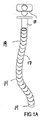
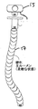
図1Bは、図17から50に示す装置の典型例である選択的に操作可能な装置1の実施の形態を示す。選択的に操作可能な装置1は、数個のセグメント7からなる制御可能な末端部5を有する。図示する実施の形態において、選択的に操作可能な装置1の基端部10は、柔軟なチューブ又はシースとして形成される。基端部10が、セグメント化されて、又末端部5として制御可能であってもよい。図1Aは、長さ方向に沿って連接して固定している種々のセグメント19を有するセグメント化されたガイド・チューブ17を示す。ガイド・チューブ17は、図67から95を参照して説明する種々のガイド・チューブの典型例である。導入部15が、ガイド17の整列を補助するために備えられ、患者の口を介して消化チューブの中を通って胃に至る装置1について、以下に説明する。導入部15は、ガイド17と一体形成されてもよく、別個のコンポーネントとして備えられてもよい。
FIG. 1B shows an embodiment of the selectively
図1Cは、ユーザ23から制御可能な装置1の連接する制御可能な末端部5への制御信号を通信するために使用される基本制御システム20を示す。制御システム20は、コンピュータ22と表示部21とを含む。更に、制御システムの詳細は、図17から33、51から60及び128から135を説明して後に説明する。図1Cは、ガイド・チューブ17を通って伸びる制御可能な装置1の変形例を示す。
FIG. 1C shows the
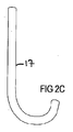
ガイド・チューブ17は、広く異なる種類の形状に操作される。図2A−2Fは、ガイドのいくつかの可能な形状を示す。以下で詳細に説明するように、末端が係合する組織又はガイド・チューブ17に沿った組織を操作するためにユーザがてこの原理を利用できるように、ガイド・チューブ17は、いずれか又は他の形状に固定される。ガイド・チューブを利用して組織を操作する能力によって、更なる安全性を実現し、後述のように操作の傷つけない性質を向上させている。
The
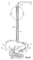
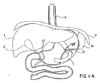
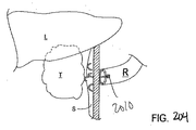
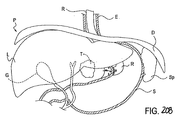
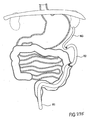
図3は、患者Pの生体構造の部分を示す図である。食堂(E)、横隔膜(D)、肝臓(L)、胆嚢(G)、胃(S)及び脾臓(Sp)が示される。必要に応じて、胃への酸の分泌は、胃酸抑制薬、迷走神経の切断又は神経インパルスのブロック機構の移植のような従来の技術のいずれかを用いて、抑制される。導入部15は、患者の口に取り付けられる。
FIG. 3 is a diagram showing a part of the anatomy of the patient P. The canteen (E), diaphragm (D), liver (L), gallbladder (G), stomach (S) and spleen (Sp) are shown. If desired, acid secretion into the stomach is suppressed using any of the conventional techniques such as gastric acid inhibitors, vagus nerve cutting or transplantation of nerve impulse blocking mechanisms. The
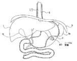
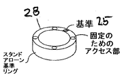
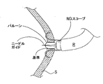
図示する実施の形態において、導入部15は、基準及び位置の表示器25を含む。基準及び位置の表示器は、計測し、追跡し、又は装置若しくは装置の一部の長さを示すために使用される装置であり、この装置は、基準及び位置の表示器の近傍を通り、該表示器に近接し、又は該表示器によって検出される。基準及び位置の表示器では、操作を可能にするために、内部的に生成された画像、外部的に生成された画像又は他の形式のデータの同期化ができる。1つ以上の基準及び位置の表示器が、本明細書に記載された操作に使用される。基準及び位置の表示器は、概ね、近傍を通過した、近接する又は検出された装置又は装置の部分の長さを計測し、追跡し又は表示するために使用されるトランスミッタ、受信機、センサ検出器又は他のコンポーネントの位置を示すために使用される。更に、基準及び位置の表示器の詳細は、以下で説明される。
In the illustrated embodiment, the
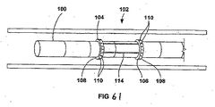
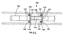
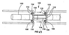
図4は、胃壁近くの位置にまで導入部15を通過するガイド・チューブ17を示す。図示する実施の形態において、ガイド・チューブ17は、位置及び基準の表示器25を備える。位置及び基準の表示器25が、導入部15によって装置の移動を検出し、監視するために使用されることと同様に、ガイド・チューブ17の末端の位置及び基準の表示器25は、ガイド・チューブ17の末端部によって装置の移動を検出し、監視するために使用される。ガイド・チューブ17の末端部は、経腔的な操作に使用される開口の近傍にあり、それらが経腔的な開口を通過して腹腔内に進むとき、ガイド・チューブの末端の基準及び位置の表示器は、装置の位置に関する正確な情報を提供する。
FIG. 4 shows the
図4に示すように、選択的に硬化可能なガイド・チューブ17は、口を介し、胃瘻チューブ(すなわち、導入部15)を介して消化チューブに進入し、又は、自然の又は人工の開口を通って体内に進入する。(自身の内部に、内視鏡又は操作可能なセグメント装置を有し、又は、それを有しない)ガイド・チューブは、食道Eに沿って、所望のガイド・チューブの配置場所へ前進し、それによって、セグメント化された操作可能な装置1にアクセスすることが可能になる。ガイド・チューブ配置場所は、例えば、ガイド・チューブを用いて行われる操作、アクセスされる体の領域、及び、治療を受ける個別の特別な身体的特徴のような多数の要素に基づいて選択される。ガイド・チューブの配置場所の一例は、胃壁である。所望の配置場所に位置付けられると、硬化可能なガイドは、必要に応じて配置場所に固定される。固定方式の多数の代替例が後述される。開口が形成された所望の組織に硬化可能なチューブの末端を固定した後に、セグメント化された装置が硬化可能なガイドに沿って体腔に前進する。
As shown in FIG. 4, the selectively
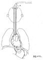
次に、組織の配置場所に開口を形成する。図6A及び6Bは、ガイド・チューブ17の末端が胃壁に固定されない場合の他の操作を示す。図6Bに示すように、ニードル27は、所望の領域近傍の胃壁に開口を形成するために使用される。従って、セグメント化された装置は、解剖学的な組織又は他の構造を検査するために使用され、それによって、治療の適切な経路を決定する。従って、適切な内視鏡の道具、装置又は他の装置は、ガイド・チューブ又はセグメント装置の1つ又は両方を備え、それによって、状態を治療する操作を行う。
Next, an opening is formed at the tissue placement location. 6A and 6B show another operation where the distal end of the
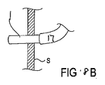
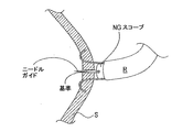
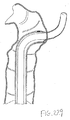
実施の形態において、硬化可能なガイドが胃壁に配置される場合、開口は、胃壁に設けられる必要がある。開口は、ニードル27、ナイフ、針、レーザーその他の外科的な切除用具いて形成される。更に、以下に詳述する1つ以上の開口技術が用いられる。
In embodiments, if a curable guide is placed in the stomach wall, the opening needs to be provided in the stomach wall. The opening is formed with a
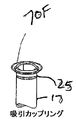
ある形態において、形成された開口は、操作を行うために必要な他の装置にアクセスできるただけの十分な大きさを有する。組織を開口する技術の他の形態において、組織は、切開され、次に拡大されるか、又は、発明に係る開口装置を使用することによって、統合的な操作において開口を形成して拡大する。一実施の形態では、胃の側部に穴を開けるために、バルーンが膨張する。米国公開特許2005/0107664に説明される技術を用いることによって、バルーン膨張が利用可能であり、これは参照によって本明細書に組み込まれる。ルーメン孔を開けるためにバルーンを使用する場合について、図7A及び7Bに示しており、バルーン29は、胃壁の開口を拡大するために使用される。
In one form, the formed aperture is large enough to allow access to other devices necessary to perform the operation. In other forms of opening the tissue, the tissue is dissected and then expanded, or the opening is formed and expanded in an integrated operation by using the inventive opening device. In one embodiment, the balloon is inflated to puncture the side of the stomach. By using the technique described in US Patent Publication No. 2005/0107664, balloon inflation is available and is incorporated herein by reference. The use of a balloon to open a lumen hole is illustrated in FIGS. 7A and 7B, where the
ある形態では、好ましくは、操作の一部として吹き込むことを行う。必要に応じて、1つ以上の密閉装置又は技術が、開口に気密シールを備えるために使用され、それによって、操作の対象である組織に陽圧を掛けることが可能になる。穴がほぼ密閉されると、本明細書で説明される技術を用いてアクセスされる歯周腔又は他の腔を膨張させることができる。ガイド・チューブを胃の内側に位置付けた後に、所定位置を密閉し、スコープ又はニードルの稼働チャネルから吹き付けることによって、局所的にCO2その他のガスを使用することができ、歯周腔に吹き付けることが可能になる。 In one form, blowing is preferably performed as part of the operation. If desired, one or more sealing devices or techniques are used to provide a hermetic seal at the opening, thereby allowing positive pressure to be applied to the tissue being manipulated. Once the hole is substantially sealed, the periodontal or other cavity accessed can be inflated using the techniques described herein. The guide tube after positioning inside the stomach, sealing the predetermined position, by blowing from the working channel of the scope or needle can be used locally CO 2 and other gases, is blown in periodontal cavity Is possible.
図8A及び8Bに示すように、セグメント化された装置1は、適切な治療経路を決定するために、解剖学的な組織又は他の構造の検査に使用される。従って、適切な内視鏡の道具、装置又は他の装置が備えられ、ガイド・チューブ17又はセグメント装置1の1つ又は両方を用いて状態を治療する操作が実行される。
As shown in FIGS. 8A and 8B, the
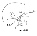
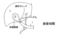
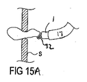
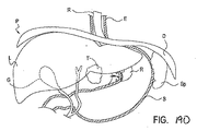
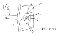
図9−16は、経腔的な操作を用いて胆嚢を除去する様子を示す。硬化可能なガイド・チューブ17によって、操作可能な装置1は、胃壁の開口に固定する。図9に示すように、これによって、操作可能な装置1は、胆嚢Gの除去又は治療のために用いられる。操作可能な装置の先端は、ユーザによって操作され、より基端側のセグメントが、後述するような先導チップの「リーダに追従」する。図10Aは、ダクトを操作可能な装置1の稼働チャネルを介して提供される焼灼ブレード32を示す。クリップ34は、図10Bに示すダクトに取り付けられ、ダクトは図10Cに示すように切断される。次に、胆嚢は。図11、12、13、14、15A及び15Bに示すように分析され除去される。次に、胃壁の開口を閉じるために、ステープラーが用いられ、ステープル又は他の従来の組織を閉じる技術が使用されてよい。
FIG. 9-16 shows the removal of the gallbladder using transluminal operation. By means of a
図8Aの開口ルーメンの位置において、アクセスすることによって、操作可能な装置が、腹腔内の肝臓L、脾臓Sp、横隔膜D、小腸又は他の領域を治療することができる。 By accessing in the position of the open lumen of FIG. 8A, an operable device can treat the liver L, spleen Sp, diaphragm D, small intestine or other area within the abdominal cavity.
本明細書で説明される装置を用いた他の操作において、磁石が内蔵に適切に取り付けられ、これによって、小腸の一部は、小腸における胃のバイパス治療の代わりとして胃壁の方へ引っ張られる。硬化したガイドは、スコープを胃に前進させるために使用され、胃壁に磁石を取り付ける。次に、磁力要素を小腸に配置する。このようなことは、図61−64を参照して後述する周辺組織把持部を備え、本明細書に説明する硬化可能なガイドの実施の形態を用いて行われる。組織把持部は、腸の一部にひだを付けるために使用され、所望の位置に向けた磁石の前進を支援する。次に、磁力要素は、腸内の所望の場所に向けて前進することによって、胃に隣接する。次に、磁石を引きつけるために磁力が利用できるように磁石を用いて、又それらに組織を接合させ、それによって、小腸を胃壁に接合させて吻合する。代わりに、胃から腸内の所望の位置にまで、磁石上及び磁石下のバルーンを使用してもよい。 In other operations using the devices described herein, a magnet is suitably attached to the built-in, whereby a portion of the small intestine is pulled toward the stomach wall as an alternative to gastric bypass treatment in the small intestine. The hardened guide is used to advance the scope into the stomach and attaches a magnet to the stomach wall. Next, the magnetic element is placed in the small intestine. Such is done using the curable guide embodiment described herein with a peripheral tissue gripper described below with reference to FIGS. 61-64. The tissue gripper is used to fold a portion of the intestine and assists in the advancement of the magnet toward the desired location. The magnetic element is then adjacent to the stomach by advancing toward the desired location in the intestine. Next, the magnets are used so that magnetic force can be used to attract the magnets, and the tissue is joined to them, thereby joining the small intestine to the stomach wall and anastomosing. Alternatively, balloons above and below the magnet may be used from the stomach to the desired location in the intestine.
これら及び他に例示する有効な技術は、例えば、スクリューを用いる組織の穿孔、RFナイフ、ニードル、又は、他の外科的な道具について、バルブ、シール又は吹き付ける圧力を支持するための他の拘束具について、種々の程度に制御可能なスコープを有する種々の形態のチューブの組み合わせについて、及び、わずか数個のセグメントが制御可能であり、特に硬化するガイド・チューブを超えて伸びるセグメントのみが制御可能なハイブリッド・スコープの使用について、より詳細に以下に説明される。 These and other effective techniques include, for example, drilling tissue with screws, RF knives, needles, or other restraints to support valves, seals, or blowing pressure for other surgical tools. For various tube combinations with different degrees of controllable scope, and only a few segments are controllable, especially only the segments that extend beyond the hardened guide tube The use of a hybrid scope is described in more detail below.
多くの他の詳細及び特別な操作可能な装置、ガイド・チューブ、シース、並びに、基準及び位置の挟持器の技術及び装置その他の詳細が以下の特許及び出願に記載されており、本願の出願人によって一般に所有され、それらの各々は参照によってその全体が組み込まれる。米国特許6,46,203、6,610,007、6,858,005、6,837,846、6,800,056及び米国特許出願US2003/167007、US2003/171775、US2006/052664、US2005/020901、US2005/165276、US2005/085693、及びUS2004/176683(正確には、「ネオガイド出願(Neoguide application)」)を参照。
Many other details and special manipulatable devices, guide tubes, sheaths, and reference and position clamper techniques and devices and other details are described in the following patents and applications, and are hereby incorporated by reference. In general, each of which is incorporated by reference in its entirety.
操作可能な装置の種類 Types of devices that can be operated
ネオガイド出願において説明される操作可能なセグメント化された制御可能な装置が、幅広く種々の経腔的な応用に使用される。第1の実施の形態において、操作可能なセグメント装置は、完全にセグメント化されている、完全にセグメント化された装置は、体のあらゆる部分に挿入される装置の長さ又は全体にわたって連接され制御可能である。第2の実施の形態において、制御可能なセグメント化された装置は、部分的に制御されているだけであり、ガイド・チューブに接続して使用される。本形態において、操作可能な装置の制御可能なセグメント化された部分は、硬化したアクセス・ポートを提供するためにガイド・チューブが本体の中に拘束され又は固定される場合に、ガイド・チューブを超えて伸びる装置の一部である。更に他の形態において、制御可能な装置のセグメント化された部分は、セグメントを有しており、そのセグメントの大きさと関節は、スコープを利用する解剖学上の特徴に応じて適用される。例えば、食道経由の配置に使用するための操作可能なセグメント化された装置は、食道の小部分を示す非常に長い部分を有する。これに対して、結腸に使用するための装置は、大きさがより小さいセグメントを有し、それによって、食堂に比べて曲がりくねった結腸の特徴に適するより高い柔軟性が実現できる。セグメント及び種々の部材が完全に連接し、制御可能であり、受動的であり、手動制御の下にあり、個別に適用されるモータによって操作され、コンピュータの制御下にあり、種々の機械的なアクチュエータを使用し、又は他の関節、操作及び制御の組み合わせが十分に考慮されるべきである。 The steerable segmented controllable device described in the NeoGuide application is used for a wide variety of transluminal applications. In the first embodiment, the steerable segment device is fully segmented, the fully segmented device is articulated and controlled over the length or whole of the device inserted into any part of the body Is possible. In a second embodiment, the controllable segmented device is only partially controlled and is used in connection with a guide tube. In this configuration, the controllable segmented portion of the manipulatable device can move the guide tube when the guide tube is constrained or secured within the body to provide a hardened access port. Part of the device that extends beyond. In yet another form, the segmented portion of the controllable device has segments, the size and joints of which are adapted depending on the anatomical features utilizing the scope. For example, a steerable segmented device for use in placement via the esophagus has a very long portion that represents a small portion of the esophagus. In contrast, devices for use in the colon have segments that are smaller in size, thereby providing greater flexibility suitable for tortuous colon features compared to canteens. The segments and various members are fully connected, controllable, passive, under manual control, operated by individually applied motors, under computer control, and various mechanical The use of actuators or other joint, manipulation and control combinations should be fully considered.
操作可能な装置 Operable device
図17は、本発明の操作可能な内視鏡100の第1の実施の形態を示す。内視鏡100は、手動で又は選択的に操作可能な末端部105と、自動的に制御される基端部107とを有する細長い本体103を有する。選択的に操作可能な末端部105は、選択的に操作され、又は、任意の方向に全180度湾曲して折り曲げられる。結像用光ファイバの束113又は1つ以上の照明用ファイバ115が、基端部111から末端部109にまで本体103を通って伸びる。代わりに、内視鏡100は、内視鏡本体103の末端部109に位置づけられたCCDカメラのような小型のビデオカメラを有するビデオ内視鏡として設けられてもよい。ビデオカメラからの画像は、送信ケーブル又は無線送信によって、ビデオモニタに送信されてもよい。適宜、内視鏡100の本体103は、吹き付け又は注水のためにも使用され得る1つ以上の装置チャネル117、119を含んでもよい。内視鏡100の本体103は、非常に柔軟であって、そのため、座屈又はよじれを生じさせることなく、小さい半径の周で湾曲できる。結腸内視鏡を使用するために設けられる場合、内視鏡100の本体103は、典型的には、長さ方向が135から185cmであり、直径がほぼ12−13mmである。内視鏡100は、他の医療及び産業上の応用のために、種々の他の大きさ及び形状で作られる。
FIG. 17 shows a first embodiment of an
基端ハンドル121は、細長い本体103の基端部111に取り付けられる。ハンドル121は、直接見るためやビデオカメラ126に接続するための結像用光ファイバの束113に接続した接眼レンズ124を含む。ハンドル121は、照明用ファイバ115に接続され、又は、それと連続している照明用ケーブル134によって、光源128に接続される。ハンドル121の第1ルアー・ロック係合130及び第2ルアー・ロック係合は、装置ちゃんる117,119に接続される。
The
ハンドル121は、コントローラ・ケーブル136を介して、電動コントローラ140に接続される。操作制御部122は、第2ケーブル138を介して、電動コントローラ140に接続される。操作制御部122によって、ユーザは、選択的に本体103の操作可能な末端部105を選択的に操作し又は湾曲させることが可能になる。操作制御部122は、図示するようなジョイスティックのコントローラであり、又は他の知られた操作制御機構である。電動コントローラ140は、自動的に制御される本体103の基端部107の動きを制御する。電動コントローラ140は、マイクロコンピュータ上で実行される移動制御プログラムを用いて又はアプリケーション専用電動コントローラを用いて、実装される。代わりに、電動コントローラ140は、ニューラル。ネットワーク。コントローラを用いて実装されてもよい。
The
軸移動トランスデューサ150が、前進又は後退する時の内視鏡本体130の軸移動を計測するために備えられる。軸移動トランスデューサ150は、種々の可能な形態で設けられる。例えば、図17の軸移動トランスデューサ150は、内視鏡100の本体を囲むリング152として備えられる。軸移動トランスデューサ150は、手術台又は患者の体の内視鏡100への挿入箇所のような参考定点に取り付けられる。内視鏡100の本体103が軸移動トランスデューサ150を通ってスライドする場合、参考定点に関する内視鏡本体103の軸方向の位置を示す信号を生成し、テレメトリ又はケーブル(図示せず)によって電動コントローラ140へ信号を送る。軸移動トランスデューサ150は、内視鏡本体103の軸方向の位置を測定するために、光学的、電気的又は機械的な手段を用いる。軸移動トランスデューサ150の他の可能な形態については、後述する。
An
図18は、本発明の内視鏡100の第2の実施の形態を示す。図17の実施の形態では、内視鏡100は、選択的に操作可能な末端部105と自動制御される基端部107とを有する細長い本体103を有する。操作制御部122は、内視鏡100の選択的に操作可能な末端部105を選択的に操作するための基端ハンドル121に一体化される。適宜、電動コントローラ140は、基端ハンドル121に小型化され、又一体化されたものであってもよい。一実施の形態において、軸移動トランスデューサ150は、手術台のような参照定点に取り付けられたベース154によって形成される。第1ローラ156及び第2ローラ158は、内視鏡本体103の外部に接触する。多重(multi−turn)ポテンショメータ160又は他の移動トランスデューサは、内視鏡本体130の軸移動を計測するために、又、軸方向の位置を示す信号を生成するために、第1ローラ156に接続される。
FIG. 18 shows a second embodiment of the
ユーザは、軸移動トランスデューサ150より末端側の本体を把持することによって、内視鏡100を手動で前進又は後退させる。代わりに、第1ローラ156や第2ローラ158が、内視鏡100の本体103を自動的に前進又後退させるために、モニター162に接続されてもよい。
The user manually advances or retracts the
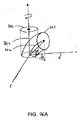
図19は、ニュートラル又は直線位置における内視鏡100の本体103の一部のワイヤ・フレーム・モデルを示す。本図では、内視鏡本体103の内部構造の大部分が、分かり易くするために省略されている。内視鏡本体103は、部分1,2,3・・・,10等に分割されている。各部の形状は、a,b,c及びd軸に沿って計測される4つの長さによって決まる。例えば、部分1は、計測長さlとしての1a,lとしての1b,lとしての1c,lとしての1dの4つの計測長さによって決まり、部分2は、計測長さlとしての2a,lとしての2b,lとしての2c,lとしての2dの4つの計測長さによって決まる等である。好ましくは、計測長さの各々は、リニア・アクチュエータ(図示せず)によって個別に制御される。リニア・アクチュエータは、いくつかの異なる操作原理の1つを利用する。例えば、リニア・アクチュエータの各々は、自己発熱するNiTi合金リニア・アクチュエータ又はエレクトレオロジカル・プラスチック・アクチュエータ、すなわち、他の知られた機械式、空圧式、水圧式又は電気機械式アクチュエータであってよい。各部分の形状は、リニア・アクチュエータを用いて変化し、それによって、a,b,c及びd軸に沿った4つの計測長さを変化させる。好ましくは、計測長さは、所望の方向の内視鏡本体103を選択的に湾曲させるために、相補的な組みで変化する。例えば、内視鏡本体103をa軸方向で湾曲させるために、計測長さlとしての1a,lとしての2a,lとしての3a,lとしての10aは、短くなり、計測長さlとしての1b,lとしての2b,lとしての3b,・・・,lとしての10bは、等しい長さになる。これらの計測長さが変化する量によって、結果としての曲率半径が決まる。
FIG. 19 shows a wire frame model of a portion of the
内視鏡本体103の選択的に操作可能な末端部105において、a,b,c及びd軸方向の各部の計測長さを制御するリニア・アクチュエータは、ユーザによって操作制御部122を介して選択的に制御される。このように、a,b,c及びd軸方向の計測長さを適切に制御することによって、内視鏡本体103の選択的に操作可能な末端部105を選択的に操作し、又は、180度全体の任意の方向に曲げることが可能になる。
The linear actuator that controls the measurement length of each part in the a, b, c, and d axis directions at the selectively
しかしながら、自動制御される基端部107において、a,b,c及びd軸方向の各部の計測長さは、電動コントローラ140によって自動制御され、電動コントローラ140は、内視鏡本体103の形状を制御するために、湾曲伝播法を用いる。湾曲伝播法による操作方法を説明するため、図20は、図30に示す患者の結腸Cの湾曲を通過する内視鏡本体103の自動制御される基端部107の部分のワイヤ・フレーム・モデルを示す。簡単のため、2次元カーブの例が示され、a及びb軸のみが考慮されている。3次元カーブの場合、a,b,c及びd軸の全てが利用される。
However, in the
図20において、内視鏡本体103は、選択的に操作可能な末端部105(この部分の操作は後に詳述する。)の利点を活かして、結腸Cの湾曲を介して操作され、同図では、自動制御される基端部107は湾曲の中に存在する。部分1及び2は、結腸Cの比較的直線状の部分にあり、従って、lとしての1a=lとしての1b、かつ、lとしての2a=lとしての2bである。しかし、部分3−7が、S字状のカーブ部分である場合、lとしての3a<lとしての3b、lとしての4a<lとしての4b、かつ、lとしての5a<lとしての5b、しかし、lとしての6a>lとしての6b、lとしての7a>lとしての7b、かつ、lとしての8a>lとしての8bである。内視鏡本体103が1つのユニットによって末端部に前進する場合、部分1は1’でマークされた位置に移動し、部分2は以前に部分1が占めていた位置に移動し、部分3は以前に部分2が占めていた位置に移動する。軸移動トランスデューサ150は、参照定点に関する内視鏡本体103の軸方向の位置を示す信号を生成し、電動コントローラ140に信号を送信する。電動コントローラ140の制御の下で、各時間において、内視鏡本体103は、1つのユニットを前進させ、自動制御された基端部106の各部分は、自身が今存在している空間を以前に占めた部分の形状を示す信号を受ける。そのため、内視鏡本体103は、1’でマークされた位置に前進すると、lとしてのla=lとしてのlb、lとしての2a=lとしての2b、lとしての3a=lとしての3b、lとしての4a<lとしての4b、lとしての5a<lとしての5b、lとしての6a<lとしての6b、lとしての7a>lとしての7b、lとしての8a>lとしての8b、lとしての9a>lとしての9bとなり、そして、内視鏡本体103が1”でマークされた位置に前進すると、lとしてのla=lとしてのlb、lとしての2a=lとしての2b、lとしての3a=lとしての3b、lとしての4a=lとしての4b、lとしての5a<lとしての5b、lとしての6a<lとしての6b、lとしての7a<lとしての7b、lとしての8a>lとしての8b、lとしての9a>lとしての9b、lとしての10a>lとしての10bとなる。このように、S字状カーブは、内視鏡本体103の自動制御される基端部107に沿って基端側に伝播する。S字状カーブは、内視鏡本体103が末端側に前進しているとき、所定空間に固定されているように見える。
In FIG. 20, the endoscope
同様に、内視鏡本体103が末端側に引き抜かれる場合、毎回、内視鏡本体103が基端側に1つのユニットによって移動し、自動制御される基端部107の各部分は、自身が今存在している空間を以前に占めた部分の形状を示す信号を受ける。S字状カーブは、内視鏡本体103の自動制御される基端部107の長さ方向に沿って末端側に伝播し、S字状カーブは、内視鏡本体103が基端側に後退しているとき、所定空間に固定されているように見える。
Similarly, when the endoscope
内視鏡本体103が前進又は後退する時は常に、軸移動トランスデューサ150が位置の変化を検出し、電動コントローラ140は、空間的に固定の位置にカーブを維持するために、選択されたカーブを基端側又は末端側に、内視鏡本体103の自動制御される基端部107に沿って伝播する。これによって、内視鏡本体103は、曲がりくねったカーブを、結腸の壁に余分な力を掛けることなく移動することができる。
Whenever the
図32は、接続部192によって相互に接続された複数のセグメント192を有する他の内視鏡本体の実施の形態190の典型的な部分を示す。本実施の形態において、隣接するセグメント192は、少なくとも1つの自由度を有する接続部194によって、互いに相対的に移動し又は傾動し、好ましくは本図に示すような2軸に関する、好ましくは複数の自由度を有する。更に図33を参照すると、実施の形態190の部分的な略図196が示されており、2つのセグメント192が、2つの独立軸に関する接続部194に関して回転している。可動範囲は、角度アルファ及びベータによって球軸198に関連付けて説明される。
FIG. 32 shows an exemplary portion of another
上述のように、そのようなセグメントの本体は、種々の方法によって、作動してよい。好ましい方法は、互いに相対的にセグメントを移動させるために、個別のセグメントに設けられた電気機械モータの使用を含む。図23は、電動のセグメント接続部を有する好ましくは実施の形態200を示す。各セグメント192は、好ましくは、背骨セグメント202を備え、好ましくはそれは、光ファイバ、空気や水の流路、種々の内視鏡ツール、すなわち種々の装置及びワイヤが通るアクセス・チャネルを提供するために、自身を貫く少なくとも1つのルーメンを有する。背骨セグメントは、種々の要素からなり、それは好ましくは生体適合性のものであり、又、それは、ステンレス鋼のような、種々のツール及び他のコンポーネントを支持するために、十分な強度を提供する。説明の大部分は個別のセグメント192に関するが、セグメント192の各々は、末端部に位置付けられるセグメント(又は第1の少ないセグメント)を除いて好ましくは同一であり、以下の説明は少なくともセグメント192の大部分に容易に適用できる。
As mentioned above, the body of such a segment may be actuated in various ways. A preferred method involves the use of electromechanical motors provided in individual segments to move the segments relative to one another. FIG. 23 shows a
望ましい結果及び応用に依存するシングル・モータ又は複数モータは、少なくともセグメントの主要部分に取り付けられる。セグメントにシングル・モータを有する実施の形態は、図23に示すように、好ましくは個別モータ204には背骨部202が取り付けられ、外傷を与えることなく患者に挿入するために十分に快適で小さい比較的小さな直径を可能にするために、十分に小さく又コンパクトである。モータ204は、本図に示すように小さくブラシがけされたDCモータである場合、隣接セグメント192を作動させるために使用され、他のモータから独立的に制御される。小さいブラシがけされたDCモータを除いて、種々のモータがACモータ、リニア・モータ等として使用される。各モータ204は、好ましくは、ハウジングの中に電気的なモータ・アセンブリEM自身だけではなく、ギア減速ステージGR及びポジション・エンコーダPEをも含む。モータ・アセンブリEMに取り付けられるギア減速ステージGRによって、高速低トルク操作状態をより利用し易い低速高トルクの出力に変換し、それによって、適切なスピードとトルクの幅でモータ204の使用が可能になる。ポジション・エンコーダPEは、従来のエンコーダであって、コンピュータ制御により、モータ204の出力軸の回転移動角を追跡し続けることによって、セグメントの接続部194の位置を読み出すことが可能になる。
Depending on the desired result and application, a single motor or multiple motors are attached at least to the main part of the segment. The embodiment with a single motor in the segment is preferably a comfortable and small comparison, as shown in FIG. 23, with a
各モータ204は、セグメント192を作動するパワーを伝達するために、モータ204の端部から伸びる回転可能なシャフトを有する。このシャフトにつき、スプール2006には、スプール206に関して更に湾曲したケーブル208の第1端部に回転可能に取り付けられる。ケーブル208は、次に、スプール206から、ケーブル・ガイド210に設けられたチャネル212を介して、開口214から外部のケーブル・アンカ216に配置され、ケーブル208の第2端部は、好ましくは例えば圧着やはんだ付けによって、ケーブル・アンカ216に取り付けられている。ケーブル・ガイド210は、スプール206に関して湾曲するケーブル208を補足するために役立つ。ケーブル・アンカ216は、自在継ぎ手ピボット220を横切って隣接するセグメント192にピン218を介して接続し、従来の電気的なリング接続のような形状をし、又は、セグメント192に設けるために通過するホールを形成する丸い部分と、ケーブル208の第2端部に接続するためにアンカ216から突出する延長部とを有する。ケーブル208は、種々のフィラメント、ストランド、ワイヤ、チェーン、ブレード等を備えており。それらのいずれかが、例えばステンレス鋼、プラスチック及びナイロンのようなポリマー等の種々の生体適合性の要素を用いて製造される。
Each
操作時において、例えば時計回りのような第1の方向にシャフトが回転するようにモータ204が操作される場合、スプール206は、適宜に回転し、ケーブル208は、隣接するセグメント192に応じた方向に引き、又、次に第1軸に沿って作動するようにトルクを伝達する。第1方向とは反対の第2方向(例えば、半時計回り)にシャフトを回転させるために、モータ204が操作される場合、スプール206は、適宜に再び回転し、ケーブル208は、後続するトルクの伝達及び反対方向での作動のために、次に隣接するセグメント192を適宜反対方向に引く。
In operation, for example, when the
図24A及び24Bは、2つの隣接するセグメントを展開したアイソメトリックの組立図を示し、それぞれ、図23に示す実施の形態である。図24Aに示すように、背骨部202は、上述のように、ルーメン221を有して示されており、そのルーメンは、稼働チャネルを提供するために使用される。又、ケーブル・ガイド210に形成されたチャネル212が、貫通するケーブル208のための開口214とともに示されている。隣接するセグメントに相互に接続する場合、セグメントとの間で必要な自由度を提供するために、好ましい接続方法は、自在継ぎ手ピボット220を用いることを含む。しかし、他の実施の形態では、自在継ぎ手ピボット220を用いるのではなく、種々の継ぎ手の方法、例えば、2つのセグメントをそれぞれの中心で接続するために用いられる柔軟なチューブ、空間的に近くに位置する1自由度の一連の接続部等を使用する。この特別な実施の形態では、自在継ぎ手ピボット220の使用について説明する。他のセグメントの近くの背骨部202の端部に、1組のユニバーサル結合部材224が、1組の対応するピン開口部226とともに形成される。自在継ぎ手ピボット220が、あるセグメントの第1結合部材の組みに接続され、隣接するセグメントから対応する結合部材224の組みが接続部ピボット220に取り付けられる。
FIGS. 24A and 24B show isometric assembly views in which two adjacent segments are expanded, each of the embodiment shown in FIG. As shown in FIG. 24A, the
図24Bに更に示すように、自在継ぎ手ピボット220は、本実施の形態では、対応する結合部材224を回転可能に収容するために、対向する収容ホール228の2つのセットを有する筒状リングとして示される。収容ホール228は、図示するように、90度の間を開けて配置されるが、他の形態においては、収容ホールは、所望の自由度及び応用例に応じて他の角度を開けてで配置されてもよい。図示するように、スプール206の展開したアセンブリは、モータ204から取り外され、ドライブ・シャフト205が露出している。モータ204が背骨部202に取り付けられる場合、グルーブ230は、背骨部202に形成される場合に、露出する。このグルーブ230は、好ましくはモータ204のハウジングの半径に適合させるために、背骨部202に押し下げられ、これは、モータ204を背骨部202の近傍に位置付けることを支援するだけでなく、組み立てられたセグメントの全体的な直径を小さくすることにも役立つ。例えば粘着、クランプ、バンド、機械的な拘束等の種々の方法によって、モータ204は、背骨部202に取り付けられてよい。
As further shown in FIG. 24B, the universal
患者に挿入する前、内視鏡200は、診断チェックを自動的に実行するように適宜設けられる。内視鏡200がドラム上に曲げられると、隣接するセグメント192は、ドラムの直径及び内視鏡200が位置付けられるストレージ・ユニットの最初の形状によって最初に決定されるため、互いに相対的に所定角度を有する。挿入前の診断中に、コンピュータが、各隣接するセグメント192の間の角度を自動的に検知して計測するように設けられる。隣接するセグメント192のいずれかが、所定の許容範囲の角度を超えた角度を相対的に計測した場合、位置から外れたセグメント192が示され、内視鏡200を使用している間の問題の潜在的な箇所が示される。従って、コンピュータは、続いて、音又は視覚の警告を発して、自動的に更に使用することを避けて患者に外傷を与えないようにするために、セグメント192の各々をニュートラル位置に位置付ける。
Prior to insertion into the patient, the
図25は、本発明の腱駆動式内視鏡20の形態を示す。内視鏡20は、手動で又は選択的に操作可能な末端部24と、自動制御される部分28と、柔軟で受動的に操作される基端部22とを有する細長い本体21を有し、基端部22は適宜装置から省略されてもよい。操作可能な末端部24は、手又はアクチュエータの機械的な支援によって、関節で接続される。自動制御される部分28はセグメント化され、各セグメントは、操作可能な動きの全範囲にわたって湾曲可能である。末端部24も制御可能なセグメントである。
FIG. 25 shows a form of the tendon driven
選択的に操作可能な末端部24は、選択的に操作され、又は、例えば図示するように180度の全体に任意の方向26に曲がる。結像用光ファイバの束40及び1つ以上の照明用ファイバ42は、本体21を通って基端部22から末端部24へ伸びる。代わりに、内視鏡20は、CCD又はCMOSカメラようのような小型のビデオカメラを有するビデオ内視鏡として設けられ、内視鏡本体21の末端部24に位置付けられる。ビデオカメラからの画像は、伝送ケーブル又は無線伝送によってビデオモニタに送信され、画像は、リアルタイムで見られ、かつ/又は、例えば磁気テープのようなアナログ記録媒体、又は、例えばコンパクト・ディスク、デジタル・テープ等のようなデジタル記録媒体に記録装置によって記録される。LED又は他の光源が、内視鏡の末端での照明に用いられてもよい。
The selectively
内視鏡20の本体21は、光源、空気や水を吹き付け又は注水するチャネルや吸引するためのチャネルを提供するために、照明用ファイバに適宜使用される1つ以上のアクセス・ルーメ38を含む。概ね、内視鏡20の本体21は、非常に柔軟であり、そのため、種々のチャネルをそのままで維持しておく一方で、座屈し又はよじれることなくそれは小さい直径のカーブに湾曲させることができる。結腸内視鏡として使用するために設けられる場合、内視鏡20の本体21は、典型的に135cmから185cmまでの長さの範囲にあり、約13−19mmの直径にある。内視鏡20は、種々の他の大きさで作られ、他の医療及び産業上の応用のために形成されてもよい。
The
制御可能な部分28は、少なくとも1つのセグメント30を備えており、好ましくは数個のセグメント30を備え、セグメントは、内視鏡20から末端に位置するコンピュータ又は電気制御器(コントローラ)45を介して制御可能である。セグメント30の各々は、アクチュエータに機械的に接続される腱を有し、それによって、制御されたセグメント30の所定空間における移動が可能になる。腱を操作するアクチュエータは、腱に力を掛けることが可能な種々の異なるタイプの機構、例えば、電気機械モータ、空気圧式及び水圧式のシリンダ、空気圧式及び水圧式のモータ、ソレノイド、形状記憶合金のワイヤ、電気回転アクチュエータ又は当業者に知られた他の装置又は方法を含む。形状記憶合金のワイヤが使用される場合、それらは、好ましくはいくつかのワイヤ・バンドルに形成され、コントローラ内部の各腱の基端に取り付けられる。セグメント関節は、次に腱の移動を作動させるワイヤ・バンドルを先ず直線移動させるために、例えば電流、熱等のエネルギーをバンドルの各々に掛けることによって実行される。コントローラ内でのアクチュエータの直線移動は、比較的短い距離、例えば数インチ又は+/−0.1インチより小さい範囲で移動するように設けられ、それによって、所望の角度のセグメントの移動及び関節による効果的な関節を実現する。
The
受動的な基端部22が使用されるが、内視鏡の挿入部の長さは、好ましくは制御可能なセグメント30を備える。基端部22は、好ましくは、種々の形状を形成し、又、例えば従来の内視鏡のチューブを製造するために使用された熱硬化性及び耐熱ポリマーのような種々の要素から作られる柔軟なチューブ部材である。
Although a passive
各セグメント30は、好ましくは、貫通する少なくとも1つのルーメンを形成し、それによって、ワイヤ、光ファイバ、空気や水の流路、種々の内視鏡ツール、すなわちあらゆる種類の装置及びワイヤが通過するアクセス・チャネルを提供することができる。ポリマーのカバー又はシース39は、制御可能な部分28及び操作可能な末端部24を含む内視鏡21の本体を超えて伸びる。このシース39は、好ましくは、制御可能なセグメント30、操作可能な末端部24及び基端部22の柔軟なチューブの間の円滑な移行を提供する。
Each
ハンドル32は、内視鏡の基端に取り付けられる。ハンドル32は、直接見るための結像用光ファイバの束42に接続された接眼レンズを含む。ハンドル32は、例えばCCD
又はCMOSカメラのようなビデオモニタ、カメラ、又は、記録装置52に接続するための接続部54を有する。ハンドル32は、照明用ファイバ42に接続され、又はそれと連続する照明用ケーブル44によって光源43に接続される。代わりに、一部又は全てのこれらの接続がコントローラ45でなされてもよい。ルアー・ロック係合34が、ハンドル43に設けられ、種々の装置チャネルに接続されてもよい。
The
Or it has the connection part 54 for connecting with a video monitor like a CMOS camera, a camera, or the
ハンドル32はコントローラ・ケーブル46を通してモーション・コントローラ45に接続される。操作制御部47は、第2ケーブル48を通してコントローラ45に接続され、又は、それは適宜直接的にハンドル32に接続される。代わりに、ハンドルは、直接ハンドルと一体化した、例えば、例えば、ジョイスティック形式、ダイヤル、プーリー又はホイールなどの従来のディスクコントローラ等の操作制御機構を有する。操作制御部47によって、ユーザに選択的な操作が可能になるか、又は、本体21の操作可能な末端部24を選択的に所望の方向に湾曲させることが可能になる。操作制御部47は、図示するようなジョイスティック・コントローラ、又は、例えば、従来の内視鏡にあるような回転ノブ若しくはデュアル・ダイアル、トラック・ボールタッチパッド、マウス、又はセンサグローブ他の操作制御機構である。
モーション・コントローラ45が、本体21のセグメント化された自動制御される基端部28の移動を制御する。このコントローラ45は、マイクロコンピュータ上で実行される移動制御プログラムを用いて、又は、アプリケーション専用電動コントローラを用いて、実装される。代わりに、コントローラ45は、例えば、ニューラルネットワーク・コントローラを用いて実装されてもよい。
The
A motion controller 45 controls the movement of the segmented automatically controlled
腱に力を掛けるアクチュエータは、図示するようなコントローラ・ユニット45に含まれるか、又は、別個に設けられてコントロール・ケーブルで接続される。操作可能な末端部24を制御する腱と制御可能なセグメント30は、内視鏡本体21の長さ方向の下側に伸びて、アクチュエータに接続する。図25は、腱がハンドル32を通過し、簡易開放接続部60を介してモーション・コントローラに直接的に接続する形態を示す。本形態において、腱は、アクチュエータがコントローラ45と通信している限り、独立的にアクチュエータに接続するが、コントロール・ケーブル46の一部である。
The actuator for applying force to the tendon is included in the controller unit 45 as shown in the figure, or is provided separately and connected by a control cable. The tendon that controls the
軸移動トランスデューサ (又は、深さ参照装置又は基準とも呼ばれる。)49は、軸方向の移動、すなわち、内視鏡本体21が前進及び後退する場合の内視鏡本体21の深さの変化を計測する。深さ参照装置49は、多くの可能な形態で作られてもよい。例えば、図25における軸移動トランスデューサ49は、内視鏡20の本体21を囲むリング49として形成される。好ましくは、軸移動トランスデューサ49は、手術台又は患者の体への内視鏡20のための挿入箇所のような、参照定点に取り付けられる。内視鏡20の本体21が軸移動トランスデューサ49を介してスライド移動する場合、それは、参照定点に関する内視鏡本体21の軸方向の位置を示し、又、電気コントローラ45にテレメトリ又はケーブルによって信号を送信する。軸移動トランスデューサ49は、内視鏡本体21の軸方向の位置を測定するために、光、電気、磁力、高周波又は機械的な方法を用いる。
The axial movement transducer (or also referred to as a depth reference device or standard) 49 measures axial movement, that is, changes in the depth of the
内視鏡本体21が前進及び後退すると、軸移動トランスデューサ49は、位置の変化を検出し、モーション・コントローラ45に信号を送る。末端部24を操作するユーザによって選択された経路に従って、内視鏡の移動を維持するために、コントローラは、内視鏡本体21の制御部28に沿った基端側又は末端側に、選択されたカーブを伝播するために、この情報を使用する。軸移動トランスデューサ49によって、計測された深さの変化によって、結腸Cの中での現在の深さを増加させることが可能になる。これによって、内視鏡本体21が、結腸Cの壁に余分な力を掛けることなく、入り組んだカーブを通って導かれることが可能になる。
As the
図26Aは、操作可能な末端部分を含む制御可能なセグメントを関節で接続するために、2本又は3本の腱を用いることで可能になるセグメント関節の実施の形態を示す。図26Aは、本発明の本実施の形態において、3本の腱によって作動する制御可能なセグメントの可動範囲の一例を示す。弛緩して直立位置301にあるセグメントは、事実上xy平面に対して任意の方向に曲がる。例としても図は、元の位置301に対する角度で見て下方に曲がるセグメント302を示す。角度α、βは、セグメントによる湾曲を表す。角度βはxy平面における角度であり、αはxz面における動きを表す。一形態において、内視鏡の制御可能なセグメントは、角度βの場合、360度全てにわたって曲がることができ、角度αの場合、90度にまで曲がることができる。90度より大きい角度は、結果的に内視鏡の循環になる。図26Aにおいて、セグメントは、角度αがほぼ45度に沿って示される。セグメントの所定部分における動きの自由度は、関節の方法、セグメントの大きさ、構成する要素の形式、構成する方法その他によって予め決まっている。これらの要素の一部は本明細書において説明する。
FIG. 26A shows an embodiment of a segment joint that is enabled by using two or three tendons to articulate a controllable segment that includes a steerable end portion. FIG. 26A shows an example of a movable range of a controllable segment operated by three tendons in the present embodiment of the present invention. A segment that is relaxed and in the
操作可能な末端部は、内視鏡及び制御可能なセグメントと同様に、湾曲するが、好ましくは、収縮又は膨張しない。このように、図26Aにおいて、弛緩したセグメント301の中心軸304は、湾曲後302のセグメントの中心軸とほぼ同じ長さである。
The steerable end is curved, but preferably not contracted or expanded, similar to the endoscope and controllable segment. Thus, in FIG. 26A, the
図26Bから26Fは、本発明の内視鏡に使用される制御可能なセグメントを作動させるために、3本の腱を使用する場合を示す。本例に示される腱は、全てボウデン(Bowden)タイプのケーブル310であり、ケーブルが自由に移動可能なハウジング又はスリーブ314によって囲まれる同軸上の内部ケーブル312を有する。ボウデン・ケーブルは、テンシル力又は圧縮力のいずれかを掛けるために使用され、すなわち、それらは、関節で接続する内視鏡を押し又は引くものであり、又、内視鏡に沿う場所で所望の力を遠隔から伝達できる。腱からの力は、腱ケーブルをセグメント320の末端に、又は、腱ハウジング314をセグメント322の基端に取り付けることによって、セグメントを横切り又は通って伝わる。図26Bは、320で示される腱ケーブルのための3つの取付箇所を有するセグメントの平面図を示す。
Figures 26B to 26F illustrate the use of three tendons to actuate the controllable segments used in the endoscope of the present invention. The tendons shown in this example are all
一実施の形態において、操作可能な末端部を含む3つの腱が各セグメントを作動させるために使用されるが、4つ以上の腱が使用されてもよい。3つの腱は、セグメント又は内視鏡をその長軸方向に関して回転させることなく、セグメントを確実に任意の方向で関節で接続する。3本のケーブル腱312は、好ましくは、セグメント端部近くのセグメント320の末端に取り付けられ、均等に離して配置される。図26Bにおいて、腱は、2時、6時及び10時の位置に取り付けられる。各セグメントを制御する腱は基端側にアクチュエータを突出させるため、空間的な理由から、より少ない腱を用いることが望ましい。このように、2本の腱がセグメントを制御するために使用されてもよい。望ましくは、セグメントを3次元で連接するために、例えば、バネのような1つ以上の付勢部材を含む。他の形態において、2本の腱が、その長軸方向に関してセグメントを回転させる一方で2方向の動きを制御することによって、3次元の空間においてセグメントを関節で接続するために使用される。
In one embodiment, three tendons with manipulable ends are used to actuate each segment, but more than four tendons may be used. The three tendons ensure that the segments are articulated in any direction without rotating the segment or endoscope with respect to its longitudinal direction. The three
図26Cじゃ、3本の腱を用いて取り付けられた弛緩したセグメントを示す。対応するケーブル取付箇所の下に直接にセグメント322の末端側に取り付けられた腱スリーブ314が図示されている。図26Dから26Fは、このセグメントが制御している腱の各々によって個別に曲げられることを示す。
FIG. 26C shows a relaxed segment attached using three tendons. A
図26Dに示すように、第1腱330に張力を掛けることによって、第1腱330の方向は曲がる。すなわち、曲がっていないセグメント(図26Bに示す)の情報から見下ろすと、この腱をただ引っ張ることによって、6時の方向にセグメントが曲がっている。図26Eにおいて、2時の位置に取り付けられた第2腱332に押す力を掛けるだけで、セグメントは2時の方向に曲がる。最後に10時の位置334で腱を引くと、セグメントは、10時の方向に曲がる。全ての場合で、湾曲は連続的であり、より大きな力を掛けると更に(図26Aのxz平面における角度αを)湾曲させる。セグメントは、個別の腱又は2本の腱の組み合わせを引くことによって任意の方向に曲げることができる。このようにして、セグメントを12時の方向に湾曲させる場合、第2腱332及び第3腱334の両方が等しい力で引かれる。代わりに、6時の位置の第1腱330が単独又は引っ張られた第2腱332及び第3腱334との組み合わせのいずれかが押されると、同じの形状になる。
As shown in FIG. 26D, by applying tension to the
図27A及び27Bは、セグメントが、2本の腱及び1つの付勢部材によって関節で接続される形態を示す。図27Aは、セグメントの平面図を示す。付勢部材340のための取付箇所及び2つの腱320は図示されているようにセグメントの末端部の周囲に間隔を開けて設けられる。セクションの上方から見て、腱320は2時及び10時の位置に取り付けられ、付勢部材340は6時の位置に取り付けられる。図27Bは、直線形状でのセグメントの斜視図を示す。この形態では、セグメントの側部が6時の位置の方に曲がるような張力をそれに掛けるために、付勢部材は形成される。付勢部材は区分、例えばばね、弾性部材、ピストン等のセグメントを横切る圧縮力又は張力を加えることができるいかなる部材であってもよい。セグメントは、両方の腱312から張力を掛けることによって、図27Bに示すニュートラル又は直線位置で保持される。腱によって掛けられる張力の大きさを制御することによって、三次元空間でのセグメントの湾曲させることができる。1つ以上の付勢部材は2つ以上の腱とともに使用されてもよい。例えば、付勢部材は各腱の反対に取付けられてもよい。
FIGS. 27A and 27B show a configuration in which segments are articulated by two tendons and a biasing member. FIG. 27A shows a plan view of the segments. Attachment points for the biasing
代わりに、腱がプッシュプル・ケーブルであり、そして各腱が張力と同様、圧縮力を掛ける場合、2つの腱は付勢部材を全く用いることなく、セグメントの動きを制御できる。 Instead, if the tendons are push-pull cables and each tendon applies a compressive force, as well as tension, the two tendons can control the movement of the segments without using any biasing members.
又3つ以上の腱がセグメントの湾曲を制御するために使用されてもよい。図27Cは11時、2時、5時及び8時の位置に取り付けられた4本の腱によって制御されるグメントを上方から見た平面図を示す。3本の腱を用いる実施の形態と同様に、腱の1本又は組み合わせにより掛かる張力によって、セグメントの側部は短くなる。従って、張力が11時の位置355で末端側に取り付けられた腱でのみ掛けられる場合、腱に対応する側部は短くなり、セグメントは11時の方向に曲がる。
Three or more tendons may also be used to control segment curvature. FIG. 27C shows a plan view from above of a segment controlled by four tendons attached at 11 o'clock, 2 o'clock, 5 o'clock and 8 o'clock positions. Similar to the embodiment with three tendons, the tension on one or a combination of tendons shortens the side of the segment. Thus, if the tension is only applied with a tendon attached to the distal side at 11
これら全ての形態では、腱や付勢部材の円周での位置は例示であって、本明細書に記載される例に限定されることを意図するものではない。むしろ、当業者によって理解されるように、望ましい効果に従って変形されてもよい。 In all these forms, the circumferential positions of the tendons and biasing members are exemplary and are not intended to be limited to the examples described herein. Rather, it may be modified according to the desired effect, as will be appreciated by those skilled in the art.
図28は、セグメントを曲げる単一の腱の一部の概略図を示す。明確にするために、他の腱及びセグメントを含む内視鏡の他の部品は、図28では省略されている。腱ケーブルに掛かる張力は、セグメントの全体に伝わり、セグメントを湾曲させる。スリーブ314がセグメントのベースに取り付けられ、アクチュエータ端部403にも固定されるボウデン・ケーブル310を使用することによって、腱312に張力が掛かり、意図されたセグメント401のみが湾曲し、より基端側のセグメントは影響されない。本形態ではモータが腱ケーブル312を引く場合に、図示するアクチュエータ410による張力が腱に掛けられる。
FIG. 28 shows a schematic view of a portion of a single tendon that bends a segment. For clarity, other parts of the endoscope, including other tendons and segments, are omitted in FIG. The tension applied to the tendon cable is transmitted throughout the segment, causing the segment to bend. By using the
接続された制御リングは、操作可能な末端部分及び制御可能なセグメントを組み立てるのに必要とされる柔軟な構造を備える。利用され得る制御リングの2つのタイプの例が示される。第1に図29Aは、本発明の制御可能なセグメントを形成する脊椎骨部型制御リングを示す。図29Aは単一の椎骨部の端面図を示す。各リング状の椎骨部501は、上述のように、中央チャネル又は開口504若しくは装置の内部ルーメンを連通できる開口を形成する。椎骨部は、2組のヒンジを有し、第1組506は、椎骨部の第1面から垂直に突出し、第2組506は、外周部に第1組から90度の位置に配置され、第1面に対向する椎骨部の第2面に、椎骨部表面から垂直方向に離れるように突出する。29A及び29Bに示すヒンジはタブ形状であるが、他の形状が使用されてもよい。
The connected control ring comprises the operative end portion and the flexible structure required to assemble the controllable segment. Examples of two types of control rings that can be utilized are shown. First, FIG. 29A shows a vertebral control ring forming the controllable segment of the present invention. FIG. 29A shows an end view of a single vertebra. Each ring-shaped
図29Aの椎骨部制御リングは、椎骨部の端部を通る3つの穴510とともに示されており、椎骨部制御リングは、例えば、椎骨部がセグメントの最も末端の椎骨部である場合、腱ケーブル312のための取付箇所として、又は、椎骨部が使用されるセグメントを作動できる腱ケーブルのための経路として機能する。椎骨部がセグメントの最も基端側を制御するディスクである場合、これらの穴510は、ボウデン型腱ケーブル314のスリーブを取り付けるためにも使用される。代わりに、穴510よりもむしろ、取付箇所は、凹部又は他の特別な形状であってもよい。図29Aは、3つの穴510を示しており、穴の数は、椎骨部が属するセグメントを制御するために使用される腱の数に依存する。穴510が腱のための取付箇所として使用されるため、セグメントを制御する腱と同数の穴がある。
The vertebral control ring of FIG. 29A is shown with three
図29Aの椎骨部の外方端部は、末端セグメントを制御し、椎骨部をバイパスする腱の腱ハウジングのためのスペース512を提供するためにスカラップ状である。これらの腱のバイパス・スペースは、好ましくは、使用される腱の外径に合致する。腱のバイパス・スペース512の数は腱の数によって変わってもよい。また、バイパスする腱が内視鏡の周囲で曲がる方法を変える場合には、腱のバイパス・スペースの方向が変更されてもよい。例えば、図29Cのスペース512'は、椎骨部の長軸方向に関して所定角度で方向づけられており、基端側に突出するため、腱は、内視鏡本体の周囲を巻くことができる。更に、腱のバイパス・スペースは、セグメントを横断してバイパスする腱の移動を容易にするために、滑らかであり又は滑らかな要素で作られ、それによって、セグメントの湾曲とバイパスする腱との間の干渉を防ぐことができる。
The outer end of the vertebra in FIG. 29A is scalloped to provide a
図29B及び29Cは、図29Aと同じ椎骨部の側面図を示す。2組のヒンジ接続部508,506が示される。ヒンジ接続部508,506が隣接した椎骨部からのヒンジ接続部と回転して当接できるように、ヒンジ接続部508、506は、好ましくは約90度離れて配置され、軸方向に伸びる。隣接した椎骨部との当接520は図29Cにより分かり易く示される。これらのヒンジは、522で示すような穴525を通して結合されるか、ピンで止められるか、又は接続される。代わりに、ヒンジはまた、例えば、熱可塑性プラスチック、形状記憶合金等を利用する要素を用いて作られる。ヒンジ接続されると、各椎骨部は1軸方向の隣接した椎骨部に関して回動できる。しかし、椎骨部は、90度ごとに交互になる方向で互いにヒンジ接続されるので、多数の椎骨部のアセンブリは事実上あらゆる方向で動ける。より多くの椎骨部がこの方法で結合する場合、可動範囲はより広くなる。一実施の形態では、2から10の椎骨部が1つのセグメントにつき使用され、セグメントあたり約4cmから10cmの長さを実現できる。椎骨部およびヒンジ接続部の両方の大きさが変更されてもよく、例えば別の椎骨部に結合された場合に、より長いヒンジ接続部によって大きい曲率半径を有してもよい。更に、1セグメント当たりの椎骨部の数が変わってもよく、例えば10以上の椎骨部が使用されてもよい。
29B and 29C show the same side view of the vertebra as in FIG. 29A. Two sets of
図29D及び29Eは、他の実施の形態の椎骨部の部分及び透視図をそれぞれ示す。
図29D及び29Eにおいて、セグメントをバイパスする腱は、椎骨部の外方端部に沿うよりもむしろ、図29Aで示すようにスペース550をバイパスする腱の椎骨部の本体の中に含まれる。図29D及び29Eの脊椎部は、スペースをバイパスする4本の腱を示し、各スペースは、約15本のバイパスする腱のスリーブを保持できる。スペースをバイパスする腱の数、形及び大きさは変更されてもよい。例えば、椎骨部は、35個より多くの腱のスリーブを保持できる2つの腱バイパス・スペースを有してもよい。更に、腱バイパス・スペースは、椎骨部504の中央開口又はルーメンの内部に配置されてもよい。
29D and 29E show a vertebral portion and a perspective view, respectively, of another embodiment.
In FIGS. 29D and 29E, the tendon that bypasses the segment is contained within the body of the vertebrae of the tendon that bypasses the
図29Dは、単一の腱ケーブル560だけを保持する腱のスリーブを示しており、1本以上の腱ケーブルが、腱のハウジング又はスリーブに含まれている。例えば、3本の腱がセグメントを関節で接続させたら、3つの腱の全てが単一の腱ハウジングに含まれる。そのように組み込まれた腱ハウジングは、更に、個々の腱ケーブルによる独立した動きに適応するために潤滑剤を利用してもよく、且つ/又は、ハウジング内の腱を隔離するコンパートメントに分離してもよい。
FIG. 29D shows a tendon sleeve that holds only a
図29Eは、回動することによって隣接した椎小粒からのヒンジ接続部508の組と当接するヒンジ接続部506の斜視図を示す。
図29A及び29Bは、軸方向に突出する2組のヒンジ接続部を示し、椎骨部の各表面で単一のヒンジ接続部が使用される。更に、ヒンジ接続部が隣接した椎骨と回動して当接できる限り、ヒンジ接続部は椎骨部の中心から異なる半径の位置に取り付けられてもよい。例えば、図29Aから29Cに示すヒンジ接続部の組は、図29D及び図29Eのヒンジ接続部よりも椎骨の中心の近くに取り付けられる。
FIG. 29E shows a perspective view of a
FIGS. 29A and 29B show two sets of axially protruding hinge connections, where a single hinge connection is used on each surface of the vertebra. Further, as long as the hinge connection portion can rotate and come into contact with the adjacent vertebra, the hinge connection portion may be attached at a position having a different radius from the center of the vertebra portion. For example, the set of hinge connections shown in FIGS. 29A-29C are attached closer to the center of the vertebra than the hinge connections of FIGS. 29D and 29E.
図30A及び30Bは、制御リングの第2の形態を説明する。図で示す形態は、柔軟な背骨部601を利用し、背骨部601は、好ましくは比較的、非圧縮性且つ非膨張性の要素を用いて作られ、制御リングが所定間隔で取り付けられる。このような構造によって、あらゆる所望の方向に連続的なカーブで曲がることが可能になる。図30Aは、制御リングおよび背骨を示すために外層が除かれた、本形態の1つの制御可能なセグメントの側面図を示す。多数制御リング602は、等間隔で柔軟な背骨に取り付けられる。少数又はより多くの制御リングは、所望の程度の関節に依存する単一のセグメントを構成するために使用される。腱ケーブル312は、セグメント604の末端制御リングに取り付けられる。椎骨部型の形態の場合、この中央背骨部の実施形態は、セグメント604の末端制御リングの端部の周に均等な間隔の場所に取り付けられた3本の腱310によって作動する。スペース又は穴610を通してセグメント312を制御する腱ケーブルは、自由に移動可能な制御リング602に形成される。これらの穴610は、円滑な要素を用いて滑らかにされ、直線状にされ、又制御される。穴610を通してケーブルの動きを容易にするために、リング602は滑らかな要素で作られる。好ましくは、腱のスリーブのセグメント612の最も基端側の制御リングに所定箇所で取り付けられる。腱312に張力が掛かる場合、この力は全体のセグメントに沿って伝わる。内部の腱ケーブル312は、腱のスリーブ314の中で自由にスライド移動可能であり、腱のスリーブは、腱614の両端に固定され、それによって、選択されたセグメントで腱ケーブルを引くことによる湾曲しか起きないようになる。
30A and 30B illustrate a second form of control ring. The illustrated form utilizes a
図30Aは、より基端側のセグメント604'の第1制御リングを示す。末端側のセグメントを制御する腱は、アクチュエータより基端側に突き出すような基端側のセグメントの外側を通過する。柔軟な背骨のための制御リングの外方端部の実施の形態は、図30Bに示すように、チャネル又は腱バイパス・スペース616とともに示される。脊椎骨型制御リングを有する場合、これらの腱バイパス・スペースは、制御リングの中、例えば、閉鎖された腱バイパス・スペースの中に配置される。 FIG. 30A shows the first control ring of the more proximal segment 604 ′. The tendon controlling the distal segment passes outside the proximal segment protruding from the actuator to the proximal side. An embodiment of the outer end of the control ring for the flexible spine is shown with a channel or tendon bypass space 616, as shown in FIG. 30B. With a vertebral control ring, these tendon bypass spaces are placed in the control ring, for example, in a closed tendon bypass space.
図30Bは、内視鏡の柔軟な背骨部の実施の形態を用いて使用される制御リング602の端面図を示す。制御リングの中心は、柔軟な背骨601が取り付けられるチャネルを含む。制御リング618を通る複数の付加的なチャネルが示される。これらのチャネルは、上述のように、結像用光ファイバの束、照明用ファイバ等のための内部ルーメン又はチャネルを形成するために、隣接した制御リングのチャネルと一直線に並べられる。更に、隣接したコントロールリングは、湾曲又は制御が要求される程度に依存して、均一な又は種々の距離で互いに近くで間隔をおいて配置される。図30Bは、腱ケーブルが通ることができる3つの均等な間隔があけられた穴610を示し、これらの穴610は、制御リングがセグメント604の中で最も末端側の制御リングである場合、腱ケーブルのための取付箇所として使用され、又、制御リングがセグメント612の中で最も基端側の制御リングである場合、腱ケーブル・スリーブのための取付箇所として使用される。これらの穴610は、腱端部又は腱のスリーブを収容するために特に形成される。他の形状の制御リングは、セグメントの種々の領域、又は種々のセグメントのために使われてもよい。
FIG. 30B shows an end view of the
図31Aから31Cは、蛇行した経路を案内する腱駆動式内視鏡の形態を示す。パス701は図31Aに示される。このパスは、例えば、結腸の一部を表す。図31Aにおいて、装置704の末端部は、指定された湾曲に接近する。図31Bは、適切な曲線を形成するために、操作されう末端部705を示す。この操作は、例えば医師のようなユーザによって手動で行われるか、又は、経路の壁への近接を決定する自動検出方法を用いる。上述のように、操縦可能な先端部の湾曲は、腱又は腱の組み合わせに張力を掛けることによって行われ、その結果、湾曲に接近できる。
31A to 31C show a form of a tendon-driven endoscope that guides a meandering path.
装置は、図31Cにおいて再度前進し、すなわち、前進すると同時に、選択されたカーブは内視鏡の基端側の長さの下で、内視鏡の湾曲がパス701に関して比較的同じ位置に留まるように、伝播する。これによって、壁との余分な接触を防ぎ、内視鏡が曲がりくねったパス701に沿ってより容易に動くことが可能になる。内視鏡は、モーション・コントローラと連続的に通信し、モーション・コントローラは、例えば、内視鏡のパスを形成する湾曲又は選択されたカーブだけではなく、パスに中での内視鏡の位置、挿入の深さを監視する。深さは、例えば、上述の軸移動トランスデューサ49によって、又はより直接的に測定する技術によって決定される。同様に、各セグメントの形状は、腱に掛かる張力、又は腱ケーブルの変位の直接測定のような直接測定によって、決定される。モーション・コントローラは、本体の中の特定の位置又は深さにおいて、セグメントの選択された形状を伝播することができ、例えば、装置が基端側に移動する場合、これは、基端側セグメントの側部の長さを対応する末端側セグメントの側部の長さと等しくなるように設定することによってなされる。コントローラは、この情報を内視鏡本体の自動操作のために使用することもでき、又は例えば分析に使用するために、内視鏡のパスの事実上の地図を作成するために使用することもできる。
The device advances again in FIG. 31C, i.e., as it advances, the selected curve remains under the length of the proximal end of the endoscope, and the curvature of the endoscope remains relatively the same with respect to
腱の配置を測定することに加えて、モーション・コントローラは、腱の伸張又は圧縮のために適応される。例えば、コントローラは、腱、特に張力又は圧縮力の下で機能しない腱の「たるみ」を制御できる、機能しない腱のたるみが、より基端側のセグメントを関節で接続するために必要な力の強さを小さくする。一形態において、内視鏡の末端部のへそが空間を含み、それによって、個別の腱を緩めることが可能になる。 In addition to measuring tendon placement, the motion controller is adapted for tendon stretching or compression. For example, the controller can control the “sag” of a tendon, particularly a tendon that does not function under tension or compressive force. The slack of a non-functioning tendon requires the force required to connect more proximal segments to the joint. Reduce strength. In one form, the navel at the distal end of the endoscope includes a space, thereby allowing individual tendons to be loosened.
湾曲し又前進するプロセスは、段階的又は連続的な方法でなされる。例えばセグメントの長さによって腱が前進するように、段階的である場合、次の基端側のセグメント706は、その前のセグメント又は末端側の操作可能な部分と同じ形状に曲げられる。より連続的なプロセスによっても、セグメントを次第に湾曲させることによって、腱を前進させることができる。このようなことは、コンピュータ制御によって、例えばセグメントが案内されるカーブよりも小さい場合に実現できる。
The process of bending and advancing can be done in a stepwise or continuous manner. When stepped, for example, so that the tendon is advanced by the length of the segment, the next
制御可能なセグメントは、操作可能な末端部を含み、同じ内視鏡の中であっても、例えば異なる直径又は長さのような異なる大きさを有するように選択される。セグメントの大きさが異なることは、湾曲する空間、柔軟性及び方法を考慮すると、好ましいことである。例えば、内視鏡内のセグメントが多くなると、本体の空洞の中で更に操作可能になるが、セグメントが多くなるとセグメントを制御するためにより多くの腱が必要になる。図32及び33は、腱駆動式内視鏡の2つの形態を例示する。 The controllable segment includes a steerable end and is selected to have different sizes, such as different diameters or lengths, even within the same endoscope. It is preferable that the size of the segments be different considering the curved space, flexibility and method. For example, the more segments in the endoscope, the more maneuverable within the body cavity, but the more segments require more tendons to control the segments. 32 and 33 illustrate two forms of a tendon driven endoscope.
図32は、異なる直系のセグメント800を有する腱駆動式内視鏡の形態を示す。末端側のセグメント程、基端側のセグメント(例えば802,801)より小さい直径803を有する。典型的な内視鏡の直径は、例えば20mmから例えば12.5mmに減少する。図32に示す内視鏡は、順に嵌め込まれており、末端側に向けて段階的に直径が小さくなる。この形状は、例えば、次第に狭くなる体内の構造に好適である。この形状は、基端側のアクチュエータに向けて前進する場合に、基端側のセグメント程大きい直径であるため、末端側のセグメントからバイパスする腱に好適である。図21は、4つの異なる大きさのセグメントを示すが、事実上任意の数の異なる大きさのセグメントが使用されてもよい。更に、本形態のセグメントは段階的であるが、外表面は、末端側になる程直径が減少する滑らかな外表面になるように、緩やかなテーパ状であってもよい。
FIG. 32 shows the configuration of a tendon driven endoscope having different
図33は、異なる長さのセグメントを有する腱駆動式内視鏡の他の形態を示す。種々の長さのセグメントを使う場合、等しい長さの連接式の内視鏡を構成するためには、より少ない全体のセグメント900が必要である。図33に例示するように、基端側のセグメント901ほど、末端側のセグメント(例えば902,903)よりも長い。例えば、セグメントの長さは、基端部での20cmから末端部での6cmにまで減少する。長さは、セグメントからセグメントに次第に一定のファクターによって減少してもよく、代わりに、長さは、要求された発音に幾何学的に指数的に、又は恣意的に所望の関節に依存して減少してもよい。実際に、これによって、屈曲及び回転が基端側に伝播するため、末端側のセグメントになるに従って、カーブを「平均化」することができる。これを実行するために、適宜、モーション・コントローラは、異なる大きさを有するセグメントを設けて形成される。代わりに、内視鏡は、アプリケーションに応じて、異なる長さと厚さのセグメントの組み合わせから形成されてもよい。
FIG. 33 shows another form of a tendon driven endoscope having segments of different lengths. When using various length segments, fewer
セグメントを連接する腱は、アクチュエータと機械的に接続される。しかし、内視鏡の挿入可能な末端部は、例えば清掃し又は消毒するために、アクチュエータ及びコントローラから取り外し可能であることが望ましい。内視鏡の基端部とアクチュエータとの間の簡易解放機構は、容易に取り外し可能であり、取り替え可能であり、又は交換可能である内視鏡を達成するために効率的な方法です。例えば、腱の基端部は、対応したアクチュエータに予測可能に接続できるように、構成される。腱は、束状、配列状、又はラック状に構成される。この組織は、腱のたるみの能動的又は受動的な制御を可能にする等の内視鏡に他の利点も提供する。更に、接続及び操作を可能にするために、各腱の基端が設けられてもよく、例えば、腱の端部が、特別に形成されたシース又はケーシングに保持されてもよい。 The tendons connecting the segments are mechanically connected to the actuator. However, it is desirable that the insertable distal end of the endoscope be removable from the actuator and controller, for example for cleaning or disinfecting. A simple release mechanism between the proximal end of the endoscope and the actuator is an efficient way to achieve an endoscope that is easily removable, replaceable, or replaceable. For example, the proximal end of the tendon is configured to be predictably connected to a corresponding actuator. The tendon is configured in a bundle shape, an array shape, or a rack shape. This tissue also provides other advantages to the endoscope, such as allowing active or passive control of tendon sagging. Further, the proximal end of each tendon may be provided to allow connection and manipulation, for example, the end of the tendon may be held in a specially formed sheath or casing.
ガイド・チューブ及び操作可能な装置を含む連接装置のための上述の技術に加えて、活性化ポリマー・アクチュエータより詳細に後述するように用いられる。 In addition to the techniques described above for articulating devices including guide tubes and operable devices, activated polymer actuators are used as described in more detail below.
あるタイプのポリマーが一定条件の刺激の下で形状を変化させるという原理に基づく種々の電気機械式アクチュエータは、数十年にわたって調査されてきた。1990年代の間に、活性化ポリマー・アクチュエータに関して、広く国際的な研究が行われ、多くの出版がなされ、いくつかの会議が行われた。2001年1月に、この研究は、「人工的筋肉としてのエレクトロアクティブ・ポリマ(EAP)アクチュエータ:リアリティとポテンシャルとチャレンジ」(SPIEプレス,2001年1月)という表題の本の中でヨゼフ・バーコーエン(Yoseph Bar−Cohen)により体系化された。本明細書に用いられるように、活性化ポリマーとは、一般に、適切な刺激に従って変化を示すポリマーのファミリーのことをいう。例えば、Bar−Cohen トピックス1,3及び7、第1章(1−38頁)、第4章(89−117頁)、第5章(123−134頁)、第6章(139−184頁)、第7章(193−214頁)、第8章(223−243頁)及び第16章(457−493頁)のこれら全てが本明細書に全体的に取り込まれる。
Various electromechanical actuators based on the principle that certain types of polymers change shape under constant conditions of stimulation have been investigated for decades. During the 1990s, extensive international research, many publications, and several conferences on activated polymer actuators took place. In January 2001, this study was published in a book titled “Electroactive Polymer (EAP) Actuator as Artificial Muscle: Reality, Potential and Challenge” (SPIE Press, January 2001). Organized by Cos (Yoseph Bar-Cohen). As used herein, an activated polymer generally refers to a family of polymers that change according to an appropriate stimulus. For example, Bar-
活性化ポリマーを分類する1つの方法が、活性化メカニズムのタイプである。
バーコーエンにより使われたそのような分類は、本明細書に使用されるものであって、非電気的活性化ポリマー、イオン活性化ポリマー、及び電子的活性化ポリマーを含むものである。活性化メカニズムの各タイプには、多数のサブカテゴリがある。非電気的活性化ポリマーは、化学的活性化ポリマー、形状記憶ポリマー、マッキベン(McKibben)人工筋肉、軽活性化ポリマー、磁気的活性化ポリマー、熱的活性化ポリマー・ゲル、及び電気期間を利用して活性化したポリマーを含む。
One way to classify activated polymers is the type of activation mechanism.
Such classifications used by Barcoen are those used herein and include non-electrically activated polymers, ion activated polymers, and electronically activated polymers. There are many subcategories for each type of activation mechanism. Non-electrically activated polymers utilize chemically activated polymers, shape memory polymers, McKibben artificial muscles, light activated polymers, magnetic activated polymers, thermally activated polymer gels, and electrical periods. Activated polymer.
イオン活性化ポリマーは、電子的活性化ポリマー・ゲル、イオメトリック・ポリマー金属合成物、伝導性ポリマー、及び炭素ナノチューブのグループを含む。
1つの面において、発明により、電解質の使用なしで作動したionicallyに作動したポリマー・アクチュエータのコントロールされた使用を通じて作動するか、又は処理される連結機器が提供されます。一形態において、本発明は、電解質を用いることなく作動するイオン活性化アクチュエータを用いた制御を介して作動又は操作される関節接続装置を提供する。更なる形態において、イオン活性化ポリマー・アクチュエータは、電子的活性化ポリマー・ゲルを含む。更なる形態において、イオン活性化ポリマーゲルアクチュエーターは、物質的なゲル、化学のゲル、化学的に活性化したゲル、又は電気的に活性化したゲルを含む。更なる形態において、イオン活性化ポリマー・アクチュエータは、イオメトリック・ポリマー金属合成物を含む。更なる形態において、イオン活性化ポリマー・アクチュエータは、カーボン・ナノチューブを含む。更なる形態において、イオン活性化ポリマー・アクチュエータは、酸化/縮小プロセスを受けるイオン活性化ポリマーを用いていない連接装置の移動の結果として活性化する。
Ion activated polymers include groups of electronically activated polymer gels, iometric polymer metal composites, conducting polymers, and carbon nanotubes.
In one aspect, the invention provides a coupling device that operates or is processed through the controlled use of ionically operated polymer actuators that operate without the use of electrolytes. In one form, the present invention provides an articulating device that is actuated or manipulated through control using an ion activated actuator that operates without the use of an electrolyte. In a further form, the ion activated polymer actuator comprises an electronically activated polymer gel. In further forms, the ion activated polymer gel actuator comprises a material gel, a chemical gel, a chemically activated gel, or an electrically activated gel. In a further form, the ion activated polymer actuator comprises an iometric polymer metal composite. In a further form, the ion activated polymer actuator comprises carbon nanotubes. In a further form, the ion activated polymer actuator is activated as a result of movement of the articulating device not using the ion activated polymer undergoing an oxidation / reduction process.
電子活性化ポリマーは、電歪性の、静電気の、圧電気および/又は強誘電性の力だけでなくクーロン力、電気力を使って活性化されるポリマーを含む。
更に他の形態において、本発明は、電子電気活性化ポリマーのカテゴリーに基づくアクチュエータから電気機械式のアクチュエータの使用を通じて作動又は操作される連接装置を提供する。一形態において、電子電気活性化ポリマーに基づくアクチュエータは、末端側の操作可能な部分を含む内視鏡の制御可能なセグメントを関節で接続するために使用される。他の形態において、電子電気活性化ポリマーに基づくアクチュエータは、限定されるものではないが、ノン・ドープド・ポリマー、誘電性エラストマー、静電気的に拘束されたポリマー、電気的に拘束されたポリマー(すなわち、重合ビニリデン・フッ化物トリフルオロエチレン高分子化合物又はP(VDF−TrFE))、ポリマー、ポリウレタン(例えば、ディアフィールド(Deerfield)により製造される:PT6100S)、シリコン(ダウコーニング(Dow Corning)により製造される:Sylgard 186)、フルオロシリコン(ダウコーニングにより製造される:730)、フルオロエラストマ(LaurenL143HCにより製造される)、ポリブタジエン(オールドリッチ(Aldrich)により製造される:PBD)、イソプレン天然ゴムラテックス、アクリル、アクリル・エラストマー、予め直線状にされた誘電性エラストマー、アクリル電気的活性化ポリマーの人工的筋肉、シリコン(CF19−2186)電気的活性化ポリマー人工的筋肉を含む。
Electro-activated polymers include polymers that are activated using electrostrictive, electrostatic, piezoelectric and / or ferroelectric forces as well as Coulomb and electrical forces.
In yet another form, the present invention provides an articulating device that is actuated or operated through the use of an electromechanical actuator from an actuator based on the category of electro-electrically activated polymers. In one form, an actuator based on an electro-electrically activated polymer is used to articulate a controllable segment of an endoscope that includes a distal manipulable portion. In other forms, actuators based on electro-electrically activated polymers include, but are not limited to, non-doped polymers, dielectric elastomers, electrostatically constrained polymers, electrically constrained polymers (ie, , Polymerized vinylidene / fluoride trifluoroethylene polymer compound or P (VDF-TrFE)), polymer, polyurethane (eg, manufactured by Deerfield: PT6100S), silicon (produced by Dow Corning) Sylgard 186), fluorosilicone (manufactured by Dow Corning: 730), fluoroelastomer (manufactured by Lauren L143HC), polybutadiene (manufactured by Aldrich) : PBD), isoprene natural rubber latex, acrylic, acrylic elastomer, pre-linearized dielectric elastomer, acrylic electro-activated polymer artificial muscle, silicon (CF19-2186) electro-activated polymer artificial Including muscles.
他の形態において、本発明の実施の形態に係る連接装置は、予め直線状にされたポリマー、直線状ではないポリマー、適合した電極、ポリマー変形の一平面の方向を生成する活性化領域、ポリマー変形の二平面の方向を生成する活性化領域、複数の自由度を有する適合した電極パターン及び上記の組み合わせを含む薄板状のポリマー・シートを使って成形されたプラスチックのアクチュエータを使用する。 In another form, the articulation device according to embodiments of the present invention comprises a pre-straightened polymer, a non-straight polymer, a conforming electrode, an activated region that produces a unidirectional direction of polymer deformation, a polymer A plastic actuator molded using a laminar polymer sheet comprising an active region that generates a bi-directional direction of deformation, a conformed electrode pattern with multiple degrees of freedom, and a combination of the above is used.
一実施の形態において、活性化ポリマーは、予め直線状にされている。予め直線状にすることによって、電気的及び機械的エネルギーの間の変換が向上すると考えられている。一実施の形態において、予め直線状にすることによって、ポリマーの誘電力が向上する。予め直線状にすることによって、電気活性ポリマーがより多く屈折させ又より大きい機械的な仕事を提供することが可能になる。ポリマーを予め直線状にすることとは、予め直線状にする前の所定方向の大きさに対する予め直線状にした後の所定方向の大きさの、1つ以上の方向における変化として説明できる。予め直線状にすることは、ポリマーの弾性変形を含み、例えば、ポリマーを張力で伸ばし、伸びている間に1つ以上の端部を固定することによって形成される。一実施の形態において、予め直線状である場合に柔軟である。作動の後に、弾性的に予め直線状にされたポリマーは、原則として固定されず、その本来の状態に戻る。予め直線状にすることは、堅いフレームを用いた境界に押し付けられるか、又はポリマー部分のために局所的に施される。 In one embodiment, the activated polymer is pre-linearized. It is believed that pre-linearity improves the conversion between electrical and mechanical energy. In one embodiment, the pre-linearity improves the dielectric force of the polymer. Pre-straightening allows the electroactive polymer to refract more and provide greater mechanical work. Pre-straightening a polymer can be described as a change in one or more directions in a predetermined direction after pre-linearization relative to a pre-linear size in advance. Pre-straightening includes elastic deformation of the polymer and is formed, for example, by stretching the polymer in tension and securing one or more ends while stretching. In one embodiment, it is flexible if it is previously linear. After operation, the polymer which has been elastically pre-linearized is in principle not fixed and returns to its original state. Pre-straightening is pressed against the boundary using a rigid frame or applied locally for the polymer part.
一実施の形態において、予め直線状にすることは、等方性の予め直線状にしたポリマーを形成するために、活性化ポリマーの部分の上に均一になされる。例えば、アクリル・エラストマー・ポリマーは両面の方向に200−400パーセント伸張する。他の実施の形態において、予め直線状にすることは、異方性の予め直線状にされたポリマーを形成するために、ポリマーの部分のための種々の方向に不均一になされる。この場合、ポリマーは、作動時に、1つの方向において別のものより大きく屈曲する。理論に拘束されることは望まないが、ポリマーを一方向に予め直線状にすることによって、予め直線状の方向にポリマーの硬さを増すことができると考えられている。適宜、ポリマーは、高い予め直線状にした方向に比較的硬くなり、低い予め直線状にした方向により屈曲し易くなり、作動時には、変位の大部分は低い予め直線状にした方向に生じる。例えば、使われたアクリル・エラストマー・ポリマーは、第1の方向に100パーセント、第1の方向に垂直な方向に500パーセントの方向に伸びる。更に、予め直線状にした活性化ポリマーに関する詳細は、米国特許番号6,664,718(ペルリン(Pelrine)等,「モノリシック電気活性化ポリマー」)に記載されており、その全体が、参照によって本明細書に組み込まれる。 In one embodiment, the pre-straightening is done uniformly over the portion of the activated polymer to form an isotropic pre-linearized polymer. For example, an acrylic elastomer polymer stretches 200-400 percent in both directions. In other embodiments, pre-straightening is done non-uniformly in various directions for portions of the polymer to form an anisotropic pre-linearized polymer. In this case, the polymer bends more in one direction than another in operation. While not wishing to be bound by theory, it is believed that pre-linearizing the polymer in one direction can increase the hardness of the polymer in the linear direction in advance. Optionally, the polymer will be relatively stiff in the high pre-linearized direction and will be more likely to bend in the low pre-linearized direction, and in operation most of the displacement will occur in the low pre-linearized direction. For example, the acrylic elastomer polymer used extends 100 percent in the first direction and 500 percent in the direction perpendicular to the first direction. Further details regarding pre-linearized activated polymers are described in US Pat. No. 6,664,718 (Pelline et al., “Monolithic Electro-Activated Polymers”), which is hereby incorporated by reference in its entirety. Incorporated in the description.
本発明の他の形態において、本発明の実施の形態に係る連接装置は、例えば、電気粘性流体、ポリジメチル・シロキサン、ポリアクリロニトリル、カーボン・ナノチューブ、及びカーボン・シングルウォール・ナノチューブ(SWNT)を含むか含まないかにかかわらず高分子ゲルの混合物を含む他の要素の作動に依存するプラスチックの電気機械アクチュエータを利用する。 In another aspect of the invention, the articulation device according to embodiments of the invention includes, for example, an electrorheological fluid, polydimethyl siloxane, polyacrylonitrile, carbon nanotubes, and carbon single wall nanotubes (SWNT). Utilizes plastic electromechanical actuators that depend on the operation of other elements, including polymer gel mixtures, whether or not.
連接装置は、例えば無線内視鏡、ロボット内視鏡、カテーテル、カテーテル専用に設計された例えば血栓溶解カテーテル、電気生理学カテーテル及びガイドカテーテル、カヌーレ、外科装置若しくは導入用シース又は他の操作専用の連接装置を含む多種の技術を含む。 The articulating device can be, for example, a radio endoscope, robotic endoscope, catheter, catheter designed specifically for catheters such as thrombolysis catheters, electrophysiology catheters and guide catheters, canoe, surgical devices or introducer sheaths or other manipulators dedicated to other operations. Includes a variety of technologies including equipment.
更に、連接装置は、体内構造の医学的な診察又は治療のための操作可能な内視鏡、カテーテル及び挿入装置を含む。そのような多くの装置が、以下の米国特許及び米国特許出願、すなわち米国特許番号6,610,007;6,468,203;4,054,128;4,543,090;4,753,223;4,873,965;5,174,277;5,337,732;5,383,852;5,487,757;5,624,380;5,662,587;6,770,027;6,679,836及び6,835,173に記載されており、各々の開示内容は参照によって本明細書に組み入れられる。 In addition, the articulating device includes an operable endoscope, catheter and insertion device for medical examination or treatment of body structures. Many such devices are described in the following U.S. patents and U.S. patent applications: U.S. Patent Nos. 6,610,007; 6,468,203; 4,054,128; 4,543,090; 4,753,223. 4,873,965; 5,174,277; 5,337,732; 5,383,852; 5,487,757; 5,624,380; 5,662,587; 6,770,027; 6; 679,836 and 6,835,173, the disclosures of each of which are incorporated herein by reference.
操作可能で、マルチセグメント化され、コンピュータ制御された内視鏡装置は、本発明の実施の形態を説明するために、説明する目的に有用な特定の一例である。そのような内視鏡の例は、出願人により出願された米国特許番号6,468,203及び6,610,007の両方で説明されている。これらの操作可能な内視鏡は、例えば、結腸内視検査のために肛門を通した患者の身体への挿入のために利用されてもよい。蛇のような「ものまね(follow−the−leader)」式の動きを利用して患者の体内を前進させるための装置及び方法の例は、米国特許番号6,646,8203(共有に係るものであり、上記参照により本明細書に組み入れられる。)に記載される。内視鏡の各セグメントは、任意形状を形成するために、個別に作動して、制御されてもよい。そのような「ものまね」式アルゴリズムを使用することによって、装置は、周辺組織又は対象物に阻害されずに曲がりくねったルーメン又はパスの中を前進する。 An operable, multi-segmented, computer-controlled endoscopic device is a specific example useful for purposes of illustration to describe embodiments of the present invention. Examples of such endoscopes are described in both US Pat. Nos. 6,468,203 and 6,610,007 filed by the applicant. These steerable endoscopes may be utilized, for example, for insertion into the patient's body through the anus for colonoscopy. An example of an apparatus and method for advancing a patient's body using a snake-like “follow-the-leader” type motion is disclosed in US Pat. No. 6,646,8203 (in common). And is incorporated herein by reference above). Each segment of the endoscope may be individually actuated and controlled to form an arbitrary shape. By using such a “mock” algorithm, the device advances through a tortuous lumen or path without being disturbed by surrounding tissue or objects.
「ものまね」の動きを実現するために、セグメント動作の別の形態が米国特許出願継続番号2002/0062062(2001年8月2日出願)に記載されている。記載されるように、形態の1つにおいて、少なくとも各個別セグメントの主要部分に搭載されるモータが使用される。本発明の実施の形態において、本明細書で記載されるモータは、米国特許の出願公開番号US2002/0175598(ヘイム(Heim)等,「電気活性ポリマー・ロータリー・クラッチ・モータ」)に記載されるような電気活性ポリマー・ロータリー・クラッチ・モータによって代替されてもよく、又、米国特許の出願公開番号US2002/0185937(ヘイム(Heim)等,「電気活性ポリマー・ロータリー・クラッチ・モータ」)に記載されるようなエレクトロアクティブ・ポリマー・モータ−によって代替されてもよく、これら両出願は、参照によってそれらの全体が本明細書に組み入れられる。他の形態が米国特許出願の継続番号2003/0045778(2002年8月27日出願)に記載される。記載されるように、マルチセグメント化された内視鏡の各セグメントは、内視鏡装置から遠隔に配置された例えばモータのような1つ以上のアクチュエータに接続されたプッシュプル・ケーブル又は「(「ボウデン(Bowden)・ケーブル」として当業者にも知られる)腱」によって作動してもよい。これらの各公開に記載された内容は、共有されるものであり、参照によって全体が本明細書に組み入れられる。 Another form of segment motion is described in US Patent Application Continuation No. 2002/0062062 (filed Aug. 2, 2001) to achieve the “mock” movement. As described, in one form, motors are used that are mounted on at least the main portion of each individual segment. In an embodiment of the invention, the motor described herein is described in US patent application publication number US2002 / 0175598 (Heim et al., “Electroactive Polymer Rotary Clutch Motor”). May be substituted by such electroactive polymer rotary clutch motors, and is described in US Patent Application Publication No. US2002 / 0185937 (Heim et al., “Electroactive Polymer Rotary Clutch Motor”). Which may be replaced by electroactive polymer motors, both of which are incorporated herein by reference in their entirety. Another form is described in US Patent Application Serial No. 2003/0045778 (filed Aug. 27, 2002). As described, each segment of a multi-segmented endoscope is a push-pull cable or “(” connected to one or more actuators, such as motors, located remotely from the endoscopic device. It may be actuated by a “tendon” (also known to a person skilled in the art as “Bowden cable”). The content described in each of these publications is shared and is incorporated herein by reference in its entirety.
本明細書に記載されるように、活性化ポリマーは、例えば、2つの隣接しているセグメント、複数のセグメント、連接装置のセクション、又は連接装置の全体の長さの間の関係を変更するために、マルチセグメント化された連接装置に関連づけて使用される。ポリマーを活性化することによって連接装置を制御するように装置の近傍、周囲等に配置される、例えば、活性化ポリマー要素のような、要素の大きさ又は長さが相対的に異なるものを含むことによって、装置の一部を湾曲させることができる。例えば、活性化ポリマー要素を利用するアクチュエータが、内視鏡の反対側に配置されてもよく、その場合、活性化ポリマー要素を活性化させることによって、活性化ポリマー・アクチュエータを有する側部に向けて湾曲させることになる。代わりの実施の形態において、活性化ポリマー要素を利用する他のアクチュエータは、先に説明したアクチュエータの反対側に配置され、それによって、内視鏡の一部を容易に曲げ又は回転させる反対側に沿って収縮又は膨張のいずれもしなくなる。結果形成される形状は、内径に沿って要素の圧縮部分を有し、又、外径にそって圧縮又は膨張しない長さ方向の要素を有する。 As described herein, an activated polymer may be used, for example, to alter the relationship between two adjacent segments, multiple segments, a connecting device section, or the overall length of a connecting device. And used in connection with multi-segmented articulation devices. Includes relatively different element sizes or lengths, such as activated polymer elements, located near, around, etc., to control the articulating device by activating the polymer Thus, a part of the device can be curved. For example, an actuator that utilizes an activated polymer element may be placed on the opposite side of the endoscope, in which case it is directed toward the side having the activated polymer actuator by activating the activated polymer element. Will be bent. In an alternative embodiment, other actuators utilizing activated polymer elements are located on the opposite side of the previously described actuator, thereby causing the other side of the endoscope to be easily bent or rotated. No contraction or expansion along. The resulting shape has a compressed portion of the element along the inner diameter, and a lengthwise element that does not compress or expand along the outer diameter.
セグメント10は、第1側部12及び第2側部14を有する。活性化ポリマーの要素又はアクチュエータは、側部に沿って備えられる(図示せず)。アクチュエータ又は要素のいずれもが作動しない場合、セグメントはニュートラル・ポジションにとどまる(図34B)。
他方で、図34(a)は、セグメント10の第1側部12の長さ(L1で示す)方向に沿って要素が配置され、反対側である第2側部14の長さ(L2で示す)方向に沿った要素の長さより短い場合を示し、そのため、第1側部12の方向にセグメントが湾曲する。図34(b)は、第1側部12の長さ(LI)が、第2側部14の長さ(L2)に等しい場合を示し、セグメント10は、直線状で湾曲のない形状になる。図34(c)は、セグメント10の第1側部12の長さ(L1)が、第2側部14の長さ(L2)より長い場合を示し、そのため、第2側部14の方向にセグメントが湾曲する。
The
On the other hand, FIG. 34 (a) shows the arrangement of elements along the length (indicated by L1) direction of the
連接装置の全方向又は多方向への屈曲を制御することは、アプリケーションに適合可能である限り、概ね好ましいことである。1つの好ましい実施の形態では、活性ポリマーに基づくアクチュエータは、セグメントの長さ方向に関して少なくとも2軸に沿って湾曲可能なセグメントを制御する。セグメント20は、2軸(図35a−35d参照)に沿って曲がる、そのような制御及び接続を可能にする一形態を示す。図35(a)及び35(b)は、セグメント20の側面図及び平面図をそれぞれ示す。セグメント20は、直線状であり、側部L1,L2,L3及びL4の長さは全て等しい。図35(c)及び35(d)は、作動又は屈曲するセグメント20又はセグメント20’の側面図及び平面図をそれぞれ示す。セグメント20’に接続した活性化ポリマー・アクチュエータの作動を制御する結果として、セグメント20’は、2方向、すなわちL2によって示される側部の方向に、又、紙面の外方からL3によって示される側部の方向に連接される。図示するセグメント20’を図示するように屈曲させるために、例えば活性化ポリマー要素又はアクチュエータをL2’及びL3’に沿って接触して配置することによって、長さL2’は長さL1’より短く形成され、又、長さL3’は長さL4’より短く形成される。このように、セグメント20’は、2つの独立軸において連接し又は屈曲する。代わりに、L2’及びL3’に沿った電気ポリメトリック材要素は、活性化しないままであり、反対側の側部L1’及びL4’に沿った要素は、結果的に屈曲させるように伸びてもよい。他の形態において、セグメント20’の全ての側部が、他と関連づけて利用されてもよい。例えば、側部L1’及び4’に沿って要素が同時に伸びる一方で、側部L2’及びL3’に沿った要素が、収縮してもよい。
Controlling the articulation device's omni-directional or multi-directional bending is generally preferred as long as it is adaptable to the application. In one preferred embodiment, the active polymer based actuator controls a segment that is bendable along at least two axes with respect to the length direction of the segment.
更に他の形態において、
セグメント20’は、予め直線状にしたセグメントのために、最初の不活性化状態であるか、又は、予め決定された所望の形状又は湾曲した変形した状態を有する。本例示において、セグメント20’は、不活性状態において右方向に湾曲している(図35c及び図35d参照)。セグメント20’に接続する活性化ポリマー又はアクチュエータが活性化すると、セグメントは直線状態に作動する。プレバイアス(pre−bias)されたセグメントによると、より少ないアクチュエータで作動できる。本例示において、プレバイアスされた場合、この位置でアクチュエータが湾曲しているため、側部L2に沿ったアクチュエータは、取り除かれる。操作中、プレバイアスすることによって、低減するか(すなわち、右への旋回が低減する。)、省略されるか(すなわち、図35aに示すように直線状になる。)、又は所望の他の形態に連接されるかのいずれかになる。
In yet another form,
The segment 20 'is initially in an inactivated state or has a predetermined desired shape or curved deformed state due to the previously straightened segment. In the present example, the
プレバイアスされたものを使用した連接装置22が示される(図35e,35f)。連接装置23は、選択的に操作可能な末端部25及び自動制御される基端部26を有するセグメントを複数有する(明確にするため図示せず)。連接装置22は、所望の任意のカーブに予じめ変形されてよい。カーブは、例えば胸腔内の手術において使用される典型的なパスを示しており、プレバイアスされた形状は、最終的に位置付けられるときの装置の形状に関連する。プレバイアスされた形状は、患者の解剖学的特徴に応じた形状に修正されてもよい。他の例では、プレバイアスされた形状は、血チューブ系が形成する経路に関連づけられてもよく、又、心臓のような臓器の解剖学的構造に関連づけられてもよい。
A connecting
連接装置22は、活性ポリマー層又はアクチュエータの使用で作動した制御可能でセグメント化された結腸内視鏡としての使用と関連して説明する。連接装置22が滑らかにされ、肛門Aを通して患者の結腸に挿入されると、末端部は、結腸における最初の回転部分に達するまで、直腸を通って前進する。この最初の回転は図35Fにおいて、湾曲24によって示される。回転を乗り切るために、選択的に操作可能な末端部25は、ユーザによって操作制御部を介してS状結腸に向かって手動で導かれる。操作制御部から選択的に操作可能な末端部25までの制御信号は、電動コントローラによって監視される。装置22の末端部をS状結腸に前進させるために、選択的に操作可能な圧端部25の正しいカーブが、選択されると、そのカーブは、参照のため、電動コントローラのメモリに記録される。手動モード又は自動モードのいずれで操作されるかに関係なく、望ましいカーブ(24)が、選択的に操作可能な末端部25で選択されると、連接装置22が末端側に前進するのに応じて、選択されたカーブ24は、電動コントローラを使用して、自動的に制御された基端部26に沿って基端側に伝播する。「ものまね」の技術(以下で、説明される)で一般的であるように、カーブ24は、連接装置22が末端側にS状結腸を通って前進する間、固定されたまま所定空間にとどまる。
The articulating
しかし、S状結腸に到達するために最初の回転を超えると、結腸を横断することは、一連の「左折」と考えられる。結腸が横断する例について考えると、S状結腸から下行結腸に、下行結腸から横行結腸に、横行結腸から(7回の)右曲がりを経て上行結腸に一連の左回転を含む。このように、結腸が横断されると、プレバイアスによる湾曲23は、一般的な連接装置の回転を連接するために用いられる左側にプレバイアスしておく例である。このように結腸を横断する装置22のために、プレバイアスすることは、進展するにつれて、選択的に取り除かれるプレバイアスしておくことは、患者の解剖学的特徴に密接に適合するために、選択的に取り除かれてもよい。代わりの形態に置いて、プレバイアスによる形状は、上述のような最終的な位置というよりも、あらゆる位置に適応したものである。
However, crossing the colon is considered a series of “left turns” beyond the first rotation to reach the sigmoid colon. Consider the example where the colon crosses, including a series of left rotations from the sigmoid colon to the descending colon, from the descending colon to the transverse colon, from the transverse colon (seven times) to the ascending colon. Thus, when the colon is traversed, the
図35Fは、一部でプレバイアスした状態を保持している間、装置が他の部分で作動する方法を示す。例えば、選択的に操作可能な端部25は湾曲部24を形成するために関節で接続され、中間領域は、基端部がプレバイアスによる本来の湾曲を保持している間、プレバイアスによる湾曲を減少させるように作動する。プレバイアスを使用することによって、より少ないアクチュエータで、装置を最終的な形状に維持し、又、全体的にアクチュエータを使用することが可能になる。例えば、装置22が左側にバイアスする場合、側部23aに沿ったアクチュエータは、より少ないか、又は存在しなくてもよい。そのような装置22の実施の形態は、プレバイアスした形状から装置を減少させ、無効にし、又は回復させて、方向を修正するために、アクチュエータを用いて作動する。
FIG. 35F shows how the device operates on the other part while holding the part pre-biased. For example, the selectively
末端部25及び基端部26を有する細長い本体を有する湾曲可能な装置22が提供される。細長い本体は、プレバイアスした形状を備える。作動時に少なくとも1つ活性化ポリマー・アクチュエータが、細長い本体の少なくとも一部をプレバイスした形状から変形するように、細長い本体に接続した活性化ポリマー・アクチュエータが少なくとも1つ含まれる。一実施の形態において、少なくとも1つの活性化ポリマー・アクチュエータが、電気的に活性化した高分子アクチュエータを含む。別の実施の形態において、少なくとも1つの活性化ポリマー・アクチュエータが、イオン的に活性化した高分子アクチュエータを含む。更に別の実施の形態では、少なくとも1つの活性化ポリマー・アクチュエータが非電気的に活性化した高分子アクチュエータを含む。上述のプレバイアスした形状に加えて又はそれとの組み合わせにおいて、プレバイアスした形状の実施の形態は、外科的操作に使用される典型的な経路、血チューブ経の一部、骨格形の一部、内外の組織の形状を含む器官の形状に関連付けられたプレバイアスした形状を含む。ある実施の形態において、プレバイアスした形状は、心臓、コロン、腸、又は喉の一部の内部の形状に関連する。ある実施の形態において、プレバイアスした形状は、心臓、肝臓、又は腎臓の一部の外部の形に関連する。
A
ある実施の形態においては、一実施の形態における部分的な直線形状に、又は、非線形な形状若しくは上述の特別な形状に、アセンブリの全体を偏らせる復元力である。上述のように、アクチュエータは、この実質的に直線的な形状から変形するために使用されてもよい。例えば、すでに例示したように、装置は弾性を有するスリーブの中に配列されるかもしれず、そのスリーブは、直線状、非直線状又は他の形成された形状のスリーブによって決定された形状にシステムを復元させようとする。代わりに、バネ又は他の適当な弾性部材が、所望の形状、直線、非直線又は別で説明する他の形状に装置を復元するために、セグメントの構成要素と関連して配置される。更に別の形態において、装置自体の構成要素は、所望の形状に装置を維持し又は回復させるために、単独で又は他の適切な弾性の又は回復可能な部材と組み合わされる。 In some embodiments, the restoring force biases the entire assembly to a partial linear shape in one embodiment, or to a non-linear shape or the special shape described above. As mentioned above, the actuator may be used to deform from this substantially linear shape. For example, as already illustrated, the device may be arranged in a sleeve having elasticity, which sleeves the system into a shape determined by a sleeve of linear, non-linear or other formed shape. Try to restore. Instead, a spring or other suitable elastic member is placed in association with the components of the segment to restore the device to the desired shape, straight, non-linear, or other shape described elsewhere. In yet another form, the components of the device itself are combined alone or with other suitable resilient or recoverable members to maintain or restore the device to the desired shape.
本発明の連接装置の実施の形態において、装置セグメントの側部は、少なくとも2つの制御可能な長さを有することが望ましい。ある実施の形態において、セグメントを任意の方向に曲げるために、少なくとも2つの制御可能なセグメントの長さ方向に2本の独立した軸を提供する必要がある。ある実施の形態において、各側部又は制御可能な長さが独自に作動可能である。代わりに、ただ1つの制御可能な長さが、制御可能な長さ又はアクチュエータに対向する偏ったバネ式の部材の位置とともに、各軸に利用されてもよい。一実施の形態において、1つの軸方向の側部の長さが固定されると、次に反対側の長さが変わる。図に2(a)を参照すると、例えば、長さL1及びL3が固定されると、長さL2及びL4を作動させることによって、セグメント20’を多くの方向に曲げることができる。 In the articulated device embodiment of the present invention, it is desirable that the sides of the device segment have at least two controllable lengths. In certain embodiments, in order to bend a segment in any direction, it is necessary to provide two independent axes in the length direction of at least two controllable segments. In certain embodiments, each side or controllable length is independently operable. Alternatively, only one controllable length may be utilized for each axis, along with a controllable length or biased spring-loaded member position opposite the actuator. In one embodiment, once the length of one axial side is fixed, the opposite length then changes. Referring to FIG. 2 (a), for example, when lengths L1 and L3 are fixed, segment 20 'can be bent in many directions by actuating lengths L2 and L4.
別の実施の形態において、3つの独立的に制御可能なアクチュエータ又は活性化ポリマー要素が、装置の作動を制御するために、装置の側部に接続する。90°の間隔である代わりに、図35B、35Dに示すように、独立に制御可能なアクチュエータ又は活性化ポリマー要素は、120°の間隔で配置され、又は、連接装置の外周部に60°の角度のセグメントを形成してもよい。延長することによって、セクション(縦、水平又は側方セクションを含む。)に形成された任意の数の制御可能なアクチュエータ又は活性化ポリマー要素が、連接装置又はセグメントに、すなわち、湾曲した且つ/又は関節接続した所望の装置を提供するために、セグメントのグループに係合する。 In another embodiment, three independently controllable actuators or activated polymer elements are connected to the side of the device to control the operation of the device. Instead of 90 ° spacing, as shown in FIGS. 35B and 35D, independently controllable actuators or activated polymer elements are arranged at 120 ° spacing or 60 ° on the outer periphery of the articulation device. Angular segments may be formed. By extending, any number of controllable actuators or activated polymer elements formed in a section (including longitudinal, horizontal or lateral sections) can be connected to the articulating device or segment, i.e. curved and / or Engage groups of segments to provide the desired articulated device.
ある実施の形態において、少なくとも1組の装置の反対側に接続する少なくとも1組の活性化ポリマー・アクチュエータを制御することが好ましい。これによって、4つの独立的に制御可能な、セグメントの湾曲を決定するために利用されるセグメントの側部又は部分が形成される。これによって、望ましい又は必要な湾曲を決定するための計算を単純にすることが可能になる。更に、セグメントを湾曲させる場合に、これは、望ましい制御性及び応答性を実現する。例えば、図36(a)は、セグメント30の側部の長さ又は湾曲を決定するために、側部に沿って4つの独立的に制御可能なアクチュエータを利用する形態のセグメント30の平面図を示す。本実施の形態において、アクチュエータ(U,D,L及びR)は、90度間隔のセグメント30の外周部の対向する側部に配置される。代わりに、図36(b)のセグメント32は、側部の長さを決定するために、側部(U,L,R)に沿った3つの独立的に制御可能なアクチュエータを示す。3つのアクチュエータU,L,Rは、セグメント32の外周部に120度間隔で配置される。図36(c)は、セグメント34の側部の長さを決定するために、2つの独立的に制御可能な側部U,Rと、90度間隔で配置される側部U,Rに対向する2つの固定長さを有する側部D,Lとを含む更に他の形態34を示す。
In certain embodiments, it is preferable to control at least one set of activated polymer actuators that connect to opposite sides of at least one set of devices. This forms four independently controllable segments sides or portions that are utilized to determine segment curvature. This makes it possible to simplify the calculations for determining the desired or required curvature. Furthermore, this provides the desired controllability and responsiveness when the segment is curved. For example, FIG. 36 (a) shows a plan view of a
図示した例は、セグメントの周辺部に活性化ポリマー要素及びアクチュエータを取り付けるための特別な形態に関し、これらの例は例示であって、それらを取り付けるための他の形態及び変形は、本発明の範囲に含まれる。 The illustrated examples relate to special configurations for attaching activated polymer elements and actuators to the periphery of the segment, these examples are exemplary, and other configurations and variations for attaching them are within the scope of the present invention. include.
ある実施の形態において、活性化ポリマー要素及び/又は活性化ポリマーに基づくアクチュエータは、装置を所望の方向、姿勢又は形状に湾曲又は操作するために、連接装置の部分の側部、すなわちセグメントの長さを制御するように形成される。個別に制御可能な、活性化ポリマー要素又はアクチュエータの部分又は領域を位置付けることによって、修正し、短くし、長くし、又は、セグメント若しくは装置の部分の相対的な位置を変更しするために、装置のセグメントを作用させ、次に、活性化ポリマーの拘束や活性化を制御することによって、連接装置のセグメントは、上述のように湾曲して収縮する。 In certain embodiments, an activated polymer element and / or an actuator based on an activated polymer may be used to bend or manipulate the side of the articulating device portion, i.e., the length of the segment, to bend or manipulate the device in a desired direction, posture or shape. It is formed to control the thickness. To modify, shorten, lengthen or change the relative position of a segment or part of a device by positioning individually controllable activated polymer elements or actuator parts or regions By actuating the segments, and then controlling the restraint and activation of the activated polymer, the segments of the articulating device are bent and contracted as described above.
一実施の形態において、活性化ポリマー要素や活性化ポリマーに基づくアクチュエータの部分又は長さは、2つの隣接するセグメント42,44の間のヒンジ又は接続部40の周辺又は外周部に配置される(図37(a)から37(c)参照)。活性化ポリマー要素や活性化ポリマーに基づくアクチュエータ46,48の部分50,52の端部は、ヒンジ又は接続部40の周で隣接するセグメント42,44に対して収縮する。そのように、活性化ポリマー要素や活性化ポリマーに基づくアクチュエータ46,48が活性化し又はその長さが変化することによって、ヒンジ又は接続部40に力が掛かり、その移動軸方向に湾曲する。図37(a)に示すように、第1側部L1での活性ポリマー要素46の長さの収縮は、第2側部L2での要素48の長さと同じ長さとなるように制御され、ヒンジ40は湾曲せず、直線形状を形成する。この場合、ヒンジ40は、適宜、両方の活性ポリマー要素や活性化ポリマーに基づくアクチュエータ46,48の両方からの等しい張力の下にあり、すなわち、長さL1又はL2のいずれからも張力か掛からない状態になっている。
In one embodiment, the portion or length of the activated polymer element or actuator based on the activated polymer is located around or around the hinge or
図37(b)に示すように、接続部又はヒンジをL1方向の第1側部へ湾曲させるために、ポリメトリック要素48の長さL2が弛緩又は膨張する一方で、ポリメトリック要素46の長さL1は収縮する。図37(c)に示すように、接続部又はヒンジ40を、対向するL2方向の第2側部へ湾曲させるために、ポリメトリック要素46の長さL1が弛緩又は膨張する一方で、リメトリック要素48の長さL2は収縮する。ポリメトリック要素も、隣接するセグメント42,44及びヒンジ40の中の割れ目の空間又はルーメンの中に配置される。図37Aは、活性化ポリマー要素や活性化ポリマーに基づくアクチュエータがセグメント及びヒンジの外周に形成される実施の形態である。他の形態であってもよく、例えば、活性化ポリマー要素や活性化ポリマーに基づくアクチュエータが、セグメントやヒンジの中又はそれらの間に配置されるものであってもよい。
As shown in FIG. 37 (b), the length L2 of the
図37Aに示す実施の形態は、長さ又は大きさが等しい(すなわち、L1がL2の長さと等しい。)活性化ポリマー・チュエータを含むが、本発明の他の実施の形態がそのように限定されるものではない。他の形態は、同じ接続部又はヒンジについて種々の長さを有する活性化ポリマー・アクチュエータや要素の長さ、大きさ及び形状を利用する。一実施の形態において、第1長さL1と第2長さL2との両方の長さがニュートラル又は非活性の状態である場合、第1長さL1は、第2長さL2よりも長く又は短い。長さのいずれか又は両方が、収縮又は膨張するように刺激されると、隣接するセグメントは、接続部又はヒンジに関して、互いに対する種々の角度で湾曲するように形成される。代わりに、種々の長さの活性ポリマー・アクチュエータや要素が、セグメントの長軸方向に関するセグメントの均一な湾曲に作用するように形成されてもよい。 While the embodiment shown in FIG. 37A includes an activated polymer tutor that is equal in length or size (ie, L1 is equal to the length of L2), other embodiments of the invention are so limited. It is not done. Other configurations take advantage of the length, size and shape of activated polymer actuators and elements having different lengths for the same connection or hinge. In one embodiment, if both the first length L1 and the second length L2 are in a neutral or inactive state, the first length L1 is longer than the second length L2 or short. When either or both of the lengths are stimulated to contract or expand, adjacent segments are formed to curve at various angles relative to each other with respect to the connection or hinge. Alternatively, various lengths of active polymer actuators and elements may be formed to act on the uniform curvature of the segment with respect to the long axis of the segment.
他の実施の形態において、連接装置の形態は、ヒンジの代わりに自在継ぎ手を使用することによって、湾曲の2軸方向に延長されてもよい。自在継ぎ手によって、セグメントの長軸に対して任意の方向に湾曲することが可能になる。この場合、活性化ポリマー要素や活性化ポリマーに基づくアクチュエータの長さは、隣接するセグメントが任意の所望の方向に湾曲できるように、自在継ぎ手を横断してセグメントの外周部に配置される。好ましくは、セグメントの間に配置される要素の2つの長さが利用され、それによって、長さの各々が2つの独立軸の各々において接続部の動きに作用することが可能になる。一実施の形態において、要素又はアクチュエータの長さの最小の数量は、2つである。他の実施の形態において、自在継ぎ手の所望の湾曲を実現するために、任意の数のものが用いられてもよい。他の特定の実施の形態において、4つの活性化ポリマー要素又はアクチュエータの長さが、自在継ぎ手の周辺に所定間隔で配置される、それによって、活性化した場合に、それらは、湾曲に関する2つの独立軸の各々の方向に、押し且つ/又は引く力を生成する。一実施の形態において、間隔は90度である。他の実施の形態において、間隔は90度間隔ではなく、使用される接続部の特別な形状に適する他の配置である。 In other embodiments, the articulating device configuration may be extended in the biaxial direction of curvature by using a universal joint instead of a hinge. The universal joint allows the segment to bend in any direction relative to the long axis of the segment. In this case, the length of the activated polymer element or actuator based on the activated polymer is placed on the outer periphery of the segment across the universal joint so that the adjacent segment can bend in any desired direction. Preferably, two lengths of elements arranged between the segments are utilized, thereby allowing each of the lengths to affect the movement of the connection in each of the two independent axes. In one embodiment, the minimum quantity of element or actuator length is two. In other embodiments, any number may be used to achieve the desired curvature of the universal joint. In another particular embodiment, the lengths of the four activated polymer elements or actuators are arranged at predetermined intervals around the universal joint, so that when activated, they have two Generate a pushing and / or pulling force in each direction of the independent axis. In one embodiment, the interval is 90 degrees. In other embodiments, the spacing is not 90 degrees apart, but other arrangements suitable for the particular shape of the connection used.
図38A−Cを参照すると、本発明の活性化ポリマー作動装置の他の実施の形態が示される。本実施の形態において、活性化ポリマー要素の連続するバンドが、所定長さを有して2つの隣接するセグメント62,64に取り付けられるアニュアルリング60に形成される。ヒンジ66は、セグメント62,64の間に位置付けられる。活性化ポリマー・リング60は、1つ以上の軸に関して湾曲するヒンジ66の周辺に配置される。代わりに、セグメント62,64は、図38Aに示すように、2つ以上の軸に関して湾曲する自在継ぎ手66’を用いて互いに接続する。アニュアルリング60は、セグメント62,64の移動を制御するためにポリマーの選択された部分を屈曲させる複数の活性領域を有する活性化ポリマー要素の単一のシートである(図38A参照)。代わりの形態において、アニュアルリングは、単一の部品ではなく、代わりに、図38Bのポリマー・ストリップ68,70及び72のような複数の細長い活性化ポリマー・ストリップであってもよい。一実施の形態において、制御可能な活性化ポリマー領域68,70,72の各々(又は、単一の部品であるアニュアルリング60の集まり)は、形成されて制御される。それらは、セグメント62,64の所望の形状又は姿勢に変形するために、電圧が印加された、印加されない、及び/又は、反対の極性を用いて印加された電極を使用して、所望のように収縮し、弛緩し、且つ/又は、膨張する。好ましい一実施の形態において、制御可能な領域68,70,72の各々は、単一のリング60が独立に制御される。そのように、単一部品又は活性化ポリマー要素の長さは、ヒンジ66又は自在継ぎ手66’のいずれかを所望の方向に作動させるために、使用される。
Referring to FIGS. 38A-C, another embodiment of the activated polymer actuator of the present invention is shown. In this embodiment, a continuous band of activated polymer elements is formed in an
3つで例示されるが、高分子電解質要素からなる任意の数量の個別に制御可能な領域が設けられてもよい。ある実施の形態において、領域の数は2以上である。一実施の形態において、領域は、それらが制御する軸の平面において作用するように、配置される。例えば、図38Bに示すように3つの領域68,70,72、又は、図38Cに示すように4つの領域74,76,78,80が、望ましい押す力及び/又は引く力を生成する領域を個別に制御するために、利用される。
Although exemplified by three, any number of individually controllable regions of polyelectrolyte elements may be provided. In some embodiments, the number of regions is two or more. In one embodiment, the regions are arranged to work in the plane of the axis they control. For example, three
更に他の形態において、図39Aに示すように、アニュラ・リングに形成されてセグメントの周辺部に取り付けられる高分子電解質要素の連続的なバンドは、数個にわたって伸びるように、すなわち、少なくとも2つのヒンジ又は自在継ぎ手を超えて伸びるように、長さにおいてより長く設けられてもよい。それは、単一の連続する部品に作られてもよく、柔軟な内視鏡構造の長さの一部又は全体の長さを覆うように作られてもよい。本形態90において、独立に制御可能な領域の高分子電解質要素(例えば、領域96,98,100,102等)は、それらが各ヒンジ、接続部又は自在継ぎ手に湾曲する力を内視鏡、すなわち高分子電解質要素92,94のスリーブの中に含まれるヒンジ、接続部、又は自在継ぎ手の長さ方向に沿って掛けることができるように、形成され、位置付けられてもよい。高分子電解質要素は、ヒンジ及び接続部を湾曲させるようにそれらに力を加えるために、ヒンジ若しくは接続部の硬い部分中間点で若しくはその近傍で、ヒンジ若しくは接続構造に固定されてもよく、又は、適宜、高分子電解質要素を構造から取り外して、摩擦接触及び弾力性を用いる構造に力を加えるか、若しくは、電極を使用して制御された形状に形成する構造のいずれかとしてもよい。代わりに、高分子電解質要素の長さは、セグメント、ヒンジ、及び/又は自在継ぎ手の内部に形成される割れ目の空間において、それらの内部に位置付けられる。
In yet another form, as shown in FIG. 39A, the continuous bands of polyelectrolyte elements formed in the annular ring and attached to the periphery of the segment extend over several, ie at least two It may be provided longer in length so that it extends beyond the hinge or universal joint. It may be made in a single continuous part, or it may be made to cover part or the entire length of the flexible endoscope structure. In this
他の実施の形態において、マルチセグメント連接装置90は、複数の個別に制御可能な領域を含む(図39A参照)。本実施の形態において、連接装置90は、活性化ポリマー要素92,94によって覆われた6つのヒンジ接続されたセグメントを含む。一実施の形態において、活性化ポリマー要素は、セグメントの間でヒンジ接続された部分に応じた複数の制御可能なセグメントに分割される。活性化した場合、これらの活性化ポリマー要素は、ヒンジ接続されたセグメントの間で移動を制御する(すなわち、セグメント5−6は、制御可能なセグメント100又は制御可能なセグメント部分102によって変換される。)。連接装置90は、ポリマー要素92,94の個別に制御される領域96,98,100,102において、活性化ポリマーの活性化を介して、各ヒンジ又は接続部を所望の方向に湾曲させてもよい。連接装置90の一実施の形態において、装置の長さ方向、すなわち長さ方向の集まりに設けられてシースを形成する活性化ポリマー要素の連続バンドが備えられる。このシースは、内視鏡又は他の医療装置で一般に用いられる、シリコン、ウレタン又は他の任意の生体適合性材料のような生体適合性の材料を用いて作られ、又は、それによってコートされてもよく、それによって、損傷又は危害を引き起こすことなく生きた組織と接触することができるようになる。一実施の形態において、活性ポリマー要素又はアクチュエータの形状と長さの制御に用いられる電極は、感電を防ぐために絶縁されるか、又はカバーされ、そして、それは生体適合性の材料を用いて実現されてもよい。他の実施の形態において、電極は、柔軟な電極である。更に他の実施の形態において、シースは、マルチ・レイヤーのラミネート・ポリマーのアクチュエータの一部である。一実施の形態において、シースは、ヒンジに接続したヒンジ及び活性化ポリマー要素を含むセグメント化された構造を覆う使い捨てのカバーを形成する。一実施の形態において、シースは、清掃可能であり、洗浄可能であり、且つ/又は、再利用可能である。
In other embodiments,
図39Bは、制御可能な領域の他の実施の形態の横断面の図を示す。全体に活性化ポリマー要素スリーブを有するよりむしろ、活性化ポリマー要素及び非活性化ポリマー要素の部分を備える。例えば、セクション104、110は、活性化ポリマーを有する部分である一方で、セクション106、108は、活性化ポリマーを有することなく、又は、非活性化ポリマー要素を用いて形成される。代わりに、部分104,106,108,110の各々は、活性化ポリマー要素を用いて作られ、互いに独立的に制御可能である。セクションは、図示する長手方向のセクションに限定されない。他の実施の形態は、4つより多くのセクション、複数の同心の長手セクション、環状セクション、複数の同心環状セクション、並びに、長手セクション、環状セクション及び同心セクションの組み合わせを含む。
FIG. 39B shows a cross-sectional view of another embodiment of the controllable region. Rather than having an activated polymer element sleeve as a whole, it comprises portions of activated and non-activated polymer elements. For example,
他の実施の形態では、湾曲可能装置又は連接装置は、連続した柔軟な要素であるが、図39B,Cに示すようにセグメントを使用しない。図40A−Cに示すように、典型的なセグメント124は、柔軟な要素で作られており、例えば、ホース、チューブ、バネ又は他の屈曲又は湾曲する連続した要素などである。図示する実施の形態では、活性化ポリマー要素120,122のセクション、部品又は長手部材がセグメント124の周辺に配置される。活性化ポリマー要素の部品は、ポリマーの活性化によってセグメントの124の所望の屈曲、湾曲又は他の作動をするように、セグメント124に接続されます。活性化ポリマー要素は、任意の位置の数でセグメント124の構造に接続され、例えば、セグメントの外部に沿って、セグメントの内部に沿って、セグメント端部のみで、セグメントの長さ方向に沿って連続的に、又は、活性化ポリマー要素の活性化が、形状、姿勢、湾曲又はセグメント124の全体の姿勢に制御された変化をもたらす任意の他の方法で接続される。
In other embodiments, the bendable or articulating device is a continuous flexible element, but does not use segments as shown in FIGS. 39B and 39C. As shown in FIGS. 40A-C, the
セグメント124の典型的な動作が、図40A−Cを参照して説明される。図40Aに示すように、長さL1を有する第1側部の高分子電解質要素120の長さは、それが長さL2を有する第2側部の材料122の長さと同じ長さになるように制御され、それによって、セグメント124は、曲げられず、直線形状となる。この場合、セグメント124は、適宜、活性化ポリマー要素120,122の両方から等しい張力の下にあってもよく、又は代わりに、セグメント124は、活性化ポリマーのいずれかから張力を受けない状態であってもよい。セグメント124を第1側部に対して湾曲させるために、図40Bに示すように、セグメント124の左側(L1)の活性化ポリマー要素又はアクチュエータ120が接触している一方、右側(L2)の活性化ポリマー要素又はアクチュエータ120は弛緩又は膨張している。セグメント124を右側に湾曲させるために、図40Cに示すように、セグメント124の右側(L2)の活性化ポリマー要素又はアクチュエータ120は収縮する一方で、右側(L1)の活性化ポリマー要素又はアクチュエータ120は弛緩又は膨張する。図40は、図示するために1軸方向(左右)に湾曲するホース、チューブ、又は、バネを示しているが、紙面(上下)から外の平面において湾曲させるために、追加的な個別に制御可能な高分子電解質要素120の長手部材を、ホース、チューブ又はバネに追加することによって、2軸方向に伸びる3次元形状であってもよい。
An exemplary operation of
更に別の形態において、活性化ポリマー要素の連続したバンドは、アニュラ・リングで形成され、セグメント130、例えば、ホース、チューブ、バネ又はいかなる他の連続した要素の周辺に取り付けられる。図41Aに示すような本形態において、活性化ポリマー要素の独自に制御可能な領域132、134、136は、通電されるか、通電されないか、又は極性が逆の状態で通電される電極を使用することによって、所望のように収縮して、弛緩して、膨張するように形成されます。このように、活性化ポリマー要素の単一の部品は、セグメント130の長さを作動させるために使用される。活性化ポリマー要素の任意の数量の個別に制御可能な領域132、134、136が形成されてよい。一実施の形態には、2つの制御可能な領域がある。別の実施の形態には、3つの制御可能な領域が図41Bに示す3つの領域132、134、136のようにある。更に別の実施の形態には、図41Cに示す4つの領域138、140、142、144などの4つ以上の制御可能な領域がある。上述の領域のいずれかにおいて、領域は、それらが制御する軸の平面において膨張させ且つ/又は収縮させるように、且つ/又は、押す力及び/又は引く力をセグメント130に生成するように個別に領域を制御するために使用されるように配置される。
In yet another form, a continuous band of activated polymer elements is formed with an annular ring and attached around a
図42Aは、本発明の連接装置の他の実施の形態を示す。連接装置150は、本実施の形態では、環状リングとして形成され、又、所望の方向に湾曲又は屈曲するホース、チューブ、バネ又は他の連続的な要素153の長さによって形成される割れ目の空間の内径に沿って周辺に取り付けられる活性化ポリマー要素152,154の連続的なバンドに含まれる。ある実施の形態において、活性化ポリマー要素は、十分な長さを有し、それによって、いくつかの「セグメント」を超えて伸びる。図42Aにおいて、制御可能な部分又は領域156,158,160,162の各々を個別に制御するため、連続的構造の5つの「セグメント」が形成される。これらのセグメントは、任意の方向に湾曲させることができる独立的に制御可能な部分として形成される。セグメントは、任意の所望の長さに選択されてもよい。典型的な実施の形態において、連接装置は、内視鏡であり、セグメントは、例えば1cmから10cmの範囲にある。他のアプリケーションのために、より小さいセグメントの長さが使用されてもよく、それはアプリケーションに依存する。ある実施の形態において、連接装置は、血チューブ系又は密閉された経路を案内することに関し、セグメントの長さは、50mm又は25mmのように、第1cmより短い。
FIG. 42A shows another embodiment of the connecting device of the present invention. The
使用される活性化ポリマー要素152,154は、単一の連続的な部品に製造され、ホース、チューブ、バネ、又は、柔軟な内視鏡構造150を形成する他の柔軟な要素の全体の長さを覆うように形成される。本形態において、活性化ポリマー要素の独立的に制御可能な領域156,158,160,162は、湾曲させる力を内視鏡の長さ方向に沿って各セグメントに加えることができるように、形成されて配置され、又は、内視鏡の全体の長さよりも短い活性化ポリマー要素のスリーブの中に含まれるセグメントと同数のセグメントである。活性化ポリマー要素152,154は、セグメントを湾曲させるようにセグメントに力を加えるために、ホース、チューブ、バネ、又は、各セグメントの端部又はその近傍に内視鏡を設ける他の柔軟な要素に固定され、又は、適宜、活性化ポリマー要素152,154を構造から取り外して、摩擦接触及び弾力性を用いる構造に力を加えるか、若しくは、電極を使用して制御された形状に形成する構造のいずれかとしてもよい。
The activated
図42Aは、各ヒンジ又は接続部を所望の方向に湾曲させることができるように作用するように形成された活性化ポリマー要素の個別の制御可能な領域156,158,160,162有する実施の形態を示す。この構造の場合、一連のセグメントを形成する内視鏡の長さ方向に設けられた活性化ポリマー要素の連続したバンド、すなわち長さ方向の集まりはシースを形成する。このシースは、内視鏡又は他の医療装置で一般に用いられる、シリコン、ウレタン又は他の任意の生体適合性材料のような生体適合性の材料を用いて作られ、又は、それによってコートされてもよく、それによって、損傷又は危害を引き起こすことなく生きた組織と接触することができるようになる。活性ポリマー要素の形状及び長さを制御するために用いられる電極は、柔軟な電極であって、感電を防ぐために絶縁されるか、又はカバーされ、そして、それは生体適合性の材料を用いて実現されてもよい。一実施の形態において、シースは、使い捨てである。他の実施の形態において、シースは、清掃可能であり、又、再利用可能である。
FIG. 42A illustrates an embodiment having individual
図42Bは、制御可能な領域の一部の一実施の形態の断面図を示す。制御可能な領域部分166,168は活性化ポリマー要素で形成される一方で、部分164,170は非活性化ポリマー要素で形成される。他の実施の形態において、各制御可能な領域部分164、166、168、170が活性化ポリマー要素を含み、各々が互いに独立に制御可能であってもよい。
FIG. 42B shows a cross-sectional view of one embodiment of a portion of the controllable region.
更に他の形態において、ホース、チューブ、バネ又は他の柔軟な要素若しくは構造の長さ180は、図43Aに示すように、複数のヒンジ、接続部又は自在継ぎ手182から192を含む。ヒンジ、接続部又は自在継ぎ手182から192は、図43Aに示すように、セグメント180を形成するように互いに接続され、それによって、活性化ポリマー要素を用いることにより2軸方向に湾曲することが可能になる。ヒンジ、接続部、又は自在継ぎ手182から192は、図43Bのセグメント180の端面図に示すように、内部ルーメン194又は稼働チャネルを形成し、それは、十分に大きく、それによって、形成されたルーメン194の内部でコンポーネントが組み立てられ又は通過することが出来るようになる。ケーブル、チューブ、稼働チャネル、光ファイバ、及び他のツール、照明用バンドル等のようなツール及びコンポーネントは、ルーメン194を通過する。1軸方向のみに湾曲する(少なくとも2軸方向以上に湾曲可能な自在継ぎ手とは異なる。)ように形成されたヒンジ又は接続部を使用して配置するために、好ましくは、ヒンジ又は接続部の姿勢を変えることができ、それによって、他の全てのヒンジ又は接続部の各々は、他の軸方向(例えば、横断又は上下方向)に湾曲するヒンジ又は接続部を用いて仲介する1軸方向(例えば、左右方向)に湾曲することが可能になる。
In yet another form, the
接続部182から192の間の空間は長さ方向に下り、セグメント180は好ましくは各リンクの直径に比べて小さく(例えば、1:1又はそれより小さい)、それによって、直線部分の長さ、すなわち隣接するリンクの間の接続部をカバーする連接要素の長さは対応して短くなる。このように、一連の離散的なヒンジ、接続部又は自在継ぎ手182から192は、柔軟な要素(例えば、ホース、チューブ、バネ等)の連続的な形状に接合する。本形態において、上述の形態のいずれかの活性化ポリマー要素が使用されてもよい。
The space between the
図43Cに示す一実施の形態において、活性化ポリマー要素182,184の個別の部品又は長さは、セグメントの外部又は内部のいずれかに使用され、それによって、ヒンジ又は接続部を形成するセグメントに湾曲させる力を掛けることができる。代わりに、図43Dに示すように、連続的なバンド186は、セグメントの外周部、又は、セグメントの内径に取り付けられ、それは、セグメントの長さ又は少なくともセグメントの部分長さであり、端部又はその近傍でセグメントに取り付けられる。図43Eに示すように、他の形態において、連続的なスリーブ188は、複数のセグメント190,192の外周部に取り付けられ、それは、内視鏡の全体又は内視鏡を形成するセグメントの集まりを含む。
連続的なバンド又はスリーブが使用される形態において、好ましくは、活性化ポリマー要素を形成し、ある実施の形態ではそれによって、セグメント毎の外周部について4つの個別の制御可能な領域を有することができ、又、これらの領域は、押す力及び/又は引く力をヒンジ又は接続部を湾曲する軸と一直線状に掛けることができる。活性化ポリマー要素の個別の制御可能な部品又は長さは、又は、活性化ポリマー要素の個別領域をカバーする個別に制御可能な電極は、任意の所望の方向に個別に各セグメントを湾曲させるために使用される。更に、シースは、内視鏡又は他の医療装置で一般に用いられる、シリコン、ウレタン又は他の任意の生体適合性材料のような生体適合性の材料を用いて作られ、又は、それによってコートされてもよい。シースのコーティング又は材料は、損傷又は危害を引き起こすことなく生きた組織と接触することができるようなものが選択される。ある実施の形態において、活性ポリマー要素の形状と長さの制御に用いられる電極は、感電を防ぐために絶縁されるか、又はカバーされ、そして、それは生体適合性の材料を用いて実現されてもよい。他の実施の形態において、電極は、柔軟な電極である。一実施の形態において、シースは、使い捨てである。他の実施の形態において、清掃可能であり、再利用可能である。
In one embodiment shown in FIG. 43C, individual parts or lengths of activated
In the form in which a continuous band or sleeve is used, it preferably forms an activated polymer element, which in certain embodiments thereby has four separate controllable regions for the perimeter per segment. Also, these areas can be applied with a pushing and / or pulling force in line with an axis that curves the hinge or connection. Individual controllable parts or lengths of the activated polymer element or individually controllable electrodes covering individual regions of the activated polymer element can individually curve each segment in any desired direction Used for. Further, the sheath is made of or coated with a biocompatible material, such as silicon, urethane or any other biocompatible material commonly used in endoscopes or other medical devices. May be. The sheath coating or material is selected such that it can contact live tissue without causing damage or harm. In certain embodiments, the electrode used to control the shape and length of the active polymer element is insulated or covered to prevent electric shock, and it may be realized using a biocompatible material. Good. In other embodiments, the electrode is a flexible electrode. In one embodiment, the sheath is disposable. In other embodiments, it can be cleaned and reused.
活性化ポリマー要素の作動は、特定ポリマーの作動メカニズムに基づいて、複数の方法のいずれかで引き起こされればよい。例えば、活性化は、電場の中にそれら、すなわちそれらの部品又は領域を配置することによって生じる。他の場合では、活性化メカニズムは、pHのレベルが変化する物質に接触して活性化ポリマーを配置することに関連する。ある実施の形態では、電気的に活性化するポリマー要素及びアクチュエータが、図44に示すように、電極が使用される電場を生成する電場を使用することよって作動する。これらの電極202,206は、部品の側部又は高分子電解質要素204の領域のいずれかに導電性の材料を配置することによって形成され、又、高分子電解質要素の一方側部の導電性要素202を第1電位差(V1)にする一方で、高分子電解質要素の他方側部の導電性材料206を第2電位差(V2)にする。このように、電場は電気高分子要素を横断して確立する。電位差は、安定し一定であってもよく、又は時間とともに変化してもよい。
Activation of the activated polymer element may be triggered in any of several ways based on the activation mechanism of the particular polymer. For example, activation occurs by placing them, i.e. their parts or regions, in an electric field. In other cases, the activation mechanism involves placing the activated polymer in contact with a substance that changes the level of pH. In one embodiment, the electrically activated polymer elements and actuators operate by using an electric field that generates the electric field in which the electrodes are used, as shown in FIG. These
他の形態において、電極は、高分子電解質要素と密接する別個の材料であってもよい。電極及び高分子電解質要素の配置は、互いのコンポーネントが分離して構成される、例えばサンドイッチ構造に形成される。層は、平坦又はチューブ状である。マイラー(Mylar)のような薄い、導電性の、柔軟な材料が用いられてもよい。高分子電解質要素の収縮、弛緩及び/又は膨張を可能にするため、サンドイッチ配列の層は、互いに相対的にスライド可能である。このため、滑り、又は滑らかな材料が利用される。 In other forms, the electrode may be a separate material in intimate contact with the polyelectrolyte element. The arrangement of the electrode and the polyelectrolyte element is formed in, for example, a sandwich structure in which the components are separated from each other. The layer is flat or tubular. A thin, conductive, flexible material such as Mylar may be used. In order to allow the polyelectrolyte element to shrink, relax and / or expand, the layers of the sandwich arrangement are slidable relative to each other. For this reason, sliding or smooth materials are used.
更に他の形態において、電極は、活性化ポリマー要素の表面に直接に接着される。この場合、電極は、好ましくは、柔軟であり、又、圧縮及び膨張可能であり、それによって、収縮し、弛緩し又は膨張させるように、高分子電解質要素に沿って移動できる。電極は、導電性ラバーのような柔軟な材料から作られ、又は、導電性要素の規格に適合した波動が用いられてもよく、これによって、活性化ポリマー要素を最大可動範囲で移動させることが可能になる。ある実施の形態において、高分子電解質要素の表面に電極を取り付けるためには、適用範囲の広い方法が好ましく、例えば、ゴム・セメント、ウレタン接着、又は他の適用範囲の広い粘着剤が用いられる。更に、電極の実施の形態及び柔軟な電極の実施の形態は、米国特許番号6,376,971(ペルリン(Pelrine);「電気活性ポリマー電極」)に記載されており、参照によってその全体が本明細書に組み入れられる。 In yet another form, the electrode is bonded directly to the surface of the activated polymer element. In this case, the electrodes are preferably flexible and can be compressed and expanded, thereby moving along the polyelectrolyte element so as to contract, relax or expand. The electrode may be made from a flexible material such as conductive rubber, or a wave that conforms to the standard of the conductive element may be used, thereby moving the activated polymer element in the maximum range of motion. It becomes possible. In certain embodiments, a flexible method is preferred to attach the electrode to the surface of the polyelectrolyte element, such as rubber cement, urethane adhesive, or other flexible adhesive. In addition, electrode embodiments and flexible electrode embodiments are described in US Pat. No. 6,376,971 (Pelline; “electroactive polymer electrode”), which is hereby incorporated by reference in its entirety. Incorporated into the specification.
更に他の形態において、導電性インクを利用したシルク・スクリーンのようなプロセス、又は、回路プリント基板の生産に用いられるような生産プロセスを用いて、電極は、直接的に活性化ポリマー要素の表面にプリントされる。本形態において、導電性インクは、活性化ポリマー要素の移動に伴って膨張して接触することが必要である。これを実現するために、電極は、領域に一部分割され、波形又は他の幾何学的な形状で、全体的な動きを可能にする。図45は、収縮度を大きくすることが可能な、導電性インクのパターン210,212を示す。本形態において、電極のいずれか又は全てを個別に制御するために必要な全ての接続を印刷することが好ましく、それによって、活性化ポリマー要素の多くの領域を制御することが可能になり、従って、図46に示すように更にワイヤを追加する必要を低減し又はなくすことができる。
In yet another form, using a process such as a silk screen utilizing conductive ink, or a production process such as that used in the production of circuit printed boards, the electrode is directly on the surface of the activated polymer element. Will be printed. In this form, the conductive ink needs to swell and contact as the activated polymer element moves. In order to achieve this, the electrodes are partly divided into regions, allowing an overall movement in corrugations or other geometric shapes. FIG. 45
個別に制御可能な電位の各々を制御することによって、連接装置の形状を制御するために使用される高分子電解質要素の部品又は領域の形状の制御に作用する。これは、電極の各々のオン又はオフを切り替えるコントローラを使用することによってなされ、各電極の電圧を個別の望ましい電圧に制御する。これは、コンピュータ又は他のプログラマブル・コントローラを使用することで実現される。コントローラは、次に、内視鏡の高分子電解質要素の個別に制御可能な領域、部分又は部品を作動させることができる。この方法において、内視鏡の全体にわたる長さの形状は、例えば上述の「ものまね」アルゴリズムを含む望ましい方法に制御される。 Controlling each individually controllable potential affects the control of the shape of the part or region of the polyelectrolyte element used to control the shape of the articulation device. This is done by using a controller that switches each electrode on or off, controlling the voltage at each electrode to a separate desired voltage. This is accomplished using a computer or other programmable controller. The controller can then activate individually controllable regions, portions or parts of the polyelectrolyte element of the endoscope. In this method, the overall length shape of the endoscope is controlled in a desirable manner including, for example, the “imitation” algorithm described above.
更に他の形態において、着脱部は、個別の電極の各々とコントロー他との間に形成される。この形態において、分離したワイヤ又はワイヤの組み、すなわちワイヤを含むプリントされた跡が、図46に概略を示すように、各電極をコントローラに接続するために使用される。 In yet another embodiment, the detachable part is formed between each individual electrode and the controller or the like. In this configuration, a separate wire or set of wires, i.e., a printed trace containing the wire, is used to connect each electrode to the controller, as schematically shown in FIG.
更に他の形態において、各々が小数の電極の切り替え及び制御できる小さいコントローラのネットワークは、内視鏡のセグメントを作動させるようなものであって、図47に示すような、データネットワーク及びパワーネットワークによって互いにメイン・コントローラに接続される。メイン・コントローラは、次に、ネットワーク上の各通信ノードと各電極の設定を個別に通信することによって、各セグメントを形成する。これによって、各電極から内視鏡のメイン・コントローラになされる必要がある接続数を低減することが重要である。更にコントローラについて、ハイム(Heim)及びペルリン(Pelrine)の共同特許出願(米国特許出願:番号US2003/0067245,「マスター/スレーブ電気ポリマー・システム」,ペルリン等)に記載されており、参照によって、本明細書に組み入れられる。 In yet another form, a network of small controllers, each of which can switch and control a small number of electrodes, is to operate the segment of the endoscope, by means of a data network and a power network as shown in FIG. Connected to the main controller. The main controller then forms each segment by communicating the settings of each electrode with each communication node on the network individually. Thus, it is important to reduce the number of connections that need to be made from each electrode to the endoscope's main controller. Further controllers are described in Heim and Perrine joint patent applications (US Patent Application No. US2003 / 0067245, “Master / Slave Electropolymer System”, Perlin et al.). Incorporated into the specification.
選択された形状の形態にかかわらず、可能な限り素早く且つ反応よくセグメントを作動させるために、拘束を中止して弛緩中である高分子電解質要素の領域を機能的に引くことが有益である。これにより、高分子電解質要素の領域又は一部が受動的に弛緩するための時間が、反対側の高分子電解質要素の一片又は領域が、セグメントを新たに要求された位置に引くために必要な時間より長いため、セグメントが新たに指示された位置に到達するために必要な反応時間を低減させることができる。このアルゴリズム、セグメント、接続部又はヒンジを使用することによって、新たな位置に到達するためにそれらが弛緩する代わりに、能動的に新たな位置に移動させることができる。 Regardless of the shape of the selected shape, it is beneficial to suspend the restraint and to functionally pull the area of the polyelectrolyte element that is relaxing in order to activate the segment as quickly and responsively as possible. This allows time for the region or part of the polyelectrolyte element to passively relax so that a piece or region of the opposite polyelectrolyte element is required to pull the segment to the newly required position. Since it is longer than the time, the reaction time required for the segment to reach the newly indicated position can be reduced. By using this algorithm, segment, connection or hinge, they can be actively moved to a new position instead of relaxing to reach the new position.
セグメントに関する多くの別の実施の形態が、図48A−48Fを参照指定説明される。いくつかの実施の形態には、少なくとも2つのセグメントを有する連接装置、外表面を有する各セグメント、及び内表面を備えて、外表面と内表面の間に配列された少なくとも2つのインターナル・アクチュエータ・アクセス・ポートを含むものがある。更に、少なくとも1つの電気機械アクチュエータは、各インターナル・アクチュエータ・アクセス・ポートを通って伸び、且つ、少なくとも2つのセグメントに接続されており、それによって、少なくとも1つの電気機械アクチュエータが作動することで、少なくとも2つのセグメントの間でたわむことになる。 Many alternative embodiments for segments are described with reference to FIGS. 48A-48F. Some embodiments include a connecting device having at least two segments, each segment having an outer surface, and at least two internal actuators arranged between the outer surface and the inner surface -Some include access ports. Furthermore, at least one electromechanical actuator extends through each internal actuator access port and is connected to at least two segments, whereby at least one electromechanical actuator is activated. Will bend between at least two segments.
セグメント1802は、外表面1804及び内表面1806を有する環状の連続したセグメントの例である(図48A)。3つのインターナル・アクチュエータ・アクセス・ポート1808が外表面1804と内表面1806の間に配列される。本実施の形態において、インターナル・アクセスポート1808は、概ね卵形又は楕円形の形状を有する。他の形状も可能である。以下で詳細に説明するように、インターナル・アクセスポートの実施の形態は、アクチュエータ、巻かれたアクチュエータ、1つ以上の活性化領域を含むシート状の活性化ポリマー要素等のような活性化ポリマー・コンポーネントとセグメントとの接続箇所を提供する。
セグメント1810は、概ね円形の形状であり、外表面1804及び内表面1806を有する(図48B参照)。2つのインターナル・アクチュエータ・アクセス・ポート1822が、外表面1804及び内表面1806の間に配置される。本実施の形態において、インターナル・アクセスポート1812は、概ね円形形状を有する。
セグメント1816は、概ね円形の形状であり、外表面1804及び内表面1806を有する(図48C参照)。12の均等に区切られたアクチュエータ・アクセス・ポート1818は、外表面1804及び内表面1806の間であって、セグメントの外周部分に配置される。本実施の形態において、インターナル・アクセスポート1818は、概ね円形形状を有する。各内部アクセス・ポートの形状は、1つのセグメントの全てのポートについて同じである必要はなく、ポートは、セグメントの周囲に均等に配置される必要もない。一部のポートが、外表面1804又は内表面1806により近くてもよく、又、2つ以上のポートが同じ半径に沿って位置付けられ、内表面1806及び外表面1816の間で分散されてもよい。これらの代替例がセグメント1816の実施の形態と関連付けて説明される一方で、それらはここに説明された他のセグメントの実施の形態にも適応する。
セグメント1820は、概ね円形の形状であり、外表面1804及び内表面1806を有する(図48D参照)。8つのアクチュエータ・アクセス・ポート1822が、外表面1804及び内表面1806の間のセグメントの周辺に配置される。本実施の形態において、インターナル・アクセスポート1818は、種々の概ね楕円形状を有する。
セグメント1825は、概ね円形状であり、外表面1804及び内表面1806を有する(図48E参照)。4つのアクチュエータ・アクセス・ポート1826は、セグメント1825の外周部であって、外表面1804及び内表面1806の間に配置される。インターナル・アクセス/ポート1826は、本実施の形態において、長方形状である。
The
セグメント1830は、概ね円形であり、先のセグメントの実施の形態とは異なり、連続的ではない(図48F参照)。セグメント1830は、外表面1832及び内表面1834を有する。3つのアクチュエータ・アクセス・ポート1836は、外表面1832及び内表面1834の間であって、セグメント1830のところどころに配置される。インターナル・アクセスポート1836は、本実施の形態において、複合的な幾何学形状を有する。本実施の形態において、複合的な幾何学形状は、インゲン豆の形状に似ている。後述のように、複合的な幾何学形状のアクセス・ポートは、活性化ポリマー要素のシート、セクション又はセグメントのための優れた湾曲を提供する。セグメント1832も、非環状又は非円形のセグメント形状を示す。セグメントの部分は、ある実施の形態において、より卵形の形状を提供するために、フレア形状になり、他の実施の形態において、形状は、平坦な三角又は丸められた円錐形状に似ている。
The
上述の種々のセグメント及びアクセス・ポートから、セグメントの少なくとも1つのアクセス・ポートは、標準的な幾何学形状を有することが理解されるべきである。一部の実施の形態において、アクセス・ポートは、円形、長方形、卵形、楕円形からなるグループから選択される通常の幾何学形状を有する。他の実施の形態において、アクセス・ポートは、複合的な幾何学形状を有する。更に、インターナル・アクセスポートは、任意の形状、数量、姿勢及び均一ではない空間的な配置を有する。例えば、実施の形態において、セグメントの実施の形態は、上述のプレバイアスした形状の装置を組み込むために有利であり、セグメント・アクセスポートは、プレバイアスした形状の反対に作用させるためにアクチュエータが位置付けられる必要性を評価するよりむしろ、所定の方法で分配される。他の実施の形態において、1つ以上の活性化ポリマー・アクチュエータ又は要素は、アクセス・ポートを介して備えられ、そこに接続され、又はそこで終端する。 From the various segments and access ports described above, it should be understood that at least one access port of the segment has a standard geometry. In some embodiments, the access port has a conventional geometric shape selected from the group consisting of a circle, a rectangle, an oval, and an ellipse. In other embodiments, the access port has a complex geometry. Furthermore, the internal access port has any shape, quantity, orientation and non-uniform spatial arrangement. For example, in embodiments, the segment embodiment is advantageous for incorporating the pre-biased shape device described above, and the segment access port positions the actuator to act against the pre-biased shape. Rather than assessing the need to be distributed, it is distributed in a predetermined manner. In other embodiments, one or more activated polymer actuators or elements are provided via, connected to, or terminate at the access port.
図49A及び49Bは、本発明の連接装置の実施の形態を関節接続し、湾曲させ、又は他の操作をするために使用される活性化ポリマー・セグメントの更に実施の形態を示す。連接セグメント1900及び1950は、同様の構造を備える。少なくとも2つのセグメントがあり、各セグメントは、外表面と内表面と有し、又、外表面と内表面との間に配置される少なくとも2つのインターナル・アクチュエータ・アクセスポートを有する。図示する実施の形態は、アクセス・ポート1808を有するセグメント1802を示すが、他で説明されるセグメント等のいずれが使用されてもよいことが理解されるべきである。連接セグメントは、インターナル・アクチュエータ・アクセスポートの各々を介して伸び、又、少なくとも2つのセグメントに接続する少なくとも1つの電気機械アクチュエータを含み、それによって、少なくとも1つの電気機械アクチュエータを作動させることで、少なくとも2つのセグメントの間が偏向することになる。一実施の形態において、活性化ポリマー・アクチュエータ1910は、外部セグメント1802に取り付けられ(例えば、終端し)、中間セグメント1802を通過して、すぐ面と1802の各々、いずれか、及び/又は全ての間で偏向するように十分に中間セグメント1802に接続する。図49Aに示す実施の形態において、活性化ポリマー・アクチュエータ1910はポリマー・シート1910と、電極を含む活性領域1915とを含む。ポリマー・シートは、活性領域1915に用いられる部分のみを有する活性化ポリマーを用いて形成される。更に、異なる材料の背部シートを要求するよりも、活性化ポリマー要素は、アクチュエータに用いられる構造的なシート1912として使用されてもよい。
Figures 49A and 49B show a further embodiment of an activated polymer segment that is used to articulate, curve, or otherwise manipulate an embodiment of the articulating device of the present invention. The articulating
更に、シース1905は、少なくとも2つのセグメントの外表面1816に取り付けられる。他の実施の形態において、シース1905は、少なくとも2つのセグメントの内表面1806に取り付けられる。ある実施の形態において、シースは、医療技術において知られた適切な材料を用いて形成されており、丈夫で、柔軟で、且つ、再利用可能に洗浄可能である。他の実施の形態にいて、シースは、セグメントから除去可能であり、使い棄てである。更に他の実施の形態において、シースの材料は、生体適合性の材料を含む。
Further, the
連接セグメント1950(図49B参照)は、複数の活性領域1965がセグメント1802の間に備えられる点で連接セグメント1900と異なる。3つの活性領域1965が図49Bに示される。より多くてもよい。更に、活性領域は、均等な空間である必要がなく、又、セグメントの長軸方向のみに沿って配置される必要もない。更に、セグメント1900,1950の全ての実施の形態のために、活性領域及びポリマー・シート1912,1962の構造は、活性化ポリマー・アクチュエータの適切な操作を実現するために、予め直線状にされ及び直線状にされていないポリマー、複数の薄板状の電極構造、柔軟な電極、他の構造要素を含む。例えば、導電ポリマータイプのアクチュエータの近傍に電解質を備える。
The articulated segment 1950 (see FIG. 49B) differs from the articulated
上述のセグメントは、閉じたループと開いたループとである一方で、セグメントは、必要に応じて種々の長さのチューブとともに、又はそれに代えて使用されてもよい。例えば、知られている血チューブ、胆嚢、食道のステントに似た方法で構成される一連の短いチューブが使用されてもよい。そのような構造は、一連の短いステント状の要素の間に位置付けられる複数のアクチュエータの取り付けを含む。 While the segments described above are closed loops and open loops, the segments may be used with or in place of various lengths of tubing as required. For example, a series of short tubes constructed in a manner similar to known blood tubes, gallbladder, esophageal stents may be used. Such a structure involves the attachment of a plurality of actuators positioned between a series of short stent-like elements.
本発明のある実施の形態において連接装置は、上述の巻かれたポリマー・アクチュエータの実施の形態を使用して作動し、湾曲し又は操作される。一般に、巻かれたポリマー・アクチュエータは、セグメント2008の組みの間で伸びる。図50Aにおいて、活性化セグメント2005は、セグメント2008の間に分配された巻かれたアクチュエータ2010a,b及びcを含む。適切な電気制御によると、セグメント2008の間の望ましく偏向させるために、アクチュエータは個別に又は組み合わせて制御できる。
In one embodiment of the invention, the articulation device is actuated, bent or manipulated using the above-described wound polymer actuator embodiment. In general, a wound polymer actuator extends between a set of
活性化セグメント2020は、巻かれたアクチュエータ2025a及び2025bの協働する組みを含む(図50B参照)。巻かれたアクチュエータ025a,2025bは、アクチュエータに掛けられた電位が、反対の操作を行うために、除去される方法を示す。例えば、実線は、正電位の負荷を示し、破線は、負電位の負荷を示す。適切な電気制御によって、アクチュエータは、セグメント2008の間の望ましく偏向させるために、個別に又は組み合わせて反対作動を用いて、操作できる。
活性化セグメント2030は、協働する巻かれたポリマー・アクチュエータの組みの他の実施の形態を含む。巻かれたアクチュエータの組み2034a,b及び2036a,bは、セグメント2009の間に配置される。一実施の形態において、セグメント2008は、アクチュエータ2034がその取り付けられたセグメント2008を引く一方で、アクチュエータ2034にその取り付けられたセグメント2008を押圧させることによって、操作され又は関節で接続される。他の実施の形態において、アクチュエータの組みの両方2034a,b及び2036a,bが上述のプッシュ・プル・モードで操作する。他の実施の形態において、全てのアクチュエータの一部が、セグメント2008を偏向させるために、作動する。他の巻かれた活性化ポリマー・アクチュエータの形態も可能である。例えば、図50Bにおいて説明した逆の形態が、他の実施の形態に適応され、アクチュエータの形態の組み合わせ2010、2025及び2034が、同じセグメントの組みの間でしようされてもよい。
The
更に、図38,39,40,41及び42において説明した実施の形態では、単一の細長いチューブ2100が、本発明の連接装置の実施の形態を形成する構成要素として使用されてもよい。ある実施の形態において、構造のデザインが、複数のステント状の要素の形状であってもよい。ある実施の形態において、細長い部材2100は、柔軟な弾性材料を用いて作られ、それによって、部材2100は、図35E及び35Fを参照して上述したように本来のバイアス又は記憶を有するように形成されてもよい。バイアスは、図示するような実質的な線形形状又は上述のような望ましいバイアス形状にアセンブリを回復させるように作用する。同様に、部材2100に接続するアクチュエータは、例えば、連接装置が挿入されるルーメン、器官又は体腔の形状に合わせて偏向させる必要に応じて、本来の又はバイアスした形態から、それを偏向させるように使用されてもよい。もちろん、(例えば、上述の構造の内部又は近傍に挿入された)弾性スリーブのようなバイアスの源泉が備えられてもよい。 Further, in the embodiment described in FIGS. 38, 39, 40, 41 and 42, a single elongated tube 2100 may be used as a component forming the embodiment of the articulating device of the present invention. In certain embodiments, the design of the structure may be in the form of a plurality of stent-like elements. In some embodiments, the elongate member 2100 is made using a flexible elastic material, whereby the member 2100 is formed to have a natural bias or memory as described above with reference to FIGS. 35E and 35F. May be. The bias acts to restore the assembly to a substantially linear shape as shown or the desired bias shape as described above. Similarly, an actuator connected to member 2100 may deflect it from its native or biased form, for example, as necessary to deflect to the shape of the lumen, organ or body cavity into which the articulating device is inserted. May be used. Of course, a bias source such as an elastic sleeve (e.g., inserted in or near the structure described above) may be provided.
セグメント化された制御可能な装置のための接続アセンブリとドライブ・システム Connection assembly and drive system for segmented controllable devices
図51は、制御可能なアーティクル1100と、ユーザ入力装置1140の1つ又は両方の制御下にある駆動源(Force Generator)と、制御可能なアーティクル1100を移動させるために利用される力を生成するシステム・コントローラ1145とを移動させるためのシステム1000の概略図を示す。駆動源によって生成される力は、力伝達部材1135及び接続アセンブリ1120を利用する制御可能なアーティクルに伝達される。制御可能なアーティクルは、連接装置であってもよい。
FIG. 51 generates a controllable article 1100, a drive generator (Force Generator) under the control of one or both of the
接続アセンブリ1120は、駆動源1110によって生成され又制御可能なアーティクル1100に掛けられるパワーを伝達する。接続アセンブリ1120の2つの部分1125,1130は、嵌合できないように接続される。接続部1125は、第1接続部又は駆動側接続部である。接続部1130は、第2接続部又は制御可能なアーティクル側接続部である。接続部1125,1130が接続状態である場合、力伝達部材1135は結合され、駆動源1110によって生成された力は、制御可能なアーティクル1100に掛けられる。接続部1125,1130が接続部1130に接続しない場合、単一の統合ユニットとしての実施の形態において、力伝達部材1135及び制御可能なアーティクル1100は、接続部1125、力伝達部材1135、及び駆動源1110又はアクチュエータ1115から取り除かれる。
The
接続アセンブリ1120は、本発明の一効果を奏する。2つの部位1125,1130を素早く着脱可能であることによって、単一の力伝達部は、複数の制御可能なアーティクルを用いて使用される。例えば内視鏡のような連接装置は、4本のみのケーブルを有し、それによって、内視鏡の先端で限定的な制御を提供する。本発明は、従来の連接装置によって好適に利用されてもよく、それによって、わずか数個の力伝達部材を用いて内視鏡を動力源に迅速に且つより素早く接続することが可能になる。更に、本発明の接続部の実施の形態は、コンパクトな機構を提供し、高度な操作ができる制御可能なアーティクルによって使用される複数の力伝達部材を効率的に接続する。制御可能なアーティクルに用いられる制御の度合いが増すにつれて、制御に用いるために必要な力伝達部材の数も増す。力伝達部材の数が増加することによって、本発明の実施の形態によって示されるような、非常にコンパクトであり、かつ、力伝達部材が組織化されて接続する配置を提供する接続部の解決が必要になる。
The
本発明の簡素化された接続/非接続形態の1つの利点は、多くの形態において、清掃し、消毒し又はメンテナンスのためにアクチュエータ、駆動源又はコントローラから容易に分離可能な制御可能なアーティクルを有することが望ましい。本発明のティー接続部の簡易開放機構によって、有効な方法で、容易に除去でき、取り替えることができ、又交換できる制御可能なアーティクルを実現できる。この方法において、単一のコントローラ及びアクチュエータ・システムは、複数の制御可能な装置を関節接続するために使用されてもよい。一装置が開放された後、他の装置が素早く且つ容易に接続され、使用の準備に入る。 One advantage of the simplified connected / disconnected configuration of the present invention is that in many configurations a controllable article that can be easily separated from an actuator, drive source or controller for cleaning, disinfection or maintenance. It is desirable to have. The simple opening mechanism of the tee connection portion of the present invention provides a controllable article that can be easily removed, replaced, and replaced in an effective manner. In this manner, a single controller and actuator system may be used to articulate multiple controllable devices. After one device is opened, the other device is quickly and easily connected and ready for use.
本発明の接続部の他の利点は、制御可能なアーティクルに取り付けられる力伝達部材の基端部が組織されることにあり、これによって、対応する力伝達部材の予測可能な取り付け点がアクチュエータに接続することが可能になる。複数の力伝達部材が、バンドル、配列又はラックに組織される。そのような組織によって、アクチュエータの力伝達部材と連接装置の力伝達部材との間のよく知られた取り付け点が実現される。更に、以下に例示されるように、連接装置を前進させる場合、12個の力伝達部材が利用される。本発明の接続部の実施の形態は、拡張性のある解決方法であり、それによると、ユーザは、1回の動き(シングル・アクション)で、アクチュエータに接続された力伝達部材の全てを、制御可能な接続部材に接続するものに、接続することが可能になる。更に、本発明のある実施の形態のシングル・アクション接続の機構は、安全でない状態が生じた場合、アクチュエータ又は駆動源は素早く連接装置との接続が解かれるという重要な安全性に関する機構も備える。 Another advantage of the connection of the present invention is that the proximal end of the force transmission member attached to the controllable article is organized, thereby providing a predictable attachment point for the corresponding force transmission member to the actuator. It becomes possible to connect. A plurality of force transmission members are organized in a bundle, array or rack. Such a structure provides a well-known attachment point between the force transmission member of the actuator and the force transmission member of the articulation device. Furthermore, as illustrated below, twelve force transmission members are utilized when the articulating device is advanced. The embodiment of the connection according to the invention is an expansible solution, according to which the user can move all of the force transmission members connected to the actuator in a single movement (single action). It is possible to connect to anything that connects to a controllable connection member. In addition, the single action connection mechanism of an embodiment of the present invention also includes an important safety mechanism in which the actuator or drive source is quickly disconnected from the articulating device if an unsafe condition occurs.
後述するように、本構成によると、腱のたるみを能動的又は受動的に制御可能にするような、制御可能なアーティクルに他の利点も提供できる。更に、各腱の基端部が、取り付け及び操作(例えば、腱の端部が特別に形成されたシース又はケーシングに保持されること)が可能になるようい変更されてもよい。 As will be described below, this configuration can also provide other advantages to controllable articles that allow active or passive control of tendon sagging. Further, the proximal end of each tendon may be modified to allow attachment and manipulation (eg, the tendon end held in a specially formed sheath or casing).
更に、接続部1120は、安全性に関するセンサ及び/又は機構を含み、それによって、適切な操作及び制御可能なアーティクルの連接を確実にするように支援する。後述するように、接続部は、第1及び/又は第2接続部1125,1130と同様に、実施の形態の接続部1120にも言及する。あるセンサ又は機構は、接続部材(例えば、後述する搬送アセンブリ120)又は力伝達部材1135自身の並進又は移動量を検出して、測定又は測量する。接続部1125,1130又は各個別接続部材(例えば、搬送アセンブリ120)の適切な接続を示すために、他のセンサが利用されてもよい。他のセンサ又は指示器が、リミット・ストップに接触すること又は特別なコンポーネントの移動距離に基づく信号を生成するために、使用されてもよい。更に他のセンサは、コンポーネントの失敗を接続部1120の内部で検出するために使用される。
Further, the
図51に戻って、システムは、駆動源1110を含む。駆動源は、制御可能なアーティクル1100が移動するために十分な力を提供又は生成するために使用される従来の生成器のいずれかであってよい。例えば、駆動源は、機械的な力、水力、回転力又は空気力を提供する。駆動源は、形状記憶合金(SMA)及び/又は弾性ポリマー(EAP)を利用してもよい。適宜、図51の実施の形態に示すように、駆動源1110は、それ自体がアクチュエータであるか又は、各力伝達部材1135のために個別に制御可能な駆動源として作用する複数の個別のアクチュエータ1115を含む。代わりに、各アクチュエータ1115は、要素1135の全てのうち、1つの要素より多い一部を駆動し又制御するために、接続されてもよい。例えば、各アクチュエータは、2、3、4又はそれより多くの各力伝達部材を駆動するために接続される。複数の第1力伝達部材1135が示されており、それは、力生成器1110,1115に接続された第1端部と、接続部の内部に第1接続部材を有する第2端部とを有する。接続要素の実施の形態のいくつかの例の詳細が後述される。
Returning to FIG. 51, the system includes a
制御可能なアーティクル1100は、複数の力伝達部材1135によって接続部1130に接続される。制御可能なアーティクルは、多数の商業、工業又は医療装置のいずれかであってもよい。これらの力伝達部材は、制御可能なアーティクルの中の制御可能な要素、モジュール、又はコンポーネントに接続される第1端部を有する。制御可能なアーティクルは、例えば、ロボット操作であり、それは、複数の連接するリンケージを有する。本例において、接続部1130に取り付けられる力伝達部材1135は、連接リンケージに力を伝達するために接続される。他の形態において、制御可能なアーティクルは、セグメント化された連接装置である。この場合、接続部1130に取り付けられる力伝達部材1135は、装置を関節で接続するように各セグメントに力を伝達するために、接続される。接続部1120の内部の力伝達部材1135の端部は、接続部1125,1130が接続する場合、互いに接続するように設けられる。ある実施の形態において、第1及び第2要素は機械的に接続する。接続形態は、他のタイプであってもよく、より詳細は後述する。
The controllable article 1100 is connected to the
制御可能なアーティクル1100は、少なくとも1つのセグメント又はモジュールを含み、好ましくは、いくつかのセグメント又はモジュールを含んでおり、それらは、制御可能なアーティクル1100から離れて配置されるコンピュータ及び/又は電気コントローラ1140を介して制御可能である。各セグメントは、力伝達部材1135と、腱と、駆動源1110又はアクチュエータ1115に接続される機械的なリンケージ又は要素とを有し、それによって、セグメント又はモジュールの制御された移動が可能になる。(力伝達部材1135の特別な例のような)腱を駆動するアクチュエータは、腱に力を掛けることが可能な、例えば、電気モータ、空気圧及び水圧シリンダ、空気圧及び水圧モータ、ソレノイド、形状記憶合金のワイヤ、電気活性ポリマー作動装置、電気回転アクチュエータ、又は、技術分野において知られた他の装置若しくは方法のような種々の異なるタイプの機構を含む。形状記憶合金が使用される場合、それらは、好ましくは、コントローラ内の各腱の基端に取り付けられるいくつかのワイヤ・バンドルに形成される。セグメントの連接は、順次腱の移動を作動させるワイヤ・バンドルにおいて直線状で移動させるために、例えば、電流、熱等のエネルギーを各バンドルに掛けることによって実現される。コントローラ内でアクチュエータを直線状で並進させることによって、制御可能なアーティクルの望ましい移動に適合して形成され、拡張され、制御可能なアーティクルのアプリケーションに依存して変形する。一部の商業的なアプリケーションは、フィート単位の長い移動で連接する制御可能なアーティクルを含む。更に他のアプリケーションにおいて、例えば医療での応用において、制御可能なアーティクルは、比較的短い距離(例えば、数インチ又はそれより小さい距離)のより的確な移動が可能になるように厳しく制御され、それによって、セグメントの移動及び連接について望まれる程度に依存して効果的な連接を実現できる。
Controllable article 1100 includes at least one segment or module, and preferably includes a number of segments or modules, which are computer and / or electrical controllers located remotely from controllable article 1100. Control is possible via 1140. Each segment has a
ある実施の形態において、駆動源はモータである。モータは、リードスクリュー・アセンブリに接続し、それによって、モータは回転し、トルクをリードスクリューに伝達する。リードスクリューの改善されたナットは、回転移動を防ぐように拘束され、それによって、リードスクリューが回転する場合、ナットは、リードスクリューの軸方向に沿って平行移動する。モータのトルクは、それによって、直線移動に変換される。本実施の形態において、力伝達部材は、一端でナットに、且つ、他端で搬送アセンブリ120に接続されるケーブルである。ナットの直線移動は、ケーブルに力を掛ける。そのように、リードスクリューの移動は、一接続部で搬送アセンブリの直線移動に変換され、又はそれによって、制御可能なアーティクルに接続された他の接続アセンブリにおいて、他の搬送アセンブリに伝達する。一実施の形態において、リードスクリュー・アセンブリの64は、構造とメンテナンスを容易にするように、モジュールに配置される。モジュールは、上述の接続部の第1部を位置付けるシャーシーにおいて支持される。
In some embodiments, the drive source is a motor. The motor connects to the lead screw assembly, whereby the motor rotates and transmits torque to the lead screw. The improved nut of the lead screw is constrained to prevent rotational movement, so that when the lead screw rotates, the nut translates along the axial direction of the lead screw. The motor torque is thereby converted into linear movement. In the present embodiment, the force transmission member is a cable connected to the nut at one end and to the
図52は、本発明の一実施の形態に係る接続アセンブリ110の斜視図を示す。接続アセンブリ110は、第1接続部112(ハウジング109の内部であるが図示せず)及び第2接続部114を含む。第1接続部112は、ハウジング109の中に位置付けられる。第2接続アセンブリ114は、複数のガイドウェイ118を含み、その各々は、搬送アセンブリ120を含む。各搬送アセンブリは、1つ以上の一接続機構122を含む。第2接続部114の搬送アセンブリ120の接続機構122は、第1接続部112の搬送アセンブリ120の接続機構122に接続するように設けられる(図53参照)。搬送アセンブリの一端部は、力伝達部材又はケーブル130に接続される。実施の形態に示すように、ケーブルは、ボウデン・ケーブルである。ケーブルは、たるみ領域116を通って設けられる。たるみ領域116によって、制御可能なアーティクルの移動の間に形成されるケーブルのたるみに空間が追加される。従って、ケーブルは、必要に応じて、制御可能なアーティクルに接続される。
FIG. 52 shows a perspective view of a
ハウジング109は、接続アセンブリ110を支持するために構造ベースを備える。本実施の形態において、第1接続部112(図示せず)は、ハウジング109の中に固定される。第1接続部とその搬送アセンブリは、アクチュエータ105に力伝達部材130を介して接続される。4つのアクチュエータ105が示されており、
より多くのアクチュエータが、対応する数の搬送アセンブリを駆動するために、使用されてもよい。ハウジング109は、第2接続部114を収容するように形成される。適宜、開口107の1つ又は両方のいずれか又は第2接続部114が、接続前の正しい回転を確かにするために、鍵をかけてもよい。第2接続部114が開口107に取り付けられる場合、第1及び第2接続部112、114は、適切な簡易開放機構を用いて接続され、例えば、その機構は、カム作動レベルのもの又は当業者にしられた他の接続装置である。第1及び第2接続部112,114が接続されると、アクチュエータ105によって生成される力が制御可能なアーティクルに伝達される。一実施の形態において、第1接続部及び第2接続部の間で相対的に移動することによって、第1接続部が第2接続部に接続する。一実施の形態において、第1接続部と第2接続部の間のほぼ垂直方向の移動は、第1及び第2接続部を接続するために使用される。他の実施の形態において、第1及び第2接続部の間の接続力は、第1及び第2接続部の範囲内で、個々の接続要素(すなわち搬送アセンブリ120)の移動方向に対してほぼ垂直に作用する。
The
More actuators may be used to drive a corresponding number of transport assemblies. The
接続部110の図52の実施の形態及び本発明の他の実施の形態は、複数の安全機構を備える。例えば、接合に用いられ、又、第1及び第2接続部に固定して搬送アセンブリを保持する力は、これらが正圧で接合して滑らないことを確実にする大きさで掛けられる。接続部を保持する力は、例えば力伝達部材のような力を伝達する経路においてコンポーネントを毀損する閾値となる力よりも弱い力で、分離するために掛けられてもよい。代わりに、搬送アセンブリは、ある程度の安全性のための余裕をもって、力伝達部材に取り付けられてもよく、アクチュエータが制御を失う場合に、各搬送アセンブリが力伝達部材から分離する。
The embodiment of the connecting
図53は、アクチュエータ105に接続する接続部112の実施の形態を示す。接続部112は、後述する第2接続部114と同様に構成される。そのように、接続部112は、複数の案内経路118及び搬送アセンブリ120を含む。制御可能なアーティクルを接続する代わりに、接続部112の搬送アセンブリ120は、適宜、アクチュエータ105に接続される。
FIG. 53 shows an embodiment of the
図54は、第2接続部114の一実施の形態の斜視図を示す。第2接続部114は、搬送経路内に、搬送アセンブリ120を形成し、収容する。力伝達部材を搬送アセンブリに接続することによって、本構成は、高度な制御される連接装置及び制御可能なアーティクルに必要とされる複数の力伝達部材に備えられる。実施の形態において、第2接続部は、64個の案内経路を備え、32個の案内経路を上面114Aに、32個の案内経路を下面114Bに備える(より低い面114Bの案内経路118の端部は見えない)。図54の実施の形態は、本発明に係る接続部のコンパクトな本質部分を示す。高度に効率的に空間を利用するため、本発明の接続部は、32本のケーブル又はケーブルの全本数の半分より僅かに広い空間の64本の個別のケーブルに連接する力を掛ける。代わりに、接続部の幅は、力伝達部材の数の半分によって操作される単一の搬送アセンブリの幅より僅かに広くてもよい。
FIG. 54 shows a perspective view of an embodiment of the
ダブル及びシングル・サイドの接続部の両方であってもよい。例えば、ダブル・サイド第2接続部は、2つのシングル・サイド第1接続部に接続する(例えば、一方のシングル・サイド第1接続部は、第2接続部の上面に接続し、他方が底面に接続する。)。多くの異なる接続部の形状及び形態が可能である。例えば、他の形態において、2つのダブル・サイド第2接続部114が、1つのダブル・サイド接続部122によって接続されてもよい。ダブル・サイド第2接続部114及びシングル・サイド第1接続部、又は、上記の1つ及び第2シングル・サイド第1接続部又は他の第2接続部114。これらの実施の形態の各々において、ハウジング109の中で稼働する機構は、種々の接続部の間で、用いられる数には関係なく、適切な配置と素早い接続を可能にする。
Both double and single side connections may be used. For example, the double side second connection part is connected to two single side first connection parts (for example, one single side first connection part is connected to the upper surface of the second connection part and the other is the bottom surface). Connect to.) Many different connection shapes and configurations are possible. For example, in another form, two double side
接続部及びハウジング109は、使用される力又はエネルギーを伝えるために、十分な強度を有する適切な材料を用いて形成される。適切な材料には金属、プラスチック、押し出し型材、射出形成材、鍛造材及び/又は金属製の射出形成材料を含む。更に、表面を形成することによって、搬送アセンブリ及び案内経路の間でのように接続部の中の摩擦を低減するために、適切な低摩擦のコーティング材で覆われる。接続アセンブリの中の1つ以上の表面は、必要に応じて覆われてもよい。適切なコーティング材は、例えば、テフロン(登録商標)、PTFE、他の低摩擦コーティング材を含む。更に、表面を形成することには、粘性のコーティング、又は、ボール・ベアリング、リニア・ベアリング又は空気ベアリング等のような他の保持構造又は表面を含む、
The connection and
接続アセンブリ部114は、制御可能なアーティクルを制御するために使用されるテンショニング部材及び/又はケーブル121配列を組織するために、複数の案内経路118を有する。案内経路118は、図示するようにハウジング114の中に統合して形成されるU字状のチャネルであってもよく、又は、個別に製造され、ハウジング114の上に取り付けられてもよい。図58A−58Dを参照して詳細に説明されるように、案内経路118の実施の形態は、互いに近くに配置されるトラック又はレールを含む。ある実施の形態において、レールの各々は、案内経路118の長さ方向に沿って伸び、その結果、長方形形状のレールが形成される。レール又はトラックは、任意の形状であってもよく、例えば、長方形、凹面、凸面、丸みのある又は曲線形状である。補完的な形状が、案内経路のために搬送アセンブリの接続表面に形成される。レールの数は、制御可能な装置に利用されるテンショニング部材の数に応じ、又、より多くのレールが、追加的なテンショニング部材のために適応して備えられる。ある実施の形態において、他の形態において、レールの形状及び配置は変化してもよいが、レールは、互いに平行に配置される。
The
図53及び54に示すように、ケーブル搬送アセンブリ120は、少なくとも1つの接続部材及び/又はケーブル121に接続される。1つ又は複数の搬送アセンブリ120が、案内経路118に沿って横切るように形成される。これらの例示として、各搬送アセンブリ120は、テンショニング部材又は力伝達部材から伸びるケーブル121に固定される。図53に最も良く示されるように、ケーブル121は、ケーブル・ストップ117、コイル・チューブ111を通過し、アクチュエータ105に適切に接続する。図53の実施の形態の例示において、ケーブル121は、ケーブル121は、アクチュエータ105の端部に包まれる。ケーブル・ストップ117は、フレーム・ストップ119及び案内経路118の間の割れ目に固定される。コイル・チューブ111の端部は、アクチュエータ・フェーム又は支持部115とケーブル・ストップ117との間に固定される。従来のボウデン・ケーブルの配置と同様に、上述の固定形態は、圧縮状態のコイル・チューブ111を保持する一方で、ケーブル121は、緊張状態のままであり、アクチュエータ105からの力を伝達する。図54に示されるように、搬送アセンブリ120は、移動126の方向によって示されるように、案内経路118の中を移動する。搬送アセンブリ120に取り付けられる力伝達部材(例えば、130,130.1,130.2)は、制御可能なアーティクル1100は、制御可能なアーティクル1100を適宜移動させるために、その移動126を伝達する。利用される搬送アセンブリ120の数は、制御可能なアーティクルの連接のために利用されるテンショニング部材の数に応じて変化する。
As shown in FIGS. 53 and 54, the
案内経路118は、ケーブル搬送アセンブリ120の並進移動のための制限された範囲の移動を提供するために形成される。例えば、案内経路118は、搬送アセンブリ120が安全に位置付けられ、各レールに配置されるように、案内経路118の一端部に形成されるフレーム・ストップ119を有する。フレーム・ストップ119は、搬送アセンブリ120が非連続な中に位置付けられるように、非連続的な案内経路の一部を形成する。図54に示すように、案内経路118の一端が非連続的であるが、代わりに、それは、案内経路118に沿った他の場所の他端に配置されてもよい。代わりに、フレーム・ストップ119は、搬送アセンブリ120の過度の移動を防ぐように固定するために、クリンプ、クランプ、粘着性、機械的な締結具、又は当業者に知られた他の方法により形成される。
第2接続部114の図示する実施の形態において、第2接続部114は、ケーブル移動経路又はたるみ領域116を含む。たるみ領域116は、十分に広い領域であって、更に詳しく後述するように、移動経路116を介して案内され、且つ/又は、その中を湾曲した腱やケーブルにおけるたるみを包含することが可能である。移動経路116は、制御可能なアーティクルのインターフェース113及び案内経路118は互いに対して傾斜するように湾曲し、その傾斜は図示するように90度であってもよいが、0度から80度の間であってもよい。搬送アセンブリの移動方向を示す直線(例えば移動126の方向)と、インターフェース113を通る連接装置の方向を示す直線との間のたるみ領域の角度が計測される。たるみ領域の大きさと正確な形状は、それが含まれる場合、特定のアプリケーションにおいて使用される力伝達部材の数量、形状及び柔軟性に応じて変わる。そのように、たるみ領域は、種々の形状又は湾曲のいずれかを有し、それによって、制御可能なアーティクルの移動又は操作の間に、一時的に形成される超過又はたるみケーブルの長さに適応が可能になる。
In the illustrated embodiment of the
図54に示す実施の形態において、力伝達部材130,130.1及び130.2は、ボウデン・ケーブル(例えば、柔軟なハウジング又はコイル・チューブ111の中のケーブル121)である。制御可能なアーティクルがケーブルの移動によって操作される場合、ケーブルのためのケーブル・ハウジングは、長手方向の基端側に移動してもよく、且つ/又は、同様に末端側に移動してもよい。たるみ領域116は、接続アセンブリのテンショニング部材の数に応じた形状及び大きさである。たるみ領域116は、十分に大きい区画であり、それによって、ケーブル130,130.1及び130.2に、例えば膨張状態で延長するための空間を提供することができ、接続部110でケーブルをたるませることが可能になる。力伝達部材130,130.1及び130.2は、コイル・チューブ及びケーブル・テンションに必要な空間の相対的な大きさを示す。力伝達部材130に掛かる弱い張力から適度に強い力伝達部材130.1及び130.2のそれぞれに掛かる力まで種々の程度の張力が示される。たるみ領域116が利用される場合、接続アセンブリ部とたるみ領域との間の関係は、図示しているように傾斜している必要はなく、代わりに同一直線状に配置されてもよい。
In the embodiment shown in FIG. 54,
図55A及び55Bは、搬送アセンブリ120の接続部114,112の間の接続方法を示す。2つの接続部が互いに近付き、搬送アセンブリ120は、ダブル・サイド接続部114の一方の側部に搬送アセンブリ120に一致して接続されるダブル・サイド第1接続部112の一方の側部に配置される(図55A参照)。搬送アセンブリが矢印の方向に進む場合、図55Bに示す搬送アセンブリ120の機構122の間に接続されてもよい。図55Bは、互いに一面が結合するように移動する両接続部112,114を示しているが、接続部は、他の方向への相対的な移動(例えば、直線又は円形の移動)を介して接続してもよく、又、接続部が一面に接続する場合、一方の接続部は固定されたままであり、他方の接続部は接続するように移動してもよい。
55A and 55B illustrate a connection method between the
問題は、接続部112,114が、搬送アセンブリによる適切な接続前の配置する場合である。多数の機械的な配置機構及び技術が用いられ、それによって、搬送アセンブリは、第1及び2接続部が接続する前に、ゼロ又は配置位置に配置される。図56は、一実施の形態を示しており、そこでは、搬送アセンブリの配置は、搬送アセンブリ近傍の位置付け及び配置部材123によって実現される。この方法において、搬送アセンブリは、案内経路118の中の同様の位置に導かれる。例示した実施の形態において、配置部材は、バネのような付勢部材であってもよい。代わりに、小さい配置機構が、各案内経路に備えられ、それによって、一時的に搬送アセンブリを接続する。接続部に掛かけられる最初の力は、接続後に、制御可能なアーティクルを連接する準備のために、搬送はセンブリを配置から切り離す機構に使用される。一実施の形態において、各接続部112,114は、搬送アセンブリを配置位置に移動させる配置機構を含む。配置位置は、他方の接続部に同様に配置された搬送アセンブリに更に搬送アセンブリを接続する一方の接続部の案内経路における搬送アセンブリの位置である。
The problem is when the
図57A及び57Bは、2つの他の搬送アセンブリの実施の形態120’及び120”の詳細な斜視図を示す。搬送アセンブリ120’,120”は、適宜、案内経路118の中に配置されるレール、又は、案内経路118の中に形成される他の機構に適合して又それに沿ってスライドするために、ラック130を提供する。図示する実施の形態において、ラック130は、U字状又は概ね長方形のチャネル132を形成する。
FIGS. 57A and 57B show detailed perspective views of two other
図57Aは、チャネル132を有するラック130の実施の形態を示す。力伝達ケーブル144の一端は、クリンプ138されるか又は粘着材、はんだ付け等を用いてラック130に固着される。ケーブル144は、ストップ146及びコイル・チューブ142を介して伸びる。ケーブル144は、ストップ146を超えて伸び、又、他端部は、例えば駆動源又は連接装置の連接セグメントに接続される。コイル・チューブ142は、適宜、アセンブリ・ストップ146を超えて伸び、それによって、ケーブル144及びストップ146の間で、ケーブル144のよじれを防ぐように補助するインターフェースを支持することが可能になる。ラック130が適切な形状の案内経路118(例えば、チャネル132を接続するために、レール又は機構と相補的な形状を有するもの)に取り付けられると、ストップ146は、アセンブリ・ストップ119の中の接続アセンブリ第1位部112又は第2部114に保持される。
FIG. 57A shows an embodiment of a
図57Bは、テレスコーピング・チューブ140,136を利用する実施の形態を示す。インナー・チューブ136は、スライド可能に配置されて、テレスコーピング・チューブ140の内部を伸びる。インナー・チューブ136は、チャネル132の中でクリンプ138され、又は、粘着材、はんだ付け等の当業者にしられた固着技術によってラック130に取り付けられる。テレスコーピング・チューブ140は、ストップ146で終端し、それによって、フレーム・ストップ119の中又は近傍に位置付けられる。ケーブル144は、アセンブリ・ストップ146から伸び、それによって、更に伸びて、駆動源又は連接装置の部分に接続する。変わりに、ケーブル144は、更にアセンブリ・ストップ146から、連接内視鏡のセグメントの中に直接的に伸びてもよい。コイル・チューブ142は、部分的にアセンブリ・ストップ146を超えて伸びてもよく、それによって、ケーブル144及びストップ146の間で、ケーブル144のよじれを防ぐように補助する、又は、通常の力の伝達を補助するインターフェースを支持することが可能になる。適宜、ケーブル144の一方端部が、インナー・チューブ136の他端部に固定され、又は、ケーブル144は、インナー・チューブ136を介して配置されて、クリンプ138を用いてラック130に直接的に取り付けるために、インナー・チューブ136の基端部側に伸びる。操作中、搬送アセンブリ120”が平行移動するにつれて、ラック130は、案内経路118のレールに沿って移動する一方で、インナー・チューブ136は、テレスコーピング・チューブ140を介して、ステーショナリー・アセンブリ・ストップ146に相対的にスライド移動する。タック130の末端部及び/又は基端部の移動は、ラック130とともに移動させるために、ケーブル144を案内し、それによって、長手方向の移動を直接的に又は間接的に連接装置セグメント又はケーブル144に取り付けられる部分に伝達する。
FIG. 57B shows an embodiment utilizing telescoping tubes 140,136. The
図57Bにおいて、タック130の少なくとも1つの外表面にあるインターフェース部134が示されており、それは、例えば、電気モータ、形状記憶合金アクチュエータ、水圧式又は空気圧式アクチュエータ等のアクチュエータとの固定接続のインターフェースを実現する。インターフェース部134は、図示するように、一連のギア形状の突起部であり、アクチュエータに取り付けられる対応する部材への接続表面を実現する。代わりに、インターフェース部134は、レシービング・クリンプ又はスロット・インターフェースを有してもよく、それによって、接続部又は当業者に知られた他のタイプの接続インターフェースが実現できる。
In FIG. 57B, an
図57A及び57Bの実施の形態は、長方形又は概ねU字状のチャネル132を示すが、他の形状のチャネル及び対応するレールであってもよい。スライド移動するチャネル132は、略球形状、略卵形等の種々の開いた形状に形成されてもよく、その場合、タック130が移動するレールは、対応する形状に形成される。例えば、他のレール及びチャネルの形状は、図58A−58Dに示される。
While the embodiment of FIGS. 57A and 57B shows a rectangular or generally
図58A−58Dは、他の案内経路及び搬送アセンブリの配置を示す。搬送アセンブリ/案内経路の望ましい配置は、第1及び第2接続部又はアセンブリ112,114のいずれか一方又は両方に適応可能である。図58Aは、搬送アセンブリ120案内経路18の配置を図53,54及び55Aに示す。搬送アセンブリ120の形状は、案内経路118の形状に適応する。
58A-58D show other guide paths and transport assembly arrangements. The desired placement of the transport assembly / guide path is adaptable to either or both of the first and second connections or assemblies 112,114. FIG. 58A shows the arrangement of the
図58Bは、図57A及び57Bを参照して説明した搬送アセンブリ120’又は120”を受け入れるように形成される案内経路118の一実施の形態を示す。案内経路118は、チャネル132を用いたスライド移動での配置に協働するように形成された機構又はレール118’を含む。図58Cは、他の実施の形態を示しており、案内経路は、持ち上げ機構118”であって、搬送アセンブリ120.1の相補的な形状のチャネル132’に接続するように設けられる。図58Dは、他の実施の形態を示し、搬送アセンブリ120.2は、形状機構132”を含み、細くなる形状の案内経路118”’の内部に沿ってスライド移動するように設けられる。全ての形態において、搬送アセンブリの相補的な表面の配置及び形状の実施の形態及び案内経路の実施の形態が図示されるが、それらは本明細書で説明する例を限定することを意図するものではない。むしろ、搬送アセンブリの案内経路へのインターフェースに使用される特定の形状は、当業者の理解に従って種々に変形され得る。
58B shows one embodiment of a
図59A及び59Bは、一連のアクチュエータ又は駆動源から連接装置を着脱するための簡易解放機構の2つの形態を示す。図59Aは、簡易化以降機構の一形態を示す。力伝達部材の基端部は、へそ90に拘束され、個別の部材が、接続インターフェース92において組織された配列で保持された窪み接続部102で終端する。明確にするために、力伝達部材93は、接続部102の中に示される。各接続部102は、力伝達部材93を有し、それによって、対応ピン100を嵌合させる。接続インターフェース92は、例えばコントローラ・ボックスの一部としてアクチュエータ104を収容する構造上、相補的収容インターフェース96に適合する。アクチュエータは、窪み接続部に嵌合できる「ピン」100に応じたものであり、アクチュエータから腱に力を伝える。このように、例えば、アクチュエータは、対応する窪んだ受容部102に圧力を掛けることによって、ピン100に圧力を掛けることができる。窪んだ受容部は、ピンの押圧をテンシル力又は圧縮力に変換して、関連づけられた力伝達部材に力を掛ける。これによって、レバーを用いて例えば力の方向を逆転させることができる。各ピンは、好ましくは、対応する受容部に嵌合するものであるため、内視鏡及びアクチュエータの接続部の係合を維持することが望ましい。アクチュエータの回転メートを収容する接続部の回転ノッチ94は、両インターフェースを配置するために使用される。代わりに、ピンの配置及び受容部は、回転可能であってもよい。
FIGS. 59A and 59B show two forms of a simple release mechanism for detaching the articulation device from a series of actuators or drive sources. FIG. 59A shows one form of the mechanism after simplification. The proximal end of the force transmission member is constrained to the
この機構は、ピン及び受容部に限定されるものではなく、アクチュエータからの力を、力伝達部材を稼働させる力に変換するための事実上どのような従来の機構であってもよい。図59Bは、連接装置をアクチュエータから着脱するための簡易開放機構の他の形態を示しており、アクチュエータは、力伝達部材を作動させるために、ネイル・ヘッド形状である。力伝達部材は、ネイル・ヘッド部106に類似の平坦な突起部で終端する。ネイル・ヘッド部106は、へそ90の端部の接続インターフェース92から突出する、アクチュエータ機構104のインターフェース96のスロット・ホール108に嵌合することができる(図59C)。このように、アクチュエータのスロット・ホール108は、アクチュエータによって個別に待避可能であり、それによって、力伝達部材に個別に張力を掛けることができる。簡易解放機構は、同じアクチュエータ及び/又はコントローラ・ユニットから、種々の形態をした種々の制御可能装置を使用できるように設けられる。
This mechanism is not limited to the pin and the receiving part, but may be virtually any conventional mechanism for converting the force from the actuator into a force for operating the force transmitting member. FIG. 59B shows another form of a simple opening mechanism for detaching the connecting device from the actuator, and the actuator has a nail head shape for operating the force transmission member. The force transmission member terminates in a flat protrusion similar to the
詳しくは後述するが、本明細書において説明した経腔的なシステム及び方法の実施の形態は、本体の多くの部分にアクセスするために使用され、種々のマッピング及び画像化装置を用いて実現される。 Although described in detail below, the transluminal system and method embodiments described herein are used to access many parts of the body and can be implemented using various mapping and imaging devices. The
図60は、治療を容易にするために、操作可能な内視鏡システムの位置付けを可能にする複数のコンポーネントの関係を示す。上述のように、本発明に係る内視鏡の位置、追跡及び制御は、ユーザのみ又は画像化装置、位置及び配置システム並びに手術計画方法及び技術のいずれか若しくは全てとともに行われる。システム概略4000は、本発明の操作可能で制御可能な内視鏡を位置付けて制御するための検出、マッピング及び制御の統合システム一実施の形態を示す。第1に、適切な装置、要素又はシステムは、生理学的指標(4010)を検出して位置付けるために使用される。生理学的指標は、状態を知覚可能であり、治療が容易になるいかなる指標であってもよい。同様の例において、生理学的指標は、心臓からの生理学的な指標は、電気物理学的なデータ又は電気信号を含む。このようなシステムによって、誤った操作の場所を特定し又は決定するために、モニターされたデータの分析することが可能になる。
FIG. 60 illustrates the relationship of multiple components that allow positioning of an operable endoscope system to facilitate treatment. As mentioned above, the position, tracking and control of the endoscope according to the present invention is performed only by the user or with any or all of the imaging device, position and placement system, and surgical planning method and technique.
次に、検出され又位置付けられた生理学的な指標に関する情報は、画像/マッピング・システム(4020)に送られる。画像/マッピング・システムは、位置、配置、組織タイプ、病状、又は任意の他の情報、すなわち生理学的活動を、生理学的構造の中の又は参照フレームの中の位置を特定し且つ/又は位置付け可能に関係づけることが可能な任意の他の情報を提供する任意のイメージング・モダリティを含む。例えば、画像/マッピング・システムは、X線、蛍光透視法、コンピュータ断層撮影(CT)、3次元CATスキャン、磁気共鳴映像法(MRI)及び磁場ローケーティング・システムのようなイメージング技術を含む。画像/マッピング・システムは、心臓血管の異常検出心電図システム、心臓電気物理マッピング・システム、心臓疾患マッピング・システム又は他のシステム及び方法、すなわち生理学データの取得・視覚化・変換・それに基づく作動を提供する他のシステム及び方法を含む心臓治療に特に適したものである。そのようなシステムの例は、US特許(番号5,848,972,「マルチ電極カテーテルを用いた心臓作動のマッピング方法」)に記載されており、参照によってその全体が本明細書に組み入れられる。さらに例えば、米国特許(番号5,487,385;5,848,972;5,645,064)にも記載されており、これらの各々の全体は参照によって本明細書に組み入れられる。統合的なマッピング、検出及び切除プローブ及び装置が、本発明の操作可能な内視鏡を用いて配置される。そのような統合システムの1つが米国特許出願公開(US003/0236455;スワンソン(Swanson)等)に記載されており、参照によって全体が本明細書に組み入れられる。不整脈の源泉を治療するために、更に他のシステムが、マッピング、表示部又は位置情報、内視鏡の相対的な位置に伴う心臓の局所的な等時性の動作マップ、及び、内視鏡を位置付けるための方向情報又は移動コマンドを提供する。 Information about the detected and located physiological indicators is then sent to the image / mapping system (4020). Image / mapping system can locate and / or locate position, placement, tissue type, medical condition, or any other information, ie physiological activity, in a physiological structure or in a reference frame Including any imaging modality that provides any other information that can be related to For example, imaging / mapping systems include imaging techniques such as X-ray, fluoroscopy, computed tomography (CT), 3D CAT scan, magnetic resonance imaging (MRI) and magnetic field locating systems. Image / mapping system provides cardiovascular anomaly detection electrocardiogram system, cardiac electrophysical mapping system, cardiac disease mapping system or other systems and methods, ie acquisition, visualization, conversion and operation based on physiological data It is particularly suitable for cardiac treatment, including other systems and methods. An example of such a system is described in the US patent (No. 5,848,972, “Method for mapping cardiac actuation using a multi-electrode catheter”), which is incorporated herein by reference in its entirety. Further examples are described, for example, in US patents (numbers 5,487,385; 5,848,972; 5,645,064), each of which is incorporated herein by reference in its entirety. Integrated mapping, detection and ablation probes and devices are deployed using the steerable endoscope of the present invention. One such integrated system is described in US Patent Application Publication (US003 / 0236455; Swanson et al.), Which is incorporated herein by reference in its entirety. In order to treat the source of arrhythmia, still other systems include mapping, display or position information, local isochronous motion map of the heart with the relative position of the endoscope, and endoscope Provides direction information or move commands for positioning
次に、前のステップにおいて情報が提供されコンパイルされ且つ/又は分析され、又は、ユーザ又はユーザが利用する他のシステムによって提供される他の追加的な情報が内視鏡コントローラ(4030)に入力され、又は、それによって利用される。このステップにおいて、内視鏡コントローラは、指標、位置、画像、マッピングその他のデータに応じた、又、スコープの形状、位置、回転又は提供される情報に対応するスコープ・コントローラの他の相関情報指標を変換するためのデータを利用する内視鏡コントローラの能力を示す。内視鏡は、モニターされる生理学的な指標の治療を容易にするためのコンポーネント、要素又はシステムを容易に提供できるように形成される。コントローラは、操作可能で制御可能な内視鏡を、誤作動を示す場所又は位置に位置付けるために提供されるデータを利用する。誤作動の場所又は位置に対する内視鏡の基端は、例えば、治療を容易にするために利用される移植治療、要素、コンポーネント又はシステムに基づいて変更される。 The information is then provided, compiled and / or analyzed in the previous step, or other additional information provided by the user or other system utilized by the user is input to the endoscope controller (4030). Or utilized by it. In this step, the endoscope controller is responsive to the indicators, positions, images, mappings and other data, and other scope information indicators of the scope controller corresponding to the scope shape, position, rotation or information provided. The ability of the endoscope controller to use the data to convert The endoscope is configured to easily provide a component, element or system for facilitating treatment of the physiological indicator being monitored. The controller utilizes data provided to position the operable and controllable endoscope at a location or position that indicates malfunction. The proximal end of the endoscope relative to the location or position of the malfunction will vary based on, for example, the implantation treatment, element, component or system utilized to facilitate the treatment.
最後に、内視鏡は、画像又はマッピング・システムに戻して、治療(4040)を容易にする望ましい位置に内視鏡を案内するときの優れた補助のためにフィードバック形式で供給される。 Finally, the endoscope is provided in a feedback format for superior assistance in guiding the endoscope back to the desired location that facilitates treatment (4040) back to the image or mapping system.
他の実施の形態において、システム4000は、全マッピング・システムを含み、治療を容易にする医学的に重要なデータを提供する。全マッピング又はイメージング・システムは、モニターされる動作のマッピング又はイメージング領域を含む。動作がモニターされた領域は、体の治療に重要な部分だけでなく、治療によって衝撃を受けないが治療を容易にする領域に到達するための操作可能な内視鏡の経路のような体の他の部分も含む。更に、システムのある実施の形態は、治療領域の位置又は誤動作若しくは治療対称となる疾患の領域を検出し、位置付け又は示す。このように示した内容は、操作可能で制御可能な内視鏡を治療可能な所望の位置に案内するために利用される。更に、他の医学的なイメージング及び追跡システムは、操作可能な内視鏡を制御するための、追跡、案内及び位置付けのフィードバック情報を提供するために利用される。システムの例が米国特許(番号5,377,678,ドモウリン(Dumoulin)等)に記載されており、参照によって全体が本明細書に組み入れられる。
In other embodiments, the
上述のステップは典型例の一実施の形態に過ぎず、生理学的指標及び位置情報は、ガイダンス・システム及び操作可能な内視鏡を改良するために利用され、それによって、治療を容易にする内視鏡の取り付けが確実になる。ステップは、明確にするために、及び、議論を容易にするためと理解されるべきである。本発明の実施の形態の方法は限定されない。例えば、単一のシステムが、内視鏡の位置をリアルタイムでフィードバックする統合的な指標、画像化、内視鏡コントローラとして使用されてもよい。他の実施の形態において、生理学的な指標及び画像/マッピング機能は、単一ユニットと組み合わされる。そのように、一度だけ又は連続的に発生するような上述のステップが説明される一方で、ステップは、異なった順序で又は複数回実行されてもよい。他の生理学的な指標の検出及び位置付けシステムは、使用され、実行される治療に有用な適切なシステムに対応する。更に、他の画像及びマッピング・システムが採用されてもよく、本発明の操作可能で制御可能な内視鏡の使用を介して施される治療に基づいて選択されてもよい。システムは、例えば手術計画毎のデータ又は他の望ましい経路若しくは回避すべき経路を示すユーザからの入力に基づいて自動的に内視鏡の移動を制御する。代わりに又は更に、ユーザは、更に、内視鏡の案内又は取付けを改善するために、更なる案内又は制御情報をシステムに入力してもよい。 The above steps are just one exemplary embodiment, and physiological indicators and position information are utilized to improve the guidance system and operable endoscope, thereby facilitating treatment. The attachment of the endoscope is ensured. The steps should be understood for clarity and to facilitate discussion. The method of the embodiment of the present invention is not limited. For example, a single system may be used as an integrated index, imaging, and endoscope controller that feeds back endoscope position in real time. In other embodiments, physiological indicators and image / mapping functions are combined in a single unit. As such, while the above steps are described as occurring only once or sequentially, the steps may be performed in a different order or multiple times. Other physiological index detection and positioning systems correspond to suitable systems useful for the treatment being used and performed. In addition, other image and mapping systems may be employed and selected based on the treatment administered through the use of the operable and controllable endoscope of the present invention. The system automatically controls the movement of the endoscope based on, for example, data for each surgical plan or input from a user indicating other desired or avoided routes. Alternatively or additionally, the user may further input further guidance or control information into the system to improve the guidance or attachment of the endoscope.
他の内視鏡装置は、経腔的なシステム及び方法を拡張するために使用されてもよい。 Other endoscopic devices may be used to expand transluminal systems and methods.
図61は、患者結腸のルーメンを介して設けられた結腸切除装置102を有する操作可能な結腸内視鏡100を示す断面図である。上述のように、同じ技術が1つ置きに管形状をした器官に適用されてもよい。好ましくは、操作可能な結腸内視鏡100は、米国特許出願(番号:09/790,204;6,468,203),09/969,927及び10/229,577に記載されるように、結腸への接触と結腸に掛けるストレスとを最小に抑えながら、結腸内視鏡の挿入と回収とを容易にする蛇行を伴って移動するように制御される複数の連接するセグメントを備えてように形成される。更に、詳細な種々の実施の形態の操作可能な結腸内視鏡100は、図28−33を参照して後述される。更に、操作可能な結腸内視鏡100の制御システムは、操作者の制御の下でルーメンを前進する場合、結腸の3次元機構モデル又はマップを構成することができる。結腸の3次元算術モデル、並びに、最初の結腸内視鏡検査の経路内で特定される病変の位置及び要部は、保存され、内視鏡結腸切除操作の実施において使用される。代わりの実施の形態において、本発明の結腸切除装置102は、種々に形成及び構成される結腸内視鏡に設けられる。
FIG. 61 is a cross-sectional view illustrating an
結腸切除装置102は、操縦可能な結腸鏡100に、永久に、または、取り外し可能に取り付けられることができる。結腸切除装置102は、末端コンポーネント104及び基端コンポーネント106を有する。末端コンポーネント104及び基端コンポーネント106の各々は、結腸の壁を把持するために膨張可能部材108及び把持機構110を有する。膨張可能部材108は、膨張可能なバルーン又は機械的に膨張可能な機構である。把持機構110は、複数の周辺に位置付けられるポートを備えおり、そのポート内部の取り付けポイント112、例えばニードル、フック、バーブ等は、膨張可能部材108の外部表面に待避可能に位置付けられる。代わりに、把持機構110は、末端コンポーネント104及び/又は基端コンポーネント106の周りの複数の周縁部に位置付けられるポートを介してバキューム・グリッパー又は他の知られた把持機構を利用してもよい。この場合のバキューム・グリッパーにおいて、把持機構110は、ポートを介して又結腸内視鏡100を介して、結腸内視鏡の基端に及びバキュームポンプ(図示せず)に流体的に連通している。少なくとも1つ及び適宜両方の末端コンポーネント104及び基端コンポーネント106は、操作可能な結腸内視鏡100の本体に関して長手方向に移動可能である。レール、グルーブその他114は、末端コンポーネント104及び基端コンポーネント106の長手方向の移送を案内するために、操作可能な結腸内視鏡100の本体に備えられる。
The
更に、結腸切除装置102は、外科用ステープラー116又はその他の吻合機構を含む。外科用ステープラー116は、末端コンポーネント104又は基端コンポーネント106のいずれかで運ばれ、ステープラー・アンビル118は、これらのコンポーネントの他方で運ばれる。外科用ステープラー116は、組織にステープルを作動させるように設けられる任意の数の従来のステープラー装置と同様に設けられる。端部をステープルし密閉するために、適宜、両コンポーネントのステープラー及びアンビルがある。適宜、結腸切除装置102は、結腸壁を切断するために、切除装置及び/又は電気メス及び/又はレーザー装置を含む。適宜、結腸切除装置102は、切除後のために操作可能な結腸内視鏡100に伴う結腸切除装置102に切除組織を引き抜くための、バキューム機構その他を含む。
In addition, the
図61は、患者の結腸のルーメンの移動を容易にするための、収縮状態の末端コンポーネント104及び基端コンポーネント106の膨張可能部材108を有する操作可能な結腸内視鏡100を示す。操作可能な結腸内視鏡100の制御システムは、結腸内で前進する結腸内視鏡100の各セグメントの位置を監視し、結腸装置102の末端コンポーネント104及び基端コンポーネント106を運ぶセグメントが、以前に検出した結腸の病変に正確に位置付ける場合、操作者に信号を送ることができる。代わりに、操作可能な結腸内視鏡100の制御システムは、結腸のルーメンを介して結腸内視鏡100を自動的に前進させるために、又、結腸切除装置102の末端コンポーネント104及び基端コンポーネント106が結腸の病変に関して正確に位置付けられた時にそれを停止させるために、プログラムされてもよい。代わりに、制御システムは、結腸内視鏡が結腸に挿入された後に、2つのコンポーネントを所望の場所に自動的に案内し配置することができる。
FIG. 61 illustrates an
図62は、把持機構10が結腸の壁を把持するように、結腸のルーメンの中に伸びる結腸内視鏡を備える結腸切除装置の末端コンポーネント104及び基端コンポーネント106の膨張可能部材108を示す酢断面図である。末端コンポーネント104及び基端コンポーネント106は、任意の数の膨張可能装置を介して伸びてよい。例えば、それらは、スポーク状の支持構造で半径方向に伸び、それらは、望ましい半径の伸びが達成されるまで回転移動で半径方向に伸びる。この点で、結腸内視鏡を備える結腸切除装置102によって特定及び分離される結腸の病巣を有し、病巣は網から分離され、腹腔鏡技術を用いて、それを供給する血管は結紮し且つ/又は焼灼する。
FIG. 62 shows vinegar showing the
次に、結腸の病巣は、病巣の基端及び末端で結腸を切断することによって、切除される。結腸は、腹腔鏡技術、又は、結腸切除装置102に設けられた切断機構及び/若しくは電気メス装置を用いて、切断される。切除された組織は、腹腔鏡を用いて除去され、又は、操作可能な結腸内視鏡100の回収後の除去のために結腸切除装置102の中に引き込まれる。図63は、切断された結腸の端部を接合する位置において、腸腸が切除され、結腸内視鏡を備える結腸切除装置102を用いて除去された後の結腸を示す。
The colon lesion is then excised by cutting the colon at the proximal and distal ends of the lesion. The colon is cut using laparoscopic techniques or a cutting mechanism and / or electrosurgical device provided in the
結腸の残りの端部は、操作可能な結腸内視鏡100の本体に関する長手方向(矢印で示す方向)に末端コンポーネント104及び/又は基端コンポーネント106を移動させるによって、一方と他方とが接合される。適宜、基端コンポーネント106は、長手方向の末端コンポーネント104の方向に平行移動してもよく、又、両方のコンポーネント104,106は、互いの方向に同時に接近してもよい。結腸の端部は、外科用ステープラー及び/又は結腸切除装置102のステープラー・アンビル118を用いて端部同士の吻合120を形成するために、互いにステープル止めされる。組織の端部が接合すると、ステープラー又は他の締結装置、例えばクリップ、ネジ、粘着剤、縫合及びこれらの組み合わせは、それらがステープラー・アンビル118に対向する組織の両端部を貫通するように、外科用ステープラーを介して使用される。図64は、結腸切除装置を示しており、結腸切除装置は、内視鏡結腸切除の操作を行うために端部同士の吻合120を形成する結腸内視鏡を備える。吻合術120が完遂すると、末端コンポーネント104及び基端コンポーネント105の膨張可能部材108は、収縮又は縮小し、操作可能な結腸内視鏡100及び結腸切除装置102は、患者の体から引き抜かれる。膨張可能部材は、非常に正確に端部同素の吻合を確実にして、両端部の不正確な接合の結果として発生する狭窄を防ぐ。
The remaining end of the colon is joined one to the other by moving the
結腸内視鏡を備える結腸切除装置102を用いる他の方法において、病巣の端部が接合され吻合された後、結腸の病巣は、結腸切除装置102の中の切除装置を用いて切除される。操作可能な結腸内視鏡100が患者から引き抜かれた時、切除された組織は、結腸切除装置102の中に引き込まれ、取り除かれる。
In another method using a
他の方法において、結腸切除の操作は、腹腔鏡の支援がない結腸内視鏡を備える結腸切除装置102を用いた全体的に内腔的なアプローチでなされる。この方法は特に結腸の小さい部分の切除のための利点であり、接合と吻合とを成功するために、網から結腸を伸張した部分を集結させる必要はない。操作可能な結腸内視鏡102の3次元マッピング機能は、腹腔鏡の支援なく予め特定した病変に位置づけるために使用される。結腸のために記載されたが、上述の方法及び装置を用いる組織の場合、取り付け、移動及び結合は、体の他の部位又は生来の及び人工のルーメンに適用されてもよい。例えば、結腸切除装置102に設けられる技術及び装置は、食道、胃及び小腸のような内臓の他の部位を把持及び操作するために使用される。装置102は、図215A−215Dを参照して後述する空の胃の操作操作にも使用される。把持機構110は、組織把持装置を基礎にした装置(例えば、装置側壁吸引部、装置側壁の機械的把持部/固定部、又は、末端装置の端部吸引部又は固定部)に加えて又は代わりに胃壁を把持する。
In another method, the operation of colectomy is done with a totally luminal approach using a
他の実施の形態において、操作可能な装置、ガイド・チューブ及び基準及び位置の表示器は、分光装置を含むように設けられる。例えば、照明用装置112は及び画像認識装置114は、基準及び位置の表示又はガイド・チューブに統合されてもよい。そのように、後述の記載は分光機能を有する内視鏡に関し、分光の質は、システムの他のコンポーネントに適用される。分光装置及び機能が提供するコンポーネントにかかわらず、集められた分光情報は、図128−135を参照して後述するマッピング及び追跡システムへの他の入力として他の入力に使用されてもよい。
In other embodiments, operable devices, guide tubes and reference and position indicators are provided to include the spectroscopic device. For example, the
図65は、本発明に係る第1の実施の形態の内視鏡分光システムを示しており、光ファイバ分光装置102と操作可能な結腸内視鏡100とを結合する。好ましくは、操作可能な結腸内視鏡100は、米国特許出願番号09/790,204(米国特許番号6,468,203)、09/969,927及び10/229,577に記載されており、結腸壁への接触及びそれに掛かるストレスを最小にして、結腸内視鏡の挿入及び回収を容易にする蛇行を伴って移動するように制御される複数の連接セグメントを有する。操作可能な結腸内視鏡100は、光ファイバの内視鏡であり、より好ましくは、結腸の内部の画像を認識するためのCCDカメラ等を用いるビデオ内視鏡である。更に、操作可能な結腸内視鏡100の制御システムは、操作者の制御の下でルーメンを介して前進する場合、結腸の3次元の数学的なモデルを構築する機能を有する。最初の結腸内視鏡検査の経路において特定された結腸の3次元の数学的なモデルと、いずれかの病変の場所及び要部とは、診断の調査又は外科的診察を更にするために正確に結腸内視鏡100を疑わしい病変の場所に再び案内するために、保存されて使用される。光ファイバ分光装置102は、直接的に操作可能な結腸内視鏡100又は光ファイバ分光装置102に統合され、又、操作可能な結腸内視鏡100は、例えば光ファイバ分光装置102を操作可能な結腸内視鏡100の稼動チャネルを介して挿入することによって、内視鏡分光法を実行するために機能的に結合された装置に分離される。
FIG. 65 shows the endoscope spectroscopic system according to the first embodiment of the present invention, in which the optical
光ファイバ分光装置102は、患者の組織を照明するために、1以上の励起周波数を伴う光のビームを届ける。励起周波数は、UV、IR、NIR、青色光及び/又は他の可視若しくは不可視周波数の光を含む。光ファイバ分光装置102は、操作可能な結腸内視鏡100が前進又は後退するとき、組織をスキャンするために回転する。光ファイバ分光装置102は、反射による、生来的な蛍光による且つ/又は着色された(dye−enhanced)蛍光又は他の知られた分光技術による組織の表面から戻る光を認識する。操作可能な結腸内視鏡100は、位置情報を提供し、又、光ファイバ分光装置102は、組織の分光特性の3次元マップを生成するために、分光画像データだけでなく回転情報をも提供する。光ファイバ分光装置102によって認識される結腸の分光画像は、組織の分析及び特定された病変を調べるために、操作可能な結腸内視鏡100によって認識される結腸の白色光の内視鏡画像と重ね合わされる。各々に用いられる波長が適する場合や2つの画像が適切な光学的又は電気的なフィルターで分割できる場合に、分光検査及び内視鏡検査は、同時に行われる。代わりに、分光検査及び白色光の内視鏡検査は、用いられる波長は互いに干渉しないように、断続的に又は代替的な方法で実行される。作成される3次元マップによって、操作者は、予めなされた検査で病変を有し又はそれがあると疑われる領域に戻ることが可能になる。
The
図66は、操作可能な結腸内視鏡100に直接的に統合する分光装置110を有する内視鏡分光システムの第2の実施の形態を示す。好ましくは、操作可能な結腸内視鏡100は、米国特許出願番号09/790,204(米国特許番号6,468,203)、09/969,927及び10/229,577に記載されるように形成され、結腸壁への接触及びそれに掛かるストレスを最小にして、結腸内視鏡の挿入及び回収を容易にする蛇行を伴って移動するように制御される複数の連接セグメントを有する。操作可能な結腸内視鏡100は、結腸の内部の画像を認識するための光ファイバ内視鏡であり、又はより好ましくは、CCDカメラ等を使うビデオ内視鏡である。更に、操作可能な結腸内視鏡100の制御システムは、操作者の制御の下でルーメンを通って前進する時に、結腸の3次元の数学的モデルを構成する機能を有する。最初の結腸内視鏡検査の過程において特定された結腸と病変の位置及び要部との3次元の数学的なモデルが、診断の調査又は外科的診察を更にするために正確に結腸内視鏡100を疑わしい病変の場所に再び案内するために、保存されて使用される。
FIG. 66 shows a second embodiment of an endoscopic spectroscopy system having a
好ましくは、分光装置110は、例えば、操作可能な結腸内視鏡100の連接セグメントの1つに分光装置110を統合することによって、操作可能な結腸内視鏡100に直接的に統合される。好ましい実施の形態において、分光装置110は、操作可能な結腸内視鏡100の外周部に伸び、分光装置110の周りの組織の360度の全周から同時に分光データを認識可能である。代わりに、分光装置110は、操作可能な結腸内視鏡100が前進又は後退する場合に、分光装置110の周囲の組織を機械的又は電気的にスキャンするように形成されてもよい。
Preferably, the
分光装置110は、患者の組織に照射するために、照明装置112が1つ以上の励起周波数を有する光のビームを届けることを含む。好ましくは、照射装置112は、分光装置110の周囲の360度環状の照明リングを搬送する。好ましくは、照明装置112は、1つ以上の励起周波数の光を生成するために、1つ以上のLED若しくはダイオード・レーザ又は他の知られた装置内部の光源を含む。
The
代わりに、照明装置112は、ビーム光を届けるために、外部光源及び光ファイバの照明ケーブルを使用する。励起周波数は、UV、IR、NIR、青色光及び/又は他の可視若しくは不可視周波数の光を含む。光ファイバ分光装置102は、反射による、生来的な蛍光による且つ/又は着色された(dye−enhanced)蛍光又は他の知られた分光技術による組織の表面から戻る光を認識するために、画像認識装置114を含む。分光装置110は、操作可能な結腸内視鏡100の外周部に伸び、分光装置110の周りの組織の360度の全周から同時に分光データを認識可能である。好ましくは、分光画像データを認識するために、画像認識装置114は、CCDカメラその他の装置内部に設けられるものを使用する。CCDカメラは、関心のある分光画像周波数のみに高感度に形成され、適切な光学的又は電気的なフィルタリングが使用されてもよい。代わりに、画像認識装置は、分光画像データを認識するために、光ファイバの画像ケーブル、及び、CCDカメラのような外部画像装置を使用してもよい。CCDカメラは、結腸内部の広角の画像を捉えることができるように設けられる。広角度の画像を認識する方法は、魚眼レンズ又は球面レンズのカメラを用いることも含むが、これに限定されない。
Instead, the
操作可能な結腸内視鏡100は、位置情報を提供し、分光装置110は、組織の分光特性の3次元マップを作成するために、分光画像データを提供する。分光装置110によって認識される結腸の分光画像は、組織及び特定された病変と疑われるものの分析を容易にするために、操作可能な結腸内視鏡100によって認識される結腸の白色光の内視鏡画像と重ね合わされる。分光検査及び内視鏡検査は、各々に用いられる波長が適合したものである場合、及び/又は、2つの画像が適切な光学的又は電気的フィルターによって、同時に実行される。代わりに、分光検査及び白色光の内視鏡検査は、断続的に又は用いられる波長が互いに干渉しないような他の方法で実行される。先端から十分遠くに分光装置を離して位置づけ、それによって、視認のために使用される光が分光学的検査と干渉しないようにしてもよい。
The
分光画像データ及び白色光の内視鏡画像データは、リアルタイムで見ることができ、且つ/又は、特定された病変と疑われるいずれかのものの後の分析と診断のために記録されて保存される。本発明の内視鏡分光システムを用いる好ましい方法において、分光検査は、操作可能な結腸内視鏡100が患者の結腸内で前進し又退避するとき、自動的に実行される。操作者は、このように、操作可能な結腸内視鏡100を操作するときに解放され、それによって、結腸の蛇行した経路を案内し、白色光の内視鏡検査を実行できる。分光画像データと白色光の内視鏡画像データの両方が、特定された病変と疑わしいものを後に分析して検査するために、それらの正確な位置の情報とともに記録されて保存される。内視鏡分光システムは、分光画像データ及び/又は白色光の内視鏡画像データから潜在的な病変を特定するために、又、結腸の特定部位がより密着した検査を保障するような情報を操作者に提供するために、パターン認識のソフトウェア等を利用してもよい。このような機能は、好ましくは、病変と疑われるものが直ちに調査できるように、結腸内視鏡検査の間にリアルタイムで実行される。更に、この機能によって、記録された画像データに基づいて、診断の確度を向上させることができる。
Spectral image data and white light endoscopic image data can be viewed in real time and / or recorded and stored for later analysis and diagnosis of any suspected identified lesion . In a preferred method using the endoscopic spectroscopy system of the present invention, spectroscopic examination is performed automatically when the
好ましくは、示される画像が、結腸内視鏡の先端が現在位置づけられる場所から、以前に撮影された写真である場合、挿入中に記録される分光データは、退出時の操作者に示される。操作可能な結腸内視鏡100の3次元マッピングの機能を用いることによって実現される。
Preferably, if the displayed image is a photograph taken previously from where the colonoscope tip is currently positioned, the spectral data recorded during insertion is shown to the operator upon exit. This is realized by using the three-dimensional mapping function of the
他に適宜、分光データを分析するソフトウェアが疑わしい領域を特定し、又、結腸内視鏡が引き抜かれて病変と疑われる領域に到達する場合、システムは病変と疑われるものについて操作者に信号を送り、操作者は、他の分光試験を実行し、又は、病変又は疑わしい領域の生体組織検査を行う。 If appropriate, the software that analyzes the spectroscopic data identifies the suspicious area, and if the colonoscope is pulled out to reach the suspected lesion, the system signals the operator about the suspected lesion. The sending operator performs another spectroscopic test or performs a biopsy of the lesion or suspicious area.
操作可能な結腸内視鏡100によって生成される内視鏡分光システム及び結腸の3次元の数学的なモデルの保存された画像データは、病変の時間的な進展の追跡、及び/又は、次の外科的な診療のときに操作可能な結腸内視鏡100を特定された病変に案内するために使用される。
Stored image data of the endoscopic spectroscopy system generated by the
選択的に硬化可能なガイドの形態 Selective curable guide form
本明細書で記載されるガイド・チューブ及び制御可能な装置の実施の形態は、
上部GI管、腸歯、結腸等を含む消化管の中のいずれかに用いられる。本明細書に記載される操作可能で制御可能な装置は、硬化可能なガイド・チューブに関連付けて使用される。実施の形態において、ガイド・チューブは、対象となる組織に固定され、その後、開口は、ガイド・チューブ部のルーメンと開口(now−open)組織の間でアクセスを提供できるように形成される。その後、制御可能なセグメント化された装置は、開口から対象となる体の部分にガイド・チューブの内部ルーメンを介して操作される。代わりに、制御可能なセグメント化された装置は、ガイド・チューブを用いない。この方法で、制御可能なセグメント化された装置は、組織の望ましい開口に位置づけるように前進する。開口を形成した後に、制御可能なセグメント化された装置は、望ましい位置の開口を通って前進する。特定の組織に関する体内の望ましい位置又はいかなる望ましい回転においても、制御可能なセグメント化された装置は、固定された位置に取り付けられる。結果として、制御可能なセグメント化された装置の中の1つ以上の稼動チャネルは、装置その他の制御可能なセグメント化された装置上の又はその中のルーメンを介して現在アクセスされる組織に提供される装置のために作動する経路を提供する。
Embodiments of the guide tube and controllable device described herein include:
Used in any of the digestive tract including the upper GI tract, intestinal teeth, colon and the like. The operable and controllable device described herein is used in connection with a curable guide tube. In an embodiment, the guide tube is secured to the tissue of interest, and then the opening is formed to provide access between the lumen of the guide tube portion and the now-open tissue. Thereafter, the controllable segmented device is operated from the opening to the body part of interest through the internal lumen of the guide tube. Instead, the controllable segmented device does not use a guide tube. In this way, the controllable segmented device is advanced to locate the desired opening in the tissue. After forming the aperture, the controllable segmented device is advanced through the aperture in the desired location. The controllable segmented device is mounted in a fixed position at any desired position in the body for any particular tissue or any desired rotation. As a result, one or more working channels in a controllable segmented device are provided to the organization currently accessed via a lumen on or in the device or other controllable segmented device. Providing a working path for the device to be operated.
更に、効果可能なガイド・チューブは、後述のように備えられる。 Further, an effective guide tube is provided as described below.
図62−75Cは、本発明の硬化可能なガイドの実施の形態と関連して用いられる硬化可能な部材の他の形態及び更に詳細を示す。米国特許6,800,056は、本明細書に参照によってその全体が全ての目的のために組み入れられる。ある実施の形態において、これらの部材は、硬化可能なガイド・チューブ又は操作可能な装置に使用されてもよい。 62-75C illustrate another form and further details of the curable member used in connection with the curable guide embodiment of the present invention. US Pat. No. 6,800,056 is hereby incorporated by reference in its entirety for all purposes. In certain embodiments, these members may be used in curable guide tubes or steerable devices.
図67は、分かり易くするために取り除かれた稼動チャネル本体1120の部分を有する基端部1122の本例における稼動チャネル1120の長さに関するアイソメトリック図である。図示する典型的な硬化可能な部材1136は、基端部1122の中の硬化可能な部材チャネル又はルーメン1150の中に配置して示される。ルーメン1150は、従来の稼動チャネルであり、例えば、他の道具のためのアクセス・チャネルであり、又は、それは、望ましいアプリケーションに基づく硬化可能な部材1136のために指定された部材であってもよい。硬化可能な部材1136は、稼動チャネルのハンドル若しくは基端開口及び押圧された基端を介して硬化可能な部材チャネル1150の中に挿入され、又は、それは図16−21に記載するように基端側に押され若しくは末端側に引かれる。硬化可能な部材36は、本形態において稼動チャネル本体20の内部にスライド移動可能に配置されるように図示されるが、他の形態における硬化可能な部材又は外部チャネルに沿って本体20の外部に配置される。
FIG. 67 is an isometric view of the length of the working
図68Aから68Cは、図67の断面図32A−32A、32B−32B及び32C−32Cのそれぞれの断面図の形態を示す。図68Aは、基端部1122の中にスライド移動可能に配置された円形の直径を有する可能な部材1136の簡素化された断面部分1122’を示す。図示するように、硬化可能な部材1136は、チャネル1150’の中にスライド移動可能に位置づけられ、チャネル1150’は、種々の装置又は道具のための治療箇所へのアクセスを提供するために、例えば経腔的な操作の間、硬化可能な部材1136を除去する時の稼動チャネルとしても使用されてもよい。
図68Bは、硬化可能な部材1136がチャネル1150”の中に位置づけられる断面1122”における他の可能な形態を示す。断面1122の基端部の形態は、装置1120の本体の中に適宜形成される複数のアクセス・ルーメン1152を含む。これらのルーメン1152は、装置1120の長さ方向に設けられ、例えば照明用ファイバ、腹腔鏡ツール等種々のアプリケーションのために使用される。3つのルーメン1152が図に示されるが、事実上可能な任意の数のチャネルが近傍のアプリケーションに応じて利用される。図68Cは、断面図1122”’の他の形態を示す。本形態において、硬化可能な部材1136’は、同様の形状のチャネル1150”’の中に略円形又は楕円形に形成される。本形態において、基端部1122”’は、硬化可能な部材1136’を除去せずに稼動チャネルを保持できるように、チャネル1150”’とともに本体1122”’の中に適合するように形成される稼動チャネル1152’を含む。
68A to 68C show the respective cross-sectional views of cross-sectional views 32A-32A, 32B-32B and 32C-32C of FIG. FIG. 68A shows a simplified
FIG. 68B shows another possible configuration at the
上述の任意の例において、稼動している又は硬化可能な部材のチャネルは、稼動チャネル1120の本体の中で一体構造である。一体構造を有することによって、硬化可能な部材1136又は他の道具が挿入される例えば分離シースのようなルーメン構造を分離する必要がなくなる。複数のチャネル及び複数の硬化可能な部材を利用する他の形態が更に詳しく後述される。これらの形態は、本発明の可能な形態に過ぎず、限定する意図ではない。他の構造及び形態は、当業者によって認識されるものであり、又、特許請求の範囲の範囲に含まれる。
In any of the above examples, the channel of the working or curable member is a unitary structure within the body of the working
硬化可能な部材の構造は、望ましいアプリケーションに従って変形されてもよい。後述の硬化可能な部材は、可能な形態として提案されるが、それらの構造に限定することを意図するものではない。図69A及び69Bは、硬化可能な部材に掛けられる吸引力によって硬化可能な案内装置の形態の端部及び側部の断面図のそれぞれを示す。好ましくは、硬化可能な部材は、選択的に硬化可能であり、例えば硬化可能な部材が柔軟な状態で形状又は湾曲を形成する場合、硬化可能な部材は、所定の時間、形状及び湾曲を保持するように硬化する。本発明の稼動チャネル構造は、比較的柔軟な形状を保つ硬化可能な部材を利用するが、好ましくは、硬化可能な部材は、選択的に硬化可能である。 The structure of the curable member may be modified according to the desired application. The curable members described below are proposed as possible forms, but are not intended to be limited to their structure. FIGS. 69A and 69B show end and side cross-sectional views, respectively, in the form of a guide device curable by a suction force applied to the curable member. Preferably, the curable member is selectively curable, eg, if the curable member forms a shape or curvature in a flexible state, the curable member retains the shape and curvature for a predetermined time. To cure. Although the working channel structure of the present invention utilizes a curable member that retains a relatively flexible shape, preferably the curable member is selectively curable.
硬化可能な部材1160は、2つの同軸に配置されたチューブ、すなわち内側チューブ及び外側チューブを形成し、それらは、2つのチューブの間のギャップ1166によって分離される。内側チューブ1164は、追加の道具又は他のアクセス装置のためのチャネルを提供するために、チューブの長さ方向を通ってアクセス・ルーメン1168を形成する。両チューブ1162,2264は、好ましくは、十分に柔軟であり、広い角度で湾曲し、ポリマー及びプラスチックのような種々の材料を用いて作られる。好ましくは、それらは、十分に柔軟であり、外側チューブ1162、内側チューブ1164又は両チューブは半径方向に変形可能である。硬化可能な部材1160が一度取り付けられ、所望の形状又は湾曲を形成すると、吸引力がギャップ1166の中の空気を引き抜くように掛けられる。吸引力は内側チューブ1164を半径方向に変形させ、内側チューブ1164が外側チューブ1162より相対的により柔軟である場合外側チューブの内面と接触する。外側チューブ1162が内側チューブ1164に比べてより柔軟である場合、外側チューブ1162は、内側チューブ1164の外面に接触する。
The
他の形態において、チューブ1162,1164は、ともに柔軟に作られ、互いに引き抜かれる。更に他の形態において、好ましいものではないが、空気圧又は例えば水若しくは生理食塩水のような液体の前向きの力が、アクセス・ルーメン1168の中に送り込まれる。ガス又は液体からの前向きの力は、内側チューブ1164の壁に力を掛け、外側チューブ1162の内表面に半径方向に接触させる。これらの形態のいずれかにおいて、2つの管状表面の間の接触は、摩擦力によってチューブ1162,1164を互いに固定し、より柔軟性を低下させる。エラストマーのアウター・カバー1169又は同様の部材は、適宜、内視鏡装置の中で硬化可能な部材1160の動きを容易にする滑らかな表面を提供するために、外側チューブ1162の外表面に取り付けられる。硬化可能な部材1160に似た装置の例は、更に詳細に米国特許5,337,733に記載されており、その全体が参照によって組み入れられる。
In another form, the
硬化可能な部材の他の形態が図70A及び70Bに示され、それは、テンショニング部材によって硬化可能な案内装置の形態1170の端部及び側方断面のそれぞれを示す。張力が掛かる硬化可能な部材1170が、一連の個別のセグメント1172を構成して示され、それらは、回動可能に互いに一体に連結される。各セグメント1172は、接触リップ1178に沿って結合セグメント1172と接触してもよく。各セグメント1172は、更に、チャネルを形成し、そのため、その他のセグメント1172とともに、硬化可能な部材1170の長さ方向の主要部分を介する集合的に共通のチャネル1174を形成する。セグメント1172は、例えばステンレス鋼、熱可塑性ポリマー、プラスチック等sの圧縮力を支持する適切な種々の材料を備える。
Another form of curable member is shown in FIGS. 70A and 70B, which show an end and a side cross-section, respectively, of a
硬化可能な部材1170の基端及び末端セグメントは、テンショニング部材1176のそれぞれの端部を保持し、それは、好ましくは、硬化可能な部材1170を介して共通チャネル1174の中に配置される。テンショニング部材1176は、患者の外部に配置されるテンショニング・ハウジングに接続される。使用中、硬化可能な部材が本発明の稼動チャネルを介して末端側に前進する場合、テンショニング部材1176は好ましくは、稼動チャネルによって形成される形状又は湾曲を形成することができるように、十分にたるんでおり又は緩められている。硬化可能な部材1170は、望ましい状態であり、望ましい形状を形成する場合、テンショニング部材1176は引っ張られる。このような部材76が引き締め又は引っ張ることによって、各セグメントは互いに引き合い、そして、硬化可能な部材1170は望ましい形状を形成して硬化する。例えばエラストマー等の滑らかなカバーが、適宜少なくとも硬化可能な部材1170の主要部に取り付けられ、それによって、内視鏡装置に相対する硬化可能な部材1170の移動が容易になる。同様に、概念及び形態が更に米国特許番号5,624,381に詳細に記載され、その全体が参照によって本明細書に組み入れられる。
The proximal and distal segments of the
図71A及び71Bは、個別セグメント1182を連結する吸引力によって硬化可能な案内装置の形態1180の端部及び側方の断面図をそれぞれ示す。各セグメント1182は、好ましくは各接続部のインターフェース1186でガスケットするボール・ソケット式ジョイントを連結することによって近傍のセグメントと結合する。末端セグメントを除く、各セグメント1182の中で、一方端部で狭められ、且つ、対向する端部でフレア状にされたチャネルを形成してもよい。全体的に、セグメント1182が硬化可能な部材1180の構造を結合する場合、個別のチャネルの各々が、硬化可能な部材の長さ方向に沿って少なくともセグメント1182の主要部を介して共通のチャネル1184を形成する。硬化可能な部材1180の基端部で、好ましくは患者の外側に配置される吸引ポンプが、共通チャネル1184と流体的に接続される。使用中に、稼動チャネルの中で硬化可能な部材1180が一度柔軟な状態で操作されると、それによって、所望の形状又は湾曲が形成され、共通チャネル1184の内部には周囲の圧力が存在する。
71A and 71B show end and side cross-sectional views, respectively, of a
硬化可能な部材180の硬い形状が望ましい場合、ポンプは次に共通チャネル1184の中に陰圧を掛けるために使用され、この陰圧は、所望の形状を維持するために、各セグメント1182を互いに引き合わせて硬く接触させる。吸引力が解放されると、各セグメント1182は、解放され、それによって、硬化可能な部材1180は前進又は回収するための柔軟な状態になる。硬化可能な部材80は、更に、内視鏡装置の内部で硬化可能な部材80を前進させ又は回収するために、エラストマー又は滑らかなカバーによって覆われる。
If a hard shape of the
図72A及び72Bは、更に他の案内装置の形態1190の端部及び側部の断面図をそれぞれ示し、それは適宜、個別のセグメント1192を結合する吸引力又はテンショニング部材のいずれかによって硬化可能である。セグメント1192は、セグメント化された形態に形成され、それを介して形成される共通のチャネル1194を有する2つの対向するカップを備える。各セグメント1192の間には、各隣接するセグメント1192の中の接触リム又は領域1197に沿って内部で係合するボール・セグメント1196が介在する。ボール・セグメント1196は、好ましくは、各カップの中に形成された収容するチャネル1198の中で近傍の組み合わされたセグメント96に接触する。柔軟な状態で操作された場合、硬化可能な部材1190は、前進し若しくは引き抜かれ、又は、望ましい形状又は湾曲を形成するように設けられる。硬化可能な要素1190が硬化した形状で取り付けられる場合、吸引力又はテンショニング部材1199は、上述と同様の方法で硬化可能な部材1190に利用される。更に、硬化可能な部材1190は、硬化可能な要素1190の前進及び回収を支援するために、同様に、エラストマー又は滑らかなカバーによって覆われる。
72A and 72B show end and side cross-sectional views, respectively, of yet another
図73A及び73Bは、他の案内装置の形態2105の典型的な端面図及び側面図のそれぞれを示す。形態2105は、一体化した湾曲又は半球状の部分2106均一なスリーブ部分2104を有する個別のセグメント2102を備える。各セグメント2102は、図73Bの硬化可能な部材100の断面である図73Cに示すように、隣接するセグメント2102の湾曲部分106を収容するスリーブ部分2104と互いに同一直線状に配置される。隣接するセグメント2102は、共通のチャネル2108を硬化可能な部材2105を介して保持する一方で、スリーブの半球インターフェースの上で互いに相対的に回転する。テンショニング部材2110は、硬化可能な部材2105の全体が硬化する場合に、個別のセグメント2102を互いに圧縮するために、チャネル2108を硬化可能な部材2105の長さ方向に沿って通過する。
73A and 73B show an exemplary end view and a side view, respectively, of another
図74は、硬化可能な部材の他の形態2120の断面図を示す。図示する典型的なセグメントは、スリーブ・セグメント2124の代わりに、球形のビーズ・セグメント2122を備える。各ビーズ及びスリーブ・セグメント2122,2124のそれぞれは、テンショニング部材126が硬化可能な部材2120の長さ方向に設けられるチャネルを有する。他のセグメントによって、上述と同様の方法で硬化可能な部材2120が硬化する場合、テンショニング部材2126が互いにセグメントを圧縮する一方で、隣接するセグメントの回転が可能になる。
FIG. 74 shows a cross-sectional view of another
硬化可能な部材の代わりの形態は、図75Aから79Cを示し、それらは、同軸方向に位置づけられた硬化可能な部材を分離した硬化可能な硬化アセンブリを示す。図75Aは、典型的な数のネスト化した硬化アセンブリ2130のネスト化セグメント2132を示す。各ネスト化セグメント2132は、セグメント2132の各々を通過するテンショニング部材2134を有する、複数の異なる形態であり、例えばボール・ソケット・ジョイント、積み重なったリング状セグメント等である。ネスト化されたアセンブリ2130を使用するための環状硬化アセンブリ140が図79Bに示される。わずか数個の典型例が図示される環状アセンブリ2140は、互いに上に積み重ねられ又は配置される環状セグメント2142の本形態に形成される。少なくとも1つのテンショニング部材2144が、好ましくは少なくとも2つが、セグメント2142の各々を通過する。中心領域2146は、環状硬化アセンブリ2140によって形成される中心領域146の中にネスト化された硬化アセンブリ2130がスライド移動して取り付けられるように、各環状セグメント2142に形成される。図75Cは、同軸に配置された硬化アセンブリ2150を形成するために、環状アセンブリ140の中にスライド移動して位置づけられた硬化アセンブリ2130を示す。
An alternative form of curable member is shown in FIGS. 75A through 79C, which show a curable curing assembly with the curable members positioned coaxially separated. FIG. 75A shows a nested number 2132 of a typical number of nested hardening assemblies 2130. Each nested segment 2132 is of a plurality of different forms, including a
本発明の稼動チャネルの実施の形態とともに用いられる硬化可能な部材の更に他の形態は、図76から85に関して記載される。US特許出願公開2003/0233058(2003年8月25日出願)が参照によって、本明細書に組み入れられる。 Still other forms of curable members for use with the working channel embodiments of the present invention are described with respect to FIGS. US Patent Application Publication 2003/0233058 (filed 25 August 2003) is hereby incorporated by reference.
図76、77A及び77Bは、本発明の実施の形態の稼動チャネルを容易に硬化させる更に他の構造を示す。例えば、一部又は全てのネスト可能な硬化可能な部材1230が、親水性のコートされたポリマー層3209を含み、それはボア1233の末端部1230の周囲に配置される。複数の部材1230は、稼動チャネルの長さ方向に沿って配置される。
76, 77A and 77B show yet another structure for easily curing the working channel of an embodiment of the present invention. For example, some or all of the nestable
代わりに、図77A及び77Bに記載されるように、稼動チャネルの実施の形態は、ネスト化された場合、直線状に分離する必要がない装置を形成するために、滑らかな内部ルーメンを備える複数の蛍光要素3215を含む。各蛍光要素3215は、中心ボア3216と、少なくとも2つ以上のテンション・ワイヤ・ボア3217とを含む。中心ボア3216は、実質的に一定の直径を有する円筒状の末端側内表面3218と、末端側内表面3218に連続する基端側内表面3219によって形成される。
Instead, as described in FIGS. 77A and 77B, the working channel embodiment includes a plurality of smooth internal lumens to form a device that does not need to be separated linearly when nested. Of
基端側内表面3219は、テンション・ワイヤ1236が弛緩する場合に、基端側内表面3219は隣接要素の外表面3220に相対して回転できるように、半径方向の外方に僅かに湾曲する。各蛍光要素の外表面3220は、基端側内表面3219の形状に適合するような直線状又は曲線状であり、又、各要素は、末端3221が基端部3222より外形が小さくなるように、テーパ状である。蛍光要素3215が、互いにネスト化される場合、各蛍光要素の末端側の内表面3218は、蛍光要素が結合する末端側内表面の近傍に配置される。
Proximal
本形態は、実質的に連続的な形状のルーメン1225を備える。これによって、それを通る装置の滑らかな前進が可能になり、そのため、ルーメン1225を分離した直線状に配置する必要がなくなる。結腸内視鏡の前進を更に容易にする滑らかな移動方法を提供するために、各蛍光要素は、適宜、上述の図76の実施の形態に関して記載されるポリマー層209のような一体化した親水性のポリマーの内面を含み、又は、親水性のコーティングを有する薄く、柔軟な内面は、ルーメン1225を介して配置される。
This embodiment includes a lumen 1225 having a substantially continuous shape. This allows for a smooth advancement of the device therethrough, thus eliminating the need for the lumens 1225 to be arranged in a separate straight line. In order to provide a smooth movement method that further facilitates the advancement of the colonoscope, each fluorescent element is optionally integrated with an integral hydrophilic layer such as the
図78において、更に他の構造が記載され、末端表面1231の各ネスト可能な部材は、圧縮方向のクランプの付加が掛けられた場合、近隣のネスト可能な部材1230の間で摩擦を増加させるために、肉眼的にざらつきがある。例えば、各部材1230は、末端表面1231に配置される複数の窪み3225と、基端部3227の近傍の基端表面1232に配置される歯3226を含む。歯3226は、隣接する要素に配置される複数の窪みと嵌合するように曲線を付けて設けられる。従って、複数の隣接する硬化可能な部材1230に掛けられる張力は、各部材の歯3226に力を掛けて部材1230に締結する負荷を隣接する要素の接続用の窪み3225に掛ける。これによって、稼動チャネルが固定形状である場合、隣接するネスト可能な部材1230の間の相対的な角度が変化する危険が低減し、それによって更に、稼動チャネルが望ましくない形状になる危険が低減する。
In FIG. 78, yet another structure is described, where each nestable member of the distal surface 1231 increases friction between neighboring
図79及び80を参照して、稼動チャネルの代わりの実施の形態について説明する。上述の実施の形態とは異なり、本形態では、機械的な機構が、複数のネスト可能な部材に締結する負荷を掛けるために作動し、図79及び80の実施の形態は、他のテンショニング機構を用いる。特に、以下の実施の形態は、形状記憶材料の収縮によって、圧縮方向に締結する負荷が掛かる複数のリンクを備える。 79 and 80, an alternative embodiment of the working channel will be described. Unlike the embodiment described above, in this embodiment, the mechanical mechanism operates to apply a load to fasten a plurality of nestable members, and the embodiment of FIGS. Use mechanism. In particular, the following embodiments include a plurality of links that are subjected to a load to be fastened in the compression direction due to contraction of the shape memory material.
図79を参照して、本発明の稼動チャネルの他の実施の形態について説明する。稼動チャネル3270は、本明細書で説明した複数の複数のネスト可能な部材1230を含む。ネスト可能な部材1230は、空間的に分離して図示されるが、部材1230は、各部材1230の末端表面1231が隣接する部材の基端表面1232と協働するように、配置されることが理解されるべきである。各ネスト可能な部材1230は、装置を形成するための中心のボア1233を有しており、好ましくは2つ以上のテンション・ワイヤ・ボア1235を有する。図79に示されるように組み立てられる場合、ネスト可能な部材1230は、テンション・ワイヤ・ボア1235を介して伸びる複数のテンション・ワイヤ3271によって協働して締結するように配置される末端表面及び基端表面1231及び1232で締結される。
With reference to FIG. 79, another embodiment of the working channel of the present invention will be described. The working channel 3270 includes a plurality of
前述の稼動チャネルの実施の形態に対して、本稼動チャネルのテンション・ワイヤ3271は、例えばニッケル・チタン合金、又は電気活性ポリマー等の東京者に知られた形状記憶材料を用いて作られる。テンション・ワイヤ3271は、稼動チャネル3270の末端に末端及で固定的に接続され、ハンドル又は従来のテンション制御システムに固定的に基端で接続される。電流がテンション・ワイヤ3271を流れる場合、ワイヤは、長さ方向に接触し、ネスト可能な部材1230の末端及び基端表面1231及び1232を互いに現在の相対的な姿勢で締結するように圧縮方向のクランプする負荷を掛け、それによって稼動チャネル3270の形状を固定する。電気的なエネルギーを掛ける場合、テンション・ワイヤ3271は、ネスト可能な部材1230の間で相対的な角度の変化を実現するために、長手方向に再び長くなる。これにより、次に、体の結腸その他の器官又は領域の蛇行した経路を通過し易くなるように、稼動チャネル3270を十分に柔軟な状態にする。
In contrast to the working channel embodiment described above, the working channel tension wire 3271 is made using a shape memory material known to Tokyo, such as a nickel-titanium alloy or an electroactive polymer. A tension wire 3271 is fixedly connected distally to the distal end of the working channel 3270 and is fixedly proximally connected to a handle or conventional tension control system. When current flows through the tension wire 3271, the wire contacts the length direction and compresses so that the distal and
テンショニング機構の失敗によって稼動チャネルが望まない形状に再形成される危険を低減するフェイル・セーフ・モデルを用いて稼動チャネル3270を提供するために、直径方向に配置されるテンション・ワイヤ3271は、一連の環に接続される。従って、1つのワイヤが失敗すると、直径方向に対向するワイヤは、稼動チャネル3270の内部でクランプする負荷を対象に維持するために、細長くなる。代わりに、全てのテンション・ワイヤ3271は、電気的に一連の電気回路に接続されてもよい。従って、テンション・ワイヤの1つが失敗する場合、稼動チャネル3270は柔軟な状態に戻る。 To provide the working channel 3270 with a fail safe model that reduces the risk of the working channel being reshaped into an undesired shape due to a failure of the tensioning mechanism, the diametrically placed tension wire 3271 is: Connected to a series of rings. Thus, if one wire fails, the diametrically opposed wires are elongated to maintain the load that clamps inside the working channel 3270. Alternatively, all tension wires 3271 may be electrically connected to a series of electrical circuits. Thus, if one of the tension wires fails, the working channel 3270 returns to a flexible state.
当業者に知られた引っ張りバネ(図示せず)又はダンパ(図示せず)は、稼動チャネルが固定形状の状態である場合、テンション・ワイヤを一定の張力で保持するために、テンション・ワイヤの基端の間で接続される。そのような一定の張力は、配置されるネスト可能な部材が隣接するネスト可能な部材に対してシフトする場合、稼動チャネルがその柔軟な状態に再形成する危険を低減させる。 A tension spring (not shown) or damper (not shown) known to those skilled in the art is provided for the tension wire to hold the tension wire at a constant tension when the working channel is in a fixed shape. Connected between proximal ends. Such constant tension reduces the risk that the working channel will reform to its flexible state when the nestable member being placed shifts relative to the adjacent nestable member.
代わりに、図80に示すように、稼動チャネル3280は、上述の実施の形態と同様の複数のネスト可能な部材を含む。例示のため、ネスト可能な部材3281は、空間的に分離して示されるが、部材3281は、各要素3280の末端表面3282が隣接する部材の基端表面3283と協働するように配置されることが理解されるべきである。各ネスト化部材3280は、装置を形成するために、中心ボア3284を有する。 Instead, as shown in FIG. 80, the working channel 3280 includes a plurality of nestable members similar to those described above. For illustration, the nestable member 3281 is shown spatially separated, but the members 3281 are arranged such that the distal surface 3282 of each element 3280 cooperates with the proximal surface 3283 of the adjacent member. It should be understood. Each nested member 3280 has a central bore 3284 to form a device.
図80に示すように組み立てられる場合、ネスト可能な部材3280は、ネスト可能なブリッジ部材3286に固定的に接続される複数の薄いテンション・リボン3285によって協働する方法で配置される末端及び基端表面3282及び3283で締結される。テンション・リボン3285は、例えばニッケル・チタン合金又は電気活性ポリマーのような形状記憶合金を用いて作られ、電流が流れる場合、均衡のとれた長さから収縮した長さに変換される。 When assembled as shown in FIG. 80, the nestable member 3280 is distally and proximally arranged in a cooperative manner by a plurality of thin tension ribbons 3285 fixedly connected to the nestable bridge member 3286. Fastened at surfaces 3282 and 3283. The tension ribbon 3285 is made using a shape memory alloy, such as a nickel-titanium alloy or an electroactive polymer, for example, and is converted from a balanced length to a contracted length when current flows.
ネスト可能な部材3286は、所定の数のネスト可能な部材の間の稼動チャネル3280の内部に配置される。ネスト可能な部材3281と同様に、ブリッジ要素3286は、装置を形成する中心ボア3287と、末端側に隣接するネスト可能部材の基端表面3283と協働する末端表面3288と、基端側に隣接するネスト化部材3281の末端表面3282と協働する基端表面3289とを含む。各ブリッジ部材は、複数の導電性部材3290を含み、それは、中心ボア3287の周囲に方位角的に配置され、好ましくは、一連の電気回路における稼動チャネル3280の中で同じ角度の周辺部の位置を占めるテンション・リボン3285を接続する。
Nestable member 3286 is disposed within working channel 3280 between a predetermined number of nestable members. Similar to the nestable member 3281, the bridge element 3286 has a central bore 3287 forming a device, a distal surface 3288 cooperating with a proximal surface 3283 of the proximally nestable member, and proximally adjacent. And a
電流がテンション・リボン3285を流れる場合、リボンは、隣接するネスト可能な部材の末端及び基端表面を互いに現在の相対的な関係で締結する圧縮負荷を掛けると、長さ方向に収縮し、それによって、稼動チャネル3280の形状を固定することができる。エネルギー源が電気力の提供を中止する場合、テンション・リボン3285は、ネスト可能な部材の相対的な角度の移動を実現するために、均衡のとれた長さに再び長くなる。これによって、次に、結腸その他の体の器官又は領域を通って蛇行した経路をうまく通り抜けるように、稼動チャネル280を十分に柔軟にさせる。 When current flows through the tension ribbon 3285, the ribbon contracts in length when subjected to a compressive load that fastens the distal and proximal surfaces of adjacent nestable members in their current relative relationship to each other. Thus, the shape of the working channel 3280 can be fixed. If the energy source ceases to provide electrical force, the tension ribbon 3285 is again elongated to a balanced length to achieve relative angular movement of the nestable member. This in turn makes the working channel 280 sufficiently flexible so that it can successfully navigate the tortuous path through the colon or other body organs or areas.
後続する本実施の形態の他の形態では、直径方向に対向する周辺部の位置に配置されるテンション・リボン3285は、電気的に一連に接続される。本形態は、テンション・リボンを介して形成される電気回路の1つの励起が解かれた場合に稼動チャネルが望まない形状に再形成される危険を低減するフェイル・セーフ・モードを有する稼動チャネル3280を提供する。 In another form of the present embodiment that follows, the tension ribbon 3285 disposed at the position of the diametrically opposed peripheral portion is electrically connected in series. This configuration provides a working channel 3280 with a fail-safe mode that reduces the risk of the working channel being reshaped into an undesired shape when one excitation of the electrical circuit formed via the tension ribbon is unwound. I will provide a.
例えば、図80の稼動チャネル3280は、90度間隔で均衡をとって配置された4セットのテンション・リボンを備える。テンション・リボンTaの励起が解かれ、直径方向に対向して配置されたテンション・リボンTb及びテンション・リボンTcの間の電流がなくなった場合、稼動チャネルの中のテンションがもはや対称的に均衡しないため、稼動チャネル3280は自然に新しく硬化した形状に再形成する。新たな形状の稼動チャネル3280は、選択された経路を折り返さないかもしれず、従って、患者に実質的な危害を及ぼすかもしれない。 For example, the working channel 3280 of FIG. 80 comprises four sets of tension ribbons that are balanced at 90 degree intervals. When the tension ribbon Ta is de-energized and there is no current between the tension ribbon Tb and the tension ribbon Tc arranged diametrically opposite, the tension in the working channel is no longer balanced symmetrically. Thus, the working channel 3280 naturally re-forms into a newly cured shape. The new shape of the working channel 3280 may not wrap around the selected path and thus may cause substantial harm to the patient.
本発明は、好ましくは、直径方向に配置されたテンション・リボンを一連の回路で電気的に接続することによって、望まない形状に再形成する危険が低減する。テンション・リボンTaは励起が解かれ、テンション・リボンTcも励起が解かれ、それによって、テンション・ワイヤTbによって提供されるような対称の張力を有する稼動チャネル3280を提供し、そのテンション・ワイヤは直径方向に対向して配置される(図示せず)。この方法において、稼動チャネルは、テンショニング機構が機能する場合、望ましく硬化した形状を保持する。稼動チャネル3280を直ちに柔軟な状態に戻すために、テンション・リボンの励起が解かれる場合、全てのテンション・リボン3285は、電気的に一連の回路に接続される。 The present invention preferably reduces the risk of re-forming into an undesired shape by electrically connecting diametrically arranged tension ribbons in a series of circuits. The tension ribbon Ta is de-energized and the tension ribbon Tc is also de-energized, thereby providing a working channel 3280 having a symmetric tension as provided by the tension wire Tb, which tension wire is It arrange | positions facing a diameter direction (not shown). In this way, the working channel desirably retains a hardened shape when the tensioning mechanism is functional. In order to immediately return the working channel 3280 to a flexible state, all tension ribbons 3285 are electrically connected to a series of circuits when the tension ribbon is unenergized.
代わりの実施の形態において、テンション・リボン285は、稼動チャネルの選択領域を稼動チャネルの残部を硬くせずに硬化するために、電気的に接続される。図示するように、このことは、平行な回路及び一連の回路に環状の隣接するテンション・リボンにおいて、長手方向に隣接するテンション・リボン接続によって、実現される。 In an alternative embodiment, the tension ribbon 285 is electrically connected to cure the selected area of the working channel without hardening the rest of the working channel. As shown, this is accomplished by a longitudinally adjacent tension ribbon connection in an adjacent tension ribbon that is annular in parallel circuits and series of circuits.
当業者には明らかではあろうが、図80は、テンション・リボン3285を中央ボア3284,3287に配置させるが、テンション・リボンは、隣接する外部のネスト可能な部材3281及び3286の側面3292に配置される。代わりに、テンション・リボンは、ネスト可能部材3281の末端及び基端表面を通って伸びるテンション・リボン・ボア(図示せず)を通って伸び、ネスト可能ブリッジ部材3286に固定される。更に、本発明の稼動チャネルに関連付けた形状記憶部材の実施の形態は、稼動チャネルを収容形態及び配置形態の間で変形する。
As will be apparent to those skilled in the art, FIG. 80 places the tension ribbon 3285 in the central bores 3284, 3287, but the tension ribbon is located on the
図81を参照すると、稼動チャネルの代わりの実施の形態が記載され、各グレシャン・リンク3350は、長手方向に配置された柔軟な本体3353の対向する硬い第1及び第2リム3351及び3352を含む。第1リム3351は、チャネル3355及び開口3356を形成するU字状アーム3354を含む。第2リム3352は、レトロフレックス・アーム3357を含み、それは、隣接するものの第1リム3351に接続する場合、U字条アーム3354及びレトロフレックス・アーム3357が接続し、稼動チャネルの長軸に沿って重なり合うように、開口3356を通ってU字状のチャネル3355の中に配置される。
Referring to FIG. 81, an alternative embodiment of the working channel is described, wherein each Grecian link 3350 includes opposing rigid first and second rims 3351 and 3352 of a longitudinally disposed
グレシャン・リンク3350は、圧縮スリーブ3358に配置され、それは、第1圧縮部分3359及び第2圧縮部分3360を含む。圧縮スリーブ3358において、第2圧縮部分3360は、重なり合うU字状アーム3354及び第1及び第2リムのレトロフレックス・アーム3357に沿って配置され、連結力が掛かる。代替例と組み合わされた本発明の思想によると、稼動チャネルは、当業者に知られた他の連結システムとともにグレシャン・リンク3350を用いて形成される。 Grechan link 3350 is disposed on compression sleeve 3358, which includes a first compression portion 3359 and a second compression portion 3360. In the compression sleeve 3358, the second compression portion 3360 is disposed along the overlapping U-shaped arm 3354 and the first and second rim retroflex arms 3357 to exert a coupling force. In accordance with the inventive idea in combination with alternatives, the working channel is formed using a Gleshan link 3350 with other coupling systems known to those skilled in the art.
図82を参照して、本発明の使用に適する稼動チャネルの他の実施の形態について説明する。本実施の形態は、柔軟な本体3373の長手方向の対向する端部に配置されるボール3371及びソケット3372を含むジョイント・リンク3370を備える。隣接するジョイント・リンク3370が接続される場合、あるリンクのボール3371が、隣接するリンクのソケット3372の中に配置される。稼動チャネルが柔軟である場合、ボール3371は、稼動チャネルの連接を可能にするために、ソケット3372と協働する。
With reference to FIG. 82, another embodiment of the working channel suitable for use in the present invention will be described. This embodiment includes a
ジョイント・リンク3370は圧縮スリーブ3374の中に配置され、それは第1圧縮部分3375及び第2圧縮部分3376を含む。圧縮スリーブ43374は、構造的に特定され、第2圧縮部分3376は配置され、内部に隣接するリンクのボール3371が配置されるソケット3372に結合力を掛けることを除いて、記載された操作において特定される。本発明の思想によると稼動チャネルは、代わりにジョイント・リンク3370を用いて形成されてもよく、当業者に知られた結合システムを用いて形成されてもよい。
図83A−83Cを参照すると、本発明に用いられる稼動チャネルの更に他の実施の形態が記載される。稼動チャネル3390は、装置を形成する中央ルーメン3392と、円筒状のワイヤ・ルーメン表面3394によって形成されるワイヤ・ルーメン3393とを有する細長い本体3391を備える。ワイヤ・ルーメン3393の中に、細長い本体の長手方向に伸びるワイヤ3395は配置される。細長い本体3391は、ワイヤ・ルーメン3393が電気エネルギーに応じて直系を変えることが可能な当業者に知られた電気活性ポリマーを用いて作られる。
Referring to FIGS. 83A-83C, yet another embodiment of the working channel used in the present invention is described. The working
特に、細長い本体3391に電流が流れる場合、各ワイヤ・ルーメン3393の直径は、ワイヤ・ルーメンがそれぞれのワイヤ3395の周りで結合するように小さくなる。好ましくは、ワイヤ3395及びワイヤ・ルーメン表面3394の両方は、それらの間の摩擦を大きくするようにざらざらしている。本発明は更に、細長い本体3391及びワイヤ3395の間を相対的に移動し、稼動チャネル3390を硬くさせる。電流が止まると、ワイヤ・ルーメン3393は、ワイヤを解放するために、細長い本体3391が相対的にワイヤ3395にシフトするように、直径が大きくなる。これによって、稼動チャネル3390を十分に柔軟にして、結腸その他の器官又は体の領域を通る蛇行した経路をうまく通り抜ける。
In particular, when current flows through the
図84に関連して、稼動チャネルの更に他の実施の形態が説明される。稼動チャネル3400は、稼動チャネルに構造的に一体化した複数の硬いリンク3402を覆い囲む方法で複数の種々の直径のリンク3401に組み入れられる。各リンクは、配置時に装置に適合する大きさである稼動チャネルのルーメン1225を形成する中央ボアを備える。種々の直径リンク3401は、好ましくは電気活性ポリマー又は形状記憶合金を用いて操作され、活性化時に直径方向に収縮する。可変直径リンク401が電気的に活性化した場合、可変直径リンクは、硬いリンク3402の近傍で、固定形状の状態に変化している稼動チャネル3400に締結される。可変直径リンクが電気的に活性化した場合、可変直径リンクは、十分に柔らかくなり、稼動チャネル3400を柔軟な状態戻す。
With reference to FIG. 84, yet another embodiment of the working channel is described. The working
好ましい実施の形態において、可変直径リング3401及び硬いリンク3402は、稼動チャネル3400を形成するために、重ね合わせる方法でらせん状に巻かれた部材のそれぞれのストリップから形成される。代わりに、各リンクは、重ね合わせる方法で個別に形成及び配置される。
In a preferred embodiment, the
図85A−85Bにおいて、本発明の装置に使用するための稼動チャネルの更に他の実施の形態が、概略示される。稼動チャネル3405は、好ましくは電気活性ポリマー又は形状記憶合金を用いて作られた複数のネスト可能なくびれた部材406を備え、各々は、ネック3409によって接続された球根状の末端及び基端部3407及び3408を有する。ネック3409の直径は、末端部3407の最大径より小さく、それは基端部3408の最大直径より小さい。各くびれた部材3406の外表面3410の末端部は、隣接するくびれた部材の内表面3411の基端と協働するために、曲線を付けて作られる。従って、稼動チャネル3405を形成するために、複数のくびれた部材のが互いにネスト化した場合、隣接する部材3406は、稼動チャネルが柔軟な状態であるとき、互いに相対的に移動する。
In FIGS. 85A-85B, yet another embodiment of a working channel for use in the apparatus of the present invention is schematically illustrated. The working
相対的な移動中に隣接する部材の間の摩擦が減少するため、基端部3408は、基端部3413と接触して配置される複数のスリット3412を含む。スリット3412は、隣接する部材の末端部3407の周囲の各部材の基端部3408の接触を容易にする。各くびれた部材3406は、装置に適合する中心ボア3414を有する。
電流が複数のネスト可能なくびれた部材3406に掛けられた場合、各部材の基端部3408は、隣接する部材の末端部3407の周囲で直径方向に収縮する。そこで掛けられる圧縮方向の結合力は、隣接する部材との間で相対的な移動を防ぎ、それによって、稼動チャネルの形状を固定する。ネスト可能部材は非活性化すると、基端部3408は、隣接するネスト化のうぶ材3406の間で相対的に移動することができるように十分に弛緩し、これによって、稼動チャネル3405が曲がりくねったカーブをうまく通りぬけることが可能になる。図示する目的のため、本アプリケーションの図は、電解質媒体、電極、配線、制御システム、パワー供給、及び、典型的には本舞最初で説明した電気活性ポリマーに接続し、制御可能に作動させるために使用されるその他の従来のコンポーネントを示していない。
When current is applied to a plurality of nestable constricted
本明細書に記載された例示する実施の形態は内視鏡に言及するが、他の外科的道具が本発明の実施の形態を用いて硬化させられるように適用されてもよい。更に、内視鏡のような制御装置を用いて説明したが、本明細書で記載される膨張可能な稼動チャネルは、医療、産業及び治療の応用の種々において使用されてもよい。 Although the exemplary embodiment described herein refers to an endoscope, other surgical tools may be applied to be cured using embodiments of the present invention. Further, although described using a control device such as an endoscope, the inflatable working channel described herein may be used in a variety of medical, industrial and therapeutic applications.
装置、システム、及び案内方法、操作方法、位置付け方法、又は外部の稼動チャネルを有する装置若しくは外部の稼動チャネル自身を本体の開口及び硬い領域に配置するための支持方法について本明細書で説明した。本明細書で記載され例示された実施の形態は、結腸又は心臓に関連する手術及び/又は診断操作とともに本発明の外部の稼動チャネルに言及したが、これは例示に過ぎない。 The apparatus, system, and guidance method, operating method, positioning method, or support method for positioning an apparatus having an external working channel or the external working channel itself in an opening and a hard region of the body has been described herein. Although the embodiments described and illustrated herein refer to the external working channel of the present invention, as well as surgical and / or diagnostic operations related to the colon or heart, this is exemplary only.
特定の実施の形態が、結腸のような特定の器官のために提供されるg、本発明が限定されるものではない。本明細書で使用する「器官」は、体の硬い器官及び硬い組織のようなルーメン構造を意味しており、病気であるか病気でないかにはかかわらない。ルーメン構造又はルーメンの例は、限定されるものではないが、血管、動静脈の奇形、動脈瘤、動静脈の瘻孔、心臓チャンバ、胆嚢管、乳管、卵管、尿管、大小の気道、例えば胃、小腸、結腸及び膀胱のような内空の器官のような管である。硬い器官又は組織は、それに限定されないが、肌、筋肉、脂肪、脳、肝臓、腎臓、脾臓及び良性/悪性の腫瘍を含む。そのように、本発明の外部の稼動チャネルの実施の形態は、多くの外科的治療及び/又は診断操作に適用できる。 Although specific embodiments are provided for specific organs such as the colon, the present invention is not limited. As used herein, “organ” refers to a rumen structure such as a hard organ and hard tissue of the body, regardless of whether it is ill or not. Examples of lumen structures or lumens include, but are not limited to, blood vessels, arteriovenous malformations, aneurysms, arteriovenous fistulas, heart chambers, gallbladder ducts, milk ducts, fallopian tubes, ureters, large and small airways, For example, tubes such as internal organs such as stomach, small intestine, colon and bladder. Hard organs or tissues include but are not limited to skin, muscle, fat, brain, liver, kidney, spleen and benign / malignant tumors. As such, the external working channel embodiments of the present invention are applicable to many surgical treatment and / or diagnostic operations.
図86に示すように、明確にするために部分的に、ガイド・チューブ・アセンブリ10の形態の典型例が示される。アセンブリ10は、概ね、ガイド・ルーメン16を介してガイド・チューブ14の中に挿入可能な内視鏡12を備える。内視鏡12は、ハンドルから伸びるシャフト20を有するハンドル18を有する従来式の内視鏡であってもよい。シャフト20の末端部は、好ましくは、本体を介した装置の操作を容易にするために操作される制御可能な末端部22を備える。内視鏡シャフト20は、ガイド・チューブ14及びチューブ14の末端部で形成される外部末端開口24の全体を末端部22が制御可能に通過できるように、ガイド・ルーメン16の中でスライド移動して配置される。
As shown in FIG. 86, a typical example of a configuration of the
ガイド・チューブ14は、更に後述するように、自動的に制御される基端部及び選択的に操作可能な末端部を有する内視鏡とともに使用されてもよい。そのような制御可能な内視鏡は、技師又は医師によって手動で操作可能な末端部を有し、それによって、内視鏡が前進し又は引き抜かれるとき、形成された形状基端部に沿って伝達するために、例えばコンピュータによって自動的に制御された任意の湾曲した経路及び基端部を横切る形状を形成する。より詳細な例が、米国特許出願番号09/969,927に記載され、その全体が参照によって組み入れられる。
The
図86を参照すると、ベローズ又はカバー26は、ガイド・チューブの末端開口24をカバーし、それによって、破片又は流体がガイド・ルーメン16の中に進入することを防ぐことができる。シャフト20の末端部22が、チューブ14を介して末端側にそして、ガイド・ルーメン16から外に前進するとき、カバー26は、ガイド・ルーメン16でシールを維持する一方で、シャフト20の上を又はそれとともに末端側に伸びるように好ましくは形成される。シャフト20がガイド・ルーメン16の中に退避する場合、又は、ガイド・チューブ14がシャフト20に対して末端側に前進する場合、カバー26は、好ましくは、末端部22の基端の移動に沿って、末端側24から基端側に待避するように形成される。カバー26を用いることは、オプションであり、ガイド・ルーメン16の滅菌を維持するために使用されてもよい。カバー26は、シャフト20がガイド・ルーメン16の中で引き抜かれるとき、組織の圧迫及び引き裂きを防ぐために使用される。
Referring to FIG. 86, the bellows or cover 26 covers the
ガイド・チューブ14は、全体の長さに沿って硬化する従来の適切で柔軟な導管である。図86に示す形態は、複数の個別セグメント28を備え、それらは、複数(例えば1つ以上の)のテンショニング・ワイヤ又は部材30を介して互いに隣接するものに接続される。セグメント28は、セグメント28が互いに相対的に角度的に回動することができ、それによって横断する湾曲を形成することができる一連の相互に接続するボール・ソケット式セグメントである。これらのセグメント28は、図1のアセンブリ10の断面図である図87に示すようにセグメント28の近傍の周縁部に取り付けられたテンショニング部材30を介して硬化してもよい。本形態において、4つのテンショニング・ワイヤ30A,30B,30C,30Dがあり、それらの各々は、互いに90°開けて取り付けられる。4つのワイヤがここで例示されるが、より少ない本数のワイヤが、例えば3本のワイヤが用いられてもよい。これらのワイヤ30A,30B,30C,30Dの各々は、各セグメント28の壁に形成される一体的なチャネル又はルーメンを通って配置される。更に、それらは、ガイド・チューブ14を長さ方向に沿って硬化又は弛緩させるために張力が働くように、個別に操作され、又は、それらは、全て同時に操作される。
図87は、セグメント28に対するシャフト20の相対的な位置を示す。図示するように、シャフト20は、照明用ファイバ、光学ファイバ等のための複数のチャネル34を含み、稼動チャネル34は、ガイド・ルーメン16の中にスライド移動して配置される。本形態は、シャフト20の外表面とセグメント28の内表面との間のすき間の分離を示す。すき間は、使用される内視鏡の直径、及び、ガイド・チューブ14の望ましい断面領域に従って変化するが、名目上の分離によって、好ましくは、ガイド・ルーメン16の中で制約なくシャフト20を横たえることが可能になる。本発明の一部として利用される硬化可能な導管構造の例は、米国特許番号5,251,611(ゼール(Zehel)等)に詳細に記載されており、その全体が参照によって本明細書に組み入れられる。
FIG. 87 shows the relative position of the
ガイド・チューブ14の外表面は好ましくは、少なくとも管14の大部分を覆う管カバー32を有する。管カバー32は、カバー26とともに用いられる場合、体内環境の破片及び流体と内部ガイド・ルーメン16との間のバリアを提供する。更に、カバー26は、管カバー32の一体的な拡張であり、従って、材料の連続層を用いて作られる。管カバー32は、組織が挟まれ又は引っかかることを防ぐための個別のセグメント28の間の滑らかな表面を提供するためだけでなく、体腔の壁に沿ってガイド・チューブ14の挿入と移動とを容易にするために、滑らかなカバーを提供する。管カバー32は、種々のポリマー材料(例えば、PTFE、FEP、Tecoflex等)を用いて作られる。
The outer surface of the
図86は、明確にするために部分的に取り除かれた壁の一部を有するガイド・チューブの形態14の側面図を示す。図示するように、個別のセグメント28は、中間に取り付けえられた相互に接続したスリーブ49と互いに隣接して配置される。スリーブ40は、本形態において、ガイド・チューブ14が種々の位置に曲がるように、ピボット構造を備える。代わりに、セグメント28は、湾曲したボール・ソケット式ジョイントであり、互いに内部的に係合するように設けられる。管カバー32は、少なくとも大部分のガイド・チューブ14を覆う。適宜、ガイド・チューブ14の末端部は、制御可能に設けられ、それによって、内視鏡12の制御可能な末端部22のようなガイド・チューブ14が光学経路を形成する。
FIG. 86 shows a side view of
ベローズ又はカバー26は、適宜、従来の内視鏡シャフト20又は制御可能なシャフト82の末端に付加される。本明細書の記載を通して、自動的に制御可能な内視鏡82は、ベローズ又はカバー26の使用を伴うだけでなくガイド・チューブ14に使用される場合、従来の内視鏡12と交換されてもよい従来の内視鏡12を用いた。使用方法の説明は、従来の内視鏡12の使用を説明するが、これは簡潔にするためであり、これに限定されることを意図するものではない。2つが望ましい使用結果に基づいて容易に交換されるため、説明は制御可能な内視鏡80の使用に等しく適用できる。図89Aは、内視鏡12がガイド・ルーメン16から自由に挿入され、又引き抜かれるように、シャフト20又は80がカバー26から取り外される一形態を示す。カバー26はアセンブリから全て省かれるが、好ましくは、妨害されていないガイド・ルーメン16を保持することを支援するだけでなく、アセンブリが前進する間、体腔壁が内視鏡シャフト20又は80及びガイド・チューブ14の間で挟まれるのを防ぐために用いられる。図89Aに示すようにカバー26は、取付領域50で、外表面又はガイド・チューブ14の末端に個別に取り付けられる。カバー26は、シャフト20又は80が前進する間、カバー26がベローズのように小さいコンパクトな形状に収縮し又膨張することを可能にするガゼット領域52を更に含む。シャフト20又は80が引き抜かれる場合、ガゼット領域52によって、カバー26は、そのコンパクトな形状に自身を再圧縮するか、又は再形成することが可能になる。本形態において、カバー26はシャフト20又は80から取り外され、従って、アセンブリが結腸内の所定の場所に到着すると、操作が開始する前に、カバー26は、内視鏡12の中の稼動チャンネルを通して取り除かれるか、又は、あまり好ましくはないが、稼動ツールがカバー26を介して突き通されるかもしれない。
A bellows or cover 26 is optionally added to the end of the
図89Bは他の形態を示しており、カバー26は、制御可能な末端部22の近傍又はそこで、取付領域54に沿って内視鏡シャフト20又は80から取り外される。シャフト20又は80は、ガイド・ルーメン16を前進し又はそこから引き抜かれ、カバー26は内視鏡12に取り付けられたままである。図90は、ガイド・ルーメン16を介して末端位置に前進するシャフト20又は80を示す。シャフト20又は80が前進する場合、ガゼット領域52は末端を移動させるように膨張する。ガゼット領域52は、シャフト20又は80がアプリケーションに応じて、例えば数インチのような任意の長さだけガイド・チューブ14を越えて前進することを可能にする。本形態で、シャフト20又は80は、制御可能な末端部22が、ガイド・チューブ14が前進する所望の形状又は湾曲を形成するために十分な空間を有するために十分な空間だけでなく、患者の結腸内の第1に前進しているシャフト20又は80の前方のガイド・ルーメン16を通って伸びる。
FIG. 89B shows another configuration, where the
他の形態が図91Aで示されており、そこではカバー60が弾力性がある管状部材として形成される。内視鏡シャフト20又は80が退避位置に退避する場合、カバー60は、弛緩時に管構造を形成するように設けられる。内視鏡シャフト20又は80は、末端側に移動し、図92に示すように、カバー60は、滅菌又はガイド・ルーメン16を維持するために、シャフト20又は80に沿って伸びる。
Another form is shown in FIG. 91A where the
図91Bの他の形態において、カバー62は弾性の巻いている横隔膜として形成される。内視鏡シャフト20又は80が退避する場合、カバー62は、自身の前の状態に戻るように形成され、その結果、カバー62の部分はガイド・ルーメン16の基端側に引かれる。そのようなカバー62の材料は任意の数のエラストマー、エラストマー材料、又は、例えばネオプレン又はラテックスのようなゴムタプの材料を含む。内視鏡シャフト20又は80が末端側に前進する場合、カバー62は、図92に示されるように、前の状態に戻り、シャフト20又は80に沿って末端側に伸びる。
In another form of FIG. 91B, the
代わりに、カバーは、図93に示すような非弾性の単にプラスチック・カバー又はラッパー64である。そのようなカバー64は、従来から利用でき、内視鏡シャフト20又は80に沿って前進し、内視鏡シャフト20又は80が退避するように退避する。
Instead, the cover is simply an inelastic plastic cover or
図を分かり易くするため、本明細書に記載される複数のガイド・チューブには、上述のシース・カバーが示されていない。本明細書に記載される全てのカイド・チューブがシース又はラッパーを含むように形成される。後述するように、ライナーを使用することは、特に、消毒領域の保護において重要である。 For clarity of illustration, the sheath covers described above are not shown in the guide tubes described herein. All guide tubes described herein are formed to include a sheath or wrapper. As will be described later, the use of a liner is particularly important in the protection of the disinfection area.
図94及び95は、部分的にセグメント化された又は半硬化のみ可能なガイド・チューブの実施の形態を示す。図94は、セグメント9419を含む柔軟な部分9418及び選択的に硬化可能な部分9420を有する半硬化可能なガイド・チューブ941を示す。ガイドの末端部は、標的組織Tの近くに取り付けられる。制御可能な装置1は、ガイドのルーメン内にある。図95は、セグメント化された硬化可能な末端部9518を有する半硬化可能なガイド9517を示す。ガイド9517は、柔軟な基端部9520を有し、基準及び位置の表示器25を用いて操作するように設けられる。
Figures 94 and 95 show embodiments of guide tubes that are partially segmented or only semi-cured. FIG. 94 shows a semi-curable guide tube 941 having a flexible portion 9418 that includes a
部分的にセグメント化された制御可能な装置のような半硬化可能なガイドは、装置又はガイドの柔軟な部分に対して十分な支持を取り巻く解剖学的な構造が提供する場合に、単純さという利点を有する。経腔的な操作が胃壁に開口を形成することを含む場合を例に考える。柔軟な基端部9520,9418は、口から食道を通り、それによって支持される。硬化可能な末端部は、十分なセグメント9419,9519を有し、それによって、十分な湾曲、胃壁の連接、及び/又は、望ましい標的場所へのアクセスを提供することができる。この例は、単純な構成(例えば、制御のための数個のセグメント)によりその機能を維持できる方法を示す。
A semi-curable guide, such as a partially segmented controllable device, is said to be simple if an anatomical structure is provided that provides sufficient support for the device or a flexible part of the guide. Have advantages. Consider the case where transluminal manipulation involves forming an opening in the stomach wall. Flexible proximal ends 9520, 9418 pass through the esophagus from the mouth and are supported thereby. The curable end may have
複数のガイド・チューブ技術 Multiple guide tube technology
硬化可能なガイド及び操作可能なセグメント化された装置の組み合わせは、体の種々の操作を行うために好適に使用される。ある操作は、硬化可能なオーバーチューブを胃に置き、胃壁に穴を開け、追加的な硬化可能なガイド・チューブによって支援されていない横隔膜に穴を開けるために、制御可能なセグメント化された装置を前進させることによって、胸腔にアプローチすることに関する。横隔膜を通ってセグメント化された装置は、胸腔での操作のために、案内され、前進し、又は胸の空洞に導入される。例えば、例えば、セグメント化された装置の稼動チャネル若しくはその中の他のルーメンが使用され、又は、二心室のリードを取り付けるために、又は、心房の細動を治療するために、追加の装置が備えられる。代わりに、選択的に硬化可能なガイド・チューブが胃壁に置かれ、ガイド・チューブを取り付けた後に、胃壁に開口を提供する。その後、第2の硬化可能なガイド・チューブは、硬化可能なガイド・チューブを通って、胃の開口を通って、横隔膜の位置に前進する。第2の硬化可能なガイド・チューブは、横隔膜に固定され、横隔膜の開口が形成される。その後、操作可能でセグメント化された装置は、第1及び第2の硬化可能なガイド・チューブを通って前進して案内し、胸腔の中の種々の横隔膜を経由した操作を実行する。これらの操作の各々は、後述する基準及び位置の表示器並びに画像及びマッピング・システムの一方又は両方の使用を通じて説明される。 The combination of a curable guide and an operable segmented device is preferably used to perform various body operations. One operation is a controllable segmented device to place a curable overtube in the stomach, puncture the stomach wall, and puncture the diaphragm not supported by an additional curable guide tube Relates to approaching the thoracic cavity by advancing. Devices segmented through the diaphragm are guided, advanced, or introduced into the chest cavity for manipulation in the thoracic cavity. For example, for example, the working channel of a segmented device or other lumen in it may be used, or an additional device may be used to attach a biventricular lead or to treat atrial fibrillation Provided. Instead, a selectively curable guide tube is placed on the stomach wall to provide an opening in the stomach wall after the guide tube is attached. The second curable guide tube is then advanced through the curable guide tube, through the stomach opening and into the diaphragm location. A second curable guide tube is secured to the diaphragm to form a diaphragm opening. The steerable and segmented device is then advanced and guided through the first and second curable guide tubes to perform manipulations through the various diaphragms in the thoracic cavity. Each of these operations will be described through the use of one or both of the reference and position indicators and image and mapping systems described below.
他の形態は、オーバーチューブの内部のオーバーチューブであり、外部のオーバーチューブは胃に残されるものではない。潜在的に、このオーバーチューブは、壁に固定されている。内部のオーバーチューブは、スコープを支持し又位置を保持する腹腔のスコープとともに進む。更に、第2スコープは、器官又は横隔膜の壁のような体内の第2の場所に固定するために使用される。 Another form is an overtube inside the overtube, and the external overtube is not left in the stomach. Potentially, this overtube is fixed to the wall. The internal overtube advances with the abdominal scope that supports and maintains position. In addition, the second scope is used to secure to a second location in the body, such as an organ or diaphragm wall.
図96A,96Bは、複数のガイド・チューブの使用のための配置例を示す。第1のガイド・チューブ9617は、完全にセグメント化され、複数のセグメント9619を含む。第1のガイド・チューブ9617は、基端部及び末端部の基準及び位置の表示器を含み、十分に大きいルーメンを有して、それによって、第2のガイド・チューブ9627を収容することができる。第2のガイド・チューブ9627も、完全にセグメント化され、複数のセグメント9629を有する。第2のガイド・チューブ9627も、基端部及び末端部の両方の基準及び位置の表示器とともに形成される。図96Bは、第1のガイド・チューブ9617のルーメンの中の第2ガイド・チューブを示す。複数の基準位置の指標を使用することによって、各ガイド・チューブの形状及び体内のその位置を追跡する能力を向上させることができる。
96A and 96B show an example arrangement for the use of multiple guide tubes.
上述した半硬化可能なガイド・チューブと同様に、図97は、部分的にセグメント化された制御可能な装置1を示す。部分的にセグメント化された制御可能な装置の1つは、複数の制御可能なセグメント7をその端部に含む。複数の制御可能なセグメントは、装置によって実行される特別な操作に基づいて選択される。複数の制御可能なセグメントが、経腔的な開口から手術が必要な場所までの見積もられた望ましい経路の距離に基づいて選択される。もちろん、更にセグメントが追加され、又は経路が修正されてもよく、又は更に外科的な治療場所が必要とされてもよい。半硬化可能なガイドと同様に、半制御可能な装置は、より少ない制御可能なセグメント7を含むため、操作がより単純である。
Similar to the semi-curable guide tube described above, FIG. 97 shows a partially segmented
図98Aから98Eは、複数の硬化可能なガイドを用いて得られる種々の複雑な湾曲を示す。ある操作において、第1の硬化可能なガイド9617は、標的となる組織にたいして経腔的な開口のために固定されるように操作される。図示しないが、経腔的な開口は、第2のガイド・チューブ9627が第1のガイド9617のルーメンを存在させる連結点にある。これらに示されるように、種々の解剖学的な形状が、第1のガイド9617のためのR1及び第2のガイド9627のためのR2によって示される。複数の外科的経路は、ガイド・チューブを用いて同じ方法で得られる。
FIGS. 98A through 98E show various complex curvatures obtained with multiple curable guides. In some operations, the first
上述の実施の形態は、硬化可能なガイド・チューブのみ、又は、ボード上で可視化可能な機能を有するガイド・チューブを用いて説明されるが、他の形態が用いられてもよい。例えば、ガイド・チューブは、装置からの可視化が側壁に対してガイド・チューブを位置づけるために、使用されるように、単独で、操作可能なセグメント化された装置に沿って前進する。更に又は代わりに、操作可能なセグメント化された装置は、胃壁を把持するために単独で使用されてもよく、それによって、胃の位置を修正するように適用可能なセグメント化された部分が機械的な利点を提供する。従って、周囲の組織又は構造からはなれて胃が操作される方法である一方で、装置の稼動チャネルが、胃壁に開口を形成するために使用される。 Although the above-described embodiments are described using only a curable guide tube or a guide tube having a function that can be visualized on a board, other forms may be used. For example, the guide tube advances alone along the steerable segmented device so that visualization from the device is used to position the guide tube relative to the sidewall. Additionally or alternatively, the steerable segmented device may be used alone to grasp the stomach wall so that the segmented portion applicable to correct the position of the stomach is mechanical. Offer a special advantage. Thus, while the stomach is manipulated away from the surrounding tissue or structure, the working channel of the device is used to create an opening in the stomach wall.
シーリングは、例えば、ルーメン壁又は基準及び位置の表示器の一部に取り付けられるガイド・チューブ又は他のルーメンに沿って配置されるシールを用いて行われる。ルーメン・アクセス及び/又はルーメン開口はほぼ密閉され、歯周、又は、その他適切に密閉された体腔を膨張させることができる。アンブレラ・シーリング形状が、後述され、二重バルーンの使用が提案される。バルーンは、膨張時に、それらの間の胃壁が捉える胃壁に対して互いにバルーンが押圧するように配置され、一方のバルーンは胃の中に、バルーンに接続された他方のバルーンは胃の外側にある。 Sealing is accomplished, for example, using a seal placed along a lumen tube or guide tube or other lumen attached to a portion of the reference and position indicator. The lumen access and / or lumen opening is substantially sealed and can inflate the periodontal or other appropriately sealed body cavity. The umbrella sealing shape is described below and the use of a double balloon is proposed. The balloons are arranged so that when inflated, the balloons press against each other against the stomach wall captured by the stomach wall between them, with one balloon in the stomach and the other balloon connected to the balloon outside the stomach .
ガイド・チューブ も、ルーメンに沿ったシールを提供するために使用される。シール・リング、例えば、硬化可能なガイド・チューブの外壁の膨張可能なリングは、胃の開口の上の食道をシールするためにしようされる。膨張可能なリングは、ガイド・チューブの外壁に沿った空間を形成する一連の選択可能なリングの1つである。1つ以上のリングは、ガイド・チューブの位置及び特定の患者の解剖学的構造のような多数の要素に基づいて膨張する。更に又は代わりに、膨張可能なリング又は他の密閉手段は、ガイド・チューブの害へ貴意に沿って前進し、胃を密閉するために、ガイド・チューブと消化チューブとの間に位置づけられる。後述のように、バルーン又は他のシールが追加され、セグメント化され、又ガイドを有して使用されてもよく、それによって、ガイドのセグメント化された部分は、ガイダンスを提供するために、経腔的な開口を介して伸びる。 Guide tubes are also used to provide a seal along the lumen. A seal ring, such as an inflatable ring on the outer wall of a curable guide tube, is used to seal the esophagus over the stomach opening. The inflatable ring is one of a series of selectable rings that form a space along the outer wall of the guide tube. One or more rings expand based on a number of factors such as the location of the guide tube and the particular patient anatomy. Additionally or alternatively, an inflatable ring or other sealing means is positioned between the guide tube and digestive tube to advance freely along the guide tube's harm and seal the stomach. As described below, a balloon or other seal may be added, segmented, and used with a guide so that the segmented portion of the guide can be passed through to provide guidance. It extends through a luminal opening.
他の実施の形態において、シーリングは、末端部近傍の硬化可能なガイド・チューブのルーメンの部分、又は、開口を介して又対象の組織に提供されるガスのシーリングを提供する位置に備えられる。言い換えると、ガイド・ルーメン又は操作可能な装置のシーリングは、装置又はガイドの端部又はシーリングの上の、中の又は近傍のシールを用いて実現され、又は、シーリングが必要な領域に備えられる別個の装置を用いて実現される In other embodiments, the sealing is provided at a portion of the lumen of the curable guide tube near the distal end or at a location that provides sealing of the gas provided through the opening and to the target tissue. In other words, sealing of the guide lumen or operable device is accomplished using a seal in or near the end of the device or guide or sealing, or a separate area provided for sealing. Realized using the equipment of
図99は、本体外部のシール・・リング9430A,9430Bを有するガイド・チューブ9417を示す。シール・リングは、ガイド・チューブ9417が位置づけられるルーメン内に気密性シールを提供するために、使用される。一実施の形態において、経腔的な操作が胃壁になされ、胃への噴霧が必要な場合、レーティング9430A及び9430Bが、膨張時にリングが食道の壁を用いてシールを形成するように、ガイド・チューブ9417の外壁の長さ方向に沿って取り付けられる。典型的な操作において、その外壁の近傍に又はそれに沿って配置されるシール・リングを有するガイド・チューブは、経腔的な開口を形成するために、ルーメンを介して前進する。リングは、噴霧操作を支援するシールを形成するために、又は、必要に応じた他の気密環境を提供するために、膨張する。
FIG. 99 shows a
図100Aは、長さ方向に沿って配置される複数のシールを有するガイド・チューブ9517を示す。図示するように、ガイド・チューブ95は、硬化可能なガイド・チューブの柔軟な部分に沿って基端近傍にシール9530を有する。更に、シール・リング9530B,C及びDは、ガイド・チューブのセグメント化された部分に沿って取り付けられる。
FIG. 100A shows a
図100Bは、半硬化可能なガイド・チューブ9617を示し、それは、複数のセグメント9619及び末端部の基準位置指標を有する。図100Bに示すように、経腔的な開口は、組織Tに形成され、ガイド9617の末端部はそれを通って伸びる。組織Tの経腔的な開口は、リング・シール9430,9432の間で密閉される。この方法の場合、リング9432の末端側のセグメント9619’は、経腔的な開口によってアクセスされる体の部分に更にガイダンスを提供するために、操作される。装置1は、ガイド・チューブ・ルーメンの中に配置され、ガイド・チューブ9617又は最も基端側のセグメント9619(例えば、それらのセグメントは経腔的な開港を超える)を固定又は硬化する前に所望の湾曲を形成するために使用される。
FIG. 100B shows a
例示するシール・リングは円形状である。他の形状であってもよく、例えば円筒状である。シール・リングは、ざら付いた表面を有しており、それは、シールが接続するルーメンの表面の形状に基づく、より優れた密閉を可能にする。シール・リングは、圧力の下で膨張可能で、所望の気密圧を維持できる医療グレードのポリマーを用いて胃形成される。基準及び位置の表示器及び他の装置は、装置の深さ及び位置を追跡する。 The illustrated seal ring is circular. Other shapes may be used, for example, a cylindrical shape. The seal ring has a roughened surface, which allows a better seal based on the shape of the surface of the lumen to which the seal connects. The seal ring is gastroformed using a medical grade polymer that can expand under pressure and maintain the desired hermetic pressure. Reference and position indicators and other devices track the depth and position of the device.
基準及び位置の表示器は、(a)口、肛門又は人工の開口のような最初の開口で、体内に挿入された装置の量を計測するために使用され、(b)胃、内臓その他の組織の場所の壁に取り付けられ、その場所で、操作可能な装置は硬化可能なガイドから出て、自由に移動可能であるか又は(a)及び(b)の両方で自由である。 Reference and position indicators are used to (a) measure the amount of device inserted into the body at the first opening, such as the mouth, anus or artificial opening, and (b) stomach, viscera and other Attached to the wall of the tissue location, where the operable device exits the curable guide and is freely movable or free in both (a) and (b).
基準及び位置の表示器は、基準及び位置の表示器及び位置表示器によって通過し、その近くにあり又はそれによって検出する装置又は装置の部分の長さを測定し、追跡し、又は表示するために用いられる任意の装置である。基準及び位置の表示器は、内部で生成される画像、外部で生成される画像又は操作を可能にする他の形式のデータの同期化を可能にする参照ポイントに好適である。1つ以上の基準及び位置の表示器が本明細書で説明される操作に使用される。例えば、ある基準及び位置の表示器が、操作可能な装置にガイド・チューブへの入り口を登録するために、ガイド・チューブの口に備えられる。口にある基準及び位置の表示器は、体内に送り込まれたガイド・チューブの量の登録を可能にする。 Reference and position indicators are used to measure, track, or display the length of a device or part of a device that is passed by, in proximity to, or detected by a reference and position indicator. Any device used in Reference and position indicators are suitable for reference points that allow synchronization of internally generated images, externally generated images or other types of data that allow manipulation. One or more reference and position indicators are used for the operations described herein. For example, a reference and position indicator may be provided at the mouth of the guide tube to register the entrance to the guide tube in an operable device. A reference and position indicator in the mouth allows registration of the amount of guide tube delivered into the body.
代わりに又は更に、基準及び位置の表示器は、配置場所の又はその近くのガイド・チューブの末端に位置づけられる。基準及び位置の表示器は、ガイド・チューブの一部又は分離した構造であってもよい。そのように、基準及び位置の表示器は、ガイド・チューブが胃壁又は体の他の場所に置かれ且つ/又は固定される場所に位置づけられる。基準及び位置の表示器がある場所は、オーバーチューブの近傍であり、次に、ゼロの基準及び位置の表示器のポイント又は参照ポイントは、胃からの出口と体の操作する空間への入り口との境界になる。 Alternatively or additionally, a reference and position indicator is located at the end of the guide tube at or near the location of placement. The reference and position indicator may be part of the guide tube or a separate structure. As such, the reference and position indicator is positioned where the guide tube is placed and / or fixed in the stomach wall or other location on the body. The location of the reference and position indicator is in the vicinity of the overtube, and then the zero reference and position indicator point or reference point is the exit from the stomach and the entrance to the body operating space. It becomes the boundary.
基準及び位置の表示器のポイントは、基準及び位置の表示器を通過して体内に挿入された操作可能で制御可能な装置の量を決定し又制御するために使用される。本形態において、オーバーチューブは、口に入り、胃壁に置かれる。オーバーチューブの末端は、本明細書に記載される形態を用いて胃壁に固定するために設けられる。オーバーチューブの末端は、周期的な空洞を導入するセグメント化された装置の量、位置又は関係を計測し、検出し、又は表示するために、基準及び位置の表示器センサを含む。ある実施の形態において、セグメント化された装置は、その末端においてのみセグメント化される。他の実施の形態において、セグメント化された装置の複数のセグメント化された部分は、周期的に空洞を導入するセグメント化された装置の長さに応じたものであるか又はそれより多い。 The reference and position indicator points are used to determine and control the amount of operable and controllable device inserted through the reference and position indicator into the body. In this form, the overtube enters the mouth and is placed on the stomach wall. The distal end of the overtube is provided for fixation to the stomach wall using the configuration described herein. The end of the overtube includes reference and position indicator sensors to measure, detect, or display the amount, position, or relationship of the segmented device that introduces the periodic cavity. In certain embodiments, the segmented device is segmented only at its ends. In other embodiments, the plurality of segmented portions of the segmented device depends on or more than the length of the segmented device that periodically introduces the cavity.
患者の中の体器官に挿入される内視鏡又は結腸内視鏡の長さに関する情報は、体器官、解剖学的目標、例外等をマッピングすることを支援するために、且つ/又は、体内の内視鏡の全体の長さ方向に沿ったリアルタイムの情報を維持するために使用される。末端の操作可能な部分と、自動的に例えばコントローラによって制御される自動制御可能な基端部分とを有する種々の内視鏡や結腸鏡とともに使われる場合、これは特に有用である。そのような装置の例は、上に詳しく説明された。 Information regarding the length of an endoscope or colonoscope inserted into a body organ in a patient to help map body organs, anatomical goals, exceptions, and / or in the body Used to maintain real-time information along the entire length of the endoscope. This is particularly useful when used with various endoscopes and colonoscopes that have a distal steerable portion and an automatically controllable proximal portion that is automatically controlled, for example, by a controller. Examples of such devices have been described in detail above.
内視鏡の挿入深さ及び/又は位置を決定するための一方法は、完全な制御器機を備える内視鏡装置を利用し、その装置は、分離する必要なく又は外部の検知装置を用いずに挿入した内視鏡の深さを決定するように、又、この情報を操作者、医師、看護師その他の操作の実行に関わる技術者に伝えるように形成された機構又は部材を有する。他の方法は、内視鏡とは別にその外部にあって、内視鏡と接続していてもよく又していなくてもよい検出装置を利用し、それは、内視鏡のいずれの部分が通過したかを決定するために、又は、境界を参照することによって、内視鏡と相互作用する。外部検出装置は、内視鏡や患者の位置に相対する参照点として部分的に機能する基準又は基準装置として、本明細書において交換可能に参照される。基準は、内視鏡の外部、及び、患者の体の内部又は外部のいずれかに設けられ、このように内視鏡及び基準の相互作用は、直接の接触又は直接的ではない相互作用を介するものである。 One method for determining the insertion depth and / or position of an endoscope utilizes an endoscopic device with a complete controller machine that does not need to be separated or use an external sensing device. A mechanism or member configured to determine the depth of the endoscope inserted into the device and to communicate this information to an operator, doctor, nurse or other technician involved in performing the operation. Another method utilizes a detection device that is external to the endoscope and may or may not be connected to the endoscope, so that any part of the endoscope may be Interact with the endoscope to determine if it has passed or by referring to the boundary. The external detection device is interchangeably referred to herein as a reference or reference device that partially functions as a reference point relative to the endoscope or patient position. The reference is provided outside the endoscope and either inside or outside the patient's body, and thus the endoscope-reference interaction is via direct contact or non-direct interaction Is.
制御用器機を備えた内視鏡は、全体のスコープの状態(又は少なくともスコープの長さの部分)をポーリングすることによって、計測を実行し、解剖学的な境界又は目標(例えば結腸内視鏡の場合は、肛門)との関係で内視鏡の位置を決定する。ポーリングされた情報は、装置の長さ方向に配置された多数のセンサによって取得される。検出された情報が内視鏡の長さの全体(又は、その長さの少なくとも一部)から取得されるため、内視鏡を挿入する又は体から回収する方向は、省略されてもよい。瞬間的又はほぼ瞬間的であるため、内視鏡の状態は、センサによって提供されてもよい。 Endoscopes with control instruments perform measurements by polling the entire scope state (or at least a portion of the scope length) and provide anatomical boundaries or targets (eg, colonoscopes). In this case, the position of the endoscope is determined in relation to the anus). The polled information is obtained by a number of sensors arranged along the length of the device. Since the detected information is acquired from the entire length of the endoscope (or at least a part of the length), the direction in which the endoscope is inserted or recovered from the body may be omitted. Because it is instantaneous or nearly instantaneous, the status of the endoscope may be provided by a sensor.
挿入深さを計測するために備えられている内視鏡を除いて、他の内視鏡の形態は、体に取り付けられ又は取り付けられなくてもよく、そして、内視鏡の挿入深さを計測し且つ/又は記録するように形成される、分離した外部の装置とともに使われる。装置は、検知装置又は基準若しくは基準装置として言及される。これらの用語は、本明細書において交換可能に使用され、外部検知装置が内視鏡や患者の位置に関して参照するポイントとして部分的に機能するものとして使用される。この基準は、内視鏡の外部、及び、患者の体の内部又は外部のいずれかに位置してもよく、このように、内視鏡と基準との間の相互作用は、直接的な接触を通したもの、又は、非接触の相互作用を通したものであってよい。更に、基準は、センサの状態をポーリングすることによって潜在的な情報を検知し又は読み取るように形成され、それは、内視鏡が例えば肛門を通って体内に通過する場合、内視鏡の本体に沿って配置される。基準は、患者の外部に位置づけられてもよく、例えばベッド又は患者が位置づけられるプラットフォームに置かれ、分離したカートに取り付けられ、又は移動可能に患者の体に取り付けられる等である。 Except for endoscopes that are equipped to measure the insertion depth, other endoscope configurations may or may not be attached to the body and the insertion depth of the endoscope Used with a separate external device that is configured to measure and / or record. The device is referred to as a sensing device or a reference or reference device. These terms are used interchangeably herein and are used as a partial function of the external sensing device as a reference point for the endoscope or patient position. This reference may be located outside the endoscope and either inside or outside the patient's body, and thus the interaction between the endoscope and the reference is a direct contact. Through a non-contact interaction. In addition, the reference is configured to detect or read potential information by polling the sensor status, which can be applied to the body of the endoscope when the endoscope passes into the body, for example through the anus. Arranged along. The reference may be located external to the patient, such as placed on a bed or platform on which the patient is located, attached to a separate cart, or movably attached to the patient's body, and so forth.
患者は、操作の間、重要な移動を伴って移動できない場合、基準は、それを空間の他の定点に固定することによって、参照定点として機能する。代わりに、基準は、内視鏡の患者の体への入り口のポイントに対して定位置の患者に直接的に取り付けられてもよい。例えば、結腸内視鏡の操作にとって、基準は、肛門近傍の患者の体に位置づけられる。操作の間、患者は位置を変え、痙攣し、屈曲する等、内視鏡の計測を妨げるため、基準が位置づけられる場所は、理想的には、肛門に対する移動が最小の場所である。従って、基準は、体の複数の場所の1つに位置づけられる。 If the patient cannot move with significant movement during operation, the reference serves as a reference fixed point by fixing it to another fixed point in space. Alternatively, the reference may be attached directly to the patient in position relative to the point of entry of the endoscope into the patient's body. For example, for colonoscopy operations, the reference is located on the patient's body near the anus. During operation, the patient is repositioned, convulsed, bent, etc., preventing endoscopic measurements, so the location where the reference is positioned is ideally the place with minimal movement relative to the anus. Thus, the reference is located in one of the body locations.
1つの場所が、臀裂、すなわち、一般的に、典型的には腰の低位置の肛門側から伸びる臀筋の間に形成されるしわに沿ってある。臀裂は、概ね殆ど又は全く脂肪層又は筋肉を有さず、肛門に対して感知できるほどには移動しない。他の場所は、直接に肛門の近傍の臀筋である。 One location is along a rupture, ie, a wrinkle that is generally formed between the gluteal muscles that typically extend from the anal side of the lower hip. The rupture generally has little or no fat layer or muscle and does not move appreciably relative to the anus. The other place is the gluteal muscle near the anus directly.
患者の体内器官、すなわち概ね閉じた空間に挿入された内視鏡又は結腸内視鏡の長さを決定することは、体内器官、解剖学的な指標、異常等のマッピングを支援するため及び/又は体内の内視鏡の位置のリアルタイムの情報を維持するために使用される有用な情報である。内視鏡及び結腸内視鏡という用語は、本明細書で置き換え可能に用いられるが、同種の装置を言及している。これは、例えばコントローラによって自動的に制御される末端の操作可能な部位及び自動的に制御される基端部を有する種々の内視鏡及び/又は結腸内視鏡に関連付けて使用される場合、特に有用である。そのような装置の例の詳細は後に説明される。 Determining the length of a patient's internal organs, ie, an endoscope or colonoscope inserted in a generally closed space, to assist in mapping internal organs, anatomical indicators, abnormalities, etc. and / or Or useful information used to maintain real-time information about the position of the endoscope in the body. The terms endoscope and colonoscope are used interchangeably herein, but refer to similar devices. This may be used in conjunction with various endoscopes and / or colonoscopes, for example, having a distal manipulable portion automatically controlled by a controller and an automatically controlled proximal end, It is particularly useful. Details of examples of such devices will be described later.
少なくとも2つの異なるアプローチがあり、それは、内視鏡が体内に挿入されたとき、内視鏡の挿入深さや位置を測定する際に利用される。1つ目の方法は、内視鏡の挿入深さを計測するように形成される機構又は要素を組み入れる完全な制御用器機を備えた内視鏡装置を利用し、操作の実行に関係する操作者、外科医、看護婦又は技術者に情報を伝達する。 There are at least two different approaches, which are used to measure the insertion depth and position of the endoscope when the endoscope is inserted into the body. The first method uses an endoscopic device with a complete control instrument that incorporates a mechanism or element configured to measure the insertion depth of the endoscope, and involves operations related to performing the operation. Communicate information to the operator, surgeon, nurse or technician.
他の方法は、内視鏡と分離した外部の検出装置を利用することであり、そして、その装置は、内視鏡のどの部分が参照境界を通過しい又はその近傍を通ったかを決定するために内視鏡と相互作用する。外部検出装置は、本明細書において取り替え可能に言及しており、それは部分的に、内視鏡や患者の位置に対する参照ポイントとして機能する。この基準は、内視鏡の外部と、患者の体の内部及び外部のいずれかに配置され、このように、内視鏡と基準との間の相互作用は、直接的な接触を通したもの、又は、非接触の相互作用を通したものであってよい。 Another method is to use an external detection device that is separate from the endoscope, and the device determines which part of the endoscope has passed or near the reference boundary. Interact with the endoscope. External detection devices are referred to herein interchangeably, which in part serves as a reference point for the endoscope and patient position. This reference is placed outside the endoscope and either inside or outside the patient's body, and thus the interaction between the endoscope and the reference is through direct contact. Or through a non-contact interaction.
制御用器機を備えた内視鏡 Endoscope with control equipment
内視鏡の挿入深さや位置を決定する1つの方法は、その挿入深さを決定するように設けられた内視鏡装置を介して行われる。つまり、内視鏡装置は、分離した又は外部の検知装置を必要とせずに、体器官に挿入された内視鏡の部分を示すように形成される。このタイプの決定方法は、その深さの計測が体器官への挿入又は退出中にその進展とは独立に行われるように、又、代わりに、その挿入履歴と関係なくその深さを反映するように形成された内視鏡を反映してもよい。 One method of determining the insertion depth and position of the endoscope is performed via an endoscope apparatus provided to determine the insertion depth. That is, the endoscopic device is formed to show the portion of the endoscope inserted into the body organ without the need for a separate or external sensing device. This type of determination method allows the depth to be measured independently of its progress during insertion or withdrawal from the body organ, and instead reflects its depth regardless of its insertion history. The endoscope formed as described above may be reflected.
そのような内視鏡装置は、スコープ全体の状態(又は、少なくともスコープの長さの部分)をポーリングし、解剖学上の境界又はランドマーク(例えば、結腸内視鏡の場合、肛門)に関する内視鏡の位置を決定することによって、部分的に、これを実現する。ポーリングによる情報は、後に詳細に説明するように装置の長さ方向に沿って配置された多数のセンサによって取得される。検知された情報は、内視鏡の全体の長さ(又は少なくともその長さの部分)から取得されるため、内視鏡を挿入する又は体から回収する方向は、省略されてもよい。瞬間的又はほぼ瞬間的であるため、内視鏡の状態は、センサによって提供されてもよい。方向の情報又は内視鏡位置の履歴は、診査又は診断の操作の間、適宜、内視鏡の挿入深さの経時的履歴を検討することによって、記録され、且つ/又は、保存される。 Such an endoscopic device polls the state of the entire scope (or at least a portion of the scope length) and relates to an anatomical boundary or landmark (eg, anus in the case of a colonoscope). This is achieved in part by determining the position of the endoscope. Information by polling is acquired by a number of sensors arranged along the length of the apparatus as will be described in detail later. Since the detected information is acquired from the entire length of the endoscope (or at least a portion of the length), the direction in which the endoscope is inserted or recovered from the body may be omitted. Because it is instantaneous or nearly instantaneous, the status of the endoscope may be provided by a sensor. Directional information or endoscope position history is recorded and / or stored by reviewing the history of endoscope insertion depth over time, as appropriate during examination or diagnostic operations.
図101Aで示される1つの形態は、内視鏡アセンブリ10を示す。内視鏡12は、少なくとも1つの回路14を内視鏡12のシャフトの長さ方向を通して配線するように形成される。操作者、外科医又は技術者がセンサとして作動させることを望むシャフトの部分に基づいて、回路14は、一部のシャフトの長さだけを通して、又は、大部分のシャフトの長さを通して配線されてもよい。1つの回路14は、内視鏡12が1つの連続するセンサとして機能するように、形成される。搭載されるセンサのタイプに基づいて、更に詳細に後述するように、センサによって取得される出力変数の変化が計測され、記録される。出力変数の変化の程度は、体内に挿入された内視鏡12の長さに相関する。出力変数の変化は、内視鏡12が経てきた環境要素の変化に基づく。例えば、サーキット14によって検知される出力変数の変化を引き起こす可能性がある環境要因の1つの例は、内視鏡12が最初に体内に挿入される周囲の組織から(例えば、肛門から)検知される圧力を含む。他の要素は、例えば、内視鏡12が体内に挿入された時の組織からの導電性の変化を含む。
One form shown in FIG. 101A shows an
内視鏡12は、代わりに、挿入深さを直接的ではなく計算するために、体内のものよりも体外に残っている内視鏡12の長さを検出して、それを関連付けるように形成される。更に、内視鏡12は、体中に挿入された内視鏡12の長さだけでなく、体外に残っている内視鏡12の長さの両方を、追加的に検出して、関連付けてもよい。代わりに、内視鏡12は、装置の長さ方向に沿ってオリフィス又は肛門20の位置を検知し、そして、対外に残っている長さ又は肛門20の位置に対する挿入長さのいずれかを計算してもよい。
The
出力変数の変化をもたらす環境要素の変化の他の例が、図101B及び101Cに示されており、それらは、容量検知内視鏡装置として形成される内視鏡アセンブリ10の例を示す。図101Bに示すように、患者18は、テーブル、且つ/又は、電気接地22に接続される接地パッド16の上に位置付けられる。図101Cは、患者18の肛門20に中に挿入される内視鏡12を示す。内視鏡12が患者18に挿入される前又はその途中に、一定の入力電流が内視鏡12に提供され、従って、電圧が計測される。患者の下に取り付けられる接地パッド16が内視鏡に対して対向する第2のプレートとして機能する間、内視鏡12は、このように、概略24に示されるように、キャパシタ内のプレートとして作用する。内視鏡12と接地パッド16との間の結果的なキャパシタンスは、所定時間での電流値i、及び/又は、入力電流及び結果的な周波数の間の相のシフトにおいて測定される違いに基づいて計算される。内視鏡12が肛門20から挿入され又は回収される場合、計算されるキャパシタンスは、患者18の組織と空気との間の誘電率の相違に従って変化する。キャパシタンスの変化は、患者18の中への挿入長さを示すために、常にモニターされ、内視鏡12の長さに対してマッピングされる。
Other examples of changes in environmental elements that result in changes in output variables are shown in FIGS. 101B and 101C, which illustrate an example of an
内視鏡の検知に関する他の形態は、キャパシタンスではなく抵抗値を利用してもよい。例えば、連続する回路14は、導電的に印刷されたカーボンのオーバーレイを用いて、単一に印刷された回路に形成される図101Dは、そのように形成される内視鏡12の断面の一形態を示す。図示するように、導電性の印刷されたカーボン層25は、印刷されたフレックス回路26の中の円周に位置付けられ一方で、内視鏡内部28を囲む。内視鏡12は、内視鏡及び電気部品を覆うために、適宜、アウター・ジャケット又はシース27によって覆われる。使用時に、内視鏡12が、例えば肛門20を通って、患者18に挿入される場合、体内への挿入ポイントでの周囲の組織からの圧力は、カーボン層25とフレックス回路26との間を接触させる力を内視鏡12の中で掛け、それによって、挿入ポイントでのサーキット14を閉じる。内視鏡12が肛門20から挿入され回収される場合、カーボン層25とフレックス回路26との接触ポイントは、挿入ポイントに圧力が掛けられる場所に従って変化し、任意の時点での回路14の抵抗が、肛門20の中の挿入長さを示すために、内視鏡12の長さに対して測定され、マッピングされる。
Other forms of endoscope detection may utilize resistance rather than capacitance. For example, a
図102A及び102Bに他の形態が示され、それらは、その挿入深さ又は位置を検知するための一連の個別のセンサ又はスイッチを有する内視鏡装置を示す。内視鏡30は、装置30の長さ方向に沿って位置付けられる複数の開口、個別のスイッチ又は導電部分32とともに連続的な回路を有するように示される。スイッチS1からSNは、内視鏡12に沿って等間隔で位置付けられる。スイッチ間の間隔は、種々であってもよく、内視鏡の位置の決定において望まれる正確さに基づく。スイッチは、より正確なデータの読み取りを可能にするため、互いに接近して位置付けられる一方で、互いに離して配置されたスイッチは、より不正確な決定を提供する。更に、スイッチは、互いに均一な距離で位置付けられてもよく、又は代わりに、所望の結果に基づいて、それらは不均一な間隔が開けられてもよい。スイッチは、種々の導電性の形状を成す(例えば、膜状スイッチ、感圧抵抗(FSR)等)。
Other configurations are shown in FIGS. 102A and 102B, which show an endoscopic device having a series of individual sensors or switches for sensing its insertion depth or position. The
スイッチのタイプに関する他の形態では、光検出トランスデューサが使用される。スイッチS1からSNは、例えば、光電子放出検出器、光電子導電性セル、光起電性のセル、フォトダイオード、フォトトランジスタ等の感光性スイッチの種々の異なるタイプの1つとして形成される。スイッチS1からSNは、内視鏡30の長さ方向に沿って所定位置に位置付けられる。内視鏡30が患者18に挿入される場合、患者18の外部から患者18の内部までの周辺光の変化は、体18の中に挿入されるスイッチの電圧の変化になる。この変化は、それによって、体18の中への内視鏡30の挿入深さ又は未だに体18の外に配置される内視鏡30の長さを示す。前述の感光性のスイッチのタイプは、完全に体外の周辺光によって電力を供給する光起電性のスイッチを除いて、操作の間、それらを通って流れる電流を有する。
In another form of switch type, a light detection transducer is used. The switches S1 to SN are formed as one of various different types of photosensitive switches such as, for example, a photoemission detector, a photoconductive cell, a photovoltaic cell, a photodiode, a phototransistor and the like. The switches S1 to SN are positioned at predetermined positions along the length direction of the
図102Bは、図102Aの装置の概略図34を示す。図示するように、スイッチS1からSNは、互いに平行になるように設けられる。患者18の中への内視鏡12の挿入又は回収は、例えば、導電性の組織の相互作用、肛門閉鎖スイッチからの圧力、湿度又はpH変化、温度変化、光強度の変化等を介してスイッチを作動させ又は閉じる。特定のスイッチが閉じることは、内視鏡12が肛門20の中に挿入される深さの程度に従って変化する。特定のスイッチが電気的に作動した場合、挿入長さを示すために、R1からRNの範囲の対応する抵抗値が計測され、内視鏡12に対してマッピングされる。
FIG. 102B shows a schematic diagram 34 of the apparatus of FIG. 102A. As illustrated, the switches S1 to SN are provided so as to be parallel to each other. The insertion or withdrawal of the
他の形態が図103A及び103Bに示され、それらは、離散的な場所で内視鏡40の長さに沿って位置付けられる複数のセンサを有する内視鏡40を示す。本形態において、複数のセンサ・ワイヤは、内視鏡12の長さに沿って取り付けられ、それによって、各ワイヤは、図103Bに示されるように、内視鏡12に沿ってそれに続く場所で終端する。3本のみのワイヤを図示するが、これは単に例示であって、より少ない又は追加された任意の数のワイヤが、制御機器を備えた内視鏡12の望ましい長さに基づいて利用されてもよい。センサ・ワイヤ46’,48’,50’の末端部の取り付けは、脊椎骨型又はリンクの内視鏡12の構造の数に適合する。センサ・ワイヤ46’,48’,50’は、単に内視鏡12の長さ方向に内部を通るか又はそれらは装置の外部に沿って取り付けられてもよい。ワイヤの末端部は、組織との通電を可能にするために、露出しているか、又は、それらは各々が代わりに、内視鏡12を複数のセグメント44に分割する、対応する導体42に接続されてもよい。これらの選択的な導体42は、組織との環状の接触を可能にするために、リングの形状を形成する。各センサ・ワイヤ46’,48’,50’は、このように、対応する導体46,48,50とそれぞれ通電し、それらは、利用されるワイヤ及び対応する導体の数に基づく。個別のセンサは、互いに1つのバスで、又は、より複雑なネットワーキングで接続され、センサの取り付けは、追加的な情報(例えば、内視鏡12の回転位置)を生成するために行われてもよい。センサ・ワイヤ46’,48’,50’の基端部の各々は、対応するプロセッサにそれぞれ接続され、それによって、肛門20の中に挿入された内視鏡12の長さが、各個別センサ・ワイヤ46’,48’,50’の状態をポーリングすることによって決定される。
Another form is shown in FIGS. 103A and 103B, which shows an
図104は、ワイヤ・センサの対応するペアが内視鏡62の本体に沿って位置付けられる、他の内視鏡アセンブリの形態60を示す。ワイヤ・センサの第1のペア64は、内視鏡62に沿って伸び、第1末端の位置で終端する。ワイヤ・センサの第2のペア66は、内視鏡62に沿って伸び、第1末端の位置より基端側である第2末端の位置で終端する。ワイヤ・センサの第3のペア64は、内視鏡62に沿って伸び、第1末端の位置で終端する。ワイヤ・センサの第2のペア66は、内視鏡62に沿って伸び、第1端部の場所より基端側である第2端部の場所で終端する。任意の数のワイヤのペアが使用されてもよく、第1、第2、第3等の各々の間の距離、すなわち末端の場所は、所望の測定結果に基づいて、均一又は不均一である。この形態60は、挿入され又は患者から回収される場合、ワイヤ・センサのいずれのペアが途絶するかを測定することによって、上述と同じ方法で操作してもよい。
FIG. 104 shows another
更に他の例が図105AからDに示されており、それは、内視鏡72の長さ方向に沿って位置付けられる少なくとも1つ以上の、好ましくは2つ以上の導電性センサ74を有する内視鏡72を含む内視鏡アセンブリ70を示す。センサ74は、リング形状であり、更に各隣接するリングの間の距離を測定するように設けられる。図105Bは、第1センサ76及び隣接する第2センサ78を示す内視鏡72の一部の詳細図である。各センサ76,78は、組織の領域と接触する場合、隣接するセンサ(例えば、センサ76,78)の間の電気抵抗(例えば、R1)が測定されるように、分離したセンサ・ワイヤ76’,78’に接続する。図105Cは、組織79と接触するセンサ76,78を示す。内視鏡72が前進し、又は、組織から回収される場合、隣接するセンサの間の抵抗値は、患者18の中の内視鏡72の位置を決定するために測定される。図105Dに示すように、抵抗値は、装置が患者18の中を前進するに従って、各隣接するセンサ(センサ1,2,3等として示される。)の間で、続いて測定される。これは、センサ間で測定された抵抗値を相互に関連づけることによって、部分的に実現される。ここで、センサが体外で測定された場合、抵抗値はR〜∞であり、センサが組織によって囲まれたとき体内で測定された場合、抵抗値はR<<∞である。
Yet another example is shown in FIGS. 105A-D, which is an endoscope having at least one, preferably two or more,
上述のように、圧力又は力、キャパシタンス及び抵抗測定値を除く他の出力変数が、内視鏡の挿入深さを決定するために、使用されてもよい。例えば、湿度又はpHは体内に挿入すると劇的に変化するため、湿度又はpHセンサが利用されてもよい。例えば、サーミスタ、熱電対等の温度センサを内視鏡本体に沿った種々の場所に配置することによって、温度又は熱流速の検知が利用されてもよい。温度検知は、大気及び体の間で温度が異なることを活用する。他の代替例は、体温の上下の幅で内視鏡の中を加熱又は冷却することを含む。このように、内視鏡への又は内視鏡からの結果的な熱流速は、内視鏡の内部温度に基づいて、内視鏡のどの部分が体の組織と接触しているか決定するためにモニターされる。他の形態は、内視鏡本体に沿った場所で、光センサを検知することによって光検知を含む。このようい、光密度の違いが、内視鏡の挿入深さをマッピングするために、本体の内外の間で決定されてもよい。代わりに、音波又は他の圧力波、超音波、誘導的な近接センサ等が利用されてもよい。 As mentioned above, other output variables, except pressure or force, capacitance and resistance measurements, may be used to determine the insertion depth of the endoscope. For example, humidity or pH sensors may be utilized because humidity or pH changes dramatically upon insertion into the body. For example, temperature or thermal flow rate detection may be utilized by placing temperature sensors such as thermistors, thermocouples, etc. at various locations along the endoscope body. Temperature sensing takes advantage of the temperature differences between the atmosphere and the body. Another alternative involves heating or cooling the endoscope with a width above and below body temperature. Thus, the resulting heat flow rate to or from the endoscope is based on the internal temperature of the endoscope to determine which part of the endoscope is in contact with body tissue. To be monitored. Another form includes light detection by detecting a light sensor at a location along the endoscope body. In this way, the difference in light density may be determined between the inside and outside of the main body in order to map the insertion depth of the endoscope. Alternatively, sound waves or other pressure waves, ultrasound, inductive proximity sensors, etc. may be utilized.
内視鏡本体の上に位置付けられたセンサを利用する場合、図106に示すように患者の中への内視鏡の挿入深さを決定し記録するために、アルゴリズムが利用される。アルゴリズムに関する本形態は、内視鏡が挿入され又は患者から回収される場合、センサの各々が順次始動させられる一般的な原則に基づいて、操作する。登録は、最新の挿入深さ(すなわち、最も新しく又有効に始動したセンサ)の足跡を記録及び保持するために、使用されてもよい。内視鏡及びアルゴリズムは、有効と考えられるセンサの読み取りデータが、同じセンサ又は隣接するセンサによって始動した読み取りデータであるように、形成されてもよく、それによって、挿入、回収又は移動しないことを示すことが可能になる。有効なセンサの始動により登録が更新されている間、他のセンサの始動は、無視され又は拒否されてもよい。 When utilizing a sensor positioned on the endoscope body, an algorithm is utilized to determine and record the insertion depth of the endoscope into the patient as shown in FIG. This form of algorithm operates on the general principle that each of the sensors is fired sequentially when the endoscope is inserted or retrieved from the patient. Registration may be used to record and keep track of the latest insertion depth (ie, the most recent and effectively triggered sensor). The endoscope and algorithm may be configured so that the sensor readings that are considered valid are readings initiated by the same or adjacent sensors, thereby preventing insertion, retrieval, or movement. It becomes possible to show. While the registration is being updated by a valid sensor start, the start of other sensors may be ignored or rejected.
そのようなアルゴリズムは、失敗した計測を排除し、正確な挿入深さの計測を維持するために、上述のいずれかの装置によって実装されてもよい。ステップ80は、アルゴリズムの開始を示し、内視鏡は、始動されるべきセンサを待つ82。センサが始動していない場合84、アルゴリズムは「NO」を示し、装置は始動信号を待つ。センサが始動したことを示す場合84、センサ登録88において保存された登録情報と始動したセンサの情報とを比較することによって隣接するセンサ85から検知された信号であるかどうかを対照するために、始動信号の比較が行われる。始動信号が隣接するセンサからではない場合、信号は、フォルス信号として拒否され87、内視鏡は始動されるべきセンサの待機82に戻る。しかし、始動信号が隣接するセンサからである場合、登録88において保存された値と比較するとき、登録88は新しいセンサの情報で更新され86、内視鏡は他の始動されるべきセンサを待ち続ける82。
Such an algorithm may be implemented by any of the devices described above to eliminate failed measurements and maintain accurate insertion depth measurements.
外部の検知装置を用いた内視鏡 Endoscope using an external detector
内視鏡が挿入深さを計測するための装置である場合を除いて、他の内視鏡は、内視鏡の挿入深さを計測し且つ/又は記録するように設けられた、分離された装置とともに使用される。分離された装置は、外部の検知装置又は基準若しくは基準装置として言及される。これらの用語は、本明細書において置き換え可能に使用され、外部の検知装置は、部分的に、内視鏡や患者の位置に対する参照ポイントとして機能してもよい。この基準は、内視鏡の外部と、患者の体の内部又は外部のいずれかとに配置され、このように、内視鏡と基準との間の相互作用は、直接の接触を介するものであるか、又は、直接的ではない相互作用を介するものである。更に、基準は、センサ又は中継装置の状態をポーリングすることによって、位置的な情報を検知し又は読み取るように形成され、それは、内視鏡は例えば肛門を通って体内を通るとき、内視鏡の本体に沿って位置付けられる。代わりに、制限された領域又は範囲の中でセンサ又は中継装置を検出するために、基準が設けられてもよい。基準は、患者の外に位置付けられ、例えば患者が位置付けられるベッド又はプラットフォームに置かれ、分離したカートに取り付けられ、又は、患者の体の内外のいずれかに移動可能に取り付けられる等である。 Except when the endoscope is a device for measuring the insertion depth, the other endoscopes are separated, provided to measure and / or record the insertion depth of the endoscope. Used with other devices. The separated device is referred to as an external sensing device or reference or reference device. These terms are used interchangeably herein, and an external sensing device may function in part as a reference point for an endoscope or patient position. This reference is placed outside the endoscope and either inside or outside the patient's body, and thus the interaction between the endoscope and the reference is through direct contact. Or through a non-direct interaction. In addition, the reference is configured to sense or read positional information by polling the status of the sensor or relay device, as the endoscope passes through the body, for example through the anus. It is positioned along the body. Alternatively, a reference may be provided to detect a sensor or relay device within a limited area or range. The reference is positioned outside the patient, eg, placed on a bed or platform where the patient is positioned, attached to a separate cart, or movably attached either inside or outside the patient's body.
図107A及び107Bは、外部の検知装置又は基準96と関連付けられた内視鏡アセンブリ90を用いる一形態を示す。基準96は、結腸内視鏡の操作のために、体腔への開口(例えば、肛門20)に隣接する患者18の外部に位置付けられる。基準96は、開口100に隣接して位置付けられるセンサ又はリーダ98を有し、それは、肛門20の中へ入る内視鏡92の移動のためのガイドとして使用されてもよい。内視鏡92は、内視鏡92の本体に沿って位置付けられる多数のタグ94(例えば、センサ、中継装置等)を有するように形成される。これらのタグ94は、内視鏡92に沿って等間隔で位置付けられてもよい。タグ94の間の空間は、変化してもよく、内視鏡の位置の決定において望まれる正確さに基づく。タグ94は、より正確な読み取を可能にするために、互いに密接して位置付けられる一方で、互いに離して配置されたスイッチは、より不正確な決定を提供する。更に、タグ94は、互いに均一な距離で位置付けられてもよく、又は代わりに、所望の結果に基づいて、それらは不均一な間隔が開けられてもよい。更に、タグ94は、所望の結果に基づいて、名異境92の全体の長さ方向に沿って、又は、その一部のみに沿って、位置付けられてもよい。図107Bに示すように、内視鏡92は、基準96を通過し、開口100を介して、肛門20に入り、基準96に配置されたリーダ98は、それらが開口100を通過するときに各タグ94を検知してもよい。従って、内視鏡92の方向及び挿入深さは、内視鏡92のリアルタイムの位置情報のために、記録され且つ/又は保持されてもよい。
107A and 107B illustrate one form of using an
任意の数の技術がタグ94に利用されてもよい。例えば、一形態は、RFタグ又はアンテナとして設けられたタグ94を有してもよい。従って、リーダ98は、RF収容装置として形成されてもよい。各タグ94は、例えば、内視鏡92の末端からの特定のタグ94の距離のような位置情報を用いてコード化されてもよい。リーダ98は、ある領域又はゾーンでのみ読み取るように、形成されてもよく、例えば、リーダ98は、開口100を通過知るそれらのRFタグのみ、又は肛門20に隣接するそれらのタグのみを読み取る。代わりに、RFタグは、挿入長さを決定するために、例えば上述の基準96の圧力スイッチの状態を送信するように形成される。タグ94の他の形態は、検知するためのタグを形成する。例えば、各タグ94は、内視鏡92に沿って位置付けられる圧電性のトランスデューサ又はスピーカーとして形成される。このように、リーダ98は、各々がその位置情報を伝達する調整されたトランスデューサ又はタグ94から位置情報を受信するための超音波の受信機として、設けられる。代わりに、光学センサは、タグ94として使用されてもよい。本形態において、各タグ94は、内視鏡92の外表面に配置され、受動的にコード化されるマーカとして設けられてもよい。これらのマーカは、従来のバーコード、カスタムバーコード、カラーパターン等の形式でもよく、各々は、更に、方向の移動、すなわち挿入又は回収を示すように設けられてもよい。更に、各タグ94は、アクティブなコード化されたマーカ(例えば、コード化されたパターンで点滅するLED)として設けられてもよい。リーダ98は、光学センサとして形成されてもよい。
Any number of techniques may be utilized for the
他の形態は、赤外線(IR)の検知のためのタグ94及びリーダ98を備え、この場合、IRエミッタは、各IRエミッタ又はタグ94が内視鏡92に沿ったその位置に従って特定周波数の光を放出するように形成されるように、内視鏡92の長さ方向に沿って位置付けられる。リーダ98は、このように、光の異なる周波数を受信して、検知された特定周波数を内視鏡92の長さに対してマッピングするためのIRレシーバとして設けられる。更に他の形態は、磁気を帯びて設けられるタグ94を有し、それによって、更に詳細は後述するように、基準96の磁力リーダが装置の位置を読むことが可能になる。
Another form comprises a
更に他の形態は、直線状のケーブル・トランスデューサ・アセンブリとして基準及び内視鏡アセンブリを形成する。本形態において、リーダ98は、トランスデューサとして設けられ、ケーブル・ワイヤを有し、又は、リーダ98から伸びるその他の柔軟な部材を有し、内視鏡92の末端部に取り付けられる。基準96は、患者の外のままであり、更に、患者に対して固定位置にとどまる一方で、内視鏡92は、リーダ98からのケーブル又はワイヤを引っ張る間、患者の中を前進する。ケーブル又はワイヤの基端は、ケーブル又はワイヤのスプールに取り付けられ、多重ポテンショメータと導電する。ケーブル又はワイヤを待避させるために、内視鏡92が回収される場合、スプールは、ケーブル又はワイヤのスプール上への待避を促すように付勢する。このように、ワイヤの長さの変化は、伸長したケーブルの長さ及びこのように、内視鏡が患者の中に挿入された長さのリーダ98又はポテンショメータの出力に関係づけられる。
Yet another form forms the reference and endoscope assembly as a linear cable transducer assembly. In this embodiment, the
更に、他の例は、例えば多重ポテンショメータ、エンコーダ等に基準96で接続されたローラを設ける。これらのローラは、内視鏡92に直接接触して設けられ、それによって、内視鏡92が前進する場合、ローラは第1の方向に回転し、又、内視鏡92が回収される場合、ローラは反対方向に回転する。回転すること及びローラによって回転させられる回転数は、内視鏡92の挿入深さの大きさに関係する。
Furthermore, another example provides a roller connected by a
更に他の形態は、患者の体内の画像を生成できる従来の画像化技術とともに、内視鏡又は本明細書で説明した内視鏡のいずれかを使用してもよい。例えば、X線、蛍光透視法、コンピュータ断層撮影(CT)、磁気共鳴映像法(MRI)、磁場領域システム等のような画像化技術のいずれか1つが、挿入深さを決定するために、本明細書で説明される内視鏡とともに使われてもよい。 Still other configurations may use either an endoscope or the endoscope described herein, with conventional imaging techniques that can generate an image of a patient's body. For example, any one of imaging techniques such as X-ray, fluoroscopy, computed tomography (CT), magnetic resonance imaging (MRI), magnetic field system, etc. can be used to determine the insertion depth. It may be used with the endoscope described in the specification.
更に他の形態において、基準は、例えば基準96のような基準に位置付けられる1つ又は複数の圧力センサの使用を通じて、内視鏡からの位置情報を検知するために使用される。圧力センサは、前進又は回収するとき内視鏡92に対して押し上げるように、基準96に位置付けられる。この圧力センサは、例えばスイッチとして形成され、又は、それは代わりに、内視鏡92のある特徴(例えば、パターン化されたテクスチャ、くぼみ、戻り止め等)を検知するために設けられてもよく、それは、圧力スイッチに内視鏡92の挿入深さを示すために、所定の長さ又は長さの間隔で配置され、
In yet another form, the reference is used to detect position information from the endoscope through the use of one or more pressure sensors positioned at the reference, eg,
更に他の形態は、図107Cに示すように患者に挿入される内視鏡本体の直径の変化を検知する。内視鏡の挿入長さは、複数のセクションを有し、各々は固有の直径、例えば最も末端側のセクション102は最小の直径を有し、各連続する、基端側セクション104,106は、付加的に大きくなる直径を有する。代わりに、連続するセクションは、異なる直径の長さを有してもよく、第1のセクションは第1の直径を有し、第2のセクションは2番目に長い直径を有し、第3のセクションは、第1の直径に等しいか又は第2の直径より大きい等である。内視鏡の直径の違いは、内視鏡との接触を維持するように設けられる基準108を用いて内視鏡の挿入深さを検出するために使用され、又、内視鏡の矢印によって示すように、直径の変化に従って移動する。内視鏡の位置が他の検知方法を用いる結果と一致することを確かに確認するために、装置及び方法で言及するこの直径が、独立的に、又は、本明細書で説明する他の方法のいずれかとともに使用されてもよい。
Yet another embodiment detects changes in the diameter of the endoscope body inserted into the patient as shown in FIG. 107C. The insertion length of the endoscope has a plurality of sections, each having a unique diameter, for example, the most
図108は、内視鏡112が内視鏡112の本体に沿って配置された複数のセンサ又はタグ114を有する内視鏡アセンブリ110の他の例を示す。内視鏡112が前進し又は肛門20から回収される場合、患者の外部に且つ内視鏡112から離れて設けられる基準116は、上述の形態のいずれかに形成されたレシーバ又はリーダ118を有する。例えば、レシーバ又はリーダ118は、RFレシーバ、超音波レシーバ、光学センサ又は上述の他の形態のいずれかとして機能するように設けられ、それによって、肛門20近傍のそれらのタグ114のみの読み取りと、内視鏡112上のそれらの位置及びこのようにして挿入長さをマッピングすることが可能になる。
FIG. 108 illustrates another example of an
リーダ118が光学センサとして設けられる場合、基準116の中に、更に光源(例えば、LED、レーザ、カーボン等)を利用してもよい。光源は、リーダ118の中のデジタル信号プロセッサ(DSP)に接続されるCCD又はCMOS画像システムとともに利用されてもよい。光は、内視鏡112に沿って所定の間隔で配置されたマーキングを照明するために使用されてもよい。代わりに、マーキングは、完全に省かれてもよく、単に、内視鏡の表面に沿って通常存在する異常を検出するために、CCD又はCMOS画像化システムが使用されてもよい。内視鏡が光源及びリーダ118を通って移動する一方で、内視鏡の移動は、検出され、挿入深さを示すために関連付けられてもよい。
When the
図109は、内視鏡122が内視鏡122の長さ方向に沿って配置される複数のセンサ124を有する内視鏡アセンブリ120を有する他の形態を示す。これらのセンサ124は、より詳細に後述するように、ホール効果式センサとして設けられてもよい。基準126は、内視鏡ガイド128を形成するリング状磁石として設けられてもよく、そのため、磁場は、センサ124に対して垂直に形成される。このように、センサ124は、それら各々がガイド128を通過するとき、磁石126と相互作用してもよい。ホールセンサ124が基準126を通過する場合、センサ124は、基準126を通過するセンサの移動を示す圧力差を生じる。これらのタイプのセンサは、より詳しく後に説明される。
FIG. 109 shows another configuration in which the
前進又は患者からの回収のいずれかである場合に内視鏡の方向を決定するために、方向を示す情報が上述の例のいずれかを用いて取得される。他の例は、互いに所定の距離で位置付けられる少なくとも2つ以上のセンサを利用する。図110は、第1センサ132及び第2センサ124を有するセンサ検出アセンブリ130を示す一形態を示す。第1及び第2センサ132,134は、所定の距離dで互いに位置付けられる。内視鏡136がセンサアセンブリ130を通過して前進し又は回収されると、内視鏡136の移動方向138は、各センサ132,134から受信する信号を試し且つ比較することによって決定される。いずれのセンサが立ち上がり又は入力信号を、他のセンサに対して最初に受信したかを決定することによって、移動138の方向が決まる。図111Aに示すように、プロット140は概ね第1センサ132から受信する信号を示す。位置x=1から位置x=2まで、信号では上昇が計測され、プロット142において位置x=1から位置x=2までに計測された信号より前にピークを検知する。プロット142は、図111Bに示すように、第2センサ134から受信する信号である。このように、移動の第1の方向(例えば、挿入)は、プロット140及び142における信号間の相対的な比較によって示される。内視鏡136が反対方向(例えば、回収方向)に移動する場合、第2センサ134は第1センサ132より前にピークを検知する。
In order to determine the direction of the endoscope when it is either advanced or withdrawn from the patient, information indicating the direction is obtained using any of the examples described above. Another example utilizes at least two or more sensors positioned at a predetermined distance from each other. FIG. 110 shows one form of a
内視鏡の移動方向を決定するためのより詳細な説明を後述する。図112Aから112Dは、第1センサ150及び第2センサ152を用いる内視鏡の移動方向を決定するための種々の場合を示す。第1及び第2センサ150,152は、好ましくは、所定の距離で互いにある一方で、内視鏡はセンサの近傍を通過する。この例示の目的のため、右方向は、内視鏡装置の移動の第1方向(例えば、体内への挿入)である一方、左方向は、第1方向とは反対である移動の第2方向(例えば、体からの回収)を示す。
A more detailed description for determining the moving direction of the endoscope will be described later. 112A to 112D show various cases for determining the moving direction of the endoscope using the
図112Aは、第1センサ150が、第2センサ152によって計測される電圧より低い電圧を計測する状態を示しており、プロット154によって示される。第1位及び第2センサ150,152の両方での電圧の上昇が内視鏡の左への移動を示す一方で、第1及び第2のセンサ150,152の両方が電圧の低下を計測する場合、これは、内視鏡の右への移動を示す。図112Bは、他の状態を示しており、第1センサ150が第2センサによって計測されるよりも高い電圧を計測する状態であって、プロット156によって示される。第1及び第2センサ150,152の両方が電圧の上昇を計測する場合、これは内視鏡が右へ移動していることを示す。しかし、第1及び第2センサ150,152の両方が電圧の上昇を計測する場合、これは、内視鏡が左へ移動していることを示す。
FIG. 112A shows a state in which the
図112Cは、第1センサ150が第2センサ152によって計測される電圧と等しい電圧を計測する他の状態を示しており、プロット158によって示される。この場合、第1センサ150が第2センサ152より前に電圧の上昇を計測するとき、これは、内視鏡が右へ移動していることを示す。これに対して、第2センサ152が第1センサ150より前に電圧の上昇を計測するとき、これは、内視鏡が左へ移動していることを示す。図112Dは、第1センサ150が第2センサ152によって計測される電圧に等しい電圧を再び計測するプロット160の最終状態を示す。この場合、図12Cに示すものと反対のことが発生する。例えば、第1センサ150によって計測される電圧が第2センサ152によって計測される電圧より前に低下するとき、これは内視鏡が右へ移動していることを示す。しかし、第2センサ152は、第1センサ150によって計測される電圧の低下よりも前に低下する電圧を計測するとき、これは、内視鏡が左へ移動していることを示す。
FIG. 112C shows another state where the
図113は、内視鏡が前進しているのか又は体から回収されているのかを決定する一方法として実装されるアルゴリズムの一形態を示す。図113は、上述の種々の決定が一形態のアルゴリズムに組み合わされる方法を示す。図示するように、アルゴリズムはステップ170から始まる。ステップ172において、第1センサ150が第2センサより高い電圧を計測するかどうかを決定する最初のステップが実行される。第1センサ150が第2センサより高い電圧を計測しない場合、第2の決定がステップ174においてなされ、そこでの決定は、両センサ150,152によって計測される電圧が上昇しているか否かに関してなされる。両電圧が上昇している場合、ステップ178は、内視鏡が挿入されていることを示す。この点、内視鏡の位置及びその小部分の位置が、すなわち、その最後の計測から内視鏡が移動する距離が決定され、アルゴリズムは、次の計測を待つために、次のステップ172に戻る。
FIG. 113 shows one form of an algorithm that is implemented as a way to determine whether the endoscope is moving forward or being retrieved from the body. FIG. 113 illustrates how the various decisions described above are combined into a form of algorithm. As shown, the algorithm begins at
しかし、ステップ172において第1センサ150が第2センサ152より高い電圧を計測しない場合、センサ150,152によって計測される電圧が等しいかどうかを決定するために、ステップ176において他の決定がなされる。電圧が等しい場合、アルゴリズムは、ステップ180に進み、更にステップ180において、電圧が高くなっているかどうかを決定するために、他の決定が実行される。等しくない場合、ステップ178が上述のように実行される。両電圧が上昇している場合、ステップ184は内視鏡が回収されていることを示す。この点、内視鏡の位置及びその小部分の位置が、すなわち、その最後の計測から内視鏡が移動する距離が決定され、アルゴリズムは、次の計測を待つために、次のステップ172に戻る。
However, if the
ステップ176において、第1センサ150及び第2電圧152によって計測される電圧が等しい場合、アルゴリズムは、ステップ182においてピーク電圧が検知されるかどうかに関する決定を待つ。ピーク電圧が検知された場合、ステップ186は挿入カウントを加算する。しかし、ピークが検出されない場合、ステップ188は挿入カウントを減算する。挿入カウントを加算するか減算するかに関して、次の計測を待つために、アルゴリズムは、ステップ172に戻る。
In step 176, if the voltages measured by the
磁力検知装置を用いた内視鏡 Endoscope using magnetic force detection device
内視鏡の計測に関する特定の実施の形態において、挿入深さは、特にホール効果を活用した磁力検知を利用する。概ね、ホール効果は、センサにおいて横断する電位差(例えば、磁場に対して垂直な電流を流す導体)が表れるものであり、この電位差は、センシング部材を通る流束密度に直接に比例する。永久磁石、電磁石又は他の磁場の源は、磁場を提供するために、ホール効果センサに組み込まれる。他の永久磁石、鉄部材又は他の磁場生成素材のような通過する対象物が磁場を変える場合、ホール効果の電圧の変化は、トランスデューサによって計測される。 In particular embodiments relating to endoscope measurements, the insertion depth utilizes magnetic force detection, particularly utilizing the Hall effect. In general, the Hall effect is manifested by a potential difference across the sensor (eg, a conductor that conducts a current perpendicular to the magnetic field), which is directly proportional to the flux density through the sensing member. Permanent magnets, electromagnets or other magnetic field sources are incorporated into Hall effect sensors to provide a magnetic field. When a passing object such as another permanent magnet, iron member or other magnetic field generating material changes the magnetic field, the change in Hall effect voltage is measured by the transducer.
図114は、概ねホール効果センサアセンブリ190を示しており、それは、磁石194,196,198がそれぞれ距離x1,x2,x3の距離で通過するときに距離dを維持する導体又はセンサ192を示す。各磁石は、隣接する磁石の極性が互いに反対になるか、又は、隣接する磁石の極性が互いに同じになるように位置付けられる。センサ192が通過するとき、いずれの磁力センサ192が隣接するかを示すために、電位差が計測される。
FIG. 114 shows a generally Hall
図115は、一形態を示し、内視鏡位置計測のためにホール効果センサを実装するためのアプリケーションの概略を示す。図示するように、センサアセンブリ200は、磁石202に隣接する第1センサ204及び第2センサ206を有する磁石202を有する一形態を示す。磁石202は、永久磁石であってもよく、又は、電磁石であってもよい。第1及び第2センサ204,206は、電力供給源(図示せず)に接続され、互いに所定距離だけ離して位置付けられる。両センサ204,206は、磁石202から所定距離だけ離して配置される。内視鏡208の概ねの外観が図示されており、そこでは、上述の参照により組み入れられた文献に更に詳細が記載されるように、内視鏡の構造の一部を構成する個別のリンク又は脊椎骨部210が示される。各脊椎骨部210は、概略図示するように、内視鏡が蛇行した経路を通って連接することを可能にするジョイント212を介して隣接する脊椎骨部に接続される。内視鏡208は、挿入され又は患者の開口から回収される場合、所定の距離だけ離れたセンサアセンブリ200によって通過される。脊椎骨部210の各々又は選択された数が、鉄鋼材、磁場を変え若しくはそれに影響する他の材料、又は、脊椎骨部210に組み入れられる鉄鋼材を有する他の材料を用いて作られる。このように、内視鏡208は、第1又は第2センサ204,206を通過し、鉄の脊椎骨部210は、磁石202によって生成された磁場を通過してそれを乱し、それによって、センサ204,206によって検知される対応する電圧の計測が可能になる。内視鏡の挿入深さだけでなく内視鏡208が移動する方向(すなわち、挿入又は回収)も、上述の方法のいずれかを適用することによって決定される。
FIG. 115 shows one form and outlines an application for implementing a Hall effect sensor for endoscope position measurement. As shown, the
他の形態は、ホール効果センシングの概略図220である図116に示されており、センサは、内視鏡226自身に設けられる。内視鏡266が挿入され又は患者から回収される場合に磁石222の近傍を通過するように、磁石222は、例えば患者の肛門に隣接して配置される。内視鏡226は、内視鏡226の本体に沿って配置される複数の離散的なホール・スイッチ(Hall switches)228を有する。内視鏡226が磁石222を通過するとき、磁石ライン224は、隣接して通過するスイッチ228を乱す。内視鏡226の挿入深さを決定するために、ホール・スイッチ228は、バイポーラ、ユニポーラ、ラッチ、アナログ等であってもよく、全抵抗RI2を決定するために使用される。
Another form is shown in FIG. 116, which is a schematic 220 of Hall effect sensing, where the sensor is provided on the
図117A及び117Bは、ホール・センサの位置の他の形態を示す。図117Aは、内視鏡の個別の脊椎骨部232の近傍のセンサアセンブリ230を示す。分かり易くするため、1つの脊椎骨部232が図示される。図示するように、脊椎骨部232は、直接的に磁石234に隣接し、磁束線238は、センサ236を通過することを妨げ、又その力を生じさせる。センサ236を通過する磁束線238は、電流の障害を生じさせ、それによって、内視鏡の移動を知らせる。図117Bは、磁石234が隣接する脊椎骨部232及び232’の間に位置付けられるように、内視鏡230が部分的に前進し又は後退するときの図117Aのアセンブリを示す。脊椎骨部が直接に磁石234に隣接しない場合、センサ236が磁力線によって乱されないように、磁力線238’は、通常の乱されない状態に戻る。センサ236の中の電流の回復は、内視鏡230が、センサアセンブリ230に対して移動したことを示す。
117A and 117B show another form of Hall sensor location. FIG. 117A shows the
図118は、アセンブリ240の他の形態を示し、そこでは、センサの計測においてより顕著な効果を得るために、離散的な磁石248が個別の脊椎骨部242に位置付けられる。磁石248は、内視鏡の半径方向に均一な磁場を生成するために、内視鏡の長軸方向に沿って位置付けられてもよい。離散的な磁石248は永久磁石であってもよく、又は、代わりにそれらは電磁石であってもよい。いずれの場合も、それらは、脊椎骨部と同じ多数若しくは少数だけ取り付けられ、又は、所望の計測結果に応じて内視鏡に沿って種々の選択された位置に取り付けられる。図示するように、脊椎骨部232の上に設けられる離散的な磁石248を有する脊椎骨部242が、磁石244の近くに移動した場合、磁石間の相互作用によって、ホール・センサ246がより明確な計測を検知できるように、更なる磁束の相互作用250が生じる。内視鏡本体に沿って配置される各個別の磁石248の双極性は、場所によって種々変化してもよいが、内視鏡本体の隣接する磁石の双極性は、好ましくは互いに反対である。
FIG. 118 shows another form of
代わりに、各々が特有の磁力特性を有する複数の磁石が、内視鏡の長さ方向に沿った所定位置に取り付けられてもよい。特有の磁力特性を有する磁石が検出される場合、各磁石248は、内視鏡に沿った位置にマッピングされ、内視鏡の挿入深さが関連付けられる。磁石248は、(電磁石が利用される場合、)双極性を反対にした磁場等の代わりに、特有の磁力特性(例えば磁場の強度において測定可能な形態)を有してもよい。
Alternatively, a plurality of magnets, each having a unique magnetic characteristic, may be attached at predetermined positions along the length of the endoscope. If magnets with unique magnetic properties are detected, each
図119A及び119Bは、代替の形態において、1つより多くのマグネットが利用されるアセンブリ260における更に他の形態を示す。第1の磁石262は、組み合わせた磁力線268は、各磁石に応じて相互作用するように、第2の磁石に対して所定角度で位置付けられる。このように、各磁石262,264の双極性は、図示するように互いに反対である。乱されていない領域のライン168がセンサ266を通過するように、センサ266は位置付けられる。脊髄骨部270はセンサ266に隣接して通過すると、図119Bのアセンブリ260に示すように、乱された磁力線268’は、脊椎骨部270との相互関係のためにそれらがもはやセンサ266を通過しないように変更される。代わりに、脊椎骨270が通るとき、センサ266を通過するフィールドライン268は、所定の強さに変更される。
119A and 119B illustrate yet another form of
図120は、離散的な磁石が内視鏡アセンブリの各個別の脊椎骨部に取り付けられる更に他の形態を示す。図示するように、センサアセンブリ280は、明確にするために、内視鏡の脊椎骨部282のみを示す。第1の方向を向いて離散した磁石284は、脊椎骨部282に1つ置きに取り付けられる一方、第2の方向を向く磁石286は、磁石284の間の脊椎骨部282に1つ置きで取り付けられる。このよに、例えば移動方向292に沿って内視鏡が移動する場合、各脊椎骨部282で交互の方向を向く磁力線288が、センサ290により検知される。計測された交互の磁力線は、第1又は第2の方向の内視鏡の移動の特定に使用される。各々の磁石は、脊椎骨部の一方の周辺に沿って位置付けられる。しかし、それらは、後に詳細を説明するように、周辺にも位置付けられる。図121A及び121Bはそれぞれ、磁石の位置付けにおける他の代替例を示す側面図及び断面図を示す。図121Aは、内視鏡アセンブリ300の側面図を示し、第1の方向を向く複数の磁石304は、内視鏡302の周辺に位置付けられる。第1の方向とは反対の第2の方向を向く複数の磁石306は、長手方向に磁石304から距離dだけ離れた内視鏡302の周辺に位置付けられてもよい。内視鏡302の周辺に位置付けられた離散的な磁石の位置の場合、内視鏡302はセンサ308を通過するため、装置の挿入深さの決定において、内視鏡302の回転方向はあまり重要ではない。図121Bは、図121Aの装置の断面図を示し、磁石304が外周部に位置付けられる方法の一例を示す。本形態が、内視鏡302の半径方向の外方に「N」側、半径方向の内方に「S」側を有する磁石304を有するが、周辺部の磁石の隣接するセットが好ましくは同様に逆方向である限り、この方向性は逆転してもよい。更に、各周辺部のセットに7つの磁石が図示されるが、実用可能な限り、任意の数だけより少なく又は多い磁石が使用されてよい。
FIG. 120 shows yet another configuration in which discrete magnets are attached to each individual vertebra of the endoscope assembly. As shown, the sensor assembly 280 shows only the vertebra 282 of the endoscope for clarity. The discrete magnets 284 facing in the first direction are attached to every other vertebra 282, while the magnets 286 pointing in the second direction are every other attached to the vertebra 282 between the magnets 284. . Thus, for example, when the endoscope moves along the movement direction 292, the magnetic field lines 288 that are directed alternately in the vertebrae 282 are detected by the sensor 290. The measured alternating magnetic field lines are used to identify the movement of the endoscope in the first or second direction. Each magnet is positioned along one periphery of the vertebra. However, they are also located in the periphery, as will be described in detail later. 121A and 121B show a side view and a cross-sectional view, respectively, showing another alternative for magnet positioning. FIG. 121A shows a side view of the
図122Aは、更に他の形態を示しており、内視鏡310は、離散的に周辺部に位置付けられ、内視鏡310の外表面の各脊椎部312に取り付けられた磁石312を有する。内視鏡310は肛門20に入り、ホール・センサ314は、離散的な磁石312が肛門20に進入するときセンサ314が離散的な磁石312を読み取り又は計測できるように、肛門20の近くに位置付けられる。図122Bは、更に他の形態を示し、内視鏡アセンブリ320は、個別の脊椎骨部326が脊椎骨部326の内部又は外部に一体化され又は設けられた強磁性体材料328を有する内視鏡322を有する。強磁性体材料328は、脊椎骨部326条で一体化するために、又は、脊椎骨部326の部分をカバーするために、バンド、コーティング又はその他の閉塞性の形状である。シース又はスキン324は、滑らかな表面を備えるために、脊椎骨部326の上に取り付けられる。脊椎骨部326の間に、脊椎骨部326と強磁性体材料328の間との間に区別を備えるために、非磁性領域330が維持されてもよい。更に、強磁性体材料328は、脊椎骨部を有する内視鏡に対してのみならず、挿入深さの決定が必要な従来の内視鏡に対しても以前に遡って応用されてもよい。内視鏡322が磁石332を通過する場合、センサ334は、強磁性体材料328を有する領域が通過するように、磁力線336の障害を検出する。更に、内視鏡322は、センサ334から距離hだけ離れて通過してもよく、その距離は、正確な計測を可能にするだけ十分に近いが、内視鏡の移動を妨げることがないだけ十分に離れている。
FIG. 122A shows still another embodiment, and the
図123は、本明細書で説明したホール・センサ基準のいずれかを有する従来の内視鏡が使用される更に他の形態を示す。図示するように、細長い支持部又は道具337は、所定の間隔で道具に沿って位置付けられた複数の磁石338、すなわち、鉄を材料とするか、又は磁場を変えるか誘導する他の材料を有する。磁石338は、道具337の長さ方向に沿って位置付けられ、それによって、隣接する磁石が、極性を代えるか、又は極性を一様に揃える。更に、磁石338は、道具337の中に一体的に作られるか、又は、それらは道具337に関してヒダがつけられたワイヤ・フォーム又はメンバとして作られる。道具337は、本明細書で説明した基準装置を用いて使用するために、従来の内視鏡の稼働ルーメン339の中に位置付けられる。道具337を使用することによって、従来の又は制御用機器を備えた内視鏡の挿入深さを決定することが可能になる。従来の内視鏡が使用される場合、診査の操作の間、道具337は、稼働ルーメン339の中に固定して保持される。ツール337は、適宜、操作の間に除去され、それによって、他の道具の挿入が可能になり、次に、ツール337は、ルーメン339の中に後に再度挿入され、それによって、内視鏡の挿入や回収を進めることが可能になる。
FIG. 123 shows yet another form in which a conventional endoscope having any of the Hall sensor references described herein is used. As shown, the elongated support or
図124Aから124Cは、永久磁石、鉄鋼材又は磁場を変え若しくは影響する他の材料を個別の脊髄骨部に取り付けるための他の形成の斜視図を示し、図124Aは、一形態を示し、脊椎骨部340は、その外表面344に沿って周辺部にノッチ(V字型の切り込み)又はチャネル342を有する。鉄鋼材又は磁場を変え若しくは影響する他の材料を用いて作られた(例えば永久磁石の)リングは、ノッチ342の中に取り付けられる。図124Bは、他の形態を示しており、形成されたリング348は、永久磁石を用いて作られ、又は、他のそのような素材が、別個に形成され、脊椎骨部346に取り付けられる。図124Cは、更に他の形態を示し、鉄鋼材又は磁場を変え若しくは影響する(例えば永久磁石の)ワイヤ・フォーム354が、脊椎骨部350のノッチ352の中に取り付けられる。代わりに、鉄粉が円周形状に形成され、ノッチ352の中に取り付けられてもよい。他の形態は、鉄鋼を用いて単に全体的な脊椎骨部を製造し、又は、単に脊椎骨部若しくは脊椎骨部の一部を鉄でコーティングするだけであってもよい。
124A-124C show perspective views of other forms for attaching permanent magnets, steel, or other materials that alter or affect magnetic fields to individual spinal bones, and FIG.
ホール・センサを利用するための他の形態が図125A及び125Bに示される。図125Aの形態は、磁石346が設けられる小手のプラットフォーム360を有する。圧力センサ又は微小力センサ362が、磁石364とプラットフォーム360との間に取り付けられる。内視鏡が磁石364の近傍を通過するとき、脊椎骨部366が近傍を通過するため、磁石364は脊椎骨部366に引きつけられる。脊椎骨部366は、引力や斥力を強くするために、適宜、鉄鋼材、又は、上述の磁場を変え若しくは影響する他の材料を含んでもよい。図灼364が、磁力によって引きつけられ又は反発されるため、圧力センサ362は、内視鏡の挿入深さに関連している対応する陽圧又は陰圧の値を記録する。図125Bは他の例を示し、磁石368が圧力ゲージ370、例えば、アメテック社(Ametek,Inc)によって作られるChatillon(登録商標)ゲージに取り付けられる。内視鏡がある深さhで磁石368を通過するとき、磁石368と脊椎骨部366との間の引力や斥力がゲージ370によって適宜に計測され、同様に内視鏡の挿入深さに関連づけられる。
Another form for utilizing Hall sensors is shown in FIGS. 125A and 125B. The configuration of FIG. 125A has a
更に他の形態が、図126A及び126Bのアセンブリ380に示される。静的な基準を通過する内視鏡の直線状の移動を利用するよりも、回転可能な基準382が挿入長さを記録するために使用されてもよい。内視鏡386の移動を検知する間、基準ホイール382は、ピボット384に関して回転するように形成され、それを明確にするため、脊椎骨部の概略図のみが示される。基準ホイール382は、ホイール382の外周部に組み込まれた複数の磁石398を有してもよい。各磁石は、交互の極性を形成するように、又は代わりに同じ極性で並べて配置される。各磁石398は、好ましくは、磁石388,390の間又は、内視鏡386の本体に沿って配置される永久磁石の間に直線距離で等しいすき間を互いに空けて配置される。鉄鋼材、すなわち磁場を変える材料が、永久磁石の位置付けに用いられる。内視鏡386が基準ホイール382を通って移動する場合、ホイール382は、基準382を通過した内視鏡386の直線移動に応じた方法で回転する。
Yet another form is shown in
内視鏡386が移動した時に生じる基準ホイール382の回転は、種々の方法で検知できる。一例は、適宜回転するエンコーダを含み、他の例は、例えばホール効果センサ又は磁気抵抗センサによって計測される固定点に対して相対的に回転するとき、基準ホイール382の磁石398の移動を検知することを含む。基準ホイール382が内視鏡386の直線移動と伴って回転する場合、基準ホイール382は、直接的に内視鏡386に接触し、又は、薄い材料がホイール382を内視鏡386の本体から分離する。図26Bは、ハウジング392に回転可能に取り付けられた基準ホイール382の組み立て図の一形態を示す。ハウジング392は、ステム又は支持部394に接続し、それは、ハウジング392から伸び、又、基準ホイール382を患者、検査台、スタンド、又は他のプラットフォームに固定するための支持部材を提供する。支持部94は、ケーブル、ワイヤ、接続部等をハウジング392や基準ホイール382に送るために使用される。例えば、ロータリーエンコーダ、磁場センサ等の関連するセンサ及び種々の支援する電子機器が、ハウジング392の中に配置される。支持部394は、更に、選択的に固定可能なジョイント396を含み、それによって、患者の内外を通過するとき、基準ホイール382が内視鏡386の移動を追跡することを可能にする。
The rotation of the
外部の検知装置の例 Example of external detector
外部の検知装置、すなわち基準は、部分的に、上述のように内視鏡や患者の位置に対する参照点として機能する。基準は、適宜、内視鏡の外、及び、患者の体の内部又は外部で回転する。操作の間に患者が重要な移動ができないように患者が位置づけられると、基準は、それを室内の他の固定点(例えば、検査テーブル、操作カート等)に固定することによって参照定点として機能する。代わりに、基準は、患者の体内に内視鏡が入る入り口に対して固定した場所で患者に直接的に取り付けられてもよい。本明細書で説明した基準の形態は、上述の検知及び計測方法を利用する。 The external sensing device, or standard, functions in part as a reference point for the endoscope and patient position as described above. The reference rotates as appropriate outside the endoscope and inside or outside the patient's body. Once the patient is positioned so that the patient cannot make significant movements during the operation, the reference functions as a reference fixed point by fixing it to other fixed points in the room (eg, examination table, operation cart, etc.) . Alternatively, the reference may be attached directly to the patient at a fixed location relative to the entrance where the endoscope enters the patient's body. The reference form described herein utilizes the detection and measurement methods described above.
例えば、結腸内視鏡の操作のために、基準は肛門近くの患者の体に位置づけられる。そのような操作の間、患者は位置をシフトし、ひねり、曲がる等して内視鏡の計測を妨げるため、基準が位置づけられる場所は、理想的には肛門に対して最小限の移動しかしない場所である。従って、基準は、体のいくつかの場所の1つに位置づけられる。 For example, for operation of the colonoscope, the reference is located on the patient's body near the anus. During such operations, the location where the reference is positioned is ideally minimal movement relative to the anus, as the patient shifts position, twists, turns, etc. to interfere with endoscopic measurements. Is a place. Thus, the reference is located in one of several places on the body.
内視鏡の操作に関して実施の形態及び特定の例について説明したが、使用される技術、装置及びシステムは、経腔的な操作での使用に適用するだけでなく基準及び位置の表示器の一部として体内での使用に適用されてもよい。 Although embodiments and specific examples have been described with respect to endoscope operation, the techniques, devices, and systems used are not only applicable for use in transluminal operations, but also for reference and position indicators. It may be applied for use in the body as a part.
最も一般的な方法の場合、データ及び位置の表示器は、装置に取り付けられる位置リーダ又は距離(proximity)センサである。リーダが装置の位置や移動を検出できる限り、基準の形態は、リーダ(ここでは、基準及び位置の表示器)に関連して知られる装置の位置に備えられる。そのように、従来の装置は、本明細書で説明した基準及び位置の表示器とマッピング制御システムとを利用するシステムにおいて操作するために備えられる。図127Aは、セクター1275に分割された柔軟なストリップ1270を示す。各セクター1275は、位置又は検出表示器1272である。位置又は検出表示器1272は、詳細は後述するが、基準及び位置の表示器を用いて登録するために鍵が掛けられる任意の装置である。図127Bは、従来の内視鏡1279の所定位置にある柔軟なストリップ1270を示す。柔軟なストリップ1270を応用する場合、位置表示器1272は、内視鏡の長さ方向に沿って、一定間隔で分配される。この方法で、基準及び位置の表示器は、基準点を通過したスコープ1279の長さを決定することができる。基準点を通過したスコープの量は、本明細書で説明したマッピングと制御とのために利用できる。
In the most common method, the data and position indicator is a position reader or a proximity sensor attached to the device. As long as the reader can detect the position and movement of the device, the form of the reference is provided at the position of the device known in relation to the reader (here the reference and position indicator). As such, conventional devices are provided for operation in systems that utilize the reference and position indicators and mapping control system described herein. FIG. 127A shows a
コード化されたストリップ1270は、任意の装置に適用できる。コード化されたストリップが従来の装置に追加されると、その装置は、基準及び位置の表示器によって検出される。コード化されたストリップ1270を応用することによって、従来のスコープは「DPI読み取り準備状態」になる。
The coded
図133に示すように、コード化された位置及び/又は検出要素は、デザインされ装置自体に組み込まれる。位置及び/又は検出要素は、従来のスコープの構成に特定の箇所(すなわち、ヒンジ、ジョイント、または他の構成要素)に追加されるか、又は、スキン、脊椎骨部又はジョイントのようなスコープの要素に組み込まれる。 As shown in FIG. 133, the encoded location and / or detection elements are designed and incorporated into the device itself. Position and / or detection elements are added at specific locations (ie, hinges, joints, or other components) in a conventional scope configuration, or scope elements such as skins, vertebrae, or joints Incorporated into.
基準及び位置の表示器と画像化システム Reference and position indicators and imaging systems
位置及び基準の表示器は、本体の中や基準位置表示器に対して移動する制御可能な装置の位置の登録及び検出のための情報を提供するために、位置検出及び制御システムの一部として使用される。 The position and reference indicator is part of a position detection and control system to provide information for registration and detection of the position of controllable devices that move in the body or relative to the reference position indicator. used.
図128は、典型的な外科装置案内システム10のダイアグラムである。本発明の一形態によると、外科装置案内システム10によって、患者13の空洞に位置付けられた外科装置12の視点から、体腔のような患者の体内で事実上の立体画像を視覚的にシミュレートして操作することが可能になる。そのため、外科装置案内システム10は、外科装置12と、表示部18を有するデータ・プロセッサ16と、外科装置12における操作及び連接を支援するための連接要素又は塚的な制御部を収容する追跡サブシステム20とを有する。外科装置案内システム10は、更に、システムへの画像データの提供を可能にする画像装置14を含む(又は、伴う)。画像装置14は、本明細書で説明したように、適切な医療用画像化モダリティであってもよい。
FIG. 128 is a diagram of a typical surgical
外科装置12は、柔軟で操作可能で制御可能で硬化可能な1つ又は複数の装置、及び、本明細書で説明した他の装置の組み合わせである。外科装置12は、追跡サブシステム20によって検出可能な1つ以上の追跡センサを含むように改良される。他のタイプの外科装置(例えば、ガイドワイヤ、ポインタ・プローブ、ステント、移植、内視鏡等)が本発明の範囲にあることはすでに理解されている。これら外科装置の少なくとも一部が無線であり、又は、無線通信のリンクを有してもよい。外科装置は、診査目的、試験目的、又は、経腔的な操作及び他の本明細書で説明した操作を含むその他の医療目的のために使用される医療装置を含む。
図129を参照すると、画像装置14は、患者13の中の目的となる内部領域のスキャンデータの典型例を取得するために使用される。スキャンデータは、患者13の手術の前に取得される。この場合、取得されたスキャンデータは、後続する処理のために、データ・プロセッサ16に関連づけて、データ蓄積に蓄積される。しかし、当業者は、本発明の思想が、操作の間に取得されたスキャンデータに拡張することを理解するであろう。スキャンデータ14が、磁気共鳴映像法(MRI)、コンピュータ断層撮影装置(CT)、陽電子放出型断層撮影装置(PET)、2次元又は3次元蛍光透視装置、及び、2次元、3次元又は4次元の超音波画像装置を含む種々の従来の医療画像装置14を用いて取得されることは、すでに理解されている。スキャンデータは、2次元及び3次元のスキャンデータを含む多次元データであってもよい。2次元超音波画像装置又は他の2次元画像取得装置の場合、一連2次元データセットが取得された後に、2次元から3次元への変換を用いる技術において知られるように、3次元データに組み立てられる。
Referring to FIG. 129, the
動的参照フレーム19は、患者13の中の対象領域の近くで患者に取り付けられる。動的参照フレーム19の機能は、基準位置表示器、ガイド・チューブ又はその他のコンポーネント又は装置のように本明細書で説明したように、スタンド・アローンのコンポーネント又は他のコンポーネントの一部によって提供される。対象領域が患者の血管又は空洞である程度であれば、動的参照フレーム19は患者13の中に取り付けられてもよい。その場所を決定するために、動的参照フレーム19は、追跡サブシステム20によって検出可能な追跡センサを含むような変形も含む。追跡サブシステム20は、詳細は後述されるように、動的参照フレーム19のための位置データを決定するために操作可能である。
The
スキャンデータは34で示されるように登録される。動的参照フレーム19の登録によって、概ねスキャンデータの情報は患者の対象領域に関連づけられる。このようなプロセスは、患者空間への画像空間の登録として説明される。しばしば、画像空間は、他の画像空間に登録される必要がある。登録は、画像空間及び患者空間の同一直線上にない少なくとも3点の座標ベクトルの情報を介して実行される。登録は、従来の画像登録技術を用いて実現される。
Scan data is registered as shown at 34. By registering the
画像案内手術のための登録は、異なる知られた技術で実現されてもよい。第1に、点から点への登録が、画像空間における点を特定することによって行われ、それによって、患者空間の同じ点に接触できる。これらの点は、概ね、患者に関して容易に特定できる解剖学的なランドマークである。第2に、表面登録は、複数の点を選択するか又はスキャンするかのいずれかによって、患者空間の表面をユーザが生成することを含み、データ・プロセッサを用いて表面の適合が判定されるまで反復して計算することによって画像空間の表面に最も適合するものを決める。第3に、装置の固定を繰り返すことによって、ユーザが繰り返し、患者に関して知られた関係又は標準的な患者の画像において、(動的参照フレーム等の)装置の再移動と再配置をする。第4に、画像データを取得する前に、最初に動的参照フレームを患者に取り付けることによって、自動登録する。他の知られた登録手順も本発明の範囲に含まれ、例えば、米国継続出願(番号09/274,972,1999年3月23日出願,名称「コンピュータ支援型の蛍光透視画像を介した案内」)であり、これは参照によって本明細書に組み入れられる。 Registration for image guided surgery may be accomplished with different known techniques. First, point-to-point registration is done by identifying points in the image space, so that the same point in the patient space can be touched. These points are generally anatomical landmarks that can be easily identified with respect to the patient. Second, surface registration includes the user generating a surface of the patient space, either by selecting or scanning a plurality of points, and a surface fit is determined using a data processor. The one that best fits the surface of the image space is determined by iterative calculation. Third, by repeatedly fixing the device, the user repeatedly moves and repositions the device (such as a dynamic reference frame) in a known relationship with the patient or in a standard patient image. Fourth, auto-registration is performed by first attaching a dynamic reference frame to the patient before acquiring image data. Other known registration procedures are also within the scope of the present invention, for example, US continuation application (No. 09 / 274,972, filed on March 23, 1999, entitled “Guidance via Computer Assisted Fluoroscopic Images”). ]), Which is incorporated herein by reference.
操作の間、手術装置12が、外科医によって患者13の中の対象領域に導かれる。追跡サブシステム20は、患者の中での外科装置12の場所や回転を示す位置データ37を取得するために、電磁力検知を採用する。制御システムを介して装置は、位置、形状、及び、装置の連接システム(すなわち、詳細は上述したような、制御可能な連接装置のための接続システム)から導かれる位置情報を含むその他の情報を提供してもよい。装置情報は、動的参照フレーム19に関連づけて提供されてもよい。追跡サブシステム20は、位置付け装置22として設けられてもよく、又、1つ以上の磁気センサ24が、外科装置12のような対象のアイテムに統合されてもよい。一実施の形態において、位置付け装置22は、平面上の知られた場所に設けられる3つ以上のフィールド生成部(送信部)を含み、電磁力センサ(受信部)24が更に単一のワイヤコイルとして設けられる。フィールド生成部(送信部)及びセンサ(受信部)の位置は反対であり、それによって、生成部を外科装置12に関連づけ、受信部を他の場所に位置付けることが可能になる。限定されるものではないが、位置付け装置22は、患者を支持する操作テーブルの下方側部に取り付けられてもよい。代わりに、位置付け装置は、動的参照フレーム19に備えられてもよい。一実施の形態において、動的参照フレーム19は、フィールド生成部又は他の位置付けシステムを含むように設けられる本明細書で説明された基準位置表示器である。
During operation, the
操作において、フィールド生成部は、センサによって検出される磁場を生成する。センサで各フィールド生成部によって生成された磁場を測定することによって、センサの場所及び回転方向が計算され、それによって、外科装置12のための位置データを決定することができる。限定されるものではないが、典型的な電磁力追跡サブシステムが、米国特許(番号5,913,820;5,592,939;6,374,134)に更に説明され、参照によって組み入れられる。更に、他のタイプの位置追跡装置が本発明の範囲に含まれる。例えば、非直線状視界の追跡(non line−of−sight)サブシステム20は、基本的に音波放出器又は高周波放出器である。他の例において、リジッド内視鏡、硬化可能な又は半硬化可能なガイドのようなリジッド又はセミ・リジッド外科装置は、直線状視界の光学的追跡サブシステム(すなわち、LED、受動的マーカ、反射マーカ等)を用いて追跡されてもよい。
In operation, the field generator generates a magnetic field that is detected by the sensor. By measuring the magnetic field generated by each field generator at the sensor, the location and direction of rotation of the sensor can be calculated, thereby determining position data for the
追跡サブシステム20からの場所や方向データのような位置データは、次に、データ・プロセッサ16に送られる。データ・プロセッサ16は、追跡サブシステム20からの位置/方向データを受信するように設けられ、3次元的な透視画像を描画し、且つ/又は、所望の領域の2次元で描画された画像を操作できるように設けられる。3次元透視画像及び/又は2次元画像は、スキャンデータ32からその分野では知られた描画技術を用いて描画される36。更に、画像データは、追跡サブシステム20から受信した外科装置12のための位置/方向データに基づいて操作される38。特に、3次元透視画像又は2次元描画画像は、外科装置12の位置に関する画像の点から描画する。例えば、少なくとも1つの電磁力センサ24が外科装置12の先端に位置付けられ、その結果、画像は外科装置の先行する点から描画される。この方法で、本発明の外科装置案内システム10は、例えば、空洞に位置する外科装置12の画像の点から、又は、動的参照フレーム19の画像の点からの内部の空洞に関する仮想的な3次元シーンを視覚的にシミュレートできる。外科装置12に組み込まれた2つ以上の磁力センサ24を追跡することによって、外科装置12の方向をシステム10が決定できる。
Position data such as location and orientation data from the
外科医が外科装置12を対象領域の中で移動させる場合、その位置と方向は、追跡サブシステム20によって、リアルタイム・ベースで追跡及び記録される。3次元透視画像は、外科装置12の位置又は動的参照フレーム若しくは基準位置表示器に対する外科装置の位置に基づく又描画画像データ36を操作すること38によって更新される。操作された3次元透視画像は、データ・プロセッサ16に関連づけて表示装置18に表示される。表示部18は、好ましくは、医学的な操作の間に外科医が容易に視認できるように、位置付けられる。一実施の形態において、表示部18は、更に、ヘッドアップ表示部又はその他の適切な表示部として設けられる。画像は、必要に応じて後に再生するために、データ・プロセッサ16によって保存される。
As the surgeon moves the
対象領域の第1透視画像38は、他の第2画像によって、補完される。例えば、従来の画像処理技術が、種々の対象領域の複数面画像を生成するために使用されてもよい。代わりに、血管若しくは空洞の外部からの画像、又は、ユーザが種々のシェーディング又は不透明にされた血管壁を通して見ることができる画像を含む、画像は、ユーザ39によって特定された種々の画像ポイントから生成されてもよい。他の例において、外科装置の場所データは、動画形式で保存及び再生される。これらの種々の第2画像は、第1画像の取り付けとともに、又はその時に、同時に表示される。
The
更に、外科装置12は、外科装置が移動する内部経路又は内部空洞の外部境界に応じたリアルタイムのマップを生成するために、使用されてもよい。予め選択された望ましい経路に沿った装置の前進を示すマップが表示されてもよい。予め選択された経路は、本明細書で説明したように、患者の特定の経腔的な操作に関する操作前の計画の間に生成される。リアルタイム・マップは、装置の先端位置、その全長、その位置、形状又は連接の状態を連続的に記録することによって生成されてもよい。リアルタイム・マップは、装置の位置が最も外方に伸びること、及び、その分野で既知の外挿カーブを最小にすることによって、生成されてもよい。装置が患者の中を移動するとき、マップは連続的に更新され、それによって、空洞の内部境界を表示する経路又は体積部分を生成できる。影が付けられた表面その他3次元コンピュータ表示モダリティは、対象領域の3次元透視画像から独立しており又は重ね合わされているため、マップは、ワイヤフレーム形式で表示される。更に、マップは、圧力データ、温度データ又は電気生理学的データのような、外科装置に組み込まれたセンサから収集されたデータを含んでもよい。この場合、マップは、収集されたデータを示すために、カラー・コード化されてもよい。マップは、基準位置表示器を通って又はその近傍でアクセスする空洞の中で装置の移動を示すために生成される。
Furthermore, the
図130は、第1画像38に関連づけて表示される他のタイプの第2画像28を示す。この例において、第1透視画像は、患者13の気道の内部の図である。第2画像28は、軌道内の外科装置の場所に応じた、目印又はグラフィカル表示29を含む気道の外部の図である。図130において、目印29は十字形で示される。第2画像における外科装置の場所を示すために、他の目印が用いられてもよい。更に後述するように、第2画像28は、外科装置の目印を操作された画像データ38に重ね合わせることによって、構築される。
FIG. 130 shows another type of
図131を参照すると、第2画像での外科装置の目印の表示は、患者の心臓又は呼吸器の周期のような解剖学的な機能と同期する。ある例において、患者の心臓又は呼吸器の周期は、患者内部で外科装置を震わせ又は不安定にさせる。例えば、心腔に又はその近くに位置付けられた外科装置は、患者の心臓の鼓動に関連して移動する。この例において、外科装置の目印は、表示された画像で同様に振動し又は不安定である。患者の中の外科装置の位置に影響する他の解剖学的な機能も、本発明の範囲に含まれる。 Referring to FIG. 131, the display of the surgical device landmark in the second image is synchronized with anatomical functions such as the patient's heart or respiratory cycle. In certain instances, the patient's heart or respiratory cycle causes the surgical device to shake or become unstable within the patient. For example, a surgical device positioned at or near the heart chamber moves relative to the heartbeat of the patient. In this example, the surgical device landmark is similarly oscillating or unstable in the displayed image. Other anatomical functions that affect the position of the surgical device within the patient are also within the scope of the present invention.
表示画像での目印の振動を除去するために、外科装置のための位置データが、患者の心臓サイクル又は呼吸サイクルのいずれかの各サイクルの中の反復的な点で取得される。上述のように、画像装置は、患者の中の内部の対象領域の3次元スキャンデータ42の例を取得するために使用される。第2画像は、3次元スキャンデータからデータ・プロセッサによって描画される44。
In order to eliminate landmark vibrations in the displayed image, position data for the surgical device is acquired at repetitive points in each cycle of either the patient's cardiac cycle or respiratory cycle. As described above, the imaging device is used to obtain an example of three-
外科装置が位置データの取得を同期させるために、外科装置案内システム10は、更にタイミング信号発生器26を含む。タイミング信号発生器26は、患者の心臓サイクル又は呼吸サイクルの少なくとも1つ(又は両方)に関連したタイミング信号46を生成し、又送信するために操作可能である。一定リズムのサイクルを有する患者にとって、タイミング信号は、周期的なクロック信号の形式であってもよい。代わりに、タイミング信号は、患者13の心電図信号から導かれてもよい。当業者は、患者の心臓又は呼吸サイクルその他の解剖的なサイクルの少なくとも1つに関連するタイミング信号を導くための他の技術を十分に理解するであろう。
In order for the surgical device to synchronize the acquisition of position data, the surgical
上述のように、患者13の中で外科医が移動させる場合、外科装置12の目印は、装置12の移動を追跡する。リアルタイム・ベースの外科装置12の目印を表示するのではなく、外科装置12の目印の表示は、タイミング信号生成器26からのタイミング信号に基づいて、周期的に更新される48。ある実施の形態において、タイミング生成器26は、追跡サブシステム20に電気的に接続される。追跡サブシステム20は、次に、タイミング信号生成器26から受信したタイミング信号に応じて、外科装置12のために位置データを記録するために操作可能である。外科装置12の目印の位置は、次に、画像データの表示部で更新される50。既に理解されているように、タイミング信号に基づいて外科装置12の目印の表示を同期させるための他の技術は、本発明の範囲に含まれ、それによって、表示された画像52に表れる振動や不安定さを除去することが可能になる。外科装置12の経路(又は計画された経路)が、表示された画像データ52に示されてもよい。
As described above, when the surgeon moves within the
本発明の他の形態において、外科装置案内システム10は更に、図132に示すように、対象領域の4次元画像データを表示するために設けられる。この場合、画像装置14は、内部の対象領域の3次元スキャンデータ62を所定期間にわたって認識するために操作可能であり、その結果、対象領域は、患者13の心臓サイクル又は呼吸サイクルによって生じる移動を含む。領域の3次元の斜視図は、上述のようにデータ・プロセッサ16によって、3次元スキャンデータに基づいて描画する64。4次元画像データは、更に、色付けによるコード化技術を用いた体温、又は血圧のような他の患者のデータによって補完される。
In another form of the invention, the surgical
本発明の手術装置案内システムは、アトラス・マップを組み込んでもよい。3次元又は4次元アトラス・マップは、患者の特定のスキャンデータ又は一般的な解剖学モデルとともに登録される。アトラス・マップは、4次元画像データと同期され得る運動学的情報(例えば心臓モデル)を含み、それによって、リアルタイム情報を補完する。更に、運動学的情報は、器官の動きの完全な4次元モデルを提供するために、複数の装置からの位置付け情報と組み合わされてもよい。アトラス・マップは、インプラントの取り付け及び場所を決定することを支援する骨又は軟らかい組織を位置付けるために使用されてもよい。米国特許(番号6,892,090,名称「仮装的な内視鏡検査のための方法及び装置」,ヴェラルド(Verard)等)は、参照によって全体が本明細書に組み入れられる。 The surgical device guidance system of the present invention may incorporate an atlas map. A 3D or 4D atlas map is registered along with patient specific scan data or a general anatomical model. Atlas maps contain kinematic information (eg, a heart model) that can be synchronized with 4D image data, thereby complementing real-time information. Furthermore, kinematic information may be combined with positioning information from multiple devices to provide a complete four-dimensional model of organ movement. Atlas maps may be used to locate bone or soft tissue that assists in determining implant placement and location. The US patent (No. 6,892,090, name “Method and Apparatus for Disseminated Endoscopy”, Verard et al.) Is hereby incorporated by reference in its entirety.
更に、画像案内操作の形態は、経腔的な操作のための画像及び装置の制御及び案内を提供するために使用されてもよい。そのように、本発明の実施の形態は、解剖学的領域の画像を用いて解剖学的領域を登録するための方法及び装置に関し、解剖学的領域の登録を変換し、解剖学的領域を動的に参照し、登録を可能にする基準位置表示の使用、1つの特別な例、すなわち上述のセグメント化され制御可能な装置又はガイド・チューブの登録を含む。 Further, the form of image guidance operation may be used to provide image and device control and guidance for transluminal operation. As such, embodiments of the present invention relate to a method and apparatus for registering an anatomical region using an image of the anatomical region, converting the registration of the anatomical region, Use of a reference position display that allows dynamic reference and registration, including one special example, registration of the segmented and controllable device or guide tube described above.
画像案内手術(IGS;Image Guided Surgery)は、「フレームレスの定位脳手術」として知られており、長年の間、体内に治療装置又は医療的な測定装置を的確に配置し位置付けるために使用されてきた。これら装置の位置及び方向を含む適切な位置付けは、良好な結果と患者の回復を得るために決定的に重要である。 Image Guided Surgery (IGS), known as “frameless stereotaxy”, has been used for many years to accurately place and position therapeutic or medical measurement devices in the body. I came. Proper positioning, including the position and orientation of these devices, is critical to obtaining good results and patient recovery.
画像案内手術に関する技術は、追跡可能なコンポーネント、又は、「位置表示要素」を有するカメラシステム又は磁場生成器のような外部に取り付けられた位置付け装置を使用し、「位置表示要素」は、位置付け装置又は追跡システム(本明細書において後にまとめて言及する追跡装置)によって位置付けられ得るものである。位置表示要素は、座標系に関連しており、典型的には、外科的プローブ、ドリル、マイクロスコープ、ニードル、X線マシン等の装置及び患者に取り付けられる。位置表示器に関連する座標系の空間座標及び(使用される技術に依存する)方向は、追跡装置の固定座標系(又は、固定された「参照フレーム」)における追跡装置によって決定される。多くの追跡装置は、複数の位置表示要素を同時にそれらの固定参照フレームにおいて追跡可能である。幾何学的な変形を介して、要素を示す他の位置の参照フレームに対する相対的な要素を示す位置に関する位置及び方向を決定することが可能である。 Techniques for image guided surgery use a trackable component or an externally mounted positioning device such as a camera system or magnetic field generator having a “position display element”, the “position display element” Or it can be positioned by a tracking system (a tracking device collectively referred to later in this specification). Position indication elements are associated with a coordinate system and are typically attached to devices such as surgical probes, drills, microscopes, needles, x-ray machines, and patients. The spatial coordinates of the coordinate system associated with the position indicator and the direction (depending on the technique used) are determined by the tracking device in the fixed coordinate system (or fixed “reference frame”) of the tracking device. Many tracking devices can track multiple position indication elements simultaneously in their fixed reference frames. Through geometric deformation, it is possible to determine the position and orientation relative to the position indicating the element relative to the reference frame at other positions indicating the element.
種々の異なる長所と短所を互いに有する種々の追跡装置がある。例えば、光学追跡装置は、計算されるべき要素の位置に備えられるツールの非常に正確な位置及び方向を構築する。しかし、これらの光学的な追跡装置は、他の物の中で直線状の視野の制約に縛られる。電磁力(EM)追跡装置は、追跡装置及び位置表示要素との間での直線状の視野を要求するものではない。電磁力追跡装置は、従って、位置表示要素が装置の先端に取り付けられた柔軟な装置に使用される。しかし、1つの欠点は、電磁力追跡装置は、強磁性体材料及び導体の影響を受けることである。この妨害によって、そのような電磁力材料又は導体が位置表示要素又はEM追跡装置の近くに取り付けられている場合、正確さが低下する。他の従来の追跡装置は、制限されるものではないが、光ファイバの装置、超音波装置及びグローバル・ポジショニング(「飛行時間型」)装置を含む。 There are various tracking devices that have various different advantages and disadvantages. For example, the optical tracking device builds a very accurate position and orientation of the tool provided at the position of the element to be calculated. However, these optical tracking devices are constrained by linear field constraints among other things. Electromagnetic force (EM) tracking devices do not require a linear field of view between the tracking device and the position indicating element. The electromagnetic force tracking device is therefore used in a flexible device with a position indicating element attached to the tip of the device. However, one drawback is that electromagnetic force tracking devices are affected by ferromagnetic materials and conductors. This interference reduces accuracy when such electromagnetic force materials or conductors are mounted near the position indicating element or EM tracking device. Other conventional tracking devices include, but are not limited to, fiber optic devices, ultrasound devices, and global positioning (“time of flight”) devices.
予め操作された又は操作可能なスキャン(例えば、X線、超音波、蛍光透視法、コンピュータ断層撮影装置(CT)、マルチスライスCTスキャン、磁気共鳴映像法(MRI)、陽電子放出型断層撮影装置(PET)、アイソセントリック蛍光透視画像、回転蛍光透視画像生成、血管内超音波画像(IVUS)、単光子放出型コンピュータ断層撮影(SPECT)システム、他の画像)によって追跡装置及び位置表示要素から取得したデータを組み合わせたデータによって、位置表示要素の場所を(及び、位置表示要素を有する手術装置を)画像にグラフィカルに重ね合わせることができる。これによって、外科医は操作の間により良く装置を位置付け又は方向付けることが可能になるため、外科医は診療行為/操作をより正確に実行することができる。外科医は、更に、前に取得したデータに依存する代わりにX線又は他の画像を追加する必要なく、操作の全て又は一部を実行できる。これによって、外科医及び患者が晒されるイオン化放射エネルギーの量が減るだけでなく、内部の操作で通常得られるものよりも非常に忠実な画像を使用することが可能になる。外科的な計画は、使用されるために、これらの画像に注釈をつける(又は、画像を使用せずに使用される)ものであってもよい。 Pre-operated or operable scans (e.g. X-ray, ultrasound, fluoroscopy, computed tomography (CT), multi-slice CT scan, magnetic resonance imaging (MRI), positron emission tomography ( PET), isocentric fluoroscopic images, rotational fluoroscopic image generation, intravascular ultrasound images (IVUS), single photon emission computed tomography (SPECT) systems, other images) acquired from tracking devices and position display elements With the combined data, the location of the position display element (and the surgical device having the position display element) can be graphically superimposed on the image. This allows the surgeon to more accurately position or orient the device during the operation, allowing the surgeon to perform the practice / operation more accurately. The surgeon can also perform all or part of the operation without having to add x-rays or other images instead of relying on previously acquired data. This not only reduces the amount of ionizing radiant energy to which the surgeon and patient are exposed, but also allows the use of images that are much more faithful than those normally obtained with internal operations. A surgical plan may be annotated (or used without an image) of these images to be used.
正確な登録によって、追跡装置(すなわち、外部の画像データの座標腱である「患者空間」であり、画像が撮影される所定の特に決定される「画像空間」」)の座標系に関連して、説明した位置表示要素の位置データが算術的に位置づけられる場合、画像案内手術は、最も効果的に行われる。頭蓋骨又は骨のような硬い対象物において、登録の一方法が、基準に関する患者空間の座標系を得るために患者に取り付けられた基準マーカ(例えば、the Beekley Corporation,Bristol,CTにより製造される小さい金属のボール(xスポット))を接触させるように、位置表示要素に備えられる(従って、例えばプローブ自身が追跡装置によって追跡される)プローブを用いることによって実行される。これらの同じ基準は、例えば、CTスキャンのように画像で見ることができ、それらを例えばコンピュータディスプレイに表示することによって、画像空間において特定される。これら同じマーカが両空間において特定されると、登録の変形又は同等の数学的構造が計算される。一般に使用される1つの形式において、登録の変形は4回なされる。並進、拡大要素、及び回転を具体化する4つのマトリックスによると、他の空間の同じマーカと一致する1つの空間にマーカ(及び座標系)を持ち込むことが必要である。 With correct registration, in relation to the coordinate system of the tracking device (ie the “patient space” which is the coordinate tendon of the external image data and the predetermined specially determined “image space” in which the image is taken) If the position data of the described position display element is arithmetically positioned, the image guidance operation is most effectively performed. For rigid objects such as skulls or bones, a method of registration is a small manufactured by a fiducial marker attached to the patient to obtain a patient space coordinate system with respect to the fiducial (e.g., the Beekley Corporation, Bristol, CT). This is done by using a probe provided on the position indicating element (thus tracking the probe itself by a tracking device, for example) so as to contact a metal ball (x spot). These same criteria can be seen in the image, for example CT scans, and are specified in the image space, for example by displaying them on a computer display. Once these same markers are identified in both spaces, a registration variant or equivalent mathematical structure is calculated. In one commonly used form, the registration variant is made four times. According to the four matrices that embody translation, magnification elements, and rotation, it is necessary to bring markers (and coordinate systems) into one space that coincides with the same marker in other spaces.
登録に使用される基準マーカは、選択された画像装置で視認できるボーン・スクリュー又はスティックオン・マーカのような対象物に適用され、又は、患者の解剖学的構造上の明白な部分のような暗示的なものであってもよい。これらの解剖学的な基準は、通常、形状に特徴がある骨、骨棘又は他の骨の突起、血管の特徴、又は他の自然のルーメン(例えば分岐点)、脳の個別のしわ、その他画像及び患者において一義的に特定できるマーカである。上述のような固定のアファイン変換の場合、少なくとも3つの非線形の点を画像空間及び患者空間に特定することが必要である。しばしば、より多くの点が使用され、最適な登録のために、ベスト・フィットが使用されてよい。通常、望ましくは、基準は、画像化の時から登録が完了する時まで、解剖学的構造に対して固定されたままである。一例において、解剖学的基準は、基準及び位置の表示器に備えられる。基準及び位置の表示器がルーメンに沿った又は体の部分の中の位置に取り付けられるため、それは、装置の的確な取り付け及び医療操作のためのアクセス経路の計画に利用される。 The fiducial marker used for registration is applied to an object such as a bone screw or stick-on marker that is visible on the selected imaging device, or such as an obvious part of the patient's anatomy It may be implicit. These anatomical criteria usually include bones characterized by shape, osteophytes or other bone processes, vascular features, or other natural lumens (eg branch points), individual wrinkles of the brain, etc. It is a marker that can be uniquely identified in an image and a patient. For fixed affine transformations as described above, it is necessary to identify at least three non-linear points in the image space and patient space. Often more points are used, and a best fit may be used for optimal registration. Usually, the reference preferably remains fixed with respect to the anatomy from the time of imaging until the registration is complete. In one example, an anatomical reference is provided on a reference and position indicator. Since the reference and position indicator is mounted at a position along the lumen or in the body part, it is used for precise installation of the device and planning of the access path for medical operations.
画像案内手術のための登録は、種々の方法でなされる。ペア・ポイント登録は、上述のように、画像空間で点を特定したユーザによって実行され、患者空間における対応する点の座標が取得される。他のタイプの登録、表面の登録は、ペア・ポイントの組み合わせで又は独立して行われる。表面の登録に置いて、ポイントの集団は、患者空間においてデジタル化され、画像空間における同じ領域の表面のモデルと適合される。一表面を他に関連づけるベスト・フィット変換が計算されてもよい。他のタイプの登録では、反復固定(repeat−fixation)装置が使用され、それは、ユーザが患者又は患者の基準画像に対して既知の関係で装置を繰り返し移動させ、再配置することを含む。 Registration for image guided surgery is done in various ways. As described above, the pair point registration is executed by the user who specified the point in the image space, and the coordinates of the corresponding point in the patient space are acquired. Other types of registration, surface registration, can be done in combination of pair points or independently. In registering the surface, the population of points is digitized in patient space and fitted with a model of the surface of the same region in image space. A best-fit transform that relates one surface to another may be calculated. In another type of registration, a repeat-fixation device is used, which involves the user repeatedly moving and repositioning the device in a known relationship with respect to the patient or patient reference image.
自動登録がなされてもよい。自動登録には、例えば、所定の基準配列、又は、コンピュータによる画像空間において既に特定可能な「基準形状」を使用する。これらの配列の患者空間の位置及び方向は、基準配列に固定された位置表示要素を使用することによって推測される。他の登録方法もあり、それは、概ね画像処理手段を用いて、非剛性の対象物を登録することを目的にする方法も含む。 Automatic registration may be performed. For the automatic registration, for example, a predetermined reference array or a “reference shape” that can be specified in an image space by a computer is used. The positions and orientations of these arrays in patient space are inferred by using position indicator elements that are fixed to the reference array. There are other registration methods, including methods aimed at registering non-rigid objects, generally using image processing means.
登録は、個別に取得される画像の間の変換を計算するために実行されてもよい。これは、「相互情報」(例えば、各空間に存在する同じ基準マーカ)を特定することによってなされる。この方法の場合、ある画像において視認できるが、他の画像では視認できない情報が、両方からの画像を含む組み合わせ画像に融合される。同じ方法で、2つの異なる追跡装置が、追跡装置の範囲を拡張するために、又は、その正確性を向上させるために、互いに登録されてもよい。 Registration may be performed to calculate the conversion between individually acquired images. This is done by identifying “mutual information” (eg, the same reference markers present in each space). In the case of this method, information that can be visually recognized in one image but cannot be visually recognized in another image is fused into a combined image including images from both. In the same way, two different tracking devices may be registered with each other to extend the range of tracking devices or to improve their accuracy.
後続する登録では、2つの空間(患者及び画像)が変換計算を介してリンクされる。一旦登録されると、登録領域のいずれかに取り付けられた追跡プローブの位置及び方向は、例えAB、領域のスキャンに関連付けられる。典型的には、挿著を追跡することによって、コンピュータシステムに接続される。スキャンは、コンピュータシステムに保持される。コンピュータシステムのディスプレイは、予め操作された画像データに重ね合わされたプローブ又は装置の位置のグラフィカルな表示形式で表示する。従って、外科医が同時に見ることができない対象物に対する装置の位置及び方向だけでなく探知された対象に関する情報を取得することができる。表示された情報は、外科医がより正確に手術前の計画を実行可能にするように、正確に且つ定量的に測定され得る。 In subsequent registrations, the two spaces (patient and image) are linked through a transformation calculation. Once registered, the position and orientation of the tracking probe attached to any of the registration areas is associated with, for example, AB, a scan of the area. Typically, it is connected to a computer system by tracking the inserts. The scan is held in the computer system. The display of the computer system displays a graphical display format of the position of the probe or device superimposed on the previously manipulated image data. Thus, information about the detected object as well as the position and orientation of the device relative to the object that the surgeon cannot see at the same time can be obtained. The displayed information can be accurately and quantitatively measured to allow the surgeon to more accurately perform pre-operative planning.
更に、画像案内手術における考え方は、「動的参照(dynamic referencing)」に関するものである。動的参照は、追跡装置に対する生体構造上の大部分の移動を考慮する。これは、追加的な位置表示要素、すなわち他の技術を必要とする。例えば、頭蓋の手術において、動的参照を形成する位置表示要素は、頭が動かないようにするため、しばしば直接に頭に又はより典型的にはクランプ手段に取り付けられる。脊椎の手術の場合、例えば、治療のために(一時的なクランプ又はスクリューを介して)椎体に取り付けられた動的参照は、追跡装置の動きだけでなく、呼吸器官の動き、操作自体によって生じる医源性の(例えば、医師が誘発する)動きを考慮するために使用される。類似の方法において、追跡装置自体が、それが移動するとく生体構造もともに移動するため、直接に解剖学的領域に取り付けられてもよい。例えば、小型カメラが、ヘッドの移動がカメラを移動させ、それが登録を阻害するため、ヘッドクランプに取り付けられてもよい。 Furthermore, the idea in image guided surgery is related to “dynamic referencing”. Dynamic referencing considers most movements on the anatomy relative to the tracking device. This requires an additional position indication element, ie another technique. For example, in cranial surgery, the position indicating element that forms the dynamic reference is often attached directly to the head or more typically to the clamping means to prevent the head from moving. In the case of spinal surgery, for example, dynamic references attached to the vertebral body for treatment (via temporary clamps or screws) are not only the movement of the tracking device, but also the movement of the respiratory tract, the operation itself Used to take into account the iatrogenic (eg, physician-induced) movement that occurs. In a similar manner, the tracking device itself may be attached directly to the anatomical region because it moves with the anatomy as it moves. For example, a small camera may be attached to the head clamp because the movement of the head causes the camera to move, which hinders registration.
生体構造の移動を考慮するために、「ゲーティング(geting)」が使用されてもよい。動的参照を介した移動のための連続的な補完の代わりに、「ゲート測定(gated measurements)」は、所定時間内の特定の瞬間にのみなされる計測である。ゲーティングは、例えば、心臓の動きの研究に用いられる。ゲーティングは、動きを取り除くために、計測された動き(例えば、心臓の鼓動、呼吸等)を軽食のスタートに同調させる。特定の時間でのみ計測がなされる。例えば、脊柱の画像案内手術の間のゲーティングは、追跡装置の位置が、呼吸周期のピーク吸気の時の間のみ短時間で収集される方法である。 “Gating” may be used to account for movement of anatomy. Instead of continuous interpolation for movement through dynamic references, “gated measurements” are measurements made only at specific moments within a predetermined time. Gating is used, for example, to study heart motion. Gating synchronizes measured movements (eg, heart beat, breathing, etc.) to the start of a snack to remove movement. Measurements are made only at specific times. For example, gating during spinal image guided surgery is a method in which the position of the tracking device is acquired in a short time only during peak inspiration of the respiratory cycle.
(通常の呼吸の間に生じるような)生体構造が移動する中での画像案内手術システムの登録及び使用の両方が、動的参照装置が登録前に取り付けられた場合(及び/又はゲーティングが使用される場合)、より安全且つより正確なものとして概ね考慮される。追跡装置の固定座標系における追跡装置の位置表示要素の位置及び方向を記録する代わりに、追跡装置の位置表示要素の位置及び回転が、動的参照の内部座標系に対して記録される。動的参照及び追跡装置の両方によって相互になされる動きは、「相殺(cancelled out)」される。 Both registration and use of an image guided surgical system in the course of moving anatomy (such as occurs during normal breathing) may occur if the dynamic reference device is attached prior to registration (and / or gating If used), it is generally considered as safer and more accurate. Instead of recording the position and orientation of the tracking device's position display element in the tracking device's fixed coordinate system, the position and rotation of the tracking device's position display element are recorded relative to the dynamic reference internal coordinate system. The movements made by both the dynamic reference and the tracking device are “cancelled out”.
ある実施の形態において、統合されたシステムは、参照装置を含む。ある実施の形態において、データは、参照装置及びコンピュータ要素との間で送信及び受信される。とりわけ、参照装置は、患者の生体構造領域に関する画像データ、場所データ、位置データ、座標データや移動データの提供を支援する。参照装置は、(柔軟な組織や変形可能な本体を含むため、)患者の生体構造領域の動的参照を可能にする。一実施の形態において、参照装置の機能は、基準及び位置の表示器に備えられる。 In certain embodiments, the integrated system includes a reference device. In certain embodiments, data is transmitted and received between the reference device and the computer element. In particular, the reference device supports the provision of image data, location data, position data, coordinate data, and movement data related to the patient's anatomical region. The reference device allows dynamic reference of the patient's anatomical region (since it includes flexible tissue and deformable body). In one embodiment, the reference device functionality is provided in a reference and position indicator.
一実施の形態において、統合されたシステムは、追跡装置を含んでもよい。追跡装置は、電磁力追跡装置、グローバル・ポジショニング・システム(GPS)により機能する追跡装置、超音波追跡装置、光ファイバの追跡装置、光学追跡装置、レーダー追跡装置、又は他のタイプの追跡装置である。追跡装置は、3次元の場所、位置、座標、及び/又は、患者の生体構造領域の1つ以上の位置表示要素に関する他の情報に関するデータを取得するために使用されてもよい。追跡装置は、このデータ/情報をコンピュータ要素に送信する。 In one embodiment, the integrated system may include a tracking device. The tracking device is an electromagnetic force tracking device, a tracking device functioning by a global positioning system (GPS), an ultrasonic tracking device, a fiber optic tracking device, an optical tracking device, a radar tracking device, or other type of tracking device. is there. The tracking device may be used to obtain data regarding the three-dimensional location, position, coordinates, and / or other information regarding one or more position display elements of the patient's anatomical region. The tracking device sends this data / information to the computer element.
一実施の形態において、統合システムは、画像装置を含む。画像装置は、統合システムからデータを送受信する。一実施の形態において、顔図装置は、画像データ、位置データ、又は、本明細書で説明した装置及び/又は操作を可能にするために必要なその他のデータを取得するためにしようされる。画像装置は、このデータをコンピュータ要素に提供する。画像装置は、x線装置、コンピュータ断層撮影装置(CT)、陽電子放出型断層撮影装置(PET)、磁気共鳴映像法(MRI)、蛍光透視法装置、超音波装置、アイソセントリック蛍光透視装置、回転蛍光透視画像生成システム、マルチスライスコンピュータ断層撮影装置、血管内超音波画像、単光子放出型コンピュータ断層撮影、磁気共鳴映像法装置その他の画像化/スキャニング装置を含む。 In one embodiment, the integrated system includes an imaging device. The image device transmits and receives data from the integrated system. In one embodiment, the facial view device is used to obtain image data, position data, or other data necessary to enable the devices and / or operations described herein. The imaging device provides this data to the computer element. The imaging apparatus includes an x-ray apparatus, a computed tomography apparatus (CT), a positron emission tomography apparatus (PET), a magnetic resonance imaging method (MRI), a fluoroscopic apparatus, an ultrasonic apparatus, an isocentric fluoroscopic apparatus, Includes rotating fluoroscopic image generation system, multi-slice computed tomography device, intravascular ultrasound image, single photon emission computed tomography, magnetic resonance imaging device and other imaging / scanning devices.
例えば温度センサ、圧力センサ、動きセンサ、電気センサ、EMG装置、ECG装置又は他の装置若しくはセンサが、統合システムの一部であり、又は統合システムからデータを送受信してもよい。 For example, a temperature sensor, pressure sensor, motion sensor, electrical sensor, EMG device, ECG device, or other device or sensor may be part of the integrated system or send and receive data from the integrated system.
当業者は、本明細書に記載した発明が種々のシステムの形態で実現されることを十分に理解するであろう。従って、より多くの又はより少ない上述のシステムのコンポーネントが種々の実施の形態に使用され、且つ/又は、組み合わされる。本明細書で説明した機能を実現するために使用される種々のソフトウェア・モジュール及び制御アプリケーションが、本明細書で引用されたシステムのコンポーネントの1つ以上に設けられてもよく、必要であれば、個別の道具又は装置の中にそれらを含んでもよい。他の実施の形態において、理解されるであろうが、本明細書で説明した機能は、ソフトウェアに追加される又はそれに代わる、種々のハードウェアやファームウェアの組み合わせによって実現される。 Those skilled in the art will appreciate that the invention described herein may be implemented in various system forms. Accordingly, more or fewer components of the system described above may be used and / or combined in various embodiments. Various software modules and control applications used to implement the functions described herein may be provided in one or more of the components of the system cited herein, if necessary. They may be included in separate tools or devices. In other embodiments, as will be appreciated, the functionality described herein is implemented by a combination of various hardware and firmware that is added to or instead of software.
画像案内システムは、患者の生体構造領域の登録、種々の生体構造領域の登録及び生体構造領域の動的参照のためのシステム及び方法を提供する。ここで、生体構造領域は、柔軟な組織や変形可能な体を含む。 The image guidance system provides a system and method for registration of patient anatomical regions, registration of various anatomical regions, and dynamic reference of anatomical regions. Here, the anatomical region includes a flexible tissue and a deformable body.
ある実施の形態において、画像案内システムは、特に生体構造領域からの/その中の画像情報及び位置情報の提供を支援するために、患者の生体構造領域の中の導管を使用する。この導管は、生体構造領域の登録のために使用される生体構造に関する十分な座標情報を提供する。例えば、心臓を囲む冠動脈は、発明の方法によって登録するための導管として使用するために、心臓に関して十分に場所を示す座標情報を提供する。 In certain embodiments, the image guidance system uses a conduit in the patient's anatomy region, particularly to assist in providing image information and location information from / in the anatomy region. This conduit provides sufficient coordinate information about the anatomy used for registration of the anatomical region. For example, the coronary arteries that surround the heart provide coordinate information that is sufficiently location relative to the heart to be used as a conduit for registration by the method of the invention.
一実施の形態において、本明細書で使用される導管は、生体構造領域内の本来的に存在する導管を含むものであって、例えば、動脈、静脈又は他の循環システムの血管、気管支又は他の呼吸器官系の管、リンパ管システムの管、腸又は他の消化器官システムの管、尿道、脳脊髄液管、生殖系の管、聴覚系の管、脳室、耳鼻咽喉系の管、その他自然に備わり、対象の生体構造領域の中にある導管である。 In one embodiment, the conduits used herein include naturally occurring conduits within the anatomical region, for example, arterial, venous or other circulatory system vessels, bronchi or other Respiratory system tube, lymphatic system tube, intestinal or other digestive system tube, urethra, cerebrospinal fluid tube, reproductive system tube, auditory system tube, ventricle, ENT tube, etc. A naturally occurring conduit within the anatomical region of interest.
ある実施の形態において、例えば、皮下注射針がもたらすようなカニューレによる生体構造領域内の組織に経皮的に穴をあけるような生体構造領域内に「人工導管」が形成される。このカニューレの挿入過程は、次に、人工的な導管を生体構造領域内に形成する。 In certain embodiments, an “artificial conduit” is formed in a anatomical region such as percutaneously puncturing tissue in the anatomical region with a cannula, such as provided by a hypodermic needle. This cannula insertion process then forms an artificial conduit in the anatomical region.
他の実施の形態において、導管は、例えば、ガイド・チューブ、カテーテル、中空の内視鏡、血管ガイドワイヤ又は対象となる解剖学的な領域に挿入される他の2次的な導管のような、解剖学的領域内に取り付けられる2次的な導管を含む。ある実施の形態において、2次的な導管及び自然の又は人工の導管はともに使用される。例えば、カテーテル、カニューレ又はチューブは、生体構造領域の自然に備わる導管の中で案内される。ある実施の形態において、第1の製造された導管が、第2の製造された導管に挿入され、第2の製造された導管は、次に、生体構造領域、生体構造領域の中の人工導管、又は、生体構造領域に自然に備わる導管の中に挿入される。1つ以上の接続部が、導管と体又は体の一部のルーメンとの間に形成される。(ユーザによって選択される)接続点は、次に、追加的な画像、制御及び案内情報を、ユーザが体内の装置を制御するために表示し又は使用されるシステムに提供するために使用される In other embodiments, the conduit is, for example, a guide tube, a catheter, a hollow endoscope, a vascular guidewire or other secondary conduit inserted into the anatomical region of interest. A secondary conduit attached within the anatomical region. In certain embodiments, secondary conduits and natural or artificial conduits are used together. For example, a catheter, cannula or tube is guided in a naturally occurring conduit in the anatomical region. In certain embodiments, a first manufactured conduit is inserted into a second manufactured conduit, and the second manufactured conduit is then an anatomical region, an artificial conduit in the anatomical region. Or inserted into a naturally occurring conduit in the anatomical region. One or more connections are formed between the conduit and the body or a lumen of the body part. The connection point (selected by the user) is then used to provide additional images, control and guidance information to the system that is displayed or used by the user to control the device in the body.
ある実施の形態において、製造された導管は、少なくとも部分的に生体構造領域内に挿入され、且つ/又は、生体構造領域の中の空間の大きさを順応させる。例えば、カテーテル又は他の導管が、生体構造領域内の空洞に与えられ、その結果、カテーテルは、コイル状になり、湾曲し、折り重なり、又は(内部のいずれのルーメンも妨害することなく)「ボールアップ」され、それによって、少なくとも部分的に空洞の容積を埋め、又は、空洞の大きさを形成する。本明細書で説明した方法は、空洞内のカテーテルを使用して実行される。 In certain embodiments, the manufactured conduit is at least partially inserted into the anatomical region and / or accommodates the size of the space within the anatomical region. For example, a catheter or other conduit is provided in a cavity in the anatomical region so that the catheter is coiled, curved, folded, or “without interfering with any lumen inside”. “Balled up”, thereby at least partially filling the volume of the cavity or forming the size of the cavity. The methods described herein are performed using a catheter in the cavity.
ある実施の形態において、人工導管が、自然の導管や(後述する)製造された導管と関連づけて使用される。例えば、人工導管が、(例えば肌、接続可能な組織等の)組織に(例えばニードルを用いて)形成され、それによって、生体構造領域(例えば、空洞)内の自然の導管に到達でき、又は、製造された導管(例えばカテーテル)を挿入できる。 In one embodiment, an artificial conduit is used in conjunction with a natural conduit or a manufactured conduit (described below). For example, an artificial conduit may be formed in a tissue (eg, using a needle) (eg, with skin, connectable tissue, etc.), thereby reaching a natural conduit within a anatomical region (eg, a cavity), or A manufactured conduit (eg, a catheter) can be inserted.
一実施の形態において、本発明は、患者の生体構造領域を登録するための登録装置を提供する。後述のように、登録装置は、登録、登録の確認、動的参照、案内及び/又は詳細は後述する他の機能(以下、「統合システム」という。)のための統合システムの一部であり、又は統合システムに操作可能に接続される。 In one embodiment, the present invention provides a registration device for registering a patient's anatomical region. As will be described later, the registration device is part of an integrated system for registration, confirmation of registration, dynamic reference, guidance and / or other functions described below (hereinafter referred to as “integrated system”). Or operably connected to an integrated system.
図133は、本発明の実施の形態に係る登録装置101である。登録装置101は、登録される生体構造領域内のチューブ、カテーテル、血管ガイドワイヤ、又は、導管に挿入されるその他の装置を含む。本実施の形態において、登録装置101は、ガイド・チューブである。 FIG. 133 shows registration apparatus 101 according to the embodiment of the present invention. Registration device 101 includes a tube, catheter, vascular guidewire, or other device that is inserted into a conduit within the anatomical region to be registered. In the present embodiment, the registration device 101 is a guide tube.
ある実施の形態において、登録装置101は、体腔の導管又は部分の中で(すなわち、本明細書で説明した経腔的な操作を用いてアクセスされる空洞において)自由にスライド可能である。ある実施の形態において、登録装置101は、例えばバルーン、配置フック、ケージ、補強ワイヤ、又はその他の固定部材若しくは本明細書で説明した技術の1つ以上の固定部材を用いて、一時的に導管の中に固定される。 In certain embodiments, the registration device 101 is freely slidable within a body cavity conduit or portion (ie, in a cavity accessed using transluminal manipulation as described herein). In certain embodiments, the registration device 101 may temporarily connect a conduit using, for example, a balloon, a deployment hook, a cage, a reinforcing wire, or other securing member or one or more securing members of the techniques described herein. Fixed inside.
一実施の形態において、登録装置101は、少なくとも1つの位置表示要素103を含む。位置表示要素103は、要素の場所、位置、方向や追跡装置に対する座標が決定され記録される要素を含む。そのように、導管内の位置表示要素103の位置、及び、そのような患者の生体構造領域の中の導管の少なくとも1点の位置が決定される。位置表示要素103は、装置を含み、装置の位置は、追跡装置の参照フレーム内で追跡装置によって検出可能である。例えば、位置表示要素103は、電磁力追跡装置によって検出可能な磁場を生成するコイルを含む。一実施の形態において、位置表示要素103は、電磁力追跡装置によって放射される磁場を検出するコイルを含む。ある実施の形態において、位置表示要素及び追跡装置の参照フレームにおけるそれらの位置は、「ホール効果」トランスデューサ又は超伝導量子干渉素子(SQUID)によって機能する。他の実施の形態において、位置表示要素103は、グローバル・ポジショニング・システム(GPS)により機能する追跡装置、超音波追跡装置、光ファイバ追跡装置(例えば、Shape−Tape;MEasurand,Inc.,Fredricton,New Bruswick)、光学追跡装置又はレーダー追跡装置によって位置が検出可能な要素を含む。他のタイプの位置表示要素や追跡装置が使用されてもよい。一実施の形態において、位置表示要素103の位置を検出するために使用される追跡装置は、統合システムの一部であり、又は、統合システムに操作可能に接続される。
In one embodiment, the registration device 101 includes at least one
登録装置101は、1つ以上の検出可能な要素を含む(図示せず)。一実施の形態において、検出可能な要素は、位置表示要素103に又はその近傍に取り付けられ、その結果、検出可能な要素の場所は、米国特許(番号6,785,571。これは、参照によって本明細書に全体が組み入れられる。)に記載されているように位置表示要素103の場所や方向に関連づけられる。検出可能な要素は、X線不透過性の要素であり、又は、例えば、X線、超音波、蛍光透視法、コンピュータ断層撮影法(CT)、陽電子放出型断層撮影法(PET)、磁気共鳴映像法(MRI)その他の画像化装置のような画像モダリティを検出可能な要素である。検出可能な要素は、患者の生体構造領域にある導管内の登録装置101の参照点に関する検出や可視化を可能にするものであり、それは、登録、登録の確認、動的参照、案内や他の使用を支援する。
Registration device 101 includes one or more detectable elements (not shown). In one embodiment, the detectable element is attached to or near the
実施の形態において、制御可能な装置107は、登録装置101が備えるルーメンを介して膨張する。制御可能な装置107は、1つ以上の検出可能な要素105a−iを含み、それは、セグメント107A−107Eに沿って取り付けられる。一実施の形態において、検出可能な要素は、制御可能な装置107に沿って取り付けられ、それによって、検出可能な要素105a−gの場所を、位置表示要素103の場所及び/又は方向に関連づけることが可能になる。これは、米国特許6,785,571に記載されており、参照によって全体が本明細書に組み入れられる。検出可能な要素105は、X線不透過性の要素又は画像化モダリティを検出可能な他の要素を含む。画像化モダリティは、例えば、X線、超音波、蛍光透視法、コンピュータ断層撮影法(CT)、陽電子放出型断層撮影法(PET)、磁気共鳴映像法(MRI)その他の画像化装置を含む。検出可能な要素により、患者の生体構造領域にある導管の中の登録装置101の参照点の検出や可視化が可能になり、それいよって、登録、登録の確認、動的参照、案内や他の使用を支援する。このように、制御可能な装置の形状及び位置は、登録装置101に対して取得される。
In an embodiment, the
一実施の形態において、位置表示要素103は、登録装置101に又はその近傍に位置付けられる。他の実施の形態において、複数の位置表示要素は、登録装置101の長さ方向に沿った種々の点に位置付けられる。他の実施の形態において、位置表示要素は、経腔的な操作又は他の操作の部分としてルーメンに形成された開口の近傍に位置付けられる。
In one embodiment, the
図134は、本発明の実施の形態に係る典型的なプロセス200を示し、そこでは、患者の生体構造領域の登録が行われる。操作201において、患者の生体構造領域の1つ以上の画像や生体構造領域内の導管が、画像装置によって取得される。画像装置は、例えば、X線装置、超音波装置、蛍光透視法装置、コンピュータ断層撮影装置(CT)、陽電子放出型断層撮影装置(PET)、磁気共鳴映像法(MRI)装置、アイソセントリック蛍光透視装置、回転蛍光透視画像生成システム、マルチスライスコンピュータ断層撮影装置、血管内超音波画像、単光子放出型コンピュータ断層撮影その他の装置を含む。ある実施の形態において、画像装置は、統合システムの一部であり、それにに接続されており、且つ/又は、それとデータを交換する。
FIG. 134 shows an
操作203において、生体構造領域の中の導管の経路に関する位置情報は、操作201において取得される画像(例えば、「画像空間」における導管の経路)の参照フレームにおいて取得される。一実施の形態において、導管の経路はセグメント化プロセスを通じて取得され、セグメント化プロセスにおける画像は、画像内での導管に対して試験されたものであって、(導管として特定された)画像内の接続領域は、画像の座標系における導管の空間的な経路を決定するために結合される。いくつかのそのような方法は、技術分野において知られており、例えば、L.M.Lorigo in Lorigo等「カーブ:導管セグメント化のためのカーブの進化」(5 Medical Image Analysis 195−206(2001))によって概要が示される。このステップは、画像空間における基準位置表示器の位置の決定を含む。
In
操作205において患者の(すなわち、「患者空間」での)参照フレームにおける導管の空間的な経路が取得される。一実施の形態において、空間的な経路(又は、「位置データ」)は、(図1の登録装置101と類似のように又は同様に)登録装置を介して取得され、登録装置は、導管に挿入されるものであり、登録装置は、少なくとも1つの位置表示要素を含む。
In
一実施の形態において、登録装置は、位置表示要素を先端に含む。操作205において、位置表示要素や検出可能な要素を有する装置は、患者の生体構造領域の中の導管に挿入される。操作205bにおいて、登録装置は、次に、制御可能な装置が導管の中に移動するとき、制御可能な装置に含まれる位置表示要素の座標を収集し、それらが、追跡装置の参照フレームの中の生体構造領域の中の制御可能な装置の経路及び形状に関する位置情報になる(これは、患者の参照フレームとして及される。)。操作205は、制御可能な装置が基準位置表示器に対して移動している間、制御可能な装置の位置又は検出可能な要素を読み出し/問い合わせるために、登録装置(すなわち、基準位置表示器)を使用することを含む。
In one embodiment, the registration device includes a position display element at the tip. In
他の実施の形態において、登録装置は、長さ方向に沿って複数の位置表示要素を含む。これらの実施の形態において、登録装置は、患者の生体構造領域の中の導管に挿入される。複数の位置表示要素の座標は、次に、位置表示要素が導管内で移動し又は静止したままのいずれかが追跡装置によって検出され、追跡装置の参照フレーム(すなわち、患者空間)における生体構造領域の中の導管の経路に関する位置情報になる。一実施の形態において、登録装置が複数の位置表示要素を含み、導管が移動しているときに(例えば、次に導管に作用する生体構造領域に作用して移動するときに)、それらの座標が導管の中で収集される場合、患者空間の移動に関する拡張された空間情報が取得される。 In another embodiment, the registration device includes a plurality of position display elements along the length direction. In these embodiments, the registration device is inserted into a conduit in the patient's anatomical region. The coordinates of the plurality of position indicating elements are then detected by the tracking device, whether the position indicating element moves or remains stationary within the conduit, and the anatomical region in the reference frame (ie, patient space) of the tracking device It becomes position information about the path of the conduit in In one embodiment, the registration device includes a plurality of position indicating elements, and when the conduit is moving (eg, when acting on the anatomical region that next acts on the conduit and moves), their coordinates Is collected in the conduit, extended spatial information regarding patient space movement is obtained.
操作S207において、登録変換が計算される。ある実施の形態において、登録変換は、登録変換マトリックス又は他の適切な登録変換の表示を含む。 In operation S207, registration conversion is calculated. In certain embodiments, the registration transformation includes a representation of a registration transformation matrix or other suitable registration transformation.
変換は、数学的な道具であり、それは、ある座標系の座標を他の座標系の座標に変換することに関する。登録変換を計算するための複数の方法がある。登録変換の計算方法の一例は「ブルート・フォース」アプローチを含む。ブルート・フォース・アプローチは、完全に独立したデータセットとしての予め登録した画像データ及び登録位置データを含み、最も適合させるために各並進、回転及びスケーリング・パラメータを順次変更することによって、2つのデータセットを相互に適合させようとする。しかし、これは効率的ではない。 Transformation is a mathematical tool that relates to transforming the coordinates of one coordinate system to the coordinates of another coordinate system. There are several ways to calculate the registration transformation. An example of a registration transformation calculation method includes a “brute force” approach. The brute force approach includes pre-registered image data and registration position data as a completely independent data set, with two data by sequentially changing each translation, rotation and scaling parameter to best fit Try to fit sets together. However, this is not efficient.
他の例示的な方法は、インタレーティブ・クローゼスト・ポイント(ICP)アルゴリズムを含む。その1つの形態が、米国特許番号5,715,166に記載されており、参照によってその全体が本明細書に組み入れられる。 Another exemplary method includes an Interactive Closest Point (ICP) algorithm. One form is described in US Pat. No. 5,715,166, which is hereby incorporated by reference in its entirety.
登録変換の計算方法の他の例は、シングラー・バリュード・デコンポジション(SVD)として知られる方法であり、そこでは、同じ点の場所が、各座標系(例えば、画像空間及び患者空間)において特定される。他の画像化システム、技術及び手順は、米国特許出願公開番号2004/0024309(2003年4月30日出願,名称「患者の体に対する医療装置の位置をモニタリングするためのシステム」,MAURICE R.Ferre等)、米国特許出願公開番号2002/0077544(2001年9月20日出願,名称「内視鏡を標的に近づける方法及びシステム」,Ramin Shahidi)、米国特許出願公開番号2006/0036162(2005年1月27日出願,名称「医療装置を患者のサブサーフェスの標的箇所にに案内するための方法及び装置」,Ramin Shahidi等)、及び米国特許出願公開番号2006/00173287(2003年12月19日出願,名称「医療装置を追跡するための配置及び方法」,Joerg Sabczynski等)に記載されており、各々は、参照によって本明細書に全体が組み入れられる。 Another example of a registration transformation calculation method is the method known as Singler Valued Decomposition (SVD), where the same point location is specified in each coordinate system (eg, image space and patient space). Is done. Other imaging systems, techniques and procedures are described in U.S. Patent Application Publication No. 2004/0024309 (filed Apr. 30, 2003, entitled "System for Monitoring the Position of a Medical Device with respect to a Patient's Body", MAURICE R. Ferre. U.S. Patent Application Publication No. 2002/0077544 (filed on September 20, 2001, entitled “Method and System for Endoscope Approaching Target”, Ramin Shahidi), U.S. Patent Application Publication No. 2006/0036162 (2005 1). Filed on May 27, entitled “Method and apparatus for guiding medical device to target location on patient subsurface”, Ramin Shahidi et al.), And US Patent Application Publication No. 2006/00173287 (filed December 19, 2003). , Name “Arrangement for tracking medical devices and Law ", is described in Joerg Sabczynski etc.), each of entirety herein by reference are incorporated.
操作209において、生体領域構造(患者空間)の中の経路の導管の生体構造領域(画像空間)の画像情報及び位置情報は、ともに登録変換を用いて、登録され又はマッピングされる。登録又はマッピングが、画像データ(画像空間)から導かれる生体構造領域の座標系を、追跡装置/位置表示要素(患者空間)から導かれた生体構造領域の中の導管の座標系に一致させることによってなされる。ある実施の形態において、追加的な座標系セットが、画像及び追跡装置データとともに登録される(co−registered)。例えば、磁気共鳴映像法のデータセットは、最初に、計算された断層撮影法の画像のデータセット(両画像空間)とともに登録され、それによって、次に、患者の参照フレーム(患者空間)に導管の経路が登録される。
In
画像空間データ及び患者空間データをともにマッピングした結果、装置又は生体構造領域を介して位置表示要素に備えられた他の道具の正確な画像表示(例えば、オリジナル画像データに基づく、手術計画又は他の表示)が可能になる。ある実施の形態において、案内によって、画像案内手術又は他の医療手技が人体構造領域の中/上で実行可能になる。更に、画像表示は、例えば、基準位置表示器の位置、提案された手術経路及び実際にたどった経路のために準備される。ユーザ・インタフェース及びコントロールによって、ユーザは、新たな望ましい経路を示すことが可能になり、新たな望ましい経路は、関節接続のために、又は、操作可能で制御可能な装置を操作するために、制御システムへの入力として使用される。 As a result of mapping both the image space data and the patient space data, an accurate image display (eg, surgical plan or other based on the original image data based on the original image data) through the device or anatomical region Display). In certain embodiments, guidance allows image guided surgery or other medical procedures to be performed in / on the anatomical region. Furthermore, an image display is prepared for the position of the reference position indicator, the proposed surgical path and the path actually followed, for example. The user interface and controls allow the user to indicate a new desired route that can be controlled for articulation or to operate an operable and controllable device. Used as input to the system.
操作311において、1つ以上の位置表示要素は、それらの位置が追跡装置によって収集されるにつれて、生体構造領域の中に移動する。1つ以上の位置表示要素の変換された場所は、それらが移動するとき、画像に表示される。登録の誤りが、生体構造領域の中で(例えば、生体構造領域の中の登録された導管の外部のような)登録された経路の外側の1つ以上の位置表示要素の移動によって示される。誤りがない場合、望ましい追跡が後に続くことを確認するために使用される。 In operation 311, the one or more position display elements move into the anatomical region as their positions are collected by the tracking device. The transformed locations of one or more position display elements are displayed in the image as they move. Registration errors are indicated by the movement of one or more position indicating elements outside the registered path (eg, outside the registered conduit in the anatomical region) within the anatomical region. If there are no errors, it is used to confirm that the desired tracking follows.
生体構造領域の中の1つ以上の位置表示要素の場所が、画像装置を利用して画像化される。画像装置は、例えば、X線装置、超音波装置、蛍光透視法装置、コンピュータ断層撮影装置(CT)、陽電子放出型断層撮影装置(PET)、磁気共鳴映像法(MRI)装置その他の画像化装置を含む。生体構造領域の中の位置表示要素の可視化された場所は、登録によって取得された生体構造領域の中の点と対比される。位置表示要素の画像と登録によって取得される点との間の相違は、登録時の誤差を示す。一実施の形態において、操作が全体的に複数回且つ自動的に、例えば、2つの経路を比較するためのコンピュータを用いて、実行されてもよい。 The location of one or more position display elements in the anatomical region is imaged using an imaging device. Examples of the imaging apparatus include an X-ray apparatus, an ultrasonic apparatus, a fluoroscopic apparatus, a computed tomography apparatus (CT), a positron emission tomography apparatus (PET), a magnetic resonance imaging (MRI) apparatus, and other imaging apparatuses. including. The visualized location of the position display element in the anatomical region is compared with a point in the anatomical region obtained by registration. The difference between the image of the position display element and the point obtained by registration indicates an error during registration. In one embodiment, the operation may be performed multiple times overall and automatically, for example, using a computer for comparing the two paths.
一実施の形態において、制御可能な装置又は他のコンポーネントが、位置表示要素又は装置を含んでもよく、それらの位置は、基準及び位置の表示器の参照フレームにおいて検出可能である。例えば、位置表示要素は、基準及び位置の表示器に位置付けられた又は組み込まれた電磁力追跡装置によって、検出可能な磁場を生成するコイルを含む。一実施の形態において、基準及び位置の表示器は、電磁力追跡装置を含み、それは、装置(図1参照)に取り付けられた位置表示要素によって生成された電磁場を検出する。ある実施の形態において、位置表示要素、及び、追跡装置の参照フレームにおけるそれらの位置が、「ホール効果」トランスデューサ又は超伝導量子干渉素子(SQUID)によって機能する。他の実施の形態において、位置表示要素は、その位置が、超音波追跡装置、光ファイバ追跡装置、光学追跡装置、レーダー追跡装置又はRFIDを機能させるグローバル・ポジショニング・システム(GPS)によって検出可能な要素を含む。他のタイプの位置表示要素及び/又は追跡装置が使用されてもよい。一実施の形態において、位置表示要素の位置を検出するために使用される追跡システムは、統合システムの一部であり、又はそれに操作可能に接続される。 In one embodiment, the controllable device or other component may include a position indicator element or device, the position of which can be detected in the reference frame of the reference and position indicator. For example, the position indicating element includes a coil that generates a magnetic field that is detectable by an electromagnetic force tracking device positioned or incorporated in the reference and position indicator. In one embodiment, the reference and position indicator includes an electromagnetic force tracking device that detects an electromagnetic field generated by a position indicating element attached to the device (see FIG. 1). In one embodiment, the position indication elements and their position in the reference frame of the tracking device function by a “Hall Effect” transducer or a superconducting quantum interference element (SQUID). In other embodiments, the position indicating element can be detected by a global positioning system (GPS) whose position is enabled by an ultrasonic tracking device, fiber optic tracking device, optical tracking device, radar tracking device or RFID. Contains elements. Other types of position indicating elements and / or tracking devices may be used. In one embodiment, the tracking system used to detect the position of the position indication element is part of, or operably connected to, an integrated system.
基準及び位置の表示器は、圧力センサ、筋電計(EMG)センサ、心電計(ECG)センサその他の装置若しくはセンサを含み、それらは、血圧、空気圧又は他の体の状態又は特徴を計測するために、参照センサのサンプリングをゲートで制御するように使用される。 Reference and position indicators include pressure sensors, electromyograph (EMG) sensors, electrocardiograph (ECG) sensors and other devices or sensors that measure blood pressure, air pressure or other body conditions or characteristics In order to do that, it is used to control the sampling of the reference sensor with a gate.
基準及び位置の表示器は、患者の生体構造領域の中の動的参照のために使用される。ある実施の形態において、本明細書で説明された1つ以上の装置やプロセスは、互いに種々の組み合わせで使用されてもよい。例えば、基準位置表示器は、単独で、又は、ガイド・チューブ及び制御可能な装置に取り付けられて、登録を行うために使用され、生体構造領域を参照する。肺の経路をマッピングするために肺に使用され、消化器システムの部分をマッピングするために結腸に使用され、泌尿器系をマッピングするために尿道に使用され、その他人又はほ乳類の生体構造領域を他の領域にマッピング又は画像化するために使用される本発明に従って、当業者は、類似の装置及び技術を実現できるであろう。 Reference and position indicators are used for dynamic reference within the patient's anatomy area. In certain embodiments, one or more of the devices or processes described herein may be used in various combinations with each other. For example, the reference position indicator can be used to perform registration, either alone or attached to a guide tube and controllable device, to reference a anatomical region. Used in the lungs to map pulmonary pathways, used in the colon to map parts of the digestive system, used in the urethra to map the urinary system, and other anatomical regions of humans or mammals Those skilled in the art will be able to implement similar devices and techniques in accordance with the present invention used to map or image multiple regions.
ガイド/チューブは、例えば患者の口、鼻、尿道、肛門、膣、循環器系、横隔膜若しくは食道への切り口、外科手術の間に形成された製造されたチャネル、又は他の(自然に備わる又は形成された)オリフィスのような患者の(自然の又は人工の)オリフィスを介して患者に導入される。基準位置表示器は、ポータルを介して、ガイドワイヤ上を又は当業者に知られた他の方法で導入される。基準及び位置の表示器は、オリフィスを介して、例えば、 気管支樹、消化管、食道、又は他の患者の生体構造の領域のような患者のルーメン又は領域に導入される。 The guide / tube may be, for example, the patient's mouth, nose, urethra, anus, vagina, circulatory system, cut into the diaphragm or esophagus, manufactured channels formed during surgery, or other (naturally provided or It is introduced into the patient via the patient's (natural or artificial) orifice, such as a formed orifice. The reference position indicator is introduced via the portal, on the guide wire or in other ways known to those skilled in the art. Reference and position indicators are introduced via orifices into the patient's lumen or region, such as the bronchial tree, gastrointestinal tract, esophagus, or other region of the patient's anatomy.
基準及び位置の表示器は、従来の技術(例えば、蛍光透視法)を用いて体の所定位置に取り付けられる。取付けの標的は、例えば、狭窄、動脈瘤、腫瘍、ポリープ、硬化又は対象となる他の要素若しくは状態ような対象となるものを含む。取付けの標的は、体の他の生体構造領域に存在するが、対象の標的領域へのアクセスを提供するルーメンに標的は選択される。更に、標的は的確な生体構造システムに存在する必要はなく、そのシステムの中には、基準及び位置の表示器及び本発明の他の要素が取り付けられてもよいが、基準及び位置の表示器によってモニタされるような腫瘍が存在するのと同じ又はその近傍の組織のような近である。基準及び位置の表示器を取り付けるための特定の場所、そして、経腔的な手技のために開口を形成する場所を選択することによって、より的確に標的領域にアクセスすることが可能になる。 The reference and position indicator is attached to a predetermined position on the body using conventional techniques (eg, fluoroscopy). Attachment targets include, for example, targets such as stenosis, aneurysms, tumors, polyps, stiffening, or other elements or conditions of interest. The target for attachment exists in other anatomical regions of the body, but the target is selected for the lumen that provides access to the target region of interest. Further, the target need not be in an accurate anatomy system, in which a reference and position indicator and other elements of the invention may be attached, but the reference and position indicator. As close as the tissue in which the tumor is present, as in the vicinity. By selecting the specific location for attaching the reference and position indicators and the location where the opening is made for transluminal procedures, the target area can be more accurately accessed.
基準及び位置の表示器は、本明細書で説明した技術又は他の固定技術を用いてルーメンの中で移動を防ぐような場所に固定される。基準及び位置の表示器は、例えばバルーンのような膨張メンバを使用することによって、所定箇所に固定される。ある実施の形態において、基準及び位置の表示器は、配置可能なケージ、フック、挿入可能な硬化ワイヤ、吸飲装置、生体構造領域又は導管の中で基準及び位置の表示器の位置を維持するように配置されたヘリカル・カテーテル、又は、本出願で説明された若しくは既存の技術の方法を用いて固定されてもよい。ある実施の形態において、基準及び位置の表示器は、本明細書で説明したように、又は、知られた固定技術を用いて、先端だけではない複数の場所又は長さ方向に沿って連続的に固定され、それによって、基準位置表示器及び装置(ガイド・チューブ、柔軟なチューブ又は他のそれに取り付けられるルーメン)が、生体構造の中で独立に移動することがなく、又、一旦取り付けられた形状を変えないようにすることが可能になる。 The reference and position indicators are secured in a location that prevents movement within the lumen using the techniques described herein or other securing techniques. The reference and position indicator is fixed in place by using an inflatable member, such as a balloon. In certain embodiments, the reference and position indicator maintains the position of the reference and position indicator in a positionable cage, hook, insertable stiffening wire, inhalation device, anatomy region or conduit. May be secured using a helical catheter arranged in such a manner, or a method of the art described or existing in this application. In certain embodiments, the reference and position indicators may be continuous along multiple locations or lengths, not just the tip, as described herein or using known fixation techniques. So that the reference position indicator and device (guide tube, flexible tube or other lumen attached to it) does not move independently within the anatomy and is once attached It becomes possible not to change the shape.
上述のように、制御可能な装置は、基準のルーメン又は基準及び位置の表示器の近傍に挿入される。制御可能な装置は、位置表示要素、更にはルーメンの位置情報を決定可能にする複数の位置表示要素を含む。 As described above, the controllable device is inserted in the vicinity of the reference lumen or reference and position indicator. The controllable device includes a position display element, as well as a plurality of position display elements that allow determination of lumen position information.
一実施の形態において、2D生体構造領域は、適宜、適用可能で予め操作された画像とともに登録される。例えば、予め操作可能なスキャン(例えば、MRI、腹腔又は胸腔画像等のスキャン)が行われ、基準又は他の病変が明らかになった場合、予め操作されたスキャンは、基準位置表示器の位置とともに登録する前に、登録する目的を考慮した画像とともに登録される。 In one embodiment, the 2D anatomical region is registered with an appropriately applicable and pre-manipulated image as appropriate. For example, if a pre-operable scan (eg, MRI, abdominal or thoracic image scan, etc.) is performed and a reference or other lesion is revealed, the pre-operated scan is displayed along with the position of the reference position indicator Before registration, the image is registered together with an image considering the purpose of registration.
ある実施の形態において、登録中、登録装置の中心(センターライン)の3次元の経路が、予め取得した生体構造領域の画像の座標系で計算される。ある実施の形態において、対象となる生体構造領域の3次元(3D)マップや、基準及び位置の表示器の少なくとも部分的な場所が計算中に構築される。生体構造領域について、同時に広い平面の蛍光透視法、マルチスライスCT又は他のファースト3D画像の取得が使用され、それによって、生体構造領域の画像に関連して、3Dマップや基準位置装置及び周辺の生体機構の少なくとも一部の場所が構築される。基準及び位置の表示器701を超えて案内されるべき生体構造領域の3D数理解析マップの構成は、生体構造領域の(上述の又は他の)画像又は(特に、造影剤又は他の画像化を補助する物がそこに導入された場合)スキャン情報を用いて構築される。ある実施の形態において、生体構造領域に関する画像データ(例えば、3dモデル/マップ)と、ルーメン、開口及び空洞とは、3Dスプライン、パラメトリックを含む等式、ボクセル、ポリゴン、コーディネート・リスト又は他の壁若しくは経路の指標として、又は、画像装置の座標系に存在するコンポーネント・チューブ及び構造の中心軸(センターライン)の単なる「スケルトン」として表現される。
In one embodiment, during registration, a three-dimensional path at the center (center line) of the registration device is calculated in the coordinate system of the previously acquired anatomical region image. In certain embodiments, at least a partial location of a three-dimensional (3D) map of the anatomical region of interest and a reference and position indicator is constructed during the calculation. For anatomical regions, wide plane fluoroscopy, multi-slice CT or other first 3D image acquisition is used at the same time, so that 3D maps, reference position devices and surrounding At least a portion of the biomechanism is constructed. The construction of the 3D mathematical analysis map of the anatomical region to be guided beyond the reference and
対象となる他の周辺領域がマップに取り入れられてもよい。血管の手術では、例えば、3Dマップは、腫瘍、病変又は探索領域若しくは例えば事前の生体検査法その他の検査の場所のような対象領域への経路を示す基準及び位置の表示器の端部で拡張された血管を含む。 Other surrounding areas of interest may be incorporated into the map. In vascular surgery, for example, a 3D map is expanded at the end of a reference and position indicator that shows the path to the area of interest, such as a tumor, lesion, or search area or a prior biopsy or other examination location, for example. Containing blood vessels.
基準及び位置の表示器に対して又はその中で3Dマップの装置は、基準及び位置の表示器それ自体の画像から、基準及び位置の表示器の中で制限された画像から、装置から得られた画像から、及び/又は、3Dの経路に関する他の画像又は情報源から再構築される。3Dの経路は、「画像空間」又は画像装置の座標系に、装置の経路の座標系を形成する。 The 3D map device for or in the reference and position indicator is obtained from the device from the image of the reference and position indicator itself, or from the restricted image in the reference and position indicator. And / or from other images or sources related to the 3D path. The 3D path forms the coordinate system of the device path in the “image space” or image system coordinate system.
生体構造領域の登録の間、装置上の追跡装置が作動し、基準及び位置の表示器の座標系又は制御可能な装置により形成される参照フレーム座標系の座標における装置の経路が(それが使用される場合)、決定される。ある実施の形態において、これは、追跡装置が同時に装置の座標、装置の形状又は装置からの他の位置/方向情報を収集する間、装置を基準及び位置の表示器を介してスライドさせることによって実現される。これは重要なことに、画像空間の逆向きの経路を引き返す。これによって、「患者空間」又は追跡システムの座標システムの位置データの対応するセットを提供することができる。取得される位置データは、3Dスプライン、登録されたチューブに沿ったパラメータを含む等式、座標リスト、又は他の適切な形式で表現される。 During registration of the anatomical region, the tracking device on the device is activated and the path of the device in the coordinates of the reference frame coordinate system formed by the coordinate system of the reference and position indicator or the controllable device (it uses Determined). In one embodiment, this is done by sliding the device through a reference and position indicator while the tracking device is simultaneously collecting device coordinates, device shape or other position / orientation information from the device. Realized. Importantly, this reverses the reverse path of the image space. This can provide a corresponding set of “patient space” or position data for the coordinate system of the tracking system. The acquired position data is expressed in 3D splines, equations containing parameters along registered tubes, coordinate lists, or other suitable forms.
登録変換が次に計算される。登録変換を計算する複数の方法がある。典型的な登録変換の計算方法において、(x,y,z)位置が、装置が移動する経路に沿った距離の関数として決定される。一実施の形態において、画像化(例えば、X線や他の画像データ)の時にその経路(すなわち、S(O))を決定するため、位置データの収集を開始した時、装置は基準及び位置の表示器の中に配置される。装置が基準及び位置の表示器の中及びそれを超えて移動する場合、位置表示要素は、所定距離S(t)だけ移動し、その距離は、インクリメンタル・ユークリッド距離を用いて位置表示要素の(x,y,z)位置から計算される。インクリメンタル・ユークリッド距離とは、すなわち、pk=(x.sub.k,y.sub.k,z.sub.k)が位置表示要素の座標系でk.sup.thのサンプルであり、Pi=(x.sub.i,y.sub.i,z.sub.i)がセンサ座標系でのi.sup.thサンプルである場合、sqrt((x.sub.k−x.sub.i).sup.2+(y.sub.k−y.sub.i).sup.2+(z.sub.k−z.sub.i).sup.2)となる。一般に、i及びkを選択するための仮定については、後述する。 The registration transformation is then calculated. There are several ways to calculate the registration transformation. In a typical registration transformation calculation method, the (x, y, z) position is determined as a function of the distance along the path the device travels. In one embodiment, when starting the collection of position data to determine its path (ie, S (O)) during imaging (eg, X-rays or other image data), the device may Placed in the display. When the device moves in and beyond the reference and position indicators, the position indicating element moves by a predetermined distance S (t), which is calculated using the incremental Euclidean distance (( x, y, z) position. Incremental Euclidean distance means that pk = (x.sub.k, y.sub.k, z.sub.k) is the coordinate system of the position display element, k. sup. Th is a sample of Pi, and Pi = (x.sub.i, y.sub.i, z.sub.i) is i. sup. If it is the th sample, sqrt ((x.sub.kx.sub.i) .sup.2 + (y.sub.ky-sub.i) .sup.2 + (z.sub.k-z) .Sub.i) .sup.2). In general, the assumptions for selecting i and k will be described later.
1setS=0set sample=0 NEXTj:set i=P(sample)NEXTJk:set set sample=sample+1 set k=P(sample) set time=sample+1 if sqrt((x.sub.k−x.sub.i).sup.2+(y.sub.k−y.sub.i).sup.2+(z.sub.k−z.sub.i).sup.2)>threshold distance(S=S+sqrt((x.sub.k−x.sub.i).sup.2+(y.sub.k−y.sub.i).sup.2+(z.sub.k−z.sub.i).sup.2)//sample Oからsample kまでの距離//スタート・セットからの距離がSである画像空間における対応する点を計算する。sample=sample+1 if more samples:go to NEXT_i}else{if more sanples:go to NEXTJc} 1 setS = 0 set sample = 0 NEXTj: set i = P (sample) NEXTJk: set set sample = sample + 1 set k = P (sample) set time = sample + 1 if sqrt. (X.sub. sup.2 + (y.sub.k-y.sub.i) .sup.2 + (z.sub.kz.sub.i) .sup.2)> threshold distance (S = S + sqrt ((x.sub K.sub.x.sub.i) .sup.2 + (y.sub.ky.sub.i) .sup.2 + (z.sub.kz.sub.i) .sup.2) // distance from sample O to sample k // in the image space where the distance from the start set is S Calculating a point to respond .sample = sample + 1 if more samples: go to NEXT_i} else {if more sanples: go to NEXTJc}
一旦位置表示要素が所定量(閾値距離)より多く移動すると、Sは、装置の経路を示す画像データから計算できる。これがなされなければ、Sの見積もりに継続的に誤差が積もり、Sの見積もりは、正確な計測より常に大きくなる。Sの対応する値で、画像データ(画像空間)からのデータが位置表示要素空間データ(患者空間)に適合され、基準及び位置の表示器を越えて装置の経路に沿った全ての場所で適合する高精度なポイントの組みを生成する。 Once the position display element has moved more than a predetermined amount (threshold distance), S can be calculated from image data showing the path of the device. If this is not done, errors will continuously accumulate in the estimate of S, and the estimate of S will always be greater than an accurate measurement. With the corresponding value of S, the data from the image data (image space) is adapted to the position display element space data (patient space) and fits everywhere along the device path beyond the reference and position indicators Generate a highly accurate set of points.
基準及び位置の表示器の経路の座標系の画像空間セットと、同様の経路の座標系の患者空間のセットとを決定したため、登録は、患者空間の位置データと患者空間の画像データとの間で実行される。説明したように、この登録は、異なる座標システムから互いに一致する2つのセットのデータを生成するために、変換マトリックスの計算を含む。一実施の形態において、更に座標セットが画像追跡座標と「ともに登録」される。非固定の登録において、登録マトリックスは、登録される領域の時間及び場所にわたって変化することができてもよい。 Since the image space set of the coordinate system of the reference and position indicator paths and the set of patient space of the coordinate system of similar paths has been determined, the registration is between the patient space position data and the patient space image data. Is executed. As explained, this registration involves the calculation of a transformation matrix in order to generate two sets of data that match each other from different coordinate systems. In one embodiment, the coordinate set is also “registered” with the image tracking coordinates. In non-fixed registration, the registration matrix may be able to vary over the time and location of the registered area.
生体構造領域が登録されると、チューブ、案内装置、治療の道具、ニードル、プローブ、柔軟な内視鏡、ステント、コイル、ドリル、トランスデューサ超音波振動子、圧力センサ、又は、位置表示要素に備えられる実際に柔軟な又は硬い装置は、それぞれの導管に挿入され、案内目的で、治療又は他の医療手技のために、他の目的で使用されてもよい。一実施の形態において、登録は、案内可能な導管が視認できる画像を生成し又は際立たせるために使用される。装置又は道具の位置表示要素は、追跡装置によって追跡され、装置又は道具の位置が、生成された又は際立たされた画像に表示され、そのため、案内が可能になる。更に、本明細書で説明した方法(又は他の方法)に従って、登録領域に確認が行われる。 Once the anatomical region is registered, the tube, guide device, treatment tool, needle, probe, flexible endoscope, stent, coil, drill, transducer ultrasonic transducer, pressure sensor, or position indicator element The actual flexible or stiff device that is inserted may be inserted into the respective conduit and used for other purposes, for guidance purposes, for treatment or other medical procedures. In one embodiment, registration is used to generate or highlight an image in which a guideable conduit is visible. The device or tool position indication element is tracked by the tracking device, and the device or tool position is displayed in the generated or highlighted image, thus allowing guidance. Further, the registration area is checked according to the method (or other method) described herein.
ある実施のにおいて(例えば、基準及び位置の表示器又は登録に使用されるチューブの末端の領域に造影剤が注入される場合)、基準及び位置の表示器の末端領域が、画像に表示され、案内される。 In some implementations (eg, where contrast agent is injected into the distal region of the reference and position indicator or tube used for registration), the distal region of the reference and location indicator is displayed in the image; Guided.
ある実施において、本発明は、本明細書で説明した1つ以上の方法を実行するためのコンピュータ・インプラント統合システム(「統合システム」)を含み、(例えば、治療、診断又は他の方法のための他の方法と同様に)本明細書で説明した機構、機能又は操作をも含む。統合システムは、(他の装置だけでなく)本明細書で説明した装置又は要素のいずれかであってよい。 In certain implementations, the present invention includes a computer implant integration system (“integration system”) for performing one or more of the methods described herein (eg, for treatment, diagnosis or other methods). Also includes the mechanisms, functions or operations described herein (as well as other methods). The integrated system may be any of the devices or elements described herein (not just other devices).
図135Aは、本発明の一実施の形態に係る出発装置を制御追跡するシステムの主要部700のブロック図を示す。出発装置を制御追跡するシステムの主要部700は、経腔的な手技の間の制御及び装置の取付けに関する改良した方法を提供するために、本明細書で説明した種々のコンポーネント及びサブシステムを1つにまとめる。所定の手技のための最適な経腔的開口は、患者によって変化し、又は、自然の生体構造のランドマークを有するものではないため、出発装置を制御追跡するシステムの主要部が、ランドマーク(すなわち、基準位置表示)を提供し、そのランドマークは、経腔的な手技を改良するように追加の情報をユーザに他のシステムが提供するために使用される。出発装置を制御追跡するシステムの主要部は、基準及び位置の表示器の操作と、装置の連接及び制御を含む装置制御と、本明細書で説明したマッピング及び追跡システムとを統合する。出発装置を制御追跡するシステムの主要部700は、表示部740を提供し、ユーザの入力730及び手術計画720の入力を受け付ける。矢印によって示されるように、システム700は、手術計画システム又はプログラムだけでなくユーザにフィードバックを提供する。
FIG. 135A shows a block diagram of a
図135Bは、本発明の実施の形態に係る統合システムの他の例を示す。一実施の形態において、統合システム800は、コンピュータ要素801を含む。コンピュータ要素800は、プロセッサ803、メモリ装置805、電源807、制御アプリケーション809、1つ以上のソフトウェア・モジュール811a−811n、1つ以上の入力/出力813a−813n、表示装置817、ユーザ入力装置819及び/又は他の要素を含む。
FIG. 135B shows another example of the integrated system according to the embodiment of the present invention. In one embodiment, the
コンピュータ要素801は、1つ以上のサーバ、パーソナル・コンピュータ、ラップトップ・コンピュータ又は他のコンピュータ装置を含む。コンピュータ要素801は、(図2、3又は5を参照して説明した機構、機能又は装置を含む)本明細書で説明したプロセス、計算、又は装置を実行するために必要なデータを受信し、送信し、保存し、且つ/又は、操作する。コンピュータ要素801は、本明細書で説明した装置又は要素の機能のために必要な任意のプロセス、計算、又は操作を実行してもよい。
一実施によると、コンピュータ要素801は、制御アプリケーション809をホストにする。制御アプリケーション809は、1つ以上のソフトウェア・モジュール811a−811nを機能させるコンピュータ・アプリケーションを含む。
According to one implementation, the
ある実施の形態において、コンピュータ要素801は、プロセッサ803が場所、位置、及び/又は、1つ以上の装置、検出可能な要素、位置表示要素、若しくは、患者の生体構造領域の中の本発明のその他の要素の座標に関する画像データを受信、送信及び/又は操作することを可能にする1つ以上のソフトウェア・モジュール811a−811nを含む。画像データは、メモリ装置805又は他のデータ保存場所に保存される。
In some embodiments, the
ある実施の形態において、1つ以上のソフトウェア・モジュール811a−811nによって、プロセッサ803は、場所、位置、方向、及び/又は、1つ以上の位置表示要素、若しくは、患者の生体構造領域の中の本発明のその他の要素の座標に関するデータを受信し、送信し、且つ/又は、操作できるようになる。このデータは、メモリ装置805又は他のデータ保存場所に保存される。
In certain embodiments, one or
ある実施の形態において、1つ以上のソフトウェア・モジュール811a−811nによって、プロセッサ803は、1つ以上の登録変換を計算し、1つ以上の変換の計算に係る1つ以上の座標系から座標系の登録(又はマッピング)を実行し、登録されたデータから1つ以上の画像を生成することも可能になる。ある実施の形態において、画像データ、位置データ、登録データ、他のデータ又はそれらの組み合わせから生成された画像が、表示装置817に表示される。
In one embodiment, the one or
ある実施の形態において、1つ以上のソフトウェア・モジュール811a−811nによって、プロセッサ803は、患者の生体構造領域の固定した本体の描写を構築することに使用するために、場所、位置、方向、及び/又は、1つ以上の位置表示要素の座標に関するデータを受信し、送信し、且つ/又は、操作できるようになる。ある実施の形態において、1つ以上のソフトウェア・モジュール811a−811nによって、プロセッサ803は、動的な、変形可能な、且つ/又は、患者の生体構造領域の他のモデルを形成することが可能になり、生体構造領域に関するリアルタイムの画像の表示が可能になる。ある実施の形態において、これらの画像は、表示装置817に表示される。
In one embodiment, one or
一実施の形態において、統合システム800は、(図133の登録装置101と同じ又は同様である)登録装置821を含む。ある実施の形態において、登録装置821は、操作可能にコンピュータ要素801に入力/出力813を」介して接続される。他の実施の形態において、登録装置821は、操作可能にコンピュータ要素801に接続される必要はなく、データは登録装置821及びコンピュータ要素813の間で送受信される。登録装置821は、特に、患者の人体構造領域若しくは患者の人体構造の領域の中の1つ以上の要素に関する画像データ、場所データ、位置データ及び/又は座標データを提供することを支援する。登録装置によって、(柔らかい組織や変形可能な体を含む)患者の人体構造領域の登録が可能になる。
In one embodiment, the
一実施の形態において、統合システム800は、(図133の参照装置101と同様又は類似の)参照装置823を含む。ある実施の形態において、参照装置823は、入力/出力813を介してコンピュータ要素801に操作可能に接続される。他の実施の形態において、参照装置823は、コンピュータ要素801に接続される必要はなく、データが参照装置823とコンピュータ要素801との間で送受信される。参照装置823は、特に、患者の人体構造領域若しくは患者の人体構造の領域の中の1つ以上の要素に関する画像データ、場所データ、位置データ、座標データ及び/又は移動データを提供することを支援する。参照装置823は、(柔軟な組織や変形可能な体を含む)患者の生体構造領域の動的な参照を可能にする。
In one embodiment, the
一実施の形態において、統合システム800は、追跡装置825を含む。一実施の形態において、追跡装置825は、入力/出力813を介してコンピュータ要素813に操作可能に接続される。他の実施の形態において、追跡装置825は、コンピュータ要素813に操作可能に接続される必要はなく、データが追跡装置825とコンピュータ要素813との間で送受信される。ついせき装置825は、電磁力追跡装置、グローバル・ポジショニング・システム(GPS)により機能する追跡装置、光ファイバのついせき装置、光学追跡装置、レーダー追跡装置又は他のタイプの追跡装置である。追跡装置825は、3次元の場所、位置、座標、及び/又は、患者の生体構造領域の中の1つ以上の位置表示要素に関する他の情報を取得するために使用される。追跡装置825は、このデータ/情報をコンピュータ要素801に提供する。
In one embodiment, the
一実施の形態において、統合システム800は、画像装置827を含む、一実施の形態において、データは、画像装置827及びコンピュータ要素813の間で送受信される。このデータは、操作可能な接続、ネットワーク接続、ワイヤレス接続を介して、1つ以上のフロッピーディスクを介して、又あh、他のデータ変換方法を介して送受信される。画像装置827は、画像データ、位置データ、又は本明細書で説明した装置及びプロセルを可能にするために必要な他のデータを取得するために使用される。画像装置827は、コンピュータ要素813にデータを提供する。画像装置827は、X線装置、コンピュータ断層撮影装置(CT)、陽電子放出型断層撮影装置(PET)、磁気共鳴映像法(MRI)、超音波装置、アイソセントリック蛍光透視装置、回転蛍光透視画像生成システム、マルチスライスコンピュータ断層撮影装置、血管内超音波画像、単光子放出型コンピュータ断層撮影、磁気共鳴映像法(MRI)装置その他の画像化/スキャニング装置を含む。
In one embodiment, the
例えば、温度センサ、圧力センサ、動きセンサ、電気センサ、EMG装置、ECG装置又は他の装置若しくはセンサのような他の装置や要素が、統合システム800に含まれ、且つ/又は、統合システム800との間でデータを送受信する。更に、治療診断又は他の医療道具若しくは装置が、統合システム800に含まれ、且つ/又は、統合システム800との間でデータを送受信する。
For example, other devices or elements such as temperature sensors, pressure sensors, motion sensors, electrical sensors, EMG devices, ECG devices or other devices or sensors are included in and / or
一実施の形態において、本明細書で説明した種々の装置が交換可能に、1つ以上の入力/出力813a−813nに接続される。ある実施の形態において、統合システム800に含まれるソフトウェア、ハードウェア及び/又はファームウェアによって、種々の画像化、参照、登録、案内、診断、治療又は他の装置が、統合システム800によって交換可能に使用されることが可能になる。
In one embodiment, the various devices described herein are interchangeably connected to one or more inputs /
本明細書で説明した発明が種々のシステムの形態で稼働してもよいことが、当業者には十分に理解されるであろう。従って、より多くの又はより少ない上述のシステム・コンポーネントが、種々の実施の形態において、使用され且つ/又は組み込まれてもよい。本明細書で説明した機能を実現するために使用される種々のソフトウェア・モジュール811a−811n及び制御アプリケーション809が、本明細書で引用したシステムのコンポーネントの1つ以上に保持され、必要に応じて、個別の医療道具又は装置に中に含まれることも理解されるであろう。他の実施の形態において、十分に理解されるであろうが、本明細書で説明した機能は、ハードウェア及び/又はファームウェアの種々の組み合わせで、ソフトウェアに加えて又はその代わりに、組み込まれてもよい。米国特許出願公開US2005/0182319(名称「内部の器官を登録、確認及び参照するための方法及び装置」,Neil David Glossop)が参照によって、本明細書に組み入れられる。
Those skilled in the art will appreciate that the invention described herein may operate in various system forms. Accordingly, more or fewer of the above system components may be used and / or incorporated in various embodiments.
画像化、登録及び他の詳細に関する他の詳細は、以下の特許及び公開に開示されており、各々は、参照によってその全体が組み入れられる。その特許は、米国特許出願公開2002/0077544(Shahidl)、米国特許出願公開2006/0036162(Shahidl)、米国特許出願公開2006/0173287(Sabcyznski等)、米国特許出願公開2005/0182319及び米国特許6892090(Verard等)である。
Other details regarding imaging, registration and other details are disclosed in the following patents and publications, each of which is incorporated by reference in its entirety. The patents are U.S. Patent Application Publication 2002/0077544 (Shahidl), U.S. Patent Application Publication 2006/0036162 (Shahidl), U.S. Patent Application Publication 2006/0173287 (Sabcyznski et al.), U.S.
記載された実施の形態に加えて、基準及び位置の表示器が、例えばキャパシタンス近接センサ及びプローブ、光電子センサ、誘導センサ、磁力センサ、超音波センサ及びRFIDベース追跡システムのような近接センサ及び位置表示器の使用を含む。データと位置と表示部との実施の形態は、基準の近傍を通過する装置と基準との間の接触及び非接触の両方の位置検出器を含む。代わりの形態は、装置が(a)連続するリングの基準を通過し、(b)部分的にリングの基準を通過し、(c)基準の側方に沿って通過し、又は(d)基準位置表示器上の近接センサ又は他の検出器の検出可能な領域内を移動する方向を含む。基準及び位置の表示器は、体の内部又は外部に取り付けられる。基準位置表示器の表面は、基準位置表示器が使用される経腔的な入り口、周辺組織又は構造の点に設けられる。 In addition to the described embodiments, reference and position indicators are proximity sensors and position indicators such as capacitance proximity sensors and probes, optoelectronic sensors, inductive sensors, magnetic sensors, ultrasonic sensors and RFID-based tracking systems. Including the use of vessels. The data, position, and display embodiments include both contact and non-contact position detectors between the reference and the device passing in the vicinity of the reference. An alternative configuration is that the device passes (a) a continuous ring reference, (b) partially passes the ring reference, (c) passes along the side of the reference, or (d) the reference. Includes the direction of movement within the detectable area of the proximity sensor or other detector on the position indicator. Reference and position indicators are attached to the inside or outside of the body. The surface of the reference position indicator is provided at the point of transluminal entrance, surrounding tissue or structure where the reference position indicator is used.
上述のように、基準及び位置の表示器は、硬化可能で制御可能なオーバーチューブに組み込まれ、そのオーバーチューブは、胃壁のようなルーメン壁に取り付けられる。基準及び位置の表示器を取付点に含む硬化可能なオーバーチューブの末端部は、経腔的な開口を通過する装置の大きさ又は長さを示す。更に、基準及び位置の表示器の形態は、第1の硬化可能なチューブに配置される第1の基準及び位置の表示器の点を含む。第1の基準及び位置の表示器は、口のような体の入り口、又は、第1硬化可能なチューブ(すなわち、第1の又は主たる硬化可能なチューブの末端)の出口に配置される。第2の硬化可能なガイド・チューブ(すなわち、第2のガイド・チューブ)は、第2の硬化可能なガイド・チューブに入り又はそこから出ることを示すために、第2の基準及び位置の表示器を用いて使用される。 As described above, the reference and position indicator is incorporated into a curable and controllable overtube, which is attached to a lumen wall, such as the stomach wall. The end of the curable overtube that includes a reference and position indicator at the attachment point indicates the size or length of the device that passes through the transluminal opening. Further, the reference and position indicator configuration includes a first reference and position indicator point disposed on the first curable tube. A first reference and position indicator is located at the body entrance, such as the mouth, or the exit of the first curable tube (ie, the end of the first or main curable tube). The second curable guide tube (ie, the second guide tube) is a second reference and position indicator to indicate that it enters or exits the second curable guide tube. Used with a vessel.
他の実施の形態において、基準及び位置の表示器は、硬化可能なガイド・チューブと独立して備えられ、又は、それは、ガイド・チューブに統合される。基準及び位置の表示器のランディング・パッドは、パッドを介してアクセス可能にするため、体と基準及び位置の表示器との一部に固定するために設けられ、又、セグメント化された制御可能な装置を収容するように設けられたベースを含む。 In other embodiments, the reference and position indicator is provided independently of the curable guide tube or it is integrated into the guide tube. Reference and position indicator landing pads are provided to be secured to the body and a portion of the reference and position indicator to allow access through the pads, and are segmented controllable. Including a base provided to accommodate a device.
代わりに、基準及び位置の表示器のランディング・パッドは、セグメント化された装置が基準及び位置の表示器を介して体の一部に前進することを可能にするために設けられた開口を形成し且つ/又は閉じるために、縫合機構又は充填機構を含む。 Instead, the landing pad of the reference and position indicator forms an opening provided to allow the segmented device to advance to the body part via the reference and position indicator. And / or a closure mechanism for filling and / or closing.
複数の代わりの形態が基準位置表示器に利用可能である。上述の基準位置表示器は、結腸を経由した手技に適するように、肛門の近くに取り付けるように形成されてもよい。基準位置表示器Iも、後述の図225及び226に示す膨張可能な袋が備える柔軟な表面を有する。袋を使用することによって、基準位置表示器の組織への密閉が支援され、丸められたルーメン壁の形状、種々の湾曲及び非平面の形状の違いを埋めることが可能になる。 Several alternative forms are available for the reference position indicator. The reference position indicator described above may be configured to be mounted near the anus to suit a procedure via the colon. The reference position indicator I also has a flexible surface provided in the inflatable bag shown in FIGS. 225 and 226 described below. The use of a bag assists in sealing the reference position indicator to the tissue and makes it possible to fill in the differences in the shape of the rounded lumen wall, various curvatures and non-planar shapes.
図136Aは、硬化可能なガイドだけでなく、マウスピース導入部の基準を示す。図136Bは、経腔的な手技の間、他の装置と独立して備えられるスタンド・アローンの固定部及び基準リングを示す。図136Cは、制御可能な装置1の上のセグメント7に取り付けられる基準を示す。基準及び位置の表示器又は位置表示部は、図示されるように、末端部又は各個別のセグメント7に配置される。
FIG. 136A shows the criteria for the mouthpiece inlet as well as the curable guide. FIG. 136B shows a stand-alone fixture and reference ring that are provided independently of other devices during a transluminal procedure. FIG. 136C shows the reference attached to the
図137は、自身の固定システムを有する統合された基準及び位置の表示器1370を示す。ランディング・パッド1378は、経腔的な手技のための標的組織の輪郭に柔軟なフレームワークを有するベース1372を含む。ベース1371は、固定部材1372及びそれらの作動機構(図示せず)だけでなく基準1379を支持する。使用時に、統合された基準及び位置の表示器1370が、標的領域に備えられ、固定部材1372を用いて所定位置に保持される。そして、経腔的な開口を形成する装置や経腔的な手技を実行する行為が、ルーメン1373を介して行われる。ルーメン1373を通過する装置が登録され、追跡され、基準1379によって認識される。
FIG. 137 shows an integrated reference and
図138は、他のスタンド・アローン基準位置表示部1380を示す。基準位置表示部1380は、末端部4803に固定部材4801を含む。位置及び追跡センサは、表示部1380の長さ方向に沿って配置された複数のリーダ25の中に取り付けられる。末端部4803は、固定連接部4805によって作動した固定部材4001を用いて標的組織に取り付けられる。末端部4803は、固定部材4001を用いて標的組織に取り付けられる。
FIG. 138 shows another stand-alone reference
図139は、導入部マウスピース15の上の基準25を示す。基準及び位置の表示器を口の入り口に位置付けることによって、食道に進入して胃を通過する装置のための安定したプラットフォームを備えることが可能になる。胃壁に取り付けられた基準位置表示部は経腔的な手技の間に移動するため、口のような安定した場所で基準及び位置の表示器によって提供される計測データ及び読み取りデータは、正確なマッピング、追跡及びシステムの制御機能を確かにするために、有用な情報を提供する。
FIG. 139 shows the
本発明に係る基準及び位置の表示器は、複数のガイドの先端に利用される。図96及び97は、基準及び位置の表示器を有する複数のガイド・チューブを示す。 The reference and position indicator according to the present invention is used at the tips of a plurality of guides. FIGS. 96 and 97 show a plurality of guide tubes with reference and position indicators.
更に、患者の身体に依存する各手技に関する各人の特性、及び、実行される特定の手技のため、望ましい経路が各患者に特定され、DPIが他の実施の形態で広範囲に提供され、種々の異なる機能が可能になる。1つ以上の追加的な機能を有する実施の形態があり、それは、柔軟なチューブ、硬化可能な、又は、半硬化可能なガイド・チューブ、すなわち、他の装置によって搬送されるスタンド・アローン・コンポーネントのようなものである。 In addition, because of each person's characteristics for each procedure that depends on the patient's body and the specific procedure to be performed, a desired route is specified for each patient, DPI is widely provided in other embodiments, and various Different functions are possible. There are embodiments with one or more additional functions, which are flexible tubes, curable or semi-curable guide tubes, ie stand-alone components that are carried by other devices It ’s like that.
硬化可能なガイドの末端部は、統合した組織のカッターと、基準及び位置の表示器のリーダとを備える。例えば、硬化可能なガイド・チューブの末端を見ると、そこには、複数の同心のリングの種々の器具がある。例えば、最も外側のリングは、末端への吸引に適用される吸引ポートを含み、それによって、組織壁に位置付け且つ固定することが可能になる。次に、もっとの内側のリングは、胃壁に開口を形成するための、カッター又は装置であり、カッティング・リングの内部は、完全に閉じられた基準及び位置の表示器であり、
又は、以前の基準及び位置の表示器を移動ささせる制御可能な装置の移動量を再登録するために端部に単に設けられたエッジであるる。代わりに基準及び位置の表示器はリングであってもよく、操作可能で制御可能な装置を収容できる大きさを有する。
The distal end of the curable guide comprises an integrated tissue cutter and a reference and position indicator reader. For example, looking at the end of a curable guide tube, there are various instruments of a plurality of concentric rings. For example, the outermost ring includes a suction port that is applied for suction to the distal end, thereby allowing it to be positioned and secured to the tissue wall. Next, the more inner ring is a cutter or device for forming an opening in the stomach wall, the inside of the cutting ring is a fully closed reference and position indicator,
Or it is simply an edge provided at the end to re-register the amount of movement of the controllable device that moves the previous reference and position indicator. Alternatively, the reference and position indicators may be rings and are sized to accommodate operable and controllable devices.
例示するように、基準及び位置の表示器は、経腔的な手技を支援する1つ以上の機能を有する。基準及び位置の表示器に組み込まれる機能の例は、例示にすぎず限定するものではないが、
(a)ライナーストレージのような消毒領域及び配置を形成し維持する機能と、
(b)基準及び位置の表示器の構造によって隔離した後に、標的組織を洗浄して洗い流すような消毒領域の準備と、
(c)経腔的な開口を形成する前、又はその後に、組織の把持、並びに、基準位置表示器ルーメンを標的組織に固定するための固着及びアンカと、
(d)出発装置情報のポイントを提供する基準ハウジングと、
(e)経腔的な開口を形成するための道具と、
(f)経腔的な開口を閉じるための道具と、
(g)他の道具及び装置のためのアクセス経路として基準及び位置の表示器のルーメンを利用する(すなわち、道具のアクセス・ポートとして側方の洗浄チャネルを使用する)ことである。
As illustrated, the reference and position indicator has one or more functions to support transluminal procedures. Examples of functions incorporated in the reference and position indicators are merely illustrative and not limiting,
(A) the ability to form and maintain disinfection areas and arrangements such as liner storage;
(B) preparation of a disinfection area to wash away and wash away the target tissue after isolation by the reference and position indicator structure;
(C) before or after forming the transluminal opening, grasping the tissue, and securing and anchoring to secure the reference position indicator lumen to the target tissue;
(D) a reference housing that provides points of departure device information;
(E) a tool for forming a transluminal opening;
(F) a tool for closing the transluminal opening;
(G) Utilizing the reference and location indicator lumen as an access path for other tools and devices (ie, using the lateral wash channel as a tool access port).
安全で適切な標的組織の開口を確実にする追加的な特徴として、基準及び位置の表示器の実施の形態は、周辺組織を計測又は検出する(すなわち、2次元又は3次元の画像化が可能な)装置又はコンポーネントを含む。 As an additional feature to ensure a safe and appropriate target tissue opening, the reference and position indicator embodiments measure or detect surrounding tissue (ie, allow 2D or 3D imaging) Device) or component.
例えば、基準及び位置の表示器は、アタッチメント箇所について追加的な情報を提供するために、適宜、トランスデューサ超音波振動子又は他の検出若しくは画像化システムを含む。これらのコンポーネントは、容積内の手技を実行する装置を位置付けることを支援するための基準及び位置の表示器についての容量を形成するために、上述のような立体画像を形成する能力を有してもよい。ルーメン壁の厚さを選択された開口の箇所で計測するために、超音波プローブが提供され、それによって、固定部材が望ましい深さの組織に確実に運ぶことができる。そのような超音波プローブは、より速い穿孔のために適切な深さを選択するために、システムへの入力に使用されてもよい。超音波プローブは、開口箇所の標的組織の場所を確認するために、すなわち、事前の手術計画からの期待される開口箇所と比較するために、壁の反対側の構造、組織、器官を特定するために使用されてもよい。超音波プローブは、標的開口場所の背後にある器官、組織、構造及び他の生体構造への近さ、空間、距離又は他の位置情報を確かにする安全装置としても作動する。 For example, the reference and position indicators may include transducer ultrasound transducers or other detection or imaging systems, as appropriate, to provide additional information about attachment locations. These components have the ability to form a stereoscopic image as described above to form a capacity for a reference and position indicator to assist in positioning the device performing the procedure within the volume. Also good. An ultrasonic probe is provided to measure the lumen wall thickness at a selected opening, thereby ensuring that the fixation member is transported to the desired depth of tissue. Such an ultrasound probe may be used at the input to the system to select the appropriate depth for faster drilling. The ultrasound probe identifies structures, tissues, and organs on the opposite side of the wall to confirm the location of the target tissue at the opening location, ie, to compare with the expected opening location from a prior surgical plan May be used for The ultrasound probe also acts as a safety device to ensure proximity, space, distance or other positional information to the organs, tissues, structures and other anatomy behind the target opening location.
基準及び位置の表示器の形態及び例 Reference and position indicator forms and examples
上述のように、基準及び位置の表示器は、図137,138に示すように、スタンド・アローン・コンポーネントである。本形態において、基準及び位置の表示器は、標的組織自体に取り付けられる。従って、装置及び/又は道具は、そのルーメンに案内され又それを介して通過する。 As described above, the reference and position indicator is a stand-alone component, as shown in FIGS. In this configuration, the reference and position indicators are attached to the target tissue itself. Thus, the device and / or tool is guided through and through the lumen.
図140は、ガイド・チューブ6405の末端部に形成された基準及び位置の表示器25を示す。ガイド・チューブ6405の末端部は、吸引ポート6408と固定部材6412とを含む。基準及び位置の表示器25は、末端のバルーン6410へのガイドの近くである。吸引チャネル6407は、吸引ポート6408に吸引源(図示せず)を必要とする。操作時に、ガイド・チューブ6405は、体内の標的組織近傍の位置へ導く。次に、吸引が、吸引ポート6408を介して行われ、そによって、ガイド6405の末端を標的組織壁に固定的に係合させる。一旦、組織壁に固定されると、固定部材6402が作動し、それによって、ガイドの末端が係合して、標的組織壁に固定される。一旦、末端が組織壁に固定されると、吸引源は切られてもよく、固定部材6412がガイド・チューブを標的組織の所定位置に保持する。代わりに、ガイド・チューブが、吸引ポート6408を用いて所定位置に保持されてもよく、固定部材6412が制御された経腔的な開口を標的組織に提供するように形成されてもよい。固定部材6412及び他の固着又は組織アンカについて本明細書で開示される実施の形態は、治癒を早め、標的ルーメン壁の開口に形成された経腔的な開口の傷跡を低減するために、ステロイド又は他の薬剤で覆われる
FIG. 140 shows the reference and
配置場所への取り付け Installation to the location
組織を把持するために、末端に設けられた硬化可能なオーバーチューブを使用する利点の1つは、ガイド・チューブが組織を把持するための機械的な利点を提供するように操作されることである。例えば、口を通り、食道を介して胃の中へ、そして肝臓又は他の器官から胃壁に対向する位置に硬化可能なガイド・チューブを導くことができる。固定されたガイド・チューブは、次に、操作による力を胃に掛けるために使用され、それによって、近傍の構造に対して取り付け場所又は胃を修正することができる。硬化可能なガイド・チューブの末端部に配置された組織把持手段を用いることによって、胃の内側は、把持され、肝臓又は他の器官から離される。その後に、切断手段が、ガイド・チューブを介して前進し、胃の内側を切断するために使用されるか又は胃の内側に開口を設ける。従来の切断システムに対して、本発明の装置及び/又は方法は、胃の内側が周辺組織及び器官から離れるように引っ張られ、それによって、胃の内側が切断されるとき、近傍の組織又は器官は安全な位置にある。硬化可能なガイドは、胃のより小さい湾曲部分に取り付けられ、本明細書で説明したような突き刺すことのない固定具を用いて胃の内側に取り付けられる。一旦、胃の内側に取り付けられると、胃は、胃壁に開口を設ける前に、周辺組織から離れるように操作される。一旦、側壁に穴が形成されると、固定位置の硬化可能なスコープを介して装置が前進する間、組織は開放され又はその位置に保持され、それによって、所望の器官にアクセスする装置の的確な取付けのための安定したガイドを提供することができる。一実施の形態において、肝臓又は胆嚢にアクセスするために、そのうような形態が使用される。 One advantage of using a curable overtube at the end to grasp tissue is that the guide tube is manipulated to provide a mechanical advantage for grasping tissue. is there. For example, a curable guide tube can be guided through the mouth, through the esophagus, into the stomach, and from the liver or other organ to a location opposite the stomach wall. The fixed guide tube is then used to apply operational forces to the stomach, thereby modifying the attachment location or stomach relative to nearby structures. By using tissue grasping means located at the distal end of the curable guide tube, the inside of the stomach is grasped and separated from the liver or other organs. Thereafter, the cutting means is advanced through the guide tube and used to cut the inside of the stomach or provide an opening inside the stomach. In contrast to conventional cutting systems, the device and / or method of the present invention allows the inside of the stomach to be pulled away from the surrounding tissues and organs, thereby causing the nearby tissues or organs to be cut when the inside of the stomach is cut. Is in a safe position. The curable guide is attached to a smaller curved portion of the stomach and attached to the inside of the stomach using a non-piercing fixture as described herein. Once attached to the inside of the stomach, the stomach is manipulated away from the surrounding tissue before opening the stomach wall. Once a hole has been formed in the sidewall, the tissue is released or held in position while the device is advanced through the fixed position curable scope, thereby ensuring the accuracy of the device to access the desired organ. Can provide a stable guide for safe installation. In one embodiment, such a form is used to access the liver or gallbladder.
胃壁にガイド・チューブを保持する技術は、更に、吸引ポート、ステープル、バーブ又は他の機械的な把持装置又は挟持具の使用を含む。 Techniques for holding the guide tube to the stomach wall further include the use of suction ports, staples, barbs or other mechanical grasping devices or clamps.
更に、胃のような器官の壁に固定するための固定機構のオーバーチューブの先端に組み合わせがある。例えば、オーバーチューブの先端は、組織に固定するために、吸引及びステープルを備える。 Furthermore, there is a combination at the tip of the overtube of a fixation mechanism for fixation to the wall of an organ such as the stomach. For example, the tip of the overtube includes suction and staples for fixation to the tissue.
他に、複数のフック(例えば、NiTiフック)を有してもよい。それは、壁に固定するための手段として、先端から押し出される。これらのフックは、例えば、胃壁の組織の中で曲がるように又は曲がらないように、曲げられており、それによって、それらは、全体に突き刺し、同じ側の胃壁を突き出る。又は、それらは、第2面で出るように突き刺された一面に進入するように突き刺し、次に近傍の組織又は構造を傷つけることなく、第2面で係合するように再進入する。 In addition, a plurality of hooks (for example, NiTi hooks) may be provided. It is pushed out of the tip as a means for fixing to the wall. The hooks are bent, for example, to bend or not bend in the tissue of the stomach wall, so that they pierce the whole and protrude from the same side of the stomach wall. Alternatively, they pierce to enter one side that is pierced to exit at the second side, and then re-enter to engage at the second side without damaging nearby tissue or structure.
種々のグリップ又は固定手段が、硬化可能なスコープの末端部に備えられてもよい。従って、硬化可能なガイド・チューブの末端は、アタッチメント又は固定具を有する実施の形態を含み、それによって、ガイド・チューブの位置を体の組織又は構造に固定する。種々の適切な把持又は固定手段が、以下の特許又は特許公開に説明されており、それらは参照によって全体が本明細書に組み入れられる。その特許は、5,443,484、5,613,937、5,865,791、5,964,782、6,183,486、6,206,696、6,228,023、6,506,190、6,663,640、2,001/0,001,825、2,002/0,107,531、2002/0,120,254、2,003/0,078,604、2,004/0,087,831、2004/0,054,335、2,003/0,144,694、6,716,196、6,663,639、6,139,522、6,068,637、5,702,412、5,577,993、5,573,496、5,488,958、5,407,427、5,582,577、5,681,341、5,873,876、5,925,064、5,928,264、5,984,896、6,110,187、6,123,667、6,620,098、6,626,930、6,698,433、6,743,220、2,002/0,032,415、2,002/0,099,410、2,003/0,176,883、2,004/0,087,967、2,004/0,093,023、2,004/0,116,949、2004/0,133,220及び2004/0,133,229である。 Various grips or securing means may be provided at the end of the curable scope. Accordingly, the distal end of the curable guide tube includes embodiments having attachments or fasteners, thereby fixing the position of the guide tube to body tissue or structure. Various suitable gripping or securing means are described in the following patents or patent publications, which are hereby incorporated by reference in their entirety. The patents are 5,443,484, 5,613,937, 5,865,791, 5,964,782, 6,183,486, 6,206,696, 6,228,023, 6,506, 190, 6,663,640, 2,001 / 0,001,825, 2,002 / 0,107,531, 2002 / 0,120,254, 2,003 / 0,078,604, 2,004 / 0,087,831, 2004 / 0,054,335, 2,003 / 0,144,694, 6,716,196, 6,663,639, 6,139,522, 6,068,637, 5, 702, 412, 5,577, 993, 5,573, 496, 5,488, 958, 5,407, 427, 5,582, 577, 5,681, 341, 5,873, 876, 5,925, 0 4, 5,928,264, 5,984,896, 6,110,187, 6,123,667, 6,620,098, 6,626,930, 6,698,433, 6,743,220, 2,002 / 0,032,415, 2,002 / 0,099,410, 2,003 / 0,176,883, 2,004 / 0,087,967, 2,004 / 0,093,023, 2,004 / 0, 116, 949, 2004/0, 133, 220 and 2004/0, 133, 229.
図141A−141Hに示すように、種々の末端固定手段が可能である。ガイド・チューブ17及び基準25は全て、参照のために例示される。図140Aは、ガイド・チューブ17の末端から外方に伸びる末端フック70Aの使用を示す。図141Bは、ガイド17の末端の側壁の吸引ポートを示す。側壁の吸引ポート70Bを使用することによって、末端部の全体を他の目的のために利用可能な状態にしながら、側壁へのガイドは、ルーメンに係合することが可能になる。後述のように、側壁の吸引ポート70B及び側壁固定部は、空の胃に関連する経腔的な手技の間(図示せず)、使用される。図141Cは吸引ポート70Cの末端を示す。図141Dは、ガイド・チューブの末端に位置付けられたバルーン70Dを示す。図141Eは、ガイド・チューブ17の末端に位置付けられる複数のピンチャー又は組織グリッパー70Eを示す。図141Fは、ガイド・チューブ17の末端の吸引カップ・リングを示す。図141Gは、図141Fの部分を示す図である。図141Gに示すように、吸引カップ・リング70Fは、標的組織に位置付けられると、円形の吸引ポート73を形成する。標的組織に位置付けられると、リング・ブレード71は、均一で経腔的な開口を標的組織に形成するために作動する。制御可能な詳細なものが、ブレード71によって形成された経腔的な開口を通過して示される。
Various end anchoring means are possible as shown in FIGS. 141A-141H.
歯及び回転アンカ機構の使用 Use of tooth and rotary anchor mechanism
組織壁に硬化可能なチューブを固定するための他のアタッチメント機構は、移動可能な歯を有するピンチャータイプの装置である。ピンチャーが組織に対して位置づけられ、それから組織の中に前進する場合、通常、組織に対して歯が回転することによって、歯は組織に導かれる。結果として、組織は、制御可能な方法で2つ以上の分離した位置で把持される。歯の回転は、歯が貫く深さを決める。本明細書で説明した歯の実施の形態は、1回より小さい回転によって組織に完全に係合し、標的組織を貫通することなくそのようになる。歯は、機械的な又は他の移動機構が作動すると、互いに移動するように設けられる。そのように、少なくとも1つ以上の歯が作動すると、それが把持する組織は、他の歯の方向及びそれが取り付けられた組織の方向に前進する。硬化可能なガイド・チューブの末端又は接触している端部に位置づけられると、組織は、突き刺さり、把持し又組織と互いに結合することによって、硬化可能なガイド・チューブに取り付けられる。本明細書で説明された歯及び他の固定部材は、組織の表面のみを貫き、組織を貫かずに組織内へ深くささり、そして組織を貫くように設けられる。組織を貫く適切な1つの形態が使用されるが、制御された作動をともなって、組織の固定が表面でなされ、組織を貫通せずに深く刺さり、又は組織を貫通するようになされてもよい。突き刺す深さの制御は、回転量を制限し、又は、増やすことによって制御される。 Another attachment mechanism for securing a curable tube to a tissue wall is a pincher type device having movable teeth. When the pincher is positioned relative to the tissue and then advanced into the tissue, the teeth are typically guided into the tissue by rotating the teeth relative to the tissue. As a result, the tissue is grasped at two or more separate locations in a controllable manner. Tooth rotation determines the depth that the tooth penetrates. The tooth embodiments described herein fully engage the tissue with less than one rotation and do so without penetrating the target tissue. The teeth are provided to move relative to each other when a mechanical or other moving mechanism is activated. As such, when at least one or more teeth are activated, the tissue it grips advances in the direction of the other teeth and the tissue to which it is attached. When positioned at the distal end or contacting end of the curable guide tube, the tissue is attached to the curable guide tube by piercing, grasping and bonding to the tissue. The teeth and other fixation members described herein are provided to penetrate only the surface of the tissue, go deep into the tissue without penetrating the tissue, and penetrate the tissue. One suitable form that penetrates tissue is used, but with controlled actuation, tissue fixation may be made on the surface, penetrate deeply without penetrating tissue, or penetrate tissue. . The depth of piercing is controlled by limiting or increasing the amount of rotation.
図142は、係合リング700から伸びる2つの歯702を有する係合リング700の実施の形態を示す。装置が取り付けられると、係合リング700は、装置の末端部内の円筒状のチャネルに配置され、それによって、各歯702の係合先端703は、装置の末端から引き抜かれる。このよう方法で、歯は、不注意で装置の操作の間に係合することを防止している。係合先端703は、突き刺さる深さ、回転量、及び係合する組織の厚さによって種々の形態を有する。図142A,B及びCは、3つの異なる歯状の穿刺要素の形態703’,703”,703”’を示す。図143A−Cは、深さtを有する組織Tの中に深さdだけ刺さる歯702の係合を示す。図143Aは、歯(図示せず)を収容する装置が組織表面へ前進することによって、歯702が組織Tの表面へ前進する様子を示す。図143Bは、歯リングが回転するときの歯の先端703と組織の係合を示す。図143Cは、歯の回転が完了し、係合先端703が組織内の深さdだけ刺さった様子を示す。歯702は、本出願において説明した他のアンカ及び固定機構と同様に、それらが使用される経腔的な手技に関するルーメン壁の厚さに係合するように設けられる。多くの場合、標的となる壁の厚さは3mmから6mmの間で、標的となる壁の特定に依存する。例えば、胃壁の厚さは、約4mmから約6mmの間である。胃壁を貫通することなく胃において使用される、そのような固定及びアンカ装置は、4から6mmの中で刺さり又係合するように設けられる。例えば、トランスデューサ超音波振動子のようなセンサ及び位置表示器は、標的壁の場所での実際の組織の厚さに関するユーザの決定を支援する。実際の又は測定された組織の厚さに関する情報は、固定部材を組織に刺す量を調節するために、医師又は操作者によって用いられる。
FIG. 142 illustrates an embodiment of an
1つの典型的な実施の形態において、ガイド・チューブは、一定方向にひねられると、中へ前進して近傍組織と係合する複数の歯を有する末端に円形のリング又は半円状のリングを有する。反対方向に前進すると、又は、反対方向に回転すると、歯は組織から引き抜かれて回収される。ガイド・チューブの側壁に収容される場合、歯のリング又は歯は、ガイド・チューブの側壁の収容部から回転して出るように作動する。回転して出る場合、歯は組織に係合し、それによって、硬化可能なチューブの末端を組織に固定する。歯の形状、サイズ、係合深さ、大きさ、及び他の要素は、特に、硬化可能なチューブが係合する組織に貫通するように設けられる。他の形態において、歯の形状、サイズ、係合深さ、大きさ及び他の要素は、特に硬化可能なチューブの末端近傍の組織に表面的にのみ係合するように設けられる。更に他の形態において、歯の形状、サイズ、係合深さ、大きさ及び他の要素は、特に硬化可能なガイド・チューブが置かれる組織を完全に貫通することなく契合するように設けられる。 In one exemplary embodiment, the guide tube, when twisted in a certain direction, has a circular or semi-circular ring at its distal end that has a plurality of teeth that advance into engagement with nearby tissue. Have. When advanced in the opposite direction or rotated in the opposite direction, the tooth is withdrawn from the tissue and retrieved. When housed in the guide tube sidewall, the tooth ring or tooth operates to rotate out of the guide tube sidewall housing. When rotating out, the teeth engage the tissue, thereby securing the end of the curable tube to the tissue. Teeth shape, size, depth of engagement, size, and other factors are specifically provided to penetrate the tissue to which the curable tube engages. In other forms, the tooth shape, size, engagement depth, size and other elements are provided to engage only superficially, particularly in the tissue near the distal end of the curable tube. In yet another form, the tooth shape, size, engagement depth, size and other elements are provided to engage without completely penetrating the tissue in which the hardenable guide tube is placed.
後述の組織アンカは、例えば、ガイド・チューブ、基準位置表示器、又は、経腔的な手技を支援するルーメンの壁に固定するように設けられた他のコンポーネントの中の固定部材のルーメンに形成されたルーメンを通って移動するために設けられる。1つ以上の組織アンカは、装置をルーメン壁に係合させるために、装置の部分の周囲に配置される。1つ以上の組織アンカは、本明細書で図示したようなガイド・チューブ又は基準位置表示器の末端の周囲に配置される。これによって、組織アンカは、ガイド・チューブ、基準位置表示器又は他のコンポーネントを、経腔的な手技の支援に望ましい場所でルーメンに固定するために好適に使用される。例えば、標的組織は、腹膜、肋膜、心内膜、器官カプセル、肌、又は、他の組織であり、経腔的な手技を支援において開口を形成するために、選択された標的に依存する。特に組織アンカにおける係合要素のサイズは、ルーメン壁の中に留まるように選択されて、それに取り付けられるように選択され、又は、ルーメン壁を貫通するように選択される。近い大きさに組織アンカの大きさを調整することは、従来の技術を用いてなされる。 The tissue anchor described below is formed in the lumen of a fixation member, for example, in a guide tube, reference position indicator, or other component provided to be secured to a lumen wall that supports a transluminal procedure. Provided to travel through the lumen. One or more tissue anchors are placed around a portion of the device to engage the device with the lumen wall. One or more tissue anchors are placed around the distal end of a guide tube or reference position indicator as illustrated herein. Thereby, the tissue anchor is preferably used to secure a guide tube, fiducial position indicator or other component to the lumen where desired for assisting transluminal procedures. For example, the target tissue is the peritoneum, capsule, endocardium, organ capsule, skin, or other tissue, depending on the target selected to form an opening in support of a transluminal procedure. In particular, the size of the engagement element in the tissue anchor is selected to remain in the lumen wall, to be attached to it, or to penetrate the lumen wall. Adjusting the size of the tissue anchor to a close size is done using conventional techniques.
後述するように、組織アンカは、ガイド・チューブを用いて説明される。本明細書において説明する組織アンカ及び他の固定部材は、他のコンポーネントをルーメン壁又は生体構造の他の部分に固定するために使用される。ガイド・チューブ、又は、固定される他の装置は、外科的手技を施す患者のルーメンに挿入される。組織アンカの末端の組織把持機構は、標的組織の近傍に位置付け、標的組織の中に移動させるように操作され、それによって、外科医が計画した外科的手技を容易に行えるように、ガイド・チューブ、基準及び位置の表示器又は他のコンポーネントを所望の位置に固定する。組織アンカの端部を把持する組織は、反対の端部を制御することによって、所定の角度で関節接続するように設けられ、それによって、端部又は表面を把持する組織は標的組織を容易に把持できるように実質的に標的組織に対して直角になる。 As will be described later, the tissue anchor is described using a guide tube. The tissue anchors and other fixation members described herein are used to secure other components to the lumen wall or other part of the anatomy. A guide tube, or other device to be secured, is inserted into the lumen of the patient performing the surgical procedure. A tissue gripping mechanism at the distal end of the tissue anchor is positioned in the vicinity of the target tissue and is manipulated to move into the target tissue, thereby facilitating the surgeon's planned surgical procedure, Fix the reference and position indicators or other components in the desired position. The tissue gripping the end of the tissue anchor is provided to articulate at a predetermined angle by controlling the opposite end so that the tissue gripping the end or surface can easily target the target tissue It is substantially perpendicular to the target tissue so that it can be grasped.
図144は、組織アンカの一実施の形態の斜視図であり、ガイド・チューブ又は基準位置表示器とともに使用される操作固定装置を含む。図145は、ず144の線2によって囲まれた領域の拡大図である。組織アンカ20は、ガイド・チューブのチャネルに挿入されるように設けられた細長い外部チューブ22を含む。細長いせみ・リジッド・シャフト26は、長軸27を形成し、チューブ22の中に収容される。シャフト26は、末端部又は遠隔端部28と、末端部又は稼動端部30を含む。末端部30は、標的組織(図示せず)を把持し固定するための組織把持部材32を含む。図145の例示において、組織把持部材32は、2つの近い水平に対向する突起36,38を含み、それらは、各々がらせん状に形成され、先端40及び42をそれぞれ有する。シャフト26の基端部28は、シャフト26及び組織把持部材32を操作するために、ノブ34又は他の装置に接続される。
FIG. 144 is a perspective view of one embodiment of a tissue anchor and includes an operational fixation device for use with a guide tube or reference position indicator. FIG. 145 is an enlarged view of the region surrounded by the
組織アンカ20は、その間での相対的な移動を防ぐために、アウター・チューブ22をガイド・チューブに固定する軸固定部50を含む。一実施の形態において、軸固定部50は、軸固定部50をカテーテル24の基端部55に固定するための標準的なルアー接続部53を有するハウジング52を含む。軸固定部50は、更に、ハウジング52とアウター・チューブ22の間に配置される「腺要素」(図示せず)を含む。キャップ56は、ハウジング52にネジ入ると、それらの間での軸方向の移動を低減させるために、アウター・チューブ22に対して係合を密着させて腺要素を圧縮する。係合を密着させることによって、体腔からの流体又は注入ガスが漏れる可能性を低減させることに効果がある。そのよな固定装置は、典型的には、BECTON−Dickinson Corporation,Franklin Lakes,NJ.,U.S.A.で購入できるTouhy−Borstである。ガイド・チューブに対してアウター・チューブ22を軸方向に固定する他の適切な固定部が使用されてもよい。
The
組織アンカ20は、アウター・チューブ22及びシャフト26に回転して固定するように形成されて配置される回転固定部60を含む。本例において、回転固定部60は、軸固定部50と同様の構成を有する。しかし、回転固定部60は、2つの同軸部材を回転して固定するために、適切な固定装置又は配置であることは理解されるべきである。従って、回転固定部60は、ハウジング62の中に形成される標準的なルアー接続部63を有するハウジング62を含む。プラグ64は、アウター・チューブ22に固定され、アウター・チューブ22をハウジング62に固定するために、ルアー接続部63に挿入されるように設けられる。回転固定部60は、更に、ハウジング62に形成された腺要素(図示せず)を含む。シャフト26は、腺要素を通過し、ノブ24に取り付けられる。キャップ66も備えられ、それは、シャフト26が貫通することができる開口を有している。キャップ66がハウジング62にネジ入ると、腺要素は圧縮されてシャフト26に密着して係合し、それによって、流体又はガスが漏れる可能性が低減するだけでなく、そこからの回転移動を軽減することができる。
The
外科的手技の間、ガイド・チューブは患者の体腔に挿入される。組織アンカ20が、(側壁固定チャネルにすでに存在しない場合)ガイド・チューブに挿入されて位置づけられ、それによって、組織把持部材32を有する末端部30は標的組織に接触する。1つ以上の組織アンカは、ガイド・チューブ又は基準位置表示器の末端又は組織コーティング部に配置される。次に、ノブ34が、シャフト26とともに、例えば半時計周りに、回転し、それによって、ほぼ水平に対向する端部40が標的組織に組み込まれ、標的組織に鯛s手ガイド・チューブを固定する。回転固定部60は、次に固定され、それによって、アウター・チューブ22に対するシャフト26の追加的な回転を低減させることができる。次に、これによって、標的組織を不注意で開放することが低減する。一旦、ガイド・チューブの軸の取付けが望ましく実現されると、軸固定部50が固定され、それによって、更に組織アンカ20がガイド・チューブに対して軸方向に移動することを低減させ、又、それらの間での漏れを低減させることができる。標的組織を開放するために、シャフト26は、反対方向(例えば時計回り)に回転し、それによって、組織把持部材32の突起36,38は、標的組織から解放し、ガイド・チューブ又は基準位置表示器を回収できるようにする。一実施の形態において、全ての組織アンカ20の移動は、同期し、それによって、同時に標的組織の係合及びその解除がなされてもよい。代わりに、各個別の組織アンカが、独立に制御されてもよい。
During the surgical procedure, the guide tube is inserted into the patient's body cavity. A tissue anchor 20 (if not already present in the sidewall fixation channel) is inserted and positioned in the guide tube so that the
アウター・チューブ22は、ガイド・チューブの道具チャネルに応じたサイズの外径と、シャフト26に応じた内径とを有する。一実施の形態において、アウター・チューブ26は、典型的なカテーテル・ニードルのそれにほぼ等しい外形(例えば、17ゲージ又は0.058インチ)を有し、又、より厚く又はより薄い壁が適しているが、約5−10ミリ(mills)の厚さの壁を有する。シャフト26が示され、セミ・リジッドの円柱形状のシャフトとして記載されるが、シャフトは、ケーブル又は任意の断面形状のチューブから形成されてもよく、硬く又は柔軟であってもよく、例えばステンレス鋼又はプラスチックを含む任意の適切な材料を用いて作られてよい。組織把持部材32は、クランプ又はロウ付けのような適切な手段によって、シャフトに接続されてもよい。
The
図146は、関節接続するように設けられた組織アンカの本実施の形態の斜視図である。本実施の形態において、組織アンカ100は、アウター・チューブ102と、内部での軸方向の移動のために設けられたインナー・チューブ104と、内部での回転移動のためのインナー・チューブ104の中に配置された柔軟なシャフト106とを含む。シャフト106は、基端部108と末端部110を含む。組織把持部材112は、末端部110でシャフト106に取り付けられる。組織アンカ100の本例において、組織把持部材112は、組織アンカ20に関する上述の説明に類似する。組織把持部材12は、2つの近い水平方向に対向する突起114,166を含み、それらは、らせん形に形成され、それによって、組織把持部材112が回転し、突起116,118の先端118,120のそれぞれが固定のために標的組織に埋め込まれる。インナー・チューブ104は、基端部121と末端部122を有する。
FIG. 146 is a perspective view of this embodiment of a tissue anchor provided for articulation. In the present embodiment, the
図146−150を参照して説明した実施の形態において、インナー・チューブ104は、形状記憶材料を用いて作られる。そのような材料は、鋼ばね、ニッケル・チタン、プラスチック、又は他の材料であり、望ましい停止位置に偏向し又戻る特徴を十分に有する現在又は今後開発されるものである。
In the embodiment described with reference to FIGS. 146-150, the
シャフト106は、ステンレス鋼、プラスチック、又は他の適切な材料のような柔軟な材料を用いて作られる。材料は、シャフトが曲がった形状であるとき、軸に関してシャフト106が回転できる程度に十分に柔軟である。
The
インナー・チューブ104がアウター・チューブ102の中に退避する場合、2つは実質的に互いに同軸である(図147に、図146の線6によって囲まれた退避位置の末端部110の拡大図を示す。)。しかし、インナー・チューブ104が末端部122がアウター・チューブ102から生じる場合、末端部122は、アウター・チューブ102に対して所定角シータで湾曲する(図148に示すように、それは、図146の線6によって囲まれた伸張位置における末端部110の拡大図を示す。)。インナー・チューブ104は、形状記憶材料を用いて、最大角シータでの湾曲を有する停止位置で形成されるため、湾曲している。一旦アウター・チューブ102が退避すると、インナー・チューブ104は、偏向位置になり、その位置では、インナー・チューブ104は、アウター・チューブ102に対して実質的に同軸の配置になる。このように、インナー・チューブ104がアウター・チューブ102に対して偏向する角度は、インナー・チューブ104がアウター・チューブ102に対して伸びる量によって決まる。角度シータを変えるために、インナー・チューブ102は、アウター・チューブ102に対して望ましい軸の配置に位置づけられる。本発明によると、角度シータは、約0度から180度の範囲であり、好ましくは、0度から90度の範囲である。
When the
使用時に、組織アンカ100は、ガイド・ツール側壁の道具チャネルに存在しない場合、ガイド・チューブ・チャネルに挿入されて、組織把持部材112が標的組織の近くにあるように位置づけられる。しかし、図144及び145とは対照的に、組織把持部材122が最初に実質的に標的組織の表面に垂直である場合、組織アンカは、ガイド・チューブに対して僅かに退避し、インナー・チューブ104は、アウター・チューブ102に対して軸方向に取り付けられ、それによって、インナー・チューブ104は、組織把持部材112が標的組織の表面に対して実質的に垂直になり、それに接触するまで、アウター・チューブ102に対して関節接続する。この位置において、シャフト106は、組織把持部材112の突起114,116がガイド・チューブに固定するために標的組織に埋め込まれるように、回転する。一旦埋め込まれると、組織アンカ100は、ガイド・チューブに対して退避し、標的組織を望ましい位置に持ち上げ、そこにガイド・チューブを固定する。1つ以上の組織アンカ100が、ガイド・チューブの末端部に固定するために使用されてもよい。組織アンカ100は、同時に又は独立に作動してもよい。
In use, if
図146を参照すると、軸固定部139は、相対的な軸移動を防ぐために、アウター・チューブ192をカテーテル130に固定する。そのような軸固定部139は、図144を参照して説明した軸固定部50と同様である。図149及び150を参照して説明したように、組織アンカ100は、追加的な固定部を含んで、それによって、インナー・チューブ104をアウター・チューブ102に対してイ固定し、又、アウター・チューブ102に対してシャフト106を固定する。
Referring to FIG. 146, the
図146−150を参照して説明した実施の形態において、アウター・チューブ102は、ガイド・チューブ固定チャネルの中に適合するサイズの外径、及び、インナー・チューブ104及びシャフト106の両方に適合するサイズの内径を有する。好ましい実施の形態において、アウター・チューブは、約17ゲージ(0.058インチ)の外形を有し、壁厚は約5−10ミリ(mills)であるが、より大きい又はより小さい直径又は厚さが若しくは薄さが適していてもよい。シャフト106は、柔軟で、円柱状の形状のシャフトとして説明されたが、シャフトは、ケーブル、チューブ又は任意の断面形状であってもよく、ステンレス鋼又はプラスチックを用いて作られてもよい。組織把持部材32は、クリンプ又はロウ付けのような適切な手段によって、シャフトに接続される。
In the embodiment described with reference to FIGS. 146-150, the
図146−150を参照して説明した実施の形態は、らせん状に形成された突起114,116を含むが、組織把持部材112は、対向するバネ状突起を有して形成され、又は、他の固定部材の形状若しくは本明細書で説明した構造であってもよい。そのような実施の形態において、図示しないが、シャフトは、インナー・チューブに対して軸方向に移動可能であってもよく、それによって、組織把持部材が、標的組織を望ましい位置に把持して保持するだけでなく、標的組織を開口して収容できる。
The embodiment described with reference to FIGS. 146-150 includes spirally formed
図149を特に参照すると、図146の組織アンカ100のハンドル140の一実施の形態が示される。ハンドル140は、ガイド・チューブ・コントローラを伴って位置づけられ、又は、その中に含まれ、それによって、必要に応じて固定機構を作動することができる。アクチュエータ142は、ハンドル140の中に収容され、それに対して軸方向に移動できるように設けられ、それによって、インナー・チューブ104がアウター・チューブ102に対して軸方向に移動できる。
With particular reference to FIG. 149, one embodiment of the
第2のスライディング・アクチュエータ150は、アクチュエータ150の直線移動をシャフト106の回転移動に変換するハンドル140に備えられる。これは、シャフト106の基端部108に形成されたへリックス152及びアクチュエータ150に形成されるカム・フォロア156を用いて実現される。アクチュエータ150は、ハンドル140に対してスライドするため、カム・フォロア156は、シャフト106を回転させる力をかける。へリックス152が基端部108一体的に形成されてもよく、又は、必要に応じて、基端部108に取り付けられる別部材であってもよいことは十分に理解されるであろう。
The second sliding
再び、軸固定部160は、アクチュエータ150をハンドル140に対して固定するためにアクチュエータ150に形成されてもよく、それによって、それらの間での相対的な移動を低減することができ、それはシャフト106の回転につながる。
Again, the
図146−149に関する実施の形態に示されるように、アクチュエータ142,150は、ハンドル140の中に収容されるが、他の作動機構が使用されてもよく、それは、上述のような複数のプランジャーの配置、又はネスト化されたアクチュエータの配置を含み、それによって、第2のスライディング、アクチュエータ150が第1のスライディング・アクチュエータ142の中に収容されることを、当業者は、開示から十分に理解するであろう。シャフトを回転させずにインナー・チューブを移動させる場合、両アクチュエータが調和して移動しなければならないため、このネスト化した配置は、望ましいものである。シャフトの回転が望ましい場合にのみ、第2のアクチュエータは、第1のものに独立して移動する。
As shown in the embodiment with respect to FIGS. 146-149, the
図150は、ハンドル140の他の実施の形態を示しており、ノブ160は、シャフト106に取り付けられ、第2のスライディング・アクチュエータ150を提供するよりもむしろ、ハンドル140の中に収容される。シャフト106は、ノブ160をハンドル140に対して回転させることによって、回転する。回転固定部162は、シャフト106の回転を固定するために備えられる。
FIG. 150 illustrates another embodiment of the
図149を参照して説明した実施の形態は、直線移動を回転移動に変換し、シャフトの基端部108に形成されるへリックス152を示す。しかし、図151及び152の実施の形態に示すように、へリックスは、組織アンカの末端部に形成されてもよい。図151の本例において、組織アンカ200の概略が示される。組織アンカ200は、ガイド・チューブ固定チャネルに挿入されたアウター・チューブ202と、アウター・チューブ202の中に配置されたインナー・チューブ206と、インナー・チューブ202の中に配置された柔軟なシャフト208とを含む。軸固定部220は、図144−150を参照して説明したように、カテーテル204に対してアウター・チューブ202を軸方向に固定するために使用される。図151の線10によって囲まれた領域の拡大図である図152に示すように、組織把持部材210は、シャフト208の末端部212に形成される。組織把持部材210は、図144−150を参照して説明したように、らせん状に形成された突起214,216を含む。
The embodiment described with reference to FIG. 149 converts a linear motion into a rotational motion and shows a
組織把持部材210は、ハウジング224の中に収容される本体222のらせんグルーブ221のように、らせん状に形成される。ハウジング224は、グルーブ221に係合するカム・フォロア226を有して形成される。連接組織アンカが本例におけるように採用される場合、ハウジング224は、インナー・チューブ206に取り付けられる。シャフト208がインナー・チューブ206に対して軸方向に移動する場合、組織把持部材210は、ハウジング224に対して回転し、それによって、組織把持部材210の突起214,216は、標的組織を把持できる。組織把持部材の本体はらせん及びカム・フォロアを有してハウジング上に形成されるが、反対であってもよく、すなわち、ハウジングが、グルーブ又は起立した部分であるらせん部と組織把持機構に形成されるカム・フォロアとを含んでもよいことを、当業者は開示の点から理解するでろう。
The
図146−150の実施の形態を参照して説明したように、図151及び152の実施の形態のインナー・チューブ206は、鋼ばね、ニッケル・チタン、プラスチック又は他の材料のような形状記憶材料を用いて作られ、望ましい停止位置に偏向し又戻る特徴を十分に有する現在又は今後開発されるものである。シャフト208は、ステンレス鋼、プラスチック、又は他の適切な材料を用いて作られる。シャフトが湾曲形状である場合、選択される材料は、軸に関するシャフト208の回転が可能な程度に十分に柔軟なものである。
As described with reference to the embodiment of FIGS. 146-150, the
図151及び152の例における、インナー・チューブ206及びシャフト208の移動は、ネスト化したプランジャ・タイプの配置により実現され、その場合、第1のプランジャー230は、インナー・チューブ206に取り付けられ、第2のプランジャーはシャフト208に取り付けられる。第1及び第2のバネ234,236は、インナー・チューブ206の軸方向の位置と、シャフト208の回転方向の位置とを、それぞれ望ましい停止位置に偏向させるために使用される。好ましい実施の形態において、回転停止位置にあることによって、組織把持部材210は組織把持部の回転方向にある。このように、プランジャー232が押し下げられると、組織把持部材210は、突起214,216の方向と反対の方向に回転し、それによって、標的組織は把持できなくなる。プランジャー232を解放すると、バネ234はプランジャー232を軸方向に押し、それによって、突起214,216が標的組織を把持する位置に組織把持部材210を回転させる。本明細書で説明した機構と、組織アンカの回転、固定及び操作は、本明細書で説明した他の固定部材とともに使用されるように適用され且つ/又は設けられる。
The movement of the
図146−150を参照して説明した実施の形態において、図151及び152の実施の形態のアウター・チューブ202は、ガイド・チューブ固定チャネルの中に適合するサイズの外径、及び、インナー・チューブ206及びシャフト208の両方に適合するサイズの内径を有する。好ましい実施の形態において、アウター・チューブは、約17ゲージ(0.058インチ)の外形を有し、壁厚は約5−10ミリ(mills)であるが、より大きい又はより小さい直径又は厚さが若しくは薄さが適していてもよい。シャフト208は、柔軟で、円柱状の形状のシャフトとして説明されたが、シャフトは、ケーブル、チューブ又は任意の断面形状であってもよく、ステンレス鋼又はプラスチックを用いて作られてもよい。組織把持部材32は、クリンプ又はロウ付けのような適切な手段によって、シャフトに接続される。
In the embodiment described with reference to FIGS. 146-150, the
本発明の他の形態には、外科手技の間に、本発明の複数の組織アンカを複数使用することによって、例えば、組織構造を再構築するために安定させることができるという利点がある。更に、複数(例えば4つ)である場合、「心臓鼓動」手技の間に、心臓を安定させるために使用できる。他の例では、本発明に係る1つ又は複数の組織アンカは、当業者にはすでに明らかであろう。 Another aspect of the present invention has the advantage that it can be stabilized, for example, to reconstruct tissue structure, by using multiple tissue anchors of the present invention during a surgical procedure. Furthermore, if there are multiple (eg 4), they can be used to stabilize the heart during a “heartbeat” procedure. In other examples, one or more tissue anchors according to the present invention will be apparent to those skilled in the art.
更に、当業者には開示の点から明らかなように、他の適切な装置だけでなく、開示された装置のいずれかは、インナー・チューブ又はシャフトを作動させるために使用され、実施の形態のいずれかに使用されてもよい。本明細書で説明した例に示すらせん状は、直線移動を回転移動に変換するために使用され、グルーブ又は起立状であるが、バネがらせんとして使用されてもよい。本明細書に使用するように、「らせん」は、任意のらせん形状、又は、直線移動を回転移動に変換するらせん状の部材をいう。米国特許番号6,228,023(名称「最小の侵襲である外科的手技に使用するための組織採集及び方法」,1999年2月17日出願,Zaslavsky等)が、参照によって本明細書に全体的に取り入れられる。 Further, as will be apparent to those skilled in the art from the disclosure, any of the disclosed devices, as well as other suitable devices, may be used to actuate the inner tube or shaft, It may be used for either. The spiral shown in the examples described herein is used to convert linear movement to rotational movement and is a groove or upright, but a spring may be used as a spiral. As used herein, “spiral” refers to any helical shape or helical member that converts linear movement into rotational movement. US Pat. No. 6,228,023 (named “tissue collection and method for use in minimally invasive surgical procedures”, filed February 17, 1999, Zaslavsky et al.) Is hereby incorporated by reference in its entirety. Is incorporated.
図153及び154は更に係合部材の実施の形態を示す。図153は、その末端に形成された収納部1532を有するルーメン1531を示す。ルーメン1531が経腔的な開口を形成する間、収納部1532は、ルーメン1531の側壁にあり、歯1533を収容し、歯1533は、歯が不注意で係合し且つ/又は標的組織以外の組織を傷つけることがないように、収容部1532の中にとどまる。一旦、1531の末端部が、標的組織面に取り付けられると、作動機構(図示せず)が1532の中の収容部から外へ歯を前進させ、矢印で示されるねじり移動を伴って、標的組織に係合する。ルーメン1538は、1532の収納部を有し、歯1533を収容する。歯1533はルーメン1538の末端にとどまる。一実施の形態において、ルーメン1538,1531は、図示するように設けられるガイド・チューブであり、標的組織領域に歯1533を係合させ固定する。
153 and 154 further show an embodiment of the engagement member. FIG. 153 shows a
図155−159は、所定の破断部を有する他の回転係合リング700’及び700”を示す。図155に示すように、係合リング700’は、歯702’の各々のシャフトに沿って破断部706を有する。破断部706は、縫合又は他の閉鎖装置を係合させるために用いる機構を残すような方法で、係合リングから歯を分離するために設けられ、それによって、経腔的な開口の閉鎖が容易になる。図156は、歯702’が上述のように歯を用いて係合する方法を示す。図157及び158に示されるように、係合リング700’は、縫合又は閉鎖係合機構706を残して、歯702’から分離される。図159は、破断線706に加えて破断部709を有する係合リング700”を示す。破断線709によって、後述の膨張手技のように、係合リングは、膨張し、経腔的な開口に適応される膨張手技の結果として破壊することが可能になる。ある実施の形態において、歯702’,702”は、時間が経過すると消滅する生体適合性の、医療グレードの材料を用いて形成される。代わりに、又は加えて、歯702’は、経腔的な開口の治癒を促す薬理的な薬を用いてコートされてもよい。
FIGS. 155-159 illustrate other
ルーメン1531,1538とは対照的に、図160の実施の形態のルーメン1601は、1組の大きい歯の代わりに複数の小さい歯を有する。細長い本体1601は、ルーメン1608を形成する。アウター・ティン・リング1602及びインナー・ティン・リング1604は、細長い本体1601の末端部1607に位置付けられる。アウター・ティン・リング1602は、リング1602の周辺に組みで配置される複数の歯(tines)1603を有する。同様に、インナー・ティン・リング1604は、リング1602の周辺に組みで配置される複数の歯1605を有する。図示される形態において、アウター・ティン・リング1602は、時計回りに回転し(矢印の方向)、それによって組織と係合する。インナー・ティン・リング1604は、組織と係合するために、反時計回りに回転する(矢印の方向)。図161は、歯1603,1605が組織Tに係合する様子を示す。
In contrast to
交差する経路を除いて並進する上述の歯の実施の形態に対して、図162−166に示す歯は、標的組織の表面にほぼ垂直に係合する経路において回転する。図162−166は、締結フランジと一体的に形成されたステープル部材とを有する2つのティン・リング組織アンカ1621を示す。この場合、装置の締結フランジは、2つの同軸円筒状のフランジ・リング497,498からなる。歯は、図162に示すように完全にリングを囲み、又は、図166に示すように部分的にリングを囲む。複数の連動ステープル部材499、500は、図163及び164に示すように、円筒状のフランジ・リング497,498の両方の端部から伸びる。好ましくは、ステープル部材499,500は、円筒状のフランジ・リング497,498と一体的に形成されるが、別個のコンポーネントであってもよい。図162に示すように、インナー・フランジ・リング497のステープル部材499は、それらがリング497から時計回りで下方に螺旋状に降下するように傾斜する。アウター・フランジ・リング498のステープル部材500は、それらがリング497から反時計回りで下方に螺旋状に降下するように、反対に傾斜する。アウター・フランジ・リング498の内表面上及びインナー・フランジ・リング497の外表面上の固定機構501,502に応じて、2つのフランジ・リング498,497をまとめて定位置に固定することができる。他のフランジ・リングの対応する戻り止めに用いるフランジ・リング上の窪みは、多くの可能な固定機構501,502の1つである。組織に係合すると、歯499,500はず165に示されるように突き刺さる。
In contrast to the tooth embodiment described above that translates except for intersecting paths, the teeth shown in FIGS. 162-166 rotate in a path that engages the surface of the target tissue approximately perpendicularly. FIGS. 162-166 show two tin ring tissue anchors 1621 having a fastening flange and a staple member formed integrally therewith. In this case, the fastening flange of the device consists of two coaxial cylindrical flange rings 497,498. The teeth completely surround the ring as shown in FIG. 162 or partially surround the ring as shown in FIG. A plurality of interlocking
使用時に、組織アンカ1621は、例えば、第1のアウター・フランジ・リング498を位置付けることによって標的組織に適用され、そして、インナー・フランジ・リング497がガイド・チューブ496の端部に固定される。標的壁組織Tは、矢印示す吸引を用いて、ガイド・チューブ496のルーメンに回収される。アウター・リング498の固定機構501がインナー・リング497の固定機構502と同軸である場合、アウター・リング498及びインナー・リング497は、ともに固定される。フランジ・リング497,498が反対方向に回転すると、アウター・リング498及びインナー・リング497のステープル部材499,500は、図165に示すような反対方向で血管壁を突き刺し、それによって、ガイド・チューブ固定装置を標的組織壁に固定する。
In use, the
代わりに、組織アンカのインナー・リング497及びアウター・リング498は、インナー・リング497及びアウター・リング498が反対に回転している間にステープル部材499、500を組織壁Tへ押し入れることによって、組織壁を標的壁の場所Tで同時に把持するように設けられる。これは、インナー・リング497及びアウター・リング498を機械的に保持して回転させる装置を用いて実現される。吸引によって保持されると、経腔的な開口が、本明細書に説明した技術を用いて、組織Tに形成される。図163に示すように、操作可能な装置1は、ガイド・チューブ496のルーメンを通り、又、経腔的な開口を通って前進する。
Instead, the tissue anchor
図167から168Bは、他の末端接続部の実施の形態を示す。図157に示すように、ガイド・チューブ1670は、末端部1671、及び、それを通って伸びるルーメン1672を有する。末端部1671の外周部のアニュラー・ディスク1674は、複数のマイクロ・バーブ、マイクロ・ワイヤ、又は、ディスク1674が標的組織に適用されると、標的組織に係合する形状である他の小さい機構1676を含む。図167a−167dは、ディスク1674に取り付けられる種々のマイクロ・バーブ、マイクロ・フック及びマイクロ・ワイヤの形態を示す。種々の代わりの機構1676が6mmより浅い深さで組織を刺してもよい。
Figures 167 to 168B show other end connection embodiments. As shown in FIG. 157, the
図167に示すディスク1674に含まれる固定機構に対して、図168に示す実施の形態は、自身の外周部に配置された複数の開口を有する格納式ディスク1674を有する。ディスク174は、図169Aに示す伸長位置にある場合、機構1677の係合部分は、装置1679の中にある。そのように、図168Aに示す形態は、不注意で組織を機構1677に係合させることを防ぎながら、ガイド・チューブ1670を操作するために適した方法である。ガイド・チューブ1670が望ましい場所に位置付けられる場合、係合機構1677は、図168Bに示すように、ディスク1674を末端部1671の方向に単に引き抜くことによって係合する。このような動作によって、機構1677は、開口1679を通って標的組織との係合部の中に前進する。この動作によって、ガイド・チューブ1670は、標的組織を有する位置に固定される。図168A及びBに示す実施の形態において、開口1670は、単純な円形状に配置される。他の装置/機構の形態が可能であり、例えば、複数の円形状の配置、特定の点での機構のクラスター、又は、特定の経腔的な標的箇所に適する他の形態である。
In contrast to the fixing mechanism included in the disk 1673 shown in FIG. 167, the embodiment shown in FIG. When the
ガイド・チューブの側壁に固定部材を回収する方法が図169Aから169Cに示される。図169Aに示すように、ガイド・チューブ1690は、末端部1692と側壁の中に固定部材チャネル1694とを有する。図169Aは、固定部材チャネル1694の中に収容された状態である固定部材1695を示す。収容状態である場合、固定部材の末端部1695は、末端部1692の下方にある。上述の実施の形態ではガイド・チューブ又は他の装置の末端の固定部材がないため、標的組織箇所の周辺の組織に不注意で穴を開け又は係合させる可能性を抑えることができる。固定部材1695は、固定部材チャネル1694の中に収容された状態で示される(図169A)。図169B及び169Cに示すように、複数の小さいワイヤ1696が、固定部材1695の末端部に固定される。固定部材1695が固定部材チャネル1694から前進する場合、固定部材の先端1695及びワイヤ1696の両方が、図169Cに示すように周辺標的組織に係合する。
A method of retrieving the securing member on the side wall of the guide tube is shown in FIGS. 169A to 169C. As shown in FIG. 169A, the
代わりに、複数の格納式ワイヤ1696を有する固定部材1695’を図170A及び170Bに示す。本実施の形態において、ワイヤ1696は、固定部材1695’の内部に回収される。配置されると、ワイヤ1696は、固定部材1695’の本体において、装置1693から前進する。
Instead, a securing member 1695 'having a plurality of
図169Cの実施の形態に示されるように、末端1695が突き刺す深さ、及び、ワイヤ1696の係合が到達する深さは、先端1695が組織の厚さtを貫通しないように、又、ワイヤ1696が組織に係合して、本明細書で説明される経腔的な開口手技を用いてガイド・チューブを介して形成されるルーメンの経路Lを実質的に塞がないように選択される。
As shown in the embodiment of FIG. 169C, the depth to which the
図171は、図168に示す実施の形態から僅かに改善されたガイド・チューブ1670を示す。図171に示す実施の形態において、プッシュ・ロッド1677は、末端部1671を介して伸び、アニュラー・プレート1674aに係合する。プッシュ・ロッド1677は、図示するように、収容された位置から、末端部1671a及び伸長位置に対してアニュラー・プレート1674aを移動させる。図示する実施の形態において、アニュラー・プレート1674aは、ガイドの末端部を1672標的組織壁に密着させるために使用される粘着剤1710によってコートされる。粘着剤1710は、組織を結合するために医療技術で使用される粘着剤である。後に、粘着剤を消滅させるために溶剤が使用され、ガイド・チューブ1670は標的組織から自由になる。
FIG. 171 shows a
図172Aから172Dまでは、代わりの組織固定装置を示す。ガイド・チューブ1720は、末端部1721及びルーメン1721aを有する。吸引ポート1722は、ガイド・チューブの側壁に配置され、ガイド・チューブ・ルーメン1721aを吸引するために使用される。側壁把持セット1723は、ガイド・チューブ・ルーメンの末端部1721より基端側の側壁に配置される。側壁把持セット1723は、図172Cに示す1組の係合部材1724を含む。ルーメン1721aが吸引されると、末端部1721は十分に閉じ、標的組織Tは、図172Bに示すように、ガイド・チューブ・ルーメン1721の中に回収される。係合部材1724は、標的組織Tに固定するために、ガイド・チューブ・ルーメン軸を横切って円弧状に移動する。これに対して、図172Dに示すガイド・チューブ1720の実施の形態は、固定部材1728が設けられた側壁を含む。固定部材1728が設けられた側壁は、概ねガイド・チューブ・ルーメン・アクセスに従った方向に移動することによって、標的組織に係合するために開放して操作するように、ガイドの側壁の中に収容される。係合部材1724及び1728の両方が、標的組織を係合するために、ルーメン側壁を利用し、それによって、経腔的な又は他の手技を支援する他のタスクのために末端部1721を自由なままにしておく。
FIGS. 172A through 172D show an alternative tissue fixation device.
図173及び174は、ガイド・チューブ塗布器1735の他の実施の形態を示す。ガイド・チューブ1730は、末端部1731及び側壁に係合部材1732を有する。係合部材1732は、塗布器1735の外壁で相補的な係合部材1739と係合するように設けられる。塗布器1735は、末端部1732及び表面1737を有する。図173において、塗布器1735は、プッシュ・ロッド1738を表面の下に有し、図示する開口を通り表面1737を取って伸びるように形成される。一実施の形態において、消毒した粘着性パッチが、表面1737に取り付けられ、そして、塗布器は、係合部材1739/1732がガイド・チューブ・ルーメンに沿って更に移動することを阻害するまで、末端側に前進する。ガイド・チューブ機構1732は、ルーメンに沿って任意の位置に取り付けられ、それによって、塗布器1735のガイド・チューブの中の正確な場所を変更することができる。消毒領域を維持し又生成することを支援するために、表面1737が標的組織に適用されるパッチを含む場合、機構1732が図示するように位置付けられ、それによって、表面1737に取り付けられる消毒した粘着パッチは、ガイド・チューブを組織の方に前進させて接触させることによって、組織に接触して取り付けられる。一旦位置付けられると、プッシュ・ロッド1738は、パッチを標的組織に押し付けるように前進し、それを標的組織に固定する。粘着パッチは、ガイド・チューブ・ルーメンと同じか又は僅かに大きいサイズである、そのため、ガイド・チューブ・ルーメンの中の標的組織の全体がカバーされる。消毒した粘着パッチを標的壁に適用することによって、消毒した環境を提供するための簡単で且つ効率的な方法を実現できる。経腔的な開口は、組織及び横たわる消毒されていない組織との両方を通って切断することによって形成される。
FIGS. 173 and 174 show another embodiment of the guide and
図174に示す塗布器は、標的組織の方向を向く複数のノズル1741を有する。ノズル1741は、消毒薬を吹き付け又は消毒したコーティング又は消毒した壁を有するシーリング材の上に吹き付けるために使用される。液体状で肌に吹き付ける製品は、NuSkin、LiquidBandAid、LiquidGloves等の商品名で販売されている、この目的のために適切なものである。ガイド・チューブ・係合機構は、図示するよりも基端側に位置付けられる。本方法において、地井さんチャンバがガイド・チューブの末端に形成される(すなわち、ガイド・チューブが標的組織に固定されるが、経腔的な開口が形成されていないことが例によって示される。)。チャンバは、ガイド・チューブ・ルーメン、標的組織壁及び塗布器末端部1736によって区分される。塗布器は、図示する形態で使用されてもよく、又、概ね消毒液、シーリング剤又は、必要に応じた他の合成物を吹き付けるように設けられる。
The applicator shown in FIG. 174 has a plurality of nozzles 1741 that face the direction of the target tissue. Nozzle 1741 is used to spray a disinfectant onto a sealing material having a disinfected coating or disinfecting wall. Products that are applied in liquid form to the skin are suitable for this purpose, sold under the trade names such as NuSkin, LiquidBandAid, LiquidGloves. The guide / tube / engaging mechanism is positioned closer to the proximal end than shown. In the present method, Mr. Chii's chamber is formed at the distal end of the guide tube (ie, the example shows that the guide tube is secured to the target tissue but no transluminal opening is formed). . The chamber is separated by a guide tube lumen, a target tissue wall, and an
図175は、ガイド・チューブ1750係合ルーメン壁を示す。シール又は横隔膜1753は、ガイド・チューブの末端部に配置され、ガイド・チューブ・ルーメンを完全に密閉する。ガイド・チューブの末端部が、標的組織に固定される場合、消毒チャンバ1754は、組織(例えば、横隔膜1753)とガイド・ルーメン壁との間のガイドの末端部に形成される。ガイド・チューブ1750は、ガイドの末端部をルーメン壁に固定するための側壁チャネルを含む。側壁チャネル1751は、ルーメン壁に係合するらせん状の把持部を含む。側壁チャネル1751bは、吸引を使用して、組織壁に固定するように設けられる。固定チャネルの中で使用される固定部材は、同種又は異種のものであってよい。側壁チャネル1751C及びDは消毒チャンバ1754と連通する。消毒液、化合物、シーリング材又は他の材料が、側壁チャネル1751C,Dを用いて備えられてもよく、それによって、標的組織を消毒し又は経腔的な手技のための準備として標的組織に開口を設ける準備ができる。図175に示すように、切断アタッチメント1755がある。切断アタッチメント1755は、ガイド・チューブ1750の末端部に配置され、側壁の中に1組のブレード1756を有する。切断アタッチメント1755は、標的組織に開口を形成するようにブレード1756を開放又は 作動させることによって、経腔的な開口を形成するために、使用される。好ましい実施の形態において、ブレード1756は、標的組織が消毒され、シールされ、又は、経腔的な手技のための準備がなされるまで作動しない。操作可能な装置1を含む第2のガイド・チューブ17が、ガイド・チューブ・ルーメンの中に存在する。シース1757は、ガイド・チューブ・ルーメンの滅菌と装置1の滅菌とを維持するために、ガイド・チューブ17の末端部の周囲に伸びる。消毒が完了し、経腔的な開口が形成されると、ガイド・チューブ及び装置は、横隔膜1753に対して前進し、経腔的な開口を介してアクセス可能になった体腔の中に進入する。
FIG. 175 shows the
ガイド・チューブが使用される場合、ガイド・チューブは、任意の数の種々の固定方法及び機構を用いて、組織に固定されてもよい。図176は、吸引リング70Fを用いて組織Tに固定される第1のガイド・チューブ17を示す。第2のガイド・チューブ19は、フック70Aを用いて第2の組織T2に固定される
If a guide tube is used, the guide tube may be secured to the tissue using any number of various securing methods and mechanisms. FIG. 176 shows the
図177のフローチャート1770は、体の壁に突き刺す一方で、不注意で器官又は組織を傷つける可能性を低減させる方法を示す。ステップ1770Aにおいて、ルーメンを介して、固定可能なガイドを前進させる。次に、ステップ1770Bにおいて、ガイドをルーメンに固定する。ステップ1770Cにおいて、組織、構造等の近傍/周辺に関して開口のために望ましい部分が清掃されるまで、ガイドを関節で接続する。その後に、1770Dにおいて、周辺組織を傷つける危険を低減した方法で所望の場所でルーメン壁に開口を切断する。選択的なステップ1770は、開口の末端部に傷つけない構造を提供する。典型的な傷つけない構造は、以下、図216及び217に示される。次に、ステップ1770Fにおいて、経腔的な手技のため、所望の位置にルーメンを位置付けるようにガイドを関節で接続する。蹴べを所定位置に操作した後、開口を介した操作可能な装置のアクセスが可能になる。ガイド及び壁の開口を通って装置を前進させ、硬化可能なガイドを通って、開口に装置を前進させる。
図178から196は、本明細書で説明した他の固定技術と同様に末端を固定したガイド・ルーメンの使用を示す。更に、図示されるステップは、図1−15Bを参照して詳細を上述した胆嚢除去と同様である。フローチャート1770に関する違いについて、説明する。図186において、ガイドRは、図187及び189に示すように、腫瘍Tから組織を回収するために、組織に取り付けられる。ニードルを使用して開口する手技は(上述のように)、図190Gに示すように標的の開口組織が回収された後まで実行されず、図192に示すように開口ステップ1770Dの間、そのまま維持されている。次に、典型的なガイド・チューブに関して上述した図194、195及び196に示すように、腫瘍が取り除かれる。
FIGS. 178 to 196 illustrate the use of a guide lumen that is fixed at the ends, similar to other fixation techniques described herein. Further, the illustrated steps are similar to the gallbladder removal described in detail above with reference to FIGS. 1-15B. Differences regarding the
図197Aから214は、図178−196を参照して上述した腫瘍Tの除去だけでなく、本明細書で説明した他の固定技術と同様に、末端固定部でガイド・ルーメンを使用する様子を示す。更に、図示するステップは、図1−15Bに関して上述した胆嚢除去と同様に図示される。主な違いは、ガイド・チューブや装置の末端に超音波センサ2010を含むことである。手技において、ガイドRは、図202に示すように標的組織の近くに取り付けられ、ルーメン壁の接合厚さ、腫瘍Tまでの接合距離、及び/又は、他の対象となる特徴を決定するために使用される。図204に示すように固定部材を係合させるための、腫瘍Tからの十分なクリアランスがあることを確認した後に、ガイドは、標的の開口組織を腫瘍Tから引っ張るために関節で接続する。図207に示すように、センサ2010は、再び、開口操作の前に、腫瘍の位置を確認するために使用される。その後に、開口操作及び腫瘍除去が、図208−214に示して本明細書に説明したように、実行される。
FIGS. 197A-214 illustrate the use of guide lumens at the end anchors, as well as removal of the tumor T described above with reference to FIGS. 178-196, as well as other fixation techniques described herein. Show. Further, the illustrated steps are illustrated in the same manner as the gallbladder removal described above with respect to FIGS. 1-15B. The main difference is that an
図215A−Dは、胃を密閉して送気する代わりとして、空の胃を操作するための手技を示す。図215Aは、空の胃Sの中を前進するガイド・チューブGを示す。ガイド・チューブは、図141Bを参照して上述したように、吸引ポートPを用いて側壁に形成される。空の胃が頸を下げた状態が、ポートP及びガイドGの側壁に対して吸引されるための理想である。図215A及び215Bに示すように、ガイドGを空の胃に前進させ、側壁を使用する。一旦、係合すると、位置付けるように標的ルーメンを回転させ、それによって、図215C及び215Dに示すように開口が末端部に形成される。側壁固定部は、空の胃を回転させ、連接し、又は操作するために使用され、他の構造を取り除く。空の胃において、特定の対象を用いて説明されるが、ガイド・チューブ連接部(例えば、図2A−2F参照。)は、他の構造が取り除かれた空の胃及び送気された胃の両方を移動させるために使用される。更に、又は、代わりに、ガイドの側壁は、吸引、フック、結腸締結具及び本明細書で説明された他の係合装置を設け、それによって、ルーメンを係合して操作するためのアウター・ガイド・チューブ壁を使用することができる。 FIGS. 215A-D show a procedure for manipulating the empty stomach as an alternative to sealing and delivering air. FIG. 215A shows a guide tube G that is advanced through an empty stomach S. FIG. The guide tube is formed on the side wall using the suction port P as described above with reference to FIG. 141B. An empty stomach with the neck lowered is ideal for suction against the port P and the side wall of the guide G. As shown in FIGS. 215A and 215B, guide G is advanced into the empty stomach and the side walls are used. Once engaged, the target lumen is rotated to position, thereby forming an opening at the distal end as shown in FIGS. 215C and 215D. Sidewall anchors are used to rotate, articulate, or manipulate the empty stomach and remove other structures. Although described with a specific subject in the empty stomach, the guide tube connection (see, eg, FIGS. 2A-2F) can be used for empty and insufflated stomachs with other structures removed. Used to move both. Additionally or alternatively, the guide sidewalls may be provided with suction, hooks, colon fasteners and other engagement devices as described herein to thereby engage outer lumens for engaging and manipulating the lumen. Guide tube walls can be used.
図177を参照して上述したように、非外傷性エレメントに取り付けられた装置のためのに、組織を押すことを支援し、構成し且つ経路を清掃するために、非外傷性エレメントが適宜、経腔的な開口を介して前進する。図216に示すように、組織Tに取り付けられたガイド・チューブGにより、ルーメンが経腔的な開口0に配置される。図216は、非外傷エレメントの実施の形態を透明ボールAに形式で例示する。ボールAが透明であるため、画像及び(ボールAに取り付けられた)装置1の画像化能力が、ボールBを案内し、又は、前進させるために使用され、それによって、装置1のための経路を形成することができる。
As described above with reference to FIG. 177, the atraumatic element is optionally adapted to assist in pushing, configuring and cleaning the pathway for a device attached to the atraumatic element. Advance through a transluminal opening. As shown in FIG. 216, the lumen is placed in the
図217A−217Cは、膨張や拡張可能なスリーブSである非外傷性エレメントを示す。スリーブSは、シース、透明なもの、医療グレードのプラスチック又は伸長可能なポリマーのような上述の材料を用いて作られる。開口の操作が完了した後(図217A)、スリーブSは、開口Oを介して、経腔的な開口Oに最も近い非外傷性取付け組織、構造及び/又は器官にまで膨張又は拡張する。スリーブによって経路が清掃されると(又、スリーブが透明であるために装置1に可視化されると)、装置1はスリーブSを介して、図217Cに示されるように形成された経路に沿って前進する。
217A-217C shows an atraumatic element that is an inflatable and expandable sleeve S. FIG. The sleeve S is made using the materials described above, such as a sheath, transparent, medical grade plastic or extensible polymer. After completion of the opening operation (FIG. 217A), the sleeve S expands or expands through the opening O to the atraumatic attachment tissue, structure and / or organ closest to the transluminal opening O. When the path is cleaned by the sleeve (and visualized by the
経腔的な開口を形成するための他の方法は、制御可能なセグメント化された装置及びガイド・チューブを用いた操作が完了した後の閉鎖操作のために組織を利用可能に維持して開口が作られるように、1つ以上の線が交差する切り口を設けることである。例えば、クロス・カットが使用され、それによって、装置が通過できるように外方に開く連続的なフラップのための円形の開口を形成し、操作が完了すると4つのフラップは、一緒にされ、閉じるために十字状に固定される。クロス(X)カット又は、本願の切断装置に示し、後述するような交差した円弧であってもよい。そのような切断機構は、一体化した装置又はスタンド・アローンの装置の一部であってもよい。 Another method for creating a transluminal opening is to maintain and open the tissue for a closing operation after operation with a controllable segmented device and guide tube is completed. Is to make a cut where one or more lines intersect. For example, a cross cut is used, thereby forming a circular opening for a continuous flap that opens outward to allow the device to pass, and the four flaps are brought together and closed when the operation is complete To be fixed in a cross shape. It may be a cross (X) cut or a crossed arc as shown in the cutting device of the present application and described later. Such a cutting mechanism may be part of an integrated device or a stand-alone device.
スクリュー、RFナイフ、ニードル、4つ以上のフラップに組織を切り込むクロス・レイ(cross−lay)等を用いて組織を穿孔する。超音波切断技術、レーザー切断技術、化学的物質を局所的に用いて焼くこと等を用いて組織に開口を形成する。 The tissue is perforated using a screw, RF knife, needle, cross-lay or the like that cuts the tissue into four or more flaps. An opening is formed in the tissue using an ultrasonic cutting technique, a laser cutting technique, baking using a chemical substance locally, or the like.
代わりに、アンカは、穴が形成されたとき、アンカ又はステープルの点が開口を形成する組織を操作するために使用されるように、穴の近傍の又は所定の場所の組織に備えられてもよい。ある実施の形態において、アンカ・ステープルは、12時、3時、6時及び9時の位置にある。他の形態において、ステープルは、組織のクロス・カット片の中に45°で位置づけられる。これらの各実施の形態において、スクリューが組織内を前進する場合、ステープル止めされた組織は、離れて移動する。 Alternatively, the anchor may be provided in tissue near or in place so that when the hole is formed, the anchor or staple point is used to manipulate the tissue forming the opening. Good. In some embodiments, the anchor staples are at the 12 o'clock, 3 o'clock, 6 o'clock and 9 o'clock positions. In another form, the staples are positioned at 45 ° in the cross cut piece of tissue. In each of these embodiments, as the screw is advanced through the tissue, the stapled tissue moves away.
クロス・カットから形成されるフラップは単に接合されるため、クロス・カットは、組織に開口を形成するために使用され、後の閉鎖及び治癒に効果を奏する。クロス・カットの幅は、結果的な開口の大きさに適合する。クロス・カットは、所望のアクセスを同時に提供する複数の半径方向に伸びる切り口の単なる例である。円形ではない部分的な切り口が、形成されるべき所望の開口の形状に基づいて使用される。 Because the flaps formed from the cross cut are simply joined, the cross cut is used to create an opening in the tissue and is effective for subsequent closure and healing. The width of the cross cut matches the size of the resulting opening. A cross cut is merely an example of a plurality of radially extending cuts that simultaneously provide the desired access. Non-circular partial cuts are used based on the shape of the desired opening to be formed.
全ての外科処置に関心がある又経腔的な操作に関心が高まっている一領域は、経腔的な開口の形成と治療である。以下の種々の図は、的確に繰り返し可能で単純な開口の操作のために必要なものについて説明する。特に、開口の操作のためのものであり、それは、素早く且つ術後の合併症なく治癒する。 One area that is of interest to all surgical procedures and of increasing transluminal operation is the formation and treatment of transluminal openings. The following various figures describe what is necessary for the manipulation of simple apertures that are precisely repeatable. In particular, for manipulation of the opening, which heals quickly and without post-operative complications.
図218A−Cは、計画された開口標的(図218Aの点線領域)に関して位置付けたれた縫合アタッチメントSを用いた開口操作を示す。従って、開放のための切り口Cは、(図218Cに示すように)マットが折り返され、又は、操作のために利用可能な開口Oを形成するために位置付けられた4つの又は毛羽立つようにほぼ巡回する部分を形成するために、十字型の切り口に形成される。 FIGS. 218A-C show an opening operation using the suture attachment S positioned with respect to the planned opening target (dotted area in FIG. 218A). Accordingly, the opening C for opening is approximately circular so that the mat is folded (as shown in FIG. 218C) or four or fuzzy positioned to form an opening O available for manipulation. In order to form the part to be cut, it is formed in a cross-shaped cut.
図219A−Cは、種々のカーター・アセンブリ2190の図を示す。図219Aに示すように、カッター・アセンブリは、ハウジングと、切断ブレード2191のための開口を有する末端部2192とを含む。シャフト2194を押すことによって、表面2192を通過したブレード2191が前進し、それによって、的確な十字状の切り口を有する経腔的な開口を形成する。必要な特定のタイプの開口に応じて種々の異なる形状のブレードが使用されるため、十字状の切り口は例示である。ガイド・チューブ接続機構2197が、末端部に備えられ、それによって、ガイド・チューブの相補的な特徴と適合することができる(例えば図219Cの特徴17A)。止め具2195は、ブロック2196がより末端側のブロックに接触するため、シャフト2194の移動を制限する。ブロック2195と接続機構2197の位置との間の空間は、経腔的な開口を形成するために、非常に正確な切断の深さを提供するために使用される。図示するように、閉鎖機構2193も表面2192にある。機構2193は、表面2193に取り付けられ、そこは、破線によって示される。機構2193は、形成された先端を用いてルーメン組織に取り付けられる。ブレード・アセンブリ2190が回収される場合、機構は表面を削ぎとり、図219Dに示すように組織にとどまる。操作の後、機構2192のC字状の開口は、図219Dの機構2193を介して縫合Sを通過することによって、図示するように、閉鎖操作のために使用される。
219A-C show views of
アンブレラの形態が使用され、そこでは、アンブレラは、ルーメンに形成された開口を通って前進して開いた状態になり、それによって、埋めることが可能なルーメンを形成し、その後、スクリューは開口から外へ後退し、その動作によって、アンブレラは壁に密接し又はそれをシールし、このようにして、今は密閉された壁を通るルーメンが圧力を掛けることを支援することが可能になる。アンブレラの形態によって、固定と折り返された組織とを保ち、ルーメン開口を清潔に保つことができる。そのように、経腔的な開口を行った後に形成されるフラップは、図220Bに示すように、アンブレラ状のシール2220を用いて保持されてよい。アンブレラ・シール2220は、ガイド・ルーメンを通って前進し(図220A)、そして、図220Bに示すように、経腔的な開口をシールするために開口する。
Umbrella form is used, where the umbrella advances and opens through the opening formed in the lumen, thereby forming a lumen that can be filled, after which the screw exits from the opening. Retracting outwards, the action causes the umbrella to touch or seal the wall, thus allowing the lumen through the now enclosed wall to assist in applying pressure. The shape of the umbrella keeps the fixed and folded tissue and keeps the lumen opening clean. As such, the flap formed after the transluminal opening may be retained using an umbrella-
複数の代わりの膨張させる技術は、経腔的な開口を形成を支援するために使用されてもよく、代わりに、ガイド・チューブの配置場所の組織に開口を形成するために使用されてもよい。 Multiple alternative inflating techniques may be used to assist in forming a transluminal opening, and instead may be used to form an opening in the tissue where the guide tube is located. .
切断装置は、選択的に硬化可能なガイド・チューブを通って前進した操作可能なセグメント化された装置の末端に位置づけられる。経腔的な開口を形成する場所に到達すると、複数の複合装置が組織の開口を形成し、膨張させる。膨張カッターの実施の形態は、膨張コイル形状の一部としてのカッターであり、それによって、更に、コイル状の部材においてより大きい直径部分が前進し、開口(opening)は、それによって穴(hole)を形成することが可能になり、そして形成された穴の全体を1つのステップで開口することが可能になる。 The cutting device is positioned at the end of an operable segmented device advanced through a selectively curable guide tube. Upon reaching the location where the transluminal opening is formed, multiple composite devices form the tissue opening and inflate it. An embodiment of the expansion cutter is a cutter as part of an expansion coil shape, thereby further advancing a larger diameter portion in the coiled member, thereby opening the hole. And the entire formed hole can be opened in one step.
経制された経腔的な開口の膨張は、経腔的な穴を開く方法の問題を解決するために、探求する。胃の側部に穴を開けるためのバルーンの膨張は、カロー(Kalloo等)によって記載された技術の一部に用いることも有用であり、上述の参照によって、組み入れられる。 Transposed transluminal opening dilation explores to solve the problem of transluminal hole opening. Balloon inflation to puncture the sides of the stomach is also useful for use in some of the techniques described by Kaloo et al., Incorporated by reference above.
ある場合に、形成された開口は、十分に大きく、操作を施すことが必要な他の装置にアクセスを提供できる。ある他の組織を開口する技術において、組織は、開口され、次に、膨張され、又は、発明の開口装置を使用することによって、一体的な操作が開口を形成して膨張させる。開口を形成した後に、更に道具を通すために、開口を膨張させる。 In some cases, the formed aperture is large enough to provide access to other devices that need to be manipulated. In the technique of opening some other tissue, the tissue is opened and then expanded, or by using the inventive opening device, an integral operation forms the opening and expands it. After forming the opening, the opening is inflated for further tooling.
空気圧式の筋肉2210が膨張のために使用されてもよい。図221A−221Eは、ルーメン壁に開口を形成するために使用される、収容されは位置された空気圧式の筋肉2210の種々の図を示す。空気式筋肉は、適切な作動エネルギーを掛けると、平坦になり膨張する要素である。例えば、図221Cに示すように、弾性の円筒の空気式筋肉が、小さい径の穴に前進する。所望の位置において、細長い円筒状の空気式筋肉が作動すると、(b)図221D及び221Eに示すように、(a)高さ/長さが減少し、(b)直径が増すことが起きる。直径が増加する結果、開口の大きさが大きくなり、追加の道具若しくは装置又は他の装置のアクセスが可能になる。種々のルーメンの直径は、作動前がd1として図221Bに、作動後がd2として図221Eに示される。ルーメンの直径d2はd1より大きい。
図222A−222Dは、ルーメン壁に開口を形成するためのスプリット・スクリュー2220の使用を示す。ルーメン壁は、壁に開口を形成するために、スクリューを用いて開口され、そして、1つは開口を形成するために開かれる。図222Bに明示するように、スクリュー2220はスプリット2221を有する。スクリュー2220は、図222Aの矢印で示すように回転する。回転によって、スクリューは図222Bに示すように壁を介して前進する。壁を通過すると、ピン2225又は他の装置は、ルーメンの中間又はスクリューを通して設けられたルーメンに挿入され、それによって、スプリット部2221は図222cに示すように外方に開き、隣接した空間に大きいアクセスを提供する。
Figures 222A-222D illustrate the use of
更に、図222C及び222Dに示すように、ピン2225がスクリューを通って前進する場合、セグメント221は、図222Dに示すように、ルーメン壁を広げて平坦にする。更に、スクリュー2220が開いた状態になると、アンブレラ2220又は他のフラップ・ベースのシール装置は、スクリューの開いた部分を通って前進する。図220に示すように、、アンブレラがスクリュー部分を通過すると、それが開いて、スクリューに対して後方をシールし、それによって、壁に対して後方を埋める。代わりに、スクリュー及びアンブレラの形態が使用され、そこでは、アンブレラは、スクリューを通って前進して開いた状態になり、それによって、埋めることが可能なルーメンを形成し、その後、スクリューは開口から外へ後退し、その動作によって、アンブレラは壁に密接し又はそれをシールし、このようにして、今は密閉された壁を通るルーメンが圧力を掛けることを支援することが可能になる。
Further, as shown in FIGS. 222C and 222D, when the
ルーメン壁を開口するための他の技術について説明する。スクリューを組織の壁に取り付け、その後に、穴を形成するために、スクリュー端部を使用する。次に、クロスカット装置又は他のカッティング装置をその端部に有する硬化可能なチューブを介してカテーテルを前進させる。代わりに、スクリューは、リードスクリューの中のブレードとともに備えられてもうよい。例えば、スクリューは、先端に十字型のナイフを有する。使用時に、硬化可能なガイド・チューブとともに配置し、組織をそこに保持するために吸引して切断する。他の形態において、硬いワイヤ又はSMAワイヤのようなワイヤのコイルは、組織を通って前進し、組織を切断する。形状記憶合金の形態の場合、ワイヤのコイルは、作動時にコイルが伸びるコイルを用いて形成される。コイルは、膨張する直径又は膨張するらせん又は他の形状を有する。結果として、組織に前進する場合、組織は引き離される。硬いコイルの実施の形態の場合、硬いコイルは、膨張する直径又は代わりに膨張するらせんを形状有する。組織を通って硬いコイルが前進し、又、組織がらせんの方に前進する場合、組織は、らせんの大きさ及び形状に応じて、それまで拡張していた開口を引き離される。これらコイルの実施の形態のいずれかは、組織を通って切断するために使用される短いニードルの先端を有する。 Another technique for opening the lumen wall will be described. A screw is attached to the tissue wall, after which the screw end is used to form a hole. The catheter is then advanced through a curable tube having a cross-cut device or other cutting device at its end. Alternatively, the screw may be provided with a blade in the lead screw. For example, the screw has a cross-shaped knife at the tip. In use, it is placed with a curable guide tube and aspirated and cut to hold the tissue there. In other forms, a coil of wire, such as a hard wire or SMA wire, is advanced through the tissue and cuts the tissue. In the form of a shape memory alloy, the coil of wire is formed using a coil that extends during operation. The coil has an expanding diameter or an expanding helix or other shape. As a result, when advancing to tissue, the tissue is pulled apart. In the case of the hard coil embodiment, the hard coil has the shape of an expanding diameter or alternatively an expanding spiral. As the stiff coil advances through the tissue and the tissue advances toward the helix, the tissue is pulled away from the previously expanded opening, depending on the size and shape of the helix. Any of these coil embodiments have a short needle tip that is used to cut through tissue.
スクリューを使用する考え方は、ドライ・ウォール・スクリューに類似する。ドライ・ウォール・スクリューは、本来、スロットが設けられたスクリューであって、それは、前進した後に、ピン又は他の拡張装置がスプリット・スクリューの中間部を通って前進し、それによって、フレア形状を形成してより大きな開口を形成する。同じ原理が本形態においても適用される。 The idea of using a screw is similar to a dry wall screw. A dry wall screw is essentially a slotted screw that, after advancement, advances a pin or other expansion device through the middle of the split screw, thereby creating a flare shape. Forming a larger opening. The same principle is applied in this embodiment.
他の形態において、らせん又は硬いコイル又は他のコイルの実施の形態は、中空のニードルであり、開口の形状を制御し、それが中空先端に進入した場合に、組織を取り除く。このような方法で、ニードルは、完全に取り除かれると組織に開口を形成する材料の極めて小さいコアを取り除くために使用される。 In other forms, the helical or stiff coil or other coil embodiment is a hollow needle that controls the shape of the opening and removes tissue when it enters the hollow tip. In this way, the needle is used to remove a very small core of material that, when completely removed, forms an opening in the tissue.
更に他の形態において、図223A及び223Bに示すような開口を形成するために、ステントが使用される。図示するように、膨張するステント又は他の膨張構造又は膨張する付着物がルーメン壁の開口を形成するために使用されてもよい。壁に形成された開口を通って、閉じた又は収容されたステントを挿入する。図223Aは、組織Tの開口の中で収容形態にあるステント2230を示す。この形態において、開口及び直径の大きさは、d1である。その後に、図223Bに示すように、壁を開けるためにステント2230を配置し、ルーメンを通過する装置のために構造的な支持を提供する。配置されると、ステント及びルーメンの開口は、直径d1より大きい直径d2に拡張する。そのような構造的支持は、本明細書で記載された他の装置とともに提供される。例えば、ステントは、パッドに置かれる基準及び位置の表示器、硬化可能なオーバーチューブ又は操作可能なセグメント化された装置と組み合わて使用される。
In yet another form, a stent is used to form an opening as shown in FIGS. 223A and 223B. As shown, an expanding stent or other expanding structure or expanding deposit may be used to form the lumen wall opening. A closed or contained stent is inserted through an opening formed in the wall. FIG. 223A shows the
ルーメンに開口を設ける場合に有用な他の態様には、スプリットチューブ又は3角開口がある。図224A−224Cは、操作中の変曲点オープナーを示す。ソリッドチューブ2240は、フラップ2243、2244、2246、2241等の間にヒンジを有する。閉塞状態(図224Aに示す想定状態)から、一方の側部を持ち上げ、それによって、対向するフラップの間にヒンジ2248により接続する。その側部が低い位置にある場合、対向する側部が開く。操作の時、開口が切開され、リフター2240が中へスライドし、(図224A及びBに示すように)固定するように持ち上げ、開口を形成して壁部に対して組織を押し戻すように側方部を持ち上げ、そして、ルーメン開口を清潔に保つ(図224C)。リフター2240は、十分な空間が形成されるように、吹き込まれた胃において独自の基準によって使用されてもよく、又代わりに、リフター2240は、解剖学上の他に部分に適合するうように大きさが変更されてもよい。このように、操作において、フレア状挿入部2240は、ヒンジ2248によってフレア状端部に接続された円筒状端部を有し、円筒状端部は小さい穴に挿入される。図224Bに示すように挿入後に、基端側のフレア状端部は、フレア部分をともに運ぶために前進し、次に円筒端部を外へ開かせる。これを図224Cに示しており、リフター−2240は、末端側に広い開口を形成し、又、その前にフレア状になる基端側にルーメン部分を形成する。
Other embodiments useful for providing an opening in the lumen include a split tube or a triangular opening. 224A-224C show the inflection point opener during operation. The
密閉(シーリング)方法及び装置 Sealing method and apparatus
経腔的な穴がほぼシールされると、歯周の空洞を膨張させる。アンブレラ密閉形状が使用される。代わりに、一方のバルーンは胃の中にあり、バルーンに接続された他方は胃の外にある2重バルーンであってもよく、それによって、膨張した場合、互いに胃壁に押し付けられたバルーンはそれらの間で胃壁を捉えることができる。更に、硬化可能なガイド・チューブの外壁の膨張可能なリングのようなリール・リングは、胃の開口上の食道をシールするために使用される。膨張可能なリングは、ガイド・チューブの外壁に沿った空間に基づく一連の選択可能なリングであってもよい。1つ以上のリングが、ガイド・チューブの一及び特定の患者の生体構造のような複数の要素に基づいて膨張する。更に又は代わりに、膨張可能なリング又は他の密閉手段は、胃を密閉するために、ガイド・チューブの外壁に沿って前進し、ガイド・チューブと消化チューブの部分との間に位置づけられる。 When the transluminal hole is nearly sealed, the periodontal cavity is inflated. An umbrella sealed shape is used. Alternatively, one balloon may be in the stomach and the other connected to the balloon may be a double balloon outside the stomach, so that when inflated, the balloons pressed against the stomach wall against each other Can capture the stomach wall. In addition, a reel ring, such as an inflatable ring on the outer wall of the curable guide tube, is used to seal the esophagus over the stomach opening. The inflatable ring may be a series of selectable rings based on the space along the outer wall of the guide tube. One or more rings expand based on a number of factors such as one of the guide tubes and the particular patient anatomy. Additionally or alternatively, an inflatable ring or other sealing means is advanced along the outer wall of the guide tube and positioned between the guide tube and the portion of the digestion tube to seal the stomach.
他の実施の形態において、シーリングは、硬化可能なガイド・チューブ・ルーメンの末端近傍部分、又は、開口を介して又対象の組織の中に提供されるガスのシーリングを有する位置に備えられる。言い換えると、ガイド・ルーメン又は操作可能な装置のシーリングは、装置又はガイドの末端の上の、中の若しくは近傍のシール又はシーリング端部を用いて実現さてもよく、又は、シーリングが必要な領域に提供される分離装置であってもよい。 In other embodiments, the seal is provided at a location near the distal end of the curable guide tube lumen or at a location having a gas seal provided through the opening and into the tissue of interest. In other words, sealing of the guide lumen or operable device may be accomplished with a seal or sealing end on or near the end of the device or guide, or in areas where sealing is required. It may be a separation device provided.
他の形態において、ガイド・チューブをルーメン壁にシールするために、ガイド・チューブがルーメン壁に固定された後に膨張する収縮した袋が供えられる。図225A−226Bは2つの代替的な袋の形態を示す。ガイド・チューブ2250において、固定歯Tは、図225Aに示すように、密閉袋2251を通過する。歯チャネル2253は、図225Bの底面図に示される。それに対して、ガイド・チューブ2260は、膨張可能な袋2261の外側を通過する歯によってルーメン壁と接続する。図226Bに示すように、歯は袋2261の外周部の周りを通る。
In another form, to seal the guide tube to the lumen wall, a deflated bag is provided that inflates after the guide tube is secured to the lumen wall. Figures 225A-226B show two alternative bag configurations. In the
袋/派の形態は種々である一方、袋は、ガイド・チューブをルーメン壁に同様の方法で密閉するために操作する。第1に、ガイド・チューブの末端部の膨張しない袋は、ルーメン壁に置かれる。次に、袋を押し(例えば変形させ)、それによって、歯がルーメン壁に接続して固定される。歯の形状に応じて、歯を完全に接続するために捩れる。歯が完全に接続すると、末端部をルーメン壁にシールするために、袋を膨張させる。図220A−Bを参照して説明するように、アンブレラ・シール2220は、一旦形成された開口の内側を覆うために、開口の周りに広がってもよく、又は、上述のアンブレラ式のシールを使用してもよい。
While the bag / group configuration varies, the bag operates to seal the guide tube to the lumen wall in a similar manner. First, the uninflated bag at the end of the guide tube is placed on the lumen wall. The bag is then pushed (eg, deformed) so that the teeth are connected and secured to the lumen wall. Depending on the shape of the teeth, it is twisted to fully connect the teeth. When the teeth are fully connected, the bag is inflated to seal the distal end to the lumen wall. As described with reference to FIGS. 220A-B, the
密閉技術は、壁の小さい開口を介して前進する閉じたアンブレラも含み、一旦アンブレラが壁を通過すると、それは外方に開き、それによって、密閉するために、壁に対して位置付けられたアンブレラを基端方向に引っ張る。更に、第2シールは、開口に対して押し下げられ、アンブレラを埋めるために使用される壁の内側に備えられる。 The sealing technique also includes a closed umbrella that advances through a small opening in the wall, once it has passed through the wall, it opens outward, thereby opening the umbrella positioned against the wall for sealing. Pull in the proximal direction. In addition, a second seal is provided inside the wall that is pushed down against the opening and used to fill the umbrella.
全円又は部分円のアンブレラ式のシールを使用してもよい。部分的に円形のアンブレラは、完全な円形のカバー又は複数の重なり合わない区分若しくはフラップより小さいものを含む。実施の形態において、開口を作り又は広げるために、スクリュー又はらせんが使用され、完全な又は部分フラップを有するアンブレラは、開口を通って前進し、シールを形成するように配置される。同様に、開口するためにスクリューを使用し、組織壁に固定してもよい。固定した後、アンカ及びシールに対してアンブレラ又は他のシーリング装置を提供し、又は、シールとして機能させるためのスクリュー内のシール、拘束又は他の密閉装置を形成する。 Full or partial circle umbrella type seals may be used. A partially circular umbrella includes a full circular cover or smaller than multiple non-overlapping sections or flaps. In embodiments, a screw or helix is used to create or widen the opening, and an umbrella with full or partial flaps is positioned to advance through the opening and form a seal. Similarly, a screw may be used to open and secure to the tissue wall. After securing, an umbrella or other sealing device is provided for the anchor and seal, or a seal, restraint or other sealing device in the screw is formed to function as a seal.
消毒領域の形成と維持 Formation and maintenance of disinfection areas
多機能塗布器は、消毒領域を形成し且つ/又は維持するために使用される。これは消毒の代わりになされる。標的ルーメンを消毒する代わりに、シーリング材上への吹き付け又は領域上にバンデージを適用することによって、組織領域を密閉のみする。図173を用いて上述したように、バンデージに用いる技術があり、それによって、滅菌が可能になる。密閉するために粘着性のバンデージ又はパッチを配置し、それを適用した後に、経腔的な開口が切断される。更に、パッチの裏面(ガイド・チューブに対面する部分)は、容易に封鎖できる機構を有する。機構は、経腔的な操作の完了時の開口の閉鎖を支援するために、縫合リング、フック、バーブ、及び他の部材を含む。 Multi-function applicators are used to create and / or maintain a disinfection area. This is done instead of disinfection. Instead of disinfecting the target lumen, only the tissue area is sealed by spraying on the sealant or applying a bandage over the area. As described above with reference to FIG. 173, there is a technique used for bandages, which allows sterilization. After placing an adhesive bandage or patch for sealing and applying it, the transluminal opening is cut. Further, the back surface of the patch (the portion facing the guide tube) has a mechanism that can be easily sealed. The mechanism includes a suture ring, hooks, barbs, and other members to assist in closing the opening upon completion of transluminal operation.
図174を参照して上述した吹きつけノズルは、消毒したリンス溶液又は他の化学トリートメントを提供するために使用され、経腔的な開口の周辺領域に消毒領域を提供するために、液体の応急処置を施し又は他のシーリング材を施すために使用される。 The spray nozzle described above with reference to FIG. 174 is used to provide a sterilized rinsing solution or other chemical treatment to provide a liquid emergency to provide a sterilization area in the peripheral area of the transluminal opening. Used to apply treatments or other sealants.
図227A−Dは、一体化した固定又は開口ガイド・チューブ2270を示す。ガイド・チューブ2270は、ガイド・チューブの末端を介して操作する歯2272に接続される歯作動チャネル2271を含む。カッター・システム2275は、ガイド・チューブの側壁の中にあり、1組の円弧状ブレード2276を有する。シース2274は、ガイド・チューブの末端部に備えられる。装置として展開されるシース2274は、ガイド・チューブ・ルーメンを介して、開口を通って前進する。シース2274は、上述のような消毒操作のための消毒したバリアを提供するために使用される。図227Bに示すように、ブレード2276は、組織Tに経腔的な開口2278を形成するために使用される。アーク又は湾曲した断面形状の開口のパターンは、図227Cに示される。その後、装置1はシース2274を通って前進する。シースは、展開され、カバーを装置1の末端に残す。図227Dは、装置1が開口を通って前進するとき、展開されるシースを示す。
FIGS. 227A-D show an integrated fixed or
更に、操作に関する消毒領域を維持するオーバーチューブの使用を含む経腔的な操作ための発明的となるアプリケーションを提供する。 In addition, it provides an inventive application for transluminal operation, including the use of an overtube that maintains a disinfection area for operation.
消毒領域を維持するためのライナー及びシースの使用 Use of liner and sheath to maintain disinfection area
オーバーチューブの内部は、消毒して保たれ、それによって、消毒したスコープは、通過するときに、腹膜腔の中の滅菌を維持する。操作が終わると、我々は、壁に取り付けられたオーバーチューブを残して、スコープを引き抜き、次に、分離装置をオーバーチューブに挿入する。例えば、小さいCCD又は光学ワイヤを有するステープラーは、入り口のポートをシールするためのオプションとして提供される。更に、我々は、リム又はオーバーチューブの圧力センサの端部を組み込み、それによって、アタッチメントの滅菌を維持するように吸引及び/又はステープル止めを用いた接触部をシールが確実に維持することが可能になる。 The interior of the overtube is kept disinfected so that the disinfected scope maintains sterility in the peritoneal cavity as it passes. When the operation is complete, we pull out the scope, leaving the overtube attached to the wall, and then insert the separation device into the overtube. For example, a stapler with a small CCD or optical wire is offered as an option to seal the inlet port. In addition, we incorporate the end of the pressure sensor on the rim or overtube so that the seal can reliably maintain contact using suction and / or stapling to maintain sterility of the attachment become.
他の形態において、胃を経由するアプリケーションに使用される硬化可能なオーバーチューブは、体内にアクセスするための消毒領域を提供するために使用される。カバーは、内部を消毒し、外部を消毒しないオーバーチューブとともにスコープの上に備えられ、それにより、我々は、先端を満たして、消毒した閉じた管を有することができる。管が壁を介して挿入されるとき、管の内部は滅菌状態を維持する。制御可能な装置が管を介して消毒したライナーを前進させるとき、その後、組織が穴を開けられた箇所にまで消毒した環境を維持する。 In other forms, curable overtubes used for applications through the stomach are used to provide a disinfecting area for access to the body. A cover is provided on the scope with an overtube that disinfects the interior and does not disinfect the exterior so that we can have a closed tube that fills the tip and is disinfected. When the tube is inserted through the wall, the interior of the tube remains sterile. As the controllable device advances the sterilized liner through the tube, it then maintains the sterilized environment to where the tissue has been punctured.
シースは、ガイドの中への又はルーメンを介した導入の前に装置に適用されてもよい。図228は、ガイド・チューブ・ルーメンの中を通って装置が前進した後に、図229に示すようなアクセスされた体腔又は場所の中で開口するときに配置される末端部に、収容されたシースを有するガイド・チューブを示す。図230A−Cは、図230Aに示される、又は、図230Bに示すようにガイドから前進するガイド・チューブの中で最初に使用されるシースを示す。望ましい位置になると、シースは、図230Cに示すように穴を開けられる。 The sheath may be applied to the device prior to introduction into the guide or through the lumen. FIG. 228 shows a sheath housed at the distal end that is positioned when opening in an accessed body cavity or location as shown in FIG. 229 after the device has been advanced through the guide tube lumen. A guide tube having 230A-C show the sheath used first in the guide tube shown in FIG. 230A or advanced from the guide as shown in FIG. 230B. When in the desired position, the sheath is punctured as shown in FIG. 230C.
本明細書で説明した技術及び装置は、内部及び外部に設けられる装置の組み合わせを有する操作にも使用される。一例は、外部に設けられる装置にアクセスし又はそれを操作するための装置を案内するために使用される経腔的な操作である。 The techniques and devices described herein are also used for operations having a combination of devices provided inside and outside. One example is a transluminal operation used to guide a device for accessing or operating an externally provided device.
硬化可能な内視鏡の他の好ましい組み合わせは、案内経路または選択的に操作可能なセグメント化された装置を提供するために、体内で使用される。体内で使用される装置は、体内の現在のスコープの位置に隣接するスコープを有する肌を通過する。例えば、小さいニードル又はトロカール又は導入具を用いて肌を通過して装置を導入してもよい。肌に導入された装置は、次に、操作可能なセグメント化された装置を用いて体の内部から操作又は固定される。その後に、操作可能な装置は、体内の装置の配置、使用及び利用のための操作するために使用される。本技術で使用される装置の例は、例えば、ステント、移植可能な装置、スペーシング・リード又は他の薬理学的な材料又は添加剤、ステープル止め、バーブ、又は他の移植可能な装置である。 Other preferred combinations of curable endoscopes are used in the body to provide a guide path or a selectively operable segmented device. Devices used in the body pass through the skin having a scope adjacent to the current scope location in the body. For example, the device may be introduced through the skin using a small needle or trocar or introducer. The device introduced into the skin is then manipulated or secured from within the body using an operable segmented device. Thereafter, the operable device is used to manipulate for placement, use and utilization of the device in the body. Examples of devices used in the art are, for example, stents, implantable devices, spacing leads or other pharmacological materials or additives, stapling, barbs, or other implantable devices. .
本明細書で記載した装置、システム及び方法は、本発明の装置及び方法により可能になる新しい操作を提供する。硬化可能なガイド及び操作可能なセグメント化された装置の組み合わせは、体内の種々の操作を実行するために、有利に使用される。1つの操作は、図231及び232に示されるように、胸腔にアプローチに関するものであり、それは、追加的に硬化可能なガイド・チューブによって補助させることなく横隔膜に穴を開けるために、硬化可能なオーバーチューブを胃に置き、胃壁を貫通し、制御可能なセグメント化された装置を前進する。横隔膜を通過すると、セグメント化された装置は、案内され、前進し、又は、胸腔において行われるあらゆる操作のために、胸腔に案内される。例えば、セグメント化された装置の稼動チャネル又はそこでの他のルーメンが使用され、追加の装置が、例えば、2心室のリードを取り付け又は心房細動の治療のために、提供されてもよい。 The devices, systems and methods described herein provide new operations enabled by the devices and methods of the present invention. The combination of curable guide and operable segmented device is advantageously used to perform various operations within the body. One operation concerns the approach to the thoracic cavity, as shown in FIGS. 231 and 232, which is curable to puncture the diaphragm without being assisted by an additional curable guide tube. The overtube is placed in the stomach and penetrates the stomach wall to advance the controllable segmented device. Upon passage through the diaphragm, the segmented device is guided, advanced, or guided into the thoracic cavity for any manipulation performed in the thoracic cavity. For example, the working channel of a segmented device or other lumens therein may be used, and additional devices may be provided, for example, for attaching two ventricular leads or treating atrial fibrillation.
図233及び234は、複数の硬化可能なガイドが、心臓及び/又は胸腔の他の器官へ食道を経由し、横隔膜を経由してアクセスするために使用されてもよい。代わりに、選択的に硬化可能なガイド・チューブが胃壁に置かれ、その後に、ガイド・チューブを固定し、胃壁に開口を設ける。それによって、第2の硬化可能なガイド・チューブは、第1の硬化可能なガイド・チューブを通り、胃の中の開口を通り、横隔膜に位置づけられる。第2の硬化可能なガイド・チューブは、横隔膜及び横隔膜に形成された開口に固定される。その後、操作可能なセグメント化された装置は、胸腔内の種々の横隔膜を経由した任意の操作を行うために、第1及び第2の硬化可能なガイド・チューブを通って案内されて前進する。 233 and 234, multiple curable guides may be used to access the other organs of the heart and / or thoracic cavity via the esophagus and via the diaphragm. Instead, a selectively curable guide tube is placed on the stomach wall, after which the guide tube is secured and an opening is made in the stomach wall. Thereby, the second curable guide tube is positioned in the diaphragm through the first curable guide tube, through the opening in the stomach. A second curable guide tube is secured to the diaphragm and an opening formed in the diaphragm. The steerable segmented device is then guided and advanced through the first and second curable guide tubes to perform any manipulation via the various diaphragms in the thoracic cavity.
他の考えでは、1つ以上の硬化可能なガイド・チューブが、胃及び横隔膜を経由した胸腔へのアクセスを提供するために、使用される。第1の硬化可能なオーバーチューブは、胃壁に置かれ、その後に、第2の硬化可能なガイド・チューブが第1パスを通り、胃壁を通って前進し、横隔膜との接続位置に前進する。第2の硬化可能な末端部は、多くの方法で横隔膜にシールされる。代わりに、横隔膜に対して硬化可能なスコープをシールするために、バルーンが用いられてもよい。本明細書で記載されるシーリングに代わってこれらの考え方が、横隔膜を経由する胃のシールのために記載された硬化可能なガイド・チューブ1及び2の一方又は両方をシールするために使用される。これによって、胃経由、横隔膜経由、胸の外科的技術及びアクセスを提供することができる。本明細書に記載のこれらの又他の技術を用いることで、胸腔を介したアクセス方法の新しいアクセス・ポートが可能になる。
In another idea, one or more curable guide tubes are used to provide access to the thoracic cavity via the stomach and diaphragm. The first curable overtube is placed on the stomach wall, after which the second curable guide tube is advanced through the first path, through the stomach wall, and advanced to a connection location with the diaphragm. The second curable end is sealed to the diaphragm in a number of ways. Alternatively, a balloon may be used to seal the curable scope against the diaphragm. Instead of the sealing described herein, these concepts are used to seal one or both of the
本発明の実施の形態によって提供される他のアクセス・ポイントは、食道を経由し横隔膜を経由してアクセスする方法を含む。この方法によって、胃ではなく食道を介して横隔膜を経由したアクセスが可能になる。この方法において、硬化可能なオーバーチューブは、食道を通って、横隔膜に到達するまで前進する。従って、1つ以上の硬化可能なチューブが、職工の内壁と通ってアクセスし、そこに固定すること可能にするために使用され、その後、横隔膜に固定される第1の硬化可能なスコープ及び第2の硬化可能なスコープを介して前進し、次に、アクセスによって、本明細書で記載された第2ステージを使用して、また第1及び第2の硬化可能なスコープを使用して横隔膜を通り、食道及び横隔膜といった胸腔にアクセス通路が設けられる。代わりに、1つの硬化可能な内視鏡が、本技術及び他の技術のために使用される。1つの食道を経由し横隔膜を経由する硬化可能なチューブは、特定の生理学的構造に適応するために、種々の部分及び固定機構の大きさに変更される。より長く且つより少なく連接可能可能な部分が食道部分に用いられる一方で、より小さく且つより多く連接する又はより湾曲可能な部分が、食道に存在する硬化可能なチューブの部分に使用され、横隔膜に取り付けられる。そのような操作可能なセグメント装置の場合、選択的に硬化可能なガイドは、特定のアプリケーション、生理学的構造及び解剖学的構造に応じた種々の大きさのセグメントを含む。 Other access points provided by embodiments of the present invention include a method of accessing via the diaphragm via the esophagus. This method allows access via the diaphragm via the esophagus rather than the stomach. In this method, the curable overtube is advanced through the esophagus until it reaches the diaphragm. Accordingly, one or more curable tubes are used to allow access to and secured to the interior wall of the craft and are then secured to the diaphragm and the first curable scope and Advance through the two curable scopes, and then access the diaphragm using the second stage described herein and using the first and second curable scopes. Access passages are provided in the thoracic cavity, such as the passage, esophagus and diaphragm. Instead, one curable endoscope is used for this and other technologies. A curable tube that goes through one esophagus and then through the diaphragm is resized to various parts and anchoring mechanisms to accommodate a particular physiological structure. The longer and less connectable part is used for the esophagus part, while the smaller and more articulating or more bendable part is used for the part of the curable tube that is present in the esophagus, to the diaphragm It is attached. For such steerable segment devices, the selectively curable guide includes segments of various sizes depending on the particular application, physiological structure and anatomy.
自然及び人工の開口の使用 Use of natural and artificial openings
本明細書に記載の本実施の形態は、制御可能な硬化可能なガイド・チューブ及び操作可能なセグメント化された装置の使用のために使用される。胃を経由する例及び胃腸又は内臓の器官の中での使用は、本明細書で記載された技術の組み合わせた使用例の一部である。体に形成された自然の又は人工的な開口又は口は、本明細書に記載された硬化可能なガイド・チューブのためのアクセス・ポイント又は固定位置を提供するために使用される。例えば、図236に示されるように、本発明の実施の形態は、膣を経由し、子宮を経由し、頸部を経由して用いられてもよい。例えば、硬化可能なチューブの実施の形態は、膣を介して前進し、子宮壁に固定される(図236参照)。従って、制御可能で操作可能な装置は、子宮又は頸部の空洞に更なる技術を提供するために、ガイド・チューブ及び子宮に形成される開口を通って前進する。自然に又は人工的に形成された体の任意の開口がアクセス・ポート又は本発明の実施の形態として使用されてもよい。例えば、図235に示すように、本明細書に記載される装置は、結腸壁に取り付けられた結腸を通り、又、そこから結腸を経由したアクセス方法で体腔に前進する。 The embodiments described herein are used for the use of controllable curable guide tubes and operable segmented devices. Examples via the stomach and use in gastrointestinal or visceral organs are part of a combined use case of the techniques described herein. A natural or artificial opening or mouth formed in the body is used to provide an access point or fixed location for the curable guide tube described herein. For example, as shown in FIG. 236, embodiments of the present invention may be used via the vagina, via the uterus, and via the neck. For example, the curable tube embodiment is advanced through the vagina and secured to the uterine wall (see FIG. 236). Thus, the controllable and maneuverable device is advanced through the guide tube and the opening formed in the uterus to provide additional technology to the uterine or cervical cavity. Any natural or artificially formed body opening may be used as an access port or an embodiment of the present invention. For example, as shown in FIG. 235, the device described herein is advanced through a colon attached to the colon wall and from there to the body cavity in an access manner via the colon.
本発明の好ましい実施の形態が示され、本明細書に記載されるが、当業者に明らかなように、そのような実施の形態はただの例として示されるものである。多数の形態、変形及び代替例が、本発明から逸脱することなく当業者によってなされるであろう。本明細書に記載した発明の実施の形態の種々の代替例は、発明を実施する際に採用されてもよい。添付の特許請求の範囲が、本発明の範囲を形成することを意図するが、これら特許請求の範囲に記載の発明の範囲に含まれる方法及び構成とそれと均等なものがそれに含まれる。 While preferred embodiments of the invention have been shown and described herein, such embodiments are presented by way of example only, as will be apparent to those skilled in the art. Numerous forms, variations and alternatives will occur to those skilled in the art without departing from the invention. Various alternatives to the embodiments of the invention described herein may be employed in practicing the invention. The appended claims are intended to form the scope of the present invention, including the methods and configurations that fall within the scope of the claimed invention, and equivalents thereof.
Claims (38)
基準及び位置の表示器を対象となるルーメンの壁に固定し、
壁に開口を形成し、
開口を介して装置を前進させ、
基準及び位置の表示器を用いて装置の前進を追跡することを特徴とする方法。 A method for performing a transluminal operation,
Fix the reference and position indicators to the target lumen wall,
Form an opening in the wall,
Advance the device through the opening,
Tracking the advance of the device using a reference and position indicator.
切除用具と、
上記切除用具によって形成されたルーメン壁の開口を介する装置の移動を監視するように設けられたルーメン壁係合機構及び追跡機構を有する基準及び位置の表示器とを備えることを特徴とする装置。 A device for performing transluminal operations,
A resection tool,
A device comprising: a reference and position indicator having a lumen wall engagement mechanism and a tracking mechanism provided to monitor movement of the device through the lumen wall opening formed by the cutting tool.
上記装置の追跡機構は、上記ガイド・ルーメンを通り、又、上記切除用具によって形成されたルーメン壁の開口を通る装置の移動を検出するように設けられたことを特徴とする請求項10に記載の装置。 In addition, with a guide lumen
11. The device tracking mechanism is provided to detect movement of the device through the guide lumen and through a lumen wall opening formed by the cutting tool. Equipment.
切除用具と、
経腔的な装置と、
切除用具によって形成されたルーメン壁の開口を通る装置の移動を検出するように設けられた、ガイド・ルーメンと、ルーメン壁係合機構と、装置追跡機構とを有する基準及び位置の表示器とを備えることを特徴とする装置。 A device for performing a transluminal operation,
A resection tool,
A transluminal device;
A reference and position indicator having a guide lumen, a lumen wall engagement mechanism, and a device tracking mechanism, provided to detect movement of the device through the lumen wall opening formed by the cutting tool; A device comprising:
細長い本体をルーメンの壁に固定することと、
上記細長い本体を介して消毒装置を上記ルーメン壁の近傍の所定位置に前進させることと、
消毒装置を用いて上記ルーメン壁の標的部分を消毒することとを含むことを特徴とする方法。 A method for providing a disinfection area during transluminal operation, comprising:
Fixing the elongated body to the lumen wall;
Advancing a disinfection device through the elongated body to a predetermined position near the lumen wall;
Disinfecting the target portion of the lumen wall with a disinfecting device.
ことを特徴とする請求項1に記載の方法。 21. The method of claim 20, wherein the disinfecting step includes spraying a disinfecting sealant against the lumen wall.
The method according to claim 1.
自身の末端部にルーメン壁係合機構を備える細長い本体と、
上記細長い本体の基端部から上記細長い本体の末端部まで伸びるルーメン壁の消毒装置とを備えることを特徴とする装置。 A device for transluminal operation,
An elongated body with a lumen wall engaging mechanism at its distal end;
A lumen wall disinfection device extending from the proximal end of the elongated body to the distal end of the elongated body.
上記パッチは、ルーメン壁係合機構を備えることを特徴とする請求項24に記載の装置。 The disinfection device includes a patch,
25. The apparatus of claim 24, wherein the patch comprises a lumen wall engagement mechanism.
ガイド・ルーメンと、上記ガイド・ルーメンを横切って伸びて完全に密閉するハウジングの末端部より基端側のシールとを有するハウジングと、
上記ハウジングの末端部を組織に固定するように設けられた、上記ハウジングの固定部材と、
上記シールの末端側のルーメンに連通する排出口を有する上記ハウジングの側壁を介して伸びるチャネルとを備えることを特徴とする請求項1に記載の方法。 A device for use in transluminal operation,
A housing having a guide lumen and a seal proximal to the distal end of the housing that extends across and completely seals the guide lumen;
A fixing member of the housing, provided to fix the distal end of the housing to tissue;
The method of claim 1, further comprising: a channel extending through a side wall of the housing having an outlet communicating with a lumen on the distal side of the seal.
ハウジングの末端部を組織に固定し、上記ハウジングは、ガイド・ルーメンと、上記ガイド・ルーメンを横切って伸びて完全に密閉する、上記ハウジングの末端よりも基端側にシールを備えるものであり、
上記シールの末端側の上記ガイド・ルーメンの領域を消毒することを含むことを特徴とする方法。 A method for performing a transluminal operation comprising:
Fixing the distal end of the housing to the tissue, wherein the housing comprises a guide lumen and a seal extending proximally relative to the distal end of the housing, extending across the guide lumen and completely sealing;
Disinfecting the region of the guide lumen on the distal side of the seal.
Applications Claiming Priority (2)
| Application Number | Priority Date | Filing Date | Title |
|---|---|---|---|
| US71723005P | 2005-09-14 | 2005-09-14 | |
| PCT/US2006/036140 WO2007033379A2 (en) | 2005-09-14 | 2006-09-14 | Methods and apparatus for performing transluminal and other procedures |
Related Child Applications (1)
| Application Number | Title | Priority Date | Filing Date |
|---|---|---|---|
| JP2009264709A Division JP2010069314A (en) | 2005-09-14 | 2009-11-20 | Apparatus for performing transluminal and other procedures |
Publications (2)
| Publication Number | Publication Date |
|---|---|
| JP2009507617A true JP2009507617A (en) | 2009-02-26 |
| JP2009507617A5 JP2009507617A5 (en) | 2009-11-05 |
Family
ID=37865612
Family Applications (2)
| Application Number | Title | Priority Date | Filing Date |
|---|---|---|---|
| JP2008531387A Withdrawn JP2009507617A (en) | 2005-09-14 | 2006-09-14 | Method and apparatus for performing transluminal and other operations |
| JP2009264709A Withdrawn JP2010069314A (en) | 2005-09-14 | 2009-11-20 | Apparatus for performing transluminal and other procedures |
Family Applications After (1)
| Application Number | Title | Priority Date | Filing Date |
|---|---|---|---|
| JP2009264709A Withdrawn JP2010069314A (en) | 2005-09-14 | 2009-11-20 | Apparatus for performing transluminal and other procedures |
Country Status (4)
| Country | Link |
|---|---|
| US (1) | US20070135803A1 (en) |
| EP (1) | EP1931237A2 (en) |
| JP (2) | JP2009507617A (en) |
| WO (1) | WO2007033379A2 (en) |
Cited By (20)
| Publication number | Priority date | Publication date | Assignee | Title |
|---|---|---|---|---|
| WO2012005322A1 (en) * | 2010-07-09 | 2012-01-12 | オリンパスメディカルシステムズ株式会社 | Endoscope-holding device and endoscopic system |
| JP2013535279A (en) * | 2010-07-30 | 2013-09-12 | エシコン・エンド−サージェリィ・インコーポレイテッド | TRANSWALL visualization configuration for a circular surgical stapler |
| KR20140085293A (en) * | 2012-12-27 | 2014-07-07 | 삼성전자주식회사 | Medical insertion tube and flexibility variable mechanism with the same |
| JP2015507506A (en) * | 2012-01-10 | 2015-03-12 | ボード オブ リージェンツ オブ ザ ユニバーシティ オブ ネブラスカ | Methods, systems and devices for surgical access and insertion |
| US9610006B2 (en) | 2008-11-11 | 2017-04-04 | Shifamed Holdings, Llc | Minimally invasive visualization systems |
| US9655677B2 (en) | 2010-05-12 | 2017-05-23 | Shifamed Holdings, Llc | Ablation catheters including a balloon and electrodes |
| US9717557B2 (en) | 2008-11-11 | 2017-08-01 | Apama Medical, Inc. | Cardiac ablation catheters and methods of use thereof |
| US9795442B2 (en) | 2008-11-11 | 2017-10-24 | Shifamed Holdings, Llc | Ablation catheters |
| JP2018140102A (en) * | 2017-02-28 | 2018-09-13 | キヤノン株式会社 | Wire drive manipulator |
| US10098694B2 (en) | 2013-04-08 | 2018-10-16 | Apama Medical, Inc. | Tissue ablation and monitoring thereof |
| JP2019503232A (en) * | 2001-06-12 | 2019-02-07 | エシコン エルエルシーEthicon LLC | Modular battery powered hand-held surgical instrument including an elongated multilayer shaft |
| US10349824B2 (en) | 2013-04-08 | 2019-07-16 | Apama Medical, Inc. | Tissue mapping and visualization systems |
| US10736693B2 (en) | 2015-11-16 | 2020-08-11 | Apama Medical, Inc. | Energy delivery devices |
| JP2020527985A (en) * | 2017-07-20 | 2020-09-17 | ネプチューン メディカル インク. | Dynamically rigid overtube |
| JP2021020088A (en) * | 2019-03-28 | 2021-02-18 | 有限会社渥美不動産アンドコーポレーション | Work device comprising cylindrical rotor |
| US11478608B2 (en) | 2018-07-19 | 2022-10-25 | Neptune Medical Inc. | Dynamically rigidizing composite medical structures |
| US11744443B2 (en) | 2020-03-30 | 2023-09-05 | Neptune Medical Inc. | Layered walls for rigidizing devices |
| US11793392B2 (en) | 2019-04-17 | 2023-10-24 | Neptune Medical Inc. | External working channels |
| US11937778B2 (en) | 2022-04-27 | 2024-03-26 | Neptune Medical Inc. | Apparatuses and methods for determining if an endoscope is contaminated |
| US11944277B2 (en) | 2016-08-18 | 2024-04-02 | Neptune Medical Inc. | Device and method for enhanced visualization of the small intestine |
Families Citing this family (1164)
| Publication number | Priority date | Publication date | Assignee | Title |
|---|---|---|---|---|
| US8944070B2 (en) | 1999-04-07 | 2015-02-03 | Intuitive Surgical Operations, Inc. | Non-force reflecting method for providing tool force information to a user of a telesurgical system |
| US6858005B2 (en) * | 2000-04-03 | 2005-02-22 | Neo Guide Systems, Inc. | Tendon-driven endoscope and methods of insertion |
| US6468203B2 (en) | 2000-04-03 | 2002-10-22 | Neoguide Systems, Inc. | Steerable endoscope and improved method of insertion |
| US6610007B2 (en) | 2000-04-03 | 2003-08-26 | Neoguide Systems, Inc. | Steerable segmented endoscope and method of insertion |
| US8517923B2 (en) | 2000-04-03 | 2013-08-27 | Intuitive Surgical Operations, Inc. | Apparatus and methods for facilitating treatment of tissue via improved delivery of energy based and non-energy based modalities |
| US8888688B2 (en) | 2000-04-03 | 2014-11-18 | Intuitive Surgical Operations, Inc. | Connector device for a controllable instrument |
| EP1469781B1 (en) | 2002-01-09 | 2016-06-29 | Intuitive Surgical Operations, Inc. | Apparatus for endoscopic colectomy |
| US8614768B2 (en) | 2002-03-18 | 2013-12-24 | Raytheon Company | Miniaturized imaging device including GRIN lens optically coupled to SSID |
| US7756583B2 (en) | 2002-04-08 | 2010-07-13 | Ardian, Inc. | Methods and apparatus for intravascularly-induced neuromodulation |
| US8347891B2 (en) | 2002-04-08 | 2013-01-08 | Medtronic Ardian Luxembourg S.A.R.L. | Methods and apparatus for performing a non-continuous circumferential treatment of a body lumen |
| US8882657B2 (en) | 2003-03-07 | 2014-11-11 | Intuitive Surgical Operations, Inc. | Instrument having radio frequency identification systems and methods for use |
| US9060770B2 (en) | 2003-05-20 | 2015-06-23 | Ethicon Endo-Surgery, Inc. | Robotically-driven surgical instrument with E-beam driver |
| US20070084897A1 (en) | 2003-05-20 | 2007-04-19 | Shelton Frederick E Iv | Articulating surgical stapling instrument incorporating a two-piece e-beam firing mechanism |
| US8308682B2 (en) | 2003-07-18 | 2012-11-13 | Broncus Medical Inc. | Devices for maintaining patency of surgically created channels in tissue |
| US8015727B2 (en) * | 2003-11-11 | 2011-09-13 | Lg Electronics Inc. | Dryer rack |
| US8409167B2 (en) | 2004-07-19 | 2013-04-02 | Broncus Medical Inc | Devices for delivering substances through an extra-anatomic opening created in an airway |
| US11896225B2 (en) | 2004-07-28 | 2024-02-13 | Cilag Gmbh International | Staple cartridge comprising a pan |
| US8215531B2 (en) | 2004-07-28 | 2012-07-10 | Ethicon Endo-Surgery, Inc. | Surgical stapling instrument having a medical substance dispenser |
| US7980248B2 (en) * | 2004-09-21 | 2011-07-19 | Hegde Anant V | Delivery tools for sleep disorders treatment implant and methods of implantation |
| US20060178562A1 (en) * | 2005-02-10 | 2006-08-10 | Usgi Medical Inc. | Apparatus and methods for obtaining endoluminal access with a steerable guide having a variable pivot |
| US8836513B2 (en) | 2006-04-28 | 2014-09-16 | Proteus Digital Health, Inc. | Communication system incorporated in an ingestible product |
| US8730031B2 (en) | 2005-04-28 | 2014-05-20 | Proteus Digital Health, Inc. | Communication system using an implantable device |
| US9198608B2 (en) | 2005-04-28 | 2015-12-01 | Proteus Digital Health, Inc. | Communication system incorporated in a container |
| EP3827747A1 (en) | 2005-04-28 | 2021-06-02 | Otsuka Pharmaceutical Co., Ltd. | Pharma-informatics system |
| US8802183B2 (en) | 2005-04-28 | 2014-08-12 | Proteus Digital Health, Inc. | Communication system with enhanced partial power source and method of manufacturing same |
| US8912908B2 (en) | 2005-04-28 | 2014-12-16 | Proteus Digital Health, Inc. | Communication system with remote activation |
| US9789608B2 (en) | 2006-06-29 | 2017-10-17 | Intuitive Surgical Operations, Inc. | Synthetic representation of a surgical robot |
| US7618413B2 (en) * | 2005-06-22 | 2009-11-17 | Boston Scientific Scimed, Inc. | Medical device control system |
| EP1908384B1 (en) * | 2005-07-26 | 2016-05-04 | Mitsubishi Electric Corporation | Hand drying device |
| US8784336B2 (en) | 2005-08-24 | 2014-07-22 | C. R. Bard, Inc. | Stylet apparatuses and methods of manufacture |
| US11246590B2 (en) | 2005-08-31 | 2022-02-15 | Cilag Gmbh International | Staple cartridge including staple drivers having different unfired heights |
| US8800838B2 (en) | 2005-08-31 | 2014-08-12 | Ethicon Endo-Surgery, Inc. | Robotically-controlled cable-based surgical end effectors |
| US20070194082A1 (en) * | 2005-08-31 | 2007-08-23 | Morgan Jerome R | Surgical stapling device with anvil having staple forming pockets of varying depths |
| US11484312B2 (en) | 2005-08-31 | 2022-11-01 | Cilag Gmbh International | Staple cartridge comprising a staple driver arrangement |
| US9237891B2 (en) | 2005-08-31 | 2016-01-19 | Ethicon Endo-Surgery, Inc. | Robotically-controlled surgical stapling devices that produce formed staples having different lengths |
| US10159482B2 (en) | 2005-08-31 | 2018-12-25 | Ethicon Llc | Fastener cartridge assembly comprising a fixed anvil and different staple heights |
| US7934630B2 (en) | 2005-08-31 | 2011-05-03 | Ethicon Endo-Surgery, Inc. | Staple cartridges for forming staples having differing formed staple heights |
| US7669746B2 (en) | 2005-08-31 | 2010-03-02 | Ethicon Endo-Surgery, Inc. | Staple cartridges for forming staples having differing formed staple heights |
| JP5714210B2 (en) | 2005-09-01 | 2015-05-07 | プロテウス デジタル ヘルス, インコーポレイテッド | Implantable wireless communication system |
| US20070100279A1 (en) * | 2005-11-03 | 2007-05-03 | Paragon Intellectual Properties, Llc | Radiopaque-balloon microcatheter and methods of manufacture |
| US20070106317A1 (en) | 2005-11-09 | 2007-05-10 | Shelton Frederick E Iv | Hydraulically and electrically actuated articulation joints for surgical instruments |
| EP1956962B1 (en) | 2005-11-22 | 2020-09-16 | Intuitive Surgical Operations, Inc. | System for determining the shape of a bendable instrument |
| US8083879B2 (en) | 2005-11-23 | 2011-12-27 | Intuitive Surgical Operations, Inc. | Non-metallic, multi-strand control cable for steerable instruments |
| US9962066B2 (en) * | 2005-12-30 | 2018-05-08 | Intuitive Surgical Operations, Inc. | Methods and apparatus to shape flexible entry guides for minimally invasive surgery |
| US9060678B2 (en) | 2006-06-13 | 2015-06-23 | Intuitive Surgical Operations, Inc. | Minimally invasive surgical system |
| US7930065B2 (en) | 2005-12-30 | 2011-04-19 | Intuitive Surgical Operations, Inc. | Robotic surgery system including position sensors using fiber bragg gratings |
| AU2007210011A1 (en) * | 2006-01-27 | 2007-08-09 | Medtronic, Inc. | Device and system for surgical dissection and or guidance of other medical devices into body |
| US20120292367A1 (en) | 2006-01-31 | 2012-11-22 | Ethicon Endo-Surgery, Inc. | Robotically-controlled end effector |
| US7753904B2 (en) | 2006-01-31 | 2010-07-13 | Ethicon Endo-Surgery, Inc. | Endoscopic surgical instrument with a handle that can articulate with respect to the shaft |
| US8763879B2 (en) | 2006-01-31 | 2014-07-01 | Ethicon Endo-Surgery, Inc. | Accessing data stored in a memory of surgical instrument |
| US8161977B2 (en) | 2006-01-31 | 2012-04-24 | Ethicon Endo-Surgery, Inc. | Accessing data stored in a memory of a surgical instrument |
| US20110295295A1 (en) | 2006-01-31 | 2011-12-01 | Ethicon Endo-Surgery, Inc. | Robotically-controlled surgical instrument having recording capabilities |
| US7845537B2 (en) | 2006-01-31 | 2010-12-07 | Ethicon Endo-Surgery, Inc. | Surgical instrument having recording capabilities |
| US20110024477A1 (en) | 2009-02-06 | 2011-02-03 | Hall Steven G | Driven Surgical Stapler Improvements |
| US8708213B2 (en) | 2006-01-31 | 2014-04-29 | Ethicon Endo-Surgery, Inc. | Surgical instrument having a feedback system |
| US11224427B2 (en) | 2006-01-31 | 2022-01-18 | Cilag Gmbh International | Surgical stapling system including a console and retraction assembly |
| US20110006101A1 (en) | 2009-02-06 | 2011-01-13 | EthiconEndo-Surgery, Inc. | Motor driven surgical fastener device with cutting member lockout arrangements |
| US8820603B2 (en) | 2006-01-31 | 2014-09-02 | Ethicon Endo-Surgery, Inc. | Accessing data stored in a memory of a surgical instrument |
| US8186555B2 (en) | 2006-01-31 | 2012-05-29 | Ethicon Endo-Surgery, Inc. | Motor-driven surgical cutting and fastening instrument with mechanical closure system |
| US11793518B2 (en) | 2006-01-31 | 2023-10-24 | Cilag Gmbh International | Powered surgical instruments with firing system lockout arrangements |
| US9861359B2 (en) | 2006-01-31 | 2018-01-09 | Ethicon Llc | Powered surgical instruments with firing system lockout arrangements |
| US11278279B2 (en) | 2006-01-31 | 2022-03-22 | Cilag Gmbh International | Surgical instrument assembly |
| US8219177B2 (en) | 2006-02-16 | 2012-07-10 | Catholic Healthcare West | Method and system for performing invasive medical procedures using a surgical robot |
| US8219178B2 (en) * | 2007-02-16 | 2012-07-10 | Catholic Healthcare West | Method and system for performing invasive medical procedures using a surgical robot |
| WO2007095637A1 (en) * | 2006-02-16 | 2007-08-23 | Catholic Healthcare West (D/B/A St. Joseph's Hospital Medical Center) | System utilizing radio frequency signals for tracking and improving navigation of slender instruments during insertion into the body |
| US20070208256A1 (en) * | 2006-03-03 | 2007-09-06 | Medtronic Vascular, Inc. | Multiple Branch Tubular Prosthesis and Methods |
| US8992422B2 (en) * | 2006-03-23 | 2015-03-31 | Ethicon Endo-Surgery, Inc. | Robotically-controlled endoscopic accessory channel |
| US20070225562A1 (en) | 2006-03-23 | 2007-09-27 | Ethicon Endo-Surgery, Inc. | Articulating endoscopic accessory channel |
| US7850686B2 (en) * | 2006-03-30 | 2010-12-14 | Ethicon Endo-Surgery, Inc. | Protective needle knife |
| US20100081863A1 (en) * | 2008-09-30 | 2010-04-01 | Ethicon Endo-Surgery, Inc. | Methods and devices for performing gastrectomies and gastroplasties |
| US8657846B2 (en) | 2006-04-21 | 2014-02-25 | Entellus Medical, Inc. | Guide catheter and method of use |
| US7520876B2 (en) | 2006-04-21 | 2009-04-21 | Entellus Medical, Inc. | Device and method for treatment of sinusitis |
| JP2009544338A (en) | 2006-05-02 | 2009-12-17 | プロテウス バイオメディカル インコーポレイテッド | Treatment regimen customized to the patient |
| US8568299B2 (en) | 2006-05-19 | 2013-10-29 | Intuitive Surgical Operations, Inc. | Methods and apparatus for displaying three-dimensional orientation of a steerable distal tip of an endoscope |
| RU2445007C2 (en) * | 2006-05-24 | 2012-03-20 | Конинклейке Филипс Электроникс, Н.В. | Superposition of coordinate systems |
| US20080009712A1 (en) * | 2006-06-16 | 2008-01-10 | Adams Mark L | Apparatus and Methods for Maneuvering a Therapeutic Tool Within a Body Lumen |
| US8679096B2 (en) | 2007-06-21 | 2014-03-25 | Board Of Regents Of The University Of Nebraska | Multifunctional operational component for robotic devices |
| US8322455B2 (en) | 2006-06-27 | 2012-12-04 | Ethicon Endo-Surgery, Inc. | Manually driven surgical cutting and fastening instrument |
| US10258425B2 (en) | 2008-06-27 | 2019-04-16 | Intuitive Surgical Operations, Inc. | Medical robotic system providing an auxiliary view of articulatable instruments extending out of a distal end of an entry guide |
| US20090192523A1 (en) | 2006-06-29 | 2009-07-30 | Intuitive Surgical, Inc. | Synthetic representation of a surgical instrument |
| US10008017B2 (en) | 2006-06-29 | 2018-06-26 | Intuitive Surgical Operations, Inc. | Rendering tool information as graphic overlays on displayed images of tools |
| US9718190B2 (en) | 2006-06-29 | 2017-08-01 | Intuitive Surgical Operations, Inc. | Tool position and identification indicator displayed in a boundary area of a computer display screen |
| US20080018424A1 (en) * | 2006-07-10 | 2008-01-24 | 3M Innovative Properties Company | Inductive sensor |
| FR2904927B1 (en) * | 2006-08-17 | 2018-05-18 | Mauna Kea Technologies | USE OF A FIBER IN VIVO IN SITU CONFOCAL FLUORESCENCE IMAGING SYSTEM, SYSTEM AND METHOD FOR CONFOCAL FIBER IN VIVO IN SITU FLUORESCENCE IMAGING |
| US20080045859A1 (en) * | 2006-08-19 | 2008-02-21 | Fritsch Michael H | Devices and Methods for In-Vivo Pathology Diagnosis |
| US7948380B2 (en) * | 2006-09-06 | 2011-05-24 | 3M Innovative Properties Company | Spatially distributed remote sensor |
| US20080082109A1 (en) * | 2006-09-08 | 2008-04-03 | Hansen Medical, Inc. | Robotic surgical system with forward-oriented field of view guide instrument navigation |
| US7506791B2 (en) | 2006-09-29 | 2009-03-24 | Ethicon Endo-Surgery, Inc. | Surgical stapling instrument with mechanical mechanism for limiting maximum tissue compression |
| US10568652B2 (en) | 2006-09-29 | 2020-02-25 | Ethicon Llc | Surgical staples having attached drivers of different heights and stapling instruments for deploying the same |
| US10130359B2 (en) | 2006-09-29 | 2018-11-20 | Ethicon Llc | Method for forming a staple |
| US8807414B2 (en) * | 2006-10-06 | 2014-08-19 | Covidien Lp | System and method for non-contact electronic articulation sensing |
| EP2087589B1 (en) | 2006-10-17 | 2011-11-23 | Proteus Biomedical, Inc. | Low voltage oscillator for medical devices |
| US8388546B2 (en) | 2006-10-23 | 2013-03-05 | Bard Access Systems, Inc. | Method of locating the tip of a central venous catheter |
| US7794407B2 (en) | 2006-10-23 | 2010-09-14 | Bard Access Systems, Inc. | Method of locating the tip of a central venous catheter |
| US8155730B2 (en) | 2006-10-24 | 2012-04-10 | The Research Foundation Of State University Of New York | Composition, method, system, and kit for optical electrophysiology |
| EP2083680B1 (en) | 2006-10-25 | 2016-08-10 | Proteus Digital Health, Inc. | Controlled activation ingestible identifier |
| US8547428B1 (en) * | 2006-11-02 | 2013-10-01 | SeeScan, Inc. | Pipe mapping system |
| EP2069004A4 (en) | 2006-11-20 | 2014-07-09 | Proteus Digital Health Inc | Active signal processing personal health signal receivers |
| US20080264430A2 (en) * | 2006-11-21 | 2008-10-30 | Edmund Roschak | Methods and devices for accessing the heart |
| US9456877B2 (en) | 2006-12-01 | 2016-10-04 | Boston Scientific Scimed, Inc. | Direct drive instruments and methods of use |
| US20080140180A1 (en) * | 2006-12-07 | 2008-06-12 | Medtronic Vascular, Inc. | Vascular Position Locating Apparatus and Method |
| US20080147173A1 (en) * | 2006-12-18 | 2008-06-19 | Medtronic Vascular, Inc. | Prosthesis Deployment Apparatus and Methods |
| JP4563446B2 (en) * | 2006-12-28 | 2010-10-13 | オリンパスメディカルシステムズ株式会社 | Stomach treatment system |
| US7941213B2 (en) * | 2006-12-28 | 2011-05-10 | Medtronic, Inc. | System and method to evaluate electrode position and spacing |
| US20080161644A1 (en) * | 2006-12-29 | 2008-07-03 | Ghabrial Ragae M | Method of and apparatus for attaching an instrument to an organ wall |
| US9232959B2 (en) | 2007-01-02 | 2016-01-12 | Aquabeam, Llc | Multi fluid tissue resection methods and devices |
| US8652120B2 (en) * | 2007-01-10 | 2014-02-18 | Ethicon Endo-Surgery, Inc. | Surgical instrument with wireless communication between control unit and sensor transponders |
| US8459520B2 (en) | 2007-01-10 | 2013-06-11 | Ethicon Endo-Surgery, Inc. | Surgical instrument with wireless communication between control unit and remote sensor |
| US8684253B2 (en) | 2007-01-10 | 2014-04-01 | Ethicon Endo-Surgery, Inc. | Surgical instrument with wireless communication between a control unit of a robotic system and remote sensor |
| US11291441B2 (en) | 2007-01-10 | 2022-04-05 | Cilag Gmbh International | Surgical instrument with wireless communication between control unit and remote sensor |
| US11039836B2 (en) | 2007-01-11 | 2021-06-22 | Cilag Gmbh International | Staple cartridge for use with a surgical stapling instrument |
| US8701958B2 (en) | 2007-01-11 | 2014-04-22 | Ethicon Endo-Surgery, Inc. | Curved end effector for a surgical stapling device |
| US8473030B2 (en) * | 2007-01-12 | 2013-06-25 | Medtronic Vascular, Inc. | Vessel position and configuration imaging apparatus and methods |
| US20080172119A1 (en) * | 2007-01-12 | 2008-07-17 | Medtronic Vascular, Inc. | Prosthesis Deployment Apparatus and Methods |
| US8784303B2 (en) | 2007-01-29 | 2014-07-22 | Intuitive Surgical Operations, Inc. | System for controlling an instrument using shape sensors |
| ES2930588T3 (en) | 2007-02-01 | 2022-12-19 | Otsuka Pharma Co Ltd | Ingestible Event Marker Systems |
| US20080188921A1 (en) * | 2007-02-02 | 2008-08-07 | Medtronic Vascular, Inc. | Prosthesis Deployment Apparatus and Methods |
| KR101528748B1 (en) | 2007-02-14 | 2015-06-15 | 프로테우스 디지털 헬스, 인코포레이티드 | In-body power source having high surface area electrode |
| US7655004B2 (en) | 2007-02-15 | 2010-02-02 | Ethicon Endo-Surgery, Inc. | Electroporation ablation apparatus, system, and method |
| US20100010302A1 (en) * | 2007-02-26 | 2010-01-14 | Vision-Sciences Inc. | Endoscopic reflector |
| US9270025B2 (en) | 2007-03-09 | 2016-02-23 | Proteus Digital Health, Inc. | In-body device having deployable antenna |
| EP2124725A1 (en) | 2007-03-09 | 2009-12-02 | Proteus Biomedical, Inc. | In-body device having a multi-directional transmitter |
| US7669747B2 (en) | 2007-03-15 | 2010-03-02 | Ethicon Endo-Surgery, Inc. | Washer for use with a surgical stapling instrument |
| US8893946B2 (en) | 2007-03-28 | 2014-11-25 | Ethicon Endo-Surgery, Inc. | Laparoscopic tissue thickness and clamp load measuring devices |
| CN101711125B (en) | 2007-04-18 | 2016-03-16 | 美敦力公司 | For the active fixing medical electrical leads of long-term implantable that non-fluorescence mirror is implanted |
| US20090209849A1 (en) * | 2007-05-02 | 2009-08-20 | Philip Stephen Rowe | Medical Device Placement and Monitoring System Utilizing Radio Frequency Identification |
| US20090138025A1 (en) * | 2007-05-04 | 2009-05-28 | Hansen Medical, Inc. | Apparatus systems and methods for forming a working platform of a robotic instrument system by manipulation of components having controllably rigidity |
| US9533122B2 (en) * | 2007-05-18 | 2017-01-03 | Boston Scientific Scimed, Inc. | Catheter drive system with control handle rotatable about two axes separated from housing by shaft |
| US8115618B2 (en) | 2007-05-24 | 2012-02-14 | Proteus Biomedical, Inc. | RFID antenna for in-body device |
| WO2008150945A2 (en) | 2007-05-30 | 2008-12-11 | The Cleveland Clinic Foundation | Automated centerline extraction method and generation of corresponding analytical expression and use thereof |
| US8534528B2 (en) | 2007-06-04 | 2013-09-17 | Ethicon Endo-Surgery, Inc. | Surgical instrument having a multiple rate directional switching mechanism |
| US11564682B2 (en) | 2007-06-04 | 2023-01-31 | Cilag Gmbh International | Surgical stapler device |
| US7832408B2 (en) | 2007-06-04 | 2010-11-16 | Ethicon Endo-Surgery, Inc. | Surgical instrument having a directional switching mechanism |
| US8931682B2 (en) | 2007-06-04 | 2015-01-13 | Ethicon Endo-Surgery, Inc. | Robotically-controlled shaft based rotary drive systems for surgical instruments |
| US7905380B2 (en) | 2007-06-04 | 2011-03-15 | Ethicon Endo-Surgery, Inc. | Surgical instrument having a multiple rate directional switching mechanism |
| US7835074B2 (en) | 2007-06-05 | 2010-11-16 | Sterling Lc | Mini-scope for multi-directional imaging |
| US9757585B2 (en) * | 2007-06-05 | 2017-09-12 | P Tech, Llc | Magnetic joint implant |
| US9089256B2 (en) | 2008-06-27 | 2015-07-28 | Intuitive Surgical Operations, Inc. | Medical robotic system providing an auxiliary view including range of motion limitations for articulatable instruments extending out of a distal end of an entry guide |
| US8620473B2 (en) | 2007-06-13 | 2013-12-31 | Intuitive Surgical Operations, Inc. | Medical robotic system with coupled control modes |
| US8945148B2 (en) | 2007-06-13 | 2015-02-03 | Intuitive Surgical Operations, Inc. | Surgical system instrument manipulator |
| US9138129B2 (en) | 2007-06-13 | 2015-09-22 | Intuitive Surgical Operations, Inc. | Method and system for moving a plurality of articulated instruments in tandem back towards an entry guide |
| US9084623B2 (en) | 2009-08-15 | 2015-07-21 | Intuitive Surgical Operations, Inc. | Controller assisted reconfiguration of an articulated instrument during movement into and out of an entry guide |
| US8903546B2 (en) | 2009-08-15 | 2014-12-02 | Intuitive Surgical Operations, Inc. | Smooth control of an articulated instrument across areas with different work space conditions |
| US9469034B2 (en) | 2007-06-13 | 2016-10-18 | Intuitive Surgical Operations, Inc. | Method and system for switching modes of a robotic system |
| US8003157B2 (en) | 2007-06-15 | 2011-08-23 | Abbott Cardiovascular Systems Inc. | System and method for coating a stent |
| US8677650B2 (en) * | 2007-06-15 | 2014-03-25 | Abbott Cardiovascular Systems Inc. | Methods and devices for drying coated stents |
| US8308040B2 (en) | 2007-06-22 | 2012-11-13 | Ethicon Endo-Surgery, Inc. | Surgical stapling instrument with an articulatable end effector |
| US7753245B2 (en) | 2007-06-22 | 2010-07-13 | Ethicon Endo-Surgery, Inc. | Surgical stapling instruments |
| DE102007029162A1 (en) * | 2007-06-25 | 2009-01-08 | Tahar Benhidjeb | Surgical instrument |
| WO2009006444A1 (en) * | 2007-06-29 | 2009-01-08 | Cvdevices, Llc | Devices, systems and methods for diagnosing and delivering therapeutic interventions in the peritoneal cavity |
| US11849941B2 (en) | 2007-06-29 | 2023-12-26 | Cilag Gmbh International | Staple cartridge having staple cavities extending at a transverse angle relative to a longitudinal cartridge axis |
| JP2010534571A (en) | 2007-07-26 | 2010-11-11 | エスアールアイ インターナショナル | Selectably curable and actively steerable articulatable device |
| US20130165945A9 (en) * | 2007-08-14 | 2013-06-27 | Hansen Medical, Inc. | Methods and devices for controlling a shapeable instrument |
| ES2774799T3 (en) * | 2007-08-14 | 2020-07-22 | Koninklijke Philips Nv | Robotic instrument systems using fiber optic sensors |
| US8287447B2 (en) | 2007-08-29 | 2012-10-16 | Minos Medical | Outer tube for natural orifice surgery |
| US20090062614A1 (en) * | 2007-08-29 | 2009-03-05 | Minos Medical | Closures for outer tube for natural orifice surgery |
| US8262655B2 (en) | 2007-11-21 | 2012-09-11 | Ethicon Endo-Surgery, Inc. | Bipolar forceps |
| US8568410B2 (en) | 2007-08-31 | 2013-10-29 | Ethicon Endo-Surgery, Inc. | Electrical ablation surgical instruments |
| US20090062606A1 (en) * | 2007-08-31 | 2009-03-05 | Hoya Corporation | Endoscope guiding tube device |
| US8579897B2 (en) | 2007-11-21 | 2013-11-12 | Ethicon Endo-Surgery, Inc. | Bipolar forceps |
| WO2009032944A2 (en) * | 2007-09-04 | 2009-03-12 | Sony Corporation | Integrated motion capture |
| US8825134B2 (en) * | 2007-09-14 | 2014-09-02 | Siemens Aktiengesellschaft | Catheter localization system |
| US10238392B2 (en) * | 2009-12-29 | 2019-03-26 | Cvdevices, Llc | Methods for diagnosing and delivering therapeutic interventions in the peritoneal cavity |
| FI2192946T3 (en) | 2007-09-25 | 2022-11-30 | In-body device with virtual dipole signal amplification | |
| US9220398B2 (en) | 2007-10-11 | 2015-12-29 | Intuitive Surgical Operations, Inc. | System for managing Bowden cables in articulating instruments |
| US8480657B2 (en) | 2007-10-31 | 2013-07-09 | Ethicon Endo-Surgery, Inc. | Detachable distal overtube section and methods for forming a sealable opening in the wall of an organ |
| US20090112059A1 (en) | 2007-10-31 | 2009-04-30 | Nobis Rudolph H | Apparatus and methods for closing a gastrotomy |
| US8083759B2 (en) * | 2007-11-02 | 2011-12-27 | Refocus Ocular, Inc. | Apparatuses and methods for forming incisions in ocular tissue |
| US10751509B2 (en) | 2007-11-26 | 2020-08-25 | C. R. Bard, Inc. | Iconic representations for guidance of an indwelling medical device |
| US10449330B2 (en) | 2007-11-26 | 2019-10-22 | C. R. Bard, Inc. | Magnetic element-equipped needle assemblies |
| JP2011504767A (en) | 2007-11-26 | 2011-02-17 | イースタン バージニア メディカル スクール | Magna retractor system and method |
| US8781555B2 (en) | 2007-11-26 | 2014-07-15 | C. R. Bard, Inc. | System for placement of a catheter including a signal-generating stylet |
| US10524691B2 (en) | 2007-11-26 | 2020-01-07 | C. R. Bard, Inc. | Needle assembly including an aligned magnetic element |
| EP2992825B1 (en) | 2007-11-26 | 2017-11-01 | C.R. Bard Inc. | Integrated system for intravascular placement of a catheter |
| US8849382B2 (en) | 2007-11-26 | 2014-09-30 | C. R. Bard, Inc. | Apparatus and display methods relating to intravascular placement of a catheter |
| US9521961B2 (en) * | 2007-11-26 | 2016-12-20 | C. R. Bard, Inc. | Systems and methods for guiding a medical instrument |
| US9649048B2 (en) | 2007-11-26 | 2017-05-16 | C. R. Bard, Inc. | Systems and methods for breaching a sterile field for intravascular placement of a catheter |
| US9456766B2 (en) | 2007-11-26 | 2016-10-04 | C. R. Bard, Inc. | Apparatus for use with needle insertion guidance system |
| US8218845B2 (en) * | 2007-12-12 | 2012-07-10 | Siemens Aktiengesellschaft | Dynamic pulmonary trunk modeling in computed tomography and magnetic resonance imaging based on the detection of bounding boxes, anatomical landmarks, and ribs of a pulmonary artery |
| FR2926384B1 (en) * | 2008-01-10 | 2010-01-15 | Gen Electric | METHOD FOR PROCESSING INTERVENTIONAL RADIOLOGY IMAGES AND ASSOCIATED IMAGING SYSTEM. |
| CN102006818A (en) * | 2008-01-24 | 2011-04-06 | 救生外科系统公司 | Common bile duct surgical imaging system |
| EP2249690B1 (en) * | 2008-02-06 | 2021-09-29 | Intuitive Surgical Operations, Inc. | A segmented instrument having braking capabilities |
| US8478382B2 (en) | 2008-02-11 | 2013-07-02 | C. R. Bard, Inc. | Systems and methods for positioning a catheter |
| US8561870B2 (en) | 2008-02-13 | 2013-10-22 | Ethicon Endo-Surgery, Inc. | Surgical stapling instrument |
| US7905381B2 (en) | 2008-09-19 | 2011-03-15 | Ethicon Endo-Surgery, Inc. | Surgical stapling instrument with cutting member arrangement |
| US8636736B2 (en) | 2008-02-14 | 2014-01-28 | Ethicon Endo-Surgery, Inc. | Motorized surgical cutting and fastening instrument |
| US8657174B2 (en) | 2008-02-14 | 2014-02-25 | Ethicon Endo-Surgery, Inc. | Motorized surgical cutting and fastening instrument having handle based power source |
| US8459525B2 (en) | 2008-02-14 | 2013-06-11 | Ethicon Endo-Sugery, Inc. | Motorized surgical cutting and fastening instrument having a magnetic drive train torque limiting device |
| US8573465B2 (en) | 2008-02-14 | 2013-11-05 | Ethicon Endo-Surgery, Inc. | Robotically-controlled surgical end effector system with rotary actuated closure systems |
| US8758391B2 (en) | 2008-02-14 | 2014-06-24 | Ethicon Endo-Surgery, Inc. | Interchangeable tools for surgical instruments |
| JP5410110B2 (en) | 2008-02-14 | 2014-02-05 | エシコン・エンド−サージェリィ・インコーポレイテッド | Surgical cutting / fixing instrument with RF electrode |
| US7819298B2 (en) | 2008-02-14 | 2010-10-26 | Ethicon Endo-Surgery, Inc. | Surgical stapling apparatus with control features operable with one hand |
| US8584919B2 (en) | 2008-02-14 | 2013-11-19 | Ethicon Endo-Sugery, Inc. | Surgical stapling apparatus with load-sensitive firing mechanism |
| US7793812B2 (en) | 2008-02-14 | 2010-09-14 | Ethicon Endo-Surgery, Inc. | Disposable motor-driven loading unit for use with a surgical cutting and stapling apparatus |
| US8622274B2 (en) | 2008-02-14 | 2014-01-07 | Ethicon Endo-Surgery, Inc. | Motorized cutting and fastening instrument having control circuit for optimizing battery usage |
| US9179912B2 (en) | 2008-02-14 | 2015-11-10 | Ethicon Endo-Surgery, Inc. | Robotically-controlled motorized surgical cutting and fastening instrument |
| US8752749B2 (en) | 2008-02-14 | 2014-06-17 | Ethicon Endo-Surgery, Inc. | Robotically-controlled disposable motor-driven loading unit |
| US7866527B2 (en) | 2008-02-14 | 2011-01-11 | Ethicon Endo-Surgery, Inc. | Surgical stapling apparatus with interlockable firing system |
| US20130153641A1 (en) | 2008-02-15 | 2013-06-20 | Ethicon Endo-Surgery, Inc. | Releasable layer of material and surgical end effector having the same |
| US11272927B2 (en) | 2008-02-15 | 2022-03-15 | Cilag Gmbh International | Layer arrangements for surgical staple cartridges |
| US8182418B2 (en) | 2008-02-25 | 2012-05-22 | Intuitive Surgical Operations, Inc. | Systems and methods for articulating an elongate body |
| AU2009221781B2 (en) | 2008-03-05 | 2014-12-11 | Otsuka Pharmaceutical Co., Ltd. | Multi-mode communication ingestible event markers and systems, and methods of using the same |
| JP5506702B2 (en) | 2008-03-06 | 2014-05-28 | アクアビーム エルエルシー | Tissue ablation and cauterization by optical energy transmitted in fluid flow |
| US8262680B2 (en) | 2008-03-10 | 2012-09-11 | Ethicon Endo-Surgery, Inc. | Anastomotic device |
| US8558882B1 (en) * | 2008-03-14 | 2013-10-15 | Dominic M. Kotab | Self articulating behind-wall camera |
| US20110015490A1 (en) * | 2008-03-20 | 2011-01-20 | Koninklijke Philips Electronics N.V. | Method and system for cannula positioning |
| US9241768B2 (en) * | 2008-03-27 | 2016-01-26 | St. Jude Medical, Atrial Fibrillation Division, Inc. | Intelligent input device controller for a robotic catheter system |
| US8317745B2 (en) | 2008-03-27 | 2012-11-27 | St. Jude Medical, Atrial Fibrillation Division, Inc. | Robotic catheter rotatable device cartridge |
| US8684962B2 (en) | 2008-03-27 | 2014-04-01 | St. Jude Medical, Atrial Fibrillation Division, Inc. | Robotic catheter device cartridge |
| US9161817B2 (en) | 2008-03-27 | 2015-10-20 | St. Jude Medical, Atrial Fibrillation Division, Inc. | Robotic catheter system |
| WO2009120982A2 (en) * | 2008-03-27 | 2009-10-01 | St. Jude Medical, Atrial Fibrillation Division, Inc. | Robotic catheter system with dynamic response |
| US8343096B2 (en) * | 2008-03-27 | 2013-01-01 | St. Jude Medical, Atrial Fibrillation Division, Inc. | Robotic catheter system |
| US8641663B2 (en) * | 2008-03-27 | 2014-02-04 | St. Jude Medical, Atrial Fibrillation Division, Inc. | Robotic catheter system input device |
| US20090248042A1 (en) * | 2008-03-27 | 2009-10-01 | Kirschenman Mark B | Model catheter input device |
| US8317744B2 (en) | 2008-03-27 | 2012-11-27 | St. Jude Medical, Atrial Fibrillation Division, Inc. | Robotic catheter manipulator assembly |
| US20090259284A1 (en) * | 2008-04-10 | 2009-10-15 | Medtronic Vascular, Inc. | Resonating Stent or Stent Element |
| US20090259296A1 (en) * | 2008-04-10 | 2009-10-15 | Medtronic Vascular, Inc. | Gate Cannulation Apparatus and Methods |
| US8494608B2 (en) * | 2008-04-18 | 2013-07-23 | Medtronic, Inc. | Method and apparatus for mapping a structure |
| US8457371B2 (en) * | 2008-04-18 | 2013-06-04 | Regents Of The University Of Minnesota | Method and apparatus for mapping a structure |
| US8839798B2 (en) | 2008-04-18 | 2014-09-23 | Medtronic, Inc. | System and method for determining sheath location |
| US8532734B2 (en) | 2008-04-18 | 2013-09-10 | Regents Of The University Of Minnesota | Method and apparatus for mapping a structure |
| US8340751B2 (en) * | 2008-04-18 | 2012-12-25 | Medtronic, Inc. | Method and apparatus for determining tracking a virtual point defined relative to a tracked member |
| US8663120B2 (en) * | 2008-04-18 | 2014-03-04 | Regents Of The University Of Minnesota | Method and apparatus for mapping a structure |
| JP5400867B2 (en) * | 2008-04-18 | 2014-01-29 | フォルティメディクス・サージカル・ベスローテン・フェンノートシャップ | Instruments for endoscopic applications |
| WO2009144729A1 (en) * | 2008-05-28 | 2009-12-03 | Technion Research & Development Foundation Ltd. | Laparoscopic camera array |
| US8771260B2 (en) | 2008-05-30 | 2014-07-08 | Ethicon Endo-Surgery, Inc. | Actuating and articulating surgical device |
| US8679003B2 (en) | 2008-05-30 | 2014-03-25 | Ethicon Endo-Surgery, Inc. | Surgical device and endoscope including same |
| US8403926B2 (en) | 2008-06-05 | 2013-03-26 | Ethicon Endo-Surgery, Inc. | Manually articulating devices |
| US20090312645A1 (en) * | 2008-06-16 | 2009-12-17 | Boston Scientific Scimed, Inc. | Methods and Devices for Accessing Anatomic Structures |
| US20090326321A1 (en) * | 2008-06-18 | 2009-12-31 | Jacobsen Stephen C | Miniaturized Imaging Device Including Multiple GRIN Lenses Optically Coupled to Multiple SSIDs |
| CN102137616B (en) | 2008-06-18 | 2014-09-10 | 雷神公司 | Transparent endoscope head defining a focal length |
| EP3649969A1 (en) | 2008-06-26 | 2020-05-13 | Smart Medical Devices, Inc. | Depth controllable and measurable medical driver devices |
| US8864652B2 (en) | 2008-06-27 | 2014-10-21 | Intuitive Surgical Operations, Inc. | Medical robotic system providing computer generated auxiliary views of a camera instrument for controlling the positioning and orienting of its tip |
| US8361112B2 (en) | 2008-06-27 | 2013-01-29 | Ethicon Endo-Surgery, Inc. | Surgical suture arrangement |
| SE533147C2 (en) * | 2008-07-07 | 2010-07-06 | Drsk Dev Ab | Method and apparatus for practicing dental treatments |
| MY154234A (en) | 2008-07-08 | 2015-05-15 | Proteus Digital Health Inc | Ingestible event marker data framework |
| US8187221B2 (en) * | 2008-07-11 | 2012-05-29 | Nexeon Medsystems, Inc. | Nanotube-reinforced balloons for delivering therapeutic agents within or beyond the wall of blood vessels, and methods of making and using same |
| US8888792B2 (en) | 2008-07-14 | 2014-11-18 | Ethicon Endo-Surgery, Inc. | Tissue apposition clip application devices and methods |
| US8262563B2 (en) | 2008-07-14 | 2012-09-11 | Ethicon Endo-Surgery, Inc. | Endoscopic translumenal articulatable steerable overtube |
| JP5559785B2 (en) | 2008-07-18 | 2014-07-23 | ボストン サイエンティフィック サイムド,インコーポレイテッド | Guided endoscope |
| AU2009274127A1 (en) * | 2008-07-21 | 2010-01-28 | Arstasis, Inc. | Devices, methods, and kits for forming tracts in tissue |
| WO2010014792A2 (en) | 2008-07-30 | 2010-02-04 | Sterling Lc | Method and device for incremental wavelength variation to analyze tissue |
| US8968355B2 (en) * | 2008-08-04 | 2015-03-03 | Covidien Lp | Articulating surgical device |
| US8529437B2 (en) * | 2008-08-06 | 2013-09-10 | Encision, Inc. | Multifunctional surgical instrument with flexible end effector tools |
| US9089360B2 (en) | 2008-08-06 | 2015-07-28 | Ethicon Endo-Surgery, Inc. | Devices and techniques for cutting and coagulating tissue |
| AU2009281876B2 (en) | 2008-08-13 | 2014-05-22 | Proteus Digital Health, Inc. | Ingestible circuitry |
| US8211125B2 (en) | 2008-08-15 | 2012-07-03 | Ethicon Endo-Surgery, Inc. | Sterile appliance delivery device for endoscopic procedures |
| EP2313143B1 (en) | 2008-08-22 | 2014-09-24 | C.R. Bard, Inc. | Catheter assembly including ecg sensor and magnetic assemblies |
| US8529563B2 (en) | 2008-08-25 | 2013-09-10 | Ethicon Endo-Surgery, Inc. | Electrical ablation devices |
| US8241204B2 (en) | 2008-08-29 | 2012-08-14 | Ethicon Endo-Surgery, Inc. | Articulating end cap |
| US8480689B2 (en) * | 2008-09-02 | 2013-07-09 | Ethicon Endo-Surgery, Inc. | Suturing device |
| JP5407036B2 (en) * | 2008-09-02 | 2014-02-05 | オリンパスメディカルシステムズ株式会社 | Treatment endoscope |
| US8409200B2 (en) | 2008-09-03 | 2013-04-02 | Ethicon Endo-Surgery, Inc. | Surgical grasping device |
| PL3476312T3 (en) | 2008-09-19 | 2024-03-11 | Ethicon Llc | Surgical stapler with apparatus for adjusting staple height |
| US9050083B2 (en) | 2008-09-23 | 2015-06-09 | Ethicon Endo-Surgery, Inc. | Motorized surgical instrument |
| US9005230B2 (en) | 2008-09-23 | 2015-04-14 | Ethicon Endo-Surgery, Inc. | Motorized surgical instrument |
| US8210411B2 (en) | 2008-09-23 | 2012-07-03 | Ethicon Endo-Surgery, Inc. | Motor-driven surgical cutting instrument |
| US11648005B2 (en) | 2008-09-23 | 2023-05-16 | Cilag Gmbh International | Robotically-controlled motorized surgical instrument with an end effector |
| US9386983B2 (en) | 2008-09-23 | 2016-07-12 | Ethicon Endo-Surgery, Llc | Robotically-controlled motorized surgical instrument |
| US8337394B2 (en) | 2008-10-01 | 2012-12-25 | Ethicon Endo-Surgery, Inc. | Overtube with expandable tip |
| US8437833B2 (en) | 2008-10-07 | 2013-05-07 | Bard Access Systems, Inc. | Percutaneous magnetic gastrostomy |
| US8608045B2 (en) | 2008-10-10 | 2013-12-17 | Ethicon Endo-Sugery, Inc. | Powered surgical cutting and stapling apparatus with manually retractable firing system |
| US20110201923A1 (en) * | 2008-10-31 | 2011-08-18 | Koninklijke Philips Electronics N.V. | Method and system of electromagnetic tracking in a medical procedure |
| US9060704B2 (en) | 2008-11-04 | 2015-06-23 | Sarcos Lc | Method and device for wavelength shifted imaging |
| US20100121148A1 (en) * | 2008-11-11 | 2010-05-13 | Intuitive Surgical, Inc. | Method and system for steerable medical device path definition and following during insertion and retraction |
| US9055865B2 (en) * | 2008-11-11 | 2015-06-16 | Intuitive Surgical Operations, Inc. | Method and system for measuring inserted length of a medical device using internal referenced sensors |
| US8568302B2 (en) | 2008-11-11 | 2013-10-29 | Intuitive Surgical Operations, Inc. | Method and system for steerable medical device path definition and following during insertion and retraction |
| KR101192690B1 (en) | 2008-11-13 | 2012-10-19 | 프로테우스 디지털 헬스, 인코포레이티드 | Ingestible therapy activator system, therapeutic device and method |
| US8157834B2 (en) | 2008-11-25 | 2012-04-17 | Ethicon Endo-Surgery, Inc. | Rotational coupling device for surgical instrument with flexible actuators |
| JP5789195B2 (en) | 2008-12-08 | 2015-10-07 | シリコンバレー メディカル インスツルメンツ インコーポレイテッド | Catheter system for image guidance |
| US8055334B2 (en) | 2008-12-11 | 2011-11-08 | Proteus Biomedical, Inc. | Evaluation of gastrointestinal function using portable electroviscerography systems and methods of using the same |
| WO2013012869A1 (en) | 2011-07-21 | 2013-01-24 | Proteus Digital Health, Inc. | Mobile communication device, system, and method |
| US9659423B2 (en) | 2008-12-15 | 2017-05-23 | Proteus Digital Health, Inc. | Personal authentication apparatus system and method |
| US9439566B2 (en) | 2008-12-15 | 2016-09-13 | Proteus Digital Health, Inc. | Re-wearable wireless device |
| TWI424832B (en) | 2008-12-15 | 2014-02-01 | Proteus Digital Health Inc | Body-associated receiver and method |
| US8175681B2 (en) | 2008-12-16 | 2012-05-08 | Medtronic Navigation Inc. | Combination of electromagnetic and electropotential localization |
| US20110238010A1 (en) * | 2008-12-31 | 2011-09-29 | Kirschenman Mark B | Robotic catheter system input device |
| JP2012514799A (en) | 2009-01-06 | 2012-06-28 | プロテウス バイオメディカル インコーポレイテッド | Methods and systems for ingestion related biofeedback and individual pharmacotherapy |
| EP3395333A1 (en) | 2009-01-06 | 2018-10-31 | Proteus Digital Health, Inc. | Pharmaceutical dosages delivery system |
| WO2010079480A1 (en) * | 2009-01-06 | 2010-07-15 | Mediflow Medical Solutions Ltd. | Anastomosis device for joining a severed bladder neck to the severed end of a urethral stump |
| US8361066B2 (en) | 2009-01-12 | 2013-01-29 | Ethicon Endo-Surgery, Inc. | Electrical ablation devices |
| US8267857B2 (en) * | 2009-01-30 | 2012-09-18 | Cook Medical Technologies Llc | Expandable port for accessing a bodily opening |
| US8252057B2 (en) | 2009-01-30 | 2012-08-28 | Ethicon Endo-Surgery, Inc. | Surgical access device |
| US9226772B2 (en) * | 2009-01-30 | 2016-01-05 | Ethicon Endo-Surgery, Inc. | Surgical device |
| US8485413B2 (en) * | 2009-02-05 | 2013-07-16 | Ethicon Endo-Surgery, Inc. | Surgical stapling instrument comprising an articulation joint |
| US8517239B2 (en) | 2009-02-05 | 2013-08-27 | Ethicon Endo-Surgery, Inc. | Surgical stapling instrument comprising a magnetic element driver |
| US8397971B2 (en) | 2009-02-05 | 2013-03-19 | Ethicon Endo-Surgery, Inc. | Sterilizable surgical instrument |
| US8414577B2 (en) | 2009-02-05 | 2013-04-09 | Ethicon Endo-Surgery, Inc. | Surgical instruments and components for use in sterile environments |
| EP2393430A1 (en) | 2009-02-06 | 2011-12-14 | Ethicon Endo-Surgery, Inc. | Driven surgical stapler improvements |
| US8444036B2 (en) | 2009-02-06 | 2013-05-21 | Ethicon Endo-Surgery, Inc. | Motor driven surgical fastener device with mechanisms for adjusting a tissue gap within the end effector |
| US8973584B2 (en) | 2009-02-13 | 2015-03-10 | Health Beacons, Inc. | Method and apparatus for locating passive integrated transponder tags |
| US20100207291A1 (en) * | 2009-02-13 | 2010-08-19 | Boston Scientific Scimed, Inc. | Method of Making a Tubular Member |
| US8388520B2 (en) * | 2009-02-25 | 2013-03-05 | Ethicon Endo-Surgery, Inc. | Shape control endoscope |
| WO2010111403A2 (en) | 2009-03-25 | 2010-09-30 | Proteus Biomedical, Inc. | Probablistic pharmacokinetic and pharmacodynamic modeling |
| US8337397B2 (en) * | 2009-03-26 | 2012-12-25 | Intuitive Surgical Operations, Inc. | Method and system for providing visual guidance to an operator for steering a tip of an endoscopic device toward one or more landmarks in a patient |
| US10004387B2 (en) | 2009-03-26 | 2018-06-26 | Intuitive Surgical Operations, Inc. | Method and system for assisting an operator in endoscopic navigation |
| WO2010114920A1 (en) * | 2009-03-31 | 2010-10-07 | Ohio University | Automatically adjustable endoscopes |
| CN102458236B (en) | 2009-04-28 | 2016-01-27 | 普罗秋斯数字健康公司 | The Ingestible event marker of high reliability and using method thereof |
| US9254123B2 (en) | 2009-04-29 | 2016-02-09 | Hansen Medical, Inc. | Flexible and steerable elongate instruments with shape control and support elements |
| US8527251B2 (en) * | 2009-05-01 | 2013-09-03 | Siemens Aktiengesellschaft | Method and system for multi-component heart and aorta modeling for decision support in cardiac disease |
| US9050019B2 (en) * | 2009-05-08 | 2015-06-09 | Luiz Ferreira Maracajá Neto | Pharyngeal ultrasound guide |
| US9149423B2 (en) | 2009-05-12 | 2015-10-06 | Proteus Digital Health, Inc. | Ingestible event markers comprising an ingestible component |
| CA2761844C (en) * | 2009-05-14 | 2017-11-28 | University Health Network | Quantitative endoscopy |
| US8834361B2 (en) * | 2009-05-15 | 2014-09-16 | Cook Medical Technologies Llc | Systems, devices and methods for accessing a bodily opening |
| DE102009021705A1 (en) * | 2009-05-18 | 2010-11-25 | Dirk Mucha | Method for generating position data of an instrument |
| US8282667B2 (en) | 2009-06-05 | 2012-10-09 | Entellus Medical, Inc. | Sinus dilation catheter |
| US8834513B2 (en) | 2009-06-05 | 2014-09-16 | Entellus Medical, Inc. | Method and articles for treating the sinus system |
| US9125578B2 (en) | 2009-06-12 | 2015-09-08 | Bard Access Systems, Inc. | Apparatus and method for catheter navigation and tip location |
| US9532724B2 (en) | 2009-06-12 | 2017-01-03 | Bard Access Systems, Inc. | Apparatus and method for catheter navigation using endovascular energy mapping |
| US9339206B2 (en) | 2009-06-12 | 2016-05-17 | Bard Access Systems, Inc. | Adaptor for endovascular electrocardiography |
| GB0910951D0 (en) * | 2009-06-24 | 2009-08-05 | Imp Innovations Ltd | Joint arrangement |
| US10080482B2 (en) | 2009-06-30 | 2018-09-25 | Intuitive Surgical Operations, Inc. | Compliant surgical device |
| US8663220B2 (en) | 2009-07-15 | 2014-03-04 | Ethicon Endo-Surgery, Inc. | Ultrasonic surgical instruments |
| US9330497B2 (en) | 2011-08-12 | 2016-05-03 | St. Jude Medical, Atrial Fibrillation Division, Inc. | User interface devices for electrophysiology lab diagnostic and therapeutic equipment |
| US9439736B2 (en) | 2009-07-22 | 2016-09-13 | St. Jude Medical, Atrial Fibrillation Division, Inc. | System and method for controlling a remote medical device guidance system in three-dimensions using gestures |
| KR20120085739A (en) * | 2009-07-29 | 2012-08-01 | 트랜센테릭스 인크. | Deflectable instrument ports |
| US8608687B2 (en) * | 2009-07-31 | 2013-12-17 | Medivity, LLC | Multi-lumen endoscopic accessory and system |
| EP2464407A4 (en) | 2009-08-10 | 2014-04-02 | Bard Access Systems Inc | Devices and methods for endovascular electrography |
| US9492927B2 (en) | 2009-08-15 | 2016-11-15 | Intuitive Surgical Operations, Inc. | Application of force feedback on an input device to urge its operator to command an articulated instrument to a preferred pose |
| US8918211B2 (en) | 2010-02-12 | 2014-12-23 | Intuitive Surgical Operations, Inc. | Medical robotic system providing sensory feedback indicating a difference between a commanded state and a preferred pose of an articulated instrument |
| EP2287478B1 (en) * | 2009-08-17 | 2012-10-03 | University Of Dundee | Element for transmitting pulling and pushing forces as well as a torque |
| US8558563B2 (en) | 2009-08-21 | 2013-10-15 | Proteus Digital Health, Inc. | Apparatus and method for measuring biochemical parameters |
| US8494613B2 (en) | 2009-08-31 | 2013-07-23 | Medtronic, Inc. | Combination localization system |
| US8494614B2 (en) | 2009-08-31 | 2013-07-23 | Regents Of The University Of Minnesota | Combination localization system |
| US20110071362A1 (en) * | 2009-09-23 | 2011-03-24 | Health Beacons, Inc. | Retractor tool |
| EP2517622A3 (en) | 2009-09-29 | 2013-04-24 | C. R. Bard, Inc. | Stylets for use with apparatus for intravascular placement of a catheter |
| US9144664B2 (en) | 2009-10-01 | 2015-09-29 | Sarcos Lc | Method and apparatus for manipulating movement of a micro-catheter |
| US8717428B2 (en) | 2009-10-01 | 2014-05-06 | Raytheon Company | Light diffusion apparatus |
| WO2011041728A2 (en) | 2009-10-01 | 2011-04-07 | Jacobsen Stephen C | Needle delivered imaging device |
| WO2011044421A1 (en) | 2009-10-08 | 2011-04-14 | C. R. Bard, Inc. | Spacers for use with an ultrasound probe |
| US10441345B2 (en) | 2009-10-09 | 2019-10-15 | Ethicon Llc | Surgical generator for ultrasonic and electrosurgical devices |
| US11090104B2 (en) | 2009-10-09 | 2021-08-17 | Cilag Gmbh International | Surgical generator for ultrasonic and electrosurgical devices |
| US9039695B2 (en) | 2009-10-09 | 2015-05-26 | Ethicon Endo-Surgery, Inc. | Surgical generator for ultrasonic and electrosurgical devices |
| US20110098704A1 (en) | 2009-10-28 | 2011-04-28 | Ethicon Endo-Surgery, Inc. | Electrical ablation devices |
| US11045221B2 (en) * | 2009-10-30 | 2021-06-29 | Medtronic, Inc. | Steerable percutaneous paddle stimulation lead |
| US8355774B2 (en) | 2009-10-30 | 2013-01-15 | Medtronic, Inc. | System and method to evaluate electrode position and spacing |
| US8828028B2 (en) | 2009-11-03 | 2014-09-09 | Raytheon Company | Suture device and method for closing a planar opening |
| TWI517050B (en) | 2009-11-04 | 2016-01-11 | 普羅托斯數位健康公司 | System for supply chain management |
| US8608652B2 (en) | 2009-11-05 | 2013-12-17 | Ethicon Endo-Surgery, Inc. | Vaginal entry surgical devices, kit, system, and method |
| US8593141B1 (en) | 2009-11-24 | 2013-11-26 | Hypres, Inc. | Magnetic resonance system and method employing a digital squid |
| UA109424C2 (en) | 2009-12-02 | 2015-08-25 | PHARMACEUTICAL PRODUCT, PHARMACEUTICAL TABLE WITH ELECTRONIC MARKER AND METHOD OF MANUFACTURING PHARMACEUTICAL TABLETS | |
| CA2807038C (en) | 2009-12-03 | 2019-09-03 | John Dr. Gurley | Central venous access system |
| US8496574B2 (en) | 2009-12-17 | 2013-07-30 | Ethicon Endo-Surgery, Inc. | Selectively positionable camera for surgical guide tube assembly |
| US8353487B2 (en) | 2009-12-17 | 2013-01-15 | Ethicon Endo-Surgery, Inc. | User interface support devices for endoscopic surgical instruments |
| US8506564B2 (en) | 2009-12-18 | 2013-08-13 | Ethicon Endo-Surgery, Inc. | Surgical instrument comprising an electrode |
| US9028483B2 (en) | 2009-12-18 | 2015-05-12 | Ethicon Endo-Surgery, Inc. | Surgical instrument comprising an electrode |
| US8851354B2 (en) | 2009-12-24 | 2014-10-07 | Ethicon Endo-Surgery, Inc. | Surgical cutting instrument that analyzes tissue thickness |
| US8220688B2 (en) | 2009-12-24 | 2012-07-17 | Ethicon Endo-Surgery, Inc. | Motor-driven surgical cutting instrument with electric actuator directional control assembly |
| US9005198B2 (en) | 2010-01-29 | 2015-04-14 | Ethicon Endo-Surgery, Inc. | Surgical instrument comprising an electrode |
| SG182825A1 (en) | 2010-02-01 | 2012-09-27 | Proteus Biomedical Inc | Data gathering system |
| US8469981B2 (en) | 2010-02-11 | 2013-06-25 | Ethicon Endo-Surgery, Inc. | Rotatable cutting implement arrangements for ultrasonic surgical instruments |
| JP5421828B2 (en) * | 2010-03-17 | 2014-02-19 | 富士フイルム株式会社 | Endoscope observation support system, endoscope observation support device, operation method thereof, and program |
| WO2011123703A1 (en) | 2010-03-31 | 2011-10-06 | Smart Medical Devices, Inc. | Depth controllable and measurable medical driver devices |
| EP2542296A4 (en) | 2010-03-31 | 2014-11-26 | St Jude Medical Atrial Fibrill | Intuitive user interface control for remote catheter navigation and 3d mapping and visualization systems |
| DE102010016291A1 (en) * | 2010-04-01 | 2011-10-06 | Erbe Elektromedizin Gmbh | Surgical instrument, in particular electrosurgical instrument |
| BR112012025650A2 (en) | 2010-04-07 | 2020-08-18 | Proteus Digital Health, Inc. | miniature ingestible device |
| US8970217B1 (en) | 2010-04-14 | 2015-03-03 | Hypres, Inc. | System and method for noise reduction in magnetic resonance imaging |
| WO2011140535A1 (en) | 2010-05-07 | 2011-11-10 | Entellus Medical, Inc. | Sinus balloon dilation catheters and sinus surgury tools |
| TWI557672B (en) | 2010-05-19 | 2016-11-11 | 波提亞斯數位康健公司 | Computer system and computer-implemented method to track medication from manufacturer to a patient, apparatus and method for confirming delivery of medication to a patient, patient interface device |
| EP4122385A1 (en) | 2010-05-28 | 2023-01-25 | C. R. Bard, Inc. | Insertion guidance system for needles and medical components |
| US20110301414A1 (en) * | 2010-06-04 | 2011-12-08 | Robert Hotto | Intelligent endoscopy systems and methods |
| WO2011159834A1 (en) * | 2010-06-15 | 2011-12-22 | Superdimension, Ltd. | Locatable expandable working channel and method |
| US8672837B2 (en) | 2010-06-24 | 2014-03-18 | Hansen Medical, Inc. | Methods and devices for controlling a shapeable medical device |
| US8460236B2 (en) * | 2010-06-24 | 2013-06-11 | Hansen Medical, Inc. | Fiber optic instrument sensing system |
| US8795327B2 (en) | 2010-07-22 | 2014-08-05 | Ethicon Endo-Surgery, Inc. | Electrosurgical instrument with separate closure and cutting members |
| US9192431B2 (en) | 2010-07-23 | 2015-11-24 | Ethicon Endo-Surgery, Inc. | Electrosurgical cutting and sealing instrument |
| US8783543B2 (en) | 2010-07-30 | 2014-07-22 | Ethicon Endo-Surgery, Inc. | Tissue acquisition arrangements and methods for surgical stapling devices |
| US8543190B2 (en) * | 2010-07-30 | 2013-09-24 | Medtronic, Inc. | Inductive coil device on flexible substrate |
| CA2806353A1 (en) | 2010-08-09 | 2012-02-16 | C.R. Bard Inc. | Support and cover structures for an ultrasound probe head |
| WO2012021440A1 (en) * | 2010-08-10 | 2012-02-16 | Cook Medical Technologies Llc | Endoscopic system for resection of tissue |
| DE102010034378A1 (en) * | 2010-08-13 | 2012-02-16 | Karl Storz Gmbh & Co. Kg | Shank element for an endoscope |
| KR101856267B1 (en) | 2010-08-20 | 2018-05-09 | 씨. 알. 바드, 인크. | Reconfirmation of ecg-assisted catheter tip placement |
| US20130150749A1 (en) * | 2010-08-20 | 2013-06-13 | Linda B. McLean | Probe for diagnosis and treatment of muscle contraction dysfunction |
| US20120057010A1 (en) * | 2010-09-08 | 2012-03-08 | Olympus Corporation | Endoscope apparatus |
| US8360296B2 (en) | 2010-09-09 | 2013-01-29 | Ethicon Endo-Surgery, Inc. | Surgical stapling head assembly with firing lockout for a surgical stapler |
| US9289212B2 (en) | 2010-09-17 | 2016-03-22 | Ethicon Endo-Surgery, Inc. | Surgical instruments and batteries for surgical instruments |
| US8632525B2 (en) | 2010-09-17 | 2014-01-21 | Ethicon Endo-Surgery, Inc. | Power control arrangements for surgical instruments and batteries |
| US20120071894A1 (en) | 2010-09-17 | 2012-03-22 | Tanner Neal A | Robotic medical systems and methods |
| US9877720B2 (en) | 2010-09-24 | 2018-01-30 | Ethicon Llc | Control features for articulating surgical device |
| JP5676190B2 (en) * | 2010-09-27 | 2015-02-25 | テルモ株式会社 | Liquid applicator |
| US9220501B2 (en) | 2010-09-30 | 2015-12-29 | Ethicon Endo-Surgery, Inc. | Tissue thickness compensators |
| US9386988B2 (en) | 2010-09-30 | 2016-07-12 | Ethicon End-Surgery, LLC | Retainer assembly including a tissue thickness compensator |
| US9277919B2 (en) | 2010-09-30 | 2016-03-08 | Ethicon Endo-Surgery, Llc | Tissue thickness compensator comprising fibers to produce a resilient load |
| US9307989B2 (en) | 2012-03-28 | 2016-04-12 | Ethicon Endo-Surgery, Llc | Tissue stapler having a thickness compensator incorportating a hydrophobic agent |
| EP2621356B1 (en) | 2010-09-30 | 2018-03-07 | Ethicon LLC | Fastener system comprising a retention matrix and an alignment matrix |
| US11298125B2 (en) | 2010-09-30 | 2022-04-12 | Cilag Gmbh International | Tissue stapler having a thickness compensator |
| US9364233B2 (en) | 2010-09-30 | 2016-06-14 | Ethicon Endo-Surgery, Llc | Tissue thickness compensators for circular surgical staplers |
| US9566061B2 (en) | 2010-09-30 | 2017-02-14 | Ethicon Endo-Surgery, Llc | Fastener cartridge comprising a releasably attached tissue thickness compensator |
| US11849952B2 (en) | 2010-09-30 | 2023-12-26 | Cilag Gmbh International | Staple cartridge comprising staples positioned within a compressible portion thereof |
| US8746535B2 (en) | 2010-09-30 | 2014-06-10 | Ethicon Endo-Surgery, Inc. | Tissue thickness compensator comprising detachable portions |
| US9216019B2 (en) | 2011-09-23 | 2015-12-22 | Ethicon Endo-Surgery, Inc. | Surgical stapler with stationary staple drivers |
| US9517063B2 (en) | 2012-03-28 | 2016-12-13 | Ethicon Endo-Surgery, Llc | Movable member for use with a tissue thickness compensator |
| US8893949B2 (en) | 2010-09-30 | 2014-11-25 | Ethicon Endo-Surgery, Inc. | Surgical stapler with floating anvil |
| US11812965B2 (en) | 2010-09-30 | 2023-11-14 | Cilag Gmbh International | Layer of material for a surgical end effector |
| US9332974B2 (en) | 2010-09-30 | 2016-05-10 | Ethicon Endo-Surgery, Llc | Layered tissue thickness compensator |
| US9301753B2 (en) | 2010-09-30 | 2016-04-05 | Ethicon Endo-Surgery, Llc | Expandable tissue thickness compensator |
| US9414838B2 (en) | 2012-03-28 | 2016-08-16 | Ethicon Endo-Surgery, Llc | Tissue thickness compensator comprised of a plurality of materials |
| US10945731B2 (en) | 2010-09-30 | 2021-03-16 | Ethicon Llc | Tissue thickness compensator comprising controlled release and expansion |
| US9314246B2 (en) | 2010-09-30 | 2016-04-19 | Ethicon Endo-Surgery, Llc | Tissue stapler having a thickness compensator incorporating an anti-inflammatory agent |
| US9629814B2 (en) | 2010-09-30 | 2017-04-25 | Ethicon Endo-Surgery, Llc | Tissue thickness compensator configured to redistribute compressive forces |
| US9839420B2 (en) | 2010-09-30 | 2017-12-12 | Ethicon Llc | Tissue thickness compensator comprising at least one medicament |
| US8695866B2 (en) | 2010-10-01 | 2014-04-15 | Ethicon Endo-Surgery, Inc. | Surgical instrument having a power control circuit |
| EP2629714B1 (en) | 2010-10-18 | 2015-12-30 | Apollo Endosurgery, Inc. | Intragastric implants with duodenal anchors |
| US9463107B2 (en) * | 2010-10-18 | 2016-10-11 | Apollo Endosurgery, Inc. | Variable size intragastric implant devices |
| US8870966B2 (en) | 2010-10-18 | 2014-10-28 | Apollo Endosurgery, Inc. | Intragastric balloon for treating obesity |
| WO2012054519A2 (en) | 2010-10-18 | 2012-04-26 | Allergan, Inc. | Reactive intragastric implant devices |
| ES2593753T3 (en) | 2010-10-19 | 2016-12-13 | Apollo Endosurgery, Inc. | Duodenal sleeve with anchor without perforation |
| US9498365B2 (en) | 2010-10-19 | 2016-11-22 | Apollo Endosurgery, Inc. | Intragastric implants with multiple fluid chambers |
| US8920447B2 (en) | 2010-10-19 | 2014-12-30 | Apollo Endosurgery, Inc. | Articulated gastric implant clip |
| US8864840B2 (en) | 2010-10-19 | 2014-10-21 | Apollo Endosurgery, Inc. | Intragastric implants with collapsible frames |
| US9198790B2 (en) | 2010-10-19 | 2015-12-01 | Apollo Endosurgery, Inc. | Upper stomach gastric implants |
| US9398969B2 (en) | 2010-10-19 | 2016-07-26 | Apollo Endosurgery, Inc. | Upper stomach gastric implants |
| US8801693B2 (en) | 2010-10-29 | 2014-08-12 | C. R. Bard, Inc. | Bioimpedance-assisted placement of a medical device |
| CA3085777C (en) | 2010-11-08 | 2022-03-15 | Conavi Medical Inc. | Systems and methods for improved visualization during minimally invasive procedures |
| CN103298432B (en) * | 2010-11-17 | 2016-03-02 | 波士顿科学西美德公司 | stent delivery system |
| JP2014504902A (en) | 2010-11-22 | 2014-02-27 | プロテウス デジタル ヘルス, インコーポレイテッド | Ingestible device with medicinal product |
| US20120197061A1 (en) * | 2010-12-30 | 2012-08-02 | Jay Anthony Requarth | Magnetic compression delivery devices and related devices and methods |
| US20120172724A1 (en) * | 2010-12-31 | 2012-07-05 | Hill Anthony D | Automatic identification of intracardiac devices and structures in an intracardiac echo catheter image |
| US20120179097A1 (en) | 2011-01-06 | 2012-07-12 | Cully Edward H | Methods and apparatus for an adjustable stiffness catheter |
| WO2012100211A2 (en) | 2011-01-20 | 2012-07-26 | Hansen Medical, Inc. | System and method for endoluminal and transluminal therapy |
| US10092291B2 (en) | 2011-01-25 | 2018-10-09 | Ethicon Endo-Surgery, Inc. | Surgical instrument with selectively rigidizable features |
| AU2012220564A1 (en) | 2011-02-23 | 2013-08-29 | Ams Research Corporation | Drug releasing pelvic treatment system and method |
| US8730316B2 (en) | 2011-02-24 | 2014-05-20 | General Electric Company | Cable apparatus |
| US9254169B2 (en) | 2011-02-28 | 2016-02-09 | Ethicon Endo-Surgery, Inc. | Electrical ablation devices and methods |
| US9233241B2 (en) | 2011-02-28 | 2016-01-12 | Ethicon Endo-Surgery, Inc. | Electrical ablation devices and methods |
| US9314620B2 (en) | 2011-02-28 | 2016-04-19 | Ethicon Endo-Surgery, Inc. | Electrical ablation devices and methods |
| US9439599B2 (en) | 2011-03-11 | 2016-09-13 | Proteus Digital Health, Inc. | Wearable personal body associated device with various physical configurations |
| US8858590B2 (en) | 2011-03-14 | 2014-10-14 | Ethicon Endo-Surgery, Inc. | Tissue manipulation devices |
| US8926598B2 (en) | 2011-03-15 | 2015-01-06 | Ethicon Endo-Surgery, Inc. | Surgical instruments with articulatable and rotatable end effector |
| WO2012125785A1 (en) | 2011-03-17 | 2012-09-20 | Ethicon Endo-Surgery, Inc. | Hand held surgical device for manipulating an internal magnet assembly within a patient |
| US8579800B2 (en) * | 2011-03-22 | 2013-11-12 | Fabian Emura | Systematic chromoendoscopy and chromocolonoscopy as a novel systematic method to examine organs with endoscopic techniques |
| US9861739B2 (en) | 2011-04-05 | 2018-01-09 | Houston Medical Robotics, Inc. | Systems and methods for accessing the lumen of a vessel |
| US9033880B2 (en) | 2011-04-05 | 2015-05-19 | Houston Medical Robotics, Inc. | Robotic insertion systems and methods |
| US8945011B2 (en) | 2011-04-05 | 2015-02-03 | Houston Medical Robotics, Inc. | Systems and methods for accessing the lumen of a vessel |
| CA2832311A1 (en) | 2011-04-08 | 2012-11-29 | Covidien Lp | Iontophoresis drug delivery system and method for denervation of the renal sympathetic nerve and iontophoretic drug delivery |
| AU2012250197B2 (en) | 2011-04-29 | 2017-08-10 | Ethicon Endo-Surgery, Inc. | Staple cartridge comprising staples positioned within a compressible portion thereof |
| US9592094B2 (en) | 2011-05-12 | 2017-03-14 | Imperial Innovations Limited | Surgical device and component having movable plug portions |
| WO2012153152A1 (en) * | 2011-05-12 | 2012-11-15 | Imperial Innovations Limited | Medical master/slave type device for minimally invasive surgery |
| US8900131B2 (en) * | 2011-05-13 | 2014-12-02 | Intuitive Surgical Operations, Inc. | Medical system providing dynamic registration of a model of an anatomical structure for image-guided surgery |
| US8827934B2 (en) | 2011-05-13 | 2014-09-09 | Intuitive Surgical Operations, Inc. | Method and system for determining information of extrema during expansion and contraction cycles of an object |
| US20120289815A1 (en) * | 2011-05-13 | 2012-11-15 | Broncus Technologies, Inc. | Methods and devices for diagnosing, monitoring, or treating medical conditions through an opening through an airway wall |
| WO2012158530A1 (en) | 2011-05-13 | 2012-11-22 | Broncus Technologies, Inc. | Methods and devices for ablation of tissue |
| US8709034B2 (en) | 2011-05-13 | 2014-04-29 | Broncus Medical Inc. | Methods and devices for diagnosing, monitoring, or treating medical conditions through an opening through an airway wall |
| US9072535B2 (en) | 2011-05-27 | 2015-07-07 | Ethicon Endo-Surgery, Inc. | Surgical stapling instruments with rotatable staple deployment arrangements |
| US11207064B2 (en) | 2011-05-27 | 2021-12-28 | Cilag Gmbh International | Automated end effector component reloading system for use with a robotic system |
| EP3714821A1 (en) | 2011-06-10 | 2020-09-30 | Board of Regents of the University of Nebraska | Surgical end effector |
| US9486614B2 (en) | 2011-06-29 | 2016-11-08 | Entellus Medical, Inc. | Sinus dilation catheter |
| DE102011107613A1 (en) * | 2011-06-30 | 2013-01-03 | Siegfried Riek | trocar |
| AU2012278809B2 (en) | 2011-07-06 | 2016-09-29 | C.R. Bard, Inc. | Needle length determination and calibration for insertion guidance system |
| WO2015112603A1 (en) | 2014-01-21 | 2015-07-30 | Proteus Digital Health, Inc. | Masticable ingestible product and communication system therefor |
| US9756874B2 (en) | 2011-07-11 | 2017-09-12 | Proteus Digital Health, Inc. | Masticable ingestible product and communication system therefor |
| EP2732344B1 (en) | 2011-07-11 | 2019-06-05 | Board of Regents of the University of Nebraska | Robotic surgical system |
| US9259265B2 (en) | 2011-07-22 | 2016-02-16 | Ethicon Endo-Surgery, Llc | Surgical instruments for tensioning tissue |
| US9138166B2 (en) | 2011-07-29 | 2015-09-22 | Hansen Medical, Inc. | Apparatus and methods for fiber integration and registration |
| USD699359S1 (en) | 2011-08-09 | 2014-02-11 | C. R. Bard, Inc. | Ultrasound probe head |
| USD724745S1 (en) | 2011-08-09 | 2015-03-17 | C. R. Bard, Inc. | Cap for an ultrasound probe |
| US9050084B2 (en) | 2011-09-23 | 2015-06-09 | Ethicon Endo-Surgery, Inc. | Staple cartridge including collapsible deck arrangement |
| US10238837B2 (en) * | 2011-10-14 | 2019-03-26 | Intuitive Surgical Operations, Inc. | Catheters with control modes for interchangeable probes |
| US20130303944A1 (en) | 2012-05-14 | 2013-11-14 | Intuitive Surgical Operations, Inc. | Off-axis electromagnetic sensor |
| US9452276B2 (en) * | 2011-10-14 | 2016-09-27 | Intuitive Surgical Operations, Inc. | Catheter with removable vision probe |
| US9387048B2 (en) | 2011-10-14 | 2016-07-12 | Intuitive Surgical Operations, Inc. | Catheter sensor systems |
| EP3552653A3 (en) * | 2011-10-14 | 2019-12-25 | Intuitive Surgical Operations Inc. | Catheter systems |
| JP5265823B1 (en) * | 2011-10-27 | 2013-08-14 | オリンパスメディカルシステムズ株式会社 | Ultrasonic observation equipment |
| WO2013070775A1 (en) | 2011-11-07 | 2013-05-16 | C.R. Bard, Inc | Ruggedized ultrasound hydrogel insert |
| EP2776102B1 (en) * | 2011-11-08 | 2019-08-07 | ResMed Pty Ltd | Electrically stimulated respiratory assistance components |
| US9235683B2 (en) | 2011-11-09 | 2016-01-12 | Proteus Digital Health, Inc. | Apparatus, system, and method for managing adherence to a regimen |
| US9283360B2 (en) | 2011-11-10 | 2016-03-15 | Entellus Medical, Inc. | Methods and devices for treating sinusitis |
| WO2013078235A1 (en) | 2011-11-23 | 2013-05-30 | Broncus Medical Inc | Methods and devices for diagnosing, monitoring, or treating medical conditions through an opening through an airway wall |
| KR20130074398A (en) * | 2011-12-26 | 2013-07-04 | 삼성메디슨 주식회사 | Ultrasound diagnostic apparatus and method for controlling the same |
| GB2513068B (en) * | 2012-01-17 | 2018-12-19 | Spiration Inc | Devices for treating fistulas in the lung and trachea |
| EP3711698B1 (en) * | 2012-01-31 | 2023-12-13 | Boston Scientific Scimed, Inc. | Systems for attaching medical device sections |
| US10092726B2 (en) | 2012-02-09 | 2018-10-09 | Bluegrass Vascular Technologies, Inc. | Occlusion access system |
| WO2013119545A1 (en) | 2012-02-10 | 2013-08-15 | Ethicon-Endo Surgery, Inc. | Robotically controlled surgical instrument |
| US9044230B2 (en) | 2012-02-13 | 2015-06-02 | Ethicon Endo-Surgery, Inc. | Surgical cutting and fastening instrument with apparatus for determining cartridge and firing motion status |
| US8986199B2 (en) | 2012-02-17 | 2015-03-24 | Ethicon Endo-Surgery, Inc. | Apparatus and methods for cleaning the lens of an endoscope |
| EP4056111A3 (en) | 2012-02-22 | 2022-12-07 | Veran Medical Technologies, Inc. | Systems, methods, and devices for four dimensional soft tissue navigation |
| WO2013130484A1 (en) * | 2012-02-28 | 2013-09-06 | Spiration, Inc. | Pulmonary nodule access devices and methods of using the same |
| EP2819599B1 (en) | 2012-02-29 | 2018-05-23 | Procept Biorobotics Corporation | Automated image-guided tissue resection and treatment |
| US9061125B2 (en) | 2012-03-21 | 2015-06-23 | Ams Research Corporation | Bladder drug eluting device |
| CN104203083B (en) * | 2012-03-27 | 2017-02-22 | 皇家飞利浦有限公司 | Integration delayed optical feedback in image guidance |
| US9198662B2 (en) | 2012-03-28 | 2015-12-01 | Ethicon Endo-Surgery, Inc. | Tissue thickness compensator having improved visibility |
| RU2639857C2 (en) | 2012-03-28 | 2017-12-22 | Этикон Эндо-Серджери, Инк. | Tissue thickness compensator containing capsule for medium with low pressure |
| RU2644272C2 (en) | 2012-03-28 | 2018-02-08 | Этикон Эндо-Серджери, Инк. | Limitation node with tissue thickness compensator |
| MX358135B (en) | 2012-03-28 | 2018-08-06 | Ethicon Endo Surgery Inc | Tissue thickness compensator comprising a plurality of layers. |
| US9211134B2 (en) | 2012-04-09 | 2015-12-15 | Carefusion 2200, Inc. | Wrist assembly for articulating laparoscopic surgical instruments |
| US9439668B2 (en) | 2012-04-09 | 2016-09-13 | Ethicon Endo-Surgery, Llc | Switch arrangements for ultrasonic surgical instruments |
| EP2844181B1 (en) | 2012-05-01 | 2021-03-10 | Board of Regents of the University of Nebraska | Single site robotic device and related systems |
| US9427255B2 (en) | 2012-05-14 | 2016-08-30 | Ethicon Endo-Surgery, Inc. | Apparatus for introducing a steerable camera assembly into a patient |
| CN103582446B (en) * | 2012-05-14 | 2015-12-09 | 奥林巴斯株式会社 | Endoscopic system |
| EP2849668B1 (en) * | 2012-05-14 | 2018-11-14 | Intuitive Surgical Operations Inc. | Systems and methods for registration of a medical device using rapid pose search |
| WO2013172474A1 (en) * | 2012-05-15 | 2013-11-21 | 国立大学法人茨城大学 | Body insertion tube self-adhering to tissue, and method for adhering body insertion tube to body organ tissue |
| US20140142420A1 (en) | 2012-05-16 | 2014-05-22 | Avery M. Jackson, III | Illuminated Endoscopic Pedicle Probe With Replaceable Tip |
| US9322678B1 (en) * | 2012-06-08 | 2016-04-26 | Electrochem Solutions, Inc. | Antenna covering for wireless sensor |
| CN104837413B (en) | 2012-06-15 | 2018-09-11 | C·R·巴德股份有限公司 | Detect the device and method of removable cap on ultrasonic detector |
| US9101358B2 (en) | 2012-06-15 | 2015-08-11 | Ethicon Endo-Surgery, Inc. | Articulatable surgical instrument comprising a firing drive |
| US9010214B2 (en) | 2012-06-22 | 2015-04-21 | Board Of Regents Of The University Of Nebraska | Local control robotic surgical devices and related methods |
| US20140001231A1 (en) | 2012-06-28 | 2014-01-02 | Ethicon Endo-Surgery, Inc. | Firing system lockout arrangements for surgical instruments |
| US9119657B2 (en) | 2012-06-28 | 2015-09-01 | Ethicon Endo-Surgery, Inc. | Rotary actuatable closure arrangement for surgical end effector |
| US20140005705A1 (en) | 2012-06-29 | 2014-01-02 | Ethicon Endo-Surgery, Inc. | Surgical instruments with articulating shafts |
| US9072536B2 (en) | 2012-06-28 | 2015-07-07 | Ethicon Endo-Surgery, Inc. | Differential locking arrangements for rotary powered surgical instruments |
| US20140005718A1 (en) | 2012-06-28 | 2014-01-02 | Ethicon Endo-Surgery, Inc. | Multi-functional powered surgical device with external dissection features |
| US9101385B2 (en) | 2012-06-28 | 2015-08-11 | Ethicon Endo-Surgery, Inc. | Electrode connections for rotary driven surgical tools |
| US9028494B2 (en) | 2012-06-28 | 2015-05-12 | Ethicon Endo-Surgery, Inc. | Interchangeable end effector coupling arrangement |
| US9561038B2 (en) | 2012-06-28 | 2017-02-07 | Ethicon Endo-Surgery, Llc | Interchangeable clip applier |
| US9226751B2 (en) | 2012-06-28 | 2016-01-05 | Ethicon Endo-Surgery, Inc. | Surgical instrument system including replaceable end effectors |
| BR112014032776B1 (en) | 2012-06-28 | 2021-09-08 | Ethicon Endo-Surgery, Inc | SURGICAL INSTRUMENT SYSTEM AND SURGICAL KIT FOR USE WITH A SURGICAL INSTRUMENT SYSTEM |
| US9649111B2 (en) | 2012-06-28 | 2017-05-16 | Ethicon Endo-Surgery, Llc | Replaceable clip cartridge for a clip applier |
| US11202631B2 (en) | 2012-06-28 | 2021-12-21 | Cilag Gmbh International | Stapling assembly comprising a firing lockout |
| US9125662B2 (en) | 2012-06-28 | 2015-09-08 | Ethicon Endo-Surgery, Inc. | Multi-axis articulating and rotating surgical tools |
| EP2866686A1 (en) | 2012-06-28 | 2015-05-06 | Ethicon Endo-Surgery, Inc. | Empty clip cartridge lockout |
| US9289256B2 (en) | 2012-06-28 | 2016-03-22 | Ethicon Endo-Surgery, Llc | Surgical end effectors having angled tissue-contacting surfaces |
| US8747238B2 (en) | 2012-06-28 | 2014-06-10 | Ethicon Endo-Surgery, Inc. | Rotary drive shaft assemblies for surgical instruments with articulatable end effectors |
| US9408622B2 (en) | 2012-06-29 | 2016-08-09 | Ethicon Endo-Surgery, Llc | Surgical instruments with articulating shafts |
| US9351754B2 (en) | 2012-06-29 | 2016-05-31 | Ethicon Endo-Surgery, Llc | Ultrasonic surgical instruments with distally positioned jaw assemblies |
| US20140005702A1 (en) | 2012-06-29 | 2014-01-02 | Ethicon Endo-Surgery, Inc. | Ultrasonic surgical instruments with distally positioned transducers |
| US9226767B2 (en) | 2012-06-29 | 2016-01-05 | Ethicon Endo-Surgery, Inc. | Closed feedback control for electrosurgical device |
| US9326788B2 (en) | 2012-06-29 | 2016-05-03 | Ethicon Endo-Surgery, Llc | Lockout mechanism for use with robotic electrosurgical device |
| US9198714B2 (en) | 2012-06-29 | 2015-12-01 | Ethicon Endo-Surgery, Inc. | Haptic feedback devices for surgical robot |
| US9393037B2 (en) | 2012-06-29 | 2016-07-19 | Ethicon Endo-Surgery, Llc | Surgical instruments with articulating shafts |
| US9078662B2 (en) | 2012-07-03 | 2015-07-14 | Ethicon Endo-Surgery, Inc. | Endoscopic cap electrode and method for using the same |
| US9271897B2 (en) | 2012-07-23 | 2016-03-01 | Proteus Digital Health, Inc. | Techniques for manufacturing ingestible event markers comprising an ingestible component |
| US9545290B2 (en) | 2012-07-30 | 2017-01-17 | Ethicon Endo-Surgery, Inc. | Needle probe guide |
| US10314649B2 (en) | 2012-08-02 | 2019-06-11 | Ethicon Endo-Surgery, Inc. | Flexible expandable electrode and method of intraluminal delivery of pulsed power |
| US9572623B2 (en) | 2012-08-02 | 2017-02-21 | Ethicon Endo-Surgery, Inc. | Reusable electrode and disposable sheath |
| WO2014024112A2 (en) * | 2012-08-08 | 2014-02-13 | Koninklijke Philips N.V. | Endorectal prostate coil with open access for surgical instruments |
| US9770305B2 (en) | 2012-08-08 | 2017-09-26 | Board Of Regents Of The University Of Nebraska | Robotic surgical devices, systems, and related methods |
| EP2882331A4 (en) | 2012-08-08 | 2016-03-23 | Univ Nebraska | Robotic surgical devices, systems, and related methods |
| EP2885765B1 (en) * | 2012-08-15 | 2019-12-18 | Intuitive Surgical Operations, Inc. | Methods and systems for optimizing video streaming |
| US9277957B2 (en) | 2012-08-15 | 2016-03-08 | Ethicon Endo-Surgery, Inc. | Electrosurgical devices and methods |
| CN104619254B (en) * | 2012-08-17 | 2018-09-11 | 皇家飞利浦有限公司 | The vision adjustment based on camera of removable x-ray imaging system |
| US9610068B2 (en) * | 2012-08-29 | 2017-04-04 | Boston Scientific Scimed, Inc. | Articulation joint with bending member |
| BR112015004465A2 (en) * | 2012-08-29 | 2017-07-04 | Entrigue Surgical Inc | systems, devices and methods for providing imaging therapy |
| WO2014052181A1 (en) | 2012-09-28 | 2014-04-03 | Ethicon Endo-Surgery, Inc. | Multi-function bi-polar forceps |
| CN111312049B (en) | 2012-10-01 | 2022-04-29 | 皇家飞利浦有限公司 | Clinical decision support and training system using device shape sensing |
| SG11201503027SA (en) | 2012-10-18 | 2015-05-28 | Proteus Digital Health Inc | Apparatus, system, and method to adaptively optimize power dissipation and broadcast power in a power source for a communication device |
| US9095367B2 (en) | 2012-10-22 | 2015-08-04 | Ethicon Endo-Surgery, Inc. | Flexible harmonic waveguides/blades for surgical instruments |
| US20140135804A1 (en) | 2012-11-15 | 2014-05-15 | Ethicon Endo-Surgery, Inc. | Ultrasonic and electrosurgical devices |
| US9532783B2 (en) * | 2012-12-17 | 2017-01-03 | Ethicon Endo-Surgery, Llc | Circular stapler with selectable motorized and manual control, including a control ring |
| US9463022B2 (en) * | 2012-12-17 | 2016-10-11 | Ethicon Endo-Surgery, Llc | Motor driven rotary input circular stapler with lockable flexible shaft |
| EP2934347B1 (en) * | 2012-12-21 | 2023-02-22 | Ircad | Applicators for modular magnetic anastomosis device |
| US9517017B2 (en) | 2013-01-14 | 2016-12-13 | Boston Scientific Scimed Inc. | Reconstruction of cardiac activation information based on electrical and mechanical means |
| US9339292B2 (en) * | 2013-01-16 | 2016-05-17 | Pacesetter, Inc. | Medical device for accessing space along an interior surface of an anatomic layer |
| US10231867B2 (en) | 2013-01-18 | 2019-03-19 | Auris Health, Inc. | Method, apparatus and system for a water jet |
| US9386908B2 (en) | 2013-01-29 | 2016-07-12 | Gyrus Acmi, Inc. (D.B.A. Olympus Surgical Technologies America) | Navigation using a pre-acquired image |
| JP2016508529A (en) | 2013-01-29 | 2016-03-22 | プロテウス デジタル ヘルス, インコーポレイテッド | Highly expandable polymer film and composition containing the same |
| US9386984B2 (en) | 2013-02-08 | 2016-07-12 | Ethicon Endo-Surgery, Llc | Staple cartridge comprising a releasable cover |
| US10507066B2 (en) | 2013-02-15 | 2019-12-17 | Intuitive Surgical Operations, Inc. | Providing information of tools by filtering image areas adjacent to or on displayed images of the tools |
| US10098527B2 (en) | 2013-02-27 | 2018-10-16 | Ethidcon Endo-Surgery, Inc. | System for performing a minimally invasive surgical procedure |
| US9314219B2 (en) * | 2013-02-27 | 2016-04-19 | Paul J Keall | Method to estimate real-time rotation and translation of a target with a single x-ray imager |
| US10092292B2 (en) | 2013-02-28 | 2018-10-09 | Ethicon Llc | Staple forming features for surgical stapling instrument |
| RU2669463C2 (en) | 2013-03-01 | 2018-10-11 | Этикон Эндо-Серджери, Инк. | Surgical instrument with soft stop |
| US9358003B2 (en) | 2013-03-01 | 2016-06-07 | Ethicon Endo-Surgery, Llc | Electromechanical surgical device with signal relay arrangement |
| RU2672520C2 (en) | 2013-03-01 | 2018-11-15 | Этикон Эндо-Серджери, Инк. | Hingedly turnable surgical instruments with conducting ways for signal transfer |
| US10149720B2 (en) | 2013-03-08 | 2018-12-11 | Auris Health, Inc. | Method, apparatus, and a system for facilitating bending of an instrument in a surgical or medical robotic environment |
| US10080576B2 (en) | 2013-03-08 | 2018-09-25 | Auris Health, Inc. | Method, apparatus, and a system for facilitating bending of an instrument in a surgical or medical robotic environment |
| US9532840B2 (en) | 2013-03-08 | 2017-01-03 | Hansen Medical, Inc. | Slider control of catheters and wires |
| US9351698B2 (en) | 2013-03-12 | 2016-05-31 | Lightlab Imaging, Inc. | Vascular data processing and image registration systems, methods, and apparatuses |
| US9339285B2 (en) | 2013-03-12 | 2016-05-17 | Levita Magnetics International Corp. | Grasper with magnetically-controlled positioning |
| US9057600B2 (en) | 2013-03-13 | 2015-06-16 | Hansen Medical, Inc. | Reducing incremental measurement sensor error |
| WO2014164992A1 (en) * | 2013-03-13 | 2014-10-09 | Miller David G | Coregistered intravascular and angiographic images |
| US9345481B2 (en) | 2013-03-13 | 2016-05-24 | Ethicon Endo-Surgery, Llc | Staple cartridge tissue thickness sensor system |
| US9629629B2 (en) | 2013-03-14 | 2017-04-25 | Ethicon Endo-Surgey, LLC | Control systems for surgical instruments |
| US9743987B2 (en) | 2013-03-14 | 2017-08-29 | Board Of Regents Of The University Of Nebraska | Methods, systems, and devices relating to robotic surgical devices, end effectors, and controllers |
| US9332987B2 (en) | 2013-03-14 | 2016-05-10 | Ethicon Endo-Surgery, Llc | Control arrangements for a drive member of a surgical instrument |
| JP5941240B2 (en) | 2013-03-15 | 2016-06-29 | プロテウス デジタル ヘルス, インコーポレイテッド | Metal detector device, system and method |
| CA2906772C (en) | 2013-03-15 | 2021-09-21 | Board Of Regents Of The University Of Nebraska | Robotic surgical devices, systems and related methods |
| US9833221B2 (en) * | 2013-03-15 | 2017-12-05 | Lightlab Imaging, Inc. | Apparatus and method of image registration |
| US11744481B2 (en) | 2013-03-15 | 2023-09-05 | Otsuka Pharmaceutical Co., Ltd. | System, apparatus and methods for data collection and assessing outcomes |
| US9014851B2 (en) | 2013-03-15 | 2015-04-21 | Hansen Medical, Inc. | Systems and methods for tracking robotically controlled medical instruments |
| US10376672B2 (en) | 2013-03-15 | 2019-08-13 | Auris Health, Inc. | Catheter insertion system and method of fabrication |
| WO2014151929A1 (en) | 2013-03-15 | 2014-09-25 | Proteus Digital Health, Inc. | Personal authentication apparatus system and method |
| US9332984B2 (en) | 2013-03-27 | 2016-05-10 | Ethicon Endo-Surgery, Llc | Fastener cartridge assemblies |
| US9572577B2 (en) | 2013-03-27 | 2017-02-21 | Ethicon Endo-Surgery, Llc | Fastener cartridge comprising a tissue thickness compensator including openings therein |
| US9795384B2 (en) | 2013-03-27 | 2017-10-24 | Ethicon Llc | Fastener cartridge comprising a tissue thickness compensator and a gap setting element |
| US9867612B2 (en) | 2013-04-16 | 2018-01-16 | Ethicon Llc | Powered surgical stapler |
| BR112015026109B1 (en) | 2013-04-16 | 2022-02-22 | Ethicon Endo-Surgery, Inc | surgical instrument |
| US9574644B2 (en) | 2013-05-30 | 2017-02-21 | Ethicon Endo-Surgery, Llc | Power module for use with a surgical instrument |
| US10744035B2 (en) * | 2013-06-11 | 2020-08-18 | Auris Health, Inc. | Methods for robotic assisted cataract surgery |
| WO2014201538A1 (en) | 2013-06-19 | 2014-12-24 | Titan Medical Inc. | Articulated tool positioner and system employing same |
| CA2918531A1 (en) | 2013-07-17 | 2015-01-22 | Board Of Regents Of The University Of Nebraska | Robotic surgical devices, systems and related methods |
| JP6173089B2 (en) * | 2013-07-24 | 2017-08-02 | オリンパス株式会社 | Control method for medical master-slave system |
| US10198966B2 (en) * | 2013-07-24 | 2019-02-05 | Applied Medical Resources Corporation | Advanced first entry model for surgical simulation |
| US10426661B2 (en) | 2013-08-13 | 2019-10-01 | Auris Health, Inc. | Method and apparatus for laser assisted cataract surgery |
| MX369362B (en) | 2013-08-23 | 2019-11-06 | Ethicon Endo Surgery Llc | Firing member retraction devices for powered surgical instruments. |
| US9775609B2 (en) | 2013-08-23 | 2017-10-03 | Ethicon Llc | Tamper proof circuit for surgical instrument battery pack |
| US9796576B2 (en) | 2013-08-30 | 2017-10-24 | Proteus Digital Health, Inc. | Container with electronically controlled interlock |
| US9814514B2 (en) | 2013-09-13 | 2017-11-14 | Ethicon Llc | Electrosurgical (RF) medical instruments for cutting and coagulating tissue |
| US9895183B2 (en) * | 2013-09-17 | 2018-02-20 | Channel Medsystems, Inc. | Liner for cryogenic treatment systems |
| EP3047618B1 (en) | 2013-09-20 | 2023-11-08 | Otsuka Pharmaceutical Co., Ltd. | Methods, devices and systems for receiving and decoding a signal in the presence of noise using slices and warping |
| JP2016537924A (en) | 2013-09-24 | 2016-12-01 | プロテウス デジタル ヘルス, インコーポレイテッド | Method and apparatus for use with electromagnetic signals received at frequencies that are not accurately known in advance |
| US20150099926A1 (en) * | 2013-10-03 | 2015-04-09 | Endochoice, Inc. | Endoscope with Integrated Sensors |
| DE102013222230A1 (en) | 2013-10-31 | 2015-04-30 | Fiagon Gmbh | Surgical instrument |
| US10084880B2 (en) | 2013-11-04 | 2018-09-25 | Proteus Digital Health, Inc. | Social media networking based on physiologic information |
| EP3021748B1 (en) * | 2013-11-06 | 2024-01-17 | St. Jude Medical International Holding S.à r.l. | Magnetic field generator with minimal image occlusion and minimal impact on dimensions in c-arm x-ray environments |
| US9265926B2 (en) | 2013-11-08 | 2016-02-23 | Ethicon Endo-Surgery, Llc | Electrosurgical devices |
| US20150141866A1 (en) * | 2013-11-18 | 2015-05-21 | Martin L. Mayse | System and method for evaluation of the pleural space |
| GB2521228A (en) | 2013-12-16 | 2015-06-17 | Ethicon Endo Surgery Inc | Medical device |
| US9839428B2 (en) | 2013-12-23 | 2017-12-12 | Ethicon Llc | Surgical cutting and stapling instruments with independent jaw control features |
| US9724092B2 (en) | 2013-12-23 | 2017-08-08 | Ethicon Llc | Modular surgical instruments |
| US20150173756A1 (en) | 2013-12-23 | 2015-06-25 | Ethicon Endo-Surgery, Inc. | Surgical cutting and stapling methods |
| US9763662B2 (en) | 2013-12-23 | 2017-09-19 | Ethicon Llc | Fastener cartridge comprising a firing member configured to directly engage and eject fasteners from the fastener cartridge |
| US9713456B2 (en) | 2013-12-30 | 2017-07-25 | Acist Medical Systems, Inc. | Position sensing in intravascular imaging |
| US9795436B2 (en) | 2014-01-07 | 2017-10-24 | Ethicon Llc | Harvesting energy from a surgical generator |
| WO2015112645A1 (en) | 2014-01-21 | 2015-07-30 | Levita Magnetics International Corp. | Laparoscopic graspers and systems therefor |
| US11344382B2 (en) | 2014-01-24 | 2022-05-31 | Elucent Medical, Inc. | Systems and methods comprising localization agents |
| ES2811323T3 (en) | 2014-02-06 | 2021-03-11 | Bard Inc C R | Systems for the guidance and placement of an intravascular device |
| US9962161B2 (en) | 2014-02-12 | 2018-05-08 | Ethicon Llc | Deliverable surgical instrument |
| US20140166725A1 (en) | 2014-02-24 | 2014-06-19 | Ethicon Endo-Surgery, Inc. | Staple cartridge including a barbed staple. |
| JP6462004B2 (en) | 2014-02-24 | 2019-01-30 | エシコン エルエルシー | Fastening system with launcher lockout |
| US9554854B2 (en) | 2014-03-18 | 2017-01-31 | Ethicon Endo-Surgery, Llc | Detecting short circuits in electrosurgical medical devices |
| US9913642B2 (en) | 2014-03-26 | 2018-03-13 | Ethicon Llc | Surgical instrument comprising a sensor system |
| US9826977B2 (en) | 2014-03-26 | 2017-11-28 | Ethicon Llc | Sterilization verification circuit |
| US10028761B2 (en) | 2014-03-26 | 2018-07-24 | Ethicon Llc | Feedback algorithms for manual bailout systems for surgical instruments |
| US20150272557A1 (en) | 2014-03-26 | 2015-10-01 | Ethicon Endo-Surgery, Inc. | Modular surgical instrument system |
| BR112016021943B1 (en) | 2014-03-26 | 2022-06-14 | Ethicon Endo-Surgery, Llc | SURGICAL INSTRUMENT FOR USE BY AN OPERATOR IN A SURGICAL PROCEDURE |
| US10463421B2 (en) | 2014-03-27 | 2019-11-05 | Ethicon Llc | Two stage trigger, clamp and cut bipolar vessel sealer |
| US10092310B2 (en) | 2014-03-27 | 2018-10-09 | Ethicon Llc | Electrosurgical devices |
| JP6609616B2 (en) * | 2014-03-28 | 2019-11-20 | インテュイティブ サージカル オペレーションズ, インコーポレイテッド | Quantitative 3D imaging of surgical scenes from a multiport perspective |
| US11266465B2 (en) | 2014-03-28 | 2022-03-08 | Intuitive Surgical Operations, Inc. | Quantitative three-dimensional visualization of instruments in a field of view |
| KR102405687B1 (en) | 2014-03-28 | 2022-06-07 | 인튜어티브 서지컬 오퍼레이션즈 인코포레이티드 | Quantitative three-dimensional imaging and printing of surgical implants |
| EP3125806B1 (en) | 2014-03-28 | 2023-06-14 | Intuitive Surgical Operations, Inc. | Quantitative three-dimensional imaging of surgical scenes |
| US10555788B2 (en) | 2014-03-28 | 2020-02-11 | Intuitive Surgical Operations, Inc. | Surgical system with haptic feedback based upon quantitative three-dimensional imaging |
| US9737355B2 (en) | 2014-03-31 | 2017-08-22 | Ethicon Llc | Controlling impedance rise in electrosurgical medical devices |
| US9913680B2 (en) | 2014-04-15 | 2018-03-13 | Ethicon Llc | Software algorithms for electrosurgical instruments |
| CN106456176B (en) | 2014-04-16 | 2019-06-28 | 伊西康内外科有限责任公司 | Fastener cartridge including the extension with various configuration |
| JP6532889B2 (en) | 2014-04-16 | 2019-06-19 | エシコン エルエルシーEthicon LLC | Fastener cartridge assembly and staple holder cover arrangement |
| US20150297223A1 (en) | 2014-04-16 | 2015-10-22 | Ethicon Endo-Surgery, Inc. | Fastener cartridges including extensions having different configurations |
| US9844369B2 (en) | 2014-04-16 | 2017-12-19 | Ethicon Llc | Surgical end effectors with firing element monitoring arrangements |
| JP6612256B2 (en) | 2014-04-16 | 2019-11-27 | エシコン エルエルシー | Fastener cartridge with non-uniform fastener |
| US10206677B2 (en) | 2014-09-26 | 2019-02-19 | Ethicon Llc | Surgical staple and driver arrangements for staple cartridges |
| US20150297308A1 (en) * | 2014-04-18 | 2015-10-22 | Enterogauge, Llc | Enteroscope measuring device |
| US9872722B2 (en) | 2014-05-05 | 2018-01-23 | Covidien Lp | Wake-up system and method for powered surgical instruments |
| US10709490B2 (en) | 2014-05-07 | 2020-07-14 | Medtronic Ardian Luxembourg S.A.R.L. | Catheter assemblies comprising a direct heating element for renal neuromodulation and associated systems and methods |
| US10045781B2 (en) | 2014-06-13 | 2018-08-14 | Ethicon Llc | Closure lockout systems for surgical instruments |
| JP6234332B2 (en) * | 2014-06-25 | 2017-11-22 | オリンパス株式会社 | Endoscope apparatus, operation method, and operation program |
| US9744335B2 (en) | 2014-07-01 | 2017-08-29 | Auris Surgical Robotics, Inc. | Apparatuses and methods for monitoring tendons of steerable catheters |
| US10792464B2 (en) | 2014-07-01 | 2020-10-06 | Auris Health, Inc. | Tool and method for using surgical endoscope with spiral lumens |
| US9561083B2 (en) | 2014-07-01 | 2017-02-07 | Auris Surgical Robotics, Inc. | Articulating flexible endoscopic tool with roll capabilities |
| CN104107073B (en) * | 2014-07-08 | 2017-11-14 | 金黑鹰 | A kind of expansion type per anum Minimally Invasive Surgery device |
| US10285724B2 (en) | 2014-07-31 | 2019-05-14 | Ethicon Llc | Actuation mechanisms and load adjustment assemblies for surgical instruments |
| US10413368B2 (en) | 2014-08-18 | 2019-09-17 | G-coder Systems AB | Arrangement for minimal invasive intervention |
| BR112017004361B1 (en) | 2014-09-05 | 2023-04-11 | Ethicon Llc | ELECTRONIC SYSTEM FOR A SURGICAL INSTRUMENT |
| US20160066913A1 (en) | 2014-09-05 | 2016-03-10 | Ethicon Endo-Surgery, Inc. | Local display of tissue parameter stabilization |
| US11311294B2 (en) | 2014-09-05 | 2022-04-26 | Cilag Gmbh International | Powered medical device including measurement of closure state of jaws |
| CA2961213A1 (en) | 2014-09-12 | 2016-03-17 | Board Of Regents Of The University Of Nebraska | Quick-release end effectors and related systems and methods |
| US10499813B2 (en) | 2014-09-12 | 2019-12-10 | Lightlab Imaging, Inc. | Methods, systems and apparatus for temporal calibration of an intravascular imaging system |
| US10105142B2 (en) | 2014-09-18 | 2018-10-23 | Ethicon Llc | Surgical stapler with plurality of cutting elements |
| US11523821B2 (en) | 2014-09-26 | 2022-12-13 | Cilag Gmbh International | Method for creating a flexible staple line |
| JP6648119B2 (en) | 2014-09-26 | 2020-02-14 | エシコン エルエルシーEthicon LLC | Surgical stapling buttress and accessory materials |
| US10076325B2 (en) | 2014-10-13 | 2018-09-18 | Ethicon Llc | Surgical stapling apparatus comprising a tissue stop |
| US9924944B2 (en) | 2014-10-16 | 2018-03-27 | Ethicon Llc | Staple cartridge comprising an adjunct material |
| US11141153B2 (en) | 2014-10-29 | 2021-10-12 | Cilag Gmbh International | Staple cartridges comprising driver arrangements |
| US10517594B2 (en) | 2014-10-29 | 2019-12-31 | Ethicon Llc | Cartridge assemblies for surgical staplers |
| US10206581B2 (en) * | 2014-10-29 | 2019-02-19 | Zoll Medical Corporation | Transesophageal or transtracheal cardiac monitoring by optical spectroscopy |
| US9844376B2 (en) | 2014-11-06 | 2017-12-19 | Ethicon Llc | Staple cartridge comprising a releasable adjunct material |
| EP3217890B1 (en) | 2014-11-11 | 2020-04-08 | Board of Regents of the University of Nebraska | Robotic device with compact joint design |
| US10045758B2 (en) * | 2014-11-26 | 2018-08-14 | Visura Technologies, LLC | Apparatus, systems and methods for proper transesophageal echocardiography probe positioning by using camera for ultrasound imaging |
| JP6668348B2 (en) | 2014-11-26 | 2020-03-18 | ヴィスラ テクノロジーズ, インク. | Transesophageal echocardiography endoscopic (TEE) camera assist device |
| US10639092B2 (en) | 2014-12-08 | 2020-05-05 | Ethicon Llc | Electrode configurations for surgical instruments |
| CN107111875B (en) * | 2014-12-09 | 2021-10-08 | 皇家飞利浦有限公司 | Feedback for multi-modal auto-registration |
| US10736636B2 (en) | 2014-12-10 | 2020-08-11 | Ethicon Llc | Articulatable surgical instrument system |
| AU2015362021B2 (en) | 2014-12-11 | 2019-03-28 | Titan Medical Inc. | Actuator and drive for manipulating a tool |
| US10117649B2 (en) | 2014-12-18 | 2018-11-06 | Ethicon Llc | Surgical instrument assembly comprising a lockable articulation system |
| US9844374B2 (en) | 2014-12-18 | 2017-12-19 | Ethicon Llc | Surgical instrument systems comprising an articulatable end effector and means for adjusting the firing stroke of a firing member |
| US10004501B2 (en) | 2014-12-18 | 2018-06-26 | Ethicon Llc | Surgical instruments with improved closure arrangements |
| US9987000B2 (en) | 2014-12-18 | 2018-06-05 | Ethicon Llc | Surgical instrument assembly comprising a flexible articulation system |
| US10188385B2 (en) | 2014-12-18 | 2019-01-29 | Ethicon Llc | Surgical instrument system comprising lockable systems |
| RU2703684C2 (en) | 2014-12-18 | 2019-10-21 | ЭТИКОН ЭНДО-СЕРДЖЕРИ, ЭлЭлСи | Surgical instrument with anvil which is selectively movable relative to staple cartridge around discrete fixed axis |
| US10085748B2 (en) | 2014-12-18 | 2018-10-02 | Ethicon Llc | Locking arrangements for detachable shaft assemblies with articulatable surgical end effectors |
| US9844375B2 (en) | 2014-12-18 | 2017-12-19 | Ethicon Llc | Drive arrangements for articulatable surgical instruments |
| US10159587B2 (en) | 2015-01-16 | 2018-12-25 | Boston Scientific Scimed, Inc. | Medical device delivery system with force reduction member |
| US10973584B2 (en) | 2015-01-19 | 2021-04-13 | Bard Access Systems, Inc. | Device and method for vascular access |
| US10245095B2 (en) | 2015-02-06 | 2019-04-02 | Ethicon Llc | Electrosurgical instrument with rotation and articulation mechanisms |
| US20160249910A1 (en) | 2015-02-27 | 2016-09-01 | Ethicon Endo-Surgery, Llc | Surgical charging system that charges and/or conditions one or more batteries |
| US11154301B2 (en) | 2015-02-27 | 2021-10-26 | Cilag Gmbh International | Modular stapling assembly |
| JP6492159B2 (en) * | 2015-02-27 | 2019-03-27 | オリンパス株式会社 | Operation support device, insert system, and operation support method |
| US10180463B2 (en) | 2015-02-27 | 2019-01-15 | Ethicon Llc | Surgical apparatus configured to assess whether a performance parameter of the surgical apparatus is within an acceptable performance band |
| US10226250B2 (en) | 2015-02-27 | 2019-03-12 | Ethicon Llc | Modular stapling assembly |
| US10441279B2 (en) | 2015-03-06 | 2019-10-15 | Ethicon Llc | Multiple level thresholds to modify operation of powered surgical instruments |
| US9901342B2 (en) | 2015-03-06 | 2018-02-27 | Ethicon Endo-Surgery, Llc | Signal and power communication system positioned on a rotatable shaft |
| US9895148B2 (en) | 2015-03-06 | 2018-02-20 | Ethicon Endo-Surgery, Llc | Monitoring speed control and precision incrementing of motor for powered surgical instruments |
| US9808246B2 (en) | 2015-03-06 | 2017-11-07 | Ethicon Endo-Surgery, Llc | Method of operating a powered surgical instrument |
| US10245033B2 (en) | 2015-03-06 | 2019-04-02 | Ethicon Llc | Surgical instrument comprising a lockable battery housing |
| US9993248B2 (en) | 2015-03-06 | 2018-06-12 | Ethicon Endo-Surgery, Llc | Smart sensors with local signal processing |
| US10617412B2 (en) | 2015-03-06 | 2020-04-14 | Ethicon Llc | System for detecting the mis-insertion of a staple cartridge into a surgical stapler |
| US9924961B2 (en) | 2015-03-06 | 2018-03-27 | Ethicon Endo-Surgery, Llc | Interactive feedback system for powered surgical instruments |
| US10687806B2 (en) | 2015-03-06 | 2020-06-23 | Ethicon Llc | Adaptive tissue compression techniques to adjust closure rates for multiple tissue types |
| JP2020121162A (en) | 2015-03-06 | 2020-08-13 | エシコン エルエルシーEthicon LLC | Time dependent evaluation of sensor data to determine stability element, creep element and viscoelastic element of measurement |
| US10045776B2 (en) | 2015-03-06 | 2018-08-14 | Ethicon Llc | Control techniques and sub-processor contained within modular shaft with select control processing from handle |
| US10052044B2 (en) | 2015-03-06 | 2018-08-21 | Ethicon Llc | Time dependent evaluation of sensor data to determine stability, creep, and viscoelastic elements of measures |
| US10321950B2 (en) | 2015-03-17 | 2019-06-18 | Ethicon Llc | Managing tissue treatment |
| US10342602B2 (en) | 2015-03-17 | 2019-07-09 | Ethicon Llc | Managing tissue treatment |
| US10595929B2 (en) | 2015-03-24 | 2020-03-24 | Ethicon Llc | Surgical instruments with firing system overload protection mechanisms |
| US11819636B2 (en) | 2015-03-30 | 2023-11-21 | Auris Health, Inc. | Endoscope pull wire electrical circuit |
| US10433844B2 (en) | 2015-03-31 | 2019-10-08 | Ethicon Llc | Surgical instrument with selectively disengageable threaded drive systems |
| US20160287279A1 (en) | 2015-04-01 | 2016-10-06 | Auris Surgical Robotics, Inc. | Microsurgical tool for robotic applications |
| CN114795471A (en) * | 2015-04-06 | 2022-07-29 | 直观外科手术操作公司 | System and method for registration compensation in image-guided surgery |
| WO2016168377A1 (en) | 2015-04-13 | 2016-10-20 | Levita Magnetics International Corp. | Retractor systems, devices, and methods for use |
| EP3282954B1 (en) | 2015-04-13 | 2021-07-28 | Levita Magnetics International Corp. | Grasper with magnetically-controlled positioning |
| US10109058B2 (en) | 2015-05-17 | 2018-10-23 | Lightlab Imaging, Inc. | Intravascular imaging system interfaces and stent detection methods |
| US9996921B2 (en) | 2015-05-17 | 2018-06-12 | LIGHTLAB IMAGING, lNC. | Detection of metal stent struts |
| US10646198B2 (en) | 2015-05-17 | 2020-05-12 | Lightlab Imaging, Inc. | Intravascular imaging and guide catheter detection methods and systems |
| US10222956B2 (en) | 2015-05-17 | 2019-03-05 | Lightlab Imaging, Inc. | Intravascular imaging user interface systems and methods |
| US10426555B2 (en) | 2015-06-03 | 2019-10-01 | Covidien Lp | Medical instrument with sensor for use in a system and method for electromagnetic navigation |
| EP3311109A2 (en) * | 2015-06-17 | 2018-04-25 | The Charles Stark Draper Laboratory, Inc. | Systems and methods for determining shape and/or position |
| US10368861B2 (en) | 2015-06-18 | 2019-08-06 | Ethicon Llc | Dual articulation drive system arrangements for articulatable surgical instruments |
| WO2016210325A1 (en) | 2015-06-26 | 2016-12-29 | C.R. Bard, Inc. | Connector interface for ecg-based catheter positioning system |
| US11141213B2 (en) | 2015-06-30 | 2021-10-12 | Cilag Gmbh International | Surgical instrument with user adaptable techniques |
| US10034704B2 (en) | 2015-06-30 | 2018-07-31 | Ethicon Llc | Surgical instrument with user adaptable algorithms |
| US11051873B2 (en) | 2015-06-30 | 2021-07-06 | Cilag Gmbh International | Surgical system with user adaptable techniques employing multiple energy modalities based on tissue parameters |
| US11129669B2 (en) | 2015-06-30 | 2021-09-28 | Cilag Gmbh International | Surgical system with user adaptable techniques based on tissue type |
| US10898256B2 (en) | 2015-06-30 | 2021-01-26 | Ethicon Llc | Surgical system with user adaptable techniques based on tissue impedance |
| US11051543B2 (en) | 2015-07-21 | 2021-07-06 | Otsuka Pharmaceutical Co. Ltd. | Alginate on adhesive bilayer laminate film |
| US10338795B2 (en) | 2015-07-25 | 2019-07-02 | Lightlab Imaging, Inc. | Intravascular data visualization and interface systems and methods |
| CA2994823A1 (en) | 2015-08-03 | 2017-02-09 | Board Of Regents Of The University Of Nebraska | Robotic surgical devices, systems and related methods |
| KR101637846B1 (en) * | 2015-08-11 | 2016-07-07 | 강윤식 | Endoscope |
| US10835249B2 (en) | 2015-08-17 | 2020-11-17 | Ethicon Llc | Implantable layers for a surgical instrument |
| US10357251B2 (en) | 2015-08-26 | 2019-07-23 | Ethicon Llc | Surgical staples comprising hardness variations for improved fastening of tissue |
| BR112018003693B1 (en) | 2015-08-26 | 2022-11-22 | Ethicon Llc | SURGICAL STAPLE CARTRIDGE FOR USE WITH A SURGICAL STAPPING INSTRUMENT |
| MX2022009705A (en) | 2015-08-26 | 2022-11-07 | Ethicon Llc | Surgical staples comprising hardness variations for improved fastening of tissue. |
| MX2022006189A (en) | 2015-09-02 | 2022-06-16 | Ethicon Llc | Surgical staple configurations with camming surfaces located between portions supporting surgical staples. |
| US10251648B2 (en) | 2015-09-02 | 2019-04-09 | Ethicon Llc | Surgical staple cartridge staple drivers with central support features |
| CN108292366B (en) * | 2015-09-10 | 2022-03-18 | 美基蒂克艾尔有限公司 | System and method for detecting suspicious tissue regions during endoscopic surgery |
| US20170084036A1 (en) * | 2015-09-21 | 2017-03-23 | Siemens Aktiengesellschaft | Registration of video camera with medical imaging |
| US10238386B2 (en) | 2015-09-23 | 2019-03-26 | Ethicon Llc | Surgical stapler having motor control based on an electrical parameter related to a motor current |
| US10105139B2 (en) | 2015-09-23 | 2018-10-23 | Ethicon Llc | Surgical stapler having downstream current-based motor control |
| US10076326B2 (en) | 2015-09-23 | 2018-09-18 | Ethicon Llc | Surgical stapler having current mirror-based motor control |
| US10327769B2 (en) | 2015-09-23 | 2019-06-25 | Ethicon Llc | Surgical stapler having motor control based on a drive system component |
| US10363036B2 (en) | 2015-09-23 | 2019-07-30 | Ethicon Llc | Surgical stapler having force-based motor control |
| US10575754B2 (en) | 2015-09-23 | 2020-03-03 | Covidien Lp | Catheter having a sensor and an extended working channel |
| US10085751B2 (en) | 2015-09-23 | 2018-10-02 | Ethicon Llc | Surgical stapler having temperature-based motor control |
| US20190015127A1 (en) * | 2015-09-23 | 2019-01-17 | Gyrus Acmi, Inc. D/B/A Olympus Surgical Technologies America | Blade positioning system |
| US10299878B2 (en) | 2015-09-25 | 2019-05-28 | Ethicon Llc | Implantable adjunct systems for determining adjunct skew |
| JP6889703B2 (en) * | 2015-09-28 | 2021-06-18 | モンテフィオレ・メディカル・センターMontefiore Medical Center | Methods and devices for observing 3D surface images of patients during surgery |
| US10980539B2 (en) | 2015-09-30 | 2021-04-20 | Ethicon Llc | Implantable adjunct comprising bonded layers |
| US10603039B2 (en) | 2015-09-30 | 2020-03-31 | Ethicon Llc | Progressively releasable implantable adjunct for use with a surgical stapling instrument |
| US10194973B2 (en) | 2015-09-30 | 2019-02-05 | Ethicon Llc | Generator for digitally generating electrical signal waveforms for electrosurgical and ultrasonic surgical instruments |
| US10271849B2 (en) | 2015-09-30 | 2019-04-30 | Ethicon Llc | Woven constructs with interlocked standing fibers |
| US11890015B2 (en) | 2015-09-30 | 2024-02-06 | Cilag Gmbh International | Compressible adjunct with crossing spacer fibers |
| WO2017059228A1 (en) | 2015-10-02 | 2017-04-06 | Elucent Medical, Inc. | Signal tag detection components, devices, and systems |
| US9730764B2 (en) | 2015-10-02 | 2017-08-15 | Elucent Medical, Inc. | Signal tag detection components, devices, and systems |
| US10595930B2 (en) | 2015-10-16 | 2020-03-24 | Ethicon Llc | Electrode wiping surgical device |
| US10265058B2 (en) * | 2015-10-19 | 2019-04-23 | DNP Biomed, LLC | Systems, devices, components and methods for displacing and repositioning the esophagus away from the heart during atrial ablation surgical procedures |
| US9668720B2 (en) * | 2015-10-19 | 2017-06-06 | DNP Biomed, LLC | Systems, devices, components and methods for displacing and repositioning the esophagus away from the heart during atrial ablation surgical procedures |
| US9955986B2 (en) | 2015-10-30 | 2018-05-01 | Auris Surgical Robotics, Inc. | Basket apparatus |
| US10231793B2 (en) | 2015-10-30 | 2019-03-19 | Auris Health, Inc. | Object removal through a percutaneous suction tube |
| US9949749B2 (en) | 2015-10-30 | 2018-04-24 | Auris Surgical Robotics, Inc. | Object capture with a basket |
| EP3979189A1 (en) | 2015-11-18 | 2022-04-06 | Lightlab Imaging, Inc. | X-ray image feature detection and registration systems and methods |
| CA3005296A1 (en) | 2015-11-23 | 2017-06-01 | Lightlab Imaging, Inc. | Detection of and validation of shadows in intravascular images |
| US10179022B2 (en) | 2015-12-30 | 2019-01-15 | Ethicon Llc | Jaw position impedance limiter for electrosurgical instrument |
| US10368865B2 (en) | 2015-12-30 | 2019-08-06 | Ethicon Llc | Mechanisms for compensating for drivetrain failure in powered surgical instruments |
| US10265068B2 (en) | 2015-12-30 | 2019-04-23 | Ethicon Llc | Surgical instruments with separable motors and motor control circuits |
| US10292704B2 (en) | 2015-12-30 | 2019-05-21 | Ethicon Llc | Mechanisms for compensating for battery pack failure in powered surgical instruments |
| US10575892B2 (en) | 2015-12-31 | 2020-03-03 | Ethicon Llc | Adapter for electrical surgical instruments |
| EP3399902A4 (en) * | 2016-01-08 | 2019-09-25 | Levita Magnetics International Corp. | One-operator surgical system and methods of use |
| US11229471B2 (en) | 2016-01-15 | 2022-01-25 | Cilag Gmbh International | Modular battery powered handheld surgical instrument with selective application of energy based on tissue characterization |
| US11129670B2 (en) | 2016-01-15 | 2021-09-28 | Cilag Gmbh International | Modular battery powered handheld surgical instrument with selective application of energy based on button displacement, intensity, or local tissue characterization |
| US11051840B2 (en) | 2016-01-15 | 2021-07-06 | Ethicon Llc | Modular battery powered handheld surgical instrument with reusable asymmetric handle housing |
| US10716615B2 (en) | 2016-01-15 | 2020-07-21 | Ethicon Llc | Modular battery powered handheld surgical instrument with curved end effectors having asymmetric engagement between jaw and blade |
| US11000207B2 (en) | 2016-01-29 | 2021-05-11 | C. R. Bard, Inc. | Multiple coil system for tracking a medical device |
| US11213293B2 (en) | 2016-02-09 | 2022-01-04 | Cilag Gmbh International | Articulatable surgical instruments with single articulation link arrangements |
| US10433837B2 (en) | 2016-02-09 | 2019-10-08 | Ethicon Llc | Surgical instruments with multiple link articulation arrangements |
| BR112018016098B1 (en) | 2016-02-09 | 2023-02-23 | Ethicon Llc | SURGICAL INSTRUMENT |
| US10258331B2 (en) | 2016-02-12 | 2019-04-16 | Ethicon Llc | Mechanisms for compensating for drivetrain failure in powered surgical instruments |
| US11224426B2 (en) | 2016-02-12 | 2022-01-18 | Cilag Gmbh International | Mechanisms for compensating for drivetrain failure in powered surgical instruments |
| JP2019509788A (en) | 2016-02-12 | 2019-04-11 | スマート・メディカル・デバイシーズ・インコーポレイテッドSmart Medical Devices, Inc. | Driving apparatus and method for determining material strength in real time |
| US10448948B2 (en) | 2016-02-12 | 2019-10-22 | Ethicon Llc | Mechanisms for compensating for drivetrain failure in powered surgical instruments |
| US10555769B2 (en) | 2016-02-22 | 2020-02-11 | Ethicon Llc | Flexible circuits for electrosurgical instrument |
| EP3421195A4 (en) * | 2016-02-25 | 2020-01-08 | Olympus Corporation | Manipulator system and operating method therefor |
| JP6188995B1 (en) | 2016-02-25 | 2017-08-30 | オリンパス株式会社 | Manipulator system and its operating method |
| JP6686156B2 (en) | 2016-02-26 | 2020-04-22 | ボストン サイエンティフィック サイムド,インコーポレイテッドBoston Scientific Scimed,Inc. | Methods of manufacturing medical devices and stent delivery systems |
| AU2017227088B2 (en) | 2016-02-29 | 2022-01-06 | Merit Medical Systems, Inc. | Catheter systems, kits, and methods for gaining access to a vessel |
| US10856867B2 (en) | 2016-04-01 | 2020-12-08 | Ethicon Llc | Surgical stapling system comprising a tissue compression lockout |
| US10617413B2 (en) | 2016-04-01 | 2020-04-14 | Ethicon Llc | Closure system arrangements for surgical cutting and stapling devices with separate and distinct firing shafts |
| US11284890B2 (en) | 2016-04-01 | 2022-03-29 | Cilag Gmbh International | Circular stapling system comprising an incisable tissue support |
| US10307159B2 (en) | 2016-04-01 | 2019-06-04 | Ethicon Llc | Surgical instrument handle assembly with reconfigurable grip portion |
| US10314582B2 (en) | 2016-04-01 | 2019-06-11 | Ethicon Llc | Surgical instrument comprising a shifting mechanism |
| WO2017181153A1 (en) | 2016-04-14 | 2017-10-19 | Transenterix Surgical, Inc. | Electromechanical surgical system inlcuding linearly driven instrument roll |
| ES2908571T3 (en) | 2016-04-14 | 2022-05-03 | Lightlab Imaging Inc | Identification of branches of a blood vessel |
| US10828028B2 (en) | 2016-04-15 | 2020-11-10 | Ethicon Llc | Surgical instrument with multiple program responses during a firing motion |
| US11607239B2 (en) | 2016-04-15 | 2023-03-21 | Cilag Gmbh International | Systems and methods for controlling a surgical stapling and cutting instrument |
| US10426467B2 (en) | 2016-04-15 | 2019-10-01 | Ethicon Llc | Surgical instrument with detection sensors |
| US10357247B2 (en) | 2016-04-15 | 2019-07-23 | Ethicon Llc | Surgical instrument with multiple program responses during a firing motion |
| US11179150B2 (en) | 2016-04-15 | 2021-11-23 | Cilag Gmbh International | Systems and methods for controlling a surgical stapling and cutting instrument |
| US10456137B2 (en) | 2016-04-15 | 2019-10-29 | Ethicon Llc | Staple formation detection mechanisms |
| US10335145B2 (en) | 2016-04-15 | 2019-07-02 | Ethicon Llc | Modular surgical instrument with configurable operating mode |
| US10405859B2 (en) | 2016-04-15 | 2019-09-10 | Ethicon Llc | Surgical instrument with adjustable stop/start control during a firing motion |
| US10492783B2 (en) | 2016-04-15 | 2019-12-03 | Ethicon, Llc | Surgical instrument with improved stop/start control during a firing motion |
| US10426469B2 (en) | 2016-04-18 | 2019-10-01 | Ethicon Llc | Surgical instrument comprising a primary firing lockout and a secondary firing lockout |
| US20170296173A1 (en) | 2016-04-18 | 2017-10-19 | Ethicon Endo-Surgery, Llc | Method for operating a surgical instrument |
| US11317917B2 (en) | 2016-04-18 | 2022-05-03 | Cilag Gmbh International | Surgical stapling system comprising a lockable firing assembly |
| US10485607B2 (en) | 2016-04-29 | 2019-11-26 | Ethicon Llc | Jaw structure with distal closure for electrosurgical instruments |
| US10646269B2 (en) | 2016-04-29 | 2020-05-12 | Ethicon Llc | Non-linear jaw gap for electrosurgical instruments |
| US10702329B2 (en) | 2016-04-29 | 2020-07-07 | Ethicon Llc | Jaw structure with distal post for electrosurgical instruments |
| US10456193B2 (en) | 2016-05-03 | 2019-10-29 | Ethicon Llc | Medical device with a bilateral jaw configuration for nerve stimulation |
| ES2854729T3 (en) | 2016-05-16 | 2021-09-22 | Lightlab Imaging Inc | Method and system for the detection of self-expanding endoprosthesis, or stent, absorbable intravascular |
| US10478254B2 (en) | 2016-05-16 | 2019-11-19 | Covidien Lp | System and method to access lung tissue |
| JP7176757B2 (en) | 2016-05-18 | 2022-11-22 | バーチャル インシジョン コーポレイション | ROBOTIC SURGICAL DEVICES, SYSTEMS AND RELATED METHODS |
| CN109561878B (en) * | 2016-05-19 | 2021-11-23 | 阿西斯特医疗系统有限公司 | Position sensing in intravascular procedures |
| US11109833B2 (en) * | 2016-05-19 | 2021-09-07 | Acist Medical Systems, Inc. | Position sensing in intravascular processes |
| US11806112B2 (en) * | 2016-05-25 | 2023-11-07 | Pensievision, Inc. | Method, system, software, and device for remote, miniaturized, and three-dimensional imaging and analysis of human lesions research and clinical applications thereof |
| WO2017209754A1 (en) | 2016-06-02 | 2017-12-07 | GYRUS ACMI, INC. (d/b/a OLYMPUS SURGICAL TECHNOLOGIES AMERICA) | Endoscope working channel protection |
| US10524770B2 (en) * | 2016-06-09 | 2020-01-07 | Boston Scientific Scimed, Inc. | Medical device handles and related methods |
| USD847989S1 (en) | 2016-06-24 | 2019-05-07 | Ethicon Llc | Surgical fastener cartridge |
| US11000278B2 (en) | 2016-06-24 | 2021-05-11 | Ethicon Llc | Staple cartridge comprising wire staples and stamped staples |
| CN109310431B (en) | 2016-06-24 | 2022-03-04 | 伊西康有限责任公司 | Staple cartridge comprising wire staples and punch staples |
| USD850617S1 (en) | 2016-06-24 | 2019-06-04 | Ethicon Llc | Surgical fastener cartridge |
| USD826405S1 (en) | 2016-06-24 | 2018-08-21 | Ethicon Llc | Surgical fastener |
| EP3478208A4 (en) * | 2016-06-30 | 2020-02-19 | Intuitive Surgical Operations Inc. | Systems and methods for fault reaction mechanisms for medical robotic systems |
| KR102051875B1 (en) | 2016-07-22 | 2019-12-04 | 프로테우스 디지털 헬스, 인코포레이티드 | Electromagnetic detection and detection of ingestible event markers |
| US10376305B2 (en) | 2016-08-05 | 2019-08-13 | Ethicon Llc | Methods and systems for advanced harmonic energy |
| WO2018031826A1 (en) * | 2016-08-12 | 2018-02-15 | Elucent Medical, Inc. | Surgical device guidance and monitoring devices, systems, and methods |
| DE102016009848A1 (en) * | 2016-08-16 | 2018-02-22 | Mecus GmbH | Medical device for circumscribed fixation, cleaning and / or germ reduction of a tissue structure |
| US10463439B2 (en) | 2016-08-26 | 2019-11-05 | Auris Health, Inc. | Steerable catheter with shaft load distributions |
| WO2018064336A1 (en) | 2016-09-28 | 2018-04-05 | Lightlab Imaging, Inc. | Stent planning systems and methods using vessel representation |
| EP3531901A4 (en) | 2016-10-26 | 2021-01-27 | Proteus Digital Health, Inc. | Methods for manufacturing capsules with ingestible event markers |
| CN110139592B (en) * | 2016-11-09 | 2022-02-01 | 俐娜医疗国际运营公司 | Device for use in hysteroscopy |
| EP3503833B1 (en) | 2016-11-21 | 2021-01-20 | St. Jude Medical International Holding S.à r.l. | Fluorolucent magnetic field generator |
| EP3548773A4 (en) | 2016-11-29 | 2020-08-05 | Virtual Incision Corporation | User controller with user presence detection and related systems and methods |
| US11266430B2 (en) | 2016-11-29 | 2022-03-08 | Cilag Gmbh International | End effector control and calibration |
| WO2018112199A1 (en) | 2016-12-14 | 2018-06-21 | Virtual Incision Corporation | Releasable attachment device for coupling to medical devices and related systems and methods |
| US11090048B2 (en) | 2016-12-21 | 2021-08-17 | Cilag Gmbh International | Method for resetting a fuse of a surgical instrument shaft |
| US10568625B2 (en) | 2016-12-21 | 2020-02-25 | Ethicon Llc | Staple cartridges and arrangements of staples and staple cavities therein |
| US20180168598A1 (en) | 2016-12-21 | 2018-06-21 | Ethicon Endo-Surgery, Llc | Staple forming pocket arrangements comprising zoned forming surface grooves |
| US10687810B2 (en) | 2016-12-21 | 2020-06-23 | Ethicon Llc | Stepped staple cartridge with tissue retention and gap setting features |
| US20180168615A1 (en) | 2016-12-21 | 2018-06-21 | Ethicon Endo-Surgery, Llc | Method of deforming staples from two different types of staple cartridges with the same surgical stapling instrument |
| US11191540B2 (en) | 2016-12-21 | 2021-12-07 | Cilag Gmbh International | Protective cover arrangements for a joint interface between a movable jaw and actuator shaft of a surgical instrument |
| US20180168648A1 (en) | 2016-12-21 | 2018-06-21 | Ethicon Endo-Surgery, Llc | Durability features for end effectors and firing assemblies of surgical stapling instruments |
| US10993715B2 (en) | 2016-12-21 | 2021-05-04 | Ethicon Llc | Staple cartridge comprising staples with different clamping breadths |
| US10426471B2 (en) | 2016-12-21 | 2019-10-01 | Ethicon Llc | Surgical instrument with multiple failure response modes |
| US11684367B2 (en) | 2016-12-21 | 2023-06-27 | Cilag Gmbh International | Stepped assembly having and end-of-life indicator |
| US10568624B2 (en) | 2016-12-21 | 2020-02-25 | Ethicon Llc | Surgical instruments with jaws that are pivotable about a fixed axis and include separate and distinct closure and firing systems |
| US10945727B2 (en) | 2016-12-21 | 2021-03-16 | Ethicon Llc | Staple cartridge with deformable driver retention features |
| MX2019007296A (en) * | 2016-12-21 | 2019-12-19 | Ethicon Llc | Firing assembly comprising a fuse. |
| MX2019007311A (en) | 2016-12-21 | 2019-11-18 | Ethicon Llc | Surgical stapling systems. |
| US10888322B2 (en) | 2016-12-21 | 2021-01-12 | Ethicon Llc | Surgical instrument comprising a cutting member |
| US10610224B2 (en) | 2016-12-21 | 2020-04-07 | Ethicon Llc | Lockout arrangements for surgical end effectors and replaceable tool assemblies |
| JP6983893B2 (en) | 2016-12-21 | 2021-12-17 | エシコン エルエルシーEthicon LLC | Lockout configuration for surgical end effectors and replaceable tool assemblies |
| US10856868B2 (en) | 2016-12-21 | 2020-12-08 | Ethicon Llc | Firing member pin configurations |
| US10695055B2 (en) * | 2016-12-21 | 2020-06-30 | Ethicon Llc | Firing assembly comprising a lockout |
| US11134942B2 (en) | 2016-12-21 | 2021-10-05 | Cilag Gmbh International | Surgical stapling instruments and staple-forming anvils |
| US10588630B2 (en) | 2016-12-21 | 2020-03-17 | Ethicon Llc | Surgical tool assemblies with closure stroke reduction features |
| US10675025B2 (en) | 2016-12-21 | 2020-06-09 | Ethicon Llc | Shaft assembly comprising separately actuatable and retractable systems |
| US11419606B2 (en) | 2016-12-21 | 2022-08-23 | Cilag Gmbh International | Shaft assembly comprising a clutch configured to adapt the output of a rotary firing member to two different systems |
| US20180168625A1 (en) | 2016-12-21 | 2018-06-21 | Ethicon Endo-Surgery, Llc | Surgical stapling instruments with smart staple cartridges |
| JP7010956B2 (en) | 2016-12-21 | 2022-01-26 | エシコン エルエルシー | How to staple tissue |
| IL268174B2 (en) | 2017-01-19 | 2023-04-01 | Ohio State Innovation Foundation | Systems and methods for mechanical displacement of an esophagus |
| US11529190B2 (en) | 2017-01-30 | 2022-12-20 | Covidien Lp | Enhanced ablation and visualization techniques for percutaneous surgical procedures |
| CA3028792C (en) * | 2017-02-15 | 2024-03-12 | Synaptive Medical (Barbados) Inc. | Sensored surgical tool and surgical intraoperative tracking and imaging system incorporating same |
| US10973499B2 (en) * | 2017-02-28 | 2021-04-13 | Boston Scientific Scimed, Inc. | Articulating needles and related methods of use |
| US11020137B2 (en) | 2017-03-20 | 2021-06-01 | Levita Magnetics International Corp. | Directable traction systems and methods |
| AU2018244318B2 (en) | 2017-03-28 | 2023-11-16 | Auris Health, Inc. | Shaft actuating handle |
| CN110602976B (en) | 2017-04-07 | 2022-11-15 | 奥瑞斯健康公司 | Patient introducer alignment |
| US10285574B2 (en) | 2017-04-07 | 2019-05-14 | Auris Health, Inc. | Superelastic medical instrument |
| WO2018213153A1 (en) * | 2017-05-15 | 2018-11-22 | Boston Scientific Scimed, Inc. | Tissue deflecting devices and related methods of use |
| EP3624668A4 (en) | 2017-05-17 | 2021-05-26 | Auris Health, Inc. | Exchangeable working channel |
| USD879809S1 (en) | 2017-06-20 | 2020-03-31 | Ethicon Llc | Display panel with changeable graphical user interface |
| US11071554B2 (en) | 2017-06-20 | 2021-07-27 | Cilag Gmbh International | Closed loop feedback control of motor velocity of a surgical stapling and cutting instrument based on magnitude of velocity error measurements |
| US10888321B2 (en) | 2017-06-20 | 2021-01-12 | Ethicon Llc | Systems and methods for controlling velocity of a displacement member of a surgical stapling and cutting instrument |
| US10881399B2 (en) | 2017-06-20 | 2021-01-05 | Ethicon Llc | Techniques for adaptive control of motor velocity of a surgical stapling and cutting instrument |
| US11517325B2 (en) | 2017-06-20 | 2022-12-06 | Cilag Gmbh International | Closed loop feedback control of motor velocity of a surgical stapling and cutting instrument based on measured displacement distance traveled over a specified time interval |
| US10813639B2 (en) | 2017-06-20 | 2020-10-27 | Ethicon Llc | Closed loop feedback control of motor velocity of a surgical stapling and cutting instrument based on system conditions |
| US10646220B2 (en) | 2017-06-20 | 2020-05-12 | Ethicon Llc | Systems and methods for controlling displacement member velocity for a surgical instrument |
| US11090046B2 (en) | 2017-06-20 | 2021-08-17 | Cilag Gmbh International | Systems and methods for controlling displacement member motion of a surgical stapling and cutting instrument |
| US11382638B2 (en) | 2017-06-20 | 2022-07-12 | Cilag Gmbh International | Closed loop feedback control of motor velocity of a surgical stapling and cutting instrument based on measured time over a specified displacement distance |
| US10980537B2 (en) | 2017-06-20 | 2021-04-20 | Ethicon Llc | Closed loop feedback control of motor velocity of a surgical stapling and cutting instrument based on measured time over a specified number of shaft rotations |
| USD890784S1 (en) | 2017-06-20 | 2020-07-21 | Ethicon Llc | Display panel with changeable graphical user interface |
| US10624633B2 (en) | 2017-06-20 | 2020-04-21 | Ethicon Llc | Systems and methods for controlling motor velocity of a surgical stapling and cutting instrument |
| US10368864B2 (en) | 2017-06-20 | 2019-08-06 | Ethicon Llc | Systems and methods for controlling displaying motor velocity for a surgical instrument |
| USD879808S1 (en) | 2017-06-20 | 2020-03-31 | Ethicon Llc | Display panel with graphical user interface |
| US10881396B2 (en) | 2017-06-20 | 2021-01-05 | Ethicon Llc | Surgical instrument with variable duration trigger arrangement |
| US10307170B2 (en) | 2017-06-20 | 2019-06-04 | Ethicon Llc | Method for closed loop control of motor velocity of a surgical stapling and cutting instrument |
| US10327767B2 (en) | 2017-06-20 | 2019-06-25 | Ethicon Llc | Control of motor velocity of a surgical stapling and cutting instrument based on angle of articulation |
| US10390841B2 (en) | 2017-06-20 | 2019-08-27 | Ethicon Llc | Control of motor velocity of a surgical stapling and cutting instrument based on angle of articulation |
| US11653914B2 (en) | 2017-06-20 | 2023-05-23 | Cilag Gmbh International | Systems and methods for controlling motor velocity of a surgical stapling and cutting instrument according to articulation angle of end effector |
| US10779820B2 (en) | 2017-06-20 | 2020-09-22 | Ethicon Llc | Systems and methods for controlling motor speed according to user input for a surgical instrument |
| US10022192B1 (en) | 2017-06-23 | 2018-07-17 | Auris Health, Inc. | Automatically-initialized robotic systems for navigation of luminal networks |
| US10772629B2 (en) | 2017-06-27 | 2020-09-15 | Ethicon Llc | Surgical anvil arrangements |
| US11266405B2 (en) | 2017-06-27 | 2022-03-08 | Cilag Gmbh International | Surgical anvil manufacturing methods |
| US10993716B2 (en) | 2017-06-27 | 2021-05-04 | Ethicon Llc | Surgical anvil arrangements |
| US10631859B2 (en) | 2017-06-27 | 2020-04-28 | Ethicon Llc | Articulation systems for surgical instruments |
| US11324503B2 (en) | 2017-06-27 | 2022-05-10 | Cilag Gmbh International | Surgical firing member arrangements |
| US10856869B2 (en) | 2017-06-27 | 2020-12-08 | Ethicon Llc | Surgical anvil arrangements |
| USD906355S1 (en) | 2017-06-28 | 2020-12-29 | Ethicon Llc | Display screen or portion thereof with a graphical user interface for a surgical instrument |
| USD854151S1 (en) | 2017-06-28 | 2019-07-16 | Ethicon Llc | Surgical instrument shaft |
| US11259805B2 (en) | 2017-06-28 | 2022-03-01 | Cilag Gmbh International | Surgical instrument comprising firing member supports |
| US11564686B2 (en) | 2017-06-28 | 2023-01-31 | Cilag Gmbh International | Surgical shaft assemblies with flexible interfaces |
| US10765427B2 (en) | 2017-06-28 | 2020-09-08 | Ethicon Llc | Method for articulating a surgical instrument |
| US11678880B2 (en) | 2017-06-28 | 2023-06-20 | Cilag Gmbh International | Surgical instrument comprising a shaft including a housing arrangement |
| US10211586B2 (en) | 2017-06-28 | 2019-02-19 | Ethicon Llc | Surgical shaft assemblies with watertight housings |
| US20190000461A1 (en) | 2017-06-28 | 2019-01-03 | Ethicon Llc | Surgical cutting and fastening devices with pivotable anvil with a tissue locating arrangement in close proximity to an anvil pivot axis |
| US10716614B2 (en) | 2017-06-28 | 2020-07-21 | Ethicon Llc | Surgical shaft assemblies with slip ring assemblies with increased contact pressure |
| USD851762S1 (en) | 2017-06-28 | 2019-06-18 | Ethicon Llc | Anvil |
| EP4070740A1 (en) | 2017-06-28 | 2022-10-12 | Cilag GmbH International | Surgical instrument comprising selectively actuatable rotatable couplers |
| USD869655S1 (en) | 2017-06-28 | 2019-12-10 | Ethicon Llc | Surgical fastener cartridge |
| US10903685B2 (en) | 2017-06-28 | 2021-01-26 | Ethicon Llc | Surgical shaft assemblies with slip ring assemblies forming capacitive channels |
| US11246592B2 (en) | 2017-06-28 | 2022-02-15 | Cilag Gmbh International | Surgical instrument comprising an articulation system lockable to a frame |
| US11007022B2 (en) | 2017-06-29 | 2021-05-18 | Ethicon Llc | Closed loop velocity control techniques based on sensed tissue parameters for robotic surgical instrument |
| US10898183B2 (en) | 2017-06-29 | 2021-01-26 | Ethicon Llc | Robotic surgical instrument with closed loop feedback techniques for advancement of closure member during firing |
| US10258418B2 (en) | 2017-06-29 | 2019-04-16 | Ethicon Llc | System for controlling articulation forces |
| US10932772B2 (en) | 2017-06-29 | 2021-03-02 | Ethicon Llc | Methods for closed loop velocity control for robotic surgical instrument |
| US10398434B2 (en) | 2017-06-29 | 2019-09-03 | Ethicon Llc | Closed loop velocity control of closure member for robotic surgical instrument |
| NL2019146B1 (en) * | 2017-06-29 | 2019-01-14 | Deam Holding B V | Medical device with flexible tip |
| US11304695B2 (en) | 2017-08-03 | 2022-04-19 | Cilag Gmbh International | Surgical system shaft interconnection |
| US11944300B2 (en) | 2017-08-03 | 2024-04-02 | Cilag Gmbh International | Method for operating a surgical system bailout |
| US11471155B2 (en) | 2017-08-03 | 2022-10-18 | Cilag Gmbh International | Surgical system bailout |
| USD917500S1 (en) | 2017-09-29 | 2021-04-27 | Ethicon Llc | Display screen or portion thereof with graphical user interface |
| US10796471B2 (en) | 2017-09-29 | 2020-10-06 | Ethicon Llc | Systems and methods of displaying a knife position for a surgical instrument |
| US10743872B2 (en) | 2017-09-29 | 2020-08-18 | Ethicon Llc | System and methods for controlling a display of a surgical instrument |
| USD907648S1 (en) | 2017-09-29 | 2021-01-12 | Ethicon Llc | Display screen or portion thereof with animated graphical user interface |
| US10765429B2 (en) | 2017-09-29 | 2020-09-08 | Ethicon Llc | Systems and methods for providing alerts according to the operational state of a surgical instrument |
| US11399829B2 (en) | 2017-09-29 | 2022-08-02 | Cilag Gmbh International | Systems and methods of initiating a power shutdown mode for a surgical instrument |
| USD907647S1 (en) | 2017-09-29 | 2021-01-12 | Ethicon Llc | Display screen or portion thereof with animated graphical user interface |
| US10729501B2 (en) | 2017-09-29 | 2020-08-04 | Ethicon Llc | Systems and methods for language selection of a surgical instrument |
| US10555778B2 (en) | 2017-10-13 | 2020-02-11 | Auris Health, Inc. | Image-based branch detection and mapping for navigation |
| US10993759B2 (en) * | 2017-10-20 | 2021-05-04 | Ethicon, Inc. | Hypothermic linear surgical staplers and methods of use |
| US10888320B2 (en) * | 2017-10-20 | 2021-01-12 | Ethicon, Inc. | Hypothermic circular surgical staplers and methods of use |
| US11090075B2 (en) | 2017-10-30 | 2021-08-17 | Cilag Gmbh International | Articulation features for surgical end effector |
| US11134944B2 (en) | 2017-10-30 | 2021-10-05 | Cilag Gmbh International | Surgical stapler knife motion controls |
| US10779903B2 (en) | 2017-10-31 | 2020-09-22 | Ethicon Llc | Positive shaft rotation lock activated by jaw closure |
| US11219489B2 (en) | 2017-10-31 | 2022-01-11 | Covidien Lp | Devices and systems for providing sensors in parallel with medical tools |
| US10842490B2 (en) | 2017-10-31 | 2020-11-24 | Ethicon Llc | Cartridge body design with force reduction based on firing completion |
| US20200337524A1 (en) * | 2017-11-07 | 2020-10-29 | Children`S Medical Center Corporation | Interventional device with adjustable configuration |
| US10743875B2 (en) | 2017-12-15 | 2020-08-18 | Ethicon Llc | Surgical end effectors with jaw stiffener arrangements configured to permit monitoring of firing member |
| US10966718B2 (en) | 2017-12-15 | 2021-04-06 | Ethicon Llc | Dynamic clamping assemblies with improved wear characteristics for use in connection with electromechanical surgical instruments |
| US10828033B2 (en) | 2017-12-15 | 2020-11-10 | Ethicon Llc | Handheld electromechanical surgical instruments with improved motor control arrangements for positioning components of an adapter coupled thereto |
| US10687813B2 (en) | 2017-12-15 | 2020-06-23 | Ethicon Llc | Adapters with firing stroke sensing arrangements for use in connection with electromechanical surgical instruments |
| US11071543B2 (en) | 2017-12-15 | 2021-07-27 | Cilag Gmbh International | Surgical end effectors with clamping assemblies configured to increase jaw aperture ranges |
| US10869666B2 (en) | 2017-12-15 | 2020-12-22 | Ethicon Llc | Adapters with control systems for controlling multiple motors of an electromechanical surgical instrument |
| US11033267B2 (en) | 2017-12-15 | 2021-06-15 | Ethicon Llc | Systems and methods of controlling a clamping member firing rate of a surgical instrument |
| US11197670B2 (en) | 2017-12-15 | 2021-12-14 | Cilag Gmbh International | Surgical end effectors with pivotal jaws configured to touch at their respective distal ends when fully closed |
| US10779825B2 (en) | 2017-12-15 | 2020-09-22 | Ethicon Llc | Adapters with end effector position sensing and control arrangements for use in connection with electromechanical surgical instruments |
| US11006955B2 (en) | 2017-12-15 | 2021-05-18 | Ethicon Llc | End effectors with positive jaw opening features for use with adapters for electromechanical surgical instruments |
| US10779826B2 (en) | 2017-12-15 | 2020-09-22 | Ethicon Llc | Methods of operating surgical end effectors |
| US10743874B2 (en) | 2017-12-15 | 2020-08-18 | Ethicon Llc | Sealed adapters for use with electromechanical surgical instruments |
| US11045270B2 (en) | 2017-12-19 | 2021-06-29 | Cilag Gmbh International | Robotic attachment comprising exterior drive actuator |
| US10835330B2 (en) | 2017-12-19 | 2020-11-17 | Ethicon Llc | Method for determining the position of a rotatable jaw of a surgical instrument attachment assembly |
| USD910847S1 (en) | 2017-12-19 | 2021-02-16 | Ethicon Llc | Surgical instrument assembly |
| US10716565B2 (en) | 2017-12-19 | 2020-07-21 | Ethicon Llc | Surgical instruments with dual articulation drivers |
| US11020112B2 (en) | 2017-12-19 | 2021-06-01 | Ethicon Llc | Surgical tools configured for interchangeable use with different controller interfaces |
| US10729509B2 (en) | 2017-12-19 | 2020-08-04 | Ethicon Llc | Surgical instrument comprising closure and firing locking mechanism |
| US11337691B2 (en) | 2017-12-21 | 2022-05-24 | Cilag Gmbh International | Surgical instrument configured to determine firing path |
| US11311290B2 (en) | 2017-12-21 | 2022-04-26 | Cilag Gmbh International | Surgical instrument comprising an end effector dampener |
| US11129680B2 (en) | 2017-12-21 | 2021-09-28 | Cilag Gmbh International | Surgical instrument comprising a projector |
| US11076853B2 (en) | 2017-12-21 | 2021-08-03 | Cilag Gmbh International | Systems and methods of displaying a knife position during transection for a surgical instrument |
| CN117140580A (en) | 2018-01-05 | 2023-12-01 | 内布拉斯加大学董事会 | Single arm robotic device with compact joint design and related systems and methods |
| US11013627B2 (en) | 2018-01-10 | 2021-05-25 | Boston Scientific Scimed, Inc. | Stent delivery system with displaceable deployment mechanism |
| WO2019152850A1 (en) | 2018-02-02 | 2019-08-08 | Centerline Biomedical, Inc. | Segmentation of anatomic structures |
| WO2019155617A1 (en) * | 2018-02-09 | 2019-08-15 | オリンパス株式会社 | Endoscope system, endoscope control device, operation method for endoscope system, and storage medium storing endoscope control program |
| US11925427B2 (en) * | 2018-02-19 | 2024-03-12 | Gregory P. Schmitz | Biometrically scalable AI designed articulated catheter device |
| CN117017505A (en) | 2018-03-28 | 2023-11-10 | 奥瑞斯健康公司 | Composite instrument and robotic system |
| US10872449B2 (en) | 2018-05-02 | 2020-12-22 | Covidien Lp | System and method for constructing virtual radial ultrasound images from CT data and performing a surgical navigation procedure using virtual ultrasound images |
| US10278779B1 (en) | 2018-06-05 | 2019-05-07 | Elucent Medical, Inc. | Exciter assemblies |
| JP7267309B2 (en) | 2018-06-07 | 2023-05-01 | オーリス ヘルス インコーポレイテッド | Robotic medical system with high-strength instruments |
| EP3578126B1 (en) | 2018-06-08 | 2023-02-22 | Stryker European Operations Holdings LLC | Surgical navigation system |
| US11844622B2 (en) * | 2018-06-14 | 2023-12-19 | GI Bionics, LLC | Devices, systems, and methods for generating and displaying large bowel information |
| KR20210024484A (en) | 2018-06-28 | 2021-03-05 | 아우리스 헬스, 인코포레이티드 | Medical system with integrated pulley sharing |
| WO2020014191A1 (en) * | 2018-07-09 | 2020-01-16 | Corfigo, Inc. | Flexible/articulating delivery device for ligation of tissue |
| US11071591B2 (en) | 2018-07-26 | 2021-07-27 | Covidien Lp | Modeling a collapsed lung using CT data |
| WO2020033318A1 (en) | 2018-08-07 | 2020-02-13 | Auris Health, Inc. | Combining strain-based shape sensing with catheter control |
| US10828118B2 (en) | 2018-08-15 | 2020-11-10 | Auris Health, Inc. | Medical instruments for tissue cauterization |
| CN112566567A (en) | 2018-08-17 | 2021-03-26 | 奥瑞斯健康公司 | Bipolar medical instrument |
| US11324501B2 (en) | 2018-08-20 | 2022-05-10 | Cilag Gmbh International | Surgical stapling devices with improved closure members |
| US11039834B2 (en) | 2018-08-20 | 2021-06-22 | Cilag Gmbh International | Surgical stapler anvils with staple directing protrusions and tissue stability features |
| USD914878S1 (en) | 2018-08-20 | 2021-03-30 | Ethicon Llc | Surgical instrument anvil |
| US10856870B2 (en) | 2018-08-20 | 2020-12-08 | Ethicon Llc | Switching arrangements for motor powered articulatable surgical instruments |
| US11207065B2 (en) | 2018-08-20 | 2021-12-28 | Cilag Gmbh International | Method for fabricating surgical stapler anvils |
| US11045192B2 (en) | 2018-08-20 | 2021-06-29 | Cilag Gmbh International | Fabricating techniques for surgical stapler anvils |
| US11253256B2 (en) | 2018-08-20 | 2022-02-22 | Cilag Gmbh International | Articulatable motor powered surgical instruments with dedicated articulation motor arrangements |
| US10842492B2 (en) | 2018-08-20 | 2020-11-24 | Ethicon Llc | Powered articulatable surgical instruments with clutching and locking arrangements for linking an articulation drive system to a firing drive system |
| US11291440B2 (en) | 2018-08-20 | 2022-04-05 | Cilag Gmbh International | Method for operating a powered articulatable surgical instrument |
| US10779821B2 (en) | 2018-08-20 | 2020-09-22 | Ethicon Llc | Surgical stapler anvils with tissue stop features configured to avoid tissue pinch |
| US10912559B2 (en) | 2018-08-20 | 2021-02-09 | Ethicon Llc | Reinforced deformable anvil tip for surgical stapler anvil |
| US11083458B2 (en) | 2018-08-20 | 2021-08-10 | Cilag Gmbh International | Powered surgical instruments with clutching arrangements to convert linear drive motions to rotary drive motions |
| WO2020040652A1 (en) * | 2018-08-23 | 2020-02-27 | Fisher & Paykel Healthcare Limited | Scope depth sensing methods |
| EP3813634A4 (en) | 2018-09-26 | 2022-04-06 | Auris Health, Inc. | Articulating medical instruments |
| CN112770689A (en) | 2018-09-26 | 2021-05-07 | 奥瑞斯健康公司 | Systems and apparatus for suction and irrigation |
| WO2020076447A1 (en) | 2018-10-08 | 2020-04-16 | Auris Health, Inc. | Systems and instruments for tissue sealing |
| US11109746B2 (en) | 2018-10-10 | 2021-09-07 | Titan Medical Inc. | Instrument insertion system, method, and apparatus for performing medical procedures |
| US10624532B1 (en) | 2018-10-10 | 2020-04-21 | Titan Medical Inc. | Camera positioning system, method, and apparatus for capturing images during a medical procedure |
| US10398287B1 (en) | 2018-10-10 | 2019-09-03 | Titan Medical Inc. | Camera positioning system, method, and apparatus for capturing images during a medical procedure |
| US11147434B2 (en) | 2018-10-10 | 2021-10-19 | Titan Medical Inc. | Systems, methods, and apparatuses for capturing images during a medical procedure |
| US10992079B2 (en) | 2018-10-16 | 2021-04-27 | Bard Access Systems, Inc. | Safety-equipped connection systems and methods thereof for establishing electrical connections |
| US11324556B2 (en) | 2018-12-11 | 2022-05-10 | Biosense Webster (Israel) Ltd. | Combining catheter visualization from different coordinate frames |
| EP3870075A4 (en) | 2018-12-20 | 2022-08-03 | Auris Health, Inc. | Shielding for wristed instruments |
| US11234783B2 (en) | 2018-12-28 | 2022-02-01 | Titan Medical Inc. | Articulated tool positioner for robotic surgery system |
| US11903658B2 (en) | 2019-01-07 | 2024-02-20 | Virtual Incision Corporation | Robotically assisted surgical system and related devices and methods |
| EP3883492A4 (en) | 2019-01-25 | 2022-11-30 | Auris Health, Inc. | Vessel sealer with heating and cooling capabilities |
| WO2020177725A1 (en) * | 2019-03-04 | 2020-09-10 | 杭州三坛医疗科技有限公司 | Target path determining method |
| US11172929B2 (en) | 2019-03-25 | 2021-11-16 | Cilag Gmbh International | Articulation drive arrangements for surgical systems |
| US11534248B2 (en) | 2019-03-25 | 2022-12-27 | Auris Health, Inc. | Systems and methods for medical stapling |
| US11147553B2 (en) | 2019-03-25 | 2021-10-19 | Cilag Gmbh International | Firing drive arrangements for surgical systems |
| US11147551B2 (en) | 2019-03-25 | 2021-10-19 | Cilag Gmbh International | Firing drive arrangements for surgical systems |
| US11696761B2 (en) | 2019-03-25 | 2023-07-11 | Cilag Gmbh International | Firing drive arrangements for surgical systems |
| US11406454B2 (en) * | 2019-03-29 | 2022-08-09 | Gyrus Acmi, Inc. | Anti-perforation device |
| US11617627B2 (en) | 2019-03-29 | 2023-04-04 | Auris Health, Inc. | Systems and methods for optical strain sensing in medical instruments |
| EP3719749A1 (en) | 2019-04-03 | 2020-10-07 | Fiagon AG Medical Technologies | Registration method and setup |
| WO2020206338A1 (en) | 2019-04-04 | 2020-10-08 | Centerline Biomedical, Inc. | Modeling regions of interest of an anatomic structure |
| US20220156936A1 (en) * | 2019-04-05 | 2022-05-19 | Carnegie Mellon University | Real-time measurement of visible surface area from colonoscopy video |
| US11648009B2 (en) | 2019-04-30 | 2023-05-16 | Cilag Gmbh International | Rotatable jaw tip for a surgical instrument |
| US11903581B2 (en) | 2019-04-30 | 2024-02-20 | Cilag Gmbh International | Methods for stapling tissue using a surgical instrument |
| US11432816B2 (en) | 2019-04-30 | 2022-09-06 | Cilag Gmbh International | Articulation pin for a surgical instrument |
| US11426251B2 (en) | 2019-04-30 | 2022-08-30 | Cilag Gmbh International | Articulation directional lights on a surgical instrument |
| US11452528B2 (en) | 2019-04-30 | 2022-09-27 | Cilag Gmbh International | Articulation actuators for a surgical instrument |
| US11471157B2 (en) | 2019-04-30 | 2022-10-18 | Cilag Gmbh International | Articulation control mapping for a surgical instrument |
| US11253254B2 (en) | 2019-04-30 | 2022-02-22 | Cilag Gmbh International | Shaft rotation actuator on a surgical instrument |
| EP3972512A4 (en) * | 2019-05-20 | 2023-06-28 | Innoblative Designs, Inc. | Minimally invasive assembly for lung ablation |
| US11123146B2 (en) | 2019-05-30 | 2021-09-21 | Titan Medical Inc. | Surgical instrument apparatus, actuator, and drive |
| US11622828B2 (en) | 2019-05-31 | 2023-04-11 | Canon U.S.A., Inc. | Actively controlled steerable medical device with passive bending mode |
| US11453093B2 (en) | 2019-06-24 | 2022-09-27 | Black & Decker Inc. | Reciprocating tool having planetary gear assembly and counterweighting assembly |
| US11229963B2 (en) * | 2019-06-24 | 2022-01-25 | Black & Decker Inc. | Force and moment canceling reciprocating mechanism and power tool having same |
| US11369386B2 (en) | 2019-06-27 | 2022-06-28 | Auris Health, Inc. | Systems and methods for a medical clip applier |
| US11771419B2 (en) | 2019-06-28 | 2023-10-03 | Cilag Gmbh International | Packaging for a replaceable component of a surgical stapling system |
| US11660163B2 (en) | 2019-06-28 | 2023-05-30 | Cilag Gmbh International | Surgical system with RFID tags for updating motor assembly parameters |
| US11478241B2 (en) | 2019-06-28 | 2022-10-25 | Cilag Gmbh International | Staple cartridge including projections |
| US11638587B2 (en) | 2019-06-28 | 2023-05-02 | Cilag Gmbh International | RFID identification systems for surgical instruments |
| US11298132B2 (en) | 2019-06-28 | 2022-04-12 | Cilag GmbH Inlernational | Staple cartridge including a honeycomb extension |
| US11224497B2 (en) | 2019-06-28 | 2022-01-18 | Cilag Gmbh International | Surgical systems with multiple RFID tags |
| US11426167B2 (en) | 2019-06-28 | 2022-08-30 | Cilag Gmbh International | Mechanisms for proper anvil attachment surgical stapling head assembly |
| US11219455B2 (en) | 2019-06-28 | 2022-01-11 | Cilag Gmbh International | Surgical instrument including a lockout key |
| US11051807B2 (en) | 2019-06-28 | 2021-07-06 | Cilag Gmbh International | Packaging assembly including a particulate trap |
| US11523822B2 (en) | 2019-06-28 | 2022-12-13 | Cilag Gmbh International | Battery pack including a circuit interrupter |
| US11259803B2 (en) | 2019-06-28 | 2022-03-01 | Cilag Gmbh International | Surgical stapling system having an information encryption protocol |
| US11298127B2 (en) | 2019-06-28 | 2022-04-12 | Cilag GmbH Interational | Surgical stapling system having a lockout mechanism for an incompatible cartridge |
| US11241235B2 (en) | 2019-06-28 | 2022-02-08 | Cilag Gmbh International | Method of using multiple RFID chips with a surgical assembly |
| US11684434B2 (en) | 2019-06-28 | 2023-06-27 | Cilag Gmbh International | Surgical RFID assemblies for instrument operational setting control |
| US11376098B2 (en) | 2019-06-28 | 2022-07-05 | Cilag Gmbh International | Surgical instrument system comprising an RFID system |
| CN114040727A (en) | 2019-06-28 | 2022-02-11 | 奥瑞斯健康公司 | Medical instrument including a wrist with hybrid redirecting surfaces |
| US11497492B2 (en) | 2019-06-28 | 2022-11-15 | Cilag Gmbh International | Surgical instrument including an articulation lock |
| US11553971B2 (en) | 2019-06-28 | 2023-01-17 | Cilag Gmbh International | Surgical RFID assemblies for display and communication |
| US11464601B2 (en) | 2019-06-28 | 2022-10-11 | Cilag Gmbh International | Surgical instrument comprising an RFID system for tracking a movable component |
| US11246678B2 (en) | 2019-06-28 | 2022-02-15 | Cilag Gmbh International | Surgical stapling system having a frangible RFID tag |
| US11627959B2 (en) | 2019-06-28 | 2023-04-18 | Cilag Gmbh International | Surgical instruments including manual and powered system lockouts |
| US11291451B2 (en) | 2019-06-28 | 2022-04-05 | Cilag Gmbh International | Surgical instrument with battery compatibility verification functionality |
| US11399837B2 (en) | 2019-06-28 | 2022-08-02 | Cilag Gmbh International | Mechanisms for motor control adjustments of a motorized surgical instrument |
| CN110379256A (en) * | 2019-08-15 | 2019-10-25 | 余守华 | A kind of multimedia teaching ancillary equipment |
| US11896330B2 (en) | 2019-08-15 | 2024-02-13 | Auris Health, Inc. | Robotic medical system having multiple medical instruments |
| EP4013285A4 (en) | 2019-08-15 | 2023-11-22 | Auris Health, Inc. | Medical device having multiple bending sections |
| US20210052258A1 (en) * | 2019-08-23 | 2021-02-25 | Behnoush Mortazavi Moghadam | Multidirectional Device for Percutaneous Procedures |
| US10959792B1 (en) | 2019-09-26 | 2021-03-30 | Auris Health, Inc. | Systems and methods for collision detection and avoidance |
| WO2021064536A1 (en) | 2019-09-30 | 2021-04-08 | Auris Health, Inc. | Medical instrument with capstan |
| US20210100428A1 (en) * | 2019-10-07 | 2021-04-08 | Boston Scientific Scimed, Inc. | Devices, systems, and methods for positioning a medical device within a body lumen |
| US11070762B2 (en) | 2019-10-10 | 2021-07-20 | Titan Medical Inc. | Imaging apparatus for use in a robotic surgery system |
| US11730349B2 (en) | 2019-10-25 | 2023-08-22 | Canon U.S.A., Inc. | Steerable medical device with bending sections and improved connector therefor |
| US11737835B2 (en) | 2019-10-29 | 2023-08-29 | Auris Health, Inc. | Braid-reinforced insulation sheath |
| BR102019023835A8 (en) * | 2019-11-12 | 2023-01-31 | Pipac Brasil Desenvolvimento E Exploracao De Instr Medicinal Ltda | ULTRASOUND AEROSOLIZATION PLATFORM FOR THE APPLICATION OF THERAPEUTIC SUBSTANCES IN BODY CAVITIES |
| US11304696B2 (en) | 2019-12-19 | 2022-04-19 | Cilag Gmbh International | Surgical instrument comprising a powered articulation system |
| US11504122B2 (en) | 2019-12-19 | 2022-11-22 | Cilag Gmbh International | Surgical instrument comprising a nested firing member |
| US11701111B2 (en) | 2019-12-19 | 2023-07-18 | Cilag Gmbh International | Method for operating a surgical stapling instrument |
| US11576672B2 (en) | 2019-12-19 | 2023-02-14 | Cilag Gmbh International | Surgical instrument comprising a closure system including a closure member and an opening member driven by a drive screw |
| US11911032B2 (en) | 2019-12-19 | 2024-02-27 | Cilag Gmbh International | Staple cartridge comprising a seating cam |
| US11529137B2 (en) | 2019-12-19 | 2022-12-20 | Cilag Gmbh International | Staple cartridge comprising driver retention members |
| US11844520B2 (en) | 2019-12-19 | 2023-12-19 | Cilag Gmbh International | Staple cartridge comprising driver retention members |
| US11529139B2 (en) | 2019-12-19 | 2022-12-20 | Cilag Gmbh International | Motor driven surgical instrument |
| US11291447B2 (en) | 2019-12-19 | 2022-04-05 | Cilag Gmbh International | Stapling instrument comprising independent jaw closing and staple firing systems |
| US11559304B2 (en) | 2019-12-19 | 2023-01-24 | Cilag Gmbh International | Surgical instrument comprising a rapid closure mechanism |
| US11234698B2 (en) | 2019-12-19 | 2022-02-01 | Cilag Gmbh International | Stapling system comprising a clamp lockout and a firing lockout |
| US11446029B2 (en) | 2019-12-19 | 2022-09-20 | Cilag Gmbh International | Staple cartridge comprising projections extending from a curved deck surface |
| US11931033B2 (en) | 2019-12-19 | 2024-03-19 | Cilag Gmbh International | Staple cartridge comprising a latch lockout |
| US11464512B2 (en) | 2019-12-19 | 2022-10-11 | Cilag Gmbh International | Staple cartridge comprising a curved deck surface |
| US11607219B2 (en) | 2019-12-19 | 2023-03-21 | Cilag Gmbh International | Staple cartridge comprising a detachable tissue cutting knife |
| US11674617B2 (en) | 2019-12-27 | 2023-06-13 | Horizon Healthcare LLC | Tube lock |
| US11635148B2 (en) | 2019-12-27 | 2023-04-25 | Horizon Healthcare LLC | Tube clamp |
| US11452525B2 (en) | 2019-12-30 | 2022-09-27 | Cilag Gmbh International | Surgical instrument comprising an adjustment system |
| US20210196362A1 (en) | 2019-12-30 | 2021-07-01 | Ethicon Llc | Electrosurgical end effectors with thermally insulative and thermally conductive portions |
| US11707318B2 (en) | 2019-12-30 | 2023-07-25 | Cilag Gmbh International | Surgical instrument with jaw alignment features |
| US11937866B2 (en) | 2019-12-30 | 2024-03-26 | Cilag Gmbh International | Method for an electrosurgical procedure |
| US11779387B2 (en) | 2019-12-30 | 2023-10-10 | Cilag Gmbh International | Clamp arm jaw to minimize tissue sticking and improve tissue control |
| US11950797B2 (en) | 2019-12-30 | 2024-04-09 | Cilag Gmbh International | Deflectable electrode with higher distal bias relative to proximal bias |
| US11937863B2 (en) | 2019-12-30 | 2024-03-26 | Cilag Gmbh International | Deflectable electrode with variable compression bias along the length of the deflectable electrode |
| US20210196349A1 (en) | 2019-12-30 | 2021-07-01 | Ethicon Llc | Electrosurgical instrument with flexible wiring assemblies |
| US11786294B2 (en) | 2019-12-30 | 2023-10-17 | Cilag Gmbh International | Control program for modular combination energy device |
| US11696776B2 (en) | 2019-12-30 | 2023-07-11 | Cilag Gmbh International | Articulatable surgical instrument |
| US11911063B2 (en) | 2019-12-30 | 2024-02-27 | Cilag Gmbh International | Techniques for detecting ultrasonic blade to electrode contact and reducing power to ultrasonic blade |
| US11944366B2 (en) | 2019-12-30 | 2024-04-02 | Cilag Gmbh International | Asymmetric segmented ultrasonic support pad for cooperative engagement with a movable RF electrode |
| US11786291B2 (en) | 2019-12-30 | 2023-10-17 | Cilag Gmbh International | Deflectable support of RF energy electrode with respect to opposing ultrasonic blade |
| US11812957B2 (en) | 2019-12-30 | 2023-11-14 | Cilag Gmbh International | Surgical instrument comprising a signal interference resolution system |
| US11660089B2 (en) | 2019-12-30 | 2023-05-30 | Cilag Gmbh International | Surgical instrument comprising a sensing system |
| US11779329B2 (en) | 2019-12-30 | 2023-10-10 | Cilag Gmbh International | Surgical instrument comprising a flex circuit including a sensor system |
| WO2021137104A1 (en) | 2019-12-31 | 2021-07-08 | Auris Health, Inc. | Dynamic pulley system |
| WO2021137071A1 (en) | 2019-12-31 | 2021-07-08 | Auris Health, Inc. | Advanced basket drive mode |
| US11730551B2 (en) | 2020-02-24 | 2023-08-22 | Canon U.S.A., Inc. | Steerable medical device with strain relief elements |
| DE102020111889A1 (en) | 2020-04-30 | 2021-11-04 | Ambu A/S | Endoscope with improved steering wire arrangement |
| USD975278S1 (en) | 2020-06-02 | 2023-01-10 | Cilag Gmbh International | Staple cartridge |
| USD976401S1 (en) | 2020-06-02 | 2023-01-24 | Cilag Gmbh International | Staple cartridge |
| USD975850S1 (en) | 2020-06-02 | 2023-01-17 | Cilag Gmbh International | Staple cartridge |
| USD975851S1 (en) | 2020-06-02 | 2023-01-17 | Cilag Gmbh International | Staple cartridge |
| USD966512S1 (en) | 2020-06-02 | 2022-10-11 | Cilag Gmbh International | Staple cartridge |
| USD974560S1 (en) | 2020-06-02 | 2023-01-03 | Cilag Gmbh International | Staple cartridge |
| USD967421S1 (en) | 2020-06-02 | 2022-10-18 | Cilag Gmbh International | Staple cartridge |
| US11701492B2 (en) | 2020-06-04 | 2023-07-18 | Covidien Lp | Active distal tip drive |
| US11766190B2 (en) * | 2020-06-12 | 2023-09-26 | CloudNav Inc. | Location and orientation estimation of devices incorporating permanent magnets |
| EP4171427A1 (en) | 2020-06-29 | 2023-05-03 | Auris Health, Inc. | Systems and methods for detecting contact between a link and an external object |
| US11931901B2 (en) | 2020-06-30 | 2024-03-19 | Auris Health, Inc. | Robotic medical system with collision proximity indicators |
| US11357586B2 (en) | 2020-06-30 | 2022-06-14 | Auris Health, Inc. | Systems and methods for saturated robotic movement |
| US11883024B2 (en) | 2020-07-28 | 2024-01-30 | Cilag Gmbh International | Method of operating a surgical instrument |
| US11617577B2 (en) | 2020-10-29 | 2023-04-04 | Cilag Gmbh International | Surgical instrument comprising a sensor configured to sense whether an articulation drive of the surgical instrument is actuatable |
| US11452526B2 (en) | 2020-10-29 | 2022-09-27 | Cilag Gmbh International | Surgical instrument comprising a staged voltage regulation start-up system |
| USD1013170S1 (en) | 2020-10-29 | 2024-01-30 | Cilag Gmbh International | Surgical instrument assembly |
| US11896217B2 (en) | 2020-10-29 | 2024-02-13 | Cilag Gmbh International | Surgical instrument comprising an articulation lock |
| US11844518B2 (en) | 2020-10-29 | 2023-12-19 | Cilag Gmbh International | Method for operating a surgical instrument |
| US11779330B2 (en) | 2020-10-29 | 2023-10-10 | Cilag Gmbh International | Surgical instrument comprising a jaw alignment system |
| US11534259B2 (en) | 2020-10-29 | 2022-12-27 | Cilag Gmbh International | Surgical instrument comprising an articulation indicator |
| USD980425S1 (en) | 2020-10-29 | 2023-03-07 | Cilag Gmbh International | Surgical instrument assembly |
| US11931025B2 (en) | 2020-10-29 | 2024-03-19 | Cilag Gmbh International | Surgical instrument comprising a releasable closure drive lock |
| US11517390B2 (en) | 2020-10-29 | 2022-12-06 | Cilag Gmbh International | Surgical instrument comprising a limited travel switch |
| US11717289B2 (en) | 2020-10-29 | 2023-08-08 | Cilag Gmbh International | Surgical instrument comprising an indicator which indicates that an articulation drive is actuatable |
| US11653915B2 (en) | 2020-12-02 | 2023-05-23 | Cilag Gmbh International | Surgical instruments with sled location detection and adjustment features |
| US11627960B2 (en) | 2020-12-02 | 2023-04-18 | Cilag Gmbh International | Powered surgical instruments with smart reload with separately attachable exteriorly mounted wiring connections |
| US11744581B2 (en) | 2020-12-02 | 2023-09-05 | Cilag Gmbh International | Powered surgical instruments with multi-phase tissue treatment |
| US11944296B2 (en) | 2020-12-02 | 2024-04-02 | Cilag Gmbh International | Powered surgical instruments with external connectors |
| US11678882B2 (en) | 2020-12-02 | 2023-06-20 | Cilag Gmbh International | Surgical instruments with interactive features to remedy incidental sled movements |
| US11653920B2 (en) | 2020-12-02 | 2023-05-23 | Cilag Gmbh International | Powered surgical instruments with communication interfaces through sterile barrier |
| US11737751B2 (en) | 2020-12-02 | 2023-08-29 | Cilag Gmbh International | Devices and methods of managing energy dissipated within sterile barriers of surgical instrument housings |
| US11890010B2 (en) | 2020-12-02 | 2024-02-06 | Cllag GmbH International | Dual-sided reinforced reload for surgical instruments |
| US11849943B2 (en) | 2020-12-02 | 2023-12-26 | Cilag Gmbh International | Surgical instrument with cartridge release mechanisms |
| GB2602024A (en) * | 2020-12-15 | 2022-06-22 | Ttp Plc | Endoscope |
| WO2022129887A1 (en) * | 2020-12-15 | 2022-06-23 | Ttp Plc. | Endoscope |
| WO2022146996A1 (en) * | 2020-12-30 | 2022-07-07 | Intuitive Surgical Operations, Inc. | Systems for updating a graphical user interface based upon intraoperative imaging |
| IT202100000287A1 (en) * | 2021-01-12 | 2022-07-12 | H Opera S R L | FOLDABLE AND ADJUSTABLE ENDOSCOPIC INSTRUMENT FOR ATTACHING THE SHOULDER OF THE FETUS |
| IT202100003197A1 (en) * | 2021-02-12 | 2022-08-12 | Medica S P A | DEVICE AND DIAGNOSTIC SYSTEM AND ACTUAL PRODUCTION METHOD |
| US11744583B2 (en) | 2021-02-26 | 2023-09-05 | Cilag Gmbh International | Distal communication array to tune frequency of RF systems |
| US11751869B2 (en) | 2021-02-26 | 2023-09-12 | Cilag Gmbh International | Monitoring of multiple sensors over time to detect moving characteristics of tissue |
| US11701113B2 (en) | 2021-02-26 | 2023-07-18 | Cilag Gmbh International | Stapling instrument comprising a separate power antenna and a data transfer antenna |
| US11812964B2 (en) | 2021-02-26 | 2023-11-14 | Cilag Gmbh International | Staple cartridge comprising a power management circuit |
| US11696757B2 (en) | 2021-02-26 | 2023-07-11 | Cilag Gmbh International | Monitoring of internal systems to detect and track cartridge motion status |
| US11925349B2 (en) | 2021-02-26 | 2024-03-12 | Cilag Gmbh International | Adjustment to transfer parameters to improve available power |
| US11730473B2 (en) | 2021-02-26 | 2023-08-22 | Cilag Gmbh International | Monitoring of manufacturing life-cycle |
| US11793514B2 (en) | 2021-02-26 | 2023-10-24 | Cilag Gmbh International | Staple cartridge comprising sensor array which may be embedded in cartridge body |
| US11950777B2 (en) | 2021-02-26 | 2024-04-09 | Cilag Gmbh International | Staple cartridge comprising an information access control system |
| US11723657B2 (en) | 2021-02-26 | 2023-08-15 | Cilag Gmbh International | Adjustable communication based on available bandwidth and power capacity |
| US11749877B2 (en) | 2021-02-26 | 2023-09-05 | Cilag Gmbh International | Stapling instrument comprising a signal antenna |
| US11950779B2 (en) | 2021-02-26 | 2024-04-09 | Cilag Gmbh International | Method of powering and communicating with a staple cartridge |
| US11717291B2 (en) | 2021-03-22 | 2023-08-08 | Cilag Gmbh International | Staple cartridge comprising staples configured to apply different tissue compression |
| US11826042B2 (en) | 2021-03-22 | 2023-11-28 | Cilag Gmbh International | Surgical instrument comprising a firing drive including a selectable leverage mechanism |
| US11826012B2 (en) | 2021-03-22 | 2023-11-28 | Cilag Gmbh International | Stapling instrument comprising a pulsed motor-driven firing rack |
| US11737749B2 (en) | 2021-03-22 | 2023-08-29 | Cilag Gmbh International | Surgical stapling instrument comprising a retraction system |
| US11759202B2 (en) | 2021-03-22 | 2023-09-19 | Cilag Gmbh International | Staple cartridge comprising an implantable layer |
| US11806011B2 (en) | 2021-03-22 | 2023-11-07 | Cilag Gmbh International | Stapling instrument comprising tissue compression systems |
| US11723658B2 (en) | 2021-03-22 | 2023-08-15 | Cilag Gmbh International | Staple cartridge comprising a firing lockout |
| US11896218B2 (en) | 2021-03-24 | 2024-02-13 | Cilag Gmbh International | Method of using a powered stapling device |
| US11832816B2 (en) | 2021-03-24 | 2023-12-05 | Cilag Gmbh International | Surgical stapling assembly comprising nonplanar staples and planar staples |
| US11903582B2 (en) | 2021-03-24 | 2024-02-20 | Cilag Gmbh International | Leveraging surfaces for cartridge installation |
| US11744603B2 (en) | 2021-03-24 | 2023-09-05 | Cilag Gmbh International | Multi-axis pivot joints for surgical instruments and methods for manufacturing same |
| US11786239B2 (en) | 2021-03-24 | 2023-10-17 | Cilag Gmbh International | Surgical instrument articulation joint arrangements comprising multiple moving linkage features |
| US11849945B2 (en) | 2021-03-24 | 2023-12-26 | Cilag Gmbh International | Rotary-driven surgical stapling assembly comprising eccentrically driven firing member |
| US11944336B2 (en) | 2021-03-24 | 2024-04-02 | Cilag Gmbh International | Joint arrangements for multi-planar alignment and support of operational drive shafts in articulatable surgical instruments |
| US11786243B2 (en) | 2021-03-24 | 2023-10-17 | Cilag Gmbh International | Firing members having flexible portions for adapting to a load during a surgical firing stroke |
| US11849944B2 (en) | 2021-03-24 | 2023-12-26 | Cilag Gmbh International | Drivers for fastener cartridge assemblies having rotary drive screws |
| US11793516B2 (en) | 2021-03-24 | 2023-10-24 | Cilag Gmbh International | Surgical staple cartridge comprising longitudinal support beam |
| US11857183B2 (en) | 2021-03-24 | 2024-01-02 | Cilag Gmbh International | Stapling assembly components having metal substrates and plastic bodies |
| US11896219B2 (en) | 2021-03-24 | 2024-02-13 | Cilag Gmbh International | Mating features between drivers and underside of a cartridge deck |
| US11903561B2 (en) * | 2021-05-03 | 2024-02-20 | Iemis (Hk) Limited | Surgical systems and devices, and methods for configuring surgical systems and performing endoscopic procedures, including ERCP procedures |
| US20220378511A1 (en) * | 2021-05-28 | 2022-12-01 | Medos International Sarl | Systems, methods, and devices for localized tracking of a vertebral body or other anatomic structure |
| US11826047B2 (en) | 2021-05-28 | 2023-11-28 | Cilag Gmbh International | Stapling instrument comprising jaw mounts |
| US20230085601A1 (en) * | 2021-09-01 | 2023-03-16 | Roen Surgical, Inc. | Stiffness-reinforced surgical system and control method thereof |
| US20230100698A1 (en) * | 2021-09-29 | 2023-03-30 | Cilag Gmbh International | Methods for Controlling Cooperative Surgical Instruments |
| US11957337B2 (en) | 2021-10-18 | 2024-04-16 | Cilag Gmbh International | Surgical stapling assembly with offset ramped drive surfaces |
| US11877745B2 (en) | 2021-10-18 | 2024-01-23 | Cilag Gmbh International | Surgical stapling assembly having longitudinally-repeating staple leg clusters |
| US11937816B2 (en) | 2021-10-28 | 2024-03-26 | Cilag Gmbh International | Electrical lead arrangements for surgical instruments |
| US20230168109A1 (en) * | 2021-11-30 | 2023-06-01 | Boston Scientific Scimed, Inc. | Endoscopic positioning encoder |
| WO2023107476A1 (en) * | 2021-12-08 | 2023-06-15 | Intuitive Surgical Operations, Inc. | Imaging systems with fiber optic light sources |
| US11958121B2 (en) | 2022-03-04 | 2024-04-16 | Black & Decker Inc. | Reciprocating tool having orbit function |
| US11839964B2 (en) | 2022-03-09 | 2023-12-12 | Black & Decker Inc. | Counterbalancing mechanism and power tool having same |
Family Cites Families (98)
| Publication number | Priority date | Publication date | Assignee | Title |
|---|---|---|---|---|
| US3071161A (en) * | 1960-05-16 | 1963-01-01 | Bausch & Lomb | Bidirectionally flexible segmented tube |
| GB983560A (en) * | 1962-09-18 | 1965-02-17 | Polymathic Engineering Company | Supporting stand for instruments, tools and the like |
| US3430662A (en) * | 1964-09-21 | 1969-03-04 | Stephen Guarnaschelli | Flexible segmented tube |
| US3497083A (en) * | 1968-05-10 | 1970-02-24 | Us Navy | Tensor arm manipulator |
| JPS4831554B1 (en) * | 1968-12-24 | 1973-09-29 | ||
| US3946727A (en) * | 1971-06-15 | 1976-03-30 | Olympus Optical Co., Ltd. | Flexible tube assembly for an endoscope |
| US3871358A (en) * | 1972-08-04 | 1975-03-18 | Olympus Optical Co | Guiding tube for the insertion of an admissible medical implement into a human body |
| US3858578A (en) * | 1974-01-21 | 1975-01-07 | Pravel Wilson & Matthews | Surgical retaining device |
| US4494417A (en) * | 1979-03-16 | 1985-01-22 | Robotgruppen Hb | Flexible arm, particularly a robot arm |
| JPS6041203Y2 (en) * | 1979-04-03 | 1985-12-14 | 富士写真光機株式会社 | Curved tube part of endoscope |
| US4366810A (en) * | 1980-08-28 | 1983-01-04 | Slanetz Jr Charles A | Tactile control device for a remote sensing device |
| EP0077526B1 (en) * | 1981-10-15 | 1987-09-16 | Olympus Optical Co., Ltd. | Endoscope system with an electric bending mechanism |
| JPS5878639A (en) * | 1981-11-04 | 1983-05-12 | オリンパス光学工業株式会社 | Endoscope |
| JPS5953188A (en) * | 1982-09-22 | 1984-03-27 | 株式会社日立製作所 | Multiple articulated manipulator |
| US4643184A (en) * | 1982-09-29 | 1987-02-17 | Mobin Uddin Kazi | Embolus trap |
| US4651718A (en) * | 1984-06-29 | 1987-03-24 | Warner-Lambert Technologies Inc. | Vertebra for articulatable shaft |
| DE3426024A1 (en) * | 1984-07-14 | 1986-01-16 | Robert 5442 Mendig Merkt | KIT FOR MANUFACTURING AN ASSEMBLY GAUGE FOR PIPELINES, IN PARTICULAR PIPELINES FOR HYDRAULIC OR PNEUMATIC SWITCHING OR. WORKING PARTIES |
| US4577621A (en) * | 1984-12-03 | 1986-03-25 | Patel Jayendrakumar I | Endoscope having novel proximate and distal portions |
| US4646722A (en) * | 1984-12-10 | 1987-03-03 | Opielab, Inc. | Protective endoscope sheath and method of installing same |
| DE3447642C1 (en) * | 1984-12-28 | 1986-09-18 | Bernhard M. Dr. 5600 Wuppertal Cramer | Steerable guidewire for catheters |
| JPH055529Y2 (en) * | 1985-03-25 | 1993-02-15 | ||
| JPS62192134A (en) * | 1986-02-17 | 1987-08-22 | オリンパス光学工業株式会社 | Curved part device for endoscope |
| US4799474A (en) * | 1986-03-13 | 1989-01-24 | Olympus Optical Co., Ltd. | Medical tube to be inserted in body cavity |
| DE3734979A1 (en) * | 1986-10-16 | 1988-04-28 | Olympus Optical Co | ENDOSCOPE |
| US4917114A (en) * | 1986-10-17 | 1990-04-17 | United States Surgical Corporation | Surgical fastener and surgical stapling apparatus |
| US4895431A (en) * | 1986-11-13 | 1990-01-23 | Olympus Optical Co., Ltd. | Method of processing endoscopic images |
| EP0549569B1 (en) * | 1987-02-09 | 1995-01-25 | Sumitomo Electric Industries Limited | Mechanism for bending elongated body |
| US4807593A (en) * | 1987-05-08 | 1989-02-28 | Olympus Optical Co. Ltd. | Endoscope guide tube |
| US4796607A (en) * | 1987-07-28 | 1989-01-10 | Welch Allyn, Inc. | Endoscope steering section |
| US4890602A (en) * | 1987-11-25 | 1990-01-02 | Hake Lawrence W | Endoscope construction with means for controlling rigidity and curvature of flexible endoscope tube |
| US4815450A (en) * | 1988-02-01 | 1989-03-28 | Patel Jayendra I | Endoscope having variable flexibility |
| US4987314A (en) * | 1988-04-21 | 1991-01-22 | Olympus Optical Co., Ltd. | Actuator apparatus utilizing a shape-memory alloy |
| US5005558A (en) * | 1988-05-16 | 1991-04-09 | Kabushiki Kaisha Toshiba | Endoscope |
| US5005559A (en) * | 1989-07-27 | 1991-04-09 | Massachusetts Institute Of Technology | Video-graphic arthroscopy system |
| US5092901A (en) * | 1990-06-06 | 1992-03-03 | The Royal Institution For The Advancement Of Learning (Mcgill University) | Shape memory alloy fibers having rapid twitch response |
| US5188111A (en) * | 1991-01-18 | 1993-02-23 | Catheter Research, Inc. | Device for seeking an area of interest within a body |
| US5400769A (en) * | 1991-02-18 | 1995-03-28 | Olympus Optical Co., Ltd. | Electrically bendable endoscope apparatus having controlled fixed bending speed |
| CA2042075C (en) * | 1991-05-08 | 2001-01-23 | Branko Palcic | Endoscopic imaging system |
| JPH05184526A (en) * | 1991-09-17 | 1993-07-27 | Olympus Optical Co Ltd | Bending mechanism for flexible tube |
| JP3149219B2 (en) * | 1991-10-15 | 2001-03-26 | 旭光学工業株式会社 | Covering structure of curved part of endoscope |
| US5624380A (en) * | 1992-03-12 | 1997-04-29 | Olympus Optical Co., Ltd. | Multi-degree of freedom manipulator |
| US5602449A (en) * | 1992-04-13 | 1997-02-11 | Smith & Nephew Endoscopy, Inc. | Motor controlled surgical system and method having positional control |
| US5482029A (en) * | 1992-06-26 | 1996-01-09 | Kabushiki Kaisha Toshiba | Variable flexibility endoscope system |
| US5297443A (en) * | 1992-07-07 | 1994-03-29 | Wentz John D | Flexible positioning appendage |
| US5402768A (en) * | 1992-09-01 | 1995-04-04 | Adair; Edwin L. | Endoscope with reusable core and disposable sheath with passageways |
| US5279610A (en) * | 1992-11-06 | 1994-01-18 | Cook Incorporated | Oroesophageal, instrument introducer assembly and method of use |
| US5383467A (en) * | 1992-11-18 | 1995-01-24 | Spectrascience, Inc. | Guidewire catheter and apparatus for diagnostic imaging |
| AU5672194A (en) * | 1992-11-18 | 1994-06-22 | Spectrascience, Inc. | Apparatus for diagnostic imaging |
| US5383852A (en) * | 1992-12-04 | 1995-01-24 | C. R. Bard, Inc. | Catheter with independent proximal and distal control |
| US5507717A (en) * | 1993-05-24 | 1996-04-16 | Olympus Optical Co., Ltd. | Device for bending the insertion section of an endoscope |
| US5487757A (en) * | 1993-07-20 | 1996-01-30 | Medtronic Cardiorhythm | Multicurve deflectable catheter |
| DE4496456D2 (en) * | 1993-08-30 | 1997-07-31 | Stm Medtech Starnberg | Endoscope with a movable front end area |
| US5389222A (en) * | 1993-09-21 | 1995-02-14 | The United States Of America As Represented By The United States Department Of Energy | Spring-loaded polymeric gel actuators |
| US5577992A (en) * | 1993-10-05 | 1996-11-26 | Asahi Kogaku Kogyo Kabushiki Kaisha | Bendable portion of endoscope |
| US5449206A (en) * | 1994-01-04 | 1995-09-12 | Lockwood Products, Inc. | Ball and socket joint with internal stop |
| US5860581A (en) * | 1994-03-24 | 1999-01-19 | United States Surgical Corporation | Anvil for circular stapler |
| US5590660A (en) * | 1994-03-28 | 1997-01-07 | Xillix Technologies Corp. | Apparatus and method for imaging diseased tissue using integrated autofluorescence |
| US5624381A (en) * | 1994-08-09 | 1997-04-29 | Kieturakis; Maciej J. | Surgical instrument and method for retraction of an anatomic structure defining an interior lumen |
| US5728044A (en) * | 1995-03-10 | 1998-03-17 | Shan; Yansong | Sensor device for spacial imaging of endoscopes |
| US5620408A (en) * | 1995-04-14 | 1997-04-15 | Vennes; Jack A. | Endoscopic over-tube |
| US6210337B1 (en) * | 1995-06-07 | 2001-04-03 | Atl Ultrasound Inc. | Ultrasonic endoscopic probe |
| ATE253964T1 (en) * | 1995-12-11 | 2003-11-15 | Zco Llc | CONSTRUCTION SYSTEM |
| JP3221824B2 (en) * | 1995-12-19 | 2001-10-22 | 富士写真光機株式会社 | Endoscope with bending section protection mechanism |
| DE69733249T8 (en) * | 1996-02-15 | 2006-04-27 | Biosense Webster, Inc., Diamond Bar | DETERMINATION OF THE EXACT POSITION OF ENDOSCOPES |
| EP0883374B1 (en) * | 1996-02-15 | 2005-06-22 | Biosense Webster, Inc. | Movable transmit or receive coils for location system |
| US6016440A (en) * | 1996-07-29 | 2000-01-18 | Bruker Analytik Gmbh | Device for infrared (IR) spectroscopic investigations of internal surfaces of a body |
| US5685822A (en) * | 1996-08-08 | 1997-11-11 | Vision-Sciences, Inc. | Endoscope with sheath retaining device |
| DE19748795B4 (en) * | 1996-11-18 | 2006-08-17 | Olympus Corporation | endoscope |
| US5885208A (en) * | 1996-12-24 | 1999-03-23 | Olympus Optical Co., Ltd. | Endoscope system |
| US5893369A (en) * | 1997-02-24 | 1999-04-13 | Lemole; Gerald M. | Procedure for bypassing an occlusion in a blood vessel |
| US6201989B1 (en) * | 1997-03-13 | 2001-03-13 | Biomax Technologies Inc. | Methods and apparatus for detecting the rejection of transplanted tissue |
| US5876373A (en) * | 1997-04-04 | 1999-03-02 | Eclipse Surgical Technologies, Inc. | Steerable catheter |
| JP3231707B2 (en) * | 1997-10-28 | 2001-11-26 | 譲 土井 | Endoscope measuring tool |
| US6348058B1 (en) * | 1997-12-12 | 2002-02-19 | Surgical Navigation Technologies, Inc. | Image guided spinal surgery guide, system, and method for use thereof |
| CN1289239A (en) * | 1998-01-26 | 2001-03-28 | 麻省理工学院 | Fluorescence imaging endoscope |
| JP2002502626A (en) * | 1998-02-10 | 2002-01-29 | アーテミス・メディカル・インコーポレイテッド | Supplementary device and method of using the same |
| US20020128661A1 (en) * | 1998-02-24 | 2002-09-12 | Brock David L. | Surgical instrument |
| US6174291B1 (en) * | 1998-03-09 | 2001-01-16 | Spectrascience, Inc. | Optical biopsy system and methods for tissue diagnosis |
| US6511417B1 (en) * | 1998-09-03 | 2003-01-28 | Olympus Optical Co., Ltd. | System for detecting the shape of an endoscope using source coils and sense coils |
| DE19840986A1 (en) * | 1998-09-08 | 2000-03-09 | Etm Endoskopische Technik Gmbh | Quick release for an endoscope |
| US6174280B1 (en) * | 1998-11-19 | 2001-01-16 | Vision Sciences, Inc. | Sheath for protecting and altering the bending characteristics of a flexible endoscope |
| US6203494B1 (en) * | 1999-03-02 | 2001-03-20 | Olympus Optical Co., Ltd. | Endoscope capable of varying hardness of flexible part of insertion unit thereof |
| US6179776B1 (en) * | 1999-03-12 | 2001-01-30 | Scimed Life Systems, Inc. | Controllable endoscopic sheath apparatus and related method of use |
| US6517477B1 (en) * | 2000-01-27 | 2003-02-11 | Scimed Life Systems, Inc. | Catheter introducer system for exploration of body cavities |
| JP3765218B2 (en) * | 2000-02-03 | 2006-04-12 | フジノン株式会社 | Endoscope operation wire guide device |
| US6511418B2 (en) * | 2000-03-30 | 2003-01-28 | The Board Of Trustees Of The Leland Stanford Junior University | Apparatus and method for calibrating and endoscope |
| US6837846B2 (en) * | 2000-04-03 | 2005-01-04 | Neo Guide Systems, Inc. | Endoscope having a guide tube |
| US6984203B2 (en) * | 2000-04-03 | 2006-01-10 | Neoguide Systems, Inc. | Endoscope with adjacently positioned guiding apparatus |
| US6858005B2 (en) * | 2000-04-03 | 2005-02-22 | Neo Guide Systems, Inc. | Tendon-driven endoscope and methods of insertion |
| US6468203B2 (en) * | 2000-04-03 | 2002-10-22 | Neoguide Systems, Inc. | Steerable endoscope and improved method of insertion |
| US8888688B2 (en) * | 2000-04-03 | 2014-11-18 | Intuitive Surgical Operations, Inc. | Connector device for a controllable instrument |
| US8517923B2 (en) * | 2000-04-03 | 2013-08-27 | Intuitive Surgical Operations, Inc. | Apparatus and methods for facilitating treatment of tissue via improved delivery of energy based and non-energy based modalities |
| US6610007B2 (en) * | 2000-04-03 | 2003-08-26 | Neoguide Systems, Inc. | Steerable segmented endoscope and method of insertion |
| WO2002024051A2 (en) * | 2000-09-23 | 2002-03-28 | The Board Of Trustees Of The Leland Stanford Junior University | Endoscopic targeting method and system |
| JP2002177198A (en) * | 2000-10-02 | 2002-06-25 | Olympus Optical Co Ltd | Endoscope |
| US7250027B2 (en) * | 2002-05-30 | 2007-07-31 | Karl Storz Endovision, Inc. | Articulating vertebrae with asymmetrical and variable radius of curvature |
| US6837847B2 (en) * | 2002-06-13 | 2005-01-04 | Usgi Medical, Inc. | Shape lockable apparatus and method for advancing an instrument through unsupported anatomy |
| US7442192B2 (en) * | 2002-07-14 | 2008-10-28 | Knowlton Edward W | Method and apparatus for surgical dissection |
-
2006
- 2006-09-14 JP JP2008531387A patent/JP2009507617A/en not_active Withdrawn
- 2006-09-14 US US11/522,305 patent/US20070135803A1/en not_active Abandoned
- 2006-09-14 EP EP06814791A patent/EP1931237A2/en not_active Withdrawn
- 2006-09-14 WO PCT/US2006/036140 patent/WO2007033379A2/en active Application Filing
-
2009
- 2009-11-20 JP JP2009264709A patent/JP2010069314A/en not_active Withdrawn
Cited By (30)
| Publication number | Priority date | Publication date | Assignee | Title |
|---|---|---|---|---|
| JP2019503232A (en) * | 2001-06-12 | 2019-02-07 | エシコン エルエルシーEthicon LLC | Modular battery powered hand-held surgical instrument including an elongated multilayer shaft |
| US9795442B2 (en) | 2008-11-11 | 2017-10-24 | Shifamed Holdings, Llc | Ablation catheters |
| US9610006B2 (en) | 2008-11-11 | 2017-04-04 | Shifamed Holdings, Llc | Minimally invasive visualization systems |
| US9717557B2 (en) | 2008-11-11 | 2017-08-01 | Apama Medical, Inc. | Cardiac ablation catheters and methods of use thereof |
| US11744639B2 (en) | 2008-11-11 | 2023-09-05 | Shifamed Holdings Llc | Ablation catheters |
| US10251700B2 (en) | 2008-11-11 | 2019-04-09 | Shifamed Holdings, Llc | Ablation catheters |
| US9655677B2 (en) | 2010-05-12 | 2017-05-23 | Shifamed Holdings, Llc | Ablation catheters including a balloon and electrodes |
| US8911352B2 (en) | 2010-07-09 | 2014-12-16 | Olympus Medical Systems Corp. | Endoscope-holding device and endoscopic system |
| WO2012005322A1 (en) * | 2010-07-09 | 2012-01-12 | オリンパスメディカルシステムズ株式会社 | Endoscope-holding device and endoscopic system |
| JP2013535279A (en) * | 2010-07-30 | 2013-09-12 | エシコン・エンド−サージェリィ・インコーポレイテッド | TRANSWALL visualization configuration for a circular surgical stapler |
| JP2015507506A (en) * | 2012-01-10 | 2015-03-12 | ボード オブ リージェンツ オブ ザ ユニバーシティ オブ ネブラスカ | Methods, systems and devices for surgical access and insertion |
| KR20140085293A (en) * | 2012-12-27 | 2014-07-07 | 삼성전자주식회사 | Medical insertion tube and flexibility variable mechanism with the same |
| JP2014124475A (en) * | 2012-12-27 | 2014-07-07 | Samsung Electronics Co Ltd | Medical tube and flexibility variable mechanism |
| KR102164971B1 (en) * | 2012-12-27 | 2020-10-13 | 삼성전자주식회사 | Medical insertion tube and flexibility variable mechanism with the same |
| US10349824B2 (en) | 2013-04-08 | 2019-07-16 | Apama Medical, Inc. | Tissue mapping and visualization systems |
| US10098694B2 (en) | 2013-04-08 | 2018-10-16 | Apama Medical, Inc. | Tissue ablation and monitoring thereof |
| US11439298B2 (en) | 2013-04-08 | 2022-09-13 | Boston Scientific Scimed, Inc. | Surface mapping and visualizing ablation system |
| US11684415B2 (en) | 2013-04-08 | 2023-06-27 | Boston Scientific Scimed, Inc. | Tissue ablation and monitoring thereof |
| US10736693B2 (en) | 2015-11-16 | 2020-08-11 | Apama Medical, Inc. | Energy delivery devices |
| US11944277B2 (en) | 2016-08-18 | 2024-04-02 | Neptune Medical Inc. | Device and method for enhanced visualization of the small intestine |
| JP2018140102A (en) * | 2017-02-28 | 2018-09-13 | キヤノン株式会社 | Wire drive manipulator |
| JP7379321B2 (en) | 2017-07-20 | 2023-11-14 | ネプチューン メディカル インク. | Dynamically rigid overtube |
| JP2020527985A (en) * | 2017-07-20 | 2020-09-17 | ネプチューン メディカル インク. | Dynamically rigid overtube |
| US11478608B2 (en) | 2018-07-19 | 2022-10-25 | Neptune Medical Inc. | Dynamically rigidizing composite medical structures |
| US11554248B1 (en) | 2018-07-19 | 2023-01-17 | Neptune Medical Inc. | Rigidizing devices |
| US11724065B2 (en) | 2018-07-19 | 2023-08-15 | Neptune Medical Inc. | Nested rigidizing devices |
| JP2021020088A (en) * | 2019-03-28 | 2021-02-18 | 有限会社渥美不動産アンドコーポレーション | Work device comprising cylindrical rotor |
| US11793392B2 (en) | 2019-04-17 | 2023-10-24 | Neptune Medical Inc. | External working channels |
| US11744443B2 (en) | 2020-03-30 | 2023-09-05 | Neptune Medical Inc. | Layered walls for rigidizing devices |
| US11937778B2 (en) | 2022-04-27 | 2024-03-26 | Neptune Medical Inc. | Apparatuses and methods for determining if an endoscope is contaminated |
Also Published As
| Publication number | Publication date |
|---|---|
| US20070135803A1 (en) | 2007-06-14 |
| JP2010069314A (en) | 2010-04-02 |
| EP1931237A2 (en) | 2008-06-18 |
| WO2007033379A3 (en) | 2009-05-28 |
| WO2007033379A2 (en) | 2007-03-22 |
Similar Documents
| Publication | Publication Date | Title |
|---|---|---|
| JP2009507617A (en) | Method and apparatus for performing transluminal and other operations | |
| US11877754B2 (en) | Systems and methods for a medical clip applier | |
| US20210401271A1 (en) | Direct view optical cardiac catheter | |
| US20190350660A1 (en) | Robotic catheter system and methods | |
| US7214230B2 (en) | Flexible instrument | |
| US8052636B2 (en) | Robotic catheter system and methods | |
| US7775972B2 (en) | Flexible instrument | |
| US8414598B2 (en) | Flexible instrument | |
| US7371210B2 (en) | Flexible instrument | |
| US8190238B2 (en) | Robotic catheter system and methods | |
| US7090683B2 (en) | Flexible instrument | |
| EP2298220B1 (en) | Flexible instrument | |
| US7713190B2 (en) | Flexible instrument | |
| US20090062602A1 (en) | Apparatus for robotic instrument having variable flexibility and torque transmission | |
| CN109069156A (en) | For providing the targeted system accurately placed for magnetic anastomosis apparatus | |
| JP2009501563A (en) | Robot for minimizing invasive procedures | |
| US20200205908A1 (en) | Medical instrument with articulable segment | |
| US20230075930A1 (en) | Uterine manipulator with robotically driven colpotomy cup | |
| US20230076663A1 (en) | Modular colpotomy cup component for robotically controlled uterine manipulator | |
| US20240000530A1 (en) | Robotic and manual aspiration catheters | |
| US20220280134A1 (en) | Endoluminal shafts including ultrasound coupling capability | |
| Taylor | Design and development of non-rigid diagnostic and interventional medical devices |
Legal Events
| Date | Code | Title | Description |
|---|---|---|---|
| A521 | Request for written amendment filed |
Free format text: JAPANESE INTERMEDIATE CODE: A523 Effective date: 20090914 |
|
| A621 | Written request for application examination |
Free format text: JAPANESE INTERMEDIATE CODE: A621 Effective date: 20090914 |
|
| A711 | Notification of change in applicant |
Free format text: JAPANESE INTERMEDIATE CODE: A711 Effective date: 20110221 |
|
| A761 | Written withdrawal of application |
Free format text: JAPANESE INTERMEDIATE CODE: A761 Effective date: 20110221 |
|
| A521 | Request for written amendment filed |
Free format text: JAPANESE INTERMEDIATE CODE: A821 Effective date: 20110221 |