JP5552113B2 - Electric surgical tool with an insulation circuit connected between the electric tool terminal inside the tool and the memory - Google Patents
Electric surgical tool with an insulation circuit connected between the electric tool terminal inside the tool and the memory Download PDFInfo
- Publication number
- JP5552113B2 JP5552113B2 JP2011507713A JP2011507713A JP5552113B2 JP 5552113 B2 JP5552113 B2 JP 5552113B2 JP 2011507713 A JP2011507713 A JP 2011507713A JP 2011507713 A JP2011507713 A JP 2011507713A JP 5552113 B2 JP5552113 B2 JP 5552113B2
- Authority
- JP
- Japan
- Prior art keywords
- tool
- memory
- signal
- power
- data
- Prior art date
- Legal status (The legal status is an assumption and is not a legal conclusion. Google has not performed a legal analysis and makes no representation as to the accuracy of the status listed.)
- Active
Links
- 230000015654 memory Effects 0.000 title claims description 307
- 238000009413 insulation Methods 0.000 title description 3
- 239000004020 conductor Substances 0.000 claims description 85
- 239000003990 capacitor Substances 0.000 claims description 76
- 230000004044 response Effects 0.000 claims description 48
- 238000002955 isolation Methods 0.000 claims description 33
- 238000000034 method Methods 0.000 claims description 21
- 230000008859 change Effects 0.000 claims description 17
- 230000002411 adverse Effects 0.000 claims description 8
- 230000008569 process Effects 0.000 claims description 8
- 230000006870 function Effects 0.000 claims description 6
- 230000001225 therapeutic effect Effects 0.000 claims description 5
- 230000004913 activation Effects 0.000 description 30
- 239000012530 fluid Substances 0.000 description 27
- 238000004140 cleaning Methods 0.000 description 18
- 230000015271 coagulation Effects 0.000 description 13
- 238000005345 coagulation Methods 0.000 description 13
- 238000010586 diagram Methods 0.000 description 12
- 238000005520 cutting process Methods 0.000 description 11
- 230000000994 depressogenic effect Effects 0.000 description 10
- 238000004804 winding Methods 0.000 description 9
- 230000002262 irrigation Effects 0.000 description 8
- 238000003973 irrigation Methods 0.000 description 8
- 239000000523 sample Substances 0.000 description 7
- 238000012360 testing method Methods 0.000 description 7
- 230000000881 depressing effect Effects 0.000 description 6
- 230000000295 complement effect Effects 0.000 description 5
- 210000003811 finger Anatomy 0.000 description 5
- 238000012545 processing Methods 0.000 description 5
- 230000008901 benefit Effects 0.000 description 4
- 239000008280 blood Substances 0.000 description 4
- 210000004369 blood Anatomy 0.000 description 4
- 210000004027 cell Anatomy 0.000 description 4
- 238000003825 pressing Methods 0.000 description 4
- 230000005540 biological transmission Effects 0.000 description 3
- 238000010438 heat treatment Methods 0.000 description 3
- 238000009434 installation Methods 0.000 description 3
- 238000012546 transfer Methods 0.000 description 3
- 230000009471 action Effects 0.000 description 2
- 125000004122 cyclic group Chemical group 0.000 description 2
- 238000013461 design Methods 0.000 description 2
- 230000000694 effects Effects 0.000 description 2
- 230000004048 modification Effects 0.000 description 2
- 238000012986 modification Methods 0.000 description 2
- 238000012544 monitoring process Methods 0.000 description 2
- 230000010363 phase shift Effects 0.000 description 2
- 238000010248 power generation Methods 0.000 description 2
- 239000004065 semiconductor Substances 0.000 description 2
- 230000008054 signal transmission Effects 0.000 description 2
- 210000003813 thumb Anatomy 0.000 description 2
- 208000000094 Chronic Pain Diseases 0.000 description 1
- 206010053567 Coagulopathies Diseases 0.000 description 1
- 125000002066 L-histidyl group Chemical group [H]N1C([H])=NC(C([H])([H])[C@](C(=O)[*])([H])N([H])[H])=C1[H] 0.000 description 1
- 208000002193 Pain Diseases 0.000 description 1
- 230000003213 activating effect Effects 0.000 description 1
- 238000013459 approach Methods 0.000 description 1
- QVGXLLKOCUKJST-UHFFFAOYSA-N atomic oxygen Chemical compound [O] QVGXLLKOCUKJST-UHFFFAOYSA-N 0.000 description 1
- 238000013475 authorization Methods 0.000 description 1
- 230000000740 bleeding effect Effects 0.000 description 1
- 230000000903 blocking effect Effects 0.000 description 1
- 210000004556 brain Anatomy 0.000 description 1
- 230000035602 clotting Effects 0.000 description 1
- 238000010276 construction Methods 0.000 description 1
- 230000006378 damage Effects 0.000 description 1
- 230000007423 decrease Effects 0.000 description 1
- 238000001514 detection method Methods 0.000 description 1
- 238000011161 development Methods 0.000 description 1
- 230000009977 dual effect Effects 0.000 description 1
- 238000005265 energy consumption Methods 0.000 description 1
- 230000002349 favourable effect Effects 0.000 description 1
- 230000020169 heat generation Effects 0.000 description 1
- 230000006872 improvement Effects 0.000 description 1
- 230000007257 malfunction Effects 0.000 description 1
- 230000007246 mechanism Effects 0.000 description 1
- 230000003340 mental effect Effects 0.000 description 1
- 210000002569 neuron Anatomy 0.000 description 1
- 229910052760 oxygen Inorganic materials 0.000 description 1
- 239000001301 oxygen Substances 0.000 description 1
- 238000007712 rapid solidification Methods 0.000 description 1
- 238000007711 solidification Methods 0.000 description 1
- 230000008023 solidification Effects 0.000 description 1
- 238000001228 spectrum Methods 0.000 description 1
- 238000001356 surgical procedure Methods 0.000 description 1
- 230000000451 tissue damage Effects 0.000 description 1
- 231100000827 tissue damage Toxicity 0.000 description 1
- XLYOFNOQVPJJNP-UHFFFAOYSA-N water Substances O XLYOFNOQVPJJNP-UHFFFAOYSA-N 0.000 description 1
Images


Classifications
-
- A—HUMAN NECESSITIES
- A61—MEDICAL OR VETERINARY SCIENCE; HYGIENE
- A61B—DIAGNOSIS; SURGERY; IDENTIFICATION
- A61B18/00—Surgical instruments, devices or methods for transferring non-mechanical forms of energy to or from the body
- A61B18/04—Surgical instruments, devices or methods for transferring non-mechanical forms of energy to or from the body by heating
- A61B18/12—Surgical instruments, devices or methods for transferring non-mechanical forms of energy to or from the body by heating by passing a current through the tissue to be heated, e.g. high-frequency current
- A61B18/1206—Generators therefor
- A61B18/1233—Generators therefor with circuits for assuring patient safety
-
- A—HUMAN NECESSITIES
- A61—MEDICAL OR VETERINARY SCIENCE; HYGIENE
- A61B—DIAGNOSIS; SURGERY; IDENTIFICATION
- A61B18/00—Surgical instruments, devices or methods for transferring non-mechanical forms of energy to or from the body
- A61B18/04—Surgical instruments, devices or methods for transferring non-mechanical forms of energy to or from the body by heating
- A61B18/12—Surgical instruments, devices or methods for transferring non-mechanical forms of energy to or from the body by heating by passing a current through the tissue to be heated, e.g. high-frequency current
- A61B18/14—Probes or electrodes therefor
- A61B18/1442—Probes having pivoting end effectors, e.g. forceps
-
- A—HUMAN NECESSITIES
- A61—MEDICAL OR VETERINARY SCIENCE; HYGIENE
- A61B—DIAGNOSIS; SURGERY; IDENTIFICATION
- A61B90/00—Instruments, implements or accessories specially adapted for surgery or diagnosis and not covered by any of the groups A61B1/00 - A61B50/00, e.g. for luxation treatment or for protecting wound edges
- A61B90/90—Identification means for patients or instruments, e.g. tags
- A61B90/98—Identification means for patients or instruments, e.g. tags using electromagnetic means, e.g. transponders
-
- A—HUMAN NECESSITIES
- A61—MEDICAL OR VETERINARY SCIENCE; HYGIENE
- A61B—DIAGNOSIS; SURGERY; IDENTIFICATION
- A61B18/00—Surgical instruments, devices or methods for transferring non-mechanical forms of energy to or from the body
- A61B18/04—Surgical instruments, devices or methods for transferring non-mechanical forms of energy to or from the body by heating
- A61B18/12—Surgical instruments, devices or methods for transferring non-mechanical forms of energy to or from the body by heating by passing a current through the tissue to be heated, e.g. high-frequency current
- A61B18/14—Probes or electrodes therefor
-
- A—HUMAN NECESSITIES
- A61—MEDICAL OR VETERINARY SCIENCE; HYGIENE
- A61B—DIAGNOSIS; SURGERY; IDENTIFICATION
- A61B17/00—Surgical instruments, devices or methods, e.g. tourniquets
- A61B2017/00017—Electrical control of surgical instruments
- A61B2017/00022—Sensing or detecting at the treatment site
- A61B2017/00084—Temperature
-
- A—HUMAN NECESSITIES
- A61—MEDICAL OR VETERINARY SCIENCE; HYGIENE
- A61B—DIAGNOSIS; SURGERY; IDENTIFICATION
- A61B18/00—Surgical instruments, devices or methods for transferring non-mechanical forms of energy to or from the body
- A61B2018/00053—Mechanical features of the instrument of device
- A61B2018/00172—Connectors and adapters therefor
- A61B2018/00178—Electrical connectors
-
- A—HUMAN NECESSITIES
- A61—MEDICAL OR VETERINARY SCIENCE; HYGIENE
- A61B—DIAGNOSIS; SURGERY; IDENTIFICATION
- A61B18/00—Surgical instruments, devices or methods for transferring non-mechanical forms of energy to or from the body
- A61B2018/0091—Handpieces of the surgical instrument or device
- A61B2018/00916—Handpieces of the surgical instrument or device with means for switching or controlling the main function of the instrument or device
- A61B2018/00958—Handpieces of the surgical instrument or device with means for switching or controlling the main function of the instrument or device for switching between different working modes of the main function
-
- A—HUMAN NECESSITIES
- A61—MEDICAL OR VETERINARY SCIENCE; HYGIENE
- A61B—DIAGNOSIS; SURGERY; IDENTIFICATION
- A61B18/00—Surgical instruments, devices or methods for transferring non-mechanical forms of energy to or from the body
- A61B2018/00988—Means for storing information, e.g. calibration constants, or for preventing excessive use, e.g. usage, service life counter
-
- A—HUMAN NECESSITIES
- A61—MEDICAL OR VETERINARY SCIENCE; HYGIENE
- A61B—DIAGNOSIS; SURGERY; IDENTIFICATION
- A61B2562/00—Details of sensors; Constructional details of sensor housings or probes; Accessories for sensors
- A61B2562/08—Sensors provided with means for identification, e.g. barcodes or memory chips
-
- A—HUMAN NECESSITIES
- A61—MEDICAL OR VETERINARY SCIENCE; HYGIENE
- A61B—DIAGNOSIS; SURGERY; IDENTIFICATION
- A61B5/00—Measuring for diagnostic purposes; Identification of persons
- A61B5/01—Measuring temperature of body parts ; Diagnostic temperature sensing, e.g. for malignant or inflamed tissue
-
- A—HUMAN NECESSITIES
- A61—MEDICAL OR VETERINARY SCIENCE; HYGIENE
- A61B—DIAGNOSIS; SURGERY; IDENTIFICATION
- A61B5/00—Measuring for diagnostic purposes; Identification of persons
- A61B5/145—Measuring characteristics of blood in vivo, e.g. gas concentration, pH value; Measuring characteristics of body fluids or tissues, e.g. interstitial fluid, cerebral tissue
Landscapes
- Health & Medical Sciences (AREA)
- Surgery (AREA)
- Life Sciences & Earth Sciences (AREA)
- Engineering & Computer Science (AREA)
- Veterinary Medicine (AREA)
- Molecular Biology (AREA)
- Nuclear Medicine, Radiotherapy & Molecular Imaging (AREA)
- Physics & Mathematics (AREA)
- Biomedical Technology (AREA)
- Heart & Thoracic Surgery (AREA)
- Medical Informatics (AREA)
- Public Health (AREA)
- Animal Behavior & Ethology (AREA)
- General Health & Medical Sciences (AREA)
- Otolaryngology (AREA)
- Plasma & Fusion (AREA)
- Electromagnetism (AREA)
- Oral & Maxillofacial Surgery (AREA)
- Pathology (AREA)
- Surgical Instruments (AREA)
Description
本発明は、一般に、発電ユニットおよびコンソールと共に外科手術ツールを含み、コンソールが、ツールに電力を供給する導体を介してツールと一体化したメモリ内のデータを読み出すことができる、外科手術ツールシステムに関する。 The present invention generally relates to a surgical tool system that includes a surgical tool along with a power generation unit and a console, the console being able to read data in memory integrated with the tool via conductors that supply power to the tool. .
最新の外科手術を実行する能力は、組織を形成し、除去し、または、変形させる能力があり、ツールと称されることもある器具の開発によってある程度促進されている。電気外科手術ツールは、このような器具の種類に属するものである。電気外科手術ツールシステムは、ツールおよび制御コンソールを共に含んでいる。ツールシステムは少なくとも2個の電極を含んでいる。コンソールは電極間に電流を供給するものである。何らかの電気外科手術ツールは単極ツールである。このタイプのツールは、組織への適用のため設計され、少なくとも1個の電極を含む構造的デバイスを有している。この電極は能動電極であると考えられる。このタイプのツールが利用されるとき、このシステムは接地パッドを含んでいる。接地パッドは、患者の身体に接触させて設置され、戻り電極としての役割を果たす。他の電気外科手術ツールは、組織への適用のため設計され、少なくとも2個の電気的に切断された電極を含む構造的デバイスを備えている。このタイプのツールは、一般に、双極ツールと称される。双極ツールが使用中であるとき、1個以上の電極は能動電極としての役割を果たしている。残りの1個以上の電極は戻り電極としての役割を果たしている。 The ability to perform state-of-the-art surgery has been facilitated to some extent by the development of instruments that may form, remove, or deform tissue and are sometimes referred to as tools. Electrosurgical tools belong to this type of instrument. The electrosurgical tool system includes both a tool and a control console. The tool system includes at least two electrodes. The console supplies current between the electrodes. Some electrosurgical tools are monopolar tools. This type of tool is designed for tissue application and has a structural device that includes at least one electrode. This electrode is considered an active electrode. When this type of tool is utilized, the system includes a ground pad. The ground pad is placed in contact with the patient's body and serves as a return electrode. Other electrosurgical tools are designed for tissue application and include a structural device that includes at least two electrically cut electrodes. This type of tool is commonly referred to as a bipolar tool. When the bipolar tool is in use, the one or more electrodes serve as active electrodes. The remaining one or more electrodes serve as return electrodes.
電気外科手術ツールが利用されるとき、電流が(複数の)能動電極から対象組織を通って(複数の)戻り電極へ流される。組織の内部抵抗は電気エネルギーを、組織を加熱する熱エネルギーに変換する。組織の加熱は、治療的に有利な状態変化を組織において引き起こす。鉗子およびループペンシルのような何らかの電気外科手術ツールは、それらが適用される組織を切断または凝固させるために使用される。凝固は組織からの失血を止めることになる。他の電気外科手術ツールはプローブの形をしている。何らかのプローブは、プローブが適用される組織を剥離するため設計されている。一つのこのような種類のプローブは、慢性疼痛信号を脳へ伝達する神経細胞を剥離している。他の電気外科手術ツールは、他の治療的効果を達成するために比較的大きい組織の区域を除去している。 When an electrosurgical tool is utilized, current is passed from the active electrode (s) through the target tissue to the return electrode (s). The internal resistance of the tissue converts electrical energy into thermal energy that heats the tissue. Tissue heating causes a therapeutically favorable state change in the tissue. Some electrosurgical tools such as forceps and loop pencils are used to cut or coagulate the tissue to which they are applied. Coagulation stops blood loss from the tissue. Other electrosurgical tools are in the form of probes. Some probes are designed to exfoliate the tissue to which the probe is applied. One such type of probe exfoliates nerve cells that transmit chronic pain signals to the brain. Other electrosurgical tools have removed relatively large areas of tissue to achieve other therapeutic effects.
電気外科手術ツールシステムはツール以外も含んでいる。システムは、制御コンソールおよびケーブルをさらに含んでいる。コンソールは、電力信号発生器を含んでいる。電力信号発生器は、多くの場合に100ボルトを超える電位のAC電力信号を電気外科手術ツールへ出力するようになっている。コンソールと一体化した制御モジュールは、ツールに印加される電力信号の特性を変化させることを可能にするように電力信号発生器を調整している。変化させることができるツール電力信号特性は、電圧、電流、信号周波数、パルス・デューティ・サイクル、パルス包絡線、および、パルス繰り返し周波数を含んでいる。ツールに印加される電力信号の特性は、ツールタイプ、処置のタイプ、および、個々の医師の好みによって変化するようになっている。 The electrosurgical tool system includes more than tools. The system further includes a control console and a cable. The console includes a power signal generator. The power signal generator is adapted to output an AC power signal, often in excess of 100 volts, to the electrosurgical tool. A control module integrated with the console adjusts the power signal generator to allow the characteristics of the power signal applied to the tool to be changed. Tool power signal characteristics that can be varied include voltage, current, signal frequency, pulse duty cycle, pulse envelope, and pulse repetition frequency. The characteristics of the power signal applied to the tool will vary depending on the tool type, treatment type, and individual physician preference.
ケーブルは、電力信号がツールに印加されるときに通る導体を含んでいる。 The cable includes a conductor through which a power signal is applied to the tool.
多くの場合、電気外科手術ツールおよび電気外科手術ツールの補完的な制御コンソールは、単一のシステムとして提供されている。この理由は、特殊なツールが典型的に特定の特性の組をもつ電力信号を受信するように設計されるからである。コンソールがコンソールと共に使用されることになるツールに印加できる電力信号だけを供給できるようにコンソールを設計することは一般的に行われている。医師は、そのツールに適した特定の範囲内で電力信号の特性を変化させることが可能である。これらのシステムの欠点は、医療設備が非常に異なる電力要件をもつ複数の異なるツールを使用する場合に、設備は、供給する電力信号の特性だけが異なる複数の制御コンソールを準備することを強制されることである。 In many cases, the electrosurgical tool and the complementary control console of the electrosurgical tool are provided as a single system. This is because specialized tools are typically designed to receive power signals with a specific set of characteristics. It is common practice to design a console so that it can only supply power signals that can be applied to tools that will be used with the console. The physician can vary the characteristics of the power signal within a specific range appropriate for the tool. The disadvantage of these systems is that when a medical facility uses multiple different tools with very different power requirements, the facility is forced to prepare multiple control consoles that differ only in the characteristics of the power signal they supply. Is Rukoto.
この配置への改善策は、広範囲の出力特性に亘る電圧印加信号を供給できる制御コンソールを提供することである。このようなシステムは、供給される電力信号の特性を手動で設定するオペレータに依存することがありうる。一人一人が電力信号の特性をそのように設定することを許可される場合、コンソールは、信号が印加されるツールに不適切な電力信号を供給するように不注意で構成されることがありうる。このようなシステムの構成は、コンソールがツールを誤動作させる原因になる電力信号を供給するという結果になることがありうる。このような誤った構成のより重大な結果は、システムが組織損傷を不注意で引き起こす電流を患者に印加することである。 An improvement to this arrangement is to provide a control console that can supply voltage application signals over a wide range of output characteristics. Such a system may rely on an operator to manually set the characteristics of the supplied power signal. If each person is allowed to set the power signal characteristics that way, the console can be inadvertently configured to supply an inappropriate power signal to the tool to which the signal is applied. . Such a system configuration can result in a power signal that causes the console to malfunction the tool. A more serious consequence of such a misconfiguration is that the system applies a current to the patient that inadvertently causes tissue damage.
上記問題への解決策は、NOVRAMを外科手術ツールに設け、ツールNOVRAMを読むために補完的な組立体をコンソールに設けることである。NOVRAM、すなわち、不揮発性メモリは、ツールに供給されるべき電力信号の特性を記述するデータを格納している。コンソールプロセッシング回路は、これらのデータを読むものである。これらのデータに基づいて、プロセッシング回路は、コンソールの内部にある電源コンポーネントがツールのため適切な特性を有する電力だけをツールに供給することを確実にしている。両方共に参照によって本明細書中に組み込まれる本出願人の譲受人による特許文献1および本出願人による特許文献2は、どのようにして電気外科手術ツールシステムにこのようなコンポーネントを設けることを可能にするかを開示している。 A solution to the above problem is to provide NOVRAM in the surgical tool and a complementary assembly in the console to read the tool NOVRAM. NOVRAM, a non-volatile memory, stores data describing the characteristics of the power signal to be supplied to the tool. The console processing circuit reads these data. Based on these data, the processing circuitry ensures that the power components inside the console supply only power to the tool that has the appropriate characteristics for the tool. Applicant's assignee's U.S. Patent Nos. 5,054,086 and 2,037, both of which are incorporated herein by reference, how can such components be provided in an electrosurgical tool system. It is disclosed what to do.
ツールと一体化したメモリ内のデータに基づいて電気外科手術ツールシステムを自動的に構成することは、素早いシステムセットアップを容易にするものである。ツール電力信号が調節可能である範囲をツールメモリ内のデータに基づいて制限することは、ヒューマンエラーが誤ったシステムセットアップをもたらす可能性を削減するものである。それにもかかわらず、既知のシステムには何らかの制限がある。このタイプのシステムは、電力をツール電極/複数のツール電極に供給するための導体と、信号がツールメモリから読み出されるときに通る付加的な導体とを備えるケーブルを必要としている。ケーブルにこれらの複数の導体を設ける必要性は、従来の2線の電力信号だけのケーブルを提供するよりこれらのケーブルを提供するための費用を高くしている。このようなケーブルの使用を必要とすることは、内部メモリを装備していないツールと共に制御コンソールを使用することを難しくしている。医療設備は、コンソールが様々なタイプのツールに、メモリ無しのツールでさえ、電圧印加できるように、コンソールがこの有用性をもつことに適合することになる。しかし、コンソールが両方のタイプのツールに給電するように構成される場合、異なるケーブルが必要とされることになる。第1のケーブルはメモリを有するツールのため必要とされる。第2のケーブルはメモリ無しのツールのため必要とされる。このことは、設備が両方のタイプのケーブルを使用できるように保つことを必要とする。さらに、システムを構成するとき、作業者は、取り付けられたケーブルが使用されるツールのため適切であることを確実にするための時間を要することになる。 Automatically configuring an electrosurgical tool system based on data in memory integrated with the tool facilitates quick system setup. Limiting the range over which the tool power signal can be adjusted based on the data in the tool memory reduces the likelihood that human errors will result in incorrect system setup. Nevertheless, there are some limitations to known systems. This type of system requires a cable with conductors for supplying power to the tool electrode / tool electrodes and additional conductors through which signals are read from the tool memory. The need to provide these multiple conductors in the cable increases the cost of providing these cables rather than providing conventional two-wire power signal only cables. The use of such cables makes it difficult to use the control console with tools that are not equipped with internal memory. Medical facilities will be adapted to have this utility so that the console can be energized to various types of tools, even tools without memory. However, if the console is configured to power both types of tools, different cables will be required. The first cable is required for tools with memory. The second cable is needed for tools without memory. This requires that the facility be able to use both types of cables. Furthermore, when configuring the system, the operator will take time to ensure that the attached cable is appropriate for the tool used.
メモリ組立体を備える上述のツールは、それ自体の有用性が限られている。なぜならば、上述のように、ツールの使用は、電力の供給だけを目的とする少なくとも1つの導体と、ツールメモリからのデータの読み出しのみを容易にする少なくとも1つの導体とを備える特別なケーブルの使用を必要とするからである。このタイプのケーブルは、したがって、電力を従来型のメモリ無しのツールに供給する従来型のコンソールに接続できない。また、上述のツールを提供することになる場合、このツールの使用は、このツールと共に用いるために設計されたケーブルを受容するのに特別に設計されたコンソールに制限されることになる。 The tools described above that comprise a memory assembly have limited usefulness in themselves. Because, as mentioned above, the use of a tool requires a special cable with at least one conductor intended only for power supply and at least one conductor that facilitates only reading data from the tool memory. This is because it requires use. This type of cable can therefore not be connected to a conventional console that supplies power to a conventional memoryless tool. Also, when providing the tool described above, the use of this tool will be limited to consoles specially designed to receive cables designed for use with the tool.
さらに、同じツールを用いて、異なる特性を有する電力信号を組織の同じ区域に供給することが望ましい処置が存在している。具体的に、最初に組織を切断し、次に切断された組織を凝固させることが望ましいときがある。組織を切断するため使用される信号は、典型的に、連続AC波の形をしている。組織に入れられた電気エネルギーは、細胞が破裂するように、組織の細胞の内部にある水分を素早く蒸発させるものである。セル破裂は組織の切断である。 In addition, there are procedures where it is desirable to use the same tool to deliver power signals with different characteristics to the same area of tissue. Specifically, it may be desirable to first cut the tissue and then coagulate the cut tissue. The signal used to cut tissue is typically in the form of a continuous AC wave. The electrical energy put into the tissue quickly evaporates the water inside the cells of the tissue so that the cells burst. A cell rupture is a tissue cut.
組織が切断されるとすぐに、組織を凝固させるために第2の信号を印加し、出血を止めるのが望ましいことが多い。凝固信号は、切断信号と同じ最大ピーク・ツー・ピーク電圧を有することがある。しかし、凝固信号は典型的に連続信号として印加されない。その代わりに、システムが凝固モードにあるとき、ツールに印加される信号は典型的にオンオフを繰り返すパルス形式である。各パルスは、ある程度のサイクル数のAC電力信号で構成されてもよい。場合によっては、パルスの各サイクルは同じピーク・ツー・ピーク電圧である。場合によっては、信号パルスの初期サイクル/複数のサイクルは、第1の比較的高いピーク・ツー・ピーク電圧を有し、残りのサイクルは、初期サイクル/複数の初期サイクルのピーク・ツー・ピーク電圧から減衰するピーク・ツー・ピーク電圧を有している。凝固電力信号は、組織の中を通される電流を制限するための連続電力信号ではない。組織電流フローの制限は、電流フローが組織を加熱する程度を低下させる。その結果、細胞破壊をもたらす電流発熱の代わりに、流体、血液、凝固を引き起こすために十分な熱だけが発生される。 As soon as the tissue is cut, it is often desirable to apply a second signal to coagulate the tissue and stop bleeding. The coagulation signal may have the same maximum peak-to-peak voltage as the cutting signal. However, the coagulation signal is typically not applied as a continuous signal. Instead, when the system is in coagulation mode, the signal applied to the tool is typically in the form of a pulse that repeats on and off. Each pulse may consist of an AC power signal with a certain number of cycles. In some cases, each cycle of the pulse is the same peak-to-peak voltage. In some cases, the initial cycle / several cycles of the signal pulse have a first relatively high peak-to-peak voltage and the remaining cycles are the peak-to-peak voltage of the initial cycle / several initial cycle. It has a peak-to-peak voltage that decays from The coagulation power signal is not a continuous power signal to limit the current passed through the tissue. Tissue current flow limitation reduces the degree to which current flow heats the tissue. As a result, only enough heat is generated to cause fluid, blood, and clotting instead of the current heat generation that causes cell destruction.
換言すると、凝固電力信号のクレストファクタ、すなわち、ピーク電圧対rms電圧の比率は、典型的に切断電力信号のクレストファクタよりも大きい。 In other words, the crest factor of the coagulation power signal, ie the ratio of peak voltage to rms voltage, is typically greater than the crest factor of the cutting power signal.
医師がツールに供給される電力信号のタイプを選択することを可能にさせるツール搭載スイッチを単極外科手術ツールに設けることは比較的簡単な仕事である。しかし、これまでのところ、双極ツールに同じタイプのツール搭載制御機器を設けることは困難であることが分かっている。医師が異なる電流を組織に順次に印加するためこのようなツールを使用することを望むとき、ツール搭載スイッチ以外の手段が電流タイプを設定するため使用される。場合によっては、たとえば、医師は、コンソールと一体化した制御要素を手動で起動することを別の人に頼らなければならない。医師がツールの電流状態を切り替えることを望むたびに、医師は、口頭で命令し、助手がコマンドを聞くのを待ち、助手が適切なスイッチを起動するのを待ち、次に、助手が医師にコマンドに基づいて処置が取られたことを知らせるのを待つことが必要である。これらのステップをすべて講じなければならないので、ツール電流セッティングを切り替えるために要する時間を顕著に増加させる可能性がある。これらの時間ギャップの長さを仮定すると、一部の医師は、双極電気外科手術ツールがそうでなければこのようなツールがうまく設計されている処置を実行するため不適当であることに気付く。 Providing a tool-mounted switch on a monopolar surgical tool that allows a physician to select the type of power signal supplied to the tool is a relatively simple task. However, so far it has proved difficult to provide the same type of tool-equipped control equipment for bipolar tools. When the physician wishes to use such a tool to sequentially apply different currents to the tissue, means other than the tool-mounted switch are used to set the current type. In some cases, for example, a physician must rely on another person to manually activate a control element integrated with the console. Each time the doctor wants to switch the current state of the tool, the doctor will verbally command, wait for the assistant to hear the command, wait for the assistant to activate the appropriate switch, and then the assistant will It is necessary to wait for notification that an action has been taken based on the command. All of these steps must be taken, which can significantly increase the time required to switch tool current settings. Given the length of these time gaps, some physicians find that bipolar electrosurgical tools are otherwise inappropriate for performing procedures in which such tools are well designed.
さらに、医師は、電気外科手術ツールの使用中に洗浄流体を供給したいときがある。ツールが適用される部位まで洗浄流体が送り込まれる導管を含む単極および双極の両方の電気外科手術ツールは知られている。しかし、これまでのところ、医師が、片手で、ツールをその部位に位置決めすると共に、ツール起動と、洗浄流体がその部位に放出されるかどうかとの両方を制御することを可能にさせるツール、特に、双極ツールを提供することは困難であることが分かっている。 In addition, the physician may wish to supply irrigation fluid during use of the electrosurgical tool. Both monopolar and bipolar electrosurgical tools are known that include a conduit through which cleaning fluid is delivered to the site where the tool is applied. So far, however, a tool that allows a physician to position the tool at that site with one hand and control both tool activation and whether or not cleaning fluid is released to that site, In particular, it has proven difficult to provide bipolar tools.
本発明は、新しい有用な外科手術ツールシステムに関する。本発明のシステムは、コンソール、ツール、および、ツールをコンソールに接続するケーブルを含む。ツールは、電力信号がツールに印加されたときに治療的または診断的効果を与える外科手術部位に適用するため設計されたコンポーネントを含んでいる。本発明のツールと一体化されているのはメモリである。メモリは、ツールを用いる操作のため、コンソールを構成するデータを格納している。メモリは、電力信号がツール電極/複数のツール電極まで供給される導体によってツール内部の回路に接続されている。同様にツールの内部にあるのは絶縁回路である。メモリからデータを読み出すため信号がコンソールからツールメモリへ送信されるとき、絶縁回路は、これらの信号の特性を顕著に変化させることなくこれらの信号をツールメモリに印加するようになっている。すなわち、ツールメモリがこれらの信号に応答できなくなる点までこれらの信号の特性を変化させることがない。電力信号がツールに印加されるとき、絶縁回路は、メモリに印加された信号の性質の特性を実質的に変化させている。すなわち、絶縁回路は、変化した信号が、ツールメモリに印加されたとき、ツールメモリに悪影響を与えないように、これらの信号を変化させている。 The present invention relates to a new useful surgical tool system. The system of the present invention includes a console, a tool, and a cable connecting the tool to the console. The tool includes components designed for application to a surgical site that provides a therapeutic or diagnostic effect when a power signal is applied to the tool. Integrated with the tool of the present invention is a memory. The memory stores data constituting the console for operation using the tool. The memory is connected to circuitry inside the tool by a conductor through which power signals are supplied to the tool electrode / tool electrodes. Similarly, within the tool is an isolation circuit. When signals are sent from the console to the tool memory to read data from the memory, the isolation circuit applies these signals to the tool memory without significantly changing the characteristics of these signals. That is, the characteristics of these signals are not changed to the point where the tool memory cannot respond to these signals. When a power signal is applied to the tool, the isolation circuit substantially changes the nature of the nature of the signal applied to the memory. That is, the insulating circuit changes these signals so that the changed signals are not adversely affected when applied to the tool memory.
コンソールは、メモリからデータを読み出す組立体を含んでいる。この組立体は、ツール電極/複数のツール電極に印加された電力信号と異なる特性を有する信号を使用してデータを取り出すものである。コンソールは、ツールに供給された電力信号がメモリリーダ組立体に印加されることを阻止しないまでも、実質的に除去する絶縁回路を含んでいる。 The console includes an assembly that reads data from memory. This assembly retrieves data using a signal having characteristics that are different from the power signal applied to the tool electrode / tool electrodes. The console includes an isolation circuit that substantially eliminates the power signal supplied to the tool without blocking it from being applied to the memory reader assembly.
本発明のシステムは、電気外科手術ツールを含む電動外科手術ツールに電力信号を供給し、ツールの内部にあるメモリ内のデータを1対のワイヤを介して読み出す手段を提供している。 The system of the present invention provides a means for supplying power signals to power surgical tools, including electrosurgical tools, and for reading data in memory internal to the tool via a pair of wires.
本発明のツールのいくつかの変形は複数のメモリを有している。各メモリは、異なるツール動作状態を特定するデータを格納している。ツール上のスイッチは、医師が選択的に読み出されるメモリを選択することを可能にさせるものである。どのメモリが読み出されるかに基づいて、コンソールは、ある程度の数の異なる動作モードのうちの特定の1つにツールを置くために、ある程度の数の異なる電力信号のうちの1つをツールに印加するようになっている。代替的に、どのメモリが読み出されるかに基づいて、コンソールは、電力をツールに供給し、洗浄流体をツールの中を通して外科手術部位まで送り出すか、または、洗浄流体が送り出されている間に電力を同時に供給するようになっている。医師は、ツールを把持している手と同じ手で、上記異なる動作状態のうちの1つにツールを置くスイッチを押し下げることになる。 Some variations of the tool of the present invention have multiple memories. Each memory stores data specifying different tool operating states. A switch on the tool allows the physician to select the memory that is selectively read out. Based on which memory is read, the console applies one of a number of different power signals to the tool to place the tool in a particular one of a number of different operating modes. It is supposed to be. Alternatively, based on which memory is being read, the console supplies power to the tool and pumps irrigation fluid through the tool to the surgical site or power while irrigation fluid is being dispensed. Are supplied at the same time. The doctor will depress the switch that places the tool in one of the different operating states with the same hand holding the tool.
本発明は特許請求の範囲において詳しく指摘されている。本発明の上記およびさらなる特徴、優位性および利点は、添付図面と併せて以下の詳細な説明を参照することによって理解が深まる。 The invention is pointed out with particularity in the claims. The above and further features, advantages and advantages of the present invention will be better understood by reference to the following detailed description taken in conjunction with the accompanying drawings.
I. システム概要
本発明の外科手術ツールシステム30、特に、電気外科手術ツールシステムは、最初に図1を参照して説明することにする。システム30は、電気外科手術ツール32を含んでいる。図1のツール32は、1対の鉗子である。このタイプのツールは、ツール尖部の端部86,88における対向面がそれぞれ対向電極34,36としての役割を果たすように形成されているので、双極ツールである。システム30は、電力をツール32に供給するコンソール40を含んでいる。電力信号は、コンソール40とツール32との間に延在するケーブル38を介して供給されるようになっている。
I. System Overview The
コンソール40は、図2で分かるように、電源42およびRF増幅器44を含んでいる。電源42は、一定DC電圧をRF増幅器44へ出力するものである。RF増幅器44は、電源42からの信号をツール電極34,36の間に印加されるAC電力信号に変換するものである。本発明の一変形では、RF増幅器44は、Hブリッジと、一連のインダクタ、コンデンサおよび変圧器とにより構成されている。Hブリッジは、2対の直列接続されたFETによって形成されている。RF増幅器の例示的な回路は、図7に示されている。
The
RF制御器46は、RF増幅器の動作を調整するためRF増幅器44への信号をアサートするものである。より具体的には、RF制御器46はHブリッジFETのゲートへの信号をアサートするものである。RF制御器46は、電源によって供給されるDC信号のレベルを調整するため電源42にも接続されている。全体的に、これらの制御信号はコンソール40からツール32へ供給される電力信号の特性を調整するためアサートされている。設定される信号の特性は、電圧、周波数、デューティ・サイクル、パルス包絡線、および、パルス繰り返し周波数を含んでいる。デジタル信号プロセッサは、RF制御器46としての役割を果たすことができる。
The
同様に、コンソール40の内部にあるディスプレイ制御器48は、システム30の全体的な制御を行うものである。ディスプレイ制御器48は、システム30の動作に関するデータをさらに発生させている。これらのデータは、同様にコンソール40の一部であるディスプレイ50上に提示されることがある。本発明のいくつかの変形で、ディスプレイ50は、医師による押し下げのためのボタンの画像を提示するタッチ・スクリーン・ディスプレイである。ディスプレイ制御器48は、米国カリフォルニア州サンタクララのインテル社製のGDPXA255A0C300プロセッサのようなプロセッサでもよい。ディスプレイ制御器48への1組の入力は医師から来る。これらの入力は、ディスプレイ50上に提示されたボタン画像の押し下げ、制御つまみもしくはコンソール40上のスイッチのセッティング、または、フット制御装置と一体化されたペダルの押し下げによって提供されることがある(コンソールつまみ、コンソールスイッチ、および、フット制御装置は図示されていない)。別個のコンポーネントとして挙げられていないが、ディスプレイ制御器48の内部にある、および/または、ディスプレイ制御器48に取り付けられているのは、1以上のメモリであることが理解されるべきである。これらのメモリは、コンソール40の動作を調整する命令が格納される場所である。
Similarly, a
受信された入力に基づいて、ディスプレイ制御器48は、RF制御器46への命令信号を発生している。これらの命令に基づいて、RF制御器46は、電源42およびRF増幅器44の動作を調整している。これにより、RF増幅器44は適切な特性を有する電力信号をツール32へ供給するようになっている。RF増幅器44によって供給される電力信号は、任意的に、能動導体52および戻り導体54をそれぞれ介して出力されるようになっている。
Based on the received input, the
ツールへのRF信号は、3端子56,58,60のうちの2個を介してツールへアサートされるようになっている。端子56,58は、ケーブル38が接続されているコンソールソケット61(図1)内の端子である。端子56は、ツールが単極ツールであるか、または、双極ツールであるかとは無関係にツールへの接続が常に確立されている端子を表している。能動導体52は端子56に接続されている。よって、端子56は、RF増幅器がツール「能動」電極に接続されるときに通る端子であると考えることができる。ツールがツール32のように双極ツールである場合、「戻り」電極はツールと一体化されている。このタイプのツールのとき、ケーブルから端子58への接続は、戻り電極を戻り導体54を介してRF増幅器44へ接続している。
The RF signal to the tool is asserted to the tool via two of the three
単極ツールは、コンソール40と共に使用することが可能である。このシステム30の構成では、戻り電極は、同様にシステムの一部である接地パッド230である(図6)。RF増幅器44は、端子60を介してこの電極に接続されている。端子60は、接地パッド230が接続されているコンソール40上のソケット63の内部にある。継電器62は、RF増幅器44まで延在する戻り導体54を端子58または端子60へ選択的に接続している。継電器62の状態は、ディスプレイ制御器48によってアサートされた信号により制御されるようになっている。本発明のいくつかの変形では、継電器62はトリステート継電器である。本発明のこれらの変形では、正常状態にある継電器62は、戻り導体54を端子58または端子60のいずれにも接続していない。
A monopolar tool can be used with the
コンソール40の内部にもメモリリーダ66がある。メモリリーダ66は、ツール32の内部にあるメモリ90(図3)からデータを読み出し、メモリ90にデータを書き込む能力をもっている。本発明の一変形では、メモリリーダ66はパルス型AC信号を送受信する能力をもっている。本発明のいくつかの変形では、メモリリーダは、約13.56MHzの周波数で信号を送信/受信する無線周波数識別装置(RFID)リーダである。制御コンソール40に一体化することができる一つの可能性のあるRFIDリーダは、オランダ国のNXPセミコンダクターズから入手できるSLRC41TOFEDである。
There is also a
メモリリーダ66は、コンソール端子56,58を介してツールメモリ90と信号を交換するものである。一方の導体、図中で導体68は、メモリリーダ66から延在し、能動導体52に接続され、延長されることにより、継電器70を介して端子56に接続されている。第2の導体、すなわち、導体72は、同様にツールメモリ90と信号を交換するメモリリーダ66から延在している。導体72は、継電器74によって端子58に選択的に接続されている。継電器70,74の開/閉状態は、ディスプレイ制御器48によってアサートされた信号によって制御されるようになっている。
The
メモリリーダ66は、データ信号を交換するため、ディスプレイ制御器48に接続されている。ディスプレイ制御器48は、メモリリーダ66がツールメモリ90からデータを読み出すか、データを書き込むとき、メモリリーダ66の起動を同様に調整している。
The
次に、双極電気外科手術ツール32の電気的能動コンポーネントおよびケーブル38について、図3を参照して説明する。ケーブル38は、2個の電気的絶縁導体75,77を含んでいる。密接に結合している導体の任意のペアのように、導体75と導体77との間には固有の容量が存在している。以下で明らかな理由のため、導体75と導体77との間の容量は、図3でコンデンサ76によって表されている。ケーブル38は、ケーブルの近接端部に2個のピン78,79を有している。ピン78および79は、ケーブル38とコンソール40との間に着脱式接続を確立するため、それぞれ、コンソール端子56および58につながっている。ケーブルの遠方端部には、プラグ39(図1)が存在している。プラグ39の内部には、2個のソケット80および81が存在する(ソケットは図示せず)。ソケット80,81は、それぞれ、ツールとケーブル38との間に電気的接続を確立するため、ツール32のピン82および84を受承する。典型的に、ケーブル38は、補助的な締め付けコンポーネントの存在無しにツール32およびコンソール40の両方に接続されている。
The electrically active components and
機械的には、ツール32はハブ85を含むことが理解されるべきである。コネクタピン82および84は、ハブ85に搭載され、ハブ85から近くに延在している。各ピン82,84は、それぞれ、ケーブル38の遠方端部でソケット80および81の別個ソケットに着脱式に着座されるように寸法が定められている。2個の尖部86,88はツールハブ85の対向する端部から延在している。尖部86,88の近接端部、すなわち、ハブ85に隣接した端部は、尖部が互いの方へ選択的に回動させることができるようにハブ85に回動式に取り付けられている。一方の電極、すなわち、任意的に、電極34は、尖部の遠方端部に隣接する尖部86の内面に配置されている。第2の電極、すなわち、電極36は、第2の尖部、すなわち、尖部88の遠方端部の上に配置されている。尖部86,88は、電極34,36が対向するように構成されている。図3では、尖部86,88は、破線の円筒体として示されている。
Mechanically, it should be understood that the
ツールハブ85の内側に配置されているのは、ツールメモリ90である。メモリ90は、コンソール40の内部にあるメモリインターフェイス66と信号を交換するものである。本発明のいくつかの変形では、同様にNXPセミコンダクターズから入手可能であるSL1IC3001のようなRFIDタグは、ツールメモリ90としての役割を果たしている。ツールメモリ90は、メモリにデータを書き込み、メモリからデータを読み出すために、AC信号が両端間に印加される2つの補完的な入力(特定されない)を有している。ツールメモリ90への入力のうちの一方は、ツールハブ85の内部にある導体92に接続されている。導体92は、ピン82から尖部86を通り電極34まで延在している。ツールメモリ90への第2の入力は導体96によってハブピン84に接続されている。導体96は、電力信号がツール電極36へ供給されるときに通る尖部88の内部にある導体としての役割をさらに果たしている。ツールメモリ90への第2の入力は、コンデンサ94を介して導体96に接続されている。メモリ90の入力からコンデンサ94まで延在する導体は特定されていない。
Arranged inside the
同様に、ツールハブ85の内部にあるのはインダクタ98である。インダクタ98は、一方の端部が導体92に接続され、第2の端部がメモリ90への入力とコンデンサ94との接合部に接続されるように、メモリ90の両端間に接続されている。ツールメモリ90の内部には、コンデンサが存在している。図3では、このコンデンサは、導体92と、メモリ90とコンデンサ94との接合部の間に接続された別個のコンデンサ102として描かれている。
Similarly, within the
コンデンサ94は、基本的にRF増幅器44によって供給された電力信号の最大周波数である周波数で、コンデンサが高インピーダンス、少なくとも5000オームを有するように選択されている。本発明のいくつかの変形では、コンデンサ94は15pF以下の容量を有している。
全体として、インダクタ98およびメモリコンデンサ102は、タンク回路を形成している。本発明のいくつかの変形では、インダクタ98は、インダクタおよびコンデンサ102が、メモリリーダ66およびツールメモリ90が信号を交換するよう構成された周波数からわずかに外れた共振周波数を有するタンク回路を形成するように選択されている。この設計上の選択は、データがツールメモリ90から読み出される手段に起因している。特に、メモリリーダ66は、特定の周波数で問い合わせ信号を出力している。ツールメモリ90は、メモリ90、インダクタ98およびコンデンサ102を備える回路のインピーダンスを変更することにより、データをリーダ66へ返送している。この変更は、メモリの内部にある抵抗器またはコンデンサ(図示されていない内部切り替え方式の抵抗器/コンデンサ)の選択的な切り替えによって行われている。インピーダンスの変化は、ツールメモリ90によって消費される問い合わせ信号の電力の割合を変化させることになる。メモリリーダ66は、メモリ90によるエネルギーの消費を監視している。メモリリーダは、ツールメモリ回路による消費電力の変化を別個のデータパルスとして解釈している。
As a whole, the
問い合わせ信号が出力されるときに通る回路は、ツールメモリ90と、インダクタ98と、メモリの内部にあるコンデンサ102との他にコンポーネントを収容している。この回路は、ハブコンデンサ94と、ケーブル導体75および77の容量と、コンデンサ76とをさらに含んでいる。
The circuit that passes when the interrogation signal is output contains components in addition to the
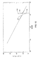
図4は、ツールメモリ回路の周波数−インピーダンス曲線を表している。2曲線が示されている。実線で表現された曲線132は、ツールメモリの内部にある抵抗が比較的高いときのインピーダンスを表している。殆どのメモリでは、これは、データ信号がオンにされたときの状態であり、ツールメモリ回路のインピーダンスは、たとえば、約20000オームである。回路がこの状態にあるとき、曲線の共振周波数は基本的に垂直方向の曲線セグメントによって表されている。基本的に曲線セグメント134の高インピーダンス端子点である点135は、回路がその高インピーダンス共振周波数を有する点を表している。
FIG. 4 shows a frequency-impedance curve of the tool memory circuit. Two curves are shown. A
点線セグメントによって表された曲線138は、ツールメモリ90の内部にある抵抗が比較的低いとき、所定の実施例では、約200オームであるときの周波数/インピーダンス曲線を表している。ツールメモリ90は、データ信号がオフであるとき、この状態にある。高抵抗セッティングが最初に低いスパイクを有し、次に高いスパイクを有するインピーダンスプロファイルを生じるときとは違って、曲線138のインピーダンスプロファイルは実質的に直線状である。
A
前述の通り、メモリリーダ66は、ツールメモリ回路によって消費される電力に基づいてツールメモリ信号のオン/オフ状態を判定している。この電力レベルは回路インピーダンスの関数である。
As described above, the
回路が問い合わせ信号の周波数に等しい共振周波数をもつように構成された場合、潜在的な問題が現れる可能性がある。この問題は、ケーブル容量(コンデンサ76の容量)が推定できる間に、ケーブル容量がケーブル同士の間で変化する可能性があることに起因している。ケーブル容量の変動は、回路の共振周波数が問い合わせ信号の周波数よりわずかに高い可能性があることを意味している。この状況では、問い合わせ信号は、信号曲線132のセグメント134が曲線138と交差する点と交差するか、または、非常に接近する周波数で、データオフ時のインピーダンス信号である可能性がある。この状況では、ツールメモリ回路によって消費される電力は、メモリがデータオン状態とデータオフ状態にあるときから著しく変化することはない。メモリリーダ66は、したがって、通常ではメモリ90のデータオン/データオフの切り替えを伴うことになる電力消費の変化を検出できない。
If the circuit is configured to have a resonant frequency equal to the frequency of the interrogation signal, a potential problem may appear. This problem is caused by the possibility that the cable capacity may change between the cables while the cable capacity (capacitance of the capacitor 76) can be estimated. Variation in cable capacity means that the resonant frequency of the circuit may be slightly higher than the frequency of the interrogation signal. In this situation, the interrogation signal may be an impedance signal at the time of data off at a frequency that intersects or is very close to the point where
メモリ回路のデータオン/データオフ時のインピーダンスレベルが差を検出できないレベルに接近する可能性を低減するため、インダクタ98は、ツールメモリ回路がツールメモリ90に印加された問い合わせ信号の周波数からオフセットした共振周波数を有するように選択されている。オフセットは、問い合わせ周波数が、データオン回路状態とデータオフ回路状態との間のインピーダンスの差が容易に検出可能である周波数のスペクトルの範囲内に入るようにされるべきである。図4では、直線139は問い合わせ周波数における横軸を表している。この直線は、2つの大きく離れた点でデータインのインピーダンス曲線132およびデータオフのインピーダンス曲線138と交差することが分かる。ケーブル容量の変動に起因して、インピーダンス曲線132,138が僅かな量だけ右または左へシフトする場合、直線139は、2つの大きく離れた点で依然として曲線132および138と交差している。したがって、曲線がシフトする場合でも、データオン/データオフの切り替えに起因するメモリ回路インピーダンスの変化は、依然として検出可能である。
本発明を構築する一変形では、インダクタ98は、ツールメモリ回路がツールメモリ問い合わせ周波数に等しい高インピーダンス共振周波数をインダクタが有するためにとるべきインダクタンスをLIDEALであるとして、約1.4LIDEALであるインダクタンスLREALを有するように選択されている。
In a variant of constructing the present invention, the
II. システム動作
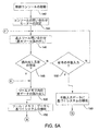
次に、本発明のシステム30が一方の電極34または36から組織を介してもう一方の電極36または34に電流を供給するプロセスについて、図5Aから図5Cを参照して説明する。ステップ142は制御コンソール40の起動を表している。制御コンソール40の起動と一体化されているのは、コンソールが実行するセルフテストである。コンソール40の起動およびセルフテストは、予めロードされた命令に基づいてディスプレイ制御器48によって実行される。
II. System Operation Next, the process by which the
制御コンソール40の起動およびセルフテストの完了時に、ステップ144で、ディスプレイ制御器48はコンソールを問い合わせモードに入れる。問い合わせモードに入るプロセスの一部として、ステップ142の実行中に、ディスプレイ制御器48は、メモリリーダ66をコンソール端子56,58に結合するように継電器70,74を設定する。
Upon activation of the
問い合わせモードに入ると、ディスプレイ制御器48は、ステップ146で、基本問い合わせを実行するようにメモリリーダ66に定期的に命令する。基本問い合わせステップ146で、メモリリーダ66はケーブル導体75,77を介して基本読み出しコマンドを出力する。この読み出しコマンドは、制御コンソール40とツールとの間で交換される他のすべての読み出し/書き込み信号伝送と共に、低電圧、典型的に、10V以下で送信され、1ms未満の間に送信される。
Upon entering the inquiry mode, the
読み出しコマンドが送信されるとき、システム30は3つの電位状態のうちの1つの状態にあってもよい。第1の状態では、ケーブル38はコンソール40に接続されず、ツールはケーブルに接続されていない。
When a read command is sent, the
第2の状態では、メモリを収容しないツールがケーブル38に接続されている。この状態では、ケーブル導体78,79の両端への信号の印加がツールの電極の間(または、ツールの電極と補完的な接地パッドとの間)に電流フローを生じる。しかし、この信号が低電位であり、電極間(または電極と接地パッドとの間)の組織が高インピーダンスであると仮定すると、基本的に組織を流れる電流フローはない。よって、読み出しコマンド信号の送信は、組織変化をもたらすツールの起動を生じる信号の送信であると考えられない。
In the second state, a tool that does not contain memory is connected to the
システム30が上記2状態のうちのいずれかであるとき、メモリは存在しないので、テストステップ148で、読み出しコマンドへの応答はない。ステップ150は、ディスプレイ制御器48による手動で入力されたコマンドの検出を表す。ステップ150は、メモリ無しのツールがケーブル38に接続されたとき、システム30において、この動作状態で行われる。
When
ディスプレイ制御器48は、問い合わせステップ146の読み出しコマンドへの応答がないこと、または、コンソールの手動セッティングがないことを、ツールがコンソール40に接続されていないと解釈する。システム30がこの状態にある場合、ディスプレイ制御器48は基本問い合わせステップ146を周期的に実行し続け、ステップ148でこの問い合わせへの応答を待機するか、または、ステップ150でシステムが手動で構成されているとの指標を待機する。
メモリ90付きのツール32は、ケーブル38に接続されることがある(接続ステップは図示されていない)。システム30がこの状態にあるとき、基本問い合わせステップ146が実行され、基本読み出しコマンドを含むAC信号がメモリ90と一体化されたツール・ハブ・タンク回路に印加される。この読み出しコマンドの受信に応答して、メモリ90は、メモリリーダに返答を送信し、基本データを書き出す(ステップは図示されていない)。
ツール・メモリ・データのこの基本読み出しでは、制御コンソール40は、ツールのタイプを特定するデータと、特異性を用いてツールを特定するデータとを読み出す。これら後者のデータは、ツールに固有の通し番号である。このステップで読み出される可能性がある他のデータは、ツールが使用された回数を指定する承認コードおよびデータを含む可能性がある。
In this basic reading of tool memory data, the
読み出しコマンドのツールメモリ90への送信およびデータの読み出しの一部として、これらのコマンドおよびデータ送信を形成する信号がコンデンサ94に印加される。メモリ90、コンデンサ94、インダクタ98およびコンデンサ102を備える回路は、絶縁回路であると考えることができる。この絶縁回路を形成するコンポーネントは、上述の通り、問い合わせ信号が回路に印加され、データが回路を介して送出されたときに、回路が共振に近い状態であるように選択される。コンデンサ94の中では最小限の電圧降下と電力損失とがある。この絶縁回路の両端間での電圧降下および絶縁回路内での電力損失は、ツールメモリ90に印加され、または、ツールメモリ90から受信された信号の特性を顕著に変化させない。ここで、ツールメモリ90に印加されるか、または、コンソール・メモリリーダ66に戻された信号の特性の「顕著」な変化は、メモリまたはコンソールが処理できなかったツールメモリまたはコンソールへの信号の印加を生じるトーンである。本発明の記載された実施形態では、絶縁回路は、端子82,84と導体92,96とに印加された信号の電位と相対的な問い合わせ信号、または、メモリから書き出された信号の電位の僅かな降下を生じさせることがある。しかし、電圧降下は、ツールメモリ90またはコンソール・メモリリーダ66が印加された信号を処理することを阻止するために足りるほど顕著ではない。本発明のこの変形では、ツールメモリ90に印加された顕著に変化した信号は、端子82,84に印加された問い合わせ信号(または書き出されたデータ信号)の電位の80%以下の電位を有する信号である。
As part of the transmission of read commands to the
コンソール・メモリリーダ66は、ツールメモリ90から読み出されたデータをディスプレイ制御器48へ転送する。次に、これらのデータは、ディスプレイ制御器48と一体化するか、ディスプレイ制御器48に取り付けられた適切なメモリに格納される。メモリリーダ66からディスプレイ制御器48へのデータの転送のこれらのサブステップおよび他のサブステップは図示されていない。ディスプレイ制御器48は、ステップ148で、これらの基本ツール識別データの受信を一体的なメモリ90付きのツール32がケーブル38に取り付けられているという指標として解釈し、ステップ148のテストの結果は肯定的である。システム30がこの状態にある場合、ディスプレイ制御器48は、ステップ156で、メモリリーダ66にツールメモリ90内のすべてのデータを読み出すように命令する。ステップ156は、ツールメモリ90内のデータをコンソールリーダ66へ読み出し、これらのデータをディスプレイ制御器48へ転送することをさらに表している。
The
ステップ158で、ディスプレイ制御器48はシステム30の初期構成を実行する。このシステム構成は、ツールメモリ90から取り出されたデータに基づいている。ステップ158で、システムが特殊な付属ツールのため動作すべき特性の範囲がツールメモリから読み出されたデータに基づいて確立される。これらの特性は、電力信号が印加されるべき周波数または周波数の範囲と、電力信号が出力されるべき電圧または電圧の範囲と、信号の最小電流および最大電流とを含んでいる。離散的なパルスの組として印加された信号に対し、特性は、パルス繰り返し周波数、パルス包絡線、および/または、パルス・デューティ・サイクルを含んでいる。
At
ステップ158で、ディスプレイ制御器がシステムを特定の動作パラメータまたはパラメータの範囲に構成するかどうかは、パラメータとツール32との両方の関数である。たとえば、特殊なツールが特定の周波数で電力信号を受信するため設計されることがある。このツールのため、ディスプレイ制御器48は、構成データに基づいて、ツールメモリ内で特定された周波数において電力信号だけを出力するようにコンソールを設定する。ツールメモリ90からの周波数範囲データは、後述される医師設定による構成ステップ160において利用される。
At
さらにステップ158の一部として、ディスプレイ制御器48は、電力信号の特性のいくつかに対しデフォルトセッティングを確立することがある。これらのデフォルトセッティングは、ツールメモリ90のため読み出されたデータに基づくことがある。代替的に、医師定義による信号特性は、ディスプレイ制御器メモリに予めロードされることがある。この状況では、ステップ156の一部として、医師がディスプレイ制御器48に対し特定されると、ディスプレイ制御器48は医師により確立された適切な特性を取り出す。次に、ディスプレイ制御器48は、システム30を構成する基礎として、これらの特性を使用する。
Further as part of
ステップ160はシステム30の医師設定による構成を表している。ステップ160では、医師は、実行されるべき特定の処置と自分の好みとに基づいて、特定の処置の範囲内で設定可能であるシステム動作特性を構成する。これらの動作特性は、タッチ・スクリーン・ディスプレイ50のような適切なI/O機器を介して特性を入力する医師によって定義される。
Step 160 represents the configuration of the
ステップ160で、医師は、ツールメモリ90内のデータに基づくセッティングの範囲外である付属ツールのための電力信号のセッティングを入力することを試みることがある。信号特性およびツールに依存して、ディスプレイ制御器48は、この範囲外である特性のセッティングを阻止することがある。代替的に、動作特性を範囲外の値に設定しようとするこの試みに応答して、ディスプレイコンソール48は、医師による承認を必要とする範囲外警告を提示することがある。医師がこの警告を承認した場合、ディスプレイ制御器48は、動作特性の範囲外セッティングを進めることを許可する。
At
ステップ160が実行されると、システム30は、ツールメモリ90および医師の好みによって定義された動作パラメータに基づく動作のため構成される。
Once
次に、ディスプレイ制御器48は、基本ツール識別ステップ170と、応答受信ステップ172と、ツール起動コマンド受信ステップ174とを循環的に繰り返す。基本ツール識別ステップ170は、基本問い合わせステップ140と類似している。ディスプレイ制御器48は、メモリリーダ68を通じて、ツールメモリがツールの通し番号を提供することを要求する読み出しコマンドを発行する。応答受信ステップ172で、ディスプレイ制御器48は、この読み出しコマンドへの応答に反応する。最初に受信された通し番号と同じ通し番号を収容している応答は、同じツール32がコンソール40に取り付けられた状態を維持していることを指示しているとして解釈される。異なるツール通し番号を含む応答は、新しいツールがコンソール40に結合されたという指標として解釈される。この状況では、ディスプレイ制御器48は、ツールメモリ90内のすべてのデータが読み出され、プロセッサ48へ転送されるようにステップ156へ戻る。ステップ158,160は、新しいツールに対する動作特性データに基づいて再実行される。
Next, the
代替的に、ツールから基本問い合わせステップ170への応答がないことがある。ディスプレイ制御器48は、ステップ172で、この無応答受信イベントを前のツールがコンソールから外され、かつ、新しいツールが無いか、または、メモリが取り付けられていないツールが存在するかを指定しているとして解釈する。ディスプレイ制御器48は、この判定を行ったとき、基本問い合わせステップ146、基本応答受信ステップ148、および、手動構成コマンド受信ステップ150の繰り返しに戻る。
Alternatively, there may be no response from the tool to the
より典型的には、応答受信ステップ172で、応答はステップ148で最初に受信された通し番号と同じ通し番号である。したがって、ディスプレイ制御器48は、ステップ174で、ツール起動コマンドの受信を待機する。このようなコマンドが受信されるまで、ステップ170,172,174が継続的に再実行される。
More typically, in
ツール起動コマンドが、厳密な構造が本発明とは無関係であるユーザ起動型制御要素から入力されることがある。たとえば、コマンドは、ディスプレイ50に提示されたツール起動ボタンの画像の押し下げに応答して入力されることがある。後述されるように、応答はツール32上のスイッチを押し下げる医師によって入力されることがある。代替的に、コマンドは、コンソール40に接続されたフットスイッチ組立体のペダルの押し下げによって入力されることがある。
Tool activation commands may be entered from user activated control elements whose exact structure is unrelated to the present invention. For example, the command may be input in response to a press of an image of a tool activation button presented on the
ツール起動コマンドの受信に対する初期応答は、ステップ178で、コンソール継電器62,70,74のセッティングである。ツールメモリ90のデータがツールは双極ツールであることを示す場合、継電器62は、戻り導体54を端子58に接続するため設定される。ツールメモリのデータがツールは単極ツールであることを示す場合、ディスプレイ制御器48は、戻り導体を端子60に接続するように継電器62を設定する。ディスプレイ制御器48はまた、メモリリーダ66を導体52,54から切断するように継電器70,74を設定する。
The initial response to the reception of the tool activation command is the setting of the console relays 62, 70 and 74 in
継電器62,70,74が設定されると、ディスプレイ制御器48は、電源42およびRF増幅器44の両方をオンにするようRF制御器46に命令する。より具体的には、RF制御器48は、適当な電圧レベルでDC信号を出力するよう電源42に命令する。DC信号の出力と同時に、RF増幅器44は、RF増幅器が定義された出力信号出力特性によって指定されるようなツール電力信号を出力するように、RF制御器46によって起動される。全体として、これらのサブプロセスは、図5Cにおいて、ステップ180によって表されている。
When the
電力信号は、ケーブル導体75,77を介してツールハブ85に印加される。1MHz未満の比較的低周波数の電力信号で、インダクタ98は、ツールメモリ90を迂回する低インピーダンスバイパスとしての役割を果たす。コンデンサ94は、ハブ導体92とハブ導体96との間に高インピーダンス負荷として現れる。よって、電力信号が印加されるとき、コンデンサ94、インダクタ98およびコンデンサ102によって形成された絶縁回路は、ツールメモリに印加された信号の特性を実質的に変化させる。ここで、信号の「実質的」な変化は、変化した信号がツールメモリ90に印加されるとき、変化した信号がメモリに悪影響を与えない程度で、信号に影響を与える信号への変化である。図3の回路では、絶縁回路は、ツールメモリ90に印加された端子82と端子84との間の信号の電位の一部を実質的に低下させることにより、信号の電位のこの変化に影響を与える。ここで、信号の特性の実質的な変化は、ツールメモリ90に印加された電力信号の電位が、信号がメモリに悪影響を与えないレベルまで低下することである。換言すると、電力信号の電力の僅かな部分だけがツールメモリ90に印加される。この信号の比較的低い電位、すなわち、本発明の説明されている変形では、典型的に、2V以下の電位は、信号がメモリ90に悪影響を与えないことを意味する。一般に、実質的に変化した電位は、端子82と端子84との間の電力信号電位と相対的に少なくとも20%低下させられた電位である。多くの場合に、絶縁回路を介してツールメモリ90に印加された信号の実質的に変化した電位は、端子82と端子84との間の信号の電位の50%以下である。
The power signal is applied to the
電力信号に含まれる電力の大部分は、代わりに、導体92,96を介して、それぞれツール電極34,36に印加される。結果として、ツール電極34とツール電極36との間で得られる電流フローは、電極間の組織の加熱と、このような加熱によって引き起こされる望ましい末端効果とをもたらすことになる。
Instead, most of the power contained in the power signal is applied to
コンソール40は、ステップ184で起動コマンドがネゲートされるまで、ツール32に起動信号を出力する。起動コマンドがネゲートされ次第、ディスプレイ制御器48は、ステップ186で、DC電源42およびRF増幅器44の両方をオフにするようRF制御器46に命令する。DC電源42およびRF増幅器44をオフにすることは、電力信号の出力を停止させる。
The
RF電圧印加信号の出力が停止すると、ディスプレイ制御器48は、ステップ188で、コンソール継電器をリセットする。継電器62は開状態にリセットされる。継電器70,74は、メモリリーダ66をそれぞれ端子56,58に再接続するため、リセットされる。
When the output of the RF voltage application signal stops, the
コンソール継電器がリセットされ次第、ディスプレイ制御器48は、ステップ170,172,174の循環的な再実行のプロセスに戻る。ツールが再起動されるとき、ステップ180〜186が再実行される。
As soon as the console relay is reset, the
上述の通り、メモリ無しのツールがケーブル38を介してコンソール40に取り付けられるときがある。システム30がそのように構成されるとき、医師は、ツールのための意図された電気外科手術電流に基づく動作のためシステムを構成する。この仕事(タスク)は、コンソール40と関連付けられた制御要素の起動によって実行される。ディスプレイ制御器48は、ステップ150で、コンソール40の手動構成として制御要素の押し下げを認識する。これらのコマンドの受信に応答して、ステップ190で、ディスプレイ制御器は、発電機およびRF制御器を適切に構成することになる。
As described above, sometimes a tool without memory is attached to the
ステップ190が実行されると、システム30は使用できる状態となる。ディスプレイ制御器48は、ステップ174へ進み、ツール起動コマンドの受信を待機する。医師がツールを起動するため制御要素を起動すると、システムは、上記のステップ、すなわち、メモリリーダ66を導体52,54から切断するために継電器70,74を設定するステップと、継電器62を適切に設定するステップと、電気外科手術電流を生成するためRF増幅器を起動するステップと、ツール起動コマンドを含む信号がネゲートされたかどうかをテストするステップとを通じて進行する。
Once
本発明の電気外科手術ツールシステム30は、システムツール32の内部にあるメモリ90の中に指定された電力信号特性に基づいて電気外科手術電流を出力するようにコンソール40を構成するため構築されている。このコンソール40の自動構成は、医療関係者が手動で構成命令を入力する場合に行われるより高速に行われる。構成が自動的であるので、ヒューマンエラーがコンソールを誤って構成する可能性は実質的に低減されることになる。
The
本発明の別の特徴は、構成命令を含む信号が、電力信号がツールに印加される際に通るケーブル導体75および76を介して交換されるように、システムが構成されることである。これは、ケーブル38に付加的な導体を設け、これらの補助的な導体への導電性接続を確立するため、ツールおよびコンソールに付加的な端子部材を設ける必要性を除去する。
Another feature of the present invention is that the system is configured such that signals including configuration instructions are exchanged via
本発明の上記特徴は、メモリをシステムツールに加える程度を低減する以外に、給電される外科手術ツールシステムのためのハードウェアコンポーネントを増加させている。上記特徴は、コンソールの構成と併せて、メモリ90を含むツールおよび従来型のメモリ無しのツールの両方のツールと共に本発明のコンソール40を使用することを可能にさせるものである。両方のタイプのツールは、同じタイプのケーブルを用いてコンソールに接続することが可能であり、両方共に同じコンソール端子に接続されている。前者の特徴は、本発明のシステム30を使用する設備が、メモリ無しのツールのためのケーブルおよびメモリ90を収容するツールのためのケーブルという2タイプのケーブルを在庫にもつ必要性を除去している。後者の特徴は、作業者がどのソケットに端子を接続すべきであるかを覚えるために精神的に努力する必要がないことを意味する。同様に、システム30の多くの構成において、ケーブル38は、従来型の電気外科手術ツールを従来型の制御コンソールに接続するため使用される従来型のケーブルでもよいことを理解すべきである。
The above features of the present invention increase the hardware components for the powered surgical tool system in addition to reducing the extent to which memory is added to the system tool. The above features, in conjunction with the console configuration, make it possible to use the
要約すると、本発明のシステム30は、メモリ90付きのツールが取り付けられているとき、コンソールの自動構成を容易にするように設計されているが、メモリ無しのツールの使用が必要とされるとき、余分な負担を加えない。
In summary, the
上記構成のさらに別の利点は、本発明のツール32がツールメモリ90内のデータを読み出す能力のないコンソールと共に使用できることである。ケーブル38は、ツールを従来型のコンソールに接続するため使用できる。コンソールは、医師の望む電力信号をツールに供給するため、手動で設定されるようになっている。ツール32がコンソール40と共に使用されるとき、コンデンサ94、インダクタ98は、ツールメモリ90に印加される電流を最小限に抑えるため協働するようになっている。
Yet another advantage of the above configuration is that the
III. 単極電気外科手術ツール
(第1の代替的なツール)
図6は、本発明のシステム30の一部として使用できる代替的な電気外科手術ツールである単極ツール202の概略配線図である。ツール202は、プローブ206が延在するハブ204を含んでいる。単一の電極208がプローブ206の遠方端部に配置されている。ハブ204は、ケーブルプラグ39において別個のソケット80,81へ接続するための2個のピン210,212をそれぞれ含んでいる。
III. Monopolar electrosurgical tool
(First alternative tool)
FIG. 6 is a schematic wiring diagram of a
コンデンサ102を含むツールメモリ90もまた、ハブ204の内側に配置されている。導体92に類似した導体216は、ピン210からツールメモリ90の入力ピンの一方に延在している。導体216もまた電極208に接続されている。インダクタ218は、データ信号がメモリに印加される際に伝わるツールメモリ90のデータ信号入力の間に延在している。よって、インダクタ218の一方の端部は、導体216に接続されていると考えることができる。コンデンサ220は、インダクタ218の反対側の端部に接続されている。したがって、メモリ90の戻りデータ信号入力およびコンデンサ102の両方は、インダクタ218とコンデンサ220との接合部に接続されていると考えることができる。
A
インダクタ218が接続されている端部と反対側にあるコンデンサ220の端部は、導体222に接続されている。導体222は、ハブピン212に接続されている。
The end of the
図6に概略的に示されているのは、接地パッド230である。接地パッド230は、ツール202のための戻り電極としての機能を果たしている。ケーブル232は、接地パッド230をコンソールソケット63に接続するものである。
Shown schematically in FIG. 6 is a
単極ツール202がコンソール40に接続されるとき、本発明のシステム30は、一般に双極ツール32が使用されるときの動作と同様に動作している。ディスプレイ制御器48およびメモリリーダ66は、ツールメモリ90内のデータを読み出すために協働している。読み出されたデータおよび医師の好みに基づいて、ディスプレイ制御器48はツール202を用いる動作のためコンソール40を構成している。
When the
メモリ90と一体的なデータは、ツールが単極ツールであることを指示するデータを含んでいる。したがって、起動信号が受信され、ステップ174のテストの結果が肯定であるとき、ディスプレイ制御器48はステップ178で継電器の異なるセッティングを実行することになる。特に、継電器62は、このステップ178の実行中に、戻り導体54と端子60との間に接続を確立するように設定されることになる。この継電器62のセッティングは、接地パッド230をRF増幅器44に接続する。この接続の確立によって、電流は、ツール電極208と接地パッド230との間でパルス化することが可能となる。
Data integral with the
したがって、システム30のさらなる利点は、ツールメモリ90内のデータに基づいて、制御コンソール40が単極ツールまたは双極ツールのいずれかを用いる動作のためシステムを構成することである。ケーブル38、すなわち、双極ツール34をコンソール40に接続するため使用されるケーブルは、単極ツール202をコンソールに接続するためにも使用できる。
Thus, a further advantage of the
IV. 代替的なコンソールおよび第2の代替的なツール
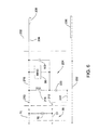
図7は、本発明の代替的な制御コンソール40aの内部にある部分組立体の一部を示している。コンソール40aはRF増幅器44aを含む。RF増幅器44aは、4個のFET252,254,256,258から形成されたHブリッジを含んでいる。FET252,254は、共に直列接続されている。FET256,258は、同様に、共に直列接続されている。FET252,256のソースは共に結合され、電源42の高電圧出力ラインに結合されている(図2)。FET254,258のドレインは共に結合され、地面に結合されている。
IV. Alternative Console and Second Alternative Tool FIG. 7 shows a portion of the subassembly within the
RF増幅器44aは、変圧器260をさらに含んでいる。変圧器260の1次巻線の一方の端部はFET252とFET254との接合部に結合されている。変圧器260の1次巻線のもう一方の端部は、FET256とFET258との間の接合部に結合されている。変圧器260の2次巻線の一方の端部は地面に結合されている。変圧器260の2次巻線のもう一方の端部は、2個の直列接続されたインダクタ262,264に結合されている。
The
同様に、RF増幅器44aの一部であるコンデンサ268は、インダクタ262,264の接合部と接地との間に結合されている。コンデンサ270は、インダクタ262から離れているインダクタ264の端部と接地との間に結合されている。インダクタ264とコンデンサ270との接合部に存在する電力信号は、並列接続されたインダクタ274とコンデンサ276とを介して第2の変圧器290に印加されるようになっている。
Similarly, a
変圧器290の1次巻線の一方の端部は、インダクタ264から離れているインダクタ274とコンデンサ276との接合部に現れる信号を受信するようになっている。変圧器の1次巻線のもう一方の端部は接地に結合されている。図7では、変圧器290の2次巻線の対向する端部は、端子56,58に結合されていることが分かる。図7に示されていないのは、コンソール端子58に結合されている変圧器の端部がどのようにして代替的に端子60に結合されるかである(図2)。
One end of the primary winding of
本発明の変形例のコンソール40aは、メモリ(RFID)リーダ66をさらに含んでいる。問い合わせ信号が間に印加されるメモリリーダ66の対向する端子は、変圧器282の一部である巻線の対向する端部に接続されている。変圧器282の2次巻線の対向する端部は、インダクタ274とコンデンサ276との対向する接合部に接続されている。
The
図7に概略的に示されているのはポンプ294である。ポンプ294は、洗浄流体を供給するため、コンソール40aの中に組み込まれることが可能である。この流体は、上述されているように、ツールが適用される身体部位に放出される流体が通る導管が下に形成されている電気外科手術ツール352(図13)へ送り込まれるようになっている。本発明の一つの例示的な変形では、ポンプ294はヘッドを回転させるモータである。管セットがヘッドに接触して位置決めされている。ヘッド上のローラは、管セットの一部である管を押圧している。ローラの繰り返し作用が管セットを通して電気外科手術ツールまで流体を強制的に送るようになっている。参照によって本明細書に組み込まれる本出願人の譲受人による米国特許第7,238,010B2号、SURGICAL IRRIGATION PUMP AND TOOL SYSTEMは、このようなポンプおよび補完的な管セットの構成についてのより詳細な説明を提供している。
Shown schematically in FIG. 7 is a pump 294. A pump 294 can be incorporated into the
ポンプ294は、ポンプ制御器296によって調整されるようになっている。特に、ポンプ制御器296は、モータのオンおよびオフを切り替えることと、回転の速度を調整することの両方の目的でポンプ294と一体的であるモータに印加される駆動信号の印加を調整している。ポンプ制御器296は、ディスプレイ制御器48(図2)から受信された制御信号に基づいてポンプ294に印加される駆動信号を調整している。典型的に、ディスプレイ制御器48は、医師がポンプ294の起動時を制御し、流体がツールへ送り込まれる速度を確立することを可能にしている。これらの医師が入力したコマンドに基づいて、ディスプレイ制御器48はポンプ制御器296への適切な命令を発生している。
The pump 294 is adjusted by a
図8は、コンソール40aと共に使用するため設計された一つの代替的な電気外科手術ツール302を示している。ツール302は、上述されたハブ85と、尖部86,87と、電極34,36とを含んでいる。ピン82,84は、ツールがケーブル38によってコンソール40aに接続できるように、ハブ85から近傍後方へ延在している。図3に関連して説明されたツールの変形例の場合と同様に、導体92はピン82を電極34に接続し、導体96はピン84を電極36に接続している。
FIG. 8 shows one
ツール302のハブ85の内部には、3個の個別にアドレス指定可能なメモリ(RFIDタグ)306,312,318がある。メモリ306,312,318の内部にあるコンデンサは、それぞれ、コンデンサ308,314,320として表されている。各メモリ306,310,318と、それぞれに関連付けられたコンデンサ308,314,320とは、ハブ導体92に接続されている1つの入力を有することが分かる。
Within the
インダクタ321は、メモリ306の対向する入力ピンの間に接続されている。コンデンサ322は、一方の端部で、インダクタ321とメモリ306の第2の入力ピンとの接合部に接続されている。コンデンサ322のもう一方の端部は、導体96に接続されている。通常時開の押しボタンスイッチ324は、メモリ312への第2の入力と、インダクタ320およびコンデンサ322の接合部との間に接続されている。第2の通常時開の押しボタンスイッチ326は、メモリ318への第2の入力と、インダクタ320およびコンデンサ322の接合部との間に接続されている。図示されていないが、両方のスイッチ324,326は、ツールハブ85に搭載されることがある。代替的に、スイッチ324,326は、尖部86または尖部88の一方に搭載されている。本発明の変形例は、医師が、鉗子を閉じるために尖部を押圧する指、および、閉じられたスイッチ324またはスイッチ326のいずれかを選択的に押す指の両方としての役割を果たす、親指または人差し指を使用することを可能にするように構成されている。
The
図9は、主メモリであると考えられるツールメモリ306内のデータを示している。これらのデータは、ツール識別ファイル324を含んでいる。ツール識別ファイルは、ツールのタイプを特定するデータと、特異性を用いてツールを特定する通し番号データの両方のデータを含んでいる。ツールメモリ306は、第1の動作状態ファイル327および第2の動作状態ファイル328をさらに含んでいる。第1の動作状態ファイル327は、ツールが第1の動作状態、たとえば、切断状態にあるとき、ツールに供給される電力信号の特性を記述するデータを収容している。第2の動作状態ファイル328は、ツールが第2の動作状態、たとえば、凝固状態にあるとき、ツールに供給される電力信号の特性を記述するデータを収容している。
FIG. 9 shows data in the
図10は、動作状態メモリであるツールメモリ312,318の中のデータを示している。各ツールメモリは、ツール識別ファイル330を含んでいる。各ツール識別ファイル330は、メモリ306のファイル324に格納されている通し番号と同じ通し番号データをツールのために収容している。各ツールメモリ312および318は、動作状態ファイル332をさらに収容している。動作状態ファイル332は、ツールがどの動作状態に入るかを指示するデータを収容する。個別のメモリ312,318のための動作状態ファイル332の中のデータは異なっている。任意的に、メモリ312は、ツールが切断モードに置かれていることを指示するデータを収容し、メモリ318は、ツールが凝固モードに置かれていることを指示するデータを収容している。各動作状態ファイル332は、単一フラグビットと同じように小規模でもよい。
FIG. 10 shows data in the
ツール302は、ケーブル38によってコンソール40aに接続されている(図1)。システムが起動されると、ステップ142(図5A)および基本問い合わせステップ144が上述の通り実行されることになる。ツールの存在の検出に応答して、ステップ148で、メモリ306内の全データがステップ156で読み出される。少なくともツール302が最初にシステムに結合されたとき、スイッチ324および326は開いている。これらのスイッチの状態によって、メモリ312またはメモリ318はどちらも読み出し要求を受信しない。メモリ312,318は、どちらもステップ144の読み出し要求を受信しないので、これらのメモリはどちらもこの要求に応答してデータを書き出さない。さらに、RFIDメモリからデータを読み出すプロトコルを使用すると、基本問い合わせステップ144の読み出し要求は、メモリ306だけがステップ144の読み出し要求に応答すべきであることを指示する命令を含むことがあると理解されるべきである。
The
メモリ306から受信されたこれらのデータに基づいて、ディスプレイ制御器48は、ステップ158で、切断モードまたは凝固モードのいずれかでツール302を動作させるようにシステムを構成する。ステップ160は、医師が切断モードまたは凝固モードにあるときに、ツール302に供給される電力信号に対する個々の好みを確立することを可能にさせるため実行することが可能である。
Based on these data received from the
上述された基本識別ステップ170および応答解析ステップ172は、本発明のシステムを動作させる第1の上記の方法と同様に実行されている。ステップ170のこの実行では、メモリ306は、メモリの内部にある識別ファイル324にデータを書き出すように命令される。本発明の本実施形態では、ツールの起動は、図11のフローチャートに関連してこれから説明されるプロセスにしたがって調整される。特に、制御コンソール40aが構成された目的のツール302がコンソールに接続された状態を保つと判定された後、すなわち、ステップ172の実行後、ツール状態問い合わせ、すなわち、ステップ338が実行される。ステップ338で、メモリリーダ66は、メモリ306以外の任意のメモリがそのメモリのデータを読み出してコンソール40aへ戻すことを要求するコマンドをツールに送信する。
The
スイッチ324,326の状態に依存して、ステップ338の読み出し要求に対する3つの潜在的な応答が存在している。スイッチ324またはスイッチ326がいずれも押し下げられていない場合、この読み出し要求に対する応答はない。ディスプレイ制御器48は、ステップ340で、この応答の欠如を、医師がツール302を起動していないという指標として解釈する。したがって、コンソールは、ステップ170,172,338,340を継続して再実行することになる。
Depending on the state of
医師が2モードのうちの一方でツール302を使用したいとき、モードと関連付けられたツール上のスイッチ324またはスイッチ326が起動されるようになっている。その結果、ステップ338が実行されるとき、閉じたボタンと関連付けられたメモリ312またはメモリ318は、メモリの内部にあるデータをメモリリーダ66へ読み出す。メモリリーダ66は、これらのデータをディスプレイ制御器48へ転送する。最初に、これらのデータの処理の一部として、ディスプレイ制御器48は、メモリ312またはメモリ318のファイル330からの識別データをメモリ306から以前に取り出された識別データと比較する(ステップは図示されていない)。この比較は、同じツール302が依然としてコンソール40aに接続されていることを検証するためフェイルセーフとして実行される。この比較が失敗である場合、ディスプレイ制御器48は適切なフォールト警告をアサートする(ステップは図示されていない)。
When the physician wants to use the
殆どの場合、上記の比較は、取り出されたデータが最初に接続されたツール302のメモリ312またはメモリ318の一方からであることを指示している。したがって、ステップ340で、ディスプレイ制御器48は、これらのデータの受信をツールが2つの動作モードのうちの一方に置かれるべきであることの指標として解釈することになる。
In most cases, the above comparison indicates that the retrieved data is from one of the
ステップ342で、ディスプレイ制御器48は、その後、適切なコマンド信号を電源42およびRF制御器46へ発生する。ディスプレイ制御器48によって発生された特定のコマンドは、医師がツールをどのモードで動作させたいかという決定に基づいている。医師がツールを切断モードで動作させたい場合、ディスプレイ制御器48は、コンソール40aに連続的な電力信号を供給させるコマンドを発生する。医師がツールを凝固モードで動作させたい場合、ディスプレイ制御器48は、パルス状電力信号が供給される結果を生じるコマンドを発生する。パルスが一定のピーク電圧をもつ信号サイクルの組、もしくは、パルスの期間に亘って減衰するサイクルをもつ信号であるかどうかは、その特殊な動作モードのための状態命令の関数である。ステップ344は、アサートされた命令に基づくツール302への電力信号の実際の供給を表現する。ステップ344で行われるプロセスは、ステップ178,180の実行中に行われるプロセスに類似している。
At
コンソール40aによって供給される電力は、導体92,96を介してツール電極34および36に供給されることになる。電力信号が導体92,96の両端間に存在するとき、コンデンサ308は、メモリ306と、回路メモリ312または回路メモリ318内のもう一方とを迂回する低インピーダンスバイパスとしての機能を果たすものである。残りのスイッチ326またはスイッチ324は開かれるべきである。したがって、電流は、開放スイッチ326または324とそれぞれに関連付けられたメモリ318またはメモリ312へ供給されないことになる。
The power supplied by the
電力信号の供給中、コンソール・メモリリーダは、ステップ346で、継続的、周期的にツール状態問い合わせ信号を出力する。ステップ346は、上記のツール状態問い合わせステップ338と同一である。本発明のいくつかの変形例では、ステップ346は、電力がツールに供給された後に50ミリ秒毎に少なくとも1回ではなくても、100ミリ秒毎に少なくとも1回実行されている。
During the supply of the power signal, the console memory reader outputs a tool status inquiry signal continuously and periodically at
ステップ346は、ツールを作動状態に維持したい医師が、ツールの動作状態を切り替えたか、または、ツールをオフにしたかどうかを判定するため実行されるものである。ステップ348は、問い合わせステップ330に応答して返送された信号の処理を表している。医師が以前の通りツールを使用し続ける場合、最初に押し下げられたスイッチ324またはスイッチ326は、押し下げられたままである。ツール302がこの状態にあるとき、問い合わせステップ346への応答は、ディスプレイ制御器48がステップ348の実行前と同様にシステムを継続して動作させることである。したがって、ステップ344,346,348は継続的に繰り返されることになる。
Step 346 is performed to determine whether the physician who wants to keep the tool in an operational state has switched the operating state of the tool or turned off the tool. Step 348 represents the processing of the signal returned in response to the
医師は、押し下げられたスイッチ324,326への圧力を解除することにより、ツールの起動を停止する。このイベントが発生したとき、問い合わせステップ346に応答して、動作状態データは制御コンソール40aへ戻されない。ディスプレイ制御器48は、ステップ348で、戻されるデータの不在をツールがオフに切り替えられるべきであるという指標として解釈する。したがって、ステップ349によって表現されているように、ディスプレイ制御器48は、電力の供給を引き起こす電源42およびRF増幅器44への制御信号のアサートをネゲートする。ディスプレイ制御器48は、その後、ステップ170,172,338,340の循環的な実行に戻り、ツール302が起動されるべきであるという次の指標を待機することになる。
The physician stops the activation of the tool by releasing the pressure on the
第3の代替案では、医師は、ツール302が第2の動作モードに置かれるべきであり、切断から凝固、または、凝固から切断へシフトすべきであると指示することがある。医師は、2個のスイッチ324または326のうち押し下げられる方のスイッチをシフトすることによりこの切り替えを指示する。ツール302がこの状態にあるとき、ツール状態問い合わせステップ346に応答して、ツール302はもう一方の動作モードに置かれるべきであることを指示する動作状態データが戻される。これらのデータの受信に応答して、ディスプレイ制御器48は、ステップ348の解析の結果として、システムを再構成する。図11Bでは、これは、ステップ350で、新しい動作モードのための電源信号が供給されることを引き起こす命令信号を次に電源42およびRF制御器48にアサートするディスプレイ制御器48によって表現されている。
In a third alternative, the physician may indicate that the
ディスプレイ制御器48は、次に、必要とされる電力信号をツール302へ供給し、スイッチ324および326の開/閉状態を監視する両方の目的のため、ステップ344,346,348を実行するように戻ることになる。
上記の本発明のシステムの変形例の使用中に、電力信号と、データ読み出しおよび応答信号とがコンソール端子56,58の間に同時に現れるときがあることは明白である。インダクタ274、コンデンサ276および変圧器28は、RFIDリーダ66とコンソール端子56,58との間で絶縁回路としての機能を果たしている。この絶縁回路は、信号の特性を顕著に変化させることなく、問い合わせ信号とツールメモリ306,312,318からの応答信号との交換を可能にする。ここで、信号の特性の「顕著」な変化とは、端子82、84における問い合わせ信号の電位と相対的に、ツールメモリに印加された問い合わせ信号の電位がツールメモリによって処理できない程に降下することである。類似した顕著な変化は、ツールメモリ90から書き出されたデータ信号の電位がRFIDリーダ66によって処理できないレベルまで降下することである。同様に、この絶縁回路は、RFIDリーダ66に印加される電力信号の特性を実質的に変化させている。ここで、電力信号の実質的な変化とは、RFIDリーダ66に印加される電力信号の電位が、RDIDリーダ66に印加された電力信号の一部がメモリリーダの動作に悪影響を与えないように十分に低いレベルまで低下することである。
Obviously, the power signal and the data read and response signal may appear simultaneously between the
したがって、電力信号および問い合わせ信号(または問い合わせ信号への応答)がツール端子82,84とツール導体92,96との間に同時に存在するときがさらに存在することになる。コンデンサ308,314,320,322と、インダクタ321とは、ツール302の内部に絶縁回路を形成している。コンデンサ314,320は、スイッチ324,326がそれぞれ閉じているとき、この絶縁回路の一部に過ぎないことが理解される。この絶縁回路は、端子82および84に印加された問い合わせ信号の電位、または、メモリ306,312,318によって出力された信号の電位の顕著な降下を引き起こさない。この絶縁回路は、メモリ308,314,318に印加され、端子82,84に印加された電力信号の電位を実質的に低下させている。
Thus, there will still be times when the power signal and the interrogation signal (or the response to the interrogation signal) are simultaneously present between the
電力信号および問い合わせ信号(または問い合わせ信号への応答)がツールに同時に印加される期間中、これらの信号はどちらもツール電極34,36の間に存在している。問い合わせ信号および応答信号は、比較的低電位であり、すなわち、10ボルト以下である。これらの信号は周期的に現れるだけであり、現れるときには、1ミリ秒以下の期間に亘って現れる。したがって、電極34と電極36との間でのこれらの信号のいずれか一方の存在は、治療上の効果または診断上の目的を達成するために、医師が望む電流フローに顕著な影響を与えないことになる。
During the period in which the power signal and the interrogation signal (or response to the interrogation signal) are simultaneously applied to the tool, both of these signals are present between the
同様に、スイッチ324またはスイッチ326の閉鎖は、コンデンサ314またはコンデンサ320の容量をコンデンサ308およびインダクタ320のタンク回路に加算することが理解されるべきである。この容量の加算は、ケーブル38およびツール302の周波数−インピーダンス曲線をシフトすることになる。特に、図12の高インピーダンス曲線342の点344によって表現されるような周波数/インピーダンス曲線、すなわち、高インピーダンス状態にあるときの回路の高インピーダンス共振周波数は、付加的な抵抗器が回路に接続されていないときの周波数(図4の曲線)より低い。図12では、破線347は低インピーダンス曲線を表している。同図によって表されているように、この場合も横軸直線139であるメモリ問い合わせ信号は、データオン状態とデータオフ状態との間で回路インピーダンスに検出可能な差が存在する点で曲線342,347と交差することが分かる。よって、加算されたコンデンサ314またはコンデンサ320の追加は、メモリ306,312,318から書き出されたデータを読み出すメモリリーダ66の能力に悪影響を与えないことになる。
Similarly, it should be understood that closing
ツール302が本発明のシステムと共に使用されるとき、医師は、スイッチ324またはスイッチ326を単に押し下げることによって、ツールを複数の動作モードのうちの1つに置く。起動されたスイッチの押し下げに応答して、コンソール40aは、医師がツールを求めるモードを判定し、そのモードに適切な電力を供給することになる。医師は、2つの異なるタスク(仕事)を即座に実現するため、本発明のツール302を使用して、指または親指の簡単な運動によって、2つの異なるタイプの電流を外科手術部位に交互に印加することが可能である。よって、医師は、最初に、組織を切断するためツールを切断モードに設定し、次に、押し下げるスイッチを交互にするだけで、切断された組織からの失血を最小限に抑えるため、ツールを凝固モードに設定することが可能である。
When
本発明のツール302は、片手によるモード選択のため設計されているが、ツールの使用は、このやり方に制限されないことが同様に認められるべきである。ツール302は、標準的なピン82,84を含むので、ケーブル38は、ツールを従来通りの用途のため従来型のコンソールに結合するため使用することができる。ツールがこのように使用されるとき、医師は、特殊なフットスイッチの押し下げ、または、従来型のコンソール上のボタンの押し下げのいずれかによって動作モードを切り替えることになる。
It should also be appreciated that although the
V. 洗浄導管付きのツール
(第3の代替的なツール)
次に、本発明のシステムを使用して、電流を組織に印加し、洗浄流体を外科手術部位に印加するため使用できる電気外科手術ツール352を、図13を参照して説明する。鉗子として表されたツール352は、上述されたハブ85を含んでいる。ピン82,84は、ケーブル38への接続のためハブ85から近傍に延在している。仮想的な円筒体として表されている尖部354,356は、ハブ85から遠方に延在している。電極34は、尖部354の遠方端部に位置している。電極36は、尖部356の遠方端部に位置している。
V. Tool with cleaning conduit (third alternative tool)
An
尖部354は、尖部の内部に管として表されている洗浄導管358を画定するように形成されている。図示されていないが、接続具が尖部354の近接端部から近傍後方へ延在することが認められる。接続具は、コンソールポンプ294からの放出ラインを受承するように成形されている。洗浄流体がカセットを通して送り込まれる本発明の変形例では、カセットからの放出ラインは入口接続具に連結されている。導管358は、特定されていないが、尖部354の遠方端部に隣接する出口開口を有している。いくつかの電気外科手術ツールは、電極が形成されるツールの表面に導管出口開口が形成されるようになっている。
The
ツール352のハブ85の内部には、電力信号が電極34,36へ供給される際に伝わる上述された導体92,96がある。ハブ85の内側にさらに配置されているのは、4個のメモリ359,364,370,376である。各メモリ359,364,370,376は、一方の端部で導体92に結合されている。図13に示されているのは、メモリ358,364,372,376への対向する入力の両端間にそれぞれ接続されたコンデンサ360,366,372,378である。インダクタ380は、メモリ359の対向する入力の両端間に接続されている。コンデンサ382は、一方の端部で、導体92から離れているメモリ359とコンデンサ360とインダクタ380との接合部に接続されている。コンデンサ382のもう一方の端部は、導体96に接続されている。
Inside the
3個の通常時開押しボタンスイッチ384,386,388がさらにツール352に搭載されている。スイッチ384は、メモリ364の第2の入力をインダクタ380およびコンデンサ382の接合点に接続している。スイッチ386は、メモリ372の第2の入力をインダクタ380およびコンデンサ382の接合点に接続している。スイッチ388は、メモリ378の第2の入力をインダクタ380およびコンデンサ382の接合点に接続している。
Three normal open button switches 384, 386, and 388 are further mounted on the
メモリ359は、メモリ306に収容されているデータと類似したデータを収容している。図9の内容によって表されているように、タイプと特異性の両方によってツールを特定するデータが存在している。ツールに適用されるべき電力信号の特性を特定するデータが存在している。しかし、メモリのための第2の動作状態ファイルは、ツールへ供給することができる2次的な電力信号の特性を示すデータを収容していない。その代わりに、第2の動作状態ファイル328は、ツール352へ供給できる洗浄流体のフローの特性を記述するデータを収容している。多くの場合に、これらの特性は、少なくとも部分的に導管358の直径の関数である。典型的に、これらの特性は、流体流速の範囲を含んでいる。本発明のいくつかの変形例では、流体流速データは、ポンプ294を循環させることができる速度の範囲として暗黙的に表現されている。
The
メモリ364,370,376は、ツールメモリ312,318内のデータに類似したデータを収容している。各メモリ364,370,376は、特異性を用いてツールを特定するデータと共にツール識別状態ファイル330(図10)を収容している。これらのデータは、メモリ364,370,376のそれぞれに対して同一である。各メモリ364,370,376は、特定のツール動作状態を特定するデータと共に動作状態ファイル332をさらに収容している。任意的に、本発明の一構成では、メモリ364は、電力だけが電極34,36へ供給される状態でツールが動作されるべきことを指示するデータを収容している。メモリ370は、電極34,36への電力の供給と同時に、洗浄流体が供給されるべきことを指示するデータを収容している。メモリ376は、洗浄流体だけが供給されるべきことを指示するデータを収容している。
The
ツール352は、ツール32またはツール302のいずれかと同じ基本的な方式でコンソール40aに接続されている。ケーブル38による接続に加えて、ポンプ294からの放出ラインは、ツール導管358と関連付けられた接続具に接続されている。
図11A〜図11Bに関連して記載されたステップは、次に、ツールの起動を調整するため実行される。電極34または36の起動、および/または、洗浄流体の供給が必要とされるとき、医師は、3個のスイッチ384,386,388のうちの適切な1つを押し下げるようになっている。ディスプレイ制御器48は、ステップ338,340の実行の結果として、3個のスイッチのうちの1個が押し下げられたかどうかを判定するため、戻されたデータを解析することになる。スイッチのうち押し下げられたスイッチがない場合、ステップ330および342は、図14のステップ340aで、従来通りに循環的に実行されることになる。
The steps described in connection with FIGS. 11A-11B are then performed to coordinate the activation of the tool. When activation of the
戻されたデータがメモリ364からのデータである場合、ディスプレイ制御器48は、ステップ340bで、電極の起動だけが要求されていることを認識する。したがって、ディスプレイ制御器48は、図14のステップ392で、電極への電力の供給を引き起こすために、電源42およびRF制御器48へ命令を発行することになる。データがメモリ370から戻されるとき、ディスプレイ制御器48は、電極34,36の同時起動と、洗浄流体の放出とが必要であることを認識する。ディスプレイ制御器48は、したがって、ステップ394で、RF増幅器44に電力を電極へ供給させる信号と、ポンプ294に洗浄流体をツール導管358へ供給させる信号とを同時にアサートすることになる。
If the returned data is from
戻されたデータがメモリ376からである場合、ディスプレイ制御器48は、ステップ340bで、洗浄流体だけが必要とされることを指示するものとしてこれらのデータを解釈する。したがって、ディスプレイ制御器48は、ステップ396で、ポンプ294の適切な起動を生じる必要な信号だけをポンプ制御器296ヘアサートすることになる。
If the returned data is from
図示されていないが、ステップ338,340a,340bは、システムが医師の望むモード動作状態に留まる間に実行されることが認められるべきである。従来通りに、これらのステップが、医師が新しい動作状態に置かれたシステムを求めるときを判定するとき、ディスプレイ制御器48は適切な信号をアサートまたはネゲートすることになる。
Although not shown, it should be appreciated that
本発明のシステムの変形例のツール352は、医師が単一のツールを用いて、電気エネルギーを供給すること、または、洗浄流体を身体部位に供給することの両方を可能にするだけではないことが認められるべきである。医師は、ツールをこの部位に位置決めする手と同じ手を使って、電力および洗浄流体が供給されるときを制御することが可能である。さらに、制御メカニズムは、医師が電力または流体を順次または同時に供給することを可能にするものである。
The modified
同様に、ツール352は従来型のコンソールに接続可能であることが認められるべきである。
Similarly, it should be appreciated that the
VI. 第4の代替的なツール
図15Aおよび図15Bは、本発明によって構成された代替的な電動外科手術ツール402をまとめて示している。ツール402は、電流が間に流される電極を有するのではなく、発電機404を有している。発電機404は、コンソールによって供給された電力を他のエネルギーの形態に変換するものである。たとえば、発電機404は、機械エネルギーを出力するモータ、RF発生器、超音波振動器、熱エネルギーを出力する機器、または、フォトニック(光)エネルギーを発生する機器でもよい。発電機404によって出力されるエネルギーは、外科手術/医療電力印加装置406によって適切な組織に与えられる。電力印加装置406は、望ましい治療上または診断上のタスクを実現するためにエネルギーを医療/外科手術部位に印加するように設計されている。エネルギーが機械エネルギーである場合、電力印加装置は、バー、髭剃り、または、ドリルのような機器でもよい。電極またはコイルは、RFエネルギーまたは熱エネルギーを外科手術部位に印加するため使用される電力印加のうちの2つである。圧電トランスデューサは、超音波エネルギーを発生し、治療部位に印加する発電機404と電力印加装置406の両方の役割を果たすことが可能である。光学的に透明なコアは、フォトニックエネルギー放出発電機404のための電力印加装置406としての機能を果たすことが可能である。
VI. Fourth Alternative Tool FIGS. 15A and 15B collectively show an alternative power
発電機404への電力信号は、導体414,416を介して供給されるようになっている。導体414,416は、導体92および96にそれぞれ類似している。導体414,416にそれぞれに接続されたピン410,412は、ケーブル導体が導体414,416に接続される機械的インターフェイスとしての役割を果たしている。図示されていないが、ツール402は、典型的に、電力ケーブルが接続され、発電機404と導体414,416とを収容するある種の手持ち型本体を含むことを理解すべきである。ピン410,412または類似した導体は、本体の一方の端部に位置している。電力印加装置406は、本体の対向する端部から延在している。
A power signal to the
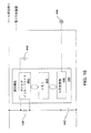
ツール402の本体の内側に配置されているのは、ツールおよび状態識別機器420である。識別機器420は、上述のRFID90に類似している。アナログインターフェイス422は、受信されたAC信号と、機器420によってシンクされた電力とのためのインターフェイスとしての機能を果たしている。メモリ428は機器420から読み出されたデータを収容している。アナログインターフェイス422とメモリ428との間には、識別機器はデジタル制御機器426を含んでいる。アナログインターフェイス422によって抽出されたデジタル信号に部分的に基づくデジタル制御機器426は、メモリ428からデータを取り出し、データ信号をアナログインターフェイス422へ転送している。受信されたデータ信号に基づいて、アナログインターフェイス422は、機器420を含む回路のインピーダンスを変調するようになっている。
Disposed inside the body of the
デジタル制御機器426にさらに接続されているのは、スイッチ430,432,434の組である。各スイッチ430,432,434は、識別機器420の内部にある基準電圧への接続を開閉するものである。本発明のいくつかの変形例では、各スイッチ430,432,434は、通常時に開状態である。ツールを保持する手の親指または指によって押し下げられうるツール本体に搭載された別個のボタンは、各スイッチ430,432,434を起動するために使用されている。
Further connected to the
ツール402は、上述されたインダクタ98に類似するインダクタ438をさらに含んでいる。インダクタ438は、識別機器420の対向する入力ピンに接続されている。より具体的には、これらの入力ピンは機器アナログインターフェイス422に接続されている。コンデンサ102に類似するコンデンサ440は、機器アナログインターフェイス422の内部にある共振コンデンサを表している。インダクタ438は、ツール420の内部にある電力信号導体414に接続されている一方の端部を有するものとして示されている。図15Aに明示的に示されていないが、コンデンサ440はインダクタ438の両端間に直列に接続されていることが理解される。コンデンサ440は実際にはアナログインターフェイス422の内部にあることがさらに理解されるべきである。
さらにツール402の本体にあるのは、コンデンサ94に類似するコンデンサ442である。コンデンサ442の一方の端部は、導体414に接続された端部の反対側にあるインダクタ438の端部に接続されている。コンデンサ440の対向する端部は、導体416に接続されている。
Also on the body of
ツール402を起動するため使用される本発明のシステムの制御コンソールは、適切な電力信号を発電機404に供給する能力がある発電回路を含んでいる。これらの信号は、たとえば、1MHz未満の低周波数AC信号でもよい。本発明のいくつかの変形例では、制御コンソールは、DC電力信号を発電機404に供給するように構成されることがある。
The control console of the system of the present invention used to activate
ツール402を含む本発明のシステムは、上述された本発明の変形例が動作する方法と同じ一般的な方法で動作させられている。インダクタ438およびコンデンサは、識別機器に印加された電力信号の電圧を実質的に低下させる間に、顕著な電圧降下無しに、端子410および412を介して受信された問い合わせ信号を識別機器420に印加するようになっている。ツール402がケーブル38のようなケーブルによって制御コンソールに取り付けられると、問い合わせ信号は、電力信号が供給される際に伝わるケーブル導体を介して、識別機器420へ送信されることになる。これらの信号に応答して、識別機器420は、制御コンソールの内部にあるリーダによって検出可能であるデータ信号を出力している。
The system of the present
より具体的には、識別機器のデジタル制御機器426は、スイッチ430,432,434の状態に基づいて、メモリ428からデータ信号の特定の組を取り出している。たとえば、ツール402が、外科手術部位で処置を実行するため使用され、洗浄流体を供給することも可能であって、デジタル制御機器426は、スイッチが押下されていない場合、第1のツール動作状態(ハンドピースおよび洗浄の両方がオフ)を指示するデータを引き起こし、スイッチ430が押下されている場合、第2のツール動作状態(ハンドピースがオン、洗浄がオフ)を指示するデータを引き起こし、スイッチ432が押下されている場合、第3の動作状態(ハンドピースがオフ、洗浄がオン)を指示するデータを引き起こし、スイッチ434が押下されている場合、第4の動作状態(ハンドピースおよび洗浄の両方がオン)を指示するデータを引き起こすようになっている。
More specifically, the
コンソールの内部にある制御器48は、特殊な状態信号を受信し次第、発電回路および/または洗浄ポンプ294を必要に応じて起動するようになっている。
The
ツール発電機404への電力信号の供給中に、周期的に、問い合わせ信号がメモリリーダ66によって出力されることになる。このプロセスは、図11Aに関連して上述されたステップ338に類似している。この場合も、これらの信号は、電力信号の供給と同時に、ケーブル電力導体を介して出力されることになる。電力信号の供給中に、医師は、通常は、スイッチ430〜434の開/閉セッティングを一挙に変化させている。したがって、これらのツールの後続の問い合わせのうちの1つに応答して、戻されるデータは、ツールが異なる状態に置かれるべきことを指示することになる。コンソール制御器48は、新たに受信された状態データに基づいて、電力信号の出力を調節し、および/または、洗浄ポンプの起動をリセットしている。
During the supply of the power signal to the
図15Aおよび図15Bに関連して説明された本発明の変形例は、本発明による外科手術ツールに、機器によって格納されたデータの内容の点で異なる二重の識別機器を設ける必要性を除くものである。 The variation of the invention described in connection with FIGS. 15A and 15B eliminates the need for a surgical tool according to the invention to have a dual identification device that differs in terms of the content of the data stored by the device. Is.
VII. 代替的な実施形態
上記の説明は、本発明の外科手術ツールシステムの特定の変形例を対象にしている。本発明の他の変形例は説明された特徴と異なる特徴を有することがある。たとえば、本発明のいくつかの変形例では、制御コンソールは、RF増幅器からメモリリーダ66を選択的に切断するために継電器のような切り替え型コンポーネントを含まないことがある。本発明の代替的な変形例では、絶縁は、RF増幅器44からの電力信号の電位がメモリリーダ66に印加される程度を実質的に低下させるため、ツールハブの内部にある回路に類似した回路を備えることがある。代替的に、図7に関連して説明された本発明の変形例のコンデンサ268およびインダクタ270は、絶縁回路としての機能を果たすことがある。
VII. Alternative Embodiments The above description is directed to specific variations of the surgical tool system of the present invention. Other variations of the invention may have different features than those described. For example, in some variations of the present invention, the control console may not include a switchable component such as a relay to selectively disconnect the
同様に、ツールと一体化したメモリの両端に印加された電力信号の電位から、電力信号の電位を実質的に低下させるツールの内部にある絶縁回路は、上述の構成とは異なる構成を有することがある。 Similarly, the insulation circuit in the tool that substantially lowers the potential of the power signal from the potential of the power signal applied to both ends of the memory integrated with the tool has a configuration different from the above configuration. There is.
同様に、このシステムの一部であるツールの構成は、上記ツールの説明と異なりうることが認められるべきである。たとえば、本発明の双極ツールは、能動電極および戻り電極の両方が取り付けられる単一構造プローブを含むことがある。同様に、ツールは、共に電気接続された複数の電極を含むことがある。このタイプのツールは、複数の能動電極または複数の戻り電極を有すると考えられることがある。 Similarly, it should be appreciated that the configuration of tools that are part of this system may differ from the description of the tools. For example, the bipolar tool of the present invention may include a single structure probe to which both the active and return electrodes are attached. Similarly, the tool may include a plurality of electrodes that are electrically connected together. This type of tool may be considered to have multiple active electrodes or multiple return electrodes.
本発明のいくつかの変形例では、ツールは十分なメモリおよびスイッチが設けられることがあるので、どのスイッチが押下されるかに依存して、供給される電力信号は、ツールに供給されることができる3個以上の電力信号の組からの1つである。たとえば、切断、高速凝固、または、低速凝固である。さらに、ツール上の制御機器がツールに供給された電力信号の特性の制御を可能にし、または、コンソールポンプ294の調整を可能にする本発明の変形例は、双極ツールに限定されない。これらの制御回路は、本発明の単極ツールに組み込まれる可能性がある。さらに、付加的なメモリおよび代替的なスイッチ組立体を組み込むことにより、電力信号の特性、および、洗浄流体を供給するポンプの両方の制御を可能にさせる本発明の単一ツールが提供される可能性があることが認められるべきである。 In some variations of the invention, the tool may be provided with sufficient memory and switches so that depending on which switch is pressed, the supplied power signal is supplied to the tool. Is one of a set of three or more power signals. For example, cutting, rapid solidification, or slow solidification. Further, the variations of the present invention that allow the control equipment on the tool to control the characteristics of the power signal supplied to the tool or to adjust the console pump 294 are not limited to bipolar tools. These control circuits may be incorporated into the unipolar tool of the present invention. Further, by incorporating additional memory and an alternative switch assembly, a single tool of the present invention can be provided that allows control of both the characteristics of the power signal and the pump supplying the cleaning fluid. It should be recognized that there is sex.
同様に、ツールは、単一スイッチが簡単に設けられることがある。このツールは、現場に単一スイッチだけを有する最初に説明されたツールに類似している可能性がある。このスイッチは、起動されたとき、ツールの内部にあるメモリが、コンソールに電力信号をツールへ供給することを命令するデータメッセージをコンソールへ読み出すようにさせている。このスイッチをツールに設置することにより、医師は、片手を使って、ツールの位置と、ツールのオン/オフ状態とを制御することが可能である。医師がフットスイッチを使用するか、または、無菌現場の外にいる助手がツールを起動する必要性は除かれることになる。 Similarly, the tool may simply be provided with a single switch. This tool may be similar to the first described tool with only a single switch in the field. When activated, this switch causes the memory inside the tool to read a data message to the console that instructs the console to supply a power signal to the tool. By installing this switch on the tool, the doctor can use one hand to control the position of the tool and the on / off state of the tool. The need for a physician to use a foot switch or an assistant outside the sterile field to activate the tool would be eliminated.
電力信号発生コンポーネント、および、制御機器の内部にある発電コンポーネントを調整するコンポーネントの構造は、同様に上述された構造と異なることがある。 The structure of the power signal generating component and the component that coordinates the power generation component inside the control equipment may be different from the structure described above as well.
同様に、本発明のすべての変形例において、ポンプ294およびポンプのレギュレータ296が電力信号を供給するコンソールに組み込まれるという要件はない。本発明のいくつかの変形例では、ポンプ294およびレギュレータ296は、ディスプレイ制御器48から命令信号を受信するように構成された自立型ユニットに組み込まれている。
Similarly, in all variations of the invention, there is no requirement that pump 294 and
上述されているように、本発明のシステムは、電気外科手術ツール以外の医療ツールおよび外科手術ツールに給電するように構築されることがある。これらのツールは、それぞれが供給された電力信号のツールメモリへの印加を阻止する絶縁回路を含んでいる。この絶縁回路は、供給された電力がDC信号であるか、または、非常に低い電圧AC信号である場合、インダクタと同様に簡単でもよい。本発明のこれらの変形例では、絶縁回路は、信号が問い合わせ信号の周波数の少なくとも2倍である周波数を有するとき、ツールメモリに印加された信号の電位を実質的に低下させるように構成される。代替的に、コンデンサは、供給された電力が高周波数AC信号である場合、バイパス回路としての機能を果たすことが可能である。本発明のこれらの変形例では、識別機器に印加される問い合わせ信号は、電力信号の周波数より顕著に低い周波数である。本発明のこれらの変形例では、絶縁回路は、電力信号が問い合わせ信号の周波数の半分未満の周波数を有するとき、ツールメモリに印加された信号の電位を実質的に低下させるように構成されている。本発明のいくつかの変形例では、識別回路からの供給された電力信号の適切なバイパスを確実にするため、電力信号および問い合わせ信号は、少なくとも10倍ずつ異なる周波数を有する筈である。換言すると、電力信号または問い合わせ信号のうちの一方の周波数は、それぞれ、問い合わせ信号または電力信号のうちのもう一方の周波数の少なくとも10倍である筈である。 As described above, the system of the present invention may be constructed to power medical and surgical tools other than electrosurgical tools. Each of these tools includes an isolation circuit that prevents application of the supplied power signal to the tool memory. This isolation circuit may be as simple as an inductor if the supplied power is a DC signal or a very low voltage AC signal. In these variations of the invention, the isolation circuit is configured to substantially reduce the potential of the signal applied to the tool memory when the signal has a frequency that is at least twice the frequency of the interrogation signal. . Alternatively, the capacitor can serve as a bypass circuit when the supplied power is a high frequency AC signal. In these variants of the invention, the inquiry signal applied to the identification device is at a frequency significantly lower than the frequency of the power signal. In these variations of the invention, the isolation circuit is configured to substantially reduce the potential of the signal applied to the tool memory when the power signal has a frequency less than half the frequency of the interrogation signal. . In some variations of the invention, the power signal and the interrogation signal should have at least 10 times different frequencies to ensure proper bypassing of the supplied power signal from the identification circuit. In other words, the frequency of one of the power signal or the interrogation signal should be at least 10 times the other frequency of the interrogation signal or the power signal, respectively.
ツールおよびコンソールの両方の絶縁回路は、信号周波数以外の特性に基づいて、選択的にツールメモリ(またはメモリリーダ)からの信号を通過させるか、または、絶縁するように設計されている場合、異なるコンポーネントを有することがある。たとえば、本発明のいくつかの変形例では、絶縁回路は、信号電位、周波数シフト、振幅シフト、位相シフト、または、インピーダンスシフトに基づいて信号を通過または阻止するように設計されることがある。 Both the tool and console isolation circuits are different if they are designed to selectively pass or isolate signals from the tool memory (or memory reader) based on characteristics other than signal frequency May have components. For example, in some variations of the invention, the isolation circuit may be designed to pass or block signals based on signal potential, frequency shift, amplitude shift, phase shift, or impedance shift.
ツールおよびコンソールの絶縁回路は、回路が実質的に影響を与えるように設計された信号の特性が信号電位と異なる場合、異なるコンポーネントを有することもある。これらの特性は、信号周波数、周波数シフト、振幅シフト、位相シフト、または、インピーダンスシフトを含んでいる。 Tool and console isolation circuits may have different components if the characteristics of the signal designed to substantially affect the circuit differ from the signal potential. These characteristics include signal frequency, frequency shift, amplitude shift, phase shift, or impedance shift.
さらに、図15Aおよび図15Bの配置を、本発明によって構築された電気外科手術ツールの中に組み込むことが可能であることが認められる筈である。よって、本発明の本実施形態の複数のスイッチは、電力信号がツール電極に供給されるかどうかだけでなく、供給された信号が組織切断または凝固を実現しやすくするために使用される電流フローの中で使用されるかどうかを制御するため使用されることが可能である。同様に、マルチ・メモリ・アセンブリは、電気外科手術ツール以外の電動外科手術ツールに組み込まれてもよい。 Further, it should be appreciated that the arrangement of FIGS. 15A and 15B can be incorporated into an electrosurgical tool constructed in accordance with the present invention. Thus, the plurality of switches of this embodiment of the present invention provides a current flow that is used to facilitate the tissue cutting or coagulation as well as whether the power signal is supplied to the tool electrode. Can be used to control whether it is used in Similarly, the multi-memory assembly may be incorporated into power surgical tools other than electrosurgical tools.
同様に、ツールは、識別機器が1個以上のスイッチの開/閉状態以外の入力に基づいて異なるデータを戻す本発明によって構築されることがある。よって、本発明の一つの代替的な変形例では、複数のスイッチは、単一の多重状態スイッチで置き換えることが可能である。ツール内部の回路および/または識別機器デジタル制御機器は、スイッチの状態を監視するものである。スイッチ状態に基づいて、デジタル制御機器426は、スイッチ状態を表すデータが問い合わせ信号に応答して制御コンソールへ戻されるようにしている。
Similarly, a tool may be constructed according to the present invention where the identification device returns different data based on inputs other than the open / closed state of one or more switches. Thus, in one alternative variation of the invention, multiple switches can be replaced with a single multi-state switch. The circuit inside the tool and / or the identification device digital control device monitors the state of the switch. Based on the switch status, the
代替的に、本発明のシステムのツールは、図16で分かるように、ある種のアナログセンサ460を含むことがある。センサは、たとえば、温度感受性トランスデューサである可能性がある。さらに別のセンサは、血中酸素を監視する能力がある機器であることがある。本発明のいくつかの変形では、アナログセンサは、ツールに取り付けられた可変ユーザ起動制御要素の状態に基づいて可変信号を発生させるようになっている。識別機器460と一体化したデジタル・アナログ信号466は、感知されたパラメータまたは感知された制御要素状態を表すデジタル信号を発生するようになっている。このデジタル化された信号は、同様に識別機器の一部であるメモリ464に格納されている。問い合わせ信号に応答して、識別機器460は、デジタル化されたセンサ信号の表現を含む応答を書き出すようになっている。
Alternatively, the tools of the system of the present invention may include some kind of
代替的に、センサからの出力信号に応答して、論理回路を含むことがあるメモリ464は、問い合わせ信号に応答して書き出す選択データを選択している。
Alternatively, in response to an output signal from the sensor,
ツールシステムが電気外科手術ツールシステムである本発明の変形例では、制御コンソールまたはツール自体のいずれかに絶縁回路を設けることが必要でないこともある。なぜならば、ある種のRFツール電力信号の特性と、コンソール・メモリリーダおよびツールメモリの構造とのために、ツール電力信号がメモリリーダまたはツールメモリに悪影響を与えないからである。 In variations of the invention where the tool system is an electrosurgical tool system, it may not be necessary to provide an isolation circuit on either the control console or the tool itself. This is because the tool power signal does not adversely affect the memory reader or tool memory due to the characteristics of certain RF tool power signals and the structure of the console memory reader and tool memory.
したがって、特許請求の範囲の目的は、本発明の精神および範囲に含まれるこのようなすべての変形および変更を対象とすることである。 Accordingly, it is the object of the appended claims to cover all such variations and modifications as fall within the spirit and scope of the invention.
Claims (11)
前記本体に取り付けられ、ケーブルを着脱式に受承し、ツールを起動するため電力信号が印加される少なくとも1つの端子コンポーネント(82,84)と、
前記本体に取り付けられ、前記電力信号の前記ツールへの印加に応じて治療的または診断的タスクを実行するために組織への印加のため設計された電力印加装置(34,36,406)と、
前記本体に取り付けられ、前記ツールに印加される前記電力信号の特性を記述するデータ(327,328)が格納され、問い合わせ信号に応答して、メモリに格納されている前記データを書き出すように構成されているメモリ(90,306,312,318,359,364,370,376,428)と、
前記本体に配置され、前記少なくとも1つの端子コンポーネントを前記メモリに接続し、
メモリ問い合わせ信号の特性を有する信号が前記少なくとも1つの端子コンポーネントに印加されるとき、前記メモリが前記メモリ問い合わせ信号の特性を有する信号を処理できるように前記メモリ問い合わせ信号の特性を有する信号の前記特性を顕著に変化させることなく前記メモリ問い合わせ信号の特性を有する信号を前記メモリに印加し、
前記メモリ問い合わせ信号の特性を有する信号の前記特性と異なる特性を有する信号が前記少なくとも1つの端子コンポーネントに印加されるとき、絶縁回路によって生成され前記メモリに印加される変化させられた信号が前記メモリに悪影響を与えないように前記メモリ問い合わせ信号の前記特性と異なる特性を有する信号の前記特性を実質的に変化させるように構成されている絶縁回路(94,98,218,220,321,322,438,442,464)と、
を含む電動外科手術ツール(32,302,402)。 The body (85, 86, 88);
At least one terminal component (82, 84) attached to the body, removably receiving a cable and receiving a power signal to activate the tool;
A power application device (34, 36, 406) attached to the body and designed for application to tissue to perform a therapeutic or diagnostic task in response to application of the power signal to the tool;
Data (327, 328) describing characteristics of the power signal applied to the tool and applied to the tool is stored, and the data stored in the memory is written in response to an inquiry signal Memory (90, 306, 312, 318, 359, 364, 370, 376, 428),
Disposed in the body and connecting the at least one terminal component to the memory;
The characteristic of the signal having the characteristic of the memory inquiry signal so that the memory can process the signal having the characteristic of the memory inquiry signal when a signal having the characteristic of the memory inquiry signal is applied to the at least one terminal component. Applying a signal having the characteristics of the memory inquiry signal to the memory without significantly changing
A changed signal generated by an isolation circuit and applied to the memory when a signal having a characteristic different from the characteristic of the signal having the characteristic of the memory inquiry signal is applied to the at least one terminal component Insulating circuits (94, 98, 218, 220, 321, 322) configured to substantially change the characteristics of signals having characteristics different from the characteristics of the memory inquiry signal so as not to adversely affect the memory inquiry signal . 438, 442, 464),
A power surgical tool (32, 302, 402).
前記絶縁回路が、前記問い合わせ信号の周波数と異なる周波数の信号が前記端子コンポーネントに印加されるとき、前記メモリに印加される前記信号の電位を実質的に低下させるように構成されている、請求項1に記載の電動外科手術ツール。 The interrogation signal applied to the memory via the at least one terminal component is at least at a selected frequency;
The isolation circuit is configured to substantially reduce the potential of the signal applied to the memory when a signal having a frequency different from the frequency of the interrogation signal is applied to the terminal component. The electric surgical tool according to 1.
導体(92,96,216)が、前記端子(82,84,210)に印加される前記信号が前記少なくとも1つの電極に供給される際に伝わる前記少なくとも1つの端子コンポーネントから延在し、
前記絶縁回路(94,98,218,220,321,322)が前記導体に接続されている、請求項1〜4のうちのいずれか1項に記載の電動外科手術ツール。 The power application device is at least one electrode (34, 36) intended for application for tissue;
A conductor (92, 96, 216) extends from the at least one terminal component that travels when the signal applied to the terminal (82, 84, 210) is applied to the at least one electrode;
The power surgical tool according to any one of claims 1 to 4, wherein the insulating circuit (94, 98, 218, 220, 321, 322) is connected to the conductor.
導体(414)が、前記端子(410)に印加される前記信号が中を通って前記発電機に供給される前記少なくとも1つの端子コンポーネントから延在し、
前記絶縁回路(438,442)が前記導体に接続されている、請求項1〜5のいずれか1項に記載の電動外科手術ツール。 A generator (404) is mounted on the main body, the power application device (406) is connected to the generator, and the generator activates the power application device in response to application of the power signal. Configured,
A conductor (414) extends from the at least one terminal component through which the signal applied to the terminal (410) is supplied to the generator;
The power surgical tool according to any one of the preceding claims, wherein the isolation circuit (438, 442) is connected to the conductor.
少なくとも1つのスイッチ(324,326,384,386,388)が前記本体に取り付けられ、前記メモリのうちの1つと、前記絶縁回路を介して、前記少なくとも1つの端子コンポーネントとの間に接続を選択的に確立している、請求項1〜6のいずれか1項に記載の電動外科手術ツール。 A plurality of separate memories (306, 312, 318, 359, 364, 370, 376) are attached to the body,
At least one switch (324, 326, 384, 386, 388) is attached to the body and selects a connection between one of the memories and the at least one terminal component via the isolation circuit The power surgical tool according to any one of claims 1 to 6, wherein the power surgical tool is mechanically established.
制御回路(426)が前記本体に取り付けられ、前記制御回路は、前記スイッチの状態を監視し、前記スイッチの前記状態に応答して、前記メモリの中のどのデータが前記メモリから書き出されるかを制御するように構成されている、請求項1〜7のいずれか1項に記載の電動外科手術ツール。 At least one switch (430, 432, 434) is attached to the body,
A control circuit (426) is attached to the body, the control circuit monitors the state of the switch, and in response to the state of the switch, which data in the memory is written from the memory. The powered surgical tool according to any one of the preceding claims, configured to control.
前記絶縁回路が前記少なくとも1つの端子コンポーネントと前記メモリ入力の両端間とに接続されているインダクタを含んでいる、請求項1〜8のいずれか1項に記載の電動外科手術ツール。 The memory includes a pair of inputs to which the interrogation signal is applied and data is written from the memory;
The power surgical tool according to any one of claims 1 to 8, wherein the isolation circuit includes an inductor connected between the at least one terminal component and across the memory input.
前記絶縁回路が、前記少なくとも1つの端子コンポーネントと前記メモリ入力との間に接続されているコンデンサを含んでいる、請求項1〜9のいずれか1項に記載の電動外科手術ツール。 The memory includes at least one input to which the interrogation signal is applied and data from the memory is written;
The power surgical tool according to any one of claims 1 to 9, wherein the isolation circuit includes a capacitor connected between the at least one terminal component and the memory input.
前記ツールが、生物学的パラメータまたはユーザ起動部分の状態を監視し、前記監視されたパラメータまたは前記ユーザ起動部分の前記状態の関数として可変センサ信号を発生するセンサ(458)を含み、
前記識別機器が前記センサ信号を受信し、前記端子コンポーネント(82,84)を介して前記センサ信号に基づく信号を出力するように構成されている、請求項1〜10のいずれか1項に記載の電動外科手術ツール。 The memory is part of the identification device (460);
The tool includes a sensor (458) that monitors a biological parameter or a state of a user-initiated portion and generates a variable sensor signal as a function of the monitored parameter or the state of the user-initiated portion;
11. The identification device according to any one of claims 1 to 10, wherein the identification device is configured to receive the sensor signal and output a signal based on the sensor signal via the terminal component (82, 84). Electric surgical tool.
Applications Claiming Priority (3)
| Application Number | Priority Date | Filing Date | Title |
|---|---|---|---|
| US5043008P | 2008-05-05 | 2008-05-05 | |
| US61/050,430 | 2008-05-05 | ||
| PCT/US2009/042739 WO2009137421A1 (en) | 2008-05-05 | 2009-05-04 | Surgical tool system including a tool and a console, the console capable of reading data from a memory integral with the tool over the conductors over which power is sourced to the tool |
Related Child Applications (1)
| Application Number | Title | Priority Date | Filing Date |
|---|---|---|---|
| JP2014103334A Division JP5763245B2 (en) | 2008-05-05 | 2014-05-19 | Surgical tool system that includes a tool and a console, and the console can read data from a memory integrated with the tool using a conductor that powers the tool |
Publications (3)
| Publication Number | Publication Date |
|---|---|
| JP2011519636A JP2011519636A (en) | 2011-07-14 |
| JP2011519636A5 JP2011519636A5 (en) | 2012-07-19 |
| JP5552113B2 true JP5552113B2 (en) | 2014-07-16 |
Family
ID=40848518
Family Applications (2)
| Application Number | Title | Priority Date | Filing Date |
|---|---|---|---|
| JP2011507713A Active JP5552113B2 (en) | 2008-05-05 | 2009-05-04 | Electric surgical tool with an insulation circuit connected between the electric tool terminal inside the tool and the memory |
| JP2014103334A Active JP5763245B2 (en) | 2008-05-05 | 2014-05-19 | Surgical tool system that includes a tool and a console, and the console can read data from a memory integrated with the tool using a conductor that powers the tool |
Family Applications After (1)
| Application Number | Title | Priority Date | Filing Date |
|---|---|---|---|
| JP2014103334A Active JP5763245B2 (en) | 2008-05-05 | 2014-05-19 | Surgical tool system that includes a tool and a console, and the console can read data from a memory integrated with the tool using a conductor that powers the tool |
Country Status (6)
| Country | Link |
|---|---|
| US (2) | US8784415B2 (en) |
| EP (2) | EP2271275B1 (en) |
| JP (2) | JP5552113B2 (en) |
| AU (1) | AU2009244445B8 (en) |
| CA (1) | CA2722972A1 (en) |
| WO (1) | WO2009137421A1 (en) |
Families Citing this family (659)
| Publication number | Priority date | Publication date | Assignee | Title |
|---|---|---|---|---|
| US11229472B2 (en) | 2001-06-12 | 2022-01-25 | Cilag Gmbh International | Modular battery powered handheld surgical instrument with multiple magnetic position sensors |
| US20070084897A1 (en) | 2003-05-20 | 2007-04-19 | Shelton Frederick E Iv | Articulating surgical stapling instrument incorporating a two-piece e-beam firing mechanism |
| US9060770B2 (en) | 2003-05-20 | 2015-06-23 | Ethicon Endo-Surgery, Inc. | Robotically-driven surgical instrument with E-beam driver |
| US8182501B2 (en) | 2004-02-27 | 2012-05-22 | Ethicon Endo-Surgery, Inc. | Ultrasonic surgical shears and method for sealing a blood vessel using same |
| US8215531B2 (en) | 2004-07-28 | 2012-07-10 | Ethicon Endo-Surgery, Inc. | Surgical stapling instrument having a medical substance dispenser |
| US11896225B2 (en) | 2004-07-28 | 2024-02-13 | Cilag Gmbh International | Staple cartridge comprising a pan |
| US20060079874A1 (en) | 2004-10-08 | 2006-04-13 | Faller Craig N | Tissue pad for use with an ultrasonic surgical instrument |
| US11484312B2 (en) | 2005-08-31 | 2022-11-01 | Cilag Gmbh International | Staple cartridge comprising a staple driver arrangement |
| US9237891B2 (en) | 2005-08-31 | 2016-01-19 | Ethicon Endo-Surgery, Inc. | Robotically-controlled surgical stapling devices that produce formed staples having different lengths |
| US11246590B2 (en) | 2005-08-31 | 2022-02-15 | Cilag Gmbh International | Staple cartridge including staple drivers having different unfired heights |
| US7669746B2 (en) | 2005-08-31 | 2010-03-02 | Ethicon Endo-Surgery, Inc. | Staple cartridges for forming staples having differing formed staple heights |
| US7934630B2 (en) | 2005-08-31 | 2011-05-03 | Ethicon Endo-Surgery, Inc. | Staple cartridges for forming staples having differing formed staple heights |
| US20070194082A1 (en) | 2005-08-31 | 2007-08-23 | Morgan Jerome R | Surgical stapling device with anvil having staple forming pockets of varying depths |
| US10159482B2 (en) | 2005-08-31 | 2018-12-25 | Ethicon Llc | Fastener cartridge assembly comprising a fixed anvil and different staple heights |
| US20070191713A1 (en) | 2005-10-14 | 2007-08-16 | Eichmann Stephen E | Ultrasonic device for cutting and coagulating |
| US20070106317A1 (en) | 2005-11-09 | 2007-05-10 | Shelton Frederick E Iv | Hydraulically and electrically actuated articulation joints for surgical instruments |
| US7621930B2 (en) | 2006-01-20 | 2009-11-24 | Ethicon Endo-Surgery, Inc. | Ultrasound medical instrument having a medical ultrasonic blade |
| US8186555B2 (en) | 2006-01-31 | 2012-05-29 | Ethicon Endo-Surgery, Inc. | Motor-driven surgical cutting and fastening instrument with mechanical closure system |
| US9861359B2 (en) | 2006-01-31 | 2018-01-09 | Ethicon Llc | Powered surgical instruments with firing system lockout arrangements |
| US7753904B2 (en) | 2006-01-31 | 2010-07-13 | Ethicon Endo-Surgery, Inc. | Endoscopic surgical instrument with a handle that can articulate with respect to the shaft |
| US20110290856A1 (en) | 2006-01-31 | 2011-12-01 | Ethicon Endo-Surgery, Inc. | Robotically-controlled surgical instrument with force-feedback capabilities |
| US11224427B2 (en) | 2006-01-31 | 2022-01-18 | Cilag Gmbh International | Surgical stapling system including a console and retraction assembly |
| US20120292367A1 (en) | 2006-01-31 | 2012-11-22 | Ethicon Endo-Surgery, Inc. | Robotically-controlled end effector |
| US8820603B2 (en) | 2006-01-31 | 2014-09-02 | Ethicon Endo-Surgery, Inc. | Accessing data stored in a memory of a surgical instrument |
| US20110006101A1 (en) | 2009-02-06 | 2011-01-13 | EthiconEndo-Surgery, Inc. | Motor driven surgical fastener device with cutting member lockout arrangements |
| US11793518B2 (en) | 2006-01-31 | 2023-10-24 | Cilag Gmbh International | Powered surgical instruments with firing system lockout arrangements |
| US11278279B2 (en) | 2006-01-31 | 2022-03-22 | Cilag Gmbh International | Surgical instrument assembly |
| US7845537B2 (en) | 2006-01-31 | 2010-12-07 | Ethicon Endo-Surgery, Inc. | Surgical instrument having recording capabilities |
| US20110024477A1 (en) | 2009-02-06 | 2011-02-03 | Hall Steven G | Driven Surgical Stapler Improvements |
| US8708213B2 (en) | 2006-01-31 | 2014-04-29 | Ethicon Endo-Surgery, Inc. | Surgical instrument having a feedback system |
| US20070225562A1 (en) | 2006-03-23 | 2007-09-27 | Ethicon Endo-Surgery, Inc. | Articulating endoscopic accessory channel |
| US8992422B2 (en) | 2006-03-23 | 2015-03-31 | Ethicon Endo-Surgery, Inc. | Robotically-controlled endoscopic accessory channel |
| US8322455B2 (en) | 2006-06-27 | 2012-12-04 | Ethicon Endo-Surgery, Inc. | Manually driven surgical cutting and fastening instrument |
| US10568652B2 (en) | 2006-09-29 | 2020-02-25 | Ethicon Llc | Surgical staples having attached drivers of different heights and stapling instruments for deploying the same |
| US8720766B2 (en) | 2006-09-29 | 2014-05-13 | Ethicon Endo-Surgery, Inc. | Surgical stapling instruments and staples |
| US11980366B2 (en) | 2006-10-03 | 2024-05-14 | Cilag Gmbh International | Surgical instrument |
| US11291441B2 (en) | 2007-01-10 | 2022-04-05 | Cilag Gmbh International | Surgical instrument with wireless communication between control unit and remote sensor |
| US8652120B2 (en) | 2007-01-10 | 2014-02-18 | Ethicon Endo-Surgery, Inc. | Surgical instrument with wireless communication between control unit and sensor transponders |
| US8684253B2 (en) | 2007-01-10 | 2014-04-01 | Ethicon Endo-Surgery, Inc. | Surgical instrument with wireless communication between a control unit of a robotic system and remote sensor |
| US11039836B2 (en) | 2007-01-11 | 2021-06-22 | Cilag Gmbh International | Staple cartridge for use with a surgical stapling instrument |
| US7434717B2 (en) | 2007-01-11 | 2008-10-14 | Ethicon Endo-Surgery, Inc. | Apparatus for closing a curved anvil of a surgical stapling device |
| US7673782B2 (en) | 2007-03-15 | 2010-03-09 | Ethicon Endo-Surgery, Inc. | Surgical stapling instrument having a releasable buttress material |
| US8057498B2 (en) | 2007-11-30 | 2011-11-15 | Ethicon Endo-Surgery, Inc. | Ultrasonic surgical instrument blades |
| US8226675B2 (en) | 2007-03-22 | 2012-07-24 | Ethicon Endo-Surgery, Inc. | Surgical instruments |
| US8911460B2 (en) | 2007-03-22 | 2014-12-16 | Ethicon Endo-Surgery, Inc. | Ultrasonic surgical instruments |
| US8142461B2 (en) | 2007-03-22 | 2012-03-27 | Ethicon Endo-Surgery, Inc. | Surgical instruments |
| US8893946B2 (en) | 2007-03-28 | 2014-11-25 | Ethicon Endo-Surgery, Inc. | Laparoscopic tissue thickness and clamp load measuring devices |
| US8931682B2 (en) | 2007-06-04 | 2015-01-13 | Ethicon Endo-Surgery, Inc. | Robotically-controlled shaft based rotary drive systems for surgical instruments |
| US11672531B2 (en) | 2007-06-04 | 2023-06-13 | Cilag Gmbh International | Rotary drive systems for surgical instruments |
| US8308040B2 (en) | 2007-06-22 | 2012-11-13 | Ethicon Endo-Surgery, Inc. | Surgical stapling instrument with an articulatable end effector |
| US7753245B2 (en) | 2007-06-22 | 2010-07-13 | Ethicon Endo-Surgery, Inc. | Surgical stapling instruments |
| US11849941B2 (en) | 2007-06-29 | 2023-12-26 | Cilag Gmbh International | Staple cartridge having staple cavities extending at a transverse angle relative to a longitudinal cartridge axis |
| US8523889B2 (en) | 2007-07-27 | 2013-09-03 | Ethicon Endo-Surgery, Inc. | Ultrasonic end effectors with increased active length |
| US8808319B2 (en) | 2007-07-27 | 2014-08-19 | Ethicon Endo-Surgery, Inc. | Surgical instruments |
| US8882791B2 (en) | 2007-07-27 | 2014-11-11 | Ethicon Endo-Surgery, Inc. | Ultrasonic surgical instruments |
| US8512365B2 (en) | 2007-07-31 | 2013-08-20 | Ethicon Endo-Surgery, Inc. | Surgical instruments |
| US8430898B2 (en) | 2007-07-31 | 2013-04-30 | Ethicon Endo-Surgery, Inc. | Ultrasonic surgical instruments |
| US9044261B2 (en) | 2007-07-31 | 2015-06-02 | Ethicon Endo-Surgery, Inc. | Temperature controlled ultrasonic surgical instruments |
| EP2217157A2 (en) | 2007-10-05 | 2010-08-18 | Ethicon Endo-Surgery, Inc. | Ergonomic surgical instruments |
| US10010339B2 (en) | 2007-11-30 | 2018-07-03 | Ethicon Llc | Ultrasonic surgical blades |
| DE102008061418A1 (en) * | 2007-12-12 | 2009-06-18 | Erbe Elektromedizin Gmbh | Apparatus for contactless communication and use of a memory device |
| US11986183B2 (en) | 2008-02-14 | 2024-05-21 | Cilag Gmbh International | Surgical cutting and fastening instrument comprising a plurality of sensors to measure an electrical parameter |
| US8758391B2 (en) | 2008-02-14 | 2014-06-24 | Ethicon Endo-Surgery, Inc. | Interchangeable tools for surgical instruments |
| US9179912B2 (en) | 2008-02-14 | 2015-11-10 | Ethicon Endo-Surgery, Inc. | Robotically-controlled motorized surgical cutting and fastening instrument |
| US8636736B2 (en) | 2008-02-14 | 2014-01-28 | Ethicon Endo-Surgery, Inc. | Motorized surgical cutting and fastening instrument |
| US7866527B2 (en) | 2008-02-14 | 2011-01-11 | Ethicon Endo-Surgery, Inc. | Surgical stapling apparatus with interlockable firing system |
| US8657174B2 (en) | 2008-02-14 | 2014-02-25 | Ethicon Endo-Surgery, Inc. | Motorized surgical cutting and fastening instrument having handle based power source |
| US7819298B2 (en) | 2008-02-14 | 2010-10-26 | Ethicon Endo-Surgery, Inc. | Surgical stapling apparatus with control features operable with one hand |
| JP5410110B2 (en) | 2008-02-14 | 2014-02-05 | エシコン・エンド−サージェリィ・インコーポレイテッド | Surgical cutting / fixing instrument with RF electrode |
| US8573465B2 (en) | 2008-02-14 | 2013-11-05 | Ethicon Endo-Surgery, Inc. | Robotically-controlled surgical end effector system with rotary actuated closure systems |
| US11272927B2 (en) | 2008-02-15 | 2022-03-15 | Cilag Gmbh International | Layer arrangements for surgical staple cartridges |
| US9770245B2 (en) | 2008-02-15 | 2017-09-26 | Ethicon Llc | Layer arrangements for surgical staple cartridges |
| US8568411B2 (en) | 2008-03-31 | 2013-10-29 | Applied Medical Resources Corporation | Electrosurgical system |
| US9089360B2 (en) | 2008-08-06 | 2015-07-28 | Ethicon Endo-Surgery, Inc. | Devices and techniques for cutting and coagulating tissue |
| US8058771B2 (en) | 2008-08-06 | 2011-11-15 | Ethicon Endo-Surgery, Inc. | Ultrasonic device for cutting and coagulating with stepped output |
| US11648005B2 (en) | 2008-09-23 | 2023-05-16 | Cilag Gmbh International | Robotically-controlled motorized surgical instrument with an end effector |
| US9005230B2 (en) | 2008-09-23 | 2015-04-14 | Ethicon Endo-Surgery, Inc. | Motorized surgical instrument |
| US8210411B2 (en) | 2008-09-23 | 2012-07-03 | Ethicon Endo-Surgery, Inc. | Motor-driven surgical cutting instrument |
| US9386983B2 (en) | 2008-09-23 | 2016-07-12 | Ethicon Endo-Surgery, Llc | Robotically-controlled motorized surgical instrument |
| US8608045B2 (en) | 2008-10-10 | 2013-12-17 | Ethicon Endo-Sugery, Inc. | Powered surgical cutting and stapling apparatus with manually retractable firing system |
| US8517239B2 (en) | 2009-02-05 | 2013-08-27 | Ethicon Endo-Surgery, Inc. | Surgical stapling instrument comprising a magnetic element driver |
| US8444036B2 (en) | 2009-02-06 | 2013-05-21 | Ethicon Endo-Surgery, Inc. | Motor driven surgical fastener device with mechanisms for adjusting a tissue gap within the end effector |
| RU2525225C2 (en) | 2009-02-06 | 2014-08-10 | Этикон Эндо-Серджери, Инк. | Improvement of drive surgical suturing instrument |
| US8423182B2 (en) | 2009-03-09 | 2013-04-16 | Intuitive Surgical Operations, Inc. | Adaptable integrated energy control system for electrosurgical tools in robotic surgical systems |
| US9700339B2 (en) | 2009-05-20 | 2017-07-11 | Ethicon Endo-Surgery, Inc. | Coupling arrangements and methods for attaching tools to ultrasonic surgical instruments |
| US8344596B2 (en) | 2009-06-24 | 2013-01-01 | Ethicon Endo-Surgery, Inc. | Transducer arrangements for ultrasonic surgical instruments |
| US8663220B2 (en) | 2009-07-15 | 2014-03-04 | Ethicon Endo-Surgery, Inc. | Ultrasonic surgical instruments |
| US8568400B2 (en) * | 2009-09-23 | 2013-10-29 | Covidien Lp | Methods and apparatus for smart handset design in surgical instruments |
| US10441345B2 (en) | 2009-10-09 | 2019-10-15 | Ethicon Llc | Surgical generator for ultrasonic and electrosurgical devices |
| USRE47996E1 (en) * | 2009-10-09 | 2020-05-19 | Ethicon Llc | Surgical generator for ultrasonic and electrosurgical devices |
| US9168054B2 (en) | 2009-10-09 | 2015-10-27 | Ethicon Endo-Surgery, Inc. | Surgical generator for ultrasonic and electrosurgical devices |
| US11090104B2 (en) | 2009-10-09 | 2021-08-17 | Cilag Gmbh International | Surgical generator for ultrasonic and electrosurgical devices |
| US8986302B2 (en) | 2009-10-09 | 2015-03-24 | Ethicon Endo-Surgery, Inc. | Surgical generator for ultrasonic and electrosurgical devices |
| US8851354B2 (en) | 2009-12-24 | 2014-10-07 | Ethicon Endo-Surgery, Inc. | Surgical cutting instrument that analyzes tissue thickness |
| US8220688B2 (en) | 2009-12-24 | 2012-07-17 | Ethicon Endo-Surgery, Inc. | Motor-driven surgical cutting instrument with electric actuator directional control assembly |
| US8486096B2 (en) | 2010-02-11 | 2013-07-16 | Ethicon Endo-Surgery, Inc. | Dual purpose surgical instrument for cutting and coagulating tissue |
| US8579928B2 (en) | 2010-02-11 | 2013-11-12 | Ethicon Endo-Surgery, Inc. | Outer sheath and blade arrangements for ultrasonic surgical instruments |
| US8469981B2 (en) | 2010-02-11 | 2013-06-25 | Ethicon Endo-Surgery, Inc. | Rotatable cutting implement arrangements for ultrasonic surgical instruments |
| US8961547B2 (en) | 2010-02-11 | 2015-02-24 | Ethicon Endo-Surgery, Inc. | Ultrasonic surgical instruments with moving cutting implement |
| US8951272B2 (en) | 2010-02-11 | 2015-02-10 | Ethicon Endo-Surgery, Inc. | Seal arrangements for ultrasonically powered surgical instruments |
| GB2480498A (en) | 2010-05-21 | 2011-11-23 | Ethicon Endo Surgery Inc | Medical device comprising RF circuitry |
| US8795327B2 (en) | 2010-07-22 | 2014-08-05 | Ethicon Endo-Surgery, Inc. | Electrosurgical instrument with separate closure and cutting members |
| US9192431B2 (en) | 2010-07-23 | 2015-11-24 | Ethicon Endo-Surgery, Inc. | Electrosurgical cutting and sealing instrument |
| US8783543B2 (en) | 2010-07-30 | 2014-07-22 | Ethicon Endo-Surgery, Inc. | Tissue acquisition arrangements and methods for surgical stapling devices |
| US8632525B2 (en) | 2010-09-17 | 2014-01-21 | Ethicon Endo-Surgery, Inc. | Power control arrangements for surgical instruments and batteries |
| US9289212B2 (en) | 2010-09-17 | 2016-03-22 | Ethicon Endo-Surgery, Inc. | Surgical instruments and batteries for surgical instruments |
| US10123798B2 (en) | 2010-09-30 | 2018-11-13 | Ethicon Llc | Tissue thickness compensator comprising controlled release and expansion |
| CA2812553C (en) | 2010-09-30 | 2019-02-12 | Ethicon Endo-Surgery, Inc. | Fastener system comprising a retention matrix and an alignment matrix |
| US11298125B2 (en) | 2010-09-30 | 2022-04-12 | Cilag Gmbh International | Tissue stapler having a thickness compensator |
| US9332974B2 (en) | 2010-09-30 | 2016-05-10 | Ethicon Endo-Surgery, Llc | Layered tissue thickness compensator |
| US10945731B2 (en) | 2010-09-30 | 2021-03-16 | Ethicon Llc | Tissue thickness compensator comprising controlled release and expansion |
| US9386988B2 (en) | 2010-09-30 | 2016-07-12 | Ethicon End-Surgery, LLC | Retainer assembly including a tissue thickness compensator |
| US9216019B2 (en) | 2011-09-23 | 2015-12-22 | Ethicon Endo-Surgery, Inc. | Surgical stapler with stationary staple drivers |
| US9839420B2 (en) | 2010-09-30 | 2017-12-12 | Ethicon Llc | Tissue thickness compensator comprising at least one medicament |
| US9314246B2 (en) | 2010-09-30 | 2016-04-19 | Ethicon Endo-Surgery, Llc | Tissue stapler having a thickness compensator incorporating an anti-inflammatory agent |
| US11812965B2 (en) | 2010-09-30 | 2023-11-14 | Cilag Gmbh International | Layer of material for a surgical end effector |
| US10405854B2 (en) | 2010-09-30 | 2019-09-10 | Ethicon Llc | Surgical stapling cartridge with layer retention features |
| US8978954B2 (en) | 2010-09-30 | 2015-03-17 | Ethicon Endo-Surgery, Inc. | Staple cartridge comprising an adjustable distal portion |
| US9301753B2 (en) | 2010-09-30 | 2016-04-05 | Ethicon Endo-Surgery, Llc | Expandable tissue thickness compensator |
| US11849952B2 (en) | 2010-09-30 | 2023-12-26 | Cilag Gmbh International | Staple cartridge comprising staples positioned within a compressible portion thereof |
| US9629814B2 (en) | 2010-09-30 | 2017-04-25 | Ethicon Endo-Surgery, Llc | Tissue thickness compensator configured to redistribute compressive forces |
| US9307989B2 (en) | 2012-03-28 | 2016-04-12 | Ethicon Endo-Surgery, Llc | Tissue stapler having a thickness compensator incorportating a hydrophobic agent |
| US9364233B2 (en) | 2010-09-30 | 2016-06-14 | Ethicon Endo-Surgery, Llc | Tissue thickness compensators for circular surgical staplers |
| US9232941B2 (en) | 2010-09-30 | 2016-01-12 | Ethicon Endo-Surgery, Inc. | Tissue thickness compensator comprising a reservoir |
| US9220501B2 (en) | 2010-09-30 | 2015-12-29 | Ethicon Endo-Surgery, Inc. | Tissue thickness compensators |
| EP3332723B1 (en) * | 2010-10-01 | 2022-02-16 | Applied Medical Resources Corporation | Electrosurgical instruments and connections thereto |
| AU2015201994C1 (en) * | 2010-10-01 | 2017-02-02 | Applied Medical Resources Corporation | Electrosurgical instrument |
| US8695866B2 (en) | 2010-10-01 | 2014-04-15 | Ethicon Endo-Surgery, Inc. | Surgical instrument having a power control circuit |
| US10448992B2 (en) * | 2010-10-22 | 2019-10-22 | Arthrocare Corporation | Electrosurgical system with device specific operational parameters |
| US9011471B2 (en) | 2010-11-05 | 2015-04-21 | Ethicon Endo-Surgery, Inc. | Surgical instrument with pivoting coupling to modular shaft and end effector |
| US10959769B2 (en) | 2010-11-05 | 2021-03-30 | Ethicon Llc | Surgical instrument with slip ring assembly to power ultrasonic transducer |
| US9017849B2 (en) | 2010-11-05 | 2015-04-28 | Ethicon Endo-Surgery, Inc. | Power source management for medical device |
| US9782214B2 (en) | 2010-11-05 | 2017-10-10 | Ethicon Llc | Surgical instrument with sensor and powered control |
| US9597143B2 (en) | 2010-11-05 | 2017-03-21 | Ethicon Endo-Surgery, Llc | Sterile medical instrument charging device |
| US9421062B2 (en) | 2010-11-05 | 2016-08-23 | Ethicon Endo-Surgery, Llc | Surgical instrument shaft with resiliently biased coupling to handpiece |
| US9039720B2 (en) | 2010-11-05 | 2015-05-26 | Ethicon Endo-Surgery, Inc. | Surgical instrument with ratcheting rotatable shaft |
| US9089338B2 (en) | 2010-11-05 | 2015-07-28 | Ethicon Endo-Surgery, Inc. | Medical device packaging with window for insertion of reusable component |
| US9526921B2 (en) | 2010-11-05 | 2016-12-27 | Ethicon Endo-Surgery, Llc | User feedback through end effector of surgical instrument |
| US20120116265A1 (en) | 2010-11-05 | 2012-05-10 | Houser Kevin L | Surgical instrument with charging devices |
| US9375255B2 (en) | 2010-11-05 | 2016-06-28 | Ethicon Endo-Surgery, Llc | Surgical instrument handpiece with resiliently biased coupling to modular shaft and end effector |
| US9381058B2 (en) | 2010-11-05 | 2016-07-05 | Ethicon Endo-Surgery, Llc | Recharge system for medical devices |
| US20120116381A1 (en) | 2010-11-05 | 2012-05-10 | Houser Kevin L | Surgical instrument with charging station and wireless communication |
| US9072523B2 (en) | 2010-11-05 | 2015-07-07 | Ethicon Endo-Surgery, Inc. | Medical device with feature for sterile acceptance of non-sterile reusable component |
| US9510895B2 (en) | 2010-11-05 | 2016-12-06 | Ethicon Endo-Surgery, Llc | Surgical instrument with modular shaft and end effector |
| US9000720B2 (en) | 2010-11-05 | 2015-04-07 | Ethicon Endo-Surgery, Inc. | Medical device packaging with charging interface |
| US10085792B2 (en) | 2010-11-05 | 2018-10-02 | Ethicon Llc | Surgical instrument with motorized attachment feature |
| US9161803B2 (en) | 2010-11-05 | 2015-10-20 | Ethicon Endo-Surgery, Inc. | Motor driven electrosurgical device with mechanical and electrical feedback |
| CN103281982B (en) * | 2010-11-05 | 2016-12-28 | 伊西康内外科公司 | There is modular end effector and the surgical instruments of detection structure |
| US9017851B2 (en) | 2010-11-05 | 2015-04-28 | Ethicon Endo-Surgery, Inc. | Sterile housing for non-sterile medical device component |
| US9649150B2 (en) | 2010-11-05 | 2017-05-16 | Ethicon Endo-Surgery, Llc | Selective activation of electronic components in medical device |
| US9782215B2 (en) | 2010-11-05 | 2017-10-10 | Ethicon Endo-Surgery, Llc | Surgical instrument with ultrasonic transducer having integral switches |
| US10881448B2 (en) | 2010-11-05 | 2021-01-05 | Ethicon Llc | Cam driven coupling between ultrasonic transducer and waveguide in surgical instrument |
| US9247986B2 (en) | 2010-11-05 | 2016-02-02 | Ethicon Endo-Surgery, Llc | Surgical instrument with ultrasonic transducer having integral switches |
| US10660695B2 (en) | 2010-11-05 | 2020-05-26 | Ethicon Llc | Sterile medical instrument charging device |
| US8998899B2 (en) * | 2010-11-08 | 2015-04-07 | Bovie Medical Corporation | Multi-button electrosurgical apparatus |
| RU2606493C2 (en) | 2011-04-29 | 2017-01-10 | Этикон Эндо-Серджери, Инк. | Staple cartridge, containing staples, located inside its compressible part |
| US9072535B2 (en) | 2011-05-27 | 2015-07-07 | Ethicon Endo-Surgery, Inc. | Surgical stapling instruments with rotatable staple deployment arrangements |
| US11207064B2 (en) | 2011-05-27 | 2021-12-28 | Cilag Gmbh International | Automated end effector component reloading system for use with a robotic system |
| US9259265B2 (en) | 2011-07-22 | 2016-02-16 | Ethicon Endo-Surgery, Llc | Surgical instruments for tensioning tissue |
| US9427280B2 (en) * | 2011-08-10 | 2016-08-30 | Electromedical Associates, Llc | Dual-mode electrosurgical devices and electrosurgical methods using same |
| US8992520B2 (en) * | 2011-08-10 | 2015-03-31 | Electromedical Associates, Llc | Dual-mode electrosurgical devices and electrosurgical methods using same |
| US9050084B2 (en) | 2011-09-23 | 2015-06-09 | Ethicon Endo-Surgery, Inc. | Staple cartridge including collapsible deck arrangement |
| JP6165780B2 (en) | 2012-02-10 | 2017-07-19 | エシコン・エンド−サージェリィ・インコーポレイテッドEthicon Endo−Surgery,Inc. | Robot-controlled surgical instrument |
| US9044230B2 (en) | 2012-02-13 | 2015-06-02 | Ethicon Endo-Surgery, Inc. | Surgical cutting and fastening instrument with apparatus for determining cartridge and firing motion status |
| BR112014024098B1 (en) | 2012-03-28 | 2021-05-25 | Ethicon Endo-Surgery, Inc. | staple cartridge |
| JP6224070B2 (en) | 2012-03-28 | 2017-11-01 | エシコン・エンド−サージェリィ・インコーポレイテッドEthicon Endo−Surgery,Inc. | Retainer assembly including tissue thickness compensator |
| MX358135B (en) | 2012-03-28 | 2018-08-06 | Ethicon Endo Surgery Inc | Tissue thickness compensator comprising a plurality of layers. |
| US9226766B2 (en) | 2012-04-09 | 2016-01-05 | Ethicon Endo-Surgery, Inc. | Serial communication protocol for medical device |
| US9237921B2 (en) | 2012-04-09 | 2016-01-19 | Ethicon Endo-Surgery, Inc. | Devices and techniques for cutting and coagulating tissue |
| US9439668B2 (en) | 2012-04-09 | 2016-09-13 | Ethicon Endo-Surgery, Llc | Switch arrangements for ultrasonic surgical instruments |
| US9724118B2 (en) | 2012-04-09 | 2017-08-08 | Ethicon Endo-Surgery, Llc | Techniques for cutting and coagulating tissue for ultrasonic surgical instruments |
| US9241731B2 (en) | 2012-04-09 | 2016-01-26 | Ethicon Endo-Surgery, Inc. | Rotatable electrical connection for ultrasonic surgical instruments |
| US9101358B2 (en) | 2012-06-15 | 2015-08-11 | Ethicon Endo-Surgery, Inc. | Articulatable surgical instrument comprising a firing drive |
| US20140005718A1 (en) | 2012-06-28 | 2014-01-02 | Ethicon Endo-Surgery, Inc. | Multi-functional powered surgical device with external dissection features |
| US11202631B2 (en) | 2012-06-28 | 2021-12-21 | Cilag Gmbh International | Stapling assembly comprising a firing lockout |
| BR112014032776B1 (en) | 2012-06-28 | 2021-09-08 | Ethicon Endo-Surgery, Inc | SURGICAL INSTRUMENT SYSTEM AND SURGICAL KIT FOR USE WITH A SURGICAL INSTRUMENT SYSTEM |
| US9289256B2 (en) | 2012-06-28 | 2016-03-22 | Ethicon Endo-Surgery, Llc | Surgical end effectors having angled tissue-contacting surfaces |
| US20140005705A1 (en) | 2012-06-29 | 2014-01-02 | Ethicon Endo-Surgery, Inc. | Surgical instruments with articulating shafts |
| US20140001234A1 (en) | 2012-06-28 | 2014-01-02 | Ethicon Endo-Surgery, Inc. | Coupling arrangements for attaching surgical end effectors to drive systems therefor |
| US20140001231A1 (en) | 2012-06-28 | 2014-01-02 | Ethicon Endo-Surgery, Inc. | Firing system lockout arrangements for surgical instruments |
| CN104487005B (en) | 2012-06-28 | 2017-09-08 | 伊西康内外科公司 | Empty squeeze latching member |
| US9649111B2 (en) | 2012-06-28 | 2017-05-16 | Ethicon Endo-Surgery, Llc | Replaceable clip cartridge for a clip applier |
| US20140005702A1 (en) | 2012-06-29 | 2014-01-02 | Ethicon Endo-Surgery, Inc. | Ultrasonic surgical instruments with distally positioned transducers |
| US9198714B2 (en) | 2012-06-29 | 2015-12-01 | Ethicon Endo-Surgery, Inc. | Haptic feedback devices for surgical robot |
| US9226767B2 (en) | 2012-06-29 | 2016-01-05 | Ethicon Endo-Surgery, Inc. | Closed feedback control for electrosurgical device |
| US9283045B2 (en) | 2012-06-29 | 2016-03-15 | Ethicon Endo-Surgery, Llc | Surgical instruments with fluid management system |
| US9326788B2 (en) | 2012-06-29 | 2016-05-03 | Ethicon Endo-Surgery, Llc | Lockout mechanism for use with robotic electrosurgical device |
| US9393037B2 (en) | 2012-06-29 | 2016-07-19 | Ethicon Endo-Surgery, Llc | Surgical instruments with articulating shafts |
| US9408622B2 (en) | 2012-06-29 | 2016-08-09 | Ethicon Endo-Surgery, Llc | Surgical instruments with articulating shafts |
| US9351754B2 (en) | 2012-06-29 | 2016-05-31 | Ethicon Endo-Surgery, Llc | Ultrasonic surgical instruments with distally positioned jaw assemblies |
| US9820768B2 (en) | 2012-06-29 | 2017-11-21 | Ethicon Llc | Ultrasonic surgical instruments with control mechanisms |
| US9700310B2 (en) | 2013-08-23 | 2017-07-11 | Ethicon Llc | Firing member retraction devices for powered surgical instruments |
| CN104640514B (en) | 2012-09-17 | 2019-05-07 | 直观外科手术操作公司 | For the method and system of the surgical instrument function distribution input equipment of remote operation |
| CN104853688B (en) | 2012-09-28 | 2017-11-28 | 伊西康内外科公司 | Multifunctional bipolar tweezers |
| US9801756B2 (en) * | 2012-09-28 | 2017-10-31 | Zoll Circulation, Inc. | Intravascular heat exchange catheter and system with RFID coupling |
| US9095367B2 (en) | 2012-10-22 | 2015-08-04 | Ethicon Endo-Surgery, Inc. | Flexible harmonic waveguides/blades for surgical instruments |
| US10201365B2 (en) | 2012-10-22 | 2019-02-12 | Ethicon Llc | Surgeon feedback sensing and display methods |
| US20140180272A1 (en) * | 2012-11-02 | 2014-06-26 | Intuitive Surgical Operations, Inc. | Flux transmission connectors, systems, and methods |
| US10631939B2 (en) * | 2012-11-02 | 2020-04-28 | Intuitive Surgical Operations, Inc. | Systems and methods for mapping flux supply paths |
| US10864048B2 (en) * | 2012-11-02 | 2020-12-15 | Intuitive Surgical Operations, Inc. | Flux disambiguation for teleoperated surgical systems |
| CN115486942A (en) * | 2012-11-02 | 2022-12-20 | 直观外科手术操作公司 | Flow delivery connector and system, flow disambiguation, and system and method for mapping flow supply paths |
| US20140135804A1 (en) | 2012-11-15 | 2014-05-15 | Ethicon Endo-Surgery, Inc. | Ultrasonic and electrosurgical devices |
| DE102013101158A1 (en) * | 2013-02-06 | 2014-08-07 | Karl Storz Gmbh & Co. Kg | Medical device e.g. endoscope, for forming medical system to perform diagnostic or therapeutic surgeries for patient, has signaling device producing viewable, audible or instruction signal to medical elements with coupling mode |
| BR112015021082B1 (en) | 2013-03-01 | 2022-05-10 | Ethicon Endo-Surgery, Inc | surgical instrument |
| MX368026B (en) | 2013-03-01 | 2019-09-12 | Ethicon Endo Surgery Inc | Articulatable surgical instruments with conductive pathways for signal communication. |
| US9468438B2 (en) | 2013-03-01 | 2016-10-18 | Eticon Endo-Surgery, LLC | Sensor straightened end effector during removal through trocar |
| US9345481B2 (en) | 2013-03-13 | 2016-05-24 | Ethicon Endo-Surgery, Llc | Staple cartridge tissue thickness sensor system |
| US9629629B2 (en) | 2013-03-14 | 2017-04-25 | Ethicon Endo-Surgey, LLC | Control systems for surgical instruments |
| US10226273B2 (en) | 2013-03-14 | 2019-03-12 | Ethicon Llc | Mechanical fasteners for use with surgical energy devices |
| US9351726B2 (en) | 2013-03-14 | 2016-05-31 | Ethicon Endo-Surgery, Llc | Articulation control system for articulatable surgical instruments |
| WO2014139018A1 (en) * | 2013-03-15 | 2014-09-18 | Synaptive Medical (Barbados) Inc. | Context aware surgical systems |
| US9241728B2 (en) | 2013-03-15 | 2016-01-26 | Ethicon Endo-Surgery, Inc. | Surgical instrument with multiple clamping mechanisms |
| US9332984B2 (en) | 2013-03-27 | 2016-05-10 | Ethicon Endo-Surgery, Llc | Fastener cartridge assemblies |
| US9795384B2 (en) | 2013-03-27 | 2017-10-24 | Ethicon Llc | Fastener cartridge comprising a tissue thickness compensator and a gap setting element |
| US9572577B2 (en) | 2013-03-27 | 2017-02-21 | Ethicon Endo-Surgery, Llc | Fastener cartridge comprising a tissue thickness compensator including openings therein |
| BR112015026109B1 (en) | 2013-04-16 | 2022-02-22 | Ethicon Endo-Surgery, Inc | surgical instrument |
| US9801626B2 (en) | 2013-04-16 | 2017-10-31 | Ethicon Llc | Modular motor driven surgical instruments with alignment features for aligning rotary drive shafts with surgical end effector shafts |
| US9574644B2 (en) | 2013-05-30 | 2017-02-21 | Ethicon Endo-Surgery, Llc | Power module for use with a surgical instrument |
| JP6416260B2 (en) | 2013-08-23 | 2018-10-31 | エシコン エルエルシー | Firing member retractor for a powered surgical instrument |
| US9814514B2 (en) | 2013-09-13 | 2017-11-14 | Ethicon Llc | Electrosurgical (RF) medical instruments for cutting and coagulating tissue |
| US9265926B2 (en) | 2013-11-08 | 2016-02-23 | Ethicon Endo-Surgery, Llc | Electrosurgical devices |
| GB2521229A (en) | 2013-12-16 | 2015-06-17 | Ethicon Endo Surgery Inc | Medical device |
| GB2521228A (en) | 2013-12-16 | 2015-06-17 | Ethicon Endo Surgery Inc | Medical device |
| US20150173756A1 (en) | 2013-12-23 | 2015-06-25 | Ethicon Endo-Surgery, Inc. | Surgical cutting and stapling methods |
| US9724092B2 (en) | 2013-12-23 | 2017-08-08 | Ethicon Llc | Modular surgical instruments |
| US20150173749A1 (en) | 2013-12-23 | 2015-06-25 | Ethicon Endo-Surgery, Inc. | Surgical staples and staple cartridges |
| US9839428B2 (en) | 2013-12-23 | 2017-12-12 | Ethicon Llc | Surgical cutting and stapling instruments with independent jaw control features |
| US9795436B2 (en) | 2014-01-07 | 2017-10-24 | Ethicon Llc | Harvesting energy from a surgical generator |
| US9962161B2 (en) | 2014-02-12 | 2018-05-08 | Ethicon Llc | Deliverable surgical instrument |
| JP6462004B2 (en) | 2014-02-24 | 2019-01-30 | エシコン エルエルシー | Fastening system with launcher lockout |
| US20140166725A1 (en) | 2014-02-24 | 2014-06-19 | Ethicon Endo-Surgery, Inc. | Staple cartridge including a barbed staple. |
| US10166061B2 (en) * | 2014-03-17 | 2019-01-01 | Intuitive Surgical Operations, Inc. | Teleoperated surgical system equipment with user interface |
| US9554854B2 (en) | 2014-03-18 | 2017-01-31 | Ethicon Endo-Surgery, Llc | Detecting short circuits in electrosurgical medical devices |
| US10004497B2 (en) | 2014-03-26 | 2018-06-26 | Ethicon Llc | Interface systems for use with surgical instruments |
| US10028761B2 (en) | 2014-03-26 | 2018-07-24 | Ethicon Llc | Feedback algorithms for manual bailout systems for surgical instruments |
| BR112016021943B1 (en) | 2014-03-26 | 2022-06-14 | Ethicon Endo-Surgery, Llc | SURGICAL INSTRUMENT FOR USE BY AN OPERATOR IN A SURGICAL PROCEDURE |
| US9690362B2 (en) | 2014-03-26 | 2017-06-27 | Ethicon Llc | Surgical instrument control circuit having a safety processor |
| US9913642B2 (en) | 2014-03-26 | 2018-03-13 | Ethicon Llc | Surgical instrument comprising a sensor system |
| US10092310B2 (en) | 2014-03-27 | 2018-10-09 | Ethicon Llc | Electrosurgical devices |
| US10463421B2 (en) | 2014-03-27 | 2019-11-05 | Ethicon Llc | Two stage trigger, clamp and cut bipolar vessel sealer |
| US9737355B2 (en) | 2014-03-31 | 2017-08-22 | Ethicon Llc | Controlling impedance rise in electrosurgical medical devices |
| US9913680B2 (en) | 2014-04-15 | 2018-03-13 | Ethicon Llc | Software algorithms for electrosurgical instruments |
| US20150297222A1 (en) | 2014-04-16 | 2015-10-22 | Ethicon Endo-Surgery, Inc. | Fastener cartridges including extensions having different configurations |
| US9844369B2 (en) | 2014-04-16 | 2017-12-19 | Ethicon Llc | Surgical end effectors with firing element monitoring arrangements |
| CN106456158B (en) | 2014-04-16 | 2019-02-05 | 伊西康内外科有限责任公司 | Fastener cartridge including non-uniform fastener |
| BR112016023807B1 (en) | 2014-04-16 | 2022-07-12 | Ethicon Endo-Surgery, Llc | CARTRIDGE SET OF FASTENERS FOR USE WITH A SURGICAL INSTRUMENT |
| CN106456176B (en) | 2014-04-16 | 2019-06-28 | 伊西康内外科有限责任公司 | Fastener cartridge including the extension with various configuration |
| US10426476B2 (en) | 2014-09-26 | 2019-10-01 | Ethicon Llc | Circular fastener cartridges for applying radially expandable fastener lines |
| US20150317899A1 (en) | 2014-05-01 | 2015-11-05 | Covidien Lp | System and method for using rfid tags to determine sterilization of devices |
| AU2015266597B2 (en) * | 2014-05-30 | 2019-12-19 | Bipad, Inc. | Bipolar electrosurgery actuator |
| ES2682950T3 (en) | 2014-05-30 | 2018-09-24 | Applied Medical Resources Corporation | Electrosurgical system with an instrument comprising a jaw with a central insulating pad |
| US10045781B2 (en) | 2014-06-13 | 2018-08-14 | Ethicon Llc | Closure lockout systems for surgical instruments |
| US10285724B2 (en) | 2014-07-31 | 2019-05-14 | Ethicon Llc | Actuation mechanisms and load adjustment assemblies for surgical instruments |
| DE102014217095A1 (en) * | 2014-08-27 | 2016-03-03 | Olympus Winter & Ibe Gmbh | Electrosurgical system and method of operating the same |
| BR112017004361B1 (en) | 2014-09-05 | 2023-04-11 | Ethicon Llc | ELECTRONIC SYSTEM FOR A SURGICAL INSTRUMENT |
| US20160066913A1 (en) | 2014-09-05 | 2016-03-10 | Ethicon Endo-Surgery, Inc. | Local display of tissue parameter stabilization |
| US11311294B2 (en) | 2014-09-05 | 2022-04-26 | Cilag Gmbh International | Powered medical device including measurement of closure state of jaws |
| US9387050B2 (en) * | 2014-09-15 | 2016-07-12 | Gyrus Acmi Inc. | Surgical system having detachable component and state detection circuit for detection of state of attachment of detachable component |
| EP3936067A1 (en) * | 2014-09-15 | 2022-01-12 | Gyrus ACMI, Inc. (D.B.A. Olympus Surgical Technologies America) | Surgical system having detachable component |
| US10105142B2 (en) | 2014-09-18 | 2018-10-23 | Ethicon Llc | Surgical stapler with plurality of cutting elements |
| US10277155B2 (en) * | 2014-09-23 | 2019-04-30 | Emerson Electric Co. | Smart DC power supply for AC equipment |
| MX2017003960A (en) | 2014-09-26 | 2017-12-04 | Ethicon Llc | Surgical stapling buttresses and adjunct materials. |
| US11523821B2 (en) | 2014-09-26 | 2022-12-13 | Cilag Gmbh International | Method for creating a flexible staple line |
| US10076325B2 (en) | 2014-10-13 | 2018-09-18 | Ethicon Llc | Surgical stapling apparatus comprising a tissue stop |
| US9924944B2 (en) | 2014-10-16 | 2018-03-27 | Ethicon Llc | Staple cartridge comprising an adjunct material |
| GB201418479D0 (en) | 2014-10-17 | 2014-12-03 | Creo Medical Ltd | Cable for conveying radiofrequency and/or microwave frequency energy to an electrosurgical instrument |
| US10517594B2 (en) | 2014-10-29 | 2019-12-31 | Ethicon Llc | Cartridge assemblies for surgical staplers |
| US11141153B2 (en) | 2014-10-29 | 2021-10-12 | Cilag Gmbh International | Staple cartridges comprising driver arrangements |
| US10136938B2 (en) | 2014-10-29 | 2018-11-27 | Ethicon Llc | Electrosurgical instrument with sensor |
| WO2016070009A1 (en) | 2014-10-31 | 2016-05-06 | Medtronic Advanced Energy Llc | Power monitoring circuitry and method for reducing leakage current in rf generators |
| US9844376B2 (en) | 2014-11-06 | 2017-12-19 | Ethicon Llc | Staple cartridge comprising a releasable adjunct material |
| US10639092B2 (en) | 2014-12-08 | 2020-05-05 | Ethicon Llc | Electrode configurations for surgical instruments |
| US10736636B2 (en) | 2014-12-10 | 2020-08-11 | Ethicon Llc | Articulatable surgical instrument system |
| US9844374B2 (en) | 2014-12-18 | 2017-12-19 | Ethicon Llc | Surgical instrument systems comprising an articulatable end effector and means for adjusting the firing stroke of a firing member |
| RU2703684C2 (en) | 2014-12-18 | 2019-10-21 | ЭТИКОН ЭНДО-СЕРДЖЕРИ, ЭлЭлСи | Surgical instrument with anvil which is selectively movable relative to staple cartridge around discrete fixed axis |
| US9987000B2 (en) | 2014-12-18 | 2018-06-05 | Ethicon Llc | Surgical instrument assembly comprising a flexible articulation system |
| US10004501B2 (en) | 2014-12-18 | 2018-06-26 | Ethicon Llc | Surgical instruments with improved closure arrangements |
| US10188385B2 (en) | 2014-12-18 | 2019-01-29 | Ethicon Llc | Surgical instrument system comprising lockable systems |
| US10085748B2 (en) | 2014-12-18 | 2018-10-02 | Ethicon Llc | Locking arrangements for detachable shaft assemblies with articulatable surgical end effectors |
| US9844375B2 (en) | 2014-12-18 | 2017-12-19 | Ethicon Llc | Drive arrangements for articulatable surgical instruments |
| US10117649B2 (en) | 2014-12-18 | 2018-11-06 | Ethicon Llc | Surgical instrument assembly comprising a lockable articulation system |
| US10245095B2 (en) | 2015-02-06 | 2019-04-02 | Ethicon Llc | Electrosurgical instrument with rotation and articulation mechanisms |
| US9820825B2 (en) * | 2015-02-20 | 2017-11-21 | Gyrus Acmi Inc. | Surgical system having plurality of detachably attachable components and circuit for detecting target states of detachably attachable components and performing control based on detected target states, and method for providing surgical system |
| US10180463B2 (en) | 2015-02-27 | 2019-01-15 | Ethicon Llc | Surgical apparatus configured to assess whether a performance parameter of the surgical apparatus is within an acceptable performance band |
| US10226250B2 (en) | 2015-02-27 | 2019-03-12 | Ethicon Llc | Modular stapling assembly |
| US10182816B2 (en) | 2015-02-27 | 2019-01-22 | Ethicon Llc | Charging system that enables emergency resolutions for charging a battery |
| US11154301B2 (en) | 2015-02-27 | 2021-10-26 | Cilag Gmbh International | Modular stapling assembly |
| US9901342B2 (en) | 2015-03-06 | 2018-02-27 | Ethicon Endo-Surgery, Llc | Signal and power communication system positioned on a rotatable shaft |
| US10045776B2 (en) | 2015-03-06 | 2018-08-14 | Ethicon Llc | Control techniques and sub-processor contained within modular shaft with select control processing from handle |
| US10052044B2 (en) | 2015-03-06 | 2018-08-21 | Ethicon Llc | Time dependent evaluation of sensor data to determine stability, creep, and viscoelastic elements of measures |
| US10441279B2 (en) | 2015-03-06 | 2019-10-15 | Ethicon Llc | Multiple level thresholds to modify operation of powered surgical instruments |
| US10687806B2 (en) | 2015-03-06 | 2020-06-23 | Ethicon Llc | Adaptive tissue compression techniques to adjust closure rates for multiple tissue types |
| US9924961B2 (en) | 2015-03-06 | 2018-03-27 | Ethicon Endo-Surgery, Llc | Interactive feedback system for powered surgical instruments |
| US9895148B2 (en) | 2015-03-06 | 2018-02-20 | Ethicon Endo-Surgery, Llc | Monitoring speed control and precision incrementing of motor for powered surgical instruments |
| JP2020121162A (en) | 2015-03-06 | 2020-08-13 | エシコン エルエルシーEthicon LLC | Time dependent evaluation of sensor data to determine stability element, creep element and viscoelastic element of measurement |
| US9993248B2 (en) | 2015-03-06 | 2018-06-12 | Ethicon Endo-Surgery, Llc | Smart sensors with local signal processing |
| US10245033B2 (en) | 2015-03-06 | 2019-04-02 | Ethicon Llc | Surgical instrument comprising a lockable battery housing |
| US9808246B2 (en) | 2015-03-06 | 2017-11-07 | Ethicon Endo-Surgery, Llc | Method of operating a powered surgical instrument |
| US10617412B2 (en) | 2015-03-06 | 2020-04-14 | Ethicon Llc | System for detecting the mis-insertion of a staple cartridge into a surgical stapler |
| US10321950B2 (en) | 2015-03-17 | 2019-06-18 | Ethicon Llc | Managing tissue treatment |
| US10342602B2 (en) | 2015-03-17 | 2019-07-09 | Ethicon Llc | Managing tissue treatment |
| US10595929B2 (en) | 2015-03-24 | 2020-03-24 | Ethicon Llc | Surgical instruments with firing system overload protection mechanisms |
| US10390825B2 (en) | 2015-03-31 | 2019-08-27 | Ethicon Llc | Surgical instrument with progressive rotary drive systems |
| US10034684B2 (en) | 2015-06-15 | 2018-07-31 | Ethicon Llc | Apparatus and method for dissecting and coagulating tissue |
| US11020140B2 (en) | 2015-06-17 | 2021-06-01 | Cilag Gmbh International | Ultrasonic surgical blade for use with ultrasonic surgical instruments |
| US10154841B2 (en) | 2015-06-18 | 2018-12-18 | Ethicon Llc | Surgical stapling instruments with lockout arrangements for preventing firing system actuation when a cartridge is spent or missing |
| US10898256B2 (en) | 2015-06-30 | 2021-01-26 | Ethicon Llc | Surgical system with user adaptable techniques based on tissue impedance |
| US10034704B2 (en) | 2015-06-30 | 2018-07-31 | Ethicon Llc | Surgical instrument with user adaptable algorithms |
| US10357303B2 (en) | 2015-06-30 | 2019-07-23 | Ethicon Llc | Translatable outer tube for sealing using shielded lap chole dissector |
| US11129669B2 (en) | 2015-06-30 | 2021-09-28 | Cilag Gmbh International | Surgical system with user adaptable techniques based on tissue type |
| US11051873B2 (en) | 2015-06-30 | 2021-07-06 | Cilag Gmbh International | Surgical system with user adaptable techniques employing multiple energy modalities based on tissue parameters |
| US10765470B2 (en) | 2015-06-30 | 2020-09-08 | Ethicon Llc | Surgical system with user adaptable techniques employing simultaneous energy modalities based on tissue parameters |
| US10154852B2 (en) | 2015-07-01 | 2018-12-18 | Ethicon Llc | Ultrasonic surgical blade with improved cutting and coagulation features |
| US10835249B2 (en) | 2015-08-17 | 2020-11-17 | Ethicon Llc | Implantable layers for a surgical instrument |
| US10390829B2 (en) | 2015-08-26 | 2019-08-27 | Ethicon Llc | Staples comprising a cover |
| BR112018003693B1 (en) | 2015-08-26 | 2022-11-22 | Ethicon Llc | SURGICAL STAPLE CARTRIDGE FOR USE WITH A SURGICAL STAPPING INSTRUMENT |
| MX2022009705A (en) | 2015-08-26 | 2022-11-07 | Ethicon Llc | Surgical staples comprising hardness variations for improved fastening of tissue. |
| US10357252B2 (en) | 2015-09-02 | 2019-07-23 | Ethicon Llc | Surgical staple configurations with camming surfaces located between portions supporting surgical staples |
| MX2022006189A (en) | 2015-09-02 | 2022-06-16 | Ethicon Llc | Surgical staple configurations with camming surfaces located between portions supporting surgical staples. |
| US10085751B2 (en) | 2015-09-23 | 2018-10-02 | Ethicon Llc | Surgical stapler having temperature-based motor control |
| US10076326B2 (en) | 2015-09-23 | 2018-09-18 | Ethicon Llc | Surgical stapler having current mirror-based motor control |
| US10105139B2 (en) | 2015-09-23 | 2018-10-23 | Ethicon Llc | Surgical stapler having downstream current-based motor control |
| US10363036B2 (en) | 2015-09-23 | 2019-07-30 | Ethicon Llc | Surgical stapler having force-based motor control |
| US10238386B2 (en) | 2015-09-23 | 2019-03-26 | Ethicon Llc | Surgical stapler having motor control based on an electrical parameter related to a motor current |
| US10327769B2 (en) | 2015-09-23 | 2019-06-25 | Ethicon Llc | Surgical stapler having motor control based on a drive system component |
| US10299878B2 (en) | 2015-09-25 | 2019-05-28 | Ethicon Llc | Implantable adjunct systems for determining adjunct skew |
| US10980539B2 (en) | 2015-09-30 | 2021-04-20 | Ethicon Llc | Implantable adjunct comprising bonded layers |
| US10285699B2 (en) | 2015-09-30 | 2019-05-14 | Ethicon Llc | Compressible adjunct |
| US11058475B2 (en) | 2015-09-30 | 2021-07-13 | Cilag Gmbh International | Method and apparatus for selecting operations of a surgical instrument based on user intention |
| US11890015B2 (en) | 2015-09-30 | 2024-02-06 | Cilag Gmbh International | Compressible adjunct with crossing spacer fibers |
| US10561420B2 (en) | 2015-09-30 | 2020-02-18 | Ethicon Llc | Tubular absorbable constructs |
| US10595930B2 (en) | 2015-10-16 | 2020-03-24 | Ethicon Llc | Electrode wiping surgical device |
| US10179022B2 (en) | 2015-12-30 | 2019-01-15 | Ethicon Llc | Jaw position impedance limiter for electrosurgical instrument |
| US10265068B2 (en) | 2015-12-30 | 2019-04-23 | Ethicon Llc | Surgical instruments with separable motors and motor control circuits |
| US10292704B2 (en) | 2015-12-30 | 2019-05-21 | Ethicon Llc | Mechanisms for compensating for battery pack failure in powered surgical instruments |
| US10368865B2 (en) | 2015-12-30 | 2019-08-06 | Ethicon Llc | Mechanisms for compensating for drivetrain failure in powered surgical instruments |
| US10575892B2 (en) | 2015-12-31 | 2020-03-03 | Ethicon Llc | Adapter for electrical surgical instruments |
| CN108463292B (en) * | 2016-01-07 | 2020-06-12 | 奥林巴斯株式会社 | Vibration transmission member, ultrasonic treatment instrument, and vibrator unit |
| US10716615B2 (en) | 2016-01-15 | 2020-07-21 | Ethicon Llc | Modular battery powered handheld surgical instrument with curved end effectors having asymmetric engagement between jaw and blade |
| US10709469B2 (en) | 2016-01-15 | 2020-07-14 | Ethicon Llc | Modular battery powered handheld surgical instrument with energy conservation techniques |
| US11229471B2 (en) | 2016-01-15 | 2022-01-25 | Cilag Gmbh International | Modular battery powered handheld surgical instrument with selective application of energy based on tissue characterization |
| US11129670B2 (en) | 2016-01-15 | 2021-09-28 | Cilag Gmbh International | Modular battery powered handheld surgical instrument with selective application of energy based on button displacement, intensity, or local tissue characterization |
| BR112018016098B1 (en) | 2016-02-09 | 2023-02-23 | Ethicon Llc | SURGICAL INSTRUMENT |
| US10245030B2 (en) | 2016-02-09 | 2019-04-02 | Ethicon Llc | Surgical instruments with tensioning arrangements for cable driven articulation systems |
| US11213293B2 (en) | 2016-02-09 | 2022-01-04 | Cilag Gmbh International | Articulatable surgical instruments with single articulation link arrangements |
| US10448948B2 (en) | 2016-02-12 | 2019-10-22 | Ethicon Llc | Mechanisms for compensating for drivetrain failure in powered surgical instruments |
| US11224426B2 (en) | 2016-02-12 | 2022-01-18 | Cilag Gmbh International | Mechanisms for compensating for drivetrain failure in powered surgical instruments |
| US10258331B2 (en) | 2016-02-12 | 2019-04-16 | Ethicon Llc | Mechanisms for compensating for drivetrain failure in powered surgical instruments |
| US10555769B2 (en) | 2016-02-22 | 2020-02-11 | Ethicon Llc | Flexible circuits for electrosurgical instrument |
| US20170265934A1 (en) * | 2016-03-17 | 2017-09-21 | Tyrone Secord | Electro-cauterizing bi-polar surgical forceps |
| US10617413B2 (en) | 2016-04-01 | 2020-04-14 | Ethicon Llc | Closure system arrangements for surgical cutting and stapling devices with separate and distinct firing shafts |
| US10485542B2 (en) | 2016-04-01 | 2019-11-26 | Ethicon Llc | Surgical stapling instrument comprising multiple lockouts |
| US10335145B2 (en) | 2016-04-15 | 2019-07-02 | Ethicon Llc | Modular surgical instrument with configurable operating mode |
| US11179150B2 (en) | 2016-04-15 | 2021-11-23 | Cilag Gmbh International | Systems and methods for controlling a surgical stapling and cutting instrument |
| US10426467B2 (en) | 2016-04-15 | 2019-10-01 | Ethicon Llc | Surgical instrument with detection sensors |
| US11607239B2 (en) | 2016-04-15 | 2023-03-21 | Cilag Gmbh International | Systems and methods for controlling a surgical stapling and cutting instrument |
| US10405859B2 (en) | 2016-04-15 | 2019-09-10 | Ethicon Llc | Surgical instrument with adjustable stop/start control during a firing motion |
| US10828028B2 (en) | 2016-04-15 | 2020-11-10 | Ethicon Llc | Surgical instrument with multiple program responses during a firing motion |
| US10456137B2 (en) | 2016-04-15 | 2019-10-29 | Ethicon Llc | Staple formation detection mechanisms |
| US10492783B2 (en) | 2016-04-15 | 2019-12-03 | Ethicon, Llc | Surgical instrument with improved stop/start control during a firing motion |
| US10357247B2 (en) | 2016-04-15 | 2019-07-23 | Ethicon Llc | Surgical instrument with multiple program responses during a firing motion |
| US11317917B2 (en) | 2016-04-18 | 2022-05-03 | Cilag Gmbh International | Surgical stapling system comprising a lockable firing assembly |
| US20170296173A1 (en) | 2016-04-18 | 2017-10-19 | Ethicon Endo-Surgery, Llc | Method for operating a surgical instrument |
| US10426469B2 (en) | 2016-04-18 | 2019-10-01 | Ethicon Llc | Surgical instrument comprising a primary firing lockout and a secondary firing lockout |
| US10702329B2 (en) | 2016-04-29 | 2020-07-07 | Ethicon Llc | Jaw structure with distal post for electrosurgical instruments |
| US10646269B2 (en) | 2016-04-29 | 2020-05-12 | Ethicon Llc | Non-linear jaw gap for electrosurgical instruments |
| US10485607B2 (en) | 2016-04-29 | 2019-11-26 | Ethicon Llc | Jaw structure with distal closure for electrosurgical instruments |
| US10456193B2 (en) | 2016-05-03 | 2019-10-29 | Ethicon Llc | Medical device with a bilateral jaw configuration for nerve stimulation |
| USD826405S1 (en) | 2016-06-24 | 2018-08-21 | Ethicon Llc | Surgical fastener |
| USD850617S1 (en) | 2016-06-24 | 2019-06-04 | Ethicon Llc | Surgical fastener cartridge |
| USD847989S1 (en) | 2016-06-24 | 2019-05-07 | Ethicon Llc | Surgical fastener cartridge |
| US10702270B2 (en) | 2016-06-24 | 2020-07-07 | Ethicon Llc | Stapling system for use with wire staples and stamped staples |
| JP6957532B2 (en) | 2016-06-24 | 2021-11-02 | エシコン エルエルシーEthicon LLC | Staple cartridges including wire staples and punched staples |
| US10245064B2 (en) | 2016-07-12 | 2019-04-02 | Ethicon Llc | Ultrasonic surgical instrument with piezoelectric central lumen transducer |
| US10893883B2 (en) | 2016-07-13 | 2021-01-19 | Ethicon Llc | Ultrasonic assembly for use with ultrasonic surgical instruments |
| US10842522B2 (en) | 2016-07-15 | 2020-11-24 | Ethicon Llc | Ultrasonic surgical instruments having offset blades |
| US10376305B2 (en) | 2016-08-05 | 2019-08-13 | Ethicon Llc | Methods and systems for advanced harmonic energy |
| US10285723B2 (en) | 2016-08-09 | 2019-05-14 | Ethicon Llc | Ultrasonic surgical blade with improved heel portion |
| USD847990S1 (en) | 2016-08-16 | 2019-05-07 | Ethicon Llc | Surgical instrument |
| US10952759B2 (en) | 2016-08-25 | 2021-03-23 | Ethicon Llc | Tissue loading of a surgical instrument |
| US10420580B2 (en) | 2016-08-25 | 2019-09-24 | Ethicon Llc | Ultrasonic transducer for surgical instrument |
| US10646268B2 (en) | 2016-08-26 | 2020-05-12 | Bipad, Inc. | Ergonomic actuator for electrosurgical tool |
| JP6802373B2 (en) | 2016-10-31 | 2020-12-16 | ジンマー,インコーポレイティド | Surgical power tools with critical error handlers |
| DE102016121036A1 (en) * | 2016-11-03 | 2018-05-03 | Olympus Winter & Ibe Gmbh | Medical device applicator and method |
| US10603064B2 (en) | 2016-11-28 | 2020-03-31 | Ethicon Llc | Ultrasonic transducer |
| US11266430B2 (en) | 2016-11-29 | 2022-03-08 | Cilag Gmbh International | End effector control and calibration |
| US10687810B2 (en) | 2016-12-21 | 2020-06-23 | Ethicon Llc | Stepped staple cartridge with tissue retention and gap setting features |
| US11684367B2 (en) | 2016-12-21 | 2023-06-27 | Cilag Gmbh International | Stepped assembly having and end-of-life indicator |
| US20180168625A1 (en) | 2016-12-21 | 2018-06-21 | Ethicon Endo-Surgery, Llc | Surgical stapling instruments with smart staple cartridges |
| US11134942B2 (en) | 2016-12-21 | 2021-10-05 | Cilag Gmbh International | Surgical stapling instruments and staple-forming anvils |
| US10537324B2 (en) | 2016-12-21 | 2020-01-21 | Ethicon Llc | Stepped staple cartridge with asymmetrical staples |
| US20180168575A1 (en) | 2016-12-21 | 2018-06-21 | Ethicon Endo-Surgery, Llc | Surgical stapling systems |
| US10682138B2 (en) | 2016-12-21 | 2020-06-16 | Ethicon Llc | Bilaterally asymmetric staple forming pocket pairs |
| US10888322B2 (en) | 2016-12-21 | 2021-01-12 | Ethicon Llc | Surgical instrument comprising a cutting member |
| US11419606B2 (en) | 2016-12-21 | 2022-08-23 | Cilag Gmbh International | Shaft assembly comprising a clutch configured to adapt the output of a rotary firing member to two different systems |
| US20180168615A1 (en) | 2016-12-21 | 2018-06-21 | Ethicon Endo-Surgery, Llc | Method of deforming staples from two different types of staple cartridges with the same surgical stapling instrument |
| US10993715B2 (en) | 2016-12-21 | 2021-05-04 | Ethicon Llc | Staple cartridge comprising staples with different clamping breadths |
| US10675025B2 (en) | 2016-12-21 | 2020-06-09 | Ethicon Llc | Shaft assembly comprising separately actuatable and retractable systems |
| US10779823B2 (en) | 2016-12-21 | 2020-09-22 | Ethicon Llc | Firing member pin angle |
| US20180168608A1 (en) | 2016-12-21 | 2018-06-21 | Ethicon Endo-Surgery, Llc | Surgical instrument system comprising an end effector lockout and a firing assembly lockout |
| US10980536B2 (en) | 2016-12-21 | 2021-04-20 | Ethicon Llc | No-cartridge and spent cartridge lockout arrangements for surgical staplers |
| US10537325B2 (en) | 2016-12-21 | 2020-01-21 | Ethicon Llc | Staple forming pocket arrangement to accommodate different types of staples |
| US10426471B2 (en) | 2016-12-21 | 2019-10-01 | Ethicon Llc | Surgical instrument with multiple failure response modes |
| JP7010956B2 (en) | 2016-12-21 | 2022-01-26 | エシコン エルエルシー | How to staple tissue |
| US10973516B2 (en) | 2016-12-21 | 2021-04-13 | Ethicon Llc | Surgical end effectors and adaptable firing members therefor |
| US10588631B2 (en) | 2016-12-21 | 2020-03-17 | Ethicon Llc | Surgical instruments with positive jaw opening features |
| US20180168633A1 (en) | 2016-12-21 | 2018-06-21 | Ethicon Endo-Surgery, Llc | Surgical stapling instruments and staple-forming anvils |
| US10945727B2 (en) | 2016-12-21 | 2021-03-16 | Ethicon Llc | Staple cartridge with deformable driver retention features |
| JP6983893B2 (en) | 2016-12-21 | 2021-12-17 | エシコン エルエルシーEthicon LLC | Lockout configuration for surgical end effectors and replaceable tool assemblies |
| CN110087565A (en) | 2016-12-21 | 2019-08-02 | 爱惜康有限责任公司 | Surgical stapling system |
| EP3614931A1 (en) | 2017-04-28 | 2020-03-04 | Stryker Corporation | System and method for indicating mapping of console-based surgical systems |
| US11071554B2 (en) | 2017-06-20 | 2021-07-27 | Cilag Gmbh International | Closed loop feedback control of motor velocity of a surgical stapling and cutting instrument based on magnitude of velocity error measurements |
| US10624633B2 (en) | 2017-06-20 | 2020-04-21 | Ethicon Llc | Systems and methods for controlling motor velocity of a surgical stapling and cutting instrument |
| US10646220B2 (en) | 2017-06-20 | 2020-05-12 | Ethicon Llc | Systems and methods for controlling displacement member velocity for a surgical instrument |
| USD879809S1 (en) | 2017-06-20 | 2020-03-31 | Ethicon Llc | Display panel with changeable graphical user interface |
| US11382638B2 (en) | 2017-06-20 | 2022-07-12 | Cilag Gmbh International | Closed loop feedback control of motor velocity of a surgical stapling and cutting instrument based on measured time over a specified displacement distance |
| US10307170B2 (en) | 2017-06-20 | 2019-06-04 | Ethicon Llc | Method for closed loop control of motor velocity of a surgical stapling and cutting instrument |
| US11090046B2 (en) | 2017-06-20 | 2021-08-17 | Cilag Gmbh International | Systems and methods for controlling displacement member motion of a surgical stapling and cutting instrument |
| US10779820B2 (en) | 2017-06-20 | 2020-09-22 | Ethicon Llc | Systems and methods for controlling motor speed according to user input for a surgical instrument |
| US10813639B2 (en) | 2017-06-20 | 2020-10-27 | Ethicon Llc | Closed loop feedback control of motor velocity of a surgical stapling and cutting instrument based on system conditions |
| US11653914B2 (en) | 2017-06-20 | 2023-05-23 | Cilag Gmbh International | Systems and methods for controlling motor velocity of a surgical stapling and cutting instrument according to articulation angle of end effector |
| US10368864B2 (en) | 2017-06-20 | 2019-08-06 | Ethicon Llc | Systems and methods for controlling displaying motor velocity for a surgical instrument |
| US10980537B2 (en) | 2017-06-20 | 2021-04-20 | Ethicon Llc | Closed loop feedback control of motor velocity of a surgical stapling and cutting instrument based on measured time over a specified number of shaft rotations |
| US11517325B2 (en) | 2017-06-20 | 2022-12-06 | Cilag Gmbh International | Closed loop feedback control of motor velocity of a surgical stapling and cutting instrument based on measured displacement distance traveled over a specified time interval |
| US10888321B2 (en) | 2017-06-20 | 2021-01-12 | Ethicon Llc | Systems and methods for controlling velocity of a displacement member of a surgical stapling and cutting instrument |
| US10881399B2 (en) | 2017-06-20 | 2021-01-05 | Ethicon Llc | Techniques for adaptive control of motor velocity of a surgical stapling and cutting instrument |
| US10390841B2 (en) | 2017-06-20 | 2019-08-27 | Ethicon Llc | Control of motor velocity of a surgical stapling and cutting instrument based on angle of articulation |
| USD879808S1 (en) | 2017-06-20 | 2020-03-31 | Ethicon Llc | Display panel with graphical user interface |
| US10881396B2 (en) | 2017-06-20 | 2021-01-05 | Ethicon Llc | Surgical instrument with variable duration trigger arrangement |
| US10327767B2 (en) | 2017-06-20 | 2019-06-25 | Ethicon Llc | Control of motor velocity of a surgical stapling and cutting instrument based on angle of articulation |
| USD890784S1 (en) | 2017-06-20 | 2020-07-21 | Ethicon Llc | Display panel with changeable graphical user interface |
| US11266405B2 (en) | 2017-06-27 | 2022-03-08 | Cilag Gmbh International | Surgical anvil manufacturing methods |
| US10772629B2 (en) | 2017-06-27 | 2020-09-15 | Ethicon Llc | Surgical anvil arrangements |
| US11090049B2 (en) | 2017-06-27 | 2021-08-17 | Cilag Gmbh International | Staple forming pocket arrangements |
| US11324503B2 (en) | 2017-06-27 | 2022-05-10 | Cilag Gmbh International | Surgical firing member arrangements |
| US10856869B2 (en) | 2017-06-27 | 2020-12-08 | Ethicon Llc | Surgical anvil arrangements |
| US10993716B2 (en) | 2017-06-27 | 2021-05-04 | Ethicon Llc | Surgical anvil arrangements |
| US10588633B2 (en) | 2017-06-28 | 2020-03-17 | Ethicon Llc | Surgical instruments with open and closable jaws and axially movable firing member that is initially parked in close proximity to the jaws prior to firing |
| US11246592B2 (en) | 2017-06-28 | 2022-02-15 | Cilag Gmbh International | Surgical instrument comprising an articulation system lockable to a frame |
| US10903685B2 (en) | 2017-06-28 | 2021-01-26 | Ethicon Llc | Surgical shaft assemblies with slip ring assemblies forming capacitive channels |
| US11129666B2 (en) * | 2017-06-28 | 2021-09-28 | Cilag Gmbh International | Shaft module circuitry arrangements |
| USD854151S1 (en) | 2017-06-28 | 2019-07-16 | Ethicon Llc | Surgical instrument shaft |
| EP4070740A1 (en) | 2017-06-28 | 2022-10-12 | Cilag GmbH International | Surgical instrument comprising selectively actuatable rotatable couplers |
| US11484310B2 (en) | 2017-06-28 | 2022-11-01 | Cilag Gmbh International | Surgical instrument comprising a shaft including a closure tube profile |
| US11298128B2 (en) | 2017-06-28 | 2022-04-12 | Cilag Gmbh International | Surgical system couplable with staple cartridge and radio frequency cartridge, and method of using same |
| USD851762S1 (en) | 2017-06-28 | 2019-06-18 | Ethicon Llc | Anvil |
| US11259805B2 (en) | 2017-06-28 | 2022-03-01 | Cilag Gmbh International | Surgical instrument comprising firing member supports |
| US10765427B2 (en) | 2017-06-28 | 2020-09-08 | Ethicon Llc | Method for articulating a surgical instrument |
| US11278346B2 (en) | 2017-06-28 | 2022-03-22 | Cilag Gmbh International | Systems and methods of displaying surgical instrument status |
| US11272976B2 (en) | 2017-06-28 | 2022-03-15 | Cilag Gmbh International | Surgical end effector for applying electrosurgical energy to different electrodes on different time periods |
| US11103301B2 (en) | 2017-06-28 | 2021-08-31 | Cilag Gmbh International | Surgical system coupleable with staple cartridge and radio frequency cartridge, and having a plurality of radio-frequency energy return paths |
| USD869655S1 (en) | 2017-06-28 | 2019-12-10 | Ethicon Llc | Surgical fastener cartridge |
| US11013552B2 (en) | 2017-06-28 | 2021-05-25 | Cilag Gmbh International | Electrosurgical cartridge for use in thin profile surgical cutting and stapling instrument |
| US11065048B2 (en) | 2017-06-28 | 2021-07-20 | Cilag Gmbh International | Flexible circuit arrangement for surgical fastening instruments |
| US11058477B2 (en) | 2017-06-28 | 2021-07-13 | Cilag Gmbh International | Surgical cutting and fastening instruments with dual power sources |
| US11564686B2 (en) | 2017-06-28 | 2023-01-31 | Cilag Gmbh International | Surgical shaft assemblies with flexible interfaces |
| US10716614B2 (en) | 2017-06-28 | 2020-07-21 | Ethicon Llc | Surgical shaft assemblies with slip ring assemblies with increased contact pressure |
| US10888369B2 (en) * | 2017-06-28 | 2021-01-12 | Ethicon Llc | Systems and methods for controlling control circuits for independent energy delivery over segmented sections |
| USD906355S1 (en) | 2017-06-28 | 2020-12-29 | Ethicon Llc | Display screen or portion thereof with a graphical user interface for a surgical instrument |
| US10211586B2 (en) | 2017-06-28 | 2019-02-19 | Ethicon Llc | Surgical shaft assemblies with watertight housings |
| US11160604B2 (en) | 2017-06-28 | 2021-11-02 | Cilag Gmbh International | Surgical end effector to adjust jaw compression |
| US11007022B2 (en) | 2017-06-29 | 2021-05-18 | Ethicon Llc | Closed loop velocity control techniques based on sensed tissue parameters for robotic surgical instrument |
| US10898183B2 (en) | 2017-06-29 | 2021-01-26 | Ethicon Llc | Robotic surgical instrument with closed loop feedback techniques for advancement of closure member during firing |
| US10258418B2 (en) | 2017-06-29 | 2019-04-16 | Ethicon Llc | System for controlling articulation forces |
| US10398434B2 (en) | 2017-06-29 | 2019-09-03 | Ethicon Llc | Closed loop velocity control of closure member for robotic surgical instrument |
| US10932772B2 (en) | 2017-06-29 | 2021-03-02 | Ethicon Llc | Methods for closed loop velocity control for robotic surgical instrument |
| US10426559B2 (en) * | 2017-06-30 | 2019-10-01 | Auris Health, Inc. | Systems and methods for medical instrument compression compensation |
| US10820920B2 (en) | 2017-07-05 | 2020-11-03 | Ethicon Llc | Reusable ultrasonic medical devices and methods of their use |
| US11471155B2 (en) | 2017-08-03 | 2022-10-18 | Cilag Gmbh International | Surgical system bailout |
| US11974742B2 (en) | 2017-08-03 | 2024-05-07 | Cilag Gmbh International | Surgical system comprising an articulation bailout |
| US11304695B2 (en) | 2017-08-03 | 2022-04-19 | Cilag Gmbh International | Surgical system shaft interconnection |
| US11944300B2 (en) | 2017-08-03 | 2024-04-02 | Cilag Gmbh International | Method for operating a surgical system bailout |
| US10695073B2 (en) | 2017-08-22 | 2020-06-30 | Arthrex, Inc. | Control system for retrograde drill medical device |
| USD917500S1 (en) | 2017-09-29 | 2021-04-27 | Ethicon Llc | Display screen or portion thereof with graphical user interface |
| US10729501B2 (en) | 2017-09-29 | 2020-08-04 | Ethicon Llc | Systems and methods for language selection of a surgical instrument |
| US10796471B2 (en) | 2017-09-29 | 2020-10-06 | Ethicon Llc | Systems and methods of displaying a knife position for a surgical instrument |
| USD907648S1 (en) | 2017-09-29 | 2021-01-12 | Ethicon Llc | Display screen or portion thereof with animated graphical user interface |
| USD907647S1 (en) | 2017-09-29 | 2021-01-12 | Ethicon Llc | Display screen or portion thereof with animated graphical user interface |
| US11399829B2 (en) | 2017-09-29 | 2022-08-02 | Cilag Gmbh International | Systems and methods of initiating a power shutdown mode for a surgical instrument |
| US10765429B2 (en) | 2017-09-29 | 2020-09-08 | Ethicon Llc | Systems and methods for providing alerts according to the operational state of a surgical instrument |
| US10743872B2 (en) | 2017-09-29 | 2020-08-18 | Ethicon Llc | System and methods for controlling a display of a surgical instrument |
| US11134944B2 (en) | 2017-10-30 | 2021-10-05 | Cilag Gmbh International | Surgical stapler knife motion controls |
| US11090075B2 (en) | 2017-10-30 | 2021-08-17 | Cilag Gmbh International | Articulation features for surgical end effector |
| US10842490B2 (en) | 2017-10-31 | 2020-11-24 | Ethicon Llc | Cartridge body design with force reduction based on firing completion |
| US10779903B2 (en) | 2017-10-31 | 2020-09-22 | Ethicon Llc | Positive shaft rotation lock activated by jaw closure |
| US11006955B2 (en) | 2017-12-15 | 2021-05-18 | Ethicon Llc | End effectors with positive jaw opening features for use with adapters for electromechanical surgical instruments |
| US10869666B2 (en) | 2017-12-15 | 2020-12-22 | Ethicon Llc | Adapters with control systems for controlling multiple motors of an electromechanical surgical instrument |
| US11197670B2 (en) | 2017-12-15 | 2021-12-14 | Cilag Gmbh International | Surgical end effectors with pivotal jaws configured to touch at their respective distal ends when fully closed |
| US10743874B2 (en) | 2017-12-15 | 2020-08-18 | Ethicon Llc | Sealed adapters for use with electromechanical surgical instruments |
| US10779826B2 (en) | 2017-12-15 | 2020-09-22 | Ethicon Llc | Methods of operating surgical end effectors |
| US10687813B2 (en) | 2017-12-15 | 2020-06-23 | Ethicon Llc | Adapters with firing stroke sensing arrangements for use in connection with electromechanical surgical instruments |
| US11033267B2 (en) | 2017-12-15 | 2021-06-15 | Ethicon Llc | Systems and methods of controlling a clamping member firing rate of a surgical instrument |
| US10743875B2 (en) | 2017-12-15 | 2020-08-18 | Ethicon Llc | Surgical end effectors with jaw stiffener arrangements configured to permit monitoring of firing member |
| US10779825B2 (en) | 2017-12-15 | 2020-09-22 | Ethicon Llc | Adapters with end effector position sensing and control arrangements for use in connection with electromechanical surgical instruments |
| US11071543B2 (en) | 2017-12-15 | 2021-07-27 | Cilag Gmbh International | Surgical end effectors with clamping assemblies configured to increase jaw aperture ranges |
| US10966718B2 (en) | 2017-12-15 | 2021-04-06 | Ethicon Llc | Dynamic clamping assemblies with improved wear characteristics for use in connection with electromechanical surgical instruments |
| US10828033B2 (en) | 2017-12-15 | 2020-11-10 | Ethicon Llc | Handheld electromechanical surgical instruments with improved motor control arrangements for positioning components of an adapter coupled thereto |
| USD910847S1 (en) | 2017-12-19 | 2021-02-16 | Ethicon Llc | Surgical instrument assembly |
| US11045270B2 (en) | 2017-12-19 | 2021-06-29 | Cilag Gmbh International | Robotic attachment comprising exterior drive actuator |
| US10716565B2 (en) | 2017-12-19 | 2020-07-21 | Ethicon Llc | Surgical instruments with dual articulation drivers |
| US11020112B2 (en) | 2017-12-19 | 2021-06-01 | Ethicon Llc | Surgical tools configured for interchangeable use with different controller interfaces |
| US10729509B2 (en) | 2017-12-19 | 2020-08-04 | Ethicon Llc | Surgical instrument comprising closure and firing locking mechanism |
| US10835330B2 (en) | 2017-12-19 | 2020-11-17 | Ethicon Llc | Method for determining the position of a rotatable jaw of a surgical instrument attachment assembly |
| US20190192151A1 (en) | 2017-12-21 | 2019-06-27 | Ethicon Llc | Surgical instrument having a display comprising image layers |
| US11076853B2 (en) | 2017-12-21 | 2021-08-03 | Cilag Gmbh International | Systems and methods of displaying a knife position during transection for a surgical instrument |
| US11129680B2 (en) | 2017-12-21 | 2021-09-28 | Cilag Gmbh International | Surgical instrument comprising a projector |
| US11311290B2 (en) | 2017-12-21 | 2022-04-26 | Cilag Gmbh International | Surgical instrument comprising an end effector dampener |
| GB2571567B (en) * | 2018-03-01 | 2022-03-09 | Cmr Surgical Ltd | Electrosurgical network |
| US11045192B2 (en) | 2018-08-20 | 2021-06-29 | Cilag Gmbh International | Fabricating techniques for surgical stapler anvils |
| US11039834B2 (en) | 2018-08-20 | 2021-06-22 | Cilag Gmbh International | Surgical stapler anvils with staple directing protrusions and tissue stability features |
| US10856870B2 (en) | 2018-08-20 | 2020-12-08 | Ethicon Llc | Switching arrangements for motor powered articulatable surgical instruments |
| US11324501B2 (en) | 2018-08-20 | 2022-05-10 | Cilag Gmbh International | Surgical stapling devices with improved closure members |
| US11291440B2 (en) | 2018-08-20 | 2022-04-05 | Cilag Gmbh International | Method for operating a powered articulatable surgical instrument |
| US11083458B2 (en) | 2018-08-20 | 2021-08-10 | Cilag Gmbh International | Powered surgical instruments with clutching arrangements to convert linear drive motions to rotary drive motions |
| US10912559B2 (en) | 2018-08-20 | 2021-02-09 | Ethicon Llc | Reinforced deformable anvil tip for surgical stapler anvil |
| US11253256B2 (en) | 2018-08-20 | 2022-02-22 | Cilag Gmbh International | Articulatable motor powered surgical instruments with dedicated articulation motor arrangements |
| USD914878S1 (en) | 2018-08-20 | 2021-03-30 | Ethicon Llc | Surgical instrument anvil |
| US10779821B2 (en) | 2018-08-20 | 2020-09-22 | Ethicon Llc | Surgical stapler anvils with tissue stop features configured to avoid tissue pinch |
| US10842492B2 (en) | 2018-08-20 | 2020-11-24 | Ethicon Llc | Powered articulatable surgical instruments with clutching and locking arrangements for linking an articulation drive system to a firing drive system |
| US11207065B2 (en) | 2018-08-20 | 2021-12-28 | Cilag Gmbh International | Method for fabricating surgical stapler anvils |
| WO2020051369A1 (en) | 2018-09-05 | 2020-03-12 | Applied Medical Resources Corporation | Electrosurgical generator control system |
| WO2020101954A1 (en) | 2018-11-16 | 2020-05-22 | Applied Medical Resources Corporation | Electrosurgical system |
| DE102019101026A1 (en) * | 2019-01-16 | 2020-07-16 | Olympus Winter & Ibe Gmbh | Surgical tool, resectoscope and transporter for a resectoscope |
| US11147551B2 (en) | 2019-03-25 | 2021-10-19 | Cilag Gmbh International | Firing drive arrangements for surgical systems |
| US11147553B2 (en) | 2019-03-25 | 2021-10-19 | Cilag Gmbh International | Firing drive arrangements for surgical systems |
| US11696761B2 (en) | 2019-03-25 | 2023-07-11 | Cilag Gmbh International | Firing drive arrangements for surgical systems |
| US11172929B2 (en) | 2019-03-25 | 2021-11-16 | Cilag Gmbh International | Articulation drive arrangements for surgical systems |
| US11471157B2 (en) | 2019-04-30 | 2022-10-18 | Cilag Gmbh International | Articulation control mapping for a surgical instrument |
| US11426251B2 (en) | 2019-04-30 | 2022-08-30 | Cilag Gmbh International | Articulation directional lights on a surgical instrument |
| US11903581B2 (en) | 2019-04-30 | 2024-02-20 | Cilag Gmbh International | Methods for stapling tissue using a surgical instrument |
| US11253254B2 (en) | 2019-04-30 | 2022-02-22 | Cilag Gmbh International | Shaft rotation actuator on a surgical instrument |
| US11452528B2 (en) | 2019-04-30 | 2022-09-27 | Cilag Gmbh International | Articulation actuators for a surgical instrument |
| US11432816B2 (en) | 2019-04-30 | 2022-09-06 | Cilag Gmbh International | Articulation pin for a surgical instrument |
| US11648009B2 (en) | 2019-04-30 | 2023-05-16 | Cilag Gmbh International | Rotatable jaw tip for a surgical instrument |
| US11399837B2 (en) | 2019-06-28 | 2022-08-02 | Cilag Gmbh International | Mechanisms for motor control adjustments of a motorized surgical instrument |
| US11426167B2 (en) | 2019-06-28 | 2022-08-30 | Cilag Gmbh International | Mechanisms for proper anvil attachment surgical stapling head assembly |
| US11771419B2 (en) | 2019-06-28 | 2023-10-03 | Cilag Gmbh International | Packaging for a replaceable component of a surgical stapling system |
| US11638587B2 (en) | 2019-06-28 | 2023-05-02 | Cilag Gmbh International | RFID identification systems for surgical instruments |
| US11298132B2 (en) | 2019-06-28 | 2022-04-12 | Cilag GmbH Inlernational | Staple cartridge including a honeycomb extension |
| US11376098B2 (en) | 2019-06-28 | 2022-07-05 | Cilag Gmbh International | Surgical instrument system comprising an RFID system |
| US11298127B2 (en) | 2019-06-28 | 2022-04-12 | Cilag GmbH Interational | Surgical stapling system having a lockout mechanism for an incompatible cartridge |
| US11478241B2 (en) | 2019-06-28 | 2022-10-25 | Cilag Gmbh International | Staple cartridge including projections |
| US11051807B2 (en) | 2019-06-28 | 2021-07-06 | Cilag Gmbh International | Packaging assembly including a particulate trap |
| US11497492B2 (en) | 2019-06-28 | 2022-11-15 | Cilag Gmbh International | Surgical instrument including an articulation lock |
| US11291451B2 (en) | 2019-06-28 | 2022-04-05 | Cilag Gmbh International | Surgical instrument with battery compatibility verification functionality |
| US11660163B2 (en) | 2019-06-28 | 2023-05-30 | Cilag Gmbh International | Surgical system with RFID tags for updating motor assembly parameters |
| US11684434B2 (en) | 2019-06-28 | 2023-06-27 | Cilag Gmbh International | Surgical RFID assemblies for instrument operational setting control |
| US11259803B2 (en) | 2019-06-28 | 2022-03-01 | Cilag Gmbh International | Surgical stapling system having an information encryption protocol |
| US11553971B2 (en) | 2019-06-28 | 2023-01-17 | Cilag Gmbh International | Surgical RFID assemblies for display and communication |
| US11219455B2 (en) | 2019-06-28 | 2022-01-11 | Cilag Gmbh International | Surgical instrument including a lockout key |
| US11224497B2 (en) | 2019-06-28 | 2022-01-18 | Cilag Gmbh International | Surgical systems with multiple RFID tags |
| US11523822B2 (en) | 2019-06-28 | 2022-12-13 | Cilag Gmbh International | Battery pack including a circuit interrupter |
| US11246678B2 (en) | 2019-06-28 | 2022-02-15 | Cilag Gmbh International | Surgical stapling system having a frangible RFID tag |
| US11464601B2 (en) | 2019-06-28 | 2022-10-11 | Cilag Gmbh International | Surgical instrument comprising an RFID system for tracking a movable component |
| US11350938B2 (en) | 2019-06-28 | 2022-06-07 | Cilag Gmbh International | Surgical instrument comprising an aligned rfid sensor |
| US11627959B2 (en) | 2019-06-28 | 2023-04-18 | Cilag Gmbh International | Surgical instruments including manual and powered system lockouts |
| US11576672B2 (en) | 2019-12-19 | 2023-02-14 | Cilag Gmbh International | Surgical instrument comprising a closure system including a closure member and an opening member driven by a drive screw |
| US11931033B2 (en) | 2019-12-19 | 2024-03-19 | Cilag Gmbh International | Staple cartridge comprising a latch lockout |
| US11234698B2 (en) | 2019-12-19 | 2022-02-01 | Cilag Gmbh International | Stapling system comprising a clamp lockout and a firing lockout |
| US11529137B2 (en) | 2019-12-19 | 2022-12-20 | Cilag Gmbh International | Staple cartridge comprising driver retention members |
| US11529139B2 (en) | 2019-12-19 | 2022-12-20 | Cilag Gmbh International | Motor driven surgical instrument |
| US11559304B2 (en) | 2019-12-19 | 2023-01-24 | Cilag Gmbh International | Surgical instrument comprising a rapid closure mechanism |
| US11504122B2 (en) | 2019-12-19 | 2022-11-22 | Cilag Gmbh International | Surgical instrument comprising a nested firing member |
| US11464512B2 (en) | 2019-12-19 | 2022-10-11 | Cilag Gmbh International | Staple cartridge comprising a curved deck surface |
| US11844520B2 (en) | 2019-12-19 | 2023-12-19 | Cilag Gmbh International | Staple cartridge comprising driver retention members |
| US11701111B2 (en) | 2019-12-19 | 2023-07-18 | Cilag Gmbh International | Method for operating a surgical stapling instrument |
| US11607219B2 (en) | 2019-12-19 | 2023-03-21 | Cilag Gmbh International | Staple cartridge comprising a detachable tissue cutting knife |
| US11446029B2 (en) | 2019-12-19 | 2022-09-20 | Cilag Gmbh International | Staple cartridge comprising projections extending from a curved deck surface |
| US11291447B2 (en) | 2019-12-19 | 2022-04-05 | Cilag Gmbh International | Stapling instrument comprising independent jaw closing and staple firing systems |
| US11304696B2 (en) | 2019-12-19 | 2022-04-19 | Cilag Gmbh International | Surgical instrument comprising a powered articulation system |
| US11911032B2 (en) | 2019-12-19 | 2024-02-27 | Cilag Gmbh International | Staple cartridge comprising a seating cam |
| US11684412B2 (en) | 2019-12-30 | 2023-06-27 | Cilag Gmbh International | Surgical instrument with rotatable and articulatable surgical end effector |
| US11779329B2 (en) | 2019-12-30 | 2023-10-10 | Cilag Gmbh International | Surgical instrument comprising a flex circuit including a sensor system |
| US11779387B2 (en) | 2019-12-30 | 2023-10-10 | Cilag Gmbh International | Clamp arm jaw to minimize tissue sticking and improve tissue control |
| US11452525B2 (en) | 2019-12-30 | 2022-09-27 | Cilag Gmbh International | Surgical instrument comprising an adjustment system |
| US11759251B2 (en) * | 2019-12-30 | 2023-09-19 | Cilag Gmbh International | Control program adaptation based on device status and user input |
| US11660089B2 (en) | 2019-12-30 | 2023-05-30 | Cilag Gmbh International | Surgical instrument comprising a sensing system |
| US11911063B2 (en) | 2019-12-30 | 2024-02-27 | Cilag Gmbh International | Techniques for detecting ultrasonic blade to electrode contact and reducing power to ultrasonic blade |
| US11950797B2 (en) | 2019-12-30 | 2024-04-09 | Cilag Gmbh International | Deflectable electrode with higher distal bias relative to proximal bias |
| US11937866B2 (en) | 2019-12-30 | 2024-03-26 | Cilag Gmbh International | Method for an electrosurgical procedure |
| US20210196359A1 (en) | 2019-12-30 | 2021-07-01 | Ethicon Llc | Electrosurgical instruments with electrodes having energy focusing features |
| US11786291B2 (en) | 2019-12-30 | 2023-10-17 | Cilag Gmbh International | Deflectable support of RF energy electrode with respect to opposing ultrasonic blade |
| US20210196357A1 (en) | 2019-12-30 | 2021-07-01 | Ethicon Llc | Electrosurgical instrument with asynchronous energizing electrodes |
| US11812957B2 (en) | 2019-12-30 | 2023-11-14 | Cilag Gmbh International | Surgical instrument comprising a signal interference resolution system |
| US11696776B2 (en) | 2019-12-30 | 2023-07-11 | Cilag Gmbh International | Articulatable surgical instrument |
| US11937863B2 (en) | 2019-12-30 | 2024-03-26 | Cilag Gmbh International | Deflectable electrode with variable compression bias along the length of the deflectable electrode |
| US11986201B2 (en) | 2019-12-30 | 2024-05-21 | Cilag Gmbh International | Method for operating a surgical instrument |
| US11944366B2 (en) | 2019-12-30 | 2024-04-02 | Cilag Gmbh International | Asymmetric segmented ultrasonic support pad for cooperative engagement with a movable RF electrode |
| USD975278S1 (en) | 2020-06-02 | 2023-01-10 | Cilag Gmbh International | Staple cartridge |
| USD974560S1 (en) | 2020-06-02 | 2023-01-03 | Cilag Gmbh International | Staple cartridge |
| USD966512S1 (en) | 2020-06-02 | 2022-10-11 | Cilag Gmbh International | Staple cartridge |
| USD976401S1 (en) | 2020-06-02 | 2023-01-24 | Cilag Gmbh International | Staple cartridge |
| USD975850S1 (en) | 2020-06-02 | 2023-01-17 | Cilag Gmbh International | Staple cartridge |
| USD967421S1 (en) | 2020-06-02 | 2022-10-18 | Cilag Gmbh International | Staple cartridge |
| USD975851S1 (en) | 2020-06-02 | 2023-01-17 | Cilag Gmbh International | Staple cartridge |
| US20220031346A1 (en) | 2020-07-28 | 2022-02-03 | Cilag Gmbh International | Articulatable surgical instruments with articulation joints comprising flexible exoskeleton arrangements |
| US11517390B2 (en) | 2020-10-29 | 2022-12-06 | Cilag Gmbh International | Surgical instrument comprising a limited travel switch |
| US11617577B2 (en) | 2020-10-29 | 2023-04-04 | Cilag Gmbh International | Surgical instrument comprising a sensor configured to sense whether an articulation drive of the surgical instrument is actuatable |
| US11717289B2 (en) | 2020-10-29 | 2023-08-08 | Cilag Gmbh International | Surgical instrument comprising an indicator which indicates that an articulation drive is actuatable |
| US11931025B2 (en) | 2020-10-29 | 2024-03-19 | Cilag Gmbh International | Surgical instrument comprising a releasable closure drive lock |
| USD980425S1 (en) | 2020-10-29 | 2023-03-07 | Cilag Gmbh International | Surgical instrument assembly |
| US11844518B2 (en) | 2020-10-29 | 2023-12-19 | Cilag Gmbh International | Method for operating a surgical instrument |
| US11896217B2 (en) | 2020-10-29 | 2024-02-13 | Cilag Gmbh International | Surgical instrument comprising an articulation lock |
| US11534259B2 (en) | 2020-10-29 | 2022-12-27 | Cilag Gmbh International | Surgical instrument comprising an articulation indicator |
| US11779330B2 (en) | 2020-10-29 | 2023-10-10 | Cilag Gmbh International | Surgical instrument comprising a jaw alignment system |
| US11452526B2 (en) | 2020-10-29 | 2022-09-27 | Cilag Gmbh International | Surgical instrument comprising a staged voltage regulation start-up system |
| USD1013170S1 (en) | 2020-10-29 | 2024-01-30 | Cilag Gmbh International | Surgical instrument assembly |
| CN112535517B (en) * | 2020-11-12 | 2023-09-08 | 嘉善飞阔医疗科技有限公司 | Two-wire ultrasonic scalpel system with multiple control inputs |
| US11737751B2 (en) | 2020-12-02 | 2023-08-29 | Cilag Gmbh International | Devices and methods of managing energy dissipated within sterile barriers of surgical instrument housings |
| US11944296B2 (en) | 2020-12-02 | 2024-04-02 | Cilag Gmbh International | Powered surgical instruments with external connectors |
| US11627960B2 (en) | 2020-12-02 | 2023-04-18 | Cilag Gmbh International | Powered surgical instruments with smart reload with separately attachable exteriorly mounted wiring connections |
| US11890010B2 (en) | 2020-12-02 | 2024-02-06 | Cllag GmbH International | Dual-sided reinforced reload for surgical instruments |
| US11653915B2 (en) | 2020-12-02 | 2023-05-23 | Cilag Gmbh International | Surgical instruments with sled location detection and adjustment features |
| US11653920B2 (en) | 2020-12-02 | 2023-05-23 | Cilag Gmbh International | Powered surgical instruments with communication interfaces through sterile barrier |
| US11849943B2 (en) | 2020-12-02 | 2023-12-26 | Cilag Gmbh International | Surgical instrument with cartridge release mechanisms |
| US11678882B2 (en) | 2020-12-02 | 2023-06-20 | Cilag Gmbh International | Surgical instruments with interactive features to remedy incidental sled movements |
| US11744581B2 (en) | 2020-12-02 | 2023-09-05 | Cilag Gmbh International | Powered surgical instruments with multi-phase tissue treatment |
| US11696757B2 (en) | 2021-02-26 | 2023-07-11 | Cilag Gmbh International | Monitoring of internal systems to detect and track cartridge motion status |
| US11950779B2 (en) | 2021-02-26 | 2024-04-09 | Cilag Gmbh International | Method of powering and communicating with a staple cartridge |
| US11925349B2 (en) | 2021-02-26 | 2024-03-12 | Cilag Gmbh International | Adjustment to transfer parameters to improve available power |
| US11749877B2 (en) | 2021-02-26 | 2023-09-05 | Cilag Gmbh International | Stapling instrument comprising a signal antenna |
| US11723657B2 (en) | 2021-02-26 | 2023-08-15 | Cilag Gmbh International | Adjustable communication based on available bandwidth and power capacity |
| US11980362B2 (en) | 2021-02-26 | 2024-05-14 | Cilag Gmbh International | Surgical instrument system comprising a power transfer coil |
| US11744583B2 (en) | 2021-02-26 | 2023-09-05 | Cilag Gmbh International | Distal communication array to tune frequency of RF systems |
| US11730473B2 (en) | 2021-02-26 | 2023-08-22 | Cilag Gmbh International | Monitoring of manufacturing life-cycle |
| US11701113B2 (en) | 2021-02-26 | 2023-07-18 | Cilag Gmbh International | Stapling instrument comprising a separate power antenna and a data transfer antenna |
| US11793514B2 (en) | 2021-02-26 | 2023-10-24 | Cilag Gmbh International | Staple cartridge comprising sensor array which may be embedded in cartridge body |
| US11812964B2 (en) | 2021-02-26 | 2023-11-14 | Cilag Gmbh International | Staple cartridge comprising a power management circuit |
| US11950777B2 (en) | 2021-02-26 | 2024-04-09 | Cilag Gmbh International | Staple cartridge comprising an information access control system |
| US11751869B2 (en) | 2021-02-26 | 2023-09-12 | Cilag Gmbh International | Monitoring of multiple sensors over time to detect moving characteristics of tissue |
| US11717291B2 (en) | 2021-03-22 | 2023-08-08 | Cilag Gmbh International | Staple cartridge comprising staples configured to apply different tissue compression |
| US11723658B2 (en) | 2021-03-22 | 2023-08-15 | Cilag Gmbh International | Staple cartridge comprising a firing lockout |
| US11737749B2 (en) | 2021-03-22 | 2023-08-29 | Cilag Gmbh International | Surgical stapling instrument comprising a retraction system |
| US11759202B2 (en) | 2021-03-22 | 2023-09-19 | Cilag Gmbh International | Staple cartridge comprising an implantable layer |
| US11806011B2 (en) | 2021-03-22 | 2023-11-07 | Cilag Gmbh International | Stapling instrument comprising tissue compression systems |
| US11826042B2 (en) | 2021-03-22 | 2023-11-28 | Cilag Gmbh International | Surgical instrument comprising a firing drive including a selectable leverage mechanism |
| US11826012B2 (en) | 2021-03-22 | 2023-11-28 | Cilag Gmbh International | Stapling instrument comprising a pulsed motor-driven firing rack |
| US11896219B2 (en) | 2021-03-24 | 2024-02-13 | Cilag Gmbh International | Mating features between drivers and underside of a cartridge deck |
| US11849945B2 (en) | 2021-03-24 | 2023-12-26 | Cilag Gmbh International | Rotary-driven surgical stapling assembly comprising eccentrically driven firing member |
| US11944336B2 (en) | 2021-03-24 | 2024-04-02 | Cilag Gmbh International | Joint arrangements for multi-planar alignment and support of operational drive shafts in articulatable surgical instruments |
| US11793516B2 (en) | 2021-03-24 | 2023-10-24 | Cilag Gmbh International | Surgical staple cartridge comprising longitudinal support beam |
| US11857183B2 (en) | 2021-03-24 | 2024-01-02 | Cilag Gmbh International | Stapling assembly components having metal substrates and plastic bodies |
| US11849944B2 (en) | 2021-03-24 | 2023-12-26 | Cilag Gmbh International | Drivers for fastener cartridge assemblies having rotary drive screws |
| US11903582B2 (en) | 2021-03-24 | 2024-02-20 | Cilag Gmbh International | Leveraging surfaces for cartridge installation |
| US11786243B2 (en) | 2021-03-24 | 2023-10-17 | Cilag Gmbh International | Firing members having flexible portions for adapting to a load during a surgical firing stroke |
| US11896218B2 (en) | 2021-03-24 | 2024-02-13 | Cilag Gmbh International | Method of using a powered stapling device |
| US11832816B2 (en) | 2021-03-24 | 2023-12-05 | Cilag Gmbh International | Surgical stapling assembly comprising nonplanar staples and planar staples |
| US11786239B2 (en) | 2021-03-24 | 2023-10-17 | Cilag Gmbh International | Surgical instrument articulation joint arrangements comprising multiple moving linkage features |
| US11744603B2 (en) | 2021-03-24 | 2023-09-05 | Cilag Gmbh International | Multi-axis pivot joints for surgical instruments and methods for manufacturing same |
| US11944295B2 (en) | 2021-04-30 | 2024-04-02 | Cilag Gmbh International | Surgical instrument comprising end effector with longitudinal sealing step |
| US11826043B2 (en) | 2021-04-30 | 2023-11-28 | Cilag Gmbh International | Staple cartridge comprising formation support features |
| US11857184B2 (en) | 2021-04-30 | 2024-01-02 | Cilag Gmbh International | Surgical instrument comprising a rotation-driven and translation-driven tissue cutting knife |
| US11931035B2 (en) | 2021-04-30 | 2024-03-19 | Cilag Gmbh International | Articulation system for surgical instrument |
| US11918275B2 (en) | 2021-04-30 | 2024-03-05 | Cilag Gmbh International | Electrosurgical adaptation techniques of energy modality for combination electrosurgical instruments based on shorting or tissue impedance irregularity |
| US11918217B2 (en) | 2021-05-28 | 2024-03-05 | Cilag Gmbh International | Stapling instrument comprising a staple cartridge insertion stop |
| US11957337B2 (en) | 2021-10-18 | 2024-04-16 | Cilag Gmbh International | Surgical stapling assembly with offset ramped drive surfaces |
| US11980363B2 (en) | 2021-10-18 | 2024-05-14 | Cilag Gmbh International | Row-to-row staple array variations |
| US11877745B2 (en) | 2021-10-18 | 2024-01-23 | Cilag Gmbh International | Surgical stapling assembly having longitudinally-repeating staple leg clusters |
| US11937816B2 (en) | 2021-10-28 | 2024-03-26 | Cilag Gmbh International | Electrical lead arrangements for surgical instruments |
Family Cites Families (27)
| Publication number | Priority date | Publication date | Assignee | Title |
|---|---|---|---|---|
| US4750488A (en) * | 1986-05-19 | 1988-06-14 | Sonomed Technology, Inc. | Vibration apparatus preferably for endoscopic ultrasonic aspirator |
| DE3604823C2 (en) * | 1986-02-15 | 1995-06-01 | Lindenmeier Heinz | High frequency generator with automatic power control for high frequency surgery |
| US5312401A (en) * | 1991-07-10 | 1994-05-17 | Electroscope, Inc. | Electrosurgical apparatus for laparoscopic and like procedures |
| US5697909A (en) * | 1992-01-07 | 1997-12-16 | Arthrocare Corporation | Methods and apparatus for surgical cutting |
| US5400267A (en) * | 1992-12-08 | 1995-03-21 | Hemostatix Corporation | Local in-device memory feature for electrically powered medical equipment |
| GB9526627D0 (en) * | 1995-12-29 | 1996-02-28 | Gyrus Medical Ltd | An electrosurgical instrument and an electrosurgical electrode assembly |
| US6017354A (en) | 1996-08-15 | 2000-01-25 | Stryker Corporation | Integrated system for powered surgical tools |
| DE69921449T2 (en) * | 1998-01-12 | 2005-11-24 | Ronald P. Lesser | METHOD FOR THE TREATMENT OF HORN DRESSES BY MEANS OF CONTROLLED HEAT SUPPLY |
| WO1999040856A1 (en) * | 1998-02-10 | 1999-08-19 | Biosense Inc. | Improved catheter calibration |
| US6308089B1 (en) * | 1999-04-14 | 2001-10-23 | O.B. Scientific, Inc. | Limited use medical probe |
| US6346106B1 (en) * | 1999-08-23 | 2002-02-12 | Geza J Jako | Instrument and method employing snare electrode windable about rotatable spool for minimally invasive electrosurgical resection |
| US6666860B1 (en) * | 1999-08-24 | 2003-12-23 | Olympus Optical Co., Ltd. | Electric treatment system |
| US6611793B1 (en) * | 1999-09-07 | 2003-08-26 | Scimed Life Systems, Inc. | Systems and methods to identify and disable re-use single use devices based on detecting environmental changes |
| JP4519980B2 (en) * | 2000-03-10 | 2010-08-04 | オリンパス株式会社 | Electrosurgical equipment |
| US6908472B2 (en) * | 2000-10-20 | 2005-06-21 | Ethicon Endo-Surgery, Inc. | Apparatus and method for altering generator functions in an ultrasonic surgical system |
| DE60239812D1 (en) * | 2001-08-08 | 2011-06-01 | Stryker Corp | SURGICAL TOOL SYSTEM WITH COMPONENTS THAT CARRY OUT AN INDUCTIVE DATA TRANSFER |
| US6652514B2 (en) * | 2001-09-13 | 2003-11-25 | Alan G. Ellman | Intelligent selection system for electrosurgical instrument |
| US20030204185A1 (en) * | 2002-04-26 | 2003-10-30 | Sherman Marshall L. | System and method for monitoring use of disposable catheters |
| US7238010B2 (en) | 2003-04-14 | 2007-07-03 | Stryker Corporation | Surgical irrigation pump and tool system |
| US6913087B1 (en) * | 2004-01-30 | 2005-07-05 | Black & Decker Inc. | System and method for communicating over power terminals in DC tools |
| US20050283148A1 (en) * | 2004-06-17 | 2005-12-22 | Janssen William M | Ablation apparatus and system to limit nerve conduction |
| US7799021B2 (en) * | 2004-08-04 | 2010-09-21 | Kimberly-Clark Inc. | Electrosurgical treatment in conjunction with monitoring |
| US7422582B2 (en) * | 2004-09-29 | 2008-09-09 | Stryker Corporation | Control console to which powered surgical handpieces are connected, the console configured to simultaneously energize more than one and less than all of the handpieces |
| WO2006119245A2 (en) | 2005-04-29 | 2006-11-09 | Stryker Corporation | Medical bipolar electrode assembly with cannula and removable supply electrode |
| DE202005021732U1 (en) * | 2005-07-21 | 2010-01-28 | Bowa-Electronic Gmbh & Co. Kg | Apparatus for contactless identification and communication between an RF generator and instruments |
| US20070244471A1 (en) | 2005-10-21 | 2007-10-18 | Don Malackowski | System and method for managing the operation of a battery powered surgical tool and the battery used to power the tool |
| US8186877B2 (en) * | 2007-12-30 | 2012-05-29 | St. Jude Medical, Atrial Fibrillation Division, Inc. | Method and system for using common subchannel to assess the operating characteristics of transducers |
-
2009
- 2009-05-04 WO PCT/US2009/042739 patent/WO2009137421A1/en active Application Filing
- 2009-05-04 EP EP09743407A patent/EP2271275B1/en active Active
- 2009-05-04 AU AU2009244445A patent/AU2009244445B8/en active Active
- 2009-05-04 EP EP12003804.7A patent/EP2502595B1/en active Active
- 2009-05-04 CA CA2722972A patent/CA2722972A1/en not_active Abandoned
- 2009-05-04 JP JP2011507713A patent/JP5552113B2/en active Active
- 2009-05-05 US US12/435,905 patent/US8784415B2/en active Active
-
2014
- 2014-05-06 US US14/270,870 patent/US9463061B2/en active Active
- 2014-05-19 JP JP2014103334A patent/JP5763245B2/en active Active
Also Published As
| Publication number | Publication date |
|---|---|
| AU2009244445B2 (en) | 2014-11-27 |
| US20140324039A1 (en) | 2014-10-30 |
| US20090275940A1 (en) | 2009-11-05 |
| EP2502595B1 (en) | 2014-10-01 |
| JP2014236971A (en) | 2014-12-18 |
| CA2722972A1 (en) | 2009-11-12 |
| AU2009244445B8 (en) | 2014-12-18 |
| US8784415B2 (en) | 2014-07-22 |
| EP2502595A3 (en) | 2012-10-31 |
| EP2271275B1 (en) | 2012-06-27 |
| AU2009244445A1 (en) | 2009-11-12 |
| JP2011519636A (en) | 2011-07-14 |
| EP2271275A1 (en) | 2011-01-12 |
| JP5763245B2 (en) | 2015-08-12 |
| US9463061B2 (en) | 2016-10-11 |
| EP2502595A2 (en) | 2012-09-26 |
| WO2009137421A1 (en) | 2009-11-12 |
Similar Documents
| Publication | Publication Date | Title |
|---|---|---|
| JP5763245B2 (en) | Surgical tool system that includes a tool and a console, and the console can read data from a memory integrated with the tool using a conductor that powers the tool | |
| US11147608B2 (en) | Computerized electrical signal generator | |
| CN107693108B (en) | Surgical generator and surgical system | |
| US11147611B2 (en) | Relay device and ultrasonic-surgical and electrosurgical system | |
| JP5409988B2 (en) | Enhanced electrosurgical instrument | |
| JP6018158B2 (en) | Surgical system | |
| EP1905373B1 (en) | Transformer for RF voltage sensing | |
| US20170086909A1 (en) | Frequency agile generator for a surgical instrument | |
| WO2017058619A1 (en) | Frequency agile generator for a surgical instrument | |
| US20080125768A1 (en) | Relay device and ultrasonic-surgical and electrosurgical system | |
| EP2404564A1 (en) | Current-fed push-pull converter with passive voltage clamp | |
| JP2005058616A (en) | Control device for medical system and method of control for medical system | |
| JP2007319697A (en) | Control device for medical system | |
| JP2000000250A (en) | Electric cautery device | |
| US20210186591A1 (en) | Inductive power joint allowing unrestricted rotation | |
| WO2024057203A1 (en) | System for optimizing tissue treatment using fluid control |
Legal Events
| Date | Code | Title | Description |
|---|---|---|---|
| A521 | Request for written amendment filed |
Free format text: JAPANESE INTERMEDIATE CODE: A523 Effective date: 20120501 |
|
| A621 | Written request for application examination |
Free format text: JAPANESE INTERMEDIATE CODE: A621 Effective date: 20120501 |
|
| A521 | Request for written amendment filed |
Free format text: JAPANESE INTERMEDIATE CODE: A523 Effective date: 20120531 |
|
| A977 | Report on retrieval |
Free format text: JAPANESE INTERMEDIATE CODE: A971007 Effective date: 20130724 |
|
| A131 | Notification of reasons for refusal |
Free format text: JAPANESE INTERMEDIATE CODE: A131 Effective date: 20130726 |
|
| A601 | Written request for extension of time |
Free format text: JAPANESE INTERMEDIATE CODE: A601 Effective date: 20131018 |
|
| A602 | Written permission of extension of time |
Free format text: JAPANESE INTERMEDIATE CODE: A602 Effective date: 20131025 |
|
| A521 | Request for written amendment filed |
Free format text: JAPANESE INTERMEDIATE CODE: A523 Effective date: 20131101 |
|
| TRDD | Decision of grant or rejection written | ||
| A01 | Written decision to grant a patent or to grant a registration (utility model) |
Free format text: JAPANESE INTERMEDIATE CODE: A01 Effective date: 20140408 |
|
| A601 | Written request for extension of time |
Free format text: JAPANESE INTERMEDIATE CODE: A601 Effective date: 20140507 |
|
| A602 | Written permission of extension of time |
Free format text: JAPANESE INTERMEDIATE CODE: A602 Effective date: 20140513 |
|
| A61 | First payment of annual fees (during grant procedure) |
Free format text: JAPANESE INTERMEDIATE CODE: A61 Effective date: 20140523 |
|
| R150 | Certificate of patent or registration of utility model |
Ref document number: 5552113 Country of ref document: JP Free format text: JAPANESE INTERMEDIATE CODE: R150 |
|
| R250 | Receipt of annual fees |
Free format text: JAPANESE INTERMEDIATE CODE: R250 |
|
| R250 | Receipt of annual fees |
Free format text: JAPANESE INTERMEDIATE CODE: R250 |
|
| R250 | Receipt of annual fees |
Free format text: JAPANESE INTERMEDIATE CODE: R250 |
|
| R250 | Receipt of annual fees |
Free format text: JAPANESE INTERMEDIATE CODE: R250 |
|
| R250 | Receipt of annual fees |
Free format text: JAPANESE INTERMEDIATE CODE: R250 |
|
| R250 | Receipt of annual fees |
Free format text: JAPANESE INTERMEDIATE CODE: R250 |
|
| R250 | Receipt of annual fees |
Free format text: JAPANESE INTERMEDIATE CODE: R250 |