RU2448840C2 - Covered instrument - Google Patents
Covered instrument Download PDFInfo
- Publication number
- RU2448840C2 RU2448840C2 RU2009133326/02A RU2009133326A RU2448840C2 RU 2448840 C2 RU2448840 C2 RU 2448840C2 RU 2009133326/02 A RU2009133326/02 A RU 2009133326/02A RU 2009133326 A RU2009133326 A RU 2009133326A RU 2448840 C2 RU2448840 C2 RU 2448840C2
- Authority
- RU
- Russia
- Prior art keywords
- layer
- watermark
- security document
- simulating
- security
- Prior art date
Links
Images


Classifications
-
- B—PERFORMING OPERATIONS; TRANSPORTING
- B42—BOOKBINDING; ALBUMS; FILES; SPECIAL PRINTED MATTER
- B42D—BOOKS; BOOK COVERS; LOOSE LEAVES; PRINTED MATTER CHARACTERISED BY IDENTIFICATION OR SECURITY FEATURES; PRINTED MATTER OF SPECIAL FORMAT OR STYLE NOT OTHERWISE PROVIDED FOR; DEVICES FOR USE THEREWITH AND NOT OTHERWISE PROVIDED FOR; MOVABLE-STRIP WRITING OR READING APPARATUS
- B42D25/00—Information-bearing cards or sheet-like structures characterised by identification or security features; Manufacture thereof
- B42D25/30—Identification or security features, e.g. for preventing forgery
- B42D25/333—Watermarks
-
- B—PERFORMING OPERATIONS; TRANSPORTING
- B42—BOOKBINDING; ALBUMS; FILES; SPECIAL PRINTED MATTER
- B42D—BOOKS; BOOK COVERS; LOOSE LEAVES; PRINTED MATTER CHARACTERISED BY IDENTIFICATION OR SECURITY FEATURES; PRINTED MATTER OF SPECIAL FORMAT OR STYLE NOT OTHERWISE PROVIDED FOR; DEVICES FOR USE THEREWITH AND NOT OTHERWISE PROVIDED FOR; MOVABLE-STRIP WRITING OR READING APPARATUS
- B42D25/00—Information-bearing cards or sheet-like structures characterised by identification or security features; Manufacture thereof
- B42D25/20—Information-bearing cards or sheet-like structures characterised by identification or security features; Manufacture thereof characterised by a particular use or purpose
- B42D25/23—Identity cards
-
- B—PERFORMING OPERATIONS; TRANSPORTING
- B42—BOOKBINDING; ALBUMS; FILES; SPECIAL PRINTED MATTER
- B42D—BOOKS; BOOK COVERS; LOOSE LEAVES; PRINTED MATTER CHARACTERISED BY IDENTIFICATION OR SECURITY FEATURES; PRINTED MATTER OF SPECIAL FORMAT OR STYLE NOT OTHERWISE PROVIDED FOR; DEVICES FOR USE THEREWITH AND NOT OTHERWISE PROVIDED FOR; MOVABLE-STRIP WRITING OR READING APPARATUS
- B42D25/00—Information-bearing cards or sheet-like structures characterised by identification or security features; Manufacture thereof
- B42D25/20—Information-bearing cards or sheet-like structures characterised by identification or security features; Manufacture thereof characterised by a particular use or purpose
- B42D25/24—Passports
-
- B—PERFORMING OPERATIONS; TRANSPORTING
- B42—BOOKBINDING; ALBUMS; FILES; SPECIAL PRINTED MATTER
- B42D—BOOKS; BOOK COVERS; LOOSE LEAVES; PRINTED MATTER CHARACTERISED BY IDENTIFICATION OR SECURITY FEATURES; PRINTED MATTER OF SPECIAL FORMAT OR STYLE NOT OTHERWISE PROVIDED FOR; DEVICES FOR USE THEREWITH AND NOT OTHERWISE PROVIDED FOR; MOVABLE-STRIP WRITING OR READING APPARATUS
- B42D25/00—Information-bearing cards or sheet-like structures characterised by identification or security features; Manufacture thereof
- B42D25/20—Information-bearing cards or sheet-like structures characterised by identification or security features; Manufacture thereof characterised by a particular use or purpose
- B42D25/29—Securities; Bank notes
-
- D—TEXTILES; PAPER
- D21—PAPER-MAKING; PRODUCTION OF CELLULOSE
- D21H—PULP COMPOSITIONS; PREPARATION THEREOF NOT COVERED BY SUBCLASSES D21C OR D21D; IMPREGNATING OR COATING OF PAPER; TREATMENT OF FINISHED PAPER NOT COVERED BY CLASS B31 OR SUBCLASS D21G; PAPER NOT OTHERWISE PROVIDED FOR
- D21H21/00—Non-fibrous material added to the pulp, characterised by its function, form or properties; Paper-impregnating or coating material, characterised by its function, form or properties
- D21H21/14—Non-fibrous material added to the pulp, characterised by its function, form or properties; Paper-impregnating or coating material, characterised by its function, form or properties characterised by function or properties in or on the paper
- D21H21/40—Agents facilitating proof of genuineness or preventing fraudulent alteration, e.g. for security paper
- D21H21/44—Latent security elements, i.e. detectable or becoming apparent only by use of special verification or tampering devices or methods
-
- B42D2033/06—
-
- B42D2035/20—
Landscapes
- Business, Economics & Management (AREA)
- Accounting & Taxation (AREA)
- Finance (AREA)
- Credit Cards Or The Like (AREA)
- Inspection Of Paper Currency And Valuable Securities (AREA)
- Diffracting Gratings Or Hologram Optical Elements (AREA)
- Transition And Organic Metals Composition Catalysts For Addition Polymerization (AREA)
Abstract
Description
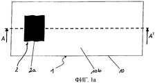
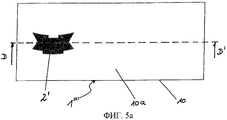
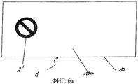
Изобретение относится к защищенному документу, содержащему просвечивающую несущую подложку, в частности, из бумаги и/или пластмассы и, по меньшей мере, один нанесенный на несущую подложку или заделанный в несущую подложку защитный элемент, который при рассматривании, по меньшей мере, с первой стороны защищенного документа в проходящем свете показывает, по меньшей мере, одно первое изображение и имитирует наличие, по меньшей мере, одного первого водяного знака в несущей подложке, при этом защищенный документ, по меньшей мере, в некоторых зонах имеет, по меньшей мере, один имитирующий, по меньшей мере, один первый водяной знак слой, который локально изменяет визуально воспринимаемую просвечиваемость несущей подложки.The invention relates to a security document comprising a translucent carrier substrate, in particular of paper and / or plastic, and at least one security element deposited on the carrier substrate or embedded in the carrier substrate, which, when viewed from at least the first side a transmitted document in transmitted light shows at least one first image and simulates the presence of at least one first watermark in the carrier substrate, while the protected document, at least in some nach has at least one layer simulating at least one first watermark that locally changes the visually perceived translucency of the carrier substrate.
Такие защищенные документы известны из WO 99/13157 А1. Здесь в качестве защитного элемента на ценную бумагу наносится защитная пленка или же заделывается в нее. Защитная пленка состоит из просвечивающей пленки и нанесенного на нее металлического покрытия, которое имеет не содержащие металл зоны, которые четко распознаются, в частности, в проходящем свете. Металлическое покрытие разделено на отдельные растровые точки, которые создают полутоновое изображение. Если защитная пленка заделана между двумя слоями защитной бумаги, то с помощью металлического покрытия имитируется наличие водяного знака в защитной бумаге, который можно четко распознавать в проходящем свете.Such security documents are known from WO 99/13157 A1. Here, as a protective element, a protective film is applied to the security paper or is embedded in it. The protective film consists of a transmission film and a metal coating deposited on it, which has metal-free zones that are clearly recognizable, in particular in transmitted light. The metal coating is divided into individual raster dots that create a grayscale image. If the protective film is embedded between two layers of protective paper, then using a metal coating, the presence of a watermark in the protective paper is simulated, which can be clearly recognized in transmitted light.
Обычный водяной знак создается в бумаге за счет того, что толщина бумаги при ее изготовлении локально изменяется, так что в бумаге возникают различия в пропускании света. В проходящем свете наблюдатель с обеих сторон бумаги видит непрерывное серое изображение, так называемый водяной знак.A common watermark is created in the paper due to the fact that the thickness of the paper during its manufacture locally changes, so that differences in light transmission occur in the paper. In transmitted light, the observer on both sides of the paper sees a continuous gray image, the so-called watermark.
Имитация водяного знака с помощью защитного элемента имеет то преимущество, что можно отказаться от сложного процесса изготовления, который необходим для создания обычного водяного знака на бумажных подложках. Кроме того, с помощью имитируемого водяного знака можно снабжать простым образом также просвечивающую пластмассовую подложку эффектом водяного знака. Необходимо лишь заделывать или наносить создаваемый независимо от просвечивающей несущей подложки защищенного документа защитный элемент в или на просвечивающую несущую подложку, выполненную из бумаги, пластмассы или же Teslin®, или, соответственно, ламинатов из этих материалов. При этом в зависимости от выполнения защитного элемента можно имитировать различные водяные знаки в одной и той же несущей подложке.Simulating a watermark with a security element has the advantage that you can abandon the complex manufacturing process that is necessary to create a conventional watermark on paper substrates. In addition, with the aid of a simulated watermark, the translucent plastic substrate can also be provided with a watermark effect in a simple manner. It is only necessary to close up or apply a security element created independently of the translucent bearing substrate of the security document into or onto the translucent bearing substrate made of paper, plastic or Teslin®, or, respectively, laminates from these materials. Moreover, depending on the implementation of the protective element, you can simulate different watermarks in the same carrier substrate.
Однако было установлено, что имитация водяного знака с помощью раздельных защитных элементов на защищенном документе может также выполняться фальсификатором с приемлемыми затратами. Для этого, например, между слоями бумаги располагают напечатанный текст или вклеивают маскировочный слой для имитации желаемого серого изображения.However, it has been found that simulating a watermark using separate security features on a security document can also be done with a falsifier at an affordable cost. For this, for example, printed text is placed between the paper layers or a mask layer is pasted to simulate the desired gray image.
Поэтому задачей изобретения является создание защищенного документа, который имеет особенно труднодоступный подражанию, имитируемый с помощью защитного элемента эффект водяного знака.Therefore, the object of the invention is the creation of a security document that has a particularly difficult to follow imitation, simulated using a protective element, the effect of the watermark.
Задача решена для защищенного документа, содержащего просвечивающую несущую подложку и, по меньшей мере, один нанесенный на несущую подложку или заделанный в несущую подложку защитный элемент, который при рассматривании, по меньшей мере, с первой стороны защищенного документа в проходящем свете показывает, по меньшей мере, одно первое изображение и имитирует наличие, по меньшей мере, одного первого водяного знака в несущей подложке, при этом защищенный документ, по меньшей мере, в некоторых зонах имеет, по меньшей мере, один имитирующий, по меньшей мере, один первый водяной знак слой, тем, что, по меньшей мере, один нанесенный на несущую подложку или заделанный в несущую подложку защитный элемент обеспечивает возможность визуального распознаванияThe problem is solved for a security document containing a translucent carrier substrate and at least one security element deposited on the carrier substrate or embedded in the carrier substrate, which, when viewed from at least the first side of the security document, shows at least transmitted light , one first image and simulates the presence of at least one first watermark in the carrier substrate, while the protected document, in at least some areas, has at least one simulating, at least one first watermark layer, in that the at least one applied to the carrier substrate or embedded into the carrier substrate the security element provides a possibility of visual recognition
а) в падающем свете отличного от первого изображения второго изображения и/илиa) in incident light different from the first image of the second image and / or
b) в проходящем свете при рассматривании с противоположной первой стороне второй стороны отличного от первого изображения третьего изображения, и/илиb) in transmitted light when viewed from the opposite first side of the second side other than the first image of the third image, and / or
с) в проходящем свете при рассматривании с противоположной первой стороне второй стороны в зависимости от угла рассматривания, по меньшей мере, одного отличного от первого изображения четвертого изображения.c) in transmitted light when viewed from the opposite first side of the second side, depending on the viewing angle of at least one fourth image different from the first image.
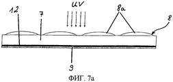
При этом в качестве освещения обычно предусматривается дневной свет или искусственное освещение. Однако эти и другие оптические эффекты можно видеть также при дополнительном ультрафиолетовом или инфракрасном облучении, если, по меньшей мере, один имитирующий первый водяной знак слой содержит одно или несколько веществ (таких как, например, люминесцентные, термохромные, фотохромные вещества или т.п.), которые можно возбуждать с помощью такого облучения.In this case, daylight or artificial lighting is usually provided as lighting. However, these and other optical effects can also be seen with additional ultraviolet or infrared radiation, if at least one layer simulating the first watermark contains one or more substances (such as, for example, luminescent, thermochromic, photochromic substances, etc. ), which can be excited by such irradiation.
Выполнение защищенного документа в соответствии с изобретением придает ему наряду с эффектом водяного знака дополнительные интересные и неожиданные эффекты в непосредственной связи с имитируемым водяным знаком.The execution of a security document in accordance with the invention gives it, along with the watermark effect, additional interesting and unexpected effects in direct connection with a simulated watermark.
При обычных заделанных в несущую подложку, имитирующих водяной знак защитных элементах наблюдатель видит в проходящем свете с каждой стороны защищенного документа одинаковое изображение водяного знака, при асимметричных мотивах лишь в зеркальном виде. Если защитный элемент нанесен на одну сторону несущей подложки, то наблюдатель обычно видит непосредственно тот слой или те слои, которые в проходящем свете влияют на пропускание света несущей подложкой. При этом наблюдатель ожидает, что, по меньшей мере, форма непрозрачных слоев соответствует тому, что он воспринимает с другой стороны как водяной знак, возможно в зеркальном виде. Однако при рассматривании защищенного документа, согласно изобретению, наблюдатель получает неожиданное оптическое впечатление, поскольку привычные эффекты водяного знака в этом виде не проявляются или проявляются лишь частично.With the usual security elements imitating a watermark that imitate a watermark, the observer sees in transmitted light from each side of the protected document the same image of a watermark, with asymmetric motives only in a mirror form. If the protective element is applied on one side of the carrier substrate, then the observer usually sees directly that layer or those layers that in transmitted light affect the transmission of light by the carrier substrate. At the same time, the observer expects that at least the shape of the opaque layers corresponds to what he perceives on the other hand as a watermark, possibly in a mirror form. However, when viewing a security document according to the invention, the observer receives an unexpected optical impression, since the usual effects of the watermark in this form do not appear or only partially appear.
Если защищенный документ рассматривается в проходящем свете, то имеется в виду наблюдение человеческим глазом при нормальных условиях, при этом свет падает на защищенный документ с задней стороны, т.е. противоположной наблюдателю стороны защищенного документа.If a security document is viewed in transmitted light, it means observing by the human eye under normal conditions, and light is incident on the security document from the back side, i.e. opposite to the observer side of the security document.
Предпочтительно, когда в случае а) имитирующий, по меньшей мере, один первый водяной знак слой имеет зоны с различным пропусканием света.Preferably, in case a), the layer simulating at least one first watermark has zones with different light transmission.
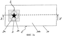
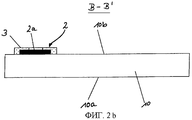
При этом предпочтительно, когда в случае а) защитный элемент расположен на второй стороне защищенного документа или же так заделан в просвечивающую несущую подложку, что защитный элемент находится в плоскости, параллельной первой стороне и второй стороне, и зона несущей подложки, которая находится на второй стороне между имитирующим, по меньшей мере, один водяной знак слоем и наблюдателем, выполнена, по меньшей мере, с частичной выемкой, при этом видимые со второй стороны зоны имитирующего первый водяной знак слоя в падающем свете воспринимаются визуально как сплошные, непрозрачные зоны, однако, по меньшей мере, видимые зоны имитирующего первый водяной знак слоя имеют в проходящем свете различное пропускание света. Таким образом, наблюдатель распознает в защищенном документе в случае а) как обычно при рассматривании первой стороны в проходящем свете первый водяной знак. На второй стороне наблюдатель видит в падающем свете нанесенный на несущую подложку защитный элемент и, по меньшей мере, один имитирующий первый водяной знак слой, форма которого, однако, против ожидания не совпадает с формой первого водяного знака. Однако в проходящем свете также со второй стороны снова виден первый водяной знак, возможно в зеркальном виде. Этот эффект достигается тем, что, по меньшей мере, один имитирующий, по меньшей мере, один первый водяной знак слой выполнен с зонами различного пропускания света, которые можно визуально различать друг от друга в проходящем свете.In this case, it is preferable that in case a) the security element is located on the second side of the security document or is so embedded in the translucent carrier substrate that the security element is in a plane parallel to the first side and the second side and the region of the carrier substrate which is on the second side between the layer simulating at least one watermark and the observer, is made at least partially recessed, while visible from the second side of the zone simulating the first watermark layer in incident light is perceived mayutsya visually as a solid, opaque areas, however, at least the visible area simulating the first watermark layers are different in transmitted light transmittance of light. Thus, the observer recognizes in the security document in case a), as usual, when examining the first side in transmitted light, the first watermark. On the second side, the observer sees in incident light a protective element applied to the supporting substrate and at least one layer simulating the first watermark, the shape of which, however, does not coincide with the shape of the first watermark against expectation. However, in transmitted light also from the second side the first watermark is again visible, possibly in a mirror form. This effect is achieved in that at least one layer simulating at least one first watermark is made with zones of different transmission of light, which can be visually distinguished from each other in transmitted light.
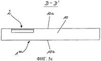
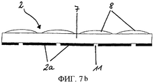
При бумажной или пластмассовой (полимерной) несущей подложке последний случай, в котором защитный элемент находится в плоскости, параллельной первой стороне и второй стороне защищенного документа, и зона несущей подложки, которая находится на второй стороне между, по меньшей мере, одним непрозрачным слоем и наблюдателем, выполнена с выемкой, можно реализовать тем, что несущая подложка выполнена, по меньшей мере, из двух слоев, и, по меньшей мере, один защитный элемент расположен между этими слоями. Перед соединением слоев один из них снабжается оконным отверстием, и оконное отверстие позиционировано над защитным элементом так, что в падающем свете виден, по меньшей мере, один непрозрачный слой.With a paper or plastic (polymer) carrier substrate, the latter case, in which the security element is in a plane parallel to the first side and the second side of the security document, and the area of the carrier substrate, which is on the second side between at least one opaque layer and the observer is made with a recess, it can be realized in that the carrier substrate is made of at least two layers, and at least one protective element is located between these layers. Before joining the layers, one of them is provided with a window hole, and the window hole is positioned above the protective element so that at least one opaque layer is visible in incident light.
При этом под оконным отверстием понимается, так же как в остальном тексте, не только отверстие, но также прозрачная, или, соответственно, просвечивающая зона, например, из прозрачной как стекло пластмассы.In this case, a window opening is understood, as in the rest of the text, not only the hole, but also a transparent, or, respectively, translucent zone, for example, of a plastic transparent as glass.
В качестве альтернативного решения, оконное отверстие может быть выполнено также в обоих слоях, и, по меньшей мере, один защитный элемент совмещен с обоими оконными отверстиями. Затем защитный элемент покрывается на первой стороне, по меньшей мере, одним просвечивающим цветным слоем, так что имитирующий, по меньшей мере, один водяной знак слой можно распознавать лишь со второй стороны.As an alternative solution, the window opening can also be made in both layers, and at least one security element is aligned with both window openings. The security element is then coated on the first side with at least one translucent color layer, so that the layer simulating at least one watermark can be recognized only on the second side.
В общем случае, по меньшей мере, один просвечивающий цветной слой может быть, однако, уже составляющей частью защищенного документа, так что отпадает необходимость его нанесения после заделывания защитного элемента в несущую подложку. Кроме того, просвечивающий цветной слой может быть образован просвечивающим слоем клея, который применяется при заделывании защитного элемента между слоями несущей подложки для склеивания с одним слоем. Для оптического сокрытия наличия оконных отверстий может быть предпочтительным интегрирование просвечивающих цветных слоев в защитный элемент в комбинации с дополнительным нанесением просвечивающих цветных слоев после заделывания защитного элемента или применение просвечивающих слоев клея для заделывания.In the general case, at least one translucent color layer may, however, already be an integral part of the security document, so that there is no need to apply it after embedding the security element in the carrier substrate. In addition, a translucent color layer can be formed by a translucent adhesive layer, which is used to seal the protective element between the layers of the carrier substrate for bonding with one layer. To optically obscure the presence of window openings, it may be preferable to integrate the translucent color layers in the security element in combination with the additional application of the translucent color layers after sealing the protective element or to use translucent adhesive layers for sealing.
Кроме того, предпочтительно, когда в случае а), по меньшей мере, один имитирующий водяной знак слой при рассматривании в падающем свете виден имеющим другую величину поверхности, чем распознается в проходящем свете.In addition, it is preferable when in case a), at least one watermarking layer when viewed in incident light is seen to have a different surface value than is recognized in transmitted light.
Кроме того, предпочтительно, когда в случае а) имитирующий первый водяной знак слой нанесен на второй стороне защищенного документа и покрыт в некоторых зонах, по меньшей мере, одним, расположенным на второй стороне просвечивающим цветным слоем, или же заделан в просвечивающую несущую подложку так, что защитный элемент находится в плоскости, параллельной первой стороне и второй стороне, и зона несущей подложки, которая находится на второй стороне между, по меньшей мере, одним имитирующим первый водяной знак слоем и наблюдателем, выполнена либо с частичной выемкой или полной выемкой и покрыта в некоторых зонах, по меньшей мере, одним расположенным на второй стороне просвечивающим цветным слоем, при этом видимые со второй стороны зоны имитирующего первый водяной знак слоя визуально распознаются, как сформированные в некоторых зонах непрозрачные зоны слоя, которые показывают защитную информацию, и в проходящем свете со второй стороны показывают, по меньшей мере, один водяной знак, который отличается от защитной информации.In addition, it is preferable when in case a) a layer imitating the first watermark is applied to the second side of the security document and coated in some areas with at least one translucent color layer located on the second side, or embedded in a translucent carrier substrate so that the protective element is in a plane parallel to the first side and the second side, and the area of the carrier substrate, which is on the second side between at least one layer simulating the first watermark and the observer, is made either with a partial recess or a full recess and covered in some zones with at least one translucent color layer located on the second side, while the visible from the second side zones of the layer simulating the first watermark are visually recognized as opaque zones of the layer formed in some zones, which show the security information, and in transmitted light from the second side show at least one watermark that is different from the security information.
Наблюдатель распознает в защищенном документе, согласно случаю а) так же, как привычно при рассматривании первой стороны в проходящем свете, первый водяной знак. На второй стороне наблюдатель видит в падающем свете нанесенный на несущую подложку защитный элемент или, соответственно, сформированные в некоторых зонах непрозрачные зоны имитирующего первый водяной знак слоя, которые показывают защитную информацию, форма которой, однако, против ожидания не совпадает с формой первого водяного знака. В проходящем свете снова распознается водяной знак, но возможно в зеркальном виде. Этот эффект достигается, с одной стороны, тем, что, не распознаваемым наблюдателем в падающем свете образом, расположены непосредственно видимым образом лишь части полностью или в некоторых зонах сформированного, имитирующего первый водяной знак слоя. При этом имитирующий первый водяной знак слой может быть снабжен зонами различного пропускания света, которые отличимы друг от друга лишь в проходящем свете. С другой стороны, эффект можно достигать тем, что, по меньшей мере, один непрозрачный в падающем свете слой, видимый без труда для глаза человека, выполнен лишь в некоторых зонах и полностью виден и дополнительно имеет зоны различного пропускания света, которые можно визуально отличать друг от друга лишь в проходящем свете.The observer recognizes in a protected document, according to case a), as is usual when viewing the first side in transmitted light, the first watermark. On the second side, the observer sees in incident light a protective element applied to the supporting substrate or, accordingly, opaque zones formed in some zones that imitate the first watermark layer, which show protective information, the shape of which, however, does not coincide with the shape of the first watermark. In transmitted light, a watermark is again recognized, but possibly in a mirror form. This effect is achieved, on the one hand, by the fact that, in a way that is not recognized by the observer in the incident light, only parts of the layer are completely or partially located in the directly visible layer that are simulated by the first watermark. Moreover, the layer imitating the first watermark can be equipped with zones of different light transmission, which are distinguishable from each other only in transmitted light. On the other hand, the effect can be achieved in that at least one layer opaque in incident light, visible without difficulty to the human eye, is made only in some areas and is fully visible and additionally has zones of different light transmission, which can visually distinguish each other from a friend only in transmitted light.
При этом наблюдатель воспринимает зону имитирующего первый водяной знак слоя в проходящем свете как непрозрачную, когда пропускание видимого света меньше 5%, в частности меньше 1%. Как просвечивающие наблюдатель воспринимает в проходящем свете зоны с пропусканием видимого света больше 10%, в частности больше 20%. Однако в падающем свете для наблюдателя также воспринимаемые в проходящем свете как просвечивающие зоны могут оставлять впечатление непрозрачной зоны слоя. Если, например, используется металлический слой в качестве имитирующего первый водяной знак слоя, то воспринимаемые в проходящем свете непрозрачными и просвечивающими зоны при рассматривании в падающем свете отражают различно максимально с фактором 10. Различное на фактор 10 отражение хорошо различимо человеческим глазом, в то время как различие в отражении до примерно 20% едва воспринимается.In this case, the observer perceives the area of the layer simulating the first watermark in transmitted light as opaque when the transmittance of visible light is less than 5%, in particular less than 1%. As translucent, the observer perceives in transmitted light zones with a transmission of visible light of more than 10%, in particular more than 20%. However, in incident light for the observer also perceived in transmitted light as translucent zones can leave the impression of an opaque zone of the layer. If, for example, a metal layer is used as a layer imitating the first watermark, then the zones that are perceived in transmitted light as opaque and translucent when viewed in incident light reflect differently as much as possible with
Таким образом, если фактор выбирается, возможно, меньшим и/или характеристики отражения имитирующего первый водяной знак согласованы с фоном, то человеческий глаз не различает различия в падающем свете и воспринимает равномерно непрозрачную поверхность.Thus, if the factor is possibly selected smaller and / or the reflection characteristics of the first watermark simulating the watermark are consistent with the background, then the human eye does not distinguish between differences in incident light and perceives a uniformly opaque surface.
При несущей подложке, например, из бумаги и/или пластмассы можно случай, когда защитный элемент заделан в просвечивающую несущую подложку и находится в плоскости, параллельной первой стороне и второй стороне, при этом зона несущей подложки, которая находится на второй стороне между, по меньшей мере, одним имитирующим первый водяной знак слоем и наблюдателем, выполнена, по меньшей мере, с частичной выемкой, можно реализовать тем, что несущая подложка выполнена, по меньшей мере, из двух слоев, и что, по меньшей мере, один защитный элемент расположен между этими слоями. Перед соединением слоев друг с другом один из них снабжают оконным отверстием, и оконное отверстие позиционируют над защитным элементом так, что, по меньшей мере, один имитирующий первый водяной знак слой виден лишь частично. В качестве альтернативного решения, имитирующий первый водяной знак слой может быть также полностью виден, и его затем в некоторых областях покрывают просвечивающим цветным слоем. Кроме того, в этом случае также возможно, что оконное отверстие выполняют в двух слоях, и, по меньшей мере, один защитный элемент совмещают с обоими оконными отверстиями. Затем защитный элемент на первой стороне частично или полностью покрывают просвечивающим цветным слоем, а на второй стороне покрывают цветным слоем в некоторых зонах, так что имитирующий первый водяной знак слой на второй стороне в падающем свете виден лишь частично. На первой стороне, по меньшей мере, один имитирующий первый водяной знак слой не распознаваем или распознаваем лишь частично. Если, по меньшей мере, один имитирующий первый водяной знак слой распознаваем также лишь частично на первой стороне в падающем свете, то предпочтительно, когда на второй стороне видны в падающем свете различные зоны, по меньшей мере, одного имитирующего первый водяной знак слоя.With a carrier substrate, for example, of paper and / or plastic, it is possible that the protective element is embedded in a translucent carrier substrate and is in a plane parallel to the first side and the second side, while the region of the carrier substrate, which is on the second side between at least at least one layer simulating the first watermark and an observer is made with at least partial recess, it can be realized that the carrier substrate is made of at least two layers, and that at least one protective element is located dix between these layers. Before connecting the layers to each other, one of them is provided with a window opening, and the window opening is positioned above the security element so that at least one layer imitating the first watermark is only partially visible. As an alternative solution, the layer simulating the first watermark can also be completely visible, and then in some areas it is covered with a translucent color layer. In addition, in this case, it is also possible that the window opening is performed in two layers, and at least one security element is combined with both window openings. Then, the protective element on the first side is partially or completely covered with a translucent color layer, and on the second side it is covered with a colored layer in some areas, so that the layer simulating the first watermark on the second side is only partially visible in the incident light. On the first side, at least one layer simulating the first watermark is not recognizable or only partially recognizable. If at least one layer simulating the first watermark is also only partially recognized on the first side in the incident light, it is preferable when different zones of at least one layer simulating the first watermark are visible on the second side in the incident light.
В целом и в данном случае, по меньшей мере, один просвечивающий цветной слой может быть уже составной частью защитного элемента, или же для заделывания применяются просвечивающие слои клея, так что нет необходимости в его нанесении после заделывания защитного элемента в несущую подложку. Относительно оптической маскировки наличия оконных отверстий в несущей подложке может быть предпочтительной интеграция просвечивающих цветных слоев в защитный элемент в комбинации с дополнительным нанесением просвечивающих цветных слоев после заделывания защитного элемента или при применении для заделывания просвечивающих слоев клея.In general, and in this case, at least one translucent color layer may already be an integral part of the protective element, or translucent layers of glue are used for sealing, so that it is not necessary to apply it after the protective element is embedded in the carrier substrate. Regarding the optical masking of the presence of window openings in the carrier substrate, it may be preferable to integrate the translucent color layers into the security element in combination with the additional application of the translucent color layers after sealing the protective element or when applying adhesive translucent layers.
Для случая b) предпочтительно, когда, по меньшей мере, один имитирующий первый водяной знак слой на первой стороне и на противоположной первой стороне второй стороне защищенного документа покрыт, по меньшей мере, частично, по меньшей мере, одним просвечивающим слоем, при этом, по меньшей мере, один просвечивающий слой на первой стороне и, по меньшей мере, один просвечивающий слой на второй стороне рассеивают падающий на вторую сторону свет с различной степенью.For case b), it is preferable that at least one layer simulating the first watermark on the first side and on the opposite first side of the second side of the security document is covered at least partially with at least one translucent layer, wherein at least one translucent layer on the first side and at least one translucent layer on the second side scatter light incident on the second side with varying degrees.
Наконец, предпочтительно, когда в случае b) защитный элемент расположен на второй стороне, и имитирующий водяной знак слой покрыт, по меньшей мере, одним расположенным на второй стороне просвечивающим цветным слоем, или же защитный элемент так заделан в просвечивающую несущую подложку, что защитный элемент находится в плоскости, параллельной первой стороне и второй стороне, но на разном расстоянии от первой стороны и второй стороны, или же защитный элемент заделан в просвечивающую несущую подложку, а имитирующий водяной знак покрыт, по меньшей мере, одним расположенным на первой стороне и/или второй стороне просвечивающим цветным слоем, при этом имитирующий водяной знак слой при рассматривании со второй стороны в проходящем свете показывает, по меньшей мере, одно второе изображение, которое имитирует наличие в несущей подложке, по меньшей мере, одного отличающегося от первого водяного знака второго водяного знака.Finally, it is preferable that in case b) the security element is located on the second side and the watermarking layer is coated with at least one translucent color layer located on the second side, or the security element is embedded in the transmission substrate so that the security element is in a plane parallel to the first side and the second side, but at different distances from the first side and the second side, or the security element is embedded in a translucent carrier substrate, and the imitating watermark is covered, alternately at least one translucent color layer located on the first side and / or second side, while the watermarking layer when viewed from the second side in transmitted light shows at least one second image that simulates the presence of at least at least one different from the first watermark of the second watermark.
Наблюдатель распознает в защищенном документе в случае b) так же, как привычно при рассматривании первой стороны в проходящем свете, первый водяной знак. На второй стороне наблюдатель не видит в падающем свете или видит лишь частично, по меньшей мере, один имитирующий водяной знак слой. Однако в проходящем свете наблюдатель видит на второй стороне отличный от первого водяного знака второй водяной знак. Этот эффект достигается тем, что защищенный документ выполнен так, что между имитирующим первый водяной знак слоем и первой стороной, и между имитирующим первый водяной знак слоем и второй стороной проходящий свет рассеивается с различимой степенью. Это приводит к тому, что, например, филигранные отверстия в имитирующем первый водяной знак слое могут быть видны со второй стороны в проходящем свете, но не видны с первой стороны.The observer recognizes in a protected document in case b), as is usual when viewing the first side in transmitted light, the first watermark. On the second side, the observer does not see in incident light or only partially sees at least one layer imitating a watermark. However, in transmitted light, the observer sees on the second side a second watermark different from the first watermark. This effect is achieved in that the security document is designed so that between the layer simulating the first watermark and the first side, and between the layer simulating the first watermark and the second side, the transmitted light is scattered with a distinct degree. This leads to the fact that, for example, filigree holes in the layer simulating the first watermark can be visible from the second side in transmitted light, but not visible from the first side.
Для случая b) предпочтительно, когда несущая подложка образована, по меньшей мере, из двух слоев различного материала. Заделывание защитного элемента и расположение, а также выполнение просвечивающих слоев может осуществляться аналогично уже указанному выше случаю а).For case b), it is preferable when the carrier substrate is formed of at least two layers of different material. The closure of the protective element and the location, as well as the implementation of the translucent layers can be carried out similarly to the above case a).
Фальсификация защищенного документа, согласно изобретению, в соответствии со случаем а) и/или b) лишь трудно возможна, поскольку необходимо осуществлять точное и зависящее от материала, по меньшей мере, одного имитирующего первый водяной знак слоя выполнение различных толщин слоя и/или отверстий, или прозрачных зон, по меньшей мере, на одном имитирующем первый водяной знак слое, или же точно устанавливать характеристики рассеяния слоев с согласованием с выполнением имитирующего первый водяной знак слоя.The falsification of a security document according to the invention in accordance with case a) and / or b) is only difficult, since it is necessary to carry out accurate and depending on the material of at least one layer simulating the first watermark layer various thicknesses of the layer and / or holes, or transparent zones on at least one layer simulating the first watermark, or precisely set the dispersion characteristics of the layers in accordance with the implementation of the layer simulating the first watermark.
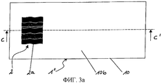
Для случая с) предпочтительно, когда, по меньшей мере, один имитирующий первый водяной знак слой имеет зоны с зависящим от угла рассматривания пропусканием света.For case c), it is preferable that at least one layer simulating the first watermark has zones with light transmission depending on the viewing angle.
Кроме того, предпочтительно, когда в случае с), по меньшей мере, один первый водяной знак в проходящем свете при наклоне защищенного документа, по меньшей мере, на одной стороне защищенного документа показывает кинематический эффект и/или трехмерный эффект и/или эффект изменения цвета.In addition, it is preferable when in case c) at least one first watermark in transmitted light when the security document is tilted at least on one side of the security document shows a kinematic effect and / or a three-dimensional effect and / or a color change effect .
Наблюдатель распознает в защищенном документе, согласно случаю с), так же, как привычно при рассматривании первой стороны в проходящем свете, первый водяной знак. На второй стороне наблюдатель также видит водяной знак. Однако при наклоне защищенного документа возникает, по меньшей мере, на одной стороне защищенного документа кинематический эффект и/или трехмерный эффект, и/или эффект изменения цвета. Первый водяной знак с кинематическим эффектом кажется наблюдателю движущимся, например, как если бы показываемый человек выполнял движение. Первый водяной знак с трехмерным эффектом кажется наблюдателю выполненным объемно в несущей подложке. Первый водяной знак с эффектом изменения цвета показывает наблюдателю различный цвет или цвета при различных углах рассматривания. Эти эффекты, которые можно комбинировать друг с другом, достигаются, по существу, тем, что защитный элемент выполнен с зависящим от угла локальным пропусканием света, которое обуславливается, по существу, выполнением, по меньшей мере, одного имитирующего первый водяной знак слоя, возможно дополнительно наличием дифракционных структур и выдерживающих расстояния слоев в защитном элементе.The observer recognizes in a protected document, according to case c), as is usual when viewing the first side in transmitted light, the first watermark. On the second side, the observer also sees a watermark. However, when the security document is tilted, a kinematic effect and / or a three-dimensional effect and / or a color change effect occurs on at least one side of the security document. The first watermark with a kinematic effect seems moving to the observer, for example, as if the person being shown was performing a movement. The first watermark with a three-dimensional effect seems to the observer to be performed three-dimensionally in the carrier substrate. The first watermark with the color change effect shows the observer a different color or colors at different viewing angles. These effects, which can be combined with each other, are achieved essentially by the fact that the protective element is made with an angle-dependent local transmission of light, which is caused, in essence, by the implementation of at least one layer simulating the first watermark, possibly additionally the presence of diffraction structures and distance-resistant layers in the protective element.
Заделывание защитного элемента и расположение, а также выполнение просвечивающих слоев в этом случае можно также выполнять аналогично указанному выше случаю а).The closure of the protective element and the location, as well as the implementation of the translucent layers in this case can also be performed similarly to the above case a).
Особенно предпочтительной является комбинация случаев а)-с), в которой защищенный документ или же защитный элемент имеет, по меньшей мере, одну зону, которая выполнена в соответствии со случаем а)-с), и дополнительно имеет, по меньшей мере, одну вторую зону, которая выполнена в соответствии, по меньшей мере, с одним случаем а)-с), отличным от случая, соответствующего первой зоне. Таким образом, можно особенно эффективным образом комбинировать достигаемые эффекты. При этом различные эффекты могут иметься в одном единственном защищенном элементе или же могут быть распределены в нескольких защитных элементах.Particularly preferred is a combination of cases a) -c), in which the security document or security element has at least one zone, which is made in accordance with case a) -c), and further has at least one second a zone that is made in accordance with at least one case a) to c) different from the case corresponding to the first zone. Thus, the effects achieved can be combined in a particularly effective manner. In this case, various effects can be present in one single protected element or can be distributed in several protective elements.
При этом несколько одинаково и/или различно выполненных защитных элементов можно использовать на одном защищенном документе. Так, например, по меньшей мере, один первый защитный элемент может быть расположен на второй стороне, а второй защитный элемент может быть заделан в несущую подложку. Кроме того, на обеих сторонах защищенного документа могут быть расположены защитные элементы, которые при рассматривании на другой соответствующей противоположной стороне в проходящем свете имитируют наличие водяного знака.In this case, several equally and / or differently made security elements can be used on one security document. So, for example, at least one first security element may be located on the second side, and the second security element may be embedded in the carrier substrate. In addition, security elements may be located on both sides of the security document, which when viewed on the other opposite side in transmitted light imitate the presence of a watermark.
Возможно также, по меньшей мере, частично перекрывающее друг друга расположение, по меньшей мере, защитных элементов, при рассматривании перпендикулярно плоскости защищенного документа.It is also possible at least partially overlapping the location of at least the security elements when viewed perpendicular to the plane of the security document.
Если применяется, по меньшей мере, один просвечивающий цветной слой, то предпочтительно, когда он по цвету не отличается или отличается лишь незаметно от возможно покрытых краской приграничных зон несущей подложки. За счет этого наличие защитного элемента в этих зонах становится оптически скрытым или, соответственно, не распознаваемым для наблюдателя.If at least one translucent color layer is used, then it is preferable when it does not differ in color or differs only imperceptibly from the border zones of the carrier substrate possibly covered with paint. Due to this, the presence of the protective element in these areas becomes optically hidden or, accordingly, not recognizable to the observer.
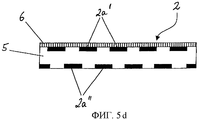
Предпочтительно, когда, по меньшей мере, один имитирующий первый водяной знак слой имеет прозрачные зоны и/или отверстия, размеры которых, по меньшей мере, в одном направлении лежат ниже предела разрешения человеческого глаза, т.е. составляют меньше примерно 0,3 мм. Особенно предпочтительными являются отверстия, размеры которых, по меньшей мере, в одном направлении лежат в диапазоне от 1 до 250 мкм, в частности, в диапазоне от 2 до 100 мкм и, в частности, в диапазоне от 5 до 80 мкм. Такие прозрачные зоны или отверстия не видны для человеческого глаза в падающем свете, но различимы в проходящем свете на основании повышенного пропускания света.Preferably, at least one layer simulating the first watermark has transparent zones and / or holes whose dimensions in at least one direction lie below the resolution limit of the human eye, i.e. are less than about 0.3 mm. Particularly preferred are openings whose dimensions in at least one direction are in the range of 1 to 250 microns, in particular in the range of 2 to 100 microns and, in particular, in the range of 5 to 80 microns. Such transparent zones or openings are not visible to the human eye in incident light, but are distinguishable in transmitted light based on increased light transmission.
Кроме того, предпочтительно, когда, по меньшей мере, один имитирующий первый водяной знак слой имеет прозрачные зоны и/или отверстия, при этом средняя поверхностная плотность прозрачных зон или отверстий в непрозрачном слое составляет менее 10%. Такие прозрачные зоны или отверстия являются в падающем свете для человеческого глаза, по существу, также невидимыми, однако легко распознаются в проходящем свете на основании повышенного пропускания света.In addition, it is preferable when at least one simulating the first watermark layer has transparent zones and / or holes, while the average surface density of the transparent zones or holes in the opaque layer is less than 10%. Such transparent zones or holes are in the incident light to the human eye, essentially also invisible, but are easily recognized in transmitted light on the basis of increased light transmission.
Кроме того, предпочтительно, когда, по меньшей мере, один имитирующий первый водяной знак слой имеет зоны с различной толщиной слоя. Зоны с различной толщиной слоя могут казаться для человеческого глаза в падающем свете непрозрачными, однако зоны с меньшей толщиной слоя легко отличаются в проходящем свете на основании повышенного пропускания света от зон с большей толщиной слоя.In addition, it is preferable when at least one layer simulating the first watermark has zones with different layer thicknesses. Zones with different layer thicknesses may appear opaque to the human eye in incident light, however, zones with a lower layer thickness can easily be distinguished in transmitted light due to increased light transmission from zones with a larger layer thickness.
В прозрачных зонах, которые воспринимаются одинаково со сквозными отверстиями, по меньшей мере, в одном имитирующем первый водяной знак слое материал, применяемый для образования, по меньшей мере, одного имитирующего первый водяной знак слоя, может иметь настолько небольшую толщину слоя, что он не оказывает существенного или, соответственно, распознаваемого влияния на свойства пропускания света защищенного документа.In transparent zones that are perceived identically with through holes in at least one layer simulating a first watermark, the material used to form at least one layer simulating a first watermark can have such a small thickness that it does not have a significant or, accordingly, recognizable effect on the light transmission properties of a protected document.
Структурирование, по меньшей мере, одного имитирующего первый водяной знак слоя или, соответственно, образование отверстий или прозрачных зон можно при этом реализовывать с помощью способа, согласно DE 102004042136 А1. При этом толщину слоя регулируют так, что материал для образования слоя равномерно наносят на снабженную дифракционными поверхностными структурами поверхность, при этом в зависимости от соотношения глубины к ширине поверхностных структур образуется локально различная эффективная толщина слоя.The structuring of at least one layer simulating the first watermark or, correspondingly, the formation of holes or transparent zones can be achieved using the method according to DE 102004042136 A1. In this case, the thickness of the layer is controlled so that the material for forming the layer is uniformly applied to the surface provided with diffractive surface structures, and a locally different effective layer thickness is formed depending on the ratio of depth to width of the surface structures.
По меньшей мере, один имитирующий первый водяной знак слой может иметь в кажущихся в падающем свете непрозрачными зонах, по меньшей мере, в некоторых зонах постоянно изменяющуюся толщину слоя. В качестве альтернативного решения или в комбинации с этим, по меньшей мере, один имитирующий первый водяной знак слой может иметь в кажущихся в падающем свете непрозрачными зонах ступенчато изменяющуюся толщину слоя. Образование различной толщины слоя создает при рассматривании в проходящем свете различное пропускание света или, соответственно, оптическую плотность и может быть также реализовано с помощью способа, согласно DE 102004042136 А1.At least one layer simulating a first watermark can have opaque zones that appear in incident light, at least in some zones, a constantly changing layer thickness. As an alternative solution or in combination with this, at least one layer simulating the first watermark may have stepwise varying layer thickness in seemingly opaque zones. The formation of different layer thicknesses when viewed in transmitted light creates different light transmission or, accordingly, optical density and can also be realized using the method according to DE 102004042136 A1.
Кроме того, предпочтительно, когда, по меньшей мере, один имитирующий первый водяной знак слой имеет отверстия так, что этот слой структурирован в виде тонкого точечного или линейного растра с шириной растра меньше 300 мкм. При этом особенно предпочтительно, когда слой структурирован в виде апериодического точечного или линейного растра.In addition, it is preferable when at least one layer simulating the first watermark has openings so that this layer is structured as a thin point or linear raster with a raster width of less than 300 μm. It is particularly preferred when the layer is structured as an aperiodic dot or linear raster.
При этом под понятием «точка» понимаются не только круглые точки изображения, но также точки другой геометрической формы, такие как треугольные, прямоугольные, эллиптические и т.д. точки изображения. Возможны также точки изображения в виде символов, картинных изображений, буквенно-цифровых знаков или последовательностей знаков. При этом точки или линии расположены либо с равномерным растровым расстоянием, либо с локально или постоянно изменяющимся растровым расстоянием. В качестве альтернативного решения или в комбинации с этим может изменяться величина поверхности точек или линий.Moreover, the term “point” refers not only to circular points of the image, but also points of a different geometric shape, such as triangular, rectangular, elliptical, etc. image points. Image points in the form of characters, picture images, alphanumeric characters or character sequences are also possible. In this case, points or lines are located either with a uniform raster distance, or with a locally or constantly changing raster distance. Alternatively, or in combination with this, the magnitude of the surface of points or lines may change.
Предпочтительно, когда образующие точечный или линейный растр зоны, по меньшей мере, одного имитирующего первый водяной знак слоя, по меньшей мере, в некоторых зонах выполнены субструктурированно. При этом под субструктурированием понимается, например, фазовый сдвиг частичного количества точек изображения или линий относительно остального растра. Другие возможности для субструктурирования состоят в локальном изменении кривизны линий, локальном изменении ориентации точек изображения или линий, локальном изменении расстояний между точками или линиями, локальном изменении формы точек изображения или линий, выполнении в виде различных знаков или элементов изображения и т.д. Так, например, может быть субструктурирована одна единственная линия за счет того, что линия состоит из последовательности букв, которая, по меньшей мере, на некоторых участках имеет определенное, поддающееся считыванию информационное содержание. Такие субструктурирования можно считывать лишь с помощью вспомогательных средств, например с помощью лупы или посредством наложения другого точечного или линейного растра в виде экрана верификации.Preferably, when forming a dotted or linear raster zone of at least one layer simulating the first watermark layer, at least in some areas are made substructured. Moreover, substructuring is understood, for example, as a phase shift of a partial number of image points or lines relative to the rest of the raster. Other possibilities for substructuring include local change in the curvature of lines, local change in the orientation of image points or lines, local change in the distance between points or lines, local change in the shape of image points or lines, execution in the form of various characters or image elements, etc. So, for example, one single line can be substructured due to the fact that the line consists of a sequence of letters, which, at least in some areas, has a specific, readable information content. Such substructures can only be read using auxiliary means, for example, using a magnifying glass or by superimposing another point or linear raster in the form of a verification screen.
Особенно предпочтительно, когда защитный элемент имеет, по меньшей мере, два, по меньшей мере, в некоторых зонах расположенных с наложением друг на друга, имитирующих, по меньшей мере, один первый водяной знак слоя. При этом, по меньшей мере, между двумя имитирующими, по меньшей мере, один первый водяной знак слоями предпочтительно расположен, по меньшей мере, один прозрачный удерживающий расстояние слой.Particularly preferably, when the protective element has at least two, at least in some areas located overlapping each other, simulating at least one first watermark of the layer. In this case, at least between the two layers imitating at least one first watermark and preferably at least one transparent distance-retaining layer is arranged.
При этом первый и второй слой имеют предпочтительно несколько различающихся своими свойствами пропускания и отражения света частичных зон. Эти различные частичные зоны расположены в соответствующем слое предпочтительно в соответствии с регулярным, периодическим растром. При этом растровые расстояния лежат предпочтительно ниже возможности разрешения человеческого глаза. При этом в зависимости от угла рассматривания различные частичные зоны первого и второго слоя в лучах проходящего или, соответственно, отраженного света накладываются друг на друга, так что в зависимости от угла рассматривания для наблюдателя создается другое оптическое впечатление в падающем свете и в проходящем свете.In this case, the first and second layer preferably have partial zones differing in their transmission and reflection properties. These various partial zones are located in the corresponding layer, preferably in accordance with a regular, periodic raster. In this case, the raster distances are preferably lower than the resolution of the human eye. In this case, depending on the viewing angle, various partial zones of the first and second layer in the rays of transmitted or, accordingly, reflected light are superimposed on each other, so that depending on the viewing angle a different optical impression is created for the observer in the incident light and in the transmitted light.
Кроме того, в данном случае возможно, что первый и второй слои имеют в частичных зонах также дифракционные структуры, которые действуют при пропускании или отражении света. За счет этого можно дополнительно создавать зависящее от угла рассматривания, оптически изменяющееся впечатление.In addition, in this case, it is possible that the first and second layers also have diffraction structures in partial zones that act when light is transmitted or reflected. Due to this, it is possible to additionally create an optically variable impression depending on the viewing angle.
При наклоне защищенного документа, в зоне наложения друг на друга, по меньшей мере, двух имитирующих, по меньшей мере, один первый водяной знак слоев распознается в проходящем свете зависящее от угла наклона различное пропускание света и/или цвет. Это является предпочтительным вариантом выполнения, в частности, для случая с).When the security document is tilted, in the overlapping zone of at least two imitating at least one first watermark of the layers, the transmitted light and / or color, depending on the tilt angle, are recognized in transmitted light. This is a preferred embodiment, in particular for case c).
Если предусмотрены три или более, расположенных на расстоянии друг от друга с помощью удерживающих расстояние слоев, имитирующих, по меньшей мере, один первый водяной знак слоев, то можно дополнительно с помощью различной толщины прозрачного удерживающего расстояние слоя улучшать угловое разрешение зависящего от угла рассматривания эффекта.If three or more spacers are provided spaced apart by means of distance-retaining layers imitating at least one first watermark of the layers, then it is possible to further improve the angular resolution of the effect depending on the viewing angle using different thicknesses of the transparent distance-holding layer.
Предпочтительно, когда на защищенном документе имеются, по меньшей мере, два имитирующих, по меньшей мере, один первый водяной знак слоя, которые структурированы каждый в виде микроскопически тонкого точечного или линейного растра, которые при наложении друг на друга создают, в частности, периодический муаровый узор.Preferably, the security document contains at least two layers imitating at least one first watermark, each of which is structured as a microscopically thin dot or linear raster, which when applied to each other create, in particular, a periodic moire pattern pattern.
Предпочтительно, когда защитный элемент имеет оптически изменяемый эффект, который можно видеть при рассматривании в падающем свете.Preferably, the security element has an optically variable effect that can be seen when viewed in incident light.
При этом защитный элемент имеет, в частности, оптически изменяемый материал, в частности, оптически изменяемый пигмент, жидкокристаллический материал, люминесцентный материал или термохромный материал, и/или дифракционную или рефракционную структуру, в частности, голограмму, кинеграмму (Kinegram®), стохастическую матовую структуру, асимметричную матовую структуру, макроструктуру, поглощающую свет структуру или микролинзовую структуру.The security element has, in particular, an optically variable material, in particular an optically variable pigment, a liquid crystal material, a luminescent material or a thermochromic material, and / or a diffractive or refractive structure, in particular, a hologram, cinegram (Kinegram ® ), stochastic matte structure, asymmetric matte structure, macrostructure, light absorbing structure, or microlens structure.
Предпочтительно, когда защитный элемент имеет, по меньшей мере, один граничащий, по меньшей мере, с одним имитирующим, по меньшей мере, один первый водяной знак слоем прозрачный слой, в котором сформирована, в частности, дифракционная структура. Прозрачный слой предпочтительно выполнен в виде слоя лака, в частности в виде слоя термопластичного или затвердевающего под действием ультрафиолетового излучения лака. При этом прозрачный слой может быть выполнен также без дифракционной структуры и служить в качестве защитного слоя для имитирующего, по меньшей мере, один первый водяной знак слоя с целью покрывания, по меньшей мере, в некоторых зонах расположенного на защищенном документе видимого, имитирующего, по меньшей мере, один первый водяной знак слоя и минимизации механической нагрузки этого слоя. Кроме того, прозрачный слой может служить в качестве удерживающего расстояние слоя между имитирующими, по меньшей мере, один первый водяной знак слоями, или же придавать этому слою или водяному знаку в проходящем свете, если он не окрашен, окрашенный вид.Preferably, when the protective element has at least one layer adjacent to at least one simulating at least one first watermark layer, a transparent layer in which, in particular, a diffractive structure is formed. The transparent layer is preferably made in the form of a layer of varnish, in particular in the form of a layer of thermoplastic or hardening under the action of ultraviolet radiation of the varnish. In this case, the transparent layer can also be made without a diffractive structure and serve as a protective layer for simulating at least one first watermark layer in order to cover at least in some areas of the visible, imitating, at least one visible document on the security document at least one first watermark of the layer and minimize the mechanical load of this layer. In addition, the transparent layer can serve as a distance-retaining layer between the layers simulating at least one first watermark, or give the layer or watermark in transmitted light, if it is not painted, a colored appearance.
Если защищенный документ имеет, по меньшей мере, два имитирующих, по меньшей мере, один первый водяной знак слоя, то между ними предпочтительно расположен, по меньшей мере, один просвечивающий цветной слой и/или прозрачный слой, возможно содержащий дифракционные структуры.If the security document has at least two layers imitating at least one first watermark, then at least one translucent color layer and / or a transparent layer, possibly containing diffractive structures, are preferably located between them.
Просвечивающий цветной слой предпочтительно образован с помощью пигментированного слоя цветного лака. При этом можно использовать как пастельные цвета, так и чистые цвета. В частности, предпочтительно, когда цветные слои образованы фоторезистивными слоями, которые выполнены с приводкой в некоторых зонах к имитирующему, по меньшей мере, один первый водяной знак слою. При этом имитирующий, по меньшей мере, один первый водяной знак может служить в качестве маски для структурирования фоторезистивных слоев с приводкой.The translucent color layer is preferably formed using a pigmented layer of colored varnish. In this case, you can use both pastel colors and pure colors. In particular, it is preferable when the color layers are formed by photoresistive layers, which are made in some zones to register at least one first watermark layer. In this case, simulating at least one first watermark can serve as a mask for structuring photoresistive layers with register.
В частности, прозрачный слой имеет множество микролинз, при этом толщина, по меньшей мере, одного прозрачного слоя, по меньшей мере, приблизительно соответствует фокусному расстоянию микролинз.In particular, the transparent layer has many microlenses, the thickness of the at least one transparent layer at least approximately corresponding to the focal length of the microlenses.
При этом предусмотрено, что защитный элемент имеет один или несколько прозрачных первых слоев и один второй слой, который имеет множество микроузоров из одной или нескольких непрозрачных первых частичных зон и одной или нескольких прозрачных вторых частичных зон, что один из первых слоев на своей противоположной второму слою поверхности имеет поверхностный профиль, который образует множество первых микролинз, и что толщина этого первого слоя или этого второго слоя и расположенных между этим первым слоем и вторым слоем одного или нескольких дополнительных первых слоев примерно соответствует фокусному расстоянию первых микролинз. Таким образом, защитный элемент имеет первые частичные зоны, в которых, по меньшей мере, второй слой выполнен непрозрачным; и он имеет вторые частичные зоны, в которых все слои защищенного элемента выполнены прозрачными. В зоне вторых частичных зон защитный элемент является полностью прозрачным, т.е. слои защитного элемента выполнены в зоне вторых частичных зон прозрачными. Такой защитный элемент создает при рассматривании с передней стороны и с задней стороны весьма различные оптические эффекты, которые образуют трудно фальсифицируемый защитный признак. Сформированные в одном из первых слоев микролинзы образуют оптическую систему отображения, которая способна увеличивать микроузор. С помощью микролинз выбирается точка изображения микроузора для каждой микролинзы. С помощью микролинз это происходит очень ярко, однако, в принципе, может работать также теневая маска с точечными отверстиями. Микроузор состоит из первых частичных зон, которые кажутся наблюдателю или, соответственно, человеческому глазу непрозрачными, т.е. не пропускающими свет (за счет поглощения или отражения падающего света), и вторых частичных зон, которые кажутся наблюдателю или, соответственно, человеческому глазу прозрачными для света. Создаваемое таким образом общее впечатление показывает прозрачные зоны изображения, которые в зависимости от направления рассматривания изменяют свое положение, так что может казаться, что прозрачная зона изображения парит перед непрозрачным фоном. Изображения могут появляться позади поверхности защитного элемента или же перед, или в его поверхности в зависимости от того, является ли ширина растра микролинз меньше или больше ширины растра микроизображений. Когда ширина обоих растров точно одинакова, однако растры несколько повернуты относительно друг друга, то наблюдается интересный эффект, что изображения кажутся перемещающимися слева направо, когда защитный элемент перемещают немного назад и вперед, и изображения кажутся перемещающимися вперед и назад, когда защитный элемент перемещают влево и вправо. Кроме того, возможно, что изображения отображаются зеркально или, соответственно, перевернутыми, т.е. изображения могут быть увеличенными версиями микроузоров (увеличение больше 1), или же изображения могут быть зеркальными или, соответственно, перевернутыми версиями микроузоров (увеличение меньше -1). В противоположность этому, при рассматривании с задней стороны защитный элемент кажется непрозрачной поверхностью, которая может отображать информацию в виде полутонового или, соответственно, серого изображения. Это кажущееся противоречие между обоими оптическими впечатлениями проявляется как в падающем свете, так и в проходящем свете и является очень заметным и запоминающимся. Неизбежные погрешности изготовления относительно радиуса микролинз, коэффициента преломления и толщины слоя микролинз не сказываются отрицательно на функциях защитного элемента. Как показали опыты, толщина слоя микролинз может отклоняться от номинального значения фокусного расстояния на 10-20%.It is provided that the protective element has one or more transparent first layers and one second layer, which has many microblocks from one or more opaque first partial zones and one or more transparent second partial zones, which is one of the first layers on its opposite second layer surface has a surface profile that forms many of the first microlenses, and that the thickness of this first layer or this second layer and located between this first layer and the second layer of one or several The additional first layers approximately correspond to the focal length of the first microlenses. Thus, the protective element has first partial zones in which at least the second layer is made opaque; and it has second partial zones in which all layers of the protected element are made transparent. In the zone of the second partial zones, the security element is completely transparent, i.e. layers of the protective element are made transparent in the zone of the second partial zones. Such a protective element creates, when viewed from the front side and from the rear side, very different optical effects, which form a difficultly falsified security feature. Formed in one of the first layers of the microlenses form an optical imaging system, which is able to increase the microcirculation. With the help of microlenses, the image point of the micro-tracer for each microlens is selected. With the help of microlenses this happens very brightly, however, in principle, a shadow mask with pinholes can also work. A microzinc consists of the first partial zones that appear to the observer or, accordingly, to the human eye opaque, i.e. not transmitting light (due to absorption or reflection of incident light), and second partial zones that appear to the observer or, accordingly, the human eye transparent to light. The overall impression thus created shows the transparent areas of the image, which, depending on the viewing direction, change their position, so that it may seem that the transparent area of the image soars in front of an opaque background. Images may appear behind the surface of the security element either in front of or in its surface depending on whether the width of the microlens raster is less than or greater than the width of the microimage raster. When the width of both rasters is exactly the same, but the rasters are slightly rotated relative to each other, there is an interesting effect that the images appear to move from left to right when the security element is moved slightly back and forth, and the images appear to move forward and backward when the security element is moved left and to the right. In addition, it is possible that the images are mirrored or, respectively, inverted, i.e. the images may be enlarged versions of the micro-clogs (magnification greater than 1), or the images may be mirrored or, respectively, inverted versions of the micro-clogs (magnification less than -1). In contrast, when viewed from the rear, the security element appears to be an opaque surface that can display information in the form of a grayscale or, accordingly, gray image. This apparent contradiction between both optical impressions is manifested both in the incident light and in the transmitted light and is very noticeable and memorable. The inevitable manufacturing errors with respect to the radius of the microlenses, the refractive index, and the thickness of the layer of microlenses do not adversely affect the functions of the security element. As experiments have shown, the layer thickness of microlenses can deviate from the nominal value of the focal length by 10-20%.
Предпочтительно, когда, по меньшей мере, один имитирующий, по меньшей мере, один первый водяной знак слой образован с помощью, по меньшей мере, одного металлического слоя и/или, по меньшей мере, одного пигментированного слоя, в частности, высоко пигментированного слоя цветного лака. При этом имитирующий, по меньшей мере, один первый водяной знак слой, по меньшей мере, при рассматривании в падающем свете является для человеческого глаза при нормальных условиях освещения, т.е. при дневном свете, а также искусственном свете, предпочтительно непрозрачным. Однако при рассматривании в проходящем свете этот слой может быть, по меньшей мере, в некоторых зонах, пропускающим свет.Preferably, at least one layer simulating at least one first watermark is formed using at least one metal layer and / or at least one pigmented layer, in particular a highly pigmented color layer varnish. At the same time, the layer imitating at least one first watermark, at least when viewed in incident light, is for the human eye under normal lighting conditions, i.e. in daylight as well as artificial light, preferably opaque. However, when viewed in transmitted light, this layer may be, at least in some areas, transmitting light.
Для создания кажущегося человеческому глазу непрозрачным в падающем свете металлического слоя пригодны, в частности, алюминий, серебро, золото, хром, медь, титан и т.д., а также их сплавы. При выполнении видимых в проходящем свете пропускающих свет или прозрачных зон важно знать отдельные параметры влияния при образовании металлического слоя в их зависимостях и целесообразно выбирать. Специально при металлических слоях необходимо учитывать имеющееся поглощение света, за счет которого сумма пропускания и отражения света меньше 100%. Наблюдатель воспринимает зону металлического слоя в падающем свете уже как полностью отражающую, когда отражается 85% падающего света, и воспринимает зону уже как прозрачную, когда отражается меньше 20% падающего света, т.е. больше 80% света пропускается. Эти величины могут изменяться в зависимости от фона, от освещения и т.д. При этом важную роль при поглощении света в металлическом слое играет также вид металла. Например, хром и медь отражают иногда намного меньше, чем золото и серебро. Это может означать, что лишь 50% падающего света отражается, при этом коэффициент пропускания меньше 1%.In order to make the metal layer that appears to be opaque to the human eye in the incident light, in particular, aluminum, silver, gold, chromium, copper, titanium, etc., as well as their alloys are suitable. When performing light-transmitting or transparent zones visible in transmitted light, it is important to know the individual influence parameters during the formation of the metal layer in their dependencies and it is advisable to choose. Especially with metal layers, it is necessary to take into account the existing absorption of light, due to which the sum of the transmission and reflection of light is less than 100%. The observer perceives the zone of the metal layer in the incident light as completely reflecting when 85% of the incident light is reflected, and perceives the zone as transparent when less than 20% of the incident light is reflected, i.e. more than 80% of the light is transmitted. These values may vary depending on the background, lighting, etc. In this case, the type of metal also plays an important role in the absorption of light in the metal layer. For example, chrome and copper sometimes reflect much less than gold and silver. This may mean that only 50% of the incident light is reflected, with a transmittance of less than 1%.
Кроме того, коэффициент пропускания, возможно, уменьшается дополнительно, когда угол падения света отличается от нормального угла падения. Это означает, что металлический слой, например, в зоне поверхностной рельефной структуры может быть выполнен пропускающим свет лишь в ограниченном конусе падения света. Может быть также предусмотрено, что металлический слой кажется непрозрачным лишь при косом рассматривании в падающем свете.In addition, the transmittance may be further reduced when the angle of incidence of the light differs from the normal angle of incidence. This means that the metal layer, for example, in the area of the surface relief structure can be made to transmit light only in a limited cone of incidence of light. It may also be provided that the metal layer appears opaque only when viewed obliquely in incident light.
Кроме того, предпочтительно, когда, по меньшей мере, один имитирующий, по меньшей мере, один первый водяной знак слой образован из комбинации, по меньшей мере, одного металлического слоя и, по меньшей мере, одного пигментированного слоя.In addition, it is preferable when at least one imitating at least one first watermark layer is formed from a combination of at least one metal layer and at least one pigmented layer.
Пигментированный слой также является предпочтительно слоем, который представляется человеческому глазу при нормальных условиях освещения, по меньшей мере, при рассматривании в падающем свете, непрозрачным. Однако в проходящем свете также как в металлическом слое, могут иметься пропускающие свет зоны. Если имитирующий, по меньшей мере, один первый водяной знак слой на защищенном документе является, по меньшей мере, частично видимым, то при комбинации металлического слоя и пигментированного слоя могут быть образованы видимые в падающем свете цветные узоры в комбинации с металлическими узорами, и имитирующий, по меньшей мере, один первый водяной знак слой выполняется тем самым особенно защищенным от подделки.The pigmented layer is also preferably a layer that appears to the human eye under normal lighting conditions, at least when viewed in incident light, opaque. However, in transmitted light as well as in a metal layer, there may be light transmitting zones. If the layer imitating at least one first watermark on the security document is at least partially visible, then by combining the metal layer and the pigmented layer, color patterns visible in incident light can be formed in combination with metal patterns, and imitating, at least one first watermark layer is thereby made especially protected against falsification.
Предпочтительно, когда несущая подложка снабжена просвечивающим защитным напечатанным изображением. Защитные напечатанные изображения обычно трудно подделывать за счет их выполнения и применяемых материалов. Так, на банкнотах обычно используется защитное напечатанное изображение из филигранных линий или, соответственно, гильошей, при этом можно дополнительно использовать оптически изменяемые материалы.Preferably, the carrier substrate is provided with a translucent protective printed image. Protective printed images are usually difficult to fake due to their implementation and the materials used. So, on banknotes a protective printed image of filigree lines or guilloches, respectively, is usually used, and optically variable materials can be additionally used.
Особенно предпочтительно, когда имитирующий, по меньшей мере, один первый водяной знак слой при рассматривании в падающем свете и/или в проходящем свете показывает полутоновое изображение.It is particularly preferred that the layer simulating at least one first watermark when viewed in incident light and / or in transmitted light shows a grayscale image.
Особенно предпочтительно, когда защитное напечатанное изображение содержит цветной материал и/или магнитный материал, и/или электрически проводящий материал, и/или оптически изменяемый материал, в частности люминесцентный материал, термохромный материал, интерференционные пигменты или жидкокристаллический материал. Так, например, люминесцентный материал защитного напечатанного изображения может быть наложен на, по меньшей мере, один имитирующий, по меньшей мере, один первый водяной знак слой, при этом в проходящем свете можно наблюдать интенсивное свечение прозрачных для света зон или, соответственно, отверстий, по меньшей мере, в одном имитирующем, по меньшей мере, один первый водяной знак слое.It is particularly preferred that the protective printed image comprises colored material and / or magnetic material and / or electrically conductive material and / or optically variable material, in particular luminescent material, thermochromic material, interference pigments or liquid crystal material. So, for example, the luminescent material of the protective printed image can be superimposed on at least one layer imitating at least one first watermark, while in transmitted light an intense glow of light-transparent zones or holes can be observed, in at least one layer simulating at least one first watermark.
Предпочтительно, когда защитный элемент образован слоистой пленкой или передаточным слоем переводной пленки. В слоистой пленке имеется самонесущая, просвечивающая или прозрачная несущая пленка, на которой образован, по меньшей мере, один имитирующий, по меньшей мере, один первый водяной знак слой, а также при необходимости другие слои, такие как прозрачные слои, оптически изменяемые слои, просвечивающие слои, слои клея и т.д.Preferably, when the protective element is formed by a layered film or transfer layer of the transfer film. The laminated film has a self-supporting, translucent or transparent carrier film on which at least one layer simulating at least one first watermark is formed, as well as other layers, such as transparent layers, optically variable translucent layers, if necessary layers, adhesive layers, etc.
Переводная пленка имеет обычно самонесущую пленку, на которой находится передаточный слой, который образован из, по меньшей мере, одного имитирующего, по меньшей мере, один первый водяной знак слоя и при необходимости из других слоев, таких как защитные слои, прозрачные слои, оптически изменяемые слои, просвечивающие слои, слои клея и т.д. Отдельные слои передаточного слоя обычно настолько тонки, что они, так же как передаточный слой, не являются самонесущими.The transfer film usually has a self-supporting film on which there is a transfer layer, which is formed from at least one layer simulating at least one first watermark and, if necessary, from other layers, such as protective layers, transparent layers, optically variable layers, translucent layers, adhesive layers, etc. The individual layers of the transfer layer are usually so thin that they, like the transfer layer, are not self-supporting.
Таким образом, слоистая пленка имеет по сравнению с передаточным слоем обычно, по меньшей мере, на 50% большую толщину слоя, и тем самым она пригодна для применения в сквозном окне в несущей подложке. Несущая пленка переводной пленки удаляют после закрепления передаточного слоя на несущей подложке защищенного документа. Для этого необходима хорошая отделяемость несущей пленки от передаточного слоя, которую можно при необходимости заданным образом регулировать посредством расположения воскообразных или силиконовых отделительных слоев между несущей пленкой и передаточным слоем.Thus, the laminated film usually has at least 50% greater thickness than the transfer layer, and is therefore suitable for use in a through window in a carrier substrate. The carrier film of the transfer film is removed after fixing the transfer layer on the carrier substrate of the security document. This requires good separability of the carrier film from the transfer layer, which can optionally be adjusted in a predetermined manner by arranging waxy or silicone release layers between the carrier film and the transfer layer.
Защищенный документ, согласно изобретению, может быть банкнотой, банковской карточкой, идентификационной карточкой, удостоверением, паспортом, ценной бумагой, свидетельством или многим другим. Банкноты могут быть обычными банкнотами с подложкой из защитной бумаги или же банкнотами с подложкой в виде многослойного ламината из пластмассы.A security document according to the invention may be a banknote, a bank card, an identification card, a certificate, a passport, a security, a certificate or many others. Banknotes can be ordinary banknotes with a backing made of protective paper or banknotes with a backing in the form of a multilayer laminate made of plastic.
При этом защитный элемент заделывается в соответствующую несущую подложку или наносится на нее. Нанесение защитного элемента можно выполнять непосредственно в защитную подложку. При заделывании защитного элемента, например, в бумагу это можно осуществлять тем, что защитный элемент уже интегрируется при изготовлении бумаги или вносится между отдельными, подлежащими соединению друг с другом по поверхности слоями бумаги, в частности вклеивается, или же вкладывается между еще влажными слоями бумаги. При многослойных подложках можно осуществлять вложение, вклеивание или ламинирование защитного элемента между слоями подложки. В карточках с основным телом карточки из пластмассы или несколькими слоями карточки из различных материалов, защитный элемент можно ламинировать между отдельными слоями карточки, тиснить на слое карточки и затем закрывать при литье под давлением, или же непосредственно интегрировать в полученный способом литья под давлением слой карточки, который в этом случае может соответствовать также всему основному телу карточки. Заделывание можно имитировать также оптически, когда защитный элемент покрыт напечатанным просвечивающим слоем, который согласован с оптическим видом несущей подложки, снабжен тиснением и т.д.In this case, the protective element is embedded in the corresponding carrier substrate or applied to it. The application of the protective element can be carried out directly on the protective substrate. When embedding a security element, for example, in paper, this can be done by the fact that the security element is already integrated in the manufacture of paper or inserted between the individual layers of paper to be connected to each other over the surface, in particular glued, or inserted between still wet layers of paper. With multilayer substrates, embedding, gluing or laminating the security element between the layers of the substrate can be carried out. In cards with the main body of the card made of plastic or several layers of the card made of various materials, the security element can be laminated between the individual layers of the card, embossed on the card layer and then closed by injection molding, or directly integrated into the card layer obtained by injection molding, which in this case may also correspond to the entire main body of the card. Embedding can also be simulated optically when the protective element is covered with a printed translucent layer, which is consistent with the optical view of the carrier substrate, embossed, etc.
Ниже приводится лишь в качестве примера подробное пояснение защищенного документа и способа его изготовления, согласно изобретению, со ссылками на прилагаемые чертежи, на которых изображено:The following is only an example of a detailed explanation of the security document and the method of its manufacture, according to the invention, with reference to the accompanying drawings, which depict:
фиг.1а - защищенный документ в виде банкноты с защитным элементом, который имитирует наличие водяного знака;figa - a security document in the form of a banknote with a security element that simulates the presence of a watermark;
фиг.1b - разрез защищенного документа по линии А-А' на фиг.1а;fig.1b - section of a security document along the line aa 'in figa;
фиг.1с - защищенный документ, согласно фиг.1а, при рассматривании со второй стороны в проходящем свете;figs - a secure document, according to figa, when viewed from the second side in transmitted light;
фиг.1d - защищенный документ, согласно фиг.1а, при рассматривании с первой стороны в проходящем свете;fig.1d - a security document, according figa, when viewed from the first side in transmitted light;
фиг.2а - другой защищенный документ в виде банкноты с защитным элементом, который имитирует наличие водяного знака;figa - another security document in the form of a banknote with a security element that simulates the presence of a watermark;
фиг.2b - разрез защищенного документа по линии В-В' на фиг.2а;fig.2b - section of a security document along the line BB 'in figa;
фиг.3а - другой защищенный документ в виде банкноты с защитным элементом, который имитирует наличие водяного знака;figa - another security document in the form of a banknote with a security element that simulates the presence of a watermark;
фиг.3b - защищенный документ, согласно фиг.3а, при рассматривании со второй стороны в проходящем свете;fig.3b - a security document, according figa, when viewed from the second side in transmitted light;
фиг.3с - защищенный документ, согласно фиг.3а, при рассматривании с первой стороны в проходящем свете;figs - protected document, according to figa, when viewed from the first side in transmitted light;
фиг.3d - разрез защищенного документа по линии С-С' на фиг.1а;fig.3d - section of a security document along the line CC 'in figa;
фиг.3е - разрез защищенного документа с асимметрично заделанным в несущую подложку защитным элементом;fige - section of a security document with an asymmetrically embedded security element in a carrier substrate;
фиг.4а - другой защищенный документ в виде свидетельства с защитным элементом, который имитирует в проходящем свете наличие водяного знака, при этом защищенный документ рассматривается в этом случае в падающем свете;figa - another security document in the form of a certificate with a security element that simulates the presence of a watermark in transmitted light, while the security document is considered in this case in incident light;
фиг.4b - защищенный документ, согласно фиг.4а, снова в падающем свете, но под другим углом рассматривания;fig.4b - a protected document, according figa, again in incident light, but from a different viewing angle;
фиг.4с - защищенный документ, согласно фиг.4а и 4b, в проходящем свете;figs - a protected document, according to figa and 4b, in transmitted light;
фиг.5а - другой защищенный документ с защитным элементом, который в проходящем свете имитирует наличие трехмерного водяного знака;figa - another security document with a security element, which in transmitted light simulates the presence of a three-dimensional watermark;
фиг.5b - защищенный документ, согласно фиг.5а, но под другим углом рассматривания;5b is a security document according to FIG. 5a, but at a different viewing angle;
фиг.5с - поперечный разрез защищенного документа, согласно фиг.5а;figs is a cross section of a security document, according to figa;
фиг.5d - защищенный документ, согласно фиг.5с (в том же виде), в увеличенном масштабе;fig.5d - a secure document, according to figs (in the same form), on an enlarged scale;
фиг.6а - другой защищенный документ с защитным элементом, который в проходящем свете имитирует наличие движущегося водяного знака;figa - another security document with a security element, which in transmitted light simulates the presence of a moving watermark;
фиг.6b - защищенный документ, согласно фиг.6а, но под другим углом рассматривания;6b is a security document according to FIG. 6a, but at a different viewing angle;
фиг.7а - изготовление показанного в разрезе защитного элемента для создания видимого лишь на одной стороне защищенного документа эффекта водяного знака;figa - manufacturing shown in the context of the security element to create visible only on one side of the security document watermark effect;
фиг.7b - поперечный разрез изготовленного, согласно фиг.7а, защитного элемента;Fig. 7b is a cross-sectional view of the security element manufactured according to Fig. 7a;
фиг.7с - защитный элемент, согласно фиг.7b, заделанный в защищенный документ (в поперечном разрезе);Fig. 7c is a security element according to Fig. 7b embedded in a security document (in cross section);
фиг.8а - график зависимости пропускания света, соответственно, оптической плотности алюминиевого слоя от толщины слоя при нормальном освещении;figa is a graph of the dependence of light transmission, respectively, of the optical density of the aluminum layer on the thickness of the layer under normal lighting;
фиг.8b - график зависимости пропускания/отражения света, соответственно, оптической плотности серебряного слоя от толщины слоя при нормальном освещении.fig.8b is a graph of the transmission / reflection of light, respectively, the optical density of the silver layer on the thickness of the layer under normal lighting.
На фиг.1а показан на виде сверху защищенный документ 1 в виде банкноты с защитным элементом 2 в падающем свете. Банкнота имеет просвечивающую несущую подложку 10 из бумаги. На второй стороне 10b защищенного документа 1 наклеен защитный элемент 2 в виде пленочного элемента, который содержит, по меньшей мере, один имитирующий, по меньшей мере, один первый водяной знак слой 2а из алюминия. Изображение других компонентов банкноты, таких как защитные напечатанные изображения и т.д., не приводится по соображениям наглядности.On figa shows a top view of a
На фиг.1b показан защищенный документ 1 из фиг.1а в разрезе по линии А-A'.FIG. 1 b shows a
На фиг.1с показан защищенный документ 1, согласно фиг.1а, при рассматривании в проходящем свете со второй стороны 10b. При этом наблюдателю представляется в зоне защитного элемента 2 имитируемый защитным элементом 2 водяной знак 2'. Водяной знак 2' составлен из пяти волнисто изогнутых полос, которые имеют различные свойства пропускания света. При этом обе расположенные внизу и вверху полосы имеют более низкие свойства пропускания света, чем заключенные между ними полосы, и поэтому воспринимаются в проходящем свете как более темные. Хотя защитный элемент 2 на основе имитирующего, по меньшей мере, один первый водяной знак слоя 2а в падающем свете выглядит как сплошная, зеркально отражающая непрозрачная поверхность из алюминия, в проходящем свете эта поверхность различно пропускает свет и видна как разделенная на отдельные зоны или, соответственно, полосы с различными тонами серого. Это достигается тем, что имитирующий, по меньшей мере, один первый водяной знак слой 2а выполнен с различной толщиной слоя. Толщина слоя 2а изменяется в диапазоне от 10 нм до 100 нм, в частности в диапазоне от 10 до 50 нм. Соседние зоны с различной толщиной слоя отличаются на 2-50 нм, в частности на 2-20 нм. Однако это в решающей степени зависит от того, из какого материала выполнен имитирующий, по меньшей мере, один первый водяной знак слой 2а. В данном случае имитирующий первый водяной знак слой 2а выполнен из алюминия, и на фиг.8а специально показано пропускание света или, соответственно, оптическая плотность OD при нормальном освещении в виде функции толщины слоя (в нм) алюминиевого слоя.Fig. 1c shows a
Таким образом, имитирующий, по меньшей мере, один первый водяной знак слой 2а в зоне расположенных сверху и снизу, изображенных черными полос выполнен с большей толщиной слоя, чем в зоне обеих расположенных между ними, изображенных темно-серыми полос. В зоне светло-серой полосы в середине имитирующий, по меньшей мере, один первый водяной знак слой 2а снова имеет меньшую толщину слоя, чем в зоне темно-серых полос. Между отдельными полосами находится при рассматривании в проходящем свете светлая разделительная линия. В зоне разделительной линии имитирующий, по меньшей мере, один первый водяной знак слой 2а имеет еще меньшую толщину слоя, чем в зоне средней полосы. Толщину имитирующего, по меньшей мере, один первый водяной знак слоя 2а следует выбирать так, что в проходящем свете достигаются различные величины пропускания света. Поскольку наблюдатель воспринимает в падающем свете непрозрачную алюминиевую поверхность, то тем более удивительным является появление в проходящем свете различного по форме и выполнению водяного знака 2'.Thus, the
На фиг.1d показан защищенный документ 1, согласно фиг.1а-1с, при рассматривании с первой стороны 10а в проходящем свете. При этом водяной знак 2' представляется идентичным виду со второй стороны 10b, лишь в зеркальном виде.On fig.1d shows a
На фиг.2а показан на виде сверху защищенный документ 1' в виде банкноты с защитным элементом 2 в падающем свете. Банкнота имеет просвечивающую несущую подложку 10 из бумаги. На второй стороне 10b защищенного документа 1' выполнен тиснением защитный элемент 2 в виде пленочного элемента, который содержит имитирующий, по меньшей мере, один первый водяной знак слой 2а из алюминия. Между имитирующим, по меньшей мере, один первый водяной знак слоем 2а и наблюдателем находится напечатанный в виде узора просвечивающий слой 3 с имеющим форму звезды отверстием, который образован из слоя пигментированного лака с цветом, аналогичным цвету граничащей несущей подложки 10, и маскирует действительные размеры имитирующего, по меньшей мере, один первый водяной знак слоя 2а (в данном случае форму креста, которая изображена штриховыми линиями). Таким образом, имитирующий первый водяной знак слой 2а виден непосредственно лишь в зоне звездообразного отверстия в просвечивающем слое 3, в то время как его остальные зоны не видны в падающем свете. Другие компоненты банкноты, такие как защитные напечатанные изображения и т.д., не изображены в данном случае для наглядности.On figa shows a top view of a security document 1 'in the form of a banknote with a
На фиг.2b показан защищенный документ 1', согласно фиг.2а, в разрезе по линии В-В'. Можно ясно видеть, что звездообразное отверстие в просвечивающем слое 3 оставляет непокрытой лишь часть имитирующего первый водяной знак слоя 2а.Fig. 2b shows a security document 1 ', according to Fig. 2a, in section along the line BB'. It can be clearly seen that the star-shaped hole in the
При рассматривании в проходящем свете защищенный документ 1', показанный на фиг.2а, показывает аналогичный водяной знак 2' (смотри фиг.1с), как защищенный документ 1 на фиг.1а, но с контуром в виде креста. При этом наблюдатель видит в зоне защитного элемента 2 имитируемый защитным элементом 2 водяной знак 2'. Хотя защитный элемент 2 имитирующего, по меньшей мере, один первый водяной знак слоя 2а в падающем свете показывает лишь сплошную, звездообразную зеркально отражающую непрозрачную поверхность из алюминия, при рассматривании в проходящем свете слой 2а разделен на отдельные зоны, в частности полосы, с различной проницаемостью для света, в частности, тонами серого. Это достигается тем, что непрозрачный в падающем свете слой 2а в некоторых зонах выполнен с различной толщиной слоя и/или имеет множество отверстий, расстояние между которыми, по меньшей мере, в одном направлении составляет менее 0,3 мм. Так, например, отверстия имеют диаметр примерно от 2 до 100 мкм, соответственно, занимаемая одним отверстием площадь составляет примерно 3-75·103 мкм2, и они расположены на расстоянии друг от друга в растре с шириной растра от 20 до 300 мкм в направлении Х и от 20 до 300 мкм в направлении Y. Доля поверхности отверстий составляет примерно между 0,003 и 10%. Поскольку наблюдатель в падающем свете воспринимает звездообразную непрозрачную алюминиевую поверхность, то тем более удивительным является появление в проходящем свете различного по форме и выполнению водяного знака 2' с крестообразным контуром.When viewed in transmitted light, the
Показанный на фиг.2а защищенный документ 1' показывает при рассматривании с первой стороны 10а в проходящем свете изображение, аналогичное показанному на фиг.1d изображению, но с крестообразным контуром. При этом имитированный водяной знак виден идентичным со второй стороны, но в зеркальном виде.The
На фиг.3а показан другой защищенный документ 1'' в виде банкноты с тисненым на ней защитным элементом 2. Имитирующий, по меньшей мере, один первый водяной знак слой 2а образован отдельными, расположенными в регулярном растре с шириной 5-300 мкм, в частности 10-100 мкм, и кажущимися непрозрачными в падающем свете точками изображения из алюминия (не изображены по отдельности), между которыми видна при рассматривании, по меньшей мере, через микроскоп, несущая подложка 10. Точки изображения покрывают 80-100% поверхности. Дополнительное уменьшение доли поверхности точек изображения можно достигать, когда отражение имитирующего водяной знак слоя 2а согласовано с отражением фона, соответственно, несущей подложки 10, например, с помощью рассеивающей микроструктуры. Имитирующий, по меньшей мере, один первый водяной знак слой 2а показывает в падающем свете полутоновое или, соответственно, серое изображение из пяти изогнутых полос в двух различных тонах серого.FIG. 3a shows another
На фиг.3b показан защищенный документ 1'', согласно фиг.3а, при рассматривании со второй стороны 10b в проходящем свете. На основании различной толщины слоя отдельных точек изображения имитирующего, по меньшей мере, один первый водяной знак слоя 2а в проходящем свете виден первый водяной знак 2' в зонах различной проницаемости для света. Так, средняя изогнутая полоса в проходящем свете является более проницаемой для света, чем полосы сверху и снизу, и, кроме того, распознаются пять вертикальных филигранных линий с высокой проницаемостью для света.FIG. 3b shows a
На фиг.3с показан защищенный документ 1'', согласно фиг.3а, при рассматривании с первой стороны 10а в проходящем свете. При этом наблюдатель видит зеркальный относительно первого водяного знака 2' аналогичный второй водяной знак 2'', который, однако, не показывает пять вертикальных филигранных линий с высокой проницаемостью для света. Это реализовано тем, что несущая подложка 10 так сильно рассеивает проходящий свет в зоне выполненных особенно пропускающими свет филигранных линий защитного элемента 2 на первой стороне 10а, что они визуально не видны в проходящем свете.FIG. 3c shows a
На фиг.3d показан разрез защищенного документа 1'' по линии С-С' на фиг.3а. Защитный элемент 2 имеет прозрачный слой 3а клея горячего отверждения, который имеет имитирующий, по меньшей мере, один первый водяной знак слой 2а, а также прозрачный лаковый слой 3b и наклеен на несущую подложку 10. При этом защитный элемент 2 образован передаточным слоем переводной пленки и нанесен способом переноса на несущую подложку 10.FIG. 3d shows a section through a
На фиг.3е показан в разрезе защищенный документ 1'' с асимметрично заделанным в несущую подложку 10 из бумаги защитным элементом 2, который, в принципе, выполнен как защитный элемент 2, согласно фиг.3а-3d, и оставляет в проходящем свете аналогичное впечатление. В падающем свете защитный элемент 2, по существу, не виден ни с какой стороны 10а, 10b защищенного документа 1''. Защитный элемент 2 выполнен в виде слоистой пленки и имеет прозрачный лаковый слой 4а, имитирующий, по меньшей мере, один первый водяной знак слой 2а, а также прозрачный лаковый слой 4b. При этом между защитным элементом 2 и первой стороной 10а находится более сильно рассеивающий проходящий свет бумажный слой, чем между защитным элементом 2 и второй стороной 10b. Так, например, бумажный слой между защитным элементом 2 и первой стороной 10а на 10-95% толще, чем бумажный слой между защитным элементом 2 и стороной 10b, при общей толщине слоя несущей подложки 10 от 50 мкм до 2 мм, в частности, от 50 мкм до 1 мм. Заделывание защитного элемента 2 в несущую подложку 10 осуществляется в данном случае уже во время изготовления бумаги.FIG. 3e shows a section through a
Таким образом, в проходящем свете за счет увеличенного с одной стороны числа бумажных слоев или, соответственно, увеличенной толщины бумажного слоя образуется более длинный путь прохождения света и более сильное рассеяние света, так что с одной стороны к защитному элементу 2 приходит меньше света. При рассматривании защитного элемента 2 с первой стороны 10а наблюдается аналогичный показанному на фиг.3с водяной знак. В противоположность этому, при рассматривании со второй стороны 10b наблюдается аналогичный показанному на фиг.3b водяной знак. Филигранные линии видны в проходящем свете лишь со второй стороны 10b, но не видны с первой стороны 10а.Thus, in transmitted light, due to the increased number of paper layers on one side or, correspondingly, increased thickness of the paper layer, a longer light path and stronger light scattering are formed, so that on the one hand less light comes to the
На фиг.4а показан другой защищенный документ 1''' в виде свидетельства с защитным элементом 2, который в падающем свете имеет зависящий от угла рассматривании, оптически изменяющийся эффект. Так, наблюдатель 100 защищенного документа 1''' видит с первого направления рассматривания защитный элемент 2 с имитирующим, по меньшей мере, один первый водяной знак, кажущимся в падающем свете непрозрачным слоем 2а, при этом в качестве первого изображения распознается дом. Первое изображение создается с помощью внесенных в слой 2а дифракционных первых рельефных структур.Fig. 4a shows another
Из второго направления рассматривания наблюдатель 100 распознает, как показано на фиг.4b, также защитный элемент 2 с имитирующим, по меньшей мере, один первый водяной знак, кажущимся в падающем свете непрозрачным слоем 2а. Однако с этого направления рассматривания распознается не первое изображения, а за счет внесенных в слой 2а вторых рельефных структур второе изображение в виде розы. При этом первая и вторая рельефные структуры образованы, например, дифракционными решетками с различными относительно друг друга азимутальными углами или различными, асимметричными рельефными структурами, например, концентрирующими дифракционными решетками с различным наклоном боковых поверхностей.From the second viewing direction, the
На фиг.4c показан защищенный документ 1''', согласно фиг.4а и 4b, в проходящем свете и в слегка увеличенном масштабе. Не видны ни первое, ни второе изображение, а третье изображение в виде зайца на цветном фоне в качестве водяного знака 2', который виден также с первой стороны 10а.FIG. 4c shows a
Защитный элемент 2 для реализации защищенного документа 1''' выполнен с имитирующим, по меньшей мере, один первый водяной знак слоем 2а из алюминия, содержащим также дифракционные структуры, которые расположены в тонком растре, ширина которого, по меньшей мере, в одном направлении меньше примерно 0,3 мм. Первая группа растровых поверхностей содержит дифракционные первые структуры, которые служат для создания первого изображения при рассматривании в одном направлении. Вторая группа растровых поверхностей содержит отличающиеся дифракционные вторые структуры, которые служат для создания второго изображения при рассматривании во втором направлении. Третья группа растровых поверхностей содержит отверстия, которые при рассматривании в проходящем свете увеличивают пропускание света в некоторых зонах для создания третьего изображения. Непрозрачный в падающем свете слой 2а имеет в данном случае не видимые для человеческого глаза в падающем свете отверстия, которые, однако, распознаются в проходящем свете. При этом относительная величина и локальная частота отверстий изменяется с целью создания в проходящем свете различных полутонов, соответственно, ступеней серого. При этом в зоне отверстий могут быть расположены прозрачные для света цветные слои и/или размещенные на фоне прозрачного отражательного слоя прозрачные для света дифракционные структуры, с целью создания в проходящем свете цветовые эффекты и/или оптически изменяемые эффекты. Для того чтобы отверстия не оказывали мешающего влияния на видимые в падающем свете первое и второе изображения, имеющие отверстия, растровые поверхности попеременно расположены рядом с дифракционными растровыми поверхностями. При этом зоны имитирующего, по меньшей мере, один первый водяной знак слоя 2а, которые соответствуют третьему изображению, кажутся в падающем свете металлически зеркально отражающими. В качестве альтернативного решения, может быть предусмотрена третья структура в виде металлической структуры в зоне снабженной отверстиями растровой поверхности, которая имеет характеристики рассеяния, аналогичные несущей подложке 10, так что зоны имитирующего, по меньшей мере, один первый водяной знак слоя 2а, которые соответствуют третьему изображению, не заметны для глаза в падающем свете. Кроме того, может иметься также поглощающая свет четвертая дифракционная структура в зонах имитирующего, по меньшей мере, один первый водяной знак слоя 2а, которые соответствуют третьему изображению, так что они в падающем свете кажутся темными. Для обеспечения дополнительного цветного фона для третьего изображения, предпочтительно с приводкой к отверстиям располагают, по меньшей мере, один просвечивающий или прозрачный цветной слой, который в падающем свете скрыт за имитирующим, по меньшей мере, один первый водяной знак слоем 2а, однако распознается в проходящем свете и придает третьему изображению цвет или, по меньшей мере, создает цветные зоны, при этом могут иметься один или несколько цветов.The
Кроме того, возможно также, что четвертая группа растровых поверхностей покрыта третьими структурами, и пятая группа растровых поверхностей покрыта четвертыми структурами, так что наряду с первым, вторым и третьим изображением с помощью защитного элемента 2 обеспечивается еще четвертое и пятое изображение, которые в падающем свете образуются третьей и четвертой и, соответственно, третьей и пятой группой растровых поверхностей. Кроме того, может накладываться на эффекты филигранная кинеграмма®, которая не оказывает отрицательного воздействия на эффект водяного знака и служит для отвлечения глаза от растра и сокрытия его.In addition, it is also possible that the fourth group of raster surfaces is covered with third structures, and the fifth group of raster surfaces is covered with fourth structures, so that along with the first, second and third image, a fourth and fifth image are provided with the
При этом растровые поверхности первой и третьей группы растровых поверхностей предпочтительно расположены попеременно в соответствии с регулярным растром, например в последовательности растровая поверхность первой группы, растровая поверхность второй группы, растровая поверхность третьей группы, растровая поверхность первой группы и т.д. При этом период повторения в последовательности выбирается меньше 0,3 мм.Moreover, the raster surfaces of the first and third groups of raster surfaces are preferably arranged alternately in accordance with a regular raster, for example, in sequence, the raster surface of the first group, the raster surface of the second group, the raster surface of the third group, the raster surface of the first group, etc. In this case, the repetition period in the sequence is selected less than 0.3 mm.
На фиг.5а показан другой защищенный документ 1'''' в виде свидетельства с защитным элементом 2 (см. также фиг.5а), который заделан в несущую подложку 10 из рассеивающей свет бумаги на границе с поверхностью и имитирует в проходящем свете при рассматривании с первой стороны 10а наличие трехмерного водяного знака 2'. При этом защитный элемент 2 имеет, по меньшей мере, два расположенных на расстоянии друг от друга имитирующих, по меньшей мере, один первый водяной знак слоя 2а', 2a'' из непрозрачного, окрашенного в черный цвет лака (см. фиг.5d), который с помощью действующего в качестве фильтра для света определенных углов рассматривания удерживающего расстояние слоя 5 из полимерной пленки, которая пропускает приходящий со второй стороны 10b, рассеянный свет лишь определенного углового диапазона. Два имитирующих, по меньшей мере, один первый водяной знак слоя 2a', 2a'' снабжены каждый отверстиями, при этом отверстия наложены друг на друга так, что в проходящем свете в зависимости от угла рассматривания различные зоны защитного элемента 2 пропускают свет. Так, в проходящем свете под первым углом рассматривания, как показано на фиг.5а, видно первое трехмерное изображение, в данном случае сложенная в складки лента.Fig. 5a shows another
Если защищенный документ 1'''', согласно фиг.5b, рассматривается под другим углом в проходящем свете, то видна на основании сдвига, соответственно, изменения положения пропускающих свет зон трехмерная лента с другой перспективы. При этом изменение перспективы может наблюдаться непрерывно или скачкообразно при изменении угла рассматривания.If the
На фиг.5с показан в упрощенном виде в разрезе защищенный документ из фиг.5а и заделанный в несущую подложку 10 защитный элемент 2.Fig. 5c shows a simplified sectional view of a security document from Fig. 5a and a
На фиг.5d показан защитный элемент 2 из фиг.5с в разрезе и в увеличенном масштабе. Показан удерживающий расстояние слой 5, который на каждой стороне имеет один из имитирующих, по меньшей мере, один первый водяной знак слоев 2a', 2a'', которые снабжены каждый отверстиями, через которые проходит в зависимости от действующего в качестве фильтра удерживающего расстояние слоя 5 свет определенного углового направления. Кроме того, может быть предусмотрен оптически изменяемый элемент 6 в виде объемной голограммы, амплитудной голограммы или дифракционной поверхностной структуры, которая хорошо видна в проходящем свете, однако в падающем свете, по существу, не распознаваема.On fig.5d shows the
На фиг.6а показан другой защищенный документ 1 с заделанным в несущую подложку 10 из рассеивающей свет бумаги на границе с поверхностью защитным элементом, который при рассматривании в проходящем свете с первой стороны 10а имитирует наличие движущегося водяного знака 2', когда изменяется угол рассматривания. При этом защитный элемент имеет, как уже, в принципе, представлено на фиг.5а-5d, по меньшей мере, два имитирующих, по меньшей мере, один первый водяной знак слоя, которые расположены на расстоянии друг от друга за счет действующего в качестве фильтра удерживающего расстояние слоя и снабжены каждый отверстиями, причем отверстия так наложены друг на друга, что в проходящем свете в зависимости от угла рассматривания различные зоны защитного элемента пропускают свет. Так, в проходящем свете под первым углом рассматривания виден водяной знак 2' в первом изображении, в данном случае в виде разделенного посредине кругового кольца.Fig. 6a shows another
На фиг.6b показан защищенный документ 1 из фиг.6а также в проходящем свете, однако под другим углом рассматривания. За счет сдвига или, соответственно, изменения положения пропускающих свет зон водяной знак 2' виден во втором изображении, в частности круговое кольцо в другой пространственной ориентации. При этом изменение положения кругового кольца можно наблюдать непрерывно при изменении угла рассматривания, или же оно может происходить внезапно.FIG. 6b shows the
На фиг.7а показано в поперечном разрезе изготовление защитного элемента 2, согласно фиг.7b, для создания видимого лишь на одной стороне защищенного документа эффекта водяного знака. Пленочный носитель 7 из прозрачного полиэтилентерефталата (РЕТ) с толщиной слоя в диапазоне от 12 до 50 мкм покрывают на одной стороне слоем 8 затвердевающего под действием ультрафиолета репликационного лака и реплицируют в него микролинзы 8а. Микролинзы 8а предпочтительно выполнены отражательными и имеют толщину или, соответственно, глубину структуры обычно 2-50 мкм и диаметр (перпендикулярно плоскости слоя 8 репликационного лака) обычно 5-100 мкм. На противоположной микролинзам 8а стороне пленочного носителя 7 наносят на всю поверхность металлический слой 12 из алюминия с толщиной слоя 50 нм, на который нанесена информация в виде знака Евро. Информация создается посредством нанесения на выполненный по всей поверхности металлический слой 12 на противоположной пленочному носителю 7 стороне положительного фоторезистивного слоя 9. Затем через не изображенную здесь маску, которая содержит информацию, выполняют освещение ультрафиолетовым светом (см. стрелки) со стороны микролинз 8а. Ультрафиолетовый свет падает на микролинзы 8а и фокусируется ими или, соответственно, собирается в пучки, так что из репликационного слоя 8 выходит единственный пучок света на каждую микролинзу 8а. Пучки света попадают через пленочный носитель 7 на металлический слой 12 и, за счет достаточного пропускания имеющего толщину 50 нм алюминиевого слоя для ультрафиолетового излучения, проходят через него к положительному фоторезистивному слою 9. Затем освещенные зоны фоторезистивного слоя 9 удаляют в процессе промывки и освобожденные зоны металлического слоя 12 удаляют с помощью травления. В металлическом слое возникают отверстия, которые ориентированы с безупречной приводкой к микролинзам 8а. Наконец, удаляют фоторезистивный слой 9 и освобождают снабженный отверстиями металлический слой 12, который становится имитирующим первый водяной знак слоем 2а (см. фиг.7b). В качестве альтернативного решения, отверстия в металлическом слое можно создавать также с помощью лазерной абляции, при этом предпочтительно применяют металлический слой из алюминия с толщиной слоя 20 нм или слой из теллура с толщиной слоя 50 нм.Fig. 7a shows in cross-section the manufacture of the
На фиг.7b показан в поперечном разрезе изготовленный, согласно фиг.7а, защитный элемент 2, который при заделывании в несущую подложку защищенного документа может имитировать водяной знак с особенно необычным оптическим эффектом.Fig. 7b shows in cross-section a
На фиг.7с показан в поперечном разрезе защитный элемент 2, согласно фиг.7b, который полностью заделан в несущую подложку 10 защищенного документа из бумаги и склеен с ней на обеих сторонах. Несущая подложка 10 выполнена относительно слабо рассеивающей и тонкой.Fig. 7c shows in cross-section a
Для склеивания на обеих сторонах защитного элемента 2 имеется прозрачный слой 13а, 13b клея на всей поверхности или лишь на части поверхности (например, в виде линейного или точечного растра). Толщина слоя 13b слоя, который расположен на границе с микролинзами 8а, необходимо выбирать пренебрежимо малым относительно глубины структуры микролинз 8а, чтобы не оказывать отрицательного влияния на оптическое действие защитного элемента 2. Пограничный с имитирующим первый водяной знак слоем 2а слой 13а клея может быть выполнен значительно более толстым. Защитный элемент 2 в падающем свете не виден ни с первой стороны 10а, ни со второй стороны 10b несущей подложки 10. С первой стороны несущей подложки 10 наблюдатель видит в проходящем свете первый водяной знак с легким динамическим эффектом движения, который передает информацию в виде знака Евро, за счет того, что имитирующий первый водяной знак слой 2а пропускает через отверстия 11 лишь часть падающего света. При рассматривании со второй стороны 10b наблюдатель, однако, не видит водяной знак, поскольку линзы приводят к тому, что весь падающий на них свет фокусируется и проходит через отверстия 11. Следующий за ними материал несущей подложки 10 рассеивает или, соответственно, распределяет равномерно сфокусированный свет, прежде чем свет достигнет глаза наблюдателя, так что на удивление наблюдателя со второй стороны 10b нельзя различить отличия в освещенности или, соответственно, водяной знак в несущей подложке 10.For bonding on both sides of the
На фиг.8а показан график зависимости пропускания света или, соответственно, оптической плотности OD алюминиевого слоя от толщины d слоя (в нм) при нормальном освещении. Наблюдатель воспринимает алюминиевый слой как просвечивающий, когда пропускание света больше 10%, в частности, больше 20%. Это справедливо для алюминия с толщиной слоя до примерно 10-15 нм.On figa shows a graph of the dependence of light transmission or, accordingly, the optical density OD of the aluminum layer on the thickness d of the layer (in nm) under normal lighting. The observer perceives the aluminum layer as translucent when the light transmission is more than 10%, in particular more than 20%. This is true for aluminum with a layer thickness of up to about 10-15 nm.
На фиг.8b показан график зависимости пропускания/отражения света, соответственно, оптической плотности OD серебряного слоя от толщины d слоя (в нм) при нормальном освещении. Наблюдатель воспринимает серебряный слой как просвечивающий, когда пропускание света больше 10%, в частности больше 20%. Это справедливо для серебра с толщиной слоя до примерно 19-27 нм.On fig.8b shows a graph of the transmission / reflection of light, respectively, the optical density OD of the silver layer on the thickness d of the layer (in nm) under normal lighting. The observer perceives the silver layer as translucent when the light transmission is greater than 10%, in particular more than 20%. This is true for silver with a layer thickness of up to about 19-27 nm.
Если используется слой золота, то при толщине слоя 40 нм получается пропускание света меньше 10%, т.е. непрозрачный слой.If a gold layer is used, then with a layer thickness of 40 nm, a light transmission of less than 10% is obtained, i.e. opaque layer.
Указанные выше варианты выполнения защищенного документа для имитации оптически удивительных водяных знаков можно без проблем комбинировать друг с другом с расположением на одном защищенном документе для дополнительной защиты от подделывания.The aforementioned embodiments of a security document for simulating optically amazing watermarks can be easily combined with one another on a single security document for additional protection against counterfeiting.
Другие, не представленные детально варианты выполнения защищенного документа, согласно изобретению, очевидны для специалистов в данной области техники после ознакомления с изобретением.Other, not presented in detail, embodiments of a security document according to the invention are apparent to those skilled in the art upon familiarization with the invention.
Claims (38)
Applications Claiming Priority (2)
| Application Number | Priority Date | Filing Date | Title |
|---|---|---|---|
| DE102007005884.7A DE102007005884B4 (en) | 2007-02-07 | 2007-02-07 | security document |
| DE102007005884.7 | 2007-02-07 |
Publications (2)
| Publication Number | Publication Date |
|---|---|
| RU2009133326A RU2009133326A (en) | 2011-03-20 |
| RU2448840C2 true RU2448840C2 (en) | 2012-04-27 |
Family
ID=39430777
Family Applications (1)
| Application Number | Title | Priority Date | Filing Date |
|---|---|---|---|
| RU2009133326/02A RU2448840C2 (en) | 2007-02-07 | 2008-02-07 | Covered instrument |
Country Status (11)
| Country | Link |
|---|---|
| US (1) | US8403368B2 (en) |
| EP (1) | EP2114673B1 (en) |
| CN (1) | CN101610907B (en) |
| AT (1) | ATE502773T1 (en) |
| AU (1) | AU2008213375B2 (en) |
| DE (2) | DE102007005884B4 (en) |
| ES (2) | ES2363878T3 (en) |
| PL (1) | PL2114673T3 (en) |
| RU (1) | RU2448840C2 (en) |
| UA (1) | UA100683C2 (en) |
| WO (1) | WO2008095696A1 (en) |
Cited By (5)
| Publication number | Priority date | Publication date | Assignee | Title |
|---|---|---|---|---|
| RU2557565C1 (en) * | 2014-04-23 | 2015-07-27 | Федеральное Государственное Унитарное Предприятие "Гознак" (Фгуп "Гознак") | Multilayer counterfeit-proof article (versions) and valuable document based on it |
| RU2561413C1 (en) * | 2014-04-23 | 2015-08-27 | Федеральное Государственное Унитарное Предприятие "Гознак" (Фгуп "Гознак") | Multi-layer composite element based on paper and valuable counterfeit-proof document |
| RU2661743C2 (en) * | 2013-09-04 | 2018-07-19 | ЛЮМЕНКО, ЭлЭлСи | Pixel mapping and printing for micro lens arrays to achieve dual-axis activation of images |
| RU2676932C1 (en) * | 2018-02-07 | 2019-01-11 | Сергей Николаевич Полушкин | Identification and individualization device and its manufacturing method |
| RU2807664C2 (en) * | 2019-05-22 | 2023-11-21 | Сикпа Холдинг Са | Secured document and method of its production |
Families Citing this family (44)
| Publication number | Priority date | Publication date | Assignee | Title |
|---|---|---|---|---|
| GB2437939B (en) * | 2006-05-08 | 2008-03-26 | Rue De Int Ltd | Improvements in security substrates |
| DE102007005884B4 (en) | 2007-02-07 | 2022-02-03 | Leonhard Kurz Stiftung & Co. Kg | security document |
| DE102008046511A1 (en) * | 2008-09-10 | 2010-03-11 | Giesecke & Devrient Gmbh | representation arrangement |
| FR2940179B1 (en) * | 2008-12-23 | 2017-06-02 | Arjowiggins | SECURITY DOCUMENT COMPRISING AT LEAST ONE COMBINED IMAGE AND A REVELATION MEANS, AND ASSOCIATED METHOD. |
| FR2942244B1 (en) * | 2009-02-16 | 2011-04-15 | Arjowiggins Security | METHOD FOR CREATING VISUAL ANIMATION ON A SUPPORT |
| DE102009056934A1 (en) | 2009-12-04 | 2011-06-09 | Giesecke & Devrient Gmbh | Security element, value document with such a security element and manufacturing method of a security element |
| DE102010047250A1 (en) | 2009-12-04 | 2011-06-09 | Giesecke & Devrient Gmbh | Security element, value document with such a security element and manufacturing method of a security element |
| FR2968239B1 (en) * | 2010-12-07 | 2012-12-21 | Hologram Ind | SECURE PRODUCT AND METHOD OF MAKING SAID SECURE PRODUCT |
| DE102010054760A1 (en) * | 2010-12-16 | 2012-02-16 | Giesecke & Devrient Gmbh | Security element, method of making same and disk |
| US9708773B2 (en) | 2011-02-23 | 2017-07-18 | Crane & Co., Inc. | Security sheet or document having one or more enhanced watermarks |
| FR2974930B1 (en) * | 2011-05-03 | 2013-11-08 | Media Relief | METHOD FOR MANUFACTURING AN IRIDESCENT IMAGE, IMAGE OBTAINED AND DEVICE COMPRISING IT, PROGRAM THEREFOR |
| DE102011100979A1 (en) * | 2011-05-10 | 2012-11-15 | Giesecke & Devrient Gmbh | Security element and the same equipped disk |
| DE102011108242A1 (en) | 2011-07-21 | 2013-01-24 | Giesecke & Devrient Gmbh | Optically variable element, in particular security element |
| CN102903298B (en) * | 2011-07-25 | 2015-08-05 | 中钞特种防伪科技有限公司 | There is the coat of metal anti false film of surface micro relief structure |
| WO2013028534A1 (en) | 2011-08-19 | 2013-02-28 | Visual Physics, Llc | Optionally transferable optical system with a reduced thickness |
| EP2581422A1 (en) * | 2011-10-11 | 2013-04-17 | Sicpa Holding Sa | Ink coatings for security documents to prevent forgery by means of heat sensitive erasable ink |
| AU2011101567B4 (en) * | 2011-11-30 | 2012-08-09 | Innovia Security Pty Ltd | Diffractive device |
| EP2862977B1 (en) * | 2012-06-15 | 2023-10-18 | Toppan Printing Co., Ltd. | Counterfeiting prevention paper |
| EP4282665A1 (en) | 2012-08-17 | 2023-11-29 | Visual Physics, LLC | A process for transferring microstructures to a final substrate |
| KR102219805B1 (en) | 2013-03-12 | 2021-02-24 | 도판 인사츠 가부시키가이샤 | Display body |
| BR112015022369A2 (en) | 2013-03-15 | 2017-07-18 | Visual Physics Llc | optical safety device |
| US9873281B2 (en) | 2013-06-13 | 2018-01-23 | Visual Physics, Llc | Single layer image projection film |
| ES2938837T3 (en) * | 2013-12-03 | 2023-04-17 | Crane & Co Inc | Security sheet or document that has one or more enhanced watermarks |
| US10766292B2 (en) | 2014-03-27 | 2020-09-08 | Crane & Co., Inc. | Optical device that provides flicker-like optical effects |
| EP3122572B1 (en) | 2014-03-27 | 2023-06-07 | Visual Physics, LLC | An optical device that produces flicker-like optical effects |
| WO2015183243A1 (en) | 2014-05-27 | 2015-12-03 | Rolith, Inc. | Anti-counterfeiting features and methods of fabrication and detection |
| RU2689041C9 (en) | 2014-07-17 | 2019-07-22 | Визуал Физикс, Ллс | Improved polymer sheet material for use in making polymer protected documents, such as banknotes |
| US10385514B1 (en) | 2014-12-30 | 2019-08-20 | Idemia Identity & Security USA LLC | Identification document with dynamic window |
| EP3256642A1 (en) | 2015-02-11 | 2017-12-20 | Crane & Co., Inc. | Method for the surface application of a security device to a substrate |
| EP3150400A1 (en) * | 2015-10-02 | 2017-04-05 | Hueck Folien Gesellschaft m.b.H. | Method for manufacturing a safety element |
| DE102015015731A1 (en) * | 2015-12-01 | 2017-06-01 | Giesecke & Devrient Gmbh | Security element and the same equipped disk |
| FR3046111B1 (en) * | 2015-12-29 | 2022-03-25 | Arjowiggins Security | SECURE ARTICLE COMPRISING A REVELATION FRAME AND A COMBINED IMAGE |
| US11434003B2 (en) * | 2016-06-08 | 2022-09-06 | The Boeing Company | Drone deterrence system, method, and assembly |
| US9861883B1 (en) | 2016-06-17 | 2018-01-09 | Mohawk Fine Papers Inc. | Secure substrate for scratch-off products |
| EP3576956A1 (en) * | 2017-02-02 | 2019-12-11 | Fedrigoni S.p.A. | Double metal security element having transparent pattern |
| CA3051841A1 (en) | 2017-02-10 | 2018-08-16 | Crane & Co., Inc. | Machine-readable optical security device |
| GB2562262B (en) * | 2017-05-10 | 2019-12-11 | De La Rue Int Ltd | Security devices and methods for their manufacture |
| DE102018003603A1 (en) * | 2018-05-03 | 2019-11-07 | Giesecke+Devrient Currency Technology Gmbh | Security element, disk and usage |
| DE102018005474A1 (en) * | 2018-07-09 | 2020-01-09 | Giesecke+Devrient Currency Technology Gmbh | Optically variable security element with reflective surface area |
| FR3105088B1 (en) * | 2019-12-20 | 2021-12-24 | Oberthur Fiduciaire Sas | Optical structure with relief effect |
| AT523814B1 (en) * | 2020-05-08 | 2022-08-15 | Hueck Folien Gmbh | security element |
| DE102021111065A1 (en) | 2021-04-29 | 2022-11-03 | Leuchtstoffwerk Breitungen Gmbh | Security element for valuables with a one-way watermark |
| DE102021005814A1 (en) | 2021-11-23 | 2023-05-25 | Giesecke+Devrient Currency Technology Gmbh | See-through security element, data carrier and method of manufacture |
| DE102022000785A1 (en) | 2022-03-07 | 2023-09-07 | Giesecke+Devrient Currency Technology Gmbh | Security element for a document of value, document of value and method for producing a security element |
Citations (3)
| Publication number | Priority date | Publication date | Assignee | Title |
|---|---|---|---|---|
| RU2110408C1 (en) * | 1993-06-08 | 1998-05-10 | Домтар Инк. | Securities wit color code, laminated securities, security documents and method of production of securities |
| DE19739193A1 (en) * | 1997-09-08 | 1999-03-11 | Giesecke & Devrient Gmbh | Security films for securities and processes for their manufacture |
| RU2004110050A (en) * | 2001-09-10 | 2005-09-20 | Фабриано Секьюритиз С.Р.Л. (It) | DOCUMENT AND METHOD AIMED AGAINST FALSIFICATION AND FORGING OF THIS DOCUMENT |
Family Cites Families (17)
| Publication number | Priority date | Publication date | Assignee | Title |
|---|---|---|---|---|
| AUPO260296A0 (en) | 1996-09-26 | 1996-10-24 | Reserve Bank Of Australia | Banknotes incorporating security devices |
| US20030137145A1 (en) * | 1999-01-08 | 2003-07-24 | John Fell | Authentication means |
| DE10047450A1 (en) | 2000-09-21 | 2002-04-11 | Orga Kartensysteme Gmbh | Product with a security element |
| DE10154051A1 (en) * | 2000-11-04 | 2002-06-20 | Kurz Leonhard Fa | Plastics article comprising of or provided with foil e.g. transfer or hot embossing foil useful for decorating e.g. metal or wood, contains 3 or more different colorants, bleached by laser under conditions specific for each |
| DK1330368T3 (en) | 2000-11-04 | 2004-09-27 | Kurz Leonhard Fa | Plastic body formed as a foil, e.g. |
| FR2818672B1 (en) | 2000-12-22 | 2003-02-21 | Arjo Wiggins Sa | SECURITY PAPER COMPRISING AN AREA RESPONDING TO APOLAR SOLVENTS |
| CA2399356C (en) | 2001-09-07 | 2012-01-24 | Kba-Giori S.A. | Control element for printed articles |
| DE10150293B4 (en) * | 2001-10-12 | 2005-05-12 | Ovd Kinegram Ag | security element |
| DE10226114A1 (en) * | 2001-12-21 | 2003-07-03 | Giesecke & Devrient Gmbh | Security element for security papers and documents of value |
| DE10256832A1 (en) | 2002-12-04 | 2004-06-24 | Giesecke & Devrient Gmbh | Security film and method of making the same |
| DE10349000A1 (en) | 2003-10-17 | 2005-05-19 | Giesecke & Devrient Gmbh | Security element with color shift effect |
| DE10356146A1 (en) | 2003-12-02 | 2005-06-30 | Giesecke & Devrient Gmbh | Data carrier and method for its production |
| GB0409747D0 (en) * | 2004-04-30 | 2004-06-09 | Rue De Int Ltd | Improvements in substrates incorporating security devices |
| DE102004042136B4 (en) | 2004-08-30 | 2006-11-09 | Ovd Kinegram Ag | Metallized security element |
| DE102005028162A1 (en) | 2005-02-18 | 2006-12-28 | Giesecke & Devrient Gmbh | Security element for protecting valuable objects, e.g. documents, includes focusing components for enlarging views of microscopic structures as one of two authenication features |
| US20060202469A1 (en) * | 2005-03-10 | 2006-09-14 | Neil Teitelbaum | Financial instrument having indicia related to a security feature thereon |
| DE102007005884B4 (en) | 2007-02-07 | 2022-02-03 | Leonhard Kurz Stiftung & Co. Kg | security document |
-
2007
- 2007-02-07 DE DE102007005884.7A patent/DE102007005884B4/en active Active
-
2008
- 2008-02-07 UA UAA200908383A patent/UA100683C2/en unknown
- 2008-02-07 CN CN2008800042469A patent/CN101610907B/en active Active
- 2008-02-07 AT AT08707586T patent/ATE502773T1/en active
- 2008-02-07 US US12/449,459 patent/US8403368B2/en active Active
- 2008-02-07 ES ES08707586T patent/ES2363878T3/en active Active
- 2008-02-07 PL PL08707586T patent/PL2114673T3/en unknown
- 2008-02-07 ES ES08707598T patent/ES2363879T3/en active Active
- 2008-02-07 EP EP08707586A patent/EP2114673B1/en not_active Revoked
- 2008-02-07 AU AU2008213375A patent/AU2008213375B2/en active Active
- 2008-02-07 WO PCT/EP2008/000924 patent/WO2008095696A1/en active Application Filing
- 2008-02-07 DE DE502008002941T patent/DE502008002941D1/en active Active
- 2008-02-07 RU RU2009133326/02A patent/RU2448840C2/en not_active IP Right Cessation
Patent Citations (3)
| Publication number | Priority date | Publication date | Assignee | Title |
|---|---|---|---|---|
| RU2110408C1 (en) * | 1993-06-08 | 1998-05-10 | Домтар Инк. | Securities wit color code, laminated securities, security documents and method of production of securities |
| DE19739193A1 (en) * | 1997-09-08 | 1999-03-11 | Giesecke & Devrient Gmbh | Security films for securities and processes for their manufacture |
| RU2004110050A (en) * | 2001-09-10 | 2005-09-20 | Фабриано Секьюритиз С.Р.Л. (It) | DOCUMENT AND METHOD AIMED AGAINST FALSIFICATION AND FORGING OF THIS DOCUMENT |
Cited By (5)
| Publication number | Priority date | Publication date | Assignee | Title |
|---|---|---|---|---|
| RU2661743C2 (en) * | 2013-09-04 | 2018-07-19 | ЛЮМЕНКО, ЭлЭлСи | Pixel mapping and printing for micro lens arrays to achieve dual-axis activation of images |
| RU2557565C1 (en) * | 2014-04-23 | 2015-07-27 | Федеральное Государственное Унитарное Предприятие "Гознак" (Фгуп "Гознак") | Multilayer counterfeit-proof article (versions) and valuable document based on it |
| RU2561413C1 (en) * | 2014-04-23 | 2015-08-27 | Федеральное Государственное Унитарное Предприятие "Гознак" (Фгуп "Гознак") | Multi-layer composite element based on paper and valuable counterfeit-proof document |
| RU2676932C1 (en) * | 2018-02-07 | 2019-01-11 | Сергей Николаевич Полушкин | Identification and individualization device and its manufacturing method |
| RU2807664C2 (en) * | 2019-05-22 | 2023-11-21 | Сикпа Холдинг Са | Secured document and method of its production |
Also Published As
| Publication number | Publication date |
|---|---|
| ATE502773T1 (en) | 2011-04-15 |
| DE502008002941D1 (en) | 2011-05-05 |
| CN101610907B (en) | 2013-08-21 |
| EP2114673B1 (en) | 2011-03-23 |
| US8403368B2 (en) | 2013-03-26 |
| DE102007005884A1 (en) | 2008-08-14 |
| ES2363879T3 (en) | 2011-08-18 |
| US20100001508A1 (en) | 2010-01-07 |
| CN101610907A (en) | 2009-12-23 |
| RU2009133326A (en) | 2011-03-20 |
| UA100683C2 (en) | 2013-01-25 |
| DE102007005884B4 (en) | 2022-02-03 |
| WO2008095696A1 (en) | 2008-08-14 |
| ES2363878T3 (en) | 2011-08-18 |
| PL2114673T3 (en) | 2011-07-29 |
| AU2008213375B2 (en) | 2011-09-01 |
| EP2114673A1 (en) | 2009-11-11 |
| AU2008213375A1 (en) | 2008-08-14 |
Similar Documents
| Publication | Publication Date | Title |
|---|---|---|
| RU2448840C2 (en) | Covered instrument | |
| RU2376641C2 (en) | Protective document | |
| RU2358317C2 (en) | Optical protective element | |
| RU2363051C2 (en) | Valuable object, containing moire pattern | |
| AU2011232310B2 (en) | Security document with integrated security device and method of manufacture | |
| RU2376642C2 (en) | Protective document with transparent windows | |
| CN102905909B (en) | Security element, value document comprising such a security element, and method for producing such a security element | |
| AU2016238893A1 (en) | Optically Variable Security Element | |
| CA2780458A1 (en) | Security element, value document having such a security element, and manufacturing method for a security element | |
| JP2016510431A (en) | Security device and manufacturing method thereof | |
| TW201102282A (en) | Multi-layer body | |
| EA011968B1 (en) | Security devices | |
| AU2012283462A1 (en) | Visually variable element, in particular a security element for a data medium | |
| CN108466504A (en) | Optical anti-counterfeit element and optical anti-counterfeiting product | |
| CN113966279B (en) | Security substrate and value document produced therefrom | |
| SE1751541A1 (en) | Shaped microlenses | |
| AU2015100643A4 (en) | Shaped microlenses |
Legal Events
| Date | Code | Title | Description |
|---|---|---|---|
| MM4A | The patent is invalid due to non-payment of fees |
Effective date: 20200208 |