KR20200099512A - Measuring device and measuring method - Google Patents
Measuring device and measuring method Download PDFInfo
- Publication number
- KR20200099512A KR20200099512A KR1020207010607A KR20207010607A KR20200099512A KR 20200099512 A KR20200099512 A KR 20200099512A KR 1020207010607 A KR1020207010607 A KR 1020207010607A KR 20207010607 A KR20207010607 A KR 20207010607A KR 20200099512 A KR20200099512 A KR 20200099512A
- Authority
- KR
- South Korea
- Prior art keywords
- measurement object
- measuring
- measurement
- measuring device
- distance
- Prior art date
Links
- 238000000034 method Methods 0.000 title claims abstract description 38
- 238000005259 measurement Methods 0.000 claims abstract description 171
- 230000010355 oscillation Effects 0.000 claims description 61
- 238000004364 calculation method Methods 0.000 claims description 21
- 230000001678 irradiating effect Effects 0.000 claims description 10
- 238000000691 measurement method Methods 0.000 claims description 6
- 238000012544 monitoring process Methods 0.000 claims description 3
- 238000005516 engineering process Methods 0.000 abstract description 5
- 239000011248 coating agent Substances 0.000 description 43
- 238000000576 coating method Methods 0.000 description 43
- 238000011088 calibration curve Methods 0.000 description 19
- 238000012360 testing method Methods 0.000 description 19
- 239000000126 substance Substances 0.000 description 15
- 230000010287 polarization Effects 0.000 description 11
- 239000000463 material Substances 0.000 description 9
- 229910000831 Steel Inorganic materials 0.000 description 7
- 230000007423 decrease Effects 0.000 description 7
- 230000006870 function Effects 0.000 description 7
- 239000010959 steel Substances 0.000 description 7
- GWEVSGVZZGPLCZ-UHFFFAOYSA-N Titan oxide Chemical compound O=[Ti]=O GWEVSGVZZGPLCZ-UHFFFAOYSA-N 0.000 description 4
- 230000000694 effects Effects 0.000 description 4
- JEIPFZHSYJVQDO-UHFFFAOYSA-N iron(III) oxide Inorganic materials O=[Fe]O[Fe]=O JEIPFZHSYJVQDO-UHFFFAOYSA-N 0.000 description 4
- 239000004973 liquid crystal related substance Substances 0.000 description 4
- 239000000203 mixture Substances 0.000 description 4
- 230000003287 optical effect Effects 0.000 description 4
- 230000003449 preventive effect Effects 0.000 description 4
- 239000011347 resin Substances 0.000 description 4
- 229920005989 resin Polymers 0.000 description 4
- 238000003384 imaging method Methods 0.000 description 3
- 239000003973 paint Substances 0.000 description 3
- GQPLMRYTRLFLPF-UHFFFAOYSA-N Nitrous Oxide Chemical compound [O-][N+]#N GQPLMRYTRLFLPF-UHFFFAOYSA-N 0.000 description 2
- XLOMVQKBTHCTTD-UHFFFAOYSA-N Zinc monoxide Chemical compound [Zn]=O XLOMVQKBTHCTTD-UHFFFAOYSA-N 0.000 description 2
- 230000002238 attenuated effect Effects 0.000 description 2
- 238000012937 correction Methods 0.000 description 2
- 229910052736 halogen Inorganic materials 0.000 description 2
- 150000002367 halogens Chemical class 0.000 description 2
- 239000013307 optical fiber Substances 0.000 description 2
- 238000002360 preparation method Methods 0.000 description 2
- 230000005855 radiation Effects 0.000 description 2
- 230000035945 sensitivity Effects 0.000 description 2
- 230000003595 spectral effect Effects 0.000 description 2
- 239000007921 spray Substances 0.000 description 2
- 238000002834 transmittance Methods 0.000 description 2
- VYZAMTAEIAYCRO-UHFFFAOYSA-N Chromium Chemical compound [Cr] VYZAMTAEIAYCRO-UHFFFAOYSA-N 0.000 description 1
- 241001272720 Medialuna californiensis Species 0.000 description 1
- ATGLZGGYYRAGGV-UHFFFAOYSA-N [Sb].[Ti].[Cr] Chemical compound [Sb].[Ti].[Cr] ATGLZGGYYRAGGV-UHFFFAOYSA-N 0.000 description 1
- DVKNZOANXCZDCP-UHFFFAOYSA-N [Ti].[Ni].[Sb] Chemical compound [Ti].[Ni].[Sb] DVKNZOANXCZDCP-UHFFFAOYSA-N 0.000 description 1
- 238000010521 absorption reaction Methods 0.000 description 1
- KYAZRUPZRJALEP-UHFFFAOYSA-N bismuth manganese Chemical compound [Mn].[Bi] KYAZRUPZRJALEP-UHFFFAOYSA-N 0.000 description 1
- 229910052804 chromium Inorganic materials 0.000 description 1
- 239000011651 chromium Substances 0.000 description 1
- 230000002596 correlated effect Effects 0.000 description 1
- 238000005520 cutting process Methods 0.000 description 1
- 238000001514 detection method Methods 0.000 description 1
- 238000011161 development Methods 0.000 description 1
- 230000005672 electromagnetic field Effects 0.000 description 1
- 239000000835 fiber Substances 0.000 description 1
- 230000005484 gravity Effects 0.000 description 1
- 229910052595 hematite Inorganic materials 0.000 description 1
- 239000011019 hematite Substances 0.000 description 1
- 238000005286 illumination Methods 0.000 description 1
- 238000007689 inspection Methods 0.000 description 1
- 238000009434 installation Methods 0.000 description 1
- LIKBJVNGSGBSGK-UHFFFAOYSA-N iron(3+);oxygen(2-) Chemical compound [O-2].[O-2].[O-2].[Fe+3].[Fe+3] LIKBJVNGSGBSGK-UHFFFAOYSA-N 0.000 description 1
- HEQBUZNAOJCRSL-UHFFFAOYSA-N iron(ii) chromite Chemical compound [O-2].[O-2].[O-2].[Cr+3].[Fe+3] HEQBUZNAOJCRSL-UHFFFAOYSA-N 0.000 description 1
- 238000004519 manufacturing process Methods 0.000 description 1
- 238000002156 mixing Methods 0.000 description 1
- 239000001272 nitrous oxide Substances 0.000 description 1
- 230000000737 periodic effect Effects 0.000 description 1
- 238000003825 pressing Methods 0.000 description 1
- 238000002310 reflectometry Methods 0.000 description 1
- 238000005507 spraying Methods 0.000 description 1
- GZCWPZJOEIAXRU-UHFFFAOYSA-N tin zinc Chemical compound [Zn].[Sn] GZCWPZJOEIAXRU-UHFFFAOYSA-N 0.000 description 1
- 235000010215 titanium dioxide Nutrition 0.000 description 1
- 230000000007 visual effect Effects 0.000 description 1
- 239000011787 zinc oxide Substances 0.000 description 1
Images


Classifications
-
- G—PHYSICS
- G01—MEASURING; TESTING
- G01B—MEASURING LENGTH, THICKNESS OR SIMILAR LINEAR DIMENSIONS; MEASURING ANGLES; MEASURING AREAS; MEASURING IRREGULARITIES OF SURFACES OR CONTOURS
- G01B11/00—Measuring arrangements characterised by the use of optical techniques
- G01B11/02—Measuring arrangements characterised by the use of optical techniques for measuring length, width or thickness
- G01B11/06—Measuring arrangements characterised by the use of optical techniques for measuring length, width or thickness for measuring thickness ; e.g. of sheet material
- G01B11/0616—Measuring arrangements characterised by the use of optical techniques for measuring length, width or thickness for measuring thickness ; e.g. of sheet material of coating
- G01B11/0625—Measuring arrangements characterised by the use of optical techniques for measuring length, width or thickness for measuring thickness ; e.g. of sheet material of coating with measurement of absorption or reflection
- G01B11/0633—Measuring arrangements characterised by the use of optical techniques for measuring length, width or thickness for measuring thickness ; e.g. of sheet material of coating with measurement of absorption or reflection using one or more discrete wavelengths
-
- G—PHYSICS
- G01—MEASURING; TESTING
- G01B—MEASURING LENGTH, THICKNESS OR SIMILAR LINEAR DIMENSIONS; MEASURING ANGLES; MEASURING AREAS; MEASURING IRREGULARITIES OF SURFACES OR CONTOURS
- G01B11/00—Measuring arrangements characterised by the use of optical techniques
- G01B11/02—Measuring arrangements characterised by the use of optical techniques for measuring length, width or thickness
- G01B11/024—Measuring arrangements characterised by the use of optical techniques for measuring length, width or thickness by means of diode-array scanning
-
- G—PHYSICS
- G01—MEASURING; TESTING
- G01B—MEASURING LENGTH, THICKNESS OR SIMILAR LINEAR DIMENSIONS; MEASURING ANGLES; MEASURING AREAS; MEASURING IRREGULARITIES OF SURFACES OR CONTOURS
- G01B11/00—Measuring arrangements characterised by the use of optical techniques
- G01B11/02—Measuring arrangements characterised by the use of optical techniques for measuring length, width or thickness
- G01B11/026—Measuring arrangements characterised by the use of optical techniques for measuring length, width or thickness by measuring distance between sensor and object
-
- G—PHYSICS
- G01—MEASURING; TESTING
- G01B—MEASURING LENGTH, THICKNESS OR SIMILAR LINEAR DIMENSIONS; MEASURING ANGLES; MEASURING AREAS; MEASURING IRREGULARITIES OF SURFACES OR CONTOURS
- G01B11/00—Measuring arrangements characterised by the use of optical techniques
- G01B11/02—Measuring arrangements characterised by the use of optical techniques for measuring length, width or thickness
- G01B11/06—Measuring arrangements characterised by the use of optical techniques for measuring length, width or thickness for measuring thickness ; e.g. of sheet material
-
- G—PHYSICS
- G01—MEASURING; TESTING
- G01B—MEASURING LENGTH, THICKNESS OR SIMILAR LINEAR DIMENSIONS; MEASURING ANGLES; MEASURING AREAS; MEASURING IRREGULARITIES OF SURFACES OR CONTOURS
- G01B11/00—Measuring arrangements characterised by the use of optical techniques
- G01B11/26—Measuring arrangements characterised by the use of optical techniques for measuring angles or tapers; for testing the alignment of axes
-
- G—PHYSICS
- G01—MEASURING; TESTING
- G01N—INVESTIGATING OR ANALYSING MATERIALS BY DETERMINING THEIR CHEMICAL OR PHYSICAL PROPERTIES
- G01N21/00—Investigating or analysing materials by the use of optical means, i.e. using sub-millimetre waves, infrared, visible or ultraviolet light
- G01N21/17—Systems in which incident light is modified in accordance with the properties of the material investigated
- G01N21/25—Colour; Spectral properties, i.e. comparison of effect of material on the light at two or more different wavelengths or wavelength bands
- G01N21/31—Investigating relative effect of material at wavelengths characteristic of specific elements or molecules, e.g. atomic absorption spectrometry
- G01N21/35—Investigating relative effect of material at wavelengths characteristic of specific elements or molecules, e.g. atomic absorption spectrometry using infrared light
- G01N21/3563—Investigating relative effect of material at wavelengths characteristic of specific elements or molecules, e.g. atomic absorption spectrometry using infrared light for analysing solids; Preparation of samples therefor
Landscapes
- Physics & Mathematics (AREA)
- General Physics & Mathematics (AREA)
- Spectroscopy & Molecular Physics (AREA)
- Health & Medical Sciences (AREA)
- Life Sciences & Earth Sciences (AREA)
- Chemical & Material Sciences (AREA)
- Analytical Chemistry (AREA)
- Biochemistry (AREA)
- General Health & Medical Sciences (AREA)
- Immunology (AREA)
- Pathology (AREA)
- Length Measuring Devices By Optical Means (AREA)
- Investigating Or Analysing Materials By Optical Means (AREA)
Abstract
측정 대상으로부터의 전자파 반사 강도를 기초로, 각종 파라미터를 비접촉 방식에 의해, 정밀도 좋게 측정가능한 측정장치 및 그 관련 기술을 제공한다. 측정 대상에 대한 비접촉식의 측정장치이며, 전자파가 조사된 측정 대상으로부터의 전자파 반사 강도를 측정하는 검출기와, 측정 대상으로부터의 거리를 계측하는 거리계와, 측정 대상과 측정장치와의 정대로부터의 어긋남 각도를 계측하는 어긋남 각도 계측기구를 포함하는, 측정장치 및 그 관련 기술을 제공한다. A measuring apparatus capable of accurately measuring various parameters by non-contact method based on the intensity of electromagnetic wave reflection from a measurement object, and related technologies thereof are provided. It is a non-contact type measuring device for the measurement object, a detector that measures the intensity of reflection of electromagnetic waves from the measurement object to which electromagnetic waves are irradiated, a rangefinder that measures the distance from the measurement object, and the angle of deviation from the true pole between the measurement object and the measurement device It provides a measuring device and a related technology thereof, including a deviation angle measuring device for measuring the.
Description
본 발명은, 측정장치 및 측정방법에 관한 것이다. The present invention relates to a measuring device and a measuring method.
통상, 선박등의 대형강 구조물에 도장된 도포막의 막 두께 측정은, 웨트 도포막에 대하여는 웨트 게이지, 건조 도포막에 대하여는 전자 막 두께계가 사용되고 있어, 모두 접촉 방식에 의한 측정방법이다. 한편, 비접촉 방식의 측정방법으로서는, 적외선을 사용하는 것이 알려져 있지만, 예를 들면, 특허문헌1에 기재되어 있는 것 같이, 측정 대상과의 거리와 각도를 일정하게 할 수 있는 생산 라인에 막 두께 측정장치를 고정하여, 제조물의 검사 등에만 이용되고 있다.
In general, for measuring the film thickness of a coating film coated on a large steel structure such as a ship, a wet gauge is used for a wet coating film and an electronic film thickness meter is used for a dry coating film, and all are measurement methods by a contact method. On the other hand, it is known to use infrared rays as a non-contact method of measurement, but for example, as described in
또, 특허문헌2에는, 적외선 반사 강도를 사용한 도포막의 막 두께 측정장치 및 측정방법이 기재되어 있다. In addition, Patent Document 2 describes a film thickness measuring apparatus and a measuring method of a coating film using infrared reflection intensity.
전술한 선박 내부와 같은 복잡한 형상을 갖는 대형강 구조물에 도장된 도포막을 측정 대상으로 할 경우, 현행의 접촉 방식에 의한 측정에서는, 높은 장소에서의 위험한 작업이 필요해진 후에, 작업을 위한 발판을 짜는 것에 의한 경제적인 불이익이 있다. 그 때문에, 비접촉 방식의 측정방법의 개발이 기대되고 있다. 또한, 상기 이외의 경우이여도, 측정 대상에 대하여 손상을 줄 우려가 없는 비접촉 방식이 바람직하다. In the case of measuring a coating film coated on a large steel structure having a complex shape such as the interior of the ship as described above, in the measurement by the current contact method, a scaffolding for work is made after a dangerous work in a high place becomes necessary. There are economic penalties for this. For that reason, development of a non-contact method of measurement is expected. In addition, even in the case other than the above, a non-contact method is preferred that does not cause damage to the object to be measured.
그 한편, 전자파의 일종인 적외선을 사용한 막 두께 측정방법에 있어서, 검출할 수 있는 적외선 반사 강도는, 측정 대상으로부터의 거리나 측정 대상에 대한 정대(正對)로부터의 어긋남 각도의 영향을 받는다. 종래의 적외선 막 두께 측정방법에서는, 이 영향이 고려되지 않고 있다. On the other hand, in the film thickness measurement method using infrared rays, which is a kind of electromagnetic wave, the detectable infrared reflection intensity is affected by the distance from the measurement object or the deviation angle from the positive zone to the measurement object. In the conventional infrared film thickness measurement method, this influence is not considered.
본 발명은, 측정 대상으로부터의 전자파 반사 강도를 기초로, 각종 파라미터를 비접촉 방식에 의해 정밀도 좋게 측정가능한 측정장치, 및 그 관련 기술을 제공하는 것을 목적으로 한다. An object of the present invention is to provide a measuring apparatus capable of accurately measuring various parameters by a non-contact method based on the intensity of reflection of electromagnetic waves from an object to be measured, and related technologies thereof.
본 발명의 제1의 형태는, The first aspect of the present invention,
측정 대상에 대한 비접촉식의 측정장치이며, It is a non-contact measuring device for the measurement object,
전자파가 조사된 측정 대상으로부터의 전자파 반사 강도를 측정하는 검출기와, A detector for measuring the intensity of reflection of electromagnetic waves from a measurement object irradiated with electromagnetic waves,
측정 대상으로부터의 거리를 계측하는 거리계와, A rangefinder that measures the distance from the measurement object,
측정 대상과 측정장치와의 정대로부터의 어긋남 각도를 계측하는 어긋남 각도 계측기구를, A deviation angle measuring device that measures the deviation angle from the apex between the measurement object and the measuring device,
포함하는, 측정장치다. It is a measuring device that includes.
본 발명의 제2의 형태는, 제1의 형태에 기재된 형태이며, The second aspect of the present invention is the aspect described in the first aspect,
측정 대상에 대하여 전자파를 조사하는 발진부를 더 포함한다. It further includes an oscillator for irradiating electromagnetic waves to the measurement object.
본 발명의 제3의 형태는, 제2의 형태에 기재된 형태이며, The third aspect of the present invention is the aspect described in the second aspect,
상기 발진부가, 온도조절기능 구비 레이저 다이오드다. The oscillation unit is a laser diode having a temperature control function.
본 발명의 제4의 형태는, 제2 또는 제3의 형태에 기재된 형태이며, The fourth aspect of the present invention is the aspect described in the second or third aspect,
상기 발진부로부터 조사되는 전자파의 일부를 추출하고, 상기 검출기와는 다른 검출기로 상기 발진부의 출력 변동을 감시한다. A part of the electromagnetic wave irradiated from the oscillator is extracted, and a variation in the output of the oscillator is monitored by a detector different from the detector.
본 발명의 제5의 형태는, 제1∼제4 중 어느 하나의 형태에 기재된 형태이며, The fifth aspect of the present invention is the aspect described in any one of the first to fourth aspects,
상기 어긋남 각도 계측기구에서는, 상기 거리계에 의해 계측된 거리에 근거하여, 어긋남 각도를 연산한다. The shift angle measuring mechanism calculates a shift angle based on the distance measured by the rangefinder.
본 발명의 제6의 형태는, 제1∼제5 중 어느 하나의 형태에 기재된 형태이며, The sixth aspect of the present invention is the aspect described in any one of the first to fifth aspects,
가반형이다. It is a portable type.
본 발명의 제7의 형태는, 제1∼제6 중 어느 하나의 형태에 기재된 형태이며, The seventh aspect of the present invention is the aspect described in any one of the first to sixth aspects,
더욱, 편광 필터를 갖는다. Moreover, it has a polarizing filter.
본 발명의 제8의 형태는, 제1∼제7 중 어느 하나의 형태에 기재된 형태이며, The eighth aspect of the present invention is the aspect described in any one of the first to seventh aspects,
상기 전자파는 비가시 광이며, 상기 거리계로부터는 가시 광이 조사된다. The electromagnetic wave is invisible light, and visible light is irradiated from the rangefinder.
본 발명의 제9의 형태는, 제1∼제8 중 어느 하나의 형태에 기재된 형태이며, The ninth aspect of the present invention is the aspect described in any one of the first to eighth aspects,
상기 거리계를 복수 갖는다. It has a plurality of said rangefinders.
본 발명의 제10의 형태는, 제9의 형태에 기재된 형태이며, The tenth aspect of the present invention is the aspect described in the ninth aspect,
측정 대상에 대하여 전자파를 조사하는 발진부를 더욱 포함하고, Further comprising an oscillation unit for irradiating electromagnetic waves to the measurement object,
상기 거리계는 모두 동일평면상에서 상기 발진부로부터의 거리를 동일하게 하여 배치되고, 또한, 상기 발진부는 상기 거리계의 위치의 중심에 배치된다. All of the rangefinders are disposed on the same plane with the same distance from the oscillation unit, and the oscillator unit is disposed at the center of the position of the rangefinder.
본 발명의 제11의 형태는, 제1∼제10 중 어느 하나의 형태에 기재된 형태이며, The eleventh aspect of the present invention is the aspect described in any one of the first to tenth aspects,
상기 전자파의 파장범위는 780nm을 초과하고, 또 3,000㎛이하다. The wavelength range of the electromagnetic wave exceeds 780 nm and is less than 3,000 μm.
본 발명의 제12의 형태는, 제1∼제11 중 어느 하나의 형태에 기재된 형태이며, The twelfth aspect of the present invention is an aspect described in any one of the first to eleventh aspects,
더욱, 측정 대상으로부터의 전자파 반사 강도와, 측정 대상으로부터의 거리와, 측정 대상과 장치와의 정대로부터의 어긋남 각도로부터, 측정 대상의 두께를 연산하는 연산 기구를 포함한다. Further, it includes a calculation mechanism that calculates the thickness of the measurement object from the electromagnetic wave reflection intensity from the measurement object, the distance from the measurement object, and the deviation angle from the normal stand between the measurement object and the device.
본 발명의 제13의 형태는, 제1∼제11 중 어느 하나의 형태에 기재된 형태이며, The thirteenth aspect of the present invention is the aspect described in any one of the first to eleventh aspects,
더욱, 측정 대상으로부터의 전자파 반사 강도와, 측정 대상으로부터의 거리와, 측정 대상과 장치와의 정대로부터의 어긋남 각도로부터, 측정 대상의 농도를 연산하는 연산 기구를 포함한다. Further, it includes a calculation mechanism that calculates the concentration of the measurement object from the electromagnetic wave reflection intensity from the measurement object, the distance from the measurement object, and the deviation angle from the positive pole between the measurement object and the device.
본 발명의 제14의 형태는, The fourteenth aspect of the present invention,
제12의 형태에 기재된 측정장치를 사용해서 측정 대상의 두께를 측정하는, 측정방법이다. It is a measurement method in which the thickness of the object to be measured is measured using the measuring device according to the twelfth aspect.
본 발명의 제15의 형태는, The fifteenth aspect of the present invention,
제13의 형태에 기재된 측정장치를 사용해서 측정 대상의 농도를 측정하는, 측정방법이다. This is a measurement method in which the concentration of a measurement object is measured using the measurement device according to the thirteenth aspect.
본 발명에 의하면, 측정 대상으로부터의 전자파 반사 강도를 기초로, 각종 파라미터를 비접촉 방식에 의해 정밀도 좋게 측정가능한 측정장치, 및 그 관련 기술을 제공할 수 있다. Advantageous Effects of Invention According to the present invention, it is possible to provide a measuring device capable of accurately measuring various parameters by a non-contact method based on the intensity of reflection of electromagnetic waves from an object to be measured, and related technologies thereof.
[도1] 본 실시형태의 측정장치의 개략 사시도다.
[도2] 본 실시형태의 측정장치의 개략 측면도다.
[도3] 본 실시예에 있어서의, 측정 대상과 동일 종류의 물질(후술의 도포막X)에 대한 적외선 반사 강도와 두께(막 두께)와의 관계를 나타내는 그래프다.
[도4] 본 실시예에 있어서의, 측정 대상과 동일 종류의 물질에 대한 적외선 반사 강도와, 해당 물질로의 거리와의 관계를 나타내는 그래프다.
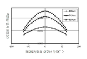
[도5] 본 실시예에 있어서의, 측정 대상과 동일 종류의 물질에 대한 적외선 반사 강도와, 측정장치의 해당 물질에 대한 정대로부터의 어긋남 각도와의 관계를 나타내는 그래프다.[Fig. 1] A schematic perspective view of a measuring device according to the present embodiment.
[Fig. 2] A schematic side view of the measuring device of the present embodiment.
[Fig. 3] A graph showing the relationship between the infrared reflection intensity and thickness (film thickness) of a substance of the same type (coat film X described later) as a measurement object in the present embodiment.
Fig. 4 is a graph showing the relationship between the infrared reflection intensity of a substance of the same type as that of the object to be measured in the present embodiment and the distance to the substance.
Fig. 5 is a graph showing the relationship between the infrared reflection intensity of the substance of the same type as the measurement object in the present embodiment and the deviation angle from the positive pole of the substance of the measuring device.
이하, 본 발명의 일 실시형태에 대해서, 도1 및 도2를 사용하여 설명한다. 변형 예에 대해서는 후술한다. 본 명세서에 있어서 「∼」는 소정의 값 이상 또한 소정의 값 이하를 가리킨다. Hereinafter, an embodiment of the present invention will be described with reference to FIGS. 1 and 2. A modified example will be described later. In this specification, "-" refers to a predetermined value or more and a predetermined value or less.
본 실시형태에 있어서 예시하는 측정장치(1)는, 적어도 이하의 구성을 포함한다.
The
· 측정 대상에 대하여 전자파를 조사하는 발진원(11)· An oscillation source that irradiates electromagnetic waves to the object to be measured (11)
· 측정 대상으로부터의 전자파 반사 강도를 측정하는 검출기(12)· Detector (12) that measures the intensity of reflection of electromagnetic waves from a measurement object
· 측정 대상으로부터의 거리를 계측하는 거리계(13)(13a∼13d)Rangefinder 13 (13a-13d) that measures the distance from the measurement object
· 측정 대상과 측정장치(1)와의 정대로부터의 어긋남 각도를 계측하는 어긋남 각도 계측기구(14)· A deviation angle measuring device (14) that measures the angle of deviation from the apex between the measurement object and the measuring device (1)
또, 본 명세서에 있어서 "정대로부터의 어긋남 각도"란, 측정장치(1)로부터 조사되는 전자파의 광축이 측정 대상에 대하여 수직이 되는 위치를 "정대"로 하여, 그 광축으로부터의 어긋남을 각도로 나타낸 것이다. 이후, 특별히 기재하지 않는 한, 어긋남 각도란 상기를 의미한다.
In addition, in this specification, the "shift angle from the top" refers to the position at which the optical axis of the electromagnetic wave irradiated from the
또, 본 명세서에 있어서의 전자파란, 전자장의 주기적인 변화로 발생하는 파동이며, 파장의 긴 쪽으로부터 전파, 적외선, 가시 광, 자외선, 방사선을 들 수 있다. 본 실시형태에 있어서의 측정장치(1)의 발진원이 채용하는 전자파의 종류는, 각종 파라미터를 비접촉 방식에 의해 정밀도 좋게 측정가능하면 특별히 한정되지 않는다. 본 실시형태에 있어서는, 일례로서, 780nm로부터 3,000㎛(3mm)까지의 파장범위의 전자파를 예시한다. 본 명세서에 있어서는 이 파장범위의 전자파를, 설명의 편의상, 적외선이라고 칭한다.
In addition, an electromagnetic wave in this specification is a wave generated by a periodic change in an electromagnetic field, and includes radio waves, infrared rays, visible light, ultraviolet rays, and radiation from the longer wavelength. The type of electromagnetic wave employed by the oscillation source of the measuring
본 실시형태에 있어서의 측정장치(1)에 의해 측정되는 각종 파라미터로서는, 측정 대상으로부터의 적외선 반사 강도를 기초로 얻을 수 있다. 이 각종 파라미터로서는 특별히 제한은 없고, 예를 들면 "두께" 또는 "농도",혹은 적외선 반사 강도 바로 그것을 들 수 있다.
As various parameters measured by the measuring
여기서 말하는 "두께"란, 측정 대상의 도포막, 방청유나 수지막등의 두께이며, 웨트 도포막의 두께, 건조 막 두께의 어느 것이어도 좋다. 또한, 상기 측정 대상으로서는, 측정 대상에 적외선을 조사했을 때, 측정 대상의 두께에 따라서 적외선 반사 강도가 변화되는 것이면, 특별히 제한되지 않는다. The "thickness" referred to herein is the thickness of the coating film to be measured, the rust preventive oil or the resin film, and may be any of the thickness of the wet coating film and the dry film thickness. In addition, the measurement object is not particularly limited as long as the infrared reflection intensity changes according to the thickness of the measurement object when the measurement object is irradiated with infrared rays.
본 실시형태에 있어서는 설명의 편의상, "두께"를 측정하는 경우를 예시한다. 본 실시형태 중에서는, 도포막을 측정 대상으로 하는 경우를 예시하지만, 본 발명은 막 두께 측정에 한정되는 것이 아니고, 이후에 서술하는 적합 예는, 농도를 측정하는 경우에도 유효하다. 농도를 측정하는 경우에 대해서는 나중에 상세히 설명한다. In this embodiment, for convenience of explanation, the case of measuring "thickness" is illustrated. In the present embodiment, a case in which the coating film is used as a measurement object is illustrated, but the present invention is not limited to the film thickness measurement, and a suitable example described later is also effective when measuring the concentration. The case of measuring the concentration will be described in detail later.
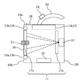
도1에 도시한 바와 같이, 본 실시형태에 있어서의 측정장치(1)는, 크게 나누어, 각 기구가 수납된 대략 입방체형의 케이스(10)와, 해당 케이스의 상면(10a)으로부터 밖을 향해서 반달 모양으로 연장하는 핸들(20)(즉, 측정장치(1) 반출시의 손잡이)을 갖고, 가반형이다. 핸들(20)에는, 적외선의 조사를 행하기 위한 적외선 발진 버튼(21)을 구비하고 있다.
As shown in Fig. 1, the measuring
적외선을 조사하는 발진원(11)은, 케이스(10)에 설치되고, 케이스의 전방면(10b)으로부터 측정 대상에 대하여 적외선을 조사가능한 구조를 갖고 있다. 이때, 적외선의 광축이 케이스의 전방면(10b)(더욱 말하면 후술의 4개의 거리계 13a, 13b, 13c, 13d(4개를 합한 것에는 부호 13을 구비한다)가 배치된 동일평면)에 대하여 수직이 되도록 발진원(11)을 배치한다. 또한, 본 실시형태에 있어서, 발진원(11)에 있어서의 적외선의 출사 부분도 상기의 동일평면상에 배치해도 좋지만, 출사 부분을 케이스의 전방면(10b)보다도 측정 대상측(즉, 외측)에 배치해도 개의치 않고, 출사 부분을 케이스(10)의 내부에 설치해도 개의치 않는다.
The
이 발진원(11)으로서는, 발광 다이오드, 레이저 다이오드, 할로겐 램프등, 적외선을 출력할 수 있는 것이면 좋고, 직선적으로 강한 에너지의 적외선을 출력할 수 있는 레이저 다이오드가 바람직하다. 발진원(11)으로서 레이저 다이오드를 선택함으로써, 할로겐 램프 등을 사용하는 경우보다도 공간절약화를 꾀할 수 있어, 전력 절약에 의해 측정장치(1)의 전지(15)의 경량화 및 소형화를 꾀할 수 있다.
As the
발진원(11)으로부터 조사되는 적외선은, 분해능이 뛰어나다는 점에서 근적외선인 것이 바람직하다. 상세하게 말하면, 검출기(12)에서의 적외선의 검출시, 적외선 중에서도 근적외선의 검출 정밀도가 높고, 분해능이 뛰어나다. 구체적인 파장의 값은, 바람직하게는 780nm을 초과하고, 또한 30,000nm이하(혹은 830nm을 초과하고 또한 30,000nm이하), 보다 바람직하게는 780nm를 초과하고(혹은 830nm을 초과하고) 또한 2,600nm이하, 특히 바람직하게는 830nm을 초과하고 또한 1,200nm이하다. 또한, 상기 발진원(11)으로부터 조사되는 적외선은, 사용 환경에 의한 영향을 받기 어려운 점으로부터, 초원적외선 혹은 테라헤르츠파인 것도 바람직하고, 구체적으로는, 파장이 바람직하게는 30㎛을 초과하고 또한 3,000㎛이하, 보다 바람직하게는 40∼300㎛이다.
The infrared rays irradiated from the
적외선 레이저 다이오드를 사용할 경우, 온도조절기능 구비 레이저 다이오드인 것이 바람직하다. 레이저 다이오드의 연속 발진 등에 의해, 온도가 변동하는 것에 기인하는 적외선의 출력 변동을 억제하는 것이 가능해 지고, 나아가서는 각종 파라미터를 더욱 정밀도 좋게 측정하는 것이 가능해 진다. 이 온도조절기능을 실현하는 기구로서는, 예를 들면 펠티에 소자를 들 수 있다. When using an infrared laser diode, it is preferable that it is a laser diode with a temperature control function. Due to continuous oscillation of the laser diode or the like, it becomes possible to suppress fluctuations in the output of infrared rays caused by fluctuations in temperature, and furthermore, it becomes possible to measure various parameters more accurately. As a mechanism for realizing this temperature control function, for example, a Peltier element can be mentioned.
또, 적외선의 출력 변동은, 상기한 바와 같이 컨트롤 하는 방법이외에, 적외선의 출력을 감시하는 방법을 들 수 있다. 일 실시형태로서는, 전자파 반사 강도를 측정하는 검출기와는 별도의 검출기를 구비한 구성으로 함으로써, 상기 레이저 다이오드로부터 조사되는 적외선의 일부를 ND필터등의 광학 필터로 추출하고, 상기 별도의 검출기로 출력 변동을 감시할 수 있다. 예를 들면, 조사되는 적외선의 90%가 측정 대상에 조사되어, 나머지 10%를 출력 변동의 감시에 이용할 수 있다. 얻어진 출력 변동에 관한 기록을 기초로 강도에의 영향을 해석하는 구성으로 하여도 좋고, 출력 변동에 맞춰서 발진원의 출력을 변동시키는 구성으로 하여도 좋다. In addition to the above-described control method, infrared output fluctuations include a method of monitoring infrared output. In an embodiment, by having a detector separate from the detector measuring the electromagnetic wave reflection intensity, a part of the infrared ray irradiated from the laser diode is extracted with an optical filter such as an ND filter, and output to the separate detector. Changes can be monitored. For example, 90% of the irradiated infrared rays are irradiated to the object to be measured, and the remaining 10% can be used for monitoring of output fluctuations. The configuration may be configured to analyze the influence on the intensity based on the obtained output fluctuation record, or may be configured to fluctuate the output of the oscillation source according to the output fluctuation.
측정 대상으로부터의 적외선 반사광은, 케이스(10)의 내부이며 케이스의 후방면(10c)에 설치된 검출기(12)에 의해 강도가 측정된다. 검출기(12)에 의해 측정된 적외선 반사 강도에 근거하여, 측정 대상의 막 두께를 측정할 수 있다. 또한, 검출기(12)로서는, 측정 대상으로부터의 적외선 반사광을 검지가능한 것이며, 적외선 반사 강도를 전압값으로서 측정가능한 것이면, 공지의 것을 사용할 수 있다.
The intensity of infrared reflected light from the measurement object is measured by the
이때, 케이스의 전방면(10b)에 집광 렌즈(16)를 설치해도 좋다. 이에 따라 적외선 반사광(도2의 점선 화살표)을 효율 좋게 검출기(12)를 향하게 하는 것이 가능해지고, 나아가서는 감도 좋게 강도를 측정하는 것이 가능해진다.
At this time, the condensing
또, 본 실시형태의 측정장치(1)는, 편광 필터17a, 17b(합친 것은 부호 17)를 갖는 것이 바람직하다. 그 이유는 아래와 같다.
Moreover, it is preferable that the measuring
측정 대상으로부터의 반사광에는, 경면반사에 의한 정반사광과, 측정 대상내에 있어서의 확산반사에 의한 산란 광이 포함되어 있다. 만일, 측정장치(1)가 측정 대상에 대하여 정대는 아니고, 어긋남 각도가 존재할 경우, 정반사광의 강도는 어긋남 각도에 의존해서 변화된다. 이것은, 측정 대상에 대한 각도에 의한 감도차가 커지는 것을 의미한다.
The reflected light from the measurement object includes regular reflection light due to specular reflection and scattered light due to diffuse reflection in the measurement object. If the measuring
그 한편, 편광 필터(17)에 의해 정반사광을 커트 할 수 있으면, 검출기(12)는 산란 광만을 검출해서 적외선 반사 강도를 측정하게 되므로, 측정 결과에 대한 측정장치(1)의 어긋남 각도에 의한 영향을 작게 하는 것이 가능해진다.
On the other hand, if the regular reflected light can be cut by the
더욱, 정반사광의 강도는, 측정 대상의 막 두께와 아울러, 측정 대상의 표면상태에 일부 의존한다. 즉, 편광 필터(17)에 의해 정반사광을 커트 함에 의해, 막 두께에 기인하는 반사광 강도를 정밀도 좋게 측정하는 것이 가능해진다.
Further, the intensity of the specular reflection light partially depends on the surface state of the measurement object in addition to the film thickness of the measurement object. That is, by cutting the regular reflected light by the
단, 정반사광은 강도가 높은 광이며, 측정 대상에 따라서는 막 두께 측정에 적합한 경우가 있다. 편광 필터(17)는, 반사광 전체의 강도는 저하시키기 때문에, 조작자의 의도에 따라서 편광 필터(17)의 기능의 온/오프를 전환할 수 있는 편광 필터 전환기구(도시되지 않음)를 측정장치(1)에 구비시켜도 좋다. 이 편광 필터 전환기구로서는, 예를 들면 케이스(10)의 터치패널인 액정 디스플레이(18)나 스위치(도시되지 않음)등으로 조작 함에 의해, 편광 필터(17)의 유무를 전환하여도 좋고, 편광 필터(17)의 위치를 물리적으로 변경해도 좋다.
However, regular reflected light is light with high intensity, and depending on the measurement object, it may be suitable for film thickness measurement. Since the
이때, 도2에는, 편광 필터(17)의 배치를 개략적으로 기재하고 있지만, 편광 필터(17)를 배치하는 형태에는 특별히 제한은 없고, 예를 들면 발진원(11)에 있어서의 적외선의 출사 부분에 제1의 편광 필터(17a)를 설치해 일방향만의 파로 하여, 검출기(12)에 대하여 정반사광을 커트하기 위해, 해당 일방향과 직교하는 방향의 제2의 편광 필터(17b)를 설치해도 개의치 않는다.
In this case, although the arrangement of the
또, 본 실시형태의 측정장치(1)는, 분광기를 구비한 구성으로 할 수 있다.
Moreover, the measuring
일 구체예로서는, 발진원(11)으로부터 조사되는 전자파의 입사파와 반사파의 위상차를 기초로, 측정 대상의 막 두께를 측정해도 좋다.
As a specific example, the film thickness of the measurement object may be measured based on the phase difference between the incident wave and the reflected wave of the electromagnetic wave irradiated from the
위상차는, 전자파가 막내에서 왕복하는 거리에 막의 굴절률을 곱한 값에 의해 결정된다. 즉, 위상차는 막 두께에 의존한다. 그 때문에, 미리 위상차와 막 두께와의 관계성(예를 들면, 검량선)을 얻고 있으면, 분광기에 의해 분리한 상기 입사파와 상기 반사파의 위상차를 검출기(12)로 측정함에 의해, 막 두께를 측정하는 것이 가능해진다.
The phase difference is determined by a value obtained by multiplying the distance the electromagnetic waves travel back and forth within the film by the refractive index of the film. That is, the phase difference depends on the film thickness. Therefore, if the relationship between the phase difference and the film thickness (e.g., calibration curve) has been obtained in advance, the film thickness is measured by measuring the phase difference between the incident wave and the reflected wave separated by a spectroscope with the
별도의 구체예로서는, 근적외 분광 카메라나 근적외 분광 조성 분석 장치와 같이, 특정 파장에 있어서의 전자파 반사 강도를 검출기(12)에 의해 측정해도 좋다. 이때, 특정 파장에 있어서의 전자파의 반사 강도는 일차원 해석해도 좋고, 2차원 해석(이미징)해도 좋다.
As another specific example, the electromagnetic wave reflection intensity at a specific wavelength may be measured by the
본 실시형태의 특징의 하나이지만, 케이스의 전방면(10b)에는, 측정 대상으로부터의 거리를 계측하는 거리계(13)가 4개 설치되어 있다. 거리계(13)은 모두 동일평면상에서 정방형 또는 직사각형의 정점의 위치에 배치되고, 또한, 발진원(11)은 거리계(13)의 중심에 배치되어 있다. 이 거리계(13)로서는, 측정 대상으로부터의 거리를 계측가능한 것이면 공지의 것을 사용해서 개의치 않고, 예를 들면 펄스 레이저를 조사하고, 반사광이 다시 거리계(13)에 입사하는 시간을 기초로 거리를 계측해도 개의치 않는다. 또한, 본 실시형태에 있어서, 거리계(13)의 내부에 상기 펄스 레이저의 반사광을 검출하는 기구가 설치되어 있어, 적외선 반사 강도를 측정하는 검출기(12)와는 다른 경우를 예시한다.
Although it is one of the features of this embodiment, four rangefinders 13 that measure the distance from the measurement object are provided on the
또, 본 실시형태에 있어서는, 거리계(13)로부터는 가시 광(파장400∼780nm(혹은, 830nm), 또한, 이 범위이외의 전자파를 비가시 광으로 칭한다.)이 조사되는 것이 바람직하다. 그 이유는 아래와 같다.
In addition, in this embodiment, it is preferable that visible light (
본 실시형태의 측정장치(1)를 사용해서 측정을 실시할 때, 측정 대상에는 발진원(11)으로부터 적외선이 조사되지만, 적외선은 불가시광선이기 때문에, 발진원(11)만으로는 측정 대상의 어느 위치에 적외선이 조사되어 있는 것인지, 조작자를 파악할 수 없다.
When measuring using the
한편, 거리계(13)로부터 가시 광(예를 들면, 가시 광의 펄스 레이저)이 조사될 경우, 본 실시형태에 있어서 거리계(13)는 동일평면상에서 정방형 또는 직사각형의 정점의 위치에 배치되고, 또한, 발진원(11)은 거리계(13)의 중심에 배치하고 있기 때문에, 4개의 거리계(13)로부터 가시 광이 조사 됨으로써, 조작자는, 측정 대상상에 4개의 광점을 시인할 수 있고, 4개의 광점을 대각선으로 연결한 교점상에 적외선이 조사되어 있는 것을 용이하게 파악할 수 있다.
On the other hand, when visible light (e.g., a pulsed laser of visible light) is irradiated from the rangefinder 13, the rangefinder 13 in this embodiment is disposed at the position of a square or rectangular vertex on the same plane, and Since the
그 때, 측정장치(1)의 핸들에 구비된 버튼에 대하여, 얕게 누를 경우는 거리계(13)만을 기동해서 가시 광을 조사하고, 조작자에 의한 눈으로 보는 위치결정이 완료한 후에 버튼을 깊게 눌러서 적외선을 조사하는 구성을 채용해도 개의치 않는다. 즉, 가시 광과 적외선으로 광선의 종류를 전환하는 전환기구를 설치해도 개의치 않는다. 물론, 이 구체적인 구성이외이여도 좋고, 예를 들면 1회째에 버튼을 눌렀을 때에는 가시 광이 조사되고, 2회째에 버튼을 눌렀을 때에는 적외선이 조사되는 구성이어도 좋다.
At that time, when pressing the button lightly on the handle of the measuring
본 실시형태의 특징의 하나는, 측정 대상과 측정장치(1)와의 정대로부터의 어긋남 각도를 계측하는, 어긋남 각도 계측기구(14)를 갖고 있는 것에 있다. 어긋남 각도 계측기구(14)로서 일례를 들면, 거리계(13)에 의해 계측된 거리에 근거하여, 어긋남 각도를 계측하는 기구다. 그 계측의 일례를, 측정 대상으로부터의 거리를 계측하는 구체예와 함께, 이하에 나타낸다.
One of the features of this embodiment is that it has a shift angle measurement mechanism 14 that measures the shift angle from the apex between the measurement object and the
본 실시형태의 측정장치(1)의 발진원(11)으로부터 적외선(상기 예에서는 적외선 레이저)을 조사함과 동시에, 4개의 거리계(13)로부터 가시 광의 펄스 레이저가 측정 대상에 동시에 조사된다. 적외선 레이저를 조사한 측정 대상으로부터의 반사광은, 집광 렌즈(16)를 통과시켜서 검출기(12)로 검지되어, 전압값으로서 그 강도를 얻을 수 있다.
An infrared ray (infrared laser in the above example) is irradiated from the
측정 대상으로부터의 거리의 계측이지만, 4개의 거리계(13)는, 측정장치(1)의 전방면(10b)에 있어서, 정방형 또는 직사각형의 정점의 위치가 되도록 설치되어 있다. 또한, 발진원(11)인 적외선 레이저 다이오드는, 4개의 거리계(13)의 설치 위치로부터 대각선으로 연결한 교점상(중심)에 배치되어 있다. 그 때문에, 4개의 거리계(13)로부터 얻어진 거리의 평균값은, 적외선 레이저 다이오드로부터 측정 대상까지의 거리로 간주해도 개의치 않고, 측정 대상이 평면형이면 측정 대상까지의 거리 바로 그것이다. 또한, 이 수법은, 적외선 레이저 다이오드를 둘러싸는 거리계(13)의 수가 3개이여도 실현가능하다.
Although the distance from the measurement object is measured, the four rangefinders 13 are provided so as to be at the positions of square or rectangular vertices on the
그리고, 어긋남 각도의 계측이지만, 측정장치(1)의 전방면(10b)을 향해 보았을 때, 거리계(13)는 발진원(11)으로부터 동일한 수평거리에 배치되어 있으므로, 수평 어긋남 각도 및 그 각도를 갖는 평면의 방정식을 얻을 수 있다. 마찬가지로, 발진원(11)으로부터 동일한 수직거리에 거리계(13)가 배치되어 있으므로, 수직 어긋남 각도 및 그 각도를 갖는 평면의 방정식도 얻을 수 있다. 본 실시형태에 있어서, 측정 대상과 전방면(10b)의 2개의 평면이 이루는 각은 어긋남 각도와 동일하다.
In addition, although the deviation angle is measured, the rangefinder 13 is disposed at the same horizontal distance from the
이상의 구성에 의해, 측정 대상으로부터의 거리 및 측정 대상에 대한 정대로부터의 어긋남 각도를 계측하는 것이 가능해진다. 본 실시형태의 측정장치(1)는, 측정 대상의 적외선 반사 강도와, 측정 대상으로부터의 거리와, 측정 대상과 장치와의 정대로부터의 어긋남 각도로부터, 측정 대상의 막 두께를 연산하는 연산 기구(19)를 더욱 설치하는 것이 바람직하다.
With the above configuration, it becomes possible to measure the distance from the measurement object and the deviation angle from the apex to the measurement object. The measuring
예를 들면, 특허문헌2의 도3등이나 후술의 실시예의 도3등의 검량선에 도시된 것 같이, 측정 대상의 막 두께는, 측정 대상의 적외선 반사 강도와 상관 관계가 있다. For example, as shown in the calibration curve in Fig. 3 of Patent Document 2 and Fig. 3 of the Examples to be described later, the film thickness of the measurement object is correlated with the infrared reflection intensity of the measurement object.
그리고, 측정장치(1)에 의해 검출되는 적외선 반사 강도는, 측정 대상으로부터의 거리가 멀어질수록 감쇠한다. 그 때에, 측정 대상의 적외선 반사 강도와 측정 대상으로부터의 거리와의 사이에는 상관 관계가 있다(후술의 실시예의 도4의 검량선 참조).
Then, the infrared reflection intensity detected by the measuring
어긋남 각도에 대해서도 마찬가지이어서, 어긋남 각도가 커질수록 적외선 반사 강도는 감쇠한다. 그 때에, 측정 대상의 적외선 반사 강도와 어긋남 각도와의 사이에는 상관 관계가 있다(후술의 실시예의 도5의 검량선 참조). The same applies to the shift angle, and the infrared reflection intensity decreases as the shift angle increases. At that time, there is a correlation between the infrared reflection intensity of the measurement object and the shift angle (refer to the calibration curve in Fig. 5 in the example described later).
후술의 실시예에 나타내는 검량선에 의해 표현되는 관계는, 측정 대상의 조성이나 각 조성의 함유량이 동등하면 유지된다. 한편, 조성이나 각 성분의 함유량이 상이한 측정 대상에 대하여 측정을 행할 경우, 상기 관계를 그대로 사용하거나, 상기 관계에 대하여 어떠한 보정을 행하는 것보다도, 그 측정 대상과 동일 종류의 물질에 대한, 막 두께와, 적외선 반사 강도와, 해당 물질로부터의 거리와, 해당 물질과 측정장치(1)와의 정대로부터의 어긋남 각도와의 관계, 즉 검량선을 미리 얻어 두는 것이 바람직하다. 또한, 이 검량선은 하나일 필요는 없고, 도3∼5에 도시한 바와 같이 복수의 검량선으로 되어도 좋다.
The relationship expressed by the calibration curve shown in Examples described later is maintained as long as the composition of the measurement object and the content of each composition are equal. On the other hand, when measurement is performed on a measurement object having a different composition or content of each component, the film thickness of the substance of the same kind as the measurement object, rather than using the above relationship as it is or performing any correction for the above relationship. It is preferable to obtain in advance the relationship between the infrared reflection intensity, the distance from the substance, and the deviation angle between the substance and the measuring
그 결과, 상기한 각 상관 관계로부터 얻어진 검량선에 의해, 측정장치(1)로부터 측정 대상에 대하여 조사된 적외선 반사 강도로부터, 측정 대상으로부터의 거리 및 어긋남 각도의 영향을 배제한 막 두께를 측정하는 것이 가능해지고, 그 결과를 케이스(10)의 액정 디스플레이(18)등에 실시간으로 표시하는 것도 가능해진다.
As a result, it is possible to measure the film thickness by excluding the influence of the distance from the measurement object and the deviation angle from the infrared reflection intensity irradiated from the measuring
또, 측정 대상의 종류마다 준비된 상기 검량선을, 측정 대상의 종류에 따라서 전환가능한 종류 선택 기구(도시되지 않음)를, 본 실시형태의 측정장치(1)에 더욱 설치하는 것이 바람직하다. 또한, 상기 검량선은, 케이스(10)안의 메모리(도시되지 않음)에 보존해두고, 연산 기구(19)가 작동할 때에 메모리로부터 인출하면 좋다.
In addition, it is preferable to further provide a type selection mechanism (not shown) capable of switching the calibration curve prepared for each type of measurement object according to the type of measurement object in the measuring
연산 기구(19)는, 어긋남 각도 계측기구(14)와 공통의 구성으로 하여도 좋고, 예를 들면 케이스(10)안에 설치된 하나의 연산 기구(19)에 의해, 막 두께의 연산 및 어긋남 각도의 계측을 행해도 개의치 않는다. 또한, 연산 기구(19)는, 측정장치(1)와 접속한 퍼스널 컴퓨터나 타블렛 등의 외부단말이여도 좋다.
The calculation mechanism 19 may be configured in common with the shift angle measuring device 14, for example, by one calculation device 19 provided in the case 10, the film thickness is calculated and the shift angle is calculated. It doesn't matter if you measure. Further, the calculation mechanism 19 may be an external terminal such as a personal computer or a tablet connected to the
또한, 상기한 구성에 의해, 본 발명의 효과에 더하여, 이하의 효과도 발휘한다. Further, by the above-described configuration, in addition to the effects of the present invention, the following effects are also exhibited.
전술과 같이, 본 실시형태의 측정장치(1)를 검출할 수 있는 적외선 반사 강도는, 측정 대상으로부터의 거리가 멀어질수록 감쇠하고, 그 측정 정밀도도 저하한다. 물론 측정가능한 거리는 발진원(11)의 파워에도 의존하지만, 본 실시형태의 측정장치(1)에 사용한 발진원(11)은, 측정 대상까지의 거리가 5m이여도 충분한 정밀도로 도포막의 막 두께를 측정할 수 있는 것이 확인되어 있다. 덧붙이자면, 먼저 예를 든 편광 필터 전환기구로 편광 필터(17)의 기능을 오프로 할 경우는, 정반사광을 검출 가능해지기 때문에, 적외선 반사광의 강도를 크게 확보할 수 있고, 거리가 10∼15m이여도 충분한 정밀도로 도포막의 막 두께를 측정할 수 있다.
As described above, the infrared reflection intensity that can be detected by the measuring
또, 상기 적외선 반사 강도는, 측정 대상에 대한 정대로부터의 어긋남 각도가 커질수록 감쇠하기 때문에, 측정 대상과 장치의 전방면(10b)이 정대에 가까울수록 양호한 측정 정밀도를 갖는다. 그 한편, 본 실시형태의 측정장치(1)는, 어긋남 각도가 크더라도 정밀도 좋게 막 두께를 측정하는 것이 가능하다. 예를 들면, 본 실시형태의 측정장치(1)에 있어서는, 측정 대상에 대한 정대로부터의 어긋남 각도는, 85°이하이여도 대단히 양호한 정밀도로 측정을 실시하는 것이 가능하고, 75°이하이면 더욱 양호한 정밀도가 된다.
Further, since the infrared reflection intensity decreases as the angle of deviation from the apex with respect to the measurement object increases, the closer the measurement object and the
물론, 본 발명은 본 실시형태에 한정되는 것이 아니다. 이하, 적용 예 또는 변형 예를 열거한다. 또한, 본 실시형태에서 예를 든 적합 예를 이하의 예에 적절하게 조합해도 개의치 않는다. Of course, the present invention is not limited to this embodiment. Hereinafter, application examples or modified examples are listed. In addition, it does not matter if the suitable examples exemplified in the present embodiment are appropriately combined with the following examples.
예를 들면, 측정 대상으로서는, 특히 제한되지 않지만, 티탄 백색, 아산화동, 산화 아연, 벵갈라, 황색 벵갈라, 크롬그린 블랙 헤마타이트, 망간 비스무트 블랙, 크로뮴 아이언 옥사이드, 니켈 안티몬 티타늄 옐로우루틸, 크롬 안티몬 티타늄 버프 루틸 및 루틸 주석 아연 등으로부터 선택되는 1종 이상의 적외선 반사 재료를 함유하는 도포막인 것이 바람직하고, 또한, 적외선에 대한 반사성과 투과성의 양쪽을 맞춰 갖는 성질을 가지는 도포막인 것이 바람직하다. For example, the measurement object is not particularly limited, but titanium white, nitrous oxide, zinc oxide, bengala, yellow bengala, chromium green black hematite, manganese bismuth black, chromium iron oxide, nickel antimony titanium yellow rutile, chromium antimony titanium It is preferable that it is a coating film containing at least one kind of infrared reflecting material selected from buff rutile, rutile tin zinc, etc., and it is preferable that it is a coating film which has the property which has both reflectivity to infrared rays and transmittance.
이러한 도포막의 안, 적외선 반사 재료를 많이 함유할 경우는, 적외선의 투과율이 떨어지기 때문에, 본 장치에 의해 측정할 수 있는 막 두께의 범위가 좁아지는 경향에 있다. 따라서, 측정 대상의 도포막은, 막 두께가 2,000㎛이하가 바람직하고, 1,000㎛이하가 보다 바람직하다. In the case where a large amount of the infrared reflecting material is contained in such a coating film, the transmittance of infrared rays decreases, and thus the range of the film thickness that can be measured by the present apparatus tends to be narrow. Therefore, the film thickness of the coating film to be measured is preferably 2,000 µm or less, and more preferably 1,000 µm or less.
또, 그 밖의 측정 대상으로서는, 적외선을 반사하는 기본재료, 예를 들면 강판등에 도포된 방청유나 수지막등의 두께를 측정하는 것도 가능하다. In addition, as another measurement object, it is also possible to measure the thickness of a base material that reflects infrared rays, for example, an rust preventive oil or a resin film applied to a steel plate.
방청유나 수지막은, 두께가 늘면 적외선의 흡수가 커지기 때문에, 기본재료로부터 반사하는 적외선 반사 강도는 감쇠한다. 따라서, 해당 상관 관계를 이용함으로써, 적외선을 흡수하는 방청유나 수지막등의 두께를 비접촉 방식에 의해 온 사이트(on-site)에서 측정하는 것도 가능하다. As the thickness of the rust preventive oil or the resin film increases, the absorption of infrared rays increases, so the intensity of infrared reflection reflected from the base material is attenuated. Therefore, by using the correlation, it is also possible to measure the thickness of the rust preventive oil or resin film that absorbs infrared rays on-site by a non-contact method.
또, 본 실시형태의 측정장치(1)는, 측정 대상중에 함유하는 적외선 반사 재료의 농도를 측정할 수 있다. 이 "농도"란, 적외선 반사 재료가 얼마나 함유되어 있는지를 나타내는 것이며, (중량, 체적)함유율이기도 하다.
Moreover, the measuring
해당 농도의 측정은, 전술의 측정 대상의 두께 측정과 마찬가지로, 적외선 반사 강도를 측정 대상으로부터의 거리와 정대로부터의 어긋남 각도에 따라서 보정함으로써 측정된다.The measurement of the concentration is measured by correcting the infrared reflection intensity according to the distance from the measurement object and the deviation angle from the apex, similar to the measurement of the thickness of the measurement object described above.
구체예를 들면, 전술의 두께 측정의 경우와 마찬가지로, 측정 대상과 같은 도료에 대한 농도와, 적외선 반사 강도와, 측정 대상으로부터의 거리와, 측정 대상과 측정장치(1)와의 정대로부터의 어긋남 각도와의 관계, 즉 검량선을 미리 얻어 두는 것으로, 측정 대상으로부터의 거리 및 어긋남 각도의 영향이 배제된 농도를 연산 기구(19)에 의해 연산할 수 있다.
For example, as in the case of the above-described thickness measurement, the concentration of the same paint as the object to be measured, the intensity of infrared reflection, the distance from the object to be measured, and the angle of deviation from the positive pole between the object to be measured and the measuring
또, 측정장치(1)를 사용하여, "농도"가 기지의 도료로부터 형성된 특정한 막 두께(예를 들면, 막 두께t㎛)의 도포막에 대하여, 적외선 반사 강도를 측정한다. 그리고, 그 측정 결과로부터, 측정 대상으로부터의 거리 및 어긋남 각도의 영향을 배제하는 것으로 농도를 측정한다.
In addition, infrared reflection intensity is measured for a coating film having a specific film thickness (for example, film thickness t mu m) formed from a paint having a known "concentration" using the
이렇게 하여 적외선 반사 재료의 농도를 측정함으로써, 예를 들면, 측정 대상의 도포막이 2성분형 도료로부터 형성될 경우, 그 혼합비에 오류가 없는지를 비파괴로 용이하게 검사할 수 있다. 덧붙이자면, 상술의 두께 측정이나 농도측정이외라도, 본 발명의 기술적 사상을 적용가능하고, 본 명세서에서 말하는 각종 파라미터 중 임의의 파라미터와, 측정 대상으로부터의 전자파 반사 강도와, 측정 대상으로부터의 거리와, 측정 대상과 장치와의 정대로부터의 어긋남 각도와의 관계로부터, 해당 임의의 파라미터를 연산 기구(14)로 연산해도 좋다. By measuring the concentration of the infrared reflecting material in this way, for example, when a coating film to be measured is formed from a two-component coating material, it is possible to easily inspect whether there is no error in the mixing ratio or not. Incidentally, the technical idea of the present invention can be applied to other than the above-described thickness measurement and concentration measurement, arbitrary parameters among various parameters referred to in the present specification, electromagnetic wave reflection intensity from the measurement object, distance from the measurement object, and , The arbitrary parameter may be calculated by the calculation mechanism 14 from the relationship between the measurement object and the angle of deviation from the top of the device.
또한, 본 실시형태의 측정장치(1)의 사용 형태로서 특별히 제한은 없지만, 근적외선을 포함하는 태양광 아래에서는, 날씨나 측정 대상의 방위등에 의해 영향을 받을 우려가 있기 때문에, 근적외선이 거의 포함되지 않는 조명(예를 들면, 형광등 등) 아래의 옥내에서의 사용이 바람직하다. 더욱, 본 실시형태의 측정장치(1)는, 완전한 암소이여도 사용할 수 있고, 예를 들면 야간의 옥외, 선박이나 구조물의 블록 내부등의 거의 조명이 없는 환경에서도 측정할 수 있다. 또한, 외광의 적외선 강도가 대단히 높은 환경이 아니면, 측정에 의해 얻어진 적외선 반사 강도로부터 외광에 의한 영향을 배제해서 두께를 구할 수도 있다.
In addition, although there is no particular limitation as a mode of use of the measuring
한편, 발진원의 파장이, 일반적으로 초원적외선 혹은 테라헤르츠파, 서브테라헤르츠파라고 불리는 파장(예를 들면, 30㎛를 초과하고 또한 3,000㎛이하)일 경우, 태양광의 영향을 받기 어렵다고 한 이점이 있다. On the other hand, when the wavelength of the oscillation source is generally called ultra-infrared, terahertz wave, or sub-terahertz wave (for example, exceeding 30 μm and not exceeding 3,000 μm), it is difficult to be affected by sunlight. There is this.
이하, 본 측정장치의 변형 예를 열거한다. Hereinafter, the modified example of this measuring device is enumerated.
본 실시형태에 있어서는, 측정 대상의 적외선 반사 강도와, 측정 대상으로부터의 거리와, 측정 대상과 장치와의 정대로부터의 어긋남 각도로부터, 측정 대상의 두께를 연산하는 연산 기구(19)를 설치하는 예를 들었다. 그 한편, 상기 거리 및 어긋남 각도가 액정 디스플레이(18)등에 표시되는 것에 의해 거리 및 어긋남 각도를 조작자를 파악할 수 있으면, 본 실시형태의 가반형의 측정장치(1)를 측정 대상에 대하여 적절하게 배치하는 것이 가능해진다. 그 결과, 연산 기구(19)를 사용하지 않은 경우이여도, 측정 대상으로부터의 적외선 반사 강도의 기초가 되는 각종 파라미터를 비접촉 방식에 의해 단시간으로 정밀도 좋게 측정 가능해진다. 단, 연산 기구(19)를 설치하는 쪽이 조작자의 부담이 줄어든 후, 측정 결과의 정밀도도 향상한다.
In the present embodiment, an example in which a calculation mechanism 19 is provided that calculates the thickness of the measurement object from the infrared reflection intensity of the measurement object, the distance from the measurement object, and the deviation angle from the apex between the measurement object and the device. I heard. On the other hand, if the operator can grasp the distance and the deviation angle by displaying the distance and the deviation angle on the
본 실시형태의 측정장치(1)에 있어서, 어긋남 각도 계측기구(14)는, 거리계(13)에 의해 계측된 거리에 근거하여, 어긋남 각도를 계측하는 예를 들었지만, 그 이외에도, 측정장치(1)에 중력 센서(도시되지 않음)를 탑재할 경우, 측정 대상을 전방면(10b)에 대하여 수직하게 배치함에 의해, 측정장치(1)와의 어긋남 각도를 계측하는 것이 가능하다.
In the
본 실시형태의 측정장치(1)는, 거리계(13)를 4개 갖고, 거리계(13)는 모두 동일평면상에서 정방형 또는 직사각형의 정점의 위치에 배치되고, 또한, 발진원(11)이 거리계(13)의 중심에 배치되었을 경우를 예시했다. 본 실시형태에 있어서, 거리계(13)를 복수 가지는 것이 바람직하고, 거리계(13)를 3개이상 가지는 것이 보다 바람직하다. 그 한편, 거리계(13)는, 예를 들면 케이스의 전방면(10b)에 있어서 발진원(11)을 중심으로 해서 배치된 1개의 원환형의 거리계이여도 좋고, 측정 대상으로부터의 거리(평균값)나, 측정장치(1)에 대한 수직방향, 수평방향의 어긋남 각도를 얻는 것이 가능해진다. 또한, 발진원(11)을 끼워서 2개의 긴 거리계를 수평(수직)방향으로 배치한 형태이여도 좋다.
The measuring
본 실시형태의 측정장치(1)는, 거리계(13)가 모두 동일평면상에서 발진원(11)으로부터의 거리를 동일하게 해서 배치되고, 또한, 발진원(11)은 거리계(13)의 위치의 중심에 배치되었을 경우를 예시했지만, 이 형태에 한정되지 않는다. 예를 들면, 각 거리계(13)의 발진원(11)으로부터의 거리가 다른 경우이여도, 각 거리계와 발진원(11)과의 위치 관계를 기초로, 측정 대상으로부터의 거리 및 정대로부터의 어긋남 각도를, 연산 기구(19)에 의해 연산할 수 있다.
In the measuring
본 실시형태의 측정장치(1)는, 절대치로서의 두께를 얻기 위해, 미리 검량선을 얻어 두는 예를 들었지만, 상대치로서의 두께를 얻을 경우, 검량선은 불필요해진다. 예를 들면, 측정 대상이 대면적일 경우, 측정 대상의 수 개소에 대하여 랜덤하게 적외선을 조사하고, 각 측정 개소간에서의 적외선 반사 강도의 어긋남의 유무를 조사하는 것에 의해, 측정 대상의 두께에 변동이 있는 것인가 아닌가를 조사하는 것이 가능해진다. 본 명세서에 있어서, "연산 기구(19)에 의해, 측정 대상의 두께 및 농도 중 적어도 어느 하나를 연산한다"란, 절대치로서, 예를 들면 두께를 얻기 위한 연산은 처음부터, 상대치로서, 예를 들면 두께(보다 상세하게는, 두께의 기초가 되는 적외선 반사 강도)를 얻기 위한 연산도 의미한다.
In the measuring
본 실시형태에 있어서 서술한, 절대치로서의 두께를 얻은 경우와 아울러, 상기한 바와 같이 상대치로서의 두께를 얻은 경우에 있어서, 측정 대상의 수 개소에 대하여 랜덤하게 적외선을 조사했을 때, 각 측정 개소에서의 측정 결과를 메모리에 보존하고, 상기 연산 기구(19) 또는 다른 연산 기구에 의해, 측정 결과의 평균치나 표준편차등을 산출해도 좋다. In the case of obtaining the thickness as an absolute value described in the present embodiment, as well as the case of obtaining the thickness as a relative value as described above, when irradiating infrared rays at random for several points to be measured, at each measurement point The measurement result of may be stored in a memory, and the average value or standard deviation of the measurement result may be calculated by the calculation mechanism 19 or another calculation mechanism.
본 실시형태의 측정장치(1)에 대해서 상술했지만, 이 측정장치(1)를 사용해서 측정 대상의 두께 및 농도 중 적어도 어느 하나를 측정하는 것에, 본 발명의 기술적 사상이 반영되어 있다.
Although the
또, 본 실시형태의 측정장치(1)에 있어서의 두께 보정에 관한 측정 시스템이나 측정 프로그램에 대해서도 본 발명의 기술적 사상이 반영되어 있다.
Further, the technical idea of the present invention is also reflected in the measurement system and measurement program relating to thickness correction in the
측정 시스템으로서의 일 구성으로서는, 상기한 측정장치(1)를 측정 시스템으로 다른 음으로 읽으면 충분하다. 이 측정 시스템은, 예를 들면 케이스(10)안의 제어부(도시되지 않음)로 제어된다.
As a configuration as a measurement system, it is sufficient to read the
또, 어긋남 각도 계측기구(14)나 연산 기구(19)는, 서버를 통해 원격지에서 접속되어 있어도 개의치 않는다. 그 반대로, 연산 기구(19)(또는, 그것에 더하여 어긋남 각도 계측기구(14))를 손잡이에 존재시켜, 그 이외의 구성은 서버를 통해 원격지에서 접속되어 있어도 개의치 않는다. 또한, 측정 대상의 검량선이 케이스(10)안의 메모리에 보존되지 않고 있을 경우, 케이스(10)안의 제어부(도시되지 않음)에 의해, 서버를 통해 메모리에 상기 검량선을 다운로드시키는 구성을 채용해도 개의치 않는다. In addition, the deviation angle measurement mechanism 14 and the calculation mechanism 19 do not care even if they are connected from a remote location via a server. Conversely, the arithmetic mechanism 19 (or the shift angle measuring mechanism 14 in addition to it) is provided on the handle, and other configurations do not care even if they are connected from a remote location via a server. In addition, if the calibration curve to be measured is not stored in the memory in the case 10, it does not matter if a configuration in which the calibration curve is downloaded to the memory through the server by a control unit (not shown) in the case 10 is adopted. .
측정 프로그램으로서의 일 구성으로서는, 측정장치(1)를, 상기한 각 구성으로서 기능시키는 측정 프로그램이면 좋다. 케이스(10)안의 제어부에 의해, 컴퓨터로서의 측정장치(1)를 기능시킴으로써 측정 프로그램은 실행된다.
One configuration as the measurement program may be a measurement program in which the
본 명세서에 있어서, 실시형태로서 가반형의 측정장치(1)를 예시했지만, 측정장치(1)를 거치형으로 한 후에 본 발명의 기술적 사상을 적용하는 데에 방해는 없다.
In the present specification, a
또, 측정장치(1)의 구성의 일부를 거치형으로 하여도 개의치 않는다. 예를 들면, 케이스(10)의 밖에 발진원을 배치하면서, 해당 발진원에 도광부재(예: 광파이버)의 일단을 접속하고, 해당 광파이버의 다른 일단을 케이스(10)안에 받아들이고, 도1 및 도2의 발진원(11)의 위치에 배치해도 좋다. 이렇게 발진원(11)의 구동원이 케이스(10)의 밖에 배치되었을 경우에도, 도1 및 도2에 도시한 바와 같이 전자파(예: 적외선)가 방출되는 발진원(11) 그 자체가 배치되었을 경우에도, 본 발명의 기술적 사상을 적용가능하다. 본 명세서에서는, 발진원 또는 도광부재에서 전자파를 방사하는 것인 것을 「발진부」라고 칭한다. 즉, 발진부의 적어도 일부를, 도1 및 도2의 발진원(11)의 위치에 배치해도 좋다.
In addition, it does not matter even if a part of the configuration of the measuring
더욱 말하면, 상기 발진부를 측정장치(1)와는 별체의 장치로서 배치해도 개의치 않는다. 또한, 상기 발진부를 처음부터 설치하지 않고, 예를 들면 태양광이 조사된 측정 대상으로부터의 전자파 반사 강도를 검출기(12)에 의해 측정해도 개의치 않는다.
In other words, it does not matter if the oscillation part is arranged as a separate device from the measuring
또, 측정장치(1)의 전원을 케이스(10)의 밖에 배치해도 개의치 않는다. 전원을 밖에 배치할 경우는, 외부로부터의 전력공급을 받게 된다.
In addition, it does not matter if the power supply of the measuring
실시예Example
다음에, 본 발명에 대해서 실시예에 근거하여, 더욱 상세하게 설명한다. 이하의 실시예에 있어서, 본 실시형태의 측정장치(1)(도1)를 도포막의 막 두께 측정에 사용한 예를 나타내지만, 본 발명은, 이하의 실시예에 한정되지 않는다. Next, the present invention will be described in more detail based on examples. In the following examples, an example in which the measuring device 1 (FIG. 1) of the present embodiment is used for measuring the film thickness of a coating film is shown, but the present invention is not limited to the following examples.
본 예에 있어서는, 일본 특허공개 2016-17164호 공보의 실시예5에 기재와 같이, 밑칠 도료SP-GY로 이루어지는 밑칠 도포막을 형성하고, 덧칠 도료IR-U로 이루어지는 덧칠 도포막을 형성한 것을 합쳐서 측정 대상 도포막으로 하였다. 게다가, 두께를 구하는 대상으로서는, 덧칠 도료IR-U의 도포막(이후, 도포막X라고 칭한다.)을 선택했다. In this example, as described in Example 5 of Japanese Patent Application Laid-Open No. 2016-17164, an undercoat film made of an undercoat paint SP-GY was formed, and the overcoat film made of the overcoat IR-U was formed, and measured. It was set as the target coating film. In addition, as an object for determining the thickness, a coating film of the overcoat IR-U (hereinafter referred to as coating film X) was selected.
미리 도포막X에 있어서의 검량선을 얻기 위해, 이하의 순서를 행했다. In order to obtain the calibration curve in the coating film X beforehand, the following procedure was performed.
우선, 하기의 순서로 도포막X의 건조 막 두께가 108㎛, 243㎛, 469㎛, 701㎛, 935㎛의 5개의 막 두께의 시험편을 작성했다. First, test pieces having a dry film thickness of 108 µm, 243 µm, 469 µm, 701 µm, and 935 µm were prepared in the following procedure.
<시험편의 작성 순서> <The procedure of preparation of the test piece>
강판(폭70mm×길이150mm×두께1.6mm, IS08501-1:2007에 준거한 처리 그레이드SA2.5의 샌드 블라스트 처리 강판, 이하 마찬가지) 위에, 밑칠 도료SP-GY를, 약 10㎛가 되도록 스프레이 도장하고, 실온에서 1주간 건조시켰다. 또한, 밑칠 도포막의 막 두께는, 전자 막 두께계(Kett사제, LZ-990)로 측정했다. Spray coating SP-GY on the steel plate (70 mm wide × 150 mm long × 1.6 mm thick, sandblasted steel plate of treatment grade SA2.5 according to IS08501-1:2007, hereinafter the same applies) to a thickness of about 10 μm. And dried at room temperature for 1 week. In addition, the film thickness of the undercoat film was measured with an electronic film thickness meter (manufactured by Kett, LZ-990).
얻어진 밑칠 도포막 첨부 강판의 밑칠 도포막 위에, 덧칠 도료IR-U를, 5종류의 막 두께가 되도록 스프레이 도장했다. 얻어진 웨트 도포막을 60℃에서 24시간 건조시켜, 밑칠 도포막과 도포막X로 이루어진 측정 대상 도포막 첨부 시험편을 작성했다. 측정 대상 도포막의 막 두께를 상기 전자 막 두께계로 측정하고, 얻어진 값으로부터 밑칠 도포막의 막 두께를 뺀 값을 도포막X의 막 두께로 했다. The overcoat IR-U was spray-coated on the undercoat film of the obtained steel plate with an undercoat film so as to have five types of film thickness. The obtained wet coating film was dried at 60° C. for 24 hours to prepare a test piece with a coating film to be measured consisting of an undercoat film and a coating film X. The film thickness of the coating film to be measured was measured with the electronic film thickness meter, and the value obtained by subtracting the film thickness of the undercoat film from the obtained value was taken as the film thickness of the coating film X.
상기 시험편을 사용하여, 측정장치(1)의 전방면(10b)의 측정 대상 도포막에 대한 정대로부터의 어긋남 각도θ=0°, 측정 대상 도포막과 측정장치(1)의 전방면(10b)과의 사이의 거리가 1m(4개의 각 거리계(13)와 측정 대상과의 사이의 거리La, Lb, Lc, Ld의 평균치L=1m)일 때의 측정장치(1)에 설치된 적외선 레이저 다이오드(형식: QFLD-850-100S-PM, 파장: 855nm, QPhotonics,LLC사제)로부터 발생한 적외선 반사 강도를 측정했다. 측정장치(1)에 설치된 검출기(12)는, Si PIN포토다이오드(형식: S3204-08, 치수: 18mm×18mm, 하마마츠 포토닉스(주)제)로 했다. 그 측정 결과, 즉 측정 대상과 동일 종류의 물질(상기 도포막X)에 대한 적외선 반사 강도와 두께(막 두께)과의 관계를 나타내는 그래프를 도3에 나타낸다.
Using the test piece, the deviation angle θ = 0° from the apex of the
도3에 도시한 바와 같이, 거리와 각도를 고정했을 때, 도포막X에 있어서, 측정장치(1)가 검출하는 적외선 반사 강도는, 막 두께가 두꺼짐에 따라서 커졌다.
As shown in Fig. 3, when the distance and the angle were fixed, the infrared reflection intensity detected by the measuring
다음에, 상기 시험편을 사용하여, 전방면(10b)의 측정 대상 도포막에 대한 정대로부터의 어긋남 각도를 θ=0°로 하여 측정 대상 도포막과 측정장치(1)의 전방면(10b)과의 사이의 거리를, 50cm∼5m의 범위에서 변동시켰을 경우의 적외선 레이저 다이오드로부터 발생한 적외선 반사 강도를 측정했다. 그 측정 결과, 즉, 측정 대상과 동일 종류의 물질에 대한 적외선 반사 강도와, 해당 물질로부터의 거리와의 관계를 나타내는 그래프를 도4에 도시한다.
Next, using the test piece, the deviation angle of the
도4에 도시한 바와 같이, 각도를 고정하여, 거리를 변동시켰을 때, 측정장치(1)가 검출하는 적외선 반사 강도는, 거리가 멀수록 작아졌다.
As shown in Fig. 4, when the angle is fixed and the distance is varied, the infrared reflection intensity detected by the measuring
다음에, 상기 시험편을 사용하여, 측정 대상 도포막과 측정장치(1)의 전방면(10b)과의 사이의 거리를 1m로 하여 전방면(10b)의 측정 대상 도포막에 대한 정대로부터의 어긋남 각도를, θ=-65∼+65°의 범위에서 변동시켰을 경우의 적외선 레이저 다이오드로부터 발생한 적외선 반사 강도를 측정했다. 그 측정 결과, 즉, 측정 대상과 동일 종류의 물질에 대한 적외선 반사 강도와, 측정장치(1)의 해당 물질에 대한 정대로부터의 어긋남 각도와의 관계를 나타내는 그래프를 도5에 도시한다.
Next, using the test piece, the distance between the coating film to be measured and the
도5에 도시한 바와 같이, 거리를 고정하여, 어긋남 각도를 변동시켰을 때, 장치가 검출하는 적외선 반사 강도는, 정대로부터의 어긋남 각도가 커짐에 따라서 작아졌다. As shown in Fig. 5, when the distance is fixed and the shift angle is varied, the infrared reflection intensity detected by the device decreases as the shift angle from the positive pole increases.
상기의 순서에 의해, 측정 대상과 동일 종류의 물질에 대한, 막 두께와, 적외선 반사 강도와, 해당 물질로부터의 거리와, 측정장치(1)의 해당 물질에 대한 정대로부터의 어긋남 각도와의 관계(검량선)를 얻었다. According to the above procedure, the relationship between the film thickness, the infrared reflection intensity, the distance from the substance, and the angle of deviation from the positive pole for the substance of the measurement object and the same kind of the substance. (Calibration curve) was obtained.
그리고, 막 두께가 미지인 도포막X를 포함하는 측정 대상 도포막에 대하여, 본 실시형태의 측정장치(1)를 사용해서 막 두께 측정을 행했다. 그 결과는 아래와 같았다.
And the film thickness measurement was performed about the measurement target coating film containing the coating film X whose film thickness is unknown using the
적외선 레이저 다이오드로부터 발생한 적외선 반사 강도=0.850V Infrared reflection intensity from infrared laser diode = 0.850V
거리계13a의 값La=980mm
거리계13b의 값Lb=1,040mm
거리계13c의 값Lc=1,020mm
거리계13d의 값Ld=960mm
La, Lb, Lc, Ld의 평균치(거리)=1,000mm(1m) Average value (distance) of La, Lb, Lc, Ld = 1,000mm (1m)
어긋남 각도=41.1도 Deviation angle=41.1 degrees
그리고, 상기 수치를, 본 실시형태에서 서술한 연산 기구(19)로 앞의 관계(검량선)에 적용시킨 결과, 얻어진 막 두께는 322㎛이었다. In addition, as a result of applying the above numerical values to the above relationship (calibration curve) by the calculation mechanism 19 described in the present embodiment, the obtained film thickness was 322 µm.
상기의 측정 결과의 정밀도를 확인하기 위해, 전술의 시험편의 작성 순서를 따라, 앞의 측정 대상 도포막의 도포막X의 막 두께를 측정했다. 그 결과, 막 두께는 320㎛이었다. 전자 막 두께계의 오차범위는 2%로 되어 있는 바, 본 실시형태의 측정장치(1)이면, 접촉식에 필적하는 정밀도로 두께를 측정할 수 있는 것을 알았다.
In order to confirm the accuracy of the above measurement results, the film thickness of the coating film X of the previous coating film to be measured was measured in accordance with the procedure for preparing the test piece described above. As a result, the film thickness was 320 µm. Since the error range of the electronic film thickness meter is 2%, it has been found that the measuring
또한, 본 발명자는, 상기한 적외선 레이저 다이오드 대신에, 이하의 각종 발진원을 사용했을 경우에 대해서도 시험을 행했다. In addition, the present inventors also tested the case where the following various oscillation sources were used instead of the above-described infrared laser diode.
·「H8385030D」(Egismos Technology사제, 소형 레이저 다이오드, 파장 850nm) ・"H8385030D" (manufactured by Egismos Technology, small laser diode, wavelength 850nm)
·「KEDE1452H」(쿄토 세미컨덕터(주)제, 발광 다이오드, 파장 1200∼1600nm, 2.8mW) ・「KEDE1452H」 (Kyoto Semiconductor Co., Ltd., light-emitting diode, wavelength 1200-1600nm, 2.8mW)
·「FLD-980-100S」(QPhotonics, LLC사제, 온도조절기능 구비 파이버 레이저 다이오드, 파장 975nm) ・"FLD-980-100S" (manufactured by QPhotonics, LLC, fiber laser diode with temperature control function, wavelength 975nm)
· 파나소닉(주)제의 레블라이트(사진촬영용, 500W형 산란광 타입)를 측정장치(1)의 케이스 측방에 설치했다(즉, 측정장치(1)와는 별체의 발진원을 케이스 측방에 설치했다). 그리고, 도포막으로부터 반사된 파장900∼1700nm의 전자파의 반사 강도를 적외선 카메라 「SC2500-NIR」(FLIR Systems사제)를 사용해서 측정했다.
Panasonic Corporation Reblite (for photography, 500W type scattered light type) was installed on the side of the case of the measuring device 1 (i.e., an oscillation source separate from the measuring
그 결과, 이것들의 각종 발진원을 사용했을 경우, 상기한 실시예와 같이 접촉식에 필적하는 정밀도로 두께를 측정할 수 있는 것을 알았다. As a result, it was found that when these various oscillation sources were used, the thickness could be measured with an accuracy comparable to that of the contact type as in the above-described examples.
더욱, 본 발명자는, 파장3,000㎛의 테라헤르츠파를 본 발명의 기술적 사상에 적용가능한 것을 나타내기 위해 시험을 행했다. 이 시험에는 이하의 장치를 사용했다. Further, the inventors conducted a test to show that a terahertz wave having a wavelength of 3,000 mu m is applicable to the technical idea of the present invention. The following apparatus was used for this test.
·발진원(11)으로서, Terasense사제의 테라헤르츠 광원(파장3,000㎛(100GHz), 출력200mW)
・As the
·검출기(12)로서, Terasense사제의 테라헤르츠 이미징 카메라(Tera-1024, 100GHz)
-As the
또한, 이 시험에 있어서는 발진원(11)과 검출기(12)는 별도의 장치다.
In addition, in this test, the
서로 인접해서 배치된 발진원(11) 및 검출기(12)에 정대하도록, 거리20cm의 위치에 플라스틱 보드(두께3mm)를 설치했다. 그리고, 검출기(12)가 포착한 플라스틱 보드로부터의 전자파 반사 강도(전압값)를 측정했다. 그 결과, 전자파 반사 강도는 6.2×10⁻²V이었다.A plastic board (thickness 3 mm) was installed at a distance of 20 cm so as to be abutment to the
상기 발진원 및 검출기와 상기 플라스틱 보드와의 사이의 거리를 19cm로 변경하여, 측정을 행했다. 그 결과, 전자파 반사 강도는 7.1×10⁻²V(거리20cm, 정대상태일 경우의 전자파 반사 강도(전압값)에 대한 상대치1.18)이었다.Measurement was carried out by changing the distance between the oscillation source and the detector and the plastic board to 19 cm. As a result, the electromagnetic wave reflection intensity was 7.1 × 10 -2 V (distance 20 cm, a relative value of 1.18 to the electromagnetic wave reflection intensity (voltage value) in the stationary state).
거리20cm는 변경하지 않고, 상기 플라스틱 보드에 대한 정대로부터의 어긋남 각도를 30°로 변경하여, 측정을 행했다. 그 결과, 전자파 반사 강도는 4.1×10⁻²V(거리20cm, 정대상태일 경우의 전자파 반사 강도(전압값)에 대한 상대치0.66)이었다.The distance of 20 cm was not changed, and the angle of deviation from the apex to the plastic board was changed to 30°, and measurement was performed. As a result, the electromagnetic wave reflection intensity was 4.1 × 10 -2 V (distance 20 cm, a relative value of 0.66 to the electromagnetic wave reflection intensity (voltage value) in a steady state).
이 시험에 의해, 장파장 영역의 전자파(테라헤르츠파)이여도, 전자파 반사 강도는 거리와 각도의 영향을 받는 것을 확인했다. By this test, it was confirmed that even if it was an electromagnetic wave (terahertz wave) in a long wavelength region, the electromagnetic wave reflection intensity was affected by a distance and an angle.
다음에, <시험편의 작성 순서>로써 설명한 상기 강판에 대하여, 「CMP 노바 2000 라이트그레이」(주고쿠도료(주)제)을 2종류의 막 두께가 되도록 스프레이 도장했다. 얻어진 웨트 도포막을 60℃에서 24시간 건조시켜, 건조 막 두께가 262㎛, 431㎛의 2개의 측정 대상 도포막 첨부 시험편2를 작성했다.
Next, with respect to the steel sheet described as <Procedure of Preparation of Test Pieces>, "
발진원 및 검출기와의 사이의 거리가 20cm이며, 또한, 정대가 되는 위치에, 상기 측정 대상 도포막 첨부 시험편2를 설치하고, 검출기가 포착한 시험편으로부터의 전자파 반사 강도(전압값)를 측정했다. The distance between the oscillation source and the detector was 20 cm, and the test piece 2 with the coating film to be measured was installed at a position to be a positive position, and the electromagnetic wave reflection intensity (voltage value) from the test piece captured by the detector was measured. .
상기 전자 막 두께계로 측정한 해당 시험편의 건조 막 두께가 262㎛일 경우, 전자파 반사 강도는 1.0×10⁻²V이었다.When the dry film thickness of the test piece measured by the electronic film thickness meter was 262 µm, the electromagnetic wave reflection intensity was 1.0 × 10 -2 V.
또, 해당 시험에의 건조 막 두께가 431㎛일 경우, 전자파 반사 강도는 4.2×10⁻²V(건조 막 두께가 262㎛일 경우에 대한 상대치4.2)이었다.In addition, when the dry film thickness in this test was 431 µm, the electromagnetic wave reflection intensity was 4.2 × 10 -2 V (relative value 4.2 for the case where the dry film thickness was 262 µm).
이 시험에 의해, 장파장 영역의 전자파(테라헤르츠파)이여도, 측정 대상의 도포막의 막 두께가, 전자파 반사 강도에 영향을 주는 것을 확인했다. By this test, even in the case of electromagnetic waves (terahertz waves) in a long wavelength region, it was confirmed that the film thickness of the coating film to be measured affects the electromagnetic wave reflection intensity.
상기 2개의 시험 결과로부터, 측정 대상으로부터의 전자파 반사 강도와, 측정 대상으로부터의 거리와, 측정 대상과 장치와의 정대로부터의 어긋남 각도와, 막 두께와의 관계를 얻어지는 것을 알았다. 마찬가지로, 농도와의 관계를 얻는 것도 가능하다. From the above two test results, it was found that the relationship between the electromagnetic wave reflection intensity from the measurement object, the distance from the measurement object, the deviation angle from the apex between the measurement object and the device, and the film thickness were obtained. Likewise, it is possible to obtain a relationship with concentration.
상기 관계가 얻어지는 것과 아울러, 측정 대상으로부터의 거리는, 측정장치(1)에 있어서의 거리계(13)로써, 또한, 측정 대상에 대한 정대로부터의 어긋남 각도는, 어긋남 각도 계측기구(14)로써 측정할 수 있고, 및, 전자파 반사 강도는, 상기 테라헤르츠 이미징 카메라를 측정장치(1)에 내장한 후에 검출기(12)로 하는 것으로 얻어진다.
In addition to obtaining the above relationship, the distance from the measurement object can be measured with the rangefinder 13 in the
이상의 결과, 전자파가 파장3,000㎛의 테라헤르츠파이여도, 본 실시형태에 따른 측정장치(1)이면, 막 두께등을 측정가능한 것을 알았다.
As a result of the above, it was found that even if the electromagnetic wave was a terahertz pie having a wavelength of 3,000 µm, it was possible to measure the film thickness and the like with the measuring
이상의 결과로부터, 본 실시형태의 측정장치(1)이면, 막 두께를 비접촉 방식에 의해 정밀도 좋게 측정가능한 것을 알았다. 또한, 막 두께이외의 각종 파라미터(예를 들면, 두께, 농도)이여도 마찬가지의 순서를 밟으면 본 발명의 효과를 발휘한다.
From the above results, it was found that in the measuring
1 ···측정장치
10 ···케이스
10a ···케이스의 상면
10b ···케이스의 전방면
10c ···케이스의 후방면
11 ···발진원
12 ···검출기
13(13a, 13b, 13c, 13d) ···거리계
14 ···어긋남 각도 계측기구
15 ···전지
16 ···집광 렌즈
17(17a, 17b) ···편광 필터
18 ···액정 디스플레이
19 ···연산 기구
20 ···핸들
21 ···적외선 발진 버튼1 ···Measuring device
10...case
10a ···Top surface of the case
10b ···Front side of the case
10c ···Rear side of the case
11 ···Source
12 ...detector
13(13a, 13b, 13c, 13d) ... rangefinder
14 ···Difference angle measuring device
15...Battery
16...condensing lens
17(17a, 17b) ···Polarization filter
18...Liquid crystal display
19 ···Calculation mechanism
20 ... handle
21 ···Infrared ray generator button
Claims (15)
전자파가 조사된 측정 대상으로부터의 전자파 반사 강도를 측정하는 검출기와,
측정 대상으로부터의 거리를 계측하는 거리계와,
측정 대상과 측정장치와의 정대로부터의 어긋남 각도를 계측하는 어긋남 각도 계측기구를 포함하는, 측정장치.
It is a non-contact measuring device for the measurement object,
A detector for measuring the intensity of reflection of electromagnetic waves from a measurement object irradiated with electromagnetic waves,
A rangefinder that measures the distance from the measurement object,
A measuring device comprising a shift angle measuring device for measuring a shift angle from an apex between the measurement object and the measuring device.
측정 대상에 대하여 전자파를 조사하는 발진부를 더욱 포함하는, 측정장치.
The method of claim 1,
A measuring apparatus further comprising an oscillation unit for irradiating electromagnetic waves to a measurement object.
상기 발진부가, 온도조절기능 구비 레이저 다이오드인, 측정장치.
The method of claim 2,
The oscillation unit is a laser diode having a temperature control function, a measuring device.
상기 발진부로부터 조사되는 전자파의 일부를 추출하고, 상기 검출기와는 별도의 검출기에서 상기 발진부의 출력 변동을 감시하는, 측정장치.
The method according to claim 2 or 3,
A measuring apparatus for extracting a part of the electromagnetic wave irradiated from the oscillation part, and monitoring output variation of the oscillation part in a detector separate from the detector.
상기 어긋남 각도 계측기구에서는, 상기 거리계에 의해 계측된 거리에 근거하여, 어긋남 각도를 연산하는, 측정장치.
The method according to any one of claims 1 to 4,
The measurement device in which the deviation angle measurement mechanism calculates a deviation angle based on the distance measured by the distance meter.
가반형인, 측정장치.
The method according to any one of claims 1 to 5,
Portable, measuring device.
더욱, 편광 필터를 갖는, 측정장치.
The method according to any one of claims 1 to 6,
Further, a measuring device having a polarizing filter.
상기 전자파는 비가시 광이며, 상기 거리계로부터는 가시 광이 조사되는, 측정장치.
The method according to any one of claims 1 to 7,
The electromagnetic wave is invisible light, and visible light is irradiated from the rangefinder.
상기 거리계를 복수 갖는, 측정장치.
The method according to any one of claims 1 to 8,
A measuring device having a plurality of the rangefinders.
측정 대상에 대하여 전자파를 조사하는 발진부를 더욱 포함하고,
상기 거리계는 모두 동일평면상에서 상기 발진부로부터의 거리를 동일하게 해서 배치되고, 또한, 상기 발진부는 상기 거리계의 위치의 중심에 배치된, 측정장치.
The method of claim 9,
Further comprising an oscillation unit for irradiating electromagnetic waves to the measurement object,
The measuring device, wherein the rangefinders are all arranged on the same plane with the same distance from the oscillation unit, and the oscillation unit is disposed at the center of the position of the rangefinder.
상기 전자파의 파장범위는 780nm를 초과하고 또한 3,000㎛이하인, 측정장치.
The method according to any one of claims 1 to 10,
The measuring apparatus, wherein the wavelength range of the electromagnetic wave exceeds 780 nm and is 3,000 μm or less.
더욱, 측정 대상으로부터의 전자파 반사 강도와, 측정 대상으로부터의 거리와, 측정 대상과 장치와의 정대로부터의 어긋남 각도로부터, 측정 대상의 두께를 연산하는 연산 기구를 포함하는, 측정장치.
The method according to any one of claims 1 to 11,
Further, a measuring apparatus comprising a calculation mechanism that calculates the thickness of the measurement object from the electromagnetic wave reflection intensity from the measurement object, the distance from the measurement object, and a deviation angle from the normal stand between the measurement object and the device.
더욱, 측정 대상으로부터의 전자파 반사 강도와, 측정 대상으로부터의 거리와, 측정 대상과 장치와의 정대로부터의 어긋남 각도로부터, 측정 대상의 농도를 연산하는 연산 기구를 포함하는, 측정장치.
The method according to any one of claims 1 to 11,
Further, a measuring apparatus comprising a calculation mechanism that calculates the concentration of the measurement object from an electromagnetic wave reflection intensity from a measurement object, a distance from the measurement object, and a deviation angle from a normal stand between the measurement object and the device.
A measuring method for measuring the thickness of a measurement object using the measuring device according to claim 12.
Applications Claiming Priority (3)
| Application Number | Priority Date | Filing Date | Title |
|---|---|---|---|
| JPJP-P-2017-250427 | 2017-12-27 | ||
| JP2017250427 | 2017-12-27 | ||
| PCT/JP2018/048055 WO2019131840A1 (en) | 2017-12-27 | 2018-12-27 | Measurement device and measurement method |
Publications (1)
| Publication Number | Publication Date |
|---|---|
| KR20200099512A true KR20200099512A (en) | 2020-08-24 |
Family
ID=67067463
Family Applications (1)
| Application Number | Title | Priority Date | Filing Date |
|---|---|---|---|
| KR1020207010607A KR20200099512A (en) | 2017-12-27 | 2018-12-27 | Measuring device and measuring method |
Country Status (5)
| Country | Link |
|---|---|
| JP (1) | JP6857259B2 (en) |
| KR (1) | KR20200099512A (en) |
| CN (1) | CN111417834B (en) |
| DE (1) | DE112018006697T5 (en) |
| WO (1) | WO2019131840A1 (en) |
Families Citing this family (1)
| Publication number | Priority date | Publication date | Assignee | Title |
|---|---|---|---|---|
| EP3742191A1 (en) * | 2019-05-24 | 2020-11-25 | Helmut Fischer GmbH | Terahertz measuring device and method of operating a terahertz measuring device |
Citations (2)
| Publication number | Priority date | Publication date | Assignee | Title |
|---|---|---|---|---|
| JPS63242375A (en) | 1987-03-30 | 1988-10-07 | Sumitomo Metal Ind Ltd | Method for measuring thickness of coated film |
| KR20160017164A (en) | 2014-07-31 | 2016-02-16 | 현대엠엔소프트 주식회사 | Method for creating traffic information |
Family Cites Families (11)
| Publication number | Priority date | Publication date | Assignee | Title |
|---|---|---|---|---|
| EP0320139A3 (en) * | 1987-12-08 | 1990-08-08 | Emhart Industries, Inc. | Optical measurement of wall thickness of transparent articles |
| JPH04172207A (en) * | 1990-11-05 | 1992-06-19 | Nec Corp | Apparatus of light interference type for measuring film thickness |
| JP3241991B2 (en) * | 1996-02-09 | 2001-12-25 | 株式会社東芝 | Rangefinder |
| CA2255111C (en) * | 1997-12-05 | 2004-11-23 | Grove U.S. L.L.C. | Aerial work platform with pothole and/or obstacle detection and avoidance system |
| JP4255586B2 (en) * | 1999-10-25 | 2009-04-15 | 株式会社ニデック | Sample inspection equipment |
| JP3995579B2 (en) * | 2002-10-18 | 2007-10-24 | 大日本スクリーン製造株式会社 | Film thickness measuring device and reflectance measuring device |
| JP2016142672A (en) * | 2015-02-04 | 2016-08-08 | 株式会社東芝 | Thickness measuring apparatus using optical distance detectors |
| FR3038044B1 (en) * | 2015-06-23 | 2020-05-15 | Lisi Aerospace | CONTROL RING |
| JP6502525B2 (en) * | 2015-11-27 | 2019-04-17 | 富士フイルム株式会社 | Object measuring apparatus and object measuring method |
| CN108427116A (en) * | 2017-02-12 | 2018-08-21 | 钱浙滨 | A kind of position reference net node working method and device |
| CN109765532A (en) * | 2018-12-04 | 2019-05-17 | 中国科学院遥感与数字地球研究所 | Remote sensing satellite based on unmanned plane receives the long-range calibration device and method of system |
-
2018
- 2018-12-27 CN CN201880076721.7A patent/CN111417834B/en active Active
- 2018-12-27 WO PCT/JP2018/048055 patent/WO2019131840A1/en active Application Filing
- 2018-12-27 DE DE112018006697.5T patent/DE112018006697T5/en active Pending
- 2018-12-27 KR KR1020207010607A patent/KR20200099512A/en active IP Right Grant
- 2018-12-27 JP JP2019562146A patent/JP6857259B2/en active Active
Patent Citations (2)
| Publication number | Priority date | Publication date | Assignee | Title |
|---|---|---|---|---|
| JPS63242375A (en) | 1987-03-30 | 1988-10-07 | Sumitomo Metal Ind Ltd | Method for measuring thickness of coated film |
| KR20160017164A (en) | 2014-07-31 | 2016-02-16 | 현대엠엔소프트 주식회사 | Method for creating traffic information |
Also Published As
| Publication number | Publication date |
|---|---|
| CN111417834A (en) | 2020-07-14 |
| DE112018006697T5 (en) | 2020-09-10 |
| JPWO2019131840A1 (en) | 2020-11-19 |
| CN111417834B (en) | 2022-07-12 |
| JP6857259B2 (en) | 2021-04-14 |
| WO2019131840A1 (en) | 2019-07-04 |
Similar Documents
| Publication | Publication Date | Title |
|---|---|---|
| US8786836B2 (en) | Measuring instrument and method for determination of the properties of an item and its surface | |
| JP2015200664A (en) | Device for angular colorimetry and method of the same | |
| Montecchi | Approximated method for modelling hemispherical reflectance and evaluating near-specular reflectance of CSP mirrors | |
| JP6053506B2 (en) | Reflection characteristic measuring device | |
| US20120026512A1 (en) | Apparatus and method for determining surface characteristics using multiple measurements | |
| US20150377770A1 (en) | Spectrum measuring device and spectrum measuring method | |
| KR20200099512A (en) | Measuring device and measuring method | |
| KR102526101B1 (en) | System and method for measuring thermal degradation of composites | |
| US9250186B2 (en) | Profilometry systems and methods based on absorption and optical frequency conversion | |
| US20240035961A1 (en) | Laser imaging of gases for concentration and location identification | |
| CN107907527A (en) | Raman spectrum detection device and method based on reflected optical power and image recognition | |
| CN207779900U (en) | Raman spectrum detection device based on reflected optical power and image recognition | |
| US9885668B2 (en) | Surface inspection device, surface inspection method, and program | |
| JP5149880B2 (en) | Determination of surface properties using angular offset correction. | |
| JP4589905B2 (en) | Pesticide spray drift detection method | |
| Germer et al. | Angle-resolved diffuse reflectance and transmittance | |
| KR101623490B1 (en) | Apparatus and method for measuring gas using reflected infrared detector measuring with extensive of poison gas, and computer-readable recording medium with program therefor | |
| JPWO2014038601A1 (en) | Coating surface roughness distribution measuring device | |
| Hallberg et al. | Round robin comparison of BRDF measurements | |
| Tiranov et al. | Laser goniophotometer–polarimeter for investigating the reflective characteristics of structural materials | |
| Birkebak et al. | Radiometry 101 Calibrating with diffuse reflecting targets | |
| CN200958977Y (en) | Portable interference measuring equipment based on monocolor LED sided light source | |
| CN100494944C (en) | Single color LED surface light source based portable interference measuring device | |
| Koo | OPTICAL DETECTION SYSTEM FOR MONOCHROMATIC BEAM GONIOSPECTROHOTOMETRY | |
| Peckhaus et al. | Field validation of a mobile detection system for laser scattering measurements in the NIR range |
Legal Events
| Date | Code | Title | Description |
|---|---|---|---|
| A201 | Request for examination | ||
| E902 | Notification of reason for refusal | ||
| AMND | Amendment | ||
| AMND | Amendment | ||
| E601 | Decision to refuse application | ||
| AMND | Amendment | ||
| X701 | Decision to grant (after re-examination) |