KR20170036702A - An improved polymeric sheet material for use in making polymeric security documents such as banknotes - Google Patents
An improved polymeric sheet material for use in making polymeric security documents such as banknotes Download PDFInfo
- Publication number
- KR20170036702A KR20170036702A KR1020177004009A KR20177004009A KR20170036702A KR 20170036702 A KR20170036702 A KR 20170036702A KR 1020177004009 A KR1020177004009 A KR 1020177004009A KR 20177004009 A KR20177004009 A KR 20177004009A KR 20170036702 A KR20170036702 A KR 20170036702A
- Authority
- KR
- South Korea
- Prior art keywords
- substrate
- sheet material
- polymer
- array
- image icon
- Prior art date
Links
- 239000000463 material Substances 0.000 title claims abstract description 133
- 229920000642 polymer Polymers 0.000 claims abstract description 91
- 230000003287 optical effect Effects 0.000 claims abstract description 88
- 238000004519 manufacturing process Methods 0.000 claims abstract description 9
- 239000000758 substrate Substances 0.000 claims description 125
- 239000010410 layer Substances 0.000 claims description 57
- 229920000307 polymer substrate Polymers 0.000 claims description 28
- 239000002131 composite material Substances 0.000 claims description 19
- 238000000034 method Methods 0.000 claims description 19
- 239000011347 resin Substances 0.000 claims description 16
- 229920005989 resin Polymers 0.000 claims description 16
- 238000003491 array Methods 0.000 claims description 15
- 239000000853 adhesive Substances 0.000 claims description 13
- 229910052751 metal Inorganic materials 0.000 claims description 13
- 239000002184 metal Substances 0.000 claims description 13
- 230000001070 adhesive effect Effects 0.000 claims description 12
- 238000000576 coating method Methods 0.000 claims description 11
- 239000011248 coating agent Substances 0.000 claims description 10
- 239000011800 void material Substances 0.000 claims description 10
- 239000007788 liquid Substances 0.000 claims description 8
- 239000012790 adhesive layer Substances 0.000 claims description 7
- 239000011148 porous material Substances 0.000 claims description 6
- 125000006850 spacer group Chemical group 0.000 claims description 5
- 239000000203 mixture Substances 0.000 claims 1
- 239000011819 refractory material Substances 0.000 claims 1
- 230000000694 effects Effects 0.000 description 13
- 239000011295 pitch Substances 0.000 description 9
- 238000012546 transfer Methods 0.000 description 6
- JOYRKODLDBILNP-UHFFFAOYSA-N Ethyl urethane Chemical compound CCOC(N)=O JOYRKODLDBILNP-UHFFFAOYSA-N 0.000 description 5
- 229910052770 Uranium Inorganic materials 0.000 description 5
- 229920000728 polyester Polymers 0.000 description 5
- 230000005855 radiation Effects 0.000 description 5
- 229910052709 silver Inorganic materials 0.000 description 5
- 239000004332 silver Substances 0.000 description 5
- 230000033001 locomotion Effects 0.000 description 4
- 239000011127 biaxially oriented polypropylene Substances 0.000 description 3
- 238000001723 curing Methods 0.000 description 3
- 238000003384 imaging method Methods 0.000 description 3
- VYZAMTAEIAYCRO-UHFFFAOYSA-N Chromium Chemical compound [Cr] VYZAMTAEIAYCRO-UHFFFAOYSA-N 0.000 description 2
- 239000004593 Epoxy Substances 0.000 description 2
- 239000004743 Polypropylene Substances 0.000 description 2
- NIXOWILDQLNWCW-UHFFFAOYSA-N acrylic acid group Chemical group C(C=C)(=O)O NIXOWILDQLNWCW-UHFFFAOYSA-N 0.000 description 2
- 229910052782 aluminium Inorganic materials 0.000 description 2
- XAGFODPZIPBFFR-UHFFFAOYSA-N aluminium Chemical compound [Al] XAGFODPZIPBFFR-UHFFFAOYSA-N 0.000 description 2
- 229920006378 biaxially oriented polypropylene Polymers 0.000 description 2
- 238000005266 casting Methods 0.000 description 2
- 229910052804 chromium Inorganic materials 0.000 description 2
- 239000011651 chromium Substances 0.000 description 2
- 238000004049 embossing Methods 0.000 description 2
- 238000001125 extrusion Methods 0.000 description 2
- 239000011888 foil Substances 0.000 description 2
- PCHJSUWPFVWCPO-UHFFFAOYSA-N gold Chemical compound [Au] PCHJSUWPFVWCPO-UHFFFAOYSA-N 0.000 description 2
- 229910052737 gold Inorganic materials 0.000 description 2
- 239000010931 gold Substances 0.000 description 2
- 238000001746 injection moulding Methods 0.000 description 2
- 238000001465 metallisation Methods 0.000 description 2
- 238000012986 modification Methods 0.000 description 2
- 230000004048 modification Effects 0.000 description 2
- 229910052762 osmium Inorganic materials 0.000 description 2
- SYQBFIAQOQZEGI-UHFFFAOYSA-N osmium atom Chemical compound [Os] SYQBFIAQOQZEGI-UHFFFAOYSA-N 0.000 description 2
- 239000002245 particle Substances 0.000 description 2
- 229920000515 polycarbonate Polymers 0.000 description 2
- 239000004417 polycarbonate Substances 0.000 description 2
- 229920006254 polymer film Polymers 0.000 description 2
- -1 polypropylene Polymers 0.000 description 2
- 229920001155 polypropylene Polymers 0.000 description 2
- 229910052703 rhodium Inorganic materials 0.000 description 2
- 239000010948 rhodium Substances 0.000 description 2
- MHOVAHRLVXNVSD-UHFFFAOYSA-N rhodium atom Chemical compound [Rh] MHOVAHRLVXNVSD-UHFFFAOYSA-N 0.000 description 2
- 238000002834 transmittance Methods 0.000 description 2
- JFALSRSLKYAFGM-UHFFFAOYSA-N uranium(0) Chemical compound [U] JFALSRSLKYAFGM-UHFFFAOYSA-N 0.000 description 2
- 230000000007 visual effect Effects 0.000 description 2
- 239000011165 3D composite Substances 0.000 description 1
- NIXOWILDQLNWCW-UHFFFAOYSA-M Acrylate Chemical compound [O-]C(=O)C=C NIXOWILDQLNWCW-UHFFFAOYSA-M 0.000 description 1
- 238000005299 abrasion Methods 0.000 description 1
- 238000013459 approach Methods 0.000 description 1
- 239000011230 binding agent Substances 0.000 description 1
- 230000005540 biological transmission Effects 0.000 description 1
- 238000006243 chemical reaction Methods 0.000 description 1
- 239000003086 colorant Substances 0.000 description 1
- 239000000470 constituent Substances 0.000 description 1
- 230000000593 degrading effect Effects 0.000 description 1
- 230000000994 depressogenic effect Effects 0.000 description 1
- 238000001514 detection method Methods 0.000 description 1
- 239000002270 dispersing agent Substances 0.000 description 1
- 230000007613 environmental effect Effects 0.000 description 1
- 230000008020 evaporation Effects 0.000 description 1
- 238000001704 evaporation Methods 0.000 description 1
- 230000001747 exhibiting effect Effects 0.000 description 1
- 239000000945 filler Substances 0.000 description 1
- 239000000499 gel Substances 0.000 description 1
- 239000003292 glue Substances 0.000 description 1
- 238000010348 incorporation Methods 0.000 description 1
- 239000004922 lacquer Substances 0.000 description 1
- 150000002739 metals Chemical class 0.000 description 1
- 239000000049 pigment Substances 0.000 description 1
- 239000011253 protective coating Substances 0.000 description 1
- 230000001681 protective effect Effects 0.000 description 1
- 239000003566 sealing material Substances 0.000 description 1
- 239000002356 single layer Substances 0.000 description 1
- 239000007787 solid Substances 0.000 description 1
- 239000000243 solution Substances 0.000 description 1
- 239000002904 solvent Substances 0.000 description 1
- 230000003068 static effect Effects 0.000 description 1
- 239000000126 substance Substances 0.000 description 1
- 238000010345 tape casting Methods 0.000 description 1
- 239000012780 transparent material Substances 0.000 description 1
- 238000007740 vapor deposition Methods 0.000 description 1
- 239000011345 viscous material Substances 0.000 description 1
Images


Classifications
-
- B—PERFORMING OPERATIONS; TRANSPORTING
- B42—BOOKBINDING; ALBUMS; FILES; SPECIAL PRINTED MATTER
- B42D—BOOKS; BOOK COVERS; LOOSE LEAVES; PRINTED MATTER CHARACTERISED BY IDENTIFICATION OR SECURITY FEATURES; PRINTED MATTER OF SPECIAL FORMAT OR STYLE NOT OTHERWISE PROVIDED FOR; DEVICES FOR USE THEREWITH AND NOT OTHERWISE PROVIDED FOR; MOVABLE-STRIP WRITING OR READING APPARATUS
- B42D25/00—Information-bearing cards or sheet-like structures characterised by identification or security features; Manufacture thereof
- B42D25/30—Identification or security features, e.g. for preventing forgery
- B42D25/36—Identification or security features, e.g. for preventing forgery comprising special materials
- B42D25/373—Metallic materials
-
- B—PERFORMING OPERATIONS; TRANSPORTING
- B41—PRINTING; LINING MACHINES; TYPEWRITERS; STAMPS
- B41F—PRINTING MACHINES OR PRESSES
- B41F11/00—Rotary presses or machines having forme cylinders carrying a plurality of printing surfaces, or for performing letterpress, lithographic, or intaglio processes selectively or in combination
- B41F11/02—Rotary presses or machines having forme cylinders carrying a plurality of printing surfaces, or for performing letterpress, lithographic, or intaglio processes selectively or in combination for securities
-
- B—PERFORMING OPERATIONS; TRANSPORTING
- B42—BOOKBINDING; ALBUMS; FILES; SPECIAL PRINTED MATTER
- B42D—BOOKS; BOOK COVERS; LOOSE LEAVES; PRINTED MATTER CHARACTERISED BY IDENTIFICATION OR SECURITY FEATURES; PRINTED MATTER OF SPECIAL FORMAT OR STYLE NOT OTHERWISE PROVIDED FOR; DEVICES FOR USE THEREWITH AND NOT OTHERWISE PROVIDED FOR; MOVABLE-STRIP WRITING OR READING APPARATUS
- B42D25/00—Information-bearing cards or sheet-like structures characterised by identification or security features; Manufacture thereof
- B42D25/20—Information-bearing cards or sheet-like structures characterised by identification or security features; Manufacture thereof characterised by a particular use or purpose
- B42D25/29—Securities; Bank notes
-
- B—PERFORMING OPERATIONS; TRANSPORTING
- B42—BOOKBINDING; ALBUMS; FILES; SPECIAL PRINTED MATTER
- B42D—BOOKS; BOOK COVERS; LOOSE LEAVES; PRINTED MATTER CHARACTERISED BY IDENTIFICATION OR SECURITY FEATURES; PRINTED MATTER OF SPECIAL FORMAT OR STYLE NOT OTHERWISE PROVIDED FOR; DEVICES FOR USE THEREWITH AND NOT OTHERWISE PROVIDED FOR; MOVABLE-STRIP WRITING OR READING APPARATUS
- B42D25/00—Information-bearing cards or sheet-like structures characterised by identification or security features; Manufacture thereof
- B42D25/30—Identification or security features, e.g. for preventing forgery
- B42D25/324—Reliefs
-
- B—PERFORMING OPERATIONS; TRANSPORTING
- B42—BOOKBINDING; ALBUMS; FILES; SPECIAL PRINTED MATTER
- B42D—BOOKS; BOOK COVERS; LOOSE LEAVES; PRINTED MATTER CHARACTERISED BY IDENTIFICATION OR SECURITY FEATURES; PRINTED MATTER OF SPECIAL FORMAT OR STYLE NOT OTHERWISE PROVIDED FOR; DEVICES FOR USE THEREWITH AND NOT OTHERWISE PROVIDED FOR; MOVABLE-STRIP WRITING OR READING APPARATUS
- B42D25/00—Information-bearing cards or sheet-like structures characterised by identification or security features; Manufacture thereof
- B42D25/30—Identification or security features, e.g. for preventing forgery
- B42D25/328—Diffraction gratings; Holograms
-
- B—PERFORMING OPERATIONS; TRANSPORTING
- B42—BOOKBINDING; ALBUMS; FILES; SPECIAL PRINTED MATTER
- B42D—BOOKS; BOOK COVERS; LOOSE LEAVES; PRINTED MATTER CHARACTERISED BY IDENTIFICATION OR SECURITY FEATURES; PRINTED MATTER OF SPECIAL FORMAT OR STYLE NOT OTHERWISE PROVIDED FOR; DEVICES FOR USE THEREWITH AND NOT OTHERWISE PROVIDED FOR; MOVABLE-STRIP WRITING OR READING APPARATUS
- B42D25/00—Information-bearing cards or sheet-like structures characterised by identification or security features; Manufacture thereof
- B42D25/30—Identification or security features, e.g. for preventing forgery
- B42D25/351—Translucent or partly translucent parts, e.g. windows
-
- B—PERFORMING OPERATIONS; TRANSPORTING
- B42—BOOKBINDING; ALBUMS; FILES; SPECIAL PRINTED MATTER
- B42D—BOOKS; BOOK COVERS; LOOSE LEAVES; PRINTED MATTER CHARACTERISED BY IDENTIFICATION OR SECURITY FEATURES; PRINTED MATTER OF SPECIAL FORMAT OR STYLE NOT OTHERWISE PROVIDED FOR; DEVICES FOR USE THEREWITH AND NOT OTHERWISE PROVIDED FOR; MOVABLE-STRIP WRITING OR READING APPARATUS
- B42D25/00—Information-bearing cards or sheet-like structures characterised by identification or security features; Manufacture thereof
- B42D25/40—Manufacture
- B42D25/405—Marking
- B42D25/43—Marking by removal of material
-
- B—PERFORMING OPERATIONS; TRANSPORTING
- B42—BOOKBINDING; ALBUMS; FILES; SPECIAL PRINTED MATTER
- B42D—BOOKS; BOOK COVERS; LOOSE LEAVES; PRINTED MATTER CHARACTERISED BY IDENTIFICATION OR SECURITY FEATURES; PRINTED MATTER OF SPECIAL FORMAT OR STYLE NOT OTHERWISE PROVIDED FOR; DEVICES FOR USE THEREWITH AND NOT OTHERWISE PROVIDED FOR; MOVABLE-STRIP WRITING OR READING APPARATUS
- B42D25/00—Information-bearing cards or sheet-like structures characterised by identification or security features; Manufacture thereof
- B42D25/40—Manufacture
- B42D25/45—Associating two or more layers
- B42D25/455—Associating two or more layers using heat
-
- B—PERFORMING OPERATIONS; TRANSPORTING
- B42—BOOKBINDING; ALBUMS; FILES; SPECIAL PRINTED MATTER
- B42D—BOOKS; BOOK COVERS; LOOSE LEAVES; PRINTED MATTER CHARACTERISED BY IDENTIFICATION OR SECURITY FEATURES; PRINTED MATTER OF SPECIAL FORMAT OR STYLE NOT OTHERWISE PROVIDED FOR; DEVICES FOR USE THEREWITH AND NOT OTHERWISE PROVIDED FOR; MOVABLE-STRIP WRITING OR READING APPARATUS
- B42D25/00—Information-bearing cards or sheet-like structures characterised by identification or security features; Manufacture thereof
- B42D25/40—Manufacture
- B42D25/45—Associating two or more layers
- B42D25/46—Associating two or more layers using pressure
-
- B—PERFORMING OPERATIONS; TRANSPORTING
- B42—BOOKBINDING; ALBUMS; FILES; SPECIAL PRINTED MATTER
- B42D—BOOKS; BOOK COVERS; LOOSE LEAVES; PRINTED MATTER CHARACTERISED BY IDENTIFICATION OR SECURITY FEATURES; PRINTED MATTER OF SPECIAL FORMAT OR STYLE NOT OTHERWISE PROVIDED FOR; DEVICES FOR USE THEREWITH AND NOT OTHERWISE PROVIDED FOR; MOVABLE-STRIP WRITING OR READING APPARATUS
- B42D25/00—Information-bearing cards or sheet-like structures characterised by identification or security features; Manufacture thereof
- B42D25/40—Manufacture
- B42D25/45—Associating two or more layers
- B42D25/465—Associating two or more layers using chemicals or adhesives
- B42D25/47—Associating two or more layers using chemicals or adhesives using adhesives
-
- G—PHYSICS
- G03—PHOTOGRAPHY; CINEMATOGRAPHY; ANALOGOUS TECHNIQUES USING WAVES OTHER THAN OPTICAL WAVES; ELECTROGRAPHY; HOLOGRAPHY
- G03H—HOLOGRAPHIC PROCESSES OR APPARATUS
- G03H1/00—Holographic processes or apparatus using light, infrared or ultraviolet waves for obtaining holograms or for obtaining an image from them; Details peculiar thereto
- G03H1/0005—Adaptation of holography to specific applications
- G03H1/0011—Adaptation of holography to specific applications for security or authentication
-
- G—PHYSICS
- G03—PHOTOGRAPHY; CINEMATOGRAPHY; ANALOGOUS TECHNIQUES USING WAVES OTHER THAN OPTICAL WAVES; ELECTROGRAPHY; HOLOGRAPHY
- G03H—HOLOGRAPHIC PROCESSES OR APPARATUS
- G03H1/00—Holographic processes or apparatus using light, infrared or ultraviolet waves for obtaining holograms or for obtaining an image from them; Details peculiar thereto
- G03H1/02—Details of features involved during the holographic process; Replication of holograms without interference recording
- G03H1/0252—Laminate comprising a hologram layer
-
- G—PHYSICS
- G03—PHOTOGRAPHY; CINEMATOGRAPHY; ANALOGOUS TECHNIQUES USING WAVES OTHER THAN OPTICAL WAVES; ELECTROGRAPHY; HOLOGRAPHY
- G03H—HOLOGRAPHIC PROCESSES OR APPARATUS
- G03H1/00—Holographic processes or apparatus using light, infrared or ultraviolet waves for obtaining holograms or for obtaining an image from them; Details peculiar thereto
- G03H1/02—Details of features involved during the holographic process; Replication of holograms without interference recording
- G03H2001/0208—Individual components other than the hologram
- G03H2001/0216—Optical components
-
- G—PHYSICS
- G03—PHOTOGRAPHY; CINEMATOGRAPHY; ANALOGOUS TECHNIQUES USING WAVES OTHER THAN OPTICAL WAVES; ELECTROGRAPHY; HOLOGRAPHY
- G03H—HOLOGRAPHIC PROCESSES OR APPARATUS
- G03H2223/00—Optical components
- G03H2223/19—Microoptic array, e.g. lens array
-
- G—PHYSICS
- G03—PHOTOGRAPHY; CINEMATOGRAPHY; ANALOGOUS TECHNIQUES USING WAVES OTHER THAN OPTICAL WAVES; ELECTROGRAPHY; HOLOGRAPHY
- G03H—HOLOGRAPHIC PROCESSES OR APPARATUS
- G03H2250/00—Laminate comprising a hologram layer
- G03H2250/35—Adhesive layer
Abstract
은행권과 같은 중합체 보안 문서의 제조에 사용하기 위한 개선된 중합체 시트 재료가 제공된다. 본 발명의 중합체 시트 재료는 하나 이상의 집적되고/또는 도포된 광학 보안 소자를 갖는다. 이와 같이 개선된 중합체 시트 재료를 사용하여 제조된 중합체 보안 문서가 또한 제공된다.Improved polymer sheet materials are provided for use in the manufacture of polymer security documents such as banknotes. The polymeric sheet material of the present invention has one or more integrated and / or coated optical security elements. Polymer security documents made using such improved polymeric sheet materials are also provided.
Description
관련 출원에 대한 상호 참조Cross-reference to related application
본원은 2014년 7월 17일자로 출원된 미국 가특허 출원 번호 제62/025,637호를 우선권 주장하며, 상기 가특허 출원은 그 전체가 본원에 참조로 인용되어 있다.Priority is claimed on U.S. Provisional Patent Application No. 62 / 025,637, filed July 17, 2014, which is incorporated herein by reference in its entirety.
기술 분야Technical field
본 발명은 일반적으로 하나 이상의 집적되고/또는 도포된 광학 보안 소자를 가진 중합체 또는 중합체 기재로 구성된 은행권과 같은 중합체 보안 문서의 제조에 사용하기 위한 개선된 중합체 시트 재료, 및 이와 같이 개선된 중합체 시트 재료를 사용하여 제조된 중합체 보안 문서에 관한 것이다. The present invention relates to improved polymeric sheet materials for use in the manufacture of polymeric security documents, such as banknotes, which generally consist of polymeric or polymeric substrates with one or more integrated and / or coated optical security elements, and such improved polymeric sheet materials ≪ / RTI >
은행권과 같은 중합체 보안 문서는 일반적으로 이축 연신 폴리프로필렌(BOPP)과 같은 중합체로 제조된다. 이러한 문서는 위조를 방지하도록 설계된 보안 요소를 통합할 수 있는 고유한 기회를 제공한다.Polymer security documents such as banknotes are generally made of polymers such as biaxially oriented polypropylene (BOPP). These documents provide a unique opportunity to integrate security elements designed to prevent counterfeiting.
이러한 보안 요소 중 하나는 합성 화상을 투사하는 광학 보안 소자이며, 광학 보안 소자는 일반적으로 중합체 기재 상에 또는 그 내부에 배치된 포커싱 요소(예컨대, 마이크로 렌즈 또는 마이크로 미러) 배열체와 화상 아이콘(예컨대, 마이크로 사이즈의 화상 아이콘) 배열체를 포함한다. 화상 아이콘 배열체 및 포커싱 요소 배열체는, 포커싱 요소 배열체를 통해 또는 포커싱 요소 배열체를 이용하여 화상 아이콘 배열체를 보았을 때, 하나 이상의 합성 화상이 투사되도록 구성된다. 이와 같이 투사된 화상은 다양한 광학 효과를 나타낼 수 있다. 이러한 효과를 나타낼 수 있는 재료의 구성이, 예컨대, 스틴블릭 등의 미국 특허 제7,333,268호, 스틴블릭 등의 미국 특허 제7,468,842호, 및 스틴블릭 등의 미국 특허 제7,738,175호에 기술되어 있다. One such security element is an optical security element that projects a composite image and the optical security element typically includes a focusing element (e.g., a microlens or micromirror) arrangement disposed on or within the polymer substrate and an image icon , Micro-sized image icons). The image icon array and the focusing element array are configured to project one or more composite images when viewing the image icon array through the focusing element array or using the focusing element array. The projected image may exhibit various optical effects. Constituent materials capable of exhibiting such effects are described, for example, in US Patent No. 7,333,268 to Stinblick et al., U.S. Patent No. 7,468,842 to Stinblick et al, and U.S. Patent No. 7,738,175 to Stinblick et al.
이러한 광학 보안 소자에 사용되는 포커싱 요소 배열체 및 화상 아이콘 배열체는 압출(예컨대, 압출 엠보싱, 소프트 엠보싱), 방사선 경화성 주조, 사출 성형, 반응 사출 성형 및 반응 주조를 포함한 미세 광학 및 미세 구조 복제 분야에 공지된 다양한 방법을 이용하여, 아크릴, 아크릴레이티드 폴리에스테르, 아크릴레이티드 우레탄, 에폭시, 폴리카보네이트, 폴리프로필렌, 폴리에스테르, 우레탄 등과 같이 실질적으로 투명하거나 맑은, 유색 또는 무색의 중합체와 같은 다양한 재료로 형성된다. The focusing element array and image icon array used in such optical security elements can be used in micro optics and microstructure reproduction applications including extrusion (e.g., extrusion embossing, soft embossing), radiation curable casting, injection molding, reactive injection molding, Such as acrylic, acrylated polyester, acrylated urethane, epoxy, polycarbonate, polypropylene, polyester, urethane, and the like, substantially transparent or clear, colored or colorless polymers, using various methods known in the art .
본 발명에 의하면, 중합체 보안 문서(예컨대, 은행권)의 제조에 사용하기 위한 중합체 또는 중합체 기재와 이 광학 보안 소자를 조합하는 혁신적인 방법이 제공된다. 특히, 본 발명은 하나 이상의 집적되고/또는 도포된 광학 보안 소자를 가진 중합체 또는 중합체 기재로 구성된 개선된 중합체 시트 재료를 제공하며, 광학 보안 소자(들)는 기재의 전부 또는 일부에 집적되고/또는 도포되며, 광학 보안 소자(들)가 기재의 일부분 또는 일부 상에만 또는 그 내부에만 배치되는 경우, 그 나머지 부분을 덮기 위해 불투명화 코팅이 사용될 수 있다.According to the present invention, an innovative method of combining this optical security element with a polymer or polymer substrate for use in the manufacture of polymer security documents (e.g. banknotes) is provided. In particular, the present invention provides an improved polymeric sheet material comprised of a polymeric or polymeric substrate with one or more integrated and / or coated optical security elements, wherein the optical security element (s) are integrated in all or part of the substrate and / An opaque coating may be used to cover the remainder of the optical security element (s) if the optical security element (s) is disposed only on or within a portion or portion of the substrate.
이하, 광학 보안 소자가 집적되거나 도포된 중합체 또는 중합체 기재 형태의 본 발명의 개선된 중합체 시트 재료의 고려된 실시예를 설명한다.The following describes a considered embodiment of the improved polymeric sheet material of the present invention in the form of a polymer or polymer on which the optical security element is integrated or applied.
1. 중합체 시트 재료에 있어서, 광학 보안 소자는 약 60 미크론 이상인 두께를 가진 중합체 또는 중합체 기재의 대향면의 전부 또는 일부에 직접 형성(예컨대, 주조)되거나 도포된(예컨대, 접착제와 함께 전사된) 화상 아이콘 배열체(들)와 선택적으로 내장된 포커싱 요소 배열체로 구성된 집적된 피처이고, 기재는 광학 스페이서 역할을 하며; 1. For a polymer sheet material, an optical security element is formed (e.g., cast) or applied (e.g., transferred with an adhesive) directly to all or a portion of the polymeric or polymeric facing surface of about 60 microns or greater, Wherein the substrate is an integrated feature consisting of an image icon array (s) and a selectively built-in focusing element array, the substrate serving as an optical spacer;
2. 중합체 시트 재료에 있어서, 광학 보안 소자는 중합체 기재의 일면의 전부 또는 일부에 직접 형성되거나 도포된 화상 아이콘 배열체(들) 상에 또는 그 위에 배치된 선택적으로 내장된 포커싱 요소 배열체(들), 및 기재의 대향면의 전부 또는 일부에 도포된 반사(예컨대, 금속)면으로 구성된 집적된 피처이며, 이 반사면은 반사면을 넘어 화상 아이콘의 반사를 제공하는 역할을 함으로써, 포커싱 요소가 화상 아이콘의 반사에 집중할 수 있고, 이에 따라, 화상 아이콘 배열체(들)를 넘어 연장하는 초점 길이를 가진 포커싱 요소의 사용을 허용하며; 2. For a polymer sheet material, the optical security element may comprise an optional built-in focusing element array (s) disposed on or above the image icon array (s) formed or applied directly to all or a portion of one side of the polymer substrate ), And reflective (e.g., metal) surfaces that are applied to all or a portion of the opposing surfaces of the substrate, the reflective surface serving to provide reflection of the image icon beyond the reflective surface, Allowing the use of a focusing element having a focal length that extends beyond the image icon array (s);
3. 중합체 시트 재료에 있어서, 광학 보안 소자는 중합체 기재의 일면의 전부 또는 일부에 직접 형성되거나 도포된 제1 화상 아이콘 배열체(들) 상에 또는 그 위에 배치된 선택적으로 내장된 제1 포커싱 요소 배열체(들), 및 기재의 대향면의 전부 또는 일부에 직접 형성되거나 도포된 동일하거나 상이한 제2 화상 아이콘 배열체(들) 상에 또는 그 위에 배치된 선택적으로 내장된 제2 포커싱 요소 배열체(들)로 구성된 집적된 피처이다. 여기서, 기재의 일면 상의 포커싱 요소(예컨대, 제1 포커싱 요소 배열체(들))는 기재의 대향면 상의 화상 아이콘(예컨대, 제2 화상 아이콘 배열체(들))에 집중한다. 이 기재의 대향면으로부터 투사된 화상은 동일하거나 상이할 수 있으며, 동일하거나 상이한 컬러 및/또는 광학 효과(예컨대, 동작 또는 운동, 깊이, 플로팅)를 가질 수 있고; 3. For a polymer sheet material, the optical security element may comprise an optional built-in first focusing element (s) disposed on or above a first image icon array (s) formed or applied directly to all or a portion of one side of the polymer substrate And a second built-in focusing element array (s) disposed on or on the same or different second image icon array (s) directly or formed on all or a portion of the opposite faces of the substrate, (S). Here, the focusing element (e.g., the first focusing element arrangement (s)) on one side of the substrate focuses on the image icon (e.g., the second image icon array (s)) on the opposite side of the substrate. The images projected from the opposite sides of the substrate may be the same or different and may have the same or different color and / or optical effects (e.g., motion or motion, depth, plotting);
4. 중합체 시트 재료에 있어서, 광학 보안 소자는 오목하거나 볼록한 반사성 포커싱 요소 배열체(들)와 그 위에 놓인 화상 아이콘 배열체(들)로 구성된 도포된 피처이며, 중합체 기재의 일면 또는 대향면 상에 그대로 형성되거나 전사되고; 4. For a polymer sheet material, the optical security element is an applied feature consisting of a concave or convex reflective focusing element arrangement (s) and an image icon array (s) placed thereon and is on one or both sides of the polymer substrate Is formed or transferred as it is;
5. "절첩" 중합체 시트 재료에 있어서, 광학 보안 소자는 중합체 기재의 일면의 원격지에 직접 형성되거나 도포된 제1 화상 아이콘 배열체(들)와 선택적으로 내장된 포커싱 요소 배열체, 및 (바람직하게는, 제1 화상 아이콘 배열체에 바로 대향하여) 기재의 대향면에 직접 형성되거나 도포된 동일하거나 상이한 제2 화상 아이콘 배열체로 구성된 집적된 피처이다. 제1 및 제2 화상 아이콘 배열체가 기재 상에 서로 대향하여 배치된 바람직한 실시예에서, 포커싱 요소 배열체(들)는 2개의 상이한 크기의 포커싱 요소에 선택적으로 내장된 배열체이며, 포커싱 요소 배열체(들)를 포함하고 있는 시트 재료의 부분이 이 배열체들을 포함하고 있는 시트 재료의 부분 바로 위에 위치되면, 2개의 화상이 투사될 것이다. 2개의 화상은 동일하거나 상이할 수 있으며, 동일하거나 상이한 컬러 및/또는 광학 효과를 가질 수 있고; 5. In a "fold" polymer sheet material, the optical security element comprises a first image icon array (s) directly formed or applied at a remote location on one side of the polymer substrate, Is an integrated feature consisting of the same or a different second image icon array that is formed or applied directly to the opposite side of the substrate (as opposed to the first image icon array). In a preferred embodiment in which the first and second image icon arrays are disposed opposite one another on a substrate, the focusing element arrangement (s) is an arrangement optionally embodied in two differently sized focusing elements, (S) is positioned just above the portion of the sheet material containing these arrangements, two images will be projected. The two images may be the same or different and may have the same or different color and / or optical effects;
6. 집적된 광학 보안 소자를 가진 "2겹" 중합체 또는 중합체 기재 형태의 중합체 시트 재료에 있어서, (ⅰ) 포커싱 요소 배열체(들)가 2겹 사이에 배치되고, 1개 또는 2개의 동일하거나 상이한 화상 아이콘 배열체가 2겹 기재의 일면 또는 대향면의 전부 또는 일부에 형성되거나 도포되고, 또는 (ⅱ) 1개 또는 2개의 동일하거나 상이한 화상 아이콘 배열체가 2겹 사이에 배치되고, 1개 또는 2개의 선택적으로 내장된 포커싱 요소 배열체가 2겹 기재의 일면 또는 대향면의 전부 또는 일부에 형성되거나 도포된다. 여기서, 시트 재료의 일면 또는 대향면으로부터 화상이 투사된다. 이 화상은 동일하거나 상이할 수 있으며, 동일하거나 상이한 컬러 및/또는 광학 효과를 가질 수 있고; 6. A " two-ply "polymer or polymer-based polymer sheet material having an integrated optical security element, wherein: (i) the focusing element arrangement (s) is disposed between two plies, (Ii) one or two identical or different image icon arrangements are disposed between two plies, and one or two or more image icon arrangements are disposed between two plies; ≪ / RTI > are selectively formed or applied to all or a portion of one or both sides of the double layer substrate. Here, the image is projected from one surface or the opposite surface of the sheet material. The images may be the same or different and may have the same or different color and / or optical effects;
7. 중합체 시트 재료에 있어서, 광학 보안 소자는 제1 화상 아이콘 배열체(들)와, 중합체 기재의 표면에 제 위치에 형성되거나 전사된, 아래에 놓인 하이브리드 굴절성/반사성 포커싱 요소 배열체(들), 및 기재의 대향면에 그대로 형성되거나 전사된 제2 화상 아이콘 배열체(들)로 구성된 집적되거나 도포된 피처이며, 하이브리드 굴절성/반사성 포커싱 요소는 투과광에서 화상을 형성하고 반사광에서 상이한 화상을 형성하는 수단을 제공하고;7. In a polymer sheet material, the optical security element comprises a first image icon array (s) and a hybrid refractive / reflective focusing element array (s) positioned or placed on the surface of the polymer substrate ) And a second image icon array (s) formed or transferred on the opposite side of the substrate, wherein the hybrid refractive / reflective focusing element forms an image in transmitted light and a different image in reflected light Providing a means for forming;
8. 중합체 시트 재료에 있어서, 광학 보안 소자는 중합체 기재의 일면 또는 대향면에 그대로 형성되거나 전사되고 얇은 스페이서에 의해 분리된 화상 아이콘 배열체(들)와 선택적으로 내장된 포커싱 요소 배열체(들)로 구성된 도포된 피처이다. 8. In a polymer sheet material, the optical security element comprises an image icon array (s) separated by thin spacers or formed on or transferred to one side or the opposite side of the polymer substrate, and optionally a built-in focusing element array (s) ≪ / RTI >
또한, 본 발명의 방법에 의하면, 그 일면 또는 대향 측면에 인쇄되거나 다른 식별 표시를 가진, 전술한 개선된 중합체 시트 재료를 사용하여 제조된 중합체 보안 문서(예컨대, 은행권)가 제공된다. Further, according to the method of the present invention, there is provided a polymer security document (for example, a banknote) made using the above-described improved polymer sheet material, which is printed on one side or opposite side thereof or has another identification mark.
본 발명의 다른 특징 및 장점은 다음의 상세한 설명으로부터 기술자에게 명백할 것이다. 달리 정의되지 않는 한, 본원에서 사용되는 모든 기술 및 과학 용어는 본 발명이 속하는 기술 분야의 기술자가 일반적으로 이해하는 것과 동일한 의미를 갖는다. 본원에 언급된 모든 공보, 특허 출원, 특허 및 기타 참고 문헌은 그 전체가 참조로 인용된다. 상충되는 경우, 정의를 포함하여 본 명세서가 우선한다. 또한, 재료, 방법 및 예는 단지 예시적인 것이며 한정하고자 하는 것이 아니다.Other features and advantages of the present invention will become apparent to those skilled in the art from the following detailed description. Unless defined otherwise, all technical and scientific terms used herein have the same meaning as commonly understood by one of ordinary skill in the art to which this invention belongs. All publications, patent applications, patents and other references mentioned herein are incorporated by reference in their entirety. In the event of conflict, the present description, including definitions, shall control. In addition, the materials, methods, and examples are illustrative only and not intended to be limiting.
이하의 도면을 참조하면 본 개시물을 더 잘 이해할 수 있다. 일치하는 참조 번호는 도면 전반에 걸쳐 대응하는 부분을 나타내며, 도면의 구성 요소가 반드시 축척을 따르는 것은 아니고, 본 개시물의 원리를 명확하게 예시하는 것에 중점을 둔다. 도면과 관련하여 예시적인 실시예를 개시하고 있지만, 본 개시물을 본원에 개시된 실시예 또는 실시예들로 한정하고자 하는 의도는 없다. 반대로, 모든 대안, 변형 및 등가물을 포함하고자 한다.
첨부 도면을 참조하여 개시된 발명의 특정 특징을 예시한다.
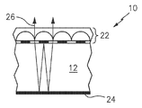
도 1은 포커싱 요소 배열체와 화상 아이콘 배열체가 중합체 또는 중합체 기재의 대향면 상에 직접 형성되는, 본 발명의 개선된 중합체 시트 재료의 일 실시예의 측단면도이고;
도 2는 도 1과 유사하지만, 포커싱 요소 배열체와 화상 아이콘 배열체가 기재의 대향면 상에 전사되는, 일 실시예의 측단면도이며;
도 3a는 화상 아이콘 배열체와 그 위에 놓인 내장된 포커싱 요소 배열체가 중합체 기재의 상면에 배치되고 반사층이 기재의 하면에 배치되는, 본 발명의 개선된 중합체 시트 재료의 일 실시예의 측단면도이고;
도 3b는 반사층이 탈금속화된 "홀"을 포함하도록 조정되어 있는, 도 3a에 도시된 실시예의 측단면도이며;
도 3c는 흰색 표면 위에 놓였을 때 밝은 "누락" 영역으로 보이는 단어 "DEMET TEXT"를 포함하도록 반사층이 조정된 도 3b에 나타낸 실시예의 평면도인 반면; 도 3d는 어두운 표면 위에 놓였을 때 단어 "DEMET TEXT"가 이제는 어두운 "누락" 영역으로 보이는 도 3c에 나타낸 실시예의 평면도이고;
도 3e는 투과광에서 볼 때 단어 "DEMET TEXT"가 불투명한 배경에 대해 밝은 영역으로 보이는 도 3c에 나타낸 실시예의 평면도이며;
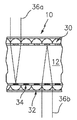
도 4a는 제1 화상 아이콘 배열체와 제1 포커싱 요소 배열체가 중합체 기재의 일면에 직접 형성되거나 도포되고, 동일하거나 상이한 제2 화상 아이콘 배열체와 제2 포커싱 요소 배열체가 기재의 대향면에 직접 형성되거나 도포되는, 본 발명의 개선된 중합체 시트 재료의 일 실시예의 측단면도이다. 도 4b는 도 4a와 유사하지만, 포커싱 요소가 내장된 포커싱 요소인 일 실시예의 측단면도이다. 도 4c는 도 4a와 유사하지만, 포커싱 요소가 일면에서는 내장되고 타면에서는 내장되지 않거나 개방된 포커싱 요소인 다른 실시예의 측단면도이다.
도 5는 화상 아이콘 배열체와 그 아래에 놓인 오목한 반사성 포커싱 요소 배열체 형태의 광학 보안 소자가 중합체 기재의 일면에 전사되는 것으로 도시된 본 발명의 개선된 중합체 시트 재료의 일 실시예의 측단면도이다.
도 6a는 집적된 광학 보안 소자가 2개의 상이한 크기를 가진 내장되거나 밀봉된 포커싱 요소 배열체, 중합체 기재의 일면 상의 원격지에 배치된 제1 화상 아이콘 배열체, 및 제1 화상 아이콘 배열체에 직접 대향하여 기재의 대향면 상에 배치된 상이한 제2 화상 아이콘 배열체를 포함하고, 제1 및 제2 화상 아이콘 배열체가 모두 동시에 보이는, 본 발명의 중합체 시트 재료의 "절첩" 실시예의 측단면도이다. 도 6b는 도 6a와 유사하지만, 포커싱 요소가 동일한 크기이며, 일부 포커싱 요소는 내장되거나 밀봉된 반면 다른 포커싱 요소는 내장되지 않거나 개방되고, 제1 및 제2 화상 아이콘 배열체가 모두 동시에 보이는, 일 실시예의 측단면도이다. 도 6c는 도 6a와 유사하지만, 포커싱 요소는 동일한 크기이며 내장되거나 밀봉되고, 기재가 긴밀하게 절첩될 경우 기재의 동일한 측면의 화상 아이콘을 이미징하며, 기재가 느슨하게 절첩될 경우 기재의 대향 측면의 아이콘을 이미징하도록 조정되는, 다른 실시예의 측단면도이다.
도 7은 포커싱 요소 배열체가 2겹 사이에 배치되고, 동일하거나 상이한 제1 및 제2 화상 아이콘 배열체가 2겹 기재의 대향면에 배치된, 집적된 광학 보안 소자를 가진 "2겹" 중합체 또는 중합체 기재 형태의 개선된 중합체 시트 재료의 일 실시예의 측단면도이다.
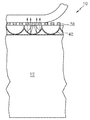
도 8a, 도 8b 및 도 8c는 "가볍게 금속화된(lightly metalized)" 하이브리드 굴절성/반사성 포커싱 요소 배열체 위 아래에 놓인 2개의 화상 아이콘 배열체 형태의 도포된 광학 보안 소자가 도시되어 있는, 본 발명의 개선된 중합체 시트 재료의 일 실시예의 측단면도이다. 도 8a에는 반사된 광에서 보이는 시트 재료가 도시되어 있는 반면, 도 8b에는 기재의 "배면"으로 향하는 밝은 광으로 보이는 시트 재료가 도시되어 있다. 도 8c에는, 기재의 "상부"에 원격으로 이격된 화상 아이콘을 가진 절첩 피처로서 사용될 경우, 기재의 "상부"로 향하는 밝은 광으로 보이는 본 발명의 시트 재료가 도시되어 있다.
도 9는 중합체 기재의 대향면 상의 상이한 컬러의 화상 아이콘과, 기재의 대향 측면 상의 "가볍게 금속화된" 하이브리드 굴절성/반사성 포커싱 요소 배열체 아래에 놓인 일부 화상 아이콘 상의 불투명 가쇄(overprint)를 채용한, 도 8a, 도 8b 및 도 8c와 유사한 일 실시예의 측단면도이다. The present disclosure may be better understood with reference to the following drawings. Corresponding reference numerals designate corresponding parts throughout the figures, and the components of the figures are not necessarily to scale, emphasis instead being placed upon clearly illustrating the principles of the present disclosure. Having thus described exemplary embodiments with reference to the drawings, it is not intended that the disclosure be limited to the embodiments or embodiments disclosed herein. On the contrary, the intention is to cover all alternatives, modifications and equivalents.
Illustrate certain features of the disclosed invention with reference to the accompanying drawings.
BRIEF DESCRIPTION OF THE DRAWINGS Figure 1 is a side cross-sectional view of one embodiment of an improved polymeric sheet material of the present invention in which a focusing element array and an image icon array are formed directly on opposite faces of a polymer or polymer substrate;
Figure 2 is a side cross-sectional view of one embodiment, similar to Figure 1, but in which the focusing element array and the image icon array are transferred onto opposite sides of the substrate;
Figure 3a is a side cross-sectional view of one embodiment of an improved polymeric sheet material of the present invention wherein an image icon array and an on-board focusing element array disposed thereon are disposed on an upper surface of the polymeric substrate and a reflective layer is disposed on a lower surface of the substrate;
Figure 3b is a side cross-sectional view of the embodiment shown in Figure 3a, with the reflective layer adjusted to include a "hole "
3C is a top view of the embodiment shown in FIG. 3B where the reflective layer is adjusted to include the word "DEMET TEXT " which appears as a bright" missing " FIG. 3D is a plan view of the embodiment shown in FIG. 3C where the word "DEMET TEXT " is now in the dark" missing "area when placed on a dark surface;
Fig. 3E is a plan view of the embodiment shown in Fig. 3C where the word "DEMET TEXT " seen in the transmitted light appears as a bright region against an opaque background;
Figure 4a shows a first image icon array and a first focusing element array are formed or applied directly on one side of the polymer substrate and a second image icon array and a second focusing element array are formed on opposite sides of the substrate, Sectional side view of one embodiment of the improved polymeric sheet material of the present invention. FIG. 4B is a side cross-sectional view of an embodiment similar to FIG. 4A, but with a focusing element incorporated therein. FIG. 4C is a side cross-sectional view of another embodiment similar to FIG. 4A, but with the focusing element incorporated on one side and not on the other side or an open focusing element.
5 is a side cross-sectional view of one embodiment of an improved polymeric sheet material of the present invention shown as an optical security element in the form of an image icon array and a recessed reflective focusing element array underlying it transferred to one side of the polymeric substrate.
Figure 6a illustrates an integrated optical security element having a built-in or sealed focusing element arrangement with two different sizes, a first image icon arrangement disposed at a remote location on one side of the polymer substrate, Sectional view of a "folded" embodiment of a polymer sheet material of the present invention, comprising a different second image icon array disposed on opposite sides of the substrate towards the first and second image icon arrangements, all of which are simultaneously visible. Figure 6b is similar to Figure 6a except that the focusing elements are the same size, some focusing elements are embedded or sealed while the other focusing elements are not embedded or open, and the first and second image icon arrays are all visible at the same time. Fig. 6C is similar to FIG. 6A except that the focusing elements are the same size and are built-in or sealed, imaging the image icon on the same side of the substrate when the substrate is folded tightly, and when the substrate is loosely folded, Lt; / RTI > is a side cross-sectional view of another embodiment that is adapted to image an image.
Figure 7 is a "two-ply" polymer or polymer having an integrated optical security element in which the focusing element array is disposed between two plies and the same or different first and second image icon arrays are disposed on opposite faces of the double- Sectional side view of one embodiment of an improved polymeric sheet material in substrate form.
Figures 8a, 8b and 8c illustrate an applied optical security element in the form of two image icon arrangements placed above a "lightly metallized" hybrid refractive / reflective focusing element array. Sectional side view of one embodiment of the improved polymeric sheet material of the present invention. Figure 8a shows the sheet material seen in the reflected light, while Figure 8b shows the sheet material seen as bright light directed to the "backside" of the substrate. Figure 8c shows the sheet material of the present invention as seen by the bright light directed to the "top" of the substrate when used as a folded feature with a remotely spaced image icon on the "top" of the substrate.
Figure 9 employs opaque overprints on image icons of different colors on the polymer-based facing side and some image icons placed below "lightly metallized" hybrid refractive / reflective focusing element arrays on opposite sides of the substrate 8A, 8B and 8C. In the embodiment shown in Fig.
전술한 바와 같이, 본 발명은 하나 이상의 집적되고/또는 도포된 광학 보안 소자를 가진 중합체 또는 중합체 기재 형태의 개선된 중합체 시트 재료를 제공한다. 중합체 또는 중합체 기재는 하나 이상의 투명한 중합체 필름 층, 바람직하게는 투명한 이축 연신 중합체 필름을 포함할 수 있다. 더 바람직한 실시예에서, 기재는 단층 BOPP 필름, 또는 열 활성화 접착제 층으로 각각 코팅된 2개 이상의 BOPP 필름 층의 라미네이트 중 어느 하나이다. 중합체 또는 중합체 기재의 전체 두께는 통상적으로 약 60 미크론 이상(바람직하게는, 약 60 내지 약 90 미크론)의 범위이다. As described above, the present invention provides an improved polymeric sheet material in the form of a polymer or polymer substrate having one or more integrated and / or coated optical security elements. The polymer or polymer substrate may comprise at least one transparent polymer film layer, preferably a transparent biaxially oriented polymer film. In a more preferred embodiment, the substrate is either a single layer BOPP film, or a laminate of two or more layers of BOPP film each coated with a layer of heat activated adhesive. The overall thickness of the polymer or polymer substrate is typically in the range of about 60 microns or greater (preferably about 60 to about 90 microns).
광학 보안 소자(들)가 기재의 일부에만 집적되고/또는 도포되는 실시예의 경우, 그 나머지 부분을 덮기 위해 불투명화 코팅이 사용될 수 있다. 불투명화 코팅은 대부분(≥50%)의 안료와 약간(<50%)의 가교 결합된 중합체 바인더로 구성된다.For embodiments in which the optical security element (s) are only integrated and / or applied to a portion of the substrate, an opaque coating may be used to cover the remainder. Opacified coatings consist of mostly (≥50%) pigments and slightly (<50%) cross-linked polymeric binders.
광학 보안 소자(들)가 전체 기재에 집적되고/또는 도포되는 실시예의 경우, 불투명화 코팅이 사용되거나 사용되지 않을 수 있다. 관련 기술 분야의 기술자라면 쉽게 알 수 있는 바와 같이, 이러한 시트 재료는 완전히 미세 광학적인 보안 문서 또는 은행권을 제조하기 위해 사용되며, 이는 다수의 분명하고 특이한 장점을 제공한다. For embodiments in which the optical security element (s) are integrated and / or applied to the entire substrate, an opaque coating may or may not be used. As will be readily apparent to those skilled in the relevant art, such sheet materials are used to manufacture fully micro-optical security documents or banknotes, which provide a number of clear and unique advantages.
본 발명의 중합체 시트 재료의 광학 보안 소자는 기본적으로 하나 이상의 선택적으로 내장된 원통형 또는 비-원통형 포커싱 요소 배열체와, 하나 이상의 화상 아이콘 배열체를 포함한다. 전술한 바와 같이, 이 배열체들은, 포커싱 요소 배열체를 통해 화상 아이콘 배열체를 보았을 때, 하나 이상의 합성 화상이 투사되도록 구성된다.The optical security element of the polymer sheet material of the present invention basically comprises one or more selectively embedded cylindrical or non-cylindrical focusing element arrays and one or more image icon arrays. As described above, these arrangements are configured to project one or more composite images when viewing the image icon array through the focusing element arrangement.
본 발명을 실시하는데 사용되는 선택적으로 내장된 포커싱 요소는 굴절성 포커싱 요소, 반사성 포커싱 요소, 하이브리드 굴절성/반사성 포커싱 요소, 및 이들의 조합을 포함하지만, 이에 한정되지는 않는다. 하나의 고려된 실시예에서, 포커싱 요소는 굴절성 마이크로 렌즈이다. 적당한 포커싱 요소의 예가 스틴블릭 등의 미국 특허 제7,333,268호, 스틴블릭 등의 미국 특허 제7,468,842호, 및 스틴블릭 등의 미국 특허 제7,738,175호에 기술되어 있으며, 이 특허들은 모두 그 전체가 본원에 완전히 명시된 것처럼 참조로 인용되어 있다.An optional built-in focusing element used in practicing the invention includes, but is not limited to, a refractive focusing element, a reflective focusing element, a hybrid refractive / reflective focusing element, and combinations thereof. In one contemplated embodiment, the focusing element is a refractive micro lens. Examples of suitable focusing elements are described in U.S. Patent No. 7,333,268 to Stinblick et al., U.S. Patent No. 7,468,842 to Stinblick et al, and U.S. Patent No. 7,738,175 to Stinblick, all of which are hereby incorporated by reference in their entirety Quoted < / RTI > as indicated.
포커싱 요소는 (ⅰ) 약 200 내지 약 500 미크론 범위 및 약 50 내지 약 199 미크론 범위의 폭/베이스 직경을 포함한 1㎜ 이하, 또는 (ⅱ) 약 45 미크론 미만의 범위 및 약 5 내지 약 40 미크론 범위의 폭/베이스 직경을 포함한 약 50 미크론 미만 중 어느 하나인 바람직한 폭(원통형 렌즈의 경우)과 베이스 직경(비-원통형 렌즈의 경우)을 갖는다. (Ii) a range of less than about 45 microns and a range of about 5 to about 40 microns, including (i) a range of about 200 to about 500 microns and a width / base diameter in the range of about 50 to about 199 microns; (In the case of a cylindrical lens) and a base diameter (in the case of a non-cylindrical lens) which is either less than about 50 microns including the width / base diameter of the lens.
포커싱 요소의 내장은 광학적으로 저하하는 외부 효과에 대한 광학 보안 소자의 저항을 향상시키는 역할을 한다. 그러한 일 실시예에서, 광학 보안 소자의 외면으로부터 굴절 계면까지의 굴절률은 제1 굴절률과 제2 굴절률 사이에서 변하며, 제1 굴절률은 제2 굴절률과 실질적으로 또는 측정 가능하게 상이하다. 본원에서 사용되는 바와 같이, 어구 "실질적으로 또는 측정 가능하게 상이하다"는 포커싱 요소의 초점 길이(들)를 적어도 약 0.1 미크론 변화시키는 굴절률의 차이를 의미한다.The incorporation of the focusing element serves to improve the resistance of the optical security element to optically degrading external effects. In one such embodiment, the index of refraction from the outer surface of the optical security element to the refractive interface varies between a first index of refraction and a second index of refraction, wherein the first index of refraction is substantially or measurably different from the second index of refraction. As used herein, the phrase "substantially or measurably different" means a difference in refractive index that varies the focal length (s) of the focusing element by at least about 0.1 microns.
내장 재료는 투명하거나, 반투명하거나, 염색되거나, 착색될 수 있으며, 광학적 효과, 전기 전도성 또는 전기 용량, 자기장 검출에 의존하는 자동화된 통화 인증, 확인, 추적, 계수 및 검출 시스템의 지원을 포함하여, 보안 및 인증을 목적으로 추가적인 기능을 제공할 수 있다. 적절한 재료는 접착제, 겔, 아교, 래커, 액체, 성형된 중합체, 및 유기 또는 금속 분산제를 함유한 중합체 또는 다른 재료를 포함할 수 있다.Embedded materials can be transparent, translucent, dyed, or pigmented, and can be transparent, including optical effects, electrical conductivity or capacitance, automated call authentication that relies on magnetic field detection, identification, tracking, Additional features may be provided for security and authentication purposes. Suitable materials may include adhesives, gels, glue, lacquers, liquids, shaped polymers, and polymers or other materials containing organic or metallic dispersants.
화상 아이콘은 중합체 또는 중합체 기재 상에 인쇄될 수 있거나, 기재의 표면에 비해 융기되거나 함몰된 미세 구조 화상 아이콘을 구성할 수 있다. 바람직한 실시예에서, 화상 아이콘은 기재 상에 또는 그 내부에 공극 또는 리세스로서 형성되거나, 기재에 비해 융기된다. 어느 경우에나, 화상 아이콘은 주조 또는 열 압력 공정으로 형성될 수 있다. The burn icon may be printed on a polymer or polymer substrate, or may constitute a microstructure burn icon raised or depressed relative to the surface of the substrate. In a preferred embodiment, the image icons are formed as voids or recesses on or in the substrate, or are raised relative to the substrate. In either case, the burn icon may be formed by a casting or thermal pressure process.
본 발명에 의해 고려된 일 실시예에서, 화상 아이콘은 중합체 또는 중합체 기재 상에 또는 그 내부에 형성되는 선택적으로 코팅되고/또는 충전된 공극 또는 리세스이다. 공극 또는 리세스는 각각 전체 깊이가 약 0.5 내지 약 8 미크론이고, 전체 폭이 약 0.5 미크론 이상일 수 있다.In one embodiment contemplated by the present invention, the image icon is an optionally coated and / or filled void or recess formed on or within the polymer or polymer substrate. The voids or recesses may each have a total depth of from about 0.5 to about 8 microns, and the overall width may be greater than about 0.5 microns.
이제, 도면과 관련하여 본 발명의 중합체 시트 재료의 예시적인 실시예를 개시할 것이다. 그러나, 본 개시물을 본원에 개시된 실시예로 한정하고자 하는 의도는 없다. 반대로, 모든 대안, 변형 및 등가물을 포함하고자 한다. Now, an exemplary embodiment of the polymer sheet material of the present invention will be described with reference to the drawings. However, there is no intention to limit the disclosure to the embodiments disclosed herein. On the contrary, the intention is to cover all alternatives, modifications and equivalents.
도 1에 가장 잘 나타낸 제1 예시적 실시예에서, 본 발명의 개선된 중합체 시트 재료(10)는 집적된 광학 보안 소자(14)를 가진 중합체 또는 중합체 기재(12)의 형태이며, 집적된 소자(14)는 기재(12)의 대향면에 직접 형성되는 포커싱 요소(예컨대, 굴절성 마이크로 렌즈) 배열체(16)와 화상 아이콘 배열체(18)로 구성된다. 여기서, 기재(12)는 광학 스페이서로서 작용함으로써 집적된 광학 보안 소자(14)의 광학적 기능에 기여한다.1, the improved
굴절성 마이크로 렌즈(16)는, 표면에 대해 수직하게 보았을 때, 기재(12)의 대향 측면의 화상 아이콘(18)이 그 초점 깊이의 일부와 실질적으로 교차하도록 하는, 초점 길이를 각각 갖는다. 이 굴절성 마이크로 렌즈(16)는 원통면, 구면 또는 비구면을 가질 수 있다.
전술한 바와 같이, 화상 아이콘은 인쇄법으로, 또는 미세 구조의 공극 또는 중실 영역으로 형성될 수 있다. 바람직한 실시예에서, 화상 아이콘은 기재 상에 또는 그 내부에 선택적으로 코팅되고/또는 충전되는 공극 또는 리세스로 형성되고, 각각의 공극 또는 리세스의 전체 깊이는 약 0.5 내지 약 8 미크론이며, 전체 폭은 약 0.5 이상이다. 공극 또는 리세스는 주변 또는 하부의 재료와는 상이한 굴절률을 가진 재료, 염색된 재료, 금속, 또는 착색된 재료(예컨대, 서브 미크론 입자가 착색된 유색 재료)로 충전되거나 코팅될 수 있다. 이러한 접근 방식은 거의 무한한 공간 해상도의 이점을 갖는다. As described above, the image icon may be formed by a printing process, or into a pore or solid area of the microstructure. In a preferred embodiment, the image icon is formed by pores or recesses that are selectively coated and / or filled on or within the substrate, wherein the total depth of each pore or recess is from about 0.5 to about 8 microns, The width is about 0.5 or more. The void or recess may be filled or coated with a material having a refractive index different from that of the surrounding or underlying material, a dyed material, a metal, or a colored material (e.g., colored material with submicron particles colored). This approach has the advantage of almost infinite spatial resolution.
전술한 바와 같이, 포커싱 요소 배열체(16)와 화상 아이콘 배열체(18)는 아크릴, 아크릴레이티드 폴리에스테르, 아크릴레이티드 우레탄, 에폭시, 폴리카보네이트, 폴리프로필렌, 폴리에스테르, 우레탄 등과 같이 실질적으로 투명하거나 맑은, 유색 또는 무색의 중합체와 같은 다양한 재료로 형성될 수 있다. As described above, the focusing
예시적인 제조 방법에서, 기재(12)에 대해 아이콘 주형으로부터 주조되는 방사선 경화성 액체 중합체(예컨대, 아크릴레이티드 우레탄) 내의 공극으로서 화상 아이콘을 형성한다. 그 다음, 중합체 아이콘 표면에 대한 그라비어와 같은 닥터 블레이딩(doctor blading)에 의해 서브 미크론 입자가 착색된 유색 재료로 화상 아이콘 공극을 충전한다. 그 다음, 적절한 수단(예컨대, 용매 제거, 방사선 경화 또는 화학 반응)으로 충전물을 고화한다. 그 다음, 방사선 경화성 중합체로 충전된 렌즈 주형에 기재(12)의 대향 측면을 접촉시킴으로써, 그 측면에 대해 렌즈를 주조한다. 그 다음, 자외선(UV) 광 또는 다른 화학 방사선을 조사하여 중합체를 고화한다.In an exemplary method of manufacture, an image icon is formed as a void in a radiation curable liquid polymer (e.g., acrylated urethane) cast from an icon mold for the
이 예시적인 실시예에서 집적된 광학 보안 소자(14)와 다음의 예시적인 실시예의 집적되거나 도포된 광학 보안 소자는 임의의 크기 또는 형상을 채택할 수 있다. 예컨대, 이들은 패치, 스트라이프(밴드 또는 스레드) 또는 공동-확장층(co-extensive layer)의 형상으로 형성될 수 있다.In this exemplary embodiment, the integrated
도 2에 가장 잘 나타낸 제2 예시적 실시예에서는, 굴절성 마이크로 렌즈 배열체(16)와 화상 아이콘 배열체(18)가 기재(12)의 대향면의 전부 또는 일부에 전사된다. In the second exemplary embodiment best illustrated in FIG. 2, the refractive
이와 같이 전사 가능한 포커싱 요소 층과 화상 아이콘 층을 형성하는 예시적인 방법은, An exemplary method of forming such a transferable focusing element layer and image icon layer,
캐리어 필름(예컨대, 자외선 투과성 캐리어 필름)에 부착된 "렌즈 주형" 층을 포함하는 미세 구조-수반(microstructure-bearing) 박리 라이너를 형성하는 단계로서, "렌즈 주형" 층은 발산 렌즈(negative lens) 형태의 복수의 공극을 가진 경화성 수지로 형성되고, 발산 렌즈 형태는 수렴 렌즈(positive lens) 형태를 가진 강성 표면에 대해 수지를 자외선 경화시킴으로써 만들어지는, 단계; Forming a microstructure-bearing release liner comprising a "lens mold" layer attached to a carrier film (e.g., an ultraviolet transparent carrier film) Wherein the diverging lens shape is made by ultraviolet curing the resin against a rigid surface having a shape of a positive lens;
복수의 공극을 광학적으로 기능하는 자외선 경화성 액체 중합체(예컨대, 폴리에스테르 아크릴레이트)로 충전하고, 닙 롤러로 가압하여 과잉 액체 중합체를 압출함과 동시에, 자외선 경화성 중합체가 경화하거나 굳어져 렌즈 주형으로부터 리프팅될 수 있도록, 액체 중합체를 자외선에 노출시키는 단계; A plurality of voids are filled with an optically functional, ultraviolet curable liquid polymer (e.g., polyester acrylate) and pressed with a nip roller to extrude the excess liquid polymer, and the ultraviolet curable polymer is cured or hardened, Exposing the liquid polymer to ultraviolet light;
박리 라이너(예컨대, 기능성 박리 코팅을 가진 평활한 또는 비-구조화된 캐리어 기재)의 표면에 경화성 수지 재료를 도포하고, 그 표면을 강성 아이콘 주형에 대해 경화시켜서 경화성 수지 재료의 표면 내의 공극 형태로 하나 이상의 화상 아이콘 배열체를 형성하는 단계; A curable resin material is applied to the surface of a release liner (e.g., a smooth or non-structured carrier substrate with a functional release coating) and the surface is cured against the rigid iconic mold to form a void in the surface of the curable resin material Forming an image icon array;
경화성 수지 재료와 함께 콘트라스트를 제공하는 재료로 공극을 충전하여 충전된 화상 아이콘 층을 형성하는 단계; 및Filling the void with a material that provides contrast with the curable resin material to form a charged image icon layer; And
전사 가능한 층에 하나 이상의 접착제 층(예컨대, 부점착(tack free) 열 활성화 접착제 층)을 도포하는 단계를 포함한다. (E. G., A tack-free thermally activatable adhesive layer) to the transferable layer.
일단 제조되면, 전사 가능한 층은 통상적인 전사 호일처럼 취급될 수 있으며, 즉, 이 재료는 롤에 권취되거나 롤로부터 권출될 수 있고, 보안 인쇄 및 패키징 산업에서 일반적인 변환 방법으로 패치, 스트라이프(밴드 또는 스레드) 또는 시트와 같은 적절한 최종 형상으로 더 변환될 수 있다. 박리 라이너로부터 포커싱 요소 층(16)과 화상 아이콘 층(18)을 전사하기 위해, 각각의 전사 가능한 층의 접착제 측면이 중합체 또는 중합체 기재(12)의 대향 측면과 접촉하도록 배치된다. 열 및/또는 압력이 인가됨으로써, 접착제 층(20)의 접착제가 기재(12)에 견고하게 접착되도록 한다. 그 다음, "렌즈 주형" 층을 구비한 박리 라이너와 다른 박리 라이너가 박리됨으로써, 원하는 포커싱 요소 층과 화상 아이콘 층을 남긴다.Once formed, the transferable layer can be treated like a conventional transfer foil, i.e. the material can be wound onto a roll or unwound from a roll, and can be patch, striped Thread) or sheet, as shown in FIG. To transfer the focusing
도 3a에 가장 잘 나타낸 제3 예시적 실시예에서, 본 발명의 중합체 시트 재료(10)는 중합체 또는 중합체 기재(12)의 상면에 배치된 화상 아이콘 배열체와 그 위에 놓인 선택적으로 내장된 포커싱 요소 배열체로 구성된 필름 재료(22) 형태의 집적된 광학 보안 소자와, 기재(12)의 하면 바로 아래에 배치된 반사층(24)(예컨대, 기상 증착 금속 층)을 채택하고 있다. 전술한 바와 같이, 이 실시예에서는, 반사층(24)이 반사면을 넘어 화상 아이콘의 반사를 제공하는 역할을 함으로써, 포커싱 요소가 화상 아이콘의 반사에 집중할 수 있고, 이에 따라, 화상 아이콘 배열체(들)를 넘어 연장하는 초점 길이를 가진 포커싱 요소의 사용을 허용한다.In the third exemplary embodiment, best illustrated in FIG. 3A, the
필름 재료(22)는 기재(12) 상에 그대로 형성될 수 있거나, (하나 이상의 접착제 층을 구비한) 필름 재료는 기계적, 화학적, 열적 및 광유도 분리 기술을 포함한 전술한 기술을 사용하여 전사 필름으로서 기재에 전사될 수 있다. 캐리어 기재로부터 원하는 구성 요소를 분리하는 개념은 홀로그램 호일 전사 분야에 공지되어 있으며, 이에 따라, 열과 압력의 인가를 통해 광학 코팅 및 접착제가 최종 기재에 전사될 수 있도록, 박리 코팅을 구비한 필름(즉, 박리 라이너)에 광학 코팅이 제공된다. The
반사층(24)은 기상 증착 금속 층일 수 있다. 예컨대, 증발되거나 스퍼터링된 알루미늄, 금, 로듐, 크롬, 오스뮴에 의해, 열화된 우라늄 또는 은에 의해, 화학적으로 증착된 은에 의해, 또는 다층 간섭 필름에 의해, 금속화가 달성될 수 있다. 이 층은 패턴화된 탈금속화 또는 홀로그램 피처로부터 형성된 화상 아이콘을 포함할 수 있다. 이 예시적인 실시예에서, 포커싱 요소는 아이콘의 반사에 중점을 둔다.The
바람직한 실시예에서, 반사층(24)은, 그들의 배경과 비교하여 융기되거나 함몰된 화상 아이콘(보조 화상 아이콘)이 패턴화된 탈금속화에 의해 형성되는, 패턴화된 금속 층이다. 탈금속화된 패턴 또는 보조 화상 아이콘은 양각 문자, 음각 문자, 이미지, 선(line work) 등을 포함한 임의의 형태를 채택할 수 있지만, 이에 한정되지는 않는다. 이러한 보조 화상 아이콘은 어떤 포커싱 요소가 반사를 볼 것인지, 어떤 포커싱 요소가 반사를 보지 않을 것인지를 제어한다. 이 제어를 제공함으로써, 광을 차단하고 선명한 화상이 투과된 광에서 보일 수 있도록 하는 제2 화상이 제공된다. 이는 정적 화상이며, 합성 화상(예컨대, 움직이거나 3차원적인 합성 화상)이 아닐 것이다. In a preferred embodiment, the
도 3b 내지 도 3e와 함께, 이 바람직한 실시예에 의해 달성되는 시각적 효과를 설명한다. 도 3b에서, 반사층(24)은 탈금속화된 "홀"을 포함하도록 조정된다(도 3b에는 1개의 탈금속화된 "홀"만 도시됨). 그 결과, 그 영역에 있는 광학 기기를 광이 곧바로 통과한다. 본 발명의 시트 재료를 보면, "홀"이 위치하는 누락 부분을 가진 하나 이상의 합성 화상이 보일 것이다. 아래에 놓인 기재의 색상(또는 투명도)에 따라, 누락된 부분이 밝은 "누락" 영역이나 어두운 "누락" 영역으로 나타날 수 있다. 예컨대, 그리고 도 3c, 도 3d 및 도 3e에 가장 잘 나타낸 바와 같이, 반사층은 단어 "DEMET TEXT"를 포함하도록 조정된다. 도 3c에서, 이 단어는 밝은 "누락" 영역으로 나타나며, 이는 본 발명의 중합체 시트 재료가 흰색 표면(예컨대, 흰색 중합체 표면) 위에 또는 종이 기재 위에 배치되어 있음을 나타낸다. 이 효과는 본 발명의 시트 재료가 반사광과 투과광의 조합으로 보인다는 것을 또한 나타낼 수 있다. 도 3d에서, 이 단어는 어두운 "누락" 영역으로 나타나며, 이는 시트 재료가 (반사된 광에서 나타나는) 어두운 배경에 대해 유지된 투명 중합체 또는 중합체 기재 위에 배치되어 있음을 나타낸다. 도 3e에 나타낸 바와 같이, 본 발명의 시트 재료를 투과광에서 보면, 미세 광학 기기 영역은 (금속 반사층의 존재로 인해) 불투명할 것이고, 탈금속화된 영역(즉, 단어 "DEMET TEXT")은 밝게 나타날 것이다. 3B to 3E, the visual effects achieved by this preferred embodiment will be described. In Figure 3B, the
하나의 버전이 도 4a에 도시되어 있는 제4 예시적 실시예에서, 본 발명의 중합체 시트 재료(10)는 기재(12)의 일면의 전부 또는 일부에 직접 형성되거나 도포된 제1 화상 아이콘 배열체(30)와 제1 포커싱 요소 배열체(28), 및 기재(12)의 대향면의 전부 또는 일부에 직접 형성되거나 도포된 동일하거나 상이한 제2 화상 아이콘 배열체(34)와 제2 포커싱 요소 배열체(32)로 구성된 집적된 광학 보안 소자를 채택하고 있다. 여기서, 기재(12)의 일면의 포커싱 요소는 기재의 대향면의 화상 아이콘에 초점을 맞춘다. 이 실시예는 앞면과 뒷면에 상이한 및/또는 상이한 컬러 화상(36a, 36b)을 표시하는 양면 실시예이다. 도 4b에서, 포커싱 요소는 내장된 포커싱 요소이다. 4a, a
동일한 포커싱 요소 또는 렌즈(배열체(28) 내의 렌즈 및 배열체(32) 내의 렌즈)를 사용하여 이 시트 재료를 제조하고자 한다면, 이 렌즈들은 서로 이미징하여 양측에서 볼 수 있는 렌즈 자체의 물결 무늬 패턴을 형성할 것이다. 이러한 효과를 피하기 위해서, 도 4a 및 도 4b에 도시된 본 발명의 중합체 시트 재료(10)는 다음과 같은 사항을 포함한다. If the same focusing element or lens (lens in
(A) 기재의 각 측면에서의 내장되지 않거나 개방된 렌즈 배열체의 사용(도 4a 참조)으로서, 각각의 렌즈 배열체는 다음 중 하나 이상을 갖는다. (See Fig. 4A), each lens arrangement having one or more of the following:
a. 렌즈 배열체의 상이한 회전각(바람직하게, 물결 무늬 효과를 최소화하도록 설계된 회전각)(즉, 다른 렌즈 배열체의 회전각과는 상이한 회전각). 통상적으로, 1 내지 2°또는 약간 더 큰 각도는 임의의 물결 무늬 효과를 충분히 축소할 것이므로, 렌즈를 바라보고 있는 렌즈의 물결 무늬 효과가 임의의 원하는 합성 화상과 비교하여 크기가 매우 작아질 것이다. 원한다면, 이 각도는 더 조정될 수 있지만, 각도를 너무 많이 증가시키면, 새로운 물결 무늬 화상이 나타날 수 있다; a. Different angles of rotation of the lens arrangement (preferably rotational angles designed to minimize the wave pattern effect) (i.e., rotational angles different from the angles of rotation of the other lens arrays). Typically, an angle of from 1 to 2 degrees or slightly larger will sufficiently reduce any wavelet effect, so that the wavelet effect of the lens facing the lens will be much smaller in size compared to any desired composite image. If desired, this angle can be further adjusted, but if you increase the angle too much, a new wave pattern image may appear;
b. 육각형 그리드에 놓이도록 된 배열체(28) 내의 상부 렌즈와 직사각형 또는 정사각형 그리드에 놓이도록 된 배열체(32) 내의 하부 렌즈와 같은, 상이한 격자 구조 또는 렌즈 패턴(예컨대, 원형, 삼각형, 사각형, 육각형 렌즈 어레이 패턴)(즉, 다른 렌즈 배열체의 격자 구조와는 상이한 격자 구조); 또는
b. A different lattice structure or lens pattern (e.g., a circle, a triangle, a rectangle, a hexagon, a hexagon, or the like), such as an upper lens in an
c. 상이한 피치(즉, 다른 렌즈 배열체의 피치와는 상이한 피치), c. Different pitches (i.e., different pitches from the pitches of the other lens arrangements)
(B) 기재의 각 측면에서의 내장되거나 밀봉된 렌즈 배열체의 사용(도 4b 참조)으로서, 각각의 렌즈 배열체는 다음 중 하나 이상을 갖는다. (B) the use of a built-in or sealed lens arrangement on each side of the substrate (see Figure 4b), each lens arrangement having one or more of the following:
a. 렌즈 배열체의 상이한 회전각(바람직하게, 물결 무늬 효과를 최소화하도록 설계된 회전각)(즉, 다른 렌즈 배열체의 회전각과는 상이한 회전각). 통상적으로, 1 내지 2°또는 약간 더 큰 각도는 임의의 물결 무늬 효과를 충분히 축소할 것이므로, 렌즈를 바라보고 있는 렌즈의 물결 무늬 효과가 임의의 원하는 합성 화상과 비교하여 크기가 매우 작아질 것이다. 원한다면, 이 각도는 더 조정될 수 있지만, 각도를 너무 많이 증가시키면, 새로운 물결 무늬 화상이 나타날 수 있다; a. Different angles of rotation of the lens arrangement (preferably rotational angles designed to minimize the wave pattern effect) (i.e., rotational angles different from the angles of rotation of the other lens arrays). Typically, an angle of from 1 to 2 degrees or slightly larger will sufficiently reduce any wavelet effect, so that the wavelet effect of the lens facing the lens will be much smaller in size compared to any desired composite image. If desired, this angle can be further adjusted, but if you increase the angle too much, a new wave pattern image may appear;
b. 육각형 그리드에 놓이도록 된 배열체(28) 내의 상부 렌즈와 직사각형 또는 정사각형 그리드에 놓이도록 된 배열체(32) 내의 하부 렌즈와 같은, 상이한 격자 구조 또는 렌즈 패턴(예컨대, 원형, 삼각형, 사각형, 육각형 렌즈 어레이 패턴)(즉, 다른 렌즈 배열체의 격자 구조와는 상이한 격자 구조); 또는
b. A different lattice structure or lens pattern (e.g., a circle, a triangle, a rectangle, a hexagon, a hexagon, or the like), such as an upper lens in an
c. 상이한 피치(즉, 다른 렌즈 배열체의 피치와는 상이한 피치). c. Different pitches (i.e., different pitches from the pitches of the other lens arrays).
위의 경우들에서, 불가피하게 피치를 변경하면, 렌즈가 서로로부터 더 멀리 이격되거나(이로 인해, 광 효율의 손실이 발생하며), (항상 급격하게 변화될 수 있은 파라미터가 아닌) 렌즈의 곡률 반경의 변화가 필요하기 때문에, 상이한 피치를 가지면, "유일한" 해결책으로서 달성하기 어려울 수 있다. 이 문제점을 고려하여, 본 발명자는 도 4c에 도시된 더 바람직한 실시예에 도달하였다. 이와 같이 더 바람직한 실시예에 의하면, 본 발명의 중합체 시트 재료(10)는 기재의 일측면의 내장되지 않거나 개방된 렌즈 배열체와, 타측면의 내장되거나 밀봉된 렌즈를 채용한다. 이 배열체는 2개의 포커싱 요소 시스템들 간의 피치 차이를 크게 변화시킨다. 또한, 이는 시트 재료(10)의 일측면이 약간 "조직화"되는 반면, 타측면이 완전히 평활하게 되는 흥미로운 결과를 갖는다. 이 효과는 유용한 보조(세미-포렌식) 인증 피처를 구성한다.In these cases, inevitably changing the pitch causes the lens to be farther away from each other (thereby causing a loss of light efficiency), or the radius of curvature of the lens (not the parameter that can always be changed rapidly) , It can be difficult to achieve as a "unique" solution if it has different pitches. In consideration of this problem, the present inventor reached a more preferred embodiment shown in Fig. 4C. According to such a more preferred embodiment, the
도 5에 가장 잘 나타낸 제5 실시예에서, 본 발명의 중합체 시트 재료(10)는 기재(12)의 일면에 전사되는 화상 아이콘 배열체(38)와 그 아래에 놓인 오목한 반사성 포커싱 요소 배열체(40)로 구성된 도포된 광학 보안 소자를 구비한 중합체 또는 중합체 기재(12)의 형태이다. 5, the
이 제5 실시예에서, 본 발명의 시트 재료(10)는 화상 아이콘 배열체(38)와 박리 라이너 간의 접착 강도에 맞게 제작된다. 이 접착 강도는 기재(12)와 오목한 반사성 포커싱 요소 배열체(40) 사이에 위치하게 되는 접착제 간의 접착 강도보다 작아야 한다. 상이한 접착 강도가 필요한 이유는, 본 발명의 일부 실시예의 경우, 일단 시트 재료가 기재(12)에 도포되면, 박리 라이너가 시트 재료(10)로부터 "박리"되어야 하기 때문이다. 내마모성이 더 요구되는 다른 실시예의 경우, 도포된 중합체 시트 재료(10) 상에 박리 라이너가 그대로 남아 있으므로, 시트 재료(10)로부터 "박리"될 필요가 없다. In this fifth embodiment, the
이 전사 가능한 얇은(반사성) 광학 보안 소자의 예시적인 실시예를 제조하는 예시적인 방법은, An exemplary method of making an exemplary embodiment of this transferable thin (reflective) optical security element,
박리 라이너(예컨대, 기능성 박리 코팅을 가진 평활한 또는 비-구조화된 캐리어 기재)의 표면에 경화성 수지 재료를 도포하고, 그 표면을 강성 아이콘 주형에 대해 경화시켜서 경화성 수지 재료의 표면 내의 공극 형태로 하나 이상의 화상 아이콘 배열체를 형성하는 단계; A curable resin material is applied to the surface of a release liner (e.g., a smooth or non-structured carrier substrate with a functional release coating) and the surface is cured against the rigid iconic mold to form a void in the surface of the curable resin material Forming an image icon array;
경화성 수지 재료와 함께 콘트라스트를 제공하는 재료로 공극을 충전하여 충전된 화상 아이콘 층을 형성하는 단계; Filling the void with a material that provides contrast with the curable resin material to form a charged image icon layer;
충전된 화상 아이콘 층의 표면에 경화성 수지 재료를 도포하고, 발산 렌즈 형태를 가진 강성 표면(즉, 발산 렌즈 주형)에 대해 수지를 경화시켜서 경화성 수지 재료의 표면에 하나 이상의 포커싱 요소 배열체를 형성하는 단계; Applying a curable resin material to the surface of the charged image icon layer and curing the resin against a rigid surface having a diverging lens shape (i.e., a diverging lens mold) to form one or more focusing element arrangements on the surface of the curable resin material step;
포커싱 요소에 금속 또는 다른 반사성 재료의 컨포멀한 코팅을 도포하여 하나 이상의 반사성 포커싱 요소 배열체를 형성하는 단계; Applying a conformal coating of a metal or other reflective material to the focusing element to form at least one reflective focusing element arrangement;
하나 이상의 반사성 포커싱 요소 배열체에 하나 이상의 보호 코팅 층을 선택적으로 도포하는 단계; 및Selectively applying one or more protective coating layers to at least one reflective focusing element array; And
하나 이상의 선택적으로 보호 코팅된 반사성 포커싱 요소 배열체에 하나 이상의 접착제 층(예컨대, 부점착 열 활성화 접착제 층)을 도포하는 단계를 포함한다. Applying one or more adhesive layers (e. G., A sub-adhesive heat activated adhesive layer) to one or more selectively protective coated reflective element arrangements.
이렇게 얻어진 필름형 구조는 전통적인 전사 필름처럼 취급/변환/전사될 수 있다. 즉, 변환된 구조가 중합체 또는 중합체 기재(12)와 접촉될 수 있으며, 열 및 압력이 인가되면, 박리 라이너는 기재(12)의 일측면에 얇은(반사성) 전사 생성물만을 남기고 완전히 박리될 수 있다. The film-like structure thus obtained can be handled / converted / transferred like a conventional transfer film. That is, the converted structure can be contacted with the polymer or
도 6a에 가장 잘 나타낸 제6 실시예에서, 본 발명의 중합체 시트 재료는 2개의 상이한 크기를 가진 내장되거나 밀봉된 포커싱 요소 배열체(42), 기재(12)의 일면의 원격지에 직접 형성되거나 도포된 제1 화상 아이콘 배열체(44), 및 제1 화상 아이콘 배열체(44)에 직접 대향하여 기재(12)의 대향면에 직접 형성되거나 도포된 상이한 제2 화상 아이콘 배열체(46)로 구성된 집적된 광학 보안 소자를 구비한 중합체 또는 중합체 기재(12) 형태의 "절첩" 중합체 시트 재료(10)이다. 상이한 초점 길이를 가진 상이한 크기의 포커싱 요소를 사용하는 이 실시예는 화상 아이콘 배열체(44, 46)를 모두 동시에 볼 수 있도록 한다. 내장된 포커싱 요소 배열체(42)를 포함하고 있는 기재의 부분이 제1 및 제2 화상 아이콘 배열체(44, 46)를 포함하고 있는 기재의 부분 바로 위에 위치되면, 2개의 상이한 화상(48, 50)이 투사될 것이다. 여기서, "동일한 측면"의 화상(48)은 "더 멀리"에서 보일 것이고, "대향 측면"의 화상(50)은 "더 가깝게" 보일 것이다. In the sixth embodiment best illustrated in Figure 6a, the polymeric sheet material of the present invention comprises a built-in or sealed focusing
도 6b에 도시된 유사한 실시예에서, 유사한 크기의 포커싱 요소가 사용되며, 그 중 일부는 내장되거나 밀봉되며, 나머지는 그렇지 않다. 이 특정 실시예는 본 발명의 시트 재료를 (제조하는 도중이 아닌) 제조한 후, 실크 스크린에서 광택 또는 투명 재료를 이용하여 규정된 패턴으로 내장 또는 밀봉 재료를 "인쇄"할 수 있은 장점을 갖는다. 이러한 인쇄는 기재(12)(예컨대, 은행권)의 나머지 부분이 인쇄됨과 동시에 인쇄기에서 수행될 수 있다. In a similar embodiment shown in Fig. 6 (b), a similar sized focusing element is used, some of which are embedded or sealed, while others are not. This particular embodiment has the advantage that after manufacturing the sheet material of the present invention (not during manufacture), it is possible to "print" the viscous or sealing material in a defined pattern using a glossy or transparent material on the silk screen . Such printing may be performed in the printer at the same time that the remainder of the substrate 12 (e.g. banknote) is printed.
도 6c에 가장 잘 나타낸 다른 유사한 실시예에서, 포커싱 요소는 은행권이 긴밀하게 절첩될 경우 기재(12)(예컨대, 은행권)의 동일한 측면의 화상 아이콘을 이미징하며, 은행권이 느슨하게 절첩될 경우 은행권의 대향 측면의 아이콘을 이미징하도록 조정되는 초점 길이를 갖는다. 즉, 사용자는 은행권을 절첩하고 절첩된 부분을 다른 절반에 대해 직접 누르거나, 은행권을 느슨하게 절첩하고 가까운 화상 아이콘이 포커싱 요소 또는 렌즈의 초점면에 위치하도록 약간의 공극이 존재할 수 있도록 허용함으로써, 화상 아이콘의 위치를 제어할 수 있다. 이 실시예는 렌즈(장초점 거리 렌즈)의 일부가 이 절첩 압착 효과를 나타낼 수 있는 전술한 복합 렌즈 중 어느 하나와 조합될 수 있다.In another similar embodiment, best illustrated in FIG. 6C, the focusing element imaged an image icon on the same side of the substrate 12 (e.g. banknote) when the banknote is folded tightly, and when the banknote is loosely folded, And has a focal length adjusted to image the side icon. That is, the user may fold the banknote and press the folded portion directly against the other half, or loosely fold the banknote and allow the near image icon to be in the focal plane of the focusing element or lens, You can control the position of the icon. This embodiment can be combined with any of the above-described composite lenses in which a part of the lens (long focal length lens) can exhibit this folding effect.
도 7에 가장 잘 나타낸 제7 실시예에서, 본 발명의 중합체 시트 재료(10)는 포커싱 요소 배열체가 2겹 사이에 배치되고 동일하거나 상이한 제1 및 제2 화상 아이콘 배열체가 2겹 기재의 대향면의 전부 또는 일부에 형성되거나 도포된, 집적된 광학 보안 소자를 가진 "2겹" 중합체 또는 중합체 기재(12a, 12b) 형태이다. 여기서, 하나 이상의 화상이 기재의 대향면으로부터 투사된다. 다른 예시적 실시예(미도시)에서는, 동일하거나 상이한 하나 이상의 화상 아이콘 배열체(예컨대, 제1 및 제2 배열체)가 2겹 사이에 배치되며, 선택적으로 내장된 포커싱 요소 배열체가 2겹 기재의 일면 또는 대향면의 전부 또는 일부에 형성되거나 도포된다. In the seventh embodiment best illustrated in Figure 7, the
제8 예시적 실시예에서, 본 발명의 중합체 시트 재료(10)는 기재(12)의 표면에 형성되거나 도포된 하이브리드 굴절성/반사성 광학 보안 소자를 갖는다.In an eighth exemplary embodiment, the
도 8a 내지 도 8c에 가장 잘 나타낸 바와 같이, "가볍게 금속화된" 하이브리드 굴절성/반사성 포커싱 요소 배열체(52)는 제1 화상 아이콘 배열체(54)의 아래와 제2 화상 아이콘 배열체(56)의 위에 배치된다. 포커싱 요소(52)는 부분적으로 반사하고 부분적으로 투명하도록 "가볍게 금속화된다". 즉, 포커싱 요소 또는 렌즈 표면에 대해 반사성 금속의 기상 증착이 이루어진다. 선택된 재료의 층 두께는 렌즈에 대한 광 반사율 및 투과율에 영향을 미칠 것이다. 은을 사용하는 경우, 층 두께가 두꺼우면, 즉, 20 나노미터(㎚)를 초과하면, 투과율이 상당히 낮아져 소자를 거의 완전히 불투명하게 만들 것이다. 금속의 원하는 층 두께는 반사율과 투과율의 균형을 제공하기 위해, 10㎚ 미만, 바람직하게는 약 5㎚이다. 특정 금속의 경우, 정상 "실내" 조명 조건에서 반사된 합성 화상을 분명하게 볼 수 있고, 건물이나 가정에서 사용하는 형광등과 같이 쉽게 이용 가능한 환경 조명을 이용하여 재료에 역광을 비추어 투과된 합성 화상을 분명하게 볼 수 있을 때, 적절한 균형이 발견된다. 백열등 또는 형광등과 같이 쉽게 이용 가능한 조명은 비교적 밝은 광원으로 간주되며, 반사된 모드를 압도하고, 투과된 모드를 사용자가 볼 수 있도록 할 것이다. 이는 일방향 미러가 동작하는 것과 동일한 원리이다. 전술한 바와 같이, 예컨대, 증발되거나 스퍼터링된 알루미늄, 금, 로듐, 크롬, 오스뮴에 의해, 열화된 우라늄 또는 은에 의해, 화학적으로 증착된 은에 의해, 또는 다층 간섭 필름에 의해, 금속화가 달성될 수 있다. 8A-8C, a "lightly metallized" hybrid refractive / reflective focusing
이 실시예에 의하면, 반사되고 투과광에서 상이한 광학 효과를 볼 수 있다. 도 8a를 참조하면, 반사 모드(즉, 기재(12)의 "상부" 또는 "배면"으로부터 밝은 광이 나오지 않는 모드)에서, "가볍게 금속화된" 하이브리드 굴절성/반사성 포커싱 요소(52)는 반사성 포커싱 요소로서의 역할을 한다. 제1 화상 아이콘 배열체(54)를 포함한 화상 아이콘 층은 관찰자의 눈(미도시)과 "가볍게 금속화된" 포커싱 요소(52) 사이에 놓인다. 화상 아이콘으로부터 산란된 광은 "가볍게 금속화된" 포커싱 요소 층으로부터 반사되고/이에 의해 투사되어, 관찰자 측으로 아이콘 층을 통과한다. 아이콘 층은 "가볍게 금속화된" 포커싱 요소(52)의 초점 길이와 동일한 거리에 유지된다.According to this embodiment, a different optical effect can be seen in the reflected and transmitted light. 8A, in a reflective mode (i.e., a mode in which no bright light emerges from the "upper" or "back" of the substrate 12), a "lightly metallized" hybrid refractive / reflective focusing
도 8b 및 도 8c에 도시된 바와 같이, 투과 모드에서 사용되는 비교적 밝은 광은 반사 모드를 압도할 것이다. 도 8b에서, (워터 마크를 확인하기 위해 사용되는 것과 유사한) 비교적 밝은 광이 기재(12)의 "배면"을 향해 조사된다. 이 광은 기재(12)와 이제는 굴절성 포커싱 요소와 같은 역할을 하는 "가볍게 금속화된" 포커싱 요소(52)를 "통과"할 수 있을 정도로 충분히 밝다. 이 포커싱 요소는 기재(12)의 "배면"에 위치된 제2 화상 아이콘 배열체(56)에 집중된다. 도 8c에서, 비교적 밝은 광이 기재(12)의 "상부"를 향해 조사된다. 여기서, "가볍게 금속화된" 포커싱 요소(52)는 굴절성 포커싱 요소와 같은 역할을 다시 하고 있지만, 초점 또는 초점면이 이제는 기재의 "상부"를 넘어 또는 그 위에 놓인다. 이 실시예는 기재의 "상부"에 원격 배치된 화상 아이콘을 사용함으로써 절첩 피처로서 사용될 수 있다. 그 다음, 이제는 기재의 "상부"를 넘어 놓이는 초점면에 또는 그 내부에 이 화상 아이콘을 배치하도록 기재가 절첩될 수 있고, 이렇게 얻은 투사된 화상을 기재의 "배면"으로부터 볼 수 있다.As shown in Figs. 8B and 8C, the relatively bright light used in the transmission mode will overwhelm the reflection mode. In Figure 8b, relatively bright light (similar to that used to identify the watermark) is directed towards the "backside" This light is bright enough to "pass through" the
도 9에는, 도 8에 도시된 것과 유사한 실시예가 도시되어 있다. 본 발명의 중합체 시트 재료(10), 반사광도(reflected light view, 60) 및 투과광도(transmitted light view, 62)에 의해 2개의 상이한 컬러 화상이 투사된다. 이 도면에서 화상 아이콘 배열체 상에는 투명창과 아울러 불투명 가쇄가 도시되어 있으며, 투명창은 반사광도를 압도할 수 있는 투과광도를 허용한다. In Fig. 9, an embodiment similar to that shown in Fig. 8 is shown. Two different color images are projected by the
전술한 각각의 실시예에 의해 입증된 시각적 효과는 동작 또는 운동, 오쏘 시차 동작(OPM), 디프(Deep), 플로트(Float), 공중 부양(Levitate), 모프(Morph), 입체(3-D)를 포함하지만, 이에 한정되지 않는다. 이들 효과가 스틴블릭 등의 미국 특허 제7,333,268호, 스틴블릭 등의 미국 특허 제7,468,842호, 및 스틴블릭 등의 미국 특허 제7,738,175호에 완전히 기술되어 있으며, 전술한 바와 같이, 이 특허들은 본원에 완전히 참조로 인용되어 있다.The visual effects proven by each of the embodiments described above can be applied to any one or more of the following: movement or movement, OPM, Deep, Float, Levitate, Morph, But are not limited thereto. These effects are fully described in U.S. Patent No. 7,333,268 to Stinblick et al., U.S. Patent No. 7,468,842 to Stinblick et al, and U.S. Patent No. 7,738,175 to Stinblick et al., And as discussed above, Quot;
본 발명의 다양한 실시예를 상술하였지만, 이들은 단지 예로서 제시된 것이지 한정하고자 하는 것이 아니라는 것을 이해하여야 한다. 따라서, 본 발명의 폭과 범위는 예시적인 실시예들에 의해 한정되어서는 안된다.While various embodiments of the present invention have been described above, it should be understood that they have been presented by way of example only, and not limitation. Accordingly, the breadth and scope of the present invention should not be limited by the illustrative embodiments.
Claims (11)
개선된 중합체 시트 재료는 하나 이상의 집적된 광학 보안 소자를 가지며, 하나 이상의 집적된 광학 보안 소자는, 중합체 또는 중합체 기재의 상면에 배치된 화상 아이콘 배열체 및 그 위에 놓인 선택적으로 내장된 포커싱 요소 배열체, 및 기재의 하면에 선택적으로 내장된 포커싱 요소 배열체 및 화상 아이콘 배열체 바로 아래에 배치된 반사층으로 구성되고, 반사층은 보조 화상 아이콘이 패턴화된 탈금속화에 의해 형성되는 패턴화된 금속 층이며, 개선된 중합체 시트 재료를 보았을 때, 하나 이상의 합성 화상은 보조 화상 아이콘 형태의 누락 영역으로 나타나고,
또는
개선된 중합체 시트 재료는 하나 이상의 도포된 광학 보안 소자를 가지며, 하나 이상의 도포된 광학 보안 소자는 기재의 일면에 전사된 화상 아이콘 배열체와 그 아래에 놓인 오목한 반사성 포커싱 요소 배열체로 구성되고,
또는
개선된 중합체 시트 재료는 하나 이상의 집적된 광학 보안 소자를 가진 중합체 또는 중합체 기재 형태의 절첩 중합체 시트 재료이며, 하나 이상의 집적된 광학 보안 소자는, 기재의 일면의 원격지에 직접 형성되거나 도포된 제1 화상 아이콘 배열체와 선택적으로 내장된 포커싱 요소 배열체, 및 제1 화상 아이콘 배열체에 바로 대향하여 기재의 대향면에 직접 형성되거나 도포된 상이한 제2 화상 아이콘 배열체로 구성되고, 내장된 포커싱 요소 배열체를 포함하고 있는 기재의 부분이 제1 및 제2 화상 아이콘 배열체들을 포함하고 있는 기재의 부분 바로 위에 위치되면, 하나 이상의 합성 화상이 투사되며,
또는
개선된 중합체 시트 재료는 하나 이상의 집적된 광학 보안 소자를 갖고, 하나 이상의 집적된 광학 보안 소자는 기재의 상면에서 제1 화상 아이콘 배열체 아래에 배치된 가볍게 금속화된 하이브리드 굴절성/반사성 포커싱 요소 배열체와, 기재의 하면에서 가볍게 금속화된 하이브리드 굴절성/반사성 포커싱 요소 배열체와 제1 화상 아이콘 배열체 바로 아래에 배치된 상이한 제2 화상 아이콘 배열체로 구성되며, 반사되고 투과된 광에서 상이한 합성 화상이 보이고,
또는
개선된 중합체 시트 재료는 하나 이상의 집적된 광학 보안 소자를 갖고, 하나 이상의 집적된 광학 보안 소자는 기재의 일면의 전부 또는 일부에 직접 형성되거나 도포된 제1 화상 아이콘 배열체와 제1 포커싱 요소 배열체, 및 기재의 대향면의 전부 또는 일부에 직접 형성되거나 도포된 동일하거나 상이한 제2 화상 아이콘 배열체와 제2 포커싱 요소 배열체로 구성되며, 기재의 일면 상의 포커싱 요소는 기재의 대향면 상의 화상 아이콘에 집중하고, 시트 재료는 그 대향면에 하나 이상의 상이한 합성 화상을 표시하며,
또는
개선된 중합체 시트 재료는 하나 이상의 집적된 광학 보안 소자를 가진 2겹 중합체 또는 중합체 기재 형태이며, 하나 이상의 집적된 광학 보안 소자는, 2겹 중합체 또는 중합체 기재 사이에 배치된 포커싱 요소 배열체와, 2겹 기재의 대향면의 전부 또는 일부에 형성되거나 도포된 동일하거나 상이한 제1 및 제2 화상 아이콘 배열체로 구성되고, 기재의 대향면으로부터 하나 이상의 합성 화상이 투사되며,
또는
개선된 중합체 시트 재료는 하나 이상의 집적된 광학 보안 소자를 가진 2겹 중합체 또는 중합체 기재 형태이며, 하나 이상의 집적된 광학 보안 소자는, 2겹 중합체 또는 중합체 기재 사이에 배치된 동일하거나 상이한 하나 이상의 화상 아이콘 배열체와, 2겹 기재의 대향면의 전부 또는 일부에 형성되거나 도포된 선택적으로 내장된 포커싱 요소 배열체로 구성되고, 기재의 대향면으로부터 하나 이상의 합성 화상이 투사되며,
또는
개선된 중합체 시트 재료는 하나 이상의 집적된 광학 보안 소자를 갖고, 하나 이상의 집적된 광학 보안 소자는 기재 상의 하나 이상의 투명창 및 하나 이상의 불투명 영역과 정렬되며, 기재의 상면에서 제1 화상 아이콘 배열체 아래에 배치된 가볍게 금속화된 하이브리드 굴절성/반사성 포커싱 요소 배열체와, 기재의 하면에서 가볍게 금속화된 하이브리드 굴절성/반사성 포커싱 요소 배열체와 제1 화상 아이콘 배열체 바로 아래에 배치된 제2 화상 아이콘 배열체로 구성되고, 제2 화상 아이콘 배열체 상에 하나 이상의 불투명 영역이 배치되며, 반사되고 투과된 광 아래에서 중합체 시트 재료에 의해 하나 이상의 합성 화상이 투사되고, 하나 이상의 불투명 영역은 반사광도를 허용하며, 하나 이상의 투명창은 반사광도를 압도하는 투과광도를 허용하고;
또는
개선된 중합체 시트 재료는 하나 이상의 집적된 광학 보안 소자를 갖고, 하나 이상의 집적된 광학 보안 소자는, 선택적으로 내장된 포커싱 요소 배열체와 화상 아이콘 배열체로 구성되며, 화상 아이콘은 기재 상에 또는 그 내부에 선택적으로 코팅되고/또는 충전된 공극 또는 리세스로 형성되고, 각각의 공극 또는 리세스의 전체 깊이는 약 0.5 내지 약 8 미크론이며 전체 폭은 약 0.5 미크론 이상이고, 중합체 또는 중합체 기재는 광학 스페이서 역할을 하는,
개선된 중합체 시트 재료. An improved polymeric sheet material for use in the production of polymeric security documents, such as banknotes, comprising one or more integrated and / or coated optical security elements that project one or more composite images and a polymeric or polymeric substrate having a thickness of at least about 60 microns, Wherein one or more optical security elements are integrated and / or applied to all or a portion of the substrate, and when one or more optical security elements are disposed only in a part or only a part of the substrate, the opaque coating is selectively Lt; / RTI >
The improved polymeric sheet material has at least one integrated optical security element, wherein the at least one integrated optical security element comprises an image icon array disposed on the top surface of the polymer or polymer substrate, and an optionally built-in focusing element array And a reflective layer disposed directly underneath the image icon array and a focusing element arrangement selectively embedded in the bottom surface of the substrate, wherein the reflective layer comprises a patterned metal layer formed by patterned demetallization of the sub- , When viewing the improved polymer sheet material, one or more composite images appear as missing areas in the form of secondary image icons,
or
Wherein the improved polymeric sheet material comprises at least one coated optical security element wherein the at least one coated optical security element is comprised of a concave reflecting element array arranged below the image icon array and transferred to one side of the substrate,
or
The improved polymeric sheet material is a polymeric or polymer-based, folded polymeric sheet material having one or more integrated optical security elements, wherein the at least one integrated optical security element comprises a first image formed or applied directly to a remote site on one side of the substrate And a second image icon arrangement formed or applied directly to the opposite side of the substrate directly opposite the first image icon array, and wherein the built-in focusing element array Is positioned directly above the portion of the substrate comprising the first and second image icon arrays, one or more composite images are projected,
or
The improved polymeric sheet material has at least one integrated optical security element, wherein the at least one integrated optical security element comprises a lightly metallized hybrid refractive / reflective focusing element array < RTI ID = 0.0 > And a different second image icon arrangement disposed beneath the first image icon array and lightly metallized hybrid refractive / reflective focusing element arrays on the bottom surface of the substrate, wherein different compositions of the reflected and transmitted light When the image is seen,
or
The improved polymeric sheet material has at least one integrated optical security element, wherein the at least one integrated optical security element comprises a first image icon array and a first image icon array, both formed or applied directly to all or a portion of one side of the substrate, And a second focusing element array and a second focusing element array, which are the same or different, directly formed or applied to all or a part of the opposite surface of the substrate, the focusing element on one side of the substrate being arranged on the image icon And the sheet material displays one or more different composite images on its facing surface,
or
Wherein the improved polymeric sheet material is in the form of a two-ply polymer or polymer substrate having one or more integrated optical security elements, wherein the at least one integrated optical security element comprises a focusing element arrangement disposed between the two-ply polymer or polymer substrate, A first and a second image icon array formed or applied on all or a part of the opposed faces of the folded substrate and projecting one or more composite images from opposite faces of the substrate,
or
The improved polymeric sheet material is in the form of a two-ply polymer or polymer substrate having one or more integrated optical security elements, wherein the one or more integrated optical security elements are formed from two or more identical or different image icons An arrangement and a selectively built-in focusing element arrangement formed or applied on all or a portion of the opposing faces of the double layer substrate, wherein one or more composite images are projected from opposite faces of the substrate,
or
Wherein the at least one integrated optical security element is aligned with at least one transparent window on the substrate and the at least one opaque area and wherein the at least one integrated optical security element is aligned with the at least one opaque area, Reflective hybrid focusing / reflective focusing element arrangement disposed on the bottom of the substrate, a lightly metallized hybrid refractive / reflective focusing element arrangement on the bottom surface of the substrate, and a second image disposed directly beneath the first image icon array Wherein at least one opaque area is disposed on the second image icon array and one or more composite images are projected by the polymer sheet material under the reflected and transmitted light, Wherein at least one transparent window permits transmitted light intensity to overwhelm the reflected light intensity;
or
The improved polymeric sheet material comprises at least one integrated optical security element, wherein the at least one integrated optical security element is comprised of an optional built-in focusing element arrangement and an image icon array, Wherein the total depth of each pore or recess is from about 0.5 microns to about 8 microns and the overall width is greater than about 0.5 microns, and wherein the polymer or polymeric substrate comprises an optical spacer Acting,
Improved polymer sheet material.
개선된 중합체 시트 재료는 하나 이상의 집적된 광학 보안 소자를 가지며, 하나 이상의 집적된 광학 보안 소자는, 중합체 또는 중합체 기재의 상면에 배치된 화상 아이콘 배열체와 그 위에 놓인 선택적으로 내장된 포커싱 요소 배열체, 및 기재의 하면에 선택적으로 내장된 포커싱 요소 배열체 및 화상 아이콘 배열체 바로 아래에 배치된 반사층으로 구성되고, 반사층은 보조 화상 아이콘이 패턴화된 탈금속화에 의해 형성되는 패턴화된 금속 층이며, 보조 화상 아이콘은 양각 문자, 음각 문자, 이미지, 선 작업 및 이들의 조합으로 이루어진 군으로부터 선택되고, 개선된 중합체 시트 재료를 보았을 때, 하나 이상의 합성 화상은 보조 화상 아이콘 형태의 누락 영역으로 나타나는,
개선된 중합체 시트 재료. The method according to claim 1,
The improved polymeric sheet material has at least one integrated optical security element wherein the at least one integrated optical security element comprises an image icon array disposed on an upper surface of the polymer or polymer substrate and a selectively built- And a reflective layer disposed directly underneath the image icon array and a focusing element arrangement selectively embedded in the bottom surface of the substrate, wherein the reflective layer comprises a patterned metal layer formed by patterned demetallization of the sub- , And the secondary image icon is selected from the group consisting of embossed characters, engraved characters, images, line work, and combinations thereof, and when one sees the improved polymer sheet material, one or more composite images appear as missing areas in the form of secondary image icons ,
Improved polymer sheet material.
개선된 중합체 시트 재료는 하나 이상의 집적된 광학 보안 소자를 가진 중합체 또는 중합체 기재 형태의 절첩 중합체 시트 재료이며, 하나 이상의 집적된 광학 보안 소자는, 기재의 일면의 원격지에 직접 형성되거나 도포된 제1 화상 아이콘 배열체와 적어도 2개의 상이한 크기의 포커싱 요소를 가진 내장된 포커싱 요소 배열체, 및 제1 화상 아이콘 배열체에 바로 대향하여 기재의 대향면에 직접 형성되거나 도포된 상이한 제2 화상 아이콘 배열체로 구성되고, 내장된 상이한 크기의 포커싱 요소 배열체를 포함하고 있는 기재의 부분이 제1 및 제2 화상 아이콘 배열체들을 포함하고 있는 기재의 부분 바로 위에 위치되는 경우, 적어도 2개의 합성 화상이 투사되는,
개선된 중합체 시트 재료. The method according to claim 1,
The improved polymeric sheet material is a polymeric or polymer-based, folded polymeric sheet material having one or more integrated optical security elements, wherein the at least one integrated optical security element comprises a first image formed or applied directly to a remote site on one side of the substrate A built-in focusing element arrangement having an icon arrangement and at least two differently sized focusing elements and a different second image icon arrangement formed directly on or facing the opposite side of the substrate directly opposite the first image icon arrangement Wherein at least two composite images are projected when a portion of the substrate containing the built-in focusing elements array of different sizes is positioned directly above the portion of the substrate comprising the first and second image icon arrays,
Improved polymer sheet material.
개선된 중합체 시트 재료는 하나 이상의 집적된 광학 보안 소자를 가진 중합체 또는 중합체 기재 형태의 절첩 중합체 시트 재료이며, 하나 이상의 집적된 광학 보안 소자는, 기재의 일면의 원격지에 직접 형성되거나 도포된 제1 화상 아이콘 배열체와 내장 및 내장되지 않은 유사한 크기의 포커싱 요소를 모두 가진 포커싱 요소 배열체, 및 제1 화상 아이콘 배열체에 바로 대향하여 기재의 대향면에 직접 형성되거나 도포된 상이한 제2 화상 아이콘 배열체로 구성되고, 포커싱 요소 배열체를 포함하고 있는 기재의 부분이 제1 및 제2 화상 아이콘 배열체들을 포함하고 있는 기재의 부분 바로 위에 위치되는 경우, 적어도 2개의 합성 화상이 투사되는,
개선된 중합체 시트 재료. The method according to claim 1,
The improved polymeric sheet material is a polymeric or polymer-based, folded polymeric sheet material having one or more integrated optical security elements, wherein the at least one integrated optical security element comprises a first image formed or applied directly to a remote site on one side of the substrate A focusing element array having both an icon array and a similarly sized focusing element that is not built-in and embedded, and a second image icon array that is formed or applied directly to the opposite surface of the substrate directly opposite the first array of image icons Wherein at least two composite images are projected when a portion of the substrate comprising the focusing element arrangement is located directly above the portion of the substrate comprising the first and second image icon arrays,
Improved polymer sheet material.
개선된 중합체 시트 재료는 하나 이상의 집적된 광학 보안 소자를 가진 중합체 또는 중합체 기재 형태의 절첩 중합체 시트 재료이며, 하나 이상의 집적된 광학 보안 소자는, 기재의 일면의 원격지에 직접 형성되거나 도포된 제1 화상 아이콘 배열체와 내장된 유사한 크기의 포커싱 요소 배열체, 및 제1 화상 아이콘 배열체에 바로 대향하여 기재의 대향면에 직접 형성되거나 도포된 상이한 제2 화상 아이콘 배열체로 구성되고, 내장된 포커싱 요소 배열체를 포함하고 있는 기재의 부분이 제1 거리에 제1 및 제2 화상 아이콘 배열체들을 포함하고 있는 기재의 부분 바로 위에 위치되는 경우, 적어도 하나의 화상이 투사되며, 내장된 포커싱 요소 배열체를 포함하고 있는 기재의 부분이 제2 거리에 제1 및 제2 화상 아이콘 배열체들을 포함하고 있는 기재의 부분 바로 위에 위치되는 경우, 적어도 하나의 상이한 화상이 투사되는,
개선된 중합체 시트 재료. The method according to claim 1,
The improved polymeric sheet material is a polymeric or polymer-based, folded polymeric sheet material having one or more integrated optical security elements, wherein the at least one integrated optical security element comprises a first image formed or applied directly to a remote site on one side of the substrate And a second image icon arrangement directly formed on or coated on opposite sides of the substrate directly opposite to the first image icon array, the built-in focusing element array If the portion of the substrate containing the sieve is positioned directly above the portion of the substrate that includes the first and second image icon arrays at the first distance, then at least one image is projected and the built- Wherein a portion of the containing substrate comprises a first portion of the substrate including the first and second image icon arrays at a second distance, When in position over at least one different which an image is projected,
Improved polymer sheet material.
개선된 중합체 시트 재료는 하나 이상의 집적된 광학 보안 소자를 가진 절첩 중합체 시트 재료이며, 하나 이상의 집적된 광학 보안 소자는, 기재의 상면에서 제1 화상 아이콘 배열체 아래에 배치된 가볍게 금속화된 하이브리드 굴절성/반사성 포커싱 요소 배열체와, 기재의 하면에서 가볍게 금속화된 하이브리드 굴절성/반사성 포커싱 요소 배열체와 제1 화상 아이콘 배열체 바로 아래에 배치된 상이한 제2 화상 아이콘 배열체와, 기재의 하면에서 상이한 제2 화상 아이콘 배열체로부터 원격 배치된 제3 화상 아이콘 배열체로 구성되며, 제3 화상 아이콘 배열체가 가볍게 금속화된 하이브리드 굴절성/반사성 포커싱 요소 배열체와 제1 및 제2 화상 아이콘 배열체 위에 위치되도록 중합체 시트 재료가 절첩되는 경우, 재료는 기재의 하면으로부터 볼 수 있는 투과광에서 하나 이상의 합성 화상을 투사하는,
개선된 중합체 시트 재료.The method according to claim 1,
The improved polymeric sheet material is a folded polymeric sheet material having at least one integrated optical security element wherein the at least one integrated optical security element comprises a lightly metallized hybrid refractory material disposed below the first image icon array at the top surface of the substrate, A second image icon array disposed beneath the first image icon array and a hybrid refractive / reflective focusing element array lightly metallized on the bottom surface of the substrate; Wherein the third image icon array comprises a lightly metalized hybrid refractive / reflective focusing element array and a first and a second image icon array, When the polymeric sheet material is folded so that it is positioned on top, the material can be seen from the bottom surface of the substrate Projecting one or more synthesized images in the ambient light,
Improved polymer sheet material.
개선된 중합체 시트 재료는 하나 이상의 집적된 광학 보안 소자를 갖고, 하나 이상의 집적된 광학 보안 소자는 기재의 일면의 전부 또는 일부에 직접 형성되거나 도포된 제1 화상 아이콘 배열체와 제1 포커싱 요소 배열체, 및 기재의 대향면의 전부 또는 일부에 직접 형성되거나 도포된 동일하거나 상이한 제2 화상 아이콘 배열체와 제2 포커싱 요소 배열체로 구성되며, 기재의 일면 상의 포커싱 요소는 기재의 대향면 상의 화상 아이콘에 집중하고, 시트 재료는 그 대향면에 하나 이상의 화상을 표시하며, 중합체 시트 재료는,
(a) 기재의 각 측면 상의 내장되지 않거나 개방된 포커싱 요소 배열체로서, 각각의 포커싱 요소 배열체는,
ⅰ. 다른 배열체의 회전각과는 상이한 회전각;
ⅱ. 다른 배열체의 격자 구조와는 상이한 격자 구조; 또는
ⅲ. 다른 배열체의 피치와는 상이한 피치
중 하나 이상을 갖는, 포커싱 요소 배열체;
또는
(b) 기재의 각 측면 상의 내장되거나 밀봉된 포커싱 요소 배열체로서, 각각의 포커싱 요소 배열체는,
ⅰ. 다른 배열체의 회전각과는 상이한 회전각;
ⅱ. 다른 배열체의 격자 구조와는 상이한 격자 구조; 또는
ⅲ. 다른 배열체의 피치와는 상이한 피치
중 하나 이상을 갖는, 포커싱 요소 배열체;
또는
(c) 기재의 일 측면 상의 내장되지 않거나 개방된 포커싱 요소 배열체 및 대향 측면 상의 내장된 포커싱 요소 배열체를 갖는,
개선된 중합체 시트 재료.The method according to claim 1,
The improved polymeric sheet material has at least one integrated optical security element, wherein the at least one integrated optical security element comprises a first image icon array and a first image icon array, both formed or applied directly to all or a portion of one side of the substrate, And a second focusing element array and a second focusing element array, which are the same or different, directly formed or applied to all or a part of the opposite surface of the substrate, the focusing element on one side of the substrate being arranged on the image icon And the sheet material displays one or more images on its opposite surface,
(a) a non-embedded or open focusing element array on each side of the substrate, each focusing element arrangement comprising:
I. A rotation angle different from the rotation angle of the other arrangement;
Ii. A lattice structure different from the lattice structure of another arrangement; or
Iii. A pitch different from the pitch of the other arrangement
A focusing element arrangement having at least one of:
or
(b) a built-in or sealed focusing element arrangement on each side of the substrate, each focusing element arrangement comprising:
I. A rotation angle different from the rotation angle of the other arrangement;
Ii. A lattice structure different from the lattice structure of another arrangement; or
Iii. A pitch different from the pitch of the other arrangement
A focusing element arrangement having at least one of:
or
(c) a non-built-in or open focusing element array on one side of the substrate and a built-in focusing element array on the opposite side,
Improved polymer sheet material.
중합체 시트 재료는 기재의 일 측면 상의 내장되지 않거나 개방된 포커싱 요소와 기재의 대향 측면에서의 내장된 포커싱 요소를 갖는,
개선된 중합체 시트 재료.9. The method of claim 8,
The polymeric sheet material may be a polymeric sheet material having a non-built-in or open focusing element on one side of the substrate and an internal focusing element on the opposite side of the substrate,
Improved polymer sheet material.
개선된 중합체 시트 재료는 선택적으로 내장된 포커싱 요소 배열체와 화상 아이콘 배열체로 구성된 하나 이상의 집적된 광학 보안 소자를 갖고, 화상 아이콘은 주변 또는 아래에 놓인 재료와는 상이한 굴절률을 가진 재료, 염색된 재료, 금속, 또는 착색된 재료로 충전되거나 코팅된 기재 상의 또는 기재 내부의 공극 또는 리세스로 형성되며, 각각의 공극 또는 리세스의 전체 깊이는 약 0.5 내지 약 8 미크론이며 전체 폭은 약 0.5 미크론 이상이고, 중합체 또는 중합체 기재는 광학 스페이서 역할을 하는,
개선된 중합체 시트 재료.The method according to claim 1,
The improved polymeric sheet material optionally has one or more integrated optical security elements comprised of a built-in focusing element arrangement and a picture icon array, the picture icon having a refractive index different from the surrounding or underlying material, a dyed material , A metal, or a void or recess on or in a substrate filled or coated with a colored material, wherein the total depth of each void or recess is from about 0.5 microns to about 8 microns and the overall width is at least about 0.5 microns Lt; / RTI > and the polymer or polymer substrate serves as an optical spacer,
Improved polymer sheet material.
캐리어 필름에 부착된 렌즈 주형 층을 포함하는 미세 구조-수반 박리 라이너를 형성하는 단계로서, 렌즈 주형 층은 발산 렌즈 형태의 복수의 공극을 가진 경화성 수지로 형성되고, 발산 렌즈 형태는 수렴 렌즈 형태를 가진 강성 표면에 대해 수지를 자외선 경화시킴으로써 만들어지는, 단계;
복수의 공극을 광학적으로 기능하는 자외선 경화성 액체 중합체로 충전하고, 닙 롤러로 가압하여 과잉 액체 중합체를 압출함과 동시에, 자외선 경화성 중합체가 경화하거나 굳어져 렌즈 주형으로부터 리프팅될 수 있도록, 액체 중합체를 자외선에 노출시키는 단계;
다른 박리 라이너의 표면에 경화성 수지 재료를 도포하고, 그 표면을 강성 아이콘 주형에 대해 경화시켜서 경화성 수지 재료의 표면 내의 공극 형태로 하나 이상의 화상 아이콘 배열체를 형성하는 단계;
경화성 수지 재료와 함께 콘트라스트를 제공하는 재료로 공극을 충전하여 충전된 화상 아이콘 층을 형성하는 단계;
전사 가능한 층에 하나 이상의 접착제 층을 도포하는 단계;
중합체 또는 중합체 기재의 대향 측면과 접촉하도록 각각의 전사 가능한 층의 접착제 측면을 배치하는 단계;
접착제 층의 접착제가 기재에 견고하게 접착되도록 각각의 전사 가능한 층에 열 및/또는 압력을 인가하는 단계; 및
렌즈 주형 층을 구비한 박리 라이너와 다른 박리 라이너를 박리함으로써, 포커싱 요소 층과 화상 아이콘 층을 남기는 단계를 포함하는,
개선된 중합체 시트 재료의 형성 방법. A method of forming the improved polymeric sheet material of claim 10,
Forming a microstructure-accompanying release liner comprising a lens mold layer attached to a carrier film, wherein the lens mold layer is formed of a curable resin having a plurality of voids in the form of a diverging lens, Made by ultraviolet curing the resin against the rigid surface with the resin;
The liquid polymer is irradiated with ultraviolet light so that the plurality of voids are filled with an optically functional ultraviolet curable liquid polymer and pressed with a nip roller to extrude the excess liquid polymer and the ultraviolet curable polymer can be cured or hardened and lifted from the lens mold, ;
Applying a curable resin material to the surface of another release liner and curing the surface of the release liner against the rigid icon mold to form one or more image icon arrangements in the form of pores in the surface of the curable resin material;
Filling the void with a material that provides contrast with the curable resin material to form a charged image icon layer;
Applying at least one adhesive layer to the transferable layer;
Disposing an adhesive side of each transferable layer to contact opposite sides of the polymer or polymer substrate;
Applying heat and / or pressure to each transferable layer such that the adhesive of the adhesive layer is firmly adhered to the substrate; And
Leaving a focusing element layer and an image icon layer by peeling off the release liner with the lens mold layer and another release liner.
A method of forming an improved polymeric sheet material.
Applications Claiming Priority (3)
| Application Number | Priority Date | Filing Date | Title |
|---|---|---|---|
| US201462025637P | 2014-07-17 | 2014-07-17 | |
| US62/025,637 | 2014-07-17 | ||
| PCT/US2015/040745 WO2016011249A2 (en) | 2014-07-17 | 2015-07-16 | An improved polymeric sheet material for use in making polymeric security documents such as banknotes |
Publications (2)
| Publication Number | Publication Date |
|---|---|
| KR20170036702A true KR20170036702A (en) | 2017-04-03 |
| KR102380371B1 KR102380371B1 (en) | 2022-04-01 |
Family
ID=54007955
Family Applications (1)
| Application Number | Title | Priority Date | Filing Date |
|---|---|---|---|
| KR1020177004009A KR102380371B1 (en) | 2014-07-17 | 2015-07-16 | An improved polymeric sheet material for use in making polymeric security documents such as banknotes |
Country Status (12)
| Country | Link |
|---|---|
| US (1) | US10800203B2 (en) |
| EP (2) | EP3287295A1 (en) |
| JP (2) | JP2017529555A (en) |
| KR (1) | KR102380371B1 (en) |
| CN (3) | CN108749391B (en) |
| AU (4) | AU2015289606B2 (en) |
| BR (1) | BR112017000914B1 (en) |
| CA (4) | CA3230731A1 (en) |
| ES (1) | ES2721757T3 (en) |
| MX (1) | MX2017000681A (en) |
| RU (1) | RU2689041C9 (en) |
| WO (1) | WO2016011249A2 (en) |
Cited By (5)
| Publication number | Priority date | Publication date | Assignee | Title |
|---|---|---|---|---|
| KR20190076185A (en) * | 2017-12-22 | 2019-07-02 | 한국조폐공사 | Security device with protruding image |
| CN110461618A (en) * | 2017-04-04 | 2019-11-15 | 捷德货币技术有限责任公司 | Security element and its production method |
| KR20200023580A (en) * | 2018-08-24 | 2020-03-05 | 주식회사 상보 | Image film and transfer material |
| KR20200034085A (en) * | 2018-09-20 | 2020-03-31 | 주식회사 상보 | Image film having multiple layer and transfer material |
| KR102105081B1 (en) * | 2019-05-03 | 2020-04-27 | 지제이엠 주식회사 | Pattern label made of various thicknesses using focal length |
Families Citing this family (16)
| Publication number | Priority date | Publication date | Assignee | Title |
|---|---|---|---|---|
| DE102015226604A1 (en) | 2015-12-22 | 2017-06-22 | Bundesdruckerei Gmbh | A method of integrating a hologram into a security document body and security document body |
| DE102016203609A1 (en) | 2016-03-04 | 2017-09-07 | Bundesdruckerei Gmbh | Security article with dynamic and static window security feature and method of manufacture |
| KR102489526B1 (en) | 2017-02-10 | 2023-01-17 | 크레인 앤 코, 인크 | Machine-readable optical security device |
| EP3401114A1 (en) * | 2017-05-12 | 2018-11-14 | KBA-NotaSys SA | Security element or document and process of producing the same |
| CN109808337B (en) * | 2017-11-21 | 2021-08-17 | 中钞特种防伪科技有限公司 | Optical anti-counterfeiting element and optical anti-counterfeiting product |
| EP4163120A1 (en) | 2018-01-03 | 2023-04-12 | Visual Physics, LLC | Micro-optic security device with interactive dynamic security features |
| DE102018001379A1 (en) * | 2018-02-21 | 2019-08-22 | Giesecke+Devrient Currency Technology Gmbh | transfer materials |
| US11912057B2 (en) * | 2018-12-27 | 2024-02-27 | Crane & Co., Inc. | Surface applied micro-optic anti-counterfeit security device |
| JP7463633B2 (en) | 2019-02-08 | 2024-04-09 | シクパ ホルディング ソシエテ アノニム | Magnetic assembly and process for producing optical effect layers containing oriented non-spherical and flattened magnetic or magnetisable pigment particles - Patents.com |
| CN110333606A (en) * | 2019-05-06 | 2019-10-15 | 苏州大学 | A kind of optical imaging film based on micro- concentrating element |
| KR20220010487A (en) * | 2019-05-20 | 2022-01-25 | 크레인 앤 코, 인크 | Use of nanoparticles to tune the refractive index of a layer of a polymer matrix to optimize micro-optical (MO) focus |
| MX2022007639A (en) * | 2019-12-18 | 2022-07-19 | Crane & Co Inc | Micro-optic security device with phase aligned image layers. |
| AT522996A1 (en) * | 2020-01-29 | 2021-04-15 | Hueck Folien Gmbh | Security feature for a value document |
| US20220184991A1 (en) * | 2020-12-16 | 2022-06-16 | Spectra Systems Corporation | Porous polymer substrates and coatings for banknotes and other security articles |
| DE102022111096B3 (en) | 2022-05-05 | 2023-08-24 | Koenig & Bauer Ag | Method of authenticating a security document |
| DE102022111099B3 (en) * | 2022-05-05 | 2023-06-01 | Koenig & Bauer Ag | Security document having a transparent window formed in its substrate |
Citations (6)
| Publication number | Priority date | Publication date | Assignee | Title |
|---|---|---|---|---|
| KR920011575A (en) * | 1990-12-28 | 1992-07-24 | 서주인 | Surface treatment method of chemical reactor |
| KR950028902A (en) * | 1994-04-04 | 1995-11-22 | 이진희 | Pipe manufacturing method |
| JP2009536885A (en) * | 2006-05-12 | 2009-10-22 | クレイン アンド カンパニー インコーポレーテッド | A micro-optical film structure that projects a spatially coordinated image by static and / or other projected images, alone or with a security document or label |
| KR20120058726A (en) * | 2010-11-30 | 2012-06-08 | 한국조폐공사 | Security device including self-aligned icon array and method for fabricating the same |
| KR20140045985A (en) * | 2011-06-28 | 2014-04-17 | 비쥬얼 피직스 엘엘씨 | Low curl or curl free optical film-to-paper laminate |
| JP2014514177A (en) * | 2011-01-28 | 2014-06-19 | クレーン アンド カンパニー インコーポレイテッド | Laser marked device |
Family Cites Families (360)
| Publication number | Priority date | Publication date | Assignee | Title |
|---|---|---|---|---|
| US992151A (en) | 1909-02-04 | 1911-05-16 | Rodolphe Berthon | Apparatus for color photography. |
| US1824353A (en) | 1926-12-15 | 1931-09-22 | Jensen Rasmus Olaf Jonas | Screen for showing projected images in lighted rooms and for shortexposure photography |
| US1849036A (en) | 1926-12-23 | 1932-03-08 | Victor C Ernst | Photographic process and auxiliary element therefor |
| US1942841A (en) | 1931-01-19 | 1934-01-09 | Shimizu Takeo | Daylight screen |
| US2268351A (en) | 1938-08-25 | 1941-12-30 | Tanaka Nawokich | Means for presenting pictures in apparent three dimensions |
| US2355902A (en) | 1941-04-10 | 1944-08-15 | Photoplating Company | Sign with animated effect |
| US2432896A (en) | 1945-03-12 | 1947-12-16 | Hotchner Fred | Retroreflective animation display |
| NL201432A (en) | 1955-03-29 | |||
| US2888855A (en) | 1956-08-23 | 1959-06-02 | Tanaka Nawokich | Means for presenting pictures in three dimensional effect |
| US3122853A (en) | 1961-08-10 | 1964-03-03 | John C Koonz | Fishing lure |
| US3264164A (en) | 1962-04-30 | 1966-08-02 | Toscony Inc | Color dynamic, three-dimensional flexible film and method of making it |
| US3241429A (en) | 1962-05-14 | 1966-03-22 | Pid Corp | Pictorial parallax panoramagram units |
| US3357772A (en) | 1963-02-27 | 1967-12-12 | Rowland Products Inc | Phased lenticular sheets for optical effects |
| GB1095286A (en) | 1963-07-08 | 1967-12-13 | Portals Ltd | Security device for use in security papers |
| US3312006A (en) | 1964-03-11 | 1967-04-04 | Rowland Products Inc | Motion displays |
| JPS414953Y1 (en) | 1964-07-28 | 1966-03-18 | ||
| US3357773A (en) | 1964-12-31 | 1967-12-12 | Rowland Products Inc | Patterned sheet material |
| JPS4622600Y1 (en) | 1965-07-02 | 1971-08-05 | ||
| US3463581A (en) | 1966-01-17 | 1969-08-26 | Intermountain Res & Eng | System for three-dimensional panoramic static-image motion pictures |
| US3811213A (en) | 1968-11-17 | 1974-05-21 | Photo Motion Corp | Moire motion illusion apparatus and method |
| JPS4941718B1 (en) | 1968-12-30 | 1974-11-11 | ||
| US3643361A (en) | 1969-11-17 | 1972-02-22 | Photo Motion Corp | Moire motion illusion apparatus |
| BE789941A (en) | 1971-04-21 | 1973-02-01 | Waly Adnan | MINIATURIZED IMAGE RECORDING AND PLAYBACK SYSTEM |
| US3887742A (en) | 1972-04-13 | 1975-06-03 | Richard E Reinnagel | Copy resistant documents |
| US4025673A (en) | 1972-04-13 | 1977-05-24 | Reinnagel Richard E | Method of forming copy resistant documents by forming an orderly array of fibers extending upward from a surface, coating the fibers and printing the coated fibers and the copy resistant document resulting from said method |
| US3801183A (en) | 1973-06-01 | 1974-04-02 | Minnesota Mining & Mfg | Retro-reflective film |
| US4105318A (en) | 1974-05-30 | 1978-08-08 | Izon Corporation | Pinhole microfiche recorder and viewer |
| US4082426A (en) | 1976-11-26 | 1978-04-04 | Minnesota Mining And Manufacturing Company | Retroreflective sheeting with retroreflective markings |
| US4185191A (en) | 1978-06-05 | 1980-01-22 | Honeywell Inc. | Range determination system |
| US4498736A (en) | 1981-02-02 | 1985-02-12 | Griffin Robert B | Method and apparatus for producing visual patterns with lenticular sheets |
| US4892385A (en) | 1981-02-19 | 1990-01-09 | General Electric Company | Sheet-material authenticated item with reflective-diffractive authenticating device |
| US4417784A (en) | 1981-02-19 | 1983-11-29 | Rca Corporation | Multiple image encoding using surface relief structures as authenticating device for sheet-material authenticated item |
| US4345833A (en) | 1981-02-23 | 1982-08-24 | American Optical Corporation | Lens array |
| US4437935A (en) | 1981-06-03 | 1984-03-20 | Crane And Company | Method and apparatus for providing security features in paper |
| US4519632A (en) | 1982-03-19 | 1985-05-28 | Computer Identification Systems, Inc. | Identification card with heat reactive coating |
| DE3211102A1 (en) | 1982-03-25 | 1983-10-06 | Schwarz Klaus Billett Automat | METHOD FOR AUTHENTICITY CONTROL OF PAPER SECTIONS AND USE OF A COLOR REACTION SYSTEM SUITABLE FOR THIS |
| JPS58175091A (en) | 1982-04-06 | 1983-10-14 | 株式会社東芝 | Security thread detector |
| US4814594A (en) | 1982-11-22 | 1989-03-21 | Drexler Technology Corporation | Updatable micrographic pocket data card |
| US4634220A (en) | 1983-02-07 | 1987-01-06 | Minnesota Mining And Manufacturing Company | Directionally imaged sheeting |
| US4645301A (en) | 1983-02-07 | 1987-02-24 | Minnesota Mining And Manufacturing Company | Transparent sheet containing authenticating image and method of making same |
| US4507349A (en) | 1983-05-16 | 1985-03-26 | Howard A. Fromson | Security medium and secure articles and methods of making same |
| EP0156460B1 (en) | 1984-01-31 | 1989-10-18 | Matsushita Electric Industrial Co., Ltd. | Pick-up arm for an optical disk player |
| NL8400868A (en) | 1984-03-19 | 1984-10-01 | Philips Nv | LAYERED OPTICAL COMPONENT. |
| US4534398A (en) | 1984-04-30 | 1985-08-13 | Crane & Co. | Security paper |
| GB8431446D0 (en) | 1984-12-13 | 1985-01-23 | Secr Defence | Alkoxyphthalocyanines |
| US4688894A (en) | 1985-05-13 | 1987-08-25 | Minnesota Mining And Manufacturing Company | Transparent retroreflective sheets containing directional images and method for forming the same |
| US4662651A (en) | 1985-05-31 | 1987-05-05 | The Standard Register Company | Document protection using multicolor characters |
| DE3687560D1 (en) | 1985-10-15 | 1993-03-04 | Gao Ges Automation Org | DATA CARRIER WITH AN OPTICAL AUTHENTICITY CHARACTER, AND METHOD FOR PRODUCING AND CHECKING THE DATA CARRIER. |
| US4920039A (en) | 1986-01-06 | 1990-04-24 | Dennison Manufacturing Company | Multiple imaging |
| US4935335A (en) | 1986-01-06 | 1990-06-19 | Dennison Manufacturing Company | Multiple imaging |
| DE3609090A1 (en) | 1986-03-18 | 1987-09-24 | Gao Ges Automation Org | SECURITY PAPER WITH SECURED THREAD STORED IN IT AND METHOD FOR THE PRODUCTION THEREOF |
| CH670904A5 (en) | 1986-07-10 | 1989-07-14 | Landis & Gyr Ag | |
| IN173621B (en) | 1987-12-04 | 1994-06-18 | Portals Ltd | |
| DE3741179A1 (en) | 1987-12-04 | 1989-06-15 | Gao Ges Automation Org | DOCUMENT WITH FALSE-PROOF SURFACE RELIEF AND METHOD FOR PRODUCING THE SAME |
| GB2227451B (en) | 1989-01-20 | 1992-10-14 | Bank Of England The Governor A | Coding security threads for bank notes and security papers |
| DE69028882T3 (en) | 1989-01-31 | 2005-01-05 | Dai Nippon Insatsu K.K. | Heat transfer recording medium |
| JPH0355501A (en) | 1989-07-25 | 1991-03-11 | Nippon Sheet Glass Co Ltd | Lens array plate |
| US5085514A (en) | 1989-08-29 | 1992-02-04 | American Bank Note Holographics, Inc. | Technique of forming a separate information bearing printed pattern on replicas of a hologram or other surface relief diffraction pattern |
| US4988151A (en) | 1989-08-31 | 1991-01-29 | Hughes Aircraft Company | Method for making edge faded holograms |
| US5695346A (en) | 1989-12-07 | 1997-12-09 | Yoshi Sekiguchi | Process and display with moveable images |
| US5044707A (en) | 1990-01-25 | 1991-09-03 | American Bank Note Holographics, Inc. | Holograms with discontinuous metallization including alpha-numeric shapes |
| US5142383A (en) | 1990-01-25 | 1992-08-25 | American Banknote Holographics, Inc. | Holograms with discontinuous metallization including alpha-numeric shapes |
| US5438928A (en) | 1990-01-31 | 1995-08-08 | Thomas De La Rue & Company Limited | Signature panels |
| US6870681B1 (en) | 1992-09-21 | 2005-03-22 | University Of Arkansas, N.A. | Directional image transmission sheet and method of making same |
| US6724536B2 (en) | 1990-05-18 | 2004-04-20 | University Of Arkansas | Directional image lenticular window sheet |
| JP3553929B2 (en) | 1990-05-21 | 2004-08-11 | ナシュア コーポレイション | Method for producing light diffusing material |
| US5232764A (en) | 1990-06-04 | 1993-08-03 | Meiwa Gravure Co., Ltd. | Synthetic resin pattern sheet |
| US5135262A (en) | 1990-06-20 | 1992-08-04 | Alcan International Limited | Method of making color change devices activatable by bending and product thereof |
| US5413839A (en) | 1990-07-12 | 1995-05-09 | Thomas De La Rue & Company Limited | Transfer film |
| US5215864A (en) | 1990-09-28 | 1993-06-01 | Laser Color Marking, Incorporated | Method and apparatus for multi-color laser engraving |
| US5254390B1 (en) | 1990-11-15 | 1999-05-18 | Minnesota Mining & Mfg | Plano-convex base sheet for retroreflective articles |
| DE4036637A1 (en) | 1990-11-16 | 1992-05-21 | Gao Ges Automation Org | SECURITIES AND METHOD FOR THE PRODUCTION THEREOF |
| JP3120401B2 (en) | 1991-01-08 | 2000-12-25 | 日本ビクター株式会社 | Optical card |
| GB9106128D0 (en) | 1991-03-22 | 1991-05-08 | Amblehurst Ltd | Article |
| US5169707A (en) | 1991-05-08 | 1992-12-08 | Minnesota Mining And Manufacturing Company | Retroreflective security laminates with dual level verification |
| GB9113462D0 (en) | 1991-06-21 | 1991-08-07 | Pizzanelli David J | Laser-activated bar-code holograms and bar-code recognition system |
| US5384861A (en) | 1991-06-24 | 1995-01-24 | Picker International, Inc. | Multi-parameter image display with real time interpolation |
| US5211424A (en) | 1991-08-15 | 1993-05-18 | Prc Inc. | Secure passport document and method of making the same |
| US5538753A (en) | 1991-10-14 | 1996-07-23 | Landis & Gyr Betriebs Ag | Security element |
| US5626969A (en) | 1992-02-21 | 1997-05-06 | General Binding Corporation | Method of manufacturing film for lamination |
| WO1993024332A1 (en) | 1992-05-25 | 1993-12-09 | Reserve Bank Of Australia Trading As Note Printing Australia | Applying diffraction gratings to security documents |
| DK95292D0 (en) | 1992-07-23 | 1992-07-23 | Frithioff Johansen | PROCEDURE AND DISPLAY TO PROVIDE AN ENLARGED PICTURE OF A TWO-DIMENSIONAL PERIODIC PICTURE PATTERN |
| US5359454A (en) | 1992-08-18 | 1994-10-25 | Applied Physics Research, L.P. | Apparatus for providing autostereoscopic and dynamic images |
| DE4243987C2 (en) | 1992-12-23 | 2003-10-09 | Gao Ges Automation Org | ID cards with visually visible authenticity |
| BE1006880A3 (en) | 1993-03-01 | 1995-01-17 | Solvay | Precurseur solid system of a catalyst for olefin polymerization, method of preparation, catalytic system including the solid precursor and method for polymerization of olefins in the presence of this system catalyst. |
| DE4314380B4 (en) | 1993-05-01 | 2009-08-06 | Giesecke & Devrient Gmbh | Security paper and process for its production |
| GB9309673D0 (en) | 1993-05-11 | 1993-06-23 | De La Rue Holographics Ltd | Security device |
| US5393099A (en) | 1993-05-21 | 1995-02-28 | American Bank Note Holographics, Inc. | Anti-counterfeiting laminated currency and method of making the same |
| US5449200A (en) | 1993-06-08 | 1995-09-12 | Domtar, Inc. | Security paper with color mark |
| US5574083A (en) | 1993-06-11 | 1996-11-12 | Rohm And Haas Company | Aromatic polycarbodiimide crosslinkers |
| US5393590A (en) | 1993-07-07 | 1995-02-28 | Minnesota Mining And Manufacturing Company | Hot stamping foil |
| US5555476A (en) | 1993-08-30 | 1996-09-10 | Toray Industries, Inc. | Microlens array sheet for a liquid crystal display, method for attaching the same and liquid crystal display equipped with the same |
| CA2173201C (en) | 1993-09-30 | 2001-05-29 | Yoshihide Yumoto | Mehtod of producing lens, method of fabricating article with lens, articles with lens, resin composition for forming defining lines and lens-forming resin composition |
| US6345104B1 (en) | 1994-03-17 | 2002-02-05 | Digimarc Corporation | Digital watermarks and methods for security documents |
| US5598281A (en) | 1993-11-19 | 1997-01-28 | Alliedsignal Inc. | Backlight assembly for improved illumination employing tapered optical elements |
| JPH07225303A (en) | 1993-12-16 | 1995-08-22 | Sharp Corp | Microlens substrate, liquid crystal display element using the same, and liquid crystal projector device |
| DE4344553A1 (en) | 1993-12-24 | 1995-06-29 | Giesecke & Devrient Gmbh | Security paper with a thread-like or ribbon-shaped security element and method for producing the same |
| GB9400942D0 (en) | 1994-01-19 | 1994-03-16 | De La Rue Thomas & Co Ltd | Copy indicating security device |
| US5460679A (en) | 1994-02-03 | 1995-10-24 | Triad Technologies International, Inc. | Method for producing three-dimensional effect |
| US5503902A (en) | 1994-03-02 | 1996-04-02 | Applied Physics Research, L.P. | Light control material |
| US6302989B1 (en) | 1994-03-31 | 2001-10-16 | Giesecke & Devrient Gmbh | Method for producing a laminar compound for transferring optically variable single elements to objects to be protected |
| US5464690A (en) | 1994-04-04 | 1995-11-07 | Novavision, Inc. | Holographic document and method for forming |
| US5933276A (en) | 1994-04-13 | 1999-08-03 | Board Of Trustees, University Of Arkansas, N.A. | Aberration-free directional image window sheet |
| DE4416935C2 (en) | 1994-05-13 | 1996-03-14 | Terlutter Rolf Dr | Process for creating spatial images |
| US6373965B1 (en) | 1994-06-24 | 2002-04-16 | Angstrom Technologies, Inc. | Apparatus and methods for authentication using partially fluorescent graphic images and OCR characters |
| DE4423291A1 (en) | 1994-07-02 | 1996-01-11 | Kurz Leonhard Fa | Embossing foil, in particular hot stamping foil with decoration or security elements |
| FR2722303B1 (en) | 1994-07-07 | 1996-09-06 | Corning Inc | METHOD AND DEVICE FOR MANUFACTURING OPTICAL MICROLENTIAL NETWORKS |
| GB9415780D0 (en) | 1994-08-04 | 1994-09-28 | Portals Ltd | A security thread, a film and a method of manufacture of a security thread |
| DE69506373T2 (en) | 1994-08-09 | 1999-04-29 | Pilot Kk | WRITER |
| US6036230A (en) | 1994-10-11 | 2000-03-14 | Oesterreichische National Bank | Paper, especially security paper |
| US5642226A (en) | 1995-01-18 | 1997-06-24 | Rosenthal; Bruce A. | Lenticular optical system |
| US5604635A (en) | 1995-03-08 | 1997-02-18 | Brown University Research Foundation | Microlenses and other optical elements fabricated by laser heating of semiconductor doped and other absorbing glasses |
| GB9509487D0 (en) | 1995-05-10 | 1995-07-05 | Ici Plc | Micro relief element & preparation thereof |
| US5639126A (en) | 1995-06-06 | 1997-06-17 | Crane & Co., Inc. | Machine readable and visually verifiable security threads and security papers employing same |
| DE69632863T2 (en) | 1995-08-01 | 2004-11-18 | Boris Iliich Belousov | TAPE DATA CARRIER, METHOD AND DEVICE FOR PRODUCING THE SAME |
| US5886798A (en) | 1995-08-21 | 1999-03-23 | Landis & Gyr Technology Innovation Ag | Information carriers with diffraction structures |
| US6249588B1 (en) | 1995-08-28 | 2001-06-19 | ECOLE POLYTECHNIQUE FéDéRALE DE LAUSANNE | Method and apparatus for authentication of documents by using the intensity profile of moire patterns |
| US5995638A (en) | 1995-08-28 | 1999-11-30 | Ecole Polytechnique Federale De Lausanne | Methods and apparatus for authentication of documents by using the intensity profile of moire patterns |
| DE19541064A1 (en) | 1995-11-03 | 1997-05-07 | Giesecke & Devrient Gmbh | Data carrier with an optically variable element |
| ATE431260T1 (en) | 1995-11-28 | 2009-05-15 | Ovd Kinegram Ag | OPTICAL INFORMATION CARRIER |
| US7114750B1 (en) | 1995-11-29 | 2006-10-03 | Graphic Security Systems Corporation | Self-authenticating documents |
| JP2761861B2 (en) | 1996-02-06 | 1998-06-04 | 明和グラビア株式会社 | Decorative sheet |
| JPH09258007A (en) * | 1996-03-22 | 1997-10-03 | Victor Co Of Japan Ltd | Production of microlens array and production of optical recording medium having microlens array |
| US5731883A (en) | 1996-04-10 | 1998-03-24 | Eastman Kodak Company | Apparatus and method for producing integral image elements |
| WO1997044769A1 (en) | 1996-05-20 | 1997-11-27 | Minnesota Mining And Manufacturing Company | Tamper indicating multilayer sheet |
| GB2350319B (en) | 1996-06-14 | 2001-01-10 | Rue De Int Ltd | Security printed device |
| US6819775B2 (en) | 1996-07-05 | 2004-11-16 | ECOLE POLYTECHNIQUE FéDéRALE DE LAUSANNE | Authentication of documents and valuable articles by using moire intensity profiles |
| JP3338860B2 (en) | 1996-07-17 | 2002-10-28 | ヤマックス株式会社 | Decorative pattern |
| JPH1039108A (en) | 1996-07-19 | 1998-02-13 | Toray Ind Inc | Manufacture of microlens array sheet |
| RU2111125C1 (en) | 1996-08-14 | 1998-05-20 | Молохина Лариса Аркадьевна | Decorative base for personal visiting, business or identification card, souvenir or congratulatory card, or illustration, or monetary document |
| AUPO260296A0 (en) * | 1996-09-26 | 1996-10-24 | Reserve Bank Of Australia | Banknotes incorporating security devices |
| AUPO289296A0 (en) | 1996-10-10 | 1996-10-31 | Securency Pty Ltd | Self-verifying security documents |
| KR100194536B1 (en) | 1996-10-17 | 1999-06-15 | 김충환 | 3D effect handbill and its manufacturing method |
| US6060143A (en) | 1996-11-14 | 2000-05-09 | Ovd Kinegram Ag | Optical information carrier |
| US6329987B1 (en) | 1996-12-09 | 2001-12-11 | Phil Gottfried | Lenticular image and method |
| AU1270397A (en) | 1996-12-12 | 1998-07-03 | Landis & Gyr Technology Innovation Ag | Surface pattern |
| US6144795A (en) | 1996-12-13 | 2000-11-07 | Corning Incorporated | Hybrid organic-inorganic planar optical waveguide device |
| US6177953B1 (en) | 1997-06-26 | 2001-01-23 | Eastman Kodak Company | Integral images with a transition set of images |
| US6362868B1 (en) | 1997-07-15 | 2002-03-26 | Silverbrook Research Pty Ltd. | Print media roll and ink replaceable cartridge |
| IL121760A (en) | 1997-09-14 | 2001-03-19 | Ben Zion Pesach | Three dimensional depth illusion display |
| WO1999023513A1 (en) | 1997-11-05 | 1999-05-14 | Koninklijke Philips Electronics N.V. | Lenticular sheet |
| AUPP044197A0 (en) | 1997-11-19 | 1997-12-11 | Securency Pty Ltd | Moire security device |
| US6930606B2 (en) | 1997-12-02 | 2005-08-16 | Crane & Co., Inc. | Security device having multiple security detection features |
| JP3131771B2 (en) | 1997-12-26 | 2001-02-05 | 明和グラビア株式会社 | Decorative sheet with three-dimensional effect |
| DE19804858A1 (en) | 1998-01-30 | 1999-08-05 | Ralf Dr Paugstadt | Methods and devices for producing lenticular alternating images |
| US6271900B1 (en) | 1998-03-31 | 2001-08-07 | Intel Corporation | Integrated microlens and color filter structure |
| CA2239671C (en) | 1998-06-04 | 2007-10-02 | H.B. Fuller Licensing & Financing, Inc. | Waterborne primer and oxygen barrier coating with improved adhesion |
| DE19825950C1 (en) | 1998-06-12 | 2000-02-17 | Armin Grasnick | Arrangement for three-dimensional representation |
| IL125210A (en) | 1998-07-05 | 2003-03-12 | Mvt Multi Vision Technologies | Computerized method for creating a multi-image print |
| JP4069337B2 (en) | 1998-08-11 | 2008-04-02 | セイコーエプソン株式会社 | Manufacturing method of microlens array |
| US6404555B1 (en) | 1998-07-09 | 2002-06-11 | Seiko Epson Corporation | Micro lens array, method of fabricating the same and display |
| US6483644B1 (en) | 1998-08-07 | 2002-11-19 | Phil Gottfried | Integral image, method and device |
| US6618201B2 (en) | 1998-08-27 | 2003-09-09 | Seiko Epson Corporation | Micro lens array, method of fabricating the same, and display device |
| US6297911B1 (en) | 1998-08-27 | 2001-10-02 | Seiko Epson Corporation | Micro lens array, method of fabricating the same, and display device |
| JP3542329B2 (en) | 1998-09-16 | 2004-07-14 | 富士通株式会社 | Optical device and display device using the same |
| US6256149B1 (en) | 1998-09-28 | 2001-07-03 | Richard W. Rolfe | Lenticular lens sheet and method of making |
| US6301363B1 (en) | 1998-10-26 | 2001-10-09 | The Standard Register Company | Security document including subtle image and system and method for viewing the same |
| EP0997750B1 (en) | 1998-10-30 | 2005-05-04 | Avery Dennison Corporation | Retroreflective sheeting containing a validation image and methods of making the same |
| GB2343864B (en) | 1998-11-20 | 2003-07-16 | Agra Vadeko Inc | Improved security thread and method and apparatus for applying same to a substrate |
| GB9828770D0 (en) | 1998-12-29 | 1999-02-17 | Rue De Int Ltd | Security paper |
| JP3438066B2 (en) | 1999-02-15 | 2003-08-18 | 独立行政法人 国立印刷局 | Anti-counterfeit formation by variable drilling |
| JP2000256994A (en) | 1999-03-10 | 2000-09-19 | Tokushu Paper Mfg Co Ltd | Windowed thread paper |
| JP3505617B2 (en) | 1999-06-09 | 2004-03-08 | ヤマックス株式会社 | Virtual image appearance decoration |
| DE19932240B4 (en) | 1999-07-10 | 2005-09-01 | Bundesdruckerei Gmbh | Optically variable displayable / concealable security elements for value and security documents |
| US6751024B1 (en) | 1999-07-22 | 2004-06-15 | Bruce A. Rosenthal | Lenticular optical system |
| GB9917442D0 (en) | 1999-07-23 | 1999-09-29 | Rue De Int Ltd | Security device |
| GB9918617D0 (en) | 1999-08-07 | 1999-10-13 | Epigem Limited | An optical display composite |
| BR0007172A (en) | 1999-09-30 | 2001-09-04 | Koninkl Philips Electronics Nv | Lenticular device, and, set of lenticular devices |
| WO2001039138A1 (en) | 1999-11-29 | 2001-05-31 | Ecole Polytechnique Federale De Lausanne (Epfl) | New methods and apparatus for authentication of documents by using the intensity profile of moire patterns |
| US6521324B1 (en) | 1999-11-30 | 2003-02-18 | 3M Innovative Properties Company | Thermal transfer of microstructured layers |
| FR2803939B1 (en) | 2000-01-18 | 2002-03-01 | Rexor | SECURITY WIRE OR TRANSFER FILM FOR HOT MARKING FOR BANK NOTES, DOCUMENTS OR OTHER SECURITY ARTICLES |
| KR100837593B1 (en) | 2000-01-21 | 2008-06-13 | 플렉스 프로덕츠, 인코포레이티드 | Optically variable security devices |
| US20010048968A1 (en) | 2000-02-16 | 2001-12-06 | Cox W. Royall | Ink-jet printing of gradient-index microlenses |
| US6288842B1 (en) | 2000-02-22 | 2001-09-11 | 3M Innovative Properties | Sheeting with composite image that floats |
| US7068434B2 (en) | 2000-02-22 | 2006-06-27 | 3M Innovative Properties Company | Sheeting with composite image that floats |
| US7336422B2 (en) | 2000-02-22 | 2008-02-26 | 3M Innovative Properties Company | Sheeting with composite image that floats |
| JP4994556B2 (en) | 2000-03-17 | 2012-08-08 | ストラテジック パテント アクイジションズ エルエルシー | High clarity lens system |
| US7254265B2 (en) | 2000-04-01 | 2007-08-07 | Newsight Corporation | Methods and systems for 2D/3D image conversion and optimization |
| GB2362493B (en) | 2000-04-04 | 2004-05-12 | Floating Images Ltd | Advertising hoarding,billboard or poster with high visual impact |
| JP4013450B2 (en) | 2000-05-16 | 2007-11-28 | 凸版印刷株式会社 | Dot pattern display medium and manufacturing method thereof |
| GB0013379D0 (en) | 2000-06-01 | 2000-07-26 | Optaglio Ltd | Label and method of forming the same |
| GB0015871D0 (en) | 2000-06-28 | 2000-08-23 | Rue De Int Ltd | A security device |
| US6424467B1 (en) | 2000-09-05 | 2002-07-23 | National Graphics, Inc. | High definition lenticular lens |
| US6500526B1 (en) | 2000-09-28 | 2002-12-31 | Avery Dennison Corporation | Retroreflective sheeting containing a validation image and methods of making the same |
| DK1322480T3 (en) | 2000-10-05 | 2007-03-12 | Trueb Ag | recording Medium |
| KR200217035Y1 (en) | 2000-10-09 | 2001-03-15 | 주식회사테크노.티 | A printed matter displaying various colors according to a view-angle |
| EP1346315A4 (en) | 2000-11-02 | 2008-06-04 | Taylor Corp | Lenticular card and processes for making |
| DE10139719A1 (en) | 2000-11-04 | 2002-05-08 | Kurz Leonhard Fa | Multi-layer body, in particular multi-layer film and method for increasing the security against forgery of a multi-layer body |
| US6450540B1 (en) | 2000-11-15 | 2002-09-17 | Technology Tree Co., Ltd | Printed matter displaying various colors according to view angle |
| DE10058638A1 (en) | 2000-11-25 | 2002-06-13 | Orga Kartensysteme Gmbh | Method for producing a data carrier and a data carrier |
| JP2002169223A (en) | 2000-11-29 | 2002-06-14 | Mitsubishi Rayon Co Ltd | Manufacturing method of lenticular lens sheet |
| WO2002048755A2 (en) | 2000-12-13 | 2002-06-20 | Zograph, Llc | Resolution modulation in microlens image reproduction |
| US6795250B2 (en) | 2000-12-29 | 2004-09-21 | Lenticlear Lenticular Lens, Inc. | Lenticular lens array |
| DE10100692B4 (en) | 2001-01-09 | 2004-08-19 | Konrad Hornschuch Ag | Decorative film with 3-D effect and process for its production |
| US6661578B2 (en) | 2001-03-02 | 2003-12-09 | Innovative Solutions & Support, Inc. | Image display generator for a head-up display |
| US6833960B1 (en) | 2001-03-05 | 2004-12-21 | Serigraph Inc. | Lenticular imaging system |
| DE60136927D1 (en) | 2001-03-27 | 2009-01-22 | Serigraph Inc | RETRIELD PRINCIPLE AND ITS MANUFACTURING PROCESS |
| US6726858B2 (en) | 2001-06-13 | 2004-04-27 | Ferro Corporation | Method of forming lenticular sheets |
| GB0117096D0 (en) | 2001-07-13 | 2001-09-05 | Qinetiq Ltd | Security label |
| GB0117391D0 (en) | 2001-07-17 | 2001-09-05 | Optaglio Ltd | Optical device and method of manufacture |
| JP2003039583A (en) | 2001-07-27 | 2003-02-13 | Meiwa Gravure Co Ltd | Decorative sheet |
| DE10139653A1 (en) | 2001-08-11 | 2003-02-20 | Tesa Ag | Label with increased protection against counterfeiting |
| US7030997B2 (en) | 2001-09-11 | 2006-04-18 | The Regents Of The University Of California | Characterizing aberrations in an imaging lens and applications to visual testing and integrated circuit mask analysis |
| EP1308485A1 (en) | 2001-10-31 | 2003-05-07 | Sicpa Holding S.A. | Ink set with an IR-taggant |
| FR2832354B1 (en) | 2001-11-20 | 2004-02-20 | Arjo Wiggins Sa | PROCESS FOR MANUFACTURING AN ARTICLE COMPRISING A SHEET AND AT LEAST ONE ELEMENT REPORTED ON THIS SHEET |
| JP2003162006A (en) * | 2001-11-28 | 2003-06-06 | Toppan Printing Co Ltd | Transfer sheet, method for manufacturing lens sheet for transmission type screen by using the same and lens sheet for transmission type screen |
| JP3909238B2 (en) | 2001-11-30 | 2007-04-25 | 日本写真印刷株式会社 | Printed matter with micropattern |
| CA2470094C (en) | 2001-12-18 | 2007-12-04 | Digimarc Id Systems, Llc | Multiple image security features for identification documents and methods of making same |
| BR0215271A (en) | 2001-12-21 | 2004-10-19 | Giesecke & Devrient Gmbh | Sheet material and apparatus and methods for producing and processing such sheet material |
| DE10163266A1 (en) | 2001-12-21 | 2003-07-03 | Giesecke & Devrient Gmbh | Document of value and device for processing documents of value |
| DE10226114A1 (en) | 2001-12-21 | 2003-07-03 | Giesecke & Devrient Gmbh | Security element for security papers and documents of value |
| TW200302355A (en) | 2002-01-18 | 2003-08-01 | Nippon Sheet Glass Co Ltd | Method for producing aspherical structure, and aspherical lens array molding tool and aspherical lens array produced by the same method |
| US7221512B2 (en) | 2002-01-24 | 2007-05-22 | Nanoventions, Inc. | Light control material for displaying color information, and images |
| GB0201767D0 (en) | 2002-01-25 | 2002-03-13 | Rue De Int Ltd | Improvements in methods of manufacturing substrates |
| US6856462B1 (en) | 2002-03-05 | 2005-02-15 | Serigraph Inc. | Lenticular imaging system and method of manufacturing same |
| JP2005521894A (en) | 2002-04-03 | 2005-07-21 | ドゥ ラ リュ インターナショナル リミティド | Optically variable security device and method |
| US6943952B2 (en) | 2002-04-08 | 2005-09-13 | Hologram Industries (Sa) | Optical security component |
| AT504463A1 (en) | 2002-04-11 | 2008-05-15 | Hueck Folien Gmbh | COATED SUPPORT SUBSTRATE, PREFERABLY WITH BOTH DIFFERENT OPTICAL AND / OR FLUORESCENT CHARACTERISTICS |
| JP3853247B2 (en) | 2002-04-16 | 2006-12-06 | 日東電工株式会社 | Heat-peelable pressure-sensitive adhesive sheet for electronic parts, method for processing electronic parts, and electronic parts |
| JP4121773B2 (en) | 2002-05-15 | 2008-07-23 | 大日本印刷株式会社 | Anti-counterfeit paper having a light diffraction layer and securities |
| US7288320B2 (en) | 2002-05-17 | 2007-10-30 | Nanoventions Holdings, Llc | Microstructured taggant particles, applications and methods of making the same |
| US6983048B2 (en) | 2002-06-06 | 2006-01-03 | Graphic Security Systems Corporation | Multi-section decoding lens |
| US6935756B2 (en) | 2002-06-11 | 2005-08-30 | 3M Innovative Properties Company | Retroreflective articles having moire-like pattern |
| JP2004021814A (en) | 2002-06-19 | 2004-01-22 | Konica Minolta Holdings Inc | Ic card and creation method therefor |
| US7058202B2 (en) | 2002-06-28 | 2006-06-06 | Ecole polytechnique fédérale de Lausanne (EPFL) | Authentication with built-in encryption by using moire intensity profiles between random layers |
| DE10243863A1 (en) | 2002-08-13 | 2004-02-26 | Giesecke & Devrient Gmbh | Data carrier, e.g. a banknote, with at least a security marking area to prevent counterfeiting in the form of an optically variable embossed structure with optically varying coatings arranged over the embossed area |
| AU2003253402B2 (en) | 2002-08-13 | 2007-08-23 | Giesecke & Devrient Gmbh | Data carrier comprising an optically variable element |
| US7751608B2 (en) | 2004-06-30 | 2010-07-06 | Ecole Polytechnique Federale De Lausanne (Epfl) | Model-based synthesis of band moire images for authenticating security documents and valuable products |
| US7194105B2 (en) | 2002-10-16 | 2007-03-20 | Hersch Roger D | Authentication of documents and articles by moiré patterns |
| US6803088B2 (en) | 2002-10-24 | 2004-10-12 | Eastman Kodak Company | Reflection media for scannable information system |
| JP4023294B2 (en) | 2002-11-11 | 2007-12-19 | 凸版印刷株式会社 | Method for manufacturing lenticular lens sheet |
| GB2395724B (en) | 2002-11-28 | 2004-11-10 | Rue De Int Ltd | Method of manufacturing a fibrous substrate incorporating an electronic chip |
| RU2245566C2 (en) | 2002-12-26 | 2005-01-27 | Молохин Илья Валерьевич | Light-reflecting layout material |
| KR200311905Y1 (en) | 2003-01-24 | 2003-05-09 | 정현인 | Radial Convex Lens Stereoprint Sheet |
| JP4391103B2 (en) | 2003-03-03 | 2009-12-24 | 大日本印刷株式会社 | Authenticator and authenticator label |
| US7763179B2 (en) | 2003-03-21 | 2010-07-27 | Digimarc Corporation | Color laser engraving and digital watermarking |
| WO2004087430A1 (en) | 2003-04-02 | 2004-10-14 | Ucb, S.A. | Authentication means |
| JP2004317636A (en) | 2003-04-14 | 2004-11-11 | Sanko Sangyo Co Ltd | Body to be observed |
| US20040209049A1 (en) | 2003-04-17 | 2004-10-21 | Marco Bak | Laser marking in retroreflective security laminate |
| WO2004095401A2 (en) | 2003-04-21 | 2004-11-04 | 3M Innovative Properties Company | Tamper indicating devices and methods for securing information |
| US20080130018A1 (en) | 2003-05-19 | 2008-06-05 | Nanoventions, Inc. | Microstructured Taggant Particles, Applications and Methods of Making the Same |
| DE10342253A1 (en) | 2003-09-11 | 2005-04-07 | Giesecke & Devrient Gmbh | Flat safety element |
| CN100470301C (en) | 2003-09-22 | 2009-03-18 | 吉恩·多戈夫 | Omnidirectional lenticular and barrier-grid image displays and methods for making them |
| US7389939B2 (en) | 2003-09-26 | 2008-06-24 | Digimarc Corporation | Optically variable security features having covert forensic features |
| KR100544300B1 (en) | 2003-10-02 | 2006-01-23 | 주식회사 제이디씨텍 | Method for manufacturing plastic cards |
| DE10351129B4 (en) | 2003-11-03 | 2008-12-24 | Ovd Kinegram Ag | Diffractive security element with a halftone image |
| GB0325946D0 (en) | 2003-11-06 | 2003-12-10 | Optaglio Ltd | Tamper resistant data protection security laminates |
| EP1529653A1 (en) | 2003-11-07 | 2005-05-11 | Sicpa Holding S.A. | Security document, method for producing a security document and the use of a security document |
| KR100561321B1 (en) | 2003-11-19 | 2006-03-16 | 주식회사 미래코코리아 | Method for manufacturing lenticular plastic sheets |
| US8867134B2 (en) | 2003-11-21 | 2014-10-21 | Visual Physics, Llc | Optical system demonstrating improved resistance to optically degrading external effects |
| ES2854709T3 (en) | 2003-11-21 | 2021-09-22 | Visual Physics Llc | Micro-optical security and image presentation system |
| JP4452515B2 (en) | 2004-01-07 | 2010-04-21 | 中井銘鈑株式会社 | 3D pattern decorative body |
| US7744002B2 (en) | 2004-03-11 | 2010-06-29 | L-1 Secure Credentialing, Inc. | Tamper evident adhesive and identification document including same |
| US20050247794A1 (en) | 2004-03-26 | 2005-11-10 | Jones Robert L | Identification document having intrusion resistance |
| EP1747099B2 (en) | 2004-04-30 | 2017-09-20 | De La Rue International Limited | Arrays of microlenses and arrays of microimages on transparent security substrates |
| GB0409747D0 (en) | 2004-04-30 | 2004-06-09 | Rue De Int Ltd | Improvements in substrates incorporating security devices |
| DE102004031118A1 (en) | 2004-06-28 | 2006-01-19 | Infineon Technologies Ag | Bill, reader and bill ID system |
| US7576918B2 (en) | 2004-07-20 | 2009-08-18 | Pixalen, Llc | Matrical imaging method and apparatus |
| US7504147B2 (en) | 2004-07-22 | 2009-03-17 | Avery Dennison Corporation | Retroreflective sheeting with security and/or decorative image |
| WO2006025980A2 (en) | 2004-07-26 | 2006-03-09 | Applied Opsec, Inc. | Diffraction-based optical grating structure and method of creating the same |
| US7686187B2 (en) | 2004-08-26 | 2010-03-30 | Scott V. Anderson | Apparatus and method for open thread, reusable, no-waste collapsible tube dispensers with control ribs and/or detent |
| JP4285373B2 (en) | 2004-09-01 | 2009-06-24 | セイコーエプソン株式会社 | Microlens manufacturing method, microlens and microlens array, and electro-optical device and electronic apparatus |
| WO2006024530A1 (en) | 2004-09-02 | 2006-03-09 | Giesecke & Devrient Gmbh | Value document with luminescent properties |
| US20080094716A1 (en) | 2004-09-10 | 2008-04-24 | Toshihiko Ushiro | Transmission-Type Display Panel and Method of Manufacturing the Same |
| DE102004044458B4 (en) * | 2004-09-15 | 2010-01-07 | Ovd Kinegram Ag | The security document |
| CN1749829A (en) * | 2004-09-17 | 2006-03-22 | 日立麦克赛尔株式会社 | Microlens array, method of fabricating microlens array, and liquid crystal display apparatus with microlens array |
| JP2006086069A (en) | 2004-09-17 | 2006-03-30 | Three M Innovative Properties Co | Organic electroluminescent element and its manufacturing method |
| US7524617B2 (en) | 2004-11-23 | 2009-04-28 | E.I. Du Pont De Nemours And Company | Low-temperature curable photosensitive compositions |
| DE102005028162A1 (en) | 2005-02-18 | 2006-12-28 | Giesecke & Devrient Gmbh | Security element for protecting valuable objects, e.g. documents, includes focusing components for enlarging views of microscopic structures as one of two authenication features |
| DE102005017170B4 (en) | 2005-04-13 | 2010-07-01 | Ovd Kinegram Ag | Transfer film, process for their preparation and multilayer body and its use |
| DE102005017169B4 (en) | 2005-04-13 | 2023-06-22 | Ovd Kinegram Ag | transfer film |
| ES2554859T3 (en) * | 2005-05-18 | 2015-12-23 | Visual Physics, Llc | Imaging system and micro-optical security |
| GB0514327D0 (en) | 2005-07-13 | 2005-08-17 | Harris Colin A | Producing security paper |
| FR2891848A1 (en) | 2005-10-06 | 2007-04-13 | Banque De France | METHOD FOR MANUFACTURING A FIBROUS SHEET HAVING LOCALIZED FIBROUS MATERIAL CONTRIBUTIONS |
| US20070092680A1 (en) | 2005-10-26 | 2007-04-26 | Sterling Chaffins | Laser writable media substrate, and systems and methods of laser writing |
| GB0525888D0 (en) | 2005-12-20 | 2006-02-01 | Rue De Int Ltd | Improvements in methods of manufacturing security substrates |
| DE102005062132A1 (en) | 2005-12-23 | 2007-07-05 | Giesecke & Devrient Gmbh | Security unit e.g. seal, for e.g. valuable document, has motive image with planar periodic arrangement of micro motive units, and periodic arrangement of lens for moire magnified observation of motive units |
| EP2110776B1 (en) | 2005-12-23 | 2012-10-31 | Ingenia Holdings Limited | Optical authentication |
| DE102006005000B4 (en) | 2006-02-01 | 2016-05-04 | Ovd Kinegram Ag | Multi-layer body with microlens arrangement |
| BRPI0707509A2 (en) | 2006-02-06 | 2011-05-10 | Rubbermaid Commercial Products | breather receptacle |
| DE102006021961A1 (en) | 2006-05-10 | 2007-11-15 | Giesecke & Devrient Gmbh | Safety element with laser marking |
| US7457039B2 (en) | 2006-06-07 | 2008-11-25 | Genie Lens Technologies, Llc | Lenticular display system with a lens sheet spaced apart from a paired interlaced image |
| US8488242B2 (en) | 2006-06-20 | 2013-07-16 | Opsec Security Group, Inc. | Optically variable device with diffraction-based micro-optics, method of creating the same, and article employing the same |
| DE102006029536B4 (en) | 2006-06-26 | 2011-05-05 | Ovd Kinegram Ag | Multi-layer body with microlenses and process for its preparation |
| AU2007272705B2 (en) * | 2006-06-28 | 2012-09-20 | Visual Physics, Llc | Micro-optic security and image presentation system |
| EP1876028A1 (en) | 2006-07-07 | 2008-01-09 | Setec Oy | Method for producing a data carrier and data carrier produced therefrom |
| JP2008014892A (en) * | 2006-07-10 | 2008-01-24 | Fujifilm Corp | Radiological image conversion panel, and manufacturing method of same |
| DE102006034854A1 (en) | 2006-07-25 | 2008-01-31 | Ovd Kinegram Ag | A method for generating a laser mark in a security document and such a security document |
| FR2904723B1 (en) | 2006-08-01 | 2008-12-19 | Arjowiggins Security Soc Par A | SECURITY STRUCTURE, IN PARTICULAR FOR A DOCUMENT OF SECURITY AND / OR VALUE |
| US20080258457A1 (en) | 2006-09-08 | 2008-10-23 | De La Rue International Limited | Method of manufacturing a security device |
| JP4905053B2 (en) * | 2006-10-24 | 2012-03-28 | 凸版印刷株式会社 | OVD medium and card-like information medium including OVD medium |
| DE102006051524A1 (en) | 2006-10-27 | 2008-04-30 | Giesecke & Devrient Gmbh | Safety unit for safety document e.g. bank note, has visually inspectable safety feature placing automatically reversible color imprint relative to information pattern in recess, such that pattern is disguised without external stimulus |
| US7359120B1 (en) | 2006-11-10 | 2008-04-15 | Genie Lens Technologies, Llc | Manufacture of display devices with ultrathin lens arrays for viewing interlaced images |
| KR20080048578A (en) | 2006-11-29 | 2008-06-03 | 김현회 | Shield filter manufacturing method for display having advertising function and the shield filter therefrom |
| DE102007005414A1 (en) | 2007-01-30 | 2008-08-07 | Ovd Kinegram Ag | Security element for securing value documents |
| DE102007005884B4 (en) | 2007-02-07 | 2022-02-03 | Leonhard Kurz Stiftung & Co. Kg | security document |
| DE102007057658A1 (en) | 2007-02-07 | 2009-06-04 | Leonhard Kurz Stiftung & Co. Kg | Security document in the form of a multilayer film body for viewing in incident light and in transmitted light, comprises a carrier film and a partial metallic reflective layer in a first region that is transparent or semi-transparent |
| DE102007039996B4 (en) | 2007-02-07 | 2020-09-24 | Leonhard Kurz Stiftung & Co. Kg | Security element for a security document and method for its production |
| DE102007007914A1 (en) | 2007-02-14 | 2008-08-21 | Giesecke & Devrient Gmbh | Embossing lacquer for micro-optical safety elements |
| US7609450B2 (en) | 2007-03-29 | 2009-10-27 | Spartech Corporation | Plastic sheets with lenticular lens arrays |
| DE102007029204A1 (en) | 2007-06-25 | 2009-01-08 | Giesecke & Devrient Gmbh | security element |
| DE102007029203A1 (en) | 2007-06-25 | 2009-01-08 | Giesecke & Devrient Gmbh | security element |
| ES2852750T3 (en) | 2007-08-01 | 2021-09-14 | Crane Security Tech Inc | Improved micro-optical security device |
| DE102007049512B4 (en) | 2007-10-15 | 2010-09-30 | Ovd Kinegram Ag | Multi-layer body and method for producing a multi-layer body |
| WO2009118946A1 (en) | 2008-03-27 | 2009-10-01 | シャープ株式会社 | Optical member, illuminating apparatus, display apparatus, television receiving apparatus and method for manufacturing optical member |
| CN102123873A (en) | 2008-04-01 | 2011-07-13 | 爱克发-格法特公司 | Security laminate having a security feature |
| DE102008016795A1 (en) | 2008-04-02 | 2009-10-08 | Giesecke & Devrient Gmbh | Method for producing a micro-optical moiré magnification arrangement |
| FR2929962B1 (en) | 2008-04-11 | 2021-06-25 | Arjowiggins Licensing Sas | METHOD OF MANUFACTURING A SHEET INCLUDING AN UNDERTHICKNESS OR AN EXCESS THICKNESS AT THE LEVEL OF A RIBBON AND ASSOCIATED SHEET. |
| JP4953026B2 (en) | 2008-04-23 | 2012-06-13 | ヤマックス株式会社 | Decorative body |
| JP5304018B2 (en) | 2008-05-14 | 2013-10-02 | 大日本印刷株式会社 | Method for manufacturing patch intermediate transfer recording medium |
| DE102008029638A1 (en) * | 2008-06-23 | 2009-12-24 | Giesecke & Devrient Gmbh | security element |
| US8857028B2 (en) | 2008-07-08 | 2014-10-14 | 3M Innovative Properties Company | Processes for producing optical elements showing virtual images |
| BRPI0916781A2 (en) | 2008-07-15 | 2018-06-05 | Azuna Llc | Method of manufacturing a custom three-dimensional product |
| DE102008036482A1 (en) | 2008-08-05 | 2010-02-11 | Giesecke & Devrient Gmbh | Method for producing microlenses |
| TWI382239B (en) | 2008-09-12 | 2013-01-11 | Eternal Chemical Co Ltd | Optical film |
| US7995278B2 (en) | 2008-10-23 | 2011-08-09 | 3M Innovative Properties Company | Methods of forming sheeting with composite images that float and sheeting with composite images that float |
| US8111463B2 (en) | 2008-10-23 | 2012-02-07 | 3M Innovative Properties Company | Methods of forming sheeting with composite images that float and sheeting with composite images that float |
| EP2399159A1 (en) | 2009-02-20 | 2011-12-28 | Rolling Optics AB | Devices for integral images and manufacturing method therefore |
| MX2011008909A (en) | 2009-03-04 | 2011-12-12 | Securency Int Pty Ltd | Improvements in methods for producing lens arrays. |
| FR2943800A1 (en) | 2009-03-30 | 2010-10-01 | Arjowiggins Security | SECURITY ELEMENT COMPRISING ELEMENTARY REFLECTING STRUCTURES. |
| EP2417489B1 (en) | 2009-04-06 | 2017-03-08 | Reserve Bank of Australia | Method of manufacturing a security document or device with an optically variable image |
| DE102009022612A1 (en) * | 2009-05-26 | 2010-12-02 | Giesecke & Devrient Gmbh | Security element, security system and manufacturing method therefor |
| DE102009023715A1 (en) | 2009-06-03 | 2010-12-09 | Leonhard Kurz Stiftung & Co. Kg | The security document |
| US20110017498A1 (en) | 2009-07-27 | 2011-01-27 | Endicott Interconnect Technologies, Inc. | Photosensitive dielectric film |
| DE102009035361A1 (en) | 2009-07-30 | 2011-02-03 | Giesecke & Devrient Gmbh | Security element for an object to be protected and to be protected object with such a security element |
| WO2011015384A1 (en) | 2009-08-04 | 2011-02-10 | Giesecke & Devrient Gmbh | Security arrangement |
| CA2769301C (en) | 2009-08-12 | 2018-09-18 | Visual Physics, Llc | A tamper indicating optical security device |
| JP5364526B2 (en) | 2009-10-02 | 2013-12-11 | 三菱重工業株式会社 | Infrared detector, infrared detector, and method of manufacturing infrared detector |
| WO2011044704A1 (en) | 2009-10-15 | 2011-04-21 | Orell Füssli Sicherheitsdruck Ag | Manufacturing security documents using 3d surface parameterization and halftone dithering |
| FR2952194B1 (en) | 2009-10-30 | 2012-04-20 | Arjowiggins Security | SECURITY ELEMENT COMPRISING A SUBSTRATE CARRYING AN OPTICAL STRUCTURE AND A REFERENCE PATTERN, AND ASSOCIATED METHOD. |
| GB0919109D0 (en) | 2009-10-30 | 2009-12-16 | Rue De Int Ltd | Security device |
| EP2335937B1 (en) | 2009-12-18 | 2013-02-20 | Agfa-Gevaert | Laser markable security film |
| EP2338682A1 (en) | 2009-12-22 | 2011-06-29 | KBA-NotaSys SA | Intaglio printing press with mobile carriage supporting ink-collecting cylinder |
| JP2013516646A (en) | 2009-12-30 | 2013-05-13 | スリーエム イノベイティブ プロパティズ カンパニー | Labeling substrate that deflects light |
| GB201003397D0 (en) | 2010-03-01 | 2010-04-14 | Rue De Int Ltd | Moire magnification security device |
| GB201003398D0 (en) * | 2010-03-01 | 2010-04-14 | Rue De Int Ltd | Optical device |
| GB2505724B (en) | 2010-03-24 | 2015-10-14 | Securency Int Pty Ltd | Security document with integrated security device and method of manufacture |
| NL2004481C2 (en) | 2010-03-31 | 2011-10-04 | Sagem Identification B V | METHOD FOR PRODUCING A THREE-DIMENSIONAL IMAGE BASED ON CALCULATED IMAGE ROTATIONS. |
| CN103080780B (en) | 2010-09-03 | 2016-03-09 | 伊诺维亚证券私人有限公司 | Optically variable device |
| US8693101B2 (en) | 2010-12-07 | 2014-04-08 | Travel Tags, Inc. | Lens sheet having lens array formed in pre-selected areas and articles formed therefrom |
| US9708773B2 (en) | 2011-02-23 | 2017-07-18 | Crane & Co., Inc. | Security sheet or document having one or more enhanced watermarks |
| RU2465147C1 (en) | 2011-03-10 | 2012-10-27 | Федеральное Государственное Унитарное Предприятие "Гознак" (Фгуп "Гознак") | Polymer multilayer protective element with optically variable effect |
| GB201107657D0 (en) | 2011-05-09 | 2011-06-22 | Rue De Int Ltd | Security device |
| DE102011103000A1 (en) | 2011-05-24 | 2012-11-29 | Leonhard Kurz Stiftung & Co. Kg | Method and apparatus for hot stamping |
| RU2641316C9 (en) | 2011-08-19 | 2019-03-21 | Визуал Физикс, Ллс | Optionally transferable optical system with reduced thickness |
| DE102011114750A1 (en) | 2011-09-29 | 2013-04-04 | Giesecke & Devrient Gmbh | Process for producing a microstructure support |
| DE102011115125B4 (en) | 2011-10-07 | 2021-10-07 | Giesecke+Devrient Currency Technology Gmbh | Manufacture of a micro-optical display arrangement |
| WO2013090586A1 (en) | 2011-12-15 | 2013-06-20 | 3M Innovative Properties Company | A personalized security article and methods of authenticating a security article and verifying a bearer of a security article |
| DE102011121588A1 (en) | 2011-12-20 | 2013-06-20 | Giesecke & Devrient Gmbh | Security element for security papers, documents of value or the like |
| FR2984799A1 (en) | 2011-12-22 | 2013-06-28 | Arjowiggins Security | MULTILAYER STRUCTURE COMPRISING AT LEAST ONE DIFFUSING LAYER |
| FR2985324B1 (en) | 2011-12-29 | 2015-01-16 | Oberthur Technologies | SECURITY DEVICE |
| BR112015004922A2 (en) | 2012-09-05 | 2017-07-04 | Lumenco Llc | pixel mapping, arrangement, and image processing for circle and square based micro-lens arrays to achieve maximum 3d volume and multi-directional motion |
| US9019613B2 (en) | 2012-09-05 | 2015-04-28 | Lumenco, Llc | Pixel mapping and printing for micro lens arrays to achieve dual-axis activation of images |
| US9873281B2 (en) | 2013-06-13 | 2018-01-23 | Visual Physics, Llc | Single layer image projection film |
| US20140367957A1 (en) | 2013-06-13 | 2014-12-18 | Ad Lucem Corp. | Moiré magnification systems |
| GB201313363D0 (en) | 2013-07-26 | 2013-09-11 | Rue De Int Ltd | Security devices and method of manufacture |
| BR112016021736A2 (en) | 2014-03-27 | 2017-08-15 | Visual Physics Llc | OPTICAL DEVICE PRODUCING SPARKLING-TYPE OPTICAL EFFECTS |
| GB2531581B (en) | 2014-10-23 | 2016-09-07 | De La Rue Int Ltd | Improvements in security papers and documents |
| SE1751306A1 (en) | 2015-03-26 | 2017-10-23 | Ccl Secure Pty Ltd | An aperiodic moiré security element and method for production thereof |
| MA42899A (en) | 2015-07-10 | 2018-05-16 | De La Rue Int Ltd | PROCESSES FOR MANUFACTURING SAFETY DOCUMENTS AND SAFETY DEVICES |
-
2015
- 2015-07-16 MX MX2017000681A patent/MX2017000681A/en active IP Right Grant
- 2015-07-16 RU RU2017104544A patent/RU2689041C9/en active
- 2015-07-16 JP JP2017502818A patent/JP2017529555A/en active Pending
- 2015-07-16 CN CN201810391431.3A patent/CN108749391B/en active Active
- 2015-07-16 BR BR112017000914-5A patent/BR112017000914B1/en active IP Right Grant
- 2015-07-16 CN CN201810391917.7A patent/CN108583058B/en active Active
- 2015-07-16 CN CN201580049896.5A patent/CN106715141B/en active Active
- 2015-07-16 EP EP17195119.7A patent/EP3287295A1/en active Pending
- 2015-07-16 CA CA3230731A patent/CA3230731A1/en active Pending
- 2015-07-16 WO PCT/US2015/040745 patent/WO2016011249A2/en active Application Filing
- 2015-07-16 CA CA2955372A patent/CA2955372C/en active Active
- 2015-07-16 CA CA3168669A patent/CA3168669C/en active Active
- 2015-07-16 EP EP15754316.6A patent/EP3169531B1/en active Active
- 2015-07-16 ES ES15754316T patent/ES2721757T3/en active Active
- 2015-07-16 US US15/326,129 patent/US10800203B2/en active Active
- 2015-07-16 KR KR1020177004009A patent/KR102380371B1/en active IP Right Grant
- 2015-07-16 AU AU2015289606A patent/AU2015289606B2/en active Active
- 2015-07-16 CA CA3230729A patent/CA3230729A1/en active Pending
-
2020
- 2020-07-02 JP JP2020114786A patent/JP2020175664A/en not_active Ceased
- 2020-09-11 AU AU2020230329A patent/AU2020230329B2/en active Active
- 2020-09-11 AU AU2020230332A patent/AU2020230332A1/en not_active Abandoned
-
2022
- 2022-11-01 AU AU2022263490A patent/AU2022263490A1/en active Pending
Patent Citations (6)
| Publication number | Priority date | Publication date | Assignee | Title |
|---|---|---|---|---|
| KR920011575A (en) * | 1990-12-28 | 1992-07-24 | 서주인 | Surface treatment method of chemical reactor |
| KR950028902A (en) * | 1994-04-04 | 1995-11-22 | 이진희 | Pipe manufacturing method |
| JP2009536885A (en) * | 2006-05-12 | 2009-10-22 | クレイン アンド カンパニー インコーポレーテッド | A micro-optical film structure that projects a spatially coordinated image by static and / or other projected images, alone or with a security document or label |
| KR20120058726A (en) * | 2010-11-30 | 2012-06-08 | 한국조폐공사 | Security device including self-aligned icon array and method for fabricating the same |
| JP2014514177A (en) * | 2011-01-28 | 2014-06-19 | クレーン アンド カンパニー インコーポレイテッド | Laser marked device |
| KR20140045985A (en) * | 2011-06-28 | 2014-04-17 | 비쥬얼 피직스 엘엘씨 | Low curl or curl free optical film-to-paper laminate |
Cited By (5)
| Publication number | Priority date | Publication date | Assignee | Title |
|---|---|---|---|---|
| CN110461618A (en) * | 2017-04-04 | 2019-11-15 | 捷德货币技术有限责任公司 | Security element and its production method |
| KR20190076185A (en) * | 2017-12-22 | 2019-07-02 | 한국조폐공사 | Security device with protruding image |
| KR20200023580A (en) * | 2018-08-24 | 2020-03-05 | 주식회사 상보 | Image film and transfer material |
| KR20200034085A (en) * | 2018-09-20 | 2020-03-31 | 주식회사 상보 | Image film having multiple layer and transfer material |
| KR102105081B1 (en) * | 2019-05-03 | 2020-04-27 | 지제이엠 주식회사 | Pattern label made of various thicknesses using focal length |
Also Published As
Similar Documents
| Publication | Publication Date | Title |
|---|---|---|
| KR20170036702A (en) | An improved polymeric sheet material for use in making polymeric security documents such as banknotes | |
| US10112432B2 (en) | Security device | |
| JP5424564B2 (en) | Security element and manufacturing method thereof | |
| TWI682859B (en) | Transfer film, method for applying the transfer film to a film, film, security document and method for producing the transfer film | |
| JP2008545550A5 (en) | ||
| US10780729B2 (en) | Information recording medium and individual certificate medium | |
| CN114475044B (en) | Optical anti-counterfeiting element, manufacturing method thereof and anti-counterfeiting product |
Legal Events
| Date | Code | Title | Description |
|---|---|---|---|
| A201 | Request for examination | ||
| E902 | Notification of reason for refusal | ||
| E701 | Decision to grant or registration of patent right |