JP5304018B2 - Method for manufacturing patch intermediate transfer recording medium - Google Patents
Method for manufacturing patch intermediate transfer recording medium Download PDFInfo
- Publication number
- JP5304018B2 JP5304018B2 JP2008126646A JP2008126646A JP5304018B2 JP 5304018 B2 JP5304018 B2 JP 5304018B2 JP 2008126646 A JP2008126646 A JP 2008126646A JP 2008126646 A JP2008126646 A JP 2008126646A JP 5304018 B2 JP5304018 B2 JP 5304018B2
- Authority
- JP
- Japan
- Prior art keywords
- layer
- patch
- transfer
- recording medium
- intermediate transfer
- Prior art date
- Legal status (The legal status is an assumption and is not a legal conclusion. Google has not performed a legal analysis and makes no representation as to the accuracy of the status listed.)
- Active
Links
Images


Abstract
Description
本発明は、パッチ中間転写記録媒体の製造方法に関し、さらに詳しくは、個人情報などの画像をパッチの所定位置へ位置精度よく印画でき、該画像が印画されたパッチを正確に位置精度よく被転写体へ転写でき、かつ、低コストで製造でき、転写後は耐擦傷性や耐溶剤性などに優れ、しかも、セキュリティ性と意匠性に優れるパッチ中間転写記録媒体の製造方法に関するものである。 The present invention relates to a method for manufacturing a patch intermediate transfer recording medium, and more specifically, an image such as personal information can be printed at a predetermined position on a patch with high positional accuracy, and the patch on which the image is printed is accurately transferred with high positional accuracy. it is transferred to the body, and can be manufactured at low cost, after the transfer has excellent like scratch resistance and solvent resistance, moreover, it relates to a method for manufacturing a patch intermediate transfer recording medium which is excellent in security and design.
本明細書において、配合を示す「比」、「部」、「%」などは特に断わらない限り質量基準であり、「/」印は一体的に積層されていることを示す。また、「PET」は「ポリエチレンテレフタレート」、「エクストルージョンコーティング」は「EC」、「印字」は「印画」の略語、同意語、機能的表現、通称、又は業界用語である。また、「ホログラム」は「ホログラムと、回折格子などの光回折性機能を有するものも含む。 In the present specification, “ratio”, “part”, “%” and the like indicating the composition are based on mass unless otherwise specified, and the “/” mark indicates that they are integrally laminated. “PET” is an abbreviation, synonym, functional expression, common name, or industry term for “polyethylene terephthalate”, “extrusion coating” for “EC”, and “printing” for “printing”. “Hologram” includes “hologram and those having a light diffractive function such as a diffraction grating”.
(主なる用途)本発明のパッチ中間転写記録媒体の製造方法で製造されたパッチ中間転写記録媒体の受容層面へ情報を印画した後に、透明基材、ホログラム層、透明反射層及び情報が印画された受容層からなるパッチが被転写体へ転写した偽造防止媒体の主なる用途としては、例えば、紙幣、株券、証券、証書、商品券、小切手、手形、入場券、通帳類、ギフト券、乗車券、車馬券、印紙、切手、鑑賞券、入場証、通行証、チケット等の金券類、キャッシュカード、クレジットカード、IDカード、プリペイドカード、メンバーズカード、ICカード、光カードなどのカード類、グリーティングカード、ハガキ、名刺、運転免許証、パスポート等の各種証明書やその証明写真類、カートン、ケース、軟包装材などの包装材類、バッグ類、化粧品、腕時計、ライター等のブランド装身具、封筒、タグ、しおり、カレンダー、ポスター、パンフレット、ネームプレート、レポート用紙など文具類、建材、パネル、エンブレム、キー、布、衣類、履物、ラジオ、テレビ、電卓、OA機器等の装置類などがある。
しかしながら、画像を印画でき、パッチを転写性よく転写でき、転写後は耐擦傷性や耐溶剤性などに優れる用途であれば、特に限定されるものではない。
(Main application) After printing information on the receiving layer surface of the patch intermediate transfer recording medium produced by the method for producing a patch intermediate transfer recording medium of the present invention, the transparent substrate, hologram layer, transparent reflection layer and information are printed. Main uses of anti-counterfeit media in which patches consisting of a receiving layer are transferred to a transfer medium include, for example, banknotes, stock certificates, securities, certificates, gift certificates, checks, bills, admission tickets, passbooks, gift certificates, and rides Tickets, car horse tickets, stamps, stamps, appreciation tickets, entrance tickets, passports, tickets, etc., cash cards, credit cards, ID cards, prepaid cards, cards, IC cards, optical cards, etc., greeting cards , Postcards, business cards, driver's licenses, passports and other certificates and their photographs, cartons, cases, packaging materials such as soft packaging, bags, makeup Brand accessories such as watches, lighters, envelopes, tags, bookmarks, calendars, posters, brochures, nameplates, report paper, stationery, building materials, panels, emblems, keys, cloth, clothing, footwear, radio, television, calculators, There are devices such as OA equipment.
However, it is not particularly limited as long as it can print an image, can transfer a patch with good transferability, and is excellent in scratch resistance and solvent resistance after transfer.
(背景技術)従来、上記の用途の媒体、例えば、一定の金額を払い込んだ(プリペイドという)権利や資格などを証明する媒体が増加している。該媒体は一定の経済的価値や効果を持ち、1枚毎に有効期間や区間、氏名、年齢などの個人の個別情報が記載(印画)されて偽造防止媒体となる。個人情報の印画方法として、溶融転写タイプや昇華タイプの熱転写フイルムを用いた熱転写方式、インクジェット方式がある。従来の偽造防止媒体に用いる中間転写記録媒体は、個人情報などの画像をまず印画した後に、引き続いて、画像に合わせて被転写体へ転写するので、画像を中間転写記録媒体へ位置合わせする必要がなかった。しかしながら、予め転写部分をハーフカットしてパッチ状としてあるパッチ中間転写記録媒体では、パッチへ1枚毎に異なる個人情報などの画像を印画するので、画像をパッチの所定位置へ位置精度よく印画しなければならない。その後、被転写体へ転写する際にも、該画像が印画されたパッチを被転写体とズレがないよう正確に位置精度よく被転写体へ転写しなければならない。かつ、パッチ中間転写記録媒体は、低コストで製造しなければならない。転写後の偽造防止媒体には、使用時における外力に対する耐擦傷性や耐溶剤性などの耐久性に優れ、しかも、画像などが改竄されて、不正に偽造、変造、不正使用されないセキュリティ性と、意匠性に優れることも必要である。
従って、偽造防止媒体に用いるパッチ中間転写記録媒体は、1枚毎に異なる所有者の個人情報などの画像をパッチの所定位置へ位置精度よく印画でき、該画像が印画されたパッチを正確に位置精度よく被転写体へ転写でき、かつ、低コストで製造でき、転写後は耐擦傷性や耐溶剤性などに優れ、しかも、セキュリティ性と意匠性に優れることが求められている。
(Background Art) Conventionally, a medium for the above-mentioned use, for example, a medium for certifying a right or qualification for which a certain amount of money has been paid (called prepaid) is increasing. The medium has a certain economic value and effect, and individual information such as a valid period, a section, a name, and an age is written (printed) for each sheet to be a forgery prevention medium. As a method for printing personal information, there are a thermal transfer system using a thermal transfer film of a melt transfer type or a sublimation type, and an ink jet system. An intermediate transfer recording medium used as a conventional anti-counterfeit medium first prints an image such as personal information, and then transfers it to the transfer target in accordance with the image. Therefore, it is necessary to align the image with the intermediate transfer recording medium. There was no. However, in the patch intermediate transfer recording medium in which the transfer portion is cut in advance in the form of a patch, an image such as different personal information is printed on each patch, so that the image is printed at a predetermined position on the patch with high positional accuracy. There must be. Thereafter, when transferring to the transfer target, the patch on which the image has been printed must be transferred to the transfer target accurately and with high positional accuracy so that there is no deviation from the transfer target. In addition, the patch intermediate transfer recording medium must be manufactured at a low cost. The anti-counterfeit medium after transfer has excellent durability such as scratch resistance and solvent resistance against external force during use, and the image is tampered with security to prevent unauthorized forgery, alteration, unauthorized use, It is also necessary to have excellent design properties.
Therefore, the patch intermediate transfer recording medium used for the forgery prevention medium can accurately print an image such as personal information of a different owner for each sheet to a predetermined position of the patch, and accurately position the patch on which the image is printed. It is required to transfer to a transfer medium with high accuracy, to be manufactured at a low cost, to have excellent scratch resistance and solvent resistance after transfer, and to have excellent security and design.
(先行技術)従来、ホログラム画像の余白部分へレジスターマーク(本願のタイミングマークに相当する)をつけておき、センサで読み取り位置修正する方法が知られている(例えば、特許文献1参照。)。しかしながら、光回折構造のタイミングマークでは、マークからの回折光を読まねばならないので、特殊なセンサーを必要とするという欠点がある。
また、マークからの光をラインセンサで読み取る方法が知られている(例えば、特許文献2参照。)。しかしながら、マークを照明する照明光源に、レーザ光をスリット光にして照明するために、特殊な光源を必要とするという問題点がある。
さらに、本出願人は、樹脂層を設けたシート基材と、受容層とホログラム形成層が積層されている設けた透明シートが積層され、受容層を含めて透明シート部にハーフカット処理が施され、樹脂層と透明シートの間で剥離する中間転写記録媒体の、受容層に転写画像を形成し、該画像形成された部分のみを被転写体へ再転写して画像を形成する画像形成方法が知られている(例えば、特許文献3参照。)。しかしながら、画像のハーフカット処理部(本願のパッチに相当する)との位置合わせ、及びハーフカット処理部を被転写体へ再転写する位置精度などについては、記載も示唆も全くない。
(Prior Art) Conventionally, a method is known in which a register mark (corresponding to a timing mark of the present application) is attached to a blank portion of a hologram image, and a reading position is corrected by a sensor (see, for example, Patent Document 1). However, the timing mark of the light diffraction structure has a drawback that a special sensor is required because the diffraction light from the mark must be read.
Further, a method of reading light from a mark with a line sensor is known (for example, see Patent Document 2). However, the illumination light source for illuminating the mark has a problem that a special light source is required to illuminate the laser beam with slit light.
Further, the present applicant has laminated a sheet base material provided with a resin layer and a transparent sheet provided with a receiving layer and a hologram forming layer, and the transparent sheet portion including the receiving layer is subjected to a half-cut treatment. Image forming method for forming a transfer image on a receiving layer of an intermediate transfer recording medium that is peeled between a resin layer and a transparent sheet, and re-transferring only the image-formed portion to a transfer medium Is known (for example, see Patent Document 3). However, there is no description or suggestion regarding the alignment of the image with the half-cut processing unit (corresponding to the patch of the present application) and the positional accuracy of retransferring the half-cut processing unit to the transfer target.
そこで、本発明はこのような問題点を解消するためになされたものである。その目的は、1枚毎に異なる個人情報などの画像をパッチの所定位置へ位置精度よく印画でき、該画像が印画されたパッチを正確に位置精度よく被転写体へ転写でき、かつ、低コストで製造できるパッチ中間転写記録媒体の製造方法を提供する。 Accordingly, the present invention has been made to solve such problems. The purpose is to be able to print images of personal information, etc., which differ from one sheet to another at a predetermined position on the patch with high positional accuracy, and to accurately transfer the patch on which the image has been printed onto the transfer medium with low cost. A method for manufacturing a patch intermediate transfer recording medium that can be manufactured by the above method is provided.
上記の課題を解決するために、請求項1の発明に係わるパッチ中間転写記録媒体の製造方法は、(1)透明基材、該透明基材の一方の面にホログラム層、透明反射層及び受容層を設け、他方の面へ剥離性樹脂層を設けてなる転写材を準備する転写材準備工程と、(2)支持基材と、該支持基材の一方の面へレーザマーキング層を設けてなる支持材を準備する支持材準備工程と、(3)前記支持材のレーザマーキング層面と前記転写材の剥離性樹脂層面とを接着剤層を介して積層し積層体とする積層工程と、(4)前記積層体のレーザマーキング層へレーザ光線でタイミングマークを描画する描画工程と、(5)前記タイミングマークに位置合わせしながら、前記転写材の透明基材、ホログラム層、透明反射層及び受容層からなる転写部をハーフカット処理を施してパッチとするハーフカット工程と、からなり、前記パッチが前記支持材の剥離性樹脂層面へ剥離可能に積層されているように、したものである。請求項2の発明に係わるパッチ中間転写記録媒体の製造方法は、前記受容層がカチオン性ウレタン系樹脂、カチオン性フィックス剤、フィラー及び分子内に2個以上のアジリジニル基を有するアジリジン誘導体とを含み、かつ前記受容層がインクジェット方式で印画できるように、したものである。 In order to solve the above problems, a method for producing a patch intermediate transfer recording medium according to the invention of claim 1 includes: (1) a transparent substrate, a hologram layer, a transparent reflective layer, and a receptor on one surface of the transparent substrate. A transfer material preparation step of providing a transfer material in which a layer is provided and a peelable resin layer is provided on the other surface; (2) a support substrate; and a laser marking layer is provided on one surface of the support substrate. A supporting material preparing step of preparing a supporting material, and (3) a laminating step of laminating the laser marking layer surface of the supporting material and the peelable resin layer surface of the transfer material via an adhesive layer, 4) a drawing step of drawing a timing mark with a laser beam on the laser marking layer of the laminate, and (5) a transparent base material, a hologram layer, a transparent reflection layer, and a receptor of the transfer material while being aligned with the timing mark. The transfer part consisting of layers A half-cut process of the patch is subjected to cutting processing, consists, as the patch is releasably laminated to the peelable resin layer surface of the support material is obtained by. According to a second aspect of the present invention, there is provided a method for producing a patch intermediate transfer recording medium, wherein the receptor layer includes a cationic urethane resin, a cationic fixing agent, a filler, and an aziridine derivative having two or more aziridinyl groups in the molecule. In addition, the receiving layer can be printed by an ink jet method .
請求項1の本発明によれば、1枚毎に異なる個人情報などの画像をパッチの所定位置へ位置精度よく印画でき、該画像が印画されたパッチを正確に位置精度よく被転写体へ転写でき、かつ、低コストで製造できるパッチ中間転写記録媒体の製造方法が提供される。請求項2の本発明によれば、個人情報などの画像の印画方法はインクジェット方式での印画であるので、該画像は溶融転写又は昇華タイプの熱転写インクリボンを用いる熱転写方法による転写画像と異なって、インクリボンを使用しないので、個人情報などの痕跡が残らず、セキュリティ性に優れるパッチ中間転写記録媒体の製造方法が提供される。 According to the first aspect of the present invention, it is possible to print an image such as different personal information for each sheet at a predetermined position of the patch with high positional accuracy, and transfer the patch on which the image has been printed to the transfer target with high positional accuracy. A method for manufacturing a patch intermediate transfer recording medium that can be manufactured at low cost is provided. According to the present invention of claim 2, since the printing method of an image of personal information or the like is an inkjet printing, the image is different from a transfer image by a thermal transfer method using a thermal transfer ink ribbon of a melt transfer or sublimation type. In addition, since no ink ribbon is used, there is provided a method for manufacturing a patch intermediate transfer recording medium that has no trace of personal information or the like and is excellent in security .
以下、本発明の実施形態について、図面を参照しながら、詳細に説明する。
図1は、本発明のパッチ中間転写記録媒体の製造方法で製造された1実施例を示すパッチ中間転写記録媒体の断面図である。
図2は、本発明のパッチ中間転写記録媒体の製造方法で製造されたパッチ中間転写記録媒体を用いて転写した本発明の1実施例を示す偽造防止媒体の断面図である。
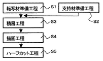
図3は、本発明のパッチ中間転写記録媒体の製造方法のステップを説明するためのの工程図である。
Hereinafter, embodiments of the present invention will be described in detail with reference to the drawings.
FIG. 1 is a sectional view of a patch intermediate transfer recording medium showing an embodiment manufactured by the method for manufacturing a patch intermediate transfer recording medium of the present invention.
FIG. 2 is a cross-sectional view of an anti-counterfeit medium showing an embodiment of the present invention transferred using a patch intermediate transfer recording medium manufactured by the method for manufacturing a patch intermediate transfer recording medium of the present invention.
FIG. 3 is a process diagram for explaining the steps of the method for manufacturing the patch intermediate transfer recording medium of the present invention.
(パッチ中間転写記録媒体の製造方法)本発明のパッチ中間転写記録媒体20の製造方法は、図3に示すように、(1)透明基材、該透明基材の一方の面にホログラム層、透明反射層及び受容層を設け、他方の面へ剥離性樹脂層を設けてなる転写材を準備する転写材準備工程S2と、(2)支持基材と、該支持基材の一方の面へレーザマーキング層を設けてなる支持材を準備する支持材準備工程S1と、(3)前記支持材のレーザマーキング層面と前記転写材の剥離性樹脂層面とを接着剤層を介して積層し積層体とする積層工程S3と、(4)前記積層体のレーザマーキング層へレーザ光線でタイミングマークを描画する描画工程S4と、(5)前記タイミングマークに位置合わせしながら、前記転写材の透明基材、ホログラム層、透明反射層及び受容層からなる転写部をハーフカット処理を施してパッチとするハーフカット工程S5と、からなる。 (Method for Producing Patch Intermediate Transfer Recording Medium) As shown in FIG. 3, the method for producing the patch intermediate transfer recording medium 20 of the present invention comprises: (1) a transparent substrate, a hologram layer on one surface of the transparent substrate, A transfer material preparation step S2 for preparing a transfer material provided with a transparent reflective layer and a receiving layer and a peelable resin layer on the other surface; (2) a support substrate and one surface of the support substrate; A support material preparation step S1 for preparing a support material provided with a laser marking layer, and (3) a laminate in which the laser marking layer surface of the support material and the peelable resin layer surface of the transfer material are laminated via an adhesive layer. And (4) a drawing step S4 for drawing a timing mark with a laser beam on the laser marking layer of the laminate, and (5) a transparent base material for the transfer material while being aligned with the timing mark. , Hologram layer, transparent reflection And with the half-cut process S5 for the patch transcription unit consisting of the receiving layer is subjected to half-cut treatment, consisting of.
(パッチ中間転写記録媒体)製造されたパッチ中間転写記録媒体20は、図1に示すように、パッチ21が支持材30の剥離性樹脂層33面へ剥離可能に積層されている。パッチ21は転写材10の転写部をハーフカット処理して、パッチ状としたものである。 転写材10は透明基材11と、該透明基材11の一方の面にホログラム層15、透明反射層17及び受容層23からなる転写部(ハーフカットされてパッチとなる)と、さらに他方の面へ剥離性樹脂層33が設けられている。支持材30は支持基材31の一方の面へレーザマーキング層35を設けてある。パッチ21は透明基材11、ホログラム層15、透明反射層17及び受容層23からなっている。
(Patch Intermediate Transfer Recording Medium) In the manufactured patch intermediate transfer recording medium 20, as shown in FIG. 1, the
(パッチ中間転写記録媒体の製造方法)本発明のパッチ中間転写記録媒体20の製造方法を、工程で用いる材料及び方法も含めて、工程順に説明する。 (Method for Producing Patch Intermediate Transfer Recording Medium) The method for producing the patch intermediate transfer recording medium 20 of the present invention will be described in the order of steps, including materials and methods used in the steps.
(転写材)S1の転写材準備工程は、(1)透明基材、該透明基材の一方の面にホログラム層、透明反射層及び受容層を設け、他方の面へ剥離性樹脂層を設けてなる転写材を準備する工程である。転写材10は透明基材11、該透明基材11の一方の面にホログラム層15、反射層17及び受容層23からなり、他方の面へ剥離性樹脂層33からなっている。図1に示すように、剥離性樹脂層33/透明基材11/ホログラム層15/反射層17/受容層23からなる転写材10は、ハーフカット処理で切断された部分がパッチ21となって、被転写体101へ転写され、保護層として機能する。剥離性樹脂層33は1部が被転写体101へ転写される場合や、剥離性樹脂層33が2層のときには1層が被転写体101へ転写される場合もある。
(Transfer material) The transfer material preparation step of S1 includes (1) a transparent base material, a hologram layer, a transparent reflective layer and a receiving layer provided on one surface of the transparent base material, and a peelable resin layer provided on the other surface. This is a step of preparing a transfer material. The transfer material 10 includes a transparent substrate 11, a
(透明基材)透明基材11としては、透明性、耐候性、耐摩擦性、耐薬品性等の耐久性を有するものであれば、用途に応じて種々の材料が適用できる。例えば、ポリエチレンテレフタレート、ポリエチレンナフタレートなどのポリエステル系樹脂、ポリアミド系樹脂、ポリ塩化ビニルなどのビニル系樹脂、アクリル系樹脂、イミド系樹脂、ポリアリレートなどのエンジニアリング樹脂、ポリカーボネート、環状ポリオレフィン系樹脂、セロファンなどのセルロース系フィルムなどが例示できる。該透明基材11は、これら樹脂を主成分とする共重合樹脂、または、混合体(アロイでを含む)、若しくは複数層からなる積層体であっても良い。 (Transparent Substrate) As the transparent substrate 11, various materials can be applied depending on the use as long as it has durability such as transparency, weather resistance, friction resistance and chemical resistance. For example, polyester resins such as polyethylene terephthalate and polyethylene naphthalate, polyamide resins, vinyl resins such as polyvinyl chloride, acrylic resins, imide resins, engineering resins such as polyarylate, polycarbonate, cyclic polyolefin resins, cellophane Examples thereof include cellulosic films. The transparent substrate 11 may be a copolymer resin containing these resins as a main component, a mixture (including an alloy), or a laminate composed of a plurality of layers.
また、該透明基材11は、延伸又は未延伸のフィルムでも良いが、強度を向上させる目的で、一軸方向または二軸方向に延伸したフィルムが好ましい。厚は、通常2.5〜50μm程度が適用できるが、2.5〜25μmが好適である。該透明基材11は、塗布に先立って塗布面へ、コロナ放電処理、プラズマ処理、プライマー(アンカーコート、接着促進剤、易接着剤とも呼ばれる)塗布処理、アルカリ処理、などの易接着処理を行ってもよい。また、必要に応じて、充填剤、可塑剤、着色剤、帯電防止剤などの添加剤を加えてもよい。2軸延伸ポリエチレンテレフタレートのフィルムが、耐熱性、機械的強度がよいため好適に使用され。 The transparent substrate 11 may be a stretched or unstretched film, but a film stretched in a uniaxial direction or a biaxial direction is preferable for the purpose of improving strength. A thickness of about 2.5 to 50 μm is usually applicable, but 2.5 to 25 μm is preferable. Prior to coating, the transparent substrate 11 is subjected to easy adhesion treatment such as corona discharge treatment, plasma treatment, primer (also called an anchor coat, adhesion promoter, or easy adhesive) coating treatment, alkali treatment, etc. May be. Moreover, you may add additives, such as a filler, a plasticizer, a coloring agent, and an antistatic agent, as needed. A biaxially stretched polyethylene terephthalate film is preferably used because of its good heat resistance and mechanical strength.
(ホログラム層)ホログラム層15としては、電離放射線硬化樹脂を主成分とし、必要に応じてシリコーンやフィラーなどの添加物を含ませてもよい。電離放射線硬化樹脂は電離放射線硬化性樹脂の硬化物で、該電離放射線硬化性樹脂としては、好ましくは、(1)分子中にイソシアネート基を3個以上有するイソシアネート類、(2)分子中に水酸基を少なくとも1個と(メタ)アクリロイルオキシ基を少なくとも2個有する多官能(メタ)アクリレート類、又は(3)分子中に水酸基を少なくとも2個有する多価アルコール類の反応生成物であるウレタン(メタ)アクリレートオリゴマーを含有する電離放射線硬化性樹脂を用い、好ましくはポリエチレンワックスを含ませて、塗布し乾燥して電離放射線で硬化させて、電離放射線硬化樹脂とすればよい。具体的には、特開2001−329031号公報で開示されている光硬化性樹脂などが例示できる。具体的には、MHX405ニス(ザ・インクテック(株)製、電離放射線硬化性樹脂商品名)、ユピマーUV・V3031(三菱化学(株)製、電離放射線硬化性樹脂商品名)が例示できる。
(Hologram layer) The
(ホログラム層の形成)ホログラム層15の形成は、上記の電離放射線硬化性樹脂、必要に応じて、シリコーンやフィラー、光重合開始剤、可塑剤、安定剤、界面活性剤等を加え、溶媒へ分散または溶解して、ロールコート、グラビアコート、コンマコート、ダイコートなどの公知のコーティング方法で塗布し乾燥して、ホログラムを賦型後に電離放射線で反応(硬化)させればよい。ホログラム層15の厚さは、通常、1〜10μm程度、好ましくは2〜5μmである。
(Hologram layer formation) The
(ホログラム)本発明の転写材10では、ホログラム層15の受容層23側の表面に、光回折性の微細な凹凸を形成してホログラム層15とし、微細な凹凸面に反射層17を設けることで、ホログラムの持つ高意匠性及び偽造防止性を付与することができる。
(Hologram) In the transfer material 10 of the present invention, a light diffractive fine unevenness is formed on the surface of the
(ホログラム)次に、ホログラム層15の表面には、ホログラムなどの光回折効果の発現する所定の微細な凹凸(レリーフ構造)を賦型し、硬化させる。ホログラムは物体光と参照光との光の干渉による干渉縞を凹凸のレリーフ形状で記録されたもので、例えば、フレネルホログラム等のレーザ再生ホログラム、及びレインボーホログラム等の白色光再生ホログラム、さらに、それらの原理を利用したカラーホログラム、コンピュータジェネレーティッドホログラム(CGH)、ホログラフィック回折格子などがある。レリーフ形状は凹凸形状であり、特に限定されるものではなく、微細な凹凸形状を有する光拡散、光散乱、光反射、光回折などの機能を発現するものでもよく、例えば、フーリエ変換やレンチキュラーレンズ、光回折パターン、モスアイ、が形成されたものである。また、光回折機能はないが、特異な光輝性を発現するヘアライン柄、マット柄、万線柄、干渉パターンなどでもよい。
(Hologram) Next, predetermined fine unevenness (relief structure) such as a hologram that exhibits a light diffraction effect is formed on the surface of the
ホログラム層15面へ、レリーフ形状を賦形(複製ともいう)する。ホログラムの賦型は、公知の方法によって形成でき、例えば、回折格子やホログラムの干渉縞を表面凹凸のレリーフとして記録する場合には、回折格子や干渉縞が凹凸の形で記録された原版をプレス型(スタンパという)として用い、上記樹脂層上に前記原版を重ねて加熱ロールなどの適宜手段により、両者を加熱圧着することにより、原版の凹凸模様を複製することができる。
A relief shape is formed (also referred to as replication) on the surface of the
また、ホログラム層15に形成するホログラムパターンは単独でも、複数でもよい。ホログラム層15は、スタンパでエンボス中、又はエンボス後に、電離放射線を照射して、電離放射線硬化性樹脂を硬化させる。上記の電離放射線硬化性樹脂は、レリーフを形成後に、紫外線や電子線などの電離放射線を照射して硬化(反応)させると電離放射線硬化樹脂(微細な凹凸=レリーフ構造=ホログラム)となる。
Further, the hologram pattern formed on the
(反射層)反射層17は、所定のレリーフ構造を設けたホログラム層15面のレリーフ面へ、反射層17へ設けることにより、レリーフの反射及び/又は回折効果を高めるので、ホログラム層15の反射率のより高れば、特に限定されない。該反射層17としては、真空薄膜法などによる金属薄膜などの金属光沢反射層、又は透明反射層のいずれでもよいが、金属光沢反射層は部分的に設け、透明反射層は被転写体へ形成されている画像の面へ転写しても、画像が観察できるので好ましい。透明反射層としては、ほぼ無色透明な色相で、その光学的な屈折率がホログラム層のそれとは異なることにより、金属光沢が無いにもかかわらず、ホログラムなどの光輝性を視認できるから、透明なホログラムを作製することができる。例えば、ホログラム層15よりも光屈折率の高い薄膜、および光屈折率の低い薄膜とがあり、前者の例としては、ZnS、TiO2、Al2O3、Sb2S3、SiO、SnO2、ITO等があり、後者の例としては、LiF、MgF2、AlF3がある。好ましくは、金属酸化物又は窒化物であり、具体的には、Be、Mg、Ca、Cr、Mn、Cu、Ag、Al、Sn、In、Te、Fe、Co、Zn、Ge、Pb、Cd、Bi、Se、Ga、Rb、Sb、Pb、Ni、Sr、Ba、La、Ce、Au等の酸化物又は窒化物他はそれらを2種以上を混合したもの等が例示できる。またアルミニウム等の一般的な光反射性の金属薄膜も、厚みが200Å以下になると、透明性が出て使用できる。透明金属化合物の形成は、金属の薄膜と同様、ホログラム層15のレリーフ面に、10〜2000nm程度、好ましくは20〜1000nmの厚さになるよう、蒸着、スパッタリング、イオンプレーティング、CVDなどの真空薄膜法などにより設ければよい。
(Reflection layer) Since the
(受容層)透明反射層層17面へ、必要に応じてプライマー層を介して、受容層23を設け、該受容層23はパッチ中間転写記録媒体20の最表面となり、該受容層23には個人情報などの情報印字層103が印画される。印画方法としては、例えば、溶融転写タイプや昇華タイプの熱転写フイルムを用いた熱転写方式、インクジェット方式が適用できる。受容層23は熱転写方式やインクジェット方式などの印画方式に応じた公知の受容性樹脂層でよい。
(Receiving layer) A
好ましくは、溶融転写又は昇華タイプの熱転写インクリボンを用いる熱転写方法では使用済みインクリボンに情報の残渣が残るが、インクリボンを使用しないインクジェット方式が情報の痕跡が残らず、セキュリティ性に優れる点でインクジェット方式が好ましい。
インクジェット方式で用いる受容層23としては、インクジェット用受容層組成物を塗布したもので、該インクジェット用受容層組成物は、少なくともカチオン性ウレタン系樹脂、カチオン性フィックス剤、フィラー、及び分子内に2個以上のアジリジニル基を有するアジリジン誘導体とを含ませる。
Preferably, in the thermal transfer method using the thermal transfer ink ribbon of the melt transfer or sublimation type, the information residue remains on the used ink ribbon, but the ink-jet method that does not use the ink ribbon does not leave any trace of information and is excellent in security. An ink jet method is preferred.
As the receiving
カチオン性ウレタン系樹脂としてはカチオン性基を有するポリカーボネート系ポリウレタン、ポリテトラメチレンエーテルグリコール系ポリウレタン、ポリエステルエーテル系ポリウレタン、ポリブチレンアジペート系ポリウレタン、ポリメチルペンタンアジペート系ポリウレタン、ポリノナンジオールアジペート/ポリオクタンアジペート系ポリウレタン、ポリメチルペンタンアジペート系ポリウレタンなどのウレタン系樹脂で、好ましくは自己乳化性又は水性で、カチオン性親水基を有するポリカーボネート系又はポリエステル系のポリオールと脂肪族イソシアネートの反応物が好ましい。カチオン性基としては1〜3級アミン或いは4級アンモニウム塩基などが例示できる。 Polycationic polyurethane resins with cationic groups, polytetramethylene ether glycol polyurethane, polyester ether polyurethane, polybutylene adipate polyurethane, polymethylpentane adipate polyurethane, polynonanediol adipate / polyoctane adipate Polyurethane resins such as polyurethane and polymethylpentane adipate polyurethane, preferably self-emulsifying or aqueous, and a reaction product of a polycarbonate or polyester polyol having a cationic hydrophilic group and an aliphatic isocyanate. Examples of cationic groups include primary to tertiary amines or quaternary ammonium bases.
(カチオン性フィックス剤)カチオン性フィックス剤としては、ポリアミン誘導体や第4級アンモニウム塩などの染料固着剤が例示できる。 (Cationic Fixing Agent) Examples of the cationic fixing agent include dye fixing agents such as polyamine derivatives and quaternary ammonium salts.
(フィラー)フィラーとしては、箔切れ性を良くし、透明性を害さない程度に含有させ、シリカ、アルミナ、炭酸カルシウム、プラスチックピグメント等の透明性の高い微粒子やワックス等で、マイクロシリカが好ましい。 (Filler) As the filler, micro-silica is preferable because it contains fine particles such as silica, alumina, calcium carbonate, and plastic pigment, wax, and the like so as to improve foil cutting properties and not to impair transparency.
(アジリジニン誘導体)アジリジル誘導体としては分子内に2個以上のアジリジニル基を有する化合物を用い、好ましくは、

一般式1におけるR3〜5のうち2個以上が一般式2の構造を有する化合物、即ち、分子内に2個以上のアジリジニル基を有するアジリジル誘導体である。
(Aziridinine derivative) As the aziridyl derivative, a compound having two or more aziridinyl groups in the molecule is used.
Two or more of R 3 to 5 in the general formula 1 are compounds having the structure of the general formula 2, that is, aziridyl derivatives having two or more aziridinyl groups in the molecule.
分子内に2個以上のアジリジニル基を有するアジリジン誘導体、例えば、トリメチロールプロパン−トリス−(α−メチル−α−アジリジニルアセテート)、トリメチロールプロパン−トリス−(α−エチル−α−アジリジニルアセテート)、トリメチロールメタン−トリス−(β−(1−アジリジニルプロピオナート))、トリメチロールエタン−トリス−(β−(1−アジリジニルプロピオナート))、トリメチロールブタン−トリス−(β−(1−アジリジニルプロピオナート))、モノエトキシトリメチロールメタン−トリス−(β−(1−アジリジニルプロピオナート))、トリメチロールエタン−トリス−(β−(2−メチル-1−アジリジニルプロピオナート))、テトラメチロールメタン−トリス−(α−メチル−α−アジリジニルアセテート)、テトラメチロールエタン−トリス−(β−(1−アジリジニルプロピオナート))、ジトリメチロールプロパン−ヘキサキス−(β−アジリジニルプロピオナート)、ジトリメチロールプロパン−ペンタキス−(β−(2−メチルアジリジニルプロピオナート)等が挙げられる。 Aziridine derivatives having two or more aziridinyl groups in the molecule, such as trimethylolpropane-tris- (α-methyl-α-aziridinyl acetate), trimethylolpropane-tris- (α-ethyl-α-aziridinini) Acetate), trimethylolmethane-tris- (β- (1-aziridinylpropionate)), trimethylolethane-tris- (β- (1-aziridinylpropionate)), trimethylolbutane- Tris- (β- (1-aziridinylpropionate)), monoethoxytrimethylolmethane-tris- (β- (1-aziridinylpropionate)), trimethylolethane-tris- (β- ( 2-methyl-1-aziridinylpropionate)), tetramethylolmethane-tris- (α-methyl-α-aziridinyl a) Tate), tetramethylolethane-tris- (β- (1-aziridinylpropionate)), ditrimethylolpropane-hexakis- (β-aziridinylpropionate), ditrimethylolpropane-pentakis- (β- (2-methylaziridinyl propionate) and the like.
好ましくは、トリメチロールメタン−トリス−(β−(1−アジリジニルプロピオナート))、トリメチロールエタン−トリス−(β−(1−アジリジニルプロピオナート))、トリメチロールプロパン−トリス−(β−(1−アジリジニルプロピオナート))、トリメチロールブタン−トリス−(β−(1−アジリジニルプロピオナート))、トリメチロールエタン−トリス−(β−(2−メチル-1−アジリジニルプロピオナート))、トリメチロールプロパン−トリス−(β−(2−メチル−1−アジリジニルプロピオナート))、トリメチロールプロパン−トリス−(β−(2,2−ジメチル−1−アジリジニルプロピオナート))、トリメチロールプロパン−トリス−(α−メチル−β−(1−アジリジニルプロピオナート)、トリメチロールプロパン−トリス−(β−メチル−β−(1−アジリジニルプロピオナート)、テトラメチロールメタン−トリス−(α−メチル−α−アジリジニルアセテート)、テトラメチロールメタン−トリス−(β−(1−アジリジニルプロピオナート)、テトラメチロールエタン−トリス−(β−(1−アジリジニルプロピオナート))、テトラメチロールメタン−トリス−(β−(2−プロピル−1−アジリジニルプロピオナート))、テトラメチロールメタン−トリス−(β−(2−メチル−1−アジリジニルプロピオナート))、テトラメチロールメタン−トリス−(β−(2,2−ジメチル−1−アジリジニルプロピオナート)、テトラメチロールメタン−トリス−(β−(2,2−ジエチル−1−アジリジニルプロピオナート)テトラメチロールメタン−テトラキス−β−(1−アジリジニルプロピオナート)、テトラメチロールメタン−テトラキス−β−メチル−β−(1−アジリジニルプロピオナート)、テトラメチロールメタン−テトラキス−β−(2−メチル−1−アジリジニルプロピオナート)、ジトリメチロールプロパン−ヘキサキス−(β−アジリジニルプロピオナート)、ジトリメチロールプロパン−ペンタキス−(β−(2−メチルアジリジニルプロピオナート)が好ましく、トリメチロールプロパン−トリス−(β−(1−アジリジニルプロピオナート)、テトラメチロールメタン−トリス−(β−(1−アジリジニルプロピオナート)、テトラメチロールメタン−テトラキス−(β−アジリジニルプロピオナート)である。 Preferably, trimethylolmethane-tris- (β- (1-aziridinylpropionate)), trimethylolethane-tris- (β- (1-aziridinylpropionate)), trimethylolpropane-tris -(Β- (1-aziridinylpropionate)), trimethylolbutane-tris- (β- (1-aziridinylpropionate)), trimethylolethane-tris- (β- (2-methyl -1-aziridinylpropionate)), trimethylolpropane-tris- (β- (2-methyl-1-aziridinylpropionate)), trimethylolpropane-tris- (β- (2,2 -Dimethyl-1-aziridinylpropionate)), trimethylolpropane-tris- (α-methyl-β- (1-aziridinylpropionate), trimethylo Propane-tris- (β-methyl-β- (1-aziridinylpropionate), tetramethylolmethane-tris- (α-methyl-α-aziridinyl acetate), tetramethylolmethane-tris- (β- (1-aziridinylpropionate), tetramethylolethane-tris- (β- (1-aziridinylpropionate)), tetramethylolmethane-tris- (β- (2-propyl-1-aziridini) Lupropionate)), tetramethylolmethane-tris- (β- (2-methyl-1-aziridinylpropionate)), tetramethylolmethane-tris- (β- (2,2-dimethyl-1-) Aziridinylpropionate), tetramethylolmethane-tris- (β- (2,2-diethyl-1-aziridinylpropionate) tetramethylo Rumethane-tetrakis-β- (1-aziridinylpropionate), tetramethylolmethane-tetrakis-β-methyl-β- (1-aziridinylpropionate), tetramethylolmethane-tetrakis-β- (2 -Methyl-1-aziridinylpropionate), ditrimethylolpropane-hexakis- (β-aziridinylpropionate), ditrimethylolpropane-pentakis- (β- (2-methylaziridinylpropionate) Are preferred, trimethylolpropane-tris- (β- (1-aziridinylpropionate), tetramethylolmethane-tris- (β- (1-aziridinylpropionate), tetramethylolmethane-tetrakis- ( β-aziridinylpropionate).
分子内に2個以上のアジリジニル基を有するアジリジン誘導体について市販されているものとしては、例えば、相互薬工社製のTAZM(トリメチロールプロパン−トリス−(β−アジリジニルプロピオナート)、TAZO(テトラメチロールメタン−トリス−(β−(1−アジリジニルプロピオナート)))日本触媒製のケミタイトPZ−33(トリメチロールプロパン−トリス−(β−アジリジニルプロピオナート))等が挙げられる。3個のアジリジニル基を有するアジリジン誘導体が、硬化する反応性の速さ、硬化後に網目状となるので耐久性の高さ点で、特に好ましい。 Examples of commercially available aziridine derivatives having two or more aziridinyl groups in the molecule include TAZM (trimethylolpropane-tris- (β-aziridinylpropionate), TAZO, manufactured by Mutual Yakuhin Co., Ltd.) (Tetramethylolmethane-tris- (β- (1-aziridinylpropionate))) Nippon Shokubai's Chemite PZ-33 (trimethylolpropane-tris- (β-aziridinylpropionate)) and the like An aziridine derivative having three aziridinyl groups is particularly preferred because of its high reactivity and a high network durability after curing.
カチオン性ウレタン系樹脂とカチオン性フィックス剤とマイクロシリカと分子内に2個以上のアジリジニル基を有するアジリジン誘導体との割合が質量基準でカチオン性ウレタン系樹脂:カチオン性フィックス剤:マイクロシリカ:分子内に2個以上のアジリジニル基を有するアジリジン誘導体=100:5〜20:1〜10:1〜15である。カチオン性フィックス剤の含有割合が上記範囲未満では定着性が悪く、上記範囲を越えると洗濯中に溶出して堅牢性を低下させる。マイクロシリカの含有割合が上記範囲未満ではインキ定着性が悪く、上記範囲を越えると透明性が低下し画像が見えにくくなる。 The ratio of cationic urethane resin, cationic fixing agent, microsilica, and aziridine derivative having two or more aziridinyl groups in the molecule is based on mass. Cationic urethane resin: Cationic fixing agent: Microsilica: Intramolecular The aziridine derivative having two or more aziridinyl groups in the group is 100: 5 to 20: 1 to 10: 1 to 15. If the content of the cationic fixing agent is less than the above range, the fixing property is poor, and if it exceeds the above range, it elutes during washing and lowers the fastness. If the content ratio of the microsilica is less than the above range, the ink fixing property is poor, and if it exceeds the above range, the transparency is lowered and the image becomes difficult to see.
アジリジン誘導体の添加量は、本発明の効果を阻害しない量であれば特に制限されないが、通常カチオン性ウレタン系樹脂に対する分子内に2個以上のアジリジニル基を有するアジリジン誘導体の配合割合が質量基準で、カチオン性ウレタン系樹脂:分子内に2個以上のアジリジニル基を有するアジリジン誘導体=100:1〜15が好ましく、さらに好ましくは100:3〜10である。アジリジン誘導体は水溶性の硬化剤として機能するので、アジリジン誘導体の含有割合が上記範囲未満では、硬化が不足するために耐水性や耐アルコール性などの耐溶剤性などの耐久性が充分ではなく、上記範囲を越えると透明性が低下し画像が見えにくくなる。 The addition amount of the aziridine derivative is not particularly limited as long as it does not inhibit the effect of the present invention, but the blending ratio of the aziridine derivative having two or more aziridinyl groups in the molecule with respect to the cationic urethane resin is usually on a mass basis. Cationic urethane resin: Aziridine derivative having two or more aziridinyl groups in the molecule = 100: 1 to 15 is preferable, and 100: 3 to 10 is more preferable. Since the aziridine derivative functions as a water-soluble curing agent, if the content ratio of the aziridine derivative is less than the above range, since the curing is insufficient, durability such as water resistance and alcohol resistance is not sufficient, If it exceeds the above range, the transparency is lowered and the image becomes difficult to see.
受容層23の形成は、上記の材料を溶媒へ分散又は溶解して、必要に応じて添加剤を添加し、媒体101の少なくとも一方の面へ、必要に応じてコロナ処理やプライマ層を設けて、ロールコート、グラビアコート、コンマコート、ダイコートなどの公知のコーティング方法で、塗布し乾燥すればよい。そのの厚さとしては、通常は1μm〜15μm程度、好ましくは2μm〜10μm程度である。
The receiving
(剥離性樹脂層)透明基材11の他方の面へ設ける剥離性樹脂層33としては、粘着剤層や簡易接着層やエクストルージョンコーティング(EC)層により形成する。 (Peelable resin layer) The peelable resin layer 33 provided on the other surface of the transparent substrate 11 is formed of an adhesive layer, a simple adhesive layer, or an extrusion coating (EC) layer.
粘着剤層は、従来公知の溶剤系及び水系のいずれの粘着剤、例えば、酢酸ビニル樹脂、アクリル樹脂、酢酸ビニル−アクリル共重合体、酢酸ビニル−塩化ビニル共重合体、エチレン−酢酸ビニル共重合体、ポリウレタン樹脂や、天然ゴム、クロロプレンゴムなどのゴム系樹脂などが挙げられる。粘着剤層の塗工量は、約8〜30g/m2(固形分)が一般的であり、従来公知の方法、すなわち、グラビアコート、ロールコート、コンマコート等の方法で、塗布し乾燥して粘着剤層を形成する。また、粘着剤層の粘着力は、透明基材11と粘着剤層との剥離強度で、JIS Z0237準拠の180°による剥離方法において、5〜1,000g程度の範囲にすることが望ましい。以上の如き粘着剤の種類や、塗工量は、前記透明基材11上に粘着剤層を形成する際に、その剥離強度が前記範囲になるように、選択して使用することが好ましい。 The pressure-sensitive adhesive layer is a conventionally known solvent-based or water-based pressure-sensitive adhesive, such as vinyl acetate resin, acrylic resin, vinyl acetate-acrylic copolymer, vinyl acetate-vinyl chloride copolymer, ethylene-vinyl acetate copolymer. Examples thereof include rubber resins such as coalescence, polyurethane resin, natural rubber, and chloroprene rubber. The coating amount of the pressure-sensitive adhesive layer is generally about 8 to 30 g / m 2 (solid content), and is applied and dried by a conventionally known method such as gravure coating, roll coating, comma coating, and the like. To form an adhesive layer. Further, the adhesive strength of the pressure-sensitive adhesive layer is the peel strength between the transparent substrate 11 and the pressure-sensitive adhesive layer, and is desirably in the range of about 5 to 1,000 g in a 180 ° peeling method in accordance with JIS Z0237. It is preferable to select and use the kind of adhesive and the coating amount as described above so that the peel strength is within the above range when the adhesive layer is formed on the transparent substrate 11.
簡易接着層は、スチレン−ブタジエン共重合ゴム(SBR)、アクリロニトリル−ブタジエン共重合ゴム(NBR)やポリアクリル酸エステル等のアクリル系樹脂のラテックスや、ゴム系レジン、ワックス類及びそれらの混合物を用いて、透明基材11面へ従来公知の塗工方式で形成すればよい。 For the simple adhesive layer, latex of acrylic resin such as styrene-butadiene copolymer rubber (SBR), acrylonitrile-butadiene copolymer rubber (NBR) or polyacrylate, rubber resin, waxes and a mixture thereof are used. Then, it may be formed on the surface of the transparent substrate 11 by a conventionally known coating method.
また、剥離性樹脂層33として、透明基材11面へEC層で設けてもよい。EC層を形成する熱可塑性樹脂は透明基材11には本質的に接着せず、EC加工特性のある樹脂であれば特に限定されないが、透明基材11に一般的に利用されるPETフィルムに対して、本質的な接着性を有さず加工性も優れる、ポリオレフィン系樹脂が特に好ましい。具体的には、LDPE、MDPE、HDPE、PP樹脂等を使用できる。これらの樹脂をEC加工する際の冷却ロールをマットロールを使用して、EC層表面にマット面が転写されて凹凸形状を賦形して不透明としたり、ポリオレフィン系樹脂に炭酸カルシウム、酸化チタン等の白色顔料を練り混んで、不透明としたり、してもよい。また、該EC層は単層でも、複数層でもよい。透明基材11からの剥離強度は、EC加工時の加工温度、樹脂種によって調整することができる。EC法による複数層を設ける場合には、異なる樹脂種の2層とし、該樹脂種の差で剥離強度を容易に調整できる。 Further, as the peelable resin layer 33, an EC layer may be provided on the surface of the transparent substrate 11. The thermoplastic resin forming the EC layer does not essentially adhere to the transparent substrate 11 and is not particularly limited as long as the resin has EC processing characteristics. On the other hand, a polyolefin-based resin having no essential adhesiveness and excellent workability is particularly preferable. Specifically, LDPE, MDPE, HDPE, PP resin, etc. can be used. Using a mat roll as the cooling roll for EC processing of these resins, the mat surface is transferred to the surface of the EC layer to make the irregular shape opaque, and the polyolefin resin is calcium carbonate, titanium oxide, etc. The white pigment may be kneaded and made opaque. The EC layer may be a single layer or a plurality of layers. The peel strength from the transparent substrate 11 can be adjusted by the processing temperature and the resin type during EC processing. When a plurality of layers are provided by the EC method, two layers of different resin types are used, and the peel strength can be easily adjusted by the difference in the resin types.
(他の層)層間及び/又は層表面へ必要に応じて設ける層としては、プライマ層、印刷層、帯電防止層、背面滑性層などがあり、それぞれ公知のものでよい。特に、印刷層としては、着色インキや蛍光インキなどを用いて、公知のスクリーン印刷やグラビア印刷法で印刷すればよい。 (Other layers) The layers provided on the interlayer and / or the layer surface as needed include a primer layer, a printing layer, an antistatic layer, a back-sliding layer, etc., and each may be a known layer. In particular, the printing layer may be printed by a known screen printing or gravure printing method using colored ink or fluorescent ink.
S2の支持材準備工程は、(2)支持基材31と、該支持基材31の一方の面へレーザマーキング層35を設けてなる支持材30を準備する工程である。 The support material preparation process of S2 is a process of preparing (2) the support base material 31 and the support material 30 provided with the laser marking layer 35 on one surface of the support base material 31.
(支持材・支持基材)支持材30は支持基材31へレーザマーキング層35が設けられている。支持基材31としては、特に限定されず、例えば、コンデンサーペーパー、グラシン紙、硫酸紙、またはサイズ度の高い紙、合成紙(ポリオレフィン系、ポリスチレン系)、上質紙、コート紙、合成樹脂またはエマルジョン含浸紙、あるいは、ポリエチレンテレフタレート、ポリブチレンテレフタレート、ポリエチレンナフタレートなどのポリエステル系樹脂、ポリアミド系樹脂、ポリ塩化ビニルなどのビニル系樹脂、アクリル系樹脂、イミド系樹脂、ポリアリレートなどのエンジニアリング樹脂、ポリカーボネート、環状ポリオレフィン系樹脂、セロファンなどのセルロース系フィルムなどのフィルムが例示できる。上記の支持基材31上に後述するレーザマーキング層35を設ける際に、接着性を向上させるために、支持基材31表面をコロナ放電処理したり、プライマー層を設けてもよい。 (Support Material / Support Base Material) The support material 30 is provided with a laser marking layer 35 on the support base material 31. The support substrate 31 is not particularly limited. For example, condenser paper, glassine paper, sulfuric acid paper, high-size paper, synthetic paper (polyolefin-based, polystyrene-based), fine paper, coated paper, synthetic resin, or emulsion Impregnated paper or polyester resins such as polyethylene terephthalate, polybutylene terephthalate, polyethylene naphthalate, polyamide resins, vinyl resins such as polyvinyl chloride, engineering resins such as acrylic resins, imide resins, polyarylate, polycarbonate Examples thereof include films such as cellulose-based films such as cyclic polyolefin resins and cellophane. When providing a laser marking layer 35 to be described later on the support substrate 31, the surface of the support substrate 31 may be subjected to a corona discharge treatment or a primer layer may be provided in order to improve adhesion.
支持基材31は10μm〜100μmの厚みのものが好ましく、支持基材が薄すぎると得られるパッチ中間転写記録媒体20のいわゆるコシがなくなり、熱転写プリンターで搬送できなかったり、パッチ中間転写記録媒体20にカールやシワが発生したりする。一方、支持基材31が厚すぎると、得られるパッチ中間転写記録媒体20が厚くなりすぎ、熱転写プリンタで搬送駆動させる力が大きくなりすぎて、熱転写プリンタに故障が生じたり、正常に搬送できなかったりする。 The support substrate 31 preferably has a thickness of 10 μm to 100 μm. If the support substrate is too thin, the patch intermediate transfer recording medium 20 obtained is free from so-called stiffness, and cannot be transported by a thermal transfer printer, or the patch intermediate transfer recording medium 20 Curls and wrinkles may occur. On the other hand, if the support base material 31 is too thick, the resulting patch intermediate transfer recording medium 20 becomes too thick, and the force to drive and drive the thermal transfer printer becomes so large that the thermal transfer printer fails or cannot be transported normally. Or
(レーザマーキング層)レーザマーキング層35は、レーザー光の照射により印字を行うもので、バインダ樹脂とレーザー照射より変色可能な発色剤を含ませる。レーザー照射より変色可能な発色剤としては、特に限定されないが、鉄、亜鉛、スズ、ニッケルなどの金属、炭酸銅、炭酸ニッケル、硝酸マグネシウム、硝酸鉄、硝酸ニッケル、硝酸銅、酢酸マグネシウム、酢酸亜鉛、酢酸ニッケル、酢酸銅、塩化銅、塩化鉄、塩化ニッケル、塩化亜鉛、リン酸銅、リン酸鉄、ピロリン酸銅、硫酸銅、硫酸鉄、硫酸コバルト、シュウ酸銅、シュウ酸鉄、安息香酸銅、芳香環を有するホスホン酸銅などの金属の塩、水酸化銅、水酸化アルミニウム、水酸化マグネシウム、水酸化亜鉛、水酸化ニッケル、水酸化鉄などの金属の水酸化物、酸化ケイ素、酸化アルミニウム、酸化鉄、酸化マグネシウム、酸化コバルト、酸化スズ、酸化ニッケル、酸化銅、ATO、ITO、合成ゼオライト、天然ゼオライト、水酸化銅一リン酸塩などの無機酸銅水和物、銅−モリブテン複合酸化物(42−903A、東缶マテリアル・テクノロジー株式会社製)、層状構造を有する、マイカ、モンモリロナイト、スメクタイトなどの金属の酸化物、カーボンブラック、感熱記録に使用される公知の発色剤や顕色剤などが例示できる。また、レーザ照射によりマーキングされた文字や図柄の黒色度の高さ、近傍の樹脂なども黒化させやすい点で、銅−モリブテン複合酸化物が好ましい。 (Laser Marking Layer) The laser marking layer 35 performs printing by irradiating laser light, and includes a binder resin and a color former that can be changed by laser irradiation. There are no particular limitations on color formers that can be changed by laser irradiation, but metals such as iron, zinc, tin, and nickel, copper carbonate, nickel carbonate, magnesium nitrate, iron nitrate, nickel nitrate, copper nitrate, magnesium acetate, and zinc acetate , Nickel acetate, copper acetate, copper chloride, iron chloride, nickel chloride, zinc chloride, copper phosphate, iron phosphate, copper pyrophosphate, copper sulfate, iron sulfate, cobalt sulfate, copper oxalate, iron oxalate, benzoic acid Metal salts such as copper and copper phosphonate having an aromatic ring, metal hydroxides such as copper hydroxide, aluminum hydroxide, magnesium hydroxide, zinc hydroxide, nickel hydroxide, iron hydroxide, silicon oxide, oxidation Aluminum, iron oxide, magnesium oxide, cobalt oxide, tin oxide, nickel oxide, copper oxide, ATO, ITO, synthetic zeolite, natural zeolite, copper hydroxide Inorganic acid copper hydrates such as phosphates, copper-molybten complex oxides (42-903A, manufactured by Tocan Material Technology Co., Ltd.), metal oxides such as mica, montmorillonite, smectite, etc. having a layered structure, Examples thereof include carbon black and known color formers and developers used for thermal recording. In addition, a copper-molybten complex oxide is preferable in that the blackness of characters and designs marked by laser irradiation and the nearby resin are easily blackened.
バインダ樹脂としては、特に限定はされないが、例えば、アクリル系樹脂、ポリアセタール樹脂、ポリアミド系樹脂、ポリエステル系樹脂、ポリ塩化ビニル系樹脂、ポリオレフィン系樹脂、ポリカーボネート樹脂、ポリスチレン系樹脂などが例示できる。上記のバインダ樹脂とレーザー照射より変色可能な発色剤を含ませ、必要に応じて分散剤、表面処理剤、レーザー特性向上のための増感剤、顕色剤、その他の添加物を加えてインキとし、グラビア印刷、スクリーン印刷などの公知の印刷法で印刷し乾燥して、レーザマーキング層35を形成すればよい。レーザマーキング層35は、支持基材31の全体、或いは一部にベタ印刷し、使用時に所望のタイミングマークの形状にレーザー光を照射することで、描画できる。レーザマーキング層35の、バインダ樹脂に対するレーザー照射より変色可能な発色剤の割合は、0.01〜20%、好ましくは0.1〜10%である。この範囲未満ではレーザー発色性が劣り、この範囲を超えてもレーザー発色性は過剰であり、バインダ樹脂分が少ないため基材との密着性や皮膜の凝集力が劣る。 The binder resin is not particularly limited, and examples thereof include acrylic resins, polyacetal resins, polyamide resins, polyester resins, polyvinyl chloride resins, polyolefin resins, polycarbonate resins, and polystyrene resins. Including the above binder resin and color former that can be changed by laser irradiation, and adding a dispersant, surface treatment agent, sensitizer for improving laser characteristics, color developer, and other additives as necessary. The laser marking layer 35 may be formed by printing by a known printing method such as gravure printing or screen printing and drying. The laser marking layer 35 can be drawn by solid printing on the whole or a part of the support base material 31 and irradiating the desired timing mark shape with laser light during use. The ratio of the color former capable of changing color by laser irradiation with respect to the binder resin in the laser marking layer 35 is 0.01 to 20%, preferably 0.1 to 10%. If it is less than this range, the laser color developability is inferior, and if it exceeds this range, the laser color developability is excessive, and since the binder resin content is small, the adhesion to the substrate and the cohesive strength of the film are inferior.
(耐熱滑性層)パッチ中間転写記録媒体20では、必要に応じて、支持基材31のレーザマーキング層35面と反対面に耐熱滑性層や帯電防止層などを設けてもよい。パッチ中間転写記録媒体20を用いて被転写体101へ再転写はサーマルヘッドやヒートロール等の熱転写プリンタが用いるので、その熱によるスティッキングやシワなどの悪影響を防止するため、耐熱滑性層を設けてもよい。耐熱滑性層を形成する樹脂としては、従来公知のものであればよく、例えば、ポリビニルブチラール樹脂、ポリビニルアセトアセタール樹脂、アクリル系樹脂、セルロース系樹脂、芳香族ポリアミド樹脂、ポリイミド樹脂、ポリカーボネート樹脂等が挙げられる。 (Heat resistant slipping layer) In the patch intermediate transfer recording medium 20, if necessary, a heat resistant slipping layer, an antistatic layer or the like may be provided on the surface opposite to the laser marking layer 35 surface of the support base 31. Since retransfer to the transfer target 101 using the patch intermediate transfer recording medium 20 is performed by a thermal transfer printer such as a thermal head or a heat roll, a heat resistant slipping layer is provided to prevent adverse effects such as sticking and wrinkles due to the heat. May be. The resin for forming the heat-resistant slipping layer may be any conventionally known resin such as polyvinyl butyral resin, polyvinyl acetoacetal resin, acrylic resin, cellulose resin, aromatic polyamide resin, polyimide resin, polycarbonate resin, etc. Is mentioned.
また、耐熱滑性層に添加、又は上塗りする滑り性付与剤としては、例えば、ポリアルコール高分子化合物とポリイソシアネート化合物及び燐酸エステル系化合物からなる層であり、更に充填剤を添加することがより好ましい。耐熱滑性層は、上記に記載した樹脂、滑り性付与剤、更に充填剤を、適当な溶剤により、溶解又は分散させて、支持基材31の背面に、例えば、グラビア印刷法、スクリーン印刷法等で塗布し乾燥して形成すればよい。 The slipperiness-imparting agent that is added to or overcoated the heat-resistant slipping layer is, for example, a layer composed of a polyalcohol polymer compound, a polyisocyanate compound, and a phosphate ester compound, and a filler may be further added. preferable. The heat resistant slipping layer is prepared by dissolving or dispersing the above-described resin, slipperiness-imparting agent, and filler with an appropriate solvent, and, for example, gravure printing or screen printing on the back surface of the support substrate 31. It may be formed by applying and drying with the like.
(積層工程)S3の積層工程は、(3)前記支持材のレーザマーキング層面と前記転写材の剥離性樹脂層面とを積層して積層体とする工程である。支持材30のレーザマーキング層35面と転写材10の剥離性樹脂層33面とを、粘着剤や接着剤19を介してのドライラミネーション法や、ホットメルトラミネーション法などの公知の積層方法でよい。好ましくは、ウレタン系2液接着剤を用いたドライラミネーション法である。 (Lamination process) The lamination process of S3 is a process of (3) laminating the laser marking layer surface of the support material and the peelable resin layer surface of the transfer material to form a laminate. The laser marking layer 35 surface of the support material 30 and the peelable resin layer 33 surface of the transfer material 10 may be formed by a known lamination method such as a dry lamination method using an adhesive or an adhesive 19 or a hot melt lamination method. . A dry lamination method using a urethane two-component adhesive is preferable.
(描画工程)S4の描画工程は、(4)前記積層体のレーザマーキング層へレーザ光線でタイミングマークを描画する工程である。レーザマーキング層35へレーザ光線でタイミングマーク(当業者は、レジスターマーク、見当マーク、見当トンボとも呼称する)を描画する。 (Drawing process) The drawing process of S4 is a process of (4) drawing a timing mark with a laser beam on the laser marking layer of the laminate. A timing mark (a person skilled in the art also calls a register mark, a register mark, or a register mark) is drawn on the laser marking layer 35 with a laser beam.
タイミングマークを描画するレーザの種類は特に限定されず、例えば、炭酸ガスレーザー等の遠赤外線レーザー、YAGレーザー等の近赤外線レーザー、半導体レーザー、エキシマレーザーが例示できるが、赤外線レーザーが好ましい。マーキングの種類は特に限定されず、文字、記号、図柄等の何れであってもよいが、使用時にタイミングマークを検出し易い点で、四角形状、線状が好ましい。レーザで描画されたタイミングマークの色調、濃度は特に限定されないが、使用時に使用されるセンサで検出できればよい。 The type of laser for drawing the timing mark is not particularly limited, and examples thereof include a far infrared laser such as a carbon dioxide laser, a near infrared laser such as a YAG laser, a semiconductor laser, and an excimer laser, but an infrared laser is preferable. The type of marking is not particularly limited and may be any of a character, a symbol, a design, and the like. However, a rectangular shape and a linear shape are preferable in that a timing mark can be easily detected during use. The color tone and density of the timing mark drawn by the laser are not particularly limited as long as it can be detected by a sensor used at the time of use.
(ハーフカット工程)S5のハーフカット工程は、(5)前記タイミングマークに位置合わせしながら、前記転写材の透明基材、ホログラム層、透明反射層及び受容層からなる転写部をハーフカット処理を施してパッチとする工程である。 (Half cut process) In the half cut process of S5, (5) the transfer part consisting of the transparent base material, the hologram layer, the transparent reflection layer and the receiving layer of the transfer material is subjected to a half cut process while being aligned with the timing mark. It is a process of applying and making a patch.
ハーフカット処理法としては、カッター刃を取り付けた上型と台座の間に、カット前の積層状態のパッチ中間転写記録媒体20を挿入して、上型を上下動させる方法や、シリンダータイプのロータリーカッター方法、レーザー加工手段により熱処理加工方法等、ハーフカットできる方法であれば特に制限はない。パッチ21部分とそれ以外部分を除去しなくてもよいが、図1に示すパッチ中間転写記録媒体20の断面のように、ハーフカットしてパッチ21部分のみを残して、それ以外部分を予め剥離し除去しておく(当業者はカス取りという)のが好ましい。被転写体へパッチ21を転写する際に、ハーフカット処理された部分で透明基材11部が切断されることがなく、確実に転写することができる。
Half-cut treatment methods include a method of inserting the patch intermediate transfer recording medium 20 in a stacked state before cutting between the upper die attached with the cutter blade and the pedestal, and moving the upper die up and down, or a cylinder type rotary There is no particular limitation as long as it is a method capable of half-cutting, such as a heat treatment method using a cutter method or laser processing means. It is not necessary to remove the
なお、ハーフカットは、一般的には、パッチ21の回り一周分単位で連続的にカットを施す、四隅等の部分的にアンカット(全くカットがない)部分、ミシン目部分を設けたりして、熱転写プリンター搬送中等取扱で、ハーフカットの部分が剥離するトラブルを防ぐことができる。なお、支持材30の少なくとも1部はカットされず連続状にしておく。ハーフカット処理で切断の深さが深過ぎると、支持基材31まで切断されて、プリンター搬送中にハーフカット加工部で切断され、搬送トラブルが発生しやすくなる。
In general, half-cutting is performed by continuously cutting around the
(パッチ中間転写記録媒体)以上説明してきたパッチ中間転写記録媒体の製造方法で製造され、図1に示すようなパッチ中間転写記録媒体20は支持材30面にパッチ21が剥離可能に積層されている。パッチ21は透明基材11/ホログラム層15/反射層17/受容層23からなる転写材10の転写部をハーフカット処理されているパッチである。パッチ21の形状としては、特に限定されないが、例えば矩形、楕円形、丸形、ドーナッツ形などが例示できる。ハーフカット処理されたパッチ21部分が被転写体の転写される全面の大きさよりも小さくてもよく、また、パッチ21部分が、被転写体に対して、部分的に抜けている部分があってもよく、さらに、パッチ中間転写記録媒体20の全幅が、被転写体の転写される面の幅よりも広くてもよい。
(Patch Intermediate Transfer Recording Medium) The patch intermediate transfer recording medium 20 manufactured as described above has a patch intermediate transfer recording medium 20 as shown in FIG. Yes. The
(偽造防止媒体)パッチ21は、支持基材31/レーザマーキング層35/接着剤層19/剥離性樹脂層33/パッチ21からなる支持材30面に剥離可能に積層されており、転写する際には剥離性樹脂層33とパッチ21の透明基材11面で剥離する。パッチ中間転写記録媒体20のパッチ21の受容層23面へ情報を印画した後に、パッチ21部分が被転写体101へ転写されて、図2に示すような、本発明の偽造防止媒体100となる。
(Anti-Counterfeit Medium) The
(転写方法)被転写体101への転写する転写方法としては、公知の転写法でよく、例えば、熱刻印によるホットスタンプ(箔押)、熱ロールによる転写、サーマルヘッド(感熱印画ヘッド)によるサーマルプリンタ(熱転写プリンタともいう)などの公知の方法が適用できる。また、パッチ21の形状に合わせて加熱し転写してもよい。
(Transfer method) As a transfer method for transferring to the transfer object 101, a known transfer method may be used, for example, hot stamping by hot stamping (foil stamping), transfer by a hot roll, thermal by a thermal head (thermal printing head). A known method such as a printer (also referred to as a thermal transfer printer) can be applied. Further, it may be transferred by heating in accordance with the shape of the
(被転写体)被転写体101としては、特に限定されず、例えば天燃繊維紙、コート紙、トレーシングペーパー、転写時の熱で変形しないプラスチックフイルム、ガラス、金属、セラミックス、木材、布等いずれのものでもよく、用途によって、適宜選択すればよい。また、被転写体101の媒体はその少なくとも1部が、画像、着色、印刷、その他の加飾が施されていてもよい。 (Transfer To be Transferred) The transfer target 101 is not particularly limited, for example, natural fiber paper, coated paper, tracing paper, plastic film that is not deformed by heat during transfer, glass, metal, ceramics, wood, cloth, etc. Any one of them may be used, and it may be appropriately selected depending on the application. Further, at least a part of the medium of the transfer target 101 may be subjected to image, coloring, printing, or other decoration.
(印画)受容層23面へ個人情報などの情報印字層103の印画方法は、例えば、溶融転写タイプや昇華タイプの熱転写フイルムを用いた熱転写方式、インクジェット方式が適用できる。受容層23への画像としては、特に限定されないが、円形や星形などのスポット状、文字、数字、イラスト、写真などの任意の形状(左右対称画像を除き鏡像)でよく、その色調も単独、複数、フルカラー用など限定されるものではない。該情報印字層103は、前記のタイミングマーク37に位置合わせしながら印画する。パッチ21もタイミングマーク37に位置合わせしてハーフカット処理されているので、1枚毎に異なる個人情報などの情報印字層103である画像も、パッチの所定位置へ位置精度よく印画できる。しかも、該画像が印画されたパッチ21を被転写体101へ転写する際にも、タイミングマーク37で位置合わせするので、正確に位置精度よく転写することができる。
(Printing) As a printing method of the information printing layer 103 such as personal information on the surface of the receiving
従来のタイミングマーク37は、支持基材31へ予めグラビア印刷などで設けていたので、後加工の工程での熱や張力による伸縮で、タイミングマーク37の間隔精度が低下したり、工程が多く高コストであった。本願発明のタイミングマーク37は、パッチ中間転写記録媒体20の加工が終わり、完成したパッチ中間転写記録媒体20へ、レーザ照射してタイミングマーク37を形成するために、位置精度よく、低コストで製造できる。 Since the conventional timing mark 37 is provided in advance on the support base 31 by gravure printing or the like, due to expansion and contraction due to heat or tension in the post-processing step, the interval accuracy of the timing mark 37 is reduced or the number of steps is high. It was a cost. The timing mark 37 according to the present invention is manufactured at a low cost and with high positional accuracy in order to form the timing mark 37 by irradiating the completed patch intermediate transfer recording medium 20 with laser light after the processing of the patch intermediate transfer recording medium 20 is completed. it can.
(インクジェット)画像(情報印字層103)の形成法としては、溶融転写又は昇華タイプの熱転写インクリボンを用いる熱転写方法では使用済みインクリボンに情報の残渣が残るが、インクリボンを使用しないインクジェット方式が情報の痕跡が残らず、セキュリティ性に優れる点で好ましい。インクジェット方式には熱インパクト法などがあるが特に限定されず、インクジェットインキも水性や油性インキなどがあるが特に限定されない。インクジェット方式で情報印字層103を印画する際の好ましい受容層23としては、カチオン性ウレタン系樹脂、カチオン性フィックス剤、フィラー及び分子内に2個以上のアジリジニル基を有するアジリジン誘導体を含みことである。カチオン性ウレタン系樹脂、カチオン性フィックス剤、フィラーとを含むので、インクジェット方式で印画しても画像が滲まず、乾燥が早いので効率よく印画することができる。かつ、分子内に2個以上のアジリジニル基を有するアジリジン誘導体をも含んでいるので、インクジェット方式によって印画された情報画像であっても、高画質で定着性がよく、印画された画像は耐擦傷性、耐水性や耐アルコール性などの耐溶剤性、洗濯堅牢度などの耐久性に優れるようになる。
(Inkjet) As a method for forming an image (information printing layer 103), a thermal transfer method using a melt transfer or sublimation type thermal transfer ink ribbon leaves an information residue on a used ink ribbon, but an inkjet method using no ink ribbon is used. This is preferable in that no trace of information remains and security is excellent. The ink jet method includes a thermal impact method, but is not particularly limited. The ink jet ink includes water-based and oil-based inks, but is not particularly limited. A preferable receiving
(画像)また、インクジェット方式で形成する情報印字層103の画像も、任意の形状、色調でよく限定されるものではない。好ましくは、オンデマンドで可変情報をインクジェット方式で印画するで、1枚1枚異なる情報を印画できる。 (Image) Further, the image of the information printing layer 103 formed by the ink jet method is not limited to any shape and color tone. Preferably, different information can be printed one by one by printing variable information on an on-demand basis using an inkjet method.
(定着性)従来のインクジェット方式による画像としては、身分証明書等のIDカードを作成する場合、画像の形成は容易であるが、これらの画像は耐久性、特に耐摩擦性が劣るという欠点がある。従来のインクジェット用受容層はポリビニルアルコールなどの水溶性樹脂を主体とするもので、耐水性は著しく悪く、また、多孔質質のフィラーを用いたり、受容層塗工液の溶媒として良溶媒と貧溶媒を用いて、乾燥中に相分離、ゲル化させて多孔質の網目構造とさせたり、していたが、画像の定着性が充分でなく、洗濯時に画像が淡くなる問題点もあった。 (Fixability) As an image by a conventional ink jet method, when creating an ID card such as an ID card, it is easy to form an image. However, these images have a drawback that they are inferior in durability, particularly in abrasion resistance. is there. Conventional ink-receiving layers are mainly composed of water-soluble resins such as polyvinyl alcohol, and the water resistance is remarkably poor. Also, porous fillers are used, and good and poor solvents are used as the solvent for the receiving layer coating solution. Although a solvent is used to separate the phases and gel during drying to form a porous network structure, there is a problem that the image is not sufficiently fixed and the image becomes light during washing.
これに対して、好ましい受容層23は分子内に2個以上のアジリジニル基を有するアジリジン誘導体をも含んでおり、インクジェット方式によって印画された画像103であっても、高画質で定着性がよく、印画された画像は耐擦傷性、耐水性や耐アルコール性などの耐溶剤性、洗濯堅牢度などの耐久性に優れるようになる。定着性と洗濯堅牢度の両立は定かではないが、カチオン性ウレタン系樹脂、カチオン性フィックス剤、フィラー、及び分子内に2個以上のアジリジニル基を有するアジリジン誘導体とを含むことで、塗膜の表面が微細な凹凸状となったり、塗膜自身の凝集状態も密ではなくかなり粗状になっていたり、また、分子内に2個以上のアジリジニル基を有するアジリジン誘導体が他の成分を反応して、網目状や凝集状態の安定化したりするために、画像成分との密着性が向上し、特に、耐アルコール性が向上させることができる。また、画像を構成する染料などがカチオン性ウレタン系樹脂、カチオン性フィックス剤、分子内に2個以上のアジリジニル基を有するアジリジン誘導体と硬化などの反応や相互に作用すると推測される。
On the other hand, the preferable receiving
(画像の耐久性)情報印字層103は、転写材10と被転写体101との間に挟まれるが、断面は露出しており、断面からの浸水による耐水性にも優れている。例えば、本発明のパッチ中間転写記録媒体20の受容層23を有する塩化ビニル製クレジットカード(インクジェット用画像記録媒体)は、JIS X6301に準拠したカードの耐薬品浸漬性に合格し、具体的には実施例で述べる。即ち、80℃の雰囲気に240時間の暴露試験でも層間及び/又は被貼着材からの剥離のない耐熱性を有している。40℃の温水に96時間の浸漬試験でも層間及び/又は被貼着材からの剥離のない耐温水性を有している。シートクリナーを用いて20kPaで加圧しながら常温で100回の拭取り試験で著しい傷が付かない耐摩擦性を有している。低温(−40℃)、高温(80℃)及び高湿度(40℃90%RH)の条件を8時間毎に1サイクル(1日)として5サイクル(5日)の冷熱サイクル試験でも著しい変形や剥離のない耐冷熱繰り返し性を有している。
(Durability of Image) The information printing layer 103 is sandwiched between the transfer material 10 and the transfer target 101, but the cross section is exposed and water resistance by water immersion from the cross section is excellent. For example, a vinyl chloride credit card (inkjet image recording medium) having the receiving
(印画と転写)パッチ中間転写記録媒体20の受容層23へインクジェットプリンタなどで、画像となる情報印字層103を印画し、該情報印字層103を含むパッチ21を転写すれば、偽造防止媒体100となる。インクジェットプリンタなどでの印画に引き続き、同一プリンタ内のインライン方式で、該情報印字層103を含むパッチ21を転写するのが好ましく、タイミングマーク37に位置合わせしながら印画と転写とを1回の走行で処理できるので、情報印字層103の位置精度、及び被転写体101へ転写の位置精度が極めてよく、また効率的である。
(Printing and Transfer) If the information printing layer 103 to be an image is printed on the receiving
(耐久性)このようにして、パッチ中間転写記録媒体20を用いた偽造防止媒体100は、情報印字層103上に耐久性の高いパッチ(透明基材11が保護層となる)を形成し、過酷な使用条件においても、熱転写画像の各種耐久性に優れ、また、パッチは被転写体101へ容易に転写でき、転写された媒体においては、セキュリティ性に優れるホログラムを有し、かつ、使用時耐久性を有し、多数回の繰り返し使用でも、媒体の表面と保護する耐擦傷性や耐溶剤性などに優れる。多数回の繰り返し使用でも、媒体の表面と保護し、機械的化学的な損傷から長期間にわたって保護できるので、極めて過酷な環境で使用されるガソリンスタンドカードや工事現場カード、及び、使用期限がなかったり、長期にわたる入退室カードやポイントカード、金融機関などの多数のセキュリティ管理された部屋への入退室を繰り返す入退室カードなどにも好適に使用することができる。 (Durability) In this way, the anti-counterfeit medium 100 using the patch intermediate transfer recording medium 20 forms a highly durable patch (the transparent base material 11 serves as a protective layer) on the information printing layer 103. Excellent durability for various types of thermal transfer images even under harsh use conditions. Patches can be easily transferred to the transfer target 101. The transferred medium has a hologram with excellent security and is in use. It has durability and is excellent in scratch resistance and solvent resistance that protects the surface of the medium even after repeated use. Protects the surface of the medium even after repeated use and protects it from mechanical and chemical damage over a long period of time, so there is no gas station card or construction site card used in extremely harsh environments and no expiration date It can also be suitably used for long-term entrance / exit cards, point cards, and entrance / exit cards that repeatedly enter and exit a number of security-controlled rooms such as financial institutions.
以下、実施例及び比較例により、本発明を更に詳細に説明するが、これに限定されるものではない。なお、溶媒を除き、各層の各組成物は固形分換算の質量部である。 EXAMPLES Hereinafter, although an Example and a comparative example demonstrate this invention further in detail, it is not limited to this. In addition, except a solvent, each composition of each layer is a mass part of solid content conversion.
(実施例1)
(S1)透明基材11として厚さ25μmのPETフィルムを用い、該基材11の一方の面へ、下記のホログラム層組成物をグラビアリバースコーターで乾燥後の厚さが2μmになるように、塗工し100℃で乾燥させた。
・<ホログラム層組成物>
ユピマーUV−V3031(三菱化学社製、UV硬化性樹脂商品名)100部
反応性シリコーン(信越化学社製、商品名X−22−1602) 0.5部
ポリエチレンワックス(平均粒径3〜5μm、球状) 2部
光重合開始剤(チバ社製、商品名イルガキュア184) 5部
酢酸エチル 300部
次に、該層面へ、2光束干渉法による回折格子から2P法で複製した擬似連続絵柄としたプレス型を複製装置のエンボスローラーに貼着して、相対するローラーと間で加熱プレス(エンボス)して、微細な凹凸パターンからなるレリーフを賦形させた。賦形後直ちに、高圧水銀灯を用いて紫外線を照射して硬化させて、ホログラム層15を形成した。
該ホログラム層15のレリーフ面へ、厚さ50nmの酸化チタンを真空蒸着法で形成して、透明反射層17とした。
該透明反射層17面へ、下記のプライマ層組成物をグラビアコーターで乾燥後の塗布量が0.5μmになるように、塗工し100℃で乾燥させた後に、該プライマ層面へ下記の受容層組成物をグラビアコーターで乾燥後の塗布量が1μmになるように、塗工し100℃で乾燥させて、受容層23を形成した。
・<プライマ層組成物途工液>
ポリエステル樹脂 20質量部
溶媒(トルエン:メチルエチルケトン=1:1)80質量部
・<受容層組成物>
第4級アンモニウム塩型ポリカーボネート系ポリウレタン 20部
ダンフィックス505RE(日東紡績社製;ポリカチオン性フィックス剤)2部
マイクロシリカ(平均粒子径0.5μ) 1部
ケミタイトPZ−33(日本触媒製、アジリジン誘導体商品名) 3部
溶媒(水) 80部
次に、該基材11の他方の面へ、下記剥離性樹脂層組成物を、乾燥後の塗布量が3μmになるように、塗工し100℃で乾燥させて、剥離性樹脂層33を形成して、剥離性樹脂層33/透明基材11/ホログラム層15/透明反射層17/プライマ層/受容層23の層構成からなる転写材10を得た。
・<剥離性樹脂層組成物(簡易接着層タイプ)>
アクリル系樹脂ラテックス(日本ゼオン(株)製、LX874) 30部
溶媒(水:イソプロピルアルコール=1:1) 70部
(S2)支持体31として厚さ38μmのPETフィルムを用い、該支持体31の一方の面へ下記レーザマーキング層組成物を、乾燥後の塗布量が2μmになるように、ロールコーターで塗工し100℃で乾燥させて、レーザマーキング層35を形成した。
・<レーザマーキング層組成物>
ウレタン樹脂 100部
レーザマーク用マイカ(メルク社、発色剤商品名) 5部
溶媒(トルエン:マチルエチルケトン=1:1) 300部
(S3)先に製造しておいた支持材30のレーザマーキング層35面と、転写材10の剥離性樹脂層33面とを2液硬化型ウレタン系接着剤(接着剤層19となる)を用いて、公知のドライラミネーション法で積層し、40℃で3日間放置して積層体とした。
(S4)レーザマカー部、打ち抜き部、ハーフカット部を有する機械を用いて、前記積層体を間歇走行させながら、レーザマーキング層35へ、YAGレーザー「キーエンス社製MD―H9800」を用いてレーザ光線で5mm×20mmの長方形のタイミングマーク37を描画した。該タイミングマーク37は膨れや剥がれもなく、黒色で視認性も良好でサンサーでも充分に読み取れる色濃度であった。
(S5)該タイミングマーク37に引き続き、矩形状のカッター刃を取り付けた上型と下型との切断方式の打ち抜き部で、パッチ21の肩部分に15mm×20mmの穴を孔け、さらに、角丸の矩形状のカッター刃を取り付けた上型と台座とのプレス方式のハーフカット処理とカス取りを行えるハーフカット部で積層体のホログラム層15/透明反射層17/プライマ層/受容層23の層構成部分を54mm×85mmで角丸形状(パッチ21となる)にハーフカット処理を施し、カス取りして、パッチ21が剥離性樹脂層33面から剥離可能に積層された連続巻取状の実施例1のパッチ中間転写記録媒体20を得た。
Example 1
(S1) Using a PET film having a thickness of 25 μm as the transparent base material 11, on one surface of the base material 11, the following hologram layer composition is dried by a gravure reverse coater so that the thickness after drying becomes 2 μm. It was applied and dried at 100 ° C.
・ <Hologram layer composition>
Iupimer UV-V3031 (Mitsubishi Chemical Corporation, UV curable resin trade name) 100 parts Reactive silicone (Shin-Etsu Chemical Co., trade name X-22-1602) 0.5 part Polyethylene wax (average particle size 3-5 μm, Spherical) 2 parts Photopolymerization initiator (product name, Irgacure 184, manufactured by Ciba) 5 parts Ethyl acetate 300 parts Next, the layer surface was pressed into a quasi-continuous pattern duplicated by a 2P method from a diffraction grating by a two-beam interference method. The mold was attached to an embossing roller of a duplicating apparatus and heated and pressed (embossed) with an opposing roller to form a relief composed of a fine uneven pattern. Immediately after the shaping, the
Titanium oxide with a thickness of 50 nm was formed on the relief surface of the
The following primer layer composition was applied to the surface of the transparent
・ <Primer layer composition working solution>
Polyester resin 20 parts by mass Solvent (toluene: methyl ethyl ketone = 1: 1) 80 parts by mass <Receptive layer composition>
Quaternary ammonium salt type polycarbonate-based polyurethane 20 parts Dunfix 505RE (manufactured by Nitto Boseki Co., Ltd .; polycationic fixative agent) 2 parts Microsilica (average particle size 0.5 μm) 1 part Chemite PZ-33 (manufactured by Nippon Shokubai, Aziridine) Derivative trade name) 3 parts Solvent (water) 80 parts Next, the following peelable resin layer composition was applied to the other surface of the substrate 11 so that the coating amount after drying was 3 μm. The transfer material 10 having a layer structure of a peelable resin layer 33 / transparent substrate 11 /
・ <Peelable resin layer composition (simple adhesive layer type)>
Acrylic resin latex (manufactured by Nippon Zeon Co., Ltd., LX874) 30 parts Solvent (water: isopropyl alcohol = 1: 1) 70 parts (S2) A 38 μm thick PET film was used as the support 31, and the support 31 The following laser marking layer composition was applied to one surface with a roll coater so that the coating amount after drying was 2 μm, and dried at 100 ° C. to form a laser marking layer 35.
・ <Laser marking layer composition>
Urethane resin 100 parts Mica for laser mark (Merck, color developer product name) 5 parts Solvent (toluene: Methyl ethyl ketone = 1: 1) 300 parts (S3) Laser marking layer of support 30 previously produced 35 surfaces and the peelable resin layer 33 surface of the transfer material 10 are laminated by a known dry lamination method using a two-component curable urethane-based adhesive (becomes an adhesive layer 19), and then at 40 ° C. for 3 days. The laminate was left to stand.
(S4) Using a machine having a laser marker part, a punching part, and a half-cut part, the laminate is intermittently run, and a laser beam is applied to the laser marking layer 35 using a YAG laser “MD-H9800 manufactured by Keyence Corporation”. A rectangular timing mark 37 of 5 mm × 20 mm was drawn. The timing mark 37 did not swell or peel off, was black, had good visibility, and had a color density that could be sufficiently read by a suncer.
(S5) Subsequent to the timing mark 37, a 15 mm × 20 mm hole is punched in the shoulder portion of the
(実施例2)実施例1のパッチ中間転写記録媒体20の受容層23へ、タイミングマークセンサー部、600dpiのカラーインクジェットプリンター部、転写部を有する機械を用いて、タイミングマーク37をセンサーで読み取り、読み取りに応じて位置合わせしながら、公知の水性インクジェット用インクで、オンデマンド方式で情報印字層103として氏名とカラー顔写真を印画した後に、被転写体101としてクレジットカード用で厚さが0.76mmの4層ポリ塩化ビニル製のシート面へ、加熱ロール方式転写装置で転写し、支持基材31/レーザマーキング層35/接着剤層19/離型層33と共に剥離し容易に徐去できて、実施例2の偽造防止媒体100を得た。
(Example 2) The timing mark 37 is read by a sensor using a machine having a timing mark sensor unit, a 600 dpi color ink jet printer unit, and a transfer unit to the receiving
(評価)パッチ21に対して、1枚毎に異なる個人情報などのインクジェット方式での情報印字層103である画像も、パッチの所定位置へ位置精度よく、かつ正常に印画できており、また、パッチ21も被転写体101へ正確に位置精度よく転写できていた。このように、加工工程での熱や張力での伸縮の影響を既に終わり、層構成が出来上がったパッチ中間転写記録媒体20へ、タイミングマーク37を設け、該タイミングマーク37に全抜き、ハーフカット、情報印字層103のすべてが位置合わせされているので、それぞれの位置精度は極めてよかった。また、50枚のカードを連続して操作したが、すべての位置精度は極めて安定していた。かつ、従来のタイミングマーク37は、支持基材31へ予めグラビア印刷などで設けていたので、後加工の工程での熱や張力による伸縮で、タイミングマーク37の間隔精度が低下したり、工程が多く高コストであった。本願発明のタイミングマーク37は、パッチ中間転写記録媒体20の加工が終わり、完成したパッチ中間転写記録媒体20へ、レーザ照射してタイミングマーク37を形成するために、後加工の工程での熱や張力による伸縮の影響を受けず、また、低コストで製造ができた。
(Evaluation) The image that is the information printing layer 103 in the ink jet method such as personal information that differs for each sheet can be printed with high positional accuracy and normally with respect to the
実施例2の偽造防止媒体100について、JIS X6301に準拠して、カードの耐薬品浸漬性で評価した。5%食塩水、5%酢酸水、5%炭酸ナトリウム水溶液、10%砂糖水、50%エチレングリコール、60%エタノールの各薬品に、24時間浸漬した後に、画像を目視で観察した。評価は「◎印」は画像103にほとんど変化が認められず、「○印」は著しい変化が認められず実用上支障なく合格とし、「×印」は画像103が歪んだり、欠けたり、喪失したりして、不合格とした。実施例2の偽造防止媒体100は、すべて「◎」であり、クレジットカード規格を満足していた。 The anti-counterfeit medium 100 of Example 2 was evaluated based on the chemical immersion resistance of the card in accordance with JIS X6301. Images were visually observed after being immersed in 5% saline, 5% acetic acid, 5% aqueous sodium carbonate solution, 10% sugar water, 50% ethylene glycol, and 60% ethanol for 24 hours. In the evaluation, “◎” indicates that almost no change is observed in the image 103, “○” indicates that no significant change is observed and that it is acceptable for practical use, and “×” indicates that the image 103 is distorted, missing, or lost. And rejected it. All of the anti-counterfeit media 100 of Example 2 were “」 ”and satisfied the credit card standard.
さらに、実施例2の偽造防止媒体100を80℃の雰囲気に240時間の暴露試験でも層間及び/又は被貼着材からの剥離のない耐熱性を有していた。40℃の温水に96時間の浸漬試験でも層間及び/又は被貼着材からの剥離のない耐温水性を有していた。シートクリナーを用いて20kPaで加圧しながら常温で100回の拭取り試験で著しい傷が付かない耐摩擦性を有していた。低温(−40℃)、高温(80℃)及び高湿度(40℃90%RH)の条件を8時間毎に1サイクル(1日)として5サイクル(5日)の冷熱サイクル試験でも著しい変形や剥離のない耐冷熱繰り返し性を有していた。 Furthermore, the anti-counterfeit medium 100 of Example 2 had heat resistance without peeling from the interlayer and / or the adherend even in an exposure test for 240 hours in an atmosphere of 80 ° C. Even in a 96-hour immersion test in warm water at 40 ° C., it had warm water resistance without peeling from the interlayer and / or the adherend. It had friction resistance that did not cause significant scratches in 100 wiping tests at room temperature while applying pressure at 20 kPa using a sheet cleaner. The conditions of low temperature (−40 ° C.), high temperature (80 ° C.) and high humidity (40 ° C. and 90% RH) are set to 1 cycle (1 day) every 8 hours, and even in a 5 cycle (5 days) thermal cycle test, It had cold-heat repeatability without peeling.
10:転写材
11:基材
15:ホログラム層
17:反射層
19:接着剤層
20:パッチ中間転写記録媒体
21:パッチ
23:受容層
30:支持材
31:支持基材
33:剥離性樹脂層
35:レーザマーキング層
37:タイミングマーク
100:偽造防止媒体
101:被転写体
103:情報印字層
DESCRIPTION OF SYMBOLS 10: Transfer material 11: Base material 15: Hologram layer 17: Reflective layer 19: Adhesive layer 20: Patch intermediate transfer recording medium 21: Patch 23: Receiving layer 30: Support material 31: Support base material 33: Release resin layer 35: Laser marking layer 37: Timing mark 100: Anti-counterfeit medium 101: Transfer object 103: Information printing layer
Claims (2)
Priority Applications (1)
| Application Number | Priority Date | Filing Date | Title |
|---|---|---|---|
| JP2008126646A JP5304018B2 (en) | 2008-05-14 | 2008-05-14 | Method for manufacturing patch intermediate transfer recording medium |
Applications Claiming Priority (1)
| Application Number | Priority Date | Filing Date | Title |
|---|---|---|---|
| JP2008126646A JP5304018B2 (en) | 2008-05-14 | 2008-05-14 | Method for manufacturing patch intermediate transfer recording medium |
Publications (2)
| Publication Number | Publication Date |
|---|---|
| JP2009274293A JP2009274293A (en) | 2009-11-26 |
| JP5304018B2 true JP5304018B2 (en) | 2013-10-02 |
Family
ID=41440165
Family Applications (1)
| Application Number | Title | Priority Date | Filing Date |
|---|---|---|---|
| JP2008126646A Active JP5304018B2 (en) | 2008-05-14 | 2008-05-14 | Method for manufacturing patch intermediate transfer recording medium |
Country Status (1)
| Country | Link |
|---|---|
| JP (1) | JP5304018B2 (en) |
Families Citing this family (13)
| Publication number | Priority date | Publication date | Assignee | Title |
|---|---|---|---|---|
| AU2012211170B2 (en) * | 2011-01-28 | 2015-02-19 | Crane & Co., Inc. | A laser marked device |
| RU2641316C9 (en) | 2011-08-19 | 2019-03-21 | Визуал Физикс, Ллс | Optionally transferable optical system with reduced thickness |
| CA2881826C (en) | 2012-08-17 | 2021-03-30 | Visual Physics, Llc | A process for transferring microstructures to a final substrate |
| US10173453B2 (en) | 2013-03-15 | 2019-01-08 | Visual Physics, Llc | Optical security device |
| US9873281B2 (en) | 2013-06-13 | 2018-01-23 | Visual Physics, Llc | Single layer image projection film |
| BR112016021736A2 (en) | 2014-03-27 | 2017-08-15 | Visual Physics Llc | OPTICAL DEVICE PRODUCING SPARKLING-TYPE OPTICAL EFFECTS |
| US10766292B2 (en) | 2014-03-27 | 2020-09-08 | Crane & Co., Inc. | Optical device that provides flicker-like optical effects |
| MX2017000681A (en) | 2014-07-17 | 2018-03-12 | Visual Physics Llc | An improved polymeric sheet material for use in making polymeric security documents such as banknotes. |
| KR102497982B1 (en) | 2014-09-16 | 2023-02-09 | 크레인 시큐리티 테크놀로지스, 인크. | Secure lens layer |
| RU2712604C2 (en) | 2015-02-11 | 2020-01-29 | КРАНЕ и КО., ИНК. | Method of applying protective device on substrate surface |
| KR102489526B1 (en) | 2017-02-10 | 2023-01-17 | 크레인 앤 코, 인크 | Machine-readable optical security device |
| US20220016921A1 (en) * | 2019-03-29 | 2022-01-20 | Dai Nippon Printing Co., Ltd. | Intermediate transfer medium, recording medium, method for producing decorative sheet, decorative sheet, method for producing decorated article, and decorated article |
| CN110509681B (en) * | 2019-08-15 | 2020-12-15 | 彭永贵 | Anti-counterfeiting process for printing decorative paper |
Family Cites Families (2)
| Publication number | Priority date | Publication date | Assignee | Title |
|---|---|---|---|---|
| JP4478350B2 (en) * | 2001-03-16 | 2010-06-09 | 大日本印刷株式会社 | Intermediate transfer recording medium, manufacturing method thereof and image forming method |
| JP2004284096A (en) * | 2003-03-20 | 2004-10-14 | Dainippon Printing Co Ltd | Intermediate transfer recording medium, manufacturing method for it and method for forming image |
-
2008
- 2008-05-14 JP JP2008126646A patent/JP5304018B2/en active Active
Also Published As
| Publication number | Publication date |
|---|---|
| JP2009274293A (en) | 2009-11-26 |
Similar Documents
| Publication | Publication Date | Title |
|---|---|---|
| JP5304018B2 (en) | Method for manufacturing patch intermediate transfer recording medium | |
| JP5083607B2 (en) | Intermediate transfer recording medium and transferred object | |
| JP2010194722A (en) | Patch transfer medium | |
| JP2002254840A (en) | Method for forming image and intermediate transfer recording medium | |
| JP2008188866A (en) | Intermediate transfer recording medium and image forming method | |
| JP2005319777A (en) | Receiving-layer transfer material, transfer sheet, and image forming method using the same | |
| JP2009297932A (en) | Method for manufacturing anti-counterfeit medium | |
| JP2009276483A (en) | Method for manufacturing patch intermediate transfer recording medium, and counterfeit-preventing medium | |
| JP2010143039A (en) | Patch transfer medium | |
| JP2008188865A (en) | Transfer device | |
| JP4347274B2 (en) | Color material receiving sheet with relief layer, image forming method and image formed product using the same | |
| JP2004284096A (en) | Intermediate transfer recording medium, manufacturing method for it and method for forming image | |
| JP4816736B2 (en) | Receiving layer transfer material and transfer sheet | |
| JP4962386B2 (en) | Patch intermediate transfer recording medium and anti-counterfeit medium using the same | |
| JP2008201086A (en) | Intermediate transfer recording medium, information recording method using it and manufacturing method of information recording body | |
| JPH0740690A (en) | Id card and its preparation | |
| JP2010173203A (en) | Patch transfer medium | |
| JP4130577B2 (en) | card | |
| JP4391081B2 (en) | Thermal printing recording medium, commuter pass, and manufacturing method thereof | |
| JP2009241404A (en) | Recording medium | |
| JP2009274291A (en) | Patch intermediate transfer recording medium and forgery prevention medium using the same | |
| JP2010005885A (en) | Intermediate transfer recording medium and forgery preventing medium | |
| JP4280122B2 (en) | Decorative sheet and manufacturing method thereof | |
| JP4177580B2 (en) | Intermediate transfer recording medium | |
| JP2010120201A (en) | Patch transfer medium |
Legal Events
| Date | Code | Title | Description |
|---|---|---|---|
| A621 | Written request for application examination |
Free format text: JAPANESE INTERMEDIATE CODE: A621 Effective date: 20110310 |
|
| A977 | Report on retrieval |
Free format text: JAPANESE INTERMEDIATE CODE: A971007 Effective date: 20121211 |
|
| A131 | Notification of reasons for refusal |
Free format text: JAPANESE INTERMEDIATE CODE: A131 Effective date: 20130219 |
|
| A521 | Written amendment |
Free format text: JAPANESE INTERMEDIATE CODE: A523 Effective date: 20130308 |
|
| TRDD | Decision of grant or rejection written | ||
| A01 | Written decision to grant a patent or to grant a registration (utility model) |
Free format text: JAPANESE INTERMEDIATE CODE: A01 Effective date: 20130528 |
|
| A61 | First payment of annual fees (during grant procedure) |
Free format text: JAPANESE INTERMEDIATE CODE: A61 Effective date: 20130610 |
|
| R150 | Certificate of patent or registration of utility model |
Free format text: JAPANESE INTERMEDIATE CODE: R150 Ref document number: 5304018 Country of ref document: JP Free format text: JAPANESE INTERMEDIATE CODE: R150 |