KR20160029746A - Shaving apparatus - Google Patents
Shaving apparatus Download PDFInfo
- Publication number
- KR20160029746A KR20160029746A KR1020157035642A KR20157035642A KR20160029746A KR 20160029746 A KR20160029746 A KR 20160029746A KR 1020157035642 A KR1020157035642 A KR 1020157035642A KR 20157035642 A KR20157035642 A KR 20157035642A KR 20160029746 A KR20160029746 A KR 20160029746A
- Authority
- KR
- South Korea
- Prior art keywords
- rotary cutter
- cutter
- tube
- cutting
- blade
- Prior art date
Links
Images


Classifications
-
- B—PERFORMING OPERATIONS; TRANSPORTING
- B26—HAND CUTTING TOOLS; CUTTING; SEVERING
- B26B—HAND-HELD CUTTING TOOLS NOT OTHERWISE PROVIDED FOR
- B26B19/00—Clippers or shavers operating with a plurality of cutting edges, e.g. hair clippers, dry shavers
- B26B19/14—Clippers or shavers operating with a plurality of cutting edges, e.g. hair clippers, dry shavers of the rotary-cutter type; Cutting heads therefor; Cutters therefor
- B26B19/16—Clippers or shavers operating with a plurality of cutting edges, e.g. hair clippers, dry shavers of the rotary-cutter type; Cutting heads therefor; Cutters therefor involving a knife cylinder or a knife cone or separate cutting elements moved like a rotating cylinder or a rotating cone
- B26B19/18—Clippers or shavers operating with a plurality of cutting edges, e.g. hair clippers, dry shavers of the rotary-cutter type; Cutting heads therefor; Cutters therefor involving a knife cylinder or a knife cone or separate cutting elements moved like a rotating cylinder or a rotating cone in combination with a fixed razor-blade without shearing perforations
-
- B—PERFORMING OPERATIONS; TRANSPORTING
- B26—HAND CUTTING TOOLS; CUTTING; SEVERING
- B26B—HAND-HELD CUTTING TOOLS NOT OTHERWISE PROVIDED FOR
- B26B19/00—Clippers or shavers operating with a plurality of cutting edges, e.g. hair clippers, dry shavers
- B26B19/28—Drive layout for hair clippers or dry shavers, e.g. providing for electromotive drive
-
- B—PERFORMING OPERATIONS; TRANSPORTING
- B26—HAND CUTTING TOOLS; CUTTING; SEVERING
- B26B—HAND-HELD CUTTING TOOLS NOT OTHERWISE PROVIDED FOR
- B26B21/00—Razors of the open or knife type; Safety razors or other shaving implements of the planing type; Hair-trimming devices involving a razor-blade; Equipment therefor
- B26B21/08—Razors of the open or knife type; Safety razors or other shaving implements of the planing type; Hair-trimming devices involving a razor-blade; Equipment therefor involving changeable blades
- B26B21/14—Safety razors with one or more blades arranged transversely to the handle
- B26B21/34—Safety razors with one or more blades arranged transversely to the handle of the type carrying rollers
Abstract
본 면도기는 면도하는 동안 사용자의 털을 절단하기 위해 회전 커터와 고정 블레이드를 이용한다. 회전 커터의 회전은 전기 모터에 의해 구동된다. 특정 실시예에서, 회전 커터는 폐쇄구조를 형성하는 절단날에 의해 정의되는 복수의 구멍을 포함하는 커팅 튜브를 포함한다. 다른 실시예에서는, 윤활 요소가 회전 커터에 연결된다. 또 다른 실시예에서는, 한 번에 털을 절단하기 위해 활동할 수 있는 구멍을 선택하거나, 그 개수를 조절하기 위해 패턴으로 배열된다. 또 다른 실시예에서는, 고정 블레이드가 헤드의 하우징과 함께 일체형으로 형성된다. 이때, 하우징은 스택화된 복수의 평판 세그먼트에 의해 형성되고, 회전 커터는 스택화된 복수의 평판 세그먼트에 의해 형성된다. 그리고/또는, 고정 블레이드는 왕복 운동이 가능하다.The shaver uses a rotary cutter and a stationary blade to cut the user's hair while shaving. The rotation of the rotary cutter is driven by an electric motor. In a particular embodiment, the rotary cutter includes a cutting tube that includes a plurality of holes defined by cutting edges that form a closed structure. In another embodiment, a lubricating element is connected to the rotary cutter. In another embodiment, the holes are arranged in a pattern to select holes that can act to cut the hair at a time, or to adjust the number of holes. In yet another embodiment, the stationary blade is integrally formed with the housing of the head. At this time, the housing is formed by a plurality of stacked planar segments, and the rotary cutter is formed by a plurality of stacked planar segments. And / or the stationary blade is capable of reciprocating movement.
Description
본 출원은 2013년 5월 17일에 제출된 미국 가출원 61/824,579호 및 2014년 2월 18일에 제출된 미국 가출원 61/941,240호의 이익을 주장하며, 이들의 모든 내용이 참조로써 여기에 포함된다. This application claims the benefit of U.S. Provisional Application No. 61 / 824,579, filed May 17, 2013, and U.S. Provisional Application No. 61 / 941,240, filed on February 18, 2014, all of which are incorporated herein by reference .
본 발명은 전반적으로 면도기에 관한 것으로, 상세하게는 회전 커터와 고정 블레이드 사이에서 털을 깎는 제모 기술을 이용하는 면도기에 관한 것이다.BACKGROUND OF THE INVENTION 1. Field of the Invention The present invention relates generally to a razor, and more particularly to a razor using a hair removal technique for cutting hair between a rotary cutter and a stationary blade.
영구적 제모(epilation)가 아닌, 인체의 체모를 면도로 제거하는 현재 방식은 기본적으로 2가지가 있다. 면도날 방식(razor approach)은 매우 날카로운 날이 피부를 비스듬히 누르면서 털을 깎는 방식이고, 스크린 방식(screen approach)은 구멍이 있는 박형 금속 스크린이 피부 위를 이동하면서 구멍으로 털을 드러내어 기계적인, 일반적으로는 모터화된, 커팅 요소로 털을 깎는 방식이다.There are basically two ways to shave human body hair, not permanent epilation. A razor approach is a method in which a very sharp blade slashes the skin while pressing the skin at an angle, and a screen approach is a method in which a thin metal screen with a hole is moved over the skin to expose the hair with a hole, Is a method of cutting hair with a motorized, cutting element.
날카로운 면도날 방식에서는, 사용자의 피부 위에서 면도날을 움직이는 핸드, 일반적으로는, 사용자의 손으로부터 절단 동력이 공급된다. 제모 조건은 부드러운(부드러워진) 털(혹은, 거친 털)에 대한 제모의 용이성과 거친 털의 딱딱함에서만 나오는 날의 힘에 대한 필요반력(counter-force)의 절충에 의한다. 다양한 털에 매일 최적화하기 어려운 절충 외에도, 날의 날카로움과 각도는 날이 피부 위에서 힘있게 움직이면서 베이거나 상처가 날 수 있는 위험에 항상 노출시킨다.In the case of a sharp razor blade, a cutting power is supplied from a hand, generally a user's hand, that moves the razor blade over the user's skin. The hair removal condition is due to the trade-off of the ease of hair removal for soft (soft hair) (or rough hair) and the counter-force for the force of the blade only in the roughness of the rough hair. In addition to the difficulties of daily optimization of the various fur, the sharpness and angle of the blade always expose the skin to the risk of beating or scarring as the blade moves forcefully over the skin.
가장 모터화된 면도기의 스크린 방식에서는 피부와 커팅 요소가 스크린에 의해 분리되어 있기에 위험에 대한 문제가 완화된다. 게다가, 구멍을 통해 스크린을 관통하는 털은 삐죽 솟아 절단된다. 따라서, 제모를 위한 반력의 부족이 어느 정도는 완화된다. 하지만, 효율적인 제모 환경에 이르기 위해서는, 털이 구멍으로 들어와 피부에 대해 수직이 되어야 하는데, 피부 위에서 스크린이 지속적으로 움직이지 않으면 이러한 조건이 상시 충족되지는 않는다. 또한, 결국 최적의 각도로 털이 커팅된다고 해도, 분리 스크린 때문에 피부 가까이에서 제모될 수는 없다. In the most motorized shaver screen method, the problem of risk is alleviated because the skin and cutting elements are separated by the screen. Furthermore, the hair passing through the hole through the screen is stitched and cut. Therefore, the lack of reaction force for hair removal is alleviated to a certain extent. However, in order to achieve an efficient hair removal environment, the hair must enter the hole and be perpendicular to the skin, and this condition is not always satisfied if the screen does not move continuously over the skin. Also, even if the hair is cut at an optimal angle, it can not be removed near the skin due to the separation screen.
제모를 위한 최소의 힘을 요구하는 하나의 제모법은 가위로부터 영향을 받을 수 있다. 가위는 두 개의 날이 교차하는 지점에서 털을 커팅하는데, 두 개의 날이 거의 반대 방향로부터 절단면에서 털과 접촉하여 서로 커팅을 위한 반력을 제공하므로, 털을 깎기 위해 매우 날카로울 필요는 없다. 일상적인 면도를 위해, 피부에 대한 최대 접근거리를 요구하는 가위를 이용하는 것이 비현실적이기는 하지만, 가위를 이용한 제모법은 평면적이고 곧은 고정 블레이드로 밀어 털을 커팅하는 회전 커터 유닛의 형태로 이용되었다. 이 제모법은 제모시에 커팅날이 피부에 대해 동일한 높이에 위치하므로 매우 근접한 면도를 가능케 한다. 또한, 이는 베이는 사고로부터 상대적으로 안전하게 만든다.A single epilation method that requires minimal force for hair removal can be influenced by scissors. The scissors cut the hair at the point where the two blades intersect, since the two blades come in contact with the hair at the cutting face from almost the opposite direction and provide a reaction force for cutting each other, so that it is not necessary to be very sharp to cut the hair. For everyday shaving, scissors using scissors were used in the form of a rotary cutter unit that cuts the hair with a flat, straight, fixed blade, although it is impractical to use scissors that require maximum approach distance to the skin. This epilation method allows a very close shave since the cutting edge is located at the same height relative to the skin during epilation. It also makes bays relatively safe from accidents.
그러나, 이 기술을 실행하기 위해 시도되었던 현재 공지된 구성품은 다수의 문제점을 겪어왔다.However, currently known components that have been attempted to implement this technique have suffered from a number of problems.
본 발명은, 일 특징에서, 면도기에 관한 것이고, 상기 면도기에는 회전 커터와 고정 블레이드가 이용되며, 면도하는 동안 그 사이에서 사용자의 털이 제모된다. 회전 커터의 회전은 전기 모터에 의해 구동되고, 회전 커터는 폐쇄구조를 형성하는 절단날들에 의해 정의되는(defined) 복수의 구멍들을 포함하는 커팅 튜브를 포함한다. 상기 커팅 튜브는 하나 이상의 격자 구조(lattice structure)를 갖는 튜브형 스크린(tubular screen)일 수 있다.The present invention, in one aspect, relates to a razor, wherein a rotary cutter and a stationary blade are used in the shaver and the user's hair is removed therefrom during shaving. The rotation of the rotary cutter is driven by an electric motor and the rotary cutter includes a cutting tube that includes a plurality of holes defined by cutting blades forming a closed structure. The cutting tube may be a tubular screen having one or more lattice structures.
일 실시예에서, 본 발명은 핸들부, 전원 및 핸들부에 연결된 헤드부를 포함하는 면도기일 수 있다. 헤드부는 회전 커터와 고정 블레이드를 포함할 수 있다. 회전 커터는 외표면에 복수의 구멍을 포함하는 커터 튜브를 포함할 수 있다. 각각의 구멍은 폐쇄구조(closed-geometry)를 가지는 절단날(cutting edge)에 의해 정의된다(defined). 고정 블레이드는 절단날을 가지며 회전 커터에 인접하게 장착된다. 전기 모터는 전원과 회전 커터에 동작 가능하게 연결된다. 전기 모터는 커터 튜브의 절단날과 고정 블레이드의 절단날 사이에서 사용자의 털이 절단되도록 축을 중심으로 회전 커터를 회전시키도록 작동될 수 있다.In one embodiment, the present invention can be a razor comprising a handle portion, a power source and a head portion coupled to the handle portion. The head portion may include a rotary cutter and a stationary blade. The rotary cutter may include a cutter tube including a plurality of holes on its outer surface. Each hole is defined by a cutting edge having a closed-geometry. The stationary blade has a cutting edge and is mounted adjacent to the rotary cutter. The electric motor is operatively connected to a power source and a rotary cutter. The electric motor may be operated to rotate the rotary cutter about an axis so that the user's hair is cut between the cutting edge of the cutter tube and the cutting edge of the stationary blade.
다른 실시예에서, 본 발명은 핸들부, 전원, 핸들부에 연결된 헤드부 및 전기 모터를 포함하는 면도기일 수 있다. 전기 모터는 축을 중심으로 회전 커터를 회전시키기 위해 전원 및 회전 커터에 동작 가능하게 연결된다. 헤드부는 핸들부에 연결되고 회전 커터를 포함한다. 회전 커터는 외표면에 하나 이상의 구멍을 포함하는 커터 튜브를 포함하고, 구멍은 폐쇄구조를 가지는 절단날에 의해 정의된다. 헤드부는 절단날을 갖는 고정 블레이드를 포함한다. 회전 커터가 회전하면서 커터 튜브의 절단날과 고정 블레이드의 절단날 사이에서 사용자의 털이 절단되도록, 고정 블레이드는 회전 커터에 인접하게 장착될 수 있다.In another embodiment, the present invention may be a razor comprising a handle portion, a power source, a head portion coupled to the handle portion, and an electric motor. The electric motor is operatively connected to a power source and a rotary cutter for rotating the rotary cutter about an axis. The head portion is connected to the handle portion and includes a rotary cutter. The rotary cutter includes a cutter tube including at least one hole in its outer surface, the hole defined by a cutting edge having a closed structure. The head portion includes a stationary blade having a cutting edge. The stationary blade may be mounted adjacent the rotary cutter so that the user's hair is cut between the cutting blade of the cutter tube and the cutting blade of the stationary blade while the rotary cutter is rotating.
다른 실시예에서, 본 발명은 회전 커터와 고정 블레이드가 이용되는 면도기에 관한 것이고, 면도 중 사용자의 털은 회전 커터와 고정 블레이드 사이에서 절단된다. 회전 커터의 회전은 전기 모터에 의해 구동되고, 같이 회전하기 위해 윤활 요소가 회전 커터에 연결되어, 면도가 이루어지는 동안 윤활 요소가 사용자 피부에 접촉하거나, 윤활제를 사용자 피부에 공급할 수 있고, 사용자 피부에 접촉하면서 윤활제를 사용자 피부에 공급할 수 있다.In another embodiment, the present invention relates to a razor in which a rotating cutter and a stationary blade are used, and the user's hair during shaving is cut between the rotating cutter and the stationary blade. The rotation of the rotary cutter is driven by the electric motor and the lubricating element is connected to the rotary cutter for rotation so that the lubricating element can contact the user's skin while shaving or can supply the lubricant to the user's skin, The lubricant can be supplied to the user's skin while being in contact.
일 실시예에서, 본 발명은 핸들부, 전원 및 핸들부에 연결된 헤드부를 포함하는 면도기일 수 있다. 헤드부는 복수의 절단날을 포함하는 회전 커터 및 함께 회전하기 위하여 회전 커터에 연결된 적어도 하나의 윤활 요소를 포함할 수 있다. 또한, 헤드부는 절단날을 가지는 고정 블레이드를 포함할 수 있다. 고정 블레이드는 회전 커터에 인접하게 장착된다. 전기 모터는 전원과 회전 커터에 동작 가능하게 연결된다. 구동시, 전기 모터는 축을 중심으로 회전 커터를 회전시켜, (1)회전 커터가 회전할 때 윤활 요소는 사용자 피부에 윤활제를 공급하고 (2)회전 커터가 회전할 때, 사용자의 털은 고정 블레이드의 절단날과 회전 커터의 절단날 사이에서 절단된다.In one embodiment, the present invention can be a razor comprising a handle portion, a power source and a head portion coupled to the handle portion. The head portion may include a rotating cutter including a plurality of cutting blades and at least one lubricating element connected to the rotating cutter for rotation therewith. The head portion may also include a stationary blade having a cutting edge. The stationary blade is mounted adjacent to the rotary cutter. The electric motor is operatively connected to a power source and a rotary cutter. In operation, the electric motor rotates the rotary cutter about its axis, (1) the lubrication element supplies lubricant to the user's skin as the rotary cutter rotates, (2) when the rotary cutter rotates, Between the cutting edge of the rotary cutter and the cutting edge of the rotary cutter.
또 다른 실시예에서, 본 발명은 핸들부, 전원 및 핸들부에 연결된 헤드부를 포함하는 면도기일 수 있다. 헤드부는 외표면에 복수의 구멍을 포함하는 커터 튜브를 포함하는 회전 커터를 포함할 수 있고, 각각의 구멍들은 폐쇄구조를 갖는 절단날에 의해 정의된다. 헤드부는, 함께 회전되기 위해 커터 튜브에 연결되는 적어도 하나의 윤활 요소 및 절단날을 가지는 고정 블레이드를 더 포함할 수 있고, 고정 블레이드는 회전 커터에 인접하게 장착된다. 전기 모터는 회전 커터와 전원에 동작 가능하게 연결된다. 구동시, 전기 모터는 축을 중심으로 회전 커터를 회전시켜, (1)회전 커터가 회전할 때, 윤활 요소는 사용자 피부에 접촉하거나 사용자 피부에 윤활제를 공급하고, (2)회전 커터가 회전할 때, 사용자의 털은 회전 커터의 절단날과 고정 블레이드의 절단날 사이에서 절단된다.In yet another embodiment, the present invention may be a razor comprising a handle portion, a power source, and a head portion coupled to the handle portion. The head portion may include a rotary cutter including a cutter tube including a plurality of holes on an outer surface, wherein each of the holes is defined by a cutting blade having a closed structure. The head portion may further comprise at least one lubricating element connected to the cutter tube for rotation together and a stationary blade having a cutting blade, the stationary blade being mounted adjacent to the rotary cutter. The electric motor is operatively connected to the rotary cutter and the power source. In operation, the electric motor rotates the rotary cutter about its axis, (1) when the rotary cutter rotates, the lubricating element contacts the user's skin or supplies lubricant to the user's skin, (2) when the rotary cutter rotates , The hair of the user is cut between the cutting edge of the rotary cutter and the cutting edge of the fixed blade.
다른 실시예에서, 본 발명은 회전 커터와 고정 블레이드가 이용되고, 면도중 사용자의 털이 회전 커터와 고정 블레이드 사이에서 절단된다. 회전 커터의 회전은 전기 모터 및 회전 커터에 의해 구동된다. 회전 커터의 외표면에는 폐쇄구조를 갖는 절단날에 의해 정의되는 복수의 구멍이 구비되고, 절단부(shearing portion)와 비절단부(non-shearing portion)를 포함한다. 구멍들은, 언제든지 오직 선택된 개수의 절단부만 고정 블레이드와 함께 털을 절단하는데 활동할 수 있도록, 회전 커터의 외표면 상에 패턴으로 배열된다.In another embodiment, the present invention uses a rotary cutter and a stationary blade, and the user's hairs are cut between the rotary cutter and the stationary blade during shaving. The rotation of the rotary cutter is driven by the electric motor and the rotary cutter. The outer surface of the rotary cutter is provided with a plurality of holes defined by cutting blades having a closed structure, and includes a shearing portion and a non-shearing portion. The holes are arranged in a pattern on the outer surface of the rotary cutter so that, at any time, only a selected number of cuts can act to cut the hair together with the fixed blade.
일 실시예에서, 본 발명은 핸들부, 전원, 회전축을 중심으로 회전 커터를 회전시키기 위해 전원과 회전 커터에 동작 가능하게 연결된 전기 모터, 핸들부에 연결된 헤드부를 포함하고, 상기 헤드부는 회전 커터를 포함하고, 회전 커터는 회전 커터의 외표면에 복수의 구멍을 포함하고, 각각의 구멍은 폐쇄구조를 갖고 절단부와 비절단부를 포함하는 절단날에 의해 정의되고, 절단날을 갖는 고정 블레이드를 포함하며, 고정 블레이드는 회전 커터가 회전할 때 커터 튜브의 절단날의 절단부와 고정 블레이드의 절단날 사이에서 사용자의 털이 절단되도록 회전 커터에 인접하게 장착되며, 구멍들은 회전 커터가 회전하면서 고정 블레이드의 절단날로 사용자의 털을 절단하는데 2개보다 많지 않은 절단부만 활동할 수 있도록 패턴으로 배열되는 면도기일 수 있다.In one embodiment, the present invention includes a handle, a power source, an electric motor operatively connected to a power cutter and a rotary cutter for rotating the rotary cutter about a rotational axis, and a head portion coupled to the handle portion, Wherein the rotary cutter includes a plurality of holes on the outer surface of the rotary cutter, each hole having a closed structure and defined by a cutting edge comprising a cut and a non-cut, , The stationary blade being mounted adjacent to the rotary cutter such that when the rotary cutter rotates, the user's hairs are cut between the cut of the cutting blade of the cutter tube and the cutting blade of the stationary blade, It may be a razor that is arranged in a pattern so that no more than two cuts are active to cut the user's hair. .
또 다른 실시예에서, 본 발명은 핸들부, 전원, 회전축을 중심으로 상기 회전 커터를 회전시키기 위해 상기 전원 및 상기 회전 커터에 동작 가능하게 연결되는 전기 모터, 및 상기 핸들부에 연결된 헤드부를 포함하고, 상기 헤드부는, 외표면에 복수의 구멍을 포함하는 회전 커터를 포함하고, 상기 구멍들 각각은 폐쇄구조를 갖고, 절단부와 비절단부를 가지는 절단날에 의해 정의되고, 절단날을 가지는 고정 블레이드를 포함하고, 상기 고정 블레이드는, 상기 회전 커터가 회전할 때, 사용자의 털이 상기 회전 커터의 절단날의 절단부 및 상기 고정 블레이드의 절단날 사이에서 절단되도록 상기 회전 커터에 인접하게 장착되고, 상기 구멍들은, 상기 회전 커터의 각위치(angular position)와 무관하게 상기 커팅 튜브의 외표면 상의 상기 고정 블레이드의 절단날의 투사 기준선(projected reference line)이, 2개보다 많지 않은 절단부와 교차하도록 패턴으로 배열되는 면도기일 수 있다.In another embodiment, the invention includes a handle, a power source, an electric motor operatively connected to the power source and the rotary cutter for rotating the rotary cutter about a rotational axis, and a head portion coupled to the handle portion Wherein the head portion includes a rotary cutter including a plurality of holes on an outer surface thereof, each of the holes having a closed structure and defined by a cutting blade having a cut portion and a non-cut portion, Wherein the fixed blade is mounted adjacent to the rotary cutter so that when the rotary cutter rotates, the user's hairs are cut between the cutting edge of the cutting blade of the rotary cutter and the cutting blade of the fixed blade, , The cutting blade of the fixed blade on the outer surface of the cutting tube, regardless of the angular position of the rotary cutter The projected reference line may be a razor that is arranged in a pattern so as to intersect with no more than two cuts.
또 다른 실시예에서, 본 발명은 핸들부, 전원, 회전축을 중심으로 상기 회전 커터를 회전시키기 위해 상기 전원 및 상기 회전 커터에 동작 가능하게 연결되는 전기 모터, 및 상기 핸들부에 연결된 헤드부를 포함하고, 상기 헤드부는, 외표면에 복수의 구멍을 포함하는 회전 커터를 포함하고, 상기 구멍들 각각은 폐쇄구조를 갖고, 절단부와 비절단부를 가지는 절단날에 의한 정의되며, 상기 절단부는 꼭짓점을 포함하며, 절단날을 가지는 고정 블레이드를 포함하고, 상기 고정 블레이드는, 상기 회전 커터가 회전할 때, 사용자의 털이 상기 절단날의 상기 절단부 및 상기 고정 블레이드의 절단날 사이에서 절단되도록 상기 회전 커터에 인접하게 장착되고, 상기 구멍들은, 상기 회전 커터의 각위치와 무관하게 상기 커팅 튜브의 외표면 상의 상기 고정 블레이드의 절단날의 투사 기준선이, 2개보다 많지 않은 절단부와 교차하도록 패턴으로 배열되는 면도기일 수 있다.In another embodiment, the invention includes a handle, a power source, an electric motor operatively connected to the power source and the rotary cutter for rotating the rotary cutter about a rotational axis, and a head portion coupled to the handle portion Wherein the head portion includes a rotary cutter including a plurality of holes on an outer surface thereof, each of the holes having a closed structure and defined by a cutting edge having a cut portion and a non-cut portion, the cut portion including a vertex And a stationary blade having a cutting blade, the stationary blade being adjacent to the rotary cutter such that when the rotary cutter rotates, the user's hairs are cut between the cutting edge of the cutting blade and the cutting blade of the stationary blade And the holes are formed in the outer surface of the cutting tube, irrespective of the position of the rotary cutter, The razor may be a razor that is arranged in a pattern such that the projection baseline of the cutting edge of the cutting edge intersects the not more than two cuts.
또 다른 실시예에서, 본 발명은 핸들부, 전원, 회전축을 중심으로 회전 커터를 회전시키기 위해 상기 전원과 상기 회전 커터에 동작 가능하게 연결되는 전기 모터 및 상기 핸들부에 연결된 헤드부를 포함하고, 상기 헤드부는, 외표면에 복수의 구멍을 포함하는 회전 커터를 포함하고, 상기 복수의 구멍은 적어도 하나의 열을 가지는 구멍들을 포함하는 패턴으로 배열되고, 각 구멍은 폐쇄구조를 갖고, 절단부와 비절단부를 가지는 절단날에 의해 정의되며, 절단날을 갖는 고정 블레이드를 포함하고, 상기 고정 블레이드는 상기 회전 커터가 회전할 때, 사용자의 털이 상기 회전 커터의 절단날의 절단부와 상기 고정 블레이드의 절단날 사이에서 절단되도록 상기 회전 커터에 인접하게 장착되며, 상기 패턴은 상기 커팅 튜브의 외표면 상의 상기 고정 블레이드의 절단날의 투사 기준선이 상기 열의 구멍들의 절단부 중 적어도 하나와 교차하고, 상기 열의 구멍들의 절단부 중 적어도 하나와 교차하지 않는 면도기일 수 있다.In another embodiment, the invention includes a handle, a power source, an electric motor operatively connected to the power cutter and the rotary cutter for rotating the rotary cutter about a rotational axis, and a head portion coupled to the handle portion, Wherein the head portion includes a rotary cutter including a plurality of holes on an outer surface thereof, the plurality of holes being arranged in a pattern including holes having at least one row, each hole having a closed structure, Wherein the fixed blade is configured such that when the rotary cutter rotates, the user's hairs are positioned between the cutting portion of the cutting blade of the rotary cutter and the cutting blade of the fixed blade, Said cutting blade being mounted adjacent said rotary cutter so as to be cut at an outer surface of said cutting tube, The projection of the cutting edge intersects the reference line at least one of the cut portions of the holes in the columns, and may be non-intersecting and at least one of the cut portions of the column hole razor.
또 다른 실시예에서, 본 발명은 핸들부, 전원, 상기 핸들부에 연결된 헤드부 및 전기 모터를 포함하고, 상기 헤드부는, 내부 캐비티를 갖는 하우징, 복수의 절단날을 포함하는 회전 커터를 포함하고, 상기 회전 커터는 상기 하우징의 내부 캐비티 안에 장착되며, 상기 하우징은 상기 하우징의 내부 캐비티 안으로 향하는 통로를 형성하고 상기 회전 커터의 일부를 노출시키는 장형 슬롯(elongated slot)을 포함하며, 일체형으로 상기 하우징의 일부로서 형성되고, 상기 장형 슬롯을 부분적으로 정의하는 고정 블레이드를 포함하고, 상기 전기 모터는, 상기 커터 튜브의 절단날과 상기 고정 블레이드의 절단날 사이에서 사용자의 털이 절단되도록, 회전축을 중심으로 상기 회전 커터를 회전시키기 위해 상기 전원 및 상기 회전 커터에 동작 가능하게 연결되는 면도기일 수 있다. In another embodiment, the invention comprises a handle, a power source, a head connected to the handle, and an electric motor, the head including a housing having an inner cavity, a rotary cutter including a plurality of cutting blades Wherein the rotary cutter is mounted in an inner cavity of the housing, the housing includes an elongated slot defining a passageway into the inner cavity of the housing and exposing a portion of the rotary cutter, Wherein the electric motor is formed as a part of the elongated slot and the electric motor is arranged to rotate about the rotational axis so that the user's hair is cut between the cutting blade of the cutter tube and the cutting blade of the fixed blade A shaving operably connected to the power source and the rotary cutter for rotating the rotary cutter, .
또 다른 실시예에서, 본 발명은 핸들부, 전원, 상기 핸들부에 연결된 헤드부및 전기 모터를 포함하고, 상기 헤드부는, 복수의 절단날을 포함하는 회전 커터를 총체적으로 형성하기 위해 스택(stack)으로 배치되는 복수의 평판링 세그먼트, 및 상기 회전 커터에 인접하게 장착되고, 절단날을 갖는 고정 블레이드를 포함하며, 상기 전기 모터는, 사용자의 털이 상기 회전 커터의 절단날과 상기 고정 블레이드의 절단날 사이에서 절단되도록, 회전축을 중심으로 상기 회전 커터를 회전시키기 위해 상기 전원과 상기 회전 커터에 동작 가능하게 연결되는 면도기일 수 있다.In another embodiment, the invention comprises a handle, a power supply, a head portion coupled to the handle portion, and an electric motor, wherein the head portion includes a stack of cutters for collectively forming a rotating cutter comprising a plurality of cutting blades, ), And a stationary blade mounted adjacent to the rotary cutter and having a cutting edge, wherein the electric motor is arranged such that the user's hair is in contact with the cutting blade of the rotary cutter and the cutting of the stationary blade And a razor operably connected to the power source and the rotary cutter for rotating the rotary cutter about a rotational axis so as to be cut between the blades.
또 다른 실시예에서, 본 발명은 핸들부, 전원, 상기 핸들부에 연결된 헤드부 및 전기 모터를 포함하고, 상기 헤드부는, 내부 캐비티를 갖는 하우징을 전체적으로 형성시키기 위해 스택으로 배치되는 복수의 평판 세그먼트 및 복수의 절단날을 포함하는 회전 커터를 포함하고, 상기 회전 커터는 상기 하우징의 내부 캐비티 내부에 장착되고, 상기 하우징은, 상기 하우징의 내부 캐비티로 향하는 통로를 형성하고 상기 회전 커터의 일부를 노출시키는 장형 슬롯을 포함하며, 상기 장형 슬롯을 부분적으로 정의하는 절단날을 포함하는 고정 블레이드를 포함하고, 상기 전기 모터는, 사용자의 털이 상기 회전 커터의 절단날과 상기 고정 블레이드의 절단날 사이에서 절단되도록, 회전축을 중심으로 상기 회전 커터를 회전시키기 위해 상기 전원 및 상기 회전 커터에 동작 가능하게 연결되는 면도기일 수 있다.In another embodiment, the invention comprises a handle, a power supply, a head portion coupled to the handle portion, and an electric motor, wherein the head portion includes a plurality of planar segments disposed in a stack to form a housing having an internal cavity, And a rotary cutter including a plurality of cutting blades, wherein the rotary cutter is mounted within an inner cavity of the housing, the housing defining a passageway to an inner cavity of the housing, And a fixed blade including a cutting blade that partially defines the elongated slot, wherein the electric motor is configured to allow the user's hair to be cut between a cutting edge of the rotary cutter and a cutting edge of the fixed blade, In order to rotate the rotary cutter about the rotation axis, The razor may be operatively connected.
또 다른 실시예에서, 본 발명은 핸들부, 전원, 상기 핸들부에 연결된 헤드부및 전기 모터를 포함하고, 상기 헤드부는, 마루(peak)와 골(valley)을 포함하는 외표면을 포함하는 회전 커터, 및 마루와 골을 포함하는 파동형 절단날을 가지는 고정 블레이드를 포함하고, 상기 고정 블레이드는, 상기 고정 블레이드의 상기 파동형 절단날의 마루가 상기 회전 커터의 골에 안착하고, 상기 회전 커터의 마루가 상기 고정 블레이드의 상기 파동형 절단날의 골에 안착하도록 상기 회전 커터에 인접하게 장착되고, 상기 전기 모터는, 사용자의 털이 상기 회전 커터 및 상기 고정 블레이드의 파동형 절단날 사이에서 절단되도록 회전축을 중심으로 상기 회전 커터를 회전시키기 위해, 상기 전원과 상기 회전 커터에 동작 가능하게 연결되는 면도기일 수 있다.In another embodiment, the present invention provides an electric motor comprising a handle portion, a power source, a head portion coupled to the handle portion, and an electric motor, wherein the head portion includes a rotatable member including an outer surface including a peak and a valley, And a stationary blade having a wavy cutting blade including a floor and a valley, wherein the stationary blade is configured such that a floor of the wavy cutting edge of the stationary blade is seated on a valley of the rotary cutter, Is mounted adjacent to the rotary cutter so that a floor of the fixed blade is seated on the valley of the wave cutting blade of the fixed blade, the electric motor is arranged such that the user's hairs are cut between the rotary cutter and the wave- And a razor operably connected to the power source and the rotary cutter for rotating the rotary cutter about a rotational axis.
나아가, 또 다른 실시예에서, 본 발명은 핸들부, 전원, 상기 핸들부에 연결된 헤드부 및 전기 모터를 포함하고, 상기 헤드부는, 회전 커터 및 절단날을 갖는 고정 블레이드를 포함하고, 상기 고정 블레이드는 상기 회전 커터의 회전축에 평행한 방향으로 왕복 병진 운동할 수 있도록 상기 회전 커터에 인접하게 장착되며, 상기 전기 모터는, 상기 회전 커터의 절단날과 상기 고정 블레이드의 절단날 사이에서 사용자의 털이 절단되도록 회전축을 중심으로 상기 회전 커터를 회전시키기 위하여, 상기 전원 및 상기 회전 커터에 동작 가능하게 연결되는 면도기일 수 있다.Further, in another embodiment, the present invention includes a handle, a power source, a head portion connected to the handle portion, and an electric motor, wherein the head portion includes a fixed blade having a rotary cutter and a cutting blade, Is mounted adjacent to the rotary cutter so as to reciprocally translate in a direction parallel to the rotary shaft of the rotary cutter, and the electric motor is configured such that the user's hair is cut between the cutting blade of the rotary cutter and the cutting blade of the fixed blade And may be a razor operably connected to the power source and the rotary cutter to rotate the rotary cutter about the rotary axis.
이하에 제시되는 상세한 설명에 의하여 본 발명의 추가적 적용 영역이 분명해질 것이다. 본 발명의 일부 실시예를 지시하면서 이루어진 상세한 설명과 특정 본보기들은 오로지 설명의 목적을 가질 뿐, 본 발명의 범위를 제한하려는 의도가 없음을 이해해야 할 것이다.Further areas of applicability of the present invention will become apparent from the detailed description provided below. It is to be understood that the detailed description and specific examples, while indicating the embodiments of the invention, are intended for purposes of illustration only and are not intended to limit the scope of the invention.
예시된 실시예의 특징들은 아래의 도면들을 참조하면서 설명될 것이고, 여기서 동일한 구성은 유사한 참조 번호를 가진다. 본 발명은 상세한 설명과 첨부 도면들로부터 더욱 충분히 이해될 것이다.
도 1은 본 발명에 따른 면도기의 전면 사시도이다.
도 2는 도 1의 면도기의 배면 사시도이다.
도 3은 도 1의 면도기의 헤드부의 상면 사시도이다.
도 4는 도 1의 면도기의 헤드부의 분해도이다.
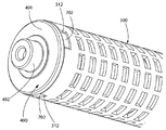
도 5는 본 발명에 따른 도 1의 면도기의 회전 커터의 사시도이다.
도 6은 도 1의 면도기의 회전 커터의 제2 끝단부의 사시도로서, 모터 조립체가 안에 위치되어 있다.
도 7은 도 6의 모터 조립체 및 회전 커터의 제2 끝단부의 사시도로서, 모터 조립체의 출력 샤프트에 연결된 연결 요소를 갖는다.
도 8은 도 8의 회전 커터의 제2 끝단부, 모터 조립체 및 연결 요소의 사시도로서, 회전 커터의 제2 끝단부를 덮는 제2 회전 커터 엔드캡을 갖는다.
도 9는 도 2의 B-B축을 따라 절개한 도 1의 면도기의 헤드부의 단면도이다.
도 9a는 도 1의 면도기의 고정 블레이드와 회전 커터의 상호 동작과 상대적 위치를 예시한 개략도이다.
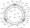
도 10은 도 1의 면도기에 이용될 수 있는 구멍들의 제1 교체 패턴을 가지는 회전 커터의 사시도이다.
도 11은 도 1의 면도기에 이용될 수 있는 구멍들의 제2 교체 패턴을 가지는 회전 커터의 2차원 평면도이다.
도 12는 도 11의 XII 영역의 확대도이다.
도 13은 도 1의 면도기에 이용될 때, 제3 교체 패턴의 구멍들을 가지는 회전 커터의 절단날이 고정 블레이드와 어떻게 상호 작용하는지를 도시한 개략도이다.
도 14는 도 13의 XIV 영역의 확대도이다.
도 15는 도 1의 면도기에 이용될 때, 제4 교체 패턴의 구멍들을 가지는 회전 커터의 절단날이 고정 블레이드와 어떻게 상호 작용하는지를 도시한 개략도이다.
도 16은 도 15의 XVI 영역의 확대도이다.
도 17은 도 1의 면도기에 이용될 때, 제5 교체 패턴의 구멍들을 가지는 회전 커터의 절단날이 고정 블레이드와 어떻게 상호 작용하는지를 도시한 개략도이다.
도 18은 도 17의 XVIII 영역의 확대도이다.
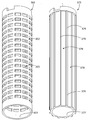
도 19는 본 발명에 따른 도 1의 면도기에 이용될 수 있는 회전 커터의 사시도로서, 회전 커터는 커팅 튜브와 지지 튜브를 포함한다.
도 20은 도 XX-XX를 따라 절개한 도 19의 회전 커터의 수평 단면도이다.
도 21은 도 19의 회전 커터의 분해도이다.
도 22는 본 발명에 따른 도 1의 면도기에 이용될 수 있는, 윤활 요소가 연결된 회전 커터의 사시도이다.
도 23은 도 22의 XXIII-XXIII를 따라 절개한 회전 커터의 수평 단면도이다.
도 24는 본 발명에 따른 회전 커터에 연결된 윤활 요소를 충전하는 저장소를 포함하는 면도기의 사시도이다.
도 25는 도 1의 면도기에 이용될 수 있는 진동 고정 블레이드를 포함하는 제1 대체 헤드의 사시도이다.
도 26은 하우징에서 제거된 도 25의 헤드부의 진동 고정 블레이드 및 회전 커터의 사시도이다.
도 27은 도 26의 헤드부의 진동 고정 블레이드 및 회전 커터의 평면도이다.
도 28은 도 1의 면도기에 이용될 수 있는, 하우징 안에 장착된 회전 커터와 하우징에 일체형으로 형성되는 고정 블레이드를 포함한 하우징을 포함하는 제2 대체 헤드의 사시도이다.
도 29는 도 1의 면도기에 이용될 수 있는, 하우징 안에 장착되는 회전 커터와 하우징의 슬롯에 장착되는 고정 블레이드를 포함한 하우징을 포함하는 제3 대체 헤드의 사시도이다.
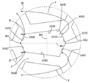
도 30은 도 1의 면도기에 이용될 수 있는, 스택화된 복수의 판 세그먼트로 형성된 하우징을 포함하는 제4 대체 헤드의 사시도이다.
도 31은 도 30의 2개의 판 세그먼트의 사시도이다.
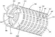
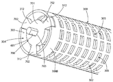
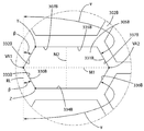
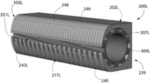
도 32는 도 1의 면도기에 이용될 수 있는, 각오프셋된 방식으로 배열된 스택화된 복수의 링 세그먼트로 형성된 회전 커터의 사시도이다.
도 33은 도 32의 2개의 링 세그먼트의 사시도이다.The features of the illustrated embodiment will be described with reference to the following drawings, wherein like structure has like reference numerals. The invention will be more fully understood from the detailed description and the accompanying drawings.
1 is a front perspective view of a razor according to the present invention.
Fig. 2 is a rear perspective view of the razor of Fig. 1;
3 is a top perspective view of the head of the razor of Fig.
Fig. 4 is an exploded view of the head of the razor of Fig. 1;
Figure 5 is a perspective view of a rotary cutter of the shaver of Figure 1 according to the present invention.
Fig. 6 is a perspective view of the second end of the rotary cutter of the shaver of Fig. 1, in which the motor assembly is located.
Figure 7 is a perspective view of the motor assembly and the second end of the rotary cutter of Figure 6, having a connection element connected to the output shaft of the motor assembly.
Fig. 8 is a perspective view of the second end of the rotary cutter of Fig. 8, the motor assembly and the connecting element, and has a second rotary cutter end cap covering the second end of the rotary cutter.
Figure 9 is a cross-sectional view of the head of the shaver of Figure 1 taken along the BB axis of Figure 2;
FIG. 9A is a schematic view illustrating the mutual operation and relative positions of the fixed blade and the rotary cutter of the shaver of FIG. 1; FIG.
Figure 10 is a perspective view of a rotary cutter having a first alternating pattern of holes that can be used in the shaver of Figure 1;
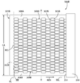
Figure 11 is a two-dimensional top view of a rotary cutter having a second alternating pattern of holes that can be used in the shaver of Figure 1;
12 is an enlarged view of the region XII in Fig.
13 is a schematic view showing how a cutting blade of a rotary cutter having holes of a third replacement pattern when used in the shaver of Fig. 1 interacts with the fixed blade. Fig.
14 is an enlarged view of the XIV region in Fig.
Fig. 15 is a schematic view showing how a cutting blade of a rotary cutter having holes of a fourth replacement pattern, when used in the shaver of Fig. 1, interacts with the fixed blade. Fig.
16 is an enlarged view of the XVI region of Fig.
17 is a schematic view showing how a cutting blade of a rotary cutter having holes of a fifth replacement pattern when used in the shaver of Fig. 1 interacts with the fixed blade.
18 is an enlarged view of the region XVIII in Fig.
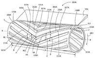
Figure 19 is a perspective view of a rotary cutter that may be used in the shaver of Figure 1 according to the present invention, wherein the rotary cutter includes a cutting tube and a support tube.
20 is a horizontal sectional view of the rotary cutter of FIG. 19 cut along the line XX-XX.
21 is an exploded view of the rotary cutter of Fig.
Figure 22 is a perspective view of a rotary cutter to which a lubricating element is connected, which may be used in the shaver of Figure 1 according to the present invention.
23 is a horizontal sectional view of the rotary cutter cut along the line XXIII-XXIII in FIG.
Figure 24 is a perspective view of a razor comprising a reservoir for filling a lubricating element connected to a rotating cutter according to the present invention.
25 is a perspective view of a first alternative head including a vibration-stabilizing blade that can be used in the razor of Fig.
26 is a perspective view of the vibration fixing blade and the rotary cutter of the head portion of Fig. 25 removed from the housing.
27 is a plan view of the vibration fixing blade and the rotary cutter of the head portion of Fig.
28 is a perspective view of a second alternative head that can be used with the razor of FIG. 1 and includes a housing including a rotating cutter mounted within the housing and a stationary blade integrally formed in the housing.
29 is a perspective view of a third alternative head that can be used in the razor of FIG. 1 and includes a housing including a rotating cutter mounted within a housing and a stationary blade mounted in a slot in the housing.
Figure 30 is a perspective view of a fourth alternative head comprising a housing formed of a plurality of stacked plate segments, which may be used in the shaver of Figure 1;
31 is a perspective view of the two plate segments of Fig. 30;
32 is a perspective view of a rotary cutter formed of a plurality of stacked ring segments arranged in each offset manner, which may be used in the shaver of FIG.
Figure 33 is a perspective view of the two ring segments of Figure 32;
아래 설명의 실시예(들)은 전적으로 단순한 예시에 불과하고, 본 발명이나 그의 응용 방식 혹은 사용 방식을 한정하는 의도는 전혀 없다.The embodiment (s) described below are merely exemplary in nature and are not intended to limit the invention, its application or manner of use.
본 발명의 원리에 따른 예시적 실시예들에 대한 설명은 첨부 도면과 연관하여 읽히도록 의도된 것이고, 이는 전반적인 설명의 일부로 간주될 것이다. 여기에 개시된 본 발명의 실시예에 대한 설명에 있어서, 방향(direction)이나 지향(orientation)에 대한 모든 언급은 오로지 설명의 편의를 위한 것일 뿐, 어떠한 방식으로도 본 발명의 범위를 제한하려는 의도가 없다. "아래(lower)", "위(upper)", "수평의(horizontal)", "수직의(vertical)", "상측의(above)", "하측의(below)", "위로(up)", "아래로(down)", "상부(top)", "하부(bottom)"와 이들의 파생어(예를 들어, "수평으로(horizontally)", "아래쪽으로(downwardly)", "위쪽으로(upwardly)" 등)와 같은 상대어는, 설명되거나 설명 중에 있는 도면에 보여지는 방향을 참조하면서 이해해야 한다. 이런 상대어는 오로지 설명의 편의를 위한 것일 뿐, 구체적인 지시가 없는 한, 본 장치가 특정 방향으로 구성되거나 동작해야 할 것을 요구하지 않는다. "붙여진(attached)", "부착된(affixed)", "연결된(connected)", "이어진(coupled)", "상호 연결된(interconnected)" 등의 용어는, 별도의 언급이 없는 한, 매개 구조를 통해 직접적 혹은 간접적으로 상호 부착되거나 고정된 관계, 서로 고정되거나 부착된 관계 또는 이동 가능한 부착이나 강력한 부착 관계를 지칭한다. 나아가, 여기서 사용된 것처럼, 어떤 2개의 구성이나 축이 서로 "평행"하거나 "수직"이라고 할 때, 이러한 용어는 특정예로 1∼3°일 수 있는 허용 오차 때문에, 구성들이나 축들이 완벽히 "평행"하거나 "수직"이지 않은 예들을 포함하는 의도를 가진다.The description of exemplary embodiments in accordance with the principles of the present invention is intended to be read in connection with the accompanying drawings, which are to be regarded as a part of the overall description. In the description of the embodiments of the invention disclosed herein, all references to direction or orientation are for convenience of description only and are not intended to limit the scope of the invention in any way. none. The terms "lower", "upper", "horizontal", "vertical", "above", "below" Downward, "" top, "" bottom, "and their derivatives (eg," horizontally, "" downwardly, "" Upwardly ", etc.) should be understood with reference to the direction shown or described in the illustrative drawings. Such correspondence is for illustrative purposes only, and does not require that the apparatus be configured or operated in a particular direction, unless specifically instructed. The terms "attached," "affixed," "connected," "coupled," "interconnected," and the like, Directly or indirectly, directly or indirectly, to each other, to a fixed or attached relationship, or to a movable attachment or a strong attachment relationship. Furthermore, as used herein, when any two constructions or axes are referred to as "parallel" or "perpendicular" to one another, Quot; vertical "or" vertical " non-vertical.
게다가, 본 발명의 특징이나 효과들은 예시적인 실시예들을 참조하면서 설명될 것이다. 따라서, 본 발명은 독립적으로 혹은 특징들 간의 기타 조합으로 존재할 수 있는, 구성들의 가능한 비제한적인 조합들을 설명하는 그런 예에 특정적으로 한정되지 말아야 한다. 본 발명의 범위는 첨부된 청구항들에 의해 정의된다.In addition, features and effects of the present invention will be described with reference to exemplary embodiments. Accordingly, the present invention should not be particularly limited to such examples, which describe possible, non-limiting combinations of configurations, which may exist independently or in other combinations between features. The scope of the invention is defined by the appended claims.
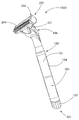
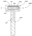
먼저, 도 1 및 2를 동시에 참조하면, 본 발명의 일 실시예에 따른 면도기(1000)가 도시되어 있다. 일반적으로 면도기(1000)는 핸들부(handle portion)(100)(이하에서는, "핸들(handle)"로 칭함) 및 헤드부(head portion)(200)(이하에서는, "헤드(head)"로 칭함)를 포함한다. 핸들(100)은 원하는 피부 영역을 면도하기 위해 편리하고 안정적으로 면도기(1000)를 잡고 조작할 수 있는 구조를 면도기(1000)의 사용자에게 제공한다. 본 실시예에서, 핸들(100)은 장형 구조(elongated structure)를 가지고, 일반적으로, 그립을 위한 원통부(cylindrical portion)(104)와, 헤드(200)와 핸들(100)의 결합을 위한 장착부재(mounting member)(106)를 포함한다. 일 실시예에서, 핸들(100)은 70㎜에서 140㎜ 사이의 길이를 갖는다.Referring first to FIGS. 1 and 2, a
원통부(104)는 길이방향축(longitudinal axis)(A-A)을 따라 연장된다. 일 실시예에서, 핸들(100)의 원통부(104)는 10㎜에서 25㎜ 사이의 지름을 갖는다. 장착부재(106)는 원통부(104)의 원단부(distal end)에 연결되고, 길이방향축(A-A)에서 반지름 방향으로 멀어지면서 경사지게 연장된다. 장착부재(106)의 원단부는 헤드(200)가 연결될 수 있도록 구성된다. 헤드(200)는 영구적으로, 반영구적으로 또는 착탈식으로 장착부재(106)에 연결될 수 있다. 예를 들어, 헤드(200)는 장착부재(106)와 일체형으로 형성되어 영구적인 연결을 이룰 수 있다. 이와 달리, 헤드(200)는 초음파 용접(ultrasonic welding), 열용접(thermal welding), 납땜(soldering), 접착(adhesion) 또는 이들의 조합에 의해 장착부재(106)와 연결되어 반영구적 연결을 이룰 수 있다. 또 다른 실시예에서는, 스냅핏(snap-fit) 연결, 기계적인 인터록(mechanical interlock), 인터퍼런스핏(interference fit), 나사연결(threaded connection), 탭/슬롯 인터록(tab/slot interlock), 래치 또는 이들의 조합에 의해 헤드(200)가 장착부재(106)에 연결되어 착탈식 연결을 이룰 수 있다. 물론, 본 발명의 범위 내에서 다른 연결 기술이 고려되거나 생각될 수 있다. 게다가, 본 발명의 어떤 실시예에서는, 위에서 설명한 방식이나 고려될 수 있는 다른 방식에 의해 헤드(200)가 원통부(104)에 직접 결합되기 위해, 장착부재(106)가 그다지 중요하지 않을 수 있고, 혹은, 전체적으로 생략될 수 있다.The
당업자가 이미 인지하고 있겠지만, 배터리 구동의 전동식 면도기의 최소 크기나 무게는, 요구되는 기간 동안 소기의 효율을 전달할 수 있게 효율적으로 모터에 전력을 공급할 수 있는 배터리의 크기 제약으로 귀결된다. 전동 요소의 작업 부하를 감소시키고, 보다 효율적인 동작을 만들 때, 사람들은 전원, 즉, 배터리나 배터리들에 의해서도 야기되는 전체적인 크기의 제약을 감소시킬 수 있다. 아래에서 설명하는 바와 같이, 본 발명의 몇몇 실시예에 따른 면도 헤드는, 현재 공지된 구성과 비교하면, 가위와 같은 제모 동작이 작은 모터에 의해 이루어지도록 설계되므로, 이에 대응하는 작은 전원에 의해 전원이 공급될 수 있다.As will be appreciated by those skilled in the art, the minimum size or weight of a battery powered electric shaver results in a size constraint on the battery that can efficiently power the motor to deliver the desired efficiency over the required period of time. When reducing the workload of the electromotive element and making more efficient operation, people can reduce the overall size limitation caused by the power source, that is, the battery or the batteries. As will be described below, the shaving head according to some embodiments of the present invention is designed such that the depilating operation, such as scissors, is performed by a small motor compared to the currently known configuration, Can be supplied.
일 실시예에서, 핸들(100)은 헤드(200)의 회전 커터(rotary cutter)(300)(상세는 아래에서 더욱 세부적으로 설명됨)를 회전시키는 모터(motor)(400)에 전원을 공급하는 전원(power source)(105)(점선으로 표시)을 위한 방수 하우징(water-tight housing)으로서 기능할 수도 있다. 물론, 다른 실시예에서는 전원(105)이 면도기(1000)의 다른 부분에 수용될 수 있다. 예를 들어, 특정 실시예에서, 전원(105)은 전체 혹은 부분적으로 헤드(200)에 수용될 수 있고, 적어도 일부가 헤드(200)에 수용될 수 있다. 전원(105)은 종래 기술과 마찬가지로 하나 이상의 배터리의 형태를 취할 수 있다. 본 실시예에서, 배터리들은 핸들(100)의 길이방향축(A-A)을 따라 연장되어 배치될 수 있다. 물론, 필요하다면 모터(400)에 전원을 공급하는 다른 종류의 전원이 이용될 수 있다. 면도기(1000)에 이용되는 전원(105)의 정확한 타입은 모터(400)의 전력공급조건에 의존하게 되므로, 청구항에서 별다른 언급이 없는 한 본 발명을 제한하는 것으로 간주되지 않는다.In one embodiment, the
전원(105)은 교체 가능하거나 영구적일 수 있다. 떼어낼 수 있는 전원(105)이 이용된 실시예에서, 전원(105)은 교체나 충전을 위해 핸들(100)에서 떼어낼 수 있는 하나 이상의 배터리일 수 있다. 그런 실시예에서, 핸들(100)은 전원(105)이 위치된 핸들(100)의 챔버(chamber)로 접근하기 위해 필요한 구성을 더 포함할 것이다. 본 실시예에서, 착탈캡(removable cap)(107)은 핸들(100)의 근단부(proximal end)(101)에 구비된다. 착탈캡(107)은, 전원(105)이 위치된 챔버 안으로 물이 들어오지 못하게끔, 나사결합, 타이트핏 구조 또는 기타 연결 방식에 의해 핸들(100)의 원통부(104)와 연결될 수 있다. 다른 실시예에서, 전원(105)을 내부에 갖는 핸들(100)의 내부 챔버로 접근하는 통로는 힌지 패널(hinged panel), 래치, 착탈 패널 또는 당업자에 알려진 기타 구조로 이루어질 수 있다.The
영구적(또는 비착탈식) 배터리가 이용된 실시예에서, 핸들(100)은 전원(105)을 충전하기 위해 전기적으로 연결될 수 있는 전기 포트(electrical port)를 더 포함할 수 있다. 물이나 기타 액체가 전기 포트로 유입되지 못하도록, 전기 포트는 착탈식 접근 패널의 뒷면에 구비될 수 있고, 전기 포트를 실링하는 캡/플러그를 구비할 수 있다.In embodiments where a permanent (or non-removable) battery is used, the
또 다른 실시예에서, 전원은 벽소켓이나 기타 전원으로부터의 전력공급원과 같이, 헤드(200)의 핸들(100)의 외부에 존재할 수 있다. 그런 실시예에서, 핸들(100)이나 헤드(200)는 전원플러그의 제1단과 같은, 외부 전력공급원에 동작 가능하게 연결될 수 있는 포트 또는 기타 구조를 포함할 수 있다.In another embodiment, the power source may be external to the
본 실시예에서, 모터(400)는 면도기(1000)의 헤드(200)의 내부, 더욱 상세하게는, 회전 커터(300)의 중앙 캐비티(central cavity)의 내부에 위치한다. 하지만, 다른 실시예에서 모터(400)는 핸들(1000)의 내부에 전체 혹은 부분적으로 위치할 수 있다. 그런 실시예에서, 모터(400)의 구동 샤프트(drive shaft)는 기어(gear), 풀리(pulley), 벨트(belt) 및 회전 운동을 전달할 수 있는 기타 연결원을 통해 회전 커터(400)에 동작 가능하게 연결될 수 있다.The
모터(400)의 동력 공급을 수동적으로 조절하기 위해 스위치(108)가 핸들(100)에 구비된다. 스위치(108)는 수동 방식의 슬라이드 스위치(slide switch)로 예시되어 있지만, 스위치는 당업자에 주지된 기타 종류의 수동 또는 자동 스위치일 수 있다. 필요하다면, 스위치(108)에 더해, 모터(400)의 동작 특성(performance characteristics)를 조절하기 위한 제어회로가 핸들(100)의 챔버 내부에 위치할 수도 있다.A
위에서 언급한 바와 같이, 헤드(200)는 핸들(100)의 장착부재(106)의 원단부에 연결된다. 헤드(200)는 일반적으로 길쭉한 모양을 갖고 길이방향축(longitudinal axis)(B-B)을 따라 연장된다. 아래에서 상세히 설명하겠지만, 헤드(200)의 길이방향축(B-B)은 회전 커터(300)의 회전축으로서도 기능한다. 본 실시예에서, 헤드(200)가 핸들(100)에 연결될 때, 헤드(200)는 핸들(100)에 대해 실질적으로 수직이 된다. 더욱 상세하게는, 헤드(200)가 핸들(100)에 연결될 때, 헤드(200)의 길이방향축(B-B)은 핸들(100)의 길이방향축(A-A)에 대해 실질적으로 수직이 된다. 게다가, 면도기(1000)가 일반적으로 T자 모양을 갖도록 핸들(200)은 헤드(200)의 중앙에 연결된다.As mentioned above, the
헤드(200) 및 핸들(100)의 가능한 구조적 구현 방법이 단 하나만 예시되었음에 주의해야 한다. 그러나, 다른 실시예에서는, 헤드(200)와 핸들(100)이 훨씬 다양한 모양과 크기를 취할 수 있음을 이해해야 한다. 예를 들어, 특정 실시예에서는, 헤드(200)가 핸들(100)보다 그렇게 특징적인 구성이 아니어도 좋다. 예컨대, 헤드(200)는 단순히 사용자 피부에 접촉하는 핸들(100)의 단부나 측부일 수 있다. 일 실시예에서, 헤드(200)와 핸들(200)의 조합은 원통 구조, 둥글납작한 구조(bulbous structure) 또는 달걀형 구조를 형성할 수 있지만, 이에 한정되지 않는다.It should be noted that only one possible structural implementation of the
본 실시예에서, 헤드(200)의 튜브형 하우징(tubular housing)(202)에서 연장되는 고정요소(fastener element)(201)들의 이용을 통해, 헤드(200) 핸들(100)에 연결된다. 고정요소(201)들은 헤드(200)의 전면(front face)(204)의 반대편에 있는 헤드(200)의 후면(rear face)(203)에서 연장되는 판(plate)들이고, 이때, 전면(204)은 아래 설명과 같이 헤드(200)의 작용/커팅면으로 간주될 수 있다. 고정요소(201)는 핸들(100)의 장착부재(106)의 대응 구조와 짝결합한다. 물론, 고정요소(201)는 핀(pin), 탱(tang), 소켓(socket) 또는 기타 연결구조나 짝결합 구조를 포함하여 다양한 종류의 구조를 취할 수 있다. 다른 특정 실시예에서, 헤드(200)의 배향이 핸들(100)에 대해 피봇될 수 있도록, 헤드(200)는 피봇 가능하게 핸들(100)에 연결될 수 있다. 다른 방식으로 생각하면, 그런 배치에서, 헤드(200)의 길이방향축(B-B)이 핸들(100)의 길이방향축(A-A)에 대해서 예각의 경로로 움직이도록 헤드(200)가 피봇될 수 있다. 그런 피봇 움직임은 다양한 방식으로 이루어질 수 있다. 일 실시예에서, 헤드(200)의 고정요소(201)는 헤드(200)를 피봇 가능하게 장착부재(106)에 연결한다. 다른 실시예에서, 장착부재(106)는 핸들(100)의 원통부(104)에 피봇 가능하게 연결된다. 헤드(200)를 피봇 가능하게 핸들(100)에 연결하면, 면도기(1000)를 사용 중 헤드(200)의 전면(204)을 핸들(100)에 대해 원하는 어떤 위치로도 피봇시키킬 수 있기에, 닿기 어려운 곳이나 복잡한 윤곽면을 면도하기 위해, 각도상 사용자에게 더 큰 각도의 유연함을 제공한다,The
헤드(200)를 피봇 가능하게 핸들(100)에 연결하면, 핸들의 길이방향축(A-A)을 중심으로 제한된 각도 영역 내에서 헤드(200)의 스위블(swivel)(즉, 흔들림(rock))을 허용한다. 그런 피봇 회전은, 면도기(1000) 사용 중, 헤드(200)가 사용자의 움직임이나 피부면에 대응해 그 위치를 조정할 수 있게 만든다. 이러한 피봇 움직임은, 부착 매커니즘을 가진 부착 수단 및/또는 핸들(100) 및/또는 헤드(200)에 의해 소기의 회전각으로 제한될 수 있다. 특정 실시예에서, 회전각은 180도, 90도, 60도, 30도 혹은 30도 미만일 수 있다.Pivotally connecting the
위에서 언급한 바와 같이, 다른 특정 실시예에서는 헤드(200)가 핸들(100)에 착탈식으로 연결될 것이다. 그런 실시예에서, 헤드(200)는 핸들(100)을 위한 "리필용(refill)" 헤드로 판매될 수 있다. 위에서 언급한 바와 같이(도 4 및 9를 참조하면서 아래에서 더욱 상세히 설명), 특정 실시예에서 모터(400)는 헤드(200)의 회전 커터(300) 안에 위치할 수 있다. 나아가, 위에서 설명한 바와 같이, 전원(105)은 핸들(100) 안에 위치한다. 따라서, 사용시 모터(400)에 전력을 공급하기 위해 일련의 전기적인 연결이 핸들(100)의 전원(105)에서 헤드(200)의 모터(400)로 이어진다. 그래서, 헤드(200)가 핸들(100)에 착탈식으로 연결되고, 모터가 헤드(200) 안에 위치하는 실시예에서는, 핸들(100)과 헤드(200)의 적절한 위치에 전기적인 인터페이스 커넥터(즉, 접점들(contacts))가 구비될 수 있고, 헤드(200)가 핸들(100)에 연결될 때 서로 전기적 연결을 이루어 전기 회로를 완성한다.As mentioned above, in other specific embodiments, the
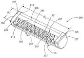
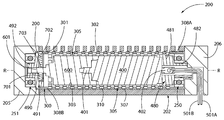
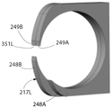
이제, 도 3 및 4를 동시에 참조하면, 헤드(100)는 일반적으로 튜브형 하우징(202), 고정 블레이드(fixed blade)(350), 모터(400), 회전 커터(300), 제1 엔드캡(end cap)(205), 제2 엔드캡(206), 제1 환형 베어링(annular bearing)(250), 제2 환형 베어링(251), 일렬 구동 트레인(inline drive train)(600), 연결요소(coupling element)(700), 제1 회전 커터 엔드캡(480) 및 제2 회전 커터 엔드캡(490)을 포함한다. 헤드(200)가 조립되면(도 5와 관련해 후술함), 헤드(200)는 길이방향축(B-B)을 따라 연장된 컴팩트한 구조(compact structure)가 된다.3 and 4, the
헤드(100)는 길이방향축(B-B)을 따라 제1 끝단(207)에서 제2 끝단(208)으로 연장되어, 헤드(200)의 최대길이폭(WL)을 정의한다. 일 실시예에서, 헤드(200)의 최대길이폭(WL)은 60㎜보다 작거나 같다. 다른 실시예에서, 헤드(200)의 최대길이폭(WL)은 40㎜와 60㎜ 사이의 값이다. 또 다른 실시예에서, 헤드(200)의 최대길이폭(WL)은 45㎜와 55㎜ 사이의 값이다. 또한, 헤드는 최대가로폭(WT)을 더 포함하고, 이는 헤드(200)의 선두면(lead face)(209)에서 헤드(200)의 후미면(trail face)(210)으로 연장된다. 일 실시예에서, 헤드(200)의 최대가로폭(WT)은 25㎜보다 작거나 같다. 다른 실시예에서, 헤드(200)의 최대가로폭(WT)은 10㎜와 25㎜ 사이의 값이다. 또 다른 실시예에서, 헤드(200)의 최대가로폭(WT)은 10㎜와 20㎜ 사이의 값이다. 또 다른 실시예에서, 헤드(200)의 최대가로폭(WT)은 10㎜와 15㎜ 사이의 값이다.The
본 실시예에서, 헤드(200)의 최대길이폭(WL)과 헤드(200)의 최대가로폭(WT)은 모두 헤드(200)의 전면(204)에서 측정된다. 헤드(200)의 전면(204)은 헤드(200)의 작업면(working face)이고, 사용자 피부에 접촉하는 헤드의 페이스(face)이고, 면도기(100)가 회전 커터(300)와 고정 블레이드(350) 사이에서 털을 절단할 수 있도록 한다(아래에서 더욱 상세히 설명). 다른 실시예에서, 헤드(200)의 최대길이폭(WL) 및/또는 헤드(200)의 최대가로폭(WT)은 헤드(200)의(혹은 헤드의 다른 위치의) 기타 부품들에 의해 영향을 받을 수 있다.In this embodiment, both the maximum length WL of the
튜브형 하우징(202)은 회전 커터(300), 모터(400), 일렬 구동 트레인(600), 제1 환형 베어링(250), 제2 환형 베어링(251), 연결요소(700), 제1 회전 커터 엔드캡(480) 및 제2 회전 커터 엔드캡(490)을 수용하기 위한 내부 캐비티(internal cavity)(211)를 포함한다. 튜브형 하우징(202)의 내부 캐비티(211)는 위에서 언급한 회전하는 상술의 부품들(이하에서 더욱 상세히 설명)을 수용하여 커버할 수 있는 크기를 갖는다. The
또한, 튜브형 하우징(202)은 내부 캐비티(211)로의 통로(passageway)를 형성하는 장형 슬롯(elongated slot)(214)을 포함한다. 회전 커터(300)의 일부가 장형 슬롯(214)을 통해 노출된다. 장형 슬롯(214)은 털을 튜브형 하우징(202)으로 들어오게 해서 회전 커터(300)와 고정 블레이드(350) 사이에서 절단되도록 하는데, 도 9 및 9a와 관련하여 더욱 상세히 설명된다. 본 실시예에서, 장형 슬롯(214)은 연속되고 끊기지 않는 방식으로 튜브형 하우징(202)의 전체 길이에 연장된다. 하지만, 다른 실시예에서 장형 슬롯(214)은 튜브형 하우징(202)의 전체 길이에 연장되지 않고, 본질적으로 분절화되거나 비연속적일 수 있고, 분절화되면서 비연속적일 수 있다.The
장형 슬롯(214)은 고정 블레이드(350)의 절단날(351)과 튜브형 하우징(202)의 맞은편 가장자리(opposing edge)(215)에 의해 정의된다. 본 실시예에서, 튜브형 하우징(202)의 맞은편 가장자리(215)는 축방향으로 이격된 복수의 핑거(finger)(216)에 의해 형성되고, 이는 전체적으로 빗살보호부(comb guard)(216)를 형성한다. 빗살보호부(217)는 튜브형 하우징(202)의 일부이고, 제모 중 회전 커터(300)와 고정 블레이드(350)에 털을 효율적으로 공급하기 위해 사용자 피부에 대해 눌릴 수 있는 한편 사용자 피부가 상처를 입거나 베이지 않게 만든다. 이 목적 달성을 더욱 향상시키기 위해, 빗살보호부(217)의 핑거(216)의 외표면은 선택적으로 평면이나 곡선형일 수 있는데, 이는 사용자 피부상에서 헤드(200)의 움직임을 용이하게 한다. 다른 실시예에서는, 맞은편 가장자리(215)는 핑거(216)들을 생략함으로써 빗살보호부(217)가 제거된 연속적인 가장자리일 수 있다.The
특정 실시예에서는, 튜브형 하우징(202)의 내부 캐비티(211) 및/또는 회전 커터(300)의 중앙 캐비티(304)에서 제모된 털 파편을 제거할 수 있도록, 튜브형 하우징(202), 제1 엔드캡(205) 및/또는 제2 엔드캡(206)에 하나 이상의 개구(opening)가 구비될 수 있다. 마지막으로, 도 3에서 볼 수 있듯이, 고정요소(201)들은 튜브형 하우징(202)의 일부일 수도 있다. 헤드(200)의 하우징(202)이 형상 면에서 튜브형으로 예시되었으나, 본 발명의 모든 실시예가 이에 한정되는 것은 아니다. 다른 실시예에서 하우징(202)은 다른 구조적 배열과 형상을 취할 수 있다.In a particular embodiment, the
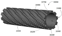
도 4, 5, 9 및 9a를 참조하면, 회전 커터(300)는 속이 빈 원통형 구성이다. 회전 커터(300)는 외표면(outer surface)(302)과 내표면(inner surface)(303)을 갖는 속이 빈 커터 튜브(301)를 포함한다. 본 실시예에서, 회전 커터(300)는 중앙축(central axis)의 둘레를 따라 커터 튜브(301)의 내표면(303)에 의해 형성되는 중앙 캐비티(304)를 포함하는데, 여기서 중앙축은 회전 커터(300)의 회전축(R-R)이기도 하다. 회전 커터(300)의 내부 캐비티(304)는 모터(400)와 일렬 구동 트레인(600)을 수용하는 크기를 가진다.Referring to Figures 4, 5, 9 and 9a, the
회전 커터(300)는 커터 튜브(301)의 외표면(302)에 형성된 복수의 구멍(aperture)(305)을 더 포함한다. 커터 튜브(301)의 외표면(302)은 회전 커터(300)의 회전축(R-R)에 대해 동심(concentric)을 이루고, 지름(D2)을 갖는 기준 실린더(도 9a의 원(C-C)으로 도시됨)를 정의한다. 일 실시예에서, 상기 지름(D2)은 20㎜보다 작거나 같다. 다른 실시예에서, 상기 지름(D2)은 6㎜ 내지 20㎜ 사이의 값이다.The
구멍(305)들 각각은 폐쇄구조를 갖는 절단날(307)에 의해 정의된다. 특정 실시예에서, 커팅 튜브(301)의 절단날(307)은 커터 튜브(301)의 외표면(302)의 교차점과 구멍(305)들을 둘러싸는 방사상벽부(radial wall)(310)에 의해 형성될 수 있다. 특정 실시예에서, 절단날(307)은 커터 튜브(301)의 외표면(302)과 실질적으로 동일한 높이에 위치하거나, 커터 튜브(301)의 내·외표면(302,303) 사이에 위치할 수 있다. 또한, 특정 실시예에서 커터 튜브(301)는 하나의 개방구조(open geometry)를 갖는 절단날(307)들에 의해 정의되는 하나 이상의 구멍들(305)을 포함할 수 있고, 이들은 커터 튜브(301)의 가장자리 부근에 위치(미도시)할 수 있다.Each of the
회전 커터(300)가 헤드(200) 안에 장착되어 모터(400)에 의해 회전될 때, 면도가 이루어지는 중 사용자의 털은 구멍(305) 속으로 들어가 절단날(307)과 고정 블레이드(350)의 절단날(351) 사이에서 절단된다. 도 10 내지 18을 참조하면서 아래에서 더욱 상세히 설명되겠지만, 복수의 구멍(305) 각각은 절단부(shearing portion)(330)와 비절단부(non-shearing portion)(331)를 갖도록 고려될 수 있다.When the
장형 돌출 리지(ridge)와 달리, 회전 커터(300)의 절단날(307)을 형성하는 구멍(305)들을 사용하면 면도기(1000)의 안정성을 높일 수 있다. 절단날(307)을 형성하는 구멍(305)들을 이용하여, 피부를 완전히 회전 커터(300)의 기준원(C-C)(도 9a 참조) 바깥에 있게 하여 안전요소를 더함으로써, 피부가 끼이거나 베일 확률을 감소시킨다. The stability of the
본 실시예에서, 각각의 구멍(305)은 커터 튜브(301)를 통해 외표면(302)에서 내표면(303)으로 연장됨으로써, 커터 튜브(301)를 통해 복수의 반지름방향 통로(radial passageway)를 형성한다. 하지만, 다른 실시예에서 구멍(305)들은 커터 튜브(301)의 전체 두께를 통과하지 않는 오목부(depression)의 형태로 외표면(302)에 존재하며, 이 구멍(305)은 막혀있다(blind).Each
예시된 바와 같이, 커터 튜브(301)는 구멍(305)들을 정의하는 격자 구조(lattice structure)(306)를 포함할 수 있다. 격자 구조(306)는 복수의 축방향부재(axial member)(306A)와 복수의 원주방향부재(circumferential member)(306B)를 포함하고, 이들은 교차하는 방식으로 배열된다. 본 실시예에서, 복수의 축방향부재(306A)는 회전축(R-R)에 평행한 커터 튜브(301)의 외표면(302) 상의 기준선(reference line)에 실질적으로 평행한 방향으로 연장되고, 복수의 원주방향부재(306B)는 그 기준선에 대해 실질적으로 수직인 방향으로 연장된다. 하지만, 다른 실시예에서는, 복수의 축방향부재(306A)가 그 기준선에 대해 경사지고, 이에 따라 원주방향의 연장요소(component of extention)를 가질 수 있다. 마찬가지로, 어떤 실시예에서는, 복수의 원주방향부재(306B)가 그 기준선에 대해 경사지고, 이에 따라 축방향의 연장요소를 가질 수 있다. 그런 실시예에서는, 상기 부재들의 격자 구조(306)가 주된 연장요소에 기반해 "원주방향" 또는 "축방향"으로 분류될 수 있다. 45°의 각으로 배열된 부재에 대해, 그 부재는 "원주방향" 또는 "축방향" 어느 것으로도 분류될 수 있다.As illustrated, the
본 실시예에서, 격자 구조(306)는, 축방향 단부들(axial end portions)(308A,308B)을 제외하고, 연속적으로 커터 튜브(301)의 둘레 전체를 커버한다. 다른 실시예에서, 격자 구조(308)는 구멍(305)이 없는 커터 튜브(301)의 부분들로 분절화되고 분리될 수 있다(도 22에 도시된 바와 같이, 구멍(305)이 없는 부분은 윤활 요소를 수용하는 데 이용된다).In this embodiment, the
본 실시예에서, 구멍(305)들은 사각형이다. 다른 실시예에서, 구멍(305)들은 폐쇄구조를 갖는 원형, 삼각형, 길쭉한 타원형, 오각형, 육각형 또는 기타 다각형 이나 불규칙 형상일 수 있다. 본 실시예에서 구멍(305)들 모두는 동일한 크기와 모양을 가진다. 하지만, 다른 실시예에서는 구멍(305)들이 서로 다른 복수의 형상 및/또는 크기를 갖는 구멍들을 포함할 수 있다. 특정 실시예에서, 각각의 구멍(305)은 사용자의 털 중 적어도 하나를 수용하기에 적절한 크기와 모양을 가지며, 이는 15 내지 180마이크론(micron) 범위의 지름을 가질 수 있다.In this embodiment, the
본 실시예에서, 구멍(305)들은 길쭉하고, 장축(major axis)(A1)과 단축(minor axis)(A2)을 포함한다. 장축(A1)은 단축(A2)보다 길다. 특정 실시예에서, A1/A2의 비율은 10:1에서 2:1 사이의 범위일 수 있다. 구멍(305)들의 장축(A1)은 원주방향으로 연장되고, 단축은 축방향으로 연장된다. 그 결과 각각의 구멍(305)들은 원주방향의 길쭉한 모양으로 간주될 수 있다. 다른 실시예에서는, 도 10 및 11에 도시된 바와 같이, 구멍(305)들은 축방향으로 길쭉할 수 있다. 이러한 실시예나 기타 실시예에서는, 장축(A1)이 축방향으로 연장될 것이고, 단축이 원주방향으로 연장될 것이다.In this embodiment, the
특정 실시예에서, 구멍(305)들은 커터 튜브(301)의 (외표면(302)의 총면적과 비교해) 넓은 누적 면적(cumulative surface area)을 정의하고, 커터 튜브(301)는 튜브형 스크린으로 간주될 수 있다. 일 실시예에서, 구멍(305)들은 커터 튜브(301)의 외표면(302)의 총면적의 0.5보다 크거나 같은 누적 면적을 가질 수 있다. 다른 실시예에서, 구멍(305)들은 커터 튜브(301)의 외표면(302)의 총면적의 0.6보다 크거나 같은 누적 면적을 가질 수 있다. 또 다른 실시예에서, 구멍(305)들은 커터 튜브(301)의 외표면(302)의 총면적의 0.75보다 크거나 같은 누적 면적을 가질 수 있다. 또 다른 실시예에서는, 구멍(305)들이 커터 튜브(301)의 외표면(302)의 총면적의 0.8보다 크거나 같은 누적 면적을 갖는다.In certain embodiments, holes 305 define a cumulative surface area (relative to the total area of outer surface 302) of
본 실시예에서, 구멍(305)들은 복수의 열(row)(309)을 가지는 구멍(305)들을 포함하는 패턴으로 구비된다. 본 실시예에서, 이 열(309)들은 회전 커터(300)의 회전축(R-R)과 실질적으로 평행한 방향으로 연장된 축방향의 열이다. 다른 실시예에서, 열(309)은 커터 튜브(301)의 외표면(302) 둘레로 부분적인 나선(helix)을 형성하기 위해 회전축(R-R)에 대해 경사질 수 있다. 구멍(305)들은 다양한 범위의 크기와 모양으로 형성될 수 있고, 다양한 범위의 패턴들로 커터 튜브(301)에 적용될 수 있다. 이러한 실시예들 중 일부는, 도 10 내지 18을 참조하면서 더욱 상세히 설명될 것이다. 나아가, 도 13 내지 18을 참조하면서 더욱 상세히 설명되겠지만, 회전 커터(300)의 절단날(307)과 고정 블레이드(350)의 절단날(351) 사이에서 절단되는 털의 개수가 정밀하게 제어되도록, 구멍(305)들의 모양, 크기 및 패턴이 선택될 수 있고, 이는, 예컨대 모터(400)에 대한 낮은 토크 사양 및 회전 커터(300)에 가해지는 힘의 균형과 같은 목적을 달성하기 위한 것이다.In this embodiment, the
특정 실시예예서, 커터 튜브(301)는 0.1㎜ 내지 2.5㎜ 사이의 두께를 가질 수 있다. 커터 튜브(301)는 메탈이나 기타 적절한 물질로 이루어질 수 있다. 일 실시예에서, 커터 튜브(301)는 둥글게 감겨 가장자리가 서로 연결된 모양을 갖는 시트 메탈(sheet metal)로 형성될 수 있다. 구멍(305)들은 커터 튜브(301)를 형성하기 위한 롤링이 이루어지기 전이나 후에 시트 메탈로 형성될 수 있는데, 레이저 커팅(laser cutting), 펀칭(punching), 화학적 식각(chemical etching) 또는 이들의 조합을 이용할 수 있다. 특정 실시예에서, 레이저 커팅은 처리된 시트 메탈에 잔류 응력이 생기지 않게 하는 것이 바람직할 수 있다. 이에 따라, 커터 튜브(301)를 형성하는 레이저 커팅된 시트 메탈이 변형되지 않고 원하는 형상을 유지할 것이다. 다른 실시예에서, 커터 튜브(301)는 다른 물질이나 다른 기술에 의해 형성될 수 있고, 이는 적절한 물질들에 대한 기계가공(machining), 사출성형(injection molding), 주조(casting) 및 이들의 조합을 포함한다. 일 실시예에서는, 레이저 커팅과 같은 방식에 의한 스톡 튜브(stock tube)가 이용될 수 있고, 여기에 구멍(305)들이 형성된다.In a particular embodiment example, the
일 실시예에서, 커터 튜브(301)의 외표면(302)은 연마된 마무리(polished finish)를 가질 수 있다. 또한, 외표면(302)에는 저마찰 코팅 및/또는 고강도 코팅이 가해질 수 있다. In one embodiment, the
이제, 도 3, 도 4, 도 6 내지 9a를 참조하면서, 특정 부품들과 그들 간의 구조적 협력을 포함하는 헤드(200)의 조립체가 설명될 것이다. 헤드(200)가 작동을 위해 조립될 때, 고정 블레이드(350)는 회전 커터(300)에 인접하게 장착된다. 일 실시예에서, 고정 블레이드(350)는 그의 절단날(351)이 회전 커터(300)의 회전축(R-R)(본 실시예에서, 헤드(200)의 길이방향축(B-B)과 일치)에 실질적으로 평행하게 연장되도록 회전 커터(300)에 인접하게 장착된다. 본 실시예에서, 고정 블레이드(350)의 절단날(351)이 슬롯(314) 안으로 연장되고, 회전 커터(300)의 커터 튜브(301)의 외표면(302)(절단날(307)을 포함)에 인접하도록 튜브형 하우징(202)에 고정 블레이드(350)를 장착시킴으로써 그러한 인접 위치맞춤을 이룰 수 있다. Referring now to Figures 3, 4, and 6 through 9A, an assembly of
일 실시예에서, 고정 블레이드(350)는 회전 커터(300)의 회전축(B-B)으로부터 반지름 거리에 대해 고정(fixed)된다. 여기서 사용된 "고정"이라는 용어는 고정 블레이드(350)에 자그마한 진동이 전해질 수 있는 실시예 및/또는 절단날(351)이 회전축(B-B)에 대해 실질적으로 평행하게 유지되거나, 그로부터의 반지름 거리가 유지되는 방식으로 미세하게 축방향 병진운동할 수 있는 실시예를 커버하는 의미이다. 다른 특정 실시예에서, 고정 블레이드(350)는 튜브형 하우징(202)과 회전축(R-R) 모두에 대해 움직일 수 없거나 완벽히 고정될 수 있다.In one embodiment, the
특정 실시예에서, 고정 블레이드(350)의 절단날(351)은 회전 커터(300)의 전체 길이를 따라 연장될 수 있다. 모터(400)가 동작하면서 제모가 이루어지는 동안, 회전 커터(300)의 절단날(307)과 고정 블레이드(350)의 절단날(351) 사이에서 털을 절단하기 위하여, 커터 튜브(301)의 절단날(307)과의 효율적인 협력을 위해, 고정 블레이드(350)의 절단날(351)은 회전 커터(300)의 절단날(307)에 충분히 근접하고, 헤드(200)의 전면(204)이 피부를 누르면서 피부 위에서 움직인다. 일 실시예에서, 제모 동작이 이루어지는 동안, 회전 커터(300)의 커터 튜브(301)의 절단날(307)과 고정 블레이드(350)의 절단날(351) 사이에 커팅갭(cutting gap)(325)의 형태로 공차(tolerance)가 존재하도록 설계된다.In certain embodiments, the
사용을 위해 헤드(200)가 조립되면, 회전축(R-R)을 중심으로 회전 커터(300)를 회전시킬 수 있도록, 모터(400)가 회전 커터(300)의 중앙 캐비티(304)에 위치되어 동작 가능하게 연결된다. 본 발명의 어떤 실시예에 따르면, 위에서 설명한 바와 같이, 모터(400)는 전기 모터이고, 핸들(100)에 수용된 전원(105)에 전기적으로 연결된다. 모터(400)는 직류 혹은 교류에 의해 전원이 공급될 수 있다. 특정 실시예에서, 모터(400)는 브러시리스 모터(brushless type motor)나 브러시 모터(brushed motor type) 및/또는 코어 모터(cored motor)나 코어리스 모터(coreless type motor)일 수 있다. 예를 들어, 브러시리스 직류 전기 모터는 직류 전기에 의해 전원을 공급받는 동기형 전기 모터(synchronous electric motor)이고, 브러시 모터에서 브러시에 기반한 기계적인 전류(轉流, commutation) 시스템 대신, 전기적으로 제어되는 전류(轉流) 시스템(컨트롤러)을 갖는다. 여기서, "모터"라는 용어는 전기적인 힘을 필요한 출력의 힘(force)/토크(torque)나 속도(speed)와 같은 기계적인 운동으로 변환시키는 부품들의 조립체를 포괄하는 의미이다.When the
특정 실시예에서는 생략될 수 있는 일렬 구동 트레인(600)은 전기 모터(400)의 출력 속도나 토크를 제어하기 위해 구비될 수 있다. 일렬 구동 트레인(600)은 기어 박스(gear box)와 같은 구동 트랜스미션 장치(drive transmission device)로서, 모터(400), 즉, 모터(400)의 구동 샤프트(401)와 일렬로 놓인다. 일렬 구동 트레인(600)의 출력 샤프트(output shaft)(601)는 동일한 회전축을 공유할 수 있다. 일렬 구동 트레인(600)은 에피싸이클릭 기어(epicyclic gearing) 또는 유성기어(planetary gearing)를 포함할 수 있다. 이러한 일렬 기어 시스템은, 선택된 모터 또는 필요로 하는 말단 회전 출력(terminal rotation output)에 따라, 모터의 토크를 증가시키면서 그 속도를 감소시키거나, 그와 반대로 만들기 위해 선택될 수 있다.The
전기 모터(400)의 회전 출력이 연결 요소(700)에 의해 회전 커터(300)의 커터 튜브(301)에 전달되도록, 연결 요소(700)는 전기 모터(400)와 회전 커터(300)의 커터 튜브(301)에 (직접적으로 또는 간접적으로) 연결된다. 본 실시예에서, 연결 요소(700)는 일렬 구동 트레인(600)의 출력 샤프트(601)에 연결되고(차례차례 모터(400)에 동작 가능하게 연결됨), 회전 커터(300)의 커터 튜브(301)의 단부(308B)에 연결된다. 다른 실시예에서, 연결 요소(700)는 (예를 들어, 구동 샤프트(401) 또는 기타 회전 아웃풋(rotating output)을 통해) 전기 모터(400)에 직접적으로 연결될 수 있다. 또 다른 실시예에서, 부가적인 매개 구동 트랜스미션 장치(intervening drive transmission device)가 이용될 수 있다.The connecting
연결 요소(700)는 회전 커터(300)에 대해 회전할 수 없다. 나아가, 연결 요소(700)는, 커터 튜브(301) 상에서 반경방향힘(radial force)(외측 반지름 방향 힘)을 가하지 않도록 회전 커터(300)의 커터 튜브(301)를 체결한다. 커터 튜브(601)에 가해지는 반경방향힘은 (미세하게나마) 커터 튜브(301)의 변형을 야기할 수 있다. 미세한 변형이라 할지라도 빠르게 회전하는 동안 커터 튜브(301)의 균형을 잃게 하고, 이는 면도가 진행되는 동안, 고정 블레이드(350)와 피부에 대해 고르지 못한 접촉을 야기한다. 연결 요소(700)는, 체결 과정이나 모터(400)에 의해 회전 커터(400)가 회전하는 동안, 커터 튜브(301)에 인가되는 반경방향힘이 없을 때의 변형에 대한 가능성 없이, 모터(400)의 회전 출력을 회전 커터(300)에 전달하는 구조를 제공한다.The connecting
본 실시예에서, 연결 요소(700)는 허브(hub component)(701)와 상기 허브(701)로부터 방사상으로 연장된 복수의 스포크(spoke component)(702)를 포함한다. 스포크(702)들은 원주상으로 동일한 거리 이격된 방식(equi-spaced manner)으로 허브 둘레에 구비된다. 각각의 스포크(702)는 원주상 두께를 가지며, 이는 허브(701)로부터 멀어질수록 두꺼워진다. 3개의 스포크(702)가 도시되었지만, 다른 실시예서는 다른 개수의 스포크(702)가 이용될 수도 있고, 하나만 포함될 수도 있다. 나아가, 각 스포크(702)는 일정한 원주상 두께를 가질 수도 있고, 또는, 단순한 돌기의 형태일 수도 있다.In this embodiment, the
허브(701)는 일렬 구동 트레인(600)의 출력 샤프트(601)를 수용하기 위한 중앙 구멍(central aperture)(703)을 포함한다. 허브(701)의 중앙 구멍(703)은 출력 샤프트(601)의 것과 같이 비원형(non-circular)이어서, 출력 샤프트(601)가 연결 요소(700)를 체결하고 회전시킬 수 있다. 연결 요소(700)의 스포크(702)는 커터 튜브(701)에 연결된다. 커터 튜브(301)는 복수의 피처(feature)(312)를 포함하며, 본 실시예에서 이들은 커터 튜브(301)의 가장자리 안으로 형성된 슬롯의 형태이며, 연결 요소(700)의 스포크(702)와 짝을 이룬다. 스포크(702) 각각은 하나의 피처(312)와 짝을 이룬다. 슬롯 각각은 회전축(R-R)으로부터 멀어짐에 따라 증가하는 원주상 폭을 가지며, 이는 그와 짝을 이루는 스포크(702)의 원주상 폭에 대응한다. 스포크(702)와 짝을 이루는 커터 튜브(301)의 피처(312)가 슬롯으로 예시되었지만, 다른 실시예에서 피처들은 스포크(702)를 체결하는 인보드 구멍(inboard apertures), 컬러(collars) 또는, 스포크(702)를 체결하는 돌기 구조를 포함할 수 있다.The
특정 실시예에서, 연결 요소(700)는 조립체의 동심도 조건(concentricity requirement)을 분리시킬 수 있다. 커터 튜브(301)의 회전축(R-R)과 일렬 구동 트레인(600)의 출력 샤프트(601)의 회전축이 특정례에서는 미소하게 분리될 수 있다(비동심(non-concentric)). 연결 요소(700)를 통해 전달되는 회전 운동은 커터 튜브(301)와 출력 샤프트(601) 사이의 완전한 동심도에 의존하거나, 이를 요구하지 않는다. 다시 말하면, 회전축은 회전축(R-R)과 미소하게 비정렬될 수 있고, 이는 제조와 조립체를 단순화하고, 로버스트한 방식을 제공한다.In certain embodiments,
모터(400), 일렬 구동 트레인(600) 및 연결 요소(700)가 조립되면, 제1 및 제2 회전 커터 엔드캡(480,490)은 거기에 연결된다. 제1 회전 커터 엔드캡(480)은 커터 튜브(301)의 제1 끝단(first end)에 끼워지고, 환형체(annular body)(481)와 내부가 빈 포스트(hollow post)(482)를 포함한다. 축방향 통로가 제1 회전 커터 엔드캡(480)을 통해 형성되어, 전기적인 커텍터(501A,501B), 본 실시예에서는 와이어(wire)가 이를 통과하여 모터(400)의 접점(402)들에 연결될 수 있다. 제1 회전 커터 엔드캡(480)은 회전 불가능하게 모터(400)에 연결되어 동작시 회전축(R-R)을 중심으로 회전하지 않는다. 제1 환형 베어링(250)은 제1 회전 커터 엔드캡(480)의 내부가 빈 포스트(482) 위로, 회전 커터(300)의 내부 캐비티(304) 안으로 슬라이딩한다. 제1 환형 베어링(250)의 외표면은 커터 튜브(301)의 내표면(303)을 체결하고, 제1 환형 베어링(250)의 내표면은 제1 회전 커터 엔드캡(480)의 내부가 빈 포스트(482)를 체결한다. 이렇게, 제1 환형 베어링(250)의 외측 부분은 내부에 대해 제1 환형 베어링(250)의 내측 부분에 대하여 회전할 수 있다.When the
제2 회전 커터 엔드캡(490)은 커터 튜브(301)의 제2 끝단(second end)에 끼워지고, 환형체(annular body)(491)와 내부가 빈 포스트(hollow post)(492)를 포함한다. 제 회전 커터 엔드캡(490)은 일렬 구동 트레인(600)의 출력 샤프트(601)를 수용하고 체결하며, 연결 요소(700)를 체결한다. 제2 회전 커터 엔드캡(490)은 회전축(R-R)을 중심으로, 회전 커터(300), 연결 요소(700), 일렬 구동 트레인(600)의 출력 샤프트(601)와 함께 회전한다. 제2 환형 베어링(251)은 제2 회전 커터 엔드캡(490)의 내부가 빈 포스트(492) 위로 슬라이드하지만, 커터 튜브(301)의 외측에 머무른다. 제2 환형 베어링(251)의 내표면은 제2 회전 커터 엔드캡(490)의 내부가 빈 포스트(492)를 체결한다.The second rotary
상술한 조립체는 그 다음 하우징(202)의 내부 캐비티(211) 안에 장착된다. 구체적으로, 제1 회전 커터 엔드캡(480)의 내부가 빈 포스트(482)는 제1 엔드캡(205)에 대해 회전하지 못하도록, 제1 앤드캡(205)을 체결한다. 마찬가지로, 제2 환형 베어링(251)의 외표면은 제2 엔드캡(206)에 대해 회전하지 못하도록, 제2 앤드캡(205)에 체결된다. 하지만, 제2 환형 베어링(251)의 내측 부분과 제1 환형 베어링(250)의 외측 부분의 자유 회전이 가능하기 때문에, 모터(400)에 의한 회전 커터(300)의 회전은 가능하다.The above-described assembly is then mounted in the
본 실시예에서, 양 환형 베어링(250,252)은 볼베어링(ball-bearing)이다. 하지만, 본 발명에 이용될 수 있는 베어링의 종류로서, 접찰면(rubbing surface)과 일반적으로 윤활제에 기초한 (마찰계수가 대략 0.05인 PTFE와 같은 플라스틱이나 강금속을 이용해 구현되는) 슬라이딩(sliding) 혹은 슬립 베어링(slipping bearing)으로 알려진 평면 베어링(plain bearing), 볼이나 롤러(실린더)나 제한링(restriction ring)에 기초한 볼 베어링, 또는 자기 베어링(magnetic bearing) 및 플렉셔 베어링(flexure bearing)을 포함한다. 특정 실시예에서, "환형"이라는 용어는 단편적으로 환형임을 포함할 수 있지만, 이에 한정되지 않는다.In this embodiment, the
여기에 제시된 내부적으로 구동되는 면도기 헤드의 다양한 구성들은, 명확함과 분명함을 위해 별개의 개별적인 구성으로 제시되었음을 이해해야 한다. 하지만, 여기에 설명된 몇몇 구성들은 다른 구성들과 통합되어 제조됨으로써 단일의 연속적인 유닛(continuous unit)을 형성할 수 있고, 여기서 단일의 연속적인 유닛으로 설명된 몇몇 구성들은 복수의 서브 구성으로 형성될 수도 있다. It should be appreciated that the various configurations of the internally driven razor head presented herein are presented in separate, separate configurations for clarity and clarity. However, some of the configurations described herein may be combined with other configurations to form a single continuous unit, wherein some of the configurations described as a single continuous unit may be formed in a plurality of sub-configurations .
이제, 도 10 내지 18을 참조하면, 구멍(305A-E)들의 교체 패턴(alternate pattern)을 가지는 복수의 회전 커터(300A-E)들이 도시되어 있다. 회전 커터(300A-E)는 상술한 도 1 내지 9의 회전 커터(300)를 대체해 이용될 수 있다. 구멍(305A-E)의 크기, 모양 및 패턴을 제외하고는, 회전 커터(300A-E)는 회전 커터(300)와 동일할 수 있다. 그래서, 이하에서 회전 커터(300A-E)에 대한 설명은, 상기 회전 커터(300)와 관련한 설명이 각 실시예에 적용되는 것을 이해하면서, 이러한 새로운 특징에 제한될 것이다. 따라서, 동일한 참조 번호가 동일한 구성에 대해 적절한 알파벳 접미사 "A-E"가 부가되면서 사용될 것이다. 나아가, 면도기(1000)의 동작과 성능의 특정 효과를 달성할 수 있는 구멍의 패턴과 모양을 구현하면서, 구멍들(305A-E)의 부가적인 세부 사항들이 설명될 것이다. 마지막으로, 면도기(1000)에 이용될 때, 회전 커터(305B-E)들은 3D 실린더나 튜브의 형상을 취한다는 것을 이해하면서, 설명의 단순화를 위해 로터리 커터(305B-E)들이 단순화된 2D 도식으로 도시되었음에 유의해야 한다.Referring now to Figures 10-18, a plurality of
먼저, 도 10으로 돌아가면, 제1 교체 패턴(a first alternate pattern)에 배치된 구멍(307A)들을 포함하는 커터 튜브(301A)를 포함하는 회전 커터(300A)가 예시되었다. 커터 튜브(301A)는 축방향의 장형 구멍(elongated aperture)(305A)을 복수개 포함하고, 이들은 V자 형상을 취한다. 각각의 구멍(305A)들은 (구멍이 없는) 제1 축방향 단부(first axial end portion)(308A)로부터 (역시 구멍이 없는) 제2 축방향 단부(second axial end portion)(308B)로 연장된다. 각각의 구멍(305A)은 폐쇄구조를 정의하는 절단날(307A)에 의해 정의된다. 각 절단날(307A)은 절단부(330A)와 비절단부(331A)를 포함한다. 회전 커터(300A)가 회전축(R-R)을 중심으로 각방향(AD1)(angular direction)으로 회전되는 본 실시예에서, 절단부(330A)는 Y점으로부터 Z점까지 연장되고 골꼭짓점(valley apex)(VA)을 포함하고, 비절단부(331A)는 Z점으로부터 Y점까지 연장되고 마루꼭짓점(peak apex)(PA)을 포함한다. 10, a
여기서 말하는, 회전 커터의 구멍들에 의해 정의되는 절단날의 "절단부"는 면도가 이루어지면서 회전 커터가 회전할 때, 고정 블레이드의 절단날과의 협력에 의해, 털에 접촉하여 절단할 수 있는 회전 커터의 절단날 부위이다. 반면, 여기서 말하는, 회전 커터의 구멍들에 의해 정의되는 절단날의 "비절단부"는 면도가 이루어지면서 회전 커터가 회전할 때, 고정 블레이드의 절단날과의 협력에 의해, 털에 접촉하여 절단할 수 없는 회전 커터의 절단날 부위이다. 어떤 구멍에서든, "절단부"로 생각될 수 있는 절단날 부위와 "비절단부"로 생각될 수 있는 절단날 부위는, 회전축을 중심으로 한 회전 커터의 회전 각방향에 의존한다. 따라서, 구멍의 절단날의 어떤 부위는, 회전 커터가 제1 각방향으로 회전축을 중심으로 회전할 때에는 "절단부"로 생각되지만, 상기 구멍의 그 어떤 부위는 회전 커터가 제2 각방향(제1 각방향의 반대방향)으로 회전축을 중심으로 회전할 때에는 "비절단부"로 생각될 수 있다. Quot; cut "portion of the cutting blade defined by the holes of the rotary cutter, as referred to herein, is a rotation that can be cut in contact with the hair by cooperation with the cutting blade of the fixed blade when the rotary cutter is rotated, The cutting edge of the cutter. On the other hand, here, the "non-cut portion" of the cutting edge defined by the holes of the rotary cutter is cut in contact with the hair by cooperation with the cutting edge of the fixed blade when the rotary cutter is rotated, It is the cutting edge part of the rotary cutter which can not be made. In any hole, the cutting blade portion, which can be thought of as a "cut portion", and the cutting blade portion, which can be thought of as a "non-cut portion", depend on the rotational angle direction of the rotary cutter about the rotation axis. Therefore, while a certain portion of the cutting edge of the hole is considered to be a "cut portion" when the rotary cutter rotates about the rotation axis in the first angular direction, Quot; non-cut portion "when it is rotated around the rotation axis in the opposite direction to the direction of the arrows).
다시 도 10의 실시예로 돌아오면, 각각의 구멍(305A)들에 있어서, 절단부(330A)는 제1 경사 영역(a first inclined section)(332A)과 제2 경사 영역(a second inclined section)(333A)을 포함하며, 이들은 서로 만나 골꼭짓점(VA)을 형성한다. 제1 및 제2 경사 영역(332A,333A) 각각은, 회전축(R-R)에 평행한, 커터 튜브(301A)의 외표면(302A)(회전 커터(300A)의 외표면이기도 함) 상의 기준선(RL)과 함께 예각(β)을 이룬다. 각각의 구멍(305A)에서, 절단부(331A)는 제1 원주 영역(first circumferential section)(334A)과 제2 원주 영역(second circumferential section)(335A)을 포함하고, 상기 제1 및 제2 원주 영역 각각은 상기 기준선(RL)에 직교한다. 또한, 비절단부는 제1 경사 영역(336A)과 제2 경사 영역(337A)을 포함하며, 이들은 서로 만나 마루꼭짓점(PA)을 형성한다. 제1 및 제2 경사 영역(336A,337A)은 기준선(RL)과 예각(α)을 이룬다. 본 실시예에서, 예각(α)은 예각(β)과 실질적으로 동일하다. 다른 실시예에서는, 예각(α)이 예각(β)과 다르다. 특정 실싱예에서, 예각(α)과 예각(β)은 10°에서 60°사이일 수 있다.Referring back to the embodiment of FIG. 10, in each of the
각각의 구멍(305A)들에서, 절단날(307A)의 골꼭짓점(VA)과 마루꼭짓점(PA)은 커터 튜브(301A)의 축길이(LA)의 중앙에 위치하며, 이는 기준 중심선(RCL)으로 그려져 있다. 또한, 구멍(305A)들의 패턴은 기준 중심선(RCL)에 대해 대칭이다. 더욱 상세하게, 기준 중심선(RCL)의 일측면의 패턴 부위는 기준 중심선(RCL)의 반대측면의 패턴 부위의 거울상이다. 마지막으로, 도 10의 실시예에서는, 각각의 구멍(305A)이 V자 구멍을 형성하기 위하여, 2개의 반대방향으로 경사진 "레그(leg)"를 포함하지만, 다른 실시예에서는, 축방향으로 길쭉한 파동형 구멍들을 잇따라 형성하기 위해 반대방향으로 경사진 "레그"를 2개 이상 포함할 수 있다.In each of the
도 11 및 12를 동시에 참조하면, 회전 커터(300B)가 제2 교체 패턴으로 배열된 구멍(307B)들을 포함한 커터 튜브(301B)를 포함하는 것으로 도시되어 있다. 제2 교체 패턴에서, 구멍(305B)들은 복수의 열(309B)로 배열된다. 도시된 바와 같이, 복수의 열(309B)은 어느 열(309B)도 구멍(305B)들의 중심들을 연결하는 기준열선(reference row line)(RRL)이 회전축(R-R)에 평행하도록 방향 지어져 있다. 따라서, 본 실시예에서 복수의 열(309B)은 축방향 열로 생각될 수 있다. 다른 실시예에서는(도 17에 도시된 바와 같은), 복수의 열(309B)이 기준열선(RRL)이 회전축(R-R)에 대해 예각(또는 이와 달리 경사지게)을 갖도록 방향이 정렬될 수 있다.11 and 12, the
각각의 구멍(305B)들은 육각 형상을 가진다. 또한, 본 실시예에서, 각각의 구멍(305B)은 각 구멍(305B)이 장축(M1)과 단축(M2)을 포함하고, 장축(M1)이 단축(M2)보다 더 길도록, 원주방향으로 길쭉할 수 있다. 장축(M1)은 회전축(R-R)에 평행한, 커터 튜브(301B)의 외표면(302B)(회전 커터(300B)의 외표면이기도 함)상의 기준선(RL)에 실질적으로 수직이고, 단축(M2)은 기준선(RL)에 실질적으로 수직이다. 다른 실시예에서, 구멍(305B)은 단축(M2)이 장축(M1)보다 크게 축방향으로 길쭉할 수 있다.Each
각 구멍(305B)은 폐쇄구조를 정의하는 절단날(307B)에 의해 정의된다. 각 절단날(307B)은 절단부(330B)와 비절단부(331B)를 포함한다. 회전 커터가 회전축(R-R)을 중심으로 각방향(AD1)으로 회전하는 본 실시예에서, 절단부(330B)는 Y점으로부터 Z점까지 연장되며 제1 골꼭짓점(VA1)을 포함하고, 비절단부(331B)는 Z점으로부터 Y점까지 연장되며 제2 골꼭짓점(VA2)을 포함한다. Each
본 실시예에서는, 각 구멍(305B)에서, 절단부(330B)는 제1 경사 영역(332B)과 제2 경사 영역(333B)을 포함하며, 이들은 서로 만나 제1 골꼭짓점(VA1)을 형성한다. 제1 및 제2 경사 영역(332B,333B) 각각은 기준선(RL)과 예각(β)을 이룬다. 각 구멍(305B)에서, 비절단부(331B)는 제1 원주 영역(334B)과 제2 원주 영역(335B)을 포함하고, 제1 원주 영역(334B)과 제2 원주 영역(335B) 각각은 기준선(RL)에 대해 직교한다. 또한, 비절단부(331B)는 제1 경사 영역(336B)와 제2 경사 영역(337B)을 포함하고, 이들은 서로 만나 제2 골꼭짓점(VA2)을 형성한다. 제1 및 제2 경사 영역(336B,337B) 각각은 기준선(RL)과 둔각(γ)을 이룬다. 본 실시예에서, 둔각(γ)과 예각(β)은 서로에 대해 보각(supplementary)이다. 다른 실시예에서, 둔각(γ)과 예각(β)은 서로 보각이 아닐 수 있다. 특정 실시예에서, 예각(β)은 10°에서 60°이고, 둔각(γ)은 90°에서 150°일 수 있다.In this embodiment, in each
마지막 언급으로, 본 패턴의 구멍(305B)들은 (회전 커터(300B)의 축길이(LA)를 절반으로 양분하는) 기준 중심선(RCL)에 대해 대칭이다. 본 실시예에서, 기준 중심선(RCL)의 일측의 패턴 부분은 기준 중심선(RCL)의 반대측의 패턴 부분의 거울상이다.In the last mention, the
이제, 도 13 및 14를 참조하면, 회전 커터(300C)는 제3 교체 패턴으로 배열된 구멍(307C)들을 포함하는 커터 튜브(301C)를 포함하는 것으로 도시되었다. 특히, 구멍(307C)들의 제3 교체 패턴은, 임의의 점에서 구멍(305C)들의 절단날(307C)의 오직 선택된 개수의 절단부(330C)만이 고정 블레이드(350)와 함께 털을 절단하는 데 활성화될 수 있도록 설계된다. 나아가, 구멍(307C)들의 제3 교체 패턴은, 특히, 회전 커터(300C)가 실질적으로 균형적인(balanced) 부하를 받도록 설계되는데, 이 부하는 면도시에 고정 블레이드(350)의 절단날(351)과 함께 이루어지는 제모 중, 털에 의해 회전 커터(300C)에 가해지는 반동력으로부터 야기되는 것이다. 그 결과, 모터(400)의 토크 요구조건이 최적화될 수 있고, 회전 커터(300C)는 그의 적절한 형상과 고정 블레이드(350)와의 이격거리를 더욱 정밀하게 유지할 수 있다.13 and 14, the
제3 교체 패턴에서, 구멍(305C)들은 복수의 열(309C)로 배열된다. 각 열(309C)의 구멍(305C)들은 그 중심이 기준열선(RRL)을 따라 위치한다. 각각의 열(309C)은, (회전 커터(300C)의 축길이를 절반으로 양분하는) 기준 중심선(RCL)의 일측에 위치하는 제1 열영역(340C)과 기준 중심선(RCL)의 타측에 위치하는 제2 열영역(340C)을 포함한다. 제1 및 제2 열영역(340C,341C)은 총체적으로 열(309C)을 형성한다. 제1 열부분(340C)을 따라 연장되는 기준열선(RRL)의 부분과, 제1 열부분(340C)을 따라 연장되는 기준열선(RRL)의 부분은 기준 중심선(RCL)에서 교차하여, 180°보다 작은 각도(θ)를 이룬다. 나아가, 제1 열부분(340C)을 따라 연장되는 기준열선(RRL)의 부분과 제1 열부분(340C)을 따라 연장된 기준열선(RRL)의 부분 각각은 기준 중심선(RCL)과 둔각(φ)을 이룬다. 2개의 둔각(φ)과 각도(θ)는 총체적으로 합계가 360°일 수 있다. 본 패턴의 구멍(305C)은 (회전 커터(300C)의 축길이(LA)를 절반으로 양분하는) 기준 중심선(RCL)에 대해 대칭이다. 본 실시예에서, 기준 중심선(RCL)의 일측의 패턴 부분은 기준 중심선(RCL)의 타측의 패턴 부분의 거울상이다.In the third replacement pattern, the
구멍(305C)들 각각은 폐쇄구조를 정의하는 절단날(307C)에 의해 경계가 정의된다. 각각의 절단날(307C)은 절단부(330C)와 비절단부(331C)를 포함한다. 기준 중심선(RCL)에 교차되지 않는 구멍(305C)들은 마름모 형상(rhombus shape)이고, 기준 중심선(RCL)에 교차하는 구멍(305C)들은 셰브런 형상(chevron shape)이다. 회전 커터(300C)가 회전축(R-R)을 중심으로 각방향(AD1)으로 회전하는 본 실시예에서, 각 마름모 형상의 구멍들(305C)은 Y점으로부터 Z점으로 연장되는(도 14에서 절단날(307C)의 주위를 반시계 방향으로 움직임) 절단부(330C)를 포함하고, 비절단부(331C)는 Z점으로부터 Y점까지 연장된다(도 14에서 절단날(307C)의 주위를 반시계 방향으로 움직임). Each of the
본 실시예에서, 마름모 형상의 구멍(305C)들 각각에서, 절단부(330C)는 경사 영역(332C)을 가진다. 경사 영역은 회전축(R-R)에 평행한, 커터 튜브(301C)의 외표면(회전 커터(300C)의 외표면이기도 함)상의 기준선(RL)과 예각(β)을 이룬다. 각각의 마름모 형상 구멍(305C)들에서, 비절단부(331C)는 제1 원주 영역(334C)과 제2 원주 영역(335C)을 포함하고, 이때, 제1 및 제2 원주 영역(334C,335C) 각각은 기준선(RL)에 대해 직교한다. 또한, 비절단부(331C)는 경사 영역(336C)을 포함한다. 경사 영역(336C)은 기준선(RL)과 예각(α)을 이룬다. 본 실시예에서, 예각(α)은 실질적으로 예각(β)과 동일하다. 다른 실시예에서, 예각(α)은 예각(β)과 다르다. 특정 실시예에서, 예각(β,α) 각각은 10°에서 60°사이일 수 있다.In this embodiment, in each of the rhombus-shaped
설명의 목적으로, 셰브런 형상의 구멍(305C)들은 형상을 제외하고는 위에서 설명한 마름모 형상의 구멍(305C)들과 동일하다. 특히, 각각의 셰브런 형상의 구멍은 상술한 도 10의 구멍(305A)들과 유사한 형상을 가진다. 따라서, 여기의 전체적인 설명과 같이, 구멍(305A)의 구조에 대한 설명이 셰브런 형상의 구멍(305C)들에 적용될 수 있다. For the purpose of explanation, the cobra shaped
도 13에 잘 도시된 바와 같이, 구멍(305C)들의 패턴은, 회전축(R-R)을 중심으로 회전 커터(300C)가 회전할 때, 2개 이하의 절단부(330C)가 고정 블레이드의 절단날(351)과 함께 사용자의 털을 절단하는 데 활동할 수 있다. 다른 방법을 생각하면, 구멍(305C)들의 패턴은, 커팅 튜브(300C)의 외표면(302C)상에서 고정 블레이드(350)의 절단날(351)의 투사 기준선(PRL)이, 회전 커터(300C)의 각위치(angular position)과 무관하게, 2개 이하의 절단부(330C)와 교차하는 방식일 수 있다. 13, the pattern of the
예를 들어, 도 13에 도시된 각위치에서, 투사 기준선(RRL)은 오직 2개의 구멍(305C)들, 즉, 제1 및 제2 교차점(IP1,IP2)의 절단부(330C)와 교차하는 것을 볼 수 있다. 이 각위치에서 투사 기준선(PRL)은 많은 비절단부(330C)와 교차할 수 있지만, 단 2개의 절단부(330C)만이 교차한다. 회전 커터(300C)를 포함하는 면도기(1000)의 동작시, 임의의 점에서 투사 기준선(PRL)과 교차하는 이 절단부(330C)들만이 고정 블레이드(350)의 절단날(351)과 함께 사용자 털을 절단하는 데 활성화될 수 있다. For example, at each location shown in FIG. 13, the projection baseline RRL intersects only two
회전 커터(300C)가 회전축(R-R)을 중심으로 각방향(AD1)으로 회전하면서, 회전 커터(300C)의 각위치는 구멍(305C)들의 패턴을 고정 블레이드(350)(고정 블레이드(350)는 그대로 고정됨)의 절단날(351) 쪽으로 전진(도 13에서 왼쪽에서 오른쪽으로)시키도록 전진한다. 그 결과, 투사 기준선(PRL_의 위치는 구멍(305)들의 패턴 전체를 걸쳐 효율적으로 병진(竝進)된다. 그럼에도 불구하고, 구멍(305C)들에 대한 임의의 위치의 투사 기준선(PRL)은, 임의의 점에서 투사 기준선(PRL)은 2개보다 많은 절단부(330C)와 교차하지 않는다. 따라서, 구멍(305C)들의 패턴을 적절히 설계함으로써 모터(400)의 토크 요구조건이 정밀하게 제어될 수 있다.As the
또한, 구멍(305C)들의 패턴은 제1 및 제2 교차점(IP1,IP2)들이 기준 중심선(RCL)의 반대측에 위치되도록 설계된다. 더욱 상세하게, 균형잡힌 부하를 회전 커터(300C)에 부여하기 위하여, 특정 실시예에서, 제1 및 제2 교차점(IP1,IP2)들은 기준 중심선(RCL)로부터 등거리에 위치할 수 있다.In addition, the pattern of
도시되지 않은 실시예로서, 도 13 및 14의 구멍(305C)들의 패턴은, 회전축(R-R)을 중심으로 회전 커터(300C)가 회전할 때, 단 하나의 절단부(330C)가 고정 블레이드의 절단날(351)과 함께 사용자의 털을 절단하는 데 활동할 수 있도록 변형될 수 있다. 다시 말하면, 도 13 및 14의 구멍(305C)들의 패턴은, 투사 기준선(PRL)이 회전 커터(300C)의 각위치와 무관하게, 단 하나의 절단부(330C)와 교차하도록 변형될 수 있다. 그런 변형은 기준열선(RRL)이 전체 길이에서 선형적이고, 기준선(RL)에 대해 적절한 예각(δ)으로 배치되도록(이 각도는 도 15 참조), 구멍(305C)들의 열(390C)을 변경하는 것을 수반할 것이다.As a non-illustrated embodiment, the pattern of the
다른 실시예에서, 본 발명은 특정 각위치에서 투사 기준선(PRL)이 2개보다 많은 구멍(307C)들의 절단부(330C)와 교차하되, 회전 커터가 임의의 각위치에 있을 때, 각 열(309C)이 투사 기준선(PRL)에 의해 교차되는 절단부(330C)와 투사 기준선(PRL)에 의해 교차되지 않는 절단부(330C)를 모두 포함하도록 설계되는 실시예에 대한 것일 수 있다. In another embodiment, the present invention provides a method and system for determining the angle of incidence of each of the
도 15 및 16을 참조하면, 회전 커터(300D)는 제4 교체 패턴으로 배열된 구멍(307D)을 포함하는 커터 튜브(301D)를 포함하는 것으로 도시되어 있다. 특히, 구멍(307D)들의 제4 교체 패턴은 임의의 점에서 구멍(305D)들의 절단날(307D)의 오직 선택된 개수의 절단부 꼭짓점만이 고정 블레이드(350)와 함께 털을 절단하는 데 활동할 수 있도록 설계된다. 나아가, 구멍(307D)들의 제4 교체 패턴은, 특히, 회전 커터(300D)가 실질적으로 균형잡힌 부하를 받도록 설계되는데, 이 부하는 면도시에 고정 블레이드(350)의 절단날(351)과 함께 이루어지는 제모 중, 털에 의해 회전 커터(300D)에 가해지는 반동력으로부터 야기되는 것이다. 그 결과, 모터(400)의 토크 요구조건이 최적화될 수 있고, 회전 커터(300D)는 그 형상이나 고정 블레이드(350)와의 이격거리를 더욱 정밀하게 유지할 수 있다.15 and 16, the
제4 교체 패턴에서, 구멍(305D)들은 복수의 열(309D)로 배열된다. 각 열(309D)의 구멍(305D)들은 그 중심이 기준열선(RRL)을 따라 위치되도록 배열된다. 각 열(309D)은 기준 중심선(RCL)(회전 커터(300D)의 축길이(LA)를 절반으로 양분함)의 일측에 위치하는 제1 열영역(340D)과 기준 중심선(RCL)의 반대측에 위치하는 제2 열영역(340D)을 포함한다. 제1 및 제2 열영역(340D,341D)은 총체적으로 열(309D)을 형성한다. 제1 열부분(340D)을 따라 연장된 기준열선(RRL) 부분과 제1 열부분(340D)을 따라 연장된 기준열선(RRL)의 부분은 기준 중심선(RCL)에서 교차하여 180°보다 작은 각도(θ)를 형성한다. 나아가, 제1 열부분(340D)를 따라 연장된 기준열선(RRL) 부분과 제1 열부분(340D)을 따라 연장된 기준열선(RRL)의 부분 각각은 기준 중심선(RCL)과 둔각(φ)을 이룬다. 두 둔각(φ)과 각도(θ)는 총체적으로 합계가 360°가 된다. 구멍(305D)들의 패턴은 중심 기준선(RCL)(회전 커터(300D)의 축길이(LA)를 절반으로 양분함)에 대해 대칭이다. 본 실시예에서, 기준 중심선(RCL)의 일측의 패턴 부분은 기준 중심선(RCL)의 반대측의 패턴 부분의 거울상이다. In the fourth alternate pattern, the
각각의 구멍(305D)은 육각 형상이다. 또한, 본 실시예에서, 각 구멍(305D)은 장축(M1)과 단축(M2)을 가지며, 장축(M1)이 단축(M2)보다 길어, 원주 방향으로 길쭉하다. 각 구멍(305D)은 장축(M1)에 대해 대칭이지만, 단축(M2)에 대해서는 비대칭이다. 나아가, 구멍(305D)들은 열(309D)에서 인접하는 구멍들이 그들의 중심점에 대해 180°회전되도록 교번하는 패턴으로 배열된다.Each
각각의 구멍(305D)은 폐쇄구조를 정의하는 절단날(307D)에 의해 정의된다. 각각의 절단날(307D)은 절단부(330D)와 비절단부(331D)를 포함한다. 회전 커터가 회전축(R-R)을 중심으로 각방향(AD1)으로 회전하는 본 실시예에서, 절단부(330D)는 Y점으로부터 Z점으로 연장되고 제1 골꼭짓점(VA1)을 가지며, 비절단부(331D)는 Z점으로부터 Y점으로 연장되고, 제2 골꼭짓점(VA2)을 가진다.Each
본 실시예에서, 각 구멍(305D)에서, 절단부(330D)는 제1 경사 영역(332D)과 제2 경사 영역(333D)을 갖고, 이들은 서로 만나 제1 골꼭짓점(VA1)을 형성한다. 제1 및 제2 경사 영역(332D,333D) 각각은 기준선(RL)과 예각(β)을 이룬다. 각 구멍(305D)에서, 비절단부(331D)는 제1 원주 영역(334D)과 제2 원주 영역(335D)을 포함하고, 제1 및 제2 원주 영역(334D,335D)은 기준선(RL)과 직교하지 않는다. 또한, 비절단부(331D)는 제1 경사 영역(336D)과 제2 경사 영역(337D)을 갖고, 이들은 서로 만나 제2 골꼭짓점(VA2)을 형성한다. 제1 및 제2 경사 영역(336D,337D)은 기준선(RL)과 둔각(γ)을 이룬다. 특정 실시예에서, 둔각(γ)과 예각(β)은 서로 보각일 수 있다. 다른 실시예에서, 둔각(γ)과 예각(β)은 보각이 아닐 수 있다. 특정 실시예에서, 각(β)은 10°에서 60°사이일 수 있고, 둔각(γ)은 90°에서 150°사이일 수 있다. In this embodiment, in each
도 15에 잘 도시된 바와 같이, 구멍(305D)들의 패턴은, 회전 커터(300D)가 회전축(R-R)을 중심으로 회전할 때, 고정 블레이드의 절단날과 함께 사용자의 털을 절단함에 있어, 2개 이하의 절단부(330D) 꼭짓점(본 실시예에서 골꼭짓점(VA1))이 활동할 수 있게 한다. 다른 방식으로 생각하면, 구멍(305D)들의 패턴은, 커팅 튜브(300D)의 외표면(302D)상에서 고정 블레이드(350)의 절단날(351)의 투사 기준선(PRL)이 회전 커터(300D)의 각위치와 무관하게, 절단부(330D)의 2개 이하의 꼭짓점(본 실시예에서 골꼭짓점(VA1))과 교차하도록 하는 패턴이다. 15, the pattern of the
예를 들어, 도 15에 도시된 각위치에서, 투사 기준선(PRL)은 구멍들(305D)의 절단부(330D)의 단 2개의 꼭짓점(VA1), 즉, 제1 및 제2 교차점(IP1,IP2)과 교차하는 것을 볼 수 있다. 이 각위치에서 투사 기준선(PRL)이 다수의 비절단부(330D)(또는 그의 꼭짓점)와 교차할 수 있는 반면, 절단부(330D)의 단 2개의 꼭짓점(AV1)만이 교차된다. 회전 커터(300D)가 통합된 면도기(1000)의 동작시, 투사 기준선(PRL)과 교차하는 절단부(330D)의 꼭짓점(AV1)들만이, 임의의 점에서 고정 블레이드(350)의 절단날(351)과 함께 사용자의 털을 절단하는 데 활동할 수 있다. For example, at each position shown in FIG. 15, the projection baseline PRL is defined by only two vertexes VA1 of the
회전 커터(300D)가 회전축(R-R)을 중심으로 각방향(AD1)으로 회전됨에 따라, 회전 커터(300D)의 각위치는 구멍(305D)들의 패턴을 고정 블레이드(350)(고정 블레이드(350)는 고정된 상태임)의 절단날(351)쪽으로 전진(도 15에서 왼쪽에서 오른쪽)시키도록 전진한다. 그 결과, 투사 기준선(PRL)이 구멍(305D)들의 전체 패턴에 대해 효율적으로 병진 이동된다. 그럼에도 불구하고, 구멍(305D)들에 대한 투사 기준선(PRL)의 임의의 위치에서, 투사 기준선(PRL)은 임의의 점에서 절단부(330C)의 2개보다 많은 꼭짓점(AV1)과 교차하지 않는다. 따라서, 구멍(305C)들의 패턴을 적절히 설계함으로써 모터(400)의 토크 요구조건이 정밀하게 제어될 수 있다.As the
또한, 구멍(305D)들의 패턴이, 투사 기준선(PRL)에 의해 교차점(IP1,IP2)들에서 교차되는 제1 및 제2 꼭짓점(AV1)이 기준 중심선(RCL)의 반대측에 위치되도록 설계된 것을 볼 수 있다. 더욱 상세하게, 회전 커터(300D)에 대하여 균형잡힌 부하를 부가하기 위하여, 특정 실시예에서는, 투사 기준선(PRL)에 의하여 교차점(IP1,IP2)에서 교차되는 제1 및 제2 꼭짓점(AV1)이 기준 중심선(RCL)으로부터 등거리에 위치할 수 있다. It is also seen that the patterns of the
도 17 및 18을 참조하면, 제4 교체 패턴으로 배열된 구멍(307E)들을 포함한 커터 튜브(301E)를 포함하는 회전 커터(300E)가 예시되었다. 특히, 구멍(307E)들의 제4 교체 패턴은 임의의 점에서, 구멍(305E)들의 절단날(307E)의 오직 선택된 개수의 절단부 꼭짓점만 고정 블레이드(350)와 함께 활동적으로 털을 절단할 수 있도록 설계된다. 특히, 구멍(307E)들의 제4 교체 패턴은, 임의의 점에서 단 하나의 절단부 꼭짓점만 고정 블레이드(350)와 함께 활동적으로 털을 절단할 수 있도록 설계된다. 제4 교체 패턴의 구멍(307E)들은 상술한 도 11 및 12와 유사한 육각형 구멍들을 포함한다. 따라서, 이와 관련해서는 더 이상의 설명이 요구되지 않는다. 나아가, 임의의 점에서 단 하나의 절단부 꼭짓점만 고정 블레이드(350)와 함께 활동적으로 털을 절단할 수 있게 하는 목적의 달성과 관련해서는, 회전 커터(300E)는 도 15 및 16에 대해 상술한 회전 커터(300D)와 유사하다. 따라서, 중복 설명을 피하기 위해, 이러한 단일의 절단부 꼭짓점 기능을 수행하기 위한 제4 교체 패턴의 구멍(307E)들과 제3 대체 패턴의 구멍(307D)들 사이의 차이점만 설명될 것이다.17 and 18, a
이 목적을 위해, 임의의 점에서 구멍(307E)들의 절단부(3330E) 중 단 하나의 꼭짓점(VA1)만 고정 블레이드(350)와 함께 털을 절단하는 데 활성화되도록, 제4 교체 패턴의 구멍(307E)들은 투사 기준선(PRL)이 (회전 커터(300E)의 각위치와 무관하게) 교체 접점(IP1)에서 절단부(330E)의 단 하나의 꼭짓점(VA1)과 교차하도록 설계된다. 이는, 기준열(RRL)이 그 길이 전체에 대하여 선형이고, 기준선(RL)에 대해 적절한 예각(δ)(이 각은 도 17 참조)으로 배열되도록, 구멍(305E)들의 열(390E)을 변경함으로써 이루어진다.For this purpose, the holes of the
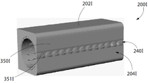
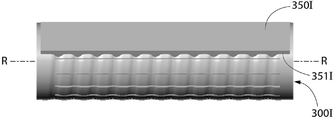
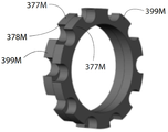
이제, 도 19 내지 22를 동시에 참조하면, 면도기(1000)에 이용될 수 있는, 본 발명의 일 실시예에 따른 회전 커터(300F)가 도시된다. 일반적으로, 회전 커터(300F)는 커터 튜브(301)(도 1 내지 9와 관련하여 상술함)와 지지 튜브(support tube)를 포함한다. 도 1 내지 9와 관련한 커터 튜브(301)의 설명이 적용되는 것을 감안하여, 중복 설명을 피하고자 아래에서는 커터 튜브(301)에 대한 상세한 설명을 생략한다. 나아가, 도 10 내지 18의 교체 구멍 패턴들 중 어느 것이나 회전 커터(300F)에 이용되는 커터 튜브에 적용될 수 있음을 이해해야 한다.Referring now simultaneously to Figures 19-22, a
커터 튜브(301)는 지지 튜브(375) 상에 장착된다. 특정 실시예에서, 지지 튜브(375)는, 커터 튜브(301)가 사용을 거듭하면서 변형되거나 휘어지지 않도록 어느 정도의 강성을 커터 튜브(301)에 제공한다. 나아가, 지지 튜브(375)에 의해 제공되는 구조적 지지는 회전 커터(300F)의 절단날(307)과 고정 블레이드(350)의 절단날(351) 사이의 적절하고 일정한 이격을 유지하도록 도울 수 있다. 지지 튜브(375)는 플라스틱이나 금속을 포함하는 다양한 종류의 물질로 이루어질 수 있다. 특정 실시예에서, 지지 튜브(375)는 0.2㎜에서 5㎜사이의 범위의 두께(내표면(377)에서 외표면(376)까지 측정)를 가질 수 있다.The
커터 튜브(301)는 내표면(303)이 지지 튜브(375)의 외표면(376)과 면접촉하도록 지지 튜브(375)에 장착된다. 커터 튜브(301)는 지지 튜브(375)에 대해 비회전한다. 따라서, 커터 튜브(301)와 지지 튜브(375)는 회전 커터(300F)의 회전시, 일체적 단위로 회전한다. 커터 튜브(301)는 마찰결합(friction fit), 피처의 짝결합, 파스너(fastner), 접착제(adhesive), 열융합(thermal fusion), 납땜(brazing), 용접(welding) 또는 그러한 요소들을 서로 연결하는데 이용되는 기타 수단을 통해 지지 튜브(375)에 대해 고정될 수 있다. 예를 들어, 일 실시예에서, 지지 튜브(375)는 하나 이상의 피처(feature)를 가질 수 있고, 이는 커터 튜브(301)에서 대응하는 피처에 정렬될 것이고, 놓인 뒤 고정되어 커터 튜브(301)와 지지 튜브(375) 사이에 상대적 운동이 없게 된다. 그런 일 실시예에서, 지지 튜브(375)의 외경 밖으로 돌출된 작은 핀은 커터 튜브(301)의 대응 구멍이나 슬롯에 정렬되어 체결될 것이다.The
다른 실시예에서, 커터 튜브(301)와 지지 튜브(375) 사이의 마찰결합은 양자 사이의 상대적 회전을 방지한다. 그런 실시예에서, 커터 및 지지 튜브(301,375)는 가열수축 끼워맞춤(shrink fitting)에 의해 조립될 수 있고, 이는 커터 튜브(301)의 가열 및/또는 지지 튜브(375)의 냉각을 포함함으로써, 지지 튜브(375)의 외경과 커터 튜브(301)의 내경 사이에 갭(gap)이 형성된다. 충분한 갭이 존재하면, 커터 튜브(301)는 지지 튜브(375) 위에서 슬라이드 가능하다. 그 다음 동일한 온도로 되돌아오면, 커터 및 지지 튜브(301,375)가 서로 마찰결합된다.In another embodiment, frictional engagement between the
지지 튜브(375)는 그의 외표면(376) 안으로 형성된 복수의 오목부(depression)(378)를 포함한다. 본 실시예에서, 오목부(378)는 장형의 축방향 채널 형태이다. 오목부(378)가 장형 축방향 채널이기 때문에, 복수의 축방향 리브(rib)(379)는 인접한 오목부(378)를 분리하도록 형성된다. 축방향 리브(379)는 (도시된 바와 같이) 연속적이거나 분절화될 수 있다. 본 실시예에서, 전체적으로 지지 튜브(375)의 외표면(376)을 정의하는 것은 리브(379)의 끝단면(terminal surface)이다. 채널로 도시되었지만, 오목부(378)는 다양한 종류의 모양과 방향성을 취할 수 있다. 다른 실시예에서, 오목부(378)는 딤플(dimple)의 형상을 취할 수 있다. 또 다른 실시예에서, 오목부(378)는 복수의 돌기가 연장되는 분지(basin)의 바닥 형상을 취할 수 있고, 돌기들의 끝단면이 총체적으로 지지 튜브(375)의 외표면(376)을 형성할 수 있다.The
특정 실시예에서, 커터 튜브(301)는 그의 적어도 하나의 구멍(305)이 커터 튜브(301)를 통해 지지 튜브(301)의 오목부(378) 안으로 들어가는 통로를 형성하도록 지지 튜브(375)와 결합된다. 이런 구조는 제모시에 더욱 긴 털이 회전 커터(300F) 안으로 들어올 수 있게 함으로써, 커터 튜브(301)를 포일(foil)과 같이 매우 얇게 할 수 있고, 회전 커터(300F)로 하여금 더욱 긴 털을 절단할 수 있게 하지만, 이에 한정되는 것은 아니다. In a particular embodiment, the
이제, 도 22 및 23을 참조하면, 본 발명의 일 실시예에 따른 윤활 요소(lubricating element)(800)를 가지는 회전 커터(300G)가 도시되며, 윤활 요소(800)는 회전 커터(300G)에 연결된다. 연결된 윤활 요소(800)를 가진 회전 커터(300G)는 도 1 내지 9의 면도기(1000)에서 회전 커터(300)를 대신해 이용될 수 있다. 회전 커터(300G)는 윤활 요소(300)를 수용하고 그 충전을 가능케 하는 아래 설명을 제외하고는, 도 1 내지 9의 회전 커터(300)와 동일하다. 따라서, 회전 커터(300)에 대한 상기 설명이 적용될 수 있음을 감안하여, 회전 커터(300G)에 대한 설명은 회전 커터(300)와 다른 회전 커터(300G)의 특징에 한정될 것이다. 따라서, 동일한 구성을 식별하기 위하여 알파벳 접미사 "G"를 부가하면서 동일한 참조 번호가 이용될 것이다.Referring now to Figures 22 and 23, there is shown a
윤활 요소(800)는 모터(400)가 회전하면서, 회전축(R-R)을 중심으로 함께 회전하기 위해 회전 커터(300G)의 커터 튜브(301G)에 연결된다. 회전 커터(300)에 대한 상기 설명과 같이 면도기(1000)에 조립되면, 면도기 작동 중 회전 커터(300)와 윤활 요소(800)의 조립체의 회전은 (1)회전 요소(800)로 하여금 사용자 피부에 윤활제를 공급하게 하고, (2)회전 커터(300G)의 절단날(307G)과 고정 블레이드(350)의 절단날(351) 사이에서 사용자 털이 절단되도록 한다. 회전 요소(800)는 사용자 피부에 대한 접촉(직접 적용) 및/또는 윤활제의 분출(간접 적용)에 의하여 윤활제를 사용자 피부에 공급하는데, 이는 회전 중 윤활 요소(800)이 받는 원심력에 의해 이루어진다. 따라서, 회전 커터(300G)가 회전하면서, 윤활 요소(800)는 적어도 한 번, 대부분 여러 번, 면도가 이루어지기 직전에 면도가 이루어질 피부 영역에 윤활제를 바른다. The
일 실시예에서, 윤활 요소(800)는 면도에 적합한 소기의 유체 윤활제를 지닌 매트릭스 물질(matrix material)(804)을 포함한다. 매트릭스 물질은 선택된 윤활제를 흡수(absorbing), 유지(retaining)하고 나중에 배출(release)시킬 수 있는 다공성 물질(porous material), 섬유재(fibrous material) 또는 기타 물질의 형태를 취할 수 있다. 매트릭스 물질은 폴리스티렌(polystyrene)과 같은 불수용성 폴리머 매트릭스를 포함한다. 적합한 윤활제로, 피부 로션(dermal lotions), 라놀린(lanolins), 오일(oils), 보습제(moisturizers), 완화제(emollients) 등과 같은 것을 포함하지만, 이에 한정되지 않는다. 윤활제에 부가되는 물질은, 예를 들어, (1)피부과용 에이전트와 같은 피부 건강 관련 물질(여드름(acne), 각질(flaky), 가려움(itchy)), 밸런싱 에이전트(balancing agent)(건성 또는 지성 피부, 산도 보정(pH correct), 보습제, 계절별 솔루션(seasonal solution)), 재생/활성 에이전트(비타민 테라피, 허벌(herbal), 컨디셔너, 애시드(acids), 세포 재생(cell renewal)), 클렌징 에이전트(항균(antibacterial), 천연(natural), 저자극(hypoallergenic), 식물성 추출물(botanical-derived), 유향, 무향) 또는 피부보호 에이전트(자외선, 노화방지, 주름방지) (2)맨톨(menthol)과 같은 피부자극 에이전트(skin sensation agent) 또는 통증 완화(아스피린) (3)네오스포린(neosporin)과 같은 진정 에이전트(soothing agent) (4)수염 소프트너(beard softner)와 같은 헤어 트리팅 에이전트(hair treating agent), 헤어 성장 억제제(hair growth inhibitors), 모발 표층 열화제(hair outer layer degradants), 헤어 하이드레이팅 에이전트(hair hydrating agent), 헤어 컨디셔너 또는 헤어 씨닝 에이전트(hair thining agent) (5)태닝 에이전트(tanning agent)와 같은 화장품 (6)향수나 에센스를 포함하는 아로마테라피 제품 및 (7)오일, 우유, 꿀, 젤(gel), 크림(cream), 밤(balm), 촉매제(catalyst), 발포제(effervescent)를 포함할 수 있다.In one embodiment, the
윤활 요소(800)는 회전 커터(300G)의 커터 튜브(301G)의 외표면(302G)과 동일한 높이의 외표면(본 실시예에서 스트립(strip)(801-803)의 외표면(804-806)에 의해 총체적으로 형성됨)을 갖는다. 위에서 설명한 바와 같이, 커터 튜브(301G)의 외표면(302G)은 구멍(305G)들을 정의하는 절단날(307G)들을 포함할 수도 있다. 따라서, 커터 튜브(301G)의 외표면(302G)과 윤활 요소(800)의 외표면(도시된 표면(804-806))은 총체적으로 회전축(R-R)을 중심으로 하는 기준써클(reference circle)(G)의 경계를 정의한다. 윤활 요소(800)의 외표면을 커터 튜브(301G)의 외표면(302G)과 동일한 높이로 만듦으로써, 면도하는 동안 윤활 요소(800)는 고정 블레이드(350)의 절단날(351)에 간섭하지 않고(거나), 접촉하지 않는다. 특정 실시예에서, 윤활 요소(800)의 외표면은, 회전하는 동안 윤활 요소(800)가 고정 블레이드(350)에 접촉하지 않도록, 커팅갭(325)(도 9a 참조)의 거리보다 작게 돌출되는 한, 커터 튜브(301G)의 외표면(302G)에서 살짝 돌출되어 있을 수 있다.The
일 실시예에서, 윤활 스트립(lubricating strip)(801-803)의 외표면(804-806)은 건조되어 있을 때, 회전 커터(301G)의 외표면(302G)에 대해 살짝 오목지게 된다. 하지만, 윤활 스트립(801-803)이 윤활제로 충전되면, 윤활 스트립(801-803)은 윤활 스트립(801-803)의 외표면(804-806)이 회전 커터(302G)의 외표면 높이와 동일해지도록 팽창할 수 있다. 일 실시예에서, 예를 들어, 면도날이 처음 사용되거나, 커터 튜브(301G)가 면도 헤드(200) 안으로 조립될 때, 윤활 요소(800)는 조립되면서 마르게 저장되고, 나중에 보습 로션(moisturizing lotion)으로 적셔진다. In one embodiment, the outer surfaces 804-806 of the lubricating strips 801-803 are slightly recessed relative to the
본 실시예에서, 윤활 요소(800)는 복수의 장형 윤활 스트립(801-803)의 형태이다. 3개의 윤활 스트립(801-803)이 도시되었지만, 필요한 경우 하나의 윤활 스트립을 포함한 다른 개수의 윤활 스트립(801-803)이 이용될 수 있고, 이는 윤활 요소(800)를 형성한다. 나아가, 윤활 요소(800)는 하나 이상의 장형 윤활 스트립(801-803)으로 예시되었지만, 윤활 요소(800)는 이와 다른 다양한 모양과 형태를 취할 수 있을 것이다. 다른 특정 실시예에서는, 예를 들어, 윤활 요소(800)는 커터 튜브(301G)의 외표면(302G)에 서로 이격된 방식으로 배열되어, 원형, 다각형 또는 기타 폐쇄구조/패드와 같은 고립된 윤활 영역의 형태를 취할 수 있다.In this embodiment, the
각 윤활 스트립(801-803)은 커터 튜브(301G)의 외표면(302G)에 형성된 오목부(390G-392G) 안에 위치한다. 각 오목부(390G-392G)는 대응하는 윤활 스트립(801-803)을 수용하기 위한 크기와 형태를 갖는 장형 축방향 슬롯의 형태이다. 이와 같이, 윤활 스트립(801-803)은 커터 튜브(301G)에 끼워진다.Each lubrication strip 801-803 is located in a
본 실시예에서, 윤활 스트립(801-803)은 커터 튜브(30G)의 외표면(302G) 둘레에 원주방향으로 이격된 방식으로 배열된다. 윤활 스트립(801-803)은 커터 튜브(301G)의 축방향 전체 길이까지 연장되어, 커터 튜브(301G)의 외표면(302G)에서 복수의 고립 절단 영역(isolated shearing zone)(910,920,930)을 형성한다. 각 절단 영역(910,920,930)은 폐쇄구조의 절단날(307G)에 의해 정의되는 복수의 구멍(305G)들을 포함한다.In this embodiment, the lubrication strips 801-803 are arranged in a circumferentially spaced manner about the
일 실시예에서, 커터 튜브(301G)는 포일과 같은 편평한 스톡 메탈 시트(stock metal sheet)로부터 제조될 수 있다. 그런 실시예에서, 편평한 스톡은 커터 튜브(301G)를 형성시키기 위해 롤링된 양 끝단이 서로 연결된다. 이러한 형성 공정은, 양단을 적당히 정렬시키고 부드러운 이음새를 형성시킬 수 있다. 윤활 요소(800)가 이용되는 실시예에서, 이러한 이음새(395G로 표시된 것과 같이)는 오목부(390G-392G) 중 어느 하나의 바닥에 위치된 다음 윤활 스트립(801-803) 중 어느 하나에 의해 커버됨으로써, 제조 공정을 단순화한다.In one embodiment, the
특정 실시예에서는, 지속적으로 윤활 요소(800)를 충전하기 위하여, 윤활 요소(800)의 유효기간 연장과 건조방지를 위한 윤활제 내부 저장소(internal reservoir)가 면도기(1000)의 핸들(100)이나 헤드(200)에 구비될 수 있다. 내부 저장소는 윤활제로 가득 차게 되는 비어있는 공간일 수 있고, 윤활제로 포화되는 내부 챔버 안에 다공성 물질이 포함되어 있을 수 있다. 저장소의 세부구성 및/또는 위치와 무관하게, 윤활 요소(800)는 저장소와 지속적 혹은 간헐적으로 유체 연결되어, 면도 중 사용자 피부에 바르고자 하는 저장소 내 윤활제가 윤활 요소(800)로 흘러갈 수 있다.A lubricant internal reservoir for prolonging the lifetime of the
도 23을 계속 참조하면, 본 실시예에서, 윤활제의 저장소(500)는 회전 커터(500G) 내부에 위치한다. 본 실시예에서, 저장소는 지지 튜브(375G)(도 19 내지 21 관련한 상기 설명 참조)의 변형된 방식으로 형성된다. 이 실시예에서, 지지 튜브(375G)는 내층(inner layer)(381G)과 외층(outer layer)(382G)을 포함한다. 환형 공간(383G)은 내층과 외층(381G-382G) 사이에 형성되고, 윤활제의 저장물로 채워져, 윤활제 저장소(500)를 형성한다. 각 윤활 스트립(801-803)은 모세관 현상을 통해 윤활제를 윤활 스트립(801-803)에 유입시킬 수 있는 매트릭스 물질의 포스트(post)(807-809)를 통해, 윤활제 저장소(500)에 유체 연결된다. 이 실시예에서, 윤활 스트립(801-803)은 저장소와 지속적으로 유체 연결되고, 윤활제는 오로지 모세관 현상을 통해 운반된다. 다른 실시예에서(예를 들어 도 24와 관련하여 아래에서 설명하는 바와 같이), 윤활제 저장소(500)에 압력을 공급하기 위한 액추에이터(actuator)가 구비될 수 있고, 이는 윤활제를 윤활 스트립(801-803)으로 흐르게 한다. 액추에이터는 사용자에 의해 눌리는 버튼과 같은 수동식이거나, 모터(400)에 전원을 인가함으로써 활성화되는 전자식일 수 있다. 윤활 스트립(801-803)으로 흐를 수 있는 것을 제외하면, 윤활제 저장소(500)는 밀봉된다. 필요에 따라, 원웨이 밸브(one way valve)가 구비될 수 있다.23, in this embodiment, the
이제, 도 24를 참조하면, 면도기(1000H)가 예시된다. 면도기(1000H)는 윤활제 저장소(500)가 부가되고, 회전 커터(300G)가 이용되는 것을 제외하고는, 도 1 내지 9의 면도기(1000)와 동일하다. 따라서, 면도기(1000)에 대한 상기 설명이 적용될 수 있음을 감안하여, 면도기(1000H)에 대한 설명은 면도기(1000)와 상이한 특징에 한정될 것이다. 따라서, 동일한 구성을 식별하기 위하여 알파벳 접미사 "H"를 부가하면서 동일한 참조 번호가 이용될 것이다.Referring now to FIG. 24, a
면도기(1000H)에서, 윤활제의 저장소(500)는 회전 커터(300G)의 윤활 요소(800)를 충전하기 위해 헤드(200H)와 핸들(100H) 모두에 구비된다. 헤드(200H)에 위치한 저장소(500) 부분은 회전 커터(300G)에 인접하게 위치하여, 회전 커터(300G)가 회전축(R-R)을 중심으로 회전할 때, 윤활 요소(800)의 각 윤활 스트립(801-803)이 지나치면서 윤활제 저장소(500)와 유체 연결되거나 유체 연결이 단절된다. 이런 방식으로, 면도중 윤활제가 윤활 스트립(801-803)에 충전된다.In
면도기(1000H)는 액추에이터(550)를 더 포함하는데, 이는 누름 가능한 버튼으로 형성된다. 액추에이터(550)는 저장소(500)에 동작 가능하게 연결된다. 액추에이터가 눌리면, 저장소(500)가 압력을 받게 되어, 부가적인 윤활제를 윤활 스트립(801-803)으로 흐르게 한다. 또 다른 실시예에서, 액추에이터는 병진 운동하는 저장소에 동작 가능하게 연결된 슬라이드 스위치와 같이 구비될 수 있고, 이는 활성화될 때, 저장소와 윤활 요소를 유체 연결시키거나 유체 연결을 단절시킨다.The
이제, 도 25 내지 27을 동시에 참조하면, 면도기(1000)에 이용될 수 있는 진동 고정 블레이드(350I)를 포함하는 헤드(200I)가 예시된다. 헤드(200I)(부품들과 함께)는 고정 블레이드(350I)가 진동할 수 있고, 그 절단날(315)이 변형된 회전 커터(300I)에 대응하여 변형된 것을 제외하고는, 도 1 내지 9의 헤드(200)와 동일하다. 따라서, 상기 설명이 적용될 수 있음을 감안하여, 헤드(200I)에 대한 설명은 헤드(200)와 상이한 특징에 한정될 것이다. 따라서, 동일한 구성을 식별하기 위하여 알파벳 접미사 "I"를 부가하면서 동일한 참조 번호가 이용될 것이다.25-27, a head 200I including a
본 실시예에서, 고정 블레이드(350I)의 절단날(351I)의 모양은 사인파(sine wave) 형상이다. 따라서, 절단날(351I)은 복수의 마루(peak)와 골(valley)을 가진 파동형(undulating) 절단날로 생각될 수 있다. 절단날(351I)은 회전 커터(300I)의 외표면(302I)의 대응되는 마루 및 골과 결합하도록 설계된다. 더욱 상세하게, 고정 블레이드(351I)는 고정 블레이드(351I)의 파동형 절단날(351I)의 마루들이 회전 커터(300I)의 골들에 안착하고, 회전 커터(300I)의 마루들이 고정 블레이드(351I)의 파동형 절단날(351I)의 골들에 안착하도록, 회전 커터(300I)에 인접하게 장착된다. 파동형 설계는 절단날(351I)의 유효 길이를 증가시키고, 고정 블레이드(350I)의 절단날(351I)과 회전 커터(300I) 사이에 연속적인(continuum) 절단각을 제공한다. 회전 커터(300I)는, (상술한 커터 튜브를 포함하는) 회전 커터(300I)의 절단날을 형성하는 복수의 장형 슬릿 구멍(307I)을 포함한다.In this embodiment, the shape of the cutting edge 351I of the fixed
마루와 골 각각은 회전축(R-R)에 수직인 방향을 갖도록, 회전 커터(300I)의 외표면(302I) 둘레에서 원주 방향으로 연장될 수 있다(도 26 참조). 다른 실시예에서, 회전 커터(300I)의 마루와 골은 회전축에 대해 작은 경사를 갖도록 회전 커터(300I)의 외표면(302I) 둘레에서 원주 방향으로 연장될 수 있고, 각 마루와 골은 원주 방향의 원을 정의한다(도 27 참조). 마루들과 골들은 나선(spiral)을 형성하지 않는다. Each of the floor and the ridge can extend in the circumferential direction around the outer surface 302I of the rotary cutter 300I so as to have a direction perpendicular to the rotation axis R-R (see Fig. 26). In another embodiment, the floor and the valleys of the rotary cutter 300I may extend in the circumferential direction around the outer surface 302I of the rotary cutter 300I so as to have a small inclination with respect to the rotation axis, and each floor and valley may extend in the circumferential direction (See Fig. 27). Floors and bones do not form a spiral.
또한, 고정 블레이드(305I)는, 마루와 골에 의해 형성된 원주 방향의 경로를 따라 이동하는 것처럼, 회전축(R-R)과 평행하게 병진 방식으로 짧게 움직일 수 있다. 고정 블레이드(350I)는, 회전 커터(300I)의 대응 피처와 정렬되는 핀(pin)과 같은 적어도 하나의 피처(feature)를 가지며, 이는 마루 및 골과 동일한 경사를 갖도록 설계된다. 이 2개의 피처가 서로 맞물리고, 회전 커터(300I)가 회전축(R-R)을 중심으로 회전하면, 고정 블레이드(350I)는 앞뒤로 선형적인 움직임을 가질 것이다. 왕복 선형 운동은 털의 두께보다 크게, 예를 들어, 25마이크론(micron)보다 크게 설계된다. 몇몇 경우에서는, 회전 커터에서 마루와 골의 진폭(amplitude)보다 크다.Further, the fixed blade 305I can be moved in a translational manner in parallel with the rotation axis R-R, as if it moves along a circumferential path formed by the floor and the valley. The fixed
고정 블레이드의 선형 진동 주기는 회전 커터의 회전 속도 및 회전 커터의 마루와 골의 설계에 의해 결정된다. 진동 고정 블레이드는 2개의 가위 절단 모드를 동시에 만들어낸다. 고정 블레이드에 대해 리지(ridge)를 가지는 회전 커터의 회전에 의한, 회전 커터에 의해 정의되는 써클에 무관한 절단 모드와, 고정 블레이드의 선형 움직임에 의한, 회전축(R-R)에 평행한 절단 모드이다. The linear vibration period of the fixed blade is determined by the rotation speed of the rotary cutter and the design of the floor and the valley of the rotary cutter. Vibrating fixed blades simultaneously produce two scissors cutting modes. A cutting mode independent of the circle defined by the rotary cutter by rotation of the rotary cutter having a ridge with respect to the fixed blade and a cutting mode parallel to the rotary axis R-R due to the linear movement of the fixed blade.
도 28을 참조하면, 회전 커터(300J)를 수용하고 있는 하우징(202J)의 일부로서 일체적으로 형성된 고정 블레이드(350J)를 갖는 헤드(200J)가 도시되어 있다. 헤드(200J)(그의 부품들과 함께)는 하우징(202J)의 일부로서 일체적으로 형성된 고정 블레이드(350J)를 제외하고는 도 1 내지 9의 헤드(200)와 동일하다. 따라서, 상기 설명이 적용될 수 있음을 감안하여, 헤드(200J)에 대한 설명은 헤드(200)와 상이한 특징에 한정될 것이다. 따라서, 동일한 구성을 식별하기 위하여 알파벳 접미사 "I"를 부가하면서 동일한 참조 번호가 이용될 것이다.28, there is shown a
헤드(200J)는 위의 헤드(200)에 대한 설명과 같이, 회전 커터(300J)와 기타 구성들을 수용하는 하우징(202J)을 포함한다. 하지만, 헤드(200J)는 작용면(working surface)의 일부를 형성하는 한편 일체적으로 형성된 고정 블레이드(350J)로서 동작하는 포션(portion)(270J)을 갖는다. 이를 위하여, 하우징(202J)의 이 포션(270J)은 첨날(sharp edge)까지 이어지고, 이는 장형 슬롯(240J)의 일측을 정의하며, 회전 커터(300J)의 절단날(307J)과 함께 털을 절단하는 동안 고정 블레이드(350J)의 절단날(351J)로서 동작한다. 하우징(202J)(과 절단날(351J))은 적절히 단단하고 강성을 갖는 물질, 예를 들어, 금속이나 강화 플라스틱으로 형성될 수 있다.The
이제, 도 29를 참조하면, 헤드(202K)의 하우징(202K)에 형성된 슬롯(271K)에 장착되는 고정 블레이드(350K)를 가진 헤드(200J)가 도시된다. 헤드(200K)(그의 구성들과 함께)는 고정 블레이드(350K)가 도시된 바와 같이 내부 슬롯(internal slot)(271K)에 장착되는 것을 제외하고는, 도 1 내지 9의 헤드(200)와 동일하다. 따라서, 상기 헤드(200J)에 대한 상세한 설명이 적용될 수 있음을 이해할 수 있을 것이다. 따라서, 동일한 구성을 식별하기 위하여 알파벳 접미사 "K"를 부가하면서 동일한 참조 번호가 이용되었다.29, there is shown a
도 30 및 31을 동시에 참조하면, 복수의 스택 평판 세그먼트(248)로 형성된 하우징(202L)을 포함하는 헤드(200L)가 도시되어 있다. 헤드(200L)(그의 부품들과 함께)는 하우징(202L)이 복수의 스택형 판 세그먼트(248)로 구성되고, 고정 블레이드가 하우징(202L)과 일체형으로 형성되는 것을 제외하고는, 도 1 내지 9의 헤드(200)와 동일하다. 따라서, 상기 설명이 적용될 수 있음을 감안하여, 헤드(200L)에 대한 설명은 헤드(200)와 상이한 특징에 한정될 것이다. 따라서, 동일한 구성을 식별하기 위하여 알파벳 접미사 "L"을 부가하면서 동일한 참조 번호가 이용될 것이다.30 and 31, there is shown a
헤드(200L)는 빗살부(comb)(217L)를 포함하고, 하우징(202L)을 형성하기 위해 스택(239)으로 배열된 평판 세그먼트(248)로부터 조립된다. 평판 세그먼트(248)는 박판 메탈(thin sheet metal)로부터 레이저컷될 수 있다. 일 실시예에서, 평판 세그먼트(248)의 두께는 빗살부(217L)의 빗살의 두께에 의해 정의된다.The
일 실시예에서, 각각의 평판 세그먼트(248)는 중심점(center point)을 갖는 중앙 구멍(central aperture)을 포함한다. 스택(239)으로 배열될 때, 평판 세그먼트(248)는 그 중심점들이 정렬되고, 상기 중심 구멍들이 총체적으로 하우징(202L)의 내부 캐비티를 정의하도록 배열된다.In one embodiment, each
하우징(202L)은 제1 형상을 가지는 복수의 제1 평판 세그먼트(248A)와 제2 형상을 가지는 복수의 제2 평판 세그먼트(248B)로부터 조립된다. 제1 및 제2 평판 세그먼트(248A,248B)들은 스택(239)에서 교번하는 방식으로 배열된다. 이는 빗살부(217L)가 형성되게 만든다. 따라서, 특정 실시예에서, 하우징(202L)은 일체형으로 형성된 빗살부(217L)와 일체형으로 형성된 고정 블레이드(250L)를 갖는다. 일 실시예에서, 각 세그먼트(248A,248B)의 가장자리(249A,249B)는 날카로운 팁으로 형성되거, 스택(239)이 완성되면, 각 세그먼트(248A,248B)의 가장자리(249A,249B)가 총체적으로 고정 블레이드(250L)의 절단날(251L)을 형성하며, 이는 절단날(307L)과 상호작용하여 제모를 수행한다. 일 실시예에서, 헤드(202L)는 서로 다른 두께의 세그먼트들로 형성될 수 있다.The
도 32 및 33을 동시에 참조하면, 복수의 스택형 링세그먼트(stacked ring segment)(399M)에 의해 형성된 회전 커터(300M)가 도시되어 있다. 회전 커터(300M)는 면도기(1000)와 함께 사용될 수 있고, 몇 가지 면에서 회전 커터(300)와 유사하다. 따라서, 동일한 구성을 식별하기 위하여 알파벳 접미사 "M"을 부가하면서 동일한 참조 번호가 이용될 것이다.32 and 33, there is shown a
회전 커터(300M)는 복수의 링 세그먼트(399M)들에 의해 형성되는데, 이들은 스택(398M)으로 배열되어 회전 커터(300M)를 만들어낸다. 일 실시예에서, 각각의 링 세그먼트(399M)는 중심점을 갖는 중앙 구멍을 포함한다. 스택(398M)으로 배열될 때, 중심점들이 정렬되고, 중앙 구멍들이 총체적으로 회전 커터(300M)의 중앙 캐비티를 정의하도록 링 세그먼트(399M)들이 배열된다.The
각 세그먼트(399M)는 균등하게 이격된 복수의 외부돌출 리브(outwardly-projecting rib)(377M)를 포함하며, 이들은 그 외표면에 절단날(378M)로 이루어진다. 각 세그먼트(399M)는 스택(398M)에서 인접하는 세그먼트(399M)에 대해 작은 각도(예: 5°에서 10°)만큼 시프트되어 있다. 즉, 각오프셋(angularly offset)되어 있다. 그런 실시예에서, 최종 형상은 계단식 나선(step wise spiral)일 수 있다. 계단식 나선에서, 회전 커터(399M)의 절단날의 유효 길이는 점점 증가한다. 일 실시예에서, 세그먼트(399M)들은 동일하다. 세그먼트(399M)들은 박판 메탈로부터 레이저컷될 수 있다.Each
각 계단의 수직 부분과 수평 부분의 교차영역은 매우 작은 반경을 가지며, 이는 보통의 제조 기술에 의해 경제적으로 이루어지기 어렵다. 일 실시예에서는, 시트 메탈 세그먼트(399M)의 가장자리가 "깨지거나" 둥글게 될 수 있다. 각 계단의 수직 부분과 수평 부분의 교차영역은 언더컷(undercut)을 가진다. 일 실시예에서, 세그먼트(399M)들은 그들 사이에서 서로 다른 회전 시프트를 가지며 조립되어 계단식 나선을 이루고, 그의 평균 경사(average slope)가 해당 구성 전체적으로 달라진다. 계단식 나선의 평균 경사는 몇 도 정도로 미세하게 변할 수 있다. 일 실시예에서, 세그먼트(399M)들은 그들 사이에서 서로 다른 회전 시프트를 가지며 조립되어 계단식 나선을 이루고, 그의 평균 경사는 회전 커터(300M) 전체적으로 달라진다. 계단식 나선의 평균 경사는 연속적 라인 혹은 비연속적으로 방향을 바꿀 수 있다. The intersection of the vertical and horizontal sections of each staircase has a very small radius, which is difficult to economically achieve by normal manufacturing techniques. In one embodiment, the edges of the
상술한 설명과 도면들이 본 발명의 실시예들을 보여주고 있지만, 첨부된 특허청구범위에 기재된 본 발명의 범위나 사상으로부터 벗어나지 않으면서 다양한 부가, 변형 및 대체가 이루어질 수 있음을 이해할 것이다. 특히, 본 발명의 사상이나 본질적인 특징들로부터 벗어나지 않는 한, 본 발명이 다른 특정 형태, 구조, 배치, 성분, 크기로 구현되거나, 기타 요소, 물질, 부품들과 함께 구현될 수 있음은 당업자에 자명할 것이다. 당업자는 본 발명이 그 실시예 이용되는 구조, 배치, 성분, 크기, 물질, 부품 및 그 밖의 많은 변형과 함께 이용될 수 있고, 특히, 본 발명의 원리를 벗어나지 않으면서 특정 환경이나 동작 조건에 특히 적응될 수 있음을 이해할 것이다. 따라서, 여기 개시된 실시예들은 모든 점이 예시적이지만 제한적이지 않고, 본 발명의 권리범위는 첨부된 청구범위에 의해 정의되며, 상술한 설명이나 실시예에 한정되지 않는 것으로 간주된다.While the foregoing description and drawings illustrate embodiments of the invention, it will be appreciated that various additions, modifications, and substitutions may be made thereto without departing from the scope of the invention as defined in the appended claims. In particular, it will be understood by those skilled in the art that the present invention may be embodied in other specific forms, structures, arrangements, components, sizes, or other elements, materials, components, something to do. Those skilled in the art will recognize that the invention can be utilized with the structures, arrangements, components, sizes, materials, components, and many other variations that the embodiments use, and particularly those skilled in the art, It will be understood that the invention may be adapted. Accordingly, the embodiments disclosed herein are to be considered in all respects as illustrative and not restrictive, and the scope of the present invention is defined by the appended claims, and are not to be construed as being limited to the foregoing description or examples.
Claims (89)
전원;
상기 핸들부에 연결된 헤드부; 및
전기 모터;를 포함하고,
상기 헤드부는,
커터 튜브를 포함하는 회전 커터;를 포함하고, 상기 커터 튜브는 외표면에 복수의 구멍을 포함하고, 각각의 구멍은 폐쇄구조(closed-geometry)를 갖는 절단날(cutting edge)에 의해 정의되며,
상기 회전 커터에 인접하게 장착되고, 절단날을 가지는 고정 블레이드;를 포함하고,
상기 전기 모터는, 상기 회전 커터가 회전할 때, 상기 커터 튜브의 절단날과 상기 고정 블레이드의 절단날의 사이에서 사용자의 털이 절단되도록, 회전축을 중심으로 상기 회전 커터를 회전시키기 위하여, 상기 전원 및 상기 회전 커터에 동작 가능하게 연결되는 면도기.A handle portion;
power;
A head portion connected to the handle portion; And
An electric motor,
Wherein:
And a rotary cutter including a cutter tube, wherein the cutter tube includes a plurality of holes on an outer surface, each hole being defined by a cutting edge having a closed-geometry,
And a stationary blade mounted adjacent to the rotary cutter and having a cutting edge,
Wherein the electric motor is adapted to rotate the rotary cutter around a rotation axis such that when the rotary cutter rotates, the user's hair is cut between the cutting blade of the cutter tube and the cutting blade of the fixed blade, And a shaver operatively connected to the rotary cutter.
상기 커터 튜브는 내표면을 포함하고, 각각의 구멍은 상기 커터 튜브를 통해, 상기 커터 튜브의 외표면으로부터 상기 커터 튜브의 내표면으로 연장되는 면도기. The method according to claim 1,
Wherein the cutter tube includes an inner surface and each hole extends through the cutter tube from an outer surface of the cutter tube to an inner surface of the cutter tube.
상기 회전 커터는 지지 튜브를 더 포함하고,
상기 커터 튜브는, 상기 커터 튜브의 내표면이 상기 지지 튜브의 외표면과 면접촉하도록 상기 지지 튜브 상에 장착되고, 상기 커터 튜브는 상기 지지 튜브에 대해 비회전하는 면도기.3. The method of claim 2,
Wherein the rotary cutter further comprises a support tube,
Wherein the cutter tube is mounted on the support tube such that the inner surface of the cutter tube is in surface contact with the outer surface of the support tube and the cutter tube is non-rotatable with respect to the support tube.
상기 커터 튜브와 상기 지지 튜브 사이의 마찰 결합은 상기 커터 튜브와 상기 지지 튜브 사이의 상대적인 회전을 방지하는 면도기.The method of claim 3,
Wherein the frictional engagement between the cutter tube and the support tube prevents relative rotation between the cutter tube and the support tube.
상기 지지 튜브는, 상기 지지 튜브의 외표면에 형성된 복수의 오목부를 포함하고, 상기 구멍들 중 적어도 일부는 상기 커터 튜브를 통해 상기 지지 튜브의 오목부로 들어가는 통로(passageway)들을 형성하는 면도기.The method according to claim 3 or 4,
Wherein the support tube comprises a plurality of recesses formed in an outer surface of the support tube and wherein at least some of the holes form passageways through the cutter tube into the recesses of the support tube.
상기 지지 튜브는 0.2㎜ 내지 5㎜ 범위의 두께를 가지는 면도기.6. The method according to any one of claims 2 to 5,
Wherein the support tube has a thickness in the range of 0.2 mm to 5 mm.
상기 커터 튜브는 메탈 시트(metal sheet)로 이루어지는 면도기.7. The method according to any one of claims 1 to 6,
Wherein the cutter tube is made of a metal sheet.
상기 커터 튜브는 0.1㎜ 내지 2.5㎜ 범위의 두께를 가지는 면도기.8. The method according to any one of claims 1 to 7,
Wherein the cutter tube has a thickness ranging from 0.1 mm to 2.5 mm.
상기 구멍들은 상기 커터 튜브의 외표면의 총면적의 0.5보다 큰 누적 면적을 가지는 면도기.9. The method according to any one of claims 1 to 8,
Said holes having a cumulative area greater than 0.5 of the total area of the outer surface of said cutter tube.
상기 커터 튜브는 상기 구멍들을 정의하는 격자 구조를 포함하는 면도기.10. The method according to any one of claims 1 to 9,
Wherein the cutter tube comprises a grating structure defining the holes.
상기 격자 구조는 복수의 축방향부재와 복수의 원주방향부재를 포함하는 면도기.11. The method of claim 10,
Wherein the grating structure comprises a plurality of axial members and a plurality of circumferential members.
각각의 구멍에서, 상기 절단날은 절단부와 비절단부를 포함하고, 각각의 구멍에서, 상기 절단부는, 상기 회전축에 평행한 상기 커터 튜브의 외표면 상의 기준선에 대해 각각 예각을 갖는 제1 및 제2 앵글영역을 포함하고, 상기 제1 및 제2 앵글영역은 꼭짓점(apex)에서 만나는 면도기.12. The method according to any one of claims 1 to 11,
In each hole, the cutting edge includes a cut-away portion and a non-cut portion, and in each hole, the cut-out portion includes first and second cutout portions, each having an acute angle with respect to a baseline on the outer surface of the cutter tube parallel to the rotation axis, An angle region, said first and second angle regions meeting at apex.
각각의 구멍은 장축과 단축을 포함하고, 상기 장축은 상기 단축보다 긴 면도기.13. The method according to any one of claims 1 to 12,
Each hole comprising a major axis and a minor axis, the major axis being longer than the minor axis.
상기 구멍들은 상기 커터 튜브상에서 복수의 열을 포함하는 패턴으로 배열된 면도기. 14. The method according to any one of claims 1 to 13,
Wherein the holes are arranged in a pattern including a plurality of rows on the cutter tube.
각각의 구멍에서, 상기 절단날은 절단부와 비절단부를 포함하고, 상기 회전 커터가 회전할 때, 상기 고정 블레이드의 절단날과 상기 커터 튜브의 절단날의 절단부 사이에서 사용자의 털이 절단되고, 상기 구멍들은, 상기 회전 커터가 회전할 때, 상기 고정 블레이드의 절단날로 사용자의 털을 절단하는 데 있어서, 2개보다 많지 않은 절단부가 활동하도록, 상기 커터 튜브의 외표면 상에 패턴으로 배열되는 면도기.14. The method according to any one of claims 1 to 13,
In each hole, the cutting blade includes a cut portion and a non-cut portion, and when the rotary cutter rotates, the user's hair is cut between the cutting edge of the fixed blade and the cut edge of the cutting edge of the cutter tube, Are arranged in a pattern on the outer surface of the cutter tube such that no more than two cuts are active in cutting the user's hair with the cutting blade of the fixed blade when the rotating cutter rotates.
각각의 구멍에서, 상기 절단날은 절단부와 비절단부를 포함하고, 상기 회전 커터가 회전할 때, 상기 고정 블레이드의 절단날과 상기 커터 튜브의 상기 절단날의 상기 절단부 사이에서 사용자의 털이 절단되고, 상기 구멍들은, 상기 회전 커터의 각위치(angular position)와 무관하게, 상기 커팅 튜브의 외표면 상의 상기 고정 블레이드의 절단날의 투사 기준선(projected reference line)이 2개보다 많지 않은 절단부와 교차하도록, 상기 커터 튜브의 외표면 상에 패턴으로 배열되는 면도기.14. The method according to any one of claims 1 to 13,
In each hole, the cutting blade includes a cut portion and a non-cut portion, and when the rotary cutter rotates, the user's hair is cut between the cutting blade of the fixed blade and the cut portion of the cutting blade of the cutter tube, The holes are arranged such that the projected reference line of the cutting blade of the stationary blade on the outer surface of the cutting tube intersects with a cut of no more than two irrespective of the angular position of the rotary cutter, Wherein the cutter tube is arranged in a pattern on the outer surface of the cutter tube.
내부 캐비티를 가지는 하우징;을 더 포함하고, 상기 회전 커터는 상기 하우징의 상기 내부 캐비티 안에 회전 가능하게 장착되고, 상기 고정 블레이드는 상기 하우징에 장착되며,
상기 하우징의 상기 내부 캐비티로 들어가는 통로를 형성하고, 상기 커터 튜브의 일부를 노출시키는 상기 하우징 내의 장형 슬롯(elongated slot);을 더 포함하고, 상기 슬롯은 상기 하우징의 가장자리와 상기 고정 블레이드의 절단날에 의해 정의되는 면도기.17. The image forming apparatus according to any one of claims 1 to 16,
Wherein the rotary cutter is rotatably mounted within the inner cavity of the housing, the stationary blade is mounted to the housing,
Further comprising: an elongated slot in the housing defining a passageway for the interior cavity of the housing and exposing a portion of the cutter tube, the slot including an edge of the housing and a cutting edge of the stationary blade, A razor defined by.
상기 고정 블레이드의 상기 절단날은 상기 회전축에 평행하게 연장되는 면도기.18. The method according to any one of claims 1 to 17,
Wherein the cutting blade of the stationary blade extends parallel to the rotation axis.
상기 전기 모터와 상기 커터 튜브에 연결되는 연결 요소;를 더 포함하여, 상기 전기 모터의 회전 출력이 상기 연결 요소에 의해 상기 커터 튜브로 전달되고,
상기 연결 요소는, 반경방향힘(radial force)을 상기 커터 튜브에 가하지 않도록 상기 커터 튜브를 체결하는 면도기.19. The method according to any one of claims 1 to 18,
Further comprising a coupling element coupled to the electric motor and the cutter tube such that a rotational output of the electric motor is transmitted to the cutter tube by the coupling element,
Wherein the connecting element engages the cutter tube so as not to apply a radial force to the cutter tube.
허브와, 상기 허브에서 방사상으로 연장되는 적어도 하나의 스포크를 포함하는 연결 요소;를 더 포함하고,
상기 허브는 상기 전기 모터에 연결되고, 상기 스포크는 상기 커터 튜브에 연결되며,
상기 전기 모터의 회전 출력은 상기 연결 요소에 의해 상기 커터 튜브로 전달되는 면도기. 19. The method according to any one of claims 1 to 18,
And a coupling element including a hub and at least one spoke extending radially in the hub,
The hub being connected to the electric motor, the spokes being connected to the cutter tube,
Wherein the rotational output of the electric motor is transmitted to the cutter tube by the connecting element.
상기 스포크는 상기 커터 튜브의 피처(feature)와 짝을 이루는 면도기.21. The method of claim 20,
Said spoke being paired with a feature of said cutter tube.
상기 스포크는 상기 허브의 둘레에 원주상으로 등거리 이격된 방식으로 배열되는 면도기.22. The method of claim 21,
Wherein the spokes are arranged in a circumferentially equidistant manner around the hub.
상기 스포크는 상기 허브로부터의 거리에 따라 증가하는 원주폭(circumferential width)을 가지는 면도기.22. The method of claim 21,
Wherein the spoke has a circumferential width that increases with distance from the hub.
상기 커터 튜브의 피처는 상기 커터 튜브의 가장자리에 형성된 슬롯인 면도기.24. The method of claim 23,
Wherein a feature of the cutter tube is a slot formed at an edge of the cutter tube.
전원;
상기 핸들부에 연결된 헤드부; 및
전기 모터;를 포함하고,
상기 헤드부는,
복수의 절단날을 포함하는 회전 커터;
함께 회전하기 위하여 상기 회전 커터에 연결되는 적어도 하나의 윤활 요소; 및
상기 회전 커터에 인접하게 장착되며, 절단날을 가지는 고정 블레이드;를 포함하고,
상기 전기 모터는, 회전축을 중심으로 상기 회전 커터를 회전시키기 위해 상기 전원과 상기 회전 커터에 동작 가능하게 연결되어, (1)상기 회전 커터가 회전할 때, 상기 윤활 요소가 사용자 피부에 윤활제를 공급하고, (2)상기 회전 커터가 회전할 때, 상기 고정 블레이드의 절단날과 상기 회전 커터의 절단날 사이에서 사용자의 털이 절단되는 면도기.A handle portion;
power;
A head portion connected to the handle portion; And
An electric motor,
Wherein:
A rotary cutter including a plurality of cutting blades;
At least one lubricating element connected to said rotary cutter for rotation together; And
And a stationary blade mounted adjacent to the rotary cutter and having a cutting edge,
Wherein the electric motor is operatively connected to the power source and the rotary cutter to rotate the rotary cutter about a rotation axis so that when the rotary cutter rotates, the lubricating element supplies lubricant to the user's skin (2) When the rotary cutter rotates, the user's hair is cut between the cutting blade of the stationary blade and the cutting blade of the rotary cutter.
상기 윤활 요소는 매트릭스 물질(matrix material)을 포함하고, 상기 윤활제는 상기 매트릭스 물질에 수용되고, 상기 매트릭스 물질로부터 방출되는 면도기. 26. The method of claim 25,
Wherein the lubricating element comprises a matrix material and the lubricant is received in the matrix material and emitted from the matrix material.
상기 윤활 요소는 상기 회전 커터의 외표면 둘레에 원주상으로 이격된 방식으로 배열되는 복수의 윤활 스트립을 포함하고, 이에 따라, 상기 회전 커터의 외표면을 제모 영역으로 구분하고, 각각의 제모 영역은 상기 회전 커터의 절단날을 적어도 하나 포함하는 면도기.27. The method of claim 25 or 26,
Wherein the lubrication element comprises a plurality of lubricating strips arranged circumferentially spaced about the outer surface of the rotary cutter so that the outer surface of the rotary cutter is divided into a depilation area, And at least one cutting edge of the rotary cutter.
상기 윤활 요소는 상기 회전 커터의 외표면에 형성된 오목부에 끼워지는 면도기.27. The method of claim 25 or 26,
And the lubrication element is fitted in the recess formed on the outer surface of the rotary cutter.
상기 윤활 요소는 상기 회전 커터의 절단날을 포함하는 상기 회전 커터의 외표면과 동일한 높이의 외표면을 가지는 면도기.27. The method of claim 25 or 26,
Wherein the lubrication element has an outer surface that is flush with an outer surface of the rotary cutter including a cutting edge of the rotary cutter.
상기 윤활제의 저장소;를 더 포함하고, 상기 윤활제의 저장소는 상기 윤활 요소를 충전하기 위해 상기 윤활 요소에 유체 연결되는 면도기.30. The method according to any one of claims 25 to 29,
And a reservoir of said lubricant fluidly connected to said lubricating element for filling said lubricating element.
상기 회전 커터가 회전하는 동안, 상기 윤활 요소는 상기 저장소와 유체 연결이 이루어지거나 해제되는 면도기. 31. The method of claim 30,
Wherein the lubrication element is in fluid communication with the reservoir or is released during rotation of the rotary cutter.
상기 저장소와 상기 윤활 요소는 연속적으로 유체 연결되는 면도기.31. The method of claim 30,
Wherein the reservoir and the lubricating element are in continuous fluid communication.
상기 저장소와 상기 윤활 요소의 유체 연결을 이루거나 해제하는 액추에이터;를 더 포함하는 면도기.31. The method of claim 30,
And an actuator for establishing or releasing fluid connection between the reservoir and the lubricating element.
상기 저장소의 적어도 일부는 상기 헤드부에 위치하는 면도기.34. The method according to any one of claims 30 to 33,
Wherein at least a portion of the reservoir is located in the head portion.
상기 저장소의 적어도 일부는 상기 핸들부에 위치하는 면도기.35. The method according to any one of claims 30 to 34,
Wherein at least a portion of the reservoir is located at the handle portion.
상기 회전 커터는 외표면에 복수의 구멍을 포함하는 커터 튜브;를 포함하고, 각각의 구멍은 상기 회전 커터의 상기 절단날 중 하나에 의해 정의되는 폐쇄구조를 가지는 면도기.36. The method according to any one of claims 25 to 35,
Wherein the rotary cutter includes a cutter tube having a plurality of holes on its outer surface, each hole having a closed structure defined by one of the cutting edges of the rotary cutter.
상기 커터 튜브는 내표면을 포함하고, 각각의 구멍은 상기 커터 튜브를 통하여 상기 커터 튜브의 외표면에서 상기 커터 튜브의 내표면으로 연장되는 면도기.37. The method of claim 36,
Wherein the cutter tube comprises an inner surface and each hole extends through the cutter tube from an outer surface of the cutter tube to an inner surface of the cutter tube.
상기 회전 커터는 지지 튜브;를 더 포함하고, 상기 커터 튜브는 상기 커터 튜브의 내표면이 상기 지지 튜브의 외표면과 면접촉하도록 상기 지지 튜브에 장착되고, 상기 커터 튜브는 상기 지지 튜브에 대해 비회전하는 면도기.37. The method of claim 36 or 37,
Wherein the cutter tube is mounted to the support tube such that the inner surface of the cutter tube is in surface contact with the outer surface of the support tube, Rotating razor.
상기 커터 튜브는 메탈 시트로 이루어지는 면도기.39. The method according to any one of claims 36 to 38,
Wherein the cutter tube is made of a metal sheet.
상기 커터 튜브는 0.1㎜ 내지 2.5㎜ 범위의 두께를 가지는 면도기.40. The method according to any one of claims 36 to 39,
Wherein the cutter tube has a thickness ranging from 0.1 mm to 2.5 mm.
상기 구멍들은 상기 커터 튜브의 외표면의 총 면적의 0.5보다 큰 누적 면적을 가지는 면도기.32. The method according to any one of claims 36 to 30,
Said holes having a cumulative area greater than 0.5 of the total area of the outer surface of said cutter tube.
상기 커터 튜브는 상기 구멍들을 정의하는 격자 구조를 포함하는 면도기.42. The method according to any one of claims 36 to 41,
Wherein the cutter tube comprises a grating structure defining the holes.
상기 격자 구조는 복수의 축방향부재와 복수의 원주방향부재를 포함하는 면도기.43. The method of claim 42,
Wherein the grating structure comprises a plurality of axial members and a plurality of circumferential members.
상기 커터 튜브는 튜브형 스크린인 면도기.44. The method according to any one of claims 36 to 43,
Wherein the cutter tube is a tubular screen.
내부 캐비티를 포함하는 하우징;을 더 포함하고, 상기 회전 커터는 상기 하우징의 상기 내부 캐비티 안에 회전 가능하게 장착되고, 상기 고정 블레이드는 상기 하우징에 장착되며,
상기 하우징의 내부 캐비티 안으로 통로를 형성하고, 상기 커터 튜브의 일부를 노출시키는 상기 하우징 내의 장형 슬롯;을 더 포함하고, 상기 슬롯은 상기 하우징의 가장자리와 상기 고정 블레이드의 절단날에 의해 정의되는 면도기.45. The headrest according to any one of claims 25 to 44,
Wherein the rotary cutter is rotatably mounted within the inner cavity of the housing, the stationary blade is mounted to the housing,
Further comprising an elongated slot in said housing defining a passageway within an interior cavity of said housing and exposing a portion of said cutter tube, said slot defined by a cutting edge of said stationary blade and an edge of said housing.
상기 고정 블레이드의 상기 절단날은 상기 회전축에 평행하게 연장되는 면도기.The method according to any one of claims 25 to 45,
Wherein the cutting blade of the stationary blade extends parallel to the rotation axis.
상기 전기 모터는 상기 회전 커터의 중앙 캐비티 안에 장착되는 면도기.The method according to any one of claims 25 to 46,
Wherein the electric motor is mounted in a central cavity of the rotary cutter.
전원;
상기 핸들부에 연결된 헤드부; 및
전기 모터;를 포함하고,
상기 헤드부는,
커터 튜브를 포함하는 회전 커터;를 포함하고, 상기 커터 튜브는 외표면에 복수의 구멍을 포함하고, 각각의 구멍은 폐쇄구조를 가지는 절단날에 의해 정의되며,
함께 회전하기 위하여 상기 커터 튜브에 연결되는 적어도 하나의 윤활 요소; 및
상기 회전 커터에 인접하게 장착되고, 절단날을 가지는 고정 블레이드;를 포함하고,
상기 전기 모터는, 회전축을 중심으로 상기 회전 커터를 회전시키기 위해 상기 전원 및 상기 회전 커터에 동작 가능하게 연결되어, (1)상기 회전 커터가 회전할 때, 상기 윤활 요소가 사용자 피부에 접촉하고, (2)상기 회전 커터가 회전할 때, 상기 고정 블레이드의 절단날 및 상기 회전 커터의 절단날 사이에서 사용자의 털이 절단되는 면도기.A handle portion;
power;
A head portion connected to the handle portion; And
An electric motor,
Wherein:
And a rotary cutter including a cutter tube, wherein the cutter tube includes a plurality of holes on an outer surface, each hole being defined by a cutting edge having a closed structure,
At least one lubricating element connected to said cutter tube for rotation together; And
And a stationary blade mounted adjacent to the rotary cutter and having a cutting edge,
The electric motor is operatively connected to the power source and the rotary cutter to rotate the rotary cutter about a rotation axis so that when the rotary cutter rotates, the lubrication element contacts the user skin, (2) When the rotary cutter rotates, the user's hair is cut between the cutting blade of the stationary blade and the cutting blade of the rotary cutter.
전원;
회전축을 중심으로 회전 커터를 회전시키기 위해 상기 전원 및 상기 회전 커터에 동작 가능하게 연결되는 전기 모터; 및
상기 핸들부에 연결된 헤드부;를 포함하고,
상기 헤드부는,
회전 커터;를 포함하고, 상기 회전 커터는, 외표면에 하나 이상의 구멍을 포함하는 커터 튜브를 포함하고, 상기 구멍은 폐쇄구조를 가지는 절단날에 의해 정의되며,
절단날을 가지는 고정 블레이드;를 포함하고, 상기 고정 블레이드는, 상기 회전 커터가 회전할 때, 상기 커터 튜브의 절단날 및 상기 고정 블레이드의 절단날 사이에서 사용자의 털이 절단되도록 상기 회전 커터에 인접하게 장착되는 면도기.A handle portion;
power;
An electric motor operatively connected to the power source and the rotary cutter for rotating the rotary cutter about a rotational axis; And
And a head portion connected to the handle portion,
Wherein:
Wherein the rotary cutter includes a cutter tube having at least one hole in its outer surface, the hole being defined by a cutting blade having a closed structure,
Wherein the stationary blade is disposed adjacent to the rotary cutter such that when the rotary cutter rotates, the user's hair is cut between the cutting blade of the cutter tube and the cutting blade of the stationary blade Razor mounted.
전원;
회전축을 중심으로 상기 회전 커터를 회전시키기 위해 상기 전원과 상기 회전 커터에 동작 가능하게 연결되는 전기 모터; 및
상기 핸들부에 연결된 헤드부;를 포함하고,
상기 헤드부는,
회전 커터;를 포함하고, 상기 회전 커터는, 외표면에 복수의 구멍을 포함하는 커터 튜브를 포함하고, 각각의 구멍은, 폐쇄구조를 갖고 절단부와 비절단부를 포함하는 절단날에 의해 정의되며,
절단날을 가지는 고정 블레이드;를 포함하고, 상기 고정 블레이드는, 상기 회전 커터가 회전할 때, 상기 커터 튜브의 절단날의 절단부 및 상기 고정 블레이드의 절단날 사이에서 사용자의 털이 절단되도록 상기 회전 커터에 인접하게 장착되며,
상기 구멍들은, 상기 회전 커터가 회전할 때, 상기 고정 블레이드의 절단날로 사용자의 털을 절단함에 있어, 2개보다 많지 않은 절단부가 활동할 수 있도록 패턴으로 배열되는 면도기.A handle portion;
power;
An electric motor operatively connected to the power source and the rotary cutter for rotating the rotary cutter about a rotational axis; And
And a head portion connected to the handle portion,
Wherein:
Wherein the rotary cutter includes a cutter tube including a plurality of holes on an outer surface thereof, each hole being defined by a cutting edge having a closed structure and including a cut portion and a non-cut portion,
And a fixed blade having a cutting blade for rotating the rotary cutter so that the user's hair is cut between the cutting portion of the cutting blade of the cutter tube and the cutting blade of the fixed blade when the rotary cutter rotates, Mounted adjacent,
Wherein the holes are arranged in a pattern such that no more than two cuts are active in cutting the user's hair with the cutting edge of the fixed blade when the rotary cutter rotates.
상기 패턴은, 상기 회전 커터가 회전할 때, 상기 고정 블레이드의 절단날로 사용자의 털을 절단함에 있어, 단 하나의 절단부만 활동하도록 하는 면도기.51. The method of claim 50,
Wherein the pattern is such that, when the rotary cutter rotates, only one cut portion is activated in cutting the user's hair with the cutting blade of the fixed blade.
상기 회전 커터는 기준 중심선을 포함하고, 상기 패턴은, 회전 커터가 회전할 때, 상기 고정 블레이드의 절단날로 사용자의 털을 절단함에 있어 활동하는 절단부분은 제1 절단부와 제2 절단부를 포함하고, 상기 제1 절단부와 제2 절단부는 상기 기준 중심선에 대해 서로 반대 방향에 위치하는 면도기.51. The method of claim 50,
Wherein the rotary cutter includes a reference center line and the pattern includes a first cut portion and a second cut portion that are active in cutting the user's hair with the cutting blade of the stationary blade when the rotary cutter rotates, Wherein the first cut portion and the second cut portion are located opposite to each other with respect to the reference center line.
상기 제1 및 제2 절단부는 상기 기준 중심선으로부터 등거리에 위치하는 면도기.53. The method of claim 52,
Wherein the first and second cutouts are equidistant from the reference centerline.
상기 패턴은 상기 기준 중심선에 대해 대칭인 면도기.54. The method of claim 52 or 53,
Wherein the pattern is symmetrical about the reference center line.
각각의 구멍에서, 상기 절단부는 상기 회전축에 평행한 상기 회전 커터의 외표면 상의 기준선에 대해 예각을 이루는 앵글영역을 포함하는 면도기.55. The method according to any one of claims 50 to 54,
Wherein in each hole said cutout portion comprises an angle area that is acute to the baseline on the outer surface of said rotary cutter parallel to said axis of rotation.
상기 구멍 각각에서, 상기 절단부는 상기 회전축에 평행한 상기 회전 커터의 외표면 상의 기준선에 대해 각각 예각을 이루는 제1 앵글영역 및 제2 앵글영역을 포함하고, 상기 제1 및 제2 앵글영역은 꼭짓점에서 만나는 면도기.55. The method according to any one of claims 50 to 54,
Wherein each of the cutouts includes a first angle area and a second angle area, each of which has an acute angle with respect to a reference line on an outer surface of the rotary cutter parallel to the rotation axis, and the first and second angle areas are vertexes The shaver that meets at.
상기 회전 커터는 커터 튜브를 포함하고, 상기 커터 튜브는 상기 회전 커터의 외표면을 포함하는 면도기.57. The method of any one of claims 50-56,
Wherein the rotary cutter includes a cutter tube, and the cutter tube includes an outer surface of the rotary cutter.
상기 커터 튜브는 내표면을 포함하고, 각각의 구멍은 상기 커터 튜브를 통해 상기 회전 커터의 외표면에서 상기 커터 튜브의 내표면으로 연장되는 면도기.58. The method of claim 57,
Wherein the cutter tube includes an inner surface and each hole extends through the cutter tube from an outer surface of the rotary cutter to an inner surface of the cutter tube.
상기 커터 튜브는 시트 메탈로 이루어지는 면도기.58. The method of claim 57 or 58,
Wherein the cutter tube is made of sheet metal.
상기 회전 커터는 지지 튜브;를 더 포함하고, 상기 커터 튜브는, 상기 커터 튜브의 내표면이 상기 지지 튜브의 외표면과 면접촉되도록 상기 지지 튜브에 장착되며, 상기 커터 튜브는 상기 지지 튜브에 대해 비회전하는 면도기.60. The method according to any one of claims 57 to 59,
Wherein the cutter tube is mounted to the support tube such that the inner surface of the cutter tube is in surface contact with the outer surface of the support tube, Non-rotating razor.
상기 지지 튜브는 상기 지지 튜브의 외표면에 형성된 복수의 오목부;를 포함하고, 상기 구멍의 적어도 일부는 상기 커터 튜브를 통해 상기 지지 튜브의 상기 오목부로 들어가는 통로를 형성하는 면도기.64. The method of claim 60,
Wherein said support tube comprises a plurality of recesses formed in an outer surface of said support tube and wherein at least a portion of said hole defines a passage through said cutter tube into said recess of said support tube.
상기 구멍 각각은 2개보다 많지 않은 사용자 털을 수용하도록 구성된 면적을 가지는 면도기.62. The method according to any one of claims 50 to 61,
Each of said holes having an area configured to receive no more than two user hairs.
전원;
회전축을 중심으로 회전 커터를 회전시키기 위하여, 상기 전원 및 상기 회전 커터에 동작 가능하게 연결되는 전기 모터; 및
상기 핸들부에 연결된 헤드부;를 포함하고,
상기 헤드부는,
외표면에 복수의 구멍을 포함하는 회전 커터;를 포함하고, 각각의 상기 구멍은, 폐쇄구조를 갖고 절단부와 비절단부를 포함하는 절단날에 의해 정의되며,
절단날을 가지는 고정 블레이드;를 포함하고, 상기 고정 블레이드는, 상기 회전 커터가 회전할 때, 상기 회전 커터의 절단날의 절단부 및 상기 고정 블레이드의 절단날 사이에서 사용자의 털이 절단되도록, 상기 회전 커터에 인접하게 장착되며,
상기 구멍들은, 상기 회전 커터의 각위치(angular position)와 무관하게, 상기 커팅 튜브의 외표면 상의 상기 고정 블레이드의 절단날의 투사 기준선이 2개보다 많지 않은 절단부와 교차하도록 패턴으로 배열되는 면도기.A handle portion;
power;
An electric motor operatively connected to the power source and the rotary cutter for rotating the rotary cutter about a rotational axis; And
And a head portion connected to the handle portion,
Wherein:
And a rotary cutter including a plurality of holes on an outer surface thereof, wherein each of the holes is defined by a cutting edge having a closed structure and including a cut portion and a non-cut portion,
And a fixed blade having a cutting blade such that when the rotary cutter rotates, the user's hair is cut between the cutting portion of the cutting blade of the rotary cutter and the cutting blade of the fixed blade, Respectively,
Wherein the holes are arranged in a pattern such that the projection baseline of the cutting blade of the stationary blade on the outer surface of the cutting tube intersects with a cut of no more than two, regardless of the angular position of the rotary cutter.
상기 투사 기준선은 선형적이고 상기 회전축에 평행한 면도기.64. The method of claim 63,
Wherein the projection baseline is linear and parallel to the rotation axis.
상기 패턴은, 상기 회전 커터의 각위치와 무관하게 상기 커팅 튜브의 외표면 상의 상기 고정 블레이드의 절단날의 상기 투사 기준선이 단 하나의 절단부와 교차하도록 하는 면도기.65. The method of claim 63 or 64,
Wherein the pattern causes the projection baseline of the cutting blade of the fixed blade on the outer surface of the cutting tube to intersect with only one cut, regardless of each position of the rotary cutter.
상기 회전 커터는 기준 중심선을 포함하고, 상기 패턴은, 상기 회전 커터의 각위치와 무관하게 상기 커팅 튜브의 외표면 상의 상기 고정 블레이드의 절단날의 상기 투사 기준선이 제1 절단부 및 제2 절단부와 교차하도록 하며, 상기 제1 및 제2 절단부는 상기 기준 중심선에 대해 서로 반대편에 위치하는 면도기.65. The method of claim 63 or 64,
Wherein the rotary cutter includes a reference center line and the pattern is such that the projection baseline of the cutting blade of the stationary blade on the outer surface of the cutting tube is independent of the angular position of the rotary cutter intersecting the first and second cuts Wherein the first and second cuts are located opposite each other with respect to the reference centerline.
상기 제1 및 제2 절단부는 상기 기준 중심선으로부터 등거리에 위치하는 면도기.67. The method of claim 66,
Wherein the first and second cutouts are equidistant from the reference centerline.
상기 패턴은 상기 기준 중심선에 대해 대칭인 면도기.67. The method of claim 66 or 67,
Wherein the pattern is symmetrical about the reference center line.
각각의 구멍에서, 상기 절단부는 상기 회전축에 평행한 상기 회전 커터의 외표면 상의 기준선에 대해 예각을 이루는 앵글영역을 포함하는 면도기.69. A method according to any one of claims 63 to 68,
Wherein in each hole said cutout portion comprises an angle area that is acute to the baseline on the outer surface of said rotary cutter parallel to said axis of rotation.
각각의 구멍에서, 상기 절단부는 상기 회전축에 평행한 상기 회전 커터의 외표면 상의 기준선에 대해 각각 예각을 이루는 제1 앵글영역 및 제2 앵글영역을 포함하고, 상기 제1 및 제2 앵글영역은 꼭짓점에서 만나는 면도기.71. The method according to any one of claims 63 to 69,
In each of the holes, the cutout portion includes a first angle region and a second angle region, each of which has an acute angle with respect to a reference line on the outer surface of the rotary cutter parallel to the rotation axis, and the first and second angle regions are vertexes The shaver that meets at.
상기 회전 커터는 커터 튜브를 포함하고, 상기 커터 튜브는 상기 회전 커터의 외표면을 포함하는 면도기.A method according to any one of claims 63 to 70,
Wherein the rotary cutter includes a cutter tube, and the cutter tube includes an outer surface of the rotary cutter.
상기 구멍 각각은 2개보다 많지 않은 사용자 털을 수용하도록 구성된 면적을 가지는 면도기.72. The method according to any one of claims 63 to 71,
Each of said holes having an area configured to receive no more than two user hairs.
전원;
회전축을 중심으로 회전 커터를 회전시키기 위해 상기 전원 및 상기 회전 커터에 동작 가능하게 연결되는 전기 모터; 및
상기 핸들부에 연결된 헤드부;를 포함하고,
상기 헤드부는,
외표면에 복수의 구멍을 포함하는 회전 커터;를 포함하고, 상기 구멍들 각각은 폐쇄구조를 갖고, 절단부와 비절단부를 포함하는 절단날에 의해 정의되고, 상기 절단부는 꼭짓점(apex)을 포함하며,
절단날을 가지는 고정 블레이드;를 포함하고, 상기 고정 블레이드는, 상기 회전 커터가 회전할 때, 상기 절단날의 상기 절단부 및 상기 고정 블레이드의 절단날 사이에서 사용자의 털이 절단되도록, 상기 회전 커터에 인접하게 장착되고,
상기 구멍들은, 상기 회전 커터의 각위치와 무관하게 상기 커팅 튜브의 외표면 상의 상기 고정 블레이드의 절단날의 투사 기준선이, 2개보다 많지 않은 절단부와 교차하도록 패턴으로 배열되는 면도기.A handle portion;
power;
An electric motor operatively connected to the power source and the rotary cutter for rotating the rotary cutter about a rotational axis; And
And a head portion connected to the handle portion,
Wherein:
Wherein each of the holes has a closed structure and is defined by a cutting edge including a cut portion and a non-cut portion, the cut portion includes a vertex (apex) ,
And a stationary blade having a cutting blade, wherein the stationary blade is disposed adjacent to the rotary cutter such that when the rotary cutter rotates, the user's hair is cut between the cutting edge of the cutting blade and the cutting blade of the stationary blade, Respectively,
Wherein the holes are arranged in a pattern so that the projection baseline of the cutting blade of the fixed blade on the outer surface of the cutting tube crosses with no more than two cuts regardless of each position of the rotary cutter.
상기 투사 기준선은 선형적이고 상기 회전축에 평행한 면도기.77. The method of claim 73,
Wherein the projection baseline is linear and parallel to the rotation axis.
상기 패턴은, 상기 회전 커터의 각위치와 무관하게 상기 커팅 튜브의 외표면 상의 상기 고정 블레이드 절단날의 상기 투사 기준선이 단 하나의 꼭짓점과 교차하도록 하는 면도기.74. The method of claim 73 or 74,
Wherein the pattern causes the projection baseline of the fixed blade cutting edge on the outer surface of the cutting tube to intersect with only one corner point, regardless of the angular position of the rotary cutter.
상기 회전 커터는 기준 중심선을 포함하고, 상기 패턴은, 상기 회전 커터의 각위치와 무관하게, 상기 커팅 튜브의 외표면 상의 상기 고정 블레이드 절단날의 상기 투사 기준선이 제1 꼭짓점 및 제2 꼭짓점과 교차하는 패턴이고, 상기 제1 및 제2 꼭짓점은 상기 기준 중심선에 대해 서로 반대편에 위치하는 면도기.74. The method of claim 73 or 74,
Wherein the rotary cutter includes a reference center line and the pattern is such that the projection baseline of the fixed blade cutting edge on the outer surface of the cutting tube intersects the first and second vertexes, Wherein the first and second vertexes are opposite to each other with respect to the reference centerline.
상기 제1 및 제2 꼭짓점은 상기 중심 기준선으로부터 등거리에 위치하는 면도기.80. The method of claim 76,
Wherein the first and second vertexes are equidistant from the center reference line.
상기 패턴은 상기 기준 중심선에 대해 대칭인 면도기.78. The method of claim 76 or claim 77,
Wherein the pattern is symmetrical about the reference center line.
전원;
상기 핸들부에 연결된 헤드부; 및
전기 모터;를 포함하고,
상기 헤드부는,
내부 캐비티를 가지는 하우징;
복수의 절단날을 포함하는 회전 커터;를 포함하고, 상기 회전 커터는 상기 하우징의 내부 캐비티 안에 장착되며, 상기 하우징은 상기 하우징의 내부 캐비티 안으로 향하는 통로를 형성하고 상기 회전 커터의 일부를 노출시키는 장형 슬롯(elongated slot)을 포함하며,
일체적으로 상기 하우징의 일부로서 형성되고, 상기 장형 슬롯의 경계를 부분적으로 정의하는 고정 블레이드;를 포함하고,
상기 전기 모터는, 상기 커터 튜브의 절단날과 상기 고정 블레이드의 절단날 사이에서 사용자의 털이 절단되도록, 회전축을 중심으로 상기 회전 커터를 회전시키기 위해 상기 전원 및 상기 회전 커터에 동작 가능하게 연결되는 면도기.A handle portion;
power;
A head portion connected to the handle portion; And
An electric motor,
Wherein:
A housing having an inner cavity;
A rotatable cutter mounted within an inner cavity of the housing, the housing defining a passageway directed into an inner cavity of the housing, the elongate cutter exposing a portion of the rotary cutter, And includes an elongated slot,
And a stationary blade formed as a part of the housing integrally and partially defining a boundary of the elongated slot,
The electric motor includes a razor operably connected to the power source and the rotary cutter for rotating the rotary cutter about a rotational axis such that the user's hair is cut between the cutting edge of the cutter tube and the cutting blade of the stationary blade, .
전원;
상기 핸들부에 연결된 헤드부; 및
전기 모터;를 포함하고,
상기 헤드부는,
복수의 절단날을 포함하는 회전 커터를 총체적으로 형성시키기 위해 스택(stack)으로 배치되는 복수의 평판링 세그먼트; 및
상기 회전 커터에 인접하게 장착되고, 절단날을 갖는 고정 블레이드;를 포함하며,
상기 전기 모터는, 상기 회전 커터의 절단날과 상기 고정 블레이드의 절단날 사이에서 사용자의 털이 절단되도록, 회전축을 중심으로 상기 회전 커터를 회전시키기 위해 상기 전원 및 상기 회전 커터에 동작 가능하게 연결되는 면도기.A handle portion;
power;
A head portion connected to the handle portion; And
An electric motor,
Wherein:
A plurality of flat ring segments disposed in a stack for collectively forming a rotating cutter comprising a plurality of cutting blades; And
And a stationary blade mounted adjacent to the rotary cutter and having a cutting edge,
The electric motor includes a razor operably connected to the power source and the rotary cutter for rotating the rotary cutter about a rotational axis such that the user's hair is cut between the cutting edge of the rotary cutter and the cutting blade of the stationary blade, .
상기 평판링 세그먼트 모두는 서로 동일한 면도기.79. The method of claim 80,
Wherein the flat ring segments are all identical to one another.
상기 평판링 세그먼트 각각은 복수의 외부돌출 리브를 포함하는 면도기.83. The method of claim 80 or 81,
Wherein each of the flat ring segments includes a plurality of outer protruding ribs.
상기 스택의 평판링 세그먼트 중 서로 인접하는 평판링 세그먼트는 서로 각시프트(angularly shifted)되어, 상기 스택의 평판링 세그먼트 중 서로 인접하는 평판링 세그먼트의 외부돌출 리브가 서로 각시프트되는 면도기. 83. The method of claim 82,
Wherein adjacent flat ring segments of the flat ring segments of the stack are angularly shifted so that the outer protruding ribs of the adjacent flat ring segments of the flat ring segments of the stack are offset from each other.
전원;
상기 핸들부에 연결된 헤드부; 및
전기 모터;를 포함하고,
상기 헤드부는,
내부 캐비티를 갖는 하우징을 총체적으로 형성시키기 위해 스택으로 배치되는 복수의 평판 세그먼트; 및
복수의 절단날을 포함하는 회전 커터;를 포함하고, 상기 회전 커터는상기 하우징의 내부 캐비티 안에 장착되고, 상기 하우징은 상기 하우징의 내부 캐비티로 들어가는 통로를 형성하고 상기 회전 커터의 일부를 노출시키는 장형 슬롯을 포함하며,
상기 장형 슬롯을 부분적으로 정의하는 절단날을 포함하는 고정 블레이드;를 포함하고,
상기 전기 모터는, 상기 회전 커터의 절단날과 상기 고정 블레이드의 절단날 사이에서 사용자의 털이 절단되도록, 회전축을 중심으로 상기 회전 커터를 회전시키기 위해 상기 전원 및 상기 회전 커터에 동작 가능하게 연결되는 면도기.A handle portion;
power;
A head portion connected to the handle portion; And
An electric motor,
Wherein:
A plurality of flat segments disposed in a stack to collectively form a housing having an inner cavity; And
And a rotary cutter including a plurality of cutting blades, wherein the rotary cutter is mounted in an inner cavity of the housing, the housing defining a passage for entering an inner cavity of the housing, Slot,
And a fixed blade including a cutting blade that partially defines the elongated slot,
The electric motor includes a razor operably connected to the power source and the rotary cutter for rotating the rotary cutter about a rotational axis such that the user's hair is cut between the cutting edge of the rotary cutter and the cutting blade of the stationary blade, .
상기 고정 블레이드는 상기 스택에서 서로 정렬된 상기 평판 세그먼트의 첨날(sharp edge)들에 의해 총체적으로 형성되는 면도기.85. The method of claim 84,
Wherein the fixed blade is integrally formed by sharp edges of the flat segment aligned with each other in the stack.
상기 스택의 상기 평판 세그먼트는 제1 형상을 가진 복수의 제1 평판 세그먼트 및 제2 형상을 가진 복수의 제2 평판 세그먼트를 포함하고, 상기 제1 및 제2 평판 세그먼트는 상기 스택에서 교번하는 방식으로 배치되는 면도기.85. The method of claim 84,
Wherein the flat segment of the stack comprises a plurality of first flat plate segments having a first shape and a plurality of second flat segment segments having a second shape and wherein the first and second flat segment segments are arranged in an alternating manner in the stack Razor placed.
전원;
상기 핸들부에 연결된 헤드부; 및
전기 모터;를 포함하고,
상기 헤드부는,
마루(peak)와 골(valley)을 포함하는 외표면을 포함한 회전 커터; 및
마루와 골을 포함하는 파동형 절단날을 가지는 고정 블레이드;를 포함하고, 상기 고정 블레이드는, 상기 고정 블레이드의 상기 파동형 절단날의 마루가 상기 회전 커터의 골에 안착하고, 상기 회전 커터의 마루가 상기 고정 블레이드의 상기 파동형 절단날의 골에 안착하도록 상기 회전 커터에 인접하게 장착되고,
상기 전기 모터는, 상기 회전 커터 및 상기 고정 블레이드의 파동형 절단날 사이에서 사용자의 털이 절단되도록 회전축을 중심으로 상기 회전 커터를 회전시키기 위해, 상기 전원 및 상기 회전 커터에 동작 가능하게 연결되는 면도기.A handle portion;
power;
A head portion connected to the handle portion; And
An electric motor,
Wherein:
A rotary cutter including an outer surface including a peak and a valley; And
And a stationary blade having a wave cutting blade including a floor and a valley, wherein the stationary blade is configured such that a floor of the wave cutting edge of the stationary blade is seated on a valley of the rotary cutter, Is mounted adjacent to the rotary cutter so as to be seated on the valley of the wave-like cutting blade of the stationary blade,
Wherein the electric motor is operably connected to the power source and the rotary cutter for rotating the rotary cutter about a rotation axis such that the user's hair is cut between the rotary cutter and the wave cutting blade of the stationary blade.
전원;
상기 핸들부에 연결된 헤드부; 및
전기 모터;를 포함하고,
상기 헤드부는,
회전 커터; 및
절단날을 가지는 고정 블레이드;를 포함하고, 상기 고정 블레이드는 상기 회전 커터의 회전축에 평행한 방향으로 왕복 병진 운동할 수 있도록 상기 회전 커터에 인접하게 장착되며,
상기 전기 모터는, 상기 회전 커터의 절단날과 상기 고정 블레이드의 절단날 사이에서 사용자의 털이 절단되도록 회전축을 중심으로 상기 회전 커터를 회전시키기 위하여, 상기 전원 및 상기 회전 커터에 동작 가능하게 연결되는 면도기.A handle portion;
power;
A head portion connected to the handle portion; And
An electric motor,
Wherein:
Rotary cutter; And
And a stationary blade having a cutting blade, wherein the stationary blade is mounted adjacent to the rotary cutter so as to reciprocally translate in a direction parallel to the rotation axis of the rotary cutter,
The electric motor includes a razor that is operatively connected to the power source and the rotary cutter for rotating the rotary cutter about a rotational axis such that the user's hairs are cut between the cutting edge of the rotary cutter and the cutting blade of the stationary blade, .
전원;
회전축을 중심으로 회전 커터를 회전시키기 위해 상기 전원 및 상기 회전 커터에 동작 가능하게 연결되는 전기 모터; 및
상기 핸들부에 연결된 헤드부;를 포함하고,
상기 헤드부는,
외표면에 복수의 구멍을 포함하는 회전 커터;를 포함하고, 상기 복수의 구멍은, 상기 구멍들의 적어도 하나의 열(row)을 포함하고, 각 구멍이 폐쇄구조를 갖고, 절단부와 비절단부를 가지는 절단날에 의해 정의되는 패턴으로 배치되고,
절단날을 갖는 고정 블레이드;를 포함하고, 상기 고정 블레이드는 상기 회전 커터가 회전할 때, 상기 회전 커터의 절단날의 절단부와 상기 고정 블레이드의 절단날 사이에서 사용자의 털이 절단되도록 상기 회전 커터에 인접하게 장착되며,
상기 패턴은, 상기 커팅 튜브의 외표면 상의 상기 고정 블레이드의 절단날의 투사 기준선이 상기 열의 구멍의 절단부 중 적어도 하나와 교차하고, 상기 열의 구멍의 절단부 중 적어도 하나와 교차하지 않는 면도기.A handle portion;
power;
An electric motor operatively connected to the power source and the rotary cutter for rotating the rotary cutter about a rotational axis; And
And a head portion connected to the handle portion,
Wherein:
And a rotary cutter including a plurality of holes on an outer surface thereof, the plurality of holes including at least one row of the holes, each hole having a closed structure, Arranged in a pattern defined by a cutting edge,
Wherein the fixed blade is disposed adjacent to the rotary cutter such that when the rotary cutter rotates, the user's hair is cut between the cut portion of the cutting blade of the rotary cutter and the cutting blade of the stationary blade, Respectively,
Wherein the pattern is such that the projection baseline of the cutting blade of the stationary blade on the outer surface of the cutting tube intersects at least one of the cuts of the hole of the row and does not intersect with at least one of the cuts of the hole of the row.
Applications Claiming Priority (5)
| Application Number | Priority Date | Filing Date | Title |
|---|---|---|---|
| US201361824579P | 2013-05-17 | 2013-05-17 | |
| US61/824,579 | 2013-05-17 | ||
| US201461941240P | 2014-02-18 | 2014-02-18 | |
| US61/941,240 | 2014-02-18 | ||
| PCT/IB2014/001886 WO2014191844A2 (en) | 2013-05-17 | 2014-05-19 | Shaving apparatus |
Publications (1)
| Publication Number | Publication Date |
|---|---|
| KR20160029746A true KR20160029746A (en) | 2016-03-15 |
Family
ID=51844770
Family Applications (1)
| Application Number | Title | Priority Date | Filing Date |
|---|---|---|---|
| KR1020157035642A KR20160029746A (en) | 2013-05-17 | 2014-05-19 | Shaving apparatus |
Country Status (5)
| Country | Link |
|---|---|
| US (2) | US9862107B2 (en) |
| EP (1) | EP2996844A2 (en) |
| JP (1) | JP2016518213A (en) |
| KR (1) | KR20160029746A (en) |
| WO (1) | WO2014191844A2 (en) |
Families Citing this family (14)
| Publication number | Priority date | Publication date | Assignee | Title |
|---|---|---|---|---|
| US8601696B2 (en) * | 2010-01-18 | 2013-12-10 | Hybrid Razor Ltd | Motorized shaving apparatus head and shaving apparatus implementing the same |
| US10456935B2 (en) | 2010-01-18 | 2019-10-29 | Hybrid Razor Ltd | Shaving apparatus and shaving apparatus head |
| US8887369B2 (en) * | 2011-12-09 | 2014-11-18 | The Gillette Company | Personal-care appliance and method of assembly |
| WO2014191844A2 (en) * | 2013-05-17 | 2014-12-04 | Hybrid Razor Ltd. | Shaving apparatus |
| WO2015125021A2 (en) * | 2014-02-18 | 2015-08-27 | Hybrid Razor Ltd. | Shaving apparatus |
| GB201500491D0 (en) * | 2015-01-13 | 2015-02-25 | Rathbone Razor Ltd | Disposable razor |
| USD776875S1 (en) * | 2015-08-19 | 2017-01-17 | Xiangrong Ren | Razor head |
| KR101974964B1 (en) | 2015-12-01 | 2019-05-03 | 빅-비올렉스 에스아 | Shaving razors and shaving cartridges |
| EP3445546A1 (en) * | 2016-04-20 | 2019-02-27 | Hybrid Razor Ltd. | Shaving apparatus |
| EP3445547A2 (en) * | 2016-04-20 | 2019-02-27 | Hybrid Razor Ltd. | Shaving apparatus |
| US11014254B2 (en) * | 2016-12-01 | 2021-05-25 | Koninklijke Philips N.V. | Hair cutting apparatus comprising a current detector |
| CN113509076B (en) * | 2017-05-26 | 2023-08-01 | 尚科宁家运营有限公司 | Hair cutting brush roller |
| EP3524396B1 (en) | 2018-02-08 | 2020-12-02 | BIC Violex S.A. | Rotary razor |
| EP3569371A1 (en) | 2018-05-16 | 2019-11-20 | Koninklijke Philips N.V. | Shaving unit with lubricating arrangement |
Family Cites Families (92)
| Publication number | Priority date | Publication date | Assignee | Title |
|---|---|---|---|---|
| US2281789A (en) | 1942-05-05 | Shaving apparatus | ||
| US911472A (en) | 1908-06-27 | 1909-02-02 | Luigi Brunacci | Electric safety-razor. |
| US1420943A (en) | 1920-09-10 | 1922-06-27 | Philp Joseph Howard | Rotary razor |
| US1436960A (en) | 1922-01-20 | 1922-11-28 | Jakubiec Joseph | Combined safety razor and hair clipper |
| US1981202A (en) | 1934-01-08 | 1934-11-20 | Charles W Shipman | Mower razor |
| US2086716A (en) * | 1935-09-30 | 1937-07-13 | Koehler James Frederic | Shaving implement |
| US2096379A (en) | 1936-06-09 | 1937-10-19 | Clyde J Peak | Razor |
| US2229972A (en) | 1937-05-07 | 1941-01-28 | American Safety Razor Corp | Shaving device |
| US2127881A (en) | 1937-05-10 | 1938-08-23 | Morris Leopold | Safety razor |
| US2281922A (en) * | 1937-06-22 | 1942-05-05 | American Safety Razor Corp | Shaving device |
| US2186092A (en) | 1937-10-30 | 1940-01-09 | Remington Rand Inc | Rotary cutter |
| US2360785A (en) * | 1941-07-21 | 1944-10-17 | Ulysses G Charles | Safety razor for dry shaving |
| US2342291A (en) | 1943-03-03 | 1944-02-22 | Morelli Raffaele | Adjustable razor |
| US2474027A (en) | 1946-03-18 | 1949-06-21 | Berger Morris | Electromechanical safety razor |
| US2524822A (en) * | 1946-03-20 | 1950-10-10 | Neidig William Jonathan | Shaving mechanism |
| US2594764A (en) | 1946-09-26 | 1952-04-29 | Fairey Aviat Co Ltd | Rotary blade safety razor |
| US2586022A (en) * | 1947-09-23 | 1952-02-19 | Fairey Aviat Co Ltd | Rotary blade safety razor |
| US2601721A (en) | 1948-01-29 | 1952-07-01 | Fairey Aviat Co Ltd | Rotary blade safety razor |
| US2574472A (en) * | 1949-06-08 | 1951-11-13 | Joseph A C Galvao | Motor operated shaving device |
| US2858607A (en) | 1955-04-18 | 1958-11-04 | Kane Edward | Electric razor with rotary operated double edged blades |
| US2839829A (en) | 1956-01-30 | 1958-06-24 | Knapp Raymond | Razor with stationary blade and movable shear plate |
| FR1193387A (en) * | 1958-03-13 | 1959-11-02 | Electric razor | |
| GB869317A (en) | 1958-10-11 | 1961-05-31 | Olivetti & Co Spa | Dry shaver |
| US2946121A (en) * | 1960-01-14 | 1960-07-26 | Marach Paul | Electric shaver |
| US3092904A (en) * | 1960-05-09 | 1963-06-11 | Bruecker John | Movable cutter for a dry shaver having saw tooth design cutting edge |
| GB933740A (en) * | 1960-10-06 | |||
| US3128550A (en) | 1962-08-29 | 1964-04-14 | Miselli Afro | Cutting head for electric shavers having a helical shaped movable cutter |
| US3381373A (en) | 1965-09-02 | 1968-05-07 | Brown Ernest | Device for cutting body hairs growing in or adjacent body cavities |
| US3431643A (en) | 1967-06-09 | 1969-03-11 | Joseph S Miceli | Electric safety razor |
| FR1556327A (en) * | 1967-12-21 | 1969-02-07 | ||
| US3494031A (en) | 1968-02-01 | 1970-02-10 | Wenceslas F Sklenar | Electric shaver |
| BE759429A (en) | 1969-12-05 | 1971-04-30 | Carinthia Elektrogeraete Gmbh | DRY RAZOR |
| FR2074579A1 (en) * | 1970-01-07 | 1971-10-08 | Basset James | |
| FR2126486A5 (en) * | 1971-02-08 | 1972-10-06 | Ragot Claude | |
| JPS4886650A (en) * | 1972-02-18 | 1973-11-15 | ||
| US3829966A (en) * | 1972-09-05 | 1974-08-20 | N Owens | A rotary shaver with slidably mounted blades |
| JPS5030993U (en) * | 1973-07-18 | 1975-04-05 | ||
| JPS5748232B2 (en) * | 1973-10-08 | 1982-10-14 | ||
| DE2503175A1 (en) * | 1974-01-28 | 1975-07-31 | Mettoy Co Ltd | Dry razor with fixed blade and rotating cylinder - has blade located with cutting edge next to rotating cylinder |
| US4151645A (en) | 1976-07-07 | 1979-05-01 | U.S. Philips Corporation | Dry-shaving apparatus with hair-pulling lead cutters |
| US4043036A (en) * | 1977-01-27 | 1977-08-23 | Alpha Nova Development Corporation | Power driven shaver |
| JPS58146383A (en) * | 1982-02-26 | 1983-08-31 | 松下電工株式会社 | Electric razor |
| JPS59176460U (en) * | 1982-07-21 | 1984-11-26 | 九州日立マクセル株式会社 | rotary electric shaver |
| JPS5928586A (en) * | 1982-08-09 | 1984-02-15 | Kyushu Hitachi Maxell Ltd | Preparation of cylindrical reticulated inner blade of electric razor |
| JPS5937072U (en) * | 1982-09-03 | 1984-03-08 | 九州日立マクセル株式会社 | Cylindrical mesh inner blade of rotary electric shaver |
| ES2015264B3 (en) | 1985-12-20 | 1990-08-16 | N V Philips' Gloeilampenfabrieken | DRY SHAVING DEVICE |
| NL8503519A (en) | 1985-12-20 | 1987-07-16 | Philips Nv | SHAVER. |
| NL8503521A (en) * | 1985-12-20 | 1987-07-16 | Philips Nv | SHAVER. |
| NL8601295A (en) | 1986-05-22 | 1987-12-16 | Philips Nv | SHAVER. |
| NL8700186A (en) | 1987-01-27 | 1988-08-16 | Philips Nv | SHAVER. |
| NL8700515A (en) * | 1987-03-04 | 1988-10-03 | Philips Nv | SHAVER. |
| US4884338A (en) | 1988-07-18 | 1989-12-05 | Stewart John V | Electric shaver improvement |
| NL8802311A (en) | 1988-09-19 | 1990-04-17 | Philips Nv | SHAVER. |
| JP2502183Y2 (en) * | 1990-02-27 | 1996-06-19 | 株式会社テック | Inner blade device for rotary razor |
| US5022154A (en) | 1990-10-01 | 1991-06-11 | Johnson Wayne A | Reaper razor |
| US5367599A (en) | 1992-05-27 | 1994-11-22 | Sanyo Electrical Co., Ltd. | Electric shaver in which motor rotational speed is controlled according to beard thickness |
| US5377699A (en) * | 1993-04-02 | 1995-01-03 | Varnum; Shirley | Hair abrader |
| GB2294228A (en) | 1994-08-01 | 1996-04-24 | Michael John Franklin | Rotary shaving device |
| GB9415465D0 (en) * | 1994-08-01 | 1994-09-21 | Franklin Michael J | An improvement in dry shaving devices, known as the rotarazor |
| JP3266757B2 (en) | 1995-05-26 | 2002-03-18 | 松下電工株式会社 | Vibration type linear actuator |
| AU2451599A (en) | 1998-01-20 | 1999-08-02 | Wheel Technology Ltd. | Electric razor with direct contact roller-mounted blades |
| DE19859622A1 (en) | 1998-12-23 | 2000-07-06 | Braun Gmbh | Drive device for oscillating electrical products for personal use, in particular dry shavers |
| ATE236765T1 (en) | 1999-11-25 | 2003-04-15 | Matsushita Electric Works Ltd | DRY RAZOR WITH HEIGHT-ADJUSTABLE SHAVING HEAD |
| JP2002143574A (en) | 2000-11-06 | 2002-05-21 | Hitachi Ltd | Electric cosmetic tool |
| US20050000093A1 (en) | 2003-07-03 | 2005-01-06 | Simon Shagalov | Electric shaver |
| US20070220755A1 (en) * | 2004-05-11 | 2007-09-27 | Gideon Dror | Shaving Apparatus |
| CN1833834A (en) | 2005-03-18 | 2006-09-20 | 德昌电机股份有限公司 | Driving circuit for hair dressing device |
| US20060218793A1 (en) * | 2005-03-31 | 2006-10-05 | Wheel Technology Ltd. | Electric razor with helical filament winding |
| US7845079B2 (en) * | 2005-07-29 | 2010-12-07 | The Gillette Company | Shaving foil |
| US20070050995A1 (en) | 2005-09-06 | 2007-03-08 | Fred Schnak | Razors |
| US20070050981A1 (en) | 2005-09-06 | 2007-03-08 | Dirk Freund | Powered wet-shaving razor |
| US7367126B2 (en) | 2005-09-06 | 2008-05-06 | The Gillette Company | Powered wet-shaving razor |
| DE102005045713A1 (en) | 2005-09-24 | 2007-03-29 | Braun Gmbh | Electric hair removal device |
| DE102006004675A1 (en) | 2006-02-02 | 2007-08-09 | Braun Gmbh | Electric razor |
| KR200432537Y1 (en) * | 2006-09-12 | 2006-12-05 | 오태준 | A blade assembly of Rotation drum type electricrazor |
| FR2906180B1 (en) | 2006-09-21 | 2008-12-05 | Bic Soc | DEVICE AND METHOD FOR BLADE SHAVING |
| DE102006052622A1 (en) * | 2006-11-08 | 2008-05-15 | Braun Gmbh | Shaving foil for an electric shaver |
| EP2218559B1 (en) | 2009-02-13 | 2012-08-15 | Trisa Holding AG | Body care device |
| EP2525949B1 (en) | 2010-01-18 | 2017-08-23 | Hybrid Razor Ltd | Motorized shaving apparatus head and shaving apparatus implementing the same |
| US10456935B2 (en) | 2010-01-18 | 2019-10-29 | Hybrid Razor Ltd | Shaving apparatus and shaving apparatus head |
| US8601696B2 (en) | 2010-01-18 | 2013-12-10 | Hybrid Razor Ltd | Motorized shaving apparatus head and shaving apparatus implementing the same |
| JP2012024415A (en) * | 2010-07-26 | 2012-02-09 | Kyushu Hitachi Maxell Ltd | Rotary blade and compact electric appliance including the same |
| US20120227554A1 (en) | 2011-03-07 | 2012-09-13 | Jack Beech | Grooming device with leveling indicators |
| US8887401B2 (en) | 2012-06-18 | 2014-11-18 | Anthony J. Oxford | Rotating blade assembly |
| US20140137714A1 (en) | 2012-11-21 | 2014-05-22 | Matthew W. Krenik | Sensing and control techniques for automated hair cutting system |
| WO2014191844A2 (en) | 2013-05-17 | 2014-12-04 | Hybrid Razor Ltd. | Shaving apparatus |
| IL226809B (en) | 2013-06-06 | 2018-11-29 | Jonathan Bar Or | Adjustable load carrier device |
| WO2015125021A2 (en) | 2014-02-18 | 2015-08-27 | Hybrid Razor Ltd. | Shaving apparatus |
| US20150246454A1 (en) | 2014-02-28 | 2015-09-03 | Medline Industries, Inc. | Method and Apparatus for a Clipper |
| WO2016094327A1 (en) | 2014-12-10 | 2016-06-16 | Haggai Goldfarb | Intelligent shaving system having sensors |
| CA2993970A1 (en) | 2015-07-29 | 2017-02-02 | Linheng Li | Methods for treating chemoresistant cancer-initiating cells |
| EP3445546A1 (en) * | 2016-04-20 | 2019-02-27 | Hybrid Razor Ltd. | Shaving apparatus |
-
2014
- 2014-05-19 WO PCT/IB2014/001886 patent/WO2014191844A2/en active Application Filing
- 2014-05-19 US US14/891,881 patent/US9862107B2/en active Active
- 2014-05-19 KR KR1020157035642A patent/KR20160029746A/en not_active Application Discontinuation
- 2014-05-19 JP JP2016513458A patent/JP2016518213A/en active Pending
- 2014-05-19 EP EP14792562.2A patent/EP2996844A2/en not_active Withdrawn
-
2017
- 2017-12-01 US US15/829,312 patent/US10195752B2/en active Active
Also Published As
| Publication number | Publication date |
|---|---|
| US9862107B2 (en) | 2018-01-09 |
| US10195752B2 (en) | 2019-02-05 |
| JP2016518213A (en) | 2016-06-23 |
| US20160096279A1 (en) | 2016-04-07 |
| WO2014191844A3 (en) | 2015-07-30 |
| US20180079093A1 (en) | 2018-03-22 |
| EP2996844A2 (en) | 2016-03-23 |
| WO2014191844A2 (en) | 2014-12-04 |
Similar Documents
| Publication | Publication Date | Title |
|---|---|---|
| KR20160029746A (en) | Shaving apparatus | |
| KR20160130397A (en) | Shaving apparatus | |
| US8516706B2 (en) | Skin-heating shaving apparatus and method | |
| US7789092B2 (en) | Method for enhancing the shaving process for humans using an oscillating skin brush | |
| KR101430991B1 (en) | Motorized shaving apparatus head and shaving apparatus implementing the same | |
| RU2003460C1 (en) | Safety razor | |
| RU2675129C2 (en) | Rotary shaver with disc-shaped member | |
| BRPI1006662B1 (en) | SHAVER HEAD FOR USE IN A SHAVING DEVICE FOR SKIN HAIR REMOVAL BY HAIR CUT AND SHAVING DEVICE FOR REMOVING SKIN HAIR THROUGH HAIR CUT | |
| RU2610982C2 (en) | Improved dome-shaped shaving head with possibility of adjusting | |
| KR20150103066A (en) | Apparatus with elliptical movement for skin cleansing, stimulation and delivery of treatments | |
| KR20110011630A (en) | Razor comprising a three dimensional, microstructured abrasion material | |
| RU2693401C2 (en) | Personal care device and cutting assembly for such personal care device | |
| US20090025234A1 (en) | Form fitting electric shaver with multiple cutting assemblies | |
| US6584691B1 (en) | Electric shaver having orbitally moving blades | |
| JP6970693B2 (en) | Skin treatment head | |
| WO2003097309A1 (en) | Rotary electric shaver | |
| KR200492822Y1 (en) | Masked Artificial Intelligence Shaver | |
| JP2004000549A (en) | Inner blade unit and outer blade unit for electric razor | |
| KR20100122789A (en) | An cutting device for pet beauty used in connection with vacuum cleaner | |
| CN208663871U (en) | A kind of electric shaver of the automatic ball massage of band | |
| KR20230000416U (en) | Hair clipper with rolling bearing | |
| RU2068338C1 (en) | Knife unit for electric razor | |
| CN2892408Y (en) | Rotary shaver | |
| WO2020026248A1 (en) | A rotary shaving apparatus without direct forceable contact between the blades and the skin | |
| CN101396833A (en) | Three-ring cutter-head rotary shaver |
Legal Events
| Date | Code | Title | Description |
|---|---|---|---|
| WITN | Withdrawal due to no request for examination |