RU2693401C2 - Personal care device and cutting assembly for such personal care device - Google Patents
Personal care device and cutting assembly for such personal care device Download PDFInfo
- Publication number
- RU2693401C2 RU2693401C2 RU2016106107A RU2016106107A RU2693401C2 RU 2693401 C2 RU2693401 C2 RU 2693401C2 RU 2016106107 A RU2016106107 A RU 2016106107A RU 2016106107 A RU2016106107 A RU 2016106107A RU 2693401 C2 RU2693401 C2 RU 2693401C2
- Authority
- RU
- Russia
- Prior art keywords
- cutting
- hair
- edge
- skin
- virtual
- Prior art date
Links
Images

Classifications
-
- B—PERFORMING OPERATIONS; TRANSPORTING
- B26—HAND CUTTING TOOLS; CUTTING; SEVERING
- B26B—HAND-HELD CUTTING TOOLS NOT OTHERWISE PROVIDED FOR
- B26B19/00—Clippers or shavers operating with a plurality of cutting edges, e.g. hair clippers, dry shavers
- B26B19/38—Details of, or accessories for, hair clippers, or dry shavers, e.g. housings, casings, grips, guards
- B26B19/3846—Blades; Cutters
-
- B—PERFORMING OPERATIONS; TRANSPORTING
- B26—HAND CUTTING TOOLS; CUTTING; SEVERING
- B26B—HAND-HELD CUTTING TOOLS NOT OTHERWISE PROVIDED FOR
- B26B19/00—Clippers or shavers operating with a plurality of cutting edges, e.g. hair clippers, dry shavers
- B26B19/14—Clippers or shavers operating with a plurality of cutting edges, e.g. hair clippers, dry shavers of the rotary-cutter type; Cutting heads therefor; Cutters therefor
- B26B19/141—Details of inner cutters having their axes of rotation perpendicular to the cutting surface
-
- B—PERFORMING OPERATIONS; TRANSPORTING
- B26—HAND CUTTING TOOLS; CUTTING; SEVERING
- B26B—HAND-HELD CUTTING TOOLS NOT OTHERWISE PROVIDED FOR
- B26B19/00—Clippers or shavers operating with a plurality of cutting edges, e.g. hair clippers, dry shavers
- B26B19/14—Clippers or shavers operating with a plurality of cutting edges, e.g. hair clippers, dry shavers of the rotary-cutter type; Cutting heads therefor; Cutters therefor
- B26B19/143—Details of outer cutters
Landscapes
- Life Sciences & Earth Sciences (AREA)
- Forests & Forestry (AREA)
- Engineering & Computer Science (AREA)
- Mechanical Engineering (AREA)
- Dry Shavers And Clippers (AREA)
Abstract
Description
Область изобретенияScope of invention
Настоящее изобретение относится к устройству для личной гигиены, например, к бреющему устройству, снабженному по меньшей мере одним режущим блоком, содержащим внешний режущий элемент и внутренний режущий элемент, выполненный подвижным относительно внешнего режущего элемента по меньшей мере в одном направлении движения, при этом внутренний режущий элемент содержит множество режущих элементов, каждый из которых содержит первую режущую кромку, в котором проекция первой режущей кромки на виртуальную плоскость кожи, которая расположена на стороне внешнего режущего элемента, обращенной от внутреннего режущего элемента, образует по меньшей мере первый угол срезания с направлением движения, а внешний режущий элемент содержит множество отверстий для входа волос, каждое из которых содержит вторую режущую кромку для взаимодействия с по меньшей мере одной из первых режущих кромок, в котором проекция второй режущей кромки на виртуальную плоскость кожи образует по меньшей мере второй угол срезания с направлением движения.The present invention relates to a device for personal hygiene, for example, to a shaving device provided with at least one cutting unit comprising an outer cutting member and an inner cutting member movable relative to the outer cutting member in at least one direction of travel, while the inner cutting member the element contains many cutting elements, each of which contains the first cutting edge, in which the projection of the first cutting edge on the virtual skin plane, which is located on the side of the outer cutting element facing away from the inner cutting element forms at least a first cutting angle with the direction of movement, and the outer cutting element contains a plurality of entrance holes for the hair, each of which contains a second cutting edge for interacting with at least one of the first cutting elements edges, in which the projection of the second cutting edge on the virtual plane of the skin forms at least a second cutting angle with the direction of movement.
Изобретение также относится к режущему блоку для такого устройства для личной гигиены.The invention also relates to a cutting unit for such a device for personal hygiene.
Предпосылки к созданию изобретенияBackground to the invention
В US20080148573A1 раскрывается роторная бритва, содержащая рамку для внешнего ножа, установленную на основном корпусе бритвы. Внешний нож установлен в рамке внешнего ножа и имеет кольцевые тонкослойные участки, верхние поверхности которых являются бреющими поверхностями. Тонкослойные участки содержат отверстия для входа волос. Роторная бритва также содержит внутренний нож с режущими лезвиями. Внутренний нож установлен с возможностью вращения и лезвия ножа взаимодействуют с нижней поверхностью тонкослойных участков внешнего ножа для срезания волос, вошедших в отверстия для входа волос. Каждое из отверстий для входа волос сформировано вдоль прямой линии, которая наклонена под постоянным углом срезания в направлении вращения внутреннего ножа.US20080148573A1 discloses a rotary razor comprising a frame for an external knife mounted on the main body of the razor. The outer knife is installed in the frame of the outer knife and has annular thin-layer sections, the upper surfaces of which are shaving surfaces. Thin-layer areas contain holes for hair entry. The rotary razor also contains an internal knife with cutting blades. The inner knife is mounted with the possibility of rotation and the blade of the knife interact with the lower surface of the thin-layer sections of the outer knife for cutting hair that have entered the holes for entering the hair. Each of the hair entry holes is formed along a straight line that is inclined at a constant cutting angle in the direction of rotation of the inner knife.
Бреющие поверхности, нижняя поверхность тонкослойных участков и верхние кромки лезвий ножа проходят перпендикулярно центральной оси.The shaving surfaces, the lower surface of the thin-layer areas and the upper edges of the blades of the knife are perpendicular to the central axis.
Верхние режущие кромки лезвий ножа направлены к нижней поверхности тонкослойных участков внешнего ножа. При срезании волос режущая кромка лезвия ножа контактирует с волосом в первом положении контакта, а режущая кромка стенки, определяющей отверстие для входа волос, контактирует с волосом во втором положении контакта.The upper cutting edges of the blades of the knife are directed to the lower surface of the thin-layer sections of the outer knife. When cutting the hair, the cutting edge of the knife blade contacts the hair in the first contact position, and the cutting edge of the wall defining the opening for the hair to come in contact with the hair in the second contact position.
На практике между нижней поверхностью внешнего ножа и режущей кромкой лезвия ножа останется относительно небольшой зазор, благодаря которому первое положение контакта отстоит дальше от бреющих поверхностей, чем второе положение контакта. Из-за разницы в расстояниях до бреющей поверхности силы, прилагаемые во время срезания волоса к режущей кромке лезвия ножа, а также к режущей кромке внешнего ножа, создают крутящий момент, разводящий эти режущие кромку друг от друга. Когда расстояние между режущими кромками внутреннего ножа и внешнего ножа становится слишком большим, затрудняется срезание волоса. Чтобы поддерживать этот зазор при резании как можно меньшим и, теоретически, даже нулевым, необходимо приложить осевую силу, чтобы прижать режущие кромки внутреннего ножа к нижней поверхности внешнего ножа. Однако прижимание режущих кромок внутреннего ножа к нижней поверхности внешнего ножа требует увеличенной силы для вращения внутреннего ножа относительно внешнего ножа. Кроме того, такие силы могут привести к износу внутреннего и внешнего ножей и к генерированию теплоты, снижающей комфорт во время бритья.In practice, a relatively small gap will remain between the bottom surface of the outer knife and the cutting edge of the knife blade, due to which the first contact position is farther from the shaving surfaces than the second contact position. Because of the difference in the distance to the shaving surface, the forces applied during cutting of the hair to the cutting edge of the knife blade, as well as to the cutting edge of the outer knife, create a torque that separates these cutting edges from each other. When the distance between the cutting edges of the inner knife and the outer knife becomes too large, it is difficult to cut the hair. To keep this gap when cutting as small as possible and, theoretically, even zero, it is necessary to apply an axial force to press the cutting edges of the inner knife to the lower surface of the outer knife. However, pressing the cutting edges of the inner knife to the lower surface of the outer knife requires an increased force to rotate the inner knife relative to the outer knife. In addition, such forces can lead to wear of the inner and outer blades and to the generation of heat, which reduces comfort during shaving.
В US 3225440 раскрывается электробритва с куполообразным внешним режущим элементом с множеством отверстий для входа волос треугольной формы и имеющая внутренний режущий элемент с двумя прямыми, проходящими радиально режущими элементами, каждый их которых содержит изогнутую режущую кромку, согласующуюся с куполообразным внешние режущим элементом. Если смотреть в направлении вращения внутреннего режущего элемента, треугольные отверстия для входа волос расположены последовательно так, чтобы их участки основания были обращены к оси вращения внутреннего режущего инструмента и от нее. В результате вращение режущих кромок соответственно образует положительный и отрицательный угол срезания с взаимодействующими режущими кромками двух последовательных отверстий для входа волос.US 3,225,440 discloses an electric razor with a domed external cutting element with a plurality of entry holes of triangular hair and having an internal cutting element with two straight radially cutting elements, each of which has a curved cutting edge consistent with a domed external cutting element. When viewed in the direction of rotation of the inner cutting element, the triangular openings for the hair are arranged in series so that their base portions face the axis of rotation of the inner cutting tool. As a result, the rotation of the cutting edges respectively forms a positive and negative cutting angle with the interacting cutting edges of two consecutive openings for the hair to enter.
В US 3889372 раскрывается режущий узел для электробритвы для сухого бритья, содержащий внешний нож и внутренний нож, выполненный с возможностью вращения для срезания волос во взаимодействии с внешним ножом. Внешний нож имеет множество прорезей, проходящих по существу в радиальном направлении. Внутренний нож и прорези во внешних ножах расположены так, чтобы пересечение их линий режущей кромки определяло оптимальный угол удержания или срезания волоса, который остается постоянным во всех положениях на поверхности ножа.US 3,889,372 discloses a cutting unit for a dry razor shaver comprising an outer knife and an inner knife which is rotatable for cutting hair in cooperation with an outer knife. The outer blade has a plurality of slits extending substantially in the radial direction. The inner knife and the slits in the outer knives are positioned so that the intersection of their cutting edge lines determines the optimum angle for holding or cutting the hair, which remains constant in all positions on the surface of the knife.
Краткое описание изобретенияBrief description of the invention
Ввиду вышеизложенного общей целью настоящего изобретения является создание устройства для личной гигиены, в котором силы, необходимые для работы устройства для личной гигиены уменьшены.In view of the foregoing, it is a general object of the present invention to provide a device for personal hygiene in which the forces necessary for the operation of the device for personal hygiene are reduced.
Согласно первому аспекту изобретения, предлагается устройство для личной гигиены, относящееся к типу, указанному во вводном абзаце, в котором по меньшей мере для Р% (процентов) всех отверстий для входа волос внешнего режущего элемента, который содержит вторую режущую кромку для взаимодействия с одной из первых режущих кромок внутреннего режущего элемента, проекции первой и второй режущих кромок на плоскость, проходящую перпендикулярно направлению движения, образуют, соответственно, первый угол наклона и второй угол наклона режущего узла относительно виртуальной плоскостью кожи, в котором первый и второй углы наклона и первый и второй углы срезания выбраны так, чтобы по меньшей мере в положении начала резания виртуального цилиндрического волоса диаметром 150 мкм, расположенного в положении срезания в отверстии для входа волоса и проходящего перпендикулярно виртуальной плоскости кожи, первая режущая кромка находилась в контакте в виртуальным цилиндрическим волосом в первом положении контакта, а вторая режущая кромка находилась в контакте с виртуальным цилиндрическим волосом во втором положении контакта, в котором первое положение контакта расположено ближе к виртуальной плоскости кожи, чем второе положение контакта, при этом Р равно по меньшей мере 60.According to a first aspect of the invention, a personal care device is proposed that is of the type indicated in the introductory paragraph, in which at least P% (percent) of all the entrance holes of the hair of the outer cutting member, which contains a second cutting edge for interacting with one of the first cutting edges of the inner cutting element, the projections of the first and second cutting edges on a plane passing perpendicular to the direction of movement, form, respectively, the first angle of inclination and the second angle of inclination of the cutting node relative to the virtual plane of the skin, in which the first and second angles of inclination and the first and second angles of cutting are selected so that at least in the cutting start position of a virtual cylindrical hair with a diameter of 150 μm located in the cutting position in the opening for the hair to enter and passing perpendicular to the virtual plane skin, the first cutting edge was in contact with a virtual cylindrical hair in the first contact position, and the second cutting edge was in contact with a virtual cylindrical hair olosomes in the second contact position, in which the first contact position is located closer to the virtual plane of the skin than the second contact position, while P is at least 60.
Поскольку на практике поперечное сечение волоса имеет разные формы и размеры, в качестве эталона используется виртуальный цилиндрический волос диаметром 150 мкм. Этот виртуальный цилиндрический волос является средством, позволяющим выбирать правильные первый и второй углы наклона первой и второй режущих кромок, а также первого и второго углов срезания, при этом первое положение контакта находится ближе к виртуальной плоскости кожи, чем второе положение контакта.Since in practice the cross section of a hair has different shapes and sizes, a virtual cylindrical hair with a diameter of 150 microns is used as a reference. This virtual cylindrical hair is a tool that allows you to choose the correct first and second angles of inclination of the first and second cutting edges, as well as the first and second cutting angles, while the first contact position is closer to the virtual plane of the skin than the second contact position.
Из-за разницы расстояний до виртуальной плоскости кожи силы, возникающие во время срезания отдельного виртуального цилиндрического волоса на первой и второй режущих кромках соответственно внутреннего и внешнего режущего элемента, создают крутящий момент, толкающий режущие кромки по направлению друг к другу. Поскольку эта разница расстояний возникает по меньшей мере на 60% (процентах) всех отверстий для входа волоса на внешнем режущем элементе, который содержит вторую режущую кромку для взаимодействия с по меньшей мере одной из первых режущих кромок внутреннего режущего элемента, сумма все срезающих волосы сил, приложенных к первым режущим кромкам внутреннего режущего элемента и к вторым режущим кромкам внешнего режущего элемента, толкает внутренний режущий элемент и внешний режущий элемент по направлению друг к другу. Следовательно, для толкания режущих кромок друг к другу не требуется таких средств, как, например, пружина.Due to the difference in the distances to the virtual plane of the skin, the forces arising during the cutting of a separate virtual cylindrical hair on the first and second cutting edges of the inner and outer cutting elements, respectively, create a torque pushing the cutting edges towards each other. Since this difference in distance arises at least 60% (percent) of all the hair entry holes on the outer cutting member, which contains a second cutting edge for engaging with at least one of the first cutting edges of the inner cutting member, the sum of all the shearing forces attached to the first cutting edges of the inner cutting element and to the second cutting edges of the outer cutting element, pushes the inner cutting element and the outer cutting element towards each other. Consequently, for pushing the cutting edges to each other, no means such as, for example, a spring are required.
Относительное движение внутреннего режущего элемента относительно внешнего режущего элемента может быть вращательным движением ли возвратно-поступательным движением.The relative movement of the inner cutting element relative to the outer cutting element may be a rotational movement or a reciprocating movement.
В случае возвратно-поступательного прямолинейного движения виртуальная плоскость кожи проходит параллельно основной поверхности режущего узла.In the case of reciprocating linear motion, the virtual plane of the skin runs parallel to the main surface of the cutting unit.
На практике, волосы проходят не только перпендикулярно виртуальной плоскости кожи, но и в других направлениях. В зависимости от степени наклона первой и второй режущих кромок, а также от величины первого и второго углов срезания, первое положение контакта также будет находиться ближе к виртуальной плоскости кожи, чем второе положение контакта, для волоса, расположенного в диапазоне острых углов относительно виртуальной плоскости кожи.In practice, the hair is not only perpendicular to the virtual plane of the skin, but also in other directions. Depending on the degree of inclination of the first and second cutting edges, as well as on the size of the first and second cutting angles, the first contact position will also be closer to the virtual skin plane than the second contact position for a hair located in the range of acute angles relative to the virtual skin plane .
На практике волосы имеют форму сечения с изменяющимся диаметром. Первое положение контакта также будет находиться ближе к виртуальной плоскости кожи, чем второе положение контакта, для волоса, имеющего диаметр больше или меньше 150 мм.In practice, hair has a cross-sectional shape with varying diameter. The first contact position will also be closer to the virtual plane of the skin than the second contact position for a hair having a diameter greater or less than 150 mm.
В предпочтительном варианте устройства для личной гигиены по настоящему изобретению Р составляет по меньшей мере 80. Более предпочтительно, Р составляет 100.In a preferred embodiment of the personal care device of the present invention, P is at least 80. More preferably, P is 100.
В предпочтительном варианте устройства для личной гигиены по настоящему изобретению для указанных Р% (процентов) всех отверстий для входа волос внешнего режущего элемента, которые содержат вторые режущие кромки для взаимодействия с по меньшей мере одной режущей кромкой внутреннего режущего элемента, в каждом возможном положении срезания виртуального цилиндрического волоса в отверстии для входа волос первое положение контакта находится ближе к виртуальной плоскости кожи, чем второе положение контакта в этом начальном положении, при том виртуальный цилиндрический волос проходит перпендикулярно виртуальной плоскости кожи.In a preferred embodiment of the personal care device of the present invention, for said P% (percent) of all the hair inlets of the outer cutting member, which contain second cutting edges for engaging with at least one cutting edge of the inner cutting member, in each possible virtual cutting position a cylindrical hair in the hair entry hole, the first contact position is closer to the virtual plane of the skin than the second contact position in this initial position, with t m virtual cylindrical hair extends perpendicularly to the virtual plane of the skin.
Таким образом, независимо от положения виртуального волоса относительно первой режущей кромки, первое положение контакта всегда будет расположено ближе к вертикальной плоскости кожи, чем второе положение контакта.Thus, regardless of the position of the virtual hair relative to the first cutting edge, the first contact position will always be located closer to the vertical plane of the skin than the second contact position.
В предпочтительном варианте устройства для личной гигиены по настоящему изобретению внутренний режущий элемент выполнен с возможностью вращения относительно внешнего режущего элемента вокруг центральной оси режущего узла, при этом виртуальная плоскость кожи проходит перпендикулярно центральной оси.In a preferred embodiment of the personal care device of the present invention, the inner cutting member is adapted to rotate relative to the outer cutting member about the central axis of the cutting unit, with the virtual skin plane perpendicular to the central axis.
Внутренний режущий элемент выполнен подвижным в тангенциальном направлении вокруг центральной оси. Первая и вторая режущие кромки будут проходить под первым и вторым углом срезания относительно тангенциального направления, благодаря чему первая и вторая режущие кромки также будут проходить под углами срезания относительно радиального направления. Плоскость, проходящая перпендикулярно направлению движения, будет проходить в осевом направлении, а также в радиальном направлении.The inner cutting member is movable in a tangential direction around a central axis. The first and second cutting edges will pass under the first and second cutting angle with respect to the tangential direction, so that the first and second cutting edges will also pass under cutting angles with respect to the radial direction. A plane that runs perpendicular to the direction of motion will pass in the axial direction as well as in the radial direction.
Когда такой вращающийся внутренний режущий элемент имеет возможность вращаться только в одном направлении, вторую режущую кромку нужно создать только на одной стороне отверстия для входа волоса. Другие стороны отверстия для входа волоса не требуют наличия режущих кромок, проходящих под определенными углами. Углы наклона этих других сторон в плоскости, проходящей в осевом направлении и в радиальном направлении, предпочтительно будут такими же, что и углы наклона второй режущей кромки для создания относительно гладкой внутренней поверхности на внешнем режущем элементе.When such a rotating inner cutting element has the ability to rotate in only one direction, a second cutting edge needs to be created only on one side of the opening for the hair to enter. The other sides of the hair inlet do not require cutting edges running at certain angles. The angles of inclination of these other sides in the plane extending in the axial direction and in the radial direction will preferably be the same as the angles of inclination of the second cutting edge to create a relatively smooth inner surface on the outer cutting element.
В предпочтительном варианте устройства для личной гигиены по настоящему изобретению по меньшей мере одно из отверстий для входа волоса ограничено второй режущей кромкой и противоположной кромкой, при этом рядом с первым концом отверстия для входа волоса вторая режущая кромка и противоположная кромка соединены друг с другом изогнутым участком, а рядом со вторым концом отверстия для входа волоса, на стороне удаленной от изогнутого участка, отверстие для входа волоса открыто.In a preferred embodiment of the personal care device of the present invention, at least one of the hair entry holes is bounded by a second cutting edge and an opposite edge, while the second cutting edge and the opposite edge are connected to each other by a curved portion near the first end of the hair entry hole, and near the second end of the hair inlet, on the side distal from the curved area, the hair inlet is open.
Отверстие для входа волоса открыто в осевом направлении и частично в радиальном направлении на открытых сторонах U-образной формы. Волос может входить в это отверстие и в осевом, и в радиальном направлении так, чтобы волос легче мог направляться в отверстии для входа волоса по сравнению с отверстием, имеющим форму прорези или цилиндрическим отверстием, при этом второй конец отверстия для входа волоса на стороне, удаленной от изогнутого участка отверстия, закрыто.The hair inlet is open axially and partly in the radial direction on the open sides of the U-shape. Hair can enter this hole both axially and radially so that the hair can be more easily guided in the hair entry hole compared to a slot shaped or cylindrical hole, with the second end of the hair entry hole on the side removed from the bent portion of the hole, closed.
В предпочтительном варианте устройства для личной гигиены по настоящему изобретению по меньшей мере одно из отверстия для входа волоса ограничено второй режущей кромкой и противоположной кромкой, при этом рядом с первым концом отверстия для входа волоса вторая режущая кромка и противоположная кромка соединены друг с другом изогнутым участком, а рядом со вторым концом отверстия для входа волоса на стороне, удаленной от изогнутого участка, отверстие для входа волоса открыто, при этом вторая режущая кромка содержит первый режущий участок и второй режущий участок, соединенный с первым режущим участком, при этом первый режущий участок расположен ближе к центральной оси, чем второй режущий участок, при этом угол срезания, образованный между первым режущим участком и направлением движения, меньше, чем угол срезания, образованный вторым режущим участком и направлением движения, и при этом, первый и второй углы наклона, первый угол срезания и угол срезания первого режущего участка выбраны так, чтобы в начальном положении резания этого виртуального цилиндрического волоса в положении между режущей кромкой и первым режущим участком второй режущей кромки, первое положение контакта находилось ближе к виртуальной плоскости кожи чем второе положение контакта.In a preferred embodiment of the personal care device of the present invention, at least one of the hair inlet is bounded by a second cutting edge and an opposite edge, while the second cutting edge and the opposite edge are connected to each other by a curved portion near the first end of the hair inlet, and near the second end of the hair inlet on the side remote from the curved section, the hair inlet is open, the second cutting edge contains the first cutting section and a second cutting section connected to the first cutting section, wherein the first cutting section is located closer to the central axis than the second cutting section, while the cutting angle formed between the first cutting section and the direction of movement is smaller than the cutting angle formed by the second cutting the first and second angles of inclination, the first cutting angle and the cutting angle of the first cutting section are chosen so that in the initial cutting position of this virtual cylindrical hair in polo enii between the first cutting edge and the second cutting portion of the cutting edge, the first contact position is closer to the virtual plane of the skin than the second contact position.
Когда внутренний режущий элемент вращается в тангенциальном направлении волос, расположенный на расстоянии от центральной оси, будет сдвигаться вторым режущим участком к первому режущему участку. Хотя волос может быть срезан на втором режущем участке, предпочтительно, чтобы волос сначала был направлен у первому режущему участку и срезан на первом режущем участке. Поскольку первый режущий участок расположен ближе к центральной оси, влияние срезающей силы на устройство для личной гигиены уменьшается.When the inner cutting element rotates in the tangential direction of the hair, located at a distance from the central axis, it will move the second cutting section to the first cutting section. Although the hair may be cut off at the second cutting portion, it is preferable that the hair is first directed toward the first cutting portion and cut at the first cutting portion. Since the first cutting area is located closer to the central axis, the influence of the cutting force on the personal care device is reduced.
Согласно другому аспекту настоящего изобретения предлагается устройство для личной гигиены, в котором первый и второй углы наклона находятся в диапазоне от 5° до 30°, предпочтительно, равны 15°.According to another aspect of the present invention, there is provided a personal care device in which the first and second tilt angles are in the range of 5 ° to 30 °, preferably equal to 15 °.
При таких углах наклона волос может легко войти в отверстие для входа волоса, а благодаря наличию нескольких разных первого и второго углов срезания, первое положение контакта будет ближе к виртуальной плоскости кожи, чем второе положение контакта. Кроме того, такие углы наклона обеспечивают хорошие характеристики бритья в отношении комфорта и чистоты.With such angles of inclination, the hair can easily enter the opening for the hair, and due to the presence of several different first and second cutting angles, the first contact position will be closer to the virtual plane of the skin than the second contact position. In addition, such slopes provide good shaving performance in terms of comfort and cleanliness.
Краткое описание чертежейBrief Description of the Drawings
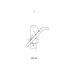
Фиг.1А-1С - соответственно, вид сбоку, схематический вид спереди и вид сверху процесса срезания волоса по прототипу.Figa-1C - respectively, a side view, a schematic front view and a top view of the process of cutting the hair of the prototype.
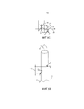
Фиг.2 - вид в перспективе в сечении части первого варианта устройства для личной гигиены по настоящему изобретению.Figure 2 is a perspective view in cross section of part of the first variant of the device for personal hygiene of the present invention.
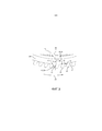
Фиг.3 - вид сверху устройства для личной гигиены по фиг.2.Figure 3 is a top view of the personal care device of Figure 2.
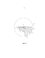
Фиг.4 - часть устройства для личной гигиены по фиг.2 в увеличенном масштабе.FIG. 4 is a part of the personal care device of FIG. 2 on an enlarged scale.
Фиг.5А-5С - соответственно вид сбоку, схематический вид спереди и вид сверху процесса срезания волоса по прототипу.Figa-5C - respectively a side view, a schematic front view and a top view of the process of cutting the hair of the prototype.
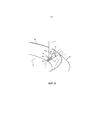
Фиг.6 - вид в перспективе части второго варианта устройства для личной гигиены по настоящему изобретению.6 is a perspective view of a portion of a second embodiment of a personal care device of the present invention.
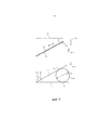
Фиг.7 - первая и вторая режущие кромки устройства для личной гигиены, показанного на фиг.2 в плоскости X,Y и в плоскости X,ZFig.7 - the first and second cutting edges of the device for personal hygiene, shown in figure 2 in the plane X, Y and in the plane X, Z
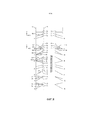
Фиг.8А-8R - схематические виды некоторых других вариантов устройства для личной гигиены по настоящему изобретению с первой и второй режущими кромками в плоскостях X,Y и в плоскостях X,Z.Figa-8R - schematic views of some other variants of the device for personal hygiene of the present invention with the first and second cutting edges in the X, Y planes and in the X, Z planes.
На чертежах одинаковыми позициями обозначены одинаковые элементы.In the drawings, the same positions denote the same elements.
Описание предпочтительных вариантовDescription of preferred options
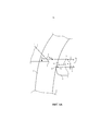
На фиг.1А-1С соответственно показаны вид сбоку, схематический вид спереди и вид сверху процесса срезания волоса устройством личной гигиены, таким как бритва, по предшествующему уровню техники.On figa-1C, respectively, shows a side view, a schematic front view and a top view of the process of cutting the hair by a personal care device, such as a razor, according to the prior art.
Такое устройство для личной гигиены содержит по меньшей мере внутренний режущий элемент 1 с первой режущей кромкой 2 и внешний режущий элемент 3 со второй режущей кромкой 4. При срезании волоса 5, отходящего от кожи 6 человека волос контактирует с первой режущей кромкой 2 в первом положении 7 контакта и со второй режущей кромкой 4 во втором положении 8 контакта. Из-за скругленной формы внешнего режущего элемента 3 второе положение 8 контакта будет находиться на расстоянии Н от внутренней поверхности 9 внешнего режущего элемента 3. Расстояние S - это расстояние между первой режущей кромкой 2 и внутренней поверхностью внешнего элемента 9, тогда как SW - это эффективный зазор резания между первым и вторым положениями 7, 8 контакта, где SW = S + H. Внутренний режущий элемент 1 выполнен подвижным относительно внешнего режущего элемента 3 в направлении, показанном стрелкой Р1. Первая и вторая режущие кромки 2, 4 проходят под углами срезания А1, А2 к направлению движения. Эффективный зазор SW резания изменяется во время срезания волоса из-за формы внутреннего режущего элемента 1 и зависит от положения режущих кромок 2, 4 и волоса 5 в направлении, показанном стрелкой Р1. Расстояние SW является наибольшим во время срезания первой половины волоса.Such a device for personal hygiene contains at least an
При срезании волоса 5 силы Fm и Fl приложены к волосу 5 внутренним режущим элементом 1 и внешним режущим элементом 3. Благодаря углам А1, А2 срезания силы Fm, Fl приводят к возникновению сил FyM, FxM, FxL, FyL. Поскольку сила FxM возникает на большем расстоянии от виртуальной плоскости 10 кожи, проходящей по существу параллельно коже 6, чем сила FxL, силы FxM, FxL создают крутящий момент Тх. Разница в расстоянии является расстоянием SW. Из-за крутящего момента Тх первая режущая кромка 2 будет отталкиваться от второй режущей кромки 3. Для сохранения постоянного расстояния между первой и второй режущими кромками 2, 4, необходимо к внутреннему режущему элементу 2 приложить силу FzM, проходящую перпендикулярно силам FxM и FyM. Из-за этой силы FzM возникает износ и генерируется теплота. Силы FyM и FyL также создают крутящий момент Ty. Этот крутящий момент Ty гасится подшипником внутреннего режущего элемента 2.When cutting the
В вышеописанном устройстве для личной гигиены по предшествующему уровню техники эффективный зазор SW резания больше нуля.In the above personal care apparatus of the prior art, the effective cutting clearance S W is greater than zero.
В случае устройства для личной гигиены по настоящему изобретению, как будет показано ниже, эффективный зазор SW резания равен или меньше нуля, поэтому фактически он является отрицательным. Это значит, что по время срезания волоса, относительно волоса 5 первое положение 7 контакта на внутренней первой режущей кромке 2 будет находиться ближе к виртуальной плоскости 10 кожи, чем второе положение 8 контакта на внешней второй режущей кромке 4. Из-за относительных положений первого и второго положений 7, 8 контакта, крутящий момент Тх будет толкать первую режущую кромку 2 в направлении второй режущей кромке 3, а не от нее, как в устройстве по прототипу.In the case of the personal care device of the present invention, as will be shown below, the effective cutting clearance S W is equal to or less than zero, therefore in fact it is negative. This means that during hair cutting, with respect to
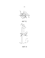
На фиг.2-4 показаны разные виды режущего узла 21 первого варианта устройства для личной гигиены по настоящему изобретению. Устройства для личной гигиены хорошо известны и подробно не описываются. Устройство для личной гигиены может быть бритвой, триммером, устройством для ухода за волосами или режущим устройством другого типа. Все режущие узлы такого устройства для личной гигиены содержать внутренний и внешний режущие элементы, при этом внутренний режущий элемент выполнен с возможностью либо вращаться относительно внешнего режущего элемента, либо совершать линейные движения.Figure 2-4 shows different types of cutting
Режущий узел 21 содержит внутренний режущий элемент 22 и внешний режущий элемент 23. Внешний режущий элемент 23 содержит центральный вал 24 и диск 25, расположенный перпендикулярно валу. Центральный вал 24 проходит параллельно центральной оси 26. Диск 25 содержит основную часть 27, проходящую перпендикулярно центральной оси 26. Рядом с внешней периферийной кромкой диск 25 содержит изогнутую часть 28 со множеством зубцов 29. Зубцы 29 расположены в осевом направлении на расстоянии от основной части 27. Как показано на фиг.3, каждый зубец 29 содержит первую и вторую сторону 30, 31, которые соединены друг с другом изогнутым участком 33. Между зубцами 29 внешнего режущего элемента 23 расположено множество U-образных отверстий 34 для входа волоса.The cutting
Внутренний режущий элемент 22 содержит полый вал 35, диск 36, отходящий перпендикулярно валу, и шестерню 36', расположенную параллельно диску 36. Полый вал 35 проходит соосно с валом 24 внешнего режущего элемента 22. Шестерня 36' соединена с другим приводным средством для вращения внутреннего режущего элемента 22 вкруг центральной оси 26 в направлении, показанном стрелкой Р2. Такое приводное средство хорошо известно и его описание опускается. Диск 36 содержит основную часть 37, расположенную перпендикулярно центральной оси 26. Рядом со своей периферийной кромкой диск 36 содержит изогнутую часть 38 с множеством зубцов 39, образующих множество режущих элементов внутреннего режущего элемента 22. Зубья 39 расположены рядом с зубьями 29.The
Первая стороне 40 каждого зубца 39 образует первую режущую кромку 50, которая взаимодействует с первой стороной 30 зубца 29, которая образует вторую режущую кромку 51.The
Как ясно видно на фиг 3, первая режущая кромка 50 образует угол А3 срезания с прямой 46, проходящей в радиальном направлении, а вторая режуща кромка 51 образует угол А4 срезания с этой линией 46. Оба угла А3, А4 срезания больше нуля градусов.As clearly seen in FIG. 3, the first cutting edge 50 forms a cutting angle A3 from a straight 46 extending in the radial direction, and the second cutting edge 51 forms a cutting angle A4 with this
Как видно на фиг.4 , зубцы 29, 39 внутреннего режущего элемента 22 и внешнего режущего элемента 23 наклонены относительно виртуальной плоскости 10 и образуют с ней угол А5 наклона. Виртуальная плоскость 10 проходит перпендикулярно центральной оси 26 и расположена на стороне внешнего режущего элемента 33, обращенной от внутреннего режущего инструмента 22.As can be seen in figure 4, the
Когда устройство для личной гигиены находится в работе, внутренний режущий элемент 22 вращается вокруг центральной оси 26 которая проходит по существу перпендикулярно поверхности кожи человека. Волосы захватываются в отверстиях 34 для входа волоса. При дальнейшем движении внутреннего режущего элемента 22, захваченные волосы срезаются взаимодействующими первой и второй режущими кромками 50, 51.When the personal care device is in operation, the
На фиг.5А-5С схематически показан волос 5, срезаемый первой и второй режущими кромками 50, 51, при этом первая и вторая режущие кромки 50, 51 образуют угол А1, А2 срезания с направлением, показанным стрелкой Р2, и наклонены на угол А5 относительно поверхности кожи и виртуальной плоскости 10 кожи.On figa-5C schematically shows the
При срезании волоса 5, волос 5 контактирует с первой режущей кромкой 50 в первом положении 52 контакта и со второй режущей кромкой 51 во втором положении 52 контакта. Режущие кромки 50, 51 прилагают к волосу 5 силы FyM, FxM, FxL и FyL. Благодаря углам А1, А2 и А5 силы FxM и FyM, прилагаемые первой режущей кромкой 50 внутреннего режущего элемента 22 прилагаются на меньшем расстоянии от виртуальной плоскости 10 кожи, чем силы FxL, FyL, прилагаемые второй режущй кромкой 51 внешнего режущего элемента 23. Разница в расстояниях является расстоянием -SW. Силы FxM и FxL создают крутящий момент Тх. Направление крутящего момента Тх противоположно направлению крутящего момента, показанного на фиг.1. Благодаря крутящему моменту Тх первая режущая кромка 50 не отжимается от второй режущей кромки 51, как в устройстве по прототипу, а прижимается к ней. Для удержания постоянного расстояния S между первой и второй режущими кромками 50, 51, не требуется или почти не требуется прилагать силу к внутреннему режущему элементу 22 в направлении, перпендикулярном силам FxM и FyM. Поскольку почти не нудно прилагать такую силу, почти не возникает износ и не генерируется теплота. Силы FyM и FyL создают крутящий момент Ty. Этот крутящий момент Ty гасится подшипником внутреннего режущего элемента 2.When cutting the
Следует отметить, что в режущем узле 21 в первом варианте устройства для личной гигиены по настоящему изобретению, для всех отверстий 34 для входа волоса внешнего режущего элемента 34, которые содержат вторую режущую кромку 51 для взаимодействия по меньшей мере с одной из режущих кромок 50 внутреннего режущего элемента 22, силы, прилагаемые к волосу 5 первой режущей кромкой 50 внутреннего режущего элемента 22, расположены на меньшем расстоянии от виртуальной плоскости 10 кожи, чем силы, прилагаемые к волосам 5 второй режущей кромкой 51 внешнего режущего элемента. Для предотвращения отталкивания внутреннего режущего элемента 22 от внешнего режущего элемента 23 под влиянием сил, возникающих при срезании волоса, и для предотвращения необходимости применять компенсирующую силу, например, силу пружины, прижимающую внутренний режущий элемент 22 и внешний режущий элемент 23 друг к другу, нет необходимости в том, чтобы для всех отверстий 34 для входа волоса внешнего режущего элемента 23 силы, приложенные к волосу 5 первой режущей кромкой 50 внутреннего режущего элемента 22, находились на меньшем расстоянии от виртуальной плоскости 10 кожи, чем силы, прилагаемые второй режущей кромкой 51 внешнего режущего элемента 23. Согласно настоящему изобретению для 60% всех отверстий 34 для входа волоса внешнего режущего элемента 23, которые содержат вторую режущую кромку 51 для взаимодействия с по меньшей мере одной из первых вторых кромок 50 внутреннего режущего элемента 22, углы А3, А4 срезания и угол А5 наклона внутреннего режущего элемента 22 и внешнего режущего элемента 23 должны быть выбраны такими, чтобы в начальном положении срезания, когда волос 5 находится в положении резания в отверстии 34 для приема волоса и проходит перпендикулярно виртуальной плоскости 10 кожи, первая режущая кромка 50 внутреннего режущего элемента 22 находилась в первом положении контакта, а вторая режущая кромка 51 внешнего режущего элемента 23 находилась в контакте с волосом 5 во втором положении контакта, при этом первое положение контакта расположено ближе к виртуальной плоскости 10 кожи, чем второе положение контакта. Когда указанная доля составляет 60%, средняя от всех срезающих волос сил, приложенных к первым режущим кромкам 50 внутреннего режущего элемента 22 и к вторым режущим кромкам 51 внешнего режущего элемента 23 заставляет внутренний режущий элемент 22 и внешний режущий элемент 23 прижиматься друг к другу. Более предпочтительно, эта доля равна 80%.It should be noted that in the cutting
На фиг.6 приведен схематический вид еще одного варианта режущего узла 61 устройства для личной гигиены по настоящему изобретению. Этот режущий узел содержит внутренний режущий элемент 62 с первыми режущими кромками 63, и внешний режущий элемент 64 со вторыми режущими кромками 65. Внутренний режущий элемент 62 выполнен с возможностью вращения вокруг центральной оси 26 (не показана на фиг.6) относительно внешнего режущего элемента 64. На фиг.6 показана только одна первая режущая кромка 63 и только одна вторая режущая кромка 65. Как и вышеописанный режущий узел 21, режущий узел 61 содержит множество таких режущих кромок 63, 65. Вторая режущая кромка 65 содержит первый режущий участок 66 и второй режущий участок 67, соединенный с ним. Первый режущий участок 66 расположен ближе к центральной оси 26, чем второй режущий участок 67. Первый режущий участок 66 образует угол А6 срезания с радиальной линией 46 и проходит от линии 46 в направлении, показанном стрелкой Р2, тогда как второй режущий участок 67 образует угол А7 срезания с радиальной линией 46 и проходит от линии 46 в направлении, противоположном показанному стрелкой Р2. При срезании волоса 5 этот волос, находясь в контакте со вторым режущим участком 67, будет выталкиваться в направлении центральной оси 26, и будет срезаться первым режущим участком 66. В варианте режущего узла 61, показанном на фиг. 6, первый угол наклона первой режущей кромки 63, второй угол наклона второй режущей кромки 65, первый угол срезания первой режущей кромки 63 и угол А6 срезания первого режущего участка 66 второй режущей кромки 65 выбирают так, чтобы когда волос 5 находится в начальном положении для срезания первой режущей кромкой 63 и первым режущим участком 66 второй режущей кромки 65, первое положение контакта между волосом 5 и первой режущей кромкой 63 находилось ближе к виртуальной плоскости кожи, чем второе положение контакта между волосом 5 и первым режущим участком 66 второй режущей кромки 65. Поскольку первый режущий участок 66 расположен ближе к центральной оси 26, влияние срезающих сил на устройство для личной гигиены дополнительно уменьшается.Figure 6 shows a schematic view of another version of the cutting
На фиг.7 схематически показан принцип срезания волоса 70 диаметром D=150 мкм первой режущей кромкой 71 и второй режущей кромкой 72. Средний диаметр волоса равен 150 мкм. Этот принцип срезания волоса также работает и для волос другого диаметра. Первая режущая кромка 71 выполнена подвижной в направлении Y относительно второй режущей кромки 72. Виртуальная плоскость, проходящая в направлении X-Y, проходит параллельно поверхности кожи пользователя и перпендикулярно направлению Z.7 schematically shows the principle of cutting
Первая режущая кромка 71 проходит под углом А8 срезания, равным 90° к направлению движения и под углом А9 наклона к виртуальной плоскости 73.The
Вторая режущая кромка 72 проходит под углом А10 срезания к направлению движения и, также под углом А9 к виртуальной плоскости 73.The
В начальном положении срезания волоса 70, первая режущая кромка 71 контактирует с волосом 70 в первом положении 74 контакта, а вторая режущая кромка 72 контактирует с волосом 70 во втором положении 75 контакта. Благодаря углам А8, А9, А10 первое положение 74 контакта расположено ближе к виртуальной плоскости 73 кожи, чем второе положение 75 контакта, что приводит к возникновению крутящего момента Тх, как описано выше, который прижимает первую режущую кромку 71 в направлении второй режущей кромки 72.In the initial position of cutting the
Углы А9 наклона первой и второй режущих кромок 71, 72 предпочтительно составляют от 5° до 30°, и более предпочтительно, прибл. 15°.The angles A9 of inclination of the first and second cutting edges 71, 72 preferably range from 5 ° to 30 °, and more preferably, approx. 15 °.
Величина углов А8, А9, А10 определяет, будет ли первое положение 74 контакта находиться ближе к виртуальной плоскости 73 кожи, чем второе положение 75 контакта.The magnitude of the angles A8, A9, A10 determines whether the
На фиг.8А-8R показаны разные относительные положения первой и второй режущих кромок 71, 72 относительно виртуальной плоскости 73, где на фиг. 8А и 8K показаны первая и вторая режущие кромки 71, 72 в плоскости X,Z, при этом расстояние между первой и второй режущими кромками 71, 72 преувеличено, чтобы показать обе режущие кромки. На практике расстояние в направлении Z является как можно меньшим. На фиг.8В-8Н и 8L-8R показаны первая и вторя режущие кромки 71, 72 в плоскости X,Y. Направление является направлением движения. Это может быть линейное возвратно-поступательное движение, или вращение. В случае вращения направление Х является радиальным направлением, направление Y является тангенциальным направлением, а направление Z является осевым направлением.FIGS. 8A-8R show different relative positions of the first and second cutting edges 71, 72 relative to the
Как показано на фиг.8А, левые стороны L режущих кромок 71, 72 расположены дальше от виртуальной плоскости 73 кожи, чем правые стороны R.As shown in FIG. 8A, the left sides L of the cutting edges 71, 72 are located further from the
На фиг.8В-8D режущие кромки 71, 72 пересекаются в точке 76 пересечения, которая расположена на левых сторонах L режущих кромок 71, 72. Для этих трех вариантов углы В1, В2 срезания первой и второй режущих кромок 71, 72 относительно направления Х таковы, что абсолютная величина В2 больше, чем абсолютная величина В1.8B-8D, the cutting edges 71, 72 intersect at the
На фиг.8Е угол А8 срезания равен углу А10.8E, the cutting angle A8 is equal to the angle A10.
На фиг.8F-8H режущие кромки 71, 72 пересекаются в точке 76 пересечения, которая расположена на правых сторонах R режущих кромок 71, 72. Для этих трех вариантов углы В3, В4 срезания первой и второй режущих кромок 71, 72 относительно направления Х таковы, что абсолютная величина В4 меньше, чем абсолютная величина В3.8F-8H, the cutting edges 71, 72 intersect at the
Во всех этих вариантах первое положение 74 контакта расположено ближе к виртуальной плоскости 73 кожи, чем второе положение 75 контакта.In all these embodiments, the
Фиг.8K-8R являются зеркальными отображениями фиг.8А-8Н, поэтому принцип работы остается тем же.Fig.8K-8R are mirror images of Fig.8A-8H, therefore, the principle of operation remains the same.
Специалистам понятно, что настоящее изобретение никоим образом не ограничено предпочтительными вариантами. Специалисты могут понять и реализовать другие варианты, помимо описанных, изучив настоящее описание, чертежи и формулу изобретения.Professionals it is clear that the present invention is in no way limited to the preferred options. Specialists can understand and implement other options, in addition to those described, having studied the present description, drawings and claims.
В формуле изобретения термин "содержащий" не исключает наличия других элементов или этапов, а единственное число не исключает множественного числа. Один лишь факт того, что определенный признак указан в разных зависимых пунктах, не указывает на то, что невозможно использовать комбинацию таких признаков.In the claims, the term "comprising" does not exclude the presence of other elements or steps, and the singular does not exclude the plural. The mere fact that a particular attribute is indicated in different dependent clauses does not indicate that it is impossible to use a combination of such signs.
Любые ссылочные позиции в формуле не должны толковаться как ограничивающие.Any reference numbers in a formula should not be construed as limiting.
Перечень позицийList of positions
1 - элемент1 - element
2 - кромка2 - edge
3 - элемент3 - element
4 - кромка4 - edge
5 - волос5 - hair
6 - кожа6 - leather
7 - положение7 - position
8 - положение8 - position
9 - поверхность9 - surface
10 - виртуальная плоскость кожи10 - the virtual plane of the skin
21 - режущий узел21 - cutting unit
22 - внутренний режущий элемент22 - inner cutting element
23 - внешний режущий элемент23 - outer cutting element
24 - вал24 - shaft
25 - диск25 - disk
26 - центральная ось26 - the central axis
27 - участок27 - plot
29 - зубец29 - prong
30 - сторона30 - side
31 - сторона31 - side
32 - участок32 - plot
33 - участок33 - plot
34 - отверстие для входа волоса34 - hole for the entrance of hair
35 - вал35 - shaft
36 - диск36 - disk
36' - шестерня36 'gear
37 - участок37 - plot
38 - участок38 - plot
39 - зубец39 - prong
40 - сторона40 - side
46 - линия46 - line
50 - первая режущая кромка50 - first cutting edge
51 - вторая режущая кромка51 - second cutting edge
52 - положение52 - position
53 - положение53 - position
61 - узел61 - node
62 - элемент62 - element
63 - кромки63 - edges
64 - элемент64 - element
65 - кромки65 - edges
66 - первый режущий участок66 - the first cutting area
67 - второй режущий участок67 - the second cutting section
70 - волос70 - hair
71 - кромка71 - edge
72 - кромка72 - edge
73 - плоскость73 - plane
74 - первое положение контакта74 - first contact position
75 - второе положение контакта75 - second contact position
76 - точка76 - point
А1 - уголA1 - angle
А2 - уголA2 - angle
А3 - уголA3 - angle
А4 - уголA4 - angle
А5 - уголA5 - angle
А7 - уголA7 - angle
А8 - уголA8 - angle
А9 - уголA9 - angle
А10 - уголA10 - angle
В1 - уголB1 - angle
В2 - уголB2 - angle
В3 - уголB3 - angle
В4 - уголB4 - angle
D - диаметрD - diameter
Fm - силаF m - force
Fl - силаF l - force
FyM - силаF yM - strength
FxM - силаF xM - power
FxL - силаF xL - power
FyL - силаF yL - strength
Н - расстояниеH - distance
Р1 - стрелкаP1 - arrow
Р2 - стрелкаP2 - arrow
R - правые стороныR - right sides
S - расстояниеS - distance
Тх - крутящий моментT x - torque
Тy - крутящий моментT y - torque
SW - зазорS W - clearance
Claims (9)
Applications Claiming Priority (3)
| Application Number | Priority Date | Filing Date | Title |
|---|---|---|---|
| EP13177931 | 2013-07-25 | ||
| EP13177931.6 | 2013-07-25 | ||
| PCT/EP2014/065212 WO2015010979A1 (en) | 2013-07-25 | 2014-07-16 | A personal care device as well as a cutting unit for such a personal care device |
Publications (3)
| Publication Number | Publication Date |
|---|---|
| RU2016106107A RU2016106107A (en) | 2017-08-30 |
| RU2016106107A3 RU2016106107A3 (en) | 2018-06-26 |
| RU2693401C2 true RU2693401C2 (en) | 2019-07-02 |
Family
ID=48875569
Family Applications (1)
| Application Number | Title | Priority Date | Filing Date |
|---|---|---|---|
| RU2016106107A RU2693401C2 (en) | 2013-07-25 | 2014-07-16 | Personal care device and cutting assembly for such personal care device |
Country Status (6)
| Country | Link |
|---|---|
| US (1) | US9956697B2 (en) |
| EP (1) | EP3024624B1 (en) |
| JP (1) | JP6325671B2 (en) |
| CN (1) | CN105408072B (en) |
| RU (1) | RU2693401C2 (en) |
| WO (1) | WO2015010979A1 (en) |
Families Citing this family (6)
| Publication number | Priority date | Publication date | Assignee | Title |
|---|---|---|---|---|
| JP6325671B2 (en) * | 2013-07-25 | 2018-05-16 | コーニンクレッカ フィリップス エヌ ヴェKoninklijke Philips N.V. | Personal care device and cutting device for such a personal care device |
| EP3103600A1 (en) | 2015-06-08 | 2016-12-14 | BaByliss Faco sprl | Beard trimmer with one or more rotating heads surrounded by combs with particular geometry and equipped with a protection position for the comb |
| US20170217030A1 (en) * | 2016-02-02 | 2017-08-03 | Izumi Products Company | Rotary electric shaver and method of manufacturing outer blade of rotary electric shaver |
| BR112018074487A2 (en) * | 2016-05-31 | 2019-03-19 | Koninklijke Philips N.V. | accessory for a personal care device, and personal care device |
| CN107309915A (en) * | 2017-07-19 | 2017-11-03 | 吴让攀 | Rotary shaver head |
| US11737395B2 (en) * | 2019-05-22 | 2023-08-29 | LPF Robotics, LLC | Apparatuses and methods for removing plant material |
Citations (5)
| Publication number | Priority date | Publication date | Assignee | Title |
|---|---|---|---|---|
| US3225440A (en) * | 1963-09-19 | 1965-12-28 | Owens Neal | Electric shaver having angled blades adapted to be inserted in corresponding angled slots in a blade supporting member |
| US3889372A (en) * | 1972-08-30 | 1975-06-17 | Matsushita Electric Works Ltd | Electric dry shaver blade assembly |
| US4707923A (en) * | 1983-06-23 | 1987-11-24 | U.S. Philips Corporation | Shaving apparatus |
| US4839964A (en) * | 1987-06-27 | 1989-06-20 | Izumi Seimitsu Kogyo Kabushiki Kaisha | Fixing structure of blade force up spring for clothes shaver and electric shaver |
| RU2121432C1 (en) * | 1993-11-05 | 1998-11-10 | Филипс Электроникс Н.В. | Shaving-set |
Family Cites Families (15)
| Publication number | Priority date | Publication date | Assignee | Title |
|---|---|---|---|---|
| HU146204A (en) | ||||
| US2261275A (en) * | 1938-06-22 | 1941-11-04 | Walter J Pasinski | Electric razor |
| NL59158C (en) | 1942-01-13 | 1900-01-01 | ||
| US2677884A (en) | 1948-12-29 | 1954-05-11 | Richard & Ammann S A | Rotary razor shear head |
| NL112975C (en) | 1962-04-16 | |||
| JPS53391Y2 (en) * | 1972-11-09 | 1978-01-09 | ||
| JPS5314974B2 (en) * | 1972-08-30 | 1978-05-22 | ||
| NL8400887A (en) * | 1984-03-21 | 1985-10-16 | Philips Nv | SHAVER. |
| NL8902807A (en) * | 1989-11-14 | 1991-06-03 | Philips Nv | SHAVER. |
| US6769179B2 (en) | 2000-07-06 | 2004-08-03 | Teizoh Satoh | Shaver |
| US20050198824A1 (en) | 2004-03-12 | 2005-09-15 | White Dennis J. | Rotary hair trimmer |
| JP2006218219A (en) | 2005-02-14 | 2006-08-24 | Izumi Products Co | Rotary type electric razor |
| JP5649213B2 (en) * | 2010-11-08 | 2015-01-07 | 株式会社泉精器製作所 | Electric razor outer blade and inner blade manufacturing method |
| CN102366962B (en) * | 2011-10-18 | 2014-11-12 | 上海奔腾电工有限公司 | Tool bit for rotary electric shaver |
| JP6325671B2 (en) * | 2013-07-25 | 2018-05-16 | コーニンクレッカ フィリップス エヌ ヴェKoninklijke Philips N.V. | Personal care device and cutting device for such a personal care device |
-
2014
- 2014-07-16 JP JP2016528428A patent/JP6325671B2/en active Active
- 2014-07-16 WO PCT/EP2014/065212 patent/WO2015010979A1/en active Application Filing
- 2014-07-16 CN CN201480041846.8A patent/CN105408072B/en active Active
- 2014-07-16 EP EP14739450.6A patent/EP3024624B1/en active Active
- 2014-07-16 US US14/904,976 patent/US9956697B2/en active Active
- 2014-07-16 RU RU2016106107A patent/RU2693401C2/en active
Patent Citations (5)
| Publication number | Priority date | Publication date | Assignee | Title |
|---|---|---|---|---|
| US3225440A (en) * | 1963-09-19 | 1965-12-28 | Owens Neal | Electric shaver having angled blades adapted to be inserted in corresponding angled slots in a blade supporting member |
| US3889372A (en) * | 1972-08-30 | 1975-06-17 | Matsushita Electric Works Ltd | Electric dry shaver blade assembly |
| US4707923A (en) * | 1983-06-23 | 1987-11-24 | U.S. Philips Corporation | Shaving apparatus |
| US4839964A (en) * | 1987-06-27 | 1989-06-20 | Izumi Seimitsu Kogyo Kabushiki Kaisha | Fixing structure of blade force up spring for clothes shaver and electric shaver |
| RU2121432C1 (en) * | 1993-11-05 | 1998-11-10 | Филипс Электроникс Н.В. | Shaving-set |
Also Published As
| Publication number | Publication date |
|---|---|
| RU2016106107A (en) | 2017-08-30 |
| US20160158947A1 (en) | 2016-06-09 |
| CN105408072A (en) | 2016-03-16 |
| JP6325671B2 (en) | 2018-05-16 |
| EP3024624A1 (en) | 2016-06-01 |
| EP3024624B1 (en) | 2018-07-11 |
| RU2016106107A3 (en) | 2018-06-26 |
| WO2015010979A1 (en) | 2015-01-29 |
| JP2016525001A (en) | 2016-08-22 |
| CN105408072B (en) | 2018-05-18 |
| US9956697B2 (en) | 2018-05-01 |
Similar Documents
| Publication | Publication Date | Title |
|---|---|---|
| RU2693401C2 (en) | Personal care device and cutting assembly for such personal care device | |
| JP6231992B2 (en) | Rotary shaving unit | |
| EP1930137B1 (en) | Shaving foil for a dry shaver | |
| EP1690655A1 (en) | Rotary type electric shaver | |
| JP2007135991A (en) | Rotary electric shaver | |
| EP3137267A2 (en) | Hybrid shaving system | |
| US7743507B2 (en) | Rotary type electric shaver | |
| JP6525298B1 (en) | Rotary shaver and its inner blade | |
| US10442095B2 (en) | Rotary electric shaver | |
| RU2767374C1 (en) | Hair cutting unit of a shaving apparatus containing hair guiding elements with a profile of variable thickness | |
| JP6482149B1 (en) | Rotating shaver and its inner blade | |
| US20050198824A1 (en) | Rotary hair trimmer | |
| JPS6117729Y2 (en) | ||
| JPH0246839Y2 (en) | ||
| NL8300542A (en) | High speed electric shaver - has resilient arms for cutter to reduce blade wear | |
| GB1603044A (en) | Dry-shaving apparatus | |
| JPS6257580A (en) | Electric razor |