JP2016518213A - Shaving equipment - Google Patents
Shaving equipment Download PDFInfo
- Publication number
- JP2016518213A JP2016518213A JP2016513458A JP2016513458A JP2016518213A JP 2016518213 A JP2016518213 A JP 2016518213A JP 2016513458 A JP2016513458 A JP 2016513458A JP 2016513458 A JP2016513458 A JP 2016513458A JP 2016518213 A JP2016518213 A JP 2016518213A
- Authority
- JP
- Japan
- Prior art keywords
- rotary cutter
- cutter
- tube
- cutting edge
- fixed blade
- Prior art date
- Legal status (The legal status is an assumption and is not a legal conclusion. Google has not performed a legal analysis and makes no representation as to the accuracy of the status listed.)
- Pending
Links
Images


Classifications
-
- B—PERFORMING OPERATIONS; TRANSPORTING
- B26—HAND CUTTING TOOLS; CUTTING; SEVERING
- B26B—HAND-HELD CUTTING TOOLS NOT OTHERWISE PROVIDED FOR
- B26B19/00—Clippers or shavers operating with a plurality of cutting edges, e.g. hair clippers, dry shavers
- B26B19/14—Clippers or shavers operating with a plurality of cutting edges, e.g. hair clippers, dry shavers of the rotary-cutter type; Cutting heads therefor; Cutters therefor
- B26B19/16—Clippers or shavers operating with a plurality of cutting edges, e.g. hair clippers, dry shavers of the rotary-cutter type; Cutting heads therefor; Cutters therefor involving a knife cylinder or a knife cone or separate cutting elements moved like a rotating cylinder or a rotating cone
- B26B19/18—Clippers or shavers operating with a plurality of cutting edges, e.g. hair clippers, dry shavers of the rotary-cutter type; Cutting heads therefor; Cutters therefor involving a knife cylinder or a knife cone or separate cutting elements moved like a rotating cylinder or a rotating cone in combination with a fixed razor-blade without shearing perforations
-
- B—PERFORMING OPERATIONS; TRANSPORTING
- B26—HAND CUTTING TOOLS; CUTTING; SEVERING
- B26B—HAND-HELD CUTTING TOOLS NOT OTHERWISE PROVIDED FOR
- B26B21/00—Razors of the open or knife type; Safety razors or other shaving implements of the planing type; Hair-trimming devices involving a razor-blade; Equipment therefor
- B26B21/08—Razors of the open or knife type; Safety razors or other shaving implements of the planing type; Hair-trimming devices involving a razor-blade; Equipment therefor involving changeable blades
- B26B21/14—Safety razors with one or more blades arranged transversely to the handle
- B26B21/34—Safety razors with one or more blades arranged transversely to the handle of the type carrying rollers
Landscapes
- Life Sciences & Earth Sciences (AREA)
- Forests & Forestry (AREA)
- Engineering & Computer Science (AREA)
- Mechanical Engineering (AREA)
- Dry Shavers And Clippers (AREA)
Abstract
シェービングプロセス中に、使用者の毛を回転カッターと固定刃との間でせん断するためにそれらが使用されるシェービング装置。回転カッターの回転は、電気モータによって駆動される。特定の実施形態において、回転カッターは、閉形状を形成する切断エッジによって画定される複数の開口部を備える切断管を備える。他の実施形態において、潤滑要素が回転カッターに連結され、さらなる実施形態において、開口部は、常に毛をせん断するために稼働中であることが可能な開口部の数及び選択を制御するようなパターンで配置される。なおもさらなる実施形態において、固定刃は、ヘッドの筐体と一体化して形成され、筐体は、複数のスタックされた平板セグメントによって形成され、回転カッターは、複数のスタックされた平板セグメントによって形成され、かつ/または固定刃は、往復移動することができる。【選択図】図1A shaving device in which they are used to shear the user's hair between a rotating cutter and a fixed blade during the shaving process. The rotation of the rotary cutter is driven by an electric motor. In certain embodiments, the rotary cutter comprises a cutting tube comprising a plurality of openings defined by a cutting edge that forms a closed shape. In other embodiments, the lubrication element is coupled to a rotary cutter, and in further embodiments, the openings control the number and selection of openings that can always be active to shear the hair. Arranged in a pattern. In a still further embodiment, the fixed blade is formed integrally with the housing of the head, the housing is formed by a plurality of stacked flat plate segments, and the rotary cutter is formed by a plurality of stacked flat plate segments. And / or the fixed blade can reciprocate. [Selection] Figure 1
Description
関連特許出願の相互参照
本出願は、2013年5月17日に出願された米国仮特許出願第61/824,579号及び2014年2月18日に出願された米国仮特許出願第61/941,240号の利益を主張するものであり、参照により、それらの全体が本明細書に組み込まれる。
CROSS REFERENCE TO RELATED PATENT APPLICATIONS This application is based on US Provisional Patent Application No. 61 / 824,579, filed May 17, 2013, and US Provisional Patent Application No. 61/941, filed February 18, 2014. , 240, which are incorporated herein by reference in their entirety.
本発明は、概してシェービング装置に関し、具体的には、回転カッターと固定刃との間で剛毛を切断するためにせん断技術を用いたシェービング装置に関する。 The present invention relates generally to a shaving device, and more particularly to a shaving device that uses shearing technology to cut bristles between a rotating cutter and a fixed blade.
剃毛によって人体から毛を除去するための現在の方法は、脱毛とは対照的に、2つの基本的な手法を含む:非常に鋭利な刃を皮膚に斜めに押し当て、それによって毛を切断するレーザー手法、及び薄い有窓金属スクリーンを皮膚を横切って移動させ、穴を通して毛を露出させ、機械化された、典型的には電動化された切断要素によってそれらを切断するスクリーン手法。 Current methods for removing hair from the human body by shaving include two basic techniques, as opposed to hair removal: pressing a very sharp blade diagonally against the skin, thereby cutting the hair A laser technique that moves the thin windowed metal screen across the skin, exposes the hair through the holes, and cuts them with a mechanized, typically motorized cutting element.
鋭利なカミソリ刃による手法では、切断のためのエネルギーが、使用者の皮膚を横切って刃を駆動する手によって、典型的には使用者自身の手によって提供される。毛を切断する条件は、軟らかい(または軟化した)毛(または剛毛)の切断し易さと、剛毛の硬さにのみ由来し得る刃の力に対して必要な反力を有することとの妥協である。日常的に最適化することが困難な多様な剛毛に関する妥協である以外にも、皮膚を横切って強制的に刃が駆動されるため、刃の鋭さ及びその角度によって絶えず切り傷のリスクがもたらされる。 In a sharp razor blade approach, the energy for cutting is provided by the hand driving the blade across the user's skin, typically by the user's own hand. The condition for cutting the hair is a compromise between the ease of cutting soft (or softened) hair (or bristles) and the necessary reaction force against the force of the blade that can only be derived from the hardness of the bristles. is there. Besides compromising on a variety of bristles that are difficult to optimize on a daily basis, the blade is forced across the skin, so the sharpness and angle of the blade poses a constant risk of cuts.
ほとんどの電動化されたシェービング装置のスクリーン手法では、皮膚と切断要素とがスクリーンによって分離されるため、安全性の問題が軽減される。さらに、その穴を通ってスクリーンを貫通する剛毛には切断される支えが与えられ、したがって、切断のための反力の欠如もある程度軽減される。しかしながら、効率的な切断条件に到達するためには、剛毛が穴に進入し、皮膚に垂直にならなければならず、これは、皮膚を横切って絶えずスクリーンを移動させていない限り、必ずしも満たされるとは限らない要件である。さらに、剛毛が最終的に最適な角度で切断される時、分離スクリーンのために皮膚に接近して切断することができない。 Most motorized shaving device screen techniques alleviate safety issues because the skin and cutting elements are separated by the screen. Furthermore, the bristles that pass through the screen through the hole are provided with the support to be cut, and thus the lack of reaction force for cutting is also reduced to some extent. However, in order to reach an efficient cutting condition, the bristles must enter the hole and become perpendicular to the skin, which is not always met unless the screen is constantly moved across the skin. It is not necessarily a requirement. Furthermore, when the bristles are finally cut at the optimum angle, they cannot be cut close to the skin due to the separation screen.
毛を切断するために最小限の力を必要とするある切断技術は、はさみによって実現することができる。はさみは、刃が切断面における実質的に反対の方向から毛に接触し、互いに切断のための反力を相互に提供するという事実に起因して、毛を切断するためにそれほど鋭利でなくともよい2枚の刃の交点で毛を切断する。毎日の剃毛に、切断点が皮膚に最大限に接近する必要があるはさみを使用することは実用的ではないが、はさみの切断技術は、平坦かつ線形の静止刃に対して毛を切断する回転カッターユニットの形態で実装された。切断時に、切断刃が皮膚に対して同一平面に位置付けられるため、この毛切断技術は、非常にきれいに剃毛することができる。またこれにより、この切断手法による不慮の切り傷が比較的できなくなる。 Certain cutting techniques that require minimal force to cut the hair can be achieved with scissors. The scissors may be less sharp to cut the hair due to the fact that the blades contact the hair from a substantially opposite direction on the cutting surface and provide each other with a reaction force for cutting each other. Cut the hair at the intersection of two good blades. For daily shaving, it is impractical to use scissors where the cutting point needs to be as close as possible to the skin, but scissor cutting techniques cut hair against a flat, linear stationary blade Mounted in the form of a rotary cutter unit. Since the cutting blade is positioned flush with the skin when cutting, this hair cutting technique can be shaved very cleanly. This also makes it relatively difficult to make inadvertent cuts by this cutting technique.
しかしながら、この技術を実装しようと試みた現在既知の構成は、数多くの欠陥に悩まされてきた。 However, currently known configurations that attempt to implement this technology have suffered from a number of deficiencies.
本発明は、一態様において、シェービングプロセス中に、使用者の毛を回転カッターと固定刃との間でせん断するためにそれらが使用されるシェービング装置を対象とする。回転カッターの回転は、電気モータによって駆動され、回転カッターは、閉形状を形成する切断エッジによって画定される複数の開口部を備える切断管を備える。切断管は、1つ以上の格子構造を備える筒状スクリーンであってもよい。 The present invention, in one aspect, is directed to a shaving device in which they are used to shear a user's hair between a rotating cutter and a fixed blade during the shaving process. The rotation of the rotary cutter is driven by an electric motor, and the rotary cutter comprises a cutting tube with a plurality of openings defined by a cutting edge that forms a closed shape. The cutting tube may be a cylindrical screen with one or more lattice structures.
そのような一実施形態において、本発明は、ハンドル部、電源、及びハンドル部に連結されたヘッド部を備えるシェービング装置であってもよい。ヘッド部は、回転カッター及び固定刃を備えてもよい。回転カッターは、カッター管の外面に複数の開口部を備えるカッター管を備えてもよい。それぞれの開口部は、閉形状を有する切断エッジによって画定されてもよい。固定刃は、切断エッジを有し、回転カッターに隣接して取り付けられる。電気モータは、電源及び回転カッターに動作可能に連結される。電気モータは、使用者の毛が固定刃の切断エッジとカッター管の切断エッジとの間でせん断されるように、軸を中心に回転カッターを回転させるように動作させてもよい。 In such an embodiment, the present invention may be a shaving device including a handle portion, a power source, and a head portion connected to the handle portion. The head unit may include a rotary cutter and a fixed blade. The rotary cutter may include a cutter tube having a plurality of openings on the outer surface of the cutter tube. Each opening may be defined by a cutting edge having a closed shape. The fixed blade has a cutting edge and is mounted adjacent to the rotating cutter. The electric motor is operably coupled to the power source and the rotary cutter. The electric motor may be operated to rotate the rotating cutter about the axis so that the user's hair is sheared between the cutting edge of the fixed blade and the cutting edge of the cutter tube.
別のそのような実施形態において、本発明は、ハンドル部、電源、ハンドル部に連結されたヘッド部、及び電気モータを備えるシェービング装置であってもよい。電気モータは、軸を中心に回転カッターを回転させるように電源及び回転カッターに動作可能に連結される。ヘッド部は、ハンドル部に連結され、回転カッターを備える。回転カッターは、カッター管の外面に1つ以上の開口部を備えるカッター管を備え、開口部は、閉形状を有する切断エッジによって画定される。ヘッド部は、切断エッジを有する固定刃をさらに備える。固定刃は、回転カッターが回転している時に、使用者の毛が固定刃の切断エッジとカッター管の切断エッジとの間でせん断されるように、回転カッターに隣接して取り付けられる。 In another such embodiment, the present invention may be a shaving device comprising a handle portion, a power source, a head portion coupled to the handle portion, and an electric motor. The electric motor is operably coupled to the power source and the rotary cutter to rotate the rotary cutter about the axis. The head unit is connected to the handle unit and includes a rotary cutter. The rotating cutter comprises a cutter tube with one or more openings on the outer surface of the cutter tube, the openings being defined by a cutting edge having a closed shape. The head unit further includes a fixed blade having a cutting edge. The fixed blade is mounted adjacent to the rotating cutter such that when the rotating cutter is rotating, the user's hair is sheared between the cutting edge of the fixed blade and the cutting edge of the cutter tube.
別の態様において、本発明は、シェービングプロセス中に、使用者の毛を回転カッターと固定刃との間でせん断するためにそれらが使用されるシェービング装置を対象とする。回転カッターの回転は、シェービングプロセス中に潤滑要素が使用者の皮膚に接触するように、かつ/または使用者の皮膚に潤滑剤を塗布するように、電気モータによって駆動され、潤滑要素は、一緒に回転するように回転カッターに連結される。 In another aspect, the present invention is directed to a shaving device in which they are used to shear a user's hair between a rotating cutter and a fixed blade during the shaving process. The rotation of the rotary cutter is driven by an electric motor so that the lubricating element contacts the user's skin during the shaving process and / or applies lubricant to the user's skin, It is connected to a rotary cutter so as to rotate.
そのような一実施形態において、本発明は、ハンドル部、電源、及びハンドル部に連結されたヘッド部を備えるシェービング装置であってもよい。ヘッド部は、複数の切断エッジと、一緒に回転するように回転カッターに連結された少なくとも1つの潤滑要素とを備える回転カッターを備えてもよい。ヘッド部はまた、切断エッジを有する固定刃を備えてもよい。固定刃は、回転カッターに隣接して取り付けられる。電気モータは、電源及び回転カッターに動作可能に連結される。起動されると、電気モータは、軸を中心に回転カッターを回転させ、そうすることで、(1)回転カッターが回転している時に、潤滑要素が使用者の皮膚に潤滑剤を塗布するか、または使用者の皮膚に接触し、(2)回転カッターが回転している時に、使用者の毛が固定刃の切断エッジと回転カッターの切断エッジとの間でせん断される。 In such an embodiment, the present invention may be a shaving device including a handle portion, a power source, and a head portion connected to the handle portion. The head portion may comprise a rotary cutter comprising a plurality of cutting edges and at least one lubricating element coupled to the rotary cutter for rotation together. The head portion may also include a fixed blade having a cutting edge. The fixed blade is attached adjacent to the rotary cutter. The electric motor is operably coupled to the power source and the rotary cutter. When activated, the electric motor rotates the rotating cutter about the axis so that (1) the lubricating element applies lubricant to the user's skin when the rotating cutter is rotating. Or (2) when the rotating cutter is rotating, the user's hair is sheared between the cutting edge of the fixed blade and the cutting edge of the rotating cutter.
さらなる実施形態において、本発明は、ハンドル部、電源、及びハンドル部に連結されたヘッド部を備えるシェービング装置であってもよい。ヘッド部は、カッター管の外面に複数の開口部を備えるカッター管を備える回転カッターを備えてもよく、開口部の各々は、閉形状を有する切断エッジによって画定される。ヘッド部は、一緒に回転するようにカッター管に連結された少なくとも1つの潤滑要素と、切断エッジを有する固定刃とをさらに備えてもよく、固定刃は、回転カッターに隣接して取り付けられる。電気モータは、電源及び回転カッターに動作可能に連結される。起動されると、電気モータは、軸を中心に回転カッターを回転させ、そうすることで、(1)回転カッターが回転している時に、潤滑要素が使用者の皮膚に接触するか、または使用者の皮膚に潤滑剤を塗布し、(2)回転カッターが回転している時に、使用者の毛が固定刃の切断エッジと回転カッターの切断エッジとの間でせん断される。 In a further embodiment, the present invention may be a shaving device comprising a handle portion, a power source, and a head portion coupled to the handle portion. The head portion may comprise a rotating cutter comprising a cutter tube with a plurality of openings on the outer surface of the cutter tube, each opening being defined by a cutting edge having a closed shape. The head portion may further comprise at least one lubricating element coupled to the cutter tube for rotation together, and a stationary blade having a cutting edge, the stationary blade being mounted adjacent to the rotating cutter. The electric motor is operably coupled to the power source and the rotary cutter. When activated, the electric motor rotates the rotating cutter about the axis so that (1) the lubricating element contacts or uses the user's skin when the rotating cutter is rotating. Lubricant is applied to the skin of the person, and (2) when the rotary cutter is rotating, the user's hair is sheared between the cutting edge of the fixed blade and the cutting edge of the rotary cutter.
別の態様において、本発明は、シェービングプロセス中に、使用者の毛を回転カッターと固定刃との間でせん断するためにそれらが使用されるシェービング装置を対象とする。回転カッターの回転は、電気モータ及び回転カッターによって駆動される。回転カッターの外面は、閉形状を有する切断エッジによって画定された、せん断部及び非せん断部を備える複数の開口部を備える。開口部は、選択された数のせん断部のみが、任意の所与の時間に固定刃で毛を能動的にせん断することができるようなパターンで回転カッターの外面に配置される。 In another aspect, the present invention is directed to a shaving device in which they are used to shear a user's hair between a rotating cutter and a fixed blade during the shaving process. The rotation of the rotary cutter is driven by an electric motor and a rotary cutter. The outer surface of the rotary cutter comprises a plurality of openings comprising a sheared portion and a non-sheared portion defined by a cutting edge having a closed shape. The openings are arranged on the outer surface of the rotary cutter in a pattern such that only a selected number of shears can actively shear the hair with a fixed blade at any given time.
そのような一実施形態において、本発明は、ハンドル部と、電源と、回転軸を中心に回転カッターを回転させるように電源及び回転カッターに動作可能に連結される電気モータと、ハンドル部に連結されたヘッド部であって、ヘッド部は、回転カッターであって、回転カッターは、回転カッターの外面に複数の開口部を備え、開口部の各々は、閉形状を有する切断エッジによって画定され、かつせん断部及び非せん断部を備える、回転カッターと、切断エッジを有する固定刃であって、回転カッターが回転している時に、使用者の毛が固定刃の切断エッジとカッター管の切断エッジのせん断部との間でせん断されるように、回転カッターに隣接して取り付けられる、固定刃と、回転カッターが回転している時に、せん断部のうちの2つ以下が、固定刃の切断エッジで使用者の毛をせん断する際に稼働中であり得るようなパターンで配置される、開口部と、を備えるヘッド部と、を備えるシェービング装置であってもよい。 In one such embodiment, the present invention includes a handle portion, a power source, an electric motor operably connected to the power source and the rotary cutter to rotate the rotary cutter about the rotation axis, and the handle portion. A rotary cutter, the rotary cutter comprising a plurality of openings on the outer surface of the rotary cutter, each of the openings being defined by a cutting edge having a closed shape; And a fixed blade having a rotating cutter and a cutting edge, each having a shearing portion and a non-shearing portion, and when the rotating cutter is rotating, the user's hair is separated between the cutting edge of the fixed blade and the cutting edge of the cutter tube. No more than two of the shearing parts are mounted when the rotary cutter is rotating, with a fixed blade attached adjacent to the rotary cutter so that it is sheared between the shearing parts. They are arranged in a pattern as may be running at the time of shearing the hair of the user in the cutting edge of the fixed blade, and the opening may be a shaving apparatus comprising a head portion, a with a.
別のそのような実施形態において、本発明は、ハンドル部と、電源と、回転軸を中心に回転カッターを回転させるように電源及び回転カッターに動作可能に連結される電気モータと、ハンドル部に連結されたヘッド部であって、ヘッド部は、回転カッターであって、回転カッターは、回転カッターの外面に複数の開口部を備え、開口部の各々は、閉形状を有する切断エッジによって画定され、かつせん断部及び非せん断部を備える、回転カッターと、切断エッジを有する固定刃であって、回転カッターが回転している時に、使用者の毛が固定刃の切断エッジと回転カッターの切断エッジのせん断部との間でせん断されるように、回転カッターに隣接して取り付けられる、固定刃と、回転カッターの角度位置にかかわらず、切断管の外面上の固定刃の切断エッジの突出した基準線がせん断部のうちの2つ以下と交差するパターンで配置される、開口部と、を備えるヘッド部と、を備えるシェービング装置であってもよい。 In another such embodiment, the present invention includes a handle portion, a power source, an electric motor operably coupled to the power source and the rotary cutter to rotate the rotary cutter about the rotation axis, and the handle portion. A coupled head portion, wherein the head portion is a rotary cutter, the rotary cutter comprising a plurality of openings on the outer surface of the rotary cutter, each of the openings being defined by a cutting edge having a closed shape. A rotary cutter having a shearing portion and a non-shearing portion, and a fixed blade having a cutting edge, and when the rotary cutter is rotating, the user's hair is the cutting edge of the fixed blade and the cutting edge of the rotary cutter Regardless of the angular position of the fixed blade and the rotary cutter that are mounted adjacent to the rotary cutter so that they are sheared between Projecting the reference line of the cutting edge of the blade are arranged in a pattern crossing the following two of the shearing section, and the opening may be a shaving apparatus comprising a head portion, a with a.
さらに別のそのような実施形態において、本発明は、ハンドル部と、電源と、回転軸を中心に回転カッターを回転させるように電源及び回転カッターに動作可能に連結される電気モータと、ハンドル部に連結されたヘッド部であって、ヘッド部は、回転カッターであって、回転カッターは、回転カッターの外面に複数の開口部を備え、開口部の各々は、閉形状を有する切断エッジによって画定され、かつせん断部及び非せん断部を備え、せん断部は頂点を備える、回転カッターと、切断エッジを有する固定刃であって、回転カッターが回転している時に、使用者の毛が固定刃の切断エッジと切断エッジのせん断部との間でせん断されるように、回転カッターに隣接して取り付けられる、固定刃と、回転カッターの角度位置にかかわらず、切断管の外面上の固定刃の切断エッジの突出した基準線が頂点のうちの2つ以下と交差するパターンで配置される、開口部と、を備えるヘッド部と、を備えるシェービング装置であってもよい。 In yet another such embodiment, the present invention includes a handle portion, a power source, an electric motor operably coupled to the power source and the rotary cutter to rotate the rotary cutter about the rotation axis, and the handle portion. A head part coupled to the rotary head, wherein the head part is a rotary cutter, the rotary cutter comprising a plurality of openings on the outer surface of the rotary cutter, each of the openings being defined by a cutting edge having a closed shape A rotary cutter having a shearing portion and a non-shearing portion, and a shearing portion having a vertex, and a fixed blade having a cutting edge, and when the rotary cutter is rotating, the user's hair is Cutting regardless of the angular position of the fixed blade and the rotary cutter, which is mounted adjacent to the rotary cutter so that it is sheared between the cutting edge and the shear of the cutting edge A shaving device comprising: a head portion comprising: an opening portion arranged in a pattern in which a protruding reference line of a cutting edge of a fixed blade on the outer surface of the fixed blade intersects with two or less of the vertices; .
さらに別のそのような実施形態において、本発明は、ハンドル部と、電源と、回転軸を中心に回転カッターを回転させるように電源及び回転カッターに動作可能に連結される電気モータと、ハンドル部に連結されたヘッド部であって、ヘッド部は、回転カッターであって、回転カッターは、回転カッターの外面に複数の開口部を備え、複数の開口部は、開口部のうちの少なくとも1つの列を含むパターンで配置され、開口部の各々は、閉形状を有する切断エッジによって画定され、かつせん断部及び非せん断部を備える、回転カッターと、切断エッジを有する固定刃であって、固定刃は、回転カッターが回転している時に、使用者の毛が固定刃の切断エッジと回転カッターの切断エッジのせん断部との間でせん断されるように、回転カッターに隣接して取り付けられる、固定刃と、切断管の外面上の固定刃の切断エッジの突出した基準線が、列の開口部のせん断部のうちの少なくとも1つと交差し、かつ列の開口部のせん断部のうちの少なくとも1つと交差しないように構成される、パターンと、を備えるヘッド部と、を備えるシェービング装置であってもよい。 In yet another such embodiment, the present invention includes a handle portion, a power source, an electric motor operably coupled to the power source and the rotary cutter to rotate the rotary cutter about the rotation axis, and the handle portion. The head unit is a rotary cutter, and the rotary unit includes a plurality of openings on an outer surface of the rotary cutter, and the plurality of openings are at least one of the openings. A rotary cutter, a fixed blade having a cutting edge, each of the openings being arranged in a pattern comprising a row, each opening being defined by a cutting edge having a closed shape and comprising a shearing portion and a non-shearing portion, The rotating cutter ensures that when the rotating cutter is rotating, the user's hair is sheared between the cutting edge of the fixed blade and the shearing portion of the cutting edge of the rotating cutter. The adjacent fixed blade and the protruding reference line of the cutting edge of the fixed blade on the outer surface of the cutting tube intersect with at least one of the shearing portions of the row openings and A shaving device may be provided that includes a head portion including a pattern that is configured not to intersect at least one of the shearing portions.
さらなる態様において、本発明は、ハンドル部と、電源と、ハンドル部に連結されたヘッド部であって、ヘッド部は、内部空洞を有する筐体と、複数の切断エッジを備える回転カッターであって、回転カッターは、筐体の内部空洞内に取り付けられ、筐体は、筐体の内部空洞への通路を形成する細長いスロットを備え、かつ回転カッターの一部を露出させる、回転カッターと、筐体の一部として一体化して形成され、かつ細長いスロットを部分的に画定する切断エッジを備える固定刃と、を備える、ヘッド部と、使用者の毛が固定刃の切断エッジと回転カッターの切断エッジとの間でせん断されるように、回転軸を中心に回転カッターを回転させるように電源及び回転カッターに動作可能に連結される電気モータと、を備える、シェービング装置であってもよい。 In a further aspect, the present invention provides a handle portion, a power source, and a head portion coupled to the handle portion, wherein the head portion is a rotary cutter comprising a housing having an internal cavity and a plurality of cutting edges. The rotary cutter is mounted in an internal cavity of the housing, the housing includes an elongated slot that forms a passage to the internal cavity of the housing and exposes a portion of the rotary cutter; and the housing A fixed blade with a cutting edge that is integrally formed as part of the body and that partially defines an elongated slot; a head portion; and a user's hair cuts the cutting edge of the fixed blade and the rotary cutter A power source and an electric motor operably coupled to the rotary cutter to rotate the rotary cutter about the axis of rotation so as to be sheared between the edges It may be a location.
なおもさらなる態様において、本発明は、ハンドル部と、電源と、ハンドル部に連結されたヘッド部であって、ヘッド部は、複数の切断エッジを備える回転カッターを集合的に形成するようにスタックに配置された複数の平板リングセグメントと、切断エッジを有する固定刃であって、回転カッターに隣接して取り付けられる、固定刃と、を備える、ヘッド部と、使用者の毛が固定刃の切断エッジと回転カッターの切断エッジとの間でせん断されるように、回転軸を中心に回転カッターを回転させるように電源及び回転カッターに動作可能に連結される電気モータと、を備える、シェービング装置であってもよい。 In yet a further aspect, the present invention provides a handle portion, a power source, and a head portion coupled to the handle portion, wherein the head portion is stacked to collectively form a rotary cutter with a plurality of cutting edges. A fixed blade having a plurality of flat ring segments and a cutting edge disposed adjacent to the rotary cutter, the head portion comprising a fixed blade, and a user's hair cutting the fixed blade A shaving device comprising: a power source and an electric motor operably coupled to the rotary cutter to rotate the rotary cutter about the rotary axis so as to be sheared between the edge and the cutting edge of the rotary cutter There may be.
なおもさらなる態様において、本発明は、ハンドル部と、電源と、ハンドル部に連結されたヘッド部であって、ヘッド部は、内部空洞を有する筐体を集合的に形成するようにスタックに配置された複数の平板セグメントと、複数の切断エッジを備える回転カッターであって、回転カッターは、筐体の内部空洞内に取り付けられ、筐体は、筐体の内部空洞への通路を形成する細長いスロットを備え、かつ回転カッターの一部を露出させる、回転カッターと、細長いスロットを部分的に画定する切断エッジを備える固定刃と、を備える、ヘッド部と、使用者の毛が固定刃の切断エッジと回転カッターの切断エッジとの間でせん断されるように、回転軸を中心に回転カッターを回転させるように電源及び回転カッターに動作可能に連結される電気モータと、を備える、シェービング装置であってもよい。 In yet a further aspect, the present invention is a head portion coupled to a handle portion, a power source, and a handle portion, wherein the head portion is disposed in a stack so as to collectively form a housing having an internal cavity. A rotary cutter having a plurality of flat plate segments and a plurality of cutting edges, wherein the rotary cutter is mounted within an internal cavity of the housing, the housing being elongated to form a passage to the internal cavity of the housing A head portion comprising a rotary cutter having a slot and exposing a portion of the rotary cutter, and a fixed blade having a cutting edge partially defining an elongated slot, and a user's hair cutting the fixed blade An electric motor operably coupled to the power source and the rotary cutter to rotate the rotary cutter about the rotational axis so that it is sheared between the edge and the cutting edge of the rotary cutter. Comprising data and, the may be a shaving device.
なおもさらなる態様において、本発明は、ハンドル部と、電源と、ハンドル部に連結されたヘッド部であって、ヘッド部は、山部及び谷部を備える外面を備える回転カッターと、山部及び谷部を備える波状の切断エッジを有する固定刃であって、固定刃の波状のエッジの山部が回転カッターの谷部内で入れ子状になり、回転カッターの山部が固定刃の波状のエッジの谷部内で入れ子上になるように、固定刃が回転カッターに隣接して取り付けられる、固定刃と、を備える、ヘッド部と、使用者の毛が固定刃の波状の切断エッジと回転カッターとの間でせん断されるように、回転軸を中心に回転カッターを回転させるように電源及び回転カッターに動作可能に連結される電気モータと、を備える、シェービング装置であってもよい。 In yet a further aspect, the present invention is a head portion coupled to a handle portion, a power source, and a handle portion, wherein the head portion includes a rotary cutter including an outer surface including a peak portion and a valley portion, a peak portion, and A fixed blade having a wavy cutting edge with a trough, wherein the crest of the wavy edge of the fixed blade is nested within the trough of the rotary cutter, and the crest of the rotary cutter is the wavy edge of the fixed blade. A fixed blade is mounted adjacent to the rotary cutter so as to be nested within the valley, and the head portion includes a wavy cutting edge of the fixed blade and the rotary cutter. A shaving device comprising: a power source and an electric motor operably coupled to the rotary cutter to rotate the rotary cutter about the rotational axis so as to be sheared between.
なおもさらなる態様において、本発明は、ハンドル部と、電源と、ハンドル部に連結されたヘッド部であって、ヘッド部は、山部及び谷部を備える外面を備える回転カッターと、山部及び谷部を備える波状の切断エッジを有する固定刃であって、固定刃の波状のエッジの山部が回転カッターの谷部内で入れ子状になり、回転カッターの山部が固定刃の波状のエッジの谷部内で入れ子上になるように、固定刃が回転カッターに隣接して取り付けられる、固定刃と、を備える、ヘッド部と、使用者の毛が固定刃の波状の切断エッジと回転カッターとの間でせん断されるように、回転軸を中心に回転カッターを回転させるように電源及び回転カッターに動作可能に連結される電気モータと、を備える、シェービング装置であってもよい。 In yet a further aspect, the present invention is a head portion coupled to a handle portion, a power source, and a handle portion, wherein the head portion includes a rotary cutter including an outer surface including a peak portion and a valley portion, a peak portion, and A fixed blade having a wavy cutting edge with a trough, wherein the crest of the wavy edge of the fixed blade is nested within the trough of the rotary cutter, and the crest of the rotary cutter is the wavy edge of the fixed blade. A fixed blade is mounted adjacent to the rotary cutter so as to be nested within the valley, and the head portion includes a wavy cutting edge of the fixed blade and the rotary cutter. A shaving device comprising: a power source and an electric motor operably coupled to the rotary cutter to rotate the rotary cutter about the rotational axis so as to be sheared between.
本発明のさらなる利用可能性の領域は、これ以降に提供される詳細な説明から明らかになるであろう。詳細な説明及び特定の実施例は、本発明のいくつかの実施形態を示しているが、例示のみを目的とすることを意図しているのであって、本発明の範囲を限定することを意図するものではないことを理解されたい。 Further areas of applicability of the present invention will become apparent from the detailed description provided hereinafter. The detailed description and specific examples, while indicating some embodiments of the invention, are intended for purposes of illustration only and are intended to limit the scope of the invention. Please understand that it does not.
例示的な実施形態の特徴を、同様の要素に同様の符号を付した以下の図面を参照して説明する。本発明は、詳細な説明及び添付の図面からより完全に理解されるであろう。 The features of the exemplary embodiments will be described with reference to the following drawings, in which like elements have like reference numerals. The present invention will become more fully understood from the detailed description and the accompanying drawings, wherein:
以下のいくつかの実施形態(複数可)の記載は、本質的に例示的であるに過ぎず、決して本発明、その用途、または使用を制限することを意図するものではない。 The following description of several embodiment (s) is merely exemplary in nature and is in no way intended to limit the invention, its application, or uses.
本発明の原則に従った例示的な実施形態の記載は、記載される明細書全体の一部であるとみなされるべきである添付の図面と関連付けて読まれることが意図される。本明細書に開示される本発明の実施形態の記載において、方向または配向への任意の言及は、説明の便宜のために意図されるに過ぎず、決して本発明の範囲を限定することを意図するものではない。「より低い」、「より高い」、「水平方向の」、「縦方向の」、「〜の上」、「〜の下」、「上」、「下」、「左」、「右」、「上方」及び「下方」等の相対的な用語ならびにそれらの派生語(例えば、「水平方向に」、「下向きに」、「上向きに」等)は、その時に議論される図中に描写されるまたは示される配向を指すと解釈されるべきである。これらの相対的な用語は、説明の便宜のためであるに過ぎず、そのように明示的に示されない限り、装置は、特定の配向で構築されるまたは動作する必要はない。「装着された」、「添付された」、「接続された」、「連結された」、「相互接続された」、「取り付けられた」等の用語及び同様の用語は、別途明示的に記載されない限り、構造が、介在する構造によって直接的または間接的のいずれかで互いに固定または装着された関係、及び移動可能なまたは固定された装着または関係の両方を指す。さらに、本明細書で使用される場合、任意の2つの物品または軸が互いに「平行」から「垂直」であるといわれる時、これらの用語は、特定の場合において1〜3度であり得る公差のために、物品または軸が完全に「平行」から「垂直」ではない場合を含むことが意図される。 The description of exemplary embodiments in accordance with the principles of the invention is intended to be read in connection with the accompanying drawings, which are to be considered part of the entire written description. In the description of the embodiments of the invention disclosed herein, any reference to direction or orientation is intended for convenience of description only and is not intended to limit the scope of the invention in any way. Not what you want. “Lower”, “Higher”, “Horizontal”, “Vertical”, “Up to”, “Down”, “Up”, “Down”, “Left”, “Right”, Relative terms such as “upper” and “lower” and their derivatives (eg, “horizontal”, “downward”, “upwardly”, etc.) are depicted in the figures discussed at that time. Or to be indicated as indicated. These relative terms are merely for convenience of description and unless explicitly indicated otherwise, the device need not be constructed or operated in a particular orientation. Terms such as “attached”, “attached”, “connected”, “coupled”, “interconnected”, “attached” and similar terms are explicitly stated separately. Unless otherwise stated, structures refer to both relationships that are fixed or attached to each other, either directly or indirectly by intervening structures, and movable or fixed attachments or relationships. Further, as used herein, when any two articles or axes are said to be “parallel” to “vertical” with respect to each other, these terms have tolerances that may be between 1 and 3 degrees in certain cases. Therefore, it is intended to include cases where the article or axis is not completely “parallel” to “vertical”.
さらに、本発明の特徴及び利益は、例示的な実施形態を参照することによって示される。したがって、本発明は、明示的に、単独でまたは他の特徴の組み合わせで存在し得る、いくつかの可能な非限定的な特徴の組み合わせを示すそのような例示的な実施形態に限定されるべきではなく、本発明の範囲は、本明細書に添付される特許請求の範囲によって定義される。 Furthermore, the features and benefits of the present invention are illustrated by reference to exemplary embodiments. Accordingly, the present invention should be limited to such exemplary embodiments that explicitly illustrate some possible non-limiting combination of features that may exist alone or in combination with other features. Rather, the scope of the invention is defined by the claims appended hereto.
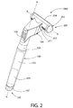
最初に図1及び2を同時に参照すると、本発明の実施形態によるシェービング装置1000が示される。シェービング装置1000は、通常、ハンドル部100(これ以降、「ハンドル」と称される)及びヘッド部200(これ以降、「ヘッド」と称される)を備える。ハンドル100は、所望の皮膚の領域を剃毛するのに必要な様式でシェービング装置1000を快適にかつしっかりと把持して操作するために必要な構造を有するシェービング装置1000を使用者に提供する。例示的な実施形態において、ハンドル100は、把持するための略円筒状部104と、ヘッド200をハンドル100に連結するための取付部材106とを備える細長い構造である。一実施形態において、ハンドル100は、70mm〜140mmの長さを有する。
Referring initially to FIGS. 1 and 2 simultaneously, a
円筒状部104は、縦軸A−Aに沿って延在する。一実施形態において、ハンドル100の円筒状部104は、10mm〜25mmの直径を有する。取付部材106は、円筒状部104の遠位端に連結され、縦軸A−Aから半径方向に離れて傾斜した様式で延在する。取付部材106の遠位端は、ヘッド200がそこに連結され得るように構成される。ヘッド200は、永久的、半永久的、または着脱可能な様式で取付部材106に連結されてもよい。例えば、ヘッド200は、取付部材106と一体化して形成されてもよく、それによって永久的な連結を形成する。代替として、ヘッド200は、超音波溶接、熱溶接、はんだ付け、接着、またはそれらの組み合わせによって取付部材106に連結されてもよく、それによって半永久的な連結を形成する。さらに他の実施形態において、ヘッド200は、スナップフィット接続、機械的インターロック、締り嵌め、ねじ山接続、タブ/スロットインターロック、ラッチ、またはそれらの組み合わせによって取付部材106に連結されてもよく、それによって着脱可能な連結を形成する。当然、他の連結技術が企図され、本発明の範囲内であるとみなされる。さらに、本発明の特定の他の実施形態において、取付部材106は、あまり重要でなくてもよいか、または全体的に省略されてもよく、そうすることで、ヘッド200が、上述のまたは別様に企図される様式のいずれかにおいて円筒状部104に直接連結される。
The
当業者には理解されるように、電池電動式シェービング装置の最小のサイズ及び重量に到達するという試みは、必要とされる期間、必要とされる効果をもたらすためにモータに効果的に電力供給できる電池のサイズの限界で終わる場合がある。電動要素の作業負荷の軽減を達成し、その動作をより効率的にする時、電源、すなわち単一または複数の電池にも課せられる全体的なサイズの限界を低減することができる。以下に提示されるように、本発明のいくつかの実施形態によるシェービングヘッドは、そのはさみのようなシェービング動作が小さなモータによって実現され得、したがって現在既知の構成と比較して相応に小さな電源によって電力供給され得るように設計される。 As will be appreciated by those skilled in the art, an attempt to reach the minimum size and weight of a battery powered shaving device effectively powers the motor to provide the required effect for the required period. It can end up with battery size limitations. When achieving a reduction in the workload of the power element and making its operation more efficient, the overall size limit imposed on the power source, ie, the single or multiple batteries, can be reduced. As will be presented below, a shaving head according to some embodiments of the present invention can have its shaving action, such as scissors, realized by a small motor, and therefore by a correspondingly small power supply compared to currently known configurations. Designed to be powered.
例示的な実施形態において、ハンドル100はまた、ヘッド200の回転カッター300を回転させるモータ400に電力供給する電源105(破線で示される)の水密筐体としても機能する(その詳細については後により詳細に論じる)。当然、他の実施形態において、電源105は、シェービング装置1000内の他の場所に収容されてもよい。例えば、特定の代替の実施形態において、電源105は、全体的にまたは少なくとも部分的にヘッド200の中に収容されてもよい。電源105は、当該技術分野で既知のように、1つ以上の電池の形態であってもよい。例示的な実施形態において、電池は、ハンドル100の縦軸A−A上に配置され、それにそって延在する。当然、必要に応じて、モータ400に電力供給するために代替の種類の電源が用いられてもよい。シェービング装置1000に用いられる電源105の正確な種類は、モータ400の電源要件に依存し、したがって、特許請求の範囲内に別途具体的に記載されない限り、本発明を制限するとみなされるべきではない。
In the exemplary embodiment, the
電源105は、交換可能または永久的であり得る。着脱可能な電源105が使用される実施形態において、電源105は、交換または充電のためにハンドル100から取り外すことができる1つ以上の電源であってもよい。そのような実施形態において、ハンドル100は、電源105が位置するハンドル100のチャンバにアクセスするために必要な構造をさらに備える。例示的な実施形態において、着脱可能なキャップ107が、ハンドル100の近位端101に提供される。着脱可能なキャップ107は、流体密封境界を形成するねじ山接続、締り嵌めアセンブリ、または他の接続技術によってハンドル100の円筒状部104に連結することができ、そうすることで、水は電源105が位置するチャンバ内に進入することができない。代替の実施形態において、電源105が配置されたハンドル100の内部チャンバへのアクセスは、ヒンジ付パネル、ラッチ、着脱可能パネル、または当業者に既知であるような任意の他の構造によって達成することができる。
The
永久(または着脱不可能な)電池が使用される実施形態において、ハンドル100は、電源105を再充電するために電源コードを電気的に連結することができる電気ポートをさらに備えてもよい。水または他の流体が電気ポートに進入するのを防ぐために、電気ポートは、着脱可能なアクセスパネルの後に提供されてもよいか、または電気ポートを封入するキャップ/栓とともに提供されてもよい。
In embodiments where a permanent (or non-removable) battery is used, the
さらに他の実施形態において、電源は、壁ソケットまたは他の電気源からの電気供給のように、ヘッド200のハンドル100の外側にあってもよい。そのような一実施形態において、ハンドル100またはヘッド200は、電源プラグの第1の端部等の、外部電源に動作可能に連結するためのポートまたは他の機構を含んでもよい。
In yet other embodiments, the power source may be external to the
例示的な実施形態において、モータ400は、シェービング装置1000のヘッド200内、より具体的には回転カッター300の中央空洞内に位置する。しかしながら、特定の他の実施形態において、モータ400は、全体的にまたは部分的にハンドル1000の中に位置してもよい。そのような実施形態において、モータ400のドライブシャフトは、歯車、滑車、ベルト、及び回転運動を伝達することが可能な他の連結器によって回転カッター400に動作可能に連結されてもよい。
In the exemplary embodiment,
モータ400の通電を手動で制御するために、スイッチ108がハンドル100上に提供される。スイッチ108は、手動の摺動スイッチとして例示されているが、スイッチは、当業者に既知であるような任意の種類の手動または自動スイッチであってもよい。スイッチ108に加えて、モータ400の性能特性を制御するための制御回路も、必要に応じてハンドル100のチャンバ内に位置してもよい。
A
前述のように、ヘッド200は、ハンドル100の取付部材106の遠位端に連結される。ヘッド200は、略細長形状を有し、縦軸B−Bに沿って延在する。後に詳述するように、ヘッド200の縦軸B−Bもまた、回転カッター300の回転軸としての役割を果たす。例示的な実施形態において、ヘッド200がハンドル100に連結されると、ヘッド200は、ハンドル100に実質的に垂直である。より具体的には、ヘッド200がハンドル100に連結されると、ヘッド200の縦軸B−Bは、ハンドル100の縦軸A−Aに実質的に垂直である。さらに、シェービング装置1000が略T形状を有するように、ハンドル200は、ヘッド200の中心に連結される。
As described above, the
ヘッド200及びハンドル100の潜在的な構造的表示が1つだけ例示されているということに留意されたい。しかしながら、ヘッド200及びハンドル100は、他の実施形態において多様な形状及びサイズを取ることができることを理解されたい。例えば、特定の実施形態において、ヘッド200は、ハンドル100の要素とは異なるそのような要素でなくてもよい。例えば、ヘッド200は、単純に、使用者の皮膚に接触することができるハンドル100の遠位部または側部であってもよい。一実施形態において、ヘッド200及びハンドル200の組み合わせは、これらに限定されないが、円筒状構造、球根状構造、または卵形構造を形成することができる。
Note that only one potential structural representation of the
例示的な実施形態において、ヘッド200は、ヘッド200の筒状筐体202から延在する締結要素201の使用を通してハンドル100に連結される。締結要素201は、ヘッド200の正面204の反対側のヘッド200の裏面203から延在する平板であり、後に記載するように、正面204は、ヘッド200の作用面/切断面であるとみなすことができる。締結要素201は、ハンドル100の取付部材106上の対応する構造と嵌合により係合する。当然、締結要素201は、ピン、タング、ソケット、または他の連結もしくは嵌合構造を含む多様な構造を取ることができる。特定の他の実施形態において、ヘッド200の配向がハンドル100に対して枢動され得るように、ヘッド200は、ハンドル100に枢動可能に接続されてもよい。別の考え方として、そのような配置において、ハンドル100の縦軸A−Aに対する正確な経路に沿ってヘッド200の縦軸B−Bを移動させることができるようにヘッド200を枢動させることができる。そのような枢動運動は、様々な様式で達成することができる。一実施形態において、ヘッド200の締結要素201は、ヘッド200を取付部材106に枢動可能に連結する。別の実施形態において、取付部材106は、ハンドル100の円筒状部104に枢動可能に連結される。ヘッド200をハンドル100に枢動可能に連結することにより、シェービング装置1000の使用中に、ヘッド200の正面204をハンドル100に対する任意の所望の位置に枢動させることができ、それによって、使用者にはるかに高い柔軟性と、複雑な輪郭及び/または届きにくい場所を剃毛する能力とを与える。
In the exemplary embodiment,
ヘッド200をハンドル100に枢動可能に連結することにより、ハンドルの縦軸A−Aの周囲の限られた角度範囲内でヘッド200を旋回させる(すなわち、揺動させる)ことができる。そのような枢動可能な回転は、シェービング装置1000の使用中に、ヘッド200が、運動面及び使用者の皮膚に対してその位置を調整することを可能にする。そのような枢動運動は、装着機構の機械的手段及び/またはハンドル100及び/またはヘッド200によって所望の回転角度に制限することができる。特定の実施形態において、回転角度は、180度、90度、60度、30度、または30度未満であってもよい。
By pivotally connecting the
前述のように、特定の実施形態において、ヘッド200は、ハンドル100に着脱可能に連結される。そのような実施形態において、ヘッド200は、ハンドル100のための「詰め替え用」ヘッドとして販売されてもよい。前述のように(また、図4及び9に関連して後により詳細に論じるように)、特定の実施形態において、モータ400は、ヘッド200の回転カッター300内に位置してもよい。さらに、上で論じたように、電源105は、ハンドル100内に位置する。よって、使用中にモータ400に電力供給するために、連続的な電気接続が、ハンドル100内の電源105からヘッド200内のモータ400まで延在する。したがって、ヘッド200がハンドル100に着脱可能に連結され、モータがヘッド200内に位置する実施形態において、ヘッド200がハンドル100に連結された時に互いと電気的に連結するハンドル100及びヘッド200の両方の適切な位置に電気インターフェースコネクタ(すなわち、接点)が提供され、それによって電気回路を完成させる。
As described above, in certain embodiments, the
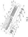
次に、図3〜4を同時に参照すると、ヘッド100は、通常、筒状筐体202、固定刃350、モータ400、及び回転カッター300、第1の端部キャップ205、第2の端部キャップ206、第1の環状軸受250、第2の環状軸受251、直列型ドライブトレイン600、連結要素700、第1の回転カッター端部キャップ480、及び第2の回転カッター端部キャップ490を備える。ヘッド200が組み立てられると(図5に関連して後に論じる)、ヘッド200は、縦軸B−Bに沿って延在する小型構造である。
Next, referring to FIGS. 3 to 4 at the same time, the
ヘッド100は、縦軸B−Bに沿って第1の端部207から第2の端部208まで延在し、それによってヘッド200の最大縦幅WLを画定する。例示的な実施形態において、ヘッド200の最大縦幅WLは、60mm以下である。別の例示的な実施形態において、ヘッド200の最大縦幅WLは、40mm〜60mmである。さらに別の実施形態において、ヘッド200の最大縦幅WLは、45mm〜55mmである。ヘッドは、ヘッド200のリード面209からヘッド200のトレイル面210まで延在する最大横幅WTをさらに備える。例示的な実施形態において、ヘッド200の最大横幅WTは、25mm以下である。別の実施形態において、ヘッド200の最大横幅WTは、10mm〜25mmである。さらに別の実施形態において、ヘッド200の最大横幅WTは、10mm〜20mmである。さらに別の実施形態において、ヘッド200の最大横幅WTは、10mm〜15mmである。
The
例示的な実施形態において、ヘッド200の最大縦幅WL及びヘッド200の最大横幅WTの両方が、ヘッド200の正面204上で測定される。シェービング装置1000が回転カッター300と固定刃350との間で毛をせん断することができるように(後により詳細に論じるように)使用者の皮膚と接触させられるヘッド200の面であるという点において、ヘッド200の正面204は、ヘッド200の作用面である。代替の実施形態において、ヘッド200の最大縦幅WL及び/またはヘッド200の最大横幅WTは、ヘッド200の他の構成要素によって(またはその上の他の位置で)決定されてもよい。
In the exemplary embodiment, both the maximum vertical width WL of the
筒状筐体202は、回転カッター300、モータ400、直列型ドライブトレイン600、第1の環状軸受250、第2の環状軸受251、連結要素700、第1の回転カッター端部キャップ480、及び第2の回転カッター端部キャップ490を収容するための内部空洞211を備える。筒状筐体202の内部空洞211は、前述のように(また、後により詳細に論じるように)回転する上記構成要素を受容して取り囲むことが可能であるような寸法である。
The
筒状筐体202はまた、筒状筐体202の内部空洞211内への通路を形成する細長いスロット214を備える。回転カッター300の一部は、細長いスロット214を介して露出される。図9及び9Aに関連して後により詳細に論じるように、細長いスロット214は、剛毛が筒状筐体202に進入し、回転カッター300と固定刃350との間でせん断されることを可能にする。例示的な実施形態において、細長いスロット214は、筒状筐体202の縦方向の長さ全体に連続的かつ不断な様式で延在する。しかしながら、特定の代替の実施形態において、細長いスロット214は、筒状筐体202の縦方向の長さ全体に延在しなくてもよく、代わりに、本質的に分割されていてもよく、かつ/または非連続的であってもよい。
The
細長いスロット214は、固定刃350の切断エッジ351及び筒状筐体202の対向するエッジ215によって画定される。例示的な実施形態において、集合的にコームガード217を形成する複数の軸方向に離間したフィンガー216によって形成される、筒状筐体202の対向するエッジ215は。コームガード217は、筒状筐体202の一部であり、せん断のために回転カッター300及び固定刃350により効率的に剛毛を供給するように、切断動作中に使用者の皮膚に押し付けることができ、それと同時に、皮膚が傷つかないようにまたは切れないように使用者を保護する。この目的をさらに達成するために、コームガード217のフィンガー216の外面は、使用者の皮膚上でのヘッド200の動きを容易にするように、任意選択的に平坦であるかまたは丸みを帯びている。特定の他の実施形態において、対向するエッジ215は、フィンガー216を省略することによってコームガード217が排除された連続的なエッジであってもよい。
The
特定の実施形態において、筒状筐体202、第1の端部キャップ205、及び/または第2の端部キャップ206は、筒状筐体202の内部空洞211から及び/または回転カッター300の中央空洞304からせん断された剛毛の屑を除去できるように、1つ以上の開放部を備えてもよい。最後に、図3に見て取れるように、締結要素201は、筒状筐体202の一部でもある。ヘッド200の筐体202は、筒状の形状として例示されているが、本発明は全ての実施形態においてそのように限定されるものではない。特定の他の実施形態において、筐体202は、他の構造配置及び形状を取ってもよい。
In certain embodiments, the
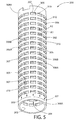
次に図4、5、9、及び9Aを参照すると、回転カッター300は、中空円筒構成である。回転カッター300は、外面302及び内面303を有する中空カッター管301を備える。回転カッター300は、例示的な実施形態において、回転カッター300の回転軸R−Rでもある中心軸の周囲にカッター管301の内面303によって形成される中央空洞304を備える。回転カッター300の内部空洞304は、モータ400及び直列型ドライブトレイン600を受容するような寸法である。
Referring now to FIGS. 4, 5, 9, and 9A, the
回転カッター300は、カッター管301の外面302に形成された複数の開口部305をさらに備える。カッター管301の外面302は、回転カッター300の回転軸と同心の基準シリンダ(図9Aの円C−Cによって描写される)を画定し、直径D2を有する。例示的な実施形態において、直径D2は、20mm以下である。別の実施形態において、直径D2は、6mm〜20mmである。
The
それぞれの開口部305は、閉形状を有する切断エッジ307によって画定される。切断管301の切断エッジ307は、特定の実施形態において、カッター管301の外面302と開口部305を取り囲む放射状の壁310との交差によって形成されてもよい。切断エッジ307は、特定の実施形態において、カッター管301の外面302と実質的に同一平面に存在してもよいか、またはカッター管301の外面302と内面303との間に介在してもよい。特定の実施形態において、カッター管301はまた、カッター管301のエッジの近傍に位置し得るもの等(図示せず)の、開形状を有する切断エッジ307によって画定される1つ以上の開口部305を備えてもよい。
Each
回転カッター300が、ヘッド200内に取り付けられ、モータ400によって回転させられると、使用者の毛が開口部305内に延出し、シェービング動作の間に切断エッジ307と固定刃350の切断エッジ351との間でせん断される。後に図10〜18を参照してより詳細に論じられるように、複数の開口部305の各々は、せん断部330及び非せん断部331を有するとみなすことができる。
When the
回転カッター300の切断エッジ307を形成するための開口部305の使用は、突出した細長い隆起部とは対照的に、シェービング装置1000の安全性を高めることができる。切断エッジ307を形成するために開口部305を用いることは、皮膚が回転カッター300の基準円C−Cにほぼ完全に触れないようにすることにより安全性の要素を加え(図9Aを参照のこと)、そうすることによって、皮膚のひだが挟まって傷つけられる確率を低下させる。
The use of the
例示的な実施形態において、開口部305の各々が外面302から内面303までカッター管301を通って延在し、それによってカッター管301を通る複数の半径方向通路を形成する。しかしながら、特定の他の実施形態において、開口部305は、カッター管301の厚み全体を通り抜けない、外面302における凹部の形態であってもよく、そうすることで開口部305が「ブラインド」となる。
In the exemplary embodiment, each of the
例示されるように、カッター管301は、開口部305を画定する格子構造306を備える。格子構造306は、交差する様式で配置される複数の軸方向部材306A及び複数の周方向部材306Bを備える。例示的な実施形態において、複数の軸方向部材306Aは、回転軸R−Rに平行なカッター管301の外面302上の基準線に対して実質的に平行に延在し、複数の周方向部材306Bは、そのような基準線に実質的に垂直に延在する。しかしながら、他の実施形態において、複数の軸方向部材306Aは、そのような基準線に対して傾斜していてもよく、したがって周方向の延在する構成要素を有する。同様に、特定の実施形態において、しかしながら、複数の周方向部材306Bは、そのような基準線に対して傾斜していてもよく、したがって、軸方向の延在する構成要素を有する。そのような場合、格子構造306のそのような部材は、その主体となる延在する構成要素に基づいて、「周方向」または「軸方向」として分類されてもよい。45度で配置されるこれらの部材の場合、「周方向」または「軸方向」のいずれかとして部材を分類することができる。
As illustrated,
例示的な実施形態において、格子構造306は、開口部305を有しない軸方向の末端部308A、308Bを除くカッター管301の外周全体を連続的な様式で覆う。特定の他の実施形態において、格子構造308は、開口部305を有しないカッター管301の部分によって分割または分離されてもよい(開口部305を有しないこれらの部分が潤滑要素を収容するために使用される、図22に示される構造等)。
In the exemplary embodiment, the
例示的な実施形態において、開口部305は、長方形の形状である。他の実施形態において、開口部305は、円、三角、四角、長楕円、五角形、六角形、または閉形状を有する他の多角形もしくは不規則な形状であってもよい。例示的な実施形態における開口部305の全ては、同じサイズ及び形状である。しかしながら、他の実施形態において、開口部305は、互いに異なる複数の形状及び/またはサイズの開口部を備えてもよい。特定の実施形態において、開口部305の各々は、使用者の少なくとも1本の毛(15〜180ミクロンの範囲の直径を有し得る)を収容できるようなサイズ及び形状であることが好ましい。
In the exemplary embodiment, opening 305 is rectangular in shape. In other embodiments, the
例示的な実施形態における開口部305は、長軸A1及び短軸A2を備えるように細長い。長軸A1は短軸A2よりも長い。特定の実施形態において、A1/A2の比は、10:1〜2:1の範囲であってもよい。開口部305の長軸A1は周方向に延在し、短軸は軸方向に延在する。結果として、開口部305の各々は、周方向に細長いとみなすことができる。特定の他の実施形態において、図10及び11に示されるもののように、開口部305は、軸方向に細長くてもよい。これらの実施形態及び他のそのような実施形態において、長軸A1は軸方向に延在し、短軸は周方向に延在する。
The
特定の実施形態において、開口部305は、カッター管301の非常に大きな累積表面積(外面302の全体的な表面積と比較して)を画定するため、カッター管301は、筒状スクリーンであるとみなすことができる。一実施形態において、開口部305は、カッター管301の外面302の全表面積の0.5倍以上の累積表面積を有してもよい。別の実施形態において、開口部305は、カッター管301の外面302の全表面積の0.6倍以上の累積表面積を有してもよい。さらに別の実施形態において、開口部305は、カッター管301の外面302の全表面積の0.75倍以上の累積表面積を有してもよい。なおも別の実施形態において、開口部305は、カッター管301の外面302の全表面積の開口部305は、カッター管301の外面302の全表面積の0.8倍以上の累積表面積を有してもよい。
In certain embodiments, the
例示的な実施形態において、開口部305は、開口部305の複数の列309を含むパターンで提供される。列309は、例示的な実施形態において、回転カッター300の回転軸R−Rに実質的に平行に延在する軸方向の列である。特定の他の実施形態において、列309は、カッター管301の外面302の周囲に部分的ならせんを形成するように回転軸R−Rに対して傾斜していてもよい。開口部305は、多様な形状及びサイズで作製されてもよく、多様なパターンでカッター管301に適用されてもよい。これらの代替例のいくつかについて、図10〜18を参照してより詳細に論じる。さらに、図13〜18を参照してより詳細に論じられるように、開口部305の形状、サイズ、及びパターンは、回転カッター300の切断エッジ307と固定刃350の切断エッジ351との間でせん断される毛の数が正確に制御され、例えば、モータ400の低トルク要件及び回転カッター300が供される力の均衡等の目標を達成するように選択されてもよい。
In the exemplary embodiment,
カッター管301は、特定の実施形態において、0.1mm〜2.5mmの範囲の厚みを有してもよい。カッター管301は、金属または他の好適な材料で形成されてもよい。カッター管301は、一実施形態において、カッター管301は、丸めて成形し、縁部を一緒に接続した金属板から形成される。開口部305は、レーザー切断、パンチング、化学エッチング、またはそれらの組み合わせ等のプロセスを用いてカッター管301を形成するために丸める前または後のいずれかに、金属板において形成されてもよい。特定の一実施形態において、レーザー切断は加工される金属板に残留応力をもたらさない可能性があるという点で、レーザー切断が好ましい場合がある。したがって、カッター管301を形成するレーザー切断された金属板は、変形することなくその所望の形状を維持する。他の実施形態において、カッター管301は、適切な材料を用いて、機械加工、射出成形、鋳造、及びそれらの組み合わせを含む他の材料及び他の技術によって形成されてもよい。一実施形態において、レーザー切断等によって開口部305が形成される管素材が使用されてもよい。
The
一実施形態において、カッター管301の外面302は、研磨仕上げを有することができる。外面302はまた、そこに塗布された低摩擦コーティング及びまたは/高強度コーティングを有してもよい。
In one embodiment, the
次に図3〜4及び6〜9Aを参照して、特定の構成要素及びその間の構造的協働部を含むヘッド200のアセンブリについて次に説明する。動作のためにヘッド200が組み立てられると、固定刃350が回転カッター300に隣接して取り付けられる。一実施形態において、固定刃350は、固定刃350の切断エッジ351が回転カッター300の回転軸R−R(例示的な実施形態において、ヘッド200の縦軸B−Bと一致する)に実質的に平行に延在するように、回転カッター300に隣接して取り付けられる。例示的な実施形態において、そのような隣接する位置付けは、固定刃350の切断エッジ351が、スロット314内に延在し、かつ回転カッター300のカッター管301の外面302(切断エッジ307を含む)に隣接するように、固定刃350を筒状筐体202に取り付けることによって達成される。
Referring now to FIGS. 3-4 and 6-9A, the assembly of the
一実施形態において、固定刃350は、回転カッター300の回転軸B−Bからのその半径方向距離に関連して「固定」される。本明細書で使用される場合、「固定される」という用語は、固定刃350にわずかな振動が与えられてもよく、かつ/または固定刃350が、回転軸B−Bに実質的に平行に、かつそこからその半径方向距離に切断エッジ351を維持する様式で軸方向に若干平行移動することができる実施形態を包含することが意図される。特定の他の実施形態において、固定刃350は、完全に静止し、回転軸R−R及び筒状筐体202の両方に対して不動であってもよい。
In one embodiment, the fixed
固定刃350の切断エッジ351は、特定の実施形態において、回転カッター300の全長に沿って延在してもよい。固定刃350の切断エッジ351は、回転カッター300の切断エッジ307に十分に近接しているため、モータ400が起動され、ヘッド200の正面204が皮膚に押し当てられ、皮膚に沿って移動させられた時に、切断動作の間にカッター管301の切断エッジ307と協働してその間の剛毛をせん断する際に効果的である。一実施形態において、公差は、切断間隙325の形態で、切断動作の間に固定刃350の切断エッジ351と回転カッター300のカッター管301の切断エッジ307との間に存在するように設計される。
The
使用のためにヘッド200が組み立てられると、回転軸R−Rを中心に回転カッター300を回転させることができるように、モータ400は、回転カッター300の中央空洞304内に位置付けられ、そこに動作可能に連結される。本発明のいくつかの実施形態によれば、モータ400は、電気モータであり、前述のようにハンドル100内に収容された電源105に電気的に連結される。モータ400は、交流または直流によって電力供給されてもよい。特定の実施形態において、モータ400は、ブラシレス型モータもしくはブラシ付きモータ種であってもよく、かつ/またはコア付きもしくはコアレス型モータであってもよい。例えば、ブラシレスDC電気モータは、直流電流によって電気的に電力供給され、ブラシ付きモータに存在するようなブラシに基づく機械的整流システムの代わりに、電気的に制御された整流システム(「コントローラ」)を有する同期電気モータである。本明細書において、「モータ」という用語は、要求される出力/トルク及び速度で電力を機械運動に変換する部品のアセンブリを包含することを意図することに留意されたい。
When the
特定の実施形態において省略されてもよい直列型ドライブトレイン600が、電気モータ400の出力速度及びトルクを制御するために提供されてもよい。直列型ドライブトレイン600は、モータ400と直列に配置されるギアボックス等の駆動伝達デバイスであり、すなわち、モータ400のドライブシャフト401である。直列型ドライブトレイン600の出力シャフト601は、同じ回転軸を共有してもよい。直列型ドライブトレイン600は、遊星ギアまたはプラネタリギアを含んでもよい。そのような直列型ギアシステムは、選択されるモータ及び所望の端末回転出力に依存して、モータのトルクを増加し、かつその速度を減速するようにまたはその反対であるように選択することができる。
A
連結要素700は、電気モータ400の回転出力が連結要素700によって回転カッター300のカッター管301に伝達されるように、電気モータ400及び回転カッター300のカッター管301に(直接的または間接的に)連結される。例示的な実施形態において、連結要素700は、直列型ドライブトレイン600の出力シャフト601(同様にモータ400に動作可能に連結される)、及び回転カッター300のカッター管301の末端部308Bに連結される。特定の他の実施形態において、連結要素700は、(例えば、ドライブシャフト401または他の回転出力によって)電気モータ400に直接的に連結されてもよい。さらに他の実施形態において、さらなる介在する駆動伝達デバイスが用いられてもよい。
The
連結要素700は、回転カッター300に対して回転不能である。さらに、連結要素700は、連結要素700がカッター管301に半径方向力(外向きの半径方向力等)をかけないように回転カッター300のカッター管301に係合する。カッター管601に半径方向力がかかると、カッター管301の変形(たとえ若干であっても)をもたらし得る。たとえ若干の変形であっても、高速回転中に不均衡なカッター管301を生じさせる可能性があり、シェービングプロセスの間に皮膚及び固定刃350との不均等な接触を引き起こす場合がある。係合プロセスの間またはモータ400による回転カッター300の回転中に半径方向力がカッター管301にかからないため、連結要素700は、変形の可能性なしにモータ400の回転出力を回転カッター300に伝達する構造を提供する。
The connecting
連結要素700は、例示的な実施形態において、ハブ構成要素701と、ハブ構成要素701から半径方向に延在する複数のスポーク構成要素702とを備える。スポーク構成要素702は、周方向に等間隔の様式でハブ構成要素701の周囲に配置される。スポーク構成要素702の各々は、ハブ構成要素701からの距離とともに増加する周方向幅を有する。3つのスポーク構成要素702が例示されているが、他の実施形態において、1つを含む任意の数のスポーク構成要素702が用いられてもよい。さらに、スポーク構成要素702の各々は、一定の周方向幅を有してもよいか、または単純な突起の形態であってもよい。
The
ハブ構成要素701は、直列型ドライブトレイン600の出力シャフト601を受容する中央開口部703を備える。出力シャフト601が連結要素700に係合して回転できるように、ハブ構成要素701の中央開口部703は、出力シャフト601と同様に非環状である。連結要素700のスポーク構成要素702は、カッター管301に連結される。カッター管301は、例示的な実施形態においてカッター管301の縁部に形成されるスロットの形態であり、かつ連結要素700のスポーク構成要素702と嵌合する、複数の特徴部312を備える。スポーク構成要素702の各々は、特徴部312のうちの1つと嵌合する。スロットの各々は、回転軸R−Rからの距離とともに増加し、かつそれと嵌合するスポーク構成要素702の周方向幅に対応する周方向幅を有する。スポーク構成要素702に嵌合するカッター管301の特徴部312はスロットとして例示されているが、特定の他の実施形態において、特徴部は、内部開口部、スポーク構成要素702と係合するカラー、またはスポーク構成要素702と係合する突出した構造を備えてもよい。
The
連結要素700は、特定の実施形態において、アセンブリの同心度要件を分離し得る。カッター管301の回転軸R−R及び直列型ドライブトレイン600の出力シャフト601の回転軸は、特定の距離において若干分離されていても(すなわち、非同心であっても)よい。連結要素700を介して伝達される回転運動は、カッター管301と出力シャフト601との間の完全な同心度に依存しないか、またはをそれを必要としない。換言すると、回転軸は、回転軸R−Rと若干整列されていなくてもよく、それによって製造及びアセンブリを単純化し、ロバストなソリューションを提供する。
The
モータ400、直列型ドライブトレイン600、及び連結要素700が組み立てられると、第1及び第2の回転カッター端部キャップ480、490がそこに連結される。第1の回転カッター端部キャップ480は、カッター管301の第1の端部に嵌り、環状本体481及び中空ポスト482を備える。例示的な実施形態においてワイヤである電気コネクタ501A、501Bが、そこを通過してモータ400の接触点402に連結することができるように、軸方向通路は、第1の回転カッター端部キャップ480を通って形成される。第1の回転カッター端部キャップ480は、モータ400に回転不能に連結され、動作中に回転軸R−Rを中心に回転しない。第1の環状軸受250は、第1の回転カッター端部キャップ480の中空ポスト482上を摺動して回転カッター300の内部空洞304内に入る。第1の環状軸受250の外面は、カッター管301の内面303に係合し、第1の環状軸受250の内面は、第1の回転カッター端部キャップ480の中空ポスト482に係合する。そのため、第1の環状軸受250の外側部分が、第1の環状軸受250の内側部分に対して回転することができる。
Once the
第2の回転カッター端部キャップ490は、カッター管301の第2の端部内に嵌り、環状本体491及び中空ポスト492を備える。第2の回転カッター端部キャップ490は、直列型ドライブトレイン600の出力シャフト601を受容して係合し、連結要素700に係合する。第2の回転カッター端部キャップ490は、回転カッター300、連結要素700、及び直列型ドライブトレイン600の出力シャフト601とともに回転軸R−Rを中心に回転する。第2の環状軸受251は、第2の回転カッター端部キャップ490の中空ポスト492の上を摺動させられるが、カッター管301の外側に留まる。第2の環状軸受251の内面は、第2の回転カッター端部キャップ490の中空ポスト492に係合する。
The second rotating
上記アセンブリは、次いで筐体202の内部空洞211内に取り付けられる。具体的には、第1の回転カッター端部キャップ480の中空ポスト482が、第1の端部キャップ205に対して回転不能であるようにそこに係合する。第2の環状軸受251の外面も同様に、第2の端部キャップ206に対して回転不能であるようにそこに係合される。しかしながら、モータ400による回転カッター300の回転は、第2の環状軸受251の内側部分及び第1の環状軸受250の外側部分に許容される自由回転によって可能である。
The assembly is then installed in the
例示的な実施形態において、環状軸受250、252の両方が玉軸受型である。しかしながら、本発明の文脈において使用され得る軸受の種類は、これらに限定されないが、こすれ面及び典型的には潤滑剤(硬質金属または約0.05の摩擦係数を有するPTFE等のプラスチックの使用によって実現される)に基づく摺動もしくは滑り軸受として知られるプレーン軸受;ボールもしくはローラー(シリンダ)及び摩擦リングに基づく玉軸受としても知られる転がり要素軸受;または磁気軸受及びたわみ軸受を含む。「環状」という用語は、特定の実施形態において、部分的な環状を含んでもよい。
In the exemplary embodiment, both
本明細書に提示される内部電動シェービングヘッドの種々の部品は、明確性及び定義のために個別の分離した部品として表されていることを理解されたい。しかしながら、本明細書に記載される部品のうちのいくつかは、他の部品との結合体として製造され、単一の連続ユニットを形成してもよく、単一の連続ユニットとして本明細書に記載されるいくつかの部品は、複数の副部品によって形成されてもよい。 It should be understood that the various parts of the internal electric shaving head presented herein are represented as separate separate parts for clarity and definition. However, some of the components described herein may be manufactured as a combination with other components to form a single continuous unit, which is herein described as a single continuous unit. Some parts described may be formed by a plurality of subparts.
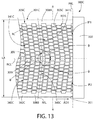
次に図10〜18を参照すると、開口部305A〜Eの代替パターンを有する複数の回転カッター300A〜Eが示される。前述のように、回転カッター300A〜Eが、図1〜9の回転カッター300の代わりに使用されてもよい。開口部305A〜Bのサイズ、形状、及びパターンを除いて、回転カッター300A〜Eは、回転カッター300と同一であってもよい。したがって、回転カッター300に関連する上記議論はそれぞれの例示的な実施形態に適用可能であるという理解の下、回転カッター300A〜Eに関する以下の議論はこれらの新しい特徴に限定される。したがって、適切なアルファベット接尾辞「A〜E」を追加して、同様の参照番号が同様の要素を特定するために使用される。さらに、シェービング装置1000の動作及び性能の特定の利益をもたらし得る開口部のパターン及び開口部の形状の作製とともに、開口部305A〜Eのさらなる詳細が以下に論じられる。最後に、シェービング装置1000に用いられる場合、回転カッター305B〜Eは3Dシリンダまたは管の形態を取るという理解の下、議論を簡単にするために、回転カッター305B〜Eは、簡素化された2D略図形態で示されることに留意されたい。
10-18, a plurality of
最初に図10を参照すると、第1の代替パターンに配置された開口部307Aを含むカッター管301Aを備える回転カッター300Aが例示される。カッター管301Aは、複数の軸方向に細長いV字型の開口部305Aを備える。開口部305Aの各々は、第1の軸方向の末端部308A(開口部が存在しない)から第2の軸方向の末端部308B(同様に開口部が存在しない)まで延在する。開口部305Aの各々は、閉形状を画定する切断エッジ307Aによって画定される。切断エッジ307Aの各々は、せん断部330A及び非せん断部331Aを備える。回転カッター300Aが回転軸R−Rを中心に角度方向AD1に回転させられる例示的な実施形態において、せん断部330Aは、Y点からZ点まで延在し、谷部頂点VAを含み、非せん断部331Aは、Z点からY点まで延在し、山部頂点PAを含む。
Referring initially to FIG. 10, a
本明細書で使用される場合、回転カッターの開口部によって画定される切断エッジの「せん断部」は、シェービングプロセスの間、回転カッターの回転中に固定刃の切断エッジと協働して毛に接触してせん断することが可能な回転カッターの切断エッジの部分である。その一方で、本明細書で使用される場合、回転カッターの開口部によって画定される切断エッジの「非せん断部」は、シェービングプロセスの間、回転カッターの回転中に固定刃の切断エッジと協働して毛に接触してせん断することが不可能な回転カッターの切断エッジの部分である。任意の所与の開口部について、「せん断部」とみなすことができる切断エッジの部分及び「非せん断部」とみなすことができる切断エッジの部分は、回転軸を中心とする回転カッターの回転の角度方向に依存することを理解されたい。したがって、開口部の切断エッジの部分は、回転カッターが回転軸を中心に第1の角度方向に回転させられる場合に「せん断部」とみなされてもよく、開口部の切断エッジの同じ部分は、回転カッターが回転軸を中心に第2の角度方向(第1の角度方向の反対)に回転させられる場合に「非せん断部」とみなされてもよい。 As used herein, the “shear portion” of the cutting edge defined by the opening of the rotary cutter is the hair that cooperates with the cutting edge of the fixed blade during the rotation of the rotary cutter during the shaving process. It is the part of the cutting edge of the rotary cutter that can be contacted and sheared. On the other hand, as used herein, the “non-shear portion” of the cutting edge defined by the opening of the rotary cutter cooperates with the cutting edge of the fixed blade during the rotation of the rotary cutter during the shaving process. It is the part of the cutting edge of the rotary cutter that cannot work and contact the hair to shear. For any given opening, the portion of the cutting edge that can be considered a “shear” and the portion of the cutting edge that can be considered a “non-shear” is the rotation of the rotating cutter about the axis of rotation. It should be understood that it depends on the angular orientation. Thus, the cut edge portion of the opening may be considered a “shear portion” when the rotary cutter is rotated in the first angular direction about the axis of rotation, and the same portion of the cut edge of the opening is When the rotary cutter is rotated about the rotation axis in the second angular direction (opposite to the first angular direction), it may be regarded as a “non-shear portion”.
図10の実施形態に戻ると、開口部305Aの各々につき、せん断部330Aは、合流して谷部頂点VAを形成する第1の傾斜部分332A及び第2の傾斜部分333Aを備える。第1及び第2の傾斜部分332A、333Aの各々は、カッター管301Aの外面302A(回転カッター300Aの外面でもある)上の、回転軸R−Rに平行な基準線RLと鋭角βを形成する。開口部305Aの各々につき、非せん断部331Aは、第1の周方向部分334A及び第2の周方向部分335Aを備え、第1及び第2の周方向部分334A、335Aの各々が基準線RLと直交する。非せん断部はまた、合流して山部頂点PAを形成する第1の傾斜部分336A及び第2の傾斜部分337Aを備える。第1及び第2の傾斜部分336A、337Aの各々は、基準線RLと鋭角αを形成する。例示的な実施形態において、鋭角αは、鋭角βと実質的に等しい。特定の他の実施形態において、鋭角αは鋭角βと異なる。鋭角β及びαは、特定の実施形態において、10度〜60度であってもよい。
Returning to the embodiment of FIG. 10, for each of the
開口部305Aの各々につき、切断エッジ307Aの谷部頂点VA及び山部頂点PAは、基準中心線RCLによって画成されるカッター管301Aの軸方向長さLAの中心に位置する。さらに、開口部305Aのパターンは、基準中心線RCLを中心に対称である。より具体的には、基準中心線RCLの片側のパターンの一部は、基準中心線RCLの反対側のパターンの一部の鏡像である。最後に、図10の例示的な実施形態において、開口部305Aの各々は、V字型開口部を形成するように逆に傾斜する2つの「脚部」を備えるが、他の実施形態において、軸方向に細長い波状の開口部を形成するように、2つより多くの逆に傾斜する「脚部」が連続して含まれてもよい。
For each
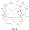
次に図11〜12を同時に参照すると、第2の代替パターンに配置された開口部307Bを含むカッター管301Bを備える回転カッター300Bが例示される。第2の代替パターンにおいて、開口部305Bは複数の列309Bに配置される。例示されるように、複数の列309Bは、任意の所与の列309Bにおける開口部305Bの中心部を接続する基準列線RRLが、回転軸R−Rに平行になるように配向される。したがって、例示的な実施形態において、複数の列309Bは、軸方向の列であるとみなすことができる。他の実施形態(図17に示される実施形態等)において、複数の列309Bは、基準列線RRLが回転軸R−Rに対して鋭角を成す(または別様に傾斜する)ように配向されてもよい。
Next, referring simultaneously to FIGS. 11-12, a
開口部305Bの各々は、六角形の形状を有する。例示的な実施形態において、開口部305Bの各々はまた、開口部305Bが長軸M1及び短軸M2(M1がM2よりも長い)を備えるように周方向に細長い。長軸M1は、カッター管301Bの外面302B(回転カッター300Bの外面でもある)上の、回転軸R−Rに平行な基準線RLに実質的に垂直であり、短軸M2は、基準線RLに実質的に垂直である。他の実施形態において、開口部305Bは、M2がM1よりも大きくなるように軸方向に細長い。
Each of the
開口部305Bの各々は、閉形状を画定する切断エッジ307Bによって画定される。切断エッジ307Bの各々は、せん断部330B及び非せん断部331Bを備える。回転カッター300Bが回転軸R−Rを中心に角度方向AD1に回転させられる例示的な実施形態において、せん断部330Bは、Y点からZ点まで延在し、第1の谷部頂点VA1を含み、非せん断部331Bは、Z点からY点まで延在し、第2の谷部頂点VA2を含む。
Each of the
例示的な実施形態において、開口部305Bの各々につき、せん断部330Bは、合流して第1の谷部頂点VA1を形成する第1の傾斜部分332B及び第2の傾斜部分333Bを備える。第1及び第2の傾斜部分332B、333Bの各々は、基準線RLと鋭角βを形成する。開口部305Bの各々につき、非せん断部331Bは、第1の周方向部分334B及び第2の周方向部分335Bを備え、第1及び第2の周方向部分334B、335Bの各々が基準線RLと直交する。非せん断部331Bはまた、合流して第2の谷部頂点VA2を形成する第1の傾斜部分336B及び第2の傾斜部分337Bを備える。第1及び第2の傾斜部分336B、337Bの各々は、基準線RLと鈍角γを形成する。例示的な実施形態において、鈍角γ及び鋭角βは相互補完的である。特定の他の実施形態において、鈍角γ及び鋭角βは、補完的でなくてもよい。鋭角βは、特定の実施形態において、10度〜60度であってもよく、鈍角γは、特定の実施形態において、90度〜150度であってもよい。
In the exemplary embodiment, for each of the
最後に、開口部305Bのパターンは、基準中心線RCL(回転カッター300Bの軸方向長さLAを半分に分割する)を中心に対称である。この特定の実施形態において、基準中心線RCLの片側のパターンの一部は、基準中心線RCLの反対側のパターンの一部の鏡像である。
Finally, the pattern of the
次に図13〜14を参照すると、第3の代替パターンに配置された開口部307Cを含むカッター管301Cを備える回転カッター300Cが例示される。開口部307Cの第3の代替パターンは、開口部305Cの切断エッジ307Cの選択された数のせん断部330Cのみが、任意の所与の時点に固定刃350で毛を能動的にせん断することが可能であるように特別に設計される。さらに、開口部307Cの第3の代替パターンは、回転カッター300Cが、シェービングプロセスの間に固定刃350の切断エッジ351によって行われるせん断プロセスの間に毛によって回転カッター300Cに付与される反作用力によって生じる実質的に均衡のとれた負荷に供されてもよいように特別に設計される。結果として、モータ400のトルク要件を最適化することができ、回転カッター300Cは、その適切な形状及び固定刃350との間隔をより正確に維持することができる。
Referring now to FIGS. 13-14, a
第3の代替パターンにおいて、開口部305Cは、複数の列309Cに配置される。列309Cの各々の開口部305Cは、それらの中心部が基準列線RRLに沿って位置するように配置される。列309Cの各々は、基準中心線RCL(回転カッター300Cの軸方向長さLAを半分に分割する)の片側に位置する第1の列部分340Cと、基準中心線RCLの反対側に位置する第2の列部分340Cとを備える。第1及び第2の列部分340C、341Cは、列309Cを集合的に形成する。第1の列部340Cに沿って延在する基準列線RRLの一部と、第1の列部340Cに沿って延在する基準列線RRLの一部とは、基準中心線RCLで交差して180度未満の角度θを形成する。さらに、第1の列部340Cに沿って延在する基準列線RRLの一部と、第1の列部340Cに沿って延在する基準列線RRLの一部とは、それぞれ、基準中心線RCLと鈍角φを形成する。2つの鈍角φと角度θとは、集合的に合計360度になる。開口部305Cのパターンは、基準中心線RCL(回転カッター300Cの軸方向長さLAを半分に分割する)を中心に対称である。この特定の実施形態において、基準中心線RCLの片側のパターンの一部は、基準中心線RCLの反対側のパターンの一部の鏡像である。
In the third alternative pattern, the
開口部305Cの各々は、閉形状を画定する切断エッジ307Cによって画定される。切断エッジ307Cの各々は、せん断部330C及び非せん断部331Cを備える。基準中心線RCLによって交差されていない開口部305Cは菱形形状を有し、基準中心線RCLによって交差される開口部305Cは山形形状を有する。回転カッター300Cが回転軸R−Rを中心に角度方向AD1に回転させられる例示的な実施形態において、菱形形状の開口部305Cの各々の切断エッジ307Cは、Y点からZ点まで延在する(図14において切断エッジ307Cの周囲で反時計回りに移動する)せん断部330Cを有し、非せん断部331Cは、Z点からY点まで延在する(同様に図14において切断エッジ307Cの周囲で反時計回りに移動する)。
Each of the
例示的な実施形態において、菱形形状の開口部305Cの各々につき、せん断部330Cは傾斜部分332Cを備える。傾斜部分は、カッター管301Cの外面302C(回転カッター300Cの外面でもある)上の、回転軸R−Rに平行な基準線RLと鋭角βを形成する。菱形形状の開口部305Cの各々につき、非せん断部331Cは、第1の周方向部分334C及び第2の周方向部分335Cを備え、第1及び第2の周方向部分334C、335Cの各々が基準線RLと直交する。非せん断部331Cはまた、傾斜部分336Cを備える。傾斜部分336Cは、基準線RLと鋭角αを形成する。例示的な実施形態において、鋭角αは、鋭角βと実質的に等しい。特定の他の実施形態において、鋭角αは鋭角βと異なる。鋭角β及びαは、特定の実施形態において、10度〜60度であってもよい。
In the exemplary embodiment, for each of the diamond-shaped
説明の目的で、山形形状の開口部305Cは、それらの形状を除いて、上で論じたような菱形形状の開口部305Cと同一である。具体的には、山形形状の開口部の各々は、図10の開口部305Aについて上で論じたものに類似する形状を有する。したがって、開口部305Aの形状の説明は、あたかも本明細書に完全に記載されるかのように山形形状の開口部305Cに適用することができる。
For illustration purposes, the chevron-shaped
図13に最もよく示されるように、開口部305Cのパターンは、回転カッター300Cが回転軸R−Rを中心に回転している時に、せん断部330Cのうちの2つ以下が固定刃の切断エッジ351で使用者の毛をせん断する際に稼働中にあり得るようなパターンである。別の考え方として、開口部305Cのパターンは、回転カッター300Cの角度位置にかかわらず、切断管300Cの外面302C上の固定刃350の切断エッジ351の突出した基準線PRLが、せん断部330Cのうちの2つ以下と交差するようなパターンである。
As best shown in FIG. 13, the pattern of the
例えば、図13に示される角度位置の場合、突出した基準線PRLは、開口部305Cのうちの2つのみのせん断部330C、すなわち第1及び第2の交点IP1及びIΡ2で交差することが見て取れる。突出した基準線PRLは、この角度を成す位置において多くの非せん断部330Cと交差してもよいが、2つのせん断部330Cのみが交差される。回転カッター300Cが組み込まれたシェービング装置1000の動作中、突出した基準線PRLと交差するこれらのせん断部330Cのみが、任意の所与の時点に固定刃350の切断エッジ351で使用者の毛をせん断するように稼働中であり得る。
For example, in the case of the angular position shown in FIG. 13, it can be seen that the protruding reference line PRL intersects at only two
回転カッター300Cが回転軸R−Rを中心に角度方向AD1に回転させられると、開口部305Cのパターンを(図13では左から右へ)固定刃350の切断エッジ351に向かって前進させるように回転カッター300Cの角度位置が前進する(固定刃350は静止したまま)。結果として、突出した基準線PRLの位置が、開口部305Cのパターンの全体を横切って効果的に平行移動される。これにもかかわらず、開口部305Cのパターンに対する突出した基準線PRLの任意の所与の位置において、突出した基準線PRLは、任意の所与の時点にせん断部330Cのうちの2つより多くとは決して交差しない。したがって、開口部305Cのパターンを正確に設計することによってモータ400のトルク要件を正確に制御することができる。
When the
さらに、開口部305Cのパターンは、第1及び第2の交点IP1及びIP2が基準中心線RCLの対向する側に位置するように設計されることが見て取れる。より具体的には、回転カッター300Cに均衡の取れた負荷を付与するために、特定の実施形態において、第1及び第2の交点IP1及びIP2は、基準中心線RCLから等距離であってもよい。
Further, it can be seen that the pattern of the
図示されていない実施形態において、図13〜14の開口部305Cのパターンは、回転カッター300Cが回転軸R−Rを中心に回転している時に、1つのせん断部330Cのみが固定刃の切断エッジ351で使用者の毛をせん断する際に稼働中であり得るように改変されてもよい。換言すると、図13〜14の開口部305Cのパターンは、回転カッター300Cの角度位置にかかわらず、突出した基準線PRLがせん断部330Cのうちの1つのみと交差するように改変することができる。そのような改変は、基準列線RRLがその長さ全体にわたって直線であり、基準線RLに対する適切な鋭角δで配置されるように開口部305Cの列390Cを改変することを必然的に伴う(この角度については図15を参照されたい)。
In the embodiment not shown, the pattern of the
特定の他の実施形態において、本発明は、特定の角度位置にある場合、突出した基準線PRLが開口部307Cのせん断部330Cのうちの2つより多くと交差する場合を対象としてもよいが、パターンは、回転カッターが所与の角度位置にある時に、列309Cの各々が、突出した基準線PRLによって交差されるせん断部330C、及び突出した基準線PRLによって交差されないせん断部330Cの両方を含むように設計される。
In certain other embodiments, the present invention may be directed to the case where the protruding reference line PRL intersects more than two of the
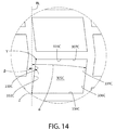
次に図15〜16を参照すると、第4の代替パターンに配置された開口部307Dを含むカッター管301Dを備える回転カッター300Dが例示される。開口部307Dの第4の代替パターンは、開口部305Dの切断エッジ307Dの選択された数のせん断部の頂点のみが、任意の所与の時点に固定刃350で能動的に毛をせん断することが可能であるように特別に設計される。さらに、開口部307Dの第4の代替パターンは、回転カッター300Dが、シェービングプロセスの間に固定刃350の切断エッジ351によって行われるせん断プロセスの間に毛によって回転カッター300Dに付与される反作用力によって生じる実質的に均衡のとれた負荷に供されてもよいように特別に設計される。結果として、モータ400のトルク要件を最適化することができ、回転カッター300Dは、その適切な形状及び固定刃350との間隔をより正確に維持することができる。
Referring now to FIGS. 15-16, a
第4の代替パターンにおいて、開口部305Dは、複数の列309Dに配置される。列309Dの各々の開口部305Dは、それらの中心部が基準列線RRLに沿って位置するように配置される。列309Dの各々は、基準中心線RCL(回転カッター300Dの軸方向長さLAを半分に分割する)の片側に位置する第1の列部分340Dと、基準中心線RCLの反対側に位置する第2の列部分340Dとを備える。第1及び第2の列部分340D、341Dは、列309Dを集合的に形成する。第1の列部340Dに沿って延在する基準列線RRLの一部と、第1の列部340Dに沿って延在する基準列線RRLの一部とは、基準中心線RCLで交差して180度未満の角度θを形成する。さらに、第1の列部340Dに沿って延在する基準列線RRLの一部と、第1の列部340Dに沿って延在する基準列線RRLの一部とは、それぞれ、基準中心線RCLと鈍角φを形成する。2つの鈍角φと角度θとは、集合的に合計360度になる。開口部305Dのパターンは、基準中心線RCL(回転カッター300Dの軸方向長さLAを半分に分割する)を中心に対称である。この特定の実施形態において、基準中心線RCLの片側のパターンの一部は、基準中心線RCLの反対側のパターンの一部の鏡像である。
In the fourth alternative pattern, the
開口部305Dの各々は、六角形の形状を有する。例示的な実施形態において、開口部305Dの各々はまた、開口部305Dが長軸M1及び短軸M2(M1がM2よりも長い)を備えるように周方向に細長い。開口部305Dの各々は、それらの長軸M1を中心に対称であるが、それらの単軸M2を中心に非対称である。さらに、開口部305Dは、列309Dにおいて隣接する開口部がそれらの中心点を中心に180度回転させられるようにパターンを互い違いにするように列309Dに配置される
Each of the
開口部305Dの各々は、閉形状を画定する切断エッジ307Dによって画定される。切断エッジ307Dの各々は、せん断部330D及び非せん断部331Dを備える。回転カッター300Dが回転軸R−Rを中心に角度方向AD1に回転させられる例示的な実施形態において、せん断部330Dは、Y点からZ点まで延在し、第1の谷部頂点VA1を含み、非せん断部331Dは、Z点からY点まで延在し、第2の谷部頂点VA2を含む。
Each of the
例示的な実施形態において、開口部305Dの各々につき、せん断部330Dは、合流して第1の谷部頂点VA1を形成する第1の傾斜部分332D及び第2の傾斜部分333Dを備える。第1及び第2の傾斜部分332D、333Dの各々は、基準線RLと鋭角βを形成する。開口部305Dの各々につき、非せん断部331Dは、第1の周方向部分334D及び第2の周方向部分335Dを備え、第1及び第2の周方向部分334D、335Dの各々が基準線RLと直交しない。非せん断部331Dはまた、合流して第2の谷部頂点VA2を形成する第1の傾斜部分336D及び第2の傾斜部分337Dを備える。第1及び第2の傾斜部分336D、337Dの各々は、基準線RLと鈍角γを形成する。特定の実施形態において、鈍角γ及び鋭角βは相互補完的であってもよい。特定の他の実施形態において、鈍角γ及び鋭角βは、補完的でなくてもよい。鋭角βは、特定の実施形態において、10度〜60度であってもよく、鈍角γは、特定の実施形態において、90度〜150度であってもよい。
In the exemplary embodiment, for each of the
図15に最もよく示されるように、開口部305Dのパターンは、回転カッター300Dが回転軸R−Rを中心に回転している時に、せん断部330Dの2つ以下の頂点(例示的な実施形態において谷部頂点VA1である)が固定刃の切断エッジ351で使用者の毛をせん断する際に稼働中にあり得るようなパターンである。別の考え方として、開口部305Dのパターンは、回転カッター300Dの角度位置にもかかわらず、切断管300Dの外面302D上の固定刃350の切断エッジ351の突出した基準線PRLが、せん断部330Dの頂点のうちの2つ以下(例示的な実施形態において谷部頂点VA1である)と交差するようなパターンである。
As best shown in FIG. 15, the pattern of
例えば、図15に示される角度位置の場合、突出した基準線PRLは、開口部305Dのせん断部330Dの2つの頂点VA1のみ、すなわち第1及び第2の交点IP1及びIΡ2で交差することが見て取れる。突出した基準線PRLは、この角度を成す位置において多くの非せん断部330D(またはその頂点)と交差してもよいが、せん断部330Dの2つの頂点AV1のみが交差される。回転カッター300Dが組み込まれたシェービング装置1000の動作中、突出した基準線PRLと交差するせん断部330Dのこれらの頂点AV1のみが、任意の所与の時点に固定刃350の切断エッジ351で使用者の毛をせん断するように稼働中であり得る。
For example, in the case of the angular position shown in FIG. 15, it can be seen that the protruding reference line PRL intersects only at the two vertices VA1 of the
回転カッター300Dが回転軸R−Rを中心に角度方向AD1に回転させられると、開口部305Dのパターンを(図15では左から右へ)固定刃350の切断エッジ351に向かって前進させるように回転カッター300Dの角度位置が前進する(固定刃350は静止したまま)。結果として、突出した基準線PRLの位置が、開口部305Dのパターンの全体を横切って効果的に平行移動される。これにもかかわらず、開口部305Dのパターンに対する突出した基準線PRLの任意の所与の位置において、突出した基準線PRLは、任意の所与の時点にせん断部330Cの頂点AV1のうちの2つより多くとは決して交差しない。したがって、開口部305Cのパターンを正確に設計することによってモータ400のトルク要件を正確に制御することができる。
When the
さらに、開口部305Dのタイヤパターンは、交点IP1及びIP2で突出した基準線PRLによって交差される第1及び第2の頂点AV1が基準中心線RCLの対向する側に位置するように設計されることが見て取れる。より具体的には、回転カッター300Dに均衡の取れた負荷を付与するために、特定の実施形態において、交点IP1及びIP2で突出した基準線PRLによって交差される第1及び第2の頂点AV1は、基準中心線RCLから等距離であってもよい。
Further, the tire pattern of the
次に図17〜18を参照すると、第4の代替パターンに配置された開口部307Eを含むカッター管301Eを備える回転カッター300Eが例示される。開口部307Eの第4の代替パターンは、開口部305Eの切断エッジ307Eの選択された数のせん断部頂点のみが、任意の所与の時点に固定刃350で毛を能動的にせん断することが可能であるように特別に設計される。具体的には、開口部307Eの第4の代替パターンは、1つのせん断部頂点のみが、任意の所与の時点に固定刃350で毛を能動的にせん断することが可能であるように設計される。開口部307Eの第4の代替パターンは、図11及び12について上で論じたものに類似する六角形の開口部を備える。したがって、これに関してさらなる説明は必要ない。さらに、1つのせん断部頂点のみが、任意の所与の時点に固定刃350で毛を能動的にせん断することが可能であるという目的を達成することに関して、回転カッター300Eは、図15〜16について上で論じた回転カッター300Dに類似する。したがって、冗長を避けるために、開口部307Eの第4の代替パターンと、この単一せん断部頂点の機能を達成する開口部307Dの第3の代替パターンとの違いのみを説明する。
Referring now to FIGS. 17-18, a
この目的を達成するために、開口部307Eのせん断部3330Eの1つの頂点VA1のみが任意の所与の時点に固定刃350で毛をせん断する際に稼働中であるように、開口部307Eの第4の代替パターンは、突出した基準線PRLが、(回転カッター300Eの角度位置にかかわらず)交点IP1でせん断部330Eの1つの頂点VA1のみと交差するように設計される。これは、基準列線RRLがその長さ全体にわたって直線であり、基準線RLに対する適切な鋭角δで配置されるように開口部305Eの列390Eを改変することによって達成される(この角度については図17を参照されたい)。
To achieve this objective, only one vertex VA1 of the shear 3330E of the
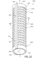
次に、図19〜22を同時に参照すると、シェービング装置1000に使用することができる本発明の実施形態による回転カッター300Fが示される。回転カッター300Fは、通常、カッター管301(図1〜9に関連して前述された)及び支持管375を備える。冗長を避けるために、図1〜9に関連するカッター管301に関する議論が適用可能であるという理解の下、カッター管301の詳細は後の議論において省略される。さらに、図10〜18の代替の開口部パターン(及び関連する概念)のうちのいずれかが回転カッター300Fに使用されるカッター管に適用されてもよいことを理解されたい。
Next, referring simultaneously to FIGS. 19-22, a
カッター管301は、支持管375に取り付けられる。支持管375は、特定の実施形態において、使用中、カッター管301が経時的に変形しないようにまたは歪まないように、カッター管301にある程度の構造的剛性を提供してもよい。さらに、支持管375によって提供される構造的支持は、回転カッター300Fの切断エッジ307と固定刃350の切断エッジ351との間に適切な一定の間隔を維持するのに役立ち得る。支持管375は、プラスチック及び金属を含む多様な材料で形成されてもよい。支持管375は、特定の実施形態において、0.2mm〜5mm(内面377から外面376までを測定)の範囲の厚みを有してもよい。
The
カッター管301は、カッター管301の内面303が支持管375の外面376と面接触するように支持管375に取り付けられる。カッター管301は、支持管375に対して回転不能である。したがって、カッター管301及び支持管375は、回転カッター300Fの回転中に集合単位として回転する。カッター管301は、摩擦嵌め、特徴部との嵌合による係合、締結具、接着剤、熱融着、ろう付け、溶接、またはそのような物品を一緒に連結するために使用される他の手段によって支持管375に対して固定されてもよい。例えば、一実施形態において、支持管375は、一旦そこに設置及び固定されると、カッター管及び支持管301、375の間で相対運動が生じないように、カッター管301の対応する特徴部と整列する1つまたは特徴を有してもよい。そのような一実施形態において、支持管375の外径から突出する小さなピンが、カッター管301の対応するスロットまたは穴と整列して係合する。
The
別の例において、カッター管301と支持管375との間の摩擦嵌めは、それら2つの相対的な回転を防止する。そのような一実施形態において、カッター及び支持管301、375は、支持管375の外径とカッター管301の内径との間に間隙が形成されるようにカッター管301を加熱すること及び/または支持管375を冷却することを含み得る焼嵌めによって組み立てることができる。一旦、十分な間隙が存在すると、カッター管301を支持管375の上で摺動させることができる。その後同じ温度に戻すことにより、カッター管及び支持管301、375が一緒に摩擦嵌めされる。
In another example, a friction fit between the
支持管375は、その外面376に形成された複数の凹部378を備える。例示的な実施形態において、凹部378は、細長い軸方向のチャネルの形態である。凹部378が細長い軸方向のチャネルであることの結果として、複数の軸方向のリブ379が形成され、隣接する凹部378を分離する。軸方向のリブ379は、(例示されるように)連続していてもよいか、または分割されていてもよい。例示的な実施形態において、支持管375の外面376を集合的に画定するのはリブ379の末端表面である。凹部378は、チャネルとして例示されているが、多様な形状及び配向を取ることができる。別の実施形態において、凹部378は、小さな窪みの形態を取ることができる。さらに別の実施形態において、凹部378は、複数の突起が延在する鉢底の形態を取ることができ、突起の末端表面は支持管375の外面376を集合的に形成する。
特定の実施形態において、カッター管301は、カッター管の開口部305のうちの少なくともいくつかがカッター管301を通る支持管301の凹部378への通路を形成するように支持管375に連結される。そのような構成は、より長い毛がせん断のために回転カッター300F内に供給されることを可能にし、それによって、回転カッター300Fがより長い毛をせん断する能力を制限することなく、カッター管301を箔片のように非常に薄くすることができる。
In certain embodiments, the
次に図22〜23を参照すると、本発明の実施形態に従って、そこに連結された潤滑要素800を有する回転カッター300Gが示される。連結された潤滑要素800を有する回転カッター300Gは、回転カッター300の代わりに図1〜9のシェービング装置1000に用いることができる。回転カッター300Gは、図1〜9の回転カッター300と同一であるが、潤滑要素800を収容し、その再充填を促進するために、後に論じる特定の例外を伴う。したがって、回転カッター300に関連する上記議論が適用可能であるという理解の下、回転カッター300Gに関する議論は、回転カッター300と異なる回転カッター300Gの態様に限定される。したがって、アルファベット接尾辞「G」を追加して、同様の参照番号が同様の要素を特定するために使用される。
22-23, a
潤滑要素800は、モータ400の動作中に回転軸R−Rを中心にそれと一緒に回転するように回転カッター300Gのカッター管301Gに連結される。回転カッター300について上で論じたようなシェービング装置1000に組み立てられると、回転カッター300及び潤滑要素800の集合体を回転させることにより、(1)潤滑要素800が使用者の皮膚に潤滑剤を塗布し、(2)使用者の毛が固定刃350の切断エッジ351と回転カッター300Gの切断エッジ307Gとの間でせん断される。潤滑要素800は、使用者の皮膚に接触すること(直接的な塗布)及び/または潤滑剤を放出すること(間接的な塗布)によって使用者の皮膚に潤滑剤を塗布することができ、これは、回転中に潤滑要素800が受ける遠心力によって引き起こされ得る。したがって、回転カッター300Gが回転すると、潤滑要素800は、毛のせん断プロセスの直前に、剃毛される皮膚の領域を、少なくとも1回、ほとんどの場合は複数回、潤滑させることができ、その時点で皮膚が固定刃350に最も近接する。
The
一実施形態において、潤滑要素800は、剃毛に好適な所望の流動性潤滑剤を運搬するマトリックス材804を含む。マトリックス材は、多孔質材料、繊維質材料、または選択された潤滑剤を吸収し、保持し、続いて放出することが可能な他の材料の形態を取ることができる。マトリックス材の一例は、ポリスチレン等の水不溶性ポリマーマトリックスを含む。好適な潤滑剤として、これらに限定されないが、皮膚用ローション、ラノリン、オイル、保湿剤、皮膚軟化薬等が挙げられる。潤滑剤中のさらなる成分は、例えば、(1)皮膚の健康に関連する成分、例えば、外皮用剤(にきび、乾燥、痒み)、調整剤(乾燥肌もしくは脂性肌、pH調整剤、保湿剤、季節用溶液)、回復剤/再生剤(ビタミン療法、生薬、コンディショナー、酸、細胞再生)、クレンジング剤(抗菌性、天然、低アレルギー性、植物由来、芳香剤もしくは香料不含)、または皮膚保護剤(UV、抗老化、抗シワ);(2)皮膚感覚剤、例えば、メントール、または鎮痛剤(アスピリン);(3)ネオスポリンを含む無痛化剤;(4)ムダ毛処理剤、例えば、髭軟化剤、発毛抑制剤、毛髪外層分解剤、髪水分補給剤、ヘアコンディショナー、または梳毛剤;(5)日焼け剤等の化粧品;(6)香水またはエッセンスを含むアロマセラピー剤;及び(7)オイル、ミルク、蜂蜜、ゲル、クリーム、香油、触媒、または発泡剤等の他の物質を含んでもよい。
In one embodiment, the
潤滑要素800は、回転カッター300Gのカッター管301Gの外面302Gと同一平面にある外面(例示的な実施形態において、ストリップ801〜803の外面804〜806によって集合的に形成される)を有する。上で論じたように、カッター管301Gの外面302Gはまた、開口部305Gを画定する切断エッジ307Gを備える。したがって、カッター管301Gの外面302G及び潤滑要素800の外面(例示されるように表面804〜806)は、回転軸R−Rの中心にある基準円Gを集合的に画定する。潤滑要素800の外面をカッター管301Gの外面302Gと同一平面にすることによって、シェービング中に潤滑要素800が固定刃350の切断エッジ351に干渉しない、かつ/または接触しない。特定の実施形態において、回転中に潤滑要素800が固定刃350に接触しないように、突出部の距離が切断間隙325(図9Aを参照のこと)の距離よりも短い限り、潤滑要素800の外面はカッター管301Gの外面302Gから若干突出してもよい。
実施形態において、潤滑ストリップ801〜803の外面804〜806は、乾燥している時、回転カッター301Gの外面302Gに対して若干窪んでいる。しかしながら、潤滑ストリップ801〜803に潤滑剤を充填すると、潤滑ストリップ801〜803の外面804〜806が回転カッター301Gの外面302Gと同一平面になるように潤滑ストリップ801−803が伸長することができる。一実施形態において、潤滑要素800は、乾燥した状態で組み立てられて保管され、後に、例えば、レーザーが最初に使用される時に、例えば、カッター管301Gがシェービングヘッド200に組み立てられる時に、保湿ローションで湿潤させられる。
In the embodiment, the
例示的な実施形態において、潤滑要素800は、複数の細長い潤滑ストリップ801〜803の形態である。3つの潤滑ストリップ801〜803が例示されているが、潤滑剤要素800を形成するために、必要に応じて、1つを含む任意の数の潤滑ストリップ801〜803が用いられてもよい。さらに、潤滑要素800は、1つ以上の細長い潤滑ストリップ801〜803として例示されているが、潤滑要素800は、多様な他の形状及び形態を取ることができる。特定の他の実施形態において、例えば、潤滑要素800は、カッター管301Gの外面302G上に離間した様式で配置された、円、多角形、または他の閉形状の構造/パッド等の隔離された潤滑領域の形態であってもよい。
In the exemplary embodiment, lubricating
潤滑ストリップ801〜803の各々は、カッター管301Gの外面302Gに形成された凹部390G〜392G内に位置する。凹部390G〜392Gの各々は、対応する潤滑ストリップ801〜803のうちの1つを受容するようなサイズ及び形状の細長い軸方向のスロットの形態である。そのため、潤滑ストリップ801〜803は、カッター管301Gに埋め込まれる。
Each of the lubricating strips 801 to 803 is located in the
例示的な実施形態において、潤滑ストリップ801〜803は、カッター管30Gの外面302Gの周囲に周方向に離間した様式で配置される。潤滑ストリップ801〜803は、カッター管301Gの軸方向長さ全体に延在し、それによってカッター管301Gの外面302G上に複数の隔離されたせん断域910、920、930を形成する。せん断域910、920、930の各々は、閉形状の切断エッジ307Gによって画定される複数の開口部305Gを備える。
In the exemplary embodiment, lubricating strips 801-803 are arranged in a circumferentially spaced manner around
一実施形態において、カッター管301Gは、箔片等の平坦な金属板素材から製造されてもよい。そのような実施形態において、平坦な素材はカッター管301Gを形成するように丸められ、端部が一緒に接続される。そのような形成プロセスにおいて、端部を適切に整列させて滑らかなシームを作製することは困難である場合がある。潤滑要素800が用いられる一実施形態において、このシーム(395Gで示されるもの等)は、凹部390G〜392Gのうちの1つの底部に位置し、後に潤滑ストリップ801〜803のうちの1つによって覆われてもよく、それによって製造プロセスを単純化する。
In one embodiment, the
特定の実施形態において、乾燥を防止するために経時的に潤滑要素800を再充填するため、及び潤滑要素800の有効寿命を延長するために、潤滑剤の内部貯蔵容器が、シェービング装置1000のハンドル100またはヘッド200のいずれかに提供されてもよい。内部貯蔵容器は、潤滑剤で充填された空容積であってもよいか、または潤滑剤で飽和した内部チャンバに多孔質材料を含んでもよい。貯蔵容器の詳細及び/または位置に関係なく、貯蔵容器内の潤滑剤が、シェービングプロセスの間に、必要に応じて使用者の皮膚に塗布されるように潤滑要素800に流れることができるように、潤滑要素800は、連続的または断続的のいずれかで貯蔵容器と流体連通している。
In certain embodiments, an internal reservoir of lubricant is used to handle the
なおも図23を参照すると、この例示的な実施形態において、潤滑剤の貯蔵容器500は、回転カッター300G内に位置する。この特定の実施形態において、貯蔵容器は、支持管375Gの改変版において形成される(図19〜21に関する上記議論を参照されたい)。この実施形態において、支持管375Gは、内層381G及び外層382Gを備える。内層及び外層381G〜382Gの間に、蓄積された潤滑剤で充填された環状空間383Gが形成され、それによって潤滑剤の貯蔵容器500を形成する。潤滑ストリップ801〜803の各々は、毛管作用によって潤滑剤を潤滑ストリップ801〜803内に運ぶことができるマトリックス材のポスト807〜809を介して潤滑剤の貯蔵容器500と流体連結する。この実施形態において、潤滑ストリップ801〜803は、貯蔵容器と連続的に流体連通し、潤滑剤は毛管作用によってのみ送達される。他の実施形態(図24に関連して後に論じられるもの等)において、潤滑剤の貯蔵容器500に圧力を印加するためにアクチュエータが供給されてもよく、それによって潤滑剤を潤滑ストリップ801〜803へと流す。アクチュエータは、使用者によって押圧され得るボタン等の手動であってもよいか、またはモータ400に電力供給した時に起動されるように自動化されてもよい。潤滑ストリップ801〜803に流れることが可能であることを除いて、潤滑剤の貯蔵容器500は密封される。必要に応じて一方向弁が提供されてもよい。
Still referring to FIG. 23, in this exemplary embodiment, the
次に図24を参照すると、シェービング装置1000Hが例示される。潤滑剤の貯蔵容器500が加えられ、回転カッター300Gが用いられることを除いて、シェービング装置1000Hは、図1〜9のシェービング装置1000と同一である。したがって、シェービング装置1000に関連する上記議論が適用可能であるという理解の下、シェービング装置1000Hに関する議論は、シェービング装置1000と異なる態様に限定される。したがって、アルファベット接尾辞「H」を追加して、同様の参照番号が同様の要素を特定するために使用される。
Next, referring to FIG. 24, a
シェービング装置1000Hにおいて、潤滑剤の貯蔵容器500は、回転カッター300Gの潤滑要素800を再充填するために、ヘッド200H及びハンドル100Hの両方に提供される。回転カッター300Gが回転軸R−Rを中心に回転させられた時に、潤滑要素800の潤滑ストリップ801〜803の各々が潤滑剤の貯蔵容器500を通過する際にそれと流体連結及び流体解除するように、ヘッド200Hに位置する貯蔵容器500の一部は回転カッター300Gに隣接する。そのため、潤滑ストリップ801〜803は、シェービングプロセスの間に潤滑剤で再充填される。
In the
シェービング装置1000Hは、押下可能なボタンの形態であるアクチュエータ550をさらに備える。アクチュエータ550は、貯蔵容器500に動作可能に連結される。アクチュエータが押下されると貯蔵容器500が加圧され、それによって潤滑剤ストリップ801〜803にさらなる潤滑剤を流す。さらに他の実施形態において、起動されると貯蔵容器及び潤滑要素を流体連結及び流体解除させることができる、平行移動可能な貯蔵容器と動作可能に連結された摺動スイッチ等のアクチュエータが提供されてもよい。
The
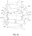
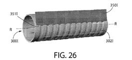
次に図25〜27を同時に参照すると、シェービング装置1000とともに使用することができる振動する固定刃350Iを備えるヘッド200Iが例示される。ヘッド200Iは(その構成要素とともに)、固定刃350Iは振動できること、及びその切断エッジ315が改変された回転カッター300Iに対応するように改変されていることを除いて、図1〜9のヘッド200と同一である。したがって、上記議論が適用可能であるという理解の下、ヘッド200Iに関する議論は、ヘッド200と異なる態様に限定される。したがって、アルファベット接尾辞「I」を追加して、同様の参照番号が同様の要素を特定するために使用される。
Referring now to FIGS. 25-27 simultaneously, there is illustrated a head 200I with a vibrating fixed blade 350I that can be used with the
この実施形態において、固定刃350Iの切断エッジ351Iの形状は、サイン波の形状である。よって、切断エッジ351Iは、複数の山部及び谷部を有する波状の切断エッジであるとみなすことができる。切断エッジ351Iは、回転カッター300Iの外面302Iにある対応する山部及び谷部に係合するように設計される。より具体的には、固定刃350Iの波状のエッジ351Iの山部が回転カッター300Iの谷部内で入れ子状になり、回転カッター300Iの山部が固定刃350Iの波状のエッジ351Iの谷部内で入れ子状になるように、固定刃351Iは、回転カッター300Iに隣接して取り付けられる。波状の設計は、切断エッジ351Iの有効長を延長し、固定刃350Iの切断エッジ351Iと回転カッター300Iとの間に切断角度の連続性を提供する。回転カッター300Iは、回転カッター300I(上で論じたようにカッター管を備える)の切断エッジを形成する複数の細長いスリット開口部307Iを備える。 In this embodiment, the shape of the cutting edge 351I of the fixed blade 350I is a sine wave shape. Therefore, the cutting edge 351I can be regarded as a wavy cutting edge having a plurality of peaks and valleys. The cutting edge 351I is designed to engage a corresponding peak and valley on the outer surface 302I of the rotary cutter 300I. More specifically, the crest of the wavy edge 351I of the fixed blade 350I is nested within the trough of the rotary cutter 300I, and the crest of the rotary cutter 300I is nested within the trough of the wavy edge 351I of the fixed blade 350I. The fixed blade 351I is attached adjacent to the rotary cutter 300I so as to have a shape. The wavy design extends the effective length of the cutting edge 351I and provides continuity of the cutting angle between the cutting edge 351I of the fixed blade 350I and the rotary cutter 300I. The rotary cutter 300I includes a plurality of elongated slit openings 307I that form the cutting edge of the rotary cutter 300I (including the cutter tube as discussed above).
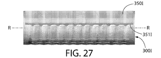
各稜部及び谷部は、回転軸R−Rに垂直に配向されるように、回転カッター300Iの外面302Iの周囲に周方向に延在してもよい(図26を参照のこと)。別の実施形態において、回転カッター300Iの山部及び谷部は、回転軸に対して小さな傾斜となるように、回転カッター300Iの外面302Iの周囲に周方向に延在してもよく、各稜部及び谷部は周方向の円を画定する(図27を参照のこと)。山部及び谷部は、らせんを形成しない。 Each ridge and valley may extend circumferentially around the outer surface 302I of the rotary cutter 300I so as to be oriented perpendicular to the rotation axis RR (see FIG. 26). In another embodiment, the crests and troughs of the rotary cutter 300I may extend circumferentially around the outer surface 302I of the rotary cutter 300I so as to have a small inclination with respect to the axis of rotation. The section and the valley define a circumferential circle (see FIG. 27). The peaks and valleys do not form a helix.
さらに、固定刃350Iは、回転軸R−Rに平行に短距離を移動することができ、同様に、山部及び谷部によって形成される周方向の経路に沿って往復様式で進む。固定刃350Iは、回転カッター300Iにおける対応する特徴部と整列するピン等、山部及び谷部と同じ傾斜で設計されるスロット等の、少なくとも1つの特徴部と有する。これらの2つの特徴部が相互連結し、回転カッター300Iが回転軸R−Rを中心に回転すると、固定刃350Iは、直線運動、前後運動で移動する。往復直線運動は、毛の幅よりも大きく、例えば、25ミクロンよりも大きくなるように設計される。いくつかの場合において、それは回転カッターにおける稜部及び谷部の振幅よりも大きい。 Furthermore, the fixed blade 350I can move a short distance parallel to the rotation axis RR, and similarly travels in a reciprocating manner along a circumferential path formed by peaks and valleys. The fixed blade 350I has at least one feature, such as a slot designed with the same slope as the peaks and troughs, such as pins aligned with corresponding features in the rotary cutter 300I. When these two features are interconnected and the rotary cutter 300I rotates about the rotation axis RR, the fixed blade 350I moves in a linear motion and a longitudinal motion. The reciprocating linear motion is designed to be greater than the hair width, for example greater than 25 microns. In some cases, it is greater than the amplitude of the ridges and valleys in the rotary cutter.
固定刃の直線振動周期は、回転カッターの回転速度と、回転カッターの稜部及び谷部の設計によって決定される。振動する固定刃は、はさみによる2つの切断モードを同時にもたらす。回転カッターによって画定される円に正接し、固定刃に対する隆起部を有する回転カッターの回転によって引き起こされる、切断モードと、回転軸R−Rに平行な、固定刃の直線運動によって引き起こされる、切断モード。 The linear vibration period of the fixed blade is determined by the rotational speed of the rotary cutter and the design of the ridges and valleys of the rotary cutter. The oscillating fixed blade simultaneously provides two cutting modes with scissors. Cutting mode caused by rotation of a rotary cutter tangent to a circle defined by the rotary cutter and having a ridge relative to the fixed blade, and a cutting mode caused by linear movement of the fixed blade parallel to the rotation axis RR .
次に図28を参照すると、回転カッター300Jを保持する筐体202Jの一部として一体化して形成される固定刃350Jを有するヘッド200Jが示される。ヘッド200Jは(その構成要素とともに)、筐体202Jの一部として一体化して形成されることを除いて、図1〜9のヘッド200と同一である。したがって、上記議論が適用可能であるという理解の下、ヘッド200Jに関する議論は、ヘッド200と異なる態様に限定される。したがって、アルファベット接尾辞「I」を追加して、同様の参照番号が同様の要素を特定するために使用される。
Next, referring to FIG. 28, a
ヘッド200Jは、ヘッド200に関して上で論じたように、回転カッター300J及び他の構成要素を収容する筐体202Jを備える。しかしながら、ヘッド200Jは、作用面の一部を形成すると同時に、一体化して形成される固定刃350Jとしても作用する、部分270Jを有する。この目的を達成するために、筐体202Jのこの部分270Jは、細長いスロット240Jの片側を画定し、かつ回転カッター300Jの切断エッジ307Jと協働してせん断する間に固定刃350Jの切断エッジ351Jとして作用する、鋭利なエッジ351Jで終端する。筐体202J(及びすなわち切断エッジ351J)は、金属及び硬質プラスチック等の任意の好適に硬質及び剛性な材料で形成されてもよい。
The
次に図29を参照すると、ヘッド202Kの筐体202K内に形成されたスロット271K内に取り付けられた固定刃350Kを有するヘッド200Jが示される。ヘッド200Kは(その構成要素とともに)、図示されるように固定刃350Kが内部スロット271K内に取り付けられることを除いて、図1〜9のヘッド200と同一である。したがって、上記ヘッド200Jに関する詳細な議論がこれに適用可能であることを理解されたい。したがって、アルファベット接尾辞「K」を追加して、同様の参照番号が同様の要素を特定するために使用されている。
Referring now to FIG. 29, there is shown a
次に図30〜31を同時に参照すると、複数のスタックされた平板セグメント248で形成される筐体202Lを備えるヘッド200Lが示される。ヘッド200Lは(その構成要素とともに)、筐体202Lが複数のスタックされた平板セグメント248で形成されること、及び固定刃が筐体202Lと一体化して形成されることを除いて、図1〜9のヘッド200と同一である。したがって、上記議論が適用可能であるという理解の下、ヘッド200Lに関する議論は、ヘッド200と異なる態様に限定される。したがって、アルファベット接尾辞「L」を追加して、同様の参照番号が同様の要素を特定するために使用される。
Referring now to FIGS. 30-31 simultaneously, a
ヘッド200Lは、コーム217Lを含み、筐体202Lを形成するようにスタック239に配置された平板セグメント248から組み立てられる。平板セグメント248は、薄い金属板からレーザー切断されてもよい。一実施形態において、平板セグメント248の厚みは、コーム217Lの歯の厚みによって画定される。
The
一実施形態において、平板セグメント248の各々は、中心点を有する中央開口部を備える。スタック239に配置された時、平板セグメント248は、それらの中心点が整列し、中央開口部が筐体202Lの内部空洞を集合的に画定するように配置される。
In one embodiment, each of the
筐体202Lは、第1の形状を有する複数の第1の平板セグメント248A及び第2の形状を有する複数の第2の平板セグメント248Bから組み立てられる。第1及び第2の平板セグメント248A、248Bは、交互の様式でスタック239に配置される。これによってコーム217Lの形成を可能にする。したがって、特定の実施形態において、筐体202Lは、一体化して形成されたコーム217L及び一体化して形成された固定刃350Lを有する。そのような一実施形態において、スタック239が組み立てられた時に、セグメント248A、248Bの各々のエッジ249A、249Bが、切断エッジ307Lと相互作用して毛のせん断を行う固定切断刃250Lの切断エッジ251Lを集合的に形成するように、セグメント248A、248Bの各々のエッジ249A、249Bは、鋭利な先端を伴って形成される。一実施形態において、ヘッド202Lは、異なる厚みのセグメントで形成されてもよい。
The
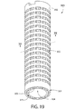
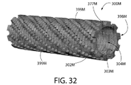
次に図32〜33を同時に参照すると、複数のスタックされたリングセグメント399Mによって形成される回転カッター300Mが示される。回転カッター300Mは、シェービング装置1000とともに使用することができ、いくつかの点において回転カッター300に類似する。したがって、アルファベット接尾辞「M」を追加して、同様の参照番号が同様の要素を特定するために使用される。
Referring now to FIGS. 32-33 simultaneously, a
回転カッター300Mは、回転カッター300Mを形成するようにスタック398Mに配置された複数のリングセグメント399Mによって形成される。一実施形態において、リングセグメント399Mの各々は、中心点を有する中央開口部を備える。スタック398Mに配置された時、リングセグメント399Mは、それらの中心点が整列し、中央開口部が回転カッター300Mの中央空洞を集合的に画定するように配置される。
The
各セグメント399Mは、その外面上に切断エッジ378Mを有する、複数の等間隔に離間された、外向きに突出するリブ377Mで形成される。各セグメント399Mは、スタック398Mの内のその隣接するセグメント399Mに対して、わずかな角度(例えば、5度〜20度)だけずらされている、すなわち、角度オフセットされている。そのような実施形態において、最終形態は、階段状のらせんであってもよい。階段状のらせんにおいて、回転カッター399Mの切断エッジの有効長が延長されている。実施形態において、セグメント399Mは同一である。セグメント399Mは、薄い金属板からレーザー切断されてもよい。
Each
縦部と横部の交差は、各階段が非常に小さい半径を有する場合、標準的な製造技術を用いて経済的に達成することはできない。実施形態において、金属板セグメント399Mのエッジは、「欠けている」かまたは丸みを帯びている。縦部と横部の交差は、各階段がアンダーカットを有する場合。実施形態において、セグメント399Mは、セグメント399M間で異なる回転シフトで組み立てられ、その平均勾配が部品を通して変化する階段状のらせんを生じる。階段状のらせんの平均勾配は、数度だけわずかに変化することができる。実施形態において、セグメント399Mは、セグメント間で異なる回転シフトで組み立てられ、その平均勾配が回転カッター300Mを通して変化する階段状のらせんを生じる。階段状のらせんの平均勾配は、連続的な線でまたは非連続的に方向を変更することができる。
Longitudinal and transverse intersections cannot be achieved economically using standard manufacturing techniques if each staircase has a very small radius. In embodiments, the edge of the
上記説明及び図面は本発明の例示的な実施形態を表すが、添付の特許請求の範囲に定義されるような本発明の主旨及び範囲から逸脱することなく、そこに種々の追加、修正、及び置換が行われ得ることを理解されたい。特に、本発明は、その主旨または本質的な特徴から逸脱することなく、他の特定の形態、構造、配置、割合、サイズで、他の要素、材料、及び構成要素を用いて具現化され得ることは、当業者には明確となるであろう。当業者は、本発明が、構造、配置、割合、サイズ、材料、及び構成要素の多くの修正を伴って使用され得ること、また別様に、本発明の主旨及び範囲から逸脱することなく、特定の環境及び動作要件に特に適合された本発明の実施において使用され得ることを理解するであろう。したがって、本発明に開示される実施形態は、全ての点において限定的ではなく例示的であるとみなされるべきであり、本発明の範囲は、添付の特許請求の範囲によって定義され、上記説明または実施形態に限定されないとみなされるべきである。 While the above description and drawings represent exemplary embodiments of the present invention, various additions, modifications, and modifications may be made thereto without departing from the spirit and scope of the invention as defined in the appended claims. It should be understood that substitutions can be made. In particular, the invention may be embodied using other elements, materials, and components in other specific forms, structures, arrangements, proportions, sizes without departing from the spirit or essential characteristics thereof. This will be clear to those skilled in the art. Those skilled in the art will recognize that the present invention may be used with many modifications in structure, arrangement, proportion, size, material, and components, and otherwise without departing from the spirit and scope of the present invention. It will be appreciated that it can be used in the practice of the present invention specifically adapted to specific environmental and operational requirements. Accordingly, the embodiments disclosed herein are to be considered in all respects as illustrative and not restrictive, the scope of the invention being defined by the appended claims, It should be regarded as not limited to the embodiments.
Claims (89)
電源と、
前記ハンドル部に連結されたヘッド部であって、
カッター管の外面に複数の開口部を備える前記カッター管を備える回転カッターであって、前記開口部の各々は、閉形状を有する切断エッジによって画定される、回転カッターと、
切断エッジを有する固定刃であって、前記回転カッターに隣接して取り付けられる、固定刃と、を備える、ヘッド部と、
前記回転カッターが回転している時に、使用者の毛が前記固定刃の前記切断エッジと前記カッター管の前記切断エッジとの間でせん断されるように、回転軸を中心に前記回転カッターを回転させるように前記電源及び前記回転カッターに動作可能に連結される電気モータと、を備える、シェービング装置。 A handle,
Power supply,
A head portion coupled to the handle portion,
A rotary cutter comprising the cutter tube with a plurality of openings on an outer surface of the cutter tube, wherein each of the openings is defined by a cutting edge having a closed shape;
A fixed blade having a cutting edge, the fixed blade being attached adjacent to the rotary cutter, and a head portion comprising:
When the rotary cutter is rotating, the rotary cutter is rotated about a rotation axis so that a user's hair is sheared between the cutting edge of the fixed blade and the cutting edge of the cutter tube. And an electric motor operably coupled to the power source and the rotary cutter.
内部空洞を有する筐体であって、前記回転カッターが前記筐体の前記内部空洞内に回転可能に取り付けられ、前記固定刃が前記筐体に取り付けられる、筐体と、
前記筐体の前記内部空洞内への通路を形成し、かつ前記カッター管の一部を露出させる前記筐体内の細長いスロットであって、前記固定刃の前記切断エッジ及び前記筐体のエッジによって画定される、スロットと、をさらに備える、請求項1〜16のいずれか1項に記載の前記シェービング装置。 The head portion is
A housing having an internal cavity, wherein the rotary cutter is rotatably mounted in the internal cavity of the housing, and the fixed blade is attached to the housing; and
An elongated slot in the housing that defines a passage into the internal cavity of the housing and exposes a portion of the cutter tube, defined by the cutting edge of the fixed blade and the edge of the housing The shaving device according to claim 1, further comprising a slot.
前記連結要素は、前記連結要素が前記カッター管に半径方向力をかけないように前記カッター管に係合する、請求項1〜18のいずれか1項に記載の前記シェービング装置。 And further comprising the connecting element connected to the electric motor and the cutter tube so that a rotational output of the electric motor is transmitted to the cutter tube by a connecting element,
The shaving device according to any one of claims 1 to 18, wherein the connecting element engages the cutter tube so that the connecting element does not apply a radial force to the cutter tube.
前記ハブ構成要素は、前記電気モータに連結され、前記スポーク構成要素は、前記カッター管に連結され、
前記電気モータの回転出力は、前記連結要素によって前記カッター管に伝達される、請求項1〜18のいずれか1項に記載の前記シェービング装置。 A coupling element comprising a hub component and at least one spoke component extending radially from the hub component;
The hub component is coupled to the electric motor, and the spoke component is coupled to the cutter tube;
The said shaving apparatus of any one of Claims 1-18 by which the rotation output of the said electric motor is transmitted to the said cutter pipe | tube by the said connection element.
電源と、
前記ハンドル部に連結されたヘッド部であって、
複数の切断エッジを備える回転カッターと、
一緒に回転するように前記回転カッターに連結された少なくとも1つの潤滑要素と、
切断エッジを有する固定刃であって、前記回転カッターに隣接して取り付けられる、固定刃と、を備える、ヘッド部と、
(1)前記回転カッターが回転している時に、前記潤滑要素が使用者の皮膚に潤滑剤を塗布し、(2)前記回転カッターが回転している時に、前記使用者の毛が前記固定刃の前記切断エッジと前記回転カッターの前記切断エッジとの間でせん断されるように、回転軸を中心に前記回転カッターを回転させるように前記電源及び前記回転カッターに動作可能に連結される電気モータと、を備える、シェービング装置。 A handle,
Power supply,
A head portion coupled to the handle portion,
A rotary cutter with a plurality of cutting edges;
At least one lubrication element coupled to the rotary cutter for rotation together;
A fixed blade having a cutting edge, the fixed blade being attached adjacent to the rotary cutter, and a head portion comprising:
(1) When the rotary cutter is rotating, the lubricating element applies a lubricant to the user's skin, and (2) when the rotary cutter is rotating, the user's hair is the fixed blade. An electric motor operably coupled to the power source and the rotary cutter to rotate the rotary cutter about a rotary axis so as to be sheared between the cutting edge of the rotary cutter and the cutting edge of the rotary cutter A shaving device comprising:
内部空洞を有する筐体であって、前記回転カッターが前記筐体の前記内部空洞内に回転可能に取り付けられ、前記固定刃が前記筐体に取り付けられる、筐体と、
前記筐体の前記内部空洞内への通路を形成し、かつ前記カッター管の一部を露出させる前記筐体内の細長いスロットであって、前記固定刃の前記切断エッジ及び前記筐体のエッジによって画定される、スロットと、をさらに備える、請求項25〜44のいずれか1項に記載の前記シェービング装置。 The head portion is
A housing having an internal cavity, wherein the rotary cutter is rotatably mounted in the internal cavity of the housing, and the fixed blade is attached to the housing; and
An elongated slot in the housing that defines a passage into the internal cavity of the housing and exposes a portion of the cutter tube, defined by the cutting edge of the fixed blade and the edge of the housing 45. The shaving device according to any one of claims 25 to 44, further comprising a slot.
電源と、
前記ハンドル部に連結されたヘッド部であって、
カッター管の外面に複数の開口部を備える前記カッター管を備える回転カッターであって、前記開口部の各々は、閉形状を有する切断エッジによって画定される、回転カッターと、
一緒に回転するように前記カッター管に連結された少なくとも1つの潤滑要素と、
切断エッジを有する固定刃であって、前記回転カッターに隣接して取り付けられる、固定刃と、を備える、ヘッド部と、
(1)前記回転カッターが回転している時に、前記潤滑要素が使用者の皮膚に接触し、(2)前記回転カッターが回転している時に、前記使用者の毛が前記固定刃の前記切断エッジと前記回転カッターの前記切断エッジとの間でせん断されるように、回転軸を中心に前記回転カッターを回転させるように前記電源及び前記回転カッターに動作可能に連結される電気モータと、を備える、シェービング装置。 A handle,
Power supply,
A head portion coupled to the handle portion,
A rotary cutter comprising the cutter tube with a plurality of openings on an outer surface of the cutter tube, wherein each of the openings is defined by a cutting edge having a closed shape;
At least one lubricating element connected to the cutter tube for rotation together;
A fixed blade having a cutting edge, the fixed blade being attached adjacent to the rotary cutter, and a head portion comprising:
(1) When the rotary cutter is rotating, the lubricating element is in contact with the user's skin. (2) When the rotary cutter is rotating, the user's hair is cut by the fixed blade. An electric motor operably coupled to the power source and the rotary cutter to rotate the rotary cutter about a rotational axis so that it is sheared between an edge and the cutting edge of the rotary cutter. A shaving device provided.
電源と、
回転軸を中心に回転カッターを回転させるように前記電源及び前記回転カッターに動作可能に連結される電気モータと、
前記ハンドル部に連結されたヘッド部であって、
前記回転カッターであって、前記回転カッターは、カッター管の外面に1つ以上の開口部を備える前記カッター管を備え、前記開口部は、閉形状を有する切断エッジによって画定される、前記回転カッターと、
切断エッジを有する固定刃であって、前記回転カッターが回転している時に、使用者の毛が前記固定刃の前記切断エッジと前記カッター管の前記切断エッジとの間でせん断されるように、前記回転カッターに隣接して取り付けられる、固定刃と、を備える、ヘッド部と、を備える、シェービング装置。 A handle,
Power supply,
An electric motor operably coupled to the power source and the rotary cutter to rotate the rotary cutter about a rotational axis;
A head portion coupled to the handle portion,
The rotary cutter, wherein the rotary cutter comprises the cutter tube with one or more openings on an outer surface of the cutter tube, the openings defined by a cutting edge having a closed shape. When,
A fixed blade having a cutting edge, such that when the rotary cutter is rotating, a user's hair is sheared between the cutting edge of the fixed blade and the cutting edge of the cutter tube; A shaving device comprising: a fixed blade attached adjacent to the rotary cutter; and a head portion.
電源と、
回転軸を中心に回転カッターを回転させるように前記電源及び前記回転カッターに動作可能に連結される電気モータと、
前記ハンドル部に連結されたヘッド部であって、
前記回転カッターであって、前記回転カッターは、前記回転カッターの外面に複数の開口部を備え、前記開口部の各々は、閉形状を有する切断エッジによって画定され、かつせん断部及び非せん断部を備える、前記回転カッターと、
切断エッジを有する固定刃であって、前記回転カッターが回転している時に、使用者の毛が前記固定刃の前記切断エッジと前記カッター管の前記切断エッジの前記せん断部との間でせん断されるように、前記回転カッターに隣接して取り付けられる、固定刃と、
前記回転カッターが回転している時に、前記せん断部のうちの2つ以下が、前記固定刃の前記切断エッジで前記使用者の毛をせん断する際に稼働中であり得るようなパターンで配置される開口部と、を備える、ヘッド部と、を備える、シェービング装置。 A handle,
Power supply,
An electric motor operably coupled to the power source and the rotary cutter to rotate the rotary cutter about a rotational axis;
A head portion coupled to the handle portion,
The rotary cutter, wherein the rotary cutter includes a plurality of openings on an outer surface of the rotary cutter, each of the openings is defined by a cutting edge having a closed shape, and includes a shearing portion and a non-shearing portion. Comprising the rotating cutter;
A fixed blade having a cutting edge, wherein a user's hair is sheared between the cutting edge of the fixed blade and the shearing portion of the cutting edge of the cutter tube when the rotary cutter is rotating. A fixed blade attached adjacent to the rotating cutter, and
When the rotary cutter is rotating, no more than two of the shearing portions are arranged in a pattern that may be in operation when shearing the user's hair at the cutting edge of the fixed blade. A shaving device comprising: a head portion comprising:
電源と、
回転軸を中心に回転カッターを回転させるように前記電源及び前記回転カッターに動作可能に連結される電気モータと、
前記ハンドル部に連結されたヘッド部であって、
前記回転カッターであって、前記回転カッターは、前記回転カッターの外面に複数の開口部を備え、前記開口部の各々は、閉形状を有する切断エッジによって画定され、かつせん断部及び非せん断部を備える、前記回転カッターと、
切断エッジを有する固定刃であって、前記回転カッターが回転している時に、使用者の毛が前記固定刃の前記切断エッジと前記回転カッターの前記切断エッジの前記せん断部との間でせん断されるように、前記回転カッターに隣接して取り付けられる、固定刃と、
前記回転カッターの角度位置にかかわらず、前記切断管の外面上の前記固定刃の前記切断エッジの突出した基準線が前記せん断部のうちの2つ以下と交差するパターンで配置される開口部と、を備える、ヘッド部と、
を備える、シェービング装置。 A handle,
Power supply,
An electric motor operably coupled to the power source and the rotary cutter to rotate the rotary cutter about a rotational axis;
A head portion coupled to the handle portion,
The rotary cutter, wherein the rotary cutter includes a plurality of openings on an outer surface of the rotary cutter, each of the openings is defined by a cutting edge having a closed shape, and includes a shearing portion and a non-shearing portion. Comprising the rotating cutter;
A fixed blade having a cutting edge, wherein the user's hair is sheared between the cutting edge of the fixed blade and the shearing portion of the cutting edge of the rotating cutter when the rotating cutter is rotating. A fixed blade attached adjacent to the rotating cutter, and
Regardless of the angular position of the rotary cutter, an opening that is arranged in a pattern in which a reference line protruding the cutting edge of the fixed blade on the outer surface of the cutting tube intersects with two or less of the shearing portions; A head portion comprising:
A shaving device comprising:
電源と、
回転軸を中心に回転カッターを回転させるように前記電源及び前記回転カッターに動作可能に連結される電気モータと、
前記ハンドル部に連結されたヘッド部であって、
前記回転カッターであって、前記回転カッターは、前記回転カッターの外面に複数の開口部を備え、前記開口部の各々は、閉形状を有する切断エッジによって画定され、かつせん断部及び非せん断部を備え、前記せん断部は頂点を備える、前記回転カッターと、
切断エッジを有する固定刃であって、前記回転カッターが回転している時に、使用者の毛が前記固定刃の前記切断エッジと前記切断エッジの前記せん断部との間でせん断されるように、前記回転カッターに隣接して取り付けられる、固定刃と、
前記回転カッターの角度位置にかかわらず、前記切断管の前記外面上の前記固定刃の前記切断エッジの突出した基準線が前記頂点のうちの2つ以下と交差するパターンで配置される、開口部と、を備える、ヘッド部と、
を備える、シェービング装置。 A handle,
Power supply,
An electric motor operably coupled to the power source and the rotary cutter to rotate the rotary cutter about a rotational axis;
A head portion coupled to the handle portion,
The rotary cutter, wherein the rotary cutter includes a plurality of openings on an outer surface of the rotary cutter, each of the openings is defined by a cutting edge having a closed shape, and includes a shearing portion and a non-shearing portion. Comprising, the shearing portion comprises a vertex, the rotary cutter,
A fixed blade having a cutting edge, such that when the rotary cutter rotates, a user's hair is sheared between the cutting edge of the fixed blade and the shearing portion of the cutting edge; A fixed blade attached adjacent to the rotating cutter;
Regardless of the angular position of the rotary cutter, the opening is arranged in a pattern in which the protruding reference line of the cutting edge of the fixed blade on the outer surface of the cutting tube intersects with two or less of the vertices. A head portion comprising:
A shaving device comprising:
電源と、
前記ハンドル部に連結されたヘッド部であって、
内部空洞を有する筐体と、
複数の切断エッジを備える回転カッターであって、前記回転カッターは、前記筐体の前記内部空洞内に取り付けられ、前記筐体は、前記筐体の前記内部空洞への通路を形成する細長いスロットを備え、かつ前記回転カッターの一部を露出させる、回転カッターと、
前記筐体の一部として一体化して形成され、かつ前記細長いスロットを部分的に画定する切断エッジを備える固定刃と、を備える、ヘッド部と、
使用者の毛が前記固定刃の前記切断エッジと前記回転カッターの前記切断エッジとの間でせん断されるように、回転軸を中心に前記回転カッターを回転させるように前記電源及び前記回転カッターに動作可能に連結される電気モータと、
を備える、シェービング装置。 A handle,
Power supply,
A head portion coupled to the handle portion,
A housing having an internal cavity;
A rotary cutter comprising a plurality of cutting edges, wherein the rotary cutter is mounted within the internal cavity of the housing, the housing having an elongated slot that forms a passage to the internal cavity of the housing. A rotary cutter that exposes and exposes a portion of the rotary cutter;
A head part comprising a fixed blade formed integrally as part of the housing and having a cutting edge that partially defines the elongated slot;
The power supply and the rotary cutter are rotated to rotate the rotary cutter about a rotation axis so that a user's hair is sheared between the cutting edge of the fixed blade and the cutting edge of the rotary cutter. An electric motor operably coupled;
A shaving device comprising:
電源と、
前記ハンドル部に連結されたヘッド部であって、
複数の切断エッジを備える回転カッターを集合的に形成するようにスタックに配置された複数の平板リングセグメントと、
切断エッジを有する固定刃であって、前記回転カッターに隣接して取り付けられる、固定刃と、を備える、ヘッド部と、
使用者の毛が前記固定刃の前記切断エッジと前記回転カッターの前記切断エッジとの間でせん断されるように、回転軸を中心に前記回転カッターを回転させるように前記電源及び前記回転カッターに動作可能に連結される電気モータと、
を備える、シェービング装置。 A handle,
Power supply,
A head portion coupled to the handle portion,
A plurality of flat ring segments arranged in a stack to collectively form a rotary cutter with a plurality of cutting edges;
A fixed blade having a cutting edge, the fixed blade being attached adjacent to the rotary cutter, and a head portion comprising:
The power supply and the rotary cutter are rotated to rotate the rotary cutter about a rotation axis so that a user's hair is sheared between the cutting edge of the fixed blade and the cutting edge of the rotary cutter. An electric motor operably coupled;
A shaving device comprising:
電源と、
前記ハンドル部に連結されたヘッド部であって、
内部空洞を有する筐体を集合的に形成するようにスタックに配置された複数の平板セグメントと、
複数の切断エッジを備える回転カッターであって、前記回転カッターは、前記筐体の前記内部空洞内に取り付けられ、前記筐体は、前記筐体の前記内部空洞への通路を形成する細長いスロットを備え、かつ前記回転カッターの一部を露出させる、回転カッターと、
前記細長いスロットを部分的に画定する切断エッジを備える固定刃と、を備える、前記ヘッド部と、
使用者の毛が前記固定刃の前記切断エッジと前記回転カッターの前記切断エッジとの間でせん断されるように、回転軸を中心に前記回転カッターを回転させるように前記電源及び前記回転カッターに動作可能に連結される電気モータと、を備える、シェービング装置。 A handle,
Power supply,
A head portion coupled to the handle portion,
A plurality of flat plate segments arranged in a stack to collectively form a housing having an internal cavity;
A rotary cutter comprising a plurality of cutting edges, wherein the rotary cutter is mounted within the internal cavity of the housing, the housing having an elongated slot that forms a passage to the internal cavity of the housing. A rotary cutter that exposes and exposes a portion of the rotary cutter;
A fixed blade with a cutting edge that partially defines the elongated slot; and the head portion;
The power supply and the rotary cutter are rotated to rotate the rotary cutter about a rotation axis so that a user's hair is sheared between the cutting edge of the fixed blade and the cutting edge of the rotary cutter. An electric motor operably coupled to the shaving apparatus.
電源と、
前記ハンドル部に連結されたヘッド部であって、
山部及び谷部を備える外面を備える回転カッターと、
山部及び谷部を備える波状の切断エッジを有する固定刃であって、前記固定刃の前記波状のエッジの前記山部が前記回転カッターの前記谷部内で入れ子状になり、前記回転カッターの前記山部が前記固定刃の前記波状のエッジの前記谷部内で入れ子上になるように、前記固定刃が前記回転カッターに隣接して取り付けられる、固定刃と、を備える、ヘッド部と、
使用者の毛が前記固定刃の前記波状の切断エッジと前記回転カッターとの間でせん断されるように、回転軸を中心に前記回転カッターを回転させるように前記電源及び前記回転カッターに動作可能に連結される電気モータと、を備える、シェービング装置。 A handle,
Power supply,
A head portion coupled to the handle portion,
A rotary cutter with an outer surface with peaks and valleys;
A fixed blade having a wavy cutting edge having a crest and a trough, wherein the crest of the wavy edge of the fixed blade is nested within the trough of the rotary cutter, and the rotary cutter A fixed blade, wherein the fixed blade is mounted adjacent to the rotary cutter such that the peak portion is nested within the trough of the wavy edge of the fixed blade;
Operate the power supply and the rotary cutter to rotate the rotary cutter around the rotation axis so that the user's hair is sheared between the wavy cutting edge of the fixed blade and the rotary cutter An electric motor coupled to the shaving device.
電源と、
前記ハンドル部に連結されたヘッド部であって、
回転カッターと、
切断エッジを有する固定刃であって、前記回転カッターの回転軸に平行な方向に往復平行移動することが可能であるように前記回転カッターに隣接して取り付けられる、固定刃と、を備えるヘッド部と、
使用者の毛が前記固定刃の前記切断エッジと前記回転カッターの前記切断エッジとの間でせん断されるように、回転軸を中心に前記回転カッターを回転させるように前記電源及び前記回転カッターに動作可能に連結される電気モータと、
を備える、シェービング装置。 A handle,
Power supply,
A head portion coupled to the handle portion,
A rotating cutter,
A fixed blade having a cutting edge, and a fixed blade that is attached adjacent to the rotary cutter so as to be capable of reciprocating parallel movement in a direction parallel to the rotation axis of the rotary cutter. When,
The power supply and the rotary cutter are rotated to rotate the rotary cutter about a rotation axis so that a user's hair is sheared between the cutting edge of the fixed blade and the cutting edge of the rotary cutter. An electric motor operably coupled;
A shaving device comprising:
電源と、
回転軸を中心に回転カッターを回転させるように前記電源及び前記回転カッターに動作可能に連結される電気モータと、
前記ハンドル部に連結されたヘッド部であって、
前記回転カッターであって、前記回転カッターは、前記回転カッターの外面に複数の開口部を備え、前記複数の開口部は、前記開口部のうちの少なくとも1つの列を含むパターンで配置され、前記開口部の各々は、閉形状を有する切断エッジによって画定され、かつせん断部及び非せん断部を備える、前記回転カッターと、
切断エッジを有する固定刃であって、前記回転カッターが回転している時に、使用者の毛が前記固定刃の前記切断エッジと前記回転カッターの前記切断エッジの前記せん断部との間でせん断されるように、回転カッターに隣接して取り付けられる、固定刃と、
前記切断管の前記外面上の前記固定刃の前記切断エッジの突出した基準線が、前記列の前記開口部の前記せん断部のうちの少なくとも1つと交差し、かつ前記列の前記開口部の前記せん断部のうちの少なくとも1つと交差しないように構成される、パターンと、を備える、ヘッド部と、
を備える、シェービング装置。 A handle,
Power supply,
An electric motor operably coupled to the power source and the rotary cutter to rotate the rotary cutter about a rotational axis;
A head portion coupled to the handle portion,
The rotary cutter, wherein the rotary cutter includes a plurality of openings on an outer surface of the rotary cutter, and the plurality of openings are arranged in a pattern including at least one row of the openings, Each of the openings is defined by a cutting edge having a closed shape and comprises a shearing portion and a non-shearing portion;
A fixed blade having a cutting edge, wherein the user's hair is sheared between the cutting edge of the fixed blade and the shearing portion of the cutting edge of the rotating cutter when the rotating cutter is rotating. A fixed blade mounted adjacent to the rotary cutter,
A protruding reference line of the cutting edge of the fixed blade on the outer surface of the cutting tube intersects at least one of the shearing portions of the opening of the row, and the opening of the opening of the row A head portion comprising a pattern configured not to intersect at least one of the shear portions;
A shaving device comprising:
Applications Claiming Priority (5)
| Application Number | Priority Date | Filing Date | Title |
|---|---|---|---|
| US201361824579P | 2013-05-17 | 2013-05-17 | |
| US61/824,579 | 2013-05-17 | ||
| US201461941240P | 2014-02-18 | 2014-02-18 | |
| US61/941,240 | 2014-02-18 | ||
| PCT/IB2014/001886 WO2014191844A2 (en) | 2013-05-17 | 2014-05-19 | Shaving apparatus |
Publications (2)
| Publication Number | Publication Date |
|---|---|
| JP2016518213A true JP2016518213A (en) | 2016-06-23 |
| JP2016518213A5 JP2016518213A5 (en) | 2017-06-22 |
Family
ID=51844770
Family Applications (1)
| Application Number | Title | Priority Date | Filing Date |
|---|---|---|---|
| JP2016513458A Pending JP2016518213A (en) | 2013-05-17 | 2014-05-19 | Shaving equipment |
Country Status (5)
| Country | Link |
|---|---|
| US (2) | US9862107B2 (en) |
| EP (1) | EP2996844A2 (en) |
| JP (1) | JP2016518213A (en) |
| KR (1) | KR20160029746A (en) |
| WO (1) | WO2014191844A2 (en) |
Families Citing this family (14)
| Publication number | Priority date | Publication date | Assignee | Title |
|---|---|---|---|---|
| US8601696B2 (en) * | 2010-01-18 | 2013-12-10 | Hybrid Razor Ltd | Motorized shaving apparatus head and shaving apparatus implementing the same |
| US10456935B2 (en) | 2010-01-18 | 2019-10-29 | Hybrid Razor Ltd | Shaving apparatus and shaving apparatus head |
| US8887369B2 (en) * | 2011-12-09 | 2014-11-18 | The Gillette Company | Personal-care appliance and method of assembly |
| US9862107B2 (en) * | 2013-05-17 | 2018-01-09 | Hybrid Razor Ltd | Shaving apparatus |
| JP2017506109A (en) * | 2014-02-18 | 2017-03-02 | ハイブリツド・レイザー・リミテツド | Shaving equipment |
| GB201500491D0 (en) * | 2015-01-13 | 2015-02-25 | Rathbone Razor Ltd | Disposable razor |
| USD776875S1 (en) * | 2015-08-19 | 2017-01-17 | Xiangrong Ren | Razor head |
| JP6803911B2 (en) | 2015-12-01 | 2020-12-23 | ビック・バイオレクス・エス・エー | Shaving laser and shaving cartridge |
| WO2017182871A2 (en) * | 2016-04-20 | 2017-10-26 | Hybrid Razor Ltd | Shaving apparatus |
| US10695924B2 (en) * | 2016-04-20 | 2020-06-30 | Hybrid Razor Ltd. | Shaving apparatus |
| EP3548231B1 (en) * | 2016-12-01 | 2021-01-20 | Koninklijke Philips N.V. | Hair cutting apparatus comprising a current detector |
| WO2018218157A1 (en) * | 2017-05-26 | 2018-11-29 | Sharkninja Operating Llc | Hair cutting brushroll |
| EP3524396B1 (en) | 2018-02-08 | 2020-12-02 | BIC Violex S.A. | Rotary razor |
| EP3569371A1 (en) | 2018-05-16 | 2019-11-20 | Koninklijke Philips N.V. | Shaving unit with lubricating arrangement |
Citations (13)
| Publication number | Priority date | Publication date | Assignee | Title |
|---|---|---|---|---|
| US2360785A (en) * | 1941-07-21 | 1944-10-17 | Ulysses G Charles | Safety razor for dry shaving |
| FR1556327A (en) * | 1967-12-21 | 1969-02-07 | ||
| JPS4886650A (en) * | 1972-02-18 | 1973-11-15 | ||
| JPS5030993U (en) * | 1973-07-18 | 1975-04-05 | ||
| DE2503175A1 (en) * | 1974-01-28 | 1975-07-31 | Mettoy Co Ltd | Dry razor with fixed blade and rotating cylinder - has blade located with cutting edge next to rotating cylinder |
| JPS58146383A (en) * | 1982-02-26 | 1983-08-31 | 松下電工株式会社 | Electric razor |
| JPS5928586A (en) * | 1982-08-09 | 1984-02-15 | Kyushu Hitachi Maxell Ltd | Preparation of cylindrical reticulated inner blade of electric razor |
| JPS5937072U (en) * | 1982-09-03 | 1984-03-08 | 九州日立マクセル株式会社 | Cylindrical mesh inner blade of rotary electric shaver |
| JPS59176460U (en) * | 1982-07-21 | 1984-11-26 | 九州日立マクセル株式会社 | rotary electric shaver |
| JPH03111265U (en) * | 1990-02-27 | 1991-11-14 | ||
| WO1996004110A1 (en) * | 1994-08-01 | 1996-02-15 | Michael John Franklin | Dry shaving device |
| JP2012024415A (en) * | 2010-07-26 | 2012-02-09 | Kyushu Hitachi Maxell Ltd | Rotary blade and compact electric appliance including the same |
| JP2013517038A (en) * | 2010-01-18 | 2013-05-16 | ハイブリツド・レイザー・リミテツド | Shaving device head with motor and shaving device with similar structure |
Family Cites Families (79)
| Publication number | Priority date | Publication date | Assignee | Title |
|---|---|---|---|---|
| US2281789A (en) | 1942-05-05 | Shaving apparatus | ||
| US911472A (en) | 1908-06-27 | 1909-02-02 | Luigi Brunacci | Electric safety-razor. |
| US1420943A (en) | 1920-09-10 | 1922-06-27 | Philp Joseph Howard | Rotary razor |
| US1436960A (en) | 1922-01-20 | 1922-11-28 | Jakubiec Joseph | Combined safety razor and hair clipper |
| US1981202A (en) | 1934-01-08 | 1934-11-20 | Charles W Shipman | Mower razor |
| US2086716A (en) * | 1935-09-30 | 1937-07-13 | Koehler James Frederic | Shaving implement |
| US2096379A (en) | 1936-06-09 | 1937-10-19 | Clyde J Peak | Razor |
| US2229972A (en) | 1937-05-07 | 1941-01-28 | American Safety Razor Corp | Shaving device |
| US2127881A (en) | 1937-05-10 | 1938-08-23 | Morris Leopold | Safety razor |
| US2281922A (en) * | 1937-06-22 | 1942-05-05 | American Safety Razor Corp | Shaving device |
| US2186092A (en) | 1937-10-30 | 1940-01-09 | Remington Rand Inc | Rotary cutter |
| US2342291A (en) | 1943-03-03 | 1944-02-22 | Morelli Raffaele | Adjustable razor |
| US2474027A (en) | 1946-03-18 | 1949-06-21 | Berger Morris | Electromechanical safety razor |
| US2524822A (en) * | 1946-03-20 | 1950-10-10 | Neidig William Jonathan | Shaving mechanism |
| US2594764A (en) | 1946-09-26 | 1952-04-29 | Fairey Aviat Co Ltd | Rotary blade safety razor |
| US2586022A (en) * | 1947-09-23 | 1952-02-19 | Fairey Aviat Co Ltd | Rotary blade safety razor |
| US2601721A (en) | 1948-01-29 | 1952-07-01 | Fairey Aviat Co Ltd | Rotary blade safety razor |
| US2574472A (en) * | 1949-06-08 | 1951-11-13 | Joseph A C Galvao | Motor operated shaving device |
| US2858607A (en) | 1955-04-18 | 1958-11-04 | Kane Edward | Electric razor with rotary operated double edged blades |
| US2839829A (en) | 1956-01-30 | 1958-06-24 | Knapp Raymond | Razor with stationary blade and movable shear plate |
| FR1193387A (en) * | 1958-03-13 | 1959-11-02 | Electric razor | |
| US3050851A (en) | 1958-10-11 | 1962-08-28 | Olivetti & Co Spa | Rotary type dry shaver having a cylindrical grill |
| US2946121A (en) * | 1960-01-14 | 1960-07-26 | Marach Paul | Electric shaver |
| US3092904A (en) * | 1960-05-09 | 1963-06-11 | Bruecker John | Movable cutter for a dry shaver having saw tooth design cutting edge |
| GB933740A (en) * | 1960-10-06 | |||
| US3128550A (en) | 1962-08-29 | 1964-04-14 | Miselli Afro | Cutting head for electric shavers having a helical shaped movable cutter |
| US3381373A (en) | 1965-09-02 | 1968-05-07 | Brown Ernest | Device for cutting body hairs growing in or adjacent body cavities |
| US3431643A (en) | 1967-06-09 | 1969-03-11 | Joseph S Miceli | Electric safety razor |
| US3494031A (en) | 1968-02-01 | 1970-02-10 | Wenceslas F Sklenar | Electric shaver |
| BE759429A (en) | 1969-12-05 | 1971-04-30 | Carinthia Elektrogeraete Gmbh | DRY RAZOR |
| FR2074579A1 (en) * | 1970-01-07 | 1971-10-08 | Basset James | |
| FR2126486A5 (en) * | 1971-02-08 | 1972-10-06 | Ragot Claude | |
| US3829966A (en) * | 1972-09-05 | 1974-08-20 | N Owens | A rotary shaver with slidably mounted blades |
| JPS5748232B2 (en) * | 1973-10-08 | 1982-10-14 | ||
| US4151645A (en) | 1976-07-07 | 1979-05-01 | U.S. Philips Corporation | Dry-shaving apparatus with hair-pulling lead cutters |
| US4043036A (en) * | 1977-01-27 | 1977-08-23 | Alpha Nova Development Corporation | Power driven shaver |
| EP0230075B1 (en) | 1985-12-20 | 1990-04-04 | Koninklijke Philips Electronics N.V. | Dry-shaving apparatus |
| NL8503521A (en) * | 1985-12-20 | 1987-07-16 | Philips Nv | SHAVER. |
| NL8503519A (en) | 1985-12-20 | 1987-07-16 | Philips Nv | SHAVER. |
| NL8601295A (en) | 1986-05-22 | 1987-12-16 | Philips Nv | SHAVER. |
| NL8700186A (en) | 1987-01-27 | 1988-08-16 | Philips Nv | SHAVER. |
| NL8700515A (en) * | 1987-03-04 | 1988-10-03 | Philips Nv | SHAVER. |
| US4884338A (en) | 1988-07-18 | 1989-12-05 | Stewart John V | Electric shaver improvement |
| NL8802311A (en) | 1988-09-19 | 1990-04-17 | Philips Nv | SHAVER. |
| US5022154A (en) | 1990-10-01 | 1991-06-11 | Johnson Wayne A | Reaper razor |
| US5367599A (en) | 1992-05-27 | 1994-11-22 | Sanyo Electrical Co., Ltd. | Electric shaver in which motor rotational speed is controlled according to beard thickness |
| US5377699A (en) * | 1993-04-02 | 1995-01-03 | Varnum; Shirley | Hair abrader |
| GB2294228A (en) * | 1994-08-01 | 1996-04-24 | Michael John Franklin | Rotary shaving device |
| JP3266757B2 (en) | 1995-05-26 | 2002-03-18 | 松下電工株式会社 | Vibration type linear actuator |
| AU2451599A (en) | 1998-01-20 | 1999-08-02 | Wheel Technology Ltd. | Electric razor with direct contact roller-mounted blades |
| DE19859622A1 (en) | 1998-12-23 | 2000-07-06 | Braun Gmbh | Drive device for oscillating electrical products for personal use, in particular dry shavers |
| US6568083B1 (en) | 1999-11-25 | 2003-05-27 | Matsushita Electric Works, Ltd. | Dry shaver with a height adjustable cutter head |
| JP2002143574A (en) | 2000-11-06 | 2002-05-21 | Hitachi Ltd | Electric cosmetic tool |
| US20050000093A1 (en) | 2003-07-03 | 2005-01-06 | Simon Shagalov | Electric shaver |
| WO2005107373A2 (en) * | 2004-05-11 | 2005-11-17 | Gideon Dror | Shaving apparatus |
| CN1833834A (en) | 2005-03-18 | 2006-09-20 | 德昌电机股份有限公司 | Driving circuit for hair dressing device |
| US20060218793A1 (en) * | 2005-03-31 | 2006-10-05 | Wheel Technology Ltd. | Electric razor with helical filament winding |
| US7845079B2 (en) * | 2005-07-29 | 2010-12-07 | The Gillette Company | Shaving foil |
| US20070050995A1 (en) | 2005-09-06 | 2007-03-08 | Fred Schnak | Razors |
| US20070050981A1 (en) | 2005-09-06 | 2007-03-08 | Dirk Freund | Powered wet-shaving razor |
| US7367126B2 (en) | 2005-09-06 | 2008-05-06 | The Gillette Company | Powered wet-shaving razor |
| DE102005045713A1 (en) | 2005-09-24 | 2007-03-29 | Braun Gmbh | Electric hair removal device |
| DE102006004675A1 (en) | 2006-02-02 | 2007-08-09 | Braun Gmbh | Electric razor |
| KR200432537Y1 (en) * | 2006-09-12 | 2006-12-05 | 오태준 | A blade assembly of Rotation drum type electricrazor |
| FR2906180B1 (en) | 2006-09-21 | 2008-12-05 | Bic Soc | DEVICE AND METHOD FOR BLADE SHAVING |
| DE102006052622A1 (en) * | 2006-11-08 | 2008-05-15 | Braun Gmbh | Shaving foil for an electric shaver |
| PL2218559T3 (en) | 2009-02-13 | 2013-01-31 | Edgewell Personal Care Brands Llc | Body care device |
| US10456935B2 (en) | 2010-01-18 | 2019-10-29 | Hybrid Razor Ltd | Shaving apparatus and shaving apparatus head |
| US8601696B2 (en) * | 2010-01-18 | 2013-12-10 | Hybrid Razor Ltd | Motorized shaving apparatus head and shaving apparatus implementing the same |
| US20120227554A1 (en) | 2011-03-07 | 2012-09-13 | Jack Beech | Grooming device with leveling indicators |
| US8887401B2 (en) | 2012-06-18 | 2014-11-18 | Anthony J. Oxford | Rotating blade assembly |
| US20140137714A1 (en) | 2012-11-21 | 2014-05-22 | Matthew W. Krenik | Sensing and control techniques for automated hair cutting system |
| US9862107B2 (en) * | 2013-05-17 | 2018-01-09 | Hybrid Razor Ltd | Shaving apparatus |
| IL226809B (en) | 2013-06-06 | 2018-11-29 | Jonathan Bar Or | Adjustable load carrier device |
| JP2017506109A (en) | 2014-02-18 | 2017-03-02 | ハイブリツド・レイザー・リミテツド | Shaving equipment |
| US20150246454A1 (en) | 2014-02-28 | 2015-09-03 | Medline Industries, Inc. | Method and Apparatus for a Clipper |
| WO2016094327A1 (en) | 2014-12-10 | 2016-06-16 | Haggai Goldfarb | Intelligent shaving system having sensors |
| CA2993970A1 (en) | 2015-07-29 | 2017-02-02 | Linheng Li | Methods for treating chemoresistant cancer-initiating cells |
| US10695924B2 (en) * | 2016-04-20 | 2020-06-30 | Hybrid Razor Ltd. | Shaving apparatus |
-
2014
- 2014-05-19 US US14/891,881 patent/US9862107B2/en active Active
- 2014-05-19 EP EP14792562.2A patent/EP2996844A2/en not_active Withdrawn
- 2014-05-19 JP JP2016513458A patent/JP2016518213A/en active Pending
- 2014-05-19 KR KR1020157035642A patent/KR20160029746A/en not_active Application Discontinuation
- 2014-05-19 WO PCT/IB2014/001886 patent/WO2014191844A2/en active Application Filing
-
2017
- 2017-12-01 US US15/829,312 patent/US10195752B2/en active Active
Patent Citations (13)
| Publication number | Priority date | Publication date | Assignee | Title |
|---|---|---|---|---|
| US2360785A (en) * | 1941-07-21 | 1944-10-17 | Ulysses G Charles | Safety razor for dry shaving |
| FR1556327A (en) * | 1967-12-21 | 1969-02-07 | ||
| JPS4886650A (en) * | 1972-02-18 | 1973-11-15 | ||
| JPS5030993U (en) * | 1973-07-18 | 1975-04-05 | ||
| DE2503175A1 (en) * | 1974-01-28 | 1975-07-31 | Mettoy Co Ltd | Dry razor with fixed blade and rotating cylinder - has blade located with cutting edge next to rotating cylinder |
| JPS58146383A (en) * | 1982-02-26 | 1983-08-31 | 松下電工株式会社 | Electric razor |
| JPS59176460U (en) * | 1982-07-21 | 1984-11-26 | 九州日立マクセル株式会社 | rotary electric shaver |
| JPS5928586A (en) * | 1982-08-09 | 1984-02-15 | Kyushu Hitachi Maxell Ltd | Preparation of cylindrical reticulated inner blade of electric razor |
| JPS5937072U (en) * | 1982-09-03 | 1984-03-08 | 九州日立マクセル株式会社 | Cylindrical mesh inner blade of rotary electric shaver |
| JPH03111265U (en) * | 1990-02-27 | 1991-11-14 | ||
| WO1996004110A1 (en) * | 1994-08-01 | 1996-02-15 | Michael John Franklin | Dry shaving device |
| JP2013517038A (en) * | 2010-01-18 | 2013-05-16 | ハイブリツド・レイザー・リミテツド | Shaving device head with motor and shaving device with similar structure |
| JP2012024415A (en) * | 2010-07-26 | 2012-02-09 | Kyushu Hitachi Maxell Ltd | Rotary blade and compact electric appliance including the same |
Also Published As
| Publication number | Publication date |
|---|---|
| KR20160029746A (en) | 2016-03-15 |
| US20160096279A1 (en) | 2016-04-07 |
| EP2996844A2 (en) | 2016-03-23 |
| WO2014191844A2 (en) | 2014-12-04 |
| US20180079093A1 (en) | 2018-03-22 |
| US9862107B2 (en) | 2018-01-09 |
| WO2014191844A3 (en) | 2015-07-30 |
| US10195752B2 (en) | 2019-02-05 |
Similar Documents
| Publication | Publication Date | Title |
|---|---|---|
| JP2016518213A (en) | Shaving equipment | |
| US10350771B2 (en) | Shaving apparatus | |
| JP5550157B2 (en) | Shaving device head with motor and shaving device with similar structure | |
| US7789092B2 (en) | Method for enhancing the shaving process for humans using an oscillating skin brush | |
| JP5883156B2 (en) | Replaceable fluid dispensing cartridge | |
| KR20110011630A (en) | Razor comprising a three dimensional, microstructured abrasion material | |
| RU2610982C2 (en) | Improved dome-shaped shaving head with possibility of adjusting | |
| US6032365A (en) | Slotted rotary shaver | |
| CN103079780A (en) | Multi-blade electric rotary razor | |
| EP3524396A1 (en) | Rotary razor | |
| RU2693401C2 (en) | Personal care device and cutting assembly for such personal care device | |
| RU2508981C2 (en) | Electrically driven combination hygienic care device | |
| US11533979B1 (en) | Rotating lotion-dispensing body brush | |
| US6553668B1 (en) | Rotary electric shaver | |
| CN102275173A (en) | Electric shaver | |
| JP2008534176A (en) | Method and apparatus for rejuvenating skin | |
| JP2004000549A (en) | Inner blade unit and outer blade unit for electric razor | |
| KR20200001591U (en) | Masked Artificial Intelligence Shaver | |
| KR20100122789A (en) | An cutting device for pet beauty used in connection with vacuum cleaner | |
| JP5844478B2 (en) | Fluid dispensing shaving razor | |
| CN2715935Y (en) | Electric razor with four knife discs | |
| US11376754B2 (en) | Rotary shaving apparatus without direct forceable contact between the blades and the skin | |
| CN110948532A (en) | Annular rotatable shaver knife net structure provided with one or more circles | |
| WO2013153462A2 (en) | Reciprocating electric razor |
Legal Events
| Date | Code | Title | Description |
|---|---|---|---|
| A521 | Request for written amendment filed |
Free format text: JAPANESE INTERMEDIATE CODE: A523 Effective date: 20170512 |
|
| A621 | Written request for application examination |
Free format text: JAPANESE INTERMEDIATE CODE: A621 Effective date: 20170512 |
|
| A977 | Report on retrieval |
Free format text: JAPANESE INTERMEDIATE CODE: A971007 Effective date: 20180131 |
|
| A131 | Notification of reasons for refusal |
Free format text: JAPANESE INTERMEDIATE CODE: A131 Effective date: 20180227 |
|
| A601 | Written request for extension of time |
Free format text: JAPANESE INTERMEDIATE CODE: A601 Effective date: 20180523 |
|
| A02 | Decision of refusal |
Free format text: JAPANESE INTERMEDIATE CODE: A02 Effective date: 20181016 |