JP7464281B2 - Optical fiber sensing system, monitoring device, monitoring method, and program - Google Patents
Optical fiber sensing system, monitoring device, monitoring method, and program Download PDFInfo
- Publication number
- JP7464281B2 JP7464281B2 JP2020570258A JP2020570258A JP7464281B2 JP 7464281 B2 JP7464281 B2 JP 7464281B2 JP 2020570258 A JP2020570258 A JP 2020570258A JP 2020570258 A JP2020570258 A JP 2020570258A JP 7464281 B2 JP7464281 B2 JP 7464281B2
- Authority
- JP
- Japan
- Prior art keywords
- monitoring
- monitoring target
- optical fiber
- camera
- scattered light
- Prior art date
- Legal status (The legal status is an assumption and is not a legal conclusion. Google has not performed a legal analysis and makes no representation as to the accuracy of the status listed.)
- Active
Links
- 238000012544 monitoring process Methods 0.000 title claims description 308
- 239000013307 optical fiber Substances 0.000 title claims description 124
- 238000012806 monitoring device Methods 0.000 title claims description 32
- 238000000034 method Methods 0.000 title claims description 18
- 239000000835 fiber Substances 0.000 claims description 6
- 230000010355 oscillation Effects 0.000 claims 2
- 238000001514 detection method Methods 0.000 description 70
- 230000006399 behavior Effects 0.000 description 45
- 230000003287 optical effect Effects 0.000 description 27
- 238000010586 diagram Methods 0.000 description 21
- 238000004891 communication Methods 0.000 description 10
- 230000015654 memory Effects 0.000 description 10
- 230000009471 action Effects 0.000 description 5
- 230000008901 benefit Effects 0.000 description 5
- 230000008569 process Effects 0.000 description 5
- 206010038743 Restlessness Diseases 0.000 description 3
- 238000004458 analytical method Methods 0.000 description 3
- 238000006243 chemical reaction Methods 0.000 description 3
- 230000000694 effects Effects 0.000 description 3
- 230000001815 facial effect Effects 0.000 description 3
- 238000012545 processing Methods 0.000 description 3
- 239000002131 composite material Substances 0.000 description 2
- 238000005516 engineering process Methods 0.000 description 2
- 230000006870 function Effects 0.000 description 2
- 230000005021 gait Effects 0.000 description 2
- 238000009434 installation Methods 0.000 description 2
- 241001465754 Metazoa Species 0.000 description 1
- 230000005856 abnormality Effects 0.000 description 1
- 230000005540 biological transmission Effects 0.000 description 1
- 230000008859 change Effects 0.000 description 1
- 230000009194 climbing Effects 0.000 description 1
- 230000007613 environmental effect Effects 0.000 description 1
- 238000010304 firing Methods 0.000 description 1
- 230000004313 glare Effects 0.000 description 1
- 238000010191 image analysis Methods 0.000 description 1
- 230000036039 immunity Effects 0.000 description 1
- 239000004973 liquid crystal related substance Substances 0.000 description 1
- 238000010801 machine learning Methods 0.000 description 1
- 238000012423 maintenance Methods 0.000 description 1
- 238000012986 modification Methods 0.000 description 1
- 230000004048 modification Effects 0.000 description 1
- 230000000474 nursing effect Effects 0.000 description 1
- 238000010079 rubber tapping Methods 0.000 description 1
- 239000004065 semiconductor Substances 0.000 description 1
- 239000007787 solid Substances 0.000 description 1
- 230000007704 transition Effects 0.000 description 1
Images


Classifications
-
- G—PHYSICS
- G01—MEASURING; TESTING
- G01H—MEASUREMENT OF MECHANICAL VIBRATIONS OR ULTRASONIC, SONIC OR INFRASONIC WAVES
- G01H9/00—Measuring mechanical vibrations or ultrasonic, sonic or infrasonic waves by using radiation-sensitive means, e.g. optical means
- G01H9/004—Measuring mechanical vibrations or ultrasonic, sonic or infrasonic waves by using radiation-sensitive means, e.g. optical means using fibre optic sensors
-
- G—PHYSICS
- G08—SIGNALLING
- G08B—SIGNALLING OR CALLING SYSTEMS; ORDER TELEGRAPHS; ALARM SYSTEMS
- G08B13/00—Burglar, theft or intruder alarms
- G08B13/02—Mechanical actuation
- G08B13/12—Mechanical actuation by the breaking or disturbance of stretched cords or wires
- G08B13/122—Mechanical actuation by the breaking or disturbance of stretched cords or wires for a perimeter fence
- G08B13/124—Mechanical actuation by the breaking or disturbance of stretched cords or wires for a perimeter fence with the breaking or disturbance being optically detected, e.g. optical fibers in the perimeter fence
-
- G—PHYSICS
- G08—SIGNALLING
- G08B—SIGNALLING OR CALLING SYSTEMS; ORDER TELEGRAPHS; ALARM SYSTEMS
- G08B13/00—Burglar, theft or intruder alarms
- G08B13/18—Actuation by interference with heat, light, or radiation of shorter wavelength; Actuation by intruding sources of heat, light, or radiation of shorter wavelength
- G08B13/181—Actuation by interference with heat, light, or radiation of shorter wavelength; Actuation by intruding sources of heat, light, or radiation of shorter wavelength using active radiation detection systems
- G08B13/183—Actuation by interference with heat, light, or radiation of shorter wavelength; Actuation by intruding sources of heat, light, or radiation of shorter wavelength using active radiation detection systems by interruption of a radiation beam or barrier
- G08B13/186—Actuation by interference with heat, light, or radiation of shorter wavelength; Actuation by intruding sources of heat, light, or radiation of shorter wavelength using active radiation detection systems by interruption of a radiation beam or barrier using light guides, e.g. optical fibres
-
- G—PHYSICS
- G08—SIGNALLING
- G08B—SIGNALLING OR CALLING SYSTEMS; ORDER TELEGRAPHS; ALARM SYSTEMS
- G08B5/00—Visible signalling systems, e.g. personal calling systems, remote indication of seats occupied
- G08B5/22—Visible signalling systems, e.g. personal calling systems, remote indication of seats occupied using electric transmission; using electromagnetic transmission
- G08B5/36—Visible signalling systems, e.g. personal calling systems, remote indication of seats occupied using electric transmission; using electromagnetic transmission using visible light sources
-
- H—ELECTRICITY
- H04—ELECTRIC COMMUNICATION TECHNIQUE
- H04N—PICTORIAL COMMUNICATION, e.g. TELEVISION
- H04N7/00—Television systems
- H04N7/18—Closed-circuit television [CCTV] systems, i.e. systems in which the video signal is not broadcast
Description
本開示は、光ファイバセンシングシステム、監視装置、監視方法、及びコンピュータ可読媒体に関する。 The present disclosure relates to an optical fiber sensing system, a monitoring device, a monitoring method, and a computer-readable medium.
従来、監視対象(主に人)の監視は、カメラで行うことが多い。
例えば、特許文献1には、異常発生地点が特定されると、複数のカメラのうち、その地点を撮影可能なカメラを選択し、選択されたカメラの撮影方向を決定し、決定された撮影方向を向くように、カメラを旋回制御する技術が開示されている。
Conventionally, monitoring of a target (mainly a person) is often performed using a camera.
For example, Patent Document 1 discloses a technology in which, when an abnormality occurrence point is identified, a camera capable of photographing that point is selected from among multiple cameras, the shooting direction of the selected camera is determined, and the camera is rotated to face the determined shooting direction.
しかし、カメラで監視する監視エリアは、カメラを配置したエリアに限られる。また、特にカメラ画像の画像認識を可能とするために、カメラに高解像度が要求されるような場合には、カメラ1台辺りの監視エリアをより絞ったカメラ配置が必要となる。ここで、例えば、国境や空港周辺のように広域な監視エリアをカメラで監視する場合に、広域な監視エリアを全て網羅すべくカメラを配置すると、カメラの数も膨大となり、監視費用も膨大なものとなる。 However, the area monitored by a camera is limited to the area in which the camera is placed. Furthermore, in cases where high resolution is required for the camera, particularly to enable image recognition of the camera image, it becomes necessary to place the cameras in a way that limits the area monitored by each camera. For example, when using cameras to monitor a wide area such as the area around a border or an airport, if cameras are placed to cover the entire wide area, the number of cameras will be enormous, and the monitoring costs will also be enormous.
そこで本開示の目的は、上述した課題を解決し、監視対象の連続的な追跡が可能なシステムを構築することができる光ファイバセンシングシステム、監視装置、監視方法、及びコンピュータ可読媒体を提供することにある。 Therefore, the object of the present disclosure is to provide an optical fiber sensing system, a monitoring device, a monitoring method, and a computer-readable medium that can solve the above-mentioned problems and build a system capable of continuous tracking of a monitored object.
一態様による光ファイバセンシングシステムは、
光ファイバを含むケーブルと、
前記ケーブルに含まれる少なくとも1つの光ファイバから、監視対象の状態に応じたパターンを有する光信号を受信する受信部と、
前記光信号が有するパターンに基づいて、前記監視対象の位置を特定し、特定された位置の位置変動に基づいて、前記監視対象の軌跡を特定する監視部と、
を備える。
According to one aspect, an optical fiber sensing system includes:
a cable including an optical fiber;
a receiving unit that receives an optical signal having a pattern corresponding to a state of an object to be monitored from at least one optical fiber included in the cable;
a monitoring unit that identifies a position of the monitoring target based on a pattern of the optical signal, and identifies a trajectory of the monitoring target based on a positional fluctuation of the identified position;
Equipped with.
一態様による監視装置は、
ケーブルに含まれる少なくとも1つの光ファイバから、監視対象の状態に応じたパターンを有する光信号を受信する受信部と、
前記光信号が有するパターンに基づいて、前記監視対象の位置を特定し、特定された位置の位置変動に基づいて、前記監視対象の軌跡を特定する監視部と、
を備える。
A monitoring device according to one aspect includes:
a receiving unit that receives an optical signal having a pattern corresponding to a state of an object to be monitored from at least one optical fiber included in the cable;
a monitoring unit that identifies a position of the monitoring target based on a pattern of the optical signal, and identifies a trajectory of the monitoring target based on a positional fluctuation of the identified position;
Equipped with.
一態様による監視方法は、
ケーブルに含まれる少なくとも1つの光ファイバから、監視対象の状態に応じたパターンを有する光信号を受信し、
前記光信号が有するパターンに基づいて、前記監視対象の位置を特定し、特定された位置の位置変動に基づいて、前記監視対象の軌跡を特定する。
A monitoring method according to one aspect includes:
receiving an optical signal having a pattern corresponding to a state of an object to be monitored from at least one optical fiber included in the cable;
The position of the monitoring target is identified based on the pattern possessed by the optical signal, and the trajectory of the monitoring target is identified based on the positional fluctuation of the identified position.
一態様による非一時的なコンピュータ可読媒体は、
コンピュータに、
ケーブルに含まれる少なくとも1つの光ファイバから、監視対象の状態に応じたパターンを有する光信号を受信する手順と、
前記光信号が有するパターンに基づいて、前記監視対象の位置を特定し、特定された位置の位置変動に基づいて、前記監視対象の軌跡を特定する手順と、
を実行させるためのプログラムが格納される。
According to one aspect, a non-transitory computer readable medium includes:
On the computer,
receiving an optical signal having a pattern corresponding to a state of an object to be monitored from at least one optical fiber included in the cable;
a step of identifying a position of the monitoring target based on a pattern of the optical signal, and identifying a trajectory of the monitoring target based on a positional fluctuation of the identified position;
The program for executing the above is stored.
上述の態様によれば、監視対象の連続的な追跡が可能なシステムを構築することができる光ファイバセンシングシステム、監視装置、監視方法、及びコンピュータ可読媒体を提供できるという効果が得られる。 According to the above-mentioned aspects, it is possible to provide an optical fiber sensing system, a monitoring device, a monitoring method, and a computer-readable medium that can construct a system capable of continuous tracking of a monitored object.
以下、図面を参照して本開示の実施の形態について説明する。
<実施の形態1>
<実施の形態1の構成>
まず、図1を参照して、本実施の形態1に係る光ファイバセンシングシステムの構成について説明する。なお、本実施の形態1では、監視対象がフェンス10及びその周辺にいる人であるものとして説明するが、監視対象はこれに限定されるものではない。
Hereinafter, embodiments of the present disclosure will be described with reference to the drawings.
<First embodiment>
<Configuration of First Embodiment>
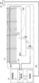
First, the configuration of an optical fiber sensing system according to the present embodiment 1 will be described with reference to Fig. 1. In the present embodiment 1, the description will be given assuming that the object to be monitored is a
図1に示されるように、本実施の形態1に係る光ファイバセンシングシステムは、フェンス10及びその周辺にいる監視対象を追跡するものであり、光ファイバケーブル20及び監視装置30を備えている。また、監視装置30は、光ファイバ検知部31及び監視部32を備えている。なお、光ファイバ検知部31は、受信部の一例である。As shown in Fig. 1, the optical fiber sensing system according to the first embodiment tracks a
光ファイバケーブル20は、1以上の光ファイバを被覆して構成されるケーブルであり、気中のフェンス10及びフェンス10周辺の地中に一続きで敷設され、両端が光ファイバ検知部31に接続されている。図1では、光ファイバケーブル20は、気中に敷設された部分は実線で示され、地中に敷設された部分は点線で示されている。ただし、図1に示される光ファイバケーブル20の敷設方法は、一例であって、これに限定されるものではない。例えば、光ファイバケーブル20は、光ファイバセンシング(後述のパターン検知に基づく監視対象の追跡)を行う光ファイバセンシングエリアAR1内に、気中又は地中であるかを問わず、網羅的に敷設されていれば良い。The
光ファイバ検知部31は、光ファイバケーブル20に含まれる少なくとも1つの光ファイバにパルス光を入射する。また、光ファイバ検知部31は、パルス光が光ファイバを伝送されることに伴い発生した反射光や散乱光を、同じ光ファイバを経由して、戻り光として受信する。図1では、光ファイバ検知部31は、時計回りの方向にパルス光を入射し、時計回りの方向から、このパルス光に対する戻り光を受信すると共に、反時計回りの方向にパルス光を入射し、反時計回りの方向から、このパルス光に対する戻り光を受信する。そのため、光ファイバ検知部31は、2方向から戻り光を受信している。The optical
フェンス10及びその周辺で振動が発生すると、その振動は光ファイバによって伝送される戻り光に重畳される。そのため、光ファイバ検知部31は、受信された戻り光に基づいて、フェンス10及びその周辺で発生した振動を検知することが可能である。また、光ファイバ検知部31は、光ファイバにパルス光を入射してから、振動が重畳された戻り光が受信されるまでの時間に基づいて、その振動が発生した位置(光ファイバ検知部31からの距離)も検知することが可能である。When vibrations occur on the
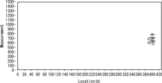
例えば、光ファイバ検知部31は、受信された戻り光を分散型振動センサ(Distributed Vibration Sensor)で検知することにより、フェンス10及びその周辺で発生した振動及びその振動が発生した位置を検知し、フェンス10及びその周辺で発生した振動の振動データを取得することが可能である。例えば、図2は、フェンス10及びその周辺で発生した振動の振動データの例を示しており、横軸は、位置(光ファイバ検知部31からの距離)、縦軸は、時間経過を示している。図2に示される例では、光ファイバ検知部31から約400m離れた位置に振動が発生している。For example, the optical
ここで、光ファイバ検知部31で検知された、フェンス10及びその周辺で発生した振動の振動データは、フェンス10及びその周辺にいる人の状態に応じて、振動の強弱、振動位置、振動数の変動の推移等が異なる固有パターンを有している。Here, the vibration data of vibrations generated on the
そのため、監視部32は、振動データが有する固有パターンの動的変化を分析することにより、フェンス10及びその周辺にいる監視対象の位置を特定することが可能となり、また、その人の位置変動を分析することにより、その人の軌跡を特定することが可能となる。また、監視部32は、上記で特定された監視対象の軌跡に基づいて、監視対象が次に移動する位置を予測しても良い。Therefore, by analyzing the dynamic changes in the unique pattern of the vibration data, the
さらに、監視部32は、振動データが有する固有パターンの動的変化を分析することにより、フェンス10及びその周辺にいる監視対象が、上記で特定された位置で取った行動を特定することも可能となる。フェンス10及びその周辺にいる人の行動としては、例えば、以下が考えられる。
(1)フェンス10を掴んで揺らす
(2)フェンス10を叩く
(3)フェンス10をよじ登る
(4)フェンス10に梯子を掛けて、梯子を登る
(5)フェンス10周辺をうろつく
(6)フェンス10周辺に穴を掘る
(7)フェンス10周辺で発砲する
(8)フェンス10周辺に物を置く
Furthermore, by analyzing dynamic changes in the unique pattern of the vibration data, the
(1) Grab the
例えば、監視対象がフェンス10を叩きながら移動し、最終的にフェンス10周辺に穴を掘っていることを示す振動データは、図3のようになる。図3に示される振動データは、図2に示される振動データと同様の振動データを、時系列に縦方向に並べたものである。For example, vibration data showing that a monitored subject moves while tapping on the
ここで、監視部32において、フェンス10及びその周辺で発生した振動の振動データに基づいて、フェンス10及びその周辺にいる監視対象の行動を特定する方法としては、例えば、パターンマッチングを利用する方法が挙げられる。以下、パターンマッチングの一例を説明する。Here, the
監視部32は、例えば、フェンス10及びその周辺で人が上述の(1)~(8)の行動をしたときに発生した振動の振動データが有する固有パターンを、事前に学習しておく。学習方法としては、機械学習が考えられるが、これには限定されない。The
監視部32は、フェンス10及びその周辺にいる監視対象の行動を特定する場合、まず、光ファイバ検知部31から振動データを取得する。そして、監視部32は、光ファイバ検知部31から取得された振動データが有するパターンと、事前に学習された振動データが有するパターンと、のパターンマッチングを行うことで、フェンス10及びその周辺にいる監視対象の行動を特定する。When the
また、フェンス10及びその周辺で発生した音及び温度も、光ファイバによって伝送される戻り光に重畳される。そのため、光ファイバ検知部31は、受信された戻り光に基づいて、フェンス10及びその周辺で発生した音及び温度も検知することが可能である。In addition, the sound and temperature generated at and around the
例えば、光ファイバ検知部31は、受信された戻り光を分散型音響センサ(Distributed Acoustic Sensor)及び分散型温度センサ(Distributed Temperature Sensor)で検知することにより、フェンス10及びその周辺で発生した音及び温度を検知し、フェンス10及びその周辺で発生した音及び温度の音響データ及び温度データを取得することが可能である。その他にも、光ファイバ検知部31は、フェンス10及びその周辺で発生した歪み・応力を検知し、歪み・応力データを取得することも可能である。また、上述の音響データ、温度データ、及び歪み・応力データも、フェンス10及びその周辺にいる監視対象の状態に応じた固有パターンを有している。For example, the optical
そのため、監視部32は、フェンス10及びその周辺に発生した振動の固有パターンだけでなく、音、温度、歪み・応力等の固有パターンを含む、複合的な固有パターンの動的変化を分析することにより、さらに高精度に人の軌跡及び行動を特定することが可能になると共に、さらに複雑な人の行動を特定することが可能となる。Therefore, by analyzing dynamic changes in complex unique patterns including not only the unique patterns of vibrations generated on the
ここで、本実施の形態1において、監視部32が監視対象の追跡を行う例について、説明する。
例えば、図4に示されるように、光ファイバセンシングエリアAR1内を監視対象が移動したとする。この場合、監視部32は、光ファイバ検知部31で受信された戻り光が有するパターンに基づいて、監視対象が移動した各位置を特定し、さらに、特定された位置の位置変動に基づいて、監視対象の軌跡を特定する。さらに、監視部32は、戻り光が有するパターンに基づいて、監視対象が、上記で特定された位置で取った行動も特定する。
Here, an example in which the
For example, assume that a monitoring target moves within the optical fiber sensing area AR1 as shown in Fig. 4. In this case, the
続いて以下では、図5を参照して、監視装置30を実現するコンピュータ60のハードウェア構成について説明する。
図5に示されるように、コンピュータ60は、プロセッサ601、メモリ602、ストレージ603、入出力インタフェース(入出力I/F)604、及び通信インタフェース(通信I/F)605等を備える。プロセッサ601、メモリ602、ストレージ603、入出力インタフェース604、及び通信インタフェース605は、相互にデータを送受信するためのデータ伝送路で接続されている。
Next, the hardware configuration of the
5, the
プロセッサ601は、例えばCPU(Central Processing Unit)やGPU(Graphics Processing Unit)等の演算処理装置である。メモリ602は、例えばRAM(Random Access Memory)やROM(Read Only Memory)等のメモリである。ストレージ603は、例えばHDD(Hard Disk Drive)、SSD(Solid State Drive)、またはメモリカード等の記憶装置である。また、ストレージ603は、RAMやROM等のメモリであっても良い。The
ストレージ603は、監視装置30が備える光ファイバ検知部31及び監視部32の機能を実現するプログラムを記憶している。プロセッサ601は、これら各プログラムを実行することで、光ファイバ検知部31及び監視部32の機能をそれぞれ実現する。ここで、プロセッサ601は、上記各プログラムを実行する際、これらのプログラムをメモリ602上に読み出してから実行しても良いし、メモリ602上に読み出さずに実行しても良い。また、メモリ602やストレージ603は、光ファイバ検知部31及び監視部32が保持する情報やデータを記憶する役割も果たす。
また、上述したプログラムは、様々なタイプの非一時的なコンピュータ可読媒体(non-transitory computer readable medium)を用いて格納され、コンピュータ(コンピュータ60を含む)に供給することができる。非一時的なコンピュータ可読媒体は、様々なタイプの実体のある記録媒体(tangible storage medium)を含む。非一時的なコンピュータ可読媒体の例は、磁気記録媒体(例えば、フレキシブルディスク、磁気テープ、ハードディスクドライブ)、光磁気記録媒体(例えば、光磁気ディスク)、CD-ROM(Compact Disc-ROM)、CD-R(CD-Recordable)、CD-R/W(CD-ReWritable)、半導体メモリ(例えば、マスクROM、PROM(Programmable ROM)、EPROM(Erasable PROM)、フラッシュROM、RAMを含む。また、プログラムは、様々なタイプの一時的なコンピュータ可読媒体(transitory computer readable medium)によってコンピュータに供給されても良い。一時的なコンピュータ可読媒体の例は、電気信号、光信号、及び電磁波を含む。一時的なコンピュータ可読媒体は、電線及び光ファイバ等の有線通信路、又は無線通信路を介して、プログラムをコンピュータに供給できる。The above-mentioned program can be stored using various types of non-transitory computer readable media and supplied to a computer (including computer 60). The non-transitory computer readable medium includes various types of tangible storage media. Examples of the non-transitory computer readable medium include magnetic recording media (e.g., flexible disks, magnetic tapes, hard disk drives), magneto-optical recording media (e.g., magneto-optical disks), compact disc-ROMs (CD-ROMs), CD-recordables (CD-Rs), CD-rewritables (CD-RWs), semiconductor memories (e.g., mask ROMs, programmable ROMs (PROMs), erasable PROMs (EPROMs), flash ROMs, and RAMs). The program may also be supplied to a computer by various types of transitory computer readable media. Examples of the transitory computer readable medium include electrical signals, optical signals, and electromagnetic waves. The transitory computer readable medium can supply the program to a computer via a wired communication path such as an electric wire or optical fiber, or via a wireless communication path.
入出力インタフェース604は、表示装置6041や入力装置6042等と接続される。表示装置6041は、LCD(Liquid Crystal Display)やCRT(Cathode Ray Tube)ディスプレイのような、プロセッサ601により処理された描画データに対応する画面を表示する装置である。入力装置6042は、オペレータの操作入力を受け付ける装置であり、例えば、キーボード、マウス、及びタッチセンサ等である。表示装置6041及び入力装置6042は一体化され、タッチパネルとして実現されていても良い。なお、コンピュータ60は、分散型振動センサ等の不図示のセンサを備え、このセンサを入出力インタフェース604に接続した構成であっても良い。The input/
通信インタフェース605は、外部の装置との間でデータを送受信する。例えば、通信インタフェース605は、有線通信路または無線通信路を介して外部装置と通信する。The
<実施の形態1の動作>
以下、図6を参照して、本実施の形態1に係る光ファイバセンシングシステムの動作フローについて説明する。
<Operation of First Embodiment>
Hereinafter, with reference to FIG. 6, an operation flow of the optical fiber sensing system according to the first embodiment will be described.
図6に示されるように、まず、光ファイバ検知部31は、光ファイバケーブル20に含まれる少なくとも1つの光ファイバにパルス光を入射し、パルス光を入射した光ファイバと同じ光ファイバから、フェンス10及びその周辺にいる監視対象の状態に応じたパターンを有する戻り光を受信する(ステップS11)。As shown in FIG. 6, first, the optical
その後、監視部32は、戻り光が有するパターンに基づいて、監視対象の位置を特定し、特定された位置の位置変動に基づいて、監視対象の軌跡を特定する(ステップS12)。このとき、監視部32は、戻り光が有するパターンに基づいて、監視対象が、上記で特定された位置で取った行動を、さらに特定しても良い。Then, the
以下、図7を参照して、本実施の形態1に係る監視部32の具体的な動作について説明する。なお、図7は、振動データに基づいて監視対象を追跡する例である。
図7の例では、複数のポイント(P1~P3)で振動パターンが発生している。そのため、監視部32は、複数のポイント(P1~P3)で振動パターンを検知し、振動パターンが検知された位置の位置変動に基づいて、監視対象の軌跡を特定する。ただし、軌跡の特定方法はこれには限定されない。
Hereinafter, a specific operation of the
In the example of Fig. 7, vibration patterns occur at multiple points (P1 to P3). Therefore, the
例えば、監視部32は、複数のポイント(P1~P3)で検知された振動パターンを複合的にマッチング・解析して監視対象の軌跡を特定しても良い。複合的なマッチング・解析には、例えば、複数のポイント(P1~P3)をひとまとまりのパターンと捉え、モデル(例えば人物の歩行を表すパターン)とマッチングする処理を含む。For example, the
また、監視部32は、それぞれのポイントにおける変動を解析して、追跡している監視対象の固有パターンを特定し、監視対象を特定しつつ追跡を実施しても良い。その場合、例えば、監視部32は、P1、P2で特定した人物行動の固有パターンをP3で検出するようにパターンマッチングを実施することで、P1~P3が同一の人物による振動パターンであることを特定し、移動軌跡を特定しても良い。
The
また、図7の例では、P1~P3が近接しているが、例えば、ポイントP3がP1、P2点から離れており連続的に検知できないような場合がある。その場合、例えば、監視部32は、P1~P2の検出結果から、監視対象の移動方向、移動速度等を特定し、P3のあたりでのパターン解析を予測して実施しても良い。このとき、監視部32は、ポイントが変動した時間とポイント間の距離との関係から移動速度を特定しても良い。
In the example of Figure 7, P1 to P3 are close to each other, but there are cases where, for example, point P3 is far from points P1 and P2 and cannot be detected continuously. In such cases, for example, the
<実施の形態1の効果>
上述したように本実施の形態1によれば、監視装置30は、光ファイバケーブル20に含まれる少なくとも1つの光ファイバから受信した戻り光が有する監視対象の状態に応じたパターンに基づいて、監視対象の位置を特定し、特定された位置の位置変動に基づいて、監視対象の軌跡を特定する。そのため、広範な監視エリアであっても、監視エリアに網羅的に光ファイバケーブル20を敷設することで、監視対象の連続的な追跡が可能である。また、光ファイバケーブル20は、安価であり、敷設も容易である。よって、監視対象の連続的な追跡が可能なシステムを、安価かつ容易に構築することができる。
<Effects of First Embodiment>
As described above, according to the first embodiment, the
また、本実施の形態1によれば、監視装置30は、戻り光が有するパターンに基づいて、監視対象が取った軌跡及び行動を特定する。このようなパターン検知に基づく追跡は、カメラ画像に基づく追跡と比較して、以下の利点がある。
・物陰等のカメラの死角ポイントにおける監視対象の軌跡及び行動も、途切れることなく追跡することが可能である。
・カメラにハレーションが発生し、カメラ画像に監視対象が映らない場合でも、監視対象の軌跡及び行動を追跡することが可能である。
・カメラで撮影されないような行動(例えば、顔を隠す、カメラの死角ポイントに移動する)をしている監視対象の軌跡及び行動も追跡することが可能である。
According to the first embodiment, the
- It is possible to seamlessly track the trajectory and behavior of a monitored subject even in blind spots of the camera, such as behind objects.
- Even if the camera has glare and the target of surveillance is not visible in the camera image, it is possible to track the trajectory and behavior of the target of surveillance.
It is also possible to track the trajectory and behavior of a monitored subject who is engaged in actions that are not captured by the camera (e.g., hiding their face, moving to a point in the camera's blind spot).
また、本実施の形態1によれば、監視装置30は、上述のように、戻り光が有するパターンに基づいて、監視対象が取った行動を特定する。すなわち、監視装置30は、例えば、振動の大小といった大まかな基準で行動を特定する(例えば、振動が大、振動数が高で、行動を特定する)のではなく、戻り光の変化を動的に(例えば、振動の強弱の変化の推移等)パターン分析することで、監視対象の行動を特定する。そのため、監視対象の行動を高精度に特定することが可能である。
Furthermore, according to the first embodiment, the
また、本実施の形態1によれば、光ファイバをセンサとして用いる光ファイバセンシング技術を利用する。そのため、電磁ノイズの影響を受けない、センサへの給電が不要になる、環境耐性に優れる、メンテナンスが容易になる等の利点が得られる。 Furthermore, according to the first embodiment, optical fiber sensing technology is used, which uses optical fiber as a sensor. Therefore, advantages are obtained such as immunity to electromagnetic noise, no need to supply power to the sensor, excellent environmental resistance, and easy maintenance.
<実施の形態2>
<実施の形態2の構成>
まず、図8を参照して、本実施の形態2に係る光ファイバセンシングシステムの構成について説明する。なお、本実施の形態2でも、上述した実施の形態1と同様に、監視対象がフェンス10及びその周辺にいる人であるものとして説明するが、監視対象はこれに限定されるものではない。
<
<Configuration of Second Embodiment>
First, the configuration of an optical fiber sensing system according to the second embodiment will be described with reference to Fig. 8. Note that, in the second embodiment, as in the first embodiment, the monitoring target will be described as the
図8に示されるように、本実施の形態2に係る光ファイバセンシングシステムは、上述した実施の形態1と比較して、カメラ40が追加されている。なお、図8においては、カメラ40が1台だけ設けられているが、カメラ40は複数台設けても良い。As shown in Fig. 8, the optical fiber sensing system according to the second embodiment has a
カメラ40は、フェンス10及びその周辺を撮影するカメラであり、例えば、固定カメラ、PTZ(Pan Tilt Zoom)カメラ等で実現される。なお、図8においては、カメラ40で撮影することが可能な撮影可能エリアAR2は、光ファイバセンシングエリアAR1の内部に含まれている。ただし、光ファイバセンシングエリアAR1と撮影可能エリアAR2の関係はこれに限定されない。例えば、撮影可能エリアAR2は、光ファイバセンシングエリアAR1に隣接して、または一部重複して配置されても良い。The
監視部32は、カメラ40の設置位置(光ファイバ検知部31からの距離、カメラ40の設置位置の緯度経度等)、撮影可能エリアを規定する位置(緯度経度等)等を示すカメラ情報を保持する。また、監視部32は、上述のように、光ファイバ検知部31で受信された戻り光が有するパターンに基づいて、監視対象の位置を特定することが可能である。そのため、監視部32は、撮影可能エリアAR2内に監視対象がいることが検知された場合、カメラ40を制御する。例えば、監視部32は、カメラ40の角度(方位角、仰角)、ズーム倍率等を制御する。The
そのため、監視部32は、撮影可能エリアAR2内に監視対象がいる場合には、カメラ40で撮影されたカメラ画像の画像認識を行い、監視対象の位置を特定し、特定された位置の位置変動に基づいて、監視対象の軌跡を特定することも可能である。また、監視部32は、カメラ画像の画像認識を行い、監視対象の行動を特定したり、カメラ画像に写る監視対象の顔認証を行ったりすることも可能である。Therefore, when a monitoring target is present within the photographable area AR2, the
以下、本実施の形態2において、監視部32が監視対象の追跡を行う例について、具体的に説明する。なお、以下の説明において、カメラ画像に基づく追跡又はカメラ画像に基づく監視対象の追跡とは、カメラ40で撮影されたカメラ画像に基づいて監視対象の軌跡及び行動を特定することを意味するものとする。また、パターン検知に基づく追跡又はパターン検知に基づく監視対象の追跡とは、光ファイバ検知部31で受信された戻り光が有するパターンに基づいて監視対象の軌跡及び行動を特定することを意味するものとする。なお、監視部32は、例えば、検出された監視対象ごとに固有のIDを割り当て、監視対象の位置情報を当該監視対象のIDに対応付けて時系列で記録することで、監視対象の軌跡を記録しても良い。Hereinafter, in the
(1)第1の例
図9に示されるように、本例は、監視対象が、撮影可能エリアAR2の内部から、撮影可能エリアAR2の外部に出る例である。
(1) First Example As shown in FIG. 9, this example is an example in which the monitored subject moves from inside the imageable area AR2 to outside the imageable area AR2.
監視部32は、監視対象が撮影可能エリアAR2の内部にいるときは、カメラ画像に基づく監視対象の追跡を行う。このとき、監視部32は、撮影可能エリアAR2の内部にいる特定の人のみを監視対象として追跡しても良い。監視対象の追跡のトリガとしては、例えば、以下が考えられる。
・カメラ画像に写る人がブラックリストに載っている人物と一致すること(顔認証、全身認証、歩容認証等による一致)
・カメラ画像に写る人が所定の行動(ふらつき、うろつき、所定時間以上の滞在、物を振り回す、フェンス10に近づく等)を取っていること
・カメラ画像に写る人が特定の服装であったり、特定の所持品を所持していたりしたこと
When the monitoring target is within the photographable area AR2, the
- The person in the camera image matches a person on the blacklist (matching based on facial recognition, full-body recognition, gait recognition, etc.)
A person captured in a camera image is engaged in a specific behavior (e.g., wandering around, staying for a certain period of time, swinging an object around, approaching the
監視部32は、監視対象が撮影可能エリアAR2の内部から外部に出ると、監視対象の追跡を、カメラ画像に基づく追跡から、パターン検知に基づく追跡に切り替える。例えば、監視部32は、同一の監視対象のIDについて、カメラ画像から特定された位置情報を記録していたのを、パターン検知によって特定された位置情報の記録に切り替える。このとき、監視部32は、カメラ画像を画像認識して監視対象が撮影可能エリアAR2の外部に出る位置を予測し、予測された位置を開始点として、パターン検知に基づく追跡を迅速に開始できるように準備しておいても良い。また、監視部32は、実際に監視対象が撮影可能エリアAR2の外部に出た位置を特定し、特定された位置を開始点として、パターン検知に基づく追跡を開始しても良い。ただし、カメラ画像で特定された位置を、パターン検知に基づく追跡の開始点とするためには、カメラ画像上の位置を、ファイバセンサ上の位置に変換する処理が必要となる。そこで、例えば、監視部32は、カメラ座標とファイバセンサの座標とを対応づけるテーブルを予め保持し、このテーブルを用いて上述の位置変換をしても良い。また、監視部32は、カメラ座標と世界座標を対応付けるテーブルと、世界座標とファイバセンサの座標を対応付けるテーブルと、の2つのテーブルを予め保持し、これらの2つのテーブルを用いて上述の位置変換をしても良い。監視部32は、このようなテーブルを用いることで、カメラ画像に基づく追跡から、パターン検知に基づく追跡に切り替え、監視対象を連続的に追跡する。When the monitored object leaves the photographable area AR2, the
なお、監視部32は、監視対象が撮影可能エリアAR2の内部にいるときに、カメラ画像に基づく監視対象の追跡と同時に、パターン検知に基づく監視対象の追跡を行っても良い。例えば、監視対象の軌跡は、カメラ画像に基づく追跡によって特定し、監視対象の行動は、パターン検知に基づく追跡によって特定しても良い。また、カメラ画像に基づく追跡及びパターン検知に基づく追跡の両方で、監視対象の位置及び軌跡を特定し、カメラ画像に基づく追跡によって特定された位置情報と、パターン検知に基づく追跡によって特定された位置情報と、の両方を記録しても良い。When the monitoring target is within the photographable area AR2, the
また、監視部32は、カメラ画像に基づく監視対象の追跡と同時に、パターン検知に基づく監視対象の追跡を行う場合、監視対象の行動に応じてカメラ40の制御を変更しても良い。例えば、監視部32は、より緊急度の高い不審行動(例えば、フェンス10周辺に穴を掘る、フェンス10をよじ登る等)が検知された場合、より詳細に顔、人を特定するようにカメラ40のズームアップを行っても良い。また、監視部32は、より緊急度の高い不審行動が検知された場合、撮影可能エリアAR2を複数台のカメラ40で撮影可能であれば、複数台のカメラ40で監視対象を追跡しても良い。また、監視部32は、複数台のカメラ40で監視対象を追跡する場合、複数台のカメラ40のうちの少なくとも1台のカメラ40は、監視対象の顔を撮影して、撮影された顔画像を顔認証に活用し、複数台のカメラ40のうちの少なくとも1台のカメラ40は、撮影可能エリアAR2全体を撮影することで、撮影された画像を、監視対象の行動監視に活用しても良い。In addition, when the
(2)第2の例
図10に示されるように、本例は、監視対象が、撮影可能エリアAR2の外部から、撮影可能エリアAR2の内部に入る例である。
(2) Second Example As shown in FIG. 10, this example is an example in which a monitored subject enters the inside of the imageable area AR2 from the outside of the imageable area AR2.
監視部32は、監視対象が撮影可能エリアAR2の外部にいるときは、パターン検知に基づく監視対象の追跡を行う。このとき、監視部32は、撮影可能エリアAR2の外部にいる特定の人のみを監視対象として追跡しても良い。監視対象の追跡のトリガとしては、例えば、フェンス10及びその周辺にいる人が、上述の(1)~(8)の行動をしたこと等が考えられる。When the monitoring target is outside the photographable area AR2, the
監視部32は、監視対象が撮影可能エリアAR2の外部から内部に入ると、監視対象の追跡を、パターン検知に基づく追跡から、カメラ画像に基づく追跡に切り替える。例えば、監視部32は、同一の監視対象のIDについて、パターン検知によって特定された位置情報を記録していたのを、カメラ画像から特定された位置情報の記録に切り替える。このとき、監視部32は、パターン検知に基づく追跡により監視対象が撮影可能エリアAR2に近づいたことを検知した場合、監視対象がいる方向を特定し、特定された方向にカメラを向ける、さらにズームアップを行う等の制御をしても良い。また、監視部32は、実際に監視対象が撮影可能エリアAR2の内部に入った位置を特定し、特定された位置を開始点として、カメラ画像に基づく追跡を開始しても良い。ただし、パターン検知で特定された位置を、カメラ画像に基づく追跡の開始点とするためには、ファイバセンサ上の位置を、カメラ画像上の位置に変換する処理が必要となる。そこで、例えば、監視部32は、上述の第1の例で説明したテーブルと同様のテーブルを予め保持し、このテーブルを用いて上述の位置変換をしても良い。監視部32は、このようなテーブルを用いることで、パターン検知に基づく追跡から、カメラ画像に基づく追跡に切り替え、監視対象を連続的に追跡する。When the monitoring target enters the photographable area AR2 from outside, the
なお、監視部32は、上述の第1の例と同様に、監視対象が撮影可能エリアAR2の内部にいるときに、カメラ画像に基づく監視対象の追跡と同時に、パターン検知に基づく監視対象の追跡を行っても良い。このときの具体例は、上述の第1の例と同様である。
As in the first example described above, when the monitoring target is inside the photographable area AR2, the
(3)第3の例
図11に示されるように、本例は、光ファイバセンシングエリアAR1の内部や、撮影可能エリアAR2の内部に、複数の人がいる場合の例である。
(3) Third Example As shown in FIG. 11, this example is an example in which a plurality of people are present inside the optical fiber sensing area AR1 and inside the imageable area AR2.
監視部32は、複数の人がいる場合、複数の人を全て監視対象にするのではなく、特定の人のみを監視対象にしても良い。
例えば、監視部32は、撮影可能エリアAR2の内部に複数の人がいる場合、複数の人のいずれかについて、以下の事象を検知した場合、その人を監視対象に決定することが考えられる。
・カメラ画像に写る人がブラックリストに載っている人物と一致すること(顔認証、全身認証、歩容認証等による一致)
・カメラ画像に写る人が所定の行動(ふらつき、うろつき、所定時間以上の滞在、物を振り回す、フェンス10に近づく等)を取っていること
・カメラ画像に写る人が特定の服装であったり、特定の所持品を所持していたりしたこと
この場合、以降、監視部32は、監視対象となった人のみを、パターン検知に基づく追跡及びカメラ画像に基づく追跡によって追跡する。また、監視部32は、監視対象となった人が何らかの行動を取ったときの振動データ等のパターンを、不審行動のパターン(例えば、歩く方向、歩くスピード、歩幅、足音等)として学習しておいても良い。
When there are multiple people, the
For example, when there are multiple people within the photographable area AR2, if the
- The person in the camera image matches a person on the blacklist (matching based on facial recognition, full-body recognition, gait recognition, etc.)
A person captured in a camera image is engaged in a specific behavior (e.g., wandering around, staying for a certain period of time, swinging an object around, approaching the
In this case, thereafter, the
また、監視部32は、光ファイバセンシングエリアAR1の内部に複数の人がいる場合、複数の人の各々について行動を特定し、複数の人の各々の行動に基づいて、複数の人の中から監視対象を決定しても良い。例えば、監視部32は、不審行動を取っている人を監視対象として決定しても良い。この場合、以降、監視部32は、監視対象となった人のみを、パターン検知に基づく追跡及びカメラ画像に基づく追跡によって追跡する。また、上述の不審行動は、複数の行動を組み合わせた行動(例えば、フェンス10周辺をうろついた後に、物を置く等)としても良い。また、監視部32は、監視対象となった人が撮影可能エリアAR2の内部に入ると、その人の顔を撮影するようにカメラ40の向き、ズーム、露出等を制御し、その人を上述のブラックリストに追加しても良い。In addition, when there are multiple people inside the optical fiber sensing area AR1, the
<実施の形態2の動作>
以下、図12を参照して、本実施の形態2に係る光ファイバセンシングシステムの動作フローについて説明する。なお、図12は、監視対象が撮影可能エリアAR2の内部にいるときは、カメラ画像に基づく追跡のみを行い、パターン検知に基づく追跡は行わない場合の例である。
<Operation of the Second Embodiment>
Hereinafter, an operation flow of the optical fiber sensing system according to the second embodiment will be described with reference to Fig. 12. Fig. 12 shows an example of a case where, when a monitored object is inside the image-capable area AR2, tracking is performed only based on camera images, and tracking based on pattern detection is not performed.
図12に示されるように、まず、光ファイバ検知部31は、光ファイバケーブル20に含まれる少なくとも1つの光ファイバにパルス光を入射し、パルス光を入射した光ファイバと同じ光ファイバから、フェンス10及びその周辺にいる監視対象の状態に応じたパターンを有する戻り光を受信する(ステップS21)。As shown in FIG. 12, first, the optical
続いて、監視部32は、監視対象が撮影可能エリアAR2の内部にいるか否かを判断する(ステップS22)。Next, the
監視対象が撮影可能エリアAR2の内部にいる場合(ステップS22のYes)、続いて、監視部32は、カメラ40で撮影されたカメラ画像に基づいて、監視対象の位置を特定し、特定された位置の位置変動に基づいて、監視対象の軌跡を特定する(ステップS23)。このとき、監視部32は、カメラ画像に基づいて、監視対象が、上記で特定された位置で取った行動を特定しても良い。If the monitoring target is within the photographable area AR2 (Yes in step S22), the
一方、監視対象が撮影可能エリアAR2の内部にいない場合(ステップS22のNo)、続いて、監視部32は、戻り光が有するパターンに基づいて、監視対象の位置を特定し、特定された位置の位置変動に基づいて、監視対象の軌跡を特定する(ステップS24)。このとき、監視部32は、戻り光が有するパターンに基づいて、監視対象が、上記で特定された位置で取った行動を特定しても良い。On the other hand, if the monitoring target is not within the photographable area AR2 (No in step S22), the
<実施の形態2の効果>
上述したように本実施の形態2によれば、監視装置30は、光ファイバケーブル20に含まれる少なくとも1つの光ファイバから受信した戻り光が有する監視対象の状態に応じたパターン及びカメラ40で撮影されたカメラ画像に基づいて、監視対象の軌跡を特定する。このように、戻り光が有するパターン検知とカメラ画像とを連携させることで、監視対象の監視及び追跡をより高精度に行うことができる。
<Effects of the Second Embodiment>
As described above, according to the second embodiment, the
また、カメラ画像に基づく追跡は、パターン検知に基づく追跡と比較して、以下の利点がある。
・光ファイバケーブル20が敷設されていないポイントにおける監視対象の軌跡及び行動も、途切れることなく追跡することが可能である。
・監視対象の画像解析(顔検知、顔認証等)を行うことが可能である。
・ファイバへの接触を伴わない行為(荷物の受け渡し、物を振り回す等)を検出することが可能である。
Furthermore, tracking based on camera images has the following advantages over tracking based on pattern detection:
It is possible to seamlessly track the trajectory and behavior of the monitored object even at points where the
- It is possible to perform image analysis of the monitored subject (face detection, face recognition, etc.).
It is possible to detect actions that do not involve contact with the fiber (handing over luggage, swinging an object, etc.).
また、光ファイバケーブル20が敷設されているエリアとカメラ40で撮影可能なエリアとが重複するエリア(上述の撮影可能エリアAR2)においては、カメラ画像に基づく追跡と、パターン検知に基づく追跡と、を同時に行っても良い。この場合、光ファイバケーブル20が敷設されていないポイントでは、カメラ画像に基づく追跡を行い、カメラ40の死角ポイントでは、パターン検知に基づく追跡を行う等により、両者の追跡の利点を生かしつつ、監視対象の監視及び追跡を行うことができる。Furthermore, in an area where the area where the
また、カメラ画像に基づく追跡結果とパターン検知に基づく追跡結果とを統合して1つの事象を検知しても良い。例えば、以下の事象を検知することが考えられる。
・カメラ画像に基づく追跡でブラックリストに載っている人を検知し、その人がフェンス10を叩いていることを、パターン検知に基づく追跡で検知する。
・カメラ画像に基づく追跡及びパターン検知に基づく追跡の両方で、監視対象が穴を掘っていることを検知する。この場合、監視対象が穴を掘っている可能性が高いと考えられる。
In addition, a single event may be detected by integrating a tracking result based on a camera image and a tracking result based on pattern detection. For example, the following events may be detected.
- A person on the blacklist is detected by tracking based on camera images, and that person is detected hitting the
Both camera image-based tracking and pattern detection-based tracking detect that the subject is digging a hole. In this case, it is considered highly likely that the subject is digging a hole.
<実施の形態3>
<実施の形態3の構成>
まず、図13を参照して、本実施の形態3に係る光ファイバセンシングシステムの構成について説明する。なお、本実施の形態3でも、上述した実施の形態1,2と同様に、監視対象がフェンス10及びその周辺にいる人であるものとして説明するが、監視対象はこれに限定されるものではない。
<Third embodiment>
<Configuration of Third Embodiment>
First, the configuration of an optical fiber sensing system according to the third embodiment will be described with reference to Fig. 13. Note that, in the third embodiment, as in the first and second embodiments, the monitoring target will be described as the
図13に示されるように、本実施の形態3に係る光ファイバセンシングシステムは、上述した実施の形態2と比較して、表示部50が追加されている。
表示部50は、監視部32が追跡した監視対象の追跡結果を表示するもので、フェンス10及びその周辺を監視する監視ルーム等に設置される。なお、表示部50は、例えば、図6の表示装置6041として、図6のコンピュータ60(監視装置30を実現するコンピュータ)の入出力インタフェース604に接続される。
As shown in FIG. 13, the optical fiber sensing system according to the third embodiment is different from the second embodiment in that a
The
表示部50は、監視部32がカメラ画像に基づく監視対象の追跡を行っているときは、例えば、図14に示されるように、カメラ40で撮影されたカメラ画像を表示する。When the
また、表示部50は、監視部32がパターン検知に基づく監視対象の追跡を行っているときは、監視対象の軌跡の画像を表示する。このとき、表示部50は、地図上や、光ファイバセンシングエリアAR1を広域的に映した画像上に、監視対象の軌跡の画像を表示しても良い。例えば、図15の例は、図9の監視対象が撮影可能エリアAR2の外部に出た後の軌跡の画像を、光ファイバセンシングエリアAR1を広域的に映した画像上に表示した例である。また、図15のマークは、監視対象の特定された位置を示している。また、表示部50は、例えば、図16に示されるように、位置が特定された順番を示す数字等をマークに付加して、時系列がわかるような表示としても良い。また、監視部32が監視対象の次の移動位置を予測した場合、表示部50は、例えば、図17に示されるように、監視対象の次の予測位置を表示しても良い。また、表示部50は、例えば、図18に示されるように、光ファイバセンシングエリアAR1の画像及び撮影可能エリアAR2の画像を表示しても良い。
When the
また、表示部50は、監視対象が撮影可能エリアAR2の内部にいるときに、監視部32がカメラ画像に基づく追跡とパターン検知に基づく追跡とを同時に行う場合、例えば、図19に示されるように、カメラ40で撮影されたカメラ画像と、パターン検知に基づく追跡で得られた監視対象の軌跡の画像と、を同時に表示しても良い。なお、図19におけるカメラ画像と監視対象の軌跡の画像との位置関係は、一例であって、これに限定されるものではない。また、表示部50は、最初は、監視対象の軌跡の画像のみを表示しておき、その軌跡の画像上で監視対象の位置がクリック等されると、そのときの監視対象が映ったカメラ画像をポップアップ等で表示しても良い。
In addition, when the
また、表示部50は、光ファイバセンシングエリアAR1の内部に複数の人がおり、複数の人の中から監視対象を決定する前には、光ファイバセンシングエリアAR1の内部にいる複数の人の各々の位置をマークで表示しても良い。このとき、不審行動を取った人がいた場合、表示部50は、不審行動を取った人のマークを、他のマークよりも目立つように表示しても良い。例えば、図20に示されるように、表示部50は、不審行動を取った人のマークを大きく表示しても良い。また、表示部50は、不審行動を取った人がいた場合、ポップアップ等でアラームを表示しても良い。
Furthermore, when there are multiple people inside the optical fiber sensing area AR1, before determining a monitoring target from among the multiple people, the
<実施の形態3の動作>
以下、図21を参照して、本実施の形態3に係る光ファイバセンシングシステムの動作フローについて説明する。なお、図21は、監視対象が撮影可能エリアAR2の内部にいるときは、カメラ画像に基づく追跡のみを行い、パターン検知に基づく追跡は行わない場合の例である。
<Operation of Third Embodiment>
Hereinafter, an operation flow of the optical fiber sensing system according to the third embodiment will be described with reference to Fig. 21. Note that Fig. 21 shows an example of a case where, when a monitored object is inside the image-capable area AR2, tracking is performed only based on camera images, and tracking based on pattern detection is not performed.
図21に示されるように、まず、上述の実施の形態2の図12で説明したステップS21~S22の処理が行われる。
その後、図12で説明したステップS23の処理(カメラ画像に基づく追跡)が行われた場合は、続いて、表示部50は、カメラ40で撮影されたカメラ画像を表示する(ステップS31)。
As shown in FIG. 21, first, the processes of steps S21 to S22 described with reference to FIG. 12 in the second embodiment are carried out.
After that, when the process of step S23 described with reference to FIG. 12 (tracking based on camera images) is performed, the
一方、図12で説明したステップS24の処理(パターンに基づく追跡)が行われた場合は、続いて、表示部50は、パターン検知に基づく追跡で得られた監視対象の軌跡の画像を表示する(ステップS32)。このとき、表示部50は、上述のように、地図上や、光ファイバセンシングエリアAR1を広域的に映した画像上に、監視対象の軌跡の画像を表示しても良い。また、表示部50は、位置が特定された順番を示す数字等をマークに付加しても良い。また、表示部50は、監視対象の次の予測位置をさらに表示しても良い。また、表示部50は、光ファイバセンシングエリアAR1の画像及び撮影可能エリアAR2の画像をさらに表示しても良い。On the other hand, when the process of step S24 (pattern-based tracking) described in FIG. 12 is performed, the
<実施の形態3の効果>
上述したように本実施の形態3によれば、表示部50は、カメラ40で撮影されたカメラ画像や、監視部32で特定された監視対象の軌跡の画像を表示する。そのため、監視ルーム等にいる監視員等は、表示部50の表示内容に基づいて、監視対象の軌跡を視覚的にかつ効率良く判断することができるようになる。
<Effects of Third Embodiment>
As described above, according to the third embodiment, the
以上、実施の形態を参照して本開示を説明したが、本開示は上述の実施の形態に限定されるものではない。本開示の構成や詳細には、本開示のスコープ内で当業者が理解し得る様々な変更をすることができる。Although the present disclosure has been described above with reference to the embodiments, the present disclosure is not limited to the above-described embodiments. Various modifications that can be understood by a person skilled in the art can be made to the configuration and details of the present disclosure within the scope of the present disclosure.
例えば、上述の実施の形態では、監視対象がフェンス及びその周辺にいる人である例について説明したが、監視対象は、これに限定されない。監視対象は、フェンス以外に、壁、床、パイプライン、電柱、土木構造物、道路、線路、及びこれらの周辺等にいる人でも良い。また、これらのフェンスや壁等は、商業施設、空港、国境、病院、街中、港、プラント、介護施設、社屋、保育所、自宅等に設置されるものであっても良い。また、監視対象は、人以外に、動物、自動車等であっても良い。 For example, in the above embodiment, an example was described in which the monitored object was a fence and people in the vicinity thereof, but the monitored object is not limited to this. In addition to fences, monitored objects may also be walls, floors, pipelines, utility poles, civil engineering structures, roads, railways, and people in the vicinity thereof. Furthermore, these fences, walls, etc. may be installed in commercial facilities, airports, borders, hospitals, city centers, ports, plants, nursing homes, company buildings, daycare centers, homes, etc. Furthermore, monitored objects may also be animals, automobiles, etc., in addition to people.
また、上述の実施の形態では、監視装置30が光ファイバ検知部31及び監視部32を備えていていたが、これには限定されない。光ファイバ検知部31及び監視部32は、別々の装置で実現されても良い。In addition, in the above-described embodiment, the
上記の実施の形態の一部又は全部は、以下の付記のようにも記載されうるが、以下には限られない。
(付記1)
光ファイバを含むケーブルと、
前記ケーブルに含まれる少なくとも1つの光ファイバから、監視対象の状態に応じたパターンを有する光信号を受信する受信部と、
前記光信号が有するパターンに基づいて、前記監視対象の位置を特定し、特定された位置の位置変動に基づいて、前記監視対象の軌跡を特定する監視部と、
を備える光ファイバセンシングシステム。
(付記2)
前記監視部は、前記光信号が有するパターンに基づいて、前記監視対象の行動を特定する、
付記1に記載の光ファイバセンシングシステム。
(付記3)
前記監視対象を撮影可能なカメラをさらに備え、
前記監視部は、前記光信号が有するパターン及び前記カメラが撮影したカメラ画像に基づいて、前記監視対象の位置を特定し、特定された位置の位置変動に基づいて、前記監視対象の軌跡を特定する、
付記2に記載の光ファイバセンシングシステム。
(付記4)
前記監視部は、
前記監視対象が前記カメラの撮影可能エリアの内部にいるときは、前記カメラ画像に基づいて、前記監視対象の軌跡を特定し、
前記監視対象が前記撮影可能エリアの外部にいるときは、前記光信号が有するパターンに基づいて、前記監視対象の軌跡を特定する、
付記3に記載の光ファイバセンシングシステム。
(付記5)
前記監視部は、前記監視対象が前記カメラの撮影可能エリアの内部にいるときは、前記カメラ画像に基づいて、前記監視対象の軌跡を特定し、前記光信号が有するパターンに基づいて、前記監視対象の行動を特定する、
付記3に記載の光ファイバセンシングシステム。
(付記6)
前記監視対象は、人であり、
前記監視部は、複数の人がいる場合、前記光信号が有するパターンに基づいて、前記複数の人の各々について行動を特定し、前記複数の人の各々の行動に基づいて、前記複数の人の中から前記監視対象を決定する、
付記3から5のいずれか1項に記載の光ファイバセンシングシステム。
(付記7)
前記監視対象は、人であり、
前記監視部は、複数の人がいる場合、前記カメラ画像に基づいて、前記複数の人の各々について顔認証を行い、前記複数の人の各々の顔認証の結果に基づいて、前記複数の人の中から前記監視対象を決定する、
付記3から5のいずれか1項に記載の光ファイバセンシングシステム。
(付記8)
前記カメラが撮影したカメラ画像を表示すると共に、前記監視対象の特定された軌跡の画像を表示する表示部をさらに備える、
付記3から7のいずれか1項に記載の光ファイバセンシングシステム。
(付記9)
ケーブルに含まれる少なくとも1つの光ファイバから、監視対象の状態に応じたパターンを有する光信号を受信する受信部と、
前記光信号が有するパターンに基づいて、前記監視対象の位置を特定し、特定された位置の位置変動に基づいて、前記監視対象の軌跡を特定する監視部と、
を備える監視装置。
(付記10)
前記監視部は、前記光信号が有するパターンに基づいて、前記監視対象の行動を特定する、
付記9に記載の監視装置。
(付記11)
前記監視部は、前記光信号が有するパターン及び前記監視対象を撮影可能なカメラが撮影したカメラ画像に基づいて、前記監視対象の位置を特定し、特定された位置の位置変動に基づいて、前記監視対象の軌跡を特定する、
付記10に記載の監視装置。
(付記12)
前記監視部は、
前記監視対象が前記カメラの撮影可能エリアの内部にいるときは、前記カメラ画像に基づいて、前記監視対象の軌跡を特定し、
前記監視対象が前記撮影可能エリアの外部にいるときは、前記光信号が有するパターンに基づいて、前記監視対象の軌跡を特定する、
付記11に記載の監視装置。
(付記13)
前記監視部は、前記監視対象が前記カメラの撮影可能エリアの内部にいるときは、前記カメラ画像に基づいて、前記監視対象の軌跡を特定し、前記光信号が有するパターンに基づいて、前記監視対象の行動を特定する、
付記11に記載の監視装置。
(付記14)
前記監視対象は、人であり、
前記監視部は、複数の人がいる場合、前記光信号が有するパターンに基づいて、前記複数の人の各々について行動を特定し、前記複数の人の各々の行動に基づいて、前記複数の人の中から前記監視対象を決定する、
付記11から13のいずれか1項に記載の監視装置。
(付記15)
前記監視対象は、人であり、
前記監視部は、複数の人がいる場合、前記カメラ画像に基づいて、前記複数の人の各々について顔認証を行い、前記複数の人の各々の顔認証の結果に基づいて、前記複数の人の中から前記監視対象を決定する、
付記11から13のいずれか1項に記載の監視装置。
(付記16)
監視装置による監視方法であって、
ケーブルに含まれる少なくとも1つの光ファイバから、監視対象の状態に応じたパターンを有する光信号を受信し、
前記光信号が有するパターンに基づいて、前記監視対象の位置を特定し、特定された位置の位置変動に基づいて、前記監視対象の軌跡を特定する、
監視方法。
(付記17)
コンピュータに、
ケーブルに含まれる少なくとも1つの光ファイバから、監視対象の状態に応じたパターンを有する光信号を受信する手順と、
前記光信号が有するパターンに基づいて、前記監視対象の位置を特定し、特定された位置の位置変動に基づいて、前記監視対象の軌跡を特定する手順と、
を実行させるためのプログラムが格納された非一時的なコンピュータ可読媒体。
A part or all of the above-described embodiments can be described as, but is not limited to, the following supplementary notes.
(Appendix 1)
a cable including an optical fiber;
a receiving unit that receives an optical signal having a pattern corresponding to a state of an object to be monitored from at least one optical fiber included in the cable;
a monitoring unit that identifies a position of the monitoring target based on a pattern of the optical signal, and identifies a trajectory of the monitoring target based on a positional fluctuation of the identified position;
An optical fiber sensing system comprising:
(Appendix 2)
The monitoring unit identifies a behavior of the monitoring target based on a pattern of the optical signal.
2. The optical fiber sensing system of claim 1.
(Appendix 3)
Further comprising a camera capable of photographing the monitoring target,
the monitoring unit specifies a position of the monitoring target based on a pattern of the optical signal and a camera image captured by the camera, and specifies a trajectory of the monitoring target based on a positional fluctuation of the specified position.
3. The optical fiber sensing system of
(Appendix 4)
The monitoring unit is
When the monitoring target is within a photographable area of the camera, a trajectory of the monitoring target is identified based on the camera image;
When the monitoring target is outside the photographable area, a trajectory of the monitoring target is identified based on a pattern of the optical signal.
4. The optical fiber sensing system of claim 3.
(Appendix 5)
When the monitoring target is within an area where the camera can capture an image, the monitoring unit identifies a trajectory of the monitoring target based on the camera image, and identifies a behavior of the monitoring target based on a pattern of the optical signal.
4. The optical fiber sensing system of claim 3.
(Appendix 6)
The monitoring target is a person,
the monitoring unit, when there are a plurality of people, identifies a behavior of each of the plurality of people based on a pattern of the optical signal, and determines the monitoring target from among the plurality of people based on the behavior of each of the plurality of people.
6. The optical fiber sensing system according to any one of claims 3 to 5.
(Appendix 7)
The monitoring target is a person,
When a plurality of people are present, the monitoring unit performs face authentication on each of the plurality of people based on the camera image, and determines the monitoring target from among the plurality of people based on the results of the face authentication on each of the plurality of people.
6. The optical fiber sensing system according to any one of claims 3 to 5.
(Appendix 8)
A display unit is further provided that displays a camera image captured by the camera and an image of the specified trajectory of the monitoring target.
8. The optical fiber sensing system according to claim 3,
(Appendix 9)
a receiving unit that receives an optical signal having a pattern corresponding to a state of an object to be monitored from at least one optical fiber included in the cable;
a monitoring unit that identifies a position of the monitoring target based on a pattern of the optical signal, and identifies a trajectory of the monitoring target based on a positional fluctuation of the identified position;
A monitoring device comprising:
(Appendix 10)
The monitoring unit identifies a behavior of the monitoring target based on a pattern of the optical signal.
10. The monitoring device of claim 9.
(Appendix 11)
the monitoring unit specifies a position of the monitoring target based on a pattern of the optical signal and a camera image captured by a camera capable of capturing an image of the monitoring target, and specifies a trajectory of the monitoring target based on a positional fluctuation of the specified position.
11. The monitoring device of
(Appendix 12)
The monitoring unit is
When the monitoring target is within a photographable area of the camera, a trajectory of the monitoring target is identified based on the camera image;
When the monitoring target is outside the photographable area, a trajectory of the monitoring target is identified based on a pattern of the optical signal.
12. The monitoring device of claim 11.
(Appendix 13)
When the monitoring target is within an area where the camera can capture an image, the monitoring unit identifies a trajectory of the monitoring target based on the camera image, and identifies a behavior of the monitoring target based on a pattern of the optical signal.
12. The monitoring device of claim 11.
(Appendix 14)
The monitoring target is a person,
the monitoring unit, when there are a plurality of people, identifies a behavior of each of the plurality of people based on a pattern of the optical signal, and determines the monitoring target from among the plurality of people based on the behavior of each of the plurality of people.
14. The monitoring device according to any one of appendixes 11 to 13.
(Appendix 15)
The monitoring target is a person,
When a plurality of people are present, the monitoring unit performs face authentication on each of the plurality of people based on the camera image, and determines the monitoring target from among the plurality of people based on the results of the face authentication on each of the plurality of people.
14. The monitoring device according to any one of appendixes 11 to 13.
(Appendix 16)
A monitoring method using a monitoring device, comprising:
receiving an optical signal having a pattern corresponding to a state of an object to be monitored from at least one optical fiber included in the cable;
identifying a position of the monitoring target based on a pattern possessed by the optical signal, and identifying a trajectory of the monitoring target based on a positional fluctuation of the identified position;
Monitoring methods.
(Appendix 17)
On the computer,
receiving an optical signal having a pattern corresponding to a state of an object to be monitored from at least one optical fiber included in the cable;
a step of identifying a position of the monitoring target based on a pattern of the optical signal, and identifying a trajectory of the monitoring target based on a positional fluctuation of the identified position;
A non-transitory computer-readable medium having stored thereon a program for executing the program.
10 フェンス
20 光ファイバケーブル
30 監視装置
31 光ファイバ検知部
32 監視部
40 カメラ
50 表示部
60 コンピュータ
601 プロセッサ
602 メモリ
603 ストレージ
604 入出力インタフェース
6041 表示装置
6042 入力装置
605 通信インタフェース
REFERENCE SIGNS
Claims (9)
前記ケーブルに含まれる少なくとも1つの光ファイバから、監視対象の状態に応じた振動パターンを有する散乱光を受信する受信部と、
前記散乱光が有する振動パターンに基づいて、前記監視対象の位置を特定し、特定された位置の位置変動に基づいて、前記監視対象の軌跡を特定する監視部と、
を備え、
前記監視部は、前記散乱光が有する振動パターンに基づいて、前記監視対象の行動を特定する、
光ファイバセンシングシステム。 a cable including an optical fiber;
a receiving unit that receives scattered light having a vibration pattern corresponding to a state of an object to be monitored from at least one optical fiber included in the cable;
a monitoring unit that identifies a position of the monitoring target based on a vibration pattern of the scattered light, and identifies a trajectory of the monitoring target based on a positional fluctuation of the identified position;
Equipped with
The monitoring unit identifies the behavior of the monitoring target based on a vibration pattern of the scattered light.
Fiber optic sensing system.
前記散乱光が有する振動パターンに基づいて、前記監視対象の位置を特定し、特定された位置の位置変動に基づいて、前記監視対象の軌跡を特定する監視部と、
を備え、
前記監視部は、前記散乱光が有する振動パターンに基づいて、前記監視対象の行動を特定する、
監視装置。 a receiving unit that receives scattered light having a vibration pattern corresponding to a state of an object to be monitored from at least one optical fiber included in the cable;
a monitoring unit that identifies a position of the monitoring target based on a vibration pattern of the scattered light, and identifies a trajectory of the monitoring target based on a positional fluctuation of the identified position;
Equipped with
The monitoring unit identifies the behavior of the monitoring target based on a vibration pattern of the scattered light.
Surveillance equipment.
請求項2に記載の監視装置。 The monitoring unit identifies a position of the monitoring target based on a vibration pattern of the scattered light and a camera image captured by a camera capable of capturing an image of the monitoring target, and identifies a trajectory of the monitoring target based on a positional fluctuation of the identified position.
The monitoring device according to claim 2 .
前記監視対象が前記カメラの撮影可能エリアの内部にいるときは、前記カメラ画像に基づいて、前記監視対象の軌跡を特定し、
前記監視対象が前記撮影可能エリアの外部にいるときは、前記散乱光が有する振動パターンに基づいて、前記監視対象の軌跡を特定する、
請求項3に記載の監視装置。 The monitoring unit is
When the monitoring target is within a photographable area of the camera, a trajectory of the monitoring target is identified based on the camera image;
When the monitoring target is outside the image capture area, a trajectory of the monitoring target is identified based on a vibration pattern of the scattered light.
The monitoring device according to claim 3 .
請求項3に記載の監視装置。 When the monitoring target is within an area where the camera can capture an image, the monitoring unit identifies a trajectory of the monitoring target based on the camera image, and identifies a behavior of the monitoring target based on a vibration pattern of the scattered light.
The monitoring device according to claim 3 .
前記監視部は、複数の人がいる場合、前記散乱光が有する振動パターンに基づいて、前記複数の人の各々について行動を特定し、前記複数の人の各々の行動に基づいて、前記複数の人の中から前記監視対象を決定する、
請求項3から5のいずれか1項に記載の監視装置。 The monitoring target is a person,
When a plurality of people are present, the monitoring unit identifies a behavior of each of the plurality of people based on a vibration pattern of the scattered light, and determines the monitoring target from among the plurality of people based on the behavior of each of the plurality of people.
A monitoring device according to any one of claims 3 to 5 .
前記監視部は、複数の人がいる場合、前記カメラ画像に基づいて、前記複数の人の各々について顔認証を行い、前記複数の人の各々の顔認証の結果に基づいて、前記複数の人の中から前記監視対象を決定する、
請求項3から5のいずれか1項に記載の監視装置。 The monitoring target is a person,
When a plurality of people are present, the monitoring unit performs face authentication on each of the plurality of people based on the camera image, and determines the monitoring target from among the plurality of people based on the results of the face authentication on each of the plurality of people.
A monitoring device according to any one of claims 3 to 5 .
ケーブルに含まれる少なくとも1つの光ファイバから、監視対象の状態に応じた振動パターンを有する散乱光を受信するステップと、
前記散乱光が有する振動パターンに基づいて、前記監視対象の位置を特定し、特定された位置の位置変動に基づいて、前記監視対象の軌跡を特定する特定ステップと、
を含み、
前記特定ステップでは、前記散乱光が有する振動パターンに基づいて、前記監視対象の行動を特定する、
監視方法。 A monitoring method using a monitoring device, comprising:
receiving scattered light from at least one optical fiber included in the cable, the scattered light having an oscillation pattern responsive to a condition of an object to be monitored;
a step of identifying a position of the monitoring target based on a vibration pattern of the scattered light, and identifying a trajectory of the monitoring target based on a positional fluctuation of the identified position;
Including,
In the identifying step, the behavior of the monitoring target is identified based on a vibration pattern of the scattered light.
Monitoring methods.
ケーブルに含まれる少なくとも1つの光ファイバから、監視対象の状態に応じた振動パターンを有する散乱光を受信する手順と、
前記散乱光が有する振動パターンに基づいて、前記監視対象の位置を特定し、特定された位置の位置変動に基づいて、前記監視対象の軌跡を特定する特定手順と、
を実行させるためのプログラムであり、
前記特定手順では、前記散乱光が有する振動パターンに基づいて、前記監視対象の行動を特定する、
プログラム。 On the computer,
receiving scattered light having an oscillation pattern responsive to a condition of an object to be monitored from at least one optical fiber included in the cable;
a step of identifying a position of the monitoring target based on a vibration pattern of the scattered light, and identifying a trajectory of the monitoring target based on a positional fluctuation of the identified position;
This is a program for executing
the identifying step includes identifying a behavior of the monitoring target based on a vibration pattern of the scattered light.
program .
Applications Claiming Priority (1)
| Application Number | Priority Date | Filing Date | Title |
|---|---|---|---|
| PCT/JP2019/004217 WO2020161823A1 (en) | 2019-02-06 | 2019-02-06 | Optical fiber sensing system, monitoring device, monitoring method, and computer-readable medium |
Publications (2)
| Publication Number | Publication Date |
|---|---|
| JPWO2020161823A1 JPWO2020161823A1 (en) | 2021-11-25 |
| JP7464281B2 true JP7464281B2 (en) | 2024-04-09 |
Family
ID=71947702
Family Applications (1)
| Application Number | Title | Priority Date | Filing Date |
|---|---|---|---|
| JP2020570258A Active JP7464281B2 (en) | 2019-02-06 | 2019-02-06 | Optical fiber sensing system, monitoring device, monitoring method, and program |
Country Status (3)
| Country | Link |
|---|---|
| US (1) | US20220120607A1 (en) |
| JP (1) | JP7464281B2 (en) |
| WO (1) | WO2020161823A1 (en) |
Families Citing this family (5)
| Publication number | Priority date | Publication date | Assignee | Title |
|---|---|---|---|---|
| US11816886B1 (en) * | 2018-06-28 | 2023-11-14 | Meta Platforms Technologies, Llc | Apparatus, system, and method for machine perception |
| US20220327923A1 (en) * | 2019-08-26 | 2022-10-13 | Nec Corporation | Optical fiber sensing system, road monitoring method, and optical fiber sensing device |
| JP7023429B1 (en) * | 2020-12-22 | 2022-02-21 | 楽天グループ株式会社 | Surveillance system and unmanned vehicle |
| CN113129530B (en) * | 2021-04-19 | 2022-05-31 | 深圳晶华相控科技有限公司 | Intelligent security electronic fence alarm system based on Internet of things and machine vision |
| CN113256926B (en) * | 2021-05-11 | 2022-10-25 | 仲永东 | Active fence system based on construction safety protection |
Citations (4)
| Publication number | Priority date | Publication date | Assignee | Title |
|---|---|---|---|---|
| JP2006208061A (en) | 2005-01-26 | 2006-08-10 | Comsec:Kk | Invasion detection sensor |
| WO2008111459A1 (en) | 2007-03-06 | 2008-09-18 | Kabushiki Kaisha Toshiba | Suspicious behavior detection system and method |
| JP2009128984A (en) | 2007-11-20 | 2009-06-11 | Yamamoto Sangyo Kk | Carpet and monitor device |
| CN107238412A (en) | 2017-06-26 | 2017-10-10 | 鞍山睿科光电技术有限公司 | It is a kind of while monitoring vibration, stress, the distributed fiberoptic sensor of temperature |
Family Cites Families (13)
| Publication number | Priority date | Publication date | Assignee | Title |
|---|---|---|---|---|
| JPH07198471A (en) * | 1993-12-29 | 1995-08-01 | Anritsu Corp | Vibration source position detector |
| US6218945B1 (en) * | 1997-09-10 | 2001-04-17 | John E Taylor, Jr. | Augmented monitoring system |
| JP4401232B2 (en) * | 2003-06-17 | 2010-01-20 | 株式会社クレヴァシステムズ | Intrusion detection system |
| JP4748981B2 (en) * | 2004-12-20 | 2011-08-17 | 株式会社クレヴァシステムズ | Intrusion detection sensor and intrusion detection system |
| ES2369039T3 (en) * | 2005-05-06 | 2011-11-24 | Omnilink Systems, Inc. | SYSTEM AND METHOD OF MONITORING THE MOVEMENT OF INDIVIDUALS AND PROPERTY. |
| GB2445364B (en) * | 2006-12-29 | 2010-02-17 | Schlumberger Holdings | Fault-tolerant distributed fiber optic intrusion detection |
| US7605369B2 (en) * | 2007-01-08 | 2009-10-20 | Max-Viz, Inc. | Assessing runway visibility to airborne infrared vision devices |
| DK177172B1 (en) * | 2010-11-05 | 2012-04-16 | Nkt Cables Group As | An integrity monitoring system and a method of monitoring integrity of a stationary structure |
| US10217133B2 (en) * | 2013-07-19 | 2019-02-26 | Paypal, Inc. | Reverse showrooming and merchant-customer engagement system |
| US9904946B2 (en) * | 2013-07-18 | 2018-02-27 | Paypal, Inc. | Reverse showrooming and merchant-customer engagement system |
| US11734958B2 (en) * | 2015-06-19 | 2023-08-22 | eConnect, Inc. | Predicting behavior from surveillance data |
| US9836756B2 (en) * | 2015-06-24 | 2017-12-05 | Intel Corporation | Emotional engagement detector |
| EP3423962A4 (en) * | 2016-03-04 | 2019-10-02 | Axon Vibe AG | Systems and methods for predicting user behavior based on location data |
-
2019
- 2019-02-06 WO PCT/JP2019/004217 patent/WO2020161823A1/en active Application Filing
- 2019-02-06 US US17/428,179 patent/US20220120607A1/en active Pending
- 2019-02-06 JP JP2020570258A patent/JP7464281B2/en active Active
Patent Citations (4)
| Publication number | Priority date | Publication date | Assignee | Title |
|---|---|---|---|---|
| JP2006208061A (en) | 2005-01-26 | 2006-08-10 | Comsec:Kk | Invasion detection sensor |
| WO2008111459A1 (en) | 2007-03-06 | 2008-09-18 | Kabushiki Kaisha Toshiba | Suspicious behavior detection system and method |
| JP2009128984A (en) | 2007-11-20 | 2009-06-11 | Yamamoto Sangyo Kk | Carpet and monitor device |
| CN107238412A (en) | 2017-06-26 | 2017-10-10 | 鞍山睿科光电技术有限公司 | It is a kind of while monitoring vibration, stress, the distributed fiberoptic sensor of temperature |
Also Published As
| Publication number | Publication date |
|---|---|
| WO2020161823A1 (en) | 2020-08-13 |
| US20220120607A1 (en) | 2022-04-21 |
| JPWO2020161823A1 (en) | 2021-11-25 |
Similar Documents
| Publication | Publication Date | Title |
|---|---|---|
| JP7464281B2 (en) | Optical fiber sensing system, monitoring device, monitoring method, and program | |
| KR101425505B1 (en) | The monitering method of Intelligent surveilance system by using object recognition technology | |
| EP2274654B1 (en) | Method for controlling an alarm management system | |
| US9767663B2 (en) | GPS directed intrusion system with data acquisition | |
| US20210400240A1 (en) | Image processing apparatus, image processing method, and computer readable medium | |
| WO2020166057A1 (en) | Optical fiber sensing system, activity identification device, activity identification method, and computer-readable medium | |
| WO2006137072A2 (en) | Wide area security system and method | |
| JP6013923B2 (en) | System and method for browsing and searching for video episodes | |
| KR20140058192A (en) | Control image relocation method and apparatus according to the direction of movement of the object of interest | |
| KR101832274B1 (en) | System for crime prevention of intelligent type by video photographing and method for acting thereof | |
| US20230401941A1 (en) | Monitoring system, monitoring apparatus, monitoring method, and computer readable medium | |
| JP7276356B2 (en) | OPTICAL FIBER SENSING SYSTEM, STATE DETECTION DEVICE, STATE DETECTION METHOD, AND PROGRAM | |
| CN114677640A (en) | Intelligent construction site safety monitoring system and method based on machine vision | |
| JP5111795B2 (en) | Monitoring device | |
| KR101611696B1 (en) | System and method for position tracking by sensing the sound and event monitoring network thereof | |
| JP4675217B2 (en) | Tracking type monitoring system | |
| JP7338687B2 (en) | Optical fiber sensing system, optical fiber sensing device, and underground behavior monitoring method | |
| WO2021059507A1 (en) | Optical fiber sensing system and monitoring method | |
| JP2022131678A (en) | Object detection device, system, method, and program | |
| Kent et al. | Integrated multisensor perimeter detection systems | |
| KR20180128877A (en) | Control Image Relocation Method and Apparatus according to the direction of movement of the Object of Interest |
Legal Events
| Date | Code | Title | Description |
|---|---|---|---|
| A521 | Request for written amendment filed |
Free format text: JAPANESE INTERMEDIATE CODE: A523 Effective date: 20210721 |
|
| A621 | Written request for application examination |
Free format text: JAPANESE INTERMEDIATE CODE: A621 Effective date: 20210721 |
|
| A131 | Notification of reasons for refusal |
Free format text: JAPANESE INTERMEDIATE CODE: A131 Effective date: 20220712 |
|
| A521 | Request for written amendment filed |
Free format text: JAPANESE INTERMEDIATE CODE: A523 Effective date: 20220907 |
|
| A02 | Decision of refusal |
Free format text: JAPANESE INTERMEDIATE CODE: A02 Effective date: 20221206 |
|
| A521 | Request for written amendment filed |
Free format text: JAPANESE INTERMEDIATE CODE: A523 Effective date: 20230224 |
|
| C60 | Trial request (containing other claim documents, opposition documents) |
Free format text: JAPANESE INTERMEDIATE CODE: C60 Effective date: 20230224 |
|
| A911 | Transfer to examiner for re-examination before appeal (zenchi) |
Free format text: JAPANESE INTERMEDIATE CODE: A911 Effective date: 20230303 |
|
| C21 | Notice of transfer of a case for reconsideration by examiners before appeal proceedings |
Free format text: JAPANESE INTERMEDIATE CODE: C21 Effective date: 20230307 |
|
| A912 | Re-examination (zenchi) completed and case transferred to appeal board |
Free format text: JAPANESE INTERMEDIATE CODE: A912 Effective date: 20230428 |
|
| A521 | Request for written amendment filed |
Free format text: JAPANESE INTERMEDIATE CODE: A523 Effective date: 20240115 |
|
| A61 | First payment of annual fees (during grant procedure) |
Free format text: JAPANESE INTERMEDIATE CODE: A61 Effective date: 20240321 |