JP5111795B2 - Monitoring device - Google Patents
Monitoring device Download PDFInfo
- Publication number
- JP5111795B2 JP5111795B2 JP2006179928A JP2006179928A JP5111795B2 JP 5111795 B2 JP5111795 B2 JP 5111795B2 JP 2006179928 A JP2006179928 A JP 2006179928A JP 2006179928 A JP2006179928 A JP 2006179928A JP 5111795 B2 JP5111795 B2 JP 5111795B2
- Authority
- JP
- Japan
- Prior art keywords
- monitoring
- sensor
- information
- camera
- spread spectrum
- Prior art date
- Legal status (The legal status is an assumption and is not a legal conclusion. Google has not performed a legal analysis and makes no representation as to the accuracy of the status listed.)
- Expired - Fee Related
Links
Images


Landscapes
- Closed-Circuit Television Systems (AREA)
- Radar Systems Or Details Thereof (AREA)
Description
この発明は、センサにより人や物体等の監視対象を検知し、カメラ等を用いて監視対象の存在を認識する監視装置に関するものである。 The present invention relates to a monitoring device that detects a monitoring target such as a person or an object using a sensor and recognizes the presence of the monitoring target using a camera or the like.
従来の監視装置では、要所毎に散在させた赤外線センサ等のようなセンサにより監視対象を検知した後、当該センサ付近を撮影可能なカメラを用いてセンサ付近の映像を得ることにより監視対象の存在を認識していた(例えば、特許文献1)。 In a conventional monitoring device, after a monitoring target is detected by a sensor such as an infrared sensor scattered at each important point, an image of the monitoring target is obtained by using a camera capable of photographing the vicinity of the sensor. The existence was recognized (for example, patent document 1).
従来の監視装置では、監視すべき要所として予め想定された箇所の監視は可能であるが、例えば予め想定された箇所以外に侵入者があった場合に対応することができないという課題がある。また、複数の監視対象が同時に監視領域に存在する場合、従来の監視装置は、複数の監視対象に対して同時に対処するための手段を有さないため、複数の監視対象を的確に監視することが困難である。 In the conventional monitoring device, it is possible to monitor a place that is assumed in advance as a key point to be monitored. However, there is a problem that it is not possible to cope with an intruder other than a place that is assumed in advance. In addition, when a plurality of monitoring targets are present in the monitoring area at the same time, the conventional monitoring apparatus does not have means for coping with the plurality of monitoring targets at the same time. Is difficult.
この発明は、上記のような課題を解決するためになされたものであり、広範囲の監視を効率的に行うと同時に、複数の監視対象も的確に監視することができる監視装置を得ることを目的とする。 The present invention has been made to solve the above-described problems, and an object of the present invention is to obtain a monitoring device that can efficiently monitor a wide range and at the same time accurately monitor a plurality of monitoring targets. And
この発明に係る監視装置は、ネットワークを介して駆動制御される複数の監視用カメラと、監視対象の位置を検出する位置検知センサとして電波応用センサを用い、位置検知センサからの検知情報に基づいて監視対象の位置を特定するセンサ情報処理手段と、監視用カメラからの映像データを表示する表示手段を有し、監視用カメラのうち、センサ情報処理手段により特定された位置に対応する監視用カメラを選定し、ネットワークを介して選定した監視用カメラを駆動制御して監視対象の映像データを表示手段に表示する監視端末と、監視用カメラが撮影した映像データを画像処理する画像処理手段を備え、画像処理手段は、前記電波応用センサによる検知範囲内外の双方において前記監視用カメラにより撮影された映像中の移動物体を追尾する画像処理を行い、移動物体を前記電波応用センサの位置分解能を超えるズームアップをしながら追尾するように前記監視用カメラを駆動制御するものである。
A monitoring device according to the present invention uses a plurality of monitoring cameras that are driven and controlled via a network, and a radio wave application sensor as a position detection sensor that detects the position of a monitoring target, and is based on detection information from the position detection sensor. A monitoring camera corresponding to the position specified by the sensor information processing means among the monitoring cameras, having sensor information processing means for specifying the position of the monitoring target and display means for displaying video data from the monitoring camera A monitoring terminal that drives and controls the monitoring camera selected via the network and displays the video data to be monitored on the display means, and an image processing means that performs image processing on the video data captured by the monitoring camera , the image processing means, add a moving object in a video image captured by the monitoring camera in both detection range and out by the Telecommunications applications sensor It performs image processing for, in which the moving object to the drive control of the surveillance camera to track while the zoom up exceeding the position resolution of the radio wave applied sensor.
この発明によれば、位置検知センサからの検知情報に基づいて監視対象の位置を特定し、複数の監視用カメラのうち特定された位置に対応する監視用カメラを選定し、選定した監視用カメラを駆動制御して監視対象の撮影を制御するので、広範囲の監視領域であっても監視用カメラを必要最小限の個数に抑えることができ、監視装置を導入するためのコストを大幅に削減することができるという効果がある。
また、カメラ映像内の動物体を自動追尾することにより、敷地境界のみならず、敷地内部についても監視を続行することができ、境界監視から敷地全体への監視へとセキュリティレベルを向上させることができるという効果がある。
According to the present invention, the position of the monitoring target is specified based on the detection information from the position detection sensor, the monitoring camera corresponding to the specified position is selected from the plurality of monitoring cameras, and the selected monitoring camera is selected. Because it controls the shooting of the monitoring target by controlling the camera, it is possible to keep the number of monitoring cameras to the minimum necessary even in a wide range of monitoring areas, greatly reducing the cost of introducing a monitoring device There is an effect that can be.
In addition, by automatically tracking the moving object in the camera image, it is possible to continue monitoring not only the site boundary but also the site interior, and improve the security level from boundary monitoring to monitoring the entire site. There is an effect that can be done.
実施の形態1.
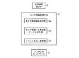
図1は、この発明の実施の形態1による監視装置の構成を示す図である。実施の形態1による監視装置は、位置検知センサ1、センサ情報処理手段2、監視端末3及び旋回カメラ(監視用カメラ)4を備え、センサ情報処理手段2、監視端末3及び旋回カメラ4がネットワーク5により互いに接続されている。
FIG. 1 is a diagram showing a configuration of a monitoring apparatus according to
位置検知センサ1としては、広範囲な検知領域を有しかつ検知領域内における監視対象の位置を的確に検知可能なセンサを用いる。例えば、参考文献1に開示される漏洩伝送路(LCX)を使用するものや、参考文献2に開示されるアレーアンテナやLCXを用いる電波応用センサが考えられる。例えば、参考文献2の電波応用センサでは、参考文献3中のテーブル1に記載されるように1km程度の広範囲にわたるセンシングが可能である。
参考文献1:特許3703689号
参考文献2:特開2004−138402号
参考文献3:K.Inomata, T.Hirai,“Microwave Back-Projection Radar for Wide-area Surveillance System,”Proc.34 European Microwave Conf., pp.1425-1428,(Oct. 2004)
As the
Reference 1: Japanese Patent No. 3703689 Reference 2: Japanese Patent Laid-Open No. 2004-138402 Reference 3: K.K. Inomata, T. Hirai, “Microwave Back-Projection Radar for Wide-area Surveillance System,” Proc. 34 European Microwave Conf., Pp.1425-1428, (Oct. 2004)
参考文献1に開示されるセンサでは、送信LCX及び受信LCXで送受信されるスペクトル拡散信号を検知用信号として監視対象を検知する。送信LCXは、監視領域に広範囲に布設され、監視対象の検知用信号(スペクトル拡散信号)を漏洩して放射する複数のスロットが長手方向の適当な間隔に設けられる。また、受信LCXは、送信LCXと対向する側に布設され、送信LCXから放射された検知用信号を受信するための複数のスロットが、長手方向の適当な間隔で設けられる。
In the sensor disclosed in
さらに、検知用信号を生成するスペクトル拡散信号生成手段が、送信LCXの一端に接続されている。また、受信LCX側には、受信LCXが受信した検知用のスペクトル拡散信号の拡散符号と同一符号系列であって、これに位相同期する拡散符号に基づいて、参照用のスペクトル拡散信号を生成する参照スペクトル拡散信号生成手段が接続される。 Furthermore, a spread spectrum signal generating means for generating a detection signal is connected to one end of the transmission LCX. On the reception LCX side, a reference spread spectrum signal is generated based on a spread code that is the same code sequence as the detection spread spectrum signal received by the reception LCX and is phase-synchronized with the spread code. Reference spread spectrum signal generating means is connected.
また、参考文献2に開示されるセンサは、参考文献1のセンサと同様に、監視対象の検知用の信号を送受信する送受信アンテナとして、検知領域に沿って並べたアレーアンテナやLCXを用い、送信アンテナから放射された電波を受信アンテナが受信すると、その受信信号の実部成分と虚部成分を復調し、その実部成分と虚部成分を解析して侵入物体を検知するように構成している。これにより、風の影響で送信アンテナや受信アンテを構成するLCXが揺れたり、降雨等によって地面等の反射率が変動しても、侵入物体の誤検知を防止することができる。
Similarly to the sensor of
このように、本実施の形態1では、従来の監視システムのように複数のセンサを設置することなく、1台のセンサにて広範囲を監視する。これにより、多数のセンサを配置する際に発生する設置費用や、多数のセンサを正常に動作させるために必要なメンテナンス費用を低く抑えることができる。なお、上述の広範囲のセンシングが可能なセンサを複数台用いて位置検知センサ1を構成してもよい。この場合でも、センシング範囲の狭いセンサを複数設置する場合と比較して設置費用やメンテナンス費を低く抑えることができる。
Thus, in this
センサ情報処理手段2は、位置検知センサ1の検知情報を処理して監視対象を検知した位置に関する情報を監視端末3に出力する。
図2は、図1中のセンサ情報処理手段の構成を示すブロック図である。図2において、センサ情報処理手段2は、センサ情報閾値処理部2a、センサ情報−位置変換テーブル照合部2b及びイベント生成・配信部2cを備え、ネットワーク5を介して監視端末3とデータ通信が可能である。
The sensor information processing means 2 processes the detection information of the
FIG. 2 is a block diagram showing the configuration of the sensor information processing means in FIG. In FIG. 2, the sensor information processing means 2 includes a sensor information threshold processing unit 2 a, a sensor information-position conversion
センサ情報閾値処理部2aは、位置検知センサ1から数十乃至数百の観測ポイントでの検知データを受信すると、観測ポイント毎の検知に関するデータを所定の閾値とそれぞれ照合する。この照合結果に基づいて、センサ情報閾値処理部2aは、監視対象を検知した観測ポイント(以下、異常発生ポイントと適宜称す)を判断する。
When the sensor information threshold value processing unit 2a receives detection data at several tens to several hundreds of observation points from the
位置検知センサ1が上述した漏洩伝送路を利用する構成のものである場合、センサ情報閾値処理部2aは、例えば参照文献1に開示される相関手段及び検知手段から構成することができる。ここで、相関手段は、スペクトル拡散信号生成手段が接続する送信LCXの端部と同じ側の受信LCXの一端に接続し、参照用のスペクトル拡散信号と受信LCXが受信した検知用のスペクトル拡散信号との相関レベルを算出する。検知手段は、相関手段により算出された相関レベルを一定の閾値としており、送信LCXと受信LCXの間に監視対象が侵入することで当初の相関レベルから変化が生じると、対応するスロットを異常発生ポイントとして判断する。
When the
センサ情報−位置変換テーブル照合部2bでは、観測ポイントに予め設定した通し番号であるポイント番号のうち、センサ情報閾値処理部2aにより異常であると判定された観測ポイントのポイント番号を本監視装置全体で扱うデータ体系のデータに変換する。具体的には、ポイント番号毎に、位置検知センサ1の検知領域における観測ポイントの物理的な位置に関する情報をまとめたテーブル情報を、センサ情報−位置変換テーブル照合部2bに設けておく。
In the sensor information-position conversion
そして、センサ情報−位置変換テーブル照合部2bが、センサ情報閾値処理部2aから異常発生ポイントのポイント番号を取得すると、当該ポイント番号に基づいてテーブル情報を検索して異常発生ポイントの位置に関する情報を抽出し、本監視装置全体で扱うデータ体系のデータとしてイベント生成・配信部2cに出力する。なお、観測ポイントの物理的な位置に関する情報としては、位置検知センサ1を参照文献1に開示されるLCXを用いるもので構成する場合、例えばLCXに設定した基準位置から距離αm等の情報が考えられる。また、異常発生ポイントの位置情報は、検知された監視対象の位置情報に相当するものである。
Then, when the sensor information-position conversion
イベント生成・配信部2cは、センサ情報−位置変換テーブル照合部2bから異常発生ポイントの位置情報を取得すると、当該位置情報をイベント情報としてネットワーク5を介して監視端末3に送信する。なお、イベント生成・配信部2cは、異常発生ポイントについての情報のみを送信し、監視対象が検知されていない正常な観測ポイントの情報については送信を行わない。
When the event generation / distribution unit 2c acquires the position information of the abnormality occurrence point from the sensor information-position conversion
監視端末3は、ネットワーク5を介してセンサ情報処理手段2から取得したイベント情報に基づいて監視対象を撮影すべき旋回カメラ4を選択して、旋回カメラ4による監視対象の撮影を制御すると共に、撮影された映像を表示して監視者に提示する。
図3は、図1中の監視端末の構成を概略的に示すブロック図である。図に示すように、監視端末3は、映像表示部(表示手段)3a、GUI3b、カメラ制御部3c及びイベント管理部3dを備える。
The
FIG. 3 is a block diagram schematically showing the configuration of the monitoring terminal in FIG. As shown in the figure, the
映像表示部3aは、旋回カメラ4の映像データを表示する表示装置であって、その映像表示画面上に、ネットワーク5を介して旋回カメラ4から配信されるライブ若しくは蓄積映像を表示する。例えば、センサ情報処理手段2から取得したイベント情報に基づいて逐次選択される旋回カメラ4の映像データを受信して表示する。
The
GUI3bは、監視者が、映像表示部3aの表示画面を介して映像の操作や、カメラ制御の指示を設定するためのGUI(Graphical User Interface)である。監視端末3の機能を実現するコンピュータのマウスやキーボード等の入力手段と協働して、表示画面を介した上記動作を行うソフトウェアから構成される。
The
カメラ制御部3cは、イベント管理部3dから取得したカメラ制御情報に基づいて、ネットワーク5を介して、対応する旋回カメラ4の動作を制御する。なお、カメラ制御情報としては、動作制御する旋回カメラ4を特定するカメラ番号、パン角度、チルト角度、ズーム倍率を指定する情報を含む。
The
イベント管理部3dは、ネットワーク5を介してセンサ情報処理手段2からのイベント情報を受信し、イベント情報に応じたカメラ制御情報をカメラ制御部3cに出力する。具体的には、イベント管理部3dの構成要素としてのデータベース若しくはデータ通信が可能な外部の記憶装置に構築したデータベースに、各観測ポイントの位置情報に対応付けてカメラ制御情報を登録しておく。イベント管理部3dは、監視対象を検知した旨のイベントの発生をイベント情報より認識し、イベント情報における異常発生ポイントの位置情報を基に上記データベースを検索して対応するカメラ制御情報を抽出し、カメラ制御部3cに出力する。
The
例えば、上記データベースにおいて、観測ポイントの位置情報としてLCXに設定した基準位置からの距離がαm等の情報と、この位置での最適な撮影アングルに旋回カメラ4を設定するためのカメラ制御情報(カメラ番号、パン角度、チルト角度、ズーム倍率等)とを登録しておき、センサ情報処理手段2から取得したイベント情報における位置情報に基づいて当該データベースを検索して対応するカメラ制御情報を抽出する。
For example, in the above database, information such as the distance αm from the reference position set in the LCX as the position information of the observation point, and camera control information (camera for setting the turning
旋回カメラ4は、パン、チルト、ズームを実現する駆動機構と、ネットワーク5を介して受信したカメラ制御情報に応じて前記駆動機構を動作させる駆動制御部とを備え、位置検知センサ1の管理エリアに沿って複数配置される。なお、駆動制御により位置検知センサ1の検知可能領域全てを撮影野に収めることができる旋回カメラであれば、1台のカメラであっても構わない。
The turning
次に動作について説明する。
ここでは、位置検知センサ1として、参考文献1に開示される漏洩伝送路(LCX)を利用したセンサを用いる例を示す。
位置検知センサ1における送信LCXと受信LCXの間でのスペクトル拡散信号の検知データは、センサ情報処理手段2に逐一送信される。センサ情報処理手段2のセンサ情報閾値処理部2aでは、送信LCXと受信LCXの間に監視対象が存在しない状態における参照用及び検知用のスペクトル拡散信号の相関レベルが閾値として相関手段により算出されている。
Next, the operation will be described.
Here, an example in which a sensor using a leaky transmission line (LCX) disclosed in
Detection data of the spread spectrum signal between the transmission LCX and the reception LCX in the
ここで、送信LCXと受信LCXとの間に例えば人等の監視対象が現れると、スペクトル拡散信号の強度が低下する。これに応じて、相関手段により算出される相関レベルに変化が生じ、センサ情報閾値処理部2aの検知手段が、相関レベルの変化したスロットを異常発生ポイントとして判断する。このとき、センサ情報閾値処理部2aから異常発生ポイントに対応する観測ポイントのポイント番号がセンサ情報−位置変換テーブル照合部2bに出力される。
Here, when a monitoring target such as a person appears between the transmission LCX and the reception LCX, the intensity of the spread spectrum signal decreases. In response to this, a change occurs in the correlation level calculated by the correlation means, and the detection means of the sensor information threshold processing unit 2a determines the slot where the correlation level has changed as an abnormality occurrence point. At this time, the point number of the observation point corresponding to the abnormality occurrence point is output from the sensor information threshold processing unit 2a to the sensor information-position conversion
センサ情報−位置変換テーブル照合部2bでは、センサ情報閾値処理部2aより取得したポイント番号に基づいて上述したポイント番号毎の観測ポイントの位置情報をまとめたテーブル情報を検索し、対応する観測ポイントの位置情報を抽出してイベント生成・配信部2cに出力する。これにより、位置検知センサ1によるセンサ情報が観測ポイントの位置情報に変換される。
The sensor information-position conversion
イベント生成・配信部2cは、センサ情報−位置変換テーブル照合部2bから観測ポイントの位置情報を取得すると、当該位置情報をイベント情報として、ネットワーク5を介して監視端末3に送信する。なお、位置検知センサ1を複数用いる場合は、位置検知センサ1ごとにセンサ番号を設定しておき、異常発生ポイントのある位置検知センサ1のセンサ番号もイベント情報として送信する。
When the event generation / distribution unit 2c acquires the position information of the observation point from the sensor information-position conversion
位置検知センサ1の検知領域内、例えば送信LCXと受信LCXの間で、監視対象が移動すると、センサ情報処理手段2が、位置検知センサ1から送信される検知情報を用いて上述の動作を行い、移動先で監視対象を検知した観測ポイントの位置情報が監視端末3に逐次送信される。
When the monitoring target moves within the detection area of the
監視端末3のイベント管理部3dは、ネットワーク5を介してセンサ情報処理手段2からのイベント情報を受信すると、当該イベント情報における異常発生ポイントの位置情報に基づいて、観測ポイントの位置情報とカメラ制御情報をまとめたデータベースを検索して、当該位置に対応するカメラ制御情報を抽出してカメラ制御部3cに出力する。
When the
カメラ制御部3cは、イベント管理部3dから取得したカメラ制御情報に基づいて、ネットワーク5を介して、対応する旋回カメラ4の動作を制御する。映像表示部3aは、カメラ制御部3cにより動作制御された旋回カメラ4が撮影する映像を、ネットワーク5を介して受信して表示画面上に表示する。送信LCXと受信LCXの間で監視対象が移動することで、次々に異なる観測ポイントでの検知データが処理された場合、映像表示部3aの表示画面では、監視対象を検知した観測ポイントの位置に最適な旋回カメラ4が選択され、最適な撮影アングルで撮影された監視対象が逐次表示されることになる。
The
以上のように、この実施の形態1によれば、広範囲の検知領域を有しかつ監視対象の位置を検知する位置検知センサ1を備え、位置検知センサ1により特定された監視対象の位置情報(監視対象を検知した観測ポイントの位置情報)に基づいて検知領域内の位置ごとに予め割り当てた監視用の旋回カメラ4の中から当該位置に対応する旋回カメラ4を選択し、選択した旋回カメラ4を当該位置において最適な撮影野に動作制御して監視対象を撮影する。
As described above, according to the first embodiment, the
このように構成することにより、例えば監視すべき複数の要所をズームや旋回操作が可能なカメラ1台で監視を行おうとする場合、通常一方の要所を旋回カメラで監視している間に他方の要所に監視対象が出現しても監視死角となるが、本実施の形態では、監視対象の位置に応じて旋回カメラ4の動作を選択するので、監視対象の移動に合わせて撮影することができ、監視装置の死角がなくなり、旋回カメラ4を十分に活用することができる。
By configuring in this way, for example, when monitoring a plurality of important points to be monitored with one camera capable of zooming and turning, usually one of the important points is monitored with the turning camera. Even if the monitoring target appears at the other important point, it becomes a monitoring blind spot. However, in this embodiment, since the operation of the turning
また、位置検知センサ1で検知された監視対象の位置に応じたカメラを制御することから、全てのカメラで監視範囲を常時監視し続ける必要がない。これにより、位置検知センサ1の検知領域内の全てを撮影するために必要な最小限の台数の旋回カメラを用意すればよく、設置すべきカメラの台数を削減することができ、設備コストを低く抑えることができる。
In addition, since the camera corresponding to the position of the monitoring target detected by the
さらに、位置検知センサ1として上述した参考文献2の電波応用センサを用いた場合、長距離を1台のセンサで監視できるだけでなく、10m程度の幅を持って検知が可能なため、敷地境界監視にこれを用いた場合、侵入者が境界を侵した瞬間だけでなく、境界への接近時も検知することが可能になり、侵入未然防止を図ることができる。
Furthermore, when the radio wave application sensor of
実施の形態2.
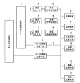
図4は、この発明の実施の形態2による監視装置の構成を示すブロック図である。実施の形態2による監視装置は、上記実施の形態1で示した構成に加え、映像符号化手段6、映像蓄積配信手段7及び制御管理手段8を備えると共に、ネットワーク5を介して複数の監視端末3が接続される。実施の形態2における監視端末3は、上記実施の形態1と異なり、図3に示したカメラ制御部3c及びイベント管理部3dに対応する構成を有さず、これら構成による処理は制御管理手段8によって複数の監視端末3に関して一括して行われる。
FIG. 4 is a block diagram showing the configuration of the monitoring apparatus according to
映像符号化手段6は、旋回カメラ4により撮影された映像をディジタル符号化し、当該符号化データをネットワーク5を介して監視端末3に配信したり、映像蓄積配信手段7に送信する。映像蓄積配信手段7は、映像符号化手段6により符号化された映像の符号化データを蓄積する。なお、ネットワーク5を介して監視端末3より映像データの読み出しが可能である。
The video encoding means 6 digitally encodes the video shot by the turning
制御管理手段8は、管理対象として登録された監視端末3に関するカメラ制御及びイベント管理処理(図3におけるカメラ制御部3c及びイベント管理部3dの機能)を行うと共に、映像蓄積配信手段7による映像データの蓄積及び配信処理を制御する。例えば、2つの監視端末3から同時に同一の旋回カメラ4への操作が行われた場合、双方の操作が競合しないようにいずれかの監視端末3からの操作を優先させる制御を行ったり、位置検知センサ1において同時に複数の監視対象が検知された際、各監視対象の位置に対応する旋回カメラ4の動作を制御し、旋回カメラ4に撮影された映像の符号化データを監視端末3にライブ映像として配信するか、映像蓄積配信手段7に蓄積する。
The
なお、映像符号化手段6は、複数の旋回カメラ4からの映像データを一括して入力し、それぞれの映像データをディジタル符号化するコンピュータであってもよく、個々の旋回カメラ4毎に設けたコンピュータ上に構築しても良い。また、制御管理手段8は、ネットワーク5に接続した、監視端末3と別個のコンピュータ上に構築され、映像蓄積配信手段7を構成に含めても良い。
The video encoding means 6 may be a computer that collectively inputs video data from a plurality of revolving
次に動作について説明する。
ここでは、上記実施の形態1と同様に、位置検知センサ1として参考文献1に開示される漏洩伝送路(LCX)を利用したセンサを用いる例を示す。
位置検知センサ1における送信LCXと受信LCXの間でのスペクトル拡散信号の検知データは、センサ情報処理手段2に逐一送信される。センサ情報処理手段2のセンサ情報閾値処理部2aでは、送信LCXと受信LCXの間に監視対象が存在しない状態における参照用及び検知用のスペクトル拡散信号の相関レベルが閾値として相関手段により算出されている。
Next, the operation will be described.
Here, as in the first embodiment, an example in which a sensor using a leaky transmission line (LCX) disclosed in
Detection data of the spread spectrum signal between the transmission LCX and the reception LCX in the
ここで、送信LCXと受信LCXとの間に例えば人等の監視対象が現れると、スペクトル拡散信号の強度が低下する。これに応じて、相関手段により算出される相関レベルに変化が生じ、センサ情報閾値処理部2aの検知手段が、相関レベルの変化したスロットを異常発生ポイントとして判断する。このとき、センサ情報閾値処理部2aから異常発生ポイントに対応する観測ポイントのポイント番号がセンサ情報−位置変換テーブル照合部2bに出力される。
Here, when a monitoring target such as a person appears between the transmission LCX and the reception LCX, the intensity of the spread spectrum signal decreases. In response to this, a change occurs in the correlation level calculated by the correlation means, and the detection means of the sensor information threshold processing unit 2a determines the slot where the correlation level has changed as an abnormality occurrence point. At this time, the point number of the observation point corresponding to the abnormality occurrence point is output from the sensor information threshold processing unit 2a to the sensor information-position conversion
センサ情報−位置変換テーブル照合部2bでは、センサ情報閾値処理部2aより取得したポイント番号に基づいて上述したポイント番号毎の観測ポイントの位置情報をまとめたテーブル情報を検索し、対応する観測ポイントの位置情報を抽出してイベント生成・配信部2cに出力する。これにより、位置検知センサ1によるセンサ情報が観測ポイントの位置情報に変換される。
The sensor information-position conversion
イベント生成・配信部2cは、センサ情報−位置変換テーブル照合部2bから観測ポイントの位置情報を取得すると、当該位置情報をイベント情報として、ネットワーク5を介して制御管理手段8に送信する。なお、位置検知センサ1を複数用いる場合は、位置検知センサ1ごとにセンサ番号を設定しておき、異常発生ポイントのある位置検知センサ1のセンサ番号もイベント情報として送信する。
When the event generation / distribution unit 2c acquires the position information of the observation point from the sensor information-position conversion
位置検知センサ1の検知領域内、例えば送信LCXと受信LCXの間で、監視対象が移動すると、センサ情報処理手段2が、位置検知センサ1から送信される検知情報を用いて上述の動作を行い、移動先で監視対象を検知した観測ポイントの位置情報が監視端末3に逐次送信される。
When the monitoring target moves within the detection area of the
制御管理手段8では、ネットワーク5を介してセンサ情報処理手段2からのイベント情報を受信すると、当該イベント情報における異常発生ポイントの位置情報に基づいて、観測ポイントの位置情報とカメラ制御情報をまとめたデータベースを検索して、当該位置に対応するカメラ制御情報を抽出する。
Upon receiving event information from the sensor information processing means 2 via the
続いて、制御管理手段8では、抽出したカメラ制御情報に基づいて、ネットワーク5を介して、対応する旋回カメラ4の動作を制御する。制御管理手段8により動作制御された旋回カメラ4が撮影する映像データは、映像符号化手段6により符号化された後、制御管理手段8によってその配信先が制御される。
Subsequently, the control management means 8 controls the operation of the
例えば、制御管理手段8に、監視端末3の現在の状態(現在どの旋回カメラ4の映像を表示しているか)を登録するテーブルを設けておき、位置検知センサ1により監視対象の位置が検知されると、前記テーブルから監視端末3の状態を把握する。このとき、監視端末3が、従前に検知された監視対象の位置に対応する旋回カメラ4からの映像を表示するものとして設定が固定されている場合、制御管理手段8は、今回検知された監視対象の位置に対応する旋回カメラ4からの映像データを映像蓄積配信手段7に蓄積する。
For example, a table for registering the current state of the monitoring terminal 3 (which image of the turning
一方、今回の映像を受信、表示できる状態であるならば、制御管理手段8は、今回検知された監視対象の位置に対応する旋回カメラ4からの映像データの配信先を当該監視端末3に決定する。なお、映像蓄積配信手段7に蓄積した映像データは、定期的に若しくは監視端末3からの映像要求により、制御管理手段8が、映像蓄積配信手段7を制御して監視端末3に再配信させる。上記テーブル情報の内容は、制御管理手段8により映像データの配信処理等が行われるたびに適宜更新される。
On the other hand, if the current video can be received and displayed, the
監視端末3では、ネットワーク5を介して旋回カメラ4からの映像データを受信すると、映像符号化手段6による符号化方式に対応する復号処理を施して映像表示部3aの表示画面上に表示する。例えば、GUI3bを介して設定情報を入力する等して、複数の監視端末3から同一の旋回カメラ4の操作(パン、チルト、ズーム等)がなされた場合であっても、各監視端末3からの操作情報は、ネットワーク5を介して制御管理手段8に送信され、制御管理手段8により、監視端末3ごとに設定した優先順位等に基づいて、互いの操作が競合しないように制御される。
When the video data from the turning
以上のように、この実施の形態2によれば、位置検知センサ1による検知情報に基づく旋回カメラ4の制御及び旋回カメラ4による映像の配信先制御を一括して管理する制御管理手段8を備えたので、複数の監視端末3が存在する場合であっても競合なく、監視端末3間の整合性を保ってカメラ制御を行うことができる。
As described above, according to the second embodiment, the
また、旋回カメラ4の映像データは、映像符号化手段6により同一の符号化方式でディジタル符号化した上でネットワーク5に伝送するので、複数の監視端末3に対し全く同じ品質の映像を提供することが可能になる。
Further, since the video data of the turning
さらに、映像データを蓄積すると共に、蓄積した映像データを監視端末3に再配信することができる映像蓄積配信手段7を設けたので、監視端末3にて監視中の監視員が実時間の監視で見逃した場面であっても後から見直すことができ、監視の見逃しを防止することができる。
Further, since the video storage and distribution means 7 is provided that can store the video data and re-distribute the stored video data to the
なお、上記実施の形態2による制御管理手段8の機能を実現する処理プログラムをコンピュータに実行させて、制御管理手段8の機能を自動化することにより、監視端末3を介して監視を行う監視員の手動操作に拠ることなく、自動で監視を行うことができる。例えば、旋回カメラ4の動作制御の他、映像蓄積配信手段7の制御についても、制御管理手段8にて監視対象検知に連動して映像データの蓄積を自動制御することにより、確実な映像蓄積を行うことができ、監視の見逃しを防ぐことができる。
It should be noted that, by causing the computer to execute a processing program that realizes the function of the
実施の形態3.
この実施の形態3は、上記実施の形態2の構成に対し、位置検知センサ1及びセンサ情報処理手段2を複数組備え、より広範囲の監視を可能としたものである。
In the third embodiment, a plurality of sets of
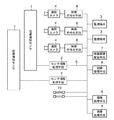
図5は、この発明の実施の形態3による監視装置の構成を示すブロック図である。実施の形態3による監視装置は、複数の位置検知センサ1を備え、より広範囲での監視を実現するものである。例えば、本実施の形態3による監視装置を境界監視に適用する場合、上記実施の形態1で説明した漏洩伝送路や電波応用センサ等の位置検知センサ1を複数直列に配置することで、より広範囲の境界を監視することができる。一方、複数の位置検知センサ1を並列にそれぞれ配置すれば、監視領域における複数の境界の監視が可能であり、監視領域である敷地内部へ監視対象物が侵入したか否かをより的確に判断できる。
FIG. 5 is a block diagram showing a configuration of a monitoring apparatus according to
また、異なる種類の位置検知センサ1を併用することで、多様な効果を得ることができる。例えば、上記実施の形態1で説明した漏洩伝送路や電波応用センサの他、光ファイバを応用した長距離振動検知センサを、建物の周囲の敷地境界に敷設されたフェンスに張り巡らせる。これにより、敷地に近づいてくる不審者を、電波応用センサを用いて検知した後、当該不審者が敷地境界を侵す場合であれば、これを光ファイバを応用したセンサによって別途検知することが可能になる。
Moreover, various effects can be obtained by using different types of
従って、不審者の中から、単なる通りすがりの人物と侵入者を区別することができ、誤報を減らせる効果があると共に、一方で不審者を予め発見するという2つの効果を同時に得ることが可能になる。これらのセンサからの情報を用いた侵入者の判断等は、監視端末3又は制御管理手段8に設けたイベント管理部3dにより処理される。
Therefore, it is possible to distinguish a mere passing person from an intruder from among suspicious persons, and it is possible to reduce false alarms while simultaneously obtaining two effects of detecting a suspicious person in advance. Become. Intruder determination using information from these sensors is processed by the
なお、光ファイバを応用した長距離振動検知センサとしては、光ファイバのコア部に歪みや熱により反射光の周波数が変化するFBG(Fiber Bragg Grating)構造を、繊維強化プラスチック(FRP)板に一体化させて埋め込み、歪みや熱を検知する光ファイバセンサがある。また、FBGとは、光ファイバのコアの屈折率を周期的に変化させた回折格子であり、光ファイバにかかる歪みや熱によって反射光の周波数が変化する。 In addition, as a long-distance vibration detection sensor using an optical fiber, an FBG (Fiber Bragg Grating) structure in which the frequency of reflected light changes due to strain or heat is integrated into the fiber reinforced plastic (FRP) plate. There is an optical fiber sensor that embeds and detects distortion and heat. The FBG is a diffraction grating in which the refractive index of the core of the optical fiber is periodically changed, and the frequency of the reflected light changes due to strain or heat applied to the optical fiber.
上述の態様の他、生産や流通現場において、生産や流通経路を通る人や物品を監視対象として、これらの位置を検知する位置検知センサ1と、経路境界に敷設された障壁に接触型の位置検知センサとを設けることが考えられる。この構成における位置検知センサ1としては、例えばRFID(Radio Frequency Identification)のアンテナを並べて広範囲のセンシングが可能なセンサを構成し、RFIDタグを有する監視対象の位置を検知するものが考えられる。また、接触型の位置検知センサとしては、例えば感圧式の位置検知センサが考えられる。
In addition to the above-described aspect, in a production or distribution site, a person or an article passing through a production or distribution route is monitored, and a
このように構成することにより、人や物品が正常に経路を流れている、あるいは経路の流通を促す装置が正常に機能していることを監視すると同時に、障壁の接触位置検知センサの情報を元に、正常な経路を離れようとする、異常な人や物品を検知することが可能となる。 With this configuration, it is possible to monitor whether a person or an article is normally flowing through a route or a device that promotes circulation of the route is functioning normally, and at the same time, obtain information from the contact position detection sensor of the barrier. In addition, it is possible to detect an abnormal person or article that is leaving the normal route.
生産や流通経路を通る人や物品を監視対象とするシステムとしては、上述した電波応用センサとFBGを用いたものであってもよい。この場合、位置検知センサ1には、漏洩伝送路等を用いた非接触型の動体位置の検知センサが用いられ、FBGを用いたセンサとしては上述した接触型の歪み検知センサを用いる。
As a system for monitoring persons and articles passing through production and distribution channels, a system using the above-described radio wave application sensor and FBG may be used. In this case, the
具体的には、物品流路に位置検知センサ1として非接触型の動体位置の検知センサを設置し、FBG構造を有する光ファイバによる接触型の歪み検知センサを流路の壁に設置して、位置検知センサ1で流路を流れる物品を検知し、スムーズに運搬が行われているか否かを検知する。ここで、位置検知センサ1に反応が無い場合、イベント管理部3dによって、物品の運搬が行われていないと判断して異常事態とする。FBGを用いた接触型の歪み検知センサに反応があった場合、物品が壁面に接触した異常事態であると判断する。
Specifically, a non-contact type moving body position detection sensor is installed as the
以上のように、この実施の形態3によれば、複数の位置検知センサ1を備えたので、より広範囲での監視を実現することができる。また、複数種類のセンサを併用することで、各種センサの能力に応じた様々な監視装置を構築することができる。
As described above, according to the third embodiment, since a plurality of
実施の形態4.
この実施の形態4は、上記実施の形態3の構成に対し、1つ乃至複数の画像処理手段を備え、監視処理におけるより詳細な映像管理を可能としたものである。
In the fourth embodiment, one or more image processing means are provided for the configuration of the third embodiment, and more detailed video management is possible in the monitoring process.
図6は、この発明の実施の形態4による監視装置の構成を示すブロック図であり、画像処理手段9以外の構成要素は、図5と同一であるので重複する説明を省略する。画像処理手段9は、映像符号化手段6によってディジタル符号化された映像を画像処理する。画像処理手段9による画像処理としては、例えば旋回カメラ4が撮影する画像中における移動物体を抽出する処理を施して追尾等に用いることが考えられる。また、画像処理手段9としては、ネットワーク5に接続した監視端末3とは別個のコンピュータ上に構築される。なお、画像処理手段9は、制御管理手段8の構成に含まれるように構成しても良い。
FIG. 6 is a block diagram showing the configuration of the monitoring apparatus according to the fourth embodiment of the present invention. The components other than the image processing means 9 are the same as those in FIG. The image processing means 9 performs image processing on the video digitally encoded by the video encoding means 6. As image processing by the image processing means 9, for example, it is conceivable to perform processing for extracting a moving object in an image taken by the turning
実施の形態4による監視装置の適用態様としては、例えば敷地に対する侵入者の監視を行う装置が考えられる。この場合において、敷地境界に位置検知センサ1を張り巡らせることで敷地への侵入者の検知を行う。このとき、敷地内で検知された侵入者に関して、上記実施の形態1と同様に旋回カメラ4を用いた映像監視を行い、その際、画像処理手段9による画像処理で侵入者の画像を抽出して自動追尾を行う。
As an application mode of the monitoring device according to the fourth embodiment, for example, a device that monitors an intruder on a site can be considered. In this case, an intruder in the site is detected by placing the
具体的には、位置検知センサ1により敷地内に侵入者が検知されると、制御管理手段8は、この検知に連動して旋回カメラ4を制御して、位置検知センサ1による反応箇所を撮影する。このとき、制御管理手段8は、先に制御した旋回カメラ4の映像データを画像処理手段9に送信するように制御し、画像処理手段9により当該映像データを画像処理するように指示する。
Specifically, when an intruder is detected in the site by the
この指示に従い、画像処理手段9では、既存の画像処理技術を用いて、カメラ映像中における移動物体である侵入者の画像を抽出する画像処理を施し、制御管理手段8に出力する。この画像処理手段9からの画像処理データを基にして、制御管理手段8が、カメラ映像内の動物体を自動追尾する。この自動追尾により、敷地境界のみならず、敷地内部についても監視を続行することができ、境界監視から敷地全体への監視へとセキュリティレベルを向上させることができる。 In accordance with this instruction, the image processing means 9 performs image processing for extracting an intruder image, which is a moving object in the camera video, using an existing image processing technique, and outputs it to the control management means 8. Based on the image processing data from the image processing means 9, the control management means 8 automatically tracks the moving object in the camera video. By this automatic tracking, not only the site boundary but also the inside of the site can be monitored, and the security level can be improved from the boundary monitoring to the entire site monitoring.
また、本実施の形態4では、画像処理手段9がネットワーク5を介して旋回カメラ4からの映像データを入力することができるので、画像処理手段9は必要最小限の数で良く、必要な旋回カメラ4からの映像に対してのみ画像処理を施せばよい。このため、画像処理手段9の設置コストを抑えることが可能となる。
In the fourth embodiment, since the image processing means 9 can input the video data from the turning
上記以外の態様としては、位置検知センサ1にて大まかに位置を特定して旋回カメラ4にて撮影を開始した後、さらに画像処理手段9により監視対象を検知してズームアップすることで、より詳細な映像監視や位置検知を低コストにて実現が可能である。
As an aspect other than the above, after the position is roughly identified by the
例えば、位置検知センサ1として漏洩伝送路等による電波応用センサを用いる場合、位置検知精度は、およそ10m単位になる。位置検知センサ1による検知に連動して10mのブロック毎の領域を旋回カメラ4で撮影し、カメラ映像で検知対象を捉えた後、画像処理によって検知対象をさらに絞り込む。これにより、10mからさらに詳細な位置情報に絞り込むことができる。以上の処理は、画像処理手段9により実行される。
For example, when a radio wave application sensor using a leaky transmission path or the like is used as the
また、上記実施の形態2で説明した映像記録に連動させて、映像蓄積配信手段7により映像データと同時に画像処理内容や処理結果を記録する場合、位置検知センサ1が検知していない不必要な処理内容の蓄積を避けることができる。このため、蓄積内容に不要な部分が含まれず、蓄積内容の確認の際にも、内容検索といった情報処理コストを下げることができる。
In addition, when the image processing contents and processing results are recorded simultaneously with the video data by the video storage / delivery means 7 in conjunction with the video recording described in the second embodiment, the
さらに、上記実施の形態3で説明した生産や流通現場での監視装置に本実施の形態4を適用した場合、例えば生産工場の廊下に位置検知センサ1を設置し、位置検知センサ1による検知に伴って従業員を撮影し、画像処理手段9にて顔認証等の画像処理を行う。これにより、従業員の出勤状況、サボタージュ監視を行うと同時に、顔認証ができない人物については不審人物として警報することもできる。従って、従業員管理とセキュリティの両立が可能となる。
Furthermore, when the fourth embodiment is applied to the production and distribution site monitoring apparatus described in the third embodiment, for example, the
以上のように、この実施の形態4によれば、旋回カメラ4による映像に対して所望の画像処理を施す、1つ乃至複数の画像処理手段9を備えたので、監視処理においてより詳細な映像管理をすることができる。
As described above, according to the fourth embodiment, since one or a plurality of image processing means 9 for performing desired image processing on the image from the turning
実施の形態5.
この実施の形態5は、上記実施の形態4の構成に対し、1つ乃至複数の人感センサを備え、監視処理におけるより詳細な監視を可能としたものである。
In the fifth embodiment, one or more human sensors are provided for the configuration of the fourth embodiment, and more detailed monitoring can be performed in the monitoring process.
図7は、この発明の実施の形態5による監視装置の構成を示すブロック図であり、人感センサ10以外の構成要素は、図6と同一であるので重複する説明を省略する。人感センサ10は、監視領域内に侵入した人間を検知するセンサであり、例えば赤外線センサ、超音波式センサ、画像処理センサを用いることができる。
FIG. 7 is a block diagram showing the configuration of the monitoring apparatus according to
本実施の形態5のように、位置検知センサ1と多種のセンサとを併用することで、より多様なニーズにコストを抑えて対応することが可能になる。例えば、敷地監視において、不審人物の侵入を検知するため、敷地境界に設けたフェンス沿いに位置検知センサ1を張り巡らせる。これに対し、通用門等では、位置検知センサ1ではなく、より安価なポイントを監視するための人感センサを用いる。これにより、コストを抑えて監視が可能になるのと同時に、入退場者数のカウントなどにも応用することができる。
As in the fifth embodiment, by using the
以上のように、この実施の形態5によれば、1つ乃至複数の人感センサを備えるので、監視処理におけるより詳細な監視を実現することができる。 As described above, according to the fifth embodiment, since one or more human sensors are provided, more detailed monitoring in the monitoring process can be realized.
実施の形態6.
この実施の形態6は、上記実施の形態5の構成に対し、1つ乃至複数のレーダセンサを備え、監視処理におけるより詳細な監視を可能としたものである。
In the sixth embodiment, one or more radar sensors are provided to the configuration of the fifth embodiment, and more detailed monitoring can be performed in the monitoring process.
図8は、この発明の実施の形態6による監視装置の構成を示すブロック図であり、レーダセンサ11以外の構成要素は、図7と同一であるので重複する説明を省略する。レーダセンサ11は、レーダ波の送受により監視対象が存在する方向を検知するセンサであって、超音波式レーダ、広角カメラ、あるいは不可視光線レーザレーダ等が考えられる。
FIG. 8 is a block diagram showing the configuration of the monitoring apparatus according to the sixth embodiment of the present invention, and the constituent elements other than the
レーダセンサ11では、監視対象の存在する方向は認識できるが、位置を認識することはできない。そこで、本実施の形態6では、レーダセンサ11を複数異なる場所に設置することで、複数のレーダセンサ11からの検知情報に基づいて、センサ情報処理手段2が、監視対象の存在する方向で重なり合う位置を特定して監視対象の位置を検知する。このように、複数のレーダセンサ11は、位置検知センサ1に故障が生じた場合等、位置検知センサ1を代替することができる。
The
また、複数のレーダセンサ11を用意することができない場合であっても、レーダセンサ11と撮影する旋回カメラ4の位置座標をほぼ同一とすることで、旋回カメラ4の旋回方向とレーダセンサ11との検知方向が一致する。これになり、位置検知センサ1と同様の効果を得ることができる。
Even if a plurality of
以上のように、この実施の形態6によれば、1つ乃至複数のレーダセンサ11を備えたので、監視処理におけるより詳細な監視を実現することができる。
As described above, according to the sixth embodiment, since one or
なお、上記実施の形態1から6までにおいて、位置検知センサ1による検知に応じて撮影すべき旋回カメラ4を選択することにより、旋回カメラ4の設置台数を減らし、効率的な監視を行うことができることを説明した。しかしながら、旋回カメラ4にて監視領域の全域を常時監視しない以上、同時多数に監視対象が存在する場合は、旋回カメラ4による撮影に限界が生じ、監視すべき対象にも関わらず見逃してしまうといった状況が生じる。
In the first to sixth embodiments, by selecting the turning
このように、物理的に旋回カメラ4が不足する以上、全ての監視対象を撮影することは不可能であるが、例えば上記実施の形態1であれば監視端末3上に、上記実施の形態2から6までであれば、制御管理手段8に、制御すべき旋回カメラ4の優先順位を設定しておき、これに従って監視を続行する。これにより、限られたカメラ資源を最大限に生かして監視を行うことが可能になる。
Thus, as long as the turning
例えば、実施の形態6による監視装置を敷地侵入監視システムに適用した場合であれば、画像処理において顔認証や動線解析等の処理よりも画像処理追尾を優先し、画像処理追尾よりも位置検知センサ1からの信号を優先し、位置検知センサ1の中でも重要施設付近に設置した部分におけるセンサ情報を優先する。このように、位置検知センサ1内の位置や、センサ間の全てあるいは必要とする一部に優先順位を設定することにより、監視装置の想定を超えた事態にも混乱することなく最大限効率的に対応することができる。
For example, if the monitoring device according to the sixth embodiment is applied to a site intrusion monitoring system, image processing tracking is prioritized over image processing and processing such as face authentication and flow line analysis, and position detection is performed over image processing tracking. Priority is given to the signal from the
なお、上記実施の形態2から上記実施の形態6では、監視端末3が上記実施の形態1と異なり、図3に示したカメラ制御部3c及びイベント管理部3dに対応する構成を有さず、これら構成による処理は制御管理手段8によって複数の監視端末3に関して一括して行う例を示したが、上記実施の形態1の監視端末3と、上記実施の形態2から上記実施の形態6までのいずれかで示した構成とを組み合わせて監視装置を構成してもよい。この場合、映像蓄積配信手段7による映像データ蓄積、配信は、例えば監視端末3のイベント管理部3dによる制御で実行される。
In the second embodiment to the sixth embodiment, the
また、本発明では、映像蓄積配信手段7に蓄積された映像データから所望の映像データを検索する場合、監視対象が位置検知センサ1により検知された時刻の他、位置検知センサ1の位置及びこれに対応する旋回カメラ4を特定することができるので、検知時刻、位置検知センサ1の位置及びこれに対応する旋回カメラ4に関する情報を基にして所望の映像データを検索するようにしても良い。
In the present invention, when searching for desired video data from the video data stored in the video storage / distribution means 7, in addition to the time when the monitoring target is detected by the
例えば、監視者からの検知時刻、位置検知センサ1の位置及びこれに対応する旋回カメラ4に関する情報を受けた制御管理手段8や上記実施の形態1による監視端末3が、これら情報に基づいて映像蓄積配信手段7に蓄積された映像データを検索し、所望の映像データを監視端末3に配信させる。
For example, the control management means 8 or the
また、上記実施の形態4〜6に示した構成を有する場合、画像処理の結果、例えば顔認証の場合であれば顔画像での検索、追尾の場合、追尾パターン(移動パターン)に関する情報に基づいて映像蓄積配信手段7に蓄積された映像データを検索し、所望の映像データを監視端末3に配信させる。このように構成することにより、所望の映像データをより絞り込んで検索することができ、長時間の映像でも的確に所望の映像を得ることができる。
Further, in the case of having the configuration shown in the above-described
従来の映像配信では、蓄積された時刻や映像データに設定したタグなどに基づいて所望の映像データを検索するのが一般的であったが、この場合、所望の映像データを的確に検索するためには、時刻などを基準に粗く検索した後、早送りや巻き戻し等により見直しながら所望の映像を見つけるか、映像データにこまめにタグを設定する必要がある。これに対して、本発明では、上述のように、監視対象により得られる検知位置データや画像処理データに基づいて検索することができるので、従来のような煩雑な処理を施すことなく、的確に所望の映像データを検索することが可能である。 In conventional video distribution, it has been common to search for desired video data based on the accumulated time or tags set in the video data. In this case, in order to accurately search for desired video data. In this case, after roughly searching based on time or the like, it is necessary to find a desired video while reviewing it by fast-forwarding or rewinding, or to set tags frequently in video data. On the other hand, in the present invention, as described above, the search can be performed based on the detected position data and the image processing data obtained by the monitoring target, so that it can be performed accurately without performing complicated processing as in the prior art. It is possible to search for desired video data.
1 位置検知センサ、2 センサ情報処理手段、2a センサ情報閾値処理部、2b センサ情報−位置変換テーブル照合部、2c イベント生成・配信部、3 監視端末、3a 映像表示部(表示手段)、3b GUI、3c カメラ制御部、3d イベント管理部、4 旋回カメラ(監視用カメラ)、5 ネットワーク、6 映像符号化手段、7 映像蓄積配信手段、8 制御管理手段、9 画像処理手段、10 人感センサ、11 レーダセンサ。
DESCRIPTION OF
Claims (3)
監視対象の位置を検出する位置検知センサとして電波応用センサを用い、
前記位置検知センサからの検知情報に基づいて監視対象の位置を特定するセンサ情報処理手段と、
前記監視用カメラからの映像データを表示する表示手段を有し、前記監視用カメラのうち、前記センサ情報処理手段により特定された位置に対応する監視用カメラを選定し、前記ネットワークを介して前記選定した監視用カメラを駆動制御して前記監視対象の映像データを前記表示手段に表示する監視端末と、
前記監視用カメラが撮影した映像データを画像処理する画像処理手段とを備え、
前記画像処理手段は、前記電波応用センサによる検知範囲内外の双方において前記監視用カメラにより撮影された映像中の移動物体を追尾する画像処理を行い、移動物体を前記電波応用センサの位置分解能を超えるズームアップをしながら追尾するように前記監視用カメラを駆動制御することを特徴とする監視装置。 A plurality of surveillance cameras driven and controlled via a network;
Using a radio wave application sensor as a position detection sensor that detects the position of the monitoring target,
Sensor information processing means for specifying a position of a monitoring target based on detection information from the position detection sensor;
Displaying means for displaying video data from the monitoring camera, wherein the monitoring camera corresponding to the position specified by the sensor information processing means is selected from the monitoring cameras, and the network is selected via the network. A monitoring terminal that drives and controls the selected monitoring camera and displays the video data to be monitored on the display means;
Image processing means for image processing video data captured by the monitoring camera,
The image processing means performs image processing for tracking a moving object in an image taken by the monitoring camera both inside and outside the detection range of the radio wave application sensor , and the moving object exceeds the position resolution of the radio wave application sensor. A monitoring apparatus, wherein the monitoring camera is driven and controlled to track while zooming up .
監視対象の検知用信号を放射する送信側の漏洩伝送路と、
前記送信側の漏洩伝送路に対向して設けられ、前記検知用信号を受信する受信側の漏洩伝送路と、
拡散符号に基づいて前記検知用信号としてスペクトル拡散信号を生成して前記送信側の漏洩伝送路に放射させるスペクトル拡散信号送信手段と、
前記スペクトル拡散信号送信手段の拡散符号と同一符号系列の拡散符号に基づいて、参照用のスペクトル拡散信号を生成する参照スペクトル拡散信号生成手段と、
前記受信側の漏洩伝送路が受信した前記検知用のスペクトル拡散信号の拡散符号に位相同期する拡散符号に基づいて、前記参照スペクトル拡散信号生成手段が生成した参照用のスペクトル拡散信号と前記受信側の漏洩伝送路が受信した前記検知用のスペクトル拡散信号との相関レベルを算出する相関手段と、
この相関手段が算出した相関レベルの変化から支障物を検知する検知手段とを備えたことを特徴とする請求項1記載の監視装置。 Radio wave application sensors used as position detection sensors
A leaky transmission line on the transmission side that emits a detection signal to be monitored;
A leakage transmission path on the reception side that is provided opposite to the leakage transmission path on the transmission side and receives the detection signal;
A spread spectrum signal transmitting means for generating a spread spectrum signal as the detection signal based on a spread code and radiating it to the leaky transmission line on the transmission side;
A reference spread spectrum signal generating means for generating a reference spread spectrum signal based on a spread code of the same code sequence as the spread code of the spread spectrum signal transmitting means;
The reference spread spectrum signal generated by the reference spread spectrum signal generator and the reception side based on a spread code that is phase-synchronized with the spread code of the detection spread spectrum signal received by the leaky transmission path on the reception side Correlation means for calculating a correlation level with the detection spread spectrum signal received by the leaky transmission line of
The monitoring apparatus according to claim 1, further comprising a detecting unit that detects an obstacle from a change in the correlation level calculated by the correlation unit.
Priority Applications (1)
| Application Number | Priority Date | Filing Date | Title |
|---|---|---|---|
| JP2006179928A JP5111795B2 (en) | 2006-06-29 | 2006-06-29 | Monitoring device |
Applications Claiming Priority (1)
| Application Number | Priority Date | Filing Date | Title |
|---|---|---|---|
| JP2006179928A JP5111795B2 (en) | 2006-06-29 | 2006-06-29 | Monitoring device |
Publications (2)
| Publication Number | Publication Date |
|---|---|
| JP2008011212A JP2008011212A (en) | 2008-01-17 |
| JP5111795B2 true JP5111795B2 (en) | 2013-01-09 |
Family
ID=39069011
Family Applications (1)
| Application Number | Title | Priority Date | Filing Date |
|---|---|---|---|
| JP2006179928A Expired - Fee Related JP5111795B2 (en) | 2006-06-29 | 2006-06-29 | Monitoring device |
Country Status (1)
| Country | Link |
|---|---|
| JP (1) | JP5111795B2 (en) |
Families Citing this family (6)
| Publication number | Priority date | Publication date | Assignee | Title |
|---|---|---|---|---|
| KR101361801B1 (en) * | 2008-12-01 | 2014-02-11 | 삼성테크윈 주식회사 | Surveillance camera system |
| JP2012008802A (en) * | 2010-06-24 | 2012-01-12 | Toshiba Corp | Monitoring system and person specification method |
| US9912857B2 (en) | 2013-04-05 | 2018-03-06 | Andra Motion Technologies Inc. | System and method for controlling an equipment related to image capture |
| KR101548168B1 (en) * | 2014-01-15 | 2015-08-31 | 삼영이엔씨 (주) | Aquafarm Monitoring System |
| CN104660990A (en) * | 2015-01-30 | 2015-05-27 | 深圳市浩科电子有限公司 | Intelligent monitoring processing method and system |
| KR102427110B1 (en) * | 2020-07-10 | 2022-07-28 | 주식회사 에스원 | Method for connecting image and leak though connection with CCTV and leak management system using the method |
Family Cites Families (10)
| Publication number | Priority date | Publication date | Assignee | Title |
|---|---|---|---|---|
| JP2000105835A (en) * | 1998-07-28 | 2000-04-11 | Hitachi Denshi Ltd | Object recognizing method and object tracking and monitoring device |
| JP3703689B2 (en) * | 2000-06-01 | 2005-10-05 | 三菱電機株式会社 | Obstacle detection device and obstacle detection system |
| JP2004101239A (en) * | 2002-09-05 | 2004-04-02 | Mitsubishi Electric Corp | Obstacle detecting apparatus |
| JP3760918B2 (en) * | 2003-01-21 | 2006-03-29 | 株式会社日立製作所 | Security system |
| JP2005045712A (en) * | 2003-07-25 | 2005-02-17 | Mitsubishi Electric Corp | Monitor system |
| JP2005065238A (en) * | 2003-07-25 | 2005-03-10 | Hitachi Ltd | Surveillance information providing device and surveillance information providing method |
| JP4400167B2 (en) * | 2003-10-08 | 2010-01-20 | 三菱電機株式会社 | Monitoring system |
| JP4301051B2 (en) * | 2004-03-24 | 2009-07-22 | 三菱電機株式会社 | Harbor monitoring system |
| JP4685390B2 (en) * | 2004-09-07 | 2011-05-18 | 株式会社日立国際電気 | Surveillance camera system |
| JP4472579B2 (en) * | 2004-09-30 | 2010-06-02 | 三菱電機株式会社 | Tension sensor and intrusion monitoring system |
-
2006
- 2006-06-29 JP JP2006179928A patent/JP5111795B2/en not_active Expired - Fee Related
Also Published As
| Publication number | Publication date |
|---|---|
| JP2008011212A (en) | 2008-01-17 |
Similar Documents
| Publication | Publication Date | Title |
|---|---|---|
| KR100685979B1 (en) | Security monitoring system using sensor and camera, and method thereof | |
| EP2274654B1 (en) | Method for controlling an alarm management system | |
| JP5111795B2 (en) | Monitoring device | |
| US20100245588A1 (en) | Tag tracking system | |
| KR100962529B1 (en) | Method for tracking object | |
| WO2017033404A1 (en) | Security system and method for displaying images of people | |
| KR101404153B1 (en) | Intelligent cctv integrated control system | |
| US20080036860A1 (en) | PTZ presets control analytiucs configuration | |
| CN106205042A (en) | A kind of subway swarm and jostlement accident early warning linked system and early warning interlock method | |
| EP2710801A1 (en) | Surveillance system | |
| KR102310192B1 (en) | Convergence camera for enhancing object recognition rate and detecting accuracy, and boundary surveillance system therewith | |
| JP2006202062A (en) | Facility monitoring system | |
| JP7464281B2 (en) | Optical fiber sensing system, monitoring device, monitoring method, and program | |
| JP2005086626A (en) | Wide area monitoring device | |
| CN101867789A (en) | Method and apparatus for monitoring using a movable video device | |
| JP2009015412A (en) | Entrance monitoring system | |
| KR101014842B1 (en) | Security image monitoring system and method using rfid reader | |
| RU2595532C1 (en) | Radar system for protection of areas with small-frame video surveillance system and optimum number of security guards | |
| KR101324221B1 (en) | System for tracking object using capturing and method thereof | |
| JP6045806B2 (en) | Intrusion monitoring device | |
| KR102355769B1 (en) | Method for construction of 3d digital twin by dron | |
| KR100929921B1 (en) | Ubiquitous integrated security video device and system | |
| KR101599614B1 (en) | Integrated type vehicle monitoring system using video | |
| JP7176868B2 (en) | monitoring device | |
| JP5829855B2 (en) | Mobile monitoring system |
Legal Events
| Date | Code | Title | Description |
|---|---|---|---|
| RD04 | Notification of resignation of power of attorney |
Free format text: JAPANESE INTERMEDIATE CODE: A7424 Effective date: 20080701 |
|
| A621 | Written request for application examination |
Free format text: JAPANESE INTERMEDIATE CODE: A621 Effective date: 20081222 |
|
| A977 | Report on retrieval |
Free format text: JAPANESE INTERMEDIATE CODE: A971007 Effective date: 20110228 |
|
| A131 | Notification of reasons for refusal |
Free format text: JAPANESE INTERMEDIATE CODE: A131 Effective date: 20110308 |
|
| A521 | Request for written amendment filed |
Free format text: JAPANESE INTERMEDIATE CODE: A523 Effective date: 20110428 |
|
| A131 | Notification of reasons for refusal |
Free format text: JAPANESE INTERMEDIATE CODE: A131 Effective date: 20120207 |
|
| A521 | Request for written amendment filed |
Free format text: JAPANESE INTERMEDIATE CODE: A523 Effective date: 20120405 |
|
| TRDD | Decision of grant or rejection written | ||
| A01 | Written decision to grant a patent or to grant a registration (utility model) |
Free format text: JAPANESE INTERMEDIATE CODE: A01 Effective date: 20121002 |
|
| A01 | Written decision to grant a patent or to grant a registration (utility model) |
Free format text: JAPANESE INTERMEDIATE CODE: A01 |
|
| A61 | First payment of annual fees (during grant procedure) |
Free format text: JAPANESE INTERMEDIATE CODE: A61 Effective date: 20121010 |
|
| FPAY | Renewal fee payment (event date is renewal date of database) |
Free format text: PAYMENT UNTIL: 20151019 Year of fee payment: 3 |
|
| R150 | Certificate of patent or registration of utility model |
Ref document number: 5111795 Country of ref document: JP Free format text: JAPANESE INTERMEDIATE CODE: R150 Free format text: JAPANESE INTERMEDIATE CODE: R150 |
|
| R250 | Receipt of annual fees |
Free format text: JAPANESE INTERMEDIATE CODE: R250 |
|
| R250 | Receipt of annual fees |
Free format text: JAPANESE INTERMEDIATE CODE: R250 |
|
| R250 | Receipt of annual fees |
Free format text: JAPANESE INTERMEDIATE CODE: R250 |
|
| R250 | Receipt of annual fees |
Free format text: JAPANESE INTERMEDIATE CODE: R250 |
|
| R250 | Receipt of annual fees |
Free format text: JAPANESE INTERMEDIATE CODE: R250 |
|
| R250 | Receipt of annual fees |
Free format text: JAPANESE INTERMEDIATE CODE: R250 |
|
| LAPS | Cancellation because of no payment of annual fees |