JP7187777B2 - OCT device and OCT control program - Google Patents
OCT device and OCT control program Download PDFInfo
- Publication number
- JP7187777B2 JP7187777B2 JP2018018727A JP2018018727A JP7187777B2 JP 7187777 B2 JP7187777 B2 JP 7187777B2 JP 2018018727 A JP2018018727 A JP 2018018727A JP 2018018727 A JP2018018727 A JP 2018018727A JP 7187777 B2 JP7187777 B2 JP 7187777B2
- Authority
- JP
- Japan
- Prior art keywords
- oct
- optical system
- eye
- lens
- focus position
- Prior art date
- Legal status (The legal status is an assumption and is not a legal conclusion. Google has not performed a legal analysis and makes no representation as to the accuracy of the status listed.)
- Active
Links
Images


Description
被検眼を撮影するためのOCT装置、およびOCT制御プログラムに関する。 The present invention relates to an OCT apparatus for imaging an eye to be examined and an OCT control program.
従来、被検眼の眼軸長等の眼内距離を測定するためにOCT(Optical coherence tomography)装置が利用されている。例えば、SD(Spectral Domain)-OCTの場合、光路長を変化させることによって被検眼の各部位(角膜、水晶体、網膜など)をそれぞれ撮影し、各画像から検出された各部位の位置関係を求めることで、被検眼の眼内距離を算出する。 2. Description of the Related Art Conventionally, an OCT (optical coherence tomography) apparatus has been used to measure an intraocular distance such as an axial length of an eye to be examined. For example, in the case of SD (Spectral Domain)-OCT, each part of the subject's eye (cornea, lens, retina, etc.) is photographed by changing the optical path length, and the positional relationship of each part detected from each image is obtained. Thus, the intraocular distance of the subject's eye is calculated.
ところで、波長掃引光源を用いたSS(Swept Source)-OCTの場合、被検眼の前眼部全体を一度に撮影することができる。しかしながら、SS-OCTによって前眼部全体を撮影した場合、ゼロディレイ位置およびフォーカス位置などの影響で水晶体後面のOCT感度が低下する場合があった。 By the way, in the case of SS (Swept Source)-OCT using a wavelength swept light source, the entire anterior segment of the subject's eye can be imaged at once. However, when the entire anterior segment is imaged by SS-OCT, the OCT sensitivity of the posterior surface of the lens may decrease due to the effects of the zero-delay position and the focus position.
本開示は、従来の問題点に鑑み、適切な感度で被検眼を測定できるOCT装置、およびOCT制御プログラムを提供することを技術課題とする。 In view of the conventional problems, the technical problem of the present disclosure is to provide an OCT apparatus and an OCT control program that can measure an eye to be examined with appropriate sensitivity.
上記課題を解決するために、本開示は以下のような構成を備えることを特徴とする。 In order to solve the above problems, the present disclosure is characterized by having the following configurations.
(1) 被検眼を撮影するOCT装置であって、波長掃引型光源から出射された測定光が前記被検眼によって反射した反射光と、前記測定光に対応する参照光と、の干渉状態に基づいて角膜、水晶体および網膜の各部のOCT信号を一度に取得するOCT光学系と、前記OCT光学系のフォーカス位置を、前記OCT光学系の光軸方向に調整する調整手段と、前記調整手段を制御する制御手段と、を備え、前記制御手段は、前記OCT光学系のゼロディレイ位置を前記角膜、または前記角膜と前記OCT装置の間に配置させ、前記フォーカス位置を前記ゼロディレイ位置とは前記光軸方向に異なる水晶体後面付近に配置させることを特徴とする。
(2) 被検眼を撮影するOCT装置において実行されるOCT制御プログラムであって、前記OCT装置のプロセッサによって実行されることで、OCT光学系を制御し、波長掃引型光源から出射された測定光が前記被検眼によって反射した反射光と、前記測定光に対応する参照光と、の干渉状態に基づいて角膜、水晶体および網膜の各部のOCT信号を取得する取得ステップと、前記OCT光学系のゼロディレイ位置を前記角膜、または前記角膜と前記OCT装置の間に配置させ、前記OCT光学系のフォーカス位置を前記ゼロディレイ位置とは前記OCT光学系の光軸方向に異なる水晶体後面付近に配置する調整ステップと、を前記OCT装置に実行させることを特徴とする。
(1) An OCT apparatus for imaging an eye to be inspected, based on the state of interference between measurement light emitted from a wavelength-swept light source and reflected by the eye to be inspected, and reference light corresponding to the measurement light. an OCT optical system for obtaining OCT signals from each part of the cornea, lens, and retina at once; adjusting means for adjusting the focus position of the OCT optical system in the optical axis direction of the OCT optical system; and controlling the adjusting means. and a control means for placing the zero-delay position of the OCT optical system on the cornea or between the cornea and the OCT apparatus, and adjusting the focus position to the zero-delay position. It is characterized in that it is arranged near the posterior surface of the lens that is different in the axial direction.
(2) An OCT control program executed in an OCT apparatus for imaging an eye to be inspected, which is executed by a processor of the OCT apparatus to control an OCT optical system and generate measurement light emitted from a swept-wavelength light source. an acquiring step of acquiring OCT signals of each part of the cornea, the lens, and the retina based on the state of interference between the reflected light reflected by the eye to be inspected and the reference light corresponding to the measurement light; A zero-delay position is arranged between the cornea or the cornea and the OCT apparatus, and the focus position of the OCT optical system is arranged near the posterior surface of the lens different from the zero-delay position in the optical axis direction of the OCT optical system. and an adjusting step are performed by the OCT apparatus.
以下、本開示に係る実施形態を図面に基づいて説明する。本実施形態のOCT装置(例えば、眼軸長測定装置200)は、被検眼を撮影する。OCT装置は、例えば、OCT光学系(例えば、OCT光学系100)と、調整部(フォーカスレンズ124および駆動部125など)と、制御部(例えば、制御部80)を備える。OCT光学系は、例えば、波長掃引型光源から出射された測定光が被検眼によって反射した反射光と、測定光に対応する参照光と、の干渉状態に基づいてOCT信号を取得する。調整部は、OCT光学系のフォーカス位置を、OCT光学系の光軸方向に調整する。制御部は、調整部を制御する。例えば、制御部は、フォーカス位置を、OCT光学系のゼロディレイ位置とは光軸方向に異なる位置に配置させる。
Hereinafter, embodiments according to the present disclosure will be described based on the drawings. The OCT apparatus (for example, the axial length measuring apparatus 200) of this embodiment photographs the subject's eye. The OCT apparatus includes, for example, an OCT optical system (for example, OCT optical system 100), an adjustment section (for example,
以上のような構成を備えることによって、OCT装置は、フォーカス位置とゼロディレイ位置との影響によってOCT感度がばらつくことを抑制できる。 With the configuration as described above, the OCT apparatus can suppress variation in OCT sensitivity due to the influence of the focus position and the zero delay position.
なお、制御部は、フォーカス位置を水晶体後面付近に配置させてもよい。水晶体後面付近とは、例えば、少なくとも水晶体前面よりも眼底側かつ硝子体中心部より前眼側である。これによって、OCT装置は、水晶体後面のOCT感度を上げることができ、角膜及び水晶体等の被検眼の各面をバランスよく検出することができる。 Note that the control unit may arrange the focus position near the posterior surface of the lens. The vicinity of the posterior surface of the lens is, for example, at least closer to the fundus than the front surface of the lens and closer to the anterior eye than the center of the vitreous body. Thereby, the OCT apparatus can increase the OCT sensitivity of the posterior surface of the lens, and can detect each surface of the subject's eye such as the cornea and the lens in a well-balanced manner.
なお、制御部は、被検眼が所定の作動距離に配置された状態において、ゼロディレイ位置を角膜、または角膜とOCT装置の間に配置させてもよい。これによって、OCT装置は、OCT画像が眼球内での折り返すことを防ぐことができる。 Note that the control unit may place the zero delay position on the cornea or between the cornea and the OCT apparatus in a state where the eye to be examined is placed at a predetermined working distance. Thereby, the OCT apparatus can prevent the OCT image from folding back inside the eyeball.
なお、制御部は、ゼロディレイ位置を固定した状態で、被検眼に応じてフォーカス位置を変化させてもよい。例えば、制御部は、被検眼の眼球形状または混濁状況に応じてフォーカス位置を変化させてもよい。例えば、制御部は、被検眼の水晶体後面付近にフォーカス位置を変化させてもよいし、被検眼に挿入されたIOLの位置にフォーカス位置を変化させてもよい。例えば、制御部は、OCT信号から水晶体後面またはIOLの位置を検出し、その位置にフォーカス位置を合わせてもよい。また、例えば、制御部は、角膜、水晶体前面、および水晶体後面におけるOCT信号の強度(例えば、ピーク値)がすべて所定条件を満たすようにフォーカス位置を変化させてもよい。例えば、制御部は、各部位のOCT信号の強度が所定値以上となるようにフォーカス位置を変化させてもよい。また、例えば、制御部は、各部位のOCT信号の強度の差、または標準偏差などが所定未満となるようにフォーカス位置を変化させてもよい。このように、被検眼に応じてフォーカス位置を変化させることによって、眼球形状または混濁状況が異なる場合であっても、各被検眼に適したOCT画像を撮影することができる。 Note that the control unit may change the focus position according to the subject's eye while fixing the zero-delay position. For example, the control unit may change the focus position according to the eyeball shape or the opacity state of the subject's eye. For example, the control unit may change the focus position to the vicinity of the posterior surface of the lens of the subject's eye, or may change the focus position to the position of the IOL inserted into the subject's eye. For example, the controller may detect the position of the posterior surface of the lens or the IOL from the OCT signal and adjust the focus position to that position. Further, for example, the control unit may change the focus position so that the intensities (for example, peak values) of the OCT signals in the cornea, the anterior lens surface, and the posterior lens surface all satisfy a predetermined condition. For example, the control unit may change the focus position so that the intensity of the OCT signal of each site is equal to or greater than a predetermined value. Further, for example, the control unit may change the focus position so that the difference in intensity of the OCT signal of each site or the standard deviation is less than a predetermined value. In this way, by changing the focus position according to the eye to be inspected, an OCT image suitable for each eye to be inspected can be captured even when the eyeball shape or the opacity state is different.
なお、制御部は、フォーカス位置を変化させながら取得した複数のOCT信号をマージしてもよい。これによって、OCT装置は、部位ごとに最適な位置の画像または信号をマージすることによって、1A-scanよりも各部位のOCT感度が高い画像または信号を得ることができる。 Note that the control unit may merge a plurality of OCT signals acquired while changing the focus position. Accordingly, the OCT apparatus can obtain images or signals with higher OCT sensitivity for each site than 1A-scan by merging images or signals at optimal positions for each site.
なお、制御部は、フォーカス位置を変化させながら取得した複数のOCT信号の中から任意のOCT信号のみを表示部に表示させてもよい。例えば、最も良好な画像のみを表示部に表示させてもよい。これによって、検者は、複数の画像の中から良好な画像を探す手間が省ける。 Note that the control unit may cause the display unit to display only an arbitrary OCT signal among the plurality of OCT signals acquired while changing the focus position. For example, only the best image may be displayed on the display unit. This saves the examiner the trouble of searching for a good image among a plurality of images.
なお、制御部は、初期状態のフォーカス位置で撮影されたOCT信号に基づいて、被検眼に応じたフォーカス位置を算出してもよい。これによって、OCT装置は、フォーカスレンズを少しずつずらしながら撮影しなくてもよくなり、測定時間全体を短縮することができる。 Note that the control unit may calculate the focus position according to the subject's eye based on the OCT signal captured at the focus position in the initial state. This eliminates the need for the OCT apparatus to capture images while gradually shifting the focus lens, thereby shortening the overall measurement time.
なお、OCT装置のプロセッサ(例えば、制御部80)は、記憶部(例えば、メモリ85)に記憶されたOCT制御プログラムを実行してもよい。OCT制御プログラムは、例えば、取得ステップと、調整ステップを含む。取得ステップは、例えば、OCT光学系を制御し、波長掃引型光源から出射された測定光が被検眼によって反射した反射光と、測定光に対応する参照光と、の干渉状態に基づいてOCT信号を取得するステップである。調整ステップは、例えば、OCT光学系のフォーカス位置をゼロディレイ位置とは光軸方向に異なる位置に配置するステップである。 Note that the processor (eg, control unit 80) of the OCT apparatus may execute an OCT control program stored in a storage unit (eg, memory 85). An OCT control program includes, for example, an acquisition step and an adjustment step. The obtaining step, for example, controls the OCT optical system, and generates an OCT signal based on the state of interference between the measurement light emitted from the wavelength-swept light source and the reflected light reflected by the subject's eye and the reference light corresponding to the measurement light. is the step of obtaining The adjusting step is, for example, a step of disposing the focus position of the OCT optical system at a position different from the zero delay position in the optical axis direction.
<実施例>
以下、本開示に係る眼軸長測定装置200を図面に基づいて説明する。図1は本実施例に係る眼軸長測定装置200の光学系について示す概略構成図である。以下の光学系は、図示無き筐体に内蔵されている。その筐体は、周知のアライメント駆動機構の駆動によって、被検眼Eに対して3次元的に移動される。被検者の顔は図示無き顔支持部によって支持される。なお、以下の説明においては、被検眼Eの光軸方向をZ方向、水平方向をX方向、鉛直方向をY方向として説明する。眼底の表面方向をXY方向として考えてもよい。
<Example>
An axial
以下の説明においては、光コヒーレンストモグラフィーデバイス(OCTデバイス)5と、を備えた眼軸長測定装置200を例に挙げて説明する。OCTデバイス5は、眼Eの眼軸長を測定するために用いられる。角膜形状測定デバイス300は、角膜形状を測定するために用いられる。
In the following description, an eye axial
OCTデバイス5は、干渉光学系(OCT光学系)100を備えている。OCT光学系100は、眼Eに測定光を照射する。OCT光学系100は、被検眼の前眼部または眼底から反射された測定光と,参照光との干渉状態を受光素子(検出器120)によって検出する。OCT光学系100は、被検眼上の撮像位置を変更するための走査部(例えば、光スキャナ108)を備えてもよい。制御部80は、設定された撮像位置情報に基づいて走査部の動作を制御し、検出器120によってスペクトル干渉信号を取得する。
The
OCT光学系100は、いわゆる眼科用光断層干渉計(OCT:Optical coherence tomography)の装置構成を持つ。OCT光学系100は、測定光源102から出射された光をカップラー(光分割器)104によって測定光(試料光)と参照光に分割する。そして、OCT光学系100は、測定光学系106によって測定光を被検眼に導き,また、参照光を参照光学系110に導く。その後、被検眼によって反射された測定光と,参照光との合成による干渉光を検出器(受光素子)120に受光させる。
The OCT
光源102から出射された光は、カップラー104によって測定光束と参照光束に分割される。そして、測定光束は、光ファイバを通過した後、空気中へ出射される。その光束は、コリメートレンズ123、フォーカスレンズ124、光スキャナ108、及び測定光学系106の他の光学部材を介して前眼部に集光される。そして、被検眼で反射された光は、同様の光路を経て光ファイバに戻される。
Light emitted from
コリメートレンズ123は、光ファイバから出射された測定光束を平行光にする。フォーカスレンズ124は、駆動部125によって光軸方向に移動されることで、測定光学系106のフォーカス位置を調整する。
The
光スキャナ108は、眼E上でXY方向(横断方向)に測定光を走査させる。光スキャナ108は、例えば、2つのガルバノミラーであり、その反射角度が駆動機構109によって任意に調整される。
The
これにより、光源102から出射された光束はその反射(進行)方向が変化され、眼E上で任意の方向に走査される。これにより、被検眼上における撮像位置が変更される。光スキャナ108としては、光を偏向させる構成であればよい。例えば、反射ミラー(ガルバノミラー、ポリゴンミラー、レゾナントスキャナ)の他、光の進行(偏向)方向を変化させる音響光学素子(AOM)等が用いられる。
As a result, the luminous flux emitted from the
参照光学系110は、眼Eでの測定光の反射によって取得される反射光と合成される参照光を生成する。参照光学系110は、マイケルソンタイプであってもよいし、マッハツェンダタイプであっても良い。参照光学系110は、例えば、反射光学系(例えば、参照ミラー)によって形成され、カップラー104からの光を反射光学系により反射することにより再度カップラー104に戻し、検出器120に導く。他の例としては、参照光学系110は、透過光学系(例えば、光ファイバー)によって形成され、カップラー104からの光を戻さず透過させることにより検出器120へと導く。
The reference
参照光学系110は、参照光路中の光学部材を移動させることにより、測定光と参照光との光路長差を変更する構成を有する。例えば、参照ミラーが光軸方向に移動される。光路長差を変更するための構成は、測定光学系106の測定光路中に配置されてもよい。
The reference
検出器120は、測定光と参照光との干渉状態を検出する。フーリエドメインOCTの場合では、干渉光のスペクトル強度が検出器120によって検出され、スペクトル強度データに対するフーリエ変換によって所定範囲における深さプロファイル(OCTデータ)が取得される。ここで、制御部80は、光スキャナ108により測定光を被検眼上で所定の横断方向に走査することにより断層像を取得してもよい。例えば、X方向もしくはY方向に走査することにより、被検眼のXZ面もしくはYZ面における断層像を取得できる。なお、取得された被検眼の断層画像は、制御部80に接続されたメモリ85に記憶される。さらに、測定光をXY方向に二次元的に走査することにより、被検眼前眼部の三次元画像を取得することも可能である。
A
本実施例のOCT光学系100は、SS(Swept Source)-OCTが採用されている。SS-OCTの場合、光源102として出射波長を時間的に高速で変化させる波長掃引型光源(波長可変光源)が用いられる。光源102の波長掃引幅は、例えば、7nmである。検出器120は、例えば、受光素子である。光源102は、例えば、光源、ファイバーリング共振器、及び波長選択フィルタによって構成される。そして、波長選択フィルタとして、例えば、回折格子とポリゴンミラーの組み合わせ、ファブリー・ペローエタロンを用いたものが挙げられる。
The OCT
また、眼軸長測定装置200は、ケラト投影光学系50、アライメント投影光学系40、前眼部正面撮像光学系30等を備えてもよい。
The axial
ケラト投影光学系50は、測定光軸O1を中心に配置されたリング状の光源51を有し、被検眼角膜にリング指標を投影して角膜形状(曲率、乱視軸角度、等)を測定するために用いられる。なお、光源51には、例えば、赤外光または可視光を発するLEDが使用される。なお、投影光学系50について、光軸O1を中心とする同一円周上に少なくとも3つ以上の点光源が配置されていればよく、間欠的なリング光源であってもよい。さらに、複数のリング指標を投影するプラチド指標投影光学系であってもよい。
The keratoprojection
アライメント投影光学系40は、光源51の内側に配置され、赤外光を発する投影光源41(例えば、λ=970nm)を有し、被検眼の角膜Ecにアライメント指標を投影するために用いられる。そして、角膜Ecに投影されたアライメント指標は、被検眼に対する位置合わせ(例えば、自動アライメント、アライメント検出、手動アライメント、等)に用いられる。本実施形態において、投影光学系50は、被検眼の角膜Ecに対してリング指標を投影する光学系であって、リング指標は、マイヤーリングも兼用する。また、投影光学系40の光源41は、前眼部を斜め方向から赤外光にて照明する前眼部照明を兼用する。なお、投影光学系40において、さらに、角膜Ecに平行光を投影する光学系を設け、投影光学系40による有限光との組合せにより前後のアライメントを行うようにしてもよい。
The alignment projection
正面撮像光学系30は、前眼部正面像を撮像(取得)するために用いられる。正面撮像光学系30は、ダイクロイックミラー33、対物レンズ47、ダイクロイックミラー62、フィルタ34、撮像レンズ37、二次元撮像素子35、を含み、被検眼の前眼部正面像を撮像するために用いられる。二次元撮像素子35は、被検眼前眼部と略共役な位置に配置されている。
The front imaging
前述の投影光学系40、投影光学系50による前眼部反射光は、ダイクロイックミラー33、対物レンズ47、ダイクロイックミラー62、フィルタ34、及び撮像レンズ37を介して二次元撮像素子35に結像される。
The anterior segment reflected light from the projection
光源1は、固視灯である。また、例えば、光源1から発せられた光の前眼部での反射により取得される前眼部反射光の一部は、ダイクロイックミラー33で反射され、正面撮像光学系30で結像される。
Light source 1 is a fixation lamp. Further, for example, part of the anterior segment reflected light acquired by reflection of the light emitted from the light source 1 on the anterior segment is reflected by the
次に、制御系について説明する。制御部80は、装置全体の制御及び測定結果の算出を行う。制御部80は、OCTデバイス5の各部材、角膜形状測定デバイス300の各部材、モニタ70、操作部84、メモリ85、等と接続されている。
Next, the control system will be explained. The
また、操作部84には、操作入力部として、マウス等の汎用インターフェースが用いられてもよいし、その他、タッチパネルが用いられてもよい。
Further, the
メモリ85には、各種制御プログラムの他、制御部80が解析を行うための解析プログラム等が記憶されている。
In addition to various control programs, the
<制御動作>
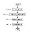
以上のような構成を備える装置において、眼軸長測定を行う場合の制御動作を図2に基づいて説明する。図2は、眼軸長測定の流れを示すフローチャートである。
<Control operation>
The control operation for measuring the axial length of the apparatus having the configuration as described above will be described with reference to FIG. FIG. 2 is a flow chart showing the flow of axial length measurement.
(ステップS1:アライメント)
まず、検者は、モニタ70に表示される被検眼のアライメント状態を見ながら、図示なきジョイスティック等の操作手段を用いて、装置を上下左右及び前後方向に移動させ、装置を被検眼Eに対して所定の位置関係に置く。このとき、検者は、被検者に固視標を固視させておく。
(Step S1: Alignment)
First, while viewing the alignment state of the eye to be examined displayed on the
アライメントの際には、光源41及び光源51が点灯される。例えば、検者は、モニタ70に電子的に表示されたレチクルと、光源41によるリング指標が同心円状になるように上下左右のアライメントを行う。これによって、被検眼の角膜頂点に本装置の光軸O1が通るようにXY方向にアライメントされる。また、検者は、リング指標のピントが合うように、前後のアライメントを行う。なお、制御部80は、正面撮像光学系30によって撮影された前眼部正面像に基づいて、自動でアライメントを行ってもよい。
During alignment, the
(ステップS2:撮影およびフォーカス位置調整)
アライメントが完了すると、制御部80は、OCT画像の撮影を開始する。制御部80は、まず、初期状態での撮影を行う。初期状態では、例えば、フォーカスレンズ124は、初期位置に配置されている。このとき、OCT光学系100のフォーカス位置は、ゼロディレイ(Zero delay)位置と同じ位置であってもよい。ゼロディレイ位置とは、例えば、測定光路長と参照光路長が一致する位置である。一般的に、ゼロディレイ位置から離れるにしたがってOCT感度は下がる。また、フォーカス位置から離れるにしたがって、デフォーカスの影響のためOCT感度は下がる。例えば、ゼロディレイ位置とフォーカス位置が角膜付近に配置される場合、眼底側にいくにしたがってOCT感度は下がる。なお、ゼロディレイ位置を境界として、正規の画像と折り返し画像が取得される。本実施例の場合、ゼロディレイ位置は、角膜の前面、またはその少し上流(装置側)に配置される(図3左端の位置Dに相当)。これによって、眼球内での折り返しを防ぐことができる。
(Step S2: Shooting and Focus Position Adjustment)
When the alignment is completed, the
制御部80は、駆動部125によってフォーカスレンズ124を初期位置から移動させながらOCT画像の撮影を行う。つまり、制御部80は、OCT光学系100のフォーカス位置をずらしながら繰り返し撮影を行い、フォーカス状態の異なる複数のOCT画像を取得する。このとき、ゼロディレイ位置Dは、角膜前面またはその少し上流から変化させないため、OCT光学系100の光路長またはカップラー104のファイバ長は変更しなくてもよい。
The
図3は、フォーカス位置をずらしながら撮影した同一被検眼の測定結果を示す。図3(a)は角膜面Cにフォーカス位置P1を配置したときの測定結果であり、水晶体後面Lrの信号は弱い。図3(b)は水晶体前面Lfにフォーカス位置P2を配置したときの測定結果であり、図3(a)と同様に水晶体後面Lrの信号は弱い。図3(c)は水晶体後面Lrにフォーカス位置P3を配置したときの測定結果であり、水晶体後面の信号が強く出ている。一方で角膜面Cの信号は、図3(a),(b)と比べると弱くなっているが、元々角膜の信号強度は強いため、検出が困難になるほどではない。図3(d)は硝子体内にフォーカス位置P4を配置したときの測定結果だが、この場合、前眼部の必要な信号強度が得られていない。したがって、フォーカス位置は水晶体後面付近が適している。なお、水晶体後面付近とは、例えば、少なくとも水晶体前面よりも眼底側で硝子体中心部より前眼側である。 FIG. 3 shows measurement results of the same subject's eye photographed while shifting the focus position. FIG. 3A shows the measurement results when the focus position P1 is placed on the corneal surface C, and the signal on the posterior surface Lr of the lens is weak. FIG. 3(b) shows the measurement results when the focus position P2 is arranged on the front surface Lf of the lens, and the signal on the rear surface Lr of the lens is weak as in FIG. 3(a). FIG. 3(c) shows the measurement results when the focus position P3 is placed on the posterior surface Lr of the lens, and the signal on the posterior surface of the lens is strong. On the other hand, the signal on the corneal surface C is weaker than in FIGS. 3A and 3B, but since the signal strength of the cornea is originally strong, it is not difficult to detect. FIG. 3(d) shows the measurement result when the focus position P4 is arranged in the vitreous, but in this case, the required signal intensity of the anterior segment is not obtained. Therefore, a focus position near the posterior surface of the lens is suitable. The vicinity of the posterior surface of the lens is, for example, at least closer to the fundus than the front surface of the crystalline lens and closer to the anterior eye than the center of the vitreous body.
制御部80は、フォーカス位置が水晶体後面付近に配置され、図3(c)のように、前眼部の各面の信号がバランスよく取得されるまで、フォーカス位置をずらしながら繰り返し撮影を行う。なお、水晶体後面の位置またはベストフォーカス位置は、眼球形状によって被検者毎に異なる。また、ベストフォーカス位置は、被検眼の混濁状況によっても異なる。例えば、被検眼の一部が混濁している場合、各部位に対するOCT感度が変化する。このような場合、上記のように、フォーカス位置を徐々にずらしながらOCT撮影を行うことによって、被検者毎に適したフォーカス位置で撮影できる。もちろん、フォーカス位置は、ゼロディレイ位置とは異なる位置に固定されてもよい。
The
なお、制御部80は、初期状態のフォーカス位置で最初の1枚を撮影し、そのときの画像(信号)からベストフォーカス位置を算出してもよい。この場合、ベストフォーカス位置の算出は、水晶体後面を基準としてもよいし、IOL挿入眼であればIOL後面でもよい。また、制御部80は、全ての部位の信号バランスが取れるような演算式によってベストフォーカス位置を算出してもよい。このように、所定のフォーカス状態で撮影された1枚のOCT信号に基づいてベストフォーカス位置を算出することによって、フォーカスレンズ124を少しずつずらしながら複数枚撮影する必要がなくなるため、測定全体の時間短縮となる。
Note that the
なお、フォーカス位置を移動させる場合、フォーカスレンズ124のみの可動に限定する必要はない。例えば、ファイバ端122とコリメートレンズ123の間隔を変えてもよいし、作動距離と光路長を同時に変化させてもよい。
When moving the focus position, it is not necessary to limit the movement of only the
(ステップS3:眼内距離算出)
制御部80は、良好なOCT画像が撮影できると、OCT画像(信号)から眼内距離を算出する。例えば、制御部80は、OCT画像に基づいて角膜前面、角膜後面、水晶体前面、水晶体後面、および網膜等の各部の位置を検出し、角膜厚、前房深度、水晶体厚、眼軸長等の眼内距離を算出する。もちろん、各部位の曲率等を算出してもよい。
(Step S3: intraocular distance calculation)
When a good OCT image can be captured, the
なお、制御部80は、各部位の信号強度が最も大きくなるようにそれぞれの画像(信号)をマージしてもよい。例えば、図3(a)の角膜面Cの信号と、図3(b)の水晶体前面Lfの信号と、図3(c)の水晶体後面Lrの信号とをマージしてもよい。これによって、1A-scanで得られるよりも感度の高い信号を取得できる。なお、フォーカスレンズ124を移動させても光路長は変化しないため、各信号を容易にマージすることができる。制御部80は、マージしたOCT信号に基づいて眼内距離を算出してもよい。
Note that the
(ステップS4:測定結果表示)
制御部80は、眼内距離の算出結果、およびOCT画像等を表示部70に表示させる。このとき、制御部80は、フォーカスを変化させながら撮影した複数のOCT信号の中から任意の信号を表示させてもよい。例えば、制御部80は、良好な撮影画像(例えば、ベストショット)のみをユーザに提示してもよい。これによって、検者は良好な撮影画像を探す手間が省ける。
(Step S4: Display measurement results)
The
以上のように、本実施例のOCT装置は、フォーカス位置とゼロディレイ位置を異なる位置にすることでOCT感度のばらつきを抑えることができる。例えば、フォーカス位置を水晶体後面付近にすることによって、角膜、水晶体の各面をバランス良く検出することができる。これによって、後方散乱の強度が低い水晶体後面も検出できるようになり、水晶体厚または水晶体後面曲率等を測定できる。また、反射が強い角膜前面でサチレーションすることを防ぐことができる。 As described above, the OCT apparatus of this embodiment can suppress variations in OCT sensitivity by setting the focus position and the zero delay position to different positions. For example, by setting the focus position to the vicinity of the posterior surface of the lens, each surface of the cornea and the lens can be detected in a well-balanced manner. This makes it possible to detect the posterior surface of the lens where the intensity of backscattering is low, and to measure the thickness of the lens, the curvature of the posterior surface of the lens, or the like. In addition, it is possible to prevent saturation on the front surface of the cornea where reflection is strong.
なお、フォーカスの初期位置は、ゼロディレイ位置と同じ位置に限らず、例えば、水晶体後面付近をフォーカスの初期位置としてもよい。この場合、被検眼によって水晶体後面付近の位置は異なるため、おおよそ平均的な眼の水晶体後面付近の位置が初期位置として設定されてもよい。これによって、ベストフォーカス位置の算出が容易となる。 Note that the initial focus position is not limited to the same position as the zero delay position, and for example, the vicinity of the posterior surface of the lens may be the initial focus position. In this case, since the position of the vicinity of the posterior surface of the crystalline lens differs depending on the subject's eye, a position of the vicinity of the posterior surface of the crystalline lens of an approximately average eye may be set as the initial position. This facilitates calculation of the best focus position.
5 光コヒーレンストモグラフィーデバイス
30 前眼部正面撮像光学系
40 アライメント投影光学系
50 ケラト投影光学系
70 モニタ
80 制御部
85 メモリ
84 操作部
5 Optical
Claims (4)
波長掃引型光源から出射された測定光が前記被検眼によって反射した反射光と、前記測定光に対応する参照光と、の干渉状態に基づいて角膜、水晶体および網膜の各部のOCT信号を一度に取得するOCT光学系と、
前記OCT光学系のフォーカス位置を、前記OCT光学系の光軸方向に調整する調整手段と、
前記調整手段を制御する制御手段と、を備え、
前記制御手段は、前記OCT光学系のゼロディレイ位置を前記角膜、または前記角膜と前記OCT装置の間に配置させ、前記フォーカス位置を前記ゼロディレイ位置とは前記光軸方向に異なる水晶体後面付近に配置させることを特徴とするOCT装置。 An OCT apparatus for imaging an eye to be examined,
Based on the state of interference between the measurement light emitted from the wavelength swept light source and reflected by the eye to be inspected and the reference light corresponding to the measurement light, the OCT signal of each part of the cornea, the lens, and the retina is obtained at once. an OCT optical system to acquire;
adjusting means for adjusting the focus position of the OCT optical system in the optical axis direction of the OCT optical system;
and a control means for controlling the adjustment means,
The control means places the zero-delay position of the OCT optical system on the cornea or between the cornea and the OCT apparatus, and places the focus position near the posterior surface of the lens different from the zero-delay position in the optical axis direction. An OCT apparatus characterized by placing.
OCT光学系を制御し、波長掃引型光源から出射された測定光が前記被検眼によって反射した反射光と、前記測定光に対応する参照光と、の干渉状態に基づいて角膜、水晶体および網膜の各部のOCT信号を取得する取得ステップと、
前記OCT光学系のゼロディレイ位置を前記角膜、または前記角膜と前記OCT装置の間に配置させ、前記OCT光学系のフォーカス位置を前記ゼロディレイ位置とは前記OCT光学系の光軸方向に異なる水晶体後面付近に配置する調整ステップと、
を前記OCT装置に実行させることを特徴とするOCT制御プログラム。 An OCT control program that is executed in an OCT apparatus that images an eye to be examined, and that is executed by a processor of the OCT apparatus,
The OCT optical system is controlled to control the cornea, lens, and retina based on the state of interference between the measurement light emitted from the wavelength-swept light source and the reflected light reflected by the subject's eye and the reference light corresponding to the measurement light. an acquisition step of acquiring an OCT signal of each part;
The zero-delay position of the OCT optical system is arranged between the cornea or the cornea and the OCT apparatus, and the focus position of the OCT optical system is different in the optical axis direction of the OCT optical system from the zero-delay position. an adjustment step located near the rear surface;
An OCT control program characterized by causing the OCT apparatus to execute.
Priority Applications (1)
| Application Number | Priority Date | Filing Date | Title |
|---|---|---|---|
| JP2018018727A JP7187777B2 (en) | 2018-02-05 | 2018-02-05 | OCT device and OCT control program |
Applications Claiming Priority (1)
| Application Number | Priority Date | Filing Date | Title |
|---|---|---|---|
| JP2018018727A JP7187777B2 (en) | 2018-02-05 | 2018-02-05 | OCT device and OCT control program |
Publications (3)
| Publication Number | Publication Date |
|---|---|
| JP2019134908A JP2019134908A (en) | 2019-08-15 |
| JP2019134908A5 JP2019134908A5 (en) | 2021-02-12 |
| JP7187777B2 true JP7187777B2 (en) | 2022-12-13 |
Family
ID=67623526
Family Applications (1)
| Application Number | Title | Priority Date | Filing Date |
|---|---|---|---|
| JP2018018727A Active JP7187777B2 (en) | 2018-02-05 | 2018-02-05 | OCT device and OCT control program |
Country Status (1)
| Country | Link |
|---|---|
| JP (1) | JP7187777B2 (en) |
Families Citing this family (1)
| Publication number | Priority date | Publication date | Assignee | Title |
|---|---|---|---|---|
| CN114847868B (en) * | 2022-05-06 | 2024-05-03 | 山东探微医疗技术有限公司 | Focusing assembly, intermittent focusing scanning and automatic focusing OCT device and method |
Citations (9)
| Publication number | Priority date | Publication date | Assignee | Title |
|---|---|---|---|---|
| JP2005348755A (en) | 2004-06-08 | 2005-12-22 | Nidek Co Ltd | Ophthalmologic measuring device |
| JP2007101250A (en) | 2005-09-30 | 2007-04-19 | Fujifilm Corp | Optical tomographic imaging method |
| JP2010169503A (en) | 2009-01-22 | 2010-08-05 | Canon Inc | Optical tomographic image photographing apparatus |
| JP2014100230A (en) | 2012-11-19 | 2014-06-05 | Topcon Corp | Optical image measuring apparatus |
| JP2016032609A (en) | 2014-07-31 | 2016-03-10 | 株式会社ニデック | Ophthalmologic apparatus |
| JP2016032578A (en) | 2014-07-31 | 2016-03-10 | 株式会社ニデック | Ophthalmologic apparatus |
| JP2016198668A (en) | 2016-09-08 | 2016-12-01 | 株式会社トーメーコーポレーション | Ophthalmologic apparatus |
| JP2017080135A (en) | 2015-10-29 | 2017-05-18 | 株式会社トプコン | Ophthalmologic apparatus |
| JP2016533235A5 (en) | 2014-07-10 | 2017-08-17 |
Family Cites Families (1)
| Publication number | Priority date | Publication date | Assignee | Title |
|---|---|---|---|---|
| CN105530853B (en) | 2013-07-25 | 2018-12-04 | 光学医疗公司 | The original position of the refractive index of substance is determined |
-
2018
- 2018-02-05 JP JP2018018727A patent/JP7187777B2/en active Active
Patent Citations (9)
| Publication number | Priority date | Publication date | Assignee | Title |
|---|---|---|---|---|
| JP2005348755A (en) | 2004-06-08 | 2005-12-22 | Nidek Co Ltd | Ophthalmologic measuring device |
| JP2007101250A (en) | 2005-09-30 | 2007-04-19 | Fujifilm Corp | Optical tomographic imaging method |
| JP2010169503A (en) | 2009-01-22 | 2010-08-05 | Canon Inc | Optical tomographic image photographing apparatus |
| JP2014100230A (en) | 2012-11-19 | 2014-06-05 | Topcon Corp | Optical image measuring apparatus |
| JP2016533235A5 (en) | 2014-07-10 | 2017-08-17 | ||
| JP2016032609A (en) | 2014-07-31 | 2016-03-10 | 株式会社ニデック | Ophthalmologic apparatus |
| JP2016032578A (en) | 2014-07-31 | 2016-03-10 | 株式会社ニデック | Ophthalmologic apparatus |
| JP2017080135A (en) | 2015-10-29 | 2017-05-18 | 株式会社トプコン | Ophthalmologic apparatus |
| JP2016198668A (en) | 2016-09-08 | 2016-12-01 | 株式会社トーメーコーポレーション | Ophthalmologic apparatus |
Also Published As
| Publication number | Publication date |
|---|---|
| JP2019134908A (en) | 2019-08-15 |
Similar Documents
| Publication | Publication Date | Title |
|---|---|---|
| JP5887839B2 (en) | Intraocular lens power determination device and program | |
| US9820645B2 (en) | Ophthalmologic apparatus | |
| JP5650482B2 (en) | Ophthalmic imaging equipment | |
| JP6007549B2 (en) | Fundus photographing device | |
| JP6221516B2 (en) | Ophthalmic photographing apparatus and ophthalmic photographing program | |
| US10918277B2 (en) | Ophthalmic device | |
| JP7027698B2 (en) | Ophthalmologic photography equipment | |
| JP7009846B2 (en) | OCT device | |
| JP6604020B2 (en) | Fundus imaging apparatus and fundus imaging program | |
| JP6421919B2 (en) | Ophthalmic imaging equipment | |
| JP7187777B2 (en) | OCT device and OCT control program | |
| JP2016049368A (en) | Ophthalmological photographing apparatus | |
| JP2018033807A (en) | Intraocular lens power determination device and intraocular lens power determination program | |
| JP6052445B2 (en) | Intraocular lens power determination device and program | |
| CN115778312A (en) | Ophthalmic device | |
| JP7164328B2 (en) | Ophthalmic device and control method for ophthalmic device | |
| JP7043790B2 (en) | OCT device | |
| JP7124270B2 (en) | ophthalmic imaging equipment | |
| JP7119286B2 (en) | OCT device | |
| JP2015085043A (en) | Fundus photographing device | |
| JP2020049128A (en) | Intraocular lens selection device and intraocular lens selection program | |
| WO2022186115A1 (en) | Oct device, and ophthalmic image processing program | |
| JPH05192295A (en) | Bio-eye size measuring instrument with refracting power correction function | |
| JP7030577B2 (en) | Ophthalmic equipment | |
| JP2020036717A (en) | Ophthalmologic imaging apparatus |
Legal Events
| Date | Code | Title | Description |
|---|---|---|---|
| A521 | Request for written amendment filed |
Free format text: JAPANESE INTERMEDIATE CODE: A523 Effective date: 20201223 |
|
| A621 | Written request for application examination |
Free format text: JAPANESE INTERMEDIATE CODE: A621 Effective date: 20201223 |
|
| A977 | Report on retrieval |
Free format text: JAPANESE INTERMEDIATE CODE: A971007 Effective date: 20210916 |
|
| A131 | Notification of reasons for refusal |
Free format text: JAPANESE INTERMEDIATE CODE: A131 Effective date: 20211005 |
|
| A601 | Written request for extension of time |
Free format text: JAPANESE INTERMEDIATE CODE: A601 Effective date: 20211202 |
|
| A521 | Request for written amendment filed |
Free format text: JAPANESE INTERMEDIATE CODE: A523 Effective date: 20220203 |
|
| A131 | Notification of reasons for refusal |
Free format text: JAPANESE INTERMEDIATE CODE: A131 Effective date: 20220615 |
|
| A521 | Request for written amendment filed |
Free format text: JAPANESE INTERMEDIATE CODE: A523 Effective date: 20220809 |
|
| TRDD | Decision of grant or rejection written | ||
| A01 | Written decision to grant a patent or to grant a registration (utility model) |
Free format text: JAPANESE INTERMEDIATE CODE: A01 Effective date: 20221101 |
|
| A61 | First payment of annual fees (during grant procedure) |
Free format text: JAPANESE INTERMEDIATE CODE: A61 Effective date: 20221114 |
|
| R150 | Certificate of patent or registration of utility model |
Ref document number: 7187777 Country of ref document: JP Free format text: JAPANESE INTERMEDIATE CODE: R150 |