WO2022186115A1 - Oct device, and ophthalmic image processing program - Google Patents
Oct device, and ophthalmic image processing program Download PDFInfo
- Publication number
- WO2022186115A1 WO2022186115A1 PCT/JP2022/008184 JP2022008184W WO2022186115A1 WO 2022186115 A1 WO2022186115 A1 WO 2022186115A1 JP 2022008184 W JP2022008184 W JP 2022008184W WO 2022186115 A1 WO2022186115 A1 WO 2022186115A1
- Authority
- WO
- WIPO (PCT)
- Prior art keywords
- oct
- eye
- optical system
- light
- fundus
- Prior art date
Links
- 230000003287 optical effect Effects 0.000 claims abstract description 226
- 238000005259 measurement Methods 0.000 claims description 101
- 210000004087 cornea Anatomy 0.000 claims description 30
- 230000003595 spectral effect Effects 0.000 claims description 13
- 210000001747 pupil Anatomy 0.000 claims description 12
- 208000004350 Strabismus Diseases 0.000 claims description 6
- 238000005070 sampling Methods 0.000 claims description 6
- 238000006243 chemical reaction Methods 0.000 claims description 5
- 230000004323 axial length Effects 0.000 claims description 4
- 230000002194 synthesizing effect Effects 0.000 claims description 3
- 238000012014 optical coherence tomography Methods 0.000 abstract description 249
- 210000001508 eye Anatomy 0.000 description 135
- 210000000695 crystalline len Anatomy 0.000 description 45
- 210000005252 bulbus oculi Anatomy 0.000 description 20
- 238000003384 imaging method Methods 0.000 description 19
- 238000000034 method Methods 0.000 description 13
- 238000004458 analytical method Methods 0.000 description 10
- 238000012545 processing Methods 0.000 description 10
- 238000005457 optimization Methods 0.000 description 9
- 230000010287 polarization Effects 0.000 description 8
- 230000000007 visual effect Effects 0.000 description 8
- 238000001514 detection method Methods 0.000 description 7
- 230000000052 comparative effect Effects 0.000 description 6
- 238000010586 diagram Methods 0.000 description 5
- 239000013307 optical fiber Substances 0.000 description 5
- 238000006073 displacement reaction Methods 0.000 description 4
- 238000005516 engineering process Methods 0.000 description 4
- 230000035515 penetration Effects 0.000 description 4
- 210000002159 anterior chamber Anatomy 0.000 description 3
- 230000006870 function Effects 0.000 description 3
- 238000004364 calculation method Methods 0.000 description 2
- 238000012937 correction Methods 0.000 description 2
- 238000013481 data capture Methods 0.000 description 2
- 230000004907 flux Effects 0.000 description 2
- 210000000873 fovea centralis Anatomy 0.000 description 2
- 230000007246 mechanism Effects 0.000 description 2
- 238000012986 modification Methods 0.000 description 2
- 230000004048 modification Effects 0.000 description 2
- 230000008569 process Effects 0.000 description 2
- 230000001179 pupillary effect Effects 0.000 description 2
- 210000001525 retina Anatomy 0.000 description 2
- 210000003786 sclera Anatomy 0.000 description 2
- 230000035945 sensitivity Effects 0.000 description 2
- 238000010408 sweeping Methods 0.000 description 2
- 230000001131 transforming effect Effects 0.000 description 2
- 210000002294 anterior eye segment Anatomy 0.000 description 1
- 210000001110 axial length eye Anatomy 0.000 description 1
- 238000005452 bending Methods 0.000 description 1
- 230000008859 change Effects 0.000 description 1
- 239000002131 composite material Substances 0.000 description 1
- 230000003247 decreasing effect Effects 0.000 description 1
- 238000011835 investigation Methods 0.000 description 1
- 238000000691 measurement method Methods 0.000 description 1
- 230000010355 oscillation Effects 0.000 description 1
- 230000002093 peripheral effect Effects 0.000 description 1
- 238000003672 processing method Methods 0.000 description 1
- 230000002207 retinal effect Effects 0.000 description 1
- 230000002123 temporal effect Effects 0.000 description 1
- 238000011144 upstream manufacturing Methods 0.000 description 1
Images


Classifications
-
- A—HUMAN NECESSITIES
- A61—MEDICAL OR VETERINARY SCIENCE; HYGIENE
- A61B—DIAGNOSIS; SURGERY; IDENTIFICATION
- A61B3/00—Apparatus for testing the eyes; Instruments for examining the eyes
- A61B3/10—Objective types, i.e. instruments for examining the eyes independent of the patients' perceptions or reactions
- A61B3/102—Objective types, i.e. instruments for examining the eyes independent of the patients' perceptions or reactions for optical coherence tomography [OCT]
-
- A—HUMAN NECESSITIES
- A61—MEDICAL OR VETERINARY SCIENCE; HYGIENE
- A61B—DIAGNOSIS; SURGERY; IDENTIFICATION
- A61B3/00—Apparatus for testing the eyes; Instruments for examining the eyes
- A61B3/10—Objective types, i.e. instruments for examining the eyes independent of the patients' perceptions or reactions
- A61B3/107—Objective types, i.e. instruments for examining the eyes independent of the patients' perceptions or reactions for determining the shape or measuring the curvature of the cornea
-
- A—HUMAN NECESSITIES
- A61—MEDICAL OR VETERINARY SCIENCE; HYGIENE
- A61B—DIAGNOSIS; SURGERY; IDENTIFICATION
- A61B3/00—Apparatus for testing the eyes; Instruments for examining the eyes
- A61B3/10—Objective types, i.e. instruments for examining the eyes independent of the patients' perceptions or reactions
- A61B3/117—Objective types, i.e. instruments for examining the eyes independent of the patients' perceptions or reactions for examining the anterior chamber or the anterior chamber angle, e.g. gonioscopes
-
- A—HUMAN NECESSITIES
- A61—MEDICAL OR VETERINARY SCIENCE; HYGIENE
- A61B—DIAGNOSIS; SURGERY; IDENTIFICATION
- A61B3/00—Apparatus for testing the eyes; Instruments for examining the eyes
- A61B3/10—Objective types, i.e. instruments for examining the eyes independent of the patients' perceptions or reactions
- A61B3/12—Objective types, i.e. instruments for examining the eyes independent of the patients' perceptions or reactions for looking at the eye fundus, e.g. ophthalmoscopes
- A61B3/1216—Objective types, i.e. instruments for examining the eyes independent of the patients' perceptions or reactions for looking at the eye fundus, e.g. ophthalmoscopes for diagnostics of the iris
-
- A—HUMAN NECESSITIES
- A61—MEDICAL OR VETERINARY SCIENCE; HYGIENE
- A61B—DIAGNOSIS; SURGERY; IDENTIFICATION
- A61B3/00—Apparatus for testing the eyes; Instruments for examining the eyes
- A61B3/10—Objective types, i.e. instruments for examining the eyes independent of the patients' perceptions or reactions
- A61B3/14—Arrangements specially adapted for eye photography
- A61B3/15—Arrangements specially adapted for eye photography with means for aligning, spacing or blocking spurious reflection ; with means for relaxing
- A61B3/152—Arrangements specially adapted for eye photography with means for aligning, spacing or blocking spurious reflection ; with means for relaxing for aligning
-
- A—HUMAN NECESSITIES
- A61—MEDICAL OR VETERINARY SCIENCE; HYGIENE
- A61B—DIAGNOSIS; SURGERY; IDENTIFICATION
- A61B3/00—Apparatus for testing the eyes; Instruments for examining the eyes
- A61B3/10—Objective types, i.e. instruments for examining the eyes independent of the patients' perceptions or reactions
- A61B3/14—Arrangements specially adapted for eye photography
- A61B3/15—Arrangements specially adapted for eye photography with means for aligning, spacing or blocking spurious reflection ; with means for relaxing
- A61B3/154—Arrangements specially adapted for eye photography with means for aligning, spacing or blocking spurious reflection ; with means for relaxing for spacing
-
- G—PHYSICS
- G01—MEASURING; TESTING
- G01B—MEASURING LENGTH, THICKNESS OR SIMILAR LINEAR DIMENSIONS; MEASURING ANGLES; MEASURING AREAS; MEASURING IRREGULARITIES OF SURFACES OR CONTOURS
- G01B9/00—Measuring instruments characterised by the use of optical techniques
- G01B9/02—Interferometers
- G01B9/02001—Interferometers characterised by controlling or generating intrinsic radiation properties
- G01B9/02002—Interferometers characterised by controlling or generating intrinsic radiation properties using two or more frequencies
- G01B9/02004—Interferometers characterised by controlling or generating intrinsic radiation properties using two or more frequencies using frequency scans
-
- G—PHYSICS
- G01—MEASURING; TESTING
- G01B—MEASURING LENGTH, THICKNESS OR SIMILAR LINEAR DIMENSIONS; MEASURING ANGLES; MEASURING AREAS; MEASURING IRREGULARITIES OF SURFACES OR CONTOURS
- G01B9/00—Measuring instruments characterised by the use of optical techniques
- G01B9/02—Interferometers
- G01B9/02015—Interferometers characterised by the beam path configuration
- G01B9/02029—Combination with non-interferometric systems, i.e. for measuring the object
- G01B9/0203—With imaging systems
-
- G—PHYSICS
- G01—MEASURING; TESTING
- G01B—MEASURING LENGTH, THICKNESS OR SIMILAR LINEAR DIMENSIONS; MEASURING ANGLES; MEASURING AREAS; MEASURING IRREGULARITIES OF SURFACES OR CONTOURS
- G01B9/00—Measuring instruments characterised by the use of optical techniques
- G01B9/02—Interferometers
- G01B9/02055—Reduction or prevention of errors; Testing; Calibration
- G01B9/02062—Active error reduction, i.e. varying with time
- G01B9/02063—Active error reduction, i.e. varying with time by particular alignment of focus position, e.g. dynamic focussing in optical coherence tomography
-
- G—PHYSICS
- G01—MEASURING; TESTING
- G01B—MEASURING LENGTH, THICKNESS OR SIMILAR LINEAR DIMENSIONS; MEASURING ANGLES; MEASURING AREAS; MEASURING IRREGULARITIES OF SURFACES OR CONTOURS
- G01B9/00—Measuring instruments characterised by the use of optical techniques
- G01B9/02—Interferometers
- G01B9/02055—Reduction or prevention of errors; Testing; Calibration
- G01B9/02062—Active error reduction, i.e. varying with time
- G01B9/02064—Active error reduction, i.e. varying with time by particular adjustment of coherence gate, i.e. adjusting position of zero path difference in low coherence interferometry
-
- G—PHYSICS
- G01—MEASURING; TESTING
- G01B—MEASURING LENGTH, THICKNESS OR SIMILAR LINEAR DIMENSIONS; MEASURING ANGLES; MEASURING AREAS; MEASURING IRREGULARITIES OF SURFACES OR CONTOURS
- G01B9/00—Measuring instruments characterised by the use of optical techniques
- G01B9/02—Interferometers
- G01B9/02055—Reduction or prevention of errors; Testing; Calibration
- G01B9/02062—Active error reduction, i.e. varying with time
- G01B9/02067—Active error reduction, i.e. varying with time by electronic control systems, i.e. using feedback acting on optics or light
- G01B9/02068—Auto-alignment of optical elements
-
- G—PHYSICS
- G01—MEASURING; TESTING
- G01B—MEASURING LENGTH, THICKNESS OR SIMILAR LINEAR DIMENSIONS; MEASURING ANGLES; MEASURING AREAS; MEASURING IRREGULARITIES OF SURFACES OR CONTOURS
- G01B9/00—Measuring instruments characterised by the use of optical techniques
- G01B9/02—Interferometers
- G01B9/0209—Low-coherence interferometers
- G01B9/02091—Tomographic interferometers, e.g. based on optical coherence
-
- G—PHYSICS
- G01—MEASURING; TESTING
- G01N—INVESTIGATING OR ANALYSING MATERIALS BY DETERMINING THEIR CHEMICAL OR PHYSICAL PROPERTIES
- G01N21/00—Investigating or analysing materials by the use of optical means, i.e. using sub-millimetre waves, infrared, visible or ultraviolet light
- G01N21/17—Systems in which incident light is modified in accordance with the properties of the material investigated
-
- G—PHYSICS
- G01—MEASURING; TESTING
- G01B—MEASURING LENGTH, THICKNESS OR SIMILAR LINEAR DIMENSIONS; MEASURING ANGLES; MEASURING AREAS; MEASURING IRREGULARITIES OF SURFACES OR CONTOURS
- G01B2290/00—Aspects of interferometers not specifically covered by any group under G01B9/02
- G01B2290/70—Using polarization in the interferometer
Definitions
- the present disclosure relates to an OCT apparatus and an ophthalmic image processing program.
- OCT optical coherence tomography
- the retinal fovea is not on the eye axis (or the optical axis of the eye), but is slightly eccentric to the temporal side. Therefore, a so-called physiological oblique angle exists even in a normal ocular optical system.
- various angles such as ⁇ angle, ⁇ angle, ⁇ angle, and ⁇ angle are known. For example, in recent years, these angles have been considered in situations such as the prescription of premium IOLs (see Patent Document 1).
- the ⁇ angle is obtained based on the information of the front image of the anterior segment.
- An OCT apparatus obtains OCT data (B-scan data or volume data) according to the trajectory of the measurement light by scanning the tissue of the eye to be inspected with the measurement light using an optical scanner. , no investigation has been made on a scanning method that facilitates extensive scanning of both the anterior eye and the fundus.
- the actual position of the fovea is unknown in the method adopted in Patent Document 1 and the like as a method for obtaining the physiological strabismic angle of the eye to be examined.
- a wide range of OCT data may allow the physiological strabismus angle of the eye to be examined to be determined more appropriately.
- the present invention has been made in view of at least one of the above circumstances, and the technical problem thereof is to appropriately obtain the physiological strabismic angle of an eye to be examined.
- An ophthalmologic image processing program is executed by a processor of an ophthalmologic computer so that OCT data of an anterior segment and a turning point of measurement light are positioned closer to the subject's eye than the objective optical system.
- An OCT apparatus executes the above ophthalmic image processing program.
- FIG. 1 is a diagram showing a schematic configuration of an OCT system according to an example; FIG. It is a figure which shows the OCT optical system which concerns on an Example. 4 is a flowchart for explaining a photographing operation; FIG. 10 is a diagram showing the positional relationship between the device and the subject's eye E in the fundus mode; FIG. 10 is a diagram showing fundus OCT data acquired in fundus mode; FIG. 10 is a diagram showing the positional relationship between the device and the subject's eye E in the anterior segment mode. FIG. 10 illustrates fundus OCT data acquired in anterior segment mode; It is a figure which shows the positional relationship of the apparatus and the to-be-tested eye E in all eyeballs mode. FIG. 10 illustrates fundus OCT data acquired in whole eye mode; FIG. 4 shows synthetic OCT data; It is a figure for demonstrating analysis processing. It is a figure which shows the measuring method which concerns on a modification.
- An OCT apparatus includes at least an OCT optical system, a light guide optical system, an arithmetic controller, and an alignment adjustment section.
- the OCT optical system (see FIG. 2) is used to capture OCT data of the subject's eye.
- the OCT optical system includes at least a light splitter and a detector.
- a light splitter is utilized to split the light from the OCT light source into measurement light and reference light.
- a detector detects spectral interference signals of the measurement light and the reference light directed to the eye to be examined.
- OCT data is obtained by processing the signal from the detector by an operation controller, which will be described later.
- the OCT optical system may be suitable for acquiring OCT data with high penetration (in other words, wide area).
- the OCT optical system according to the first embodiment may be a wavelength-swept OCT (SS-OCT) optical system.
- the OCT optical system includes a wavelength swept light source (wavelength scanning light source) as an OCT light source that is a light source for measurement light and reference light.
- a wavelength swept light source changes the emission wavelength at high speed in time.
- the VCSEL wavelength swept light source has a long coherence length, it can be used as an OCT light source to capture OCT data over a wide range in the depth direction. For example, an imaging range of about 10 mm or more can be achieved.
- the wavelength swept light source performs wavelength sweeping in a so-called 1 ⁇ m band (wavelength sweeping is performed centering on about 1050 nm). It is known that the so-called 1 ⁇ m band exhibits a higher penetration depth into tissues of the eye to be examined than other wavelength bands.
- the swept frequency in the wavelength swept light source may be changeable between at least a first frequency and a second frequency.
- the second frequency has a smaller value than the first frequency.
- the sweep frequency is changed by changing either the speed of an optical element built in the light source and driven to sweep the wavelength or the duty ratio in the sweep cycle.
- the OCT device further comprises a conversion section.
- the detector detects spectral interference signals as beat signals as the wavelength is swept.
- a transform unit samples the spectral interference signal output from the detector.
- the converter converts the spectral interference signal output from the detector from an analog signal to a digital signal.
- the conversion unit may be a digitizer capable of adjusting the sampling frequency.
- the light guide optical system forms at least part of a measurement light path for guiding measurement light to the subject's eye. More specifically, the light guiding optical system of this embodiment includes at least an optical scanner and an objective optical system.
- the optical scanner scans measurement light over the tissue of the eye to be examined.
- the light guiding optical system may be provided with two optical scanners having different scanning directions.
- the objective optical system is arranged between the optical scanner and the subject's eye. The objective optical system thereby forms a pivot point for the measurement light. The measurement light that has passed through the optical scanner is turned around the turning point.
- the measurement light that has passed through the turning point is scanned along a plurality of predetermined scan lines on the tissue of the eye to be examined.
- OCT data for each scan line is captured along with the scanning.
- the scan line may be set at any position based on instructions from the examiner.
- a scan line corresponding to a scan pattern may be set by selecting one of a plurality of predetermined scan patterns.
- Various scan patterns such as line, cross, multi, map, radial, and circle are known.
- the alignment adjustment unit adjusts the three-dimensional position of the light guiding optical system with respect to the eye to be examined. At this time, in the present embodiment, at least the position of the light guiding optical system in the front-rear direction with respect to the eye to be examined is adjusted.
- the light guide optical system may be electrically moved by an actuator provided in the alignment adjustment section.
- the alignment adjustment unit is not limited to this, and may be a mechanical mechanism.
- the alignment adjustment section may include a face support unit capable of changing the position of the subject's face. In other words, the three-dimensional position of the subject's eye may be adjusted by moving the position of the subject's face.
- the OCT apparatus of this embodiment may additionally have an alignment detection optical system.
- the alignment detection optical system is used to guide the light guiding optical system to the proper working distance with respect to the eye to be inspected.
- the alignment detection optical system detects the alignment state of the light guiding optical system with respect to the subject's eye at least in the Z direction.
- the alignment detection optical system may include at least an observation optical system (preferably an anterior segment observation optical system).
- it may further include a light projecting optical system for projecting a working distance detection index onto the anterior segment of the subject's eye.
- the working distance may be adjusted based on the position of the index observed by the observation optical system or the imaging state.
- an OCT optical system may be used as the alignment detection optical system.
- the alignment state may be adjusted based on the OCT data so that an image of the anterior segment is captured at a predetermined position on the OCT data.
- An arithmetic controller acquires OCT data based on the signal from the detector. More specifically, the spectral interference signal converted into a digital signal by the conversion section is arithmetically processed by the image processor. Thereby, the OCT data of the eye to be examined is obtained. Further, the arithmetic controller controls at least the OCT optical system to perform an operation of acquiring OCT data.
- the OCT data may be signal data or visualized image data.
- the OCT data includes tomographic image data indicating reflection intensity characteristics of the eye to be examined, OCT angio data of the eye to be examined (for example, OCT motion contrast data), Doppler OCT data indicating Doppler characteristics of the eye to be examined, and polarization characteristics of the eye to be examined. It may be at least one of the polarization characteristic data shown, and the like.
- OCT data includes B-scan data (e.g., B-scan tomographic image data, two-dimensional OCT angio data, etc.), en face data (e.g., OCT frontal data, frontal motion contrast data, etc.), three-dimensional data (eg, three-dimensional tomographic image data, three-dimensional OCT angio data, etc.), and/or the like.
- B-scan data e.g., B-scan tomographic image data, two-dimensional OCT angio data, etc.
- en face data e.g., OCT frontal data, frontal motion contrast data, etc.
- three-dimensional data e.g, three-dimensional tomographic image data, three-dimensional OCT angio data, etc.
- a full-ranging technique may be applied to the OCT data.
- Various techniques for removing artifacts in OCT data are called full-ranging techniques.
- any full-ranging technique may be applied, which may allow acquisition of a wider range of OCT data with artifacts selectively removed.
- Examples of full-range technology include technology for removing virtual images (also referred to as mirror images) with additional hardware (see, for example, Non-Patent Document 1), technology for correcting with software without using additional hardware (for example, , see Patent Document 2) and the like.
- Wojtkowski, M. et al. (2002) Full-range complex spectral optical coherence tomography technique in eye imaging, Optics Letters, 27(16), p.1415.
- the arithmetic controller guides the three-dimensional position of the light guide optical system with respect to the subject's eye so that the pivot point is located at the target position. If the pivot point reaches the target position as a result of the navigation, an OCT data acquisition operation is performed.
- Position guidance of the light guide optical system for placing the turning point at the target position may be so-called auto-alignment. That is, the light guiding optical system may be moved in a direction in which the deviation between the position of the turning point and the target position is reduced by driving and controlling the alignment adjustment section by the arithmetic controller. Further, instead of auto-alignment, or additionally, guide information for assisting alignment may be output to the examiner so that the turning point is arranged at the target position.
- the guide information may be graphical information displayed on a monitor (for example, character information, graphic information, etc., details of which will be described later), or audio information output from a speaker.
- the guide information may be operation guidance for the examiner.
- the target position of the turning point is set between the subject's eye and the objective optical system.
- the target position may be set at a position a predetermined distance away from the corneal vertex in the front-rear direction.
- the measurement light that is not parallel to the optical axis enters the cornea of the subject's eye while moving away from the optical axis of the optical system.
- Such measurement light is guided to each tissue of the anterior segment of the eye and to the fundus without crossing the optical axis again within the eyeball. This makes it possible to irradiate the measurement light over a wider range of the subject's eye.
- the pivot point is arranged inside the eyeball of the subject's eye.
- the portion of the subject's eye at a depth position near the turning point is less likely to be irradiated with the measurement light and is less likely to be imaged.
- the turning point since the turning point is not arranged in the eyeball of the eye to be examined by being set between the eye to be examined and the objective optical system, each depth position Tissues in the are likely to be photographed.
- Comparative Example 2 the subject's eye is irradiated with the measurement light substantially telecentrically from the objective optical system. Since the telecentric luminous flux is refracted by the translucent body of the eye to be examined, the measurement light reaching the fundus is concentrated in the approximate center of the fundus (near the fovea centralis). Therefore, in Comparative Example 2, it is difficult to ensure the imaging range on the fundus.
- the measurement light is incident on the cornea of the subject's eye from the turning point between the subject's eye and the objective optical system while moving away from the optical axis of the optical system. Therefore, even if the measuring light is refracted by the translucent body of the subject's eye, the measuring light is likely to irradiate (that is, can be photographed) a position distant from the approximate center of the fundus (near the fovea).
- the scanning amount of the measurement light may be set so that the measurement light is intentionally vignetted by the iris at the target position.
- OCT data including at least the cornea, the fundus, and the iris can be acquired once (in other words, in one shot).
- the positional information of the cornea, iris, and fundus is included in the OCT data acquired in one shot, making it possible to appropriately identify the positional relationship between the fundus and the anterior segment of the eye.
- the OCT data can be appropriately synthesized (collaged) with the local OCT data of the anterior segment or the fundus.
- the OCT apparatus of this embodiment may include a second adjuster.
- the measurement range in the depth direction in the OCT data may be adjustable (changeable) by controlling the second adjuster by the arithmetic controller.
- the measurement range in the depth direction may be switchable between at least a first measurement range and a second measurement range that is narrower than the first measurement range based on the control of the second adjuster. .
- the width of the measurement range in the depth direction in OCT data is changed by changing one or both of the sweep frequency and the sampling period of the interference signal.
- the measurement range is set so that the measurement range includes from the cornea to the fundus. may be adjusted. More specifically, the width of the measurement range in the depth direction may be adjusted so that the measurement range is larger than the axial length of the subject's eye.
- the second adjuster may include an optical path length difference adjuster.
- the optical path length difference adjusting section changes at least one of the optical path length of the measurement light and the optical path length of the reference light.
- the optical path length difference adjusting section adjusts the optical path length difference between the measurement light and the reference light.
- the measurement range is displaced in the depth direction according to the optical path length difference.
- the optical path length difference adjustment unit is a device that changes the optical path length of at least one of the optical path on the upstream side (light source side) of the objective optical system in the light guiding optical system and the optical path of the reference optical system.
- the OCT apparatus of the present embodiment may have a focus adjustment unit that adjusts the focus position of the measurement light.
- the arithmetic controller acquires a plurality of OCT data with mutually different focus positions of the measurement light at a target position where the turning point is arranged between the subject's eye and the objective optical system, and synthesizes the plurality of OCT data. Synthetic OCT data may be acquired. As a result, even if the depth of field of the OCT optical system is not sufficiently large relative to the axial length of the eye, it becomes easier to obtain OCT data with overall high brightness.
- the ophthalmic image processing program according to the second embodiment is executed by the processor of the ophthalmic computer to cause the ophthalmic computer to execute the ophthalmic image processing method according to the following steps.
- the ophthalmic computer may be integrated with the OCT device or may be separate. If they are separate units, the ophthalmologic computer and the ophthalmologic imaging apparatus are connected by wire or wirelessly, and can communicate with each other.
- the ophthalmic computer will be described as being integrated with the OCT apparatus.
- the ophthalmic image processing program is executed by the arithmetic controller described above.
- the arithmetic controller may acquire wide-area OCT data of the subject's eye.
- the wide-area OCT data includes at least OCT data of the anterior segment and OCT data of the fundus.
- the OCT data of the fundus are obtained with the turning point of the measurement light placed on the side of the subject's eye relative to the objective optical system.
- the wide-area OCT data in this embodiment has a sufficient amount of information for identifying the optical features of the subject's eye in the transverse direction of the fundus.
- the wide-area OCT data may be captured in one shot by the imaging method shown in the first embodiment.
- one-shot imaging may be performed with the turning point positioned within the eyeball of the subject's eye.
- the arithmetic controller analyzes wide-area OCT data (for example, B-scan data acquired at the target position in the first embodiment) to obtain information representing the inclination of the anterior segment with respect to the fundus (hereinafter, for convenience, inclination information ) may be obtained.
- wide-area OCT data for example, B-scan data acquired at the target position in the first embodiment
- inclination information information representing the inclination of the anterior segment with respect to the fundus
- information representing the inclination of the anterior segment with respect to the fundus may be obtained.
- tilt information may be obtained based on the positional relationship between the center of the pupil and the fovea based on the fundus.
- the pupil center may be the center of the edge of the iris, particularly preferably the center of the outer edge of the iris (which may be the corneal position).
- a straight line connecting the center of the pupil and the fovea may be acquired as the tilt information.
- the straight line itself, or the amount of deviation between the straight line and the reference axis of the device or the subject's eye may be acquired as the tilt information.
- the deviation amount may be obtained, for example, as an angle between a straight line connecting the center of the pupil and the fovea and the optical axis of the OCT optical system.
- a more appropriate IOL prescription or the like can be proposed based on the inclination information.
- the physiological oblique angle of the subject's eye may be obtained.
- Physiological oblique angles include, for example, ⁇ angle, ⁇ angle, ⁇ angle, ⁇ angle, and the like. Any of these physiological strabismus angles may be obtained by analyzing global OCT data.
- the physiological strabismus angle can be obtained based on the cornea, lens, and fovea fundus in the wide-area OCT data.
- the ⁇ angle which is one of the physiological oblique angles
- the ⁇ angle is defined as the angle between the visual axis of the subject's eye and the center line of the pupil, and the visual axis is approximated by an A-scan passing through the central fovea of the retina.
- the optical axis of the eye is specified from the information of the cornea and lens in the OCT data.
- an A-scan passing through the centers of curvature of the cornea and lens is approximated as the optical axis of the eye.
- the optical axis of the eye For example, refer to the technique of Non-Patent Document 1 described later. Since the pupil center line is also used as the optical axis of the eye (Gullstrand's optic axis), the ⁇ angle can be easily estimated based on at least the amount of displacement of the two A-scans (details will be described later in the examples). do).
- the ⁇ angle is the angle between the optical axis of the eye and the visual axis, it is possible that the ⁇ angle obtained as described above can be regarded as substantially the same as the ⁇ angle.
- the lens includes at least the corneal luminescent point and the lens luminescent point
- the straight line passing through the corneal luminescent point and the lens luminescent point is defined as the optical axis of the eye (and the pupil center line ) can be obtained as This makes it possible to identify the optical axis (and pupil centerline) of the eye even when the curves of the cornea and lens are difficult to detect in wide-area OCT data. Therefore, the optical axis of the eye (and the center line of the pupil) itself and tilt information based on them can be easily obtained from one-shot wide-area OCT data captured with the focus on the fundus side.
- the centers of curvature of the cornea and the lens are determined based on the curved shapes of the cornea and the lens, and the optical axis of the eye is determined based on the respective curvature centers.
- the pupillary centerline passes through the pupillary center and is perpendicular to the cornea by utilizing iris (more preferably angle) and corneal information. It can be obtained more strictly anatomically as a straight line. The pupil centerline obtained in this manner may be used in calculating the ⁇ angle.
- various reference axes of the eye or information based on the reference axes may be obtained by analyzing the wide-area OCT data.
- the reference axis may be, for example, any one of the visual axis, gaze line, line of sight, pupil center line, eye axis, and the like. Furthermore, it is believed that these information can be used to determine physiological oblique angles other than the ⁇ and ⁇ angles.
- Example An OCT system (optical coherence tomography system) shown in FIGS. 1 and 2 will be described below as an embodiment.
- the OCT system of this embodiment switches the measurement range in the eye E to be examined.
- the photographing modes are switched to photograph the fundus, the anterior segment, and the entire eyeball of the subject's eye in each photographing mode.
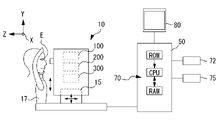
- the OCT system includes at least an optical unit 10 and a control unit 50 corresponding to the computer of this embodiment.
- the optical unit 10 and the control unit 50 are integrated as an OCT apparatus.
- the OCT system (OCT apparatus) according to the present embodiment has a basic configuration of wavelength-swept OCT (SS-OCT).
- the optical unit 10 includes a light guide optical system 150 . Furthermore, the optical unit 10 in this embodiment includes a fundus observation optical system 200 and an anterior ocular segment observation optical system 300 .
- the optical unit 10 is three-dimensionally movable by the XYZ moving section 15 .
- the XYZ moving section 15 is driven and controlled by the arithmetic controller 70 .
- the three-dimensional position of the optical unit 10 with respect to the eye E is adjusted by three-dimensionally moving the optical unit 10 by the XYZ moving section 15 .
- the three-dimensional position of the optical unit 10 is aligned with the eye E to be examined.
- the subject's face is supported by the face support unit 17 .
- the support position of the face by the face support unit 17 is movable in the vertical direction.
- the control unit 50 is a computer in this embodiment, and includes at least an arithmetic controller (processor) 70 that controls the entire OCT system.
- the arithmetic controller 70 is composed of, for example, a CPU and a memory.
- the arithmetic controller 70 also serves as an image processor in the OCT system.
- the OCT system may be provided with a storage unit (memory) 72, an input interface (operation unit) 75, a monitor 80, and the like. Each part is connected to the arithmetic controller 70 .
- Various programs, initial values, etc. for controlling the operation of the OCT apparatus may be stored in the memory 72 .
- a hard disk drive, a flash ROM, a USB memory that is detachably attached to the OCT apparatus, or the like can be used as the memory 72 .
- the memory 72 may store OCT images generated from OCT data as well as various information related to imaging.
- the monitor 80 may display OCT data (OCT images).
- the OCT optical system 100 guides the measurement light to the subject's eye E using the light guiding optical system 150 .
- the OCT optical system 100 guides reference light to the reference optical system 110 .
- the OCT optical system 100 causes the detector (light receiving element) 120 to receive spectral interference signal light obtained by interference between the measurement light reflected by the eye E to be examined and the reference light.
- the OCT optical system 100 uses the SS-OCT method.
- the OCT optical system 100 has a wavelength swept light source as the OCT light source 102 .
- the OCT optical system 100 has a point detector as the detector 120 .
- a wavelength-swept light source has its emission wavelength swept in time.
- the OCT light source 102 may be a VCSEL-based wavelength swept light source.
- a VCSEL type wavelength swept light source includes a VCSEL responsible for laser oscillation and a MEMS that realizes high-speed scanning.
- a device capable of changing the sweep frequency (scan rate) is used as the VCSEL wavelength swept light source in this embodiment.
- the OCT light source 102 in this embodiment can be varied to multiple sweep frequencies ranging from at least 20 kHz (second frequency in this embodiment) to 400 kHz (first frequency in this embodiment).
- the detector 120 is a balanced detector that performs balanced detection using a plurality of (for example, two) detectors.
- the arithmetic controller 70 samples the interference signal of the return light of the reference light and the measurement light according to the change in the emission wavelength of the wavelength swept light source, and performs OCT of the eye to be inspected based on the interference signal at each wavelength obtained by sampling. get the data.
- the sampling period is appropriately adjusted so that the measurement range in the depth direction is changed according to the sweep frequency of the OCT light source 102 .
- a coupler (splitter) 104 is used as a first light splitter and splits the light emitted from the light source 102 into a measurement optical path and a reference optical path.
- the coupler 104 guides the light from the light source 102 to the optical fiber 152 on the measurement optical path side and to the reference optical system 110 on the reference optical path side.
- a light guide optical system 150 is provided to guide the measurement light to the eye E.
- the light guiding optical system 150 may be sequentially provided with, for example, an optical fiber 152, a collimator lens 153, a focusing lens 155, an optical scanner 156, and an objective lens system 158 (objective optical system in this embodiment).
- the measurement light is emitted from the output end of the optical fiber 152 and converted into a parallel beam by the collimator lens 153 . After that, it goes to the optical scanner 156 via the focusing lens 155 .
- the focusing lens 155 can be displaced along the optical axis by a drive unit (not shown) and is used to adjust the condensing state.
- the light that has passed through the optical scanner 156 is applied to the eye E via the objective lens system 158 .
- the turning point P is formed at a position conjugate with the optical scanner 156 with respect to the objective lens system 158 (provided in the apparatus main body).
- the turning point P for at least one of the eye to be examined E and the optical system of the apparatus is adjusted according to the measurement range (in other words, imaging region) in the depth direction of the eye to be examined E. position is changed.
- the optical scanner 156 may scan the tissue of the eye E to be examined with measurement light in the XY directions (transverse directions).
- the optical scanner 156 is, for example, two galvanometer mirrors, the reflection angles of which are arbitrarily adjusted by a driving mechanism.
- the light flux emitted from the light source 102 is changed in its reflection (advancing) direction, and the tissue of the eye E to be examined is scanned in an arbitrary direction.
- an acoustooptic device (AOM) that changes the traveling (deflecting) direction of light may be used in addition to a reflecting mirror (galvanomirror, polygon mirror, resonant scanner).
- Coupler 104 directs light from optical fiber 152 into an optical path toward detector 120 .
- a reference optical system 110 generates reference light.
- the reference light is combined with the reflected light from the subject's eye E of the measurement light.
- the reference light that has passed through the reference optical system 110 is combined with the light from the measurement optical path at the coupler 148 and interferes.
- the reference optical system 110 may be of the Michelson type or of the Mach-Zehnder type.
- the reference optical system 110 shown in FIG. 2 is formed by a transmissive optical system as an example.
- the reference optics 110 direct the light from the coupler 104 to the detector 120 by transmitting it rather than returning it.
- the reference optical system 110 is not limited to this, for example, may be formed by a reflective optical system, and the light from the coupler 104 may be guided to the detector 120 by being reflected by the reflective optical system.
- an optical path length difference adjuster 145 and a polarization adjuster 147 are arranged on the optical path from the coupler 104 to the detector 120 .
- the optical path length difference adjusting section 145 is used to adjust the optical path length difference between the measurement light and the reference light.
- it is necessary to previously adjust the optical path length difference between the measurement light and the reference light according to at least the depth position of the object to be imaged (the part of the eye E to be examined).
- a mirror 145a having two orthogonal surfaces is provided on the reference optical path.
- the optical path length of the reference optical path can be increased or decreased by moving the mirror 145a in the direction of the arrow by the actuator 145b.
- the configuration for adjusting the optical path length difference between the measurement light and the reference light is not limited to this.
- the collimator lens 153 and the coupler are integrally moved to adjust the optical path length of the measurement light, and as a result, the optical path length difference between the measurement light and the reference light is adjusted.
- the polarization adjuster 147 adjusts the polarization of the reference light.
- the polarization adjuster may be arranged on the measurement optical path.
- the arithmetic controller 70 processes (Fourier analysis) the spectral signal detected by the detector 120 to obtain OCT data of the eye to be examined.
- the arithmetic controller may obtain OCT data in the depth (Z) domain by Fourier transforming the spectral signal in wavenumber k-space.
- information after Fourier transform may be represented as a signal containing real and imaginary components in Z space.
- the arithmetic controller 70 may obtain OCT data by determining the absolute values of the real and imaginary components of the signal in Z space.
- the shooting mode is set in advance based on the selection operation (S1, S2).
- the selection operation S1, S2
- one of three types of photographing modes corresponding to the measurement range of the subject's eye E is set based on the selection operation.
- a fundus mode, an anterior segment mode, and a full eyeball mode can be set as the photographing mode.
- the shooting mode selection operation may be input via a setting screen. Also, the scan pattern, imaging type, and the like may be set at this time.
- the fundus mode is selected (S2: fundus mode).
- the measurement range is about several millimeters around the fundus.
- the control unit 70 sets the sweep frequency of the OCT light source 110 to the first frequency (400 kHz in this embodiment) (S3). Thereby, the measurement range in the depth direction is adjusted to about several millimeters.
- the alignment state and the state of each part of the OCT optical system 100 are adjusted according to the measurement range (S4, S5).
- the three-dimensional position of the optical unit 10 with respect to the subject's eye E is guided to a position suitable for photographing the fundus (S4). That is, as shown in FIG. 5A, the three-dimensional position is guided such that the turning point P is located in the anterior segment of the subject's eye (more specifically, the center of the pupil).
- the measurement light reaches the fundus without being vignetted by the iris.
- the measurement light is scanned around the turning point P according to the operation of the optical scanner 156 .
- the controller 70 drives and controls the XYZ moving unit 15 to adjust the positional relationship between the eye to be examined and the optical unit 10 .
- the observation optical system 200 acquires a front image of the fundus as an observation image.
- the arithmetic controller 70 acquires an OCT image of the fundus via the OCT optical system 100 as needed.
- optimization control of imaging conditions is performed (S5).
- the state of each part of the OCT optical system 100 (that is, the imaging conditions) is adjusted according to the fundus site that is the measurement range. As a result, the fundus region can be observed with high sensitivity and high resolution by the OCT optical system 100 .
- optical path length adjustment, focus adjustment, and polarization state adjustment are performed as an example of optimization control in the OCT optical system 100 .
- the polarizer 147 outputs from the light receiving element 120 so that the polarization states of the measurement light and the reference light match (in this case, a stronger interference signal is obtained).
- the driving is controlled based on the output signal provided (the same applies to the anterior segment mode and the whole eyeball mode).
- the optimization control is started with the operation of an optimization start button (Optimize button) not shown as a trigger.
- Optimize button an optimization start button
- the optical path length difference is adjusted so that the fundus image is detected within a predetermined section from the zero delay position in the OCT data.
- the focusing lens is driven according to the position where the fundus image is detected on the OCT data, and the focus position is adjusted.
- focus in the OCT optical system 100 Adjustments may be made.
- the OCT data of the fundus is photographed (captured) via the OCT optical system 100 .
- the OCT data may be captured using one of a plurality of predetermined scan patterns.
- FIG. 4B shows a B-scan image of the fundus as an example of OCT data of the fundus obtained by imaging, but the present invention is not limited to this, and volume data may be captured.
- the captured OCT data may be stored (saved) in the memory of the apparatus in association with the scanning position and the identification information indicating the date and time of capturing. Thereby, the captured OCT data is acquired by the arithmetic controller 70 as a captured image.
- the OCT data of the periphery of the fundus may be captured.
- the fixation position is changed with respect to the case of imaging the center of the fundus, and the OCT data is captured after optimization control is performed on the periphery of the fundus.
- the anterior segment mode is selected (S2: anterior segment mode).
- the measurement range is about several millimeters of the anterior segment.
- the control unit 70 sets the sweep frequency of the OCT light source 110 to the first frequency (400 kHz in this embodiment) (S11).
- the sweep frequency is the same between the fundus mode and the anterior segment mode, but the sweep frequencies in each mode may be different from each other.
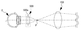
- the anterior segment adapter 500 is attached to the device (S12).
- the adapter lens 500a is positioned between the objective lens system 158 of the device main body and the subject's eye E (in this embodiment, between the pivot point P and the subject's eye E). inserted.
- the pivot point P is substantially aligned with the focal position of the adapter lens 500a.
- the measurement light is emitted substantially parallel to the optical axis via the adapter lens 500a. That is, an optical system telecentric to the object side is formed by the objective lens system 158 of the apparatus main body and the adapter lens 500a as an objective optical system in the anterior eye segment mode.
- the measurement light is telecentrically irradiated on the object side, the distortion of the tomographic image due to the displacement of the subject's eye E in the working distance direction is less likely to occur. Furthermore, by being telecentric on the object side, the measurement light can easily irradiate a part distant from the visual axis of the eye to be examined E, and the return light (reflected light or backscattered light) from the anterior segment can be collected more efficiently. Therefore, it is possible to suppress a decrease in luminance in the peripheral portion of the image.
- alignment adjustment is performed (S13).
- alignment adjustment between the subject's eye E and the optical unit 10 may be performed based on an observation image acquired by the observation optical system 200 .
- optimization control of imaging conditions is performed (S14).
- the state of each part of the OCT optical system 100 is adjusted according to the anterior ocular segment, which is the measurement range.
- the anterior segment can be observed with high sensitivity and high resolution by the OCT optical system 100 .
- individual differences in the subject's eye E are less of a problem than when photographing the fundus. may be adjusted.
- the OCT data of the anterior segment is photographed (captured) via the OCT optical system 100 and stored (saved) in the memory of the apparatus. .
- OCT data of the anterior segment including the sclera may be captured from the angle.
- imaging may be performed after shifting the alignment position in the XY direction with respect to the visual axis.
- OCT data of the anterior segment including the anterior and posterior surfaces of the crystalline lens may be captured.
- the full-eyeball mode is selected (S2: full-eyeball mode).
- the entire eyeball including the anterior segment and fundus is the measurement range.
- the control unit 70 sets the sweep frequency of the OCT light source 110 to the second frequency (20 kHz in this embodiment) (S21). Thereby, the measurement range in the depth direction is adjusted to approximately 30 mm.
- the alignment state and the state of each part of the OCT optical system 100 are adjusted according to the measurement range (S22, S23).
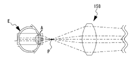
- the three-dimensional position of the optical unit 10 with respect to the subject's eye E is guided to a position suitable for all-eye photography (S22). That is, as shown in FIG. 6A, the three-dimensional position is guided such that the pivot point P is located between the subject's eye and the objective lens system 158 . Positioning the pivot point P between the subject's eye and the objective lens system 158 enables the measurement light to irradiate the cornea, the fundus, and part of the iris. Therefore, in the whole eyeball mode of the present embodiment, OCT data including at least part of the cornea, fundus, and iris can be acquired in one shot. From such whole-eye OCT data, the positional relationship between the fundus and the anterior segment can be appropriately specified.
- alignment adjustment is performed in at least the XY directions based on the anterior eye observation image acquired via the anterior eye observation optical system 300 .
- Alignment adjustment in the Z direction may be performed based on an alignment index image projected onto the cornea of the subject's eye from an alignment projection optical system (not shown). Alternatively, it may be adjusted based on OCT data acquired by the OCT optical system 100 . Alignment may be automatically adjusted by controller 70 .
- the arithmetic controller 70 acquires a whole-eyeball OCT image at any time via the OCT optical system 100 .
- the state of each part of the OCT optical system 100 (that is, the imaging conditions) is adjusted according to the measurement range.
- the optical path length difference is adjusted so that the images of the anterior segment and fundus are detected within a predetermined interval from the zero delay position in the OCT data.
- the focus position may be adjusted by driving the focusing lens according to the positions at which the images of the anterior segment and fundus are detected on the OCT data.
- the focus position may be adjusted near the image position of either the anterior segment or the fundus, or may be adjusted midway between the anterior segment and the fundus.
- the OCT data of the entire eyeball is captured through the OCT optical system 100 and stored. .
- ⁇ Bending Correction> In each of the OCT data shown in FIGS. 4B, 5B, and 6B, an image is formed by arranging the A-scan data parallel to the scanning direction (linear direction) of the measurement light.
- the fundus OCT data and the ocular OCT data are expressed on polar coordinates with the pivot point P as the center, so that the curvature of the image resulting from scanning with the pivot point P as the center is corrected.
- the corrected OCT data is expressed as a more accurate image with respect to the shape of the actual eye to be examined.
- the curvature of the intraocular tissue image may be corrected in consideration of the refraction of the measurement light by the translucent body of the subject's eye. At this time, for example, the curvature may be corrected by ray tracing.
- the image will be curved according to the inclination of the light beam with respect to the optical axis of the OCT optical system 100 during each A-scan. may be corrected.
- Whole-eye OCT data captures the subject's eye in a wide range in the depth direction, but in the transverse direction, the anterior segment OCT data and the fundus OCT data capture each region in a wider range. Therefore, by synthesizing the anterior segment OCT data and the fundus OCT data with the whole eyeball OCT data, a wider OCT image is generated. Curvature correction may be performed for each OCT data to be synthesized.
- a wide-area OCT image may be generated by aligning and synthesizing the images with respect to the features included in each image. Registration between images may be rigid registration or non-rigid registration.
- the local OCT data of the anterior segment or the fundus can be appropriately combined with the whole-eye OCT data (collage). )can. That is, it is possible to generate a wide-area OCT image that reflects the actual positional relationship between the fundus and the anterior segment of the eye.
- a plurality of OCT data for each of the anterior segment and the fundus may be combined with the OCT data for the entire eyeball. More specifically, with respect to the anterior segment, each of the OCT data of the anterior segment including the angle to the sclera and the OCT data of the anterior segment including the anterior and posterior surface of the lens is compared with the whole eyeball OCT data. may be synthesized by Further, for example, regarding the fundus, OCT data of the fundus photographed with the optical axis of the OCT optical system 100 and the fixation optical axis aligned, The captured OCT data of the fundus may be combined with the whole-eye OCT data.
- ⁇ Analysis processing> Various analysis processes may be performed on the whole-eye OCT data (or the above-described composite image based on the whole-eye OCT data). For example, analysis processing relating to eye size information may be performed. Any one of various types of eye dimension information such as corneal thickness, anterior chamber depth, eye axial length, and angle of the anterior chamber angle may be obtained by the analysis processing.
- information regarding the positional relationship of each part may be obtained.
- information representing the tilt of the anterior segment relative to the fundus may be obtained.
- a straight line connecting the fovea centralis of the fundus and the center of the pupil is the axis L1 of the whole-eye OCT image (or the above-mentioned synthesized image based on the whole-eye OCT data). is detected based on Further, the tilt angle of the axis L1 with respect to the optical axis of the OCT optical system 100 is derived.
- the position information itself of the axis L1 and the inclination angle of the axis L1 with respect to the optical axis of the OCT optical system 100 are obtained as information representing the inclination of the anterior segment with respect to the fundus.
- the whole-eye OCT data includes the position information of the cornea, iris, and fundus, it is possible to appropriately identify the positional relationship between the fundus and the anterior segment of the eye. As a result, for example, the IOL may be better positioned during IOL prescription.
- the OCT apparatus of the above embodiment can be switched among the fundus mode, the anterior segment mode, and the whole eyeball mode, but the OCT apparatus is not necessarily limited to this. may be capable of being photographed in at least full eye mode.
- the OCT apparatus does not need to have two or more optical scanners.
- the OCT apparatus may be capable of scanning measurement light in only one direction with a single optical scanner.
- the three-dimensional position is guided such that the turning point P is arranged inside the eyeball of the subject's eye.
- further wide-area OCT data obtained after the three-dimensional position is guided so that the corneal bright point, the lens bright point, and the fundus fovea are included in the tomographic image may be obtained.
- the presence or absence of the corneal bright point and the lens bright point is detected in the tomographic image that is acquired at any time, and the position where the corneal bright point and the lens bright point are detected is automatically adjusted. may be guided to
- tomographic images acquired at any time may be displayed so that the examiner can manually adjust the three-dimensional position.
- FIG. 9 An example of OCT data acquired at this time is shown as a tomographic image in FIG. Note that the tomographic image shown in FIG. 9 may be one after full-range processing.
- the fundus is scanned over a wide range. It can be seen that there is a sufficient amount of information in the transverse direction to identify the optical features of the eye under examination.
- bright spots are generated in the cornea and the lens.
- a bright spot is considered to occur at the center of the optical axis of the subject's eye as shown in the schematic diagram.
- the ⁇ angle which is an example of a physiological strabismic angle, is defined as the angle between the visual axis of the subject's eye and the center line of the pupil, where the visual axis is an A-scan that passes through the fovea of the retina.
- the A-scan corresponding to the optical axis of the eye is specified from the information of the cornea and lens in the OCT data.
- the approximate value of the ⁇ angle can be obtained by converting the displacement amount of the two A-scans to the angle of view.
- the scanning direction of the wide-area OCT data is reversed between the front side and the back side of the turning point of the measurement light.
- the ⁇ angle may be obtained as described above.
- eye dimension information such as corneal thickness, anterior chamber depth, and axial length can be obtained from OCT data including the cornea and fundus.
- the ⁇ angle is used as an index of whether or not a toric IOL prescription is appropriate for the eye to be examined, and eye dimension information is used for IOL calculation. Therefore, information used in IOL prescription can be preferably acquired, so there is a possibility that a more appropriate IOL can be prescribed.
- the OCT apparatus according to the present disclosure can also be expressed as follows.
- the first ophthalmologic image processing program is executed by a processor of an ophthalmologic computer, so that the OCT data of the anterior segment and the turning point of the measurement light are positioned closer to the subject's eye than the objective optical system.
- the second ophthalmic image processing program is the first ophthalmic image processing program, wherein the wide-area OCT data is obtained by capturing the OCT data of the anterior segment and the OCT data of the fundus in one shot.
- the third ophthalmic image processing program is the second ophthalmic image processing program.
- the wide-area OCT data is captured with the turning point of the measurement light adjusted to the anterior segment of the subject's eye.
- a fourth ophthalmic image processing program is the third ophthalmic image processing program, wherein the wide-area OCT data includes the cornea, the crystalline lens, and the fovea fundus, and in the analysis processing step, the The physiological strabismus angle is determined based on at least the positional relationship among the cornea, the lens, and the fundus fovea.
- a fifth ophthalmic image processing program is the fourth ophthalmic image processing program.
- the cornea and the lens in the wide-area OCT data include at least a corneal bright point and a lens bright point, and in the analysis processing step, the corneal bright point, the lens bright point, and the fundus fovea in the OCT data
- the physiological oblique angle is determined based on at least the positional relationship of the .
- a sixth OCT apparatus executes the ophthalmic image processing program according to any one of the first to fifth.
- a sixth OCT apparatus in the sixth OCT apparatus, includes an OCT optical system for acquiring the wide-area OCT so that the wide-area OCT data includes the corneal bright point and the lens bright point. Align to the optometry.
Landscapes
- Health & Medical Sciences (AREA)
- Life Sciences & Earth Sciences (AREA)
- Physics & Mathematics (AREA)
- General Health & Medical Sciences (AREA)
- Engineering & Computer Science (AREA)
- Biophysics (AREA)
- Public Health (AREA)
- Veterinary Medicine (AREA)
- Animal Behavior & Ethology (AREA)
- Surgery (AREA)
- Molecular Biology (AREA)
- Medical Informatics (AREA)
- Heart & Thoracic Surgery (AREA)
- Ophthalmology & Optometry (AREA)
- Biomedical Technology (AREA)
- General Physics & Mathematics (AREA)
- Radiology & Medical Imaging (AREA)
- Nuclear Medicine, Radiotherapy & Molecular Imaging (AREA)
- Chemical & Material Sciences (AREA)
- Analytical Chemistry (AREA)
- Pathology (AREA)
- Immunology (AREA)
- Biochemistry (AREA)
- Automation & Control Theory (AREA)
- Optics & Photonics (AREA)
- Eye Examination Apparatus (AREA)
Abstract
An Optical Coherence Tomography (OCT) device provided with an OCT optical system and an arithmetic controller is provided with a light-guiding optical system including, at least, an optical scanner which causes measuring light to scan over tissue of a subject eye, and an objective optical system which is arranged between the optical scanner and the subject eye, and which forms a turning point at which the measuring light that has passed through the optical scanner is turned, and an alignment adjusting unit which adjusts a three-dimensional position of the light-guiding optical system relative to the subject eye, wherein the arithmetic controller guides the three-dimensional position such that the turning point is arranged at a target position set between the subject eye and the objective optical system, and executes an OCT data acquisition operation at the target position.
Description
本開示は、OCT装置および眼科画像処理プログラムに関する。
The present disclosure relates to an OCT apparatus and an ophthalmic image processing program.
眼科分野において、被検眼の組織の断層画像を撮影する装置である、光干渉断層計(Optical Coherence Tomography:OCT)が知られている。
In the field of ophthalmology, an optical coherence tomography (OCT), which is a device that captures a tomographic image of the tissue of an eye to be examined, is known.
OCTの技術分野では、OCTデータにおける深達性を改善する(つまり、深さ方向の撮影範囲を拡大する)種々の試みが行われている。
In the technical field of OCT, various attempts have been made to improve the penetration depth of OCT data (that is, to expand the imaging range in the depth direction).
近年では、光源の改良等によって、撮影範囲を著しく改善できることが報告されている。例えば、VCSELと呼ばれる、コヒーレンス長の長い光を出射する光源を、OCT光源として採用することが、深達性の改善に有効である。高深達なOCTでは、一度のAスキャンで角膜から眼底までの深さ領域を撮影することも提案されている(特許文献1参照)。
In recent years, it has been reported that the shooting range can be significantly improved by improving the light source. For example, adopting a light source called VCSEL that emits light with a long coherence length as the OCT light source is effective in improving penetration depth. In deep-penetration OCT, it has also been proposed to image a depth region from the cornea to the fundus in a single A-scan (see Patent Document 1).
また、一般に、網膜中心窩は、眼軸(または眼の光軸)にはなく、わずかに耳側に偏心している。そのため,正常の眼球光学系においても、いわゆる生理的斜視角が存在する。この角度を表として、α角、γ角、κ角、λ角等の各種の角度が知られている。例えば、これらの角度は、近年では、プレミアムIOLの処方等の場面において考慮されている(特許文献1参照)。例えば、特許文献1等では、前眼部の正面画像の情報に基づいてκ角が求められている。
Also, in general, the retinal fovea is not on the eye axis (or the optical axis of the eye), but is slightly eccentric to the temporal side. Therefore, a so-called physiological oblique angle exists even in a normal ocular optical system. Using this angle as a table, various angles such as α angle, γ angle, κ angle, and λ angle are known. For example, in recent years, these angles have been considered in situations such as the prescription of premium IOLs (see Patent Document 1). For example, in Patent Document 1 and the like, the κ angle is obtained based on the information of the front image of the anterior segment.
OCT装置では、光スキャナを用いて被検眼の組織上で測定光を走査することで、測定光の軌跡に応じたOCTデータ(Bスキャンデータまたはボリュームデータ)が得られるところ、特許文献1には、前眼と眼底の両方を広範囲にスキャンしやすいスキャン手法について、何ら検討されていない。
An OCT apparatus obtains OCT data (B-scan data or volume data) according to the trajectory of the measurement light by scanning the tissue of the eye to be inspected with the measurement light using an optical scanner. , no investigation has been made on a scanning method that facilitates extensive scanning of both the anterior eye and the fundus.
また、被検眼の生理的斜視角を求める手法として、特許文献1等で採用される手法では、中心窩の実際の位置は不明である。広範囲なOCTデータであれば、被検眼の生理的斜視角をより適正に求められる可能性がある。
In addition, the actual position of the fovea is unknown in the method adopted in Patent Document 1 and the like as a method for obtaining the physiological strabismic angle of the eye to be examined. A wide range of OCT data may allow the physiological strabismus angle of the eye to be examined to be determined more appropriately.
本発明は、上記事情の少なくとも1つに鑑みてなされたものであり、被検眼の生理的斜視角を適正に求めること、を技術課題とする。
The present invention has been made in view of at least one of the above circumstances, and the technical problem thereof is to appropriately obtain the physiological strabismic angle of an eye to be examined.
本開示の第1態様に係る眼科画像処理プログラムは、眼科用コンピュータのプロセッサによって実行されることによって、前眼部のOCTデータと、測定光の旋回点が対物光学系よりも被検眼側に配置された状態で取得された眼底のOCTデータと、を少なくとも含む被検眼の広域OCTデータを取得する取得ステップと、前記広域OCTデータを解析することによって、被検眼の生理的斜視角を求める解析処理ステップと、を前記眼科用コンピュータに実行させる。
An ophthalmologic image processing program according to the first aspect of the present disclosure is executed by a processor of an ophthalmologic computer so that OCT data of an anterior segment and a turning point of measurement light are positioned closer to the subject's eye than the objective optical system. an acquisition step of acquiring wide-area OCT data of an eye to be inspected including at least the OCT data of the fundus acquired in the state in which the wide-area OCT data is acquired; and causing the ophthalmic computer to perform the steps.
本開示の第2態様に係るOCT装置は、上記の眼科画像処理プログラムを実行する。
An OCT apparatus according to the second aspect of the present disclosure executes the above ophthalmic image processing program.
本開示によれば、前眼と眼底の両方を広範囲にスキャンしやすい。
According to the present disclosure, it is easy to scan both the anterior eye and the fundus over a wide range.
「概要」
本開示の実施形態を説明する。以下の<>にて分類された項目は、独立または関連して利用されうる。各実施形態に係るOCT装置は、広域のOCTデータの取得に適している。 "Overview"
Embodiments of the present disclosure will be described. The items classified in <> below can be used independently or in conjunction with each other. The OCT apparatus according to each embodiment is suitable for acquiring OCT data over a wide area.
<第1実施形態>
第1実施形態に係るOCT装置は、OCT光学系、導光光学系、演算制御器、および、アライメント調整部、を少なくとも備える。 <First embodiment>
An OCT apparatus according to the first embodiment includes at least an OCT optical system, a light guide optical system, an arithmetic controller, and an alignment adjustment section.
第1実施形態に係るOCT装置は、OCT光学系、導光光学系、演算制御器、および、アライメント調整部、を少なくとも備える。 <First embodiment>
An OCT apparatus according to the first embodiment includes at least an OCT optical system, a light guide optical system, an arithmetic controller, and an alignment adjustment section.
<OCT光学系>
OCT光学系(図2参照)は、被検眼のOCTデータを撮影するために利用される。OCT光学系は、光分割器と、検出器と、を少なくとも備える。光分割器は、OCT光源からの光を測定光と参照光とに分割するために利用される。検出器は、被検眼に導かれた測定光と、参照光と、のスペクトル干渉信号を検出する。検出器からの信号が後述の演算制御器によって処理されることにより、OCTデータが取得される。 <OCT optical system>
The OCT optical system (see FIG. 2) is used to capture OCT data of the subject's eye. The OCT optical system includes at least a light splitter and a detector. A light splitter is utilized to split the light from the OCT light source into measurement light and reference light. A detector detects spectral interference signals of the measurement light and the reference light directed to the eye to be examined. OCT data is obtained by processing the signal from the detector by an operation controller, which will be described later.
OCT光学系は、深達性の高い(換言すれば広域の)OCTデータの取得に適していてもよい。例えば、第1実施形態に係るOCT光学系は、波長掃引式OCT(SS-OCT)光学系であってもよい。この場合、OCT光学系は、測定光および参照光の光源であるOCT光源として、波長掃引光源(波長走査型光源)を備える。波長掃引光源は、出射波長を時間的に高速で変化させる。例えば、VCSEL式波長掃引光源は、コヒーレンス長が長いことから、OCT光源として利用されることで、深さ方向に関して広域のOCTデータを撮影可能となる。例えば、10mm程度またはそれ以上の撮影範囲が実現され得る。これにより、被検眼において互いに異なる深さ位置にある複数の組織を1回的に撮影できるようになる。具体例として、眼底と透光体との両方が1回的に撮影され得る。また、波長掃引光源は、いわゆる1μm帯で波長掃引を行う(約1050nmを中心に、波長掃引を行う)ことが好ましい。いわゆる1μm帯は、他の波長帯と比べて、被検眼の組織に対してより高い深達性を示すことが知られている。
The OCT optical system may be suitable for acquiring OCT data with high penetration (in other words, wide area). For example, the OCT optical system according to the first embodiment may be a wavelength-swept OCT (SS-OCT) optical system. In this case, the OCT optical system includes a wavelength swept light source (wavelength scanning light source) as an OCT light source that is a light source for measurement light and reference light. A wavelength swept light source changes the emission wavelength at high speed in time. For example, since the VCSEL wavelength swept light source has a long coherence length, it can be used as an OCT light source to capture OCT data over a wide range in the depth direction. For example, an imaging range of about 10 mm or more can be achieved. As a result, a plurality of tissues at different depth positions in the subject's eye can be imaged at once. As a specific example, both the fundus and translucent body can be imaged at once. Moreover, it is preferable that the wavelength swept light source performs wavelength sweeping in a so-called 1 μm band (wavelength sweeping is performed centering on about 1050 nm). It is known that the so-called 1 μm band exhibits a higher penetration depth into tissues of the eye to be examined than other wavelength bands.
波長掃引光源における掃引周波数は、少なくとも第1周波数と第2周波数との間で変更可能であってもよい。第2周波数は、第1周波数よりも小さな値である。例えば、光源に内蔵された光学素子であって波長を掃引するために駆動される光学素子の速度、および、掃引サイクルにおけるデューティ比のいずれかが変更されることで、掃引周波数は変更される。
The swept frequency in the wavelength swept light source may be changeable between at least a first frequency and a second frequency. The second frequency has a smaller value than the first frequency. For example, the sweep frequency is changed by changing either the speed of an optical element built in the light source and driven to sweep the wavelength or the duty ratio in the sweep cycle.
<変換部>
装置の光学系がSS-OCT光学系である場合、OCT装置は、更に、変換部を備える。SS-OCT光学系において、検出器では、波長掃引に伴って、スペクトル干渉信号がビート信号として検出される。変換部は、検出器から出力されるスペクトル干渉信号をサンプリングする。また、変換部は、検出器から出力されるスペクトル干渉信号を、アナログ信号からデジタル信号へと変換する。変換部は、サンプリング周波数を調整可能なデジタイザであってもよい。 <Converter>
When the optical system of the device is the SS-OCT optical system, the OCT device further comprises a conversion section. In the SS-OCT optical system, the detector detects spectral interference signals as beat signals as the wavelength is swept. A transform unit samples the spectral interference signal output from the detector. Also, the converter converts the spectral interference signal output from the detector from an analog signal to a digital signal. The conversion unit may be a digitizer capable of adjusting the sampling frequency.
<導光光学系>
導光光学系は、測定光を被検眼に導くための測定光路の少なくとも一部を形成する。より具体的には、本実施形態の導光光学系は、光スキャナ、および、対物光学系、を少なくとも含む。光スキャナは、被検眼の組織上で測定光を走査する。例えば、導光光学系には、走査方向が互いに異なる2つの光スキャナが設けられていてもよい。また、対物光学系は、光スキャナと被検眼との間に配置される。これによって、対物光学系は、測定光の旋回点を形成する。旋回点を中心として、光スキャナを経由した測定光が旋回される。 <Light guide optical system>
The light guide optical system forms at least part of a measurement light path for guiding measurement light to the subject's eye. More specifically, the light guiding optical system of this embodiment includes at least an optical scanner and an objective optical system. The optical scanner scans measurement light over the tissue of the eye to be examined. For example, the light guiding optical system may be provided with two optical scanners having different scanning directions. Also, the objective optical system is arranged between the optical scanner and the subject's eye. The objective optical system thereby forms a pivot point for the measurement light. The measurement light that has passed through the optical scanner is turned around the turning point.
ここで、旋回点を通過した測定光は、被検眼の組織上であらかじめ定められた複数のスキャンラインに沿って走査される。走査に伴って、各スキャンラインについてのOCTデータが撮影される。スキャンラインは、検者からの指示に基づいて任意の位置に設定されてもよい。また、あらかじめ定められた複数のスキャンパターンのうちいずれかが選択されることで、スキャンパターンと対応するスキャンラインが設定されてもよい。スキャンパターンとしては、ライン、クロス、マルチ、マップ、ラジアル、サークル、等の種々のものが知られている。
Here, the measurement light that has passed through the turning point is scanned along a plurality of predetermined scan lines on the tissue of the eye to be examined. OCT data for each scan line is captured along with the scanning. The scan line may be set at any position based on instructions from the examiner. Alternatively, a scan line corresponding to a scan pattern may be set by selecting one of a plurality of predetermined scan patterns. Various scan patterns such as line, cross, multi, map, radial, and circle are known.
<アライメント調整部>
アライメント調整部は、被検眼に対する導光光学系の3次元位置を調整する。このとき、本実施形態では、被検眼に対する導光光学系の前後方向の位置が少なくとも調整される。アライメント調整部が備えるアクチュエータによって、導光光学系は電動で移動されてもよい。これに限らず、アライメント調整部は、メカニカルな機構であってもよい。また、アライメント調整部は、被検者の顔の位置を変更可能な、顔支持ユニットを含んでいてもよい。つまり、被検者の顔の位置が移動されることで、被検眼側の3次元位置が調整されてもよい。 <Alignment adjustment part>
The alignment adjustment unit adjusts the three-dimensional position of the light guiding optical system with respect to the eye to be examined. At this time, in the present embodiment, at least the position of the light guiding optical system in the front-rear direction with respect to the eye to be examined is adjusted. The light guide optical system may be electrically moved by an actuator provided in the alignment adjustment section. The alignment adjustment unit is not limited to this, and may be a mechanical mechanism. Also, the alignment adjustment section may include a face support unit capable of changing the position of the subject's face. In other words, the three-dimensional position of the subject's eye may be adjusted by moving the position of the subject's face.
なお、本実施形態のOCT装置は、追加的に、アライメント検出光学系を有してもよい。アライメント検出光学系は、導光光学系を被検眼に対して適正作動距離に誘導するために利用される。アライメント検出光学系は、少なくともZ方向について被検眼に対する導光光学系のアライメント状態を検出する。本実施形態において、アライメント検出光学系は、少なくとも観察光学系(好ましくは前眼部観察光学系)が含まれていてもよい。この場合、作動距離検出用の指標を被検眼の前眼部に投光する投光光学系を更に有していてもよい。観察光学系で観察される指標の位置あるいは結像状態に基づいて、作動距離が調整されてもよい。また、OCT光学系がアライメント検出光学系として利用されてもよい。この場合、OCTデータ上の予め定められた位置に前眼部の像が撮像されるように、OCTデータに基づいてアライメント状態が調整されてもよい。
The OCT apparatus of this embodiment may additionally have an alignment detection optical system. The alignment detection optical system is used to guide the light guiding optical system to the proper working distance with respect to the eye to be inspected. The alignment detection optical system detects the alignment state of the light guiding optical system with respect to the subject's eye at least in the Z direction. In this embodiment, the alignment detection optical system may include at least an observation optical system (preferably an anterior segment observation optical system). In this case, it may further include a light projecting optical system for projecting a working distance detection index onto the anterior segment of the subject's eye. The working distance may be adjusted based on the position of the index observed by the observation optical system or the imaging state. Also, an OCT optical system may be used as the alignment detection optical system. In this case, the alignment state may be adjusted based on the OCT data so that an image of the anterior segment is captured at a predetermined position on the OCT data.
<演算制御器>
演算制御器は、検出器からの信号に基づいてOCTデータを取得する。より詳細には、変換部によってデジタル信号に変換されたスペクトル干渉信号が、画像処理器によって演算処理される。これによって、被検眼のOCTデータが取得される。また、演算制御器は、OCT光学系を少なくとも制御してOCTデータの取得動作を実行する。 <Calculation controller>
An arithmetic controller acquires OCT data based on the signal from the detector. More specifically, the spectral interference signal converted into a digital signal by the conversion section is arithmetically processed by the image processor. Thereby, the OCT data of the eye to be examined is obtained. Further, the arithmetic controller controls at least the OCT optical system to perform an operation of acquiring OCT data.
<OCTデータ>
OCTデータは、信号データであってもよいし、視覚化された画像データであってもよい。例えば、OCTデータは、被検眼の反射強度特性を示す断層画像データ、被検眼のOCTアンジオデータ(例えば、OCTモーションコントラストデータ)、被検眼のドップラー特性を示すドップラーOCTデータ、被検眼の偏光特性を示す偏光特性データ、等の少なくともいずれかであってもよい。 <OCT data>
The OCT data may be signal data or visualized image data. For example, the OCT data includes tomographic image data indicating reflection intensity characteristics of the eye to be examined, OCT angio data of the eye to be examined (for example, OCT motion contrast data), Doppler OCT data indicating Doppler characteristics of the eye to be examined, and polarization characteristics of the eye to be examined. It may be at least one of the polarization characteristic data shown, and the like.
また、OCTデータは、Bスキャンデータ(例えば、Bスキャン断層画像データ、二次元OCTアンジオデータ、等)、正面(En face)データ(例えば、OCT正面データ、
正面モーションコントラストデータ、等)、三次元データ(例えば、三次元断層画像データ、三次元OCTアンジオデータ、等)、等の少なくともいずれかであってもよい。 In addition, OCT data includes B-scan data (e.g., B-scan tomographic image data, two-dimensional OCT angio data, etc.), en face data (e.g., OCT frontal data,
frontal motion contrast data, etc.), three-dimensional data (eg, three-dimensional tomographic image data, three-dimensional OCT angio data, etc.), and/or the like.
<フルレンジ化技術の適用>
OCTデータには、フルレンジ化技術が適用されてもよい。OCTデータにおいて虚像を除去する種々の手法が、フルレンジ化技術と呼ばれる。本実施形態では、いずれかのフルレンジ化技術を適用してもよく、これによって、虚像が選択的に除去された更に広範囲のOCTデータが取得可能であってもよい。 <Application of full-range technology>
A full-ranging technique may be applied to the OCT data. Various techniques for removing artifacts in OCT data are called full-ranging techniques. In this embodiment, any full-ranging technique may be applied, which may allow acquisition of a wider range of OCT data with artifacts selectively removed.
なお、フルレンジ化技術の一例としては、追加のハードウェアにより虚像(鏡像ともいう)を除去する技術(例えば、非特許文献1参照)、追加のハードウェアを用いずにソフトウェアで補正する技術(例えば、特許文献2参照)等を挙げることができる。
Wojtkowski, M. et al. (2002) Full range complex spectral optical coherence tomography technique in eye imaging, Optics Letters, 27(16), p. 1415. 特表2015-506772号公報 また、本出願人による出願(特願2019-014771号)では、スペクトル干渉信号を検出する際の光路長が異なる複数のOCTデータに基づいて、OCTデータにおける実像と虚像との重複領域に対して少なくとも補完処理を行い、補完処理が施されたOCTデータを生成する、更に別のフルレンジ化技術が提案されており、これを本実施形態において適用してもよい。
Examples of full-range technology include technology for removing virtual images (also referred to as mirror images) with additional hardware (see, for example, Non-Patent Document 1), technology for correcting with software without using additional hardware (for example, , see Patent Document 2) and the like.
Wojtkowski, M. et al. (2002) Full-range complex spectral optical coherence tomography technique in eye imaging, Optics Letters, 27(16), p.1415. In addition, in the application by the present applicant (Japanese Patent Application No. 2019-014771), based on a plurality of OCT data with different optical path lengths when detecting spectral interference signals, real images and virtual images in OCT data Further, another full-range technique has been proposed in which at least the complementing process is performed on the overlapping region of the , and the complemented OCT data is generated.
Wojtkowski, M. et al. (2002) Full range complex spectral optical coherence tomography technique in eye imaging, Optics Letters, 27(16), p. 1415.
Wojtkowski, M. et al. (2002) Full-range complex spectral optical coherence tomography technique in eye imaging, Optics Letters, 27(16), p.1415.
<導光光学系の位置誘導>
例えば、演算制御器は、旋回点が目標位置に配置されるように、被検眼に対する導光光学系の3次元位置を誘導する。誘導の結果として旋回点が目標位置へ到達した場合、OCTデータの取得動作が実行される。 <Position Guidance of Light Guide Optical System>
For example, the arithmetic controller guides the three-dimensional position of the light guide optical system with respect to the subject's eye so that the pivot point is located at the target position. If the pivot point reaches the target position as a result of the navigation, an OCT data acquisition operation is performed.
旋回点を目標位置に配置するための導光光学系の位置誘導は、いわゆるオートアライメントであってもよい。すなわち、アライメント調整部が演算制御器によって駆動制御されることで、旋回点の位置と目標位置とのズレが低減する方向に導光光学系が移動されてもよい。また、オートアライメントの代わりに、或いは、追加的に、旋回点が目標位置に配置されるように、アライメントを補助するガイド情報が検者に対して出力されてもよい。ガイド情報は、モニタに表示されるグラフィカルな情報(例えば、文字情報、図形情報等、詳細は後述する)であってもよいし、スピーカから出力される音声情報であってもよい。例えば、ガイド情報は、検者に対する操作の案内であってもよい。
Position guidance of the light guide optical system for placing the turning point at the target position may be so-called auto-alignment. That is, the light guiding optical system may be moved in a direction in which the deviation between the position of the turning point and the target position is reduced by driving and controlling the alignment adjustment section by the arithmetic controller. Further, instead of auto-alignment, or additionally, guide information for assisting alignment may be output to the examiner so that the turning point is arranged at the target position. The guide information may be graphical information displayed on a monitor (for example, character information, graphic information, etc., details of which will be described later), or audio information output from a speaker. For example, the guide information may be operation guidance for the examiner.
本実施形態において、旋回点の目標位置は、被検眼と対物光学系との間に設定される。角膜頂点から前後方向に所定距離だけ離れた位置に、目標位置は定められていてもよい。
In this embodiment, the target position of the turning point is set between the subject's eye and the objective optical system. The target position may be set at a position a predetermined distance away from the corneal vertex in the front-rear direction.
目標位置は被検眼と対物光学系との間にあるので、光軸と平行でない測定光は、被検眼の角膜に対して光学系の光軸から遠ざかりながら入射する。このような測定光は、眼球内で再び光軸と交わることなく、前眼部の各組織、および、眼底へ導かれる。これにより、被検眼のより広範囲に対して測定光を照射できる。
Since the target position is between the subject's eye and the objective optical system, the measurement light that is not parallel to the optical axis enters the cornea of the subject's eye while moving away from the optical axis of the optical system. Such measurement light is guided to each tissue of the anterior segment of the eye and to the fundus without crossing the optical axis again within the eyeball. This makes it possible to irradiate the measurement light over a wider range of the subject's eye.
ここで、旋回点が被検眼と対物光学系との間に形成されずに測定光が被検眼へ導かれる2つの比較例(比較例1,2)と、本実施形態との測定範囲の違いを示す。
Here, two comparative examples (comparative examples 1 and 2) in which the measurement light is guided to the eye to be inspected without the turning point being formed between the eye to be inspected and the objective optical system, and the difference in the measurement range from the present embodiment. indicates
比較例1では、旋回点が被検眼の眼球内に配置される。比較例1では、被検眼において旋回点付近の深さ位置にある部位には測定光が照射されにくく、撮影されにくい。これに対し、本実施形態では、被検眼と対物光学系との間に設定されることで、被検眼の眼球内に旋回点が配置されないので、比較例1と比べて、それぞれの深さ位置にある組織が撮影されやすい。
In Comparative Example 1, the pivot point is arranged inside the eyeball of the subject's eye. In Comparative Example 1, the portion of the subject's eye at a depth position near the turning point is less likely to be irradiated with the measurement light and is less likely to be imaged. On the other hand, in this embodiment, since the turning point is not arranged in the eyeball of the eye to be examined by being set between the eye to be examined and the objective optical system, each depth position Tissues in the are likely to be photographed.
比較例2では、対物光学系から被検眼に対して略テレセントリックに、測定光が照射される。テレセントリックな光束は、被検眼の透光体で屈折するので、眼底まで到達する測定光は、眼底の略中心(中心窩付近)に集められてしまう。よって、比較例2では、眼底上の撮影範囲を確保し難い。これに対し、本実施形態では、測定光が、被検眼と対物光学系との間にある旋回点から被検眼の角膜に対して、光学系の光軸から遠ざかりながら入射する。このため、測定光が被検眼の透光体で屈折しても、眼底の略中心(中心窩付近)から離れた位置にも測定光が照射されやすい(つまり、撮影できる)。
In Comparative Example 2, the subject's eye is irradiated with the measurement light substantially telecentrically from the objective optical system. Since the telecentric luminous flux is refracted by the translucent body of the eye to be examined, the measurement light reaching the fundus is concentrated in the approximate center of the fundus (near the fovea centralis). Therefore, in Comparative Example 2, it is difficult to ensure the imaging range on the fundus. In contrast, in the present embodiment, the measurement light is incident on the cornea of the subject's eye from the turning point between the subject's eye and the objective optical system while moving away from the optical axis of the optical system. Therefore, even if the measuring light is refracted by the translucent body of the subject's eye, the measuring light is likely to irradiate (that is, can be photographed) a position distant from the approximate center of the fundus (near the fovea).
ここで、本実施形態に係るOCT装置では、目標位置において、あえて虹彩で測定光がケラレるように、測定光の走査量が設定されてもよい。この場合、目標位置においてOCTデータの取得動作が実行された結果として、角膜、眼底、および、虹彩が少なくとも含まれるOCTデータが、1回的に(換言すれば、ワンショットで)取得可能となる。
Here, in the OCT apparatus according to the present embodiment, the scanning amount of the measurement light may be set so that the measurement light is intentionally vignetted by the iris at the target position. In this case, as a result of executing the OCT data acquisition operation at the target position, OCT data including at least the cornea, the fundus, and the iris can be acquired once (in other words, in one shot). .
ワンショットで取得されたOCTデータにおいて、角膜、虹彩、および、眼底の位置情報が含まれていることで、眼底と前眼部との位置関係が適切に特定可能となる。また、眼底と前眼部との位置関係が適切に特定可能であることで上記OCTデータは、前眼部または眼底の局所的なOCTデータと、適切に合成(コラージュ)することができる。
The positional information of the cornea, iris, and fundus is included in the OCT data acquired in one shot, making it possible to appropriately identify the positional relationship between the fundus and the anterior segment of the eye. In addition, since the positional relationship between the fundus and the anterior segment can be appropriately specified, the OCT data can be appropriately synthesized (collaged) with the local OCT data of the anterior segment or the fundus.
<深さ方向に関する測定範囲の調整>
本実施形態のOCT装置は、第2調整部を備えてもよい。第2調整部が演算制御器によって制御されることによって、OCTデータにおける深さ方向に関する測定範囲が調整可能(変更可能)であってもよい。例えば、深さ方向に関する測定範囲は、少なくとも第1測定範囲と、第1測定範囲に対して狭い第2測定範囲との間で、第2調整部の制御に基づいて切換可能であってもよい。 <Adjustment of measurement range in depth direction>
The OCT apparatus of this embodiment may include a second adjuster. The measurement range in the depth direction in the OCT data may be adjustable (changeable) by controlling the second adjuster by the arithmetic controller. For example, the measurement range in the depth direction may be switchable between at least a first measurement range and a second measurement range that is narrower than the first measurement range based on the control of the second adjuster. .
例えば、SS-OCTの場合、波長掃引光源、および、変換部の一方または両方が、第2調整部として用いられてもよい。この場合、OCTデータにおける深さ方向に関する測定範囲の広さが、掃引周波数および干渉信号のサンプリング周期の一方または両方を変更することによって変更される。本実施形態では、少なくとも、被検眼と対物光学系との間に設定される目標位置においてOCTデータの取得動作を実行する場合に、測定範囲に角膜から眼底までが含まれるように、測定範囲が調整されてもよい。より詳細には、測定範囲が被検眼の眼軸長よりも大きくなるように、深さ方向に関する測定範囲の広さが調整されてもよい。
For example, in the case of SS-OCT, one or both of the swept wavelength light source and conversion section may be used as the second adjustment section. In this case, the width of the measurement range in the depth direction in OCT data is changed by changing one or both of the sweep frequency and the sampling period of the interference signal. In the present embodiment, at least when the OCT data acquisition operation is performed at the target position set between the subject's eye and the objective optical system, the measurement range is set so that the measurement range includes from the cornea to the fundus. may be adjusted. More specifically, the width of the measurement range in the depth direction may be adjusted so that the measurement range is larger than the axial length of the subject's eye.
また、第2調整部は、光路長差調整部を含んでいてもよい。光路長差調整部は、測定光の光路長および参照光の光路長のうち少なくとも一方を変更する。これにより、光路長差調整部は、測定光と参照光との光路長差を調整する。光路長差に応じて測定範囲が深さ方向に関して変位される。なお、光路長差調整部は、導光光学系のうち対物光学系よりも上流側(光源側)の光路、および、参照光学系の光路、の少なくともいずれかの光路長を変更するデバイスであってもよい。
Also, the second adjuster may include an optical path length difference adjuster. The optical path length difference adjusting section changes at least one of the optical path length of the measurement light and the optical path length of the reference light. Thereby, the optical path length difference adjusting section adjusts the optical path length difference between the measurement light and the reference light. The measurement range is displaced in the depth direction according to the optical path length difference. The optical path length difference adjustment unit is a device that changes the optical path length of at least one of the optical path on the upstream side (light source side) of the objective optical system in the light guiding optical system and the optical path of the reference optical system. may
また、本実施形態のOCT装置は、測定光のフォーカス位置を調整するフォーカス調整部を、有してもよい。
Also, the OCT apparatus of the present embodiment may have a focus adjustment unit that adjusts the focus position of the measurement light.
演算制御器は、被検眼と対物光学系との間に旋回点が配置される目標位置において、測定光のフォーカス位置が互いに異なる複数のOCTデータを取得し、複数のOCTデータを合成処理して合成OCTデータを取得してもよい。これにより、OCT光学系の被写界深度が眼軸長に対して十分大きくない場合であっても、全体的に輝度の高いOCTデータを取得しやすくなる。
The arithmetic controller acquires a plurality of OCT data with mutually different focus positions of the measurement light at a target position where the turning point is arranged between the subject's eye and the objective optical system, and synthesizes the plurality of OCT data. Synthetic OCT data may be acquired. As a result, even if the depth of field of the OCT optical system is not sufficiently large relative to the axial length of the eye, it becomes easier to obtain OCT data with overall high brightness.
<第2実施形態>
次に、第2実施形態を説明する。第2実施形態に係る眼科画像処理プログラムは、眼科用コンピュータのプロセッサによって実行されることで、以下の各ステップによる眼科画像処理方法を眼科用コンピュータに実行させる。眼科用コンピュータは、OCT装置と一体化されていてもよいし、別体であってもよい。なお、別体である場合は、眼科用コンピュータと、眼科撮影装置とは、有線または無線で接続されており、相互に通信可能である。 <Second embodiment>
Next, a second embodiment will be described. The ophthalmic image processing program according to the second embodiment is executed by the processor of the ophthalmic computer to cause the ophthalmic computer to execute the ophthalmic image processing method according to the following steps. The ophthalmic computer may be integrated with the OCT device or may be separate. If they are separate units, the ophthalmologic computer and the ophthalmologic imaging apparatus are connected by wire or wirelessly, and can communicate with each other.
説明の便宜上、特に断りが無い限り、実施形態及び実施例の説明において、眼科用コンピュータは、OCT装置と一体化されているものとして説明する。この場合、上述の演算制御器によって、眼科画像処理プログラムが実行される。
For convenience of explanation, unless otherwise specified, in the description of the embodiments and examples, the ophthalmic computer will be described as being integrated with the OCT apparatus. In this case, the ophthalmic image processing program is executed by the arithmetic controller described above.
<取得ステップ>
第2実施形態において、演算制御器は、被検眼の広域OCTデータを取得してもよい。広域OCTデータには、少なくとも、前眼部のOCTデータと、眼底のOCTデータと、が少なくとも含まれる。眼底のOCTデータは、対物光学系よりも被検眼側に測定光の旋回点が配置された状態で取得されたものである。その結果として、本実施形態における広域OCTデータは、眼底の横断方向に関して、被検眼の光学的な特徴を特定するうえで十分な情報量を有する。 <Acquisition step>
In the second embodiment, the arithmetic controller may acquire wide-area OCT data of the subject's eye. The wide-area OCT data includes at least OCT data of the anterior segment and OCT data of the fundus. The OCT data of the fundus are obtained with the turning point of the measurement light placed on the side of the subject's eye relative to the objective optical system. As a result, the wide-area OCT data in this embodiment has a sufficient amount of information for identifying the optical features of the subject's eye in the transverse direction of the fundus.
広域OCTデータは、第1実施形態において示した撮影手法によって、ワンショットで撮影されていてもよい。また、旋回点が被検眼の眼球内に配置された状態で、ワンショットで撮影されてもよい。
The wide-area OCT data may be captured in one shot by the imaging method shown in the first embodiment. Alternatively, one-shot imaging may be performed with the turning point positioned within the eyeball of the subject's eye.
<解析ステップ>
演算制御器は、広域OCTデータ(例えば、第1実施形態において、目標位置において取得されたBスキャンデータ)を解析することで、眼底に対する前眼部の傾きを表す情報(以下、便宜上、傾き情報と称する)を取得してもよい。 <Analysis step>
The arithmetic controller analyzes wide-area OCT data (for example, B-scan data acquired at the target position in the first embodiment) to obtain information representing the inclination of the anterior segment with respect to the fundus (hereinafter, for convenience, inclination information ) may be obtained.
例えば、広域OCTデータとして、角膜、虹彩、および、眼底を含むBスキャンデータを解析することで、眼底に対する前眼部の傾きを表す情報を取得してもよい。この場合において、例えば、傾き情報を、瞳孔中心と、眼底に基づく中心窩と、の位置関係に基づいて取得してもよい。瞳孔中心は、虹彩の端部の中心であってもよく、特に好ましくは、虹彩の外側端部(隅角位置でもよい)の中心であってもよい。
For example, by analyzing B-scan data including the cornea, iris, and fundus as wide-area OCT data, information representing the inclination of the anterior segment with respect to the fundus may be obtained. In this case, for example, tilt information may be obtained based on the positional relationship between the center of the pupil and the fovea based on the fundus. The pupil center may be the center of the edge of the iris, particularly preferably the center of the outer edge of the iris (which may be the corneal position).
一例として、瞳孔中心と中心窩とを結ぶ直線を、傾き情報として取得してもよい。該直線そのもの、または、該直線と装置あるいは被検眼の基準軸とのズレ量を、傾き情報として取得してもよい。
As an example, a straight line connecting the center of the pupil and the fovea may be acquired as the tilt information. The straight line itself, or the amount of deviation between the straight line and the reference axis of the device or the subject's eye may be acquired as the tilt information.
ズレ量は、例えば、瞳孔中心と中心窩とを結ぶ直線と、OCT光学系の光軸とがなす角度として、求められてもよい。例えば、より適切なIOL処方等を、傾き情報に基づいて提案できる可能性がある。
The deviation amount may be obtained, for example, as an angle between a straight line connecting the center of the pupil and the fovea and the optical axis of the OCT optical system. For example, there is a possibility that a more appropriate IOL prescription or the like can be proposed based on the inclination information.
また、傾き情報として、被検眼の生理的斜視角を求めてもよい。生理的斜視角には、例えば、α角、γ角、κ角、λ角等が挙げられる。これらのうちいずれかの生理的斜視角を、広域OCTデータを解析することによって取得してもよい。
Also, as the inclination information, the physiological oblique angle of the subject's eye may be obtained. Physiological oblique angles include, for example, α angle, γ angle, κ angle, λ angle, and the like. Any of these physiological strabismus angles may be obtained by analyzing global OCT data.
広域OCTデータに、角膜、水晶体、および、眼底中心窩が含まれていれば、広域OCTデータに、角膜、水晶体、および、眼底中心窩に基づいて、生理的斜視角を求めることができる。
If the wide-area OCT data includes the cornea, lens, and fovea fundus, the physiological strabismus angle can be obtained based on the cornea, lens, and fovea fundus in the wide-area OCT data.
ここで、測定光の旋回点が被検眼の前眼部に調整された状態で撮影された広域OCTデータを用いて、例えば、生理的斜視角の1つであるκ角を測定する場合について説明する。κ角は、被検眼の視軸、瞳孔中心線とのなす角度であると定義されるところ、視軸は、網膜中心窩を通過するAスキャンと近似される。また、OCTデータにおける角膜および水晶体の情報から眼の光軸が特定される。例えば、OCTデータにおける角膜および水晶体の形状情報から、角膜および水晶体の曲率中心(より詳細には、それぞれの前後面の曲率中心)を通るAスキャンが、眼の光軸として近似される。例えば、後述の非特許文献1の手法を参照されたい。瞳孔中心線は、眼の光軸(GullstrandのOptic axis)としても用いられるものであるから、2つのAスキャンの変位量に少なくとも基づいて、κ角を容易に概算できる(詳細は実施例で後述する)。なお、α角は、眼の光軸と視軸とのなす角度であるから、上記のようにして求められたκ角は、実質的にα角とも同視できる可能性がある。
Hyung-Jin Kim,et al."Full ocular biometry through dual-depth whole-eye optical coherence tomography" Biomedical Optics Express Vol. 9, Issue 2, pp. 360-372 (2018) ここで、広域OCTデータにおける、角膜、および、水晶体が、角膜輝点、および、水晶体輝点を少無くとも含むものである場合は、角膜輝点、および、水晶体輝点、を通過する直線を、眼の光軸(および、瞳孔中心線)として求めることができる。これにより、広域OCTデータにおいて、角膜および水晶体のカーブが検出困難な場合であっても、眼の光軸(および瞳孔中心線)を特定できる。よって、眼底側にフォーカスを合わせて撮影されたワンショットの広域OCTデータから、眼の光軸(および瞳孔中心線)そのもの、および、それらを基準とする傾き情報を容易に取得しやすい。 Here, a case will be described where, for example, the κ angle, which is one of the physiological oblique angles, is measured using wide-area OCT data captured with the turning point of the measurement light adjusted to the anterior segment of the eye to be examined. do. The κ angle is defined as the angle between the visual axis of the subject's eye and the center line of the pupil, and the visual axis is approximated by an A-scan passing through the central fovea of the retina. Also, the optical axis of the eye is specified from the information of the cornea and lens in the OCT data. For example, from the shape information of the cornea and lens in OCT data, an A-scan passing through the centers of curvature of the cornea and lens (more specifically, the centers of curvature of the front and back surfaces of each) is approximated as the optical axis of the eye. For example, refer to the technique of Non-Patent Document 1 described later. Since the pupil center line is also used as the optical axis of the eye (Gullstrand's optic axis), the κ angle can be easily estimated based on at least the amount of displacement of the two A-scans (details will be described later in the examples). do). Since the α angle is the angle between the optical axis of the eye and the visual axis, it is possible that the κ angle obtained as described above can be regarded as substantially the same as the α angle.
Hyung-Jin Kim, et al."Full ocular biometry through dual-depth whole-eye optical coherence tomography" Biomedical Optics Express Vol. 9, Issue 2, pp. 360-372 (2018) , and if the lens includes at least the corneal luminescent point and the lens luminescent point, the straight line passing through the corneal luminescent point and the lens luminescent point is defined as the optical axis of the eye (and the pupil center line ) can be obtained as This makes it possible to identify the optical axis (and pupil centerline) of the eye even when the curves of the cornea and lens are difficult to detect in wide-area OCT data. Therefore, the optical axis of the eye (and the center line of the pupil) itself and tilt information based on them can be easily obtained from one-shot wide-area OCT data captured with the focus on the fundus side.
広域OCTデータにおいて、角膜および水晶体のカーブが検出可能な場合は、角膜および水晶体のカーブ形状に基づいて、それぞれの曲率中心を求め、更には、眼の光軸をそれぞれの曲率執心に基づいて求めてもよい。
If the curves of the cornea and the lens are detectable in the wide-area OCT data, the centers of curvature of the cornea and the lens are determined based on the curved shapes of the cornea and the lens, and the optical axis of the eye is determined based on the respective curvature centers. may
また、広範囲な前眼部OCTが広域OCTデータに含まれていれば、虹彩(より好ましくは隅角)および角膜の情報を利用することによって、瞳孔中心線は、瞳孔中心を通過し角膜に垂直な直線として、より厳密に解剖学的に求めることができる。このようにして求められる瞳孔中心線を、κ角の算出において利用してもよい。
Also, if the wide anterior segment OCT is included in the wide OCT data, the pupillary centerline passes through the pupillary center and is perpendicular to the cornea by utilizing iris (more preferably angle) and corneal information. It can be obtained more strictly anatomically as a straight line. The pupil centerline obtained in this manner may be used in calculating the κ angle.
更に、広域OCTデータを解析することによって、眼の各種参照軸、或いは、参照軸に基づく情報が取得されてもよい。参照軸は、例えば、視軸、注視線、照準線、瞳孔中心線、眼軸等のうち何れかであってもよい。更には、これらの情報を利用して、α角およびκ角以外の生理的斜視角を求めることができると考えられる。
Furthermore, various reference axes of the eye or information based on the reference axes may be obtained by analyzing the wide-area OCT data. The reference axis may be, for example, any one of the visual axis, gaze line, line of sight, pupil center line, eye axis, and the like. Furthermore, it is believed that these information can be used to determine physiological oblique angles other than the α and κ angles.
「実施例」
以下、実施例として、図1,2に示すOCTシステム(光コヒーレンストモグラフィーシステム)を説明する。 "Example"
An OCT system (optical coherence tomography system) shown in FIGS. 1 and 2 will be described below as an embodiment.
以下、実施例として、図1,2に示すOCTシステム(光コヒーレンストモグラフィーシステム)を説明する。 "Example"
An OCT system (optical coherence tomography system) shown in FIGS. 1 and 2 will be described below as an embodiment.
本実施例のOCTシステムは、被検眼Eにおける測定範囲を切換える。撮影モードを切り換えて、被検眼の眼底、前眼部、および、全眼球を、それぞれの撮影モードで撮影する。
The OCT system of this embodiment switches the measurement range in the eye E to be examined. The photographing modes are switched to photograph the fundus, the anterior segment, and the entire eyeball of the subject's eye in each photographing mode.
図1に示すように、実施例に係るOCTシステムは、光学ユニット10と、本実施例のコンピュータに相当する制御ユニット50と、を少なくとも含む。本実施例において、光学ユニット10と、制御ユニット50と、は、OCT装置として、一体化されている。本実施例に係るOCTシステム(OCT装置)は、波長掃引式OCT(SS-OCT)を基本的構成としている。
As shown in FIG. 1, the OCT system according to the embodiment includes at least an optical unit 10 and a control unit 50 corresponding to the computer of this embodiment. In this embodiment, the optical unit 10 and the control unit 50 are integrated as an OCT apparatus. The OCT system (OCT apparatus) according to the present embodiment has a basic configuration of wavelength-swept OCT (SS-OCT).
光学ユニット10は、導光光学系150を備える。更に、本実施例における光学ユニット10は、眼底観察光学系200、および、前眼部観察光学系300を備える。
The optical unit 10 includes a light guide optical system 150 . Furthermore, the optical unit 10 in this embodiment includes a fundus observation optical system 200 and an anterior ocular segment observation optical system 300 .
光学ユニット10は、XYZ移動部15によって3次元的に移動可能である。本実施例では、XYZ移動部15は、演算制御器70によって駆動制御される。本実施例では、XYZ移動部15が光学ユニット10を3次元的に移動させることによって、被検眼Eに対して光学ユニット10の3次元位置が調整される。これにより、被検眼Eに対して光学ユニット10の3次元位置がアライメントされる。また、被検者の顔は顔支持ユニット17によって支持される。顔支持ユニット17による顔の支持位置は、上下方向に移動可能である。
The optical unit 10 is three-dimensionally movable by the XYZ moving section 15 . In this embodiment, the XYZ moving section 15 is driven and controlled by the arithmetic controller 70 . In the present embodiment, the three-dimensional position of the optical unit 10 with respect to the eye E is adjusted by three-dimensionally moving the optical unit 10 by the XYZ moving section 15 . Thereby, the three-dimensional position of the optical unit 10 is aligned with the eye E to be examined. Also, the subject's face is supported by the face support unit 17 . The support position of the face by the face support unit 17 is movable in the vertical direction.
制御ユニット50は、本実施例におけるコンピュータであり、OCTシステムの全体を制御する演算制御器(プロセッサ)70を少なくとも備える。演算制御器70は、例えば、CPUおよびメモリなどによって構成される。一例として、本実施例では、演算制御器70が、OCTシステムにおける画像処理器を兼用している。
The control unit 50 is a computer in this embodiment, and includes at least an arithmetic controller (processor) 70 that controls the entire OCT system. The arithmetic controller 70 is composed of, for example, a CPU and a memory. As an example, in this embodiment, the arithmetic controller 70 also serves as an image processor in the OCT system.
その他、OCTシステムには、記憶部(メモリ)72、入力インターフェース(操作部)75、モニタ80、等が設けられてもよい。各部は、演算制御器70に接続される。
In addition, the OCT system may be provided with a storage unit (memory) 72, an input interface (operation unit) 75, a monitor 80, and the like. Each part is connected to the arithmetic controller 70 .
OCT装置の動作を制御するための各種プログラム、初期値等は、メモリ72に記憶されてもよい。例えば、ハードディスクドライブ、フラッシュROM、および、OCT装置に着脱可能に装着されるUSBメモリ等をメモリ72として使用することができる。また、メモリ72には、OCTデータから生成されるOCT画像の他、撮影に関する各種情報が記憶されてもよい。モニタ80は、OCTデータ(OCT画像)を表示してもよい。
Various programs, initial values, etc. for controlling the operation of the OCT apparatus may be stored in the memory 72 . For example, a hard disk drive, a flash ROM, a USB memory that is detachably attached to the OCT apparatus, or the like can be used as the memory 72 . In addition, the memory 72 may store OCT images generated from OCT data as well as various information related to imaging. The monitor 80 may display OCT data (OCT images).
<OCT光学系>
次に、図2を参照し、本実施例におけるOCT光学系100を説明する。OCT光学系100は、導光光学系150によって測定光を被検眼Eに導く。OCT光学系100は、参照光学系110に参照光を導く。OCT光学系100は、被検眼Eによって反射された測定光と参照光との干渉、によって取得されるスペクトル干渉信号光を検出器(受光素子)120に受光させる。 <OCT optical system>
Next, the OCToptical system 100 in this embodiment will be described with reference to FIG. The OCT optical system 100 guides the measurement light to the subject's eye E using the light guiding optical system 150 . The OCT optical system 100 guides reference light to the reference optical system 110 . The OCT optical system 100 causes the detector (light receiving element) 120 to receive spectral interference signal light obtained by interference between the measurement light reflected by the eye E to be examined and the reference light.
次に、図2を参照し、本実施例におけるOCT光学系100を説明する。OCT光学系100は、導光光学系150によって測定光を被検眼Eに導く。OCT光学系100は、参照光学系110に参照光を導く。OCT光学系100は、被検眼Eによって反射された測定光と参照光との干渉、によって取得されるスペクトル干渉信号光を検出器(受光素子)120に受光させる。 <OCT optical system>
Next, the OCT
本実施例において、OCT光学系100には、SS-OCT方式が用いられる。この場合、OCT光学系100は、OCT光源102として、波長掃引光源を有する。また、OCT光学系100は、検出器120として、点検出器を有する。
In this embodiment, the OCT optical system 100 uses the SS-OCT method. In this case, the OCT optical system 100 has a wavelength swept light source as the OCT light source 102 . Also, the OCT optical system 100 has a point detector as the detector 120 .
波長掃引光源は、出射波長が時間的に掃引される。OCT光源102は、VCSEL式波長掃引光源であってもよい。VCSEL式波長掃引光源は、レーザ発振を担うVCSELと、高速走査を実現するMEMSと、を含む。本実施例におけるVCSEL式波長掃引光源として、掃引周波数(スキャンレート)を変更可能なデバイスが用いられる。例えば、本実施例におけるOCT光源102は、少なくとも20kHz(本実施例における第2周波数)から400kHz(本実施例における第1周波数)までの範囲で、複数の掃引周波数に変更できる。
A wavelength-swept light source has its emission wavelength swept in time. The OCT light source 102 may be a VCSEL-based wavelength swept light source. A VCSEL type wavelength swept light source includes a VCSEL responsible for laser oscillation and a MEMS that realizes high-speed scanning. A device capable of changing the sweep frequency (scan rate) is used as the VCSEL wavelength swept light source in this embodiment. For example, the OCT light source 102 in this embodiment can be varied to multiple sweep frequencies ranging from at least 20 kHz (second frequency in this embodiment) to 400 kHz (first frequency in this embodiment).
本実施例において検出器120は、複数(例えば、2つ)の検出器を用いて平衡検出を行う平衡検出器である。演算制御器70は、波長掃引光源による出射波長の変化に応じて参照光と測定光の戻り光の干渉信号をサンプリングし、サンプリングによって得られた各波長での干渉信号に基づいて被検眼のOCTデータを得る。本実施例において、サンプリング周期は、OCT光源102における掃引周波数に応じて深さ方向に関する測定範囲が変更されるように適宜調整される。
In this embodiment, the detector 120 is a balanced detector that performs balanced detection using a plurality of (for example, two) detectors. The arithmetic controller 70 samples the interference signal of the return light of the reference light and the measurement light according to the change in the emission wavelength of the wavelength swept light source, and performs OCT of the eye to be inspected based on the interference signal at each wavelength obtained by sampling. get the data. In this embodiment, the sampling period is appropriately adjusted so that the measurement range in the depth direction is changed according to the sweep frequency of the OCT light source 102 .
カップラ(スプリッタ)104は、第1の光分割器として用いられ、光源102から出射された光を測定光路と参照光路に分割する。カップラ104は、例えば、光源102からの光を測定光路側の光ファイバー152に導光すると共に、参照光路側の参照光学系110に導光する。
A coupler (splitter) 104 is used as a first light splitter and splits the light emitted from the light source 102 into a measurement optical path and a reference optical path. The coupler 104, for example, guides the light from the light source 102 to the optical fiber 152 on the measurement optical path side and to the reference optical system 110 on the reference optical path side.
<導光光学系>
導光光学系150は、測定光を眼Eに導くために設けられる。導光光学系150には、例えば、光ファイバー152、コリメータレンズ153、フォーカシングレンズ155、光スキャナ156、及び、対物レンズ系158(本実施例における対物光学系)が順次設けられてもよい。この場合、測定光は、光ファイバー152の出射端から出射され、コリメータレンズ153によって平行ビームとなる。その後、フォーカシングレンズ155を介して、光スキャナ156に向かう。フォーカシングレンズ155は、図示なき駆動部によって光軸に沿って変位可能であり、集光状態を調整するために利用される。光スキャナ156を通過した光は、対物レンズ系158を介して、眼Eに照射される。本実施例では、(装置本体が備える)対物レンズ系158に関して光スキャナ156と共役な位置に、旋回点Pが形成される。本実施例では、後述するように、被検眼Eの深さ方向に関する測定範囲(換言すれば、撮影部位)に応じて、被検眼Eおよび装置の光学系の少なくともいずれかに対する、旋回点Pの位置が変更される。 <Light guide optical system>
A light guideoptical system 150 is provided to guide the measurement light to the eye E. As shown in FIG. The light guiding optical system 150 may be sequentially provided with, for example, an optical fiber 152, a collimator lens 153, a focusing lens 155, an optical scanner 156, and an objective lens system 158 (objective optical system in this embodiment). In this case, the measurement light is emitted from the output end of the optical fiber 152 and converted into a parallel beam by the collimator lens 153 . After that, it goes to the optical scanner 156 via the focusing lens 155 . The focusing lens 155 can be displaced along the optical axis by a drive unit (not shown) and is used to adjust the condensing state. The light that has passed through the optical scanner 156 is applied to the eye E via the objective lens system 158 . In this embodiment, the turning point P is formed at a position conjugate with the optical scanner 156 with respect to the objective lens system 158 (provided in the apparatus main body). In the present embodiment, as will be described later, the turning point P for at least one of the eye to be examined E and the optical system of the apparatus is adjusted according to the measurement range (in other words, imaging region) in the depth direction of the eye to be examined E. position is changed.
導光光学系150は、測定光を眼Eに導くために設けられる。導光光学系150には、例えば、光ファイバー152、コリメータレンズ153、フォーカシングレンズ155、光スキャナ156、及び、対物レンズ系158(本実施例における対物光学系)が順次設けられてもよい。この場合、測定光は、光ファイバー152の出射端から出射され、コリメータレンズ153によって平行ビームとなる。その後、フォーカシングレンズ155を介して、光スキャナ156に向かう。フォーカシングレンズ155は、図示なき駆動部によって光軸に沿って変位可能であり、集光状態を調整するために利用される。光スキャナ156を通過した光は、対物レンズ系158を介して、眼Eに照射される。本実施例では、(装置本体が備える)対物レンズ系158に関して光スキャナ156と共役な位置に、旋回点Pが形成される。本実施例では、後述するように、被検眼Eの深さ方向に関する測定範囲(換言すれば、撮影部位)に応じて、被検眼Eおよび装置の光学系の少なくともいずれかに対する、旋回点Pの位置が変更される。 <Light guide optical system>
A light guide
光スキャナ156は、被検眼Eの組織上でXY方向(横断方向)に測定光を走査させてもよい。本実施例において、光スキャナ156は、例えば、2つのガルバノミラーであり、その反射角度が駆動機構によって任意に調整される。光源102から出射された光束は、その反射(進行)方向が変化され、被検眼Eの組織上で任意の方向に走査される。光スキャナ156としては、例えば、反射ミラー(ガルバノミラー、ポリゴンミラー、レゾナントスキャナ)の他、光の進行(偏向)方向を変化させる音響光学素子(AOM)等が用いられてもよい。
The optical scanner 156 may scan the tissue of the eye E to be examined with measurement light in the XY directions (transverse directions). In this embodiment, the optical scanner 156 is, for example, two galvanometer mirrors, the reflection angles of which are arbitrarily adjusted by a driving mechanism. The light flux emitted from the light source 102 is changed in its reflection (advancing) direction, and the tissue of the eye E to be examined is scanned in an arbitrary direction. As the optical scanner 156, for example, an acoustooptic device (AOM) that changes the traveling (deflecting) direction of light may be used in addition to a reflecting mirror (galvanomirror, polygon mirror, resonant scanner).
測定光による眼Eからの散乱光(反射光)は、投光時の経路を遡って、光ファイバー152へ入射され、カップラ104に達する。カップラ104は、光ファイバー152からの光を、検出器120に向かう光路へと導く。
Scattered light (reflected light) from the eye E due to the measurement light travels back along the path at the time of projection, is incident on the optical fiber 152 , and reaches the coupler 104 . Coupler 104 directs light from optical fiber 152 into an optical path toward detector 120 .
<参照光学系>
参照光学系110は、参照光を生成する。参照光は、測定光の被検眼Eからの反射光と合成される。参照光学系110を経由した参照光は、カップラ148にて測定光路からの光と合波されて干渉する。参照光学系110は、マイケルソンタイプであってもよいし、マッハツェンダタイプであってもよい。 <Reference optical system>
A referenceoptical system 110 generates reference light. The reference light is combined with the reflected light from the subject's eye E of the measurement light. The reference light that has passed through the reference optical system 110 is combined with the light from the measurement optical path at the coupler 148 and interferes. The reference optical system 110 may be of the Michelson type or of the Mach-Zehnder type.
参照光学系110は、参照光を生成する。参照光は、測定光の被検眼Eからの反射光と合成される。参照光学系110を経由した参照光は、カップラ148にて測定光路からの光と合波されて干渉する。参照光学系110は、マイケルソンタイプであってもよいし、マッハツェンダタイプであってもよい。 <Reference optical system>
A reference
図2に示す参照光学系110は、一例として、透過光学系によって形成されている。この場合、参照光学系110は、カップラ104からの光を戻さず透過させることにより検出器120へと導く。これに限らず、参照光学系110は、例えば、反射光学系によって形成され、カップラ104からの光を反射光学系により反射することにより検出器120に導いてもよい。本実施例において、カップラ104から検出器120までの光路上には、光路長差調整部145、および、偏波調整部147、が配置されている。
The reference optical system 110 shown in FIG. 2 is formed by a transmissive optical system as an example. In this case, the reference optics 110 direct the light from the coupler 104 to the detector 120 by transmitting it rather than returning it. The reference optical system 110 is not limited to this, for example, may be formed by a reflective optical system, and the light from the coupler 104 may be guided to the detector 120 by being reflected by the reflective optical system. In this embodiment, an optical path length difference adjuster 145 and a polarization adjuster 147 are arranged on the optical path from the coupler 104 to the detector 120 .
光路長差調整部145は、測定光と参照光との光路長差を調整するために利用される。OCTデータを取得する際には、撮影対象(被検眼Eの部位)の深さ位置に少なくとも応じて、測定光と参照光との光路長差を、事前に調整しておく必要がある。本実施例では、参照光路上に、直交した2つの面を持つミラー145aが設けられている。このミラー145aがアクチュエータ145bによって矢印方向に移動されることによって、参照光路の光路長を増減することができる。勿論、測定光と参照光との光路長差が調整する構成は、これに限られるものではない。例えば、導光光学系150において、コリメータレンズ153とカップラとが一体的に移動されることで、測定光の光路長が調整され、結果として、測定光と参照光との光路長差が調整されてもよい。
The optical path length difference adjusting section 145 is used to adjust the optical path length difference between the measurement light and the reference light. When acquiring OCT data, it is necessary to previously adjust the optical path length difference between the measurement light and the reference light according to at least the depth position of the object to be imaged (the part of the eye E to be examined). In this embodiment, a mirror 145a having two orthogonal surfaces is provided on the reference optical path. The optical path length of the reference optical path can be increased or decreased by moving the mirror 145a in the direction of the arrow by the actuator 145b. Of course, the configuration for adjusting the optical path length difference between the measurement light and the reference light is not limited to this. For example, in the light guiding optical system 150, the collimator lens 153 and the coupler are integrally moved to adjust the optical path length of the measurement light, and as a result, the optical path length difference between the measurement light and the reference light is adjusted. may
本実施例において、偏波調整部147は、参照光の偏光を調整する。偏波調整部は測定光路上に配置されていてもよい。
In this embodiment, the polarization adjuster 147 adjusts the polarization of the reference light. The polarization adjuster may be arranged on the measurement optical path.
<深さ情報の取得>
演算制御器70は、検出器120によって検出されたスペクトル信号を処理(フーリエ解析)し、被検眼のOCTデータを得る。 <Acquisition of depth information>
Thearithmetic controller 70 processes (Fourier analysis) the spectral signal detected by the detector 120 to obtain OCT data of the eye to be examined.
演算制御器70は、検出器120によって検出されたスペクトル信号を処理(フーリエ解析)し、被検眼のOCTデータを得る。 <Acquisition of depth information>
The
スペクトル信号(スペクトルデータ)は、波長λの関数として書き換えられ、波数k(=2π/λ)に関して等間隔な関数I(k)に変換されてもよい。あるいは、初めから波数kに関して等間隔な関数I(k)として取得されてもよい(K―CLOCK技術)。演算制御器は、波数k空間でのスペクトル信号をフーリエ変換することにより深さ(Z)領域におけるOCTデータを得てもよい。
The spectral signal (spectral data) may be rewritten as a function of wavelength λ and converted into a function I(k) equally spaced with respect to wavenumber k (=2π/λ). Alternatively, it may be acquired as a function I(k) equally spaced with respect to wavenumber k from the beginning (K-CLOCK technique). The arithmetic controller may obtain OCT data in the depth (Z) domain by Fourier transforming the spectral signal in wavenumber k-space.
さらに、フーリエ変換後の情報は、Z空間での実数成分と虚数成分を含む信号として表されてもよい。演算制御器70は、Z空間での信号における実数成分と虚数成分の絶対値を求めることによりOCTデータを得てもよい。
Furthermore, information after Fourier transform may be represented as a signal containing real and imaginary components in Z space. The arithmetic controller 70 may obtain OCT data by determining the absolute values of the real and imaginary components of the signal in Z space.
<動作説明>
次に、フローチャートに基づいて、実施例に係るOCT装置の動作を説明する。 <Description of operation>
Next, operations of the OCT apparatus according to the embodiment will be described based on flowcharts.
次に、フローチャートに基づいて、実施例に係るOCT装置の動作を説明する。 <Description of operation>
Next, operations of the OCT apparatus according to the embodiment will be described based on flowcharts.
まず、図4のフローチャートを参照し、撮影までの流れを説明する。
First, the flow up to shooting will be described with reference to the flowchart in FIG.
<S1,S2:撮影モードの設定>
本実施例では、事前に、選択操作に基づいて撮影モードが設定される(S1,S2)。ここでは、被検眼Eの測定範囲に応じた3種類の撮影モードの中からいずれかが選択操作に基づいて設定される。撮影モードとして、眼底モード、前眼部モード、および、全眼球モードが設定可能である。撮影モードの選択操作は、設定画面を介して入力可能であってもよい。また、スキャンパターン、および、撮影種別等が、このとき設定されてもよい。 <S1, S2: Setting of shooting mode>
In this embodiment, the shooting mode is set in advance based on the selection operation (S1, S2). Here, one of three types of photographing modes corresponding to the measurement range of the subject's eye E is set based on the selection operation. A fundus mode, an anterior segment mode, and a full eyeball mode can be set as the photographing mode. The shooting mode selection operation may be input via a setting screen. Also, the scan pattern, imaging type, and the like may be set at this time.
<眼底モード>
被検眼の眼底を測定範囲とする場合に、眼底モードが選択される(S2:眼底モード)。図4Aに示すように、眼底モードでは、眼底周辺の数mm程度が測定範囲となる。この場合、制御部70は、OCT光源110の掃引周波数を、第1周波数(本実施例では、400kHz)に設定する(S3)。これにより、深さ方向に関する測定範囲が数mm程度に調整される。 <Fundus Mode>
When the fundus of the subject's eye is the measurement range, the fundus mode is selected (S2: fundus mode). As shown in FIG. 4A, in the fundus mode, the measurement range is about several millimeters around the fundus. In this case, thecontrol unit 70 sets the sweep frequency of the OCT light source 110 to the first frequency (400 kHz in this embodiment) (S3). Thereby, the measurement range in the depth direction is adjusted to about several millimeters.
被検眼の眼底を測定範囲とする場合に、眼底モードが選択される(S2:眼底モード)。図4Aに示すように、眼底モードでは、眼底周辺の数mm程度が測定範囲となる。この場合、制御部70は、OCT光源110の掃引周波数を、第1周波数(本実施例では、400kHz)に設定する(S3)。これにより、深さ方向に関する測定範囲が数mm程度に調整される。 <Fundus Mode>
When the fundus of the subject's eye is the measurement range, the fundus mode is selected (S2: fundus mode). As shown in FIG. 4A, in the fundus mode, the measurement range is about several millimeters around the fundus. In this case, the
また、本実施例では、測定範囲に応じて、アライメント状態、および、OCT光学系100の各部の状態が調整される(S4,S5)。
Also, in this embodiment, the alignment state and the state of each part of the OCT optical system 100 are adjusted according to the measurement range (S4, S5).
まず、被検眼Eに対して光学ユニット10の3次元位置が、眼底撮影に適した位置へと誘導される(S4)。すなわち、図5Aに示すように、旋回点Pが被検眼の前眼部(より具体的には瞳孔中心)に配置されるように、3次元位置が誘導される。旋回点Pが被検眼の前眼部に配置されることで、虹彩によってケラレずに、測定光は眼底に到達する。光スキャナ156の動作に応じて、旋回点Pを中心として測定光は走査される。その際、旋回点Pの位置は、眼球光学系における主点の位置と略一致しているため、被検眼Eの透光体による屈折の影響を受けにくい。このため、眼底モードでは、眼底の広範囲が撮影可能である。
First, the three-dimensional position of the optical unit 10 with respect to the subject's eye E is guided to a position suitable for photographing the fundus (S4). That is, as shown in FIG. 5A, the three-dimensional position is guided such that the turning point P is located in the anterior segment of the subject's eye (more specifically, the center of the pupil). By arranging the turning point P in the anterior segment of the eye to be examined, the measurement light reaches the fundus without being vignetted by the iris. The measurement light is scanned around the turning point P according to the operation of the optical scanner 156 . At this time, since the position of the turning point P substantially coincides with the position of the principal point in the eyeball optical system, it is less likely to be affected by the refraction of the translucent body of the eye E to be examined. Therefore, in the fundus mode, a wide range of the fundus can be photographed.
アライメント調整の際には、例えば、事前に被検者に固視標を注視させたうえで、前眼部観察光学系300を介して取得される前眼部観察像に基づいて、制御部70がXYZ移動部15を駆動制御し、被検眼と光学ユニット10との位置関係が調整される。アライメント調整が完了した位置では、眼底の正面画像が、観察画像として観察光学系200によって取得される。
At the time of alignment adjustment, for example, after having the subject gaze at the fixation target in advance, based on the anterior segment observed image acquired via the anterior segment observation optical system 300, the controller 70 drives and controls the XYZ moving unit 15 to adjust the positional relationship between the eye to be examined and the optical unit 10 . At the position where the alignment adjustment is completed, the observation optical system 200 acquires a front image of the fundus as an observation image.
アライメント完了後は、観察光学系200を介した観察画像の取得と、モニタ80における観察画像の表示と、が開始される。併せて、演算制御器70は、OCT光学系100を介して、眼底のOCT画像を、随時取得する。
After the alignment is completed, acquisition of an observation image via the observation optical system 200 and display of the observation image on the monitor 80 are started. In addition, the arithmetic controller 70 acquires an OCT image of the fundus via the OCT optical system 100 as needed.
次に、撮影条件の最適化制御が行われる(S5)。OCT光学系100の各部の状態(つまり、撮影条件)が、測定範囲となる眼底部位にあわせて調整される。その結果、眼底部位が、OCT光学系100によって高感度・高解像度で観察できるようにする。なお、本実施例では、OCT光学系100における最適化の制御の一例として、光路長調整、フォーカス調整、および、偏光状態の調整(ポラライザ調整)が実行される。なお、本実施例において、ポラライザ調整では、測定光と参照光の間で偏光状態が合致するように(ここでは、より強い干渉信号が得られるように)、ポラライザ147が、受光素子120から出力される出力信号に基づいて駆動制御される(前眼部モード、および、全眼球モードにおいても同様)。
Next, optimization control of imaging conditions is performed (S5). The state of each part of the OCT optical system 100 (that is, the imaging conditions) is adjusted according to the fundus site that is the measurement range. As a result, the fundus region can be observed with high sensitivity and high resolution by the OCT optical system 100 . In this embodiment, optical path length adjustment, focus adjustment, and polarization state adjustment (polarizer adjustment) are performed as an example of optimization control in the OCT optical system 100 . In this embodiment, in the polarizer adjustment, the polarizer 147 outputs from the light receiving element 120 so that the polarization states of the measurement light and the reference light match (in this case, a stronger interference signal is obtained). The driving is controlled based on the output signal provided (the same applies to the anterior segment mode and the whole eyeball mode).
例えば、図示なき最適化開始ボタン(Optimizeボタン)の操作をトリガとして、最適化制御が開始される。これにより、OCTデータにおけるゼロディレイ位置から所定区間内で眼底の像が検出されるように、光路長差が調整される。光路長差の調整後には、OCTデータ上で眼底の像が検出される位置に応じて、フォーカシングレンズが駆動されて、フォーカス位置が調整される。但し、最適なフォーカス位置を検出するうえで、OCTデータを利用する代わりに、又は、追加的に、観察画像を利用した観察光学系200でのフォーカス調整と連動させて、OCT光学系100におけるフォーカス調整が行われてもよい。
For example, the optimization control is started with the operation of an optimization start button (Optimize button) not shown as a trigger. Thereby, the optical path length difference is adjusted so that the fundus image is detected within a predetermined section from the zero delay position in the OCT data. After adjusting the optical path length difference, the focusing lens is driven according to the position where the fundus image is detected on the OCT data, and the focus position is adjusted. However, in detecting the optimum focus position, instead of using OCT data, or additionally, in conjunction with focus adjustment in the observation optical system 200 using the observation image, focus in the OCT optical system 100 Adjustments may be made.
本実施例では、最適化の完了後、検者によって図示無き撮影スイッチが押されると、OCT光学系100を介して眼底のOCTデータが撮影(キャプチャー)される。このとき、あらかじめ定められた複数のスキャンパターンのうちいずれかで、OCTデータが撮影されてもよい。図4Bには、撮影で得られた眼底のOCTデータの一例として、眼底のBスキャン画像を示しているが、これに限られるものではなく、ボリュームデータが撮影されてもよい。撮影されたOCTデータは、スキャン位置、および、撮影日時を示す識別情報と対応付けて装置のメモリへ記憶(保存)されてもよい。これによって、撮影されたOCTデータが、撮影画像として演算制御器70によって取得される。
In this embodiment, when the examiner presses a photographing switch (not shown) after the optimization is completed, the OCT data of the fundus is photographed (captured) via the OCT optical system 100 . At this time, the OCT data may be captured using one of a plurality of predetermined scan patterns. FIG. 4B shows a B-scan image of the fundus as an example of OCT data of the fundus obtained by imaging, but the present invention is not limited to this, and volume data may be captured. The captured OCT data may be stored (saved) in the memory of the apparatus in association with the scanning position and the identification information indicating the date and time of capturing. Thereby, the captured OCT data is acquired by the arithmetic controller 70 as a captured image.
なお、眼底モードにおいて、眼底周辺部のOCTデータが撮影されてもよい。この場合に、眼底中心部を撮影する場合に対して固視位置を変更し、更に、眼底周辺部に対して最適化制御が実施されたうえで、OCTデータの撮影が実施される。
In addition, in the fundus mode, the OCT data of the periphery of the fundus may be captured. In this case, the fixation position is changed with respect to the case of imaging the center of the fundus, and the OCT data is captured after optimization control is performed on the periphery of the fundus.
<前眼部モード>
被検眼の前眼部を測定範囲とする場合に、前眼部モードが選択される(S2:前眼部モード)。図5Aに示すように、前眼部モードでは、前眼部の数mm程度が測定範囲となる。この場合、制御部70は、OCT光源110の掃引周波数を、第1周波数(本実施例では、400kHz)に設定する(S11)。これにより、深さ方向に関する測定範囲が数mm程度に調整される。このように本実施例では、眼底モードと前眼部モードとの間で掃引周波数が同一であるが、それぞれのモードでの掃引周波数は互いに異なっていてもよい。 <Anterior segment mode>
When the anterior segment of the subject's eye is the measurement range, the anterior segment mode is selected (S2: anterior segment mode). As shown in FIG. 5A, in the anterior segment mode, the measurement range is about several millimeters of the anterior segment. In this case, thecontrol unit 70 sets the sweep frequency of the OCT light source 110 to the first frequency (400 kHz in this embodiment) (S11). Thereby, the measurement range in the depth direction is adjusted to about several millimeters. Thus, in this embodiment, the sweep frequency is the same between the fundus mode and the anterior segment mode, but the sweep frequencies in each mode may be different from each other.
被検眼の前眼部を測定範囲とする場合に、前眼部モードが選択される(S2:前眼部モード)。図5Aに示すように、前眼部モードでは、前眼部の数mm程度が測定範囲となる。この場合、制御部70は、OCT光源110の掃引周波数を、第1周波数(本実施例では、400kHz)に設定する(S11)。これにより、深さ方向に関する測定範囲が数mm程度に調整される。このように本実施例では、眼底モードと前眼部モードとの間で掃引周波数が同一であるが、それぞれのモードでの掃引周波数は互いに異なっていてもよい。 <Anterior segment mode>
When the anterior segment of the subject's eye is the measurement range, the anterior segment mode is selected (S2: anterior segment mode). As shown in FIG. 5A, in the anterior segment mode, the measurement range is about several millimeters of the anterior segment. In this case, the
また、本実施例では、前眼部モードの場合には、前眼部アダプタ500が、装置に対して装着される(S12)。前眼部アダプタ500が装着されることで、装置本体の対物レンズ系158と被検眼Eとの間に(本実施例では、旋回点Pと被検眼Eとの間に)、アダプタレンズ500aが挿入される。これにより、旋回点Pはアダプタレンズ500aの焦点位置と略一致される。その結果、アダプタレンズ500aを介して、測定光が光軸に対して略平行に出射される。つまり、装置本体の対物レンズ系158とアダプタレンズ500aとによって物体側にテレセントリックな光学系が、前眼部モードでの対物光学系として形成される。
Also, in the present embodiment, in the case of the anterior segment mode, the anterior segment adapter 500 is attached to the device (S12). By attaching the anterior segment adapter 500, the adapter lens 500a is positioned between the objective lens system 158 of the device main body and the subject's eye E (in this embodiment, between the pivot point P and the subject's eye E). inserted. As a result, the pivot point P is substantially aligned with the focal position of the adapter lens 500a. As a result, the measurement light is emitted substantially parallel to the optical axis via the adapter lens 500a. That is, an optical system telecentric to the object side is formed by the objective lens system 158 of the apparatus main body and the adapter lens 500a as an objective optical system in the anterior eye segment mode.
これにより、被検眼Eの位置の変化による撮影画像の倍率変化が低減されるので、結果、撮影された前眼部断層像に基づいて、眼内距離を、精度よく計測しやすい。また、測定光が物体側にテレセントリックに照射されるので、作動距離方向の被検眼Eの位置ずれに起因する断層像の歪みが生じにくい。更に、物体側にテレセントリックであることで、被検眼Eの視軸から離れた部位へも測定光が照射されやすいうえ、前眼部からの戻り光(反射光または後方散乱光)の回収効率が向上するため、画像の周辺部における輝度低下を抑制できる。
As a result, changes in the magnification of the captured image due to changes in the position of the eye E to be examined are reduced, and as a result, it is easy to accurately measure the intraocular distance based on the captured anterior segment tomographic image. In addition, since the measurement light is telecentrically irradiated on the object side, the distortion of the tomographic image due to the displacement of the subject's eye E in the working distance direction is less likely to occur. Furthermore, by being telecentric on the object side, the measurement light can easily irradiate a part distant from the visual axis of the eye to be examined E, and the return light (reflected light or backscattered light) from the anterior segment can be collected more efficiently. Therefore, it is possible to suppress a decrease in luminance in the peripheral portion of the image.
次に、アライメント調整が行われる(S13)。このとき、例えば、観察光学系200によって取得される観察画像に基づいて、被検眼Eと光学ユニット10とのアライメント調整が行われてもよい。
Next, alignment adjustment is performed (S13). At this time, for example, alignment adjustment between the subject's eye E and the optical unit 10 may be performed based on an observation image acquired by the observation optical system 200 .
次に、撮影条件の最適化制御が行われる(S14)。OCT光学系100の各部の状態が、測定範囲となる前眼部にあわせて調整される。その結果、前眼部が、OCT光学系100によって高感度・高解像度で観察できるようにする。前眼部を撮影する場合において被検眼Eの個体差は、眼底を撮影する場合ほど問題とならないので、例えば、光路長およびフォーカス位置等については、被検眼Eに関わらず、略一定の値に調整されてもよい。
Next, optimization control of imaging conditions is performed (S14). The state of each part of the OCT optical system 100 is adjusted according to the anterior ocular segment, which is the measurement range. As a result, the anterior segment can be observed with high sensitivity and high resolution by the OCT optical system 100 . When photographing the anterior segment, individual differences in the subject's eye E are less of a problem than when photographing the fundus. may be adjusted.
次に、検者によって図示無き撮影スイッチが押されると、OCT光学系100を介して前眼部のOCTデータ(図5B参照)が撮影(キャプチャー)され、装置のメモリへ記憶(保存)される。
Next, when the examiner presses a photographing switch (not shown), the OCT data of the anterior segment (see FIG. 5B) is photographed (captured) via the OCT optical system 100 and stored (saved) in the memory of the apparatus. .
なお、前眼部モードにおいて、隅角から強膜を含む前眼部のOCTデータが撮影されてもよい。この場合、視軸に対してXY方向のアライメント位置をずらしたうえで、撮影が実施されてもよい。また、水晶体の前後面を含む前眼部のOCTデータが撮影されてもよい。
In addition, in the anterior segment mode, OCT data of the anterior segment including the sclera may be captured from the angle. In this case, imaging may be performed after shifting the alignment position in the XY direction with respect to the visual axis. Also, OCT data of the anterior segment including the anterior and posterior surfaces of the crystalline lens may be captured.
<全眼球モード>
被検眼の全眼球(ここでは、前眼部および眼底)を測定範囲とする場合に、全眼球モードが選択される(S2:全眼球モード)。本実施例では、図6Aに示すように、全眼球モードでは、前眼部および眼底を含む全眼球が測定範囲となる。この場合、制御部70は、OCT光源110の掃引周波数を、第2周波数(本実施例では、20kHz)に設定する(S21)。これにより、深さ方向に関する測定範囲がおよそ30mm程度に調整される。 <All eyeball mode>
When the entire eyeball (here, the anterior segment and the fundus) of the subject's eye is set as the measurement range, the full-eyeball mode is selected (S2: full-eyeball mode). In this embodiment, as shown in FIG. 6A, in the full eyeball mode, the entire eyeball including the anterior segment and fundus is the measurement range. In this case, thecontrol unit 70 sets the sweep frequency of the OCT light source 110 to the second frequency (20 kHz in this embodiment) (S21). Thereby, the measurement range in the depth direction is adjusted to approximately 30 mm.
被検眼の全眼球(ここでは、前眼部および眼底)を測定範囲とする場合に、全眼球モードが選択される(S2:全眼球モード)。本実施例では、図6Aに示すように、全眼球モードでは、前眼部および眼底を含む全眼球が測定範囲となる。この場合、制御部70は、OCT光源110の掃引周波数を、第2周波数(本実施例では、20kHz)に設定する(S21)。これにより、深さ方向に関する測定範囲がおよそ30mm程度に調整される。 <All eyeball mode>
When the entire eyeball (here, the anterior segment and the fundus) of the subject's eye is set as the measurement range, the full-eyeball mode is selected (S2: full-eyeball mode). In this embodiment, as shown in FIG. 6A, in the full eyeball mode, the entire eyeball including the anterior segment and fundus is the measurement range. In this case, the
また、本実施例では、測定範囲に応じて、アライメント状態、および、OCT光学系100の各部の状態が調整される(S22,S23)。
Also, in this embodiment, the alignment state and the state of each part of the OCT optical system 100 are adjusted according to the measurement range (S22, S23).
まず、被検眼Eに対して光学ユニット10の3次元位置が、全眼球撮影に適した位置へと誘導される(S22)。すなわち、図6Aに示すように、旋回点Pが、被検眼と対物レンズ系158との間に配置されるように、3次元位置が誘導される。旋回点Pが被検眼と対物レンズ系158との間に配置されることで、測定光が、角膜、眼底、および、虹彩の一部に対して照射可能となる。よって、本実施例の全眼球モードでは、角膜、眼底、および、虹彩の一部を少なくとも含むOCTデータが、ワンショットで取得可能となる。このような全眼球OCTデータからは、眼底と前眼部との位置関係が適切に特定可能となる。
First, the three-dimensional position of the optical unit 10 with respect to the subject's eye E is guided to a position suitable for all-eye photography (S22). That is, as shown in FIG. 6A, the three-dimensional position is guided such that the pivot point P is located between the subject's eye and the objective lens system 158 . Positioning the pivot point P between the subject's eye and the objective lens system 158 enables the measurement light to irradiate the cornea, the fundus, and part of the iris. Therefore, in the whole eyeball mode of the present embodiment, OCT data including at least part of the cornea, fundus, and iris can be acquired in one shot. From such whole-eye OCT data, the positional relationship between the fundus and the anterior segment can be appropriately specified.
本実施例の全眼球モードでは、前眼部観察光学系300を介して取得される前眼部観察像に基づいて、少なくともXY方向に関するアライメント調整が行われる。Z方向のアライメント調整については、図示なきアライメント投影光学系から、被検眼の角膜に投影されるアライメント用の指標像に基づいて調整されてもよい。または、OCT光学系100によって取得されるOCTデータに基づいて調整されてもよい。アライメントは、制御部70によって自動的に調整されてもよい。
In the all-eyeball mode of the present embodiment, alignment adjustment is performed in at least the XY directions based on the anterior eye observation image acquired via the anterior eye observation optical system 300 . Alignment adjustment in the Z direction may be performed based on an alignment index image projected onto the cornea of the subject's eye from an alignment projection optical system (not shown). Alternatively, it may be adjusted based on OCT data acquired by the OCT optical system 100 . Alignment may be automatically adjusted by controller 70 .
アライメント完了後は、観察光学系200を介した観察画像の取得と、モニタ80における観察画像の表示と、が開始される。併せて、演算制御器70は、OCT光学系100を介して、全眼球OCT画像を、随時取得する。
After the alignment is completed, acquisition of an observation image via the observation optical system 200 and display of the observation image on the monitor 80 are started. At the same time, the arithmetic controller 70 acquires a whole-eyeball OCT image at any time via the OCT optical system 100 .
全眼球モードにおける撮影条件の最適化制御(S23)では、OCT光学系100の各部の状態(つまり、撮影条件)が、測定範囲にあわせて調整される。OCTデータにおけるゼロディレイ位置から所定区間内で、前眼部および眼底の像が検出されるように、光路長差が調整される。また、OCTデータ上で前眼部および眼底の像が検出される位置に応じて、フォーカシングレンズが駆動されて、フォーカス位置が調整されてもよい。フォーカス位置は、前眼部および眼底のいずれの像位置の近傍に調整されてもよいし、前眼部および眼底の中間に調整されてもよい。
In the optimization control of the imaging conditions in the all-eyeball mode (S23), the state of each part of the OCT optical system 100 (that is, the imaging conditions) is adjusted according to the measurement range. The optical path length difference is adjusted so that the images of the anterior segment and fundus are detected within a predetermined interval from the zero delay position in the OCT data. Also, the focus position may be adjusted by driving the focusing lens according to the positions at which the images of the anterior segment and fundus are detected on the OCT data. The focus position may be adjusted near the image position of either the anterior segment or the fundus, or may be adjusted midway between the anterior segment and the fundus.
本実施例では、最適化の完了後、検者によって図示無き撮影スイッチが押されると、OCT光学系100を介して全眼球のOCTデータ(図6B参照)が撮影(キャプチャー)され、保存される。
In this embodiment, after the optimization is completed, when the examiner presses an imaging switch (not shown), the OCT data of the entire eyeball (see FIG. 6B) is captured through the OCT optical system 100 and stored. .
<湾曲補正>
なお、図4B,図5B,図6Bに示す各々のOCTデータは、Aスキャンデータが測定光の走査方向(直線方向)に平行に並べて画像が形成されている。眼底OCTデータおよび全眼球OCTデータについては、旋回点Pを中心とする極座標上に表現することで、旋回点Pを中心とする走査に由来する、像の湾曲が補正される。補正されたOCTデータは、実際の被検眼の形状に対してより正確な画像として表現される。眼底OCTデータおよび全眼球OCTデータを極座標に変換する際、被検眼の透光体による測定光の屈折を考慮して、眼球内の組織の像の湾曲が補正されてもよい。このとき、例えば、光線追跡的に湾曲が補正されてもよい。 <Bending Correction>
In each of the OCT data shown in FIGS. 4B, 5B, and 6B, an image is formed by arranging the A-scan data parallel to the scanning direction (linear direction) of the measurement light. The fundus OCT data and the ocular OCT data are expressed on polar coordinates with the pivot point P as the center, so that the curvature of the image resulting from scanning with the pivot point P as the center is corrected. The corrected OCT data is expressed as a more accurate image with respect to the shape of the actual eye to be examined. When transforming the fundus OCT data and the whole-eyeball OCT data into polar coordinates, the curvature of the intraocular tissue image may be corrected in consideration of the refraction of the measurement light by the translucent body of the subject's eye. At this time, for example, the curvature may be corrected by ray tracing.
また、前眼部OCTデータについても、測定光の照射が光軸に対して完全に平行でなければ、各Aスキャンの際におけるOCT光学系100の光軸に対する光線の傾きに応じて像の湾曲が補正されてもよい。
Also, for the anterior segment OCT data, if the irradiation of the measurement light is not completely parallel to the optical axis, the image will be curved according to the inclination of the light beam with respect to the optical axis of the OCT optical system 100 during each A-scan. may be corrected.
<コラージュ>
全眼球OCTデータでは、深さ方向に関して広域に被検眼が撮影されているが、横断方向に関しては、前眼部OCTデータ、および、眼底OCTデータの方が、各部位を広域に撮影できる。そこで、全眼球OCTデータに対して、前眼部OCTデータ、および、眼底OCTデータが合成されることで、より広域のOCT画像が生成される。合成される各々のOCTデータについては、湾曲補正がされていてもよい。各々の画像に含まれる特徴部に関して画像間の位置合わせを行い、合成することで、広域のOCT画像が生成されてもよい。画像間の位置合わせは、剛体レジストレーションであってもよいし、非剛体レジストレーションであってもよい。 <Collage>
Whole-eye OCT data captures the subject's eye in a wide range in the depth direction, but in the transverse direction, the anterior segment OCT data and the fundus OCT data capture each region in a wider range. Therefore, by synthesizing the anterior segment OCT data and the fundus OCT data with the whole eyeball OCT data, a wider OCT image is generated. Curvature correction may be performed for each OCT data to be synthesized. A wide-area OCT image may be generated by aligning and synthesizing the images with respect to the features included in each image. Registration between images may be rigid registration or non-rigid registration.
全眼球OCTデータにおいて、眼底と前眼部との位置関係が適切に特定可能であることで、前眼部または眼底の局所的なOCTデータを、全眼球OCTデータに対して適切に合成(コラージュ)できる。つまり、実際の眼底と前眼部との位置関係が反映された広域のOCT画像が生成され得る。
In whole-eye OCT data, since the positional relationship between the fundus and the anterior segment can be appropriately specified, the local OCT data of the anterior segment or the fundus can be appropriately combined with the whole-eye OCT data (collage). )can. That is, it is possible to generate a wide-area OCT image that reflects the actual positional relationship between the fundus and the anterior segment of the eye.
例えば、図7に示すOCT画像を得るために、前眼部および眼底のそれぞれについて、複数のOCTデータを、全眼球のOCTデータに対して合成してもよい。より詳細には、前眼部に関しては、隅角から強膜を含む前眼部のOCTデータと、水晶体の前後面を含む前眼部のOCTデータと、のそれぞれが、全眼球OCTデータに対して合成されてもよい。また、例えば、眼底に関しては、OCT光学系100の光軸と固視光軸を一致させて撮影した眼底のOCTデータと、OCT光学系100の光軸に対して固視光軸を傾斜させて撮影した眼底のOCTデータと、のそれぞれが、全眼球OCTデータに対して合成されてもよい。
For example, in order to obtain the OCT image shown in FIG. 7, a plurality of OCT data for each of the anterior segment and the fundus may be combined with the OCT data for the entire eyeball. More specifically, with respect to the anterior segment, each of the OCT data of the anterior segment including the angle to the sclera and the OCT data of the anterior segment including the anterior and posterior surface of the lens is compared with the whole eyeball OCT data. may be synthesized by Further, for example, regarding the fundus, OCT data of the fundus photographed with the optical axis of the OCT optical system 100 and the fixation optical axis aligned, The captured OCT data of the fundus may be combined with the whole-eye OCT data.
<解析処理>
全眼球OCTデータ(または全眼球OCTデータに基づく上記の合成画像)には、種々の解析処理が行われてもよい。例えば、眼寸法情報に関する解析処理が行われてもよい。解析処理によって、角膜厚、前房深度、眼軸長、および、前房隅角の角度等の種々の眼寸法情報のうちいずれかが求められてもよい。 <Analysis processing>
Various analysis processes may be performed on the whole-eye OCT data (or the above-described composite image based on the whole-eye OCT data). For example, analysis processing relating to eye size information may be performed. Any one of various types of eye dimension information such as corneal thickness, anterior chamber depth, eye axial length, and angle of the anterior chamber angle may be obtained by the analysis processing.
また、全眼球OCTデータ(または全眼球OCTデータに基づく上記の合成画像)に基づいて、各部位の位置関係に関する情報が取得されてもよい。特に、眼底に対する前眼部の傾きを表す情報が取得されてもよい。
Also, based on the whole-eye OCT data (or the above-described synthesized image based on the whole-eye OCT data), information regarding the positional relationship of each part may be obtained. In particular, information representing the tilt of the anterior segment relative to the fundus may be obtained.
図8に示すように、具体例として、本実施例では、眼底中心窩と、瞳孔中心と、を結ぶ直線が、軸L1として全眼球OCT画像(または全眼球OCTデータに基づく上記の合成画像)に基づいて検出される。また、OCT光学系100の光軸に対する軸L1の傾斜角度が、更に導出される。軸L1の位置情報そのもの、および、OCT光学系100の光軸に対する軸L1の傾斜角度、が、眼底に対する前眼部の傾きを表す情報として求められる。このように、全眼球OCTデータにおいて、角膜、虹彩、および、眼底の位置情報が含まれているため、眼底と前眼部との位置関係が適切に特定可能となる。その結果、例えば、IOL処方の際に、より適切にIOLを位置決めできる可能性がある。
As shown in FIG. 8, as a specific example, in this embodiment, a straight line connecting the fovea centralis of the fundus and the center of the pupil is the axis L1 of the whole-eye OCT image (or the above-mentioned synthesized image based on the whole-eye OCT data). is detected based on Further, the tilt angle of the axis L1 with respect to the optical axis of the OCT optical system 100 is derived. The position information itself of the axis L1 and the inclination angle of the axis L1 with respect to the optical axis of the OCT optical system 100 are obtained as information representing the inclination of the anterior segment with respect to the fundus. In this way, since the whole-eye OCT data includes the position information of the cornea, iris, and fundus, it is possible to appropriately identify the positional relationship between the fundus and the anterior segment of the eye. As a result, for example, the IOL may be better positioned during IOL prescription.
「変形例」
以上、実施形態および実施例に基づいて説明を行ったが、本開示は、必ずしもこれに限られるものでは無く、種々の変形が可能である。 "Variation"
Although the above has been described based on the embodiments and examples, the present disclosure is not necessarily limited to these, and various modifications are possible.
以上、実施形態および実施例に基づいて説明を行ったが、本開示は、必ずしもこれに限られるものでは無く、種々の変形が可能である。 "Variation"
Although the above has been described based on the embodiments and examples, the present disclosure is not necessarily limited to these, and various modifications are possible.
例えば、上記実施例のOCT装置は、掃引周波数を変更することで、眼底モード、前眼部モード、および、全眼球モードに切替可能であったが、必ずしもこれに限られるものではなく、OCT装置は、少なくとも全眼球モードによって撮影可能であってもよい。
For example, by changing the sweep frequency, the OCT apparatus of the above embodiment can be switched among the fundus mode, the anterior segment mode, and the whole eyeball mode, but the OCT apparatus is not necessarily limited to this. may be capable of being photographed in at least full eye mode.
また、例えば、OCT装置は、光スキャナを2つ以上備える必要はない。OCT装置は、唯一の光スキャナによって、一方向のみに測定光を走査可能であってもよい。
Also, for example, the OCT apparatus does not need to have two or more optical scanners. The OCT apparatus may be capable of scanning measurement light in only one direction with a single optical scanner.
<生理的斜視角の取得に有利な測定手法>
また、上記実施例では、全眼球モードでは、図6Aに示すように、旋回点Pが、被検眼の眼球内に配置されるように3次元位置が誘導されている。この状態で、更に、断層画像において、角膜輝点、水晶体輝点、および、眼底中心窩が含まれるように、3次元位置が誘導されたうえで取得された広域OCTデータが取得されてもよい。例えば、3次元位置が誘導される途中で、随時取得される断層画像において、角膜輝点、水晶体輝点の有無が検出され、角膜輝点、水晶体輝点が検出される位置へと、自動的に誘導されてもよい。また、3次元位置が誘導される途中で、随時取得される断層画像を表示し、検者に手動で3次元位置を調整させてもよい。 <Measurement method advantageous for acquisition of physiological strabismic angle>
Further, in the above-described embodiment, in the all-eyeball mode, as shown in FIG. 6A, the three-dimensional position is guided such that the turning point P is arranged inside the eyeball of the subject's eye. In this state, further wide-area OCT data obtained after the three-dimensional position is guided so that the corneal bright point, the lens bright point, and the fundus fovea are included in the tomographic image may be obtained. . For example, while the three-dimensional position is being guided, the presence or absence of the corneal bright point and the lens bright point is detected in the tomographic image that is acquired at any time, and the position where the corneal bright point and the lens bright point are detected is automatically adjusted. may be guided to In addition, while the three-dimensional position is being guided, tomographic images acquired at any time may be displayed so that the examiner can manually adjust the three-dimensional position.
このとき取得されるOCTデータの一例を、図9における断層画像として示す。なお、図9に示した断層画像は、フルレンジ処理後のものであってもよい。
An example of OCT data acquired at this time is shown as a tomographic image in FIG. Note that the tomographic image shown in FIG. 9 may be one after full-range processing.
対物レンズよりも被検眼側(好ましくは、前眼部)に測定光の旋回点が配置された結果として、眼底においては広範囲にスキャンされるため、図9の断層画像に示すように、眼底の横断方向に関して、被検眼の光学的な特徴を特定するうえで十分な情報量があることが看て取れる。
As a result of arranging the turning point of the measurement light on the side of the subject's eye (preferably, the anterior segment) of the objective lens, the fundus is scanned over a wide range. It can be seen that there is a sufficient amount of information in the transverse direction to identify the optical features of the eye under examination.
また、図9に示す断層画像には、角膜および水晶体において輝点が生じている。輝点は、模式図において示したように被検眼の光軸中心に生じるものと考えられる。
Also, in the tomographic image shown in FIG. 9, bright spots are generated in the cornea and the lens. A bright spot is considered to occur at the center of the optical axis of the subject's eye as shown in the schematic diagram.
生理的斜視角の一例であるκ角は、被検眼の視軸と瞳孔中心線とのなす角度であると定義されるところ、視軸は、網膜中心窩を通過するAスキャンである。また、OCTデータにおける角膜および水晶体の情報から眼の光軸に対応するAスキャンが特定される。眼の光軸と瞳孔中心線と看做すことによって、2つのAスキャンの変位量に少なくとも基づいて、κ角を概算できる。
The κ angle, which is an example of a physiological strabismic angle, is defined as the angle between the visual axis of the subject's eye and the center line of the pupil, where the visual axis is an A-scan that passes through the fovea of the retina. Also, the A-scan corresponding to the optical axis of the eye is specified from the information of the cornea and lens in the OCT data. By considering the optical axis of the eye and the pupil centerline, the κ angle can be approximated based at least on the displacement of the two A-scans.
すなわち、一般に、画角に占めるAスキャンの数は既知であるので、2つのAスキャンの変位量を画角換算することによって、κ角の概算値が得られる。
That is, since the number of A-scans occupying the angle of view is generally known, the approximate value of the κ angle can be obtained by converting the displacement amount of the two A-scans to the angle of view.
なお、この場合において、広域OCTデータは、測定光の旋回点の手前側と奥側との間で、スキャンの向きが逆転しているので、画像上、或いは、計算上、スキャン方向を補正する処理を行ったうえで、上記のようにκ角を求めてもよい。
In this case, the scanning direction of the wide-area OCT data is reversed between the front side and the back side of the turning point of the measurement light. After processing, the κ angle may be obtained as described above.
また、図9に示すように、角膜から眼底を含むOCTデータからは、角膜厚、前房深度、眼軸長等の眼寸法情報を求めることができる。κ角は、被検眼に対してトーリックIOLの処方が適切か否かの指標として利用されており、眼寸法情報は、IOL計算に利用される。よって、IOL処方において利用される情報を好適に取得できるので、より適切なIOLを処方できる可能性がある。
In addition, as shown in FIG. 9, eye dimension information such as corneal thickness, anterior chamber depth, and axial length can be obtained from OCT data including the cornea and fundus. The κ angle is used as an index of whether or not a toric IOL prescription is appropriate for the eye to be examined, and eye dimension information is used for IOL calculation. Therefore, information used in IOL prescription can be preferably acquired, so there is a possibility that a more appropriate IOL can be prescribed.
本開示に係るOCT装置は、次のように表現することもできる。
The OCT apparatus according to the present disclosure can also be expressed as follows.
例えば、第1の眼科用画像処理プログラムは、眼科用コンピュータのプロセッサによって実行されることによって、前眼部のOCTデータと、測定光の旋回点が対物光学系よりも被検眼側に配置された状態で取得された眼底のOCTデータと、を少なくとも含む被検眼の広域OCTデータを取得する取得ステップと、前記広域OCTデータを解析することによって、被検眼の生理的斜視角を求める解析処理ステップと、を前記眼科用コンピュータに実行させる。
For example, the first ophthalmologic image processing program is executed by a processor of an ophthalmologic computer, so that the OCT data of the anterior segment and the turning point of the measurement light are positioned closer to the subject's eye than the objective optical system. an acquisition step of acquiring wide-area OCT data of an eye to be inspected including at least OCT data of the fundus acquired in a state; and an analysis processing step of finding a physiological strabismus angle of the eye to be inspected by analyzing the wide-area OCT data. , to the ophthalmic computer.
第2の眼科用画像処理プログラムは、第1の眼科用画像処理プログラムにおいて、前記広域OCTデータは、前記前眼部のOCTデータと前記眼底のOCTデータとがワンショットで撮影されている。
The second ophthalmic image processing program is the first ophthalmic image processing program, wherein the wide-area OCT data is obtained by capturing the OCT data of the anterior segment and the OCT data of the fundus in one shot.
第3の眼科用画像処理プログラムは、第2の眼科用画像処理プログラムにおいて、
前記広域OCTデータは、測定光の旋回点が被検眼の前眼部に調整された状態で撮影されている。 The third ophthalmic image processing program is the second ophthalmic image processing program,
The wide-area OCT data is captured with the turning point of the measurement light adjusted to the anterior segment of the subject's eye.
前記広域OCTデータは、測定光の旋回点が被検眼の前眼部に調整された状態で撮影されている。 The third ophthalmic image processing program is the second ophthalmic image processing program,
The wide-area OCT data is captured with the turning point of the measurement light adjusted to the anterior segment of the subject's eye.
第4の眼科用画像処理プログラムは、第3の眼科用画像処理プログラムにおいて、 前記広域OCTデータには、角膜、水晶体、および、眼底中心窩を含み、前記解析処理ステップでは、前記OCTデータにおける前記角膜、前記水晶体、および、前記眼底中心窩の位置関係に少なくとも基づいて、前記生理的斜視角を求める。
A fourth ophthalmic image processing program is the third ophthalmic image processing program, wherein the wide-area OCT data includes the cornea, the crystalline lens, and the fovea fundus, and in the analysis processing step, the The physiological strabismus angle is determined based on at least the positional relationship among the cornea, the lens, and the fundus fovea.
第5の眼科用画像処理プログラムは、第4の眼科用画像処理プログラムにおいて、
前記広域OCTデータにおける角膜および水晶体には、角膜輝点、および、水晶体輝点を少なくとも含み、前記解析処理ステップでは、前記OCTデータにおける前記角膜輝点、前記水晶体輝点、および、前記眼底中心窩の位置関係に少なくとも基づいて、前記生理的斜視角を求める。 A fifth ophthalmic image processing program is the fourth ophthalmic image processing program,
The cornea and the lens in the wide-area OCT data include at least a corneal bright point and a lens bright point, and in the analysis processing step, the corneal bright point, the lens bright point, and the fundus fovea in the OCT data The physiological oblique angle is determined based on at least the positional relationship of the .
第6のOCT装置は、第1~5のいずれかに記載の前記眼科用画像処理プログラムを実行する。
A sixth OCT apparatus executes the ophthalmic image processing program according to any one of the first to fifth.
第6のOCT装置は、第6のOCT装置において、前記広域OCTデータにおいて前記角膜輝点、および、前記水晶体輝点が含まれるように、前記広域OCTを取得するためのOCT光学系を、被検眼に対してアライメントする。
A sixth OCT apparatus, in the sixth OCT apparatus, includes an OCT optical system for acquiring the wide-area OCT so that the wide-area OCT data includes the corneal bright point and the lens bright point. Align to the optometry.
A sixth OCT apparatus, in the sixth OCT apparatus, includes an OCT optical system for acquiring the wide-area OCT so that the wide-area OCT data includes the corneal bright point and the lens bright point. Align to the optometry.
Claims (10)
- OCT光源からの光を測定光と参照光とに分割するための光分割器と、被検眼に導かれた前記測定光と前記参照光とのスペクトル干渉信号を検出する検出器と、を備えるOCT光学系と、
前記検出器からの信号に基づいてOCTデータを取得すると共に、前記OCT光学系を少なくとも制御してOCTデータの取得動作を実行する、演算制御器と、を備えるOCT装置において、
前記被検眼の組織上で前記測定光を走査する光スキャナ、および、前記光スキャナと前記被検眼との間に配置され、前記光スキャナを経由した前記測定光が旋回される旋回点を形成する対物光学系、を少なくとも備える導光光学系と、
前記被検眼に対する前記導光光学系の3次元位置を調整するアライメント調整部と、を備え、
前記演算制御器は、前記旋回点が前記被検眼と前記対物光学系との間に設定される目標位置に配置されるように前記3次元位置を誘導し、更に、前記目標位置において前記OCTデータの取得動作を実行する、OCT装置。 An OCT comprising a light splitter for splitting light from an OCT light source into measurement light and reference light, and a detector for detecting a spectral interference signal between the measurement light and the reference light guided to an eye to be examined. an optical system;
an OCT apparatus that acquires OCT data based on a signal from the detector and that controls at least the OCT optical system to perform an OCT data acquisition operation,
an optical scanner that scans the tissue of the eye to be inspected with the measurement light; and a turning point that is arranged between the optical scanner and the eye to be inspected and forms a turning point around which the measurement light that has passed through the optical scanner is turned. a light guiding optical system comprising at least an objective optical system;
an alignment adjustment unit that adjusts the three-dimensional position of the light guiding optical system with respect to the eye to be inspected;
The arithmetic controller guides the three-dimensional position so that the pivot point is located at a target position set between the eye to be inspected and the objective optical system, and further controls the OCT data at the target position. An OCT device that performs the acquisition operation of - 前記OCTデータにおける深さ方向に関する測定範囲を調整する第2調整部を有し、
前記演算制御器は、前記目標位置において前記OCTデータの取得動作を実行する場合において、角膜から眼底までが前記測定範囲に含まれるように、前記第2調整部を制御する、請求項1記載のOCT装置。 Having a second adjustment unit that adjusts a measurement range in the depth direction in the OCT data,
2. The arithmetic controller according to claim 1, wherein when the operation of acquiring the OCT data is performed at the target position, the second adjustment unit is controlled so that the measurement range includes the cornea to the fundus. OCT device. - 更に、前記OCT光源である波長掃引光源を有すると共に、
前記検出器から出力される前記スペクトル干渉信号をサンプリングし、アナログ信号からデジタル信号へと変換を行う変換部を有し、
前記第2調整部は、前記波長掃引光源および前記変換部の少なくともいずれかであって、
前記演算制御器は、前記測定範囲が前記被検眼の眼軸長よりも大きくなるように、前記波長掃引光源における掃引周波数および前記変換部における前記スペクトル干渉信号のサンプリングレートのうちいずれかを制御する請求項2記載のOCT装置。 Furthermore, having a wavelength swept light source that is the OCT light source,
a converter for sampling the spectral interference signal output from the detector and converting from an analog signal to a digital signal;
The second adjustment unit is at least one of the swept wavelength light source and the conversion unit,
The arithmetic controller controls either the sweep frequency of the wavelength swept light source or the sampling rate of the spectral interference signal in the converter so that the measurement range is longer than the axial length of the eye to be examined. The OCT apparatus according to claim 2. - 前記第2調整部は、測定光と参照光との光路長差を調整する光路長差調整部を少なくとも含む、請求項2又は3記載のOCT装置。 The OCT apparatus according to claim 2 or 3, wherein the second adjuster includes at least an optical path length difference adjuster that adjusts the optical path length difference between the measurement light and the reference light.
- 更に、前記測定光のフォーカス位置を調整するフォーカス調整部を備え、
前記演算制御器は、前記目標位置において、前記測定光のフォーカス位置を第1のフォーカス位置に調整して第1のOCTデータを取得し、更に、前記フォーカス位置を前記第1のフォーカス位置とは異なる第2のフォーカス位置に調整して第2のOCTデータを取得し、前記第1のOCTデータと前記第2のOCTデータとを合成処理して合成OCTデータを取得する、請求項1から4のいずれかに記載のOCT装置。 Furthermore, a focus adjustment unit for adjusting the focus position of the measurement light is provided,
The arithmetic controller acquires first OCT data by adjusting the focus position of the measurement light to a first focus position at the target position, and further sets the focus position to the first focus position. 5. Adjusting to a different second focus position to acquire second OCT data, and synthesizing said first OCT data and said second OCT data to acquire synthesized OCT data. The OCT apparatus according to any one of . - 前記演算制御器は、前記OCTデータのBスキャンデータに、被検眼の角膜、虹彩、および、眼底が含まれるように、前記目標位置において前記OCTデータの取得動作を実行する、請求項1から5のいずれかに記載のOCT装置。 6. The arithmetic controller acquires the OCT data at the target position so that the B-scan data of the OCT data includes the cornea, iris, and fundus of the eye to be examined. The OCT apparatus according to any one of .
- 前記演算制御器は、前記Bスキャンデータを解析することで、眼底に対する前眼部の傾きを表す情報を取得する請求項6記載のOCT装置。 The OCT apparatus according to claim 6, wherein the arithmetic controller acquires information representing the inclination of the anterior segment with respect to the fundus by analyzing the B-scan data.
- 前記演算制御器は、眼底に対する前眼部の傾きを表す情報として、被検眼の生理的斜視角を取得する、請求項7記載のOCT装置。 The OCT apparatus according to claim 7, wherein the arithmetic controller acquires the physiological strabismic angle of the subject's eye as information representing the inclination of the anterior segment with respect to the fundus.
- 前記OCTデータにおける角膜および水晶体には、角膜輝点、および、水晶体輝点を少なくとも含み、
前記前記演算制御器は、前記Bスキャンデータにおける前記角膜輝点、前記水晶体輝点、および、前記眼底中心窩の位置関係に少なくとも基づいて、前記生理的斜視角を求める請求項8記載のOCT装置。 The cornea and lens in the OCT data include at least a corneal bright point and a lens bright point,
9. The OCT apparatus according to claim 8, wherein the arithmetic controller obtains the physiological strabismus angle based at least on the positional relationship between the corneal luminescent spot, the lens luminescent spot, and the fundus fovea in the B-scan data. . - 前記演算制御器は、前記Bスキャンデータを解析することで、虹彩の端部に基づく瞳孔中心と、眼底に基づく中心窩と、の位置関係に基づいて、眼底に対する前眼部の傾きを表す情報を取得する、請求項7記載のOCT装置。 The arithmetic controller analyzes the B-scan data to obtain information representing the inclination of the anterior segment of the eye with respect to the fundus based on the positional relationship between the center of the pupil based on the edge of the iris and the fovea based on the fundus. 8. The OCT apparatus of claim 7, which obtains
Priority Applications (2)
| Application Number | Priority Date | Filing Date | Title |
|---|---|---|---|
| JP2023503806A JPWO2022186115A1 (en) | 2021-03-03 | 2022-02-28 | |
| US18/460,111 US20240008739A1 (en) | 2021-03-03 | 2023-09-01 | Oct device |
Applications Claiming Priority (4)
| Application Number | Priority Date | Filing Date | Title |
|---|---|---|---|
| JP2021033935 | 2021-03-03 | ||
| JP2021-033935 | 2021-03-03 | ||
| JP2021-162174 | 2021-09-30 | ||
| JP2021162174 | 2021-09-30 |
Related Child Applications (1)
| Application Number | Title | Priority Date | Filing Date |
|---|---|---|---|
| US18/460,111 Continuation US20240008739A1 (en) | 2021-03-03 | 2023-09-01 | Oct device |
Publications (1)
| Publication Number | Publication Date |
|---|---|
| WO2022186115A1 true WO2022186115A1 (en) | 2022-09-09 |
Family
ID=83153764
Family Applications (1)
| Application Number | Title | Priority Date | Filing Date |
|---|---|---|---|
| PCT/JP2022/008184 WO2022186115A1 (en) | 2021-03-03 | 2022-02-28 | Oct device, and ophthalmic image processing program |
Country Status (3)
| Country | Link |
|---|---|
| US (1) | US20240008739A1 (en) |
| JP (1) | JPWO2022186115A1 (en) |
| WO (1) | WO2022186115A1 (en) |
Citations (5)
| Publication number | Priority date | Publication date | Assignee | Title |
|---|---|---|---|---|
| JPS63502642A (en) * | 1985-11-04 | 1988-10-06 | アイ リサ−チ インステイテユ−ト オブ ザ レテイナ フアウンデ−シヨン | Apparatus and method for measuring the angle of eye direction |
| JP2016209577A (en) * | 2015-05-01 | 2016-12-15 | 株式会社ニデック | Ophthalmologic imaging device |
| JP2018171168A (en) * | 2017-03-31 | 2018-11-08 | 株式会社ニデック | Oct apparatus |
| JP2019025255A (en) * | 2017-08-03 | 2019-02-21 | 株式会社ニデック | Oct apparatus |
| JP2020010889A (en) * | 2018-07-19 | 2020-01-23 | 株式会社トプコン | Ophthalmologic apparatus and control method thereof |
-
2022
- 2022-02-28 WO PCT/JP2022/008184 patent/WO2022186115A1/en active Application Filing
- 2022-02-28 JP JP2023503806A patent/JPWO2022186115A1/ja active Pending
-
2023
- 2023-09-01 US US18/460,111 patent/US20240008739A1/en active Pending
Patent Citations (5)
| Publication number | Priority date | Publication date | Assignee | Title |
|---|---|---|---|---|
| JPS63502642A (en) * | 1985-11-04 | 1988-10-06 | アイ リサ−チ インステイテユ−ト オブ ザ レテイナ フアウンデ−シヨン | Apparatus and method for measuring the angle of eye direction |
| JP2016209577A (en) * | 2015-05-01 | 2016-12-15 | 株式会社ニデック | Ophthalmologic imaging device |
| JP2018171168A (en) * | 2017-03-31 | 2018-11-08 | 株式会社ニデック | Oct apparatus |
| JP2019025255A (en) * | 2017-08-03 | 2019-02-21 | 株式会社ニデック | Oct apparatus |
| JP2020010889A (en) * | 2018-07-19 | 2020-01-23 | 株式会社トプコン | Ophthalmologic apparatus and control method thereof |
Also Published As
| Publication number | Publication date |
|---|---|
| US20240008739A1 (en) | 2024-01-11 |
| JPWO2022186115A1 (en) | 2022-09-09 |
Similar Documents
| Publication | Publication Date | Title |
|---|---|---|
| JP5255524B2 (en) | Optical tomographic imaging device, optical tomographic image processing device. | |
| JP5601613B2 (en) | Fundus photographing device | |
| JP6616704B2 (en) | Ophthalmic apparatus and ophthalmic examination system | |
| JP7304780B2 (en) | ophthalmic equipment | |
| CN110916611B (en) | Ophthalmologic apparatus, control method thereof, program, and storage medium | |
| JP6685144B2 (en) | Ophthalmic equipment and ophthalmic examination system | |
| JP6221516B2 (en) | Ophthalmic photographing apparatus and ophthalmic photographing program | |
| JP2018175258A (en) | Image generating device, image generation method, and program | |
| JP6831171B2 (en) | Axial axis length measuring device, eyeball shape information acquisition method, and eyeball shape information acquisition program | |
| JP7186587B2 (en) | ophthalmic equipment | |
| JP2022176282A (en) | Ophthalmologic apparatus and control method thereof | |
| JP2018186930A (en) | Ophthalmologic imaging apparatus | |
| JP6421919B2 (en) | Ophthalmic imaging equipment | |
| JP6946643B2 (en) | Optical interference tomography imaging device | |
| US11129529B2 (en) | Ophthalmologic apparatus and method of controlling the same | |
| JP2016049368A (en) | Ophthalmological photographing apparatus | |
| JP2018023675A (en) | Optical tomographic imaging apparatus | |
| JP2023002745A (en) | Ophthalmologic apparatus | |
| CN115778312A (en) | Ophthalmic device | |
| JP2019170710A (en) | Ophthalmologic apparatus | |
| JP2022060588A (en) | Ophthalmologic apparatus and control method of ophthalmologic apparatus | |
| WO2022186115A1 (en) | Oct device, and ophthalmic image processing program | |
| JP7164328B2 (en) | Ophthalmic device and control method for ophthalmic device | |
| US11298019B2 (en) | Ophthalmologic apparatus and method for controlling the same | |
| JP2019080804A (en) | Oct apparatus |
Legal Events
| Date | Code | Title | Description |
|---|---|---|---|
| 121 | Ep: the epo has been informed by wipo that ep was designated in this application |
Ref document number: 22763171 Country of ref document: EP Kind code of ref document: A1 |
|
| WWE | Wipo information: entry into national phase |
Ref document number: 2023503806 Country of ref document: JP |
|
| NENP | Non-entry into the national phase |
Ref country code: DE |
|
| 122 | Ep: pct application non-entry in european phase |
Ref document number: 22763171 Country of ref document: EP Kind code of ref document: A1 |