JP7304780B2 - ophthalmic equipment - Google Patents
ophthalmic equipment Download PDFInfo
- Publication number
- JP7304780B2 JP7304780B2 JP2019165944A JP2019165944A JP7304780B2 JP 7304780 B2 JP7304780 B2 JP 7304780B2 JP 2019165944 A JP2019165944 A JP 2019165944A JP 2019165944 A JP2019165944 A JP 2019165944A JP 7304780 B2 JP7304780 B2 JP 7304780B2
- Authority
- JP
- Japan
- Prior art keywords
- eye
- optical axis
- unit
- tilt angle
- image
- Prior art date
- Legal status (The legal status is an assumption and is not a legal conclusion. Google has not performed a legal analysis and makes no representation as to the accuracy of the status listed.)
- Active
Links
Images


Classifications
-
- A—HUMAN NECESSITIES
- A61—MEDICAL OR VETERINARY SCIENCE; HYGIENE
- A61B—DIAGNOSIS; SURGERY; IDENTIFICATION
- A61B3/00—Apparatus for testing the eyes; Instruments for examining the eyes
- A61B3/10—Objective types, i.e. instruments for examining the eyes independent of the patients' perceptions or reactions
- A61B3/12—Objective types, i.e. instruments for examining the eyes independent of the patients' perceptions or reactions for looking at the eye fundus, e.g. ophthalmoscopes
- A61B3/1225—Objective types, i.e. instruments for examining the eyes independent of the patients' perceptions or reactions for looking at the eye fundus, e.g. ophthalmoscopes using coherent radiation
-
- A—HUMAN NECESSITIES
- A61—MEDICAL OR VETERINARY SCIENCE; HYGIENE
- A61B—DIAGNOSIS; SURGERY; IDENTIFICATION
- A61B3/00—Apparatus for testing the eyes; Instruments for examining the eyes
- A61B3/10—Objective types, i.e. instruments for examining the eyes independent of the patients' perceptions or reactions
- A61B3/102—Objective types, i.e. instruments for examining the eyes independent of the patients' perceptions or reactions for optical coherence tomography [OCT]
-
- A—HUMAN NECESSITIES
- A61—MEDICAL OR VETERINARY SCIENCE; HYGIENE
- A61B—DIAGNOSIS; SURGERY; IDENTIFICATION
- A61B3/00—Apparatus for testing the eyes; Instruments for examining the eyes
- A61B3/0016—Operational features thereof
- A61B3/0025—Operational features thereof characterised by electronic signal processing, e.g. eye models
-
- A—HUMAN NECESSITIES
- A61—MEDICAL OR VETERINARY SCIENCE; HYGIENE
- A61B—DIAGNOSIS; SURGERY; IDENTIFICATION
- A61B3/00—Apparatus for testing the eyes; Instruments for examining the eyes
- A61B3/0016—Operational features thereof
- A61B3/0041—Operational features thereof characterised by display arrangements
- A61B3/0058—Operational features thereof characterised by display arrangements for multiple images
-
- A—HUMAN NECESSITIES
- A61—MEDICAL OR VETERINARY SCIENCE; HYGIENE
- A61B—DIAGNOSIS; SURGERY; IDENTIFICATION
- A61B3/00—Apparatus for testing the eyes; Instruments for examining the eyes
- A61B3/0083—Apparatus for testing the eyes; Instruments for examining the eyes provided with means for patient positioning
-
- A—HUMAN NECESSITIES
- A61—MEDICAL OR VETERINARY SCIENCE; HYGIENE
- A61B—DIAGNOSIS; SURGERY; IDENTIFICATION
- A61B3/00—Apparatus for testing the eyes; Instruments for examining the eyes
- A61B3/10—Objective types, i.e. instruments for examining the eyes independent of the patients' perceptions or reactions
- A61B3/14—Arrangements specially adapted for eye photography
- A61B3/15—Arrangements specially adapted for eye photography with means for aligning, spacing or blocking spurious reflection ; with means for relaxing
- A61B3/152—Arrangements specially adapted for eye photography with means for aligning, spacing or blocking spurious reflection ; with means for relaxing for aligning
-
- A—HUMAN NECESSITIES
- A61—MEDICAL OR VETERINARY SCIENCE; HYGIENE
- A61B—DIAGNOSIS; SURGERY; IDENTIFICATION
- A61B3/00—Apparatus for testing the eyes; Instruments for examining the eyes
- A61B3/10—Objective types, i.e. instruments for examining the eyes independent of the patients' perceptions or reactions
- A61B3/1005—Objective types, i.e. instruments for examining the eyes independent of the patients' perceptions or reactions for measuring distances inside the eye, e.g. thickness of the cornea
-
- A—HUMAN NECESSITIES
- A61—MEDICAL OR VETERINARY SCIENCE; HYGIENE
- A61B—DIAGNOSIS; SURGERY; IDENTIFICATION
- A61B3/00—Apparatus for testing the eyes; Instruments for examining the eyes
- A61B3/10—Objective types, i.e. instruments for examining the eyes independent of the patients' perceptions or reactions
- A61B3/103—Objective types, i.e. instruments for examining the eyes independent of the patients' perceptions or reactions for determining refraction, e.g. refractometers, skiascopes
-
- A—HUMAN NECESSITIES
- A61—MEDICAL OR VETERINARY SCIENCE; HYGIENE
- A61B—DIAGNOSIS; SURGERY; IDENTIFICATION
- A61B3/00—Apparatus for testing the eyes; Instruments for examining the eyes
- A61B3/10—Objective types, i.e. instruments for examining the eyes independent of the patients' perceptions or reactions
- A61B3/107—Objective types, i.e. instruments for examining the eyes independent of the patients' perceptions or reactions for determining the shape or measuring the curvature of the cornea
Description
この発明は、眼科装置に関する。 The present invention relates to an ophthalmic device.
眼科装置には、被検眼の画像を得るための眼科撮影装置と、被検眼の特性を測定するための眼科測定装置が含まれる。 The ophthalmologic apparatus includes an ophthalmologic imaging apparatus for obtaining an image of an eye to be examined and an ophthalmic measurement apparatus for measuring characteristics of the eye to be examined.
眼科撮影装置の例として、光コヒーレンストモグラフィ(Optical Coherence Tomography:OCT)を用いて断層像を得る光干渉断層計、眼底を写真撮影する眼底カメラ、共焦点光学系を用いたレーザー走査により眼底像を得る走査型レーザー検眼鏡(Scanning Laser Ophthalmoscope:SLO)などがある。 Examples of ophthalmic imaging equipment include an optical coherence tomography (OCT) to obtain a tomographic image, a fundus camera for photographing the fundus, and a fundus image by laser scanning using a confocal optical system. and a scanning laser ophthalmoscope (SLO).
また、眼科測定装置の例として、被検眼の屈折特性を測定する眼屈折検査装置(レフラクトメータ、ケラトメータ)、眼圧計、角膜の特性(角膜厚、細胞分布等)を得るスペキュラーマイクロスコープ、ハルトマン-シャックセンサを用いて被検眼の収差情報を得るウェーブフロントアナライザなどがある。 Examples of ophthalmic measurement equipment include eye refraction examination equipment (refractometer, keratometer) for measuring the refractive characteristics of the eye to be examined, tonometer, specular microscope for obtaining corneal characteristics (corneal thickness, cell distribution, etc.), Hartmann - There is a wavefront analyzer that obtains aberration information of the eye to be examined using a Shack sensor.
眼科検査においては、検査の精度や確度の観点から、装置光学系と被検眼との間の位置合わせが極めて重要である。この位置合わせはアライメントと呼ばれる。アライメントには、被検眼の軸に対して装置光学系の光軸を一致させる動作(XYアライメント)と、被検眼と装置光学系との間の距離を合わせる動作(Zアライメント)とが含まれる。 In ophthalmologic examinations, the alignment between the apparatus optical system and the subject's eye is extremely important from the viewpoint of the precision and accuracy of the examination. This alignment is called alignment. Alignment includes an operation for aligning the optical axis of the device optical system with the axis of the eye to be inspected (XY alignment) and an operation for adjusting the distance between the eye to be inspected and the device optical system (Z alignment).
アライメントには様々な手法がある。典型的な手法として、角膜に光束を投射し、その反射像(プルキンエ像)を検出してアライメントを行う手法が知られている(例えば、特許文献1を参照)。
There are various methods for alignment. As a typical method, a method of projecting a light beam onto the cornea and detecting its reflected image (Purkinje image) for alignment is known (see
また、近年実現された手法として、前眼部を異なる方向から撮影して得られた2以上の撮影画像から被検眼の3次元位置を特定し、この3次元位置に基づいてXYアライメントとZアライメントの双方を行う手法がある(例えば、特許文献2を参照)。 In addition, as a technique realized in recent years, the three-dimensional position of the eye to be examined is specified from two or more images obtained by photographing the anterior segment from different directions, and the XY alignment and Z alignment are performed based on this three-dimensional position. There is a method of performing both (see, for example, Patent Document 2).
病的近視等の眼疾患には、眼球の後部の形状等との関連性が指摘されているものがある。しかしながら、従来の眼科装置において眼底に対してOCT計測を実行することにより得られた断層像では、装置光学系と被検眼との間の位置合わせ状態に応じて眼底の傾きが変化する。従って、断層像における眼底の傾きが、位置合わせ状態に起因しているか、真に眼球の後部の変形に起因しているかを特定することが困難である。 Some eye diseases such as pathological myopia are pointed out to be related to the shape of the rear part of the eyeball. However, in a tomographic image obtained by performing OCT measurement on the fundus with a conventional ophthalmologic apparatus, the tilt of the fundus changes according to the alignment state between the optical system of the apparatus and the subject's eye. Therefore, it is difficult to determine whether the tilt of the fundus in the tomographic image is caused by the alignment state or by the deformation of the rear part of the eyeball.
本発明は、このような事情を鑑みてなされたものであり、その目的は、被検眼の眼底の傾斜角度を高い確度で測定可能な眼科装置を提供することにある。 SUMMARY OF THE INVENTION The present invention has been made in view of such circumstances, and an object of the present invention is to provide an ophthalmologic apparatus capable of measuring the inclination angle of the fundus of an eye to be examined with high accuracy.
いくつかの実施形態の第1態様は、被検眼の眼底に測定光を照射することにより前記眼底のOCTデータを取得するOCT光学系と、前記被検眼における所定部位を基準として前記OCT光学系のアライメントを行うアライメント部と、前記アライメント部によりアライメントが行われた前記OCT光学系により取得された前記OCTデータに基づいて前記眼底の断層像を形成する画像形成部と、前記断層像の第1傾斜角度を算出する第1算出部と、前記アライメント部による前記所定部位に対する前記OCT光学系のアライメント結果に基づいて前記第1傾斜角度を補正することにより前記眼底の第2傾斜角度を算出する第2算出部と、を含む眼科装置である。 A first aspect of some embodiments is an OCT optical system that acquires OCT data of the fundus by irradiating the fundus of the eye to be examined with measurement light, and the OCT optical system with a predetermined site in the eye to be examined as a reference. an alignment unit that performs alignment; an image forming unit that forms a tomographic image of the fundus based on the OCT data acquired by the OCT optical system aligned by the alignment unit; and a first tilt of the tomographic image. a first calculator that calculates an angle; and a second calculator that calculates a second tilt angle of the fundus by correcting the first tilt angle based on a result of alignment of the OCT optical system with respect to the predetermined site by the alignment unit. and a calculator.
いくつかの実施形態の第2態様は、第1態様において、前記アライメント部によりアライメントが行われた前記OCT光学系の測定光軸と前記被検眼の眼球光軸とのずれ量を特定するずれ量特定部を含み、前記第2算出部は、前記ずれ量に基づいて前記第2傾斜角度を算出する。 A second aspect of some embodiments is, in the first aspect, a deviation amount specifying a deviation amount between the measurement optical axis of the OCT optical system aligned by the alignment unit and the eyeball optical axis of the subject's eye. A specifying unit is included, and the second calculation unit calculates the second tilt angle based on the deviation amount.
いくつかの実施形態の第3態様では、第2態様において、前記測定光軸と前記眼球光軸とが略一致しているとき、前記第2算出部は、前記第1傾斜角度を前記第2傾斜角度として出力する。 In a third aspect of some embodiments, in the second aspect, when the measurement optical axis and the eyeball optical axis substantially match, the second calculator calculates the first tilt angle as the second Output as tilt angle.
いくつかの実施形態の第4態様では、第2態様又は第3態様において、前記ずれ量特定部は、前記測定光軸に交差する方向における前記測定光軸に対する前記眼球光軸の変位量をシフト量として特定し、前記測定光軸に対して前記眼球光軸がシフトしているとき、前記第2算出部は、前記シフト量に基づいて前記第1傾斜角度を補正することにより前記第2傾斜角度を算出する。 In a fourth aspect of some embodiments, in the second aspect or the third aspect, the displacement amount specifying unit shifts the displacement amount of the eyeball optical axis with respect to the measurement optical axis in a direction intersecting the measurement optical axis. amount, and when the eyeball optical axis is shifted with respect to the measurement optical axis, the second calculator corrects the first tilt angle based on the shift amount to obtain the second tilt Calculate the angle.
いくつかの実施形態の第5態様では、第4態様において、前記第2算出部は、前記シフト量を変数とする一次式に従って前記第1傾斜角度を補正することにより前記第2傾斜角度を算出する。 In a fifth aspect of some embodiments, in the fourth aspect, the second calculator calculates the second tilt angle by correcting the first tilt angle according to a linear expression with the shift amount as a variable. do.
いくつかの実施形態の第6態様では、第2態様~第5態様のいずれかにおいて、前記ずれ量特定部は、前記測定光軸に対して前記眼球光軸がなす角度をチルト量として特定し、前記測定光軸に対して前記眼球光軸がチルトしているとき、前記第2算出部は、前記チルト量に基づいて前記第1傾斜角度を補正することにより前記第2傾斜角度を算出する。 In a sixth aspect of some embodiments, in any one of the second aspect to the fifth aspect, the deviation amount specifying unit specifies an angle formed by the eyeball optical axis with respect to the measurement optical axis as a tilt amount. and when the eyeball optical axis is tilted with respect to the measurement optical axis, the second calculator calculates the second tilt angle by correcting the first tilt angle based on the tilt amount. .
いくつかの実施形態の第7態様では、第6態様において、前記第2算出部は、前記チルト量を変数とする一次式に従って前記第1傾斜角度を補正することにより前記第2傾斜角度を算出する。 According to a seventh aspect of some embodiments, in the sixth aspect, the second calculator calculates the second tilt angle by correcting the first tilt angle according to a linear expression with the tilt amount as a variable. do.
いくつかの実施形態の第8態様では、第2態様又は第3態様において、前記ずれ量特定部は、前記測定光軸に交差する方向における前記測定光軸に対する前記眼球光軸の変位量をシフト量として特定すると共に、前記測定光軸に対して前記眼球光軸がなす角度をチルト量として特定し、前記測定光軸に対して前記眼球光軸がシフトし、且つチルトしているとき、前記第2算出部は、前記シフト量及び前記チルト量に基づいて前記第1傾斜角度を補正することにより前記第2傾斜角度を算出する。 In an eighth aspect of some embodiments, in the second aspect or the third aspect, the displacement amount specifying unit shifts the displacement amount of the eyeball optical axis with respect to the measurement optical axis in a direction intersecting the measurement optical axis. and the angle formed by the eyeball optical axis with respect to the measurement optical axis is specified as a tilt amount, and when the eyeball optical axis is shifted and tilted with respect to the measurement optical axis, the The second calculator calculates the second tilt angle by correcting the first tilt angle based on the shift amount and the tilt amount.
いくつかの実施形態の第9態様では、第8態様において、前記第2算出部は、前記シフト量を変数とする一次式と前記チルト量を変数とする一次式とを線形結合することにより得られた結合式に従って前記第1傾斜角度を補正することにより前記第2傾斜角度を算出する。 According to a ninth aspect of some embodiments, in the eighth aspect, the second calculation unit is obtained by linearly combining a linear expression with the shift amount as a variable and a linear expression with the tilt amount as a variable. The second tilt angle is calculated by correcting the first tilt angle according to the obtained coupling formula.
いくつかの実施形態の第10態様は、第2態様~第9態様のいずれかにおいて、前記OCTデータを取得するときに前記眼底に固視光束を投影する固視投影系を含み、前記眼球光軸は、視軸である。 A tenth aspect of some embodiments is any of the second to ninth aspects, including a fixation projection system that projects a fixation light beam onto the fundus when acquiring the OCT data, The axis is the visual axis.
いくつかの実施形態の第11態様は、第1態様~第10態様のいずれかにおいて、前記アライメント部は、前記被検眼にアライメント光を投射するアライメント光投射系と、前記被検眼と前記OCT光学系とを相対的に移動する移動機構と、前記アライメント光が投射されている前記被検眼の前眼部を異なる方向から撮影する2以上の撮影部と、前記2以上の撮影部により得られた2以上の撮影画像を解析することにより前記アライメント光による角膜の反射像の第1位置と前記所定部位の第2位置とを特定し、前記第1位置と前記第2位置とに基づいて前記OCT光学系の移動目標位置を決定する位置決定部と、を含む。 An eleventh aspect of some embodiments is any one of the first to tenth aspects, wherein the alignment unit comprises an alignment light projection system that projects alignment light onto the eye to be inspected, the eye to be inspected and the OCT optical system. system, two or more photographing units for photographing from different directions the anterior segment of the subject's eye onto which the alignment light is projected, and the two or more photographing units. A first position of a reflected image of the cornea by the alignment light and a second position of the predetermined portion are specified by analyzing two or more captured images, and the OCT is performed based on the first position and the second position. a position determination unit that determines a movement target position of the optical system.
いくつかの実施形態の第12態様では、第1態様~第11態様のいずれかにおいて、前記断層像のフレーム右端における前記眼底における所定の層領域に相当する部位の画像領域とフレーム左端における前記部位の画像領域との垂直方向の距離の差分を実寸法に相当する値に換算した値をdとし、前記断層像のフレームの水平方向の距離を実寸法に相当する値に換算した値をcとしたとき、前記第1算出部は、arctan(|d|/c)を求めることにより前記第1傾斜角度を算出する。 In a twelfth aspect of some embodiments, in any one of the first to eleventh aspects, an image region of a region corresponding to a predetermined layer region of the fundus at the right end of the frame of the tomographic image and the region at the left end of the frame Let d be a value obtained by converting the difference in the vertical distance from the image area of the tomographic image into a value corresponding to the actual size, and c be a value obtained by converting the horizontal distance of the frame of the tomographic image into a value corresponding to the actual size Then, the first calculator calculates the first tilt angle by obtaining arctan(|d|/c).
いくつかの実施形態の第13態様は、第12態様において、少なくとも前記被検眼の角膜曲率半径を測定する角膜形状測定部と、前記被検眼の眼屈折度数を測定する眼屈折力測定部と、前記OCTデータに基づいて前記被検眼の眼軸長を算出する眼内距離算出部と、を含み、前記第1算出部は、前記角膜曲率半径と、前記眼屈折度数と、前記眼軸長とに基づいて、前記断層像のフレームの水平方向の距離を実寸法に相当する値に換算する。 A thirteenth aspect of some embodiments is, in the twelfth aspect, a corneal shape measuring unit that measures at least the corneal curvature radius of the eye to be examined, an eye refractive power measuring unit that measures the eye refractive power of the eye to be examined, an intraocular distance calculator that calculates the axial length of the subject eye based on the OCT data, wherein the first calculator calculates the corneal curvature radius, the eye refraction power, and the axial length; , the horizontal distance of the frame of the tomographic image is converted into a value corresponding to the actual size.
いくつかの実施形態の第14態様は、第12態様において、少なくとも前記被検眼の角膜曲率半径を測定する角膜形状測定部と、前記OCTデータに基づいて前記被検眼の眼軸長を算出する眼内距離算出部と、を含み、前記OCT光学系は、測定光軸に沿って移動可能な合焦レンズを含み、前記第1算出部は、前記角膜曲率半径と、前記測定光軸における前記合焦レンズの位置と、前記眼軸長とに基づいて、前記断層像のフレームの水平方向の距離を実寸法に相当する値に換算する。 A fourteenth aspect of some embodiments is, in the twelfth aspect, a corneal topography measuring unit that measures at least the corneal curvature radius of the eye to be examined, and an eye that calculates the axial length of the eye to be examined based on the OCT data. an inner distance calculator, wherein the OCT optical system includes a focusing lens movable along a measurement optical axis, and the first calculator calculates the corneal radius of curvature and the alignment at the measurement optical axis; Based on the position of the focal lens and the axial length of the eye, the horizontal distance of the frame of the tomographic image is converted into a value corresponding to the actual size.
いくつかの実施形態の第15態様では、第12態様~第14態様のいずれかにおいて、前記第1算出部は、前記距離の差分に所定の画素間隔値を乗算することにより前記距離の差分を実寸法に相当する値に換算する。 In a fifteenth aspect of some embodiments, in any one of the twelfth to fourteenth aspects, the first calculator calculates the distance difference by multiplying the distance difference by a predetermined pixel interval value. Convert to a value equivalent to the actual size.
いくつかの実施形態の第16態様は、第1態様~第15態様のいずれかにおいて、前記第2算出部により算出された前記第2傾斜角度を、前記OCTデータの取得タイミングを表す情報に関連付けて記憶する記憶部と、前記記憶部に記憶された前記第2傾斜角度と前記取得タイミングを表す情報とに基づいて、前記第2傾斜角度の経時的な変化を表す情報を表示手段に表示させる制御部と、を含む。 According to a sixteenth aspect of some embodiments, in any one of the first to fifteenth aspects, the second tilt angle calculated by the second calculation unit is associated with information representing acquisition timing of the OCT data. and the information representing the second tilt angle and the acquisition timing stored in the storage unit, causing the display means to display the information representing the change over time of the second tilt angle. and a controller.
いくつかの実施形態の第17態様は、第1態様~第15態様のいずれかにおいて、眼底の傾斜角度の基準範囲を表す情報を、前記画像形成部により形成された前記断層像に重畳するように表示手段に表示させる制御部を含む。 According to a seventeenth aspect of some embodiments, in any one of the first to fifteenth aspects, information representing a reference range of the inclination angle of the fundus oculi is superimposed on the tomographic image formed by the image forming unit. includes a control unit for displaying on the display means.
なお、上記した複数の態様に係る構成を任意に組み合わせることが可能である。 Note that it is possible to arbitrarily combine the configurations according to the plurality of aspects described above.
本発明によれば、被検眼の眼底の傾斜角度を高い確度で測定することが可能になる。 According to the present invention, it is possible to measure the inclination angle of the fundus of the subject's eye with high accuracy.
この発明に係る眼科装置の実施形態の例について、図面を参照しながら詳細に説明する。なお、この明細書において引用された文献の記載内容や任意の公知技術を、以下の実施形態に援用することが可能である。 An example of an embodiment of an ophthalmologic apparatus according to the present invention will be described in detail with reference to the drawings. It should be noted that the descriptions of the documents cited in this specification and any known techniques can be incorporated into the following embodiments.
実施形態に係る眼科装置は、装置光学系と被検眼との間のアライメントを実行することが可能である。眼科装置は、アライメント完了後にOCTを実行することにより被検眼の断層像を取得し、取得された断層像の傾斜角度を求め、OCTを実行したときのアライメント情報(ずれ量)に応じて断層像の傾斜角度を補正することにより眼底の傾斜角度を算出する。 An ophthalmic apparatus according to an embodiment can perform alignment between an apparatus optical system and an eye to be examined. The ophthalmologic apparatus acquires a tomographic image of the subject's eye by executing OCT after alignment is completed, obtains the tilt angle of the acquired tomographic image, and obtains a tomographic image according to alignment information (amount of deviation) when performing OCT. The tilt angle of the fundus is calculated by correcting the tilt angle of .
更に、実施形態に係る眼科装置は、角膜形状測定(ケラト測定)と、眼屈折力測定(レフ測定)と、OCTを用いた計測や撮影とを実行可能である。 Furthermore, the ophthalmologic apparatus according to the embodiment can perform corneal shape measurement (keratometry), eye refractive power measurement (reflex measurement), and measurement and imaging using OCT.
以下、実施形態では、OCTを用いた計測等においてスウェプトソースタイプのOCTの手法を用いる場合について特に詳しく説明するが、他のタイプ(例えば、スペクトラルドメインタイプ)のOCTを用いる眼科装置に対して、実施形態に係る構成を適用することも可能である。 Hereinafter, in the embodiments, the case where the swept source type OCT method is used in the measurement using OCT will be described in detail. It is also possible to apply the configuration according to the embodiment.
いくつかの実施形態に係る眼科装置は、更に、自覚検査を行うための自覚検査光学系や、その他の他覚測定を行うための他覚測定系を含む。 The ophthalmologic apparatus according to some embodiments further includes a subjective test optical system for performing subjective tests and an objective measurement system for performing other objective measurements.
自覚検査は、被検者からの応答を利用して情報を取得する測定手法である。自覚検査には、遠用検査、近用検査、コントラスト検査、グレア検査等の自覚屈折測定や、視野検査などがある。 Subjective testing is a measurement technique that uses responses from subjects to obtain information. Subjective tests include subjective refraction measurements such as distance tests, near vision tests, contrast tests, glare tests, and visual field tests.
他覚測定は、被検者からの応答を参照することなく、主に物理的な手法を用いて被検眼に関する情報を取得する測定手法である。他覚測定には、被検眼の特性を取得するための測定と、被検眼の画像を取得するための撮影とが含まれる。その他の他覚測定には、眼圧測定、眼底撮影等がある。 Objective measurement is a measurement technique that obtains information about the subject's eye using mainly physical techniques without referring to responses from the subject. Objective measurement includes measurement for acquiring characteristics of the eye to be inspected and photographing for acquiring an image of the eye to be inspected. Other objective measurements include intraocular pressure measurement, fundus photography, and the like.
以下、眼底共役位置は、アライメントが完了した状態での被検眼の眼底と光学的に略共役な位置であり、被検眼の眼底と光学的に共役な位置又はその近傍を意味するものとする。同様に、瞳孔共役位置は、アライメントが完了した状態での被検眼の瞳孔と光学的に略共役な位置であり、被検眼の瞳孔と光学的に共役な位置又はその近傍を意味するものとする。 Hereinafter, the fundus conjugate position is a position that is substantially optically conjugate with the fundus of the subject's eye after alignment is completed, and means a position that is optically conjugate with the fundus of the subject's eye or its vicinity. Similarly, the pupil conjugate position is a position that is approximately optically conjugate with the pupil of the eye to be inspected in a state in which alignment is completed, and means a position that is optically conjugate with the pupil of the eye to be inspected or in the vicinity thereof. .
<光学系の構成>
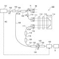
図1に、実施形態に係る眼科装置の光学系の構成例を示す。実施形態に係る眼科装置1000は、被検眼Eを観察するための光学系と、被検眼Eを検査するための光学系と、これらの光学系の光路を波長分離するダイクロイックミラーとを含む。被検眼Eを観察するための光学系として、前眼部観察(撮影)系5が設けられている。被検眼Eを検査するための光学系としてOCT光学系やレフ測定光学系(屈折力測定光学系)などが設けられている。
<Configuration of optical system>
FIG. 1 shows a configuration example of an optical system of an ophthalmologic apparatus according to an embodiment. An
眼科装置1000は、アライメント光投射系2、ケラト測定系3、固視投影系4、前眼部観察系5、レフ測定投射系6、レフ測定受光系7、及びOCT光学系8を含む。以下では、例えば、前眼部観察系5が主に940nm~1000nmの光を用い、レフ測定光学系(レフ測定投射系6、レフ測定受光系7)が830nm~880nmの光を用い、固視投影系4が400nm~700nmの光を用い、OCT光学系8が1000nm~1100nmの光を用いるものとする。
The
(前眼部観察系5)
前眼部観察系5は、被検眼Eの前眼部を動画撮影する。前眼部観察系5を経由する光学系において、撮像素子59の撮像面は瞳孔共役位置に配置されている。前眼部照明光源50は、被検眼Eの前眼部に照明光(例えば、赤外光)を照射する。被検眼Eの前眼部により反射された光は、対物レンズ51を通過し、ダイクロイックミラー52を透過し、絞り(テレセン絞り)53に形成された孔部を通過し、ハーフミラー23を透過し、リレーレンズ55及び56を通過し、ダイクロイックミラー76を透過する。ダイクロイックミラー52は、レフ測定光学系の光路と前眼部観察系5の光路とを合成(分離)する。ダイクロイックミラー52は、これらの光路を合成する光路合成面が対物レンズ51の光軸に対して傾斜して配置される。ダイクロイックミラー76を透過した光は、結像レンズ58により撮像素子59(エリアセンサー)の撮像面に結像される。撮像素子59は、所定のレートで撮像及び信号出力を行う。撮像素子59の出力(映像信号)は、後述の処理部9に入力される。処理部9は、この映像信号に基づく前眼部像E´を後述の表示部10の表示画面10aに表示させる。前眼部像E´は、例えば赤外動画像である。
(Anterior segment observation system 5)
The anterior
(アライメント光投射系2)
アライメント光投射系2は、前眼部観察系5の光軸方向(前後方向、Z方向)及び光軸に直交する方向(左右方向(X方向)、上下方向(Y方向))のアライメントを行うための光(赤外光)を被検眼Eに照射する。アライメント光投射系2は、ハーフミラー23により前眼部観察系5の光路から分岐された光路に設けられたアライメント光源21とコリメータレンズ22とを含む。アライメント光源21から出力された光は、コリメータレンズ22を通過し、ハーフミラー23により反射され、前眼部観察系5を通じて被検眼Eに投射される。被検眼Eの角膜Crによる反射光は、前眼部観察系5を通じて撮像素子59に導かれる。
(Alignment light projection system 2)
The alignment
この反射光に基づく像(輝点像)Brは前眼部像E´に含まれる。処理部9は、輝点像Brを含む前眼部像E´とアライメントマークALとを表示部の表示画面に表示させる。手動でXYアライメントを行う場合、ユーザは、アライメントマークAL内に輝点像Brを誘導するように光学系の移動操作を行うことができる。手動でZアライメントを行う場合、ユーザは、表示部の表示画面に表示された前眼部像E´を参照しながら光学系の移動操作を行うことができる。自動でアライメントを行う場合、処理部9は、後述するように被検眼Eの所定部位(例えば、瞳孔中心位置)の位置と輝点像Brの位置とに基づいて、所定のアライメント完了条件を満たすように光学系を移動させる機構を制御する。 The image (bright spot image) Br based on this reflected light is included in the anterior segment image E'. The processing unit 9 causes the display screen of the display unit to display the anterior segment image E′ including the bright spot image Br and the alignment mark AL. When the XY alignment is performed manually, the user can move the optical system so as to guide the bright spot image Br within the alignment mark AL. When manually performing the Z alignment, the user can move the optical system while referring to the anterior segment image E′ displayed on the display screen of the display unit. When the alignment is performed automatically, the processing unit 9 satisfies a predetermined alignment completion condition based on the position of a predetermined portion (for example, pupil center position) of the subject's eye E and the position of the bright spot image Br, as will be described later. It controls the mechanism that moves the optical system.
(ケラト測定系3)
ケラト測定系3は、被検眼Eの角膜Crの形状を測定するためのリング状光束(赤外光)を角膜Crに投射する。ケラト板31は、対物レンズ51と被検眼Eとの間に配置されている。ケラト板31の背面側(対物レンズ51側)にはケラトリング光源32が設けられている。ケラトリング光源32からの光でケラト板31を照明することにより、被検眼Eの角膜Crにリング状光束(円弧状又は円周状の測定パターン)が投射される。被検眼Eの角膜Crからの反射光(ケラトリング像)は撮像素子59により前眼部像E´とともに検出される。処理部9は、このケラトリング像を基に公知の演算を行うことで、角膜Crの形状を表す角膜形状パラメータを算出する。
(Kerato measurement system 3)
The
(レフ測定投射系6、レフ測定受光系7)
レフ測定光学系は、眼屈折力測定に用いられるレフ測定投射系6及びレフ測定受光系7を含む。レフ測定投射系6は、眼屈折力測定用の光束(例えば、リング状光束)(赤外光)を眼底Efに投射する。レフ測定受光系7は、この光束の被検眼Eからの戻り光を受光する。レフ測定投射系6は、レフ測定受光系7の光路に設けられた孔開きプリズム65によって分岐された光路に設けられる。孔開きプリズム65に形成されている孔部は、瞳孔共役位置に配置される。レフ測定受光系7を経由する光学系において、撮像素子59の撮像面は眼底共役位置に配置される。
(ref
The reflector measurement optical system includes a reflector
いくつかの実施形態では、レフ測定光源61は、高輝度光源であるSLD(Superluminescent Diode)光源である。レフ測定光源61は、光軸方向に移動可能である。レフ測定光源61は、眼底共役位置に配置される。レフ測定光源61から出力された光は、リレーレンズ62を通過し、円錐プリズム63の円錐面に入射する。円錐面に入射した光は偏向され、円錐プリズム63の底面から出射する。円錐プリズム63の底面から出射した光は、リング絞り64にリング状に形成された透光部を通過する。リング絞り64の透光部を通過した光(リング状光束)は、孔開きプリズム65の孔部の周囲に形成された反射面により反射され、ロータリープリズム66を通過し、ダイクロイックミラー67により反射される。ダイクロイックミラー67により反射された光は、ダイクロイックミラー52により反射され、対物レンズ51を通過し、被検眼Eに投射される。ロータリープリズム66は、眼底Efの血管や疾患部位に対するリング状光束の光量分布を平均化や光源に起因するスペックルノイズの低減のために用いられる。
In some embodiments, the ref
眼底Efに投射されたリング状光束の戻り光は、対物レンズ51を通過し、ダイクロイックミラー52及びダイクロイックミラー67により反射される。ダイクロイックミラー67により反射された戻り光は、ロータリープリズム66を通過し、孔開きプリズム65の孔部を通過し、リレーレンズ71を通過し、反射ミラー72により反射され、リレーレンズ73及び合焦レンズ74を通過する。合焦レンズ74は、レフ測定受光系7の光軸に沿って移動可能である。合焦レンズ74を通過した光は、反射ミラー75により反射され、ダイクロイックミラー76により反射され、結像レンズ58により撮像素子59の撮像面に結像される。処理部9は、撮像素子59からの出力を基に公知の演算を行うことで被検眼Eの眼屈折度数(眼屈折力値)を算出する。例えば、眼屈折度数は、球面度数、乱視度数及び乱視軸角度、又は等価球面度数を含む。
The return light of the ring-shaped luminous flux projected onto the fundus oculi Ef passes through the
(固視投影系4)
ダイクロイックミラー67によりレフ測定光学系の光路から波長分離された光路に、後述のOCT光学系8が設けられる。ダイクロイックミラー83によりOCT光学系8の光路から分岐された光路に固視投影系4が設けられる。
(Fixation projection system 4)
An OCT
固視投影系4は、固視標を被検眼Eに呈示する。固視投影系4の光路には、固視ユニット40が配置されている。固視ユニット40は、後述の処理部9からの制御を受け、固視投影系4の光路に沿って移動可能である。固視ユニット40は、液晶パネル41を含む。
A fixation projection system 4 presents a fixation target to the eye E to be examined. A
処理部9による制御を受けた液晶パネル41は、固視標を表すパターンを表示する。液晶パネル41の画面上におけるパターンの表示位置を変更することにより、被検眼Eの固視位置を変更できる。被検眼Eの固視位置としては、眼底Efの黄斑部を中心とする画像を取得するための位置や、視神経乳頭を中心とする画像を取得するための位置や、黄斑部と視神経乳頭との間の眼底中心を中心とする画像を取得するための位置などがある。固視標を表すパターンの表示位置を任意に変更することが可能である。なお、液晶パネル41に代えて、フィルム等に視標等が印刷された透過型のレフ測定用の視標チャートと、視標チャートを照明する照明用光源と、OCT計測用の点光源とが設けられていてもよい。
The
液晶パネル41からの光は、リレーレンズ42を通過し、ダイクロイックミラー83を透過し、リレーレンズ82を通過し、反射ミラー81により反射され、ダイクロイックミラー67を透過し、ダイクロイックミラー52により反射される。ダイクロイックミラー52により反射された光は、対物レンズ51を通過して眼底Efに投射される。いくつかの実施形態では、液晶パネル41及びリレーレンズ42のそれぞれは、独立に光軸方向に移動可能である。
Light from the
眼科装置1000には、前眼部カメラ300が設けられている。前眼部カメラ300は、被検眼Eの前眼部を異なる方向から撮影する。この実施形態では、眼科装置1000の被検者に対向する面に2台のカメラが設けられている(図3Aに示す前眼部カメラ300A及び300Bを参照)。前眼部カメラ300A及び300Bはそれぞれ、図1及び図3Aに示すように、対物レンズ51の光軸(前眼部観察系5の光路(光軸)、OCT光学系8の光路(光軸))から外れた位置に設けられている。以下、2台の前眼部カメラ300A及び300Bをまとめて符号300で表すことがある。
The
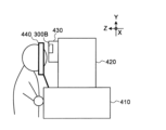
図3A及び図3Bに、眼科装置1000の外観構成の概要を示す。
3A and 3B show an overview of the external configuration of the
眼科装置1000には、被検者の顔を支持するための顎受けと額当てが設けられている。顎受け及び額当ては、図3A及び図3Bに示す支持部440に相当する。移動機構200等の駆動系や処理部9は、ベース410に格納される。ベース410上には、光学系が格納された筐体420が設けられる。筐体420の前面には、対物レンズ51が収容されたレンズ収容部430が設けられる。
The
この実施形態では、2台の前眼部カメラ300A及び300Bが設けられているが、実施形態に係る前眼部カメラの個数は2以上の任意の個数である。
Although two
また、この実施形態では、前眼部観察系5とは別個に前眼部カメラ300を設けているが、少なくとも前眼部観察系5を用いて同様の前眼部観察を行うことができる。いくつかの実施形態では、2以上の前眼部カメラのうちの1つは、前眼部観察系5(撮像素子59)を含む。実施形態に係る眼科装置1000は、異なる2以上の方向から前眼部を撮影可能に構成されていればよい。
In addition, in this embodiment, the
いくつかの実施形態では、2以上の前眼部カメラのそれぞれの近傍に少なくとも1つの前眼部照明光源50(赤外光源等)を設けることができる。例えば、前眼部カメラ300Aの上方近傍に設けられた前眼部照明光源及び下方近傍に設けられた前眼部照明光源と、前眼部カメラ300Bの上方近傍に設けられた前眼部照明光源及び下方近傍に設けられた前眼部照明光源とが設けられる。
In some embodiments, at least one anterior segment illumination source 50 (such as an infrared source) can be provided proximate each of the two or more anterior segment cameras. For example, an anterior segment illumination light source provided in the vicinity of the upper portion of the
2以上の前眼部カメラは、異なる2以上の方向から実質的に同時に前眼部を撮影することができる。「実質的に同時」とは、例えば、2以上の前眼部カメラによる撮影において、眼球運動を無視できる程度の撮影タイミングのズレを許容することを示す。それにより、被検眼Eが実質的に同じ位置(向き)にあるときの画像を2以上の前眼部カメラによって取得することができる。 Two or more anterior segment cameras can image the anterior segment substantially simultaneously from two or more different directions. “Substantially simultaneously” means, for example, that, in imaging with two or more anterior eye cameras, a deviation in imaging timing to the extent that eye movement can be ignored is allowed. Thereby, two or more anterior eye cameras can acquire images when the subject's eye E is in substantially the same position (orientation).
また、2以上の前眼部カメラによる撮影は動画撮影でも静止画撮影でもよい。動画撮影の場合、撮影開始タイミングを合わせるよう制御したり、フレームレートや各フレームの撮影タイミングを制御したりすることにより、上記のような実質的に同時の前眼部撮影を実現することができる。一方、静止画撮影の場合、撮影タイミングを合わせるよう制御することにより、これを実現することができる。 Further, photographing by two or more anterior segment cameras may be either moving image photographing or still image photographing. In the case of video shooting, by controlling the shooting start timing to match, or by controlling the frame rate and the shooting timing of each frame, it is possible to realize substantially simultaneous shooting of the anterior segment as described above. . On the other hand, in the case of still image shooting, this can be achieved by controlling the shooting timing to match.
(OCT光学系8)
図1に示すOCT光学系8は、OCT計測を行うための光学系である。例えば、OCT計測よりも前に実施されたレフ測定結果に基づいて、光ファイバーf1の端面が撮影部位(眼底Ef又は前眼部)と光学系に共役となるように合焦レンズ87の位置が調整される。或いは、例えば、OCT計測により得られる干渉信号の強度が最大になるように合焦レンズ87の位置が調整される。
(OCT optical system 8)
The OCT
OCT光学系8は、ダイクロイックミラー67によりレフ測定光学系の光路から波長分離された光路に設けられる。上記の固視投影系4の光路は、ダイクロイックミラー83によりOCT光学系8の光路に結合される。それにより、OCT光学系8及び固視投影系4のそれぞれの光軸を同軸で結合することができる。
The OCT
OCT光学系8は、OCTユニット100を含む。図2に示すように、OCTユニット100において、OCT光源101は、一般的なスウェプトソースタイプのOCT装置と同様に、出射光の波長を掃引(走査)可能な波長掃引型(波長走査型)光源を含んで構成される。波長掃引型光源は、共振器を含むレーザー光源を含んで構成される。OCT光源101は、人眼では視認できない近赤外の波長帯において、出力波長を時間的に変化させる。
OCT
図2に例示するように、OCTユニット100には、スウェプトソースOCTを実行するための光学系が設けられている。この光学系は、干渉光学系を含む。この干渉光学系は、波長可変光源(波長掃引型光源)からの光を測定光と参照光とに分割する機能と、被検眼Eからの測定光の戻り光と参照光路を経由した参照光とを重ね合わせて干渉光を生成する機能と、この干渉光を検出する機能とを備える。干渉光学系により得られた干渉光の検出結果(検出信号、干渉信号)は、干渉光のスペクトルを示す信号であり、処理部9に送られる。
As illustrated in FIG. 2, the
OCT光源101は、例えば、出射光の波長(1000nm~1100nmの波長範囲)を高速で変化させる近赤外波長可変レーザーを含む。OCT光源101から出力された光L0は、光ファイバー102により偏波コントローラ103に導かれてその偏光状態が調整される。偏光状態が調整された光L0は、光ファイバー104によりファイバーカプラー105に導かれて測定光LSと参照光LRとに分割される。
The OCT
参照光LRは、光ファイバー110によりコリメータ111に導かれて平行光束に変換され、光路長補正部材112及び分散補償部材113を経由し、コーナーキューブ114に導かれる。光路長補正部材112は、参照光LRの光路長と測定光LSの光路長とを合わせるよう作用する。分散補償部材113は、参照光LRと測定光LSとの間の分散特性を合わせるよう作用する。コーナーキューブ114は、参照光LRの入射方向に移動可能であり、それにより参照光LRの光路長が変更される。
The reference light LR is guided by the
コーナーキューブ114を経由した参照光LRは、分散補償部材113及び光路長補正部材112を経由し、コリメータ116によって平行光束から集束光束に変換され、光ファイバー117に入射する。光ファイバー117に入射した参照光LRは、偏波コントローラ118に導かれてその偏光状態が調整され、光ファイバー119によりアッテネータ120に導かれて光量が調整され、光ファイバー121によりファイバーカプラー122に導かれる。
The reference light LR that has passed through the
一方、ファイバーカプラー105により生成された測定光LSは、光ファイバーf1により導かれてコリメータレンズユニット89により平行光束に変換され、光スキャナー88、合焦レンズ87、リレーレンズ85、及び反射ミラー84を経由し、ダイクロイックミラー83により反射される。
On the other hand, the measurement light LS generated by the
光スキャナー88は、測定光LSを1次元的又は2次元的に偏向する。光スキャナー88は、例えば、第1ガルバノミラーと、第2ガルバノミラーとを含む。第1ガルバノミラーは、OCT光学系8の光軸に直交する水平方向に撮影部位(眼底Ef又は前眼部)をスキャンするように測定光LSを偏向する。第2ガルバノミラーは、OCT光学系8の光軸に直交する垂直方向に撮影部位をスキャンするように、第1ガルバノミラーにより偏向された測定光LSを偏向する。このような光スキャナー88による測定光LSの走査態様としては、例えば、水平スキャン、垂直スキャン、十字スキャン、放射スキャン、円スキャン、同心円スキャン、螺旋スキャンなどがある。
The
ダイクロイックミラー83により反射された測定光LSは、リレーレンズ82を通過し、反射ミラー81により反射され、ダイクロイックミラー67を透過し、ダイクロイックミラー52により反射され、対物レンズ51により屈折されて被検眼Eに入射する。測定光LSは、被検眼Eの様々な深さ位置において散乱・反射される。被検眼Eからの測定光LSの戻り光は、往路と同じ経路を逆向きに進行してファイバーカプラー105に導かれ、光ファイバー128を経由してファイバーカプラー122に到達する。
The measurement light LS reflected by the
ファイバーカプラー122は、光ファイバー128を介して入射された測定光LSと、光ファイバー121を介して入射された参照光LRとを合成して(干渉させて)干渉光を生成する。ファイバーカプラー122は、所定の分岐比(例えば1:1)で干渉光を分岐することにより、一対の干渉光LCを生成する。一対の干渉光LCは、それぞれ光ファイバー123及び124を通じて検出器125に導かれる。
The
検出器125は、例えばバランスドフォトダイオードである。バランスドフォトダイオードは、一対の干渉光LCをそれぞれ検出する一対のフォトディテクタを含み、これらフォトディテクタにより得られた一対の検出結果の差分を出力する。検出器125は、この出力(検出信号)をDAQ(Data Acquisition System)130に送る。
DAQ130には、OCT光源101からクロックKCが供給される。クロックKCは、OCT光源101において、波長可変光源により所定の波長範囲内で掃引される各波長の出力タイミングに同期して生成される。OCT光源101は、例えば、各出力波長の光L0を分岐することにより得られた2つの分岐光の一方を光学的に遅延させた後、これらの合成光を検出した結果に基づいてクロックKCを生成する。DAQ130は、検出器125から入力される検出信号をクロックKCに基づきサンプリングする。DAQ130は、検出器125からの検出信号のサンプリング結果を処理部9の演算処理部220に送る。演算処理部220は、例えば一連の波長走査毎に(Aライン毎に)、サンプリングデータに基づくスペクトル分布にフーリエ変換等を施すことにより、各Aラインにおける反射強度プロファイルを形成する。更に、演算処理部220は、各Aラインの反射強度プロファイルを画像化することにより画像データを形成する。
A clock KC is supplied from the OCT
本例では、参照光LRの光路(参照光路、参照アーム)の長さを変更するためのコーナーキューブ114が設けられているが、これら以外の光学部材を用いて、測定光路長と参照光路長との差を変更することも可能である。
In this example, a
処理部9は、レフ測定光学系を用いて得られた測定結果から眼屈折度数を算出し、算出された眼屈折度数に基づいて、眼底Efとレフ測定光源61と撮像素子59とが共役となる位置に、レフ測定光源61及び合焦レンズ74それぞれを光軸方向に移動させる。いくつかの実施形態では、処理部9は、合焦レンズ74の移動に連動してOCT光学系8の合焦レンズ87をその光軸方向に移動させる。いくつかの実施形態では、処理部9は、レフ測定光源61及び合焦レンズ74の移動に連動して液晶パネル41(固視ユニット40)をその光軸方向に移動させる。
The processing unit 9 calculates the eye refraction power from the measurement result obtained using the reflex measurement optical system, and based on the calculated eye refraction power, the fundus oculi Ef, the reflex
<処理系の構成>
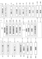
眼科装置1000の処理系の構成について説明する。眼科装置1000の処理系の機能的構成の例を図4~図7に示す。図4は、眼科装置1000の処理系の機能ブロック図の一例を表す。図5は、データ処理部225の機能ブロック図の一例を表す。図6は、アライメント処理部2251の機能ブロック図の一例を表す。図7は、傾斜角度処理部2252の機能ブロック図の一例を表す。
<Configuration of processing system>
The configuration of the processing system of the
処理部9は、眼科装置1000の各部を制御する。また、処理部9は、各種演算処理を実行可能である。処理部9は、プロセッサを含む。プロセッサの機能は、例えば、CPU(Central Processing Unit)、GPU(Graphics Processing Unit)、ASIC(Application Specific Integrated Circuit)、プログラマブル論理デバイス(例えば、SPLD(Simple Programmable Logic Device)、CPLD(Complex Programmable Logic Device)、FPGA(Field Programmable Gate Array))等の回路により実現される。処理部9は、例えば、記憶回路や記憶装置に格納されているプログラムを読み出し実行することで、実施形態に係る機能を実現する。
The processing unit 9 controls each unit of the
処理部9は、実施形態に係る「眼科情報処理装置」の一例である。すなわち、処理部9の機能を実現するためのプログラムは、実施形態に係る「眼科情報処理プログラム」の一例である。 The processing unit 9 is an example of an "ophthalmic information processing apparatus" according to the embodiment. That is, the program for realizing the function of the processing unit 9 is an example of the "ophthalmic information processing program" according to the embodiment.
処理部9は、制御部210と、演算処理部220とを含む。また、眼科装置1000は、移動機構200と、表示部270と、操作部280と、通信部290とを含む。
Processing unit 9 includes
移動機構200は、アライメント光投射系2、ケラト測定系3、固視投影系4、前眼部観察系5、レフ測定投射系6、レフ測定受光系7及びOCT光学系8等の光学系(装置光学系)が収納されたヘッド部を前後左右方向に移動させるための機構である。例えば、移動機構200には、ヘッド部を移動するための駆動力を発生するアクチュエータと、この駆動力を伝達する伝達機構とが設けられる。アクチュエータは、例えばパルスモータにより構成される。伝達機構は、例えば歯車の組み合わせやラック・アンド・ピニオンなどによって構成される。制御部210(主制御部211)は、アクチュエータに対して制御信号を送ることにより移動機構200に対する制御を行う。
The moving
移動機構200に対する制御は、アライメントやトラッキングにおいて用いられる。トラッキングとは、被検眼Eの眼球運動に合わせて装置光学系を移動させるものである。トラッキングを行う場合には、事前にアライメントとフォーカス調整が実行される。トラッキングは、装置光学系の位置を眼球運動に追従させることにより、アライメントとピントが合った好適な位置関係を維持する機能である。
Control over the moving
(制御部210)
制御部210は、プロセッサを含み、眼科装置1000の各部を制御する。制御部210は、主制御部211と、記憶部212とを含む。記憶部212には、眼科装置1000を制御するためのコンピュータプログラムがあらかじめ格納される。コンピュータプログラムには、光源制御用プログラム、検出器制御用プログラム、光スキャナー制御用プログラム、光学系制御用プログラム、アライメント制御用プログラム、トラッキング制御用プログラム、演算処理用プログラム及びユーザインターフェイス用プログラムなどが含まれる。このようなコンピュータプログラムに従って主制御部211が動作することにより、制御部210は制御処理を実行する。
(control unit 210)
The
主制御部211は、測定制御部として眼科装置の各種制御を行う。
A
アライメント光投射系2に対する制御には、アライメント光源21の制御などがある。アライメント光源21の制御には、光源の点灯、消灯、光量調整、絞り調整などがある。それにより、アライメント光源21の点灯と非点灯とが切り替えられたり、光量が変更されたりする。
Control of the alignment
ケラト測定系3に対する制御には、ケラトリング光源32の制御などがある。ケラトリング光源32の制御には、光源の点灯、消灯、光量調整、絞り調整などがある。それにより、ケラトリング光源32の点灯と非点灯とが切り替えられたり、光量が変更されたりする。主制御部211は、撮像素子59により検出されたケラトリング像に対する公知の演算を演算処理部220に実行させる。それにより、被検眼Eの角膜形状パラメータが求められる。
Control of the
固視投影系4に対する制御には、液晶パネル41の制御や固視ユニット40の移動制御などがある。液晶パネル41の制御には、固視標の表示のオン・オフや、固視標の表示位置の切り替えなどがある。
The control of the fixation projection system 4 includes control of the
例えば、固視投影系4には、液晶パネル41(又は固視ユニット40)を光軸方向に移動する移動機構が設けられる。この移動機構には、移動機構200と同様に、当該移動機構を移動するための駆動力を発生するアクチュエータと、この駆動力を伝達する伝達機構とが設けられる。主制御部211は、アクチュエータに対して制御信号を送ることにより移動機構に対する制御を行い、少なくとも液晶パネル41を光軸方向に移動させる。それにより、液晶パネル41と眼底Efとが光学的に共役となるように液晶パネル41の位置が調整される。
For example, the fixation projection system 4 is provided with a moving mechanism that moves the liquid crystal panel 41 (or the fixation unit 40) in the optical axis direction. Similar to the moving
前眼部観察系5に対する制御には、前眼部照明光源50の制御、撮像素子59の制御などがある。前眼部照明光源50の制御には、光源の点灯、消灯、光量調整、絞り調整などがある。それにより、前眼部照明光源50の点灯と非点灯とが切り替えられたり、光量が変更されたりする。撮像素子59の制御には、撮像素子59の露光調整やゲイン調整や検出レート調整などがある。主制御部211は、撮像素子59により検出された信号を取り込み、取り込まれた信号に基づく画像の形成等の処理を演算処理部220に実行させる。
The control of the anterior
前眼部カメラ300に対する制御には、2以上の前眼部カメラの撮影開始タイミングや各フレームの撮影タイミングの同期制御や、各前眼部カメラの露光調整やゲイン調整やフレームレート調整などがある。それにより、被検眼Eの前眼部が実質的に同時に撮影される。
The control of the
レフ測定投射系6に対する制御には、レフ測定光源61の制御、ロータリープリズム66の制御などがある。レフ測定光源61の制御には、光源の点灯、消灯、光量調整、絞り調整などがある。それにより、レフ測定光源61の点灯と非点灯とが切り替えられたり、光量が変更されたりする。例えば、レフ測定投射系6は、レフ測定光源61を光軸方向に移動する移動機構を含む。この移動機構には、移動機構200と同様に、当該移動機構を移動するための駆動力を発生するアクチュエータと、この駆動力を伝達する伝達機構とが設けられる。主制御部211は、アクチュエータに対して制御信号を送ることにより移動機構に対する制御を行い、レフ測定光源61を光軸方向に移動させる。ロータリープリズム66の制御には、ロータリープリズム66の回転制御などがある。例えば、ロータリープリズム66を回転させる回転機構が設けられており、主制御部211は、この回転機構を制御することによりロータリープリズム66を回転させる。
The control of the ref
レフ測定受光系7に対する制御には、合焦レンズ74の制御などがある。合焦レンズ74の制御には、合焦レンズ74の光軸方向への移動制御などがある。例えば、レフ測定受光系7は、合焦レンズ74を光軸方向に移動する移動機構を含む。この移動機構には、移動機構200と同様に、当該移動機構を移動するための駆動力を発生するアクチュエータと、この駆動力を伝達する伝達機構とが設けられる。主制御部211は、アクチュエータに対して制御信号を送ることにより移動機構に対する制御を行い、合焦レンズ74を光軸方向に移動させる。主制御部211は、レフ測定光源61と眼底Efと撮像素子59とが光学的に共役となるように、例えば被検眼Eの屈折力に応じてレフ測定光源61及び合焦レンズ74をそれぞれ光軸方向に移動させることが可能である。
Control of the ref measurement light-receiving system 7 includes control of the focusing
OCT光学系8に対する制御には、OCT光源101の制御、光スキャナー88の制御、合焦レンズ87の制御、コーナーキューブ114の制御、検出器125の制御、DAQ130の制御などがある。OCT光源101の制御には、光源の点灯、消灯、光量調整、絞り調整などがある。光スキャナー88の制御には、第1ガルバノミラーによる走査位置や走査範囲や走査速度の制御、第2ガルバノミラーによる走査位置や走査範囲や走査速度の制御などがある。
Control of the OCT
合焦レンズ87の制御には、合焦レンズ87の光軸方向への移動制御、撮影部位に対応した合焦基準位置への合焦レンズ87の移動制御、撮影部位に対応した移動範囲(合焦範囲)内での移動制御などがある。例えば、OCT光学系8は、合焦レンズ87を光軸方向に移動する移動機構を含む。この移動機構には、移動機構200と同様に、当該移動機構を移動するための駆動力を発生するアクチュエータと、この駆動力を伝達する伝達機構とが設けられる。主制御部211は、アクチュエータに対して制御信号を送ることにより移動機構に対する制御を行い、合焦レンズ87を光軸方向に移動させる。いくつかの実施形態では、眼科装置1000には、合焦レンズ74及び87を保持する保持部材と、保持部材を駆動する駆動部が設けられる。主制御部211は、駆動部を制御することにより合焦レンズ74及び87の移動制御を行う。主制御部211は、例えば、合焦レンズ74の移動に連動して合焦レンズ87を移動させた後、干渉信号の強度に基づいて合焦レンズ87だけを移動させるようにしてもよい。
The control of the focusing
コーナーキューブ114の制御には、コーナーキューブ114の光路に沿った移動制御などがある。例えば、OCT光学系8は、コーナーキューブ114を光路に沿った方向に移動する移動機構を含む。この移動機構には、移動機構200と同様に、当該移動機構を移動するための駆動力を発生するアクチュエータと、この駆動力を伝達する伝達機構とが設けられる。主制御部211は、アクチュエータに対して制御信号を送ることにより移動機構に対する制御を行い、コーナーキューブ114を光路に沿った方向に移動させる。検出器125の制御には、検出素子の露光調整やゲイン調整や検出レート調整や検出信号のデータ転送制御などがある。主制御部211は、検出器125により検出された信号をDAQ130によりサンプリングし、サンプリングされた信号に基づく画像の形成等の処理を演算処理部220(画像形成部224)に実行させる。
The control of the
主制御部211は、OCT計測を行う前に複数の予備的な動作を実行可能である。予備的な動作としては、フォーカス調整、偏光調整などがある。例えば、フォーカス調整は、OCT計測の干渉感度に基づいて行われる。例えば、上記のように、干渉強度が最大となるような合焦レンズ87の位置を求め、その位置に合焦レンズ87を移動させることにより、フォーカス調整を実行することができる。偏光調整においては、測定光LSと参照光LRとの干渉効率を最適化するために参照光LRの偏光状態が調整される。
The
また、主制御部211は、表示制御部として、眼屈折度数算出部221により算出された眼屈折度数の測定値、画像形成部224により形成された断層像、後述のデータ処理部225の処理結果に対応した情報を表示部270に表示させる。
Further, the
更に、主制御部211は、記憶部212にデータを書き込む処理や、記憶部212からデータを読み出す処理を行う。
Furthermore, the
(記憶部212)
記憶部212は、各種のデータを記憶する。記憶部212に記憶されるデータとしては、例えば他覚測定の測定結果、OCT計測の計測結果、断層像の画像データ、前眼部像の画像データ、被検眼情報、後述の収差情報、後述の模型眼データ(標準値データ)などがある。被検眼情報は、左眼/右眼の識別情報などの被検眼に関する情報を含む。
(storage unit 212)
The
収差情報は、各前眼部カメラ300に対応して、光学系の影響により撮影画像に発生する歪曲収差を定量化したパラメータを含む。光学系が撮影画像に与える歪曲収差に関連するパラメータとして、主点距離、主点位置(縦方向、横方向)、レンズのディストーション(放射方向、接線方向)などがある。例えば、収差情報は、各前眼部カメラ300の識別情報と、これに対応する補正係数とを関連付けた情報(例えばテーブル情報)として構成される。
The aberration information includes parameters that quantify the distortion aberration that occurs in the captured image due to the influence of the optical system, corresponding to each
また、記憶部212には、眼科装置を動作させるための各種プログラムやデータが記憶されている。
The
(光学系位置取得部213)
光学系位置取得部213は、眼科装置1000に搭載され、被検眼Eのデータを光学的に取得するための上記の装置光学系の現在位置を取得する。
(Optical system position acquisition unit 213)
The optical system
例えば、光学系位置取得部213は、移動機構200の移動制御の内容を表す情報を主制御部211から受けて、図1に示す装置光学系の現在位置を取得する。この場合、主制御部211は、所定のタイミング(装置起動時、患者情報入力時など)で移動機構200を制御して、装置光学系を所定の初期位置に移動させる。それ以降、主制御部211は、移動機構200を制御する度に、その制御内容を記録する。それにより、制御内容の履歴が得られる。光学系位置取得部213は、この履歴を参照して現在までの制御内容を取得し、この制御内容に基づいて装置光学系の現在位置を求める。
For example, the optical system
いくつかの実施形態では、主制御部211が移動機構200を制御する度にその制御内容を光学系位置取得部213に送信する。光学系位置取得部213は、当該制御内容を受ける度に装置光学系の現在位置を逐次求める。
In some embodiments, every time the
いくつかの実施形態では、光学系位置取得部213は、装置光学系の位置を検知する位置センサーを含む。
In some embodiments, optics position
主制御部211は、光学系位置取得部213により取得された現在位置と、後述のデータ処理部225により決定された移動目標位置とに基づいて、移動機構200を制御することができる。それにより、装置光学系を移動目標位置に移動させることができる。例えば、主制御部211は、現在位置と移動目標位置との差分を求める。この差分値は、例えば、現在位置を始点とし、移動目標位置を終点とするベクトル値である。このベクトル値は、例えば、XYZ座標系で表現される3次元ベクトル値である。
The
(演算処理部220)
演算処理部220は、眼屈折度数算出部221と、角膜形状算出部222と、眼内距離算出部223と、画像形成部224と、データ処理部225とを含む。
(Arithmetic processing unit 220)
(眼屈折度数算出部221)
眼屈折度数算出部221は、レフ測定投射系6により眼底Efに投影されたリング状光束(リング状の測定パターン)の戻り光を撮像素子59が受光することにより得られたリング像(パターン像)を解析する。例えば、眼屈折度数算出部221は、得られたリング像が描出された画像における輝度分布からリング像の重心位置を求め、この重心位置から放射状に延びる複数の走査方向に沿った輝度分布を求め、この輝度分布からリング像を特定する。続いて、眼屈折度数算出部221は、特定されたリング像の近似楕円を求め、この近似楕円の長径及び短径を公知の式に代入することによって球面度数、乱視度数及び乱視軸角度(眼屈折度数)を求める。或いは、眼屈折度数算出部221は、基準パターンに対するリング像の変形及び変位に基づいて眼屈折度数のパラメータを求めることができる。
(Eye refraction power calculator 221)
The eye refraction
(角膜形状算出部222)
角膜形状算出部222は、ケラト測定系3により被検眼Eの角膜Crに投影されたリング状光束の戻り光を撮像素子59が受光することにより得られたケラトリング像を解析することにより被検眼Eの角膜形状情報を算出する。
(Corneal shape calculator 222)
The
角膜形状情報は、例えば、公知の眼科装置を用いて測定可能な、角膜の形状を表す任意のパラメータ値を含む。典型的には、角膜形状情報は、曲率半径(曲率)、強主経線の向き、強主経線に沿う曲率半径(度数)、弱主経線の向き、弱主経線に沿う曲率半径(度数)、楕円率、離心率、扁平率、不正乱視も含むトポグラフ、ゼルニケ多項式を用いた収差情報などのいずれかを含んでよい。 The corneal shape information includes, for example, arbitrary parameter values representing the shape of the cornea that can be measured using known ophthalmic equipment. Typically, the corneal shape information includes the radius of curvature (curvature), the orientation of the strong principal meridian, the radius of curvature (degrees) along the strong principal meridian, the orientation of the weak principal meridian, the radius of curvature (degrees) along the weak principal meridian, Any of ellipticity, eccentricity, flattening, topography including irregular astigmatism, and aberration information using Zernike polynomials may be included.
例えば、角膜形状算出部222は、得られたケラトリング像を解析することにより角膜前面の強主経線や弱主経線の角膜曲率半径を算出し、角膜曲率半径に基づいて角膜の形状を表すパラメータを算出する。角膜形状算出部222は、得られたケラトリング像に対して演算処理を施すことにより角膜曲率半径を算出し、算出された角膜曲率半径から角膜屈折力、角膜乱視度及び角膜乱視軸角度を算出することができる。
For example, the
(眼内距離算出部223)
眼内距離算出部223は、OCT光学系8により得られた干渉光LCの検出結果に基づいて被検眼Eにおける1以上の眼内距離を求める。1以上の眼内距離は、眼軸長(角膜頂点から内境界膜までの距離)を含む。いくつかの実施形態では、眼内距離算出部223は、OCT光学系8により得られた干渉光LCの検出結果を解析することにより眼内の所定部位に相当する干渉光の検出結果(干渉信号)のピーク位置を特定し、特定されたピーク位置間の距離に基づいて上記の眼内距離を求める。いくつかの実施形態に係る眼内距離算出部223は、更に、角膜厚、前房深度、水晶体厚、硝子体腔長、網膜厚、脈絡膜厚などを求める。
(Intraocular distance calculator 223)
The
(画像形成部224)
画像形成部224は、検出器125により検出された信号に基づいて、眼底Efの断層像の画像データを形成する。すなわち、画像形成部224は、干渉光学系による干渉光LCの検出結果に基づいて被検眼Eの画像データを形成する。この処理には、従来のスペクトラルドメインタイプのOCTと同様に、フィルター処理、FFT(Fast Fourier Transform)などの処理が含まれている。このようにして取得される画像データは、複数のAライン(被検眼E内における各測定光LSの経路)における反射強度プロファイルを画像化することにより形成された一群の画像データを含むデータセットである。
(Image forming unit 224)
The
画質を向上させるために、同じパターンでのスキャンを複数回繰り返して収集された複数のデータセットを重ね合わせる(加算平均する)ことができる。 To improve image quality, multiple data sets collected by scanning the same pattern multiple times can be superimposed (averaged).
(データ処理部225)
データ処理部225は、画像形成部224により形成された断層像に対して各種のデータ処理(画像処理)や解析処理を施す。例えば、データ処理部225は、画像の輝度補正や分散補正等の補正処理を実行する。また、データ処理部225は、前眼部観察系5を用い得られた画像(前眼部像等)に対して各種の画像処理や解析処理を施す。
(Data processing unit 225)
The
データ処理部225は、断層像の間の画素を補間する補間処理などの公知の画像処理を実行することにより、被検眼Eのボリュームデータ(ボクセルデータ)を形成することができる。ボリュームデータに基づく画像を表示させる場合、データ処理部225は、このボリュームデータに対してレンダリング処理を施して、特定の視線方向から見たときの擬似的な3次元画像を形成する。
The
図5に示すように、データ処理部225は、アライメント処理部2251と、傾斜角度処理部2252とを含む。アライメント処理部2251は、前眼部カメラ300により得られた2以上の撮影画像に基づいて角膜を基準としてアライメントを実行するためのデータ処理を行う。傾斜角度処理部2252は、眼底Efの傾斜角度を求めるための処理を行う。
As shown in FIG. 5 , the
(アライメント処理部2251)
図6に示すように、アライメント処理部2251は、画像補正部2251Aと、プルキンエ像特定部2251Bと、プルキンエ像位置特定部2251Cと、瞳孔中心特定部2251Dと、瞳孔中心位置特定部2251Eと、移動目標位置決定部2251Fと、ずれ量特定部2251Gとを含む。
(Alignment processing unit 2251)
As shown in FIG. 6, the
(画像補正部2251A)
画像補正部2251Aは、前眼部カメラ300により得られた撮影画像の歪みを補正する。画像補正部2251Aは、記憶部212に記憶されている収差情報に基づいて撮影画像の歪みを補正することができる。この処理は、例えば、歪曲収差を補正するための補正係数に基づく公知の画像処理技術によって実行される。なお、前眼部カメラ300の光学系が撮影画像に与える歪曲収差が十分に小さい場合などには、収差情報及び画像補正部2251Aが設けられていなくてよい。
(
The
(プルキンエ像特定部2251B)
主制御部211は、例えば、アライメント光源21を点灯させる。それにより、前眼部にアライメント光束が投射され、プルキンエ像が形成される。プルキンエ像は、角膜曲率半径の2分の1の距離だけ角膜頂点から軸方向(Z方向)に偏位した位置に形成される。
(Purkinje
The
アライメント光束が投射されている前眼部は、2つの前眼部カメラ300によって実質的に同時に撮影される。2つの前眼部カメラ300により実質的に同時に取得された2つの撮影画像は、必要に応じて画像補正部2251Aによる補正を受け、プルキンエ像特定部2251Bに入力される。
The anterior segment onto which the alignment beams are projected is imaged substantially simultaneously by the two
プルキンエ像特定部2251Bは、2つの撮影画像のそれぞれを解析することでプルキンエ像(プルキンエ像に相当する画像領域)を特定する。この特定処理は、例えば従来と同様に、プルキンエ像に相当する輝点(高輝度の画素)を探索するための、画素値に関する閾値処理を含む。それにより、プルキンエ像に相当する撮影画像中の画像領域が特定される。
The Purkinje
プルキンエ像特定部2251Bは、プルキンエ像に相当する画像領域における代表点の位置を求めることができる。代表点は、例えば、当該画像領域の中心点又は重心点であってよい。この場合、プルキンエ像特定部2251Bは、例えば、当該画像領域の周縁の近似円又は近似楕円を求め、近似円又は近似楕円の中心又は重心を求めることができる。
The Purkinje
(プルキンエ像位置特定部2251C)
プルキンエ像位置特定部2251Cは、プルキンエ像特定部2251Bから入力された情報に基づいて、プルキンエ像特定部2251Bにより特定されたプルキンエ像の位置を特定する。プルキンエ像の位置は、少なくともX方向の位置(X座標値)及びY方向の位置(Y座標値)を含んでよく、更にZ方向の位置(Z座標値)を含んでもよい。
(Purkinje image
The Purkinje image
図8に、前眼部カメラ300により取得される2つの撮影画像を模式的に示す。
FIG. 8 schematically shows two captured images acquired by the
撮影画像400Aは、前眼部カメラ300Aにより取得された撮影画像(前眼部像)である。撮影画像400Bは、前眼部カメラ300Bにより取得された撮影画像である。撮影画像400A及び400Bは、画像補正部2251Aにより補正された画像であってよい。
The captured
撮影画像400Aは、前眼部を斜め方向から撮影して得られた画像である。撮影画像400Aには、瞳孔領域401Aとプルキンエ像402Aとが描出されている。プルキンエ像特定部2251Bは、撮影画像400A内のプルキンエ像402Aを特定する。
A photographed
同様に、撮影画像400Bは、撮影画像400Aとは異なる斜め方向から前眼部を撮影して得られた画像である。撮影画像400Bには、瞳孔領域401Bとプルキンエ像402Bとが描出されている。プルキンエ像特定部2251Bは、撮影画像400B内のプルキンエ像402Bを特定する。
Similarly, a photographed
撮影画像400A及び400Bは、対物レンズ51の光軸と異なる方向からの撮影により取得された画像である。また、XYアライメントが実質的に合っているとき、図8に示すように、プルキンエ像402A及び402Bは対物レンズ51の光軸上に形成される。
The captured
前眼部カメラ300A及び300Bの見込角(対物レンズ51の光軸に対する角度)が既知であり、撮影倍率も既知であるから、撮影画像400A内のプルキンエ像402Aの位置と撮影画像400B内のプルキンエ像402Bの位置とに基づいて、眼科装置1000(前眼部カメラ300A及び300B)に対する前眼部に形成されたプルキンエ像の相対位置(実空間における3次元位置)を求めることができる。
Since the angle of view (the angle with respect to the optical axis of the objective lens 51) of the
また、撮影画像400A内における瞳孔領域401Aとプルキンエ像402Aとの相対位置(ズレ量)と、撮影画像400B内における瞳孔領域401Bとプルキンエ像402Bとの相対位置(ズレ量)とに基づいて、被検眼Eの瞳孔と前眼部に形成されたプルキンエ像との間の相対位置を求めることができる。
Further, based on the relative position (amount of deviation) between the
(瞳孔中心特定部2251D)
瞳孔中心特定部2251Dは、前眼部カメラ300により得られた各撮影画像、又は画像補正部2251Aにより歪曲収差が補正された画像を解析することで、前眼部の所定の特徴点に相当する当該撮影画像中の位置を特定する。この実施形態では、被検眼Eの瞳孔中心が特定される。なお、瞳孔中心として、瞳孔の重心を求めてもよい。また、瞳孔中心(瞳孔重心)以外の特徴点を特定するように構成することもできる。
(Pupil
The pupil
瞳孔中心特定部2251Dは、撮影画像の画素値(輝度値など)の分布に基づいて、被検眼Eの瞳孔に相当する画像領域(瞳孔領域)を特定する。一般に瞳孔は他の部位よりも低い輝度で表現されるので、低輝度の画像領域を探索することによって瞳孔領域を特定することができる。このとき、瞳孔の形状を考慮して瞳孔領域を特定するようにしてもよい。つまり、略円形かつ低輝度の画像領域を探索することによって瞳孔領域を特定するように構成することができる。
The pupil
次に、瞳孔中心特定部2251Dは、特定された瞳孔領域の中心位置を特定する。上記のように瞳孔は略円形であるので、瞳孔領域の輪郭を特定し、この輪郭の近似楕円の中心位置を特定し、これを瞳孔中心とすることができる。また、瞳孔領域の重心を求め、この重心位置を瞳孔中心としてもよい。
Next, the pupil
なお、他の特徴点が適用される場合であっても、上記と同様に撮影画像の画素値の分布に基づいて当該特徴点の位置を特定することが可能である。 Note that even when other feature points are applied, the positions of the feature points can be specified based on the distribution of the pixel values of the captured image in the same manner as described above.
(瞳孔中心位置特定部2251E)
瞳孔中心位置特定部2251Eは、2つの前眼部カメラ300の位置(及び撮影倍率)と、瞳孔中心特定部2251Dにより特定された2つの撮影画像中の瞳孔中心の位置とに基づいて、被検眼Eの瞳孔中心の3次元位置を特定する。
(Pupil center
The pupil center
図9Aは、被検眼Eと前眼部カメラ300A及び300Bとの間の位置関係を示す上面図である。図9Bは、被検眼Eと前眼部カメラ300A及び300Bとの間の位置関係を示す側面図である。2つの前眼部カメラ300A及び300Bの間の距離(基線長)を「B」で表す。2つの前眼部カメラ300A及び300Bの基線と、被検眼Eの瞳孔中心Pとの間の距離(撮影距離)を「H」で表す。各前眼部カメラ300A及び300Bと、その画面平面との間の距離(画面距離)を「f」で表す。
FIG. 9A is a top view showing the positional relationship between the subject's eye E and the
このような配置状態において、前眼部カメラ300A及び300Bによる撮影画像の分解能は次式で表される。ここで、Δpは画素分解能を表す。
In such an arrangement state, the resolution of images captured by the
xy方向の分解能(平面分解能):Δxy=H×Δp/f
z方向の分解能(奥行き分解能):Δz=H×H×Δp/(B×f)
Resolution in xy direction (planar resolution): Δxy=H×Δp/f
Resolution in z direction (depth resolution): Δz=H×H×Δp/(B×f)
瞳孔中心位置特定部2251Eは、2つの前眼部カメラ300A及び300Bの位置(既知である)と、2つの撮影画像において瞳孔中心Pに相当する位置とに対して、図9A及び図8Bに示す配置関係を考慮した公知の三角法を適用することにより、瞳孔中心Pの3次元位置を算出する。
The pupil center
(移動目標位置決定部2251F)
移動目標位置決定部2251Fは、プルキンエ像位置特定部2251Cにより特定されたプルキンエ像の位置と、瞳孔中心位置特定部2251Eにより特定された瞳孔中心位置とに基づいて、装置光学系の移動目標位置を決定する。例えば、移動目標位置決定部2251Fは、特定されたプルキンエ像の位置と、特定された瞳孔中心位置との差分を求め、求められた差分が既定のアライメント完了条件を満たすように移動目標位置を決定する。
(Movement target
The movement target
主制御部211は、移動目標位置決定部2251Fにより決定された移動目標位置に基づいて移動機構200を制御する。
The
(ずれ量特定部2251G)
ずれ量特定部2251Gは、アライメントが行われたOCT光学系8の測定光軸と被検眼Eの眼球光軸とのずれ量を特定する。測定光軸は、被検眼Eに測定光LSを照射する光学系の光軸(又は対物レンズ51の光軸)である。眼球光軸は、視軸、眼軸など、眼球を通過する任意の軸であってよい。被検眼Eに固視光束を投影しつつOCT計測を行う場合、眼球光軸は、視軸である。この実施形態では、ずれ量特定部2251Gは、測定光軸と被検眼Eの視軸とのずれ量を特定する。
(Shift
The shift
ずれ量は、測定光軸と眼球光軸(視軸)との間のシフト量及びチルト量を含む。シフト量は、測定光軸に対して直交(交差)する方向の眼球光軸のずれ量に相当する。チルト量は、測定光軸と眼球光軸とがなす角度に相当する。 The amount of deviation includes the amount of shift and the amount of tilt between the measurement optical axis and the eyeball optical axis (visual axis). The amount of shift corresponds to the amount of deviation of the eyeball optical axis in the direction orthogonal (crossing) to the measurement optical axis. The tilt amount corresponds to the angle formed by the measurement optical axis and the eyeball optical axis.
ずれ量特定部2251Gは、プルキンエ像位置特定部2251Cにより特定されたプルキンエ像の位置と所定の基準位置とのずれ量に基づいてシフト量(単位:ミリメートル)を特定することが可能である。所定の基準位置として、測定光軸の位置などがある。ずれ量特定部2251Gは、例えば、プルキンエ像のZ方向の位置における測定光軸の位置に対するプルキンエ像の位置の差分をシフト量(単位:ミリメートル)として特定する。
The shift
ずれ量特定部2251Gは、プルキンエ像位置特定部2251Cにより特定されたプルキンエ像の位置と瞳孔中心位置特定部2251Eにより特定された瞳孔中心位置とのずれ量に基づいてチルト量(単位:度)を特定することが可能である。ずれ量特定部2251Gは、例えば、プルキンエ像の位置と瞳孔中心位置とから眼球光軸(視軸)の方向を特定し、特定された視軸の方向と測定光軸とのなす角をチルト量として特定する。
The shift
ずれ量特定部2251Gは、少なくともOCT計測中のずれ量を特定することが可能である。いくつかの実施形態では、前眼部カメラ300により逐次に得られた撮影画像に基づいてプルキンエ像の位置や瞳孔中心の位置が逐次に特定され、ずれ量特定部2251Gは、リアルタイムにずれ量を特定する。
The deviation
(傾斜角度処理部2252)
図7に示すように、傾斜角度処理部2252は、換算部2252Aと、画像傾斜角度算出部2252Bと、眼底傾斜角度算出部2252Cとを含む。
(Inclination angle processing unit 2252)
As shown in FIG. 7, the
(換算部2252A)
換算部2252Aは、画像形成部224により形成された断層像において指定された距離を実寸法に相当する値に変換する。換算部2252Aは、断層像におけるZ方向の距離については、装置光学系に固有の眼球組織内の画素間隔値Δp(単位:マイクロメートル/ピクセル)を基準に換算する。換算部2252Aは、断層像におけるXY方向の距離(OCT計測範囲)については、以下のように生成されたサイズ情報を基準に換算する。
(Converter 2252A)
The conversion unit 2252A converts the distance specified in the tomographic image formed by the
例えば、換算部2252Aは、標準値データである模型眼データと被検眼Eの光学特性の測定値とを用いてサイズ情報を生成する。模型眼データには、Gullstrandの模型眼データ、Helmholtzの模型眼データなどがある。被検眼Eの光学特性の測定値には、角膜曲率半径、眼屈折度数、及び眼軸長のうち少なくとも1つを含む。角膜曲率半径は、ケラト測定系3を用いて取得することができる。眼屈折度数は、レフ測定投射系6及びレフ測定受光系7を用いて取得することができる。眼軸長は、OCT光学系8を用いて取得することができる。このような換算部2252Aによる処理は、例えば特開2016-043155号公報に開示された処理と同様であってよい。
For example, the conversion unit 2252A generates size information using the model eye data, which is the standard value data, and the measured value of the optical characteristics of the eye E to be examined. The eye model data includes Gullstrand's eye model data, Helmholtz's eye model data, and the like. The measured values of the optical properties of the eye E to be examined include at least one of the corneal curvature radius, eye refraction power, and eye axial length. The corneal radius of curvature can be obtained using the
換算部2252Aは、模型眼データと、眼科装置1000により取得された測定値とを用いてサイズ情報を生成する。このサイズ情報の生成処理では、模型眼データに含まれるパラメータのうち、眼科装置1000により測定可能なパラメータについては眼科装置1000により取得された測定値が用いられる。
The conversion unit 2252A generates size information using the model eye data and the measurement values obtained by the
この実施形態では、換算部2252Aは、取得された測定値に基づく倍率補正を行うことによりサイズ情報を生成することが可能である。例えば、換算部2252Aは、被検眼Eの眼球光学系による倍率を求め、求められた倍率から被検眼Eの断層像における1画素のサイズを示すサイズ情報を生成する。 In this embodiment, the conversion unit 2252A can generate size information by performing magnification correction based on the acquired measurement value. For example, the conversion unit 2252A obtains the magnification of the eyeball optical system of the subject's eye E, and generates size information indicating the size of one pixel in the tomographic image of the subject's eye E from the determined magnification.
その具体例として、まず、換算部2252Aは、被検眼Eの光学特性の測定値に基づいて、被検眼の眼球光学系による倍率を演算する。この実施形態では、被検眼Eによる倍率と、OCT光学系8による倍率の双方を考慮した撮影倍率を求める。ここで、OCT光学系8は、被検眼Eの側から順に対物レンズ51、撮影絞り(不図示)、変倍レンズ(合焦レンズ87)及びリレーレンズ85が光軸に配置された一般的な構成を有しているものとする。
As a specific example, first, the conversion unit 2252A calculates the magnification of the eyeball optical system of the eye to be inspected based on the measured value of the optical characteristics of the eye E to be inspected. In this embodiment, the imaging magnification is obtained by considering both the magnification of the eye to be examined E and the magnification of the OCT
まず、換算部2252Aは、眼屈折度数が角膜頂点における測定値(角膜屈折度数)である場合、必要に応じて、瞳孔における屈折度数(瞳屈折度数)に変換する。この演算は、例えば、従来と同様に、眼鏡装用距離と、角膜頂点から入射瞳までの距離とに基づいて行うことができる。 First, if the eye refraction power is a measured value at the corneal vertex (corneal refraction power), the conversion unit 2252A converts it into a refraction power at the pupil (pupil refraction power), if necessary. This calculation can be performed, for example, based on the spectacle wearing distance and the distance from the corneal vertex to the entrance pupil, as in the conventional art.
次に、換算部2252Aは、対物レンズ51による結像位置を演算する。この演算は、例えば、瞳屈折度数と、対物レンズ51の焦点距離と、入射瞳から対物レンズ51の前側焦点までの距離とを基に、ニュートンの式を用いることにより行うことができる。
Next, the conversion section 2252A calculates the imaging position by the
次に、換算部2252Aは、変倍レンズ(合焦レンズ)による撮影倍率を演算する。この演算は、例えば、対物レンズ51による結像位置の演算結果、変倍レンズの焦点距離、主点間距離、物像距離の関係を表す2次式を、撮影倍率について解くことにより行うことができる。
Next, the conversion section 2252A calculates the imaging magnification of the variable power lens (focusing lens). This calculation can be performed, for example, by solving a quadratic expression representing the relationship between the result of the calculation of the imaging position by the
次に、換算部2252Aは、対物レンズ51からの射出角を演算する。この演算は、例えば、撮影倍率の演算結果と、対物レンズ51の後側主点から撮影絞りまでの距離と、対物レンズ51の焦点距離とに基づいて行うことができる。このとき、像の検出面における像の高さが所定値となるように射出角を演算する。この所定値は、例えば-0.1mmとする(負号は、光軸から下方向に像が形成されることを示す)。
Next, the conversion section 2252A calculates the angle of emergence from the
次に、換算部2252Aは、撮影絞りの絞り面における像の高さが上記の所定値となるような、対物レンズ51への入射角を演算する。この演算は、例えば、対物レンズ51からの射出角の演算結果と、入射瞳と撮影絞りの角倍率とに基づいて行うことができる。
Next, the conversion unit 2252A calculates the incident angle to the
次に、換算部2252Aは、被検眼Eの角膜の後面の曲率半径を演算する。この演算は、例えば、ケラト測定系3を用いて測定された角膜曲率(角膜の前面の曲率)の測定値と、角膜の前面及び後面の曲率の比とに基づいて行うことができる。この曲率の比は、例えば、模型眼データの値を用いることができる。なお、OCT光学系8を用いて角膜Crの後面の曲率(曲率半径)を測定した場合には、角膜の後面の曲率半径として、この測定値を用いることが可能である。
Next, the conversion unit 2252A calculates the radius of curvature of the posterior surface of the cornea of the eye E to be examined. This calculation can be performed, for example, based on the measured value of the corneal curvature (curvature of the anterior surface of the cornea) measured using the
次に、換算部2252Aは、遠点と物体(角膜頂点)との距離を演算する。この演算は、例えば、角膜頂点における屈折度数と、眼鏡装用距離とに基づいて行うことができる。 Next, conversion unit 2252A calculates the distance between the far point and the object (corneal vertex). This calculation can be performed, for example, based on the refractive power at the corneal vertex and the spectacle wearing distance.
次に、換算部2252Aは、被検眼Eの水晶体の後面から網膜面(眼底)までの距離を演算する。この演算は、例えば、角膜Crの曲率(曲率半径)の測定値と演算値に基づく近軸光線追跡により行うことができる。このとき、眼球の光学定数は、例えば模型眼データの値を用いることができる。 Next, the conversion unit 2252A calculates the distance from the posterior surface of the crystalline lens of the subject's eye E to the retinal surface (fundus). This calculation can be performed, for example, by paraxial ray tracing based on the measured value and the calculated value of the curvature (curvature radius) of the cornea Cr. At this time, for the optical constants of the eyeball, for example, the values of model eye data can be used.
次に、被検眼Eの眼球光学系の光学定数を決定する。被検眼Eの光学定数として、例えば、角膜の曲率(曲率半径)の測定値及び演算結果、屈折度数の測定値及び眼軸長の測定値を採用する。また、網膜面(眼底)の曲率半径として、眼軸長の測定値の半分の値を採用する。また、水晶体後面から網膜(眼底)までの距離として、OCT光学系8を用いて得られた測定値、又は角膜前面から水晶体後面までの距離の標準値(模型眼データの値)を眼軸長の測定値から引いた値を採用する。
Next, the optical constants of the ocular optical system of the eye E to be examined are determined. As the optical constants of the subject's eye E, for example, the measured value and calculation result of the curvature (curvature radius) of the cornea, the measured value of the refractive power, and the measured value of the axial length are employed. Also, as the radius of curvature of the retinal surface (fundus), a value that is half the measured value of the axial length is adopted. In addition, as the distance from the posterior surface of the lens to the retina (fundus), the measured value obtained using the OCT
被検眼Eの光学定数が決定されたら、換算部2252Aは、網膜面(眼底)における像の高さを演算する。この演算は、たとえば、決定された光学定数と、対物レンズ51への入射角の演算結果とを用いた光線追跡により行うことができる。
After the optical constants of the subject's eye E are determined, the conversion unit 2252A calculates the height of the image on the retinal plane (fundus). This calculation can be performed, for example, by ray tracing using the determined optical constant and the calculated result of the angle of incidence on the
最後に、換算部2252Aは、網膜面における像の高さの演算結果、検出面における像の高さの演算結果、リレーレンズによるリレー倍率(撮影光学系等の影響)などに基づいて、倍率を演算する。この倍率は、被検眼Eの眼球光学系による倍率と、撮影光学系による倍率とを考慮したものである。 Finally, the conversion unit 2252A converts the magnification based on the calculation result of the image height on the retinal plane, the calculation result of the image height on the detection plane, the relay magnification by the relay lens (influence of the imaging optical system, etc.), and the like. Calculate. This magnification takes into account the magnification of the eyeball optical system of the subject's eye E and the magnification of the photographing optical system.
換算部2252Aは、求められた倍率から断層像における1画素の縦横それぞれの長さ(単位:マイクロメートル/画素)をサイズ情報として求める。例えば、換算部2252Aは、複数の倍率のそれぞれに1画素の縦横それぞれの長さをあらかじめ関連付けたテーブル情報を含み、当該テーブル情報を参照することにより、求められた倍率から眼底像における1画素の縦横それぞれの長さを求めることができる。なお、複数の離散的な倍率値に関するテーブル情報の代わりに、倍率値の連続的な変化と1画素のサイズの変化とを対応付けたグラフ情報を用いることも可能である。 The conversion unit 2252A obtains the vertical and horizontal lengths (unit: micrometers/pixel) of one pixel in the tomographic image as size information from the obtained magnification. For example, the conversion unit 2252A includes table information that pre-associates the length and width of one pixel with each of a plurality of magnifications. You can find the length and width of each. Instead of table information relating to a plurality of discrete magnification values, it is also possible to use graph information in which continuous changes in magnification values are associated with changes in the size of one pixel.
(画像傾斜角度算出部2252B)
画像傾斜角度算出部2252Bは、画像形成部224により形成された被検眼Eの断層像における眼底Efの傾斜角度を算出する。画像傾斜角度算出部2252Bは、例えば、データ処理部225による公知のセグメンテーション処理により特定された所定の層領域の傾斜角度を求める。所定の層領域として、内境界膜(Inner Limiting Membrane)、神経繊維層、神経節細胞層、内網状層、内顆粒層、外網状層、外顆粒層、外境界膜、視細胞層、網膜色素上皮層(Retinal Pigment Epithelium)などがある。
(Image
The image
図10に、実施形態に係る眼底Efの断層像を模式的に示す。 FIG. 10 schematically shows a tomographic image of the fundus oculi Ef according to the embodiment.
図10において、断層像IMGのフレーム左端LTにおいて、フレーム上端UTから眼底Efにおける所定の層領域(例えば、神経線維層)に相当する部位の画像領域との垂直方向の距離をL1とする。同様に、断層像IMGのフレーム右端RTにおいて、フレーム上端UTから当該層領域に相当する部位の画像領域との垂直方向の距離をR1とする。換算部2252Aは、断層像IMGにおけるフレーム左端LTとフレーム右端RTにおける当該部位の画像領域の垂直方向の差分(|R1-L1|)に、画素間隔値Δpを乗算することにより、差分(|R1-L1|)について実寸法に相当する値|d|を求める。 In FIG. 10, in the frame left end LT of the tomographic image IMG, the vertical distance from the frame upper end UT to the image region corresponding to a predetermined layer region (for example, nerve fiber layer) in the fundus oculi Ef is L1. Similarly, at the right edge RT of the frame of the tomographic image IMG, the vertical distance from the upper edge UT of the frame to the image area corresponding to the layer area is defined as R1. Conversion unit 2252A multiplies the difference (|R1-L1|) in the vertical direction between the image regions of the part at the left end LT and the right end RT of frame in tomographic image IMG by the pixel interval value Δp to obtain the difference (|R1 −L1|), the value |d| corresponding to the actual dimension is obtained.
次に、換算部2252Aは、OCT計測範囲に相当する断層像IMGのフレームの水平方向の距離H1を上記のサイズ情報を用いて、距離H1について実寸法に相当する値cに換算する。 Next, the conversion unit 2252A converts the horizontal distance H1 of the frame of the tomographic image IMG corresponding to the OCT measurement range into a value c corresponding to the actual size of the distance H1 using the above size information.
画像傾斜角度算出部2252Bは、断層像の傾斜角度g0(単位:度)を式(1)に従って求める。
The image
g0=arctan(|d|/c) ・・・(1) g0=arctan(|d|/c) (1)
(眼底傾斜角度算出部2252C)
眼底傾斜角度算出部2252Cは、ずれ量特定部2251Gにより特定されたずれ量に応じて、画像傾斜角度算出部2252Bにより求められた断層像の傾斜角を補正することにより眼底傾斜角を算出することが可能である。
(Fundus
The fundus
具体的には、傾斜角度処理部2252(又はデータ処理部225)は、ずれ量特定部2251Gによるずれ量の特定結果を判定する。眼底傾斜角度算出部2252Cは、傾斜角度処理部2252による判定結果に基づいて、眼底傾斜角を算出する。
Specifically, the tilt angle processing unit 2252 (or the data processing unit 225) determines the deviation amount identification result by the deviation
<測定光軸と眼球光軸とが略一致しているとき>
図11に示すように、傾斜角度処理部2252により測定光軸(対物レンズ51の光軸)Oaxと眼球光軸(視軸)Eaxとが略一致していると判定されたとき、眼底傾斜角度算出部2252Cは、断層像の傾斜角度g0を補正することなく眼底傾斜角度g1として出力する。すなわち、眼底傾斜角度算出部2252Cは、式(2)に示すように、画像傾斜角度算出部2252Bにより求められた断層像の傾斜角度g0を眼底傾斜角度g1として出力する。
<When the measurement optical axis and the eyeball optical axis substantially match>
As shown in FIG. 11, when the tilt
g1=g0=arctan(|d|/c) ・・・(2) g1=g0=arctan(|d|/c) (2)
<測定光軸に対して眼球光軸がシフトしているとき>
図12に示すように、傾斜角度処理部2252により測定光軸Oaxに対して眼球光軸Eaxがシフトしていると判定されたとき、眼底傾斜角度算出部2252Cは、ずれ量特定部2251Gにより特定されたシフト量dsに基づいて断層像の傾斜角度g0を補正することにより眼底傾斜角度g1を求める。
<When the eyeball optical axis is shifted with respect to the measurement optical axis>
As shown in FIG. 12, when the inclination
眼底傾斜角度算出部2252Cは、式(3)に示すようなシフト量dsを変数とする一次式に従って補正角度φ1を求め、式(4)に示すように、求められた補正角度φ1を用いて断層像の傾斜角度g0を補正することで眼底傾斜角度g1を求める。式(3)において、α1及びc1は定数である。例えば、模型眼データを用いてα1及びc1を求めることができる。
The fundus
φ1=α1×ds+c1 ・・・(3)
g1=g0-φ1 ・・・(4)
φ1=α1×ds+c1 (3)
g1=g0-φ1 (4)
<測定光軸に対して眼球光軸がチルトしているとき>
図13に示すように、傾斜角度処理部2252により測定光軸Oaxに対して眼球光軸Eaxがチルトしていると判定されたとき、眼底傾斜角度算出部2252Cは、ずれ量特定部2251Gにより特定されたチルト量dtに基づいて断層像の傾斜角度g0を補正することにより眼底傾斜角度g1を求める。
<When the eyeball optical axis is tilted with respect to the measurement optical axis>
As shown in FIG. 13, when the inclination
眼底傾斜角度算出部2252Cは、式(5)に示すようなチルト量dtを変数とする一次式に従って補正角度φ2を求め、式(6)に示すように、求められた補正角度φ2を用いて断層像の傾斜角度g0を補正することで眼底傾斜角度g1を求める。式(5)において、α2及びc2は定数である。例えば、模型眼データを用いてα2及びc2を求めることができる。
The fundus
φ2=α2×dt+c2 ・・・(5)
g1=g0-φ2 ・・・(6)
φ2=α2×dt+c2 (5)
g1=g0-φ2 (6)
<測定光軸に対して眼球光軸がシフトし、且つチルトしているとき>
図14に示すように、傾斜角度処理部2252により測定光軸Oaxに対して眼球光軸Eaxがシフトし、且つチルトしていると判定されたとき、眼底傾斜角度算出部2252Cは、ずれ量特定部2251Gにより特定されたシフト量ds及びチルト量dtに基づいて断層像の傾斜角度g0を補正することにより眼底傾斜角度g1を求める。
<When the eyeball optical axis is shifted and tilted with respect to the measurement optical axis>
As shown in FIG. 14, when the inclination
シフト量ds及びチルト量dtが小さい範囲において、眼底傾斜角度算出部2252Cは、式(7)に示すようなシフト量ds及びチルト量dtを変数とする式に従って補正角度φ3を求め、式(8)に示すように、求められた補正角度φ3を用いて断層像の傾斜角度g0を補正することで眼底傾斜角度g1を求める。いくつかの実施形態では、式(8)は、シフト量の補正角度を求める式と、チルト量の補正角度を求める式とを線形結合することにより得られる結合式である。式(7)において、α3、α4及びc3は定数である。例えば、模型眼データを用いてα3、α4及びc3を求めることができる。
In the range where the shift amount ds and the tilt amount dt are small, the fundus
φ3=α3×ds+α4×dt+c3 ・・・(7)
g1=g0-φ3 ・・・(8)
φ3=α3×ds+α4×dt+c3 (7)
g1=g0-φ3 (8)
以上のような構成を有するデータ処理部225は、例えば、プロセッサ、RAM、ROM、ハードディスクドライブ等を含む。ハードディスクドライブ等の記憶装置には、上記した処理をプロセッサに実行させるコンピュータプログラムが予め格納されている。
The
(表示部270、操作部280)
表示部270は、ユーザインターフェイス部として、制御部210による制御を受けて情報を表示する。表示部270は、図1などに示す表示部10を含む。
(
操作部280は、ユーザインターフェイス部として、眼科装置を操作するために使用される。操作部280は、眼科装置に設けられた各種のハードウェアキー(ジョイスティック、ボタン、スイッチなど)を含む。また、操作部280は、タッチパネル式の表示画面10aに表示される各種のソフトウェアキー(ボタン、アイコン、メニューなど)を含んでもよい。
The
表示部270及び操作部280の少なくとも一部が一体的に構成されていてもよい。その典型例として、タッチパネル式の表示画面10aがある。
At least part of the
(通信部290)
通信部290は、図示しない外部装置と通信するための機能を有する。通信部290は、外部装置との接続形態に応じた通信インターフェイスを備える。外部装置の例として、レンズの光学特性を測定するための眼鏡レンズ測定装置がある。眼鏡レンズ測定装置は、被検者が装用する眼鏡レンズの度数などを測定し、この測定データを眼科装置1000に入力する。また、外部装置は、任意の眼科装置、記録媒体から情報を読み取る装置(リーダ)や、記録媒体に情報を書き込む装置(ライタ)などでもよい。更に、外部装置は、病院情報システム(HIS)サーバ、DICOM(Digital Imaging and COmmunication in Medicine)サーバ、医師端末、モバイル端末、個人端末、クラウドサーバなどでもよい。通信部290は、例えば処理部9に設けられていてもよい。
(Communication unit 290)
The
アライメント光投射系2、移動機構200、前眼部カメラ300、アライメント処理部2251、及び制御部210は、実施形態に係る「アライメント部」の一例である。換算部2252A及び画像傾斜角度算出部2252Bは、実施形態に係る「第1算出部」の一例である。断層像の傾斜角度は、実施形態に係る「第1傾斜角度」の一例である。眼底傾斜角度算出部2252Cは、実施形態に係る「第2算出部」の一例である。眼底傾斜角度は、実施形態に係る「第2傾斜角度」の一例である。前眼部カメラ300は、実施形態に係る「2以上の撮影部」の一例である。移動目標位置決定部2251Fは、実施形態に係る「位置決定部」の一例である。ケラト測定系3及び角膜形状算出部222は、実施形態に係る「角膜形状測定部」の一例である。レフ測定光学系(レフ測定投射系6及びレフ測定受光系7)及び眼屈折度数算出部221は、実施形態に係る「眼屈折力測定部」の一例である。
The alignment
<動作例>
実施形態に係る眼科装置1000の動作について説明する。
<Operation example>
The operation of the
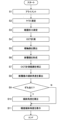
図15に、眼科装置1000の動作例を示す。図15は、眼科装置1000の動作例のフロー図を表す。記憶部212には、図15に示す処理を実現するためのコンピュータプログラムが記憶されている。主制御部211は、このコンピュータプログラムに従って動作することにより、図15に示す処理を実行する。
FIG. 15 shows an operation example of the
(S1:アライメント)
図示しない顔受け部に被検者の顔が固定された状態で、検者が操作部280に対して所定の操作を行うことで、眼科装置1000は、アライメントを実行する。
(S1: Alignment)
The
具体的には、主制御部211は、アライメント光源21を点灯させる。また、主制御部211は、前眼部カメラ300A及び300Bを制御することにより、アライメント光源21から出力されたアライメント光が照射された被検眼Eの前眼部を実質的に同時に撮影させる。主制御部211は、上記のように光学系位置取得部213により取得された装置光学系の位置とアライメント処理部2251により求められた移動目標位置とに基づいて移動機構200を制御することにより、図1に示す光学系が被検眼Eの検査位置に移動される。検査位置とは、被検眼Eの検査を十分な精度内で行うことが可能な位置である。
Specifically, the
また、主制御部211は、レフ測定光源61と、合焦レンズ74と、固視ユニット40(液晶パネル41)をそれぞれの光軸に沿って原点の位置(例えば、0Dに相当する位置)に移動させる。
Further, the
(S2:ケラト測定)
次に、主制御部211は、所望の固視位置に対応した表示位置に固視標を示すパターンを液晶パネル41に表示させる。それにより、所望の固視位置に被検眼Eを注視させる。その後、主制御部211は、ケラトリング光源32を点灯させる。ケラトリング光源32から光が出力されると、被検眼Eの角膜Crに角膜形状測定用のリング状光束が投射される。角膜形状算出部222は、撮像素子59によって取得された像に対して演算処理を施すことにより、角膜曲率半径を算出し、算出された角膜曲率半径から角膜屈折力、角膜乱視度及び角膜乱視軸角度を算出する。制御部210では、算出された角膜屈折力などが記憶部212に記憶される。
(S2: Kerato measurement)
Next, the
主制御部211からの指示、又は操作部280に対するユーザの操作若しくは指示により、眼科装置1000の動作はステップS3に移行する。
In response to an instruction from the
(S3:眼屈折力測定)
眼屈折力測定では、主制御部211は、前述のように屈折力測定のためのリング状の測定パターン光束を被検眼Eに投射させる。被検眼Eからの測定パターン光束の戻り光に基づくリング像が撮像素子59の撮像面に結像される。主制御部211は、撮像素子59により検出された眼底Efからの戻り光に基づくリング像を取得できたか否かを判定する。例えば、主制御部211は、撮像素子59により検出された戻り光に基づく像のエッジの位置(画素)を検出し、像の幅(外径と内径との差)が所定値以上であるか否かを判定する。或いは、主制御部211は、所定の高さ(リング径)以上の点(像)に基づいてリングを形成できるか否かを判定することにより、リング像を取得できたか否かを判定してもよい。
(S3: eye refractive power measurement)
In the eye refractive power measurement, the
リング像を取得できたと判定されたとき、眼屈折度数算出部221は、被検眼Eに投射された測定パターン光束の戻り光に基づくリング像を公知の手法で解析し、仮の球面度数S及び仮の乱視度数Cを求める。主制御部211は、求められた仮の球面度数S及び乱視度数Cに基づき、レフ測定光源61、合焦レンズ74、及び固視ユニット40(液晶パネル41)を等価球面度数(S+C/2)の位置(仮の遠点に相当する位置)へ移動させる。主制御部211は、その位置から固視ユニット40(液晶パネル41)を更に雲霧位置に移動させた後、本測定としてレフ測定投射系6及びレフ測定受光系7を制御することによりリング像を再び取得させる。主制御部211は、前述と同様に得られたリング像の解析結果と合焦レンズ74の移動量から球面度数、乱視度数及び乱視軸角度を眼屈折度数算出部221に算出させる。
When it is determined that the ring image has been acquired, the eye refraction
また、眼屈折度数算出部221は、求められた球面度数及び乱視度数から被検眼Eの遠点に相当する位置(本測定により得られた遠点に相当する位置)を求める。主制御部211は、求められた遠点に相当する位置に液晶パネル41を移動させる。制御部210では、合焦レンズ74の位置や算出された球面度数などが記憶部212に記憶される。主制御部211からの指示、又は操作部280に対するユーザの操作若しくは指示により、眼科装置1000の動作はステップS4に移行する。
Further, the eye
リング像を取得できないと判定されたとき、主制御部211は、強度屈折異常眼である可能性を考慮して、レフ測定光源61及び合焦レンズ74をあらかじめ設定したステップでマイナス度数側(例えば-10D)、プラス度数側(例えば+10D)へ移動させる。主制御部211は、レフ測定受光系7を制御することにより各位置でリング像を検出させる。それでもリング像を取得できないと判定されたとき、主制御部211は、所定の測定エラー処理を実行する。このとき、眼科装置1000の動作はステップS4に移行してもよい。制御部210では、レフ測定結果が得られなかったことを示す情報が記憶部212に記憶される。
When it is determined that the ring image cannot be acquired, the
(S4:OCT計測)
まず、主制御部211は、固視ユニット40(液晶パネル41)を雲霧位置から合焦位置に移動させる。いくつかの実施形態では、合焦位置は、ステップS3で特定された等価球面度数(S+C/2)の位置、又は等価球面度数(S+C/2)の位置から干渉信号の強度等が最大になるようにフォーカス調整された位置である。
(S4: OCT measurement)
First, the
続いて、主制御部211は、OCT光源101を点灯させ、光スキャナー88を制御することにより眼底Efの所定の部位(例えば、黄斑部を含む部位)を測定光LSでスキャンさせる。
Subsequently, the
(S5:眼軸長を算出)
主制御部211は、被検眼Eの眼軸長を眼内距離算出部223に算出させる。眼内距離算出部223は、ステップS4において取得された干渉光LCの検出信号のピーク位置から角膜頂点に相当する位置と眼底に相当する位置とを特定し、特定された位置から眼軸長を算出する。
(S5: Calculate axial length)
The
(S6:断層像を形成)
主制御部211は、ステップS4における測定光LSのスキャンにより得られた検出信号を画像形成部224に送り、得られた検出信号から眼底Efの断層像を画像形成部224に形成させる。
(S6: Form a tomogram)
The
(S7:OCT計測範囲を補正)
続いて、主制御部211は、図10に示すようにOCT計測範囲(断層像の水平方向の距離)を特定し、換算部2252Aを制御することにより、特定されたOCT計測範囲を実寸法に相当する値に変換させる。換算部2252Aは、ステップS2において取得された角膜曲率半径、ステップS3において取得された眼屈折度数、及びステップS5において取得された眼軸長を用いてOCT計測範囲を実寸法に相当する値に換算する。
(S7: Correct the OCT measurement range)
Subsequently, the
(S8:断層像の傾斜角度を算出)
次に、主制御部211は、図10に示すように、ステップS6において形成された断層像の傾斜角度を画像傾斜角度算出部2252Bに算出させる。
(S8: Calculate tilt angle of tomogram)
Next, as shown in FIG. 10, the
(S9:ずれあり?)
主制御部211は、ステップS4におけるOCT計測が行われたときにずれ量特定部2251Gにより特定されたずれ量を傾斜角度処理部2252に取得させ、測定光軸に対して眼球光軸がシフト又はチルトしているか否かを判定させる。
(S9: Deviation?)
The
傾斜角度処理部2252により測定光軸に対して眼球光軸がシフト又はチルトしていると判定されたとき(S9:Y)、眼科装置1000の動作はステップS10に移行する。傾斜角度処理部2252により測定光軸に対して眼球光軸がシフト又はチルトしていないと判定されたとき(S9:N)、眼科装置1000の動作はステップS11に移行する。
When the tilt
(S10:傾斜角度を補正)
ステップS9において測定光軸に対して眼球光軸がシフト又はチルトしていると判定されたとき(S9:Y)、主制御部211は、眼底傾斜角度算出部2252Cを制御することにより、ステップS9において算出された断層像の傾斜角度を補正させる。
(S10: correct tilt angle)
When it is determined in step S9 that the eyeball optical axis is shifted or tilted with respect to the measurement optical axis (S9: Y), the
すなわち、測定光軸に対して眼球光軸がシフトしていると判定されたとき、眼底傾斜角度算出部2252Cは、上記のように、式(3)及び式(4)に従って断層像の傾斜角度g0を補正することにより眼底傾斜角度g1を求める。
That is, when it is determined that the eyeball optical axis is shifted with respect to the measurement optical axis, the fundus
また、測定光軸に対して眼球光軸がチルトしていると判定されたとき、眼底傾斜角度算出部2252Cは、上記のように、式(5)及び式(6)に従って断層像の傾斜角度g0を補正することにより眼底傾斜角度g1を求める。
Further, when it is determined that the eyeball optical axis is tilted with respect to the measurement optical axis, the fundus
また、測定光軸に対して眼球光軸がシフトし、且つチルトしていると判定されたとき、眼底傾斜角度算出部2252Cは、上記のように、式(7)及び式(8)に従って断層像の傾斜角度g0を補正することにより眼底傾斜角度g1を求める。
In addition, when it is determined that the eyeball optical axis is shifted and tilted with respect to the measurement optical axis, the fundus
(S11:眼底傾斜角度を表示)
ステップS9において測定光軸が眼球光軸に略一致していると判定されたとき(S9:N)、主制御部211は、ステップS8において求められた断層像の傾斜角度g0を補正することなく、眼底傾斜角度g1として表示部270に表示させる。
(S11: Display fundus inclination angle)
When it is determined in step S9 that the measurement optical axis substantially coincides with the eyeball optical axis (S9: N), the
また、主制御部211は、ステップS10において補正された眼底傾斜角度を表示部270に表示させる。以上で、眼科装置1000の動作は終了である(エンド)。
Further, the
<変形例>
[第1変形例]
上記の実施形態では、レフ測定光学系により眼屈折度数を取得し、取得された眼屈折度数を用いてOCT計測範囲を補正する場合について説明したが、実施形態に係る構成はこれに限定されるものではない。
<Modification>
[First modification]
In the above embodiment, the eye refraction power is acquired by the refractometer optical system, and the OCT measurement range is corrected using the acquired eye refraction power. However, the configuration according to the embodiment is limited to this. not a thing
例えば、OCT計測の前に実行されるフォーカス調整において決定された合焦レンズ87の位置から被検眼Eの眼屈折度数を特定し、特定された眼屈折度数を用いて上記のようにOCT計測範囲を補正してもよい。この場合、合焦レンズ87の位置を眼屈折度数に関連付けた対応情報を予め記憶部212に記憶させ、主制御部211は、対応情報を参照することにより合焦レンズ87の位置に対応する眼屈折度数を特定する。本変形例によれば、眼科装置1000は、レフ測定投射系6及びレフ測定受光系7の構成を備えていなくてもよい。
For example, the eye refraction power of the subject's eye E is specified from the position of the focusing
図16に、実施形態の第1変形例に係る眼科装置の動作例を示す。図16は、第1変形例に係る眼科装置の動作例のフロー図を表す。記憶部212には、図16に示す処理を実現するためのコンピュータプログラムが記憶されている。主制御部211は、このコンピュータプログラムに従って動作することにより、図16に示す処理を実行する。
FIG. 16 shows an operation example of the ophthalmologic apparatus according to the first modified example of the embodiment. FIG. 16 represents a flow diagram of an operation example of the ophthalmologic apparatus according to the first modified example. A computer program for realizing the processing shown in FIG. 16 is stored in the
(S21:アライメント)
眼科装置は、ステップS1と同様にアライメントを実行する。
(S21: Alignment)
The ophthalmologic apparatus performs alignment as in step S1.
(S22:ケラト測定)
次に、主制御部211は、ステップS2と同様に、ケラト測定を実行させる。
(S22: Kerato measurement)
Next, the
(S23:OCT計測)
続いて、主制御部211は、ステップS4と同様にOCT計測を実行させる。このとき、OCT計測の前に実行されるフォーカス調整において決定された合焦レンズ87の位置から被検眼Eの眼屈折度数が特定される。
(S23: OCT measurement)
Subsequently, the
(S24:眼軸長を算出)
主制御部211は、ステップS5と同様に、被検眼Eの眼軸長を眼内距離算出部223に算出させる。
(S24: Calculate axial length)
The
(S25:断層像を形成)
主制御部211は、ステップS6と同様に、眼底Efの断層像を画像形成部224に形成させる。
(S25: Form a tomogram)
The
(S26:OCT計測範囲を補正)
続いて、主制御部211は、ステップS7と同様に、換算部2252Aを制御することにより、特定されたOCT計測範囲を実寸法に相当する値に変換させる。このとき、換算部2252Aは、ステップS22において取得された角膜曲率半径、ステップS23におけるOCT計測前のフォーカス調整で決定された合焦レンズ87の位置に対応した眼屈折度数、及びステップS24において取得された眼軸長を用いてOCT計測範囲を実寸法に相当する値に換算する。すなわち、第1変形例に係る画像傾斜角度算出部2252Bは、角膜曲率半径と、測定光軸における合焦レンズ87の位置と、眼軸長とに基づいて、断層像のフレームの水平方向の距離を実寸法に相当する値に換算する。
(S26: Correct the OCT measurement range)
Subsequently, the
(S27:断層像の傾斜角度を算出)
次に、主制御部211は、ステップS8と同様に、ステップS25において形成された断層像の傾斜角度を画像傾斜角度算出部2252Bに算出させる。
(S27: Calculate tilt angle of tomogram)
Next, the
(S28:ずれあり?)
主制御部211は、ステップS9と同様に、測定光軸に対して眼球光軸がシフト又はチルトしているか否かを判定させる。
(S28: Deviation?)
The
傾斜角度処理部2252により測定光軸に対して眼球光軸がシフト又はチルトしていると判定されたとき(S28:Y)、眼科装置の動作はステップS29に移行する。傾斜角度処理部2252により測定光軸に対して眼球光軸がシフト又はチルトしていないと判定されたとき(S28:N)、眼科装置の動作はステップS30に移行する。
When the tilt
(S29:傾斜角度を補正)
ステップS28において測定光軸に対して眼球光軸がシフト又はチルトしていると判定されたとき(S28:Y)、主制御部211は、ステップS10と同様に、眼底傾斜角度算出部2252Cを制御することにより、ステップS27において算出された断層像の傾斜角度を補正させる。
(S29: Correct tilt angle)
When it is determined in step S28 that the eyeball optical axis is shifted or tilted with respect to the measurement optical axis (S28: Y), the
(S30:眼底傾斜角度を表示)
ステップS28において測定光軸が眼球光軸に略一致していると判定されたとき(S28:N)、主制御部211は、ステップS27において求められた断層像の傾斜角度を補正することなく、眼底傾斜角度として表示部270に表示させる。
(S30: Display fundus inclination angle)
When it is determined in step S28 that the measurement optical axis substantially matches the eyeball optical axis (S28: N), the
また、主制御部211は、ステップS29において補正された眼底傾斜角度を表示部270に表示させる。以上で、第1変形例に係る眼科装置の動作は終了である(エンド)。
Further, the
[第2変形例]
上記の実施形態又は第1変形例において、経過観察を目的として同一の被検眼に対して複数回のOCT計測が実行される場合に、算出された眼底傾斜角度の経時的な変化を表す情報を表示部270に表示させてもよい。
[Second modification]
In the above embodiment or the first modified example, when OCT measurements are performed a plurality of times on the same subject eye for the purpose of follow-up observation, the information representing the temporal change in the calculated fundus inclination angle is You may make it display on the
第2変形例では、経過観察のためにOCT計測が実行される毎に、傾斜角度処理部2252(眼底傾斜角度算出部2252C)は、上記のように眼底傾斜角度を求める。主制御部211は、求められた眼底傾斜角度を、OCT計測の実行タイミング(OCTデータの取得タイミング)を表す情報(日時情報、時刻情報)に関連付けて記憶部212に保存する。
In the second modification, the inclination angle processing unit 2252 (fundus inclination
例えば、操作部280に対する所定の操作を受けて、主制御部211(制御部210)は、記憶部212に記憶された眼底傾斜角度とOCT計測の実行タイミングを表す情報とに基づいて、眼底傾斜角度の経時的な変化を表す情報を表示部270(表示手段)に表示させる。いくつかの実施形態では、主制御部211は、眼底傾斜角度算出部2252Cにより眼底傾斜角度が算出される毎に、算出された眼底傾斜角度が反映された眼底傾斜角度の経時的な変化を表す情報を表示部270に表示させる。
For example, in response to a predetermined operation on the
図17に、実施形態の第2変形例における眼底傾斜角度の経時的な変化を表す情報の一例を模式的に示す。 FIG. 17 schematically shows an example of information representing temporal changes in the fundus tilt angle in the second modified example of the embodiment.
図17は、眼底傾斜角度の経時的な変化を表す情報の一例として、眼底傾斜角度のトレンドグラフを模式的に表したものである。すなわち、図17では、横軸は、OCT計測の実行タイミングを表す情報(時間)を表し、縦軸は、各OCT計測で取得された眼底傾斜角度を表す。 FIG. 17 schematically shows a trend graph of the fundus tilt angle as an example of information representing temporal changes in the fundus tilt angle. That is, in FIG. 17, the horizontal axis represents information (time) representing the execution timing of OCT measurement, and the vertical axis represents the fundus inclination angle obtained in each OCT measurement.
いくつかの実施形態では、主制御部211は、記憶部212に記憶された眼底傾斜角度の複数の算出値に対して回帰分析をデータ処理部225に実行させる。主制御部211は、データ処理部225による回帰分析により得られた回帰直線(又は回帰曲線)を図17に示すトレンドグラフに重畳して表示させる。これにより、将来の眼底傾斜角度を推定することが可能になる。
In some embodiments, the
第2変形例では、算出された眼底傾斜角度の前回との差分を時系列に表示部270に表示させてもよい。
In the second modification, the difference between the calculated fundus tilt angle and the previous time may be displayed on the
以上説明したように、第2変形例によれば、眼底傾斜角度の経時的な変化を可視化するようにしたので、強度近視等の進行具合を容易に把握することができるようになり、近視進行のスクリーニング(特に、小児)に用いることができるようになる。 As described above, according to the second modification, the temporal change in the fundus tilt angle is visualized, so that the progress of severe myopia or the like can be easily grasped, and the myopia progresses. screening (particularly in children).
[第3変形例]
上記の実施形態又はその変形例において、被検眼の眼底の傾斜の程度を容易に把握できるように、眼底の傾斜角度の基準範囲を表す情報を眼底の断層像に重畳させて表示部270に表示させてもよい。
[Third Modification]
In the above embodiment or its modification, information representing the reference range of the fundus tilt angle is superimposed on the fundus tomographic image and displayed on the
第3変形例では、標準データから眼底の標準的な傾斜角度が特定され、特定された標準的な傾斜角度を基準とする眼底傾斜角度の基準範囲を表す情報があらかじめ算出されている。標準データは、多数の正常眼の眼底の傾斜角度の測定データ(又は算出データ)から統計的に導出された正常眼データ(ノーマティブデータ)である。 In the third modified example, the standard tilt angle of the fundus is specified from the standard data, and information representing the reference range of the fundus tilt angle based on the specified standard tilt angle is calculated in advance. The standard data is normal eye data (normative data) statistically derived from measurement data (or calculated data) of the fundus inclination angles of a large number of normal eyes.
主制御部211(制御部210)は、画像形成部224により形成された断層像を表示部270に表示させる。いくつかの実施形態では、データ処理部225は、眼底傾斜角度算出部2252Cにより算出された眼底傾斜角度が0度になるように(眼底が水平方向になるように)断層像の傾斜を補正する。主制御部211は、算出された眼底傾斜角度に基づいて傾斜が補正された断層像を表示部270に表示させる。主制御部211は、あらかじめ算出された眼底の傾斜角度の基準範囲を表す情報を断層像に重畳するように表示部270(表示手段)に表示させる。主制御部211は、断層像において特定された黄斑部を基準に、眼底の傾斜角度の基準範囲を表す情報を断層像に重畳表示させることが可能である。
The main control unit 211 (control unit 210) causes the
図18に、実施形態の第3変形例における断層像に重畳表示された眼底の標準的な傾斜角度を表す情報の一例を模式的に示す。 FIG. 18 schematically shows an example of information representing the standard inclination angle of the fundus superimposed on the tomographic image in the third modification of the embodiment.
図18では、黄斑部に対して左側の領域に右下がりの基準範囲KR1が描出され、黄斑部に対して右側の領域に左下がりの基準範囲KR2が描出される。基準範囲KR1、KR2を断層像に重畳表示させることで、被検眼の眼底の傾斜の程度を容易に把握することができるようになる。基準範囲は、算出された眼底傾斜角度が標準的な眼底傾斜角度の範囲内であるか否かを判断するための許容範囲とすることができる。 In FIG. 18, a right-sloping reference range KR1 is drawn on the left side of the macula, and a left-sloping reference range KR2 is drawn on the right side of the macula. By superimposing the reference ranges KR1 and KR2 on the tomographic image, the degree of inclination of the fundus of the subject's eye can be easily grasped. The reference range can be an allowable range for determining whether or not the calculated fundus tilt angle is within the range of the standard fundus tilt angle.
例えば、主制御部211は、断層像における眼底の所定の層領域(例えば、内境界膜、又は網膜色素上皮層)を特定させ、特定された所定の層領域が基準範囲KR1、KR2に含まれるか否かをデータ処理部225に判定させてもよい。主制御部211は、データ処理部225による判定結果を表示部270に表示させることが可能である。これにより、強度近視やその他の眼底傾斜に起因する眼疾患へのアラートを出力することが可能になる。
For example, the
第3変形例では、眼底の標準的な眼底傾斜角度に対する、算出された眼底傾斜角度の偏差を表示部270に表示させてもよい。
In the third modified example, the deviation of the calculated fundus tilt angle from the standard fundus tilt angle may be displayed on the
[作用・効果]
実施形態に係る眼科装置の作用及び効果について説明する。
[Action/effect]
Actions and effects of the ophthalmologic apparatus according to the embodiment will be described.
いくつかの実施形態に係る眼科装置(1000)は、OCT光学系(8)と、アライメント部(アライメント光投射系2、移動機構200、前眼部カメラ300、アライメント処理部2251、制御部210)と、画像形成部(224)と、第1算出部(換算部2252A、画像傾斜角度算出部2252B)と、第2算出部(眼底傾斜角度算出部2252C)と、を含む。OCT光学系は、被検眼(E)の眼底(Ef)に測定光(LS)を照射することにより眼底のOCTデータを取得する。アライメント部は、被検眼における所定部位を基準としてOCT光学系のアライメントを行う。画像形成部は、アライメント部によりアライメントが行われたOCT光学系により取得されたOCTデータに基づいて眼底の断層像を形成する。第1算出部は、断層像の第1傾斜角度(g0)を算出する。第2算出部は、アライメント部による所定部位に対するOCT光学系のアライメント結果に基づいて第1傾斜角度を補正することにより眼底の第2傾斜角度(g1)を算出する。
An ophthalmologic apparatus (1000) according to some embodiments includes an OCT optical system (8) and an alignment unit (alignment
このような構成によれば、アライメント結果に基づいて断層像の第1傾斜角度を補正することにより眼底の第2傾斜角度を取得するようにしたので、被検眼の眼底の傾斜角度を高い確度で測定することが可能になる。それにより、取得された断層像における眼底の傾きがアライメント状態に起因するものであるか、真に眼球の後部の変形に起因するものであるかを特定することができるようになる。 According to such a configuration, the second inclination angle of the fundus is obtained by correcting the first inclination angle of the tomographic image based on the alignment result. measurement becomes possible. As a result, it becomes possible to identify whether the inclination of the fundus in the acquired tomographic image is caused by the alignment state or is truly caused by the deformation of the rear part of the eyeball.
いくつかの実施形態に係る眼科装置は、アライメント部によりアライメントが行われたOCT光学系の測定光軸(対物レンズ51の光軸)と被検眼の眼球光軸とのずれ量を特定するずれ量特定部(2251G)を含み、第2算出部は、ずれ量に基づいて第2傾斜角度を算出する。 The ophthalmologic apparatus according to some embodiments has a shift amount that specifies the shift amount between the measurement optical axis (optical axis of the objective lens 51) of the OCT optical system aligned by the alignment unit and the eyeball optical axis of the subject's eye. A second calculator, including a specifying unit (2251G), calculates a second tilt angle based on the deviation amount.
このような構成によれば、OCT光学系の測定光軸と被検眼の眼球光軸とのずれ量から第2傾斜角度を算出するようにしたので、眼球光軸に対する眼底の傾斜角度を高い確度で測定することができるようになる。 According to such a configuration, the second tilt angle is calculated from the amount of deviation between the measurement optical axis of the OCT optical system and the eyeball optical axis of the eye to be examined. can be measured with
いくつかの実施形態に係る眼科装置では、測定光軸と眼球光軸とが略一致しているとき、第2算出部は、第1傾斜角度を第2傾斜角度として出力する。 In the ophthalmologic apparatus according to some embodiments, the second calculator outputs the first tilt angle as the second tilt angle when the measurement optical axis substantially coincides with the eyeball optical axis.
このような構成によれば、OCT光学系の測定光軸と被検眼の眼球光軸とのずれがないと判断できる場合でも、眼球光軸に対する眼底の傾斜角度を高い確度で測定することができるようになる。 According to such a configuration, even if it can be determined that there is no deviation between the measurement optical axis of the OCT optical system and the eyeball optical axis of the eye to be examined, the inclination angle of the fundus with respect to the eyeball optical axis can be measured with high accuracy. become.
いくつかの実施形態に係る眼科装置では、ずれ量特定部は、測定光軸に交差(直交)する方向における測定光軸に対する眼球光軸の変位量をシフト量として特定し、測定光軸に対して眼球光軸がシフトしているとき、第2算出部は、シフト量に基づいて第1傾斜角度を補正することにより第2傾斜角度を算出する。 In the ophthalmologic apparatus according to some embodiments, the shift amount specifying unit specifies, as the shift amount, the amount of displacement of the eyeball optical axis with respect to the measurement optical axis in a direction intersecting (perpendicular to) the measurement optical axis. When the eyeball optical axis is shifted, the second calculator calculates the second tilt angle by correcting the first tilt angle based on the shift amount.
このような構成によれば、測定光軸に対する眼球光軸のシフト量を特定し、特定されたシフト量に基づいて第1傾斜角度を補正することにより第2傾斜角度を算出するようにしたので、測定光軸に対して眼球光軸がシフトしている場合であっても、眼球光軸に対する眼底の傾斜角度を高い確度で測定することができるようになる。 According to such a configuration, the shift amount of the eyeball optical axis with respect to the measurement optical axis is specified, and the second tilt angle is calculated by correcting the first tilt angle based on the specified shift amount. Therefore, even when the eyeball optical axis is shifted with respect to the measurement optical axis, the tilt angle of the fundus with respect to the eyeball optical axis can be measured with high accuracy.
いくつかの実施形態に係る眼科装置では、第2算出部は、シフト量を変数とする一次式に従って第1傾斜角度を補正することにより第2傾斜角度を算出する。 In the ophthalmologic apparatus according to some embodiments, the second calculator calculates the second tilt angle by correcting the first tilt angle according to a linear expression with the shift amount as a variable.
このような構成によれば、測定光軸に対して眼球光軸がシフトしている場合であっても、模型眼データを用いた簡素な処理で、眼球光軸に対する眼底の傾斜角度を高い確度で測定することができるようになる。 According to such a configuration, even when the eyeball optical axis is shifted with respect to the measurement optical axis, simple processing using model eye data can accurately determine the inclination angle of the fundus with respect to the eyeball optical axis. can be measured with
いくつかの実施形態に係る眼科装置では、ずれ量特定部は、測定光軸に対して眼球光軸がなす角度をチルト量として特定し、測定光軸に対して眼球光軸がチルトしているとき、第2算出部は、チルト量に基づいて第1傾斜角度を補正することにより第2傾斜角度を算出する。 In the ophthalmologic apparatus according to some embodiments, the deviation amount specifying unit specifies the angle formed by the eyeball optical axis with respect to the measurement optical axis as the tilt amount, and the eyeball optical axis is tilted with respect to the measurement optical axis. Then, the second calculator calculates the second tilt angle by correcting the first tilt angle based on the tilt amount.
このような構成によれば、測定光軸に対する眼球光軸のチルト量を特定し、特定されたチルト量に基づいて第1傾斜角度を補正することにより第2傾斜角度を算出するようにしたので、測定光軸に対して眼球光軸がチルトしている場合であっても、眼球光軸に対する眼底の傾斜角度を高い確度で測定することができるようになる。 According to such a configuration, the tilt amount of the eyeball optical axis with respect to the measurement optical axis is specified, and the second tilt angle is calculated by correcting the first tilt angle based on the specified tilt amount. Therefore, even when the eyeball optical axis is tilted with respect to the measurement optical axis, the tilt angle of the fundus with respect to the eyeball optical axis can be measured with high accuracy.
いくつかの実施形態に係る眼科装置では、第2算出部は、チルト量を変数とする一次式に従って第1傾斜角度を補正することにより第2傾斜角度を算出する。 In the ophthalmologic apparatus according to some embodiments, the second calculator calculates the second tilt angle by correcting the first tilt angle according to a linear expression with the tilt amount as a variable.
このような構成によれば、測定光軸に対して眼球光軸がチルトしている場合であっても、模型眼データを用いた簡素な処理で、眼球光軸に対する眼底の傾斜角度を高い確度で測定することができるようになる。 According to such a configuration, even when the eyeball optical axis is tilted with respect to the measurement optical axis, the inclination angle of the fundus with respect to the eyeball optical axis can be determined with high accuracy by simple processing using model eye data. can be measured with
いくつかの実施形態に係る眼科装置では、ずれ量特定部は、測定光軸に交差(直交)する方向における測定光軸に対する眼球光軸の変位量をシフト量として特定すると共に、測定光軸に対して眼球光軸がなす角度をチルト量として特定し、測定光軸に対して眼球光軸がシフトし、且つチルトしているとき、第2算出部は、シフト量及びチルト量に基づいて第1傾斜角度を補正することにより第2傾斜角度を算出する。 In the ophthalmologic apparatus according to some embodiments, the shift amount specifying unit specifies, as the shift amount, the amount of displacement of the eyeball optical axis with respect to the measurement optical axis in a direction intersecting (perpendicular to) the measurement optical axis. On the other hand, the angle formed by the eyeball optical axis is specified as the tilt amount, and when the eyeball optical axis is shifted and tilted with respect to the measurement optical axis, the second calculation unit calculates a second A second tilt angle is calculated by correcting the first tilt angle.
このような構成によれば、測定光軸に対する眼球光軸のシフト量及びチルト量を特定し、特定されたシフト量及びチルト量に基づいて第1傾斜角度を補正することにより第2傾斜角度を算出するようにしたので、測定光軸に対して眼球光軸がシフトし、且つチルトしている場合であっても、眼球光軸に対する眼底の傾斜角度を高い確度で測定することができるようになる。 According to such a configuration, the shift amount and tilt amount of the eyeball optical axis with respect to the measurement optical axis are specified, and the second tilt angle is obtained by correcting the first tilt angle based on the specified shift amount and tilt amount. Therefore, even when the eyeball optical axis is shifted and tilted with respect to the measurement optical axis, the tilt angle of the fundus with respect to the eyeball optical axis can be measured with high accuracy. Become.
いくつかの実施形態に係る眼科装置では、第2算出部は、シフト量を変数とする一次式とチルト量を変数とする一次式とを線形結合することにより得られた結合式に従って第1傾斜角度を補正することにより第2傾斜角度を算出する。 In the ophthalmologic apparatus according to some embodiments, the second calculator calculates the first tilt according to a combined formula obtained by linearly combining a linear formula with a shift amount as a variable and a linear formula with a tilt amount as a variable. A second tilt angle is calculated by correcting the angle.
このような構成によれば、測定光軸に対して眼球光軸がシフトし、且つチルトしている場合であっても、簡素な処理で、眼球光軸に対する眼底の傾斜角度を高い確度で測定することができるようになる。 According to such a configuration, even when the eyeball optical axis is shifted and tilted with respect to the measurement optical axis, the tilt angle of the fundus with respect to the eyeball optical axis can be measured with high accuracy through simple processing. be able to
いくつかの実施形態に係る眼科装置は、OCTデータを取得するときに眼底に固視光束を投影する固視投影系(4)を含み、眼球光軸は、視軸である。 The ophthalmic apparatus according to some embodiments includes a fixation projection system (4) that projects a fixation beam onto the fundus when acquiring OCT data, wherein the eye optical axis is the visual axis.
このような構成によれば、被検眼の視軸に対する眼底の傾斜角度を高い確度で測定することができるようになる。 With such a configuration, it is possible to measure the inclination angle of the fundus with respect to the visual axis of the subject's eye with high accuracy.
いくつかの実施形態に係る眼科装置では、アライメント部は、被検眼にアライメント光を投射するアライメント光投射系(2)と、被検眼とOCT光学系とを相対的に移動する移動機構(200)と、アライメント光が投射されている被検眼の前眼部を異なる方向から撮影する2以上の撮影部(前眼部カメラ300)と、2以上の撮影部により得られた2以上の撮影画像を解析することによりアライメント光による角膜の反射像(プルキンエ像)の第1位置と所定部位の第2位置とを特定し、第1位置と第2位置とに基づいてOCT光学系の移動目標位置を決定する位置決定部(移動目標位置決定部2251F)と、を含む。
In the ophthalmologic apparatus according to some embodiments, the alignment unit includes an alignment light projection system (2) that projects alignment light onto the subject's eye, and a moving mechanism (200) that relatively moves the subject's eye and the OCT optical system. and two or more photographing units (anterior eye cameras 300) photographing from different directions the anterior segment of the subject's eye onto which the alignment light is projected, and two or more photographed images obtained by the two or more photographing units. A first position of a reflected image (Purkinje image) of the cornea by the alignment light and a second position of the predetermined portion are specified by the analysis, and a movement target position of the OCT optical system is determined based on the first position and the second position. and a position determination unit (movement target
このような構成によれば、広いアライメント可能範囲(ダイナミックレンジ)で、角膜の反射像の位置と被検眼の所定部位の位置とを高精度に特定し、被検眼の眼球光軸に対する眼底の傾斜角度を高い確度で測定することが可能な眼科装置を提供することができるようになる。 According to such a configuration, the position of the reflected image of the cornea and the position of the predetermined part of the eye to be examined can be specified with high accuracy in a wide alignment range (dynamic range), and the inclination of the fundus with respect to the optical axis of the eyeball to be examined. It becomes possible to provide an ophthalmologic apparatus capable of measuring angles with high accuracy.
いくつかの実施形態に係る眼科装置では、断層像のフレーム右端における眼底における所定の層領域に相当する部位の画像領域とフレーム左端における上記の部位の画像領域との垂直方向の距離の差分を実寸法に相当する値に換算した値をdとし、断層像のフレームの水平方向の距離を実寸法に相当する値に換算した値をcとしたとき、第1算出部は、arctan(|d|/c)を求めることにより第1傾斜角度を算出する。 In the ophthalmologic apparatus according to some embodiments, the difference in vertical distance between the image area of the part corresponding to the predetermined layer area of the fundus at the right end of the frame of the tomographic image and the image area of the above-mentioned part at the left end of the frame is calculated. Let d be a value converted into a value corresponding to the dimension, and let c be a value converted into a value equivalent to the actual dimension of the horizontal distance of the frame of the tomographic image. /c) to calculate the first tilt angle.
このような構成によれば、簡素な処理で第1傾斜角度を算出することができる。 According to such a configuration, the first tilt angle can be calculated by simple processing.
いくつかの実施形態に係る眼科装置は、少なくとも前記被検眼の角膜曲率半径を測定する角膜形状測定部(ケラト測定系3、角膜形状算出部222)と、被検眼の眼屈折度数を測定する眼屈折力測定部(レフ測定投射系6、レフ測定受光系7、眼屈折度数算出部221)と、OCTデータに基づいて被検眼の眼軸長を算出する眼内距離算出部(223)と、を含み、第1算出部は、角膜曲率半径と、眼屈折度数と、眼軸長とに基づいて、断層像のフレームの水平方向の距離を実寸法に相当する値に換算する。
An ophthalmologic apparatus according to some embodiments includes at least a corneal shape measurement unit (
このような構成によれば、被検眼の眼球光学特性を反映した第1傾斜角度を算出することができるので、被検眼の眼底の傾斜角度を高いより確度で測定可能な眼科装置を提供することができるようになる。 With such a configuration, it is possible to calculate the first tilt angle that reflects the eyeball optical characteristics of the subject's eye, so that it is possible to provide an ophthalmologic apparatus capable of measuring the tilt angle of the fundus of the subject's eye with high accuracy. will be able to
いくつかの実施形態に係る眼科装置は、少なくとも被検眼の角膜曲率半径を測定する角膜形状測定部(ケラト測定系3、角膜形状算出部222)と、OCTデータに基づいて被検眼の眼軸長を算出する眼内距離算出部(223)と、を含み、OCT光学系は、測定光軸に沿って移動可能な合焦レンズ(87)を含み、第1算出部は、角膜曲率半径と、測定光軸における合焦レンズの位置と、眼軸長とに基づいて、断層像のフレームの水平方向の距離を実寸法に相当する値に換算する。
The ophthalmologic apparatus according to some embodiments includes at least a corneal shape measurement unit (
このような構成によれば、眼屈折力測定部を備えていない場合であっても、被検眼の眼球光学特性を反映した第1傾斜角度を算出して、簡素な構成で被検眼の眼底の傾斜角度を高いより確度で測定可能な眼科装置を提供することができるようになる。 According to such a configuration, even if the eye refractive power measuring unit is not provided, the first tilt angle reflecting the eyeball optical characteristics of the subject's eye is calculated, and the fundus of the subject's eye is measured with a simple configuration. It is possible to provide an ophthalmologic apparatus capable of measuring the tilt angle with high accuracy.
いくつかの実施形態に係る眼科装置では、第1算出部は、上記の距離の差分に所定の画素間隔値を乗算することにより距離の差分を実寸法に相当する値に換算する。 In the ophthalmologic apparatus according to some embodiments, the first calculator converts the distance difference into a value corresponding to the actual size by multiplying the distance difference by a predetermined pixel interval value.
このような構成によれば、簡素な処理で第1傾斜角度を算出することができる。 According to such a configuration, the first tilt angle can be calculated by simple processing.
いくつかの実施形態に係る眼科装置は、第2算出部により算出された第2傾斜角度を、OCTデータの取得タイミングを表す情報に関連付けて記憶する記憶部(212)と、憶部に記憶された第2傾斜角度と取得タイミングを表す情報とに基づいて、第2傾斜角度の経時的な変化を表す情報を表示手段(表示部270)に表示させる制御部(210)と、を含む。 The ophthalmologic apparatus according to some embodiments includes a storage unit (212) that stores the second tilt angle calculated by the second calculation unit in association with information representing OCT data acquisition timing; a control unit (210) for causing a display means (display unit 270) to display information representing the temporal change in the second tilt angle based on the second tilt angle and the information representing the acquisition timing.
このような構成によれば、眼底傾斜角度の経時的な変化を可視化するようにしたので、強度近視等の進行具合を容易に把握することができるようになり、近視進行のスクリーニング(特に、小児)に用いることができるようになる。 According to such a configuration, since the temporal change of the fundus tilt angle is visualized, it is possible to easily grasp the progress of high myopia or the like, and screening of the progress of myopia (especially in children) is possible. ).
いくつかの実施形態に係る眼科装置は、眼底の傾斜角度の基準範囲を表す情報を、画像形成部により形成された断層像に重畳するように表示手段(表示部270)に表示させる制御部(210)を含む。 The ophthalmologic apparatus according to some embodiments includes a control unit (display unit 270) that displays information representing the reference range of the inclination angle of the fundus oculi so as to be superimposed on the tomographic image formed by the image forming unit (display unit 270). 210).
このような構成によれば、被検眼の眼底の傾斜の程度を容易に把握することができるようになる。 With such a configuration, it is possible to easily grasp the degree of inclination of the fundus of the subject's eye.
<その他>
上記の実施形態又はその変形例では、被検眼に光を投射することにより眼屈折度数を取得する場合について説明したが、実施形態に係る眼科装置の構成はこれに限定されるものではない。実施形態に係る眼科装置は、公知の波面センサーを用いて取得された波面収差に基づいて眼屈折度数を取得してもよい。
<Others>
In the above embodiment or its modification, the case where the eye refraction power is obtained by projecting light onto the subject's eye has been described, but the configuration of the ophthalmologic apparatus according to the embodiment is not limited to this. The ophthalmologic apparatus according to the embodiment may obtain the eye refraction power based on the wavefront aberration obtained using a known wavefront sensor.
本発明のいくつかの実施形態を説明したが、これら実施形態は、例として提示したものであり、発明の範囲を限定することは意図していない。これら実施形態は、その他の様々な形態で実施されることが可能であり、発明の要旨を逸脱しない範囲で、種々の省略、置き換え、変更を行うことができる。これら実施形態やその変形は、発明の範囲や要旨に含まれると共に、特許請求の範囲に記載された発明とその均等の範囲に含まれるものである。 While several embodiments of the invention have been described, these embodiments have been presented by way of example and are not intended to limit the scope of the invention. These embodiments can be implemented in various other forms, and various omissions, replacements, and modifications can be made without departing from the scope of the invention. These embodiments and their modifications are included in the scope and gist of the invention, and are included in the scope of the invention described in the claims and equivalents thereof.
2 アライメント光投射系
3 ケラト測定系
4 固視投影系
5 前眼部観察系
6 レフ測定投射系
7 レフ測定受光系
8 OCT光学系
9 処理部
210 制御部
211 主制御部
212 記憶部
213 光学系位置取得部
220 演算処理部
221 眼屈折度数算出部
222 角膜形状算出部
223 眼内距離算出部
224 画像形成部
225 データ処理部
2251 アライメント処理部
2251A 画像補正部
2251B プルキンエ像特定部
2251C プルキンエ像位置特定部
2251D 瞳孔中心特定部
2251E 瞳孔中心位置特定部
2251F 移動目標位置決定部
2251G ずれ量特定部
2252 傾斜角度処理部
2252A 換算部
2252B 画像傾斜角度算出部
2252C 眼底傾斜角度算出部
1000 眼科装置
2 alignment
Claims (16)
前記被検眼における所定部位を基準として前記OCT光学系のアライメントを行うアライメント部と、
前記アライメント部によりアライメントが行われた前記OCT光学系により取得された前記OCTデータに基づいて前記眼底の断層像を形成する画像形成部と、
前記断層像の第1傾斜角度を算出する第1算出部と、
前記アライメント部によりアライメントが行われた前記OCT光学系の測定光軸と前記被検眼の眼球光軸とのずれ量を特定するずれ量特定部と、
前記ずれ量に基づいて前記第1傾斜角度を補正することにより前記眼底の第2傾斜角度を算出する第2算出部と、
を含む眼科装置。 an OCT optical system for acquiring OCT data of the fundus by irradiating the fundus of the eye to be inspected with measurement light;
an alignment unit that aligns the OCT optical system with reference to a predetermined portion of the eye to be examined;
an image forming unit that forms a tomographic image of the fundus based on the OCT data acquired by the OCT optical system aligned by the alignment unit;
a first calculator that calculates a first tilt angle of the tomogram;
a shift amount specifying unit that specifies a shift amount between the measurement optical axis of the OCT optical system aligned by the alignment unit and the eyeball optical axis of the eye to be examined;
a second calculator that calculates a second tilt angle of the fundus by correcting the first tilt angle based on the shift amount ;
ophthalmic equipment, including
ことを特徴とする請求項1に記載の眼科装置。 2. The method according to claim 1 , wherein when the measurement optical axis and the eyeball optical axis substantially match, the second calculator outputs the first tilt angle as the second tilt angle. ophthalmic equipment.
前記測定光軸に対して前記眼球光軸がシフトしているとき、前記第2算出部は、前記シフト量に基づいて前記第1傾斜角度を補正することにより前記第2傾斜角度を算出する
ことを特徴とする請求項1又は請求項2に記載の眼科装置。 The shift amount specifying unit specifies a displacement amount of the eyeball optical axis with respect to the measurement optical axis in a direction intersecting the measurement optical axis as a shift amount,
When the eyeball optical axis is shifted with respect to the measurement optical axis, the second calculator calculates the second tilt angle by correcting the first tilt angle based on the shift amount. The ophthalmologic apparatus according to claim 1 or 2 , characterized by:
ことを特徴とする請求項3に記載の眼科装置。 The ophthalmologic apparatus according to claim 3 , wherein the second calculator calculates the second tilt angle by correcting the first tilt angle according to a linear expression with the shift amount as a variable.
前記測定光軸に対して前記眼球光軸がチルトしているとき、前記第2算出部は、前記チルト量に基づいて前記第1傾斜角度を補正することにより前記第2傾斜角度を算出する
ことを特徴とする請求項1~請求項4のいずれか一項に記載の眼科装置。 The shift amount specifying unit specifies an angle formed by the eyeball optical axis with respect to the measurement optical axis as a tilt amount,
When the eyeball optical axis is tilted with respect to the measurement optical axis, the second calculator calculates the second tilt angle by correcting the first tilt angle based on the tilt amount. The ophthalmologic apparatus according to any one of claims 1 to 4 , characterized by:
ことを特徴とする請求項5に記載の眼科装置。 The ophthalmologic apparatus according to claim 5 , wherein the second calculator calculates the second tilt angle by correcting the first tilt angle according to a linear expression with the tilt amount as a variable.
前記測定光軸に対して前記眼球光軸がシフトし、且つチルトしているとき、前記第2算出部は、前記シフト量及び前記チルト量に基づいて前記第1傾斜角度を補正することにより前記第2傾斜角度を算出する
ことを特徴とする請求項1又は請求項2に記載の眼科装置。 The shift amount specifying unit specifies a displacement amount of the eyeball optical axis with respect to the measurement optical axis in a direction intersecting the measurement optical axis as a shift amount, and an angle formed by the eyeball optical axis with respect to the measurement optical axis. is specified as the tilt amount, and
When the eyeball optical axis is shifted and tilted with respect to the measurement optical axis, the second calculator corrects the first tilt angle based on the shift amount and the tilt amount, thereby correcting the 3. The ophthalmologic apparatus according to claim 1, wherein the second tilt angle is calculated.
ことを特徴とする請求項7に記載の眼科装置。 The second calculation unit corrects the first tilt angle according to a combined formula obtained by linearly combining a linear formula having the shift amount as a variable and a linear formula having the tilt amount as a variable. The ophthalmologic apparatus according to claim 7, wherein the second tilt angle is calculated.
前記眼球光軸は、視軸である
ことを特徴とする請求項1~請求項8のいずれか一項に記載の眼科装置。 including a fixation projection system that projects a fixation light beam onto the fundus when acquiring the OCT data;
The ophthalmologic apparatus according to any one of claims 1 to 8 , wherein the eyeball optical axis is a visual axis.
前記被検眼にアライメント光を投射するアライメント光投射系と、
前記被検眼と前記OCT光学系とを相対的に移動する移動機構と、
前記アライメント光が投射されている前記被検眼の前眼部を異なる方向から撮影する2以上の撮影部と、
前記2以上の撮影部により得られた2以上の撮影画像を解析することにより前記アライメント光による角膜の反射像の第1位置と前記所定部位の第2位置とを特定し、前記第1位置と前記第2位置とに基づいて前記OCT光学系の移動目標位置を決定する位置決定部と、
を含む
ことを特徴とする請求項1~請求項9のいずれか一項に記載の眼科装置。 The alignment section
an alignment light projection system that projects alignment light onto the eye to be inspected;
a movement mechanism that relatively moves the eye to be examined and the OCT optical system;
two or more photographing units for photographing from different directions the anterior ocular segment of the subject's eye onto which the alignment light is projected;
A first position of a reflected image of the cornea by the alignment light and a second position of the predetermined part are specified by analyzing two or more captured images obtained by the two or more imaging units, and the first position and the second position are specified. a position determination unit that determines a movement target position of the OCT optical system based on the second position;
The ophthalmic apparatus according to any one of claims 1 to 9, comprising:
前記第1算出部は、arctan(|d|/c)を求めることにより前記第1傾斜角度を算出する
ことを特徴とする請求項1~請求項10のいずれか一項に記載の眼科装置。 A value obtained by converting a difference in vertical distance between an image region of a region corresponding to a predetermined layer region of the fundus at the right end of the frame of the tomographic image and an image region of the region at the left end of the frame into a value corresponding to an actual size. When d is the horizontal distance of the frame of the tomographic image and c is the value obtained by converting the horizontal distance to the actual size,
The ophthalmologic apparatus according to any one of claims 1 to 10 , wherein the first calculator calculates the first tilt angle by obtaining arctan(|d|/c).
前記被検眼の眼屈折度数を測定する眼屈折力測定部と、
前記OCTデータに基づいて前記被検眼の眼軸長を算出する眼内距離算出部と、
を含み、
前記第1算出部は、前記角膜曲率半径と、前記眼屈折度数と、前記眼軸長とに基づいて、前記断層像のフレームの水平方向の距離を実寸法に相当する値に換算する
ことを特徴とする請求項11に記載の眼科装置。 a corneal shape measuring unit that measures at least the corneal curvature radius of the eye to be examined;
an eye refractive power measuring unit that measures the eye refractive power of the eye to be inspected;
an intraocular distance calculator that calculates the axial length of the subject eye based on the OCT data;
including
The first calculator converts the horizontal distance of the frame of the tomographic image into a value corresponding to the actual size based on the corneal curvature radius, the eye refraction power, and the eye axial length. 12. An ophthalmic device according to claim 11 .
前記OCTデータに基づいて前記被検眼の眼軸長を算出する眼内距離算出部と、
を含み、
前記OCT光学系は、測定光軸に沿って移動可能な合焦レンズを含み、
前記第1算出部は、前記角膜曲率半径と、前記測定光軸における前記合焦レンズの位置と、前記眼軸長とに基づいて、前記断層像のフレームの水平方向の距離を実寸法に相当する値に換算する
ことを特徴とする請求項11に記載の眼科装置。 a corneal shape measuring unit that measures at least the corneal curvature radius of the eye to be examined;
an intraocular distance calculator that calculates the axial length of the subject eye based on the OCT data;
including
the OCT optics includes a focusing lens movable along the measurement optical axis;
The first calculator calculates a horizontal distance of the frame of the tomographic image based on the radius of curvature of the cornea, the position of the focusing lens on the measurement optical axis, and the axial length of the eye. 12. The ophthalmologic apparatus according to claim 11 , wherein the value is converted into a value that
ことを特徴とする請求項11~請求項13のいずれか一項に記載の眼科装置。 14. The first calculator converts the distance difference into a value corresponding to an actual dimension by multiplying the distance difference by a predetermined pixel interval value. or the ophthalmic device according to claim 1.
前記記憶部に記憶された前記第2傾斜角度と前記取得タイミングを表す情報とに基づいて、前記第2傾斜角度の経時的な変化を表す情報を表示手段に表示させる制御部と、
を含む
ことを特徴とする請求項1~請求項14のいずれか一項に記載の眼科装置。 a storage unit that stores the second tilt angle calculated by the second calculation unit in association with information representing acquisition timing of the OCT data;
a control unit that causes a display unit to display information representing changes over time in the second tilt angle based on the information representing the second tilt angle and the acquisition timing stored in the storage unit;
The ophthalmic device according to any one of claims 1 to 14, comprising:
ことを特徴とする請求項1~請求項14のいずれか一項に記載の眼科装置。 The apparatus according to any one of claims 1 to 14, further comprising: a control unit for causing a display unit to display information representing a reference range of the inclination angle of the fundus so as to be superimposed on the tomographic image formed by the image forming unit. An ophthalmic device according to any one of the preceding paragraphs.
Applications Claiming Priority (2)
| Application Number | Priority Date | Filing Date | Title |
|---|---|---|---|
| US16/146,144 | 2018-09-28 | ||
| US16/146,144 US10743762B2 (en) | 2018-09-28 | 2018-09-28 | Ophthalmologic apparatus |
Publications (2)
| Publication Number | Publication Date |
|---|---|
| JP2020054806A JP2020054806A (en) | 2020-04-09 |
| JP7304780B2 true JP7304780B2 (en) | 2023-07-07 |
Family
ID=69947959
Family Applications (1)
| Application Number | Title | Priority Date | Filing Date |
|---|---|---|---|
| JP2019165944A Active JP7304780B2 (en) | 2018-09-28 | 2019-09-12 | ophthalmic equipment |
Country Status (2)
| Country | Link |
|---|---|
| US (1) | US10743762B2 (en) |
| JP (1) | JP7304780B2 (en) |
Families Citing this family (8)
| Publication number | Priority date | Publication date | Assignee | Title |
|---|---|---|---|---|
| DE102019101409B4 (en) * | 2019-01-21 | 2021-12-30 | Oculus Optikgeräte GmbH | Procedure and vision testing system for examining eyes |
| JP6707239B1 (en) * | 2019-03-13 | 2020-06-10 | 株式会社中京メディカル | Keratoconus determination device and program |
| US11583179B2 (en) * | 2020-02-20 | 2023-02-21 | Meta Platforms Technologies, Llc | Lens fitting metrology with optical coherence tomography |
| EP3888528A1 (en) * | 2020-03-30 | 2021-10-06 | Nidek Co., Ltd. | Ophthalmic apparatus |
| CN112215883B (en) * | 2020-09-07 | 2023-03-31 | 上海市第一人民医院 | Fundus OCT image virtual measuring device, fundus OCT image virtual measuring method and computer-readable storage medium |
| FI130863B1 (en) * | 2020-12-21 | 2024-04-29 | Optomed Oyj | Ophthalmic examination apparatus and method of forming alignment between eye and ophthalmic examination apparatus |
| US20240041318A1 (en) * | 2020-12-23 | 2024-02-08 | Essilor International | Method of evaluating the efficiency of a myopia control solution |
| CN113397476B (en) * | 2021-06-16 | 2023-08-22 | 浙大宁波理工学院 | Method for fully automatically measuring eyeball parameters |
Citations (2)
| Publication number | Priority date | Publication date | Assignee | Title |
|---|---|---|---|---|
| US20120200824A1 (en) | 2011-02-04 | 2012-08-09 | Nidek Co., Ltd. | Ophthalmic photographing apparatus |
| JP2015033397A (en) | 2013-08-07 | 2015-02-19 | キヤノン株式会社 | Image processing device, image processing method and program |
Family Cites Families (5)
| Publication number | Priority date | Publication date | Assignee | Title |
|---|---|---|---|---|
| JP3569026B2 (en) | 1995-04-05 | 2004-09-22 | 株式会社コーナン・メディカル | Fundus camera |
| JP5601612B2 (en) * | 2009-06-02 | 2014-10-08 | 株式会社ニデック | Ophthalmic imaging equipment |
| WO2013137148A1 (en) * | 2012-03-12 | 2013-09-19 | 株式会社トプコン | Optical image measurement device, image display device, and image display method |
| JP5989523B2 (en) | 2012-05-01 | 2016-09-07 | 株式会社トプコン | Ophthalmic equipment |
| JP6469387B2 (en) | 2014-08-26 | 2019-02-13 | 株式会社トプコン | Fundus analyzer |
-
2018
- 2018-09-28 US US16/146,144 patent/US10743762B2/en active Active
-
2019
- 2019-09-12 JP JP2019165944A patent/JP7304780B2/en active Active
Patent Citations (3)
| Publication number | Priority date | Publication date | Assignee | Title |
|---|---|---|---|---|
| US20120200824A1 (en) | 2011-02-04 | 2012-08-09 | Nidek Co., Ltd. | Ophthalmic photographing apparatus |
| JP2012161427A (en) | 2011-02-04 | 2012-08-30 | Nidek Co Ltd | Ophthalmic photographing device |
| JP2015033397A (en) | 2013-08-07 | 2015-02-19 | キヤノン株式会社 | Image processing device, image processing method and program |
Also Published As
| Publication number | Publication date |
|---|---|
| US10743762B2 (en) | 2020-08-18 |
| JP2020054806A (en) | 2020-04-09 |
| US20200100673A1 (en) | 2020-04-02 |
Similar Documents
| Publication | Publication Date | Title |
|---|---|---|
| JP7304780B2 (en) | ophthalmic equipment | |
| JP7213048B2 (en) | Ophthalmic information processing device, ophthalmic device, and ophthalmic information processing method | |
| JP7186587B2 (en) | ophthalmic equipment | |
| JP7141279B2 (en) | Ophthalmic information processing device, ophthalmic device, and ophthalmic information processing method | |
| JP7134014B2 (en) | Ophthalmic device and its control method | |
| JP6513747B2 (en) | Ophthalmic device | |
| JP7349807B2 (en) | ophthalmology equipment | |
| JP7236927B2 (en) | Ophthalmic device, control method thereof, ophthalmic information processing device, control method thereof, program, and recording medium | |
| JP6825042B2 (en) | Ophthalmic equipment | |
| JP7164328B2 (en) | Ophthalmic device and control method for ophthalmic device | |
| JP7106320B2 (en) | Ophthalmic device and control method for ophthalmic device | |
| JP2022110602A (en) | Ophthalmologic apparatus, ophthalmologic apparatus control method, and program | |
| JP6518733B2 (en) | Ophthalmic device | |
| JP2020072966A (en) | Ophthalmologic apparatus and ophthalmologic examination system | |
| JP7292072B2 (en) | ophthalmic equipment | |
| JP7201855B2 (en) | Ophthalmic device and ophthalmic information processing program | |
| JP7116572B2 (en) | Ophthalmic device and ophthalmic information processing program | |
| JP7394948B2 (en) | ophthalmology equipment | |
| JP7281877B2 (en) | ophthalmic equipment | |
| JP7244211B2 (en) | Ophthalmic device and control method for ophthalmic device | |
| JP7103813B2 (en) | Ophthalmic equipment | |
| JP7133995B2 (en) | Ophthalmic device and its control method | |
| JP7030577B2 (en) | Ophthalmic equipment | |
| JP7339011B2 (en) | Ophthalmic device, ophthalmic information processing device, program, and recording medium | |
| JP2023126596A (en) | Ophthalmologic apparatus and control method thereof |
Legal Events
| Date | Code | Title | Description |
|---|---|---|---|
| A621 | Written request for application examination |
Free format text: JAPANESE INTERMEDIATE CODE: A621 Effective date: 20220830 |
|
| A977 | Report on retrieval |
Free format text: JAPANESE INTERMEDIATE CODE: A971007 Effective date: 20230406 |
|
| A131 | Notification of reasons for refusal |
Free format text: JAPANESE INTERMEDIATE CODE: A131 Effective date: 20230418 |
|
| A521 | Request for written amendment filed |
Free format text: JAPANESE INTERMEDIATE CODE: A523 Effective date: 20230530 |
|
| TRDD | Decision of grant or rejection written | ||
| A01 | Written decision to grant a patent or to grant a registration (utility model) |
Free format text: JAPANESE INTERMEDIATE CODE: A01 Effective date: 20230606 |
|
| A61 | First payment of annual fees (during grant procedure) |
Free format text: JAPANESE INTERMEDIATE CODE: A61 Effective date: 20230627 |
|
| R150 | Certificate of patent or registration of utility model |
Ref document number: 7304780 Country of ref document: JP Free format text: JAPANESE INTERMEDIATE CODE: R150 |