JP7124270B2 - ophthalmic imaging equipment - Google Patents
ophthalmic imaging equipment Download PDFInfo
- Publication number
- JP7124270B2 JP7124270B2 JP2017108871A JP2017108871A JP7124270B2 JP 7124270 B2 JP7124270 B2 JP 7124270B2 JP 2017108871 A JP2017108871 A JP 2017108871A JP 2017108871 A JP2017108871 A JP 2017108871A JP 7124270 B2 JP7124270 B2 JP 7124270B2
- Authority
- JP
- Japan
- Prior art keywords
- eye
- measurement light
- light
- profile
- oct
- Prior art date
- Legal status (The legal status is an assumption and is not a legal conclusion. Google has not performed a legal analysis and makes no representation as to the accuracy of the status listed.)
- Active
Links
Images


Landscapes
- Eye Examination Apparatus (AREA)
Description
本開示は、被検眼の断層像を撮影する眼科撮影装置に関する。 The present disclosure relates to an ophthalmologic imaging apparatus that captures a tomographic image of an eye to be examined.
被検眼の断層像を撮影する眼科撮影装置として、低コヒーレント光を用いた光断層干渉計(Optical Coherence Tomography: OCT)が知られている(特許文献1参照)。 An optical coherence tomography (OCT) using low-coherent light is known as an ophthalmologic imaging apparatus that captures a tomographic image of an eye to be examined (see Patent Document 1).
光断層干渉計(OCTデバイス)は、光源から出射された光を測定光と参照光に分割し、分割した測定光を被検眼(例えば、眼底等)に照射する。ところが、被検眼に照射する測定光が、被検眼の瞼や、白内障等の疾患により生じた混濁や浮腫に妨げられてしまい、良好な断層像を取得できない場合があった。 An optical tomography interferometer (OCT device) divides light emitted from a light source into measurement light and reference light, and irradiates the divided measurement light onto an eye to be examined (for example, fundus). However, there have been cases where the measurement light irradiated to the eye to be inspected is obstructed by the eyelid of the eye to be inspected, opacity or edema caused by a disease such as cataract, and a good tomographic image cannot be obtained.
本開示は、上記従来技術に鑑み、被検眼の眼底における良好な断層像を取得することができる眼科撮影装置を提供することを技術課題とする。 A technical problem of the present disclosure is to provide an ophthalmologic imaging apparatus capable of acquiring a satisfactory tomographic image of the fundus of an eye to be examined in view of the above-described conventional technology.
上記課題を解決するため、本開示は以下の構成を備えることを特徴とする。 In order to solve the above problems, the present disclosure is characterized by having the following configurations.
(1) 本開示の第1態様に係る眼科撮影装置は、被検眼眼底に照射された測定光と参照光によるOCT信号を検出するOCT光学系を有し、前記OCT信号を処理することで被検眼のOCTデータを取得する眼科撮影装置であって、前記OCT光学系における前記測定光の分布を示すプロファイルであって、被検眼の眼底に向けて照射される前記測定光のうち、前眼部から眼底までの経路における測定光の分布を示すプロファイルを変更する変更手段と、前記変更手段によって、前眼部から眼底までの経路における前記測定光の分布が互いに異なる複数の仮撮影用の第1プロファイルに変更された状態で、前記被検眼眼底上に設定された照射位置に前記測定光を照射し、複数の前記第1プロファイルそれぞれの第1OCTデータを取得する取得手段と、を備え、前記変更手段は、前記取得手段によって取得された複数の前記第1OCTデータから前記被検眼眼底に対する戻り光の透過率分布を取得し、前記透過率分布に基づいて、本撮影用のプロファイルとして、前眼部から眼底までの経路における前記測定光の分布が前記第1プロファイルとは異なる新たな第2プロファイルに変更し、前記取得手段は、前記第2プロファイルに変更された状態で、前記被検眼眼底の前記照射位置に前記測定光を照射し、第2OCTデータを取得することを特徴とする。
(2) 本開示の第2態様に係る眼科撮影方法は、被検眼眼底に照射された測定光と参照光によるOCT信号を検出するOCT光学系を有し、前記OCT信号を処理することで被検眼のOCTデータを取得する眼科撮影方法であって、前記OCT光学系における前記測定光の分布を示すプロファイルであって、被検眼の眼底に向けて照射される前記測定光のうち、前眼部から眼底までの経路における測定光の分布を示すプロファイルを変更する変更手段によって、前眼部から眼底までの経路における前記測定光の分布が互いに異なる複数の仮撮影用の第1プロファイルに変更された状態で、前記被検眼上に設定された照射位置に前記測定光を照射し、複数の前記第1プロファイルそれぞれの第1OCTデータを取得する第1取得ステップと、前記第1取得ステップによって取得された複数の前記第1OCTデータから前記被検眼眼底に対する戻り光の透過率分布を取得し、前記透過率分布に基づいて、本撮影用のプロファイルとして、前眼部から眼底までの経路における前記測定光の分布が前記第1プロファイルとは異なる新たな第2プロファイルに変更する変更ステップと、前記変更ステップによって、前記第2プロファイルに変更された状態で、前記被検眼眼底の前記照射位置に前記測定光を照射し、第2OCTデータを取得する第2取得ステップと、を備えることを特徴とする。
(1) An ophthalmologic imaging apparatus according to a first aspect of the present disclosure has an OCT optical system that detects an OCT signal from measurement light and reference light irradiated to the fundus of an eye to be examined, and processes the OCT signal to An ophthalmologic imaging apparatus for acquiring OCT data for optometry, which is a profile showing the distribution of the measurement light in the OCT optical system, the profile showing the distribution of the measurement light in the OCT optical system , the anterior segment of the measurement light irradiated toward the fundus of the eye to be examined. changing means for changing the profile indicating the distribution of the measurement light on the route from the to the fundus, and the plurality of temporary imaging firsts having different distributions of the measurement light on the route from the anterior segment to the fundus by the changing means obtaining means for obtaining first OCT data for each of the plurality of first profiles by irradiating the measurement light to the irradiation position set on the fundus of the eye to be examined in a state where the profile has been changed, and means acquires a transmittance distribution of return light with respect to the fundus of the subject eye from the plurality of first OCT data acquired by the acquisition means; to the fundus oculi, the distribution of the measurement light on the path from the to the fundus is changed to a new second profile different from the first profile. It is characterized by irradiating the irradiation position with the measurement light and acquiring the second OCT data.
(2) An ophthalmologic imaging method according to a second aspect of the present disclosure includes an OCT optical system that detects an OCT signal from measurement light and reference light irradiated to the fundus of a subject's eye, and processes the OCT signal to An ophthalmologic imaging method for acquiring OCT data for optometry, wherein a profile showing the distribution of the measurement light in the OCT optical system , the anterior ocular segment of the measurement light irradiated toward the fundus of the eye to be examined The distribution of the measurement light in the path from the anterior segment to the fundus is changed to a plurality of first profiles for provisional imaging, which are different from each other, by the changing means for changing the profile indicating the distribution of the measurement light in the path from the to the fundus. a first obtaining step of obtaining first OCT data of each of the plurality of first profiles by irradiating the measurement light onto an irradiation position set on the eye to be inspected, and a first obtaining step obtained by the first obtaining step A transmittance distribution of return light to the fundus of the subject's eye is obtained from a plurality of the first OCT data, and based on the transmittance distribution, a profile for main imaging is obtained as a profile for the measurement light on the path from the anterior segment to the fundus . a changing step of changing the distribution to a new second profile different from the first profile; and in the state changed to the second profile by the changing step, directing the measurement light to the irradiation position of the fundus of the subject's eye. and a second acquisition step of irradiating and acquiring second OCT data.
<概要>
以下、典型的な実施形態の1つについて、図面を参照して説明する。図1~図10は、本実施形態に係る眼科撮影装置を説明する図である。本実施形態においては、被検眼の水平方向をX方向、鉛直方向をY方向、軸方向をZ方向として説明する。眼底の表面方向をXY方向として考えてもよい。なお、以下の<>にて分類された項目は、独立または関連して利用され得る。
<Overview>
One exemplary embodiment will now be described with reference to the drawings. 1 to 10 are diagrams for explaining an ophthalmologic imaging apparatus according to this embodiment. In this embodiment, the horizontal direction of the eye to be examined is the X direction, the vertical direction is the Y direction, and the axial direction is the Z direction. The surface direction of the fundus may be considered as the XY direction. The items classified by <> below can be used independently or in association with each other.
なお、本開示は、本実施例に記載する装置に限定されない。例えば、下記実施形態の機能を行う端末制御ソフトウェア(プログラム)を、ネットワークまたは各種記憶媒体等を介してシステムあるいは装置に供給し、システムあるいは装置の制御装置(例えば、CPU等)がプログラムを読み出して実行することも可能である。 It should be noted that the present disclosure is not limited to the apparatus described in this example. For example, terminal control software (program) that performs the functions of the following embodiments is supplied to a system or device via a network or various storage media, and a control device (eg, CPU, etc.) of the system or device reads the program. It is also possible to execute
例えば、本実施例における眼科撮影装置(例えば、眼科撮影装置1)は、OCT光学系(例えば、OCT光学系2)を有し、OCT信号を処理することで被検眼のOCTデータを取得する。例えば、OCT光学系(OCTデバイス)は、フーリエドメイン光コヒーレンストモグラフィー(FD-OCT)を基本的構成としてもよい。例えば、FD-OCTとしては、スペクトルドメインOCT(SD-OCT)、波長掃引式OCT(SS-OCT)を用いてもよい。また、例えば、OCTデバイスは、タイムドメインOCT(TD-OCT)を基本構成としてもよい。なお、例えば、本開示の技術は、被検物の反射強度を検出するためのスダンダートOCT、被検物のモーションコントラストデータを検出するためのOCTアンジオグラフィー(例えば、ドップラーOCT)、偏光感受OCT(PS-OCT:Polarization Sensitive OCT)等において適用されてもよい。また、スダンダートOCTとPS-OCTとが複合されたマルチファンクションOCTにおいて適用されてもよい。 For example, the ophthalmologic imaging apparatus (e.g., ophthalmic imaging apparatus 1) in the present embodiment has an OCT optical system (e.g., OCT optical system 2), and obtains OCT data of the subject's eye by processing OCT signals. For example, the OCT optical system (OCT device) may be based on Fourier domain optical coherence tomography (FD-OCT). For example, spectral domain OCT (SD-OCT) and wavelength sweeping OCT (SS-OCT) may be used as FD-OCT. Also, for example, the OCT device may be based on time domain OCT (TD-OCT). Note that, for example, the technology of the present disclosure includes standard OCT for detecting the reflection intensity of the subject, OCT angiography (for example, Doppler OCT) for detecting motion contrast data of the subject, polarization-sensitive OCT ( It may be applied in PS-OCT: Polarization Sensitive OCT) and the like. It may also be applied in multi-function OCT in which standard OCT and PS-OCT are combined.
<OCT光学系>
例えば、OCT光学系は、被検眼に照射された測定光と参照光によるOCT信号を検出する。例えば、OCT光学系は、OCT原理を用いて被検物の断層像を得るための干渉計に係る構成を備えていてもよい。例えば、OCT光学系は、光源(例えば、光源11)、分割器(例えば、カップラー15)、コンバイナ(光合成器)(例えば、カップラー15)、検出器(例えば、検出器40)、参照光学系(例えば、参照光学系30)を備えていてもよい。
<OCT optical system>
For example, the OCT optical system detects OCT signals from measurement light and reference light that are applied to the subject's eye. For example, the OCT optical system may have a configuration relating to an interferometer for obtaining a tomographic image of the subject using the OCT principle. For example, the OCT optical system includes a light source (e.g., light source 11), a splitter (e.g., coupler 15), a combiner (e.g., coupler 15), a detector (e.g., detector 40), a reference optical system ( For example, a reference optical system 30) may be provided.
例えば、分割器は、光源からの光を測定光と参照光に分割してもよい。例えば、コンバイナは、測定光と参照光とを合成(干渉)させてもよい。例えば、分割器とコンバイナは兼用されてもよい。また、例えば、分割器とコンバイナは別途設けられてもよい。例えば、分割器及びコンバイナには、ビームスプリッタ、ハーフミラー、ファイバーカップラー、サーキュレータ等のいずれかを用いてもよい。例えば、検出器は、測定光と参照光との干渉により生じた干渉信号光を受光してもよい。例えば、参照光学系は、参照光を装置内で進行させ、測定光と干渉させるための構成を備えていてもよい。 For example, a splitter may split the light from the light source into measurement light and reference light. For example, the combiner may combine (interfere) the measurement light and the reference light. For example, the divider and combiner may be combined. Also, for example, the divider and combiner may be provided separately. For example, the splitter and combiner may be beam splitters, half mirrors, fiber couplers, circulators, or the like. For example, the detector may receive interference signal light caused by interference between the measurement light and the reference light. For example, the reference optics may have a configuration for causing the reference light to travel within the device and interfere with the measurement light.
例えば、OCT光学系は、OCT信号を処理することで被検眼のOCTデータを取得する。なお、OCT光学系は、撮影する被検眼の深度帯を切り換え、被検眼の第1深度帯(例えば、被検眼の前眼部等)に対応する第1位置と、被検眼の第2深度帯(例えば、被検眼の眼底等)に対応する第2位置と、においてOCTデータを取得する構成であってもよい。 For example, the OCT optical system acquires OCT data of the subject's eye by processing the OCT signal. In addition, the OCT optical system switches the depth zone of the eye to be imaged, and the first position corresponding to the first depth zone of the eye to be inspected (for example, the anterior segment of the eye to be inspected) and the second depth zone of the eye to be inspected (For example, the second position corresponding to the fundus of the eye to be examined, etc.) may be configured to acquire OCT data.
<測定光学系>
例えば、測定光学系(例えば、測定光学系20)は、測定光を被検眼へ導くための構成であってもよい。例えば、測定光学系は、走査部(光スキャナー)(例えば、走査部24)を備えていてもよい。例えば、走査部は、測定光を被検眼の第1深度帯に対応する第1位置上で走査する。また、例えば、走査部は、測定光を被検眼の第2深度帯に対応する第2位置上で走査する。例えば、走査部は、互いに異なる方向へ測定光を偏向する2つの光スキャナ(例えば、ガルバノミラー241、ガルバノミラー242)を含んでいてもよい。例えば、走査部に含まれる光スキャナには、MEMSスキャナ、レゾナントスキャナ、ポリゴンミラー等の反射型スキャナや、音響光学素子を用いてもよい。すなわち、走査部に含まれる光スキャナは、測定光を偏向することが可能なスキャナであればよい。
<Measurement optical system>
For example, the measurement optical system (for example, the measurement optical system 20) may be configured to guide measurement light to the subject's eye. For example, the measurement optical system may include a scanning section (optical scanner) (for example, scanning section 24). For example, the scanning unit scans the measurement light over a first position corresponding to a first depth zone of the subject's eye. Also, for example, the scanning unit scans the measurement light at a second position corresponding to a second depth zone of the subject's eye. For example, the scanning unit may include two optical scanners (eg,
<OCTデータ>
例えば、OCTデータは、被検眼の反射強度特性を示す断層画像データ、被検眼のOCTアンジオ画像データ(例えば、OCTモーションコントラスト画像データ)、被検眼のドップラー特性を示すドップラーOCT画像データ、被検眼の偏光特性を示す偏光特性画像データ、等の少なくともいずれかであってもよい。なお、各データは、生成された画像のデータであってもよいし、画像が生成される前の信号データであってもよい。
<OCT data>
For example, the OCT data includes tomographic image data indicating reflection intensity characteristics of the eye to be examined, OCT angio image data of the eye to be examined (for example, OCT motion contrast image data), Doppler OCT image data indicating Doppler characteristics of the eye to be examined, It may be at least one of polarization characteristic image data indicating polarization characteristics, and the like. Each data may be data of a generated image, or may be signal data before the image is generated.
例えば、断層画像データは、Aスキャン断層画像データであってもよい。また、例えば、断層画像データは、Bスキャン断層画像データであってもよい。なお、例えば、Bスキャン断層画像データは、走査ライン(横断位置)に沿って測定光をXY方向のいずれかの方向(例えば、X方向)に走査させることによって取得される断層画像データであってもよい。また、例えば、断層画像データは、三次元断層画像データであってもよい。なお、例えば、三次元断層画像データは、測定光を二次元的に走査することによって取得される断層画像データであってもよい。例えば、OCTデータは、三次元断層画像データから取得されるOCT正面(Enface)画像データ(例えば、深さ方向に関して積算された積算画像、XY各位置でのスペクトルデータの積算値、ある一定の深さ方向におけるXY各位置での輝度データ、網膜表層画像、等)であってもよい。 For example, the tomographic image data may be A-scan tomographic image data. Further, for example, the tomographic image data may be B-scan tomographic image data. Note that, for example, the B-scan tomographic image data is tomographic image data acquired by scanning the measurement light along a scanning line (transverse position) in one of the XY directions (for example, the X direction). good too. Further, for example, the tomographic image data may be three-dimensional tomographic image data. Note that, for example, the three-dimensional tomographic image data may be tomographic image data acquired by two-dimensional scanning with measurement light. For example, OCT data is OCT enface image data acquired from three-dimensional tomographic image data (for example, an integrated image integrated in the depth direction, an integrated value of spectral data at each XY position, a certain depth luminance data at each XY position in the vertical direction, a retinal surface layer image, etc.).
例えば、OCTアンジオ画像データは、二次元OCTアンジオ画像データであってもよい。なお、例えば、二次元OCTアンジオ画像データは、走査ライン(横断位置)に沿って測定光をXY方向のいずれかの方向(例えば、X方向)に走査させることによって取得されるOCTアンジオ画像データであってもよい。また、例えば、OCTアンジオ画像データは、三次元OCTアンジオ画像データであってもよい。なお、例えば、三次元OCTアンジオ画像データは、測定光を二次元的に走査することによって取得されるOCTアンジオ画像データであってもよい。また、例えば、OCTアンジオ画像データは、三次元モーションコントラストデータから取得される正面(En face)モーションコントラストデータであってもよい。 For example, the OCT angio image data may be two-dimensional OCT angio image data. Note that, for example, the two-dimensional OCT angio image data is OCT angio image data obtained by scanning the measurement light along the scanning line (transverse position) in one of the XY directions (for example, the X direction). There may be. Also, for example, the OCT angio image data may be three-dimensional OCT angio image data. Note that, for example, the three-dimensional OCT angio image data may be OCT angio image data acquired by two-dimensionally scanning measurement light. Also, for example, the OCT angio image data may be En face motion contrast data obtained from 3D motion contrast data.
例えば、本実施例における眼科撮影装置は、OCT光学系における測定光のプロファイルを変更する変更手段(例えば、DMD28)を備える。例えば、変更手段は、測定光のプロファイルを、複数の互いに異なる第1プロファイル(例えば、第1プロファイル100)に変更することができる。例えば、測定光のプロファイルは、少なくとも2つ以上の第1プロファイルに変更される構成であればよい。 For example, the ophthalmologic imaging apparatus of this embodiment includes a changing means (for example, DMD 28) that changes the profile of measurement light in the OCT optical system. For example, the changing means can change the profile of the measurement light to a plurality of mutually different first profiles (for example, the first profile 100). For example, the profile of the measurement light may be changed to at least two or more first profiles.
例えば、第1プロファイルは、測定光の分布を変化させるものである。例えば、測定光の分布としては、被検眼の眼底に向けて照射される測定光のうち、前眼部から眼底までの経路のいずれかの被検眼部位(例えば、被検眼の瞳面(瞳孔面)、硝子体等)における測定光の分布を示してもよい。また、測定光の分布としては、測定光を規則的なパターン形状に変化させるものであってもよい。この場合、第1プロファイルは、格子模様や縞模様等の形状としてもよいし、リング形状としてもよいし、測定光を拡大あるいは縮小した形状としてもよい。また、測定光の分布としては、測定光を不規則なパターン形状に変化させるものであってもよい。例えば、第1プロファイルは、ウォルシュ・アダマール基底の-1を測定光が被検眼に照射される領域、+1を測定光が被検眼に照射されない領域とした所定のパターン形状であってもよいし、ランダムなパターン形状であってもよい。 For example, the first profile changes the distribution of the measurement light. For example, as the distribution of the measurement light, of the measurement light irradiated toward the fundus of the eye to be inspected, the part of the eye to be inspected (for example, the pupil plane of the eye to be inspected (pupil plane ), vitreous body, etc.). Moreover, the distribution of the measurement light may be one in which the measurement light is changed into a regular pattern shape. In this case, the first profile may have a lattice pattern, striped pattern, or the like, a ring shape, or a shape obtained by enlarging or reducing the measurement light. Moreover, the distribution of the measurement light may be one in which the measurement light is changed into an irregular pattern shape. For example, the first profile may have a predetermined pattern shape in which -1 of the Walsh-Hadamard basis is an area where the eye is irradiated with the measurement light and +1 is an area where the eye is not irradiated with the measurement light, It may be a random pattern shape.
また、例えば、本実施例における眼科撮影装置は、変更手段によって測定光のプロファイルを複数の互いに異なる第1プロファイルに変更した状態で、被検眼に測定光を照射し、それぞれの第1OCTデータを取得する取得手段(例えば、制御部70)を備える。このような構成であることによって、検者は、複数の第1プロファイルを試行して、被検眼に照射した測定光の戻り光が眼底に達し、再びOCT光学系によって回収されるまでの間に、いかなる経路で測定光が伝搬したかの情報を得ることができる。 Further, for example, the ophthalmologic imaging apparatus according to the present embodiment irradiates the subject's eye with the measurement light in a state in which the profile of the measurement light is changed to a plurality of mutually different first profiles by the changing means, and obtains the respective first OCT data. An acquisition means (for example, the control unit 70) is provided. With such a configuration, the examiner tries a plurality of first profiles, and the return light of the measurement light irradiated to the eye to be examined reaches the fundus and is collected again by the OCT optical system. , it is possible to obtain information on the path along which the measurement light propagates.
例えば、本実施例における変更手段はDMD(Digital Micromirror Device)である。これによって、測定光のプロファイルを、容易に様々な形状に変更することができる。なお、変更手段としては、測定光のプロファイルを変更することが可能な構成を備えていればよい。例えば、この場合には、DMDの他、透過型LCD(Liquid Crystal Display)、反射型LCD、波面変調素子等の少なくともいずれかが変更手段として用いられる構成であってもよい。例えば、変更手段としてDMDを用いた場合には、測定光のプロファイルにおいて照射と非照射の離散2値しか取れないが、LCDや波面変調素子を用いた場合には連続的な値を取ることが可能である。これによって、例えば、第1プロファイルを(離散)コサイン基底等のパターン形状に変化させることもできる。 For example, the changing means in this embodiment is a DMD (Digital Micromirror Device). This makes it possible to easily change the profile of the measurement light into various shapes. It should be noted that the changing means only needs to have a configuration capable of changing the profile of the measurement light. For example, in this case, in addition to the DMD, at least one of a transmissive LCD (Liquid Crystal Display), a reflective LCD, a wavefront modulation element, and the like may be used as the changing means. For example, when a DMD is used as a changing means, only discrete binary values of irradiation and non-irradiation can be taken in the profile of the measurement light, but continuous values can be taken when an LCD or wavefront modulation element is used. It is possible. Thereby, for example, the first profile can also be changed into a pattern shape such as a (discrete) cosine basis.
<測定光のプロファイル変更>
例えば、変更手段は、取得手段によって取得された複数のOCTデータに基づいて、本撮影用のプロファイルとして、測定光のプロファイルを第1プロファイルとは異なる新たな第2プロファイル(例えば、第2プロファイル200)に変更する。なお、第2プロファイルは、第1プロファイルにおける測定光の分布とは異なる測定光の分布をもつものである。すなわち、第2プロファイルは、変更手段によって、第1プロファイルとは全く異なるパターン形状に変更される。
<Change profile of measurement light>
For example, based on the plurality of OCT data acquired by the acquiring means, the changing means changes the profile of the measurement light to a new second profile different from the first profile (for example, the second profile 200 ). The second profile has a measurement light distribution different from the measurement light distribution in the first profile. That is, the second profile is changed by the changing means into a pattern shape completely different from that of the first profile.
例えば、取得手段は、測定光のプロファイルを第2プロファイルに変更した状態で、被検眼に測定光を照射し、第2OCTデータを取得する。このとき、変更手段は、測定光のプロファイルを、被検眼に照射した測定光の戻り光をより多く回収(受光)することができるような、第2プロファイルを変更してもよい。例えば、このような第2プロファイルとしては、測定光の戻り光が所定の閾値以上(例えば、80%、90%等)となるようなプロファイルに変更されてもよい。なお、所定の閾値は、予め、実験やシミュレーションによって取得されていてもよい。もちろん、所定の閾値は、任意の値を設定できるようにしてもよい。これによって、検者は、第1プロファイルを参考にして、第2プロファイルを被検眼に対する最適なプロファイルに変更することができ、精度のよいOCTデータを取得することができる。 For example, the acquisition means acquires the second OCT data by irradiating the subject's eye with the measurement light while changing the profile of the measurement light to the second profile. At this time, the changing unit may change the profile of the measurement light to a second profile that allows more return light of the measurement light irradiated to the subject's eye to be collected (received). For example, such a second profile may be changed to a profile in which the return light of the measurement light is equal to or higher than a predetermined threshold (for example, 80%, 90%, etc.). Note that the predetermined threshold may be obtained in advance through experiments or simulations. Of course, the predetermined threshold value may be set to any value. Thereby, the examiner can refer to the first profile to change the second profile to the optimum profile for the eye to be examined, and can obtain highly accurate OCT data.
例えば、変更手段は、取得手段によって取得された複数のOCTデータから、被検眼Eに対する測定光の戻り光の透過率分布(例えば、透過率分布85)を作成することによって、第2プロファイルを変更してもよい。例えば、透過率分布は、被検眼の瞳上において、測定光の戻り光の透過のしやすさがわかるものであればよい。なお、透過率分布は、信号データであってもよいし、信号データを画像化した画像データであってもよい。例えば、このような透過率分布としては、測定光の戻り光における透過のしやすさをマップとして表示するようにしてもよい。 For example, the changing means changes the second profile by creating a transmittance distribution (e.g., transmittance distribution 85) of the return light of the measurement light with respect to the eye E from the plurality of OCT data acquired by the acquiring means. You may For example, the transmittance distribution may indicate the ease with which the return light of the measurement light passes through the pupil of the subject's eye. The transmittance distribution may be signal data or image data obtained by imaging the signal data. For example, as such a transmittance distribution, the ease of transmission of the return light of the measurement light may be displayed as a map.
例えば、透過率分布は、第1OCTデータの所定の信号強度に基づいて作成されてもよい。例えば、信号強度としては、OCT信号の総量を検出してもよい。この場合には、OCT信号の包絡線を積分した値を総量として検出するようにしてもよい。また、例えば、所定の信号強度としては、第1OCTデータの一部の波長領域、または一部の周波数領域での絶対値を積分したものとしてもよい。あるいは、所定の信号強度としては、ピーク、コントラスト、ヒストグラム等の特徴量などであってもよい。これによって、例えば、信号が飽和してしまうような場合においても、第1プロファイルごとの差異を検出しやすくなる。あるいは、被検眼が動いてしまうことを考慮し、公知のセグメンテーション処理によって、同じ箇所からの反射であることの証左を得てもよい。 For example, the transmittance distribution may be created based on predetermined signal intensities of the first OCT data. For example, as the signal intensity, the total amount of OCT signals may be detected. In this case, a value obtained by integrating the envelope of the OCT signal may be detected as the total amount. Further, for example, the predetermined signal intensity may be obtained by integrating absolute values in a partial wavelength region or a partial frequency region of the first OCT data. Alternatively, the predetermined signal intensity may be a feature amount such as a peak, contrast, histogram, or the like. This makes it easier to detect the difference for each first profile even when the signal saturates, for example. Alternatively, considering that the subject's eye moves, it is possible to obtain proof that the reflections are from the same location by a known segmentation process.
なお、例えば、透過率分布は、OCT画像における輝度値に基づいて作成されてもよい。この場合には、XYZ方向のいずれか一方向に対する輝度の立ち上がりや立ち下がりを検出してもよい。また、この場合には、OCT画像の画素ごとに輝度値を検出してもよい。 Note that, for example, the transmittance distribution may be created based on the luminance values in the OCT image. In this case, the rise or fall of luminance in one of the XYZ directions may be detected. Also, in this case, the luminance value may be detected for each pixel of the OCT image.
なお、変更手段は、取得手段によって取得された複数のOCTデータの所定の信号強度における強弱を判定する構成としてもよい。例えば、変更手段は、検出した所定の信号強度が、所定の閾値を超えるか否かを判定することによって、信号強度の強弱を判定する。なお、例えば、判定処理に用いられる所定の閾値は、予め、実験やシミュレーションによって取得されるようにしてもよい。 In addition, the changing means may be configured to determine strength at a predetermined signal intensity of the plurality of OCT data acquired by the acquiring means. For example, the changing means determines whether or not the detected predetermined signal strength exceeds a predetermined threshold, thereby determining whether the signal strength is strong or weak. Note that, for example, the predetermined threshold value used in the determination process may be obtained in advance through experiments or simulations.
例えば、本実施例における眼科撮影装置は、複数の互いに異なる第1プロファイルに変更した状態で、被検眼の眼底に向けて照射される測定光のうち、前眼部から眼底までの経路のいずれかの被検眼部位における測定光の光量を同一とする光量調整手段(例えば、制御部70)を備えていてもよい。例えば、眼科撮影装置としては、測定光の光量が同一となる第1プロファイルのみを記憶部(例えば、メモリ72)に記憶している構成であってもよい。この場合、光量調整手段は、記憶された第1プロファイルを順に設定することで、被検眼に照射される測定光の光量を同一とするようにしてもよい。また、例えば、眼科撮影装置としては、測定光の光量が同一の第1プロファイルと、測定光の光量が異なる第1プロファイルと、が混在して記憶部に記憶されている構成であってもよい。この場合、光量調整手段は、第1プロファイルの中から、測定光の光量が同一となる第1プロファイルを選択して順に設定するようにしてもよい。 For example, the ophthalmologic imaging apparatus according to the present embodiment, in a state where the first profile is changed to a plurality of mutually different first profiles, is one of the paths from the anterior segment to the fundus of the measurement light irradiated toward the fundus of the subject's eye. A light quantity adjusting means (for example, the control unit 70) may be provided for making the light quantity of the measuring light at the eye portion to be examined the same. For example, the ophthalmologic imaging apparatus may have a configuration in which only the first profile in which the light amount of the measurement light is the same is stored in the storage unit (for example, the memory 72). In this case, the light amount adjusting means may sequentially set the stored first profiles so that the light amount of the measurement light applied to the eye to be examined is the same. Further, for example, the ophthalmologic imaging apparatus may have a configuration in which a first profile with the same amount of measurement light and a first profile with a different amount of measurement light are mixed and stored in the storage unit. . In this case, the light amount adjusting means may select the first profiles in which the light amount of the measurement light is the same from the first profiles and set them in order.
なお、例えば、光量調整手段は、測定光の光量を同一に調整する際に、前眼部から眼底までの経路のいずれかの被検眼部位における測定光の光量の総和が等しくなるようにしてもよい。例えば、光量調整手段は、被検眼に対する測定光の照射面積が同一となるように変更手段を制御することで、測定光の光量を同一に調整する構成であってもよい。また、例えば、光量調整手段は、光源の出力を制御することで、測定光の光量を同一に調整する構成であってもよい。また、例えば、光量調整手段は、測定光の光路中に配置した部材を制御することで測定光の光量を同一に調整する構成であってもよいし、測定光の光路中に部材を挿脱することで測定光の光量を同一に調整する構成であってもよい。例えば、このような部材としては、濃度フィルタ、偏光フィルタ、減光フィルタ等を用いてもよい。すなわち、本実施例における眼科撮影装置は、被検眼に照射する測定光の光量を、いずれの第1プロファイルに変更した状態においても一致させることが可能な構成を備えていてもよい。これによって、被検眼に照射した測定光の戻り光における光量を、複数の互いに異なる第1プロファイル間で容易に比較できるようになる。 It should be noted that, for example, when adjusting the light amount of the measurement light to be the same, the light amount adjusting means may make the sum of the light amounts of the measurement light at any part of the eye to be examined on the path from the anterior segment to the fundus equal. good. For example, the light amount adjusting means may be configured to adjust the light amount of the measuring light to be the same by controlling the changing means so that the irradiation area of the measuring light to the subject's eye becomes the same. Further, for example, the light amount adjusting means may be configured to adjust the light amount of the measurement light to be the same by controlling the output of the light source. Further, for example, the light quantity adjusting means may be configured to adjust the light quantity of the measuring light to be the same by controlling a member arranged in the optical path of the measuring light, or a member may be inserted into or removed from the optical path of the measuring light. By doing so, the light amount of the measurement light may be adjusted to be the same. For example, such a member may be a density filter, a polarizing filter, a neutral density filter, or the like. That is, the ophthalmologic imaging apparatus according to the present embodiment may have a configuration capable of matching the light amount of the measurement light irradiating the eye to be inspected in any state in which the first profile is changed. This makes it possible to easily compare the light amount of the return light of the measurement light irradiated to the subject's eye between a plurality of mutually different first profiles.
例えば、本実施例における眼科撮影装置は、被検眼に向けて照射光を出射して、被検眼を照明する照明光学系と、被検眼からの反射光を受光する受光光学系と、を有し、受光光学系からの受光信号に基づいて被検眼の正面画像を取得する観察光学系であって、OCT光学系とは異なる観察光学系を備える構成としてもよい。すなわち、眼科撮影装置は、SLO(Scanning Laser Ophthalmoscope)や眼底カメラの構成を備える構成であってもよい。もちろん、本実施例における眼科撮影装置とは別に、SLOや眼底カメラを設ける構成であってもよい。例えば、この場合には、眼科撮影装置と、SLOや眼底カメラと、を接続し、SLOや眼底カメラが取得した被検眼の正面画像を眼科撮影装置が受信してもよい。これらの眼科撮影装置において、第2変更手段(例えば、制御部70)は、照明光学系における照射光のプロファイルを変更し、照射光のプロファイルを第2プロファイルと同一のプロファイルに変更する。これによって、検者は、OCT光学系を備えた装置において取得した測定光のプロファイルを参考にして、OCT光学系とは異なる観察光学系を備えた装置における照射光のプロファイルを、効率よく第2プロファイルと同一にすることができる。また、OCT光学系とは異なる観察光学系を備えた装置において、精度よく被検眼を撮影することができる。 For example, the ophthalmologic imaging apparatus of this embodiment includes an illumination optical system that emits irradiation light toward the eye to illuminate the eye, and a light receiving optical system that receives the reflected light from the eye. Alternatively, an observation optical system that acquires a front image of the subject's eye based on a light receiving signal from the light receiving optical system may be provided, which is different from the OCT optical system. That is, the ophthalmologic imaging apparatus may have a configuration including a configuration of an SLO (Scanning Laser Ophthalmoscope) or a fundus camera. Of course, the configuration may be such that an SLO or a fundus camera is provided separately from the ophthalmologic imaging apparatus in this embodiment. For example, in this case, the ophthalmologic imaging apparatus may be connected to the SLO or fundus camera, and the ophthalmologic imaging apparatus may receive the front image of the subject's eye obtained by the SLO or fundus camera. In these ophthalmologic imaging apparatuses, the second changing means (for example, the control unit 70) changes the profile of the irradiation light in the illumination optical system to change the profile of the irradiation light to the same profile as the second profile. As a result, the examiner can refer to the profile of the measurement light acquired in the apparatus provided with the OCT optical system, and efficiently obtain the profile of the irradiation light in the apparatus provided with the observation optical system different from the OCT optical system. Can be the same as profile. In addition, an apparatus having an observation optical system different from the OCT optical system can accurately photograph the subject's eye.
<実施例>
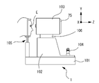
以下、本開示の実施例について図面を用いて説明する。図1は本実施例に係る眼科撮影装置1の外観構成図である。例えば、眼科撮影装置1は、基台101と、移動台102と、測定部103と、操作部材104と、顔支持ユニット105と、駆動部106と、モニタ75と、を備える。例えば、移動台102は、基台101に対して左右方向(X方向)及び前後方向(Z方向)に移動可能である。例えば、測定部103は後述する光学系を収納する。例えば、顔支持ユニット105は、被検者の顔を支持するために基台101に固設されている。例えば、駆動部106は、移動台102に対して上下方向(Y方向)に移動可能である。例えば、モニタ75は、後述するOCTデータ(例えば、第1OCTデータ及び第2OCTデータ)等を表示する。
<Example>
Hereinafter, embodiments of the present disclosure will be described with reference to the drawings. FIG. 1 is an external configuration diagram of an ophthalmologic photographing
例えば、操作部材(ジョイスティック)104には、被検眼Eに対して測定部103を相対的に移動させる移動機構が設けられている。より詳細には、例えば、ジョイスティック104は、基台101上で移動台102をXZ方向に摺動させる図示なき摺動機構を備える。例えば、ジョイスティック104を操作すると、移動台102が基台101上をXZ方向に摺動する。また、ジョイスティック104には回転ノブが設けられている。例えば、ジョイスティック104を回転操作すると、駆動部106がY方向へ駆動し、測定部103がY方向に移動する。例えば、これによって、被検眼Eに対して測定部103を移動させることができる。
For example, the operation member (joystick) 104 is provided with a moving mechanism for moving the
なお、本実施例においては、駆動部106によって測定部103をY方向へ移動させる構成を例に挙げて説明したがこれに限定されない。例えば、測定部103には、測定部103をXYZ方向に移動可能とする移動機構を設けてもよい。この場合には、例えば、被検眼Eに対して測定部103のXYZ方向の移動機構が、測定部103を微動させる際に用いられ、移動台102の摺動機構が、測定部103を粗動させる際に用いられるようにしてもよい。
In this embodiment, the configuration in which the
例えば、本実施例における眼科撮影装置1は、被検眼Eの深さ情報を取得する光断層干渉計(以下、OCTデバイス1と称す)である。例えば、OCTデバイス1は、フーリエドメイン光コヒーレンストモグラフィー(FD-OCT:Fourier Domain OCT)であってもよいし、タイムドメインOCT(TD-OCT:Time Domain OCT)であってもよい。FD-OCTとしては、スペクトルドメインOCT(SD-OCT:Spectral Domain OCT)、波長掃引式OCT(SS-OCT:Swept Source OCT)が代表的であり、もちろん、それらの装置に対して本開示が適用され得る。
For example, the
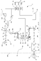
図2A及び図2Bは、本実施例に係る眼科撮影装置1の光学系及び制御系を示す概略構成図である。図2Aは眼底撮影時の光学配置を示し、図2Bは前眼部撮影時の光学配置を示している。図2Aと図2Bに示すOCTデバイス1は、主に、干渉光学系(OCT光学系)2と、測定光学系(導光光学系)20と、制御部70と、を備える。本実施例におけるOCTデバイス1は、さらに、固視標投影ユニット90(第2光学系)と、記憶部(メモリ)72と、操作部74と、モニタ75と、を備える。例えば、前述した測定部103には、OCT光学系2と、測定光学系20と、固視標投影ユニット90と、が収納される。また、例えば、前述した移動台102には、制御部70と、記憶部72と、が収納される。
2A and 2B are schematic configuration diagrams showing the optical system and control system of the
まず、OCT光学系2について説明する。OCT光学系2は、光源11から発せられた光束を測定光と参照光に分割する。OCT光学系2は、測定光を被検眼Eに導くと共に、参照光を参照光学系30に導く。そして、OCT光学系2は、被検眼Eに照射された測定光と参照光との干渉を検出器(光検出器)40によって検出する。より具体的には、本実施例では、被検眼Eで反射(または後方散乱)された測定光、及び参照光の合成による干渉光が検出器40によって検出され、干渉信号が取得される。
First, the OCT
例えば、SD-OCTの場合、光源11として低コヒーレント光源(広帯域光源)が用いられ、検出器40には、干渉光を周波数成分に分光する分光光学系(スペクトルメータ)が設けられる。例えば、スペクトルメータは、回折格子とラインセンサからなる。
For example, in the case of SD-OCT, a low coherent light source (broadband light source) is used as the
また、例えば、SS-OCTの場合、光源11として出射波長を時間的に高速で変化させる波長走査型光源(波長可変光源)が用いられ、検出器40には、例えば、単一の受光素子が設けられる。光源11は、例えば、光源、ファイバーリング共振器、及び波長選択フィルタによって構成される。そして、波長選択フィルタとして、例えば、回折格子とポリゴンミラーの組み合わせ、ファブリー・ペローエタロンを用いたものが挙げられる。
Further, for example, in the case of SS-OCT, a wavelength scanning light source (wavelength tunable light source) is used as the
OCTデバイス1では、測定光学系20の光学配置が切り換わる。一例として、図2Aに示す光学配置と、図2Bに示す光学配置とに切り換わってもよい。図2A及び図2Bの光学配置では、OCTデバイス1によって断層像が撮像される部位の深度帯が互いに異なる。以下、本実施例においては、OCTデバイス1にSD-OCTを適用した場合を例に挙げて説明する。
In the
図2Aと図2Bに例示するOCT光学系2は、光源11と、光ファイバ15a,15b,15c,15dと、分割器15と、参照光学系30と、検出器40と、を備える。
The OCT
光源11は、OCT光学系2の測定光及び参照光として用いられる低コヒーレントの光を発する。光源11としては、例えば、SLD光源等が用いられてもよい。より詳細には、例えば、光源11はλ=800nm~1100nmの間に中心波長を持つ光を出射してもよい。光源11からの光は、光ファイバ15aを介して、分割器15へ導かれる。
The
なお、光ファイバ15a,15b,15c,15dは、内部に光を通過させることで、分割器15,光源11,測定光学系20,参照光学系30,及び検出器40等のそれぞれを繋ぐ。
The
分割器15は、(光ファイバ15aを介して)光源11から導かれた光を、測定光と参照光とに分割する。測定光は、光ファイバ15bを通って、測定光学系20へ導かれる。一方、参照光は、光ファイバ15c、及びポラライザ31を介して、参照光学系30へ導かれる。
図2A,図2Bの例において、分割器15は、被検眼Eへ導光された測定光の戻り光と、参照光との導光路を結合する結合部(コンバイナ)を兼用する(詳細は後述する)。このような分割器15は、例えば、ファイバーカップラーであってもよい。以下、分割器15をカップラー15と示す。
In the example of FIGS. 2A and 2B, the
便宜上、ここで、測定光学系20について説明する。測定光学系20は、例えば、測定光を被検眼Eに導く。一例として、図2A,図2Bに示す測定光学系20は、コリメータレンズ21,変更部材28,ミラー29,光束径調節部22,集光位置可変光学系(集光位置可変レンズ系)23,走査部(光スキャナー)24,ミラー25,ダイクロイックミラー26,及び対物光学系27を有する。
For convenience, the measurement
コリメータレンズ21は、光ファイバ15bの端部16bから出射される測定光をコリメートする。
The
変更部材28は、変更部材28に入射した測定光の反射光を局所的に変化させることで、被検眼Eに照射する測定光のプロファイルを変更する。例えば、変更部材28としては、DMD、LCD(例えば、反射型LCDや透過型LCD等)、波面変調素子等を用いることができる。なお、本実施例においては、変更部材28としてDMDを用いる場合を例に挙げて説明する。このため、以下では変更部材28をDMD28と示す。
The changing
例えば、DMD28には、反射角度を変更することができる微小なミラーP(図6(a)参照)が二次元的に多数配置されている。例えば、DMD28は、微小なミラーPの1つ1つの反射角度を制御することによって、DMD28に入射した測定光の反射方向を局所的に変化させることができる。このため、被検眼Eに照射される測定光のプロファイルは、DMD28を介すことで変更される。つまり、DMD28に反射される測定光のプロファイルは、DMD28に入射した測定光のプロファイルとは異なる形状となって、被検眼Eへ照射される。
For example, the
なお、DMD28は、各微小なミラーPを2種類の状態に切り換えることによって、測定光のプロファイルを変更するようにしてもよい。この場合、DMD28は、微小なミラーPの反射角度をON(例えば、+12度)あるいはOFF(例えば、-12度)に変化させる。例えば、DMD28は、微小なミラーPをONの状態にすることで、測定光をミラー29の方向へ反射させ、被検眼Eに導光させてもよい。また、例えば、DMD28は、微小なミラーPをOFFの状態にすることで、測定光を図示なき吸収部材の方向へ反射させ、被検眼Eに導光させないようにしてもよい。
The
例えば、DMD28は、コリメータレンズ21とミラー29との間に配置される。なお、DMD28は、コリメータレンズ21と、走査部24と、の間におけるいずれかの位置に配置される構成であればよく、本実施例に限定されない。
For example,
光束径調節部22は、OCT光学系2と走査部24(つまり、光スキャナ)との間の光路中に配置されており、その光路における測定光の光束径を変更するために利用される。図2A,図2Bの例において、光束径調節部22は、測定光学系20におけるカップラー15と、走査部24と、の間の光路中に設けられる。光束径調節部22は、例えば、挿脱機構によって光路から挿脱可能なアパーチャ、可変ビームエクスパンダ,及び開口の径を調整可能な可変アパーチャ等の少なくともいずれかであってもよい。例えば、本実施例において図2A,図2Bに示す光束径調節部22は、可変ビームエクスパンダである。図2A,図2Bに示すように、可変ビームエクスパンダには、例えば、2つのレンズ22a,22bと、駆動部22cと、が含まれてもよい。駆動部22cは、互いのレンズ22a,22bにおける光軸方向の位置関係を、制御部70からの制御信号に基づいて変更する。これにより、測定光の光束径(及び、開口数NA)が変更される。
The beam
集光位置可変光学系23は、測定光の集光位置を、光軸L1方向に変更するために利用される。集光位置可変光学系23は、少なくとも1つのレンズ23aを有し、レンズ23aを用いて、測定光の集光位置を光軸L1方向に関して調整する。図2A,図2Bの例において、集光位置可変光学系23は、カップラー15と、走査部24と、の間の光路中に設けられている。なお、本実施例では、光束径調節部22と走査部24との中間に集光位置可変光学系23が配置される。しかし、光束径調節部22と集光位置可変光学系23の配置は、必ずしもこれに限られるものではない。例えば、互いに置き換えられてもよい。また、両者の間にリレー光学系等が介在してもよい。レンズ23aは、光軸L1方向に関して、測定光の集光位置を定めるフォーカス光学系を構成する。集光位置可変光学系23は、レンズ23a単独で構成されてもよいし、レンズ23aと、それ以外の光学素子と共に構成されてもよい。集光位置可変光学系23は、例えば、レンズ23aの屈折力,対物光学系27とレンズ23aとの光軸L1方向に関する位置関係,のいずれかを調整する構成で実現される。なお、対物光学系27とレンズ23aとの位置関係の調整は、例えば、光軸L1方向に関するレンズ23aの位置,レンズ23aと対物光学系27aとの間の光路長,及び,測定光路に対するレンズの挿脱,のいずれかによって実現されてもよい。この場合、レンズ23aを所期する方向に移動させる駆動部(アクチュエータ)が、制御部70によって制御される。
The condensing position variable
図2A,図2Bの例において、レンズ23aは、可変焦点レンズである。レンズ23aは、光軸L1に対して静止した状態で、焦点位置を変更可能である。レンズ23aは、制御部70によって設定される印加電圧の大きさに応じて、屈折力を変化させる。典型的な可変焦点レンズとしては、液晶レンズ等が知られている。なお、屈折力可変のレンズとしては、液晶レンズに限られるものではなく、例えば、液体レンズ、非線形光学部材、分子部材、回転非対称な光学部材等であってもよい。
In the example of FIGS. 2A and 2B,
走査部24は、測定光を走査するために、OCT光学系からの測定光を偏向する光スキャナを有する。走査部24は、例えば、2つのガルバノミラー241,242(光スキャナの一例)を有してもよい。図3の例において、241は、X走査用ガルバノミラーであり、242は、Y走査用ガルバノミラーである。各ガルバノミラー241,242は、それぞれ、ミラー部241a,242aと、それぞれの241a,242aを回転させる駆動部241b,242b(例えば、モーター)を含んでいてもよい。制御部70は、各々のガルバノミラー241,242の向きを独立に制御することで、測定光の進行方向を変更する。その結果、被検眼Eに対して、上下左右方向に測定光を走査することができる。なお、走査部24は、ガルバノミラー241b,242b以外の光スキャナを用いることができる。例えば、反射型のスキャナ(例えば、MEMSスキャナ、レゾナントスキャナ、ポリゴンミラー等)が用いられてもよいし、音響光学素子等が用いられてもよい。
The
図2A,図2Bの例では、走査部24によって進行方向が変えられた測定光は、各ミラー面が直角を挟んで配置されるミラー25,及び,ダイクロイックミラー26,のそれぞれで反射される。これにより、測定光は、走査部24からの出射時とは反対向きに折り返される。その結果として、測定光が対物光学系27へ導かれる。
In the examples of FIGS. 2A and 2B, the measurement light whose traveling direction has been changed by the
本実施例において、対物光学系27は、固定的に配置されている。より詳細には、対物光学系27は、測定光学系20において、走査部24と被検眼Eとの間に配置されている。対物光学系27は、光スキャナ(本実施例では、ガルバノミラー241,242)によって偏向された測定光を、被検眼Eに導く。本実施例において、対物光学系27は、正のパワーを持つレンズ系(対物レンズ系)として形成されている。このため、走査部24からの測定光は、対物光学系27を通過することで、光軸L1側に折れ曲がる。なお、図2A,図2Bでは、便宜上、対物光学系27を、2枚のレンズ27a,27bからなる光学系として示しているが、対物光学系27を構成するレンズの数は、これに限定されない。対物光学系27は、1枚のレンズに置き換えてもよいし、3枚以上のレンズに置き換えてもよい。また、対物光学系27は、レンズ系に限られるものではなく、例えば、ミラー系であってもよいし、レンズとミラーとの組み合わせによる光学系であってもよいし、レンズ及びミラー以外の光学部材を含む光学系であってもよい。
In this embodiment, the objective
このような測定光学系20では、光ファイバ15bの端部16bから測定光が出射すると、コリメータレンズ21によって測定光がコリメートされる。また、DMD28によって測定光のプロファイルが変更される。その後、測定光は、ミラー29に反射され、光束径調節部22及び集光位置可変光学系23を通過して、走査部24に達する。測定光は、走査部24に設けられた2つのガルバノミラーで反射された後、更に、ミラー25及びダイクロイックミラー26で反射される。その結果、測定光は、対物光学系27に入射する。そして、測定光は、対物光学系27を通過して、被検眼Eへ導光される。その後、測定光は、被検眼Eで反射または散乱され、その結果として、測定光学系20を逆に辿って光ファイバ15bの端部16bに入射する。端部16bに入射した測定光は、光ファイバ15bを介して、カップラー15に入射する。
In such a measurement
OCTデバイス1は、駆動部(アクチュエータ)を備える。駆動部は、対物光学系27に対する走査部24(つまり、光スキャナであるガルバノミラー241,242)の相対位置であって、測定光学系20の光軸L1方向に関する相対位置を変位させる。より詳細には、駆動部の駆動によって、対物光学系27の後側焦点位置(または、その共役位置)に対する走査部24の相対位置が変更される。この相対位置の変位によって、測定光の旋回位置が光軸L1方向に関して変更される。駆動部は、走査部24、及び、対物光学系27と走査部24との間に配置される光学部材、の少なくとも一方を移動させることで、対物光学系27に対する走査部24の相対距離を変位させてもよい。図2A,図2Bの例において、OCTデバイス1は、駆動部50を有する。対物光学系27と走査部24との間隔(光路長)が、駆動部50の駆動によって変更され、これにより、対物光学系27に対する走査部24の相対位置が変位される。この相対位置は、断層像が撮影される被検眼Eの深度帯と対応して変更される。
The
図2A,図2Bの例において、駆動部50は、それぞれのミラー面が直角を挟んで配置される2枚のミラー(ミラー25及びダイクロイックミラー26)を、所定の方向に一体的に移動させる。本実施例では、対物光学系27の光軸方向に移動される。その結果、走査部24から対物光学系27までの光路長が変更される(例えば、図2A→図2B,図2B→図2A)。例えば、断層像が得られる深度帯を前眼部Ecと眼底Erとの間で切り換える場合は、走査部24から対物光学系27までの光路長を比較的大きく変更する必要がある。これに対し、図2Aの例において、走査部24から出射した測定光は、2枚のミラーによって折り返されているので、2枚のミラーを移動させた場合、走査部24から対物光学系27までの光路長の変化(換言すれば、対物光学系27に対する走査部24の光軸L1方向に関する変位量)を、2枚のミラー25,26の移動量の2倍とることができる。故に、対物光学系27に対する走査部24の位置を、測定光学系20の光軸L1方向に関して変位させるために必要なスペースを抑制できる。
In the example of FIGS. 2A and 2B, the
また、図2A,図2Bに示すように、OCTデバイス1は、対物光学系27に対する走査部24の位置を検出するためのセンサ51を備えていてもよい。センサ51としては、様々なデバイスを利用可能である。例えば、ポテンショメータ等のリニア変位センサがセンサ51として適用されてもよい。
2A and 2B, the
ここで、OCT光学系2の説明に戻る。参照光学系30は、参照光を生成する。参照光は、眼底Erによって反射された測定光の反射光と合成される光である。参照光学系30は、マイケルソンタイプであってもよいし、マッハツェンダタイプであっても良い。図2A,図2Bに例示する参照光学系30は、反射光学系(例えば、参照ミラー34)によって形成される。図2A,図2Bの例では、カップラー15からの光が、反射光学系によって反射されることで再度カップラー15に戻され、結果として、検出器40に導かれる。なお、参照光学系30は必ずしもこれに限られるものではなく、透過光学系(例えば、光ファイバー)によって形成されてもよい。この場合、参照光学系30は、カップラー15で分割された参照光を、カップラー15へ戻さずに透過させることで、検出器40へ導く。
Here, the explanation of the OCT
図2A,図2Bの例において、参照光学系30は、分割器15から、参照ミラー34までの光路に、光ファイバ15c,光ファイバ15cの端部16c,コリメータレンズ33,参照ミラー34,を有している。光ファイバ15cは、参照光の偏光方向を変化させるため、駆動部32により回転移動される。すなわち、光ファイバ15c及び駆動部32は、偏光方向を調整するためのポラライザ31として用いられる。なお、ポラライザとしては、上記構成に限定されず、測定光の光路または参照光の光路に配置されるポラライザを駆動させることにより、測定光と参照光の偏光状態を略一致させるものであればよい。例えば、1/2波長板や1/4波長板を用いることや光ファイバに圧力を加えて変形させることで偏光状態を変えるもの等が適用できる。
2A and 2B, the reference
なお、ポラライザ31(偏光コントローラ)は、測定光と参照光の偏光方向を一致させるために、測定光と参照光の少なくともいずれかの偏光方向を調整する構成であればよい。例えば、ポラライザ31は、測定光の光路に配置された構成であってもよい。
The polarizer 31 (polarization controller) may be configured to adjust the polarization direction of at least one of the measurement light and the reference light in order to match the polarization directions of the measurement light and the reference light. For example, the
また、参照ミラー34は、参照ミラー駆動部34aによって、光軸方向L2に関して変位する。参照ミラー34が変位することで、参照光の光路長が調整される。
Further, the
光ファイバ15cの端部16cから出射した参照光は、コリメータレンズ33で平行光束とされ、参照ミラー34で反射される。その後、参照光はコリメータレンズ33によって集光されて光ファイバ15cの端部16cに入射する。端部16cに入射した参照光は、光ファイバ15c、光ファイバ31(ポラライザ31)を介して、カップラー15に達する。
The reference light emitted from the
図2A,図2Bの例では、参照ミラー34で反射された参照光と、被検眼Eに導光された測定光の戻り光(つまり、被検眼Eで反射または散乱された測定光)とは、カップラー15によって合成されて、干渉光とされる。この干渉光は、光ファイバ15dを介して、端部16dから出射される。その結果、干渉光が検出器40に導かれる。
In the examples of FIGS. 2A and 2B, the reference light reflected by the
検出器(ここでは、スペクトロメータ部)40は、周波数(波長)毎の干渉信号を得るために、参照光と測定光による干渉光を周波数(波長)毎に分光し、分光された干渉光を受光する。 In order to obtain an interference signal for each frequency (wavelength), the detector (here, spectrometer section) 40 splits the interference light between the reference light and the measurement light for each frequency (wavelength), and divides the split interference light. receive light.
図2A,図2Bに示す検出器40は、例えば、コリメータレンズ、グレーティングミラー(回折格子)、集光レンズ、等の光学系(いずれも図示せず)を含んでいてもよい。検出器40の本体(受光素子部分)は、例えば、一次元受光素子(ラインセンサ)が適用されてもよい。検出器40は、光源11から出射される光の波長に対して、感度を有する。上述したように、光源11から赤外域の光が出射される場合、赤外域の感度がある検出器40を利用し得る。
The
端部16bから出射された干渉光は、コリメータレンズ21によって平行光とされ、その後、図示なきグレーティングミラーによって、周波数成分に分光される。そして、周波数成分に分光された干渉光は、図示なき集光レンズを介して、検出器40の受光面に集光する。これによって、検出器40上での干渉縞のスペクトル情報(スペクトル信号)が得られる。スペクトル情報は、制御部70へ入力され、制御部70において、フーリエ変換を用いて解析される。そして、解析結果として、被検眼Eの断層像が形成される。また、解析結果として、被検眼Eの深さ方向における情報が計測可能となる。
The interference light emitted from the
ここで、制御部70は、走査部24により測定光を被検眼Eの横断方向に走査することにで、断層像を取得できる。例えば、X方向もしくはY方向に走査することにより、被検眼眼底ErのXZ面もしくはYZ面における断層像を取得できる(なお、本実施例においては、このように測定光を眼底Erに対して一次元走査し、断層像を得る方式をBスキャンとする)。なお、取得された断層像は、制御部70に接続された記憶部72に記憶される。更に、走査部24の駆動を制御して、測定光をXY方向に二次元的に走査することにより、被検眼眼底ErのXY方向に関する二次元動画像,及び,被検眼眼底Erの三次元画像を検出器40からの出力信号に基づいて形成可能である。
Here, the
次に、固視標投影ユニット90について説明する。固視標投影ユニット90は、被検眼Eの視線方向を誘導するための光学系を有する。固視標投影ユニット90は、被検眼Eに呈示する固視標(固視光源91)を有する。固視標投影ユニット90は、複数の方向に被検眼Eを誘導する構成でもよい。ここで、ダイクロイックミラー26は、OCT光学系2の測定光として用いられる波長成分の光を反射し、固視標投影ユニット90に用いられる波長成分の光を透過する特性を有する。故に、固視標投影ユニット90から出射される固視標光束は、対物光学系27を介して被検眼Eに照射される。これにより、被検者は固視が可能になる。
Next, the fixation
<制御系>
次に、OCTデバイス1の制御系を説明する。制御部(コントローラ)70は、OCTデバイス1の各部を制御する。例えば、制御部70は、CPU(プロセッサ)及びメモリ等を含んで構成されてもよい。また、本実施例において、制御部70は、例えば、検出器40からの出力信号(つまり、干渉信号)を処理することによって、被検眼Eの深さ情報を取得する。深さ情報としては、断層像等の画像情報,被検眼Eの各部の寸法を示す寸法情報,測定光の照射部位における動き量を示す情報,偏光特性の情報を含む(複素数の)解析信号,等の少なくともいずれかであってもよい。本実施例では、制御部70が、干渉信号に基づいて被検眼Eの断層像を形成する画像処理器を兼用している。また、本実施例の制御部70は、断層像の形成以外にも、各種の画像処理を行う。画像処理は、制御部70に設けられた専用の電子回路(例えば、図示なき画像処理IC)によって行われてもよいし、プロセッサ(例えば、CPU)によって行われてもよい。
<Control system>
Next, the control system of the
制御部70には、記憶部72,操作部(ユーザインターフェイス)74,及び,モニタ75,が接続されている(図2A及び図2B参照)。記憶部72は、書き換え可能な非一過性の記憶媒体を含んでいてもよく、例えば、フラッシュメモリ及びハードディスク等のいずれかであってもよい。撮影及び測定の結果得られた画像及び測定データは、記憶部72に保存される。OCTデバイス1における撮影シーケンスを規定するプログラム及び固定データは、この記憶部72に記憶されていてもよいし、制御部70内のROMに記憶されていてもよい。また、光源11,検出器40,及び,各種駆動部22c,23a,241a,242b,32,34a,50のほか、センサ51等が接続されている。
A
<撮影深度帯の切換動作>
例えば、上記の構成を備えるOCTデバイス1は、被検眼Eにおける撮影部位の深度帯を切り換えてもよい。この場合、制御部70は、駆動部50を制御し、被検眼Eにおける測定光の旋回位置を光軸L1方向に関して切り換える。旋回位置は、対物光学系27に対する走査部24の相対位置に応じて変位する。つまり、本実施例において、制御部70は、対物光学系27に対する走査部24の相対位置を駆動部50によって変更させ、その結果として、被検眼Eにおける測定光の旋回位置を光軸L1方向に関して調整する。その際、制御部70は、測定光の旋回位置を、少なくとも、第1位置と、第2位置との間で変更する。第1位置は、被検眼Eの第1深度帯(例えば、被検眼Eの前眼部Ec)に対応し、第2位置は、第1深度帯とは異なる被検眼Eの第2深度帯(例えば、被検眼Eの眼底Er)に対応する。また、第2位置は、測定光学系の光軸方向(被検眼Eの深さ方向)に関して第1位置とは異なる。
<Switching operation of photographing depth band>
For example, the
また、被検眼Eにおける測定光の旋回位置を光軸L1方向に関して切り換えた際には、対物光学系27と走査部24との相対位置の変更と連動して、制御部70が参照光学系30における光路長を調整してもよい。また、制御部70は、集光位置可変光学系23を制御して、測定光の集光位置を切換えてもよい。また、更に、制御部70は、光束径調節部22を制御して、NAを調節してもよい。このような走査部24の位置変更(換言すれば、撮影深度帯の変更)は、例えば、操作部74から制御部70へ出力される切換信号に基づいて実行されてもよい。また、一連の撮影シーケンスにおいて、制御部70が自動的に切換えを行ってもよい。
Further, when the turning position of the measurement light in the subject's eye E is switched with respect to the direction of the optical axis L1, the
例えば、被検眼Eの前眼部撮影時においては、図2Bに示すように、制御部70が、走査部24を眼底撮影時(図2A参照)に対して対物光学系27に近づける。このとき、対物光学系27の物体側(被検眼側)において、測定光の主光線はテレセントリック(または略テレセントリック)となる。つまり、本実施例では、走査部24と対物光学系27からなる光学系が、物体側テレセントリック光学系として形成される。この場合、被検眼Eにおける測定光の旋回位置(本実施例における第1位置)は、光軸L1上の無限遠点であるものと考えることができる。また、この場合、対物光学系27の前面(つまり、最も被検眼側に配置されるレンズ面)から、被検眼Eの瞳孔面に照射される測定光の主光線は、走査部24で反射される測定光の向きに関わらず、光軸L1と平行(略平行)となる。
For example, when photographing the anterior segment of the subject's eye E, as shown in FIG. 2B, the
一方、眼底撮影時においては、図2Aに示すように、制御部70が、前眼部撮影時(図2B参照)に対して、走査部24を対物光学系27から遠ざける。このとき、走査部24の駆動に伴って、対物光学系27の前面(最も被検眼側のレンズ面)から出た測定光は、瞳孔位置を中心(旋回点)として旋回する。つまり、この場合、被検眼Eにおける測定光の旋回位置(本実施例における第2位置)が瞳孔位置に設定される。
On the other hand, when photographing the fundus, as shown in FIG. 2A, the
なお、被検眼Eの前眼部撮影時、及び眼底撮影時における測定光学系20の位置関係とその詳細については、特開2016-209577号公報を参照されたい。
For the positional relationship and details of the measurement
<制御動作>
以下、図4に示すフローチャートを用いて、上記の構成を備えるOCTデバイス1の制御動作を順に説明する。例えば、眼科撮影装置1は、被検眼Eの前眼部Ecを撮影する前眼部撮影モードと、被検眼Eの眼底Erを撮影する眼底撮影モードと、を備えるが、本実施例においては眼底撮影モードを適用する場合を例に挙げる。例えば、眼底撮影モードでは、測定光が被検眼の瞳孔面を介して眼底に照射される。この場合、被検眼Eの瞳孔面に対してある一定の径をもった測定光が照射されてもよい。
<Control action>
Hereinafter, the control operation of the
例えば、検者は、固視標投影ユニット90の固視標を注視するよう被検者に指示する。被検眼Eには、図示なき指標投影光学系の光源が点灯することにより、後述するアライメント指標像Ma~Mhが投影される。また、被検眼Eの前眼部Ecは図示なき前眼部撮像光学系によって検出され、その前眼部観察像60(図5参照)がモニタ75に表示される。
For example, the examiner instructs the subject to gaze at the fixation target of the fixation
<被検眼のアライメント(S1)>
例えば、制御部70は、アライメント指標像Ma~Mhを用いて、被検眼Eと測定光学系20とのアライメント状態を検出する。また、制御部70は、移動台102及び駆動部106を制御し、測定部103を移動させることで、被検眼Eの角膜頂点位置(または、略角膜頂点位置)と、測定光の光軸L1と、を一致させる自動アライメントを行う(S1)。
<Alignment of eye to be examined (S1)>
For example, the
図5は被検眼Eの前眼部観察像60を示す図である。例えば、被検眼Eの左右方向(X方向)及び上下方向(Y方向)におけるアライメント状態は、角膜頂点位置と光軸L1とを一致させる位置に予め設定されたアライメント基準位置を用いて判定される。例えば、制御部70は、指標像Ma~Mhにおけるリング形状のXY中心座標(図5に示す十字マーク)を角膜頂点位置として検出する。また、制御部70は、アライメント基準位置に対して、検出した被検眼Eの角膜頂点位置がXY方向にずれた偏位量を求める。例えば、制御部70は、偏位量が0となるように測定部103を移動させ、被検眼Eに対するX方向及びY方向のアライメントを調整する。なお、アライメント基準位置を中心としたXY方向における所定の領域に、アライメントの適否を判定するための許容範囲を設定しておき、測定部103をこの許容範囲内におさめるように移動させてもよい。
FIG. 5 is a diagram showing an anterior segment observed
例えば、被検眼Eの前後方向(Z方向)におけるアライメント状態は、アライメント指標像Ma~Mhを用いて判定される。例えば、指標像Ma及びMeは無限遠であり、指標像Mh及びMfは有限遠である。例えば、本実施例においては、OCTデバイス1に対して被検眼Eが適切な位置にある場合(すなわち、Z方向の位置ずれがない場合)、無限遠の指標像MaからMeまでの像間隔aと、有限遠の指標像MhからMfまでの像間隔bと、がある一定の比率となるように設定されている。例えば、OCTデバイス1に対して被検眼Eが適切な位置にない場合(すなわち、Z方向に位置ずれがある場合)、像間隔aはほとんど変化しないが、像間隔bは変化する。例えば、制御部70は、像間隔aと像間隔bの像比率(つまり、a/b)を比較し、これが一定の比率となるようにZ方向のアライメントを調整する(詳細は特開平6-46999号公報を参照されたい)。もちろん、アライメント基準位置を中心としたZ方向における所定の領域に、アライメントの適否を判定するための許容範囲を設定しておき、測定部103をこの許容範囲内におさめるように移動させてもよい。
For example, the alignment state of the subject's eye E in the front-rear direction (Z direction) is determined using the alignment index images Ma to Mh. For example, index images Ma and Me are at infinity, and index images Mh and Mf are at finite distance. For example, in this embodiment, when the subject's eye E is at an appropriate position with respect to the OCT device 1 (that is, when there is no positional deviation in the Z direction), the image interval a from the index image Ma at infinity to Me is , and the image interval b from the finite index image Mh to Mf are set to have a certain constant ratio. For example, when the subject's eye E is not in an appropriate position with respect to the OCT device 1 (that is, when there is a positional shift in the Z direction), the image interval a hardly changes, but the image interval b changes. For example, the
<最適化制御の実施(S2)>
次いで、制御部70は、撮影条件の最適化を開始する(S2)。例えば、最適化の制御を行うことによって、検者が所望する眼底部位が、高感度・高解像度で観察できるようになる。例えば、最適化の制御とは、光路長調整、フォーカス調整、偏光状態の調整(ポラライザ調整)である。
<Implementation of optimization control (S2)>
Next, the
なお、例えば、本実施例においては、第1自動光路長調整、フォーカス調整、第2自動光路長調整、ポラライザ調整の順に最適化の制御が行われる。例えば、制御部70は、参照ミラー34の位置を初期位置に設定し、レンズ23aの屈折力を0Dにする。初期化が完了すると、制御部70は、参照ミラー34を初期位置から一方向に所定ステップで移動させ、第1光路長調整(第1自動光路長調整)を行う。第1光路長調整が完了すると、制御部70は、被検眼Eの前眼部に合焦するようにレンズ23aの屈折力を変化させて、オートフォーカス調整(フォーカス調整)を行う。オートフォーカス調整が完了すると、制御部70は参照ミラー34を光軸L2方向に移動させ、光路長を再調整(光路長を微調整)するための第2光路長調整(第2自動光路長調整)を行う。第2光路長調整が完了すると、制御部70は干渉光を強く受光できる位置(すなわち、測定光と参照光の偏光状態が合う位置)にポラライザ31を移動させて、測定光の偏光状態を調整する。
For example, in this embodiment, optimization control is performed in the order of first automatic optical path length adjustment, focus adjustment, second automatic optical path length adjustment, and polarizer adjustment. For example, the
<測定光の第1プロファイルへの変更(S3)>
例えば、制御部70は、DMD28を制御することによって、OCT光学系2における測定光のプロファイルを変更する。例えば、本実施例においては、DMD28における微小なミラーPの状態(すなわち、ONの状態とOFFの状態)を切り換えることで、測定光のプロファイルを変更する場合を例に挙げて説明する。これによって、測定光のプロファイルは第1プロファイル100に変更される(S3)。なお、測定光のプロファイルは、少なくとも2つ以上の互いに異なる第1プロファイルに変更される構成であればよい。また、第1プロファイル100としては、被検眼の眼底に向けて照射される測定光のうち、前眼部から眼底までの経路のいずれかの被検眼部位(例えば、被検眼の瞳面(瞳孔面)、硝子体等)における測定光の分布が変更される構成であればよい。
<Changing Measurement Light to First Profile (S3)>
For example, the
図6はDMD28を説明する図である。例えば、本実施例では、図6における格子の1つ1つを、DMD28が備える微小なミラーP(P1~P16)として表している。また、例えば、図6において点線で示した形状は、DMD28へ入射する前の測定光の外径80を表している。すなわち、本実施例においては、DMD28へ測定光が入射する位置に、微小なミラーPが16枚配置されている。
FIG. 6 is a diagram illustrating the
図7はDMD28と第1プロファイル100の関係を示す図である。図7(a)は、微小なミラーPの反射角度を切り換えた状態を示している。なお、図7(a)では、反射角度がONの状態にある微小なミラーPを白色の領域で示し、反射角度がOFFの状態にある微小なミラーPを斜線の領域で示している。図7(b)は、図7(a)の状態にあるDMD28に対応して、被検眼Eに照射される測定光の第1プロファイル100(第1プロファイル100a~d)を示している。
FIG. 7 is a diagram showing the relationship between the
例えば、微小なミラーPがすべてONの状態である場合(図7(a)におけるB1)、DMD28に入射する測定光のプロファイルは、第1プロファイル100aに変更される。つまり、測定光は、すべての微小なミラーP1~P16によってミラー29の方向へ反射され、被検眼Eに導光される。このとき、第1プロファイル100aには、測定光が被検眼Eへ照射される照射領域110がつくられる。また、例えば、微小なミラーPがすべてOFFの状態である場合(図7(a)におけるB4)、DMD28に入射する測定光のプロファイルは、第1プロファイル100dに変更される。つまり、測定光は、すべての微小なミラーP1~P16によって図示なき吸収部材の方向へ反射され、被検眼Eに導光されない。このとき、第1プロファイル100dには、測定光が被検眼Eへ照射されない非照射領域120がつくられる。
For example, when all the minute mirrors P are in the ON state (B1 in FIG. 7A), the profile of the measurement light incident on the
例えば、一部の微小なミラーPがONの状態で、他の微小なミラーPがOFFの状態である場合(図7(a)におけるB2またはB3)、DMD28に入射する測定光のプロファイルは、第1プロファイル100bまたは第1プロファイル100cに変更される。このとき、白色の領域で示した微小なミラーP(言い換えると、反射角度がONの状態にある微小なミラーP)に向かって入射した測定光のみが被検眼Eに導光される。斜線の領域で示した微小なミラーP(言い換えると、反射角度がOFFの状態にある微小なミラーP)に向かって入射した測定光は被検眼Eに導光されない。つまり、第1プロファイル100b及び第1プロファイル100cには、照射領域110と非照射領域120とがつくられる。
For example, when some micromirrors P are ON and other micromirrors P are OFF (B2 or B3 in FIG. 7A), the profile of the measurement light incident on the
例えば、このように、DMD28に入射した後の測定光は、第1プロファイル100を変更することで、様々なパターン形状(例えば、規則的なパターン形状、不規則なパターン形状、ランダムなパターン形状等)に変化する。例えば、本実施例における制御部70は、DMD28を制御し、測定光のプロファイルを何通りにも変化させることで、複数の互いに異なる第1プロファイル100に変更することができる。
For example, by changing the
例えば、本実施例では、測定光のプロファイルを複数の互いに異なる第1プロファイル100に変更した状態において、被検眼Eに照射される測定光の光量が同一に設定される。例えば、この場合、制御部70は、被検眼に照射する測定光における光量の総和が等しくなるようにしてもよい。例えば、測定光の光量を同一に設定する構成としては、第1プロファイル100における照射領域110の面積を光源11からの測定光の強度に従って変化させることで、被検眼Eに照射される測定光の光量を同一にしてもよい。また、例えば、測定光の光量を同一に設定する構成としては、光源11の出力を変化させることで、被検眼Eに照射される測定光の光量を同一にしてもよい。もちろん、第1プロファイル100における照射領域110の面積と、光源11の出力と、を変化させることで、被検眼Eに照射される測定光の光量を同一にしてもよい。なお、本実施例においては、光源11からの測定光の強度が至る所において一様であるとし、第1プロファイル100における照射領域110の面積を一定に保つことで、被検眼Eに照射される測定光の光量を同一に設定する場合を例に挙げる。
For example, in this embodiment, in a state where the profile of the measurement light is changed to a plurality of
例えば、制御部70は、いずれの第1プロファイルにおいても照射領域110の面積が同じになるように、DMD28が備える微小なミラーPを制御する。例えば、このような場合、メモリ72には、照射領域110の面積が同じ(すなわち、反射角度がONの状態にある微小なミラーPの数が同じ)第1プロファイル100のみが予め記憶されていてもよい。また、このような場合、メモリ72には、照射領域110の面積が同じ第1プロファイル100と、照射領域110の面積が異なる第1プロファイル100と、が予め混在して記憶されていてもよい。例えば、制御部70は、メモリ72に記憶された第1プロファイル100の中から、照射領域110の面積が同じ第1プロファイル100を選択し、これに対応する微小なミラーPの状態を切り換える。
For example, the
例えば、図7(b)における第1プロファイル100bと第1プロファイル100cは、16枚の微小なミラーPのうち、8枚がOFFの状態となっており、照射領域110の面積は同一である。もちろん、OFFの状態とする微小なミラーPの数は本実施例に限定されない。これによって、光源11が一定の出力で被検眼Eに照射される場合に、測定光の光量を同一に設定することができる。なお、被検眼に照射される測定光の光量は必ずしも同一にする必要はなく、照射領域110の面積が互いに異なる第1プロファイル100を選択して設定するようにしてもよい。この場合は、第1プロファイルごとに得られる所定の信号強度を適切に規格化することで、以下と同様に第1OCTデータを取得してもよい。
For example, in the
<第1OCTデータの取得(S4)>
例えば、制御部70は、測定光のプロファイルを複数の互いに異なる第1プロファイル100に変更した状態で、被検眼Eに測定光を照射し、それぞれの第1プロファイルに対応した第1OCTデータを取得する(S4)。例えば、第1OCTデータとしては、検出器40からのOCT信号そのものであってもよいし、被検眼Eの断層画像データであってもよいし、モーションコントラストデータであってもよいし、偏光特性データであってもよい。例えば、本実施例においては、第1OCTデータとして、被検眼Eにおける断層画像の信号が取得される。なお、本実施例においては、便宜上、第1OCTデータとして、広角の眼底像を例に挙げて説明するがこれに限定されない。例えば、第1OCTデータは狭角の眼底像であってもよい。例えば、この場合には、中心窩等の所定の位置を検出しやすくなる。また、例えば、第1OCTデータは、全くスキャンを行わずに同じ位置を撮影し続けた像(Mスキャン像)であってもよい。もちろん、第1OCTデータは、所定の回数のデータを取得し、その平均を取ったものであってもよい。
<Acquisition of first OCT data (S4)>
For example, the
例えば、制御部70は、測定光のプロファイルを複数の第1プロファイル100に変更し、それぞれの第1プロファイル100に対応した複数の第1OCTデータを取得する。すなわち、本実施例では、測定光のプロファイルが、仮撮影用のプロファイルとして複数の互いに異なる第1プロファイルに変更される。また、本実施例では、仮撮影用のプロファイルにおいて、それぞれの第1OCTデータが取得される。
For example, the
<第1OCTデータの解析(S5)>
例えば、制御部70は、取得した第1OCTデータを解析することで、各第1プロファイルにおける所定の信号強度を検出する(S5)。なお、OCT信号は、フーリエ変換前の信号を解析する構成であってもよいし、フーリエ変換後の信号を解析する構成であってもよい。例えば、本実施例においては、フーリエ変換前の信号を解析することにより、信号強度としてOCT信号の総量が検出される。例えば、この場合、制御部70は、OCT信号の包絡線を求め、これを積分した値を総量として検出するようにしてもよい。なお、所定の信号強度は、第1OCTデータの一部の波長領域、または一部の周波数領域での絶対値を積分したものとしてもよいし、ピーク、コントラスト、ヒストグラム等の特徴量であってもよい。また、これらの波長領域または周波数領域は、予め実験やシミュレーション等によって設定された領域であってもよいし、任意に設定可能としてもよい。これによって、例えば、制御部70は、第1OCTデータごとに検出した所定の信号強度と、設定した第1のプロファイル100との関係を用いて、いかなる経路で測定光が伝搬したかの情報を得ることができる。
<Analysis of first OCT data (S5)>
For example, the
<透過率分布の作成(S6)>
例えば、制御部70は、いかなる経路で測定光が伝搬したかの情報を用いて、透過率分布85を作成してもよい(S6)。例えば、透過率分布85とは、被検眼Eの瞳上の位置において、被検眼Eに照射した測定光の戻り光が透過しやすい位置、あるいは透過しにくい位置を特定することが可能な分布である。なお、透過率分布は、被検眼Eの瞳上の各位置において、測定光の戻り光の光量を示すデータであってもよいし、測定光の戻り光の光量から求めた透過率を示すデータであってもよい。また、透過率分布は、測定光の戻り光の光量や透過率等のデータを可視化(例えば、マップ化)した画像データであってもよい。なお、本実施例では、透過率分布85として、測定光の戻り光の透過率を求め、これをマップ化して示す場合を例に挙げる。
<Creation of transmittance distribution (S6)>
For example, the
図8は透過率分布85を説明する図である。図8(a)は被検眼Eの瞳上の位置を示している。図8(b)は透過率分布85をマップ化した図を示している。例えば、図8(a)における格子の1つ1つは、被検眼Eにおける瞳上の位置E1~E16を示している。なお、本実施例においては、被検眼Eの瞳上の位置E1~E16と、DMD28の微小なミラーP1~P16と、の位置を対応させている。すなわち、DMD28の微小なミラーP1に反射された測定光は、被検眼Eの瞳上の位置E1を通過して眼底Erに到達する。また、被検眼Eの瞳上の位置E1を通過した測定光の戻り光は、DMD28の微小なミラーP1に反射されてカップラー15に到達する。
FIG. 8 is a diagram for explaining the
ここで、例えば、測定光は、必ずしも被検眼Eの眼底Erに到達するとは限らない。例えば、測定光が入射する位置に、被検眼Eの瞼や、被検眼Eに生じた混濁等が存在すると、これらによって測定光が遮られる場合がある。また、例えば、測定光の戻り光は、必ずしも測定光が通過した光路上における同一の位置を通過して、カップラー15に到達するとは限らない。測定光の戻り光は、眼底Erの形状等により散乱して反射し、測定光が通過した光路上における異なる位置を通過する場合がある。また、測定光の戻り光は、被検眼Eの瞼や被検眼Eに生じた混濁に遮られたり、OFFの状態にある微小なミラーP等に入射することで、カップラー15の方向へ反射しなかったりする場合がある。
Here, for example, the measurement light does not necessarily reach the fundus Er of the eye E to be examined. For example, if the eyelid of the subject's eye E, turbidity, or the like occurring in the subject's eye E exists at the position where the measurement light is incident, the measurement light may be blocked by these. Further, for example, the return light of the measurement light does not necessarily reach the
これについて、より詳細に説明する。例えば、DMD28の微小なミラーP1とP3のみがONの状態であったとき、DMD28に入射した測定光の一部は、微小なミラーP1に反射されて被検眼Eへ向かう。このとき、眼底Erにおいて散乱して反射した測定光の戻り光には、DMD28に入射し、微小なミラーP1に反射されてカップラー15に到達する戻り光と、微小なミラーP3に反射されてカップラー15に到達する戻り光と、OFFの状態にある微小なミラーP(すなわち、微小なミラーP2、P4~P16)に反射されることでカップラー15に到達しない戻り光と、がある。なお、微小なミラーP3に反射されて被検眼Eへ向かい、眼底Erにおいて散乱して反射した測定光の戻り光については、上記と同様にして説明できるため省略する。
This will be explained in more detail. For example, when only the minute mirrors P1 and P3 of the
例えば、微小なミラーP1~P16をある特定の第1プロファイルとなるよう設定し、被検眼Eの瞳上の位置E1~E16のそれぞれに入射した測定光が、被検眼の眼底Erで散乱、あるいは反射されたのち、再び被検眼Eの瞳上の位置E1~E16と微小なミラーP1~P16を経て検出されるとき、所定の信号強度Aは以下の数式で与えられる。 For example, the minute mirrors P1 to P16 are set to have a specific first profile, and the measuring light beams incident on the positions E1 to E16 on the pupil of the eye to be inspected E are scattered by the fundus Er of the eye to be inspected, or After being reflected, when detected again via positions E1 to E16 on the pupil of the eye E to be inspected and minute mirrors P1 to P16, a predetermined signal intensity A is given by the following formula.
![]()
![]()
ここに、ボールド体のxは、微小なミラーP1~P16のONあるいはOFFの状態をそれぞれ1あるいは0で表して列ベクトル表示したもので、右肩にTを付したxは転置(Transposed)されたもの、すなわち行ベクトルを意味する。従って、例えば、DMD28が備える微小なミラーP1~P16のうち、P3、P4、P7、P9~P16がONの状態にある場合は、以下の数式で表すことができる。
Here, x in bold is a column vector representing the ON or OFF state of the minute mirrors P1 to P16 by 1 or 0, respectively. means a row vector. Therefore, for example, when P3, P4, P7, and P9 to P16 among the minute mirrors P1 to P16 provided in the
![]()
![]()
これは、微小なミラーPがONの状態であれば、微小なミラーPに入射した測定光がミラー29の方向へロス無く反射して被検眼Eに導光されることを意味する。反対に、微小なミラーPがOFFの状態であれば、微小なミラーPに入射した測定光が図示なき吸収部材の方向へ反射され、被検眼Eには導光されないため、所定の信号強度Aへの寄与がない(すなわち、寄与が0である)ことを意味している。
This means that when the minute mirror P is in the ON state, the measurement light incident on the minute mirror P is reflected in the direction of the
また、斜体のTは、被検眼Eの瞳上の位置E1~E16のそれぞれに測定光が入射し、被検眼Eの瞳上の位置E1~E16と微小なミラーP1~P16を経て再び回収されるまでに、それぞれの経路がどれだけ寄与するかを表したもので、トランスファー行列と呼ばれる。例えばTの(4、7)成分は、微小なミラーP7に相当する被検眼Eの瞳上の位置E7から測定光が入射して、最終的に微小なミラーP4に相当する被検眼Eの瞳上の位置E4から測定光の戻り光が回収される経路が、所定の信号強度Aに対してどれだけ寄与しているかを表すものである。 In addition, the italic T indicates that the measurement light is incident on each of positions E1 to E16 on the pupil of the eye E to be examined, and is collected again via positions E1 to E16 on the pupil of the eye to be examined E and minute mirrors P1 to P16. It is called a transfer matrix, which shows how much each path contributes to. For example, the (4, 7) component of T is the pupil of the eye to be inspected E corresponding to the minute mirror P4 when the measurement light is incident from the position E7 on the pupil of the eye to be inspected E corresponding to the minute mirror P7. It represents how much the path along which the return light of the measurement light is collected from the upper position E4 contributes to the predetermined signal intensity A. FIG.
例えば、制御部70は、上記の数式1に、第1OCTデータの所定の信号強度Aと、微小なミラーPの状態xと、を代入し、1つの第1プロファイルを与えるDMD28の状態につき、1つのトランスファー行列Tの成分に関する条件式を得る。従って、複数の異なる第1プロファイル100を次々に取得することで、複数の条件式からトランスファー行列の各成分を連立方程式によって求められることになるので、被検眼Eの瞳上の位置E1~E16のそれぞれに測定光が入射し、被検眼Eの瞳上の位置E1~E16と微小なミラーP1~P16を経て再び回収されるまでに、それぞれの経路がどれだけ寄与するかを求めることができる。なお、その際、取得する第1プロファイル100のバリエーション数は、一般には変数の数だけ必要となるが、一定の仮定を置くことでその数を減らしてもよい。例えば、この場合には、スパース性を仮定する手法(スパースモデリング)を用いてもよい。なお、スパースモデリングはCT(Computed Tomography)再構成において広く用いられており、その詳細についてはQuant Imaging Med Surg 2013;3(3):147-161等に記載されているため省略する。また、例えば、一定の仮定を置く場合には、急峻な変化がないという仮定を置いてもよいし、前眼部観察像60で確認される明らかに測定光の通りやすい経路はトランスファー行列Tの成分が他より大きいという仮定であってもよい。また、眼科撮影装置1で予め撮影した前眼部のOCT画像を基に、どの成分がどれだけ大きいかを予め設定するようにしてもよい。もちろん、E1とE2、あるいはE3とE4等、それぞれ特定の位置を一括りにして扱って、変数を減らしてもよい。
For example, the
例えば、制御部70は、上記のトランスファー行列Tから、瞳上の位置における透過率を求めてもよい。例えば、この場合には種々の方法が考えうるが、トランスファー行列Tを以下の数式のように分解することで、瞳上の位置における透過率を得てもよい。
For example, the
![]()
![]()
数式3において、Max( )はTの成分のうちの最大の値を選び出す関数であり、規格化に用いている。ボールド体のtは被検眼Eの瞳上の位置E1~E16のそれぞれに入射する測定光の透過率を列ベクトルとして表示したものであって、中央の演算子は列ベクトルと行ベクトルから各行・各列の成分同士をかけ合わせた値を成分にもつ行列を生成する直積演算である。これは一意に決まるとは限らないが、誤差を小さくする方法(例えば、最小二乗法等の手法)を援用して得てもよい。 In Expression 3, Max( ) is a function that selects the maximum value among the components of T, and is used for normalization. t in bold indicates the transmittance of the measurement light incident on each of the positions E1 to E16 on the pupil of the eye E to be examined as a column vector, and the operator in the center is the column vector and the row vector for each row and This is a direct product operation that generates a matrix whose elements are the values obtained by multiplying the elements of each column. Although this is not necessarily determined uniquely, it may be obtained by using a method of reducing the error (for example, a technique such as the method of least squares).
例えば、これによってtの第3成分が0.5と算出された場合、制御部70は瞳上の位置E3の透過率が50%であると判断してもよい。例えば、制御部70は、瞳上の各位置における透過率を求め、これをマップ化することで、図8(b)のような透過率分布85を作成してもよい。
For example, if the third component of t is calculated to be 0.5, the
なお、瞳上の位置における透過率は、設計値などから各経路についての既知のウェイトを設定し、これに基づいてトランスファー行列Tを分解してもよく、本実施例に限定されない。このようなウェイトを付ける場合には、以下の数式のようにトランスファー行列Tを分解してもよい。なお、Wはそれぞれの経路についてのウェイトを表した行列であるが、これは実験やシミュレーション等から求めておけば既知であるため、数式3と同様にして分解することができる。 For the transmittance at the position on the pupil, known weights may be set for each path from design values or the like, and the transfer matrix T may be decomposed based thereon, and the transmittance is not limited to this embodiment. When assigning such weights, the transfer matrix T may be decomposed as in the following formula. It should be noted that W is a matrix representing the weight for each route.
![]()
![]()
<測定光の第2プロファイルへの変更(S7)>
例えば、制御部70は、取得した複数の第1OCTデータに基づいて、本撮影用のプロファイルとして、測定光のプロファイルを第1プロファイル100とは異なる新たな第2プロファイル200に変更する(S7)。例えば、本実施例においては、作成した透過率分布85に基づいて、測定光のプロファイルが第2プロファイル200に変更される。
<Change to Second Profile of Measurement Light (S7)>
For example, the
図9は第2プロファイル200を説明する図である。例えば、制御部70は、透過率分布85において、所定の透過率以下となった領域に該当する微小なミラーPをOFFの状態にしてもよい。例えば、図7(b)に示す透過率分布85が得られた場合、制御部70は、50%以下の透過率を示す領域に該当する微小なミラーP(すなわち、P8、P10~P16)をOFFの状態に切り換え、測定光のプロファイルを図9に示す第2プロファイル200に変更する。なお、例えば、所定の透過率は、予め設定された透過率(例えば、30%以下、50%以下等)であってもよいし、検者が任意に設定可能な構成であってもよいし、透過率分布85を基にして制御部70が設定する構成であってもよい。
FIG. 9 is a diagram for explaining the
また、このとき、制御部70は、光源11の出力を制御して、測定光の光量を調整する。例えば、図9では、16枚の微小なミラーPのうち、4枚の微小なミラーPがOFFの状態であるため、測定光の光量が4分の1となって被検眼Eに照射される。この場合、例えば、制御部70は、第2プロファイル200における照射領域110、あるいは非照射領域120の面積から、被検眼Eに対する最適な光量を求め、光源11の出力を制御する。すなわち、図9の場合には、光源の出力を予め4倍とすることで、被検眼Eに対して最適な照明をすることができる。
Also, at this time, the
<第2OCTデータの取得(S8)>
例えば、制御部70は、測定光のプロファイルを第2プロファイル200に変更した状態で、被検眼Eに測定光を照射し、第2プロファイルに対応した第2OCTデータを取得する(S8)。なお、第2OCTデータは、被検眼Eの断層画像データであってもよいし、モーションコントラストデータであってもよいし、偏光特性データであってもよい。また、例えば、第2OCTデータは、OCT信号(すなわち、画像化される前の信号)を取得する構成としてもよいし、OCT画像を取得する構成としてもよい。
<Acquisition of second OCT data (S8)>
For example, the
以上説明したように、例えば、本実施例における眼科撮影装置は、測定光のプロファイルを変更する変更手段と、測定光のプロファイルを複数の互いに異なる第1プロファイルに変更した状態で、それぞれの第1OCTデータを取得する取得手段と、を備える。また、例えば、本実施例における眼科撮影装置は、複数のOCTデータに基づいて、本撮影用のプロファイルとして、測定光のプロファイルを第1プロファイルとは異なる新たな第2プロファイルに変更し、第2プロファイルに変更した状態で、第2OCTデータを取得する。これによって、検者は、複数の第1プロファイルを試行して、被検眼に照射した測定光の戻り光が眼底に達し、再びOCT光学系によって回収されるまでの間に、いかなる経路で測定光が伝搬したかの情報を得ることができる。また、検者は、その情報を参考にして、第2プロファイルを被検眼に対する最適なプロファイルに変更することができる。従って、検者は、被検眼ごとに最適化されたOCTデータを取得することができる。 As described above, for example, the ophthalmologic imaging apparatus according to the present embodiment includes the changing means for changing the profile of the measurement light, and the first OCT in a state where the profile of the measurement light is changed to a plurality of mutually different first profiles. and acquisition means for acquiring data. Further, for example, the ophthalmologic imaging apparatus of the present embodiment changes the measurement light profile to a new second profile different from the first profile as the profile for main imaging based on a plurality of OCT data, Acquire the second OCT data with the changed profile. This allows the examiner to try a plurality of the first profiles, and the return light of the measurement light irradiated to the eye to be examined reaches the fundus of the eye and is collected again by the OCT optical system. It is possible to obtain information on whether or not has been propagated. Also, the examiner can refer to the information to change the second profile to the optimum profile for the eye to be examined. Therefore, the examiner can acquire OCT data optimized for each eye to be examined.
また、例えば、本実施例における眼科撮影装置は、複数の互いに異なる第1プロファイルに変更した状態で、被検眼に照射される測定光の光量を同一とする光量調整手段を備える。これによって、被検眼に照射した測定光の戻り光における光量を、複数の互いに異なる第1プロファイル間で容易に比較できるようになる。従って、検者は、第1プロファイルによる結果から、被検眼に対する良好な第2プロファイルを容易に決定することができる。 Further, for example, the ophthalmologic imaging apparatus of the present embodiment includes a light amount adjusting means for making the light amount of the measurement light irradiated to the subject's eye the same in a state where the first profiles are changed to a plurality of mutually different ones. This makes it possible to easily compare the light amount of the return light of the measurement light irradiated to the subject's eye between a plurality of mutually different first profiles. Therefore, the examiner can easily determine a good second profile for the subject's eye from the results of the first profile.
また、例えば、本実施例における眼科撮影装置は、変更手段としてDMDを備える。このため、測定光のプロファイルを、容易に様々な形状に変更することができる。 Also, for example, the ophthalmologic imaging apparatus in this embodiment includes a DMD as a changing unit. Therefore, the profile of the measurement light can be easily changed into various shapes.
<変容例>
なお、本実施例においては、互いに異なる複数の第1プロファイル100を選択する際に、スパースモデリングの技術を応用してもよい。この場合には、メモリ72に記憶されたすべての第1プロファイル100に優先順位が付けられ、第1プロファイル100を選択的に変更することができる。従って、制御部70は、少数の第1OCTデータを基にして、透過率分布85を作成することができる。なお、第1プロファイル100の優先順位は、透過率分布85を作成する過程において随時変更されてもよい。
<transformation example>
In addition, in this embodiment, when selecting a plurality of
なお、本実施例においては、第2プロファイル200における照射領域110と、第1プロファイル100における照射領域110と、が異なる面積である場合を例に挙げて説明したがこれに限定されない。例えば、第2プロファイル200における照射領域110が、第1プロファイル100における照射領域110と同一の面積となるように、DMD28の微小なミラーPの状態が切り換えられてもよい。例えば、この場合には、取得した透過率分布85に基づいて、測定光の透過率が低い位置に対応する微小なミラーPから優先的にOFFの状態とすることで、照射領域110の面積を第1プロファイル100と第2プロファイル200とで同一にしてもよい。また、例えば、測定光の透過率が低い領域が広く、これに対応する微小なミラーPの数が、第1プロファイル100においてOFFの状態にした微小なミラーPの数を越えてしまうような場合には、測定光の透過率が低い領域の周辺における透過率を考慮してOFFの状態とする微小なミラーPを決定し、照射領域110の面積を第1プロファイル100と第2プロファイル200とで同一にしてもよい。
In this embodiment, the case where the
また、本実施例においては、DMD28の微小なミラーPの状態を切り換えることで、測定光を局所的に変化させる構成を例に挙げて説明したがこれに限定されない。例えば、測定光の光路中に測定光の強度を調整するための部材を配置し、これを移動あるいは挿脱させてもよい。この場合、測定光の強度を調整するための部材としてアポダイゼーションフィルタを用い、これを測定光に対する垂直面内で移動させる構成としてもよい。また、LCD(例えば、透過型LCD、反射型LCD等)を用いる構成としてもよい。例えば、このようにして、部分的に強度を変化させた測定光を被検眼Eに照射するようにしてもよい。
Further, in this embodiment, the configuration in which the measurement light is locally changed by switching the state of the minute mirror P of the
例えば、部分的に強度を変化させた測定光を被検眼Eに照射する場合、数式1におけるボールド体のxには、透過率の分布を表す連続値を採用する。従って、例えば、被検眼Eの瞳上の位置の中央近傍(E6、E7、E10、E11)に相当する位置のみに強い減光がある場合は、以下に示す数式のようになり、前述の実施例と同様に考えることができる。なお、数式1と同様に、連立方程式を得た後は、トランスファー行列の各成分がスパース性等の仮定を置いて計算されてもよい。例えば、制御部70は、これに基づいて透過率分布85を作成し、第2プロファイル200を設定するようにしてもよい。
For example, when the subject's eye E is irradiated with measurement light whose intensity is partially changed, a continuous value representing the transmittance distribution is adopted for x in bold in
![]()
![]()
なお、本実施例においては、第1プロファイル100を変更した際に、照射領域110の面積が一定となるように微小なミラーPの状態を切り換え、測定光の光量を同一とする構成を例に挙げて説明したがこれに限定されない。例えば、本実施例では、照射領域110の面積がそれぞれ異なる第1プロファイルを設定し、光源11から出射される光量を調整することによって、測定光の光量を同一としてもよい。例えば、この場合、制御部70は、設定した第1プロファイル100における照射領域110の面積に応じて、測定光の光量を変化させる。例えば、制御部70は、第1プロファイル100における照射領域110の面積が、第1プロファイル100における全体の面積の2分の1となった場合、光源11の出力を2倍とする。これによって、照射領域110の面積が異なる第1プロファイル100を設定した場合であっても、光源11の出力を随時変化させ、被検眼に照射する測定光の光量を同一にすることができる。
In this embodiment, when the
また、例えば、光源11から出射される光量を調整することで測定光の光量を同一とする場合には、DMD28とレンズ22aとの間に、被検眼Eに照射される測定光の光量を検出するための光検出器を設置してもよい。例えば、制御部70は、光検出器が検出した測定光の光量に基づいて、光源11の出力を制御してもよい。また、例えば、制御部70は、光検出器が検出した測定光の光量に基づいて、測定光の光量を調整するための部材を、測定光が被検眼Eに到達するまでの光路中に挿脱してもよい。例えば、光量を調整するための部材としては、フィルタ(例えば、濃度フィルタ、偏光フィルタ、減光フィルタ等)等が用いられる。また、濃度可変型のフィルタを用いるのであれば、測定光が被検眼Eに到達するまでの光路中にこれを固定配置し、所望の濃度となるように回転あるいはスライド移動させてもよい。例えば、このような構成であっても、照射領域110の面積が異なる第1プロファイル100を設定した場合に、被検眼に照射する測定光の光量を同一にすることができる。
Further, for example, when the light intensity of the measurement light is made the same by adjusting the light intensity emitted from the
なお、本実施例における眼科撮影装置1は、測定光の戻り光を検出するための光検出器88を備える構成であってもよい。図10は、眼科撮影装置1の光学系における変容例を示す図である。例えば、このような場合には、DMD28からレンズ22aまでの間におけるいずれかの位置(本実施例ではミラー29とレンズ22aとの間)にビームスプリッタ87を設け、被検眼Eで反射された測定光の戻り光を、ビームスプリッタ87で光検出器88の方向へ反射させる。例えば、検出器40は、光検出器88に導光された測定光の戻り光と、参照光と、を合成してOCT信号を取得するようにしてもよい。例えば、制御部70は、取得したOCT信号から、本実施例と同様にして所定の信号強度Aを検出することができる。
Note that the
例えば、図10に示す光学系配置である場合には、以下の数式でトランスファー行列を同様に求めることができる。ここに、ボールド体の1は全ての成分を1とした行ベクトルで、数式1でDMD28の全ての微小なミラーPがONである場合の行ベクトルに相当する。なお、数式1と同様、連立方程式を得た後は、トランスファー行列の各成分がスパース性等の仮定を置いて計算されてもよい。例えば、制御部70は、これに基づいて透過率分布85を作成し、第2プロファイル200を設定するようにしてもよい。
For example, in the case of the optical system arrangement shown in FIG. 10, the transfer matrix can be similarly obtained by the following formula. Here, a bold 1 is a row vector in which all components are 1, and corresponds to the row vector when all micromirrors P of the
![]()
![]()
なお、例えば、本実施例における眼科撮影装置1は、照明光学系と、受光光学系と、OCT光学系2とは異なる観察光学系と、を有していてもよい。例えば、照明光学系は、被検眼に向けて照射光を出射することで、被検眼を照明する。例えば、受光光学系は、被検眼からの反射光を受光する。例えば、観察光学系は、受光光学系からの受光信号に基づいて、被検眼の正面画像を取得する。なお、このような眼科撮影装置1としては、眼科撮影装置1がSLOや眼底カメラを備える構成であってもよい。
Note that, for example, the
例えば、上述の眼科撮影装置1において、制御部70は、照射光学系における照射光のプロファイルを変更する。例えば、制御部70は、照射光のプロファイルを第2プロファイルと同一のプロファイルに変更することができる。この場合には、DMD28を、照明光学系と、測定光学系20と、において共通する光路中に配置してもよい。また、この場合には、SLOや眼底カメラの絞り面に、第2プロファイルのパターンを配置してもよい。例えば、このような構成とすることによって、照明光学系における照射光のプロファイルが、測定光の第2プロファイルと同一のプロファイルに変更される。
For example, in the
例えば、このように、本実施例における眼科撮影装置は、被検眼に向けて照射光を出射して被検眼を照明する照明光学系と、被検眼からの反射光を受光する受光光学系と、受光光学系からの受光信号に基づいて被検眼の正面画像を取得するOCT光学系とは異なる観察光学系と、照明光学系における照射光のプロファイルを変更する第2変更手段と、を備える。このため、検者は、OCT光学系を備えた装置において取得した測定光のプロファイルを参考にして、OCT光学系とは異なる観察光学系を備えた装置における照射光のプロファイルを、効率よく第2プロファイルと同一にすることができる。また、OCT光学系とは異なる観察光学系を備えた装置において、精度よく被検眼を撮影することができる。 For example, as described above, the ophthalmologic imaging apparatus in this embodiment includes an illumination optical system that emits irradiation light toward the eye to illuminate the eye, a light receiving optical system that receives the reflected light from the eye, An observation optical system different from the OCT optical system that acquires a front image of the subject's eye based on a light receiving signal from the light receiving optical system, and a second changing means that changes the profile of the illumination light in the illumination optical system. For this reason, the examiner refers to the profile of the measurement light obtained in the apparatus provided with the OCT optical system, and efficiently obtains the profile of the irradiation light in the apparatus provided with the observation optical system different from the OCT optical system. Can be the same as profile. In addition, an apparatus having an observation optical system different from the OCT optical system can accurately photograph the subject's eye.
なお、本実施例においては、すべての第1OCTデータを解析した所定の信号強度Aを用いて、被検眼Eに対する透過率分布85を作成する構成を例に挙げて説明したがこれに限定されない。例えば、透過率分布85は、第1OCTデータによる所定の信号強度Aの強弱を判定し、これに基づいて作成されてもよい。この場合、透過率分布85は、「強」と判断した複数の第1OCTデータのみを用いて作成してもよいし、「弱」と判断した複数の第1OCTデータのみを用いて作成してもよい。例えば、第1OCTデータによる所定の信号強度Aの強弱は、実験やシミュレーション等により予め設定された所定の閾値と、取得した振幅強度と、を比較することにより判定することができる。もちろん、このような閾値は、検者が任意に設定することが可能な構成としてもよいし、被検者が変わるごと(被検眼Eが変わるごと)に設定される構成であってもよい。
In this embodiment, the configuration in which the
なお、本実施例においては、第1OCTデータとしてOCT信号を解析し、所定の信号強度Aを検出する場合を例に挙げて説明したがこれに限定されない。例えば、第1OCTデータとしてOCT信号を解析し、信号値のピーク、コントラスト、ヒストグラム等の特徴量等を検出する構成としてもよい。この場合には、例えば、第1OCTデータの立ち上がりや立ち下がりを検出することによって取得してもよいし、第1OCTデータの一部を切り出すことで取得してもよい。もちろん、第1OCTデータとしてOCT画像を解析し、輝度値を検出する構成としてもよい。 In this embodiment, the case where an OCT signal is analyzed as the first OCT data and a predetermined signal strength A is detected has been described as an example, but the present invention is not limited to this. For example, an OCT signal may be analyzed as the first OCT data, and the peak of the signal value, the contrast, and the feature amount such as a histogram may be detected. In this case, for example, it may be obtained by detecting the rise or fall of the first OCT data, or may be obtained by cutting out a part of the first OCT data. Of course, an OCT image may be analyzed as the first OCT data to detect the luminance value.
なお、本実施例においては、作成した透過率分布85を用いることで、被検眼Eに生じた混濁等の位置を推測するようにしてもよい。この場合、例えば、制御部70は、被検眼Eの瞳上の位置において、測定光の戻り光が透過しにくい位置を、混濁等の位置と推測してもよい。
In addition, in the present embodiment, by using the created
1 眼科撮影装置
11 光源
15 分割器
20 測定光学系
22 光束径調節部
23 集光位置可変光学系
24 走査部
27 対物光学系
28 変更部材
30 参照光学系
40 検出器
50 駆動部
70 制御部
100 第1プロファイル
103 測定部
200 第2プロファイル
1 ophthalmic photographing
Claims (3)
前記OCT光学系における前記測定光の分布を示すプロファイルであって、被検眼の眼底に向けて照射される前記測定光のうち、前眼部から眼底までの経路における測定光の分布を示すプロファイルを変更する変更手段と、
前記変更手段によって、前眼部から眼底までの経路における前記測定光の分布が互いに異なる複数の仮撮影用の第1プロファイルに変更された状態で、前記被検眼眼底上に設定された照射位置に前記測定光を照射し、複数の前記第1プロファイルそれぞれの第1OCTデータを取得する取得手段と、
を備え、
前記変更手段は、前記取得手段によって取得された複数の前記第1OCTデータから前記被検眼眼底に対する戻り光の透過率分布を取得し、前記透過率分布に基づいて、本撮影用のプロファイルとして、前眼部から眼底までの経路における前記測定光の分布が前記第1プロファイルとは異なる新たな第2プロファイルに変更し、
前記取得手段は、前記第2プロファイルに変更された状態で、前記被検眼眼底の前記照射位置に前記測定光を照射し、第2OCTデータを取得することを特徴とする眼科撮影装置。 An ophthalmic imaging apparatus having an OCT optical system for detecting OCT signals from measurement light and reference light irradiated to the fundus of a subject's eye, and acquiring OCT data of the subject's eye by processing the OCT signals,
A profile showing the distribution of the measurement light in the OCT optical system, which is a profile showing the distribution of the measurement light in the path from the anterior segment to the fundus of the measurement light irradiated toward the fundus of the eye to be examined. a means for changing;
In a state in which the distribution of the measurement light in the path from the anterior segment to the fundus is changed to a plurality of first profiles for provisional imaging, which are different from each other, by the change means, the irradiation position set on the fundus of the eye to be examined. acquisition means for irradiating the measurement light and acquiring first OCT data for each of the plurality of first profiles;
with
The changing means acquires a transmittance distribution of return light with respect to the fundus of the subject's eye from the plurality of first OCT data acquired by the acquiring means, and based on the transmittance distribution, sets a profile for main imaging as a front changing the distribution of the measurement light in the path from the eye to the fundus to a new second profile different from the first profile;
The acquisition means acquires the second OCT data by irradiating the irradiation position of the fundus of the subject eye with the measurement light in a state where the profile has been changed to the second profile.
前眼部から眼底までの経路における 前記測定光の分布が互いに異なる複数の前記第1プロファイルに変更された状態で、前記被検眼眼底に照射される前記測定光の光量を同一とする光量調整手段を備えることを特徴とする眼科撮影装置。 The ophthalmic imaging apparatus of claim 1,
in the path from the anterior segment to the fundus the subject eye in a state where the distribution of the measurement light is changed to a plurality of the first profiles different from each other;fundusan ophthalmologic imaging apparatus, comprising a light amount adjusting means for adjusting the light amount of the measuring light irradiated to the same.
前記OCT光学系における前記測定光の分布を示すプロファイルであって、被検眼の眼底に向けて照射される前記測定光のうち、前眼部から眼底までの経路における測定光の分布を示すプロファイルを変更する変更手段によって、前眼部から眼底までの経路における前記測定光の分布が互いに異なる複数の仮撮影用の第1プロファイルに変更された状態で、前記被検眼上に設定された照射位置に前記測定光を照射し、複数の前記第1プロファイルそれぞれの第1OCTデータを取得する第1取得ステップと、
前記第1取得ステップによって取得された複数の前記第1OCTデータから前記被検眼眼底に対する戻り光の透過率分布を取得し、前記透過率分布に基づいて、本撮影用のプロファイルとして、前眼部から眼底までの経路における前記測定光の分布が前記第1プロファイルとは異なる新たな第2プロファイルに変更する変更ステップと、
前記変更ステップによって、前記第2プロファイルに変更された状態で、前記被検眼眼底の前記照射位置に前記測定光を照射し、第2OCTデータを取得する第2取得ステップと、
を備えることを特徴とする眼科撮影方法。 An ophthalmologic imaging method having an OCT optical system for detecting OCT signals from measurement light and reference light irradiated to the fundus of an eye to be examined, and acquiring OCT data of the eye to be examined by processing the OCT signals,
A profile showing the distribution of the measurement light in the OCT optical system, which is a profile showing the distribution of the measurement light in the path from the anterior segment to the fundus of the measurement light irradiated toward the fundus of the eye to be examined. In a state in which the distribution of the measurement light in the path from the anterior segment to the fundus is changed to a plurality of first profiles for provisional imaging by the changing means, the irradiation position set on the eye to be inspected is changed. a first acquisition step of irradiating the measurement light and acquiring first OCT data of each of the plurality of first profiles;
A transmittance distribution of return light to the fundus of the subject eye is acquired from the plurality of first OCT data acquired in the first acquisition step, and based on the transmittance distribution, a profile for main imaging is obtained from the anterior segment of the eye. a changing step of changing the distribution of the measurement light on the path to the fundus to a new second profile different from the first profile;
a second acquiring step of acquiring second OCT data by irradiating the measurement light onto the irradiation position of the fundus of the subject eye in the state changed to the second profile by the changing step;
An ophthalmologic imaging method comprising:
Priority Applications (1)
| Application Number | Priority Date | Filing Date | Title |
|---|---|---|---|
| JP2017108871A JP7124270B2 (en) | 2017-06-01 | 2017-06-01 | ophthalmic imaging equipment |
Applications Claiming Priority (1)
| Application Number | Priority Date | Filing Date | Title |
|---|---|---|---|
| JP2017108871A JP7124270B2 (en) | 2017-06-01 | 2017-06-01 | ophthalmic imaging equipment |
Publications (3)
| Publication Number | Publication Date |
|---|---|
| JP2018201742A JP2018201742A (en) | 2018-12-27 |
| JP2018201742A5 JP2018201742A5 (en) | 2020-06-25 |
| JP7124270B2 true JP7124270B2 (en) | 2022-08-24 |
Family
ID=64954437
Family Applications (1)
| Application Number | Title | Priority Date | Filing Date |
|---|---|---|---|
| JP2017108871A Active JP7124270B2 (en) | 2017-06-01 | 2017-06-01 | ophthalmic imaging equipment |
Country Status (1)
| Country | Link |
|---|---|
| JP (1) | JP7124270B2 (en) |
Families Citing this family (1)
| Publication number | Priority date | Publication date | Assignee | Title |
|---|---|---|---|---|
| JP7452042B2 (en) | 2019-02-04 | 2024-03-19 | 株式会社ニデック | fundus imaging device |
Citations (6)
| Publication number | Priority date | Publication date | Assignee | Title |
|---|---|---|---|---|
| JP2008246158A (en) | 2007-03-30 | 2008-10-16 | Topcon Corp | Optical image measurement instrument, program controlling it, and optical image measurement method |
| JP2008264137A (en) | 2007-04-18 | 2008-11-06 | Topcon Corp | Cornea observation apparatus |
| WO2015024663A1 (en) | 2013-08-23 | 2015-02-26 | Carl Zeiss Meditec Ag | Improved frequency-domain interferometric based imaging systems |
| US20150062590A1 (en) | 2013-08-29 | 2015-03-05 | Carl Zeiss Meditec, Inc. | Evaluation of optical coherence tomographic data prior to segmentation |
| JP2015142768A (en) | 2015-03-30 | 2015-08-06 | 株式会社ニデック | Ophthalmologic apparatus |
| WO2015189174A2 (en) | 2014-06-10 | 2015-12-17 | Carl Zeiss Meditec, Inc. | Improved frequency-domain interferometric based imaging systems and methods |
-
2017
- 2017-06-01 JP JP2017108871A patent/JP7124270B2/en active Active
Patent Citations (6)
| Publication number | Priority date | Publication date | Assignee | Title |
|---|---|---|---|---|
| JP2008246158A (en) | 2007-03-30 | 2008-10-16 | Topcon Corp | Optical image measurement instrument, program controlling it, and optical image measurement method |
| JP2008264137A (en) | 2007-04-18 | 2008-11-06 | Topcon Corp | Cornea observation apparatus |
| WO2015024663A1 (en) | 2013-08-23 | 2015-02-26 | Carl Zeiss Meditec Ag | Improved frequency-domain interferometric based imaging systems |
| US20150062590A1 (en) | 2013-08-29 | 2015-03-05 | Carl Zeiss Meditec, Inc. | Evaluation of optical coherence tomographic data prior to segmentation |
| WO2015189174A2 (en) | 2014-06-10 | 2015-12-17 | Carl Zeiss Meditec, Inc. | Improved frequency-domain interferometric based imaging systems and methods |
| JP2015142768A (en) | 2015-03-30 | 2015-08-06 | 株式会社ニデック | Ophthalmologic apparatus |
Also Published As
| Publication number | Publication date |
|---|---|
| JP2018201742A (en) | 2018-12-27 |
Similar Documents
| Publication | Publication Date | Title |
|---|---|---|
| EP2141447B1 (en) | Optical tomographic image photographing apparatus | |
| JP6805539B2 (en) | Ophthalmic imaging device | |
| JP5331395B2 (en) | Optical tomography system | |
| JP2011172822A (en) | Optical tomographic imaging apparatus | |
| US10568504B2 (en) | Ophthalmologic apparatus | |
| JP6221516B2 (en) | Ophthalmic photographing apparatus and ophthalmic photographing program | |
| JP6624641B2 (en) | Ophthalmic equipment | |
| JP2019063242A (en) | Oct apparatus and ophthalmologic image processing program | |
| JP5513101B2 (en) | Optical image measuring device | |
| JP7027698B2 (en) | Ophthalmologic photography equipment | |
| JP2022176282A (en) | Ophthalmologic apparatus and control method thereof | |
| JP6898716B2 (en) | Optical tomography imaging device | |
| JP7394948B2 (en) | ophthalmology equipment | |
| JP2018201749A (en) | Controller, tomographic system, control method, and program | |
| JP7124270B2 (en) | ophthalmic imaging equipment | |
| US11412925B2 (en) | Ophthalmic imaging apparatus and storage medium | |
| JP7043790B2 (en) | OCT device | |
| JP2017225599A (en) | Oct apparatus | |
| JP6431399B2 (en) | Ophthalmic imaging equipment | |
| JP2019213752A (en) | Ophthalmologic apparatus and control method of ophthalmologic apparatus | |
| JP2019134908A (en) | OCT apparatus and OCT control program | |
| JP7030577B2 (en) | Ophthalmic equipment | |
| JP6977459B2 (en) | Ophthalmic imaging device | |
| JP6418817B2 (en) | Tomographic imaging apparatus and control method thereof | |
| JP2023030467A (en) | Ophthalmology imaging apparatus and ophthalmology imaging program |
Legal Events
| Date | Code | Title | Description |
|---|---|---|---|
| A521 | Request for written amendment filed |
Free format text: JAPANESE INTERMEDIATE CODE: A523 Effective date: 20200427 |
|
| A621 | Written request for application examination |
Free format text: JAPANESE INTERMEDIATE CODE: A621 Effective date: 20200427 |
|
| A977 | Report on retrieval |
Free format text: JAPANESE INTERMEDIATE CODE: A971007 Effective date: 20210317 |
|
| A131 | Notification of reasons for refusal |
Free format text: JAPANESE INTERMEDIATE CODE: A131 Effective date: 20210406 |
|
| A521 | Request for written amendment filed |
Free format text: JAPANESE INTERMEDIATE CODE: A523 Effective date: 20210607 |
|
| A131 | Notification of reasons for refusal |
Free format text: JAPANESE INTERMEDIATE CODE: A131 Effective date: 20211116 |
|
| A601 | Written request for extension of time |
Free format text: JAPANESE INTERMEDIATE CODE: A601 Effective date: 20220117 |
|
| A521 | Request for written amendment filed |
Free format text: JAPANESE INTERMEDIATE CODE: A523 Effective date: 20220314 |
|
| TRDD | Decision of grant or rejection written | ||
| A01 | Written decision to grant a patent or to grant a registration (utility model) |
Free format text: JAPANESE INTERMEDIATE CODE: A01 Effective date: 20220712 |
|
| A61 | First payment of annual fees (during grant procedure) |
Free format text: JAPANESE INTERMEDIATE CODE: A61 Effective date: 20220725 |
|
| R150 | Certificate of patent or registration of utility model |
Ref document number: 7124270 Country of ref document: JP Free format text: JAPANESE INTERMEDIATE CODE: R150 |