JP6338813B2 - Gyro sensor and electronic device using the same - Google Patents
Gyro sensor and electronic device using the same Download PDFInfo
- Publication number
- JP6338813B2 JP6338813B2 JP2012084617A JP2012084617A JP6338813B2 JP 6338813 B2 JP6338813 B2 JP 6338813B2 JP 2012084617 A JP2012084617 A JP 2012084617A JP 2012084617 A JP2012084617 A JP 2012084617A JP 6338813 B2 JP6338813 B2 JP 6338813B2
- Authority
- JP
- Japan
- Prior art keywords
- mass
- driving
- driving mass
- drive
- island
- Prior art date
- Legal status (The legal status is an assumption and is not a legal conclusion. Google has not performed a legal analysis and makes no representation as to the accuracy of the status listed.)
- Active
Links
Images


Classifications
-
- G—PHYSICS
- G01—MEASURING; TESTING
- G01C—MEASURING DISTANCES, LEVELS OR BEARINGS; SURVEYING; NAVIGATION; GYROSCOPIC INSTRUMENTS; PHOTOGRAMMETRY OR VIDEOGRAMMETRY
- G01C19/00—Gyroscopes; Turn-sensitive devices using vibrating masses; Turn-sensitive devices without moving masses; Measuring angular rate using gyroscopic effects
- G01C19/56—Turn-sensitive devices using vibrating masses, e.g. vibratory angular rate sensors based on Coriolis forces
- G01C19/5719—Turn-sensitive devices using vibrating masses, e.g. vibratory angular rate sensors based on Coriolis forces using planar vibrating masses driven in a translation vibration along an axis
- G01C19/5733—Structural details or topology
- G01C19/574—Structural details or topology the devices having two sensing masses in anti-phase motion
- G01C19/5747—Structural details or topology the devices having two sensing masses in anti-phase motion each sensing mass being connected to a driving mass, e.g. driving frames
-
- G—PHYSICS
- G01—MEASURING; TESTING
- G01C—MEASURING DISTANCES, LEVELS OR BEARINGS; SURVEYING; NAVIGATION; GYROSCOPIC INSTRUMENTS; PHOTOGRAMMETRY OR VIDEOGRAMMETRY
- G01C19/00—Gyroscopes; Turn-sensitive devices using vibrating masses; Turn-sensitive devices without moving masses; Measuring angular rate using gyroscopic effects
- G01C19/56—Turn-sensitive devices using vibrating masses, e.g. vibratory angular rate sensors based on Coriolis forces
- G01C19/5719—Turn-sensitive devices using vibrating masses, e.g. vibratory angular rate sensors based on Coriolis forces using planar vibrating masses driven in a translation vibration along an axis
Description
本発明は、ジャイロセンサー及びそれを用いた電子機器に関し、特に駆動系の破損と貼り付きを防止するジャイロセンサー及びそれを用いた電子機器に関する。 The present invention relates to a gyro sensor and an electronic device using the gyro sensor, and more particularly to a gyro sensor that prevents damage and sticking of a drive system and an electronic device using the gyro sensor.
従来、ジャイロセンサーは、デジタルカメラ、ビデオカメラ、携帯電話機、カーナビゲーションシステム等の電子機器の角速度を検出し、姿勢制御等を行うためにこれらの電子機器に搭載されている。MEMS(Micro Electro Mechanical System)静電容量型のジャイロセンサーは、駆動系と検出系を有し、一定の振動数で振動している駆動系及びこれに連動している検出系に角速度が加わった時に、当該検出系に生じるコリオリ力を検出系(可動電極)と固定電極の静電容量の変化として検出することにより角速度を検出するが、駆動系は検出系の外側を囲うように配置される場合が多い。さらに、加速度成分を相殺して角速度のみを検出するために、駆動系・検出系のユニットを2つ並べて配置する場合が多いが、このような場合、2つの駆動系は逆位相で駆動され、反対方向に振動する。したがって、ジャイロセンサーの駆動電極に過度な電圧等の物理量を印加したり、ジャイロセンサーを落下させたりすると、駆動系は外側に配置された素子と衝突したり、2つの駆動系同士が衝突したりして、破損する危険性がある。また、特にシリコンを用いたジャイロセンサーにおいては、電極表面に発生した電荷が引き付けあって、電極同士が貼り付いて離れなくなる危険性がある。 Conventionally, a gyro sensor is mounted on an electronic device such as a digital camera, a video camera, a mobile phone, and a car navigation system in order to detect an angular velocity and perform posture control and the like. A MEMS (Micro Electro Mechanical System) capacitive gyro sensor has a drive system and a detection system, and an angular velocity is added to a drive system that vibrates at a constant frequency and a detection system that is linked to the drive system. Sometimes, the angular velocity is detected by detecting the Coriolis force generated in the detection system as a change in capacitance between the detection system (movable electrode) and the fixed electrode, but the drive system is arranged so as to surround the outside of the detection system. There are many cases. Furthermore, in order to cancel the acceleration component and detect only the angular velocity, there are many cases where two units of the drive system / detection system are arranged side by side. In such a case, the two drive systems are driven in opposite phases, Vibrates in the opposite direction. Therefore, when a physical quantity such as an excessive voltage is applied to the drive electrode of the gyro sensor or the gyro sensor is dropped, the drive system collides with an element disposed outside, or the two drive systems collide with each other. And there is a risk of damage. In particular, in a gyro sensor using silicon, there is a risk that charges generated on the electrode surface are attracted and the electrodes stick to each other and cannot be separated.
特許文献1には、物理量によって変位可能な可動電極と、可動電極と微小な空隙を隔てて対向した固定電極とを備えた容量式力学量センサーが開示されている。可動電極と固定電極との固着を抑制するために、可動電極と固定電極との少なくとも一方の電極において、当該一方の電極から他方の電極に向けて高低差を設けた突起を形成し、電極同士または固定部と錘部同士が固着するのを防止することが記載されている。 Patent Document 1 discloses a capacitive mechanical quantity sensor including a movable electrode that can be displaced by a physical quantity, and a fixed electrode that faces the movable electrode with a minute gap therebetween. In order to suppress the sticking between the movable electrode and the fixed electrode, a protrusion having a height difference from one electrode to the other electrode is formed in at least one of the movable electrode and the fixed electrode. Alternatively, it is described that the fixing portion and the weight portion are prevented from sticking to each other.
しかしながら、特許文献1に記載の容量式力学量センサーにおいては、可動電極に対向する固定電極の側面に突起部を設けているが、突起部を形成する分、電極間距離を大きくする必要があり素子の小型化を阻害する要因となる。
本発明は、衝突により素子同士が貼り付くのを防止するジャイロセンサー及びそれを用いた電子機器を提供することを目的とする。また、固定電極と可動電極との間に突起を形成しなくても、衝撃による固定電極と可動電極との接触を回避可能なジャイロセンサー及びそれを用いた電子機器を提供することを目的とする。また、衝突により素子が破損するのを防止するジャイロセンサー及びそれを用いた電子機器を提供することを目的とする。
However, in the capacitive mechanical quantity sensor described in Patent Document 1, the protrusion is provided on the side surface of the fixed electrode facing the movable electrode. However, it is necessary to increase the distance between the electrodes by forming the protrusion. This is a factor that hinders downsizing of the element.
An object of this invention is to provide the gyro sensor which prevents elements from adhering by collision, and an electronic device using the same. It is another object of the present invention to provide a gyro sensor capable of avoiding contact between the fixed electrode and the movable electrode due to impact and an electronic device using the same without forming a protrusion between the fixed electrode and the movable electrode. . It is another object of the present invention to provide a gyro sensor that prevents the element from being damaged by a collision, and an electronic device using the gyro sensor.
本発明は、上述の課題の少なくとも一部を解決するためになされたものであり、以下の形態又は適用例として実現することが可能である。
第1の形態に係るジャイロセンサーは、基板と、駆動部により第1方向に駆動される枠状の駆動マスと、平面視にて、前記駆動マスに対して、前記第1方向と直交する方向に沿って配置されているつづら折り状の検出用バネ部により前記枠状の駆動マスの内側に連結されている検出マスと、一端が前記駆動マスに連結され、他端が前記基板上に設けられている第1アンカー部に固定されている駆動用バネ部と、前記第1アンカー部に接続され、前記第1方向に沿って前記駆動マスと並んで配置され、前記駆動マスに電気的に接続されている第1の島部と、前記駆動マスの前記第1の島部に対向している面、及び前記第1の島部の前記駆動マスに対向している面の少なくとも一方に設けられている第1の突起と、平面視で、前記基板の前記駆動マス、及び前記検出マスの少なくとも一方と重なる位置に設けられている第4の突起と、を含み、前記第4の突起は、前記基板と一体形成されており、前記駆動部は、前記駆動マスに接続されている可動電極部と、前記可動電極部に対向して設けられている固定電極部と、を含み、前記検出マスは、前記検出マスに接続されている検出用の可動電極と、前記検出用の可動電極と対向するように配置されている検出用の固定電極と、を含み、前記駆動マスと、前記第1の島部と、の間の最短距離は、前記駆動マスの駆動振幅よりも大きく、且つ、前記可動電極部の最大振幅よりも小さい、ことを特徴とするジャイロセンサー。
第2の形態に係るジャイロセンサーは、第1の形態において、前記第1の島部は、前記駆動マスに対向している位置の一部が、前記駆動マスに向けて張り出し、前記駆動マスとの間の距離を規定する第1の距離規定部を含み、前記第1の突起は、前記駆動マスの前記第1の距離規定部に対向している面、及び前記第1の距離規定部の前記駆動マスに対向している面の少なくとも一方に設けられている、ことを特徴とするジャイロセンサー。
第3の形態に係るジャイロセンサーは、第1又は第2の形態において、前記駆動マスは、前記第1方向に沿って、2つ設けられ、前記2つの前記駆動マスを連結し、中間部が第2アンカー部で固定されている連結バネ部と、前記2つの前記駆動マスの間に配置され、前記第2アンカー部に接続されている第2の島部と、前記駆動マスの前記第2の島部に対向している面、及び前記第2の島部の前記駆動マスに対向している面の少なくとも一方に設けられている第2の突起とを含む、ことを特徴とするジャイロセンサー。
第4の形態に係るジャイロセンサーは、第3の形態において、前記第2の島部は、前記2つの駆動マスの各々に対向している各々の位置の一部が、前記2つの駆動マスの各々に向けて張り出し、前記駆動マスとの間の距離を規定する第2の距離規定部を含み、前記第2の突起は、前記駆動マスの前記第2の距離規定部に対向する面、及び前記第2の距離規定部の前記駆動マスに対向する面の少なくとも一方に設けられている、ことを特徴とするジャイロセンサー。
第5の形態に係るジャイロセンサーは、第1乃至第4のいずれか一形態において、前記第1の島部は、前記第1方向に交差する方向に沿って少なくとも一対設けられている、ことを特徴とするジャイロセンサー。
第6の形態に係るジャイロセンサーは、第1乃至第5のいずれか一形態において、前記検出マス、及びと前記検出用バネ部の少なくとも一方に第3の突起が設けられている、ことを特徴とするジャイロセンサー。
第7の形態に係る電子機器は、第1乃至第6の何れか一形態に記載のジャイロセンサーを備えている、ことを特徴とする電子機器。
[適用例1]駆動部により第1方向に駆動される駆動マスと、前記駆動マスに連結された検出マスと、一端が前記駆動マスに連結され、他端が第1アンカー部に固定された駆動用バネ部と、前記第1アンカー部に接続され、前記駆動マスに隣接して配置されるとともに当該駆動マスに電気的に接続された第1の島部と、前記駆動マスの前記第1の島部に対向する面と前記第1の島部の前記駆動マスに対向する面との少なくとも一方に設けられた突起と、を備え、前記駆動部は、前記駆動マスに接続された可動電極部と、前記可動電極部に対向して設けられた固定電極部と、を含み、前記駆動マス及び前記第1の島部の間の最短距離は、前記駆動マスの駆動振幅よりも大きく、且つ、前記可動電極部の最大振幅よりも小さいことを特徴とするジャイロセンサー。
SUMMARY An advantage of some aspects of the invention is to solve at least a part of the problems described above, and the invention can be implemented as the following forms or application examples.
The gyro sensor according to the first aspect includes a substrate, a frame-shaped driving mass driven in the first direction by the driving unit , and a direction orthogonal to the first direction with respect to the driving mass in plan view. a sensing mass being connected to the inside of the frame-like driving mass by zigzag of the detection spring portions arranged along the one end connected to the driving mass and the other end is provided on the substrate and a first anchor portion driving spring portion which is fixed to and connected to said first anchor portion, disposed parallel to the driving mass along the first direction, electrically connected to the driving mass a first island portion being provided at least one of the first island portion facing the surface, and the surface facing the said driving mass of the first island part of the driving mass a first protrusion which, in plan view, the driving of the substrate Scan, and includes a fourth projection is provided on at least one overlaps the position of the sensing mass, the fourth protrusion is integrally formed with the substrate, wherein the driving unit, the driving mass a movable electrode portion that is connected to, include a fixed electrode portion provided to face the movable electrode portion, the sensing mass is a movable electrode for detecting connected to said sensing mass, wherein comprises a fixed electrode for detection are arranged so as to face the movable electrode for detecting said driving mass, said first island part, the shortest distance between the driving of the driving mass greater than the amplitude, and the smaller than the maximum amplitude of the movable electrode portion, a gyro sensor, characterized in that.
Gyro sensor according to a second embodiment, in the first embodiment, the first island portion is part of the position facing the said driving mass is protruding toward the driving mass, said driving mass comprises a first distance defining portion for defining the distance between said first projection, the surface opposed to the first distance defining portion of the driving mass, and the first distance defining portion gyro sensor, wherein said opposite the driving mass is provided on at least one surface, it.
Gyro sensor according to a third embodiment, in the first or second embodiment, the driving mass along the first direction, providing two al is to connect the two said driving mass, middle portion There a connecting spring portion, which is fixed by the second anchor portion is disposed between said two of said driving mass, a second island portion connected to the second anchor portion, the said driving mass first surface faces the island of 2, and a second protrusion provided on at least one of the side facing the driving mass of the second island portion, and wherein the gyro sensor.
Gyro sensor according to a fourth embodiment, in the third embodiment, the second island portion is part of the position of each facing to each of the two driving masses, the two driving mass overhang towards each include a second distance defining portion for defining the distance between said driving mass, said second protrusion is opposed to the second distance defining portion of the driving mass and, It said second surface opposite to the driving mass distance defining portion is provided on at least one, a gyro sensor, characterized in that.
Gyro sensor according to the fifth embodiment, any one embodiment of the first to fourth, the first island portion is at least provided a pair disposed along a direction crossing the first direction, that A characteristic gyro sensor.
Gyro sensor according to the sixth embodiment, features in any one form of the first to fifth, wherein the sensing mass, and said third projection on at least one of the detection spring portion is provided, that gyro sensor to be.
Electronic device according to the seventh embodiment, an electronic apparatus, characterized in that it has, provided with a gyro sensor according to any one form of the first to sixth.
Application Example 1 A driving mass driven in the first direction by the driving unit, a detection mass coupled to the driving mass, one end coupled to the driving mass, and the other end fixed to the first anchor unit A drive spring portion; a first island portion connected to the first anchor portion, disposed adjacent to the drive mass and electrically connected to the drive mass; and the first of the drive mass. A protrusion provided on at least one of a surface facing the island portion and a surface facing the drive mass of the first island portion, and the drive portion is a movable electrode connected to the drive mass And a fixed electrode portion provided to face the movable electrode portion, and a shortest distance between the driving mass and the first island portion is larger than a driving amplitude of the driving mass, and The dipole is smaller than the maximum amplitude of the movable electrode portion. Gray sensor.
本発明によれば、駆動マスが大きく振動して突起が衝突しても、突起により衝撃が緩衝されるため、駆動マスの破損を防ぐことができる。また、突起に衝突した際の接触面積は小さく、且つ駆動マスと突起と第一の島部とは電気的に接続されており同電位となっているため、突起と、第1の島部又は駆動マスとの貼り付きを防止することができる。また、駆動マスを設計された駆動振幅で振動させることができるとともに、固定電極部と可動電極部との間に突起を形成しなくても、固定電極部と可動電極部との接触を回避することができる。 According to the present invention, even if the driving mass vibrates greatly and the projection collides, the impact is buffered by the projection, so that the driving mass can be prevented from being damaged. In addition, since the contact area when colliding with the protrusion is small and the driving mass, the protrusion, and the first island portion are electrically connected and have the same potential, the protrusion, the first island portion, or the driving mass is Can be prevented. Further, the drive mass can be vibrated with the designed drive amplitude, and contact between the fixed electrode portion and the movable electrode portion can be avoided without forming a protrusion between the fixed electrode portion and the movable electrode portion. be able to.
[適用例2]前記第1の島部は、前記駆動マスに対向する位置に向けて延設され、前記駆動マスとの距離を規定する第1の距離規定部を備え、前記突起は、前記駆動マスの前記第1の距離規定部に対向する面と前記第1の距離規定部の前記駆動マスに対向する面との少なくとも一方に設けられていることを特徴とする適用例1に記載のジャイロセンサー。
本発明によれば、第1の距離規定部によって、設けられた突起と、該突起に対向する素子(突起、駆動マス、又は第1の距離規定部)との距離を調整することができる。
Application Example 2 The first island portion extends toward a position facing the driving mass, and includes a first distance defining portion that defines a distance from the driving mass, and the protrusion includes the protrusion The application example 1 according to the application example 1, wherein the driving mass is provided on at least one of a surface facing the first distance defining portion and a surface facing the driving mass of the first distance defining portion. Gyro sensor.
According to the present invention, the distance between the protrusion provided and the element (protrusion, driving mass, or first distance defining part) facing the protrusion can be adjusted by the first distance defining part.
[適用例3]前記駆動マスは、前記第1方向に沿って2つ設けられており、前記2つの前記駆動マスを連結し、中間部が第2アンカー部で固定された連結バネ部と、前記2つの前記駆動マスの間に配置され、前記第2アンカー部に接続された第2の島部と、前記駆動マスの前記第2の島部に対向する面と前記第2の島部の前記駆動マスに対向する面との少なくとも一方に設けられた突起とを備えたことを特徴とする適用例1又は2に記載のジャイロセンサー。 Application Example 3 The drive mass is provided in two along the first direction, connects the two drive masses, and a connection spring portion in which an intermediate portion is fixed by a second anchor portion; A second island portion disposed between the two drive masses and connected to the second anchor portion; a surface of the drive mass facing the second island portion; and the second island portion. The gyro sensor according to application example 1 or 2, further comprising a protrusion provided on at least one of a surface facing the driving mass.
本発明によれば、駆動マスを2つ設けた場合に、第2の島部及び突起を2つの駆動マスの間に配置することで、各駆動マスが接近する方向に大きく振動したとしても、突起により衝撃を緩和するため、駆動マスの破損を防ぐことができる。 According to the present invention, when two drive masses are provided, even if the second island portion and the protrusion are arranged between the two drive masses, even if the drive masses vibrate greatly in the approaching direction, Since the impact is mitigated by the protrusion, the drive mass can be prevented from being damaged.
[適用例4]前記第2の島部は、前記駆動マスの各々に対向する位置に向けて延設され、前記駆動マスとの距離を規定する第2の距離規定部を備え、前記突起は、前記駆動マスの前記第2の距離規定部に対向する面と前記第2の距離規定部の前記駆動マスに対向する面との少なくとも一方に設けられていることを特徴とする適用例3に記載のジャイロセンサー。
本発明によれば、第2の距離規定部によって、設けられた突起と該突起に対向する素子(突起、駆動マス、又は第2の距離規定部)との距離を調整することができる。
[適用例5]前記第1の島部は、前記第1方向に交差する方向に沿って少なくとも一対設けられていることを特徴とする適用例1乃至4の何れか1例に記載のジャイロセンサー。
本発明によれば、少なくとも一対の第1の島部各々と、駆動マスとは、同電位であって反発し合うため、駆動マスの振動にねじれが発生していたとしても、ねじれ補正を行うことができる。
Application Example 4 The second island portion extends toward a position facing each of the drive masses, and includes a second distance defining portion that defines a distance from the drive mass, and the protrusion is In application example 3, the driving mass is provided on at least one of a surface facing the second distance defining portion and a surface facing the driving mass of the second distance defining portion. The gyro sensor described.
According to the present invention, the distance between the provided protrusion and the element (protrusion, driving mass, or second distance defining part) facing the protrusion can be adjusted by the second distance defining part.
Application Example 5 The gyro sensor according to any one of Application Examples 1 to 4, wherein at least one pair of the first island portions is provided along a direction intersecting the first direction. .
According to the present invention, at least a pair of the first island portions and the driving mass have the same potential and repel each other, so that even if the driving mass vibrates, twist correction is performed. be able to.
[適用例6]前記検出マスは、検出用バネ部により前記駆動マスに連結され、前記検出マスと前記検出用バネ部との少なくとも一方に突起を設けたことを特徴とする適用例1乃至5の何れか1例に記載のジャイロセンサー。
本発明によれば、駆動マスと検出マスとが接近する方向に変位したとしても、突起との接触面積が小さいために、駆動マスと検出マスとの貼り付きを防ぐことができる。
Application Example 6 Application Examples 1 to 5 are characterized in that the detection mass is connected to the drive mass by a detection spring portion, and a protrusion is provided on at least one of the detection mass and the detection spring portion. The gyro sensor as described in any one of these.
According to the present invention, even if the drive mass and the detection mass are displaced in the approaching direction, the contact area with the protrusion is small, so that the adhesion between the drive mass and the detection mass can be prevented.
[適用例7]前記アンカー部は基板上に固定されており、平面視で前記基板の前記駆動マスおよび前記検出マスの少なくとも一方に重なる位置には、突起が設けられていることを特徴とする適用例1乃至6の何れか1例に記載のジャイロセンサー。
本発明によれば、駆動マスや検出マスが基板に接近する方向に変位したとしても、駆動マスや検出マスの基板に対する貼り付きを防止することができる。
Application Example 7 In the application example, the anchor portion is fixed on a substrate, and a protrusion is provided at a position overlapping with at least one of the drive mass and the detection mass of the substrate in a plan view. The gyro sensor according to any one of Application Examples 1 to 6.
According to the present invention, even if the drive mass or the detection mass is displaced in the direction approaching the substrate, it is possible to prevent the drive mass or the detection mass from sticking to the substrate.
以下、本発明の実施形態について図面に参照して説明する。
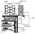
図1はジャイロセンサー1の要部を示す模式的部分平面図であり、図2は本発明の実施形態に係るジャイロセンサー1の模式的平面図であり、図3は図2に示すジャイロセンサー1のA−A線断面図である。
Embodiments of the present invention will be described below with reference to the drawings.
FIG. 1 is a schematic partial plan view showing the main part of the gyro sensor 1, FIG. 2 is a schematic plan view of the gyro sensor 1 according to the embodiment of the present invention, and FIG. 3 is a gyro sensor 1 shown in FIG. It is an AA sectional view taken on the line.
これらの図に示すように、ジャイロセンサー1は、基板60を備えており、この板面を直交座標でxy平面とした場合(図2参照)、基板60上のx軸方向に、2つのジャイロセンサー部10が、基板60との間に隙間を設けた状態で配列されている。2つのジャイロセンサー部10はキャップ70で覆われ、密閉されている。
As shown in these drawings, the gyro sensor 1 includes a substrate 60, and when this plate surface is an xy plane with orthogonal coordinates (see FIG. 2), two gyro sensors are arranged in the x-axis direction on the substrate 60. The
基板60は例えばガラスで形成されている。ジャイロセンサー部10は、例えばシリコンで形成されており、ジャイロセンサー部10の全体の外形はエッチングで形成される。
The substrate 60 is made of, for example, glass. The
2つのジャイロセンサー部10各々を構成する以下で説明する主たる構成要素は、y軸に対して線対称に配置されている。
ジャイロセンサー部10は、中央部に枠型の駆動マス20を備えている。駆動マス20の内側には駆動マス20に連結された枠型の検出マス30が設けられている。なお、検出マス30は、駆動マス20の内側に限らず、駆動マス20の外側に配置されていてもよい。また、駆動マス20及び検出マス30の形状は枠型に限定されるものではなく、質量体であればよく、形状は問わない。例えばコの字形状であってもよい。
The main components described below constituting each of the two
The
一対の駆動マス20のそれぞれは、四隅部分を連結バネ部12,駆動用バネ部14で基板60に支持されており、基板60の上面と平行な平面運動が可能となっている。各バネ部12,14は駆動マス20が特にその並び方向(x軸方向)(「第1方向」に対応)に往復振動できるように伸縮方向が設定されている。2つの駆動マス20同士の対向する2つの角部同士は、互いに近接離反する方向(x軸方向)に弾発力が出るように連結バネ部12で連結されている。各連結バネ部12は、連結バネ部12の中間部分に設定されたアンカー部(「第2のアンカー部」に対応)76により基板60に支持されている。また、駆動マス20同士の対向する辺と反対側の辺の2つの角部は、それぞれ駆動用バネ部14に連結されている。駆動用バネ部14は、アンカー部(「第1のアンカー部」に対応)72を基板60との固定支持点として、上記連結バネ部12と同様に作用し、駆動マス20をx軸方向に沿って変位移動できるように弾性支持する。なお、駆動マス20各々の四隅に配置されたバネ部12、14のバネ定数は等しくなっており、駆動マス20はそれぞれ独立してx軸方向に沿った平面振動が可能とされている。
Each of the pair of
一方、駆動マス20同士の対向する辺と直交する2つの各辺には、2つの駆動部22が連結されている。駆動マス20は、駆動部22により駆動されてx軸方向に振動する。駆動部22は、駆動マス20に連結された可動電極部24と、当該可動電極部24に対向して設けられ、基板60に固定された固定電極部26と、を備えている。可動電極部24及び固定電極部26は、櫛歯状の電極指を有している。可動電極部24及び固定電極部26の電極指は、交互に一定の間隔をおいて配置されている。
On the other hand, two
駆動部22に交流電圧をかけることにより、可動電極部24は固定電極部26との間の静電引力によりx軸方向に振動し、当該可動電極部24に連結されている駆動マス20もx軸方向に振動する。2つのジャイロセンサー部10の駆動部22に逆位相の交流電圧を印加することにより、2つの駆動マス20は互いに反対方向に振動する。
By applying an AC voltage to the
駆動マス20のx軸方向に沿った2つの各辺は、検出マス30のx軸方向に沿った2つの各辺にそれぞれy軸方向に伸縮性を持たせた2つの検出用バネ部16で連結されている。これにより検出マス30は、駆動マス20に連動してx軸方向へ振動可能とされている。2つの駆動マス20がx軸方向であって互いに反対方向に振動した状態で、z軸周りの角速度を受けると、2つの検出マス30はコリオリ力を受け、y軸方向であって互いに反対方向に振動する。
The two sides along the x-axis direction of the
検出マス30内には、検出電極部32が配置されている。検出電極部32は、検出マス30に横桟状に並んで配置された複数(実施形態では2本)の可動電極34と、前記可動電極34のそれぞれを挟み込むように平行に配置され、基板60に固定された固定電極36とから構成されている。
A
検出マス30がZ軸回りに回転すると、検出マス30に連結された可動電極34と固定電極36との間の距離が変化し、静電容量が変化する。その静電容量の変化量からZ軸回りの角速度を検出することができる。
When the
図1及び図2に示すように、駆動用マス20の外側コーナ部分に連結されている駆動用バネ部14は、y軸方向に複数並んだバネ片をつづら折状に連結してx軸方向に伸縮可能とされている。この駆動用バネ部14は、一端が駆動マス20に連結され、他端がアンカー部72を介して島部(「第1の島部」に対応)40に連結されている。島部40はアンカー部72と一体に形成され、底面が基板60に固定されている。この島部40は矩形平板とされており、駆動マス20や検出マス30、あるいは駆動用バネ部14と同一平面となるように形成されている。島部40、アンカー部72、駆動マス20並びに駆動用バネ部14は電気的に接続されており、したがってこれらは電気的に同電位となる。なお、上述した実施形態ではアンカー部72と島部40に別の符号を付して説明したが、上述したようにアンカー部72と島部40とは一体的に形成されて基板60に固定されているため、アンカー部72と島部40でアンカーとしての機能を有する。
As shown in FIGS. 1 and 2, the
島部40は、一対の駆動マス20に隣接して配置されている。この実施形態では、図2に示すように、各駆動マス20の振動方向における外側縁辺に対向し、一対の上下コーナ部分に隣接した位置に配置されている。したがって、島部40は、y軸中心線を挟んで1対、x軸中心線を挟んで一対の合計4箇所設けられ、それぞれが対称配置とされている。島部40は、駆動マス20に対向する位置に、平板の一部を駆動マス20に向けて張り出すように形成され、駆動マス20との振動方向に沿った離間距離を規定する距離規定部(「第1の距離規定部」に対応)42を備えている。この距離規定部42は矩形領域を形成しており、その張り出し先端縁は駆動マス20の外側縁部と平行とされている。距離規定部42の駆動マス20に対向する面には、複数の突起44が設けられている。なお、複数の各突起44の高さは異なっていてもよいし、設ける突起44の数は1つであってもよい。
The
このように突起44を設けることで、過度な物理量が印加されたり、外部からの衝撃により駆動マス20が大きくx軸方向に変位したとしても、突起44により駆動マス20との接触面積が小さい状態で衝突することになる。これにより、駆動マス20の過剰な変位を抑制することができ、駆動マス20の破損を防ぐことができる。また、島部40と駆動マス20とは、駆動用バネ部14及びアンカー部72に連結されており、全体として同電位であるため、島部40と駆動マス20とが接触したとしても引き合わないため、島部40と駆動マス20とが貼り付くのを防止することができる。
By providing the
また、y軸方向に沿って駆動マス20と対向させて1対の島部40を設けたため、2つの各島部40と駆動マス20とは同電位であることから、駆動マス20の振動にy軸方向に振動する成分があってねじれが生じていたとしても、当該ねじれを補正することができる。なお、島部40の数は1対に限らず、3つ以上であってもよい。
In addition, since the pair of
ここで、図1に示すように、突起44と駆動マス20との距離Dは、設計時に予め設定された駆動マス20の駆動振幅よりも大きく、かつ、駆動部22の固定電極部26で規制される可動電極部24が中立位置からx軸方向へ振動可能な最大振幅dよりも小さくなるように、距離規定部42で調整しておくのが望ましい。
Here, as shown in FIG. 1, the distance D between the
これにより、駆動マス20が突起44に接触して予め設計された駆動振幅で振動できないという不具合を防ぐことができる。さらに、駆動部22の可動電極部24が固定電極部26に接触する前に、駆動マス20が突起44に接触するため、過度な電圧を印加した場合等に可動電極部24が固定電極部26に衝突して破損するのを防ぐことができる。
なお、突起44は、距離規定部42のみならず、距離規定部42に対向する駆動マス20に設けてもよいし、或いは駆動マス20側のみに設けてもよい。突起44を距離規定部42に対向する駆動マス20にも設ける場合には、駆動マス20に設けた突起44と距離規定部42に設けた突起44との距離を距離Dとして用い、また、突起44を駆動マス20側に設ける場合には、駆動マス20に設けた突起44と距離規定部42の駆動マス20に対向する面との距離を距離Dとして用いればよい。
要するに、突起44を駆動マス20の島部40に対向する面と島部40の駆動マス20に対向する面との少なくとも一方に設ける場合、駆動マス20及び島部40の間の最短距離、すなわち、駆動マス20の、島部40が備える距離規定部42に対向する面と、距離規定部42の駆動マス20に対向する面と、の間の距離から、設けられた突起44の高さ(図ではx軸方向の長さ)の分を除いた距離を、距離Dとして用いればよい。
As a result, it is possible to prevent a problem that the driving
The
In short, when the
図2に示すように、2つの駆動マス20の間には、y軸方向に延びる島部(「第2の島部」に対応)50が設けられている。島部50はアンカー部76と一体に形成され、底面が基板60に固定されている。島部50は、2つの駆動マス20に対向する位置それぞれに、矩形状に両サイドの駆動マス20に向けて張り出され、張り出し先端縁を駆動マス20の内側縁辺と平行に形成され、当該対向する駆動マス20との距離を規定する距離規定部(「第2の距離規定部」に対応)52を備えている。距離規定部52の駆動マス20に対向する面には、複数の突起54が設けられている。上記島部50は、アンカー部76、連結バネ部12、距離規定部52及び駆動マス20と電気的に接続されているため、これらは電気的に同電位となる。なお、上述した実施形態ではアンカー部76と島部50に別の符号を付して説明したが、上述したようにアンカー部76と島部50とは一体的に形成されて基板60に固定されているため、アンカー部76と島部50でアンカーとしての機能を有する。
As shown in FIG. 2, an island portion (corresponding to a “second island portion”) 50 extending in the y-axis direction is provided between the two
この突起54により、駆動マス20同士が互いに接近する方向に振動する場合にも、駆動マス20同士の衝突を防ぐことができ、駆動マス20が突起54と衝突することで過剰変位を抑制しつつ、接触面積が極小であるため貼り付きを防止することができる。なお、突起54と駆動マス20の突起54に対向する面との距離を、突起44と駆動マス20の突起44に対向する面との距離と同様に、予め設定された駆動マス20の駆動振幅よりも大きく、可動電極部24の最大振幅dよりも小さくすることで、上記と同様の効果が得られる。また、突起54を設けた距離規定部52を、駆動マス20に対向させて2つ以上設けることで、島部40を2つ設ける場合の上述した効果と同様な効果を得ることができる。
なお、突起54は、距離規定部52のみならず、駆動マス20の距離規定部52に対向する面に設けてもよいし、或いは駆動マス20側のみに設けてもよい。
Even when the
The
また、検出マス30のx軸方向に沿った辺の外側面、及び駆動マス20と検出マス30とを連結する検出用バネ部16の折り返し部分には、突起56が設けられている。この突起56により、駆動マス20や検出マス30がy軸方向に大きく変位したとしても、突起56で過剰変位を抑制することができ、破損を防ぐことができる。また、突起56との衝突時の接触面積が小さく、さらに接触箇所は同電位であるため、貼り付きを防止することができる。なお、突起56は、検出マス30のx軸方向の内側面に設けてもよいし、駆動マス20x軸方向の内側面や外側面に設けてもよい。或いは検出用バネ部16のみに設けてもよいし、検出マス30のみに設けてもよい。
Further, a
また、図3に示すように、平面視で基板60の駆動マス20に重なる位置には、突起62が設けられている。この突起62は、基板60にアンカー部72、76等の外形をエッチングにより形成する際に同時に形成することができる。この突起62により、駆動マス20がz軸方向に大きく変位したとしても、突起62と衝突するため、過剰変位を抑制することができ、破損を防ぐことができる。また、衝突時の接触面積が小さく接触部分同士は引き合わないため、貼り付きを防止することができる。なお、平面視で基板60の駆動マス20に重なる位置のみならず、平面視で基板60の検出マス30に重なる位置に突起62を設けてもよいし、或いは、平面視で基板60の検出マス30に重なる位置のみに突起62を設けてもよい。
Further, as shown in FIG. 3, a
以上説明したように、過度な物理量の印加や落下等の衝撃により、駆動マス20が大きく変位して突起44、54、56、62に衝突したとても、突起44、54、56、62により衝撃が緩和されるため、駆動マス20の破損を防ぐことができる。また、突起44、54、56、62に衝突した際の接触面積は小さく、駆動マス20と突起44、54、56、62とは引き合わないため、接触部分同士の貼り付きを防止することができる。
As described above, the driving
また、距離規定部42、52によりx軸方向の長さを調整して、突起44、54と駆動マス20との距離を調整することができるため、駆動マス20の予め設計した駆動振幅を妨げないようにすることができるとともに、駆動部22の固定電極部26と可動電極部24との間に突起を形成することなく、可動電極部24が固定電極部26に衝突しないように設計することができる。
Further, since the distance between the
なお、上述した実施形態では、ジャイロセンサー1は、2つのジャイロセンサー部10を有するとして説明したが、1つのジャイロセンサー部10を有していてもよい。
In the above-described embodiment, the gyro sensor 1 has been described as including the two
次に、本発明の電子機器を説明する。
図4は、本発明の電子機器を適用したモバイル型(またはノート型)のパーソナルコンピューターの構成を示す斜視図である。
Next, the electronic apparatus of the present invention will be described.
FIG. 4 is a perspective view showing a configuration of a mobile (or notebook) personal computer to which the electronic apparatus of the present invention is applied.
この図において、パーソナルコンピューター1100は、キーボード1102を備えた本体部1104と、表示ユニット1106とにより構成され、表示ユニット1106は、本体部1104に対しヒンジ構造部を介して回動可能に支持されている。
このようなパーソナルコンピューター1100には、ジャイロセンサー1が内蔵されている。
In this figure, a
Such a
図5は、本発明の電子機器を適用した携帯電話機(PHSも含む)の構成を示す斜視図である。
この図において、携帯電話機1200は、アンテナ(図示せず)、複数の操作ボタン1202、受話口1204および送話口1206を備え、操作ボタン1202と受話口1204との間には、表示部が配置されている。
このような携帯電話機1200には、ジャイロセンサー1が内蔵されている。
FIG. 5 is a perspective view showing a configuration of a mobile phone (including PHS) to which the electronic apparatus of the present invention is applied.
In this figure, a
Such a
図6は、本発明の電子機器を適用したディジタルスチルカメラの構成を示す斜視図である。なお、この図には、外部機器との接続についても簡易的に示されている。
ここで、通常のカメラは、被写体の光像により銀塩写真フィルムを感光するのに対し、ディジタルスチルカメラ1300は、被写体の光像をCCD(Charge Coupled Device)などの撮像素子により光電変換して撮像信号(画像信号)を生成する。
FIG. 6 is a perspective view showing the configuration of a digital still camera to which the electronic apparatus of the present invention is applied. In this figure, connection with an external device is also simply shown.
Here, an ordinary camera sensitizes a silver halide photographic film with a light image of a subject, whereas a
ディジタルスチルカメラ1300におけるケース(ボディー)1302の背面には、表示部が設けられ、CCDによる撮像信号に基づいて表示を行う構成になっており、表示部は、被写体を電子画像として表示するファインダとして機能する。
また、ケース1302の正面側(図中裏面側)には、光学レンズ(撮像光学系)やCCDなどを含む受光ユニット1304が設けられている。
A display unit is provided on the back of a case (body) 1302 in the
A
撮影者が表示部に表示された被写体像を確認し、シャッタボタン1306を押下すると、その時点におけるCCDの撮像信号が、メモリ1308に転送・格納される。
また、このディジタルスチルカメラ1300においては、ケース1302の側面に、ビデオ信号出力端子1312と、データ通信用の入出力端子1314とが設けられている。そして、図示されるように、ビデオ信号出力端子1312にはテレビモニタ1430が、デ−タ通信用の入出力端子1314にはパーソナルコンピューター1440が、それぞれ必要に応じて接続される。さらに、所定の操作により、メモリ1308に格納された撮像信号が、テレビモニタ1430や、パーソナルコンピューター1440に出力される構成になっている。
When the photographer confirms the subject image displayed on the display unit and presses the
In the
このようなディジタルスチルカメラ1300には、ジャイロセンサー1が内蔵されている。
このような電子機器は、高感度および耐衝撃性に優れたジャイロセンサー1を備えるので、優れた信頼性を有する。
Such a
Since such an electronic device includes the gyro sensor 1 having high sensitivity and excellent impact resistance, the electronic device has excellent reliability.
なお、本発明の電子機器は、図4のパーソナルコンピューター(モバイル型パーソナルコンピューター)、図5の携帯電話機、図6のディジタルスチルカメラの他にも、例えば、インクジェット式吐出装置(例えばインクジェットプリンタ)、ラップトップ型パーソナルコンピューター、テレビ、ビデオカメラ、ビデオテープレコーダ、カーナビゲーション装置、ページャ、電子手帳(通信機能付も含む)、電子辞書、電卓、電子ゲーム機器、ワードプロセッサ、ワークステーション、テレビ電話、防犯用テレビモニタ、電子双眼鏡、POS端末、医療機器(例えば電子体温計、血圧計、血糖計、心電図計測装置、超音波診断装置、電子内視鏡)、魚群探知機、各種測定機器、計器類(例えば、車両、航空機、船舶の計器類)、フライトシュミレータ等に適用することができる。 In addition to the personal computer (mobile personal computer) in FIG. 4, the mobile phone in FIG. 5, and the digital still camera in FIG. Laptop personal computer, TV, video camera, video tape recorder, car navigation device, pager, electronic notebook (including communication function), electronic dictionary, calculator, electronic game device, word processor, workstation, video phone, crime prevention TV monitor, electronic binoculars, POS terminal, medical equipment (for example, electronic thermometer, blood pressure monitor, blood glucose meter, electrocardiogram measuring device, ultrasonic diagnostic device, electronic endoscope), fish detector, various measuring devices, instruments (for example, Vehicle, aircraft, ship instrumentation), Fleetsch It can be applied to a regulator or the like.
以上、本発明のジャイロセンサー、および電子機器について図示の実施形態に基づいて説明したが、本発明はこれらに限定されるものでなはなく、特許請求の範囲に記載された本発明の技術思想の範囲で種々の変形が可能である。 The gyro sensor and the electronic device of the present invention have been described based on the illustrated embodiments. However, the present invention is not limited to these, and the technical idea of the present invention described in the claims Various modifications are possible within the range described above.
1………ジャイロセンサー、10………ジャイロセンサー部、12………連結バネ部、14………駆動用バネ部、16………検出用バネ部、20………駆動マス、22………駆動部、24………可動電極部、30………検出マス、32………検出電極部、34………可動電極、36………固定電極、40………島部、42………距離規定部、44………突起、50………島部、52………距離規定部、54………突起、56………突起、60………基板、62………突起、70………キャップ、72………アンカー部、76………アンカー部。 DESCRIPTION OF SYMBOLS 1 ......... Gyro sensor, 10 ......... Gyro sensor part, 12 ......... Connecting spring part, 14 ......... Driving spring part, 16 ......... Detecting spring part, 20 ......... Driving mass, 22 ... ...... Driver, 24 ... Movable electrode, 30 ... Detection mass, 32 ... Detection electrode, 34 ... Movable electrode, 36 ... Fixed electrode, 40 ... Island, 42 ......... Distance defining part, 44 ......... Protrusions, 50 ......... Island part, 52 ......... Distance defining parts, 54 ......... Protrusions, 56 ...... Protrusions, 60 ......... Board, 62 ......... Projection, 70... Cap, 72... Anchor portion, 76.
Claims (7)
駆動部により第1方向に駆動される枠状の駆動マスと、
平面視にて、前記駆動マスに対して、前記第1方向と直交する方向に沿って配置されているつづら折り状の検出用バネ部により前記枠状の駆動マスの内側に連結されている検出マスと、
一端が前記駆動マスに連結され、他端が前記基板上に設けられている第1アンカー部に固定されている駆動用バネ部と、
前記第1アンカー部に接続され、前記第1方向に沿って前記駆動マスと並んで配置され、前記駆動マスに電気的に接続されている第1の島部と、
前記駆動マスの前記第1の島部に対向している面、及び前記第1の島部の前記駆動マスに対向している面の少なくとも一方に設けられている第1の突起と、
平面視で、前記基板の前記駆動マス、及び前記検出マスの少なくとも一方と重なる位置に設けられている第4の突起と、
を含み、
前記第4の突起は、前記基板と一体形成されており、
前記駆動部は、
前記駆動マスに接続されている可動電極部と、
前記可動電極部に対向して設けられている固定電極部と、
を含み、
前記検出マスは、
前記検出マスに接続されている検出用の可動電極と、
前記検出用の可動電極と対向するように配置されている検出用の固定電極と、
を含み、
前記駆動マスと、前記第1の島部と、の間の最短距離は、前記駆動マスの駆動振幅よりも大きく、且つ、前記可動電極部の最大振幅よりも小さい、
ことを特徴とするジャイロセンサー。 A substrate,
A frame-shaped drive mass driven in the first direction by the drive unit;
In plan view, the relative driving mass, wherein the frame-shaped sensing mass being connected to the inside of the driving mass by zigzag of the detection spring portions arranged along a direction perpendicular to the first direction When,
One end connected to the driving mass, a driving spring portion and the other end is fixed to the first anchor portion provided on said substrate,
Said first connected to the anchor portion, the first along a direction arranged alongside the driving mass, the first island portion is electrically connected to the driving mass,
A first protrusion provided the first island portion facing the surface, and at least one of the side facing the driving mass of the first island part of the driving mass,
A fourth protrusion provided at a position overlapping at least one of the drive mass and the detection mass of the substrate in plan view;
Including
The fourth protrusion is formed integrally with the substrate;
The drive unit is
A movable electrode portion connected to the drive mass;
A fixed electrode portion provided to face the movable electrode portion;
Including
The detection mass is
A movable electrode for detecting connected to said sensing mass,
A fixed electrode for detection are arranged so as to face the movable electrode for said detection,
Including
Said driving mass, said first island part, the shortest distance between, greater than the drive amplitude of the driving mass, and smaller than the maximum amplitude of the movable electrode portion,
This is a gyro sensor.
前記第1の島部は、
前記駆動マスに対向している位置の一部が、前記駆動マスに向けて張り出し、前記駆動マスとの間の距離を規定する第1の距離規定部を含み、
前記第1の突起は、
前記駆動マスの前記第1の距離規定部に対向している面、及び前記第1の距離規定部の前記駆動マスに対向している面の少なくとも一方に設けられている、
ことを特徴とするジャイロセンサー。 In claim 1,
The first island is
Part of the position facing the said driving mass is protruding toward the driving mass, including a first distance defining portion for defining the distance between the driving mass,
The first protrusion is
Provided on at least one of a surface of the driving mass facing the first distance defining portion and a surface of the first distance defining portion facing the driving mass ;
This is a gyro sensor.
前記駆動マスは、前記第1方向に沿って、2つ設けられ、
前記2つの前記駆動マスを連結し、中間部が第2アンカー部で固定されている連結バネ部と、
前記2つの前記駆動マスの間に配置され、前記第2アンカー部に接続されている第2の島部と、
前記駆動マスの前記第2の島部に対向している面、及び前記第2の島部の前記駆動マスに対向している面の少なくとも一方に設けられている第2の突起と
を含む、
ことを特徴とするジャイロセンサー。 In claim 1 or 2,
The driving mass along the first direction, providing two al is,
A connecting spring portion connecting the two driving masses, and having an intermediate portion fixed by a second anchor portion;
Disposed between said two of said driving mass, a second island portion connected to the second anchor portion,
The second island portion facing the surface of the driving mass, and a second protrusion provided on at least one of the side facing the driving mass of the second island portion,
This is a gyro sensor.
前記第2の島部は、
前記2つの駆動マスの各々に対向している各々の位置の一部が、前記2つの駆動マスの各々に向けて張り出し、前記駆動マスとの間の距離を規定する第2の距離規定部を含み、
前記第2の突起は、
前記駆動マスの前記第2の距離規定部に対向する面、及び前記第2の距離規定部の前記駆動マスに対向する面の少なくとも一方に設けられている、
ことを特徴とするジャイロセンサー。 In claim 3,
The second island is
Some of the positions of the respective facing the each of the two driving masses, overhang toward each of the two driving masses, the second distance defining portion for defining the distance between said driving mass Including
The second protrusion is
Provided on at least one of a surface of the driving mass facing the second distance defining portion and a surface of the second distance defining portion facing the driving mass ;
This is a gyro sensor.
前記第1の島部は、前記第1方向に交差する方向に沿って少なくとも一対設けられている、
ことを特徴とするジャイロセンサー。 In any one of Claims 1 thru | or 4,
At least one pair of the first island portions is provided along a direction intersecting the first direction .
This is a gyro sensor.
前記検出マス、及びと前記検出用バネ部の少なくとも一方に第3の突起が設けられている、
ことを特徴とするジャイロセンサー。 It said sensing mass in any one of claims 1 to 5, and a third projection on at least one of the detecting spring portion is provided,
This is a gyro sensor.
ことを特徴とする電子機器。 It is provided with the gyro sensor according to any one of claims 1 to 6 .
An electronic device characterized by that .
Priority Applications (3)
| Application Number | Priority Date | Filing Date | Title |
|---|---|---|---|
| JP2012084617A JP6338813B2 (en) | 2012-04-03 | 2012-04-03 | Gyro sensor and electronic device using the same |
| US13/849,089 US8899112B2 (en) | 2012-04-03 | 2013-03-22 | Gyro sensor and electronic device including the same |
| CN201310116379.8A CN103363980B (en) | 2012-04-03 | 2013-04-03 | Gyrosensor and the electronic equipment of the gyrosensor is used |
Applications Claiming Priority (1)
| Application Number | Priority Date | Filing Date | Title |
|---|---|---|---|
| JP2012084617A JP6338813B2 (en) | 2012-04-03 | 2012-04-03 | Gyro sensor and electronic device using the same |
Publications (3)
| Publication Number | Publication Date |
|---|---|
| JP2013213754A JP2013213754A (en) | 2013-10-17 |
| JP2013213754A5 JP2013213754A5 (en) | 2015-05-21 |
| JP6338813B2 true JP6338813B2 (en) | 2018-06-06 |
Family
ID=49233077
Family Applications (1)
| Application Number | Title | Priority Date | Filing Date |
|---|---|---|---|
| JP2012084617A Active JP6338813B2 (en) | 2012-04-03 | 2012-04-03 | Gyro sensor and electronic device using the same |
Country Status (3)
| Country | Link |
|---|---|
| US (1) | US8899112B2 (en) |
| JP (1) | JP6338813B2 (en) |
| CN (1) | CN103363980B (en) |
Families Citing this family (11)
| Publication number | Priority date | Publication date | Assignee | Title |
|---|---|---|---|---|
| US8534127B2 (en) | 2009-09-11 | 2013-09-17 | Invensense, Inc. | Extension-mode angular velocity sensor |
| US9097524B2 (en) * | 2009-09-11 | 2015-08-04 | Invensense, Inc. | MEMS device with improved spring system |
| JP2014134481A (en) | 2013-01-11 | 2014-07-24 | Seiko Epson Corp | Physical quantity sensor, electronic apparatus, and mobile body |
| JP6195051B2 (en) | 2013-03-04 | 2017-09-13 | セイコーエプソン株式会社 | Gyro sensor, electronic device, and moving object |
| JP6288413B2 (en) | 2013-10-11 | 2018-03-07 | 三菱重工業株式会社 | A heat treatment method for stainless steel members and a method for producing stainless steel forgings. |
| JP2016099269A (en) * | 2014-11-25 | 2016-05-30 | セイコーエプソン株式会社 | Gyro sensor, electronic equipment, and mobile body |
| US9702889B2 (en) * | 2015-06-17 | 2017-07-11 | Richtek Technology Corporation | Micro-electro-mechanical system (MEMS) device |
| JP6597099B2 (en) * | 2015-09-15 | 2019-10-30 | セイコーエプソン株式会社 | Physical quantity sensor, electronic device and mobile object |
| US10119834B2 (en) * | 2015-12-10 | 2018-11-06 | Panasonic Corporation | MEMS sensor with voltage sensing of movable mass |
| CN113075838B (en) * | 2017-11-23 | 2022-11-29 | 核心光电有限公司 | Camera, manufacturing method thereof, mobile electronic equipment and method for reducing space occupied by bulges |
| JP7192437B2 (en) * | 2018-11-28 | 2022-12-20 | セイコーエプソン株式会社 | Inertial sensors, electronics and vehicles |
Family Cites Families (42)
| Publication number | Priority date | Publication date | Assignee | Title |
|---|---|---|---|---|
| EP0334334B1 (en) * | 1988-03-23 | 1995-06-07 | Fujitsu Limited | Photo-cathode image projection apparatus for patterning a semiconductor device |
| US5503018A (en) * | 1992-12-08 | 1996-04-02 | Alliedsignal Inc. | Tunnel current sensor with force relief protection |
| DE4414237A1 (en) | 1994-04-23 | 1995-10-26 | Bosch Gmbh Robert | Micromechanical vibrator of an oscillation gyrometer |
| DE19526903B4 (en) * | 1995-07-22 | 2005-03-10 | Bosch Gmbh Robert | Yaw rate sensor |
| US5600065A (en) * | 1995-10-25 | 1997-02-04 | Motorola, Inc. | Angular velocity sensor |
| US6250156B1 (en) * | 1996-05-31 | 2001-06-26 | The Regents Of The University Of California | Dual-mass micromachined vibratory rate gyroscope |
| JPH112526A (en) * | 1997-06-13 | 1999-01-06 | Mitsubishi Electric Corp | Vibrating angular velocity sensor |
| JPH11173851A (en) * | 1997-12-08 | 1999-07-02 | Murata Mfg Co Ltd | Angular velocity sensor |
| JP2000046560A (en) * | 1998-07-31 | 2000-02-18 | Aisin Seiki Co Ltd | Angular velocity sensor |
| DE19930779B4 (en) * | 1999-07-03 | 2010-05-06 | Robert Bosch Gmbh | Micromechanical component |
| DE10051973A1 (en) * | 2000-10-20 | 2002-05-02 | Bosch Gmbh Robert | Micromechanical component has seismic mass sprung-mounted by double U spring to be deflectable by external acceleration, stop(s) protrusion for limiting deflection of double U spring |
| JP3512004B2 (en) | 2000-12-20 | 2004-03-29 | トヨタ自動車株式会社 | Physical quantity detector |
| JP2002228680A (en) | 2001-02-02 | 2002-08-14 | Denso Corp | Capacity-type mechanical amount sensor |
| DE10108197A1 (en) | 2001-02-21 | 2002-09-12 | Bosch Gmbh Robert | Yaw rate sensor |
| DE10108196A1 (en) * | 2001-02-21 | 2002-10-24 | Bosch Gmbh Robert | Yaw rate sensor |
| US6928872B2 (en) | 2001-04-27 | 2005-08-16 | Stmicroelectronics S.R.L. | Integrated gyroscope of semiconductor material with at least one sensitive axis in the sensor plane |
| JP4134853B2 (en) * | 2003-09-05 | 2008-08-20 | 株式会社デンソー | Capacitive mechanical sensor device |
| DE10350037A1 (en) | 2003-10-27 | 2005-05-25 | Robert Bosch Gmbh | Yaw rate sensor |
| JP2005326310A (en) * | 2004-05-14 | 2005-11-24 | Hosiden Corp | Vibration sensor |
| US7518493B2 (en) * | 2005-12-01 | 2009-04-14 | Lv Sensors, Inc. | Integrated tire pressure sensor system |
| JP4887034B2 (en) * | 2005-12-05 | 2012-02-29 | 日立オートモティブシステムズ株式会社 | Inertial sensor |
| US7461552B2 (en) * | 2006-10-23 | 2008-12-09 | Custom Sensors & Technologies, Inc. | Dual axis rate sensor |
| US8042394B2 (en) | 2007-09-11 | 2011-10-25 | Stmicroelectronics S.R.L. | High sensitivity microelectromechanical sensor with rotary driving motion |
| US7677099B2 (en) * | 2007-11-05 | 2010-03-16 | Invensense Inc. | Integrated microelectromechanical systems (MEMS) vibrating mass Z-axis rate sensor |
| DE102007054505B4 (en) * | 2007-11-15 | 2016-12-22 | Robert Bosch Gmbh | Yaw rate sensor |
| JP2009156603A (en) * | 2007-12-25 | 2009-07-16 | Panasonic Corp | Combined sensor |
| US20090315644A1 (en) * | 2008-06-19 | 2009-12-24 | Honeywell International Inc. | High-q disk nano resonator device and method of fabricating the same |
| CN101740631B (en) * | 2008-11-07 | 2014-07-16 | 株式会社半导体能源研究所 | Semiconductor device and method for manufacturing the semiconductor device |
| TWI467663B (en) * | 2008-11-07 | 2015-01-01 | Semiconductor Energy Lab | Semiconductor device and method for manufacturing the semiconductor device |
| IT1391973B1 (en) * | 2008-11-26 | 2012-02-02 | St Microelectronics Rousset | MONO OR BIASSIAL MICROELECTROMECHANICAL GYROSCOPE WITH INCREASED SENSITIVITY TO THE ANGULAR SPEED DETECTION |
| ITTO20090489A1 (en) * | 2008-11-26 | 2010-12-27 | St Microelectronics Srl | READING CIRCUIT FOR A MULTI-AXIS MEMS GYROSCOPE WITH DETECTED DETECTION DIRECTIONS COMPARED TO THE REFERENCE AXES, AND CORRESPONDING MEMS MULTI-AXIS GIROSCOPE |
| IT1391972B1 (en) * | 2008-11-26 | 2012-02-02 | St Microelectronics Rousset | MICROELETTROMECHANICAL GYROSCOPE WITH ROTARY DRIVE MOVEMENT AND IMPROVED ELECTRICAL CHARACTERISTICS |
| DE102009000345A1 (en) * | 2009-01-21 | 2010-07-22 | Robert Bosch Gmbh | Yaw rate sensor |
| US8256290B2 (en) * | 2009-03-17 | 2012-09-04 | Minyao Mao | Tri-axis angular rate sensor |
| US9201091B2 (en) * | 2009-04-14 | 2015-12-01 | Atlantic Inertial Systems Limited | Accelerometer control systems |
| US8739626B2 (en) * | 2009-08-04 | 2014-06-03 | Fairchild Semiconductor Corporation | Micromachined inertial sensor devices |
| US8534127B2 (en) * | 2009-09-11 | 2013-09-17 | Invensense, Inc. | Extension-mode angular velocity sensor |
| CN101759136B (en) * | 2009-12-25 | 2011-08-31 | 紫光股份有限公司 | Fully-decoupled vibrating micromechanical gyroscope |
| JP5682267B2 (en) * | 2010-01-12 | 2015-03-11 | ソニー株式会社 | Angular velocity sensor |
| DE102010000811A1 (en) * | 2010-01-12 | 2011-07-14 | Robert Bosch GmbH, 70469 | Micromechanical rotation rate sensor with two sensitive axes and coupled detection modes |
| US8377799B2 (en) * | 2010-03-31 | 2013-02-19 | Semiconductor Energy Laboratory Co., Ltd. | Method of manufacturing SOI substrate |
| JP5350339B2 (en) * | 2010-08-12 | 2013-11-27 | 株式会社日立製作所 | Micro-electromechanical system and manufacturing method thereof |
-
2012
- 2012-04-03 JP JP2012084617A patent/JP6338813B2/en active Active
-
2013
- 2013-03-22 US US13/849,089 patent/US8899112B2/en active Active
- 2013-04-03 CN CN201310116379.8A patent/CN103363980B/en active Active
Also Published As
| Publication number | Publication date |
|---|---|
| JP2013213754A (en) | 2013-10-17 |
| US8899112B2 (en) | 2014-12-02 |
| CN103363980B (en) | 2017-05-31 |
| CN103363980A (en) | 2013-10-23 |
| US20130255377A1 (en) | 2013-10-03 |
Similar Documents
| Publication | Publication Date | Title |
|---|---|---|
| JP6338813B2 (en) | Gyro sensor and electronic device using the same | |
| JP6020793B2 (en) | Physical quantity sensor and electronic equipment | |
| US9383383B2 (en) | Physical quantity sensor, manufacturing method thereof, and electronic apparatus | |
| US9470703B2 (en) | Physical quantity sensor and electronic apparatus | |
| JP6098780B2 (en) | Gyro sensor and electronics | |
| JP5930183B2 (en) | Physical quantity sensor and electronic equipment | |
| JP6344033B2 (en) | Angular velocity sensor, electronic device and moving object | |
| JP2013160554A (en) | Physical quantity sensor, manufacturing method thereof, and electronic apparatus | |
| JP6623634B2 (en) | Physical quantity sensors, electronic devices and moving objects | |
| US9939270B2 (en) | Physical quantity sensor element, physical quantity sensor, electronic equipment, and movable body | |
| JP6558110B2 (en) | Physical quantity sensor, electronic device and mobile object | |
| JP6127377B2 (en) | Gyro sensor and electronics | |
| JP6657626B2 (en) | Physical quantity sensors, electronic devices and moving objects | |
| JP2014021037A (en) | Mems device, electronic module, electronic apparatus, and moving body | |
| JP5935402B2 (en) | Physical quantity sensor and electronic equipment | |
| US9939269B2 (en) | Physical quantity sensor element, physical quantity sensor, electronic equipment, and movable body | |
| JP6413462B2 (en) | Physical quantity sensor, physical quantity sensor device, electronic device and mobile object | |
| JP6024163B2 (en) | Gyro sensor and electronic device | |
| JP2013213728A (en) | Gyro sensor and electronic apparatus | |
| JP2015007560A (en) | Function element, physical quantity sensor, electronic apparatus and moving body | |
| JP6447049B2 (en) | Physical quantity sensor, electronic device and mobile object | |
| JP6763458B2 (en) | Physical quantity sensors, electronic devices and moving objects | |
| JP2013217727A (en) | Gyro sensor and electronic apparatus | |
| JP2013125006A (en) | Angular velocity sensor and electronic equipment | |
| JP2013234913A (en) | Gyro sensor and electronic apparatus |
Legal Events
| Date | Code | Title | Description |
|---|---|---|---|
| A521 | Request for written amendment filed |
Free format text: JAPANESE INTERMEDIATE CODE: A523 Effective date: 20150401 |
|
| A621 | Written request for application examination |
Free format text: JAPANESE INTERMEDIATE CODE: A621 Effective date: 20150401 |
|
| A977 | Report on retrieval |
Free format text: JAPANESE INTERMEDIATE CODE: A971007 Effective date: 20160210 |
|
| A131 | Notification of reasons for refusal |
Free format text: JAPANESE INTERMEDIATE CODE: A131 Effective date: 20160223 |
|
| A521 | Request for written amendment filed |
Free format text: JAPANESE INTERMEDIATE CODE: A523 Effective date: 20160421 |
|
| A131 | Notification of reasons for refusal |
Free format text: JAPANESE INTERMEDIATE CODE: A131 Effective date: 20160913 |
|
| A521 | Request for written amendment filed |
Free format text: JAPANESE INTERMEDIATE CODE: A523 Effective date: 20161101 |
|
| A02 | Decision of refusal |
Free format text: JAPANESE INTERMEDIATE CODE: A02 Effective date: 20170411 |
|
| A521 | Request for written amendment filed |
Free format text: JAPANESE INTERMEDIATE CODE: A523 Effective date: 20170622 |
|
| A911 | Transfer to examiner for re-examination before appeal (zenchi) |
Free format text: JAPANESE INTERMEDIATE CODE: A911 Effective date: 20170913 |
|
| A912 | Re-examination (zenchi) completed and case transferred to appeal board |
Free format text: JAPANESE INTERMEDIATE CODE: A912 Effective date: 20171027 |
|
| A61 | First payment of annual fees (during grant procedure) |
Free format text: JAPANESE INTERMEDIATE CODE: A61 Effective date: 20180509 |
|
| R150 | Certificate of patent or registration of utility model |
Ref document number: 6338813 Country of ref document: JP Free format text: JAPANESE INTERMEDIATE CODE: R150 |