US8042394B2 - High sensitivity microelectromechanical sensor with rotary driving motion - Google Patents
High sensitivity microelectromechanical sensor with rotary driving motion Download PDFInfo
- Publication number
- US8042394B2 US8042394B2 US12/208,977 US20897708A US8042394B2 US 8042394 B2 US8042394 B2 US 8042394B2 US 20897708 A US20897708 A US 20897708A US 8042394 B2 US8042394 B2 US 8042394B2
- Authority
- US
- United States
- Prior art keywords
- mass
- sensing
- axis
- driving mass
- driving
- Prior art date
- Legal status (The legal status is an assumption and is not a legal conclusion. Google has not performed a legal analysis and makes no representation as to the accuracy of the status listed.)
- Ceased, expires
Links
- 230000035945 sensitivity Effects 0.000 title description 14
- 238000001514 detection method Methods 0.000 claims abstract description 65
- 230000006355 external stress Effects 0.000 claims abstract description 11
- 238000004873 anchoring Methods 0.000 claims 2
- 238000006073 displacement reaction Methods 0.000 description 13
- 230000001133 acceleration Effects 0.000 description 10
- 239000003990 capacitor Substances 0.000 description 8
- 239000000758 substrate Substances 0.000 description 7
- 230000014509 gene expression Effects 0.000 description 5
- 239000004065 semiconductor Substances 0.000 description 3
- 238000005516 engineering process Methods 0.000 description 2
- 239000000463 material Substances 0.000 description 2
- 238000000034 method Methods 0.000 description 2
- 238000012986 modification Methods 0.000 description 2
- 230000004048 modification Effects 0.000 description 2
- 229910021420 polycrystalline silicon Inorganic materials 0.000 description 2
- 230000005483 Hooke's law Effects 0.000 description 1
- 230000015572 biosynthetic process Effects 0.000 description 1
- 238000003486 chemical etching Methods 0.000 description 1
- 238000010276 construction Methods 0.000 description 1
- 230000008878 coupling Effects 0.000 description 1
- 238000010168 coupling process Methods 0.000 description 1
- 238000005859 coupling reaction Methods 0.000 description 1
- 238000010586 diagram Methods 0.000 description 1
- 230000010355 oscillation Effects 0.000 description 1
- 230000003534 oscillatory effect Effects 0.000 description 1
- 238000004513 sizing Methods 0.000 description 1
Images
Classifications
-
- G—PHYSICS
- G01—MEASURING; TESTING
- G01C—MEASURING DISTANCES, LEVELS OR BEARINGS; SURVEYING; NAVIGATION; GYROSCOPIC INSTRUMENTS; PHOTOGRAMMETRY OR VIDEOGRAMMETRY
- G01C19/00—Gyroscopes; Turn-sensitive devices using vibrating masses; Turn-sensitive devices without moving masses; Measuring angular rate using gyroscopic effects
- G01C19/56—Turn-sensitive devices using vibrating masses, e.g. vibratory angular rate sensors based on Coriolis forces
- G01C19/5705—Turn-sensitive devices using vibrating masses, e.g. vibratory angular rate sensors based on Coriolis forces using masses driven in reciprocating rotary motion about an axis
- G01C19/5712—Turn-sensitive devices using vibrating masses, e.g. vibratory angular rate sensors based on Coriolis forces using masses driven in reciprocating rotary motion about an axis the devices involving a micromechanical structure
-
- G—PHYSICS
- G01—MEASURING; TESTING
- G01P—MEASURING LINEAR OR ANGULAR SPEED, ACCELERATION, DECELERATION, OR SHOCK; INDICATING PRESENCE, ABSENCE, OR DIRECTION, OF MOVEMENT
- G01P15/00—Measuring acceleration; Measuring deceleration; Measuring shock, i.e. sudden change of acceleration
- G01P15/02—Measuring acceleration; Measuring deceleration; Measuring shock, i.e. sudden change of acceleration by making use of inertia forces using solid seismic masses
- G01P15/08—Measuring acceleration; Measuring deceleration; Measuring shock, i.e. sudden change of acceleration by making use of inertia forces using solid seismic masses with conversion into electric or magnetic values
- G01P15/125—Measuring acceleration; Measuring deceleration; Measuring shock, i.e. sudden change of acceleration by making use of inertia forces using solid seismic masses with conversion into electric or magnetic values by capacitive pick-up
-
- G—PHYSICS
- G01—MEASURING; TESTING
- G01P—MEASURING LINEAR OR ANGULAR SPEED, ACCELERATION, DECELERATION, OR SHOCK; INDICATING PRESENCE, ABSENCE, OR DIRECTION, OF MOVEMENT
- G01P15/00—Measuring acceleration; Measuring deceleration; Measuring shock, i.e. sudden change of acceleration
- G01P15/14—Measuring acceleration; Measuring deceleration; Measuring shock, i.e. sudden change of acceleration by making use of gyroscopes
-
- G—PHYSICS
- G01—MEASURING; TESTING
- G01P—MEASURING LINEAR OR ANGULAR SPEED, ACCELERATION, DECELERATION, OR SHOCK; INDICATING PRESENCE, ABSENCE, OR DIRECTION, OF MOVEMENT
- G01P15/00—Measuring acceleration; Measuring deceleration; Measuring shock, i.e. sudden change of acceleration
- G01P15/18—Measuring acceleration; Measuring deceleration; Measuring shock, i.e. sudden change of acceleration in two or more dimensions
-
- G—PHYSICS
- G01—MEASURING; TESTING
- G01P—MEASURING LINEAR OR ANGULAR SPEED, ACCELERATION, DECELERATION, OR SHOCK; INDICATING PRESENCE, ABSENCE, OR DIRECTION, OF MOVEMENT
- G01P15/00—Measuring acceleration; Measuring deceleration; Measuring shock, i.e. sudden change of acceleration
- G01P15/02—Measuring acceleration; Measuring deceleration; Measuring shock, i.e. sudden change of acceleration by making use of inertia forces using solid seismic masses
- G01P15/08—Measuring acceleration; Measuring deceleration; Measuring shock, i.e. sudden change of acceleration by making use of inertia forces using solid seismic masses with conversion into electric or magnetic values
- G01P2015/0805—Measuring acceleration; Measuring deceleration; Measuring shock, i.e. sudden change of acceleration by making use of inertia forces using solid seismic masses with conversion into electric or magnetic values being provided with a particular type of spring-mass-system for defining the displacement of a seismic mass due to an external acceleration
- G01P2015/0822—Measuring acceleration; Measuring deceleration; Measuring shock, i.e. sudden change of acceleration by making use of inertia forces using solid seismic masses with conversion into electric or magnetic values being provided with a particular type of spring-mass-system for defining the displacement of a seismic mass due to an external acceleration for defining out-of-plane movement of the mass
- G01P2015/0825—Measuring acceleration; Measuring deceleration; Measuring shock, i.e. sudden change of acceleration by making use of inertia forces using solid seismic masses with conversion into electric or magnetic values being provided with a particular type of spring-mass-system for defining the displacement of a seismic mass due to an external acceleration for defining out-of-plane movement of the mass for one single degree of freedom of movement of the mass
- G01P2015/0828—Measuring acceleration; Measuring deceleration; Measuring shock, i.e. sudden change of acceleration by making use of inertia forces using solid seismic masses with conversion into electric or magnetic values being provided with a particular type of spring-mass-system for defining the displacement of a seismic mass due to an external acceleration for defining out-of-plane movement of the mass for one single degree of freedom of movement of the mass the mass being of the paddle type being suspended at one of its longitudinal ends
Definitions
- the present invention relates to a high sensitivity microelectromechanical sensor having a rotary driving motion.
- a gyroscope whether uniaxial or biaxial
- an accelerometer whether uniaxial or biaxial
- microprocessing techniques enable formation of microelectromechanical structures or systems (the so-called MEMS) within layers of semiconductor material, which have been deposited (for example, in the case of a layer of polycrystalline silicon) or grown (for example, in the case of an epitaxial layer) on top of sacrificial layers, which are removed by chemical etching.
- MEMS microelectromechanical structures or systems
- Inertial sensors, accelerometers and gyroscopes obtained with this technology are encountering an increasing success, for example in the automotive field, in inertial navigation, or in the sector of portable devices.
- Gyroscopes operate according to the theorem of relative accelerations, exploiting Coriolis acceleration.
- Coriolis force an apparent force, referred to as Coriolis force, which causes a displacement thereof in a direction perpendicular to the direction of the linear velocity and to the axis of rotation.
- the movable mass is supported via springs that enable a displacement in the direction of the apparent force.
- the displacement is proportional to the apparent force, and consequently, based on the displacement of the movable mass, it is possible to detect the Coriolis force and the angular velocity that has generated it.
- the displacement of the movable mass can, for example, be detected capacitively, by measuring, in resonance conditions, the capacitance variations caused by the movement of movable electrodes, integrally fixed to the movable mass and operatively coupled to fixed electrodes.
- US2007/214883 assigned to STMicroelectronics Srl, discloses a microelectromechanical integrated sensor with a rotary driving motion, which is sensitive to pitch and roll angular velocities.
- This microelectromechanical sensor includes a single driving mass, anchored to a support at a single central point and driven with rotary motion about an axis, which passes through the central point and is orthogonal to the plane of the driving mass.
- the rotation of the driving mass enables two mutually orthogonal components of driving velocity in the plane of the mass.
- At least one through-opening is provided inside the driving mass, in which a sensing mass is arranged; the sensing mass is enclosed within the driving mass, suspended with respect to the substrate, and connected to the driving mass via flexible elements.
- the sensing mass is fixed to the driving mass during its rotary motion, and has a further degree of freedom of movement as a function of an external stress, in particular a Coriolis force acting on the sensor.
- the flexible elements allow the sensing mass to perform a rotary movement of detection about an axis lying in the plane of the sensor in response to a Coriolis acceleration acting in a direction perpendicular to the plane, in a way substantially decoupled from the driving mass.
- the microelectromechanical structure in addition to being compact (in so far as it envisages just one driving mass that encloses in its overall dimensions one or more sensing masses), enables with minor structural modifications, a uniaxial, biaxial or triaxial gyroscope (and/or an accelerometer, according to the electrical connections implemented) to be obtained, at the same time ensuring an excellent decoupling of the driving mass from the sensing mass during the movement of detection.
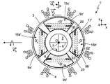
- the microelectromechanical sensor comprises a driving structure formed by a driving mass 3 and by a driving assembly 4 .
- the driving mass 3 has a circular geometry with radial symmetry, with a substantially planar configuration having a main extension in a plane defined by a first axis x and by a second axis y (referred to in what follows as “plane of the sensor xy”), and negligible dimension, with respect to the main extension, in a direction parallel to a third axis (referred to in what follows as “orthogonal axis z”), forming with the first and second axes x, y a set of three orthogonal axes fixed with respect to the sensor structure.
- the driving mass 3 has in the plane of the sensor xy substantially the shape of an annulus, and defines at the center a circular empty space 6 , the center O of which coincides with the centroid and the center of symmetry of the driving mass 3 .
- the driving mass 3 is anchored to a substrate 2 (e.g. of semiconductor material) by means of an anchorage 7 arranged at the center O, to which it is connected through elastic anchorage elements 8 .
- the elastic anchorage elements 8 depart in a crosswise configuration from the center O along a first axis of symmetry A and a second axis of symmetry B of the driving mass 3 , the axes of symmetry being parallel, respectively, to the first axis x and to the second axis y.
- the elastic anchorage elements 8 enable a rotary driving movement of the driving mass 3 about a drive axis passing through the center O, parallel to the orthogonal axis z and perpendicular to the plane of the sensor xy.
- the driving mass 3 has a first pair of through-openings 9 a , 9 b with a substantially rectangular shape elongated in a direction parallel to the second axis y, aligned in a diametric direction along the first axis of symmetry A, and set on opposite sides with respect to the empty space 6 ; and a second pair of through-openings 9 c , 9 d , which are aligned along the second axis of symmetry B, have a substantially rectangular shape elongated in a direction parallel to the first axis x, and are arranged on opposite sides with respect to the empty space 6 .
- the direction of alignment of the through-openings of each pair corresponds to a direction of detection of the microelectromechanical sensor 1 (in the case represented in the figure, coinciding with the first and second axes x, y).
- the driving assembly 4 comprises a plurality of driven arms 10 (for example, eight in number), extending externally from the driving mass 3 in a radial direction and spaced apart at a same angular distance, and a plurality of first and second driving arms 12 a , 12 b , extending parallel to, and on opposite sides of, respective driven arms 10 and anchored to the substrate 2 through respective anchorages.
- Each driven arm 10 carries a plurality of first electrodes 13 , extending in a direction perpendicular to, and on either side of, the same driven arm.
- each of the first and second driving arms 12 a , 12 b carries respective second electrodes 14 a , 14 b , extending towards the respective driven arm 10 and comb-fingered to the corresponding first electrodes 13 .
- the first driving arms 12 a are all arranged on the same side of the respective driven arms 10 and are all biased at a first voltage.
- the second driving arms 12 b are all arranged on the opposite side of the respective driven arms 10 , and are all biased at a second voltage.
- a driving circuit is connected to the second electrodes 14 a , 14 b so as to apply the first and second voltages and determine, by means of mutual and alternating attraction of the electrodes, an oscillatory rotary motion of the driving mass 3 about the drive axis, at a given oscillation frequency.
- the microelectromechanical sensor 1 further comprises a first pair of acceleration sensors with axis parallel to the orthogonal axis z, and in particular a first pair of sensing masses 16 a , 16 b , positioned, respectively, within the first through-opening 9 a and the second through-opening 9 b , so as to be completely enclosed and contained within the overall dimensions of the driving mass 3 in the plane of the sensor xy.
- the sensing masses 16 a , 16 b have a generally rectangular shape matching the shape of the respective through-opening 9 a , 9 b , and are formed by a first rectangular portion 17 , which is wider, and by a second rectangular portion 18 , which is narrower (along the first axis x), connected by a connecting portion 19 , which is shorter (in a direction parallel to the second axis y) than the first and second rectangular portions.
- Each sensing mass 16 a , 16 b has a centroid G located within the corresponding first rectangular portion 17 , and is supported by a pair of elastic supporting elements 20 .
- the elastic supporting elements 20 are connected to the connecting portion 19 , and extend towards the driving mass 3 , in a direction parallel to the second axis y. In other words, the elastic supporting elements 20 extend within recesses 21 provided at opposite sides of the sensing masses 16 a , 16 b .
- the elastic supporting elements 20 extend at a distance from the centroid G of the respective sensing mass 16 a , 16 b , and form torsional springs that are rigid for the rotary motion of the driving mass 3 , and also enable rotation of the sensing masses about an axis of rotation parallel to the second axis y and lying in the plane of the sensor xy (and, consequently, their movement outside the plane of the sensor xy).
- the microelectromechanical sensor 1 comprises a second pair of acceleration sensors with axis parallel to the orthogonal axis z, and in particular a second pair of sensing masses 16 c , 16 d housed within the through-openings 9 c , 9 d , substantially matching their shape, and completely enclosed and contained within the driving mass 3 .
- the sensing masses 16 c , 16 d are arranged as a result of a 90° rotation of the sensing masses 16 a , 16 b , and consequently the corresponding elastic supporting elements 20 extend parallel to the first axis x and enable rotation of the respective sensing masses about an axis of rotation parallel to the first axis x.
- a pair of first and second detection electrodes 22 , 23 is arranged underneath the first and second rectangular portions 17 , 18 of each one of the sensing masses 16 a - 16 d ; for example the detection electrodes 22 , 23 are constituted by regions of polycrystalline silicon formed on the substrate 2 , having equal dimensions, substantially corresponding to those of the second rectangular portion 18 .
- the first and second detection electrodes 22 , 23 are separated, respectively from the first and second rectangular portions 17 , 18 , by an air gap, and are connected to a read circuit.
- the first and second detection electrodes 22 , 23 hence form, together with the first and second rectangular portions 17 , 18 respective detection capacitors.
- the microelectromechanical sensor 1 is able to operate as a biaxial gyroscope, designed to detect an angular velocity ⁇ right arrow over ( ⁇ ) ⁇ x (in FIG. 1 assumed as being counterclockwise), about the first axis x, and an angular velocity ⁇ right arrow over ( ⁇ ) ⁇ y about the second axis y.
- the rotary movement of the driving mass 3 and of the sensing masses 16 a - 16 d about the drive axis can be represented by a driving-velocity vector ⁇ right arrow over (v) ⁇ a , linear and tangential to the circumference that describes the driving trajectory.
- the Coriolis force ⁇ right arrow over (F) ⁇ c is proportional to the vector product between the angular velocity ⁇ right arrow over ( ⁇ ) ⁇ x and the driving velocity ⁇ right arrow over (v) ⁇ a , and is hence directed along the orthogonal axis z, is zero in the points where the driving velocity ⁇ right arrow over (v) ⁇ a is parallel to the first axis x, and, in the points where it does not go to zero, it is directly proportional to the driving velocity ⁇ right arrow over (v) ⁇ a , and consequently it increases with the distance from the center O.
- the configuration of the elastic anchorage elements 8 is such as to inhibit, to a good approximation, movement of the driving mass 3 out of the plane of the sensor xy, thus allowing decoupling of the motion of detection of the sensing masses from the driving motion.
- the displacement of the sensing masses 16 a , 16 b out of the plane of the sensor xy causes a differential capacitive variation of the detection capacitors, the value of which is proportional to the angular velocity ⁇ right arrow over ( ⁇ ) ⁇ x , which can hence be determined in a per-se known manner via a purposely provided read circuit.
- the reading scheme is differential
- the presence of a pair of sensing masses enables automatic rejection of spurious linear accelerations along the orthogonal axis z.
- These accelerations in fact, cause a variation in the same direction of the detection capacitors, which is cancelled by the differential reading (on the contrary, the same structure can be operated as an accelerometer detecting accelerations along the orthogonal axis z, by modifying the electrical connections between the sensing masses and electrodes).
- the presence of the central anchorage 7 also enables rejection of spurious linear accelerations along the axes x and y, given that the arrangement of elastic anchorage elements 8 is extremely rigid in these directions, and does not enable displacement of the sensing masses.
- the described structure is able to mechanically reject spurious angular acceleration about the orthogonal axis z, since the frequency response of the sensor can be modeled as a very selective filter.
- the microelectromechanical sensor 1 is able to detect an angular velocity ⁇ right arrow over ( ⁇ ) ⁇ y about the second axis y.
- the rotary motion about the second axis y causes a Coriolis force, once again directed along the orthogonal axis z, which causes rotation of the sensing masses 16 c , 16 d about the axis of rotation parallel to the first axis x, and consequent opposite unbalancing of the corresponding detection capacitors.
- the rotation about the first axis x is not sensed by the second pair of sensing masses 16 c , 16 d , in so far as the resultant Coriolis force ⁇ right arrow over (F) ⁇ c is zero (on account of the fact that the vector product between the angular velocity ⁇ right arrow over ( ⁇ ) ⁇ x and the corresponding driving velocity ⁇ right arrow over (v) ⁇ a is, to a first approximation, zero).
- the rotation about the second axis y is not sensed for similar reasons by the first pair of sensing masses 16 a , 16 b , and consequently the two axes of detection are not affected and are substantially decoupled from one another.
- the described microelectromechanical sensor is not optimized with respect to its sensitivity to external stresses, in particular due to the size of the sensing masses, which is limited by the overall dimension of the driving mass.
- One embodiment of the present invention provides an integrated microelectromechanical structure that has an improved sensitivity to external stresses.
- an integrated microelectromechanical structure is consequently provided as defined in the present disclosure.
- FIG. 1 is a schematic top plan view of a microelectromechanical structure of a known type
- FIG. 2 is a schematic top plan view of a microelectromechanical structure according to one embodiment of the present invention
- FIG. 3 shows an enlarged portion of the microelectromechanical structure of FIG. 2 , showing a sensing mass
- FIGS. 4 and 5 show plots relating to geometrical quantities related to the sensing mass of FIG. 3 ;
- FIG. 6 shows a further embodiment of a microelectromechanical structure
- FIG. 7 shows a block diagram of a sensor device provided with the microelectromechanical structure according to a further embodiment of the invention.
- a microelectromechanical sensor is provided, wherein the geometrical shape of the sensing masses is such as to improve the overall sensitivity of the sensor.
- the microelectromechanical sensor differs from the sensor described with reference to FIG. 1 for a different shape of the through-openings made in the driving mass 3 , here denoted with 9 a ′- 9 d ′, and of the corresponding sensing masses, here denoted with 16 a ′- 16 d′.
- each of the through-openings 9 a ′- 9 d ′ has in the plane of the sensor xy the shape of a radial annulus sector whose inner radius R i can be as small as the inner radius of the driving mass 3 and outer radius R e can be as large as the outer radius of the same driving mass 3 .
- This radial annulus sector has arc-shaped inner and outer sides, and radially extending lateral sides. In the exemplary embodiment shown in FIG.
- the four through-openings 9 a ′- 9 d ′ are equally angularly spaced apart, the through-openings 9 a ′- 9 b ′ of the first pair being symmetric with respect to the second axis y, and the through-openings 9 c ′- 9 d ′ of the second pair being symmetric with respect to the first axis x.
- each of the sensing masses 16 a ′- 16 d ′ has a shape corresponding to, and matching, that of the respective through-opening 9 a ′- 9 d ′, thus having, in plan view, the overall shape of a radial annulus sector, and a radial geometry.
- each sensing mass 16 a ′- 16 d ′ is divided by the corresponding elastic supporting elements 20 into a first portion 17 ′, a second portion 18 ′ and the connecting portion 19 (the latter interposed between, and connected to, the elastic supporting elements 20 ).
- the first portion 17 ′ is wider than the second portion 18 ′ along the first and second axis x, y, so that the centroid G′ of the sensing mass is located therein, and has an arc-shaped concave outer side and radially extending lateral sides; the second portion 18 ′ has an arc-shaped convex outer side and radially extending lateral sides, aligned along the lateral sides of the first portion 17 ′.
- the elastic supporting elements 20 extending at a distance from the centroid G′ of the respective sensing mass 16 a ′- 16 d ′, form torsional springs that are rigid for the driving rotary motion of the driving mass 3 , and also enable rotation of the sensing masses outside the plane of the sensor xy (as previously described).
- the first and second detection electrodes 22 ′, 23 ′ are still arranged underneath the first and second portions 17 ′, 18 ′ of each one of the sensing masses 16 a ′- 16 d ′; in the embodiment of FIG. 2 , the detection electrodes 22 ′, 23 ′ have a trapezoidal shape in the plane of the sensor xy and are symmetric with respect to the axis defined by the elastic supporting elements 20 .
- Operation of the microelectromechanical sensor 1 ′ does not differ from the one previously discussed with reference to the structure of FIG. 1 , so that an angular velocity ⁇ right arrow over ( ⁇ ) ⁇ x about the first axis x or an angular velocity ⁇ right arrow over ( ⁇ ) ⁇ y about the second axis y are sensed by the sensor as a function of the displacement of the corresponding pair of sensing masses 16 a ′- 16 b ′ or 16 c ′- 16 d ′ out of the plane of the sensor xy (caused by the originated Coriolis force) and the associated capacitance variation of the detection capacitors.
- the Applicant has discovered that the previously described non-rectangular shape of the sensing masses 16 a ′- 16 d ′ allows the microelectromechanical sensor 1 ′ to achieve an improved sensitivity to external stresses (in particular to the angular velocities ⁇ right arrow over ( ⁇ ) ⁇ x , ⁇ right arrow over ( ⁇ ) ⁇ y ) without causing a variation of the structure resonance frequency.
- the solution herein described allows:
- the sensing mass 16 b ′ (in the following “radial sensing mass”) is compared to a traditional rectangular sensing mass 16 b (in the following “rectangular sensing mass”).
- Both sensing masses are symmetric with respect to the first axis x and are inscribed in the same annulus having inner radius R i and outer radius R e , so that the overall size of the sensor is the same in both cases; the position d of the elastic supporting elements 20 is also the same (the distance of the axis defined by the elastic supporting elements 20 from the center O being equal to d+R i ).
- tan ⁇ ( ⁇ ) h 1 2 ⁇ R i + d
- h 1 is the height of the rectangular sensing mass
- the length L 1 of the rectangular sensing mass may be also determined with geometrical considerations, by the expression:
- L 1 R e 2 - ( h 1 2 ) 2 - R i .
- x f , 1 2 3 ⁇ ( R i + L 1 ) 3 - R i 3 ( R i + L 1 ) 2 - R i 2 while the distance x f,2 between the center O and the centroid G′ of the radial sensing mass is given by:
- the radial sensing mass has a centroid G′ that is positioned at a distance farther away from the elastic supporting elements 20 (and the corresponding rotation axis) than the centroid G of any rectangular mass, inscribable within a same sector of the driving mass 3 and supported by elastic supporting elements extending along the same rotation axis.
- the radial sensing mass experiences a torque that is greater than the one experienced by the rectangular sensing mass and thus undergoes a greater rotational movement outside of the pane of the sensor xy, allowing to achieve a higher sensitivity in the detection of the external stresses.
- the rotation ⁇ s of the sensing mass resulting from the application of the Coriolis force F c is a function of the torque M t and of the stiffness k of the elastic supporting elements 20 , according to the following expression:
- the ratio between the rotation ⁇ s,1 of the rectangular sensing mass and the rotation ⁇ s,2 of the radial sensing mass can be expressed as:
- ⁇ s , 2 ⁇ s , 1 4 3 ⁇ ( x f , 2 - R i - d ) ( x f , 1 - R i - d ) ⁇ sin ⁇ ( ⁇ ) ⁇ ⁇ L 1 ⁇ ( R e 2 + R e ⁇ R i + R i 2 ) ( R e + R i ) ⁇ ( R e 2 - R i 2 - h 1 2 4 ) .
- FIG. 5 shows the plot of the above ratio as a function of the height h 1 of the rectangular sensing mass, considering the same numerical values previously discussed for FIG. 4 . Since the above ratio is always greater than one, it is evident that, considering a same external stress at input of the sensor (angular velocity), the output from the sensor (rotational movement outside the sensor plane xy) in the case of a radial sensing mass is always greater than the corresponding output in the case of a rectangular sensing mass.
- a further embodiment of the present invention envisages the provision of further anchorages and elastic anchorage elements connected to the driving mass 3 in order to improve the stiffness of the same driving mass 3 outside the plane of the sensor xy.
- the microelectromechanical sensor 1 ′ further comprises a first and a second external anchorage arrangements 30 , 31 , coupled to the driving mass 3 and the substrate 2 .
- first and second external anchorage arrangements 30 , 31 are positioned externally of the driving mass 3 , and are coupled to opposite sides of the same driving mass 3 , with respect to the empty space 6 and center O; in the exemplary embodiment shown in FIG. 6 , the first and second external anchorage arrangements 30 , 31 are aligned along the first axis x.
- Each one of the first and second external anchorage arrangements 30 , 31 includes a pair of external anchorages 32 (coupled to the substrate 2 ) and a pair of external elastic anchorage elements 33 , coupling a respective external anchorage 32 to the driving mass 3 .
- the external anchorages 32 and external elastic anchorage elements 33 of each pair are arranged on opposite sides of, and symmetrically with respect to, the first axis x.
- Each one of the external elastic anchorage elements 33 comprises a folded spring, generically extending along the first axis x and having the shape of a “S-shaped” folded beam.
- each folded spring includes: a first arm A, extending along the first axis x and connected to the respective outer side of the driving mass 3 ; a second arm B extending along the first axis x, parallel to the first arm A, and connected to a respective external anchorage 32 ; an intermediate arm C, also extending along the first axis x, and interposed between the first and second arms A, B in the second direction y; and a first and a second connecting portions D, E, extending along the second axis y and connecting (at a 90° angle) a respective end of the intermediate arm to the first arm A and to the second arm B, respectively.
- Operation of the microelectromechanical sensor 1 ′ does not differ from the one previously discussed with reference to FIG. 2 , so that an angular velocity ⁇ right arrow over ( ⁇ ) ⁇ x about the first axis x is sensed by the sensor as a function of the displacement of the first pair of sensing masses 16 a ′, 16 b ′ out of the plane of the sensor xy (caused by the Coriolis force F c ) and the associated capacitance variation of the detection capacitors.
- an angular velocity ⁇ right arrow over ( ⁇ ) ⁇ y about the second axis y is sensed by the sensor as a function of the displacement of the second pair of sensing masses 16 c ′, 16 d ′ out of the plane of the sensor xy.
- the presence of the additional first and second external anchorage arrangements 30 , 31 improves the overall stiffness of the driving mass 3 and allows to achieve an improved decoupling of the driving and sensing modes, particularly avoiding undesired movements of the driving mass 3 outside of the plane of the sensor xy.
- the Coriolis force F c acts on the structure, only the sensing masses 16 a ′- 16 d ′ undergo a rotation outside the plane of the sensor xy, while the movement of the driving mass 3 remains substantially unaltered (and in the plane of the sensor xy), so that the sensitivity of the sensor is not affected.
- undesired vibration modes of the structure are sufficiently removed that they do not interfere with the correct operation of the sensor.
- FIG. 7 illustrates a sensor device 40 according to a further embodiment and comprising: the microelectromechanical sensor 1 ′; a driving circuit 41 , connected to the driving assembly 4 for imparting the rotary driving motion on the driving mass 3 ; and a read circuit 42 , connected to the detection electrodes 22 ′, 23 ′ for detecting the displacements of the sensing masses 16 a ′- 16 d ′.
- the read circuit 42 is also configured to switch a mode of operation of the microelectromechanical sensor 1 ′ between a gyroscope mode and an accelerometer mode, by simply modifying the electrical connections between the sensing masses and the electrodes.
- the proposed geometrical shape of the sensing masses allows to achieve a sensible increase in the sensitivity of the sensor, considering a same overall size of the sensor and a same natural frequency thereof, thanks to a more efficient use of the available detection area and a more efficient use of the Coriolis force F c acting on the sensing masses.
- a suitable sizing of the radial sensing masses allows to fully exploit the available space (within the overall dimensions of the driving mass), thus achieving an even further increase of the sensitivity of the sensor.
- the microelectromechanical sensor has compact dimensions, given the presence of a single driving mass that encloses in its overall dimensions the sensing masses.
- the rotary motion of the driving mass enables two components of driving velocity, orthogonal to one another in the plane of the sensor, to be automatically obtained, and hence effective implementation of a biaxial detection.
- any geometry can be envisaged having a centroid positioned at a distance farther away from the elastic supporting elements (and the corresponding rotation axis) than the centroid G of any rectangular mass inscribable within a same sector of the driving mass 3 and supported by respective elastic supporting elements extending along the same rotation axis.
- the detection electrodes may have a different shape, corresponding to that of the sensing mass; clearly, if a differential detection is to be implemented, the two detection electrodes should have a same shape.
- a uniaxial sensor may be equally realized, by providing a single pair of radial sensing masses within the driving mass.
- the driving mass can have a shape different from the circular one, for example any closed polygonal shape. Furthermore, even though this may not be advantageous, said shape may not have a perfect radial symmetry (or in general any other type of symmetry).
- the displacement of the sensing masses can be detected with a different technique other than the capacitive one, for example, by detecting a magnetic force.
- the torsional moment for causing the driving mass to oscillate with rotary motion can be generated in a different manner, for example by means of parallel-plate electrodes, or else magnetic actuation.
Abstract
Description
-
- with same overall dimensions of the driving mass 3 (and of the whole
microelectromechanical sensor 1′), to achievesensing masses 16 a′-16 d′ with a greater size, which, if suitably chosen, allows to achieve a maximum sensitivity that is greater than a corresponding maximum sensitivity in a traditional structure; - in the particular case wherein a capacitive reading is implemented, with a same area for the detection electrodes, to achieve a greater sensitivity for the sensor (compared to a traditional case wherein all the sensing masses have a rectangular shape).
- with same overall dimensions of the driving mass 3 (and of the whole
where h1 is the height of the rectangular sensing mass.
while the distance xf,2 between the center O and the centroid G′ of the radial sensing mass is given by:
M t=(x f −R i −d)·F c=(x f −R i −d)·2·m·{right arrow over (Ω)}x{right arrow over (v)}(x f)
wherein m is the mass of the sensing mass, {right arrow over (Ω)} is the angular velocity that is to be detected (the angular velocity {right arrow over (Ω)}x or {right arrow over (Ω)}y) and {right arrow over (v)} is the linear driving velocity at the application point of the Coriolis force Fc with respect to an inertial reference system fixed to the
Claims (23)
Priority Applications (2)
Application Number | Priority Date | Filing Date | Title |
---|---|---|---|
US12/208,977 US8042394B2 (en) | 2007-09-11 | 2008-09-11 | High sensitivity microelectromechanical sensor with rotary driving motion |
US14/062,687 USRE45792E1 (en) | 2007-09-11 | 2013-10-24 | High sensitivity microelectromechanical sensor with driving motion |
Applications Claiming Priority (2)
Application Number | Priority Date | Filing Date | Title |
---|---|---|---|
US97149607P | 2007-09-11 | 2007-09-11 | |
US12/208,977 US8042394B2 (en) | 2007-09-11 | 2008-09-11 | High sensitivity microelectromechanical sensor with rotary driving motion |
Related Child Applications (1)
Application Number | Title | Priority Date | Filing Date |
---|---|---|---|
US14/062,687 Reissue USRE45792E1 (en) | 2007-09-11 | 2013-10-24 | High sensitivity microelectromechanical sensor with driving motion |
Publications (2)
Publication Number | Publication Date |
---|---|
US20090100930A1 US20090100930A1 (en) | 2009-04-23 |
US8042394B2 true US8042394B2 (en) | 2011-10-25 |
Family
ID=40430422
Family Applications (4)
Application Number | Title | Priority Date | Filing Date |
---|---|---|---|
US12/208,977 Ceased US8042394B2 (en) | 2007-09-11 | 2008-09-11 | High sensitivity microelectromechanical sensor with rotary driving motion |
US12/208,980 Ceased US8042396B2 (en) | 2007-09-11 | 2008-09-11 | Microelectromechanical sensor with improved mechanical decoupling of sensing and driving modes |
US14/062,687 Active 2030-06-04 USRE45792E1 (en) | 2007-09-11 | 2013-10-24 | High sensitivity microelectromechanical sensor with driving motion |
US14/062,671 Expired - Fee Related USRE45855E1 (en) | 2007-09-11 | 2013-10-24 | Microelectromechanical sensor with improved mechanical decoupling of sensing and driving modes |
Family Applications After (3)
Application Number | Title | Priority Date | Filing Date |
---|---|---|---|
US12/208,980 Ceased US8042396B2 (en) | 2007-09-11 | 2008-09-11 | Microelectromechanical sensor with improved mechanical decoupling of sensing and driving modes |
US14/062,687 Active 2030-06-04 USRE45792E1 (en) | 2007-09-11 | 2013-10-24 | High sensitivity microelectromechanical sensor with driving motion |
US14/062,671 Expired - Fee Related USRE45855E1 (en) | 2007-09-11 | 2013-10-24 | Microelectromechanical sensor with improved mechanical decoupling of sensing and driving modes |
Country Status (1)
Country | Link |
---|---|
US (4) | US8042394B2 (en) |
Cited By (23)
Publication number | Priority date | Publication date | Assignee | Title |
---|---|---|---|---|
US20100126272A1 (en) * | 2008-11-26 | 2010-05-27 | Stmicroelectronics S.R.L. | Uniaxial or biaxial microelectromechanical gyroscope with improved sensitivity to angular velocity detection |
US20130068018A1 (en) * | 2011-09-16 | 2013-03-21 | Invensense, Inc. | Micromachined gyroscope including a guided mass system |
US20130233048A1 (en) * | 2011-09-16 | 2013-09-12 | Invensense, Inc. | Gyroscope self test by applying rotation on coriolis sense mass |
US8733172B2 (en) | 2008-11-26 | 2014-05-27 | Stmicroelectronics S.R.L. | Microelectromechanical gyroscope with rotary driving motion and improved electrical properties |
US20140208848A1 (en) * | 2011-03-31 | 2014-07-31 | Ramot At Tel-Aviv University Ltd. | Compliant structures with time-varying moment of inertia |
US8813565B2 (en) | 2008-11-26 | 2014-08-26 | Stmicroelectronics S.R.L. | Reading circuit for MEMS gyroscope having inclined detection directions |
US8950257B2 (en) | 2009-12-24 | 2015-02-10 | Stmicroelectronics S.R.L. | Integrated microelectromechanical gyroscope with improved driving structure |
US9170107B2 (en) * | 2011-09-16 | 2015-10-27 | Invensense, Inc. | Micromachined gyroscope including a guided mass system |
USRE45855E1 (en) | 2007-09-11 | 2016-01-19 | Stmicroelectronics S.R.L. | Microelectromechanical sensor with improved mechanical decoupling of sensing and driving modes |
US9278847B2 (en) | 2008-12-23 | 2016-03-08 | Stmicroelectronics S.R.L. | Microelectromechanical gyroscope with enhanced rejection of acceleration noises |
US9309106B2 (en) | 2013-07-08 | 2016-04-12 | Motion Engine Inc. | 3D MEMS device and method of manufacturing |
US9404747B2 (en) | 2013-10-30 | 2016-08-02 | Stmicroelectroncs S.R.L. | Microelectromechanical gyroscope with compensation of quadrature error drift |
US9863769B2 (en) | 2011-09-16 | 2018-01-09 | Invensense, Inc. | MEMS sensor with decoupled drive system |
US9958271B2 (en) | 2014-01-21 | 2018-05-01 | Invensense, Inc. | Configuration to reduce non-linear motion |
US10214414B2 (en) | 2014-01-09 | 2019-02-26 | Motion Engine, Inc. | Integrated MEMS system |
US10273147B2 (en) | 2013-07-08 | 2019-04-30 | Motion Engine Inc. | MEMS components and method of wafer-level manufacturing thereof |
US10407299B2 (en) | 2015-01-15 | 2019-09-10 | Motion Engine Inc. | 3D MEMS device with hermetic cavity |
US10598690B2 (en) | 2011-09-12 | 2020-03-24 | Stmicroelectronics S.R.L. | Microelectromechanical device incorporating a gyroscope and an accelerometer |
US10768065B2 (en) | 2014-04-10 | 2020-09-08 | Mei Micro, Inc. | MEMS pressure sensor |
US10914584B2 (en) | 2011-09-16 | 2021-02-09 | Invensense, Inc. | Drive and sense balanced, semi-coupled 3-axis gyroscope |
US11287486B2 (en) | 2014-12-09 | 2022-03-29 | Motion Engine, Inc. | 3D MEMS magnetometer and associated methods |
US11674803B2 (en) | 2014-06-02 | 2023-06-13 | Motion Engine, Inc. | Multi-mass MEMS motion sensor |
US11852481B2 (en) | 2013-08-02 | 2023-12-26 | Motion Engine Inc. | MEMS motion sensor and method of manufacturing |
Families Citing this family (70)
Publication number | Priority date | Publication date | Assignee | Title |
---|---|---|---|---|
EP1832841B1 (en) * | 2006-03-10 | 2015-12-30 | STMicroelectronics Srl | Microelectromechanical integrated sensor structure with rotary driving motion |
US8082788B1 (en) * | 2007-12-20 | 2011-12-27 | Advanced Numicro Systems, Inc. | MEMS load cell and strain sensor |
IT1394007B1 (en) | 2009-05-11 | 2012-05-17 | St Microelectronics Rousset | MICROELETTROMECANICAL STRUCTURE WITH IMPROVED REJECTION OF ACCELERATION DISORDERS |
DE102009027897B4 (en) | 2009-07-21 | 2023-07-20 | Robert Bosch Gmbh | Micromechanical rotation rate sensor |
WO2011016859A2 (en) | 2009-08-04 | 2011-02-10 | Cenk Acar | Micromachined inertial sensor devices |
US8739626B2 (en) * | 2009-08-04 | 2014-06-03 | Fairchild Semiconductor Corporation | Micromachined inertial sensor devices |
US9097524B2 (en) | 2009-09-11 | 2015-08-04 | Invensense, Inc. | MEMS device with improved spring system |
US8534127B2 (en) | 2009-09-11 | 2013-09-17 | Invensense, Inc. | Extension-mode angular velocity sensor |
WO2011073935A2 (en) * | 2009-12-16 | 2011-06-23 | Y-Sensors Ltd. | Tethered, levitated-mass accelerometer |
EP2616772B1 (en) * | 2010-09-18 | 2016-06-22 | Fairchild Semiconductor Corporation | Micromachined monolithic 3-axis gyroscope with single drive |
DE112011103124T5 (en) | 2010-09-18 | 2013-12-19 | Fairchild Semiconductor Corporation | Bearing for reducing quadrature for resonant micromechanical devices |
US9278846B2 (en) | 2010-09-18 | 2016-03-08 | Fairchild Semiconductor Corporation | Micromachined monolithic 6-axis inertial sensor |
US9856132B2 (en) | 2010-09-18 | 2018-01-02 | Fairchild Semiconductor Corporation | Sealed packaging for microelectromechanical systems |
US8813564B2 (en) | 2010-09-18 | 2014-08-26 | Fairchild Semiconductor Corporation | MEMS multi-axis gyroscope with central suspension and gimbal structure |
EP2616389B1 (en) | 2010-09-18 | 2017-04-05 | Fairchild Semiconductor Corporation | Multi-die mems package |
KR101332701B1 (en) | 2010-09-20 | 2013-11-25 | 페어차일드 세미컨덕터 코포레이션 | Microelectromechanical pressure sensor including reference capacitor |
KR101311966B1 (en) | 2010-09-20 | 2013-10-14 | 페어차일드 세미컨덕터 코포레이션 | Through silicon via with reduced shunt capacitance |
JP2012173055A (en) | 2011-02-18 | 2012-09-10 | Seiko Epson Corp | Physical quantity sensor and electronic apparatus |
US8448513B2 (en) | 2011-10-05 | 2013-05-28 | Freescale Semiconductor, Inc. | Rotary disk gyroscope |
US8739627B2 (en) | 2011-10-26 | 2014-06-03 | Freescale Semiconductor, Inc. | Inertial sensor with off-axis spring system |
DE102011057081A1 (en) * | 2011-12-28 | 2013-07-04 | Maxim Integrated Products, Inc. | Micro rotation rate sensor and method for operating a micro yaw rate sensor |
US9062972B2 (en) | 2012-01-31 | 2015-06-23 | Fairchild Semiconductor Corporation | MEMS multi-axis accelerometer electrode structure |
US8978475B2 (en) | 2012-02-01 | 2015-03-17 | Fairchild Semiconductor Corporation | MEMS proof mass with split z-axis portions |
JP6338813B2 (en) | 2012-04-03 | 2018-06-06 | セイコーエプソン株式会社 | Gyro sensor and electronic device using the same |
US8754694B2 (en) | 2012-04-03 | 2014-06-17 | Fairchild Semiconductor Corporation | Accurate ninety-degree phase shifter |
US8742964B2 (en) | 2012-04-04 | 2014-06-03 | Fairchild Semiconductor Corporation | Noise reduction method with chopping for a merged MEMS accelerometer sensor |
US9488693B2 (en) | 2012-04-04 | 2016-11-08 | Fairchild Semiconductor Corporation | Self test of MEMS accelerometer with ASICS integrated capacitors |
KR102058489B1 (en) | 2012-04-05 | 2019-12-23 | 페어차일드 세미컨덕터 코포레이션 | Mems device front-end charge amplifier |
EP2647952B1 (en) | 2012-04-05 | 2017-11-15 | Fairchild Semiconductor Corporation | Mems device automatic-gain control loop for mechanical amplitude drive |
US9069006B2 (en) | 2012-04-05 | 2015-06-30 | Fairchild Semiconductor Corporation | Self test of MEMS gyroscope with ASICs integrated capacitors |
EP2647955B8 (en) | 2012-04-05 | 2018-12-19 | Fairchild Semiconductor Corporation | MEMS device quadrature phase shift cancellation |
US9625272B2 (en) | 2012-04-12 | 2017-04-18 | Fairchild Semiconductor Corporation | MEMS quadrature cancellation and signal demodulation |
KR101999745B1 (en) | 2012-04-12 | 2019-10-01 | 페어차일드 세미컨덕터 코포레이션 | Micro-electro-mechanical-system(mems) driver |
JP6098780B2 (en) | 2012-04-19 | 2017-03-22 | セイコーエプソン株式会社 | Gyro sensor and electronics |
JP6191151B2 (en) * | 2012-05-29 | 2017-09-06 | 株式会社デンソー | Physical quantity sensor |
WO2013190931A1 (en) * | 2012-06-22 | 2013-12-27 | 独立行政法人産業技術総合研究所 | Device for measuring rotation angle acceleration |
DE102013014881B4 (en) | 2012-09-12 | 2023-05-04 | Fairchild Semiconductor Corporation | Enhanced silicon via with multi-material fill |
US9547095B2 (en) * | 2012-12-19 | 2017-01-17 | Westerngeco L.L.C. | MEMS-based rotation sensor for seismic applications and sensor units having same |
EP2775258B1 (en) * | 2013-03-05 | 2016-02-03 | Teknologian tutkimuskeskus VTT Oy | Microelectromechanical gyroscope |
US9194704B2 (en) * | 2013-03-13 | 2015-11-24 | Freescale Semiconductor, Inc. | Angular rate sensor having multiple axis sensing capability |
CN105043370B (en) * | 2014-04-29 | 2019-01-22 | 财团法人工业技术研究院 | Micro-motor device with fulcrum element |
WO2015200850A2 (en) | 2014-06-26 | 2015-12-30 | Lumedyne Technologies Incorporated | System and methods for determining rotation from nonlinear periodic signals |
US9551730B2 (en) | 2014-07-02 | 2017-01-24 | Merlin Technology, Inc. | Mechanical shock resistant MEMS accelerometer arrangement, associated method, apparatus and system |
US10969399B1 (en) | 2014-07-17 | 2021-04-06 | Merlin Technology, Inc. | Advanced mechanical shock resistance for an accelerometer in an inground device and associated methods |
US10038443B2 (en) * | 2014-10-20 | 2018-07-31 | Ford Global Technologies, Llc | Directional proximity switch assembly |
US11231441B2 (en) | 2015-05-15 | 2022-01-25 | Invensense, Inc. | MEMS structure for offset minimization of out-of-plane sensing accelerometers |
US9952252B2 (en) * | 2015-05-15 | 2018-04-24 | Invensense, Inc. | Offset rejection electrodes |
US10295558B2 (en) | 2015-05-15 | 2019-05-21 | Invensense, Inc. | Offset rejection electrodes |
CN107636473B (en) | 2015-05-20 | 2020-09-01 | 卢米达因科技公司 | Extracting inertial information from non-linear periodic signals |
DE102015211387A1 (en) * | 2015-06-19 | 2016-12-22 | Robert Bosch Gmbh | Three-axis spin sensor |
JP6146592B2 (en) * | 2015-10-27 | 2017-06-14 | セイコーエプソン株式会社 | Physical quantity sensor, electronic equipment |
ITUA20161498A1 (en) * | 2016-03-09 | 2017-09-09 | St Microelectronics Srl | MICROMECHANICAL DETECTION STRUCTURE OF A MEMS SENSOR DEVICE, IN PARTICULAR OF A MEMS GYRO, WITH IMPROVED DRIVE CHARACTERISTICS |
ITUA20162172A1 (en) | 2016-03-31 | 2017-10-01 | St Microelectronics Srl | ACCELEROMETRIC SENSOR MADE IN MEMS TECHNOLOGY WITH HIGH ACCURACY AND REDUCED SENSITIVITY TOWARDS TEMPERATURE AND AGING |
US20180031602A1 (en) * | 2016-07-27 | 2018-02-01 | Lumedyne Technologies Incorporated | Converting rotational motion to linear motion |
US10234477B2 (en) | 2016-07-27 | 2019-03-19 | Google Llc | Composite vibratory in-plane accelerometer |
US10697994B2 (en) | 2017-02-22 | 2020-06-30 | Semiconductor Components Industries, Llc | Accelerometer techniques to compensate package stress |
DE102018211755A1 (en) * | 2018-07-13 | 2020-01-16 | Infineon Technologies Ag | AMPLITUDE DETECTION, AMPLITUDE CONTROL AND DIRECTION DETECTION OF A VIBRATION OF A VIBRATION BODY |
US11099207B2 (en) * | 2018-10-25 | 2021-08-24 | Analog Devices, Inc. | Low-noise multi-axis accelerometers and related methods |
EP3671116B1 (en) * | 2018-12-19 | 2021-11-17 | Murata Manufacturing Co., Ltd. | Synchronized multi-axis gyroscope |
EP3671118B1 (en) | 2018-12-19 | 2021-08-25 | Murata Manufacturing Co., Ltd. | Vibration-robust multiaxis gyroscope |
WO2020145203A1 (en) * | 2019-01-08 | 2020-07-16 | Panasonic Intellectual Property Management Co., Ltd. | Sensing device |
EP3696503B1 (en) * | 2019-02-15 | 2022-10-26 | Murata Manufacturing Co., Ltd. | Vibration-robust multiaxis gyroscope |
US11060866B2 (en) * | 2019-02-15 | 2021-07-13 | Murata Manufacturing Co., Ltd. | Balanced multiaxis gyroscope |
CN109900262B (en) * | 2019-04-08 | 2021-08-10 | 瑞声科技(新加坡)有限公司 | Gyroscope |
US11891297B2 (en) * | 2019-07-05 | 2024-02-06 | Aac Acoustic Technologies (Shenzhen) Co., Ltd. | Motion control structure and actuator |
JP7188311B2 (en) | 2019-07-31 | 2022-12-13 | セイコーエプソン株式会社 | Gyro sensors, electronic devices, and mobile objects |
US11609091B2 (en) * | 2020-11-16 | 2023-03-21 | Knowles Electronics, Llc | Microelectromechanical systems device including a proof mass and movable plate |
CN113091722A (en) * | 2021-04-02 | 2021-07-09 | 瑞声开泰科技(武汉)有限公司 | Three-axis micromechanical gyroscope and angular velocity measuring method |
CN116147600A (en) * | 2021-10-27 | 2023-05-23 | 苏州明皜传感科技股份有限公司 | Micro electromechanical multi-axis angular velocity sensor |
CN114459660A (en) * | 2021-12-14 | 2022-05-10 | 北京无线电计量测试研究所 | Decoupling space six-dimensional force measuring device |
Citations (24)
Publication number | Priority date | Publication date | Assignee | Title |
---|---|---|---|---|
US5889207A (en) | 1996-05-03 | 1999-03-30 | Robert Bosch Gmbh | Micromechanical rate of rotation sensor having ring with drive element and detection element |
US6062082A (en) * | 1995-06-30 | 2000-05-16 | Robert Bosch Gmbh | Micromechanical acceleration or coriolis rotation-rate sensor |
US6189381B1 (en) | 1999-04-26 | 2001-02-20 | Sitek, Inc. | Angular rate sensor made from a structural wafer of single crystal silicon |
US6244111B1 (en) | 1998-10-30 | 2001-06-12 | Robert Bosch Gmbh | Micromechanical gradient sensor |
US6250157B1 (en) | 1998-06-22 | 2001-06-26 | Aisin Seiki Kabushiki Kaisha | Angular rate sensor |
US6349597B1 (en) | 1996-10-07 | 2002-02-26 | Hahn-Schickard-Gesellschaft Fur Angewandte Forschung E.V. | Rotation rate sensor with uncoupled mutually perpendicular primary and secondary oscillations |
US6374672B1 (en) | 2000-07-28 | 2002-04-23 | Litton Systems, Inc. | Silicon gyro with integrated driving and sensing structures |
US20020189354A1 (en) | 2001-04-27 | 2002-12-19 | Stmicroelectronics S.R.I. | Integrated gyroscope of semiconductor material |
US6513380B2 (en) | 2001-06-19 | 2003-02-04 | Microsensors, Inc. | MEMS sensor with single central anchor and motion-limiting connection geometry |
US6626039B1 (en) | 1999-09-17 | 2003-09-30 | Millisensor Systems And Actuators, Inc. | Electrically decoupled silicon gyroscope |
US6715352B2 (en) | 2001-06-26 | 2004-04-06 | Microsensors, Inc. | Method of designing a flexure system for tuning the modal response of a decoupled micromachined gyroscope and a gyroscoped designed according to the method |
US6837107B2 (en) | 2003-04-28 | 2005-01-04 | Analog Devices, Inc. | Micro-machined multi-sensor providing 1-axis of acceleration sensing and 2-axes of angular rate sensing |
US6894576B2 (en) | 1999-11-02 | 2005-05-17 | Eta Sa Fabriques D'ebauches | Temperature compensation mechanism for a micromechanical ring resonator |
US6918298B2 (en) | 2002-12-24 | 2005-07-19 | Samsung Electro-Mechanics Co., Ltd. | Horizontal and tuning fork vibratory microgyroscope |
US6952965B2 (en) | 2002-12-24 | 2005-10-11 | Samsung Electronics Co., Ltd. | Vertical MEMS gyroscope by horizontal driving |
US7100446B1 (en) | 2004-07-20 | 2006-09-05 | The Regents Of The University Of California | Distributed-mass micromachined gyroscopes operated with drive-mode bandwidth enhancement |
US7258012B2 (en) | 2003-02-24 | 2007-08-21 | University Of Florida Research Foundation, Inc. | Integrated monolithic tri-axial micromachined accelerometer |
US20070214883A1 (en) | 2006-03-10 | 2007-09-20 | Stmicroelectronics S.R.L. | Microelectromechanical integrated sensor structure with rotary driving motion |
US20090064780A1 (en) | 2007-09-11 | 2009-03-12 | Stmicroelectronics S.R.L. | Microelectromechanical sensor with improved mechanical decoupling of sensing and driving modes |
US7677099B2 (en) | 2007-11-05 | 2010-03-16 | Invensense Inc. | Integrated microelectromechanical systems (MEMS) vibrating mass Z-axis rate sensor |
US20100126269A1 (en) | 2008-11-26 | 2010-05-27 | Stmicroelectronics S.R.L. | Microelectromechanical gyroscope with rotary driving motion and improved electrical properties |
US20100126272A1 (en) | 2008-11-26 | 2010-05-27 | Stmicroelectronics S.R.L. | Uniaxial or biaxial microelectromechanical gyroscope with improved sensitivity to angular velocity detection |
US20100154541A1 (en) | 2008-12-23 | 2010-06-24 | Stmicroelectronics S.R.L. | Microelectromechanical gyroscope with enhanced rejection of acceleration noises |
US20100281977A1 (en) | 2009-05-11 | 2010-11-11 | Stmicroelectronics S.R.I. | Microelectromechanical structure with enhanced rejection of acceleration noise |
Family Cites Families (49)
Publication number | Priority date | Publication date | Assignee | Title |
---|---|---|---|---|
US4159125A (en) | 1977-11-04 | 1979-06-26 | General Motors Corporation | Uncoupled strut suspension system |
US5447068A (en) | 1994-03-31 | 1995-09-05 | Ford Motor Company | Digital capacitive accelerometer |
DE4414237A1 (en) | 1994-04-23 | 1995-10-26 | Bosch Gmbh Robert | Micromechanical vibrator of an oscillation gyrometer |
DE19530007C2 (en) | 1995-08-16 | 1998-11-26 | Bosch Gmbh Robert | Yaw rate sensor |
US6250156B1 (en) | 1996-05-31 | 2001-06-26 | The Regents Of The University Of California | Dual-mass micromachined vibratory rate gyroscope |
US6230563B1 (en) | 1998-06-09 | 2001-05-15 | Integrated Micro Instruments, Inc. | Dual-mass vibratory rate gyroscope with suppressed translational acceleration response and quadrature-error correction capability |
JP3106395B2 (en) | 1998-07-10 | 2000-11-06 | 株式会社村田製作所 | Angular velocity sensor |
WO2000029855A1 (en) | 1998-10-14 | 2000-05-25 | Irvine Sensors Corporation | Multi-element micro-gyro |
JP3796991B2 (en) | 1998-12-10 | 2006-07-12 | 株式会社デンソー | Angular velocity sensor |
DE19938206A1 (en) | 1999-08-12 | 2001-02-15 | Bosch Gmbh Robert | Micro-mechanical rotational acceleration sensor has an oscillating mass fixed at its center with an array of differential measurement capacitors for determination of acceleration directly rather than using time differentiation |
EP1083144B1 (en) | 1999-09-10 | 2008-05-07 | STMicroelectronics S.r.l. | Micro-electromechanical structure insensitive to mechanical stresses. |
DE10108196A1 (en) | 2001-02-21 | 2002-10-24 | Bosch Gmbh Robert | Yaw rate sensor |
US6928872B2 (en) * | 2001-04-27 | 2005-08-16 | Stmicroelectronics S.R.L. | Integrated gyroscope of semiconductor material with at least one sensitive axis in the sensor plane |
US6535800B2 (en) | 2001-05-29 | 2003-03-18 | Delphi Technologies, Inc. | Vehicle rollover sensing using angular rate sensors |
US20020189351A1 (en) | 2001-06-14 | 2002-12-19 | Reeds John W. | Angular rate sensor having a sense element constrained to motion about a single axis and flexibly attached to a rotary drive mass |
US6722197B2 (en) | 2001-06-19 | 2004-04-20 | Honeywell International Inc. | Coupled micromachined structure |
DE60221103T2 (en) | 2002-05-21 | 2008-04-03 | Stmicroelectronics S.R.L., Agrate Brianza | Integrated gyroscope made of semiconductor material with at least one sensitive axis in the sensor plane |
FI119159B (en) | 2003-02-11 | 2008-08-15 | Vti Technologies Oy | Capacitive accelerator sensor construction |
CN100468062C (en) | 2003-04-28 | 2009-03-11 | 模拟器件公司 | Micro-machined multi-sensor providing 1-axis of acceleration sensing and 2-axes of angular rate sensing |
US6848304B2 (en) | 2003-04-28 | 2005-02-01 | Analog Devices, Inc. | Six degree-of-freedom micro-machined multi-sensor |
FR2858853B1 (en) | 2003-08-13 | 2006-01-13 | Sercel Rech Const Elect | ACCELEROMETER WITH REDUCED PARASITE VIBRATION BY IMPROVED ELECTRODE FORM |
FR2859528B1 (en) | 2003-09-09 | 2006-01-06 | Thales Sa | MICRO-FACTORY GYROMETER WITH DOUBLE DIAPASON AND DETECTION IN PLATE PLATE |
JP2005241500A (en) | 2004-02-27 | 2005-09-08 | Mitsubishi Electric Corp | Angular velocity sensor |
DE102004017480B4 (en) | 2004-04-08 | 2009-04-16 | Fraunhofer-Gesellschaft zur Förderung der angewandten Forschung e.V. | Rotary rotation rate sensor with mechanically decoupled vibration modes |
US7347094B2 (en) | 2004-04-14 | 2008-03-25 | Analog Devices, Inc. | Coupling apparatus for inertial sensors |
EP1617178B1 (en) | 2004-07-12 | 2017-04-12 | STMicroelectronics Srl | Micro-electro-mechanical structure having electrically insulated regions and manufacturing process thereof |
KR100652952B1 (en) | 2004-07-19 | 2006-12-06 | 삼성전자주식회사 | The MEMS gyroscope with coupling spring |
EP1624286B1 (en) | 2004-08-03 | 2017-10-04 | STMicroelectronics Srl | Micro-electro-mechanical sensor with force feedback loop |
DE602004031938D1 (en) | 2004-08-13 | 2011-05-05 | St Microelectronics Srl | Microelectromechanical structure, in particular acceleration sensor, with improved insensitivity to thermal and mechanical stresses |
JP2008514968A (en) | 2004-09-27 | 2008-05-08 | コンティ テミック マイクロエレクトロニック ゲゼルシャフト ミット ベシュレンクテル ハフツング | Rotational speed sensor |
SE528404C2 (en) | 2004-10-20 | 2006-11-07 | Imego Ab | The sensor arrangement |
JP4353087B2 (en) | 2004-12-01 | 2009-10-28 | 株式会社デンソー | Rotational vibration type angular velocity sensor |
US7155976B2 (en) | 2005-01-05 | 2007-01-02 | Industrial Technology Research Institute | Rotation sensing apparatus and method for manufacturing the same |
US7240552B2 (en) | 2005-06-06 | 2007-07-10 | Bei Technologies, Inc. | Torsional rate sensor with momentum balance and mode decoupling |
JP2007071677A (en) | 2005-09-07 | 2007-03-22 | Hitachi Ltd | Combined sensor and manufacturing method therefor |
US7454246B2 (en) | 2005-09-08 | 2008-11-18 | Massachusetts Eye & Ear Infirmary | Sensor signal alignment |
JP4887034B2 (en) | 2005-12-05 | 2012-02-29 | 日立オートモティブシステムズ株式会社 | Inertial sensor |
WO2007086849A1 (en) | 2006-01-25 | 2007-08-02 | The Regents Of The University Of California | Robust six degree-of-freedom micromachined gyroscope with anti-phase drive scheme and method of operation of the same |
KR20090052832A (en) | 2006-03-10 | 2009-05-26 | 콘티넨탈 테베스 아게 운트 코. 오하게 | Rate-of-rotation sensor having a coupling bar |
JP4687577B2 (en) | 2006-06-16 | 2011-05-25 | ソニー株式会社 | Inertial sensor |
DE102006046772A1 (en) | 2006-09-29 | 2008-04-03 | Siemens Ag | Rotating rate measuring arrangement, has capacitive units formed by fixed electrodes and by other electrodes that are connected with fixed connection, where exciting voltages are supplied to fixed electrodes of capacitive units |
US7461552B2 (en) | 2006-10-23 | 2008-12-09 | Custom Sensors & Technologies, Inc. | Dual axis rate sensor |
JP2008129088A (en) | 2006-11-16 | 2008-06-05 | Eastman Kodak Co | Method for eliminating error of camera equipped with angular velocity detection system |
EP1962054B1 (en) | 2007-02-13 | 2011-07-20 | STMicroelectronics Srl | Microelectromechanical gyroscope with open loop reading device and control method of a microelectromechanical gyroscope |
DE102007030119A1 (en) | 2007-06-29 | 2009-01-02 | Litef Gmbh | Coriolis |
DE102007035806B4 (en) | 2007-07-31 | 2011-03-17 | Sensordynamics Ag | Micromechanical rotation rate sensor |
DE102007057042A1 (en) | 2007-09-10 | 2009-03-12 | Continental Teves Ag & Co. Ohg | Micromechanical rotation rate sensor with coupling bars and suspension elements for quadrature suppression |
DE102007054505B4 (en) | 2007-11-15 | 2016-12-22 | Robert Bosch Gmbh | Yaw rate sensor |
WO2009087858A1 (en) | 2008-01-07 | 2009-07-16 | Murata Manufacturing Co., Ltd. | Angular velocity sensor |
-
2008
- 2008-09-11 US US12/208,977 patent/US8042394B2/en not_active Ceased
- 2008-09-11 US US12/208,980 patent/US8042396B2/en not_active Ceased
-
2013
- 2013-10-24 US US14/062,687 patent/USRE45792E1/en active Active
- 2013-10-24 US US14/062,671 patent/USRE45855E1/en not_active Expired - Fee Related
Patent Citations (26)
Publication number | Priority date | Publication date | Assignee | Title |
---|---|---|---|---|
US6062082A (en) * | 1995-06-30 | 2000-05-16 | Robert Bosch Gmbh | Micromechanical acceleration or coriolis rotation-rate sensor |
US5889207A (en) | 1996-05-03 | 1999-03-30 | Robert Bosch Gmbh | Micromechanical rate of rotation sensor having ring with drive element and detection element |
US6349597B1 (en) | 1996-10-07 | 2002-02-26 | Hahn-Schickard-Gesellschaft Fur Angewandte Forschung E.V. | Rotation rate sensor with uncoupled mutually perpendicular primary and secondary oscillations |
US6250157B1 (en) | 1998-06-22 | 2001-06-26 | Aisin Seiki Kabushiki Kaisha | Angular rate sensor |
US6244111B1 (en) | 1998-10-30 | 2001-06-12 | Robert Bosch Gmbh | Micromechanical gradient sensor |
US6189381B1 (en) | 1999-04-26 | 2001-02-20 | Sitek, Inc. | Angular rate sensor made from a structural wafer of single crystal silicon |
US6626039B1 (en) | 1999-09-17 | 2003-09-30 | Millisensor Systems And Actuators, Inc. | Electrically decoupled silicon gyroscope |
US6894576B2 (en) | 1999-11-02 | 2005-05-17 | Eta Sa Fabriques D'ebauches | Temperature compensation mechanism for a micromechanical ring resonator |
US6374672B1 (en) | 2000-07-28 | 2002-04-23 | Litton Systems, Inc. | Silicon gyro with integrated driving and sensing structures |
US20020189354A1 (en) | 2001-04-27 | 2002-12-19 | Stmicroelectronics S.R.I. | Integrated gyroscope of semiconductor material |
US6513380B2 (en) | 2001-06-19 | 2003-02-04 | Microsensors, Inc. | MEMS sensor with single central anchor and motion-limiting connection geometry |
US6715352B2 (en) | 2001-06-26 | 2004-04-06 | Microsensors, Inc. | Method of designing a flexure system for tuning the modal response of a decoupled micromachined gyroscope and a gyroscoped designed according to the method |
US6918298B2 (en) | 2002-12-24 | 2005-07-19 | Samsung Electro-Mechanics Co., Ltd. | Horizontal and tuning fork vibratory microgyroscope |
US6952965B2 (en) | 2002-12-24 | 2005-10-11 | Samsung Electronics Co., Ltd. | Vertical MEMS gyroscope by horizontal driving |
US7258012B2 (en) | 2003-02-24 | 2007-08-21 | University Of Florida Research Foundation, Inc. | Integrated monolithic tri-axial micromachined accelerometer |
US6837107B2 (en) | 2003-04-28 | 2005-01-04 | Analog Devices, Inc. | Micro-machined multi-sensor providing 1-axis of acceleration sensing and 2-axes of angular rate sensing |
US7100446B1 (en) | 2004-07-20 | 2006-09-05 | The Regents Of The University Of California | Distributed-mass micromachined gyroscopes operated with drive-mode bandwidth enhancement |
US20070214883A1 (en) | 2006-03-10 | 2007-09-20 | Stmicroelectronics S.R.L. | Microelectromechanical integrated sensor structure with rotary driving motion |
US7694563B2 (en) | 2006-03-10 | 2010-04-13 | Stmicroelectronics S.R.L. | Microelectromechanical integrated sensor structure with rotary driving motion |
US20090064780A1 (en) | 2007-09-11 | 2009-03-12 | Stmicroelectronics S.R.L. | Microelectromechanical sensor with improved mechanical decoupling of sensing and driving modes |
US20090100930A1 (en) | 2007-09-11 | 2009-04-23 | Stmicroelectronics S.R.L. | High sensitivity microelectromechanical sensor with rotary driving motion |
US7677099B2 (en) | 2007-11-05 | 2010-03-16 | Invensense Inc. | Integrated microelectromechanical systems (MEMS) vibrating mass Z-axis rate sensor |
US20100126269A1 (en) | 2008-11-26 | 2010-05-27 | Stmicroelectronics S.R.L. | Microelectromechanical gyroscope with rotary driving motion and improved electrical properties |
US20100126272A1 (en) | 2008-11-26 | 2010-05-27 | Stmicroelectronics S.R.L. | Uniaxial or biaxial microelectromechanical gyroscope with improved sensitivity to angular velocity detection |
US20100154541A1 (en) | 2008-12-23 | 2010-06-24 | Stmicroelectronics S.R.L. | Microelectromechanical gyroscope with enhanced rejection of acceleration noises |
US20100281977A1 (en) | 2009-05-11 | 2010-11-11 | Stmicroelectronics S.R.I. | Microelectromechanical structure with enhanced rejection of acceleration noise |
Cited By (36)
Publication number | Priority date | Publication date | Assignee | Title |
---|---|---|---|---|
USRE45855E1 (en) | 2007-09-11 | 2016-01-19 | Stmicroelectronics S.R.L. | Microelectromechanical sensor with improved mechanical decoupling of sensing and driving modes |
US8312769B2 (en) * | 2008-11-26 | 2012-11-20 | Stmicroelectronics S.R.L. | Uniaxial or biaxial microelectromechanical gyroscope with improved sensitivity to angular velocity detection |
US20100126272A1 (en) * | 2008-11-26 | 2010-05-27 | Stmicroelectronics S.R.L. | Uniaxial or biaxial microelectromechanical gyroscope with improved sensitivity to angular velocity detection |
US8661897B2 (en) | 2008-11-26 | 2014-03-04 | Stmicroelectronics S.R.L. | Uniaxial or biaxial microelectromechanical gyroscope with improved sensitivity to angular velocity detection |
US8733172B2 (en) | 2008-11-26 | 2014-05-27 | Stmicroelectronics S.R.L. | Microelectromechanical gyroscope with rotary driving motion and improved electrical properties |
US8813565B2 (en) | 2008-11-26 | 2014-08-26 | Stmicroelectronics S.R.L. | Reading circuit for MEMS gyroscope having inclined detection directions |
US9470526B2 (en) | 2008-11-26 | 2016-10-18 | Stmicroelectronics S.R.L. | Microelectromechanical gyroscope with rotary driving motion and improved electrical properties |
US9278847B2 (en) | 2008-12-23 | 2016-03-08 | Stmicroelectronics S.R.L. | Microelectromechanical gyroscope with enhanced rejection of acceleration noises |
US10168154B2 (en) | 2009-12-24 | 2019-01-01 | Stmicroelectronics S.R.L. | Integrated microelectromechanical gyroscope with improved driving structure |
US8950257B2 (en) | 2009-12-24 | 2015-02-10 | Stmicroelectronics S.R.L. | Integrated microelectromechanical gyroscope with improved driving structure |
US20140208848A1 (en) * | 2011-03-31 | 2014-07-31 | Ramot At Tel-Aviv University Ltd. | Compliant structures with time-varying moment of inertia |
US9354061B2 (en) * | 2011-03-31 | 2016-05-31 | Ramot At Tel Aviv University Ltd. | Compliant structures with time-varying moment of inertia |
US10598690B2 (en) | 2011-09-12 | 2020-03-24 | Stmicroelectronics S.R.L. | Microelectromechanical device incorporating a gyroscope and an accelerometer |
US20130068018A1 (en) * | 2011-09-16 | 2013-03-21 | Invensense, Inc. | Micromachined gyroscope including a guided mass system |
US9170107B2 (en) * | 2011-09-16 | 2015-10-27 | Invensense, Inc. | Micromachined gyroscope including a guided mass system |
US9395183B2 (en) * | 2011-09-16 | 2016-07-19 | Invensense, Inc. | Micromachined gyroscope including a guided mass system |
US11815354B2 (en) | 2011-09-16 | 2023-11-14 | Invensense, Inc. | Drive and sense balanced, semi-coupled 3-axis gyroscope |
US8833162B2 (en) * | 2011-09-16 | 2014-09-16 | Invensense, Inc. | Micromachined gyroscope including a guided mass system |
US9714842B2 (en) * | 2011-09-16 | 2017-07-25 | Invensense, Inc. | Gyroscope self test by applying rotation on coriolis sense mass |
US9863769B2 (en) | 2011-09-16 | 2018-01-09 | Invensense, Inc. | MEMS sensor with decoupled drive system |
US10914584B2 (en) | 2011-09-16 | 2021-02-09 | Invensense, Inc. | Drive and sense balanced, semi-coupled 3-axis gyroscope |
US20130233048A1 (en) * | 2011-09-16 | 2013-09-12 | Invensense, Inc. | Gyroscope self test by applying rotation on coriolis sense mass |
US10273147B2 (en) | 2013-07-08 | 2019-04-30 | Motion Engine Inc. | MEMS components and method of wafer-level manufacturing thereof |
US9309106B2 (en) | 2013-07-08 | 2016-04-12 | Motion Engine Inc. | 3D MEMS device and method of manufacturing |
US11852481B2 (en) | 2013-08-02 | 2023-12-26 | Motion Engine Inc. | MEMS motion sensor and method of manufacturing |
US10466052B2 (en) | 2013-10-30 | 2019-11-05 | Stmicroelectronics S.R.L. | Microelectromechanical gyroscope with compensation of quadrature error drift |
US9404747B2 (en) | 2013-10-30 | 2016-08-02 | Stmicroelectroncs S.R.L. | Microelectromechanical gyroscope with compensation of quadrature error drift |
US10214414B2 (en) | 2014-01-09 | 2019-02-26 | Motion Engine, Inc. | Integrated MEMS system |
US9958271B2 (en) | 2014-01-21 | 2018-05-01 | Invensense, Inc. | Configuration to reduce non-linear motion |
US11047685B2 (en) | 2014-01-21 | 2021-06-29 | Invensense, Inc. | Configuration to reduce non-linear motion |
US10527421B2 (en) | 2014-01-21 | 2020-01-07 | Invensense, Inc. | Configuration to reduce non-linear motion |
US10768065B2 (en) | 2014-04-10 | 2020-09-08 | Mei Micro, Inc. | MEMS pressure sensor |
US11579033B2 (en) | 2014-04-10 | 2023-02-14 | Mei Micro, Inc. | MEMS pressure sensor |
US11674803B2 (en) | 2014-06-02 | 2023-06-13 | Motion Engine, Inc. | Multi-mass MEMS motion sensor |
US11287486B2 (en) | 2014-12-09 | 2022-03-29 | Motion Engine, Inc. | 3D MEMS magnetometer and associated methods |
US10407299B2 (en) | 2015-01-15 | 2019-09-10 | Motion Engine Inc. | 3D MEMS device with hermetic cavity |
Also Published As
Publication number | Publication date |
---|---|
US20090100930A1 (en) | 2009-04-23 |
USRE45855E1 (en) | 2016-01-19 |
USRE45792E1 (en) | 2015-11-03 |
US20090064780A1 (en) | 2009-03-12 |
US8042396B2 (en) | 2011-10-25 |
Similar Documents
Publication | Publication Date | Title |
---|---|---|
USRE45792E1 (en) | High sensitivity microelectromechanical sensor with driving motion | |
US8733172B2 (en) | Microelectromechanical gyroscope with rotary driving motion and improved electrical properties | |
EP2192383B1 (en) | Uniaxial or biaxial microelectromechanical gyroscope with improved sensitivity to angular velocity detection | |
US7694563B2 (en) | Microelectromechanical integrated sensor structure with rotary driving motion | |
US11815354B2 (en) | Drive and sense balanced, semi-coupled 3-axis gyroscope | |
US6513380B2 (en) | MEMS sensor with single central anchor and motion-limiting connection geometry | |
US7036373B2 (en) | MEMS gyroscope with horizontally oriented drive electrodes | |
KR101700124B1 (en) | Micromachined inertial sensor devices | |
US6859751B2 (en) | Planar inertial measurement units based on gyros and accelerometers with a common structure | |
EP2327959B1 (en) | Micromachined gyroscope | |
US8739627B2 (en) | Inertial sensor with off-axis spring system | |
US20100236327A1 (en) | Tri-axis Angular Rate Sensor | |
US11015933B2 (en) | Micromechanical detection structure for a MEMS sensor device, in particular a MEMS gyroscope, with improved driving features | |
US9315376B2 (en) | Planar structure for a triaxial gyrometer | |
EP3640591B1 (en) | Microelectromechanical device for detection of rotational motion |
Legal Events
Date | Code | Title | Description |
---|---|---|---|
AS | Assignment |
Owner name: STMICROELECTRONICS S.R.L., ITALY Free format text: ASSIGNMENT OF ASSIGNORS INTEREST;ASSIGNORS:CORONATO, LUCA;LUDOVICO, ALESSANDRO BALZELLI;ZERBINI, SARAH;REEL/FRAME:021884/0303;SIGNING DATES FROM 20081119 TO 20081120 Owner name: STMICROELECTRONICS S.R.L., ITALY Free format text: ASSIGNMENT OF ASSIGNORS INTEREST;ASSIGNORS:CORONATO, LUCA;LUDOVICO, ALESSANDRO BALZELLI;ZERBINI, SARAH;SIGNING DATES FROM 20081119 TO 20081120;REEL/FRAME:021884/0303 |
|
STCF | Information on status: patent grant |
Free format text: PATENTED CASE |
|
RF | Reissue application filed |
Effective date: 20131024 |
|
FPAY | Fee payment |
Year of fee payment: 4 |