JP6071203B2 - 光源装置及びこれを用いた光干渉断層撮像装置、及び光発振方法 - Google Patents
光源装置及びこれを用いた光干渉断層撮像装置、及び光発振方法 Download PDFInfo
- Publication number
- JP6071203B2 JP6071203B2 JP2012012130A JP2012012130A JP6071203B2 JP 6071203 B2 JP6071203 B2 JP 6071203B2 JP 2012012130 A JP2012012130 A JP 2012012130A JP 2012012130 A JP2012012130 A JP 2012012130A JP 6071203 B2 JP6071203 B2 JP 6071203B2
- Authority
- JP
- Japan
- Prior art keywords
- optical
- light
- light source
- source device
- wavelength
- Prior art date
- Legal status (The legal status is an assumption and is not a legal conclusion. Google has not performed a legal analysis and makes no representation as to the accuracy of the status listed.)
- Active
Links
Images


Classifications
-
- H—ELECTRICITY
- H01—ELECTRIC ELEMENTS
- H01S—DEVICES USING THE PROCESS OF LIGHT AMPLIFICATION BY STIMULATED EMISSION OF RADIATION [LASER] TO AMPLIFY OR GENERATE LIGHT; DEVICES USING STIMULATED EMISSION OF ELECTROMAGNETIC RADIATION IN WAVE RANGES OTHER THAN OPTICAL
- H01S3/00—Lasers, i.e. devices using stimulated emission of electromagnetic radiation in the infrared, visible or ultraviolet wave range
- H01S3/05—Construction or shape of optical resonators; Accommodation of active medium therein; Shape of active medium
- H01S3/08—Construction or shape of optical resonators or components thereof
- H01S3/08013—Resonator comprising a fibre, e.g. for modifying dispersion or repetition rate
-
- G—PHYSICS
- G02—OPTICS
- G02F—OPTICAL DEVICES OR ARRANGEMENTS FOR THE CONTROL OF LIGHT BY MODIFICATION OF THE OPTICAL PROPERTIES OF THE MEDIA OF THE ELEMENTS INVOLVED THEREIN; NON-LINEAR OPTICS; FREQUENCY-CHANGING OF LIGHT; OPTICAL LOGIC ELEMENTS; OPTICAL ANALOGUE/DIGITAL CONVERTERS
- G02F1/00—Devices or arrangements for the control of the intensity, colour, phase, polarisation or direction of light arriving from an independent light source, e.g. switching, gating or modulating; Non-linear optics
- G02F1/01—Devices or arrangements for the control of the intensity, colour, phase, polarisation or direction of light arriving from an independent light source, e.g. switching, gating or modulating; Non-linear optics for the control of the intensity, phase, polarisation or colour
- G02F1/011—Devices or arrangements for the control of the intensity, colour, phase, polarisation or direction of light arriving from an independent light source, e.g. switching, gating or modulating; Non-linear optics for the control of the intensity, phase, polarisation or colour in optical waveguides, not otherwise provided for in this subclass
-
- H—ELECTRICITY
- H01—ELECTRIC ELEMENTS
- H01S—DEVICES USING THE PROCESS OF LIGHT AMPLIFICATION BY STIMULATED EMISSION OF RADIATION [LASER] TO AMPLIFY OR GENERATE LIGHT; DEVICES USING STIMULATED EMISSION OF ELECTROMAGNETIC RADIATION IN WAVE RANGES OTHER THAN OPTICAL
- H01S3/00—Lasers, i.e. devices using stimulated emission of electromagnetic radiation in the infrared, visible or ultraviolet wave range
- H01S3/05—Construction or shape of optical resonators; Accommodation of active medium therein; Shape of active medium
- H01S3/08—Construction or shape of optical resonators or components thereof
- H01S3/081—Construction or shape of optical resonators or components thereof comprising three or more reflectors
- H01S3/083—Ring lasers
-
- H—ELECTRICITY
- H01—ELECTRIC ELEMENTS
- H01S—DEVICES USING THE PROCESS OF LIGHT AMPLIFICATION BY STIMULATED EMISSION OF RADIATION [LASER] TO AMPLIFY OR GENERATE LIGHT; DEVICES USING STIMULATED EMISSION OF ELECTROMAGNETIC RADIATION IN WAVE RANGES OTHER THAN OPTICAL
- H01S3/00—Lasers, i.e. devices using stimulated emission of electromagnetic radiation in the infrared, visible or ultraviolet wave range
- H01S3/10—Controlling the intensity, frequency, phase, polarisation or direction of the emitted radiation, e.g. switching, gating, modulating or demodulating
- H01S3/106—Controlling the intensity, frequency, phase, polarisation or direction of the emitted radiation, e.g. switching, gating, modulating or demodulating by controlling devices placed within the cavity
- H01S3/107—Controlling the intensity, frequency, phase, polarisation or direction of the emitted radiation, e.g. switching, gating, modulating or demodulating by controlling devices placed within the cavity using electro-optic devices, e.g. exhibiting Pockels or Kerr effect
-
- H—ELECTRICITY
- H01—ELECTRIC ELEMENTS
- H01S—DEVICES USING THE PROCESS OF LIGHT AMPLIFICATION BY STIMULATED EMISSION OF RADIATION [LASER] TO AMPLIFY OR GENERATE LIGHT; DEVICES USING STIMULATED EMISSION OF ELECTROMAGNETIC RADIATION IN WAVE RANGES OTHER THAN OPTICAL
- H01S3/00—Lasers, i.e. devices using stimulated emission of electromagnetic radiation in the infrared, visible or ultraviolet wave range
- H01S3/10—Controlling the intensity, frequency, phase, polarisation or direction of the emitted radiation, e.g. switching, gating, modulating or demodulating
- H01S3/11—Mode locking; Q-switching; Other giant-pulse techniques, e.g. cavity dumping
- H01S3/1106—Mode locking
- H01S3/1109—Active mode locking
-
- H—ELECTRICITY
- H01—ELECTRIC ELEMENTS
- H01S—DEVICES USING THE PROCESS OF LIGHT AMPLIFICATION BY STIMULATED EMISSION OF RADIATION [LASER] TO AMPLIFY OR GENERATE LIGHT; DEVICES USING STIMULATED EMISSION OF ELECTROMAGNETIC RADIATION IN WAVE RANGES OTHER THAN OPTICAL
- H01S5/00—Semiconductor lasers
- H01S5/10—Construction or shape of the optical resonator, e.g. extended or external cavity, coupled cavities, bent-guide, varying width, thickness or composition of the active region
- H01S5/14—External cavity lasers
- H01S5/146—External cavity lasers using a fiber as external cavity
-
- H—ELECTRICITY
- H01—ELECTRIC ELEMENTS
- H01S—DEVICES USING THE PROCESS OF LIGHT AMPLIFICATION BY STIMULATED EMISSION OF RADIATION [LASER] TO AMPLIFY OR GENERATE LIGHT; DEVICES USING STIMULATED EMISSION OF ELECTROMAGNETIC RADIATION IN WAVE RANGES OTHER THAN OPTICAL
- H01S3/00—Lasers, i.e. devices using stimulated emission of electromagnetic radiation in the infrared, visible or ultraviolet wave range
- H01S3/10—Controlling the intensity, frequency, phase, polarisation or direction of the emitted radiation, e.g. switching, gating, modulating or demodulating
- H01S3/11—Mode locking; Q-switching; Other giant-pulse techniques, e.g. cavity dumping
- H01S3/1106—Mode locking
- H01S3/1121—Harmonically mode locking lasers, e.g. modulation frequency equals multiple integers or a fraction of the resonator roundtrip time
Description

能動モード同期とは、複数の共振器モードを同時に励振し(縦多モード発振)、これらの位相関係を一定にするときにレーザの高周波パルス発振動作を得る手法である。
分散チューニングとは、上述のモード同期を得るレーザの光共振器の屈折率が波長依存性を持つ場合、その結果として光共振器が有するFSRが波長依存性を持つことを利用して能動モード同期レーザの発振波長を変化させる動作方法である。
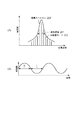
図2にモード同期動作における光パルスの発振スペクトルのグラフ(図2(A))と、このときの光変調器の透過率のグラフ(図2(B))を示す。図2(A)において、発振線幅201はモード同期動作における縦多モード発振の総合的な線幅をとる。図2(A)において202は、各共振器モード、203は、発振スペクトルをそれぞれ示す。
本発明においては、発生する光パルスの自然放出光雑音を低減できるという効果もある。自然放出光雑音は時間的に一様な強度を有する連続光である。
これまで光利得媒体として半導体光増幅器(SOA)を例に説明したが、この他、光増幅媒体としては、エルビウムやネオジウム等を含有する希土類を添加した(イオンドープ)光ファイバを用いることができる。また、光ファイバ中にローダミン6Gなどの色素を添加して、添加したこの色素により増幅を行ったもの等を採用することができる。
本発明の実施形態に係る光発振方法は、上記の本発明の実施形態に係る光源装置を用いた光発振方法である。そして、上記の光変調器を透過する光の透過時間のデューティー比を50%未満とする工程を有することを特徴とする。上述したように、上記の光変調器を透過する光の透過時間のデューティー比を50%未満とすることで、50%以上とした場合に比べて、光源から発振される光の発振線幅をより狭くすることができる。なお、光変調器を光が透過する透過時間のデューティー比は、安定した効果を得るために好ましくは20%未満、更に確実な効果を得るために、より好ましくは10%未満とすることが好ましい。
図4に本実施例の光源装置の模式図を示す。
光源装置の構成は実施例1と同じであるが光の透過時間を更に短縮した装置について説明する。短パルス信号発生装置406のパルス幅を実施例1と同じく150psとした。能動モード同期をかける光変調の繰り返し周波数をFSRの500倍の513.3MHzとした点が実施例1と異なる。
本実施例では、上記で説明した本発明の光源装置を用いた光干渉断層撮像(OCT)装置の例を示す。
102、402 光変調器
103、403 波長分散を有する光ファイバ
107 駆動制御装置
Claims (10)
- 光を増幅させる光利得媒体と屈折率の波長分散を有する光導波路とを含んで構成される光共振器と、該光共振器内における光の強度を変調する光変調器と、を備え、該光変調器の変調周波数に応じて光パルスの発振波長が変化する光源装置であって、
前記光源装置が分散チューニング方式の光源であり、
前記光変調器が、前記光変調器を透過する光の透過率を調整可能であり、かつ、前記光変調器を透過する光の透過時間のデューティー比が50%未満であることを特徴とする光源装置。 - 前記透過時間のデューティー比が20%未満であることを特徴とする請求項1に記載の光源装置。
- 前記透過時間のデューティー比が10%未満であることを特徴とする請求項2に記載の光源装置。
- 前記光導波路の屈折率の波長分散が10ps/nm以上、または−10ps/nm以下であることを特徴とする請求項1乃至3のいずれか一項に記載の光源装置。
- 前記光導波路の屈折率の波長分散が100ps/nm以上、または−100ps/nm以下であることを特徴とする請求項1乃至4のいずれか一項に記載の光源装置。
- 前記光変調器を透過する光の透過時間をΔt、前記光変調器の変調周波数をfm0、前記光導波路の分散パラメータをD、前記光共振器の共振器長をL、前記光源の発振波長をλ、真空中における光の速度をcとしたときに下記式、
を満たすことを特徴とする請求項1乃至5のいずれか一項に記載の光源装置。 - 前記光導波路が屈折率の波長分散を有する光ファイバを有することを特徴とする請求項1に記載の光源装置。
- 前記光ファイバの少なくとも一部がチャープドファイバブラッググレーティングであることを特徴とする請求項7に記載の光源装置。
- 請求項1乃至8のいずれか一項に記載の光源装置を用いた光源部と、
前記光源部からの光を検体に照射し、検体からの反射光を伝達させる検体測定部と、
前記光源部からの光を参照ミラーに照射し、該参照ミラーからの反射光を伝達させる参照部と、
前記検体測定部からの反射光と前記参照部からの反射光とを干渉させる干渉部と、
前記干渉部からの干渉光を検出する光検出部と、
前記光検出部で検出された光に基づいて、前記検体の断層像を得る画像処理部と、
を有することを特徴とする光干渉断層撮像装置。 - 光を増幅させる光利得媒体と屈折率の波長分散を有する光導波路とを含んで構成される光共振器と、該光共振器内における光の強度を変調する光変調器と、を備え、該光変調器の変調周波数に応じて光パルスの発振波長が変化する光源装置を用いた光発振方法であって、
前記光源装置が分散チューニング方式の光源であり、
前記光変調器が、前記光共振器を透過する光の透過率を調整可能であり、
前記光変調器を透過する光の透過時間のデューティー比を50%未満とする工程を有することを特徴とする光発振方法。
Priority Applications (1)
| Application Number | Priority Date | Filing Date | Title |
|---|---|---|---|
| JP2012012130A JP6071203B2 (ja) | 2011-01-24 | 2012-01-24 | 光源装置及びこれを用いた光干渉断層撮像装置、及び光発振方法 |
Applications Claiming Priority (3)
| Application Number | Priority Date | Filing Date | Title |
|---|---|---|---|
| JP2011012046 | 2011-01-24 | ||
| JP2011012046 | 2011-01-24 | ||
| JP2012012130A JP6071203B2 (ja) | 2011-01-24 | 2012-01-24 | 光源装置及びこれを用いた光干渉断層撮像装置、及び光発振方法 |
Publications (3)
| Publication Number | Publication Date |
|---|---|
| JP2012169607A JP2012169607A (ja) | 2012-09-06 |
| JP2012169607A5 JP2012169607A5 (ja) | 2015-03-12 |
| JP6071203B2 true JP6071203B2 (ja) | 2017-02-01 |
Family
ID=46543986
Family Applications (1)
| Application Number | Title | Priority Date | Filing Date |
|---|---|---|---|
| JP2012012130A Active JP6071203B2 (ja) | 2011-01-24 | 2012-01-24 | 光源装置及びこれを用いた光干渉断層撮像装置、及び光発振方法 |
Country Status (2)
| Country | Link |
|---|---|
| US (2) | US20120188554A1 (ja) |
| JP (1) | JP6071203B2 (ja) |
Families Citing this family (8)
| Publication number | Priority date | Publication date | Assignee | Title |
|---|---|---|---|---|
| GB201501502D0 (en) * | 2015-01-29 | 2015-03-18 | Univ Kent Canterbury | Akinetic swept laser apparatus and method for fast sweeping of the same |
| JP6709588B2 (ja) * | 2015-06-24 | 2020-06-17 | 国立大学法人埼玉大学 | レーザー光源装置及び干渉計 |
| US10852121B2 (en) * | 2016-02-12 | 2020-12-01 | The General Hospital Corporation | Apparatus and methods for high-speed and long depth range imaging using optical coherence tomography |
| US10302561B2 (en) * | 2016-09-12 | 2019-05-28 | Canon Kabushiki Kaisha | Light source apparatus, and information acquisition apparatus using the same |
| JP7144822B2 (ja) * | 2017-12-22 | 2022-09-30 | 株式会社トーメーコーポレーション | 光断層画像撮影装置 |
| JP7019128B2 (ja) * | 2018-01-22 | 2022-02-15 | 株式会社トーメーコーポレーション | 光断層画像撮影装置 |
| JP7007667B2 (ja) * | 2018-03-12 | 2022-02-10 | 国立研究開発法人理化学研究所 | パルス電磁波発生装置および計測装置 |
| JP2021188926A (ja) * | 2020-05-26 | 2021-12-13 | パナソニックIpマネジメント株式会社 | シート作成装置およびシート作成方法 |
Family Cites Families (6)
| Publication number | Priority date | Publication date | Assignee | Title |
|---|---|---|---|---|
| JP2772600B2 (ja) * | 1992-09-08 | 1998-07-02 | 日本電信電話株式会社 | モード同期レーザ装置 |
| US5701319A (en) * | 1995-10-20 | 1997-12-23 | Imra America, Inc. | Method and apparatus for generating ultrashort pulses with adjustable repetition rates from passively modelocked fiber lasers |
| US5878071A (en) * | 1997-03-26 | 1999-03-02 | Lucent Technologies Inc. | Fabry-perot pulsed laser having a circulator-based loop reflector |
| US20020118934A1 (en) * | 2001-02-23 | 2002-08-29 | Yochay Danziger | Method and system for dispersion management with Raman amplification |
| US20030185531A1 (en) * | 2002-03-26 | 2003-10-02 | Michael Lysiansky | High order mode dispersion compensating fiber |
| CN105581776B (zh) * | 2007-01-10 | 2018-10-16 | 光学实验室成像公司 | 用于可调谐滤波器线性化的装置和方法以及线性化可调谐滤波器 |
-
2012
- 2012-01-20 US US13/355,271 patent/US20120188554A1/en not_active Abandoned
- 2012-01-24 JP JP2012012130A patent/JP6071203B2/ja active Active
-
2015
- 2015-09-02 US US14/843,832 patent/US20150380890A1/en not_active Abandoned
Also Published As
| Publication number | Publication date |
|---|---|
| US20120188554A1 (en) | 2012-07-26 |
| JP2012169607A (ja) | 2012-09-06 |
| US20150380890A1 (en) | 2015-12-31 |
Similar Documents
| Publication | Publication Date | Title |
|---|---|---|
| JP6071203B2 (ja) | 光源装置及びこれを用いた光干渉断層撮像装置、及び光発振方法 | |
| JP5854596B2 (ja) | 光源装置及びこれを用いた撮像装置 | |
| US8964803B2 (en) | Wavelength sweeping light source and imaging apparatus using the same | |
| US10966613B2 (en) | System, apparatus and method for utilizing optical dispersion for fourier-domain optical coherence tomography | |
| JP5489730B2 (ja) | 波長可変光源装置 | |
| US8693508B2 (en) | Light source apparatus and image pickup apparatus equipped with same | |
| US20060268393A1 (en) | System and method for generating supercontinuum light | |
| US20130163620A1 (en) | Frequency referencing for tunable lasers | |
| JP5096543B2 (ja) | テラヘルツ波装置 | |
| JP2012129514A (ja) | 光源装置 | |
| Kourogi et al. | Programmable high speed (~ 1MHz) Vernier-mode-locked frequency-swept laser for OCT imaging | |
| JP2014042010A (ja) | 波長掃引光源の駆動方法 | |
| JP5717392B2 (ja) | 光源装置及びこれを用いた撮像装置 | |
| JP2018045229A (ja) | 光源装置、およびそれを用いた情報取得装置 | |
| Yamashita et al. | Wide and fast wavelength-swept fiber laser based on dispersion tuning for dynamic sensing | |
| JP2012156187A (ja) | 光源装置及びこれを用いた撮像装置 | |
| JP2009033078A (ja) | 波長走査型光源 | |
| KR101453472B1 (ko) | 테라헤르츠파 장치 | |
| JP6752567B2 (ja) | 光源装置、波長変換装置及び情報取得装置 | |
| JP2009060022A (ja) | 波長走査型光源 | |
| JP7043073B2 (ja) | パルス光源及びパルス光を発生させる方法 | |
| CN115023179A (zh) | 用于循环测距oct的基于电光相位编码锁模的频率梳生成 | |
| TWI420170B (zh) | 用於寬頻雷射之偏振調變裝置及其雷射系統 | |
| JP2011113048A (ja) | 波長掃引光源、波長掃引光源を備えたss−oct装置 | |
| JP2014232164A (ja) | 波長可変フィルタ、波長可変光源及びそれを用いた光干渉断層撮像装置 |
Legal Events
| Date | Code | Title | Description |
|---|---|---|---|
| A521 | Request for written amendment filed |
Free format text: JAPANESE INTERMEDIATE CODE: A523 Effective date: 20150126 |
|
| A621 | Written request for application examination |
Free format text: JAPANESE INTERMEDIATE CODE: A621 Effective date: 20150126 |
|
| A977 | Report on retrieval |
Free format text: JAPANESE INTERMEDIATE CODE: A971007 Effective date: 20151014 |
|
| A131 | Notification of reasons for refusal |
Free format text: JAPANESE INTERMEDIATE CODE: A131 Effective date: 20151110 |
|
| A521 | Request for written amendment filed |
Free format text: JAPANESE INTERMEDIATE CODE: A523 Effective date: 20151225 |
|
| A131 | Notification of reasons for refusal |
Free format text: JAPANESE INTERMEDIATE CODE: A131 Effective date: 20160705 |
|
| A521 | Request for written amendment filed |
Free format text: JAPANESE INTERMEDIATE CODE: A523 Effective date: 20160829 |
|
| TRDD | Decision of grant or rejection written | ||
| A01 | Written decision to grant a patent or to grant a registration (utility model) |
Free format text: JAPANESE INTERMEDIATE CODE: A01 Effective date: 20161206 |
|
| A61 | First payment of annual fees (during grant procedure) |
Free format text: JAPANESE INTERMEDIATE CODE: A61 Effective date: 20161227 |
|
| R151 | Written notification of patent or utility model registration |
Ref document number: 6071203 Country of ref document: JP Free format text: JAPANESE INTERMEDIATE CODE: R151 |