JP6060329B2 - Method for visualizing 3D image on 3D display device and 3D display device - Google Patents
Method for visualizing 3D image on 3D display device and 3D display device Download PDFInfo
- Publication number
- JP6060329B2 JP6060329B2 JP2012554214A JP2012554214A JP6060329B2 JP 6060329 B2 JP6060329 B2 JP 6060329B2 JP 2012554214 A JP2012554214 A JP 2012554214A JP 2012554214 A JP2012554214 A JP 2012554214A JP 6060329 B2 JP6060329 B2 JP 6060329B2
- Authority
- JP
- Japan
- Prior art keywords
- pixel
- new
- display device
- image
- information
- Prior art date
- Legal status (The legal status is an assumption and is not a legal conclusion. Google has not performed a legal analysis and makes no representation as to the accuracy of the status listed.)
- Active
Links
- 238000000034 method Methods 0.000 title claims description 27
- 239000011159 matrix material Substances 0.000 claims description 38
- 238000012800 visualization Methods 0.000 claims description 5
- 230000001502 supplementing effect Effects 0.000 claims 2
- 238000007794 visualization technique Methods 0.000 claims 1
- 210000004556 brain Anatomy 0.000 description 8
- 238000000605 extraction Methods 0.000 description 8
- 230000003287 optical effect Effects 0.000 description 7
- 108091008695 photoreceptors Proteins 0.000 description 7
- 108020003175 receptors Proteins 0.000 description 5
- 239000011521 glass Substances 0.000 description 3
- 244000025271 Umbellularia californica Species 0.000 description 2
- 230000004888 barrier function Effects 0.000 description 2
- 238000010586 diagram Methods 0.000 description 2
- 230000000694 effects Effects 0.000 description 2
- 238000005516 engineering process Methods 0.000 description 2
- 230000000873 masking effect Effects 0.000 description 2
- 238000012986 modification Methods 0.000 description 2
- 230000004048 modification Effects 0.000 description 2
- 230000009466 transformation Effects 0.000 description 2
- 244000126211 Hericium coralloides Species 0.000 description 1
- 230000006978 adaptation Effects 0.000 description 1
- 238000013459 approach Methods 0.000 description 1
- 238000012937 correction Methods 0.000 description 1
- 238000002224 dissection Methods 0.000 description 1
- 238000003708 edge detection Methods 0.000 description 1
- 238000011156 evaluation Methods 0.000 description 1
- 230000010365 information processing Effects 0.000 description 1
- 230000010354 integration Effects 0.000 description 1
- 239000000049 pigment Substances 0.000 description 1
- 230000035807 sensation Effects 0.000 description 1
- 230000000007 visual effect Effects 0.000 description 1
Images


Classifications
-
- H—ELECTRICITY
- H04—ELECTRIC COMMUNICATION TECHNIQUE
- H04N—PICTORIAL COMMUNICATION, e.g. TELEVISION
- H04N13/00—Stereoscopic video systems; Multi-view video systems; Details thereof
- H04N13/20—Image signal generators
- H04N13/261—Image signal generators with monoscopic-to-stereoscopic image conversion
-
- H—ELECTRICITY
- H04—ELECTRIC COMMUNICATION TECHNIQUE
- H04N—PICTORIAL COMMUNICATION, e.g. TELEVISION
- H04N13/00—Stereoscopic video systems; Multi-view video systems; Details thereof
- H04N13/30—Image reproducers
- H04N13/302—Image reproducers for viewing without the aid of special glasses, i.e. using autostereoscopic displays
-
- H—ELECTRICITY
- H04—ELECTRIC COMMUNICATION TECHNIQUE
- H04N—PICTORIAL COMMUNICATION, e.g. TELEVISION
- H04N13/00—Stereoscopic video systems; Multi-view video systems; Details thereof
- H04N13/30—Image reproducers
- H04N13/349—Multi-view displays for displaying three or more geometrical viewpoints without viewer tracking
-
- G—PHYSICS
- G06—COMPUTING; CALCULATING OR COUNTING
- G06T—IMAGE DATA PROCESSING OR GENERATION, IN GENERAL
- G06T15/00—3D [Three Dimensional] image rendering
- G06T15/50—Lighting effects
-
- G—PHYSICS
- G06—COMPUTING; CALCULATING OR COUNTING
- G06T—IMAGE DATA PROCESSING OR GENERATION, IN GENERAL
- G06T19/00—Manipulating 3D models or images for computer graphics
- G06T19/20—Editing of 3D images, e.g. changing shapes or colours, aligning objects or positioning parts
-
- G—PHYSICS
- G09—EDUCATION; CRYPTOGRAPHY; DISPLAY; ADVERTISING; SEALS
- G09G—ARRANGEMENTS OR CIRCUITS FOR CONTROL OF INDICATING DEVICES USING STATIC MEANS TO PRESENT VARIABLE INFORMATION
- G09G3/00—Control arrangements or circuits, of interest only in connection with visual indicators other than cathode-ray tubes
- G09G3/001—Control arrangements or circuits, of interest only in connection with visual indicators other than cathode-ray tubes using specific devices not provided for in groups G09G3/02 - G09G3/36, e.g. using an intermediate record carrier such as a film slide; Projection systems; Display of non-alphanumerical information, solely or in combination with alphanumerical information, e.g. digital display on projected diapositive as background
- G09G3/003—Control arrangements or circuits, of interest only in connection with visual indicators other than cathode-ray tubes using specific devices not provided for in groups G09G3/02 - G09G3/36, e.g. using an intermediate record carrier such as a film slide; Projection systems; Display of non-alphanumerical information, solely or in combination with alphanumerical information, e.g. digital display on projected diapositive as background to produce spatial visual effects
-
- H—ELECTRICITY
- H04—ELECTRIC COMMUNICATION TECHNIQUE
- H04N—PICTORIAL COMMUNICATION, e.g. TELEVISION
- H04N13/00—Stereoscopic video systems; Multi-view video systems; Details thereof
- H04N13/10—Processing, recording or transmission of stereoscopic or multi-view image signals
- H04N13/106—Processing image signals
- H04N13/111—Transformation of image signals corresponding to virtual viewpoints, e.g. spatial image interpolation
-
- H—ELECTRICITY
- H04—ELECTRIC COMMUNICATION TECHNIQUE
- H04N—PICTORIAL COMMUNICATION, e.g. TELEVISION
- H04N13/00—Stereoscopic video systems; Multi-view video systems; Details thereof
- H04N13/10—Processing, recording or transmission of stereoscopic or multi-view image signals
- H04N13/106—Processing image signals
- H04N13/172—Processing image signals image signals comprising non-image signal components, e.g. headers or format information
- H04N13/183—On-screen display [OSD] information, e.g. subtitles or menus
-
- H—ELECTRICITY
- H04—ELECTRIC COMMUNICATION TECHNIQUE
- H04N—PICTORIAL COMMUNICATION, e.g. TELEVISION
- H04N13/00—Stereoscopic video systems; Multi-view video systems; Details thereof
- H04N13/30—Image reproducers
- H04N13/302—Image reproducers for viewing without the aid of special glasses, i.e. using autostereoscopic displays
- H04N13/305—Image reproducers for viewing without the aid of special glasses, i.e. using autostereoscopic displays using lenticular lenses, e.g. arrangements of cylindrical lenses
-
- H—ELECTRICITY
- H04—ELECTRIC COMMUNICATION TECHNIQUE
- H04N—PICTORIAL COMMUNICATION, e.g. TELEVISION
- H04N13/00—Stereoscopic video systems; Multi-view video systems; Details thereof
- H04N13/30—Image reproducers
- H04N13/302—Image reproducers for viewing without the aid of special glasses, i.e. using autostereoscopic displays
- H04N13/31—Image reproducers for viewing without the aid of special glasses, i.e. using autostereoscopic displays using parallax barriers
-
- H—ELECTRICITY
- H04—ELECTRIC COMMUNICATION TECHNIQUE
- H04N—PICTORIAL COMMUNICATION, e.g. TELEVISION
- H04N13/00—Stereoscopic video systems; Multi-view video systems; Details thereof
- H04N13/30—Image reproducers
- H04N13/324—Colour aspects
-
- H—ELECTRICITY
- H04—ELECTRIC COMMUNICATION TECHNIQUE
- H04N—PICTORIAL COMMUNICATION, e.g. TELEVISION
- H04N13/00—Stereoscopic video systems; Multi-view video systems; Details thereof
- H04N13/30—Image reproducers
- H04N13/366—Image reproducers using viewer tracking
- H04N13/383—Image reproducers using viewer tracking for tracking with gaze detection, i.e. detecting the lines of sight of the viewer's eyes
-
- H—ELECTRICITY
- H04—ELECTRIC COMMUNICATION TECHNIQUE
- H04N—PICTORIAL COMMUNICATION, e.g. TELEVISION
- H04N13/00—Stereoscopic video systems; Multi-view video systems; Details thereof
- H04N13/30—Image reproducers
- H04N13/398—Synchronisation thereof; Control thereof
-
- G—PHYSICS
- G06—COMPUTING; CALCULATING OR COUNTING
- G06T—IMAGE DATA PROCESSING OR GENERATION, IN GENERAL
- G06T2219/00—Indexing scheme for manipulating 3D models or images for computer graphics
- G06T2219/20—Indexing scheme for editing of 3D models
- G06T2219/2012—Colour editing, changing, or manipulating; Use of colour codes
-
- G—PHYSICS
- G09—EDUCATION; CRYPTOGRAPHY; DISPLAY; ADVERTISING; SEALS
- G09G—ARRANGEMENTS OR CIRCUITS FOR CONTROL OF INDICATING DEVICES USING STATIC MEANS TO PRESENT VARIABLE INFORMATION
- G09G2300/00—Aspects of the constitution of display devices
- G09G2300/04—Structural and physical details of display devices
- G09G2300/0439—Pixel structures
- G09G2300/0452—Details of colour pixel setup, e.g. pixel composed of a red, a blue and two green components
-
- Y—GENERAL TAGGING OF NEW TECHNOLOGICAL DEVELOPMENTS; GENERAL TAGGING OF CROSS-SECTIONAL TECHNOLOGIES SPANNING OVER SEVERAL SECTIONS OF THE IPC; TECHNICAL SUBJECTS COVERED BY FORMER USPC CROSS-REFERENCE ART COLLECTIONS [XRACs] AND DIGESTS
- Y10—TECHNICAL SUBJECTS COVERED BY FORMER USPC
- Y10T—TECHNICAL SUBJECTS COVERED BY FORMER US CLASSIFICATION
- Y10T29/00—Metal working
- Y10T29/49—Method of mechanical manufacture
- Y10T29/49002—Electrical device making
- Y10T29/49004—Electrical device making including measuring or testing of device or component part
Description
本発明は、3Dディスプレイ装置で3次元映像を視覚化する方法に関し、視覚化される映像が入力映像で提供される。また、本発明は、3次元映像を視覚化するための3Dディスプレイ装置、特に、立体ディスプレイや自動立体ディスプレイに関する。 The present invention relates to a method for visualizing a 3D image on a 3D display device, and the image to be visualized is provided as an input image. The present invention also relates to a 3D display device for visualizing a 3D image, and more particularly to a 3D display or an autostereoscopic display.
3Dディスプレイ装置と方法は、数年前から広く知られてきた。例えば、赤青メガネ、シャッターメガネ、偏光メガネなどの視力補助器によって3次元映像を見ることができるようにする立体装置がある。 3D display devices and methods have been widely known for several years. For example, there is a three-dimensional device that allows a three-dimensional image to be viewed with a vision aid such as red-blue glasses, shutter glasses, and polarized glasses.
また、自動立体ディスプレイの前にいる者が、視力補助器がなくても3次元映像を見られるようにする自動立体視覚装置もあるが、このときは主にディスプレイパネルの前にパララックスバリア(Parallax Barrier)やレンチキュラーレンズを配置する。一名や数名の観察者が多様な角度でディスプレイに垂直となる一方向に対して相対的に存在することがあるため、すべての位置のそれぞれの観察者に可能な限り自然な3次元映像を見せようとすれば、常に2種類以上の観点が各個人の左側や右側の目に提供されなければならない。このようなシステムをマルチビューシステムと言う。 In addition, there is an autostereoscopic device that enables a person in front of an autostereoscopic display to view a 3D image without a visual aid, but in this case, the parallax barrier ( Parallax Barrier) and lenticular lenses are arranged. One or several observers may exist relative to one direction perpendicular to the display at various angles, so the 3D image is as natural as possible to each observer at all positions If you are trying to show, there must always be at least two different perspectives on each person's left or right eye. Such a system is called a multi-view system.
しかし、このような3Dディスプレイ装置は、映像再現画質が観察者を満足させることができないという問題点がある。 However, such a 3D display device has a problem that the image reproduction image quality cannot satisfy the observer.
本発明は、簡単な構造によって3次元映像の視覚化が改善されるように、上述した類型の3Dディスプレイ装置における改善された3次元映像を視覚化する方法と、このような3Dディスプレイ装置を提供することを目的とする。 The present invention provides a method for visualizing an improved 3D image in the above-described type of 3D display device such that the visualization of the 3D image is improved by a simple structure, and such a 3D display device. The purpose is to do.
本発明によって上述された課題は、請求項1の特徴によって解決される。請求項1に係る方法は、入力映像を使用して少なくとも1つの特徴行列が決定され、このような特徴行列は明暗情報を規定し、入力映像からの明暗情報を使用して3Dディスプレイ装置で再生される映像を形成する。
The problem described above by the present invention is solved by the features of
また、従来の問題は、請求項17の特徴によって解決される。請求項17に係る装置、特に、立体や自動立体ディスプレイは、提供された入力映像を使用して少なくとも1つの特徴行列を決定し、この行列は明暗情報を規定し、入力映像からの明暗情報を使用して3Dディスプレイ装置で再生されるディスプレイ映像を形成する。
The conventional problem is solved by the features of
本発明の方法では、先ず、3次元映像の視覚化のためには、人間の目が色素受容体よりも光受容体でより多くの多様性を認識するという点を考慮する。本発明の方法や装置は、人間の目に解剖学的に適応され、最終的には情報ディスプレイに有利となる。具体的に、入力映像を利用して少なくとも1つの特徴行列が決定され、この行列は明暗情報を規定する。このような明暗情報を使用することにより、3Dディスプレイ装置に再現する映像が入力映像から形成される。このために、簡単な構造によって3次元映像の視覚化が改善された。 The method of the present invention first considers that for visualization of 3D images, the human eye perceives more diversity with photoreceptors than with pigment receptors. The method and apparatus of the present invention are anatomically adapted to the human eye and ultimately favor information displays. Specifically, at least one feature matrix is determined using the input image, and the matrix defines light / dark information. By using such light / dark information, an image reproduced on the 3D display device is formed from the input image. For this reason, the visualization of 3D images has been improved with a simple structure.
このような入力映像は、左右部分映像に該当する2つの観点(部分映像)を含むことが好ましい。 Such an input video preferably includes two viewpoints (partial videos) corresponding to the left and right partial videos.
このような部分映像は、簡単に修正されることができる。 Such a partial image can be easily corrected.
また、特徴抽出を利用して特徴行列を形成するために、入力映像や部分映像から特徴が抽出されることができる。このときの特徴は局部的な特徴である場合があり、例えば、形態、テクスチャ(texture)および/またはエッジがある。 In addition, in order to form a feature matrix using feature extraction, features can be extracted from an input video or a partial video. The feature at this time may be a local feature, for example, a form, a texture, and / or an edge.
特徴抽出には、ゾーベル(Sobel)−抽出法が使用されることができる。 For feature extraction, a Sobel-extraction method can be used.
また、特徴行列がエッジ情報を有することが好ましい。人間の脳は、3次元立体映像を構成するのに物体のエッジを重要部分として使用する。このために、エッジ情報によって観察者の脳の作業が著しく容易になり、目と脳でなされる情報処理に対する適応が改善される。 The feature matrix preferably has edge information. The human brain uses the edge of an object as an important part to construct a three-dimensional stereoscopic image. For this reason, the work of the observer's brain is remarkably facilitated by the edge information, and the adaptation to information processing performed by the eyes and the brain is improved.
本発明の他の実施形態では、特徴抽出にSURF(Speed Up Robust Features)方法が利用される。SURFに関する詳しい内容は、H.Bay、T.Tuytelaars and L.V.Gool、“SURF:Speed Up Robust Features”、Computer Vision and Image Understanding、110(3)、2008、pp.346−359を参照する。 In another embodiment of the present invention, a SURF (Speed Up Robust Features) method is used for feature extraction. For more information on SURF, see H.C. Bay, T .; Tuytellars and L. V. Gool, “SURF: Speed Up Robust Features”, Computer Vision and Image Understanding, 110 (3), 2008, pp. 346-359.
本発明の特徴行列は、目に入る映像ポイントに関する情報を有することができる。 The feature matrix of the present invention may have information about the video points that are in the eye.
また、特徴行列によって入力映像の観点のピクセルごとに特徴値が1つずつ明暗情報として割り当てされればより好ましい。この場合、入力映像の観点のピクセルごとに特徴値が明暗情報として割り当てられることができる。 Further, it is more preferable that one feature value is assigned as light / dark information for each pixel from the viewpoint of the input video by the feature matrix. In this case, a feature value can be assigned as light / dark information for each pixel from the viewpoint of the input video.
このような特徴値は、ディスプレイ映像の該当ピクセルのサブピクセルに加算されたり乗算されることができる。 Such a feature value can be added to or multiplied by a sub-pixel of a corresponding pixel of the display image.
このような特徴値が尺度因子(scaling factor)として加重され、このような尺度因子はコントローラによって双方向に遠隔で調節されることが好ましい。 Such feature values are weighted as scaling factors, and such scale factors are preferably remotely adjusted bi-directionally by the controller.
RGBサブピクセルを備えたディスプレイ装置では、使用されたエッジ演算子の特徴がRGBサブピクセルにあるエッジを強調するのに使用されることができる。例えば、RGBサブピクセルからなるピクセルが、下記のように目の解剖に適応されることができる。 In display devices with RGB subpixels, the edge operator characteristics used can be used to enhance edges in the RGB subpixels. For example, a pixel consisting of RGB sub-pixels can be adapted for eye dissection as follows.

この場合、R(i、j)、G(i、j)、B(i、j)はそれぞれ、赤色、緑色、青色を規定する。M(i、j、1)は、エッジ演算子の値やピクセル(i、j)のエッジ情報を有する特徴行列の値である。sは自由に設定される尺度因子である。尺度因子が遠隔で制御されれば、それぞれの観察者は自身の感覚のためにエッジ強調を個別的に設定することができる。 In this case, R (i, j), G (i, j), and B (i, j) define red, green, and blue, respectively. M (i, j, 1) is the value of the edge matrix and the value of the feature matrix having the edge information of the pixel (i, j). s is a scale factor that can be set freely. If the scale factor is controlled remotely, each observer can individually set the edge enhancement for their own sense.
このような方法により、エッジ内部にある立体映像の(混ざっていない)カラー値が容易に強調され、光受容体のためにより容易に検出されることができる。 By such a method, the (unmixed) color value of the stereoscopic image inside the edge is easily enhanced and can be detected more easily for the photoreceptor.
多数の特徴は、下記のように積分されることができる。 A number of features can be integrated as follows.
特徴ベクトルM(i、j):=(M(i、j、1)、...、M(i、j、K))と(Kは抽出された相違した特徴の個数)、それぞれのピクセル(i、j)のための加重ベクトルS:=(s1、...、sK)を有する。このような光学的評価は、乗算的になされたりもする。 Feature vector M (i, j): = (M (i, j, 1),..., M (i, j, K)) and (K is the number of extracted different features), each pixel With a weighted vector S: = (s 1 ,..., S K ) for (i, j) Such an optical evaluation may be performed in a multiplying manner.
また、明暗サブピクセルがさらに補完された明暗情報がディスプレイに現われることもできる。明暗サブピクセルは、エッジ情報のディスプレイを通じて観察者が感じる立体映像の感覚を大きく改善することができる。 In addition, light / dark information in which the light / dark sub-pixels are further complemented may appear on the display. The bright and dark sub-pixels can greatly improve the sensation of stereoscopic images felt by the observer through the display of edge information.
例えば、3Dディスプレイ装置としての自動立体ディスプレイは、サブピクセルで構成されたパネルと、パネルの前に連結した光学素子を備えることができる。サブピクセルは、RGBやCMYのようなカラーサブピクセルはもちろん、明暗サブピクセルになることもできる。カラーサブピクセルには、図に示す観点のサブピクセルのカラー情報がディスプレイされることができる。明暗ピクセルは3D感を支援する映像特徴を、例えば、グレイスケール値(gray scalevalue)で有することができる。人間の目は、約110万個の光受容体と約650万個の色素受容体を有する。また、人間の脳は、3次元立体映像を構成するために物体のエッジを重要部分として使用するため、明暗サブピクセルを通じてエッジ情報がディスプレイされることができ、このために映像情報が遥かに多くの数の光受容体を通じて収容され、脳の作業が容易になる。 For example, an autostereoscopic display as a 3D display device may include a panel composed of subpixels and an optical element connected in front of the panel. The sub-pixels can be color sub-pixels such as RGB and CMY, as well as light and dark sub-pixels. In the color sub-pixel, color information of the sub-pixel of the viewpoint shown in the drawing can be displayed. The light and dark pixels may have video features that support a 3D feeling, for example, with gray scale values. The human eye has about 1.1 million photoreceptors and about 6.5 million dye receptors. In addition, since the human brain uses the edge of an object as an important part to construct a three-dimensional stereoscopic image, edge information can be displayed through bright and dark sub-pixels, and thus there is much more video information. Is accommodated through a number of photoreceptors and facilitates brain work.
ディスプレイ映像の品質を改善するために、ディスプレイされたサブピクセルの個数が遥かに増加することができる。疑似ホログラフィック(pseudo holographic)ディスプレイは、例えば、立体映像で提供された1つの入力映像内に含まれるものよりも少なくとも10〜20倍さらに多くのサブピクセルを含むことができる。このようなより多くの個数のサブピクセルのため、合成される多数の観点から1観点あたりさらに多くの個数のピクセルを現すことができる。現在の高画質映像とビデオは1行あたり5,760個のサブピクセルを有し、約1,920×1,080個のピクセルを有する。特徴情報を表示するサブピクセルを10倍にする場合、1つのディスプレイが少なくとも76,000×1,080個のサブピクセルを有することができる。このとき、自動立体ディスプレイの場合には、サブピクセル平面に観点の割り当てられるという事実が考慮される。ここでは、ピクセルへの統合は関係がない。 In order to improve the quality of the display image, the number of displayed sub-pixels can be greatly increased. A pseudo holographic display can include, for example, at least 10 to 20 times more subpixels than those contained within a single input image provided in a stereoscopic image. Because of such a larger number of sub-pixels, a larger number of pixels can be represented per viewpoint from the multiple viewpoints to be synthesized. Current high-quality video and video have 5,760 subpixels per row and about 1,920 × 1,080 pixels. If the number of subpixels displaying feature information is multiplied by 10, one display can have at least 76,000 × 1,080 subpixels. At this time, in the case of an autostereoscopic display, the fact that the viewpoint is assigned to the sub-pixel plane is taken into consideration. Here, pixel integration is not relevant.
本発明では、3Dディスプレイ装置として立体ディスプレイや自動立体ディスプレイが使用されることができる。 In the present invention, a stereoscopic display or an autostereoscopic display can be used as the 3D display device.
また、入力映像が第1観点および第2観点を有することができ、この場合、第2観点は第1観点がm>0の大きさだけ移動して形成される。したがって、1ステップでは、提供された2D映像が左側部分の映像として使用されることができる。右側部分映像としては同じであるが、m>0の大きさだけ右側に移動した2D映像が使用されることができる。また、下記のような視差行列が形成されることができる。 In addition, the input image may have a first viewpoint and a second viewpoint. In this case, the second viewpoint is formed by moving the first viewpoint by a magnitude of m> 0. Therefore, in one step, the provided 2D image can be used as the image of the left part. Although the same as the right side partial image, a 2D image moved to the right side by a size of m> 0 can be used. Also, the following disparity matrix can be formed.
![]()
![]()
この場合、NZは行の数であり、NSは列の数である。 In this case, NZ is the number of rows and NS is the number of columns.
したがって、すべての観察者は、2D映像がディスプレイの前に間隔を置き、浮かんでいるように感じる。 Thus, all viewers feel that the 2D image is floating in front of the display.
2D映像がm<0の大きさだけ左側に移動すれば、観察者はこの映像がディスプレイ内で動くように感じる。 If the 2D image moves to the left by the magnitude of m <0, the observer feels that this image moves in the display.
また、観察者が遠隔で前記大きさ(m)を双方向に選択することができれば、観察者が「ポップアウト(Pop−out)」や「ポップイン(Pop−in)」効果を出すことができる。 Also, if the observer can remotely select the size (m) in both directions, the observer can produce a “pop-out” or “pop-in” effect. it can.
また、3Dディスプレイ装置が所定のカラーシステムのカラーを出すためのサブピクセルと、特徴情報を示すための明暗サブピクセルを含むことができる。 In addition, the 3D display device may include subpixels for displaying a color of a predetermined color system, and light and dark subpixels for displaying feature information.
また、このようなサブピクセルは、独立素子によって形成されることもできる。 Such subpixels can also be formed by independent elements.
このようなサブピクセルが、水平垂直方向に同じ膨脹性を有することが好ましい。特に、サブピクセルが正方形であれば、解像度をさらに高めることができる。サブピクセルを円型にすることもできる。すなわち、すべてのピクセルが正方形ではなければならないという条件が不必要であることもある。むしろ、それぞれのサブピクセルが独立素子のようになる。サブピクセルごとに1つのカラーを有し、水平垂直方向に同じ膨脹性を有することができる。このような状況は、OLED技術やナノ技術により、技術的に何の問題もなく実現されることができる。 Such sub-pixels preferably have the same expandability in the horizontal and vertical directions. In particular, if the subpixel is square, the resolution can be further increased. Subpixels can also be circular. That is, the condition that all pixels must be square may be unnecessary. Rather, each subpixel becomes an independent element. It can have one color per subpixel and have the same expandability in the horizontal and vertical directions. Such a situation can be realized without any technical problems by OLED technology or nanotechnology.
図1は、本発明に係る方法および3Dディスプレイ装置の一例のブロック図である。図1の実施形態は、3D装置としての自動立体ディスプレイに3次元映像を視覚化する方法に関し、自動立体ディスプレイに提供された立体映像から任意の3Dフォーマットに100個以上の多数の観点がディスプレイにくしの歯形態にディスプレイされる。このディスプレイは、1つの光学素子と1つの映像形成ユニットからなる。前記多数の観点は、すべて常に1つの観点だけがディスプレイされなければならない、まさにそのピクセルだけが形成される方式によって形成される。前記ディスプレイの映像形成ユニットは、例えば、赤色、緑色、または青色のような1つカラーを放出するサブピクセルからなる。 FIG. 1 is a block diagram of an example of a method and 3D display device according to the present invention. The embodiment of FIG. 1 relates to a method of visualizing a 3D image on an autostereoscopic display as a 3D device, and the display includes a plurality of perspectives of 100 or more from a stereoscopic image provided on the autostereoscopic display to an arbitrary 3D format. Displayed in comb tooth form. This display includes one optical element and one image forming unit. The multiple viewpoints are all formed in such a way that only one viewpoint must be displayed at any given time, just that pixel is formed. The image forming unit of the display includes sub-pixels that emit one color such as red, green, or blue.
自動立体ディスプレイは、3D映像または3D映像シーケンスを立体映像や立体映像シーケンスのようなすべてのフォーマットに受信することができる。例えば、視差マップを含む立体映像のような他のフォーマットも受信して処理することができる。 The autostereoscopic display can receive a 3D video or 3D video sequence in all formats such as a stereoscopic video or a stereoscopic video sequence. For example, other formats such as stereoscopic video including a parallax map can also be received and processed.
立体映像は、優先的に標準立体形態やエピポーラ(epipolar)形態に修正される。既にこのような状況であれば、本ステップでは同じピクチャ(picture)が現れるようになる。 The stereoscopic image is preferentially corrected to a standard stereoscopic form or an epipolar form. In such a situation, the same picture appears in this step.
次に、図1により、2つの映像(Rl、Rr)で、例えば、エッジや際立つ映像ポイント(SURF)のような多様な特徴が確認される。このステップで多様な特徴が抽出されることができるが、特別な制約はない。このような特徴は、必要であれば、視差マップの計算だけではなく、特定の追加サブピクセルにおける視覚化にも使用される。 Next, referring to FIG. 1, various features such as edges and prominent video points (SURF) are confirmed in the two videos (R 1 , R r ). Various features can be extracted in this step, but there are no special restrictions. Such features are used not only for parallax map calculation, but also for visualization at specific additional sub-pixels, if necessary.
視差マップが入力映像と共に受信されれば次のステップに移り、そうでなければ立体映像の視差マップが計算される。2つの受信された観点内に存在する左右部分映像のピクセルが視差マップに割り当てられる。また、左右マスキング(masking)も確認される。 If the parallax map is received together with the input video, the process proceeds to the next step. Otherwise, the parallax map of the stereoscopic video is calculated. The pixels of the left and right partial images that exist within the two received viewpoints are assigned to the disparity map . Also, left and right masking is confirmed.
次に、前記特徴と受信された立体映像の視差マップ(D)を利用して多数の観点が合成される。この場合、常にディスプレイに実際にディスプレイされなければならないサブピクセルだけが合成される。したがって、それぞれの観点からディスプレイされる観点が100個である場合、1%のサブピクセルだけが計算される。 Next, a number of viewpoints are synthesized using the feature and the parallax map (D) of the received stereoscopic video. In this case, only the sub-pixels that must always be actually displayed on the display are synthesized. Thus, if there are 100 viewpoints displayed from each viewpoint, only 1% of the subpixels are calculated.
どの観点がどのサブピクセルにディスプレイされなければならないかに対する情報は観点カード(P)で決定される。観点カードは、ディスプレイを製造するときに、サブピクセルと光学システムの間の修正過程で決定されて格納される。隣接するサブピクセルは、一般的には他の観点に割り当てられる。相違する観点からの多様なサブピクセルを疑似ホログラフィック映像(B)に格納することをコーミング(combing)という。 Information on which viewpoint must be displayed on which sub-pixel is determined by the viewpoint card (P). The viewpoint card is determined and stored during the modification process between the subpixel and the optical system when the display is manufactured. Adjacent sub-pixels are generally assigned to other aspects. Storing various subpixels from different viewpoints in the pseudo holographic image (B) is called combing.
自動立体ディスプレイは、サブピクセルで構成された1つのパネルとパネルに接続した光学素子を有する。サブピクセルは、例えば、RGBまたはCMYのようなカラーサブピクセルである。このようなカラーサブピクセル内には、図に示す観点のサブピクセルのカラー情報がディスプレイされる。 The autostereoscopic display has one panel composed of subpixels and an optical element connected to the panel. The sub-pixel is a color sub-pixel such as RGB or CMY. In such a color sub-pixel, the color information of the sub-pixel of the viewpoint shown in the figure is displayed.
映像(B)の品質を改善しようとすれば、ディスプレイされたサブピクセルの数を大きく増やす。図1に係る疑似ホログラフィックディスプレイは、受信された立体映像に存在するものよりも少なくとも10〜20倍多いサブピクセルを有する。このようにサブピクセル数がさらに多いため、合成される多数の観点の各観点あたりのピクセル数がさらに多くなる。 In order to improve the quality of the image (B), the number of displayed sub-pixels is greatly increased. The pseudo holographic display according to FIG. 1 has at least 10 to 20 times more subpixels than those present in the received stereoscopic image. Since the number of subpixels is further increased in this way, the number of pixels per each viewpoint of the many viewpoints to be combined is further increased.
図2は、図1のシステムのフローチャートである。 FIG. 2 is a flowchart of the system of FIG.
以下、図1〜2に係るステップを詳しく説明する。本実施形態は、受信モジュールにより、例えば、1つのアンテナやインターネットを通じて立体映像内の1つの映像シーケンスが受信され、デコーディングされて部分映像(Il、Ir)に利用されるという事実から出発する。 Hereinafter, steps according to FIGS. 1 and 2 will be described in detail. The present embodiment starts from the fact that the receiving module receives, for example, one video sequence in the stereoscopic video through one antenna or the Internet, and decodes and uses it for the partial video (I l , I r ). To do.
受信された立体映像は、連結した疑似ホログラフィックディスプレイの解像度に合わせて拡大/縮小する。解像度19,200×10,800ピクセルのディスプレイは、高解像として認められる。この場合、例えば、1つの立体HD映像が水平垂直に10倍拡大する。 The received stereoscopic image is enlarged / reduced according to the resolution of the connected pseudo holographic display. A display with a resolution of 19,200 × 10,800 pixels is perceived as high resolution. In this case, for example, one stereoscopic HD video is enlarged 10 times horizontally and vertically.
第1ステップで修正が実施される。この方法は文献に公知されている。図1〜2の実施形態において、左側部分映像(Il)では、この映像に均一に分布された9つの際立つポイントがSURF方法によって検索される。それぞれのポイントの座標は、右側部分映像(Ir)にある検索ブロックの中心点として使用される。このような検索ブロックでは、右側部分映像(Ir)内の類似するポイントが検索される。このような9つのポイントの視差を利用して線形変換行列が定義され、このような線形変換行列によってそれぞれの部分映像(Il、Ir)が映像(Rl、Rr)に合うように修正される:
Il→R1およびIr→Rr
Correction is performed in the first step. This method is known in the literature. In the embodiment of FIGS. 1-2, in the left partial video (I l ), nine outstanding points that are uniformly distributed in this video are searched by the SURF method. The coordinates of each point are used as the center point of the search block in the right partial image (I r ). In such a search block, similar points in the right partial video (I r ) are searched. A linear transformation matrix is defined using the parallax of these nine points, and the partial videos (I 1 , I r ) are matched to the video (R 1 , R r ) by such a linear transformation matrix. Will be fixed:
I l → R 1 and I r → R r
このような修正により、今後はエピポーラは前記映像の行に対して平行に進行され、今後のすべての演算は行方式によって実施されることができる。 With such a modification, the epipolar will now proceed in parallel to the video row, and all future operations can be performed in a row manner.
特徴抽出にSURF(Speed up Robust Features)や、ゾーベルエッジディテクタ(Sobel−Edge−Detector)方式を利用することができる。 For feature extraction, a SURF (Speed up Robust Features) or a Sobel edge detector (Sobel-Edge-Detector) method can be used.
SURF特徴抽出:
この方法は、それぞれのピクセルに対するヘッセ行列(Hesse−Matrix)の行列式を近似的で求める。この場合、手順は次のようになる。
SURF feature extraction:
In this method, a Hessian matrix determinant is obtained approximately for each pixel. In this case, the procedure is as follows.
修正された左右部分映像に対して生成される行列(Isum)には、それぞれのピクセルに対する下部映像領域のグレイスケール値の部分和が格納される。 A matrix (Isum) generated for the corrected left and right partial videos stores the partial sum of the gray scale values of the lower video area for each pixel.
i:=1、...NZそしてj:=1、...NS、
この場合、NZは行の数であり、NSは列の数である。
i: = 1,. . . NZ and j: = 1,. . . NS,
In this case, NZ is the number of rows and NS is the number of columns.
計算の時行(i)ごとに行演算ユニット(i)が1つずつ割り当てられ、このような行演算ユニットは前記部分和を帰納的に計算し、 One row arithmetic unit (i) is assigned for each time row (i) of calculation, and such row arithmetic unit recursively calculates the partial sum,
![]()
![]()
i:=1、...NZそしてj:=1、...NS、
Isum内に格納される。次に、列(j)ごとに演算ユニット(j)が1つずつ割り当てられ、このような列演算ユニットは列の和を帰納的に計算する。
i: = 1,. . . NZ and j: = 1,. . . NS,
It is stored in Isum. Next, one arithmetic unit (j) is assigned to each column (j), and such a column arithmetic unit recursively calculates the sum of the columns.
![]()
![]()
i:=1、...NZそしてj:=1、...NS。 i: = 1,. . . NZ and j: = 1,. . . NS.
前記のように計算された行列は、今後はそれぞれの部分映像に対して左側および右側に所望する部分和を含むようになる。このとき、行(i)ごとに再び演算ユニット(i)(=行演算ユニット(i))が1つずつ割り当てられ、このような演算ユニットは先ず下記のような中間値を算出する。 The matrix calculated as described above will now include desired partial sums on the left and right sides for each partial video. At this time, one arithmetic unit (i) (= row arithmetic unit (i)) is again assigned to each row (i), and such arithmetic unit first calculates the following intermediate value.
これによって by this
![]()
![]()
が得られる。 Is obtained.
その次に、近似的として求めたヘッセ行列の行列式が右側部分映像のそれぞれのピクセルに対して特徴行列(Mr(1))に格納される。 Next, the determinant of the Hessian matrix obtained as an approximation is stored in the feature matrix (M r (1)) for each pixel of the right partial image.
![]()
![]()
同じように、左側部分映像(Rl)のそれぞれのピクセルに実施されて前記特徴行列(Ml(1))に格納され、全体的に特徴行列(Mr(1)、Ml(1))が得られる。これ以上の詳しい事項は、H.Bay、T.tuytelaars and L.V.Gool、“SURF:Speed Up Robust Features”、Computer Vision and Image Understanding、110(3)、2008、pp.346−359を参考にすればよい。 Similarly, it is performed on each pixel of the left partial image (R l ) and stored in the feature matrix (M l (1)), and the entire feature matrix (M r (1), M l (1) ) Is obtained. For further details, see H.C. Bay, T .; tuyellars and L. V. Gool, “SURF: Speed Up Robust Features”, Computer Vision and Image Understanding, 110 (3), 2008, pp. Reference may be made to 346-359.
ゾーベル特徴抽出:
ゾーベル演算子は、多数のエッジ演算子のうちの1つのエッジ演算子でのみなされるため、例を挙げる。
Sobel feature extraction:
An example is given because the Sobel operator is only done with one of a number of edge operators.
視差マップのためにはエッジ演算子が特に重要であり、これはエッジ演算子の割り当て時に、平坦面よりもエッジにより高い意味(重要性)が付与されるようにするためである。1つのエッジが常に1つの地域的特性にもなるため、このような方式は1つの行内部の局部的な地域の特性も考慮できるようにする。 The edge operator is particularly important for the parallax map , because when the edge operator is assigned, a higher meaning (importance) is given to the edge than to the flat surface. Such an approach also allows for local regional characteristics within a row, since an edge will always be a regional characteristic.
ゾーベルプレヴィッツ演算子は、例えば、多様な方向からエッジを検出する3×3行列によって動作する。この場合、基本的に、水平、垂直、左側、および右側対角エッジが区別されることができる。エッジを検出するために、下記のような3×3行列が使用される。 The Sobel Prewitz operator operates, for example, with a 3 × 3 matrix that detects edges from various directions. In this case, basically, horizontal, vertical, left and right diagonal edges can be distinguished. In order to detect edges, the following 3 × 3 matrix is used.
本発明に係る方法の一実施形態では、行(i)ごとに行演算ユニット(i)が1つずつ割り当てられる。すべての行(i)と列(j)に対し、演算ユニット−局部フィールドは、修正された右側部分映像(Rr)から由来するエッジ1〜エッジ9であって、下記のように満たされる。
In one embodiment of the method according to the invention, one row arithmetic unit (i) is allocated for each row (i). For all rows (i) and columns (j), the arithmetic unit-local field is
i:=1、...NZそしてj:=1、...NS。 i: = 1,. . . NZ and j: = 1,. . . NS.
次に、それぞれの指数(j)(index)に対し、それぞれの行演算ユニット(i)が計算する。 Next, for each index (j) (index), each row arithmetic unit (i) calculates.
このとき、Mr(i、j、2)は、i=1、...NZおよびj=1、...NSに対してMr(i、j、2):=H1+H2+H3+H4として示される。 At this time, M r (i, j, 2) is i = 1,. . . NZ and j = 1,. . . For NS, it is shown as M r (i, j, 2): = H 1 + H 2 + H 3 + H 4 .
この方法が、修正された右側部分映像(Rl)に対しても同じように実施される。このようにすることにより、全体的に特徴行列(Mr(2)、Ml(2))が求められる。 This method is carried out in the same way for the modified right partial image (R 1 ). In this way, a feature matrix (M r (2), M l (2)) is obtained as a whole.
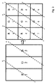
図3の左側は、3つのサブピクセルR(赤)、G(緑)、B(青)を有する従来のピクセルレイアウトである。このようなサブピクセルによっては、光学素子(O)としてレンチキュラーレンズを使用し、3つの観点(1、2、3)が作動する。図3の右側は新たなサブピクセルレイアウトであって、自動立体ディスプレイによって形成された本発明の3Dディスプレイ装置の一例に係る独立サブピクセルは正方形の形状を有する。ここでは、9つのサブピクセルによる9つの観点が光学素子(O)によって制御される。 The left side of FIG. 3 is a conventional pixel layout with three sub-pixels R (red), G (green), and B (blue). Some subpixels use a lenticular lens as the optical element (O), and three aspects (1, 2, 3) are activated. The right side of FIG. 3 is a new sub-pixel layout, and the independent sub-pixel according to an example of the 3D display apparatus of the present invention formed by an autostereoscopic display has a square shape. Here, nine viewpoints by nine sub-pixels are controlled by the optical element (O).
図4の左側は従来のピクセルレイアウト、右側は自動立体ディスプレイによって形成された本発明に係る3Dディスプレイ装置の他の実施形態である。ここでは、遥かにさらに精密かつ詳細なサブピクセル構造が形成された。従来のピクセルレイアウトの3つのサブピクセルの代りに、本実施形態のサブピクセルレイアウトでは144個のサブピクセルが形成された。ここでは、サブピクセルR(赤)、G(緑)、B(青)が明暗情報を現すため、追加サブピクセルW(例:白色や黄色)によって補完された。図に示す実施形態では、144個のサブピクセルによって36個の観点が制御される。 The left side of FIG. 4 is a conventional pixel layout, and the right side is another embodiment of a 3D display device according to the present invention formed by an autostereoscopic display. Here, a much more precise and detailed subpixel structure has been formed. Instead of the three subpixels of the conventional pixel layout, 144 subpixels were formed in the subpixel layout of the present embodiment. Here, since the subpixels R (red), G (green), and B (blue) represent light and dark information, they are complemented by additional subpixels W (eg, white and yellow). In the illustrated embodiment, 36 viewpoints are controlled by 144 subpixels.
図5は図4のサブピクセルレイアウトを示しており、この場合、144個の独立的サブピクセルが144個の観点を制御するのに使用される。 FIG. 5 shows the sub-pixel layout of FIG. 4, where 144 independent sub-pixels are used to control 144 viewpoints.
本発明に係る方法と3Dディスプレイ装置の他の実施形態によれば、自動立体ディスプレイのために下記のようになされることができる。 According to another embodiment of the method and 3D display device according to the present invention, the following can be done for autostereoscopic display.
人間の目の解剖学的な状況に適応するために、下記のような2つの特性が考慮される。 In order to adapt to the anatomical situation of the human eye, two characteristics are considered:
1.目の解像度。 1. Eye resolution.
2.目の受容体の個数および特性。 2. Number and characteristics of eye receptors.
人間の目の解像度は、一般的に0.5’〜1.5’である。このため、近来のディスプレイは、0.2〜0.3mmのドットピッチ(dot−pitch)を有する。言い換えれば、約1mのドットピッチからはディスプレイのピクセルがこれ以上認識されない。本発明に係る3Dディスプレイ装置の前記実施形態では、使用されたレンズラスター(lens raster)のレンズ幅は0.2mmの範囲であって、約125LPI(インチあたりのレンズ:Lenses per Inch)である。したがって、このようなレンズ構造では、約1mの観察距離からはこれ以上の認識が不可能である。1つのレンズの後ろに置かれるサブピクセルの個数は、レンズあたり10個以内である。すなわち、疑似ホログラフィックディスプレイのドットピッチは0.06mm以内である。従来のディスプレイは1,920×1,080ピクセル(HD−TV)であるが、本発明の疑似ホログラフィックディスプレイは、少なくとも19,200×1,080ピクセルからなる。 The resolution of the human eye is generally 0.5'-1.5 '. For this reason, modern displays have a dot pitch of 0.2 to 0.3 mm. In other words, no more pixels on the display are recognized from a dot pitch of about 1 m. In the embodiment of the 3D display device according to the present invention, the lens width of the lens raster used is in the range of 0.2 mm and is about 125 LPI (lens per inch). Therefore, with such a lens structure, no further recognition is possible from an observation distance of about 1 m. The number of subpixels placed behind one lens is within 10 per lens. That is, the dot pitch of the pseudo holographic display is within 0.06 mm. The conventional display is 1,920 × 1,080 pixels (HD-TV), but the pseudo-holographic display of the present invention consists of at least 19,200 × 1,080 pixels.
前記レンズラスターは、本実施形態の場合では、直径0.2mmのレンチキュラーレンズや6角形レンズからなることができる。 In the case of the present embodiment, the lens raster can be a lenticular lens or a hexagonal lens having a diameter of 0.2 mm.
人間の目に約650万個の色素受容体と約1億個の光受容体があるため、光受容体が色素受容体よりも約15倍多いことが分かる。また、人間の脳は、内部立体映像を1つの極めて大きい部分で形成するためにエッジ情報を使用する。エッジは、ここにある左右マスキングを通じて物体の前後方関係に対する情報を提供する。 It can be seen that there are about 15 times more photoreceptors than dye receptors because there are about 6.5 million dye receptors and about 100 million photoreceptors in the human eye. In addition, the human brain uses edge information to form an internal stereoscopic image with one extremely large portion. The edge provides information on the front-rear relationship of the object through the left-right masking here.
このために、本発明では、公知されたサブピクセルRGBまたはYMCが明暗ピクセルによって補完され、このような明暗ピクセルは、特徴抽出ステップでエッジ演算子によって生じたエッジ情報を表示する。 To this end, in the present invention, known subpixels RGB or YMC are supplemented by light and dark pixels, and such light and dark pixels display edge information generated by edge operators in the feature extraction step.
均一な面はエッジを含んでおらず、このような場所では明暗サブピクセルが映像内部に情報を表示しない。 The uniform surface does not include an edge, and in such a place, the light and dark subpixels do not display information inside the image.
明暗サブピクセル内部では、検出されたエッジの強度によってエッジがより明るく表示される。したがって、映像内部に存在するエッジは際立つようになり、1億個の光受容体がこれをより容易に認識する。 Inside the light / dark sub-pixel, the edge is displayed brighter depending on the detected edge strength. Therefore, the edges present inside the image become prominent and 100 million photoreceptors recognize this more easily.
脳は、内部立体映像をより容易に形成することができなければならない。均一な面にあるパターンは、人間の脳内で学習効果によってそれ自体として認識され、立体映像の感覚に影響を与えない。 The brain must be able to form internal stereoscopic images more easily. A pattern in a uniform plane is recognized as such by the learning effect in the human brain and does not affect the sense of the stereoscopic image.
明暗ピクセルの幾何学的な配列状態は、本発明によって変えることができる。図3〜5には多様な配列が示されている。エッジ検出を改善するための明暗サブピクセルの他にも、立体映像の形成のために他の特徴をさらに付加することができる。本発明ではSURF演算子を例示したが、必ずしもこれに限定されることはない。 The geometrical arrangement of light and dark pixels can be changed by the present invention. Various arrangements are shown in FIGS. In addition to the bright and dark sub-pixels for improving edge detection, other features can be further added to form stereoscopic images. In the present invention, the SURF operator is exemplified, but the present invention is not necessarily limited thereto.
ピクセルをカラーサブピクセル(大概はRGB)に細分する作業は省略する。自動立体ディスプレイのために観点を割り当てる作業が常にカラーおよび明暗サブピクセルを有するサブピクセル平面でなされるという事実を考慮し、本実施形態に記述されたディスプレイでは、サブピクセルをピクセルにグループ化する過程が省略される。それぞれのカラーまたは明暗サブピクセルは、1つの特定観点が割り当てられた独立的な光素子であり、水平垂直方向に同じ膨脹性を有する。このような状況が図3〜5の右側図面では既に考慮された。下位互換性があるため、すべての2D映像(ビデオ)は何の問題もなく図示されることができる。このような自動立体ディスプレイは、OLED技術によって製造することができる。 The work of subdividing the pixels into color subpixels (generally RGB) is omitted. In view of the fact that the task of assigning viewpoints for autostereoscopic displays is always done on a subpixel plane with color and light and dark subpixels, the display described in this embodiment has the process of grouping subpixels into pixels. Is omitted. Each color or light / dark sub-pixel is an independent light element assigned one particular viewpoint and has the same expansibility in the horizontal and vertical directions. Such a situation has already been taken into account in the right-side drawings of FIGS. Due to the backward compatibility, all 2D images (video) can be illustrated without any problems. Such autostereoscopic displays can be manufactured by OLED technology.
本発明の装置および方法に関するさらなる有利な実施形態に関しては、繰り返しを回避するため、付属の請求の範囲を参照のこと。 For further advantageous embodiments of the device and method of the present invention, refer to the appended claims to avoid repetition.
最後に、上記の本発明の方法および装置の実施形態は、単なる説明を目的とするものであり、実施形態を限定する目的のものではないことに留意されたい。 Finally, it should be noted that the above-described embodiments of the method and apparatus of the present invention are for illustrative purposes only and are not intended to limit the embodiments.
Claims (5)
物体のエッジを含む入力映像から、前記物体を表現する特徴行列M(i, j, 1)を抽出するステップ、
前記3Dディスプレイ装置の各ピクセルに対して、明暗情報を含む前記特徴行列M(i, j, 1)の行列値を割り当てるステップ、及び、
前記3Dディスプレイ装置の各ピクセルは、赤色(R)サブピクセル、緑色(R)サブピクセル、及び青色(R)サブピクセルを含み、
Rnew(i, j)=R(i, j)+M(i, j, 1)・s,
Gnew(i, j)=G(i, j)+M(i, j, 1)・s, (1)
Bnew(i, j)=B(i, j)+M(i, j, 1)・s,
ここで、R(i, j)、G(i, j)及びB(i, j)は、それぞれ、前記入力映像の対応するピクセルの色(赤色、緑色、青色)を規定し、
Rnew(i, j)、Gnew(i, j)及びBnew(i, j)は、それぞれ、前記視覚化される映像の対応するピクセルの新しい色(赤色、緑色、青色)を規定し、
M(i, j, 1)は、ピクセル(i, j)に先のステップで割り当てられるピクセル(i, j)の特徴行列の値であり、s(s>0)は、自由に設定可能な尺度因子(倍率)であり、
前記演算、即ち、Rnew(i, j)、Gnew(i, j)及びBnew(i, j)からなる式(1)により、3次元鑑賞のために前記3Dディスプレイ装置の各ピクセルを人間の目に解剖学的に適応させるステップ、を含むことを特徴とする方法。 A 3D display device, in which the image to be visualized is provided as an input image , presents additional information and optimizes the information for 3D viewing , and the 3D image is anatomically viewed by the human eye. as adapt, modify the color values of the three-dimensional image pixel, a visualization method of a three-dimensional image,
Extracting from an input image including an edge of an object, feature matrix M that represent the object of the (i, j, 1),
Assigning a matrix value of the feature matrix M (i, j, 1) including light and dark information to each pixel of the 3D display device; and
Each pixel of the 3D display device includes a red (R) subpixel, a green (R) subpixel, and a blue (R) subpixel,
R new (i, j) = R (i, j) + M (i, j, 1) · s,
G new (i, j) = G (i, j) + M (i, j, 1) · s, (1)
B new (i, j) = B (i, j) + M (i, j, 1) · s,
Here, R (i, j), G (i, j) and B (i, j) respectively define the color (red, green, blue) of the corresponding pixel of the input video,
R new (i, j), G new (i, j) and B new (i, j) define the new color (red, green, blue) of the corresponding pixel of the image to be visualized, respectively. ,
M (i, j, 1) is the value of the feature matrix of pixel (i, j) assigned in the previous step to pixel (i, j), and s (s> 0) can be freely set Scale factor (magnification)
Each pixel of the 3D display device for 3D viewing is calculated by the above equation, that is, equation (1) consisting of R new (i, j), G new (i, j) and B new (i, j). method characterized by comprising step of anatomically adapted to the human eye, a.
前記入力映像から、物体のエッジを表現する特徴行列を抽出するステップ、 前記3Dディスプレイ装置の各ピクセルに対して、明暗情報を含む前記特徴行列の行列値を割り当てるステップ、および
前記3Dディスプレイ装置に前記明暗情報を表示するために、前記各ピクセルに付加的な明暗サブピクセルを補足するステップを含むことを特徴とする方法。 A 3D display device in which a video to be visualized is provided as an input video, and is a method of visualizing a 3D video by anatomically adapting the 3D video to the human eye for 3D viewing. And
Extracting a feature matrix representing an edge of an object from the input video, assigning a matrix value of the feature matrix including brightness information to each pixel of the 3D display device, and the 3D display device Supplementing each pixel with an additional light / dark sub-pixel to display light / dark information.
物体のエッジを含む入力映像から、物体を表現する明暗情報を含む特徴行列M(i,j, 1)を決定する手段、
前記3Dディスプレイ装置の各ピクセルに対して、前記明暗情報を含む前記特徴行列M(i, j, 1)の行列値を割り当てる手段、及び
前記3Dディスプレイ装置の各ピクセルは、赤色(R)サブピクセル、緑色(R)サブピクセル、及び青色(R)サブピクセルを含み、
Rnew(i, j)=R(i, j)+M(i, j, 1)・s,
Gnew(i, j)=G(i, j)+M(i, j, 1)・s, (1)
Bnew(i, j)=B(i, j)+M(i, j, 1)・s,
ここで、R(i, j)、G(i, j)及びB(i, j)は、それぞれ、前記入力映像の対応するピクセルの色(赤色、緑色、青色)を規定し、
Rnew(i, j)、Gnew(i, j)及びBnew(i, j)は、それぞれ、前記視覚化される映像に対応するピクセルの新しい色(赤色、緑色、青色)を規定し、
M(i, j, 1)は、ピクセル(i, j)に先のステップで割り当てられるピクセル(i, j)の特徴行列の値であり、s(s>0))は、自由に設定可能な尺度因子であり、
前記演算、即ち、Rnew(i, j)、Gnew(i, j)及びBnew(i, j)からなる式(1)により、3次元鑑賞のために前記3Dディスプレイ装置の各ピクセルを人間の目に解剖学的に適応させる手段、を含むことを特徴とする3Dディスプレイ装置。 For 3D viewing, present additional information, optimize the information, and modify the pixel color values of the 3D video to anatomically adapt the 3D video to the human eye A 3D display device for visualizing a 3D image,
Means for determining from the input image including an edge of an object, wherein the matrix M (i, j, 1) comprising brightness information to represent the object, and
Means for assigning a matrix value of the feature matrix M (i, j, 1) including the brightness information to each pixel of the 3D display device, and each pixel of the 3D display device is a red (R) subpixel , Green (R) subpixels, and blue (R) subpixels,
R new (i, j) = R (i, j) + M (i, j, 1) · s,
G new (i, j) = G (i, j) + M (i, j, 1) · s, (1)
B new (i, j) = B (i, j) + M (i, j, 1) · s,
Here, R (i, j), G (i, j) and B (i, j) respectively define the color (red, green, blue) of the corresponding pixel of the input video,
R new (i, j), G new (i, j) and B new new (i, j), respectively, to define a new color of the pixel corresponding to the image to be the visualization (red, green, blue) and ,
M (i, j, 1) is the value of the feature matrix of pixel (i, j) assigned to pixel (i, j) in the previous step, and s (s> 0)) can be set freely It is a scale factor,
Each pixel of the 3D display device for 3D viewing is calculated by the above equation, that is, equation (1) consisting of R new (i, j), G new (i, j) and B new (i, j). Means for anatomically adapting to the human eye.
前記入力映像から、物体のエッジを含む前記入力映像における物体の表現を提供する明暗情報を含む特徴行列を決定する手段、
前記3Dディスプレイ装置の各ピクセルに対して、前記明暗情報を含む前記特徴行列の行列値を割り当てる手段、および、
前記3Dディスプレイ装置に前記明暗情報を表示するために、前記各ピクセルに付加的な明暗サブピクセルを補足する手段、を含むことを特徴とする3Dディスプレイ装置。 A 3D display device for visualizing a 3D image by anatomically adapting the 3D image to the human eye for 3D viewing,
Means for determining, from the input video, a feature matrix including light and dark information that provides a representation of the object in the input video including an edge of the object
Means for assigning a matrix value of the feature matrix including the brightness information to each pixel of the 3D display device; and
Means for supplementing each pixel with additional light and dark sub-pixels to display the light and dark information on the 3D display device.
Applications Claiming Priority (3)
| Application Number | Priority Date | Filing Date | Title |
|---|---|---|---|
| DE102010009291A DE102010009291A1 (en) | 2010-02-25 | 2010-02-25 | Method and apparatus for an anatomy-adapted pseudo-holographic display |
| DE102010009291.6 | 2010-02-25 | ||
| PCT/DE2011/000187 WO2011103866A2 (en) | 2010-02-25 | 2011-02-25 | Method for visualizing three-dimensional images on a 3d display device and 3d display device |
Publications (2)
| Publication Number | Publication Date |
|---|---|
| JP2013520890A JP2013520890A (en) | 2013-06-06 |
| JP6060329B2 true JP6060329B2 (en) | 2017-01-18 |
Family
ID=44149833
Family Applications (3)
| Application Number | Title | Priority Date | Filing Date |
|---|---|---|---|
| JP2012554214A Active JP6060329B2 (en) | 2010-02-25 | 2011-02-25 | Method for visualizing 3D image on 3D display device and 3D display device |
| JP2012554215A Active JP6142985B2 (en) | 2010-02-25 | 2011-02-25 | Autostereoscopic display and manufacturing method thereof |
| JP2016208015A Expired - Fee Related JP6278323B2 (en) | 2010-02-25 | 2016-10-24 | Manufacturing method of autostereoscopic display |
Family Applications After (2)
| Application Number | Title | Priority Date | Filing Date |
|---|---|---|---|
| JP2012554215A Active JP6142985B2 (en) | 2010-02-25 | 2011-02-25 | Autostereoscopic display and manufacturing method thereof |
| JP2016208015A Expired - Fee Related JP6278323B2 (en) | 2010-02-25 | 2016-10-24 | Manufacturing method of autostereoscopic display |
Country Status (6)
| Country | Link |
|---|---|
| US (4) | US9324181B2 (en) |
| EP (1) | EP2540089A2 (en) |
| JP (3) | JP6060329B2 (en) |
| KR (2) | KR101825759B1 (en) |
| DE (1) | DE102010009291A1 (en) |
| WO (3) | WO2011103866A2 (en) |
Families Citing this family (11)
| Publication number | Priority date | Publication date | Assignee | Title |
|---|---|---|---|---|
| DE102010009291A1 (en) * | 2010-02-25 | 2011-08-25 | Expert Treuhand GmbH, 20459 | Method and apparatus for an anatomy-adapted pseudo-holographic display |
| US9363504B2 (en) * | 2011-06-23 | 2016-06-07 | Lg Electronics Inc. | Apparatus and method for displaying 3-dimensional image |
| EP2645724A4 (en) * | 2011-11-11 | 2014-08-06 | Sony Corp | Transmitting apparatus, transmitting method, receiving apparatus and receiving method |
| WO2013085513A1 (en) * | 2011-12-07 | 2013-06-13 | Intel Corporation | Graphics rendering technique for autostereoscopic three dimensional display |
| KR101349784B1 (en) * | 2012-05-08 | 2014-01-16 | 엘지디스플레이 주식회사 | A supporting member for attacting functional panel to display panel, display device having thereof, and mehtod of fabricating display device |
| TWI637348B (en) * | 2013-04-11 | 2018-10-01 | 緯創資通股份有限公司 | Apparatus and method for displaying image |
| ITTO20130784A1 (en) | 2013-09-30 | 2015-03-31 | Sisvel Technology Srl | METHOD AND DEVICE FOR EDGE SHAPE ENFORCEMENT FOR VISUAL ENHANCEMENT OF DEPTH IMAGE BASED RENDERING |
| CN103680325A (en) | 2013-12-17 | 2014-03-26 | 京东方科技集团股份有限公司 | Display substrate, display panel and stereoscopic display device |
| CN105787877B (en) * | 2016-02-18 | 2018-11-23 | 精实万维软件(北京)有限公司 | A kind of more figure composition methods of dynamic and device |
| WO2020117841A1 (en) * | 2018-12-04 | 2020-06-11 | Sony Interactive Entertainment LLC | Fluid display device |
| US11056081B2 (en) * | 2019-08-09 | 2021-07-06 | Wuhan China Star Optoelectronics Semiconductor Display Technology Co., Ltd. | Display panel and display device |
Family Cites Families (51)
| Publication number | Priority date | Publication date | Assignee | Title |
|---|---|---|---|---|
| JPH0646461A (en) * | 1992-06-26 | 1994-02-18 | Matsushita Electric Ind Co Ltd | Flat stereoscopic image display device and its production |
| US5457574A (en) * | 1993-05-06 | 1995-10-10 | Dimension Technologies Inc. | Autostereoscopic display with high power efficiency |
| JP2944850B2 (en) * | 1993-05-25 | 1999-09-06 | シャープ株式会社 | 3D display device |
| JPH08220477A (en) * | 1995-02-13 | 1996-08-30 | Toppan Printing Co Ltd | Production of lenticular display and apparatus for production therefor |
| JP2000081918A (en) * | 1998-09-04 | 2000-03-21 | Canon Inc | Heater |
| JP3593466B2 (en) * | 1999-01-21 | 2004-11-24 | 日本電信電話株式会社 | Method and apparatus for generating virtual viewpoint image |
| FR2798708B1 (en) | 1999-09-17 | 2001-11-16 | Snfa | HYBRID BALL BEARING WITH AN OBLIQUE CONTACT, AND AN AXIAL STOP THEREWITH |
| CA2436596C (en) | 2000-01-25 | 2005-10-25 | 4D-Vision Gmbh | Method and arrangement for the three-dimensional display |
| US20020075566A1 (en) * | 2000-12-18 | 2002-06-20 | Tutt Lee W. | 3D or multiview light emitting display |
| US7103234B2 (en) * | 2001-03-30 | 2006-09-05 | Nec Laboratories America, Inc. | Method for blind cross-spectral image registration |
| GB0119176D0 (en) * | 2001-08-06 | 2001-09-26 | Ocuity Ltd | Optical switching apparatus |
| JP2003339060A (en) * | 2002-05-20 | 2003-11-28 | Denso Corp | Display apparatus for back image/side image of vehicle |
| JP2007072476A (en) * | 2002-07-29 | 2007-03-22 | Sharp Corp | Method for producing substrate with parallax barrier layer |
| AU2002952874A0 (en) * | 2002-11-25 | 2002-12-12 | Dynamic Digital Depth Research Pty Ltd | 3D image synthesis from depth encoded source view |
| JP4042615B2 (en) * | 2003-04-17 | 2008-02-06 | 株式会社デンソー | Image processing method and image processing apparatus |
| MXPA06003202A (en) * | 2003-09-22 | 2006-06-23 | Gene Dolgoff | Omnidirectional lenticular and barrier-grid image display. |
| JP4839598B2 (en) * | 2003-10-30 | 2011-12-21 | ブラザー工業株式会社 | Image display device |
| JP4402578B2 (en) * | 2004-03-31 | 2010-01-20 | 独立行政法人科学技術振興機構 | 3D display |
| JP4440066B2 (en) * | 2004-10-14 | 2010-03-24 | キヤノン株式会社 | Stereo image generation program, stereo image generation system, and stereo image generation method |
| JP4327758B2 (en) * | 2005-03-24 | 2009-09-09 | 株式会社東芝 | Stereoscopic image display device |
| US7787702B2 (en) * | 2005-05-20 | 2010-08-31 | Samsung Electronics Co., Ltd. | Multiprimary color subpixel rendering with metameric filtering |
| JP4532372B2 (en) * | 2005-09-02 | 2010-08-25 | トヨタ自動車株式会社 | Road marking line detection device |
| JP2007081635A (en) * | 2005-09-13 | 2007-03-29 | Sanyo Epson Imaging Devices Corp | Display apparatus |
| JP2007110303A (en) * | 2005-10-12 | 2007-04-26 | Matsushita Electric Ind Co Ltd | Contour correction circuit |
| US8358330B2 (en) * | 2005-10-21 | 2013-01-22 | True Vision Systems, Inc. | Stereoscopic electronic microscope workstation |
| JP4337823B2 (en) * | 2005-11-04 | 2009-09-30 | セイコーエプソン株式会社 | Printer and printing method |
| TWI294750B (en) * | 2005-11-21 | 2008-03-11 | Whe Yi Chiang | Three dimensional organic electroluminescent display |
| DE102006019169A1 (en) | 2006-04-21 | 2007-10-25 | Expert Treuhand Gmbh | Autostereoscopic adapter disc with real-time image synthesis |
| JP5018778B2 (en) * | 2006-08-23 | 2012-09-05 | 富士通株式会社 | Display element and electronic paper and electronic terminal using the same |
| CN101512415B (en) * | 2006-09-07 | 2012-06-06 | 夏普株式会社 | Image display device, electronic device, and parallax barrier element |
| US20100103175A1 (en) * | 2006-10-25 | 2010-04-29 | Tokyo Institute Of Technology | Method for generating a high-resolution virtual-focal-plane image |
| JP2008112060A (en) * | 2006-10-31 | 2008-05-15 | Seiko Epson Corp | Display device |
| JP2008216971A (en) * | 2007-02-08 | 2008-09-18 | Seiko Epson Corp | Image display device |
| US8933959B2 (en) * | 2007-02-13 | 2015-01-13 | Samsung Display Co., Ltd. | Subpixel layouts and subpixel rendering methods for directional displays and systems |
| GB0708676D0 (en) * | 2007-05-04 | 2007-06-13 | Imec Inter Uni Micro Electr | A Method for real-time/on-line performing of multi view multimedia applications |
| JP5263751B2 (en) * | 2007-06-07 | 2013-08-14 | 学校法人立命館 | Single screen display device |
| JP5115840B2 (en) * | 2007-08-23 | 2013-01-09 | 国立大学法人東京農工大学 | 3D display device |
| JP2009080144A (en) * | 2007-09-25 | 2009-04-16 | Toshiba Corp | Stereoscopic image display apparatus and stereoscopic image display method |
| JP2009162620A (en) * | 2008-01-07 | 2009-07-23 | Toshiba Corp | Inspection apparatus and its method |
| US8072448B2 (en) * | 2008-01-15 | 2011-12-06 | Google Inc. | Three-dimensional annotations for street view data |
| GB2457692A (en) * | 2008-02-21 | 2009-08-26 | Sharp Kk | A display device with a plurality of viewing modes |
| JP4987767B2 (en) * | 2008-03-18 | 2012-07-25 | 株式会社東芝 | 3D image display device manufacturing apparatus and 3D image display device manufacturing method |
| JP2010033447A (en) * | 2008-07-30 | 2010-02-12 | Toshiba Corp | Image processor and image processing method |
| KR101476219B1 (en) * | 2008-08-01 | 2014-12-24 | 삼성디스플레이 주식회사 | Method of manufacturing display device and apparatus using the same |
| KR20100033067A (en) * | 2008-09-19 | 2010-03-29 | 삼성전자주식회사 | Image display apparatus and method for both 2d and 3d image |
| JP4625517B2 (en) * | 2008-10-27 | 2011-02-02 | 富士フイルム株式会社 | Three-dimensional display device, method and program |
| EP2348746B1 (en) * | 2008-11-18 | 2015-03-11 | Panasonic Corporation | Reproduction device, reproduction method, and program for stereoscopic reproduction |
| CA2749896C (en) * | 2009-01-20 | 2019-02-19 | Koninklijke Philips Electronics N.V. | Transferring of 3d image data |
| WO2010095081A1 (en) * | 2009-02-18 | 2010-08-26 | Koninklijke Philips Electronics N.V. | Transferring of 3d viewer metadata |
| WO2011007757A1 (en) * | 2009-07-13 | 2011-01-20 | Yoshida Kenji | Parallax barrier for autostereoscopic display, autostereoscopic display, and method for designing parallax barrier for autostereoscopic display |
| DE102010009291A1 (en) * | 2010-02-25 | 2011-08-25 | Expert Treuhand GmbH, 20459 | Method and apparatus for an anatomy-adapted pseudo-holographic display |
-
2010
- 2010-02-25 DE DE102010009291A patent/DE102010009291A1/en not_active Ceased
-
2011
- 2011-02-25 JP JP2012554214A patent/JP6060329B2/en active Active
- 2011-02-25 WO PCT/DE2011/000187 patent/WO2011103866A2/en active Application Filing
- 2011-02-25 US US13/580,924 patent/US9324181B2/en not_active Expired - Fee Related
- 2011-02-25 US US13/580,909 patent/US9396579B2/en not_active Expired - Fee Related
- 2011-02-25 JP JP2012554215A patent/JP6142985B2/en active Active
- 2011-02-25 KR KR1020127024212A patent/KR101825759B1/en active IP Right Grant
- 2011-02-25 WO PCT/DE2011/000186 patent/WO2011103865A2/en active Application Filing
- 2011-02-25 KR KR1020127024214A patent/KR101852209B1/en active IP Right Grant
- 2011-02-25 EP EP11720977A patent/EP2540089A2/en not_active Withdrawn
- 2011-02-25 WO PCT/DE2011/000188 patent/WO2011103867A1/en active Application Filing
-
2016
- 2016-03-23 US US15/078,596 patent/US10134180B2/en active Active
- 2016-06-13 US US15/181,282 patent/US10229528B2/en active Active
- 2016-10-24 JP JP2016208015A patent/JP6278323B2/en not_active Expired - Fee Related
Also Published As
| Publication number | Publication date |
|---|---|
| KR101852209B1 (en) | 2018-04-25 |
| US20160300517A1 (en) | 2016-10-13 |
| US10134180B2 (en) | 2018-11-20 |
| DE102010009291A1 (en) | 2011-08-25 |
| JP2017078859A (en) | 2017-04-27 |
| WO2011103866A2 (en) | 2011-09-01 |
| JP6278323B2 (en) | 2018-02-14 |
| US9324181B2 (en) | 2016-04-26 |
| JP2013520890A (en) | 2013-06-06 |
| KR20130008555A (en) | 2013-01-22 |
| US10229528B2 (en) | 2019-03-12 |
| US9396579B2 (en) | 2016-07-19 |
| JP2013527932A (en) | 2013-07-04 |
| JP6142985B2 (en) | 2017-06-07 |
| WO2011103866A3 (en) | 2012-03-01 |
| KR101825759B1 (en) | 2018-03-22 |
| WO2011103867A1 (en) | 2011-09-01 |
| US20130135720A1 (en) | 2013-05-30 |
| KR20130036198A (en) | 2013-04-11 |
| US20160205393A1 (en) | 2016-07-14 |
| EP2540089A2 (en) | 2013-01-02 |
| US20130147804A1 (en) | 2013-06-13 |
| WO2011103865A2 (en) | 2011-09-01 |
| WO2011103865A3 (en) | 2012-02-09 |
Similar Documents
| Publication | Publication Date | Title |
|---|---|---|
| JP6060329B2 (en) | Method for visualizing 3D image on 3D display device and 3D display device | |
| US9083963B2 (en) | Method and device for the creation of pseudo-holographic images | |
| JP4740135B2 (en) | System and method for drawing 3D image on screen of 3D image display | |
| US7689031B2 (en) | Video filtering for stereo images | |
| JP5631329B2 (en) | 3D image display apparatus and 3D image display method | |
| KR101675961B1 (en) | Apparatus and Method for Rendering Subpixel Adaptively | |
| JP5150255B2 (en) | View mode detection | |
| JP6517245B2 (en) | Method and apparatus for generating a three-dimensional image | |
| KR20110049039A (en) | High density multi-view display system and method based on the active sub-pixel rendering | |
| CN106170084A (en) | Multi-view image display device and control method thereof and multi-view image production method | |
| EP1991963A2 (en) | Rendering an output image | |
| US20090109127A1 (en) | Three-Dimensional Image Display Device and a Displaying Method Thereof | |
| JP2013527932A5 (en) | ||
| US8368690B1 (en) | Calibrator for autostereoscopic image display | |
| KR20170044953A (en) | Glassless 3d display apparatus and contorl method thereof | |
| JP5476910B2 (en) | Image generating apparatus, image generating method, and program | |
| CN208257981U (en) | A kind of LED naked-eye 3D display device based on sub-pixel | |
| CN110662012A (en) | Naked eye 3D display effect optimization drawing arranging method and system and electronic equipment | |
| TW201320719A (en) | Three-dimensional image display device, image processing device and image processing method | |
| US10939092B2 (en) | Multiview image display apparatus and multiview image display method thereof | |
| CN115022612B (en) | Driving method and device of display device and display equipment | |
| CN102655600B (en) | Stereoscopic image display method | |
| KR101831978B1 (en) | Generation method of elemental image contents for display system with rotated lenticular sheet | |
| KR100824942B1 (en) | Method of generating lenticular display image and recording medium thereof |
Legal Events
| Date | Code | Title | Description |
|---|---|---|---|
| A621 | Written request for application examination |
Free format text: JAPANESE INTERMEDIATE CODE: A621 Effective date: 20140205 |
|
| A521 | Request for written amendment filed |
Free format text: JAPANESE INTERMEDIATE CODE: A523 Effective date: 20140318 |
|
| A131 | Notification of reasons for refusal |
Free format text: JAPANESE INTERMEDIATE CODE: A131 Effective date: 20150317 |
|
| A601 | Written request for extension of time |
Free format text: JAPANESE INTERMEDIATE CODE: A601 Effective date: 20150601 |
|
| A601 | Written request for extension of time |
Free format text: JAPANESE INTERMEDIATE CODE: A601 Effective date: 20150716 |
|
| A521 | Request for written amendment filed |
Free format text: JAPANESE INTERMEDIATE CODE: A523 Effective date: 20150804 |
|
| A131 | Notification of reasons for refusal |
Free format text: JAPANESE INTERMEDIATE CODE: A131 Effective date: 20160202 |
|
| A601 | Written request for extension of time |
Free format text: JAPANESE INTERMEDIATE CODE: A601 Effective date: 20160428 |
|
| A601 | Written request for extension of time |
Free format text: JAPANESE INTERMEDIATE CODE: A601 Effective date: 20160428 |
|
| A521 | Request for written amendment filed |
Free format text: JAPANESE INTERMEDIATE CODE: A523 Effective date: 20160608 |
|
| TRDD | Decision of grant or rejection written | ||
| A01 | Written decision to grant a patent or to grant a registration (utility model) |
Free format text: JAPANESE INTERMEDIATE CODE: A01 Effective date: 20160906 |
|
| A711 | Notification of change in applicant |
Free format text: JAPANESE INTERMEDIATE CODE: A711 Effective date: 20161012 |
|
| A61 | First payment of annual fees (during grant procedure) |
Free format text: JAPANESE INTERMEDIATE CODE: A61 Effective date: 20161004 |
|
| A521 | Request for written amendment filed |
Free format text: JAPANESE INTERMEDIATE CODE: A821 Effective date: 20161012 |
|
| A521 | Request for written amendment filed |
Free format text: JAPANESE INTERMEDIATE CODE: A523 Effective date: 20161117 |
|
| R150 | Certificate of patent or registration of utility model |
Ref document number: 6060329 Country of ref document: JP Free format text: JAPANESE INTERMEDIATE CODE: R150 |
|
| R250 | Receipt of annual fees |
Free format text: JAPANESE INTERMEDIATE CODE: R250 |
|
| R250 | Receipt of annual fees |
Free format text: JAPANESE INTERMEDIATE CODE: R250 |
|
| R250 | Receipt of annual fees |
Free format text: JAPANESE INTERMEDIATE CODE: R250 |
|
| R250 | Receipt of annual fees |
Free format text: JAPANESE INTERMEDIATE CODE: R250 |
|
| R250 | Receipt of annual fees |
Free format text: JAPANESE INTERMEDIATE CODE: R250 |