JP4440066B2 - Stereo image generation program, stereo image generation system, and stereo image generation method - Google Patents
Stereo image generation program, stereo image generation system, and stereo image generation method Download PDFInfo
- Publication number
- JP4440066B2 JP4440066B2 JP2004300370A JP2004300370A JP4440066B2 JP 4440066 B2 JP4440066 B2 JP 4440066B2 JP 2004300370 A JP2004300370 A JP 2004300370A JP 2004300370 A JP2004300370 A JP 2004300370A JP 4440066 B2 JP4440066 B2 JP 4440066B2
- Authority
- JP
- Japan
- Prior art keywords
- viewpoint
- image
- information
- stereoscopic
- parallax
- Prior art date
- Legal status (The legal status is an assumption and is not a legal conclusion. Google has not performed a legal analysis and makes no representation as to the accuracy of the status listed.)
- Active
Links
Images


Landscapes
- Processing Or Creating Images (AREA)
- Testing, Inspecting, Measuring Of Stereoscopic Televisions And Televisions (AREA)
Description
本発明は、立体表示デバイスを介して立体観察される立体画像の生成システム、コンピュータプログラムおよび方法に関するものである。 The present invention relates to a system, a computer program, and a method for generating a stereoscopic image that is stereoscopically observed via a stereoscopic display device.
画像を立体的に観察する方法として、インテグラルフォトグラフィを用いる方法や、パララックスバリヤ、レンチキュラ板等の立体表示デバイスを用いた方法が知られている。そして、このような立体観察可能な画像(立体画像)を生成するためには、被写体を複数の視点から撮影した画像(視点画像)群を用意する必要がある。
As a method for stereoscopically viewing images, and a method of using the integral photography, parallax barrier, a method had use a stereoscopic display device such as a lenticular plate are known. In order to generate such a stereoscopically observable image (stereoscopic image), it is necessary to prepare an image (perspective image) group obtained by photographing the subject from a plurality of viewpoints.
この場合において、比較的少数の複数視点で撮影した視点画像群から、撮影を行っていない視点に対応した視点画像を補間手法により生成して、多数の視点から立体画像観察ができるようにした方法が提案されている。例えば、特許文献1において提案された方法では、複数視点から被写体を撮影した視点画像群から該被写体の奥行き分布を表す視差マップを生成し、該視点画像群と該視差マップとに基づいて任意の視点で撮影したのと同様の仮想視点画像を生成し、該仮想視点画像を用いて立体画像を生成する。
In this case, a method of generating a viewpoint image corresponding to a viewpoint that has not been captured from a viewpoint image group captured from a relatively small number of viewpoints by an interpolation method so that stereoscopic images can be observed from a large number of viewpoints. Has been proposed. For example, in the method proposed in
また、立体画像を表示する場合には、立体表示デバイスの画面のサイズを考慮する必要がある。画面サイズに合わせて表示される立体画像のサイズが変化する場合、立体表示デバイスを介して観察者の左右の眼に提示される視点画像間の視差(つまりは立体感)が変化する。視差が小さくなりすぎると、満足な立体感が得られず、また視差が大きくなりすぎると、不自然な立体感を与えてしまう。 When displaying a stereoscopic image, it is necessary to consider the size of the screen of the stereoscopic display device. When the size of the stereoscopic image displayed in accordance with the screen size changes, the parallax (that is, the stereoscopic effect) between the viewpoint images presented to the left and right eyes of the observer via the stereoscopic display device changes. If the parallax becomes too small, a satisfactory stereoscopic effect cannot be obtained, and if the parallax becomes too large, an unnatural stereoscopic effect is given.
このような問題に対処するため、主に2眼式の立体画像表示においては、特許文献2において提案されているように、複数の視点画像の相対位置をシフトさせる等の単純な並進処理等のアフィン処理を用いて、観察者の左右の眼に提示される視点画像間の視差範囲を、一般的な融像範囲と呼ばれる固定値的な視差量にスケーリングする。
しかしながら、上記特許文献2にて提案の手法を多眼式立体表示の場合に適用しても、次の2つの点から不都合がある。
However, even if the method proposed in
第1に、特許文献2にて提案の手法は、主に2眼式立体表示を想定しているために、表示面上における視差量の許容値、つまりは表示視差許容量を、融像範囲若しくはそれに準じた固定範囲により設定している点である。該手法では、2眼式のように少ない視差画像を提示することを目的としているために、立体表示デバイスが有する個々の光学素子の性能によって左右される、隣接する視点画像間でのクロストーク、すなわち立体表示デバイスが有する個々の光学素子の解像力によって生じる問題、および観察者の眼が最適観察距離から外れた場合に生じる隣接視点画像間の混濁を考慮していないためである。
First, since the method proposed in
ここで、立体表示デバイスの個々の光学素子の解像力に起因するクロストークの問題について説明する。まず、図12には、立体表示デバイスの例として、(a)パララックスバリヤおよび(b)レンチキュラレンズを示す。図示のように、このような光学素子に対して相対的に順に視点画像を並べることにより、観察位置において左右の眼に異なる画像を提示することができる。図中の1,2,3,・・・6は各視点画像のインデックスナンバーを表す。 Here, the problem of crosstalk caused by the resolving power of the individual optical elements of the stereoscopic display device will be described. First, FIG. 12 shows (a) a parallax barrier and (b) a lenticular lens as examples of a stereoscopic display device. As shown in the figure, by arranging the viewpoint images in order relative to such an optical element, different images can be presented to the left and right eyes at the observation position. In the figure, 1, 2, 3,... 6 represent index numbers of the respective viewpoint images.
次に、図13には、立体画像を構成する視点画像の数の変化と、立体表示デバイスから射出される個々の視点画像に対応する光束との関係を示している。(a)は2眼、(b)は5眼、(c)は10眼の場合を模式的に示している。 Next, FIG. 13 shows a relationship between a change in the number of viewpoint images constituting the stereoscopic image and a light flux corresponding to each viewpoint image emitted from the stereoscopic display device. (A) schematically shows the case of 2 eyes, (b) of 5 eyes, and (c) of 10 eyes.
1301は立体表示デバイスの個々の光学素子であり、ここではレンチキュラレンズの場合を示す。また、1302はある視点位置に配置された観察者の眼であり、手前に設定したスリットの範囲は光束が眼に入射する有限範囲を示す。
1303、1304、1305は立体画像を構成する個々の視点画像の領域を示す。また、1306は個々の光学素子の性能に依存する立体画像面での解像範囲rexp からの光束を模式的に表したものである。Pは立体表示デバイスの個々の光学素子のピッチ幅P、pは立体画像を構成する個々の視点画像の幅である。つまり、(a)のように個々の視点画像の領域pが光学素子の解像範囲rexpよりも広い場合には、観察者の眼1302にはそれぞれの視点画像のみが入射される。しかし、(c)のように個々の視点画像の領域pが光学素子の解像範囲rexpよりも狭い場合には、それぞれの視点画像からの光束のみを観察する者の眼に入射させることができず、隣接した視点画像からの光束も観察者の眼1302に入射する。
さらに、図14の(a)には、理想的な形状をした光学素子から射出する光束を、(b)には、形状精度の悪い光学素子から射出する光束を示す。これらの光学素子を並列させて像を観察した場合、(a)では理想的な平行光束が射出されるため、最適観察距離の近傍で観察すれば、クロストークの小さい像が観察されるが、(b)のように射出される光束が発散している場合には、最適観察距離の近傍で観察したとしても、クロストークにより、複数の隣接視点画像の像が観察されてしまう。その影響は、図13における像数の変化に対する個々の視点画像から射出される光束の幅の変化から分かるように、像数がある一定以上になり、個々の視点画像の幅が狭くなるに従って避けられない問題となる。 Further, FIG. 14A shows a light beam emitted from an optical element having an ideal shape, and FIG. 14B shows a light beam emitted from an optical element with poor shape accuracy. When these optical elements are arranged in parallel and an image is observed, an ideal parallel light beam is emitted in (a). Therefore, if observed near the optimum observation distance, an image with small crosstalk is observed. When the emitted light beam diverges as shown in (b), even if observed near the optimum observation distance, images of a plurality of adjacent viewpoint images are observed due to crosstalk. As can be seen from the change in the width of the light beam emitted from each viewpoint image with respect to the change in the number of images in FIG. 13, the influence is avoided as the number of images becomes more than a certain value and the width of each viewpoint image becomes narrower. It becomes a problem that can not be.
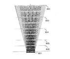
次に、最適観察距離を外れた場合に生じる視差画像の混濁について説明する。図15には、上記のような光学素子を並列させて像を表示した場合の光束の状態を示す。801は立体表示デバイス(立体画像)であり、802〜806はある最適観察距離を示す。光学素子が理想的にその要求性能を満たす場合、図のように最適観察距離においては像が分離され、あるインデックスで表される視点画像のみが観察される。しかし、最適観察距離を外れた位置で像を観察する場合、複数のインデックスで表される視点画像が眼に同時に入射してしまう。立体表示の視点数が少ない場合には、このクロストークが問題になることが一般的である。
Next, the opacity of the parallax image that occurs when the optimum observation distance is deviated will be described. FIG. 15 shows the state of a light beam when an image is displayed with the above optical elements arranged in parallel.
また、図16には、像数の変化と眼に入射する光束の幅との関係を示す。図13と同様に、1601は立体表示デバイスの個々の光学素子であり、ここではレンチキュラレンズの場合を示す。また、1602はある視点位置に配置された観察者の眼であり、手前に設定したスリットの範囲は光束が眼に入射する有限範囲を示す。1603、1604は立体画像を構成する個々の視点画像の領域を示す。1605、1606は個々の視点画像の領域の幅から光学素子1601を介して理想的に眼1602に向けて射出される光束を示している。図16(a),(b)の光束の幅の変化と観察眼の入射可能範囲との関係から類推できるように、個々の視点画像の幅が狭くなるに従ってクロストークの発生が最適観察距離に対して敏感になる。したがって、多眼式の立体画像表示において、観察視点について表示面からの距離をある程度許容する場合には、クロストークが発生してしまうため、個々の視点画像の幅が狭くなる場合、すなわち多くの視点画像によって立体画像を構成する場合には、隣接する視点画像間でのクロストークはより厳しく考慮しなければならなくなる。
FIG. 16 shows the relationship between the change in the number of images and the width of the light beam incident on the eye. Similarly to FIG. 13,
ところで、個々の光学素子の解像力は立体表示デバイスの種類、構造、材質、製造方法によって大きく異なる。したがって、具体的には、立体表示デバイスを非常に高精度なガラス製のレンチキュラシートからプラスチック製の簡易的なものに交換した場合等のように、立体表示デバイスを変更した場合、該立体表示デバイスを構成する光学素子の性能の違いからクロストークが生じやすくなる問題が生じる。このため、提示視差量を調整することなく同じ立体画像を観察した場合、観察者に像のボケや像の重なり(重像)を感じさせる等、不快感を与えてしまう。 By the way, the resolving power of each optical element varies greatly depending on the type, structure, material, and manufacturing method of the stereoscopic display device. Therefore, specifically, when the stereoscopic display device is changed, such as when the stereoscopic display device is replaced from a very high precision glass lenticular sheet to a simple one made of plastic, the stereoscopic display device There arises a problem that crosstalk is likely to occur due to the difference in the performance of the optical elements constituting the. For this reason, when the same stereoscopic image is observed without adjusting the amount of presentation parallax, the viewer feels uncomfortable, such as making the viewer feel blurry images or overlapping images (overlapping images).
また、第2に、特許文献2にて提案の視差量の調整手法では、多眼式に特有の運動視差を発生させられなくなってしまう点にある。特許文献2の手法では、提示されるステレオ画像(一対の視点画像)間の位置関係を相対的に平行移動させることにより、視点画像間の視差を調整している。しかし、このような簡易的な手法は、3つ以上の視点画像によって立体画像を構成する場合には有効ではない。なぜならば、多眼式の立体表示においては、視点移動によって運動視差を生じさせるため、自然な運動視差の変化を実現しつつ、観察者に不快感を与えない立体画像を作成するためには、立体画像を構成する視点画像の視点位置自体を変化させる必要があるからである。
Second, the parallax adjustment method proposed in
本発明は、使用する立体表示デバイスに応じて、立体画像を構成する視点画像の視点位置を自動的に調整し、立体画像の観察時のクロストークを少なくして自然な立体観察が可能な立体画像を生成することを目的の1つとする。 The present invention automatically adjusts the viewpoint position of the viewpoint image constituting the stereoscopic image according to the stereoscopic display device to be used, and reduces the crosstalk at the time of observation of the stereoscopic image to enable natural stereoscopic observation. One of the purposes is to generate an image.
本願発明の一側面としての立体画像生成プログラムは、複数の第1の視点画像から該第1の視点画像のサイズに関する第1のサイズ情報および、前記複数の第1の視点画像間の視差に関する視差情報を取得する第1の情報取得ステップと、立体画像の観察に使用される立体表示デバイスに関するデバイス情報を取得する第2の情報取得ステップと、前記第1のサイズ情報、前記視差情報および前記デバイス情報に基づいて、前記立体表示デバイスに対応した複数の視点を決定する視点決定ステップと、前記第1の視点画像を用いて、前記視点決定ステップで決定された複数の視点に対応する複数の第2の視点画像を生成し、該複数の第2の視点画像を用いて前記立体画像を生成する画像生成ステップと、をコンピュータに実行させることを特徴とする。The stereoscopic image generation program according to one aspect of the present invention provides a first size information related to a size of the first viewpoint image from a plurality of first viewpoint images and a parallax related to a parallax between the plurality of first viewpoint images. A first information acquisition step for acquiring information, a second information acquisition step for acquiring device information relating to a stereoscopic display device used for observation of a stereoscopic image, the first size information, the parallax information, and the device A viewpoint determination step for determining a plurality of viewpoints corresponding to the stereoscopic display device based on the information, and a plurality of second viewpoints corresponding to the plurality of viewpoints determined in the viewpoint determination step using the first viewpoint image. Generating a second viewpoint image, and causing the computer to execute an image generation step of generating the stereoscopic image using the plurality of second viewpoint images. To.
本願発明の別の側面としての立体画像生成プログラムは、物体の三次元モデル情報と、視点画像に対応する視点に仮想的に配置される仮想カメラの撮影パラメータに関するパラメータ情報と、該仮想カメラのビューサイズに関する第1のサイズ情報とを取得する第1の情報取得ステップと、立体画像の観察に使用される立体表示デバイスに関するデバイス情報を取得する第2の情報取得ステップと、前記パラメータ情報、前記第1のサイズ情報および前記デバイス情報に基づいて、前記立体表示デバイスに対応した複数の視点を決定する視点決定ステップと、前記三次元モデル情報を用いて、前記視点決定ステップで決定された複数の視点に対応する複数の視点画像を生成し、該複数の視点画像を用いて前記立体画像を生成する画像生成ステップと、をコンピュータに実行させることを特徴とする。A stereoscopic image generation program according to another aspect of the present invention includes a three-dimensional model information of an object, parameter information related to shooting parameters of a virtual camera virtually arranged at a viewpoint corresponding to a viewpoint image, and a view of the virtual camera. A first information acquisition step for acquiring first size information regarding size; a second information acquisition step for acquiring device information regarding a stereoscopic display device used for observation of a stereoscopic image; the parameter information; A viewpoint determination step for determining a plurality of viewpoints corresponding to the stereoscopic display device based on one size information and the device information; and a plurality of viewpoints determined in the viewpoint determination step using the three-dimensional model information A plurality of viewpoint images corresponding to the image and generating the stereoscopic image using the plurality of viewpoint images. Characterized in that to execute a flop, to the computer.
本願発明の別の側面としての立体画像生成システムは、複数の第1の視点画像から該第1の視点画像のサイズに関する第1のサイズ情報および、前記複数の第1の視点画像間の視差に関する視差情報を取得する第1の情報取得手段と、立体画像の観察に使用される立体表示デバイスに関するデバイス情報を取得する第2の情報取得手段と、前記第1のサイズ情報、前記視差情報および前記デバイス情報に基づいて、前記立体表示デバイスに対応した複数の視点を決定する視点決定手段と、前記第1の視点画像を用いて、前記視点決定手段で決定された複数の視点に対応する複数の第2の視点画像を生成し、該複数の第2の視点画像を用いて前記立体画像を生成する画像生成手段とを有することを特徴とする。 A stereoscopic image generation system according to another aspect of the present invention relates to first size information relating to a size of the first viewpoint image from a plurality of first viewpoint images, and parallax between the plurality of first viewpoint images. A first information acquisition unit that acquires parallax information; a second information acquisition unit that acquires device information relating to a stereoscopic display device used for stereoscopic image observation; the first size information; the parallax information; Based on device information, viewpoint determining means for determining a plurality of viewpoints corresponding to the stereoscopic display device, and using the first viewpoint image, a plurality of viewpoints corresponding to the plurality of viewpoints determined by the viewpoint determining means. Image generating means for generating a second viewpoint image and generating the stereoscopic image using the plurality of second viewpoint images.
本願発明の別の側面としての立体画像生成システムは、物体の三次元モデル情報と、視点画像に対応する視点に仮想的に配置される仮想カメラの撮影パラメータに関するパラメータ情報と、該仮想カメラのビューサイズに関する第1のサイズ情報とを取得する第1の情報取得手段と、立体画像の観察に使用される立体表示デバイスに関するデバイス情報を取得する第2の情報取得手段と、前記パラメータ情報、前記第1のサイズ情報および前記デバイス情報に基づいて、前記立体表示デバイスに対応した複数の視点を決定する視点決定手段と、前記三次元モデル情報を用いて、前記視点決定手段で決定された複数の視点に対応する複数の視点画像を生成し、該複数の視点画像を用いて前記立体画像を生成する画像生成手段とを有することを特徴とする。 A stereoscopic image generation system according to another aspect of the present invention includes a three-dimensional model information of an object, parameter information regarding shooting parameters of a virtual camera virtually arranged at a viewpoint corresponding to a viewpoint image, and a view of the virtual camera. First information acquisition means for acquiring first size information relating to size, second information acquisition means for acquiring device information relating to a stereoscopic display device used for observation of a stereoscopic image, the parameter information, the first information Viewpoint determining means for determining a plurality of viewpoints corresponding to the stereoscopic display device based on one size information and the device information; and a plurality of viewpoints determined by the viewpoint determining means using the three-dimensional model information Image generating means for generating a plurality of viewpoint images corresponding to the three-dimensional image and generating the stereoscopic image using the plurality of viewpoint images. To.
本願発明の別の側面としての立体画像生成方法は、複数の第1の視点画像から該第1の視点画像のサイズに関する第1のサイズ情報および、前記複数の第1の視点画像間の視差に関する視差情報を取得する第1の情報取得ステップと、立体画像の観察に使用される立体表示デバイスに関するデバイス情報を取得する第2の情報取得ステップと、前記第1のサイズ情報、前記視差情報および前記デバイス情報に基づいて、前記立体表示デバイスに対応した複数の視点を決定する視点決定ステップと、前記第1の視点画像を用いて、前記視点決定ステップで決定された複数の視点に対応する複数の第2の視点画像を生成し、該複数の第2の視点画像を用いて前記立体画像を生成する画像生成ステップとを有することを特徴とする。 A stereoscopic image generation method according to another aspect of the present invention relates to first size information relating to a size of the first viewpoint image from a plurality of first viewpoint images, and parallax between the plurality of first viewpoint images. A first information acquisition step of acquiring parallax information; a second information acquisition step of acquiring device information relating to a stereoscopic display device used for observation of a stereoscopic image; the first size information; the parallax information; A viewpoint determination step for determining a plurality of viewpoints corresponding to the stereoscopic display device based on device information, and a plurality of viewpoints corresponding to the plurality of viewpoints determined in the viewpoint determination step using the first viewpoint image. An image generation step of generating a second viewpoint image and generating the stereoscopic image using the plurality of second viewpoint images.
本願発明の別の側面としての立体画像生成方法は、物体の三次元モデル情報と、視点画像に対応する視点に仮想的に配置される仮想カメラの撮影パラメータに関するパラメータ情報と、該仮想カメラのビューサイズに関する第1のサイズ情報とを取得する第1の情報取得ステップと、立体画像の観察に使用される立体表示デバイスに関するデバイス情報を取得する第2の情報取得ステップと、前記パラメータ情報、前記第1のサイズ情報および前記デバイス情報に基づいて、前記立体表示デバイスに対応した複数の視点を決定する視点決定ステップと、前記三次元モデル情報を用いて、前記視点決定ステップで決定された複数の視点に対応する複数の視点画像を生成し、該複数の視点画像を用いて前記立体画像を生成する画像生成ステップとを有することを特徴とする。 A stereoscopic image generation method according to another aspect of the present invention includes three-dimensional model information of an object, parameter information related to shooting parameters of a virtual camera virtually arranged at a viewpoint corresponding to a viewpoint image, and a view of the virtual camera A first information acquisition step for acquiring first size information regarding size; a second information acquisition step for acquiring device information regarding a stereoscopic display device used for observation of a stereoscopic image; the parameter information; A viewpoint determination step for determining a plurality of viewpoints corresponding to the stereoscopic display device based on one size information and the device information; and a plurality of viewpoints determined in the viewpoint determination step using the three-dimensional model information Generating a plurality of viewpoint images corresponding to the image, and generating the stereoscopic image using the plurality of viewpoint images; Characterized in that it has.
本発明によれば、立体表示デバイスが変更されても立体画像の生成元となる複数の第2の視点画像の視点位置が自動的に調整されるので、観察時のクロストークが少なく自然な立体感を提示可能な立体画像を生成することができる。 According to the present invention, even if the stereoscopic display device is changed, the viewpoint positions of the plurality of second viewpoint images that are the sources of the stereoscopic images are automatically adjusted, so that the natural stereoscopic with less crosstalk during observation is obtained. A stereoscopic image capable of presenting a feeling can be generated.
以下、本発明の実施例について図面を参照しながら説明する。 Embodiments of the present invention will be described below with reference to the drawings.
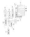
図2には、本発明の実施例1である立体画像生成システムの構成を示している。図2において、201は画像入力装置であり、異なる視点で撮影された同一被写体に関する複数の画像(第1の視点画像)により構成される入力ステレオ画像を、後述する立体画像合成装置(画像生成手段)202に入力する。この画像入力装置201は、CFカード(登録商標)やスマートメディア(登録商標)等の固定記録メディアに記録された画像ファイルを読み込む入出力装置、若しくは入出力インターフェースを持つデジタルカメラ、デジタルビデオカメラ等の撮像機器、スキャナ、フィルムスキャナ等のアナログメディアから画像情報をデジタル化して読み込みを行う画像入力機器により構成される。
FIG. 2 shows a configuration of a stereoscopic image generation system that is
また、画像入力装置201をネットワークと接続し、遠隔地の撮像機器により撮像されて、蓄積、伝送されたネットワーク上に存在するステレオ画像を立体画像合成装置202に入力することもできる。
Further, the
立体画像合成装置202は、入力されたステレオ画像の中から少なくとも2枚の視点画像を選択し、必要に応じて仮想視点画像生成を行い、立体画像データを合成する。該立体画像合成装置202は、例えば汎用のパーソナルコンピュータにより構成される。
The stereoscopic
203は操作ディスプレイであり、立体画像合成において必要な情報をユーザーとの対話的手順により取得するための表示を行ったり、該取得のアシストを行ったり、立体画像合成処理の処理状況を表示したりする。さらに、メニュー画面や、立体画像を構成する視点画像群を表示することもできる。該ディスプレイ203は、コンピュータディスプレイ等により構成される。
204は操作入力部であり、マウス、キーボード、ジョイスティック等により構成され、ユーザーがディスプレイ203上に表示されたメニュー画像を見ながらメニューを選択するのに用いられる。
An
205は立体表示ディスプレイ210や他のコンピュータ等の外部機器と接続された入出力部であり、立体画像データ等をファイルとして出力する。ここで、図2に示す立体表示デバイス210は、CRT、LCDディスプレイ等により構成されるディスプレイ部210aと、該ディスプレイ部210aの前面に配置され、ディスプレイ部210aに表示された立体画像を構成する各視点画像からの光束を所定の視点に配置された観察者の左右の眼Eに導くレンチキュラ板、パララクスバリア等の光学部材210bとにより構成されている。
An input /
なお、該入出力部205は、イーサネット(登録商標)等のネットワークに接続されたネットワークポートやフロッピー(登録商標)ディスク、MO(登録商標)、ZIP(登録商標)、CD−ROM等の固定記録メディアで構成してもよい。なお、入出力部205を画像入力装置201と同じ機器により構成してもよく、この場合は画像入力装置201と入出力部205とを共用することができる。
Incidentally, the said
プリンタ206は、立体画像合成装置202で合成された立体画像を印刷する。印刷された立体画像上に、レンチキュラ板等の立体表示デバイスとしての光学部材を重ねることにより、立体像を観察することができる。
The
次に、立体画像合成装置202の内部構成について説明する。2021は本装置全体の制御を司るコントローラとしての中央演算処理装置であり、以下、CPUと称する。
Next, the internal configuration of the stereoscopic
2022は大容量記憶装置であり、画像入力装置201等から読み込まれたステレオ画像や生成された仮想視点画像や立体画像データを保存したり、立体表示ディスプレイ210や像数に関連して経験的若しくは解析的に設定される表示視差範囲のパラメータの値を記憶したりする。該大容量記憶装置2022は、ハードディスク等により構成される。
2023は主記憶装置であり、RAM等で構成される。該主記憶装置2023は、画像入力装置201から読み込まれたステレオ画像や大容量記憶装置2022に保存されたステレオ画像を主記憶領域上に展開したり、立体画像生成のためのパラメータや生成された仮想視点画像を立体画像生成のために一時的に記憶したりする。さらに、該主記憶装置2023は、生成された立体画像データを大容量記憶装置2022に記憶させたり、入出力部205から出力したり、プリンタ206で印刷する前に一次的に記憶したりする。
次に、図1を用いて、本実施例における立体画像合成装置202(主としてCPU2021)の処理の流れを説明する。この処理は、CPU2021内に格納されたコンピュータプログラムである立体画像合成プログラムに従って実行される。
Next, a processing flow of the stereoscopic image synthesizing apparatus 202 (mainly the CPU 2021) in this embodiment will be described with reference to FIG. This process is executed according to a stereoscopic image synthesis program that is a computer program stored in the
ステップS101では、CPU2021は、ステレオ画像を画像入力装置201から入力し、大容量記憶装置2022に蓄積する。該入力ステレオ画像を構成する複数の視点画像(第1の視点画像)は、例えば図3に示すように、静止している被写体303〜305に対して、撮像機器301の視点(撮影位置)及び視線方向(撮影方向)を変化させながら被写体303〜305を撮影することにより得られる。図3においては、撮像機器301はデジタルカメラ若しくはビデオカメラである。302は視点および視線方向を変化させた後の撮像機器301を示している。なお、このように撮像機器を移動させながら撮影する代わりに、2眼以上の多眼カメラを用いてステレオ画像を撮影したり、カメラの撮影光学系にいわゆるステレオアダプタを装着又は組み込んだりしたステレオカメラを用いてもよい。
In step S <b> 101, the
本実施例においては、入力されたステレオ画像である複数の視点画像に対し、視点画像間の幾何学的歪を解消する平行視処理が施されているものとする。平行視処理とは、視点画像間の幾何配置を、該視点画像間での様々な処理を単純に行うために、いわゆる平行視配置(複数位置でのカメラの撮影光軸方向が平行になるような配置)されたカメラで撮影されたと同等の配置になるように、視点画像群に対して視線変換を行う処理方法であり、「Multiple View Geometry, Hartley and Zisserman, Cambridge Press, (2000)」等に紹介されている既知の手法である。 In the present embodiment, it is assumed that parallel vision processing for eliminating geometric distortion between viewpoint images is performed on a plurality of viewpoint images that are input stereo images. Parallel vision processing is a so-called parallel vision arrangement (so that the camera optical axis directions of the cameras at a plurality of positions are parallel to each other in order to simply perform the geometric arrangement between the viewpoint images and various processes between the viewpoint images. Is a processing method that performs line-of-sight transformation on the viewpoint image group so that the arrangement is equivalent to that taken with a camera that has been placed in a different position), such as “Multiple View Geometry, Hartley and Zisserman, Cambridge Press, (2000)”, etc. This is a known technique introduced in.
ステップS102では、ステレオ画像(各視点画像)のサイズの情報と、視点画像間で生じている視差の画像上での最大値および最小値の情報(存在視差範囲の情報)とを取得する。まず、ステレオ画像サイズを取得するために、立体画像の生成に用いられる基準となるビュー範囲を設定する。ビュー範囲は、画像が歪まないように、次段のステップS103で設定する出力画像サイズのアスペクト比に合わせたり、ステレオ画像の撮影で撮影画像に含まれてしまった不要な被写体を除外したり、ステレオ画像のシーン領域を制限してステレオ画像に含まれる視差の存在範囲を狭くしたりすることにより設定する。また、ビュー範囲を設定せずに、入力ステレオ画像の画角をそのまま入力ステレオ画像サイズとしてもよい。 In step S102, information on the size of the stereo image (each viewpoint image) and information on the maximum value and the minimum value (existing parallax range information) on the images of the parallax occurring between the viewpoint images are acquired. First, in order to acquire a stereo image size, a reference view range used for generating a stereo image is set. The view range is adjusted to the aspect ratio of the output image size set in the next step S103 so that the image is not distorted, or an unnecessary subject included in the captured image in the shooting of the stereo image is excluded. It is set by limiting the scene area of the stereo image and narrowing the range of the parallax included in the stereo image. Further, the angle of view of the input stereo image may be set as the input stereo image size without setting the view range.
また、存在視差範囲を取得するために、入力ステレオ画像を構成する複数の視点画像間でステレオマッチングを行うことにより、視点画像間での個々の画素の対応情報を取得し、該対応情報の差分から視点画像間で生じている視差の最大値と最小値を算出して存在視差範囲を求める。 In addition, in order to obtain the presence parallax range, stereo matching is performed between a plurality of viewpoint images constituting the input stereo image, thereby obtaining correspondence information of individual pixels between the viewpoint images, and the difference between the correspondence information. To calculate the maximum value and the minimum value of the parallax occurring between the viewpoint images to obtain the existing parallax range.
ここで、ステレオマッチングの概略を図4を用いて説明する。ステレオマッチングには、領域ベースの手法、特徴ベースの手法、勾配法を用いた手法等、様々な手法が存在するが、マッチング対象となる2つの視点画像における画素ごとの視差が求まる手法であればどのような手法を用いてもよい。 Here, an outline of stereo matching will be described with reference to FIG. There are various methods for stereo matching, such as region-based methods, feature-based methods, and gradient-based methods, but any method that can find the parallax for each pixel in the two viewpoint images to be matched. Any method may be used.
本実施例においては領域ベースの一手法である、差分和を用いた単純なテンプレートマッチング手法を特徴点の対応付けに用いた場合について説明する。ここでは、2つの視点画像のうち撮影した視点位置が左側に相当する左画像を基準画像501とし、視点位置が右側に相当する右画像を参照画像502とし、左画像を基準としてテンプレートマッチングを行うこととする。
In the present embodiment, a case where a simple template matching method using a difference sum, which is a region-based method, is used for feature point association will be described. Here, of the two viewpoint images, the left image corresponding to the left side of the captured viewpoint position is set as the
この場合、まず、左画像中のある特徴点を選択する。この点を注目点(注目画素)504と呼ぶ。そしてこの注目点504を中心とした所定サイズの領域をテンプレート503として切り出す。
In this case, first, a certain feature point in the left image is selected. This point is referred to as an attention point (attention pixel) 504. Then, a region having a predetermined size centered on the
次に、大まかな視点の移動量やカメラの手振れによる視点および視線方向の変動を考慮して、参照画像502中での対応点探索領域507を任意に定める。そして、対応点探索領域507内に存在する特徴点である参照点505を順次選択するとともに、該参照点505を中心とした、上記テンプレート503と同一のサイズのウィンドウ領域506について、基準画像501中のテンプレート503との相関値を求めていく。
Next, the corresponding
例えば、カメラが水平移動する場合には、通常、対応点探索領域507は、画像座標の水平方向に長辺を持つ長方形の領域として与えられることが多い。
For example, when the camera moves horizontally, the corresponding
注目点に対応する参照画像中での対応点は、相関値の最も大きい参照点に決定される。但し、対応点での相関値が所定値より小さい場合、対応点での相関値と2番目に小さい相関値との差が所定値より小さい場合、あるいは対応点近傍での相関値の変化が所定値より小さい場合等は、対応点探索処理に関して信頼性が低いと考えられるので、その点を対応点として決定しない。 The corresponding point in the reference image corresponding to the point of interest is determined as the reference point having the largest correlation value. However, when the correlation value at the corresponding point is smaller than the predetermined value, when the difference between the correlation value at the corresponding point and the second smallest correlation value is smaller than the predetermined value, or when the change of the correlation value near the corresponding point is predetermined. If the value is smaller than the value, it is considered that the reliability of the corresponding point search process is low, so that point is not determined as the corresponding point.
以上のようなステレオマッチング処理により、左画像を基準とした右画像の対応情報が求められる。以上のような対応付けを左画像内の他の特徴点についても行う。 By the stereo matching process as described above, the correspondence information of the right image based on the left image is obtained. The above association is also performed for other feature points in the left image.
なお、ここでは、左画像を基準画像とした場合について説明したが、右画像を基準画像とし、左画像を参照画像として同様の処理を行ってもよい。また、左画像を基準とした処理と右画像を基準とした処理の両方を行って得られた対応点情報の対称性を用いて、特徴点の対応関係が1対1となるように、結果の修正を行ってもよい。 Although the case where the left image is set as the reference image has been described here, the same processing may be performed using the right image as the reference image and the left image as the reference image. In addition, using the symmetry of the corresponding point information obtained by performing both the processing based on the left image and the processing based on the right image, the result is such that the correspondence between the feature points becomes 1: 1. May be corrected.
ステレオマッチングにより得られた対応点情報の差分情報を視差値として計算する。例えば、左画像を基準画像と考えた場合、左画像の各画素(各注目画素)に対する右画像での対応点との位置ずれ(視差)ベクトルにより視差を表す。視差ベクトルは、 Difference information of corresponding point information obtained by stereo matching is calculated as a parallax value. For example, when the left image is considered as the reference image, the parallax is represented by a positional deviation (parallax) vector between each pixel (each pixel of interest) of the left image and a corresponding point in the right image. The disparity vector is

により求まる。 It is obtained by.
本実施例においては、立体表示デバイス210として、レンチキュラレンズ等、1次元の視差変化のみを表現可能な光学部材を有する立体表示デバイスを用いた場合について説明する。具体的には、視差としては、左画像の各画素に対して右画像の対応点の位置との水平方向での位置ずれを表す1次元方向の視差のみに着目する。したがって、視差ベクトルは、スカラー値(視差値)により表される。但し、立体表示デバイス210として、インテグラルフォトグラフィ等、2次元の視差を表すデバイスを用いる場合には、視差をベクトルとして扱い、垂直方向の位置ずれも考慮する。
In the present embodiment, a case where a stereoscopic display device having an optical member capable of expressing only one-dimensional parallax change, such as a lenticular lens, will be described as the
このようにして求まる視点画像間の視差の最小値及び最大値を取得し、該最小視差値と最大視差値により表される範囲が入力ステレオ画像の存在視差範囲とする。但し、視差の最大値および最小値は、選択したビュー範囲内のみに限定して求められる。したがって、ビュー範囲が変化することにより、入力ステレオ画像の存在視差範囲も変化する。以上のようにして、ステップS102では、入力ステレオ画像サイズと存在視差範囲とを取得する。 The minimum value and the maximum value of the parallax between the viewpoint images obtained in this way are acquired, and the range represented by the minimum parallax value and the maximum parallax value is set as the existing parallax range of the input stereo image. However, the maximum value and the minimum value of the parallax are obtained only within the selected view range. Therefore, the presence parallax range of the input stereo image changes as the view range changes. As described above, in step S102, the input stereo image size and the existing parallax range are acquired.
次に、ステップS103では、操作入力部204を介してユーザーに立体表示デバイスを選択させ、該選択された立体表示デバイスに対応して最終的に出力される立体画像のサイズ指定を行う。
In step S103, the user is made to select a stereoscopic display device via the
本実施例では、図5(a)に示すように、プリンタ206によって印刷された立体画像を立体視するためのガラスレンチキュラ板およびプラスチックレンチキュラ板や、CRT,LCD等を有する立体ディスプレイであって、15inch、XGAサイズでパララクスバリアを用いたディスプレイAおよび15inch、XGAサイズでレンチキュラ板を用いたディスプレイB等、立体表示デバイスの構成、表示形式、表示可能な視点画像数(像数)、立体画像の表示可能領域のサイズ、該デバイスを構成する個々の光学素子の性能等の仕様に関するデバイス情報が異なるデバイスが立体表示デバイスとして選択可能であるとする。
In this embodiment, as shown in FIG. 5A, a stereoscopic display having a glass lenticular plate and a plastic lenticular plate for stereoscopic viewing of a stereoscopic image printed by the
また、立体画像は、図2の立体表示デバイス210中に模式的に示すように、左右方向一端の画素垂直ラインを構成する画素が視点画像1を表示し、次の画素垂直ラインを構成する画素が視点画像2を表示し、さらに次の画像垂直ラインを構成する画素が視点画像3を表示するというように、視点画像1〜n(図2では、n=5)の一部である画素垂直ライン(ストライプ画像)が水平方向に循環的に配置されて構成されている。すなわち、本実施例の立体画像は、各視点画像を1画素垂直ラインずつに分割し、該分割されたストライプ画像を視点の順序とは逆の順番で循環的に並べることによって1画像として合成された画像である。以下、このような立体画像をストライプ式立体画像という。また、このストライプ式立体画像の具体的な合成方法については後述する。
In addition, as schematically shown in the
但し、立体画像の形式はこのようなものに限らず、各視点画像の画素を水平方向に視点配列に従って循環的に配置し、かつ画素水平ラインごとに視点の循環位置をずらしたもの等、他の形式のものでもよい。 However, the format of the stereoscopic image is not limited to this, and the other is the one in which the pixels of each viewpoint image are circularly arranged according to the viewpoint arrangement in the horizontal direction and the viewpoint circulation position is shifted for each pixel horizontal line. It may be of the form
そして、上記立体表示デバイスの中から立体画像の観察に使用したいデバイスを選択することにより、該デバイスのデバイス情報に基づいて、該デバイスに対応する立体画像中において隣接する2つの視点画像間での表示視差許容量が決定される。 Then, by selecting a device to be used for observing a stereoscopic image from among the stereoscopic display devices, based on the device information of the device, between two adjacent viewpoint images in the stereoscopic image corresponding to the device. A display parallax allowable amount is determined.
なお、本実施例では、使用する立体表示デバイスを図5(a)に示すように、操作ディスプレイ203および操作入力部204を用いて対話的に選択する。
In this embodiment, the stereoscopic display device to be used is selected interactively using the
立体表示デバイスのそれぞれの仕様に対応する表示視差許容量は、事前に、実験的もしくは解析的に求められた、立体表示デバイスが有する個々の光学素子(例えば、レンチキュラ板を構成するレンチキュラレンズ)の解像力に基づいて計算される。 Display parallax allowable amount corresponding to each of the specifications of the stereoscopic display device, in advance, experimentally determined or analytically, the individual optical elements stereoscopic display device has (e.g., lenticular lenses constituting the lenticular plate) Calculated based on the resolution.
立体表示デバイスの個々の光学素子の解像力は、大容量記憶装置2022にデータベースとして保存されている。また、操作入力部204から立体表示デバイス210を選択する際にパラメータとして入力してもよい。
The resolution of each optical element of the stereoscopic display device is stored as a database in the large-
例えば、立体表示デバイスを対話的にメニューから選択した場合、立体表示デバイスに対応する表示視差許容量が以下のようにして与えられる。 For example, when a stereoscopic display device is interactively selected from a menu, a display parallax allowable amount corresponding to the stereoscopic display device is given as follows.
まず、表示視差許容量を、従来の2眼式等の場合のように、ユーザーによる調節と両眼視差の不一致に起因する値により決まる範囲で制限するのか、立体表示デバイスを構成する光学素子の性能により生じるクロストークに起因する値で決まる範囲で制限するのかを判定する手順を行う。 First, whether the display parallax allowable amount is limited to a range determined by a value resulting from the user's adjustment and binocular parallax mismatch, as in the case of the conventional binocular system, or the like of the optical element constituting the stereoscopic display device A procedure for determining whether or not to limit within a range determined by a value caused by crosstalk caused by performance is performed.
まず、選択された立体表示デバイスのパラメータ(光学素子のピッチ幅P)と像数nとから、立体画像を構成する各視点画像の幅pを求める。 First, the width p of each viewpoint image constituting the stereoscopic image is obtained from the parameter (pitch width P of the optical element) of the selected stereoscopic display device and the image number n.
p=P/n ・・・(2)
次に、各視点画像の幅pと立体表示デバイスの個々の光学素子の解像力rexpとを比較する。それぞれのパラメータは、図13(a)のP,p,rexpに対応する。図13(a)においてはn=2である。
p = P / n (2)
Next, the width p of each viewpoint image and the resolving power r exp of each optical element of the stereoscopic display device are compared. Each parameter corresponds to P, p, r exp in FIG. In FIG. 13A, n = 2.
但し、rexpは比較を行う場合、マージンを考えて、実測値よりも小さい値とするほうがよい。また、最適観察距離を外れた観察位置で立体像を観察する場合は、更にrexpをより小さな値として設定するほうがよい。 However, r exp should be set to a value smaller than the actually measured value in consideration of the margin when comparing. Further, when a stereoscopic image is observed at an observation position outside the optimum observation distance, it is better to set r exp as a smaller value.
立体画像を構成する個々の視点画像の幅pが立体表示デバイスを構成する個々の光学素子の解像力rexpよりも広い場合には、従来の2眼式のように、観察者による調節と両眼視差の不一致に起因する値により決まる視差範囲、すなわち融像範囲と呼ばれる範囲に表示視差許容量を設定する。 When the width p of each viewpoint image constituting the stereoscopic image is wider than the resolving power r exp of each optical element constituting the stereoscopic display device, the adjustment by the observer and the binocular are performed as in the conventional binocular system. The display parallax allowable amount is set in a parallax range determined by a value caused by the parallax mismatch, that is, a range called a fusion range.
融像範囲の視差量については、2眼式を前提とした立体画像の撮影において古くから研究されており、「3D映像の設計について(熊田典明,放送技術,1992.11)」等の文献に視差量の設定の手法が示されている。 The amount of parallax in the fusion range has been studied for a long time in the shooting of stereoscopic images on the premise of a twin-lens system, and is described in documents such as “about 3D video design (Kumada Noriaki, Broadcasting Technology, 1999.11)”. A method for setting the amount of parallax is shown.
逆に、立体画像を構成する個々の視点画像の幅pが、立体表示デバイスを構成する個々の光学素子の解像力rexpよりも狭い場合には、左右の眼に提示される視点画像間の視差量が、観察者の融像範囲内であるかという問題よりも、最適な視点間距離を取った場合にも、クロストークにより一方の眼球に複数の隣接する視点画像からの光が入射してしまうという問題の影響の方が大きくなる。複数の隣接視点画像からの光が同時に1つの眼球に入射する場合、視点像画像間の視差量による像のずれで生じる二重輪郭等が、観察者に強い不快感を及ぼすことに繋がる。解像力rexpと視点画像のピッチ幅pとの関係により重像数を決定し、以下のように視差許容量を決める。 On the contrary, when the width p of each viewpoint image constituting the stereoscopic image is narrower than the resolution r exp of each optical element constituting the stereoscopic display device, the parallax between the viewpoint images presented to the left and right eyes Rather than the problem of whether the amount is within the fusion range of the observer, light from multiple adjacent viewpoint images is incident on one eyeball due to crosstalk even when the optimal distance between viewpoints is taken. The effect of the problem is greater. When light from a plurality of adjacent viewpoint images is incident on one eyeball at the same time, a double contour or the like caused by an image shift due to a parallax amount between viewpoint image images leads to a strong discomfort to the observer. The number of overlapping images is determined based on the relationship between the resolving power r exp and the pitch width p of the viewpoint image, and the parallax tolerance is determined as follows.
但し、最適観察距離を大きく外れた観察位置で立体像の観察する場合には、図15に示した光束の分布から分かるように、次第に隣接画像とのクロストークが問題となってくる。このため、最適観察距離を大きく外れた観察位置での立体像観察が想定され、クロストークについて実際の観察位置の最適観察距離からのずれにより生じるクロストークを重視する場合には、特に立体表示デバイスを構成する個々の光学素子の解像力を考慮する必要はない。 However, when a stereoscopic image is observed at an observation position far from the optimum observation distance, crosstalk with an adjacent image gradually becomes a problem, as can be seen from the distribution of light beams shown in FIG. For this reason, stereoscopic image observation at an observation position greatly deviating from the optimum observation distance is assumed, and when the crosstalk caused by the deviation from the optimum observation distance of the actual observation position is regarded as important for the crosstalk, particularly a stereoscopic display device It is not necessary to consider the resolving power of the individual optical elements constituting the.
立体表示デバイスの個々の光学素子の解像力をデータベースから読み出す代わりに、最適観察距離からのずれの度合いに応じて直接、重像数を決定するだけでもよい。 Instead of reading out the resolving power of each optical element of the stereoscopic display device from the database, the number of multiple images may be determined directly according to the degree of deviation from the optimum observation distance.
表示視差許容量が、立体表示デバイスを構成する光学素子の性能により生じるクロストークによって決定される場合は、それぞれの立体表示デバイスを利用して立体画像を最適観察距離で観察した場合に、どれだけの像数が一度に観察できてしまうか、そして一度に複数の視点画像が提示された場合にどれだけ視点画像間のずれが許容できるかで決定される。 When the display parallax tolerance is determined by crosstalk caused by the performance of the optical elements that make up the stereoscopic display device, how much is the stereoscopic image viewed at the optimal viewing distance using each stereoscopic display device? The number of images can be observed at one time, and how much deviation between the viewpoint images is allowed when a plurality of viewpoint images are presented at one time.
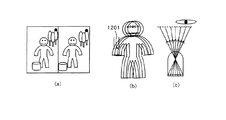
図6はあるステレオ画像の立体観察時に生じるクロストークの影響を示す図である。(a)は入力ステレオ画像、(b)は(a)の入力ステレオ画像から生成された立体画像を立体表示デバイスを通して観察した際に見えるクロストークの影響を受けた像である。また、(c)は(b)のクロストークの影響を示す図である。(c)では、3つの隣接視点画像が単一の視点に配置された眼に入射していることを示す。つまり、(b)に示すように、視差の影響によるずれを持つ重像を観察することになる。 FIG. 6 is a diagram illustrating the influence of crosstalk that occurs during stereoscopic observation of a certain stereo image. (A) is an input stereo image, (b) is an image affected by crosstalk that is seen when a stereoscopic image generated from the input stereo image of (a) is observed through a stereoscopic display device. Further, (c) is a diagram showing the influence of the crosstalk of (b). (C) shows that three adjacent viewpoint images are incident on an eye arranged at a single viewpoint. That is, as shown in (b), a multiple image having a shift due to the influence of parallax is observed.
(b)中において、1201は立体画像の表示面上でのずれ量を示している。重像の影響は、同一視点で一度に観察される視点画像間の視差量に関係する。つまり、表示視差許容量は、重像のずれ量がどの程度までならば許容できるかによって決定される。
In (b),
また、図13に示した立体画像を構成する視点画像数の変化と、立体表示デバイスから射出される個々の視点画像に対応する光束との関係から明らかなように、立体表示デバイスの個々の光学素子に対して挿入される像数に対し、表示視差許容量はある一定の像数以上では反比例する。つまり、一定数以上の像数においては、像数が増加すると表示視差許容量は減少し、例えば像数が倍増すると隣接視点画像間での表示視差許容量は約半分となる。 Further, as is apparent from the relationship between the change in the number of viewpoint images constituting the stereoscopic image shown in FIG. 13 and the light flux corresponding to each viewpoint image emitted from the stereoscopic display device, the individual optical characteristics of the stereoscopic display device are as follows. The display parallax allowable amount is inversely proportional to a certain number of images or more with respect to the number of images inserted into the element. That is, when the number of images increases, the display parallax tolerance decreases as the number of images increases. For example, when the number of images doubles, the display parallax tolerance between adjacent viewpoint images is approximately halved.
重像の影響の許容量は主観量であることから、実験的に像数と隣接視点画像間の視差範囲を変化させることにより、それぞれの立体表示デバイスについての表示許容視差量を決定する。但し、表示許容視差量は、視差を持つ部分のテクスチャの細かさにも影響される。つまり、テクスチャがぼやける遠景の沈み込み側の許容視差量は、通常の場合は大きくとることができ、逆にテクスチャがはっきりと現れる飛び出し側の視差値は小さな値に制限される。 Since the allowable amount of the influence of the multiple images is a subjective amount, the display allowable parallax amount for each stereoscopic display device is determined by experimentally changing the parallax range between the number of images and the adjacent viewpoint images. However, the display allowable parallax amount is also affected by the fineness of the texture of the part having parallax. That is, the allowable parallax amount on the sinking side of a distant view in which the texture is blurred can be made large in a normal case, and conversely, the parallax value on the pop-out side where the texture clearly appears is limited to a small value.
次に、立体表示デバイスによって観察される立体画像のサイズの選択(指定)について説明する。まず、立体表示デバイスが選択されることにより、該立体表示デバイスの表示可能領域の情報を取得し、該表示可能領域内の範囲で立体画像サイズを決定する。通常の立体表示デバイスのように、選択された立体表示デバイスとその表示可能領域との関係が1対1の関係にある場合には、繰り返し立体画像サイズを指定する必要はない。 Next, selection (designation) of the size of the stereoscopic image observed by the stereoscopic display device will be described. First, when a stereoscopic display device is selected, information on a displayable area of the stereoscopic display device is acquired, and a stereoscopic image size is determined within a range within the displayable area. When the relationship between the selected stereoscopic display device and its displayable area is a one-to-one relationship as in a normal stereoscopic display device, it is not necessary to repeatedly specify the stereoscopic image size.
立体表示デバイスとしてプリント画像に重ねて用いられるレンチキュラ板等を選択した場合、立体表示デバイスと印刷可能領域とは当然独立したものとなる。このため、プリンタとプリントされる用紙を選択することにより決まる有効印字領域のサイズが表示可能領域のサイズとなる。 When a lenticular plate or the like that is used by being superimposed on a print image is selected as the stereoscopic display device, the stereoscopic display device and the printable area are naturally independent. Therefore, the size of the effective print area determined by selecting the printer and the paper to be printed becomes the size of the displayable area.
通常は、立体表示デバイスの選択と立体画像サイズの指定(選択)については、図5(a)に示すように、本実施例における立体画像生成システムのディスプレイ203および操作入力部204等を用いて、一括して対話的に選択することができる。
Normally, for the selection of the stereoscopic display device and the designation (selection) of the stereoscopic image size, as shown in FIG. 5A, the
次に、表示可能領域内で立体画像サイズを決定する。表示可能領域をそのまま立体画像サイズとしてもよいが、入力される視点画像(入力ステレオ画像)のサイズと表示可能領域のサイズとのアスペクト比が異なる場合には、立体画像を表示した際に提示される像が歪んでしまう。このため、入力ステレオ画像サイズと表示可能領域のサイズのアスペクト比を確保したり、表示可能領域ぎりぎりまで立体画像を表示したくなかったりする場合には、余白領域を設定して立体画像サイズを決定する。 Next, the stereoscopic image size is determined within the displayable area. The displayable area may be used as the stereoscopic image size as it is, but if the aspect ratio of the input viewpoint image (input stereo image) and the displayable area size is different, it is presented when the stereoscopic image is displayed. The image will be distorted. Therefore, if you want to ensure the aspect ratio of the input stereo image size and the size of the displayable area, or if you do not want to display a 3D image to the limit of the displayable area, set the margin area to determine the 3D image size. To do.
図5(b)には、具体例として、プリントの場合に表示可能領域内で立体画像サイズを変更する様子を示す。601は表示可能領域、602はあるサイズ編集前の立体画像サイズ、603はあるサイズ編集後の立体画像サイズである。
FIG. 5B shows, as a specific example, how the stereoscopic image size is changed in the displayable area in the case of printing.
なお、ステップS102では入力ステレオ画像サイズと存在視差範囲とを取得し、またステップS103では立体画像サイズを選択しており、それぞれ独立したパラメータを求めているので、これらの処理の順番を逆にしてもよい。 Note that the input stereo image size and the existing parallax range are acquired in step S102, and the stereoscopic image size is selected in step S103, and independent parameters are obtained, so the order of these processes is reversed. Also good.
ステップS104では、入力ステレオ画像から新たに生成する視点画像(第2の視点画像、以下、仮想視点画像という)の視点(以下、仮想視点という)の位置を決定する。仮想視点位置とは、仮想視点画像を仮想的に撮影したカメラ(仮想カメラ)による撮影位置を示す。本実施例では、仮想視点画像を立体画像に変換したときに、立体表示デバイス210を通して提示される立体像の全域において隣接する視点画像間での視差が表示視差許容量を超えない範囲で最大の視差となるという条件下で、仮想視点位置を決定する。具体的には、以下のように、基準となる仮想視点位置を決定した後、順次、上記条件のもとで他の仮想視点位置を決定していく。
In step S104, the position of the viewpoint (hereinafter referred to as virtual viewpoint) of the viewpoint image (second viewpoint image, hereinafter referred to as virtual viewpoint image) newly generated from the input stereo image is determined. The virtual viewpoint position indicates a shooting position by a camera (virtual camera) that has virtually shot a virtual viewpoint image. In this embodiment, when a virtual viewpoint image is converted into a stereoscopic image, the parallax between adjacent viewpoint images in the entire area of the stereoscopic image presented through the
まず、ステップS102で得られた入力ステレオ画像のサイズおよびステップS103で得られた立体画像のサイズを用いて、入力ステレオ画像と出力立体画像とのサイズ比、すなわち変倍率を求める。 First, using the size of the input stereo image obtained in step S102 and the size of the stereo image obtained in step S103, a size ratio between the input stereo image and the output stereo image, that is, a scaling factor is obtained.
次に、求めた変倍率と、ステップS102により得られた基準となる視点画像の存在視差範囲、ステップS103により得られた隣接視点間の表示視差許容量を用いて、次段のステップS105で生成する仮想視点画像に対応する仮想視点位置を決定する。 Next, using the obtained scaling factor, the existing parallax range of the reference viewpoint image obtained in step S102, and the display parallax allowable amount between adjacent viewpoints obtained in step S103, the generation is performed in step S105. A virtual viewpoint position corresponding to the virtual viewpoint image to be determined is determined.
ここでは、まず隣接する仮想視点間の表示視差許容量に変倍率の逆数を積算することにより、入力ステレオ画像のスケールに対応する隣接視点間の視差許容量の範囲を求める。 Here, first by integrating the inverse of the scaling factor to display parallax allowable amount between virtual viewpoint adjacent to determine the range of the parallax tolerance between adjacent viewpoint corresponding to the scale of the input stereo images.
次に、基準となる仮想視点を決定する。基準となる仮想視点の位置はどのような位置でもよいが、本実施例では、入力ステレオ画像の各視点を結ぶ基線上の中間点を基準仮想視点とする。そして、ステレオ画像のスケールに対応した隣接視点間の視差許容量を超えない範囲で仮想視点位置の変位を取り、順次、他の仮想視点位置を決定していく。 Next, a reference virtual viewpoint is determined. Although the position of the reference virtual viewpoint may be any position, in this embodiment, an intermediate point on the base line connecting the viewpoints of the input stereo image is set as the reference virtual viewpoint. Then, taking the displacement of the virtual viewpoint position in a range not exceeding the parallax allowable amount between adjacent viewpoints corresponding to the scale of the stereo image, successively, it will determine the other virtual viewpoint position.
図7には、入力ステレオ画像間の視差量と、新たに生成される仮想視点画像の視差量との関係を示す。幾何的な配置の関係により、平行視配置に変換された入力ステレオ画像(ここでは2つの視点画像)1001,1002間で算出された視差量に対し、該入力ステレオ画像1001,1002の視点を結んだ直線上の仮想視点位置で、入力ステレオ画像1001,1002と同じ視線方向を持つ仮想視点画像1003を生成した場合、その生成された仮想視点画像と入力ステレオ画像のうち一方の視点画像との視差値は、その相対位置関係から一意に決定される。
FIG. 7 shows the relationship between the amount of parallax between input stereo images and the amount of parallax of a newly generated virtual viewpoint image. The viewpoints of the
つまり、入力ステレオ画像の視点間の距離がSであった場合に、仮想視点画像1003の視点が入力ステレオ画像の一方の視点画像1001を基準として、tの位置にあるとすると、該一方の視点画像1001と仮想視点画像1003間での視差値は、
That is, if the distance between the viewpoints of the input stereo image is S, and the viewpoint of the
という形で得ることができる。 Can be obtained in the form of
(3)式のd(x,y)は、(1)式により求めた視差値を、一方の視点画像の座標値に対応付けたものである。ここでは一方の視点画像1001を基準として他方の視点画像1002との間で求められる視差値である。また、d’(x,y)は、一方の視点画像1001を基準として仮想視点画像1003との間に生じる視差値に対応する。
D (x, y) in the equation (3) is obtained by associating the parallax value obtained by the equation (1) with the coordinate value of one viewpoint image. Here, it is a parallax value obtained between one
生成したい仮想視点画像の視線方向が入力ステレオ画像の視線方向と異なる場合には、一旦、入力ステレオ画像との平行視配置における視差値を求め、その後に視線変換を行うことによる対応点位置の変位をその視差に加算することにより、生成する仮想視点画像の各画素位置を計算する必要がある。 When the line-of-sight direction of the virtual viewpoint image to be generated is different from the line-of-sight direction of the input stereo image, the displacement of the corresponding point position is obtained by obtaining a parallax value in parallel viewing arrangement with the input stereo image and then performing line-of-sight conversion It is necessary to calculate each pixel position of the generated virtual viewpoint image by adding to the parallax.
このようにして得られる、隣接した仮想視点画像間での視差値が、入力ステレオ画像のスケールにおける隣接視点間の視差許容量に収まる範囲内で仮想視点位置の変位を取りながら、仮想視点位置を順次決定していく。 The virtual viewpoint position is calculated while taking the displacement of the virtual viewpoint position within a range in which the parallax value between the adjacent virtual viewpoint images obtained in this way is within the allowable parallax amount between adjacent viewpoints on the scale of the input stereo image. Determine sequentially.
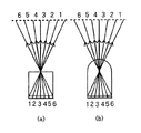
図8(a)は、表示視差許容量が小さい場合において決定された仮想視点位置を、図8(b)は表示視差許容量が大きい場合において決定された仮想視点位置である。 FIG. 8A shows the virtual viewpoint position determined when the display parallax allowable amount is small, and FIG. 8B shows the virtual viewpoint position determined when the display parallax allowable amount is large.
901は入力ステレオ画像のうち一方の視点画像、902は他方の視点画像である。903,904は図8(a),(b)のそれぞれの場合の仮想視点群である。905は入力ステレオ画像の2つの視点を結んだ中点に取った仮想視点の基準位置である。仮想視点群903,904の位置は、基準仮想視点を中心に水平方向に均等に分布するように決定している。当然、(a)の表示視差許容量が小さい場合の仮想視点群の広がりよりも、(b)の表示視差許容量が大きい場合の仮想視点群の広がりの方が大きくなる。
ステップS105では、前段のステップS104で決定した仮想視点に対応する仮想視点画像を生成する。 In step S105, a virtual viewpoint image corresponding to the virtual viewpoint determined in the previous step S104 is generated.
本実施例においては、ビューモーフィング(View Morphing,Steven M.Seitz,C. R. Dyer,Proc. SIGGRAPH 96(1996))の原理を用いて、入力ステレオ画像から直接、仮想視点画像を生成する。ここでは、特開2001−346226号公報において提案されている仮想視点の生成手法を用いた場合について、図9のフローチャートを用いて説明する。 In this embodiment, a virtual viewpoint image is generated directly from an input stereo image using the principle of view morphing (View Morphing, Steven M. Seitz, CR Dyer, Proc. SIGGRAPH 96 (1996)) . Here, the case of using the virtual viewpoint generation method proposed in Japanese Patent Laid-Open No. 2001-346226 will be described with reference to the flowchart of FIG.
ステップS1101では、入力ステレオ画像のそれぞれの画素に対して視差値が対応するように、S102において得られた存在視差範囲の視差情報を補間し、密な視差分布情報である視差マップを算出する。仮想視点画像生成における視点位置の変化の影響をより精密に再現したい場合には、階層マッチングやアダプティブマッチングと呼ばれる、より高精度な視点画像間の視差値を求めるステレオマッチングを再度実施してもよい。 In step S1101, the disparity information in the existing disparity range obtained in S102 is interpolated so that the disparity value corresponds to each pixel of the input stereo image, and a disparity map that is dense disparity distribution information is calculated. If you want to reproduce the effects of changes in the viewpoint position in virtual viewpoint image generation more precisely, you can re-execute stereo matching called hierarchical matching or adaptive matching to obtain more accurate parallax values between viewpoint images. .
また、視差情報の補間については、本実施例では、補間される未対応点の算出座標位置と対応点抽出処理で視差値の求まった対応点位置における距離パラメータを重みとして加重平均し、対応点の求まっていない未対応点の位置での視差を次式(4)により求める。 In addition, with respect to the interpolation of disparity information, in this embodiment, the weighted average is performed using the calculated coordinate position of the non-corresponding point to be interpolated and the distance parameter at the corresponding point position for which the disparity value is obtained by the corresponding point extraction process as a weight, The parallax at the position of the uncorresponding point for which is not obtained is obtained by the following equation (4).
ここで、nは補間結果を左右する任意に設定するパラメータであり、nの値を小さくしすぎると、求める視差は画像全域からの平均に近くなり、視差分布が一様になる。また、nの値を大きくしすぎると、近くの対応点の影響を大きく受ける。計算時間も考慮して、n=1程度が望ましい。 Here, n is an arbitrarily set parameter that influences the interpolation result. If the value of n is too small, the parallax to be obtained is close to the average from the entire image, and the parallax distribution becomes uniform. If the value of n is too large, it is greatly affected by nearby corresponding points. In consideration of calculation time, n = 1 is desirable.
以上の処理により、左画像に対する密な視差分布情報、つまり視差マップを得る。右画像に対応する密な視差分布は、(4)式の座標位置(x,y)、 (x’,y’)を入れ替えることで得る。 Through the above processing, dense parallax distribution information for the left image, that is, a parallax map is obtained. A dense parallax distribution corresponding to the right image is obtained by exchanging the coordinate positions (x, y) and (x ′, y ′) in the equation (4).
次に、ステップS1102では、ワーピング処理を行ってステップS104で得られた入力ステレオ画像に対する相対位置である各仮想視点位置に対応する仮想視点画像を生成する。 Next, in step S1102, warping processing is performed to generate virtual viewpoint images corresponding to the respective virtual viewpoint positions that are relative positions to the input stereo image obtained in step S104.
具体的には、(4)式で得られる個々の画素のワープ量に従い、ワープ元となる入力ステレオ画像の個々の画素をワープさせることにより、仮想視点の像を生成することができる。生成された仮想視点画像に対してオクルージョン処理、平滑化等の後処理を行うことにより、決定した仮想視点に対応する仮想視点画像が得られる。 Specifically, an image of the virtual viewpoint can be generated by warping each pixel of the input stereo image as a warp source in accordance with the warp amount of each pixel obtained by the equation (4). A virtual viewpoint image corresponding to the determined virtual viewpoint is obtained by performing post-processing such as occlusion processing and smoothing on the generated virtual viewpoint image.
ステップS1103では、生成された仮想視点画像の視線方向を、平行視処理後の入力ステレオ画像の視線方向とは異なる方向にしたい場合に、視線変換を行う。具体的には、視線行列を計算し、画像に適用することにより視線変換後の画像が得られる。 In step S1103, line-of-sight conversion is performed when the line-of-sight direction of the generated virtual viewpoint image is desired to be different from the line-of-sight direction of the input stereo image after parallel vision processing. Specifically, a line-of-sight conversion image is obtained by calculating a line-of-sight matrix and applying it to the image.
このような手順を、決定した各仮想視点に対して行うことにより、各仮想視点に対応する仮想視点画像が生成される。 By performing such a procedure for each determined virtual viewpoint, a virtual viewpoint image corresponding to each virtual viewpoint is generated.
本実施例では、入力ステレオ画像から、立体画像の合成に必要な仮想視点画像を生成するための仮想視点を、入力ステレオ画像のサイズ情報と、立体表示デバイスの種類、像数等の仕様に関するデバイス情報と、立体画像の表示サイズ情報に基づいて決定し、次に入力ステレオ画像に基づいて、決定した仮想視点に対応する仮想視点画像を生成することで、適切な視差を有する立体画像を生成する。但し、入力ステレオ画像から仮想視点画像を生成する手法自体についてはその種類は問わない。 In this embodiment, a virtual viewpoint for generating a virtual viewpoint image necessary for synthesizing a three-dimensional image from an input stereo image, a size information of the input stereo image, and a device related to specifications such as the type of stereoscopic display device and the number of images A stereoscopic image having an appropriate parallax is generated by generating a virtual viewpoint image corresponding to the determined virtual viewpoint based on the information and the display size information of the stereoscopic image and then generating the virtual viewpoint image based on the input stereo image . However, the method itself for generating the virtual viewpoint image from the input stereo image is not limited.
従来技術である特開平9−121370号公報にて提案のように、既に存在する視点画像間の相対位置をシフトさせる等、単純な視点画像のアフィン処理によって観察者の左右の眼に提示される視点画像間の視差範囲を調整する場合、その提示視差量の変化は立体の飛び出し量および沈み込み量について管面に対し近似的に垂直方向に並進するように影響するだけである。また、特に、中心視の場合のように、幾何学的関係から視点画像間の視線方向が互いに平行でない場合は大きな影響の差が出る。このような視差調整方法では、視差の変化に対し、幾何学的関係において正しくない修正を行うことになってしまうため、調整後の視点画像を観察した場合に視差変化に歪みを感じてしまう。 As proposed in Japanese Patent Application Laid-Open No. 9-121370, which is a prior art, it is presented to the left and right eyes of the observer by simple affine processing of viewpoint images, such as shifting the relative position between already existing viewpoint images. When adjusting the parallax range between the viewpoint images, the change in the amount of parallax that is presented only affects the amount of projection and the amount of sinking of the solid so as to translate approximately vertically to the tube surface. In particular, as in the case of central vision, there is a large difference in influence when the line-of-sight directions between viewpoint images are not parallel to each other due to the geometric relationship. In such a parallax adjustment method, an incorrect correction in the geometric relationship is performed for the change in parallax, and thus the parallax change is distorted when the adjusted viewpoint image is observed.
これに対して、本実施例のように、例えば、仮想視点画像の生成にビューモーフィング手法を用いて、画像の視差調整のために仮想視点画像を新たに生成することにより、図8(a),(b)に示すように、視点間隔、つまりは仮想視点間の基線長が広がった、より良好に運動視差を再現できる仮想視点画像群を生成することができる。また、中心視の場合のように、視点画像間の視線方向が平行でない場合でも、仮想視点画像の生成処理後に視線方向を変更する視線変換処理を行うことにより、立体画像合成用の視点画像群として、視差変化において歪みのない自然な立体感が得られる仮想視点画像群を最終的に生成することができる。 On the other hand, as in the present embodiment, for example, a view morphing method is used to generate a virtual viewpoint image, and a virtual viewpoint image is newly generated for parallax adjustment of the image, thereby FIG. , (B), it is possible to generate a virtual viewpoint image group that can reproduce motion parallax more favorably with a wider viewpoint interval, that is, a base length between virtual viewpoints. Further, even when the line-of-sight directions between the viewpoint images are not parallel as in the case of central vision, the viewpoint image group for stereoscopic image synthesis is performed by performing a line-of-sight conversion process that changes the line-of-sight direction after the virtual viewpoint image generation process. As a result, it is possible to finally generate a virtual viewpoint image group that provides a natural stereoscopic effect without distortion in the parallax change.
次に、図1におけるステップS106では、ステップS105において生成された仮想視点画像群を合成して立体画像を生成する。そして、生成された立体画像は、プリンタ206に出力されて印刷されたり、操作ディスプレイ203に出力されて表示されたりする。また、入出力部205から立体画像データとして出力される場合もある。
Next, in step S106 in FIG. 1, the virtual viewpoint image group generated in step S105 is synthesized to generate a stereoscopic image. The generated stereoscopic image is output to the
ここでは、図2に示すように、立体表示デバイス210として、立体画像を表示するディスプレイ部210aの前面にレンチキュラ板(光学部材)210bを配置し、ディスプレイ部210aに前述したストライプ式立体画像を表示する場合の該ストライプ式立体画像の合成について説明する。
Here, as shown in FIG. 2, as the
ストライプ式立体画像の合成は、生成された仮想視点画像群における各画像の同一座標の画素を、視点配列とは逆順に配列することにより行う。 The stripe-type stereoscopic image is synthesized by arranging pixels at the same coordinates of each image in the generated virtual viewpoint image group in the reverse order to the viewpoint arrangement.
まず、視点jに対応する仮想視点画像の画素値をPjmn(但し、m,nはそれぞれ水平、垂直方向の画素配列のインデックス)とすると、該仮想視点画像は以下のような画素値データの2次元配列で表される。 First, assuming that the pixel value of the virtual viewpoint image corresponding to the viewpoint j is P jmn (where m and n are indices of the pixel array in the horizontal and vertical directions, respectively), the virtual viewpoint image has the following pixel value data. It is represented by a two-dimensional array.
次に、各仮想視点画像を垂直方向に延びる1ラインごとにストライプ状に分解し、該ストライプ画像を実際の視点の配列順とは逆の順番に視点数分だけ並べていく。したがって,合成後の画像は以下に示すようなストライプ画像となる。 Next, each virtual viewpoint image is decomposed into stripes for each line extending in the vertical direction, and the stripe images are arranged by the number of viewpoints in the order opposite to the actual viewpoint arrangement order. Therefore, the combined image is a stripe image as shown below.
但し、上記配列は視点1が左端、Nが右端の位置関係に対応する立体画像を表す。ここで、ストライプ画像の配列順序を視点の配列順と逆にするのは、レンチキュラ板210bを構成するレンチキュラレンズの1ピッチ内で、画像が左右逆に観察されるためである。このストライプ式立体画像は、各仮想視点画像がH×vのサイズであり、N個の仮想視点画像を有する場合には、X(=N×H)×vのサイズとなる。
However, the above arrangement represents a stereoscopic image corresponding to the positional relationship where the
次に、このストライプ式立体画像に対して、レンチキュラ板210bとのピッチ合わせ(変倍処理)を行う。1ピッチのRP(dpi)の画素がN画素分存在するので、1ピッチはN/RP(inch)となるが、レンチキュラ板210bにおけるレンチキュラレンズのピッチがRL(inch)であるので、画像を水平方向にRL×RP/N倍してピッチを合わせる。
Next, pitch adjustment (scaling process) with the
また、垂直方向の画素数は、アスペクト比を保存したい場合は、(RL×RP/N)×Y画素となる必要があるので、垂直方向に(RL×RP×Y)/(N×v)のサイズとなる。 In addition, the number of pixels in the vertical direction needs to be (RL × RP / N) × Y pixels when it is desired to preserve the aspect ratio, and therefore (RL × RP × Y) / (N × v) in the vertical direction. It becomes the size.
ここで、RP(dpi)は印刷の解像度、XP×YPは印刷サイズ、X(RP×XP)×Y(RP×YP)(画素)は印刷する画像のサイズ、RL(inch)はレンチキュラ板210bにおけるレンチキュラレンズのピッチである。
Here, RP (dpi) is the printing resolution, XP × YP is the printing size, X (RP × XP) × Y (RP × YP) (pixel) is the size of the image to be printed, and RL (inch) is the
このように立体画像に対して変倍処理を行い、最終的な立体画像として立体表示デバイス210に表示する。変倍処理は、例えば、双線形補間などにより行う。立体画像をプリンタ206により印刷した場合には、印刷された立体画像にレンチキュラ板等の光学部材を重ね合わせて観察する。
In this way, the scaling process is performed on the stereoscopic image, and the final stereoscopic image is displayed on the
本実施例によれば、ストライプ式立体画像の生成元画像である仮想視点画像の生成における視点位置(仮想視点位置)を、立体表示デバイスの種類、像数等の情報や立体画像の表示サイズ情報に基づいて自動的に調整するので、十分な立体感を持ち、静止観察時や視点移動観察をした際にクロストークによる不快感を及ぼさない、より自然な立体観察が可能な立体画像を生成することが可能となる。 According to the present embodiment, the viewpoint position (virtual viewpoint position) in the generation of the virtual viewpoint image that is the generation source image of the striped stereoscopic image, the information such as the type and number of images of the stereoscopic display device, and the display size information of the stereoscopic image Automatically adjusts based on image quality, and generates a 3D image that has sufficient 3D effect and does not cause discomfort due to crosstalk during stationary observation or viewpoint movement observation. It becomes possible.
なお、上記実施例においては、レンチキュラ板を用いた立体表示デバイスに対応した画素配列の立体画像の合成方法について説明したが、本発明は、いわゆる斜めレンチキュラシート、パララックスステレオグラム、ホログラフィックステレオグラム等を用いた立体表示デバイスに対応した画素配列の立体画像を合成する場合にも適用することができる。 In the above embodiment, a method for synthesizing a stereoscopic image of a pixel array corresponding to a stereoscopic display device using a lenticular plate has been described. However, the present invention is applicable to a so-called oblique lenticular sheet, parallax stereogram, holographic stereogram. The present invention can also be applied to a case where a stereoscopic image having a pixel arrangement corresponding to a stereoscopic display device using the above is synthesized.
また、上記実施例では、立体画像の合成に、入力ステレオ画像から新たに生成された仮想視点画像群のみを用いた場合について説明したが、入力ステレオ画像中の視点画像に対応する視点が、ステップS104で決定される仮想視点に一致する場合は、その入力ステレオ画像に含まれる視点画像を立体画像生成用の視点画像として含めてもよい。 In the above embodiment, the case where only the virtual viewpoint image group newly generated from the input stereo image is used for the synthesis of the stereoscopic image has been described. However, the viewpoint corresponding to the viewpoint image in the input stereo image is a step. If the virtual viewpoint determined in S104 coincides, the viewpoint image included in the input stereo image may be included as a viewpoint image for generating a stereoscopic image.
さらに、上記実施例においては、仮想視点画像の生成手法として、平行視配置におけるビューモーフィング手法により視線方向が平行となる仮想視点画像を生成する場合について説明したが、生成後の仮想視点画像に対して視線変換等のアフィン処理を加えることにより、シーン内の特定物体に対して各仮想視点画像の視線方向が向かう、中心視の仮想視点画像群を生成してもよい。つまり、仮想視点画像の視点位置および視線方向は、任意でよい。 Furthermore, in the above embodiment, as a method for generating a virtual viewpoint image, a case has been described in which a virtual viewpoint image in which the line-of-sight direction is parallel is generated by a view morphing method in parallel viewing arrangement. Then, by adding affine processing such as line-of-sight conversion, a central viewpoint virtual viewpoint image group in which the line-of-sight direction of each virtual viewpoint image is directed toward a specific object in the scene may be generated. That is, the viewpoint position and the line-of-sight direction of the virtual viewpoint image may be arbitrary.
上記実施例1においては、ステレオ画像を入力として、表示サイズ若しくは立体表示デバイスの種類や像数が変更されるごとに、観察者にクロストークによる不快感を与えない範囲で最も大きな立体感(視差)を与えるように、立体画像を生成するための仮想視点画像の視点位置を自動的に調整し、適切な立体感を感じさせる立体画像を生成したが、入力を三次元モデル情報とすることも可能である。
本実施例の立体画像生成システム構成は、実施例1のシステム構成と基本的に同じであるので、本実施例において共通する構成要素には実施例1と同符号を付す。但し、立体画像合成装置202における処理が図10に示すフローチャートのように変更される。なお、該処理は、立体画像合成装置202のCPU2021内に格納されたコンピュータプログラムである立体画像合成プログラムに従って実行される。
In the first embodiment, each time the display size or the type of stereoscopic display device or the number of images is changed using a stereo image as an input, the largest stereoscopic effect (parallax) within a range in which the viewer does not feel uncomfortable due to crosstalk. ), The viewpoint position of the virtual viewpoint image for generating the stereoscopic image is automatically adjusted to generate a stereoscopic image that gives an appropriate stereoscopic effect, but the input may be 3D model information. Is possible .
The configuration of the stereoscopic image generation system according to the present embodiment is basically the same as the system configuration according to the first embodiment. However, the processing in the stereoscopic
本実施例にいう三次元モデル(情報)とは、物体の表面の頂点座標および頂点列で形成されるポリゴンと、該表面の色や反射率等の属性を表す2次元テクスチャ画像とから構成される、実物体を三次元でモデリングした情報である。該三次元モデルをある三次元の仮想空間内に配置し、該三次元モデルに対して移動、回転、拡大などの操作を行って仮想空間内での配置を変更することで、所望のシーンを構築することができる。このようにして三次元モデルが配置された仮想空間において、更に任意の仮想視点位置に仮想カメラを設置して画像をレンダリングすることにより、仮想視点画像を生成することができる。 The three-dimensional model (information) referred to in the present embodiment is composed of polygons formed by vertex coordinates and vertex rows on the surface of an object, and a two-dimensional texture image representing attributes such as color and reflectance of the surface. This is information obtained by modeling a real object in three dimensions. By placing the three-dimensional model in a certain three-dimensional virtual space and changing the placement in the virtual space by performing operations such as movement, rotation, and enlargement on the three-dimensional model, a desired scene can be obtained. Can be built. In this way, in the virtual space where the three-dimensional model is arranged, a virtual viewpoint image can be generated by further rendering the image by installing a virtual camera at an arbitrary virtual viewpoint position.
ステップS1401では、1又は複数の物体の三次元モデルと、該三次元モデルの仮想空間での配置情報も含む詳細な三次元モデル情報を外部機器との入出力部205から入力し、主記憶装置2023もしくは大容量記憶装置2022に記憶する。
In step S1401, detailed three-dimensional model information including a three-dimensional model of one or a plurality of objects and arrangement information of the three-dimensional model in the virtual space is input from the input /
更に、入力された三次元モデルの形状や配置を変更したい場合には、操作ディスプレイ203に仮想空間における三次元モデルの配置を表示し、操作入力部204を介して変形、移動、回転、反転、拡大・縮小等の操作を行う。
Further, when it is desired to change the shape and arrangement of the three-dimensional model is input, displays the arrangement of the three-dimensional model in the virtual space on the
ステップS1402では、仮想空間内に設置された仮想カメラの撮影パラメータおよび仮想カメラの撮像面におけるビューサイズを決定する。仮想カメラの撮影パラメータが決定されることにより、仮想空間と実空間とのスケールが決定される。仮想カメラの撮影パラメータとは、撮影方向(視線方向)、撮影倍率等、カメラの内部パラメータである。 In step S1402, the imaging parameters of the virtual camera installed in the virtual space and the view size on the imaging surface of the virtual camera are determined. By determining the shooting parameters of the virtual camera, the scale between the virtual space and the real space is determined. The shooting parameters of the virtual camera are internal parameters of the camera such as a shooting direction (gaze direction), a shooting magnification, and the like.
ステップS1403では、実施例1のステップS103と同様に、選択された立体表示デバイスのデバイス情報から表示視差許容量を求めるとともに、表示立体画像サイズの指定を受ける。 In step S1403, as in step S103 of the first embodiment, the display parallax allowable amount is obtained from the device information of the selected stereoscopic display device, and the display stereoscopic image size is designated.
ステップS1404では、仮想視点画像を撮影する仮想カメラの位置、すなわち仮想視点位置を決定する。まず、ステップS1402において決定された仮想カメラの撮影パラメータ、ビューサイズ、さらにはステップS1403で取得された表示視差許容量および表示立体画像サイズから、仮想カメラの視点において生成される仮想視点画像のスケールにおける、仮想視点画像間での許容視差量の範囲を求める。 In step S1404, the position of the virtual camera that captures the virtual viewpoint image, that is, the virtual viewpoint position is determined. First, based on the virtual camera shooting parameters and view size determined in step S1402, and the display parallax allowance and display stereoscopic image size acquired in step S1403, in the scale of the virtual viewpoint image generated at the viewpoint of the virtual camera. Then, the range of the allowable parallax amount between the virtual viewpoint images is obtained.
次に、仮想視点画像を順次生成するために、仮想視点位置を決定する。図11において、1501は基準となる視点の仮想カメラ、1502は視点移動後の仮想カメラ、1503、1504、1505は仮想空間内の三次元モデルである。
Next, a virtual viewpoint position is determined in order to sequentially generate virtual viewpoint images. In FIG. 11,
まず、実施例1と同様に、基準となる仮想カメラの視点位置を決定する。本実施例では、図11における視点位置1501とする。次に、該視点位置1501を基準として、次の仮想カメラの視点位置を決定する。仮想カメラの視点位置の決定においては、順次生成される仮想視点画像の前時点で決定された視点位置(最初は基準とした視点位置1501)に対応する仮想視点画像と、次に選択された視点位置における仮想視点画像との間の視差量が、仮想視点画像のスケールにおける許容視差量を超えないことが条件となる。
First, as in the first embodiment, the viewpoint position of the reference virtual camera is determined. In this embodiment, the
すなわち、まず次の仮想カメラの視点位置を任意に選択する。そして、基準となる視点位置において生成される仮想視点画像との間に生じる視差量を求める。さらに、画像全域の視差量について、仮想視点画像のスケールにおける許容視差量との比較を行い、生成される仮想視点画像間の視差量が許容視差量を超えていない場合はその視点位置の仮想視点位置としての選択を許可する。一方、許容視差量を超えた場合は、より小さな視点の移動の中で次の仮想カメラの視点位置を新たに選択するという形で、1つの仮想視点画像についての仮想カメラの視点位置を決定していく。 That is, first, the viewpoint position of the next virtual camera is arbitrarily selected. Then, the amount of parallax generated between the virtual viewpoint image generated at the reference viewpoint position is obtained. Furthermore, the parallax amount of the entire image is compared with the allowable parallax amount on the scale of the virtual viewpoint image. If the parallax amount between the generated virtual viewpoint images does not exceed the allowable parallax amount, the virtual viewpoint at the viewpoint position Allows selection as position. On the other hand, when the allowable parallax amount is exceeded, the viewpoint position of the virtual camera for one virtual viewpoint image is determined in such a manner that the viewpoint position of the next virtual camera is newly selected while moving the smaller viewpoint. To go.
また、視差情報は、例えば図11のようにそれぞれの仮想カメラを仮想空間内に設置し、仮想空間内に設置された物体へとレイトレースを行い、撮影パラメータおよびビュー範囲に基づいて、仮想カメラによって撮影された2つの仮想視点画像間の一方の画像を基準とした視差情報を求めていく。また、仮想空間内に設置された3次元モデルおよび仮想カメラの幾何的な位置情報は既知であることから、幾何演算により、部分的に視差情報を求めてもよい。 Further, the parallax information is obtained by installing each virtual camera in a virtual space as shown in FIG. 11, performing ray tracing to an object installed in the virtual space, and based on the shooting parameters and the view range. The parallax information with reference to one image between the two virtual viewpoint images taken by the above is obtained. In addition, since the geometric position information of the three-dimensional model and virtual camera installed in the virtual space is known, the disparity information may be partially obtained by geometric calculation.
1つの仮想視点画像の視点位置が決定されると、その視点位置が次の視点位置の決定における基準視点位置となる。こうして、仮想視点位置を順次決定していき、立体画像を構成する仮想視点画像数を満たす仮想視点位置が決定される。 When the viewpoint position of one virtual viewpoint image is determined, the viewpoint position becomes the reference viewpoint position in determining the next viewpoint position. In this way, virtual viewpoint positions are sequentially determined, and virtual viewpoint positions that satisfy the number of virtual viewpoint images constituting the stereoscopic image are determined.
ステップS1405では、ステップS1404で決定された仮想視点位置に対応する仮想視点画像を順次レンダリングすることにより、立体画像を合成するために必要な数の仮想視点画像群を生成する。 In step S1405, the virtual viewpoint images corresponding to the virtual viewpoint position determined in step S1404 are sequentially rendered, thereby generating the required number of virtual viewpoint images for synthesizing the stereoscopic image.
さらに、ステップS1406では、仮想視点画像群から立体画像を合成し、立体表示デバイス210やプリンタ206等に出力する。
In step S1406, a stereoscopic image is synthesized from the virtual viewpoint image group and output to the
本実施例によれば、三次元モデル情報を入力として、立体表示デバイスの種類、視点画像数(像数)等の仕様に関するデバイス情報および表示立体画像サイズが変更されるごとに、立体画像の生成元画像である仮想視点画像の生成における視点位置(仮想視点位置)を自動的に調整するので、十分な立体感を持ち、静止観察時や視点移動観察をした際にクロストークによる不快感を及ぼさない、より自然な立体観察が可能な立体画像を生成することが可能となる。 According to the present embodiment, the 3D model information is input, and each time the device information on the specifications such as the type of the stereoscopic display device and the number of viewpoint images (number of images) and the display stereoscopic image size are changed, the stereoscopic image is generated. Since the viewpoint position (virtual viewpoint position) in the generation of the virtual viewpoint image that is the original image is automatically adjusted, it has a sufficient three-dimensional effect and causes discomfort due to crosstalk during stationary observation and viewpoint movement observation. It is possible to generate a stereoscopic image that allows more natural stereoscopic observation.
なお、本発明は、上述した各実施例のシステム構成に限定されず、複数の装置から構成されるシステムに適用しても、1つの装置からなるシステムに適用してもよい。 The present invention is not limited to the system configuration of each of the embodiments described above, and may be applied to a system constituted by a plurality of devices or a system constituted by one device.
201 画像入力装置
202 立体画像合成装置
203 操作ディスプレイ
204 操作入力部
205 外部機器との入出力部
206 プリンタ
210 立体表示デバイス
DESCRIPTION OF
Claims (11)
立体画像の観察に使用される立体表示デバイスに関するデバイス情報を取得する第2の情報取得ステップと、
前記第1のサイズ情報、前記視差情報および前記デバイス情報に基づいて、前記立体表示デバイスに対応した複数の視点を決定する視点決定ステップと、
前記第1の視点画像を用いて、前記視点決定ステップで決定された複数の視点に対応する複数の第2の視点画像を生成し、該複数の第2の視点画像を用いて前記立体画像を生成する画像生成ステップと、
をコンピュータに実行させることを特徴とする立体画像生成プログラム。 A first information acquisition step of acquiring, from a plurality of first viewpoint images, first size information relating to the size of the first viewpoint image and disparity information relating to parallax between the plurality of first viewpoint images;
A second information acquisition step of acquiring device information relating to a stereoscopic display device used for observation of a stereoscopic image;
A viewpoint determination step of determining a plurality of viewpoints corresponding to the stereoscopic display device based on the first size information, the parallax information, and the device information;
A plurality of second viewpoint images corresponding to a plurality of viewpoints determined in the viewpoint determination step are generated using the first viewpoint image, and the stereoscopic image is converted using the plurality of second viewpoint images. An image generation step to generate ;
It characterized by causing a computer to execute the standing body image generator.
前記視点決定ステップにおいて、前記第1および第2のサイズ情報、前記視差情報および前記デバイス情報に基づいて前記複数の視点を決定することと、
をコンピュータに実行させることを特徴とする請求項1に記載の立体画像生成プログラム。 And that in said second information obtaining step obtains the second size information about the size of the three-dimensional image,
Determining the plurality of viewpoints based on the first and second size information, the parallax information, and the device information in the viewpoint determination step ;
3. The stereoscopic image generation program according to claim 1, wherein the computer is executed .
立体画像の観察に使用される立体表示デバイスに関するデバイス情報を取得する第2の情報取得ステップと、
前記パラメータ情報、前記第1のサイズ情報および前記デバイス情報に基づいて、前記立体表示デバイスに対応した複数の視点を決定する視点決定ステップと、
前記三次元モデル情報を用いて、前記視点決定ステップで決定された複数の視点に対応する複数の視点画像を生成し、該複数の視点画像を用いて前記立体画像を生成する画像生成ステップと、
をコンピュータに実行させることを特徴とする立体画像生成プログラム。 First information for acquiring three-dimensional model information of an object, parameter information regarding shooting parameters of a virtual camera virtually arranged at a viewpoint corresponding to a viewpoint image, and first size information regarding a view size of the virtual camera An information acquisition step;
A second information acquisition step of acquiring device information relating to a stereoscopic display device used for observation of a stereoscopic image;
A viewpoint determination step of determining a plurality of viewpoints corresponding to the stereoscopic display device based on the parameter information, the first size information, and the device information;
Generating a plurality of viewpoint images corresponding to a plurality of viewpoints determined in the viewpoint determination step using the three-dimensional model information, and generating the stereoscopic image using the plurality of viewpoint images ; and
It characterized by causing a computer to execute the standing body image generator.
前記視点決定ステップにおいて、前記パラメータ情報、前記第1のサイズ情報、前記デバイス情報および前記第2のサイズ情報に基づいて、前記複数の視点を決定することと、
をコンピュータに実行させることを特徴とする請求項3に記載の立体画像生成プログラム。 And that in said second information obtaining step obtains the second size information about the size of the three-dimensional image,
Determining the plurality of viewpoints based on the parameter information, the first size information, the device information, and the second size information in the viewpoint determination step ;
4. The stereoscopic image generating program according to claim 3, wherein the computer is executed .
をコンピュータに実行させることを特徴とする請求項1から4のいずれか1つに記載の立体画像生成プログラム。 Determining the plurality of viewpoints so that the maximum parallax is obtained in the parallax allowable range of the stereoscopic display device in the viewpoint determination step ;
5. The three-dimensional image generation program according to claim 1, wherein the three-dimensional image generation program according to claim 1 is executed .
立体画像の観察に使用される立体表示デバイスに関するデバイス情報を取得する第2の情報取得手段と、
前記第1のサイズ情報、前記視差情報および前記デバイス情報に基づいて、前記立体表示デバイスに対応した複数の視点を決定する視点決定手段と、
前記第1の視点画像を用いて、前記視点決定手段で決定された複数の視点に対応する複数の第2の視点画像を生成し、該複数の第2の視点画像を用いて前記立体画像を生成する画像生成手段とを有することを特徴とする立体画像生成システム。 First information acquisition means for acquiring, from a plurality of first viewpoint images, first size information relating to the size of the first viewpoint image and disparity information relating to parallax between the plurality of first viewpoint images;
Second information acquisition means for acquiring device information relating to a stereoscopic display device used for observation of a stereoscopic image;
Viewpoint determining means for determining a plurality of viewpoints corresponding to the stereoscopic display device based on the first size information, the parallax information, and the device information;
A plurality of second viewpoint images corresponding to a plurality of viewpoints determined by the viewpoint determination unit are generated using the first viewpoint images, and the stereoscopic image is converted using the plurality of second viewpoint images. A stereoscopic image generation system comprising: an image generation means for generating.
立体画像の観察に使用される立体表示デバイスに関するデバイス情報を取得する第2の情報取得手段と、
前記パラメータ情報、前記第1のサイズ情報および前記デバイス情報に基づいて、前記立体表示デバイスに対応した複数の視点を決定する視点決定手段と、
前記三次元モデル情報を用いて、前記視点決定手段で決定された複数の視点に対応する複数の視点画像を生成し、該複数の視点画像を用いて前記立体画像を生成する画像生成手段とを有することを特徴とする立体画像生成システム。 First information for acquiring three-dimensional model information of an object, parameter information regarding shooting parameters of a virtual camera virtually arranged at a viewpoint corresponding to a viewpoint image, and first size information regarding a view size of the virtual camera Information acquisition means;
Second information acquisition means for acquiring device information relating to a stereoscopic display device used for observation of a stereoscopic image;
Viewpoint determining means for determining a plurality of viewpoints corresponding to the stereoscopic display device based on the parameter information, the first size information, and the device information;
Image generating means for generating a plurality of viewpoint images corresponding to a plurality of viewpoints determined by the viewpoint determining means using the three-dimensional model information, and generating the stereoscopic image using the plurality of viewpoint images; A stereoscopic image generation system characterized by comprising:
立体画像の観察に使用される立体表示デバイスに関するデバイス情報を取得する第2の情報取得ステップと、
前記第1のサイズ情報、前記視差情報および前記デバイス情報に基づいて、前記立体表示デバイスに対応した複数の視点を決定する視点決定ステップと、
前記第1の視点画像を用いて、前記視点決定ステップで決定された複数の視点に対応する複数の第2の視点画像を生成し、該複数の第2の視点画像を用いて前記立体画像を生成する画像生成ステップとを有することを特徴とする立体画像生成方法。 A first information acquisition step of acquiring, from a plurality of first viewpoint images, first size information relating to the size of the first viewpoint image and disparity information relating to parallax between the plurality of first viewpoint images;
A second information acquisition step of acquiring device information relating to a stereoscopic display device used for observation of a stereoscopic image;
A viewpoint determination step of determining a plurality of viewpoints corresponding to the stereoscopic display device based on the first size information, the parallax information, and the device information;
A plurality of second viewpoint images corresponding to a plurality of viewpoints determined in the viewpoint determination step are generated using the first viewpoint image, and the stereoscopic image is converted using the plurality of second viewpoint images. A three-dimensional image generation method comprising: an image generation step of generating the image.
立体画像の観察に使用される立体表示デバイスに関するデバイス情報を取得する第2の情報取得ステップと、
前記パラメータ情報、前記第1のサイズ情報および前記デバイス情報に基づいて、前記立体表示デバイスに対応した複数の視点を決定する視点決定ステップと、
前記三次元モデル情報を用いて、前記視点決定ステップで決定された複数の視点に対応する複数の視点画像を生成し、該複数の視点画像を用いて前記立体画像を生成する画像生成ステップとを有することを特徴とする立体画像生成方法。 First information for acquiring three-dimensional model information of an object, parameter information regarding shooting parameters of a virtual camera virtually arranged at a viewpoint corresponding to a viewpoint image, and first size information regarding a view size of the virtual camera An information acquisition step;
A second information acquisition step of acquiring device information relating to a stereoscopic display device used for observation of a stereoscopic image;
A viewpoint determination step of determining a plurality of viewpoints corresponding to the stereoscopic display device based on the parameter information, the first size information, and the device information;
An image generation step of generating a plurality of viewpoint images corresponding to the plurality of viewpoints determined in the viewpoint determination step using the three-dimensional model information, and generating the stereoscopic image using the plurality of viewpoint images. A three-dimensional image generation method comprising:
Priority Applications (1)
| Application Number | Priority Date | Filing Date | Title |
|---|---|---|---|
| JP2004300370A JP4440066B2 (en) | 2004-10-14 | 2004-10-14 | Stereo image generation program, stereo image generation system, and stereo image generation method |
Applications Claiming Priority (1)
| Application Number | Priority Date | Filing Date | Title |
|---|---|---|---|
| JP2004300370A JP4440066B2 (en) | 2004-10-14 | 2004-10-14 | Stereo image generation program, stereo image generation system, and stereo image generation method |
Publications (3)
| Publication Number | Publication Date |
|---|---|
| JP2006115198A JP2006115198A (en) | 2006-04-27 |
| JP2006115198A5 JP2006115198A5 (en) | 2007-12-20 |
| JP4440066B2 true JP4440066B2 (en) | 2010-03-24 |
Family
ID=36383335
Family Applications (1)
| Application Number | Title | Priority Date | Filing Date |
|---|---|---|---|
| JP2004300370A Active JP4440066B2 (en) | 2004-10-14 | 2004-10-14 | Stereo image generation program, stereo image generation system, and stereo image generation method |
Country Status (1)
| Country | Link |
|---|---|
| JP (1) | JP4440066B2 (en) |
Cited By (3)
| Publication number | Priority date | Publication date | Assignee | Title |
|---|---|---|---|---|
| US9064444B2 (en) | 2012-05-31 | 2015-06-23 | Samsung Display Co., Ltd. | Three-dimensional display device |
| US9208372B2 (en) | 2013-04-11 | 2015-12-08 | Sony Corporation | Image processing apparatus, image processing method, program, and electronic appliance |
| US10074343B2 (en) | 2011-04-01 | 2018-09-11 | Panasonic Intellectual Property Management Co., Ltd. | Three-dimensional image output apparatus and three-dimensional image output method |
Families Citing this family (24)
| Publication number | Priority date | Publication date | Assignee | Title |
|---|---|---|---|---|
| US8077964B2 (en) * | 2007-03-19 | 2011-12-13 | Sony Corporation | Two dimensional/three dimensional digital information acquisition and display device |
| EP2287234B1 (en) | 2008-05-21 | 2016-03-23 | Asahi Kasei Chemicals Corporation | Cellulose powder having excellent segregation preventive effect, and compositions thereof |
| JP4737573B2 (en) * | 2009-02-05 | 2011-08-03 | 富士フイルム株式会社 | 3D image output apparatus and method |
| JP4915458B2 (en) * | 2009-04-03 | 2012-04-11 | ソニー株式会社 | Information processing apparatus, information processing method, and program |
| JP4919122B2 (en) * | 2009-04-03 | 2012-04-18 | ソニー株式会社 | Information processing apparatus, information processing method, and program |
| JP4962814B2 (en) * | 2009-04-03 | 2012-06-27 | ソニー株式会社 | Information processing apparatus, information processing method, and program |
| JP2010278878A (en) * | 2009-05-29 | 2010-12-09 | Fujifilm Corp | Stereoscopic image device and display image switching method thereof |
| JP5252223B2 (en) * | 2009-06-09 | 2013-07-31 | ソニー株式会社 | Video display device and video display system |
| JP2011044828A (en) * | 2009-08-19 | 2011-03-03 | Fujifilm Corp | Stereoscopic image generator, stereoscopic image printing device, and stereoscopic image generation method |
| JP2011090400A (en) * | 2009-10-20 | 2011-05-06 | Sony Corp | Image display device, method, and program |
| DE102010009291A1 (en) * | 2010-02-25 | 2011-08-25 | Expert Treuhand GmbH, 20459 | Method and apparatus for an anatomy-adapted pseudo-holographic display |
| JP5754044B2 (en) * | 2010-09-21 | 2015-07-22 | オリンパス株式会社 | Imaging apparatus and image communication system |
| JP5879713B2 (en) * | 2010-12-09 | 2016-03-08 | ソニー株式会社 | Image processing apparatus, image processing method, and program |
| JP5492311B2 (en) * | 2011-02-08 | 2014-05-14 | 富士フイルム株式会社 | Viewpoint image generation apparatus, viewpoint image generation method, and stereoscopic image printing apparatus |
| JP2013038602A (en) | 2011-08-08 | 2013-02-21 | Sony Corp | Image processor, image processing method, and program |
| JP5367034B2 (en) * | 2011-08-24 | 2013-12-11 | 株式会社ソニー・コンピュータエンタテインメント | Image processing apparatus and image processing method |
| JP2013089981A (en) | 2011-10-13 | 2013-05-13 | Sony Corp | Image processing apparatus, image processing method and program |
| CN104704820B (en) | 2012-09-26 | 2016-09-14 | 富士胶片株式会社 | Image processing apparatus, method and printer, display device |
| JP2014230251A (en) | 2013-05-27 | 2014-12-08 | ソニー株式会社 | Image processing apparatus and image processing method |
| KR102143472B1 (en) * | 2013-07-26 | 2020-08-12 | 삼성전자주식회사 | Multi view image processing apparatus and image processing method thereof |
| JP2015095779A (en) | 2013-11-12 | 2015-05-18 | ソニー株式会社 | Image processing apparatus, image processing method, and electronic equipment |
| JP6223226B2 (en) * | 2014-02-25 | 2017-11-01 | 日本放送協会 | Camera parameter calculation apparatus and program thereof |
| JP2015162718A (en) | 2014-02-26 | 2015-09-07 | ソニー株式会社 | Image processing method, image processing device and electronic equipment |
| CN114359396B (en) * | 2022-03-18 | 2022-05-17 | 成都工业学院 | Stereo image acquisition and display method |
-
2004
- 2004-10-14 JP JP2004300370A patent/JP4440066B2/en active Active
Cited By (3)
| Publication number | Priority date | Publication date | Assignee | Title |
|---|---|---|---|---|
| US10074343B2 (en) | 2011-04-01 | 2018-09-11 | Panasonic Intellectual Property Management Co., Ltd. | Three-dimensional image output apparatus and three-dimensional image output method |
| US9064444B2 (en) | 2012-05-31 | 2015-06-23 | Samsung Display Co., Ltd. | Three-dimensional display device |
| US9208372B2 (en) | 2013-04-11 | 2015-12-08 | Sony Corporation | Image processing apparatus, image processing method, program, and electronic appliance |
Also Published As
| Publication number | Publication date |
|---|---|
| JP2006115198A (en) | 2006-04-27 |
Similar Documents
| Publication | Publication Date | Title |
|---|---|---|
| JP4440066B2 (en) | Stereo image generation program, stereo image generation system, and stereo image generation method | |
| US7643025B2 (en) | Method and apparatus for applying stereoscopic imagery to three-dimensionally defined substrates | |
| US9438878B2 (en) | Method of converting 2D video to 3D video using 3D object models | |
| US7557824B2 (en) | Method and apparatus for generating a stereoscopic image | |
| JP4065488B2 (en) | 3D image generation apparatus, 3D image generation method, and storage medium | |
| JP4649219B2 (en) | Stereo image generator | |
| US6205241B1 (en) | Compression of stereoscopic images | |
| JP2003209858A (en) | Stereoscopic image generating method and recording medium | |
| JP4328311B2 (en) | Method and program for creating multi-viewpoint image for 3D image display | |
| US9992473B2 (en) | Digital multi-dimensional image photon platform system and methods of use | |
| US20060039529A1 (en) | System of generating stereoscopic image and control method thereof | |
| JP2006113807A (en) | Image processor and image processing program for multi-eye-point image | |
| JPH06194758A (en) | Method and apparatus for formation of depth image | |
| US20130016256A1 (en) | Image recording apparatus and image processing method | |
| JPH0879797A (en) | Method and equipment for creating depth picture through extrapolation and interpolation of intermediate picture obtained from paired stereo pictures by use of unbalanced vector field | |
| CN103562963A (en) | Systems and methods for alignment, calibration and rendering for an angular slice true-3D display | |
| JP2010521081A (en) | Method and system for calibrating and / or visualizing multi-image displays and reducing ghost artifacts | |
| US8094148B2 (en) | Texture processing apparatus, method and program | |
| JP4817425B2 (en) | Image display system and image display method | |
| JPH10500498A (en) | Spatial effective image generation method | |
| JP2006162945A (en) | Stereoscopic display apparatus | |
| WO2012140397A2 (en) | Three-dimensional display system | |
| CA2540538C (en) | Stereoscopic imaging | |
| JP6846165B2 (en) | Image generator, image display system and program | |
| JP2005026772A (en) | Method and apparatus of displaying stereoscopic video image |
Legal Events
| Date | Code | Title | Description |
|---|---|---|---|
| A621 | Written request for application examination |
Free format text: JAPANESE INTERMEDIATE CODE: A621 Effective date: 20071015 |
|
| A521 | Written amendment |
Free format text: JAPANESE INTERMEDIATE CODE: A523 Effective date: 20071106 |
|
| RD03 | Notification of appointment of power of attorney |
Free format text: JAPANESE INTERMEDIATE CODE: A7423 Effective date: 20081023 |
|
| RD05 | Notification of revocation of power of attorney |
Free format text: JAPANESE INTERMEDIATE CODE: A7425 Effective date: 20081201 |
|
| A977 | Report on retrieval |
Free format text: JAPANESE INTERMEDIATE CODE: A971007 Effective date: 20090929 |
|
| A131 | Notification of reasons for refusal |
Free format text: JAPANESE INTERMEDIATE CODE: A131 Effective date: 20091006 |
|
| A521 | Written amendment |
Free format text: JAPANESE INTERMEDIATE CODE: A523 Effective date: 20091204 |
|
| TRDD | Decision of grant or rejection written | ||
| A01 | Written decision to grant a patent or to grant a registration (utility model) |
Free format text: JAPANESE INTERMEDIATE CODE: A01 Effective date: 20100105 |
|
| A01 | Written decision to grant a patent or to grant a registration (utility model) |
Free format text: JAPANESE INTERMEDIATE CODE: A01 |
|
| A61 | First payment of annual fees (during grant procedure) |
Free format text: JAPANESE INTERMEDIATE CODE: A61 Effective date: 20100106 |
|
| FPAY | Renewal fee payment (event date is renewal date of database) |
Free format text: PAYMENT UNTIL: 20130115 Year of fee payment: 3 |
|
| R150 | Certificate of patent or registration of utility model |
Ref document number: 4440066 Country of ref document: JP Free format text: JAPANESE INTERMEDIATE CODE: R150 Free format text: JAPANESE INTERMEDIATE CODE: R150 |
|
| FPAY | Renewal fee payment (event date is renewal date of database) |
Free format text: PAYMENT UNTIL: 20140115 Year of fee payment: 4 |