JP2006113807A - Image processor and image processing program for multi-eye-point image - Google Patents
Image processor and image processing program for multi-eye-point image Download PDFInfo
- Publication number
- JP2006113807A JP2006113807A JP2004300376A JP2004300376A JP2006113807A JP 2006113807 A JP2006113807 A JP 2006113807A JP 2004300376 A JP2004300376 A JP 2004300376A JP 2004300376 A JP2004300376 A JP 2004300376A JP 2006113807 A JP2006113807 A JP 2006113807A
- Authority
- JP
- Japan
- Prior art keywords
- image
- images
- viewpoint
- image processing
- processing apparatus
- Prior art date
- Legal status (The legal status is an assumption and is not a legal conclusion. Google has not performed a legal analysis and makes no representation as to the accuracy of the status listed.)
- Pending
Links
Images


Classifications
-
- H—ELECTRICITY
- H04—ELECTRIC COMMUNICATION TECHNIQUE
- H04N—PICTORIAL COMMUNICATION, e.g. TELEVISION
- H04N13/00—Stereoscopic video systems; Multi-view video systems; Details thereof
- H04N13/20—Image signal generators
- H04N13/282—Image signal generators for generating image signals corresponding to three or more geometrical viewpoints, e.g. multi-view systems
Abstract
Description
本発明は、デジタルスチルカメラやビデオカメラを用いて複数の視点で撮影等した複数の画像(多視点画像群)から立体画像を生成する技術に関するものである。 The present invention relates to a technique for generating a stereoscopic image from a plurality of images (multi-viewpoint image group) photographed from a plurality of viewpoints using a digital still camera or a video camera.
デジタルスチルカメラ、ビデオカメラ等で撮影された多視点画像群を合成して立体画像を生成し、該立体画像を立体ディスプレイデバイス等を介して観察させることにより、立体感を有する像(立体像)を提示することができる。 A three-dimensional image (stereoscopic image) created by synthesizing multi-viewpoint images taken with a digital still camera, a video camera, etc. to generate a stereoscopic image and observing the stereoscopic image via a stereoscopic display device or the like Can be presented.
但し、多視点画像群の撮影においては、従来、カメラを平行移動させるレール等の設備や、撮影位置を移動することなく多視点画像群を撮影できる多眼カメラといった特殊な装置が必要であった(特許文献1参照)。
これらのレール等の設備や特殊な装置を使用せずに多視点画像群を撮影すると、手振れ等に起因するカメラの振動やカメラの移動速度の不均一さ等により、各視点画像の視線方向が変化したり視点間隔が不均一になったりするため、これらの多視点画像群をそのまま合成しても、観察位置によって立体感が不自然に変動するような立体画像が得られてしまう。 If a multi-viewpoint image group is shot without using equipment such as rails or special equipment, the direction of the line-of-sight of each viewpoint image may be due to camera vibration caused by camera shake or the like, or uneven movement speed of the camera. Since the viewpoint changes and the viewpoint interval becomes non-uniform, even if these multi-viewpoint image groups are synthesized as they are, a stereoscopic image whose stereoscopic effect fluctuates unnaturally depending on the observation position is obtained.
本発明は、特殊な装置を使用することなく適切な多視点画像群の取得が可能な画像処理装置および画像処理プログラムを提供することを目的の1つとする。 An object of the present invention is to provide an image processing apparatus and an image processing program capable of acquiring an appropriate multi-viewpoint image group without using a special apparatus.
1つの観点としての本発明の画像処理装置(画像処理プログラム)は、視点が異なる第1の複数の画像間での対応関係を示す対応情報を生成する情報生成手段(ステップ)と、該対応情報に基づいて、第1の複数の画像から、視点および視線方向のうち少なくとも一方に関して所定の関係を有する第2の複数の画像を選択する選択手段(ステップ)とを有する。 An image processing apparatus (image processing program) according to one aspect of the present invention includes information generation means (step) for generating correspondence information indicating correspondence between a plurality of first images having different viewpoints, and the correspondence information. And selecting means (step) for selecting, from the first plurality of images, a second plurality of images having a predetermined relationship with respect to at least one of the viewpoint and the line-of-sight direction.
本発明によれば、第1の複数の画像間の対応情報に基づいて、視点や視線方向に関して所定の関係を有する第2の複数の画像を選択するので、第1の複数の画像を撮影する際に特殊な装置を使用することなく、適切な、すなわち、例えばそれらの合成により観察位置による立体感の変動が少ない立体画像を得ることが可能な多視点画像群を取得することができる。 According to the present invention, since the second plurality of images having a predetermined relationship with respect to the viewpoint and the line-of-sight direction are selected based on the correspondence information between the first plurality of images, the first plurality of images are captured. In this case, it is possible to obtain a multi-viewpoint image group that can obtain a stereoscopic image that is appropriate, that is, by combining them, for example, and that can obtain a stereoscopic image with little variation in stereoscopic effect depending on the observation position.
以下、本発明の実施例について図面を参照しながら説明する。 Embodiments of the present invention will be described below with reference to the drawings.
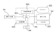
図1は本発明の実施例1に係る立体画像合成装置の構成を示すブロック図である。301は多視点画像群に相当する画像群を画像合成装置に入力する画像入力装置で、CFカード(登録商標)やスマートメディア(登録商標)等の固定記録メディアに記録された画像ファイルを読み込む入出力装置により構成したり、入出力インターフェースを持つデジタルカメラ、デジタルビデオカメラ等の撮像機器や、スキャナ、フィルムスキャナ等のアナログメディアから画像情報をデジタルデータとして読み込みを行う画像入力機器で構成してもよい。また、画像入力装置301はネットワークと接続可能で、遠隔地のカメラで撮像され、ネットワーク上に存在する多視点画像群を入力することもできる。
FIG. 1 is a block diagram illustrating a configuration of a stereoscopic image synthesis apparatus according to Embodiment 1 of the present invention. An
302は入力された少なくとも2枚以上の多視点画像群の中から、合成する立体画像の視点数に合わせて少なくとも2枚以上の多視点画像を選択し、立体画像データを合成する画像合成(処理)装置である。該画像合成装置302は例えば汎用のパーソナルコンピュータにより構成することができる。
303はCRTディスプレイ等のディスプレイで、コンピュータ若しくはこの立体画像合成を目的とする装置の表示部である。このディスプレイ303は立体画像合成において必要な情報を取得する手順を対話的に補助しつつ行ったり、処理状況、メニュー、立体画像を構成する選択された多視点画像等を表示する。304はマウスまたはキーボード、ジョイスティック等の操作入力部で、ディスプレイ303上に表示されたメニュー項目(画像)を参照しながら、メニューを選択する。
305は外部機器との入出力部であり、ネットワークに接続されたイーサーネット等のネットワークポート、若しくはフロッピー(登録商標)ディスク、MO(登録商標)、ZIP(登録商標)、CD−ROM等の固定記録メディアが該入出力部305として設けられる。そして、該入出力部305を介して入出力機器、ネットワーク端末装置等が接続され、立体画像データや他の装置で算出した多視点画像間の動きパラメータ等をファイルとして画像合成装置302へ出力または入力する。306は画像合成装置302で合成された立体画像を印刷するプリンタである。
なお、入出力部305を上記画像入力装置301とは別に設けているが、画像入力装置301の入出力部を本実施例の画像合成装置302の入出力部として用いることも可能である。また、キーボード、マウス、ジョイスティック等の入力手段からカメラの運動パラメータを入力したり、ディスプレイ303に多視点画像のサブセットの選択結果をビジュアル的に表示したりすることも可能である。
Although the input /
また、画像合成装置302は、装置全体の制御を司る中央演算装置であるCPU3021と、画像入力装置301等により読み込まれた多視点画像群を保存したり、補正後の多視点画像群、立体画像データ保存するハードディスク等の大容量記憶装置3022と、大容量記憶装置3021に保存された多視点画像群から隣り合う画像対を順次選択し、特徴点対応付けの対象となるステレオ画像対のみを主記憶領域上に展開したり、算出された対応点情報やカメラ変位情報を記憶したり、補正後の画像を大容量記憶装置3022に記憶したり、入出力部305から出力する以前に一次記憶しておくRAM等の主記憶装置3023とが設けられている。
The
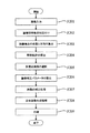
次に図2及び図3を用いて、本発明の実施例1における画像合成装置302の処理フローについて説明する。
Next, a processing flow of the
ここで、図2の101はデジタルカメラ等の撮像装置であり、102及び103は多視点画像群のシーンを構成する被写体である。そして本実施例の多視点画像の撮影では、理想的にはカメラ101をカメラ101の光軸方向に垂直、且つカメラの画像のスキャンライン方向に平行に図中の矢印の方向に移動して視点(撮影位置)を変えながら、カメラの連射機能やムービー機能、ビデオカメラを利用したり、視点移動のたびにカメラのシャッターを切ることにより、非常に狭い間隔で、立体画像の視点数に比べて多い多視点画像を撮影する。
Here,
図4にカメラを固定手段等で固定せずに手持ちでこのような撮影を行う場合の視点の変動の様子を示す。それぞれの画像中心を視点として手持ちで撮影を行う場合、カメラの移動速度が一定でないために、撮影画像の視点間隔が不均一になってしまったり、手振れにより視点位置(視点高さ)が移動方向に対し垂直な方向にも微小に変動してしまったりする。また、カメラの向きによって視線方向(撮影方向)も同様に変動する。そこで本実施例1では、以下の処理を行う。 FIG. 4 shows how the viewpoint changes when such shooting is performed by hand without fixing the camera with fixing means or the like. When taking a picture with the center of each image as a viewpoint, the moving speed of the camera is not constant, so the viewpoint interval of the shot image becomes non-uniform or the viewpoint position (viewpoint height) moves in the direction of camera shake. However, it may fluctuate slightly in the vertical direction. The line-of-sight direction (photographing direction) also varies depending on the orientation of the camera. Therefore, in the first embodiment, the following processing is performed.
図3において、ステップ201の画像入力処理では、図1に示すような撮影方法により撮影した多視点画像群を画像入力装置301から入力し、大容量記憶装置3022に記憶する。
In FIG. 3, in the image input process in step 201, a multi-viewpoint image group photographed by the photographing method as shown in FIG. 1 is input from the
ステップ202において、まず、隣り合った画像(第1の複数の画像)間における特徴点の対応付けを行う。このとき、まず、各画像に対して微分処理等を行い、画像輝度値が空間的に大きく変化する点の画像中での位置を特徴点として抽出し、その後、隣り合った画像間で抽出された特徴点同士の対応付けを行う。この対応付けは、抽出された特徴点同士の近傍領域の輝度分布が類似しているもの同士が対応するように行う。 In step 202, first, feature points are associated between adjacent images (first plurality of images). At this time, first, differential processing or the like is performed on each image, and the position in the image where the image luminance value greatly varies is extracted as a feature point, and then extracted between adjacent images. The corresponding feature points are associated with each other. This association is performed so that the extracted feature points have similar luminance distributions in the neighborhood areas.
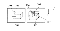
図5は被写体が立方体の場合の隣り合った画像間での抽出された特徴点の例であり、v11〜v17、v21〜v27が抽出された特徴点である。また、本実施例では領域ベースの一手法である、差分和を用いた単純なテンプレートマッチング手法を特徴点の対応付けに用いている。図6を用いて対応点探索処理について説明する。 FIG. 5 is an example of feature points extracted between adjacent images when the subject is a cube, and v11 to v17 and v21 to v27 are extracted feature points. In this embodiment, a simple template matching method using a difference sum, which is a region-based method, is used for the feature point association. The corresponding point search process will be described with reference to FIG.
図6において、2つの画像データのうち撮影した視点位置が左側に相当する左画像を基準画像701とし、視点位置が右側に相当する右画像を参照画像702として、左画像を基準としてテンプレートマッチングを行う。
In FIG. 6, template matching is performed with reference to the left image as a
まず、左画像中のある特徴点を選択する。ここではこの点を基準点704とし、基準点704を中心とした所定サイズの部分領域をテンプレート703として抽出する。次に、大まかな視点の移動量、手振れによる視点の変動、視線方向の変動を考慮して、任意に定めた参照画像702中の所定の対応点探索領域707において、順次参照画像702内の対応点探索領域内に存在する特徴点である参照点705を選択し、注目画素705を中心としたテンプレートと同一のサイズのウィンドウ領域706について、左画像701のテンプレート703との相関値を求める。
First, a certain feature point in the left image is selected. Here, this point is set as a
例えば、本実施例1のように図2に示す如くカメラ101が移動(運動)する場合、探索領域は図6の領域707のように、画像座標の水平方向に長辺を持つ長方形の領域として与える事が多い。図6の配置においては、図5において存在する特徴点v21、v22、v25、v27が、v11に対応する探索領域内に存在する。注目点に対応する対応点は、相関値の最も大きい特徴点に決定される。但し、対応点位置での相関値が所定の値より小さい場合、対応点位置での相関値と2番目に小さい相関値との差が所定の値より小さい場合、あるいは対応点位置近傍での相関値の変化が所定の値より小さい場合は、対応点探索処理に関して信頼性が低いと考えられるので、その点に対しては未対応とする。
For example, when the
これらの対応点探索処理により、基準画像701のテンプレートマッチングによる対応情報が求められる。以上のような対応付けを基準画像701内の他の特徴点についても繰り返す。なお、逆に右画像を基準画像とし、左画像を参照画像として同様な処理を行ってもよい。左画像基準、及び右画像基準の両方の対応付けを行った場合は、対応情報の対称性を用いて特徴点の対応付けの結果を特徴点同士が1対1に対応するように対応付けの結果の修正を行ってもよい。以上の特徴点の対応付けを他の隣り合った画像間でも順次行う。
Corresponding information by template matching of the
次に、図3のステップ203では、ステップ202の画像間特徴点の対応付けで得られた対応情報に基づいて、隣り合った画像間での相対的なカメラの変位、すなわち画像視点の位置と方向の算出をする。 Next, in step 203 in FIG. 3, based on the correspondence information obtained by associating the feature points between images in step 202, the relative camera displacement between adjacent images, that is, the position of the image viewpoint. Calculate the direction.
まず、画像間のエピポーラ幾何を表す基礎行列Fを求める。対応点の一方の画像の特徴点の位置を(u,v)、それに対応するもう一方の画像の特徴点の位置を(u´,v´)とし、これらを斉次表現に置き換えるとx=(u,v,1)、x´=(u´,v´,1)となる。そして、エピポーラ拘束条件式x´Fx=0…(1)を利用し、全ての対応付けの結果を用いて最小2乗法によりFを求めることができる(但し、Fは3×3の行列)。 First, a basic matrix F representing the epipolar geometry between images is obtained. If the position of the feature point of one image of the corresponding point is (u, v), the position of the feature point of the other image corresponding to that is (u ′, v ′), and these are replaced with a homogeneous expression, x = (U, v, 1), x ′ = (u ′, v ′, 1). Then, F can be obtained by the least square method using the epipolar constraint condition expression x′Fx = 0... (1) and using the results of all associations (where F is a 3 × 3 matrix).
そして、基礎行列Fを分解することにより、方向の変化を表す三次元回転行列R及び視点位置の変化を表す移動ベクトルtを求める。そして、順次他の隣り合った画像間においても順次R、tを求めていく。その結果、それぞれの隣り合った画像間で求められたカメラ変位を結びつけることにより、撮影した画像の撮影光軸の方向における全ての撮影視点、及び視線方向の相対関係が求まる。 Then, by decomposing the basic matrix F, a three-dimensional rotation matrix R representing a change in direction and a movement vector t representing a change in viewpoint position are obtained. Then, R and t are sequentially obtained between other adjacent images. As a result, by connecting the camera displacement obtained between the adjacent images, the relative relationship between all the photographing viewpoints and the line-of-sight directions in the direction of the photographing optical axis of the photographed image can be obtained.
但し、以上計算したカメラ変位のうち、多視点画像撮影時の各多視点画像の内部パラメータ、特にズーム等により変動する焦点距離等が不明な場合は、2画像からではカメラ変位のうち移動ベクトルの絶対量が曖昧なため算出できない。この場合は3つの画像間の特徴点の対応を利用して再計算することが望ましい。 However, among the camera displacements calculated above, if the internal parameters of each multi-viewpoint image at the time of shooting the multi-viewpoint image, particularly the focal length that varies due to zooming, etc., are unknown, the movement vector of the camera displacement from the two images The absolute quantity is ambiguous and cannot be calculated. In this case, it is desirable to recalculate using the correspondence of the feature points between the three images.
次に、図3のステップ204では理想的な軌跡の算出処理を行う。ステップ203で求めた各画像視点の相対的な、視点位置及び視線方向(撮影位置及び撮影方向)を結合して得られた、ある1枚の撮影画像を基準とした全体的な視点及び視線方向を利用して、近似的若しくは代表的な視点である理想軌跡及び、理想視線方向を決定する。視点位置については、各視点位置に最も近くなる3次元空間中の直線を最小2乗法等の近似演算により求めることにより手振れ等の影響を除いた、理想的なカメラ軌跡を算出することができる。図7(a)の502の一点鎖線が算出された理想的なカメラ軌跡である。また、視線方向についても、多視点画像の撮影にわたって一定の視線方向での撮影であるので、最小2乗法等により、理想視線方向を求めることができる。
Next, in step 204 of FIG. 3, an ideal trajectory calculation process is performed. Overall viewpoint and line-of-sight direction based on a single captured image obtained by combining the relative viewpoint position and line-of-sight direction (capturing position and direction) of each image viewpoint obtained in step 203. Is used to determine the ideal trajectory and the ideal line-of-sight direction, which are approximate or representative viewpoints. As for the viewpoint position, an ideal camera trajectory can be calculated without the influence of camera shake or the like by obtaining a straight line in the three-dimensional space closest to each viewpoint position by an approximate calculation such as a least square method. This is an ideal camera locus in which a one-
そして、ステップ205では、上記対応情報から決定された理想軌跡、理想視点方向に基づいて多視点画像群から立体画像の視点数に応じた多視点画像を選択する。図7(a)の画像(図7(a)において着色された画像)のようにステップ204で算出した理想軌跡502に対し、ほぼ等間隔で立体画像の視点数に対応する画像、すなわち等間隔(略一定)であり、かつ視線方向が略同じものを選択する。
In step 205, a multi-viewpoint image corresponding to the number of viewpoints of the stereoscopic image is selected from the multi-viewpoint image group based on the ideal locus and the ideal viewpoint direction determined from the correspondence information. An image corresponding to the number of viewpoints of the stereoscopic image at almost equal intervals with respect to the
言い換えれば、対応情報に基づいて算出された理想軌跡及び理想視線方向(代表情報)に関して視点間隔が略一定、すなわち該間隔が所定範囲内にある多視点画像群を選択する。より具体的には、視点の理想軌跡に対して直交する方向における該視点の位置が略等しい(理想軌跡に対して所定範囲内にある)、又は理想視線方向に対して所定の範囲内にある関係を満たす多視点画像群(第2の複数の画像)を選択する。 In other words, a multi-viewpoint image group is selected in which the viewpoint interval is substantially constant with respect to the ideal locus and the ideal line-of-sight direction (representative information) calculated based on the correspondence information. More specifically, the positions of the viewpoints in a direction orthogonal to the ideal locus of the viewpoint are substantially equal (within a predetermined range with respect to the ideal locus), or within a predetermined range with respect to the ideal line-of-sight direction. A multi-viewpoint image group (second plurality of images) that satisfies the relationship is selected.
また、立体画像における提示視差を大きくしたい場合は視点間隔を変更して該間隔を広くし、立体画像における提示視差を小さくしたい場合はこの間隔を狭くする。これにより、図7(b)のように多視点画像群からの立体画像の視点数に対応する数の多視点画像群のサブセットが選択される。 Further, when it is desired to increase the presentation parallax in the stereoscopic image, the viewpoint interval is changed to widen the interval, and when it is desired to reduce the presentation parallax in the stereoscopic image, the interval is reduced. Thereby, as shown in FIG. 7B, a subset of the multi-viewpoint image group corresponding to the number of viewpoints of the stereoscopic image from the multi-viewpoint image group is selected.
ステップ206の画像補正パラメータの算出では、まず、ステップ205の多視点画像の選択で選択された多視点画像群のサブセットに対し、ステップ204の理想軌跡の計算により算出された多視点画像の視点の理想軌跡及び理想視点方向(代表情報)に対する視線方向の変動(差)を再計算し、多視点画像と理想軌跡、理想視線方向のずれを小さくするための補正パラメータを求める。図7(b)の503の一点鎖線が再計算された多視点画像群のサブセットに対する理想的なカメラ軌跡を表している。なお、図7(a)、(b)において、細線501は実際のカメラ軌跡に対応している。
In the calculation of the image correction parameter in step 206, first, for the subset of the multi-view image group selected in the selection of the multi-view image in step 205, the viewpoint of the multi-view image calculated by the calculation of the ideal trajectory in step 204 is performed. The line-of-sight direction variation (difference) with respect to the ideal trajectory and the ideal viewpoint direction (representative information) is recalculated to obtain correction parameters for reducing the deviation between the multi-viewpoint image and the ideal trajectory and the ideal viewpoint direction. 7B represents an ideal camera trajectory for a subset of the multi-viewpoint image group in which the one-
そして、理想的な視点、視線方向との差(誤差)から補正処理パラメータを算出する。まず、カメラの理想視線方向からのずれについては、3次元回転行列からなる視線変換のパラメータを算出し、補正量を計算する。 Then, correction processing parameters are calculated from the difference (error) from the ideal viewpoint and line-of-sight direction. First, for a deviation from the ideal line-of-sight direction of the camera, a line-of-sight conversion parameter composed of a three-dimensional rotation matrix is calculated and a correction amount is calculated.
なお、カメラの視点の軌跡が理想軌跡からずれることによる画像への影響は、厳密には奥行きに依存するため、各画像点の奥行きが不明な状態では補正は困難であるが、視点の理想軌跡に対する奥行き方向(Z)のずれは理想視線方向へのカメラ移動に伴って小さいと考えられるため、本実施例のように画像面における並進により近似的に補正を行う。 The effect on the image due to the deviation of the camera viewpoint trajectory from the ideal trajectory depends strictly on the depth, so correction is difficult when the depth of each image point is unknown, but the viewpoint ideal trajectory Since the shift in the depth direction (Z) with respect to is considered to be small as the camera moves in the ideal line-of-sight direction, correction is performed approximately by translation on the image plane as in this embodiment.
図3のステップ207の画像の補正処理では、ステップ206の画像補正パラメータの算出により求めた画像補正パラメータに基づいて、アフィン変換、射影変換を行ない、各多視点画像に対し幾何学的画像補正を行う。この幾何学的画像補正により、図7(c)に示すように視線方向が一定で、カメラの光軸方向に垂直、且つ画像のスキャンライン方向に水平な方向にカメラを等間隔で移動させながら撮影したような、立体画像の視点数と同じ数の補正後の多視点画像が得られる。 In the image correction process in step 207 of FIG. 3, affine transformation and projective transformation are performed based on the image correction parameter obtained by calculating the image correction parameter in step 206, and geometric image correction is performed on each multi-viewpoint image. Do. With this geometric image correction, as shown in FIG. 7 (c), the camera is moved at regular intervals in a direction in which the line-of-sight direction is constant, perpendicular to the optical axis direction of the camera, and horizontal to the scan line direction of the image. The number of corrected multi-viewpoint images, which is the same as the number of viewpoints of the stereoscopic image, is obtained.
その後、ステップ208の立体画像の合成処理に進み、補正処理を行ってシーケンス間で滑らかに視点及び視線方向が変化するように補正された多視点画像(ステップ207)を立体画像に合成し、プリンタ306により印刷する。又は入出力部305を介して該立体画像をデータ(ファイル)として出力する。
After that, the process proceeds to a stereoscopic image synthesis process in step 208, and a correction process is performed to synthesize a multi-viewpoint image (step 207) corrected so that the viewpoint and the line-of-sight direction smoothly change between the sequences. Printing is performed according to 306. Alternatively, the stereoscopic image is output as data (file) via the input /
なお、レンチキュラ−板を観察デバイスに用いる立体画像の合成処理は、多視点画像群から立体ストライプ画像を合成することにより行う。このとき、多視点画像群の各画像の同一座標の画素を画像の視点配列に従い、隣接画素として配列するように立体ストライプ画像を合成する。j番目の視点の画素値をPjmn(但し、m,nはそれぞれ水平、垂直方向の画素配列のインデックス)とした時のj番目の画像データは以下のような2次元配列として表される。 Note that the processing for combining a stereoscopic image using a lenticular plate as an observation device is performed by combining a stereoscopic stripe image from a multi-viewpoint image group. At this time, the three-dimensional stripe image is synthesized so that pixels at the same coordinates of each image in the multi-viewpoint image group are arranged as adjacent pixels according to the viewpoint arrangement of the image. The j-th image data when the pixel value of the j-th viewpoint is Pjmn (where m and n are the indices of the pixel array in the horizontal and vertical directions, respectively) is represented as the following two-dimensional array.

そして、この合成処理は、それぞれの視点の画像を垂直方向に1ラインごとに短冊状に分解し、視点位置の逆順に視点数分だけ合成する。したがって、合成後の画像は以下に示すようなストライプ画像となる。 In this synthesis process, the images of the respective viewpoints are decomposed into strips for each line in the vertical direction, and are synthesized by the number of viewpoints in the reverse order of the viewpoint positions. Therefore, the combined image is a stripe image as shown below.
ここで、上記配列は視点1が左端、視点Nが右端の位置関係に対応する画像を表している。なお、視点位置の配列順を逆順にするのはレンチキュラ板(レンチキュラレンズ)により観察をする際、レンチキュラの1ピッチ内で画像が左右逆に観察されるためである。この立体ストライプ画像は、元の多視点画像がH×vのサイズのN視点画像である場合、X(=N×H)×vのサイズとなる。 Here, the arrangement represents an image corresponding to a positional relationship in which the viewpoint 1 is the left end and the viewpoint N is the right end. The reason why the viewpoints are arranged in the reverse order is that when the image is observed with a lenticular plate (lenticular lens), the image is observed to be reversed left and right within one pitch of the lenticular. This three-dimensional stripe image has a size of X (= N × H) × v when the original multi-view image is an N viewpoint image having a size of H × v.
次に、この立体ストライプ画像に対して、レンチキュラ板のピッチと画像のピッチとを合わせる。1ピッチのRP(dpi)の画素がN画素分存在するので、1ピッチN/RP(inch)となるが、レンチキュラ板のピッチがRL(inch)であるので、画像を水平方向にRL×RP/N倍してピッチをあわせる。また、垂直方向の画素数は、アスペクト比を保存したい場合は、(RL×RP/N)×Y画素となることから、垂直方向に(RL×RP×Y)/(N×v)のサイズとなる。なお、印刷の解像度をRP(dpi)、印刷サイズをXP×YP、印刷する画像サイズをX(RP×XP)×Y(RP×YP)画素、レンチキュラ板のピッチをRL(inch)としている。 Next, the pitch of the lenticular plate and the pitch of the image are matched with this stereoscopic stripe image. Since one pitch of RP (dpi) pixels exists for N pixels, the pitch becomes 1 pitch N / RP (inch). However, since the pitch of the lenticular plate is RL (inch), the image is RL × RP in the horizontal direction. / N times to adjust the pitch. In addition, the number of pixels in the vertical direction is (RL × RP / N) × Y pixels if the aspect ratio is to be preserved, so the size of (RL × RP × Y) / (N × v) in the vertical direction. It becomes. Note that the printing resolution is RP (dpi), the printing size is XP × YP, the image size to be printed is X (RP × XP) × Y (RP × YP) pixels, and the pitch of the lenticular plate is RL (inch).
立体ストライプ画像に上述のような水平、垂直方向の変倍処理を行ない印刷用の画像データとする。変倍処理は例えば、双線形補間などにより行う。 The stereoscopic stripe image is subjected to the scaling process in the horizontal and vertical directions as described above to obtain image data for printing. The scaling process is performed by, for example, bilinear interpolation.
ステップ209の印刷処理では、ステップ208における立体画像合成処理にて合成された立体画像を印刷する。そして、最終的に印刷結果にレンチキュラ板等の光学部材を重ね合わせて観察することで、視点移動をした際に違和感のない多視点からなる立体画像を観察することが可能となる。 In the printing process in step 209, the stereoscopic image synthesized in the stereoscopic image synthesis process in step 208 is printed. Then, by finally observing the print result by superimposing an optical member such as a lenticular plate, it is possible to observe a three-dimensional image composed of multiple viewpoints without any sense of incongruity when the viewpoint is moved.
このように本実施例では、第1の複数の画像間において対応情報を算出し、該対応情報から決定されるカメラの近似的な理想軌跡及び理想視点方向(代表情報)関して所定の関係を有する多視点画像(第2の複数の画像)を選択するので、第1の複数の画像を撮影する際に特殊な装置を使用することなく、それらの合成により観察位置による立体感の変動が少ない立体画像を得ることが可能な多視点画像群を取得することができる。 As described above, in the present embodiment, correspondence information is calculated between the first plurality of images, and a predetermined relationship is established with respect to the approximate ideal locus and ideal viewpoint direction (representative information) of the camera determined from the correspondence information. Since a multi-viewpoint image (second plurality of images) is selected, there is little variation in stereoscopic effect depending on the observation position by combining them without using a special device when photographing the first plurality of images. A multi-viewpoint image group capable of obtaining a stereoscopic image can be acquired.
言い換えれば、特殊な装置を使用せずに手持ちでカメラを移動させて視点を変更しながら多視点画像群を撮影しても、多視点の立体画像の構成に必要な画像数の画像を、立体画像において良好な立体感を提示するような視差を持ち、且つほぼ等速で視点が変動するように選択している。さらには、対応情報から算出された理想軌跡及び理想視点方向(代表情報)に基づく画像補正パラメータを用いて画像補正を行っている。 In other words, even if a multi-viewpoint image group is shot while changing the viewpoint by moving the camera by hand without using a special device, the number of images necessary for the configuration of the multi-viewpoint three-dimensional image is reduced. The viewpoint is selected so as to have a parallax that presents a good stereoscopic effect in the image and to change the viewpoint at a substantially constant speed. Furthermore, image correction is performed using image correction parameters based on the ideal locus calculated from the correspondence information and the ideal viewpoint direction (representative information).
このため、運動視差及び両眼視差による立体感の滑らかな変動の得られる立体画像を合成することが可能な画像処理装置を実現することができる。 For this reason, it is possible to realize an image processing apparatus capable of synthesizing a stereoscopic image in which a smooth change in stereoscopic effect due to motion parallax and binocular parallax is obtained.
また、この立体画像を印刷した多視点の立体画像を観察しても、視点を変化させた際の両眼視差による立体感の変動や運動視差が自然な立体画像を合成することが可能となる。 Further, even when a multi-view stereoscopic image on which this stereoscopic image is printed is observed, it is possible to synthesize a stereoscopic image in which the stereoscopic effect due to binocular parallax and the motion parallax are natural when the viewpoint is changed. .
以上、上記実施例において、立体画像としてレンチキュラレンズシートを用いた場合の画素配列に従う立体画像の合成方法について説明したが、立体画像を同様に多視点画像から合成する立体画像の提示方式である、斜めレンチキュラシート、パララックスステレオグラム、フォログラフィックステレオグラム等の方式を適用してもよい。 As described above, in the above embodiment, the method for synthesizing a stereoscopic image according to the pixel arrangement when using a lenticular lens sheet as the stereoscopic image has been described. However, this is a stereoscopic image presentation method in which a stereoscopic image is similarly synthesized from a multi-viewpoint image. A method such as an oblique lenticular sheet, a parallax stereogram, or a holographic stereogram may be applied.
また、複数の機器から構成されるシステムに適用しても、1つの機器から成る装置に適用してもよい。前述した実施形態の機能を実現するソフトウェアのプログラムコードを記憶した記憶媒体をシステムあるいは装置に供給し、そのシステムあるいは装置のコンピュータ(またはCPUやMPU)が記憶媒体に格納されたプログラムコードを読み出し実行することによって実現でき、上記実施例に限定されるものではない。 Further, the present invention may be applied to a system composed of a plurality of devices or an apparatus composed of one device. A storage medium storing software program codes for realizing the functions of the above-described embodiments is supplied to a system or apparatus, and a computer (or CPU or MPU) of the system or apparatus reads and executes the program codes stored in the storage medium. It can implement | achieve by doing and is not limited to the said Example.
なお、この場合、記憶媒体から読み出されたプログラムコード自体が上記実施例の機能を実現することになり、そのプログラムコードを記憶した記憶媒体は本実施例を構成することになる。プログラムコードを供給するための記憶媒体としては、例えばフロッピー(登録商標)ディスク、ハードディスク、光ディスク、光磁気ディスク、CD−ROM、CD−R/RW、磁気テープ、不揮発性のメモリカード、ROMを用いることが出来る。また、コンピュータが読み出したプログラムコードを実行することにより、前述した実施形態の機能が実現されるだけではなく、そのプログラムコードの指示に基づき、コンピュータ上で稼動しているOSなどが実際の処理の一部または全部を行い、その処理によって上述の実施形態の機能が実現される場合も含まれる。 In this case, the program code itself read from the storage medium realizes the function of the above-described embodiment, and the storage medium storing the program code constitutes the present embodiment. As a storage medium for supplying the program code, for example, a floppy (registered trademark) disk, hard disk, optical disk, magneto-optical disk, CD-ROM, CD-R / RW, magnetic tape, nonvolatile memory card, or ROM is used. I can do it. In addition, by executing the program code read by the computer, not only the functions of the above-described embodiments are realized, but also the OS running on the computer based on the instruction of the program code performs the actual processing. A case where the function of the above-described embodiment is realized by performing part or all of the processing is also included.
さらに、記憶媒体から読み出されたプログラムコードが、コンピュータに挿入された機能拡張ボードやコンピュータに接続された機能拡張ユニットに備わるメモリに書き込まれた後、次のプログラムコードの指示に基づき、その拡張機能を拡張ボードや拡張ユニットに備わるCPUなどが処理を行って実際の処理の一部または全部を行い、その処理によって上述の実施例の機能が実現される場合も含まれる。 Furthermore, after the program code read from the storage medium is written to the memory provided in the function expansion board inserted in the computer or the function expansion unit connected to the computer, the program code is expanded based on the instruction of the next program code. This includes a case where a CPU or the like provided in an expansion board or an expansion unit performs functions to perform part or all of the actual processing, and the functions of the above-described embodiments are realized by the processing.
101 カメラ
102,103 被写体
301 画像入力装置
302 画像処理装置
3021 CPU
3022 大容量記憶装置
3023 主記憶装置
303 ディスプレイ
304 操作入力部
305 入出力部
306 プリンタ
3022
Claims (12)
該対応情報に基づいて、前記第1の複数の画像から、前記視点および視線方向のうち少なくとも一方に関して所定の関係を有する第2の複数の画像を選択する選択手段とを有することを特徴とする画像処理装置。 Information generating means for generating correspondence information indicating a correspondence relationship between the first plurality of images having different viewpoints;
Selection means for selecting, from the first plurality of images, a second plurality of images having a predetermined relationship with respect to at least one of the viewpoint and the line-of-sight direction based on the correspondence information. Image processing device.
該対応情報に基づいて、前記第1の複数の画像から、前記視点および視線方向のうち少なくとも一方に関して所定の関係を有する第2の複数の画像を選択するステップとを有することを特徴とする画像処理プログラム。 Generating correspondence information indicating a correspondence relationship between the first plurality of images having different viewpoints;
And selecting a second plurality of images having a predetermined relationship with respect to at least one of the viewpoint and the line-of-sight direction from the first plurality of images based on the correspondence information. Processing program.
The image processing program according to claim 11, further comprising a step of generating a third image that can be stereoscopically viewed from the second plurality of images.
Priority Applications (2)
| Application Number | Priority Date | Filing Date | Title |
|---|---|---|---|
| JP2004300376A JP2006113807A (en) | 2004-10-14 | 2004-10-14 | Image processor and image processing program for multi-eye-point image |
| US11/251,266 US7873207B2 (en) | 2004-10-14 | 2005-10-14 | Image processing apparatus and image processing program for multi-viewpoint image |
Applications Claiming Priority (1)
| Application Number | Priority Date | Filing Date | Title |
|---|---|---|---|
| JP2004300376A JP2006113807A (en) | 2004-10-14 | 2004-10-14 | Image processor and image processing program for multi-eye-point image |
Publications (2)
| Publication Number | Publication Date |
|---|---|
| JP2006113807A true JP2006113807A (en) | 2006-04-27 |
| JP2006113807A5 JP2006113807A5 (en) | 2007-11-29 |
Family
ID=36180309
Family Applications (1)
| Application Number | Title | Priority Date | Filing Date |
|---|---|---|---|
| JP2004300376A Pending JP2006113807A (en) | 2004-10-14 | 2004-10-14 | Image processor and image processing program for multi-eye-point image |
Country Status (2)
| Country | Link |
|---|---|
| US (1) | US7873207B2 (en) |
| JP (1) | JP2006113807A (en) |
Cited By (16)
| Publication number | Priority date | Publication date | Assignee | Title |
|---|---|---|---|---|
| JP2009103980A (en) * | 2007-10-24 | 2009-05-14 | Fujifilm Corp | Photographic device, image processor, and photographic ystem |
| JP2009212728A (en) * | 2008-03-03 | 2009-09-17 | Ntt Docomo Inc | Stereoscopic video processor and stereoscopic video processing method |
| JP2010041076A (en) * | 2008-07-31 | 2010-02-18 | Olympus Corp | Camera |
| WO2012026185A1 (en) * | 2010-08-24 | 2012-03-01 | 富士フイルム株式会社 | Image pickup device and method for controlling operation thereof |
| CN102566246A (en) * | 2010-12-30 | 2012-07-11 | 华晶科技股份有限公司 | Stereo image shooting method |
| WO2012105122A1 (en) * | 2011-01-31 | 2012-08-09 | 富士フイルム株式会社 | Stereoscopic imaging device and motion control method therefor |
| JP2012165058A (en) * | 2011-02-03 | 2012-08-30 | Nikon Corp | Display device, imaging device, display control program, and storage medium |
| JP2012239006A (en) * | 2011-05-11 | 2012-12-06 | Canon Inc | Image processing apparatus, control method thereof, and program |
| JP2013192229A (en) * | 2007-03-19 | 2013-09-26 | Sony Corp | Two dimensional/three dimensional digital information acquisition and display device |
| US8558874B2 (en) | 2008-09-08 | 2013-10-15 | Fujifilm Corporation | Image processing device and method, and computer readable recording medium containing program |
| JP2015035799A (en) * | 2013-07-09 | 2015-02-19 | キヤノン株式会社 | Information processing apparatus, imaging apparatus, information processing system, information processing method, and program |
| JP2016100899A (en) * | 2014-11-20 | 2016-05-30 | 三星電子株式会社Samsung Electronics Co.,Ltd. | Method and apparatus for calibrating image |
| US9418486B2 (en) | 2012-12-20 | 2016-08-16 | Samsung Electronics Co., Ltd. | Method and apparatus for rendering hybrid multi-view |
| KR101731568B1 (en) | 2015-02-16 | 2017-05-02 | 한국과학기술원 | The Method and apparatus for geometric distortion compensation of multiview image with maintaining the temporal coherence |
| US9774841B2 (en) | 2010-06-28 | 2017-09-26 | Fujifilm Corporation | Stereoscopic image capture device and control method of the same |
| JP2019508928A (en) * | 2015-12-30 | 2019-03-28 | クリエイティブ テクノロジー リミテッドCreative Technology Ltd | Method for creating a stereoscopic image sequence |
Families Citing this family (32)
| Publication number | Priority date | Publication date | Assignee | Title |
|---|---|---|---|---|
| GB0329312D0 (en) * | 2003-12-18 | 2004-01-21 | Univ Durham | Mapping perceived depth to regions of interest in stereoscopic images |
| JP4508049B2 (en) * | 2005-09-05 | 2010-07-21 | 株式会社日立製作所 | 360 ° image capturing device |
| US8326022B2 (en) * | 2008-05-22 | 2012-12-04 | Matrix Electronic Measuring Properties, Llc | Stereoscopic measurement system and method |
| BRPI0913069A2 (en) * | 2008-05-22 | 2015-10-13 | Matrix Electronic Measuring Llc | stereoscopic measurement system and method |
| US8249332B2 (en) * | 2008-05-22 | 2012-08-21 | Matrix Electronic Measuring Properties Llc | Stereoscopic measurement system and method |
| WO2009143321A2 (en) * | 2008-05-22 | 2009-11-26 | Matrix Electronic Measuring, L.P. | Stereoscopic measurement system and method |
| US9449378B2 (en) | 2008-05-22 | 2016-09-20 | Matrix Electronic Measuring Properties, Llc | System and method for processing stereoscopic vehicle information |
| US8345953B2 (en) * | 2008-05-22 | 2013-01-01 | Matrix Electronic Measuring Properties, Llc | Stereoscopic measurement system and method |
| US8135238B2 (en) * | 2008-06-05 | 2012-03-13 | Kia Sha Managment Liability Company | Free view generation in ray-space |
| WO2010119496A1 (en) * | 2009-04-13 | 2010-10-21 | 富士通株式会社 | Image processing device, image processing program, and image processing method |
| WO2011014419A1 (en) * | 2009-07-31 | 2011-02-03 | 3Dmedia Corporation | Methods, systems, and computer-readable storage media for creating three-dimensional (3d) images of a scene |
| US9380292B2 (en) | 2009-07-31 | 2016-06-28 | 3Dmedia Corporation | Methods, systems, and computer-readable storage media for generating three-dimensional (3D) images of a scene |
| US20110025830A1 (en) | 2009-07-31 | 2011-02-03 | 3Dmedia Corporation | Methods, systems, and computer-readable storage media for generating stereoscopic content via depth map creation |
| TWI394097B (en) * | 2009-10-12 | 2013-04-21 | Nat Univ Tsing Hua | Detecting method and system for moving object |
| AU2009243439A1 (en) * | 2009-11-30 | 2011-06-16 | Canon Kabushiki Kaisha | Robust image alignment for distributed multi-view imaging systems |
| JP2011248723A (en) * | 2010-05-28 | 2011-12-08 | Sony Corp | Image processing device, method and program |
| US9344701B2 (en) | 2010-07-23 | 2016-05-17 | 3Dmedia Corporation | Methods, systems, and computer-readable storage media for identifying a rough depth map in a scene and for determining a stereo-base distance for three-dimensional (3D) content creation |
| WO2012061549A2 (en) | 2010-11-03 | 2012-05-10 | 3Dmedia Corporation | Methods, systems, and computer program products for creating three-dimensional video sequences |
| US10200671B2 (en) | 2010-12-27 | 2019-02-05 | 3Dmedia Corporation | Primary and auxiliary image capture devices for image processing and related methods |
| US8274552B2 (en) | 2010-12-27 | 2012-09-25 | 3Dmedia Corporation | Primary and auxiliary image capture devices for image processing and related methods |
| JP2012244396A (en) * | 2011-05-19 | 2012-12-10 | Sony Corp | Image processing apparatus, image processing method, and program |
| JP5501474B2 (en) | 2011-06-10 | 2014-05-21 | パナソニック株式会社 | Stereoscopic image generating apparatus and stereoscopic image generating method |
| JP5367846B2 (en) * | 2011-08-24 | 2013-12-11 | 株式会社東芝 | Image processing apparatus, method and program, and stereoscopic image display apparatus |
| KR101841750B1 (en) * | 2011-10-11 | 2018-03-26 | 한국전자통신연구원 | Apparatus and Method for correcting 3D contents by using matching information among images |
| JP2014007648A (en) * | 2012-06-26 | 2014-01-16 | Sony Corp | Image processing device, and image processing method and program |
| TWI459170B (en) * | 2012-10-04 | 2014-11-01 | Ind Tech Res Inst | A moving control device and an automatic guided vehicle with the same |
| EP3828496A1 (en) * | 2013-04-08 | 2021-06-02 | SNAP Inc. | Distance estimation using multi-camera device |
| US9426365B2 (en) * | 2013-11-01 | 2016-08-23 | The Lightco Inc. | Image stabilization related methods and apparatus |
| CN104992408B (en) * | 2015-06-30 | 2018-06-05 | 百度在线网络技术(北京)有限公司 | For the panorama image generation method and device of user terminal |
| JP6684475B2 (en) * | 2017-03-13 | 2020-04-22 | オムロン株式会社 | Image processing apparatus, image processing method and program |
| US10949707B2 (en) * | 2019-02-27 | 2021-03-16 | Here Global B.V. | Method, apparatus, and system for generating feature correspondence from camera geometry |
| CN113160105A (en) * | 2020-01-23 | 2021-07-23 | 阿里巴巴集团控股有限公司 | Camera viewpoint determining method, camera viewpoint recommending method, data processing method and equipment |
Citations (2)
| Publication number | Priority date | Publication date | Assignee | Title |
|---|---|---|---|---|
| JP2002077941A (en) * | 2000-08-24 | 2002-03-15 | Mitsubishi Electric Corp | Apparatus and method for generating depth image as well as computer readable recording medium recording program to execute the method in computer |
| WO2004004350A1 (en) * | 2002-06-28 | 2004-01-08 | Sharp Kabushiki Kaisha | Image data delivery system, image data transmitting device thereof, and image data receiving device thereof |
Family Cites Families (17)
| Publication number | Priority date | Publication date | Assignee | Title |
|---|---|---|---|---|
| US5065236A (en) * | 1990-11-02 | 1991-11-12 | The United States Of America As Represented By The Administrator Of The National Aeronautics And Space Administration | Stereoscopic camera and viewing systems with undistorted depth presentation and reduced or eliminated erroneous acceleration and deceleration perceptions, or with perceptions produced or enhanced for special effects |
| US5751927A (en) * | 1991-03-26 | 1998-05-12 | Wason; Thomas D. | Method and apparatus for producing three dimensional displays on a two dimensional surface |
| JP3081675B2 (en) | 1991-07-24 | 2000-08-28 | オリンパス光学工業株式会社 | Image recording device and image reproducing device |
| JP3151770B2 (en) * | 1993-03-26 | 2001-04-03 | キヤノン株式会社 | Compound eye image display |
| JPH07287761A (en) * | 1994-04-19 | 1995-10-31 | Canon Inc | Device and method for processing picture |
| KR100414629B1 (en) * | 1995-03-29 | 2004-05-03 | 산요덴키가부시키가이샤 | 3D display image generation method, image processing method using depth information, depth information generation method |
| US6005607A (en) * | 1995-06-29 | 1999-12-21 | Matsushita Electric Industrial Co., Ltd. | Stereoscopic computer graphics image generating apparatus and stereoscopic TV apparatus |
| US20020030888A1 (en) * | 1996-10-16 | 2002-03-14 | Paul Kleinberger | Systems for three-dimensional viewing and projection |
| US6163337A (en) * | 1996-04-05 | 2000-12-19 | Matsushita Electric Industrial Co., Ltd. | Multi-view point image transmission method and multi-view point image display method |
| JP4815042B2 (en) | 2000-04-17 | 2011-11-16 | オリンパス株式会社 | Image display device and image presentation method |
| JP4536231B2 (en) | 2000-08-29 | 2010-09-01 | オリンパス株式会社 | Imaging device |
| US7113634B2 (en) * | 2001-07-31 | 2006-09-26 | Canon Kabushiki Kaisha | Stereoscopic image forming apparatus, stereoscopic image forming method, stereoscopic image forming system and stereoscopic image forming program |
| US7349568B2 (en) * | 2001-08-30 | 2008-03-25 | Sanyo Electric Co., Ltd. | Method and apparatus for handling stereoscopic images utilizing parallax images |
| JP2003337303A (en) * | 2002-05-17 | 2003-11-28 | Canon Inc | Device and system for stereoscopic image display |
| US7466336B2 (en) * | 2002-09-05 | 2008-12-16 | Eastman Kodak Company | Camera and method for composing multi-perspective images |
| JP4228646B2 (en) * | 2002-10-02 | 2009-02-25 | 株式会社セガ | Stereoscopic image generation method and stereoscopic image generation apparatus |
| JP2004363758A (en) * | 2003-06-03 | 2004-12-24 | Konica Minolta Photo Imaging Inc | Image processing method, imaging apparatus, image processing apparatus, and image recording apparatus |
-
2004
- 2004-10-14 JP JP2004300376A patent/JP2006113807A/en active Pending
-
2005
- 2005-10-14 US US11/251,266 patent/US7873207B2/en not_active Expired - Fee Related
Patent Citations (2)
| Publication number | Priority date | Publication date | Assignee | Title |
|---|---|---|---|---|
| JP2002077941A (en) * | 2000-08-24 | 2002-03-15 | Mitsubishi Electric Corp | Apparatus and method for generating depth image as well as computer readable recording medium recording program to execute the method in computer |
| WO2004004350A1 (en) * | 2002-06-28 | 2004-01-08 | Sharp Kabushiki Kaisha | Image data delivery system, image data transmitting device thereof, and image data receiving device thereof |
Non-Patent Citations (1)
| Title |
|---|
| 中川雅朗,斎藤英雄,小沢慎治: "ハンディカメラを用いて撮影された画像列からのEPIの補正に基づく室内環境3次元再構築", 電子情報通信学会論文誌, vol. 84, no. 2, JPN6010005555, 1 February 2001 (2001-02-01), JP, pages 266 - 275, ISSN: 0001530546 * |
Cited By (18)
| Publication number | Priority date | Publication date | Assignee | Title |
|---|---|---|---|---|
| JP2013192229A (en) * | 2007-03-19 | 2013-09-26 | Sony Corp | Two dimensional/three dimensional digital information acquisition and display device |
| JP2009103980A (en) * | 2007-10-24 | 2009-05-14 | Fujifilm Corp | Photographic device, image processor, and photographic ystem |
| JP2009212728A (en) * | 2008-03-03 | 2009-09-17 | Ntt Docomo Inc | Stereoscopic video processor and stereoscopic video processing method |
| JP2010041076A (en) * | 2008-07-31 | 2010-02-18 | Olympus Corp | Camera |
| US8558874B2 (en) | 2008-09-08 | 2013-10-15 | Fujifilm Corporation | Image processing device and method, and computer readable recording medium containing program |
| US9774841B2 (en) | 2010-06-28 | 2017-09-26 | Fujifilm Corporation | Stereoscopic image capture device and control method of the same |
| WO2012026185A1 (en) * | 2010-08-24 | 2012-03-01 | 富士フイルム株式会社 | Image pickup device and method for controlling operation thereof |
| CN102566246A (en) * | 2010-12-30 | 2012-07-11 | 华晶科技股份有限公司 | Stereo image shooting method |
| US8902289B2 (en) | 2010-12-30 | 2014-12-02 | Altek Corporation | Method for capturing three dimensional image |
| WO2012105122A1 (en) * | 2011-01-31 | 2012-08-09 | 富士フイルム株式会社 | Stereoscopic imaging device and motion control method therefor |
| JP2012165058A (en) * | 2011-02-03 | 2012-08-30 | Nikon Corp | Display device, imaging device, display control program, and storage medium |
| JP2012239006A (en) * | 2011-05-11 | 2012-12-06 | Canon Inc | Image processing apparatus, control method thereof, and program |
| US9418486B2 (en) | 2012-12-20 | 2016-08-16 | Samsung Electronics Co., Ltd. | Method and apparatus for rendering hybrid multi-view |
| JP2015035799A (en) * | 2013-07-09 | 2015-02-19 | キヤノン株式会社 | Information processing apparatus, imaging apparatus, information processing system, information processing method, and program |
| JP2016100899A (en) * | 2014-11-20 | 2016-05-30 | 三星電子株式会社Samsung Electronics Co.,Ltd. | Method and apparatus for calibrating image |
| US11140374B2 (en) | 2014-11-20 | 2021-10-05 | Samsung Electronics Co., Ltd. | Method and apparatus for calibrating image |
| KR101731568B1 (en) | 2015-02-16 | 2017-05-02 | 한국과학기술원 | The Method and apparatus for geometric distortion compensation of multiview image with maintaining the temporal coherence |
| JP2019508928A (en) * | 2015-12-30 | 2019-03-28 | クリエイティブ テクノロジー リミテッドCreative Technology Ltd | Method for creating a stereoscopic image sequence |
Also Published As
| Publication number | Publication date |
|---|---|
| US20060082644A1 (en) | 2006-04-20 |
| US7873207B2 (en) | 2011-01-18 |
Similar Documents
| Publication | Publication Date | Title |
|---|---|---|
| JP2006113807A (en) | Image processor and image processing program for multi-eye-point image | |
| JP4942221B2 (en) | High resolution virtual focal plane image generation method | |
| JP4065488B2 (en) | 3D image generation apparatus, 3D image generation method, and storage medium | |
| JP4328311B2 (en) | Method and program for creating multi-viewpoint image for 3D image display | |
| US8581961B2 (en) | Stereoscopic panoramic video capture system using surface identification and distance registration technique | |
| JP4440066B2 (en) | Stereo image generation program, stereo image generation system, and stereo image generation method | |
| US20010052935A1 (en) | Image processing apparatus | |
| US20110064299A1 (en) | Image processing apparatus and image processing method | |
| WO2011052064A1 (en) | Information processing device and method | |
| US20100085423A1 (en) | Stereoscopic imaging | |
| JP2003209858A (en) | Stereoscopic image generating method and recording medium | |
| JP2005349127A (en) | Three-dimensional image generating system and its control method | |
| KR100897542B1 (en) | Method and Device for Rectifying Image in Synthesizing Arbitary View Image | |
| US20100302234A1 (en) | Method of establishing dof data of 3d image and system thereof | |
| RU2690757C1 (en) | System for synthesis of intermediate types of light field and method of its operation | |
| JP2008217243A (en) | Image creation device | |
| JP2005165614A (en) | Device and method for synthesizing picture | |
| JP4819834B2 (en) | 3D image processing apparatus and 3D image processing method | |
| US10148931B2 (en) | Three-dimensional video image display processing device, video information recording medium, video information providing server, and recording medium storing a program | |
| CN108450031A (en) | Image capture apparatus | |
| JP2001256482A (en) | Device and method for generating parallax image | |
| JP5747679B2 (en) | Presentation method of 3D image | |
| US8711208B2 (en) | Imaging device, method and computer readable medium | |
| JPH07296195A (en) | Device and method for image processing | |
| Knorr et al. | Super-resolution stereo-and multi-view synthesis from monocular video sequences |
Legal Events
| Date | Code | Title | Description |
|---|---|---|---|
| A521 | Request for written amendment filed |
Free format text: JAPANESE INTERMEDIATE CODE: A523 Effective date: 20071015 |
|
| A621 | Written request for application examination |
Free format text: JAPANESE INTERMEDIATE CODE: A621 Effective date: 20071015 |
|
| RD03 | Notification of appointment of power of attorney |
Free format text: JAPANESE INTERMEDIATE CODE: A7423 Effective date: 20081023 |
|
| RD05 | Notification of revocation of power of attorney |
Free format text: JAPANESE INTERMEDIATE CODE: A7425 Effective date: 20081201 |
|
| A977 | Report on retrieval |
Free format text: JAPANESE INTERMEDIATE CODE: A971007 Effective date: 20100128 |
|
| A131 | Notification of reasons for refusal |
Free format text: JAPANESE INTERMEDIATE CODE: A131 Effective date: 20100209 |
|
| A521 | Request for written amendment filed |
Free format text: JAPANESE INTERMEDIATE CODE: A523 Effective date: 20100409 |
|
| A02 | Decision of refusal |
Free format text: JAPANESE INTERMEDIATE CODE: A02 Effective date: 20100506 |