JP5901904B2 - Mechanical equipment management system - Google Patents
Mechanical equipment management system Download PDFInfo
- Publication number
- JP5901904B2 JP5901904B2 JP2011153871A JP2011153871A JP5901904B2 JP 5901904 B2 JP5901904 B2 JP 5901904B2 JP 2011153871 A JP2011153871 A JP 2011153871A JP 2011153871 A JP2011153871 A JP 2011153871A JP 5901904 B2 JP5901904 B2 JP 5901904B2
- Authority
- JP
- Japan
- Prior art keywords
- information
- crane
- user
- alarm
- unit
- Prior art date
- Legal status (The legal status is an assumption and is not a legal conclusion. Google has not performed a legal analysis and makes no representation as to the accuracy of the status listed.)
- Active
Links
Images


Description
本発明は、1つ又は複数の拠点に設置された機械設備に関する情報を管理する管理システムに関する。 The present invention relates to a management system that manages information related to mechanical equipment installed at one or a plurality of bases.
クレーンなどの機械設備を稼動させる際には、その稼動を円滑に継続させる必要がある。したがって、機械設備が何らかの異常な状況に陥った場合(例えば、機械設備の稼動が突然、停止してしまった場合など)には、その故障原因を特定して速やかに対処しなければならない。
機械設備の稼動状況を把握し、故障原因を特定するためには、機械設備の稼動を制御する制御装置からの指令情報や、機械設備に設置された複数のセンサから得られるセンサ情報が必要となる。
When operating machinery such as cranes, it is necessary to continue the operation smoothly. Therefore, when the mechanical equipment falls into some abnormal situation (for example, when the operation of the mechanical equipment suddenly stops), the cause of the failure must be identified and promptly dealt with.
In order to understand the operation status of machine equipment and identify the cause of failure, command information from a control device that controls the operation of the machine equipment and sensor information obtained from multiple sensors installed in the machine equipment are required. Become.
また、機械設備を構成する各機器には、その構成や使用状況によって寿命(許容される使用回数)がある。すなわち、機械設備を構成する機器の寿命が近づいた場合には、当該部品を交換する必要がある。したがって、機械設備を構成する各機器が寿命に達する前に各機器の交換を行うなど、機械設備の保全管理を行う必要がある。 Moreover, each apparatus which comprises a mechanical installation has a lifetime (allowable number of use) by the structure and use condition. That is, when the life of the equipment constituting the machine facility is approaching, it is necessary to replace the part. Therefore, it is necessary to perform maintenance management of the machine facility, such as replacing each device before each device constituting the machine facility reaches the end of its life.
特許文献1には、3軸方向を独立して計測する2組の加速度センサを搬送車に設置し、搬送車が走行レールを走行する際の加速度を上記の加速度センサによって計測し、当該計測値に基づいて設備の状態を判断することを特徴とする搬送装置の設備監視方法について記載されている。
特許文献1に記載の技術によれば、加速度センサによって計測させる加速度に基づいて早期に異常個所を特定し、搬送システムの停止や事故を未然に防ぐことができる。
In
According to the technique described in
特許文献2には、顧客の設備と、遠隔地にある監視システムとを通信回線で結び、上記設備の動作状況の診断データ及び判断情報を監視システムに通知し、専門家がメンテナンスの要否を判断して通知する異常予知・寿命管理システムについて記載されている。
特許文献2に記載の技術によれば、遠隔地に設置された設備の動作状況を各部位に亘りチェックし、専門家の立場で異常の発見と対策の内容を生産工場に知らせ、メンテナンスを行うことができる。
In
According to the technology described in
しかしながら、特許文献1に記載の技術では、例えば、搬送装置が複数台存在する場合には、それぞれの搬送装置の稼動情報を記憶させるための大容量の記憶装置が必要となり、コストがかかるという問題があった。また、特許文献1に記載の技術では、搬送装置を構成する機器の在庫管理や、当該機器に関する警報情報や点検情報の履歴などを一括して管理することができないという問題があった。
However, in the technique described in
また、特許文献2に記載の技術では、専門家の立場で異常の発見と対策の内容を生産工場に知らせることができるものの、設備に関する各データは、設備から監視システムへの一方向に送信される構成となっている。すなわち、特許文献2に記載の技術では、設備の稼動情報や構成機器に関する情報などを、設備の管理者(ユーザ)側から監視システムにアクセスし、理解しやすい形で閲覧することができないという問題があった。
Moreover, in the technique described in
そこで本発明は、機械設備の監視情報及び機器情報を管理し、ユーザが各情報を閲覧することができる、機械設備の管理システムを提供することを課題とする。 Then, this invention makes it a subject to provide the management system of a mechanical installation which manages the monitoring information and apparatus information of a mechanical installation, and a user can browse each information.
前記課題を解決するために、本発明に係る機械設備の管理システムは、第1の通信手段を介して機械設備から監視情報を取得し、それぞれの機械設備ごとに監視情報を第1の記憶手段に格納する第1の情報取得手段と、第2の通信手段を介して機器情報を取得し、それぞれの前記機械設備ごとに機器情報を第2の記憶手段に格納する第2の情報取得手段と、ユーザのコンピュータから機械設備の監視情報を取得する旨の指令信号を受信した場合に、当該指令信号に従って、第1の記憶手段から監視情報を読み出し、当該監視情報を画面情報として第2の通信手段を介してユーザのコンピュータに送信する第1の情報公開手段と、ユーザのコンピュータから機械設備の機器情報を取得する旨の指令信号を受信した場合に、当該指令信号に従って、第2の記憶手段から機器情報を読み出し、当該機器情報を画面情報として第2の通信手段を介してユーザのコンピュータに送信する第2の情報公開手段と、前記監視情報及び前記機器情報に基づいて、前記機械設備に関する情報を解析する情報解析手段と、を備え、
前記情報解析手段は、
それぞれの前記機器について、少なくとも前記機械設備を構成するそれぞれの機器の累計稼動回数と、予めコンピュータから前記第2の通信手段を介して送信されたそれぞれの前記機器の寿命回数及び前回交換日と、に基づいてそれぞれの前記機器の次回交換予定日を算出し、
前記累計稼動回数と、前記寿命回数と、前記前回交換日と、前記次回交換予定日と、を前記機器に対応付けて前記第2の記憶手段に格納し、
前記第1の情報取得手段が、前記第1の通信手段を介して前記機械設備から前記警報情報を取得した場合に、前記情報解析手段は、前記警報情報の内容に応じて前記寿命回数を少なくすること
を特徴とする。
In order to solve the above-mentioned problems, a management system for mechanical equipment according to the present invention acquires monitoring information from mechanical equipment via first communication means, and first storage means stores monitoring information for each mechanical equipment. A first information acquisition unit that stores the device information via the second communication unit, and a second information acquisition unit that stores the device information in the second storage unit for each of the mechanical facilities; When receiving a command signal for acquiring the monitoring information of the machine equipment from the user's computer, the monitoring information is read from the first storage means according to the command signal, and the second communication is performed using the monitoring information as screen information. When receiving a first information disclosing means to be transmitted to the user's computer via the means and a command signal for acquiring the equipment information of the mechanical equipment from the user's computer, the command signal is Based on the second information disclosing means for reading out device information from the second storage means and transmitting the device information as screen information to the user's computer via the second communication means, the monitoring information and the device information. And information analysis means for analyzing information related to the mechanical equipment,
The information analysis means includes
For each of the devices, at least the cumulative number of operation times of each device constituting the mechanical facility, the number of lifetimes of each device and the previous replacement date transmitted in advance from the computer via the second communication means, Calculate the next replacement date for each of the devices based on
The cumulative operation count, the lifetime count, the previous replacement date, and the next replacement scheduled date are stored in the second storage unit in association with the device,
When the first information acquisition unit acquires the alarm information from the mechanical equipment via the first communication unit, the information analysis unit reduces the number of times of life according to the content of the alarm information. To do
It is characterized by.
本発明により、機械設備の監視情報及び機器情報を管理し、ユーザが各情報を閲覧することができる、機械設備の管理システムを提供することができる。 According to the present invention, it is possible to provide a machine equipment management system that manages machine equipment monitoring information and device information, and allows a user to view each piece of information.
以下、本発明の実施形態について、適宜図面を参照しながら詳細に説明する。
なお、各図において、共通する部分には同一の符号を付し、重複する説明を省略する。
Hereinafter, embodiments of the present invention will be described in detail with reference to the drawings as appropriate.
In each figure, common portions are denoted by the same reference numerals, and redundant description is omitted.
≪第1実施形態≫
<管理システムの構成>
図1は、本発明の一実施形態に係る管理システムの概要を示す構成図である。本発明に係る管理システムAは、次のような構成となっている。すなわち、統括管理センタ1がクレーン拠点21,22,23のそれぞれとネットワークN1を介して通信可能となっている。また、統括管理センタ1はネットワークN2を介してユーザPC(Personal Computer)3と通信可能となっており、ネットワークN3を介して研究開発センタ4と通信可能となっている。また、サービスセンタ5は、ネットワークN2を介してユーザPC3と通信可能となっている。さらにサービスセンタ5は、ネットワークN3を介して統括管理センタ1及び研究開発センタ4と通信可能となっている。
管理システムAは、ネットワーク上に存在するサーバ群が提供するサービスを、それらのサーバ群を意識することなしに利用できるクラウド・コンピューティングのシステムとなっている。
統括管理センタ1は、各クレーン拠点21,22,23から受信する稼動情報や警報情報、予めユーザPC3から入力される各クレーンの機器情報などを一括して管理する。また、統括管理センタ1は上記の各情報に基づいて、ユーザPC3に対して特定のクレーン拠点に関するさまざまな情報を、ネットワークN2を介して提供する。
なお、統括管理センタ1の詳細については後記する。
<< First Embodiment >>
<Configuration of management system>
FIG. 1 is a configuration diagram showing an outline of a management system according to an embodiment of the present invention. The management system A according to the present invention has the following configuration. That is, the
The management system A is a cloud computing system that can use a service provided by a group of servers existing on a network without being aware of the group of servers.
The
Details of the
クレーン拠点21は、クレーン211a,211bと、インタフェース212a,212bと、制御装置213a,213bと、通信手段214と、を有している。
クレーン211aは、例えば、ごみ処理場などで使用される周知のクレーンであり、以下の構成を備えている。すなわち、走行装置(図示せず)が、ガーダ(図示せず)を第1のレール(図示せず)上で移動させる。また、横行装置(図示せず)が、台車であるトロリ(図示せず)を、ガーダに設けられた第2のレール(図示せず)上で移動させる。また、爪体(図示せず)を備えるバケット(図示せず)がトロリに吊るされている。このように、走行装置と横行装置を制御装置213aが制御することによって、クレーン211aをごみ処理場の任意の場所に移動可能な構成となっている。
The
The
また、巻上装置(図示せず)が、上記のバケットを吊るすワイヤロープ(図示せず)の巻上運転又は巻下運転を行うことによって、バケットを上下に移動可能な構成となっている。
なお、上記の各制御は、制御装置213aが上記の各装置に対応するインバータ(図示せず)を制御することによって実現される。その他、巻上装置(図示せず)、横行装置(図示せず)、走行装置(図示せず)は、それぞれ、制御装置213aからの指令に従ってその移動を止めるブレーキ(図示せず)を備えている。
Further, the hoisting device (not shown) is configured to move the bucket up and down by performing a hoisting operation or a lowering operation of a wire rope (not shown) for suspending the bucket.
Each control described above is realized by the
また、制御装置213aは、巻上装置(図示せず)、横行装置(図示せず)、走行装置(図示せず)などを制御するための指令値を、インタフェース212aを介して上記の各装置に出力する。また、制御装置213aは、巻上装置、横行装置、走行装置などの位置、速さ、加速度や、クレーン211aによって吊り上げた物体(ごみ)の荷重に関する情報などを、各計測に対応するセンサ(図示せず)から所定時間ごとに取得する。
さらに、クレーン211aには、複数のインターロック(図示せず)が設置されており、制御装置213aは、当該インターロックからの警報情報及びその警報が発せられた時刻を取得する。そして、制御装置213aは、上記の指令値の情報、クレーン211aの位置などの計測情報、及び警報情報などを、通信手段214及びネットワークN1を介して統括管理センタ1に出力可能な構成となっている。
In addition, the
Further, the
クレーン211bも、クレーン211aが設置されているクレーン拠点21(クレーン211aの近隣の設備内に位置する。)内に存在する。なお、「クレーン拠点」には、その拠点(領域)内に少なくとも一つのクレーンが設置されているものとする。
なお、クレーン211b、インタフェース212b、制御装置213bの構成については、上記と同様であるから説明を省略する。
クレーン211aを制御する制御装置213aと、クレーン211bを制御する制御装置213bとは、通信手段214及びネットワークN1を介して、上記の指令値の情報、クレーンの位置などの計測情報、及び警報情報などを統括管理センタ1に送信する。ちなみに、制御装置213aから送信される情報と、制御装置213bから送信される情報とを、それぞれ別々の通信手段を介して統括管理センタ1に送信することとしてもよい。
The
Note that the configurations of the
The
クレーン拠点22は、上記したクレーン拠点21とは別の地域に存在し、クレーン221と、インタフェース222と、制御装置223と、通信手段224と、を備えている。これらの各構成については、上記で説明したものと同様であるから、説明を省略する。また、クレーン拠点23の各構成についても同様である。
なお、図1(及び図2)では、一つのクレーン拠点にクレーンが1台又は2台設置されている場合を示しているが、一つのクレー拠点に設置されるクレーン台数はこれに限らず、3台以上でもよい。また、図1(及び図2)では、クレーン拠点が3箇所の場合を示しているが、これに限らずクレーン拠点は少なくとも1つあればよく、拠点数に制限はない。
以下、任意のクレーン拠点、クレーン、制御装置、通信手段などに関して言及する場合には、符号を付さずに、単に「クレーン拠点」などと記すこととする。
The
In addition, in FIG. 1 (and FIG. 2), although the case where one or two cranes are installed in one crane base is shown, the number of cranes installed in one clay base is not limited to this, Three or more units may be used. Moreover, although FIG. 1 (and FIG. 2) shows the case where there are three crane bases, the present invention is not limited to this, and at least one crane base is sufficient, and the number of bases is not limited.
Hereinafter, when referring to an arbitrary crane base, crane, control device, communication means, etc., it will be simply referred to as “crane base” or the like without reference numerals.
また、各クレーン拠点の通信手段214,224,234から送信される情報は暗号化されて、ネットワークN1を介して統括管理センタ1に送信される。そして、統括管理センタ1が備える通信手段101(図2参照)は、通信手段214,224,234のそれぞれから受信する暗号化された各情報を復号化するとともに、どの通信手段から取得された情報であるかを識別可能な構成となっている。
したがって、部外者はもちろん、例えば、特定のクレーン拠点の管理者が、自身が登録していないクレーン拠点に関する情報を取得することができないように、ネットワークN1及び各通信手段が構築されている。
Further, the information transmitted from the communication means 214, 224, 234 at each crane site is encrypted and transmitted to the
Therefore, the network N1 and each communication means are constructed so that, for example, an administrator of a specific crane base cannot obtain information on a crane base that he / she has not registered, as well as an outsider.
ユーザPC3は、例えば、各クレーン拠点21,22,23の中央操作室(図示せず)に設置されており、ネットワークN2を介して統括管理センタ1と通信可能になっている。ここで「ユーザ」とは、それぞれのクレーン拠点(例えば、クレーン拠点21)に関する情報を管理する者が想定される。また、「ユーザ」として、クレーンに関する情報を参照するために、特定のクレーン拠点の管理者と予め契約した者なども想定される。
なお、図1(及び図2)では、ユーザPC3は1つだけ描かれているが、実際には、各クレーン拠点の中央操作室(図示せず)に設置されたパソコンや、後記する無線の通信カードを用いてユーザが中央操作室以外の場所で使用するパソコンなど、複数個存在する。
For example, the
In FIG. 1 (and FIG. 2), only one
ユーザPC3は、例えば、特定のクレーン拠点内の中央操作室に設置されており、ネットワークN2を介してインターネット回線で接続されている。そして、ユーザID及びパスワードを入力し、認証サーバ113(図2参照)で認証されることによって、ユーザは統括管理センタ1から送信される情報を閲覧ことができる。
また、ユーザは、上記のように、クレーン拠点の中央操作室(図示せず)において統括管理センタ1からの情報を閲覧できる他、中央操作室外においても、無線の通信カードをユーザPC3に接続し、認証サーバ113(図2参照)による認証処理を経ることによって、統括管理センタ1からの情報を閲覧することができる。
ちなみに、統括管理センタ1が備える認証サーバ113(図2参照)による認証によって、ユーザは、自身が登録したクレーン拠点に設置されている各クレーンに関する情報のみを閲覧することができ、自身が登録していないクレーン拠点の情報に関しては閲覧することができないようになっている。これは、特定のクレーン拠点に関する情報が部外者に漏洩してしまうことを防ぐためである。
For example, the
Further, as described above, the user can browse information from the
By the way, by the authentication by the authentication server 113 (see FIG. 2) provided in the
ユーザは、例えば、自身が登録したクレーン拠点のクレーンが故障した場合などには、サービスセンタ3のサービス員とリアルタイムで情報を共有することができるとともに、その対応について上記のサービス員との間でメールや電話を用いて連絡などを行うことができる(詳細については後記する)。
The user can share information in real time with the service staff of the
研究開発センタ4では、統括管理センタ1の各記憶手段104〜108(図2参照)に格納されている情報を取得し、当該情報を分析することによって、より高度な管理システムが研究開発される。また、研究開発センタ4は、統括管理センタ1で使用される各種アプリケーションの更新やバージョンアップなどを通信手段41及びネットワークN3を介して行う。
研究開発センタ4は、通信手段41と、記憶手段42と、制御手段43と、情報分析手段44と、専用PC45と、を有している。通信手段41は、ネットワークN3を介して統括管理センタ1と研究開発センタ4とを通信可能としている。記憶手段42には、統括管理センタ1から取得された各種データが格納される。制御手段43は、統括管理センタ1からネットワークN3及び通信手段41を介して取得した上記の各種データを記憶手段42に格納するとともに、研究開発センタ4のシステム全体を制御する。
情報分析手段44は、記憶手段42に格納されている情報を用いて情報分析を行い、その結果を専用PC45に出力する。専用PC45は、上記の情報分析の結果をモニタ(図示せず)に表示させ、開発者がその結果を確認できるようになっている。また、専用PC45は、入力手段(図示せず)を介して情報分析手段44が情報分析を行う際の各種設定など行うことができる。
なお、研究開発センタ4が統括管理センタ1から取得する情報に関しては、後記する。
In the research and development center 4, by acquiring information stored in each storage means 104 to 108 (see FIG. 2) of the
The research and development center 4 includes a
The
Information acquired by the research and development center 4 from the
サービスセンタ5は、ネットワークN3を介して統括管理センタ1の各記憶手段104〜108(図2参照)に格納されているさまざまな情報を取得可能であり、当該情報に基づいて、ユーザにとって有用な資料を作成する。また、サービスセンタ5のサービス員は、登録されているクレーンの故障などに関し、メールや電話を用いてユーザと連絡などを行うことができる。
サービスセンタ5は、サービス用PC51と、管理用PC52と、を有している。
サービス用PC51では、例えば、サービス員が入力手段(図示せず)を介してユーザのIDを入力することにより、そのユーザのユーザPC3(図1参照)に表示される画面(例えば、図5の稼動状況画面など)と同様の画面を見ることができる。
そして、サービス用PC51を操作するサービス員は、クレーンの故障発生時などに、上記の画面を閲覧しつつ、メールや電話などを用いてユーザとの間で連絡をとって迅速に対応することが可能である。
The
The
In the
A service person who operates the
管理用PC52は、ネットワークN3及び通信手段118(図2参照)を介して統括管理センタ1の各記憶手段104〜108に格納されている情報を取得可能な構成となっている。管理用PC52は、サービスセンタ5の管理室などに設置されている。そして、サービスセンタ5の管理者が、管理用PC52のモニタ(図示せず)に表示される各クレーンに関する情報を常時監視している。例えば、クレーンが故障した場合には、その故障箇所に対応する警報情報がネットワークN3を介してサービスセンタ5の管理用PC52にただちに送信される。
また、詳細については後記するが、予め設定された所定内容(又は所定レベル以上)の警報情報がクレーンの制御装置から第1の情報取得部102aに送信された場合には、バス111及び通信手段118を介して当該警報情報が直接的にサービスセンタ5の管理用PC52に送信されるようになっている。
つまり、各クレーン拠点の任意のクレーンの制御装置において、所定内容(又は所定レベル以上)の警報が出された場合に、サービスセンタ5の管理用PC52を見ている管理者は、現場のクレーン拠点の作業員とほぼ同じタイミングで警報の有無及びその内容を把握することができる。
The
Although details will be described later, when warning information having predetermined contents (or a predetermined level or more) set in advance is transmitted from the crane control device to the first
In other words, when an alarm having a predetermined content (or a predetermined level or higher) is issued in an arbitrary crane control device at each crane base, the manager watching the
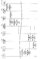
図2は、管理システムの構成図であり、統括管理センタの詳細な構成を示す図である。図2に示すように、統括管理センタ1は、通信手段101と、第1の情報管理手段102と、F/W(ファイアウォール:Fire Wall)103と、各種記憶手段104〜108と、情報解析手段109と、バス111と、通信手段112と、認証サーバ113と、F/W114a,114bと、フロントサーバ115と、第2の情報管理手段116と、F/W117と、通信手段118と、を備えている。
FIG. 2 is a configuration diagram of the management system, showing a detailed configuration of the overall management center. As shown in FIG. 2, the
通信手段101は、上記で説明したように、各クレーン拠点21,22,23にそれぞれ設置された通信手段214,224,234(図1参照)から受信する暗号化された情報を復号化するとともに、受信した情報が、どの拠点の通信手段から送信されたものであるかを識別可能な構成となっている。
第1の情報管理手段102は、各クレーンの制御装置から監視情報を取得する。また第1の情報管理手段102は、特定のクレーン拠点に所属するユーザに対して、当該クレーン拠点に設置されているクレーンに関する監視情報を公開する。
ここで、上記の「監視情報」とはクレーンの稼動情報、警報情報、及び診断情報を含む情報を指すものとする。
As described above, the
The 1st information management means 102 acquires monitoring information from the control apparatus of each crane. In addition, the first
Here, the “monitoring information” refers to information including crane operation information, alarm information, and diagnostic information.
第1の情報管理手段102は、第1の情報取得部102aと、第1の情報公開部102bと、を備える。
第1の情報取得部102aは、ネットワークN1、通信手段101、及びF/W114aを介して各クレーンの制御装置から稼動情報及び警報情報を取得し、稼動情報記憶手段104及び警報・診断情報記憶手段105にそれぞれ格納する。
ここで、稼動情報とは、例えば、上記した巻上装置、横行装置、走行装置に関する位置情報や速度情報、吊り上げた物体(ごみ)の荷重に関する情報や、各制御装置の指令値に関する情報などである。また、稼動情報は、クレーンを構成するそれぞれ機器の稼動に関する所定の状態情報(ON/OFF情報)なども含む。例えば、制御装置は、図5に示すクレーンの各状態に対応させて、該当する場合にはその旨の情報(例えば、巻上インバータ出力が「正転」である場合には、それに対応する情報:図5参照)を第1の情報取得部102aに対して送信する。
The first
The first
Here, the operation information is, for example, the position information and speed information related to the hoisting device, the traversing device, and the traveling device, the information related to the load of the lifted object (garbage), and the information related to the command value of each control device. is there. In addition, the operation information includes predetermined state information (ON / OFF information) related to the operation of each device constituting the crane. For example, the control device corresponds to each state of the crane shown in FIG. 5 and, if applicable, information to that effect (for example, if the hoisting inverter output is “forward rotation”, information corresponding thereto) : See FIG. 5) to the first
また、警報情報とは、制御装置が、クレーンの複数の箇所に設置されているインターロックなどから入力される警報内容、警報レベル、及び警報が発声した時刻を示す時刻情報を含む。例えば、クレーン211a(図1参照)の主電源電流がオーバしている場合には、図示しない配線用遮断器(Molded Case Circuit Breaker:MCB)が解放され、その旨の信号が制御装置213aに入力される。すなわち、上記のように、ある警報が発生した場合には、制御装置213はその警報内容に対応するフラグを立てるとともに、当該警報が発生した時刻情報と対応付けて警報情報として、図示しない記憶部に格納する。そして、制御装置213a(図1参照)は、第1の情報取得部102a(図2参照)の通信プログラム(図示せず)から稼動情報送信指令の信号を受信した場合には、当該指令に従って、上記の記憶部に格納された警報情報を読み出し、第1の情報取得部に対して送信する。
なお、第1の情報取得部102aに組み込まれている通信プログラム(図示せず)は、所定時間(例えば、0.1sec)ごとに通信手段101及びネットワークN1を介して各制御装置に上記の指令信号を送信するようになっている。
The alarm information includes alarm information, alarm level, and time information indicating the time when the alarm is uttered, which is input from an interlock installed at a plurality of locations of the crane. For example, when the main power supply current of the
Note that a communication program (not shown) incorporated in the first
また、診断情報は、警報情報に対応する故障の原因情報、及び、故障状態からクレーンを回復させるための指示情報を含む。例えば、図7に示す警報一覧画面の警報メッセージG405、診断メッセージG411の一段目に示すように、「走行制動異常」(G405参照)を示す警報情報には、「走行放電ユニット異常を検出しました。制動ユニットの故障か又は始動、停止の頻度が高すぎる。」(G411参照)という診断情報が対応している。詳細については後記するが、診断情報は、各警報情報に対応して、予め警報・診断情報記憶手段105に格納されている。
The diagnostic information includes failure cause information corresponding to the alarm information and instruction information for recovering the crane from the failure state. For example, as shown in the first row of the alarm message G405 and diagnostic message G411 on the alarm list screen shown in FIG. 7, the alarm information indicating “travel braking abnormality” (see G405) includes “travel discharge unit abnormality detected. "The brake unit is faulty or the frequency of starting and stopping is too high" (see G411). Although details will be described later, the diagnostic information is stored in advance in the alarm / diagnosis
第1の情報公開部102bは、認証サーバ113によって正当性が確認されたユーザのユーザPC3から、クレーンの監視情報(稼動情報、警報情報、及び診断情報)を取得する旨の指令信号を受信した場合に、当該指令信号に従って、各記憶手段104〜107から指令信号に対応する監視情報を読み出し、当該監視情報を画面情報として通信手段112及びネットワークN2を介してユーザPC3に送信する。
ちなみに、機器情報記憶手段108に格納されている情報は、第2の情報管理手段116によって管理される。
The first
Incidentally, the information stored in the device information storage means 108 is managed by the second information management means 116.
例えば、第1の情報公開部102bは、ユーザPC3から稼動情報取得指令の信号を受信した場合に、稼動情報記憶手段104から、ユーザIDに対応するクレーン拠点の稼動情報を読み出し、フロントサーバ115に出力する。この場合、第1の情報公開部102bは、ユーザIDに対応するクレーン拠点の稼動情報の全てを稼動情報記憶手段104から取得するのではなく、ユーザPC3に画面表示するために必要となる一部の情報(例えば、図5に示す稼動状況画面G3を提示する際に必要となる情報)を選択的に取得する。さらに、第1の情報公開部102bは、選択的に取得した当該情報をユーザPC3のモニタ(図示せず)に表示可能な情報に変換するための制御も行う。
なお、第1の情報公開部102bによる上記の処理は、他の記憶手段105〜107から所定の情報を取得する場合も同様である。
For example, when receiving the operation information acquisition command signal from the
The above-described processing by the first
F/W(ファイアウォール:Fire Wall)103は、統括管理センタ1の各記憶手段104〜108に格納されているデータを、第三者に不正に取得されないようにするためのセキュリティ機能を果たしている。
稼動情報記憶手段104には、上記で説明した、各制御装置による指令値の情報、クレーン位置などの計測情報などと、それぞれの情報が取得された時刻情報とが、データベース形式で各クレーンに対応して、異なる記憶領域に格納されている。ちなみに、各クレーン拠点の制御装置から統括管理センタ1に送信される稼動情報には、クレーンを構成する各機器に対応する識別情報が付されている。また、機器情報記憶手段108にはクレーンを構成する各機器の、機器名称、機器コード、型式などが予め上記の識別情報に対応付けて格納されている(機器情報の詳細については、後記する)。
The F / W (Firewall) 103 fulfills a security function for preventing data stored in the
In the operation
警報・診断情報記憶手段105には、上記で説明した、制御装置からの警報情報と、当該警報情報が取得された時刻とが、データベースの形式で各クレーンに対応して、異なる記憶領域に格納されている。また、警報・診断情報記憶手段105には、警報情報に対応する診断情報が予め記憶されている。当該診断情報は、各クレーンを構成する機器に関する情報に基づいて、研究開発センタ4(又はユーザPC3)から、予め警報・診断情報記憶手段105に格納されている。
ちなみに、警報情報として、上記で説明した、クレーンを構成するそれぞれ機器の稼動に関する所定の状態情報(ON/OFF情報)もさらに対応させて、警報・診断情報記憶手段105に格納されることとしてもよい。
さらに、警報・診断情報記憶手段105には、警報情報と診断情報との対応関係に関する情報が格納されている。ちなみに、警報情報と診断情報とは、1対1に対応しているとは限らず、所定の組み合わせの警報情報と特定の診断情報とが対応付けられている場合もある。
In the alarm / diagnosis
Incidentally, as the alarm information, the above-described predetermined state information (ON / OFF information) relating to the operation of each of the devices constituting the crane may be stored in the alarm / diagnosis
Further, the alarm / diagnosis
稼動時間・回数情報記憶手段106には、巻上装置(図示せず)、横行装置(図示せず)、走行装置(図示せず)などの稼働時間及び稼動回数が、データベース形式で各クレーンに対応して、異なる記憶領域に格納されている。例えば、稼動時間・回数情報記憶手段106には、各クレーンの各動作時間や各動作回数を朝(9:00〜12:00)、昼(13:00〜17:00)、夜(17:00〜21:00)の各時間帯での合計値、一日当たりの合計値、1時間当たりの平均値などが、データベース形式で格納されている(図9参照)。
ちなみに、上記の稼動時間や稼動回数に関しては、稼動情報記憶手段104に記憶されている稼動情報を、後記する情報解析手段109が読み出して算出し、稼動情報・回数情報記憶手段106に格納する。
The operating time / number of times information storage means 106 stores the operating time and the number of times of operation of the hoisting device (not shown), the traversing device (not shown), the traveling device (not shown), etc. Correspondingly, they are stored in different storage areas. For example, the operation time / number of times information storage means 106 stores each crane operation time and each operation count in the morning (9:00 to 12:00), noon (13: 0 to 17:00), and night (17: A total value in each time zone (00 to 21:00), a total value per day, an average value per hour, and the like are stored in a database format (see FIG. 9).
Incidentally, with respect to the above-described operation time and number of operations, the operation information stored in the operation
運用情報記憶手段107には、各クレーンを構成する各器具に対応して、機器コード、機器名称、型式、稼動回数、寿命回数、前回交換日などがデータベース形式で格納されている(図10参照)。
ちなみに、上記の機器コード、機器名称、型式、寿命回数、前回交換日については、各クレーン拠点の管理者が、統括管理センタ1に登録手続をする際に、ユーザPC3から統括管理センタ1に各データを送信する。そして、通信手段112を介して受信した上記の各情報を、第2の情報取得部116aが各クレーンに対応させて運用情報記憶手段107に格納する。また、ユーザは、クレーンの各機器を新たに交換した場合には、その交換日を統括管理センタ1に対して送信する。そして第2の情報取得部116aが上記の「前回交換日」を更新する。また、第1の情報取得部102aが、上記の更新機能を有することとしてもよい。
なお、第2の情報取得部116aの詳細については、後記する。
The operation information storage means 107 stores the equipment code, equipment name, model, number of operations, number of times of service, the number of times of previous replacement, etc. in a database format corresponding to each equipment constituting each crane (see FIG. 10). ).
By the way, regarding the above-mentioned device code, device name, model, number of times of service, and previous replacement date, the administrator of each crane base sends each information from the
Details of the second
機器情報記憶手段108には、図12に示すように、各クレーン拠点のクレーン拠点名称、拠点コード(図12(a)参照)や、各クレーンのクレーン名称、クレーンコード(図12(b)参照)がデータベース形式で格納されている。
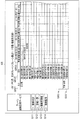
また、機器情報記憶手段108には、図13に示すように、機器名称、機器コード、型式、稼動回数、寿命回数、警報履歴、前回点検日、点検結果、前回交換日、次回交換予定日、在庫数などが、データベース形式で各クレーンに対応して、異なる記憶領域に格納されている。
ちなみに、上記の機器名称、機器コード、型式、寿命回数、在庫数については、上記と同様に、予めユーザPC3から統括管理センタ1に各データが送信され、第2の情報取得部116aが各クレーンに対応させて機器情報記憶手段108に格納する。
また、図13に示す稼動回数は、情報解析手段109が稼動情報記憶手段104に格納されている稼動情報を読み出し、当該稼動情報に基づいて動作回数を算出し、所定時間ごとに機器情報記憶手段108に格納して更新する。また、図13に示す警報履歴は、情報解析手段109が警報・診断情報記憶手段105に格納されている警報情報を読み出し、所定時間ごとに機器情報記憶手段108に格納して更新する。
In the equipment information storage means 108, as shown in FIG. 12, the crane base name and base code (see FIG. 12 (a)) of each crane base, the crane name and crane code of each crane (see FIG. 12 (b)). ) Is stored in database format.
Further, in the device information storage means 108, as shown in FIG. 13, the device name, device code, model, operation count, life count, alarm history, previous inspection date, inspection result, previous replacement date, next replacement date, The stock quantity and the like are stored in different storage areas corresponding to each crane in a database format.
Incidentally, with respect to the device name, device code, type, number of times of life, and number of stock, each data is transmitted from the
In addition, the number of operations shown in FIG. 13 is calculated by reading the operation information stored in the operation
また、図13に示す前回点検日及び点検結果については、各クレーン拠点に勤務している作業員などが所定期間ごとに各機器の状態を点検し、その点検記録をユーザPC3から統括管理センタ1に送信し、第2の情報取得部116aがその情報を取得して機器情報記憶手段108に格納する。ちなみに、上記の点検は、例えば、クレーン拠点の作業員がモバイル端末(図示せず)を用いて各機器を点検し、その点検情報を当該クレーン拠点の制御装置に転送することも可能である。
また、図13に示す前回交換日は、上記と同様に、クレーンの各機器について新たに交換された場合には、クレーン拠点の作業員がモバイル端末(図示せず)を用いて交換された機器及びその交換日を統括管理センタ1に送信する。そして第2の情報取得部116aが上記の「前回交換日」及び「在庫数」を更新する。
ちなみに、登録時における機器の在庫数は、当該サービスの登録時などに各クレーン拠点のユーザがクレーンを構成する各機器の在庫数を統括管理センタ1に送信し、第2の情報取得部116aが当該在庫数の情報を機器ごとに機器情報記憶手段108に格納する。
Further, regarding the previous inspection date and the inspection result shown in FIG. 13, the workers working at each crane base inspect the state of each device every predetermined period, and the inspection record is sent from the
In addition, the previous replacement date shown in FIG. 13 is the same as the above, and when the crane equipment is newly replaced, the crane base operator uses the mobile terminal (not shown) to replace the equipment. And the exchange date is transmitted to the
By the way, as for the inventory quantity of equipment at the time of registration, the user of each crane base sends the inventory quantity of each equipment constituting the crane to the
さらに、図13に示す次回交換予定日は、各機器の稼動回数、寿命回数、前回交換予定日、1日当たりの平均動作回数などに基づいて、情報解析手段109が算出する。その他、警報履歴や点検内容なども考慮して、情報解析手段109が次回交換予定日を決定することとしてもよい。例えば、特定の機器に関して重故障の警報が警報履歴として記録されていた場合には、その警報内容に対応して、寿命回数を所定回数だけ減らすように設定してもよい。
上記の情報解析手段109による次回交換予定日の決定方法は、研究開発センタ4によって、新たに更新することができる。
Further, the next scheduled replacement date shown in FIG. 13 is calculated by the
The method for determining the next scheduled replacement date by the information analysis means 109 can be newly updated by the research and development center 4.
情報解析手段109は、CPU(Central Processing Unit)、ROM(Read Only Memory)、RAM(Random Access Memory)、各種インタフェースなどの電子回路(図示せず)を含んで構成されている。情報解析手段109は、設定されたプログラムに基づいて、以下に示すさまざまな処理を行う。
例えば、情報解析手段109は、稼動情報記憶手段104に格納されている稼動情報に基づいて稼動時間・回数情報を算出し、稼動時間・回数情報記憶手段106に格納する(図9参照)。また、情報解析手段109は、稼動情報記憶手段104に格納されている稼動情報に基づいてクレーンを構成する各機器の動作回数を算出し、運用情報記憶手段107及び機器情報記憶手段108に格納する(図10、図13参照)。また、情報解析手段109は、機器記憶手段108に格納されている機器情報などに基づいて、クレーンを構成する各機器の次回交換予定日などを算出する(図13参照)。
The
For example, the
バス111は、第1の情報管理手段102と、第2の情報管理手段116と、各記憶手段104〜108と、情報解析手段109と、通信手段118と、に接続されており、上記で説明した情報のやり取りを可能としている。
通信手段112は、ネットワークN2を介してユーザPC3と認証サーバ113とを接続する通信回線である。また、通信手段112は、認証サーバ113によってユーザの正当性が確認された後には、ユーザIDに対応する通信回線及びF/W114bを介してフロントサーバ115との間で情報を送受信することができる。
The
The
認証サーバ113は、ユーザの識別子に関する一意な情報であるユーザIDと、当該ユーザIDに対応するパスワードを認証することによって、ユーザの正当性を確認する。すなわち、認証サーバ113は、公知の公開鍵と秘密鍵を用いた認証処理を行う。
F/W114a,114bは、第三者が外部から統括管理センタ1に侵入し、データを不正に取得することを防止するためのセキュリティ機能を有する。
フロントサーバ115は、認証サーバ113による認証処理が完了した場合に、ユーザIDを第1の情報公開部102b及び第2の情報公開部116bに出力する。ちなみに、ユーザIDは登録時に一つ又は複数のクレーン拠点と対応付けられている。また、フロントサーバ115は、ユーザPC3のモニタ(図示せず)に表示された画面を見たユーザが、当該画面に表示された所定の選択ボタンをマウス等の入力手段(図示せず)を用いて選択した場合に、その選択情報を第1の情報公開部102b又は第2の情報公開部116bに出力する。
なお、ユーザPC3に表示される画面例や上記の選択情報の詳細については、後記する。
The
The F /
When the authentication process by the
Details of the screen example displayed on the
第2の情報管理手段116は、ユーザPC3から機器情報を取得する。また第2の情報管理手段116は、特定のクレーン拠点に所属するユーザに対して、当該クレーン拠点に設置されているクレーンに関する機器情報を公開する。
第2の情報管理手段116は、第2の情報取得部116aと、第2の情報公開部116bと、を備える。
第2の情報取得部116aは、ネットワークN2及び通信手段112を介してユーザPC3から機器情報を取得し、それぞれのクレーンごとに機器情報を運用情報記憶手段107及び機器情報記憶手段108に格納する。上記の機器情報とは、例えば、各機器コード、機器名称、型式、機器の在庫数、寿命回数、各機器の詳細な仕様及び回路構成、画像に関する情報などである。また、機器情報には、情報解析手段109によって上記の各情報に基づいて決定される、各機器の次回交換予定日も含まれる。
ちなみに、特定のクレーン拠点に存在する各クレーンの機器情報を統括管理センタ1に対して送信するユーザPC3と、統括管理センタ1から上記のクレーン拠点の監視情報を取得して表示するPC3とが同一であるとは限らず、それぞれ異なる場合もある。
The second
The second
The second
Incidentally, the
第2の情報公開部116bは、認証サーバ113によって正当性が認証されたユーザのユーザPC3からクレーンを構成する機器に関する機器情報を取得する旨の指令信号を受信した場合に、当該指令信号に従って、機器情報記憶手段108から機器情報を読み出し、当該機器情報を画面情報として、通信手段112を介してユーザPC3に送信する。
例えば、第2の情報公開部116bは、ユーザPC3から機器情報取得指令の信号を受信した場合に、機器情報記憶手段108から、ユーザIDに対応するクレーン拠点の機器情報を読み出し、フロントサーバ115に出力する。
When the second
For example, when receiving the device information acquisition command signal from the
この場合、第2の情報公開部116bは、ユーザIDに対応するクレーン拠点の機器情報の全てを機器情報記憶手段108から取得するのではなく、ユーザPC3に画面表示するために必要となる一部の情報(例えば、図13に示す保全管理サービス表示画面G7を提示する際に必要となる情報)を機器情報記憶手段108から選択的に取得する。
さらに、第2の情報公開部116bは、選択的に取得した当該情報を、ユーザPC3のモニタ(図示せず)に表示可能な情報に変換するための制御も行う。
ちなみに、第1の情報管理手段102及び第2の情報管理手段116をそれぞれ1台のサーバで構成してもよいし、また1台のサーバを複数台の仮想的なコンピュータに分割し、それぞれに上記の機能に対応する各OS(Operating System)やアプリケーションソフトを動作させることとしてもよい。
また、第1の情報管理手段102及び第2の情報管理手段116をそれぞれ複数台のサーバで構成して冗長化し、特定のサーバで異常が発生した場合には、速やかに別のサーバに上記機能を移行させ、管理システムAの安定化を図ることとしてもよい。
In this case, the second
Furthermore, the second
Incidentally, each of the first information management means 102 and the second information management means 116 may be composed of one server, or one server is divided into a plurality of virtual computers, Each OS (Operating System) and application software corresponding to the above functions may be operated.
Further, each of the first information management means 102 and the second information management means 116 is made up of a plurality of servers to make them redundant, and when an abnormality occurs in a specific server, the above function is quickly transferred to another server. The management system A may be stabilized.
F/W117は、第三者が外部から統括管理センタ1に侵入し、データを不正に取得することを防止するためのセキュリティ機能を有する。
通信手段118は、ネットワークN3を介して研究開発センタ4の通信手段41(図1参照)との間で通信を行うための通信回線である。上記のように、ユーザは、自らが所属するクレーン拠点に関する情報のうち、第1の情報公開部102b又は第2の情報公開部116bによって各記憶手段104〜108から取得された情報のみを閲覧可能である。
これに対して、研究開発センタ4の専用PC45(図1参照)は、第1の情報公開部102b又は第2の情報公開部116bによる選択処理を経ずに統括管理センタ1からの情報を直接的に取得することができる構成となっている。つまり、研究開発センタ4では、統括管理センタ1の各記憶手段104〜108に格納されている情報をそのまま閲覧し、研究開発や管理システムAのバージョンアップなどのために活用することができる。
The F /
The
In contrast, the dedicated PC 45 (see FIG. 1) of the R & D center 4 directly receives information from the
<設備監視サービスの処理過程と画面表示例>
以下の説明では、例として、クレーン拠点21(図1参照)から監視情報(クレーンの稼動情報、警報情報、及び診断情報)を取得又は公開する場合について説明する。
<Processing process and screen display example of equipment monitoring service>
In the following description, as an example, a case will be described in which monitoring information (crane operation information, alarm information, and diagnostic information) is acquired or disclosed from the crane base 21 (see FIG. 1).
(1.稼動状況)
図3は、稼動情報取得処理に関わる動作説明を示すシーケンスである。
図3のステップS101で、第1の情報取得部102a(図2参照)の通信プログラム(図示せず)は、通信手段101、ネットワークN1、通信手段214(図1参照)を介して制御装置213a,213b(図1参照)に稼動情報送信指令の信号を送信する。次に、ステップS102で、制御装置213a,213bは、上記の稼動情報送信指令の信号を受信すると、それに対応する稼動情報を第1の情報取得部102aに対して送信する。なお、稼動情報の内容については、上記で説明したので省略する。
次に、ステップS103で、第1の情報取得手段102aは、制御装置213aから受信したクレーン211a(図1参照)の稼動情報と、制御装置213bから受信したクレーン211bの稼動情報とを識別して、稼動情報記憶手段104の中の異なる記憶領域にそれぞれ格納する。
なお、上記のステップS101〜S103の処理は、所定時間(例えば、0.1sec)ごとに繰り返し実行され続ける。
(1. Operation status)
FIG. 3 is a sequence showing an operation description related to the operation information acquisition process.
In step S101 of FIG. 3, the communication program (not shown) of the first
Next, in step S103, the first
Note that the processes in steps S101 to S103 are repeatedly executed every predetermined time (for example, 0.1 sec).
図3のステップS104で、クレーン拠点21に所属するユーザは、ユーザPC3の入力部(図示せず)を操作して、統括管理センタ1が提供するクレーン遠隔監視サービスのサイトにアクセスし、図4(a)に示すログイン画面を表示させる。そして、ユーザはPC3の入力部を操作して、「ユーザID」G101と「パスワード」G102とを入力し、「ログインボタン」G103をクリックする。これによって、PC3はネットワークN2及び通信手段112を介してユーザIDとパスワードとを認証サーバ113に送信することとなる。
次に、ステップS105で、認証サーバ113は上記で説明した認証処理を行う。認証サーバ113は、ユーザの正当性を確認した場合、図4(b)に示す画面G2をユーザPC3のモニタ(図示せず)に表示させる。
In step S104 of FIG. 3, the user belonging to the
In step S105, the
図4(b)に示す「設備監視サービス」とは、クレーンの稼動状況、警報一覧、稼動管理表、稼動監視の各項目に対応する表示画面をユーザに閲覧させるサービスを示す(図5の表示画面例のG11〜G14参照)。
一方、図4(b)に示す「保全管理サービス」とは、クレーンの機器情報や機器の交換時期、在庫数状況、各機器の詳細な仕様及び回路構成、画像などに関する情報をユーザに閲覧させるサービスを示す。
The “facility monitoring service” shown in FIG. 4B is a service that allows the user to browse display screens corresponding to the crane operation status, alarm list, operation management table, and operation monitoring items (display shown in FIG. 5). (See G11 to G14 in the screen example).
On the other hand, the “maintenance management service” shown in FIG. 4B allows the user to browse information on crane equipment information, equipment replacement time, inventory status, detailed specifications and circuit configuration of each equipment, images, and the like. Indicates a service.
ユーザはクレーンの稼動状況画面を閲覧したい場合、図4(b)に示す「設備監視サービス」G201を選択する。当該操作により、図3のステップS106でユーザPC3は、第1の情報公開部102bに対して稼動情報取得指令の信号を送信することとなる。ステップS107で、第1の情報公開部102bは、稼動情報記憶手段104に記憶されている稼動情報の中から、ユーザIDに対応するクレーン拠点の稼動情報を検索し、当該稼動情報を取得する(ステップS108)。そして、ステップS109で第1の情報公開部102bは、ユーザPC3に上記の取得した稼動情報を送信する。
When the user wants to view the operation status screen of the crane, the user selects “equipment monitoring service” G201 shown in FIG. With this operation, the
そうすると、図5に示す稼働状況表示画面G3がユーザPC3のモニタ(図示せず)に表示される。図5に示す「サイト名」G15には、クレーン拠点の名前(クレーン拠点1)が表示される。また、「クレーンNO」G16をプルダウンすることによって、クレーン拠点に存在する各クレーンNOが表示され、ユーザは自分が見たいクレーン(例えば、クレーンNo.1のクレーン)の稼動情報を閲覧することができる。
図5に示す例では、クレーンNo.1のクレーンにおいて、現在(ユーザがサイトにアクセスした時点で)、乱巻となっており、インバータ(INV)異常が発生し、アラーム1が点灯していることが分かる。ちなみに、図5に示す各項目は、クレーンの構成に対応して異なった構成で表示されることがあるものとする。
Then, the operation status display screen G3 shown in FIG. 5 is displayed on the monitor (not shown) of the
In the example shown in FIG. It can be seen that the crane No. 1 is currently turbulent (when the user accesses the site), an inverter (INV) abnormality has occurred, and the
(2.警報一覧)
図6は、警報・診断情報取得処理に関わる動作説明を示すシーケンスである。
図6のステップS201で、第1の情報取得部102a(図2参照)の通信プログラム(図示せず)は、通信手段101(図2参照)を介して制御装置213a,213b(図1参照)に警報情報送信指令の信号を送信する。ステップS202で、制御装置213a,213bは、上記の警報情報送信指令の信号を受信すると、それに対応する警報情報を第1の情報取得部102aに対して送信する。ステップS203で、第1の情報取得部102aは、当該警報情報を情報解析手段109に送信する。
(2. List of alarms)
FIG. 6 is a sequence showing an operation description related to the alarm / diagnosis information acquisition processing.
In step S201 in FIG. 6, the communication program (not shown) of the first
ステップS204で情報解析手段109は、警報・診断情報記憶手段105から当該警報情報に対応する診断情報を検索し、当該診断情報を取得する(ステップS205)。ステップS206で、情報解析手段109は、警報情報と診断情報とを対応付けて管理用PC52(図1参照)に送信する。これによって、サービスセンタ5(図1参照)の管理者は、クレーンが設置されている現場で警報が発生したのと、ほぼ同じタイミングで、警報情報及び診断情報を知ることができる。そして、サービスセンタ5のサービス員は、メールや電話などを用いてすぐに警報が発生したクレーン拠点のユーザと連絡をとることができる。
ちなみに、ステップS206の処理では、予め定められた所定内容(又は所定レベル以上)の警報情報の場合に限って、管理用PC52に警報・診断情報を送信することが好ましい。
なお、ステップS201〜S206の処理は、所定時間(例えば、0.1sec)ごとに繰り返し実行され続ける。
In step S204, the
Incidentally, in the process of step S206, it is preferable to transmit alarm / diagnosis information to the
Note that the processes in steps S201 to S206 are repeatedly executed every predetermined time (for example, 0.1 sec).
ステップS207で、PC3はネットワークN2を介してユーザIDとパスワードを認証サーバ113に送信し、ステップS208で認証サーバ113が認証処理を行う。認証処理が完了した後、ユーザはクレーンの警報一覧画面を閲覧したい場合、図7に示す「警報一覧」G12を選択する。当該操作により、図6のステップS209でユーザPC3は、第1の情報公開部102bに対して警報・診断情報取得指令の信号を送信する。ステップS210で第1の情報公開部102bは、警報・診断情報記憶手段105からユーザIDに対応するクレーン拠点での警報・診断情報を検索し、当該警報診断情報を取得する(ステップS211)。さらに、ステップS212で第1の情報公開部102bは、ユーザPC3に警報・診断情報を送信する。
In step S207, the
そうすると、図7に示す警報一覧表示画面G4がユーザPC3のモニタ(図示せず)に表示される。なお、図7では表示を2段にして記載したが、ユーザPC3に表示させる場合には1段として表示し、スクロールバー(図示せず)によって左右にスクロールさせることができることとする。
警報一覧画面G4には、ユーザがクレーン遠隔監視サービスのサイトにアクセスした時点まで(又はユーザが指定した月)の警報・診断情報が表示される。警報一覧画面G4には、図7に示すように、例えば、警報の「発生時刻」G401、故障の「復旧時刻」G402、故障箇所の「状態」G403、「警報レベル」G404、「警報メッセージ」G405、「巻上位置」G406、「走行位置」G407、「横行位置」G408、上記で説明したバケット(図示せず)が「開状態」G409であるか「閉状態」G410であるか否か、診断メッセージ411などが表示される。ちなみに、警報一覧表示画面G4の「巻上位置」G406、「走行位置」G407、「横行位置」G408は、警報が発生した時刻及びユーザIDを参照して、第1の情報取得部102aが稼動情報記憶手段104から、対応するクレーンの稼動情報を取得することによって表示可能となる。
Then, the alarm list display screen G4 shown in FIG. 7 is displayed on the monitor (not shown) of the
The alarm list screen G4 displays alarm / diagnosis information up to the time when the user accesses the site of the crane remote monitoring service (or the month specified by the user). In the alarm list screen G4, as shown in FIG. 7, for example, an alarm “occurrence time” G401, a failure “recovery time” G402, a failure location “state” G403, an “alarm level” G404, an “alarm message” G405, “winding position” G406, “traveling position” G407, “transverse position” G408, whether the bucket (not shown) described above is “open state” G409 or “closed state” G410 A diagnostic message 411 or the like is displayed. By the way, the “winding position” G406, “traveling position” G407, and “transverse position” G408 of the alarm list display screen G4 refer to the time when the alarm is generated and the user ID, and the first
(3.稼動管理表)
図8は、稼動時間・回数情報取得処理に関わる動作説明を示すシーケンスである。
図8のステップS301で、情報解析手段109は各クレーンごとに稼動情報を検索し、稼動情報を取得する(ステップS302)。なお、例えば、図9に示すように、「朝番、昼番、夜番」G503の時間帯における稼動時間及び稼動回数を算出する場合には、情報解析手段109による上記検索処理は、一日当たり決まった時刻に3回行えば足りる。
ステップS303で、情報解析手段109は、取得した稼動情報に基づいて、稼動時間及び稼動回数を算出する。例えば、図9に示すように、情報解析手段109は、「朝番、昼番、夜番」G503の時間帯における、クレーンの巻上装置(図示せず)の巻上動作時間や巻上動作回数などを算出する。また、情報解析手段109は、一日の各動作時間及び動作回数の「合計」G504や1時間当たりの「平均」G505を算出する。
ステップS304で、情報解析手段109は、稼動時間・回数情報記憶手段106に、上記の稼動時間・回数情報を格納する。
なお、ステップS301〜S304の処理は、上記で説明した図9に示すG503の時間帯に対応して、情報解析手段109が一日当たり所定回数実行し、その処理を毎日継続させることとする。
(3. Operation management table)
FIG. 8 is a sequence showing an operation description related to the operation time / times information acquisition processing.
In step S301 of FIG. 8, the
In step S303, the
In step S <b> 304, the
Note that the processing of steps S301 to S304 is executed by the information analysis means 109 a predetermined number of times per day corresponding to the time zone of G503 shown in FIG. 9 described above, and the processing is continued every day.
図8のステップS305で、PC3はネットワークN2を介してユーザIDとパスワードを認証サーバ113に送信し、ステップS306で認証サーバ113が認証処理を行う。
認証処理が完了した後、ユーザは、クレーンの稼動管理表画面を閲覧したい場合、図9に示す「稼動管理表」G13を選択する。当該操作により、図6のステップS307でユーザPC3は、第1の情報公開部102bに稼動時間・回数情報取得指令の信号を送信することとなる。ステップS308で第1の情報公開部102bは、稼動時間・回数情報記憶手段106からユーザIDに対応するクレーン拠点での稼動時間・回数情報を検索し、当該稼動時間・回数情報を取得する(ステップS309)。さらに、ステップS310で第1の情報公開部102bは、ユーザPC3に上記の稼動時間・回数情報を送信する。
In step S305 in FIG. 8, the
After the authentication process is completed, when the user wants to browse the crane operation management table screen, the user selects “operation management table” G13 shown in FIG. By this operation, in step S307 in FIG. 6, the
そうすると、図9に示す稼動管理表画面G5がユーザPC3に表示される。稼動管理表画面G5には、クレーンの「主回路」G501aと「手動・自動」G501bとを区別する「区分」G501が表示される。ちなみに「手動」とは、クレーンを作業員が手動で動かした場合を示す。一方、「自動」とは、予め設定されたプログラムに従ってクレーンが自動制御で動作した場合を示す。その他、稼動管理表画面G5には、各動作を区別し、さらに稼動時間と稼動回数とを区別して項目別に表示する「項目」G502、日付を示すG503、上記で説明した「朝番、昼番、夜番」G504、「合計」G505、「平均」G506などが表示される。
例えば、ユーザが図9に示す2011年3月3日に、クレーン遠隔監視サービスの稼動管理表画面G5を見るために統括管理センタ1にアクセスした場合、2011年3月3日以前におけるクレーンの稼動時間・稼動回数を知ることができる。
Then, an operation management table screen G5 shown in FIG. 9 is displayed on the
For example, when the user accesses the
(4.稼動監視)
運用情報取得処理に関わる動作説明を示すシーケンスについては、上記で説明した稼動時間・回数情報取得処理に関わる動作説明を示すシーケンスと同様であるから、説明を省略する。
第1の情報公開部102bが、ユーザPC3に運用情報を送信すると、図10に示す稼動監視画面G6がユーザPC3のモニタ(図示せず)に表示される。稼動監視画面G6には、「機器コード」G601、「機器名称」G602、「型式」G603、「稼動回数」G604、「寿命回数」G605、「前回交換日」G606などが表示される。上記で説明したように、稼動監視画面G6の各項目のうち、「稼動回数」G604以外の情報は、最初に登録する際にユーザPC3から統括管理センタ1に各データが送信され、第2の情報取得部116aが運用情報記憶手段107に格納する。ちなみに、「稼動回数」G604は、各機器がクレーンに設置されてから現在(稼動情報を取得した時刻)までの累計稼動回数を意味する。
また、ユーザは、クレーンの各機器を新たに交換した場合には、その交換日に関する情報を統括管理センタ1に送信し、第2の情報取得部116aが上記の「前回交換日」G606の日付を更新する。
なお、上記の各情報は、クレーンの各機器に対応して、機器情報記憶手段108にも格納される。
(4. Operation monitoring)
Since the sequence showing the operation description related to the operation information acquisition process is the same as the sequence showing the operation description related to the operation time / number of times information acquisition process described above, the description thereof will be omitted.
When the first
In addition, when the user newly replaces each crane device, the user transmits information related to the replacement date to the
Note that each of the above information is also stored in the device information storage means 108 corresponding to each device of the crane.
<保全管理サービスの処理過程と画面表示例>
次に、クレーン監視サービスのうちの保全管理サービスについて説明する。
図11は、機器情報取得処理に関わる動作説明を示すシーケンスである。
ステップS401で、PC3はネットワークN2を介してユーザIDとパスワードを認証サーバ113に送信し、ステップS402で認証サーバ113が認証処理を行う。そうすると、図4(b)に示す画面G2がユーザPC3のモニタ(図示せず)に表示される。
さらに、図4(b)に示す「保全管理サービス」G202をユーザが選択すると、機器情報を添付可能な画面(図示せず)に遷移する。当該ユーザは、特定のクレーンを指定し、当該クレーンの機器名称、機器コード、型式、前回交換日、在庫数などの情報を例えば、ファイルとして添付して統括管理センタ1に送信する(ステップS403)。
なお、ユーザは、上記の各項目に加えて、詳細な仕様書や回路設計図、機器の画像などを添付して統括管理センタ1に送信してもよい。
上記の処理は、通常、各クレーン拠点の管理者がクレーン遠隔監視サービスの登録処理を行う際になされる。
図11のステップS403で、ユーザPC3は、第2の情報取得部116aに対して、上記の機器情報を送信する。次に、ステップS404で、第2の情報取得部116aは、受信した当該機器情報を、ユーザが選択したクレーンに対応させて機器情報記憶手段108に格納する。
<Processing of maintenance management service and screen display example>
Next, the maintenance management service of the crane monitoring service will be described.
FIG. 11 is a sequence showing an operation description related to the device information acquisition process.
In step S401, the
Furthermore, when the “maintenance management service” G202 shown in FIG. 4B is selected, the screen transitions to a screen (not shown) to which device information can be attached. The user designates a specific crane, and transmits information such as a device name, a device code, a model, a previous replacement date, and an inventory number of the crane as a file, for example, to the central management center 1 (step S403). .
In addition to the above items, the user may send detailed specifications, circuit design drawings, device images, and the like to the
The above processing is usually performed when the administrator of each crane base performs registration processing for the crane remote monitoring service.
In step S403 in FIG. 11, the
また、ユーザは、自身が所属するクレーン拠点のクレーンの機器情報を閲覧したい場合、次のような処理を行う。すなわち、図11のステップS405で、PC3はネットワークN2を介してユーザIDとパスワードを認証サーバ113に送信し、ステップS406で認証サーバ113が認証処理を行う。次に、ステップS407で、ユーザPC3は、第2の情報公開部116bに対して、機器情報取得指令の信号を送信する。なお、この場合、ユーザは自身が登録したクレーン拠点に複数のクレーンが存在する場合には、ユーザPC3の画面(図示せず)に表示された複数のクレーンのうち、特定のクレーンを指定する。
ステップS408で、第2の情報公開部116bは、機器情報記憶手段108に格納されている機器情報の中から、ユーザが指定した上記のクレーンに関する機器情報を検索し、当該機器情報を取得する(ステップS409)。
そして、ステップS410で、第2の情報公開部116bは、上記の機器情報をユーザPC3に送信する。
In addition, when the user wants to browse the equipment information of the crane at the crane base to which the user belongs, the user performs the following process. That is, in step S405 in FIG. 11, the
In step S408, the second
In step S410, the second
ちなみに、機器情報記憶手段108には、クレーン拠点の情報(図12(a)参照)、各クレーン拠点に存在するクレーンの情報(図12(b)参照)、各クレーンに設置されている機器の情報(図13参照)がデータベース形式で格納されている。
すなわち、図12(a)に示すように、クレーン拠点データベースでは、「クレーン拠点名称」G701と、「拠点コード」G702とが対応付けられている。また、図12(b)に示すように、クレーンデータベースでは、上記のそれぞれのクレーン拠点に存在するクレーンの「クレーン名称」G703と、「クレーンコード」G704とが対応付けられている。
Incidentally, in the equipment information storage means 108, information on crane bases (see FIG. 12 (a)), information on cranes existing at each crane base (see FIG. 12 (b)), and equipment installed in each crane. Information (see FIG. 13) is stored in a database format.
That is, as shown in FIG. 12A, in the crane base database, “crane base name” G701 and “base code” G702 are associated with each other. Also, as shown in FIG. 12B, in the crane database, the “crane name” G703 and “crane code” G704 of the cranes existing at the respective crane bases are associated with each other.
そして、上記で説明した図11のステップS410で、第2の情報公開部116bが機器情報をユーザPC3に送信すると、例えば、図13に示す保全管理サービス表示画面G7がユーザPC3のモニタ(図示せず)に表示される。
保全管理サービス表示画面G7には、ユーザが所属するクレーン拠点のうち、上記でユーザが指定したクレーンに設置されている機器情報が表示される。例えば、保全管理サービス表示画面G7には、「機器名称」G705、「機器コード」G706、「型式」G707、「稼動回数」G708、「寿命回数」G709、「警報履歴」G710、「前回点検日」G711、「点検結果」G712、「前回交換日」G713、「次回交換予定日」G714、「在庫数」G715などが表示される。ちなみに、「稼動回数」G708は、各機器がクレーンに設置されてから現在(稼動情報を取得した時刻)までの累計稼動回数を意味する。
その他、例えば、図13に表示されている複数の機器名称のうち、特定の機器名称(例えば、主電源リレー)を選択すると、その機器周辺の詳細な回路図を画面表示させることとしてもよい。また、各クレーンの機器の仕様書や写真などの関連情報を画面表示させることとしてもよい。
ちなみに、図13では各項目G705〜G715を一つの画面で表示した例を示したが、例えば、各機器の警報に関する情報、点検に関する情報、交換日などに関する情報の画面をそれぞれ別の画面として表示させることとしてもよい。
When the second
On the maintenance management service display screen G7, device information installed on the crane designated by the user among the crane bases to which the user belongs is displayed. For example, the maintenance management service display screen G7 includes “device name” G705, “device code” G706, “model” G707, “operation count” G708, “life count” G709, “alarm history” G710, “previous inspection date” "G711", "Inspection result" G712, "Previous replacement date" G713, "Next replacement scheduled date" G714, "Stock quantity" G715, etc. are displayed. Incidentally, the “number of operations” G708 means the total number of operations from the time when each device is installed on the crane to the present (time when the operation information is acquired).
In addition, for example, when a specific device name (for example, main power supply relay) is selected from among a plurality of device names displayed in FIG. 13, a detailed circuit diagram around the device may be displayed on the screen. Moreover, it is good also as displaying related information, such as a specification sheet and a photograph of the equipment of each crane on a screen.
Incidentally, although FIG. 13 shows an example in which each item G705 to G715 is displayed on one screen, for example, information screens for alarms, inspection information, replacement dates, etc. for each device are displayed as separate screens. It is also possible to make it.
<サービスセンタで作成される資料>
図14は、横行ブレーキ開閉器の稼動回数の比較結果を示す図である。図14に示すグラフは、例えば、各クレーン拠点の管理者などに資料として提示するために、サービスセンタ5の管理者などが作成する。図14に示すグラフを参照すると、あるクレーン拠点に存在する3台のクレーンのうち、クレーンNo.3の横行ブレーキ開閉器の累積稼動回数が少なく、クレーンNo.1の横行ブレーキ開閉器の累積稼動回数が多いことが分かる。
例えば、クレーンを自動ではなく手動で動かす場合には、クレーンの操作者によって上記のように横行ブレーキの操作回数が異なってくる。そうすると、複数のクレーンのうち、特定のクレーンを構成する機器の磨耗が早くなり、機器の交換時期などにずれが生じるなど、クレーン拠点の管理者にとって不都合な事態が生じる。つまり、一般的に、クレーンが複数台ある場合には、各クレーンを構成する機器の動作回数の差を小さくすることが望まれる。
<Documents created at the service center>
FIG. 14 is a diagram showing a comparison result of the number of operations of the traverse brake switch. The graph shown in FIG. 14 is created by, for example, the administrator of the
For example, when the crane is moved manually instead of automatically, the number of traverse brake operations differs depending on the crane operator as described above. Then, among the plurality of cranes, the equipment constituting the specific crane is quickly worn out, and there is a situation that is inconvenient for the manager of the crane base, for example, there is a deviation in the replacement time of the equipment. That is, in general, when there are a plurality of cranes, it is desirable to reduce the difference in the number of operations of the devices constituting each crane.
サービスセンタ5が図14に示すような資料をクレーン拠点の管理者などに提示することによって、クレーン拠点の管理者は、各クレーンを構成する機器の動作回数の差を小さくするように対応することが可能となる。
なお、上記では、図14に示す画面をユーザPC3からは閲覧することができないこととしたが、統括管理センタ1は、次のような方法によって上記画面をユーザPC3に表示させるサービスを行うことも可能である。すなわち、まず、情報解析手段109が稼動情報記憶手段104に記憶されている、各クレーンを構成する各機器の稼動情報を読み出して、日付ごとの累積稼動回数などを算出し、図示しない記憶手段に格納する。そして、第1の情報公開部102bがユーザPC3からの指令に従って、上記記憶手段から解析結果情報を取得することによって、図14に示す画面をユーザPC3のモニタ(図示せず)に表示させることとしてもよい。
The
In the above description, the screen shown in FIG. 14 cannot be viewed from the
<効果>
本実施形態に係る管理システムAによれば、ユーザが用意すべきものは最低限の接続環境(PC3、モバイル端末、ブラウザ、通信手段など)のみであり、各クレーンの管理は、統括管理センタ1が一括して行うことができる。したがって、各クレーン拠点の既存のクレーン設備に大きな変更を加えることなく、クレーンの監視情報や機器情報をユーザに提供することができる。
また、本実施形態に係る管理システムAは、ネットワーク上に存在するサーバ群が提供するサービスを、それらのサーバ群を意識することなしに利用できるクラウド・コンピューティングのシステムとなっている。したがって、ユーザは自身が登録したクレーン拠点に対応するID及びパスワードを付与され、インターネットの接続環境さえあれば、クラウド・コンピューティングのネットワークに接続してクレーンの状況をリアルタイムで把握することができる。
<Effect>
According to the management system A according to the present embodiment, the user should prepare only a minimum connection environment (PC3, mobile terminal, browser, communication means, etc.), and the
In addition, the management system A according to the present embodiment is a cloud computing system that can use services provided by a server group existing on a network without being aware of the server group. Therefore, the user is given an ID and password corresponding to the crane base registered by the user, and can connect to the cloud computing network and grasp the crane status in real time as long as there is an internet connection environment.
また、本実施形態に係る管理システムAによれば、クレーンの詳細な稼動情報などを統括管理センタ1の各記憶手段104〜109に格納するので、各クレーン拠点に膨大な記憶容量を有する記憶装置を設置する必要がなくなり、各クレーン拠点でのコストが抑えられる。
また、クレーン拠点の管理者などは、各クレーンの監視・保全を行う際に、その目的に応じた情報をわかりやすく把握することを欲する。本発明によれば、図4(b)に示すように、まず、「設備監視サービス」(つまり、現在までのクレーンの稼動情報などの履歴を閲覧できるサービス)と、「保全管理サービス」(つまり、クレーンを構成する機器の交換の要否などに関する情報を閲覧できるサービス)のいずれかを選択し、目的に応じた画面を閲覧することができる。
また、例えば、図5に示す稼動状況画面を閲覧することによって、ユーザは、現状のクレーンの状態がどうなっているかを一目瞭然に把握することができる。つまり、図5に示す稼動状況画面では、敢えて詳細な情報を捨象しているため、ユーザはクレーンの現状を簡単に把握することができる。
Further, according to the management system A according to the present embodiment, detailed operation information of the crane is stored in the
In addition, the manager of the crane base, etc. wants to grasp information according to the purpose in an easy-to-understand manner when monitoring and maintaining each crane. According to the present invention, as shown in FIG. 4 (b), first, an “equipment monitoring service” (that is, a service that allows browsing of history of crane operation information up to the present) and a “maintenance management service” (that is, , A service that allows browsing of information relating to the necessity of replacement of the equipment constituting the crane, etc.) can be selected, and a screen corresponding to the purpose can be browsed.
Further, for example, by browsing the operation status screen shown in FIG. 5, the user can clearly understand the current state of the crane. That is, since detailed information is intentionally discarded on the operation status screen shown in FIG. 5, the user can easily grasp the current status of the crane.
また、例えば、図7に示す警報一覧画面を閲覧することによって、ユーザは警報情報及び診断情報や、警報発生時のクレーンの位置情報なども把握することができるとともに、各クレーンの時刻ごとの詳細な動作履歴を把握することもできる。
また、従来は、クレーンが故障した場合に、まずクレーンの作業員がクレーン管理者に連絡し、さらにクレーン管理者がサポートセンタに連絡してメンテナンスを依頼するというように、クレーン拠点側の手間が非常にかかっていた。
これに対して本実施形態に係る管理システムAでは、図6のステップS206に示すように、情報解析手段109が警報情報を受診すると、すぐに管理用PC52(図1参照)に送信する。したがって、サービスセンタ5の管理者は、クレーン拠点の現場で警報が発生するのとほぼ同じタイミングで警報情報及び診断情報を把握することができる。そして、ユーザとサービスセンタ5のサービス員との間でリアルタイムにクレーンに関する情報を共有することができる。
その結果、クレーンが故障した場合には、サービスセンタ5側からメールや電話などを用いてクレーン拠点に問い合わせることも可能であり、クレーン拠点の管理者などの負担を大幅に軽減することができる。
Further, for example, by browsing the alarm list screen shown in FIG. 7, the user can grasp alarm information and diagnostic information, crane position information at the time of alarm occurrence, and the details of each crane at each time. It is also possible to grasp the operation history.
Conventionally, when a crane breaks down, the crane operator first contacts the crane administrator, and then the crane administrator contacts the support center to request maintenance. It took very much.
On the other hand, in the management system A according to the present embodiment, as shown in step S206 in FIG. 6, when the
As a result, when the crane breaks down, it is possible to make an inquiry to the crane base from the
また、従来は、クレーン拠点のクレーン台数が多いほど、クレーンを構成する機器の管理負担が増えることとなっていた。つまり、クレーンの寿命がきた場合や故障による交換のために、クレーン拠点には予め機器の在庫を備える必要があるが、機器の種類や稼動履歴、故障内容などによって機器の寿命が変化するため、在庫数にある程度の余裕を持たせる必要があった。
これに対して、本実施形態に係る管理システムAでは、クラウド・コンピューティングのシステムを利用して複数のサーバを用いて各情報を一括管理するとともに、取得した情報に基づいてさまざまな解析を行うことができる。例えば、図13に示すように、各機器の種類や動作回数、警報履歴、点検内容などに基づいて各機器の次回交換予定日を提示することができる。したがって、クレーン拠点では、図13に示す保全管理サービス表示画面G7を参照することによって、在庫状況を簡単に把握することができるとともに、在庫数を最小限に抑えることができる。
Conventionally, the larger the number of cranes at a crane base, the greater the management burden of the equipment that constitutes the crane. In other words, when the crane has reached the end of its life or for replacement due to a failure, it is necessary to have a stock of equipment in advance at the crane base, but because the life of the equipment changes depending on the type of equipment, operation history, failure details, etc. It was necessary to give some margin to the number of stock.
On the other hand, the management system A according to the present embodiment collectively manages each piece of information using a plurality of servers using a cloud computing system, and performs various analyzes based on the acquired information. be able to. For example, as shown in FIG. 13, the next scheduled replacement date of each device can be presented based on the type and number of operations of each device, alarm history, inspection details, and the like. Therefore, at the crane base, by referring to the maintenance management service display screen G7 shown in FIG. 13, the stock status can be easily grasped and the number of stocks can be minimized.
また、本実施形態に係る管理システムAは、認証サーバ113(図2参照)を備えるため、当該認証サーバ113によって正当性が確認されたユーザのみが、自身のクレーン拠点に存在するクレーンに関する情報を閲覧することができる。さらに、管理システムAは、複数のF/W103,114a,114b,117(図2参照)を備えるとともに、第1の情報公開部102b(図2参照)及び第2の情報公開部116b(図2参照)が、それぞれ、ユーザIDに対応する監視情報、機器情報をユーザに公開する。したがって、管理システムAから、部外者や、ユーザIDに対応しないクレーン拠点のユーザに、クレーンに関する情報が漏洩することを防止することができる。
In addition, since the management system A according to the present embodiment includes the authentication server 113 (see FIG. 2), only the user whose validity is confirmed by the
また、クレーン拠点の管理者などは、所定の時期ごとのメンテナンスコストを平準化させることを望む。管理システムAによれば、警報の発生履歴や稼動回数・稼動時間などによって、どのクレーンを優先的にメンテナンスすべきかを簡単に把握することができる。すなわち、管理システムAによれば、メンテナンス対象であるそれぞれのクレーンについて、メンテナンスの優先度を設定することができるため、クレーン拠点の管理者などは、各クレーンについての適切なメンテナンス計画の立案を行うことができる。
さらに、管理システムAによれば、クラウド・コンピューティングのシステムを利用することによって、クレーン拠点の管理者(ユーザ)がクレーン監視・保全を一括管理するための負担やコストを大幅に軽減させることができる。また、管理システムAは強固なセキュリティ環境が構築されているので、ユーザは安心して管理システムAによるクレーン遠隔監視サービスの提供を受けることができる。
Moreover, the manager of a crane base etc. wants to equalize the maintenance cost for every predetermined period. According to the management system A, it is possible to easily grasp which crane should be preferentially maintained based on the alarm history, the number of operations, the operation time, and the like. That is, according to the management system A, the maintenance priority can be set for each crane that is the object of maintenance, so the manager of the crane base etc. makes an appropriate maintenance plan for each crane. be able to.
Furthermore, according to the management system A, by using a cloud computing system, the crane site administrator (user) can greatly reduce the burden and cost for managing crane monitoring and maintenance collectively. it can. Further, since the management system A has a strong security environment, the user can receive the crane remote monitoring service provided by the management system A with peace of mind.
また、本実施形態に係る管理システムAは、サービスセンタ5の管理用PC52(図1参照)からネットワークN3(図1参照)を介して各記憶手段104〜108に格納されている情報を取得することができる。
これによって、サービスセンタ5では、各クレーン拠点のクレーンに関する詳細な情報に基づき所定の解析を行い、その解析結果を資料として各クレーン拠点の管理者などに提供することができる。
例えば、サービスセンタ5では、図14に示す「横行ブレーキ開閉器の動作回数比較」などの他、各クレーンのエネルギー使用量やクレーンの点検結果に基づく帳票などを作成し、各クレーン拠点に資料として提供することもできる。
このように自身が所属するクレーン拠点の各クレーンに関する有用な情報が提供されることによって、クレーン拠点の管理者は、より適切かつ容易にクレーン台数の管理、生産性の評価、補修予算の立案などを行うことができる。
In addition, the management system A according to the present embodiment acquires information stored in each of the
As a result, the
For example, in the
In this way, by providing useful information about each crane of the crane base to which it belongs, the manager of the crane base can more appropriately and easily manage the number of cranes, evaluate the productivity, plan a repair budget, etc. It can be performed.
≪変形例≫
上記の第1実施形態では、統括管理センタ1が情報を管理する対象がクレーンである場合について説明したが、これに限らない。すなわち、例えば、統括管理センタ1は、空調設備、カメラ設備、各種プラント設備など、さまざまな機械設備の情報を上記と同様の方法を用いて管理することができる。
また、統括管理センタ1は、異なる種類の機械設備に関する監視情報及び機器情報を管理することもできる。例えば、各拠点に存在するクレーンに関する情報と、別の各拠点に存在する空調設備に関する情報に、それぞれ対応する識別子を付し、各識別子に対応して各記憶手段の異なる記憶領域に各機械設備の情報を格納することによって、それぞれの機械設備に関する情報を別々に管理することができる。
また、電話機能をコンピュータシステムに統合する技術であるCTI(Computer Telephony Integration)機能を活用することによって、サービスセンタ5のサービス員の携帯電話などにクレーンに関する情報を自動転送することも可能である。
≪Modification≫
In the first embodiment described above, the case in which the object whose information is managed by the
The
In addition, by utilizing a CTI (Computer Telephony Integration) function, which is a technology for integrating a telephone function into a computer system, it is also possible to automatically transfer information about a crane to a mobile phone of a service person in the
また、第1実施形態に係る管理システムAでは、統括管理センタ1と研究開発センタ4とが、ネットワークN3を介して通信可能な構成となっていたが(図1参照)、研究開発センタ4を省略することとしてもよい。
また、第1実施形態に係る管理システムAでは、認証サーバ113が統括管理センタ1内に設置される構成となっていたが、認証サーバ113を統括管理センタ1の外に設置してもよい。この場合には、ネットワークN2を介して認証サーバ113がユーザPC3と通信可能な構成とし、かつ、ネットワーク(図示せず)及び通信手段112を介して認証サーバ113が統括管理センタ1と通信可能な構成となるようにすればよい。
In the management system A according to the first embodiment, the
In the management system A according to the first embodiment, the
A 管理システム
1 統括管理センタ
101 通信手段(第1の通信手段)
102 第1の情報管理手段
102a 第1の情報取得部(第1の情報取得手段)
102b 第1の情報公開部(第1の情報公開手段)
103,114a,114b,117 F/W
104 稼動情報記憶手段(第1の記憶手段)
105 警報・診断情報記憶手段(第1の記憶手段)
106 稼動時間・回数情報記憶手段(第1の記憶手段)
107 運用情報記憶手段(第2の記憶手段)
108 機器情報記憶手段(第2の記憶手段)
109 情報解析手段
111 バス
112 通信手段(第2の通信手段)
113 認証サーバ
115 フロントサーバ
116 第2の情報管理手段
116a 第2の情報取得部(第2の情報取得手段)
116b 第2の情報公開部(第2の情報公開手段)
118 通信手段
21,22,23 クレーン拠点(拠点)
211a,211b,221,231 クレーン(機械設備)
212a,212b,222,232 インタフェース
213a,213b,223,233 制御装置
214,224,234 通信手段
3 ユーザPC(コンピュータ)
4 研究開発センタ
41 通信手段
42 記憶手段
43 制御手段
44 情報分析手段
45 専用PC
5 サービスセンタ
51 サービス用PC
52 管理用PC(管理コンピュータ)
N1 ネットワーク(第1のネットワーク)
N2 ネットワーク(第2のネットワーク)
N3 ネットワーク(第3のネットワーク)
A
102 1st information management means 102a 1st information acquisition part (1st information acquisition means)
102b First information disclosure unit (first information disclosure means)
103,114a, 114b, 117 F / W
104 Operating information storage means (first storage means)
105 Alarm / diagnosis information storage means (first storage means)
106 Operating time / number of times information storage means (first storage means)
107 Operation information storage means (second storage means)
108 Device information storage means (second storage means)
109 Information analysis means 111
113
116b 2nd information disclosure part (2nd information disclosure means)
118 Communication means 21, 22, 23 Crane base (base)
211a, 211b, 221 and 231 crane (mechanical equipment)
212a, 212b, 222, 232
4 Research and
5
52 PC for management (management computer)
N1 network (first network)
N2 network (second network)
N3 network (third network)
Claims (6)
前記監視情報が格納される第1の記憶手段と、
前記第1の通信手段を介して前記機械設備から前記監視情報を取得し、それぞれの前記機械設備ごとに前記監視情報を前記第1の記憶手段に格納する第1の情報取得手段と、
前記機械設備を構成する機器に関する機器情報を提供するコンピュータとの間で第2のネットワークを介して通信を行う第2の通信手段と、
前記機器情報が格納される第2の記憶手段と、
前記第2の通信手段を介して前記機器情報を取得し、それぞれの前記機械設備ごとに前記機器情報を前記第2の記憶手段に格納する第2の情報取得手段と、
ユーザのコンピュータから前記機械設備の前記監視情報を取得する旨の指令信号を受信した場合に、当該指令信号に従って、前記第1の記憶手段から前記監視情報を読み出し、当該監視情報を画面情報として前記第2の通信手段を介して前記ユーザのコンピュータに送信する第1の情報公開手段と、
前記ユーザのコンピュータから前記機械設備の前記機器情報を取得する旨の指令信号を受信した場合に、当該指令信号に従って、前記第2の記憶手段から前記機器情報を読み出し、当該機器情報を画面情報として前記第2の通信手段を介して前記ユーザのコンピュータに送信する第2の情報公開手段と、
前記監視情報及び前記機器情報に基づいて、前記機械設備に関する情報を解析する情報解析手段と、を備え、
前記情報解析手段は、
それぞれの前記機器について、少なくとも前記機械設備を構成するそれぞれの機器の累計稼動回数と、予めコンピュータから前記第2の通信手段を介して送信されたそれぞれの前記機器の寿命回数及び前回交換日と、に基づいてそれぞれの前記機器の次回交換予定日を算出し、
前記累計稼動回数と、前記寿命回数と、前記前回交換日と、前記次回交換予定日と、を前記機器に対応付けて前記第2の記憶手段に格納し、
前記第1の情報取得手段が、前記第1の通信手段を介して前記機械設備から前記警報情報を取得した場合に、前記情報解析手段は、前記警報情報の内容に応じて前記寿命回数を少なくすること
を特徴とする機械設備の管理システム。 First communication means that is installed at one or a plurality of bases and receives monitoring information including operation information and alarm information of at least one machine facility existing at each base through the first network;
First storage means for storing the monitoring information;
First information acquisition means for acquiring the monitoring information from the mechanical equipment via the first communication means, and storing the monitoring information in the first storage means for each of the mechanical equipment;
Second communication means for communicating via a second network with a computer that provides device information relating to devices constituting the mechanical facility;
Second storage means for storing the device information;
Second information acquisition means for acquiring the equipment information via the second communication means, and storing the equipment information in the second storage means for each of the mechanical facilities;
When receiving a command signal for obtaining the monitoring information of the mechanical equipment from a user's computer, the monitoring information is read from the first storage means according to the command signal, and the monitoring information is used as screen information. First information disclosing means for transmitting to the user's computer via second communication means;
When receiving a command signal for acquiring the device information of the mechanical equipment from the user's computer, the device information is read from the second storage means according to the command signal, and the device information is used as screen information. Second information disclosing means for transmitting to the user's computer via the second communication means;
Based on the monitoring information and the equipment information, comprising information analysis means for analyzing information on the mechanical equipment,
The information analysis means includes
For each of the devices, at least the cumulative number of operation times of each device constituting the mechanical facility, the number of lifetimes of each device and the previous replacement date transmitted in advance from the computer via the second communication means, Calculate the next replacement date for each of the devices based on
The cumulative operation count, the lifetime count, the previous replacement date, and the next replacement scheduled date are stored in the second storage unit in association with the device,
When the first information acquisition unit acquires the alarm information from the mechanical equipment via the first communication unit, the information analysis unit reduces the number of times of life according to the content of the alarm information. A management system for mechanical equipment.
前記監視情報は、前記機械設備の前記警報情報に対応する診断情報をさらに含み、
前記診断情報は予め前記第1の記憶手段に格納されており、
前記第1の情報取得手段が、前記第1の通信手段を介して前記機械設備から前記警報情報を取得した場合に、
前記情報解析手段は、前記警報情報と、当該警報情報に対応する前記診断情報と、を前記第1の記憶手段から読み出し、前記第3のネットワークを介して前記管理コンピュータに送信すること
を特徴とする請求項1に記載の機械設備の管理システム。 A management computer capable of communicating with the first storage means, the second storage means, and the information analysis means via a third network;
The monitoring information further includes diagnostic information corresponding to the alarm information of the mechanical equipment,
The diagnostic information is stored in advance in the first storage means,
When the first information acquisition means acquires the alarm information from the mechanical equipment via the first communication means,
The information analysis unit reads the alarm information and the diagnostic information corresponding to the alarm information from the first storage unit, and transmits the information to the management computer via the third network. The machine equipment management system according to claim 1.
前記第1の情報取得手段は、前記時刻情報と、前記位置情報と、前記状態情報と、を対応付けて前記第1の記憶手段に格納すること
を特徴とする請求項2に記載の機械設備の管理システム。 The monitoring information includes time information indicating a time at which the alarm information is transmitted from the mechanical equipment via the first communication means, position information of a device causing the alarm, and the mechanical equipment. Further including predetermined status information regarding the operation of each device,
3. The machine facility according to claim 2, wherein the first information acquisition unit stores the time information, the position information, and the state information in association with each other in the first storage unit. Management system.
前記第1の情報公開手段は、前記認証手段による前記認証処理によって前記ユーザの正当性が確認された場合に、前記監視情報を前記ユーザのコンピュータに送信し、
前記第2の情報公開手段は、前記認証手段による前記認証処理によって前記ユーザの正当性が確認された場合に、前記機器情報を前記ユーザのコンピュータに送信すること
を特徴とする請求項1に記載の機械設備の管理システム。 An authentication unit that performs an authentication process based on the identification information and the password when receiving predetermined identification information and a password from the computer of the user;
The first information disclosing means transmits the monitoring information to the user's computer when the validity of the user is confirmed by the authentication processing by the authenticating means,
The said 2nd information disclosure means transmits the said apparatus information to the said user's computer, when the said user's legitimacy is confirmed by the said authentication process by the said authentication means. Machine equipment management system.
を特徴とする請求項1から請求項4のいずれか一項に記載の機械設備の管理システム。 The machine equipment management system according to any one of claims 1 to 4 , wherein the machine equipment is a crane.
を特徴とする請求項3に記載の機械設備の管理システム。 The management of the mechanical equipment according to claim 3, wherein the mechanical equipment is a crane, and the position information of the equipment includes a hoisting position, a traveling position, and a traversing position of the crane. system.
Priority Applications (1)
| Application Number | Priority Date | Filing Date | Title |
|---|---|---|---|
| JP2011153871A JP5901904B2 (en) | 2011-07-12 | 2011-07-12 | Mechanical equipment management system |
Applications Claiming Priority (1)
| Application Number | Priority Date | Filing Date | Title |
|---|---|---|---|
| JP2011153871A JP5901904B2 (en) | 2011-07-12 | 2011-07-12 | Mechanical equipment management system |
Publications (2)
| Publication Number | Publication Date |
|---|---|
| JP2013020484A JP2013020484A (en) | 2013-01-31 |
| JP5901904B2 true JP5901904B2 (en) | 2016-04-13 |
Family
ID=47691851
Family Applications (1)
| Application Number | Title | Priority Date | Filing Date |
|---|---|---|---|
| JP2011153871A Active JP5901904B2 (en) | 2011-07-12 | 2011-07-12 | Mechanical equipment management system |
Country Status (1)
| Country | Link |
|---|---|
| JP (1) | JP5901904B2 (en) |
Families Citing this family (9)
| Publication number | Priority date | Publication date | Assignee | Title |
|---|---|---|---|---|
| JP2013054682A (en) * | 2011-09-06 | 2013-03-21 | Ohbayashi Corp | Management system, device, method, and program for equipment for use at construction site |
| US10649424B2 (en) | 2013-03-04 | 2020-05-12 | Fisher-Rosemount Systems, Inc. | Distributed industrial performance monitoring and analytics |
| US9558220B2 (en) | 2013-03-04 | 2017-01-31 | Fisher-Rosemount Systems, Inc. | Big data in process control systems |
| JP6123361B2 (en) * | 2013-03-07 | 2017-05-10 | 株式会社Ihi | Maintenance support system and method |
| US10551799B2 (en) | 2013-03-15 | 2020-02-04 | Fisher-Rosemount Systems, Inc. | Method and apparatus for determining the position of a mobile control device in a process plant |
| JP2017182371A (en) * | 2016-03-30 | 2017-10-05 | 日本電信電話株式会社 | Failure prediction device, failure prediction method, and failure prediction program |
| JP7111654B2 (en) * | 2019-03-26 | 2022-08-02 | ファナック株式会社 | Incident management device, incident management system, and incident management method starting from the end-user site |
| JP7129605B2 (en) * | 2020-02-28 | 2022-09-02 | パナソニックIpマネジメント株式会社 | Production activity support system |
| JP7402789B2 (en) | 2020-12-16 | 2023-12-21 | 株式会社日立産機システム | Crane failure diagnosis system |
Family Cites Families (7)
| Publication number | Priority date | Publication date | Assignee | Title |
|---|---|---|---|---|
| JP2002132335A (en) * | 2000-08-14 | 2002-05-10 | Komatsu Denki Sangyo Kk | Monitor and control network system for water treating facilities |
| JP2002157360A (en) * | 2000-11-21 | 2002-05-31 | Nippon Steel Corp | Information processor and network system and facility maintenance method and storage medium |
| US20040156311A1 (en) * | 2001-02-23 | 2004-08-12 | Shigeru Hirano | Plant-service data server and service information providing method |
| JP2003114294A (en) * | 2001-10-04 | 2003-04-18 | Toshiba Corp | Monitor, diagnosis, inspection and maintenance system for power-generating plant |
| JP2006178717A (en) * | 2004-12-22 | 2006-07-06 | Toshiba Corp | Equipment maintenance system |
| JP2006277185A (en) * | 2005-03-29 | 2006-10-12 | Osaka Gas Co Ltd | Failure predictive diagnosis support system |
| JP2011198236A (en) * | 2010-03-23 | 2011-10-06 | Metawater Co Ltd | Plant monitoring support system, cloud service providing apparatus in the same, and program |
-
2011
- 2011-07-12 JP JP2011153871A patent/JP5901904B2/en active Active
Also Published As
| Publication number | Publication date |
|---|---|
| JP2013020484A (en) | 2013-01-31 |
Similar Documents
| Publication | Publication Date | Title |
|---|---|---|
| JP5901904B2 (en) | Mechanical equipment management system | |
| JP7459872B2 (en) | Information processing device and information processing method | |
| JP6054445B2 (en) | Elevator maintenance work support apparatus, system, and method | |
| US7575103B2 (en) | Elevator supervisory system for managing operating condition data | |
| JP5827113B2 (en) | Mechanical equipment management system | |
| JP2006199469A (en) | Elevator inspection report system, and its control method | |
| JP2002312011A (en) | Information communication system for machine tool | |
| US11635870B2 (en) | Information processing method, information processing system, and program | |
| JP6123361B2 (en) | Maintenance support system and method | |
| CN111480171A (en) | Local server for device management and center server for agent management | |
| JP2006204567A (en) | Game equipment monitoring system | |
| JP2015008004A (en) | Watching system, communication terminal device, and computer program | |
| EP2246287B1 (en) | A Process for Detecting and Using Data concerning Safety Conditions of Cable or Chain Lifting Apparatus and a Relative Device | |
| JP2018054161A (en) | Freezer monitoring device, freezer monitoring method and computer program | |
| JP5334013B2 (en) | Property data confirmation system for local elevators | |
| JP5649623B2 (en) | Server apparatus, abnormality notification method, and computer program | |
| JP6246281B1 (en) | Elevator remote monitoring system | |
| JP4404163B1 (en) | Equipment management device, equipment management system, and equipment management method | |
| JP2008087897A (en) | Function variable type remote monitoring system and remote monitoring method for elevator | |
| JP4523432B2 (en) | Integrated elevator maintenance information provision system | |
| TWI789659B (en) | Machine management device | |
| US20230029242A1 (en) | Screen image generation method, screen image generation device, and storage medium | |
| CN114538221B (en) | Elevator call registration system and elevator call registration method | |
| JP7402789B2 (en) | Crane failure diagnosis system | |
| JP6552587B2 (en) | Communication control device and SCADA system |
Legal Events
| Date | Code | Title | Description |
|---|---|---|---|
| A711 | Notification of change in applicant |
Free format text: JAPANESE INTERMEDIATE CODE: A712 Effective date: 20130618 |
|
| A621 | Written request for application examination |
Free format text: JAPANESE INTERMEDIATE CODE: A621 Effective date: 20140305 |
|
| A977 | Report on retrieval |
Free format text: JAPANESE INTERMEDIATE CODE: A971007 Effective date: 20141217 |
|
| A131 | Notification of reasons for refusal |
Free format text: JAPANESE INTERMEDIATE CODE: A131 Effective date: 20150106 |
|
| A521 | Request for written amendment filed |
Free format text: JAPANESE INTERMEDIATE CODE: A523 Effective date: 20150304 |
|
| A131 | Notification of reasons for refusal |
Free format text: JAPANESE INTERMEDIATE CODE: A131 Effective date: 20150721 |
|
| A521 | Request for written amendment filed |
Free format text: JAPANESE INTERMEDIATE CODE: A523 Effective date: 20150910 |
|
| TRDD | Decision of grant or rejection written | ||
| A01 | Written decision to grant a patent or to grant a registration (utility model) |
Free format text: JAPANESE INTERMEDIATE CODE: A01 Effective date: 20160209 |
|
| A61 | First payment of annual fees (during grant procedure) |
Free format text: JAPANESE INTERMEDIATE CODE: A61 Effective date: 20160309 |
|
| R150 | Certificate of patent or registration of utility model |
Ref document number: 5901904 Country of ref document: JP Free format text: JAPANESE INTERMEDIATE CODE: R150 |