JP5785538B2 - Robot system for laparoscopic surgery - Google Patents
Robot system for laparoscopic surgery Download PDFInfo
- Publication number
- JP5785538B2 JP5785538B2 JP2012511310A JP2012511310A JP5785538B2 JP 5785538 B2 JP5785538 B2 JP 5785538B2 JP 2012511310 A JP2012511310 A JP 2012511310A JP 2012511310 A JP2012511310 A JP 2012511310A JP 5785538 B2 JP5785538 B2 JP 5785538B2
- Authority
- JP
- Japan
- Prior art keywords
- support structure
- robot system
- arm
- instrument
- arms
- Prior art date
- Legal status (The legal status is an assumption and is not a legal conclusion. Google has not performed a legal analysis and makes no representation as to the accuracy of the status listed.)
- Active
Links
- 238000002357 laparoscopic surgery Methods 0.000 title claims description 6
- 230000002401 inhibitory effect Effects 0.000 claims 1
- 238000001356 surgical procedure Methods 0.000 description 9
- 230000007246 mechanism Effects 0.000 description 7
- 238000002324 minimally invasive surgery Methods 0.000 description 4
- 210000001015 abdomen Anatomy 0.000 description 2
- 210000000683 abdominal cavity Anatomy 0.000 description 2
- 230000008859 change Effects 0.000 description 2
- 238000010586 diagram Methods 0.000 description 2
- 238000006073 displacement reaction Methods 0.000 description 2
- 238000000034 method Methods 0.000 description 2
- 210000000056 organ Anatomy 0.000 description 2
- 230000035515 penetration Effects 0.000 description 2
- 238000002432 robotic surgery Methods 0.000 description 2
- 239000000725 suspension Substances 0.000 description 2
- 125000002066 L-histidyl group Chemical group [H]N1C([H])=NC(C([H])([H])[C@](C(=O)[*])([H])N([H])[H])=C1[H] 0.000 description 1
- 238000007675 cardiac surgery Methods 0.000 description 1
- 238000004891 communication Methods 0.000 description 1
- 230000008878 coupling Effects 0.000 description 1
- 238000010168 coupling process Methods 0.000 description 1
- 238000005859 coupling reaction Methods 0.000 description 1
- 238000001514 detection method Methods 0.000 description 1
- 239000012636 effector Substances 0.000 description 1
- 238000003780 insertion Methods 0.000 description 1
- 230000037431 insertion Effects 0.000 description 1
- 210000001835 viscera Anatomy 0.000 description 1
Images


Classifications
-
- A—HUMAN NECESSITIES
- A61—MEDICAL OR VETERINARY SCIENCE; HYGIENE
- A61B—DIAGNOSIS; SURGERY; IDENTIFICATION
- A61B34/00—Computer-aided surgery; Manipulators or robots specially adapted for use in surgery
- A61B34/30—Surgical robots
- A61B34/37—Master-slave robots
-
- A—HUMAN NECESSITIES
- A61—MEDICAL OR VETERINARY SCIENCE; HYGIENE
- A61B—DIAGNOSIS; SURGERY; IDENTIFICATION
- A61B1/00—Instruments for performing medical examinations of the interior of cavities or tubes of the body by visual or photographical inspection, e.g. endoscopes; Illuminating arrangements therefor
- A61B1/00147—Holding or positioning arrangements
- A61B1/00149—Holding or positioning arrangements using articulated arms
-
- A—HUMAN NECESSITIES
- A61—MEDICAL OR VETERINARY SCIENCE; HYGIENE
- A61B—DIAGNOSIS; SURGERY; IDENTIFICATION
- A61B1/00—Instruments for performing medical examinations of the interior of cavities or tubes of the body by visual or photographical inspection, e.g. endoscopes; Illuminating arrangements therefor
- A61B1/313—Instruments for performing medical examinations of the interior of cavities or tubes of the body by visual or photographical inspection, e.g. endoscopes; Illuminating arrangements therefor for introducing through surgical openings, e.g. laparoscopes
- A61B1/3132—Instruments for performing medical examinations of the interior of cavities or tubes of the body by visual or photographical inspection, e.g. endoscopes; Illuminating arrangements therefor for introducing through surgical openings, e.g. laparoscopes for laparoscopy
-
- A—HUMAN NECESSITIES
- A61—MEDICAL OR VETERINARY SCIENCE; HYGIENE
- A61B—DIAGNOSIS; SURGERY; IDENTIFICATION
- A61B17/00—Surgical instruments, devices or methods, e.g. tourniquets
- A61B17/02—Surgical instruments, devices or methods, e.g. tourniquets for holding wounds open; Tractors
- A61B17/0218—Surgical instruments, devices or methods, e.g. tourniquets for holding wounds open; Tractors for minimally invasive surgery
-
- A—HUMAN NECESSITIES
- A61—MEDICAL OR VETERINARY SCIENCE; HYGIENE
- A61B—DIAGNOSIS; SURGERY; IDENTIFICATION
- A61B34/00—Computer-aided surgery; Manipulators or robots specially adapted for use in surgery
- A61B34/30—Surgical robots
-
- B—PERFORMING OPERATIONS; TRANSPORTING
- B25—HAND TOOLS; PORTABLE POWER-DRIVEN TOOLS; MANIPULATORS
- B25J—MANIPULATORS; CHAMBERS PROVIDED WITH MANIPULATION DEVICES
- B25J17/00—Joints
- B25J17/02—Wrist joints
- B25J17/0283—Three-dimensional joints
- B25J17/0291—Three-dimensional joints having axes crossing at an oblique angle, i.e. other than 90 degrees
Description
本発明は、外科手術、より詳細には低侵襲腹腔鏡手術に際し外科用器具または機器を保持するまたは扱うためのロボットシステムに関する。本発明のロボットシステムは支持構造体を備えており、遠隔操作ステーションから遠隔式に操作することが可能な1つまたは複数のアームが摺動式にそこに装着されている。 The present invention relates to a robotic system for holding or handling surgical instruments or instruments during surgery, and more particularly, minimally invasive laparoscopic surgery. The robot system of the present invention includes a support structure, and one or more arms that can be remotely operated from a remote operation station are slidably mounted thereon.
この支持構造体に装着された該アームはそれぞれ、2つの要素からなる間接式の組立体として構成されている。2つの要素は互いに蝶番により取り付けられており、第1部材は支持構造体に対して回転させることができる。 Each of the arms mounted on the support structure is configured as an indirect assembly composed of two elements. The two elements are hinged to each other and the first member can be rotated relative to the support structure.
本発明は、ロボット手術の分野および具体的には低侵襲手術の分野における一般的な用途が認められる。低侵襲手術では、極めて精密に外科用器具を操作する必要がある従来の手術のものよりも小さな切開部が形成される。これらの切開部から外科手術が行なわれるが、これには内部器官の映像を取得しそれらをテレビモニタに伝送し、それによって外科医をそのような外科処置を行なうように誘導することができるビジョンカメラの導入(腹腔鏡検査法)が含まれる。 The invention finds general application in the field of robotic surgery and specifically in the field of minimally invasive surgery. In minimally invasive surgery, an incision is made that is smaller than that of conventional surgery where the surgical instrument needs to be manipulated with great precision. Surgery is performed from these incisions, which includes a vision camera that can capture images of internal organs and transmit them to a television monitor, thereby guiding the surgeon to perform such a surgical procedure Introducing (laparoscopic).
ロボット手術によるこれらの外科処置は、専用の通信ラインを介してロボットシステムに接続された遠隔操作ステーションを利用することによって遠隔式に行なわれる。 These surgical procedures by robotic surgery are performed remotely by utilizing a remote control station connected to the robotic system via a dedicated communication line.
ロボットシステムが人の腕のように動くように設計された機構を含むことで、ロボットのアームを様々な位置に配置することが可能になる。このような機構は、支持構造体に設置され蝶番により取り付けられた部材によって形成される1つまたは複数のアームによって形成されているため、アームを器具、末端器官またはグリッパーなどの末端作動体あるいは外科手術を行なうための他のデバイスを操作するための空間内で適切に動かすことができる。動作は、遠隔操作ステーションから遠隔式に受信されたコマンドによって行なわれる。 By including a mechanism designed to move the robot system like a human arm, the robot arm can be placed in various positions. Such a mechanism is formed by one or more arms formed by members placed on the support structure and attached by hinges, so that the arms are end-actors such as instruments, end-organs or grippers or surgical It can be moved appropriately in the space for operating other devices for performing the surgery. Operation is performed by commands received remotely from a remote control station.
該アームはそれぞれ間接式の構造体であり、互いに蝶番により取り付けられた複数の部材を備え、支持構造体に対して回転可能に設置されている。間接式の部材を備えたロボットアーム機構の一例はスカラとして知られるロボットであり、これはX軸とY軸の中では自由に動くが垂直軸Zにおいてはその動作が制限され、簡単で短距離の処置が通常行なわれる。 Each of the arms is an indirect structure, and includes a plurality of members attached to each other by hinges, and is installed rotatably with respect to the support structure. An example of a robot arm mechanism with an indirect member is a robot known as a SCARA, which moves freely in the X and Y axes, but is limited in its movement on the vertical axis Z, simple and short range Treatment is usually performed.
これらの機構の制限は典型的には、低侵襲手術に適したロボットシステムを実現するために複雑な電子機器と機械を集中的に利用することによって克服される。これは全体として複雑になることによりロボットシステムに好ましくないコストがかかることを意味する。 These mechanical limitations are typically overcome by intensive use of complex electronics and machines to achieve a robotic system suitable for minimally invasive surgery. This means that the robot system is undesirably expensive due to the overall complexity.
特許文献1には、1つのアームが摺動式に垂直方向に装着された支持構造体を備えた3の自由度を有するロボット機構が記載されている。アームは互いに蝶番により取り付けられた第1部材と第2部材を備える。第1部材は支持構造体に蝶番により取り付けられており、それを利用して器具を配置することができる。しかしながらこのような機構には、外科用機器(トロカール)によって器具を挿入するために器具を適切に配置することができないという欠点がある。 Patent Document 1 describes a robot mechanism having three degrees of freedom, which includes a support structure in which one arm is slidably mounted in a vertical direction. The arm includes a first member and a second member attached to each other by a hinge. The first member is attached to the support structure by a hinge, and the instrument can be arranged using the first member. However, such a mechanism has the disadvantage that the instrument cannot be properly positioned for insertion by the surgical instrument (trocar).
特許文献2は、低侵襲心臓手術手技を行なうためのシステムについて言及している。このシステムは、所定の空間において器具を扱うように適合された間接式のアームを備える。該アームには複数の自由度があり、一実施形態ではそれらは3つのモータ駆動式の継手(移動および回転するように駆動させることができる)、すなわち2つの受動継手と、アームの端部に配置された器具を駆動させるために回転させることができる1つのモータ駆動式の継手とを備える。このロボットシステムには、患者の切開部から器具を十分効果的に配置することができないという欠点がある。 U.S. Patent No. 6,057,051 refers to a system for performing minimally invasive cardiac surgery procedures. The system includes an indirect arm adapted to handle the instrument in a predetermined space. The arms have multiple degrees of freedom, and in one embodiment they are three motor driven joints (which can be driven to move and rotate), ie two passive joints and at the end of the arm A motor-driven coupling that can be rotated to drive the deployed instrument. This robot system has the disadvantage that the instrument cannot be placed sufficiently effectively from the patient's incision.
本発明は、腹腔鏡手術用、具体的には(これ以外を除外するものではない)低侵襲手術用のロボットシステムを提供する。本発明のロボットシステムは、今までこのような目的で使用されていたロボットシステムと比べてかなり簡単な構造を有する。本明細書で提供されるロボットシステムの構造が簡単であることに加えて、本発明は、器具、末端器官またはグリッパーなどの末端作動体あるいは外科手術を行なうためのデバイスを適切に配置することが可能な特定の機構と、患者の切開部から適切に挿入されるように高い可動性とを備えた腹腔鏡手術用のロボットシステムを特徴とする。 The present invention provides a robot system for laparoscopic surgery, specifically (not excluding others) for minimally invasive surgery. The robot system of the present invention has a considerably simple structure as compared with the robot system that has been used for such a purpose until now. In addition to the simplicity of the structure of the robotic system provided herein, the present invention is able to properly place an end effector such as an instrument, end organ or gripper or a device for performing a surgical procedure. It features a laparoscopic robot system with a specific mechanism possible and high mobility to be properly inserted through the patient's incision.
本発明の低侵襲腹腔鏡手術用のロボットシステムは垂直の柱を備える支持構造体を備えており、その長手軸を中心としてアームを回転させることができる。柱は固定式のプラットフォームに設置することができ、このプラットフォームは必要であれば移動を簡単にするために車輪を備えることが好ましい。1つまたは複数のロボットアームが柱に対して垂直方向に摺動式に装着される。2つ以上のロボットアームが支持構造体に設けられる場合、該アームは、地面からのその高さを調節するためにそれらを垂直方向に摺動式にずらすことができるように装着されており、よって外科用器具を適切な位置に効果的に配置することが可能である。 The robot system for minimally invasive laparoscopic surgery of the present invention includes a support structure having a vertical column, and can rotate an arm about its longitudinal axis. The pillars can be installed on a fixed platform, which is preferably equipped with wheels to facilitate movement if necessary. One or more robot arms are slidably mounted in a direction perpendicular to the column. If more than one robot arm is provided in the support structure, the arms are mounted so that they can be slidably displaced vertically to adjust their height from the ground; Therefore, it is possible to effectively arrange the surgical instrument at an appropriate position.
ロボットシステムの各アームは第1部材と第2部材を備える。第1および第2部材は共にシャフトまたは継手を介して互いに対して蝶番により取り付けられている。一方でアームの第1部材は支持構造体に回転可能に設置されており、該第1部材はその長手軸を中心として回転するように適合されている。具体的にはアームの第1部材は、支持構造体と一体式の延長部に回転可能に設置される。 Each arm of the robot system includes a first member and a second member. Both the first and second members are hinged to each other via a shaft or joint. On the other hand, the first member of the arm is rotatably mounted on the support structure, and the first member is adapted to rotate about its longitudinal axis. Specifically, the first member of the arm is rotatably installed in an extension unit integrated with the support structure.
ロボットアームの第2部材は、外科用器具または機器を装着するためにその一端において少なくとも2つの受動自由度を有する継手を受けるように適合されている。2つ以上のロボットアームが設けられる場合、アームは支持構造体の長手軸を中心として互いから独立して回転することができる。このような機構によって有意に簡素化された組立体が実現する。 The second member of the robot arm is adapted to receive a joint having at least two passive degrees of freedom at one end thereof for mounting a surgical instrument or instrument. Where more than one robot arm is provided, the arms can rotate independently of each other about the longitudinal axis of the support structure. Such a mechanism provides a significantly simplified assembly.
本発明のいくつかの実施形態では、該継手は器具を装着するのに少なくとも2の自由度を有しており、例えばジンバル式の継手など3の自由度を有する場合もある。システムに2つの受動自由度を採り入れることによって、1軸の安定性(通常器具または機器の方向の軸における)および患者の切開部から器具を操作するのに適した空間運動が達成される。 In some embodiments of the present invention, the joint has at least two degrees of freedom for mounting the instrument, and may have three degrees of freedom, such as a gimbal joint. By incorporating two passive degrees of freedom into the system, uniaxial stability (usually in the axis of the instrument or instrument direction) and spatial movement suitable for manipulating the instrument from the patient's incision are achieved.
したがってこの組立体は、全部で5の自由度(4の自由度に加えて、器具を配置しこれを操作しやすくするための支持構造体の垂直方向の変位)を備えており、それゆえトロカールを介して穿通場所によって規定される方向で患者に形成された腔(例えば腹腔)の中に常に器具を配置することができる。 The assembly thus has a total of 5 degrees of freedom (in addition to 4 degrees of freedom, the vertical displacement of the support structure for placing and manipulating the instrument) and therefore trocars. The instrument can always be placed in a cavity (eg, abdominal cavity) formed in the patient in a direction defined by the penetration location.
一実施形態では、ロボットアームの第1部材の長手軸は、第1部材と第2部材の接合軸に対して少なくとも概ね直交することができる。 In one embodiment, the longitudinal axis of the first member of the robot arm can be at least generally orthogonal to the joining axis of the first member and the second member.
アームの第2部材は2本のロッドを備えることができ、これらのロッドは互いに対してほぼ平行に配置され、その中にアームの第1部材の一端を設置し、そこに蝶番により取り付けるのに適した距離だけ隔てられている。これによりロボットアームの第1および第2部材が衝突せずに回転することができる。 The second member of the arm can comprise two rods, which are arranged substantially parallel to each other, in which one end of the first member of the arm is placed and attached by a hinge. Separated by a suitable distance. As a result, the first and second members of the robot arm can rotate without colliding.
本発明の低侵襲腹腔鏡手術用のロボットシステムの他の目的、利点および特徴は、本発明の好ましい実施形態の記載から明らかになるであろう。この記載は、非制限的な例として提示されており、それは添付の図面に例示されている。 Other objects, advantages and features of the inventive minimally invasive laparoscopic robot system will become apparent from the description of the preferred embodiment of the present invention. This description is presented as a non-limiting example, which is illustrated in the accompanying drawings.
低侵襲腹腔鏡手術を行なうための遠隔操作システム100が図面に示されている。遠隔操作システム100は、本発明による2つのロボットシステム200を有するワークステーション110と、このロボットシステム200を操作し制御するための遠隔操作ステーション120とを備える。遠隔操作ステーション120は、利用可能なアームの一方を動かすことによって調節することができる所望の拡大係数(ズーム)と展望で作業場の光景を表示する3次元制御システム130を含む。
A
オペレータの制御コマンドを遠隔操作ステーション120によってロボットシステム200の動作に変換することで手作業のオペレータの能力を高めることができ、より信頼性が上がるように手術を管理することができる。これによりオペレータの腕の動作を介してロボットシステム200の間接式のロボットアーム210、220をジェスチャーによって操作し制御することが可能になる。オペレータが彼/彼女の両手によって行なうことができる動作は、補助用の作動ペダル(図示せず)の助けを借りてアーム210、220のいずれかに意のままに適用することができる。ロボットシステム200のロボットアーム210、220(図3に示される)は電気によって作動され、器具、末端器官または末端作動体900(グリッパーまたは手術を行なうのに適した外科用デバイスなど)それぞれの位置を突き止め配置することができる。
By converting the operator's control command into the operation of the
遠隔操作ステーション120とロボットシステム200の接続は、制御ユニット140を介して行なわれる。制御ユニット140はコンピュータネットワークによって構成されており、このコンピュータネットワークは、ロボットアーム210、220の経路をリアルタイムで管理し、外科用器具900の配置をアーム210、220によって制御することが可能であり、その結果アームはオペレータのコマンドの動作と常に一致する。制御ユニット140はまた、ロボットアーム210と220との間の衝突を避けるために動作の調整を行ない、オペレータの事前に定義された判断基準に従ってその経路を観察し修正する。制御ユニット140によって変動する基準軸で操作することが可能になり、この軸は、垂直方向の作業範囲の位置ではタスクの動作を容易にする目的でオペレータの意志で所定の位置と向きにリセットされるが、他の位置では動作は患者600の腹部の容積の範囲内で実施される。また、必要に応じて作動ステーション内のセンチメートル単位の動作をミリメートル単位の動作に調節するために倍率を変えることも可能である。さらにこのようなユニット140により、患者600の安全性を高めるために各々のアーム210、220の作業量の抑制を規定することができる。手術台700および患者600の上にアームを最初に適切に配置するのを容易にするために、ユニット140を介して、アーム210、220の使用できる作業空間を表示することが可能である。
The
遠隔操作ステーション120から磁気式位置センサ450を介して受信した信号150によって器具900の経路に関する情報460が与えられる。電位差計または慣性センサなどの他の位置検出手段も利用可能である。これによりオペレータの運動能力が助長されるだけでなく、最も一般的な6D作動装置の機械的制約も回避することができる。したがってロボットシステム200の制御装置640および器具900の制御装置650ならびに衝突を避けるための制御装置660が可能になる。
ワークステーション110は、本発明による1つまたは複数のロボットシステム200を備える。図3は、該ロボットシステム200の1つを詳細に示している。ここに見ることができるように、各ロボットシステム200は共通の支持構造体230に設置された2本のアーム210、220を備えている。各アーム210、220には、2.5kgまでの力を加えることができるような耐荷重性があり、各アームが手術台700のその片側で横にならんで作動するように、あるいは手術台700の両側で1つずつ2本のアームを同時に使用するように適合されている。ロボットシステム200のアーム210、220を所定の空間内で動かすことで適切な最小限の作業空間をカバーすることができる。この作業空間は、各アーム210、220の器具900を配置することができる点の集合によって規定され、それは、その構造が完全に伸張されたときまたは完全に収縮されたとき器具900が接近できる地点によって決められた面によって囲まれた空間に相当する。この実施形態の構造では、最小限の作業空間は、固定されているが高さは調節可能な同一の中心の中央に1mm未満の精度で配置された半径50cmの半球に相当する。
The
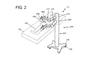
図2および図3に示される実施形態では、支持構造体230は、動かしやすいようにロック式の車輪245を有するプラットフォーム240に固定された垂直方向の柱235を備える。プラットフォーム240は下部250と、互いに対しておよび下部250に対して回転可能に設置された2つの上部260、270とを備える。支持構造体230の下部250がプラットフォーム240に固定されて手術の間ロボットシステム200を保持する。柱235の上部260、270は、それらがDで示される垂直方向に従って、すなわち支持構造体230のプラットフォーム240にほぼ直交して垂直に摺動することができるように設置されている。上部260、270が垂直方向に線形移動Dすることによって地面に対するロボットアーム210、220の高さを独立させて調節することが可能になり、これにより器具900を適切に配置することができる。
In the embodiment shown in FIGS. 2 and 3, the
簡単に記載するためにロボットシステム200の片方のアーム210の構造を以下に記載するが、該アーム210、220はそれぞれ同一のまたは技術的に等価な構成であることを理解されたい。
For simplicity, the structure of one
本発明によって記載されるシステムのロボットアーム210は、互いに蝶番により取り付けられた2つの部材300、400を備える。
The
第1部材300は支持構造体230に設置された細長い本体であり、そのため第1部材300の長手軸L1を中心として回転することができる。より具体的には、この第1部材300は上部260と一体式の延長部265に回転可能に設置されている(他方のロボットアーム220は、上部270に対応する延長部275に回転可能に設置されている)。よって第1部材300は、ロボットアーム210の上部260の延長部265に対して長手軸L1を中心として回転することができ、2本のアーム210、220は共に支持構造体230、すなわち柱235の長手軸L3を中心として独立して回転することができる。
The
ロボットアーム210の第2部材400が継手280を介してロボットアーム210の第1部材300に蝶番により取り付けられることで、それらは図3に見ることができるように軸L2を中心に回転することができる。第1部材300の長手軸L1は、第1部材300および第2部材400の継手280の軸L2にほぼ直交している。
The
ここに見ることができるように、関節を持つ第2の部材400は2本のロッド410、420によって形成されており、これは図面の実施形態では楕円形の断面を有する。しかしながら、2本のロッド410、420は他の様々な幾何学形状を有することができることを理解されたい。2本のロッド410、420が所与の距離を空けて互いに平行に配置されることで、第2部材400を第1部材300の一端に接続させる一方、アーム210の2つの部材300、400がアーム210の2つのロッド410、420の共通の端部に配置された継手280の軸L2を中心として回転する際、互いに衝突するのを避けることができる。
As can be seen here, the articulated
アーム210の2本のロッド410、420の反対側の端部500は、枢軸L4を介して外科用器具または機器900を装着するように適合されている。枢軸L4によって器具900とアーム210、220の第2部材400のロッド410、420との衝突が回避される。機械継手550が端部500に設けられ、これにより患者600にある切開部から操作するのに適切な方法で作業空間内での器具900の配置を調節することができる。この機械継手550は、外科用器具または機器900の装着に適応した2つ以上の自由度を有する継手である。図面の実施形態では、機械継手550は、例えばジンバル式継手のような3の自由度を有する継手である。これにより2つの付加的な受動自由度を採用することができるだけでなく、1軸の安定性(通常器具900を配置する軸)が実現する。したがって、器具900を、図4に示されるように穿通場所950によって規定された方向で、患者600に形成された腔(例えば、腹腔)の中に常に配置することができる。
The opposite ends 500 of the two
トロカールを手動で調節する締付け部材を設けることができる。この締付け部材は、手作業で支持構造体230に装着することができる懸垂部材である。その一端においてこの懸垂部材に固定された2つの要素が手作業でロック可能な2つの玉継手を介して支持されており、この玉継手によってジンバル式継手を介して各々のトロカールを固定することが可能になり、患者の腹部600での外科用器具または機器900を用いて行われる労力を削減することができる。
A clamping member can be provided for manually adjusting the trocar. This tightening member is a suspension member that can be manually attached to the
図4は、本発明のロボットシステム200の一実施形態の機械構造の運動学的連鎖を概略的に示している。示されるように、システム200の各アーム210、220は、5の自由度を有するD-G-G-G-G+ジンバル式の開放した運動学的連鎖であり、この構造体の2つの連続する接点において異なる要素235、300、400、900の相対運動を可能にする。
FIG. 4 schematically illustrates the kinematic chain of mechanical structure of one embodiment of the
直進継手(垂直方向に並進する動きD)とは別に、軸L1、L2、L3およびL4による4つの継手がモータ駆動され、変位Dは2本のアーム210、220によって共有される。
Apart from the straight joint (movement D that translates in the vertical direction), four joints with axes L 1, L 2, L 3 and L 4 are motor driven, and the displacement D is shared by the two
本発明を明細書に記載し、その好ましい一実施形態に関する添付の図面に示してきたが、本発明のロボットシステムには、以下の特許請求の範囲に定義される保護範囲から逸脱することなくいくつかの変更の余地がある。 Although the present invention has been described in the specification and shown in the accompanying drawings for a preferred embodiment thereof, the robot system of the present invention includes several methods without departing from the scope of protection defined in the following claims. There is room for change.
Claims (6)
Applications Claiming Priority (3)
| Application Number | Priority Date | Filing Date | Title |
|---|---|---|---|
| ESP200901313 | 2009-05-22 | ||
| ES200901313A ES2388029B1 (en) | 2009-05-22 | 2009-05-22 | ROBOTIC SYSTEM FOR LAPAROSCOPIC SURGERY. |
| PCT/ES2010/000224 WO2010133733A1 (en) | 2009-05-22 | 2010-05-20 | Robotic system for laparoscopic surgery |
Publications (3)
| Publication Number | Publication Date |
|---|---|
| JP2012527276A JP2012527276A (en) | 2012-11-08 |
| JP2012527276A5 JP2012527276A5 (en) | 2013-06-20 |
| JP5785538B2 true JP5785538B2 (en) | 2015-09-30 |
Family
ID=43125780
Family Applications (1)
| Application Number | Title | Priority Date | Filing Date |
|---|---|---|---|
| JP2012511310A Active JP5785538B2 (en) | 2009-05-22 | 2010-05-20 | Robot system for laparoscopic surgery |
Country Status (16)
| Country | Link |
|---|---|
| US (1) | US9119653B2 (en) |
| EP (1) | EP2433585B1 (en) |
| JP (1) | JP5785538B2 (en) |
| KR (1) | KR101665744B1 (en) |
| CN (1) | CN102458295B (en) |
| AU (1) | AU2010251107B2 (en) |
| BR (1) | BRPI1011053B8 (en) |
| CA (1) | CA2762780C (en) |
| ES (2) | ES2388029B1 (en) |
| IL (1) | IL216470A0 (en) |
| MX (1) | MX336487B (en) |
| PL (1) | PL2433585T3 (en) |
| RU (1) | RU2531469C2 (en) |
| SG (1) | SG176183A1 (en) |
| WO (1) | WO2010133733A1 (en) |
| ZA (1) | ZA201109443B (en) |
Families Citing this family (195)
| Publication number | Priority date | Publication date | Assignee | Title |
|---|---|---|---|---|
| US9272416B2 (en) | 1999-09-17 | 2016-03-01 | Intuitive Surgical Operations, Inc. | Phantom degrees of freedom for manipulating the movement of mechanical bodies |
| US8219178B2 (en) | 2007-02-16 | 2012-07-10 | Catholic Healthcare West | Method and system for performing invasive medical procedures using a surgical robot |
| US10893912B2 (en) | 2006-02-16 | 2021-01-19 | Globus Medical Inc. | Surgical tool systems and methods |
| US10653497B2 (en) | 2006-02-16 | 2020-05-19 | Globus Medical, Inc. | Surgical tool systems and methods |
| US10357184B2 (en) | 2012-06-21 | 2019-07-23 | Globus Medical, Inc. | Surgical tool systems and method |
| US9254123B2 (en) | 2009-04-29 | 2016-02-09 | Hansen Medical, Inc. | Flexible and steerable elongate instruments with shape control and support elements |
| US8672837B2 (en) | 2010-06-24 | 2014-03-18 | Hansen Medical, Inc. | Methods and devices for controlling a shapeable medical device |
| US20120071752A1 (en) | 2010-09-17 | 2012-03-22 | Sewell Christopher M | User interface and method for operating a robotic medical system |
| WO2012131660A1 (en) | 2011-04-01 | 2012-10-04 | Ecole Polytechnique Federale De Lausanne (Epfl) | Robotic system for spinal and other surgeries |
| US9138166B2 (en) | 2011-07-29 | 2015-09-22 | Hansen Medical, Inc. | Apparatus and methods for fiber integration and registration |
| US20130317519A1 (en) | 2012-05-25 | 2013-11-28 | Hansen Medical, Inc. | Low friction instrument driver interface for robotic systems |
| CN102689301B (en) * | 2012-05-25 | 2015-02-11 | 北京卫星制造厂 | Guide rail swinging arm type position mechanism |
| US11298196B2 (en) | 2012-06-21 | 2022-04-12 | Globus Medical Inc. | Surgical robotic automation with tracking markers and controlled tool advancement |
| US11317971B2 (en) | 2012-06-21 | 2022-05-03 | Globus Medical, Inc. | Systems and methods related to robotic guidance in surgery |
| US10231791B2 (en) | 2012-06-21 | 2019-03-19 | Globus Medical, Inc. | Infrared signal based position recognition system for use with a robot-assisted surgery |
| US11607149B2 (en) | 2012-06-21 | 2023-03-21 | Globus Medical Inc. | Surgical tool systems and method |
| US11253327B2 (en) | 2012-06-21 | 2022-02-22 | Globus Medical, Inc. | Systems and methods for automatically changing an end-effector on a surgical robot |
| US10136954B2 (en) | 2012-06-21 | 2018-11-27 | Globus Medical, Inc. | Surgical tool systems and method |
| US11399900B2 (en) | 2012-06-21 | 2022-08-02 | Globus Medical, Inc. | Robotic systems providing co-registration using natural fiducials and related methods |
| US11395706B2 (en) | 2012-06-21 | 2022-07-26 | Globus Medical Inc. | Surgical robot platform |
| US11864745B2 (en) | 2012-06-21 | 2024-01-09 | Globus Medical, Inc. | Surgical robotic system with retractor |
| US11857149B2 (en) | 2012-06-21 | 2024-01-02 | Globus Medical, Inc. | Surgical robotic systems with target trajectory deviation monitoring and related methods |
| US10350013B2 (en) | 2012-06-21 | 2019-07-16 | Globus Medical, Inc. | Surgical tool systems and methods |
| US10624710B2 (en) | 2012-06-21 | 2020-04-21 | Globus Medical, Inc. | System and method for measuring depth of instrumentation |
| US11116576B2 (en) | 2012-06-21 | 2021-09-14 | Globus Medical Inc. | Dynamic reference arrays and methods of use |
| US11045267B2 (en) | 2012-06-21 | 2021-06-29 | Globus Medical, Inc. | Surgical robotic automation with tracking markers |
| US11857266B2 (en) | 2012-06-21 | 2024-01-02 | Globus Medical, Inc. | System for a surveillance marker in robotic-assisted surgery |
| US11793570B2 (en) | 2012-06-21 | 2023-10-24 | Globus Medical Inc. | Surgical robotic automation with tracking markers |
| WO2013192598A1 (en) | 2012-06-21 | 2013-12-27 | Excelsius Surgical, L.L.C. | Surgical robot platform |
| US11864839B2 (en) | 2012-06-21 | 2024-01-09 | Globus Medical Inc. | Methods of adjusting a virtual implant and related surgical navigation systems |
| US10758315B2 (en) | 2012-06-21 | 2020-09-01 | Globus Medical Inc. | Method and system for improving 2D-3D registration convergence |
| JP6255403B2 (en) | 2012-08-15 | 2017-12-27 | インテュイティブ サージカル オペレーションズ, インコーポレイテッド | Phantom degrees of freedom in joint estimation and control |
| EP2884936A4 (en) | 2012-08-15 | 2016-04-27 | Intuitive Surgical Operations | Phantom degrees of freedom for manipulating the movement of surgical systems |
| WO2014043697A2 (en) | 2012-09-17 | 2014-03-20 | Omniguide, Inc. | Devices and methods for laser surgery |
| US10149720B2 (en) | 2013-03-08 | 2018-12-11 | Auris Health, Inc. | Method, apparatus, and a system for facilitating bending of an instrument in a surgical or medical robotic environment |
| US9057600B2 (en) | 2013-03-13 | 2015-06-16 | Hansen Medical, Inc. | Reducing incremental measurement sensor error |
| US9326822B2 (en) | 2013-03-14 | 2016-05-03 | Hansen Medical, Inc. | Active drives for robotic catheter manipulators |
| US11213363B2 (en) | 2013-03-14 | 2022-01-04 | Auris Health, Inc. | Catheter tension sensing |
| US20140277334A1 (en) | 2013-03-14 | 2014-09-18 | Hansen Medical, Inc. | Active drives for robotic catheter manipulators |
| US9173713B2 (en) | 2013-03-14 | 2015-11-03 | Hansen Medical, Inc. | Torque-based catheter articulation |
| US20140276647A1 (en) | 2013-03-15 | 2014-09-18 | Hansen Medical, Inc. | Vascular remote catheter manipulator |
| US20140276936A1 (en) | 2013-03-15 | 2014-09-18 | Hansen Medical, Inc. | Active drive mechanism for simultaneous rotation and translation |
| US9014851B2 (en) | 2013-03-15 | 2015-04-21 | Hansen Medical, Inc. | Systems and methods for tracking robotically controlled medical instruments |
| US10376672B2 (en) | 2013-03-15 | 2019-08-13 | Auris Health, Inc. | Catheter insertion system and method of fabrication |
| US9408669B2 (en) | 2013-03-15 | 2016-08-09 | Hansen Medical, Inc. | Active drive mechanism with finite range of motion |
| US9629595B2 (en) | 2013-03-15 | 2017-04-25 | Hansen Medical, Inc. | Systems and methods for localizing, tracking and/or controlling medical instruments |
| US9271663B2 (en) | 2013-03-15 | 2016-03-01 | Hansen Medical, Inc. | Flexible instrument localization from both remote and elongation sensors |
| US11020016B2 (en) | 2013-05-30 | 2021-06-01 | Auris Health, Inc. | System and method for displaying anatomy and devices on a movable display |
| CN103286787B (en) * | 2013-06-28 | 2016-06-01 | 招商局重庆交通科研设计院有限公司 | Full-automatic road and tunnel device for cleaning lamp |
| US9283048B2 (en) | 2013-10-04 | 2016-03-15 | KB Medical SA | Apparatus and systems for precise guidance of surgical tools |
| WO2015107099A1 (en) | 2014-01-15 | 2015-07-23 | KB Medical SA | Notched apparatus for guidance of an insertable instrument along an axis during spinal surgery |
| EP3104803B1 (en) | 2014-02-11 | 2021-09-15 | KB Medical SA | Sterile handle for controlling a robotic surgical system from a sterile field |
| GB2523831B (en) | 2014-03-07 | 2020-09-30 | Cmr Surgical Ltd | Surgical arm |
| EP3243476B1 (en) | 2014-03-24 | 2019-11-06 | Auris Health, Inc. | Systems and devices for catheter driving instinctiveness |
| US10046140B2 (en) | 2014-04-21 | 2018-08-14 | Hansen Medical, Inc. | Devices, systems, and methods for controlling active drive systems |
| WO2015162256A1 (en) | 2014-04-24 | 2015-10-29 | KB Medical SA | Surgical instrument holder for use with a robotic surgical system |
| US10569052B2 (en) | 2014-05-15 | 2020-02-25 | Auris Health, Inc. | Anti-buckling mechanisms for catheters |
| US9561083B2 (en) | 2014-07-01 | 2017-02-07 | Auris Surgical Robotics, Inc. | Articulating flexible endoscopic tool with roll capabilities |
| US10792464B2 (en) | 2014-07-01 | 2020-10-06 | Auris Health, Inc. | Tool and method for using surgical endoscope with spiral lumens |
| US9744335B2 (en) | 2014-07-01 | 2017-08-29 | Auris Surgical Robotics, Inc. | Apparatuses and methods for monitoring tendons of steerable catheters |
| EP3169252A1 (en) | 2014-07-14 | 2017-05-24 | KB Medical SA | Anti-skid surgical instrument for use in preparing holes in bone tissue |
| CN104149081B (en) * | 2014-07-28 | 2017-01-18 | 广东工业大学 | Modular handheld double-operating-end master robot |
| CN105455899A (en) * | 2014-08-08 | 2016-04-06 | 深圳市贝斯达医疗股份有限公司 | Non-magnetic mechanical arm for magnetic resonance surgical navigation system |
| CN107427327A (en) | 2014-09-30 | 2017-12-01 | 奥瑞斯外科手术机器人公司 | Configurable robotic surgical system with virtual track and soft endoscope |
| US10314463B2 (en) | 2014-10-24 | 2019-06-11 | Auris Health, Inc. | Automated endoscope calibration |
| US10013808B2 (en) | 2015-02-03 | 2018-07-03 | Globus Medical, Inc. | Surgeon head-mounted display apparatuses |
| EP3258872B1 (en) | 2015-02-18 | 2023-04-26 | KB Medical SA | Systems for performing minimally invasive spinal surgery with a robotic surgical system using a percutaneous technique |
| US11819636B2 (en) | 2015-03-30 | 2023-11-21 | Auris Health, Inc. | Endoscope pull wire electrical circuit |
| WO2016164824A1 (en) * | 2015-04-09 | 2016-10-13 | Auris Surgical Robotics, Inc. | Surgical system with configurable rail-mounted mechanical arms |
| GB2538497B (en) | 2015-05-14 | 2020-10-28 | Cmr Surgical Ltd | Torque sensing in a surgical robotic wrist |
| WO2016187054A1 (en) * | 2015-05-15 | 2016-11-24 | Auris Surgical Robotics, Inc. | Surgical robotics system |
| CN104983468B (en) * | 2015-07-24 | 2017-11-14 | 绵阳美科电子设备有限责任公司 | A kind of hysteroscope manipulator mechanical hand arm and its operating method |
| US10646298B2 (en) | 2015-07-31 | 2020-05-12 | Globus Medical, Inc. | Robot arm and methods of use |
| US10058394B2 (en) | 2015-07-31 | 2018-08-28 | Globus Medical, Inc. | Robot arm and methods of use |
| US10080615B2 (en) | 2015-08-12 | 2018-09-25 | Globus Medical, Inc. | Devices and methods for temporary mounting of parts to bone |
| EP3344179B1 (en) | 2015-08-31 | 2021-06-30 | KB Medical SA | Robotic surgical systems |
| EP3346899B1 (en) | 2015-09-09 | 2022-11-09 | Auris Health, Inc. | Instrument device manipulator for a surgical robotics system |
| US10034716B2 (en) | 2015-09-14 | 2018-07-31 | Globus Medical, Inc. | Surgical robotic systems and methods thereof |
| JP6824967B2 (en) | 2015-09-18 | 2021-02-03 | オーリス ヘルス インコーポレイテッド | Tubular net navigation |
| US9771092B2 (en) | 2015-10-13 | 2017-09-26 | Globus Medical, Inc. | Stabilizer wheel assembly and methods of use |
| US9949749B2 (en) | 2015-10-30 | 2018-04-24 | Auris Surgical Robotics, Inc. | Object capture with a basket |
| US10639108B2 (en) | 2015-10-30 | 2020-05-05 | Auris Health, Inc. | Process for percutaneous operations |
| US9955986B2 (en) | 2015-10-30 | 2018-05-01 | Auris Surgical Robotics, Inc. | Basket apparatus |
| US10143526B2 (en) | 2015-11-30 | 2018-12-04 | Auris Health, Inc. | Robot-assisted driving systems and methods |
| US11058378B2 (en) | 2016-02-03 | 2021-07-13 | Globus Medical, Inc. | Portable medical imaging system |
| US11883217B2 (en) | 2016-02-03 | 2024-01-30 | Globus Medical, Inc. | Portable medical imaging system and method |
| US10842453B2 (en) | 2016-02-03 | 2020-11-24 | Globus Medical, Inc. | Portable medical imaging system |
| US10117632B2 (en) | 2016-02-03 | 2018-11-06 | Globus Medical, Inc. | Portable medical imaging system with beam scanning collimator |
| US10448910B2 (en) | 2016-02-03 | 2019-10-22 | Globus Medical, Inc. | Portable medical imaging system |
| US10866119B2 (en) | 2016-03-14 | 2020-12-15 | Globus Medical, Inc. | Metal detector for detecting insertion of a surgical device into a hollow tube |
| US10454347B2 (en) | 2016-04-29 | 2019-10-22 | Auris Health, Inc. | Compact height torque sensing articulation axis assembly |
| US10463439B2 (en) | 2016-08-26 | 2019-11-05 | Auris Health, Inc. | Steerable catheter with shaft load distributions |
| US11241559B2 (en) | 2016-08-29 | 2022-02-08 | Auris Health, Inc. | Active drive for guidewire manipulation |
| KR20230096148A (en) | 2016-08-31 | 2023-06-29 | 아우리스 헬스, 인코포레이티드 | Length conservative surgical instrument |
| CN108366831B (en) | 2016-09-16 | 2022-03-18 | 威博外科公司 | Operating table adapter for mounting a robot arm to an operating table |
| US11389360B2 (en) * | 2016-09-16 | 2022-07-19 | Verb Surgical Inc. | Linkage mechanisms for mounting robotic arms to a surgical table |
| US11166770B2 (en) * | 2016-09-19 | 2021-11-09 | Intuitive Surgical Operations, Inc. | Base positioning system for a controllable arm and related methods |
| WO2018059838A1 (en) * | 2016-09-27 | 2018-04-05 | Brainlab Ag | Efficient positioning of a mechatronic arm |
| CN106236276B (en) * | 2016-09-28 | 2019-09-17 | 微创(上海)医疗机器人有限公司 | Surgical robot system |
| US9931025B1 (en) | 2016-09-30 | 2018-04-03 | Auris Surgical Robotics, Inc. | Automated calibration of endoscopes with pull wires |
| US10244926B2 (en) | 2016-12-28 | 2019-04-02 | Auris Health, Inc. | Detecting endolumenal buckling of flexible instruments |
| EP3360502A3 (en) | 2017-01-18 | 2018-10-31 | KB Medical SA | Robotic navigation of robotic surgical systems |
| IT201700025766A1 (en) * | 2017-03-08 | 2018-09-08 | Epistolio S R L | PAINTING ROBOT |
| US11071594B2 (en) | 2017-03-16 | 2021-07-27 | KB Medical SA | Robotic navigation of robotic surgical systems |
| KR102558061B1 (en) | 2017-03-31 | 2023-07-25 | 아우리스 헬스, 인코포레이티드 | A robotic system for navigating the intraluminal tissue network that compensates for physiological noise |
| KR20240035632A (en) | 2017-05-12 | 2024-03-15 | 아우리스 헬스, 인코포레이티드 | Biopsy apparatus and system |
| AU2018270785B2 (en) | 2017-05-17 | 2023-11-23 | Auris Health, Inc. | Exchangeable working channel |
| US10022192B1 (en) | 2017-06-23 | 2018-07-17 | Auris Health, Inc. | Automatically-initialized robotic systems for navigation of luminal networks |
| US11026758B2 (en) | 2017-06-28 | 2021-06-08 | Auris Health, Inc. | Medical robotics systems implementing axis constraints during actuation of one or more motorized joints |
| EP3645100A4 (en) | 2017-06-28 | 2021-03-17 | Auris Health, Inc. | Instrument insertion compensation |
| US10426559B2 (en) | 2017-06-30 | 2019-10-01 | Auris Health, Inc. | Systems and methods for medical instrument compression compensation |
| US10675094B2 (en) | 2017-07-21 | 2020-06-09 | Globus Medical Inc. | Robot surgical platform |
| US10145747B1 (en) | 2017-10-10 | 2018-12-04 | Auris Health, Inc. | Detection of undesirable forces on a surgical robotic arm |
| US11058493B2 (en) | 2017-10-13 | 2021-07-13 | Auris Health, Inc. | Robotic system configured for navigation path tracing |
| US10555778B2 (en) | 2017-10-13 | 2020-02-11 | Auris Health, Inc. | Image-based branch detection and mapping for navigation |
| US11794338B2 (en) | 2017-11-09 | 2023-10-24 | Globus Medical Inc. | Robotic rod benders and related mechanical and motor housings |
| US11382666B2 (en) | 2017-11-09 | 2022-07-12 | Globus Medical Inc. | Methods providing bend plans for surgical rods and related controllers and computer program products |
| EP3492032B1 (en) | 2017-11-09 | 2023-01-04 | Globus Medical, Inc. | Surgical robotic systems for bending surgical rods |
| US11134862B2 (en) | 2017-11-10 | 2021-10-05 | Globus Medical, Inc. | Methods of selecting surgical implants and related devices |
| KR102645922B1 (en) | 2017-12-06 | 2024-03-13 | 아우리스 헬스, 인코포레이티드 | Systems and methods for correcting non-directed instrument rolls |
| EP3723655A4 (en) | 2017-12-11 | 2021-09-08 | Auris Health, Inc. | Systems and methods for instrument based insertion architectures |
| KR20200100613A (en) | 2017-12-14 | 2020-08-26 | 아우리스 헬스, 인코포레이티드 | System and method for estimating instrument position |
| KR20200101334A (en) | 2017-12-18 | 2020-08-27 | 아우리스 헬스, 인코포레이티드 | Method and system for tracking and navigation of instruments in the luminal network |
| CN108056823B (en) * | 2017-12-27 | 2020-09-22 | 微创(上海)医疗机器人有限公司 | Surgical robot terminal |
| CN108245253A (en) * | 2018-01-09 | 2018-07-06 | 河南工程学院 | A kind of medical robot special-purpose machinery arm |
| US10888386B2 (en) | 2018-01-17 | 2021-01-12 | Auris Health, Inc. | Surgical robotics systems with improved robotic arms |
| CN111885980B (en) | 2018-01-17 | 2023-03-28 | 奥瑞斯健康公司 | Surgical platform with adjustable arm support |
| US20190254753A1 (en) | 2018-02-19 | 2019-08-22 | Globus Medical, Inc. | Augmented reality navigation systems for use with robotic surgical systems and methods of their use |
| EP3773131A4 (en) | 2018-03-28 | 2021-12-15 | Auris Health, Inc. | Systems and methods for registration of location sensors |
| JP7225259B2 (en) | 2018-03-28 | 2023-02-20 | オーリス ヘルス インコーポレイテッド | Systems and methods for indicating probable location of instruments |
| CN117017505A (en) | 2018-03-28 | 2023-11-10 | 奥瑞斯健康公司 | Composite instrument and robotic system |
| US10573023B2 (en) | 2018-04-09 | 2020-02-25 | Globus Medical, Inc. | Predictive visualization of medical imaging scanner component movement |
| CN110831486B (en) | 2018-05-30 | 2022-04-05 | 奥瑞斯健康公司 | System and method for location sensor based branch prediction |
| KR20210018858A (en) | 2018-05-31 | 2021-02-18 | 아우리스 헬스, 인코포레이티드 | Route-based navigation of coronary networks |
| WO2019232236A1 (en) | 2018-05-31 | 2019-12-05 | Auris Health, Inc. | Image-based airway analysis and mapping |
| CN112236083A (en) | 2018-05-31 | 2021-01-15 | 奥瑞斯健康公司 | Robotic system and method for navigating a luminal network detecting physiological noise |
| KR20230169481A (en) | 2018-08-07 | 2023-12-15 | 아우리스 헬스, 인코포레이티드 | Combining strain-based shape sensing with catheter control |
| EP3813634A4 (en) | 2018-09-26 | 2022-04-06 | Auris Health, Inc. | Articulating medical instruments |
| CN112752534A (en) | 2018-09-28 | 2021-05-04 | 奥瑞斯健康公司 | Apparatus, system and method for manual and robotic driving of medical instruments |
| AU2019347767A1 (en) | 2018-09-28 | 2021-04-08 | Auris Health, Inc. | Systems and methods for docking medical instruments |
| US11337742B2 (en) | 2018-11-05 | 2022-05-24 | Globus Medical Inc | Compliant orthopedic driver |
| US11278360B2 (en) | 2018-11-16 | 2022-03-22 | Globus Medical, Inc. | End-effectors for surgical robotic systems having sealed optical components |
| US11744655B2 (en) | 2018-12-04 | 2023-09-05 | Globus Medical, Inc. | Drill guide fixtures, cranial insertion fixtures, and related methods and robotic systems |
| US11602402B2 (en) | 2018-12-04 | 2023-03-14 | Globus Medical, Inc. | Drill guide fixtures, cranial insertion fixtures, and related methods and robotic systems |
| US11918313B2 (en) | 2019-03-15 | 2024-03-05 | Globus Medical Inc. | Active end effectors for surgical robots |
| US11571265B2 (en) | 2019-03-22 | 2023-02-07 | Globus Medical Inc. | System for neuronavigation registration and robotic trajectory guidance, robotic surgery, and related methods and devices |
| US11806084B2 (en) | 2019-03-22 | 2023-11-07 | Globus Medical, Inc. | System for neuronavigation registration and robotic trajectory guidance, and related methods and devices |
| US20200297357A1 (en) | 2019-03-22 | 2020-09-24 | Globus Medical, Inc. | System for neuronavigation registration and robotic trajectory guidance, robotic surgery, and related methods and devices |
| US11419616B2 (en) | 2019-03-22 | 2022-08-23 | Globus Medical, Inc. | System for neuronavigation registration and robotic trajectory guidance, robotic surgery, and related methods and devices |
| US11382549B2 (en) | 2019-03-22 | 2022-07-12 | Globus Medical, Inc. | System for neuronavigation registration and robotic trajectory guidance, and related methods and devices |
| WO2020197671A1 (en) | 2019-03-22 | 2020-10-01 | Auris Health, Inc. | Systems and methods for aligning inputs on medical instruments |
| US11317978B2 (en) | 2019-03-22 | 2022-05-03 | Globus Medical, Inc. | System for neuronavigation registration and robotic trajectory guidance, robotic surgery, and related methods and devices |
| US11617627B2 (en) | 2019-03-29 | 2023-04-04 | Auris Health, Inc. | Systems and methods for optical strain sensing in medical instruments |
| US11045179B2 (en) | 2019-05-20 | 2021-06-29 | Global Medical Inc | Robot-mounted retractor system |
| US11628023B2 (en) | 2019-07-10 | 2023-04-18 | Globus Medical, Inc. | Robotic navigational system for interbody implants |
| JP7430773B2 (en) * | 2019-07-15 | 2024-02-13 | エーエムディーティー ホールディングス インコーポレイテッド | Strut assembly and external fixation system |
| CN114222651A (en) * | 2019-07-26 | 2022-03-22 | 汉阳大学校产学协力团 | Magnetic driving system and micro-robot control method using the same |
| US11896330B2 (en) | 2019-08-15 | 2024-02-13 | Auris Health, Inc. | Robotic medical system having multiple medical instruments |
| JP2022544554A (en) | 2019-08-15 | 2022-10-19 | オーリス ヘルス インコーポレイテッド | Medical device with multiple bends |
| EP4021329A4 (en) | 2019-08-30 | 2023-05-03 | Auris Health, Inc. | Instrument image reliability systems and methods |
| CN114340542B (en) | 2019-08-30 | 2023-07-21 | 奥瑞斯健康公司 | Systems and methods for weight-based registration of position sensors |
| US11571171B2 (en) | 2019-09-24 | 2023-02-07 | Globus Medical, Inc. | Compound curve cable chain |
| US11426178B2 (en) | 2019-09-27 | 2022-08-30 | Globus Medical Inc. | Systems and methods for navigating a pin guide driver |
| US11890066B2 (en) | 2019-09-30 | 2024-02-06 | Globus Medical, Inc | Surgical robot with passive end effector |
| US11864857B2 (en) | 2019-09-27 | 2024-01-09 | Globus Medical, Inc. | Surgical robot with passive end effector |
| WO2021064536A1 (en) | 2019-09-30 | 2021-04-08 | Auris Health, Inc. | Medical instrument with capstan |
| US11510684B2 (en) | 2019-10-14 | 2022-11-29 | Globus Medical, Inc. | Rotary motion passive end effector for surgical robots in orthopedic surgeries |
| WO2021137104A1 (en) | 2019-12-31 | 2021-07-08 | Auris Health, Inc. | Dynamic pulley system |
| WO2021137071A1 (en) | 2019-12-31 | 2021-07-08 | Auris Health, Inc. | Advanced basket drive mode |
| JP2023508719A (en) | 2019-12-31 | 2023-03-03 | オーリス ヘルス インコーポレイテッド | Alignment interface for percutaneous access |
| CN114901194A (en) | 2019-12-31 | 2022-08-12 | 奥瑞斯健康公司 | Anatomical feature identification and targeting |
| US11660147B2 (en) | 2019-12-31 | 2023-05-30 | Auris Health, Inc. | Alignment techniques for percutaneous access |
| US11382699B2 (en) | 2020-02-10 | 2022-07-12 | Globus Medical Inc. | Extended reality visualization of optical tool tracking volume for computer assisted navigation in surgery |
| US11207150B2 (en) | 2020-02-19 | 2021-12-28 | Globus Medical, Inc. | Displaying a virtual model of a planned instrument attachment to ensure correct selection of physical instrument attachment |
| US11253216B2 (en) | 2020-04-28 | 2022-02-22 | Globus Medical Inc. | Fixtures for fluoroscopic imaging systems and related navigation systems and methods |
| US11510750B2 (en) | 2020-05-08 | 2022-11-29 | Globus Medical, Inc. | Leveraging two-dimensional digital imaging and communication in medicine imagery in three-dimensional extended reality applications |
| US11153555B1 (en) | 2020-05-08 | 2021-10-19 | Globus Medical Inc. | Extended reality headset camera system for computer assisted navigation in surgery |
| US11382700B2 (en) | 2020-05-08 | 2022-07-12 | Globus Medical Inc. | Extended reality headset tool tracking and control |
| US11317973B2 (en) | 2020-06-09 | 2022-05-03 | Globus Medical, Inc. | Camera tracking bar for computer assisted navigation during surgery |
| US11382713B2 (en) | 2020-06-16 | 2022-07-12 | Globus Medical, Inc. | Navigated surgical system with eye to XR headset display calibration |
| KR20230002994A (en) * | 2020-06-30 | 2023-01-05 | 베이징 서제리 테크놀로지 씨오., 엘티디. | surgical robot system |
| US11877807B2 (en) | 2020-07-10 | 2024-01-23 | Globus Medical, Inc | Instruments for navigated orthopedic surgeries |
| US11793588B2 (en) | 2020-07-23 | 2023-10-24 | Globus Medical, Inc. | Sterile draping of robotic arms |
| US20230285044A1 (en) * | 2020-08-07 | 2023-09-14 | Alma Mater Studiorum - Universita 'di Bologna | Laparoscopic surgical instrument |
| US11737831B2 (en) | 2020-09-02 | 2023-08-29 | Globus Medical Inc. | Surgical object tracking template generation for computer assisted navigation during surgical procedure |
| US11523785B2 (en) | 2020-09-24 | 2022-12-13 | Globus Medical, Inc. | Increased cone beam computed tomography volume length without requiring stitching or longitudinal C-arm movement |
| US11911112B2 (en) | 2020-10-27 | 2024-02-27 | Globus Medical, Inc. | Robotic navigational system |
| US11941814B2 (en) | 2020-11-04 | 2024-03-26 | Globus Medical Inc. | Auto segmentation using 2-D images taken during 3-D imaging spin |
| CN112388668B (en) * | 2020-11-06 | 2021-11-23 | 皖南医学院 | Simulation mechanical arm and control system thereof |
| US11717350B2 (en) | 2020-11-24 | 2023-08-08 | Globus Medical Inc. | Methods for robotic assistance and navigation in spinal surgery and related systems |
| US11857273B2 (en) | 2021-07-06 | 2024-01-02 | Globus Medical, Inc. | Ultrasonic robotic surgical navigation |
| US11439444B1 (en) | 2021-07-22 | 2022-09-13 | Globus Medical, Inc. | Screw tower and rod reduction tool |
| US11911115B2 (en) | 2021-12-20 | 2024-02-27 | Globus Medical Inc. | Flat panel registration fixture and method of using same |
| WO2023211894A1 (en) * | 2022-04-25 | 2023-11-02 | University Of Cincinnati | Bed-mounted surgical tool organization system |
| CN115431251B (en) * | 2022-09-16 | 2023-03-21 | 哈尔滨工业大学 | Humanoid robot upper limb |
Family Cites Families (31)
| Publication number | Priority date | Publication date | Assignee | Title |
|---|---|---|---|---|
| US4068156A (en) | 1977-03-01 | 1978-01-10 | Martin Marietta Corporation | Rate control system for manipulator arms |
| JPH0710510B2 (en) | 1986-06-03 | 1995-02-08 | フアナツク株式会社 | Industrial robot arm structure |
| US4921393A (en) | 1988-03-09 | 1990-05-01 | Sri International | Articulatable structure with adjustable end-point compliance |
| JPH0825151B2 (en) * | 1988-09-16 | 1996-03-13 | 東京応化工業株式会社 | Handling unit |
| CA2078295C (en) * | 1991-08-05 | 1995-11-21 | John Michael Putman | Endoscope stabilizer |
| JPH05109866A (en) * | 1991-10-16 | 1993-04-30 | Nec Corp | Wafer transfer robot |
| US5762458A (en) * | 1996-02-20 | 1998-06-09 | Computer Motion, Inc. | Method and apparatus for performing minimally invasive cardiac procedures |
| JP3476878B2 (en) * | 1993-11-15 | 2003-12-10 | オリンパス株式会社 | Surgical manipulator |
| US6120433A (en) | 1994-09-01 | 2000-09-19 | Olympus Optical Co., Ltd. | Surgical manipulator system |
| US5855583A (en) * | 1996-02-20 | 1999-01-05 | Computer Motion, Inc. | Method and apparatus for performing minimally invasive cardiac procedures |
| US6436107B1 (en) * | 1996-02-20 | 2002-08-20 | Computer Motion, Inc. | Method and apparatus for performing minimally invasive surgical procedures |
| US5811951A (en) | 1996-10-14 | 1998-09-22 | Regents Of The University Of California | High precision redundant robotic manipulator |
| AU5391999A (en) * | 1998-08-04 | 2000-02-28 | Intuitive Surgical, Inc. | Manipulator positioning linkage for robotic surgery |
| WO2000030557A1 (en) * | 1998-11-23 | 2000-06-02 | Microdexterity Systems, Inc. | Surgical manipulator |
| US6485250B2 (en) * | 1998-12-30 | 2002-11-26 | Brooks Automation Inc. | Substrate transport apparatus with multiple arms on a common axis of rotation |
| US6424885B1 (en) * | 1999-04-07 | 2002-07-23 | Intuitive Surgical, Inc. | Camera referenced control in a minimally invasive surgical apparatus |
| US6969385B2 (en) | 2002-05-01 | 2005-11-29 | Manuel Ricardo Moreyra | Wrist with decoupled motion transmission |
| US7155316B2 (en) * | 2002-08-13 | 2006-12-26 | Microbotics Corporation | Microsurgical robot system |
| JP2004288719A (en) * | 2003-03-19 | 2004-10-14 | Tokyo Electron Ltd | Substrate carrying system and substrate processing system |
| KR200319262Y1 (en) * | 2003-02-08 | 2003-07-07 | 구영만 | Cosmetics having a lighting apparatus |
| DE10324844A1 (en) | 2003-04-01 | 2004-12-23 | Tuebingen Scientific Surgical Products Gmbh | Surgical instrument with instrument handle and zero point adjustment |
| CN100336640C (en) * | 2005-02-01 | 2007-09-12 | 天津大学 | Secondary manipulator of surgery operation robot |
| CA2826925C (en) * | 2005-02-22 | 2017-01-24 | Mako Surgical Corp. | Haptic guidance system and method |
| EP1815949A1 (en) * | 2006-02-03 | 2007-08-08 | The European Atomic Energy Community (EURATOM), represented by the European Commission | Medical robotic system with manipulator arm of the cylindrical coordinate type |
| CN100463661C (en) | 2006-12-04 | 2009-02-25 | 天津大学 | Passive manual locking bracket having gravity compensation function |
| EP2170204A2 (en) * | 2007-07-02 | 2010-04-07 | M.S.T. Medical Surgery Technologies Ltd | System for positioning endoscope and surgical instruments |
| KR101075363B1 (en) | 2008-10-31 | 2011-10-19 | 정창욱 | Surgical Robot System Having Tool for Minimally Invasive Surgery |
| CN100581495C (en) * | 2008-10-31 | 2010-01-20 | 天津大学 | Lens holding robot system for microinjury surgery |
| CN101411631B (en) * | 2008-11-21 | 2011-05-11 | 南开大学 | Controlling mechanism of five-freedom degree vertebral column minimally invasive robot |
| JP2011238748A (en) * | 2010-05-10 | 2011-11-24 | Creative Sensor Inc | Ultraviolet light emitting diode solidification device |
| KR101103327B1 (en) * | 2011-09-29 | 2012-01-11 | 주식회사 쥬디산업 | Portable curing apparatus for nails |
-
2009
- 2009-05-22 ES ES200901313A patent/ES2388029B1/en active Active
-
2010
- 2010-05-20 SG SG2011085768A patent/SG176183A1/en unknown
- 2010-05-20 KR KR1020117030571A patent/KR101665744B1/en active IP Right Grant
- 2010-05-20 PL PL10777402T patent/PL2433585T3/en unknown
- 2010-05-20 US US13/321,802 patent/US9119653B2/en active Active
- 2010-05-20 CA CA2762780A patent/CA2762780C/en active Active
- 2010-05-20 RU RU2011152395/14A patent/RU2531469C2/en active
- 2010-05-20 CN CN201080027584.1A patent/CN102458295B/en active Active
- 2010-05-20 BR BRPI1011053A patent/BRPI1011053B8/en active IP Right Grant
- 2010-05-20 MX MX2011012295A patent/MX336487B/en unknown
- 2010-05-20 ES ES10777402.8T patent/ES2655029T3/en active Active
- 2010-05-20 EP EP10777402.8A patent/EP2433585B1/en active Active
- 2010-05-20 AU AU2010251107A patent/AU2010251107B2/en active Active
- 2010-05-20 JP JP2012511310A patent/JP5785538B2/en active Active
- 2010-05-20 WO PCT/ES2010/000224 patent/WO2010133733A1/en active Application Filing
-
2011
- 2011-11-20 IL IL216470A patent/IL216470A0/en active IP Right Grant
- 2011-12-21 ZA ZA2011/09443A patent/ZA201109443B/en unknown
Also Published As
| Publication number | Publication date |
|---|---|
| PL2433585T3 (en) | 2018-02-28 |
| AU2010251107A1 (en) | 2012-01-19 |
| CA2762780C (en) | 2017-09-26 |
| BRPI1011053A2 (en) | 2016-03-15 |
| ES2388029A1 (en) | 2012-10-05 |
| CN102458295B (en) | 2014-06-25 |
| RU2531469C2 (en) | 2014-10-20 |
| KR101665744B1 (en) | 2016-10-12 |
| BRPI1011053B1 (en) | 2020-09-29 |
| EP2433585A1 (en) | 2012-03-28 |
| US9119653B2 (en) | 2015-09-01 |
| KR20120068768A (en) | 2012-06-27 |
| ZA201109443B (en) | 2013-02-27 |
| IL216470A0 (en) | 2012-01-31 |
| ES2388029B1 (en) | 2013-08-13 |
| BRPI1011053B8 (en) | 2021-06-22 |
| MX2011012295A (en) | 2011-12-16 |
| CA2762780A1 (en) | 2010-11-25 |
| EP2433585A4 (en) | 2015-11-04 |
| MX336487B (en) | 2016-01-21 |
| RU2011152395A (en) | 2013-06-27 |
| US20120136372A1 (en) | 2012-05-31 |
| CN102458295A (en) | 2012-05-16 |
| EP2433585B1 (en) | 2017-09-13 |
| JP2012527276A (en) | 2012-11-08 |
| AU2010251107B2 (en) | 2015-06-25 |
| WO2010133733A1 (en) | 2010-11-25 |
| SG176183A1 (en) | 2011-12-29 |
| ES2655029T3 (en) | 2018-02-16 |
Similar Documents
| Publication | Publication Date | Title |
|---|---|---|
| JP5785538B2 (en) | Robot system for laparoscopic surgery | |
| JP7434246B2 (en) | System and method for positioning a manipulator arm by clutching in zero orthogonal space simultaneously with zero space movement | |
| JP6640947B2 (en) | Aspects of surgical instrument manipulator | |
| US10219871B2 (en) | Robotic system for tele-surgery | |
| KR102530353B1 (en) | Redundant axis and degree of freedom for hardware-constrained remote center robotic manipulator | |
| EP3620128B1 (en) | Multi-port surgical robotic system architecture | |
| CN109788994B (en) | Computer-assisted teleoperated surgical system and method | |
| US11844584B2 (en) | Robotic system for tele-surgery | |
| US20230147674A1 (en) | Robotic system for tele-surgery |
Legal Events
| Date | Code | Title | Description |
|---|---|---|---|
| A521 | Request for written amendment filed |
Free format text: JAPANESE INTERMEDIATE CODE: A523 Effective date: 20130430 |
|
| A621 | Written request for application examination |
Free format text: JAPANESE INTERMEDIATE CODE: A621 Effective date: 20130430 |
|
| A977 | Report on retrieval |
Free format text: JAPANESE INTERMEDIATE CODE: A971007 Effective date: 20140120 |
|
| A131 | Notification of reasons for refusal |
Free format text: JAPANESE INTERMEDIATE CODE: A131 Effective date: 20140128 |
|
| A521 | Request for written amendment filed |
Free format text: JAPANESE INTERMEDIATE CODE: A523 Effective date: 20140424 |
|
| A131 | Notification of reasons for refusal |
Free format text: JAPANESE INTERMEDIATE CODE: A131 Effective date: 20141007 |
|
| A521 | Request for written amendment filed |
Free format text: JAPANESE INTERMEDIATE CODE: A523 Effective date: 20150106 |
|
| TRDD | Decision of grant or rejection written | ||
| A01 | Written decision to grant a patent or to grant a registration (utility model) |
Free format text: JAPANESE INTERMEDIATE CODE: A01 Effective date: 20150630 |
|
| A61 | First payment of annual fees (during grant procedure) |
Free format text: JAPANESE INTERMEDIATE CODE: A61 Effective date: 20150724 |
|
| R150 | Certificate of patent or registration of utility model |
Ref document number: 5785538 Country of ref document: JP Free format text: JAPANESE INTERMEDIATE CODE: R150 |
|
| R250 | Receipt of annual fees |
Free format text: JAPANESE INTERMEDIATE CODE: R250 |
|
| R250 | Receipt of annual fees |
Free format text: JAPANESE INTERMEDIATE CODE: R250 |
|
| R250 | Receipt of annual fees |
Free format text: JAPANESE INTERMEDIATE CODE: R250 |
|
| R250 | Receipt of annual fees |
Free format text: JAPANESE INTERMEDIATE CODE: R250 |
|
| R250 | Receipt of annual fees |
Free format text: JAPANESE INTERMEDIATE CODE: R250 |
|
| R250 | Receipt of annual fees |
Free format text: JAPANESE INTERMEDIATE CODE: R250 |