JP5628560B2 - Portable electronic device, walking trajectory calculation program, and walking posture diagnosis method - Google Patents

Portable electronic device, walking trajectory calculation program, and walking posture diagnosis method Download PDF

Info

Publication number
JP5628560B2
JP5628560B2 JP2010127232A JP2010127232A JP5628560B2 JP 5628560 B2 JP5628560 B2 JP 5628560B2 JP 2010127232 A JP2010127232 A JP 2010127232A JP 2010127232 A JP2010127232 A JP 2010127232A JP 5628560 B2 JP5628560 B2 JP 5628560B2
Authority
JP
Japan
Prior art keywords
walking
displacement
amount
movement
unit
Prior art date
Legal status (The legal status is an assumption and is not a legal conclusion. Google has not performed a legal analysis and makes no representation as to the accuracy of the status listed.)
Expired - Fee Related
Application number
JP2010127232A
Other languages
Japanese (ja)
Other versions
JP2011251013A (en
Inventor
貴光 栗林
貴光 栗林
勝義 山口
勝義 山口
山本 達哉
達哉 山本
理恵 大宮
理恵 大宮
史朗 永嶋
史朗 永嶋
勝明 赤間
勝明 赤間
壮一郎 五島
壮一郎 五島
趙 憲弘
憲弘 趙
良和 大西
良和 大西
隆浩 中野
隆浩 中野
直人 藤井
直人 藤井
三浦 淳
淳 三浦
山本 良典
良典 山本
伊理一 長内
伊理一 長内
Current Assignee (The listed assignees may be inaccurate. Google has not performed a legal analysis and makes no representation or warranty as to the accuracy of the list.)
Fujitsu Ltd
Fujitsu Peripherals Ltd
Original Assignee
Fujitsu Ltd
Fujitsu Peripherals Ltd
Priority date (The priority date is an assumption and is not a legal conclusion. Google has not performed a legal analysis and makes no representation as to the accuracy of the date listed.)
Filing date
Publication date
Application filed by Fujitsu Ltd, Fujitsu Peripherals Ltd filed Critical Fujitsu Ltd
Priority to JP2010127232A priority Critical patent/JP5628560B2/en
Priority to EP11789832.0A priority patent/EP2578151A4/en
Priority to PCT/JP2011/062546 priority patent/WO2011152429A1/en
Priority to CN201180026675.8A priority patent/CN102917640B/en
Publication of JP2011251013A publication Critical patent/JP2011251013A/en
Priority to US13/689,496 priority patent/US20130090574A1/en
Application granted granted Critical
Publication of JP5628560B2 publication Critical patent/JP5628560B2/en
Expired - Fee Related legal-status Critical Current
Anticipated expiration legal-status Critical

Links

Images

Classifications

    • AHUMAN NECESSITIES
    • A61MEDICAL OR VETERINARY SCIENCE; HYGIENE
    • A61BDIAGNOSIS; SURGERY; IDENTIFICATION
    • A61B5/00Measuring for diagnostic purposes; Identification of persons
    • A61B5/103Detecting, measuring or recording devices for testing the shape, pattern, colour, size or movement of the body or parts thereof, for diagnostic purposes
    • A61B5/11Measuring movement of the entire body or parts thereof, e.g. head or hand tremor, mobility of a limb
    • A61B5/112Gait analysis
    • AHUMAN NECESSITIES
    • A61MEDICAL OR VETERINARY SCIENCE; HYGIENE
    • A61BDIAGNOSIS; SURGERY; IDENTIFICATION
    • A61B5/00Measuring for diagnostic purposes; Identification of persons
    • A61B5/103Detecting, measuring or recording devices for testing the shape, pattern, colour, size or movement of the body or parts thereof, for diagnostic purposes
    • A61B5/11Measuring movement of the entire body or parts thereof, e.g. head or hand tremor, mobility of a limb
    • A61B5/1116Determining posture transitions
    • AHUMAN NECESSITIES
    • A61MEDICAL OR VETERINARY SCIENCE; HYGIENE
    • A61BDIAGNOSIS; SURGERY; IDENTIFICATION
    • A61B5/00Measuring for diagnostic purposes; Identification of persons
    • A61B5/103Detecting, measuring or recording devices for testing the shape, pattern, colour, size or movement of the body or parts thereof, for diagnostic purposes
    • A61B5/11Measuring movement of the entire body or parts thereof, e.g. head or hand tremor, mobility of a limb
    • A61B5/1121Determining geometric values, e.g. centre of rotation or angular range of movement
    • A61B5/1122Determining geometric values, e.g. centre of rotation or angular range of movement of movement trajectories
    • AHUMAN NECESSITIES
    • A61MEDICAL OR VETERINARY SCIENCE; HYGIENE
    • A61BDIAGNOSIS; SURGERY; IDENTIFICATION
    • A61B5/00Measuring for diagnostic purposes; Identification of persons
    • A61B5/68Arrangements of detecting, measuring or recording means, e.g. sensors, in relation to patient
    • A61B5/6887Arrangements of detecting, measuring or recording means, e.g. sensors, in relation to patient mounted on external non-worn devices, e.g. non-medical devices
    • A61B5/6898Portable consumer electronic devices, e.g. music players, telephones, tablet computers
    • AHUMAN NECESSITIES
    • A61MEDICAL OR VETERINARY SCIENCE; HYGIENE
    • A61BDIAGNOSIS; SURGERY; IDENTIFICATION
    • A61B5/00Measuring for diagnostic purposes; Identification of persons
    • A61B5/72Signal processing specially adapted for physiological signals or for diagnostic purposes
    • A61B5/7235Details of waveform analysis
    • A61B5/7246Details of waveform analysis using correlation, e.g. template matching or determination of similarity
    • AHUMAN NECESSITIES
    • A61MEDICAL OR VETERINARY SCIENCE; HYGIENE
    • A61BDIAGNOSIS; SURGERY; IDENTIFICATION
    • A61B5/00Measuring for diagnostic purposes; Identification of persons
    • A61B5/74Details of notification to user or communication with user or patient ; user input means
    • A61B5/742Details of notification to user or communication with user or patient ; user input means using visual displays
    • A61B5/7435Displaying user selection data, e.g. icons in a graphical user interface
    • AHUMAN NECESSITIES
    • A61MEDICAL OR VETERINARY SCIENCE; HYGIENE
    • A61BDIAGNOSIS; SURGERY; IDENTIFICATION
    • A61B2560/00Constructional details of operational features of apparatus; Accessories for medical measuring apparatus
    • A61B2560/04Constructional details of apparatus
    • A61B2560/0431Portable apparatus, e.g. comprising a handle or case
    • AHUMAN NECESSITIES
    • A61MEDICAL OR VETERINARY SCIENCE; HYGIENE
    • A61BDIAGNOSIS; SURGERY; IDENTIFICATION
    • A61B2562/00Details of sensors; Constructional details of sensor housings or probes; Accessories for sensors
    • A61B2562/02Details of sensors specially adapted for in-vivo measurements
    • A61B2562/0219Inertial sensors, e.g. accelerometers, gyroscopes, tilt switches

Description

本発明は、携帯電子機器、歩行軌跡算出プログラム及び歩行姿勢診断方法に関する。 The present invention relates to a portable electronic device , a walking trajectory calculation program, and a walking posture diagnosis method.

近年、加速度センサや角速度センサを組み合わせて、人間の体等の被測定物の位置あるいは姿勢を検出するための技術が提案されている。例えば、被測定物の加速度を測定する3軸加速度センサ及び被測定物の角速度を測定する3軸角速度センサをそれぞれ備えた6軸センサによって、被測定物の姿勢を示す情報を取得する技術がある。   In recent years, a technique for detecting the position or posture of an object to be measured such as a human body by combining an acceleration sensor and an angular velocity sensor has been proposed. For example, there is a technique for acquiring information indicating the posture of a measurement object by a six-axis sensor that includes a three-axis acceleration sensor that measures acceleration of the measurement object and a three-axis angular velocity sensor that measures angular velocity of the measurement object. .

また、被測定物が回転等をしたような場合であっても、6軸センサの各出力データから、所定の3軸一括回転変換技術に基づいて、6軸センサにおける基準座標系の加速度を算出し、被測定物の位置や姿勢を取得する技術がある。   Moreover, even if the object to be measured rotates, the acceleration of the reference coordinate system in the 6-axis sensor is calculated from the output data of the 6-axis sensor based on the predetermined 3-axis batch rotation conversion technology. In addition, there is a technique for acquiring the position and orientation of the object to be measured.

特開2010−32296号公報JP 2010-32296 A 国際公開第2008/026357号International Publication No. 2008/026357 特開2000−325329号公報JP 2000-325329 A

しかしながら、被測定物が人間の体の部位である場合に、6軸センサを用いた従来技術では、歩行中の姿勢の軌跡を取得できないという問題があった。すなわち、従来技術では、6軸センサの各出力データから、歩行中の体の部位の位置や姿勢に関する情報を取得できるが、歩行中の姿勢の軌跡を取得できない。   However, when the object to be measured is a part of a human body, the conventional technique using the 6-axis sensor has a problem in that it cannot acquire the locus of the posture during walking. That is, in the prior art, information on the position and posture of the body part during walking can be acquired from each output data of the 6-axis sensor, but the locus of the posture during walking cannot be acquired.

開示の技術は、上記に鑑みてなされたものであって、被測定物が人間の体の部位であっても、歩行姿勢の軌跡を効率よく取得できる携帯電子機器、歩行軌跡算出プログラム及び歩行姿勢診断方法を提供することを目的とする。 The disclosed technology has been made in view of the above, and even if the object to be measured is a part of a human body, a portable electronic device , a walking trajectory calculation program, and a walking posture that can efficiently acquire a trajectory of the walking posture An object is to provide a diagnostic method.

本願の開示する携帯電子機器は、一つの態様において、前記携帯電子機器の上下方向の移動に伴う変位値を検出する第1の変位検出部と、前記携帯電子機器の所定方向の移動または回転に伴う変位値を検出する第2の変位検出部と、歩行姿勢に関する基準となる軌跡を記憶する歩行姿勢基準軌跡記憶部と、前記第1の変位検出部によって検出された複数時点の上下方向の変位値に基づいて、1歩毎に現れる所定の特徴変位の時点を歩行タイミングとして抽出する特徴変位時点抽出部と、前記特徴変位時点抽出部によって抽出された連続する歩行タイミングを選択し、前記第2の変位検出部によって検出された変位値に基づいて、該選択した歩行タイミングの歩行によって生じる軌跡を算出する軌跡算出部と、前記軌跡算出部によって算出された軌跡が、前記歩行姿勢基準軌跡記憶部によって記憶された歩行姿勢に関する基準を満たすか否かを判定する歩行姿勢判定部とを備える。 Portable electronic device disclosed in the present application, in one embodiment, the a first displacement detector for detecting a displacement value associated with the movement of the top and bottom direction of the portable electronic device, wherein the at constant direction of the mobile electronic device moves or A second displacement detection unit that detects a displacement value associated with rotation, a walking posture reference trajectory storage unit that stores a trajectory serving as a reference for the walking posture, and a plurality of points in the vertical direction detected by the first displacement detection unit Based on the displacement value, a feature displacement time point extraction unit that extracts a predetermined feature displacement time point that appears at each step as a walking timing, and a continuous walking timing extracted by the feature displacement time point extraction unit are selected, Based on the displacement value detected by the second displacement detector, a locus calculator that calculates a locus caused by walking at the selected walking timing and the locus calculator Locus, and a determining walking posture determining unit whether it meets the criteria for walking posture stored by the walking attitude reference locus storing unit.

本願の開示する携帯電子機器の一つの態様によれば、歩行姿勢の軌跡を効率よく取得できるという効果を奏する。 According to one aspect of the mobile electronic device disclosed in the present application, there is an effect that a trajectory of a walking posture can be efficiently acquired.

図1は、実施例1に係る携帯端末装置の構成を示す機能ブロック図である。FIG. 1 is a functional block diagram illustrating the configuration of the mobile terminal device according to the first embodiment. 図2は、実施例2に係る携帯端末装置の構成を示す機能ブロック図である。FIG. 2 is a functional block diagram illustrating the configuration of the mobile terminal device according to the second embodiment. 図3は、6軸センサの測定量を説明する図である。FIG. 3 is a diagram illustrating the measurement amount of the 6-axis sensor. 図4は、診断用閾値テーブルのデータ構造の一例を示す図である。FIG. 4 is a diagram illustrating an example of a data structure of the threshold value table for diagnosis. 図5は、診断用アドバイステーブルのデータ構造の一例を示す図である。FIG. 5 is a diagram illustrating an example of a data structure of the diagnostic advice table. 図6は、6軸センサから出力されるデータ(生データ)の一例を示す図である。FIG. 6 is a diagram illustrating an example of data (raw data) output from the 6-axis sensor. 図7は、ステップマーカ抽出処理により一時的に用いられるデータの一例を示す図である。FIG. 7 is a diagram illustrating an example of data temporarily used by the step marker extraction process. 図8は、ステップマーカ抽出処理により出力されるデータの一例を示す図である。FIG. 8 is a diagram illustrating an example of data output by the step marker extraction process. 図9は、ステップマーカ左右判断処理により出力されるデータの一例を示す図である。FIG. 9 is a diagram illustrating an example of data output by the step marker left / right determination process. 図10は、歩行姿勢軌跡量算出処理結果を用いた各種移動軌跡の算出データ(得点・フォームなし)の一例を示す図である。FIG. 10 is a diagram illustrating an example of calculation data (no score / form) of various movement trajectories using the walking posture trajectory amount calculation processing result. 図11は、歩行姿勢軌跡量算出処理結果を用いた各種移動軌跡の算出データ(得点・フォームあり)の一例を示す図である。FIG. 11 is a diagram illustrating an example of calculation data (with scores and forms) of various movement trajectories using the walking posture trajectory amount calculation processing result. 図12は、ステップマーカ抽出の具体例を説明する説明図である。FIG. 12 is an explanatory diagram illustrating a specific example of step marker extraction. 図13は、ステップマーカ左右判断の具体例を説明する説明図である。FIG. 13 is an explanatory diagram for explaining a specific example of step marker left / right determination. 図14は、前後回転量算出の具体例を説明する説明図である。FIG. 14 is an explanatory diagram illustrating a specific example of calculating the amount of forward / backward rotation. 図15は、体幹回転量算出の具体例を説明する説明図である。FIG. 15 is an explanatory diagram illustrating a specific example of calculation of trunk rotation amount. 図16は、左右回転量算出の具体例を説明する説明図である。FIG. 16 is an explanatory diagram illustrating a specific example of calculating the left / right rotation amount. 図17は、左右移動量算出の具体例を説明する説明図である。FIG. 17 is an explanatory diagram illustrating a specific example of calculating the left / right movement amount. 図18は、上下移動量算出の具体例を説明する説明図である。FIG. 18 is an explanatory diagram illustrating a specific example of calculating the vertical movement amount. 図19は、着地時衝撃算出の具体例を説明する説明図である。FIG. 19 is an explanatory diagram for explaining a specific example of calculation of landing impact. 図20は、実施例2に係るステップマーカ抽出処理の手順を示すフローチャートである。FIG. 20 is a flowchart illustrating the procedure of the step marker extraction process according to the second embodiment. 図21は、実施例2に係るステップマーカ左右判断処理の手順を示すフローチャートである。FIG. 21 is a flowchart illustrating a procedure of step marker left / right determination processing according to the second embodiment. 図22は、実施例2に係る歩行姿勢軌跡量算出処理の手順を示すフローチャートである。FIG. 22 is a flowchart illustrating a procedure of a walking posture locus amount calculation process according to the second embodiment. 図23は、実施例2に係る歩行姿勢診断処理の手順を示すフローチャートである。FIG. 23 is a flowchart illustrating the procedure of the walking posture diagnosis process according to the second embodiment. 図24は、携帯端末装置を携帯電話とした場合の6軸センサの搭載位置の一例を示す図である。FIG. 24 is a diagram illustrating an example of the mounting position of the 6-axis sensor when the mobile terminal device is a mobile phone. 図25は、表示画面の一例を示す図である。FIG. 25 is a diagram illustrating an example of a display screen. 図26は、歩行軌跡算出プログラムを実行するコンピュータを示す図である。FIG. 26 is a diagram illustrating a computer that executes a walking trajectory calculation program.

以下に、本願の開示する携帯電子機器、歩行軌跡算出プログラム及び歩行姿勢診断方法の実施例を図面に基づいて詳細に説明する。なお、本実施例によりこの発明が限定されるものではない。 Embodiments of a portable electronic device , a walking trajectory calculation program, and a walking posture diagnosis method disclosed in the present application will be described below in detail with reference to the drawings. In addition, this invention is not limited by the present Example.

図1は、本実施例1に係る携帯端末装置の構成を示す機能ブロック図である。図1に示すように、携帯端末装置1は、第1の変位検出部11、第2の変位検出部12、歩行姿勢基準軌跡記憶部13、特徴変位時点抽出部14、軌跡算出部15及び歩行姿勢判定部16を有する。   FIG. 1 is a functional block diagram illustrating the configuration of the mobile terminal device according to the first embodiment. As illustrated in FIG. 1, the mobile terminal device 1 includes a first displacement detection unit 11, a second displacement detection unit 12, a walking posture reference trajectory storage unit 13, a feature displacement time point extraction unit 14, a trajectory calculation unit 15, and a walking An attitude determination unit 16 is included.

第1の変位検出部11は、被験者の歩行における上下方向の移動に伴う変位値を検出する。第2の変位検出部12は、披験者の歩行における所定方向の移動または回転に伴う変位値を検出する。歩行姿勢基準軌跡記憶部13は、歩行姿勢に関する基準となる軌跡を記憶する。   The 1st displacement detection part 11 detects the displacement value accompanying the movement of an up-down direction in a test subject's walk. The second displacement detection unit 12 detects a displacement value that accompanies movement or rotation in a predetermined direction during walking of the examinee. The walking posture reference trajectory storage unit 13 stores a reference trajectory relating to the walking posture.

特徴変位時点抽出部14は、第1の変位検出部11によって検出された複数時点の上下方向の変位値に基づいて、1歩毎に現れる所定の特徴変位の時点を歩行タイミングとして抽出する。軌跡算出部15は、特徴変位時点抽出部14によって抽出された連続する歩行タイミングを選択し、第2の変位検出部12によって検出された変位値に基づいて、該選択した歩行タイミングの歩行によって生じる軌跡を算出する。   The feature displacement time point extraction unit 14 extracts a predetermined feature displacement time point that appears at every step as a walking timing based on the vertical displacement values at a plurality of time points detected by the first displacement detection unit 11. The trajectory calculation unit 15 selects successive walking timings extracted by the feature displacement time point extraction unit 14, and is generated by walking at the selected walking timing based on the displacement value detected by the second displacement detection unit 12. Calculate the trajectory.

歩行姿勢判定部16は、軌跡算出部15によって算出された軌跡が、歩行姿勢基準軌跡記憶部13によって記憶された歩行姿勢に関する基準を満たすか否かを判定する。   The walking posture determination unit 16 determines whether or not the trajectory calculated by the trajectory calculation unit 15 satisfies the reference regarding the walking posture stored by the walking posture reference trajectory storage unit 13.

このようにして、携帯端末装置1は、被験者の歩行における上下方向の変位値に基づいて1歩毎に現れる所定の特徴変位の時点を歩行タイミングとして抽出することとした。このため、携帯端末装置1は、抽出した歩行タイミングの1歩に関係する移動または回転に伴う変位値を取得することができる。したがって、携帯端末装置1は、歩行によって連続する歩行タイミングのそれぞれの1歩に関係する変位値を取得でき、取得したそれぞれの変位値に基づいて歩行によって生じる歩行姿勢の軌跡を効率よく算出できる。また、携帯端末装置1は、算出した歩行姿勢の軌跡との比較に歩行姿勢に関する基準となる軌跡を用いることにより、被験者の歩行姿勢の診断を効率よく行なうことができる。   In this way, the mobile terminal device 1 extracts the time point of the predetermined feature displacement that appears at every step based on the vertical displacement value in the walking of the subject as the walking timing. For this reason, the portable terminal device 1 can acquire a displacement value associated with movement or rotation related to one step of the extracted walking timing. Therefore, the mobile terminal device 1 can acquire the displacement value related to each step of the walking timing that is continuous by walking, and can efficiently calculate the trajectory of the walking posture caused by walking based on each acquired displacement value. In addition, the mobile terminal device 1 can efficiently diagnose the walking posture of the subject by using a trajectory serving as a reference for the walking posture for comparison with the calculated walking posture trajectory.

[実施例2に係る携帯端末装置の構成]
図2は、本実施例2に係る携帯端末装置2の構成を示す機能ブロック図である。図2に示すように、携帯端末装置2は、無線通信部21、入力部22、表示部23、6軸センサ24、制御部25及び記憶部26を有する。なお、携帯端末装置2は、実施例2では、携帯電話であるものとして説明するが、携帯可能な端末装置であれば良く、これに限定されるものではない。
[Configuration of Mobile Terminal Device According to Second Embodiment]
FIG. 2 is a functional block diagram illustrating the configuration of the mobile terminal device 2 according to the second embodiment. As illustrated in FIG. 2, the mobile terminal device 2 includes a wireless communication unit 21, an input unit 22, a display unit 23, a six-axis sensor 24, a control unit 25, and a storage unit 26. In the second embodiment, the mobile terminal device 2 is described as being a mobile phone. However, the mobile terminal device 2 is not limited to this as long as it is a portable terminal device.

制御部25は、無線制御部31、呼制御部32、入力制御部33、6軸センサ制御部34、ステップマーカ抽出部35、ステップマーカ左右判断部36、歩行姿勢軌跡量算出部37、歩行姿勢診断部38及び表示制御部39を有する。また、歩行姿勢軌跡量算出部37は、前後回転量算出部37A、体幹回転量算出部37B、左右回転量算出部37C、左右移動量算出部37D、上下移動量算出部37E及び着地時衝撃算出部37Fを有する。なお、制御部25は、例えば、ASIC(Application Specific Integrated Circuit)やFPGA(Field Programmable Gate Array)等の集積回路またはCPU(Central Processing Unit)やMPU(Micro Processing Unit)等の電子回路である。   The control unit 25 includes a radio control unit 31, a call control unit 32, an input control unit 33, a 6-axis sensor control unit 34, a step marker extraction unit 35, a step marker left / right determination unit 36, a walking posture trajectory amount calculation unit 37, and a walking posture. A diagnosis unit 38 and a display control unit 39 are included. The walking posture trajectory amount calculation unit 37 includes a front / rear rotation amount calculation unit 37A, a trunk rotation amount calculation unit 37B, a left / right rotation amount calculation unit 37C, a left / right movement amount calculation unit 37D, a vertical movement amount calculation unit 37E, and a landing impact. A calculation unit 37F is included. The control unit 25 is, for example, an integrated circuit such as an ASIC (Application Specific Integrated Circuit) or an FPGA (Field Programmable Gate Array) or an electronic circuit such as a CPU (Central Processing Unit) or an MPU (Micro Processing Unit).

記憶部26は、診断用閾値テーブル41、診断用アドバイステーブル42、診断履歴テーブル43及びデータ記憶部44を有する。なお、記憶部26は、例えば、RAM(Random Access Memory)、フラッシュメモリ(flash memory)等の半導体メモリ素子、または、ハードディスク、光ディスク等の記憶装置である。   The storage unit 26 includes a diagnostic threshold table 41, a diagnostic advice table 42, a diagnostic history table 43, and a data storage unit 44. The storage unit 26 is, for example, a semiconductor memory device such as a RAM (Random Access Memory) or a flash memory, or a storage device such as a hard disk or an optical disk.

無線通信部21は、携帯電話網との間で無線通信を行う。例えば、無線通信部21は、W−CDMA(Wideband Code Division Multiple Access)における通信や通話に関する処理を行うベースバンドプロセッサ等である。   The wireless communication unit 21 performs wireless communication with the mobile phone network. For example, the wireless communication unit 21 is a baseband processor or the like that performs processing related to communication and telephone calls in W-CDMA (Wideband Code Division Multiple Access).

入力部22は、各種情報や操作指示を入力するための入力デバイスであり、例えば、数字および文字等を入力するテンキーや、メニュー選択および表示スクロール等に用いられるカーソルキー等である。表示部23は、各種情報を出力する出力デバイスであり、例えば、液晶ディスプレイやスピーカである。   The input unit 22 is an input device for inputting various information and operation instructions, and is, for example, a numeric keypad for inputting numbers and characters, a cursor key used for menu selection, display scrolling, and the like. The display unit 23 is an output device that outputs various information, and is, for example, a liquid crystal display or a speaker.

6軸センサ24は、互いに直交する3軸方向の加速度を検出する3軸加速度センサ及び互いに直交する3軸周りの回転角速度を検出する3軸角速度センサ(ジャイロセンサ)を含む。ここで、6軸センサ24が測定する測定量について、図3を参照して説明する。図3は、6軸センサの測定量を説明する図である。図3に示すように、6軸センサ24の装着位置は、被験者Aの腰部Bとする。基準座標軸としてX軸を被験者Aの左右方向、Y軸を被験者Aの上下方向、Z軸を被験者Aの前後方向とすると、6軸センサ24は、自装置が持つ座標軸と基準座標軸とが合致するように被験者Aに装着されているものとする。   The six-axis sensor 24 includes a three-axis acceleration sensor that detects acceleration in three axial directions orthogonal to each other and a three-axis angular velocity sensor (gyro sensor) that detects rotational angular velocities around the three axes orthogonal to each other. Here, the measurement amount measured by the six-axis sensor 24 will be described with reference to FIG. FIG. 3 is a diagram illustrating the measurement amount of the 6-axis sensor. As shown in FIG. 3, the mounting position of the 6-axis sensor 24 is the waist B of the subject A. When the X axis is the left and right direction of the subject A as the reference coordinate axis, the Y axis is the up and down direction of the subject A, and the Z axis is the front and back direction of the subject A, the 6-axis sensor 24 matches the coordinate axis of the own device with the reference coordinate axis. In this way, it is assumed that the subject A is attached.

6軸センサ24に含まれる3軸加速度センサは、これら直交する3軸方向の加速度を検出する。X軸方向の加速度は、被験者Aの歩行において左右方向の移動に伴う変位値となる。すなわち、所定時点の6軸センサ24の装着姿勢を基準とした左右方向の移動量であり、左方向の移動量がプラスとなり、右方向の移動量がマイナスとなる。Y軸方向の加速度は、被験者Aの歩行において上下方向の移動に伴う変位値となる。すなわち、所定時点の6軸センサ24の装着姿勢を基準とした上下方向の移動量であり、上方向の移動量がプラスとなり、下方向の移動量がマイナスとなる。Z軸方向の加速度は、被験者Aの歩行において前後方向の移動に伴う変位値となる。すなわち、所定時点の6軸センサ24の装着姿勢を基準とした前後方向の移動量であり、前方向の移動量がプラスとなり、後方向の移動量がマイナスとなる。   The three-axis acceleration sensor included in the six-axis sensor 24 detects acceleration in the three-axis directions orthogonal to each other. The acceleration in the X-axis direction is a displacement value that accompanies movement in the left-right direction when the subject A walks. That is, the amount of movement in the left-right direction with reference to the mounting orientation of the six-axis sensor 24 at a predetermined time point, the amount of movement in the left direction is positive, and the amount of movement in the right direction is negative. The acceleration in the Y-axis direction is a displacement value that accompanies the movement in the vertical direction when the subject A walks. That is, the amount of movement in the vertical direction based on the mounting orientation of the six-axis sensor 24 at a predetermined time point, the amount of upward movement is positive, and the amount of downward movement is negative. The acceleration in the Z-axis direction is a displacement value that accompanies movement in the front-rear direction when the subject A walks. That is, the amount of movement in the front-rear direction based on the mounting posture of the six-axis sensor 24 at a predetermined time point, the amount of movement in the front direction is positive, and the amount of movement in the rear direction is negative.

また、6軸センサ24に含まれる3軸角速度センサは、これら直交する3軸周りの角速度を検出する。X軸周りの角速度は、被験者Aの歩行において前後方向の回転に伴う変位値となる。すなわち、所定時点の6軸センサ24の装着姿勢を基準とした前後方向の回転量であり、後方向(起き上がり方向)の回転量がプラスとなり、前方向(前傾方向)の回転量がマイナスとなる。Y軸周りの角速度は、被験者Aの歩行において体幹方向の回転に伴う変位値となる。すなわち、所定時点の6軸センサ24の装着姿勢を基準とした左右方向の回転量であり、右方向の回転量がプラスとなり、左方向の回転量がマイナスとなる。Z軸周りの角速度は、被験者Aの歩行において左右方向の回転に伴う変位値となる。すなわち、所定時点の6軸センサ24の装着姿勢を基準とした左右方向の回転量であり、右方向の回転量がプラスとなり、左方向の回転量がマイナスとなる。   A triaxial angular velocity sensor included in the six-axis sensor 24 detects angular velocities around these three orthogonal axes. The angular velocity around the X axis is a displacement value associated with the rotation in the front-rear direction during the walking of the subject A. That is, the rotation amount in the front-rear direction based on the mounting posture of the six-axis sensor 24 at a predetermined time point, the rotation amount in the rear direction (rising direction) is positive, and the rotation amount in the front direction (forward tilt direction) is negative. Become. The angular velocity around the Y axis is a displacement value associated with rotation in the trunk direction when the subject A walks. That is, the rotation amount in the left-right direction based on the mounting posture of the 6-axis sensor 24 at a predetermined time point, the rotation amount in the right direction is positive, and the rotation amount in the left direction is negative. The angular velocity around the Z-axis is a displacement value that accompanies rotation in the left-right direction when subject A walks. That is, the rotation amount in the left-right direction based on the mounting posture of the 6-axis sensor 24 at a predetermined time point, the rotation amount in the right direction is positive, and the rotation amount in the left direction is negative.

図2に戻って、無線制御部31は、無線通信部21による無線通信を制御する。呼制御部32は、無線制御部31により制御された無線通信に関わる呼を制御する。   Returning to FIG. 2, the wireless control unit 31 controls wireless communication by the wireless communication unit 21. The call control unit 32 controls a call related to wireless communication controlled by the wireless control unit 31.

入力制御部33は、各種入力制御を行う。具体的には、入力制御部33は、歩行姿勢の診断開始指示を入力部22から取得すると、6軸センサ制御部34及びステップマーカ抽出部35に歩行姿勢の診断開始指示を出力する。   The input control unit 33 performs various input controls. Specifically, when the input control unit 33 acquires a walking posture diagnosis start instruction from the input unit 22, the input control unit 33 outputs a walking posture diagnosis start instruction to the 6-axis sensor control unit 34 and the step marker extraction unit 35.

6軸センサ制御部34は、6軸センサ24から出力される各種データを取得し、取得した各種データをデータ記憶部44に生データとして蓄積する。具体的には、6軸センサ制御部34は、入力制御部33から歩行姿勢の診断開始指示を取得すると、取得した指示に基づいて、6軸センサ24から指定期間分の各種データを1秒間に所定サンプルずつ取得し、データ記憶部44に生データとして格納する。例えば、6軸センサ制御部34は、指定期間が1時間の場合、1時間分の各種データを1秒間に60サンプルずつ取得する。なお、各種データには、左右方向の移動量、上下方向の移動量、前後方向の移動量、前後方向の回転量、体幹の回転量及び左右方向の回転量が含まれる。そして、1時点毎各種データが、生データとして蓄積される。   The 6-axis sensor control unit 34 acquires various data output from the 6-axis sensor 24 and accumulates the acquired various data as raw data in the data storage unit 44. Specifically, when the 6-axis sensor control unit 34 obtains a walking posture diagnosis start instruction from the input control unit 33, based on the obtained instruction, the 6-axis sensor 24 stores various data for a specified period in one second. Each predetermined sample is acquired and stored as raw data in the data storage unit 44. For example, when the specified period is 1 hour, the 6-axis sensor control unit 34 acquires 60 hours of data for one hour for each sample. The various types of data include a horizontal movement amount, a vertical movement amount, a front-rear movement amount, a front-rear rotation amount, a trunk rotation amount, and a left-right rotation amount. Various data for each time point is accumulated as raw data.

ステップマーカ抽出部35は、Y軸方向の加速度、すなわち上下方向の移動量に基づいて、1歩毎に現れる所定の特徴時点を歩行タイミング(以降、「ステップマーカ」という。)として抽出する。ここでは、ステップマーカを、一歩の着地時点(脚の踵が地面に着地した時点)であるものとして説明する。具体的には、ステップマーカ抽出部35は、データ記憶部44に記憶された生データから上下方向の移動量を参照し、複数時点の上下方向の移動量の中で下方向(マイナス)の折り返し時点を選択する。   The step marker extraction unit 35 extracts a predetermined feature time point that appears at each step as a walking timing (hereinafter referred to as “step marker”) based on the acceleration in the Y-axis direction, that is, the amount of movement in the vertical direction. Here, the step marker will be described as being one step landing time (at the time when the leg heel has landed on the ground). Specifically, the step marker extraction unit 35 refers to the movement amount in the vertical direction from the raw data stored in the data storage unit 44, and folds downward (minus) among the movement amounts in the vertical direction at a plurality of time points. Select a time point.

また、ステップマーカ抽出部35は、選択した折り返し時点の移動量が当該折り返し時点より5サンプル前の時点の移動量より小さく、且つ選択した折り返し時点の移動量が当該折り返し時点より5サンプル後の時点の移動量より小さいか否かを判定する。そして、ステップマーカ抽出部35は、選択した折り返し時点の移動量が5サンプル前より小さく、且つ選択した折り返し時点の移動量が5サンプル後より小さい場合には、この折り返し時点をステップマーカとして抽出する。   Further, the step marker extraction unit 35 is configured such that the movement amount at the selected folding time point is smaller than the movement amount at the time point five samples before the folding time point, and the movement amount at the selected folding time point is the time point five samples after the folding time point. It is determined whether or not it is smaller than the movement amount. Then, if the movement amount at the selected folding time point is smaller than 5 samples before and the moving amount at the selected folding time point is smaller than after 5 samples, the step marker extracting unit 35 extracts this folding time point as a step marker. .

また、ステップマーカ抽出部35は、抽出したステップマーカが直前のステップマーカから250ミリ秒未満であるか否かを判定する。そして、ステップマーカ抽出部35は、抽出したステップマーカが直前のステップマーカから250ミリ秒未満であると判定する場合には、歩行姿勢の1歩でないと判断し、抽出したステップマーカをステップマーカと判断しない。そして、ステップマーカ抽出部35は、生データにステップマーカか否かを示すステップマーカの区別を追加した生データをステップマーカ左右判断部36に出力する。   Further, the step marker extraction unit 35 determines whether or not the extracted step marker is less than 250 milliseconds from the immediately preceding step marker. Then, when determining that the extracted step marker is less than 250 milliseconds from the immediately preceding step marker, the step marker extracting unit 35 determines that the step marker is not one step of the walking posture, and uses the extracted step marker as a step marker. Do not judge. Then, the step marker extraction unit 35 outputs raw data obtained by adding a step marker distinction indicating whether or not the raw data is a step marker to the step marker left / right determination unit 36.

なお、ステップマーカ抽出部35は、歩行姿勢の1歩の判断を、下限値を用いて判断したが、これに限定されず、さらに上限値を用いて判断しても良い。上限値を用いて判断する場合には、例えば、ステップマーカ抽出部35は、抽出したステップマーカが直前のステップマーカから1000ミリ秒を越えているか否かを判定する。そして、ステップマーカ抽出部35は、抽出したステップマーカが直前のステップマーカから1000ミリ秒を越えていると判定する場合には、歩行姿勢の1歩でないと判断し、抽出したステップマーカをステップマーカと判断しない。   Note that the step marker extraction unit 35 determines the determination of one step of the walking posture using the lower limit value, but is not limited thereto, and may further determine using the upper limit value. When determining using the upper limit value, for example, the step marker extracting unit 35 determines whether the extracted step marker exceeds 1000 milliseconds from the immediately preceding step marker. Then, when determining that the extracted step marker exceeds 1000 milliseconds from the immediately preceding step marker, the step marker extracting unit 35 determines that the step marker is not one step in the walking posture, and uses the extracted step marker as the step marker. Do not judge.

ステップマーカ左右判断部36は、ステップマーカ前後のZ軸周りの角速度、すなわち左右方向の最大回転量の左右方向(正負の符号)に基づいて、ステップマーカにおける1歩を成す脚の左右を判断する。具体的には、ステップマーカ左右判断部36は、ステップマーカ抽出部35によって出力された生データから、脚の左右を判断するステップマーカと、当該ステップマーカの直前と直後のステップマーカを選択する。なお、ここでは、脚の左右を判断するステップマーカを左右判断ステップマーカというものとする。そして、ステップマーカ左右判断部36は、左右判断ステップマーカと直前のステップマーカとの間の前期間及び左右判断ステップマーカと直後のステップマーカとの間の後期間を算出する。そして、ステップマーカ左右判断部36は、左右判断ステップマーカを中心に前期間30%の時点から後期間30%の時点までの範囲を前後検索範囲として算出する。   The step marker left / right determination unit 36 determines the left / right of the leg that makes one step in the step marker based on the angular velocity around the Z axis before and after the step marker, that is, the left / right direction (positive / negative sign) of the maximum rotation amount in the left / right direction. . Specifically, the step marker left / right determination unit 36 selects a step marker for determining the left / right of the leg and the step marker immediately before and after the step marker from the raw data output by the step marker extraction unit 35. Here, the step marker for determining the left and right of the leg is referred to as a left / right determination step marker. The step marker left / right determination unit 36 calculates a previous period between the left / right determination step marker and the immediately preceding step marker and a subsequent period between the left / right determination step marker and the immediately following step marker. Then, the step marker left / right determination unit 36 calculates a range from the time point of 30% in the previous period to the time point of 30% in the subsequent period as the front / rear search range centering on the left / right determination step marker.

また、ステップマーカ左右判断部36は、算出した前後検索範囲から左右方向の最大回転量を生データから読み出す。また、ステップマーカ左右判断部36は、読み出した最大回転量がプラス方向であるか否かを判定する。そして、ステップマーカ左右判断部36は、読み出した最大回転量がプラス方向であると判定する場合には、回転が右方向であると判断し、左脚着地と判定する。一方、ステップマーカ左右判断部36は、読み出した最大回転量がマイナス方向であると判定する場合には、回転が左方向であると判断し、右脚着地と判定する。そして、ステップマーカ左右判断部36は、生データのステップマーカに対するデータについて、1歩を成す脚の左右の区別を追加し、追加したデータを歩行姿勢軌跡量算出部37に出力する。   Further, the step marker left / right determination unit 36 reads the maximum rotation amount in the left / right direction from the raw data from the calculated front / rear search range. Further, the step marker left / right determination unit 36 determines whether or not the read maximum rotation amount is in the plus direction. Then, when determining that the read maximum rotation amount is in the plus direction, the step marker left / right determination unit 36 determines that the rotation is in the right direction, and determines that the left leg has landed. On the other hand, when determining that the read maximum rotation amount is in the minus direction, the step marker left / right determination unit 36 determines that the rotation is in the left direction and determines that the right leg has landed. Then, the step marker left / right determination unit 36 adds the left / right distinction of the leg constituting one step to the data for the step marker of the raw data, and outputs the added data to the walking posture trajectory amount calculation unit 37.

前後回転量算出部37Aは、連続するステップマーカを選択し、X軸周りの角速度、すなわち前後方向の回転量に基づいて、選択したステップマーカの歩行によって生じる移動軌跡を算出する。具体的には、前後回転量算出部37Aは、ステップマーカ左右判断部36によって出力された出力データから、3個の連続するステップマーカを選択する。そして、前後回転量算出部37Aは、中心のステップマーカと直前のステップマーカとの間の前期間及び中心のステップマーカと直後のステップマーカとの間の後期間を算出する。そして、前後回転量算出部37Aは、中心のステップマーカを中心に前期間50%の時点から後期間20%の時点までの範囲を前後検索範囲として算出する。また、前後回転量算出部37Aは、ステップマーカの中心を直後のステップマーカにずらして、新たに中心となったステップマーカを中心に前後検索範囲を算出する。   The front / rear rotation amount calculation unit 37A selects continuous step markers, and calculates a movement locus generated by walking the selected step marker based on the angular velocity around the X axis, that is, the rotation amount in the front / rear direction. Specifically, the forward / backward rotation amount calculation unit 37A selects three successive step markers from the output data output by the step marker left / right determination unit 36. Then, the front / rear rotation amount calculation unit 37A calculates the previous period between the central step marker and the immediately preceding step marker and the subsequent period between the central step marker and the immediately following step marker. Then, the front / rear rotation amount calculation unit 37A calculates a range from the time point of the previous period 50% to the time point of the rear period 20% as the front / rear search range centering on the central step marker. Further, the front / rear rotation amount calculation unit 37A shifts the center of the step marker to the next step marker, and calculates the front / rear search range around the newly centered step marker.

また、前後回転量算出部37Aは、出力データの前後方向の回転量に基づいて、各前後検索範囲から回転量がプラスとなる後方向(起き上がり方向)の各最大回転量を特定する。また、前後回転量算出部37Aは、特定した後方向の各最大回転量のうち連続する最大回転量となる期間で前方向(前傾方向)の最大回転量を特定する。そして、前後回転量算出部37Aは、連続する後方向(起き上がり方向)の各最大回転量と前方向(前傾方向)の最大回転量について、後方向となる時点が前方向となる時点より後の場合には、各最大回転量の差分の絶対値を「起き上がり回転量」として算出する。一方、前後回転量算出部37Aは、連続する後方向(起き上がり方向)の最大回転量と前方向(前傾方向)の最大回転量について、後方向となる時点が前方向となる時点より前の場合には、各最大回転量の差分の絶対値を「前傾回転量」として算出する。   Further, the front / rear rotation amount calculation unit 37A specifies each maximum rotation amount in the backward direction (rising direction) in which the rotation amount is positive from each front / rear search range based on the rotation amount in the front / rear direction of the output data. Further, the forward / rearward rotation amount calculation unit 37A specifies the maximum rotation amount in the forward direction (forward tilt direction) in the period of the maximum rotation amount that is continuous among the specified maximum rotation amounts in the backward direction. The front / rear rotation amount calculation unit 37A then follows the time point when the rearward direction becomes the forward direction with respect to each continuous maximum rotation amount in the rearward direction (rising direction) and the maximum rotation amount in the forward direction (forward tilt direction). In this case, the absolute value of the difference between each maximum rotation amount is calculated as “awake rotation amount”. On the other hand, the forward / rearward rotation amount calculation unit 37A has a maximum backward rotation amount (rising direction) and a forward rotation amount (forward tilt direction) with respect to the maximum rotation amount in the forward direction (frontward tilt direction). In this case, the absolute value of the difference between each maximum rotation amount is calculated as “forward tilt rotation amount”.

体幹回転量算出部37Bは、連続するステップマーカを選択し、Y軸周りの角速度、すなわち体幹方向の回転量に基づいて、選択したステップマーカの歩行によって生じる移動軌跡を算出する。具体的には、体幹回転量算出部37Bは、ステップマーカ左右判断部36によって出力された出力データから、3個の連続するステップマーカを選択する。そして、体幹回転量算出部37Bは、中心のステップマーカと直前のステップマーカとの間の前期間及び中心のステップマーカと直後のステップマーカとの間の後期間を算出する。そして、体幹回転量算出部37Bは、中心のステップマーカを中心に前期間30%の時点から後期間30%の時点までの範囲を前後検索範囲として算出する。   The trunk rotation amount calculation unit 37B selects successive step markers, and calculates a movement locus generated by walking the selected step marker based on the angular velocity around the Y axis, that is, the rotation amount in the trunk direction. Specifically, the trunk rotation amount calculation unit 37B selects three consecutive step markers from the output data output by the step marker left / right determination unit 36. Then, the trunk rotation amount calculation unit 37B calculates the previous period between the central step marker and the immediately preceding step marker and the subsequent period between the central step marker and the immediately following step marker. Then, the trunk rotation amount calculation unit 37B calculates the range from the time point of 30% in the previous period to the time point of 30% in the subsequent period as the front and rear search range around the central step marker.

また、体幹回転量算出部37Bは、算出した前後検索範囲から左右方向の最大回転量を出力データから読み出す。また、体幹回転量算出部37Bは、読み出した最大回転量がプラス方向であるか否かを判定する。そして、体幹回転量算出部37Bは、読み出した最大回転量がプラス方向であると判定する場合には、右方向の最大回転量であると判断する。一方、体幹回転量算出部37Bは、読み出した最大の回転量がマイナス方向であると判定する場合には、左方向の最大回転量であると判断する。また、体幹回転量算出部37Bは、連続する左方向と右方向の最大回転量について、右方向の最大回転量となる時点が左方向の最大回転量となる時点より前の場合には、右方向と左方向の最大回転量との差分の絶対値を「右方向体幹回転量」として算出する。また、体幹回転量算出部37Bは、連続する左方向と右方向の最大回転量について、右方向の最大回転量となる時点が左方向の最大回転量となる時点より後の場合には、右方向と左方向の最大回転量との差分の絶対値を「左方向体幹回転量」として算出する。   Further, the trunk rotation amount calculation unit 37B reads the maximum rotation amount in the left-right direction from the calculated front-rear search range from the output data. The trunk rotation amount calculation unit 37B determines whether or not the read maximum rotation amount is in the plus direction. Then, when determining that the read maximum rotation amount is in the plus direction, the trunk rotation amount calculation unit 37B determines that it is the maximum rotation amount in the right direction. On the other hand, when determining that the read maximum rotation amount is in the minus direction, the trunk rotation amount calculation unit 37B determines that it is the maximum rotation amount in the left direction. Further, the trunk rotation amount calculation unit 37B has a maximum rotation amount in the left direction and the right direction in a case where the time point when the maximum rotation amount in the right direction is before the time point when the maximum rotation amount in the left direction is reached. The absolute value of the difference between the rightward and leftward maximum amount of rotation is calculated as “right-side trunk rotation amount”. In addition, the trunk rotation amount calculation unit 37B has a maximum rotation amount in the left direction and the right direction after the time point when the maximum rotation amount in the right direction is the maximum rotation amount in the left direction. The absolute value of the difference between the rightward and leftward maximum rotation amounts is calculated as “left-handed trunk rotation amount”.

左右回転量算出部37Cは、連続するステップマーカを選択し、Z軸周りの角速度、すなわち左右方向の回転量に基づいて、選択したステップマーカの歩行によって生じる移動軌跡を算出する。具体的には、左右回転量算出部37Cは、ステップマーカ左右判断部36によって出力された出力データから、2個の連続するステップマーカを選択する。そして、左右回転量算出部37Cは、選択した2個のステップマーカの間の期間をステップマーカ範囲として算出する。   The left / right rotation amount calculation unit 37C selects continuous step markers, and calculates a movement trajectory generated by walking the selected step marker based on the angular velocity around the Z axis, that is, the rotation amount in the left / right direction. Specifically, the left / right rotation amount calculation unit 37 </ b> C selects two consecutive step markers from the output data output by the step marker left / right determination unit 36. The left / right rotation amount calculation unit 37C calculates a period between the two selected step markers as a step marker range.

また、左右回転量算出部37Cは、算出したステップマーカ範囲から左右方向の最大回転量を出力データから読み出す。また、左右回転量算出部37Cは、読み出した最大回転量がプラス方向であるか否かを判定する。そして、左右回転量算出部37Cは、読み出した最大回転量がプラス方向であると判定する場合には、左方向の最大回転量であると判断する。一方、左右回転量算出部37Cは、読み出した最大回転量がマイナス方向であると判定する場合には、左方向の最大回転量であると判断する。また、左右回転量算出部37Cは、連続する左方向と右方向の最大回転量について、左方向の最大回転量となる時点が右方向の最大回転量となる時点より前の場合には、左方向と右方向の最大回転量との差分の絶対値を「左方向回転量」として算出する。また、左右回転量算出部37Cは、連続する左方向と右方向の最大回転量について、左方向の最大回転量となる時点が右方向の最大回転量となる時点より後の場合には、左方向と右方向の最大回転量との差分の絶対値を「右方向回転量」として算出する。   Further, the left / right rotation amount calculation unit 37C reads the maximum rotation amount in the left / right direction from the calculated step marker range from the output data. The left / right rotation amount calculation unit 37C determines whether or not the read maximum rotation amount is in the plus direction. When determining that the read maximum rotation amount is in the plus direction, the left / right rotation amount calculation unit 37C determines that the left rotation amount is the maximum rotation amount in the left direction. On the other hand, when determining that the read maximum rotation amount is in the minus direction, the left / right rotation amount calculation unit 37C determines that the left rotation amount is the maximum rotation amount in the left direction. Also, the left / right rotation amount calculation unit 37C determines that the left and right maximum rotation amounts are the left when the left rotation maximum rotation amount is before the right rotation maximum amount. The absolute value of the difference between the direction and the maximum amount of rotation in the right direction is calculated as the “left direction rotation amount”. Further, the left / right rotation amount calculation unit 37C determines that the left and right maximum rotation amounts are left after the time when the left rotation amount becomes the maximum rotation amount in the right direction. The absolute value of the difference between the direction and the maximum amount of rotation in the right direction is calculated as the “right direction rotation amount”.

左右移動量算出部37Dは、連続するステップマーカを選択し、X軸方向の加速度、すなわち左右方向の移動量に基づいて、選択したステップマーカの歩行によって生じる移動軌跡を算出する。具体的には、左右移動量算出部37Dは、ステップマーカ左右判断部36によって出力された出力データから、3個の連続するステップマーカを選択する。そして、左右移動量算出部37Dは、中心のステップマーカと直前のステップマーカとの間の前期間及び中心のステップマーカと直後のステップマーカとの間の後期間を算出する。そして、左右移動量算出部37Dは、中心のステップマーカを中心に前期間30%の時点から後期間30%の時点までの範囲を前後検索範囲として算出する。また、左右移動量算出部37Dは、ステップマーカの中心を直後のステップマーカにずらして、新たに中心となったステップマーカを中心に前後検索範囲を算出する。   The left-right movement amount calculation unit 37D selects successive step markers, and calculates a movement locus generated by walking the selected step marker based on the acceleration in the X-axis direction, that is, the movement amount in the left-right direction. Specifically, the left / right movement amount calculation unit 37D selects three successive step markers from the output data output by the step marker left / right determination unit 36. The left-right movement amount calculation unit 37D calculates a previous period between the central step marker and the immediately preceding step marker and a subsequent period between the central step marker and the immediately following step marker. Then, the left-right movement amount calculation unit 37D calculates a range from the time point of 30% in the previous period to the time point of 30% in the subsequent period as the front and rear search range around the central step marker. Also, the left / right movement amount calculation unit 37D shifts the center of the step marker to the immediately following step marker, and calculates the front / rear search range around the newly centered step marker.

また、左右移動量算出部37Dは、各前後検索範囲から左右方向の最大移動量を生データから読み出す。また、左右移動量算出部37Dは、読み出した最大移動量がプラス方向であるか否かを判定する。そして、左右移動量算出部37Dは、読み出した最大移動量がプラス方向であると判定する場合には、左方向の最大移動量であると判断する。一方、左右移動量算出部37Dは、読み出した最大移動量がマイナス方向であると判定する場合には、右方向の最大移動量であると判断する。また、左右移動量算出部37Dは、連続する左方向と右方向の最大移動量について、左方向の最大移動量となる時点が右方向の最大移動量となる時点より前の場合には、左方向と右方向の最大移動量との差分の絶対値を「右方向移動量」として算出する。また、左右移動量算出部37Dは、連続する左方向と右方向の最大移動量について、左方向の最大移動量となる時点が右方向の最大移動量となる時点より後の場合には、左方向と右方向の最大移動量との差分の絶対値を「左方向移動量」として算出する。   Also, the left / right movement amount calculation unit 37D reads the maximum movement amount in the left / right direction from the raw data from each front / rear search range. Further, the left / right movement amount calculation unit 37D determines whether or not the read maximum movement amount is in the plus direction. Then, when the left and right movement amount calculation unit 37D determines that the read maximum movement amount is in the plus direction, it determines that it is the maximum movement amount in the left direction. On the other hand, when determining that the read maximum movement amount is in the minus direction, the left / right movement amount calculation unit 37D determines that it is the maximum movement amount in the right direction. Further, the left-right movement amount calculation unit 37D determines that the leftward and rightward maximum movement amounts are set to the left when the leftward maximum movement amount is earlier than the rightward maximum movement amount. The absolute value of the difference between the direction and the maximum amount of movement in the right direction is calculated as the “right direction movement amount”. Also, the left / right movement amount calculation unit 37D determines that the leftward and rightward maximum movement amounts after the time when the leftward maximum movement amount is later than the rightward maximum movement amount. The absolute value of the difference between the direction and the maximum amount of movement in the right direction is calculated as the “left direction movement amount”.

上下移動量算出部37Eは、連続するステップマーカを選択し、Y軸方向の加速度、すなわち上下方向の移動量に基づいて、選択したステップマーカの歩行によって生じる移動軌跡を算出する。具体的には、上下移動量算出部37Eは、ステップマーカ左右判断部36によって出力された出力データから、2個の連続するステップマーカを選択する。そして、上下移動量算出部37Eは、選択した2個のステップマーカの間の期間をステップマーカ範囲として算出する。   The vertical movement amount calculation unit 37E selects successive step markers, and calculates a movement trajectory generated by walking the selected step marker based on the acceleration in the Y-axis direction, that is, the vertical movement amount. Specifically, the vertical movement amount calculation unit 37E selects two consecutive step markers from the output data output by the step marker left / right determination unit 36. Then, the vertical movement amount calculation unit 37E calculates a period between the two selected step markers as a step marker range.

また、上下移動量算出部37Eは、算出したステップマーカ範囲から上方向の最大移動量を出力データから読み出す。また、上下移動量算出部37Eは、連続する下方向と上方向の最大移動量について、下方向の最大移動量となる時点が上方向の最大移動量となる時点より前の場合には、下方向と上方向の最大移動量との差分の絶対値を「上方向移動量」として算出する。また、上下移動量算出部37Eは、連続する下方向と上方向の最大移動量について、下方向の最大移動量となる時点が上方向の最大移動量となる時点より後の場合には、下方向と上方向の最大移動量との差分の絶対値を「下方向移動量」として算出する。   Further, the vertical movement amount calculation unit 37E reads the maximum upward movement amount from the calculated step marker range from the output data. In addition, the vertical movement amount calculation unit 37E determines that the continuous downward and upward maximum movement amounts are lower when the time point when the downward maximum movement amount is before the time point when the upward maximum movement amount is reached. The absolute value of the difference between the direction and the maximum amount of upward movement is calculated as the “upward movement amount”. In addition, the vertical movement amount calculation unit 37E determines that the downward maximum and downward maximum movement amounts are lower than the time when the downward maximum movement amount is later than the upward maximum movement amount. The absolute value of the difference between the direction and the maximum amount of upward movement is calculated as the “downward movement amount”.

着地時衝撃算出部37Fは、連続するステップマーカを選択し、Y軸方向の加速度、すなわち上下方向の移動量に基づいて、選択したステップマーカの歩行によって生じる着地時の衝撃を算出する。具体的には、着地時衝撃算出部37Fは、ステップマーカ左右判断部36によって出力された出力データから、2個の連続するステップマーカを選択する。そして、着地時衝撃算出部37Fは、選択した2個のステップマーカの間の期間をステップマーカ範囲として算出する。   The landing impact calculation unit 37F selects successive step markers, and calculates the landing impact generated by walking the selected step marker based on the acceleration in the Y-axis direction, that is, the amount of movement in the vertical direction. Specifically, the landing impact calculation unit 37F selects two consecutive step markers from the output data output by the step marker left / right determination unit 36. Then, the landing impact calculator 37F calculates a period between the two selected step markers as a step marker range.

また、着地時衝撃算出部37Fは、算出したステップマーカ範囲から上下方向の最大移動量を出力データから読み出す。また、着地時衝撃算出部37Fは、読み出した上下方向の最大移動量の差分の絶対値を「着地時の衝撃」として算出する。   The landing impact calculation unit 37F reads the maximum amount of vertical movement from the calculated step marker range from the output data. The landing impact calculation unit 37F calculates the absolute value of the difference between the read vertical movement amounts in the vertical direction as “landing impact”.

歩行姿勢診断部38は、歩行姿勢軌跡量算出部37によって算出された各種移動軌跡に基づいて、歩行姿勢を診断する。具体的には、歩行姿勢診断部38は、歩行姿勢軌跡量算出部37によって算出された各種移動軌跡を取得する。また、歩行姿勢診断部38は、取得した各種移動軌跡を用いて、それぞれの移動軌跡毎に平均値を算出する。例えば、歩行姿勢診断部38は、左右回転量算出部37Cによって算出された指定期間分の複数の右方向回転量を取得し、右方向回転量の平均値を算出する。なお、これら各種移動軌跡の算出結果を、「各種移動軌跡の算出データ」というものとする。   The walking posture diagnosis unit 38 diagnoses the walking posture based on various movement trajectories calculated by the walking posture trajectory amount calculation unit 37. Specifically, the walking posture diagnosis unit 38 acquires various movement tracks calculated by the walking posture track amount calculation unit 37. In addition, the walking posture diagnosis unit 38 calculates an average value for each movement trajectory using the acquired various movement trajectories. For example, the walking posture diagnosis unit 38 acquires a plurality of rightward rotation amounts for a specified period calculated by the left / right rotation amount calculation unit 37C, and calculates an average value of the rightward rotation amounts. The calculation results of these various movement trajectories are referred to as “calculation data of various movement trajectories”.

また、歩行姿勢診断部38は、各種移動軌跡が診断用閾値テーブル41に記憶された歩行姿勢に関する基準を満たすか否かを判定する。ここで、診断用閾値テーブル41について、図4を参照しながら説明する。図4は、診断用閾値テーブルのデータ構造の一例を示す図である。図4に示すように、診断用閾値テーブル41は、歩行姿勢に関する基準となる移動軌跡の閾値を記憶する。例えば、診断用閾値テーブル41は、右方向移動量の平均値について、基準となる上限値41a及び下限値41bを記憶する。また、診断用閾値テーブル41は、左方向移動量の平均値について、基準となる上限値41c及び下限値41dを記憶する。なお、図4の例では、左右方向移動量の平均、左右脚の上方向移動量の平均及び左右脚の腰の回転量の平均を記憶するようにしたが、これに限定されるものではなく、これら以外の移動軌跡の閾値を記憶しても良く、歩行姿勢の診断をさらに充実させることができる。   In addition, the walking posture diagnosis unit 38 determines whether or not various movement trajectories satisfy the criteria regarding the walking posture stored in the diagnostic threshold table 41. Here, the threshold value table for diagnosis 41 will be described with reference to FIG. FIG. 4 is a diagram illustrating an example of a data structure of the threshold value table for diagnosis. As shown in FIG. 4, the diagnostic threshold value table 41 stores a threshold value of a movement trajectory serving as a reference regarding the walking posture. For example, the diagnostic threshold value table 41 stores an upper limit value 41a and a lower limit value 41b serving as a reference for the average value of the rightward movement amount. Moreover, the threshold value table 41 for diagnosis memorize | stores the upper limit 41c used as a reference | standard and the lower limit 41d about the average value of the left direction movement amount. In the example of FIG. 4, the average of the amount of horizontal movement, the average of the upward movement of the left and right legs, and the average of the amount of rotation of the hips of the left and right legs are stored, but the present invention is not limited to this. Other thresholds of the movement trajectory may be stored, and the walking posture diagnosis can be further enhanced.

図2に戻って、より具体的に、歩行姿勢診断部38は、移動軌跡が例えば左右移動量算出部37Dによって算出された右方向移動量である場合に、この右方向移動量の平均値を算出する。そして、歩行姿勢診断部38は、右方向移動量の平均値が診断用閾値テーブル41に記憶された右方向移動量の平均の下限値41b以上であり、且つ右方向移動量の平均の上限値41a以下である場合に、歩行姿勢に関する基準を満たすと判定する。一方、歩行姿勢診断部38は、右方向移動量の平均値が診断用閾値テーブル41に記憶された右方向移動量の平均の下限値41b未満、または上限値41aを超過する場合に、歩行姿勢に関する基準を満たさないと判定する。そして、歩行姿勢診断部38は、判定結果に基づいて、右方向移動量の平均値から求められる得点を算出する。例えば、歩行姿勢診断部38は、歩行姿勢に関する基準を満たす場合には、各種移動軌跡によって割り当てられている得点のうち、右方向移動量に割り当てられている得点を満点とする。一方、歩行姿勢診断部38は、歩行姿勢に関する基準を満たさない場合には、各種移動軌跡によって割り当てられている得点のうち、右方向移動量に割り当てられている得点から右方向移動量の平均値と上限値41aまたは下限値41bとの差分値に応じた値を減点する。そして、歩行姿勢診断部38は、各種移動軌跡について各得点を算出し、算出した各得点を全て加算する。なお、各種移動軌跡によって割り当てられている得点を全て加算すると最大100点になるとしても良い。また、各種移動軌跡によって割り当てられている各得点は、各種移動軌跡の重要度に応じて重み付けを行なった得点であっても良く、歩行姿勢の診断をより正確なものとすることができる。   Returning to FIG. 2, more specifically, the walking posture diagnosis unit 38 calculates the average value of the rightward movement amount when the movement locus is, for example, the rightward movement amount calculated by the left / right movement amount calculation unit 37D. calculate. Then, the walking posture diagnosis unit 38 has an average value of the rightward movement amount that is equal to or more than the lower limit value 41b of the average rightward movement amount stored in the diagnostic threshold table 41 and an upper limit value of the average rightward movement amount. When it is 41a or less, it determines with satisfy | filling the reference | standard regarding a walking posture. On the other hand, when the average value of the rightward movement amount is less than the lower limit value 41b or the upper limit value 41a of the average rightward movement amount stored in the diagnostic threshold table 41, the walking posture diagnosis unit 38 It is determined that the criteria regarding is not satisfied. Then, the walking posture diagnosis unit 38 calculates a score obtained from the average value of the rightward movement amount based on the determination result. For example, when the walking posture diagnosing unit 38 satisfies the criteria related to the walking posture, the score assigned to the rightward movement amount among the points assigned by the various movement trajectories is set as a full score. On the other hand, when the walking posture diagnosis unit 38 does not satisfy the criteria regarding the walking posture, the average value of the rightward movement amount from the score assigned to the rightward movement amount among the points assigned by the various movement trajectories. The value corresponding to the difference value between the upper limit value 41a or the lower limit value 41b is deducted. Then, the walking posture diagnostic unit 38 calculates each score for various movement trajectories, and adds all the calculated scores. In addition, it is good also as a maximum to 100 points if all the points assigned by various movement locus | trajectories are added. Further, each score assigned by various movement trajectories may be a score weighted according to the importance of the various movement trajectories, and the walking posture can be diagnosed more accurately.

また、歩行姿勢診断部38は、各種移動軌跡について、診断用閾値テーブル41に記憶されたデータとの比較結果に基づいて、診断フォーム(歩行姿勢)情報を作成する。診断フォーム(歩行姿勢)情報には、例えば、フォームに関する診断ポイント及び後述する診断用アドバイステーブル42内の識別番号が含まれる。また、歩行姿勢診断部38は、「各種移動軌跡の算出データ」に診断フォーム(歩行姿勢)情報及び得点を結合し、表示制御部39に出力する。   In addition, the walking posture diagnosis unit 38 creates diagnostic form (walking posture) information based on the comparison results with the data stored in the diagnostic threshold table 41 for various movement trajectories. The diagnosis form (walking posture) information includes, for example, a diagnosis point related to the form and an identification number in a diagnosis advice table 42 described later. Further, the walking posture diagnosis unit 38 combines the diagnosis form (walking posture) information and the score with “calculation data of various movement trajectories” and outputs the combined information to the display control unit 39.

表示制御部39は、歩行姿勢診断部38によって診断された診断結果を表示部23に表示する。具体的には、表示制御部39は、歩行姿勢診断部38から診断フォーム(歩行姿勢)情報及び得点を結合した「各種移動軌跡の算出データ」を取得する。また、表示制御部39は、診断用アドバイステーブル42に記憶されたデータに基づいて、「各種移動軌跡の算出データ」を編集し、表示部23に表示する。また、表示制御部39は、「各種移動軌跡の算出データ」及びアドバイス内容を診断履歴テーブル43に格納する。   The display control unit 39 displays the diagnosis result diagnosed by the walking posture diagnosis unit 38 on the display unit 23. Specifically, the display control unit 39 acquires “calculation data of various movement trajectories” obtained by combining diagnostic form (walking posture) information and scores from the walking posture diagnosis unit 38. Further, the display control unit 39 edits “calculation data of various movement trajectories” based on the data stored in the diagnostic advice table 42 and displays the edited data on the display unit 23. Further, the display control unit 39 stores “calculation data of various movement trajectories” and advice contents in the diagnosis history table 43.

ここで、診断用アドバイステーブル42について、図5を参照しながら説明する。図5は、診断用アドバイステーブルのデータ構造の一例を示す図である。図5に示すように、診断用アドバイステーブル42は、識別番号42a毎に、測定ポイント42b、メッセージ内容42c及び写真コンテンツ内容42d及び画像id42eを対応付けて記憶する。識別番号42aは、診断用アドバイスの識別番号であり、診断フォーム(歩行姿勢)情報内の識別番号に対応する。測定ポイント42bは、アドバイスポイントであり、診断フォーム(歩行姿勢)情報内のフォームに関する診断のポイントが埋め込まれる。メッセージ内容42cは、ワンポイントアドバイスの内容となる。   Here, the diagnostic advice table 42 will be described with reference to FIG. FIG. 5 is a diagram illustrating an example of a data structure of the diagnostic advice table. As shown in FIG. 5, the diagnostic advice table 42 stores a measurement point 42b, a message content 42c, a photo content content 42d, and an image id 42e in association with each other for each identification number 42a. The identification number 42a is an identification number of diagnostic advice and corresponds to the identification number in the diagnostic form (walking posture) information. The measurement point 42b is an advice point, and a diagnosis point related to the form in the diagnosis form (walking posture) information is embedded. The message content 42c is the content of one-point advice.

次に、6軸センサ制御部34によってデータ記憶部44に記憶される生データの構造について、図6を参照しながら説明する。図6は、6軸センサ24から出力されるデータ(生データ)の一例を示す図である。図6に示すように、生データは、6軸センサ24によって検出された年月日時刻a1毎に、前後方向の回転量a2、体幹方向の回転量a3、左右方向の回転量a4、左右方向の移動量a5、上下方向の移動量a6及び前後方向の移動量a7を対応付けて1行に記憶する。   Next, the structure of raw data stored in the data storage unit 44 by the six-axis sensor control unit 34 will be described with reference to FIG. FIG. 6 is a diagram illustrating an example of data (raw data) output from the 6-axis sensor 24. As shown in FIG. 6, the raw data includes the rotation amount a2 in the front-rear direction, the rotation amount a3 in the trunk direction, the rotation amount a4 in the left-right direction, and the left-right direction for each date a1 detected by the six-axis sensor 24. The movement amount a5 in the direction, the movement amount a6 in the vertical direction, and the movement amount a7 in the front-rear direction are associated with each other and stored in one row.

図6の例では、L1行に示すように、2010/4/13 15:09に前後方向の回転量a2が「−33」、体幹方向の回転量a3が「16」、左右方向の回転量a4が「48」、左右方向の移動量a5が「112」となる。さらに、上下方向の移動量a6が「−600」、前後方向の移動量a7が「−736」となる。なお、開始の年月日時刻a1は、歩行姿勢の実行指示があった時点となる。また、回転量の単位は、度/秒(degree/second)で表され、移動量の単位は、ミリメートル(mm)で表される。   In the example of FIG. 6, as shown in the L1 line, the rotation amount a2 in the front-rear direction is “−33”, the rotation amount a3 in the trunk direction is “16”, and the rotation in the left-right direction is 2010/4/13 15:09. The amount a4 is “48”, and the horizontal movement amount a5 is “112”. Further, the vertical movement amount a6 is “−600”, and the front-rear movement amount a7 is “−736”. The start date / time a1 is the time when a walking posture execution instruction is given. The unit of rotation amount is expressed in degrees / second (degree / second), and the unit of movement amount is expressed in millimeters (mm).

次に、ステップマーカ抽出部35のステップマーカ抽出処理によって一時的に用いられるデータの構造について、図7を参照しながら説明する。図7は、ステップマーカ抽出処理により一時的に用いられるデータの一例を示す図である。図7に示すように、データは、インデックスb1毎に、左右方向の移動量b2、上下方向の移動量b3、前後方向の移動量b4、前後方向の回転量b5、体幹方向の回転量b6、左右方向の回転量b7、携帯電話の姿勢を表す回転行列の各要素値b8、各移動量及び各回転量のフィルタリングb9等を対応付けて1行に記憶する。なお、インデックスb1は、例えば生データに含まれるそれぞれの年月日時刻a1に対応し、「0」が診断開始時となる。   Next, the structure of data temporarily used by the step marker extraction process of the step marker extraction unit 35 will be described with reference to FIG. FIG. 7 is a diagram illustrating an example of data temporarily used by the step marker extraction process. As shown in FIG. 7, the data includes, for each index b1, a horizontal movement amount b2, a vertical movement amount b3, a front-rear movement amount b4, a front-rear rotation amount b5, and a trunk direction rotation amount b6. The horizontal rotation amount b7, each element value b8 of the rotation matrix representing the attitude of the mobile phone, each movement amount, each rotation amount filtering b9, etc. are stored in one line in association with each other. The index b1 corresponds to, for example, each date / time a1 included in the raw data, and “0” is the diagnosis start time.

次に、ステップマーカ抽出部35のステップマーカ抽出処理によってステップマーカ左右判断部36に出力される出力データの構造について、図8を参照しながら説明する。図8は、ステップマーカ抽出処理により出力されるデータの一例を示す図である。図8に示すように、出力データは、年月日時刻a1毎に、前後方向の回転量a2、体幹方向の回転量a3、左右方向の回転量a4、左右方向の移動量a5、上下方向の移動量a6、前後方向の移動量a7及びステップマーカの区別c1を対応付けて1行に記憶する。すなわち、出力データは、生データの1行毎にステップマーカか否かを示すステップマーカの区別c1を追加したデータである。図8の例では、L2行に示すように、ステップマーカであることを示す「111」が追加されている。また、L2行以外の行には、ステップマーカでないことを示す「000」が追加されている。   Next, the structure of the output data output to the step marker left / right determination unit 36 by the step marker extraction process of the step marker extraction unit 35 will be described with reference to FIG. FIG. 8 is a diagram illustrating an example of data output by the step marker extraction process. As shown in FIG. 8, the output data includes the amount of rotation a2 in the front-rear direction, the amount of rotation a3 in the trunk direction, the amount of rotation a4 in the left-right direction, the amount of movement a5 in the left-right direction, and the up-down direction. The amount of movement a6, the amount of movement a7 in the front-rear direction, and the step marker distinction c1 are stored in one row in association with each other. That is, the output data is data obtained by adding a step marker distinction c1 indicating whether or not each row of raw data is a step marker. In the example of FIG. 8, “111” indicating a step marker is added as shown in the L2 line. Further, “000” indicating that it is not a step marker is added to the lines other than the L2 line.

次に、ステップマーカ左右判断部36のステップマーカ左右判断処理によって歩行姿勢軌跡量算出部37に出力される出力データの構造について、図9を参照しながら説明する。図9は、ステップマーカ左右判断処理により出力されるデータの一例を示す図である。図9に示すように、出力データは、年月日時刻a1毎に、前後方向の回転量a2、体幹方向の回転量a3、左右方向の回転量a4、左右方向の移動量a5、上下方向の移動量a6、前後方向の移動量a7を対応付けて記憶する。また、出力データは、1行毎にステップマーカの区別c1及び左脚着地か右脚着地かの区別d1を対応付けて記憶する。すなわち、出力データは、生データの1行毎に1歩を成す脚の左右の区別d1を追加したデータである。   Next, the structure of output data output to the walking posture trajectory amount calculation unit 37 by the step marker left / right determination process of the step marker left / right determination unit 36 will be described with reference to FIG. FIG. 9 is a diagram illustrating an example of data output by the step marker left / right determination process. As shown in FIG. 9, the output data includes the amount of rotation a2 in the front-rear direction, the amount of rotation a3 in the trunk direction, the amount of rotation a4 in the left-right direction, the amount of movement a5 in the left-right direction, and the up-down direction. And the movement amount a7 in the front-rear direction are stored in association with each other. The output data stores a step marker distinction c1 and a left leg landing / right leg landing distinction d1 in association with each other for each line. That is, the output data is data obtained by adding a left / right distinction d1 of the leg that makes one step for each row of the raw data.

図9の例では、L3行に示すように、左右の区別d1に左脚着地であることを示す「111」が追加されている。また、L4行に示すように、左右の区別d1に右脚着地であることを示す「222」が追加されている。また、L3行からL4行では、左右の区別d1に左脚着地であることを示す「111」が追加されている。すなわち、この期間は、左脚の1歩によって生じる移動軌跡であることを表している。また、L4以降では、左右の区別d1に右脚着地であることを示す「222」が追加されている。すなわち、この期間は、右脚の1歩によって生じる移動軌跡であることを表している。   In the example of FIG. 9, as shown in the L3 line, “111” indicating the left leg landing is added to the left / right distinction d1. Further, as shown in the L4 line, “222” indicating the right leg landing is added to the left / right distinction d1. In lines L3 to L4, “111” indicating left landing is added to the left / right distinction d1. That is, this period represents a movement locus generated by one step of the left leg. In addition, after L4, “222” indicating the right leg landing is added to the left / right distinction d1. That is, this period represents a movement locus generated by one step of the right leg.

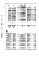
次に、歩行姿勢診断部38によって歩行姿勢軌跡量算出結果を用いた各種移動軌跡を算出した算出データの構造について、図10及び図11を参照しながら説明する。図10は、歩行姿勢軌跡量算出処理結果を用いた各種移動軌跡の算出データのうち得点及び診断フォームがない場合の一例であり、図11は、得点及び診断フォームがある場合の一例である。   Next, the structure of calculation data obtained by calculating various movement trajectories using the walking posture trajectory amount calculation result by the walking posture diagnosis unit 38 will be described with reference to FIGS. 10 and 11. FIG. 10 is an example of the case where there is no score and diagnostic form among the calculation data of various movement trajectories using the walking posture trajectory amount calculation processing result, and FIG. 11 is an example of the case where there is a score and diagnostic form.

図10に示すように、算出データには、右左方向の回転量の平均、右左方向の移動量の平均、左右回転量の差、左右移動量の差がある。また、算出データには、右脚着地での腰の起き上がり量及び前傾量の平均、左脚着地での腰の起き上がり量及び前傾量の平均、腰の起き上がり量の差、腰の前傾量の差がある。また、算出データには、右脚着地での上方向の移動量の平均、右脚着地での下方向の移動量の平均、左脚着地での上方向の移動量の平均、左脚着地での下方向の移動量の平均、上方向の移動量の差、下方向の移動量の差がある。また、算出データには、右脚着地での腰の体幹回転量の平均、左脚着地での腰の体幹回転量の平均、腰の体幹回転量の差がある。さらに、算出データには、右脚の衝撃度の平均、左脚の衝撃度の平均、左右の衝撃度の差がある。   As shown in FIG. 10, the calculated data includes an average rotation amount in the right / left direction, an average movement amount in the right / left direction, a difference in the left / right rotation amount, and a difference in the left / right movement amount. The calculated data also includes the average of the amount of rise and forward tilt of the waist when landing on the right leg, the average of the amount of rise and forward tilt of the waist when landing on the left leg, the difference in the amount of rise of the waist, the forward tilt of the waist There is a difference in quantity. The calculated data includes the average of the upward movement amount at the right leg landing, the average of the downward movement amount at the right leg landing, the average of the upward movement amount at the left leg landing, and the left leg landing. There is an average of the downward movement amount, a difference in the upward movement amount, and a difference in the downward movement amount. The calculated data includes an average of the hip trunk rotation amount at the right leg landing, an average of the hip trunk rotation amount at the left leg landing, and a difference in the hip trunk rotation amount. Further, the calculated data includes an average of the impact degree of the right leg, an average of the impact degree of the left leg, and a difference between the impact degrees of the left and right.

また、図11に示すように、算出データは、図10に示した各種移動軌跡の算出データに算出範囲e1、アドバイス結果e2及びアドバイス得点e3を追加したデータである。算出範囲e1は、生データのどの範囲のデータを用いて算出したかを示す属性を指し、例えば全期間範囲を示す「合計」、全期間範囲のうち診断開始から所定期間範囲を示す「開始」、中間範囲を示す「中間」がある。アドバイス結果e2は、診断フォーム(歩行姿勢)情報を指す。アドバイス得点e3は、各種移動軌跡の算出データに基づいて算出された得点を指す。なお、算出範囲e1は、診断開始指示のパラメータとして指示するようにしても良い。   Also, as shown in FIG. 11, the calculated data is data obtained by adding a calculation range e1, an advice result e2, and an advice score e3 to the calculation data of various movement trajectories shown in FIG. The calculation range e1 indicates an attribute indicating which range of raw data is used for calculation. For example, “total” indicating an entire period range, and “start” indicating a predetermined period range from the start of diagnosis among all the period ranges. There is an “intermediate” indicating an intermediate range. The advice result e2 indicates diagnostic form (walking posture) information. The advice score e3 indicates a score calculated based on calculation data of various movement trajectories. The calculation range e1 may be instructed as a parameter for instructing diagnosis start.

図11の例では、算出範囲e1には、生データの全期間範囲のデータを用いたことを示す「合計」が表される。アドバイス結果e2には、「左右バランスが悪い(2)」が表される。アドバイス得点e3には、「52.2」点が表される。なお、アドバイス結果e2の括弧内の数値は、診断用アドバイステーブル42内の識別番号となる。   In the example of FIG. 11, the calculation range e1 represents “total” indicating that the data of the entire period range of the raw data is used. The advice result e2 indicates “Bad left / right balance (2)”. The advice score e3 represents “52.2” points. The numerical value in parentheses of the advice result e2 is an identification number in the diagnostic advice table 42.

[ステップマーカ抽出の具体例]
次に、ステップマーカ抽出部35によるステップマーカ抽出の具体例について図12を参照しながら説明する。図12は、ステップマーカ抽出の具体例を説明する説明図である。図12(A)は、時間毎の各種回転量を示すグラフであり、図12(B)は、時間毎の各種移動量を示すグラフであり、図12(C)は、ステップマーカ抽出方法を示すグラフの一部である。
[Specific example of step marker extraction]
Next, a specific example of step marker extraction by the step marker extraction unit 35 will be described with reference to FIG. FIG. 12 is an explanatory diagram illustrating a specific example of step marker extraction. 12A is a graph showing various rotation amounts for each time, FIG. 12B is a graph showing various movement amounts for each time, and FIG. 12C shows a step marker extraction method. It is a part of the graph to show.

図12(A)の横軸は時間軸を示し、縦軸は生データから表される各種回転量(単位:degree)を示す。各種回転量のうち基準座標軸のX軸で表される前後回転量gcxを破線で示し、Y軸で表される体幹回転量gcyを実線で示し、Z軸で表される左右回転量gczを一点鎖線で示すものとする。   In FIG. 12A, the horizontal axis indicates a time axis, and the vertical axis indicates various rotation amounts (unit: degree) represented from raw data. Of the various rotation amounts, the front-rear rotation amount gcx represented by the X axis of the reference coordinate axis is indicated by a broken line, the trunk rotation amount gcy represented by the Y axis is indicated by a solid line, and the left-right rotation amount gcz represented by the Z axis is It shall be indicated by a one-dot chain line.

図12(B)の横軸は時間軸を示し、縦軸は生データから表される各種移動量(単位:mm)を示す。各種移動量のうち基準座標軸のX軸方向で表される左右移動量gaxを破線で示し、Y軸で表される上下移動量gayを実線で示し、Z軸で表される前後移動量gazを一点鎖線で示すものとする。ステップマーカ抽出部35によるステップマーカ抽出は、各種回転量及び各種移動量のうち上下移動量gayを用いる。この上下移動量gayのうち上方向の移動量がプラス、下方向の移動量がマイナスとなる。なお、上下方向の移動量の基準は、例えば、歩行姿勢診断開始時点の6軸センサ24が搭載された携帯電話の装着姿勢を基準とする。   In FIG. 12B, the horizontal axis represents a time axis, and the vertical axis represents various movement amounts (unit: mm) represented from raw data. Of the various movement amounts, the left-right movement amount gax represented in the X-axis direction of the reference coordinate axis is indicated by a broken line, the vertical movement amount gay represented by the Y-axis is indicated by a solid line, and the front-rear movement amount gaz represented by the Z-axis is It shall be indicated by a one-dot chain line. The step marker extraction by the step marker extraction unit 35 uses the vertical movement amount “gay” among various rotation amounts and various movement amounts. Of this vertical movement amount, the upward movement amount is positive, and the downward movement amount is negative. In addition, the reference | standard of the moving amount | distance of an up-down direction is based on the mounting attitude | position of the mobile telephone in which the 6-axis sensor 24 at the time of a walking attitude | position diagnosis start is mounted, for example.

ステップマーカ抽出部35は、上下移動量gayを参照し、マイナス方向の折り返し時点を選択する。ここでは、ステップマーカ抽出部35は、y0〜y9に示す時点を折り返し時点として選択する。   The step marker extraction unit 35 refers to the up / down movement amount “gay” and selects a turn-back point in the minus direction. Here, the step marker extraction unit 35 selects the time points indicated by y0 to y9 as the folding time points.

図12(C)に示すように、折り返し地点がステップマーカであるか否かを判定する。すなわち、ステップマーカ抽出部35は、選択した折り返し時点の移動量より5サンプル前の移動量及び5サンプル後の移動量を参照する。そして、ステップマーカ抽出部35は、折り返し時点の移動量が5サンプル前の移動量より小さく、且つ折り返し時点の移動量が5サンプル後の移動量より小さいか否かを判定する。そして、ステップマーカ抽出部35は、折り返し時点の移動量が5サンプル前の移動量より小さく、且つ折り返し時点の移動量が5サンプル後より小さい場合には、この折り返し時点をステップマーカとして抽出する。   As shown in FIG. 12C, it is determined whether or not the turning point is a step marker. That is, the step marker extraction unit 35 refers to the movement amount before 5 samples and the movement amount after 5 samples from the movement amount at the selected folding time point. Then, the step marker extraction unit 35 determines whether or not the movement amount at the time of folding is smaller than the movement amount before 5 samples and the movement amount at the time of folding is smaller than the movement amount after 5 samples. Then, when the amount of movement at the time of folding is smaller than the amount of movement before 5 samples and the amount of movement at the time of folding is smaller than after 5 samples, the step marker extraction unit 35 extracts this time of folding as a step marker.

[ステップマーカ左右判断の具体例]
次に、ステップマーカ左右判断部36によるステップマーカ左右判断の具体例について図13を参照しながら説明する。図13は、ステップマーカ左右判断の具体例を説明する説明図である。ステップマーカ左右判断部36によるステップマーカ左右判断は、各種回転量及び各種移動量のうち左右回転量gczを用いる。この左右回転量gczのうち右方向の回転量がプラス、左方向の回転量がマイナスとなる。なお、左右方向の回転量の基準は、例えば、歩行姿勢診断開始時点の6軸センサ24が搭載された携帯電話の装着姿勢を基準とする。
[Specific example of step marker left / right judgment]
Next, a specific example of step marker left / right determination by the step marker left / right determination unit 36 will be described with reference to FIG. FIG. 13 is an explanatory diagram for explaining a specific example of step marker left / right determination. The step marker left / right determination by the step marker left / right determination unit 36 uses a left / right rotation amount gcz among various rotation amounts and various movement amounts. Of the left / right rotation amount gcz, the right rotation amount is positive and the left rotation amount is negative. Note that the reference for the amount of rotation in the left-right direction is based on, for example, the mounting posture of the mobile phone on which the 6-axis sensor 24 is mounted when the walking posture diagnosis is started.

ステップマーカ左右判断部36は、脚の左右を判断するステップマーカ(左右判断ステップマーカ)と、当該ステップマーカの直前と直後のステップマーカを選択する。ここでは、左右判断ステップマーカをs2、このステップマーカの直前と直後のステップマーカをそれぞれs1、s3とする。そして、ステップマーカ左右判断部36は、s1からs2までの前期間とs2からs3までの後期間を算出し、s2を中心に前期間30%の時点から後期間30%の時点までの範囲を前後検索範囲として算出する。この左右判断ステップマーカs2を中心とした前後検索範囲内で左右判断ステップマーカs2における1歩を成す脚の左右を判断するのである。   The step marker left / right determination unit 36 selects a step marker (left / right determination step marker) for determining the left / right of the leg, and a step marker immediately before and after the step marker. Here, the left / right determination step marker is s2, and the step markers immediately before and after this step marker are s1 and s3, respectively. Then, the step marker left / right determination unit 36 calculates the previous period from s1 to s2 and the subsequent period from s2 to s3, and sets the range from the time point of 30% in the previous period to the time point of 30% in the subsequent period centering on s2. Calculate as the search range before and after. The left and right of the leg making one step in the left / right determination step marker s2 are determined within the front / rear search range centered on the left / right determination step marker s2.

そして、ステップマーカ左右判断部36は、前後検索範囲から左右方向の最大回転量を選択し、選択した最大回転量がプラス方向であるか否かを判定する。そして、ステップマーカ左右判断部36は、最大回転量がプラス方向であると判定する場合には、右方向の回転であると判断し、左脚着地と判定する。ここでは、左右判断ステップマーカs2を中心とした前後検索範囲から左右方向の最大回転量c1を選択し、c1がプラス方向であるので左脚着地と判定する。   Then, the step marker left / right determination unit 36 selects the maximum rotation amount in the left / right direction from the front / rear search range, and determines whether or not the selected maximum rotation amount is in the plus direction. Then, when determining that the maximum rotation amount is in the plus direction, the step marker left / right determination unit 36 determines that the rotation is in the right direction and determines that the left leg has landed. Here, the left-right maximum rotation amount c1 is selected from the front-rear search range centered on the left-right determination step marker s2, and it is determined that the left leg has landed because c1 is in the plus direction.

一方、ステップマーカ左右判断部36は、最大回転量がマイナス方向であると判定する場合には、左方向の回転であると判断し、右脚着地と判定する。例えば、左右判断ステップマーカがs5の場合には、同様に算出した前後検索範囲から左右方向の最大回転量c2を選択し、c2がマイナス方向であるので右脚着地と判定する。   On the other hand, when determining that the maximum rotation amount is in the minus direction, the step marker left / right determination unit 36 determines that the rotation is in the left direction and determines that the right leg has landed. For example, when the left / right determination step marker is s5, the maximum rotation amount c2 in the left / right direction is selected from the similarly calculated front / rear search range, and the right leg landing is determined because c2 is in the minus direction.

[前後回転量算出の具体例]
次に、前後回転量算出部37Aによる前後回転量算出の具体例について図14を参照しながら説明する。図14は、前後回転量算出の具体例を説明する説明図である。前後回転量算出部37Aによる前後回転量算出は、各種回転量及び各種移動量のうち前後回転量gcxを用いる。この前後回転量gcxのうち後方向(起き上がり方向)の回転量がプラス、前方向(前傾方向)の回転量がマイナスとなる。なお、前後方向の回転量の基準は、例えば、歩行姿勢診断開始時点の6軸センサ24が搭載された携帯電話の装着姿勢を基準とする。
[Specific example of calculation of front / rear rotation amount]
Next, a specific example of calculating the front / rear rotation amount by the front / rear rotation amount calculation unit 37A will be described with reference to FIG. FIG. 14 is an explanatory diagram illustrating a specific example of calculating the amount of forward / backward rotation. The front / rear rotation amount calculation by the front / rear rotation amount calculation unit 37A uses the front / rear rotation amount gcx among various rotation amounts and various movement amounts. Of this forward / backward rotational amount gcx, the rotational amount in the rear direction (rising direction) is positive, and the rotational amount in the forward direction (forward tilt direction) is negative. Note that the reference for the amount of rotation in the front-rear direction is based on, for example, the mounting posture of the mobile phone on which the 6-axis sensor 24 is mounted at the start of the walking posture diagnosis.

前後回転量算出部37Aは、3個の連続するステップマーカを選択する。そして、前後回転量算出部37Aは、中心のステップマーカと直前のステップマーカとの間の前期間及び中心のステップマーカと直後のステップマーカとの間の後期間を算出する。そして、前後回転量算出部37Aは、中心のステップマーカを中心に前期間50%の時点から後期間20%の時点までの範囲を前後検索範囲として算出する。例えば、中心のステップマーカがs11の場合には、直前のステップマーカs10と直後のステップマーカs12とを用いて前後検索範囲を算出する。   The front / rear rotation amount calculation unit 37A selects three continuous step markers. Then, the front / rear rotation amount calculation unit 37A calculates the previous period between the central step marker and the immediately preceding step marker and the subsequent period between the central step marker and the immediately following step marker. Then, the front / rear rotation amount calculation unit 37A calculates a range from the time point of the previous period 50% to the time point of the rear period 20% as the front / rear search range centering on the central step marker. For example, when the central step marker is s11, the front / rear search range is calculated using the immediately preceding step marker s10 and the immediately following step marker s12.

そして、前後回転量算出部37Aは、前後検索範囲からプラスの最大回転量を特定する。ここでは、d1、d2、d3の時点をプラスの最大回転量として特定する。そして、前後回転量算出部37Aは、プラスの各最大回転量のうち連続する最大回転量となる期間からマイナスの最大回転量を特定する。ここでは、d1及びd2期間からd5の時点、d2とd3期間からd6の時点をマイナスの最大回転量として特定する。そして、前後回転量算出部37Aは、連続するプラスとマイナスの最大回転量について、プラスとなる時点がマイナスとなる時点より後の場合には、各最大回転量の差分の絶対値を「起き上がり回転量」として算出する。例えば、「起き上がり回転量」は、d6時点のマイナスの最大回転量とd3時点のプラスの最大回転量との差分の絶対値となる。   Then, the front / rear rotation amount calculation unit 37A specifies the plus maximum rotation amount from the front / rear search range. Here, the time points d1, d2, and d3 are specified as positive maximum rotation amounts. Then, the front / rear rotation amount calculation unit 37A specifies a negative maximum rotation amount from a period in which the maximum rotation amount continues among the positive maximum rotation amounts. Here, the time point d5 from the d1 and d2 periods and the time point d6 from the d2 and d3 periods are specified as negative maximum rotation amounts. Then, the front / rear rotation amount calculation unit 37A determines the absolute value of the difference between the maximum rotation amounts when the positive time and the negative maximum rotation amount are after the time when the positive time is negative. Calculated as “amount”. For example, the “wake-up rotation amount” is an absolute value of the difference between the negative maximum rotation amount at the time point d6 and the positive maximum rotation amount at the time point d3.

一方、前後回転量算出部37Aは、連続するプラスとマイナスの最大回転量について、プラスとなる時点がマイナスとなる時点より前の場合には、各最大回転量の差分の絶対値を「前傾回転量」として算出する。例えば、「前傾回転量」は、d1時点の最大回転量とd5時点の最大回転量との差分の絶対値となる。   On the other hand, the forward / backward rotation amount calculation unit 37A determines the absolute value of the difference between the maximum rotation amounts when the positive time and the negative maximum rotation amount are before the time when the positive time is negative. Calculated as “rotation amount”. For example, the “forward rotation amount” is an absolute value of a difference between the maximum rotation amount at the time point d1 and the maximum rotation amount at the time point d5.

[体幹回転量算出の具体例]
次に、体幹回転量算出部37Bによる体幹回転量算出の具体例について図15を参照しながら説明する。図15は、体幹回転量算出の具体例を説明する説明図である。体幹回転量算出部37Bによる体幹回転量算出は、各種回転量及び各種移動量のうち体幹回転量gcyを用いる。この体幹回転量gcyのうち右方向の回転量がプラス、左方向の回転量がマイナスとなる。なお、体幹方向の回転量の基準は、例えば、歩行姿勢診断開始時点の6軸センサ24が搭載された携帯電話の装着姿勢を基準とする。また、前後検索範囲の算出方法については、ステップマーカ左右判断部36と同様であるので、その説明を省略する。図15の例では、中心のステップマーカがs21の場合には、直前のステップマーカs20と直後のステップマーカs22とを用いて前後検索範囲を算出する。
[Specific example of calculation of trunk rotation]
Next, a specific example of trunk rotation amount calculation by the trunk rotation amount calculation unit 37B will be described with reference to FIG. FIG. 15 is an explanatory diagram illustrating a specific example of calculation of trunk rotation amount. The trunk rotation amount calculation by the trunk rotation amount calculation unit 37B uses the trunk rotation amount gcy among various rotation amounts and various movement amounts. Of the trunk rotation amount gcy, the rotation amount in the right direction is positive, and the rotation amount in the left direction is negative. The reference for the rotation amount in the trunk direction is based on, for example, the mounting posture of the mobile phone on which the 6-axis sensor 24 is mounted at the start of the walking posture diagnosis. Further, the calculation method of the front / rear search range is the same as that of the step marker left / right determination unit 36, and thus the description thereof is omitted. In the example of FIG. 15, when the central step marker is s21, the front / rear search range is calculated using the immediately preceding step marker s20 and the immediately following step marker s22.

体幹回転量算出部37Bは、前後検索範囲の算出後、各前後検索範囲からそれぞれの体幹回転量の折り返し地点を特定する。すなわち、体幹回転量算出部37Bは、前後検索範囲からプラスの最大回転量またはマイナスの最大回転量を特定する。ここでは、e1の時点及びe3の時点をプラスの最大回転量として特定し、e2の時点をマイナスの最大回転量として特定する。そして、体幹回転量算出部37Bは、連続するプラスとマイナスの最大回転量について、プラスとなる時点がマイナスとなる時点より後の場合には、各最大回転量の差分の絶対値を「左方向体幹回転量」として算出する。例えば、「左方向体幹回転量」は、e2時点のマイナスの最大回転量とe3時点のプラスの最大回転量との差分の絶対値となる。   After calculating the front-rear search range, the trunk rotation amount calculation unit 37 </ b> B specifies a turn-back point of each trunk rotation amount from each front-rear search range. That is, the trunk rotation amount calculation unit 37B specifies a positive maximum rotation amount or a negative maximum rotation amount from the front-rear search range. Here, the time point e1 and the time point e3 are specified as a positive maximum rotation amount, and the time point e2 is specified as a negative maximum rotation amount. Then, the trunk rotation amount calculation unit 37B calculates the absolute value of the difference between each maximum rotation amount when the positive time and the negative maximum rotation amount are after the time when the positive time is negative. Calculated as “directional trunk rotation amount”. For example, the “left-handed trunk rotation amount” is an absolute value of a difference between the negative maximum rotation amount at the time point e2 and the positive maximum rotation amount at the time point e3.

一方、体幹回転量算出部37Bは、連続するプラスとマイナスの最大回転量について、プラスとなる時点がマイナスとなる時点より前の場合には、各最大回転量の差分の絶対値を「右方向体幹回転量」として算出する。例えば、「右方向体幹回転量」は、e2時点のマイナスの最大回転量とe1時点のプラスの最大回転量との差分の絶対値となる。   On the other hand, the trunk rotation amount calculation unit 37B calculates the absolute value of the difference between each maximum rotation amount when the positive time point is before the time point when the positive time point is negative. Calculated as “directional trunk rotation amount”. For example, the “rightward trunk rotation amount” is an absolute value of a difference between the negative maximum rotation amount at the time point e2 and the positive maximum rotation amount at the time point e1.

[左右回転量算出の具体例]
次に、左右回転量算出部37Cによる左右回転量算出の具体例について図16を参照しながら説明する。図16は、左右回転量算出の具体例を説明する説明図である。左右回転量算出部37Cによる左右回転量算出は、各種回転量及び各種移動量のうち左右回転量gczを用いる。この左右回転量gczのうち右方向の回転量がプラス、左方向の回転量がマイナスとなる。なお、左右方向の回転量の基準は、例えば、歩行姿勢診断開始時点の6軸センサ24が搭載された携帯電話の装着姿勢を基準とする。
[Specific example of left / right rotation amount calculation]
Next, a specific example of the left / right rotation amount calculation by the left / right rotation amount calculation unit 37C will be described with reference to FIG. FIG. 16 is an explanatory diagram illustrating a specific example of calculating the left / right rotation amount. The left / right rotation amount calculation by the left / right rotation amount calculation unit 37C uses the left / right rotation amount gcz among various rotation amounts and various movement amounts. Of the left / right rotation amount gcz, the right rotation amount is positive and the left rotation amount is negative. Note that the reference for the amount of rotation in the left-right direction is based on, for example, the mounting posture of the mobile phone on which the 6-axis sensor 24 is mounted when the walking posture diagnosis is started.

左右回転量算出部37Cは、連続するステップマーカを選択し、選択した2個のステップマーカ間をステップマーカ範囲として算出する。そして、左右回転量算出部37Cは、各ステップマーカ範囲からそれぞれの左右回転量の最大となる時点を特定する。すなわち、左右回転量算出部37Cは、ステップマーカ範囲からプラスの最大回転量またはマイナスの最大回転量を特定する。ここでは、f1の時点及びf3の時点をプラスの最大回転量として特定し、f2の時点及びf4の時点をマイナスの最大回転量として特定する。そして、左右回転量算出部37Cは、連続するプラスとマイナスの最大回転量について、プラスとなる時点がマイナスとなる時点より後の場合には、各最大回転量の差分の絶対値を「左方向回転量」として算出する。例えば、「左方向回転量」は、f2時点のマイナスの最大回転量とf3時点のプラスの最大回転量との差分の絶対値となる。   The left / right rotation amount calculation unit 37C selects continuous step markers, and calculates a step marker range between the two selected step markers. Then, the left / right rotation amount calculation unit 37 </ b> C specifies the time point at which the respective left / right rotation amount is maximum from each step marker range. That is, the left / right rotation amount calculation unit 37C specifies a positive maximum rotation amount or a negative maximum rotation amount from the step marker range. Here, the time point f1 and the time point f3 are specified as positive maximum rotation amounts, and the time point f2 and the time point f4 are specified as negative maximum rotation amounts. Then, the left and right rotation amount calculation unit 37C calculates the absolute value of the difference between the maximum rotation amounts when the positive time and the negative maximum rotation amount are after the time when the positive time is negative. Calculated as “rotation amount”. For example, the “left rotation amount” is an absolute value of the difference between the negative maximum rotation amount at the time point f2 and the positive maximum rotation amount at the time point f3.

一方、左右回転量算出部37Cは、連続するプラスとマイナスの最大回転量について、プラスとなる時点がマイナスとなる時点より前の場合には、各最大回転量の差分の絶対値を「右方向回転量」として算出する。例えば、「右方向回転量」は、f2時点のマイナスの最大回転量とf1時点のプラスの最大回転量との差分の絶対値となる。   On the other hand, the left and right rotation amount calculation unit 37C calculates the absolute value of the difference between the maximum rotation amounts in the “rightward direction” when the positive time point is before the time point when the positive time point is negative. Calculated as “rotation amount”. For example, the “rightward rotation amount” is an absolute value of a difference between the negative maximum rotation amount at the time point f2 and the positive maximum rotation amount at the time point f1.

[左右移動量算出の具体例]
次に、左右移動量算出部37Dによる左右移動量算出の具体例について図17を参照しながら説明する。図17は、左右移動量算出の具体例を説明する説明図である。左右移動量算出部37Dによる左右移動量算出は、各種回転量及び各種移動量のうち左右移動量gaxを用いる。この左右移動量gaxのうち左方向の移動量がプラス、右方向の移動量がマイナスとなる。なお、左右方向の移動量の基準は、例えば、歩行姿勢診断開始時点の6軸センサ24が搭載された携帯電話の装着姿勢を基準とする。また、前後検索範囲の算出方法については、ステップマーカ左右判断部36と同様であるので、その説明を省略する。
[Specific example of left / right movement amount calculation]
Next, a specific example of the left / right movement amount calculation by the left / right movement amount calculation unit 37D will be described with reference to FIG. FIG. 17 is an explanatory diagram illustrating a specific example of calculating the left / right movement amount. The left / right movement amount calculation by the left / right movement amount calculation unit 37D uses the left / right movement amount gax among various rotation amounts and various movement amounts. Of the left / right movement amount gax, the movement amount in the left direction is positive, and the movement amount in the right direction is negative. In addition, the reference | standard of the moving amount | distance in the left-right direction is based on the mounting attitude | position of the mobile telephone in which the 6-axis sensor 24 at the time of a walk attitude | position diagnosis start is mounted, for example. Further, the calculation method of the front / rear search range is the same as that of the step marker left / right determination unit 36, and thus the description thereof is omitted.

左右移動量算出部37Dは、前後検索範囲の算出後、各前後検索範囲からそれぞれの左右移動量の折り返し地点を特定する。すなわち、左右移動量算出部37Dは、前後検索範囲からプラスの最大移動量またはマイナスの最大移動量を特定する。ここでは、g1の時点及びg3の時点をプラスの最大移動量として特定し、g2の時点をマイナスの最大移動量として特定する。そして、左右移動量算出部37Dは、連続するプラスとマイナスの最大移動量について、プラスとなる時点がマイナスとなる時点より後の場合には、各最大移動量の差分の絶対値を「左方向移動量」として算出する。例えば、「左方向移動量」は、g2時点のマイナスの最大移動量とg3時点のプラスの最大移動量との差分の絶対値となる。   After calculating the front / rear search range, the left / right movement amount calculation unit 37D specifies the return point of each left / right movement amount from each front / rear search range. That is, the left / right movement amount calculation unit 37D specifies a positive maximum movement amount or a negative maximum movement amount from the front / rear search range. Here, the time point g1 and the time point g3 are specified as a positive maximum movement amount, and the time point g2 is specified as a negative maximum movement amount. Then, the left and right movement amount calculation unit 37D calculates the absolute value of the difference between the maximum movement amounts when the positive point and the negative maximum movement amount are after the point when the plus point is negative. Calculated as “movement amount”. For example, the “leftward movement amount” is an absolute value of a difference between the negative maximum movement amount at the time point g2 and the positive maximum movement amount at the time point g3.

一方、左右移動量算出部37Dは、連続するプラスとマイナスの最大移動量について、プラスとなる時点がマイナスとなる時点より前の場合には、各最大回転量の差分の絶対値を「右方向移動量」として算出する。例えば、「右方向移動量」は、g2時点のマイナスの最大移動量とg1時点のプラスの最大移動量との差分の絶対値となる。   On the other hand, when the positive and negative maximum movement amounts are before the negative point in time, the right and left movement amount calculation unit 37D calculates the absolute value of the difference between the maximum rotation amounts as “right direction”. Calculated as “movement amount”. For example, the “rightward movement amount” is an absolute value of a difference between the negative maximum movement amount at the time point g2 and the positive maximum movement amount at the time point g1.

[上下移動量算出の具体例]
次に、上下移動量算出部37Eによる上下移動量算出の具体例について図18を参照しながら説明する。図18は、上下移動量算出の具体例を説明する説明図である。上下移動量算出部37Eによる上下移動量算出は、各種回転量及び各種移動量のうち上下移動量gayを用いる。この上下移動量gayのうち上方向の移動量がプラス、下方向の移動量がマイナスとなる。なお、上下方向の移動量の基準は、例えば、歩行姿勢診断開始時点の6軸センサ24が搭載された携帯電話の装着姿勢を基準とする。
[Specific example of vertical movement calculation]
Next, a specific example of the vertical movement amount calculation by the vertical movement amount calculation unit 37E will be described with reference to FIG. FIG. 18 is an explanatory diagram illustrating a specific example of calculating the vertical movement amount. The vertical movement amount calculation by the vertical movement amount calculation unit 37E uses the vertical movement amount “gay” among various rotation amounts and various movement amounts. Of this vertical movement amount, the upward movement amount is positive, and the downward movement amount is negative. In addition, the reference | standard of the moving amount | distance of an up-down direction is based on the mounting attitude | position of the mobile telephone in which the 6-axis sensor 24 at the time of a walking attitude | position diagnosis start is mounted, for example.

上下移動量算出部37Eは、連続するステップマーカを選択し、選択した2個のステップマーカ間をステップマーカ範囲として算出する。そして、上下移動量算出部37Eは、マイナスの最大移動量となる時点を特定するため、既に抽出されているステップマーカを特定する。ここでは、h1の時点、h3の時点及びh5の時点となる。   The vertical movement amount calculation unit 37E selects continuous step markers, and calculates a step marker range between the two selected step markers. Then, the vertical movement amount calculation unit 37E specifies a step marker that has already been extracted in order to specify the point in time when the negative maximum movement amount is reached. Here, the time point is h1, the time point h3, and the time point h5.

そして、上下移動量算出部37Eは、ステップマーカ範囲からプラスの最大移動量を特定する。ここでは、h2の時点及びh4の時点となる。そして、上下移動量算出部37Eは、連続するプラスとマイナスの最大移動量について、マイナスの最大移動量となる時点がプラスの最大移動量となる時点より前の場合には、各最大移動量の差分の絶対値を「上方向移動量」として算出する。例えば、「上方向移動量」は、h1時点のマイナスの最大移動量とh2時点のプラスの最大移動量との差分の絶対値となる。   Then, the vertical movement amount calculation unit 37E specifies a positive maximum movement amount from the step marker range. Here, the time point is h2 and the time point h4. The vertical movement amount calculation unit 37E then sets the maximum movement amount for each of the maximum positive movement amount and the negative movement amount when the negative maximum movement amount is before the positive maximum movement amount. The absolute value of the difference is calculated as “upward movement amount”. For example, the “upward movement amount” is an absolute value of a difference between the negative maximum movement amount at the time point h1 and the positive maximum movement amount at the time point h2.

一方、上下移動量算出部37Eは、連続するプラスのマイナスの最大移動量について、マイナスの最大移動量となる時点がプラスの最大移動量となる時点より後の場合には、各最大移動量の差分の絶対値を「下方向移動量」として算出する。例えば、「下方向移動量」は、h2時点のプラスの最大移動量とh3時点のマイナスの最大移動量との差分の絶対値となる。   On the other hand, the vertical movement amount calculation unit 37E, for the continuous positive and negative maximum movement amount, when the time point when the negative maximum movement amount is later than the time point when the positive maximum movement amount is reached, The absolute value of the difference is calculated as “downward movement amount”. For example, the “downward movement amount” is an absolute value of the difference between the positive maximum movement amount at the time point h2 and the negative maximum movement amount at the time point h3.

[着地時衝撃算出の具体例]
次に、着地時衝撃算出部37Fによる着地時衝撃算出の具体例について図19を参照しながら説明する。図19は、着地時衝撃算出の具体例を説明する説明図である。着地時衝撃算出部37Fによる着地時衝撃算出は、各種回転量及び各種移動量のうち上下移動量gayを用いる。この上下移動量gayのうち上方向の移動量がプラス、下方向の移動量がマイナスとなる。なお、上下方向の移動量の基準は、例えば、歩行姿勢診断開始時点の6軸センサ24が搭載された携帯電話の装着姿勢を基準とする。
[Specific example of calculation of impact at landing]
Next, a specific example of the landing impact calculation by the landing impact calculation unit 37F will be described with reference to FIG. FIG. 19 is an explanatory diagram for explaining a specific example of calculation of landing impact. The landing impact calculation by the landing impact calculation unit 37F uses the vertical movement amount gay among various rotation amounts and various movement amounts. Of this vertical movement amount, the upward movement amount is positive, and the downward movement amount is negative. In addition, the reference | standard of the moving amount | distance of an up-down direction is based on the mounting attitude | position of the mobile telephone in which the 6-axis sensor 24 at the time of a walking attitude | position diagnosis start is mounted, for example.

着地時衝撃算出部37Fは、連続するステップマーカを選択し、選択した2個のステップマーカ間をステップマーカ範囲として算出する。そして、着地時衝撃算出部37Fは、
ステップマーカ範囲から上下方向の最大移動量を特定する。例えば、ステップマーカ範囲内のi1の時点を上方向の最大移動量として特定し、ステップマーカ範囲内のi2の時点を下方向の最大移動量として特定する。そして、着地時衝撃算出部37Fは、連続する上下方向の最大移動量の差分の絶対値を「着地時の衝撃」として算出する。例えば、「着地時の衝撃」は、i1時点の上方向の最大移動量とi2時点の下方向の最大移動量との差分の絶対値となる。
The landing impact calculation unit 37F selects successive step markers, and calculates a step marker range between the two selected step markers. The landing impact calculation unit 37F
The maximum amount of vertical movement is specified from the step marker range. For example, the time point i1 within the step marker range is specified as the maximum upward movement amount, and the time point i2 within the step marker range is specified as the maximum downward movement amount. Then, the landing impact calculation unit 37F calculates the absolute value of the difference between the continuous maximum movement amounts in the vertical direction as “landing impact”. For example, “impact at landing” is the absolute value of the difference between the maximum upward movement amount at the time point i1 and the downward maximum movement amount at the time point i2.

[実施例2に係る歩行姿勢診断処理の手順]
次に、実施例2に係る歩行姿勢診断処理の手順を、図20〜図23を参照して説明する。図20は、実施例2に係るステップマーカ抽出処理の手順を示すフローチャートである。
[Procedure of walking posture diagnosis processing according to Embodiment 2]
Next, the procedure of the walking posture diagnosis process according to the second embodiment will be described with reference to FIGS. FIG. 20 is a flowchart illustrating the procedure of the step marker extraction process according to the second embodiment.

まず、入力制御部33は、歩行姿勢の診断開始指示があるか否かを判定する(ステップS11)。そして、歩行姿勢の診断開始指示がないと判定された場合には(ステップS11No)、指示があるまで待つために、ステップS11に移行する。一方、歩行姿勢の診断開始指示があると判定された場合には(ステップS11Yes)、6軸センサ制御部34は、6軸センサ24を初期化する(ステップS12)。すなわち、6軸センサ制御部34は、6軸センサ24を構成する加速度センサ及び角速度(ジャイロ)センサを初期化する。   First, the input control unit 33 determines whether there is a walking posture diagnosis start instruction (step S11). And when it determines with there being no diagnosis start instruction | indication of a walking posture (step S11 No), in order to wait until there exists an instruction | indication, it transfers to step S11. On the other hand, when it is determined that there is an instruction to start diagnosis of walking posture (step S11 Yes), the 6-axis sensor control unit 34 initializes the 6-axis sensor 24 (step S12). That is, the 6-axis sensor control unit 34 initializes the acceleration sensor and the angular velocity (gyro) sensor that constitute the 6-axis sensor 24.

そして、6軸センサ制御部34は、歩行姿勢の診断開始指示に基づいて、一連の歩行で計測された加速度センサによって検出された各種データ及び角速度センサによって検出された各種データをすべて取得する(ステップS13)。例えば、6軸センサ制御部34は、6軸センサ24から1時間分の各種データを1秒間に60サンプル数ずつ取得する。そして、6軸センサ制御部34は、6軸センサ24を構成する加速度センサのY軸の出力値より上下移動量を算出する(ステップS14)。なお、6軸センサ制御部34は、6軸センサ24から各種データとして、算出された上下移動量、左右移動量、前後移動量、前後回転量、体幹回転量及び左右回転量のデータを含むものとしても良い。そして、6軸センサ制御部34は、これら各種データを生データとしてデータ記憶部44に蓄積する。   Then, the 6-axis sensor control unit 34 acquires all the various data detected by the acceleration sensor and the various data detected by the angular velocity sensor based on the series of walking based on the walking posture diagnosis start instruction (step) S13). For example, the 6-axis sensor control unit 34 acquires various data for 1 hour from the 6-axis sensor 24 by 60 samples per second. Then, the 6-axis sensor control unit 34 calculates the vertical movement amount from the output value of the Y-axis of the acceleration sensor that constitutes the 6-axis sensor 24 (step S14). The 6-axis sensor control unit 34 includes data of the calculated vertical movement amount, left-right movement amount, front-rear movement amount, front-rear rotation amount, trunk rotation amount, and left-right rotation amount as various data from the 6-axis sensor 24. It is good as a thing. Then, the 6-axis sensor control unit 34 accumulates these various data as raw data in the data storage unit 44.

続いて、ステップマーカ抽出部35は、複数時点の上下移動量を参照し、下方向(マイナス)の折り返し時点を特定する(ステップS15)。そして、ステップマーカ抽出部35は、特定した折り返し時点から5サンプル前の時点を特定するとともに(ステップS16)、当該折り返し時点から5サンプル後の時点を特定する(ステップS17)。   Subsequently, the step marker extraction unit 35 refers to the amount of vertical movement at a plurality of time points, and specifies a downward (minus) turn-back time point (step S15). Then, the step marker extraction unit 35 specifies a time point five samples before the specified turn-back time (step S16) and specifies a time point five samples after the turn-back time (step S17).

続いて、ステップマーカ抽出部35は、特定した折り返し時点の移動量が5サンプル前の時点の移動量より小さく、且つ特定した折り返し時点の移動量が5サンプル後の時点の移動量より小さいか否かを判定する(ステップS18)。そして、折り返し時点の移動量が5サンプル前の移動量以上、または折り返し時点の移動量が5サンプル後の移動量以上である場合(ステップS18No)、折り返し時点をステップマーカでないと判断し、ステップS15に移行する。   Subsequently, the step marker extraction unit 35 determines whether or not the movement amount at the specified folding time point is smaller than the movement amount at the time point five samples before and the movement amount at the specified folding time point is smaller than the movement amount at the time point five samples later. Is determined (step S18). If the movement amount at the turn-back time is equal to or larger than the movement amount five samples before, or the movement amount at the turn-back time is equal to or larger than the movement amount after five samples (No in step S18), it is determined that the turn-back time is not a step marker. Migrate to

一方、折り返し時点の移動量が5サンプル前の移動量より小さく、且つ折り返し時点の移動量が5サンプル後の移動量より小さい場合(ステップS18Yes)、ステップマーカ抽出部35は、折り返し時点をステップマーカとして抽出する。   On the other hand, if the amount of movement at the time of folding is smaller than the amount of movement before 5 samples and the amount of movement at the time of folding is smaller than the amount of movement after 5 samples (step S18 Yes), the step marker extraction unit 35 Extract as

さらに、ステップマーカ抽出部35は、抽出したステップマーカが直前のステップマーカから250ms未満であるか否かを判定する(ステップS19)。そして、抽出したステップマーカが直前のステップマーカから250ms未満である場合(ステップS19Yes)、ステップマーカ抽出部35は、歩行姿勢の1歩でないと判断し、抽出したステップマーカをステップマーカと判断しない。そして、ステップマーカ抽出部35は、ステップS15に移行する。   Further, the step marker extraction unit 35 determines whether or not the extracted step marker is less than 250 ms from the immediately preceding step marker (step S19). If the extracted step marker is less than 250 ms from the immediately preceding step marker (Yes in step S19), the step marker extracting unit 35 determines that it is not one step of the walking posture, and does not determine the extracted step marker as a step marker. Then, the step marker extraction unit 35 proceeds to step S15.

一方、抽出したステップマーカが直前のステップマーカから250ms未満でない場合(ステップS19No)、ステップマーカ抽出部35は、生データにステップマーカとしての区別を設定し(ステップS20)、ステップマーカ左右判断処理に移行する。   On the other hand, when the extracted step marker is not less than 250 ms from the immediately preceding step marker (No in step S19), the step marker extracting unit 35 sets the discrimination as the step marker in the raw data (step S20), and performs the step marker left / right determination process. Transition.

次に、ステップマーカ左右判断処理の手順を、図21を参照して説明する。図21は、ステップマーカ左右判断処理の手順を示すフローチャートである。   Next, the procedure of the step marker left / right determination process will be described with reference to FIG. FIG. 21 is a flowchart showing a procedure of step marker left / right determination processing.

まず、ステップマーカ左右判断部36は、生データからステップマーカを中心に前後30%の前後検索範囲を参照し(ステップS31)、当該前後検索範囲から角速度(ジャイロ)センサのZ軸の最大出力方向を読み出す(ステップS32)。すなわち、ステップマーカ左右判断部36は、前後検索範囲から左右方向の最大回転量を読み出す。   First, the step marker left / right determination unit 36 refers to a front / rear search range of 30% before and after the step marker from the raw data (step S31), and the maximum output direction of the Z-axis of the angular velocity (gyro) sensor from the front / rear search range. Is read (step S32). That is, the step marker left / right determination unit 36 reads the maximum rotation amount in the left / right direction from the front / rear search range.

続いて、ステップマーカ左右判断部36は、読み出した最大出力方向がプラス方向であるか否かを判定する(ステップS33)。そして、最大出力方向がプラス方向である場合(ステップS33Yes)、ステップマーカ左右判断部36は、回転が右方向であるので、「左脚」の着地点として判断する(ステップS34)。一方、最大出力方向がマイナス方向である場合(ステップS33No)、ステップマーカ左右判断部36は、回転が左回転であるので、「右脚」の着地点として判断する(ステップS35)。   Subsequently, the step marker left / right determination unit 36 determines whether or not the read maximum output direction is the plus direction (step S33). When the maximum output direction is the plus direction (Yes at Step S33), the step marker left / right determination unit 36 determines that the landing point is the “left leg” because the rotation is in the right direction (Step S34). On the other hand, when the maximum output direction is the minus direction (No in step S33), the step marker left / right determination unit 36 determines that the landing point of the “right leg” is reached because the rotation is a left rotation (step S35).

続いて、ステップマーカ左右判断部36は、次のステップマーカが存在するか否かを判定する(ステップS36)。そして、次のステップマーカが存在する場合(ステップS36Yes)、ステップS15に移行する。一方、次のステップマーカが存在しない場合(ステップS36No)、ステップマーカ左右判断部36は、生データのステップマーカに対するデータについて、1歩を成す脚の左右の区別を追加し、追加したデータを歩行姿勢軌跡量算出部37に出力する。そして、ステップマーカ左右判断部36は、歩行姿勢軌跡量算出処理に移行する。   Subsequently, the step marker left / right determination unit 36 determines whether or not the next step marker exists (step S36). And when the next step marker exists (step S36 Yes), it transfers to step S15. On the other hand, when the next step marker does not exist (step S36 No), the step marker left / right determination unit 36 adds the left / right distinction of the leg constituting one step to the data for the step marker of the raw data, and walks the added data. The result is output to the posture trajectory calculation unit 37. Then, the step marker left / right determination unit 36 proceeds to a walking posture trajectory amount calculation process.

次に、歩行姿勢軌跡量算出処理の手順を、図22を参照して説明する。図22は、歩行姿勢軌跡量算出処理の手順を示すフローチャートである。   Next, the procedure of the walking posture locus amount calculation process will be described with reference to FIG. FIG. 22 is a flowchart showing the procedure of the walking posture trajectory amount calculation process.

まず、前後回転量算出部37Aは、ステップマーカ左右判断部36によって出力された出力データからステップマーカを中心に前50%後20%の前後検索範囲を参照する(ステップS41)。そして、前後回転量算出部37Aは、当該前後検索範囲から角速度(ジャイロ)センサのX軸の最大出力点を特定する(ステップS42)。すなわち、前後回転量算出部37Aは、前後検索範囲から前後方向の回転量がプラスとなる後方向(起き上がり方向)の最大回転量を特定する。   First, the front / rear rotation amount calculation unit 37A refers to the front / rear search range of 50% before and 20% after the step marker from the output data output by the step marker left / right determination unit 36 (step S41). Then, the front-rear rotation amount calculation unit 37A specifies the maximum output point of the X-axis of the angular velocity (gyro) sensor from the front-rear search range (step S42). That is, the front / rear rotation amount calculation unit 37A specifies the maximum rearward rotation amount (a rising direction) in which the front / rear rotation amount is positive from the front / rear search range.

続いて、前後回転量算出部37Aは、連続する最大出力点間における最小値を特定する(ステップS43)。すなわち、前後回転量算出部37Aは、特定した後方向の各最大回転量のうち連続する最大回転量となる期間で前方向(前傾方向)の最大回転量を特定する。そして、前後回転量算出部37Aは、最大出力点の時点が最小値の時点より後である場合に、各時点の回転量の差分の絶対値を「起き上がり回転量」として算出する(ステップS44)。   Subsequently, the front / rear rotation amount calculation unit 37A specifies a minimum value between consecutive maximum output points (step S43). That is, the front-rear rotation amount calculation unit 37A specifies the maximum rotation amount in the forward direction (forward tilt direction) in the period of the maximum rotation amount that is continuous among the specified maximum rotation amounts in the rearward direction. Then, when the time point of the maximum output point is after the time point of the minimum value, the front-rear rotation amount calculation unit 37A calculates the absolute value of the difference in rotation amount at each time point as the “wake-up rotation amount” (step S44). .

そして、前後回転量算出部37Aは、最大出力点の時点が最小値の時点より前である場合に、各時点の回転量の差分の絶対値を「前傾回転量」として算出する(ステップS45)。そして、前後回転量算出部37Aは、算出した「起き上がり回転量」を「腰の起き上がり量」、算出した「前傾回転量」を「腰の前傾量」として出力する(ステップS46)。   Then, when the time point of the maximum output point is before the time point of the minimum value, the front-rear rotation amount calculation unit 37A calculates the absolute value of the difference in rotation amount at each time point as the “forward tilt rotation amount” (step S45). ). Then, the forward / rearward rotation amount calculation unit 37A outputs the calculated “wake up rotation amount” as “waist rise amount” and the calculated “forward tilt rotation amount” as “waist forward tilt amount” (step S46).

次に、体幹回転量算出部37Bは、ステップマーカ左右判断部36によって出力された出力データからステップマーカを中心に前後30%の前後検索範囲を参照する(ステップS51)。そして、体幹回転量算出部37Bは、当該前後検索範囲から角速度(ジャイロ)センサのY軸の最大出力点を特定する(ステップS52)。すなわち、体幹回転量算出部37Bは、前後検索範囲から体幹回転の左右の最大回転量を特定する。   Next, the trunk rotation amount calculation unit 37B refers to the front / rear search range of 30% before and after the step marker from the output data output by the step marker left / right determination unit 36 (step S51). Then, the trunk rotation amount calculation unit 37B specifies the maximum output point of the Y axis of the angular velocity (gyro) sensor from the front-rear search range (step S52). That is, the trunk rotation amount calculation unit 37B specifies the left and right maximum rotation amounts of the trunk rotation from the front-rear search range.

続いて、体幹回転量算出部37Bは、連続する左方向と右方向の最大回転量について、右方向の最大回転量となる時点が左方向の最大回転量となる時点より前の場合には、これらの回転量の差分の絶対値を「右方向体幹回転量」として算出する(ステップS53)。そして、体幹回転量算出部37Bは、連続する左方向と右方向の最大回転量について、右方向の最大回転量となる時点が左方向の最大回転量となる時点より後の場合には、これらの回転量の差分の絶対値を「左方向体幹回転量」として算出する(ステップS54)。   Subsequently, the trunk rotation amount calculation unit 37B determines that the maximum left rotation amount and the right maximum rotation amount are before the time when the maximum rotation amount in the right direction is the maximum rotation amount in the left direction. Then, the absolute value of the difference between these rotation amounts is calculated as “right trunk rotation amount” (step S53). Then, the trunk rotation amount calculation unit 37B, for the continuous leftward and rightward maximum rotation amounts, is later than the time point when the rightward maximum rotation amount becomes the leftward maximum rotation amount, The absolute value of the difference between these rotation amounts is calculated as “left-handed trunk rotation amount” (step S54).

そして、体幹回転量算出部37Bは、算出した「右方向体幹回転量」を「腰の回転量(右)」、「左方向体幹回転量」を「腰の回転量(左)」として出力する(ステップS55)。   Then, the trunk rotation amount calculation unit 37B sets the calculated “right trunk rotation amount” to “waist rotation (right)” and “left trunk rotation amount” to “waist rotation (left)”. (Step S55).

次に、左右回転量算出部37Cは、ステップマーカ左右判断部36によって出力された出力データからステップマーカ間のステップマーカ範囲を参照する(ステップS61)。そして、左右回転量算出部37Cは、当該ステップマーカ範囲における左右回転の最大出力点を特定する(ステップS62)。すなわち、左右回転量算出部37Cは、ステップマーカ範囲から左右方向の最大回転量を特定する。   Next, the left / right rotation amount calculation unit 37C refers to the step marker range between the step markers from the output data output by the step marker left / right determination unit 36 (step S61). Then, the left / right rotation amount calculation unit 37C specifies the maximum output point of left / right rotation in the step marker range (step S62). That is, the left / right rotation amount calculation unit 37C specifies the maximum rotation amount in the left / right direction from the step marker range.

続いて、左右回転量算出部37Cは、連続する左方向と右方向の最大回転量について、左方向の最大回転量となる時点が右方向の最大回転量となる時点より前の場合には、これらの回転量の差分の絶対値を「左方向回転量」として算出する(ステップS63)。そして、左右回転量算出部37Cは、連続する左方向と右方向の最大回転量について、左方向の最大回転量となる時点が右方向の最大回転量となる時点より後の場合には、これらの回転量の差分の絶対値を「右方向回転量」として算出する(ステップS64)。   Subsequently, the left-right rotation amount calculation unit 37C, for the continuous left and right maximum rotation amounts, is before the time when the left rotation maximum rotation amount is before the right rotation maximum amount, The absolute value of the difference between these rotation amounts is calculated as “left rotation amount” (step S63). Then, the left / right rotation amount calculation unit 37C, when the maximum rotation amount in the left direction and the right direction is continuous, when the time when the maximum rotation amount in the left direction is later than the time when the maximum rotation amount in the right direction is reached, The absolute value of the difference in rotation amount is calculated as “rightward rotation amount” (step S64).

そして、左右回転量算出部37Cは、算出した「右方向回転量」を「右方向の回転量」、「左方向回転量」を「左方向の回転量」として出力する(ステップS65)。   Then, the left / right rotation amount calculation unit 37C outputs the calculated “right rotation amount” as “right rotation amount” and “left rotation amount” as “left rotation amount” (step S65).

次に、左右移動量算出部37Dは、ステップマーカ左右判断部36によって出力された出力データからステップマーカを中心に前後30%の前後検索範囲を参照する(ステップS71)。そして、左右移動量算出部37Dは、当該前後検索範囲における左右移動の最大出力点を特定する(ステップS72)。すなわち、左右移動量算出部37Dは、前後検索範囲から左右方向の最大移動量を特定する。   Next, the left / right movement amount calculation unit 37D refers to the front / rear search range of 30% before and after the step marker from the output data output by the step marker left / right determination unit 36 (step S71). Then, the left-right movement amount calculation unit 37D specifies the maximum output point of left-right movement in the front-rear search range (step S72). That is, the left / right movement amount calculation unit 37D specifies the maximum movement amount in the left / right direction from the front / rear search range.

続いて、左右移動量算出部37Dは、連続する左方向と右方向の最大移動量について、左方向の最大移動量となる時点が右方向の最大移動量となる時点より前の場合には、これらの移動量の差分の絶対値を「右方向移動量」として算出する(ステップS73)。そして、左右移動量算出部37Dは、連続する左方向と右方向の最大移動量について、左方向の最大移動量となる時点が右方向の最大移動量となる時点より後の場合には、これらの移動量の差分の絶対値を「左方向移動量」として算出する(ステップS74)。   Subsequently, the left / right movement amount calculation unit 37D determines that the maximum movement amount in the left direction and the right direction is before the time point when the maximum movement amount in the left direction is the maximum movement amount in the right direction. The absolute value of the difference between these movement amounts is calculated as “rightward movement amount” (step S73). Then, the left and right movement amount calculation unit 37D calculates the leftward and rightward maximum movement amounts in the case where the time point when the leftward maximum movement amount is after the time point when the maximum rightward movement amount is reached. The absolute value of the difference between the movement amounts is calculated as “leftward movement amount” (step S74).

そして、左右移動量算出部37Dは、算出した「右方向移動量」を「右方向の移動量」、「左方向移動量」を「左方向の移動量」として出力する(ステップS75)。   Then, the left / right movement amount calculation unit 37D outputs the calculated “right movement amount” as “right movement amount” and “left movement amount” as “left movement amount” (step S75).

次に、上下移動量算出部37Eは、ステップマーカ左右判断部36によって出力された出力データからステップマーカ間のステップマーカ範囲を参照する(ステップS81)。そして、上下移動量算出部37Eは、当該ステップマーカ範囲における下方向移動のピーク時を特定する(ステップS82)。すなわち、上下移動量算出部37Eは、ステップマーカ範囲の両端のステップマーカを特定する。   Next, the vertical movement amount calculation unit 37E refers to the step marker range between the step markers from the output data output by the step marker left / right determination unit 36 (step S81). Then, the vertical movement amount calculation unit 37E specifies the peak time of the downward movement in the step marker range (step S82). That is, the vertical movement amount calculation unit 37E specifies step markers at both ends of the step marker range.

そして、上下移動量算出部37Eは、ステップマーカ間における上下移動の最大出力点を特定する(ステップS83)。すなわち、上下移動量算出部37Eは、ステップマーカ範囲から上方向の最大移動量を特定する。   Then, the vertical movement amount calculation unit 37E specifies the maximum output point of vertical movement between step markers (step S83). That is, the vertical movement amount calculation unit 37E specifies the maximum upward movement amount from the step marker range.

続いて、上下移動量算出部37Eは、連続する下方向と上方向の最大移動量について、下方向の最大移動量となる時点が上方向の最大移動量となる時点より前の場合には、これらの移動量の差分の絶対値を「上方向移動量」として算出する(ステップS84)。そして、上下移動量算出部37Eは、連続する下方向と上方向の最大移動量について、下方向の最大移動量となる時点が上方向の最大移動量となる時点より後の場合には、これらの移動量の差分の絶対値を「下方向移動量」として算出する(ステップS85)。   Subsequently, the vertical movement amount calculation unit 37E, for the continuous downward and upward maximum movement amount, when the time point when the downward maximum movement amount is before the time point when the upward maximum movement amount, The absolute value of the difference between these movement amounts is calculated as “upward movement amount” (step S84). Then, the vertical movement amount calculation unit 37E, for the continuous downward and upward maximum movement amounts, if the time point when the downward maximum movement amount is later than the time point when the upward maximum movement amount, The absolute value of the difference between the movement amounts is calculated as “downward movement amount” (step S85).

そして、上下移動量算出部37Eは、算出した「上方向移動量」を「上方向の移動量」、「下方向移動量」を「下方向の移動量」として出力する(ステップS86)。   Then, the vertical movement amount calculation unit 37E outputs the calculated “upward movement amount” as “upward movement amount” and “downward movement amount” as “downward movement amount” (step S86).

次に、着地時衝撃算出部37Fは、ステップマーカ左右判断部36によって出力された出力データからステップマーカ間のステップマーカ範囲を参照する(ステップS91)。着地時衝撃算出部37Fは、当該ステップマーカ範囲から加速度センサのY軸の最大値及び最小値を特定する(ステップS92)。すなわち、着地時衝撃算出部37Fは、ステップマーカ範囲から上下方向の最大移動量を特定する。   Next, the landing impact calculation unit 37F refers to the step marker range between the step markers from the output data output by the step marker left / right determination unit 36 (step S91). The landing impact calculation unit 37F specifies the maximum value and the minimum value of the Y axis of the acceleration sensor from the step marker range (step S92). That is, the landing impact calculation unit 37F specifies the maximum movement amount in the vertical direction from the step marker range.

続いて、着地時衝撃算出部37Fは、上下方向の最大移動量の差分の絶対値を「着地時の衝撃」として算出する(ステップS93)。そして、着地時衝撃算出部37Fは、算出した「着地時の衝撃」を「着地時の衝撃量」として出力する(ステップS94)。   Subsequently, the landing impact calculation unit 37F calculates the absolute value of the difference in the maximum movement amount in the vertical direction as “landing impact” (step S93). Then, the landing impact calculator 37F outputs the calculated “landing impact” as the “landing impact amount” (step S94).

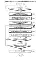
次に、歩行姿勢診断処理の手順を、図23を参照して説明する。図23は、実施例2に係る歩行姿勢診断処理の手順を示すフローチャートである。   Next, the procedure of the walking posture diagnosis process will be described with reference to FIG. FIG. 23 is a flowchart illustrating the procedure of the walking posture diagnosis process according to the second embodiment.

まず、歩行姿勢診断部38は、「各種移動軌跡算出データ」を診断用閾値テーブル41に設定されている値と比較する(ステップS101)。「各種移動軌跡算出データ」は、歩行姿勢軌跡量算出部37によって出力された各種移動軌跡のデータを用いて、移動軌跡毎に平均値が算出されたデータである。   First, the walking posture diagnosis unit 38 compares the “various movement trajectory calculation data” with the values set in the diagnostic threshold table 41 (step S101). The “various movement trajectory calculation data” is data in which an average value is calculated for each movement trajectory using the data of various movement trajectories output by the walking posture trajectory amount calculation unit 37.

そして、歩行姿勢診断部38は、比較結果に基づいて、所定の得点方法に応じて得点を算出し、診断フォーム(歩行姿勢)情報を作成する(ステップS102)。そして、歩行姿勢診断部38は、「各種移動軌跡の算出データ」に診断フォーム(歩行姿勢)情報及び得点を結合する(ステップS103)。   Then, the walking posture diagnostic unit 38 calculates a score according to a predetermined scoring method based on the comparison result, and creates diagnostic form (walking posture) information (step S102). Then, the walking posture diagnosis unit 38 combines the diagnosis form (walking posture) information and the score with “calculation data of various movement trajectories” (step S103).

続いて、表示制御部39は、結合した「各種移動軌跡の算出データ」を診断用アドバイステーブル42に設定されている情報と比較する(ステップS104)。そして、表示制御部39は、比較結果から「各種移動軌跡の算出データ」を編集し、得点、診断フォーム(歩行姿勢)情報及びアドバイス内容を画面へ表示する(ステップS105)。   Subsequently, the display control unit 39 compares the combined “calculation data of various movement trajectories” with the information set in the diagnostic advice table 42 (step S104). Then, the display control unit 39 edits “calculation data of various movement trajectories” from the comparison result, and displays the score, diagnosis form (walking posture) information, and advice content on the screen (step S105).

そして、表示制御部39は、「各種移動軌跡の算出データ」及びアドバイス内容を診断履歴テーブル43に格納する(ステップS106)。   Then, the display control unit 39 stores “calculation data of various movement trajectories” and advice contents in the diagnosis history table 43 (step S106).

次に、携帯端末装置2を携帯電話とした場合の6軸センサ24の搭載位置を、図24を参照して説明する。図24は、携帯端末装置2を携帯電話とした場合の6軸センサ24の搭載位置の一例を示す図である。図24に示すように、携帯電話2Aの表面2aを基準とした場合の右側側面2c及び裏面2bに角速度センサ24a及び加速度センサ24bを含む6軸センサ24が搭載される。また、携帯電話2Aの裏面2bの6軸センサ24は、長手方向の一方をプラスとするY軸を備え、短手方向の一方をプラスとするX軸を備える。携帯電話2Aの右側側面2cの6軸センサ24は、裏面2bから垂直方向をプラスとするZ軸を備える。   Next, the mounting position of the 6-axis sensor 24 when the mobile terminal device 2 is a mobile phone will be described with reference to FIG. FIG. 24 is a diagram illustrating an example of the mounting position of the 6-axis sensor 24 when the mobile terminal device 2 is a mobile phone. As shown in FIG. 24, a 6-axis sensor 24 including an angular velocity sensor 24a and an acceleration sensor 24b is mounted on the right side surface 2c and the back surface 2b when the front surface 2a of the mobile phone 2A is used as a reference. In addition, the 6-axis sensor 24 on the back surface 2b of the mobile phone 2A includes a Y-axis having a positive one in the longitudinal direction and an X-axis having a positive one in the short direction. The 6-axis sensor 24 on the right side surface 2c of the mobile phone 2A includes a Z-axis with the vertical direction being positive from the back surface 2b.

なお、歩行姿勢の診断を行なう際、携帯電話2Aを被験者に装着することとなるが、携帯電話2Aを6軸センサ24の座標軸と基準座標軸とが合致するように装着することが望ましい。しかしながら、携帯電話2Aの装着姿勢に応じて6軸センサ24の座標軸が回転することとなっても、6軸センサ24に含まれる加速度センサ24bが重力加速度の最大方向を判断できる。このため、携帯電話2Aの装着姿勢に応じた座標軸を、重力加速度の最大方向を利用して基準座標軸に合致するように回転させれば、基準座標軸に対応するデータとして検出することができる。したがって、携帯電話2Aの装着姿勢は、どのような姿勢であっても構わない。   Note that when diagnosing the walking posture, the mobile phone 2A is attached to the subject, but it is desirable to attach the mobile phone 2A so that the coordinate axes of the 6-axis sensor 24 and the reference coordinate axis coincide. However, even if the coordinate axis of the 6-axis sensor 24 rotates according to the mounting posture of the mobile phone 2A, the acceleration sensor 24b included in the 6-axis sensor 24 can determine the maximum direction of gravitational acceleration. Therefore, if the coordinate axis corresponding to the mounting posture of the mobile phone 2A is rotated so as to match the reference coordinate axis using the maximum direction of gravity acceleration, it can be detected as data corresponding to the reference coordinate axis. Therefore, the mounting posture of the mobile phone 2A may be any posture.

次に、表示部23によって表示する表示画面の一例を、図25を参照して説明する。図25は、表示画面の一例を示す図である。図25(A)に示すように、表示部23は、歩行姿勢の診断に関するメインメニューを表示する。例えば、メインメニューには、「フォーム診断」や「履歴を見る」等のメニューがあり、入力部22のカーソルキーによってメニューが選択される。ここでは、入力部22によって「フォーム診断」が選択されると、歩行姿勢の診断開始指示が入力制御部33に出力されることとなる。   Next, an example of a display screen displayed by the display unit 23 will be described with reference to FIG. FIG. 25 is a diagram illustrating an example of a display screen. As shown in FIG. 25A, the display unit 23 displays a main menu related to diagnosis of walking posture. For example, the main menu includes menus such as “form diagnosis” and “view history”, and the menu is selected by the cursor key of the input unit 22. Here, when “form diagnosis” is selected by the input unit 22, a walking posture diagnosis start instruction is output to the input control unit 33.

図25(B)に示すように、表示部23は、歩行姿勢の診断結果画面を表示する。例えば、歩行姿勢の診断結果画面には、「アスリートからアドバイス」のメニューがあり、入力部22のカーソルキーによってこのメニューが選択される。   As shown in FIG. 25B, the display unit 23 displays a walking posture diagnosis result screen. For example, the walking posture diagnosis result screen has a menu of “advice from athlete”, and this menu is selected by the cursor key of the input unit 22.

図25(C)〜(E)に示すように、表示部23は、表示制御部39によって「各種移動軌跡の算出データ」が編集されたアドバイス内容を表示する。図25(C)は、各種移動軌跡において基準を満たす場合のアドバイス内容の表示例である。例えば、表示部23は、「理想的な」フォームであることを表示する。図25(D)は、右方向の回転量または左方向の回転量が基準を満たさない場合のアドバイス内容の表示例である。例えば、表示部23は、「左右バランスの悪い」フォームであることを表示する。図25(E)は、上方向の移動量が基準を満たさない場合のアドバイス内容の表示例である。例えば、表示部23は、「上方向へ飛び跳ねているように歩いている」フォームであることを表示する。なお、「理想的な」e21、「左右バランスの悪い」e22及び「上方向へ飛び跳ねているように歩いている」e23は、それぞれ「各種移動軌跡の算出データ」のアドバイス結果e2として設定されている内容である。   As shown in FIGS. 25C to 25E, the display unit 23 displays the advice content in which “calculation data of various movement trajectories” is edited by the display control unit 39. FIG. 25C is a display example of the advice content when the criteria are satisfied in various movement trajectories. For example, the display unit 23 displays that it is an “ideal” form. FIG. 25D is a display example of the advice content when the amount of rotation in the right direction or the amount of rotation in the left direction does not satisfy the standard. For example, the display unit 23 displays that the form is “bad left / right balance”. FIG. 25E is a display example of the advice content when the upward movement amount does not satisfy the standard. For example, the display unit 23 displays that the form is “walking as if jumping upward”. Note that “ideal” e21, “bad left / right balance” e22, and “walking as if jumping upward” e23 are set as advice results e2 of “calculation data of various movement trajectories”, respectively. It is contents.

図25(F)に示すように、表示部23は、前述したアドバイス内容に基づいたワンポイントアドバイス内容を表示する。例えば、ワンポイントアドバイス内容は、診断用アドバイステーブル42のメッセージ内容42cに設定されている内容となる。   As shown in FIG. 25 (F), the display unit 23 displays the one-point advice content based on the above-described advice content. For example, the one-point advice content is the content set in the message content 42 c of the diagnostic advice table 42.

図25(G)に示すように、表示部23は、ウォーキングデータを表示する。すなわち、入力部22によって「履歴を見る」が選択されると、診断履歴テーブル43及びデータ記憶部44に記憶された内容に基づいて得られるウォーキングデータが表示される。例えば、「各種移動軌跡の算出データ」に設定された診断フォーム(歩行姿勢)情報や得点等が表示される。   As shown in FIG. 25G, the display unit 23 displays walking data. That is, when “view history” is selected by the input unit 22, walking data obtained based on the contents stored in the diagnosis history table 43 and the data storage unit 44 is displayed. For example, diagnostic form (walking posture) information set in “calculation data of various movement trajectories”, scores, and the like are displayed.

[実施例2の効果]
上記実施例2によれば、ステップマーカ抽出部35は、複数時点の上下方向の移動量の中で下方向の折り返し時点を選択する。そして、ステップマーカ抽出部35は、該選択した時点の移動量が該選択した時点より5サンプル前の移動量より小さく、且つ該選択した時点の移動量が該選択した時点より5サンプル後の移動量より小さい場合に、該選択した時点をステップマーカとして抽出する。かかる構成によれば、ステップマーカ抽出部35は、折り返し時点の折り返しが小さな変動を示す場合を除外できるので、1歩毎に現れるステップマーカを正確に抽出できる。この結果、ステップマーカ抽出部35は、歩行によって連続するステップマーカのそれぞれの1歩に関係する移動量を正確に取得でき、取得したそれぞれの移動量に基づいて歩行によって生じる歩行姿勢の移動軌跡を効率よく算出できる。
[Effect of Example 2]
According to the second embodiment, the step marker extraction unit 35 selects a downward folding time point from among a plurality of vertical movement amounts. The step marker extracting unit 35 then moves the selected time point less than the moving amount five samples before the selected time point, and the moving amount at the selected time point moves five samples after the selected time point. When the amount is smaller than the amount, the selected time point is extracted as a step marker. According to such a configuration, the step marker extraction unit 35 can exclude the case where the return at the time of return shows a small fluctuation, and thus can accurately extract the step marker that appears at every step. As a result, the step marker extracting unit 35 can accurately acquire the movement amount related to each step of the step marker continuous by walking, and the movement trajectory of the walking posture generated by walking based on each acquired movement amount. It can be calculated efficiently.

また、上記実施例2によれば、ステップマーカ抽出部35は、該抽出したステップマーカが直前のステップマーカから1歩に要する基準期間外にある場合に、該抽出したステップマーカをステップマーカとしないようにした。かかる構成によれば、ステップマーカ抽出部35は、1歩に要する基準期間外にあるステップマーカをステップマーカとしないようにすることで、1歩毎に現れるステップマーカをさらに正確に抽出できる。この結果、ステップマーカ抽出部35は、歩行によって連続するステップマーカのそれぞれの1歩に関係する移動量をさらに正確に取得でき、取得したそれぞれの移動量に基づいて歩行によって生じる歩行姿勢の移動軌跡を効率よく算出できる。   According to the second embodiment, the step marker extraction unit 35 does not use the extracted step marker as a step marker when the extracted step marker is outside the reference period required for one step from the immediately preceding step marker. I did it. According to such a configuration, the step marker extracting unit 35 can more accurately extract the step marker that appears at each step by making the step marker outside the reference period required for one step not a step marker. As a result, the step marker extracting unit 35 can more accurately acquire the movement amount related to each step of the step marker continuous by walking, and the movement trajectory of the walking posture generated by walking based on each acquired movement amount. Can be calculated efficiently.

また、上記実施例2によれば、左右回転量算出部37Cは、6軸センサ24によって検出された被験者の歩行における左右方向の回転に伴う回転量を取得する。そして、左右回転量算出部37Cは、抽出されたステップマーカの直前のステップマーカによって生じる最大回転量及び該抽出されたステップマーカによって生じる最大回転値の差分を左右回転軌跡として算出するようにした。かかる構成によれば、左右回転量算出部37Cは、連続するステップマーカによって生じる最大回転量から左右回転軌跡を算出することとしたので、算出した左右回転軌跡に基づいて左右回転のバランスを効率的に診断できる。   Further, according to the second embodiment, the left / right rotation amount calculation unit 37 </ b> C acquires the rotation amount accompanying the rotation in the left / right direction in the walking of the subject detected by the 6-axis sensor 24. The left / right rotation amount calculation unit 37C calculates the difference between the maximum rotation amount generated by the step marker immediately before the extracted step marker and the maximum rotation value generated by the extracted step marker as the left / right rotation locus. According to such a configuration, the left / right rotation amount calculation unit 37C calculates the left / right rotation locus from the maximum rotation amount generated by the continuous step markers, and therefore, the balance of the left / right rotation is efficiently based on the calculated left / right rotation locus. Can be diagnosed.

また、上記実施例2によれば、ステップマーカ左右判断部36は、6軸センサ24によって検出された被験者の歩行における左右方向の回転に伴う回転量を取得する。そして、ステップマーカ左右判断部36は、抽出されたステップマーカ直後の最大回転量の正負の符号に基づいて、1歩を成す脚の左右を判断するようにした。かかる構成によれば、ステップマーカ左右判断部36は、ステップマーカ直後の最大回転量の正負の符号に基づいて、1歩を成す脚の左右を判断することとしたので、当該ステップマーカの1歩を成す脚の左右を容易に判断できる。   Further, according to the second embodiment, the step marker left / right determination unit 36 acquires the rotation amount accompanying the rotation in the left / right direction in the walking of the subject detected by the 6-axis sensor 24. Then, the step marker left / right determination unit 36 determines the left / right of the leg making one step based on the positive / negative sign of the maximum rotation amount immediately after the extracted step marker. According to such a configuration, the step marker left / right determination unit 36 determines the left / right of the leg that makes one step based on the sign of the maximum rotation amount immediately after the step marker. The left and right legs can be easily determined.

また、上記実施例2によれば、携帯端末装置2は、6軸センサ24を備えるようにした。かかる構成によれば、携帯端末装置2は、歩行に関する各種データを検出できるので、歩行によって生じる各種移動軌跡を算出でき、複数の移動軌跡に基づいて歩行姿勢に関する様々なアドバイスをさせることができる。   Further, according to the second embodiment, the mobile terminal device 2 includes the 6-axis sensor 24. According to this configuration, since the mobile terminal device 2 can detect various data related to walking, the mobile terminal device 2 can calculate various movement trajectories caused by walking, and can give various advices regarding the walking posture based on a plurality of movement trajectories.

また、上記実施例2によれば、表示制御部39は、歩行姿勢診断部38によって診断された診断結果を表示部23に表示するようにした。かかる構成によれば、表示制御部39は、診断を受けた被験者に診断結果を知らせることができ、歩行姿勢に関するアドバイスを効率的に行うことができる。   Further, according to the second embodiment, the display control unit 39 displays the diagnosis result diagnosed by the walking posture diagnosis unit 38 on the display unit 23. According to such a configuration, the display control unit 39 can notify the diagnosis result to the subject who has been diagnosed, and can efficiently provide advice regarding the walking posture.

[プログラム等]
なお、ステップマーカ抽出部35は、歩行姿勢の1歩の判断を、上下限値を用いて判断するものとした。すなわち、ステップマーカ抽出部35は、ステップマーカが直前のステップマーカから下限値を示す250ミリ秒未満であるか否かを判定した。また、ステップマーカ抽出部35は、ステップマーカが直前のステップマーカから上限値を示す1000ミリ秒を越えているか否かを判定した。しかしながら、これら上下限値は、250ミリ秒及び1000ミリ秒に限定されず、変更できるものとしても良い。これによって、携帯端末装置2は、被験者の歩行タイミングに応じた値に変更できることとなり、被験者の歩行に応じた歩行姿勢の軌跡を正確に算出できる。
[Programs]
Note that the step marker extraction unit 35 determines the determination of one step of the walking posture using the upper and lower limit values. That is, the step marker extraction unit 35 determines whether or not the step marker is less than 250 milliseconds indicating the lower limit value from the immediately preceding step marker. Further, the step marker extraction unit 35 determines whether or not the step marker exceeds 1000 milliseconds indicating the upper limit value from the immediately preceding step marker. However, these upper and lower limit values are not limited to 250 milliseconds and 1000 milliseconds, and may be changed. Thereby, the portable terminal device 2 can be changed to a value corresponding to the walking timing of the subject, and can accurately calculate the trajectory of the walking posture according to the walking of the subject.

また、ステップマーカ抽出部35は、上下方向の移動量に基づいて、1歩毎に現れる特徴時点をステップマーカとして抽出する。実施例では、この特徴時点が、一歩の着地時点であるものとして説明した。しかしながら、特徴時点は、これに限定されるものではなく、例えば脚を最大に上げた時点であるものとしても良い。   Moreover, the step marker extraction part 35 extracts the feature time point which appears for every step as a step marker based on the moving amount | distance of an up-down direction. In the embodiment, it has been described that this characteristic time point is a landing point of one step. However, the characteristic time point is not limited to this, and may be a time point when the leg is raised to the maximum, for example.

また、携帯端末装置2は、6軸センサ24を備えるようにした。すなわち、6軸センサ制御部34が6軸センサ24から出力される左右方向の移動量、上下方向の移動量、前後方向の移動量、前後方向の回転量、体幹方向の回転量及び左右方向の回転量を検出する。しかしながら、携帯端末装置2は、これに限定されず、3軸加速度センサのうち上下方向の移動量を検出するY軸方向の加速度センサを備え、Y軸方向以外の座標軸方向の加速度センサまたはいずれか1つの座標軸周りの角速度センサを備えるようにしても良い。   The mobile terminal device 2 is provided with a 6-axis sensor 24. That is, the 6-axis sensor control unit 34 outputs the movement amount in the left-right direction, the movement amount in the vertical direction, the movement amount in the front-rear direction, the rotation amount in the front-rear direction, the rotation amount in the trunk direction, and the left-right direction. The amount of rotation is detected. However, the mobile terminal device 2 is not limited to this, and is provided with an acceleration sensor in the Y-axis direction that detects the amount of movement in the vertical direction among the three-axis acceleration sensors, and the acceleration sensor in the coordinate axis direction other than the Y-axis direction or any one of them An angular velocity sensor around one coordinate axis may be provided.

また、図示した各携帯端末装置の各構成要素は、必ずしも物理的に図示の如く構成されていることを要しない。すなわち、各装置の分散・統合の具体的態様は図示のものに限られず、その全部又は一部を、各種の負荷や使用状況等に応じて、任意の単位で機能的又は物理的に分散・統合して構成することができる。例えば、歩行姿勢診断部38と表示制御部39とを1個の部として統合しても良い。一方、ステップマーカ抽出部35を折り返し時点がステップマーカとなるか否かを判定するステップマーカ判定部とに分散しても良い。また、記憶部26を携帯端末装置2の外部装置としてネットワーク経由で接続するようにしても良い。   In addition, each component of each illustrated mobile terminal device does not necessarily need to be physically configured as illustrated. That is, the specific mode of distribution / integration of each device is not limited to that shown in the figure, and all or a part thereof may be functionally or physically distributed or arbitrarily distributed in arbitrary units according to various loads or usage conditions. Can be integrated and configured. For example, the walking posture diagnosis unit 38 and the display control unit 39 may be integrated as one unit. On the other hand, the step marker extraction unit 35 may be distributed to a step marker determination unit that determines whether or not the folding time point becomes a step marker. Further, the storage unit 26 may be connected as an external device of the mobile terminal device 2 via a network.

また、上記実施例で説明した各種の処理は、あらかじめ用意されたプログラムをコンピュータで実行することによって実現することができる。そこで、以下では、図26を用いて、図2に示した携帯端末装置2と同様の機能を有する歩行軌跡算出プログラムを実行するコンピュータの一例を説明する。   The various processes described in the above embodiments can be realized by executing a prepared program on a computer. In the following, an example of a computer that executes a walking trajectory calculation program having the same function as that of the mobile terminal device 2 illustrated in FIG. 2 will be described with reference to FIG.

図26は、歩行軌跡算出プログラムを実行するコンピュータを示す図である。図26に示すように、コンピュータ1000は、CPU(Central Processing Unit)1010と、入力装置1020と、モニタ1030と、音声入出力装置1040と、無線通信装置1050と、6軸センサ1060とを有する。さらに、コンピュータ1000は、RAM1070と、ハードディスク装置1080等のデータ記憶装置とを有し、これらをバス1090で接続して構成される。CPU1010は、各種演算処理を実行する。入力装置1020は、ユーザからのデータの入力を受け付ける。モニタ1030は、各種情報を表示する。音声入出力装置1040は、音声を入出力する。無線通信装置1050は、無線通信を介して他のコンピュータとの間でデータの授受を行う。6軸センサ1060は、3軸方向の加速度及び3軸周りの角速度を検出する。RAM1070は、各種情報を一時記憶する。   FIG. 26 is a diagram illustrating a computer that executes a walking trajectory calculation program. As shown in FIG. 26, the computer 1000 includes a CPU (Central Processing Unit) 1010, an input device 1020, a monitor 1030, a voice input / output device 1040, a wireless communication device 1050, and a 6-axis sensor 1060. Further, the computer 1000 includes a RAM 1070 and a data storage device such as a hard disk device 1080, which are connected by a bus 1090. The CPU 1010 executes various arithmetic processes. The input device 1020 receives data input from the user. The monitor 1030 displays various information. The voice input / output device 1040 inputs and outputs voice. The wireless communication device 1050 exchanges data with other computers via wireless communication. The six-axis sensor 1060 detects acceleration in the three-axis direction and angular velocity around the three axes. The RAM 1070 temporarily stores various information.

そして、ハードディスク装置1080には、図2に示した制御部25と同様の機能を有する歩行姿勢診断プログラム1081が記憶される。また、ハードディスク装置1080には、図2に示した記憶部26に記憶される各種データ(診断用閾値テーブル41、診断用アドバイステーブル42、診断履歴テーブル43)に対応する歩行姿勢診断処理関連データ1082及び診断履歴ファイル1083が記憶される。   The hard disk device 1080 stores a walking posture diagnosis program 1081 having the same function as that of the control unit 25 shown in FIG. Further, the hard disk device 1080 includes walking posture diagnosis processing related data 1082 corresponding to various data (diagnosis threshold table 41, diagnosis advice table 42, diagnosis history table 43) stored in the storage unit 26 shown in FIG. And a diagnosis history file 1083 is stored.

そして、CPU1010が歩行姿勢診断プログラム1081をハードディスク装置1080から読み出してRAM1070に展開することにより、歩行姿勢診断プログラム1081は、歩行姿勢診断プロセス1071として機能するようになる。そして、歩行姿勢診断プロセス1071は、歩行姿勢診断処理関連データ1082から読み出した情報等を適宜RAM1070上の自身に割り当てられた領域に展開し、この展開したデータ等に基づいて各種データ処理を実行する。そして、歩行姿勢診断プロセス1071は、所定の情報を診断履歴ファイル1083に出力する。   Then, the CPU 1010 reads out the walking posture diagnosis program 1081 from the hard disk device 1080 and develops it in the RAM 1070, so that the walking posture diagnosis program 1081 functions as the walking posture diagnosis process 1071. Then, the walking posture diagnosis process 1071 appropriately expands information read from the walking posture diagnosis processing related data 1082 in an area allocated to itself on the RAM 1070, and executes various data processing based on the expanded data and the like. . Then, the walking posture diagnosis process 1071 outputs predetermined information to the diagnosis history file 1083.

なお、上記の歩行姿勢診断プログラム1081は、必ずしもハードディスク装置1080に格納されている必要はなく、CD−ROM等の記憶媒体に記憶されたこのプログラムを、コンピュータ1000が読み出して実行するようにしてもよい。また、公衆回線、インターネット、LAN(Local Area Network)、WAN(Wide Area Network)等を介してコンピュータ1000に接続される他のコンピュータ(またはサーバ)等にこのプログラムを記憶させておいても良い。この場合には、コンピュータ1000がこれらからプログラムを読み出して実行する。   The walking posture diagnosis program 1081 is not necessarily stored in the hard disk device 1080, and the computer 1000 may read and execute the program stored in a storage medium such as a CD-ROM. Good. Further, this program may be stored in another computer (or server) connected to the computer 1000 via a public line, the Internet, a LAN (Local Area Network), a WAN (Wide Area Network), or the like. In this case, the computer 1000 reads the program from these and executes it.

以上の実施例に係る実施形態に関し、さらに以下の付記を開示する。   The following additional remarks are disclosed regarding the embodiment according to the above example.

(付記1)被験者の歩行において上下方向の移動に伴う変位値を検出する第1の変位検出部と、
前記披験者の歩行において所定方向の移動または回転に伴う変位値を検出する第2の変位検出部と、
歩行姿勢に関する基準となる軌跡を記憶する歩行姿勢基準軌跡記憶部と、
前記第1の変位検出部によって検出された複数時点の上下方向の変位値に基づいて、1歩毎に現れる所定の特徴変位の時点を歩行タイミングとして抽出する特徴変位時点抽出部と、
前記特徴変位時点抽出部によって抽出された連続する歩行タイミングを選択し、前記第2の変位検出部によって検出された変位値に基づいて、該選択した歩行タイミングの歩行によって生じる軌跡を算出する軌跡算出部と、
前記軌跡算出部によって算出された軌跡が、前記歩行姿勢基準軌跡記憶部によって記憶された歩行姿勢に関する基準を満たすか否かを判定する歩行姿勢判定部と
を有することを特徴とする携帯端末装置。
(Supplementary note 1) a first displacement detector that detects a displacement value associated with movement in the vertical direction in walking of the subject;
A second displacement detector for detecting a displacement value associated with movement or rotation in a predetermined direction in the walk of the examiner;
A walking posture reference trajectory storage unit that stores a reference trajectory related to the walking posture;
A feature displacement time point extraction unit that extracts a predetermined feature displacement time point that appears at every step as a walking timing based on vertical displacement values at a plurality of time points detected by the first displacement detection unit;
Trajectory calculation for selecting a continuous walking timing extracted by the feature displacement time point extraction unit and calculating a trajectory generated by walking at the selected walking timing based on a displacement value detected by the second displacement detection unit And
A portable terminal device, comprising: a walking posture determination unit that determines whether or not the locus calculated by the locus calculation unit satisfies a criterion related to a walking posture stored by the walking posture reference locus storage unit.

(付記2)前記軌跡算出部は、
前記第2の変位検出部が前記被験者の歩行において左右方向の回転に伴う変位値を検出する場合に、該選択した歩行タイミング直前の歩行タイミングによって生じる最大変位値及び該選択した歩行タイミング直後の歩行タイミングによって生じる最大変位値の差分を左右回転軌跡として算出する左右回転量算出部を有することを特徴とする付記1に記載の携帯端末装置。
(Appendix 2) The trajectory calculation unit
When the second displacement detector detects a displacement value associated with rotation in the left-right direction during walking of the subject, the maximum displacement value generated by the walking timing immediately before the selected walking timing and the walking immediately after the selected walking timing The mobile terminal device according to Supplementary Note 1, further comprising a left-right rotation amount calculation unit that calculates a difference between the maximum displacement values caused by timing as a left-right rotation locus.

(付記3)前記第2の変位検出部が前記被験者の歩行において左右方向の回転に伴う変位値を検出する場合に、前記特徴変位時点抽出部によって抽出された特徴変位時点を中心に所定期間内にある最大変位値の正負の符号に基づいて、1歩を成す脚の左右を判断する特徴左右判断部を有することを特徴とする付記1または付記2に記載の携帯端末装置。 (Supplementary Note 3) When the second displacement detection unit detects a displacement value associated with rotation in the left-right direction during walking of the subject, within a predetermined period centering on the feature displacement time point extracted by the feature displacement time point extraction unit The mobile terminal device according to appendix 1 or appendix 2, further comprising a characteristic left / right determination unit that determines the left / right of a leg that makes one step based on a positive / negative sign of the maximum displacement value.

(付記4)前記第1の変位検出部及び前記第2の変位検出部は、
6軸センサによって構成されていることを特徴とする付記1から付記3のいずれか1つに記載の携帯端末装置。
(Supplementary Note 4) The first displacement detector and the second displacement detector are
The mobile terminal device according to any one of appendix 1 to appendix 3, wherein the mobile terminal device is configured by a six-axis sensor.

(付記5)前記歩行姿勢判定部によって判定された判定結果を出力する出力部を有することを特徴とする付記1から付記4のいずれか1つに記載の携帯端末装置。 (Additional remark 5) It has an output part which outputs the determination result determined by the said walking posture determination part, The portable terminal device as described in any one of Additional remark 1 to Additional remark 4 characterized by the above-mentioned.

(付記6)被験者の歩行において上下方向の移動に伴う変位値を検出する第1の変位検出部によって検出された複数時点の上下方向の変位値に基づいて、1歩毎に現れる所定の特徴変位の時点を歩行タイミングとして抽出する特徴変位時点抽出手順と、
前記特徴変位時点抽出手順によって抽出された連続する歩行タイミングを選択し、前記披験者の歩行において所定方向の移動または回転に伴う変位値を検出する第2の変位検出部によって検出された変位値に基づいて、該選択した歩行タイミングの歩行によって生じる軌跡を算出する軌跡算出手順と、
前記軌跡算出手順によって算出された軌跡が、歩行姿勢に関する基準となる軌跡を記憶する記憶部によって記憶された歩行姿勢に関する基準を満たすか否かを判定する歩行姿勢判定手順と
をコンピュータに実行させることを特徴とする歩行軌跡算出プログラム。
(Supplementary Note 6) Predetermined feature displacement that appears at every step based on vertical displacement values at a plurality of points in time detected by a first displacement detector that detects displacement values associated with vertical movement during walking of the subject A feature displacement point extraction procedure for extracting the point of time as walking timing;
The continuous walking timing extracted by the feature displacement time point extraction procedure is selected, and the displacement value detected by the second displacement detector that detects the displacement value associated with movement or rotation in a predetermined direction in the walking of the examinee A trajectory calculation procedure for calculating a trajectory generated by walking at the selected walking timing,
Causing the computer to execute a walking posture determination procedure for determining whether or not the locus calculated by the locus calculation procedure satisfies a criterion regarding the walking posture stored by the storage unit that stores a locus serving as a reference for the walking posture. A walking trajectory calculation program characterized by

(付記7)携帯端末装置が歩行姿勢を診断する歩行姿勢診断方法であって、
被験者の歩行において上下方向の移動に伴う変位値を検出する第1の変位検出部によって検出された複数時点の上下方向の変位値に基づいて、1歩毎に現れる所定の特徴変位の時点を歩行タイミングとして抽出する特徴変位時点抽出工程と、
前記特徴変位時点抽出工程によって抽出された連続する歩行タイミングを選択し、前記披験者の歩行において所定方向の移動または回転に伴う変位値を検出する第2の変位検出部によって検出された変位値に基づいて、該選択した歩行タイミングの歩行によって生じる軌跡を算出する軌跡算出工程と、
前記軌跡算出工程によって算出された軌跡が、歩行姿勢に関する基準となる軌跡を記憶する記憶部によって記憶された歩行姿勢に関する基準を満たすか否かを判定する歩行姿勢判定工程と
を含むことを特徴とする歩行姿勢診断方法。
(Appendix 7) A walking posture diagnosis method in which a mobile terminal device diagnoses a walking posture,
Based on the displacement values in the vertical direction at a plurality of points detected by the first displacement detector that detects the displacement value associated with the movement in the vertical direction during the walking of the subject, the user walks at the time of a predetermined feature displacement that appears at each step. A feature displacement time point extraction process to extract as timing;
The continuous displacement timing extracted by the characteristic displacement time point extraction step is selected, and the displacement value detected by the second displacement detector that detects the displacement value associated with movement or rotation in a predetermined direction in the walking of the examinee A trajectory calculating step for calculating a trajectory generated by walking at the selected walking timing,
A walking posture determination step of determining whether or not the locus calculated by the locus calculation step satisfies a criterion relating to the walking posture stored by a storage unit that stores a reference locus relating to the walking posture. A walking posture diagnosis method.

1、2 携帯端末装置
11 第1の変位検出部
12 第2の変移検出部
13 歩行姿勢基準軌跡記憶部
14 特徴変位時点抽出部
15 軌跡算出部
16 歩行姿勢判定部
21 無線通信部
22 入力部
23 表示部
24 6軸センサ
25 制御部
26 記憶部
31 無線制御部
32 呼制御部
33 入力制御部
34 6軸センサ制御部
35 ステップマーカ抽出部
36 ステップマーカ左右判断部
37 歩行姿勢軌跡量算出部
37A 前後回転量算出部
37B 体幹回転量算出部
37C 左右回転量算出部
37D 左右移動量算出部
37E 上下移動量算出部
37F 着地時衝撃算出部
38 歩行姿勢診断部
39 表示制御部
41 診断用閾値テーブル
42 診断用アドバイステーブル
43 診断履歴テーブル
44 データ記憶部
DESCRIPTION OF SYMBOLS 1, 2 Portable terminal device 11 1st displacement detection part 12 2nd transition detection part 13 Walking attitude reference locus | trajectory memory | storage part 14 Feature displacement time point extraction part 15 Trajectory calculation part 16 Walking attitude | position determination part 21 Wireless communication part 22 Input part 23 Display unit 24 6-axis sensor 25 Control unit 26 Storage unit 31 Wireless control unit 32 Call control unit 33 Input control unit 34 6-axis sensor control unit 35 Step marker extraction unit 36 Step marker left / right determination unit 37 Walking posture trajectory amount calculation unit 37A Before and after Rotation amount calculation unit 37B Trunk rotation amount calculation unit 37C Left / right rotation amount calculation unit 37D Left / right movement amount calculation unit 37E Vertical movement amount calculation unit 37F Landing impact calculation unit 38 Walking posture diagnosis unit 39 Display control unit 41 Diagnostic threshold table 42 Diagnosis advice table 43 Diagnosis history table 44 Data storage unit

Claims (5)

携帯電子機器であって、
前記携帯電子機器の上下方向の移動に伴う変位値を検出する第1の変位検出部と、
前記携帯電子機器の所定方向の移動または回転に伴う変位値を検出する第2の変位検出部と、
歩行姿勢に関する基準となる軌跡を記憶する歩行姿勢基準軌跡記憶部と、
前記第1の変位検出部によって検出された複数時点の上下方向の変位値に基づいて、1歩毎に現れる所定の特徴変位の時点を歩行タイミングとして抽出する特徴変位時点抽出部と、
前記特徴変位時点抽出部によって抽出された連続する歩行タイミングを選択し、前記第2の変位検出部によって検出された変位値に基づいて、該選択した歩行タイミングの歩行によって生じる軌跡を算出する軌跡算出部と、
前記軌跡算出部によって算出された軌跡が、前記歩行姿勢基準軌跡記憶部によって記憶された歩行姿勢に関する基準を満たすか否かを判定する歩行姿勢判定部と
を有することを特徴とする携帯電子機器。
A portable electronic device,
A first displacement detector that detects a displacement value associated with the movement of the portable electronic device in the vertical direction;
A second displacement detector that detects a displacement value associated with movement or rotation of the portable electronic device in a predetermined direction;
A walking posture reference trajectory storage unit that stores a reference trajectory related to the walking posture;
A feature displacement time point extraction unit that extracts a predetermined feature displacement time point that appears at every step as a walking timing based on vertical displacement values at a plurality of time points detected by the first displacement detection unit;
Trajectory calculation for selecting a continuous walking timing extracted by the feature displacement time point extraction unit and calculating a trajectory generated by walking at the selected walking timing based on a displacement value detected by the second displacement detection unit And
A portable electronic device comprising: a walking posture determination unit that determines whether or not the locus calculated by the locus calculation unit satisfies a criterion related to a walking posture stored by the walking posture reference locus storage unit.
前記軌跡算出部は、
前記第2の変位検出部が左右方向の回転に伴う変位値を検出する場合に、該選択した歩行タイミング直前の歩行タイミングによって生じる最大変位値及び該選択した歩行タイミング直後の歩行タイミングによって生じる最大変位値の差分を左右回転軌跡として算出する左右回転量算出部を有することを特徴とする請求項1に記載の携帯電子機器。
The trajectory calculation unit
When the second displacement detection unit detects a displacement value associated with rotation in the left-right direction, the maximum displacement value generated by the walking timing immediately before the selected walking timing and the maximum displacement generated by the walking timing immediately after the selected walking timing. The mobile electronic device according to claim 1, further comprising a left-right rotation amount calculation unit that calculates a difference between the values as a left-right rotation locus.
前記歩行姿勢判定部によって判定された判定結果を出力する出力部を有することを特徴とする請求項1または請求項2に記載の携帯電子機器。   The portable electronic device according to claim 1, further comprising an output unit that outputs a determination result determined by the walking posture determination unit. 携帯電子機器により実行される歩行軌跡算出プログラムであって、
前記携帯電子機器の上下方向の移動に伴う変位値を検出する第1の変位検出部によって検出された複数時点の上下方向の変位値に基づいて、1歩毎に現れる所定の特徴変位の時点を歩行タイミングとして抽出する特徴変位時点抽出手順と、
前記特徴変位時点抽出手順によって抽出された連続する歩行タイミングを選択し、前記携帯電子機器の所定方向の移動または回転に伴う変位値を検出する第2の変位検出部によって検出された変位値に基づいて、該選択した歩行タイミングの歩行によって生じる軌跡を算出する軌跡算出手順と、
前記軌跡算出手順によって算出された軌跡が、歩行姿勢に関する基準となる軌跡を記憶する記憶部によって記憶された歩行姿勢に関する基準を満たすか否かを判定する歩行姿勢判定手順と
を前記携帯電子機器に実行させることを特徴とする歩行軌跡算出プログラム。
A walking trajectory calculation program executed by a portable electronic device,
Based on a plurality of vertical displacement values detected by a first displacement detector that detects a displacement value associated with the vertical movement of the portable electronic device, a predetermined characteristic displacement time point that appears at each step is determined. A feature displacement time point extraction procedure to be extracted as a walking timing;
Based on a displacement value detected by a second displacement detector that selects a continuous walking timing extracted by the feature displacement time point extraction procedure and detects a displacement value associated with movement or rotation of the portable electronic device in a predetermined direction. A trajectory calculation procedure for calculating a trajectory generated by walking at the selected walking timing;
A walking posture determination procedure for determining whether or not the locus calculated by the locus calculation procedure satisfies a reference for a walking posture stored by a storage unit that stores a reference locus for a walking posture. A walking trajectory calculation program characterized by being executed.
携帯電子機器が歩行姿勢を診断する歩行姿勢診断方法であって、
前記携帯電子機器の上下方向の移動に伴う変位値を検出する第1の変位検出部によって検出された複数時点の上下方向の変位値に基づいて、1歩毎に現れる所定の特徴変位の時点を歩行タイミングとして抽出する特徴変位時点抽出工程と、
前記前記特徴変位時点抽出工程によって抽出された連続する歩行タイミングを選択し、前記携帯電子機器の所定方向の移動または回転に伴う変位値を検出する第2の変位検出部によって検出された変位値に基づいて、該選択した歩行タイミングの歩行によって生じる軌跡を算出する軌跡算出工程と、
前記軌跡算出工程によって算出された軌跡が、歩行姿勢に関する基準となる軌跡を記憶する記憶部によって記憶された歩行姿勢に関する基準を満たすか否かを判定する歩行姿勢判定工程と
を含むことを特徴とする歩行姿勢診断方法。
A walking posture diagnostic method in which a portable electronic device diagnoses a walking posture,
On the basis of the displacement value in the vertical direction of the plurality of time points detected by the first displacement detector for detecting a displacement value associated with the movement of the top and bottom direction of the portable electronic device, when the predetermined feature displacement appearing in each step A feature displacement time point extraction step for extracting
Wherein the feature select the walking time consecutive extracted by the displacement point extracting step, said mobile second detected displacement values by the displacement detector for detecting a displacement value due to the movement or rotation of the unidirectional at the electronic device A trajectory calculating step for calculating a trajectory generated by walking at the selected walking timing based on
A walking posture determination step of determining whether or not the locus calculated by the locus calculation step satisfies a criterion relating to the walking posture stored by a storage unit that stores a reference locus relating to the walking posture. A walking posture diagnosis method.
JP2010127232A 2010-06-02 2010-06-02 Portable electronic device, walking trajectory calculation program, and walking posture diagnosis method Expired - Fee Related JP5628560B2 (en)

Priority Applications (5)

Application Number Priority Date Filing Date Title
JP2010127232A JP5628560B2 (en) 2010-06-02 2010-06-02 Portable electronic device, walking trajectory calculation program, and walking posture diagnosis method
EP11789832.0A EP2578151A4 (en) 2010-06-02 2011-05-31 Mobile terminal device, walking loci calculation program and walking posture diagnosis method
PCT/JP2011/062546 WO2011152429A1 (en) 2010-06-02 2011-05-31 Mobile terminal device, walking loci calculation program and walking posture diagnosis method
CN201180026675.8A CN102917640B (en) 2010-06-02 2011-05-31 Mobile terminal device, walking loci calculation program and walking posture diagnosis method
US13/689,496 US20130090574A1 (en) 2010-06-02 2012-11-29 Mobile electronic device and walking posture diagnostic method

Applications Claiming Priority (1)

Application Number Priority Date Filing Date Title
JP2010127232A JP5628560B2 (en) 2010-06-02 2010-06-02 Portable electronic device, walking trajectory calculation program, and walking posture diagnosis method

Related Child Applications (1)

Application Number Title Priority Date Filing Date
JP2014027952A Division JP2014131756A (en) 2014-02-17 2014-02-17 Portable electronic equipment

Publications (2)

Publication Number Publication Date
JP2011251013A JP2011251013A (en) 2011-12-15
JP5628560B2 true JP5628560B2 (en) 2014-11-19

Family

ID=45066789

Family Applications (1)

Application Number Title Priority Date Filing Date
JP2010127232A Expired - Fee Related JP5628560B2 (en) 2010-06-02 2010-06-02 Portable electronic device, walking trajectory calculation program, and walking posture diagnosis method

Country Status (5)

Country Link
US (1) US20130090574A1 (en)
EP (1) EP2578151A4 (en)
JP (1) JP5628560B2 (en)
CN (1) CN102917640B (en)
WO (1) WO2011152429A1 (en)

Families Citing this family (27)

* Cited by examiner, † Cited by third party
Publication number Priority date Publication date Assignee Title
KR102009711B1 (en) * 2011-02-07 2019-08-12 뉴우바란스아스레틱스인코포레이팃드 Systems and methods for monitoring athletic performance
JP5633472B2 (en) * 2011-05-25 2014-12-03 富士通株式会社 Electronic device and tilt balance calculation program
CN103181766B (en) * 2011-12-30 2015-05-06 华为终端有限公司 Human body guarding method and device
JP2013143996A (en) * 2012-01-13 2013-07-25 Microstone Corp Movement measuring device
JP5811360B2 (en) 2012-12-27 2015-11-11 カシオ計算機株式会社 Exercise information display system, exercise information display method, and exercise information display program
JP6334925B2 (en) * 2013-01-18 2018-05-30 キヤノンメディカルシステムズ株式会社 Motion information processing apparatus and method
EP2982422A1 (en) * 2013-04-02 2016-02-10 NEC Solution Innovators, Ltd. Body-motion assessment device, dance assessment device, karaoke device, and game device
JP6111837B2 (en) * 2013-05-10 2017-04-12 オムロンヘルスケア株式会社 Walking posture meter and program
JP6075198B2 (en) 2013-05-10 2017-02-08 オムロンヘルスケア株式会社 Walking posture meter and program
JP2015058096A (en) * 2013-09-18 2015-03-30 カシオ計算機株式会社 Exercise support device, exercise support method, and exercise support program
JP5888309B2 (en) * 2013-10-31 2016-03-22 カシオ計算機株式会社 Training support apparatus and system, form analysis apparatus and method, and program
CN105917241B (en) * 2014-01-07 2018-11-13 旭化成株式会社 Direction of travel decision maker, map matching means, direction of travel determination method and program
EP3190475B1 (en) * 2014-09-04 2022-06-01 Leomo, Inc. Information terminal device
EP3017761B1 (en) 2014-11-06 2021-07-21 Fundación Tecnalia Research & Innovation System for functional balance assessment
CN104586401A (en) * 2015-01-19 2015-05-06 赵树乔 Method for tracking gesture of human body
CN104548564B (en) * 2015-01-27 2017-03-01 北京智谷睿拓技术服务有限公司 Information getting method, information acquisition device and user equipment
JP6527024B2 (en) * 2015-05-29 2019-06-05 株式会社早稲田エルダリーヘルス事業団 Mobile motion analysis device, system and program
JP6527023B2 (en) * 2015-05-29 2019-06-05 株式会社早稲田エルダリーヘルス事業団 Mobile motion analysis device, system and program
WO2016194581A1 (en) * 2015-05-29 2016-12-08 アルプス電気株式会社 Posture detection device, spectacle-type electronic device, posture detection method, and program
JP6565369B2 (en) * 2015-06-22 2019-08-28 カシオ計算機株式会社 Exercise support device, exercise support method, and exercise support program
JP2018102855A (en) * 2016-12-28 2018-07-05 株式会社リコー Motion measurement system, motion measurement device, and motion measurement method
CN106955109A (en) * 2017-03-21 2017-07-18 深圳大学 gait behavior record analyzer, method and system
JP6798473B2 (en) * 2017-11-20 2020-12-09 カシオ計算機株式会社 Electronics, evaluation methods and programs
JP6509406B1 (en) * 2018-04-26 2019-05-08 株式会社日立ハイテクノロジーズ Walking mode display method, walking mode display system and walking mode analyzer
CN111317995B (en) * 2020-02-28 2022-06-28 新石器慧通(北京)科技有限公司 Vehicle-based motion assisting system and interaction mode
JP7459965B2 (en) 2020-10-30 2024-04-02 日本電気株式会社 Discrimination device, discrimination system, discrimination method, and program
WO2022219905A1 (en) * 2021-04-13 2022-10-20 日本電気株式会社 Measurement device, measurement system, measurement method, and recording medium

Family Cites Families (17)

* Cited by examiner, † Cited by third party
Publication number Priority date Publication date Assignee Title
US6176837B1 (en) * 1998-04-17 2001-01-23 Massachusetts Institute Of Technology Motion tracking system
JP2000325329A (en) 1999-03-16 2000-11-28 Hoya Corp Step-walking recognition device
JP2002263086A (en) * 2001-03-06 2002-09-17 Microstone Corp Motion measuring instrument
JP4007899B2 (en) * 2002-11-07 2007-11-14 オリンパス株式会社 Motion detection device
US20070250286A1 (en) * 2003-07-01 2007-10-25 Queensland University Of Technology Motion Monitoring and Analysis System
CA2605239A1 (en) * 2005-05-02 2006-11-09 University Of Virginia Patent Foundation Systems, devices, and methods for interpreting movement
JP5028751B2 (en) * 2005-06-09 2012-09-19 ソニー株式会社 Action recognition device
WO2008026357A1 (en) 2006-08-29 2008-03-06 Microstone Corporation Motion capture
JP5431650B2 (en) * 2007-03-29 2014-03-05 株式会社Comfort Lab Walking navigation system
JP5117123B2 (en) * 2007-06-23 2013-01-09 株式会社タニタ Walking evaluation system, pedometer, walking evaluation program, and recording medium
JP5332292B2 (en) * 2008-04-24 2013-11-06 アイシン精機株式会社 Walking analysis and exercise menu suggestion system
JP5256846B2 (en) * 2008-05-16 2013-08-07 住友電気工業株式会社 Posture specifying device, moving direction specifying device, position specifying device, computer program, and posture specifying method
JP5095493B2 (en) * 2008-05-16 2012-12-12 シャープ株式会社 Status determination device, status determination method, program, and recording medium
JP5222055B2 (en) 2008-07-28 2013-06-26 シャープ株式会社 Direction guidance apparatus, specific result transmission apparatus, control method for these apparatuses, direction guidance system including these apparatuses, direction guidance program, identification result transmission program, and computer-readable recording medium recording these programs
US8845494B2 (en) * 2008-10-01 2014-09-30 University Of Maryland, Baltimore Step trainer for enhanced performance using rhythmic cues
JP5421571B2 (en) * 2008-11-05 2014-02-19 国立大学法人弘前大学 Walking characteristic evaluation system and locus generation method
JP5649808B2 (en) * 2009-01-28 2015-01-07 ソニー株式会社 Information processing apparatus, information processing method, and program

Also Published As

Publication number Publication date
CN102917640A (en) 2013-02-06
CN102917640B (en) 2014-11-05
EP2578151A1 (en) 2013-04-10
WO2011152429A1 (en) 2011-12-08
EP2578151A4 (en) 2015-09-02
JP2011251013A (en) 2011-12-15
US20130090574A1 (en) 2013-04-11

Similar Documents

Publication Publication Date Title
JP5628560B2 (en) Portable electronic device, walking trajectory calculation program, and walking posture diagnosis method
JP5332292B2 (en) Walking analysis and exercise menu suggestion system
JP4915263B2 (en) Motor function improvement menu proposal system from walking ability and motor function improvement menu proposal method from walking ability
JP4971808B2 (en) Walking motion analyzer
CN107854125B (en) System and method for realizing exercise monitoring by real-time heart rate monitoring and motion analysis
JP2008307207A (en) Action measuring instrument
JP6365031B2 (en) Activity amount measuring device, activity amount measuring method, activity amount measuring program
JP5633472B2 (en) Electronic device and tilt balance calculation program
JP2009106374A (en) Display system for gait information
JP2014131756A (en) Portable electronic equipment
JP6586173B2 (en) Walking state detection device and walking state detection program
JP2003339908A (en) Training device
JP6697300B2 (en) Information processing method, program, and information processing device
CN112349381A (en) Calorie calculation method, device, wearable equipment and storage medium
CN113457106A (en) Running posture detection method and wearable device
JP4978866B2 (en) Pressure distribution measurement sensor device
JP2017221350A (en) Support information provision device, support information provision system, support information provision method, and support information provision program
KR20200134995A (en) Apparatus and method for controlling mode using movement pattern feature of user
JP6067148B1 (en) Information processing method, information processing apparatus, and program
CN111671602B (en) Sensor configuration form acquisition device and sensor configuration form acquisition method
CN112790752B (en) Heart rate value correction method and device and electronic equipment
JP7449838B2 (en) Behavior analysis system and behavior analysis method using it
WO2022070416A1 (en) Estimation device, estimation method, and program recording medium
WO2023157161A1 (en) Detection device, detection system, gait measurement system, detection method, and recording medium
FI130484B (en) Provision of content and/or functional features to wearable devices

Legal Events

Date Code Title Description
A621 Written request for application examination

Free format text: JAPANESE INTERMEDIATE CODE: A621

Effective date: 20130124

A131 Notification of reasons for refusal

Free format text: JAPANESE INTERMEDIATE CODE: A131

Effective date: 20131217

A521 Written amendment

Free format text: JAPANESE INTERMEDIATE CODE: A523

Effective date: 20140217

TRDD Decision of grant or rejection written
A01 Written decision to grant a patent or to grant a registration (utility model)

Free format text: JAPANESE INTERMEDIATE CODE: A01

Effective date: 20140930

A61 First payment of annual fees (during grant procedure)

Free format text: JAPANESE INTERMEDIATE CODE: A61

Effective date: 20141002

R150 Certificate of patent or registration of utility model

Ref document number: 5628560

Country of ref document: JP

Free format text: JAPANESE INTERMEDIATE CODE: R150

LAPS Cancellation because of no payment of annual fees