JP6798473B2 - Electronics, evaluation methods and programs - Google Patents
Electronics, evaluation methods and programs Download PDFInfo
- Publication number
- JP6798473B2 JP6798473B2 JP2017222983A JP2017222983A JP6798473B2 JP 6798473 B2 JP6798473 B2 JP 6798473B2 JP 2017222983 A JP2017222983 A JP 2017222983A JP 2017222983 A JP2017222983 A JP 2017222983A JP 6798473 B2 JP6798473 B2 JP 6798473B2
- Authority
- JP
- Japan
- Prior art keywords
- user
- waist
- waveform
- rotation speed
- peak
- Prior art date
- Legal status (The legal status is an assumption and is not a legal conclusion. Google has not performed a legal analysis and makes no representation as to the accuracy of the status listed.)
- Active
Links
Images


Classifications
-
- G—PHYSICS
- G09—EDUCATION; CRYPTOGRAPHY; DISPLAY; ADVERTISING; SEALS
- G09B—EDUCATIONAL OR DEMONSTRATION APPLIANCES; APPLIANCES FOR TEACHING, OR COMMUNICATING WITH, THE BLIND, DEAF OR MUTE; MODELS; PLANETARIA; GLOBES; MAPS; DIAGRAMS
- G09B19/00—Teaching not covered by other main groups of this subclass
- G09B19/003—Repetitive work cycles; Sequence of movements
- G09B19/0038—Sports
-
- A—HUMAN NECESSITIES
- A63—SPORTS; GAMES; AMUSEMENTS
- A63B—APPARATUS FOR PHYSICAL TRAINING, GYMNASTICS, SWIMMING, CLIMBING, OR FENCING; BALL GAMES; TRAINING EQUIPMENT
- A63B69/00—Training appliances or apparatus for special sports
- A63B69/36—Training appliances or apparatus for special sports for golf
- A63B69/3623—Training appliances or apparatus for special sports for golf for driving
-
- A—HUMAN NECESSITIES
- A63—SPORTS; GAMES; AMUSEMENTS
- A63B—APPARATUS FOR PHYSICAL TRAINING, GYMNASTICS, SWIMMING, CLIMBING, OR FENCING; BALL GAMES; TRAINING EQUIPMENT
- A63B69/00—Training appliances or apparatus for special sports
- A63B69/36—Training appliances or apparatus for special sports for golf
- A63B69/3608—Attachments on the body, e.g. for measuring, aligning, restraining
-
- A—HUMAN NECESSITIES
- A63—SPORTS; GAMES; AMUSEMENTS
- A63B—APPARATUS FOR PHYSICAL TRAINING, GYMNASTICS, SWIMMING, CLIMBING, OR FENCING; BALL GAMES; TRAINING EQUIPMENT
- A63B71/00—Games or sports accessories not covered in groups A63B1/00 - A63B69/00
- A63B71/06—Indicating or scoring devices for games or players, or for other sports activities
- A63B71/0619—Displays, user interfaces and indicating devices, specially adapted for sport equipment, e.g. display mounted on treadmills
-
- A—HUMAN NECESSITIES
- A63—SPORTS; GAMES; AMUSEMENTS
- A63B—APPARATUS FOR PHYSICAL TRAINING, GYMNASTICS, SWIMMING, CLIMBING, OR FENCING; BALL GAMES; TRAINING EQUIPMENT
- A63B2102/00—Application of clubs, bats, rackets or the like to the sporting activity ; particular sports involving the use of balls and clubs, bats, rackets, or the like
- A63B2102/32—Golf
-
- A—HUMAN NECESSITIES
- A63—SPORTS; GAMES; AMUSEMENTS
- A63B—APPARATUS FOR PHYSICAL TRAINING, GYMNASTICS, SWIMMING, CLIMBING, OR FENCING; BALL GAMES; TRAINING EQUIPMENT
- A63B2220/00—Measuring of physical parameters relating to sporting activity
- A63B2220/30—Speed
- A63B2220/34—Angular speed
-
- A—HUMAN NECESSITIES
- A63—SPORTS; GAMES; AMUSEMENTS
- A63B—APPARATUS FOR PHYSICAL TRAINING, GYMNASTICS, SWIMMING, CLIMBING, OR FENCING; BALL GAMES; TRAINING EQUIPMENT
- A63B2220/00—Measuring of physical parameters relating to sporting activity
- A63B2220/40—Acceleration
-
- A—HUMAN NECESSITIES
- A63—SPORTS; GAMES; AMUSEMENTS
- A63B—APPARATUS FOR PHYSICAL TRAINING, GYMNASTICS, SWIMMING, CLIMBING, OR FENCING; BALL GAMES; TRAINING EQUIPMENT
- A63B2220/00—Measuring of physical parameters relating to sporting activity
- A63B2220/80—Special sensors, transducers or devices therefor
- A63B2220/805—Optical or opto-electronic sensors
-
- A—HUMAN NECESSITIES
- A63—SPORTS; GAMES; AMUSEMENTS
- A63B—APPARATUS FOR PHYSICAL TRAINING, GYMNASTICS, SWIMMING, CLIMBING, OR FENCING; BALL GAMES; TRAINING EQUIPMENT
- A63B2220/00—Measuring of physical parameters relating to sporting activity
- A63B2220/80—Special sensors, transducers or devices therefor
- A63B2220/806—Video cameras
-
- G—PHYSICS
- G06—COMPUTING; CALCULATING OR COUNTING
- G06F—ELECTRIC DIGITAL DATA PROCESSING
- G06F2218/00—Aspects of pattern recognition specially adapted for signal processing
- G06F2218/08—Feature extraction
- G06F2218/10—Feature extraction by analysing the shape of a waveform, e.g. extracting parameters relating to peaks
-
- G—PHYSICS
- G06—COMPUTING; CALCULATING OR COUNTING
- G06V—IMAGE OR VIDEO RECOGNITION OR UNDERSTANDING
- G06V40/00—Recognition of biometric, human-related or animal-related patterns in image or video data
- G06V40/20—Movements or behaviour, e.g. gesture recognition
- G06V40/23—Recognition of whole body movements, e.g. for sport training
Description
本発明は、電子機器、評価方法及びプログラムに関する。 The present invention relates to electronic devices, evaluation methods and programs.
近年、スポーツ技術向上等を目的として、対象者の運動を解析するための様々な技術が検討されている。
例えば、特許文献1には、ゴルフスイングを測定する装置において、腰部に装着した角速度計の検出結果から第1の頂点と第2の頂点とを抽出して、その抽出結果に基づいてスイングの所定要素を特定する構成が記載されている。
In recent years, various techniques for analyzing the movement of a subject have been studied for the purpose of improving sports skills.
For example, in
しかしながら、ゴルフの熟練度によっては、上述の第1の頂点と第2の頂点との波形が変化することがある。これに対し、特許文献1には、第1の頂点と第2の頂点との波形及び熟練度を考慮して、ゴルフスイングの良否を評価することについて記載されていない。
However, depending on the skill level of golf, the waveforms of the first apex and the second apex described above may change. On the other hand,
本発明は、このような状況に鑑みてなされたものであり、腰部に装着したセンサによってユーザの動きを検出する電子機器において、ユーザの動きの良否をより適切に判断できるようにすることを目的とする。 The present invention has been made in view of such a situation, and an object of the present invention is to enable an electronic device that detects a user's movement by a sensor mounted on the lumbar region to more appropriately determine the quality of the user's movement. And.
上記目的を達成するため、本発明の一態様の電子機器は、
ユーザの腰部に装着されたセンサによって測定された角速度の出力結果を用いて、前記ユーザの腰の回転速度の時間変化を取得する取得手段と、
前記取得手段により取得された、時間経過に伴う前記ユーザの腰の回転速度の変化から、前記ユーザの腰の回転速度の波形を抽出する抽出手段と、
前記抽出手段により抽出された前記ユーザの腰の回転速度の波形に基づいて、前記ユーザの動きを評価する評価手段と、を備え、
前記抽出手段は、前記ユーザの腰の回転速度の波形が、
第1ピークと第2ピークを有するふた山型、
1つのピークを有するひと山型、
小刻みな山の連続となる山脈型、
の何れかの型の前記ユーザの腰の回転速度の波形を抽出し、
前記評価手段は、前記抽出手段により抽出された前記ユーザの腰の回転速度の波形が前記ふた山型の場合、前記第1ピークの波形及び前記第2ピークの波形の形状に基づいて前記ユーザの動きを評価することを特徴とする。
In order to achieve the above object, the electronic device of one aspect of the present invention is
An acquisition means for acquiring the time change of the rotation speed of the user's waist by using the output result of the angular velocity measured by the sensor mounted on the user's waist.
An extraction means for extracting a waveform of the rotation speed of the user's waist from a change in the rotation speed of the user's waist with the passage of time acquired by the acquisition means.
An evaluation means for evaluating the movement of the user based on the waveform of the rotation speed of the waist of the user extracted by the extraction means is provided.
In the extraction means, the waveform of the rotation speed of the user's waist is
A lid mountain shape with a first peak and a second peak,
One mountain type with one peak,
A mountain range type that is a series of small mountains,
The waveform of the rotation speed of the user's waist of any type of
When the waveform of the rotation speed of the waist of the user extracted by the extraction means has a mountain shape, the evaluation means of the user is based on the shape of the waveform of the first peak and the waveform of the second peak. It is characterized by evaluating movement .
本発明によれば、腰部に装着したセンサによってユーザの動きを検出する電子機器において、ユーザの動きの良否をより適切に判断することが可能となる。 According to the present invention, in an electronic device that detects a user's movement by a sensor mounted on the lumbar region, it is possible to more appropriately determine the quality of the user's movement.
以下、本発明の実施形態について、図面を用いて説明する。 Hereinafter, embodiments of the present invention will be described with reference to the drawings.
[システム構成]
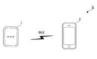
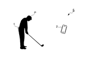
図1は、本発明の一実施形態に係る解析システムSの構成を示すシステム構成図である。また、図2は、解析システムSの使用形態例を示す模式図である。
図1及び図2に示すように、解析システムSは、センサユニット1と、処理装置2と、を含んで構成される。また、センサユニット1と処理装置2とは、Bluetooth(登録商標) low energy/Bluetooth LE(以下、「BLE」と称する。)によって通信可能に構成される。
センサユニット1は、計測対象に装着され、計測対象の動きをセンシングしてセンサ情報を処理装置2に送信する。本実施形態においては、ゴルフのスイングの動作をする者(以下、「計測対象者P」と称する。)の腰等にセンサユニット1を装着し、当該動作をセンシングする。
[System configuration]
FIG. 1 is a system configuration diagram showing a configuration of an analysis system S according to an embodiment of the present invention. Further, FIG. 2 is a schematic diagram showing an example of usage of the analysis system S.
As shown in FIGS. 1 and 2, the analysis system S includes a
The
処理装置2は、計測対象に装着したセンサユニット1から取得したセンサ情報を解析し、計測対象の動作を評価した結果を表示する。例えば、処理装置2は、計測対象が行ったゴルフのスイング毎に、計測対象の腰の回転速度、腰の角度、腰の移動量、スイングリズム、総合的な評価を表す評価結果の表示画面を表示する。
The
[ハードウェア構成]
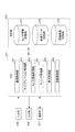
図3は、センサユニット1のハードウェアの構成を示すブロック図である。
センサユニット1は、計測対象の動きを検出する各種センサを備えた装置として構成される。
図3に示すように、センサユニット1は、CPU(Central Processing Unit)111と、ROM(Read Only Memory)112と、RAM(Random Access Memory)113と、バス114と、入出力インターフェース115と、センサ部116と、入力部117と、出力部118と、記憶部119と、通信部120と、を備えている。なお、センサユニット1は、半導体メモリ等よりなるリムーバブルメディアを装着可能な構成としてもよい。
[Hardware configuration]
FIG. 3 is a block diagram showing a hardware configuration of the
The
As shown in FIG. 3, the
CPU111は、ROM112に記録されているプログラム、または、記憶部119からRAM113にロードされたプログラムに従って各種の処理を実行する。
The
RAM113には、CPU111が各種の処理を実行する上において必要なデータ等も適宜記憶される。
Data and the like necessary for the
CPU111、ROM112及びRAM113は、バス114を介して相互に接続されている。このバス114にはまた、入出力インターフェース115も接続されている。入出力インターフェース115には、センサ部116、入力部117、出力部118、記憶部119及び通信部120が接続されている。
The
センサ部116は、3軸方向の加速度を測定する3軸加速度センサと、3軸方向の角速度を測定する3軸角速度センサと、3軸方向の地磁気を測定する3軸地磁気センサとを備えている。センサ部116は、予め設定されたサンプリング周期(例えば、0.001秒)毎に、3軸加速度センサ、3軸角速度センサ及び3軸地磁気センサによって3軸方向の加速度、角速度及び地磁気を測定する。センサ部116によって測定された加速度及び角速度のデータは、測定時刻のデータと対応付けて、記憶部119に記憶あるいは処理装置2に送信される。
The
入力部117は、各種ボタン等で構成され、ユーザの指示操作に応じて各種情報を入力する。
出力部118は、ランプやスピーカあるいは振動用モータ等で構成され、光や音声あるいはバイブレーション信号を出力する。
記憶部119は、DRAM(Dynamic Random Access Memory)等の半導体メモリで構成され、各種データを記憶する。
通信部120は、端末間の直接的な無線通信によって他の装置との間で行う通信を制御する。本実施形態において、通信部120は、BLE(登録商標)によって処理装置2と通信する。
The
The
The
The
図4は、処理装置2のハードウェア構成を示すブロック図である。
処理装置2は、情報表示機能を備えた情報処理装置であり、例えば、スマートフォンとして構成される。
FIG. 4 is a block diagram showing a hardware configuration of the
The
図4に示すように、処理装置2は、CPU211と、ROM212と、RAM213と、バス214と、入出力インターフェース215と、撮像部216と、センサ部217と、入力部218と、出力部219と、記憶部220と、通信部221と、ドライブ222と、を備えている。なお、ドライブ222には、磁気ディスク、光ディスク、光磁気ディスク、あるいは半導体メモリ等よりなる、リムーバブルメディア231が適宜装着される。
これらのうち、撮像部216、入力部218、出力部219及び通信部221以外の構成は、図3において対応する各部分と同様である。
As shown in FIG. 4, the
Of these, the configurations other than the
撮像部216は、図示はしないが、光学レンズ部と、イメージセンサと、を備えている。
Although not shown, the
光学レンズ部は、被写体を撮影するために、光を集光するレンズ、例えばフォーカスレンズやズームレンズ等で構成される。
フォーカスレンズは、イメージセンサの受光面に被写体像を結像させるレンズである。ズームレンズは、焦点距離を一定の範囲で自在に変化させるレンズである。
撮像部216にはまた、必要に応じて、焦点、露出、ホワイトバランス等の設定パラメータを調整する周辺回路が設けられる。
The optical lens unit is composed of a lens that collects light, such as a focus lens or a zoom lens, in order to photograph a subject.
The focus lens is a lens that forms a subject image on the light receiving surface of the image sensor. A zoom lens is a lens that freely changes the focal length within a certain range.
The
イメージセンサは、光電変換素子や、AFE(Analog Front End)等から構成される。
光電変換素子は、例えばCMOS(Complementary Metal Oxide Semiconductor)型の光電変換素子等から構成される。光電変換素子には、光学レンズ部から被写体像が入射される。そこで、光電変換素子は、被写体像を光電変換(撮像)して画像信号を一定時間蓄積し、蓄積した画像信号をアナログ信号としてAFEに順次供給する。
AFEは、このアナログの画像信号に対して、A/D(Analog/Digital)変換処理等の各種信号処理を実行する。各種信号処理によって、ディジタル信号が生成され、撮像部216の出力信号として出力される。
このような撮像部216の出力信号を、以下、適宜「撮像画像のデータ」と呼ぶ。撮像画像のデータは、CPU211等に適宜供給される。
The image sensor is composed of a photoelectric conversion element, an AFE (Analog Front End), and the like.
The photoelectric conversion element is composed of, for example, a CMOS (Complementary Metal Oxide Semiconductor) type photoelectric conversion element or the like. A subject image is incident on the photoelectric conversion element from the optical lens unit. Therefore, the photoelectric conversion element performs photoelectric conversion (imaging) of the subject image, accumulates an image signal for a certain period of time, and sequentially supplies the accumulated image signal as an analog signal to AFE.
The AFE executes various signal processing such as A / D (Analog / Digital) conversion processing on the analog image signal. A digital signal is generated by various signal processing and is output as an output signal of the
Such an output signal of the
入力部218は、各種ボタンやタッチパネル等で構成され、ユーザの指示操作に応じて各種情報を入力する。
出力部219は、ディスプレイやスピーカ等で構成され、画像や音声を出力する。
通信部221は、インターネットを含むネットワークを介して他の装置(図示せず)との間で行う通信を制御する。また、通信部221は、端末間の直接的な無線通信によって他の装置との間で行う通信を制御する。本実施形態において、通信部221は、BLE(登録商標)によってセンサユニット1と通信する。
The
The
The
[機能的構成]
図5は、センサユニット1の機能的構成のうち、情報検出処理を実行するための機能的構成を示す機能ブロック図である。
情報検出処理とは、解析システムSが計測対象の動きを解析する際に、計測対象に装着されたセンサユニット1が計測対象の動きをセンシングする一連の処理である。
情報検出処理が実行される場合、図5に示すように、CPU111において、通信制御部151と、キャリブレーション実行部152と、検出処理部153と、センサ情報送信制御部154とが機能する。
また、記憶部119の一領域には、センサ情報記憶部171が設定される。
センサ情報記憶部171には、センサユニット1において取得されたセンサ情報が、取得された時刻と対応付けて記憶される。
[Functional configuration]
FIG. 5 is a functional block diagram showing a functional configuration for executing information detection processing among the functional configurations of the
The information detection process is a series of processes in which the
When the information detection process is executed, as shown in FIG. 5, the
Further, a sensor information storage unit 171 is set in one area of the
The sensor information storage unit 171 stores the sensor information acquired by the
通信制御部151は、センサユニット1のBLEによる通信を制御し、他の装置とのペアリング処理やデータの送受信処理を実行する。
The
キャリブレーション実行部152は、処理装置2からの指示に応じて、基準となる状態におけるセンサ情報を取得し、取得結果を基準値とするキャリブレーションを実行する。本実施形態においては、キャリブレーション実行部152は、センサユニット1が計測対象者Pの腰に装着され、ゴルフのスイングを行うための位置にアドレスした姿勢を取った状態を基準とし、この状態で取得されたセンサ情報が基準値とされる。
The
図6Aは、センサユニット1の装着状態を示す模式図、図6Bは、センサユニット1によって検出される情報の例を示す模式図である。なお、以下の説明において、センサユニット1に設定される各軸は、前後方向の回転については計測対象者Pの前傾方向をプラス、鉛直軸周りの回転については計測対象者Pのフォロー方向をプラス、左右方向の回転については計測対象者Pのフォロー側の腰が高くなる方向をプラスとする。また、前後方向の平行移動については計測対象者Pの前方をプラス、上下方向の平行移動については計測対象者Pの上方をプラス、左右方向の平行移動については計測対象者Pのフォロー方向をプラスとする。
FIG. 6A is a schematic diagram showing a mounted state of the
キャリブレーションが行われる場合、図6Aに示すように、例えば、センサユニット1がベルト等によって計測対象者Pの腰に装着され、計測対象者Pがゴルフのスイングを行うための位置で、ボールに向かいアドレスした姿勢で所定時間(例えば2秒)静止する。このとき、図6Bに示すように、センサユニット1は、3軸加速度センサによって検出される重力方向及び3軸地磁気センサによって検出される方位を基準として、センサ情報(身体の前後方向の傾斜角度、左右方向の傾斜角度及び鉛直軸周りの回転角度)を取得し、取得された各センサ情報をアドレス時の基準値とする。そして、以降、計測対象者Pがスイングを行う際に、センサユニット1において検出される各センサ情報が、所定時間(例えば2秒)以上、アドレス時の基準値に対し、各センサ情報について設定された閾値の範囲内となっている場合に、アドレスの状態であると検出される。
また、センサユニット1は、3軸加速度センサを備えているため、センサユニット1の移動(平行移動等)についても検出可能であり、3軸地磁気センサを備えているため、センサユニット1が向いている方位についても検出可能である。
When calibration is performed, as shown in FIG. 6A, for example, the
Further, since the
なお、キャリブレーション実行部152がキャリブレーションを実行する場合、計測対象者Pが直立した状態で基準値を取得することとしてもよい。
例えば、センサユニット1がベルト等によって計測対象者Pの腰に装着され、計測対象者Pがゴルフのスイングを行うための位置で、ボールに向かい直立した姿勢で所定時間(例えば2秒)静止する。このとき、センサユニット1が、3軸加速度センサによって検出される重力方向及び3軸地磁気センサによって検出される方位を基準として、センサ情報(身体の前後方向の傾斜角度、左右方向の傾斜角度及び鉛直軸周りの回転角度)を取得し、取得された各センサ情報を直立時の基準値とする。そして、以降、計測対象者Pがスイングを行う際に、センサユニット1において検出される各センサ情報が、所定時間(例えば2秒)以上、直立時の基準値に対し、各センサ情報について設定されたアドレス時の姿勢に対応する閾値の範囲内となっている場合に、アドレスの状態であると検出される。
When the
For example, the
検出処理部153は、各種センサ情報を逐次取得し、取得したセンサ情報を、取得された時刻と対応付けてセンサ情報記憶部171に記憶する。なお、センサ情報記憶部171に記憶されたセンサ情報は、取得された時刻から所定時間が経過した場合に順次破棄することとしてもよい。ただし、ゴルフのスイングのアドレスからスイング終了までに取得されたセンサ情報は、少なくとも処理装置2への送信が完了した後に破棄される。
また、検出処理部153は、取得したセンサ情報に基づいて、ゴルフのスイングにおける所定の特徴的なポイントのタイミングを検出する。例えば、検出処理部153は、取得したセンサ情報の波形を解析し、ゴルフのスイングにおけるアドレス、トップ、ダウンスイング、インパクト、フォローの各ポイントのタイミングを検出する。
なお、上記のようにゴルフのスイングにおける各ポイントのタイミングを検出するのみならず、各ポイントに該当する期間を直接検出することとしてもよい。
The
Further, the
In addition to detecting the timing of each point in the golf swing as described above, the period corresponding to each point may be directly detected.
また、検出処理部153は、アドレスのタイミングを検出した場合及びフォローのタイミングを検出した場合、アドレスのタイミングが検出されたことを示す信号(以下、「アドレス検出信号」と称する。)及びフォローのタイミングが検出されたことを示す信号(以下、「フォロー検出信号」と称する。)を、BLEによって処理装置2に逐次送信する。
Further, when the
センサ情報送信制御部154は、検出処理部153によって取得されたセンサ情報を処理装置2に送信する制御を行う。本実施形態において、検出処理部153では、例えば、1000サンプル/秒程度でセンサ情報を取得することができる。そして、センサ情報送信制御部154は、検出処理部153によって取得されたセンサ情報を予め設定されたサンプリングレート(例えば、240サンプル/秒程度)に変換して処理装置2に送信する。なお、本実施形態においては、計測対象者Pのゴルフのスイングにおけるアドレスからフォローまでの範囲のセンサ情報が処理装置2に送信される。
The sensor information
また、センサ情報送信制御部154は、センサ情報を処理装置2に送信する場合、検出処理部153によって検出されたアドレス、トップ、ダウンスイング、インパクト、フォローの各ポイント(ゴルフのスイングにおける特徴的なポイント)のタイミングを、併せて処理装置2に送信する。
なお、本実施形態において、検出処理部153で取得されたセンサ情報は、各種センサの出力信号をそれぞれフィルタリングすることにより、ノイズの影響を抑制した波形に変換され、センサ情報送信制御部154は、処理結果のセンサ情報が表す波形から取得されるセンサ情報を処理装置2に送信する。
これにより、ノイズの影響によってばらつきが大きいセンサ情報よりも信頼度が高い情報を参照して、計測対象者Pの動きを評価することができる。
Further, when the sensor information
In the present embodiment, the sensor information acquired by the
As a result, the movement of the measurement target person P can be evaluated by referring to the information having higher reliability than the sensor information having a large variation due to the influence of noise.
次に、処理装置2の機能的構成について説明する。
図7は、処理装置2の機能的構成のうち、評価結果表示処理を実行するための機能的構成を示す機能ブロック図である。
評価結果表示処理とは、センサユニット1によって検出されたセンサ情報を解析して、計測対象者Pのゴルフのスイングにおける特徴(腰の回転速度、腰の角度、腰の移動量、スイングリズム、総合的な評価等)を取得し、取得した特徴を計測対象者Pのスイングの評価結果として数値及び図形を用いて表示する一連の処理である。
評価結果表示処理が実行される場合、図7に示すように、CPU211において、通信制御部251と、キャリブレーション管理部252と、センサ情報取得部253と、スイング評価部254と、表示制御部255と、記録制御部256とが機能する。
また、記憶部220の一領域には、センサ情報記憶部271と、参照データ記憶部272と、評価結果記憶部273とが設定される。
Next, the functional configuration of the
FIG. 7 is a functional block diagram showing a functional configuration for executing the evaluation result display processing among the functional configurations of the
The evaluation result display process analyzes the sensor information detected by the
When the evaluation result display process is executed, as shown in FIG. 7, in the
Further, a sensor
センサ情報記憶部271には、センサユニット1から送信されたスイング毎のセンサ情報が、センサ情報が取得された時刻と対応付けて記憶される。
参照データ記憶部272には、ゴルフの上級者のスイングに関する統計データ(平均値等)や計測対象者P自身の良好なスイングのデータ等、スイングを評価する際に基準として参照されるデータが記憶される。
図8は、ゴルフの上級者(プロゴルファーP1〜P7)におけるスイングのデータの一例を表す模式図である。また、図9は、ゴルフの初級者及び中級者(アマチュアA1〜A7)におけるスイングのデータの一例を表す模式図である。
図8に示すように、ゴルフの上級者におけるスイングは、腰の回転角加速度の波形において、大きな山が2つ出現する傾向にある。これは、上級者の場合、スイング中に腰の回転を一度止めていることを意味しており、この動作によって、腰の回転速度を高めることが容易となる。また、図8及び図9を参照すると、腰の回転の最大角速度は、ゴルフの上級者(プロゴルファー)の場合、平均して530[度/sec]であるのに対し、ゴルフの初級者及び中級者(アマチュア)の場合、平均して480[度/sec]である。また、トップの姿勢から腰の最高回転速度に到達するまでの平均角加速度は、ゴルフの上級者の場合、平均して2500[度/sec2]であるのに対し、ゴルフの初級者及び中級者の場合、平均して1700[度/sec2]である。また、トップの姿勢における腰の回転角度は、ゴルフの上級者の場合、平均して−60[度]であるのに対し、ゴルフの初級者及び中級者の場合、平均して−70[度]である。これらの傾向から、ゴルフの初級者及び中級者の場合、上級者に比べて、特に腰の回転角加速度が小さく、最高回転速度に到達するまでに時間を要する点で大きく異なっていると判断することができる。即ち、ゴルフの上級者と初級者及び中級者とを比べると、腰の使い方に大きな差があり、初級者及び中級者は腰の使い方を改善することで、ゴルフのスイングの上達を図ることができる。
図7に戻り、評価結果記憶部273は、評価結果表示処理において生成された計測対象者Pの評価結果に関する情報が記憶される。
The sensor
The reference
FIG. 8 is a schematic diagram showing an example of swing data in an advanced golfer (professional golfers P1 to P7). Further, FIG. 9 is a schematic diagram showing an example of swing data for beginners and intermediate golfers (amateurs A1 to A7).
As shown in FIG. 8, in a swing in an advanced golfer, two large peaks tend to appear in the waveform of the rotational angular acceleration of the waist. This means that in the case of an advanced person, the rotation of the waist is stopped once during the swing, and this operation makes it easy to increase the rotation speed of the waist. Further, referring to FIGS. 8 and 9, the maximum angular velocity of hip rotation is 530 [degrees / sec] on average for advanced golfers (professional golfers), whereas it is for beginners and intermediate golfers. In the case of a person (amateur), the average is 480 [degrees / sec]. In addition, the average angular acceleration from the top posture to the maximum rotation speed of the waist is 2500 [degrees / sec 2 ] on average for advanced golfers, whereas it is for beginners and intermediate golfers. In the case of a person, the average is 1700 [degrees / sec 2 ]. In addition, the rotation angle of the waist in the top posture is -60 [degrees] on average for advanced golfers, whereas it is -70 [degrees] on average for beginners and intermediate golfers. ]. From these tendencies, it is judged that beginners and intermediate golfers are significantly different from advanced golfers in that the angular acceleration of the waist is particularly small and it takes time to reach the maximum rotation speed. be able to. That is, when comparing advanced golfers with beginners and intermediate golfers, there is a big difference in how to use the waist, and beginners and intermediate golfers can improve their golf swing by improving how to use the waist. it can.
Returning to FIG. 7, the evaluation
通信制御部251は、処理装置2のBLEによる通信を制御し、他の装置とのペアリング処理やデータの送受信処理を実行する。本実施形態において、BLEによる通信が行われる場合、処理装置2がマスタとなり、他の装置がスレーブとなる。
The
キャリブレーション管理部252は、センサユニット1に対し、キャリブレーションの実行を指示する。本実施形態において、センサユニット1におけるキャリブレーションは、評価結果表示処理の実行時に一度実行される。
The
センサ情報取得部253は、予め設定されたサンプリングレートのセンサ情報を、BLEによってセンサユニット1から取得する。本実施形態において、センサ情報取得部253は、計測対象者Pのゴルフのスイングにおけるアドレスからフォローまでの範囲のセンサ情報をセンサユニット1から取得する。このとき取得されるセンサ情報には、アドレス、トップ、ダウンスイング、インパクト、フォローの各ポイントを識別する情報が付加されている。
The sensor
スイング評価部254は、センサユニット1から取得した各種センサ情報を解析し、計測対象者Pのゴルフのスイングにおける特徴(腰の回転速度、腰の角度、腰の移動量、スイングリズム、総合的な評価等)を表すデータ(以下、「評価結果データ」と称する。)を取得する。
このとき、スイング評価部254は、3軸加速度センサの検出値を積分して移動量(距離)を算出したり、3軸角速度センサの検出値を微分して回転角加速度を算出したり、3軸角速度センサの検出値を積分して回転角度を算出したりする。
なお、本実施形態において、スイング評価部254は、センサ情報から取得可能なスイングに関する種々のデータを取得することができ、これらのうち、必要なデータをスイングの評価結果データとして用いることができる。
The
At this time, the
In the present embodiment, the
表示制御部255は、計測対象者Pのスイングを計測するための案内画面を表示する。この案内画面には、「アドレスしてください」、「スイングを行ってください」といった行動を促すメッセージや、「スイングを解析中です」といった状況を報知するメッセージが含まれている。
また、表示制御部255は、スイング評価部254によって取得された評価結果データに基づいて、計測対象者Pのスイングの評価結果を表す画面(以下、「評価結果表示画面」と称する。)を表示する。評価結果表示画面が表示される場合、メニュー画面において、腰の回転速度、腰の角度、腰の移動量、スイングリズム、総合的な評価をそれぞれ表示するためのボタンが表示される。そして、ユーザがいずれかのボタンを操作すると、それぞれの特徴を表示する評価結果表示画面が表示される。
The
Further, the
図10は、評価結果表示画面の一例を示す模式図である。
図10に示すように、評価結果表示画面として、腰の回転速度に関する特徴を表示する回転速度表示画面、腰の角度に関する特徴を表示する角度表示画面、腰の移動量に関する特徴を表示する移動量表示画面、スイングリズムに関する特徴を表示するスイングリズム表示画面、及び、総合的な評価に関する特徴を表示する総合評価表示画面が選択可能となっている。
FIG. 10 is a schematic view showing an example of the evaluation result display screen.
As shown in FIG. 10, as the evaluation result display screen, a rotation speed display screen that displays features related to the rotation speed of the waist, an angle display screen that displays the features related to the angle of the waist, and a movement amount that displays the features related to the movement amount of the waist. A display screen, a swing rhythm display screen that displays features related to swing rhythm, and a comprehensive evaluation display screen that displays features related to comprehensive evaluation can be selected.
回転速度表示画面は、腰の回転速度(回転角速度)やトップの姿勢から腰の最高回転速度への到達時間を表す数値、及び、腰の回転速度の時間変化を表すグラフ等を含む表示画面である。
角度表示画面は、スイングにおける各ポイントでの前傾角度、回転角度、水平角度を表す数値、これらの最大値、最小値及び変化幅等を含む表示画面である。
移動量表示画面は、スイングにおける各ポイント間の上下方向、左右方向、及び、前後方向の移動量の大小(移動度合い)を表すインジケータ等を含む表示画面である。本実施形態において、移動量表示画面におけるインジケータは、所定数以上の上級者(男女のプロゴルファー等)のスイングの平均に基づく統計データに対し、計測対象者Pのスイングが有する偏差を段階的に表している。
The rotation speed display screen is a display screen that includes a numerical value indicating the rotation speed (rotational angular velocity) of the waist, the time required to reach the maximum rotation speed of the waist from the top posture, and a graph showing the time change of the rotation speed of the waist. is there.
The angle display screen is a display screen including numerical values representing a forward tilt angle, a rotation angle, and a horizontal angle at each point in the swing, their maximum value, minimum value, change width, and the like.
The movement amount display screen is a display screen including indicators and the like indicating the magnitude (movement degree) of the movement amount in the vertical direction, the horizontal direction, and the front-back direction between each point in the swing. In the present embodiment, the indicator on the movement amount display screen stepwise represents the deviation of the swing of the measurement target person P with respect to the statistical data based on the average swing of a predetermined number or more of advanced players (male and female professional golfers, etc.). ing.
スイングリズム表示画面は、スイングにおけるポイント毎の経過時間(ポイント間の所要時間)を表す数値等を含む表示画面である。
総合評価表示画面は、計測対象者Pのスイングを評価項目毎に点数で評価した結果を示すレーダーチャート及び点数を表す数値等を含む表示画面である。
The swing rhythm display screen is a display screen including numerical values indicating the elapsed time for each point (time required between points) in the swing.
The comprehensive evaluation display screen is a display screen including a radar chart showing the result of evaluating the swing of the measurement target person P by points for each evaluation item, a numerical value showing the points, and the like.
これらの表示画面うち、回転速度表示画面には、腰の回転速度に関するグラフが表示される。
図11は、回転速度表示画面の一例を示す模式図である。
図11に示すように、回転速度表示画面には、腰の回転速度(回転角速度)の最大値を表示する領域R1、トップの姿勢から腰の最高回転速度への到達時間を表示する領域R2、腰の回転速度の時間変化を表すグラフの領域R3、及び、計測対象者Pの飛距離のポテンシャル(ポテンシャル飛距離)を表示する領域R4が含まれている。なお、ポテンシャル飛距離は、スイングのデータが計測対象者Pに近い複数のプレーヤーの打球の飛距離から、統計的な方法(平均値を取る等)で算出される。
Of these display screens, the rotation speed display screen displays a graph relating to the rotation speed of the waist.
FIG. 11 is a schematic view showing an example of a rotation speed display screen.
As shown in FIG. 11, the rotation speed display screen has an area R1 for displaying the maximum value of the rotation speed (rotational angular velocity) of the waist, and an area R2 for displaying the time required to reach the maximum rotation speed of the waist from the top posture. The area R3 of the graph showing the time change of the rotation speed of the waist and the area R4 displaying the potential (potential flight distance) of the flight distance of the measurement target person P are included. The potential flight distance is calculated by a statistical method (taking an average value, etc.) from the flight distances of hit balls of a plurality of players whose swing data is close to the measurement target person P.
上述したように、ゴルフの上級者と初級者及び中級者とでは腰の使い方に大きな差があり、腰の回転速度の時間変化(グラフ)を見た場合、一般に、腰の回転速度の波形は、ゴルフの上達と共に、山脈型、ひと山型、ふた山型の順に変化する。
ふた山型は、腰の回転速度の波形が、概して前半のピーク及び後半のピークを有する山(2つの大きな山)と、その間の谷とに明確に分かれるスイングのタイプであり、プロゴルファー等の上級者に見られるタイプである。即ち、上級者は、スイング中に腰の回転が一度止まっており、この動作によって、腰の回転速度を高めることが容易となる。
As mentioned above, there is a big difference in how to use the waist between advanced golfers and beginners and intermediate golfers, and when looking at the time change (graph) of the rotation speed of the waist, the waveform of the rotation speed of the waist is generally , As golf progresses, it changes in the order of mountain range type, one mountain type, and lid mountain type.
The lid mountain type is a type of swing in which the waveform of the rotation speed of the waist is clearly divided into a mountain (two large mountains) having a peak in the first half and a peak in the second half and a valley between them, and is an advanced type such as a professional golfer. It is a type that can be seen by people. That is, the advanced person has stopped the rotation of the waist once during the swing, and this operation makes it easy to increase the rotation speed of the waist.
ひと山型は、腰の回転速度の波形が、概して1つのピークを有する山(大きな1つの山)となるスイングのタイプである。ひと山型のスイングの場合、腰は回転しているものの、回転速度が遅い、あるいは、効率的に腰を動かせていないことを意味しており、ひと山型のスイングとなる結果、体重移動をスムーズに行うことが困難となる。 The one-mountain type is a type of swing in which the waveform of the rotation speed of the waist is generally a mountain having one peak (one large mountain). In the case of a one-mountain swing, it means that the hips are rotating, but the rotation speed is slow or the hips cannot be moved efficiently, and as a result of the one-mountain swing, weight transfer is smooth. It becomes difficult to do.
山脈型は、腰の回転速度の波形が、小刻みな山の連続となるスイングのタイプである。山脈型のスイングの場合、トップからインパクトにかけて腰がスムーズに回転していないことを意味しており、手打ちあるいはスウェーとなる場合は、山脈型のスイングとなる。
回転速度表示画面を確認した計測対象者Pは、自身のスイングがいずれのタイプに該当するかを視覚的に判断することができる。
The mountain range type is a swing type in which the waveform of the rotation speed of the waist is a series of small mountains. In the case of a mountain range type swing, it means that the waist does not rotate smoothly from the top to the impact, and in the case of hand striking or swaying, it is a mountain range type swing.
The measurement target person P who has confirmed the rotation speed display screen can visually determine which type his / her swing corresponds to.
また、本実施形態において、所定の操作(例えば、アドバイスを表示させるアイコンの操作等)が行われた場合、表示制御部255は、これらスイングのタイプに関する説明と、タイプに応じたスイングの改善に関する方法とをユーザに対する支援情報として提示する画面(以下、「メソッド提示画面」と称する。)を表示する。メソッド表示画面において、表示制御部255は、支援情報として、例えば、スイングの改善点と、スイングを改善するためのトレーニングとを表示する。
Further, in the present embodiment, when a predetermined operation (for example, an operation of an icon for displaying advice) is performed, the
図12は、メソッド提示画面の表示内容の一例を示す模式図である。
図12に示すように、メソッド提示画面においては、計測対象者Pの腰の回転速度の波形のタイプ(ふた山型、ひと山型、山脈型)と、腰の回転速度の概略の評価結果(最高回転速度、トップの姿勢から腰の最高回転速度への到達時間、2つの大きな山の出現に関する○、×、△の評価)と、タイプ毎の支援情報とが表示される。ふた山型のスイングに対しては、さらにスイングを向上させるための支援情報が表示され、図12の例では、トップの姿勢から腰の最高回転速度への到達時間を短縮するべきこと、及び、そのためのアドバイスのコメントが表示されている。また、ひと山型のスイングに対しては、ふた山型のスイングとなるべき旨の支援情報、及び、そのためのアドバイスのコメントが表示されている。なお、ひと山型のスイングに対して、図12の例では、身体をトレーニングするための改善ドリルが併せて表示されている。さらに、山脈型のスイングに対しては、ひと山型のスイングとなるべき旨の支援情報、及び、そのためのアドバイス情報が表示されている。
FIG. 12 is a schematic diagram showing an example of the display contents of the method presentation screen.
As shown in FIG. 12, on the method presentation screen, the type of the waveform of the rotation speed of the waist of the measurement target person P (two mountain type, one mountain type, mountain type) and the approximate evaluation result of the rotation speed of the waist (highest). Rotation speed, time to reach the maximum rotation speed of the waist from the top posture, evaluation of ○, ×, △ regarding the appearance of two large mountains) and support information for each type are displayed. For the lid mountain type swing, support information for further improving the swing is displayed, and in the example of FIG. 12, the time required to reach the maximum rotation speed of the waist from the top posture should be shortened, and The comment of the advice for that is displayed. In addition, for a single-mountain swing, support information indicating that it should be a double-mountain swing and comments on advice for that purpose are displayed. In the example of FIG. 12, an improved drill for training the body is also displayed for the one-mountain type swing. Further, for the mountain range type swing, the support information that the swing should be a mountain range type and the advice information for that are displayed.
なお、メソッド提示画面のコンテンツは、処理装置2に記憶しておくことや、外部装置へのリンクとしておき、所定のコンテンツサーバ等からダウンロードすることが可能である。また、メソッド提示画面のコンテンツを音声によって出力することとしてもよい。これにより、スイングを行っている計測対象者Pは、より容易に表示内容を把握することができる。
The content of the method presentation screen can be stored in the
また、移動量表示画面には、スイングにおける各ポイント間の上下方向、左右方向、及び、前後方向の移動量の大小(移動度合い)を表すインジケータが表示される。
図13は、移動量表示画面の一例を示す模式図である。
図13に示すように、移動量表示画面においては、計測対象者Pのスイングについて、各ポイント間の左右移動量、上下移動量及び前後移動量それぞれの度合い(基準となるスイングに対する偏差)が5段階のインジケータInで表されている。
Further, on the movement amount display screen, an indicator indicating the magnitude (movement degree) of the movement amount in the vertical direction, the horizontal direction, and the front-back direction between each point in the swing is displayed.
FIG. 13 is a schematic view showing an example of the movement amount display screen.
As shown in FIG. 13, on the movement amount display screen, the degree of each of the left-right movement amount, the up-down movement amount, and the front-back movement amount (deviation with respect to the reference swing) between the points is 5 for the swing of the measurement target person P. It is represented by the indicator In of the stage.
図14は、インジケータと偏差との関係を示す模式図である。
なお、図14におけるx1〜x12、y1〜y12、z1〜z12は、移動量の度合いの境界値を示している。
図14に示すように、移動量表示画面が表示される場合、左右、前後、上下の各項目において、アドレス〜トップ、トップ〜正面、正面〜フィニッシュの各ポイントの腰の移動量が、統計データに対して、どの程度の偏差を有するかが分類される。そして、分類された偏差の範囲(マイナス側からプラス側に並ぶインジケータA〜Eに対応する範囲)に応じて、移動量表示画面において識別表示されるインジケータが決定される。図14においては、中央のインジケータCが「平均値」を含む範囲に対応しており、インジケータCの範囲は、「偏差」で表される値に設定されている。
FIG. 14 is a schematic diagram showing the relationship between the indicator and the deviation.
Note that x1 to x12, y1 to y12, and z1 to z12 in FIG. 14 indicate boundary values of the degree of movement.
As shown in FIG. 14, when the movement amount display screen is displayed, the movement amount of the waist at each point of address-top, top-front, front-finish is statistical data in each item of left / right, front / back, and up / down. It is classified according to how much deviation it has. Then, the indicators to be identified and displayed on the movement amount display screen are determined according to the classified deviation range (the range corresponding to the indicators A to E arranged from the minus side to the plus side). In FIG. 14, the central indicator C corresponds to the range including the “mean value”, and the range of the indicator C is set to the value represented by the “deviation”.
なお、計測対象者Pの偏差を求める場合の基準となる統計データとして、所定数以上の上級者全体の平均値を用いることや、ドロー系のプレーヤー、フェード系のプレーヤー、男子プロゴルファー、女子プロゴルファー、使用するクラブの種類等に応じたモデル毎の平均値を用いることが可能である。また、計測対象者Pが良好なスイングであると判断した過去の自らのスイングを基準として用いること等も可能である。 In addition, as statistical data that serves as a reference when calculating the deviation of the measurement target person P, the average value of all advanced players of a predetermined number or more can be used, and draw-type players, fade-type players, male professional golfers, and female professional golfers can be used. It is possible to use the average value for each model according to the type of club to be used. It is also possible to use the past swing of the person to be measured P as a reference, which is judged to be a good swing.
記録制御部256は、スイング評価部254によって取得されたスイングの評価結果データを、評価結果記憶部273またはリムーバブルメディア231に記憶する。なお、記録制御部256は、評価結果データの保存を指示する操作が行われた場合に、評価結果データの記憶を実行する。
The
[動作]
次に、解析システムSの動作を説明する。
図15は、センサユニット1が実行する情報検出処理の流れを説明するフローチャートである。
情報検出処理は、センサユニット1の起動と共に開始される。
[motion]
Next, the operation of the analysis system S will be described.
FIG. 15 is a flowchart illustrating a flow of information detection processing executed by the
The information detection process is started when the
ステップS1において、通信制御部151は、BLEによってスレーブとして処理装置2と接続する。
ステップS2において、キャリブレーション実行部152は、処理装置2からの指示に応じて、基準となる状態におけるセンサ情報を取得し、取得結果を基準値とするキャリブレーションを実行する。
In step S1, the
In step S2, the
ステップS3において、キャリブレーション実行部152は、キャリブレーションが完了したことをBLEによって処理装置2に通知する。
ステップS4において、検出処理部153は、各種センサ情報を逐次取得し、取得したセンサ情報を、取得された時刻と対応付けてセンサ情報記憶部171に記憶する処理を開始する。
In step S3, the
In step S4, the
ステップS5において、検出処理部153は、取得したセンサ情報の波形を解析し、ゴルフのスイングにおけるアドレスのポイントのタイミングを検出して、アドレス検出信号をBLEによって処理装置2に送信する。
In step S5, the
ステップS6において、検出処理部153は、取得したセンサ情報の波形を解析し、ゴルフのスイングにおけるフォローのポイントのタイミングを検出して、フォロー検出信号をBLEによって処理装置2に送信する。
In step S6, the
ステップS7において、検出処理部153は、取得したセンサ情報の波形を解析し、ゴルフのスイングにおけるトップ、ダウンスイング、インパクトの各ポイントのタイミングを検出する。
ステップS8において、センサ情報送信制御部154は、アドレスからフォローまでのセンサ情報を予め設定されたサンプリングレート(例えば、240サンプル/秒程度)に変換して処理装置2に送信する。
ステップS8の後、処理はステップS4に移行する。
その後、情報検出処理を終了させる操作が入力されると、情報検出処理は終了となる。
In step S7, the
In step S8, the sensor information
After step S8, the process proceeds to step S4.
After that, when the operation to end the information detection process is input, the information detection process ends.
次に、処理装置2が実行する評価結果表示処理について説明する。
図16は、処理装置2が実行する評価結果表示処理の流れを説明するフローチャートである。
評価結果表示処理は、入力部218を介して解析結果表示処理の開始を指示する操作が行われることにより開始される。
Next, the evaluation result display process executed by the
FIG. 16 is a flowchart illustrating a flow of evaluation result display processing executed by the
The evaluation result display process is started by performing an operation instructing the start of the analysis result display process via the
ステップS11において、通信制御部251は、BLEによってマスタとしてセンサユニット1と接続する。
ステップS12において、キャリブレーション管理部252は、センサユニット1に対し、キャリブレーションの実行を指示する。
In step S11, the
In step S12, the
ステップS13において、キャリブレーション管理部252は、センサユニット1からキャリブレーションの実行が完了したことの通知をBLEによって受信する。
ステップS14において、表示制御部255は、計測対象者Pにアドレスを促す案内画面を表示する。
ステップS15において、通信制御部251は、アドレス検出信号をBLEによってセンサユニット1から受信する。
In step S13, the
In step S14, the
In step S15, the
ステップS16において、表示制御部255は、計測対象者Pにスイングを促す案内画面を表示する。
ステップS17において、通信制御部251は、フォロー検出信号をBLEによってセンサユニット1から受信する。
ステップS18において、表示制御部255は、スイングを解析中であることを示す案内画面を表示する。
In step S16, the
In step S17, the
In step S18, the
ステップS19において、センサ情報取得部253は、予め設定されたサンプリングレートのセンサ情報を、BLEによってセンサユニット1から取得する。
ステップS20において、表示制御部255は、スイング評価部254によって取得された評価結果データに基づいて、計測対象者Pのスイングの評価結果を表す評価結果表示画面を表示する。このとき、表示制御部255は、メニュー画面において選択されたボタンに対応する評価結果表示画面(図10参照)を表示する。
In step S19, the sensor
In step S20, the
ステップS21において、表示制御部255は、メソッド提示画面の表示を指示する操作が行われたか否かの判定を行う。
メソッド提示画面の表示を指示する操作が行われた場合、ステップS21においてYESと判定されて、処理はステップS22に移行する。
一方、メソッド提示画面の表示を指示する操作が行われていない場合、ステップS21においてNOと判定されて、処理はステップS23に移行する。
ステップS22において、表示制御部255は、メソッド提示画面を表示する。
ステップS23において、記録制御部256は、評価結果データの保存を指示する操作が行われたか否かの判定を行う。
評価結果データの保存を指示する操作が行われていない場合、ステップS23においてNOと判定されて、処理はステップS14に移行する。
一方、評価結果データの保存を指示する操作が行われた場合、ステップS23においてYESと判定されて、処理はステップS24に移行する。
In step S21, the
When the operation for instructing the display of the method presentation screen is performed, YES is determined in step S21, and the process proceeds to step S22.
On the other hand, if the operation for instructing the display of the method presentation screen is not performed, NO is determined in step S21, and the process proceeds to step S23.
In step S22, the
In step S23, the
If the operation for instructing the storage of the evaluation result data has not been performed, NO is determined in step S23, and the process proceeds to step S14.
On the other hand, when the operation of instructing the storage of the evaluation result data is performed, YES is determined in step S23, and the process proceeds to step S24.
ステップS24において、記録制御部256は、スイング評価部254によって取得されたスイングの評価結果データを、評価結果記憶部273またはリムーバブルメディア231に記憶する。
ステップS24の後、処理はステップS14に移行する。
その後、評価結果表示処理を終了させる操作が入力されると、評価結果表示処理は終了となる。
In step S24, the
After step S24, the process proceeds to step S14.
After that, when an operation for ending the evaluation result display process is input, the evaluation result display process ends.
このような処理により、解析システムSにおいては、計測対象者Pの身体の動きを計測して得られたセンサ情報に基づいて、計測対象者Pの身体の3次元的な動きを解析し、腰の回転速度、腰の角度、腰の移動量、スイングリズム、総合的な評価等を表す評価結果表示画面を表示することができる。
評価結果表示画面のうち、特に、回転速度表示画面では、腰の回転速度(回転角速度)やトップの姿勢から腰の最高回転速度への到達時間を表す数値、及び、腰の回転速度の時間変化を表すグラフ等が表示される。
そのため、ゴルフの上達において重要となる腰の使い方のタイプを視覚的にわかり易く表示することができ、計測対象者Pのスイングの上達度合いを適確に把握することができる。
したがって、計測対象者Pの腰部におけるセンサ情報(角速度等)に基づいて、計測対象者Pの動きの良否をより適切に判定することができる。
By such processing, the analysis system S analyzes the three-dimensional movement of the body of the measurement target person P based on the sensor information obtained by measuring the body movement of the measurement target person P, and analyzes the waist. It is possible to display an evaluation result display screen showing the rotation speed, the angle of the waist, the amount of movement of the waist, the swing rhythm, the comprehensive evaluation, and the like.
Among the evaluation result display screens, in particular, on the rotation speed display screen, numerical values indicating the rotation speed (rotation angular velocity) of the waist, the time required to reach the maximum rotation speed of the waist from the top posture, and the time change of the rotation speed of the waist. A graph or the like representing is displayed.
Therefore, it is possible to visually and easily display the type of how to use the waist, which is important for improving golf, and it is possible to accurately grasp the degree of improvement of the swing of the measurement target person P.
Therefore, it is possible to more appropriately determine the quality of the movement of the measurement target person P based on the sensor information (angular velocity, etc.) at the waist of the measurement target person P.
また、評価結果表示画面のうち、特に、移動量表示画面では、スイングにおける各ポイント間の上下方向、左右方向、及び、前後方向の移動量の大小(移動度合い)を表すインジケータ等が表示される。移動量表示画面におけるインジケータは、所定数以上の上級者(男女のプロゴルファー等)のスイングの平均に基づく統計データに対し、計測対象者Pのスイングが有する偏差を表している。
そのため、計測対象者Pのスイングと上級者のスイングとの差異について、左右、前後、上下の各項目において、アドレス〜トップ、トップ〜正面、正面〜フィニッシュの各ポイントの腰の移動量が、どの程度の偏差を有するかを視覚的にわかり易く表示することができる。
したがって、計測対象者Pの腰部に取り付けたセンサの測定値に基づいて、計測対象者Pの動きの良否をより適切に評価することができる。
このように、本実施形態における解析システムSによれば、計測対象者Pの動きの良否をより適切に評価することができる。
なお、計測対象者Pの動きの良否を評価する際に、計測対象者Pの腰部移動量と、基準となる統計データ、例えば、上級者の腰部移動量の平均値等の所定値との差を比較し、差が小さいほど、計測対象者Pの動きを高評価とすることとしてもよい。
In addition, among the evaluation result display screens, particularly on the movement amount display screen, indicators and the like indicating the magnitude (movement degree) of the movement amount in the vertical direction, the horizontal direction, and the front-back direction between each point in the swing are displayed. .. The indicator on the movement amount display screen represents the deviation of the swing of the measurement target person P with respect to the statistical data based on the average swing of a predetermined number or more of advanced players (male and female professional golfers, etc.).
Therefore, regarding the difference between the swing of the measurement target person P and the swing of the advanced person, what is the amount of movement of the waist at each point of address-top, top-front, front-finish in each item of left / right, front / back, and up / down? It is possible to visually and easily display whether or not there is a degree of deviation.
Therefore, it is possible to more appropriately evaluate the quality of the movement of the measurement target person P based on the measured value of the sensor attached to the waist of the measurement target person P.
As described above, according to the analysis system S in the present embodiment, it is possible to more appropriately evaluate the quality of the movement of the measurement target person P.
When evaluating the quality of the movement of the measurement target person P, the difference between the waist movement amount of the measurement target person P and a predetermined value such as a reference statistical data, for example, an average value of the lumbar movement amount of an advanced person. The smaller the difference, the higher the evaluation of the movement of the measurement target person P.
[変形例1]
上述の実施形態において、評価結果表示画面によって計測対象者Pのスイングの評価結果を表示する場合に、計測対象者Pのスイングの特徴を表すアニメーションを表示することとしてもよい。
例えば、計測対象者Pのスイングにリバースピボットやスウェーが生じている場合に、リバースピボットあるいはスウェーを呈するスイングを明確に行うアニメーションを表示することができる。
これにより、計測対象者Pのスイングにおける特徴を明確に表示することができる。
なお、このアニメーションを表示する場合に、計測対象者Pのスイングにおける特徴を誇張して表示することとしてもよい。
また、アニメーションと併せて、腰部の移動量等を表す数値を表示することとしてもよい。
[Modification 1]
In the above-described embodiment, when the evaluation result of the swing of the measurement target person P is displayed on the evaluation result display screen, an animation showing the characteristics of the swing of the measurement target person P may be displayed.
For example, when a reverse pivot or a sway occurs in the swing of the measurement target person P, it is possible to display an animation that clearly performs the swing exhibiting the reverse pivot or the sway.
As a result, the characteristics of the measurement target person P in the swing can be clearly displayed.
When displaying this animation, the characteristics of the measurement target person P in the swing may be exaggerated and displayed.
In addition to the animation, a numerical value indicating the amount of movement of the lumbar region may be displayed.
[変形例2]
上述の実施形態において、デジタルカメラ等の撮像装置をさらに使用し、計測対象者Pのスイングを計測すると共に、スイングの動画を撮影し、評価結果表示処理において、評価結果データと併せて、スイングの動画を表示することとしてもよい。
これにより、計測対象者Pのスイングの特徴を表す数値やグラフと、スイングの動画とを併せて表示することができるため、計測対象者Pのスイングの評価結果をよりわかり易い形態で表示することができる。
[Modification 2]
In the above-described embodiment, an imaging device such as a digital camera is further used to measure the swing of the measurement target person P, and a moving image of the swing is taken. In the evaluation result display processing, the swing is combined with the evaluation result data. A moving image may be displayed.
As a result, numerical values and graphs showing the characteristics of the swing of the measurement target person P and a moving image of the swing can be displayed together, so that the evaluation result of the swing of the measurement target person P can be displayed in a more understandable form. it can.
以上のように構成される解析システムSは、センサユニット1と、処理装置2とを備える。センサユニット1は、ユーザの腰部に装着される。処理装置2は、スイング評価部254を備える。
スイング評価部254は、ユーザの腰部に装着されたセンサによって測定された角速度の出力結果において、第1ピーク波形と第2ピーク波形とを抽出する。
スイング評価部254は、抽出結果に基づいて、ユーザの動きを評価する。
これにより、ユーザの腰部で検出された角速度の波形における第1ピーク波形及び第2ピーク波形の状態に着目して、ユーザの動きを評価することができる。
したがって、腰部に装着したセンサによってユーザの動きを検出する電子機器において、ユーザの動きの良否をより適切に判断することが可能となる。
The analysis system S configured as described above includes the
The
The
Thereby, the movement of the user can be evaluated by paying attention to the states of the first peak waveform and the second peak waveform in the waveform of the angular velocity detected in the lumbar region of the user.
Therefore, in an electronic device that detects the movement of the user by a sensor mounted on the lumbar region, it is possible to more appropriately determine the quality of the movement of the user.
スイング評価部254は、第1ピーク波形及び第2ピーク波形の形状に基づいてユーザの動きを評価する。
これにより、第1ピーク波形及び第2ピーク波形の具体的な形状の適否を反映させて、ユーザの動きの良否を判断することが可能となる。
The
This makes it possible to determine the quality of the user's movement by reflecting the suitability of the specific shapes of the first peak waveform and the second peak waveform.
スイング評価部254は、第1ピーク波形と第2ピーク波形との波形形状の関係性に基づいてユーザの動きを評価する。
これにより、第1ピーク波形と第2ピーク波形との間に角速度がほぼゼロとなる適切な谷が出現しているか否か等、第1ピーク波形及び第2ピーク波形単独の適否以外の条件も反映させて、ユーザの動きの良否を判断することが可能となる。
The
As a result, conditions other than the suitability of the first peak waveform and the second peak waveform alone, such as whether or not an appropriate valley in which the angular velocity becomes almost zero appears between the first peak waveform and the second peak waveform, are also satisfied. By reflecting it, it becomes possible to judge the quality of the user's movement.
スイング評価部254は、第1ピーク波形及び第2ピーク波形が抽出されたか否かを判定し、その判定結果に基づいて、ユーザの動きを評価する。
これにより、初級者及び中級者に見られる角速度の波形であることを判定して、ユーザの動きを評価することが可能となる。
The
This makes it possible to determine that the waveform has an angular velocity seen in beginners and intermediates, and evaluate the movement of the user.
処理装置2は、表示制御部255を備える。
表示制御部255は、評価されたユーザの動きの評価結果を報知する。
これにより、ユーザに対し、第1ピーク波形及び第2ピーク波形の状態に着目した動きの評価結果を明示的に報知することができる。
The
The
As a result, it is possible to explicitly notify the user of the evaluation result of the movement focusing on the states of the first peak waveform and the second peak waveform.
表示制御部255は、評価されたユーザの動きの評価結果に基づいたアドバイス情報を報知する。
これにより、ユーザに対し、第1ピーク波形及び第2ピーク波形の状態に着目した動きの向上のためのアドバイス情報を提示することができる。
The
As a result, it is possible to present to the user advice information for improving the movement focusing on the states of the first peak waveform and the second peak waveform.
なお、本発明は、上述の実施形態に限定されるものではなく、本発明の目的を達成できる範囲での変形、改良等は本発明に含まれるものである。 The present invention is not limited to the above-described embodiment, and modifications, improvements, and the like within the range in which the object of the present invention can be achieved are included in the present invention.
例えば、上述の実施形態において、処理装置2に備えられた撮像機能(デジタルカメラ等)を用いてスイングの動画を撮影し、評価結果表示処理において、評価結果データと併せて、スイングの動画を表示することとしてもよい。
また、上述の実施形態において、センサユニット1がゴルフのスイングにおける所定の特徴的なポイントのタイミングを検出することとしたが、これに限られない。即ち、処理装置2が、センサユニット1から取得したセンサ情報に基づいて、ゴルフのスイングにおける所定の特徴的なポイントのタイミングを検出することとしてもよい。
For example, in the above-described embodiment, the swing moving image is captured by using the imaging function (digital camera or the like) provided in the
Further, in the above-described embodiment, the
また、上述の実施形態において、解析システムSをセンサユニット1及び処理装置2の2つの装置によって構成するものとしたが、これに限られない。例えば、センサユニット1及び処理装置2の機能を兼ね備えたスマートフォン等によって、センサユニット1と処理装置2とを一体化した装置として解析システムSを構成してもよい。
Further, in the above-described embodiment, the analysis system S is composed of two devices, the
上述の実施形態において、センサ情報に基づいて、ゴルフのスイングにおける所定の特徴的なポイントのタイミングを検出する場合、時系列のデータを時間順に解析して特徴的なポイントを判別することや、特徴的なポイントとして明らかに判別可能なタイミングから時系列を遡って解析して、他の特徴的なポイントを判別することが可能である。
これにより、ゴルフのスイングにおける所定の特徴的なポイントのタイミングをより確実に検出することができる。
In the above-described embodiment, when the timing of a predetermined characteristic point in the golf swing is detected based on the sensor information, the time-series data is analyzed in chronological order to determine the characteristic point. It is possible to discriminate other characteristic points by analyzing the time series retroactively from the timing that can be clearly discriminated as a specific point.
This makes it possible to more reliably detect the timing of a predetermined characteristic point in the golf swing.
上述の実施形態において、ゴルフのスイングを行う計測対象者Pにセンサユニット1を装着し、ゴルフのスイングの解析に解析システムSを用いる場合について説明したが、これに限られない。即ち、本発明に係る解析システムSは、野球、テニス、陸上競技等、被写体となるプレーヤーを画角の固定的な位置に撮影可能な各種スポーツ等に用いることができる。例えば、野球の打席でスイングする打者、マウンドで投球するピッチャー、テニスのサーバー、並走するカメラで撮影される短距離走者等を対象として、本発明に係る解析システムSを用いることができる。
In the above-described embodiment, the case where the
また、上述の実施形態では、本発明が適用される処理装置2は、スマートフォンを例として説明したが、特にこれに限定されない。
例えば、本発明は、画像処理機能を有する電子機器一般に適用することができる。具体的には、例えば、本発明は、ノート型のパーソナルコンピュータ、プリンタ、テレビジョン受像機、ビデオカメラ、携帯型ナビゲーション装置、携帯電話機、ポータブルゲーム機等に適用可能である。
Further, in the above-described embodiment, the
For example, the present invention can be generally applied to electronic devices having an image processing function. Specifically, for example, the present invention can be applied to notebook personal computers, printers, television receivers, video cameras, portable navigation devices, mobile phones, portable game machines, and the like.
上述した一連の処理は、ハードウェアにより実行させることもできるし、ソフトウェアにより実行させることもできる。
換言すると、図5、7の機能的構成は例示に過ぎず、特に限定されない。即ち、上述した一連の処理を全体として実行できる機能が解析システムSに備えられていれば足り、この機能を実現するためにどのような機能ブロックを用いるのかは特に図5、7の例に限定されない。
また、1つの機能ブロックは、ハードウェア単体で構成してもよいし、ソフトウェア単体で構成してもよいし、それらの組み合わせで構成してもよい。
本実施形態における機能的構成は、演算処理を実行するプロセッサによって実現され、本実施形態に用いることが可能なプロセッサには、シングルプロセッサ、マルチプロセッサ及びマルチコアプロセッサ等の各種処理装置単体によって構成されるものの他、これら各種処理装置と、ASIC(Application Specific Integrated Circuit)やFPGA(Field‐Programmable Gate Array)等の処理回路とが組み合わせられたものを含む。
The series of processes described above can be executed by hardware or software.
In other words, the functional configurations of FIGS. 5 and 7 are merely examples and are not particularly limited. That is, it is sufficient that the analysis system S is provided with a function capable of executing the above-mentioned series of processes as a whole, and what kind of functional block is used to realize this function is particularly limited to the examples of FIGS. 5 and 7. Not done.
Further, one functional block may be configured by a single piece of hardware, a single piece of software, or a combination thereof.
The functional configuration in the present embodiment is realized by a processor that executes arithmetic processing, and the processor that can be used in the present embodiment is composed of various processing units such as a single processor, a multiprocessor, and a multicore processor. In addition to the above, it includes a combination of these various processing units and processing circuits such as an ASIC (Application Specific Integrated Circuit) and an FPGA (Field-Programmable Gate Array).
一連の処理をソフトウェアにより実行させる場合には、そのソフトウェアを構成するプログラムが、コンピュータ等にネットワークや記録媒体からインストールされる。
コンピュータは、専用のハードウェアに組み込まれているコンピュータであってもよい。また、コンピュータは、各種のプログラムをインストールすることで、各種の機能を実行することが可能なコンピュータ、例えば汎用のパーソナルコンピュータであってもよい。
When a series of processes are executed by software, the programs constituting the software are installed on a computer or the like from a network or a recording medium.
The computer may be a computer embedded in dedicated hardware. Further, the computer may be a computer capable of executing various functions by installing various programs, for example, a general-purpose personal computer.
このようなプログラムを含む記録媒体は、ユーザにプログラムを提供するために装置本体とは別に配布される図4のリムーバブルメディア231により構成されるだけでなく、装置本体に予め組み込まれた状態でユーザに提供される記録媒体等で構成される。リムーバブルメディア231は、例えば、磁気ディスク(フロッピディスクを含む)、光ディスク、または光磁気ディスク等により構成される。光ディスクは、例えば、CD−ROM(Compact Disk−Read Only Memory),DVD(Digital Versatile Disk),Blu−ray(登録商標) Disc(ブルーレイディスク)等により構成される。光磁気ディスクは、MD(Mini−Disk)等により構成される。また、装置本体に予め組み込まれた状態でユーザに提供される記録媒体は、例えば、プログラムが記録されている図3、4のROM112、212や、図3、4の記憶部119、220に含まれるハードディスク等で構成される。
The recording medium containing such a program is not only composed of the
なお、本明細書において、記録媒体に記録されるプログラムを記述するステップは、その順序に沿って時系列的に行われる処理はもちろん、必ずしも時系列的に処理されなくとも、並列的あるいは個別に実行される処理をも含むものである。
また、本明細書において、システムの用語は、複数の装置や複数の手段等より構成される全体的な装置を意味するものとする。
In the present specification, the steps for describing a program to be recorded on a recording medium are not only processed in chronological order but also in parallel or individually, even if they are not necessarily processed in chronological order. It also includes the processing to be executed.
Further, in the present specification, the term of the system shall mean an overall device composed of a plurality of devices, a plurality of means, and the like.
以上、本発明のいくつかの実施形態について説明したが、これらの実施形態は、例示に過ぎず、本発明の技術的範囲を限定するものではない。本発明はその他の様々な実施形態を取ることが可能であり、さらに、本発明の要旨を逸脱しない範囲で、省略や置換等種々の変更を行うことができる。これら実施形態やその変形は、本明細書等に記載された発明の範囲や要旨に含まれると共に、特許請求の範囲に記載された発明とその均等の範囲に含まれる。 Although some embodiments of the present invention have been described above, these embodiments are merely examples and do not limit the technical scope of the present invention. The present invention can take various other embodiments, and various modifications such as omission and substitution can be made without departing from the gist of the present invention. These embodiments and modifications thereof are included in the scope and gist of the invention described in the present specification and the like, and are also included in the scope of the invention described in the claims and the equivalent scope thereof.
以下に、本願の出願当初の特許請求の範囲に記載された発明を付記する。
[付記1]
ユーザの腰部に装着されたセンサによって測定された角速度の出力結果において、第1ピーク波形と第2ピーク波形とを抽出する抽出手段と、
前記抽出手段の抽出結果に基づいて、前記ユーザの動きを評価する評価手段と、
を備えることを特徴とする電子機器。
[付記2]
前記評価手段は、前記第1ピーク波形及び前記第2ピーク波形の形状に基づいて前記ユーザの動きを評価することを特徴とする付記1に記載の電子機器。
[付記3]
前記評価手段は、前記第1ピーク波形と前記第2ピーク波形との波形形状の関係性に基づいて前記ユーザの動きを評価することを特徴とする付記2に記載の電子機器。
[付記4]
前記評価手段は、前記抽出手段によって、前記第1ピーク波形及び前記第2ピーク波形が抽出されたか否かを判定し、その判定結果に基づいて、前記ユーザの動きを評価することを特徴とする付記1から3のいずれか1つに記載の電子機器。
[付記5]
前記評価手段によって評価された前記ユーザの動きの評価結果を報知する報知手段を備えることを特徴とする付記1乃至4のいずれか1つに記載の電子機器。
[付記6]
前記報知手段は、前記評価手段によって評価された前記ユーザの動きの評価結果に基づいたアドバイス情報を報知することを特徴とする付記5に記載の電子機器。
[付記7]
電子機器が実行する評価方法であって、
ユーザの腰部に装着されたセンサによって測定された角速度の出力結果において、第1ピーク波形と第2ピーク波形とを抽出する抽出ステップと、
前記抽出ステップにおける抽出結果に基づいて、前記ユーザの動きを評価する評価ステップと、
を含むことを特徴とする評価方法。
[付記8]
電子機器を制御するコンピュータに、
ユーザの腰部に装着されたセンサによって測定された角速度の出力結果において、第1ピーク波形と第2ピーク波形とを抽出する抽出機能と、
前記抽出機能の抽出結果に基づいて、前記ユーザの動きを評価する評価機能と、
を実現させることを特徴とするプログラム。
The inventions described in the claims at the time of filing the application of the present application are described below.
[Appendix 1]
An extraction means for extracting the first peak waveform and the second peak waveform in the output result of the angular velocity measured by the sensor mounted on the user's waist, and
An evaluation means for evaluating the movement of the user based on the extraction result of the extraction means,
An electronic device characterized by being equipped with.
[Appendix 2]
The electronic device according to
[Appendix 3]
The electronic device according to
[Appendix 4]
The evaluation means is characterized in that it determines whether or not the first peak waveform and the second peak waveform have been extracted by the extraction means, and evaluates the movement of the user based on the determination result. The electronic device according to any one of
[Appendix 5]
The electronic device according to any one of
[Appendix 6]
The electronic device according to
[Appendix 7]
It is an evaluation method performed by electronic devices.
An extraction step for extracting the first peak waveform and the second peak waveform in the output result of the angular velocity measured by the sensor mounted on the user's waist.
An evaluation step that evaluates the movement of the user based on the extraction result in the extraction step, and
An evaluation method characterized by including.
[Appendix 8]
For computers that control electronic devices
An extraction function that extracts the first peak waveform and the second peak waveform in the output result of the angular velocity measured by the sensor mounted on the user's waist.
An evaluation function that evaluates the movement of the user based on the extraction result of the extraction function, and
A program characterized by realizing.
S・・・解析システム,1・・・センサユニット,2・・・処理装置,111、211・・・CPU,112、212・・・ROM,113、213・・・RAM,114、214・・・バス,115、215・・・入出力インターフェース,116、217・・・センサ部,117、218・・・入力部,118、219・・・出力部,119、220・・・記憶部,120、221・・・通信部,121、222・・・ドライブ,216・・・撮像部,231・・・リムーバブルメディア,151、251・・・通信制御部,152・・・キャリブレーション実行部,153・・・検出処理部,154・・・センサ情報送信制御部154,171、271・・・センサ情報記憶部,252・・・キャリブレーション管理部,253・・・センサ情報取得部,254・・・スイング評価部,255・・・表示制御部,256・・・記録制御部,272・・・参照データ記憶部,273・・・評価結果記憶部
S ... Analysis system, 1 ... Sensor unit, 2 ... Processing device, 111, 211 ... CPU, 112, 212 ... ROM, 113, 213 ... RAM, 114, 214 ... -Bus, 115, 215 ... Input / output interface, 116, 217 ... Sensor unit, 117, 218 ... Input unit, 118, 219 ... Output unit, 119, 220 ... Storage unit, 120 , 221 ... Communication unit, 121, 222 ... Drive, 216 ... Imaging unit, 231 ... Removable media, 151, 251 ... Communication control unit, 152 ... Calibration execution unit, 153 ... Detection processing unit, 154 ... Sensor information
Claims (7)
前記取得手段により取得された、時間経過に伴う前記ユーザの腰の回転速度の変化から、前記ユーザの腰の回転速度の波形を抽出する抽出手段と、
前記抽出手段により抽出された前記ユーザの腰の回転速度の波形に基づいて、前記ユーザの動きを評価する評価手段と、を備え、
前記抽出手段は、前記ユーザの腰の回転速度の波形が、
第1ピークと第2ピークを有するふた山型、
1つのピークを有するひと山型、
小刻みな山の連続となる山脈型、
の何れかの型の前記ユーザの腰の回転速度の波形を抽出し、
前記評価手段は、前記抽出手段により抽出された前記ユーザの腰の回転速度の波形が前記ふた山型の場合、前記第1ピークの波形及び前記第2ピークの波形の形状に基づいて前記ユーザの動きを評価することを特徴とする電子機器。 An acquisition means for acquiring the time change of the rotation speed of the user's waist by using the output result of the angular velocity measured by the sensor mounted on the user's waist.
An extraction means for extracting a waveform of the rotation speed of the user's waist from a change in the rotation speed of the user's waist with the passage of time acquired by the acquisition means.
An evaluation means for evaluating the movement of the user based on the waveform of the rotation speed of the waist of the user extracted by the extraction means is provided.
In the extraction means, the waveform of the rotation speed of the user's waist is
A lid mountain shape with a first peak and a second peak,
One mountain type with one peak,
A mountain range type that is a series of small mountains,
The waveform of the rotation speed of the user's waist of any type of
When the waveform of the rotation speed of the waist of the user extracted by the extraction means has a mountain shape, the evaluation means of the user is based on the shapes of the waveform of the first peak and the waveform of the second peak. An electronic device characterized by evaluating movement .
ユーザの腰部に装着されたセンサによって測定された角速度の出力結果を用いて、前記ユーザの腰の回転速度の時間変化を取得する取得ステップと、
前記取得ステップにより取得された、時間経過に伴う前記ユーザの腰の回転速度の変化から、前記ユーザの腰の回転速度の波形を抽出する抽出ステップと、
前記抽出ステップにより抽出された前記ユーザの腰の回転速度の波形に基づいて、前記ユーザの動きを評価する評価ステップと、を含み、
前記抽出ステップは、前記ユーザの腰の回転速度の波形が、
第1ピークと第2ピークを有するふた山型、
1つのピークを有するひと山型、
小刻みな山の連続となる山脈型、
の何れかの型の前記ユーザの腰の回転速度の波形を抽出し、
前記評価ステップは、前記抽出ステップにより抽出された前記ユーザの腰の回転速度の波形が前記ふた山型の場合、前記第1ピークの波形及び前記第2ピークの波形の形状に基づいて前記ユーザの動きを評価することを特徴とする評価方法。 It is an evaluation method performed by electronic devices.
Using the output result of the angular velocity measured by the sensor mounted on the user's waist, the acquisition step of acquiring the time change of the rotation speed of the user's waist, and the acquisition step.
An extraction step of extracting the waveform of the rotation speed of the user's waist from the change in the rotation speed of the user's waist with the passage of time acquired by the acquisition step.
An evaluation step for evaluating the movement of the user based on the waveform of the rotation speed of the waist of the user extracted by the extraction step is included.
In the extraction step, the waveform of the rotation speed of the user's waist is
A lid mountain shape with a first peak and a second peak,
One mountain type with one peak,
A mountain range type that is a series of small mountains,
The waveform of the rotation speed of the user's waist of any type of
In the evaluation step, when the waveform of the rotation speed of the waist of the user extracted by the extraction step is the lid mountain shape, the evaluation step is based on the shape of the waveform of the first peak and the waveform of the second peak. An evaluation method characterized by evaluating movement .
ユーザの腰部に装着されたセンサによって測定された角速度の出力結果を用いて、前記ユーザの腰の回転速度の時間変化を取得する取得機能、
前記取得機能により取得された、時間経過に伴う前記ユーザの腰の回転速度の変化から、前記ユーザの腰の回転速度の波形を抽出する抽出機能、
前記抽出機能により抽出された前記ユーザの腰の回転速度の波形に基づいて、前記ユーザの動きを評価する評価機能、として実現させ、
前記抽出機能は、前記ユーザの腰の回転速度の波形が、
第1ピークと第2ピークを有するふた山型、
1つのピークを有するひと山型、
小刻みな山の連続となる山脈型、
の何れかの型の前記ユーザの腰の回転速度の波形を抽出し、
前記評価機能は、前記抽出機能により抽出された前記ユーザの腰の回転速度の波形が前記ふた山型の場合、前記第1ピークの波形及び前記第2ピークの波形の形状に基づいて前記ユーザの動きを評価することを特徴とするプログラム。 For computers that control electronic devices
Acquisition functions by using the output of the angular velocity measured by the sensor attached to the user's waist, to obtain the time variation of the rotational speed of the hips of the user,
The acquired by the acquisition function, from a change in the rotational speed of the hips of the user over time, extracting function for extracting the rotational speed of the waveform of the waist of the user,
It is realized as an evaluation function for evaluating the movement of the user based on the waveform of the rotation speed of the waist of the user extracted by the extraction function .
In the extraction function, the waveform of the rotation speed of the user's waist is
A lid mountain shape with a first peak and a second peak,
One mountain type with one peak,
A mountain range type that is a series of small mountains,
The waveform of the rotation speed of the user's waist of any type of
When the waveform of the rotation speed of the waist of the user extracted by the extraction function is the lid mountain shape, the evaluation function of the user is based on the shape of the waveform of the first peak and the waveform of the second peak. A program characterized by evaluating movement .
Priority Applications (5)
| Application Number | Priority Date | Filing Date | Title |
|---|---|---|---|
| JP2017222983A JP6798473B2 (en) | 2017-11-20 | 2017-11-20 | Electronics, evaluation methods and programs |
| CN201811351247.2A CN109806564B (en) | 2017-11-20 | 2018-11-13 | Electronic device, evaluation method, and recording medium |
| CN202110010372.2A CN112791365B (en) | 2017-11-20 | 2018-11-13 | Evaluation result output device, evaluation result output method, and recording medium |
| US16/194,182 US11305171B2 (en) | 2017-11-20 | 2018-11-16 | Motion evaluation device using angular speed measured by a wearable sensor |
| JP2020185485A JP6981518B2 (en) | 2017-11-20 | 2020-11-06 | Electronics, evaluation methods and programs |
Applications Claiming Priority (1)
| Application Number | Priority Date | Filing Date | Title |
|---|---|---|---|
| JP2017222983A JP6798473B2 (en) | 2017-11-20 | 2017-11-20 | Electronics, evaluation methods and programs |
Related Child Applications (1)
| Application Number | Title | Priority Date | Filing Date |
|---|---|---|---|
| JP2020185485A Division JP6981518B2 (en) | 2017-11-20 | 2020-11-06 | Electronics, evaluation methods and programs |
Publications (3)
| Publication Number | Publication Date |
|---|---|
| JP2019092649A JP2019092649A (en) | 2019-06-20 |
| JP2019092649A5 JP2019092649A5 (en) | 2019-12-19 |
| JP6798473B2 true JP6798473B2 (en) | 2020-12-09 |
Family
ID=66534360
Family Applications (1)
| Application Number | Title | Priority Date | Filing Date |
|---|---|---|---|
| JP2017222983A Active JP6798473B2 (en) | 2017-11-20 | 2017-11-20 | Electronics, evaluation methods and programs |
Country Status (3)
| Country | Link |
|---|---|
| US (1) | US11305171B2 (en) |
| JP (1) | JP6798473B2 (en) |
| CN (2) | CN112791365B (en) |
Families Citing this family (3)
| Publication number | Priority date | Publication date | Assignee | Title |
|---|---|---|---|---|
| US10904668B1 (en) * | 2019-08-20 | 2021-01-26 | Plantronics, Inc. | Interrupt based pairing for wireless audio devices |
| JP7412265B2 (en) * | 2020-04-27 | 2024-01-12 | 株式会社日立製作所 | Operation evaluation system, operation evaluation device, and operation evaluation method |
| CN114534236A (en) * | 2022-03-24 | 2022-05-27 | 山西新和实业有限公司 | Intelligent dumbbell motion counting method based on motion sensor |
Family Cites Families (23)
| Publication number | Priority date | Publication date | Assignee | Title |
|---|---|---|---|---|
| JPH08224330A (en) * | 1994-12-21 | 1996-09-03 | Hitachi Ltd | Signal recording device and training device |
| JP2004184351A (en) * | 2002-12-06 | 2004-07-02 | Toshiba Corp | Operation information measuring system and operation information measuring method |
| JP2005110850A (en) * | 2003-10-06 | 2005-04-28 | Hitachi Metals Ltd | Body movement evaluating method, swing motion evaluating method, and body movement measuring system |
| WO2006081395A2 (en) * | 2005-01-26 | 2006-08-03 | Bentley Kinetics, Inc. | Method and system for athletic motion analysis and instruction |
| US7969314B2 (en) * | 2007-03-30 | 2011-06-28 | Nike, Inc. | RFID triggered personal athletic device |
| JP5117123B2 (en) * | 2007-06-23 | 2013-01-09 | 株式会社タニタ | Walking evaluation system, pedometer, walking evaluation program, and recording medium |
| JP2009247528A (en) * | 2008-04-04 | 2009-10-29 | Yamaha Corp | Exercise evaluation apparatus and program |
| JP2009279126A (en) * | 2008-05-21 | 2009-12-03 | Sk Japan:Kk | Swing evaluating device |
| JP5604779B2 (en) | 2008-09-17 | 2014-10-15 | 富士通株式会社 | Portable terminal device, swing measurement method and measurement program |
| JP2009050721A (en) * | 2008-11-25 | 2009-03-12 | Hitachi Metals Ltd | Swing movement assessment method, swing movement assessment apparatus, swing movement assessment system, and swing movement assessment program |
| WO2011026001A2 (en) * | 2009-08-28 | 2011-03-03 | Allen Joseph Selner | Characterizing a physical capability by motion analysis |
| JP5628560B2 (en) * | 2010-06-02 | 2014-11-19 | 富士通株式会社 | Portable electronic device, walking trajectory calculation program, and walking posture diagnosis method |
| US8696450B2 (en) * | 2011-07-27 | 2014-04-15 | The Board Of Trustees Of The Leland Stanford Junior University | Methods for analyzing and providing feedback for improved power generation in a golf swing |
| JP2013056074A (en) * | 2011-09-09 | 2013-03-28 | Sumitomo Rubber Ind Ltd | Swing analysis method |
| CN103390174A (en) * | 2012-05-07 | 2013-11-13 | 深圳泰山在线科技有限公司 | Physical education assisting system and method based on human body posture recognition |
| US20140018181A1 (en) * | 2012-07-05 | 2014-01-16 | Zeroline Golf, LLC | Golf swing analysis method and apparatus |
| JP5984002B2 (en) * | 2012-08-29 | 2016-09-06 | カシオ計算機株式会社 | Exercise support device, exercise support method, and exercise support program |
| JP5940436B2 (en) * | 2012-11-20 | 2016-06-29 | 株式会社Access | Swing analysis system using a motion sensor, swing analysis method, and swing analysis program |
| JP6027038B2 (en) * | 2014-02-13 | 2016-11-16 | 美津濃株式会社 | Measuring system and measuring device |
| CN104545936A (en) * | 2014-12-31 | 2015-04-29 | 戴晓伟 | Waist posture detection method and tactile feedback method of detection result |
| JP2017023639A (en) * | 2015-07-28 | 2017-02-02 | セイコーエプソン株式会社 | Swing diagnostic device, swing diagnostic system, swing diagnostic method, swing diagnostic program and storage medium |
| US10463909B2 (en) * | 2015-12-27 | 2019-11-05 | Seismic Holdings, Inc. | System and method for using performance signatures |
| WO2017119403A1 (en) * | 2016-01-08 | 2017-07-13 | ソニー株式会社 | Information processing device |
-
2017
- 2017-11-20 JP JP2017222983A patent/JP6798473B2/en active Active
-
2018
- 2018-11-13 CN CN202110010372.2A patent/CN112791365B/en active Active
- 2018-11-13 CN CN201811351247.2A patent/CN109806564B/en active Active
- 2018-11-16 US US16/194,182 patent/US11305171B2/en active Active
Also Published As
| Publication number | Publication date |
|---|---|
| US11305171B2 (en) | 2022-04-19 |
| US20190151737A1 (en) | 2019-05-23 |
| JP2019092649A (en) | 2019-06-20 |
| CN112791365B (en) | 2022-06-21 |
| CN112791365A (en) | 2021-05-14 |
| CN109806564A (en) | 2019-05-28 |
| CN109806564B (en) | 2021-01-26 |
Similar Documents
| Publication | Publication Date | Title |
|---|---|---|
| US10121065B2 (en) | Athletic attribute determinations from image data | |
| US20120196693A1 (en) | Swing analysis device, program, and swing analysis method | |
| JP6798473B2 (en) | Electronics, evaluation methods and programs | |
| JP7215515B2 (en) | Analysis device, analysis method and program | |
| US20150285834A1 (en) | Sensor, computing device, and motion analyzing apparatus | |
| KR101495961B1 (en) | System and method of correcting golf pose | |
| US20170203187A1 (en) | Presentation method, swing analysis apparatus, swing analysis system, swing analysis program, and recording medium | |
| JP2015156882A (en) | Motion analysis device and motion analysis system | |
| KR102553278B1 (en) | Image processing apparatus, analysis system, method for processing images, and program | |
| JP2009279126A (en) | Swing evaluating device | |
| TWI714948B (en) | State of exercise evaluation method | |
| JP2016067410A (en) | Motion analysis device, motion analysis system, and motion analysis method and program | |
| KR101972526B1 (en) | golf swing correcting system | |
| JP7069662B2 (en) | Electronic devices, evaluation methods and programs | |
| JP2012228388A (en) | Mobile terminal, program, and method for detecting address posture before hitting ball using acceleration sensor | |
| JP6981518B2 (en) | Electronics, evaluation methods and programs | |
| JP2021102075A (en) | Output device, output method, and program | |
| KR20160076486A (en) | Exercise analysis device, exercise analysis system, exercise analysis method, display device, and recording medium | |
| JP6878874B2 (en) | Motion analysis device, motion analysis method and program | |
| JP5823764B2 (en) | Golf swing evaluation system and evaluation method | |
| US20160296820A1 (en) | Motion supporting device, motion supporting system, motion supporting method, and storage medium | |
| JP7022327B2 (en) | Golf club discrimination device, golf club discrimination method, and golf club discrimination program | |
| JP2020099592A (en) | Terminal device, imaging system, and computer program | |
| JP7188422B2 (en) | Image processing device, analysis system, image processing method and program | |
| KR20110033001A (en) | Training assistance apparatus and method |
Legal Events
| Date | Code | Title | Description |
|---|---|---|---|
| A521 | Request for written amendment filed |
Free format text: JAPANESE INTERMEDIATE CODE: A523 Effective date: 20191030 |
|
| A621 | Written request for application examination |
Free format text: JAPANESE INTERMEDIATE CODE: A621 Effective date: 20191030 |
|
| A977 | Report on retrieval |
Free format text: JAPANESE INTERMEDIATE CODE: A971007 Effective date: 20200708 |
|
| A131 | Notification of reasons for refusal |
Free format text: JAPANESE INTERMEDIATE CODE: A131 Effective date: 20200714 |
|
| A521 | Request for written amendment filed |
Free format text: JAPANESE INTERMEDIATE CODE: A523 Effective date: 20200831 |
|
| TRDD | Decision of grant or rejection written | ||
| A01 | Written decision to grant a patent or to grant a registration (utility model) |
Free format text: JAPANESE INTERMEDIATE CODE: A01 Effective date: 20201020 |
|
| A61 | First payment of annual fees (during grant procedure) |
Free format text: JAPANESE INTERMEDIATE CODE: A61 Effective date: 20201102 |
|
| R150 | Certificate of patent or registration of utility model |
Ref document number: 6798473 Country of ref document: JP Free format text: JAPANESE INTERMEDIATE CODE: R150 |