JP5373385B2 - Automatic configuration of synchronous block execution for control modules operating within a fieldbus network - Google Patents
Automatic configuration of synchronous block execution for control modules operating within a fieldbus network Download PDFInfo
- Publication number
- JP5373385B2 JP5373385B2 JP2008327645A JP2008327645A JP5373385B2 JP 5373385 B2 JP5373385 B2 JP 5373385B2 JP 2008327645 A JP2008327645 A JP 2008327645A JP 2008327645 A JP2008327645 A JP 2008327645A JP 5373385 B2 JP5373385 B2 JP 5373385B2
- Authority
- JP
- Japan
- Prior art keywords
- block
- control module
- functional blocks
- input
- function block
- Prior art date
- Legal status (The legal status is an assumption and is not a legal conclusion. Google has not performed a legal analysis and makes no representation as to the accuracy of the status listed.)
- Active
Links
Images


Classifications
-
- G—PHYSICS
- G05—CONTROLLING; REGULATING
- G05B—CONTROL OR REGULATING SYSTEMS IN GENERAL; FUNCTIONAL ELEMENTS OF SUCH SYSTEMS; MONITORING OR TESTING ARRANGEMENTS FOR SUCH SYSTEMS OR ELEMENTS
- G05B19/00—Programme-control systems
- G05B19/02—Programme-control systems electric
- G05B19/418—Total factory control, i.e. centrally controlling a plurality of machines, e.g. direct or distributed numerical control [DNC], flexible manufacturing systems [FMS], integrated manufacturing systems [IMS], computer integrated manufacturing [CIM]
- G05B19/4185—Total factory control, i.e. centrally controlling a plurality of machines, e.g. direct or distributed numerical control [DNC], flexible manufacturing systems [FMS], integrated manufacturing systems [IMS], computer integrated manufacturing [CIM] characterised by the network communication
-
- G—PHYSICS
- G05—CONTROLLING; REGULATING
- G05B—CONTROL OR REGULATING SYSTEMS IN GENERAL; FUNCTIONAL ELEMENTS OF SUCH SYSTEMS; MONITORING OR TESTING ARRANGEMENTS FOR SUCH SYSTEMS OR ELEMENTS
- G05B19/00—Programme-control systems
- G05B19/02—Programme-control systems electric
- G05B19/04—Programme control other than numerical control, i.e. in sequence controllers or logic controllers
- G05B19/042—Programme control other than numerical control, i.e. in sequence controllers or logic controllers using digital processors
- G05B19/0423—Input/output
-
- G—PHYSICS
- G05—CONTROLLING; REGULATING
- G05B—CONTROL OR REGULATING SYSTEMS IN GENERAL; FUNCTIONAL ELEMENTS OF SUCH SYSTEMS; MONITORING OR TESTING ARRANGEMENTS FOR SUCH SYSTEMS OR ELEMENTS
- G05B2219/00—Program-control systems
- G05B2219/10—Plc systems
- G05B2219/11—Plc I-O input output
- G05B2219/1134—Fieldbus
-
- G—PHYSICS
- G05—CONTROLLING; REGULATING
- G05B—CONTROL OR REGULATING SYSTEMS IN GENERAL; FUNCTIONAL ELEMENTS OF SUCH SYSTEMS; MONITORING OR TESTING ARRANGEMENTS FOR SUCH SYSTEMS OR ELEMENTS
- G05B2219/00—Program-control systems
- G05B2219/20—Pc systems
- G05B2219/25—Pc structure of the system
- G05B2219/25229—Partition control software among distributed controllers
-
- G—PHYSICS
- G05—CONTROLLING; REGULATING
- G05B—CONTROL OR REGULATING SYSTEMS IN GENERAL; FUNCTIONAL ELEMENTS OF SUCH SYSTEMS; MONITORING OR TESTING ARRANGEMENTS FOR SUCH SYSTEMS OR ELEMENTS
- G05B2219/00—Program-control systems
- G05B2219/20—Pc systems
- G05B2219/25—Pc structure of the system
- G05B2219/25232—DCS, distributed control system, decentralised control unit
-
- G—PHYSICS
- G05—CONTROLLING; REGULATING
- G05B—CONTROL OR REGULATING SYSTEMS IN GENERAL; FUNCTIONAL ELEMENTS OF SUCH SYSTEMS; MONITORING OR TESTING ARRANGEMENTS FOR SUCH SYSTEMS OR ELEMENTS
- G05B2219/00—Program-control systems
- G05B2219/30—Nc systems
- G05B2219/31—From computer integrated manufacturing till monitoring
- G05B2219/31121—Fielddevice, field controller, interface connected to fieldbus
-
- G—PHYSICS
- G05—CONTROLLING; REGULATING
- G05B—CONTROL OR REGULATING SYSTEMS IN GENERAL; FUNCTIONAL ELEMENTS OF SUCH SYSTEMS; MONITORING OR TESTING ARRANGEMENTS FOR SUCH SYSTEMS OR ELEMENTS
- G05B2219/00—Program-control systems
- G05B2219/30—Nc systems
- G05B2219/32—Operator till task planning
- G05B2219/32248—Create schedule from elementary operations from database
-
- Y—GENERAL TAGGING OF NEW TECHNOLOGICAL DEVELOPMENTS; GENERAL TAGGING OF CROSS-SECTIONAL TECHNOLOGIES SPANNING OVER SEVERAL SECTIONS OF THE IPC; TECHNICAL SUBJECTS COVERED BY FORMER USPC CROSS-REFERENCE ART COLLECTIONS [XRACs] AND DIGESTS
- Y02—TECHNOLOGIES OR APPLICATIONS FOR MITIGATION OR ADAPTATION AGAINST CLIMATE CHANGE
- Y02P—CLIMATE CHANGE MITIGATION TECHNOLOGIES IN THE PRODUCTION OR PROCESSING OF GOODS
- Y02P90/00—Enabling technologies with a potential contribution to greenhouse gas [GHG] emissions mitigation
- Y02P90/02—Total factory control, e.g. smart factories, flexible manufacturing systems [FMS] or integrated manufacturing systems [IMS]
Landscapes
- Engineering & Computer Science (AREA)
- Physics & Mathematics (AREA)
- General Physics & Mathematics (AREA)
- Automation & Control Theory (AREA)
- General Engineering & Computer Science (AREA)
- Manufacturing & Machinery (AREA)
- Quality & Reliability (AREA)
- Programmable Controllers (AREA)
- Small-Scale Networks (AREA)
Abstract
Description
本出願は、2006年9月29日に出願された、「プロセス制御システムにおける機能を実行するためのスケジュールを生成する方法および装置(Methods and Apparatus to Generate Schedules to Execute Functions in a Process Control System)」と題された、米国特許出願第11/537,303号の一部継続出願であり、かつ、当該出願の優先権を主張するものである。当該出願の全開示内容は、参照により本明細書に明示的に援用される。 This application is filed on Sep. 29, 2006, “Methods and Apparatus to Generate Schedules to Execute Functions in a Process System”. And is a continuation-in-part of US patent application Ser. No. 11 / 537,303, and claims priority from that application. The entire disclosure of that application is expressly incorporated herein by reference.
本発明は、一般に、プロセス制御システムに関し、より詳細には、制御モジュールのさまざまな機能ブロックをフィールドバス(Fieldbus)セグメント上の入出力カードに割り当てるシステムであって、制御モジュールの機能ブロックをフィールドバスセグメント内で同期式に実行するためのスケジュールを生成する、システムに関する。 The present invention relates generally to process control systems, and more particularly to a system that assigns various functional blocks of a control module to input / output cards on a Fieldbus segment, wherein the functional blocks of the control module are assigned to the fieldbus. The present invention relates to a system for generating a schedule for synchronous execution within a segment.
化学プロセス、石油プロセス、またはその他のプロセスにおいて使用されるもののような、プロセス制御システムは、一般に、アナログバス、デジタルバス、またはアナログ/デジタルを組み合わせたバスを介して、少なくとも1つのホストまたはオペレータワークステーションに、および、1つ以上のフィールド装置に通信可能に結合された、1つ以上の集中型プロセスコントローラを含む。バルブ、バルブポジショナ、スイッチ、トランスミッタ(例えば、温度センサ、圧力センサ、および流量センサ)などであってもよい、フィールド装置は、バブルの開閉、およびプロセスパラメータの測定などの、プロセス内の機能を実行する。プロセスコントローラは、フィールド装置によって作成されたプロセス測定値を表す信号、および/またはフィールド装置に関連するその他の情報を表す信号を受信し、この情報を使用して制御ルーチンまたは制御モジュールを実施し、そして、次に、プロセスの動作を制御するためにバスまたはその他の通信線を介してフィールド装置に送信される、制御信号を生成する。プロセスの現在の状態を表示すること、プロセスの動作を変更することなどの、プロセスに関する所望の機能をオペレータが実行することを可能にするために、フィールド装置およびコントローラからの情報は、オペレータワークステーションによって実行される1つ以上のアプリケーションで利用できるようにされる場合がある。 Process control systems, such as those used in chemical processes, petroleum processes, or other processes, typically include at least one host or operator work via an analog bus, a digital bus, or a combined analog / digital bus. One or more centralized process controllers are communicatively coupled to the station and to one or more field devices. Field devices, which may be valves, valve positioners, switches, transmitters (eg, temperature sensors, pressure sensors, and flow sensors), perform functions in the process, such as opening and closing bubbles and measuring process parameters To do. The process controller receives signals representing process measurements created by the field device and / or signals representing other information related to the field device and uses this information to implement a control routine or control module; It then generates a control signal that is sent to the field device via a bus or other communication line to control the operation of the process. Information from field devices and controllers is used by the operator workstation to allow the operator to perform desired functions related to the process, such as displaying the current state of the process, changing the operation of the process, etc. May be made available to one or more applications executed by.
プロセス制御システムアプリケーションは、一般に、プロセス制御システム内のさまざまな機能または動作を実行するために構成されることが可能な、プロセス制御ルーチンを含む。例えば、プロセス制御ルーチンは、バルブ、モータ、ボイラ、ヒータなどを制御するために使用される場合がある。プロセス制御ルーチンは、さらに、フィールド装置、プラントエリアなどを監視するため、および、プロセス制御システムに関連付けられた情報を収集するために使用される場合がある。プロセス制御ルーチンを実施するために使用されるフィールド装置は、通常、データバスを介して、相互に、およびプロセスコントローラに結合される。しかし、それらのデータバスには、フィールド装置およびプロセスコントローラが相互に情報を通信するために利用可能な帯域幅の制限をはじめとする、資源の制限がある。場合によっては、すべてのフィールド装置とコントローラとが、それらのそれぞれの機能を実行し、そしてそれらの間で情報を通信するための、十分な時間をデータバス上で得られることを確実にするために、コントローラとフィールド装置とが、いつ、それらのそれぞれの機能を実行し、そしてデータバス上で通信すべきかを示す、スケジュールが生成される。 Process control system applications generally include process control routines that can be configured to perform various functions or operations within the process control system. For example, process control routines may be used to control valves, motors, boilers, heaters, and the like. Process control routines may also be used to monitor field devices, plant areas, etc. and to collect information associated with the process control system. Field devices used to implement process control routines are typically coupled to each other and to the process controller via a data bus. However, these data buses have resource limitations, including limiting the bandwidth available for field devices and process controllers to communicate information with each other. In some cases, to ensure that all field devices and controllers have sufficient time on the data bus to perform their respective functions and communicate information between them. In turn, a schedule is generated that indicates when the controller and the field device should perform their respective functions and communicate on the data bus.
プロセス制御システムの技術分野において周知の、ファウンデーション(FOUNDATION(登録商標))フィールドバス(Fieldbus)(FF)通信プロトコルおよび仕様は、ファウンデーション(FOUNDATION(登録商標))フィールドバス(Fieldbus)(FF)機能ブロックとして一般に知られている機能ブロックが、制御ループを実施するために、バルブ、トランスミッタなどのさまざまなフィールド装置内に配置され、そして通信リンクまたはバスを介して相互に通信することを可能にする、全デジタルの通信プロトコルである。特定の制御ループまたは機能を実施する、相互接続された機能ブロックの組は、一般に、プロセス制御モジュールと呼ばれ、そして、そのようなプロセス制御モジュールは、フィールドバスセグメントとも呼ばれるフィールドバス通信バスに接続された、さまざまな異なる装置内に配置される、機能ブロックを有する場合がある。一般に知られているように、特定のフィールドバスセグメント上の通信は、一般にオペレータまたは構成エンジニアによって、フィールドバスセグメントのセットアップ時または構成時に、セグメントのために生成される、通信スケジュールによって決定される。一般的に言えば、特定のフィールドバスセグメントのための通信スケジュールは、一組の繰り返されるマクロサイクルのそれぞれの間に、フィールドバスセグメントのバスを介して行われる、同期通信のそれぞれを定義する。 The Foundation (FOUNDATION®) Fieldbus (FF) communication protocol and specification, well known in the art of process control systems, is the Foundation (FOUNDATION®) Fieldbus (FF) function block. Functional blocks, commonly known as, are placed in various field devices such as valves, transmitters, etc. to implement a control loop and allow them to communicate with each other via a communication link or bus, It is an all-digital communication protocol. A set of interconnected functional blocks that implement a particular control loop or function is commonly referred to as a process control module, and such process control module connects to a fieldbus communication bus, also referred to as a fieldbus segment. May have functional blocks arranged in a variety of different devices. As is generally known, communication on a particular fieldbus segment is determined by a communication schedule that is typically generated by the operator or configuration engineer for the segment during fieldbus segment setup or configuration. Generally speaking, the communication schedule for a particular fieldbus segment defines each of the synchronous communications that take place over the bus of the fieldbus segment during each of a set of repeated macrocycles.
従来、モジュールを構成する機能ブロックのすべて、または少なくともいくつかを、フィールドバスセグメントに接続されたFFフィールド装置内に配置することによって、そして、制御ループを実行するために、それらのブロックが正確にスケジュールされた方法で通信可能に相互作用することを可能にすることによって、特定の制御モジュールをFFプロトコルの機能を使用して分散して動作するように構成することが知られている。残念なことに、多くの場合、特定の制御モジュールを構成する機能ブロックのすべてが、フィールドバスセグメントに接続された実際のフィールド装置内で実行されることが可能とは限らず、その理由は、機能ブロックの多くがフィールドバスセグメントに接続された特定のフィールド装置によって単にサポートされていなかったためである。これらの場合、機能ブロックのいくつか(通常は、制御計算(例えば、比例、積分、および微分(PID)制御ルーチン)を実施する制御機能ブロック)を、入出力装置を介してフィールドバスセグメントに接続されたコントローラ内に配置することが必要であったか、または標準的に実施されていた。ファウンデーション(FOUNDATION(登録商標))フィールドバス(Fieldbus)は、多数のそのような入出力装置を定義およびサポートし、それらのうちで最も一般的なものは、H1カードまたはH1装置と呼ばれる。 Traditionally, all or at least some of the functional blocks that make up a module are placed in an FF field device connected to a fieldbus segment, and the blocks are accurately configured to execute a control loop. It is known to configure certain control modules to operate in a distributed manner using the functionality of the FF protocol by allowing them to interact communicably in a scheduled manner. Unfortunately, in many cases, not all of the functional blocks that make up a particular control module can be executed in an actual field device connected to a fieldbus segment because This is because many of the functional blocks were simply not supported by the particular field device connected to the fieldbus segment. In these cases, some of the functional blocks (usually control functional blocks that perform control calculations (eg, proportional, integral, and derivative (PID) control routines)) are connected to the fieldbus segment through input / output devices. It was necessary to place it in a controller or it was standard practice. The Foundation (FOUNDATION®) Fieldbus defines and supports a number of such I / O devices, the most common of which is called an H1 card or H1 device.
しかし、特定の制御モジュールの機能ブロックが、コントローラ内に配置されて実行される場合、この機能ブロックは、フィールドバスセグメントに接続されたFFフィールド装置内に配置された機能ブロックの実行および動作に対して非同期に実行され、その理由は、コントローラは、フィールドバスセグメントに直接には接続されず、したがってフィールドバスセグメントの通信スケジュールに直接には参加しないからである。結果として、この場合、制御モジュール自体の全体的な実行レートは、フィールドバスセグメント内で全体が動作する制御モジュールに比較して遅くなり、これは、(制御モジュールの機能ブロックのうちの1つを実行している)コントローラと(制御モジュールの機能ブロックのうちのその他のものを実行している)FFフィールド装置との間の信号の受け渡しを確実なものにするために、コントローラとフィールドバスセグメント上のフィールド装置との間の通信が、入出力装置によってフィールドバスセグメントスケジュールの外部で管理されなければならないという事実による。したがって、残念なことに、FFフィールド装置とコントローラとの両方の中に配置された機能ブロックを有する制御モジュールは、フィールドバスセグメントスケジュールによって定義される1つのマクロサイクル内で実行することは一般に不可能であり、その代わりに、コントローラとFFフィールド装置との間の入出力装置を介した適切な通信を可能にするために、フィールドバスセグメントスケジュールの一連のマクロサイクルにわたって動作する必要がある。 However, if the functional block of a particular control module is placed and executed in the controller, this functional block will be used for the execution and operation of the functional block located in the FF field device connected to the fieldbus segment. Because the controller is not directly connected to the fieldbus segment and therefore does not directly participate in the communication schedule of the fieldbus segment. As a result, in this case, the overall execution rate of the control module itself is slower compared to the control module that operates entirely within the fieldbus segment, which is one of the functional blocks of the control module. On the controller and fieldbus segment to ensure the passing of signals between the controller (running) and the FF field device (running the rest of the control module functional blocks) Due to the fact that communication with other field devices must be managed by the I / O device outside the fieldbus segment schedule. Thus, unfortunately, a control module having functional blocks located in both the FF field device and the controller is generally impossible to execute within a single macrocycle defined by the fieldbus segment schedule. Instead, it must operate over a series of macrocycles of the fieldbus segment schedule to allow proper communication between the controller and the FF field device via the input / output device.
したがって、現在のところ、制御ループを実施するために必要とされる機能ブロックのいくつかまたはすべては、顧客が購入してプロセス制御システム内にインストールした実際のFFフィールド装置の識別情報に基づいて、フィールドバス装置に割り当てられる場合がある。しかし、特定の制御ループ(または制御モジュール)を実施するために必要とされるブロックのうちの1つ以上が、フィールドバス装置に割り当てられない場合、それらのブロックは、フィールドバスセグメント上にはない、コントローラ内で実行される。このようにブロックを分割することは、制御ループ内に大幅な遅延を導入し、なぜなら、コントローラ内のブロックの実行は、フィールドバスセグメント上のブロックの実行と同期されないからである。 Thus, at present, some or all of the functional blocks required to implement the control loop are based on the actual FF field device identification information that the customer has purchased and installed in the process control system, May be assigned to a fieldbus device. However, if one or more of the blocks required to implement a particular control loop (or control module) are not assigned to a fieldbus device, those blocks are not on the fieldbus segment. Executed in the controller. Dividing blocks in this way introduces significant delays in the control loop because execution of blocks in the controller is not synchronized with execution of blocks on the fieldbus segment.
ファウンデーション(FOUNDATION(登録商標))フィールドバスプロトコルを実施するものなどの、通信ネットワークの入出力(I/O)装置が、(例えば、そのI/O装置に接続されたフィールドバスセグメント上の)フィールド装置によってはサポートされない機能ブロックの実行をサポートするように構成される。この機能の結果として、FF H1カードであってもよいI/O装置は、従来はプロセスコントローラ内で実行されなければならなかった制御ブロックまたはその他の機能ブロックを実行することが可能になる。I/O装置の、この追加機能は、I/O装置に割り当てられた機能ブロックが、バルブ、またはトランスミッタ装置などの、従来のフィールドバスフィールド装置には割り当てられていないとはいえ、フィールドバスセグメントの通信スケジュール内に同期式に参加することを可能にする。 A communication network input / output (I / O) device, such as one that implements the Foundation (FOUNDATION®) fieldbus protocol, is a field (eg, on a fieldbus segment connected to the I / O device). Configured to support execution of functional blocks not supported by some devices. As a result of this function, an I / O device, which may be an FF H1 card, can execute control blocks or other functional blocks that conventionally had to be executed in the process controller. This additional functionality of the I / O device is based on the fieldbus segment, even though the functional block assigned to the I / O device is not assigned to a conventional fieldbus field device such as a valve or transmitter device. It is possible to participate synchronously within the communication schedule.
さらに、装置または方法は、特定の制御モジュールのクリティカルな機能ブロックのすべてが、ファウンデーション(FOUNDATION(登録商標))フィールドバスフィールド装置に、または、特定のフィールドバスセグメントに関連付けられたI/O装置に、割り当てられることが可能かどうかを判定することによって、フィールドバスセグメント上での同期実行のために制御モジュールを自動的に構成する。割り当てられることが可能である場合、装置または方法は、さもなければコントローラ内で実行されるようにスケジュールされるであろう、制御モジュールの機能ブロックを、フィールドバスセグメントのためのI/O装置に、自動的に割り当てる。この技術は、それにより、制御モジュール内の機能ブロックのすべて(あるいは、少なくとも、制御モジュール内のクリティカルな、または必要な機能ブロックのすべて)が、フィールドバスセグメントの1マクロサイクル内で実行され、それにより、フィールドバスセグメント上で同期して実行されることを可能にする。この動作は、さらに、制御モジュールの全体的な実行レートを増加させる。言い換えると、開示された装置および方法は、例えば制御機能ブロックを含む、制御モジュールの機能ブロックが、フィールドバスセグメントの1つのスケジュールされたマクロサイクル内で、実行され、かつフィールドバスセグメント上で相互に通信することを可能にし、それにより、コントローラと、フィールドバスセグメント上のフィールド装置との間で分割された機能ブロックを有する制御モジュールよりも速い、制御モジュールの動作を可能にする。 In addition, the device or method allows all of the critical functional blocks of a particular control module to be found in a Foundation (FOUNDATION®) fieldbus field device or in an I / O device associated with a particular fieldbus segment. Automatically configuring the control module for synchronous execution on the fieldbus segment by determining whether it can be assigned. If it can be assigned, the device or method transfers the functional block of the control module to the I / O device for the fieldbus segment that would otherwise be scheduled to be executed in the controller. Assign automatically. This technique allows all of the functional blocks in the control module (or at least all of the critical or necessary functional blocks in the control module) to be executed in one macrocycle of the fieldbus segment, which Allows them to be executed synchronously on the fieldbus segment. This operation further increases the overall execution rate of the control module. In other words, the disclosed apparatus and method are such that, for example, the control module functional blocks, including the control functional blocks, are executed within one scheduled macrocycle of the fieldbus segment and mutually on the fieldbus segment. Enabling communication, thereby allowing the control module to operate faster than the control module having functional blocks divided between the controller and field devices on the fieldbus segment.
開示された装置および方法は、さらに、1つ以上の制御モジュールの機能ブロックが、I/O装置を含む、フィールドバスセグメント上のさまざまな装置に割り当てられる方法に基づいて、フィールドバスセグメントのための通信および実行スケジュールを自動的に生成してもよい。このスケジュールは、フィールドバスセグメント上で動作するさまざまな異なる制御モジュールからの機能ブロックを含んでもよく、そして、さまざまな走査または実行レートを有する、同じ、または異なる制御モジュールからの機能ブロックを含んでもよい。 The disclosed apparatus and method further provides for a fieldbus segment based on how the functional blocks of one or more control modules are assigned to various devices on the fieldbus segment, including I / O devices. Communication and execution schedules may be automatically generated. This schedule may include functional blocks from a variety of different control modules operating on the fieldbus segment, and may include functional blocks from the same or different control modules with various scan or execution rates. .
フィールドバスセグメント上の装置への機能ブロックの自動割り当てと、フィールドバスセグメント上の通信および実行スケジュールの自動生成とは、オペレータまたは構成エンジニアが、機能ブロックをどこに割り当てるべきかについて、またはフィールドバスセグメントを構成する際に使用すべき最良のスケジュールについて、心配する必要なしに、特定のフィールドバスセグメント上で実行される制御ループ(制御モジュール)を単に指定することを可能にする。この動作は、それにより、プロセス制御システム資産のより容易かつより最適な使用を可能にし、一方でそれと同時に、特定の制御モジュールに関連付けられた機能ブロックのうちのなるべく多くを、フィールドバスセグメント上のI/O装置内に配置することによって、可能な場合にはより高速に実行されるように、制御モジュールを構成することを可能にする。 Automatic assignment of functional blocks to devices on the fieldbus segment and automatic generation of communication and execution schedules on the fieldbus segment means where the operator or configuration engineer should assign functional blocks or assign fieldbus segments. It makes it possible to simply specify a control loop (control module) that runs on a particular fieldbus segment without having to worry about the best schedule to use in configuration. This action thereby allows easier and more optimal use of process control system assets, while at the same time, as much of the functional blocks associated with a particular control module as possible on the fieldbus segment. By placing it in an I / O device, it is possible to configure the control module to execute faster if possible.
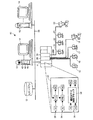
ここで、図1を参照すると、プロセス制御システム10は、データヒストリアン12と、それぞれが表示画面14を有する1つ以上のホストワークステーションまたはコンピュータ13(任意のタイプのパーソナルコンピュータ、ワークステーションなどであってもよい)とに通信可能に接続された、プロセスコントローラ11を含む。コントローラ11は、さらに、入出力(I/O)装置またはカード26および28を介して、フィールド装置15〜22に接続される。データヒストリアン12は、データを記憶するための、任意の所望のタイプのメモリと、任意の所望のまたは公知のソフトウェア、ハードウェア、またはファームウェアとを有する、任意の所望のタイプのデータ収集ユニットであってもよく、及び、(図1に示すように)ワークステーション13とは別個であるか、またはワークステーション13のうちのいずれかの一部であってもよい。例として、エマーソンプロセスマネジメント(Emerson Process Management)によって販売されているデルタV(DeltaV(登録商標))コントローラであってもよい、コントローラ11は、例えば、イーサネット(登録商標)通信リンクまたは任意のその他の所望の通信ネットワーク29を介して、ホストコンピュータ13およびデータヒストリアン12に通信可能に接続される。通信ネットワーク29は、ローカルエリアネットワーク(LAN)、ワイドエリアネットワーク(WAN)、電気通信ネットワーク、インターネット(例えば、ワールドワイドウェブ)などの形態であってもよく、そして、ハードワイヤードおよび/またはワイヤレス技術を使用して実施されてもよい。コントローラ11は、例えば、標準的な4〜20mA装置、および/または任意のスマート通信プロトコル(ファウンデーション(FOUNDATION(登録商標))フィールドバス(Fieldbus)プロトコル、ハート(HART)プロトコル、プロフィバス(Profibus)プロトコル、あるいはプロセス制御業界で使用される任意のその他の周知のまたは標準的な通信プロトコルなど)と関連付けられた、任意の所望のハードウェアおよびソフトウェアを使用して、フィールド装置15〜22に通信可能に接続される。
Referring now to FIG. 1, the
フィールド装置15〜22は、センサ、バルブ、トランスミッタ、ポジショナなどの、任意のタイプの装置であってもよく、一方、I/Oカード26および28は、任意の所望の通信プロトコルまたはコントローラプロトコルに準拠するか、あるいはそれらのプロトコルをサポートする、任意のタイプのI/O装置であってもよい。図1に示す実施形態では、フィールド装置15〜18は、アナログ回線(またはアナログ回線とデジタル回線との組み合わせ)を介してI/Oカード26との通信を行う、標準的な4〜20mA装置またはハート(HART)装置であり、一方、フィールド装置19〜22は、ファウンデーション(FOUNDATION(登録商標))フィールドバス(Fieldbus)プロトコル通信を使用して、デジタルバス28Aを介してI/Oカード28との通信を行う、ファウンデーション(FOUNDATION(登録商標))フィールドバス(Fieldbus)(FF)装置として示されている。この場合、I/Oカード28は、FFプロトコルをサポートするフィールドバスポートを有するH1カードである。理解されるように、デジタルバス28Aと、それに接続されたフィールド装置19〜22と、I/Oカード28とは、フィールドバスセグメントを形成する。もちろん、所望される場合には、I/Oカード28は、他のフィールドバスセグメント(図示せず)に接続されてもよく、フィールドバスセグメントは、それに接続された、FFプロトコルをサポートする任意の数およびタイプの装置を含んでもよい。あるいは、フィールド装置15〜22は、任意のその他の公知のフィールドバスプロトコル、あるいは、現在知られている、または将来開発される可能性がある、任意のその他の通信規格またはプロトコルを含む、任意のその他の所望の規格またはプロトコルに準拠してもよい。
Field devices 15-22 may be any type of device such as sensors, valves, transmitters, positioners, etc., while I /
コントローラ11は、プラント10内の多数の分散型コントローラのうちの1つであってもよく、それらの分散型コントローラのそれぞれは、通信リンク29に接続されてもよく、かつ、それらの分散型コントローラのそれぞれは、FFプロトコルをサポートするI/O装置(本明細書では、FF I/O装置またはフィールドバスI/O装置とも呼ばれる)を介して、1つ以上のフィールドバスセグメントに接続されてもよい。コントローラ11は、少なくとも1つのプロセッサをその中に含み、工業プロセスプラント内の制御ループを実行する1つ以上のプロセス制御モジュールを、実施または監視するように動作する。制御モジュールは、複数の通信可能に相互接続された機能ブロックを含んでもよく、それらの機能ブロックは、コントローラ11の中に、および/またはフィールド装置19〜22のうちのいくつかの中に、および、以下で述べるようにI/O装置28の中に記憶されて、それらの中で実行されてもよい。コントローラ11は、任意の所望の方法でプロセスを制御および監視するために、装置15〜22、ホストコンピュータ13、およびデータヒストリアン12と通信する。本明細書に記載された任意の制御ルーチンまたは要素は、所望される場合には、さまざまなコントローラまたはその他の装置によって実施または実行される、その部分を有してもよいということに留意すべきである。同様に、プロセス制御システム10内で実施される、本明細書に記載された制御ルーチンまたは要素は、ソフトウェア、ファームウェア、ハードウェアなどを含む、任意の形態を取ってもよい。モジュールであってもよく、または、サブルーチン、(コード行などの)サブルーチンの部分などの、制御手順の任意の部分であってもよい、制御ルーチンは、ラダーロジック、シーケンシャルファンクションチャート、機能ブロック図、オブジェクト指向プログラミング、あるいは、任意のその他のソフトウェアプログラミング言語または設計パラダイムを使用するなどの、任意の所望のソフトウェア形式で実施されてもよい。同様に、制御ルーチンは、例えば、1つ以上のEPROM、EEPROM、特定用途向け集積回路(ASIC)、または任意のその他のハードウェアまたはファームウェア要素の中にハードコートされてもよい。さらに、制御ルーチンは、グラフィカル設計ツールまたは任意のその他のタイプのソフトウェア/ハードウェア/ファームウェアプログラミングまたは設計ツールを含む、任意の設計ツールを使用して設計されてもよい。したがって、コントローラ11は、本明細書に具体的に記載された手法以外の任意の所望の手法で、制御戦略または制御ルーチンを実施するように構成されてもよい。
The
一実施形態では、コントローラ11は、プロセス制御モジュールと一般に呼ばれるものを使用する制御戦略(ストラテジー)を実施し、プロセス制御モジュールのそれぞれは、相互接続された機能ブロックの組から構成されてもよい。この場合、各機能ブロックは、全体的な制御モジュールの一部、または全体的な制御モジュール内のオブジェクトであり、プロセス制御システム10内のプロセス制御ループを実施するために(リンクと呼ばれる通信を介して)他の機能ブロックと協働して動作する。機能ブロックは、一般に、トランスミッタ、センサ、またはその他のプロセスパラメータ測定装置に関連付けられるものなどの、入力機能、あるいは、比例/積分(PI)、比例/微分(PD)、比例/積分/微分(PID)、ファジーロジックなどの制御を実行する制御ルーチンに関連付けられるものなどの、制御機能、あるいは、プロセス制御システム10内の何らかの物理的機能を実行するためにバルブなどの何らかの装置の動作を制御する、出力機能のうちの1つを実行する。もちろん、ハイブリッドおよびその他のタイプの機能ブロックが存在する。機能ブロックは、コントローラ11内に記憶されて、コントローラ11によって実行されてもよく、これは、それらの機能ブロックが、標準的な4〜20mA装置、ならびに、ハート装置および場合によってはフィールドバス装置などの、何らかのタイプのスマートフィールド装置のために使用される場合、またはそれらの装置に関連付けられる場合に一般的に当てはまる。しかし、場合によっては、それらの機能ブロックは、フィールド装置自体の中に記憶されて、フィールド装置自体によって実行されてもよく、これは、フィールドバス装置の場合に当てはまる可能性がある。制御システムの説明は、本明細書では、オブジェクト指向プログラミングパラダイム使用する機能ブロック制御戦略を用いて提供されているが、制御戦略、あるいは制御ループまたはモジュールは、ラダーロジック、シーケンシャルファンクションチャートなどの、その他の規定を使用して、あるいは、任意のその他の所望のプログラミング言語またはパラダイムを使用して、実施または設計されてもよい。
In one embodiment, the
図1の拡大ブロック30によって示すように、コントローラ11は、プロセス制御モジュール32および34として図1に示されている複数の単一入力/単一出力制御ループを監視するか、またはそれらの実施に関与してもよく、そして、プロセス制御モジュール36によって示されている1つ以上のアドバンスト制御ループを実施してもよい。各制御ループを構成する機能ブロックは、一般に、制御モジュールと呼ばれ、それらの機能ブロックは、従来、コントローラ11内、かつ/または、フィールドバスセグメント28Aを使用する場合は、フィールド装置15〜22内に記憶されていた。制御モジュール32および34は、適切なアナログ入力(AI)およびアナログ出力(AO)機能ブロックに接続された、それぞれ、単一入力/単一出力ファジーロジック制御ブロックおよび単一入力/単一出力PID制御ブロックを使用して、単一ループ制御を実行するものとして示されている。AIおよびAO機能ブロックは、バルブなどのプロセス制御装置と関連付けられてもよく、温度トランスミッタおよび圧力トランスミッタなどの測定装置と関連付けられてもよく、または、プロセス制御システム10内の任意のその他の装置と関連付けられてもよい。アドバンスト制御ループ36は、多数のAI機能ブロックに通信可能に接続された入力と、多数のAO機能ブロックに通信可能に接続された出力とを有する、アドバンスト制御ブロック38を含むものとして示されているが、アドバンスト制御ブロック38の入力および出力は、その他のタイプの入力を受信するため、およびその他のタイプの制御出力を提供するために、任意のその他の所望の機能ブロックまたは制御要素に通信可能に接続されてもよい。所望される場合には、アドバンスト制御ブロック38は、プロセスまたはプロセスの部分の最適制御を実行するための、モデル予測制御ルーチンをオプティマイザと統合した制御ブロックであってもよい。アドバンスト制御ブロック38を含む、図1に示す制御モジュールおよび機能ブロックは、従来、コントローラ11によって実行されていたか、あるいは、ワークステーション13のうちの1つ、またはさらには、フィールド装置19〜22のうちの1つなどの、その他の処理装置内に配置されて、それらの処理装置内で実行されていたということが理解されるであろう。しかし、以下でさらに詳細に述べるように、それらの機能ブロックは、さらに、有利には、フィールドバスセグメントの部分として同期して動作するように、I/O装置28などのI/O装置内に記憶されてもよい。
As indicated by the expanded
図1に示すように、ワークステーション13のうちの1つは、コントローラ11内の制御モジュール、特に、バス28Aによって定義されるフィールドバスセグメントを使用するものを作成、割り当て、ダウンロード、および実施するために使用される制御ブロック割り当ておよびスケジューリングルーチンを含む。制御ブロック割り当ておよびスケジューリングルーチン40は、ワークステーション13内のメモリ内に記憶されて、ワークステーション13内のプロセッサによって実行されてもよいが、所望される場合には、このルーチン(またはその任意の部分)は、それに加えて、または別法として、プロセス制御システム10内の任意のその他の装置内に記憶されて、その装置によって実行されてもよい。一般的に言えば、ルーチン40は、作成された制御モジュール内の機能ブロックを、実行のために、プロセスプラント内の特定の装置に割り当てるように動作するルーチン42を含み、ルーチン42は、より詳細には、(バス28Aによって定義されるセグメントなどの)特定のフィールドバスセグメントのために作成された各制御モジュールの機能ブロックが、セグメント上の装置に、またはセグメントを動作させるコントローラに割り当てられる方法を、自動的に最適化するように動作する。
As shown in FIG. 1, one of the
さらに、所望される場合、ルーチン40は、ルーチン42によって、セグメント上のフィールドバスフィールド装置に割り当てられた機能ブロックと、セグメントのためのI/O装置に割り当てられた機能ブロックとに基づいて、フィールドバスセグメントの通信スケジュール(すなわち、マクロサイクル)を自動的に作成または構成する、ルーチン44を含んでもよい。ルーチン44は、ルーチン42によって実行された割り当てに基づいて、特定のフィールドバスセグメントのための通信および実行スケジュールをユーザが最適に生成するのを容易にする。1つの場合には、ルーチン44は、フィールドバスセグメントためのマクロサイクルまたはスケジュールを、従来技術において一般的に行われているようにこのセグメントに割り当てられたモジュールの最も遅い実行レートに基づいて生成するのではなく、セグメントに割り当てられたモジュールの最も速いモジュール実行レートに基づいて生成してもよい。この場合、ルーチン44は、インタフェース装置13を介してユーザによって指定された機能ブロックマルチプライヤが、どのブロック実行がスケジュール内でスキップされるべきかを指示することを可能にしてもよく、これは、フィールドバスセグメント上の帯域幅を節約するのに役立つ。さらに、所望される場合、ルーチン40は、情報を入力および表示するため、ならびにルーチン42および44の性能を指示するために、ユーザがルーチン42および44と対話することを可能にする、ルーチン46を含んでもよい。
Further, if desired, the routine 40 may determine whether the routine 42 is based on the functional blocks assigned to the fieldbus field devices on the segment and the functional blocks assigned to the I / O devices for the segment. A routine 44 may be included that automatically creates or configures a bus segment communication schedule (ie, macrocycle).
上述のように、FF装置をサポートする公知のコントローラシステムは、ユーザがFF装置を使用することをより容易にするが、特定の制御モジュールの制御経路内の機能ブロックが、コントローラ(例えば、図1のコントローラ11)と、フィールドバスセグメント上のフィールドバス装置(例えば、図1の装置19〜22)との間で分割される場合、制御ループ内に大幅な遅延が導入される可能性がある。さらに、セグメント上のすべてのブロックが同じレートで実行されるという従来技術の要件は、同じフィールドバスセグメント上のFF装置内で複数のループが実施される際に、場合によっては制御性能に影響する可能性があり、なぜなら、場合によっては、異なる制御ループまたは特定の制御ループ内のブロックは、異なるレートで動作するように構成される可能性があるからである。ルーチン40は、一般に、コントローラ内制御(control in the controller)(CIC)と比較して、フィールド内制御(Control in the field)(CIF)を使用するために必要とされる技術的労力を減少させる方法で、そして、CICをフィールド装置と組み合わせて使用する場合に制御ループ内に導入される変動および総合遅延を最小にする方法で、フィールドバスセグメントに接続された装置に制御ブロックを割り当てるように動作する。さらに、ルーチン40は、CIFのための追加の機能ブロックの選択肢をユーザに提供するように動作してもよく、そして、フィールドバスセグメント上で実施される1つ以上のモジュールの、全体的により速い動作を可能にする、フィールドバスセグメントのためのスケジュールを定義してもよい。 As noted above, known controller systems that support FF devices make it easier for users to use FF devices, but the functional blocks in the control path of a particular control module can be controlled by a controller (eg, FIG. 1). 1) and fieldbus devices on the fieldbus segment (eg, devices 19-22 of FIG. 1) can introduce significant delays in the control loop. Furthermore, the prior art requirement that all blocks on a segment execute at the same rate can affect control performance in some cases when multiple loops are implemented within FF devices on the same fieldbus segment. There is a possibility, because in some cases, blocks in different control loops or specific control loops may be configured to operate at different rates. Routine 40 generally reduces the technical effort required to use Control in the Field (CIF) as compared to Control in the Controller (CIC). Acting to allocate control blocks to devices connected to a fieldbus segment in a manner and in a manner that minimizes variation and overall delay introduced into the control loop when using CIC in combination with field devices To do. Furthermore, the routine 40 may operate to provide the user with additional functional block options for CIF, and is generally faster for one or more modules implemented on the fieldbus segment. A schedule for fieldbus segments may be defined that enables operation.
より詳細には、ルーチン42の機能および動作をサポートするために、フィールドバスセグメントに接続されたI/O装置(すなわち、図1のI/O装置28)は、従来はコントローラ11内で実施または実行されてきた機能ブロックのサブセットを実行するように構成される。特に、フィールドバスポートが、I/O装置のために指定または作成され、このポートは、フィールドバスセグメントに接続された独立したフィールドバス装置としてモデル化されてもよい。各フィールドバスポートは、したがって、ポート(または、一般にI/O装置)によってサポートされる機能ブロック、開始リストエントリの数その他を指定する、フィールドバス装置リビジョンファイルを含んでもよい。各フィールドバスポートは、プロセス制御システムとの関連で、その他の装置に類似した方法で自動的に生成されてもよい、グローバルシステム装置タグを有してもよい。同様に、フィールドバスポートに関する参照メニューオプションが、そのポートに割り当てられる、参照されるモジュール/ブロックのすべてをリストするために提供されてもよい。しかし、一般的に言えば、フィールドバスポートは、FFフィールド装置では有するのが一般的である、リソースブロックまたはトランスデューサブロックは有さない。一実施形態では、各フィールドバスポートは、最大32の機能ブロックをサポートすることが可能である。しかし、サポートされるブロックの実際の数およびタイプは、装置内で得られる開始リストエントリの数によって決定される。さらに、各フィールドバスポートは、以下でさらに詳細に説明する、ユーザ設定可能な「自動計算スケジュールマクロサイクル(auto−calculate schedule macrocycle)」プロパティを有してもよい。
More specifically, an I / O device connected to a fieldbus segment (ie, I /
フィールドバスセグメントに接続されたI/O装置がこの追加機能を含む場合、ルーチン42は、機能ブロックをI/O装置(例えば、図1のI/O装置28)のフィールドバスポート内で実行されるように割り当てることが可能である。一般的に言えば、ルーチン42が、制御モジュールの機能ブロックをフィールドバスセグメントのためのI/O装置のフィールドバスポート内で実行されるように割り当てるのは、それらの機能ブロックが、I/O装置内でサポートされる機能ブロックのサブセットのメンバーであり、かつ、フィールドバスセグメント上で実行され、またはフィールドバスセグメントを使用する、特定の制御モジュールの、すべてのフィールドバス入力機能ブロックとフィールドバス出力機能ブロックとの間の主要制御経路内にある場合である。このようにして、ルーチン42は、可能な場合、制御モジュールの主要制御経路内のすべての機能ブロックが、フィールドバスセグメントに接続されている装置のうちの1つにおいて実行されることを確実にし、それにより、それぞれのそのような機能ブロックがフィールドバスセグメント上のマクロサイクルに直接参加する(動作および通信のためにスケジュールされる)ことを可能にする。この割り当て技術は、フィールドバスセグメント内で制御モジュール(すなわち、制御ループ)が実施されるレートを、コントローラ11と、フィールドバスセグメント上の1つ以上のフィールドバス装置との間で分割された機能ブロックを有するプロセスモジュールが動作するレートに比較して、速める、即ち増加させるように機能する。
If the I / O device connected to the fieldbus segment includes this additional function, routine 42 executes the functional block within the fieldbus port of the I / O device (eg, I /
ここで、図2を参照すると、制御モジュール50(モジュール1と称される)は、AO(アナログ出力)機能ブロック51と、AI(アナログ入力)機能ブロック52と、PID機能ブロック53とを含むものとして示されている。制御モジュール50は、例えば、図1のモジュール34であってもよい。図2の点線で示されているように、AO機能ブロック51は、フィールドバスフィールド装置54内で動作するように(通常は、オペレータまたは構成エンジニアによって)割り当てられ、一方、AI機能ブロック52は、別のフィールドバスフィールド装置55内で動作するように(同様に、通常は、オペレータまたは構成エンジニアによって)割り当てられる。この場合、AOブロック51は、バルブ54内で実行されるように割り当てられ、一方、AIブロックは、センサまたはその他の機器55内で実行されるように割り当てられる。重要なことに、フィールド装置54および55は、共通フィールドバスセグメント56に接続されているか、またはその部分である。
Referring now to FIG. 2, the control module 50 (referred to as module 1) includes an AO (analog output)
一般に、従来技術のシステムでは、PID機能ブロック53は、フィールドバス装置54または55のいずれによってもサポートされず、したがって、PID機能ブロック53は、(図1のコントローラ11であってもよい)コントローラ57内で実行されるように、オペレータまたは構成エンジニアによって割り当てられる。この従来の実施は、図2の点線57Aによって示されている。しかし、より長い点線59Aによって図2に示されているように、ルーチン42はここで、PID機能ブロック53を、I/O装置28のフィールドバスポート59内での実行のために、FFプロトコルをサポートするI/O装置58(図2で、フィールドバスカードとしてラベル付けされている)内での実行のために割り当ててもよい。図2に示すように、フィールドバスポート59は、フィールドバスセグメント56に接続され、したがって、フィールドバスセグメント56の通信スケジュールに直接参加することが可能である。PID機能ブロック53を、コントローラ57ではなく、フィールドバスポート59に割り当てることにより、ブロック51、52、および53のそれぞれは、フィールドバスセグメント56上の装置内に配置され、したがって、フィールドバスセグメント56によって使用されるマクロサイクル内での動作のために、直接スケジュールされることが可能となる。この割り当ての結果として、機能ブロックのうちのいくつか(すなわち、機能ブロック51および52)をフィールドバスセグメント56上で実行させ、かつ、機能ブロックのうちのいくつか(すなわち、機能ブロック53)をフィールドバスセグメント56の外部(すなわち、コントローラ57内)で実行させるということなしに、モジュール50全体がフィールドバスセグメント56上で動作するようになる。
In general, in prior art systems, the
所望される場合、機能ブロックがI/O装置のフィールドバスポートに割り当てられる際に、機能ブロックはコントローラ57内で作成されてもよく、そして、シャドウ機能ブロックという周知の概念を使用して、フィールドバスポート59内の機能ブロックにリンクされてもよい。特に、コントローラは、コントローラ57内のシャドウ機能ブロックを使用することによって、I/O装置のフィールドバスポートに割り当てられた機能ブロックと通信し、それらの装置に情報を送信すること、およびそれらの装置から情報を取得することが可能である。公知のように、シャドウ機能ブロックは、アルゴリズムを実行しないブロックであり、そして従来は、フィールドバス装置内で実行されるフィールドバスブロックと通信するために、コントローラベースのモジュールによって使用されている。シャドウ機能ブロックの構成および使用の、より完全な説明は、米国特許第6,738,388号明細書に記載されており、当該特許は参照により本明細書に明示的に援用される。それゆえ、この特徴については、本明細書ではさらに詳細には説明しない。
If desired, the functional block may be created in the
一般的に言えば、図1のルーチン42は、図2のフィールドバスポート59またはコントローラ57のいずれかに機能ブロックを割り当てて、それにより、可能な最適な方法でこの割り当てを行うことにおける、一定の規則の組を実施してもよい。一実施形態では、ルーチン42は、特定の制御モジュールのクリティカルフロー経路内のすべての機能ブロックが、特定のフィールドバスセグメントに接続された装置内で実行されることが可能かどうかを判定し、可能である場合、フィールドバスセグメント上のフィールド装置には割り当てることができない機能ブロックを、そのセグメント上のI/O装置のフィールドバスポートに割り当てる。可能ではない場合、ルーチン42は、フィールドバスセグメント上のフィールド装置によってサポートされない機能ブロックを、セグメントに関連付けられたコントローラに割り当てる。このようにして、ルーチン42は、I/O装置内への機能ブロックの割り当てを、制御モジュール全体がフィールドバスセグメント上で実行可能であることを保証するために必要な割り当てに制限し、それにより、I/O装置の、特にI/O装置のフィールドバスポートのリソースを節約する。
Generally speaking, the routine 42 of FIG. 1 assigns a functional block to either the
特定のモジュールがフィールドバスセグメント上のI/O装置に自動的に割り当てられるべきかどうかを、ユーザまたは構成エンジニアが指定することを可能にするために、「自動計算スケジュールマクロサイクル」と称されるユーザ設定可能なプロパティが、フィールドバスポートに追加されてもよい。ルーチン42がこのプロパティが設定されていると判定した場合、ルーチン42は、I/O装置のフィールドバスポートを使用して、フィールドバスセグメント上での実行のために、モジュールをスケジュールすることを試みる。さらに、ユーザは、ルーチン42が、特定のモジュールの機能ブロックを、フィールドバスセグメントのためのI/O装置のフィールドバスポートに割り当てようと試みるべきかどうかをモジュールごとに指定してもよい。特に、各制御モジュールは、例えば、「フィールドバスポートへの機能ブロックの自動割り当て(auto−assign function blocks to Fieldbus port)」と称される、ユーザ設定可能なプロパティを有してもよく、このプロパティは、設定されている場合、モジュールの機能ブロックが、フィールドバスセグメントのためのI/O装置のフィールドバスポートに割り当てられることを可能にする。本明細書では「自動割り当て(auto−assign)」プロパティとも呼ばれる、このプロパティは、機能ブロックレベルではなく、モジュールレベルで有効にされ、その理由は、ルーチン42は、機能ブロックを実行のためにフィールドバスI/O装置に割り当てようと試みるどうかを、機能ブロックごとではなくモジュールごとに判定するからである。したがって、一般的に言えば、自動割り当てプロパティはモジュールごとにオンおよびオフにされるべきであり、このプロパティは制御モジュールの最高レベルにおいてのみ適用されるべきである。 In order to allow a user or configuration engineer to specify whether a particular module should be automatically assigned to an I / O device on a fieldbus segment, referred to as an “automatic calculation schedule macrocycle” User configurable properties may be added to the fieldbus port. If routine 42 determines that this property is set, routine 42 will attempt to schedule the module for execution on the fieldbus segment using the fieldbus port of the I / O device. . In addition, the user may specify on a module-by-module basis whether the routine 42 should attempt to assign a particular module functional block to the fieldbus port of the I / O device for the fieldbus segment. In particular, each control module may have a user-configurable property called, for example, “auto-assignment function blocks to Fieldbus port”. Enables the functional block of the module, if set, to be assigned to the fieldbus port of the I / O device for the fieldbus segment. This property, also referred to herein as the “auto-assign” property, is enabled at the module level, not the function block level, because the routine 42 is responsible for executing the function block for execution. This is because it is determined for each module, not for each functional block, whether to try to allocate the bus I / O device. Thus, generally speaking, the auto-assignment property should be turned on and off on a module-by-module basis, and this property should only be applied at the highest level of the control module.
一実施形態では、フィールドバスプロトコルをサポートするI/O装置(フィールドバスI/O装置とも呼ばれる)のフィールドバスポートに機能ブロックを割り当てる場合、ルーチン42は、制御モジュールのクリティカルフロー経路内のすべての入力および出力機能ブロックが、共通フィールドバスセグメント上のフィールド装置に割り当てられるようにスケジュールされるかどうかを判定する。そうである場合、ルーチン42は、それらのブロックが、フィールドバスセグメント上のフィールド装置には割り当てられないことを前提として、かつ、この割り当てを可能にするための十分なリソースがまだ存在していることを前提として、(入力機能ブロックと出力機能ブロックとの間に配置された)制御モジュールのクリティカルフロー経路内のその他の機能ブロックを、フィールドバスセグメント上のI/O装置のフィールドバスポートに割り当てる。例えば、フィールドバスI/O装置のフィールドバスポートが、制御モジュール内で使用される特定のタイプの制御機能ブロックをサポートしない場合、または、フィールドバスポートに、モジュールの機能ブロックのうちの1つを割り当てるための十分なリソースさえも残されていない場合、そのモジュールの機能ブロックのうちのいずれもI/O装置のフィールドバスポートに割り当てられない。他方、制御モジュールのクリティカルフロー経路内の入力または出力機能ブロックのうちの1つ以上が、セグメント上のフィールド装置内で実行されるようにスケジュールされない場合、ルーチン42は、そのモジュールの制御機能ブロックおよびその他の機能ブロックを、I/O装置のフィールドバスポートにではなくコントローラに割り当てる。 In one embodiment, when assigning a functional block to a fieldbus port of an I / O device that supports a fieldbus protocol (also referred to as a fieldbus I / O device), the routine 42 Determine whether the input and output function blocks are scheduled to be assigned to field devices on a common fieldbus segment. If so, routine 42 assumes that those blocks are not assigned to field devices on the fieldbus segment, and there are still sufficient resources to allow this assignment. The other functional blocks in the critical flow path of the control module (placed between the input and output functional blocks) are assigned to the fieldbus ports of the I / O devices on the fieldbus segment. . For example, if the fieldbus port of the fieldbus I / O device does not support the specific type of control function block used in the control module, or if the fieldbus port has one of the function blocks of the module If not enough resources remain to allocate, none of the functional blocks of that module are allocated to the fieldbus port of the I / O device. On the other hand, if one or more of the input or output functional blocks in the critical flow path of the control module is not scheduled to be executed in a field device on the segment, the routine 42 Other functional blocks are assigned to the controller rather than to the fieldbus port of the I / O device.
したがって、一般的に言えば、制御モジュールの機能ブロックが、フィールドバスI/O装置のフィールドバスポートに割り当てられるのは、(1)モジュールのクリティカルフロー経路内のすべての入力および出力ブロックが、共通フィールドバスセグメント上の装置およびアクチュエータに割り当てられ、かつ、(2)入力ブロックと出力ブロックとの間のすべての機能ブロックが、フィールドバスポートに割り当て可能である(フィールドバスポートによってサポートされる)場合である。言い換えると、それらのブロックが、次の条件で、セグメントのためのフィールドバスポートに自動的に割り当てられることにより、モジュールのクリティカルフロー経路内にある機能ブロックは、セグメント上で実行されるように自動的に割り当てられる。(1)モジュールについての自動割り当てプロパティが有効にされている、(2)セグメント上の装置および/またはアクチュエータに割り当てられる、モジュールの、少なくとも1つの入力ブロックと少なくとも1つの出力ブロックとが存在する、(3)同期の破れがない(例えば、入力機能ブロックと出力機能ブロックとの間の、クリティカルフロー経路内の各機能ブロックが、フィールドバスポートに割り当てられることが可能である)、かつ(4)フィールドバスI/O装置のフィールドバスポートについて、「自動計算スケジュールマクロサイクル」プロパティがセットされている。 Therefore, generally speaking, the functional block of the control module is assigned to the fieldbus port of the fieldbus I / O device because (1) all input and output blocks in the critical flow path of the module are common Assigned to devices and actuators on the fieldbus segment, and (2) all functional blocks between the input block and the output block can be assigned to the fieldbus port (supported by the fieldbus port) It is. In other words, these blocks are automatically assigned to the fieldbus port for the segment under the following conditions so that functional blocks in the module's critical flow path are automatically executed on the segment: Assigned. (1) the auto assignment property for the module is enabled, (2) there is at least one input block and at least one output block of the module assigned to the device and / or actuator on the segment; (3) There is no loss of synchronization (eg, each functional block in the critical flow path between the input functional block and the output functional block can be assigned to a fieldbus port), and (4) The “automatic calculation schedule macrocycle” property is set for the fieldbus port of the fieldbus I / O device.
ここで、一実施形態では、制御ループ(制御モジュール)を通したフォワード経路(1つまたは複数)のみが、クリティカルフロー経路の部分であるとみなされ、フィードバック経路はいずれも、クリティカルフロー経路の部分であるとはみなされない、ということに留意すべきである。さらに、フィールドバスポートへのブロックの自動割り当ては、制御経路内のI/Oブロックが、同じフィールドバスセグメントに割り当てられること、および、クリティカルフロー経路内のすべての機能ブロックが、フィールドバスポート内でサポートされることを前提とする。一実施形態では、制御モジュールのためにフィールドバスセグメント上のフィールドバス装置に割り当てられる、少なくとも1つの入力ブロックと少なくとも1つの出力ブロックとが存在する限り、クリティカルフロー経路内にAI、AO、DI、またはDOブロックが複数存在する場合、それらのうちの1つのみがフィールドバス装置に結合される必要がある。しかし、この場合、フィールドバス装置に割り当てられない入力および出力機能ブロックは、フィールドバスポートには割り当てられず、したがって、それらの機能ブロックは非同期に動作する。ただし、所望される場合、いくつかの実施形態では、入力/出力機能ブロック(例えば、AI、AO、DI、DO、MAI機能ブロック)は、フィールドバスポートに割り当てられてもよく、または、フィールドバスポートには割り当てられないようにされてもよい。他の実施形態では、所望される場合、クリティカルフロー経路内のその他の機能ブロックを、そのセグメントのためのフィールドバスI/O装置のフィールドバスポートに割り当てるために、ルーチン42は、モジュールのクリティカルフロー経路上のすべての入力および出力機能ブロックが、セグメント上のフィールドバス装置に割り当てられるべきであるとしてもよい。 Here, in one embodiment, only the forward path (s) through the control loop (control module) is considered part of the critical flow path, and any feedback path is part of the critical flow path. It should be noted that it is not considered to be. In addition, automatic assignment of blocks to fieldbus ports means that I / O blocks in the control path are assigned to the same fieldbus segment, and that all functional blocks in the critical flow path are in the fieldbus port. Assumes support. In one embodiment, as long as there is at least one input block and at least one output block assigned to the fieldbus device on the fieldbus segment for the control module, AI, AO, DI, Or if there are multiple DO blocks, only one of them needs to be coupled to the fieldbus device. However, in this case, input and output functional blocks that are not assigned to the fieldbus device are not assigned to the fieldbus port, and therefore, those functional blocks operate asynchronously. However, if desired, in some embodiments, input / output functional blocks (eg, AI, AO, DI, DO, MAI functional blocks) may be assigned to fieldbus ports or fieldbuses. The port may not be assigned. In other embodiments, if desired, routine 42 may assign the module's critical flow to assign other functional blocks in the critical flow path to the fieldbus port of the fieldbus I / O device for that segment. All input and output functional blocks on the path may be assigned to fieldbus devices on the segment.
したがって、一般的に言えば、モジュールの機能ブロックをフィールドバスポートに割り当てる前に、ルーチン42は、(1)モジュールについての、自動割り当てプロパティが有効にされているかどうか、(2)フィールドバスポート上で、自動計算スケジュールマクロサイクルプロパティが有効にされているかどうか、(3)I/Oカードは、モジュールに関連付けられた機能ブロックをサポートするための十分なリソースを有するかどうか、(4)モジュールのフォワードフロー経路内の、入力機能ブロックと出力機能ブロックとの間のすべての機能ブロックが、フィールドバスカードによってサポートされるかどうか、および(5)フォワードフロー経路内のすべての機能ブロックが同じモジュール内にあるかどうか、を判定してもよい。これらの条件のうちのいずれかが満足されない場合、ルーチン42は、フィールドバスセグメント上のフィールドバスI/O装置のフィールドバスポートには、モジュールの機能ブロックのうちのいずれも割り当てないことを決定してもよく、しかし、その代わりに、それらの機能ブロックを、フィールドバスセグメントに関連付けられたコントローラに割り当ててもよい。 Thus, generally speaking, before assigning a module functional block to a fieldbus port, routine 42 determines (1) whether the auto-assign property is enabled for the module, and (2) on the fieldbus port. Whether the automatic calculation schedule macro cycle property is enabled, (3) whether the I / O card has sufficient resources to support the functional blocks associated with the module, (4) the module's Whether all functional blocks in the forward flow path between the input functional block and the output functional block are supported by the fieldbus card, and (5) all functional blocks in the forward flow path are in the same module Even if it is determined whether There. If any of these conditions are not met, routine 42 determines that none of the module's functional blocks are assigned to the fieldbus port of the fieldbus I / O device on the fieldbus segment. Alternatively, however, those functional blocks may be assigned to the controller associated with the fieldbus segment.
この技術では、ユーザは一般に、フィールドバスI/Oカードのフィールドバスポートから個々の機能ブロックを割り当て解除することはできず、その理由は、機能ブロックはモジュールのプロパティに基づいてこのカードに割り当てられるからである。その代わりに、ユーザは、モジュールの自動割り当てプロパティを設定することによって、モジュールを全体として、自動割り当てすることまたは自動割り当て解除することのみが可能である。 With this technology, users generally cannot unassign individual functional blocks from the fieldbus port of a fieldbus I / O card because functional blocks are assigned to this card based on module properties. Because. Instead, the user can only automatically assign or unassign the module as a whole by setting the module's auto-assignment property.
所望される場合、制御モジュールの自動割り当てプロパティをユーザがオン/オフした場合、変化を見て結果を明らかにするためにはユーザがモジュールを保存しなければならないことをユーザに通知するために、メッセージがユーザに提供されてもよく、その理由は、ルーチン42の割り当て動作は、モジュールが保存される際に自動的に発生してもよいからである。さらに、各機能ブロックは、このブロックが自動割り当てのために設定されているかどうかを示す、視覚的プロパティを含むことが望ましい。所望される場合、モジュールの自動割り当てプロパティが自動割り当てであるように設定された場合、フィールドバスポートを有するフィールドバスI/O装置にモジュールの機能ブロックが実際に割り当てられるのを妨げるリソースの制限があるならば、ユーザに警告が発行されてもよい。例えば、フィールドバスI/Oカードがその限界に達しており、かつ、モジュールが保存される場合、ユーザは、モジュールの機能ブロックは自動割り当てされず、モジュールは自動割り当てプロパティがオフにされて保存されるという警告を受信してもよい。この場合、ブロック自動割り当て機能を動作させるには、ユーザは、他のモジュールの自動割り当てプロパティを解消または設定解除してフィールドバスポート上のいくらかの割り当て空間を空け、モジュールの自動割り当てプロパティをオンにし、次に、モジュールを再保存しなければならない可能性がある。 If desired, if the user turns on / off the auto-assign property of the control module, in order to notify the user that the user must save the module to see the change and reveal the result, A message may be provided to the user because the routine 42 assignment operation may occur automatically when the module is saved. In addition, each functional block preferably includes a visual property that indicates whether this block is configured for automatic assignment. If desired, if the module's auto-assignment property is set to auto-assign, there is a resource limitation that prevents the functional block of the module from actually being assigned to a fieldbus I / O device having a fieldbus port. If there is, a warning may be issued to the user. For example, if the fieldbus I / O card has reached its limit and the module is saved, the user will not automatically assign the function block of the module and the module will be saved with the auto-assign property turned off. May be received. In this case, for the block auto-allocation feature to work, the user must clear or unset other module auto-allocation properties to free some allocation space on the fieldbus port and turn on the module auto-allocation property. Then, you may have to save the module again.
所望される場合、ルーチン42は、フィールドバス装置に割り当てられることが可能な、完全なクリティカルフロー経路を有する潜在的なモジュールのすべてと、それらのモジュールが有する自動割り当てプロパティが「オン」にされているか「オフ」されているかとを、例えばデータベース12内に配置するユーティリティを含んでもよい。このユーティリティは、特定のモジュールについての自動割り当てプロパティをオンまたはオフにすることがリソース空間の作成に役立つ可能性がある場合を、ユーザが理解するのを助けるために使用されてもよい。このユーティリティは、さらに、構成のダウンロードに先立って自動割り当てプロパティを設定することが有利であるモジュールの識別情報を、ユーザが判定するために役立つ場合もある。
If desired, the routine 42 can be assigned to fieldbus devices with all of the potential modules with complete critical flow paths and their auto-assigned properties turned on. A utility may be included that places in the
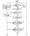
図3は、ルーチン42が、制御モジュールの機能ブロックをフィールドバスI/O装置のフィールドバスポートに、または特定のフィールドバスセグメントに関連付けられたコントローラに自動的に割り当てるために動作する、さらなる例示的な方法を説明するフローチャート60を示す。ブロック61において、ルーチン42は、調べるべきさらなる制御モジュールがあるかどうかを判定し、ない場合は終了する。調べられるべき1つ以上の制御モジュールがまだ残されている場合、ブロック62で、調べるべき次の制御モジュールを見つける。ブロック63で、次に、選択された制御モジュールについての自動割り当てプロパティが「オン」に設定されているかどうかを判定し、「オン」に設定されていない場合、制御はブロック64に与えられ、ブロック64は、従来技術のシステムにおいて通常行われるように、制御モジュールの未割り当ての制御機能ブロックおよび入力/出力機能ブロックを、コントローラに割り当てるように動作する。しかし、ブロック63で、選択された制御モジュールの自動割り当てプロパティが「オン」に設定されていると判定した場合は、ブロック65で、制御モジュールのクリティカルフロー経路を決定する。上述の説明から理解されるように、クリティカルフロー経路は、入力ブロックから出力ブロックまでの、制御モジュールを通したフォワード経路(1つまたは複数)の各構成要素を含む。このクリティカルフロー制御経路はモジュールを通して進み、それぞれの入力ブロックからそれぞれの出力ブロックまでのフォワードフローリンクによって形成される経路上に配置された、それぞれの機能ブロックを識別することによって決定されてもよい。
FIG. 3 illustrates a further example in which the routine 42 operates to automatically assign control module functional blocks to fieldbus ports of a fieldbus I / O device or to a controller associated with a particular fieldbus segment. A flow chart 60 illustrating a simple method is shown. In
次に、ブロック66で、制御モジュールのクリティカルフロー経路上の入力機能ブロックおよび出力機能ブロックのそれぞれが、共通フィールドバスセグメント上のフィールドバスフィールド装置に割り当てられるかどうかを判定する。代替の実施形態では、ブロック66で、モジュールのそれぞれのクリティカルフロー経路構成要素上の、少なくとも1つの入力機能ブロックおよび少なくとも1つの出力機能ブロックが、共通フィールドバスセグメント上のフィールドバスフィールド装置に割り当てられるかどうかを判定してもよい。入力/出力ブロックが、共通フィールドバスセグメント上のフィールドバスフィールド装置に適切に割り当てられない場合、ルーチン42は、フィールドバスセグメントへの制御モジュールの完全な同期割り当ては可能ではないと判定し、したがって、そのモジュールのいずれの機能ブロックも、フィールドバスセグメント上のフィールドバスI/O装置のフィールドバスポートには割り当てない。この場合、ルーチン42はブロック67に制御を与え、ブロック67では、フィールドバスI/O装置への制御モジュールの自動割り当ては失敗したことをユーザに通知する。ブロック64は、次に、未割り当ての制御機能ブロックおよび入力/出力機能ブロックを、(図2のコントローラ57などの)フィールドバスセグメントに関連付けられたコントローラに割り当て、そして、ブロック61に制御を戻す。
Next, block 66 determines whether each of the input function blocks and output function blocks on the control module critical flow path are assigned to fieldbus field devices on the common fieldbus segment. In an alternative embodiment, at
他方、ブロック66で、モジュールの入力/出力機能ブロックが共通フィールドバスセグメント上のフィールドバスフィールド装置に適切に割り当てられると判定した場合、次に、ブロック68で、フィールドバスセグメント上のフィールドバスI/O装置のフィールドバスポートの自動計算(auto−calculate)プロパティが「オン」(このI/O装置がフィールドバスセグメント上で機能ブロックを動作させる、または実行するように構成されていることを意味する)に設定されているかどうかを判定する。「オン」に設定されていない場合、ブロック67で、割り当ての失敗をユーザに通知し、そして、制御モジュール内の機能ブロックのコントローラへの従来の割り当てを行うブロック64に制御を与える。
On the other hand, if it is determined at
しかし、ブロック68でフィールドバスポートの自動計算プロパティがオンであると判定した場合は、ブロック69で、制御モジュールのクリティカルフロー経路内の未割り当ての機能ブロックのそれぞれをフィールドバスポートがサポートするかどうかを判定する。クリティカルフロー経路内の未割り当ての機能ブロックのうちの1つでもフィールドバスポートによってサポートされない場合、制御はブロック67および64に与えられ、ブロック67および64では割り当ての失敗をユーザに通知し、そして、未割り当ての機能ブロックのコントローラへの従来の割り当てを実行する。
However, if
他方、フィールドバスポートがクリティカルフロー経路内の未割り当ての機能ブロックのそれぞれをサポートする場合、ブロック70で、制御モジュールのクリティカルフロー経路内の未割り当ての機能ブロックのそれぞれを実行するための十分なリソース(容量)をこのポートが有するかどうかを判定する。有さない場合、制御はブロック67および64に与えられ、ブロック67および64では、割り当ての失敗をユーザに通知し、そして、未割り当ての機能ブロックのコントローラへの従来の割り当てを実行する。他方、フィールドバスポートが容量を有する場合、ブロック71で、クリティカルフロー経路内の未割り当ての機能ブロックのそれぞれを、実行のためにフィールドバスI/O装置のフィールドバスポートに割り当てる。この時点で、所望される場合、ブロック71は、さらに、制御モジュール内の任意の残りの機能ブロック(すなわち、制御モジュールのクリティカルフロー経路内にないもの)がフィールドバスI/O装置のフィールドバスポートに割り当てられることが可能かどうか、または割り当てられるべきかどうかを判定してもよい。場合によっては、それらのブロックのすべてがフィールドバスI/O装置内で動作することが可能ならば、フィールドバスセグメント上で完全に同期した方法で実行される制御モジュールを提供するために、ブロック71でそれらのブロックをその装置に割り当ててもよい。あるいは、セグメント上で動作するその他の制御モジュールのためにこの装置のリソースを節約するために、ブロック71は、残りの機能ブロックのいずれもI/O装置に割り当てないように動作してもよい。所望される場合、ブロック71は、ユーザが選択可能な設定に基づいていずれかの方法で動作してもよい。いずれの場合も、現在の制御モジュールの機能ブロックの割り当てを完了した後は、制御は、その他の制御モジュールの処理のためにブロック61に戻される。
On the other hand, if the fieldbus port supports each unassigned functional block in the critical flow path, sufficient resources to execute each unassigned functional block in the critical flow path of the control module at
もちろん、図3のフローチャート60は単に例示的なものであり、ルーチン42は、その他の方法で同様に動作してもよい。さらに、所望される場合、フローチャート60内のブロックのうちの特定のものは順番を並べ変えられてもよい。例えば、ブロック68、69、および70は、ルーチン60内のより先に、またはより後に配置されてもよく、順番を並べ変えられてもよく、そして、場合によっては制御モジュールのクリティカルフロー経路の決定に先立って実施されてもよい。 Of course, the flowchart 60 of FIG. 3 is merely exemplary, and the routine 42 may operate in other ways as well. Further, certain of the blocks in flowchart 60 may be reordered if desired. For example, blocks 68, 69, and 70 may be placed earlier or later in routine 60, may be rearranged, and in some cases, control module critical flow path determination. It may be performed prior to.
別の例では、自動ブロック割り当てのためのアルゴリズムは、以下のように要約される。 In another example, the algorithm for automatic block allocation is summarized as follows:

図4〜図9は、例示的な制御モジュールを示し、そして、ルーチン42が、上述の原理に基づいてそれらのモジュールの制御機能ブロックをコントローラに、またはフィールドバスセグメントに接続されたフィールドバスI/O装置のフィールドバスポートに割り当てる方法を示す。特に、図4は、PI機能ブロック77にリンクされたAI機能ブロック76を有し、PI機能ブロック77はフォワードおよびフィードバック方向の両方でAO機能ブロック78にリンクされている制御モジュール75を示す。公知でありかつ一般的であるように、AI機能ブロック76は測定信号またはその他の入力信号を取得し、そしてこの信号を示されているリンクを介してPI機能ブロック77に提供する。PI機能ブロック77は、比例/積分制御計算を実行して制御信号を生成する制御機能ブロックであり、その制御信号はAO機能ブロック78に提供される。AO機能ブロック78は、次に、制御信号を使用してバルブを開けること、または閉じること、あるいは、プラント内の物理的装置内の何らかのその他の設定を変更することなどの、プラント内の物理的機能を実行するように動作して制御動作を実行する。AO機能ブロック78は、さらに、例えば現在のバルブ位置のフィードバック測定値を、PI機能ブロック77による制御信号の作成における使用のためにPI機能ブロック77に提供する。
FIGS. 4-9 show exemplary control modules, and
図4のモジュール75は、AI機能ブロック76がフィールドバストランスミッタ装置などのフィールドバス測定装置の中で動作するように、またはその中に配置されるようにスケジュールされる従来のフィールドバス測定ループ内にセットアップされる。このスケジューリングは、AI機能ブロック76の上の「FF」によって示されている。しかし、AO機能ブロック78は、フィールドバス装置にはまったくスケジュールも割り当てもされないか、あるいは少なくとも、AI機能ブロック76と同じフィールドバスセグメント内のフィールドバス装置にはスケジュールも割り当てもされない。結果として、ルーチン42は、自動割り当てを実行する際に、PI機能ブロック77とAO機能ブロック78との両方をフィールドバスセグメントに関連付けられたコントローラ57内に配置し、その理由は、モジュール75のクリティカルフロー経路内のすべての機能ブロックが、フィールドバスセグメント56上のフィールドバスI/Oカード58とFFフィールド装置との中に配置されることはできないからである。この割り当て機能は、図4内の矢印によって示されている。
The
図5に示す制御モジュール75は、図4に示したものと同じであるが、ただし、従来のフィールドバスアクチュエータループ内にセットアップされる。ここでは、AO機能ブロック78は、(このブロックの上の「FF」によって示されるように)フィールドバスセグメント上のフィールドバス装置(例えば、アクチュエータ)内に配置され、しかし、AI機能ブロック76は、AO機能ブロック78と同じフィールドバスセグメント上のフィールドバス装置には関連付けられない。ここでもやはり、同じフィールドバスセグメント上のフィールドバス装置に制御モジュール75のクリティカルフロー経路内の入力ブロックと出力ブロックとの両方は割り当てられないため(この場合は、入力ブロックが割り当てられないため)、ルーチン42は、AI機能ブロック76とPI機能ブロック77との両方をコントローラ57に割り当てる。
The
しかし、図6は、共通フィールドバスセグメント上のフィールドバス装置によって測定およびアクチュエーションの両方が実行される構成内にセットアップされる、制御モジュール75を示す。この動作は、入力機能ブロックおよび出力機能ブロック76および78のそれぞれの上の「FF」によって示されている。ここでは、制御モジュール75の入力機能ブロックおよび出力機能ブロックのそれぞれが、共通フィールドバスセグメント上のフィールドバス装置に割り当てられるため、ルーチン42は、PI機能ブロック77を、フィールドバスセグメント56内での同期実行のためにフィールドバスI/O装置58に(そして、より詳細には、その装置のフィールドバスポート59に)割り当てる。
However, FIG. 6 shows the
図7は、カスケードタイプの制御ループを実施する別の制御モジュール80を示す。図7に示すように、制御モジュール80は、PI制御機能ブロック82に接続されたAI機能ブロック81を有する第1ステージを含む。PI制御機能ブロック82の出力は、第2ステージのPI機能ブロック83への第1の入力として、第2ステージのAI機能ブロック84からの追加の入力とともに提供される。第2ステージのPI機能ブロック83は、2つの入力をフィードバック信号とともに使用して制御信号を生成し、この制御信号はAO機能ブロック85に提供される。
FIG. 7 shows another
図7における「FF」の配置によって示されるように、AI機能ブロック81および84と、AO機能ブロック85とのそれぞれは、共通フィールドバスセグメント56上のフィールドバス装置に割り当てられる。結果として、ルーチン42は、フィールドバスセグメント56上での制御モジュール80の同期実行を提供するために、PI機能ブロック82および83を、実行のためにフィールドバスI/O装置58に割り当てるように動作する。
As indicated by the arrangement of “FF” in FIG. 7, each of AI function blocks 81 and 84 and
図8は図7のモジュール80を示しているが、この場合は、第2ステージのAI機能ブロック84が、フィールドバスセグメント56上のフィールドバス装置に割り当てられないという点が異なる。モジュール80のクリティカルフロー経路は、カスケードループの両方のステージの入力と出力とを含むため、そして、クリティカルフロー経路内の入力ブロックのうちの1つはモジュール80のその他の入力および出力ブロックと同じフィールドバスセグメント上のフィールドバス装置には割り当てられないかまたは関連付けられないので、ルーチン42は、クリティカルフロー経路内の未割り当てのブロックのすべて(すなわち,AIブロック84、ならびにPI制御ブロック82および83)をコントローラ57に割り当てる。なぜなら、PIブロック82および83がフィールドバスI/O装置58に割り当てられたとしても、制御モジュール80の同期実行は不可能だからである。
FIG. 8 shows the
図9は、スプリットレンジ出力構成を有する別の制御モジュール86を示す。制御モジュール86は、PI制御ブロック88に結合されたアナログ入力ブロック87を含み、PI制御ブロック88は、スプリントレンジブロック(SPL)89に出力を提供し、スプリントレンジブロック(SPL)89は、さらに、2つの並列接続されたAO機能ブロック90Aおよび90Bに結合される。ここでは、AI機能ブロック87と、AO機能ブロック90Aおよび90Bとのそれぞれが、共通フィールドバスセグメント上のフィールドバス装置に割り当てられるので、ルーチン42は、フィールドバスセグメント56上でのモジュール86の同期実行を提供するために、PI機能ブロック88とSPL機能ブロック89とを実行のためにフィールドバスI/O装置58に割り当てる。この動作は、もちろん、装置58(そして、より詳細には、この装置のフィールドバスポート59)が、PIおよびSPLブロックの機能をサポートし、かつ、これらのブロックの両方を実行するための十分なリソースを有するということを前提としている。しかし、この例は、モジュールの入力機能ブロックと出力機能ブロックとの間の、モジュールのクリティカルフロー経路内で直列に接続された複数のブロック(例えば、制御ブロック)が、フィールドバスI/O装置に割り当てられることが可能であることを示している。
FIG. 9 shows another control module 86 having a split range output configuration. The control module 86 includes an
いずれの場合も、ルーチン42(図1)が、上述のように、作成された制御モジュールのそれぞれの機能ブロックをフィールドバスセグメントに関連付けられた装置に割り当てるように動作した後は、ルーチン44が、ルーチン42によって作成された割り当てに基づいて、フィールドバスセグメントのための通信および実行スケジュールを自動的に生成するために使用されてもよい。一般的に言えば、ルーチン44は、フィールドバスセグメントのための通信および実行スケジュールの作成をそのセグメント上で動作する機能ブロックのそれぞれを識別することと、そのセグメントためのマクロサイクル(マクロサイクル内の機能ブロックのそれぞれについての通信および実行のためのオフセット時間を指定する)を作成することとによって行う。もちろん、ルーチン44は、複数の異なる制御モジュールからの機能ブロックを含むマクロサイクルを作成してもよい。 In any case, after routine 42 (FIG. 1) operates to assign each functional block of the created control module to the device associated with the fieldbus segment, as described above, routine 44 Based on the assignment made by routine 42, it may be used to automatically generate communication and execution schedules for the fieldbus segment. Generally speaking, routine 44 identifies each of the functional blocks that operate on the segment and creates a communication and execution schedule for the fieldbus segment and the macrocycle for that segment (within the macrocycle). By specifying the offset time for communication and execution for each of the functional blocks. Of course, the routine 44 may create a macrocycle including functional blocks from multiple different control modules.
理解されるように、ルーチン40の使用は、ユーザインタフェース装置における、制御の定義および表示のための統一された環境を提供する。特に、ルーチン40を使用すれば、制御ブロックが実行のためにどこに割り当てられるか(すなわち、コントローラ内か、フィールドバスインタフェースカード、または、特定のフィールドバスセグメント上のフィールドバス装置内か)を考慮することなく、制御を定義することが可能である。この特徴が可能である理由は、コントローラ内で動作可能な機能ブロックのほとんどは、フィールドバスインタフェースカード内で実行することも許可されるからである。したがって、ユーザは、測定または作動のために選択するフィールドバス装置が、制御または監視アプリケーションを実行するために必要とされる機能ブロックをサポートするかどうかを心配する必要はなく、なぜなら、フィールドバスフィールド装置内でサポートされない任意のブロックはフィールドバスインタフェースカードに割り当てられてもよく、そして、それでもフィールドバスセグメント上で同期して動作することが可能であるからである。 As will be appreciated, the use of routine 40 provides a unified environment for control definition and display in the user interface device. In particular, using routine 40 considers where the control block is allocated for execution (ie, in the controller, fieldbus interface card, or fieldbus device on a particular fieldbus segment). It is possible to define controls without. This feature is possible because most of the functional blocks operable in the controller are also allowed to execute in the fieldbus interface card. Thus, the user does not need to worry about whether the fieldbus device that is selected for measurement or operation supports the functional blocks required to perform the control or monitoring application, because the fieldbus field This is because any block not supported in the device may be assigned to the fieldbus interface card and still be able to operate synchronously on the fieldbus segment.
一実施形態では、ルーチン44は、フィールドバスセグメント上で使用されるスケジュールを、このセグメントへの機能ブロックの割り当てに基づいて自動的に計算してもよく、そして、そうすることにより、フィールドバスセグメント上での複数の異なる実行レートの機能ブロックのサポートを自動的に提供してもよい。例えば、複数の制御ループ(またはモジュール)が同じフィールドバスセグメント上で実行される場合、ループのそれぞれにとって同じ実行レートは適切ではない可能性がある。同様に、場合によっては、1つの制御ループ内に、異なるレートで実行される機能ブロックを有することが望ましい可能性がある。フィールドバスセグメント上の、いくつかの制御モジュールの、または制御モジュール内のいくつかの機能ブロックの、相対的な実行レートをユーザが選択的に変更することを可能にするために、ユーザは異なる実行レートを有するモジュール(または機能ブロック)を構成してもよい。あるいは、同じセグメント上の異なる機能ブロックについての相対的な実行レートを指定するために、実行マルチプライヤが、フィールドバスポート内で、またはフィールドバス装置内で実行されるように割り当てられるブロックに提供されてもよい。 In one embodiment, routine 44 may automatically calculate the schedule used on the fieldbus segment based on the allocation of functional blocks to this segment, and by doing so, the fieldbus segment Support for multiple different execution rate functional blocks above may be provided automatically. For example, if multiple control loops (or modules) are executed on the same fieldbus segment, the same execution rate may not be appropriate for each of the loops. Similarly, in some cases it may be desirable to have functional blocks executing at different rates within a control loop. To allow the user to selectively change the relative execution rate of some control modules, or some functional blocks within a control module, on the fieldbus segment, the user has different execution A module (or function block) having a rate may be configured. Alternatively, execution multipliers are provided for blocks that are assigned to be executed within a fieldbus port or within a fieldbus device to specify relative execution rates for different functional blocks on the same segment. May be.
例として、図10は、PID制御機能ブロック93(PID2とラベル付けされている)に接続されたAI機能ブロック92(AI2とラベル付けされている)を有する第1ステージを含む、カスケード制御ループを実施する制御モジュール91を示す。PID制御機能ブロック93の出力は、第2ステージのPID機能ブロック94(PID1とラベル付けされている)への第1の入力として、第2ステージのAI機能ブロック95(AI1とラベル付けされている)からの追加の入力とともに提供される。第2ステージのPID機能ブロック94は、2つの入力を、フィードバック信号とともに使用して制御信号を生成し、この制御信号はAO機能ブロック96に提供される。図10に示すように、入力および出力機能ブロック92、95、および96は、同じセグメント56上のフィールドバス装置に割り当てられるので、ルーチン42は、セグメント56上でのモジュール91の同期実行を提供するために、PID機能ブロック93および94をフィールドバスI/O装置58のフィールドバスポート59に割り当てる。
As an example, FIG. 10 shows a cascade control loop that includes a first stage having an AI function block 92 (labeled AI2) connected to a PID control function block 93 (labeled PID2). The
しかし、図10に示すように、AI機能ブロック92とPID機能ブロック93とは、それらに関連付けられた4xマルチプライヤを有する(それらのマルチプライヤは、構成プロセスの間に、構成エンジニアまたはその他のユーザによって指定されてもよい)。それらのブロックについての、4xマルチプライヤの指示は、それらのブロックが、制御モジュール91内のその他のブロックのレートよりも4倍遅いレートで動作すべき、または実行されるべきであるということを指定する。特に、カスケードループの1次(第1)ステージは、そのループの2次ステージよりも4倍遅く実行される必要があるため、1次ステージのAIおよびPIDブロック92および93は、4x実行マルチプライヤを使用して構成される。ルーチン44は、フィールドバスセグメント56のためのスケジュールを生成する際に、カスケードループのAIおよびPIDブロック92および93が、その他の機能ブロックよりも4倍遅く実行されるべきであるということを考慮に入れ、そして、そうすることにより、ルーチン44は、実行レートにおけるこの変化を含むマクロサイクル(すなわち、機能ブロック実行スケジュール)を作成する。特に、フィールドバスセグメントのための1つのマクロサイクル内で、(4xマルチプライヤを割り当てられた)機能ブロック92および93は、1回だけスケジュールされ、一方、その他の機能ブロックのすべては、マクロサイクル内で4回実行されるように割り当てられる。
However, as shown in FIG. 10, the
図11は、セグメント56が図10の制御モジュール91のみを実行する場合に、セグメント56のためにルーチン44によって生成される、例示的な、結果として得られるマクロサイクル97を示す。ここでは、マクロサイクル97は、4つの等しい時間周期に分割されていることがわかるであろう(時間周期のうちの1つは、「繰り返す時間(time to repeat)」の矢印によって示されている)。2次ステージのAIブロック95、PIDブロック94、およびAOブロック96のそれぞれは、繰り返す時間のそれぞれの間に実行されるように(すなわち、マクロサイクル97の間に4回実行されるように)スケジュールされ、一方、AIブロック92およびPIDブロック93は、マクロサイクル97の間に1回だけ実行されるようにスケジュールされる。したがって、1次ステージのAIおよびPIDブロック92および93は、2次ステージのブロック94〜96よりも4倍遅いレートで実行される。
FIG. 11 shows an exemplary resulting macrocycle 97 that is generated by the routine 44 for the
モジュールの2つのブロックが異なるレートで実行される場合は、通常、それらの実行を相互に同期させる必要はなく、したがって、異なるレートで動作するブロックの実行時間は、それらのブロックがフィールドバスセグメント上の異なる装置内で実行される限り、一般にオーバーラップしてもよい。多くの場合、この特徴は、図11の例示的なマクロサイクル(ここで、繰り返す時間は、制御モジュール91の2次ステージを実行するために必要とされる最小時間である)によって示されるように、より遅く実行されるブロックに関連付けられた通信が、より速く実行されるブロックに時間遅延を本質的に追加しないような方法でスケジュールされることを可能にする。
When two blocks of a module are executed at different rates, it is usually not necessary to synchronize their execution with each other, so the execution time of blocks operating at different rates is such that they run on the fieldbus segment. As long as they are executed in different devices, they may generally overlap. In many cases, this feature is as illustrated by the exemplary macrocycle of FIG. 11, where the time to repeat is the minimum time required to execute the secondary stage of the
所望される場合、異なる実行レートを有する機能ブロックを同じフィールドバスセグメント上に含むために繰り返す時間を決定し、そして次に、フィールドバスセグメントのマクロサイクルを決定することにおいて、ルーチン44によって以下の手順が使用されてもよい。最初に、ルーチン44は、実行マルチプライヤを割り当てられていない機能ブロック(すなわち、最も速い実行レートを有する機能ブロック)の実行レートと、非周期の通信をサポートするために追加される時間とに基づいて、繰り返す時間(または繰り返し時間(repeat time))を計算してもよい。これは、マクロサイクルの、提案される繰り返し時間となる。ルーチン44は、次に、各繰り返し時間の間の、それらのブロック(すなわち、最も速く動作するブロック)の1回の実行についての実行時間を、それらのブロックの、それぞれの制御モジュール内での信号フロー順序に基づいて順序付けしてもよく、そして、可能な場合は、機能ブロックの並列実行を最大限に利用してもよい。次に、ルーチン44は、マクロサイクルを、マクロサイクル=繰り返し時間×設定されている最大の実行マルチプライヤ、として計算してもよい。 If desired, the routine 44 performs the following procedure in determining the time to repeat to include functional blocks with different execution rates on the same fieldbus segment, and then determining the fieldbus segment macrocycle: May be used. Initially, routine 44 is based on the execution rate of functional blocks that are not assigned an execution multiplier (ie, the functional block with the fastest execution rate) and the time added to support aperiodic communication. Thus, the repetition time (or repeat time) may be calculated. This is the suggested repetition time for the macrocycle. The routine 44 then determines the execution time for one execution of those blocks (ie, the fastest-running block) during each iteration time as a signal within the respective control module of those blocks. Ordering may be based on flow order, and parallel execution of functional blocks may be utilized to the fullest extent possible. The routine 44 may then calculate the macrocycle as: macrocycle = repeat time × maximum execution multiplier that is set.
次に、ルーチン44は、残りのブロック(すなわち、実行マルチプライヤを有するブロック)に関連付けられた通信を、マクロサイクル全体にわたる利用可能な時間内で、層状に重ねてもよい。ルーチン44がその他のブロックのすべての通信をマクロサイクル内に収めることができない場合、ルーチン44は、より多くの通信がマクロサイクル内でスケジュールされることを可能にするために、(例えば、20パーセントだけ)繰り返し時間を拡張してもよい。ルーチン44は、次に、より遅い実行レートを有するブロックのための通信を新しいマクロサイクル内に含めることと、必要ならば繰り返し時間を拡張することとのプロセスを、セグメント上のすべての機能ブロックのためのすべての通信が、結果として得られるマクロサイクル内でスケジュールされることが可能になるまで繰り返してもよい。
The routine 44 may then layer the communications associated with the remaining blocks (ie, the blocks with execution multipliers) within the available time throughout the macrocycle. If routine 44 is unable to fit all communications of the other blocks within a macro cycle, routine 44 may select (e.g., 20 percent) to allow more communications to be scheduled within the macro cycle. Only) the repetition time may be extended.
図12は、複数のモジュールが同じフィールドバスセグメント上での実行のためにスケジュールされた、別のマクロサイクル98を示す。この例では、4つの単純なPID制御モジュール(それぞれが、1つのAI、AO、およびPID機能ブロックを有する)が、フィールドバスセグメント上で構成されている。ここでは、各制御モジュールのAIおよびAOブロックは、セグメント上のフィールドバスフィールド装置内に配置され、そして、PIDブロックは、フィールドバスセグメントのフィールドバスI/O装置のフィールドバスポートに自動的に割り当てられると仮定されている。しかし、モジュールのうちの1つ(AI1、PID1、およびAO1ブロックを含むもの)は、例えば液体圧を制御してもよく、そして、その他の制御モジュールに比較してできるだけ速く実行する必要があり得る。その他のモジュールは、この例ではそれほどクリティカルではなく、そして、より速いモジュールの実行レートよりも4倍遅いレートで実行されてもよい。上記の手順を使用して計算された、セグメントのための通信および実行スケジュールのマクロサイクル98を図12に示す。ここで、(AI1、PID1、およびAO1機能ブロックを有する)第1のモジュールは、マクロサイクル98の間に4回実行され、一方、その他のモジュールは、マクロサイクル98の間に1回だけ実行される。この特徴を実施するためには、第1のモジュールが、(このモジュールはその他のモジュールよりも4倍速く動作すべきであるという事実により)4つの繰り返し時間のそれぞれの間での実行のためにスケジュールされ、そしてその他のモジュールが、次に、結果として得られるマクロサイクル98内の残りの時間の中でスケジュールされる。
FIG. 12 shows another macrocycle 98 in which multiple modules are scheduled for execution on the same fieldbus segment. In this example, four simple PID control modules (each with one AI, AO, and PID function block) are configured on the fieldbus segment. Here, the AI and AO blocks of each control module are located in the fieldbus field device on the segment, and the PID block is automatically assigned to the fieldbus port of the fieldbus I / O device of the fieldbus segment. It is assumed that However, one of the modules (including the AI1, PID1, and AO1 blocks) may control the fluid pressure, for example, and may need to run as fast as possible compared to the other control modules. . The other modules are less critical in this example and may run at a
一般的に言えば、ルーチン44は、フィールドバスセグメントのための2つのスケジューリング技術のうちの1つをユーザが選択することを可能にするように動作してもよく、指定されるスケジューリング技術は、フィールドバスポート上の最適自動計算(optimal auto−calculate)プロパティを設定することによって選択される。2つのスケジューリング技術は、マクロサイクルごとに1回のブロック実行を許可する従来のスケジューリングと、サブスケジュールを有する1つのマクロスケジュールをサポートする最適自動計算スケジュールマクロサイクルとを含む。最も速いサブスケジュールの周期は、最も速いモジュール実行時間と機能ブロックマルチプライヤとの組み合わせによって設定される。この場合、各サブスケジュールは、その独自の周期を有してもよい。さらに、マクロサイクルは、ポート(レガシー)のために設定されたモジュール実行時間に、または、設定された時間が達成可能ではない場合は最小の時間に基づく。より遅く実行されるいくつかのブロックをサポートするサブスケジュールは、設定された実行マルチプライヤとポートマクロサイクル時間とに基づく。 Generally speaking, routine 44 may operate to allow a user to select one of two scheduling techniques for a fieldbus segment, and the designated scheduling technique is Selected by setting the optimal auto-calculate property on the fieldbus port. Two scheduling techniques include conventional scheduling that allows one block execution per macrocycle, and an optimal automatic calculation schedule macrocycle that supports one macro schedule with sub-schedules. The period of the fastest sub-schedule is set by a combination of the fastest module execution time and the function block multiplier. In this case, each sub-schedule may have its own period. Furthermore, the macrocycle is based on the module execution time set for the port (legacy) or the minimum time if the set time is not achievable. A sub-schedule that supports several blocks that execute later is based on the configured execution multiplier and port macro cycle time.
所望される場合、モジュール実行時間は、マルチプライヤを使用して特定のフィールドバスセグメント時間内にマッピングされてもよい。一般に、基準セグメント時間(base segment time)は、100、125、128、またはその倍数などの、任意の数であってもよい。制約は、基本的に、サブスケジュール時間は2の倍数でなければならないということと、サポートされる最も遅いサブスケジュールは最も速いサブスケジュールよりも最大で8倍遅いということとであるが、それらの制約の代わりに、またはそれらの制約に加えて、その他の制約が使用されてもよい。所望される場合、自動計算スケジュール特徴は、1、2、4、および8の実行マルチプライヤをサポートする。ここで、4x遅いという指示は、マクロスケジュールが4つのセグメントに分割されるということを意味し、8x遅いという指示は、マクロスケジュールが8つのセグメントに分割されるということを意味し、以下同様である。 If desired, module execution times may be mapped within specific fieldbus segment times using a multiplier. In general, the base segment time may be any number, such as 100, 125, 128, or multiples thereof. The constraints are basically that the sub-schedule time must be a multiple of 2 and that the slowest supported sub-schedule is up to 8 times slower than the fastest sub-schedule, Other constraints may be used instead of or in addition to the constraints. If desired, the automatic calculation schedule feature supports 1, 2, 4, and 8 execution multipliers. Here, an instruction of 4x late means that the macro schedule is divided into four segments, an instruction of 8x late means that the macro schedule is divided into eight segments, and so on. is there.
もちろん、2つよりも多くの実行レートがサポートされてもよい。この場合、最も遅く実行されるブロックによって使用されるマルチプライヤに基づいた回数だけ繰り返される繰り返し時間を有する、最も速い実行レートが最初にスケジュールされる。したがって、マルチプライヤを有さないブロックと、2x、4x、および8xマルチプライヤを有するブロックとがある場合、(マルチプライヤを有さない)最も速く実行されるブロックについてのサブスケジュールは、マクロサイクルの間に8回繰り返される。次に最も速い実行レートを有するブロック(例えば、2xブロック)が、次に、第1のサブスケジュールを使用して作成されたマクロサイクル内の、残りに時間にわたってスケジュールされる。この第2のサブスケジュールの繰り返し時間は、それらのブロックのマルチプライヤの、最も遅く実行されるブロックのマルチプライヤに対する比(すなわち、この場合は2x/8xであり、4に等しい)に基づく。これらのブロックが、第1のサブスケジュールを使用して作成されたマクロサイクル内でスケジュールされることができない場合、第1のサブスケジュールの繰り返し時間は増加させられ、そしてこのプロセスは、次に最も速い実行ブロックが、結果として得られるマクロサイクル内でスケジュールされることが可能になるまで繰り返される。このプロセスは、次に、異なるレート(またはサブスケジュール)のそれぞれについて、すべてのブロックが、結果として得られるマクロサイクル内でスケジュールされることが可能になるまで繰り返される。 Of course, more than two execution rates may be supported. In this case, the fastest execution rate is scheduled first, with a repeat time that is repeated a number of times based on the multiplier used by the slowest executing block. Thus, if there are blocks with no multipliers and blocks with 2x, 4x, and 8x multipliers, the sub-schedule for the fastest executing block (without multipliers) is Repeated 8 times in between. The block with the next fastest execution rate (eg, 2x block) is then scheduled over the remainder of the macrocycle created using the first sub-schedule. The repetition time of this second sub-schedule is based on the ratio of the multipliers of those blocks to the multipliers of the most recently executed blocks (ie in this case 2x / 8x and equal to 4). If these blocks cannot be scheduled within a macrocycle created using the first sub-schedule, the repetition time of the first sub-schedule is increased and this process is the next most The fast execution block is repeated until it can be scheduled within the resulting macrocycle. This process is then repeated until all blocks can be scheduled within the resulting macrocycle for each different rate (or sub-schedule).
もちろん、モジュール走査レートと機能ブロックマルチプライヤとの両方が、スケジュール内で使用される。例えばカスケードループ内において、機能ブロックマルチプライヤを使用することが重要である場合が存在する。マルチプライヤは、モジュールの相対実行レートによって決定される。マクロスケジュールおよびサブスケジュールの決定において、マクロスケジュールは最も速いループによって設定され、次に、マルチプライヤ(最大8x)が、その他のモジュールのために使用される。サブスケジュールの実行レートを達成できない場合は、その状況がユーザに警告されてもよい。所望される場合は、しかし、それでもスケジュールはダウンロードされる。ユーザは、セグメント実行レートを無効にすることはできない(例外としては、もちろん、ユーザはスケジュール全体を無効にすることができる)。 Of course, both module scan rate and function block multiplier are used in the schedule. There are cases where it is important to use a functional block multiplier, for example, in a cascade loop. The multiplier is determined by the relative execution rate of the modules. In determining the macro schedule and sub-schedule, the macro schedule is set by the fastest loop, and then the multiplier (up to 8x) is used for the other modules. If the execution rate of the sub-schedule cannot be achieved, the situation may be warned to the user. If desired, however, the schedule is still downloaded. The user cannot disable the segment execution rate (with the exception that the user can disable the entire schedule, of course).
一般に、フィールドバスセグメント上で複数の異なるブロック実行レートを構成およびサポートする1つの方法について、図13〜図35に関してより詳細に説明する。特に、上述のように、プロセス制御システム内のプロセスコントローラとフィールド装置とによって機能ブロックを実行するためのスケジュールを生成するために使用される公知の技術は、通常、同じ通信バス(例えば、機能ブロックを実行するために割り当てられたフィールド装置とコントローラとを通信可能に結合する通信バス)に関連付けられたすべての機能ブロックを、最も遅く実行される機能ブロックのレートで実行するようにスケジュールすることを含む。したがって、公知の技術では、相対的により速く実行される機能ブロックのブロック実行周期を、最も遅く実行される機能ブロックのブロック実行周期に一致するように増加させること(例えば、機能ブロック実行レートを遅くすること)が必要とされ、したがって、一部の機能ブロックのより短い実行周期(すなわち、より速い実行レート)が、プロセス制御システムを実施するために有利に使用されることはできない。 In general, one method for configuring and supporting a plurality of different block execution rates on a fieldbus segment is described in more detail with respect to FIGS. In particular, as described above, known techniques used to generate schedules for executing functional blocks by process controllers and field devices in a process control system are typically the same communication bus (eg, functional blocks). Scheduled to run at the rate of the slowest executing function block, all function blocks associated with the communication bus that communicatively couples the field device and controller assigned to execute Including. Therefore, in the known technique, the block execution period of a function block that is executed relatively faster is increased to match the block execution period of the function block that is executed most slowly (for example, the function block execution rate is reduced). Therefore, the shorter execution period (ie, faster execution rate) of some functional blocks cannot be used advantageously to implement a process control system.
機能ブロックを実行するためのスケジュールを実施するために使用されるいくつかの公知の技術とは異なり、以下で述べる例示的な方法および装置は、機能ブロックを実行するためのスケジュールを、それらのそれぞれの機能ブロック実行周期に基づいて、すなわち、同じ通信バスに関連付けられた(例えば、同じ通信バスを介して通信する)その他の機能ブロックの機能ブロック実行周期に一致するように機能ブロック実行周期を実質的に増加させる必要なしに、生成するために使用されてもよい。いくつかの機能ブロックを、同じ通信バスに関連付けられた、その他のより遅い機能ブロックよりも速く実行することは有利な場合がある。例えば、圧力測定機能ブロックとバルブ制御機能ブロックとが同じ通信バスに関連付けられている場合、圧力測定機能ブロックをより短い周期を使用して(例えば、より速いレートで)実行することは有利な可能性があり、一方、バルブ制御機能ブロックを、より短い周期を使用して実行することには、あまり利点はない可能性がある。したがって、圧力測定機能ブロックの機能ブロック実行周期は、バルブ制御機能ブロックの機能ブロック実行周期よりも短くてもよい。機能ブロックの実行をスケジュールするための公知の技術を使用する場合、圧力測定機能ブロックが、バルブ制御機能ブロックと同じ、より遅い周期を使用して実行されることが要求される。結果として、圧力測定機能ブロックは、プロセス内のより高い頻度の圧力変化を捕捉し損なう可能性がある。対照的に、本明細書に記載された例示的な方法および装置を使用して、機能ブロックを実行するためのスケジュールをそれらのそれぞれのブロック実行レートを使用して生成する場合、圧力測定機能ブロックがバルブ制御機能ブロックよりもより短い周期を使用して(例えば、より速い実行レートで)実行されることが可能となる。したがって、圧力測定機能ブロックは、圧力測定値をより頻繁に(例えば、相対的に高い分解能で)取得して、例えば、公知の機能ブロックスケジューリング技術を使用する場合には捕捉も処理もされないであろうより高い頻度の圧力変化(例えば、ブリップ、スパイク、またはその他の比較的高い頻度の圧力変化)を捕捉することが可能である。 Unlike some known techniques used to implement a schedule for executing functional blocks, the exemplary method and apparatus described below provides a schedule for executing functional blocks, each of them. The functional block execution cycle is substantially equal to the functional block execution cycle of other functional blocks associated with the same communication bus (for example, communicating via the same communication bus). May be used to generate without the need for additional increase. It may be advantageous to execute some functional blocks faster than other slower functional blocks associated with the same communication bus. For example, if the pressure measurement function block and the valve control function block are associated with the same communication bus, it may be advantageous to execute the pressure measurement function block using a shorter period (eg, at a faster rate). On the other hand, it may not be very advantageous to execute the valve control function block using a shorter period. Therefore, the function block execution cycle of the pressure measurement function block may be shorter than the function block execution cycle of the valve control function block. When using known techniques for scheduling execution of a functional block, it is required that the pressure measurement functional block be executed using the same slower cycle as the valve control functional block. As a result, the pressure measurement function block may fail to capture higher frequency pressure changes in the process. In contrast, if the exemplary methods and apparatus described herein are used to generate a schedule for executing functional blocks using their respective block execution rates, the pressure measurement functional block Can be executed using a shorter period than the valve control function block (eg, at a faster execution rate). Thus, the pressure measurement function block acquires pressure measurements more frequently (eg, with a relatively high resolution) and is not captured or processed when using, for example, known function block scheduling techniques. It is possible to capture pressure changes that are more frequent than wax (eg, blips, spikes, or other relatively frequent pressure changes).
本明細書に記載されているように、それぞれの機能ブロックのブロック実行レートを使用してスケジュールを生成することは、複数のプロセスループを、同じ通信バスに通信可能に結合されたフィールド装置またはコントローラによって実行されるようにスケジュールすることと、さらに、プロセスループがそれらのそれぞれのループ実行周期で実行されてもよいことを保証することとを可能にする。すなわち、より短いループ実行周期(例えば、より速いループ実行レート)に関連付けられたプロセスループは、より長いループ実行周期(例えば、より遅いループ実行レート)を有するプロセスループよりも相対的に速く実行されてもよい。このように、機能ブロックを実行するためのスケジュールを生成するために使用されるいくつかの公知の方法とは異なり、同じ通信バスに関連付けられたすべてのループのループ実行周期は、最も長いループ実行と同じにされる必要はない。 As described herein, generating a schedule using the block execution rate of each functional block is a field device or controller communicatively coupled to a plurality of process loops on the same communication bus. Scheduling, and in addition, ensuring that process loops may be executed in their respective loop execution cycles. That is, process loops associated with shorter loop execution periods (eg, faster loop execution rates) are executed relatively faster than process loops with longer loop execution periods (eg, slower loop execution rates). May be. Thus, unlike some known methods used to generate a schedule for executing a functional block, the loop execution period of all loops associated with the same communication bus is the longest loop execution. Need not be the same.
次に、図13を参照すると、本明細書に記載された例示的な方法および装置を実施するために使用され得る例示的なプロセス制御システム100は、ワークステーション102(例えば、アプリケーションステーション、オペレータステーションなど)と、コントローラ106とを含み、それらの両方は、アプリケーション制御ネットワーク(ACN)と一般に呼ばれるバスまたはローカルエリアネットワーク(LAN)108を介して通信可能に結合されてもよい。LAN108は、任意の所望の通信媒体およびプロトコルを使用して実施されてもよい。例えば、LAN108は、ハードワイヤードまたはワイヤレスのイーサネット(登録商標)通信方式に基づいてもよく、この通信方式は周知であり、したがって、本明細書ではさらに詳細には説明しない。しかし、当業者によって容易に理解されるように、任意のその他の好適な通信媒体およびプロトコルが使用されてもよい。さらに、1つのLANが示されているが、2つ以上のLANと、ワークステーション102内の適切な通信ハードウェアとが、ワークステーション102とそれぞれの類似したワークステーション(図示せず)との間の冗長通信経路を提供するために使用されてもよい。
Referring now to FIG. 13, an exemplary
ワークステーション102は、1つ以上の情報技術アプリケーション、ユーザ対話型アプリケーション、および/または通信アプリケーションに関連付けられた動作を実行するように構成されてもよい。例えば、ワークステーション102は、プロセス制御関連アプリケーションに関連付けられた動作と、ワークステーション102およびコントローラ106が任意の所望の通信媒体(例えば、ワイヤレス、ハードワイヤードなど)およびプロトコル(例えば、HTTP、SOAPなど)を使用してその他の装置またはシステムと通信することを可能にする、通信アプリケーションに関連付けられた動作とを実行するように構成されてもよい。ワークステーション102は、任意の好適なコンピュータシステムまたは処理システム(例えば、図35のプロセッサシステム2310)を使用して実施されてもよい。例えば、ワークステーション102は、シングルプロセッサのパーソナルコンピュータ、シングルプロセッサまたはマルチプロセッサのワークステーションなどを使用して実施されてもよい。
The
コントローラ106は、システムエンジニアまたはその他のシステムオペレータによって、ワークステーション102または任意のワークステーションを使用して生成された、かつ、コントローラ106にダウンロードされ、そしてコントローラ106内でインスタンス化された、1つ以上のプロセス制御ルーチンを実行してもよい。コントローラ106は、例えば、フィッシャーローズマウントシステムズ社(Fisher−Rosemount Systems, Inc.)とエマーソンプロセスマネジメント(Emerson Process Management(登録商標))とによって販売されている、デルタV(DeltaV(登録商標))コントローラであってもよい。しかし、任意のその他のコントローラが代わりに使用されてもよい。さらに、図13には1つのみのコントローラが示されているが、任意の所望のタイプの、または任意の所望のタイプを組み合わせた追加のコントローラが、LAN108に結合されてもよい。
The
コントローラ106は、デジタルデータバス114と、入出力(I/O)装置116とを介して、複数のフィールド装置112a〜cに結合されてもよい。プロセス制御ルーチンの実行中に、コントローラ106は、フィールドう装置112a〜cと情報(例えば、コマンド、構成情報、測定情報、ステータス情報など)を交換してもよい。例えば、コントローラ106は、コントローラ106によって実行された場合に、コントローラ106がフィールド装置112a〜cにコマンドを送信することをもたらすプロセス制御ルーチンを備えてもよく、それらのコマンドは、フィールド装置112a〜cが指定された動作(例えば、測定の実行、バルブの開閉など)を実行すること、かつ/または、デジタルデータバス114を介して情報(例えば、測定データ)を通信することをもたらすものであってもよい。
プロセス制御システム100のフィールド装置112a〜cを識別するために、フィールド装置112a〜cのそれぞれは、固有の物理的装置タグ(PDT)を備えてもよい(例えば、記憶してもよい)。例えば、第1のフィールド装置112aの物理的装置タグはPDT1であり、第2のフィールド装置112bの物理的装置タグはPDT2であり、第3のフィールド装置112cの物理的装置タグはPDT3である。図示されている例では、フィールド装置112a〜cは、第1の圧力トランスミッタ112aと、第2の圧力トランスミッタ112bと、デジタルバルブコントローラ(DVC)112cとを含む。しかし、任意のその他のタイプのフィールド装置(例えば、バルブ、アクチュエータ、センサなど)が、本明細書に記載された例示的な方法および装置に関連して使用されてもよい。
In order to identify the
図示されている例では、フィールド装置112a〜cは、周知のフィールドバスプロトコルを使用してデジタルデータバス114を介して通信するように構成されたフィールドバス準拠の装置である。フィールドバス規格により、デジタルデータバス114は、測定および制御装置(例えば、フィールド装置112a〜c)に通信可能に結合されるように構成された、デジタル、双方向、マルチドロップ通信バスである。フィールド装置112a〜cは、マルチドロップ構成内でデジタルデータバス114に通信可能に結合されて示されている。1つのフィールド装置にI/O装置116と通信するためのデジタルデータバスの排他的使用が与えられるポイントツーポイント構成を使用して、フィールド装置をI/O装置116に通信可能に結合するための、デジタルデータバス114または類似したデータバスが代わりに使用されてもよい。代替の例示的実施では、フィールドバス準拠の装置を含んでもよく、または含まなくてもよい、その他のタイプのフィールド装置(例えば、周知のプロフィバス(Profibus)およびハート(HART)通信プロトコルを使用して、データバス114を介して通信する、プロフィバスまたはハート準拠の装置)に関連して、本方法および装置が使用されてもよい。デジタルデータバス114は、本明細書ではセグメントとも呼ばれる。セグメントは、その特性インピーダンスで終端される物理的バスを表すフィールドバス用語である。図13に示されている例では、デジタルデータバス114がセグメントを形成する。本明細書に記載された例示的な方法および装置は、1つのセグメント(例えば、デジタルデータバス114)に関連して、または、より長い論理的バスを形成するためにリピータを使用してリンクされた、2つ以上のセグメント(例えば、デジタルデータバス114と、1つ以上のその他のデジタルデータバス)に関連して実施されてもよい。
In the illustrated example,
図示されている例では、I/O装置116は、コントローラ106とフィールド装置112a〜cとを、フィールドバスプロトコル、またはその他のタイプの通信プロトコル(例えば、プロフィバス(Profibus)プトロコル、ハート(HART)プロトコルなど)を使用し得るその他のフィールド装置に接続することを可能にする、I/Oサブシステムインタフェースを使用して実施される。例えば、I/O装置116は、フィールドバスプロトコルと、その他の通信プロトコルとの間の変換を行う1つ以上のゲートウェイを含んでもよい。フィールド装置の追加のグループが、コントローラ106と通信することを可能にするために、(I/O装置116に類似した、またはI/O装置116と同一の)追加のI/O装置がコントローラ106に結合されてもよい。
In the illustrated example, the I /
例示的なプロセス制御システム100は、以下でさらに詳細に説明する例示的な方法および装置が有利に使用されてもよい、1つのタイプのシステムを説明するために提供される。しかし、本明細書に記載された例示的な方法および装置は、所望される場合、図13に示す例示的なプロセス制御システム100より複雑な、またはより単純なその他のシステム内で、および/または、プロセス制御活動、企業管理活動、通信活動などに関連して使用されるシステム内で有利に使用されてもよい。
The exemplary
図13に示されている例では、コントローラ106および/またはフィールド装置112a〜cによって実行されるプロセス制御ルーチンを定義するためのモジュール120が、ワークステーション102において構成される。モジュール120は、プロセス制御ルーチンを実施するためにフィールド装置112a〜cによって実行される機能を定義する複数の機能ブロック122a〜eを含む。これら機能は、フィールド装置112a〜cに、測定値(例えば、圧力値、温度値、フロー値、電圧値、電流値など)の取得、アルゴリズムまたは計算(例えば、積分、微分、加算、減算など)の実行、計装(例えば、バルブの開閉、炉の調節、ボイラの調節など)の制御を行わせてもよく、または任意のその他の機能を実行させてもよい。図示されている例では、フィールド装置112a〜cは、機械実行可能命令の形態で、機能ブロック122a〜eのうちのそれぞれによって定義される機能を記憶して実行する。しかし、他の例示的実施では、モジュール120は、フィールド装置112a〜cのうちの1つによってではなく、コントローラ106によって実行される機能を表す機能ブロックを、機能ブロック122a〜eのうちの1つ以上の代わりに、またはそれらに加えて備えてもよい。
In the example shown in FIG. 13, a
ワークステーション102は、さらに、フィールド装置112a〜cおよび/またはコントローラ106によって実行される、1つ以上のその他の機能ブロック(図示せず)を有する、別のモジュール124を構成するために使用されてもよい。2つのモジュール(モジュール120および124)が示されているが、コントローラ106および/またはフィールド装置112a〜cによって実行される追加の機能ブロックを有するより多くのモジュールが、ワークステーション102において構成されてもよい。他のモジュール(1つまたは複数)は、他のプロセス制御ルーチンを実施するために、かつ/または、モジュール120および124に関連してプロセス制御ルーチンを実施するために使用されてもよい。
The
図示されている例では、機能ブロック122a〜eは、第1のアナログ入力(AI1)機能ブロック122aと、第1の比例/積分/微分(PID1)機能ブロック122bと、第2のアナログ入力(AI2)機能ブロック122cと、PID2機能ブロック122dと、アナログ出力(AO1)機能ブロック122eとを含む。AI1機能ブロック122aとPID1機能ブロック122bとは、フィールド装置112aによって実行される機能を定義する。AI2機能ブロック122cは、フィールド装置112bによって実行される機能を定義する。PID2機能ブロック122dとAO1機能ブロック122eとは、フィールド装置112cによって実行される機能を定義する。代替の例示的実施では、機能ブロック122a〜eの代わりに、またはそれらに加えて、任意のその他のタイプの機能ブロックが使用されてもよい。
In the illustrated example, the
図14は、機能ブロック122a〜eのグラフィカルユーザインタフェース(GUI)表示を示す。機能ブロック122a〜eは、例えばワークステーション102によって実行される、GUIベースの設計ソフトウェアアプリケーションを使用して、ユーザ(例えば、エンジニア、オペレータなど)によって相互接続されてもよい。図14に示すように、機能ブロック122a〜eのそれぞれは、1つ以上の入力、および/または1つ以上の出力を含む。機能ブロック122a〜eの入力および/または出力を接続することによって、モジュール120(図13)のプロセス制御ルーチンは定義される。機能ブロック122a〜eの間の接続は、本明細書では、機能ブロック接続線(function block connection wires)と呼ばれる。図示されている例では、AI1機能ブロック122aの出力は、PID1機能ブロック122bの入力に接続され、PID1機能ブロック122bおよびAI2機能ブロック122cの出力は、PID2機能ブロック122dの入力に接続され、そして、PID2機能ブロック122dの出力は、AO1機能ブロック122eの入力に接続される。
FIG. 14 shows a graphical user interface (GUI) display of
図15を簡単に参照すると、AI2機能ブロック122cからPID2機能ブロック122dに情報を通信することを可能にするためにAI2機能ブロック122cの出力204がPID2機能ブロック122dの入力206に結合されてもよい方法を示す例示的目的のために、例示的な機能ブロック結合構成202(すなわち、結合構成202)が提供されている。結合プロセスが、機能ブロック(例えば、図13および図14の機能ブロック122a〜e)の間の接続に基づいて結合構成202を生成する。結合プロセスは、機能ブロック相互接続に従って機能ブロックが情報を交換することを可能にするために新しい機能ブロック接続(例えば、出力204と入力206との間の接続)が作成されるときはいつでも、例えばワークステーション102によって実行されてもよい。
Referring briefly to FIG. 15, the
結合プロセスは、装置内(intra−device)通信を可能にするための装置内リンクと、装置間(inter−device)通信を可能にするための装置間リンクとを作成するために構成される。装置内リンクは、同じ装置に関連付けられた2つの機能ブロックの間の接続を定義する。例えば、装置内リンクは、AI1機能ブロック122a(図13および図14)とPID1機能ブロック122b(図13および図14)との間の接続を定義し、なぜなら、機能ブロック122aおよび122bによって定義される機能は、同じ装置(図13のフィールド装置112a)によって実行されるからである。装置間リンクは、1つのフィールド装置内の機能ブロックと、別のフィールド装置内の機能ブロックとの間の接続(2つのフィールド装置を通信可能に結合している通信バス(例えば、図13のデジタルデータバス114)を介してフィールド装置が通信することをもたらす)を定義する。例えば、装置間リンクは、AI2機能ブロック122c(図13〜図15)とPID2機能ブロック122dとの間の接続を定義し、なぜなら、AI2機能ブロック122cに関連付けられた機能は、フィールド装置112b(図13)によって実行され、PID2機能ブロック122dに関連付けられた機能は、フィールド装置112c(図13)によって実行されるからである。
The combining process is configured to create an intra-device link for enabling intra-device communication and an inter-device link for enabling inter-device communication. An intra-device link defines a connection between two functional blocks associated with the same device. For example, the intra-device link defines a connection between the
図15に示されている例では、結合プロセスは、AI2機能ブロック122cをPID2機能ブロック122dに結合するための装置間リンク構成を作成する。最初に、結合プロセスは、出力204を入力206にリンクするための情報を含む、装置−装置(device−to−device)リンクオブジェクト208(例えば、装置間リンクオブジェクト)を作成する。同じ装置に関連付けられた機能ブロックを結合するために使用される代替の例示的実施では、結合プロセスは、装置内リンクオブジェクト(図示せず)を作成する。図15の例示的な結合構成202では、結合プロセスは、次に、発行者(publisher)リンク210を作成し、発行者リンク210を出力204と関連付け、そして発行者リンク210を装置−装置リンクオブジェクト208に結合する。さらに、結合プロセスは、引用者(subscriber)リンク212を作成し、引用者リンク212を入力206と関連付け、そして引用者リンク212を装置−装置リンクオブジェクト208に結合する。
In the example shown in FIG. 15, the combining process creates an inter-device link configuration for combining the
結合プロセスは、さらに、発行者仮想通信路(virtual communication resource)(VCR)214と、引用者VCR216とを作成する。VCRは機能ブロック間の接続の識別情報を維持し(または存続させ)、それにより、機能ブロック間の任意の通信がVCR識別情報を使用して行われることが可能になる。図示されている例では、発行者VCR214は、AI2機能ブロック122cの固有の識別情報218を発行者リンク210と関連付け、そして、引用者VCR216は、PID2機能ブロック122dの固有の識別情報220を引用者リンク212と関連付ける。一般に、発行者/引用者VCR(例えば、発行者および引用者VCR214および216)は、(例えば、1つの機能ブロックが多数の機能ブロックに情報をブロードキャストする)1対多数同報通信を含む機能ブロック間のバッファリング付きの通信(buffered communications)を可能にする。図示されている例では、AI2機能ブロック122cは、新しいデータを生成した後で、そのデータを、出力204を介してPID2機能ブロック122dに通信する(または発行(publish)する)。PID2機能ブロック122dは、出力204の引用者であり、したがって、出力204を介して発行されたデータを受信する。
The join process also creates an issuer virtual communication resource (VCR) 214 and a
図14に戻ると、機能ブロック122a〜eは、ループを形成するように結合または接続される。特に、AO1機能ブロック122eの出力は、PID2機能ブロック122dの入力に結合または接続されて、PID2−AO1ループ232を形成する。さらに、PID2機能ブロック122dの出力は、PID1機能ブロック122bの入力に接続されて、PID1−PID2ループ234を形成する。図示されている例では、PID1−PID2ループ234は、PID2−AO1ループ232よりも少ない頻度で実行される(例えば、より長いループ実行周期、またはより遅いループ実行レートを有する)。
Returning to FIG. 14, the
ループ232のループ実行周期は、機能ブロック122c〜eのブロック走査レート(block scan rate)(BSR)に基づき、そして、ループ234のループ実行周期は、機能ブロック122a〜bのブロック走査レートに基づく。ブロック走査レートは、機能ブロックが、別の機能ブロックに情報を通信または発行する頻度を定義する。例えば、フィールド装置112aが、2000msごとにAI1機能ブロック122aを実行してデジタルデータバス114上に情報を発行(publish)する場合、AI1機能ブロック122aのブロック走査レートは2000msである。フィールド装置(またはコントローラ)が、それぞれの機能ブロックを実行するために必要とする時間は、本明細書ではブロック実行時間と呼ばれる。例えば、フィールド装置112aがAI1機能ブロック122aを実行するために20ミリ秒(ms)を必要とする場合、AI1機能ブロック122aのブロック実行時間は20msである。機能ブロック122a〜eにそれぞれ関連付けられた、ブロック実行時間tE1、tE2、tE3、tE4、およびtE5は、例として、図16および図17に示されている。ブロック走査レートは、一般に、機能ブロック間で異なる。図示されている例では、機能ブロック122aおよび122bに関連付けられたブロック走査レートは、機能ブロック122c〜eに関連付けられたブロック走査レートよりも少ない。結果として、PID1−PID2ループ234は、PID2−AO1ループ232よりも、少ない頻度で実行される(例えば、より遅いループ実行レート、より長いループ周期など)。
The loop execution period of
図16を参照すると、例示的な実行シーケンスダイヤグラム400は、図14のループ232の2つの連続したループ実行中における、機能ブロック122c〜eの実行の間のタイミング関係を示す。AI2機能ブロック122cの実行は参照番号402によって示され、PID2機能ブロック122dの実行は参照番号404によって示され、AO1機能ブロック122eの実行は参照番号406によって示されている。マクロサイクルは、本明細書では、ループの1回の実行(例えば、ループ232の1回の実行)を意味するために使用される。ループを実行するために必要とされる時間は、通常、最も頻度が少ないブロック走査レートを有する、ループ内の機能ブロックに基づく。公知のシステムでは、マクロサイクルに関連付けられた各機能ブロックは、マクロサイクルの間に1回だけ実行されなければならない。例えば、図16で、機能ブロック122c〜eのそれぞれは、500ミリ秒の周期を有するマクロサイクル408の間に1回だけ実行されるものとして示されている。公知のシステムでは、同じセグメント上のフィールド装置(例えば、デジタルデータバス114上のフィールド装置112a〜c)は、それらのそれぞれの機能ブロックを、同じマクロサイクルに基づいて実行しなければならない。すなわち、公知のシステムの公知の設計ガイドラインは、1つのセグメント(例えば、デジタルデータバス114)上で異なるマクロサイクルを実行することを不可として指定している。より頻度が少ない走査レート(例えば、2秒の走査レート)を有する別の機能ブロックがループ232内に導入される場合、すべての機能ブロック(例えば、機能ブロック122c〜e、および2秒の走査レートを有する追加の機能ブロック)の1回の実行をマクロサイクル408の間に含むように、マクロサイクル408の周期は増加させられなければならない。
Referring to FIG. 16, an exemplary execution sequence diagram 400 illustrates the timing relationship between execution of function blocks 122c-e during two consecutive loop executions of
図17は、図14のループ234の2つの連続したループ実行中における、機能ブロック122a〜bの実行の間のタイミング関係を表す、別の例示的な実行シーケンス図500を示す。AI1機能ブロック122aの実行は参照番号502によって示され、機能ブロック122bの実行は参照番号504によって示されている。機能ブロック122a〜bは、機能ブロック122c〜eよりも頻度が少ないブロック走査レートを有するので、ループ234は、ループ232よりも相対的に少ない頻度で実行される。図示されている例では、ループ234に関連付けられたマクロサイクル502は、ループ234のより少ない頻度の実行に対応するように、2000ミリ秒の期間(duration)を有する。
FIG. 17 shows another exemplary execution sequence diagram 500 that represents a timing relationship between execution of
図18は、異なるブロック走査レートを有する機能ブロック(例えば、図13〜図14、図16、および図17の機能ブロック122a〜e)を同じセグメント(例えば、デジタルデータバス114)上で実行するための、公知の方法に従って実施される、例示的な実行シーケンス図600を示す。具体的には、公知の方法に従って、機能ブロック122a〜eを同じセグメント(例えば、デジタルデータバス114)上で実行するために、機能ブロック122a〜eの最も遅いブロック走査レートに基づいて、2000msの周期を有するマクロサイクル602が選択される。このようにして、機能ブロック122a〜eのそれぞれが、マクロサイクル602ごとに1回実行される。例示的な実行シーケンス600を実施するために、ループ232のループ実行周期がループ234のループ実行周期と等しくなるように、機能ブロック122c〜eのブロック走査レートは減少させられる。
FIG. 18 illustrates execution of functional blocks having different block scan rates (eg,
機能ブロック122c〜eのブロック走査レートを減少させることにより、機能ブロック122c〜eと機能ブロック122a〜bとを同じセグメント上で実行することが可能になるが、機能ブロック122c〜eのブロック走査レートを減少させることにより、機能ブロック122c〜eを機能ブロック122a〜bのブロック走査レートよりも速く実行することはできなくなる。いくつかの実施においては、機能ブロック122c〜eを、機能ブロック122a〜bのブロック実行周期よりも速く実行することが有利な場合がある。例えば、AI2機能ブロック122cが、フィールド装置112b(図13)に圧力測定値を取得させる場合、図16に示すように500msの間隔でAI2機能ブロック122cを実行することは、フィールド装置112bが相対的に高い分解能(例えば、高い細分性)で複数の圧力測定値を取得して、デジタルデータバス114上に発行(publish)することを可能にする。図16に示すように、圧力測定値をより頻繁に(例えば、相対的に高い分解能で)取得することは、フィールド装置112bが、例えば、500msの範囲内で発生するブリップ、スパイク、またはその他の比較的高い頻度の圧力挙動を捕捉することを可能にする。対照的に、公知の方法を使用して例示的な実行シーケンス600を生成するためにAI2機能ブロック122cのブロック走査レートを遅くすると、フィールド装置112bは、2000ms未満の範囲内で発生するブリップ、スパイク、またはその他の比較的高い頻度の圧力挙動を捕捉することができなくなる。
By reducing the block scan rate of
すべてのループのループ実行周期を同じにすることによって1つのセグメント上で複数のループを実行するための、例示的な実行シーケンス600を生成するために使用される、公知の方法とは異なる本明細書に記載された例示的な方法および装置は、異なるループ実行周期を有する複数のループを同じセグメント上でスケジュールすることを可能にする。図19を参照すると、本明細書に記載された例示的な方法および装置に従って実施される例示的な実行シーケンス図700は、図14〜図16のループ232および234が、それらのそれぞれのループ実行周期に従って実行されることを可能にする。このようにして、より速いブロック走査レートを有する機能ブロックは、より遅いブロック走査レートを有する、同じセグメント上の機能ブロックよりも、より速いレートで実行されることが可能となる。
This specification differs from the known method used to generate an
デジタルデータバス114上で、ループ232および234を、それらのそれぞれのレートで実行することを可能にするために、本明細書に記載された例示的な方法および装置は、機能ブロック122a〜eの複数の機能ブロック実行402、404、406、502、および504として図19に示すスケジュール702(すなわち、機能ブロック実行スケジュール)を生成する。図示されている例では、スケジュール700は、時間t0において始まるスケジュール開始時間704を有する。機能ブロック実行402、404、406、502、および504のそれぞれは、スケジュール開始時間704に相対的なそれぞれの開始時間オフセット(例えば、オフセット)において始まる。AI2機能ブロック122cの機能ブロック実行402のうちの1つが始まる、スケジュール開始時間704に相対的な時を示すために、例示的な開始時間オフセット706が図19に示されている。
In order to allow
スケジュール700は、機能ブロック122a〜eのブロック走査レートと、モジュール120のモジュール実行周期(TME)とに基づいて決定される。モジュール実行周期(TME)は、モジュール120内の機能ブロック(例えば、機能ブロック122a〜eのうちの1つ)に関連付けられた、最も遅い、または最も少ない頻度のブロック走査レートの逆数に等しい。例えば、モジュール120のモジュール走査周期(TME)は2000msであり、その理由は、AI1機能ブロック122aとPID1機能ブロック122bは1走査/2000msのブロック走査レートを有し、これは、モジュール120内の機能ブロック122c〜eの1走査/500msのブロック走査レートよりも遅いからである。
The
本明細書に記載された例示的な方法および装置は、各機能ブロック(例えば、機能ブロック122a〜eのそれぞれ)について、1つ以上の開始時間オフセットを生成するように構成される。機能ブロックについての開始時間オフセットの数は、その機能ブロックのブロック未加工実行周期(block raw execution period)(TBRE)と、その機能ブロックを実行するように構成されたフィールド装置に関連付けられた、最も遅いブロック未加工実行周期(slowest block raw execution period)(TSBE)とに基づいて決定される。ブロック未加工実行周期(TBRE)は、スケジュール(例えば、図19のスケジュール702)に関係なく、機能ブロックの実行の間の時間の長さを定義し、次の式1に従って定義され得る。
(式1) TBRE=TME×FBSR
上記式1に示すように、特定の機能ブロックのブロック未加工実行周期(TBRE)は、その機能ブロックを含むモジュールのモジュール実行周期(TME)に、その機能ブロックのブロック走査レート因子(block scan rate factor)(FBSR)を掛けることによって決定される。ブロック走査レート因子(FBSR)は、機能ブロックの2つの連続した実行の開始時間の間のモジュール実行周期(TME)の数量に等しく、次の式2を使用して決定され得る。
(式2) FBSR=TME/BSR
上記の式2と、図19とを参照すると、モジュール120(図13)のモジュール実行周期(TME)が2000msであり、かつ、機能ブロック122aが2000msごとに実行されるように構成されている場合(BSR=2000ms)、AI1機能ブロック122aのブロック走査レート因子(FBSR)は1に等しく、なぜなら、AI1機能ブロック122aの2つの連続した実行の開始の間に、1つのモジュール実行周期(TME)が経過するからである。図19で、AI2機能ブロック122cは、500msごとに実行されるとして示されている(BSR=500ms)。したがって、AI2機能ブロック122cのブロック走査レート因子(FBSR)は4分の1(0.25)に等しく、なぜなら、AI2機能ブロック122cの2つの連続した実行の開始の間に、モジュール実行周期(TME)の4分の1のみが経過するからである。
The example methods and apparatus described herein are configured to generate one or more start time offsets for each functional block (eg, each of
(Formula 1) T BRE = T ME × F BSR
As shown in
(Formula 2) F BSR = T ME / BSR
Referring to
上記の式1を再び参照すると、モジュール120のモジュール実行周期(TME)が2000msであり、かつ、AI1機能ブロック122aのブロック走査レート因子(FBSR)が1に等しい場合、AI1機能ブロック122aのブロック未加工実行周期(TBRE)は2000msに等しく、これは、AI1機能ブロック122aが2000msごとに実行されることを示している。しかし、AI2機能ブロック122cのブロック未加工実行周期(TBRE)は500msに等しく、なぜなら、AI2機能ブロック122cのブロック走査レート因子(FBSR)は4分の1だからである(例えば、500ms(TBRE)=2000ms(TME)×1/4(FBSR))。
Referring back to
上記の式1に基づいてブロック未加工実行周期(TBRE)が決定された後で、ブロック未加工実行周期(TBRE)は、図20の丸めテーブル800に基づいて切り上げられる。ブロック未加工実行周期(TBRE)が切り上げられるのは、スケジュール702(図19)の複数の繰り返しの後で、機能ブロック実行(例えば、図19の機能ブロック実行402、404、406、502、および504)が時間に関してスキューしないことを確実にするため、ならびに、各機能ブロックについて必要とされる開始時間オフセットの数量(quantity of start time offsets)(QS)を、丸められたブロック未加工実行周期(rounded block raw execution period)(RTBRE)の境界に基づいて決定するためである。丸めテーブル800に示すように、機能ブロックのブロック未加工実行周期(TBRE)が0msと500msとの間である場合、ブロック未加工実行周期(TBRE)は、丸められたブロック未加工実行周期(RTBRE)に切り上げられる。同様に、機能ブロックのブロック未加工実行周期(TBRE)が、500msと1000msとの間、または1000msと2000msとの間、または2000msよりも大きい場合、ブロック未加工実行周期(TBRE)は、それぞれ、1000ms、2000ms、または4000msの丸められたブロック未加工実行周期(RTBRE)値に切り上げられる。
After the block raw execution cycle (T BRE ) is determined based on
図19に戻ると、スケジュール702は、サブスケジュール710および712を使用して実施される。図示されている例では、サブスケジュール710は500msの周期を有し、そして、図14および図16のループ232のループ実行に関連付けられている。サブスケジュール712は2000msの周期を有し、そして、図14および図17のループ234のループ実行に関連付けられている。スケジュール702の生成の間は、サブスケジュール710が最初に生成され、そして次に、サブスケジュール710は、2000msのスケジュール702を埋めるために、図19に示すように3回複製される。サブスケジュール710を生成した後は、周期が次に最も短いサブスケジュール(例えば、サブスケジュール712)が生成される。サブスケジュール710および712を生成した後で、サブスケジュール710および712は、スケジュール702を生成するためにマージされる。
Returning to FIG. 19,
図19に示すように、サブスケジュール710の間に、実行402、404、および406のそれぞれは1回発生する。したがって、機能ブロック122c〜eのそれぞれは、サブスケジュール710について開始時間オフセットを1つだけ必要とする。同様に、サブスケジュール712の間に、機能ブロック122a〜bのそれぞれは、1回のみ実行される。したがって、機能ブロック122a〜bのそれぞれは、サブスケジュール712について開始時間オフセットを1つだけ必要とする。
As shown in FIG. 19, during a sub-schedule 710, each of
機能ブロック(例えば、図13および図14の機能ブロック122a〜eのうちの1つ)によって必要とされる、サブスケジュール(例えば、サブスケジュール710またはサブスケジュール712)についての、開始時間オフセット(例えば、開始時間オフセット706)の数量(QS)は、その機能ブロックの、丸められたブロック未加工実行周期(RTBRE)と、その機能ブロックを実行するフィールド装置(例えば、図13のフィールド装置112a〜cのうちの1つ)に関連付けられた、最も遅い丸められたブロック未加工実行周期(slowest rounded block raw execution period)(RTSRE)とに基づいて決定される。機能ブロックについての、開始時間オフセットの数量(QS)は、次の式3を使用して決定されてもよい。
(式3) QS=RTSRE/RTBRE
上記の式3に示すように、機能ブロックについての、開始時間オフセットの数量(QS)は、その機能ブロックを実行するフィールド装置に関連付けられた、最も遅い丸められたブロック未加工実行周期(RTSRE)を、その機能ブロックの、丸められたブロック未加工実行周期(RTBRE)で割ることによって決定される。
Start time offset (eg, sub-schedule 710 or sub-schedule 712) required by a functional block (eg, one of
(Formula 3) Q S = RT SRE / RT BRE
As shown in
PID2機能ブロック122dについての、開始時間オフセットの数量(QS)を決定するために式3を使用することは、最初に、PID2機能ブロック122dを実行するフィールド装置112cに関連付けられた、最も遅い丸められたブロック未加工実行周期(RTSRE)を決定することを含む。図示されている例では、フィールド装置112cによって実行されるのは、PID2およびAO1機能ブロック122d〜eのみである。したがって、フィールド装置112cに関連付けられた最も遅い丸められたブロック未加工実行周期(RTSRE)は、より遅い、丸められたブロック未加工実行周期(RTBRE)を有する機能ブロック122d〜eのうちの1つの、丸められたブロック未加工実行周期(RTBRE)に等しい。機能ブロック122d〜eの丸められたブロック未加工実行周期(RTBRE)は、両方とも500msに等しいので、最も遅い丸められたブロック未加工実行周期(RTSRE)は500msに等しく設定される。
Using
フィールド装置112cに関連付けられた、最も遅い丸められたブロック未加工実行周期(RTSRE)を決定した後は、式3を使用して、500ms(フィールド装置112cに関連付けられた、最も遅い丸められたブロック未加工実行周期(RTSRE))を、500ms(PID2機能ブロック122dの、丸められたブロック未加工実行周期(RTBRE))で割ることによって、PID2機能ブロック122dのために必要とされる開始時間オフセットの数量(QS)が決定されてもよい。この割り算操作は、サブスケジュール710内で実行されるPID2機能ブロック122dに必要な開始時間オフセットの数量(QS)が1であることを示す。
After determining the slowest rounded block raw execution period (RT SRE ) associated with
図21の、例示的な開始時間オフセットの数量テーブル900は、図19のサブスケジュール712の間に、実行のために機能ブロック122a〜bによって必要とされる開始時間オフセットの数量(QS)と、図19のサブスケジュール710の間に、実行のために機能ブロック122c〜eによって必要とされる開始時間オフセットの数量(QS)とを示す。開始時間オフセットの数量テーブル900は、ブロック走査レート因子(FBSR)、ブロック未加工実行周期(TBRE)、および、丸められたブロック未加工実行周期(RTBRE)も示す。
The exemplary start time offset quantity table 900 of FIG. 21 includes the start time offset quantity (Q S ) required by the
図22は、モジュール1020の機能ブロック1022a〜eに基づいてプロセス制御システムを実施するために複数のフィールド装置1012a〜cがデジタルデータバス1014に通信可能に結合された、別の例示的な機能ブロック構成1000を示す。図21の開始時間オフセットの数量テーブル900に示すように、開始時間オフセットを1つだけ必要とする図13および図14の機能ブロック122a〜eとは異なり、図22に示す機能ブロック1022a〜eのうちのいくつかは、以下で述べるように、複数の開始時間オフセットを必要とする。複数のフィールド装置1012a〜cは、図13のフィールド装置112a〜cに類似しているか、またはそれらと同一であり、そして、デジタルデータバス1014は、図13のデジタルデータバス114に類似しているか、またはそれと同一である。図22に示すように、フィールド装置1012aは、AI11機能ブロック1022aと、AI12機能ブロック1022cと、AO11機能ブロック1022eとによって定義される機能を実行し、フィールド装置1012bは、PID12機能ブロック1022bによって定義される機能を実行し、フィールド装置1012cは、PID13機能ブロック1022dによって定義される機能を実行する。
FIG. 22 illustrates another exemplary functional block in which a plurality of
AI11機能ブロック1022aは、図13および図14のAI1機能ブロック122aに類似しているか、またはそれと同一であり、PID12機能ブロック1022bは、図13および図14のPID1機能ブロック122bに類似しているか、またはそれと同一であり、AI12機能ブロック1022cは、図13および図14のAI2機能ブロック122cに類似しているか、またはそれと同一であり、PID13機能ブロック1022dは、図13および図14のPID2機能ブロック122dに類似しているか、またはそれと同一であり、AO11機能ブロック1022eは、図13および図14のAO1機能ブロック122eに類似しているか、またはそれと同一である。例えば、AI11機能ブロック1022aおよびPID12機能ブロック1022bのブロック走査レートは、2000msに等しい。同様に、機能ブロック1022c〜eのブロック走査レートは、500msに等しい。図示されていないが、機能ブロック1022a〜eの間の接続は、図14に示す機能ブロック122a〜eの間の接続と同一である。
The
図23の、別の例示的な、開始時間オフセットの数量テーブル1100は、機能ブロック1022a〜e(図22)のそれぞれについての、それらのそれぞれのブロック走査レート因子(FBSR)、ブロック未加工実行周期(TBRE)、および、丸められたブロック未加工実行周期(RTBRE)に基づいて決定される開始時間オフセットの数量(QS)を示す。機能ブロック1022a〜eのブロック未加工実行周期(TBRE)は、上記の式1に基づいて決定され、式1は、さらに、ブロック走査レート因子(FBSR)と、モジュールのモジュール実行周期(TME)とに基づく。ブロック未加工実行周期(TBRE)のそれぞれは、次に、機能ブロック1022a〜eのそれぞれの、丸められたブロック未加工実行周期(RTBRE)を決定するために丸められる。
FIG. 23, another exemplary start time offset quantity table 1100, for each of the
機能ブロック1022a〜eのそれぞれについての、開始時間オフセットの数量(QS)が、次に、上記の式3に基づいて決定される。図23に示すように、参照番号1102は、AI12機能ブロック1022c(PDT11/FFAI12)についての、開始時間オフセットの数量(QS)が4に等しいことを示す。AI12機能ブロック1022cについての、開始時間オフセットの数量(QS)を決定するには、フィールド装置1012aに関連付けられた、最も遅い丸められたブロック未加工実行周期(RTSRE)が最初に決定される。図22に示されている例では、フィールド装置1012aは、AI11機能ブロック1022aと、AI12機能ブロック1022cと、AO11機能ブロック1022eとを実行するように構成されている。したがって、最も遅い丸められたブロック未加工実行周期(RTSRE)は、AI11機能ブロック1022aの、丸められたブロック未加工実行周期(RTBRE)と、AI12機能ブロック1022cの、丸められたブロック未加工実行周期(RTBRE)と、AO11機能ブロック1022eの、丸められたブロック未加工実行周期(RTBRE)とのうちで最も遅いものである。図23に示すように、AI11機能ブロック1022a(PDT11/FFAI11)の丸められたブロック未加工実行周期(RTBRE)は2000msであり、AI12機能ブロック1022c(PDT11/FFAI12)の丸められたブロック未加工実行周期(RTBRE)は500msであり、AO11機能ブロック1022e(PDT11/FFAO11)の丸められたブロック未加工実行周期(RTBRE)は500msである。したがって、フィールド装置1012aに関連付けられた最も遅い丸められたブロック未加工実行周期(RTSRE)は2000msである。上記の式3に従って、AI12機能ブロック1022cによって必要とされる開始時間オフセットの数量(QS)を決定するために、2000ms(フィールド装置1012aに関連付けられた、最も遅い丸められたブロック未加工実行周期(RTSRE))が500ms(AI12機能ブロック1022cの、丸められたブロック未加工実行周期(RTBRE))で割られて、参照番号1102によって示されている値4が計算される。
The quantity of start time offsets (Q S ) for each of the
テーブル1100は、さらに、AI11機能ブロック1022a(PDT11/FFAI11)によって必要とされる開始時間オフセットの数量(QS)が、参照番号1104によって示されるように1に等しいということも示している。図示されている例では、AI11機能ブロック1022aは1つの開始時間オフセットを有し、AI12機能ブロック1022cは4つの開始時間オフセットを有し、その理由は、AI11機能ブロック1022aの丸められたブロック未加工実行周期(RTBRE)(2000ms)は、フィールド装置1012aに関連付けられた最も遅い丸められたブロック未加工実行周期(RTSRE)(2000ms)に等しく、一方、AI12機能ブロック1022cの丸められたブロック未加工実行周期(RTBRE)(500ms)は、フィールド装置1012aに関連付けられた、最も遅い丸められたブロック未加工実行周期(RTSRE)(2000ms)の4分の1であるからである。したがって、フィールド装置1012aは、AI11機能ブロック1022aの各実行につき、AI12機能ブロック1022cを4回実行する必要がある。
The table 1100 further shows that the quantity of start time offset (Q S ) required by the
図24は、スケジュール1202(すなわち、機能ブロック実行スケジュール)と、それぞれの機能ブロック1022a〜e(図22)の実行1204、1206、1208、1210、および1212とを示す、別の例示的な実行シーケンス図1200である。スケジュール1202は、PID13機能ブロック1022dに関連付けられた500msのサブスケジュール1214と、機能ブロック1022a〜cおよび1022eに関連付けられた2000msのサブスケジュール1216とを使用して生成される。図示されているように、500msのサブスケジュール1214は、スケジュール1202の間に4回繰り返され、2000msのサブスケジュール1216は、スケジュール1202の間に1回発生する。
FIG. 24 shows another exemplary execution sequence showing schedule 1202 (ie, functional block execution schedule) and
図23のテーブル1100に従って、2000msのサブスケジュール1216内で、AI11機能ブロック1022aは1つの開始時間オフセット(開始時間オフセットt0)を有し、AI12機能ブロック1022cは4つの開始時間オフセット(開始時間オフセットt1、t5、t9、およびt13)を有し、AO11機能ブロック1022eは4つの開始時間オフセット(開始時間オフセットt3、t7、t11、およびt15)を有し、PID12機能ブロック1022bは1つの開始時間オフセット(開始時間オフセットt1)を有する。同様に、図23のテーブル1100に従って、500msのサブスケジュール1214内でPID13機能ブロック1022dは1つの開始時間オフセット(開始時間オフセットt2)を有する。
According to the table 1100 of FIG. 23, within the 2000
機能ブロックの開始時間オフセットは、次の式4に従って決定されてもよい。
(式4) tS=NSeq×TBRE+tDA
上記式4で示したように、機能ブロックについての開始時間オフセット(tS)は、計算されるべき現在の開始時間オフセットの順序番号(NSeq)に機能ブロックのブロック未加工実行周期(TBRE)を掛け、結果として得られた積を機能ブロックのデータ利用可能時間(tDA)に足すことによって決定される。順序番号(NSeq)は、サブスケジュール(例えば、図19のサブスケジュール710または712のうちの1つ)の間の、機能ブロックの特定の実行インスタンスを指す。例えば、図24で、AI12機能ブロック1022cは、2000msのサブスケジュール1216の間に4つの実行インスタンスを有する(すなわち、開始時間オフセットの数量(QS)は4に等しく、順序番号(NSeq)は0〜3)。機能ブロックのデータ利用可能時間(tDA)は、機能ブロックを実行するために必要とされるデータが、別の機能ブロックによって利用可能にされる機能ブロックのブロック未加工実行周期(TBRE)の間の時間を意味する。例えば、第1の機能ブロックのデータ利用可能時間(tDA)は、第2の機能ブロックからのデータが、第1の機能ブロックを実行するフィールド装置にとって利用可能になる時(例えば、そのデータがデジタルデータバス1014上に発行(publish)される時)に基づいて決定される。フィールド装置が第1の機能ブロックを実行するために、第1の機能ブロックが、第2の機能ブロックからのデータも、その他のいかなる機能ブロックからのデータも必要としない場合、第1の機能ブロックのデータ利用可能時間(tDA)は0に設定される。さらなる例として、機能ブロックのブロック未加工実行周期(TBRE)が500msであり、500msのブロック未加工実行周期(TBRE)の開始を基準として125msにおいて、別の機能ブロックによってデータがその機能ブロックにとって利用可能にされる場合、その機能ブロックのデータ利用可能時間(tDA)は125msである。
The function block start time offset may be determined according to
(Formula 4) t S = N Seq × T BRE + t DA
As shown in
式4と、AI12機能ブロック1022cの実行1206とを参照すると、オフセット開始時間(tS)t1、t5、t9、およびt13は、以下のように決定されてもよい。図24に示すように、AI12機能ブロック1022cのブロック未加工実行周期(TBRE)が500msである場合、2000msのサブスケジュール1216の間の開始時間オフセットの数量(QS)は4(すなわち、順序番号(NSeq)は0〜3)であり、なぜなら、2000msのサブスケジュール1216のサブスケジュール実行周期をAI12機能ブロック1022cの500msのブロック未加工実行周期(TBRE)で割ると4に等しいからである。さらに、AI12機能ブロック1022cのデータ利用可能時間(tDA)は125msである。したがって、上記の式4を使用すると、第1の順序番号(NSeq)に対応する開始時間オフセット(tS)t1は125msに等しく、第2の順序番号(NSeq)に対応する開始時間オフセット(tS)t5は625msに等しく、第3の順序番号(NSeq)に対応する開始時間オフセット(tS)t9は1125msに等しく、第4の順序番号(NSeq)に対応する開始時間オフセット(tS)t13は1625msに等しい。
Referring to
図25は、図13のフィールド装置112a〜cと、図13の機能ブロック122a〜eと、機能ブロック122a〜eに対応する開始時間オフセットとを表すオブジェクトの間の関係を示す、例示的なオブジェクト指向ソフトウェア実行環境1300である。図13のフィールド装置112aに対応するPDT1装置オブジェクト1302aは、FFAI1機能オブジェクト1304aと、FFPID1機能オブジェクト1304bとに結合される。FFAI1機能オブジェクト1304aは図13のAI1機能ブロック122aに対応し、FFPID1機能オブジェクト1304bは図13のPID1機能ブロック122bに対応する。図13のフィールド装置112bに対応するPDT2装置オブジェクト1302bは、AI2機能ブロック122b(図13)に対応するFFAI2機能オブジェクト1304cと、PID2機能ブロック122c(図13)に対応するFFPID2機能オブジェクト1304dとに結合される。図13のフィールド装置112cに対応するPDT3装置オブジェクト1302cは、AO1機能ブロック122e(図13)に対応するFFAO1機能オブジェクト1304eに結合される。
FIG. 25 is an exemplary object showing the relationship between the objects representing the
図21の、開始時間オフセットの数量テーブル900に従って、機能オブジェクト1304a〜eのそれぞれは、図25に示す複数の開始時間オフセット1306a〜eのうちの該当する1つを有する。開始時間オフセットのそれぞれは、データ構造を使用して、メモリ(例えば、図13のワークステーション102のメモリ)内に記憶されてもよい。図25に示されている例では、開始時間オフセット1306に対応する例示的な開始時間オフセットデータ構造1310が、開始時間オフセット1306を、FBS{順序番号,インデックス値,開始時間オフセット}という形式で記憶する。この例では、順序番号は、サブスケジュール(例えば、図19のサブスケジュール710または712のうちの1つ)の間の機能ブロックの特定の実行インスタンスを指し、インデックス値は、開始時間オフセットをそれぞれの機能ブロックと関連付けるために使用されてもよく、そして、開始時間オフセットはそれぞれの機能ブロックの開始時間オフセット(例えば、開始時間オフセット1306b)を意味する。
According to the start time offset quantity table 900 of FIG. 21, each of the
図26は、図22のフィールド装置1012a〜cと、図22の機能ブロック1022a〜eと、機能ブロック1022a〜eに対応する開始時間オフセットとを表すオブジェクトの間の関係を示す、別の例示的なオブジェクト指向ソフトウェア実行環境1400である。図22のフィールド装置1012aに対応するPDT11装置オブジェクト1402aは、AI11機能ブロック1022a(図22)に対応するFFAI11機能オブジェクト1404aと、AI12機能ブロック1022c(図22)に対応するFFAI12機能オブジェクト1404bと、図22のAO11機能ブロック1022eに対応するFFAO11機能オブジェクト1404cとに結合される。図22のフィールド装置1012bに対応するPDT12装置オブジェクト1402bは、PID12機能ブロック1022b(図22)に対応するFFPID12機能オブジェクト1404dに結合される。図22のフィールド装置1012cに対応するPDT13装置オブジェクト1402cは、PID13機能ブロック1022d(図22)に対応するFFPID13機能オブジェクト1404eに結合される。
FIG. 26 is another exemplary illustrating the relationship between objects representing the
図23の、開始時間オフセットの数量テーブル1100に従って、機能オブジェクト1404a〜eのそれぞれは、図26に示す複数の開始時間オフセット1406a〜kのうちの該当する1つ以上を有する。FFAO11機能オブジェクト1404cに対応する例示的な開始時間オフセットデータ構造1410は、開始時間オフセット1406f〜iを有する開始リスト1412を記憶する。オフセットデータ構造1410と、図24の例示的な実行シーケンス図1200とを参照すると、開始時間オフセット1406fは、順序番号1とt3の開始時間オフセットとに関連付けられ、開始時間オフセット1406gは、順序番号2とt7の開始時間オフセットとに関連付けられ、開始時間オフセット1406hは順序番号3とt11の開始時間オフセットとに関連付けられ、開始時間オフセット1406iは順序番号4とt15の開始時間オフセットとに関連付けられる。
According to the start time offset quantity table 1100 in FIG. 23, each of the
図27は、AO11機能ブロック1022e(図22)に関連付けられた開始リスト1412(図26)が、ワークステーション102(図13)からフィールド装置1012a(図22)にコピーされる例示的な方法を示す。フィールド装置1012a〜cがそれらのそれぞれの機能ブロック1022a〜e(図22)に対応する機能を、図24のスケジュール1202の間のスケジュールされた時間において実行することを可能にするために、ワークステーション102は、フィールド装置1012a〜cに開始時間オフセット(例えば、開始時間オフセット1406f〜i)を有する開始リスト(例えば、開始リスト1412)をダウンロードする。図27に示すように、ワークステーション102は、AO11機能ブロック1022eを含む図22のモジュール1020を記憶する。図示されていないが、ワークステーション102は図22のその他の機能ブロック1022a〜dも記憶する。図示されている例では、ワークステーション102は、図26の開始時間オフセット1406f〜iを有する開始リスト1412を記憶する。図示されていないが、ワークステーション102は、機能ブロック1022a〜dに対応する開始リストも記憶する。
FIG. 27 illustrates an exemplary method by which the start list 1412 (FIG. 26) associated with the
図27には、フィールド装置1012aをデジタルデータバス1014に通信可能に結合するように構成されたポート1504を有する図22のフィールド装置1012aも示されている。ポート1504は、デジタルデータバス1014に関連付けられたスケジュール1202(図24)を備える。特に、スケジュール1202は、ポート1504に、スケジュールの期間(例えば、2000ms)と、デジタルデータバス1014に通信可能に結合されたすべてのその他のフィールド装置(例えば、フィールド装置1012a〜c)がそれらのそれぞれの機能(例えば、図22の機能ブロック1022a〜dに対応する機能)を実行するように構成された時間とを指示する。
FIG. 27 also illustrates the
図示されている例では、フィールド装置1012aは、AO11機能ブロック1022eに対応するAO機能であってAOフィールド機能(FF)ブロック1506として示されているAO機能を記憶する。もちろん、フィールド装置1012aは、例えば、図22に示すAI11機能ブロック1022aに対応するAIフィールド機能ブロックを含むより多くの機能を記憶してもよい。AO11機能ブロック1022eと、AOフィールド機能ブロック1506と、開始リスト1414とは、AO11機能ブロック1022eとAOフィールド機能ブロック1506とを開始リスト1414内の開始時間オフセット1406f〜iに(例えば、キーによって)関連付けるインデックス値1508を記憶する。図13のワークステーション102またはコントローラ106内のスケジュール生成プロセスが開始時間オフセット1406f〜iを決定し、開始リスト1414内に開始時間オフセット1406f〜iを記憶した後は、ワークステーション102またはコントローラ106は、開始時間オフセット1406f〜iを有する開始リスト1414をデジタルデータバス1014を介してフィールド装置1012aに通信する。図27に示すように、フィールド装置1012aは、次に、開始リスト1414を記憶する。フィールド装置1012aは、次に、開始時間オフセット1406f〜iを使用して、スケジュール1202に従った適切な時にAOフィールド機能ブロック1506を実行するタイミングを決定する。図示されていないが、フィールド装置1012aは、AI11およびAI12機能ブロック1022aおよび1022c(図22)に対応する開始リストも記憶する。
In the illustrated example, the
図28は、本明細書に記載された例示的な方法および装置を使用して、スケジュール(例えば、図19および図24のスケジュール702および1202)を生成するように構成された複数のクラス1602a〜iを有する、例示的なオブジェクト指向プログラミング環境1600を示す。DbsInterfaceDeviceクラス1602aは、フィールド装置(例えば、図13のフィールド装置112a〜c、または図22のフィールド装置1012a〜c)あるいはフィールド装置オブジェクト(例えば、図25のフィールド装置オブジェクト1302a〜c、または図26のフィールド装置オブジェクト1402a〜c)と情報を交換するために提供される。例えば、DbsInterfaceDeviceクラス1602aは、フィールド装置またはフィールド装置オブジェクトと通信するように構成された、複数の関数またはメソッドを備えてもよい。DbsInterfaceDeviceクラス1602aの例示的な関数は、フィールド装置112a〜cまたは1012a〜cのそれぞれに関連付けられたブロック走査レートまたはブロック未加工実行周期(TBRE)を取得する。
FIG. 28 illustrates a plurality of
DbsInterfaceModuleクラス1602bは、1つ以上のフィールド装置(例えば、図13のフィールド装置112a〜c、または図22のフィールド装置1012a〜c)であって、それらについてのスケジュール(例えば、図19のスケジュール702、または図24のスケジュール1202)が生成されるべき1つ以上のフィールド装置を含む、モジュールまたはモジュールオブジェクト(例えば、図13のモジュール120、または図22のモジュール1020)と情報を交換するために提供される。DbsInterfaceModuleクラス1602bの例示的な関数またはメソッドは、GUI制御システム設計インタフェースを使用して指定される機能ブロックの相互接続(例えば、図14に示す機能ブロック122a〜eの相互接続)によって定義されるモジュール(例えば、図13のモジュール120)から、機能ブロック(例えば、図13および図14の機能ブロック122a〜e)の実行順序を取得するように構成されてもよい。
The
DbsScheduleBaseTemplateクラス1602cは、スケジュールの基準テンプレート(例えば、図19のスケジュール702を生成するための基準テンプレート、または図24のスケジュール1202を生成するための基準テンプレート)を取得および/または生成するために提供される。スケジュールの基準テンプレートは、スケジュールを生成するために必要とされる、基本的な又は基礎的な枠組みを提供する。例えば、スケジュールの基準テンプレートは、機能ブロックをスケジュールすることに関連付けられた規則を含んでもよく、かつ/または、基準テンプレートは、デフォルトパラメータ(例えば、スケジュール期間、スケジュール期間ごとの実行など)を指定してもよい。いくつかの例示的実施では、スケジュールのための基準テンプレートは、例えば、ワークステーション102内のスケジュール基準テンプレートデータベース(図示せず)から取得されてもよい。
The
DbsScheduleクラス1602dは、本明細書に記載されたスケジュール(例えば、図19のスケジュール702、図24のスケジュール1202、または任意のその他のスケジュール)を生成するために提供される。DbsSubScheduleクラス1602eは、本明細書に記載されたサブスケジュール(例えば、図19のサブスケジュール710および712、図24のサブスケジュール1214および1216、または任意のその他のサブスケジュール)を生成するために提供される。DbsSubScheduleBaseTemplateクラス1602fは、サブスケジュールの基準テンプレート(例えば、図19のサブスケジュール710および712を生成するための基準テンプレート、または図24のサブスケジュール1214および1216を生成するための基準テンプレート)を取得および/または生成するために提供される。サブスケジュールの基準テンプレートは、サブスケジュールを生成するために必要とされる、基本的な又は基礎的な枠組みを提供する。いくつかの例示的実施では、サブスケジュールのための基準テンプレートは、例えば、ワークステーション102内のサブスケジュール基準テンプレートデータベース(図示せず)から取得されてもよい。
The
DbsCompelDataSequenceクラス1602gは、スケジュールに関連付けられた強制データシーケンスを構成するために提供されてもよい。強制データシーケンスは、フィールド装置(例えば、図13のフィールド装置112a〜cのうちの1つ、または図22のフィールド装置1012a〜cのうちの1つ)が、そのデータ(例えば、測定情報、ステータス情報など)をその他のフィールド装置にいつ通信または発行(publish)すべきかを指定する。図示されている例では、DbsCompelDataSequenceクラス1602gは、スケジュール(例えば、図19および図24のスケジュール710および1202)内で指示されたフィールド装置による機能ブロックの実行に続いて、それらのフィールド装置に、コントローラ(例えば、コントローラ106)によって強制データコマンドが発行(issue)されることを確実にする。
A
DbtScheduleBaseTemplateクラス1602hおよびDbtScheduleクラス1602iは、一時的な作業領域であって、スケジュール生成プロセスの間に、かつ、フィールド装置にスケジュールを発行(publish)する前に、その中でスケジュール(例えば、スケジュール702または1202、あるいは任意のその他のスケジュール)を生成するための一時的な作業領域を提供する。
The
図29は、本明細書に記載された例示的な方法に従ってスケジュールを生成するために使用され得る例示的な装置1700の詳細なブロック図である。例示的な装置1700は、ワークステーション102(図13)、コントローラ106(図13)、あるいは、ハードウェア、ファームウェア、および/またはソフトウェアの任意の所望の組み合わせを使用して実施されてもよい。例えば、1つ以上の集積回路、個別半導体部品、または受動電子部品が使用されてもよい。それに加えて、または別法として、例示的な装置1700のブロックのいくつかまたはすべて、あるいはそれらの部分は、例えばプロセッサシステム(例えば、図35の例示的なプロセッサシステム2310)によって実行された場合に、図30〜33のフローチャートで表される動作を実行する、機械アクセス可能媒体上に記憶された、命令、コード、ならびに/あるいはその他のソフトウェアおよび/またはファームウェアなどを使用して実施されてもよい。ソフトウェアの例示的実施では、以下で述べる例示的な装置のブロックは、図28に関連して上述したオブジェクト指向プログラミングクラス1602a〜gを実施するために使用されてもよい。
FIG. 29 is a detailed block diagram of an
例示的な装置1700は、フィールド装置(例えば、図13のフィールド装置112a〜c、または図22のフィールド装置1012a〜c)と情報を交換するように構成されたフィールド装置インタフェース1702を備える。例えば、フィールド装置インタフェース1702は、フィールド装置112a〜cまたは1012a〜cのそれぞれに関連付けられたブロック走査レートまたはブロック未加工実行周期(TBRE)を取得してもよい。
例示的な装置1700は、1つ以上のフィールド装置(例えば、図13のフィールド装置112a〜c、または図22のフィールド装置1012a〜c)であって、それらについてのスケジュール(例えば、図19のスケジュール702、または図24のスケジュール1202)が生成されるべき1つ以上のフィールド装置を含むモジュールと情報を交換するように構成された、モジュールインタフェース1704をさらに備える。例えば、モジュールインタフェース1704は、GUI制御システム設計インタフェースを使用して指定される機能ブロックの相互接続(例えば、図14に示す機能ブロック122a〜eの相互接続)によって定義されるモジュール(例えば、図13のモジュール120)から、機能ブロック(例えば、図13および図14の機能ブロック122a〜e)の実行順序を取得するように構成されてもよい。
例示的な装置1700は、スケジュールの基準テンプレート(例えば、図19のスケジュール702を生成するための基準テンプレート、または図24のスケジュール1202を生成するための基準テンプレート)を取得および/または生成するように構成された、スケジュール基準テンプレートインタフェース1706をさらに備える。例示的実施では、スケジュール基準テンプレートインタフェース1706は、例えば、モジュール(例えば、図13のモジュール120、または図22のモジュール1020)内の機能ブロック(例えば、図13の機能ブロック122a〜e、および図22の1022a〜e)の数量およびタイプに基づいて、ワークステーション102内のスケジュール基準テンプレートデータベースからスケジュールの基準テンプレートを取得する。
The
例示的な装置1700は、本明細書に記載されたスケジュール(例えば、図19のスケジュール702、図24のスケジュール1202、または任意のその他のスケジュール)を生成するように構成されたスケジュール生成器(schedule generator)1708をさらに備える。それに加えて、例示的な装置1700は、本明細書に記載されたサブスケジュール(例えば、図19のサブスケジュール710および712、図24のサブスケジュール1214および1216、または任意のその他のサブスケジュール)を生成するように構成されたサブスケジュール生成器(sub−schedule generator)1710を備える。サブスケジュールの基準テンプレートを生成または取得するために、例示的な装置1700はサブスケジュール基準テンプレートインタフェース1712を備える。
The
例示的な装置1700は、スケジュールに関連付けられた強制データシーケンスを生成するように構成された強制データシーケンス生成器(compel data sequence generator)1714をさらに備える。例えば、スケジュール生成器1708がスケジュール(例えば、スケジュール702(図19)または1202(図24)のうちの1つ)の生成を完了した場合、強制データシーケンス生成器1714は、スケジュール内で指示されたフィールド装置による機能ブロックの実行に続いて、それらのフィールド装置にコントローラ(例えば、図13のコントローラ106)が強制データコマンドを発行(issue)することを確実にするために、スケジュールのための強制データシーケンスを生成してもよい。このようにして、フィールド装置によって生成されたデータ(例えば、測定情報、ステータス情報、計算結果など)は、他の動作を実行するためにそのデータを必要とするその他のフィールド装置に通信または発行(publish)される。
The
例示的な装置1700は、機能ブロック(例えば、図13および図14の機能ブロック122a〜e、ならびに図24の機能ブロック1022a〜e)を追加、削除、および相互接続することによってプロセス制御ルーチンを設計するために使用されるGUI設計ソフトウェアアプリケーション(例えば、図14に示すように機能ブロック122a〜eを相互接続するために使用される、GUI設計ソフトウェアアプリケーション)から、情報、コマンドなどを受信するように構成された構成インタフェース1716をさらに備える。例えば、ユーザが、2つの機能ブロックの間の相互接続を変更した場合、GUI設計ソフトウェアアプリケーションは、構成インタフェース1716に、変更の通知と変更について説明する情報(例えば、機能ブロックAの出力が機能ブロックBの入力に接続された)とを送信する。さらに、構成インタフェース1716は、プロセス制御システムの構成情報(例えば、デジタルデータバスの結合規則、デジタルデータバスの制限など)を取得するために、ワークステーション102内の、または図13のLAN108に結合された任意のその他のプロセッサシステム内のデータ構造またはデータベースにアクセスするように構成される。
The
例示的な装置1700は、上記の式1に従ってブロック未加工実行周期(TBRE)を決定するための、未加工実行周期決定器(raw execution period determiner)1718をさらに備える。例示的な装置1700は、図20の丸めテーブル800に示された丸め値に従ってブロック未加工実行周期(TBRE)を丸めるための丸め器(rounder)1720をさらに備える。さらに、例示的な装置1700は、機能ブロックについての開始時間オフセットの数量(QS)と開始時間オフセット値(tS)とを生成するように構成された開始時間オフセット決定器(start time offset determiner)1722を備える。例えば、開始時間オフセット決定器1722は、式3および式4に関連して上述した計算を実行するように構成されてもよい。さらに、例示的な装置1700は、機能ブロック(例えば、図13および図14の機能ブロック122a〜e、ならびに図22の機能ブロック1022a〜e)のブロック走査レート因子(FBSR)を決定するための、ブロック走査レート因子決定器(block scan rate factor determiner)1724を備える。例えば、ブロック走査レート因子決定器1724は、上記の式2に基づいて、ブロック走査レート因子(FBSR)を決定してもよい。値を比較するために、例示的装置1700は比較器(comparator)1726を備える。例えば、比較器1726は、フィールド装置に関連付けられた、最も遅いブロック未加工実行周期(TSBE)を、その装置に割り当てられた機能ブロックのブロック未加工実行周期(TBRE)を比較することによって、そして、どれが最も遅いかを決定することによって決定するために使用されてもよい。
The
図30〜図33は、図29の例示的な装置1700を実施するために使用されてもよい例示的な方法のフローチャートである。いくつかの例示的実施では、図30〜図33の例示的な方法は、プロセッサ(例えば、図35の例示的なプロセッサシステム2310内に示されているプロセッサ2312)による実行のためのプログラムを含む、機械読み取り可能命令を使用して実施されてもよい。プログラムは、CD−ROM、フロッピー(登録商標)ディスク、ハードドライブ、デジタル多用途ディスク(DVD)、またはプロセッサ2312に関連付けられたメモリなどの、有形の媒体上に記憶されたソフトウェア内に組み込まれてもよく、かつ/または、ファームウェアおよび/または専用ハードウェア内に、周知の方法で組み込まれてもよい。さらに、例示的なプログラムは、図30〜図33に示すフローチャートに関して説明されるが、図29の例示的な装置1700を実施する多くのその他の方法が代わりに使用されてもよいということを当業者は容易に理解するであろう。例えば、ブロックの実行順序は変更されてもよく、かつ/または、記載されるブロックのうちのいくつかは変更または除去されてもよく、あるいは組み合わせられてもよい。
30-33 are flowcharts of exemplary methods that may be used to implement the
説明の目的のために、図30〜図33のフロー図については、図24のスケジュール1202に関連して以下で述べる。しかし、図30〜図33のフロー図に関連して述べる例示的な方法は、例えば、図19のスケジュール702を含む任意のその他のスケジュールを生成するために使用されてもよい。
For illustrative purposes, the flow diagrams of FIGS. 30-33 are described below in connection with
図30を参照すると、スケジュール(図19および図24のスケジュール702および1202、または、プロセス制御システム内での機能ブロックの実行をスケジュールするための任意のその他のスケジュール)を生成するための例示的な方法において、構成インタフェース1716は、新しいモジュール(例えば、図22のモジュール1020)が作成されたか、または既存のモジュールの構成が変更されたかどうかを判定する(ブロック1802)。新しいモジュールが追加されておらず、かつ、既存のモジュールが変更されていないと構成インタフェース1716が判定した場合、新しいモジュールが追加されたか、または、既存のモジュールが変更されたと構成インタフェース1716が判定するまで、制御はブロック1802において留まる。
Referring to FIG. 30, an exemplary for generating a schedule (
新しいモジュールが追加されたか、または、既存のモジュールの構成が変更されたと構成インタフェース1716が判定した場合(ブロック1802)、構成インタフェース1716は、公知の方法に従ってスケジュールを生成すべきかどうかを判定する(ブロック1804)。例えば、構成インタフェース1716は、ワークステーション102(図13)内に記憶されたデータ構造から、スケジュールタイプ記述子を取得してもよい。公知の方法に従って生成された例示的なスケジュールは図18に関連して上述した。スケジュールを生成するために公知の方法が使用されるべきであると構成インタフェース1716が判定した場合、図30の例示的な方法は終了する。
If the
スケジュールを生成するために公知の方法が使用されるべきではない、と構成インタフェース1716が判定した場合、構成インタフェース1716は、モジュール構成がいかなる結合規則にも違反していないということを確認する(ブロック1806)。この結合規則は、特定のモジュール構成が有効かどうかを示す。例えば、図22のモジュール1020内の機能ブロック1022a〜eのうちの1つが、フィールド装置1012a〜cのうちの1つにも、その他のいかなるフィールド装置にも割り当てられていない場合、または、機能ブロック1022a〜eのうちの1つが適切に接続されていない場合、モジュール1020はスケジュール生成のために有効ではない。図示されている例では、構成インタフェース1716は、モジュール構成を結合規則と照合するプロセス制御システム設計ソフトウェアアプリケーション内の確認関数から確認を受信する。モジュール構成が有効ではないと構成インタフェース1716が判定した場合(ブロック1808)、図30の例示的な方法は終了する。
If the
モジュール構成が有効であると構成インタフェース1716が判定した場合(ブロック1808)、図22の機能ブロック1022a〜eの間の機能ブロック接続は、デジタルデータバス1014(図22)に、相互に結合される(ブロック1810)。例えば、機能ブロック接続は、図15に関連して上述したように結合されてもよい。例示的な装置1700は、次に、機能ブロック1022a〜e(図22)のそれぞれについて、開始時間オフセットの数量(QS)を決定する(ブロック1812)。ブロック1812の動作は、図31に関連して以下で述べる例示的な方法を使用して実施されてもよい。
If the
例示的な装置1700が、開始時間オフセットの数量(QS)を決定した後で、構成インタフェース1716は、デジタルデータバス1014の制限を取得する(ブロック1814)。例えば、構成インタフェース1716は、デジタルデータバス1014上で動作してもよい最長の可能なスケジュールを定義する時間値を取得してもよい。構成インタフェース1716は、例えば、ワークステーション102またはコントローラ106内のデジタルデータバス特性データベースから制限を取得してもよい。スケジュール基準テンプレートインタフェース1706(図29)は、次に、例えば、ワークステーション102内のスケジュールテンプレートデータベースから、スケジュール基準テンプレートを取得する(ブロック1816)。例示的な装置1700は、次に、図32の例示的な方法に関連して以下で詳細に述べるように、スケジュール1202(図24)を生成する(ブロック1818)。例示的な装置1700がスケジュール1202を生成した後で、制御は呼び出し元の関数またはプロセスに戻り、図30の例示的な方法は終了する。
After the
図31を参照すると、図示されているフロー図は、機能ブロック1022a〜e(図22)のそれぞれについて開始時間オフセットの数量(QS)を決定するための図30のブロック1812を実施するために使用され得る例示的な方法を示す。最初に、モジュールインタフェース1704は、図22のモジュール1020のモジュール実行周期(TME)を取得する(ブロック1902)。モジュールインタフェース1704は、次に、モジュール1020に関連付けられたフィールド装置(例えば、フィールド装置1022a〜eのうちの1つ)を選択する(ブロック1904)。例えば、モジュールインタフェース1704は、機能ブロック1022a〜eがどのフィールド装置(例えば、フィールド装置1012a〜c)に割り当てられているかを判定し、そして、例えばフィールド装置オブジェクト(例えば、図26のフィールド装置オブジェクト1402a〜cのうちの1つ)を選択することによって、それらのフィールド装置のうちの1つを選択してもよい。説明の目的のために、ブロック1904において、モジュールインタフェース1704は図22のフィールド装置1012aを選択するものとする。オブジェクト指向プログラミング環境では、モジュールインタフェース1704は、図26のフィールド装置オブジェクト1402aを選択することによってフィールド装置1012aを選択する。
Referring to FIG. 31, the illustrated flow diagram is for implementing
モジュールインタフェース1704は、次に、選択されたフィールド装置1012aに割り当てられた機能ブロック(例えば、機能ブロック1022a、1022c、または1022eのうちの1つ)を選択する(ブロック1906)。説明の目的のために、モジュールインタフェース1704は、ブロック1906において図22のAI12機能ブロック1022cを選択するものとする。オブジェクト指向プログラミング環境では、モジュールインタフェース1704は、図26のFFAI12機能ブロックオブジェクト1404bを選択することによってAI12機能ブロック1022cを選択する。ブロック走査レート因子決定器1724(図29)は、次に、選択されたAI12機能ブロック1022cのブロック走査レート因子(FBSR)を決定する(ブロック1908)。例えば、ブロック走査レート因子決定器1724は、モジュール1020のモジュール実行周期(TME)と、AI12機能ブロック1022cのブロック走査レート(BSR)とを、モジュールインタフェース1704から取得し、そして、上記の式2を使用してAI12機能ブロック1022cのブロック走査レート因子(FBSR)を決定してもよい。
The
未加工実行周期決定器1718(図29)は、次に、AI12機能ブロック1022cのブロック未加工実行周期(TBRE)を決定する(ブロック1910)。例えば、未加工実行周期決定器1718は、上記の式1を使用して、AI12機能ブロック1022cのブロック未加工実行周期(TBRE)を、モジュール1020のモジュール実行周期(TME)と、AI12機能ブロック1022cのブロック走査レート因子(FBSR)とに基づいて決定してもよい。丸め器1720(図29)は、次に、AI12機能ブロック1022cのブロック未加工実行周期(TBRE)を、図20の丸めテーブル800に基づいて、丸められたブロック未加工実行周期(RTBRE)に丸める(ブロック1912)。
The raw execution period determiner 1718 (FIG. 29) then determines the block raw execution period (T BRE ) of the
モジュールインタフェース1704は、次に、選択されたフィールド装置1012aに割り当てられた別の機能ブロックをモジュール1020が含むかどうかを判定する(ブロック1914)。選択されたフィールド装置1012aに割り当てられた別の機能ブロックをモジュール1020が含む、とモジュールインタフェース1704が判定した場合(ブロック1914)、制御はブロック1906に戻され、そして、モジュールインタフェース1704は、フィールド装置1012aに割り当てられた次の機能ブロック(例えば、機能ブロック1022aおよび1022eのうちの1つ)を選択する。そうではなく、選択されたフィールド装置1012aに割り当てられた別の機能ブロックをモジュール1020が含まないとモジュールインタフェース1704が判定した場合(例えば、フィールド装置1012aに割り当てられた、モジュール1020内の機能ブロック1022a、1022c、および1022eのすべてについて、丸められたブロック未加工実行周期(RTBRE)が決定済みである場合)、比較器1726は、次に、選択されたフィールド装置に関連付けられた最も遅いブロック未加工実行周期(TSBE)を決定する(ブロック1916)。例えば、比較器1726は、フィールド装置1012aに割り当てられた機能ブロック1022a、1022c、および1022eの、ブロック1906、1908、1910、および1912に関連して上記で決定された丸められたブロック未加工実行周期(RTBRE)を比較してもよい。比較器1726は、次に、比較に基づいて、最も遅いブロック未加工実行周期(TSBE)を丸められたブロック未加工実行周期(RTBRE)のうちの最も遅い1つに等しく設定してもよい。
The
モジュールインタフェース1704は、次に、機能ブロックであって、それについての、開始時間オフセットの数量(QS)を決定すべき機能ブロックを選択する(ブロック1918)。例えば、モジュールインタフェース1704は、モジュール1020内に含まれ、かつ、選択されたフィールド装置1012aに割り当てられている機能ブロック1022a、1022c、および1022eのうちの1つを選択する。説明の目的のために、モジュール1020は、ブロック1918においてAI12機能ブロック1022cを選択するものとする。開始時間オフセット決定器1722(図29)は、次に、AI12機能ブロック1022cについての開始時間オフセットの数量(QS)を決定する(ブロック1920)。例えば、開始時間オフセット決定器1722は、上記の式3を使用して、開始時間オフセットの数量(QS)を、AI12機能ブロック1022cの丸められたブロック未加工実行周期(RTBRE)と、ブロック1916において決定された最も遅いブロック未加工実行周期(TSBE)とに基づいて決定してもよい。
The
モジュールインタフェース1704は、次に、選択されたフィールド装置1012aに割り当てられた別の機能ブロックをモジュール1020が含むかどうかを判定する(ブロック1922)。選択されたフィールド装置1012aに割り当てられた別の機能ブロックをモジュール1020が含む、とモジュールインタフェース1704が判定した場合(ブロック1922)、制御はブロック1918に戻され、そして、モジュールインタフェース1704は、フィールド装置1012aに割り当てられた次の機能ブロック(例えば、機能ブロック1022aおよび1022eのうちの1つ)を選択する。そうではなく、選択されたフィールド装置1012aに割り当てられた別の機能ブロックをモジュール1020が含まないとモジュールインタフェース1704が判定した場合(例えば、フィールド装置1012aに割り当てられた、モジュール1020内の機能ブロック1022a、1022c、および1022eのすべてについて、開始時間オフセットの数量(QS)が決定済みである場合)、モジュールインタフェース1704は、別のフィールド装置(例えば、図22のフィールド装置1012bおよび1012cのうちの1つ)がモジュール1020に関連付けられているかどうかを判定する(ブロック1924)。例えば、別のフィールド装置(例えば、フィールド装置1012bおよび1012c)に割り当てられている任意の機能ブロック(例えば、機能ブロック1022bおよび1022c)であって、それについての、開始時間オフセットの数量(QS)がまだ決定されていない機能ブロックをモジュール1020が含む場合、モジュールインタフェース1704は、別のフィールド装置がモジュール1020に関連付けられていると判定してもよい。
The
別のフィールド装置(例えば、図22のフィールド装置1012bおよび1012cのうちの1つ)がモジュール1020に関連付けられている、とモジュールインタフェース1704が判定した場合(ブロック1924)、制御はブロック1904に戻され、その時点で、モジュールインタフェース1704は次のフィールド装置(例えば、図22のフィールド装置1012bおよび1012cのうちの1つ)を選択する。そうではなく、別のフィールド装置がモジュール1020に関連付けられていないとモジュールインタフェース1704が判定した場合(ブロック1924)、モジュールインタフェース1704は、別のモジュール(例えば、モジュール1020以外のモジュール)がデジタルデータバス1014に関連付けられているかどうかを判定する(ブロック1926)。例えば、デジタルデータバス1014に関連付けられた別のモジュールは、フィールド装置1012a〜cのうちのいくつかに割り当てられた機能ブロックを含んでもよく、そして、例示的な装置1700は、次に、それらの機能ブロックについての開始時間オフセットの数量(QS)を決定する。別のモジュールがデジタルデータバス1014に関連付けられているとモジュールインタフェース1704が判定した場合、制御はブロック1902に戻され、その時点で、モジュールインタフェース1704は次のモジュールのモジュール実行周期(TME)を取得する。そうではなく、別のモジュールがデジタルデータバス1014に関連付けられていないとモジュールインタフェース1704が判定した場合、制御は呼び出し元の関数またはプロセス(例えば、図30の例示的な方法)に戻され、図31の例示的な方法は終了する。
If the
図32Aおよび図32Bを参照すると、図示されているフロー図は、サブスケジュール(例えば、図24のサブスケジュール1214および1216)、ならびにサブスケジュールに基づくスケジュール(例えば、図24のスケジュール1202)を生成するための、図30のブロック1818を実施するために使用され得る例示的な方法を示す。最初に、サブスケジュール生成器1710は、デジタルデータバス1014に関連付けられた、すべての丸められたブロック未加工実行周期(RTBRE)を取得する。例えば、サブスケジュール生成器1710は、デジタルデータバス1014に関連付けられたすべての機能ブロック(例えば、図22の機能ブロック1022a〜e)について、ブロック1912において決定された、すべての丸められたブロック未加工実行周期(RTBRE)を取得する。サブスケジュール基準テンプレートインタフェース1712(図29)は、次に、丸められたブロック未加工実行周期(RTBRE)のそれぞれについてのサブスケジュール基準テンプレートを取得する(ブロック2004)。例えば、サブスケジュール基準テンプレートインタフェース1712は、ワークステーション102(図13)内のサブスケジュール基準テンプレートデータベースまたはデータ構造から、サブスケジュール基準テンプレートを取得してもよい。図示されている例では、サブスケジュール基準テンプレートのそれぞれは、ブロック2002において取得された丸められたブロック未加工実行周期(RTBRE)のうちのそれぞれの1つに等しいサブスケジュール実行周期を有するように構成されている。例えば、図24に示すように、サブスケジュール1214のサブスケジュール実行周期は500msに等しく、サブスケジュール1216のサブスケジュール実行周期は2000msに等しい。
Referring to FIGS. 32A and 32B, the illustrated flow diagram generates a sub-schedule (eg, sub-schedules 1214 and 1216 in FIG. 24), and a schedule based on the sub-schedule (eg,
サブスケジュール生成器1710は、最も短いサブスケジュール実行周期を有するサブスケジュールテンプレートを選択する(ブロック2006)。例えば、サブスケジュール生成器1710は、比較器1726(図29)を使用して、すべてのサブスケジュール実行周期を相互に比較してサブスケジュール周期のうちのどの1つが最も短いかを判定してもよい。サブスケジュール生成器1710は、次に、同期データ転送を実行するように構成されるフィールド装置を選択する(ブロック2008)。フィールド装置(例えば、図22のフィールド装置1012a〜cのうちの1つ)は、同期した方法でデータを転送する機能ブロック(例えば、図22の機能ブロック1022a〜eのうちの1つ)を実行するように割り当てられている場合、同期データ転送を実行するように構成される。機能ブロックは、その機能ブロックによって生成されたデータが別の機能ブロックによって特定の時において必要とされる場合、同期した方法でデータを転送する。例えば、PID13機能ブロック1022d(図22および図24)が、AI12機能ブロック1022c(図22および図24)からのデータを図24に示す時間t2までに必要とする場合、フィールド装置1012aは、PID13機能ブロック1022dが時間t2までにデータを取得することを確実にするために、AI12機能ブロック1022cに関連付けられた同期データ転送を実行しなければならない。説明の目的のために、サブスケジュール生成器1710はフィールド装置1012a(図22および図24)を選択するものとする。
The
サブスケジュール生成器1710は、次に、選択されたフィールド装置1012aに関連付けられた、最も遅いブロック未加工実行周期(TSBE)を取得する(ブロック2010)。例えば、サブスケジュール生成器1710は、フィールド装置1012aについて図31のブロック1916において決定された、最も遅いブロック未加工実行周期(TSBE)を取得してもよい。サブスケジュール生成器1710は、次に、例えば比較器1726(図29)を使用して、最も遅いブロック未加工実行周期(TSBE)が選択されたサブスケジュールテンプレートのサブスケジュール実行周期に等しいかどうかを判定する(ブロック2012)。ブロック2006において選択されたサブスケジュールテンプレートを使用して生成されるサブスケジュールは、選択されたサブスケジュールテンプレートのサブスケジュール実行周期に等しい最も遅いブロック未加工実行周期(TSBE)に関連付けられたフィールド装置によって実行されるように割り当てられた機能ブロックのみについての開始時間オフセット(tS)を含んでもよい。したがって、ブロック2008において選択されたフィールド装置1012aの最も遅いブロック未加工実行周期(TSBE)が、選択されたサブスケジュールテンプレートのサブスケジュール実行周期に等しくないとサブスケジュール生成器1710が判定した場合(ブロック2012)、そのフィールド装置はスキップされ、そして、制御はブロック2008に戻され、その時点でサブスケジュール生成器1710は同期データ転送を実行するように構成される別のフィールド装置を選択する。
The
そうではなく、ブロック2008において選択されたフィールド装置1012aの最も遅いブロック未加工実行周期(TSBE)が選択されたサブスケジュールテンプレートのサブスケジュール実行周期に等しいとサブスケジュール生成器1710が判定した場合(ブロック2012)、サブスケジュール生成器1710は、選択されたフィールド装置1012aに割り当てられ、かつ、同期データ転送に関連付けられた機能ブロック(例えば、機能ブロック1022a、1022c、または1022eのうちの1つ)を選択する(ブロック2014)。説明の目的のために、サブスケジュール生成器1710はAI12機能ブロック1022c(図22および図24)を選択するものとする。
Rather, if the
サブスケジュール生成器1710は、次に、選択されたAI12機能ブロック1022cのデータ利用可能時間(tDA)を取得する(ブロック2016)。図示されている例では、すべてのデータ利用可能時間(tDA)は、同期データ利用可能時間生成器(synchronous data available time generator)(図示せず)によってあらかじめ定められ、機能ブロックの入力ポートに関連したデータ構造内に記憶される。例えば、同期データ利用可能時間生成器は、図30のスケジュール生成プロセスに先立って、またはそのプロセスの間に、すべての機能ブロック(例えば、機能ブロック1022a〜e)を走査して、どの機能ブロックが同期した方法でそれらに転送されるデータを必要とするかを判定してもよい。同期データ利用可能時間生成器は、次に、他の機能ブロックに同期した方法でデータを転送しなければならない機能ブロックが、実行のための、およびデジタルデータバス1014を介してそれらのデータを転送するための十分な時間を有することを確実にして、特定の時においてデータを必要とする機能ブロックがその時までにデータを受信することができるようにするためのデータ利用可能時間(tDA)をあらかじめ定めてもよい。別の機能ブロックからのデータを必要とすることなしに実行されてもよい機能ブロック(例えば、AI11機能ブロックAI11a)については、データ利用可能時間(tDA)は0に設定され、なぜなら、その機能ブロックはサブスケジュール周期が始まったらすぐに実行されてもよいからであるる。
The
開始時間オフセット決定器1722(図29)は、図33に関連して以下に述べるように、選択されたAI12機能ブロック1022cについての開始時間オフセット値(tS)を決定する(ブロック2018)。サブスケジュール生成器1710は、次に、ブロック2018において決定された開始時間オフセット値(tS)のためのデータ転送時間を割り当てる(ブロック2020)。データ転送時間は、1つの機能ブロックから別の機能ブロックに、デジタルデータバス1014を介してデータを通信するために必要とされる時間である。同じ装置内の別の機能ブロックにデータを転送する機能ブロックは、データ転送時間を有さない。しかし、別の装置内の別の機能ブロックにデータを転送する機能ブロックは、データ転送時間を有する。データ転送時間は、デジタルデータバス1014上の時間を占め、したがって、すべての機能ブロックの実行とデジタルデータバス1014上でのデータ転送とが行われることが可能であることを確実にするのに十分なだけサブスケジュールが長いことを保証するように、サブスケジュールを生成するために必要とされる。
The start time offset determiner 1722 (FIG. 29) determines a start time offset value (t S ) for the selected
サブスケジュール生成器1710は、次に、フィールド装置1012aに割り当てられた別の機能ブロックが、同期データ転送に関連付けられているかどうかを判定する(ブロック2022)。フィールド装置1012aに割り当てられた別の機能ブロックが、同期データ転送に関連付けられている、とサブスケジュール生成器1710が判定した場合(ブロック2022)、制御はブロック2014に戻され、その時点で、サブスケジュール生成器1710は同期データ転送に関連付けられた次の機能ブロックを選択する。それ以外の場合、サブスケジュール生成器1710は、デジタルデータバス1014に通信可能に結合された別のフィールド装置が、同期データ転送を実行するように構成されるかどうかを判定する(ブロック2024)。デジタルデータバス1014に通信可能に結合された別のフィールド装置が同期データ転送を実行するように構成されるとサブスケジュール生成器1710が判定した場合(ブロック2024)、制御はブロック2008に戻され、その時点で、サブスケジュール生成器1710は同期データ転送を実行するように構成される別のフィールド装置(例えば、図22および図24のフィールド装置1012bおよび1012cのうちの1つ)を選択する。
The
そうではなく、デジタルデータバス1014に通信可能に結合された別のフィールド装置は同期データ転送を実行するように構成されないとサブスケジュール生成器1710が判定した場合(ブロック2024)、サブスケジュール生成器1710は非同期データ転送を処理する(ブロック2026)。例えば、サブスケジュール生成器1710は、非同期データ転送に関連付けられた機能ブロック1022a〜eのうちのいくつかを識別し、それらの機能ブロックについてのデータ利用可能時間(tDA)を、ブロック2016に関連して上述した方法に類似した方法で取得し、開始時間オフセット値(tS)を、図33に関連して以下で述べる方法に類似した方法で決定し、そして、それらの機能ブロックについてのデータ転送時間を、ブロック2020に関連して上述した方法に類似した方法で割り当ててもよい。
Rather, if the
サブスケジュール生成器1710は、次に、ブロック2006において選択されたサブスケジュールテンプレートのサブスケジュール実行周期が、上述のように決定された開始時間オフセット値(tS)とデータ転送時間とを含むのに十分な長さであるかどうかを判定する(ブロック2028)。ブロック2006において選択されたサブスケジュールテンプレートのサブスケジュール実行周期が、開始時間オフセット値(tS)とデータ転送時間とを含むのに十分な長さではないとサブスケジュール生成器1710が判定した場合(ブロック2028)、サブスケジュール生成器1710は、サブスケジュールを再生成するために、開始時間オフセット値(tS)とデータ転送時間とを破棄する。サブスケジュールテンプレートのために生成される機能ブロックの開始時間オフセット値(tS)とデータ転送時間とを含むのに十分な長さのサブスケジュール実行周期を、ブロック2006において選択されたサブスケジュールテンプレートに提供するために、サブスケジュール生成器1710は、サブスケジュールテンプレートのサブスケジュール周期を拡張する(ブロック2032)。すなわち、サブスケジュール生成器1710は、サブスケジュールテンプレートのサブスケジュール実行周期に時間を追加して、サブスケジュール実行周期を長くする。例えば、図24の2000msのサブスケジュール1216を生成するために使用されるサブスケジュールテンプレートが、機能ブロック1022a〜cおよび1022eに関連付けられた、開始時間オフセット(tS)とデータ転送時間とを含むのに十分な長さのサブスケジュール実行周期を有さない場合、サブスケジュール生成器1710は、サブスケジュールテンプレートに500ms(または、任意のその他の時間)を追加してもよい。
The
サブスケジュール生成器1710が、選択されたサブスケジュールテンプレートのサブスケジュール実行周期を拡張した後で(ブロック2032)、制御はブロック2008に戻され、その時点で、ブロック2008、2010、2012、2014、2016、2018、2020、2022、2024、2026、および2028の動作が、拡張されたサブスケジュール実行周期に基づいて繰り返される。ブロック2006において選択されたサブスケジュールテンプレートのサブスケジュール実行周期が、開始時間オフセット値(tS)とデータ転送時間とを含むのに十分な長さであるとサブスケジュール生成器1710が判定した場合(ブロック2028)、サブスケジュール生成器1710は、別のサブスケジュールを生成すべきかどうかを判定する(ブロック2034)。例えば、図24のスケジュール1202を生成するために図30の例示的な方法が使用され、かつ、サブスケジュール生成器1710がサブスケジュール1214を生成済みであり、しかしサブスケジュール1216は生成済みではない場合、サブスケジュール生成器1710は、別のサブスケジュール(例えば、サブスケジュール1216)が生成されるべきであると判定する。別のサブスケジュール(例えば、サブスケジュール1216)が生成されるべきであるとサブスケジュール生成器1710が判定した場合(ブロック2034)、制御はブロック2006(図32A)に戻され、その時点で、サブスケジュール基準テンプレートインタフェース1712は、次に最も短いサブスケジュール実行周期(例えば、図24の2000msのサブスケジュールに対応する2000msのサブスケジュール実行周期)を選択する(ブロック2006)。
After the
それ以外の場合、スケジュール生成器1708は、スケジュール(例えば、図24のスケジュール1202)を生成するために、サブスケジュール生成器1710によって生成されたサブスケジュール(例えば、図24のサブスケジュール1214および1216)をマージする(ブロック2036)。強制データシーケンス生成器1714は、次に、スケジュールのための強制データシーケンスを生成する(ブロック2038)。強制データシーケンスは、フィールド装置1012a〜cが、それらのそれぞれの機能ブロック1022a〜eのうちのいくつかに対応するデータを、生成されたスケジュールに従ってデジタルデータバス1014上に発行(publish)することをもたらすために、コントローラ106がフィールド装置1012a〜cに強制データコマンドを通信することを確実にする。制御は、次に、呼び出し元の関数またはプロセス(例えば、図30の例示的な方法)に戻され、図32Aおよび図32Bの例示的な方法は終了する。
Otherwise,
図33を参照すると、図示されているフロー図は、機能ブロックについての開始時間オフセット値(tS)を決定するための、図32Aのブロック2018を実施するために使用されてもよい例示的な方法を示す。図示されている例では、図33の例示的な方法は、開始時間オフセット値(tS)を決定するために、上記の式4を使用する。最初に、開始時間オフセット決定器1722(図29)は、選択された機能ブロック(例えば、図32Aのブロック2014において選択された機能ブロック)に関連付けられた、開始時間オフセットの数量(QS)を取得する(ブロック2102)。説明の目的のために、AI12機能ブロック1022c(図22および図24)が、選択された機能ブロックであるとする。したがって、ブロック2102において取得される、開始時間オフセットの数量(QS)は4である。図示されている例では、選択されたAI12機能ブロック1022cについての、開始時間オフセットの数量(QS)(例えば、4)は、図30のブロック1812において決定される。開始時間オフセット決定器1722は、次に、開始時間オフセットカウンタを0にリセットする(ブロック2104)。開始時間オフセットカウンタの値は、上記の式4の順序番号(NSeq)を提供するために使用される。さらに、開始時間オフセットカウンタの値は、選択された機能ブロックについての開始時間オフセット値(tS)がすべて決定された場合を判定するために使用される。
Referring to FIG. 33, the illustrated flow diagram is an example that may be used to implement
開始時間オフセット決定器1722は、第1の開始時間オフセット値(tS)を決定する(ブロック2106)。例えば、開始時間オフセット決定器1722は、図24においてt1として示されているAI12機能ブロック1022cの開始時間オフセット値(tS)を、上記の式4を使用して、開始時間オフセットカウンタの値(例えば、現在の開始時間オフセットの順序番号(NSeq)(順序0、順序1、順序2など))と、AI12機能ブロック1022cを実行するために割り当てられたフィールド装置(例えば、フィールド装置1012a)に関連付けられた最も遅いブロック未加工実行周期(TSBE)と、AI12機能ブロック1022cについてブロック2016において取得されたデータ利用可能時間(tDA)とに基づいて決定する。
The start time offset
開始時間オフセット決定器1722は、次に、開始時間オフセットカウンタの値をインクリメントし(ブロック2108)、そして、開始時間オフセットカウンタがブロック2102において取得された開始時間オフセットの数量(QS)と等しいかどうかを判定する(ブロック2110)。開始時間オフセットカウンタは、開始時間オフセットの数量(QS)と等しくないと開始時間オフセット決定器1722が判定した場合、制御はブロック2106に戻り、その時点で、開始時間オフセット決定器1722は、次の開始時間オフセット値(tS)(例えば、図24においてt5として示されている、AI12機能ブロック1022cの開始時間オフセット値(tS))を決定する。それ以外の場合、制御は、呼び出し元の関数またはプロセス(例えば、図32Aおよび図32Bの例示的な方法)に戻され図33の例示的な方法は終了する。
The start time offset
図34は、図24のスケジュール1202の、例示的な機能実行およびデータ転送シーケンス図2200である。例示的な機能実行およびデータ転送シーケンス図2200は、機能ブロック1022a〜eの実行と、1つの機能ブロックから別の機能ブロックにデジタルデータバス1014を介してデータを転送するために必要とされるデータ転送時間との間の関係を示す。例示的な機能実行およびデータ転送シーケンス図は、さらに、図24のフィールド装置1012a〜cがデジタルデータバス1014上にデータを発行(publish)することをもたらすために、強制データコマンドがコントローラ106によっていつ発行されるかも示す。例えば、図34に示すように、AI11機能ブロック実行2202の後でPID12実行2208を可能にするために、強制データコマンド2204が、フィールド装置1012aにAI11データ転送2206を実行させる。その他の機能ブロック実行、強制データコマンド、および対応するデータ転送も示されている。図示されていないが、2つの機能ブロックが同じフィールド装置によって実行される場合、機能ブロックの間でデータを交換するために、デジタルデータバス1014に関連付けられたデータ転送時間(例えば、AI11データ転送2206)は必要ではなく、なぜなら、データ転送は同じフィールド装置内で発生するからである。
FIG. 34 is an exemplary function execution and data transfer sequence diagram 2200 of the
図35は、本明細書に記載された装置および方法を実施するために使用されてもよい、例示的なプロセッサシステム2310のブロック図である。図35に示すように、プロセッサシステム2310は、相互接続バス2314に結合されたプロセッサ2312を含む。プロセッサ2312は、レジスタセットまたはレジスタ空間2316を含み、これは、図35では、全体的にオンチップであるとして示されているが、代わりに、全体的または部分的にチップ外に配置されて、プロセッサ2312に専用の電気的接続を介して直接結合されてもよく、かつ/または、相互接続バス2314を介して結合されてもよい。プロセッサ2312は、任意の好適なプロセッサ、処理ユニット、またはマイクロプロセッサであってもよい。図35には示されていないが、システム2310は、マルチプロセッサシステムであってもよく、したがって、プロセッサ2312と同一であるかまたはそれに類似し、かつ、相互接続バス2314に通信可能に結合された1つ以上の追加のプロセッサを含んでもよい。
FIG. 35 is a block diagram of an
図35のプロセッサ2312は、メモリコントローラ2320と周辺入出力(I/O)コントローラ2322とを含むチップセット2318に結合される。周知のように、チップセットは、一般に、I/Oおよびメモリ管理機能を提供し、さらに、チップセット2318に結合された1つ以上のプロセッサがアクセス可能な、またはそれらのプロセッサによって使用される、複数の汎用および/または専用のレジスタ、タイマなども提供する。メモリコントローラ2320は、プロセッサ2312(または、複数のプロセッサが存在する場合は、それらのプロセッサ)が、システムメモリ2324および大容量記憶メモリ2325にアクセスすることを可能にする機能を実行する。
The
システムメモリ2324は、例えば、スタティックランダムアクセスメモリ(SRAM)、ダイナミックランダムアクセスメモリ(DRAM)、フラッシュメモリ、読み出し専用メモリ(ROM)などの、任意の所望のタイプの揮発性および/または不揮発性メモリを含んでもよい。大容量記憶メモリ2325は、ハードディスクドライブ、光学式ドライブ、テープ記憶装置などを含む、任意の所望のタイプの大容量記憶装置を含んでもよい。
The
周辺I/Oコントローラ2322は、プロセッサ2312が、周辺入出力(I/O)装置2326および2328、ならびにネットワークインタフェース2330と、周辺I/Oバス2332を介して通信することを可能にする機能を実行する。I/O装置2326および2328は、例えば、キーボード、ビデオディスプレイまたはモニタ、マウスなどの任意の所望のタイプのI/O装置であってもよい。ネットワークインタフェース2330は、プロセッサシステム2310が別のプロセッサシステムと通信することを可能にする、例えば、イーサネット(登録商標)装置、非同期転送モード(ATM)装置、802.11装置、DSLモデム、ケーブルモデム、セルラーモデムなどであってもよい。
Peripheral I /
メモリコントローラ2320およびI/Oコントローラ2322は、チップセット2318内の別個の機能ブロックとして図35に示されているが、これらのブロックによって実行される機能は、1つの半導体回路内に統合されてもよく、または2つ以上の別個の集積回路を使用して実施されてもよい。
The
特定の方法、装置、および製品について、本明細書で説明したが、本発明が包含する範囲はそれらに限定されない。反対に、本発明は、字義的に、または均等論に基づいて、添付の特許請求の範囲内に公正に含まれるすべての方法、装置、および製品を包含する。さらに、本明細書では、自動ブロック割り当ておよびスケジューリングルーチンは、ファウンデーション(FOUNDATION(登録商標))フィールドバス(Fieldbus)ネットワークに適用可能であるとして説明したが、これらの技術は、ファウンデーション(FOUNDATION(登録商標))フィールドバス(Fieldbus)ネットワークに限定されず、そして、その代わりに、任意のその他の適用可能な、バスをベースにした通信ネットワークにおいて使用されてもよい。 Although specific methods, devices, and products have been described herein, the scope encompassed by the invention is not limited thereto. On the contrary, the invention encompasses all methods, devices, and products that fall within the scope of the appended claims, either literally or on an equivalent basis. Further, although the automatic block allocation and scheduling routines have been described herein as applicable to a Foundation (FOUNDATION®) Fieldbus network, these techniques are described in the Foundation (FOUNDATION®). )) Not limited to Fieldbus networks and may instead be used in any other applicable bus-based communication network.
Claims (24)
前記システムは、コンピュータ読み取り可能メモリと、前記プロセッサ上で実行するための、前記コンピュータ読み取り可能メモリ上に記憶されたルーチンとを具備し、
前記ルーチンは、前記プロセッサ上で実行される場合、
前記制御モジュールのフォワードフロー経路上に配置された機能ブロックの組であって、入力機能ブロックと出力機能ブロックと1つ以上の中間機能ブロックとを含む、機能ブロックの組を決定し、
前記制御モジュールの前記フォワードフロー経路上の、前記入力機能ブロックと前記出力機能ブロックとのそれぞれが、前記データバス上の前記1つ以上のフィールド装置内で実行されるように割り当てられるかどうかを判定し、及び、
前記制御モジュールの前記フォワードフロー経路上の、前記入力機能ブロックと前記出力機能ブロックとの両方が、前記データバス上の前記1つ以上のフィールド装置内で実行されるように割り当てられるならば、前記制御モジュールの前記フォワードフロー経路上の、前記1つ以上の中間機能ブロックを、前記入出力装置内で実行されるように割り当て、前記制御モジュールの前記フォワードフロー経路上の前記入力機能ブロックと前記出力機能ブロックとの両方が、前記データバス上の前記1つ以上のフィールド装置内で実行するように割り当てられていないならば、前記フォワードフロー経路上の、前記1つ以上の中間機能ブロックを前記コントローラ内で実行するように割り当てる、
システム。 A system operable on a processor for automatically assigning functional blocks of a control module to be executed in a device in a process control network, the process control network comprising one or more field devices A process controller communicatively coupled to an input / output device connected via a data bus to
The system comprises a computer readable memory and a routine stored on the computer readable memory for execution on the processor;
When the routine is executed on the processor,
A set of functional blocks arranged on a forward flow path of the control module, the input block including an input functional block, an output functional block, and one or more intermediate functional blocks;
Determine whether each of the input function block and the output function block on the forward flow path of the control module is assigned to be executed in the one or more field devices on the data bus And
If both the input function block and the output function block on the forward flow path of the control module are assigned to be executed in the one or more field devices on the data bus, the Allocating the one or more intermediate functional blocks on the forward flow path of the control module to be executed in the input / output device, and the input functional blocks and the output on the forward flow path of the control module If one or more functional blocks are not assigned to execute in the one or more field devices on the data bus, the one or more intermediate functional blocks on the forward flow path are transferred to the controller. It assigns to run on the inner,
system.
請求項1に記載のシステム。 When the routine is executed on the processor, at least one of the input function block and the output function block on the forward flow path of the control module is the one on the data bus. If not assigned to be executed in any of the field devices, each of the one or more intermediate functional blocks on the forward flow path of the control module is placed in the process controller. Assign to run on the
The system of claim 1.
前記ルーチンは、前記プロセッサ上で実行される場合、さらに、前記入力機能ブロックと前記出力機能ブロックと前記1つ以上の中間機能ブロックとのそれぞれを、前記事前に確立される通信スケジュール内で同期して動作するようにスケジュールする、
請求項2に記載のシステム。 Communication is performed via the data bus according to a communication schedule established in advance, and
When the routine is executed on the processor, the routine further synchronizes each of the input functional block, the output functional block, and the one or more intermediate functional blocks within the pre-established communication schedule. Schedule it to work,
The system according to claim 2.
前記ルーチンは、前記プロセッサ上で実行される場合、前記入力機能ブロックと前記出力機能ブロックと前記1つ以上の中間機能ブロックとのそれぞれが、各マクロサイクルの間に少なくとも1回、前記データバスを介して通信するようにスケジュールされる、前記データバスのためのマクロサイクルを作成することによって、前記入力機能ブロックと前記出力機能ブロックと前記1つ以上の中間機能ブロックとのそれぞれを、前記事前に確立される通信スケジュール内でスケジュールする、
請求項3に記載のシステム。 The pre-established communication schedule includes repeated macrocycles; and
When the routine is executed on the processor, each of the input function block, the output function block, and the one or more intermediate function blocks causes the data bus to pass through at least once during each macrocycle. Each of the input functional block, the output functional block, and the one or more intermediate functional blocks by creating a macrocycle for the data bus that is scheduled to communicate via Schedule within the communication schedule established by
The system according to claim 3.
請求項4に記載のシステム。 When the routine is executed on the processor, one of the input function block, the output function block, and the one or more intermediate function blocks is the input function block, the output function block, and the one. Schedule to run at a faster rate than another one of the one or more intermediate functional blocks;
The system according to claim 4.
請求項5に記載のシステム。 When the routine is executed on the processor, the routine further creates the macro cycle for the pre-established communication schedule, and in the macro cycle, the input function block and the output function block And one of the one or more intermediate functional blocks is more times than the other one of the input functional block, the output functional block, and the one or more intermediate functional blocks; Scheduled to operate during the macrocycle,
The system according to claim 5.
前記ルーチンは、前記プロセッサ上で実行される場合、前記インジケータを使用して、前記入力機能ブロックと前記出力機能ブロックと前記1つ以上の中間機能ブロックとのうちの前記1つが、前記入力機能ブロックと前記出力機能ブロックと前記1つ以上の中間機能ブロックとのうちの前記別の1つよりも速いレートで実行されるようにスケジュールする、
請求項6に記載のシステム。 And further comprising an indicator for at least one of the functional blocks of the control module that specifies a multiplier, the multiplier relative to the at least one of the functional blocks of the control module. Indicate the correct execution rate, and
When the routine is executed on the processor, the indicator is used to cause the one of the input function block, the output function block, and the one or more intermediate function blocks to be the input function block. And schedule to run at a faster rate than the other one of the output functional block and the one or more intermediate functional blocks;
The system according to claim 6.
前記ルーチンは、前記プロセッサ上で実行される場合、前記制御モジュールの前記ユーザ設定可能なプロパティが、前記制御モジュールの機能ブロックは前記入出力装置に割り当てられるべきではないということを指示するならば、たとえ、前記制御モジュールの前記フォワードフロー経路上の前記入力機能ブロックと前記出力機能ブロックとの両方が、前記データバス上の前記1つ以上のフィールド装置内で実行されるように割り当てられるとしても、前記制御モジュールの前記フォワードフロー経路上の前記1つ以上の中間機能ブロックを、前記プロセスコントローラ内で実行されるように割り当てる、
請求項7に記載のシステム。 Further comprising a user-configurable property associated with the control module indicating whether the functional block of the control module can be assigned to the input / output device; and
If the routine is executed on the processor, the user-configurable property of the control module indicates that a functional block of the control module should not be assigned to the input / output device; Even though both the input function block and the output function block on the forward flow path of the control module are assigned to be executed in the one or more field devices on the data bus, Assigning the one or more intermediate functional blocks on the forward flow path of the control module to be executed in the process controller;
The system according to claim 7.
前記ルーチンは、前記プロセッサ上で実行される場合、前記入出力装置の前記ユーザ設定可能なプロパティが、機能ブロックは前記入出力装置に割り当てられるべきではないということを指示するならば、たとえ、前記制御モジュールの前記フォワードフロー経路上の前記入力機能ブロックと前記出力機能ブロックとの両方が、前記データバス上の前記1つ以上のフィールド装置内で実行されるように割り当てられるとしても、前記制御モジュールの前記フォワードフロー経路上の前記1つ以上の中間機能ブロックを、前記プロセスコントローラ内で実行されるように割り当てる、
請求項7に記載のシステム。 Further comprising a user-configurable property associated with the input / output device indicating whether a functional block of any control module can be assigned to the input / output device; and
If the routine is executed on the processor, the user-configurable property of the input / output device indicates that a functional block should not be assigned to the input / output device, even if the routine Even though both the input function block and the output function block on the forward flow path of the control module are assigned to be executed in the one or more field devices on the data bus, the control module Assigning the one or more intermediate functional blocks on the forward flow path to be executed in the process controller;
The system according to claim 7.
前記入出力装置が、前記1つ以上の中間機能ブロックのうちのいずれか1つでもサポートしないならば、たとえ、前記制御モジュールの前記フォワードフロー経路上の前記入力機能ブロックと前記出力機能ブロックとの両方が、前記データバス上の前記1つ以上のフィールド装置内で実行されるように割り当てられるとしても、前記制御モジュールの前記フォワードフロー経路上の前記1つ以上の中間機能ブロックのそれぞれを、前記プロセスコントローラ内で実行されるように割り当てる、
請求項7に記載のシステム。 The routine, when executed on the processor, determines whether the input / output device supports each of the one or more intermediate functional blocks on the forward flow path of the control module;
If the input / output device does not support any one of the one or more intermediate functional blocks, even if the input functional block and the output functional block on the forward flow path of the control module Even though both are assigned to execute in the one or more field devices on the data bus, each of the one or more intermediate functional blocks on the forward flow path of the control module is Assign it to run in the process controller,
The system according to claim 7.
前記入出力装置が、前記1つ以上の中間機能ブロックのうちのすべてを実行するための十分な容量を有さないならば、たとえ、前記制御モジュールの前記フォワードフロー経路上の前記入力機能ブロックと前記出力機能ブロックとの両方が、前記データバス上の前記1つ以上のフィールド装置内で実行されるように割り当てられるとしても、前記制御モジュールの前記フォワードフロー経路上の前記1つ以上の中間機能ブロックを、前記プロセスコントローラ内で実行されるように割り当てる、
請求項7に記載のシステム。 When the routine is executed on the processor, the input / output device has sufficient capacity to execute all of the one or more intermediate functional blocks on the forward flow path of the control module. Check to see if you have it,
If the I / O device does not have sufficient capacity to execute all of the one or more intermediate functional blocks, even if the input functional block on the forward flow path of the control module The one or more intermediate functions on the forward flow path of the control module, even though both of the output function blocks are assigned to be executed in the one or more field devices on the data bus Assign a block to be executed in the process controller;
The system according to claim 7.
請求項11に記載のシステム。 When the routine is executed on the processor, the routine does not assign the one or more intermediate functional blocks on the forward flow path of the control module to be executed within the input / output device. Then notify the user,
The system of claim 11.
前記制御モジュールのフォワードフロー経路上に配置された機能ブロックの組を決定することであって、機能ブロックの前記組は、入力機能ブロックと、出力機能ブロックと、1つ以上の中間機能ブロックとを含む、ことと、
前記制御モジュールの前記フォワードフロー経路上の、前記入力機能ブロックと前記出力機能ブロックとのそれぞれが、前記データバス上の前記1つ以上のフィールド装置内で実行されるように割り当てられるかどうかを判定することと、
前記制御モジュールの前記フォワードフロー経路上の、前記入力機能ブロックと前記出力機能ブロックとの両方が、前記データバス上の前記1つ以上のフィールド装置内で実行されるように割り当てられるならば、前記制御モジュールの前記フォワードフロー経路上の、前記1つ以上の中間機能ブロックのうちの少なくとも1つを、前記入出力装置内で実行されるように割り当て、前記制御モジュールの前記フォワードフロー経路上の前記入力機能ブロックと前記出力機能ブロックとの両方が、前記データバス上の前記1つ以上のフィールド装置内で実行するように割り当てられていないならば、前記制御モジュールの前記フォワードフロー経路上の、前記1つ以上の中間機能ブロックの少なくとも1つを前記コントローラ内で実行するように割り当てることとを含む、方法。 A method of assigning functional blocks of a control module to a device for execution within a process control network, wherein the process control network is connected to an input / output device connected to one or more field devices via a data bus. Having a process controller communicatively coupled, the method comprising:
Determining a set of functional blocks arranged on a forward flow path of the control module, the set of functional blocks comprising an input functional block, an output functional block, and one or more intermediate functional blocks; Including,
Determine whether each of the input function block and the output function block on the forward flow path of the control module is assigned to be executed in the one or more field devices on the data bus To do
If both the input function block and the output function block on the forward flow path of the control module are assigned to be executed in the one or more field devices on the data bus, the Assigning at least one of the one or more intermediate functional blocks on the forward flow path of the control module to be executed in the input / output device ; and on the forward flow path of the control module If both the input function block and the output function block are not assigned to execute in the one or more field devices on the data bus, the control module on the forward flow path, Executing at least one of the one or more intermediate functional blocks in the controller; Allocation and a Rukoto, method.
請求項13に記載の、制御モジュールの機能ブロックを割り当てる方法。 One or more of the input function block and the output function block on the forward flow path of the control module are assigned to be executed in the one or more field devices on the data bus. If not, further comprising assigning each of the one or more intermediate functional blocks on the forward flow path of the control module to be executed in the process controller;
14. A method for assigning functional blocks of a control module according to claim 13.
請求項13に記載の、制御モジュールの機能ブロックを割り当てる方法。 Allocating at least one of the one or more intermediate functional blocks on the forward flow path of the control module to be executed in the input / output device is the forward flow path of the control module Assigning each of said one or more intermediate functional blocks to be executed within said input / output device,
14. A method for assigning functional blocks of a control module according to claim 13.
前記入力機能ブロックと前記出力機能ブロックと前記1つ以上の中間機能ブロックのうちの前記少なくとも1つとのそれぞれを、前記事前に確立される通信スケジュール内で同期して動作するようにスケジュールすることをさらに含む、
請求項15に記載の、制御モジュールの機能ブロックを割り当てる方法。 Communication is performed via the data bus according to a communication schedule established in advance, and
Scheduling each of the input function block, the output function block, and the at least one of the one or more intermediate function blocks to operate synchronously within the pre-established communication schedule; Further including
The method of assigning functional blocks of a control module according to claim 15.
請求項16に記載の、制御モジュールの機能ブロックを割り当てる方法。 Scheduling each of the input function block, the output function block, and the at least one of the one or more intermediate function blocks includes the input function block, the output function block, and the one or more intermediate functions. Scheduling one of the blocks to execute at a faster rate than another one of the input function block, the output function block, and the one or more intermediate function blocks;
17. A method for assigning functional blocks of a control module according to claim 16.
請求項17に記載の、制御モジュールの機能ブロックを割り当てる方法。 Creating a macro cycle for the pre-established communication schedule, wherein in the macro cycle, the input function block, the output function block, and the one or more intermediate function blocks; Are scheduled to operate during the macrocycle more times than the other one of the input function block, the output function block, and the one or more intermediate function blocks. Including further,
The method of assigning functional blocks of a control module according to claim 17.
請求項18に記載の、制御モジュールの機能ブロックを割り当てる方法。 Allowing a user to specify a multiplier for one or more of the input functional block, the output functional block, and the one or more intermediate functional blocks, the multiplier comprising: Further comprising indicating a relative execution rate for the associated functional block;
The method of assigning functional blocks of a control module according to claim 18.
前記入出力装置が、前記1つ以上の中間機能ブロックのうちの前記少なくとも1つを実行するための十分な容量を有さないならば、たとえ、前記制御モジュールの前記フォワードフロー経路上の前記入力機能ブロックと前記出力機能ブロックとの両方が、前記データバス上の前記1つ以上のフィールド装置内で実行されるように割り当てられるとしても、前記制御モジュールの前記フォワードフロー経路上の前記1つ以上の中間機能ブロックのうちの前記少なくとも1つを、前記プロセスコントローラ内で実行されるように割り当てることとをさらに含む、
請求項13に記載の、制御モジュールの機能ブロックを割り当てる方法。 Determining whether the I / O device has sufficient capacity to execute the at least one of the one or more intermediate functional blocks on the forward flow path of the control module; ,
The input on the forward flow path of the control module, even if the input / output device does not have sufficient capacity to execute the at least one of the one or more intermediate functional blocks The one or more on the forward flow path of the control module, even though both a functional block and the output functional block are assigned to be executed in the one or more field devices on the data bus. Assigning the at least one of the intermediate functional blocks to be executed in the process controller;
14. A method for assigning functional blocks of a control module according to claim 13.
第1の通信ネットワークを介して前記ユーザインタフェース装置に通信可能に結合された、プロセスコントローラと、
データバスと、前記データバスに通信可能に接続された1つ以上のフィールドバスフィールド装置とを含む、フィールドバスセグメントであって、前記1つ以上のフィールドバスフィールド装置は、事前に確立される通信スケジュールを使用して、前記データバスを介して通信する、フィールドバスセグメントと、
前記データバスに直接接続され、そして、前記プロセスコントローラと前記データバスとの間に通信可能に接続された、入出力装置と、
プロセス制御ループを実行するために一緒に動作する複数の通信可能にリンクされた機能ブロックを有する、制御モジュールであって、前記複数の通信可能にリンクされた機能ブロックは、入力機能ブロックと出力機能ブロックと少なくとも1つの中間機能ブロックとを含み、前記入力機能ブロックと前記出力機能ブロックとは前記1つ以上のフィールドバスフィールド装置内に配置され、前記少なくとも1つの中間機能ブロックは前記入出力装置内に配置され、及び、前記入力機能ブロックと前記出力機能ブロックと前記少なくとも1つの中間機能ブロックとのそれぞれは、前記事前に確立される通信スケジュールを使用して前記データバスを介して通信する、制御モジュールとを具備する、
プロセス制御ネットワークであって、
プロセッサと、コンピュータ読み取り可能メモリと、前記コンピュータ読み取り可能メモリ内に記憶されたルーチンとをさらに含み、前記ルーチンは、前記制御モジュールの前記機能ブロックを、前記プロセス制御ネットワーク内の特定の装置内での実行のために、自動的に割り当てるために、前記プロセッサ上で実行され、
前記ルーチンは、
前記制御モジュールのフォワードフロー経路上に配置された機能ブロックの組であって、前記入力機能ブロックと前記出力機能ブロックと前記少なくとも1つの中間機能ブロックとを含む、機能ブロックの組を決定し、
前記制御モジュールの前記フォワードフロー経路上の、前記入力機能ブロックと前記出力機能ブロックとのそれぞれが、前記データバス上の前記1つ以上のフィールドバスフィールド装置内で実行されるように割り当てられるかどうかを判定し、及び、
前記制御モジュールの前記フォワードフロー経路上の、前記入力機能ブロックと前記出力機能ブロックとの両方が、前記データバス上の前記1つ以上のフィールドバスフィールド装置内で実行されるように割り当てられるならば、前記制御モジュールの前記フォワードフロー経路上の、前記少なくとも1つの中間機能ブロックを、前記入出力装置内で実行されるように割り当て、第2の制御モジュールのフォワードフロー経路上の入力機能ブロックと出力機能ブロックの1つ以上が、前記データバス上の前記1つ以上のフィールド装置内で実行するように割り当てられていないならば、前記第2の制御モジュールの前記フォワードフロー経路上の、少なくとも1つの中間機能ブロックを前記プロセスコントローラ内で実行するように割り当てる、
プロセス制御ネットワーク。 A user interface device;
A process controller communicatively coupled to the user interface device via a first communication network;
A fieldbus segment comprising a data bus and one or more fieldbus field devices communicatively coupled to the data bus, wherein the one or more fieldbus field devices are pre-established communications A fieldbus segment that communicates via the data bus using a schedule; and
An input / output device connected directly to the data bus and communicatively connected between the process controller and the data bus;
A control module having a plurality of communicatively linked functional blocks operating together to perform a process control loop, the plurality of communicatively linked functional blocks comprising an input function block and an output function A block and at least one intermediate function block, wherein the input function block and the output function block are arranged in the one or more fieldbus field devices, and the at least one intermediate function block is in the input / output device And each of the input functional block, the output functional block, and the at least one intermediate functional block communicates via the data bus using the pre-established communication schedule, A control module;
A process control network,
A processor, a computer readable memory, and a routine stored in the computer readable memory, wherein the routine moves the functional block of the control module within a particular device in the process control network. Executed on the processor for automatic assignment for execution,
The routine
A set of functional blocks arranged on a forward flow path of the control module, the functional block set including the input functional block, the output functional block, and the at least one intermediate functional block;
Whether each of the input function block and the output function block on the forward flow path of the control module is assigned to be executed in the one or more fieldbus field devices on the data bus And
If both the input function block and the output function block on the forward flow path of the control module are assigned to be executed in the one or more fieldbus field devices on the data bus Assigning the at least one intermediate functional block on the forward flow path of the control module to be executed in the input / output device, and an input functional block and an output on the forward flow path of the second control module If one or more of the functional blocks are not assigned to execute in the one or more field devices on the data bus, at least one on the forward flow path of the second control module Assign the intermediate functional blocks to execute within the process controller ,
Process control network.
請求項21に記載のプロセス制御ネットワーク。 When the routine is executed on the processor, one of the input function block, the output function block, and the at least one intermediate function block is the input function block, the output function block, and the at least one. Schedule to run on the data bus at a faster rate than another one of the two intermediate functional blocks;
The process control network according to claim 21.
請求項22に記載のプロセス制御ネットワーク。 Further comprising a user-configurable property associated with the control module indicating whether the functional block of the control module can be assigned to the input / output device;
23. A process control network according to claim 22.
請求項22に記載のプロセス制御ネットワーク。 Further comprising a user-configurable property associated with the input / output device indicating whether a functional block of any control module can be assigned to the input / output device;
23. A process control network according to claim 22.
Applications Claiming Priority (2)
| Application Number | Priority Date | Filing Date | Title |
|---|---|---|---|
| US11/968,087 US8005553B2 (en) | 2006-09-29 | 2007-12-31 | Automatic configuration of synchronous block execution for control modules run in fieldbus networks |
| US11/968,087 | 2007-12-31 |
Publications (3)
| Publication Number | Publication Date |
|---|---|
| JP2009217812A JP2009217812A (en) | 2009-09-24 |
| JP2009217812A5 JP2009217812A5 (en) | 2012-02-16 |
| JP5373385B2 true JP5373385B2 (en) | 2013-12-18 |
Family
ID=40343773
Family Applications (1)
| Application Number | Title | Priority Date | Filing Date |
|---|---|---|---|
| JP2008327645A Active JP5373385B2 (en) | 2007-12-31 | 2008-12-24 | Automatic configuration of synchronous block execution for control modules operating within a fieldbus network |
Country Status (5)
| Country | Link |
|---|---|
| US (1) | US8005553B2 (en) |
| EP (2) | EP2472343B1 (en) |
| JP (1) | JP5373385B2 (en) |
| CN (1) | CN101477362B (en) |
| GB (1) | GB2456037B (en) |
Families Citing this family (57)
| Publication number | Priority date | Publication date | Assignee | Title |
|---|---|---|---|---|
| US8005553B2 (en) * | 2006-09-29 | 2011-08-23 | Fisher-Rosemount Systems, Inc. | Automatic configuration of synchronous block execution for control modules run in fieldbus networks |
| US7761171B2 (en) | 2006-09-29 | 2010-07-20 | Fisher-Rosemount Systems, Inc. | Methods and apparatus to generate schedules to execute functions in a process control system |
| US8126860B2 (en) * | 2007-07-17 | 2012-02-28 | Ricoh Company, Limited | Method and apparatus for processing data |
| US9730078B2 (en) * | 2007-08-31 | 2017-08-08 | Fisher-Rosemount Systems, Inc. | Configuring and optimizing a wireless mesh network |
| CN101616047B (en) * | 2009-07-28 | 2012-08-29 | 华北电力大学 | Dispatching method of WorldFIP distributed intelligent control network |
| US8229578B2 (en) * | 2009-09-21 | 2012-07-24 | Fisher-Rosemount Systems, Inc. | Methods and apparatus to manage module run sequences in a process control environment |
| US9134720B2 (en) | 2010-02-12 | 2015-09-15 | Rockwell Automation Technologies, Inc. | Macro function block for encapsulating device-level embedded logic |
| CN102193537A (en) * | 2010-02-12 | 2011-09-21 | 洛克威尔自动控制技术股份有限公司 | A plurality of boole input and output technique for device function block |
| CN102193536A (en) * | 2010-02-12 | 2011-09-21 | 洛克威尔自动控制技术股份有限公司 | Marco functional block for packaging device-level embedded logic |
| US8892218B2 (en) | 2010-02-12 | 2014-11-18 | Rockwell Automation Technologies, Inc. | Multiple boolean inputs and outputs for device function blocks |
| US8352641B2 (en) * | 2010-04-21 | 2013-01-08 | General Electric Company | Systems and methods for identifying fieldbus devices in a control system |
| US8601481B2 (en) * | 2011-03-02 | 2013-12-03 | International Business Machines Corporation | Workflow validation and execution |
| US8977372B2 (en) * | 2011-05-12 | 2015-03-10 | General Electric Company | System and method for cycle time visualization |
| US8914794B2 (en) | 2011-06-30 | 2014-12-16 | Rockwell Automation Technologies, Inc. | Multiple deployment of applications with multiple configurations in an industrial automation environment |
| US9239574B2 (en) * | 2011-06-30 | 2016-01-19 | Honeywell International Inc. | Apparatus for automating field device operations by capturing device method execution steps for later use and related method |
| DE102011107318A1 (en) * | 2011-07-06 | 2013-01-10 | Abb Ag | Method for configuring a communication interface module in a control or automation system |
| CN102313062A (en) * | 2011-08-17 | 2012-01-11 | 苏州博睿测控设备有限公司 | Control system for intelligent electric executer |
| CN102338238A (en) * | 2011-08-17 | 2012-02-01 | 苏州博睿测控设备有限公司 | Control system of reliable type electric actuator |
| US8543748B2 (en) * | 2011-09-09 | 2013-09-24 | General Electric Company | Fieldbus device control system |
| US8745281B2 (en) | 2012-04-23 | 2014-06-03 | General Electric Company | Automatic foundation fieldbus device commissioning |
| US9052708B2 (en) | 2012-09-05 | 2015-06-09 | General Electric Company | Systems and methods for improved device commissioning and decommissioning |
| US20140126583A1 (en) * | 2012-11-08 | 2014-05-08 | General Electric Company | Systems and Methods for Segment Synchronization |
| US9665088B2 (en) | 2014-01-31 | 2017-05-30 | Fisher-Rosemount Systems, Inc. | Managing big data in process control systems |
| US10223327B2 (en) | 2013-03-14 | 2019-03-05 | Fisher-Rosemount Systems, Inc. | Collecting and delivering data to a big data machine in a process control system |
| US9558220B2 (en) | 2013-03-04 | 2017-01-31 | Fisher-Rosemount Systems, Inc. | Big data in process control systems |
| US10909137B2 (en) | 2014-10-06 | 2021-02-02 | Fisher-Rosemount Systems, Inc. | Streaming data for analytics in process control systems |
| US10866952B2 (en) | 2013-03-04 | 2020-12-15 | Fisher-Rosemount Systems, Inc. | Source-independent queries in distributed industrial system |
| US10649424B2 (en) | 2013-03-04 | 2020-05-12 | Fisher-Rosemount Systems, Inc. | Distributed industrial performance monitoring and analytics |
| US10386827B2 (en) | 2013-03-04 | 2019-08-20 | Fisher-Rosemount Systems, Inc. | Distributed industrial performance monitoring and analytics platform |
| US10678225B2 (en) | 2013-03-04 | 2020-06-09 | Fisher-Rosemount Systems, Inc. | Data analytic services for distributed industrial performance monitoring |
| US10649449B2 (en) | 2013-03-04 | 2020-05-12 | Fisher-Rosemount Systems, Inc. | Distributed industrial performance monitoring and analytics |
| US10282676B2 (en) | 2014-10-06 | 2019-05-07 | Fisher-Rosemount Systems, Inc. | Automatic signal processing-based learning in a process plant |
| US9158698B2 (en) * | 2013-03-15 | 2015-10-13 | International Business Machines Corporation | Dynamically removing entries from an executing queue |
| DE112014001381T5 (en) * | 2013-03-15 | 2016-03-03 | Fisher-Rosemount Systems, Inc. Emerson Process Management | Data Modeling Studio |
| US10133243B2 (en) | 2013-03-15 | 2018-11-20 | Fisher-Rosemount Systems, Inc. | Method and apparatus for seamless state transfer between user interface devices in a mobile control room |
| US9563188B2 (en) | 2013-08-01 | 2017-02-07 | General Electric Company | Systems and methods for batch device commissioning and decommissioning |
| US9971977B2 (en) * | 2013-10-21 | 2018-05-15 | Honeywell International Inc. | Opus enterprise report system |
| US20150120001A1 (en) * | 2013-10-31 | 2015-04-30 | Sputtering Components, Inc. | Decentralized process controller |
| US9915939B2 (en) * | 2013-12-13 | 2018-03-13 | General Electric Company | Systems and methods for providing multiple frame rates on a common physical network |
| WO2015103469A1 (en) * | 2014-01-03 | 2015-07-09 | Brian Vogt | Fieldbus network with two-wire loop |
| CN104153614A (en) * | 2014-08-27 | 2014-11-19 | 中瑞丸达机电科技(北京)有限公司 | Stereoscopic garage control system |
| US10168691B2 (en) | 2014-10-06 | 2019-01-01 | Fisher-Rosemount Systems, Inc. | Data pipeline for process control system analytics |
| DE102014118389A1 (en) * | 2014-12-11 | 2016-06-16 | Weidmüller Interface GmbH & Co. KG | Automation device, connection module for an automation device and method for operating an automation device |
| CN104407555A (en) * | 2014-12-19 | 2015-03-11 | 重庆川仪自动化股份有限公司 | Actuator remote control system |
| JP6502114B2 (en) * | 2015-02-12 | 2019-04-17 | 株式会社神戸製鋼所 | Communication control system and communication control method |
| JP6477161B2 (en) * | 2015-03-31 | 2019-03-06 | オムロン株式会社 | INFORMATION PROCESSING APPARATUS, INFORMATION PROCESSING PROGRAM, AND INFORMATION PROCESSING METHOD |
| DE112016004664T5 (en) * | 2015-10-12 | 2018-07-05 | Fisher-Rosemount Systems, Inc. | CONFIGURATION IN PROCESS PLANT USING I / O ABUSED CONFIGURATIONS OF FIELD DEVICES |
| US10503483B2 (en) | 2016-02-12 | 2019-12-10 | Fisher-Rosemount Systems, Inc. | Rule builder in a process control network |
| JP6594813B2 (en) * | 2016-03-24 | 2019-10-23 | 株式会社神戸製鋼所 | Communication control system and communication control method |
| DE102016107491A1 (en) * | 2016-04-22 | 2017-10-26 | Beckhoff Automation Gmbh | Connection unit, monitoring system and method for operating an automation system |
| US10671038B2 (en) * | 2016-07-15 | 2020-06-02 | Fisher-Rosemount Systems, Inc. | Architecture-independent process control |
| US10649430B2 (en) * | 2018-06-26 | 2020-05-12 | Fisher-Rosemount Systems, Inc. | Method and apparatus for configuring access to multi-variable field devices signals |
| EP3798753B1 (en) | 2019-09-27 | 2023-03-01 | Siemens Aktiengesellschaft | Method for scheduling one or more control applications on an industrial controller and a configuration tool therefor |
| EP3809214A1 (en) | 2019-10-14 | 2021-04-21 | Siemens Aktiengesellschaft | Method for configuring an interface device and interface device thereby |
| CN111459103B (en) * | 2020-03-21 | 2021-02-12 | 江苏科瑞德智控自动化科技有限公司 | Loom communication system based on MCGS configuration screen |
| EP3929679A1 (en) * | 2020-06-23 | 2021-12-29 | ABB Schweiz AG | Engineering system for orchestration of an industrial plant |
| US11418969B2 (en) | 2021-01-15 | 2022-08-16 | Fisher-Rosemount Systems, Inc. | Suggestive device connectivity planning |
Family Cites Families (31)
| Publication number | Priority date | Publication date | Assignee | Title |
|---|---|---|---|---|
| JPH05250377A (en) | 1992-03-04 | 1993-09-28 | Fujitsu Ltd | Scheduling system |
| US20040194101A1 (en) | 1997-08-21 | 2004-09-30 | Glanzer David A. | Flexible function blocks |
| EP0928443B2 (en) * | 1996-10-04 | 2006-12-13 | Fischer Controls International LLC | A network accessible interface for a process control network |
| JPH10177401A (en) * | 1996-12-16 | 1998-06-30 | Yokogawa Electric Corp | Field bus system |
| US6662061B1 (en) | 1997-02-07 | 2003-12-09 | Peter G. Brown | System and method for simulation and modeling of batch process manufacturing facilities using process time lines |
| US6983229B2 (en) | 1997-06-20 | 2006-01-03 | Brown Peter G | Method for scheduling solution preparation in biopharmaceutical batch process manufacturing |
| US5971581A (en) | 1997-09-17 | 1999-10-26 | National Instruments Corp. | Fieldbus network configuration utility with improved scheduling and looping |
| US6076952A (en) | 1997-09-17 | 2000-06-20 | National Instruments, Corp. | Fieldbus network configuration utility with improved parameter control |
| US6285966B1 (en) * | 1998-06-25 | 2001-09-04 | Fisher Controls International, Inc. | Function block apparatus for viewing data in a process control system |
| US20040208158A1 (en) | 1998-08-19 | 2004-10-21 | Fellman Ronald D. | Methods and apparatus for providing quality-of-service guarantees in computer networks |
| US6738388B1 (en) | 1998-09-10 | 2004-05-18 | Fisher-Rosemount Systems, Inc. | Shadow function block interface for use in a process control network |
| US6915364B1 (en) | 1999-07-02 | 2005-07-05 | Fisher Rosemount Systems, Inc. | Automatically downloaded link active schedule |
| US6618745B2 (en) | 1999-09-10 | 2003-09-09 | Fisher Rosemount Systems, Inc. | Linking device in a process control system that allows the formation of a control loop having function blocks in a controller and in field devices |
| US6418350B1 (en) | 2000-06-09 | 2002-07-09 | Brooks Automation Inc. | Periodic scheduler for dual-arm robots in cluster tools with process-module residency constraints |
| JP3662822B2 (en) * | 2000-08-08 | 2005-06-22 | 三菱電機株式会社 | Plant control system |
| WO2002015564A1 (en) | 2000-08-16 | 2002-02-21 | Koninklijke Philips Electronics N.V. | Method of playing multimedia applications |
| JP4602535B2 (en) | 2000-11-17 | 2010-12-22 | 富士通株式会社 | Schedule execution management apparatus and management method |
| JP2002163003A (en) * | 2000-11-27 | 2002-06-07 | Yamatake Sangyo Systems Co Ltd | Device and method for preparing control program, and recording medium |
| US7370239B2 (en) | 2001-05-31 | 2008-05-06 | Fisher-Rosemount Systems, Inc. | Input/output device with configuration, fault isolation and redundant fault assist functionality |
| US20040260584A1 (en) | 2001-11-07 | 2004-12-23 | Takafumi Terasawa | Schedule data distribution evaluating method |
| JP2004005461A (en) | 2002-04-02 | 2004-01-08 | Hitachi Ltd | Rotation planning method and rotation planning device |
| US7048141B2 (en) | 2002-05-14 | 2006-05-23 | Antioch Holdings, Inc. | Personal medication dispenser |
| US7496041B2 (en) * | 2003-02-28 | 2009-02-24 | Fisher-Rosemount Systems, Inc. | High speed auto-tuning loop |
| WO2004092852A2 (en) | 2003-04-09 | 2004-10-28 | Brown Peter G | The use of sub (partial) cycles, nested cluster cycles, and lot cycles for determining equipment capacities in a batch manufacturing facility |
| US8397205B2 (en) | 2003-08-07 | 2013-03-12 | National Instruments Corporation | Graphically representing timing in a graphical program |
| US7730415B2 (en) | 2003-09-05 | 2010-06-01 | Fisher-Rosemount Systems, Inc. | State machine function block with a user modifiable state transition configuration database |
| JP4427734B2 (en) * | 2004-07-30 | 2010-03-10 | オムロン株式会社 | Loop controller |
| US7921026B2 (en) | 2005-03-01 | 2011-04-05 | Microsoft Corporation | Method and system for generating a timeline associated with a project schedule |
| US8160750B2 (en) | 2005-06-17 | 2012-04-17 | Rain Bird Corporation | Programmable irrigation controller having user interface |
| US7761171B2 (en) | 2006-09-29 | 2010-07-20 | Fisher-Rosemount Systems, Inc. | Methods and apparatus to generate schedules to execute functions in a process control system |
| US8005553B2 (en) | 2006-09-29 | 2011-08-23 | Fisher-Rosemount Systems, Inc. | Automatic configuration of synchronous block execution for control modules run in fieldbus networks |
-
2007
- 2007-12-31 US US11/968,087 patent/US8005553B2/en active Active
-
2008
- 2008-12-18 GB GB0823049.2A patent/GB2456037B/en not_active Expired - Fee Related
- 2008-12-24 JP JP2008327645A patent/JP5373385B2/en active Active
- 2008-12-30 EP EP12162018.1A patent/EP2472343B1/en not_active Expired - Fee Related
- 2008-12-30 EP EP20080173053 patent/EP2112570A1/en not_active Withdrawn
- 2008-12-31 CN CN200810187790.3A patent/CN101477362B/en not_active Expired - Fee Related
Also Published As
| Publication number | Publication date |
|---|---|
| EP2472343A3 (en) | 2014-04-30 |
| CN101477362B (en) | 2014-07-09 |
| GB2456037A (en) | 2009-07-01 |
| US20080249641A1 (en) | 2008-10-09 |
| EP2472343A2 (en) | 2012-07-04 |
| EP2112570A1 (en) | 2009-10-28 |
| US8005553B2 (en) | 2011-08-23 |
| JP2009217812A (en) | 2009-09-24 |
| EP2472343B1 (en) | 2016-12-21 |
| GB2456037B (en) | 2013-02-13 |
| GB0823049D0 (en) | 2009-01-28 |
| CN101477362A (en) | 2009-07-08 |
Similar Documents
| Publication | Publication Date | Title |
|---|---|---|
| JP5373385B2 (en) | Automatic configuration of synchronous block execution for control modules operating within a fieldbus network | |
| JP5196935B2 (en) | Method and apparatus for generating a schedule for performing functions in a process control system | |
| Thakur et al. | Emerging architecture for heterogeneous smart cyber-physical systems for industry 5.0 | |
| RU2487388C2 (en) | Actuator for hvac systems and method for operation thereof | |
| US7117049B2 (en) | Industrial controller based on distributable technology objects | |
| US7146232B2 (en) | Agent program environment | |
| EP1580631B1 (en) | Agent-equipped controller having data table interface between agent-type programming and non-agent-type programming | |
| JP6962099B2 (en) | Control system and control device | |
| EP1580630A2 (en) | Controller with agent functionality | |
| JP6409557B2 (en) | Control device, controller system, output control method, and program | |
| JP2010505167A (en) | Operating device for operating machine tools | |
| CN103649855B (en) | A kind of method and system for dynamic allocator function in the control system of dispersion | |
| Müller | Using S-BPM for PLC code generation and extension of subject-oriented methodology to all layers of modern control systems | |
| JP7063292B2 (en) | Control system, configuration device, and configuration program | |
| JP2012150795A (en) | Integration of field devices in distributed system | |
| US7369904B2 (en) | Integration method for automation components | |
| Bakakeu et al. | Multi-objective design space exploration for the integration of advanced analytics in cyber-physical production systems | |
| JP5951025B2 (en) | I / O response control setting device | |
| US20060155392A1 (en) | Method and a tool for allocating computational resources in a distributed control system | |
| WO2017092811A1 (en) | Configuring a real process control system | |
| JP6939665B2 (en) | Network system | |
| US11651006B2 (en) | Method of visualizing screen content on a data visualization system, and data visualization system for visualizing screen content | |
| JP7298646B2 (en) | NETWORK SIMULATOR, NETWORK SIMULATION METHOD AND NETWORK SIMULATION PROGRAM | |
| US20220137584A1 (en) | Control system, support device, and support program | |
| Yahiaoui | A system of systems view on integrating control for energy efficient building assessment |
Legal Events
| Date | Code | Title | Description |
|---|---|---|---|
| A521 | Request for written amendment filed |
Free format text: JAPANESE INTERMEDIATE CODE: A523 Effective date: 20111220 |
|
| A621 | Written request for application examination |
Free format text: JAPANESE INTERMEDIATE CODE: A621 Effective date: 20111220 |
|
| A521 | Request for written amendment filed |
Free format text: JAPANESE INTERMEDIATE CODE: A523 Effective date: 20111228 |
|
| A521 | Request for written amendment filed |
Free format text: JAPANESE INTERMEDIATE CODE: A523 Effective date: 20130415 |
|
| TRDD | Decision of grant or rejection written | ||
| A01 | Written decision to grant a patent or to grant a registration (utility model) |
Free format text: JAPANESE INTERMEDIATE CODE: A01 Effective date: 20130827 |
|
| A61 | First payment of annual fees (during grant procedure) |
Free format text: JAPANESE INTERMEDIATE CODE: A61 Effective date: 20130919 |
|
| R150 | Certificate of patent or registration of utility model |
Ref document number: 5373385 Country of ref document: JP Free format text: JAPANESE INTERMEDIATE CODE: R150 Free format text: JAPANESE INTERMEDIATE CODE: R150 |
|
| R250 | Receipt of annual fees |
Free format text: JAPANESE INTERMEDIATE CODE: R250 |
|
| R250 | Receipt of annual fees |
Free format text: JAPANESE INTERMEDIATE CODE: R250 |
|
| R250 | Receipt of annual fees |
Free format text: JAPANESE INTERMEDIATE CODE: R250 |
|
| R250 | Receipt of annual fees |
Free format text: JAPANESE INTERMEDIATE CODE: R250 |
|
| R250 | Receipt of annual fees |
Free format text: JAPANESE INTERMEDIATE CODE: R250 |
|
| R250 | Receipt of annual fees |
Free format text: JAPANESE INTERMEDIATE CODE: R250 |
|
| R250 | Receipt of annual fees |
Free format text: JAPANESE INTERMEDIATE CODE: R250 |
|
| R250 | Receipt of annual fees |
Free format text: JAPANESE INTERMEDIATE CODE: R250 |