JP5114630B2 - Improved navigation tool for comparing medical images - Google Patents
Improved navigation tool for comparing medical images Download PDFInfo
- Publication number
- JP5114630B2 JP5114630B2 JP2008553387A JP2008553387A JP5114630B2 JP 5114630 B2 JP5114630 B2 JP 5114630B2 JP 2008553387 A JP2008553387 A JP 2008553387A JP 2008553387 A JP2008553387 A JP 2008553387A JP 5114630 B2 JP5114630 B2 JP 5114630B2
- Authority
- JP
- Japan
- Prior art keywords
- image
- line
- nodule
- tool
- feature
- Prior art date
- Legal status (The legal status is an assumption and is not a legal conclusion. Google has not performed a legal analysis and makes no representation as to the accuracy of the status listed.)
- Active
Links
Images


Classifications
-
- G—PHYSICS
- G06—COMPUTING; CALCULATING OR COUNTING
- G06T—IMAGE DATA PROCESSING OR GENERATION, IN GENERAL
- G06T7/00—Image analysis
- G06T7/0002—Inspection of images, e.g. flaw detection
- G06T7/0012—Biomedical image inspection
- G06T7/0014—Biomedical image inspection using an image reference approach
- G06T7/0016—Biomedical image inspection using an image reference approach involving temporal comparison
-
- G—PHYSICS
- G06—COMPUTING; CALCULATING OR COUNTING
- G06T—IMAGE DATA PROCESSING OR GENERATION, IN GENERAL
- G06T19/00—Manipulating 3D models or images for computer graphics
-
- G—PHYSICS
- G16—INFORMATION AND COMMUNICATION TECHNOLOGY [ICT] SPECIALLY ADAPTED FOR SPECIFIC APPLICATION FIELDS
- G16H—HEALTHCARE INFORMATICS, i.e. INFORMATION AND COMMUNICATION TECHNOLOGY [ICT] SPECIALLY ADAPTED FOR THE HANDLING OR PROCESSING OF MEDICAL OR HEALTHCARE DATA
- G16H30/00—ICT specially adapted for the handling or processing of medical images
- G16H30/20—ICT specially adapted for the handling or processing of medical images for handling medical images, e.g. DICOM, HL7 or PACS
-
- G—PHYSICS
- G16—INFORMATION AND COMMUNICATION TECHNOLOGY [ICT] SPECIALLY ADAPTED FOR SPECIFIC APPLICATION FIELDS
- G16H—HEALTHCARE INFORMATICS, i.e. INFORMATION AND COMMUNICATION TECHNOLOGY [ICT] SPECIALLY ADAPTED FOR THE HANDLING OR PROCESSING OF MEDICAL OR HEALTHCARE DATA
- G16H30/00—ICT specially adapted for the handling or processing of medical images
- G16H30/40—ICT specially adapted for the handling or processing of medical images for processing medical images, e.g. editing
-
- G—PHYSICS
- G06—COMPUTING; CALCULATING OR COUNTING
- G06T—IMAGE DATA PROCESSING OR GENERATION, IN GENERAL
- G06T2200/00—Indexing scheme for image data processing or generation, in general
- G06T2200/24—Indexing scheme for image data processing or generation, in general involving graphical user interfaces [GUIs]
-
- G—PHYSICS
- G06—COMPUTING; CALCULATING OR COUNTING
- G06T—IMAGE DATA PROCESSING OR GENERATION, IN GENERAL
- G06T2207/00—Indexing scheme for image analysis or image enhancement
- G06T2207/10—Image acquisition modality
- G06T2207/10072—Tomographic images
-
- G—PHYSICS
- G06—COMPUTING; CALCULATING OR COUNTING
- G06T—IMAGE DATA PROCESSING OR GENERATION, IN GENERAL
- G06T2207/00—Indexing scheme for image analysis or image enhancement
- G06T2207/10—Image acquisition modality
- G06T2207/10116—X-ray image
-
- G—PHYSICS
- G06—COMPUTING; CALCULATING OR COUNTING
- G06T—IMAGE DATA PROCESSING OR GENERATION, IN GENERAL
- G06T2207/00—Indexing scheme for image analysis or image enhancement
- G06T2207/30—Subject of image; Context of image processing
- G06T2207/30004—Biomedical image processing
- G06T2207/30061—Lung
- G06T2207/30064—Lung nodule
-
- G—PHYSICS
- G06—COMPUTING; CALCULATING OR COUNTING
- G06T—IMAGE DATA PROCESSING OR GENERATION, IN GENERAL
- G06T2219/00—Indexing scheme for manipulating 3D models or images for computer graphics
- G06T2219/028—Multiple view windows (top-side-front-sagittal-orthogonal)
-
- G—PHYSICS
- G06—COMPUTING; CALCULATING OR COUNTING
- G06V—IMAGE OR VIDEO RECOGNITION OR UNDERSTANDING
- G06V2201/00—Indexing scheme relating to image or video recognition or understanding
- G06V2201/03—Recognition of patterns in medical or anatomical images
-
- G—PHYSICS
- G16—INFORMATION AND COMMUNICATION TECHNOLOGY [ICT] SPECIALLY ADAPTED FOR SPECIFIC APPLICATION FIELDS
- G16H—HEALTHCARE INFORMATICS, i.e. INFORMATION AND COMMUNICATION TECHNOLOGY [ICT] SPECIALLY ADAPTED FOR THE HANDLING OR PROCESSING OF MEDICAL OR HEALTHCARE DATA
- G16H40/00—ICT specially adapted for the management or administration of healthcare resources or facilities; ICT specially adapted for the management or operation of medical equipment or devices
- G16H40/60—ICT specially adapted for the management or administration of healthcare resources or facilities; ICT specially adapted for the management or operation of medical equipment or devices for the operation of medical equipment or devices
- G16H40/63—ICT specially adapted for the management or administration of healthcare resources or facilities; ICT specially adapted for the management or operation of medical equipment or devices for the operation of medical equipment or devices for local operation
Landscapes
- Engineering & Computer Science (AREA)
- Health & Medical Sciences (AREA)
- General Health & Medical Sciences (AREA)
- Medical Informatics (AREA)
- Nuclear Medicine, Radiotherapy & Molecular Imaging (AREA)
- Radiology & Medical Imaging (AREA)
- Theoretical Computer Science (AREA)
- Primary Health Care (AREA)
- Physics & Mathematics (AREA)
- General Physics & Mathematics (AREA)
- Public Health (AREA)
- Epidemiology (AREA)
- Quality & Reliability (AREA)
- Computer Vision & Pattern Recognition (AREA)
- Computer Graphics (AREA)
- Computer Hardware Design (AREA)
- General Engineering & Computer Science (AREA)
- Software Systems (AREA)
- Apparatus For Radiation Diagnosis (AREA)
- Measuring And Recording Apparatus For Diagnosis (AREA)
- Magnetic Resonance Imaging Apparatus (AREA)
Description
本発明は、コンピュータを駆使した表示上の2つの時間的に関連する医用画像の比較を容易にするナビゲーションツールに関する。医学画像という用語は、X線、CT軸断面、MRI画像、超音波画像、及び乳房X線写真などのような実際の画像だけではなく、解剖学的背景マップ上の関心領域の表示の場合におけるような画像の表現及び/又は抽象化も意味するように本明細書では広義に使用される。本発明は、特に、異なる時期に撮られた同じ患者の胸部コンピュータ断層撮影(CT)走査の比較において有用であり、その関連で以下に説明する。しかし、本発明の原理は、同じ特徴のいかなる2つの医用画像の比較においても適用することができる。 The present invention relates to a navigation tool that facilitates the comparison of two temporally related medical images on a display using a computer. The term medical image refers not only to actual images such as X-rays, CT axis sections, MRI images, ultrasound images, and mammograms, but also to the display of regions of interest on anatomical background maps In this specification, it is used broadly to mean the representation and / or abstraction of such images. The invention is particularly useful in comparing chest computed tomography (CT) scans of the same patient taken at different times and will be described in that regard below. However, the principles of the present invention can be applied in the comparison of any two medical images with the same characteristics.
異なる時期に同じ患者の胸部CT走査を取得し、それらを比較して小結節構造をモニタすることは、一般的な臨床上の慣例である。これらの走査に存在する潜在的に病的な小結節構造を比較することにより、極めて重要な診断/治療情報を取得することができる。 It is common clinical practice to obtain chest CT scans of the same patient at different times and compare them to monitor nodule structure. By comparing potentially pathological nodule structures present in these scans, vital diagnostic / treatment information can be obtained.
今日の臨床的慣例では、複数の時間的CT走査を通して小結節を追跡及び比較することは、非常に面倒な処理である。最新のCT走査は、何百もの軸線方向の画像スライスの画像スタックを生成する。両方のスタックにおいて可視の肺の主要な解剖学的特徴を適合させる多くのツールが存在するが、何百もの軸線方向のスライスから成る2つのスタック内で対応する小結節を捜して適合させることは、極めて時間を消費することである。 In today's clinical practice, tracking and comparing nodules through multiple temporal CT scans is a very tedious process. A modern CT scan produces an image stack of hundreds of axial image slices. While there are many tools that adapt the major anatomical features of the visible lung in both stacks, searching for and matching the corresponding nodules in two stacks of hundreds of axial slices is not Is extremely time consuming.
本発明は、この適合及び比較視覚化処理を容易にするナビゲーションツールに関する。本発明の例示的な実施形態では、ツールは、患者の同じ領域の2つの時間的に関連した医用画像の並列のコンピュータを駆使した表示を提供する。複数の線が画像間に延びており、少なくとも第1の線は、第1の画像内の第1の位置の特徴部で始まり、第2の画像内の対応する位置の対応する特徴部で終了し、少なくとも第2の線は、画像の一方の第2の位置で見出される特徴部から、対応する特徴部が見出されない他方の画像内の対応する第2の位置に向かって延びている。すなわち、第2の線は、一方の画像に見出されるが他方の画像に見出されない特徴部を示している。特徴部が時間的に第1の画像に見出されるが、第2の画像に見出されない場合、それは消滅しており、特徴部が時間的に第2の画像に見出されるが、第1の画像に見出されない場合、それは、新しいものである。有利な態様においては、第1及び第2の線は、異なる外観を有する。例えば、それらは、異なる色である。 The present invention relates to a navigation tool that facilitates this adaptation and comparison visualization process. In an exemplary embodiment of the invention, the tool provides a parallel computer-based display of two temporally related medical images of the same region of the patient. A plurality of lines extend between the images, and at least the first line begins with a feature at a first position in the first image and ends with a corresponding feature at a corresponding position in the second image. However, at least the second line extends from a feature found in one second position of the image toward a corresponding second position in the other image where the corresponding feature is not found. That is, the second line indicates features that are found in one image but not in the other image. If a feature is found in the first image in time but not in the second image, it has disappeared and the feature is found in the second image in time, but the first image If not found in it, it is new. In an advantageous manner, the first and second lines have different appearances. For example, they are different colors.
本発明の好ましい実施形態では、ナビゲーションツールは、医用画像の表示と共にスクロールバーも含む。スクロールバー上には、一連のマーカがあり、各マーカは、画像間に延びる複数の線の1つに対応し、好ましくは、その線に整列している。カーソルをマーカまで進めてマウスボタンをクリックすることにより、対応する線に関連した1つ又は複数の軸断面が表示される。 In a preferred embodiment of the present invention, the navigation tool also includes a scroll bar along with the display of medical images. On the scroll bar is a series of markers, each marker corresponding to one of a plurality of lines extending between the images, and preferably aligned with that line. By advancing the cursor to the marker and clicking a mouse button, one or more axial sections associated with the corresponding line are displayed.
有利な態様においては、マーカの外観は、それらが関連付けられている線で異なる。例えば、それらは、線と同じ色を有することができ、この色は、線が2つの画像の特徴部を結合するか、又は特徴部が時間的に第1の画像又は時間的に第2の画像にのみ見出されるのかに依存して変る場合がある。代替的に、マーカは、線の長さが2つの画像間の線で異なる線とすることができる。例えば、マーカ線は、関連する線が2つの医用画像の2つの特徴部を結合する場合に最長とすることができ、マーカ線は、線が1つの特徴部だけに接続される場合は、単にその線の半分とすることができる。更に、短い方のマーカ線の位置は、それが接続する特徴部が第1の画像又は第2の画像内かを示すために変えることができる。 In an advantageous manner, the appearance of the markers varies with the line with which they are associated. For example, they can have the same color as a line, which means that the line combines the features of two images or the feature is temporally a first image or temporally a second. It may vary depending on whether it is found only in the image. Alternatively, the marker can be a line whose line length is different in the line between the two images. For example, a marker line can be the longest when the associated line joins two features of two medical images, and the marker line is simply if the line is connected to only one feature It can be half that line. Furthermore, the position of the shorter marker line can be changed to indicate whether the feature it connects to is in the first image or the second image.
本発明の上記及び他の目的及び特徴は、以下の「発明を実施するための最良の形態」からより容易に明らかになるであろう。 The above and other objects and features of the present invention will become more readily apparent from the following “Best Mode for Carrying Out the Invention”.
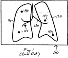
図1は、小結節の位置決め及び比較視覚化を容易にするために構成された肺解剖学的配景マップ上の小結節の表示100を示している。最先端の画像処理及び分割ツールを用いて、元のX線及びCT軸断面などから重要な解剖学的構造を抽出し、いくつかの方法でマップ内に表現することができる。例えば、解剖学的構造を2D平面上に投影して投影2Dマップを作成することができる。別の方法は、ここで示すように、肺生体組織を表現するために線画形式のマップを作成することである。肺の境界は、閉鎖線110、120により表現されている。気道及び血管構造のような他の解剖学的背景は、暗線130により表現されている。線110、120、130により表現された背景構造に対する小結節の大体の位置は、円盤140により示されている。有利な態様においては、円盤は、表示内で目立たたせるように明色、例えば、赤色である。代替的に、円盤は、明滅させるか又は他の方法で強調することができる。有利な態様においては、円盤のサイズは、小結節のサイズに比例して変えることができる。
FIG. 1 illustrates a
図1の表示は、本出願人の「ImageChecker(登録商標)」CTソフトウエアのようなコンピュータ支援小結節解析ソフトウエア内で問題なく実施して成功しており、「小結節ナビゲーションマップ」と呼ばれる。このようなマップの表示のための例示的な装置は、本明細書においてその全内容が引用により組み込まれている「解剖学的情報の表示のためのグラフィカルユーザインタフェース」という名称の本出願人の米国特許第6、925、200号に詳細に説明されている。背景に示す主要な解剖学的構造により、事例全体の重要な詳細、すなわち、いくつの小結節があるのか、それらがどこにあるのか、それらがどのくらいの大きさか、かつ類似の種類の有用な情報の迅速な全体的な視覚化及び理解を得ることが非常に容易である。更に、各円盤は、有利な態様においては、カーソルのような指示デバイスを小結節に整列させてマウスのような選択デバイスを起動させることにより、レントゲン技師が対応するCT断面にアクセスすることができるように、円盤が表現する小結節の画像を含むCT断面とホットリンクしている。すなわち、マップは、小結節の画像を含む個々のCT断面にレントゲン技師がアクセスする便利な方法を提供する。 The display of FIG. 1 has been successfully implemented without problems in computer-aided nodule analysis software such as Applicant's “ImageChecker®” CT software and is referred to as a “nodule navigation map” . An exemplary apparatus for the display of such a map is that of Applicants named “Graphical User Interface for Display of Anatomical Information”, the entire contents of which are incorporated herein by reference. This is described in detail in US Pat. No. 6,925,200. The main anatomical structure shown in the background reveals important details of the whole case: how many nodules are there, where they are, how big they are, and similar types of useful information It is very easy to get a quick overall visualization and understanding. In addition, each disk can advantageously access a corresponding CT cross section by an X-ray technician by activating a selection device such as a mouse by aligning a pointing device such as a cursor with a nodule. Thus, the CT cross section including the image of the nodule represented by the disk is hot-linked. That is, the map provides a convenient way for an X-ray technician to access individual CT sections containing images of nodules.
上述のように、異なる時期に同じ患者の胸部CT走査を取得し、これらの走査を比較して小結節構造をモニタすることは、一般的な臨床的慣例である。しかし、このような比較では、レントゲン技師は、何百もの軸線方向の画像スライスの2つのスタックをナビゲートする必要がある。更に、一部の良性小結節は、サイズが減少して最終的にその後の走査から消滅する可能性があり、一方、ある一定の悪性腫瘍は、広がって新しい小結節をその後の走査において出現させる可能性がある。 As mentioned above, it is common clinical practice to acquire chest CT scans of the same patient at different times and compare these scans to monitor the nodule structure. However, such a comparison requires the X-ray engineer to navigate two stacks of hundreds of axial image slices. In addition, some benign nodules may decrease in size and eventually disappear from subsequent scans, while certain malignancies spread and cause new nodules to appear in subsequent scans. there is a possibility.
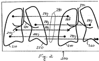
本発明の一態様は、コンピュータスクリーンなどで2つの時間的に関連付けられた医用画像の比較を容易にするナビゲーションツールである。図2は、2つのこのような画像の並列の表示200を示している。ここでもまた、画像は、コンピュータシステム上で実行される小結節解析ソフトウエアにより生成された肺解剖学的配景マップ上での小結節を示している。例示的に、右側の画像の方が、時間的に後である。左側に示す画像においては、肺の境界は、閉鎖線210、220により表現されている。気道及び血管構造のような他の解剖学的背景は、暗線230により表現されている。背景構造に対する小結節の大体の位置は、円盤240により示されている。右側に示す画像においては、肺の境界は、閉鎖線250、260により表現されており、他の解剖学的背景は、暗線270により表現されている。背景構造に対する小結節の大体の位置は、円盤280により示されている。
One aspect of the present invention is a navigation tool that facilitates comparison of two temporally related medical images, such as on a computer screen. FIG. 2 shows a
本発明によれば、ソフトウエアは、一方の画像内のどの小結節が他方の画像の小結節に対応するかを判断して、画像間に延びる複数の線290を生成する。図2に示すように、一部の線291から293は、第1の画像内の円盤240で開始され、第2の画像内の対応する位置での円盤280で終了する。従って、これらの線は、両方の画像において見出される特徴部に関連するものである。別の線294は、第1の画像内の円盤240から第2の画像内の対応する位置に向かって延びるが、第2の画像内のいかなる円盤でも終了していない。この線は、第1の画像内で見出されるが、消滅しているために第2の画像では見出されない特徴部に関連するものである。別の線295は、第2の画像内の円盤280から第1の画像内の対応する位置に向かって延びるが、第1の画像内のいかなる円盤からも開始されていない。この線は、第2の画像内で見出されるが、新しいものであるために第1の画像内では見出されない特徴部に関連するものである。
In accordance with the present invention, the software determines which nodule in one image corresponds to the nodule in the other image and generates a plurality of
有利な態様においては、様々な線290は、異なる色又は他の独特の特性を有することができる。例えば、両方の画像における円盤を結び付ける線291から293は、青色とすることができ、第2の画像内では見出されない円盤に関連する線294は、緑色とすることができ、第2の画像内の新たに見出される円盤に関連する線295は、赤色とすることができるであろう。
In advantageous embodiments, the
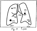
図2内の情報はまた、両方の時間的な画像内に出現する小結節を第1の画像のみ又は第2の画像のみに出現する小結節と区別するために異なるマーカが使用される肺の単一画像での表示に濃縮することもできる。図3は、肺解剖学的配景マップ上のこのような小結節の表示30である。ここでもまた、肺の境界は、閉鎖線310、320により表現されており、気道及び血管構造は、線330により表現されている。両方の組の時間的な画像内で見出される小結節は、黒く塗り潰された円盤341、342、343により表現されている。第1の画像内で見出されるが第2の画像内では見出されない小結節は、緑色のような別の色の円盤344により表現されており、第2の画像内では見出されるが第1の画像内では見出されない小結節は、赤色のような更に別の色の円盤345により表現されている。他の視覚的に独特な特性を用いて、異なる種類の小結節を区別することができる。図3においては、例示上、円盤344は、小さな円により表現されており、円盤345は、大きな円により表現されている。
The information in FIG. 2 also shows that lung markers where different markers are used to distinguish nodules appearing in both temporal images from nodules appearing only in the first image or only in the second image. It is also possible to concentrate on a single image display. FIG. 3 is a display 30 of such a nodule on a lung anatomical landscape map. Again, the lung boundaries are represented by
ここでもまた、上述の構成と共に又は上述の構成の代わりに、他のマーク付け構成を使用することができる。例えば、円盤のサイズは、小結節のサイズに比例したものとすることができる。新たな小結節は、明滅する円盤により示すことができるであろう。更に、色コード又は他の構成により小結節のサイズの変化を示すことも有利であると考えられる。例えば、第1の画像に対する第2の画像における小結節のサイズのパーセント変化を示す数字を円盤と平行して表示することができるであろう。+符号及び−符号を使用して、赤色及び緑色のような色の変化の方向を示すことができると考えられる。 Again, other marking configurations can be used with or instead of the above configuration. For example, the size of the disk can be proportional to the size of the nodule. New nodules could be indicated by a blinking disk. In addition, it may be advantageous to indicate changes in the size of the nodule by color code or other configuration. For example, a number indicating the percentage change in the size of the nodule in the second image relative to the first image could be displayed parallel to the disk. It is believed that the + and-signs can be used to indicate the direction of color change such as red and green.
本発明の好ましい実施形態では、ナビゲーションツールはまた、医用画像の表示の一方の側又は他方の側にスクロールバーを含む。図4は、右側に沿ったスクロールバー401を備えた2つの時間的に関連する画像の表示400を示している。時間的に関連する画像は、図2のものと同じものである。従って、時間的に関連する画像は、同様に付番されているので、更なる説明を割愛する。スクロールバー401は、第1の組の上下スクロールボタン402と、表示バー403と、1組の左右のスクロールボタン404と、カーソル405とを含む。スクロールバー上には、一連の水平線又はマーカ406から410があり、その各々は、1対の医用画像の間でスクロールバーの左まで延びる複数の線の1つに対応する。各マーカは、1対の画像の間にある対応する線に整列していることが好ましい。画像内の各小結節は、CT断面の1つにおいても見出されるので、表示バー403上のマーカは、小結節を含むCT軸線方向スライス番号のベクトルの視覚的表示でもある。
In a preferred embodiment of the present invention, the navigation tool also includes a scroll bar on one side or the other side of the display of the medical image. FIG. 4 shows two temporally related image displays 400 with a scroll bar 401 along the right side. The temporally related images are the same as those in FIG. Accordingly, temporally related images are similarly numbered and will not be further described. The scroll bar 401 includes a first set of up and down scroll buttons 402, a display bar 403, a set of left and
有利な態様においては、マーカの外観は、関連する線と共に変る。例えば、線と同じ色を有することができ、その色は、その線が2つの画像内の特徴部を結合するか否か、又は特徴部が時間的に第1の画像又は時間的に第2の画像内のみで見出されるのかにより変えることができる。代替的に、マーカは、その長さが2つの画像間の線と共に変る線とすることができる。例えば、マーカ406、407、409の場合におけるように、マーカ線は、関連の線が2つの医用画像内の2つの特徴部を結合する場合に最長とすることができ、かつマーカ408、410の場合におけるように、マーカ線は、線が1つの特徴部だけに接続される場合は、単にその線の半分とすることができる。更に、短い方のマーカ線の位置は、マーカ408の場合におけるように、マーカを左調整することによってそれが接続する特徴部が第1の画像内にあるか否か、又はマーカ410の場合におけるように、マーカを右調整することによって第2の画像内のあるのかを示すように変えることができる。
In an advantageous manner, the appearance of the marker varies with the associated line. For example, it can have the same color as a line, whether that line combines features in two images, or whether the feature is a first image in time or a second in time. Depending on whether it is found only in the image. Alternatively, the marker can be a line whose length varies with the line between the two images. For example, as in the case of
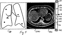
カーソル405をマーカまで進めてマウスボタンをクリックするか又は何らかの他の選択デバイスを起動させることにより、対応する線に関連した一方又は両方の断面が表示される。図5は、左の画像が肺解剖学的マップ上で小結節の位置を定めるマップ520であり、右の画像は、カーソル405により選択された小結節の画像を表示するCT断面である。マップ520は、ユーザ選択可能であることが好ましい。それは、CT断面の時間的に新しい方のスタック内の小結節のマップ、又は古い方のスタック内の小結節のマップ、又は図3に示すもののような2つのマップの複合物とすることができる。 By either moving the cursor 405 to the marker and clicking a mouse button or activating some other selection device, one or both cross sections associated with the corresponding line are displayed. FIG. 5 is a map 520 in which the left image defines the position of the nodule on the lung anatomical map, and the right image is a CT cross section displaying the image of the nodule selected by the cursor 405. The map 520 is preferably user selectable. It can be a map of nodules in the temporally newer stack of CT sections, or a map of nodules in the older stack, or a composite of two maps like the one shown in FIG. .
上下スクロールボタン402により、ユーザは、小結節を含む1つの断面から異なる小結節を含む次の断面へディスプレイ530内のCT断面の表示を段階的に変えることができる。具体的には、上又は下スクロールボタン402をクリックする度に、ディスプレイ530は、1つの小結節を含むCT断面の表示から次の小結節を含むCT断面の表示に移る。
The up / down scroll button 402 allows the user to gradually change the display of the CT cross section in the
左右のスクロールボタン404により、ユーザは、一度に一回、CT軸断面のスタック全体をナビゲートすることができる。左又は右のボタンをクリックする度に、スタック内で次の断面を下に又は上に表示するためにディスプレイ530が変る。このようにして、ユーザは、小結節の画像が出現する断面の間近のCT断面を見ることができる。代替的に、左右の制御ボタンを使用して、表示される軸断面がCT断面の古い方のスタックのものか又は新しい方のスタックのものかを選択することができる。
The left and
ユーザがスクロールバーと共に出現する画像を選択することを可能にする付加的な制御(図示せず)を提供することもできる。例えば、一部のユーザは、図5におけるような断面の代わりに、マップがスクロールバーの間近に表示される方を好むであろう。ユーザはまた、時間的に新しい方の画像スタック内の断面を先の画像スタック内の対応する断面と比較することを望む場合もあり、また、2つの断面の並列の表示を可能にするためにマップの表示を消したいと思う場合もある。 Additional controls (not shown) may also be provided that allow the user to select an image that appears with the scroll bar. For example, some users may prefer that the map be displayed close to the scroll bar instead of the cross section as in FIG. The user may also wish to compare the cross-section in the newer image stack in time with the corresponding cross-section in the previous image stack, and to allow parallel display of the two cross-sections. You may want to turn off the map display.
図6は、図2から図6の表示を生成するソフトウエアプログラムの流れ図である。ソフトウエアプログラムは、これらの表示を生成するコンピュータが利用可能であるコンピュータ可読媒体に記憶された1組のコンピュータ命令を含む。プログラムは、段階610で、1対の時間的に関連付けられた医用画像を表現するデータで開始される。上述のように、画像は、X線のような実画像、又は投影マップ又は解剖学的マップのような画像から導出された抽象画像とすることができる。段階620で、プログラムは、第1及び第2の画像の各々において関連の特徴部又は領域の位置を定める。例えば、医用画像が肺の領域のものである場合、特徴部は、小結節とすることができる。段階630で、プログラムは、各画像において実質的に同じ位置での対応する特徴部を識別するために2つの画像を比較する。段階640で、医用画像のうちの少なくとも1つを図2又は図3に示すように表示する。段階650で、両方の画像において見出される対応する特徴部を識別し、段階660で一方の医用画像だけにおいて見出される特徴部を識別する。例示的に、図2に示すように、対応する特徴部は、両方の画像内の対応する特徴部を結ぶ線により識別することができ、一方の画像だけにおいて見出される特徴部は、特徴部が見出される画像内の特徴部から他方の特徴部に向かって延びる線により識別することができる。図3に示すように、一方の画像のみが表示される場合、両方の画像内で見出される特徴部は、表示された画像上に1つの方式でマーク付けすることができ、一方、一方の画像だけにおいて見出される特徴部は、異なる方式でマーク付けすることができる。
FIG. 6 is a flow diagram of a software program that generates the displays of FIGS. The software program includes a set of computer instructions stored on a computer readable medium that can be used by a computer to generate these displays. The program begins at
当業者に明らかなように、本発明の精神及び範囲内で上述のナビゲーションツールの多くの変形を実施することができる。特に注目すべき点として、本発明は、肺解剖学的配景マップ上の小結節の2つの表示の比較という関連において説明したが、生体組織の他の領域内の特徴部を比較する際に、かつ他の形式の医用画像を比較する際に本発明を実施することができることが理解されるであろう。特に、本発明は、実際のX線画像、超音波画像、乳房X線写真、MRI走査、及びCT画像などの特徴部を比較する際にも実施することができる。更に、本発明は、2つよりも多い医用画像を比較するために実施することができる。 As will be apparent to those skilled in the art, many variations of the navigation tools described above can be implemented within the spirit and scope of the present invention. Of particular note, the present invention has been described in the context of comparing two indications of nodules on a pulmonary anatomical landscape map, but in comparing features in other regions of biological tissue. It will be appreciated that the present invention can be implemented in comparing other types of medical images. In particular, the present invention can also be implemented when comparing features such as actual X-ray images, ultrasound images, mammograms, MRI scans, and CT images. Furthermore, the present invention can be implemented to compare more than two medical images.
100 肺解剖学的配景マップ上の小結節の表示
110、120 肺の境界を示す閉鎖線
140 小結節の大体の位置を示す円盤
100 Nodule display on lung
Claims (15)
a)同じ物の異なる時期の画像である互いに並んだ第1及び第2の医用画像と、
b)少なくとも第1の線が、前記第1の画像内の第1の位置の特徴部で始まり、かつ前記第2の画像内の対応する位置の対応する特徴部で終了し、少なくとも第2の線が、該画像の一方の第2の位置で見出される特徴部から、対応する特徴部が見出されない他方の画像内の対応する第2の位置に向かって延びている該画像間に延びる複数の線と、
を表示するための表示手段
を含むことを特徴とするツール。A navigation tool that facilitates the comparison of two temporally related medical images,
a) a first and second medical imaging aligned with each other are different times of the image of the same thing,
b) at least a first line starts with a feature at a first position in the first image and ends with a corresponding feature at a corresponding position in the second image, and at least a second A plurality of lines extending between the images in which a line extends from a feature found at one second position of the image toward a corresponding second position in the other image where the corresponding feature is not found And the line
A tool characterized by including display means for displaying .
第1及び第2の医用画像の各々における対応する特徴部の位置を定める段階と、
前記医用画像の少なくとも一方を表示する段階と、
前記表示した医用画像上で前記対応する特徴部を識別する段階と、
表示した医用画像上で前記第1及び第2の医用画像の一方に見出されるが他方に見出されない少なくとも1つの特徴部を識別する段階と、
を含み、
前記第1及び第2の医用画像の両方が表示され、少なくとも第1の線が、該第1の画像内の第1の位置の特徴部と、前記第2の画像内の対応する第1の位置の対応する特徴部との間に延び、第2の線が、該画像の一方における第2の位置の特徴部から、対応する特徴部が見出されない他方の画像における対応する第2の位置に向かって延びていることを特徴とする方法。A method for comparing first and second temporally related medical images, comprising:
Determining the position of the corresponding feature in each of the first and second medical images;
Displaying at least one of the medical images;
Identifying the corresponding feature on the displayed medical image;
Identifying at least one feature found in one of the first and second medical images but not in the other on the displayed medical image;
Only including,
Both the first and second medical images are displayed, and at least a first line has a first location feature in the first image and a corresponding first in the second image. A second line extends between the corresponding feature of the position and the second line corresponds to the corresponding second position in the other image from which the corresponding feature is not found. how it characterized in that it extends toward the.
Applications Claiming Priority (3)
| Application Number | Priority Date | Filing Date | Title |
|---|---|---|---|
| US11/344,832 | 2006-01-31 | ||
| US11/344,832 US7630531B2 (en) | 2006-01-31 | 2006-01-31 | Enhanced navigational tools for comparing medical images |
| PCT/US2007/002980 WO2007089941A2 (en) | 2006-01-31 | 2007-01-30 | Enhanced navigational tools for comparing medical images |
Publications (2)
| Publication Number | Publication Date |
|---|---|
| JP2009525143A JP2009525143A (en) | 2009-07-09 |
| JP5114630B2 true JP5114630B2 (en) | 2013-01-09 |
Family
ID=38322135
Family Applications (1)
| Application Number | Title | Priority Date | Filing Date |
|---|---|---|---|
| JP2008553387A Active JP5114630B2 (en) | 2006-01-31 | 2007-01-30 | Improved navigation tool for comparing medical images |
Country Status (4)
| Country | Link |
|---|---|
| US (1) | US7630531B2 (en) |
| EP (1) | EP1979856B1 (en) |
| JP (1) | JP5114630B2 (en) |
| WO (1) | WO2007089941A2 (en) |
Families Citing this family (43)
| Publication number | Priority date | Publication date | Assignee | Title |
|---|---|---|---|---|
| US10638994B2 (en) | 2002-11-27 | 2020-05-05 | Hologic, Inc. | X-ray mammography with tomosynthesis |
| US7123684B2 (en) | 2002-11-27 | 2006-10-17 | Hologic, Inc. | Full field mammography with tissue exposure control, tomosynthesis, and dynamic field of view processing |
| US7616801B2 (en) | 2002-11-27 | 2009-11-10 | Hologic, Inc. | Image handling and display in x-ray mammography and tomosynthesis |
| US7577282B2 (en) | 2002-11-27 | 2009-08-18 | Hologic, Inc. | Image handling and display in X-ray mammography and tomosynthesis |
| US8565372B2 (en) | 2003-11-26 | 2013-10-22 | Hologic, Inc | System and method for low dose tomosynthesis |
| EP1816965B1 (en) | 2004-11-26 | 2016-06-29 | Hologic, Inc. | Integrated multi-mode mammography/tomosynthesis x-ray system |
| US7518619B2 (en) * | 2005-11-07 | 2009-04-14 | General Electric Company | Method and apparatus for integrating three-dimensional and two-dimensional monitors with medical diagnostic imaging workstations |
| WO2008075272A1 (en) * | 2006-12-19 | 2008-06-26 | Koninklijke Philips Electronics N.V. | Apparatus and method for indicating likely computer-detected false positives in medical imaging data |
| US7936910B2 (en) * | 2007-09-20 | 2011-05-03 | James Hamilton Watt | Method, system and software for displaying medical images |
| US20100063842A1 (en) * | 2008-09-08 | 2010-03-11 | General Electric Company | System and methods for indicating an image location in an image stack |
| US9146663B2 (en) | 2008-12-08 | 2015-09-29 | Hologic, Inc. | Displaying computer-aided detection information with associated breast tomosynthesis image information |
| JP2012513279A (en) * | 2008-12-23 | 2012-06-14 | コーニンクレッカ フィリップス エレクトロニクス エヌ ヴィ | Medical abnormality monitoring system and operation method thereof |
| JP5455470B2 (en) * | 2009-07-02 | 2014-03-26 | 株式会社東芝 | Medical image interpretation system |
| EP2535829A3 (en) | 2009-10-07 | 2013-07-10 | Hologic, Inc. | Processing and displaying computer-aided detection information associated with breast x-ray images |
| US9734285B2 (en) * | 2010-05-20 | 2017-08-15 | General Electric Company | Anatomy map navigator systems and methods of use |
| US8761467B2 (en) * | 2010-10-04 | 2014-06-24 | General Electric Company | Method and apparatus for assessing motion correction |
| AU2012236737B2 (en) * | 2011-03-29 | 2017-03-02 | Boston Scientific Neuromodulation Corporation | System and method for atlas registration |
| WO2013001443A2 (en) * | 2011-06-27 | 2013-01-03 | Koninklijke Philips Electronics N.V. | Exam review facilitated by clinical findings management with anatomical tagging |
| US10171734B2 (en) | 2012-02-27 | 2019-01-01 | Ovio Technologies, Inc. | Rotatable imaging system |
| US20130322712A1 (en) * | 2012-06-05 | 2013-12-05 | Siemens Medical Solutions Usa, Inc. | System for Comparing Medical Images |
| GB201210172D0 (en) * | 2012-06-08 | 2012-07-25 | Siemens Medical Solutions | Navigation mini-map for structured reading |
| CN103619245B (en) * | 2012-06-20 | 2019-04-02 | 东芝医疗系统株式会社 | Medical image-processing apparatus and method, MR imaging apparatus and method |
| KR102047696B1 (en) * | 2013-02-20 | 2019-11-22 | 엘지전자 주식회사 | Mobile terminal and controlling method thereof |
| CN104423868B (en) * | 2013-09-04 | 2019-03-08 | 腾讯科技(深圳)有限公司 | E-book reading localization method and device |
| JP6323025B2 (en) * | 2014-01-21 | 2018-05-16 | 富士通株式会社 | Display control program, display control device, and display control system |
| US9727986B2 (en) | 2014-07-02 | 2017-08-08 | Covidien Lp | Unified coordinate system for multiple CT scans of patient lungs |
| CN104323860B (en) * | 2014-11-07 | 2018-08-31 | 常州朗合医疗器械有限公司 | Navigation path planning device and method |
| JP6598565B2 (en) * | 2015-08-06 | 2019-10-30 | キヤノン株式会社 | Image processing apparatus, image processing method, and program |
| CN106803234B (en) * | 2015-11-26 | 2020-06-16 | 腾讯科技(深圳)有限公司 | Picture display control method and device in picture editing |
| JP7085492B2 (en) | 2016-04-22 | 2022-06-16 | ホロジック,インコーポレイテッド | Tomosynthesis with a shift focus X-ray system using an addressable array |
| EP3326535B1 (en) | 2016-11-25 | 2019-06-12 | ScreenPoint Medical | Displaying system for displaying digital breast tomosynthesis data |
| JP2018175216A (en) * | 2017-04-10 | 2018-11-15 | コニカミノルタ株式会社 | Medical image display device and program |
| WO2019035064A1 (en) | 2017-08-16 | 2019-02-21 | Hologic, Inc. | Techniques for breast imaging patient motion artifact compensation |
| EP3449835B1 (en) | 2017-08-22 | 2023-01-11 | Hologic, Inc. | Computed tomography system and method for imaging multiple anatomical targets |
| JP6950507B2 (en) * | 2017-12-12 | 2021-10-13 | コニカミノルタ株式会社 | Dynamic image processing device |
| US11090017B2 (en) | 2018-09-13 | 2021-08-17 | Hologic, Inc. | Generating synthesized projection images for 3D breast tomosynthesis or multi-mode x-ray breast imaging |
| EP3682804A1 (en) * | 2019-01-18 | 2020-07-22 | Samsung Electronics Co., Ltd. | X-ray imaging apparatus and control method thereof |
| EP3832689A3 (en) | 2019-12-05 | 2021-08-11 | Hologic, Inc. | Systems and methods for improved x-ray tube life |
| US11471118B2 (en) | 2020-03-27 | 2022-10-18 | Hologic, Inc. | System and method for tracking x-ray tube focal spot position |
| TWI799705B (en) * | 2020-05-20 | 2023-04-21 | 倍利科技股份有限公司 | Medical image aided interpretation system |
| US20220291823A1 (en) * | 2021-03-11 | 2022-09-15 | GE Precision Healthcare LLC | Enhanced Visualization And Playback Of Ultrasound Image Loops Using Identification Of Key Frames Within The Image Loops |
| US11786191B2 (en) | 2021-05-17 | 2023-10-17 | Hologic, Inc. | Contrast-enhanced tomosynthesis with a copper filter |
| US20230051081A1 (en) * | 2021-08-11 | 2023-02-16 | Mim Software Inc. | Registration chaining with information transfer |
Family Cites Families (12)
| Publication number | Priority date | Publication date | Assignee | Title |
|---|---|---|---|---|
| JP3085724B2 (en) * | 1991-05-10 | 2000-09-11 | 株式会社東芝 | Medical diagnosis support system |
| JPH06215108A (en) * | 1992-11-27 | 1994-08-05 | Fuji Photo Film Co Ltd | Positioning method for radiation picture |
| EP0973116A1 (en) * | 1993-03-01 | 2000-01-19 | Kabushiki Kaisha Toshiba | Medical information processing system for supporting diagnosis |
| JPH0877329A (en) * | 1994-09-02 | 1996-03-22 | Konica Corp | Display device for time-sequentially processed image |
| US6222541B1 (en) * | 1998-01-20 | 2001-04-24 | International Business Machines Corporation | Method and apparatus for fast-path location and selection of links |
| JP2001157675A (en) * | 1999-12-02 | 2001-06-12 | Fuji Photo Film Co Ltd | Method and apparatus for displaying image |
| US7072501B2 (en) | 2000-11-22 | 2006-07-04 | R2 Technology, Inc. | Graphical user interface for display of anatomical information |
| US7130457B2 (en) * | 2001-07-17 | 2006-10-31 | Accuimage Diagnostics Corp. | Systems and graphical user interface for analyzing body images |
| JP4341210B2 (en) * | 2002-07-04 | 2009-10-07 | コニカミノルタホールディングス株式会社 | Medical image processing apparatus, medical image processing method, program, and recording medium |
| US7403646B2 (en) * | 2002-10-24 | 2008-07-22 | Canon Kabushiki Kaisha | Image processing apparatus, image processing method, program, and recording medium for generating a difference image from a first radiographic image and second radiographic image |
| JP4731127B2 (en) * | 2004-05-26 | 2011-07-20 | 株式会社日立メディコ | Image diagnosis support apparatus and method |
| JP4786150B2 (en) | 2004-07-07 | 2011-10-05 | 株式会社東芝 | Ultrasonic diagnostic apparatus and image processing apparatus |
-
2006
- 2006-01-31 US US11/344,832 patent/US7630531B2/en active Active
-
2007
- 2007-01-30 WO PCT/US2007/002980 patent/WO2007089941A2/en active Application Filing
- 2007-01-30 EP EP07762774.3A patent/EP1979856B1/en active Active
- 2007-01-30 JP JP2008553387A patent/JP5114630B2/en active Active
Also Published As
| Publication number | Publication date |
|---|---|
| JP2009525143A (en) | 2009-07-09 |
| EP1979856B1 (en) | 2014-04-02 |
| US20070177780A1 (en) | 2007-08-02 |
| EP1979856A2 (en) | 2008-10-15 |
| WO2007089941A2 (en) | 2007-08-09 |
| US7630531B2 (en) | 2009-12-08 |
| EP1979856A4 (en) | 2011-12-07 |
| WO2007089941A3 (en) | 2008-05-02 |
Similar Documents
| Publication | Publication Date | Title |
|---|---|---|
| JP5114630B2 (en) | Improved navigation tool for comparing medical images | |
| US11520415B2 (en) | Interactive 3D cursor for use in medical imaging | |
| JP6799115B2 (en) | Information terminal control methods and programs | |
| US10347033B2 (en) | Three-dimensional image display apparatus, method, and program | |
| US9373181B2 (en) | System and method for enhanced viewing of rib metastasis | |
| US6944330B2 (en) | Interactive computer-aided diagnosis method and system for assisting diagnosis of lung nodules in digital volumetric medical images | |
| US9037215B2 (en) | Methods and apparatus for 3D route planning through hollow organs | |
| JP6072008B2 (en) | User-operated on-the-fly route planning | |
| US8994720B2 (en) | Diagnosis assisting apparatus, diagnosis assisting program, and diagnosis assisting method | |
| WO2011033769A1 (en) | Medical image display device, method, and program | |
| WO2006011545A1 (en) | Medical image diagnosis assisting system, device and image processing program | |
| JP6431292B2 (en) | MEDICAL IMAGE DISPLAY DEVICE, ITS CONTROL METHOD, CONTROL DEVICE, PROGRAM | |
| JP2001087228A (en) | Image reading support device | |
| JP6572370B2 (en) | MEDICAL IMAGE DISPLAY DEVICE, ITS CONTROL METHOD, PROGRAM | |
| JP5159195B2 (en) | Medical image processing device | |
| US20240024029A1 (en) | Systems and method of planning thoracic surgery | |
| JP6925795B2 (en) | Medical image diagnosis support device, its control method, and program |
Legal Events
| Date | Code | Title | Description |
|---|---|---|---|
| A621 | Written request for application examination |
Free format text: JAPANESE INTERMEDIATE CODE: A621 Effective date: 20100107 |
|
| A977 | Report on retrieval |
Free format text: JAPANESE INTERMEDIATE CODE: A971007 Effective date: 20120305 |
|
| A131 | Notification of reasons for refusal |
Free format text: JAPANESE INTERMEDIATE CODE: A131 Effective date: 20120319 |
|
| A601 | Written request for extension of time |
Free format text: JAPANESE INTERMEDIATE CODE: A601 Effective date: 20120619 |
|
| A602 | Written permission of extension of time |
Free format text: JAPANESE INTERMEDIATE CODE: A602 Effective date: 20120626 |
|
| A521 | Request for written amendment filed |
Free format text: JAPANESE INTERMEDIATE CODE: A523 Effective date: 20120705 |
|
| TRDD | Decision of grant or rejection written | ||
| A01 | Written decision to grant a patent or to grant a registration (utility model) |
Free format text: JAPANESE INTERMEDIATE CODE: A01 Effective date: 20120730 |
|
| A01 | Written decision to grant a patent or to grant a registration (utility model) |
Free format text: JAPANESE INTERMEDIATE CODE: A01 |
|
| A711 | Notification of change in applicant |
Free format text: JAPANESE INTERMEDIATE CODE: A711 Effective date: 20120802 |
|
| A61 | First payment of annual fees (during grant procedure) |
Free format text: JAPANESE INTERMEDIATE CODE: A61 Effective date: 20120823 |
|
| R150 | Certificate of patent or registration of utility model |
Free format text: JAPANESE INTERMEDIATE CODE: R150 Ref document number: 5114630 Country of ref document: JP Free format text: JAPANESE INTERMEDIATE CODE: R150 |
|
| FPAY | Renewal fee payment (event date is renewal date of database) |
Free format text: PAYMENT UNTIL: 20151026 Year of fee payment: 3 |
|
| R250 | Receipt of annual fees |
Free format text: JAPANESE INTERMEDIATE CODE: R250 |
|
| R250 | Receipt of annual fees |
Free format text: JAPANESE INTERMEDIATE CODE: R250 |
|
| R250 | Receipt of annual fees |
Free format text: JAPANESE INTERMEDIATE CODE: R250 |
|
| R250 | Receipt of annual fees |
Free format text: JAPANESE INTERMEDIATE CODE: R250 |
|
| R250 | Receipt of annual fees |
Free format text: JAPANESE INTERMEDIATE CODE: R250 |
|
| R250 | Receipt of annual fees |
Free format text: JAPANESE INTERMEDIATE CODE: R250 |
|
| R250 | Receipt of annual fees |
Free format text: JAPANESE INTERMEDIATE CODE: R250 |
|
| R250 | Receipt of annual fees |
Free format text: JAPANESE INTERMEDIATE CODE: R250 |
|
| R250 | Receipt of annual fees |
Free format text: JAPANESE INTERMEDIATE CODE: R250 |