JP4786150B2 - Ultrasonic diagnostic apparatus and image processing apparatus - Google Patents
Ultrasonic diagnostic apparatus and image processing apparatus Download PDFInfo
- Publication number
- JP4786150B2 JP4786150B2 JP2004201040A JP2004201040A JP4786150B2 JP 4786150 B2 JP4786150 B2 JP 4786150B2 JP 2004201040 A JP2004201040 A JP 2004201040A JP 2004201040 A JP2004201040 A JP 2004201040A JP 4786150 B2 JP4786150 B2 JP 4786150B2
- Authority
- JP
- Japan
- Prior art keywords
- image
- data
- luminance
- color
- luminance level
- Prior art date
- Legal status (The legal status is an assumption and is not a legal conclusion. Google has not performed a legal analysis and makes no representation as to the accuracy of the status listed.)
- Expired - Fee Related
Links
- 238000012545 processing Methods 0.000 title claims description 109
- 230000008859 change Effects 0.000 claims description 78
- 239000003086 colorant Substances 0.000 claims description 14
- 239000002131 composite material Substances 0.000 claims 2
- 235000019646 color tone Nutrition 0.000 description 129
- 230000006870 function Effects 0.000 description 47
- 238000000034 method Methods 0.000 description 40
- 238000004364 calculation method Methods 0.000 description 27
- 238000010586 diagram Methods 0.000 description 25
- 230000005540 biological transmission Effects 0.000 description 24
- 230000008569 process Effects 0.000 description 18
- 230000017531 blood circulation Effects 0.000 description 15
- 239000002872 contrast media Substances 0.000 description 13
- 238000003745 diagnosis Methods 0.000 description 13
- 239000000523 sample Substances 0.000 description 13
- 239000000203 mixture Substances 0.000 description 11
- 230000000694 effects Effects 0.000 description 8
- 230000002123 temporal effect Effects 0.000 description 7
- 206010028980 Neoplasm Diseases 0.000 description 6
- 230000015572 biosynthetic process Effects 0.000 description 6
- 238000003786 synthesis reaction Methods 0.000 description 6
- 230000007423 decrease Effects 0.000 description 5
- 230000001174 ascending effect Effects 0.000 description 4
- 230000003247 decreasing effect Effects 0.000 description 4
- 238000002604 ultrasonography Methods 0.000 description 4
- 239000002961 echo contrast media Substances 0.000 description 3
- 238000000605 extraction Methods 0.000 description 3
- 230000001771 impaired effect Effects 0.000 description 3
- 108010076504 Protein Sorting Signals Proteins 0.000 description 2
- 230000003321 amplification Effects 0.000 description 2
- 238000004458 analytical method Methods 0.000 description 2
- 239000008280 blood Substances 0.000 description 2
- 210000004369 blood Anatomy 0.000 description 2
- 210000004204 blood vessel Anatomy 0.000 description 2
- 238000001514 detection method Methods 0.000 description 2
- 239000006185 dispersion Substances 0.000 description 2
- 239000000284 extract Substances 0.000 description 2
- 238000009499 grossing Methods 0.000 description 2
- 238000003384 imaging method Methods 0.000 description 2
- 238000003199 nucleic acid amplification method Methods 0.000 description 2
- 238000012935 Averaging Methods 0.000 description 1
- 230000002238 attenuated effect Effects 0.000 description 1
- 201000011510 cancer Diseases 0.000 description 1
- 239000000470 constituent Substances 0.000 description 1
- 238000007796 conventional method Methods 0.000 description 1
- 238000002059 diagnostic imaging Methods 0.000 description 1
- 238000002405 diagnostic procedure Methods 0.000 description 1
- 238000003748 differential diagnosis Methods 0.000 description 1
- 230000004069 differentiation Effects 0.000 description 1
- 201000010099 disease Diseases 0.000 description 1
- 208000037265 diseases, disorders, signs and symptoms Diseases 0.000 description 1
- 238000005516 engineering process Methods 0.000 description 1
- 230000001605 fetal effect Effects 0.000 description 1
- 238000001727 in vivo Methods 0.000 description 1
- 230000010365 information processing Effects 0.000 description 1
- 238000001990 intravenous administration Methods 0.000 description 1
- 210000004185 liver Anatomy 0.000 description 1
- 201000007270 liver cancer Diseases 0.000 description 1
- 208000019423 liver disease Diseases 0.000 description 1
- 208000014018 liver neoplasm Diseases 0.000 description 1
- 230000036210 malignancy Effects 0.000 description 1
- 239000000463 material Substances 0.000 description 1
- 238000005259 measurement Methods 0.000 description 1
- 238000000691 measurement method Methods 0.000 description 1
- 230000007246 mechanism Effects 0.000 description 1
- 238000002156 mixing Methods 0.000 description 1
- 230000000877 morphologic effect Effects 0.000 description 1
- 210000000056 organ Anatomy 0.000 description 1
- 230000002093 peripheral effect Effects 0.000 description 1
- 230000001172 regenerating effect Effects 0.000 description 1
- 230000007704 transition Effects 0.000 description 1
- 210000003462 vein Anatomy 0.000 description 1
- 210000001835 viscera Anatomy 0.000 description 1
Images


Classifications
-
- A—HUMAN NECESSITIES
- A61—MEDICAL OR VETERINARY SCIENCE; HYGIENE
- A61B—DIAGNOSIS; SURGERY; IDENTIFICATION
- A61B8/00—Diagnosis using ultrasonic, sonic or infrasonic waves
- A61B8/46—Ultrasonic, sonic or infrasonic diagnostic devices with special arrangements for interfacing with the operator or the patient
- A61B8/467—Ultrasonic, sonic or infrasonic diagnostic devices with special arrangements for interfacing with the operator or the patient characterised by special input means
-
- A—HUMAN NECESSITIES
- A61—MEDICAL OR VETERINARY SCIENCE; HYGIENE
- A61B—DIAGNOSIS; SURGERY; IDENTIFICATION
- A61B8/00—Diagnosis using ultrasonic, sonic or infrasonic waves
- A61B8/46—Ultrasonic, sonic or infrasonic diagnostic devices with special arrangements for interfacing with the operator or the patient
- A61B8/461—Displaying means of special interest
-
- A—HUMAN NECESSITIES
- A61—MEDICAL OR VETERINARY SCIENCE; HYGIENE
- A61B—DIAGNOSIS; SURGERY; IDENTIFICATION
- A61B8/00—Diagnosis using ultrasonic, sonic or infrasonic waves
- A61B8/46—Ultrasonic, sonic or infrasonic diagnostic devices with special arrangements for interfacing with the operator or the patient
- A61B8/467—Ultrasonic, sonic or infrasonic diagnostic devices with special arrangements for interfacing with the operator or the patient characterised by special input means
- A61B8/469—Ultrasonic, sonic or infrasonic diagnostic devices with special arrangements for interfacing with the operator or the patient characterised by special input means for selection of a region of interest
-
- A—HUMAN NECESSITIES
- A61—MEDICAL OR VETERINARY SCIENCE; HYGIENE
- A61B—DIAGNOSIS; SURGERY; IDENTIFICATION
- A61B8/00—Diagnosis using ultrasonic, sonic or infrasonic waves
- A61B8/48—Diagnostic techniques
- A61B8/483—Diagnostic techniques involving the acquisition of a 3D volume of data
-
- G—PHYSICS
- G01—MEASURING; TESTING
- G01S—RADIO DIRECTION-FINDING; RADIO NAVIGATION; DETERMINING DISTANCE OR VELOCITY BY USE OF RADIO WAVES; LOCATING OR PRESENCE-DETECTING BY USE OF THE REFLECTION OR RERADIATION OF RADIO WAVES; ANALOGOUS ARRANGEMENTS USING OTHER WAVES
- G01S15/00—Systems using the reflection or reradiation of acoustic waves, e.g. sonar systems
- G01S15/88—Sonar systems specially adapted for specific applications
- G01S15/89—Sonar systems specially adapted for specific applications for mapping or imaging
- G01S15/8906—Short-range imaging systems; Acoustic microscope systems using pulse-echo techniques
- G01S15/8979—Combined Doppler and pulse-echo imaging systems
-
- G—PHYSICS
- G01—MEASURING; TESTING
- G01S—RADIO DIRECTION-FINDING; RADIO NAVIGATION; DETERMINING DISTANCE OR VELOCITY BY USE OF RADIO WAVES; LOCATING OR PRESENCE-DETECTING BY USE OF THE REFLECTION OR RERADIATION OF RADIO WAVES; ANALOGOUS ARRANGEMENTS USING OTHER WAVES
- G01S7/00—Details of systems according to groups G01S13/00, G01S15/00, G01S17/00
- G01S7/52—Details of systems according to groups G01S13/00, G01S15/00, G01S17/00 of systems according to group G01S15/00
- G01S7/52017—Details of systems according to groups G01S13/00, G01S15/00, G01S17/00 of systems according to group G01S15/00 particularly adapted to short-range imaging
- G01S7/52023—Details of receivers
- G01S7/52034—Data rate converters
-
- G—PHYSICS
- G01—MEASURING; TESTING
- G01S—RADIO DIRECTION-FINDING; RADIO NAVIGATION; DETERMINING DISTANCE OR VELOCITY BY USE OF RADIO WAVES; LOCATING OR PRESENCE-DETECTING BY USE OF THE REFLECTION OR RERADIATION OF RADIO WAVES; ANALOGOUS ARRANGEMENTS USING OTHER WAVES
- G01S7/00—Details of systems according to groups G01S13/00, G01S15/00, G01S17/00
- G01S7/52—Details of systems according to groups G01S13/00, G01S15/00, G01S17/00 of systems according to group G01S15/00
- G01S7/52017—Details of systems according to groups G01S13/00, G01S15/00, G01S17/00 of systems according to group G01S15/00 particularly adapted to short-range imaging
- G01S7/52053—Display arrangements
- G01S7/52057—Cathode ray tube displays
- G01S7/52071—Multicolour displays; using colour coding; Optimising colour or information content in displays, e.g. parametric imaging
-
- G—PHYSICS
- G01—MEASURING; TESTING
- G01S—RADIO DIRECTION-FINDING; RADIO NAVIGATION; DETERMINING DISTANCE OR VELOCITY BY USE OF RADIO WAVES; LOCATING OR PRESENCE-DETECTING BY USE OF THE REFLECTION OR RERADIATION OF RADIO WAVES; ANALOGOUS ARRANGEMENTS USING OTHER WAVES
- G01S7/00—Details of systems according to groups G01S13/00, G01S15/00, G01S17/00
- G01S7/52—Details of systems according to groups G01S13/00, G01S15/00, G01S17/00 of systems according to group G01S15/00
- G01S7/52017—Details of systems according to groups G01S13/00, G01S15/00, G01S17/00 of systems according to group G01S15/00 particularly adapted to short-range imaging
- G01S7/52053—Display arrangements
- G01S7/52057—Cathode ray tube displays
- G01S7/52073—Production of cursor lines, markers or indicia by electronic means
-
- G—PHYSICS
- G01—MEASURING; TESTING
- G01S—RADIO DIRECTION-FINDING; RADIO NAVIGATION; DETERMINING DISTANCE OR VELOCITY BY USE OF RADIO WAVES; LOCATING OR PRESENCE-DETECTING BY USE OF THE REFLECTION OR RERADIATION OF RADIO WAVES; ANALOGOUS ARRANGEMENTS USING OTHER WAVES
- G01S7/00—Details of systems according to groups G01S13/00, G01S15/00, G01S17/00
- G01S7/52—Details of systems according to groups G01S13/00, G01S15/00, G01S17/00 of systems according to group G01S15/00
- G01S7/52017—Details of systems according to groups G01S13/00, G01S15/00, G01S17/00 of systems according to group G01S15/00 particularly adapted to short-range imaging
- G01S7/52053—Display arrangements
- G01S7/52057—Cathode ray tube displays
- G01S7/52074—Composite displays, e.g. split-screen displays; Combination of multiple images or of images and alphanumeric tabular information
-
- G—PHYSICS
- G01—MEASURING; TESTING
- G01S—RADIO DIRECTION-FINDING; RADIO NAVIGATION; DETERMINING DISTANCE OR VELOCITY BY USE OF RADIO WAVES; LOCATING OR PRESENCE-DETECTING BY USE OF THE REFLECTION OR RERADIATION OF RADIO WAVES; ANALOGOUS ARRANGEMENTS USING OTHER WAVES
- G01S7/00—Details of systems according to groups G01S13/00, G01S15/00, G01S17/00
- G01S7/52—Details of systems according to groups G01S13/00, G01S15/00, G01S17/00 of systems according to group G01S15/00
- G01S7/52017—Details of systems according to groups G01S13/00, G01S15/00, G01S17/00 of systems according to group G01S15/00 particularly adapted to short-range imaging
- G01S7/52079—Constructional features
- G01S7/52084—Constructional features related to particular user interfaces
-
- A—HUMAN NECESSITIES
- A61—MEDICAL OR VETERINARY SCIENCE; HYGIENE
- A61B—DIAGNOSIS; SURGERY; IDENTIFICATION
- A61B8/00—Diagnosis using ultrasonic, sonic or infrasonic waves
- A61B8/06—Measuring blood flow
-
- A—HUMAN NECESSITIES
- A61—MEDICAL OR VETERINARY SCIENCE; HYGIENE
- A61B—DIAGNOSIS; SURGERY; IDENTIFICATION
- A61B8/00—Diagnosis using ultrasonic, sonic or infrasonic waves
- A61B8/13—Tomography
-
- G—PHYSICS
- G01—MEASURING; TESTING
- G01S—RADIO DIRECTION-FINDING; RADIO NAVIGATION; DETERMINING DISTANCE OR VELOCITY BY USE OF RADIO WAVES; LOCATING OR PRESENCE-DETECTING BY USE OF THE REFLECTION OR RERADIATION OF RADIO WAVES; ANALOGOUS ARRANGEMENTS USING OTHER WAVES
- G01S7/00—Details of systems according to groups G01S13/00, G01S15/00, G01S17/00
- G01S7/52—Details of systems according to groups G01S13/00, G01S15/00, G01S17/00 of systems according to group G01S15/00
- G01S7/52017—Details of systems according to groups G01S13/00, G01S15/00, G01S17/00 of systems according to group G01S15/00 particularly adapted to short-range imaging
- G01S7/52023—Details of receivers
- G01S7/52025—Details of receivers for pulse systems
- G01S7/52026—Extracting wanted echo signals
-
- G—PHYSICS
- G01—MEASURING; TESTING
- G01S—RADIO DIRECTION-FINDING; RADIO NAVIGATION; DETERMINING DISTANCE OR VELOCITY BY USE OF RADIO WAVES; LOCATING OR PRESENCE-DETECTING BY USE OF THE REFLECTION OR RERADIATION OF RADIO WAVES; ANALOGOUS ARRANGEMENTS USING OTHER WAVES
- G01S7/00—Details of systems according to groups G01S13/00, G01S15/00, G01S17/00
- G01S7/52—Details of systems according to groups G01S13/00, G01S15/00, G01S17/00 of systems according to group G01S15/00
- G01S7/52017—Details of systems according to groups G01S13/00, G01S15/00, G01S17/00 of systems according to group G01S15/00 particularly adapted to short-range imaging
- G01S7/52053—Display arrangements
- G01S7/52057—Cathode ray tube displays
- G01S7/5206—Two-dimensional coordinated display of distance and direction; B-scan display
- G01S7/52066—Time-position or time-motion displays
-
- G—PHYSICS
- G01—MEASURING; TESTING
- G01S—RADIO DIRECTION-FINDING; RADIO NAVIGATION; DETERMINING DISTANCE OR VELOCITY BY USE OF RADIO WAVES; LOCATING OR PRESENCE-DETECTING BY USE OF THE REFLECTION OR RERADIATION OF RADIO WAVES; ANALOGOUS ARRANGEMENTS USING OTHER WAVES
- G01S7/00—Details of systems according to groups G01S13/00, G01S15/00, G01S17/00
- G01S7/52—Details of systems according to groups G01S13/00, G01S15/00, G01S17/00 of systems according to group G01S15/00
- G01S7/52017—Details of systems according to groups G01S13/00, G01S15/00, G01S17/00 of systems according to group G01S15/00 particularly adapted to short-range imaging
- G01S7/52053—Display arrangements
- G01S7/52057—Cathode ray tube displays
- G01S7/52068—Stereoscopic displays; Three-dimensional displays; Pseudo 3D displays
- G01S7/52069—Grey-scale displays
Landscapes
- Engineering & Computer Science (AREA)
- Physics & Mathematics (AREA)
- Health & Medical Sciences (AREA)
- Life Sciences & Earth Sciences (AREA)
- Radar, Positioning & Navigation (AREA)
- Remote Sensing (AREA)
- Computer Networks & Wireless Communication (AREA)
- General Physics & Mathematics (AREA)
- Biomedical Technology (AREA)
- Animal Behavior & Ethology (AREA)
- Pathology (AREA)
- Radiology & Medical Imaging (AREA)
- Biophysics (AREA)
- Heart & Thoracic Surgery (AREA)
- Medical Informatics (AREA)
- Molecular Biology (AREA)
- Surgery (AREA)
- Nuclear Medicine, Radiotherapy & Molecular Imaging (AREA)
- General Health & Medical Sciences (AREA)
- Public Health (AREA)
- Veterinary Medicine (AREA)
- Acoustics & Sound (AREA)
- Human Computer Interaction (AREA)
- Ultra Sonic Daignosis Equipment (AREA)
- Image Processing (AREA)
Description
本発明は、被検体に照射した超音波のエコー信号に基づき、被検体の断層像を映像化する超音波診断装置に係り、特に断層像のコントラスト視認性を向上させる画像処理機能を備えた超音波診断装置および画像処理装置に関する。 The present invention relates to an ultrasonic diagnostic apparatus that visualizes a tomographic image of a subject based on an ultrasonic echo signal irradiated to the subject, and more particularly, to an ultrasonograph equipped with an image processing function that improves contrast visibility of a tomographic image. The present invention relates to an ultrasonic diagnostic apparatus and an image processing apparatus.
超音波診断は、超音波プローブを体表から当てるだけの簡単な操作で心臓の拍動や胎児の動きの様子をリアルタイム表示で得ることが可能な診断である。また、超音波診断は、X線を用いた診断のように被曝の影響がなく、安全性が高いため繰り返して検査が行える。このため、超音波診断装置は産科や在宅医療等においても使用することができる。 Ultrasound diagnosis is a diagnosis that enables real-time display of heart beats and fetal movements with a simple operation of simply touching the ultrasound probe from the body surface. In addition, unlike the diagnosis using X-rays, the ultrasonic diagnosis is not affected by exposure and has high safety, so that it can be repeatedly examined. For this reason, an ultrasonic diagnostic apparatus can be used also in obstetrics, home medical care, etc.
さらに、超音波診断装置の規模は、X線CT装置やMRIといった他の画像診断装置に比べて小さく、ベッドサイドに移動して容易に検査を行なうことができる装置も開発されている。また、超音波診断装置に備えられる機能の種類によって異なるが、特に小型の装置としては、片手で持ち運べる程度の大きさの装置が開発されている。 Furthermore, the scale of the ultrasonic diagnostic apparatus is smaller than other diagnostic imaging apparatuses such as an X-ray CT apparatus and an MRI, and an apparatus that can be easily inspected by moving to the bedside has been developed. Moreover, although it changes with kinds of function with which an ultrasonic diagnostic apparatus is equipped, the apparatus of the magnitude | size which can be carried with one hand is developed especially as a small apparatus.
近年、このような超音波診断において、静脈投与型の超音波造影剤が製品化され、造影エコー法が行われるようになってきている。この造影エコー法は、例えば、心臓および肝臓などの検査で静脈から超音波造影剤を注入して血流信号を増強し、血流動態の評価を行う手法である。造影剤の多くは微小気泡(マイクロバブル)が反射源として機能させたものである。 In recent years, in such an ultrasonic diagnosis, an intravenous administration type ultrasonic contrast agent has been commercialized, and a contrast echo method has been performed. This contrast echo method is a technique for evaluating blood flow dynamics by injecting an ultrasound contrast agent from a vein in an examination of the heart, liver, and the like to enhance blood flow signals. Most of the contrast agents are those in which microbubbles function as a reflection source.
このような超音波造影剤を用いた検査によれば、従来の技術として用いられる超音波ドプラ法に比べても、非常に微細な血管構造を映像化することが可能となる。この造影エコー法により得られたレベルの詳細な血流情報は、血管の短絡、再生結節の進行度、びまん性肝疾患、肝ガンの鑑別診断等の各種診断に対する重要な情報となることが期待されている。 According to the examination using such an ultrasonic contrast agent, it is possible to visualize a very fine blood vessel structure as compared with the ultrasonic Doppler method used as a conventional technique. It is expected that detailed blood flow information obtained by contrast-enhanced echo will be important information for various diagnoses such as blood vessel short-circuit, progression of regenerative nodules, diffuse liver disease, and differential diagnosis of liver cancer. Has been.
超音波診断の最も基本的な使われ方は、得られた断層像から体内臓器の形態や動きを観察するというものである。また別の重要な使われ方は、断層像に表現されている輝度の度合い(輝度コントラスト比)を比較し、そこから診断情報を得るというものである。これらの超音波診断の手法は、通常のBモードでの診断の際にはもちろん、近年の造影エコー法でも用いられ、断層像の観察や輝度コントラスト比の比較は、ますます重要な診断の要素となってきている。 The most basic use of ultrasound diagnosis is to observe the morphology and movement of internal organs from the obtained tomographic images. Another important usage is to compare the degree of luminance (luminance contrast ratio) expressed in the tomographic image and obtain diagnostic information therefrom. These ultrasonic diagnostic methods are used not only for normal B-mode diagnosis but also for recent contrast echography, and observation of tomographic images and comparison of luminance contrast ratio are increasingly important diagnostic elements. It has become.
例えば、1枚の断層像を輝度コントラスト比の比較により診断する場合、造影剤によって増加したエコー信号の輝度を、腫瘍等の疾病部と、正常な実質部とで比較すれば、その領域に供給される血液量の大小が分かるため、血液量の大小から着目する部位の悪性度を診断することができる。 For example, when diagnosing a tomographic image by comparing the brightness contrast ratio, if the brightness of the echo signal increased by the contrast agent is compared between a diseased part such as a tumor and a normal real part, it is supplied to that area Since the magnitude of the blood volume to be determined is known, the degree of malignancy of the site of interest can be diagnosed from the magnitude of the blood volume.
また別の例として、時間的に変化する動画像において、腫瘍部の輝度の時間的変化を把握することにより、腫瘍部に流入ないし流出する血流の特徴が判り、輝度の時間的な変化のパターンから疾病を特定することが可能となる。 As another example, in a moving image that changes over time, by grasping the temporal change in the luminance of the tumor, the characteristics of blood flow flowing into or out of the tumor can be understood, and the temporal change in luminance It becomes possible to specify the disease from the pattern.
一方、上述のような超音波診断装置の他、X線CT装置やMRI等の画像診断装置についても、診断の際における断層像の視認性が共通する重要な要素であることから、断層像の視認性を向上させた技術が提案される(例えば特許文献1参照)。この技術は、X線CT画像等の断層像を画素値の差異により背景部分と関心領域とに分け、背景部分に低輝度の輝度諧調を、関心領域には高輝度の輝度諧調を割り当てることにより、関心領域と背景とが明確に区別できるようにしたものである。さらに、関心領域と背景部分とを分ける際に閾値として参照される画素値を変更できるように工夫されている。
超音波診断装置においては、上述のように、輝度コントラスト比を改善することが重要な課題となる。この輝度コントラスト比を改善するためには、装置のS/N比といった基本性能を向上させることが必要となるが、このような装置の基本性能に起因するものの他に、人間の感覚がもたらす錯覚(いわゆる「錯視」)が輝度コントラスト比に対して問題となる場合がある。 In the ultrasonic diagnostic apparatus, as described above, it is an important problem to improve the luminance contrast ratio. In order to improve the luminance contrast ratio, it is necessary to improve the basic performance such as the S / N ratio of the device, but in addition to those resulting from the basic performance of the device, an illusion brought about by human senses. (So-called “illusion”) may be a problem for the luminance contrast ratio.
図14は、輝度コントラスト比の判断に際し、錯視が問題となる場合の例を説明する概念図である。 FIG. 14 is a conceptual diagram for explaining an example in the case where an illusion is a problem in determining the luminance contrast ratio.
図14(a)には、実写画像の例を示し、図14(b)にはイラスト画像を示す。図14(a)(b)は、いずれも画面中央に縦長の関心領域Rを有する診断画像の模式図である。図14において、関心領域Rは単一の輝度を有するが、背景Bは場所によって輝度が変化している。このため、背景Bの輝度の影響により関心領域Rの輝度レベルが場所により、図14においては上下により異なって感じられる。このように実際の輝度レベルと異なる輝度レベルとして感じられるのは、人間の錯視によるものである。 FIG. 14A shows an example of a live-action image, and FIG. 14B shows an illustration image. FIGS. 14A and 14B are schematic diagrams of diagnostic images each having a vertically long region of interest R at the center of the screen. In FIG. 14, the region of interest R has a single luminance, but the luminance of the background B changes depending on the location. For this reason, the luminance level of the region of interest R is felt differently depending on the location due to the influence of the luminance of the background B, in FIG. What is perceived as a brightness level different from the actual brightness level is due to human illusion.
動画の場合にも静止画と同様に錯視による影響を受ける。例えば、関心領域の輝度レベルが時間的に一定である場合に、関心領域の周囲における背景の輝度が徐々に明るくなるように変化すると、関心領域の輝度は暗く変化していくように見えることとなる。 In the case of a moving image, it is affected by the illusion as well as a still image. For example, if the luminance level of the region of interest is constant over time, if the luminance of the background around the region of interest changes to gradually increase, the luminance of the region of interest appears to change darkly. Become.
このように錯視が起こることによって診断情報が適切に認識されない危険性があり、誤診に繋がる恐れがある。誤診を防ぐためには錯視は回避しなければならない現象である。 If the optical illusion occurs in this way, there is a risk that the diagnostic information is not properly recognized, which may lead to misdiagnosis. Optical illusion must be avoided to prevent misdiagnosis.
しかし、従来の視認性向上技術では、単に関心領域と背景との輝度を変えるのみであり、錯視については考慮されていない。この結果、錯視を回避するための対策は全く施されておらず、前述のように背景の輝度が時間的に変化する場合や、背景の輝度が場所により異なるような場合には、錯視は依然として起こり、誤診を招く恐れがある。 However, the conventional visibility improving technique merely changes the luminance between the region of interest and the background, and does not consider the illusion. As a result, no measures are taken to avoid the illusion. If the background brightness changes over time as described above, or if the background brightness varies from place to place, the illusion remains. May occur and cause misdiagnosis.
一方、従来の錯視に対する解決手法として、関心領域の輝度レベルを数値化、ヒストグラム表示あるいはグラフ表示し、数値化、ヒストグラム表示あるいはグラフ表示された輝度レベルを診断の際に参照する手法が考えられている。 On the other hand, as a conventional solution to the optical illusion, a method is considered in which the luminance level of the region of interest is digitized, displayed in a histogram or graph, and the digitized, histogram displayed or graphed luminance level is referenced during diagnosis. Yes.
しかし、この輝度レベルを数値化等する手法では、診断画像全体を観測することが困難となる。また、ヒストグラムには、関心領域の平均値等の値が使われるため、診断画像と密に関連した微細な変化を観察する場合には適していない。 However, it is difficult to observe the entire diagnostic image by a technique such as digitizing the luminance level. Also, since the histogram uses values such as the average value of the region of interest, it is not suitable for observing minute changes closely related to the diagnostic image.
本発明はかかる従来の事情に対処するためになされたものであり、錯視の影響を低減させて診断画像の輝度コントラストの視認性を向上させることが可能な画像処理機能を備えた超音波診断装置および画像処理装置を提供することを目的とする。 The present invention has been made in order to cope with such a conventional situation, and an ultrasonic diagnostic apparatus having an image processing function capable of reducing the influence of optical illusion and improving the visibility of the luminance contrast of a diagnostic image. It is another object of the present invention to provide an image processing apparatus.
本発明に係る超音波診断装置は、上述の目的を達成するために、被検体に超音波を送信して得られたエコー信号の信号強度に応じた輝度レベルを有する前記被検体の断層像の画像データを生成する手段と、前記画像データ中の前記輝度レベルと所定の色データとの関連付けを時間によって変化させながら、前記輝度レベルを前記所定の色データに変換する画像処理手段と、を有し、前記所定の色データに変換される前記画像データは、前記関連付けの時間変化に応じて、前記輝度レベルを有する領域の色が前記所定の色データの色に順次変化する表示画像としてモニタに表示される画像データである、ことを特徴とするものである。 In order to achieve the above-described object, an ultrasonic diagnostic apparatus according to the present invention provides a tomographic image of a subject having a luminance level corresponding to the signal intensity of an echo signal obtained by transmitting ultrasonic waves to the subject. Yes means for generating image data, while changing by said luminance level and associating time with predetermined color data in the image data, an image processing means for converting the brightness levels in the predetermined color data, the Then, the image data converted into the predetermined color data is displayed on the monitor as a display image in which the color of the area having the luminance level sequentially changes to the color of the predetermined color data according to the time change of the association. It is the image data to be displayed .
本発明に係る超音波診断装置および画像処理装置においては、錯視の影響を低減させて診断画像の輝度コントラストの視認性を向上させることができる。 In the ultrasonic diagnostic apparatus and the image processing apparatus according to the present invention, it is possible to improve the visibility of the luminance contrast of the diagnostic image by reducing the influence of the optical illusion.
本発明に係る超音波診断装置および画像処理装置の実施の形態について添付図面を参照して説明する。 Embodiments of an ultrasonic diagnostic apparatus and an image processing apparatus according to the present invention will be described with reference to the accompanying drawings.
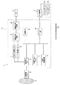
図1は本発明に係る超音波診断装置の第1の実施形態を示す構成図である。 FIG. 1 is a configuration diagram showing a first embodiment of an ultrasonic diagnostic apparatus according to the present invention.
超音波診断装置1は、装置本体2に超音波プローブ3、入力装置4、表示手段としてのモニタ5を接続して構成される。装置本体2には、送受信ユニット6、Bモード処理ユニット7、ドプラ処理ユニット8、画像生成回路9、画像合成回路10、制御プロセッサ11、画像メモリ12、内部記憶装置13、インターフェース部14が備えられる。装置本体2に内蔵される超音波送受信ユニット6等の構成要素は、集積回路等のハードウェアで構成されることもあるが、ソフトウェア的にモジュール化されたソフトウェアプログラムにより構築してもよい。
The ultrasonic
超音波プローブ3は、超音波送受信ユニット6からの駆動信号に基づき超音波を被検体Pに向けて発生し、被検体Pからの反射波を受信して電気信号に変換する複数の圧電振動子、当該圧電振動子に設けられる整合層、当該圧電振動子から後方への超音波の伝播を防止するバッキング材を有している。 The ultrasonic probe 3 generates a plurality of piezoelectric vibrators that generate an ultrasonic wave toward the subject P based on a drive signal from the ultrasonic transmission / reception unit 6, receive a reflected wave from the subject P, and convert it into an electrical signal. A matching layer provided on the piezoelectric vibrator, and a backing material for preventing propagation of ultrasonic waves from the piezoelectric vibrator to the rear.
超音波プローブ3から被検体Pに超音波が送信されると、送信超音波は、体内組織の音響インピーダンスの不連続面において次々と反射され、エコー信号として超音波プローブ3に受信される。このエコー信号の振幅は、超音波が反射する不連続面における音響インピーダンスの差に依存する。また、送信された超音波パルスが、移動している血流や心臓壁等の器官の表面において反射して得られたエコー信号は、ドプラ効果により移動体の超音波送信方向の速度成分に依存して、周波数の偏移を受ける。 When ultrasonic waves are transmitted from the ultrasonic probe 3 to the subject P, the transmitted ultrasonic waves are reflected one after another on the discontinuous surface of the acoustic impedance of the body tissue and received as an echo signal by the ultrasonic probe 3. The amplitude of this echo signal depends on the difference in acoustic impedance at the discontinuous surface where the ultrasonic waves are reflected. The echo signal obtained by reflecting the transmitted ultrasonic pulse on the surface of the moving blood flow and the organ such as the heart wall depends on the velocity component of the moving body in the ultrasonic transmission direction due to the Doppler effect. And undergoes a frequency shift.
入力装置4は、装置本体2に接続され、オペレータからの各種指示、条件、関心領域(ROI)の設定指示、種々の画質条件設定指示等の情報を装置本体2にとりこむためのトラックボール4a、各種スイッチ4bを有している。
The input device 4 is connected to the device
モニタ5は、画像合成回路10からのビデオ信号を受けて、生体内の形態学的情報や、血流情報等の情報を画像として表示させる機能を有する。
The
送受信ユニット6は、超音波送信側の構成要素として通常備えられる図示しないトリガ発生回路、遅延回路およびパルサ回路を有している。パルサ回路は、所定のレート周波数fr Hz(周期;1/fr秒)で、送信超音波を形成するためのレートパルスを繰り返し発生させる機能を備え、発生したレートパルスは遅延回路に与えられる。遅延回路は、チャンネル毎に超音波をビーム状に集束し且つ送信指向性を決定するのに必要な遅延時間を、パルサ回路から受けた各レートパルスに与える機能を有する。遅延時間が与えられたレートパルスは、遅延回路からトリガ発生回路に与えられる。トリガ発生回路は、遅延回路から受けたレートパルスに基づくタイミングで、超音波プローブ3に駆動パルスを印加する機能を有する。 The transmission / reception unit 6 has a trigger generation circuit, a delay circuit, and a pulsar circuit (not shown) that are normally provided as components on the ultrasonic transmission side. The pulsar circuit has a function of repeatedly generating a rate pulse for forming a transmission ultrasonic wave at a predetermined rate frequency fr Hz (period: 1 / fr second), and the generated rate pulse is given to the delay circuit. The delay circuit has a function of giving each rate pulse received from the pulser circuit a delay time necessary for focusing the ultrasonic wave into a beam for each channel and determining the transmission directivity. The rate pulse to which the delay time is given is given from the delay circuit to the trigger generation circuit. The trigger generation circuit has a function of applying a drive pulse to the ultrasonic probe 3 at a timing based on the rate pulse received from the delay circuit.
尚、送受信ユニット6は、スキャンシーケンスを実行するために制御プロセッサ11からの制御信号に従って送信周波数や送信駆動電圧といった超音波の送信条件を瞬時に変更させる機能を有している。特に送信駆動電圧の変更については、瞬間にその値を切り替えることが可能なリニアアンプ型の発信回路、又は複数の電源ユニットを電気的に切り替える機構によって実現される。
The transmission / reception unit 6 has a function of instantaneously changing ultrasonic transmission conditions such as a transmission frequency and a transmission drive voltage in accordance with a control signal from the
また、送受信ユニット6は、超音波受信側の構成要素として通常備えられる図示しないアンプ回路、A/D変換器、加算器を有している。アンプ回路は、超音波プローブ3を介して取り込まれたエコー信号をチャンネル毎に増幅する機能と、増幅したエコー信号をA/D変換器に与える機能とを有する。A/D変換器は、アンプ回路により増幅されたエコー信号に対し受信指向性を決定するのに必要な遅延時間を与えて加算器に与える機能を有する。また、加算器は、A/D変換器から受けたエコー信号に対して加算処理を行う機能を有する。 The transmission / reception unit 6 includes an amplifier circuit (not shown), an A / D converter, and an adder that are normally provided as components on the ultrasonic reception side. The amplifier circuit has a function of amplifying the echo signal captured via the ultrasonic probe 3 for each channel and a function of supplying the amplified echo signal to the A / D converter. The A / D converter has a function of giving a delay time necessary for determining the reception directivity to the echo signal amplified by the amplifier circuit and supplying the delay signal to the adder. The adder has a function of performing addition processing on the echo signal received from the A / D converter.
この加算器によるエコー信号の加算により、エコー信号の受信指向性に応じた方向からの反射成分が強調され、受信指向性と送信指向性とにより超音波送受信の総合的なビームが形成される。 By the addition of the echo signal by the adder, the reflection component from the direction corresponding to the reception directivity of the echo signal is emphasized, and a comprehensive beam for ultrasonic transmission / reception is formed by the reception directivity and the transmission directivity.
Bモード処理ユニット7は、送受信ユニット6からエコー信号を受け取り、信号対ノイズ比(S/N比)を最適にするような受信フィルタ等の各種処理を施して、診断画像に必要な信号を抽出する機能を有する。尚、近年、送信超音波に対して2倍の高調波成分を抽出し映像化するティッシュハーモニック映像法が採用されているが、この高調波信号の抽出も、Bモード処理ユニット7で行われる。さらに、Bモード処理ユニット7は、診断画像に必要な信号を抽出に引き続いて抽出した信号に対して対数増幅処理、包絡線検波処理等の処理を施し、信号強度を輝度で表現可能な、すなわち輝度表示可能なデータを生成する機能を有する。 The B-mode processing unit 7 receives an echo signal from the transmission / reception unit 6, performs various processes such as a reception filter to optimize the signal-to-noise ratio (S / N ratio), and extracts a signal necessary for a diagnostic image. It has the function to do. In recent years, a tissue harmonic imaging method has been adopted in which a harmonic component that is twice as high as the transmitted ultrasonic wave is extracted and visualized. This harmonic signal is also extracted by the B-mode processing unit 7. Further, the B-mode processing unit 7 can perform processing such as logarithmic amplification processing and envelope detection processing on the extracted signal subsequent to extraction of the signal necessary for the diagnostic image, and can express the signal intensity in luminance. It has a function of generating data capable of displaying luminance.
ドプラ処理ユニット8は、送受信ユニット6から受け取ったエコー信号の周波数解析により速度情報を取得する機能、ドプラ効果による血流や組織、造影剤エコー成分をエコー信号から抽出して平均速度、分散、パワー等の血流情報を多点について求める機能を有する。 The Doppler processing unit 8 has a function of acquiring velocity information by frequency analysis of the echo signal received from the transmission / reception unit 6, and extracts blood flow, tissue, and contrast agent echo components due to the Doppler effect from the echo signal, average velocity, dispersion, power It has a function to obtain blood flow information such as multiple points.
Bモード処理ユニット7およびドプラ処理ユニット8によりそれぞれ生成された情報は、Bモード画像情報およびドプラ画像情報として画像生成回路9に送信される。画像生成回路9は、例えば複数の画像の加算平均を施す時間スムージング処理や空間的に微分処理を施すエッジ抽出処理等の画像処理を施す、いわゆるポストプロセッサとしての役割を担い、ユーザの好みに応じた画像を生成する機能を有する。ドプラ画像に関しては、画像生成回路9において、平均速度画像、分散画像、パワー画像、これらの組み合わせ画像が生成される。
Information respectively generated by the B mode processing unit 7 and the Doppler processing unit 8 is transmitted to the
制御プロセッサ11は、情報処理装置(計算機)としての機能を持ち、各種プログラムを実行することにより装置本体2の動作を制御する制御手段である。
The
画像メモリ12は、画像生成回路9において生成された画像情報を受信して画像データとして格納する記憶メモリである。画像メモリ12に記憶される画像データは、必要に応じて制御プロセッサ11に画像処理プログラムが読み込まれて動作することにより画像再構成処理が施される。そして、画像再構成処理が施されて再構成された画像データは、例えば診断の後にユーザが入力装置4の操作により画像メモリ12から画像合成回路10に呼び出すことが可能である。
The
画像生成回路9からの出力あるいは画像メモリ12から読み込まれた画像データは、画像合成回路10に送られる。画像合成回路10は、一般的には、超音波スキャンの走査線信号列を、テレビなどに代表される一般的なビデオフォーマットの走査線信号列に変換し、表示画像としての超音波診断画像を生成する機能を有する。また画像合成回路10により生成された超音波診断画像は、診断に必要なパラメータ数値、時間情報、患者名などの情報と合成され、モニタ5に表示される。そして、画像再構成処理後における被検体Pの組織形状を表す断層像等の画像データを、パラメータ数値等の情報とともにモニタ5に静止画的に、あるいは複数の二次元的な画像データを使って動画的に再生することが可能である。
The output from the
インターフェース部14は、入力装置4、ネットワーク15、図示しない外部記憶装置と装置本体2との間において情報を送受信させるインターフェースである。
The
内部記憶装置13には、スキャンシーケンス、画像再構成処理を始めとする各種動作や処理を実行するための制御プログラムおよび画像処理プログラムや、患者IDや医師の所見等の診断情報、診断プロトコル、送受信条件等の超音波スキャンに必要な各種情報が保管されている。また、必要に応じて、内部記憶装置13は画像メモリ12に記憶された画像データの保管用にも使用される。内部記憶装置13に保管された各種情報は、インターフェース回路29およびネットワーク15を経由して図示しない外部周辺装置に転送することが可能である。
The
このような構成の超音波診断装置1の超音波プローブ3、送受信ユニット6、制御プロセッサ11、内部記憶装置13に格納された各種制御プログラム、Bモード処理ユニット7あるいはドプラ処理ユニット8、画像生成回路9等の各構成要素により、超音波診断装置1には、被検体Pに超音波を送信して得られたエコー信号の信号強度に基づいて被検体Pの断層像を輝度表示するための画像データを生成する手段としての機能が備えられる。
The ultrasonic probe 3, the transmission / reception unit 6, the
さらに超音波診断装置1の制御プロセッサ11には、内部記憶装置13に格納された画像処理プログラムが読み込まれて画像処理装置が構築される。この画像処理装置は装置本体2に内蔵せずに、超音波診断装置1の外部に設けてもよい。
Furthermore, an image processing program stored in the
図2は図1に示す超音波診断装置1の装置本体2に内蔵される画像処理装置の構成を示す機能ブロック図である。
FIG. 2 is a functional block diagram showing the configuration of the image processing apparatus built in the apparatus
画像処理装置20は、輝度スケール情報表示手段21、輝度スケール変更手段22、画像再構成手段23および表示色変更条件設定手段24を備える。そして、画像処理装置20は、輝度表示可能な画像データのうち、輝度レベルが同一あるいは一定の範囲内である領域の表示色を予め指定した変更色に指定した時間だけ変更して表示し、かつ表示色を変更する領域が指定時間経過後に変わるように画像処理を施す機能を有する。
The
輝度スケール情報表示手段21は、画像メモリ12に記憶された画像データをモニタ5に輝度表示させる際に、輝度スケールを表す画像を別途モニタ5に表示させるための輝度スケール情報を作成して画像メモリ12に書き込む機能を有する。
The luminance scale information display means 21 creates luminance scale information for separately displaying an image representing the luminance scale on the
輝度スケール変更手段22は、画像メモリ12に記憶された画像データをモニタ5に輝度表示させる際に用いられる輝度スケールのうち、一部の輝度レベルに相当する色彩および色調の一方または双方を予め指定された色彩および色調に変更する機能を有する。すなわち、輝度スケール変更手段22は、輝度スケールの一部の輝度レベルの表示色を予め指定された変更色に変更する機能を有する。輝度スケールの色彩および色調の変更範囲は、単一の輝度レベルの色彩および色調であっても、所要の範囲内における輝度レベルの色彩および色調であってもよい。また、複数の輝度レベルの色彩および色調を変更することもできる。
The luminance
また、輝度スケール変更手段22は、表示色が変更色に変更される輝度レベルが時間的に変化するように、既に表示色が変更色に変更された輝度レベルの表示色を元の表示色に戻す一方、輝度スケールの別の一部の輝度レベルに相当する表示色を変更色に変更して新たな輝度スケールを繰返し生成するようにされる。このときの輝度スケールの生成の際には、変更条件設定手段から受けた表示順序情報が参照される。
In addition, the luminance
画像再構成手段23は、画像メモリ12に記憶された画像データを読み込んで、輝度スケール変更手段22により生成された各輝度スケールに従って、変更条件設定手段から受けた表示時間情報で予め指定された時間だけモニタ5に表示されるように、かつ変更条件設定手段から受けた表示順序情報に従う順序で順次画像データを再構成し、再構成して得られた各画像データを画像メモリ12に書き込む機能を有する。すなわち、画像再構成手段23の画像再構成処理により、画像メモリ12に記憶された画像データの特定の輝度レベル領域の表示色が所要の変更色に所要の順序で変更されて所要の時間だけモニタ5に表示させることが可能となる。
The image reconstruction means 23 reads the image data stored in the
また、画像再構成手段23には、再構成して得られた画像データを表示させる時間を指定する表示時間情報、表示色を変更させた各画像データの表示順序を指定する表示順序情報を変更条件設定手段から受けて画像データに付帯させて画像メモリ12に書き込む機能が備えられる。
Further, the image reconstruction means 23 changes display time information for designating the time for displaying the image data obtained by reconstruction, and display order information for designating the display order of each image data whose display color has been changed. There is provided a function of receiving from the condition setting means and attaching the image data to the
変更条件設定手段は、画像データの表示方法、すなわち輝度レベルが同一あるいは一定の範囲内である領域の表示色として用いる変更色(色彩および色調の一方または双方)、輝度レベルが同一あるいは一定の範囲内である領域を変更色で表示する際における表示時間、変更色により表示させる領域の表示順序やその他変更色による画像データの表示に必要な条件を入力装置4から受け取った情報に従ってパラメータとして設定する機能と、設定した変更色、表示時間、表示順序等のパラメータを輝度スケール情報表示手段21、輝度スケール変更手段22および画像再構成手段23に与える機能を有する。また、必要に応じて、画像データの表示方法を指定するパラメータを設定するための画面情報を生成して画像メモリ12に書き込むことにより、パラメータの設定画面を表示させる機能を有する。
The change condition setting means is a display method of image data, that is, a change color (one or both of color and tone) used as a display color of an area where the brightness level is the same or within a certain range, and the brightness level is the same or within a certain range The display time when displaying an area in the changed color, the display order of the areas to be displayed in the changed color, and other conditions necessary for displaying the image data in the changed color are set as parameters according to the information received from the input device 4. It has a function of giving the function and parameters such as the set change color, display time, and display order to the brightness scale information display means 21, brightness scale change means 22, and image reconstruction means 23. Further, it has a function of displaying a parameter setting screen by generating screen information for setting a parameter for specifying a display method of image data and writing it in the
また、画像合成回路10には、上記のようにして生成され、画像メモリ12に記憶された画像データを表示順序情報に従う順序で、表示時間情報に従う時間だけ繰返しモニタ14に与えて、画像データを表示させる機能が備えられる。
The
次に超音波診断装置1の作用について説明する。
Next, the operation of the ultrasonic
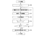
図3は、図1に示す超音波診断装置1により診断画像を表示させる際における流れを示すフローチャートであり、図中Sに数字を付した符号はフローチャートの各ステップを示す。
FIG. 3 is a flowchart showing a flow when a diagnostic image is displayed by the ultrasonic
まず、ステップS1において、被検体Pに超音波が送受信されてエコー信号が取得され、エコー信号から被検体Pの断層像が生成される。すなわち、送受信ユニット6において遅延時間を伴って生成された複数のレートパルスに基づくタイミングで、それぞれ超音波プローブ3の圧電振動子に駆動パルスが印加される。このため、超音波プローブ3の各圧電振動子から被検体Pに超音波が送信される。被検体Pに送信された送信超音波は、体内組織の音響インピーダンスの不連続面において反射し、超音波が反射した不連続面における音響インピーダンスの差に依存する振幅を有するエコー信号として超音波プローブ3において受信される。 First, in step S1, ultrasonic waves are transmitted to and received from the subject P to acquire an echo signal, and a tomographic image of the subject P is generated from the echo signal. That is, drive pulses are applied to the piezoelectric vibrators of the ultrasonic probe 3 at timings based on a plurality of rate pulses generated with a delay time in the transmission / reception unit 6. For this reason, ultrasonic waves are transmitted from the respective piezoelectric vibrators of the ultrasonic probe 3 to the subject P. The transmitted ultrasonic wave transmitted to the subject P is reflected on the discontinuous surface of the acoustic impedance of the body tissue, and the ultrasonic probe is used as an echo signal having an amplitude depending on the difference in the acoustic impedance on the discontinuous surface where the ultrasonic wave is reflected. 3 is received.
超音波プローブ3において受信されたエコー信号は、送受信ユニット6のアンプ回路により増幅され、A/D変換器において所要の遅延時間を与えられてデジタル信号に変換される。さらに、デジタル化されたエコー信号は、加算器において加算処理された後、Bモード処理ユニット7に与えられる。 The echo signal received by the ultrasonic probe 3 is amplified by the amplifier circuit of the transmission / reception unit 6 and converted into a digital signal by giving a required delay time in the A / D converter. Further, the digitized echo signal is subjected to addition processing in an adder, and then supplied to the B-mode processing unit 7.
次に、Bモード処理ユニット7において、エコー信号に対する受信フィルタ等の各種処理および診断画像として用いる信号の抽出処理が施され、さらに抽出処理により抽出信号に対する対数増幅処理、包絡線検波処理等の処理が施される。そして、Bモード処理ユニット7では、エコー信号の信号強度を輝度で表現可能なデータがBモード画像情報として生成され、画像メモリ12に格納される。
Next, in the B-mode processing unit 7, various processes such as a reception filter for the echo signal and a process for extracting a signal used as a diagnostic image are performed. Further, a logarithmic amplification process and an envelope detection process for the extracted signal are performed by the extraction process. Is given. In the B-mode processing unit 7, data that can express the signal intensity of the echo signal with luminance is generated as B-mode image information and stored in the
一方、必要に応じてドプラ処理ユニット8においてエコー信号の周波数解析が実行されて血流の速度情報等の情報が取得され、さらにドプラ効果による血流や組織、造影剤エコー成分の平均速度、分散、パワー等の血流情報が多点について求められる。ドプラ処理ユニット8において得られた血流情報等の情報は、ドプラ画像情報として画像メモリ12に格納される。
On the other hand, if necessary, the Doppler processing unit 8 performs frequency analysis of the echo signal to acquire information such as blood flow velocity information, and further, the blood flow and tissue due to the Doppler effect, the average velocity and variance of the contrast agent echo component Blood flow information such as power is obtained for multiple points. Information such as blood flow information obtained in the Doppler processing unit 8 is stored in the
画像メモリ12に格納されたBモード画像情報は、グレースケールの輝度で表現することができる。例えば、Bモード画像は64階調の輝度で表現される。しかし、64階調のグレースケールの輝度でBモード画像をモニタ5に表示させた場合に、関心領域の輝度が一定であるのに対し、背景の輝度が場所によって異なる場合には、錯視により関心領域の輝度レベルが実際の輝度レベルと異なる輝度レベルとして感じられる場合がある。
The B-mode image information stored in the
このような錯視による輝度レベルの誤認の恐れを放置すると誤診に繋がるため、例えばBモード画像に対する錯視の影響を低減させるために、Bモード画像のうち輝度レベルが同一あるいは一定の範囲内である領域の色彩あるいは色調を時間的に変化させてモニタ5に表示させることが可能となるような画像処理が画像処理装置20によりBモード画像に対して施される。ただし、ドプラ画像情報が輝度で表現される場合には、ドプラ画像情報に対して同様の画像処理を施してもよい。
If the risk of misidentification of the luminance level due to such an illusion is neglected, it may lead to a misdiagnosis. For example, in order to reduce the influence of the illusion on the B-mode image, the luminance level of the B-mode image is the same or within a certain range. The
そこで、まずステップS2において、ユーザは、Bモード画像の表示色についての表示方法を入力装置4から指定する。Bモード画像の表示方法として指定する事項は、輝度レベルが同一である領域の変更色、輝度レベルが同一である領域を変更色で表示する際における表示時間、変更色により表示させる領域の順序である。 Therefore, first, in step S2, the user designates a display method for the display color of the B-mode image from the input device 4. Items to be specified as the display method of the B-mode image are the change color of the region having the same luminance level, the display time when the region having the same luminance level is displayed in the change color, and the order of the regions to be displayed by the change color. is there.
変更色は、ユーザが入力装置4を操作することにより、無彩色の他、赤、青といった任意の色彩から選択可能である。また、特定の領域を変更色で表示させる時間は、例えば1秒、2秒といった値を、ユーザが入力装置4を操作することにより選択可能である。さらに、変更色により表示させる領域の表示順序は、例えば輝度レベルがより大きい値を有する領域から輝度レベルがより小さい値を有する領域となる表示順序とする場合(降順)や逆に輝度レベルがより小さい値を有する領域から輝度レベルがより大きい値を有する領域となる表示順序とする場合(昇順)をユーザが入力装置4を操作することにより選択可能である。 The change color can be selected from arbitrary colors such as red and blue in addition to the achromatic color by the user operating the input device 4. The time for displaying the specific area in the changed color can be selected by operating the input device 4 by the user, for example, a value such as 1 second or 2 seconds. Furthermore, the display order of the areas to be displayed by the changed color is, for example, the display order from the area having a higher luminance level to the area having a lower luminance level (descending order) or conversely the luminance level is higher. The case where the display order is changed from an area having a small value to an area having a larger luminance level (ascending order) can be selected by the user operating the input device 4.
さらに、変更色を用いて表示させる領域を全ての領域とするか、あるいは輝度レベルが所定の範囲内である領域とするのかを指定することもできる。 Furthermore, it is possible to designate whether the area to be displayed using the changed color is the entire area or the area where the luminance level is within a predetermined range.
そして、このような、Bモード画像の表示色の変更条件を指定する変更色、表示時間、表示領域の表示順序等のパラメータを設定するために、表示色変更条件設定手段24により設定画面情報が生成されて画像メモリ12に書き込まれる。そして、パラメータの設定画面情報は画像合成回路10によりモニタ5に与えられて表示される。このため、ユーザは設定画面を参照しながら入力装置4の操作により各パラメータを設定することができる。
Then, in order to set parameters such as the change color for specifying the display color change condition of the B-mode image, the display time, and the display order of the display area, the display color change condition setting means 24 sets the setting screen information. It is generated and written into the
入力装置4に入力された変更色等のパラメータの設定情報は、表示色変更条件設定手段24に与えられ、表示色変更条件設定手段24は変更色等のパラメータ情報を輝度スケール変更手段22および画像再構成手段23に与える。
The setting information of the parameter such as the changed color input to the input device 4 is given to the display color changing
次に、ユーザは、Bモード画像の表示色を時間的に変化させてモニタ5に表示させることが可能となるような画像処理の開始指令をスイッチ4b等の入力装置4により超音波診断装置1の装置本体2内部に形成された画像処理装置20に与える。
Next, the ultrasonic
そして、ステップS3おいて、画像処理装置20の輝度スケール変更手段22および画像再構成手段23により、表示色変更条件設定手段24から与えられたパラメータ情報に従って、画像データの一部の表示色が一定の時間継続して変更色となって表示されるように、画像メモリ12に保管された画像データの画像処理が開始される。
Then, in step S3, the display color of a part of the image data is constant according to the parameter information given from the display color change condition setting means 24 by the brightness
図4は、図2に示す画像処理装置20により画像データの表示色を変更させるための画像処理の手順を示すフローチャートであり、図中Sに数字を付した符号はフローチャートの各ステップを示す。
FIG. 4 is a flowchart showing a procedure of image processing for changing the display color of the image data by the
ここでは、画像データのグレースケールの輝度が64階調で表現されており、ユーザが変更色を「青」に、変更色の表示時間をT秒、変更色で表示させる表示領域の表示順序を「輝度レベルの昇順」と指示した場合の例について説明する。また、輝度階調値を低い順にI1,I2,・・・,I64とする。 Here, the gray scale luminance of the image data is expressed in 64 gradations, and the display order of the display area in which the user displays the change color as “blue”, the change color as the display time for T seconds, and the change color as the display color. An example of instructing “in ascending order of luminance levels” will be described. In addition, the luminance gradation values are I 1 , I 2 ,..., I 64 in ascending order.
まず、ステップS10において、輝度スケール変更手段22は、輝度スケールのうち表示色を変更色に変更すべき輝度諧調値Iiを決定する。変更色で表示させる表示領域の表示順序は、輝度レベルの昇順と指示されているため、iに1が代入され、輝度諧調値が最も小さいI1の輝度スケールが表示色の変更対象として決定される。
First, in step S10, the luminance
次に、ステップS11において、輝度スケール変更手段22は、表示色の変更対象として決定した輝度諧調値I1の輝度スケールの表示色を変更色である青色として新たな輝度スケールを生成する。生成した輝度スケールは、画像再構成手段23に与えられる。
Next, in step S11, the luminance
次に、ステップS12において、画像再構成手段23は、画像メモリ12から表示対象となる画像データを読み込んで、輝度スケール変更手段22により生成された新たな輝度スケールに基づいて、輝度諧調値がI1の領域の表示色が変更色である青色で表示されるように画像データを再構成する。さらに、画像再構成手段23は、表示色変更条件設定手段24から与えられたパラメータ情報であるT/64秒間表示させる旨の表示時間情報および表示順序が「輝度レベルの昇順」となるように生成された表示順序情報を画像データに付帯させて画像メモリ12に書き込む。
Next, in step S12, the
一方、輝度スケール情報表示手段21は、輝度スケール変更手段22により生成された輝度スケールを画像として別途モニタ5に表示させるための輝度スケール情報を作成して画像メモリ12に書き込む。例えば、この輝度スケール情報は、輝度諧調値I1の部分の色が青色に表示されたバー形式の画像情報とされる。
On the other hand, the luminance scale
このため、ステップS13において、画像合成回路10により、画像メモリ12に書き込まれた青色の色情報を含む画像データと輝度スケール情報が読み込まれて合成された後、表示時間情報および表示順序情報に従ってモニタ5に与えられる。この結果、表示順序が1番目である輝度諧調値が最も小さいI1の領域のみが青色で表示されたグレースケールの被検体Pの断層像がモニタ5にT/64秒間表示される。さらに、被検体Pの断層像の近傍には、輝度諧調値I1の部分の色が青色となった輝度スケールを示すバー形式の画像が表示される。
For this reason, in step S13, the
また、必要に応じて画像メモリ12から変更色を用いていない元の画像データが画像合成回路10により読み込まれてモニタ5に与えられ、画像再構成手段23により生成された画像データと並べて並列表示される。
Further, if necessary, the original image data not using the changed color is read from the
次に、ステップS14において、輝度スケール変更手段22は、変更色である青色により表示させる輝度レベルとして、輝度諧調値が次に小さいI2の輝度レベルを決定する。すなわち、輝度諧調値をIiとしてiに2が代入される。
Next, in step S14, the luminance
次に、ステップS15において、画像再構成手段23は、変更色を用いた画像データの表示を終了すべき旨の指令が入力装置4から入力されているか否かを判定する。そして、変更色を用いた画像データの表示を継続する場合には、再びステップS11から同様な手順で輝度スケールの輝度諧調値が次に小さいI2の領域の表示色が青色とされる一方、元の輝度諧調値I1の輝度レベルの表示色は初期のグレースケールの表示色に戻される。そして、新たに生成された輝度スケールに従って再構成された画像データがT/64秒間だけモニタ5に表示される。その後、輝度諧調値が次に小さいI3の輝度レベルが表示色の変更対象として決定される。
Next, in step S <b> 15, the
このような輝度諧調値Iiの異なる輝度レベルの表示色の変更並びにT/64秒間の表示が、ステップS15において、画像再構成手段23が変更色を用いた画像データの表示を終了すべき旨の指令が入力装置4から入力されたと判定するまで表示順序情報で指定された順序で順次繰り返される。このため、輝度諧調値がI64の輝度レベルまで表示色の変更が一巡すると、画像データの表示時間はT秒となる。 The change of the display color of the brightness level having the different brightness gradation value Ii and the display for T / 64 seconds indicate that the image reconstruction means 23 should end the display of the image data using the changed color in step S15. The process is sequentially repeated in the order specified by the display order information until it is determined that the command is input from the input device 4. For this reason, when the display color change is completed until the luminance gradation value reaches the luminance level of I64, the display time of the image data is T seconds.
図5は、図2に示す画像処理装置20による画像処理前後における画像データをモニタ5に表示させた例を示す図である。
FIG. 5 is a diagram showing an example in which image data before and after image processing by the
図5(a)は、表示色を変更色に変更する画像処理を施す前の画像データをモニタ5に表示させた例を示し、図5(b)は、表示色を変更色に変更する画像処理を施した後のある時刻における画像データをモニタ5に表示させた例を示す。
FIG. 5A shows an example in which image data before image processing for changing the display color to the change color is displayed on the
図5(a)(b)の画像はモニタ5の表示領域を分割して並べて表示させることもできる。図5(a)に示すように、被検体Pの断層像は、例えば背景Bの輝度が部分ごとに異なる一方、関心領域Rの輝度が一定である。このような断層像の場合には、錯視により関心領域Rの輝度が実施の輝度と異なるように感じられ、関心領域Rの輝度は背景Bの輝度に左右される。
5A and 5B can be displayed by dividing the display area of the
一方、図5(b)に示すように背景Bの特定の輝度レベルの表示色を別の色で表示し、かつ一定時間経過後には、当該輝度レベルの表示色を初期の色に戻す一方、別の輝度レベルの表示色を別の色で表示すれば、錯視の影響を低減させることができる。すなわち、同一の輝度レベルの背景部分における色調が時間的に変化するため、例えば関心領域R全体が同一の輝度であるのか、あるいは場所によって輝度レベルに差が生じているのかを容易に弁別することができる。 On the other hand, as shown in FIG. 5B, the display color of the specific brightness level of the background B is displayed in a different color, and after a certain period of time, the display color of the brightness level is returned to the initial color. If display colors of different brightness levels are displayed in different colors, the effect of the illusion can be reduced. That is, since the color tone in the background portion having the same luminance level changes with time, it is easy to discriminate whether, for example, the entire region of interest R has the same luminance or whether the luminance level varies depending on the location. Can do.
さらに、図4のステップS15において、画像再構成手段23が変更色を用いた画像データの表示を終了すべき旨の指令が入力装置4から入力されたと判定すると、ステップS16において、画像データの画像再構成処理が停止し、元の画像処理前の画像データがモニタ5に与えられて画像データの表示色が初期状態に戻されて表示される。
Furthermore, when it is determined in step S15 in FIG. 4 that the
以上のような超音波診断装置1によれば、関心領域の輝度コントラストあるいは輝度変化の度合いを、周囲の輝度あるいは輝度の時間変化によって惑わされることなく、コントラスト視認性を向上させることができる。また、この効果を得るために診断画像の描画性を損なうことがない。したがって、より高い診断情報を得ることが可能となる。
According to the ultrasonic
尚、コントラストの視認性を向上させるために、例えば輝度スケールを虹色のような多色で作成して診断画像を等高線表示の様式で表示させれば、同一の輝度レベルの部分を把握することができるであろう。しかしながらこのような手法においては、従来の診断画像としての描画性を著しく損ない、結局は有用な診断情報が得られないことも少なくない。 In order to improve the visibility of the contrast, for example, if the brightness scale is created in multiple colors such as rainbow and the diagnostic image is displayed in the contour line display format, the part having the same brightness level can be grasped. Will be able to. However, in such a method, drawing performance as a conventional diagnostic image is remarkably impaired, and useful diagnostic information is often not obtained in the end.
また、関心領域の輝度ヒストグラムを計測するなどの定量計測手法によっても輝度の差異を比較することができるが、これも計測モードに遷移するなどの手間が必要であるのみならず、計測は通常局所的に行わねばならないため診断画像全域の把握が困難である。 In addition, the luminance difference can be compared by a quantitative measurement method such as measuring the luminance histogram of the region of interest, but this also requires time and effort such as transition to the measurement mode. Therefore, it is difficult to grasp the entire diagnostic image.
一方、超音波診断装置1によれば、ユーザがスイッチ4b等の入力装置4を操作するだけで、モニタ5に表示された診断画像上の輪郭線が診断画像をスイープしていくように見えるため、従来のBモード画像全体の描画性をほとんど損なわずに、かつ輝度の差異をより明確に知ることができる。
On the other hand, according to the ultrasonic
尚、超音波診断装置1または画像処理装置20において、画像処理の際に必要な変更色等の3種類のパラメータは全てがユーザによって変更可能としたが、一部のパラメータを固定化してユーザによって変更されないものとしてもよい。
In the ultrasonic
また、超音波診断装置1の画像処理装置20により画像処理は、静止画に対して施しのみならず、リアルタイムに表示される動画像について施すことも可能である。
Further, the image processing by the
さらに、画像処理の際の表示色の変更対象となる輝度レベルIiは、単一の輝度レベルはIiのみでなくてもよく、例えばある特定のIiを基準とする一定範囲内の輝度レベルIi−mからIi+mまでの輝度レベル(但し、mは任意の整数で、i−m<0の場合にはi−mの値が0、i−m>64の場合にはi−mの値が64を取るものとする。)に対して同時に表示色の変更を行ってもよい。 Further, the luminance level I i to be a display color to be changed during the image processing, a single brightness level may not only I i, the luminance in a certain range with reference to specific I i in example Luminance levels from level I i-m to I i + m (where m is an arbitrary integer, i−m <0 when i−m <0, i−m when i−m> 64, i− The display color may be changed at the same time.
一方、画像再構成手段23に表示色の変更時間を指定する表示時間情報を作成する機能を設けずに、画像処理装置20の画像処理は、静止画あるいは動画のある輝度レベルの範囲内の猟領域の表示色を単に指定された変更色に変更する処理のみとすることもできる。この場合には、入力装置4に変更色の指定情報と、表示色を変更色に変更する輝度レベルの範囲情報が入力される。そして、表示色変更条件設定手段24から変更色の指定情報と、表示色を変更色に変更する輝度レベルの範囲情報が輝度スケール変更手段22に与えられ、輝度スケール変更手段22により新たな輝度スケールが生成される。
On the other hand, without providing the image reconstruction means 23 with a function of creating display time information for designating the display color change time, the image processing of the
さらに、画像再構成手段23により新たに輝度スケール変更手段22により生成された輝度スケールにより画像メモリ12に格納された画像データの画像再構成処理が実行され、新たな輝度スケールに基づいて再構成された画像が画像合成回路10を介してモニタ5に与えられて表示される。
Further, image reconstruction processing of the image data stored in the
また、ユーザがバー形式でモニタ5に表示された輝度スケール画像を介して入力装置4から表示色を変更色に変更する対象とすべき輝度レベルの範囲情報を入力できるようにインターフェース機能を画像処理装置20に設けることもできる。
Further, the interface function is image-processed so that the user can input range information of the luminance level to be changed from the input device 4 to the change color through the luminance scale image displayed on the
図6は、グレースケールにより輝度表示された画像の一部の輝度レベルの領域を変更色で表示させた例を示す図である。 FIG. 6 is a diagram illustrating an example in which a luminance level region of a part of an image displayed with luminance in gray scale is displayed in a changed color.
図6(a)は、グレースケールにより輝度表示された画像およびバー形式の輝度スケール画像を示す図である。図6(a)に示すグレースケールの画像に対して、例えば、輝度レベルが一定の値を超える領域が黒色表示されるように、入力装置4から変更色の変更色の指定情報と、表示色を変更色に変更する輝度レベルの範囲情報が入力される。 FIG. 6A is a diagram showing an image displayed in luminance by a gray scale and a bar-type luminance scale image. For the gray scale image shown in FIG. 6A, for example, the change color designation information and the display color are displayed from the input device 4 so that the area where the luminance level exceeds a certain value is displayed in black. The brightness level range information for changing the color to the change color is input.
図6(b)は、図6(a)の画像のうち、輝度レベルが一定の値を超える領域が黒色表示されるように画像再構成処理されて得られた画像である。図6(b)に示すように、輝度レベルが一定の値を超える領域が黒色表示され、対応するバー形式の輝度スケール画像の輝度レベルの部分も黒色表示されている。 FIG. 6B is an image obtained by performing image reconstruction processing so that a region where the luminance level exceeds a certain value is displayed in black in the image of FIG. As shown in FIG. 6B, the area where the luminance level exceeds a certain value is displayed in black, and the portion of the luminance level of the corresponding bar-type luminance scale image is also displayed in black.
さらに、バー形式の輝度スケール画像の基準となる輝度レベルの位置には、マーキング表示され、このマーキング表示を入力装置4の操作により移動させることにより、輝度レベルの範囲情報を変更させることもできる。 Further, marking is displayed at the position of the luminance level that is the reference of the bar-type luminance scale image, and the range information of the luminance level can be changed by moving the marking display by operating the input device 4.
このように、関心領域のみならず、診断に重要でない背景の一部の表示色を変更色に変更して表示させることにより、錯視の影響を低減させて、コントラストの視認性を向上させることができる。特に背景の輝度レベルが場所により異なるような場合に、単一の変更色で表示させれば、より錯視の影響を低減させることができる。 In this way, by changing the display color of not only the region of interest but also the background that is not important for diagnosis to the changed color, it is possible to reduce the influence of the illusion and improve the visibility of the contrast. it can. In particular, when the brightness level of the background varies depending on the location, the effect of the illusion can be further reduced by displaying with a single change color.
また、変更色は、単一の色に限らず、輝度レベルごとに異なる変更色で表示させることも可能であり、また、変更色で表示された部分と元の表示色で表示された部分に対してスムージング処理等の処理を施して、境界がスムーズに表示されるようにすることもできる。 In addition, the change color is not limited to a single color, and can be displayed in a different change color for each luminance level. Also, the change color and the original display color are displayed on the part displayed. On the other hand, processing such as smoothing processing can be performed so that the boundary is displayed smoothly.
図7は、図2に示す画像処理装置20による画像処理の際における変更色の設定例を示す図である。
FIG. 7 is a diagram illustrating a setting example of the change color when the
図7(a)は、輝度レベルが一定の値を超えて変更色で表示される領域と輝度レベルが一定の値以下となり元の表示色で表示される領域との境界がスムーズに表示されるようにした場合のバー形式の輝度スケール画像を示し、図7(b)は、輝度レベルが一定の値を超える領域が輝度レベルごとに異なる変更色で表示できるようにした場合のバー形式の輝度スケール画像を示す。 In FIG. 7A, the boundary between the area where the luminance level exceeds a certain value and is displayed in the changed color and the area where the luminance level is below the certain value and is displayed in the original display color is displayed smoothly. FIG. 7B shows a bar-type luminance scale image in a case where the luminance level is set as described above, and FIG. 7B shows the bar-type luminance in a case where a region where the luminance level exceeds a certain value can be displayed with a different color for each luminance level. A scale image is shown.
このように錯視の発生状況に応じて、各種変更色を任意に設定することが可能である。 In this manner, various changed colors can be arbitrarily set according to the occurrence of the illusion.
図8は本発明に係る超音波診断装置の第2の実施形態を示す機能ブロック図である。 FIG. 8 is a functional block diagram showing a second embodiment of the ultrasonic diagnostic apparatus according to the present invention.
図8に示された、超音波診断装置1Aでは、装置本体2の各構成要素の詳細機能及び画像処理装置20の機能構成が図1に示す超音波診断装置1と相違する。他の構成および作用については図1に示す超音波診断装置1と実質的に異ならないため画像処理装置20の機能ブロック図のみ図示し、同一の構成については同符号を付して説明を省略する。
In the ultrasonic diagnostic apparatus 1A shown in FIG. 8, the detailed functions of each component of the apparatus
超音波診断装置1Aの画像生成回路9は、Bモード処理ユニット7またはドプラ処理ユニット8から受けたBモード画像情報やドプラ画像情報に対して最大輝度レベル保持演算を施す機能を有する。この最大輝度レベル保持演算は、時間的に連続して画像データが収集される場合に、過去の画像データのうち輝度レベルの最大値が表示されるような画像データを再構成する画像処理演算である。最大輝度レベル保持演算は、時間的に連続したスキャンにより収集された複数の画像データから毛細血管内を流れる血流の流れを抽出して血流画像を得るような場合に有効である。
The
いま、あるスキャンにおいて収集された同一期間TLに含まれる時系列のフレームF1からFnまでのn枚の画像データに対して最大輝度レベル保持演算を施す場合について説明する。フレームF1からFnまでの画像データに対する最大輝度レベル保持演算では、F1からFnまでの各フレームにおいて、空間的に対応する、すなわち座標(x、y)が一致する部位の輝度レベルのうち最大値となる最大輝度レベルPmax(x,y)を選択して新たな画像データが生成される。 Now, a case will be described in which the maximum luminance level holding operation is performed on n pieces of image data from time series frames F 1 to F n included in the same period TL collected in a certain scan. In the maximum luminance level holding operation for the image data from the frames F 1 to F n , the luminance level of the portion corresponding to the space in each frame from F 1 to F n , that is, the coordinates (x, y) coincide with each other. Among them, the maximum luminance level P max (x, y) that is the maximum value is selected, and new image data is generated.
すなわち、あるフレームFi(iは1≦i≦nを満たす整数)の画像データは、空間的に配置された輝度レベルPi(x,y)の集合、あるいは単に一次元の輝度レベルの配列データPi(x)の集合からなる。 That is, image data of a certain frame F i (i is an integer satisfying 1 ≦ i ≦ n) is a set of spatially arranged luminance levels P i (x, y), or simply an array of one-dimensional luminance levels. It consists of a set of data P i (x).
尚、Pi(x,y)又はPi(x)の値は、「輝度」の代わりに「信号強度」、「信号振幅」、「RFデータ等の生データ値」として演算を行なうことも可能であるが、ここでは輝度レベルを採用するものとする。これらの各データ値は、一般的に数値が大きい方が、エコー信号レベルが高いことを意味するものである。 The value of P i (x, y) or P i (x) may be calculated as “signal intensity”, “signal amplitude”, “raw data value such as RF data” instead of “brightness”. Although it is possible, the luminance level is adopted here. Each of these data values generally means that the larger the numerical value, the higher the echo signal level.
そして、フレームF1からFnに渡って空間的に対応する各フレームにおける各画素のうち、輝度レベルが最大値となるものを選択して新たな画像データを生成する演算が最大輝度レベル保持演算であり、この演算は、式(1)によって表すことができる。 An operation for selecting a pixel having the maximum luminance level from among the pixels in each of the spatially corresponding frames from the frames F 1 to F n and generating new image data is a maximum luminance level holding operation. And this operation can be expressed by equation (1).
[数1]
Pmax(x,y)=max[P1(x,y),・・・,Pn(x,y)] …(1)
[Equation 1]
P max (x, y) = max [P 1 (x, y),..., P n (x, y)] (1)
この式(1)の処理で示される最大輝度レベル保持演算を、造影剤を用いた毛細血管のダイナミック撮影において同じ音圧期間TLに属する新たなフレームが収集される度に実行し、得られた画像データを表示させれば、ユーザ側から観ると時間の経過と共に毛細血管が順次造影剤により造影される様子として映し出すことができる。 The maximum luminance level holding operation shown by the processing of the expression (1) is executed every time a new frame belonging to the same sound pressure period TL is collected in the dynamic imaging of the capillary using the contrast agent. If the image data is displayed, when viewed from the user side, the capillaries can be displayed as a state in which the capillaries are sequentially contrasted with the contrast agent as time passes.
このような最大輝度レベル保持演算を実現するためのアルゴリズムは、式(1)に示す処理に限らず、例えば、式(2)に示す処理によるものとしても、同様の効果を得ることもできる。すなわち、現行の断層画像フレームFiの各座標(x、y)のピクセル輝度をPi(x,y)、時間的に一つ前の断層画像フレームFi―1のピクセル輝度をPi−1(x,y)とする。そして、相対的な2フレームについて、式(2)による画像演算処理をi=2〜nまで逐次実行することにより、最大輝度レベル保持演算を行なうことができる。 The algorithm for realizing such maximum brightness level holding calculation is not limited to the process shown in Expression (1), and for example, the same effect can be obtained even by the process shown in Expression (2). That is, the pixel brightness of each coordinate (x, y) of the current tomographic image frame F i is P i (x, y), and the pixel brightness of the previous tomographic image frame F i-1 is temporally P i−. 1 (x, y). Then, the maximum luminance level holding calculation can be performed by sequentially executing the image calculation processing according to Expression (2) from i = 2 to n for two relative frames.
[数2]
If Pi(x,y)>Pi−1(x,y)
then Pi(x,y)=Pi(x,y)
Else Pi(x,y)=Pi−1(x,y)
……(2)
[Equation 2]
If P i (x, y)> P i-1 (x, y)
then P i (x, y) = P i (x, y)
Else P i (x, y) = P i−1 (x, y)
(2)
式(2)に示すアルゴリズムは、前段および後段のフレームに関する画像データのそれぞれの輝度レベルを比較して、より大きな輝度レベルを有する画素についてのみ、その値を更新するというものである。こうして得られる画像データを表示しても、ユーザは、時間の経過と共に毛細血管が順次造影されるような様子を動画として観察することができる。 The algorithm shown in Expression (2) compares the brightness levels of the image data relating to the preceding and succeeding frames, and updates the value only for pixels having a larger brightness level. Even when the image data obtained in this way is displayed, the user can observe the state in which the capillaries are sequentially contrasted as time passes as a moving image.
さらに、毛細血管レベルを含む血流画像を生成する場合における他の好適な手法例について説明する。当該手法は、同一期間TLに含まれるフレームF1からFnまでのn枚の画像データに対して重み付けを伴う演算を施すことによって新たな画像データを生成するものである。ここで、重み付けを伴う演算とは、次の式(3)で表される演算である。 Furthermore, another preferred method example in the case of generating a blood flow image including a capillary level will be described. In this method, new image data is generated by performing an operation with weighting on n pieces of image data from frames F 1 to F n included in the same period TL . Here, the operation involving weighting is an operation represented by the following equation (3).
[数3]
If Pi(x,y)>Pi−1(x,y)
then Pi(x,y)=A*Pi(x,y)+(1−A)*Pi−1(x,y)
Else Pi(x,y)=(A−1)*Pi(x,y)+A*Pi−1(x,y)
……(3)
[Equation 3]
If P i (x, y)> P i-1 (x, y)
then P i (x, y) = A * P i (x, y) + (1-A) * P i-1 (x, y)
Else P i (x, y) = (A−1) * P i (x, y) + A * P i−1 (x, y)
...... (3)
式(3)においてAを1以下で1に近い値(例えば、0.99)に設定すると、短時間においては最大輝度レベル保持演算が行われ、長時間においては最大輝度レベル保持演算により保持された輝度は減衰するという作用が期待できる。このような手法によって得られる画像データによっても、ユーザは、時間の経過と共に毛細血管が順次造影されるような映像を観察することができる。 In Formula (3), when A is set to a value less than 1 and close to 1 (for example, 0.99), the maximum luminance level holding operation is performed for a short time, and the maximum luminance level holding operation is held for a long time. It can be expected that the brightness is attenuated. Even with the image data obtained by such a method, the user can observe an image in which the capillaries are sequentially contrasted over time.
そして、このように、画像生成回路9による最大輝度レベル保持演算により生成された画像データは、最大輝度レベル保持演算に用いる元の画像データとともに必要に応じて画像メモリ12に記憶される。
Thus, the image data generated by the maximum luminance level holding calculation by the
一方、超音波診断装置1Aに内蔵される画像処理装置20は、制御プロセッサ11に画像処理プログラムを読み込ませて第1の色調変更手段30、第2の色調変更手段31および色調指定手段32として機能させたものである。
On the other hand, the
第1の色調変更手段30は、画像メモリ12に保存された最大輝度レベル保持演算後における画像データの色調を予め指定された第1の色調に変更する画像再構成処理を施す機能を有し、第2の色調変更手段31は、画像メモリ12に保存された最大輝度レベル保持演算が施されない画像データの色調を予め指定された第2の色調に変更する画像再構成処理を施す機能を有する。また、色調指定手段32は、入力装置4から受けた色調の指定情報に基づいて第1の色調および第2の色調として用いられる色調を指定する機能を有する。
The first color tone changing means 30 has a function of performing an image reconstruction process for changing the color tone of the image data after the maximum luminance level holding calculation stored in the
尚、画像生成回路9が有する最大輝度レベル保持演算機能や画像合成回路10の処理機能の全部あるいは一部を画像処理装置20側に設けてもよい。
It should be noted that all or part of the maximum brightness level holding calculation function of the
次に超音波診断装置1Aの作用について説明する。 Next, the operation of the ultrasonic diagnostic apparatus 1A will be described.
図9は、図8に示す超音波診断装置1Aにより診断画像を表示させる際における流れを示すフローチャートであり、図中Sに数字を付した符号はフローチャートの各ステップを示す。 FIG. 9 is a flowchart showing a flow when a diagnostic image is displayed by the ultrasonic diagnostic apparatus 1A shown in FIG. 8. Symbols with numerals in S in the figure indicate steps of the flowchart.
まず、ステップS20において、被検体Pに複数回に亘って超音波が送受信されて時系列のエコー信号が順次取得される。そして、各エコー信号から輝度表示可能な複数フレーム分の被検体Pの断層像(Bモード画像)がそれぞれ生成される。 First, in step S20, ultrasonic waves are transmitted / received to / from the subject P a plurality of times, and time-series echo signals are sequentially acquired. Then, a tomographic image (B-mode image) of the subject P for a plurality of frames capable of displaying luminance is generated from each echo signal.
次に、ステップS21において、画像生成回路9により被検体Pの断層像の空間的に対応する画素に対して順次最大輝度レベル保持演算が施され、画像データが生成される。最大輝度レベル保持演算により生成された画像データは、最大輝度レベル保持演算が施されない画像データとともに画像メモリ12に書き込まれて一時的に保存される。
Next, in step S21, the
次に、ステップS22において、第1の色調変更手段30は、画像メモリ12に保存された最大輝度レベル保持演算後における画像データを読み込んで、画像データの色調を予め指定された第1の色調に変更する一方、第2の色調変更手段31は、画像メモリ12に保存された最大輝度レベル保持演算が施されない画像データを読み込んで、画像データの色調を予め指定された第2の色調に変更する。
Next, in step S22, the first color tone changing means 30 reads the image data after the maximum luminance level holding calculation stored in the
最大輝度レベル保持演算後における画像データは、被検体P内を走査して得られた複数フレームの画像データに対して、最大輝度レベル保持演算により生成された画素Pi(x、y)からなるグレースケールの輝度表示画像である。また、最大輝度レベル保持演算が施されないBモード画像データもグレースケールにより輝度表示される画像データである。そして、これらの画像データの色調がそれぞれ、第1の色調、第2の色調で表現可能な画像データとなるように、第1の色調変更手段30および第2の色調変更手段31により画像再構成処理が施される。
The image data after the maximum luminance level holding calculation is composed of pixels P i (x, y) generated by the maximum luminance level holding calculation with respect to the image data of a plurality of frames obtained by scanning the subject P. It is a grayscale luminance display image. Further, B-mode image data that is not subjected to the maximum luminance level holding calculation is also image data that is displayed in luminance by gray scale. Then, the first color
このため、最大輝度レベル保持演算後における画像データは、グレースケールではなく、元のBモード画像の輝度を反映させて第1の色調のみが変化する画像データとなる。同様に、最大輝度レベル保持演算が施されない画像データも元のBモード画像の輝度を反映させて第2の色調のみが変化する画像データとなる。そして、色調変更後の各画像データは、画像メモリ12に書き込まれて保存される。
For this reason, the image data after the maximum luminance level holding calculation is not grayscale, but is image data in which only the first color tone is changed to reflect the luminance of the original B-mode image. Similarly, image data that is not subjected to the maximum luminance level holding calculation is image data in which only the second color tone changes by reflecting the luminance of the original B-mode image. Each image data after the color tone change is written and stored in the
尚、第1、第2の色調は、予めユーザが入力装置4から色調の指定情報を入力し、色調指定手段32が入力装置4から受け取った色調の指定情報を第1の色調変更手段30に与えることにより任意に設定することができる。色調指定手段32は、ユーザによる色調指定のための色調指定画面情報を生成して画像メモリ12に書き込む。このため、画像合成回路10により色調指定画面情報がモニタ5に与えられて表示されるため、ユーザは色調指定画面を参照して入力装置4から簡易に第1、第2の色調を指定することができる。ただし、第1の色調と第2の色調とは少なくとも互いに異なる色調とされる。
For the first and second color tones, the user inputs color tone designation information from the input device 4 in advance, and the color tone designation means 32 receives the color tone designation information received from the input device 4 to the first color tone change means 30. It can be arbitrarily set by giving. The color
次に、ステップS23において、画像合成回路10は、画像メモリ12に格納された色調変更後における最大輝度レベル保持演算前後の各画像データを読み込んでモニタ5に与え、重畳表示させて単一の画像とする。この結果、重畳表示された画像の色調は、最大輝度レベル保持演算前後の各画像データの色調により決定され、別の色に混色せしめられる。
Next, in step S23, the
尚、第1、第2の色調による画像データの重畳表示によって、最終的にモニタ5に表示される画像の色が第1、第2の色調とは別な色調として表現されることに鑑みれば、ユーザによる任意の色調選択により予期せぬ色調となる恐れがある。そこで、好適には、いくつかの第1、第2の色調の推奨の組合わせを予め選択肢として設定し、ユーザが選択肢から選択するという形式をとることもできる。
In view of the fact that the color of the image finally displayed on the
さらに、色調指定の実現手段として最も簡単な方法としては、第1の色調をグレースケールの構成要素である基本色(3原色)[Red, Blue, Green]のうちいずれか1つまたは2つの色調に設定し、第2の色調をその残りの色調の1つまたは2つの色調とする方法が挙げられる。第1、第2の色調を3原色[Red, Blue, Green]のいずれかとすれば、混色の予想が容易となるのみならず、既存のカラー技術を用いて演算が容易となり、より短時間で画像データを再構成して表示させることができる。 Further, as the simplest method for specifying the color tone, the first color tone may be any one or two of the basic colors (three primary colors) [Red, Blue, Green] that are components of the gray scale. And setting the second color tone to one or two of the remaining color tones. If one of the three primary colors [Red, Blue, Green] is used for the first and second color tones, not only will it be possible to predict color mixing, but it will also be easier to calculate using existing color technology, and in a shorter time. Image data can be reconstructed and displayed.
そこで、例えば、第1の色調を[Blue+Green](=黄色)とし, 第2の色調を[Red](=赤)とする場合を想定して、重畳表示された画像の色調変化について説明する。 Therefore, for example, assuming that the first color tone is [Blue + Green] (= yellow) and the second color tone is [Red] (= red), the color tone change of the superimposed image is described. To do.
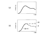
図10は、図8に示す超音波診断装置1Aのモニタ5に重畳表示された診断画像の色調の時間変化を示す概念図である。
FIG. 10 is a conceptual diagram showing temporal changes in the color tone of the diagnostic image superimposed and displayed on the
図10において、横軸は時間(Time)を示し、縦軸は信号強度値に応じて定まる各色調の強度(intensity)を示す。また、図10(a)は、最大輝度レベル保持演算を行なわずに従来のグレースケールにより、信号強度に応じて画像データを表示させる場合における輝度レベルの時間変化を示し、図10(b)は、最大輝度レベル保持演算前後の画像データを第1、第2の色調を用いて重畳表示させた場合における各色調の強度の時間変化を示す。 In FIG. 10, the horizontal axis represents time (Time), and the vertical axis represents the intensity of each color tone determined according to the signal intensity value. FIG. 10A shows a temporal change of the luminance level when image data is displayed according to the signal intensity by the conventional gray scale without performing the maximum luminance level holding calculation, and FIG. FIG. 9 shows temporal changes in the intensity of each color tone when the image data before and after the maximum brightness level holding calculation is displayed in a superimposed manner using the first and second color tones.
図10(a)に示すように例えば造影剤が被検体Pに流入し、エコー信号の信号強度が単調に増加した後、造影剤が関心領域から流出してエコー信号の信号強度が低下していく場合には、信号強度に応じて画像データの輝度レベルがグレースケールにより増減する。しかし、もし腫瘍などの関心領域の輝度レベルが一定であり、周囲の組織の輝度レベルが微小に増大していくような場合においては、図10(a)で示される従来のBモード画像では、腫瘍部の輝度が減少しているのかのごとく錯覚してしまう恐れがある。 As shown in FIG. 10A, for example, after the contrast agent flows into the subject P and the signal intensity of the echo signal increases monotonously, the contrast agent flows out of the region of interest and the signal intensity of the echo signal decreases. In the case of going, the luminance level of the image data is increased or decreased by the gray scale according to the signal intensity. However, if the brightness level of the region of interest such as a tumor is constant and the brightness level of the surrounding tissue is slightly increased, the conventional B-mode image shown in FIG. There is a risk of illusion as if the brightness of the tumor is decreasing.
一方、図(b)に示すように、最大輝度レベル保持演算前後の画像データを第1、第2の色調を用いて重畳表示させた場合には、造影剤が被検体Pに流入し、最大輝度レベル保持演算前のBモード画像の輝度レベルが単調に増加している間は、第1、第2の色調の強度が同時に増加する。このため、信号強度値100に対して各色調の強度が(R,G,B)=(100, 100, 100)となるように設定すれば、Red, Blue, Greenのいずれの色調の強度も同一となるため、重畳表示された混色の診断画像はグレー色となる。 On the other hand, as shown in FIG. 2B, when the image data before and after the maximum luminance level holding calculation is displayed superimposed using the first and second color tones, the contrast agent flows into the subject P, and the maximum While the luminance level of the B-mode image before the luminance level holding calculation is monotonically increasing, the intensity of the first and second color tones is increased at the same time. Therefore, if the intensity of each color tone is set to (R, G, B) = (100, 100, 100) with respect to the signal intensity value 100, the intensity of any color tone of Red, Blue, and Green can be obtained. Since they are the same, the mixed-color diagnosis image superimposed and displayed is gray.
尚、図(b)において、実線は各色調の強度が一致する場合の色調の強度(R,G,B)を、一点鎖線は第1の色調(黄色)の強度(G,B)を、点線は第2の色調(赤色)の強度(R)をそれぞれ示す。 In FIG. 2B, the solid line indicates the intensity (R, G, B) of the color tone when the intensity of each color matches, and the alternate long and short dash line indicates the intensity (G, B) of the first color tone (yellow). Dotted lines indicate the intensity (R) of the second color tone (red).
次に、造影剤の流入が一定量となり、例えばエコー信号の信号強度値が200に達すると元のBモード画像の輝度レベルの増加が停止する。さらに、造影剤が関心領域から流出して元のBモード画像の輝度レベルの低下が生じると、最大輝度レベル保持演算後における画像データの第1の色調(黄色)の強度(G,B) =(200, 200)が保持される一方、最大輝度レベル保持演算前における画像データの第2の色調(赤色)のみの強度(R)が低下することとなる。この結果、例えば、重畳表示された診断画像の第1、第2の色調の強度が(R, G, B)=(160, 200, 200)となると、診断画像は色調が黄色がかった色で表示されることになる。 Next, when the inflow of the contrast agent becomes a constant amount, for example, when the signal intensity value of the echo signal reaches 200, the increase in the luminance level of the original B-mode image stops. Furthermore, when the contrast agent flows out of the region of interest and the luminance level of the original B-mode image is reduced, the intensity (G, B) of the first color tone (yellow) of the image data after the maximum luminance level holding calculation = While (200, 200) is held, the intensity (R) of only the second color tone (red) of the image data before the maximum brightness level holding calculation is reduced. As a result, for example, when the intensity of the first and second color tones of the superimposed diagnostic image is (R, G, B) = (160, 200, 200), the diagnostic image has a yellowish color. Will be displayed.
このように、図10(b)に示すような色調で重畳表示される超音波診断装置1Aの診断画像によれば、診断画像の特定の領域の輝度レベルが減少した場合、あるいは一旦減少した後再び増加した場合には、周囲の輝度レベルの変化に関わらず、当該部位の色調が変化するため錯視の影響を回避して容易に輝度レベルの変化を判別することができる。また、この際、従来の診断画像としての描画性を損うこともない。 As described above, according to the diagnostic image of the ultrasonic diagnostic apparatus 1A that is superimposed and displayed in the color tone as shown in FIG. 10B, when the luminance level of a specific area of the diagnostic image is decreased, or after it is once decreased. When it increases again, regardless of the change in the surrounding brightness level, the color tone of the part changes, so that it is possible to easily determine the change in the brightness level while avoiding the effect of the illusion. At this time, the drawing performance as a conventional diagnostic image is not impaired.
図11は、図8に示す超音波診断装置1Aにより生成された被検体Pの断層像の一例を示す図である。 FIG. 11 is a diagram showing an example of a tomographic image of the subject P generated by the ultrasonic diagnostic apparatus 1A shown in FIG.
図11において、ある領域の輝度レベルが最大値に達した後に、減少すると、色調が変化して表示されるため、輝度レベルの錯視による誤認を回避することができる。 In FIG. 11, when the luminance level of a certain region decreases after reaching the maximum value, the color tone is changed and displayed, so that it is possible to avoid misperception due to the illusion of the luminance level.
以上のような、超音波診断装置1Aによれば、図1に示す超音波診断装置1と同様に錯視の影響を低減させて、コントラスト視認性を向上させることができる。すなわち、診断画像の背景の輝度が時間的に変化するような場合であっても、関心領域の輝度レベルの変化の有無を色調の変化により容易に判別することが可能となる。
According to the ultrasonic diagnostic apparatus 1A as described above, the contrast visibility can be improved by reducing the influence of the optical illusion as in the ultrasonic
図12は本発明に係る超音波診断装置の第3の実施形態を示す機能ブロック図である。 FIG. 12 is a functional block diagram showing a third embodiment of the ultrasonic diagnostic apparatus according to the present invention.
図12に示された、超音波診断装置1Bでは、装置本体2の各構成要素の詳細機能及び画像処理装置20の機能構成が図8に示す超音波診断装置1Aと相違する。他の構成および作用については図8に示す超音波診断装置1Aと実質的に異ならないため画像処理装置20の機能ブロック図のみ図示し、同一の構成については同符号を付して説明を省略する。
In the ultrasonic diagnostic apparatus 1B shown in FIG. 12, the detailed functions of each component of the apparatus
超音波診断装置1Bに内蔵される画像処理装置20は、第1の色調変更手段30、第2の色調変更手段31、色調指定手段32およびタイミング設定手段40としての機能を有する。第1の色調変更手段30は、画像メモリ12に保存された時系列の画像データからタイミング設定手段40から指示を受けた時刻の画像データを読み込んで、色調を予め指定された第1の色調に変更する画像再構成処理を施して画像メモリ12に書き込む機能を有する。第2の色調変更手段31は、画像メモリ12に保存された時系列の画像データからタイミング設定手段40から指示を受けた時刻以降の各画像データを読み込んで、色調を予め指定された第2の色調に変更する画像再構成処理を施して画像メモリ12に書き込む機能を有する。
The
色調指定手段32は、入力装置4から受けた色調の指定情報に基づいて第1の色調および第2の色調として用いられる色調を指定する機能を有する。
The color
タイミング設定手段40は、スイッチ4b等の入力装置4に入力されたタイミング指定情報を受け取って、色調を変更する画像の時刻情報を第1の色調変更手段30、第2の色調変更手段31に与える機能を有する。
The timing setting means 40 receives the timing designation information input to the input device 4 such as the
尚、超音波診断装置1Bの画像生成回路9には、最大輝度レベル保持演算機能が備えられる必要はない。
Note that the
そして、超音波診断装置1Bでは、複数回に亘る超音波の送受信により時系列のエコー信号が順次得られ、グレースケールによる輝度表示をするための画像データ(Bモード画像)が複数フレーム分生成されて順次画像メモリ12に保存される。そして、通常は、グレースケールによる輝度表示をするための画像データが画像合成回路10により順次モニタ5に与えられて動画表示される。
In the ultrasonic diagnostic apparatus 1B, time-series echo signals are sequentially obtained by transmitting and receiving ultrasonic waves a plurality of times, and a plurality of frames of image data (B-mode images) for displaying luminance in gray scale are generated. Are sequentially stored in the
さらに、ユーザが入力装置4のスイッチ4b等の操作により任意のタイミングを指定すると、タイミング設定手段40は、入力装置4に入力されたタイミング指定情報を受け取って、色調を変更する画像の時刻情報を第1の色調変更手段30、第2の色調変更手段31に与える。そして、第1の色調変更手段30は、画像メモリ12に保存された時系列の画像データからタイミング設定手段40から指示を受けた時刻の画像データを読み込んで、色調を予め指定された第1の色調に変更する画像再構成処理を施して画像メモリ12に書き込む。
Further, when the user designates an arbitrary timing by operating the
さらに、第2の色調変更手段31は、画像メモリ12に保存された時系列の画像データからタイミング設定手段40から指示を受けた時刻以降の各画像データを順次読み込んで、色調を予め指定された第2の色調に変更する画像再構成処理を施して画像メモリ12に書き込む。
Further, the second color tone changing means 31 sequentially reads each image data after the time when the instruction is received from the timing setting means 40 from the time-series image data stored in the
そして、画像合成回路10は、第1の色調変更手段30、第2の色調変更手段31により生成された色調の画像データを画像メモリ12からそれぞれ順次読み込んで、モニタ5に与えることにより動画として重畳表示させる。例えば、第1の色調が[Blue+Green](=黄色)とされ、第2の色調が[Red](=赤)とされる。
The
図13は、図12に示す超音波診断装置1Bのモニタ5に重畳表示された診断画像の色調の時間変化を示す概念図である。
FIG. 13 is a conceptual diagram showing temporal changes in the color tone of the diagnostic image superimposed and displayed on the
図13において、横軸は時間(Time)を示し、縦軸は信号強度値に応じて定まる各色調の強度(intensity)を示す。また、図13中の実線は各色調の強度が一致する場合の色調の強度(R,G,B)を、一点鎖線は第1の色調(黄色)の強度(G,B)を、点線は第2の色調(赤色)の強度(R)をそれぞれ示す。 In FIG. 13, the horizontal axis indicates time (Time), and the vertical axis indicates the intensity of each color tone determined according to the signal intensity value. Further, the solid line in FIG. 13 indicates the intensity (R, G, B) of the color tone when the intensities of the respective colors match, the dashed line indicates the intensity (G, B) of the first color tone (yellow), and the dotted line indicates The intensity (R) of the second color tone (red) is shown.
図13の実線に示すように例えば造影剤が被検体Pに流入し、エコー信号の信号強度が単調に増加して極大値となった後、造影剤が関心領域から流出入してエコー信号の信号強度が増減する場合には、信号強度に応じて画像データの輝度レベルがグレースケールにより増減する。 As shown by the solid line in FIG. 13, for example, after the contrast agent flows into the subject P, the signal intensity of the echo signal monotonously increases and reaches a maximum value, and then the contrast agent flows in and out of the region of interest. When the signal intensity increases / decreases, the luminance level of the image data increases / decreases by gray scale according to the signal intensity.
さらに、ユーザが、ある時刻から後の関心領域の輝度レベルの変化を把握したい場合には、例えば関心領域の輝度レベルが一定になったか否かを知りたいような場合には、入力装置4にタイミング指定情報を入力する。そして、図13の一点鎖線に示すようにタイミング指定情報に対応する時刻の画像データの色調は、第1の色調変更手段30により第1の色調(黄色)に変更されて継続的に重畳表示される。一方、図13の点線に示すようにタイミング指定情報に対応する時刻以降の画像データの色調は第2の色調(赤)に変更されて重畳表示される。 Further, when the user wants to grasp the change in the luminance level of the region of interest after a certain time, for example, when the user wants to know whether the luminance level of the region of interest has become constant, the timing is input to the input device 4. Enter the specified information. The color tone of the image data at the time corresponding to the timing designation information is changed to the first color tone (yellow) by the first color tone changing means 30 and continuously superimposed and displayed as shown by the one-dot chain line in FIG. The On the other hand, as shown by the dotted line in FIG. 13, the color tone of the image data after the time corresponding to the timing designation information is changed to the second color tone (red) and superimposed.
このため、重畳表示される画像のうち、第1の色調(黄色)で表現される画像データの強度は一定となる一方、第2の色調(赤)で表現される画像データの強度は、エコー信号の信号強度に応じて変化することとなる。この結果、関心領域の輝度レベルが一定であれば、重畳表示される画像のグレースケールの色調が保たれ、輝度レベルが減少すれば色調が黄色に、輝度レベルが増加すると色調が赤色に変化する。これによりユーザは、関心領域の周囲における輝度レベルの変化による錯視の影響を受けることなく、関心領域における輝度レベルの変動を識別することが可能となる。 Therefore, the intensity of the image data expressed in the first color tone (yellow) among the images displayed in a superimposed manner is constant, while the intensity of the image data expressed in the second color tone (red) is echo. It will change according to the signal strength of the signal. As a result, if the luminance level of the region of interest is constant, the gray scale color tone of the superimposed image is maintained, the color tone changes to yellow if the luminance level decreases, and the color tone changes to red if the luminance level increases. . Thus, the user can identify the change in the luminance level in the region of interest without being affected by the illusion due to the change in the luminance level around the region of interest.
以上のような超音波診断装置1Bによれば、図8に示す超音波診断装置1Aと同様に錯視の影響を低減させて、コントラスト視認性を向上させることができる。さらに、ユーザが指定する任意のタイミングにおける画像を基準として輝度レベルの変化を把握することができる。 According to the ultrasonic diagnostic apparatus 1B as described above, the contrast visibility can be improved by reducing the influence of the optical illusion as in the ultrasonic diagnostic apparatus 1A shown in FIG. Furthermore, it is possible to grasp a change in luminance level with reference to an image at an arbitrary timing designated by the user.
尚、以上の各実施形態の超音波診断装置1、1A、1Bにおいて、画像データを3次元データとして画像処理を行なってもよい。この場合には、被検体Pの走査が3次元的に行なわれ、得られたエコー信号から3次元的な画像データ(空間情報)が再構成される。しかし、最終的には、3次元情報をモニタ5に表示させる際には、種々の投影法により2次元投影された画像データが生成される。そして、2次元投影データに対して輝度スケールが参照されて輝度表示される。このため、画像処理装置20により輝度表示された2次元投影データに対して、上記と同様な画像処理を施すことができる。
In the ultrasonic
また、各実施形態における超音波診断装置1、1A、1Bを組み合わせて構成してもよい。逆に超音波診断装置1、1A、1Bの一部の構成要素を省略してもよい。
Moreover, you may comprise combining the ultrasonic diagnosing
さらに、画像処理装置20の画像処理の対象とする画像データは、輝度表示可能な画像データであれば、超音波診断装置1、1A、1Bにより収集された画像データに限らず、他のX線CT装置やMRI装置等の画像診断装置により収集された画像データとすることもできる。
Further, the image data to be subjected to image processing by the
1、1A、1B 超音波診断装置
2 装置本体
3 超音波プローブ
4 入力装置
4a トラックボール
4b スイッチ
5 モニタ
6 送受信ユニット
7 Bモード処理ユニット
8 ドプラ処理ユニット
9 画像生成回路
10 画像合成回路
11 制御プロセッサ
12 画像メモリ
13 内部記憶装置
14 インターフェース部
15 ネットワーク
20 画像処理装置
21 輝度スケール情報表示手段
22 輝度スケール変更手段
23 画像再構成手段
24 表示色変更条件設定手段
30 第1の色調変更手段
31 第2の色調変更手段
32 色調指定手段
40 タイミング設定手段
P 被検体
DESCRIPTION OF
Claims (11)
前記画像データ中の前記輝度レベルと所定の色データとの関連付けを時間によって変化させながら、前記輝度レベルを前記所定の色データに変換する画像処理手段と、
を有し、
前記所定の色データに変換される前記画像データは、前記関連付けの時間変化に応じて、前記輝度レベルを有する領域の色が前記所定の色データの色に順次変化する表示画像としてモニタに表示される画像データである、
ことを特徴とする超音波診断装置。 Means for generating tomographic image data of the subject having a luminance level corresponding to the signal intensity of an echo signal obtained by transmitting ultrasonic waves to the subject;
Image processing means for converting the luminance level into the predetermined color data while changing the association between the luminance level in the image data and the predetermined color data over time;
Have
The image data converted into the predetermined color data is displayed on a monitor as a display image in which the color of the area having the luminance level sequentially changes to the color of the predetermined color data in accordance with the time change of the association. Image data,
An ultrasonic diagnostic apparatus.
前記画像データ中の前記輝度レベルを、低いレベルから高いレベルの順で、或いは高いレベルから低いレベルの順で所定の更新時間ごとに巡回的に選択し、選択された輝度レベルに対応する前記画像データの領域のみを前記所定の色データに順次変換する、
ことを特徴とする請求項1に記載の超音波診断装置。 The image processing means includes
The luminance level in the image data is cyclically selected at a predetermined update time in order from a low level to a high level or from a high level to a low level, and the image corresponding to the selected luminance level Sequentially converting only the data area into the predetermined color data;
The ultrasonic diagnostic apparatus according to claim 1.
ことを特徴とする請求項2に記載の超音波診断装置。 The image data is a still image;
The ultrasonic diagnostic apparatus according to claim 2.
前記画像処理手段は、
フレーム毎に更新される前記動画の各画素の輝度レベルに対して最大輝度レベルを検出し、前記最大輝度レベルを各画素に保持する第1の輝度データを、前記最大輝度レベルの検出及び保持処理を行わない第2の輝度データと並列に生成すると共に、前記第1の輝度データを第1の色データに変換し、前記第2の輝度データを第2の色データに変換し、さらに前記第1の色データと前記第2の色データとを合成混色して前記所定の色データとする、
ことを特徴とする請求項1に記載の超音波診断装置。 The image data is a moving image,
The image processing means includes
The maximum luminance level is detected with respect to the luminance level of each pixel of the moving image updated for each frame, and the first luminance data that holds the maximum luminance level in each pixel is detected and held in the maximum luminance level. Is generated in parallel with the second luminance data that is not performed, the first luminance data is converted into the first color data, the second luminance data is converted into the second color data, and the second luminance data is further converted into the second color data. 1 color data and the second color data are combined and mixed to obtain the predetermined color data.
The ultrasonic diagnostic apparatus according to claim 1.
前記画像データは動画であり、
前記画像処理手段は、
フレーム毎に更新される前記動画の各画素の輝度レベルに対して、前記ユーザインタフェースから入力された切換タイミング以降は前記切換タイミング時の輝度レベルを保持する第1の輝度データを、前記保持処理を行わない第2の輝度データと並列に生成すると共に、前記第1の輝度データを第1の色データに変換し、前記第2の輝度データを第2の色データに変換し、さらに前記第1の色データと前記第2の色データとを合成混色して前記所定の色データとする、
ことを特徴とする請求項1に記載の超音波診断装置。 A user interface;
The image data is a moving image,
The image processing means includes
With respect to the luminance level of each pixel of the moving image updated for each frame, the first luminance data holding the luminance level at the switching timing after the switching timing input from the user interface is stored. The first luminance data is generated in parallel with the second luminance data not to be performed, the first luminance data is converted into first color data, the second luminance data is converted into second color data, and the first luminance data is further converted. The color data and the second color data are combined and mixed to obtain the predetermined color data.
The ultrasonic diagnostic apparatus according to claim 1.
ことを特徴とする請求項4又は5に記載の超音波診断装置。 The first color data is any one of the three primary colors, and the second color data is a composite color of the remaining two of the three primary colors.
The ultrasonic diagnostic apparatus according to claim 4 or 5, characterized in that.
ことを特徴とする請求項4又は5に記載の超音波診断装置。 The first color data is a composite color of any two of the three primary colors, and the second color data is the remaining one of the three primary colors.
The ultrasonic diagnostic apparatus according to claim 4 or 5, characterized in that.
前記画像データ中の前記輝度レベルと所定の色データとの関連付けを時間によって変化させながら、前記輝度レベルを前記所定の色データに変換する画像処理手段と、
を有し、
前記所定の色データに変換される前記画像データは、前記関連付けの時間変化に応じて、前記輝度レベルを有する領域の色が前記所定の色データの色に順次変化する表示画像としてモニタに表示される画像データである、
ことを特徴とする画像処理装置。 Means for generating image data in which a tomographic image of a subject is represented by a luminance level;
Image processing means for converting the luminance level into the predetermined color data while changing the association between the luminance level in the image data and the predetermined color data over time;
Have
The image data converted into the predetermined color data is displayed on a monitor as a display image in which the color of the area having the luminance level sequentially changes to the color of the predetermined color data in accordance with the time change of the association. Image data,
The image processing apparatus characterized by.
前記画像データ中の前記輝度レベルを、低いレベルから高いレベルの順で、或いは高いレベルから低いレベルの順で所定の更新時間ごとに巡回的に選択し、選択された輝度レベルに対応する前記画像データの領域のみを前記所定の色データに順次変換する、
ことを特徴とする請求項8に記載の画像処理装置。 The image processing means includes
The luminance level in the image data is cyclically selected at a predetermined update time in order from a low level to a high level or from a high level to a low level, and the image corresponding to the selected luminance level Sequentially converting only the data area into the predetermined color data;
The image processing apparatus according to claim 8.
前記画像処理手段は、
フレーム毎に更新される前記動画の各画素の輝度レベルに対して最大輝度レベルを検出し、前記最大輝度レベルを各画素に保持する第1の輝度データを、前記最大輝度レベルの検出及び保持処理を行わない第2の輝度データと並列に生成すると共に、前記第1の輝度データを第1の色データに変換し、前記第2の輝度データを第2の色データに変換し、さらに前記第1の色データと前記第2の色データとを合成混色して前記所定の色データとする、
ことを特徴とする請求項8に記載の画像処理装置。 The image data is a moving image,
The image processing means includes
The maximum luminance level is detected with respect to the luminance level of each pixel of the moving image updated for each frame, and the first luminance data that holds the maximum luminance level in each pixel is detected and held in the maximum luminance level. Is generated in parallel with the second luminance data that is not performed, the first luminance data is converted into the first color data, the second luminance data is converted into the second color data, and the second luminance data is further converted into the second color data. 1 color data and the second color data are combined and mixed to obtain the predetermined color data.
The image processing apparatus according to claim 8.
前記画像データは動画であり、
前記画像処理手段は、
フレーム毎に更新される前記動画の各画素の輝度レベルに対して、前記ユーザインタフェースから入力された切換タイミング以降は前記切換タイミング時の輝度レベルを保持する第1の輝度データを、前記保持処理を行わない第2の輝度データと並列に生成すると共に、前記第1の輝度データを第1の色データに変換し、前記第2の輝度データを第2の色データに変換し、さらに前記第1の色データと前記第2の色データとを合成混色して前記所定の色データとする、
ことを特徴とする請求項8に記載の画像処理装置。 A user interface;
The image data is a moving image,
The image processing means includes
With respect to the luminance level of each pixel of the moving image updated for each frame, the first luminance data holding the luminance level at the switching timing after the switching timing input from the user interface is stored. The first luminance data is generated in parallel with the second luminance data not to be performed, the first luminance data is converted into first color data, the second luminance data is converted into second color data, and the first luminance data is further converted. The color data and the second color data are combined and mixed to obtain the predetermined color data.
The image processing apparatus according to claim 8.
Priority Applications (9)
| Application Number | Priority Date | Filing Date | Title |
|---|---|---|---|
| JP2004201040A JP4786150B2 (en) | 2004-07-07 | 2004-07-07 | Ultrasonic diagnostic apparatus and image processing apparatus |
| DE200560025361 DE602005025361D1 (en) | 2004-07-07 | 2005-07-04 | Image processing device |
| EP20080019965 EP2030570B1 (en) | 2004-07-07 | 2005-07-04 | Image processing apparatus |
| DE200560027635 DE602005027635D1 (en) | 2004-07-07 | 2005-07-04 | Ultrasonic diagnostic device, image processing device and image processing method |
| EP20050014457 EP1614387B1 (en) | 2004-07-07 | 2005-07-04 | Ultrasonic diagnostic apparatus, image processing apparatus and image processing method |
| EP20060021967 EP1777544B1 (en) | 2004-07-07 | 2005-07-04 | Image processing apparatus |
| US11/174,728 US7744533B2 (en) | 2004-07-07 | 2005-07-06 | Ultrasonic diagnostic apparatus, image processing apparatus and image processing method |
| CN2008100838988A CN101264023B (en) | 2004-07-07 | 2005-07-07 | Ultrasonic diagnosis device, image processing apparatus and image processing method |
| CNB2005100832583A CN100522067C (en) | 2004-07-07 | 2005-07-07 | Ultrasonic diagnostic apparatus, image processing apparatus and image processing method |
Applications Claiming Priority (1)
| Application Number | Priority Date | Filing Date | Title |
|---|---|---|---|
| JP2004201040A JP4786150B2 (en) | 2004-07-07 | 2004-07-07 | Ultrasonic diagnostic apparatus and image processing apparatus |
Publications (2)
| Publication Number | Publication Date |
|---|---|
| JP2006020800A JP2006020800A (en) | 2006-01-26 |
| JP4786150B2 true JP4786150B2 (en) | 2011-10-05 |
Family
ID=35056930
Family Applications (1)
| Application Number | Title | Priority Date | Filing Date |
|---|---|---|---|
| JP2004201040A Expired - Fee Related JP4786150B2 (en) | 2004-07-07 | 2004-07-07 | Ultrasonic diagnostic apparatus and image processing apparatus |
Country Status (5)
| Country | Link |
|---|---|
| US (1) | US7744533B2 (en) |
| EP (3) | EP1777544B1 (en) |
| JP (1) | JP4786150B2 (en) |
| CN (2) | CN100522067C (en) |
| DE (2) | DE602005025361D1 (en) |
Families Citing this family (40)
| Publication number | Priority date | Publication date | Assignee | Title |
|---|---|---|---|---|
| IL144110A0 (en) * | 2001-07-02 | 2002-05-23 | Sharony Reuven | Methods and apparatus for objective fetal diagnosis |
| US8376946B2 (en) | 2002-05-16 | 2013-02-19 | Barbara Ann Karamanos Cancer Institute | Method and apparatus for combined diagnostic and therapeutic ultrasound system incorporating noninvasive thermometry, ablation control and automation |
| GB0416878D0 (en) * | 2004-07-29 | 2004-09-01 | Sensornet Ltd | Processing sensing measurements |
| US7630531B2 (en) * | 2006-01-31 | 2009-12-08 | Mevis Medical Solutions, Inc. | Enhanced navigational tools for comparing medical images |
| WO2008042855A2 (en) * | 2006-09-29 | 2008-04-10 | The Trustees Of The University Of Pennsylvania | Use of ultrasound as an antivascular agent |
| WO2008079219A1 (en) * | 2006-12-19 | 2008-07-03 | Bruce Reiner | Pacs portal with automated data mining and software selection |
| US10201324B2 (en) | 2007-05-04 | 2019-02-12 | Delphinus Medical Technologies, Inc. | Patient interface system |
| US8870771B2 (en) | 2007-05-04 | 2014-10-28 | Barbara Ann Karmanos Cancer Institute | Method and apparatus for categorizing breast density and assessing cancer risk utilizing acoustic parameters |
| US20080278323A1 (en) * | 2007-05-07 | 2008-11-13 | Wayne Jackson | Mail detection and notification system |
| CN101896124B (en) * | 2007-12-17 | 2013-03-13 | 皇家飞利浦电子股份有限公司 | Method for protocol creation in a diagnostic imaging system |
| JP5259175B2 (en) * | 2007-12-26 | 2013-08-07 | 株式会社東芝 | Ultrasonic diagnostic apparatus, ultrasonic image processing apparatus, and ultrasonic image processing program |
| JP5225730B2 (en) * | 2008-04-03 | 2013-07-03 | アンリツ株式会社 | Signal analyzer |
| JP4607203B2 (en) | 2008-04-28 | 2011-01-05 | 株式会社日立製作所 | Disk array device |
| CN101601593B (en) * | 2008-06-10 | 2013-01-16 | 株式会社东芝 | Ultrasonic diagnostic apparatus |
| JP4466968B2 (en) * | 2008-11-10 | 2010-05-26 | キヤノン株式会社 | Image processing apparatus, image processing method, program, and program storage medium |
| JP5438985B2 (en) * | 2009-02-10 | 2014-03-12 | 株式会社東芝 | Ultrasonic diagnostic apparatus and control program for ultrasonic diagnostic apparatus |
| JP2011005050A (en) * | 2009-06-26 | 2011-01-13 | Canon Inc | Image processing method and image processing apparatus |
| CN102869301B (en) * | 2010-02-12 | 2016-06-29 | 戴尔菲纳斯医疗科技公司 | The method characterizing the tissue of patient |
| WO2011100691A1 (en) | 2010-02-12 | 2011-08-18 | Delphinus Medical Technologies, Inc. | Method of characterizing the pathological response of tissue to a treatmant plan |
| WO2011125549A1 (en) * | 2010-03-31 | 2011-10-13 | 公立大学法人大阪府立大学 | Fatty tissue image display device |
| KR101117879B1 (en) * | 2010-05-27 | 2012-03-07 | 삼성메디슨 주식회사 | Ultrasound system and method for providing color reconstruction image |
| JP5570877B2 (en) * | 2010-06-04 | 2014-08-13 | 株式会社東芝 | Ultrasonic diagnostic equipment |
| JP5085691B2 (en) * | 2010-07-14 | 2012-11-28 | ジーイー・メディカル・システムズ・グローバル・テクノロジー・カンパニー・エルエルシー | Ultrasonic diagnostic equipment |
| KR101196211B1 (en) * | 2010-07-19 | 2012-11-05 | 삼성메디슨 주식회사 | Ultrasonic Diagnostic Apparatus and the Method thereof |
| JP5717377B2 (en) | 2010-08-30 | 2015-05-13 | キヤノン株式会社 | Image processing apparatus, image processing method, program, and program recording medium |
| JP5788229B2 (en) * | 2011-06-06 | 2015-09-30 | 株式会社東芝 | Ultrasonic diagnostic equipment |
| CN103181778B (en) * | 2011-12-31 | 2016-05-25 | 深圳迈瑞生物医疗电子股份有限公司 | Ultrasonic imaging method and system |
| US9763641B2 (en) | 2012-08-30 | 2017-09-19 | Delphinus Medical Technologies, Inc. | Method and system for imaging a volume of tissue with tissue boundary detection |
| US10123770B2 (en) | 2013-03-13 | 2018-11-13 | Delphinus Medical Technologies, Inc. | Patient support system |
| CN104217401B (en) * | 2013-06-03 | 2018-09-11 | 深圳迈瑞生物医疗电子股份有限公司 | Ultrasonic imaging method and device |
| CN104426899B (en) * | 2013-09-11 | 2020-11-24 | 上海联影医疗科技有限公司 | Dynamic setting method for diagnostic protocol set |
| KR102185725B1 (en) * | 2014-01-28 | 2020-12-02 | 삼성메디슨 주식회사 | Method and ultrasound apparatus for displaying a ultrasound image |
| JP2015181795A (en) * | 2014-03-25 | 2015-10-22 | 株式会社アドバンテスト | Measurement device, measurement method and ultrasonic measurement apparatus |
| US10285667B2 (en) | 2014-08-05 | 2019-05-14 | Delphinus Medical Technologies, Inc. | Method for generating an enhanced image of a volume of tissue |
| JP6598503B2 (en) | 2015-05-01 | 2019-10-30 | キヤノン株式会社 | Image generating apparatus, image generating method, and program |
| WO2016203288A1 (en) * | 2015-06-15 | 2016-12-22 | B-K Medical Aps | Display of imaging data in a moving viewport |
| US11380029B2 (en) * | 2017-05-17 | 2022-07-05 | St. Jude Medical, Cardiology Division, Inc. | System and method for mapping local activation times |
| JP7105172B2 (en) * | 2018-11-01 | 2022-07-22 | 富士フイルムヘルスケア株式会社 | Ultrasonic probe and ultrasonic diagnostic equipment |
| JP7424003B2 (en) | 2019-11-20 | 2024-01-30 | コニカミノルタ株式会社 | Medical image display device, area display method, and area display program |
| CN111398957B (en) * | 2020-04-01 | 2022-08-02 | 中国林业科学研究院资源信息研究所 | Short-wavelength double-antenna InSAR forest height inversion method for improving coherence calculation method |
Family Cites Families (16)
| Publication number | Priority date | Publication date | Assignee | Title |
|---|---|---|---|---|
| JPS56163639A (en) * | 1980-05-21 | 1981-12-16 | Tokyo Shibaura Electric Co | Ultrasonic diagnosing device |
| JPS602237A (en) * | 1983-06-06 | 1985-01-08 | 横河メディカルシステム株式会社 | Ct image display apparatus |
| JP2594896B2 (en) * | 1984-03-28 | 1997-03-26 | 株式会社日立製作所 | Image coloring method |
| JPS62194581A (en) * | 1986-03-29 | 1987-08-27 | Hitachi Medical Corp | Medical picture analysis processor |
| JPH0496879A (en) * | 1990-08-14 | 1992-03-30 | Toshiba Corp | Picture processor |
| JP3290027B2 (en) * | 1994-04-06 | 2002-06-10 | 株式会社モリタ製作所 | X-ray image display method and apparatus |
| JP3361620B2 (en) * | 1994-06-17 | 2003-01-07 | ジーイー横河メディカルシステム株式会社 | Image display method, image display device, and image diagnostic device |
| US5694937A (en) | 1995-01-31 | 1997-12-09 | Kabushiki Kaisha Toshiba | Ultrasound diagnostic apparatus and method |
| US5743266A (en) * | 1995-04-25 | 1998-04-28 | Molecular Biosystems, Inc. | Method for processing real-time contrast enhanced ultrasonic images |
| JP3394648B2 (en) * | 1996-05-21 | 2003-04-07 | アロカ株式会社 | Ultrasound diagnostic equipment |
| US5797397A (en) * | 1996-11-25 | 1998-08-25 | Hewlett-Packard Company | Ultrasound imaging system and method using intensity highlighting to facilitate tissue differentiation |
| US5895358A (en) * | 1997-05-07 | 1999-04-20 | General Electric Company | Method and apparatus for mapping color flow velocity data into display intensities |
| JP3495710B2 (en) | 2001-02-01 | 2004-02-09 | ジーイー・メディカル・システムズ・グローバル・テクノロジー・カンパニー・エルエルシー | Blood flow imaging apparatus and ultrasonic diagnostic apparatus |
| JP4373699B2 (en) | 2003-04-28 | 2009-11-25 | 株式会社東芝 | Ultrasonic diagnostic equipment |
| US7044912B2 (en) * | 2003-08-28 | 2006-05-16 | Siemens Medical Solutions Usa Inc. | Diagnostic medical ultrasound system having method and apparatus for storing and retrieving 3D and 4D data sets |
| JP2005081073A (en) | 2003-09-11 | 2005-03-31 | Toshiba Corp | Ultrasonic diagnostic device |
-
2004
- 2004-07-07 JP JP2004201040A patent/JP4786150B2/en not_active Expired - Fee Related
-
2005
- 2005-07-04 DE DE200560025361 patent/DE602005025361D1/en active Active
- 2005-07-04 EP EP20060021967 patent/EP1777544B1/en not_active Expired - Fee Related
- 2005-07-04 DE DE200560027635 patent/DE602005027635D1/en active Active
- 2005-07-04 EP EP20080019965 patent/EP2030570B1/en not_active Expired - Fee Related
- 2005-07-04 EP EP20050014457 patent/EP1614387B1/en not_active Expired - Fee Related
- 2005-07-06 US US11/174,728 patent/US7744533B2/en not_active Expired - Fee Related
- 2005-07-07 CN CNB2005100832583A patent/CN100522067C/en not_active Expired - Fee Related
- 2005-07-07 CN CN2008100838988A patent/CN101264023B/en not_active Expired - Fee Related
Also Published As
| Publication number | Publication date |
|---|---|
| US20060020205A1 (en) | 2006-01-26 |
| EP2030570A3 (en) | 2009-12-09 |
| US7744533B2 (en) | 2010-06-29 |
| CN101264023B (en) | 2010-12-15 |
| EP1614387B1 (en) | 2011-04-27 |
| CN100522067C (en) | 2009-08-05 |
| EP1777544A3 (en) | 2007-11-28 |
| EP2030570B1 (en) | 2012-05-02 |
| EP1614387A1 (en) | 2006-01-11 |
| DE602005025361D1 (en) | 2011-01-27 |
| CN1718164A (en) | 2006-01-11 |
| CN101264023A (en) | 2008-09-17 |
| JP2006020800A (en) | 2006-01-26 |
| EP1777544B1 (en) | 2010-12-15 |
| DE602005027635D1 (en) | 2011-06-09 |
| EP2030570A2 (en) | 2009-03-04 |
| EP1777544A2 (en) | 2007-04-25 |
Similar Documents
| Publication | Publication Date | Title |
|---|---|---|
| JP4786150B2 (en) | Ultrasonic diagnostic apparatus and image processing apparatus | |
| JP5395396B2 (en) | Ultrasonic diagnostic apparatus, medical image processing apparatus, and medical image processing program | |
| JP4373699B2 (en) | Ultrasonic diagnostic equipment | |
| JP5762076B2 (en) | Ultrasonic diagnostic apparatus, ultrasonic image processing apparatus, and medical image diagnostic apparatus | |
| US6641538B2 (en) | Ultrasonic diagnostic apparatus and method of controlling a ultrasonic diagnostic apparatus | |
| JP4763883B2 (en) | Ultrasonic diagnostic equipment | |
| JP4921826B2 (en) | Ultrasonic diagnostic apparatus and control method thereof | |
| JP6222811B2 (en) | Ultrasonic diagnostic apparatus and image processing apparatus | |
| JP5632203B2 (en) | Ultrasonic diagnostic apparatus, ultrasonic image processing apparatus, and ultrasonic image processing program | |
| US8834371B2 (en) | Ultrasound diagnostic apparatus and ultrasound image processing program | |
| JP2001212144A (en) | Ultrasonic diagnostic apparatus and ultrasonic imaging method | |
| WO2007114375A1 (en) | Ultrasound diagnostic device and control method for ultrasound diagnostic device | |
| JP2000333956A (en) | Ultrasonograph and method for changing display of ultrasonic image | |
| JP2010284516A (en) | Ultrasonic diagnostic apparatus, ultrasonic image processor, and ultrasonic image processing program | |
| JP2001061841A (en) | Ultrasonograph, and method of producing ultrasonic image | |
| US9855025B2 (en) | Ultrasonic diagnostic apparatus and ultrasonic image processing apparatus | |
| JP5259175B2 (en) | Ultrasonic diagnostic apparatus, ultrasonic image processing apparatus, and ultrasonic image processing program | |
| JP4521204B2 (en) | Ultrasonic diagnostic apparatus, image processing apparatus, and ultrasonic imaging method | |
| JP4945605B2 (en) | Ultrasonic diagnostic equipment | |
| WO2020149191A1 (en) | Image analyzing device | |
| JP2009153919A (en) | Ultrasonic diagnostic system, ultrasonic image processor and ultrasonic image processing program | |
| JP2005323657A (en) | Ultrasonic diagnosing apparatus, and image processing device | |
| JP2006087744A (en) | Ultrasonic diagnostic apparatus and ultrasonic signal processing device | |
| JP5454901B2 (en) | Ultrasonic diagnostic equipment |
Legal Events
| Date | Code | Title | Description |
|---|---|---|---|
| A621 | Written request for application examination |
Free format text: JAPANESE INTERMEDIATE CODE: A621 Effective date: 20070706 |
|
| A977 | Report on retrieval |
Free format text: JAPANESE INTERMEDIATE CODE: A971007 Effective date: 20100629 |
|
| A131 | Notification of reasons for refusal |
Free format text: JAPANESE INTERMEDIATE CODE: A131 Effective date: 20100706 |
|
| A521 | Request for written amendment filed |
Free format text: JAPANESE INTERMEDIATE CODE: A523 Effective date: 20100906 |
|
| A131 | Notification of reasons for refusal |
Free format text: JAPANESE INTERMEDIATE CODE: A131 Effective date: 20110315 |
|
| A521 | Request for written amendment filed |
Free format text: JAPANESE INTERMEDIATE CODE: A523 Effective date: 20110516 |
|
| TRDD | Decision of grant or rejection written | ||
| A01 | Written decision to grant a patent or to grant a registration (utility model) |
Free format text: JAPANESE INTERMEDIATE CODE: A01 Effective date: 20110621 |
|
| A01 | Written decision to grant a patent or to grant a registration (utility model) |
Free format text: JAPANESE INTERMEDIATE CODE: A01 |
|
| A61 | First payment of annual fees (during grant procedure) |
Free format text: JAPANESE INTERMEDIATE CODE: A61 Effective date: 20110713 |
|
| R150 | Certificate of patent or registration of utility model |
Ref document number: 4786150 Country of ref document: JP Free format text: JAPANESE INTERMEDIATE CODE: R150 Free format text: JAPANESE INTERMEDIATE CODE: R150 |
|
| FPAY | Renewal fee payment (event date is renewal date of database) |
Free format text: PAYMENT UNTIL: 20140722 Year of fee payment: 3 |
|
| S111 | Request for change of ownership or part of ownership |
Free format text: JAPANESE INTERMEDIATE CODE: R313117 |
|
| R350 | Written notification of registration of transfer |
Free format text: JAPANESE INTERMEDIATE CODE: R350 |
|
| S533 | Written request for registration of change of name |
Free format text: JAPANESE INTERMEDIATE CODE: R313533 |
|
| R350 | Written notification of registration of transfer |
Free format text: JAPANESE INTERMEDIATE CODE: R350 |
|
| LAPS | Cancellation because of no payment of annual fees |