EP3326535B1 - Displaying system for displaying digital breast tomosynthesis data - Google Patents
Displaying system for displaying digital breast tomosynthesis data Download PDFInfo
- Publication number
- EP3326535B1 EP3326535B1 EP16200820.5A EP16200820A EP3326535B1 EP 3326535 B1 EP3326535 B1 EP 3326535B1 EP 16200820 A EP16200820 A EP 16200820A EP 3326535 B1 EP3326535 B1 EP 3326535B1
- Authority
- EP
- European Patent Office
- Prior art keywords
- image
- cad
- dbt volume
- activated
- marker
- Prior art date
- Legal status (The legal status is an assumption and is not a legal conclusion. Google has not performed a legal analysis and makes no representation as to the accuracy of the status listed.)
- Active
Links
- 210000000481 breast Anatomy 0.000 title claims description 95
- 239000003550 marker Substances 0.000 claims description 164
- 206010028980 Neoplasm Diseases 0.000 claims description 38
- 201000011510 cancer Diseases 0.000 claims description 38
- 230000036210 malignancy Effects 0.000 claims description 37
- 238000000034 method Methods 0.000 claims description 22
- 238000004590 computer program Methods 0.000 claims description 11
- 238000001514 detection method Methods 0.000 claims description 4
- 230000000875 corresponding effect Effects 0.000 description 32
- 230000002596 correlated effect Effects 0.000 description 5
- 230000001276 controlling effect Effects 0.000 description 4
- 230000003902 lesion Effects 0.000 description 4
- 230000005856 abnormality Effects 0.000 description 3
- 230000001419 dependent effect Effects 0.000 description 3
- 238000009607 mammography Methods 0.000 description 3
- 206010006187 Breast cancer Diseases 0.000 description 2
- 208000026310 Breast neoplasm Diseases 0.000 description 2
- 230000008901 benefit Effects 0.000 description 2
- 230000006835 compression Effects 0.000 description 2
- 238000007906 compression Methods 0.000 description 2
- 238000002059 diagnostic imaging Methods 0.000 description 2
- 230000003993 interaction Effects 0.000 description 2
- 230000001360 synchronised effect Effects 0.000 description 2
- 210000001519 tissue Anatomy 0.000 description 2
- 238000012800 visualization Methods 0.000 description 2
- 208000004434 Calcinosis Diseases 0.000 description 1
- 230000009471 action Effects 0.000 description 1
- 238000000105 evaporative light scattering detection Methods 0.000 description 1
- 230000014509 gene expression Effects 0.000 description 1
- PCHJSUWPFVWCPO-UHFFFAOYSA-N gold Chemical compound [Au] PCHJSUWPFVWCPO-UHFFFAOYSA-N 0.000 description 1
- 238000003384 imaging method Methods 0.000 description 1
- 230000003211 malignant effect Effects 0.000 description 1
- 238000013507 mapping Methods 0.000 description 1
- 230000003287 optical effect Effects 0.000 description 1
- 210000004872 soft tissue Anatomy 0.000 description 1
- 230000009466 transformation Effects 0.000 description 1
Images

Classifications
-
- A—HUMAN NECESSITIES
- A61—MEDICAL OR VETERINARY SCIENCE; HYGIENE
- A61B—DIAGNOSIS; SURGERY; IDENTIFICATION
- A61B6/00—Apparatus or devices for radiation diagnosis; Apparatus or devices for radiation diagnosis combined with radiation therapy equipment
- A61B6/02—Arrangements for diagnosis sequentially in different planes; Stereoscopic radiation diagnosis
- A61B6/025—Tomosynthesis
-
- A—HUMAN NECESSITIES
- A61—MEDICAL OR VETERINARY SCIENCE; HYGIENE
- A61B—DIAGNOSIS; SURGERY; IDENTIFICATION
- A61B6/00—Apparatus or devices for radiation diagnosis; Apparatus or devices for radiation diagnosis combined with radiation therapy equipment
- A61B6/46—Arrangements for interfacing with the operator or the patient
- A61B6/461—Displaying means of special interest
- A61B6/463—Displaying means of special interest characterised by displaying multiple images or images and diagnostic data on one display
-
- A—HUMAN NECESSITIES
- A61—MEDICAL OR VETERINARY SCIENCE; HYGIENE
- A61B—DIAGNOSIS; SURGERY; IDENTIFICATION
- A61B6/00—Apparatus or devices for radiation diagnosis; Apparatus or devices for radiation diagnosis combined with radiation therapy equipment
- A61B6/46—Arrangements for interfacing with the operator or the patient
- A61B6/461—Displaying means of special interest
- A61B6/466—Displaying means of special interest adapted to display 3D data
-
- A—HUMAN NECESSITIES
- A61—MEDICAL OR VETERINARY SCIENCE; HYGIENE
- A61B—DIAGNOSIS; SURGERY; IDENTIFICATION
- A61B8/00—Diagnosis using ultrasonic, sonic or infrasonic waves
- A61B8/08—Detecting organic movements or changes, e.g. tumours, cysts, swellings
- A61B8/0825—Detecting organic movements or changes, e.g. tumours, cysts, swellings for diagnosis of the breast, e.g. mammography
-
- A—HUMAN NECESSITIES
- A61—MEDICAL OR VETERINARY SCIENCE; HYGIENE
- A61B—DIAGNOSIS; SURGERY; IDENTIFICATION
- A61B8/00—Diagnosis using ultrasonic, sonic or infrasonic waves
- A61B8/46—Ultrasonic, sonic or infrasonic diagnostic devices with special arrangements for interfacing with the operator or the patient
- A61B8/467—Ultrasonic, sonic or infrasonic diagnostic devices with special arrangements for interfacing with the operator or the patient characterised by special input means
-
- G—PHYSICS
- G06—COMPUTING; CALCULATING OR COUNTING
- G06F—ELECTRIC DIGITAL DATA PROCESSING
- G06F18/00—Pattern recognition
- G06F18/20—Analysing
- G06F18/22—Matching criteria, e.g. proximity measures
-
- G—PHYSICS
- G06—COMPUTING; CALCULATING OR COUNTING
- G06T—IMAGE DATA PROCESSING OR GENERATION, IN GENERAL
- G06T15/00—3D [Three Dimensional] image rendering
- G06T15/08—Volume rendering
-
- G—PHYSICS
- G06—COMPUTING; CALCULATING OR COUNTING
- G06T—IMAGE DATA PROCESSING OR GENERATION, IN GENERAL
- G06T19/00—Manipulating 3D models or images for computer graphics
- G06T19/003—Navigation within 3D models or images
-
- G—PHYSICS
- G06—COMPUTING; CALCULATING OR COUNTING
- G06T—IMAGE DATA PROCESSING OR GENERATION, IN GENERAL
- G06T7/00—Image analysis
- G06T7/0002—Inspection of images, e.g. flaw detection
- G06T7/0012—Biomedical image inspection
-
- G—PHYSICS
- G06—COMPUTING; CALCULATING OR COUNTING
- G06T—IMAGE DATA PROCESSING OR GENERATION, IN GENERAL
- G06T7/00—Image analysis
- G06T7/0002—Inspection of images, e.g. flaw detection
- G06T7/0012—Biomedical image inspection
- G06T7/0014—Biomedical image inspection using an image reference approach
- G06T7/0016—Biomedical image inspection using an image reference approach involving temporal comparison
-
- G—PHYSICS
- G06—COMPUTING; CALCULATING OR COUNTING
- G06T—IMAGE DATA PROCESSING OR GENERATION, IN GENERAL
- G06T7/00—Image analysis
- G06T7/70—Determining position or orientation of objects or cameras
- G06T7/73—Determining position or orientation of objects or cameras using feature-based methods
-
- G—PHYSICS
- G06—COMPUTING; CALCULATING OR COUNTING
- G06T—IMAGE DATA PROCESSING OR GENERATION, IN GENERAL
- G06T2200/00—Indexing scheme for image data processing or generation, in general
- G06T2200/24—Indexing scheme for image data processing or generation, in general involving graphical user interfaces [GUIs]
-
- G—PHYSICS
- G06—COMPUTING; CALCULATING OR COUNTING
- G06T—IMAGE DATA PROCESSING OR GENERATION, IN GENERAL
- G06T2207/00—Indexing scheme for image analysis or image enhancement
- G06T2207/10—Image acquisition modality
- G06T2207/10072—Tomographic images
- G06T2207/10112—Digital tomosynthesis [DTS]
-
- G—PHYSICS
- G06—COMPUTING; CALCULATING OR COUNTING
- G06T—IMAGE DATA PROCESSING OR GENERATION, IN GENERAL
- G06T2207/00—Indexing scheme for image analysis or image enhancement
- G06T2207/20—Special algorithmic details
- G06T2207/20076—Probabilistic image processing
-
- G—PHYSICS
- G06—COMPUTING; CALCULATING OR COUNTING
- G06T—IMAGE DATA PROCESSING OR GENERATION, IN GENERAL
- G06T2207/00—Indexing scheme for image analysis or image enhancement
- G06T2207/30—Subject of image; Context of image processing
- G06T2207/30004—Biomedical image processing
- G06T2207/30068—Mammography; Breast
-
- G—PHYSICS
- G06—COMPUTING; CALCULATING OR COUNTING
- G06T—IMAGE DATA PROCESSING OR GENERATION, IN GENERAL
- G06T2207/00—Indexing scheme for image analysis or image enhancement
- G06T2207/30—Subject of image; Context of image processing
- G06T2207/30004—Biomedical image processing
- G06T2207/30096—Tumor; Lesion
-
- G—PHYSICS
- G06—COMPUTING; CALCULATING OR COUNTING
- G06T—IMAGE DATA PROCESSING OR GENERATION, IN GENERAL
- G06T2207/00—Indexing scheme for image analysis or image enhancement
- G06T2207/30—Subject of image; Context of image processing
- G06T2207/30204—Marker
-
- G—PHYSICS
- G06—COMPUTING; CALCULATING OR COUNTING
- G06T—IMAGE DATA PROCESSING OR GENERATION, IN GENERAL
- G06T2210/00—Indexing scheme for image generation or computer graphics
- G06T2210/41—Medical
-
- G—PHYSICS
- G06—COMPUTING; CALCULATING OR COUNTING
- G06V—IMAGE OR VIDEO RECOGNITION OR UNDERSTANDING
- G06V2201/00—Indexing scheme relating to image or video recognition or understanding
- G06V2201/03—Recognition of patterns in medical or anatomical images
Definitions
- the invention relates to a displaying system, method and computer program for displaying digital breast tomosynthesis (DBT) data.
- DBT digital breast tomosynthesis
- Two-dimensional x-ray mammography is currently the gold standard for the detection of breast cancer in its early stages.
- a limitation of this modality is that in a two-dimensional projection of the breast superimpositions of normal tissue may look suspicious and lead to false positives while reviewing two-dimensional x-ray mammography images.
- true lesions can be obscured by overlying breast tissue.
- usually two views of each breast are acquired for examining the respective breast, i.e. a craniocaudal (CC) view and a mediolateral oblique (MLO) view, wherein the MLO view is acquired at an angle between 30 degrees and 60 degrees from the CC view.
- CC craniocaudal
- MLO mediolateral oblique
- the first and second DBT volume images can correspond to different views, for instance, to a CC view and an MLO view.
- the DBT volume images can also refer to other views.
- the first and second DBT volume images can refer to different image generation times. For instance, for each breast a current DBT volume image and an older DBT volume image can be provided.
- the image providing unit can provide two DBT volume images or more than two DBT volume images for each breast. It should be noted that the expressions "at least one of A and B" and "A and/or B" include a) A without B, b) B without A, and c) A and B.
- the image providing unit 5 is preferentially adapted to provide the DBT volume images such that they are spatially correlated.
- the DBT volume images are each formed of slices arranged at different depth positions.
- the DBT volume images are preferentially provided such that slices of different DBT volume images of the same breast show at least partly the same part of the same breast.
- the DBT volume images are preferentially provided such that slices of DBT volume images of the same view, but of different breasts, at the same depth position show at least partly corresponding parts in the left breast and the right breast.
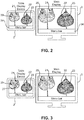
- Fig. 2 shows schematically and exemplarily the non-stationary display 2 with four navigation images 20 ... 23 and the stationary display 3 also showing the navigation images 20 ... 23.
- menu bars 24, 34 can be shown on the displays 2, 3.
- the menu bars 24, 34 can provide tools for modifying the navigation images 20 ... 23.
- a slice of the activated DBT volume image at the first slice position z can be shown in a corresponding viewer, wherein the first slice position z is set to, for instance, the depth location within the activated DBT volume image where the activated CAD marker was detected in the activated DBT volume image. If a corresponding CAD region, i.e. a region marked by another CAD marker, is found in another DBT volume image of another view being different to the view of the activated DBT volume image of the same activated breast at a second slice position z c , also the slice at the first depth position z of the other DBT volume image of the same breast can be shown on the main display.
- step 107 it is determined whether a corresponding CAD marker can be found in the other DBT volume image of the same breast, wherein, if this is the case, a second slice position z c defining a position of a slice of the other DBT volume image, which includes a three-dimensional location of the other CAD marker, is determined. Moreover, if a corresponding CAD marker has been found, in step 109 the DBT slice z of the other breast in the same view is displayed, i.e. in the view which corresponds to the view of the activated DBT volume image, and in step 110 DBT slices z c of both breasts are shown in the other view, i.e. the view not being the view of the activated DBT volume image.
- the tablet display device can be replaced by additional views on the main display device, i.e. views being in addition to views showing the DBT volume images or by a separate screen.
- the interaction with the tablet display device or its possible replacement can be performed using a touch pad device or another additional device like a keyboard or a computer mouse.
- the CAD regions, i.e. the CAD markers, displayed on the non-stationary display can point to soft tissue like masses, architectural distortions, asymmetries, et cetera and/or to microcalcification lesions.
- one or several CAD regions or CAD markers can also be displayed on the stationary display, i.e. on the slices of the DBT volume images.
Landscapes
- Engineering & Computer Science (AREA)
- Health & Medical Sciences (AREA)
- Life Sciences & Earth Sciences (AREA)
- Medical Informatics (AREA)
- Physics & Mathematics (AREA)
- Radiology & Medical Imaging (AREA)
- Nuclear Medicine, Radiotherapy & Molecular Imaging (AREA)
- General Health & Medical Sciences (AREA)
- Theoretical Computer Science (AREA)
- Veterinary Medicine (AREA)
- Biomedical Technology (AREA)
- Heart & Thoracic Surgery (AREA)
- Molecular Biology (AREA)
- Surgery (AREA)
- Animal Behavior & Ethology (AREA)
- Public Health (AREA)
- Pathology (AREA)
- Biophysics (AREA)
- General Physics & Mathematics (AREA)
- Computer Vision & Pattern Recognition (AREA)
- High Energy & Nuclear Physics (AREA)
- Optics & Photonics (AREA)
- Human Computer Interaction (AREA)
- Data Mining & Analysis (AREA)
- Quality & Reliability (AREA)
- General Engineering & Computer Science (AREA)
- Computer Graphics (AREA)
- Software Systems (AREA)
- Bioinformatics & Cheminformatics (AREA)
- Evolutionary Computation (AREA)
- Evolutionary Biology (AREA)
- Bioinformatics & Computational Biology (AREA)
- Artificial Intelligence (AREA)
- Radar, Positioning & Navigation (AREA)
- Remote Sensing (AREA)
- Computer Hardware Design (AREA)
- Apparatus For Radiation Diagnosis (AREA)
- Ultra Sonic Daignosis Equipment (AREA)
Description
- The invention relates to a displaying system, method and computer program for displaying digital breast tomosynthesis (DBT) data.
- Two-dimensional x-ray mammography is currently the gold standard for the detection of breast cancer in its early stages. However, a limitation of this modality is that in a two-dimensional projection of the breast superimpositions of normal tissue may look suspicious and lead to false positives while reviewing two-dimensional x-ray mammography images. Moreover, true lesions can be obscured by overlying breast tissue. In order to diminish these problems, usually two views of each breast are acquired for examining the respective breast, i.e. a craniocaudal (CC) view and a mediolateral oblique (MLO) view, wherein the MLO view is acquired at an angle between 30 degrees and 60 degrees from the CC view.
- DBT was introduced as a promising modality to overcome these projection problems, wherein DBT includes a reconstruction of a three-dimensional volume of the breast from several low dose, limited angle x-ray projections. With the introduction of DBT it was suggested that by adding the third dimension only one tomosynthesis view per breast would be required. However, recent insights indicate that in DBT also two views may be required, in order to optimally visualize lesions, as disclosed, for instance, in the article "Breast tomosynthesis: one view or two?" by E. A. Rafferty et al., Meeting Radiological Society of North America, page 335 (2006).
- If DBT volume images corresponding to different views need to be reviewed for detecting breast cancer, information from both views need to be combined. However, since the DBT volume images comprise many slices, combining information from the different views is very difficult and time consuming for a radiologist.
US 2011/289441 A1 discloses the marking of breast images taken at different times. - It is an object of the present invention to provide a displaying system, a displaying method and a computer program which assist a radiologist in combining information from different DBT volume images of a woman's breast.
- In a first aspect of the present invention a displaying system for displaying DBT data is presented, wherein the displaying system comprises:
- an image providing unit for providing first and second DBT volume images of the left breast of a woman and first and second DBT volume images of the right breast of the woman, wherein the first DBT volume images correspond to at least one of a first image generation time and a first view and the second DBT volume images correspond to at least one of a second image generation time and a second view,
- a navigation image providing unit for providing for each DBT volume image a respective two-dimensional navigation image,
- a computer-aided detection (CAD) marker providing unit for providing for each DBT volume image a set of CAD markers, wherein each CAD marker is associated with a set of two-dimensional locations on the respective two-dimensional navigation image and a set of three-dimensional locations in the respective DBT volume image,
- a correlation score providing unit for providing correlation scores being indicative of a likelihood that CAD markers of different DBT volume images of the same breast correspond to each other,
- a display unit for displaying the navigation images and slices of the provided DBT volume images,
- a user interface allowing a user to indicate a two-dimensional location on a navigation image, particularly displayed in a first display region which might be provided by the display unit, wherein this navigation image is regarded as being an activated navigation image and the DBT volume image, for which the activated navigation image has been provided, is regarded as being an activated DBT volume image of an activated breast,
- a CAD marker determination unit for determining a CAD marker associated with the indicated two-dimensional location, wherein the determined CAD marker is regarded as being an activated CAD marker, and for determining another CAD marker of the other DBT volume image of the activated breast, which corresponds to the activated CAD marker, based on the provided correlation scores,
- a slice determining unit for determining a first slice position defining a position of a slice of the activated DBT volume image, which includes a three-dimensional location of the activated CAD marker, and for determining a second slice position defining a position of a slice of the other DBT volume image, which includes a three-dimensional location of the other CAD marker,
- a controller for controlling the display unit to display the slice of the activated DBT volume image at the determined first slice position and the slice of the activated DBT volume image at the determined second slice position, particularly in a second display region which might be provided by the display unit.
- Thus, a user like a radiologist can review the navigation images shown in the first display region and, if the user sees a suspicious region, the user can indicate the two-dimensional location of this suspicious region on the navigation image, whereupon automatically corresponding slices of the DBT volume images are shown on the display unit. This allows for a simpler and less time consuming combining of information from the different DBT volume images.
- The display unit can be adapted to provide a first display region for displaying the navigation images and a second display region for displaying a slice of a provided DBT volume image,
- The image providing unit can be a storing unit in which the first and second DBT volume images are stored already and from which the first and second DBT volume images can be retrieved for providing the same. However, the image providing unit can also be a receiving unit for receiving the first and second DBT volume images from a DBT volume images acquisition device. The image providing unit can also be the DBT volume images acquisition device.
- The first and second DBT volume images can correspond to different views, for instance, to a CC view and an MLO view. The DBT volume images can also refer to other views. Moreover, the first and second DBT volume images can refer to different image generation times. For instance, for each breast a current DBT volume image and an older DBT volume image can be provided. The image providing unit can provide two DBT volume images or more than two DBT volume images for each breast. It should be noted that the expressions "at least one of A and B" and "A and/or B" include a) A without B, b) B without A, and c) A and B.
- In DBT imaging the respective breast is compressed just as in two-dimensional mammography, i.e. a DBT volume image is a three-dimensional image of a compressed breast. The view identification preferentially refers to the direction in which the breast is compressed, wherein the direction is the direction in which the breast would be compressed when a two-dimensional mammogram as indicated by the view would be generated. For instance, in CC views the beast is compressed with a horizontal compression paddle, while in MLO views the compression is done under an angle of, for instance, about 45 degrees.
- Also the navigation image providing unit can be a storing unit, wherein in this case the navigation images are stored in the storing unit and the stored navigation images can be provided. The navigation image providing unit can also be adapted to generate the navigation images or to receive navigation images from another unit being adapted to generate the navigation images.
- A navigation image is a two-dimensional image in which each two-dimensional location is assigned to at least one three-dimensional location in the corresponding DBT volume image, in order to allow navigating through the DBT volume image by indicating two-dimensional locations on the navigation image. The navigation image can be determined, for instance, by performing an artificial forward projection through the DBT volume image. In an embodiment a mammogram can be rendered from an intersection of a surface fitted through locations within the respective DBT volume image, which are marked by CAD markers, and the respective DBT volume image, wherein the mammogram can be used as navigation image. A preferred way of determining the navigation images is disclosed in the article "Generating Synthetic Mammograms From Reconstructed Tomosynthesis Volumes" by G. van Schie et al., IEEE Transactions on Medical Imaging, ), which is herewith incorporated by reference. The navigation image could also be regarded as being a synthetic image, i.e. a synthetic mammogram, which can also be named artificial mammogram.
- Also the CAD marker providing unit can be a storing unit, wherein in this case CAD markers are stored in the storing unit and the stored CAD markers can be provided. However, the CAD marker providing unit can also be a receiving unit for receiving the CAD markers from another unit like a CAD marker generation unit and for providing the received CAD markers. The CAD marker providing unit can also be the CAD marker generation unit itself. In particular, the CAD marker providing unit can use known CAD algorithms for generating the CAD markers based on the provided DBT volume images.
- Also the correlation score providing unit can be a storing unit, wherein in this case the correlation scores are stored in the storing unit and the stored correlation scores can be provided. The correlation score providing unit can also be a receiving unit for receiving correlation scores from a correlation score generation unit, or the correlation score providing unit can be the correlation score generation unit, wherein the generated correlation scores can be provided. The CAD marker providing unit and the correlation score providing unit can also be a same integrated unit, wherein this same integrated unit is adapted to provide the CAD markers and the correlation scores.
- In an embodiment the controller is further adapted to control the display unit to display a slice of the DBT volume image of the other breast, which corresponds to the at least one of the image generation time and view of the activated DBT volume image, at the determined first slice position and a slice of the DBT volume image of the other breast, which corresponds to the at least one of the image generation time and view of the other DBT volume image, at the determined second slice position. Moreover, the controller can be adapted to control the display unit to display a slice of the DBT volume image of the other breast, which corresponds to the at least one of the image generation time and view of the activated DBT volume image, at the determined first slice position, if the CAD marker determination unit has determined that no other CAD marker of the other DBT volume image of the activated breast corresponds to the activated CAD marker. Furthermore, also the slices of the DBT volume images, which correspond to the other of the at least one of the image generation time and view of the activated DBT volume image, at the determined first slice position can be determined and displayed. For instance, if the activated DBT volume image is a first DBT volume image, slices of the second DBT volume images can be shown at the first determined depth position. The advantage of this, compared to not performing any action, is to show at least a slice that will likely be close to the corresponding spatially correlated one. This fallback is based on the assumption that DBT volume images acquired in the same women are spatially correlated, especially the ones of the same breast. It is also possible to use other ways to do this fallback, for instance, using a spatial transformation given by a registration or mapping algorithm. If it has been determined that there is a corresponding CAD marker of the other DBT volume image of the activated breast, a corresponding slice of the other DBT volume image can be determined and shown.
- In order to improve the spatial correlation between DBT volume images of a same breast, they can be spatially registered to each other by using known registration algorithms. Also for improving the spatial correlation between DBT volume images of the same view, but of different breasts, the DBT volume images can be registered to each other by using known registration algorithms.
- The controller can be further adapted to control the display unit to show the activated marker on the activated navigation image. It is preferred that the CAD marker providing unit is adapted to provide for each CAD marker a malignancy value being indicative of a probability of malignancy at the set of three-dimensional locations associated with the CAD marker within the respective DBT volume image, wherein the controller is adapted to control the display unit to show also an indication of malignancy on the activated navigation image based on the malignancy value provided for the activated CAD marker. The controller can also be adapted to control the display unit to show the other CAD marker on the navigation image of the other DBT volume image. Moreover, the controller can be adapted to control the display unit to show also an indication of malignancy on a navigation image, which corresponds to the other DBT volume image, based on the malignancy value provided for the other CAD marker. By also showing the CAD markers and indicating the probability of malignancy the assistance of the user in reviewing the DBT volume images can be further improved.
- Preferentially, the display unit comprises stationary display and a non-stationary display, wherein a first display region is on the non-stationary display and a second display region is on the stationary display. The non-stationary display is preferentially a display of a tablet computer. The stationary display is preferentially a monitor of a workstation to be arranged, for instance, on a table. This allows for a provision of more space for displaying the DBT volume images, i.e. slices of the DBT volume images, on the stationary display, because the navigation images are not shown on the stationary display, but on the non-stationary display. Moreover, displaying the navigations images on the non-stationary display, particularly on a display of a tablet computer, can give a more natural feeling of interaction and can be more intuitive.
- Preferentially, the controller is further adapted to control the displaying system such that the user is allowed to subsequently indicate different two-dimensional locations on a navigation image, to check whether based on a previous indication of a two-dimensional location on a navigation image a CAD marker is shown, and to, if a CAD marker is shown, remove the CAD marker. This can ensure that the user is not distracted by already reviewed CAD markers, thereby further improving the assistance of the user in reviewing the DBT volume images.
- It is also preferred that the controller is adapted to control the displaying system such that the user is allowed to subsequently indicate different two-dimensional locations on the navigation images, wherein the displaying system further comprises a CAD tracking unit for tracking CAD markers shown to the user, wherein the controller is further adapted to control the display unit to display all CAD markers, which have been provided by the CAD marker providing unit, for which a malignancy value has been provided being indicative of a probability of malignancy being larger than a predefined probability threshold and which have not been tracked by the CAD tracking unit, in the first display region, wherein these CAD markers are regarded as being unvisited CAD markers. Moreover, the controller can be adapted to control the display unit such that the unvisited CAD markers are displayed subsequently, wherein the respective unvisited CAD marker is shown on the respective navigation image at the respective two-dimensional location, wherein the slice determining unit is adapted to determine a slice position defining a position of a slice of the DBT volume image, which includes a three-dimensional location of the respective unvisited CAD marker, and the controller is adapted to control the display unit to display the slice of the DBT volume image at the determined slice position. In particular, the controller is adapted to control the display unit to display a next unvisited CAD marker, after the user has indicated via the user interface that the next unvisited CAD marker is to be displayed or after a current CAD marker has been displayed for a predefined time period. This can ensure that the user does not miss a possibly malignant region, which should be investigated, thereby further improving the assistance of the user in reviewing the DBT volume images.
- In a further aspect of the present invention a displaying method for displaying DBT data is presented, wherein the displaying method comprises:
- providing first and second DBT volume images of the left breast of a woman and first and second DBT volume images of the right breast of the woman by an image providing unit, wherein the first DBT volume images correspond to at least one of a first image generation time and a first view and the second DBT volume images correspond to at least one of a second image generation time and a second view,
- providing for each DBT volume image a respective two-dimensional navigation image by a navigation image providing unit,
- providing for each DBT volume image a set of CAD markers by a CAD marker providing unit, wherein each CAD marker is associated with a set of two-dimensional locations on the respective two-dimensional navigation image and a set of three-dimensional locations in the respective DBT volume image,
- providing correlation scores being indicative of a likelihood that CAD markers of different DBT volume images of the same breast correspond to each other by a correlation score providing unit,
- allowing a user to indicate a two-dimensional location on a navigation image displayed on a display unit by a user interface, wherein this navigation image is regarded as being an activated navigation image and the DBT volume image, for which the activated navigation image has been provided, is regarded as being an activated DBT volume image of an activated breast,
- determining a CAD marker associated with the indicated two-dimensional location by a CAD marker determination unit, wherein the determined CAD marker is regarded as being an activated CAD marker, and determining another CAD marker of the other DBT volume image of the activated breast, which corresponds to the activated CAD marker, based on the provided correlation scores,
- determining a first slice position defining a position of a slice of the activated DBT volume image, which includes a three-dimensional location of the activated CAD marker, and determining a second slice position defining a position of a slice of the other DBT volume image, which includes a three-dimensional location of the other CAD marker, by a slice determining unit,
- controlling the display unit to display the slice of the activated DBT volume image at the determined first slice position and the slice of the other DBT volume image at the determined second slice position in a second display region of the display unit by a controller.
- Another aspect of the present invention a computer program for displaying DBT data is presented, wherein the computer program comprises program code means for causing a displaying system as defined in
claim 1 to carry out the steps of the displaying method as defined inclaim 13, when the computer program is run on a computer controlling the displaying system. - It shall be understood that the displaying system of
claim 1, the displaying method ofclaim 13, and the computer program ofclaim 14, have similar and/or identical preferred embodiments, in particular, as defined in the dependent claims. - It shall be understood that a preferred embodiment of the present invention can also be any combination of the dependent claims or above embodiments with the respective independent claim.
- These and other aspects of the invention will be apparent from and elucidated with reference to the embodiments described hereinafter.
- In the following drawings:
- Fig. 1
- shows schematically and exemplarily an embodiment of a displaying system for displaying DBT data,
- Fig. 2
- illustrates schematically and exemplarily a stationary display and a non-stationary display showing navigation images,
- Fig. 3
- illustrates schematically and exemplarily an indication of a two-dimensional location in a navigation image shown on the non-stationary display,
- Fig. 4
- illustrates schematically and exemplarily CAD markers on navigation images shown on the non-stationary display and corresponding slices of DBT volume images shown on the stationary display, and
- Figs. 5 and 6
- show a flowchart exemplarily illustrating an embodiment of a displaying method for displaying DBT data.
-
Fig. 1 shows schematically and exemplarily an embodiment of a displaying system for displaying DBT data. The displayingsystem 1 comprises animage providing unit 5 for providing a CC DBT volume image and an MLO DBT volume image of a women's left breast and a CC DBT volume image and an MLO DBT volume image of a women's right breast. The displayingsystem 1 further comprises a navigationimage providing unit 6 for providing for each DBT volume image a respective two-dimensional navigation image and a CADmarker providing unit 7 for providing for each DBT volume image a set of CAD markers, wherein each CAD marker is associated with a set of two-dimensional locations on the respective two-dimensional navigation image and a set of three-dimensional locations in the respective DBT volume image. The CAD markers mark CAD regions, wherein the CAD regions cover the respective set of two-dimensional locations on the respective two-dimensional navigation image and the respective set of three-dimensional locations in the respective DBT volume image. For instance, for eachDBT volume image 5 to 10 CAD markers may be provided. - The
image providing unit 5 is preferentially adapted to provide the DBT volume images such that they are spatially correlated. The DBT volume images are each formed of slices arranged at different depth positions. The DBT volume images are preferentially provided such that slices of different DBT volume images of the same breast show at least partly the same part of the same breast. Moreover, the DBT volume images are preferentially provided such that slices of DBT volume images of the same view, but of different breasts, at the same depth position show at least partly corresponding parts in the left breast and the right breast. - Moreover, the displaying
system 1 comprises a correlationscore providing unit 8 for providing correlation scores being indicative of a likelihood that CAD markers of different DBT volume images of the same breast correspond to each other. For providing the navigation images, the CAD markers and the correlation scores known algorithms can be used like the algorithms disclosed in the articles "Mass detection in reconstructed digital breast tomosynthesis volumes with a computer-aided detection system trained on 2D mammograms" by G. van Schie et al., Medical Physics, volume 40 (2013) and "Generating Synthetic Mammograms From Reconstructed Tomosynthesis Volumes" by G. van Schie et al., IEEE Transactions on Medical Imaging, ), which are herewith incorporated by reference. - The displaying
system 1 further comprises a display unit with astationary display 3, which in this embodiment may be regarded as being a main display, and anon-stationary display 2 which in this embodiment is a tablet display device. Thestationary display 3 is preferentially a monitor of a workstation. The displayingsystem 1 also comprises aninput unit 4 like a keyboard, a computer mouse, etcetera, which is adapted to allow a user like a radiologist to provide inputs into the displayingsystem 1. - The
non-stationary display 2 comprises afirst display region 11 and thestationary display 3 comprises asecond display region 12. Thefirst display region 11 is touch sensitive, in order to allow a user like a radiologist to indicate a two-dimensional location on a navigation image displayed in the first display region by touching the location. In another embodiment for indicating a two-dimensional location on a navigation image also other means can be used like a mouse pointer. The touch sensitivefirst display region 11 forms auser interface 2 via which the two-dimensional location on the navigation image can be indicated by the user. -
Fig. 2 shows schematically and exemplarily thenon-stationary display 2 with fournavigation images 20 ... 23 and thestationary display 3 also showing thenavigation images 20 ... 23. Moreover,optionally menu bars displays navigation images 20 ... 23. -
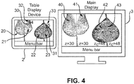
Fig. 3 is similar toFig. 2 , but in addition it illustrates that a user indicates a two-dimensional location on thenavigation image 21 shown on thenon-stationary display 2. This indication of the two-dimensional location on thenavigation image 21 is illustrated by thehand 27. Hence, the user can search for abnormalities in thenavigation images 20 ... 23 shown by thenon-stationary display 2 and thestationary display 3 and, if an abnormality is seen, the user, who can also be regarded as being a reader, can click on a two-dimensional location on a navigation image like thenavigation image 21 shown on thenon-stationary display 2. Thenavigation image 21, on which the two-dimensional location has been indicated, is regarded as being an activated navigation image. The activatednavigation image 21 is associated with a CC DBT volume image or an MLO DBT volume image and a breast i.e. the right breast or the left breast of the woman. The associated DBT volume image is regarded as being an activated DBT volume image and the breast is regarded as being an activated breast. - The displaying
system 1 further comprises a CADmarker determination unit 14 for determining aCAD marker 30 associated with the indicated two-dimensional location, wherein the determined CAD marker is regarded as being an activated CAD marker. Moreover, the CADmarker determination unit 14 is adapted to determine anotherCAD marker 31 of another DBT volume image of the activated breast, which corresponds to the activatedCAD marker 30, based on the provided correlation scores. In particular, the CADmarker determination unit 14 is adapted to determine another CAD marker, for which the highest correlation score has been provided for a correlation with the activated CAD marker, wherein, in order to ensure that the two CAD markers really correspond to each other, the correlation score should also be larger than a predefined correlation score threshold. Thus, the CADmarker determination unit 14 can be adapted to determine which other CAD markers have a correlation score for a combination with the activated CAD marker being larger than the correlation score threshold, wherein among the resulting other CAD markers having correlation scores being larger than the correlation score threshold the CAD marker can be selected having the largest correlation score. It can also be the other way around, i.e. firstly determining the other CAD marker having the largest correlation score with the activated CAD marker and then determining whether this correlation score is larger than the predefined correlation score threshold. - The displaying
system 1 further comprises aslice determining unit 15 for determining a first slice position z defining a position of aslice 41 of the activated DBT volume image, which includes a three-dimensional location of the activatedCAD marker 30, and for determining a second slice position zc defining a position of aslice 43 of the other DBT volume image which includes a three-dimensional location of theother CAD marker 30. - Moreover, the displaying
system 1 comprises acontroller 9 for controlling the displaying system, in particular the different components of the displaying system. For instance, thecontroller 9 is adapted to control thenon-stationary display 2 and thestationary display 3 such that theslice 41 of the activated DBT volume image at the determined first slice position z and theslice 43 of the other DBT volume image at the determined second slice position zc are shown in thesecond display region 12. This is schematically and exemplarily illustrated inFig. 4 . - The
controller 9 is further adapted to control thenon-stationary display 2 to show the activatedmarker 30 on the activatednavigation image 21 and theother CAD marker 31 on the correspondingnavigation image 23 of the other DBT volume image in thefirst display region 11. Thecontroller 9 is also adapted to control thenon-stationary display 2 to show anindication 32 of malignancy on the activatednavigation image 21 based on a malignancy value provided for the activatedCAD marker 30 and to show anindication 33 of malignancy on anavigation image 23, which corresponds to the other DBT volume image, based on a malignancy value provided for theother CAD marker 31 in thefirst display region 11 on thenon-stationary display 2. The malignancy values are indicative of a probability of malignancy at the set of three-dimensional locations associated with the respective CAD marker. The malignancy values are also provided by the CADmarker providing unit 7. Thecontroller 9 can be further adapted to control thestationary display 3 to display a slice of the other DBT volume image at the determined first slice position z and a slice of the activated DBT volume image at the determined second slice position zc in thesecond display region 12. - The
controller 9 can further be adapted to control thedisplays marker determination unit 14 has determined that no other CAD marker of the other DBT volume image of the activated breast corresponds to the activatedCAD marker 30, a slice of the other DBT volume image at the determined first slice position z is displayed in thesecond display region 12. - Thus, a slice of the activated DBT volume image at the first slice position z can be shown in a corresponding viewer, wherein the first slice position z is set to, for instance, the depth location within the activated DBT volume image where the activated CAD marker was detected in the activated DBT volume image. If a corresponding CAD region, i.e. a region marked by another CAD marker, is found in another DBT volume image of another view being different to the view of the activated DBT volume image of the same activated breast at a second slice position zc, also the slice at the first depth position z of the other DBT volume image of the same breast can be shown on the main display. Moreover, slices at the second position zc of DBT volume images of both breasts in the DBT volume images of the other view can be shown on the
main display 3. If a corresponding CAD region, i.e. a corresponding CAD marker covering a corresponding CAD region, is not found, slices at the first positions z of all DBT volume images can be shown. - The
controller 9 is further adapted to control thedecision support system 1 such that the user is allowed to subsequently indicate different two-dimensional locations on thenavigation images 20 ... 23, to check whether based on a previous indication of a two-dimensional location on one of thenavigation images 20 ... 23 a CAD marker is shown in thefirst display region 11 and to, if a CAD marker is shown in thefirst display region 11, remove the CAD marker in thefirst display region 11. Thus, before reviewing a next CAD marker, previous CAD markers are removed. When reviewing a CAD marker, the user can add comments to the CAD marker into the displayingsystem 1 via theinput unit 4. These comments can later be provided as a report about the reviewing of the DBT volume images, in particular of the CAD markers. - The displaying
system 1 further comprises aCAD tracking unit 13 for tracking CAD markers shown to the users, wherein thecontroller 9 is further adapted to control the display unit to display all CAD markers, which have been provided by the CADmarker providing unit 7, for which a malignancy value has been provided being indicative of a probability of malignancy being larger than a predefined probability threshold and which have not been tracked by theCAD tracking unit 13, in thefirst display region 11, wherein these CAD markers are regarded as being unvisited CAD markers. In particular, thecontroller 9 is adapted to control the display unit such that the unvisited CAD markers are displayed subsequently, wherein the respective unvisited CAD marker is shown on the respective navigation image in thefirst display region 11 at the respective two-dimensional location. Theslice determining unit 15 is adapted to determine a slice position defining a position of a slice of the DBT volume image, which includes a three-dimensional location of the respective unvisited CAD marker, and thecontroller 9 is adapted to control the display unit to display the slice of the DBT volume image at the determined slice position in thesecond display region 12. As explained above with respect to the activated CAD marker, also regarding the respective unvisited CAD marker the above described techniques for selecting certain slices of the DBT volume images, in particular by using a corresponding CAD marker, can be applied. Thus, the displayingsystem 1 keeps track of all visited CAD markers, wherein, when the user, i.e. a reader, is finished with reading, the displayingsystem 1 can collect all unvisited CAD markers with malignancy scores being larger than a given threshold. Unvisited CAD markers can be systematically displayed on thenon-stationary display 2 followed by the synchronized display of informative slices of the DBT volume images on thestationary display 3 as described above. This displaying can be performed via a "next button" mode, a "cine mode", or another mode. Thus, for instance, thecontroller 9 can be adapted to control thenon-stationary display 2 to display a next unvisited CAD marker, after the user has indicated, for example, via the touch sensitive surface of thenon-stationary display 2 or theinput unit 4 that the next unvisited CAD marker is to be displayed or after a current CAD marker has been displayed for a predefined time period. - In the following an embodiment of a displaying method for displaying DBT data will exemplarily be described with reference to a flowchart shown in
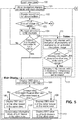
Figs. 5 and6 . - In step 100 a new case is loaded. The loaded case includes different DBT volume images corresponding to different views of the left and right breasts of a woman, respective two-dimensional navigation images, CAD markers associated with a set of two-dimensional locations on a respective two-dimensional navigation image and a set of three-dimensional locations in a respective DBT volume image, and correlation scores being indicative of a likelihood that CAD markers of different DBT volume images of a same breast correspond to each other.
- In
step 101 the navigation images are shown on the non-stationary display and the stationary display, whereafter in step 102 a reader can search for abnormalities and instep 103 it is determined whether the reader has indicated a two-dimensional location on a navigation image on thenon-stationary display 2. If this is not the case, it is determined whether the reading has been finished instep 114 and wherein, if the reading has not been finished, the method continues withstep 101. Thus, steps 101, 102, 103 and 114 are carried out in a loop, if the reader does not indicate a two-dimensional location on a navigation image and the reading has not been finished. The displaying system can allow the reader to indicate via, for instance, a button in themenu bar 24 whether the reading is finished, wherein this input may be used instep 114. - If in step 103 a two-dimensional location has been indicated on a navigation image on the
non-stationary display 2, instep 104 previous CAD markers, if present, are removed and instep 105 it is determined whether the indicated location is associated with a CAD marker. If this is not the case, the method continues withstep 101. Otherwise, the method proceeds withsteps - The associated CAD marker is regarded as being an activated CAD marker, the DBT volume image comprising the activated CAD marker is regarded as being an activated DBT volume image and the navigation image, on which the two-dimensional location has been indicated, is regarded as being an activated navigation image. In step 106 a first slice position z defining a position of a slice of the activated DBT volume image, which includes a three-dimensional location of the activated CAD marker, is determined and shown on the
stationary display 3. Thus, a DBT slice at the first slice position z, which is associated with the CAD region marked by the active CAD marker, is displayed. Instep 107 it is determined whether a corresponding CAD marker can be found in the other DBT volume image of the same breast, wherein, if this is the case, a second slice position zc defining a position of a slice of the other DBT volume image, which includes a three-dimensional location of the other CAD marker, is determined. Moreover, if a corresponding CAD marker has been found, instep 109 the DBT slice z of the other breast in the same view is displayed, i.e. in the view which corresponds to the view of the activated DBT volume image, and instep 110 DBT slices zc of both breasts are shown in the other view, i.e. the view not being the view of the activated DBT volume image. Thus, if a CAD marker is present at a certain slice position within a DBT volume image of a certain view and of a certain breast, this certain slice and in addition a slice at the certain slice position of the other DBT volume image of the certain view and of the other breast can be displayed. So, if a CAD marker is found in a breast and the correspond informative slice is displayed, the displaying system can immediately display a corresponding slice or a slice which is very close to the corresponding slice of the contralateral breast, in order to allow a radiologist to compare both breasts for finding asymmetries that might point to suspicious regions, without requiring the radiologist to, for instance, search for the slices in the large DBT volume images. - If in step 107 a corresponding CAD marker has not been found, in
step 108 the DBT slice z of the other breast in the same view is displayed, i.e. in the view which corresponds to the view of the activated DBT volume image, and instep 120 informative slices of both breasts in the other view are synchronized. This means, for instance, the slices at the first slice position z of the DBT volume images of the other view are displayed, in order to show the slices at the first slice position z of all DBT volume images of both breasts. Alternatively, if in an embodiment the DBT volume images of different views are not spatially correlated, the slice determination unit can be adapted to determine spatially correlated slices in the DBT volume images of the other view by using a known registration algorithm, wherein these determined slices might be shown instep 120. In a further embodiment instep 120 the navigation images of the DBT volume images of the other view are still displayed or arbitrary slices of the DBT volume images of the other view are shown. - In
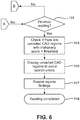
step 111 on the non-stationary display the activated CAD marker is shown together with an indication of the probability of malignancy on the activated navigation image. Instep 112 it is determined whether a corresponding CAD region has been found in the other DBT volume image of the same breast, wherein, if this is the case, instep 113 the corresponding CAD marker is shown on thenon-stationary display 2 together with an indication of malignancy on a navigation image of the other view of the same breast. If a corresponding CAD region could not be found,step 101 followsstep 112. - If the reader has indicated that he wants to finish the reading, in
step 115 it is checked if there are unvisited CAD regions, i.e. unvisited CAD markers, with a malignancy score, i.e. with a malignancy value provided by the CADmarker providing unit 7, being larger than a predefined threshold. If this is the case, these unvisited CAD regions are shown to the reader instep 116, whereafter thedisplay system 1 allows the reader to report findings instep 117.Steps above steps 106 to 113 can be provided for the respective unvisited CAD marker and instep 117 reports can be added by the user for the respective unvisited CAD marker. The method ends instep 118. - The display system can be adapted to allow the user, i.e. the reader, to have a look at the slices by, for instance, scrolling through the slices, of one or several of the DBT volume images, before going to step 101. This may lead to an improved lesion assessment.
- Since the displaying system and method described above with reference to
Figs. 1 to 6 does not only allow the reader to review the DBT volume images, but to also provide comments to suspicious regions marked by CAD markers such that the reader can interactively review the DBT volume images and generate a report which might include decisions regarding, for instance, cancer, the displaying system and method can also be regarded as being a decision support system and method, respectively. The displaying system and method are adapted to aid a radiologist in reading and interpreting findings in DBT volume images. The displaying system and method use CAD region or CAD marker correlations between DBT volume images of different views of the same breast, in order to navigate to informative slices of especially all DBT volume images displayed on the stationary display which can be regarded as being a main display. For displaying the navigation images, which can also be regarded as being CAD navigation images, the non-stationary display is used, which is preferentially a tablet display device. - Although in above described embodiments the display unit comprises a tablet display device and a main display, i.e. a monitor of a workstation, in another embodiment the display unit may only comprise the main display such that the navigation images and the DBT volume images are both shown on the main display. The main display may comprise a respective viewer for each provided DBT volume image, i.e., for instance, four viewers for showing CC and MLO DBT volume images of the left and right breast. For navigation purposes in each viewer a corresponding navigation image may be shown as a transparent, color-coded overlay on a respective slice of a respective DBT volume image. It is also possible that in each viewer only the respective navigation image is shown without an underlying slice of the respective DBT volume image. The user can indicate a two-dimensional location on a shown navigation image, whereafter one or several CAD markers and slice positions can be determined and the slices of the DBT volumes images at the determined slice positions can be displayed in the viewers as described above, for instance, with respect to
steps 106 to 110 and 120. The input unit can be adapted to allow the user to indicate, if he/she wants to see again the navigation images in the viewers, in order to allow him/her to indicate another two-dimensional location in a navigation image. For example, a button, a mouse gesture, a key combination can be input into the system, in order to indicate that the navigation images should be shown again. This input could also be regarded as being a shortcut back to the navigation images. It is also possible that, after the user has indicated a two-dimensional location on a shown navigation image, firstly it is determined whether an associated CAD marker is present, especially as described above with reference to step 105, wherein, if this is the case, this CAD marker is shown optionally together with an indication of malignancy on the navigation image. If a corresponding CAD marker can be determined, especially as described above with reference to step 107, also this corresponding CAD marker can be shown on the corresponding navigation image optionally together with an indication of malignancy. In this example slices of DBT volume images at corresponding slice positions are only displayed, especially in accordance withabove steps 106 to 110 and 120, after the user has indicated that he/she wants to see the slices by providing a corresponding input like a single our double left mouse button click, a right mouse button click, et cetera. Also in this embodiment a shortcut to the navigation images can be provided via a further input. - In another embodiment the tablet display device can be replaced by additional views on the main display device, i.e. views being in addition to views showing the DBT volume images or by a separate screen. Moreover, the interaction with the tablet display device or its possible replacement can be performed using a touch pad device or another additional device like a keyboard or a computer mouse. The CAD regions, i.e. the CAD markers, displayed on the non-stationary display can point to soft tissue like masses, architectural distortions, asymmetries, et cetera and/or to microcalcification lesions. Moreover, one or several CAD regions or CAD markers can also be displayed on the stationary display, i.e. on the slices of the DBT volume images.
- The displaying system can be adapted to allow the user to modify the thickness of the slices of the DBT volume images, in order to reduce the total number of slices. This can lead to a further reduced reading time of the user. For instance, on the main display a graphical user interface can be provided allowing the user to modify the slice thickness. The
images providing unit 5 might be adapted to modify the DBT volume images accordingly For instance, a mean intensity projection can be applied for every "X" slices, in order to increase the thickness of the slices, wherein the parameter "X" might be input by the user. - Although in above described embodiments the DBT volume images correspond to CC and MLO views, in other embodiments also other views can be used like mediolateral (ML) views. Moreover, although in above described embodiments for each breast only two DBT volume images corresponding to two different views are provided, in other embodiments more than two DBT volume images for more than two views can be provided for each breast. Correspondingly, the visualization on the
displays - Although in above described embodiments the different DBT volume images of a same breast correspond to different views, in other embodiments the different DBT volume images of a same breast can be different with respect to another parameter like the time. In particular, the different DBT volume images of a same breast can relate to a same view but to different acquisition times.
- Other variations to the disclosed embodiments can be understood and effected by those skilled in the art in practicing the claimed invention, from a study of the drawings, the disclosure, and the appended claims.
- In the claims, the word "comprising" does not exclude other elements or steps, and the indefinite article "a" or "an" does not exclude a plurality.
- A single unit or device may fulfill the functions of several items recited in the claims. The mere fact that certain measures are recited in mutually different dependent claims does not indicate that a combination of these measures cannot be used to advantage.
- Operations like the provision of a CAD marker, the provision of a correlation score, the provision of a navigation image, the determination of a CAD marker, the determination of a slice, et cetera performed by one or several units or devices can also be performed by any other number of units or devices. These operations and/or the control of the displaying system in accordance with the displaying method can be implemented as program code means of a computer program and/or as dedicated hardware.
- A computer program may be stored/distributed on a suitable medium, such as an optical storage medium or a solid-state medium, supplied together with or as part of other hardware, but may also be distributed in other forms, such as via the Internet or other wired or wireless telecommunication systems.
- Any reference signs in the claims should not be construed as limiting the scope.
- The invention relates to a displaying system for displaying DBT data. First and second DBT volume images of the left breast of a woman and first and second DBT volume images of the right breast of the woman are provided by an image providing unit. Moreover, for each DBT volume image a two-dimensional navigation image is provided by a navigation image providing unit, wherein a user is allowed to indicate a location in the navigation image by using a user interface, whereafter a CAD marker associated with the location is determined in a DBT volume image of a breast and a corresponding CAD marker, if present, is determined in another DBT volume image of the breast. Slices of these DBT volume images, which are associated with the CAD markers, are shown on a display.
Claims (14)
- A displaying system for displaying digital breast tomosynthesis (DBT) data, the displaying system (1) comprising:- an image providing unit (5) for providing first and second DBT volume images of the left breast of a woman and first and second DBT volume images of the right breast of the woman, wherein the first DBT volume images correspond to at least one of a first image generation time and a first view and the second DBT volume images correspond to at least one of a second image generation time and a second view,- a navigation image providing unit (6) for providing for each DBT volume image a respective two-dimensional navigation image (20...23),- a computer-aided detection (CAD) marker providing unit (7) for providing for each DBT volume image a set of CAD markers, wherein each CAD marker (30, 31) is associated with a set of two-dimensional locations on the respective two-dimensional navigation image (20...23) and a set of three-dimensional locations in the respective DBT volume image,- a correlation score providing unit (8) for providing correlation scores being indicative of a likelihood that CAD markers (30, 31) of different DBT volume images of the same breast correspond to each other,- a display unit (2, 3) for displaying the navigation images and slices of the provided DBT volume images,- a user interface (2) allowing a user to indicate a two-dimensional location on a navigation image (21) displayed, wherein this navigation image (21) is regarded as being an activated navigation image and the DBT volume image, for which the activated navigation image (21) has been provided, is regarded as being an activated DBT volume image of an activated breast,- a CAD marker determination unit (14) for determining a CAD marker (30) associated with the indicated two-dimensional location, wherein the determined CAD marker is regarded as being an activated CAD marker, and for determining another CAD marker (31) of the other DBT volume image of the activated breast, which corresponds to the activated CAD marker (30), based on the provided correlation scores,- a slice determining unit (15) for determining a first slice position (z) defining a position of a slice (41) of the activated DBT volume image, which includes a three-dimensional location of the activated CAD marker (30), and for determining a second slice position (zc) defining a position of a slice (43) of the other DBT volume image, which includes a three-dimensional location of the other CAD marker (30),- a controller (9) for controlling the display unit to display the slice (41) of the activated DBT volume image at the determined first slice position (z) and the slice (43) of the other DBT volume image at the determined second slice position (zc).
- The displaying system as defined in claim 1, wherein the controller (9) is further adapted to control the display unit to display a slice (40) of the DBT volume image of the other breast, which corresponds to the at least one of the image generation time and view of the activated DBT volume image, at the determined first slice position (z) and a slice (42) of the DBT volume image of the other breast, which corresponds to the at least one of the image generation time and view of the other DBT volume image, at the determined second slice position (zc).
- The displaying system as defined in any of claims 1 and 2, wherein the controller (9) is further adapted to control the display unit to display a slice of the DBT volume image of the other breast, which corresponds to the at least one of the image generation time and view of the activated DBT volume image, at the determined first slice position (z), if the CAD marker determination unit (14) has determined that no other CAD marker of the other DBT volume image of the activated breast corresponds to the activated CAD marker.
- The displaying system as defined in any of the previous claims, wherein the controller (9) is further adapted to control the display unit to show the activated marker (30) on the activated navigation image (21).
- The displaying system as defined in any of the previous claims, wherein the CAD marker providing unit (7) is adapted to provide for each CAD marker (30, 31) a malignancy value being indicative of a probability of malignancy at the set of three-dimensional locations associated with the CAD marker (30, 31) within the respective DBT volume image, wherein the controller (9) is adapted to control the display unit to show also an indication (32) of malignancy on the activated navigation image (21) based on the malignancy value provided for the activated CAD marker (30).
- The displaying system as defined in any of the previous claims, wherein the controller (9) is further adapted to control the display unit to show the other CAD marker (31) on the navigation image (23) of the other DBT volume image.
- The displaying system as defined in any of the previous claims, wherein the CAD marker providing unit (7) is adapted to provide for each CAD marker (30, 31) a malignancy value being indicative of a probability of malignancy at the set of three-dimensional locations associated with the CAD marker (30, 31) within the respective DBT volume image, wherein the controller (9) is adapted to control the display unit to show also an indication (33) of malignancy on a navigation image (23), which corresponds to the other DBT volume image, based on the malignancy value provided for the other CAD marker (31).
- The displaying system as defined in any of the previous claims, wherein the display unit is adapted to provide a first display region for displaying the navigation images and a second display region for displaying a slice of a provided DBT volume image and comprises a stationary display (3) and a non-stationary display (2), wherein the first display region (11) is on the non-stationary display (2) and the second display region (12) is on the stationary display (3).
- The displaying system as defined in any of the previous claims, wherein the controller (9) is further adapted to control the displaying system (1) such that the user is allowed to subsequently indicate different two-dimensional locations on a navigation image (20...23), to check whether based on a previous indication of a two-dimensional location on a navigation image (20...23) a CAD marker (30, 31) is shown, and to, if a CAD marker (30, 31) is shown in the first display region (11), remove the CAD marker.
- The displaying system as defined in any of the previous claims, wherein the CAD marker providing unit (7) is adapted to provide for each CAD marker (30, 31) a malignancy value being indicative of a probability of malignancy at the location of the respective CAD marker (30, 31) within the respective DBT volume image, wherein the controller (9) is adapted to control the displaying system (1) such that the user is allowed to subsequently indicate different two-dimensional locations on the navigation images (20...23), wherein the displaying system (1) further comprises a CAD tracking unit (13) for tracking CAD markers (30, 31) shown to the user, wherein the controller (9) is further adapted to control the display unit to display all CAD markers, which have been provided by the CAD marker providing unit (7), for which a malignancy value has been provided being indicative of a probability of malignancy being larger than a predefined probability threshold and which have not been tracked by the CAD tracking unit (13), wherein these CAD markers are regarded as being unvisited CAD markers.
- The displaying system as defined in claim 10, wherein the controller (9) is adapted to control the display unit such that the unvisited CAD markers are displayed subsequently, wherein the respective unvisited CAD marker is shown on the respective navigation image (20...23) at the respective two-dimensional location, wherein the slice determining unit is adapted to determine a slice position defining a position of a slice of the DBT volume image, which includes a three-dimensional location of the respective unvisited CAD marker, and the controller (9) is adapted to control the display unit to display the slice of the DBT volume image at the determined slice position.
- The displaying system as defined in any of claims 10 and 11, wherein the controller (9) is adapted to control the display unit to display a next unvisited CAD marker, after the user has indicated via the user interface (4) that the next unvisited CAD marker is to be displayed or after a current CAD marker has been displayed for a predefined time period.
- A displaying method for displaying DBT data, the displaying method comprising:- providing first and second DBT volume images of the left breast of a woman and first and second DBT volume images of the right breast of the woman by an image providing unit (5), wherein the first DBT volume images correspond to at least one of a first image generation time and a first view and the second DBT volume images correspond to at least one of a second image generation time and a second view,- providing for each DBT volume image a respective two-dimensional navigation image (20...23) by a navigation image providing unit (6),- providing for each DBT volume image a set of CAD markers by a CAD marker providing unit (7), wherein each CAD marker (30, 31) is associated with a set of two-dimensional locations on the respective two-dimensional navigation image (20...23) and a set of three-dimensional locations in the respective DBT volume image,- providing correlation scores being indicative of a likelihood that CAD markers (30, 31) of different DBT volume images of the same breast correspond to each other by a correlation score providing unit (8),- allowing a user to indicate a two-dimensional location on a navigation image (21) displayed on a display unit (2, 3) by a user interface (4), wherein this navigation image (21) is regarded as being an activated navigation image and the DBT volume image, for which the activated navigation image (21) has been provided, is regarded as being an activated DBT volume image of an activated breast,- determining a CAD marker (30) associated with the indicated two-dimensional location by a CAD marker determination unit (14), wherein the determined CAD marker is regarded as being an activated CAD marker, and determining another CAD marker (31) of the other DBT volume image of the activated breast, which corresponds to the activated CAD marker, based on the provided correlation scores,- determining a first slice position (z) defining a position of a slice (41) of the activated DBT volume image, which includes a three-dimensional location of the activated CAD marker (30), and determining a second slice position (zc) defining a position of a slice (43) of the other DBT volume image, which includes a three-dimensional location of the other CAD marker (30), by a slice determining unit (15),- controlling the display unit to display the slice (41) of the activated DBT volume image at the determined first slice position (z) and the slice (43) of the other DBT volume image at the determined second slice position (zc).
- A computer program for displaying DBT data, the computer program comprising program code means for causing a displaying system (1) as defined in claim 1 to carry out the steps of the displaying method as defined in claim 13, when the computer program is run on a computer of the displaying system (1).
Priority Applications (2)
| Application Number | Priority Date | Filing Date | Title |
|---|---|---|---|
| EP16200820.5A EP3326535B1 (en) | 2016-11-25 | 2016-11-25 | Displaying system for displaying digital breast tomosynthesis data |
| US15/821,727 US10242490B2 (en) | 2016-11-25 | 2017-11-22 | Displaying system for displaying digital breast tomosynthesis data |
Applications Claiming Priority (1)
| Application Number | Priority Date | Filing Date | Title |
|---|---|---|---|
| EP16200820.5A EP3326535B1 (en) | 2016-11-25 | 2016-11-25 | Displaying system for displaying digital breast tomosynthesis data |
Publications (2)
| Publication Number | Publication Date |
|---|---|
| EP3326535A1 EP3326535A1 (en) | 2018-05-30 |
| EP3326535B1 true EP3326535B1 (en) | 2019-06-12 |
Family
ID=57406142
Family Applications (1)
| Application Number | Title | Priority Date | Filing Date |
|---|---|---|---|
| EP16200820.5A Active EP3326535B1 (en) | 2016-11-25 | 2016-11-25 | Displaying system for displaying digital breast tomosynthesis data |
Country Status (2)
| Country | Link |
|---|---|
| US (1) | US10242490B2 (en) |
| EP (1) | EP3326535B1 (en) |
Families Citing this family (17)
| Publication number | Priority date | Publication date | Assignee | Title |
|---|---|---|---|---|
| WO2007095330A2 (en) | 2006-02-15 | 2007-08-23 | Hologic Inc | Breast biopsy and needle localization using tomosynthesis systems |
| US10595954B2 (en) | 2009-10-08 | 2020-03-24 | Hologic, Inc. | Needle breast biopsy system and method for use |
| US9075903B2 (en) | 2010-11-26 | 2015-07-07 | Hologic, Inc. | User interface for medical image review workstation |
| CN110353709A (en) | 2011-03-08 | 2019-10-22 | 霍洛吉克公司 | The system and method for dual intensity and/or radiography enhancing breast imaging |
| JP2014534042A (en) | 2011-11-27 | 2014-12-18 | ホロジック, インコーポレイテッドHologic, Inc. | System and method for generating 2D images using mammography and / or tomosynthesis image data |
| CN104135935A (en) | 2012-02-13 | 2014-11-05 | 霍罗吉克公司 | System and method for navigating a tomosynthesis stack using synthesized image data |
| WO2014151646A1 (en) | 2013-03-15 | 2014-09-25 | Hologic Inc. | Tomosynthesis-guided biopsy in prone |
| CA2937379C (en) | 2014-02-28 | 2022-08-09 | Hologic, Inc. | System and method for generating and displaying tomosynthesis image slabs |
| US11445993B2 (en) | 2017-03-30 | 2022-09-20 | Hologic, Inc. | System and method for targeted object enhancement to generate synthetic breast tissue images |
| WO2018183548A1 (en) | 2017-03-30 | 2018-10-04 | Hologic, Inc. | System and method for hierarchical multi-level feature image synthesis and representation |
| EP3600051B1 (en) | 2017-03-30 | 2024-05-01 | Hologic, Inc. | Method for synthesizing low-dimensional image data from high-dimensional image data using an object grid enhancement |
| US11403483B2 (en) | 2017-06-20 | 2022-08-02 | Hologic, Inc. | Dynamic self-learning medical image method and system |
| EP3797698A1 (en) | 2019-09-30 | 2021-03-31 | Siemens Healthcare GmbH | Method for generating a synthetic mammogram based on dual-energy tomosynthesis capture |
| JP2022554190A (en) | 2019-10-25 | 2022-12-28 | ディープヘルス, インコーポレイテッド | System and method for analyzing three-dimensional image data |
| DE102020209706A1 (en) | 2020-07-31 | 2022-02-03 | Siemens Healthcare Gmbh | Synthetic mammogram with reduced overlay of tissue changes |
| EP4134908A1 (en) | 2021-08-10 | 2023-02-15 | Siemens Healthcare GmbH | Computer-implemented method for providing an outline of a lesion in digital breast tomosynthesis |
| WO2023140475A1 (en) | 2022-01-21 | 2023-07-27 | 주식회사 루닛 | Apparatus and method for linking lesion location between guide image and 3d tomosynthesis images including plurality of 3d image slices, and providing linked image |
Family Cites Families (8)
| Publication number | Priority date | Publication date | Assignee | Title |
|---|---|---|---|---|
| GB0006598D0 (en) * | 2000-03-17 | 2000-05-10 | Isis Innovation | Three-dimensional reconstructions from images |
| US8571289B2 (en) * | 2002-11-27 | 2013-10-29 | Hologic, Inc. | System and method for generating a 2D image from a tomosynthesis data set |
| US7630531B2 (en) * | 2006-01-31 | 2009-12-08 | Mevis Medical Solutions, Inc. | Enhanced navigational tools for comparing medical images |
| US20120014578A1 (en) * | 2010-07-19 | 2012-01-19 | Qview Medical, Inc. | Computer Aided Detection Of Abnormalities In Volumetric Breast Ultrasound Scans And User Interface |
| US9734285B2 (en) * | 2010-05-20 | 2017-08-15 | General Electric Company | Anatomy map navigator systems and methods of use |
| JP6584231B2 (en) * | 2015-08-27 | 2019-10-02 | キヤノン株式会社 | Image processing apparatus, image processing system, image processing method, and program |
| US10092264B2 (en) * | 2015-08-27 | 2018-10-09 | Canon Kabushiki Kaisha | Image processing apparatus, image processing method, radiation imaging system, and non-transitory computer-readable storage medium |
| JP6614861B2 (en) * | 2015-08-27 | 2019-12-04 | キヤノン株式会社 | Image processing apparatus, image processing system, image processing method, and program |
-
2016
- 2016-11-25 EP EP16200820.5A patent/EP3326535B1/en active Active
-
2017
- 2017-11-22 US US15/821,727 patent/US10242490B2/en active Active
Non-Patent Citations (1)
| Title |
|---|
| None * |
Also Published As
| Publication number | Publication date |
|---|---|
| EP3326535A1 (en) | 2018-05-30 |
| US10242490B2 (en) | 2019-03-26 |
| US20180158228A1 (en) | 2018-06-07 |
Similar Documents
| Publication | Publication Date | Title |
|---|---|---|
| EP3326535B1 (en) | Displaying system for displaying digital breast tomosynthesis data | |
| US11663780B2 (en) | System and method for navigating a tomosynthesis stack using synthesized image data | |
| US10772591B2 (en) | Displaying computer-aided detection information with associated breast tomosynthesis image information | |
| US9763633B2 (en) | Displaying computer-aided detection information with associated breast tomosynthesis image information | |
| US8184890B2 (en) | Computer-aided diagnosis and visualization of tomosynthesis mammography data | |
| KR102109588B1 (en) | Methods for processing, displaying and navigating breast tissue images | |
| EP1568322B1 (en) | Computer-aided diagnostic apparatus | |
| JP2019069232A (en) | System and method for navigating x-ray guided breast biopsy | |
| KR20150108701A (en) | System and method for visualizing anatomic elements in a medical image | |
| KR20140055152A (en) | Apparatus and method for aiding lesion diagnosis | |
| JP2015506794A5 (en) | ||
| US20140082542A1 (en) | Viewing and correlating between breast ultrasound and mammogram or breast tomosynthesis images | |
| US20150042658A1 (en) | Providing image information of an object | |
| CN111223556B (en) | Integrated medical image visualization and exploration | |
| EP2513828B1 (en) | Associating acquired images with objects |
Legal Events
| Date | Code | Title | Description |
|---|---|---|---|
| PUAI | Public reference made under article 153(3) epc to a published international application that has entered the european phase |
Free format text: ORIGINAL CODE: 0009012 |
|
| STAA | Information on the status of an ep patent application or granted ep patent |
Free format text: STATUS: THE APPLICATION HAS BEEN PUBLISHED |
|
| AK | Designated contracting states |
Kind code of ref document: A1 Designated state(s): AL AT BE BG CH CY CZ DE DK EE ES FI FR GB GR HR HU IE IS IT LI LT LU LV MC MK MT NL NO PL PT RO RS SE SI SK SM TR |
|
| AX | Request for extension of the european patent |
Extension state: BA ME |
|
| STAA | Information on the status of an ep patent application or granted ep patent |
Free format text: STATUS: REQUEST FOR EXAMINATION WAS MADE |
|
| GRAP | Despatch of communication of intention to grant a patent |
Free format text: ORIGINAL CODE: EPIDOSNIGR1 |
|
| STAA | Information on the status of an ep patent application or granted ep patent |
Free format text: STATUS: GRANT OF PATENT IS INTENDED |
|
| 17P | Request for examination filed |
Effective date: 20181130 |
|
| RBV | Designated contracting states (corrected) |
Designated state(s): AL AT BE BG CH CY CZ DE DK EE ES FI FR GB GR HR HU IE IS IT LI LT LU LV MC MK MT NL NO PL PT RO RS SE SI SK SM TR |
|
| INTG | Intention to grant announced |
Effective date: 20190109 |
|
| GRAS | Grant fee paid |
Free format text: ORIGINAL CODE: EPIDOSNIGR3 |
|
| GRAA | (expected) grant |
Free format text: ORIGINAL CODE: 0009210 |
|
| STAA | Information on the status of an ep patent application or granted ep patent |
Free format text: STATUS: THE PATENT HAS BEEN GRANTED |
|
| AK | Designated contracting states |
Kind code of ref document: B1 Designated state(s): AL AT BE BG CH CY CZ DE DK EE ES FI FR GB GR HR HU IE IS IT LI LT LU LV MC MK MT NL NO PL PT RO RS SE SI SK SM TR |
|
| REG | Reference to a national code |
Ref country code: GB Ref legal event code: FG4D |
|
| REG | Reference to a national code |
Ref country code: CH Ref legal event code: EP |
|
| REG | Reference to a national code |
Ref country code: AT Ref legal event code: REF Ref document number: 1141525 Country of ref document: AT Kind code of ref document: T Effective date: 20190615 |
|
| REG | Reference to a national code |
Ref country code: DE Ref legal event code: R096 Ref document number: 602016015105 Country of ref document: DE |
|
| REG | Reference to a national code |
Ref country code: IE Ref legal event code: FG4D |
|
| REG | Reference to a national code |
Ref country code: NL Ref legal event code: MP Effective date: 20190612 |
|
| REG | Reference to a national code |
Ref country code: LT Ref legal event code: MG4D |
|
| PG25 | Lapsed in a contracting state [announced via postgrant information from national office to epo] |
Ref country code: HR Free format text: LAPSE BECAUSE OF FAILURE TO SUBMIT A TRANSLATION OF THE DESCRIPTION OR TO PAY THE FEE WITHIN THE PRESCRIBED TIME-LIMIT Effective date: 20190612 Ref country code: SE Free format text: LAPSE BECAUSE OF FAILURE TO SUBMIT A TRANSLATION OF THE DESCRIPTION OR TO PAY THE FEE WITHIN THE PRESCRIBED TIME-LIMIT Effective date: 20190612 Ref country code: NO Free format text: LAPSE BECAUSE OF FAILURE TO SUBMIT A TRANSLATION OF THE DESCRIPTION OR TO PAY THE FEE WITHIN THE PRESCRIBED TIME-LIMIT Effective date: 20190912 Ref country code: AL Free format text: LAPSE BECAUSE OF FAILURE TO SUBMIT A TRANSLATION OF THE DESCRIPTION OR TO PAY THE FEE WITHIN THE PRESCRIBED TIME-LIMIT Effective date: 20190612 Ref country code: FI Free format text: LAPSE BECAUSE OF FAILURE TO SUBMIT A TRANSLATION OF THE DESCRIPTION OR TO PAY THE FEE WITHIN THE PRESCRIBED TIME-LIMIT Effective date: 20190612 Ref country code: LT Free format text: LAPSE BECAUSE OF FAILURE TO SUBMIT A TRANSLATION OF THE DESCRIPTION OR TO PAY THE FEE WITHIN THE PRESCRIBED TIME-LIMIT Effective date: 20190612 |
|
| PG25 | Lapsed in a contracting state [announced via postgrant information from national office to epo] |
Ref country code: GR Free format text: LAPSE BECAUSE OF FAILURE TO SUBMIT A TRANSLATION OF THE DESCRIPTION OR TO PAY THE FEE WITHIN THE PRESCRIBED TIME-LIMIT Effective date: 20190913 Ref country code: BG Free format text: LAPSE BECAUSE OF FAILURE TO SUBMIT A TRANSLATION OF THE DESCRIPTION OR TO PAY THE FEE WITHIN THE PRESCRIBED TIME-LIMIT Effective date: 20190912 Ref country code: RS Free format text: LAPSE BECAUSE OF FAILURE TO SUBMIT A TRANSLATION OF THE DESCRIPTION OR TO PAY THE FEE WITHIN THE PRESCRIBED TIME-LIMIT Effective date: 20190612 Ref country code: LV Free format text: LAPSE BECAUSE OF FAILURE TO SUBMIT A TRANSLATION OF THE DESCRIPTION OR TO PAY THE FEE WITHIN THE PRESCRIBED TIME-LIMIT Effective date: 20190612 |
|
| REG | Reference to a national code |
Ref country code: AT Ref legal event code: MK05 Ref document number: 1141525 Country of ref document: AT Kind code of ref document: T Effective date: 20190612 |
|
| PG25 | Lapsed in a contracting state [announced via postgrant information from national office to epo] |
Ref country code: NL Free format text: LAPSE BECAUSE OF FAILURE TO SUBMIT A TRANSLATION OF THE DESCRIPTION OR TO PAY THE FEE WITHIN THE PRESCRIBED TIME-LIMIT Effective date: 20190612 Ref country code: RO Free format text: LAPSE BECAUSE OF FAILURE TO SUBMIT A TRANSLATION OF THE DESCRIPTION OR TO PAY THE FEE WITHIN THE PRESCRIBED TIME-LIMIT Effective date: 20190612 Ref country code: AT Free format text: LAPSE BECAUSE OF FAILURE TO SUBMIT A TRANSLATION OF THE DESCRIPTION OR TO PAY THE FEE WITHIN THE PRESCRIBED TIME-LIMIT Effective date: 20190612 Ref country code: EE Free format text: LAPSE BECAUSE OF FAILURE TO SUBMIT A TRANSLATION OF THE DESCRIPTION OR TO PAY THE FEE WITHIN THE PRESCRIBED TIME-LIMIT Effective date: 20190612 Ref country code: CZ Free format text: LAPSE BECAUSE OF FAILURE TO SUBMIT A TRANSLATION OF THE DESCRIPTION OR TO PAY THE FEE WITHIN THE PRESCRIBED TIME-LIMIT Effective date: 20190612 Ref country code: SK Free format text: LAPSE BECAUSE OF FAILURE TO SUBMIT A TRANSLATION OF THE DESCRIPTION OR TO PAY THE FEE WITHIN THE PRESCRIBED TIME-LIMIT Effective date: 20190612 Ref country code: PT Free format text: LAPSE BECAUSE OF FAILURE TO SUBMIT A TRANSLATION OF THE DESCRIPTION OR TO PAY THE FEE WITHIN THE PRESCRIBED TIME-LIMIT Effective date: 20191014 |
|
| PG25 | Lapsed in a contracting state [announced via postgrant information from national office to epo] |
Ref country code: IS Free format text: LAPSE BECAUSE OF FAILURE TO SUBMIT A TRANSLATION OF THE DESCRIPTION OR TO PAY THE FEE WITHIN THE PRESCRIBED TIME-LIMIT Effective date: 20191012 Ref country code: SM Free format text: LAPSE BECAUSE OF FAILURE TO SUBMIT A TRANSLATION OF THE DESCRIPTION OR TO PAY THE FEE WITHIN THE PRESCRIBED TIME-LIMIT Effective date: 20190612 Ref country code: IT Free format text: LAPSE BECAUSE OF FAILURE TO SUBMIT A TRANSLATION OF THE DESCRIPTION OR TO PAY THE FEE WITHIN THE PRESCRIBED TIME-LIMIT Effective date: 20190612 Ref country code: ES Free format text: LAPSE BECAUSE OF FAILURE TO SUBMIT A TRANSLATION OF THE DESCRIPTION OR TO PAY THE FEE WITHIN THE PRESCRIBED TIME-LIMIT Effective date: 20190612 |
|
| REG | Reference to a national code |
Ref country code: DE Ref legal event code: R097 Ref document number: 602016015105 Country of ref document: DE |
|
| PG25 | Lapsed in a contracting state [announced via postgrant information from national office to epo] |
Ref country code: TR Free format text: LAPSE BECAUSE OF FAILURE TO SUBMIT A TRANSLATION OF THE DESCRIPTION OR TO PAY THE FEE WITHIN THE PRESCRIBED TIME-LIMIT Effective date: 20190612 |
|
| PLBE | No opposition filed within time limit |
Free format text: ORIGINAL CODE: 0009261 |
|
| STAA | Information on the status of an ep patent application or granted ep patent |
Free format text: STATUS: NO OPPOSITION FILED WITHIN TIME LIMIT |
|
| PG25 | Lapsed in a contracting state [announced via postgrant information from national office to epo] |
Ref country code: DK Free format text: LAPSE BECAUSE OF FAILURE TO SUBMIT A TRANSLATION OF THE DESCRIPTION OR TO PAY THE FEE WITHIN THE PRESCRIBED TIME-LIMIT Effective date: 20190612 Ref country code: PL Free format text: LAPSE BECAUSE OF FAILURE TO SUBMIT A TRANSLATION OF THE DESCRIPTION OR TO PAY THE FEE WITHIN THE PRESCRIBED TIME-LIMIT Effective date: 20190612 |
|
| PGFP | Annual fee paid to national office [announced via postgrant information from national office to epo] |
Ref country code: IE Payment date: 20200218 Year of fee payment: 4 |
|
| 26N | No opposition filed |
Effective date: 20200313 |
|
| PG25 | Lapsed in a contracting state [announced via postgrant information from national office to epo] |
Ref country code: IS Free format text: LAPSE BECAUSE OF FAILURE TO SUBMIT A TRANSLATION OF THE DESCRIPTION OR TO PAY THE FEE WITHIN THE PRESCRIBED TIME-LIMIT Effective date: 20200224 Ref country code: SI Free format text: LAPSE BECAUSE OF FAILURE TO SUBMIT A TRANSLATION OF THE DESCRIPTION OR TO PAY THE FEE WITHIN THE PRESCRIBED TIME-LIMIT Effective date: 20190612 |
|
| REG | Reference to a national code |
Ref country code: CH Ref legal event code: PL |
|
| PG2D | Information on lapse in contracting state deleted |
Ref country code: IS |
|
| PG25 | Lapsed in a contracting state [announced via postgrant information from national office to epo] |
Ref country code: CH Free format text: LAPSE BECAUSE OF NON-PAYMENT OF DUE FEES Effective date: 20191130 Ref country code: LI Free format text: LAPSE BECAUSE OF NON-PAYMENT OF DUE FEES Effective date: 20191130 Ref country code: MC Free format text: LAPSE BECAUSE OF FAILURE TO SUBMIT A TRANSLATION OF THE DESCRIPTION OR TO PAY THE FEE WITHIN THE PRESCRIBED TIME-LIMIT Effective date: 20190612 Ref country code: LU Free format text: LAPSE BECAUSE OF NON-PAYMENT OF DUE FEES Effective date: 20191125 |
|
| REG | Reference to a national code |
Ref country code: BE Ref legal event code: MM Effective date: 20191130 |
|
| PG25 | Lapsed in a contracting state [announced via postgrant information from national office to epo] |
Ref country code: BE Free format text: LAPSE BECAUSE OF NON-PAYMENT OF DUE FEES Effective date: 20191130 |
|
| PG25 | Lapsed in a contracting state [announced via postgrant information from national office to epo] |
Ref country code: CY Free format text: LAPSE BECAUSE OF FAILURE TO SUBMIT A TRANSLATION OF THE DESCRIPTION OR TO PAY THE FEE WITHIN THE PRESCRIBED TIME-LIMIT Effective date: 20190612 |
|
| PG25 | Lapsed in a contracting state [announced via postgrant information from national office to epo] |
Ref country code: HU Free format text: LAPSE BECAUSE OF FAILURE TO SUBMIT A TRANSLATION OF THE DESCRIPTION OR TO PAY THE FEE WITHIN THE PRESCRIBED TIME-LIMIT; INVALID AB INITIO Effective date: 20161125 Ref country code: MT Free format text: LAPSE BECAUSE OF FAILURE TO SUBMIT A TRANSLATION OF THE DESCRIPTION OR TO PAY THE FEE WITHIN THE PRESCRIBED TIME-LIMIT Effective date: 20190612 |
|
| PG25 | Lapsed in a contracting state [announced via postgrant information from national office to epo] |
Ref country code: IE Free format text: LAPSE BECAUSE OF NON-PAYMENT OF DUE FEES Effective date: 20201125 |
|
| PG25 | Lapsed in a contracting state [announced via postgrant information from national office to epo] |
Ref country code: MK Free format text: LAPSE BECAUSE OF FAILURE TO SUBMIT A TRANSLATION OF THE DESCRIPTION OR TO PAY THE FEE WITHIN THE PRESCRIBED TIME-LIMIT Effective date: 20190612 |
|
| PGFP | Annual fee paid to national office [announced via postgrant information from national office to epo] |
Ref country code: GB Payment date: 20231123 Year of fee payment: 8 |
|
| PGFP | Annual fee paid to national office [announced via postgrant information from national office to epo] |
Ref country code: FR Payment date: 20231122 Year of fee payment: 8 Ref country code: DE Payment date: 20231205 Year of fee payment: 8 |