JP4838468B2 - Injector system and syringe adapter used in the injector system - Google Patents
Injector system and syringe adapter used in the injector system Download PDFInfo
- Publication number
- JP4838468B2 JP4838468B2 JP2001513456A JP2001513456A JP4838468B2 JP 4838468 B2 JP4838468 B2 JP 4838468B2 JP 2001513456 A JP2001513456 A JP 2001513456A JP 2001513456 A JP2001513456 A JP 2001513456A JP 4838468 B2 JP4838468 B2 JP 4838468B2
- Authority
- JP
- Japan
- Prior art keywords
- syringe
- adapter
- injector
- carrier
- plunger
- Prior art date
- Legal status (The legal status is an assumption and is not a legal conclusion. Google has not performed a legal analysis and makes no representation as to the accuracy of the status listed.)
- Expired - Lifetime
Links
Images


Classifications
-
- A—HUMAN NECESSITIES
- A61—MEDICAL OR VETERINARY SCIENCE; HYGIENE
- A61M—DEVICES FOR INTRODUCING MEDIA INTO, OR ONTO, THE BODY; DEVICES FOR TRANSDUCING BODY MEDIA OR FOR TAKING MEDIA FROM THE BODY; DEVICES FOR PRODUCING OR ENDING SLEEP OR STUPOR
- A61M5/00—Devices for bringing media into the body in a subcutaneous, intra-vascular or intramuscular way; Accessories therefor, e.g. filling or cleaning devices, arm-rests
- A61M5/14—Infusion devices, e.g. infusing by gravity; Blood infusion; Accessories therefor
- A61M5/142—Pressure infusion, e.g. using pumps
- A61M5/145—Pressure infusion, e.g. using pumps using pressurised reservoirs, e.g. pressurised by means of pistons
- A61M5/1452—Pressure infusion, e.g. using pumps using pressurised reservoirs, e.g. pressurised by means of pistons pressurised by means of pistons
- A61M5/1456—Pressure infusion, e.g. using pumps using pressurised reservoirs, e.g. pressurised by means of pistons pressurised by means of pistons with a replaceable reservoir comprising a piston rod to be moved into the reservoir, e.g. the piston rod is part of the removable reservoir
-
- A—HUMAN NECESSITIES
- A61—MEDICAL OR VETERINARY SCIENCE; HYGIENE
- A61M—DEVICES FOR INTRODUCING MEDIA INTO, OR ONTO, THE BODY; DEVICES FOR TRANSDUCING BODY MEDIA OR FOR TAKING MEDIA FROM THE BODY; DEVICES FOR PRODUCING OR ENDING SLEEP OR STUPOR
- A61M5/00—Devices for bringing media into the body in a subcutaneous, intra-vascular or intramuscular way; Accessories therefor, e.g. filling or cleaning devices, arm-rests
- A61M5/14—Infusion devices, e.g. infusing by gravity; Blood infusion; Accessories therefor
- A61M5/142—Pressure infusion, e.g. using pumps
- A61M5/145—Pressure infusion, e.g. using pumps using pressurised reservoirs, e.g. pressurised by means of pistons
- A61M5/1452—Pressure infusion, e.g. using pumps using pressurised reservoirs, e.g. pressurised by means of pistons pressurised by means of pistons
- A61M5/14566—Pressure infusion, e.g. using pumps using pressurised reservoirs, e.g. pressurised by means of pistons pressurised by means of pistons with a replaceable reservoir for receiving a piston rod of the pump
Landscapes
- Health & Medical Sciences (AREA)
- Vascular Medicine (AREA)
- Engineering & Computer Science (AREA)
- Anesthesiology (AREA)
- Biomedical Technology (AREA)
- Heart & Thoracic Surgery (AREA)
- Hematology (AREA)
- Life Sciences & Earth Sciences (AREA)
- Animal Behavior & Ethology (AREA)
- General Health & Medical Sciences (AREA)
- Public Health (AREA)
- Veterinary Medicine (AREA)
- Infusion, Injection, And Reservoir Apparatuses (AREA)
Description
【0001】
【発明の分野】
本発明は電動注入器システム及び該システムに用いられるシリンジアダプターに関する。
【0002】
【発明の背景】
血管撮影、コンピュータによる放射線断層写真、超音波診断及びNMR/MRIなどの医学的処置において、数多くの注入器シリンジや電動注入器が開発されている。例えば、米国特許第4006736号は、ヒトなどの動物の血管系の中へ流体を注入するための注入器及びシリンジを開示している。このような注入器は、一般的には、シリンジへ接続するピストンの如き駆動部材を具えている。例えば、米国特許第4677980号に開示された血管撮影用注入器及びシリンジは、注入器の駆動部材が、シリンジプランジャーに対して、その移行路に沿う任意位置にて着脱可能に取り付けられており、この特許の開示は引用を以て本願への記載加入とする。フロントローディング式シリンジ及び注入器システムは、米国特許第5383858号にも開示されており、この特許の開示は引用を以て本願への記載加入とする。
【0003】
米国特許第5383858号に開示されているように、フロントローディング型注入器で用いられるシリンジは、シリンジを注入器の前壁に着脱容易に取り付けるための取付機構を含んでいる。しかしながら、このシリンジは特定注入器専用の構造であるため、フロントローディング型の他の形式の注入器には使用できない。この種のシリンジは、例えば、シリンジ本体、往復動可能に配備されたプランジャー、力をプランジャーへ伝達するためのプランジャー延長部を含んでいる。
【0004】
米国特許第5520653号は、様々なシリンジをフロントローディング型注入器に用いることができるようにした幾つかのアダプターを開示しており、この特許は引用を以て本願への記載加入とする。米国特許第5520653号のアダプターの一実施例では、シリンジキャリヤーを含んでおり、該キャリヤーは、前端部と、後端部と、シリンジフランジの少なくとも一部分と係合させるために前端部及び後端部の間に配備されたシリンジ保持溝とを有している。キャリヤーの後端部近傍の取付用フランジは、注入器の前壁の所望位置にキャリヤーを着脱可能に取り付ける。米国特許第5520653号のアダプターは、さらに、キャリヤーの内部にフォロワーが往復動可能に取り付けられている。このフォロワーの前端部は、シリンジがキャリヤー内に配備されたとき、シリンジのプランジャー延長部に係合する。キャリヤー内の駆動ヘッド用開口は、フォロワーの後端部近傍に配置された一対の駆動ヘッド用溝に連通しており、注入器の駆動ヘッドの所望位置にフォロワーを着脱可能に取り付けることができるようにしている。
【0005】
米国特許第5520653号は、技術の実質的改良をもたらしているが、様々な型式のシリンジをフロントローディング型注入器に使用できるようにするために、それらシリンジに適用できるアダプターに対する改良が要請されている。
【0006】
【発明の要旨】
本発明は、フロントローディング型電動注入器(front-loading powered injector)に対してシリンジを所望位置で着脱可能に取り付けるためのアダプターを提供するものである。シリンジは、本体と、該本体の内部に摺動可能に配置されたプランジャーを含んでいる。注入器は、前壁と、前壁に形成された開口と、注入器の中に往復動可能に配備された駆動部材を含んでいる。アダプターは、シリンジの少なくとも一部分を搭載できるようにしたシリンジキャリヤーを含むことが望ましい。シリンジキャリヤーは、シリンジの少なくとも1つの前向面(forward facing surface)に当たる少なくとも1つの後向(rearward facing)アバットメント部材を含んでいる。シリンジキャリヤーは、注入器の駆動部材が、駆動部材とプランジャーとの間で係合することなく前記アバットメント部材を通じてプランジャーへ前向きの力を伝達できる開口が内部に形成されている。アダプターは、シリンジキャリヤーの後部に配置されて、アダプターを注入器の前壁の所望位置に取り付けることのできる着脱可能な取付機構をさらに具えている。
【0007】
シリンジは、本体の前端部に取り付けられ、シリンジの半径又は幅が減少する移行部(例えば、略円錐台形の領域)をさらに含んでいる。アバットメント部材(abutment member)は、移行部が形成する前向面に当たる。アバットメント部材と移行部との接触は、本体から略円錐台形の領域(例えば、移行部の外縁部)への移行路の近傍でのみ行われるのが望ましい。
【0008】
シリンジは、本体の後部に取り付けられたシリンジフランジをさらに含むことができる。アバットメント部材は、シリンジフランジの前向面に当たる。アバットメント部材は、本体からシリンジフランジまでの移行路の近傍でのみ、シリンジフランジに当たることが望ましい。
【0009】
一実施例において、アバットメントは第1部分と第2部分を含んでおり、第1部分と第2部分は、アダプターの軸線と略直交する回動軸を中心にして互いに回転可能である。第1部分と第2部分は、シリンジがアダプター内の回動軸の後部まで装填されることができるように、回動軸の周りを開位置まで回転可能であることが望ましい。第1部分と第2部分は、シリンジキャリヤーを形成するために、回動軸の周りを閉位置まで回転可能であることが望ましい。
【0010】
他の実施例において、アダプターは、第1部分と、該第1部分と構造が略同じ第2部分とを含んでいる。第1部分と第2部分は、シリンジキャリヤーと、取外し可能な取付機構とを形成するために連結可能である。
【0011】
本発明はまた、電動注入器の所望位置にシリンジを取外し可能に装着するためのアダプターを提供する。シリンジは、本体と、本体の内部に摺動可能に配置されたプランジャーを含むことが望ましい。注入器は、前壁と、前壁に形成された開口と、注入器内に往復動可能に配備された駆動部材とを含むことが望ましい。アダプターは、第1部分と第2部分を含んでおり、第1部分と第2部分は、シリンジがアダプター内の回動軸の後部まで装填されることができるように、アダプターの軸線と略直交する回動軸の周りを開位置まで互いに回転可能である。第1部分と第2部分は、シリンジキャリヤーを形成してシリンジの少なくとも一部分を搭載できるように、回動軸の周りを閉位置まで回転可能であることが望ましい。
【0012】
本発明はまた、自動注入器の所望位置にシリンジを取外し可能に配備するためのアダプターを提供する。アダプターは、第1部分と、該第1部分と構造が略同じ第2部分とを含んでいる。第1部分と第2部分は、シリンジの少なくとも一部分を搭載するためのシリンジキャリヤーを形成するために連結可能である。第1部分と第2部分は、注入器の前壁の所望位置にアダプターを装着するために、シリンジキャリヤーの後部に取外し可能に配置された取付機構を形成する。
【0013】
本発明の他の目的は、フロントローディング型電動注入器に対してシリンジを所望位置で着脱可能に取り付けるためのアダプターであって、シリンジは、アダプターを注入器の前壁の所望位置に配備するために、アダプターの後部に取外し可能に配置された取付機構を含むアダプターを提供することである。アダプターは、シリンジの少なくとも一部分を搭載するシリンジキャリヤー部を含んでいる。シリンジキャリヤー部は、シリンジを上方から装填できるように、上部は長さ方向に沿って開口していることが望ましい。注入中、シリンジからアダプターに及ぼす力がアダプターの軸心で略対称となるように、シリンジキャリヤー部の一部分は、シリンジの移行部に当たるようにしており、これにより、取付機構への曲げモーメントが低減される。シリンジキャリヤー部は、注入器の駆動部材がシリンジプランジャーへ前向きの力を伝達できるように、後部に開口が形成されている。シリンジの移行部に当たるシリンジキャリヤー部の一部分は、例えば、シリンジキャリヤー部の第1の側面に配置された第1当たり面と、キャリヤー部の第2の横面に配置された第2当たり面を含むことができる。
【0014】
本発明の他の目的は、フロントローディング型電動注入器に対してシリンジを所望位置で着脱可能に取り付けるためのアダプターであって、シリンジは中間部を含み、押し棒が中間部を通ることにより、注入器の駆動部材からプランジャーへ力を伝達することのできるアダプターを提供するものである。中間部は、注入器の前壁の所望位置へアダプターを装着するために、その後部に着脱可能に配置された取付機構を有する、アダプターを提供することである。アダプターはまた、中間部へ接続されたシリンジキャリヤー部を含んでいる。シリンジキャリヤー部は、シリンジの少なくとも一部分を搭載可能であり、注入器の駆動部材が押し棒を介してプランジャーへ前向きの力を伝達できるように、後部に開口が形成されている。
【0015】
シリンジキャリヤー部は、上部が開口していることが望ましい。注入が行われる間、シリンジキャリヤー部の前部は、シリンジの移行部に当たっている。シリンジキャリヤー部は、中間部に関して可動であり、シリンジの移行部と接触せずに前部を移動させて、駆動部材を後退させることなくシリンジを取り外すことができる。1つの具現化として、例えば、キャリヤー部は中間部へ回動可能に連結される。
【0016】
本発明の他のアダプターシステムは、前述したように、後部に着脱可能な取付機構を有する中間部を含んでいる。アダプターシステムはまた、中間部に接続され、シリンジの少なくとも一部分を搭載できるシリンジキャリヤー部を含んでいる。シリンジキャリヤー部は、注入器の駆動部材がプランジャーへ前向きの力を伝達できるように、後部に開口を含んでおり、開口は頂部に形成されるのが望ましい。注入が行われる間、シリンジキャリヤー部の前部は、シリンジの移行部に当たっている。アダプターシステムは、注入器の駆動部材からプランジャーへ力を伝達するのに用いられる押し棒をさらに含んでいる。押し棒は、シリンジの移行部をシリンジの前部と接触せずに移動させて、駆動部材を後退させることなくシリンジをアダプターから取り外すことができるように、押し棒の後部に関して移動可能な前部を有している。押し棒の前部は、例えば、押し棒の後部に関して回転可能、回動可能又は移動可能である。
【0017】
本発明の他のアダプターシステムは、前述した注入器の前壁の所望位置にアダプターを装着するために、アダプターの後部に着脱可能に配置された取付機構と、駆動部材からプランジャーへ力を伝達させる押し棒とを含んでいる。アダプターシステムはまた、シリンジの少なくとも一部分を搭載できるシリンジキャリヤー部を含んでいる。シリンジキャリヤー部は、後部に開口を含んでおり、押し棒がその中を通り、プランジャーに接触できるようにしている。アダプターシステムは、押し棒と接触して、シリンジからの流体が密封部材の後方へ通らないように、望ましくはシリンジキャリヤー部に配置された接触部材をさらに含んでいる。接触部材は、例えば、ワイパーシールを含むことができる。
【0018】
本発明の他の目的は、着脱可能な取付機構と、シリンジの少なくとも一部分を搭載できるシリンジキャリヤー部とを含むアダプターを提供することである。シリンジキャリヤー部は、上方からシリンジの装填又は取外しを行なうことができるように、頂部が開口していることが望ましい。シリンジキャリヤー部は、シリンジをシリンジキャリヤー部の中で保持するために、シリンジの少なくとも1つの側に圧力が作用するように、少なくとも1つの可撓性保持体を含んでいる。シリンジキャリヤー部は、注入器の駆動部材がプランジャーへ前向きの力を伝達できるように、後部に開口が形成されている。
【0019】
本発明のさらに他の目的は、フロントローディング型電動注入器に対してシリンジを着脱可能に取り付けるためのアダプターであって、前述した着脱可能な取付機構と、シリンジの少なくとも一部分を搭載するためのシリンジキャリヤー部を含むアダプターを提供することである。シリンジキャリヤー部の前側当たり部は、シリンジの移行部に当たる。シリンジキャリヤー部は、シリンジの後面に接触させるための付勢部材を含んでいる。付勢部材は、シリンジの移行部に力を加えて、様々な長さのシリンジの前側当たり部へ付勢する。付勢部材は、例えば、バネにより前方へ付勢される。付勢部材は、後面の可撓性部材によって前方へ付勢されることもできる。
【0020】
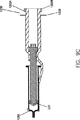
本発明のフロントローディング型注入器システム(5)の一実施例を図1A及び図1に示している。注入器システム(5)は、特にMRI処置に用いられるように作られており、電動注入器(10)と、食塩水注入用シリンジ(20)と、アダプター(100)とを含んでいる。本発明の使用に適した注入器(10)の一例として、ペンシルベニア州インディアノーラのメドラッド社が市販しているSPECTRIS(登録商標)を挙げることができる。しかしながら、本発明は、コンピュータによる放射線断層写真、超音波診断及び血管撮影に用いられる注入器及び注入ポンプなどの流体運搬システムにも用いることができる。図1Bに最も良く示されるように、注入器(10)のハウジング(30)の内部には、食塩水用シリンジ(20)のシリンジプランジャー(50)と協同作用して、食塩水をシリンジ(20)の内部から患者に注入するための第1駆動部材を具えることが望ましい。
【0021】
図1Bに示されるように、注入器(10)はまた、アダプター(100)と、造影剤(contrast medium)などの流体が入れられたシリンジ(200)のシリンジプランジャーの延長ロッド(220)(例えば図2A参照)と協同作用して、流体をシリンジ(200)内部から患者に注入するための第2駆動部材すなわちピストン(40')を含んでいる。
【0022】
本発明の注入システム(5)及び他の実施例の説明において、「軸方向の(axial)」又は「軸方向に(axially)」なる用語を用いるが、これは、例えば、アダプター(100)の軸線A(アダプターはこの軸線に対称でなくてもよい)、又は食塩水用シリンジ(20)の軸線B(シリンジはこの軸線に対称でなくてもよい)を意味するものとする。「基部の(proximal)」又は「後方の(rearward)」なる用語は、シリンジ(20)とアダプター(100)が取り付けられた端部と反対側の注入器ハウジング(30)の端部に対して軸方向又は長手方向を意味する。「先端の(distal)」又は「前方の(forward)」なる用語は、シリンジ(20)又はシリンジ(200)のシリンジ先端(20)に対して軸方向又は長手方向を意味する。「径方向の(radial)」なる用語は、軸線A又は軸線Bの如き軸線に直角の方向を意味する。
【0023】
食塩水用シリンジ(20)とアダプター(100)は、米国特許第5383858号に記載されているように、注入器(10)へ取外し可能に接続されることが望ましい。その場合、フロントローディング型注入器(10)は、第1開口(62)が形成された前壁(60)を含むことが望ましい。ピストン(40)は、注入器(10)の中で往復動可能に配備され、開口(62)の中を通ることができる。ピストン(40)はピストンフランジ又はヘッド(44)を含むことが望ましい。受入用スロット(66a)(66b)は、開口(62)の周りにて互いに対向して配置されることが望ましい。受入用フランジ(68a)(68b)は、受入用スロット(66a)(66b)の間で対向し、開口(62)に内向きに進入するように配置されることが望ましい。
【0024】
食塩水用シリンジ(20)の後端部は、注入器(10)の前壁(60)の所望位置に食塩水用シリンジ(20)を取り付けるための機構として、例えば一対の取付フランジ(22a)(22b)のように着脱容易な取付機構(mounting mechanism)を含むことが望ましい。フランジ(22b)は図示されていないが、フランジ(22a)とほぼ同一で、フランジ(22a)に対向して配置されている。取付フランジ(22a)(22b)には、戻り止め、バーコード、突起又はノッチ(24a)などの表示手段を含めることができる。これらは、例えば、用いられる食塩水用シリンジ(20)の種類に関する情報を注入器(10)に提供する。これに対応して、注入器(10)は、ノッチ(24a)からの情報を読み取るための適当な手段(図示せず)を含むことが望ましい。
【0025】
シリンジ(20)を注入器(10)に取り付けるために、シリンジ(20)の後端を、注入器開口(62)へ挿入し、取付フランジ(22a)(22b)を夫々の受入用スロット(66a)(66b)に挿入する。このとき、プランジャー(40)の位置がシリンジ(20)の後端部になく、ピストンフランジ(44)が捕獲部材(54)(米国特許第5383858号に記載)に係合していない場合、ピストン(40)は、注入器(10)の作動により、ピストンフランジ(44)が捕獲部材(54)にキャッチされる位置にまで前方へ進められる。
【0026】
一旦、取付フランジ(22a)(22b)が夫々受入用スロット(66a)(66b)の中へ挿入され、ピストン(40)が捕獲部材(54)にキャッチされる位置に達すると、操作者は、シリンジ(20)を約90度回転させると、取付フランジ(22a)(22b)は後方へ移動して、夫々の受入用フランジ(68a)(68b)と係合し、ピストンフランジ(44)は、例えばL字状捕獲部材(54)によって保持される位置に回転する。シリンジ(20)が90度以上回転しないようにするため、注入器(10)には、例えば、保持スロット(68a)(68b)の少なくとも1つから突出するストッパ機構(図示せず)を含めることもできる。接続が完了したことを操作者に告知するために、例えば、シリンジ(20)と注入器(10)に対して協同作用する部材を介して、触覚、視覚又は聴覚により操作者へフィードバックすることもできる。シリンジ(20)が注入器(10)に装着された後、ピストン(40)を前方へ進めると、プランジャー(50)は移動する。プランジャー(50)はシリンジ(20)内を前進し、これにより、シリンジ(20)内の食塩水はシリンジ首部(26)から流体経路へ押し出され、患者へ送られる。ピストン(40)を後方へ引き込めると、プランジャー(50)はシリンジ(20)内を後方に移動し、これにより、流体はシリンジ(20)に引き込められる。
【0027】
シリンジ(20)を注入器(10)に装着するために、アダプター(100)は、前述した要領にて注入器(10)へ取り付けることが望ましい。その場合、アダプター(100)の後部は、注入器(10)の前壁(60)の所望位置にアダプター(100)を取り付けるための機構として、例えば一対の取付フランジ(102a)(102b)(図2A参照)のように着脱容易な取付機構を含むことが望ましい。取付フランジ(102a)(102b)には、戻り止め又はノッチ(104a)(104b)などの表示手段を含めることができる。これらは、用いられるアダプター及び/又は食塩水用シリンジ(20)の種類に関する情報を注入器(10)に提供する。これに対応して、注入器(10)は、ノッチ(104a)(104b)からの情報を読み取るための適当な手段(図示せず)を含むことが望ましい。
【0028】
アダプター(100)を注入器(10)に取り付けるために、アダプター(100)の後端を、注入器開口(62')へ挿入し、取付フランジ(102a)(102b)を夫々の受入用スロット(66a')(66b')に挿入する。取付フランジ(102a)(102b)が夫々受入用スロット(66a')(66b')の中へ挿入された後、操作者は、アダプター(100)、又はアダプター(100)/シリンジ(200)の組合せを約90度回転させると、取付フランジ(102a)(102b)は後方へ移動して、夫々の受入用フランジ(68a')(68b')と係合する。アダプター(100)が90度以上回転しないようにするため、前述したように、例えば保持スロット(68a')(68b')の少なくとも1つから突出するストッパ機構(図示せず)を含めることもできる。接続が完了したことを操作者に告知するために、例えば、アダプター(100)と注入器(10)に対して協同作用する部材を介して、触覚、視覚又は聴覚により操作者へフィードバックすることもできる。とりわけ、接続を確かなものとするために、例えばドリップフランジ(106)を、アダプター(100)の後部に形成することもできる。操作者に対して、アダプター(100)の注入器(10)に対する配置/接続が適切に行われたことを聴覚及び/又は触覚でフィードバックするために、ドリップフランジ(106)には、例えば、開口(62')の面内の凹部(図示せず)に嵌まる隆起部材つまり戻り止め(108)(例えば図2A参照)を含めることができる。
【0029】
アダプター(100)が注入器(10)に取り付けられた後、ピストン(40')を前方へ進めると、シリンジ(200)のプランジャー延長部(220)は駆動され、シリンジプランジャー(225)(図2E参照)はシリンジ胴部(210)の中を前進し、これにより、シリンジ(200)内の造影剤はシリンジ首部(250)から流体経路へ押し出され、患者へ送られる。
【0030】
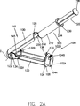
アダプター(100)については、図2A乃至図2Eにさらにその詳細が示されている。アダプター(100)の実施例において、シリンジ(200)をアダプター(100)のキャリア(110)に装填するのに、「ブレーク」作用("break" action)が用いられる。その場合、キャリヤー(110)は、第1の部分(120)と第2の部分(130)を含んでいる。第1部分(120)は、支持アーム(132a)(132b)によって第2部分(130)へ回動可能に取り付けられる。各アームの内部には孔(134)がある。第1部分(120)は、両側に略円筒形のタブ(122)(122)を含んでいる。タブは孔(134)のにスナップ式に嵌まり、望ましくはアダプター(100)の軸線Aと略直交する向きの軸線C(例えば図2D参照)の周りにて、第1部分(120)は第2部分(130)に回動可能に取り付けられる。
【0031】
図2Aに示されるアダプター(100)は、開位置の状態であり、シリンジ(200)をヒンジ機構の後部位置から受入れ可能な状態にある。この実施例では、シリンジ(200)は、略円筒形の本体又は胴部(210)を具えており、該本体には、造影剤、食塩水又は治療用薬剤などの流体が入れられている。これらの流体は、シリンジ(200)をアダプター(100)に装填する前に、シリンジ(200)の中へ入れておくことが望ましい。流体は、例えば、製造業者によりシリンジ(200)の中へ予め収容されているか、又は、注入器から離れたところで手操作で収容することができる。シリンジ(200)は、胴部(210)内部に摺動可能に配備されたプランジャー(225)をさらに含んでおり、これは食塩水用シリンジ(20)のプランジャー(50)と同様なものである。シリンジ(200)のプランジャー(225)は、プランジャーの延長ロッド(220)に連結される。連結は例えば螺合により行われる。シリンジ(200)は、胴部(210)の後端部にフランジ(230)をさらに含んでいる。胴部(210)の前端部には、略円錐台形又は円錐形の移行部(240)がある。この領域により、胴部(210)と、造影剤を注入するテーパ状首部(250)は繋がっている。テーパ状首部(250)は、例えば、当該分野で既知のの流体経路(例えば、可撓性チューブ)に接続するために、端部にルアー接続部を含むことができる。
【0032】
多くの場合、例えばMRI処置で使用されるシリンジ(200)には、製造業者により造影剤が予め充填されている。そのようなシリンジ(200)の多くは、手操作で患者への注入が行なわれるように作られている。ここでは、操作者は、プランジャーの延長ロッド(220)の後端部(228)を手操作で押圧することにより、プランジャーロッド(220)を前進させる(それにより、シリンジ(200)内のプランジャー(225)を前進させる)。シリンジ胴部(210)とフランジ(230)は、例えば、ガラスやプラスチックから作ることができる。プランジャーの延長ロッド(220)は、一般的には、プラスチック材料で作られる。
【0033】
図2A及び2Bに示されるように、シリンジ(200)をキャリヤー(110)へ装填するために、シリンジ(200)を、アダプター(100)の第1部分(120)の前端部に形成された略円筒形の通路(140)と略同一線上になるように配置する。シリンジ(200)を、シリンジフランジ(230)が第1部分(120)の内部で径方向内向きに延びる肩部(150)(図2E参照)と接触するまで、通路(140)の中を前方に向けて摺動させる。肩部(150)は、シリンジフランジ(230)と協働作用して、シリンジ(200)をアダプター(100)の内部で保持すると共に、注入処置中、ピストン(40')からプランジャーの延長ロッド(220)へ加えられる前向きの力に抵抗する力をもたらす。
【0034】
図2Eに最も良く示されるように、肩部(150)の内側部には、後方に延びる隆起部(154)を含むことが望ましい。隆起部(154)は、シリンジフランジ(230)のシリンジ胴部(230)への移行部近傍でのみフランジ(230)に接触する。隆起部(154)とシリンジフランジ(230)が胴部(210)の近傍で接触すると、フランジ(230)の張出し部に及ぼす力を最小にすることができる。例えば、ガラス製シリンジ(200)の場合、シリンジフランジ(230)の外側端部又はその近傍で肩部(150)と接触すると、フランジ(230)が破損する虞れがある。しかし、内側部又はその近傍においてシリンジのフランジ(230)と接触するレバーアームの長さが短いと、シリンジフランジ(230)に作用する力は小さくなり、破損が防止される。破損の虞れをさらに少なくするために、隆起部(154)を、アダプター(100)の残部と異なる材料、例えば、エラストマー材料のような弾性材料で作ることができる。
【0035】
シリンジ(200)が予め充填されている場合、操作者は、造影剤をシリンジ(200)に装填するためにシリンジ(200)のプランジャーを引っ込める必要がない。従って、米国特許第5520653号に記載されたアダプターでは、プランジャー(225)を引っ込めるためにプランジャーの延長ロッド(220)へフォロワー機構を取り付けているが、本発明のアダプターでは、そのようなフォロワー機構は必要でない。ピストン(40')は、プランジャーの延長ロッド(220)の後部面(228)に接触するまで、前進させるだけでよい。ピストン(40')を更に前へ移動させると、シリンジ(200)のプランジャーが前進し、造影剤がシリンジ(200)で加圧される。プランジャーを延長してキャリヤー機構を取り除くと、構造が簡素化されるため、例えば米国特許第5520653号のアダプターと比べて、製造コストが低減される。なお、本発明のアダプターは、プランジャーを引っ込めるために、プランジャーの延長ロッド(220)に接続するフォロワー機構を具えた構成にすることも容易にできる。
【0036】
図2C乃至図2Eは、第1部分(120)と第2部分(130)が閉位置にあるときのアダプター(100)内部のシリンジ(200)を示している。アダプター(100)は、注入器(100)の操作中、第1部分(120)及び第2部分(130)を閉位置に保持するのを補助する機構を含むことが望ましい。第2部分(130)は、例えば、スナップラッチ機構(snap latching mechanism)を作り出すために、第1部分(120)の後端部の凹部(128)に当接して協働作用する肩部(138)を有するラッチタブ(136)を含んでいる。第1部分(120)及び第2部分(130)を閉位置に維持するために、その他多くの閉じる機構を使用できることは、当該分野の専門家であれば明らかであろう。
【0037】
第1部分(120)と第2部分(130)によって閉じたキャリヤー(110)が形成されると、プランジャーの延長ロッド(220)の動きは制限され、軸線Aとの整列状態を維持するように機能する。これにより、プランジャーの延長ロッド(220)は、例えばピストン(40')との滑落が防止され、プランジャーの延長ロッド(220)の変形が防止され、プランジャーの延長ロッド(220)の偏りが防止される。プランジャーの延長ロッド(220)に撓み、偏り又は変形があると、例えば、プランジャー(225)の後部に流体の漏れを生じたり、シリンジ(200)の破損を生じる虞れがある。許容誤差(tolerances)をさらに小さく維持するために、第1部分(120)と第2部分(130)の一方又は両方に、径方向内向きに突出するガイドを形成することができる。シリンジの延長ロッド(220)が見える窓部を形成するために、第1部分(120)と第2部分(130)の一方又は両方について、その一部分を切り取ることができる。同様に、第1部分(120)及び第2部分(130)の一方又は両方の一部又は全体を透明にすることもできる。
【0038】
第1部分(120)及び第2部分(130)の一方又は両方は、キャリヤー(110)内でのシリンジ(200)の回転を防止するためのアバットメント部材を含むことが望ましい。例えば、シリンジ(200)を流体通過チューブに接続した後、シリンジ(200)の回転を防止することは望ましい。シリンジの回転を防止することにより、例えばシリンジ(200)における内容物の量の段階的変化を観察する場合、シリンジ(200)を適当な向きに維持することもできる。シリンジ(200)の回転を防止するために、第1部分(120)の1又は2以上の側面を、例えば、シリンジフランジ(230)の平らな部分(234)に適合するように平らな形状にすることもできる。
【0039】
図2B乃至図2Eに示されるように、シリンジ(200)の主要部は、通路(140)を通って前方へ延びているから、操作者は、シリンジ胴部(210)をはっきり見ることができる。このため、例えば、シリンジ(200)内の造影剤の残量を目視で知ることができるだけでなく、シリンジ上に印刷された文字を容易に読み取ることができる。このようにシリンジ(200)が見える構成であるので、操作者は、注入処置の開始前にシリンジ(200)内に空気が存在するかどうかを、容易に知ることもできる。さらにまた、操作者は、動作中のプランジャー(225)を見ることにより、注入が行われていることを再確認することができる。シリンジ(200)の一部分がキャリヤー(110)を越えて延びており、操作者はシリンジ(200)を容易に掴むことができるので、例えば流体経路とシリンジ首部(250)との着脱を容易に行なうことができる。
【0040】
例えば図2A乃至2Cに示すように、ヒンジ機構の回転軸C(即ち、図2Aの実施例における略円筒形タブ(122)の半径中心を通る軸)の位置は、ピストン(40')の前進中、キャリヤー(110)の受ける力がキャリヤー(100)を閉位置に付勢するか又は維持するように設定されることが望ましい。円筒形タブ(122)の軸心は、例えば、キャリヤー(110)の中心線又は長軸よりも上に位置することが望ましい。この軸位置のとき、肩部(150)に加えられる前向きの力は、第1部分(120)を、第2部分に関してラッチ止めされた閉位置に維持するトルクが生じるように作用する。
【0041】
注入処置が完了した後、操作者が、アダプター、又はアダプター/シリンジの組合せ物を掴んで、それを装着前の方向へ90度回転させて戻すと、取付用フランジ(102a)(102b)は夫々の受入用フランジ(68a)(68b)から取り外される。アダプター/シリンジの組合せ物は次に注入器(10)から取り外すことができる。
【0042】
シリンジ(200)は、肩部(150)に当接してキャリヤー(110)内で保持されるので、キャリヤー(110)を用いて、多くの異なる形状のシリンジ(200)を収容することができる。このように、アダプター(100)は、広範囲に亘って現在入手可能なシリンジ(200)に使用することができる。
【0043】
図3A乃至図3Eは、シリンジ(200)と共に使用されるアダプター(300)の他の実施例を示している。アダプター(300)の後部は、アダプター(100)のものと略同じであり、前述したように注入器(10)へ着脱可能に取り付けられる。アダプター(100)は、その内部でシリンジ(200)を保持し、シリンジフランジ(230)によるプランジャーの延長ロッド(220)への前向きの力に抵抗する力をもたらすのに対し、アダプター(300)はそれとは異なり、その内部でシリンジ(200)を保持するが、プランジャーの延長ロッド(220)への前向きの力に抵抗する力は、シリンジフランジ(230)を当接又は保持することによるのではなく、シリンジ(200)の移行部(240)の前向面に当接することによってもたらされる。
【0044】
アダプター(200)の場合と同様、アダプター(300)のキャリヤー(310)にシリンジ(200)を装填するのに、回動(hinging)つまり「ブレーク」作用が用いられる。そこで、キャリヤー(310)は、第1部分(320)と第2部分(330)を含んでいる。第1部分(320)は、各々の内部に孔(334)を有する支持アーム(332a)(332b)により、第2部分(330)に回動可能又は回転可能に取り付けられている。第1部分(320)は、両側に略円筒形のタブ(322)を含んでおり、該タブは通路(334)の中に嵌まり、第1部分(320)を第2部分(330)に回動可能に取り付ける。第1部分(320)は、タブ(322)の半径中心を通ってアダプター(300)の長軸Aと略直交する軸線Cの周りを回転する。
【0045】
図3Aは、アダプター(300)が開位置の状態にあり、シリンジ(200)を受入れ可能な状態にある。図3A及び図3Bにて示されるように、アダプター(300)の第1部分(320)に形成された略円筒形の通路(340)と略同一線上にシリンジ(200)を配置することにより、シリンジ(200)はキャリヤー(310)の中へ装填される。シリンジ(200)を、その前向面が、第1部分(310)の前部(342)の前端部で径方向内向きに延びる肩部(350)(図3E参照)と接触するまで、通路(340)の中を前方に向けて摺動する。肩部(350)は、シリンジの移行部の前部又は円錐部(240)と協働作用して、シリンジ(200)をアダプター(300)の内部で保持すると共に、注入処置中、ピストン(40')からプランジャーの延長ロッド(220)へ加えられる前向きの力に抵抗する力をもたらす。図3Eの詳細部Dに示されるように、肩部(350)は、胴部(110)の側壁から移行部(240)へ移行する部分の近傍にてシリンジ(200)に接触し、この領域における構造強度を高める利点がある。肩部(350)の接触領域は、エネルギーを吸収しシリンジ(200)の破損可能性を少なくするために、弾性又はそれに相当する材料(例えば、エラストマー材料)で作られる。
【0046】
シリンジ(200)は、アダプター(300)を注入器(10)に連結する前にアダプター(300)に挿入してもよい。或いはまた、シリンジ(200)は、アダプター(300)が注入器(10)に装着された状態でアダプター(300)に装填してもよい。実際のところ、アダプター(300)は、様々なシリンジを用いて異なる多くの注入工程を行なう間、注入器(10)に取り付けられた侭であってよい。
【0047】
前部(342)は、操作者からシリンジ胴部(210)がはっきりと見えるように、1又は2以上の開口領域又は窓部(344)を含むことが望ましい。前部(342)の全部又は一部は、シリンジの胴部(210)をより見やすくするために透明とすることもできる。開口領域(344)はまた、例えば、流体経路とシリンジ首部(250)との連結又は取外しを行なう際、操作者がシリンジ(200)を握り易くする。アダプター(100)について説明したように、第1部分(320)と第2部分(330)の一方又は両方は、キャリヤー(310)内でのシリンジ(200)の回転を防止するためのアバットメント部材を含むこともできる。例えば、第1部分(320)の側面は、シリンジ(200)の回転を防止するためにシリンジフランジ(230)の平らな部分(234)に適合する平らな側面とすることもできる。キャリヤー(310)と部分(234)をそのような平らな形状にすることにより、開口領域(344)を有するシリンジ胴部(210)を確実に所望の方向にすることができる。例えば、2つの開口領域(344)を対向して設けることができる(即ち、前部(342)のところに約180度離れて配置される)。本実施例におけるキャリヤー(310)の平らな面と、平らなシリンジフランジ部(234)とが協同作用すると、キャリヤー(310)におけるシリンジ(200)の装着は、軸方向に回転した2つの方向つまり180度離れた方向だけしかできなくなるので好ましい。
【0048】
なお、上記の如く、許容誤差を小さく維持してプランジャー延長ロッド(220)の偏りを防止するために、第1部分(120)及び第2部分(130)の一方又は両方に、径方向内向きに突出するガイド(360)を1又は複数設けることもできる。どの方向に対しても偏りを制限又は防止するために、第1部分(120)及び/又は第2部分(130)の周りに複数(例えば3つ)のガイド(360)を設けることができる。
【0049】
(径方向に)大きく不揃いな形のシリンジのフランジ(230)を収容するために、キャリヤー(310)のシリンジフランジ(230)の領域内には、開口領域(図示せず)を設けることもできる。この開口領域は、前端部からシリンジフランジまでの長さが異なるシリンジを収容するために、長手方向に延びることが望ましい。一般的に、本発明のアダプターは、長さや直径などが広範囲に亘って異なるシリンジに適した収容能力を具えていることが望ましい。
【0050】
注入器の重要な機能として、シリンジ内への送達に利用される流体の実際の量を監視及び報告することがある。この機能により、例えば、像作成工程に十分な流体が存在するかどうか、又は、流体を追加すべきかどうかを、速やかに決定することが可能となる。患者へ送達された流体の累積量を監視することは、患者へ投与量が所定量を超えてはならない場合に望ましい。注入器で送達された流体の量は、一般的には1.0ml単位で表示される。また、表示よりも高解像度で注入器による追跡が行われる。注入器は、流体量の正確な表示と送達が行われるように、種類と寸法の異なるシリンジを検出し区別できることが望ましい。
【0051】
そのような流体量の管理を行なうには、アダプター又はシリンジの注入器への取付けは、既知の如く、識別できる情報が制御系に提供されるように行われなければならない。識別は、注入器のセンサによって検出されるアダプター又はシリンジにおけるコード化内容によって行われるから、各アダプター及び/又はシリンジは、そのシリンジに固有のコード及び流体量のパラメータによって知ることができる。非電動式で手動注入用のシリンジ(200)が電動注入器(10)に装着される場合でも、適当な識別情報が提供されることが望ましい。これは、最初にシリンジ(200)をアダプター(100)又は(300)の中へ収容することによって達成され、注入器(10)への取付けを容易にして、例えばノッチ(104a)(104b)の位置がエンコードされた固有のコードを含んでいる。この様に、多くの異なる種類及び寸法のシリンジ(200)及び/又はアダプターを収容することができる。
【0052】
シリンジ(200)は同じ様な形状であることが多いから、同じアダプターを用いて2種類以上のシリンジ(200)に適用すると、注入器(10)を誤認する虞れがあり、異なる流体を誤って送達することがあり得る。特定の注入器に対してあらゆる手動シリンジを収容するのに必要なアダプターの数を最小限にすることは望ましいけれども、個々の機能を達成するには、これらのシリンジは、アダプター毎にシリンジを2本以上取り付ける必要性を生ずる。有効内径は同じでも、ストローク長さが異なるシリンジは、アダプター又は注入器(10)のどちらの場合にも、その最も前方の面(即ち、円錐状又は移行部)により、同等のものとして扱われる。もしシリンジ(200)が、有効直径は同じであるが、アダプターの注入器(10)の後フランジ(230)の長さだけ異なる場合、注入器(10)は、シリンジ(200)がどこにあるかと決定することができず、利用される造影剤の量を正確に決定/報告することができない。従って、アダプター(100)の実施例の後フランジ(230)による手動シリンジ(200)の取付けは、シリンジの直径と長さの組合せ毎に1つのアダプターを用いることが望ましいが、アダプターの数は、アダプター(300)の実施例のような前方取付け式を用いる場合に必要とされるアダプターの数よりも多くなる。アダプターの組合せが多いと、操作者の使い勝手は悪くなり、注入器(10)の論理的及び感知能力はより高いものが要求される。最適な手法は、特定の注入器に対して、あらゆる手動シリンジを収容できる単一のアダプターを使用することであろう。この目標に近づくには、アダプター(300)につてい説明したように、注入器(10)がシリンジ(200)の前端部の位置を決定できるように、シリンジ(200)の前端部を保持/当接させることが望ましい。シリンジ(200)の前端部を装填することは、シリンジの面積が増して強度が向上し、シリンジの破損防止に役立つので望ましい。
【0053】
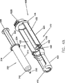
図4A乃至図4Cは、シリンジ(200)に用いられるアダプター(400)の他の実施例を示している。アダプター(400)の後部は、アダプター(100)(300)のものと略同じであり、上記の如く注入器(10)へ着脱可能に取り付けられる。シリンジ(200)を回動作用によって収容するアダプター(100)(300)とは異なり、シリンジ(400)は、開口を有するキャリア(410)を含んでいる。しかしながら、アダプター(300)と同様、シリンジ(200)はアダプター(400)の内部に収容され、シリンジ(200)前方の移行部つまり円錐状部(240)と接することにより、プランジャー延長ロッド(220)に加えられた前向きの力に抵抗する力がもたらされる。
【0054】
図4A及び図4Bに示されるように、シリンジ(200)は、上方から入れることによってアダプター(400)へ簡単に装填することができる。アダプター(400)は、シリンジフランジ(230)を載せる(支持する)第1の後部(420)を含むことが望ましい。望ましくは、第1部分(420)は略平らな側壁(422)を有しており、これはシリンジフランジの(230)の略平らな部位(234)と協働作用して、シリンジ(200)がアダプター(400)の内部で回転するのを制限し、実質的にその回転を防止する。第1部分(420)の側壁(422)は、シリンジ(200)とアダプター(400)のほぼ共通な軸線を越えて上向きに延びており、シリンジ(200)の支持を補助することができる。
【0055】
アダプター(400)は、シリンジ胴部(210)を載せる(支持する)第2の前部(430)をさらに含んでいる。第2部分(430)は径方向内向きに延びる肩部(450)を含むことが望ましい。これは、シリンジ(200)の円錐状つまり移行部(340)に当たって、シリンジ(200)をアダプター(400)の内部で保持し、ピストン(40')からプランジャ延長ロッド(220)に加えられた前向きの力に抵抗する力を与える。肩部(450)を含む第2部分(430)は、その上面が開口しているけれども、第2部分(430)及び肩部(450)の略円筒形の壁は、シリンジ(200)及びアダプター(400)のほぼ共通な軸線を越えて上向きに延びており、プランジャー延長ロッド(220)からの前向きの力に抵抗し、シリンジ(200)が、アダプター(400)との共通軸線上の位置からずれないようにしている。
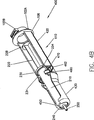
【0056】
前述したように、アダプター(400)の利点として、肩部(450)により、シリンジ(200)の前方に当たることが挙げられる。さらに、アダプター(400)はその軸方向の長さの全体に亘って開口しているから、シリンジ(200)の挿入と取外しを容易に行える。例えば、流体経路(図4A乃至図4Cには図示されていない)に接続された状態でも、シリンジ(200)をアダプター(400)から容易に取り外すことができる。しかしながら、場合によっては、更なる安定性を提供するべく、移行部(240)の前向面に接触させるための肩部(450)を移行部(240)の周囲全体に形成することが望ましい。その場合、キャリヤー(410)の最先端部は閉じており、流体経路はシリンジ(200)をアダプターキャリヤー(410)から取り外す前に連結解除されていることが望ましい。
【0057】
アダプター(400)は、シリンジ(200)を適当な位置関係に保持し、及び/又は安定させる作用を有する少なくとも1つの保持部材(460)をさらに含むことが望ましい。保持部材(460)は、キャリヤー(410)にある略円筒形の通路(470)の中で摺動可能に保持される。保持部材(460)は、図4A及び図4Bにおいて、開位置つまり係合されていない位置の状態が示されている。シリンジ(200)を保持するには、保持部材(450)を閉位置つまり係合された位置にする。この場合、操作者はつば付きタブ(462)に力を加え、通路(470)内で、保持部材(450)を図4Cに示す閉位置まで回転させればよい。図4Dに示す他の実施例において、回転可能な保持部材(460)は、回転させると中央で接する2つの部分(460')(460'')に分割されている。
【0058】
シリンジ(200)を保持し、及び又は安定させるための他の保持/安定部材又は機構が、図4E乃至図4Iに示されている。図4Eでは、摺動保持部材(460a)は、キャリヤー(410)の第2の前部(430)の上及び/又は周りに配置されている。保持部材(460a)は第2部分(430)の最先端部に配置されることが望ましく、シリンジのキャリヤー(410)への装填を容易に行なうことができる。保持部材(460a)は、前方の肩部(480)と後方の肩部(482)と接して第2部分に保持される。シリンジ(200)を載置した後、望ましくは、保持部材(450a)を第2部分の所望位置へ摺動させる。保持部材(460a)を第2部分(430)の最後方の位置に配置すると、安定性は最大になる。安定性を最大にするために、保持部材(460a)は、シリンジ胴部(210)の形状とほぼ一致させることが望ましい。取り付けられた流体経路要素を取り外すことなく、シリンジ(200)をキャリヤー(410)から容易に取り外すことができるようにするため、保持部材(460a)は、頂部に開口部(462a)を形成することができる。
【0059】
図4Fは、摺動可能な保持部材(460b)の他の実施例を示している。保持部材(460b)は、ドリップフランジ(106)と肩部(484)との間にて、キャリヤー(410)の第1部分(420)に摺動可能に保持される。シリンジ(200)の装填を容易にするには、保持部材(450b)をドリップフランジ(106)近傍に配置すればよい。シリンジ(200)の装填後、保持手段(460b)を所望位置までスライドさせる。保持部材(460b)に開口(図示せず)を形成することにより、取り付けられた流体経路要素を取り外すことなく、シリンジ(200)をキャリヤー(410)から容易に取り外すことができる。
【0060】
図4Gの実施例では、保持機構は、延出した2つの保持部材(460c')(460c'')を含んでおり、それらはシリンジ(200)をキャリヤー(410)に装填する際にシリンジ胴部(210)の周りにスナップ式に嵌まる。
【0061】
上記のように、複数の保持/安定部材を、キャリヤー(410)の長さに沿って設けることは、シリンジ胴部(210)とプランジャー延長ロッド(420)をキャリヤー(410)内の適所に保持/安定させるのに有用である。そのような保持部材の開閉操作は、例えば共通のタブを介して、個々に又は一緒に行なうことができる。
【0062】
或いはまた、保持/安定部材の安定性を高めるために、保持/安定部材の軸方向長さを長くすることもできる。例えば、図4Hを参照すると、第1部分(420)に回動可能に取り付けられた保持部材(460d)は、閉位置の状態では、第1部分(420)の全長と第2部分(430)の一部に沿って延びている。前記保持部材に代えて又はそれに加えて、同様な保持部材を、第2部分(430)に回動可能に取り付けることができる。これら保持部材は、回動させる代わりに、キャリヤー(410)に形成された通路又は溝の中で回転させることもできる。
【0063】
幅の広い回転保持部材(460e)の実施例が図4Iに示されている。保持部材(460e)は第2部分(430)に回転可能に取り付けられ(キャリヤー(410)の軸心の周りにて)、第2部分(430)のほぼ全長に沿って延びている。シリンジ(200)が上方からキャリヤー(420)へ装填された後、保持部材(460e)を回転させると、第2部分(430)に覆いが形成される。シリンジ(200)が見えるようにするため、保持部材(460d)(460e)は、透明にしてもよいし、切取り部を形成することもできる。
【0064】
本発明のアダプターは、1回又は2回以上使用した後、廃棄できるように製造することが望ましい場合がある。このような使い捨て式アダプターは、安価に製造できることが望ましい。図5A及び図5Bにおいて、望ましい使い捨て式アダプター(500)の例を示している。アダプター(500)は、略同一の2つ部材(510a)(510b)を含むことが望ましい。略同一の2つの部材(510a)(510b)からアダプター(500)を作ることにより、製造コストを低減することができる。部材(510a)(510b)は、例えば、スナップ嵌合式(例えば、延長部材(520)とキャッチ部材(530)を介して)に作ることができ、視覚的、聴覚的及び/又は触覚的にフィードバックされ、適切な接続が行われたこと知ることができる。
【0065】
使用に際しては、シリンジ(200)を、部材(510a)又は部材(510b)の一方に載せることが好ましい。次に、他方の部分を適当位置でスナップ式に嵌めると、シリンジ(200)はアダプター(500)の中で取り囲まれる(図5B参照)。組み立てるとき、部材(510a)(510b)は、プランジャーの延長ロッド(220)を収容する後方部と、シリンジ胴部(210)を収容する前方部を形成する。アダプター(500)の後端部又はその近傍で、部材(510a)(510b)は、前述した注入器(10)に対して、アダプター(500)を取外し可能に取り付けることができる第1取付フランジ(502a)と第2取付フランジ(502b)を含む連結部を形成することが望ましい。図5Bに示されるように、アダプター(500)は、シリンジ(200)を保持し及び/又は安定化させるために、シリンジ胴部(210)とプランジャー延長ロッド(220)の両方を取り囲む。シリンジ(200)がアダプター(200)の軸を中心として回転しないようにするため、シリンジフランジ(230)の略平らな部分(234)に当たって相互作用するように、アダプター(500)の側壁は略平らな形状に形成する。
【0066】
プランジャーの延長ロッド(220)又は胴部(210)のどちらか一方を観察することができるように、アダプター(500)には、その一部を切り取って窓部(540)を形成することができる。また、アダプター(500)の一部又は全部を透明にしてもよい。
【0067】
アダプター(500)は、シリンジの移行部(240)と径方向内向きの肩部(550)と接触させることにより、プランジャーの延長ロッド(220)に加えられた前向きの力に抵抗する力をもたらす。本発明のアダプターの他の実施例で説明したように、シリンジの移行部(240)に当たることによって抵抗/保持をもたらすことの利点は、アダプター(500)の場合も同様である。
【0068】
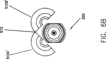
アダプターの他の実施例(500')を図6A乃至図6Cに示している。アダプター(500')は、第1の部分(510a')及び第2の部分(510b')を連結して形成される点以外はアダプター(500)と略同一である。なお、第1の部分(510a')と第2の部分(510b')は、図6A及び図6Bに最も良く示されるように、例えば、当該分野で公知のノッチ付きプラスチック製ヒンジ(512)によって回動可能に繋がれている。
【0069】
図7A乃至図7Cは、本発明のアダプターの他の実施例(600)を示している。アダプター(600)は、前ヒンジ機構により取り付けられた第1部材(610a)と第2部材(610b)を含んでいる。ヒンジ機構は、第1部材(610a)及び第2部材(610b)の一方の延長部材(614)に略円筒形の部材(612)を含むことが望ましく、該円筒形部材は、第1部材(610a)及び第2部材(610b)の他方の延長部材に形成された通路(616)の中に回転可能に載置されることができる。延長部材(614)は、図7Aに示されるように、第1部材(610a)と第2部材(610b)の各部材の前端部の各々の側を前方に延びることが望ましい。
【0070】
第1部材(610a)は、前述の第1保持フランジ(102a)を含んでおり、第2部材(610b)は、前述の注入器(10)にアダプター(600)を接続する第2保持フランジ(102b)を含んでいる。第1部材(610a)は、ドリップフランジ(106a)の2分の1を含むことが望ましく、第2部材(610b)はドリップフランジ(106b)の他方の2分の1を含むことが望ましい。
【0071】
シリンジ(200)をアダプター(600)の中に載せる場合、第1部材(610a)と第2部材(610b)は、ヒンジ機構の軸C'(アダプター(600)の長軸A'と略直交している)を中心に、図A及び図6Bに示される開位置まで回転させることが好ましい。シリンジ(200)の胴部(210)は、次に、アダプター(600)の前端部に形成された開口の中を通過させる。シリンジ(200)は通路(640)の中を前方に向けて進む。そして、フランジ(230)が径方向内向きに延びる肩部(650)に当たると、シリンジ(200)はアダプター(600)の内部で保持され、ピストン(40')によるプランジャー延長ロッド(220)に加えられた前向きの力に抵抗する力がもたらされる。次に、第1部材(610a)と第2部材(610b)を閉位置まで回転させる。アダプター(100)について説明したように、シリンジフランジ(230)が胴部(210)に接続される位置の近くでシリンジフランジ(230)との接触が確実に行われるように、肩部(650)は、(後方に延びる)隆起した当たり部(660)を含めることもできる。肩部(650)に加えられる前向きの力は、図6Cに示される閉位置でアダプター(600)を維持する作用を有する。
【0072】
アダプター(500)(500')と同様に、第1部材(610a)と第2部材(610b)を略同じ形状に形成することができる。それにより、アダプター(600)の製造コストを低減することができる。
【0073】
前述した全ての実施例において、アダプターは、アダプターの後部の取付フランジによって注入器(10)へ装着される。しかしながら、本発明のアダプターは他の方法で注入器(10)へ取り付けることもできる。図8Aに示されるように、例えば、注入器の前壁(700)に、少なくとも1つの取外し可能な面プレート(705)を取り付けることができる。図8Aの注入器は、MRI処置に用いられるように作られており、第1面プレート(705)に取り付けられた第1の造影剤用シリンジ(710)と、第2面プレート(705')に取り付けられた第2の造影剤用シリンジ(720)を含んでいる。
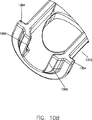
【0074】
図8Bは、図8Aの注入器への取付けに適した面プレート(805)に一体化して形成されるか又は該プレートに取り付けられたキャリヤー(810)を含むアダプター(800)の実施例を示している。シリンジ(200)は、第1の傾斜シリンジ(200)により、シリンジ(200)の胴部を、キャリヤー(810)の閉じこめられた前部(830)の最先端部に開設された通路(840)を通じて、キャリヤー(810)の中へ装填することができる。シリンジ(200)は、シリンジの円錐部(240)が、通路(840)を構成する径方向内向きに延びる肩部(850)に当たるまで前方へ進む。面プレート(805)には、通路(808)が形成されており、プランジャーの延長ロッド(220)と協同作用させるために、図8Aの注入器のピストン(図示せず)を前記通路(805)の中に通すことができる。
【0075】
図8Cは、取外し可能な面プレート(905)に取り付けられたキャリヤー(910)を含むアダプター(900)の実施例を示している。この実施例において、シリンジ(200)は面プレート(902)の通路(908)を通って前方へ進む。シリンジ(200)は、円錐状部(240)がキャリヤー(910)の径方向内向きに延びる肩部(950)に当たるまで前進する。
【0076】
図8Dは、取外し可能な面プレート(1005)に取り付けられたキャリヤー(1010)を含むアダプター(1000)の実施例を示している。この実施例において、シリンジ(200)は、上方からキャリヤー(1010)の中へ入れることによってキャリヤー(1010)の中へ装填される。キャリヤー(1010)の中に搭載されると、シリンジ(200)は、キャリヤー(1010)の径方向内向きに延びる肩部(1050)に当たる。流体経路要素に接続されたときでもシリンジ(200)を容易に取り外すことができるように、キャリヤー(1010)の頂部は、キャリヤー(1010)の長さ部分の上方が開位置の状態に維持される。
【0077】
図8Eは、取外し可能な面プレート(1105)に取り付けられたキャリヤー(1110)を含むアダプター(1100)の実施例を示している。アダプター(1010)と同様、シリンジ(200)は、上方からキャリヤー(1010)の中へ入れることによってキャリヤー(1110)の中へ装填される。キャリヤー(1110)の中に搭載されると、シリンジの移行部(240)は、キャリヤー(1110)の径方向内向きに延びる肩部(1150)に当たる。キャリヤー(1110)は、回動式カバー部(1160)を含んでおり、該カバー部を閉位置まで回転させることにより、シリンジ胴部(210)の少なくとも一部分に対して、カバー/保持体を形成し、シリンジ(200)を保持し及び/又は安定化させる役割を果たす。肩部(1050)を回転可能とすることにより、シリンジ(200)を捕獲し支持することができる。
【0078】
図9A乃至図9Cは、キャリヤー部(1210)、中間部(1220)、及び最後部の接続部(1230)を含むアダプターシステム(1200)の実施例を示している。アダプター(1200)は、押し棒(1240)をさらに含んでいる。シリンジ(200)は、キャリヤー部(1210)へ上方から入れることにより、キャリヤー部(1210)の中に搭載される。円錐部(240)は、キャリヤー部(1210)の肩部(1250)に当たる。プランジャーの延長ロッド(図示せず)を、シリンジプランジャー(225)から取り外す。なお、プランジャーの延長ロッドは、その前端部を螺合させることにより、プランジャー(225)へ接続されることが多い。
【0079】
押し棒(1240)は中間部(1220)の中を通り、プランジャー(225)と協同作用してプランジャー(225)へ力を加える。予め充填されたシリンジの場合、通常、シリンジ(200)の中でプランジャー(225)を後退させる必要はない。押し棒(1240)を後退させる場合、プランジャー(225)を押し棒(1240)へ連結するために、押し棒(1240)の前端部とプランジャー(225)の間を係合(螺合など)させる必要があるが、この実施例ではそのような必要性はない。これは、押し棒(1240)及び注入器の構造と操作を大いに簡素化することができる。
【0080】
アダプターシステム(1200)を操作する場合、押し棒(1240)の後端部に設けた連結用カップリング(1242)を通じて、押し棒(1240)を注入器のピストン(図9A乃至図9Cには示されていない。図1A参照)と接続する。接続部(1230)は、取付用フランジ(1202a)(1202b)及びドリップフランジ(1206)と、前述した注入器との協同作用により、注入器に取外し可能に取り付けられる。シリンジ(200)は、アダプター(1205)を注入器へ接続する前又は後に、接続部(1230)を介して、上方からキャリヤー部(1210)へ装填することができる。押し棒(1240)は、注入器ピストンにより、中間部(1220)を通って前方へ進む。前端部(1244)は、シリンジプランジャー(225)の中を先導し、プランジャー(225)の中の後向き壁部に当たる。もう一度述べるが、例えば、シリンジが予め充填されている場合や、プランジャー(225)をシリンジ(200)の中で後退させる必要がない場合には、押し棒の前端部(1244)とプランジャー(225)の間に、後方へ移動しないようにするための手段を取り付ける必要がない。
押し棒の前端部(1244)は、プランジャー(225)の後向きの内部形状に対応させて作ることが望ましい。このように、押し棒の前端部(1244)は、シリンジ(200)の使用中、プランジャー(225)の形状を維持するためのプランジャー(225)を支持する作用を有する。プランジャー(225)は、その大部分が弾性カバー材料から作られることが多い。プランジャー(225)の側壁とシリンジ胴部(210)の内部側壁との間で適当な密封が行われないと、プランジャー(225)を進める間、プランジャー(225)の後部で漏れが生じる。
【0081】
図10A乃至図10Dは、本発明のアダプターシステム(1300)の他の実施例を示している。アダプターシステム(1200)と同様、アダプター(1300)は、キャリヤー部(1310)、中間部(1320)、及び最後部の接続部(1330)を含んでいる。アダプターシステム(1300)は、押し棒(1240)をさらに含んでいる。シリンジ(200)は、上方からキャリヤー部(1310)へ入れることにより、開口を有するキャリヤー部(1310)に搭載される(そして、取り外すことなく又はどんな取付用チューブを用いることなく着脱を行なうことができる)。前方の移行部つまり円錐状部(240)は、キャリヤー部(1310)の肩部(1350)に当たる。
【0082】
アダプターシステム(1300)の製造コストを最少にするには、例えば、より安価で、より低強度のポリマー材料を用いることもできる。キャリヤー部(1310)と肩部(1350)の上部は、シリンジ(200)を容易に取り外すことができるように開口しているので、押し棒(1340)が前進するとき、シリンジ(200)の円錐状部(240)が肩部(1350)(例えば、肩部(1240)の場合と同様)の底部と接触する場合、接続部(1330)の装填に不均衡が生ずることがある。この場合、接続部(1330)の周りに曲げモーメントが生じ、アダプターシステム(1300)が破損する虞れがある。装填の際、できるだけ不均衡にならないように、肩部(1350)の形状は、装填の際に不均衡が生じないように、例えば、その上部と下部を開口(図10B参照)しておくことが望ましい。シリンジ(200)の円錐状部(240)が載る肩部(1350)の底縁を取り除くと、アダプターシステム(1300)(及びシリンジ(200))の軸を中心として略対称に装填することができ、プランジャーの前進中、横方向の負荷及び曲げモーメントを低減又は実質的になくすことができる。アダプター(1300)の端部に加えられる軸方向の荷重は最大となり、一方、横方向の負荷は最少となる。
【0083】
さらに、図10Bに示されるように、リブ(1354)の如き補強材をキャリヤー部(1310)に追加し、材料強度を高めることにより、壁の可撓性を抑えることもできる。同様に、図12Bに示される延長部(1556)(1558)を、アダプター組立体(1500)(又はアダプター組立体(1300))の前部に一体に形成することができる。シリンジ(200)の円錐状移行部(240)は、延長部(1556)(1558)に接触しないことが望ましい。シリンジ(200)が前向きの力によって肩部(1350)(図12Bには示されていない)に接触すると、シリンジ(200)は楔(wedge)として作用し、肩部(1350)の対向する部分に力を加えることになる。キャリヤー部(1510)の前部の周囲に延長部(1556)(1558)を形成すると、そのような変形を防止するフープ応力が生じる。延長部(1556)(1558)は、前述の如く、シリンジ(200)及び取付チューブを容易に取り外すことができるように、その頂部に十分な間隔をあけることが望ましい。
【0084】
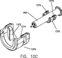
回転保持部材(1360)(図4A乃至図4Cの保持部材(460)に記載したものと略同様に作用する)に加えて又はそれに代えて、アダプターシステム(1300)は、図10C及び図10Dに示された付勢保持部(1370)を含むことが望ましい。図10C及び図10Dの実施例において、保持部材(1370)は、シリンジ(200)に圧力嵌めできるように、キャリヤー部(1310)の内壁から差し込まれた2つの可撓性保持部材(1372)(1374)を含んでおり、これによりシリンジ(200)を適当位置に取り付けることができる。シリンジ(200)がキャリヤー部(1310)を用いて配置されたとき水平位置であるが、注入器のヘッド(図10A乃至10Dには示されていない)がその水平以外の位置に回転させられるたとき、保持部(1370)は、例えば、キャリヤー部(1310)内でシリンジ(200)を保持するのを補助する。例えば、注入器ヘッド(従って、キャリヤー部(1310)も)が仮に垂直方向にある場合、保持部材(1360)が閉位置まで回転する前でも、保持部(1370)により、シリンジのキャリヤー部(1310)からの脱落は防止される。
【0085】
図10Aの実施例において、保持部(1310)は中間部(1320)に移動可能(例えば、回動可能であるが、取外し可能であってもよい)に接続される。例えば、キャリヤー部(1310)を下向きに回転させることにより、シリンジ(200)はキャリヤー部(1310)の前部に接触することなく前方へ引っ張られ、全部又は一部の注入を終えた後、プランジャーを後退させることなくシリンジ(200)を取り外すことができる。
【0086】
図10Aの実施例において、キャリヤー部(1310)はその各側にて、ピンジョイント(図示せず)により中間部(1320)に回動可能に取り付けられる。延長部材(1370)(1372)が中間部(1320)の当たり面(1374)に接触するまでアダプターアッセンブリを閉じるとき、キャリヤー部(1310)はピン位置を中心に回転する。その位置では、中間部(1320)はキャリヤー部(1310)と略同一線上に位置し、キャリヤー部(1310)は、肩部(1350)がシリンジ移行部(240)に当たる位置にある。ロックリング(1380)は延長部材(1370)(1372)に摺動可能に配置されることが望ましい。キャリヤー部(1310)が閉位置まで回転すると、ロックリング(1380)は後方に摺動し、中間部(1320)の前部の下半分に形成されたフランジ(1390)に当たり、キャリヤー部(1310)は閉位置でロックされる。
【0087】
図11は、他の実施例として、アダプターシステム(1300)に非常に似たアダプターシステム(1400)を示している。しかしながら、キャリヤー部(1410)は、中間部(1420)に回動可能に取り付けられていない。この実施例では、押し棒(1440)は、中間部(1420)の前方に配置された可動部(例えば、回動又は回転部(1442))を含んでいる。回動部(1442)は、シリンジ(200)を、アダプターシステム(1400)の軸線からずれて移動(この実施例では回転)させることができるので、全部又は一部の注入を終えた後、注入器の駆動部材を後退させることなくシリンジ(200)を取り除くことができる。
【0088】
図12A及び図12Bは、キャリヤー部(1510)、中間部(1520)、及び前述した接続部(1530)を含むアダプターシステム(1500)を示している。アダプター(1500)は、ワイパーシール(1570)の如きクリーニング又は接触部材と、アダプターの内部でワイパーシール(1570)を位置決めするための保持リング(1580)とを含んでいる。ワイパーシール(1570)は、押し棒(1540)から不要な造影剤(例えば、漏れ及び/又はこぼれにより生じたもの)を取り除くのに用いられる。この例では、押し棒(1540)にうっかり付着してしまった造影剤は、造影剤注入後にピストンを後退させるとき、ワイパーシール(1570)によってふき取られる。さらに、ワイパーシール(1570)は、不要な造影剤が、アダプターシステム(1520)の中間部(1520)へ進入するのを最小限に抑える。保持体(1580)は、キャリヤー部(1510)内での圧力嵌めにより、ワイパーシール(1570)を適当位置で保持することが好ましい。
【0089】
図12Bに最も良く示されるように、押し棒(1540)の後端部に保持フランジ(1590)が当たって、押し棒(1540)が接続部(1330)から脱落しないようにすることが望ましい(なお、押し棒は、図12Bに示されていないが、図13Bの押し棒(1640)を参照することができる)。押し棒(1540)の後端部のフランジは、中間部(1520)の内径よりも僅かに小さな寸法とすることが望ましい。接触部材(1570)と押し棒(1540)との接触、及び押し棒フランジと中間部(1520)の内壁との接触は、アダプター組立体(1500)の内部で押し棒(1540)の適当な位置関係を維持するのを助ける役割を有する。
【0090】
図13A及び図13Bは、キャリヤー部(1610)、中間部(1620)、接続部(1630)及び押し棒(1640)を含むアダプターシステム(1600)を示している。アダプターシステム(1600)は、前方に付勢する後部アバットメント部材(1670)を含んでおり、該部材により、シリンジ(200)は、その長さ如何に拘わらず、キャリヤー部(1610)内で完全に前方へ付勢される。アバットメント部材(1670)は、キャリヤー部(1610)の後部にて摺動可能に配置され、例えば、中間部(1620)内に収容されたバネ(1674)により前方へ付勢されることが望ましい。操作者がシリンジをキャリヤー部(1610)の中へ装填するとき、最初にシリンジ(200)のフランジ(230)をアバットメント部材(1670)に当たるように配置し、バネ(1674)を様々なシリンジ長さに合わせて、必要なだけ押圧する。押し棒(1674)がシリンジプランジャーへ力を加えることができるようにするため、アバットメント部材(1670)には、略中央部を貫く通路(1676)を形成することが好ましい。
【0091】
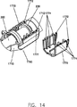
図14は、シリンジ(200)をキャリヤー部(1710)の内部で完全に前方へ付勢するために、アダプターシステム(1700)に適した、前方に付勢する後部アバットメント部材(1770)の他の実施例を示している。アバットメント部材(1770)は、キャリヤー部(1710)の中に摺動可能に配備され、可撓性部材(1772)を含んでいる。この可撓性部材(1772)は、例えば、キャリヤー部(1710)の前向面(1712)に当たり、アバットメント部材(1770)を前方に付勢する。図14のアバットメント部材(1770)は、シリンジ(200)のフランジ(230)を接触させるための内向き突出部(1774)を3組含んでいる。多数の内向き突出部(1774)が設けられるが、これは、様々なシリンジ長さに対応させるためである。シリンジ(200)が適当位置にあるとき、可撓性部材(1772)は面(1712)を押すので、シリンジ(200)は、その長さ如何に拘わらず、キャリヤー部(1710)の内部の最も前方位置に付勢される。
【図面の簡単な説明】
【図1】 図1Aは、MRI処置に用いられる本発明の注入器システムの実施例である。図1Bは、図1Aの注入器システムにおいて、食塩水用シリンジとアダプターが注入器から取り外された状態を示す図である。
【図2】 図2Aは、本発明のアダプターの実施例の開位置における斜視図で、アダプター内にシリンジが装填される前の状態を示している。図2Bは、図2Aのアダプターの開位置における斜視図で、シリンジが装填された状態を示している。図2Cは、図2Aのアダプターの閉位置における斜視図で、シリンジが装填された状態を示している。図2Dは、図2Aのアダプターの閉位置における平面図で、シリンジが装填された状態を示している。図2Eは、図2Aのアダプターの閉位置における側部断面図で、シリンジが装填された状態を示している。
【図3】 図3Aは、本発明のアダプターの他の実施例の開位置における斜視図で、アダプター内にシリンジが装填される前の状態を示している。図3Bは、図3Aのアダプターの開位置における斜視図で、シリンジが装填された状態を示している。図3Cは、図3Aのアダプターの閉位置における斜視図で、シリンジが装填された状態を示している。図3Dは、図3Aのアダプターの閉位置における平面図で、シリンジが装填された状態を示している。図3Eは、図3Aのアダプターの閉位置における側部断面図で、シリンジが装填された状態を示している。
【図4】 図4Aは、本発明のアダプターの他の実施例の斜視図で、アダプター内にシリンジが装填された状態を示している。図4Bは、図4Aのアダプターの斜視図で、シリンジが装填された状態を示している。図4Cは、図4Aのアダプターの斜視図で、シリンジ保持部材が閉位置にあるときの状態を示している。図4Dは、他の実施例のシリンジ保持部材を含むアダプターの斜視図である。図4Eは、他の実施例のシリンジ保持部材を含むアダプターの斜視図である。図4Fは、他の実施例のシリンジ保持部材を含むアダプターの斜視図である。図4Gは、他の実施例のシリンジ保持部材を含むアダプターの斜視図である。図4Hは、他の実施例のシリンジ保持部材を含むアダプターの斜視図である。図4Iは、他の実施例のシリンジ保持部材を含むアダプターの斜視図である。
【図5】 図5Aは、略同一形状の分離した部分を含むアダプターの実施例の斜視図で、前記部分が連結されていない状態を示している。図5Bは、図5Aのアダプターの斜視図で、前記部分が連結された状態を示している。
【図6】 図6Aは、略同一形状の分離した部分がその側壁を介して回動可能に取り付けられたアダプターの他の実施例の斜視図である。図6Bは、図6Aのアダプターの前面図で、開位置にあるときの状態を示している。図6Cは、図6Aのアダプターの斜視図で、閉位置にあるときの状態を示している。
【図7】 図7Aは、互いに略同一形状の部分がその前端部取り付けられたアダプターの他の実施例の斜視図で、開位置にあるときの状態を示している。図7Bは、図7Aのアダプターを示す図で、シリンジが装填された状態を示している。図7Cは、図7Aのアダプターを示す図で、アダプターを注入器へ接続するために、略同一形状の部分が回動して閉じた状態を示している。
【図8】 図8Aは、シリンジ又はアダプターが取り付けられる着脱可能な面プレートを少なくとも1つ有する注入器の一部分の斜視図である。図8Bは、図8Aの注入器に使用されるアダプターの実施例の斜視図である。図8Cは、図8Aの注入器に使用されるアダプターの実施例の斜視図である。図8Dは、図8Aの注入器に使用されるアダプターの実施例の斜視図である。図8Eは、図8Aの注入器に使用されるアダプターの実施例の斜視図である。
【図9】 図9Aは、押し棒がシリンジプランジャーの延長ロッドの機能を実行するアダプターアッセンブリの実施例の斜視図である。図9Bは、図9Aのアダプターアッセンブリの斜視図で、連結されていない状態を示している。図9Cは、図9Aのアダプターアッセンブリの横断面図である。
【図10】 図10Aは、注入処理を終えた後、注入器の駆動部材を後退させることなくシリンジを取り除くことができるように、キャリヤー部が中間部に関して回動するアダプターアッセンブリの実施例の斜視図である。図10Bは、キャリヤー部の前部の拡大斜視図である。図10Cは、アダプターシステムに用いられるシリンジ保持体の実施例の斜視図である。図10Dは、図10Cのシリンジ保持体の前部断面図である。
【図11】 注入処理を終えた後、注入器の駆動部材を後退させることなくシリンジを取り除くことができるように、押し棒が回動するアダプターシステムの斜視図である。
【図12】 図12Aは、注入用流体を押し棒から取り除くための接触又は密封部材を含むアダプターアッセンブリの実施例の斜視図で、アダプターが接続されていない状態を示している。図12Bは、図12Aのアダプターアッセンブリと同様なアダプターアッセンブリの斜視図で、アダプターが接続された状態を示している。
【図13】 図13Aは、シリンジをキャリヤー部内で前進させるための付勢部材を含むアダプターアッセンブリの実施例の斜視図である。図13Bは、図13Aのアダプターアッセンブリの斜視図で、アダプターが接続されていない状態を示している。
【図14】 シリンジをキャリヤー部内で前進させるための付勢部材を含むアダプターアッセンブリの他の実施例の斜視図である。[0001]
FIELD OF THE INVENTION
The present invention relates to an electric injector system and a syringe adapter used in the system.
[0002]
BACKGROUND OF THE INVENTION
Numerous injector syringes and motorized injectors have been developed in medical procedures such as angiography, computerized tomography, ultrasound diagnosis and NMR / MRI. For example, US Pat. No. 4,0067,36 discloses an injector and syringe for injecting fluid into the vasculature of an animal such as a human. Such injectors typically include a drive member such as a piston that connects to a syringe. For example, in the angiography injector and syringe disclosed in US Pat. No. 4,677,980, the injector drive member is detachably attached to the syringe plunger at any position along its transition path. The disclosure of this patent is incorporated herein by reference. A front-loading syringe and syringe system is also disclosed in US Pat. No. 5,383,858, the disclosure of which is incorporated herein by reference.
[0003]
As disclosed in U.S. Pat. No. 5,383,858, a syringe used in a front loading injector includes an attachment mechanism for easily attaching the syringe to the front wall of the injector. However, since this syringe has a structure dedicated to a specific injector, it cannot be used for other types of injectors of the front loading type. This type of syringe includes, for example, a syringe body, a reciprocally arranged plunger, and a plunger extension for transmitting force to the plunger.
[0004]
U.S. Pat. No. 5,520,653 discloses several adapters that allow various syringes to be used in front-loading injectors, which is incorporated herein by reference. One embodiment of the adapter of US Pat. No. 5,520,653 includes a syringe carrier that engages a front end, a rear end, and at least a portion of a syringe flange. And a syringe holding groove disposed between the two. A mounting flange near the rear end of the carrier removably mounts the carrier at a desired location on the front wall of the injector. In the adapter of US Pat. No. 5,520,653, a follower is reciprocally mounted inside the carrier. The front end of the follower engages the plunger extension of the syringe when the syringe is deployed in the carrier. The drive head opening in the carrier communicates with a pair of drive head grooves disposed near the rear end of the follower so that the follower can be detachably attached to a desired position of the drive head of the injector. I have to.
[0005]
U.S. Pat. No. 5,520,653 provides a substantial improvement in the technology, but there is a need for improvements to adapters that can be applied to syringes in order to be able to use various types of syringes in front-loading syringes. Yes.
[0006]
SUMMARY OF THE INVENTION
The present invention provides an adapter for detachably attaching a syringe at a desired position to a front-loading powered injector. The syringe includes a main body and a plunger slidably disposed inside the main body. The injector includes a front wall, an opening formed in the front wall, and a drive member reciprocally disposed within the injector. Desirably, the adapter includes a syringe carrier adapted to carry at least a portion of the syringe. The syringe carrier includes at least one rearward facing abutment member that impinges on at least one forward facing surface of the syringe. The syringe carrier has an opening formed therein that allows the injector drive member to transmit a forward force to the plunger through the abutment member without engaging between the drive member and the plunger. The adapter further comprises a detachable attachment mechanism disposed on the back of the syringe carrier to attach the adapter to a desired location on the front wall of the syringe.
[0007]
The syringe further includes a transition (eg, a generally frustoconical region) attached to the front end of the body and decreasing in radius or width of the syringe. The abutment member hits the front face formed by the transition. The contact between the abutment member and the transition portion is preferably performed only in the vicinity of the transition path from the main body to the substantially frustoconical region (for example, the outer edge of the transition portion).
[0008]
The syringe can further include a syringe flange attached to the rear of the body. The abutment member hits the front surface of the syringe flange. It is desirable that the abutment member hits the syringe flange only in the vicinity of the transition path from the main body to the syringe flange.
[0009]
In one embodiment, the abutment includes a first portion and a second portion, and the first portion and the second portion are rotatable relative to each other about a rotation axis that is substantially orthogonal to the axis of the adapter. The first part and the second part are preferably rotatable around the pivot axis to an open position so that the syringe can be loaded up to the rear of the pivot axis in the adapter. Desirably, the first and second portions are rotatable about a pivot axis to a closed position to form a syringe carrier.
[0010]
In another embodiment, the adapter includes a first portion and a second portion that is substantially the same structure as the first portion. The first portion and the second portion are connectable to form a syringe carrier and a removable attachment mechanism.
[0011]
The present invention also provides an adapter for removably attaching a syringe to a desired position of a power injector. The syringe desirably includes a main body and a plunger slidably disposed within the main body. The injector preferably includes a front wall, an opening formed in the front wall, and a drive member that is reciprocally disposed within the injector. The adapter includes a first part and a second part, the first part and the second part being substantially orthogonal to the axis of the adapter so that the syringe can be loaded up to the back of the pivot shaft in the adapter. The rotating shafts can be rotated around each other to the open position. Desirably, the first and second portions are rotatable about a pivot axis to a closed position so that a syringe carrier can be formed to mount at least a portion of the syringe.
[0012]
The present invention also provides an adapter for removably deploying a syringe at a desired location on an auto-injector. The adapter includes a first portion and a second portion having substantially the same structure as the first portion. The first part and the second part are connectable to form a syringe carrier for mounting at least a portion of the syringe. The first and second portions form a mounting mechanism that is removably disposed at the rear of the syringe carrier for mounting the adapter at a desired location on the front wall of the syringe.
[0013]
Another object of the present invention is an adapter for detachably attaching a syringe to a front loading type electric injector at a desired position, and the syringe is provided at a desired position on the front wall of the injector. And providing an adapter including an attachment mechanism removably disposed at the rear of the adapter. The adapter includes a syringe carrier portion that carries at least a portion of the syringe. As for a syringe carrier part, it is desirable for the upper part to open along the length direction so that a syringe can be loaded from upper direction. During injection, a part of the syringe carrier part touches the transition part of the syringe so that the force exerted on the adapter from the syringe is almost symmetrical with the axis of the adapter, thereby reducing the bending moment to the mounting mechanism. Is done. The syringe carrier portion has an opening at the rear so that the drive member of the injector can transmit a forward force to the syringe plunger. A portion of the syringe carrier portion that hits the transition portion of the syringe includes, for example, a first contact surface disposed on the first side surface of the syringe carrier portion and a second contact surface disposed on the second lateral surface of the carrier portion. be able to.
[0014]
Another object of the present invention is an adapter for detachably attaching a syringe to a front loading type electric injector at a desired position, wherein the syringe includes an intermediate portion, and the push rod passes through the intermediate portion. An adapter is provided that is capable of transmitting force from a drive member of an injector to a plunger. The middle part is to provide an adapter having an attachment mechanism removably disposed at the rear part for mounting the adapter to a desired position on the front wall of the injector. The adapter also includes a syringe carrier portion connected to the intermediate portion. The syringe carrier portion can be mounted with at least a portion of the syringe and has an opening at the rear so that the drive member of the injector can transmit a forward force to the plunger via the push rod.
[0015]
The upper part of the syringe carrier part is preferably open. While the injection is taking place, the front part of the syringe carrier part hits the transition part of the syringe. The syringe carrier portion is movable with respect to the intermediate portion and can move the front without contacting the syringe transition and remove the syringe without retracting the drive member. In one embodiment, for example, the carrier part is pivotally connected to the intermediate part.
[0016]
As described above, another adapter system of the present invention includes an intermediate portion having a detachable attachment mechanism at the rear portion. The adapter system also includes a syringe carrier portion connected to the intermediate portion and capable of carrying at least a portion of the syringe. The syringe carrier portion includes an opening at the rear so that the drive member of the injector can transmit a forward force to the plunger, preferably the opening is formed at the top. While the injection is taking place, the front part of the syringe carrier part hits the transition part of the syringe. The adapter system further includes a push rod that is used to transmit force from the injector drive member to the plunger. The push rod is movable with respect to the rear of the push rod so that the syringe transition can be moved without contacting the front of the syringe and the syringe can be removed from the adapter without retracting the drive member. have. The front part of the push bar is rotatable, rotatable or movable with respect to the rear part of the push bar, for example.
[0017]
Another adapter system of the present invention is configured to attach the adapter to a desired position on the front wall of the above-described injector, and to attach a detachable mounting mechanism to the rear portion of the adapter, and to transmit force from the driving member to the plunger. Includes push bar to make. The adapter system also includes a syringe carrier portion on which at least a portion of the syringe can be mounted. The syringe carrier portion includes an opening in the rear portion through which the push rod passes and can contact the plunger. The adapter system further includes a contact member, preferably disposed on the syringe carrier portion, such that fluid from the syringe does not pass behind the sealing member in contact with the push rod. The contact member can include, for example, a wiper seal.
[0018]
Another object of the present invention is to provide an adapter including a detachable attachment mechanism and a syringe carrier part on which at least a part of the syringe can be mounted. It is desirable that the top of the syringe carrier portion is open so that the syringe can be loaded or removed from above. The syringe carrier portion includes at least one flexible holder so that pressure acts on at least one side of the syringe to hold the syringe within the syringe carrier portion. The syringe carrier portion has an opening at the rear so that the drive member of the injector can transmit a forward force to the plunger.
[0019]
Still another object of the present invention is an adapter for detachably attaching a syringe to a front-loading type electric injector, wherein the detachable attachment mechanism and at least a part of the syringe are mounted. An adapter including a carrier portion is provided. The front contact portion of the syringe carrier portion corresponds to the syringe transition portion. The syringe carrier part includes a biasing member for making contact with the rear surface of the syringe. The biasing member applies a force to the transition portion of the syringe and biases it to the front side contact portion of the syringes of various lengths. The biasing member is biased forward by a spring, for example. The urging member may be urged forward by the rear flexible member.
[0020]
One embodiment of the front loading injector system (5) of the present invention is shown in FIGS. 1A and 1. The injector system (5) is specifically designed for use in MRI procedures and includes a motorized injector (10), a saline injection syringe (20), and an adapter (100). One example of an injector (10) suitable for use with the present invention is SPECTRIS®, which is commercially available from Medrad, Indianola, Pennsylvania. However, the present invention can also be used in fluid delivery systems such as injectors and infusion pumps used for computerized tomography, ultrasound diagnosis and angiography. As best shown in FIG. 1B, the inside of the housing (30) of the injector (10) cooperates with the syringe plunger (50) of the saline syringe (20) to supply the saline to the syringe ( It is desirable to have a first drive member for injecting into the patient from within 20).
[0021]
As shown in FIG. 1B, the injector (10) also includes an adapter (100) and a syringe plunger extension rod (220) of a syringe (200) containing a fluid such as a contrast medium. In cooperation with FIG. 2A, for example, it includes a second drive member or piston (40 ′) for injecting fluid into the patient from within the syringe (200).
[0022]
In the description of the infusion system (5) and other embodiments of the present invention, the terms “axial” or “axially” are used, for example, for the adapter (100). The axis A (the adapter may not be symmetric with respect to this axis) or the axis B of the saline syringe (20) (the syringe does not have to be symmetric with respect to this axis). The terms `` proximal '' or `` rearward '' refer to the end of the syringe housing (30) opposite the end where the syringe (20) and adapter (100) are attached. An axial direction or a longitudinal direction is meant. The term “distal” or “forward” means axial or longitudinal with respect to the syringe tip (20) of the syringe (20) or syringe (200). The term “radial” means a direction perpendicular to an axis, such as axis A or axis B.
[0023]
Saline syringe (20) and adapter (100) are preferably removably connected to injector (10) as described in US Pat. No. 5,383,858. In that case, the front loading injector (10) preferably includes a front wall (60) in which a first opening (62) is formed. The piston (40) is reciprocally disposed in the injector (10) and can pass through the opening (62). The piston (40) preferably includes a piston flange or head (44). The receiving slots (66a) and (66b) are preferably arranged to face each other around the opening (62). The receiving flanges (68a) and (68b) are preferably disposed so as to face each other between the receiving slots (66a) and (66b) and to enter the opening (62) inward.
[0024]
The rear end of the saline syringe (20) is a mechanism for attaching the saline syringe (20) to a desired position on the front wall (60) of the injector (10), for example, a pair of mounting flanges (22a) It is desirable to include a mounting mechanism that is easy to attach and detach as in (22b). Although the flange (22b) is not shown, it is substantially the same as the flange (22a) and is disposed to face the flange (22a). The mounting flanges (22a) (22b) may include display means such as detents, bar codes, protrusions or notches (24a). These provide, for example, information to the injector (10) regarding the type of saline syringe (20) used. Correspondingly, the injector (10) preferably includes suitable means (not shown) for reading information from the notch (24a).
[0025]
To attach the syringe (20) to the injector (10), the rear end of the syringe (20) is inserted into the injector opening (62) and the mounting flanges (22a) (22b) are inserted into the respective receiving slots (66a ) (66b). At this time, if the position of the plunger (40) is not at the rear end of the syringe (20) and the piston flange (44) is not engaged with the capture member (54) (described in U.S. Pat.No. 5,383,858), The piston (40) is advanced forward to a position where the piston flange (44) is caught by the capture member (54) by the operation of the injector (10).
[0026]
Once the mounting flanges (22a) and (22b) are inserted into the receiving slots (66a) and (66b), respectively, and the piston (40) reaches a position where it is caught by the capture member (54), the operator When the syringe (20) is rotated about 90 degrees, the mounting flanges (22a) and (22b) move rearward and engage with the respective receiving flanges (68a) and (68b), and the piston flange (44) For example, it rotates to the position held by the L-shaped capture member (54). In order to prevent the syringe (20) from rotating more than 90 degrees, the injector (10) includes, for example, a stopper mechanism (not shown) protruding from at least one of the holding slots (68a) (68b). You can also. In order to notify the operator that the connection has been completed, feedback to the operator by tactile sensation, visual sensation, or auditory sense is also possible, for example, via a member that cooperates with the syringe (20) and the injector (10). it can. When the piston (40) is advanced forward after the syringe (20) is mounted on the injector (10), the plunger (50) moves. The plunger (50) advances in the syringe (20), whereby the saline in the syringe (20) is pushed out of the syringe neck (26) into the fluid path and sent to the patient. When the piston (40) is retracted backward, the plunger (50) moves backward in the syringe (20), and thereby fluid is retracted into the syringe (20).
[0027]
In order to attach the syringe (20) to the injector (10), the adapter (100) is preferably attached to the injector (10) as described above. In that case, the rear part of the adapter (100) is a mechanism for attaching the adapter (100) to a desired position of the front wall (60) of the injector (10), for example, a pair of mounting flanges (102a) (102b) (Fig. It is desirable to include an attachment mechanism that is easy to attach and detach, as in 2A). The mounting flanges (102a) (102b) may include detents or display means such as notches (104a) (104b). These provide the injector (10) with information regarding the type of adapter and / or saline syringe (20) used. Correspondingly, the injector (10) preferably includes suitable means (not shown) for reading information from the notches (104a) (104b).
[0028]
To attach the adapter (100) to the injector (10), the rear end of the adapter (100) is inserted into the injector opening (62 ') and the mounting flanges (102a) (102b) are inserted into their respective receiving slots ( 66a ') (66b'). After the mounting flanges (102a) (102b) are inserted into the receiving slots (66a ') (66b'), the operator can use the adapter (100) or the adapter (100) / syringe (200) combination. Is rotated about 90 degrees, the mounting flanges (102a) and (102b) move rearward and engage with the respective receiving flanges (68a ') and (68b'). In order to prevent the
[0029]
After the adapter (100) is attached to the injector (10), when the piston (40 ′) is advanced forward, the plunger extension (220) of the syringe (200) is driven and the syringe plunger (225) ( 2E) advances through the syringe barrel (210), which causes the contrast agent in the syringe (200) to be pushed out of the syringe neck (250) into the fluid pathway and delivered to the patient.
[0030]
Further details of the adapter (100) are shown in FIGS. 2A-2E. In the embodiment of the adapter (100), a “break” action is used to load the syringe (200) into the carrier (110) of the adapter (100). In that case, the carrier (110) includes a first portion (120) and a second portion (130). The first part (120) is pivotally attached to the second part (130) by support arms (132a) (132b). Inside each arm is a hole (134). The first part (120) includes substantially cylindrical tabs (122) (122) on both sides. The tab snaps into the hole (134), preferably around an axis C (eg, see FIG. 2D) oriented generally orthogonal to the axis A of the adapter (100), the first portion (120) is the first It is pivotally attached to the two parts (130).
[0031]
The adapter (100) shown in FIG. 2A is in the open position and is ready to accept the syringe (200) from the rear position of the hinge mechanism. In this embodiment, the syringe (200) comprises a substantially cylindrical body or barrel (210) in which a fluid such as a contrast agent, saline or therapeutic agent is placed. These fluids are preferably placed in the syringe (200) prior to loading the syringe (200) into the adapter (100). The fluid can be pre-contained, for example, in the syringe (200) by the manufacturer, or can be manually stored away from the injector. The syringe (200) further includes a plunger (225) slidably disposed within the body (210), which is similar to the plunger (50) of the saline syringe (20). It is. The plunger (225) of the syringe (200) is connected to the plunger extension rod (220). The connection is performed by screwing, for example. The syringe (200) further includes a flange (230) at the rear end of the body (210). At the front end of the barrel (210) is a generally frustoconical or conical transition (240). By this region, the body part (210) and the tapered neck part (250) for injecting the contrast medium are connected. The tapered neck (250) can include a luer connection at the end, for example, to connect to a fluid path known in the art (eg, a flexible tube).
[0032]
In many cases, the syringe (200) used, for example, in MRI procedures is pre-filled with a contrast agent by the manufacturer. Many such syringes (200) are designed to be manually injected into a patient. Here, the operator advances the plunger rod (220) by manually pressing the rear end (228) of the extension rod (220) of the plunger (thereby, the syringe rod (200) in the syringe (200)). The plunger (225) is advanced). The syringe barrel (210) and the flange (230) can be made of, for example, glass or plastic. The plunger extension rod (220) is typically made of a plastic material.
[0033]
As shown in FIGS. 2A and 2B, in order to load the syringe (200) into the carrier (110), the syringe (200) is generally formed at the front end of the first portion (120) of the adapter (100). It arrange | positions so that it may be substantially collinear with a cylindrical channel | path (140). The syringe (200) is moved forward in the passage (140) until the syringe flange (230) contacts the shoulder (150) extending radially inward within the first portion (120) (see FIG. 2E). Slide towards The shoulder (150) cooperates with the syringe flange (230) to hold the syringe (200) inside the adapter (100) and to extend the plunger extension rod from the piston (40 ') during the injection procedure. Provides a force that resists the positive force applied to (220).
[0034]
As best shown in FIG. 2E, it is desirable to include a rearwardly raised ridge (154) on the inner side of the shoulder (150). The raised portion (154) contacts the flange (230) only near the transition portion of the syringe flange (230) to the syringe barrel (230). When the raised portion (154) and the syringe flange (230) come into contact with each other in the vicinity of the trunk portion (210), the force exerted on the protruding portion of the flange (230) can be minimized. For example, in the case of a glass syringe (200), there is a possibility that the flange (230) may be damaged if it contacts the shoulder (150) at or near the outer end of the syringe flange (230). However, if the length of the lever arm that is in contact with the flange (230) of the syringe at the inner portion or in the vicinity thereof is short, the force acting on the syringe flange (230) is reduced, and damage is prevented. To further reduce the risk of breakage, the ridge (154) can be made of a different material than the rest of the adapter (100), for example, an elastic material such as an elastomeric material.
[0035]
If the syringe (200) is pre-filled, the operator does not need to retract the plunger of the syringe (200) to load the contrast agent into the syringe (200). Thus, in the adapter described in US Pat. No. 5,520,653, a follower mechanism is attached to the extension rod (220) of the plunger to retract the plunger (225). However, in the adapter of the present invention, such a follower is used. No mechanism is needed. The piston (40 ′) need only be advanced until it contacts the rear face (228) of the plunger extension rod (220). When the piston (40 ′) is moved further forward, the plunger of the syringe (200) moves forward, and the contrast agent is pressurized by the syringe (200). Extending the plunger and removing the carrier mechanism simplifies the structure and thus reduces manufacturing costs compared to, for example, the adapter of US Pat. No. 5,520,653. Note that the adapter of the present invention can be easily configured to include a follower mechanism connected to the extension rod (220) of the plunger in order to retract the plunger.
[0036]
2C-2E show the syringe (200) inside the adapter (100) when the first part (120) and the second part (130) are in the closed position. The adapter (100) preferably includes a mechanism to assist in holding the first portion (120) and the second portion (130) in the closed position during operation of the injector (100). The second portion (130), for example, a shoulder (138) that contacts and cooperates with a recess (128) at the rear end of the first portion (120) to create a snap latching mechanism. ) Having a latch tab (136). It will be apparent to those skilled in the art that many other closing mechanisms can be used to maintain the first portion (120) and the second portion (130) in the closed position.
[0037]
When the closed carrier (110) is formed by the first part (120) and the second part (130), the movement of the extension rod (220) of the plunger is limited to maintain alignment with the axis A. To work. As a result, the plunger extension rod (220) is prevented from sliding off, for example, with the piston (40 ′), the plunger extension rod (220) is prevented from being deformed, and the plunger extension rod (220) is biased. Is prevented. If the extension rod (220) of the plunger is bent, biased or deformed, for example, fluid leakage may occur at the rear of the plunger (225) or the syringe (200) may be damaged. In order to keep tolerances even smaller, one or both of the first portion (120) and the second portion (130) can be formed with a radially inward projecting guide. A portion of one or both of the first portion (120) and the second portion (130) can be cut out to form a window where the extension rod (220) of the syringe is visible. Similarly, a part or the whole of one or both of the first part (120) and the second part (130) may be transparent.
[0038]
One or both of the first portion (120) and the second portion (130) preferably include an abutment member for preventing rotation of the syringe (200) within the carrier (110). For example, it is desirable to prevent rotation of the syringe (200) after connecting the syringe (200) to the fluid passage tube. By preventing rotation of the syringe, for example, when observing a step change in the amount of contents in the syringe (200), the syringe (200) can be maintained in an appropriate orientation. To prevent rotation of the syringe (200), one or more sides of the first portion (120) are flattened to fit, for example, the flat portion (234) of the syringe flange (230). You can also
[0039]
As shown in FIGS. 2B-2E, the main part of the syringe (200) extends forward through the passage (140) so that the operator can clearly see the syringe barrel (210). . For this reason, for example, not only can the visual amount of the contrast agent in the syringe (200) be visually confirmed, but also characters printed on the syringe can be easily read. Since the syringe (200) can be seen in this way, the operator can easily know whether air is present in the syringe (200) before the start of the injection procedure. Furthermore, the operator can reconfirm that an injection is taking place by looking at the plunger (225) in operation. Part of the syringe (200) extends beyond the carrier (110), and the operator can easily grasp the syringe (200), so that, for example, the fluid path and the syringe neck (250) can be easily attached and detached. be able to.
[0040]
For example, as shown in FIGS. 2A to 2C, the position of the rotation axis C of the hinge mechanism (ie, the axis passing through the center of the radius of the substantially cylindrical tab (122) in the embodiment of FIG. 2A) depends on the forward movement of the piston (40 ′). During this, it is desirable that the force received by the carrier (110) is set to bias or maintain the carrier (100) in the closed position. The axis of the cylindrical tab (122) is preferably located above the center line or long axis of the carrier (110), for example. When in this axial position, the forward force applied to the shoulder (150) acts to produce a torque that maintains the first part (120) in the closed position latched with respect to the second part.
[0041]
After the injection procedure is complete, the operator can grab the adapter or adapter / syringe combination and rotate it back 90 degrees in the direction prior to mounting, so that the mounting flanges 102a and 102b respectively Are removed from the receiving flanges (68a) and (68b). The adapter / syringe combination can then be removed from the injector (10).
[0042]
Since the syringe (200) is held in the carrier (110) in contact with the shoulder (150), the carrier (110) can be used to accommodate many differently shaped syringes (200). Thus, the adapter (100) can be used in a wide range of currently available syringes (200).
[0043]
3A-3E show another embodiment of an adapter (300) used with a syringe (200). The rear part of the adapter (300) is substantially the same as that of the adapter (100) and is detachably attached to the injector (10) as described above. The adapter (100) holds the syringe (200) within it and provides a force that resists the forward force of the plunger flange (230) on the plunger extension rod (220), while the adapter (300) Unlike that, it holds the syringe (200) inside it, but the force resisting the forward force on the plunger extension rod (220) is due to the abutting or holding of the syringe flange (230). Rather, it is brought about by contacting the forward face of the transition part (240) of the syringe (200).
[0044]
As with the adapter (200), a hinging or “break” action is used to load the syringe (200) into the carrier (310) of the adapter (300). Thus, the carrier (310) includes a first portion (320) and a second portion (330). The first portion (320) is rotatably or rotatably attached to the second portion (330) by support arms (332a) and (332b) each having a hole (334) inside. The first portion (320) includes a substantially cylindrical tab (322) on both sides, the tab fits into the passage (334) and the first portion (320) into the second portion (330). Mount in a pivotable manner. The first portion (320) rotates about an axis C that is substantially orthogonal to the long axis A of the adapter (300) through the radial center of the tab (322).
[0045]
FIG. 3A shows that the adapter (300) is in the open position and the syringe (200) can be received. As shown in FIGS. 3A and 3B, by placing the syringe (200) substantially collinearly with the substantially cylindrical passage (340) formed in the first portion (320) of the adapter (300), The syringe (200) is loaded into the carrier (310). The syringe (200) is channeled until its forward facing surface contacts a shoulder (350) (see FIG. 3E) extending radially inward at the front end of the front (342) of the first portion (310). Slide forward in (340). The shoulder (350) cooperates with the front or conical portion (240) of the syringe transition to hold the syringe (200) inside the adapter (300) and during the injection procedure the piston (40 ') Provides a force that resists the forward force applied to the plunger extension rod (220). As shown in detail portion D of FIG. 3E, the shoulder portion (350) contacts the syringe (200) in the vicinity of the portion that transitions from the side wall of the trunk portion (110) to the transition portion (240). There is an advantage of increasing the structural strength. The contact area of the shoulder (350) is made of an elastic or equivalent material (eg, an elastomeric material) to absorb energy and reduce the likelihood of damage to the syringe (200).
[0046]
The syringe (200) may be inserted into the adapter (300) before connecting the adapter (300) to the injector (10). Alternatively, the syringe (200) may be loaded into the adapter (300) with the adapter (300) attached to the injector (10). In fact, the adapter (300) may be a rod attached to the injector (10) during many different injection steps using various syringes.
[0047]
The front portion (342) preferably includes one or more open areas or windows (344) so that the syringe barrel (210) is clearly visible to the operator. All or part of the front portion (342) may be transparent to make the barrel (210) of the syringe easier to see. The open region (344) also makes it easier for an operator to grip the syringe (200) when, for example, connecting or removing the fluid pathway and the syringe neck (250). As described for the adapter (100), one or both of the first part (320) and the second part (330) is an abutment member for preventing rotation of the syringe (200) within the carrier (310). Can also be included. For example, the side of the first portion (320) may be a flat side that conforms to the flat portion (234) of the syringe flange (230) to prevent rotation of the syringe (200). Such a flat shape of the carrier (310) and portion (234) ensures that the syringe barrel (210) with the open region (344) is in the desired orientation. For example, two open areas (344) can be provided opposite (ie, located about 180 degrees apart at the front (342)). When the flat surface of the carrier (310) and the flat syringe flange portion (234) in this embodiment cooperate, the mounting of the syringe (200) on the carrier (310) can be performed in two directions, ie, axially rotated. This is preferable because only the direction 180 degrees away can be used.
[0048]
As described above, the plunger extension rod is maintained with a small tolerance. (220) One or a plurality of guides (360) protruding radially inward can be provided on one or both of the first portion (120) and the second portion (130). Multiple (eg, three) guides (360) can be provided around the first portion (120) and / or the second portion (130) to limit or prevent bias in any direction.
[0049]
An opening region (not shown) can also be provided in the region of the syringe flange (230) of the carrier (310) to accommodate the large and irregularly shaped syringe flange (230) (in the radial direction). . This open region preferably extends in the longitudinal direction to accommodate syringes having different lengths from the front end to the syringe flange. Generally, it is desirable that the adapter of the present invention has a storage capacity suitable for syringes having different lengths and diameters over a wide range.
[0050]
An important function of the injector is to monitor and report the actual amount of fluid utilized for delivery into the syringe. This function makes it possible, for example, to quickly determine whether there is enough fluid in the imaging process or whether fluid should be added. Monitoring the cumulative amount of fluid delivered to the patient is desirable when the dose to the patient should not exceed a predetermined amount. The amount of fluid delivered by the syringe is typically displayed in units of 1.0 ml. In addition, tracking with an injector is performed at a higher resolution than the display. It is desirable that the injector can detect and distinguish different types and sizes of syringes so that accurate indication and delivery of fluid volume can be achieved.
[0051]
In order to perform such fluid volume management, the adapter or syringe must be attached to the syringe so that, as is known, identifiable information is provided to the control system. Since the identification is made by the encoded content in the adapter or syringe detected by the injector sensor, each adapter and / or syringe can be known by the code and fluid quantity parameters specific to that syringe. Even when the non-electrically operated manual injection syringe (200) is attached to the electric injector (10), it is desirable to provide appropriate identification information. This is accomplished by first housing the syringe (200) into the adapter (100) or (300) to facilitate attachment to the injector (10), e.g., of the notches (104a) (104b). The location contains a unique encoded code. In this way, many different types and sizes of syringes (200) and / or adapters can be accommodated.
[0052]
Since the syringe (200) often has the same shape, if it is applied to two or more types of syringes (200) using the same adapter, the syringe (10) may be mistaken, and different fluids may be mistaken. May be delivered. Although it is desirable to minimize the number of adapters required to accommodate any manual syringe for a particular syringe, these syringes require two syringes per adapter to achieve individual functions. The necessity to install more than this arises. Syringes with the same effective inner diameter but different stroke lengths are treated as equivalent by their foremost surface (i.e. conical or transitional) in either the adapter or the injector (10) . If the syringe (200) has the same effective diameter but differs by the length of the rear flange (230) of the adapter injector (10), the injector (10) will determine where the syringe (200) is. Cannot be determined and the amount of contrast agent utilized cannot be accurately determined / reported. Therefore, the attachment of the manual syringe (200) by the rear flange (230) of the embodiment of the adapter (100) preferably uses one adapter for each combination of syringe diameter and length. More than the number of adapters required when using a front-mounted configuration such as the adapter (300) embodiment. When there are many combinations of adapters, the usability of the operator is deteriorated, and the logical and sensing ability of the injector (10) is required to be higher. The optimal approach would be to use a single adapter that can accommodate any manual syringe for a particular syringe. To approach this goal, the front end of the syringe (200) is held / held so that the injector (10) can determine the position of the front end of the syringe (200) as described for the adapter (300). It is desirable to abut. It is desirable to load the front end portion of the syringe (200) because the area of the syringe is increased, the strength is improved, and the syringe is prevented from being damaged.
[0053]
4A to 4C show another embodiment of the adapter (400) used for the syringe (200). The rear part of the adapter (400) is substantially the same as that of the adapter (100) (300) and is detachably attached to the injector (10) as described above. Unlike the adapter (100) (300) that accommodates the syringe (200) by a rotating action, the syringe (400) includes a carrier (410) having an opening. However, like the adapter (300), the syringe (200) is housed inside the adapter (400) and contacts the transition or conical portion (240) in front of the syringe (200), thereby causing the plunger extension rod (220). ) Is brought about to resist the positive force applied to.
[0054]
As shown in FIGS. 4A and 4B, the syringe (200) can be easily loaded into the adapter (400) by inserting from above. The adapter (400) preferably includes a first rear portion (420) for mounting (supporting) the syringe flange (230). Desirably, the first portion (420) has a generally flat sidewall (422) that cooperates with the generally flat portion (234) of the syringe flange (230) to provide a syringe (200). Restricts rotation within the adapter (400) and substantially prevents its rotation. The side wall (422) of the first portion (420) extends upward beyond a substantially common axis of the syringe (200) and the adapter (400), and can assist the support of the syringe (200).
[0055]
The adapter (400) further includes a second front portion (430) on which (supports) the syringe barrel (210). The second portion (430) preferably includes a shoulder (450) extending radially inward. This hits the conical or transitional part (340) of the syringe (200), holds the syringe (200) inside the adapter (400) and is forward-applied from the piston (40 ') to the plunger extension rod (220) Gives the power to resist the power of. The second part (430) including the shoulder (450) is open at the upper surface, but the substantially cylindrical wall of the second part (430) and the shoulder (450) is the syringe (200) and the adapter. (400) extends upwards over a common axis, resists forward force from the plunger extension rod (220), and the syringe (200) is positioned on the common axis with the adapter (400) So that it does not deviate from
[0056]
As described above, the advantage of the adapter (400) is that the shoulder (450) hits the front of the syringe (200). Furthermore, since the adapter (400) is open over the entire length in the axial direction, the syringe (200) can be easily inserted and removed. For example, the syringe (200) can be easily removed from the adapter (400) even when connected to a fluid pathway (not shown in FIGS. 4A-4C). However, in some cases, it may be desirable to form a shoulder (450) around the entire transition (240) for contacting the forward facing surface of the transition (240) to provide additional stability. In that case, it is desirable that the leading edge of the carrier (410) be closed and the fluid pathway be disconnected before the syringe (200) is removed from the adapter carrier (410).
[0057]
The adapter (400) preferably further includes at least one holding member (460) having an action of holding and / or stabilizing the syringe (200) in an appropriate positional relationship. The holding member (460) is slidably held in a substantially cylindrical passage (470) in the carrier (410). The holding member (460) is shown in the open position, that is, the position in which it is not engaged in FIGS. 4A and 4B. To hold the syringe (200), the holding member (450) is in the closed position, ie, the engaged position. In this case, the operator may apply force to the flanged tab (462) and rotate the holding member (450) to the closed position shown in FIG. 4C in the passage (470). In another embodiment shown in FIG. 4D, the rotatable holding member (460) is divided into two portions (460 ′) and (460 ″) that contact at the center when rotated.
[0058]
Other holding / stabilizing members or mechanisms for holding and / or stabilizing the syringe (200) are shown in FIGS. 4E-4I. In FIG. 4E, the sliding retaining member (460a) is disposed on and / or around the second front portion (430) of the carrier (410). The holding member (460a) is preferably disposed at the most distal end of the second portion (430), so that the syringe can be easily loaded into the carrier (410). The holding member (460a) is held by the second portion in contact with the front shoulder (480) and the rear shoulder (482). After placing the syringe (200), the holding member (450a) is desirably slid to the desired position of the second part. When the holding member (460a) is disposed at the rearmost position of the second portion (430), the stability is maximized. In order to maximize the stability, it is desirable that the holding member (460a) substantially matches the shape of the syringe barrel (210). To allow the syringe (200) to be easily removed from the carrier (410) without removing the attached fluid path element, the retaining member (460a) should form an opening (462a) at the top. Can do.
[0059]
FIG. 4F shows another embodiment of the slidable holding member (460b). The holding member (460b) is slidably held by the first portion (420) of the carrier (410) between the drip flange (106) and the shoulder (484). In order to facilitate loading of the syringe (200), the holding member (450b) may be disposed in the vicinity of the drip flange (106). After loading the syringe (200), the holding means (460b) is slid to a desired position. By forming an opening (not shown) in the retaining member (460b), the syringe (200) can be easily removed from the carrier (410) without removing the attached fluid path element.
[0060]
In the embodiment of FIG. 4G, the holding mechanism includes two extended holding members (460c ′) (460c ″), which are used when the syringe (200) is loaded into the carrier (410). It snaps around the part (210).
[0061]
As described above, providing a plurality of holding / stabilizing members along the length of the carrier (410) makes the syringe barrel (210) and plunger extension rod (420) in place within the carrier (410). Useful for holding / stabilizing. Such opening and closing operations of the holding member can be performed individually or together, for example via a common tab.
[0062]
Alternatively, the axial length of the holding / stabilizing member can be increased to increase the stability of the holding / stabilizing member. For example, referring to FIG. 4H, the holding member (460d) rotatably attached to the first part (420) has a total length of the first part (420) and the second part (430) in the closed position. Extending along a part of Instead of or in addition to the holding member, a similar holding member can be pivotally attached to the second portion (430). Instead of rotating, these holding members can also be rotated in a channel or groove formed in the carrier (410).
[0063]
An example of a wide rotation holding member (460e) is shown in FIG. 4I. The retaining member (460e) is rotatably attached to the second portion (430) (around the axis of the carrier (410)) and extends substantially along the entire length of the second portion (430). When the holding member (460e) is rotated after the syringe (200) is loaded onto the carrier (420) from above, a cover is formed on the second portion (430). In order to make the syringe (200) visible, the holding members (460d) and (460e) may be transparent, or a cut-out portion may be formed.
[0064]
It may be desirable to manufacture the adapter of the present invention so that it can be discarded after one or more uses. It is desirable that such a disposable adapter can be manufactured at low cost. 5A and 5B show an example of a desirable disposable adapter (500). The adapter (500) preferably includes two substantially identical members (510a) (510b). The manufacturing cost can be reduced by making the adapter (500) from two substantially identical members (510a) (510b). The members (510a) (510b) can be made, for example, in a snap-fit manner (eg, via the extension member (520) and the catch member (530)) and fed back visually, audibly and / or tactilely. And know that an appropriate connection has been made.
[0065]
In use, the syringe (200) is preferably placed on one of the member (510a) and the member (510b). Next, when the other part is snap-fitted at an appropriate position, the syringe (200) is surrounded in the adapter (500) (see FIG. 5B). When assembled, the members (510a) (510b) form a rear part for accommodating the extension rod (220) of the plunger and a front part for accommodating the syringe barrel (210). At or near the rear end of the adapter (500), the members (510a) and (510b) are attached to the injector (10) described above with a first mounting flange (removably attached to the adapter (500)). It is desirable to form a connecting portion including 502a) and the second mounting flange (502b). As shown in FIG. 5B, the adapter (500) surrounds both the syringe barrel (210) and the plunger extension rod (220) to hold and / or stabilize the syringe (200). To prevent the syringe (200) from rotating about the axis of the adapter (200), the side wall of the adapter (500) is substantially flat so that it strikes and interacts with the generally flat portion (234) of the syringe flange (230). It is formed into a simple shape.
[0066]
A portion of the adapter (500) can be cut out to form a window (540) so that either the plunger extension rod (220) or the barrel (210) can be observed. it can. Further, a part or all of the adapter (500) may be transparent.
[0067]
The adapter (500) provides a force that resists the forward force applied to the plunger extension rod (220) by contacting the syringe transition (240) and the radially inward shoulder (550). Bring. As described in other embodiments of the adapter of the present invention, the advantages of providing resistance / holding by striking the syringe transition (240) are similar for the adapter (500).
[0068]
Another embodiment (500 ′) of the adapter is shown in FIGS. 6A-6C. The adapter (500 ′) is substantially the same as the adapter (500) except that the adapter (500 ′) is formed by connecting the first part (510a ′) and the second part (510b ′). The first part (510a ′) and the second part (510b ′) are formed by, for example, a notched plastic hinge (512) known in the art as best shown in FIGS. 6A and 6B. It is connected so that it can rotate.
[0069]
Figures 7A-7C show another embodiment (600) of the adapter of the present invention. The adapter (600) includes a first member (610a) and a second member (610b) attached by a front hinge mechanism. The hinge mechanism preferably includes a substantially cylindrical member (612) in one extension member (614) of the first member (610a) and the second member (610b), and the cylindrical member is the first member (610). 610a) and a second member (610b) can be rotatably mounted in a passage (616) formed in the other extension member. As shown in FIG. 7A, the extension member (614) preferably extends forward on each side of the front end of each of the first member (610a) and the second member (610b).
[0070]
The first member (610a) includes the first holding flange (102a), and the second member (610b) includes a second holding flange (600) that connects the adapter (600) to the injector (10). 102b). The first member (610a) preferably includes one half of the drip flange (106a), and the second member (610b) preferably includes the other half of the drip flange (106b).
[0071]
When the syringe (200) is placed in the adapter (600), the first member (610a) and the second member (610b) are substantially orthogonal to the axis C ′ of the hinge mechanism (the long axis A ′ of the adapter (600)). It is preferable to rotate it to the open position shown in FIGS. A and 6B. The barrel (210) of the syringe (200) is then passed through an opening formed at the front end of the adapter (600). The syringe (200) travels forward in the passage (640). When the flange (230) hits the shoulder (650) extending radially inward, the syringe (200) is held inside the adapter (600) and is attached to the plunger extension rod (220) by the piston (40 ′). A force is provided that resists the applied forward force. Next, the first member (610a) and the second member (610b) are rotated to the closed position. As described for the adapter (100), the shoulder (650) to ensure contact with the syringe flange (230) near the position where the syringe flange (230) is connected to the barrel (210). Can also include a raised contact (660) (extending backward). The forward force applied to the shoulder (650) has the effect of maintaining the adapter (600) in the closed position shown in FIG. 6C.
[0072]
Similarly to the
[0073]
In all the embodiments described above, the adapter is attached to the injector (10) by a mounting flange at the rear of the adapter. However, the adapter of the present invention can be attached to the injector (10) in other ways. As shown in FIG. 8A, for example, at least one removable face plate (705) can be attached to the front wall (700) of the injector. The injector of FIG. 8A is made for use in MRI procedures, and includes a first contrast agent syringe (710) attached to a first face plate (705) and a second face plate (705 ′). A second contrast agent syringe (720) attached to the device.
[0074]
FIG. 8B shows an embodiment of an adapter (800) that includes a carrier (810) that is formed integrally with or attached to a face plate (805) suitable for attachment to the injector of FIG. 8A. ing. The syringe (200) is a passage (840) established by the first inclined syringe (200) with the body of the syringe (200) at the frontmost part of the front part (830) confined to the carrier (810). Through and into the carrier (810). The syringe (200) advances forward until the conical portion (240) of the syringe hits a radially inwardly extending shoulder (850) constituting the passage (840). The face plate (805) is formed with a passageway (808) for connecting the piston (not shown) of the injector of FIG. 8A to the passageway (805) for cooperating with the plunger extension rod (220). ).
[0075]
FIG. 8C shows an embodiment of an adapter (900) that includes a carrier (910) attached to a removable face plate (905). In this embodiment, the syringe (200) advances forward through the passage (908) of the face plate (902). The syringe (200) advances until the conical portion (240) hits the shoulder (950) extending radially inward of the carrier (910).
[0076]
FIG. 8D shows an embodiment of an adapter (1000) that includes a carrier (1010) attached to a removable face plate (1005). In this embodiment, the syringe (200) is loaded into the carrier (1010) by entering the carrier (1010) from above. When mounted in the carrier (1010), the syringe (200) strikes a radially inwardly extending shoulder (1050) of the carrier (1010). The top of the carrier (1010) is maintained in the open position above the length of the carrier (1010) so that the syringe (200) can be easily removed even when connected to the fluid path element. .
[0077]
FIG. 8E shows an embodiment of an adapter (1100) that includes a carrier (1110) attached to a removable face plate (1105). Similar to adapter (1010), syringe (200) is loaded into carrier (1110) by entering into carrier (1010) from above. When mounted in the carrier (1110), the syringe transition (240) strikes the shoulder (1150) extending radially inward of the carrier (1110). The carrier (1110) includes a pivotable cover portion (1160) that rotates the cover portion to a closed position to form a cover / holder for at least a portion of the syringe barrel (210). And serves to hold and / or stabilize the syringe (200). By making the shoulder (1050) rotatable, the syringe (200) can be captured and supported.
[0078]
9A-9C show an embodiment of an adapter system (1200) that includes a carrier portion (1210), an intermediate portion (1220), and a rearmost connection portion (1230). The adapter (1200) further includes a push rod (1240). The syringe (200) is loaded into the carrier part (1210) by being inserted into the carrier part (1210) from above. The conical portion (240) hits the shoulder (1250) of the carrier portion (1210). The plunger extension rod (not shown) is removed from the syringe plunger (225). The extension rod of the plunger is often connected to the plunger (225) by screwing the front end portion thereof.
[0079]
The push rod (1240) passes through the middle portion (1220) and cooperates with the plunger (225) to apply force to the plunger (225). In the case of a prefilled syringe, it is usually not necessary to retract the plunger (225) in the syringe (200). When retracting the push rod (1240), engage the plunger (225) between the front end of the push rod (1240) and the plunger (225) to connect the plunger (225) to the push rod (1240). This is not the case in this embodiment. This can greatly simplify the structure and operation of the push rod (1240) and injector.
[0080]
When operating the adapter system (1200), the push rod (1240) is inserted into the piston of the injector (shown in FIGS. 9A to 9C) through a coupling coupling (1242) provided at the rear end of the push rod (1240). (Refer to FIG. 1A). The connection portion (1230) is detachably attached to the injector by the cooperative action of the mounting flanges (1202a) (1202b) and the drip flange (1206) and the injector described above. The syringe (200) can be loaded into the carrier part (1210) from above via the connection part (1230) before or after the adapter (1205) is connected to the injector. The push rod (1240) is advanced forward through the intermediate portion (1220) by the injector piston. The front end (1244) leads in the syringe plunger (225) and hits the rearward wall in the plunger (225). Again, for example, if the syringe is prefilled or if the plunger (225) does not need to be retracted in the syringe (200), the front end (1244) of the push rod and the plunger ( During 225), it is not necessary to attach means for preventing it from moving backward.
It is desirable that the front end portion (1244) of the push rod is made corresponding to the rearward internal shape of the plunger (225). As described above, the front end portion (1244) of the push rod has a function of supporting the plunger (225) for maintaining the shape of the plunger (225) during use of the syringe (200). The plunger (225) is often made mostly of an elastic cover material. Without proper sealing between the side wall of the plunger (225) and the inner side wall of the syringe barrel (210), leakage will occur at the rear of the plunger (225) while the plunger (225) is advanced. .
[0081]
10A to 10D show another embodiment of the adapter system (1300) of the present invention. Similar to the adapter system (1200), the adapter (1300) includes a carrier portion (1310), an intermediate portion (1320), and a last connection portion (1330). The adapter system (1300) further includes a push rod (1240). The syringe (200) is mounted on the carrier part (1310) having an opening by being inserted into the carrier part (1310) from above (and can be attached or detached without removing or using any mounting tube). it can). The forward transition or conical section (240) hits the shoulder (1350) of the carrier section (1310).
[0082]
To minimize the manufacturing cost of the adapter system (1300), for example, a cheaper and lower strength polymer material can be used. The upper part of the carrier part (1310) and the shoulder part (1350) are open so that the syringe (200) can be easily removed, so that when the push rod (1340) advances, the cone of the syringe (200) If the profile (240) contacts the bottom of the shoulder (1350) (eg, as in the shoulder (1240)), an imbalance may occur in the loading of the connection (1330). In this case, a bending moment may be generated around the connection portion (1330), and the adapter system (1300) may be damaged. In order to avoid imbalance as much as possible during loading, the shape of the shoulder (1350) is, for example, open at the top and bottom (see FIG. 10B) so that imbalance does not occur during loading. Is desirable. By removing the bottom edge of the shoulder (1350) on which the conical part (240) of the syringe (200) rests, the adapter system (1300) (and the syringe (200)) can be loaded almost symmetrically about the axis. During the advancement of the plunger, the lateral load and bending moment can be reduced or substantially eliminated. The axial load applied to the end of the adapter (1300) is maximized, while the lateral load is minimized.
[0083]
Furthermore, as shown in FIG. 10B, the wall flexibility can be suppressed by adding a reinforcing material such as a rib (1354) to the carrier portion (1310) to increase the material strength. Similarly, the extensions (1556) (1558) shown in FIG. 12B can be integrally formed at the front of the adapter assembly (1500) (or adapter assembly (1300)). Desirably, the conical transition (240) of the syringe (200) does not contact the extensions (1556) (1558). When the syringe (200) contacts the shoulder (1350) (not shown in FIG. 12B) with a forward force, the syringe (200) acts as a wedge and the opposite portion of the shoulder (1350) Will add power. If the extensions (1556) (1558) are formed around the front part of the carrier part (1510), a hoop stress is generated to prevent such deformation. As described above, it is desirable that the extension portions (1556) and (1558) have a sufficient space at the top thereof so that the syringe (200) and the mounting tube can be easily removed.
[0084]
In addition to or instead of the rotating holding member (1360) (acting substantially the same as described for the holding member (460) of FIGS. 4A to 4C), the adapter system (1300) is shown in FIGS. 10C and 10D. It is desirable to include the biasing retention portion (1370) shown. 10C and 10D, the holding member (1370) has two flexible holding members (1372) (1372) inserted from the inner wall of the carrier part (1310) so that the holding member (1370) can be press-fitted to the syringe (200). 1374), which allows the syringe (200) to be mounted in place. The syringe (200) is in a horizontal position when placed using the carrier portion (1310), but the injector head (not shown in FIGS. 10A-10D) is rotated to a position other than that horizontal. In some cases, the holding unit (1370) assists in holding the syringe (200) in the carrier unit (1310), for example. For example, if the injector head (and hence the carrier part (1310)) is also in the vertical direction, the holding part (1370) causes the carrier part (1310) of the syringe even before the holding member (1360) rotates to the closed position. ) Is prevented from falling off.
[0085]
In the embodiment of FIG. 10A, the holding part (1310) is connected to the intermediate part (1320) so as to be movable (for example, it can be rotated but may be removable). For example, by rotating the carrier part (1310) downward, the syringe (200) is pulled forward without contacting the front part of the carrier part (1310), and after all or part of the injection is completed, the plan The syringe (200) can be removed without retracting the jar.
[0086]
In the embodiment of FIG. 10A, the carrier portion (1310) is pivotally attached to the intermediate portion (1320) by a pin joint (not shown) on each side thereof. When the adapter assembly is closed until the extension members (1370) (1372) contact the contact surface (1374) of the intermediate portion (1320), the carrier portion (1310) rotates around the pin position. In that position, the intermediate portion (1320) is positioned substantially collinear with the carrier portion (1310), and the carrier portion (1310) is in a position where the shoulder portion (1350) hits the syringe transition portion (240). The lock ring (1380) is preferably slidably disposed on the extension members (1370) (1372). When the carrier part (1310) rotates to the closed position, the lock ring (1380) slides backward, hits the flange (1390) formed in the lower half of the front part of the intermediate part (1320), and the carrier part (1310) Is locked in the closed position.
[0087]
FIG. 11 shows, as another example, an adapter system (1400) that is very similar to the adapter system (1300). However, the carrier part (1410) is not rotatably attached to the intermediate part (1420). In this embodiment, the push rod (1440) includes a movable part (for example, a rotating or rotating part (1442)) disposed in front of the intermediate part (1420). The rotating part (1442) can move the syringe (200) out of the axis of the adapter system (1400) (in this embodiment, rotate), so after all or part of the injection is completed, the injection The syringe (200) can be removed without retracting the drive member of the vessel.
[0088]
12A and 12B show an adapter system (1500) including a carrier part (1510), an intermediate part (1520), and the connection part (1530) described above. The adapter (1500) includes a cleaning or contact member, such as a wiper seal (1570), and a retaining ring (1580) for positioning the wiper seal (1570) within the adapter. The wiper seal (1570) is used to remove unwanted contrast agent (eg, caused by leakage and / or spillage) from the push rod (1540). In this example, the contrast agent that has inadvertently adhered to the push rod (1540) is wiped off by the wiper seal (1570) when the piston is retracted after injection of the contrast agent. Further, the wiper seal (1570) minimizes unwanted contrast agent from entering the middle portion (1520) of the adapter system (1520). The holding body (1580) preferably holds the wiper seal (1570) at an appropriate position by press fitting in the carrier portion (1510).
[0089]
As best shown in FIG. 12B, it is desirable that the holding flange (1590) hits the rear end of the push rod (1540) so that the push rod (1540) does not fall off the connection portion (1330) ( Note that the push bar is not shown in FIG. 12B, but the push bar (1640) of FIG. 13B can be referred to). It is desirable that the flange at the rear end of the push rod (1540) be slightly smaller than the inner diameter of the intermediate portion (1520). The contact between the contact member (1570) and the push rod (1540), and the contact between the push rod flange and the inner wall of the intermediate portion (1520) can be made at an appropriate position of the push rod (1540) inside the adapter assembly (1500). Has a role in helping maintain relationships.
[0090]
13A and 13B show an adapter system (1600) including a carrier part (1610), an intermediate part (1620), a connection part (1630) and a push rod (1640). The adapter system (1600) includes a rear abutment member (1670) that biases forward, which allows the syringe (200) to be fully contained within the carrier portion (1610) regardless of its length. Is pushed forward. The abutment member (1670) is slidably disposed at the rear portion of the carrier portion (1610), and is preferably urged forward by a spring (1674) housed in the intermediate portion (1620), for example. . When the operator loads the syringe into the carrier section (1610), the syringe (200) flange (230) is first placed so that it abuts the abutment member (1670), and the spring (1674) is placed at various syringe lengths. Press as much as necessary. In order to allow the push rod (1674) to apply a force to the syringe plunger, it is preferable that the abutment member (1670) be formed with a passage (1676) extending substantially through the center.
[0091]
FIG. 14 shows a further forward biased rear abutment member (1770) suitable for the adapter system (1700) to bias the syringe (200) completely forward inside the carrier portion (1710). Example of the present invention is shown. The abutment member (1770) is slidably disposed within the carrier portion (1710) and includes a flexible member (1772). The flexible member (1772), for example, hits the front surface (1712) of the carrier portion (1710) and biases the abutment member (1770) forward. The abutment member (1770) of FIG. 14 includes three sets of inward projections (1774) for contacting the flange (230) of the syringe (200). A number of inward protrusions (1774) are provided to accommodate different syringe lengths. When the syringe (200) is in place, the flexible member (1772) pushes the surface (1712), so that the syringe (200) is the innermost part of the carrier part (1710), regardless of its length. It is biased to the forward position.
[Brief description of the drawings]
FIG. 1A is an embodiment of the injector system of the present invention used for MRI procedures. FIG. 1B is a diagram showing a state in which the saline syringe and the adapter are removed from the injector in the injector system of FIG. 1A.
FIG. 2A is a perspective view in an open position of an embodiment of the adapter of the present invention, showing a state before a syringe is loaded in the adapter. FIG. 2B is a perspective view of the adapter of FIG. 2A in the open position, showing a state where a syringe is loaded. FIG. 2C is a perspective view of the adapter of FIG. 2A in a closed position, showing a state where a syringe is loaded. FIG. 2D is a plan view of the adapter of FIG. 2A in a closed position, showing a state where a syringe is loaded. FIG. 2E is a side cross-sectional view of the adapter of FIG. 2A in the closed position, showing the syringe loaded.
FIG. 3A is a perspective view in an open position of another embodiment of the adapter of the present invention, and shows a state before a syringe is loaded in the adapter. FIG. 3B is a perspective view of the adapter of FIG. 3A in the open position, showing a state where a syringe is loaded. FIG. 3C is a perspective view of the adapter of FIG. 3A in a closed position, showing a state where a syringe is loaded. FIG. 3D is a plan view of the adapter of FIG. 3A in a closed position, showing a state where a syringe is loaded. FIG. 3E is a side cross-sectional view of the adapter of FIG. 3A in the closed position, showing the syringe loaded.
FIG. 4A is a perspective view of another embodiment of the adapter of the present invention, showing a state where a syringe is loaded in the adapter. FIG. 4B is a perspective view of the adapter of FIG. 4A and shows a state where a syringe is loaded. FIG. 4C is a perspective view of the adapter of FIG. 4A and shows a state where the syringe holding member is in the closed position. FIG. 4D is a perspective view of an adapter including a syringe holding member according to another embodiment. FIG. 4E is a perspective view of an adapter including a syringe holding member according to another embodiment. FIG. 4F is a perspective view of an adapter including a syringe holding member according to another embodiment. FIG. 4G is a perspective view of an adapter including a syringe holding member according to another embodiment. FIG. 4H is a perspective view of an adapter including a syringe holding member of another embodiment. FIG. 4I is a perspective view of an adapter including a syringe holding member of another embodiment.
FIG. 5A is a perspective view of an embodiment of an adapter including separated portions of substantially the same shape, showing the portions not connected. FIG. 5B is a perspective view of the adapter of FIG. 5A and shows a state where the parts are connected.
FIG. 6A is a perspective view of another embodiment of an adapter in which separated portions of substantially the same shape are rotatably attached via the side wall thereof. FIG. 6B is a front view of the adapter of FIG. 6A and shows the state when in the open position. FIG. 6C is a perspective view of the adapter of FIG. 6A and shows the state when in the closed position.
FIG. 7A is a perspective view of another embodiment of the adapter in which the portions having substantially the same shape are attached to the front end portion, and shows a state when the adapter is in the open position. FIG. 7B is a diagram showing the adapter of FIG. 7A and shows a state where a syringe is loaded. FIG. 7C is a diagram showing the adapter of FIG. 7A, and shows a state in which substantially the same shape portion is rotated and closed in order to connect the adapter to the injector.
FIG. 8A is a perspective view of a portion of an injector having at least one removable face plate to which a syringe or adapter is attached. FIG. 8B is a perspective view of an embodiment of an adapter used in the injector of FIG. 8A. FIG. 8C is a perspective view of an embodiment of an adapter used in the injector of FIG. 8A. FIG. 8D is a perspective view of an embodiment of an adapter used in the injector of FIG. 8A. FIG. 8E is a perspective view of an embodiment of an adapter used in the injector of FIG. 8A.
FIG. 9A is a perspective view of an embodiment of an adapter assembly in which a push rod performs the function of an extension rod of a syringe plunger. FIG. 9B is a perspective view of the adapter assembly of FIG. 9A, showing a state where they are not connected. FIG. 9C is a cross-sectional view of the adapter assembly of FIG. 9A.
FIG. 10A is a perspective view of an embodiment of an adapter assembly in which the carrier portion pivots with respect to the intermediate portion so that the syringe can be removed after the injection process is complete without retracting the drive member of the injector. FIG. FIG. 10B is an enlarged perspective view of the front portion of the carrier portion. FIG. 10C is a perspective view of an example of a syringe holder used in the adapter system. 10D is a front cross-sectional view of the syringe holder of FIG. 10C.
FIG. 11 is a perspective view of an adapter system in which a push rod rotates so that a syringe can be removed without retreating a drive member of the injector after the injection process is completed.
FIG. 12A is a perspective view of an embodiment of an adapter assembly that includes a contact or sealing member for removing infusion fluid from a push rod, showing the adapter not connected. FIG. 12B is a perspective view of an adapter assembly similar to the adapter assembly of FIG. 12A, showing a state where the adapter is connected.
FIG. 13A is a perspective view of an embodiment of an adapter assembly that includes a biasing member for advancing the syringe within the carrier portion. FIG. 13B is a perspective view of the adapter assembly of FIG. 13A and shows a state in which the adapter is not connected.
FIG. 14 is a perspective view of another embodiment of an adapter assembly including a biasing member for advancing the syringe within the carrier portion.
Claims (18)
シリンジの少なくとも一部分を搭載できるキャリヤーであって、前端部と、後端部と、シリンジの前向面(240)(340)の少なくとも一部分に当たることのできる少なくとも1つの後向アバットメント部材(350)(450)(550)(650)(850)(950)(1050)(1150)(1250)(1350)とを具え、注入器の駆動部材がプランジャーに係合できるように、内部に開口を有するシリンジキャリヤー(110)(310)(410)(810)(910)(1010)(1110)(1210)(1310)(1410)(1510)(1610)(1710)と、
シリンジキャリヤーの後部に配置され、アダプターを注入器の前壁の所望位置に装着できる着脱可能な取付機構(102a)(102b)(502a)(502b)(705)(705')(805)(905)(1005)(1105)(1202a)(1202b)とを具えるものにおいて、
シリンジキャリヤーの前端部と後端部の間に、略平らな側壁からなる少なくとも1つのシリンジアバットメント部材(320)(422)を具えており、前記少なくとも1つのシリンジアバットメント部材の略平らな側壁が、シリンジフランジ(230)の略平らな部分(234)と協同作用してシリンジのアダプター内での回転を防止する、ことを特徴とするアダプター。An adapter (100) for detachably attaching a syringe (20) (200) to an injector (10), wherein the syringe is disposed at a main body having a front end and a rear end, and at a rear end of the main body. The flange (230) and the plunger (50) (225) slidably arranged inside the main body, the injector is formed on the front wall (60) (700) and the front wall And a drive member (40) (40 ′) reciprocally disposed in the injector, the adapter comprising:
A carrier capable of carrying at least a portion of a syringe, the front end, the rear end, and at least one rear abutment member (350) capable of striking at least a portion of the front surface (240) (340) of the syringe (450) (550) (650) (850) (950) (1050) (1150) (1250) (1350) with an opening in the interior so that the drive member of the injector can engage the plunger. Syringe carrier having (110) (310) (410) (810) (910) (1010) (1110) (1210) (1310) (1410) (1510) (1610) (1710), and
Detachable mounting mechanism (102a) (102b) (502a) (502b) (705) (705 ') (805) (905) ) (1005) (1105) (1202a) (1202b)
Between the front and rear ends of the syringe carrier, substantially and comprises at least one syringe abutment member consists of a flat side wall (320) (422), substantially flat side walls of said at least one syringe abutment member but adapters and cooperativity substantially a flat portion (234) of the syringe flange (230) that to prevent rotation within the adapter of the syringe, it is characterized.
シリンジの少なくとも一部分を搭載できるキャリヤーであって、前端部と、後端部と、径方向内向きに延びてシリンジフランジ(230)に当たるように作用する肩部(150)とを具え、注入器の駆動部材がプランジャーに係合できるように、内部に開口を有するシリンジキャリヤー(110)と、
シリンジキャリヤーの後部に配置され、アダプターを注入器の前壁の所望位置に装着できる着脱可能な取付機構(102a)(102b)とを具えるものであって、
シリンジキャリヤーの前端部と後端部の間に、平らな形状からなる少なくとも1つのシリンジアバットメント部材(120)(130)を具えており、前記少なくとも1つのシリンジアバットメント部材の平らな形状が、シリンジフランジ(230)の平らな部分(234)と協同作用してシリンジのアダプター内での回転を防止する、ことを特徴とするアダプター。An adapter (100) for detachably attaching a syringe (20) (200) to an injector (10), wherein the syringe is disposed at a main body having a front end and a rear end, and at a rear end of the main body. The flange (230) and the plunger (50) (225) slidably arranged inside the main body, the injector is formed on the front wall (60) (700) and the front wall And a drive member (40) (40 ′) reciprocally disposed in the injector, the adapter comprising:
A carrier capable of mounting at least a portion of a syringe, comprising a front end, a rear end, and a shoulder (150) extending radially inward and acting to abut the syringe flange (230) A syringe carrier (110) having an opening therein so that the drive member can engage the plunger;
A detachable mounting mechanism (102a) (102b) disposed at the rear of the syringe carrier and capable of mounting the adapter at a desired position on the front wall of the injector;
At least one syringe abutment member (120) (130) having a flat shape is provided between the front end portion and the rear end portion of the syringe carrier, and the flat shape of the at least one syringe abutment member includes: that to prevent rotation within the adapter of the syringe and cooperativity a flat portion (234) of the syringe flange (230), the adapter, characterized in that.
Applications Claiming Priority (3)
| Application Number | Priority Date | Filing Date | Title |
|---|---|---|---|
| US36528599A | 1999-07-30 | 1999-07-30 | |
| US09/365,285 | 1999-07-30 | ||
| PCT/US2000/020623 WO2001008727A1 (en) | 1999-07-30 | 2000-07-28 | Injector systems and syringe adapters for use therewith |
Publications (2)
| Publication Number | Publication Date |
|---|---|
| JP2003505210A JP2003505210A (en) | 2003-02-12 |
| JP4838468B2 true JP4838468B2 (en) | 2011-12-14 |
Family
ID=23438239
Family Applications (1)
| Application Number | Title | Priority Date | Filing Date |
|---|---|---|---|
| JP2001513456A Expired - Lifetime JP4838468B2 (en) | 1999-07-30 | 2000-07-28 | Injector system and syringe adapter used in the injector system |
Country Status (4)
| Country | Link |
|---|---|
| US (4) | US6726657B1 (en) |
| EP (1) | EP1200144A1 (en) |
| JP (1) | JP4838468B2 (en) |
| WO (1) | WO2001008727A1 (en) |
Families Citing this family (177)
| Publication number | Priority date | Publication date | Assignee | Title |
|---|---|---|---|---|
| US6336913B1 (en) | 1996-03-29 | 2002-01-08 | Medrad, Inc. | Front-loading syringe adapter for front-loading medical injector |
| WO2001008727A1 (en) | 1999-07-30 | 2001-02-08 | Medrad, Inc. | Injector systems and syringe adapters for use therewith |
| JP4593714B2 (en) * | 2000-02-10 | 2010-12-08 | 株式会社根本杏林堂 | Syringe outer cylinder, syringe holder, syringe piston and piston holder |
| US8909325B2 (en) | 2000-08-21 | 2014-12-09 | Biosensors International Group, Ltd. | Radioactive emission detector equipped with a position tracking system and utilization thereof with medical systems and in medical procedures |
| WO2005119025A2 (en) | 2004-06-01 | 2005-12-15 | Spectrum Dynamics Llc | Radioactive-emission-measurement optimization to specific body structures |
| US8565860B2 (en) | 2000-08-21 | 2013-10-22 | Biosensors International Group, Ltd. | Radioactive emission detector equipped with a position tracking system |
| US8489176B1 (en) | 2000-08-21 | 2013-07-16 | Spectrum Dynamics Llc | Radioactive emission detector equipped with a position tracking system and utilization thereof with medical systems and in medical procedures |
| US7462166B2 (en) | 2000-12-11 | 2008-12-09 | Medrad, Inc. | Encoding and sensing of syringe information |
| US7018363B2 (en) | 2001-01-18 | 2006-03-28 | Medrad, Inc. | Encoding and sensing of syringe information |
| CN100473425C (en) | 2001-01-18 | 2009-04-01 | 梅德拉股份有限公司 | Syringe interfaces and syringe adapters for use with medical injectors |
| EP1351730B1 (en) | 2001-01-18 | 2006-06-28 | Medrad, Inc. | Syringe interfaces and adapters for use with medical injectors |
| US7025757B2 (en) | 2001-02-08 | 2006-04-11 | Medrad, Inc. | Syringe loading devices for use with syringes and medical injectors |
| US20030065287A1 (en) | 2001-04-03 | 2003-04-03 | Spohn Michael A. | Encoding and sensing of syringe information |
| US8034026B2 (en) | 2001-05-18 | 2011-10-11 | Deka Products Limited Partnership | Infusion pump assembly |
| CN1306969C (en) | 2001-05-18 | 2007-03-28 | 德卡产品有限公司 | Infusion set for fluid pump |
| US7033338B2 (en) * | 2002-02-28 | 2006-04-25 | Smiths Medical Md, Inc. | Cartridge and rod for axially loading medication pump |
| US7041082B2 (en) * | 2002-02-28 | 2006-05-09 | Smiths Medical Md, Inc. | Syringe pump control systems and methods |
| FR2842112B1 (en) * | 2002-07-12 | 2005-05-13 | Becton Dickinson France | SYRINGE ACCESSORY |
| US6929619B2 (en) | 2002-08-02 | 2005-08-16 | Liebel-Flarshiem Company | Injector |
| US7240882B2 (en) | 2002-11-25 | 2007-07-10 | Medrad, Inc. | Medical container loading system and method for use with fluid containers, syringes and medical injectors |
| JP4286019B2 (en) * | 2003-02-04 | 2009-06-24 | 株式会社根本杏林堂 | Chemical injection system |
| US7988684B2 (en) * | 2003-04-30 | 2011-08-02 | Coeur, Inc. | Syringe adapter |
| JP4338447B2 (en) * | 2003-06-06 | 2009-10-07 | 株式会社根本杏林堂 | Chemical injection system |
| EP1691867A1 (en) * | 2003-12-09 | 2006-08-23 | Zi Medical Plc | Syringe driver housing |
| US9470801B2 (en) | 2004-01-13 | 2016-10-18 | Spectrum Dynamics Llc | Gating with anatomically varying durations |
| US8571881B2 (en) | 2004-11-09 | 2013-10-29 | Spectrum Dynamics, Llc | Radiopharmaceutical dispensing, administration, and imaging |
| US8586932B2 (en) | 2004-11-09 | 2013-11-19 | Spectrum Dynamics Llc | System and method for radioactive emission measurement |
| EP1709585B1 (en) | 2004-01-13 | 2020-01-08 | Spectrum Dynamics Medical Limited | Multi-dimensional image reconstruction |
| WO2008010227A2 (en) | 2006-07-19 | 2008-01-24 | Spectrum Dynamics Llc | Imaging protocols |
| US7968851B2 (en) | 2004-01-13 | 2011-06-28 | Spectrum Dynamics Llc | Dynamic spect camera |
| ITMO20040028A1 (en) * | 2004-02-06 | 2004-05-06 | Sidam Di Azzolini Graziano E C | SYRINGE INFUSION PUMP |
| ITMO20040027A1 (en) * | 2004-02-06 | 2004-05-06 | Sidam Di Azzolini Graziano E C | INFUSION PUMP SYRINGE LOCKING DEVICE |
| BR122017011640B8 (en) * | 2004-02-18 | 2021-06-22 | Ares Trading Sa | drug delivery devices |
| JP4549079B2 (en) | 2004-03-05 | 2010-09-22 | パナソニック株式会社 | Medical dosing device |
| US7497843B1 (en) | 2004-03-12 | 2009-03-03 | Medrad, Inc. | Syringe interfaces, syringe adapters and injector systems |
| DE202004006479U1 (en) * | 2004-04-21 | 2004-08-26 | Medtron Ag | Device for injecting a liquid from a syringe with a holder for the syringe |
| GB0417593D0 (en) * | 2004-08-06 | 2004-09-08 | Cox Ltd | Dispensing gun |
| US20060079842A1 (en) * | 2004-10-13 | 2006-04-13 | Liebel-Flarsheim Company | Powerhead control in a power injection system |
| US7507221B2 (en) * | 2004-10-13 | 2009-03-24 | Mallinckrodt Inc. | Powerhead of a power injection system |
| US8615405B2 (en) | 2004-11-09 | 2013-12-24 | Biosensors International Group, Ltd. | Imaging system customization using data from radiopharmaceutical-associated data carrier |
| US9943274B2 (en) | 2004-11-09 | 2018-04-17 | Spectrum Dynamics Medical Limited | Radioimaging using low dose isotope |
| US8423125B2 (en) | 2004-11-09 | 2013-04-16 | Spectrum Dynamics Llc | Radioimaging |
| US9316743B2 (en) | 2004-11-09 | 2016-04-19 | Biosensors International Group, Ltd. | System and method for radioactive emission measurement |
| EP1827505A4 (en) | 2004-11-09 | 2017-07-12 | Biosensors International Group, Ltd. | Radioimaging |
| WO2008059489A2 (en) | 2006-11-13 | 2008-05-22 | Spectrum Dynamics Llc | Radioimaging applications of and novel formulations of teboroxime |
| US11590286B2 (en) | 2004-11-22 | 2023-02-28 | Kaleo, Inc. | Devices, systems and methods for medicament delivery |
| US10737028B2 (en) | 2004-11-22 | 2020-08-11 | Kaleo, Inc. | Devices, systems and methods for medicament delivery |
| US7416540B2 (en) | 2004-11-22 | 2008-08-26 | Intelliject, Llc | Devices systems and methods for medicament delivery |
| US7947017B2 (en) | 2004-11-22 | 2011-05-24 | Intelliject, Inc. | Devices, systems and methods for medicament delivery |
| US7648483B2 (en) | 2004-11-22 | 2010-01-19 | Intelliject, Inc. | Devices, systems and methods for medicament delivery |
| EP1843812A4 (en) | 2005-02-01 | 2008-12-03 | Intelliject Llc | Devices, systems, and methods for medicament delivery |
| US8512288B2 (en) * | 2006-08-23 | 2013-08-20 | Medtronic Minimed, Inc. | Infusion medium delivery device and method with drive device for driving plunger in reservoir |
| US8277415B2 (en) * | 2006-08-23 | 2012-10-02 | Medtronic Minimed, Inc. | Infusion medium delivery device and method with drive device for driving plunger in reservoir |
| US7905868B2 (en) * | 2006-08-23 | 2011-03-15 | Medtronic Minimed, Inc. | Infusion medium delivery device and method with drive device for driving plunger in reservoir |
| EP1909853B1 (en) | 2005-07-19 | 2015-03-18 | Biosensors International Group, Ltd. | Imaging protocols |
| US8837793B2 (en) | 2005-07-19 | 2014-09-16 | Biosensors International Group, Ltd. | Reconstruction stabilizer and active vision |
| WO2007062315A2 (en) * | 2005-11-21 | 2007-05-31 | Acist Medical Systems, Inc. | Medical fluid injection system |
| US8926562B2 (en) * | 2005-12-30 | 2015-01-06 | Hospira, Inc. | Syringe holding system |
| AU2007212275B2 (en) | 2006-02-09 | 2013-03-21 | Deka Products Limited Partnership | Peripheral systems |
| US11478623B2 (en) | 2006-02-09 | 2022-10-25 | Deka Products Limited Partnership | Infusion pump assembly |
| US11027058B2 (en) | 2006-02-09 | 2021-06-08 | Deka Products Limited Partnership | Infusion pump assembly |
| US11497846B2 (en) | 2006-02-09 | 2022-11-15 | Deka Products Limited Partnership | Patch-sized fluid delivery systems and methods |
| US11364335B2 (en) | 2006-02-09 | 2022-06-21 | Deka Products Limited Partnership | Apparatus, system and method for fluid delivery |
| US8894974B2 (en) | 2006-05-11 | 2014-11-25 | Spectrum Dynamics Llc | Radiopharmaceuticals for diagnosis and therapy |
| ES2374847T3 (en) * | 2006-11-22 | 2012-02-22 | Mallinckrodt Llc | UNIVERSAL ADAPTER FOR A SYMBOL OF SYRINGE. |
| US7708169B1 (en) * | 2006-11-27 | 2010-05-04 | Szoke Jr Anthony A | Compact powered caulking gun with scissor type dispensing mechanism |
| US8454560B2 (en) | 2006-12-05 | 2013-06-04 | Mallinckrodt Llc | Syringe mount for a medical fluid injector |
| US9275451B2 (en) | 2006-12-20 | 2016-03-01 | Biosensors International Group, Ltd. | Method, a system, and an apparatus for using and processing multidimensional data |
| JP2010514509A (en) * | 2006-12-27 | 2010-05-06 | ボストン サイエンティフィック リミテッド | RF ablation probe array advance device |
| USD942005S1 (en) | 2007-03-14 | 2022-01-25 | Bayer Healthcare Llc | Orange syringe plunger cover |
| USD847985S1 (en) | 2007-03-14 | 2019-05-07 | Bayer Healthcare Llc | Syringe plunger cover |
| USD1002840S1 (en) | 2007-03-14 | 2023-10-24 | Bayer Healthcare Llc | Syringe plunger |
| US7963954B2 (en) | 2007-04-30 | 2011-06-21 | Medtronic Minimed, Inc. | Automated filling systems and methods |
| US8597243B2 (en) * | 2007-04-30 | 2013-12-03 | Medtronic Minimed, Inc. | Systems and methods allowing for reservoir air bubble management |
| WO2008136845A2 (en) | 2007-04-30 | 2008-11-13 | Medtronic Minimed, Inc. | Reservoir filling, bubble management, and infusion medium delivery systems and methods with same |
| US7959715B2 (en) * | 2007-04-30 | 2011-06-14 | Medtronic Minimed, Inc. | Systems and methods allowing for reservoir air bubble management |
| US8613725B2 (en) | 2007-04-30 | 2013-12-24 | Medtronic Minimed, Inc. | Reservoir systems and methods |
| US8323250B2 (en) * | 2007-04-30 | 2012-12-04 | Medtronic Minimed, Inc. | Adhesive patch systems and methods |
| US8434528B2 (en) * | 2007-04-30 | 2013-05-07 | Medtronic Minimed, Inc. | Systems and methods for reservoir filling |
| WO2009039050A1 (en) * | 2007-09-19 | 2009-03-26 | Mallinckrodt Inc. | Reinforced power injector syringe |
| US8521253B2 (en) | 2007-10-29 | 2013-08-27 | Spectrum Dynamics Llc | Prostate imaging |
| CN101888865B (en) | 2007-12-07 | 2013-04-24 | 马林克罗特有限公司 | Push to install syringe mount for powered injector systems |
| US10080704B2 (en) | 2007-12-31 | 2018-09-25 | Deka Products Limited Partnership | Apparatus, system and method for fluid delivery |
| EP3679969A3 (en) | 2007-12-31 | 2020-09-30 | DEKA Products Limited Partnership | Infusion pump assembly |
| US8900188B2 (en) | 2007-12-31 | 2014-12-02 | Deka Products Limited Partnership | Split ring resonator antenna adapted for use in wirelessly controlled medical device |
| US10188787B2 (en) | 2007-12-31 | 2019-01-29 | Deka Products Limited Partnership | Apparatus, system and method for fluid delivery |
| US8881774B2 (en) | 2007-12-31 | 2014-11-11 | Deka Research & Development Corp. | Apparatus, system and method for fluid delivery |
| US9456955B2 (en) | 2007-12-31 | 2016-10-04 | Deka Products Limited Partnership | Apparatus, system and method for fluid delivery |
| AU2008347241B2 (en) | 2007-12-31 | 2014-09-18 | Deka Products Limited Partnership | Infusion pump assembly |
| US8052645B2 (en) | 2008-07-23 | 2011-11-08 | Avant Medical Corp. | System and method for an injection using a syringe needle |
| CA3070644C (en) | 2008-05-20 | 2022-09-13 | Avant Medical Corp. | Autoinjector system |
| SI2307079T1 (en) * | 2008-07-15 | 2015-10-30 | Shl Group Ab, Ipr Department | Medicament delivery device |
| CA2954728C (en) | 2008-09-15 | 2019-03-26 | Deka Products Limited Partnership | Systems and methods for fluid delivery |
| US8016789B2 (en) | 2008-10-10 | 2011-09-13 | Deka Products Limited Partnership | Pump assembly with a removable cover assembly |
| US8708376B2 (en) | 2008-10-10 | 2014-04-29 | Deka Products Limited Partnership | Medium connector |
| US8066672B2 (en) | 2008-10-10 | 2011-11-29 | Deka Products Limited Partnership | Infusion pump assembly with a backup power supply |
| US8262616B2 (en) | 2008-10-10 | 2012-09-11 | Deka Products Limited Partnership | Infusion pump assembly |
| US8223028B2 (en) | 2008-10-10 | 2012-07-17 | Deka Products Limited Partnership | Occlusion detection system and method |
| US9180245B2 (en) | 2008-10-10 | 2015-11-10 | Deka Products Limited Partnership | System and method for administering an infusible fluid |
| US8267892B2 (en) | 2008-10-10 | 2012-09-18 | Deka Products Limited Partnership | Multi-language / multi-processor infusion pump assembly |
| US8882708B2 (en) * | 2008-10-30 | 2014-11-11 | Acist Medical Systems, Inc. | Mating mechanism for a pressurizing unit and corresponding sleeve in a medical fluid injection device |
| CN105212984B (en) | 2009-02-20 | 2017-12-22 | 柯惠有限合伙公司 | For the method and apparatus for the venous occlusion for treating venous insufficiency |
| US9242040B2 (en) | 2009-04-23 | 2016-01-26 | Bayer Healthcare Llc | Syringe assemblies, methods of forming syringe assemblies and adapters for forming syringe assemblies |
| JP5961111B2 (en) | 2009-07-15 | 2016-08-02 | デカ・プロダクツ・リミテッド・パートナーシップ | Apparatus, system, and method for an infusion pump assembly |
| JP5702383B2 (en) * | 2009-07-24 | 2015-04-15 | バイエル メディカル ケア インコーポレーテッド | Multi-fluid medical injector system and method of operation |
| US8338788B2 (en) | 2009-07-29 | 2012-12-25 | Spectrum Dynamics Llc | Method and system of optimized volumetric imaging |
| CN102573964A (en) | 2009-08-13 | 2012-07-11 | 马林克罗特有限公司 | Power injector syringe assembly |
| US20120136246A1 (en) * | 2009-08-13 | 2012-05-31 | Martz Kevin R | Power Injector Syringe Assembly |
| DE102009039844A1 (en) * | 2009-09-03 | 2011-03-10 | Hilti Aktiengesellschaft | dispenser to |
| SG10201406636WA (en) | 2009-10-16 | 2014-12-30 | Janssen Biotech Inc | Palm activated drug delivery device |
| US9233213B2 (en) | 2009-10-16 | 2016-01-12 | Janssen Biotech, Inc. | Palm activated drug delivery device |
| EP2317299A1 (en) * | 2009-10-28 | 2011-05-04 | Brand Gmbh + Co Kg | Method for leak testing a hand-held cylinder stroke pipette and leak testing equipment for the same |
| WO2011091265A1 (en) | 2010-01-22 | 2011-07-28 | Deka Products Limited Partnership | Method and system for shape-memory alloy wire control |
| SE535983C2 (en) * | 2010-04-20 | 2013-03-19 | Noviscens Ab | Syringe |
| JP5684490B2 (en) * | 2010-04-23 | 2015-03-11 | バイエル メディカル ケア インコーポレーテッド | Syringe assembly, method for forming a syringe assembly, and adapter for forming a syringe assembly |
| EP2382941A1 (en) * | 2010-04-29 | 2011-11-02 | 3M Innovative Properties Company | A system comprising a mixing and dispensing device and a material container |
| KR101834154B1 (en) | 2010-07-02 | 2018-03-05 | 사노피-아벤티스 도이칠란트 게엠베하 | Safety device for a pre-filled syringe and injection device |
| US9498570B2 (en) | 2010-10-25 | 2016-11-22 | Bayer Healthcare Llc | Bladder syringe fluid delivery system |
| US10046106B2 (en) | 2010-10-25 | 2018-08-14 | Bayer Healthcare Llc | Bladder syringe fluid delivery system |
| EP2468330A1 (en) | 2010-12-21 | 2012-06-27 | Sanofi-Aventis Deutschland GmbH | Auto-injector |
| US8627816B2 (en) | 2011-02-28 | 2014-01-14 | Intelliject, Inc. | Medicament delivery device for administration of opioid antagonists including formulations for naloxone |
| US8939943B2 (en) | 2011-01-26 | 2015-01-27 | Kaleo, Inc. | Medicament delivery device for administration of opioid antagonists including formulations for naloxone |
| US9084849B2 (en) | 2011-01-26 | 2015-07-21 | Kaleo, Inc. | Medicament delivery devices for administration of a medicament within a prefilled syringe |
| SG192964A1 (en) | 2011-03-28 | 2013-09-30 | Fishman Corp | System and method for releasably coupling a fluid dispenser to a dispensing system |
| CA3145238A1 (en) | 2011-04-20 | 2012-10-26 | Amgen Inc. | Autoinjector apparatus |
| US8998856B2 (en) * | 2011-05-25 | 2015-04-07 | Sanofi-Aventis Deutschland Gmbh | Handheld medicament injection device with illuminated dose button |
| WO2013013080A1 (en) | 2011-07-20 | 2013-01-24 | Sapheon, Inc. | Enhanced ultrasound visualization of intravascular devices |
| EP2601992A1 (en) | 2011-12-08 | 2013-06-12 | Sanofi-Aventis Deutschland GmbH | Syringe carrier |
| WO2013134519A2 (en) | 2012-03-07 | 2013-09-12 | Deka Products Limited Partnership | Apparatus, system and method for fluid delivery |
| CN102580187A (en) * | 2012-03-21 | 2012-07-18 | 王桂龙 | Medical syringe cover |
| US9180252B2 (en) | 2012-04-20 | 2015-11-10 | Bayer Medical Care Inc. | Bellows syringe fluid delivery system |
| US10322227B2 (en) | 2013-03-15 | 2019-06-18 | 410 Medical, Inc. | Apparatus, kits and related methods for fluid infusion |
| US9814871B2 (en) | 2013-03-15 | 2017-11-14 | Bayer Healthcare Llc | Connector assembly for syringe system |
| EP3593839A1 (en) | 2013-03-15 | 2020-01-15 | Amgen Inc. | Drug cassette |
| US9889252B2 (en) * | 2013-06-14 | 2018-02-13 | Medtronic, Inc. | Infusion device assembly |
| EP4309699A3 (en) | 2013-07-03 | 2024-04-24 | DEKA Products Limited Partnership | Apparatus and system for fluid delivery |
| US9586005B2 (en) | 2013-09-30 | 2017-03-07 | Dennis L Steffen | Dual syringe delivery device and method of use |
| US20150133861A1 (en) | 2013-11-11 | 2015-05-14 | Kevin P. McLennan | Thermal management system and method for medical devices |
| WO2015078758A1 (en) | 2013-11-28 | 2015-06-04 | Carebay Europe Ltd | Shell for a medicament delivery device |
| KR20160125951A (en) * | 2014-02-28 | 2016-11-01 | 바이엘 헬스케어 엘엘씨 | Universal adapter for a medical injector and syringe identification system |
| ES2717501T3 (en) | 2014-03-19 | 2019-06-21 | Bayer Healthcare Llc | Syringe coupling system to an injector |
| SG11201608847UA (en) | 2014-04-25 | 2016-11-29 | Bayer Healthcare Llc | Syringe with rolling diaphragm |
| US9517307B2 (en) | 2014-07-18 | 2016-12-13 | Kaleo, Inc. | Devices and methods for delivering opioid antagonists including formulations for naloxone |
| US10143795B2 (en) | 2014-08-18 | 2018-12-04 | Icu Medical, Inc. | Intravenous pole integrated power, control, and communication system and method for an infusion pump |
| EP3212256A4 (en) | 2014-10-28 | 2018-07-18 | Bayer HealthCare LLC | Self-orienting pressure jacket and pressure jacket-to-injector interface |
| NO2689315T3 (en) | 2014-10-28 | 2018-04-14 | ||
| US9199033B1 (en) | 2014-10-28 | 2015-12-01 | Bayer Healthcare Llc | Self-orienting syringe and syringe interface |
| CN107106761B (en) | 2014-10-28 | 2020-11-03 | 拜耳医药保健有限公司 | Self-orienting pressure jacket and interface of pressure jacket to syringe |
| US20160228648A1 (en) * | 2015-02-06 | 2016-08-11 | Regeneron Pharmaceuticals, Inc. | Shoulder adapter and methods of use and assembly |
| EP3261694B1 (en) | 2015-02-24 | 2021-03-24 | 410 Medical, Inc. | Apparatus and kits for fluid infusion |
| CA2987011A1 (en) | 2015-05-26 | 2016-12-01 | Icu Medical, Inc. | Disposable infusion fluid delivery device for programmable large volume drug delivery |
| TW201700117A (en) | 2015-06-03 | 2017-01-01 | 賽諾菲阿凡提斯德意志有限公司 | Syringe carrier for an autoinjector and method of assembling |
| TW201705994A (en) | 2015-06-03 | 2017-02-16 | 賽諾菲阿凡提斯德意志有限公司 | Autoinjector and method of assembling |
| EP3316928B1 (en) | 2015-06-30 | 2022-10-19 | Kaleo, Inc. | Auto-injectors for administration of a medicament within a prefilled syringe |
| CA2996525C (en) | 2015-08-28 | 2024-02-20 | Bayer Healthcare Llc | System and method for syringe fluid fill verification and image recognition of power injector system features |
| JP6683453B2 (en) * | 2015-10-20 | 2020-04-22 | 株式会社根本杏林堂 | Syringe adapter, injection device, injection system, and method for manufacturing syringe adapter |
| WO2017083622A1 (en) | 2015-11-13 | 2017-05-18 | Bayer Healthcare Llc | Nested syringe assembly |
| EP3380186A1 (en) | 2015-11-25 | 2018-10-03 | Bayer Healthcare LLC | Syringe and connector system |
| US10918790B2 (en) | 2015-12-22 | 2021-02-16 | Guangzhou Bioseal Biotech Co., Ltd. | Dual syringe with funnel feeding kit |
| USD877891S1 (en) | 2015-12-22 | 2020-03-10 | Guangzhou Bioseal Biotech Co., Ltd. | Reconstitution and delivery device |
| USD829888S1 (en) * | 2015-12-22 | 2018-10-02 | Guangzhou Bioseal Biotech Co., Ltd. | Reconstitution and delivery device |
| USD877890S1 (en) | 2015-12-22 | 2020-03-10 | Guangzhou Bioseal Biotech Co., Ltd. | Reconstitution device |
| US10328452B2 (en) * | 2016-03-08 | 2019-06-25 | Swimc Llc | Dispensing unit and methods for dispensing |
| USD806233S1 (en) | 2016-09-09 | 2017-12-26 | Liebel-Flarsheim Company Llc | Powerhead for a power injection system |
| AR109649A1 (en) * | 2016-09-16 | 2019-01-09 | Bayer Healthcare Llc | PRESSURE SHIRT WITH SYRINGE RETAINING ELEMENT |
| JP7014797B2 (en) | 2016-12-23 | 2022-02-01 | カレオ,インコーポレイテッド | Drug delivery devices and methods for delivering drugs to babies and children |
| JP7086084B2 (en) * | 2017-01-24 | 2022-06-17 | バイエル・ヘルスケア・エルエルシー | Injector system and syringe adapter for use with it |
| DK3681561T3 (en) | 2017-09-13 | 2022-01-24 | Bayer Healthcare Llc | MOVABLE SPRAYER CAP FOR SEPARATE FILLING AND FEEDING |
| US20200330676A1 (en) * | 2017-10-28 | 2020-10-22 | Novo Nordisk A/S | Syringe holder for a medical injector and method of forming a medical injector assembly |
| US11191893B2 (en) | 2018-01-31 | 2021-12-07 | Bayer Healthcare Llc | System and method for syringe engagement with injector |
| WO2019209963A1 (en) | 2018-04-24 | 2019-10-31 | Deka Products Limited Partnership | Apparatus and system for fluid delivery |
| EP4009936A4 (en) | 2019-08-09 | 2023-08-09 | Kaleo, Inc. | Devices and methods for delivery of substances within a prefilled syringe |
| USD939079S1 (en) | 2019-08-22 | 2021-12-21 | Icu Medical, Inc. | Infusion pump |
| JP2022546618A (en) | 2019-09-10 | 2022-11-04 | バイエル・ヘルスケア・エルエルシー | Pressure jacket and syringe retention mechanism for angiography fluid injector |
| EP4106857A1 (en) | 2020-02-21 | 2022-12-28 | Bayer HealthCare, LLC | Fluid path connectors for medical fluid delivery |
| JP2023530473A (en) | 2020-06-18 | 2023-07-18 | バイエル・ヘルスケア・エルエルシー | Inline Bubble Suspension Device for Angiographic Injector Fluid Path |
| CA3210215A1 (en) | 2021-03-08 | 2022-09-15 | Andrew W. Lane | Systems, apparatus, and methods for fluid infusion |
Citations (2)
| Publication number | Priority date | Publication date | Assignee | Title |
|---|---|---|---|---|
| US5779675A (en) * | 1995-08-25 | 1998-07-14 | Medrad, Inc. | Front load pressure jacket system with syringe holder |
| US5913844A (en) * | 1997-06-17 | 1999-06-22 | Liebel-Flarsheim Company | Power injector and method providing removal of used disposable syringe |
Family Cites Families (35)
| Publication number | Priority date | Publication date | Assignee | Title |
|---|---|---|---|---|
| US3880163A (en) | 1973-10-26 | 1975-04-29 | Jack H Ritterskamp | Medicinal syringe actuating device |
| US4006736A (en) | 1974-11-27 | 1977-02-08 | Medrad, Inc. | Angiographic injector |
| US4067479A (en) * | 1975-07-31 | 1978-01-10 | Products Research & Chemical Corporation | Two part material meter-mix dispenser apparatus |
| US4273122A (en) | 1976-11-12 | 1981-06-16 | Whitney Douglass G | Self contained powered injection system |
| EP0080037B1 (en) | 1981-11-24 | 1985-06-26 | Contraves Ag | Injection device for dispensing controlled amounts of fluid |
| US4563175A (en) * | 1983-12-19 | 1986-01-07 | Lafond Margaret | Multiple syringe pump |
| ATE51525T1 (en) | 1984-06-06 | 1990-04-15 | Medrad Inc | ANGIOGRAPHY INJECTOR AND ANGIOGRAPHY SYRINGE USABLE WITH THEM. |
| US4650465A (en) | 1984-11-13 | 1987-03-17 | Liebel-Flarsheim Company | Injectors and injector consoles |
| JPS61148326U (en) | 1985-03-04 | 1986-09-12 | ||
| US4695271A (en) | 1986-02-03 | 1987-09-22 | Liebel-Flarsheim Company | Angiographic injector |
| US5026349A (en) | 1988-10-05 | 1991-06-25 | Autoject Systems Inc. | Liquid medicament injector system |
| US4978335A (en) | 1989-09-29 | 1990-12-18 | Medex, Inc. | Infusion pump with bar code input to computer |
| EP0514907B1 (en) | 1991-05-23 | 1996-07-10 | Ivac Corporation | Syringe plunger driver system |
| US5300031A (en) | 1991-06-07 | 1994-04-05 | Liebel-Flarsheim Company | Apparatus for injecting fluid into animals and disposable front loadable syringe therefor |
| DE4208483C2 (en) | 1992-03-17 | 2003-07-17 | Braun Melsungen Ag | Pressure infusion apparatus |
| US5322511A (en) | 1992-04-21 | 1994-06-21 | Sterling Winthrop Inc. | Portable hand-held power injector |
| US5269762A (en) | 1992-04-21 | 1993-12-14 | Sterling Winthrop, Inc. | Portable hand-held power assister device |
| US5383858B1 (en) * | 1992-08-17 | 1996-10-29 | Medrad Inc | Front-loading medical injector and syringe for use therewith |
| US5254096A (en) | 1992-09-23 | 1993-10-19 | Becton, Dickinson And Company | Syringe pump with graphical display or error conditions |
| CA2129284C (en) | 1993-11-24 | 1999-03-09 | Kenneth J. Niehoff | Controlling plunger drives for fluid injection in animals |
| US5494036A (en) | 1993-11-26 | 1996-02-27 | Medrad, Inc. | Patient infusion system for use with MRI |
| EP0665027B1 (en) | 1994-01-28 | 1999-12-15 | MALLINCKRODT MEDICAL GmbH | Adaptor for an injector for receiving syringes of different diameters |
| US5535746A (en) | 1994-03-29 | 1996-07-16 | Sterling Winthrop Inc. | Prefilled syringe for use with power injector |
| JP3498298B2 (en) | 1995-06-12 | 2004-02-16 | 株式会社根本杏林堂 | Injection device and syringe |
| US5520653A (en) | 1995-09-01 | 1996-05-28 | Medrad, Inc. | Syringe adapter for front-loading medical injector |
| JP3429922B2 (en) | 1995-10-30 | 2003-07-28 | スーガン株式会社 | Auxiliary device for syringe fixation |
| US6336913B1 (en) | 1996-03-29 | 2002-01-08 | Medrad, Inc. | Front-loading syringe adapter for front-loading medical injector |
| US5873861A (en) | 1996-11-12 | 1999-02-23 | Medrad, Inc. | Plunger systems |
| US5944694A (en) | 1996-11-12 | 1999-08-31 | Medrad, Inc. | Prefillable syringes and injectors for use therewith |
| US5865805A (en) * | 1997-07-16 | 1999-02-02 | Liebel-Flarsheim Company | Power injector and side loadable syringe support therefor for plunger pushrod type syringes |
| US6080136A (en) | 1998-06-11 | 2000-06-27 | Polyten Plastics, Llc | Angiographic syringe adapter for front-loading injector |
| AU9112698A (en) | 1997-08-22 | 1999-03-16 | Coeur Laboratories, Inc. | Angiographic injection syringe and front-load injector adapter |
| US5947929A (en) | 1997-08-22 | 1999-09-07 | Coeur Laboratories, Inc. | Front-load angiographic injector system, angiographic syringe and plunger for angiographic syringe |
| GB2337088A (en) * | 1998-02-18 | 1999-11-10 | P C Cox Limited | A dispenser for viscous materials |
| WO2001008727A1 (en) | 1999-07-30 | 2001-02-08 | Medrad, Inc. | Injector systems and syringe adapters for use therewith |
-
2000
- 2000-07-28 WO PCT/US2000/020623 patent/WO2001008727A1/en not_active Application Discontinuation
- 2000-07-28 EP EP00952268A patent/EP1200144A1/en not_active Withdrawn
- 2000-07-28 JP JP2001513456A patent/JP4838468B2/en not_active Expired - Lifetime
- 2000-08-08 US US09/633,299 patent/US6726657B1/en not_active Ceased
-
2001
- 2001-03-21 US US09/814,138 patent/US6716195B2/en not_active Expired - Fee Related
- 2001-03-21 US US09/814,020 patent/US6743205B2/en not_active Expired - Fee Related
-
2008
- 2008-08-07 US US12/187,610 patent/USRE42804E1/en not_active Expired - Fee Related
Patent Citations (2)
| Publication number | Priority date | Publication date | Assignee | Title |
|---|---|---|---|---|
| US5779675A (en) * | 1995-08-25 | 1998-07-14 | Medrad, Inc. | Front load pressure jacket system with syringe holder |
| US5913844A (en) * | 1997-06-17 | 1999-06-22 | Liebel-Flarsheim Company | Power injector and method providing removal of used disposable syringe |
Also Published As
| Publication number | Publication date |
|---|---|
| US6726657B1 (en) | 2004-04-27 |
| JP2003505210A (en) | 2003-02-12 |
| US20010023336A1 (en) | 2001-09-20 |
| US6743205B2 (en) | 2004-06-01 |
| EP1200144A1 (en) | 2002-05-02 |
| WO2001008727A1 (en) | 2001-02-08 |
| USRE42804E1 (en) | 2011-10-04 |
| US6716195B2 (en) | 2004-04-06 |
| US20010011163A1 (en) | 2001-08-02 |
Similar Documents
| Publication | Publication Date | Title |
|---|---|---|
| JP4838468B2 (en) | Injector system and syringe adapter used in the injector system | |
| JP6816174B2 (en) | Self-oriented syringe and syringe interface | |
| US7497843B1 (en) | Syringe interfaces, syringe adapters and injector systems | |
| EP0903156B1 (en) | Pen needle assembly | |
| JP5905462B2 (en) | Medical injection device | |
| EP1243279B1 (en) | Front load pressure jacket system with syringe holder | |
| JP2021516581A (en) | Injection or infusion device including improved housing and release liner for removing sterile barrier film using release liner | |
| EP1880741A1 (en) | Straight insertion safety infusion set | |
| TWI730218B (en) | Injector systems and syringe adapters for use therewith | |
| US20110130720A1 (en) | Power Injector Syringe Clamp Assembly with RFID Antenna | |
| JP6174998B2 (en) | Contrast management using patient kidney function | |
| JP2002011096A (en) | Syringe, cylinder holder and medical fluid injecting system | |
| JP5346231B2 (en) | Syringe holder | |
| JP2000140110A (en) | Method of using safe shield assembly having needle assembly | |
| KR101289607B1 (en) | Fluid connection assembly with locking mechanism | |
| US20170065763A1 (en) | Universal Adapter for a Medical Injector and Syringe Identification System | |
| JP2022500210A (en) | Syringe holding feature for liquid injector system | |
| KR102500227B1 (en) | Syringe Needle Insertion and Retraction Assembly | |
| KR20170139012A (en) | Portable drug injection device | |
| KR20230116797A (en) | Cassette for holding fluid path components for fluid injector systems | |
| KR101359086B1 (en) | Mating mechanism for a pressurizing unit and corresponding sleeve in a medical fluid injection device | |
| CN109328080B (en) | Reusable disposable system and syringe thereof | |
| JP2014158591A (en) | Flange holding mechanism and liquid medicine injection device equipped therewith | |
| IL278534A (en) | A syringe aid device |
Legal Events
| Date | Code | Title | Description |
|---|---|---|---|
| A621 | Written request for application examination |
Free format text: JAPANESE INTERMEDIATE CODE: A621 Effective date: 20070711 |
|
| A131 | Notification of reasons for refusal |
Free format text: JAPANESE INTERMEDIATE CODE: A131 Effective date: 20100105 |
|
| A601 | Written request for extension of time |
Free format text: JAPANESE INTERMEDIATE CODE: A601 Effective date: 20100325 |
|
| A602 | Written permission of extension of time |
Free format text: JAPANESE INTERMEDIATE CODE: A602 Effective date: 20100401 |
|
| A601 | Written request for extension of time |
Free format text: JAPANESE INTERMEDIATE CODE: A601 Effective date: 20100428 |
|
| A602 | Written permission of extension of time |
Free format text: JAPANESE INTERMEDIATE CODE: A602 Effective date: 20100511 |
|
| A601 | Written request for extension of time |
Free format text: JAPANESE INTERMEDIATE CODE: A601 Effective date: 20100604 |
|
| A602 | Written permission of extension of time |
Free format text: JAPANESE INTERMEDIATE CODE: A602 Effective date: 20100611 |
|
| A521 | Request for written amendment filed |
Free format text: JAPANESE INTERMEDIATE CODE: A523 Effective date: 20100705 |
|
| A131 | Notification of reasons for refusal |
Free format text: JAPANESE INTERMEDIATE CODE: A131 Effective date: 20101012 |
|
| A601 | Written request for extension of time |
Free format text: JAPANESE INTERMEDIATE CODE: A601 Effective date: 20110111 |
|
| A602 | Written permission of extension of time |
Free format text: JAPANESE INTERMEDIATE CODE: A602 Effective date: 20110118 |
|
| A601 | Written request for extension of time |
Free format text: JAPANESE INTERMEDIATE CODE: A601 Effective date: 20110209 |
|
| A602 | Written permission of extension of time |
Free format text: JAPANESE INTERMEDIATE CODE: A602 Effective date: 20110217 |
|
| A601 | Written request for extension of time |
Free format text: JAPANESE INTERMEDIATE CODE: A601 Effective date: 20110311 |
|
| A602 | Written permission of extension of time |
Free format text: JAPANESE INTERMEDIATE CODE: A602 Effective date: 20110318 |
|
| A521 | Request for written amendment filed |
Free format text: JAPANESE INTERMEDIATE CODE: A523 Effective date: 20110406 |
|
| TRDD | Decision of grant or rejection written | ||
| A01 | Written decision to grant a patent or to grant a registration (utility model) |
Free format text: JAPANESE INTERMEDIATE CODE: A01 Effective date: 20110906 |
|
| A01 | Written decision to grant a patent or to grant a registration (utility model) |
Free format text: JAPANESE INTERMEDIATE CODE: A01 |
|
| A61 | First payment of annual fees (during grant procedure) |
Free format text: JAPANESE INTERMEDIATE CODE: A61 Effective date: 20110930 |
|
| FPAY | Renewal fee payment (event date is renewal date of database) |
Free format text: PAYMENT UNTIL: 20141007 Year of fee payment: 3 |
|
| R150 | Certificate of patent or registration of utility model |
Ref document number: 4838468 Country of ref document: JP Free format text: JAPANESE INTERMEDIATE CODE: R150 Free format text: JAPANESE INTERMEDIATE CODE: R150 |
|
| S531 | Written request for registration of change of domicile |
Free format text: JAPANESE INTERMEDIATE CODE: R313531 |
|
| S533 | Written request for registration of change of name |
Free format text: JAPANESE INTERMEDIATE CODE: R313533 |
|
| R350 | Written notification of registration of transfer |
Free format text: JAPANESE INTERMEDIATE CODE: R350 |
|
| R250 | Receipt of annual fees |
Free format text: JAPANESE INTERMEDIATE CODE: R250 |
|
| R250 | Receipt of annual fees |
Free format text: JAPANESE INTERMEDIATE CODE: R250 |
|
| R250 | Receipt of annual fees |
Free format text: JAPANESE INTERMEDIATE CODE: R250 |
|
| S111 | Request for change of ownership or part of ownership |
Free format text: JAPANESE INTERMEDIATE CODE: R313113 |
|
| R360 | Written notification for declining of transfer of rights |
Free format text: JAPANESE INTERMEDIATE CODE: R360 |
|
| R360 | Written notification for declining of transfer of rights |
Free format text: JAPANESE INTERMEDIATE CODE: R360 |
|
| R371 | Transfer withdrawn |
Free format text: JAPANESE INTERMEDIATE CODE: R371 |
|
| S111 | Request for change of ownership or part of ownership |
Free format text: JAPANESE INTERMEDIATE CODE: R313113 |
|
| R350 | Written notification of registration of transfer |
Free format text: JAPANESE INTERMEDIATE CODE: R350 |
|
| R250 | Receipt of annual fees |
Free format text: JAPANESE INTERMEDIATE CODE: R250 |
|
| R250 | Receipt of annual fees |
Free format text: JAPANESE INTERMEDIATE CODE: R250 |
|
| R250 | Receipt of annual fees |
Free format text: JAPANESE INTERMEDIATE CODE: R250 |
|
| EXPY | Cancellation because of completion of term |