JP5905462B2 - Medical injection device - Google Patents
Medical injection device Download PDFInfo
- Publication number
- JP5905462B2 JP5905462B2 JP2013525323A JP2013525323A JP5905462B2 JP 5905462 B2 JP5905462 B2 JP 5905462B2 JP 2013525323 A JP2013525323 A JP 2013525323A JP 2013525323 A JP2013525323 A JP 2013525323A JP 5905462 B2 JP5905462 B2 JP 5905462B2
- Authority
- JP
- Japan
- Prior art keywords
- needle
- cartridge
- injection device
- piston
- needle assembly
- Prior art date
- Legal status (The legal status is an assumption and is not a legal conclusion. Google has not performed a legal analysis and makes no representation as to the accuracy of the status listed.)
- Expired - Fee Related
Links
Images


Classifications
-
- A—HUMAN NECESSITIES
- A61—MEDICAL OR VETERINARY SCIENCE; HYGIENE
- A61M—DEVICES FOR INTRODUCING MEDIA INTO, OR ONTO, THE BODY; DEVICES FOR TRANSDUCING BODY MEDIA OR FOR TAKING MEDIA FROM THE BODY; DEVICES FOR PRODUCING OR ENDING SLEEP OR STUPOR
- A61M5/00—Devices for bringing media into the body in a subcutaneous, intra-vascular or intramuscular way; Accessories therefor, e.g. filling or cleaning devices, arm-rests
- A61M5/178—Syringes
- A61M5/31—Details
- A61M5/315—Pistons; Piston-rods; Guiding, blocking or restricting the movement of the rod or piston; Appliances on the rod for facilitating dosing ; Dosing mechanisms
- A61M5/31501—Means for blocking or restricting the movement of the rod or piston
-
- A—HUMAN NECESSITIES
- A61—MEDICAL OR VETERINARY SCIENCE; HYGIENE
- A61M—DEVICES FOR INTRODUCING MEDIA INTO, OR ONTO, THE BODY; DEVICES FOR TRANSDUCING BODY MEDIA OR FOR TAKING MEDIA FROM THE BODY; DEVICES FOR PRODUCING OR ENDING SLEEP OR STUPOR
- A61M5/00—Devices for bringing media into the body in a subcutaneous, intra-vascular or intramuscular way; Accessories therefor, e.g. filling or cleaning devices, arm-rests
- A61M5/001—Apparatus specially adapted for cleaning or sterilising syringes or needles
-
- A—HUMAN NECESSITIES
- A61—MEDICAL OR VETERINARY SCIENCE; HYGIENE
- A61M—DEVICES FOR INTRODUCING MEDIA INTO, OR ONTO, THE BODY; DEVICES FOR TRANSDUCING BODY MEDIA OR FOR TAKING MEDIA FROM THE BODY; DEVICES FOR PRODUCING OR ENDING SLEEP OR STUPOR
- A61M5/00—Devices for bringing media into the body in a subcutaneous, intra-vascular or intramuscular way; Accessories therefor, e.g. filling or cleaning devices, arm-rests
- A61M5/002—Packages specially adapted therefor, e.g. for syringes or needles, kits for diabetics
-
- A—HUMAN NECESSITIES
- A61—MEDICAL OR VETERINARY SCIENCE; HYGIENE
- A61M—DEVICES FOR INTRODUCING MEDIA INTO, OR ONTO, THE BODY; DEVICES FOR TRANSDUCING BODY MEDIA OR FOR TAKING MEDIA FROM THE BODY; DEVICES FOR PRODUCING OR ENDING SLEEP OR STUPOR
- A61M5/00—Devices for bringing media into the body in a subcutaneous, intra-vascular or intramuscular way; Accessories therefor, e.g. filling or cleaning devices, arm-rests
- A61M5/178—Syringes
- A61M5/20—Automatic syringes, e.g. with automatically actuated piston rod, with automatic needle injection, filling automatically
- A61M5/2033—Spring-loaded one-shot injectors with or without automatic needle insertion
-
- A—HUMAN NECESSITIES
- A61—MEDICAL OR VETERINARY SCIENCE; HYGIENE
- A61M—DEVICES FOR INTRODUCING MEDIA INTO, OR ONTO, THE BODY; DEVICES FOR TRANSDUCING BODY MEDIA OR FOR TAKING MEDIA FROM THE BODY; DEVICES FOR PRODUCING OR ENDING SLEEP OR STUPOR
- A61M5/00—Devices for bringing media into the body in a subcutaneous, intra-vascular or intramuscular way; Accessories therefor, e.g. filling or cleaning devices, arm-rests
- A61M5/178—Syringes
- A61M5/24—Ampoule syringes, i.e. syringes with needle for use in combination with replaceable ampoules or carpules, e.g. automatic
- A61M5/2455—Ampoule syringes, i.e. syringes with needle for use in combination with replaceable ampoules or carpules, e.g. automatic with sealing means to be broken or opened
- A61M5/2466—Ampoule syringes, i.e. syringes with needle for use in combination with replaceable ampoules or carpules, e.g. automatic with sealing means to be broken or opened by piercing without internal pressure increase
-
- A—HUMAN NECESSITIES
- A61—MEDICAL OR VETERINARY SCIENCE; HYGIENE
- A61M—DEVICES FOR INTRODUCING MEDIA INTO, OR ONTO, THE BODY; DEVICES FOR TRANSDUCING BODY MEDIA OR FOR TAKING MEDIA FROM THE BODY; DEVICES FOR PRODUCING OR ENDING SLEEP OR STUPOR
- A61M5/00—Devices for bringing media into the body in a subcutaneous, intra-vascular or intramuscular way; Accessories therefor, e.g. filling or cleaning devices, arm-rests
- A61M5/178—Syringes
- A61M5/31—Details
- A61M5/32—Needles; Details of needles pertaining to their connection with syringe or hub; Accessories for bringing the needle into, or holding the needle on, the body; Devices for protection of needles
- A61M5/3202—Devices for protection of the needle before use, e.g. caps
-
- A—HUMAN NECESSITIES
- A61—MEDICAL OR VETERINARY SCIENCE; HYGIENE
- A61M—DEVICES FOR INTRODUCING MEDIA INTO, OR ONTO, THE BODY; DEVICES FOR TRANSDUCING BODY MEDIA OR FOR TAKING MEDIA FROM THE BODY; DEVICES FOR PRODUCING OR ENDING SLEEP OR STUPOR
- A61M5/00—Devices for bringing media into the body in a subcutaneous, intra-vascular or intramuscular way; Accessories therefor, e.g. filling or cleaning devices, arm-rests
- A61M5/178—Syringes
- A61M5/20—Automatic syringes, e.g. with automatically actuated piston rod, with automatic needle injection, filling automatically
- A61M2005/206—With automatic needle insertion
-
- A—HUMAN NECESSITIES
- A61—MEDICAL OR VETERINARY SCIENCE; HYGIENE
- A61M—DEVICES FOR INTRODUCING MEDIA INTO, OR ONTO, THE BODY; DEVICES FOR TRANSDUCING BODY MEDIA OR FOR TAKING MEDIA FROM THE BODY; DEVICES FOR PRODUCING OR ENDING SLEEP OR STUPOR
- A61M5/00—Devices for bringing media into the body in a subcutaneous, intra-vascular or intramuscular way; Accessories therefor, e.g. filling or cleaning devices, arm-rests
- A61M5/178—Syringes
- A61M5/20—Automatic syringes, e.g. with automatically actuated piston rod, with automatic needle injection, filling automatically
- A61M2005/2086—Automatic syringes, e.g. with automatically actuated piston rod, with automatic needle injection, filling automatically having piston damping means, e.g. axially or rotationally acting retarders
-
- A—HUMAN NECESSITIES
- A61—MEDICAL OR VETERINARY SCIENCE; HYGIENE
- A61M—DEVICES FOR INTRODUCING MEDIA INTO, OR ONTO, THE BODY; DEVICES FOR TRANSDUCING BODY MEDIA OR FOR TAKING MEDIA FROM THE BODY; DEVICES FOR PRODUCING OR ENDING SLEEP OR STUPOR
- A61M5/00—Devices for bringing media into the body in a subcutaneous, intra-vascular or intramuscular way; Accessories therefor, e.g. filling or cleaning devices, arm-rests
- A61M5/178—Syringes
- A61M5/24—Ampoule syringes, i.e. syringes with needle for use in combination with replaceable ampoules or carpules, e.g. automatic
- A61M5/2455—Ampoule syringes, i.e. syringes with needle for use in combination with replaceable ampoules or carpules, e.g. automatic with sealing means to be broken or opened
- A61M5/2466—Ampoule syringes, i.e. syringes with needle for use in combination with replaceable ampoules or carpules, e.g. automatic with sealing means to be broken or opened by piercing without internal pressure increase
- A61M2005/247—Ampoule syringes, i.e. syringes with needle for use in combination with replaceable ampoules or carpules, e.g. automatic with sealing means to be broken or opened by piercing without internal pressure increase with fixed or steady piercing means, e.g. piercing under movement of ampoule
-
- A—HUMAN NECESSITIES
- A61—MEDICAL OR VETERINARY SCIENCE; HYGIENE
- A61M—DEVICES FOR INTRODUCING MEDIA INTO, OR ONTO, THE BODY; DEVICES FOR TRANSDUCING BODY MEDIA OR FOR TAKING MEDIA FROM THE BODY; DEVICES FOR PRODUCING OR ENDING SLEEP OR STUPOR
- A61M5/00—Devices for bringing media into the body in a subcutaneous, intra-vascular or intramuscular way; Accessories therefor, e.g. filling or cleaning devices, arm-rests
- A61M5/178—Syringes
- A61M5/31—Details
- A61M2005/3117—Means preventing contamination of the medicament compartment of a syringe
- A61M2005/3118—Means preventing contamination of the medicament compartment of a syringe via the distal end of a syringe, i.e. syringe end for mounting a needle cannula
-
- A—HUMAN NECESSITIES
- A61—MEDICAL OR VETERINARY SCIENCE; HYGIENE
- A61M—DEVICES FOR INTRODUCING MEDIA INTO, OR ONTO, THE BODY; DEVICES FOR TRANSDUCING BODY MEDIA OR FOR TAKING MEDIA FROM THE BODY; DEVICES FOR PRODUCING OR ENDING SLEEP OR STUPOR
- A61M5/00—Devices for bringing media into the body in a subcutaneous, intra-vascular or intramuscular way; Accessories therefor, e.g. filling or cleaning devices, arm-rests
- A61M5/178—Syringes
- A61M5/31—Details
- A61M5/315—Pistons; Piston-rods; Guiding, blocking or restricting the movement of the rod or piston; Appliances on the rod for facilitating dosing ; Dosing mechanisms
- A61M5/31511—Piston or piston-rod constructions, e.g. connection of piston with piston-rod
- A61M2005/31518—Piston or piston-rod constructions, e.g. connection of piston with piston-rod designed to reduce the overall size of an injection device, e.g. using flexible or pivotally connected chain-like rod members
-
- A—HUMAN NECESSITIES
- A61—MEDICAL OR VETERINARY SCIENCE; HYGIENE
- A61M—DEVICES FOR INTRODUCING MEDIA INTO, OR ONTO, THE BODY; DEVICES FOR TRANSDUCING BODY MEDIA OR FOR TAKING MEDIA FROM THE BODY; DEVICES FOR PRODUCING OR ENDING SLEEP OR STUPOR
- A61M5/00—Devices for bringing media into the body in a subcutaneous, intra-vascular or intramuscular way; Accessories therefor, e.g. filling or cleaning devices, arm-rests
- A61M5/178—Syringes
- A61M5/31—Details
- A61M5/32—Needles; Details of needles pertaining to their connection with syringe or hub; Accessories for bringing the needle into, or holding the needle on, the body; Devices for protection of needles
- A61M5/3205—Apparatus for removing or disposing of used needles or syringes, e.g. containers; Means for protection against accidental injuries from used needles
- A61M5/321—Means for protection against accidental injuries by used needles
- A61M5/3243—Means for protection against accidental injuries by used needles being axially-extensible, e.g. protective sleeves coaxially slidable on the syringe barrel
- A61M5/326—Fully automatic sleeve extension, i.e. in which triggering of the sleeve does not require a deliberate action by the user
Landscapes
- Health & Medical Sciences (AREA)
- Heart & Thoracic Surgery (AREA)
- Vascular Medicine (AREA)
- Engineering & Computer Science (AREA)
- Anesthesiology (AREA)
- Biomedical Technology (AREA)
- Hematology (AREA)
- Life Sciences & Earth Sciences (AREA)
- Animal Behavior & Ethology (AREA)
- General Health & Medical Sciences (AREA)
- Public Health (AREA)
- Veterinary Medicine (AREA)
- Diabetes (AREA)
- Infusion, Injection, And Reservoir Apparatuses (AREA)
Description
本発明は、薬剤を注射するための注射器具に関する。特に、本発明は、保持されたカートリッジから薬剤を注射するための注射器具およびこのような注射器具の性能向上に関する。 The present invention relates to an injection device for injecting a drug. In particular, the present invention relates to an injection device for injecting a drug from a held cartridge and to improving the performance of such an injection device.
何らかの病気に関連して、患者は、週1回、1日1回、または、場合によっては、1日に複数回のように定期的に薬剤を注射しなければならない。患者が注射針の恐怖を克服しやすくするために、注射器具をできるだけ簡単に使用できるようにする完全自動注射器具が開発されてきた。このような器具は、使用者が、典型的に、注射器具を注射部位に位置付けて注射器具を作動するように構成されている。このような作動により、注射器具は針を皮膚内に挿入し、薬剤を放出した後、針を遮蔽位置内に移動させる。 In connection with any illness, the patient must inject the drug on a regular basis, such as once a week, once a day, or in some cases multiple times a day. In order to help patients overcome the fear of needles, fully automatic injection devices have been developed that make the injection device as easy to use as possible. Such devices are configured such that a user typically activates the injection device with the injection device positioned at the injection site. By such an operation, the injection device inserts the needle into the skin, releases the drug, and then moves the needle into the shielding position.
特許文献1に、このような器具の一例が示されており、同文献では、ばねが解放されると、注射器のピストンを前方に押し出すことで、注射器の針を患者の身体に突き出し、その後、注射器内のピストンを前方に押し出して薬剤を放出する強力なばねが採用されている。この段階の最後で、ばねはピストンから自動的に切り離され、注射器は比較的弱い戻しばねによって作用可能な状態にされることで、注射器は後退位置に移動して注射針を遮蔽する。
特許文献2に明らかにされているように、上記タイプの注射器具には、注射器の長さ公差により、および針の後退を引き起こすための正確なトリガ点が注射器の長さへ大きく依存することにより投与量の送達に関する問題がある。特許文献2は、ダンパー機構によってピストンドライブの2つの部品が接続される2部品ピストンドライブを導入することによって、この問題の解消を試みている。これにより、ピストンは、針後退シーケンスをトリガする前に、注射器の針端部まで移動される。しかしながら、ダンピングシステムは、器具の初期作動時に指導されるため、針後退が実際に開始される時点は、ピストンが注射器の内部端壁に衝撃を与える時点に対して明確に規定されていない。これは、送達の精度が下がり、および/または、投薬が完了するまでの待機時間が長くなることがある。特許文献3および特許文献4に開示されたような関連する自動注入器にも同様の問題が起こる。 As disclosed in US Pat. No. 6,057,059, the above types of injection devices are due to syringe length tolerances and because the exact trigger point to cause needle retraction is highly dependent on the length of the syringe. There are problems with dose delivery. Patent Document 2 attempts to solve this problem by introducing a two-part piston drive in which two parts of the piston drive are connected by a damper mechanism. This moves the piston to the needle end of the syringe before triggering the needle retraction sequence. However, since the damping system is taught during initial instrument operation, the point at which needle retraction is actually initiated is not clearly defined relative to the point at which the piston impacts the inner end wall of the syringe. This may reduce the accuracy of delivery and / or increase the waiting time until the dosing is complete. Similar problems occur with related automatic injectors such as those disclosed in US Pat.
特許文献5に開示されるような他の注射器具において、カートリッジのピストンストロークは、ピストンの開始点と、吐出運動が中断されるストローク終了点との両方を規定するために、カートリッジの後部を用いることによって主に制御される。開示された注入器は、自動貫通および自動吐出特徴を提供するが、注入後に皮膚から針を手動で引き抜く必要がある。 In another injection device such as that disclosed in US Pat. No. 6,057,049, the cartridge piston stroke uses the back of the cartridge to define both the piston start point and the stroke end point at which the discharge motion is interrupted. It is mainly controlled by that. The disclosed injector provides automatic penetration and automatic dispensing features, but requires manual withdrawal of the needle from the skin after injection.
注入の終了後、患者が針を皮膚から手動で取り外す必要がある注入器を使用する場合、注入可能な流体の所望の量がすべて実際に注入されるように、患者は、一般に、ストローク終了状態の後に6〜10秒間、またはさらに長い時間、針を刺したままにすることが要求される。この時間、システムは緩和され、少量の薬が針を通して流出される。この影響は、投与手順の間、ピストンが変形することで、所定の距離を進行した直後、ピストンの前面の実際の進行距離がピストンドライバの進行距離とは異なることに部分的に起因する。ピストンドライバが移動を停止した後、ピストンは元の形状に戻るため、薬剤の残りを放出する。この現象は、使用者にとって不都合を生じる。使用者は、意図した投与量を完全に受けるために、比較的長い時間、皮膚に針を刺したままにする必要がある。 If the patient uses an injector that requires manual removal of the needle from the skin after the end of the infusion, the patient is generally in an end-of-stroke condition so that all the desired amount of infusible fluid is actually infused. Is required to remain pierced for 6 to 10 seconds or longer. During this time, the system is relaxed and a small amount of medicine is spilled through the needle. This effect is due in part to the fact that the actual travel distance of the front face of the piston is different from the travel distance of the piston driver immediately after traveling a predetermined distance due to the deformation of the piston during the dosing procedure. After the piston driver stops moving, the piston returns to its original shape, thus releasing the remainder of the drug. This phenomenon is inconvenient for the user. The user needs to keep the needle pierced for a relatively long time in order to fully receive the intended dose.
さらなる参考文献である特許文献6において、注入手順後の針からの滴りに関する問題は、注入直後に器具のピストンロッドに圧力を放出するように提案することによって解消される。加えて、この参考文献は、送達される投与の終了時の滴りを防止するための器具の送達開口に弁を含むことを提案している。これらの両方の解決策では、器具が不必要に複雑になる。 In a further reference, U.S. Pat. No. 6,057,086, the problem with dripping from the needle after the injection procedure is eliminated by proposing to release pressure on the piston rod of the instrument immediately after injection. In addition, this reference proposes including a valve in the delivery opening of the device to prevent dripping at the end of the delivered administration. Both of these solutions make the instrument unnecessarily complex.
上述した従来の器具を考慮すると、本発明の目的は、針を皮膚に挿入するのに必要な時間を最小限に抑えるが、高い投与精度および自動化を得る注射器具を提供することである。 In view of the conventional devices described above, an object of the present invention is to provide an injection device that minimizes the time required to insert a needle into the skin, but obtains high dosing accuracy and automation.
注射器具に関して、特に、使い捨ての注入器に関して、当業界の異なる参考文献では、少なくともカニューレの拡張部の部分に沿って針カニューレを取り囲む貫通可能な滅菌外装を有するタイプの注射針を組み込むことを提案している。このような注射針の滅菌シールにより、滅菌外装が鋭い先端に対して移動されると、針カニューレの尖った先端によって貫通が可能になる。このような注射針は、典型的に、投薬行為中に要求される取り扱いステップが最小である。しかしながら、この種類の注射針は、典型的に、各注射針が、製造中に、滅菌外装を誤って貫通しないようにするために他の注射針とは別に取り扱われる必要がある。本発明のさらなる目的は、このような注射針にコスト効率の良い滅菌および取り扱いプロセスを提供することである。 With regard to injection devices, and in particular with disposable injectors, different references in the industry suggest incorporating a needle of the type having a penetrable sterile sheath that surrounds the needle cannula at least along the portion of the cannula extension. doing. Such a sterilization seal of the injection needle allows penetration by the sharp tip of the needle cannula when the sterile sheath is moved relative to the sharp tip. Such needles typically have minimal handling steps required during the dosing operation. However, this type of needle typically needs to be handled separately from the other needles so that each needle does not accidentally penetrate the sterile sheath during manufacture. A further object of the present invention is to provide a cost effective sterilization and handling process for such needles.
本発明のさらなる目的は、優れた性能を備えると同時に、低コストで製造が可能な器具を得る手段を提供することである。 It is a further object of the present invention to provide a means for obtaining an instrument that has excellent performance and can be manufactured at low cost.
第1の態様において、本発明は、注射器具であって、
a)近位端から遠位端に形成された出口まで延伸する本体を有する薬剤カートリッジであって、本体が近位接面を含み、出口が、針カニューレに接続可能であり、または接続され、摺動可能に配設されたピストンが近位接面に対して初期所定位置から遠位方向に駆動可能である、薬剤カートリッジと、
b)ピストンと係合し、ピストンをカートリッジの遠位端に向けて所定のストローク長さだけ駆動可能なピストンドライバと、
c)ピストンドライバがピストンを遠位方向に駆動するように解放可能な蓄積エネルギー源を与えるアクチュエータと、
d)針カニューレに関連付けられた針遮蔽部であって、針遮蔽部および針カニューレが、針カニューレが針遮蔽部から突出する非遮蔽状態から、針カニューレが遮蔽される遮蔽状態へ相対運動するように構成される針遮蔽部と、
e)カートリッジの前記近位接面に対して所定の位置にピストンドライバを停止するためのストローク終了リミッタとを備え、
注射器具が、トリガ可能な遮蔽ドライバをさらに備え、トリガされると、注射器具を非遮蔽状態から遮蔽状態へ能動的に移行するように適応され、遮蔽ドライバが、ストローク終了リミッタによってピストンドライバが停止されると自動的にトリガされる注射器具に関する。
In a first aspect, the present invention is an injection device comprising:
a) a drug cartridge having a body extending from a proximal end to an outlet formed at the distal end, the body including a proximal interface, the outlet being connectable to or connected to a needle cannula; A drug cartridge, wherein the slidably disposed piston is drivable distally from an initial predetermined position relative to the proximal tangent surface;
b) a piston driver that engages with the piston and can drive the piston toward the distal end of the cartridge by a predetermined stroke length;
c) an actuator that provides a source of stored energy releasable so that the piston driver drives the piston distally;
d) a needle shield associated with the needle cannula such that the needle shield and the needle cannula move relative from an unshielded state in which the needle cannula protrudes from the needle shield to a shielded state in which the needle cannula is shielded. A needle shield configured to:
e) a stroke end limiter for stopping the piston driver in place with respect to the proximal tangent surface of the cartridge;
The injection device further comprises a triggerable shielding driver, and when triggered, the injection device is adapted to actively transition the injection device from the non-shielding state to the shielding state, the shielding driver being stopped by the end-of-stroke limiter It relates to an injection device that is automatically triggered when done.
本発明の第1の態様によれば、正確な所定のストローク長さを有する高精度の投与機構を備え、ストローク終了状態が起こった正確な時点のモニタリングを提供する器具を構成することによって、ストローク終了状態に正確にトリガされる自動針遮蔽プロセスを使用することができる。このような器具で投薬を行う場合、投与動作後に皮膚に針を挿入するのに必要な時間は最小限に抑えられるが、高い投与精度および自動化も得られる。 According to a first aspect of the present invention, a stroke is provided by configuring an instrument that includes a high precision dispensing mechanism having an accurate predetermined stroke length and provides accurate monitoring of when an end of stroke condition has occurred. An automatic needle shielding process can be used that is accurately triggered to the end condition. When dispensing with such devices, the time required to insert the needle into the skin after the dosing operation is minimized, but high dosing accuracy and automation are also obtained.
カートリッジは、針カニューレによって穿孔されることが意図された穿孔可能な隔膜を有するタイプのものであってもよい。他の実施形態において、カートリッジは、針カニューレがカートリッジの本体に固定して取り付けられるタイプのものである。カートリッジのピストンは、一般に、ピストンが移動する長手軸を規定してもよい。 The cartridge may be of the type having a pierceable diaphragm intended to be pierced by a needle cannula. In other embodiments, the cartridge is of a type where a needle cannula is fixedly attached to the body of the cartridge. The piston of the cartridge may generally define a longitudinal axis along which the piston moves.
いくつかの実施形態において、アクチュエータは、圧縮ばねやねじりばねなどのばねを備える。ばねは、いくつかの実施形態において、略一定の力でピストンドライバを推進するように構成された定荷重ばねであってもよい。 In some embodiments, the actuator comprises a spring, such as a compression spring or a torsion spring. The spring may in some embodiments be a constant load spring configured to propel the piston driver with a substantially constant force.
注射器具は、アクチュエータとピストンドライバとを連結するアクチュエータコネクタを含んでもよく、アクチュエータコネクタは、ピストンドライバがストローク終了リミッタによって停止されるまで注入ストローク中にピストンドライバを移動するように構成され、その後、アクチュエータコネクタは、遮蔽ドライバをトリガして非遮蔽状態から遮蔽状態へ注射器具を移行するために、ピストンドライバに対して移動可能である。 The injection device may include an actuator connector that couples the actuator and the piston driver, the actuator connector configured to move the piston driver during an injection stroke until the piston driver is stopped by an end of stroke limiter, and thereafter The actuator connector is movable relative to the piston driver to trigger the shield driver to transition the injection device from the unshielded state to the shielded state.
注射器具は、ピストンドライバがカートリッジ本体に対して停止された後にアクチュエータコネクタがピストンドライバに対して並進運動のみ可能であるように構成されてもよい。このようにして、アクチュエータコネクタは、実質的に、ピストンドライバがカートリッジ本体に対して移動するストロークの実質的部分の間に、ピストンドライバの軸方向の運動に従動する。 The injection device may be configured such that the actuator connector can only translate relative to the piston driver after the piston driver is stopped relative to the cartridge body. In this way, the actuator connector follows the axial movement of the piston driver substantially during a substantial portion of the stroke that the piston driver moves relative to the cartridge body.
いくつかの実施形態において、ピストンドライバは、ストロークの前記実質的部分の間にアクチュエータコネクタに対してロックされる。この時点の後、アクチュエータコネクタは、ピストンドライバに対して解放され、アクチュエータコネクタは、ピストンドライバに対して移動して、遮蔽ドライバをトリガするさいに協働する。前記解放は、ピストンドライバがカートリッジ本体に対して移動する場合、前記ストロークの50%後、例えば、前記ストロークの60%後、70%後、80%後、90%後、95%後、98%後などに起こるように構成されてもよい。 In some embodiments, the piston driver is locked relative to the actuator connector during the substantial portion of the stroke. After this point, the actuator connector is released relative to the piston driver and the actuator connector moves relative to the piston driver to cooperate in triggering the shield driver. The release may occur when the piston driver moves relative to the cartridge body after 50% of the stroke, for example 60%, 70%, 80%, 90%, 95%, 98% after the stroke. It may be configured to occur later.
いくつかの実施形態において、アクチュエータコネクタおよびピストンドライバの相対運動は、ダンパーによって制御され、ダンパーが可変容量リザーバを備え、可変容量リザーバが、粘性流体を有し、可変容量リザーバの容量が減少すると、粘性流体が貫流する制御弁を有し、制御弁が、ストローク終了リミッタがピストンドライバを停止する時点で、例えば、ストローク終了リミッタがピストンドライバを停止する前の4秒未満、例えば、ストローク終了リミッタがピストンドライバを停止する前の3秒未満、例えば2秒未満、例えば1秒未満、例えば0.8秒未満、例えば0.5秒未満に実質的に開口するように構成される。 In some embodiments, the relative movement of the actuator connector and piston driver is controlled by a damper, where the damper comprises a variable volume reservoir, the variable volume reservoir has a viscous fluid, and the volume of the variable volume reservoir decreases, A control valve through which the viscous fluid flows, and when the control valve stops the piston driver, for example, less than 4 seconds before the stroke end limiter stops the piston driver, for example, the stroke end limiter is It is configured to open substantially less than 3 seconds before stopping the piston driver, such as less than 2 seconds, such as less than 1 second, such as less than 0.8 seconds, such as less than 0.5 seconds.
前記アクチュエータコネクタおよびピストンドライバは、前記可変容量リザーバを共に規定してもよい。 The actuator connector and piston driver may both define the variable capacity reservoir.
注射器具は、いくつかの実施形態において、可変容量リザーバが所定の量まで減少すると、前記遮蔽ドライバをトリガするように、アクチュエータコネクタへの作用から蓄積エネルギー源を解放する解放機構をさらに含む。 The injection device, in some embodiments, further includes a release mechanism that releases the stored energy source from acting on the actuator connector to trigger the shield driver when the variable volume reservoir is reduced to a predetermined amount.
ダンパーは、いくつかの実施形態において、前記制御弁が開いた後、4秒以内、好ましくは、2秒以内、より好ましくは、1秒以内、最も好ましくは、0.5秒以内に解放機構を解放するように構成されてもよい。 The damper, in some embodiments, releases the release mechanism within 4 seconds, preferably within 2 seconds, more preferably within 1 second, and most preferably within 0.5 seconds after the control valve opens. It may be configured to release.
他の実施形態において、アクチュエータコネクタおよびピストンドライバの相対運動は、ストローク終了リミッタがピストンドライバを停止する時点で、例えば、ストローク終了リミッタがピストンドライバを停止する前の4秒未満、例えば、ストローク終了リミッタがピストンドライバを停止する前の3秒未満、例えば2秒未満、例えば1秒未満、例えば0.8秒未満、例えば0.5秒未満に解放する機械的ロックによって制御される。 In other embodiments, the relative movement of the actuator connector and the piston driver is detected when the stroke end limiter stops the piston driver, for example, less than 4 seconds before the stroke end limiter stops the piston driver, eg, the stroke end limiter. Is controlled by a mechanical lock that releases in less than 3 seconds, such as less than 2 seconds, such as less than 1 second, such as less than 0.8 seconds, such as less than 0.5 seconds, before the piston driver is stopped.
カートリッジの近位開口にブッシング要素が挿入されてもよく、ブッシング要素は、カートリッジの近位端面と当接するか、または当接するようにもたらされるリムセクションを備え、ストローク終了リミッタは、前記リムセクションによって規定される。このように、ピストンドライバはカートリッジの近位端面とさらに当接するブッシング要素のリムセクションと、ピストンドライバが当接するとき、停止された状態になってもよい。 A bushing element may be inserted into the proximal opening of the cartridge, the bushing element comprising a rim section that abuts or is brought into abutment with the proximal end surface of the cartridge, and an end-of-stroke limiter is provided by the rim section. It is prescribed. In this way, the piston driver may be stopped when the piston driver abuts the rim section of the bushing element that further abuts the proximal end surface of the cartridge.
器具がダンパー機構を含む実施形態において、このようなブッシング要素およびピストンドライバは、前記制御弁を共に規定してもよい。 In embodiments where the instrument includes a damper mechanism, such a bushing element and piston driver may define the control valve together.
カートリッジの前記近位接面は、カートリッジの近位端面であってもよく、近位端面は、前記ストローク終了リミッタを規定する。次に、ストローク終了リミッタは、直接当接または1つ以上の中間コンポーネントを介した当接のいずれかによって、ピストンドライバが遠位方向にさらに移動するのを正確に停止するようにピストンドライバと協働する。 The proximal tangent surface of the cartridge may be the proximal end surface of the cartridge, and the proximal end surface defines the end of stroke limiter. The end-of-stroke limiter then cooperates with the piston driver to accurately stop further movement of the piston driver further in the distal direction, either by direct abutment or abutment via one or more intermediate components. Work.
遮蔽は、いくつかの実施形態において、針カニューレおよび針遮蔽部を遮蔽状態に押しやるように構成された遮蔽ばねを含む。このような実施形態において、ピストンドライバに作用し、エネルギー解放時に前記蓄積エネルギー源から出る力が、遮蔽ばねのばね力より大きい場合がある。蓄積エネルギー源から出る前記力は、遮蔽ばねの力の200%より大きく、好ましくは、遮蔽ばねの力の200%〜150%、より好ましくは、遮蔽ばねの力の150%〜125%、最も好ましくは、遮蔽ばねの力の100%より高いものであってもよい。 The shield includes, in some embodiments, a shield spring configured to push the needle cannula and the needle shield into a shielded state. In such an embodiment, the force acting on the piston driver and coming out of the stored energy source upon energy release may be greater than the spring force of the shield spring. Said force emanating from the stored energy source is greater than 200% of the force of the shield spring, preferably 200% to 150% of the force of the shield spring, more preferably 150% to 125% of the force of the shield spring, most preferably May be higher than 100% of the force of the shielding spring.
いくつかの実施形態において、針カニューレの前針を遮蔽する遮蔽プロセスは、針カニューレが器具のハウジングに関連付けられた針遮蔽部に対して針カニューレが引き抜かれる構成を利用してもよい。他の実施形態において、針カニューレの前針を遮蔽するための遮蔽プロセスは、器具の主要ハウジングに対して移動可能な針遮蔽が、ストローク終了状態の後に、針カニューレに対して前方に押し出されて、器具の残りの部分を注入部位から効果的に離す構成を利用してもよい。 In some embodiments, the shielding process of shielding the front needle of the needle cannula may utilize a configuration in which the needle cannula is withdrawn relative to a needle shield associated with the instrument housing. In another embodiment, the shielding process for shielding the front needle of the needle cannula is such that the movable needle shield relative to the main housing of the instrument is pushed forward relative to the needle cannula after the end of stroke condition. A configuration that effectively separates the remainder of the device from the injection site may be utilized.
注射器具は、作動ボタンをさらに備えてもよく、例えば、アクチュエータを作動するためにボタンを押すことなどによって、器具をアンロックして作動ボタンを引き続き動作するために、作動ボタンを最初に回す必要がある。器具をアンロックするために、軸周りを360°より大きく、好ましくは、軸周りを180°〜360°、より好ましくは、軸周りを90°〜180°、最も好ましくは、軸周りを45°より大きくボタンを回す必要がある。 The injection device may further comprise an activation button, for example, by pressing the button to activate the actuator, the activation button must first be turned to unlock the device and continue to operate the activation button There is. To unlock the instrument, more than 360 ° around the axis, preferably around 180 ° to 360 ° around the axis, more preferably around 90 ° to 180 ° around the axis, most preferably around 45 ° around the axis. Need to turn the button bigger.
本発明の第2の態様によれば、自動注射器具であって、
a)カートリッジ内部との流通状態を確立するために針によって穿孔されるように適応されたカートリッジ隔膜で被覆される出口と、出口の方へ駆動可能である摺動可能に配設されたピストンとを有する薬剤カートリッジと、
b)ピストンと係合し、ピストンをカートリッジの出口に向けて所定のストローク長さだけ駆動可能なピストンドライバと、
c)針保持手段および、任意に、前記針保持手段に装着される針アセンブリであって、対象使用者の皮膚を貫通するための前針と、カートリッジ隔膜を穿孔するための後針とを有し、カートリッジおよび針アセンブリが、カートリッジ隔膜が後針によって穿孔され、流通が可能になる第1の状態と、流通が中断される第2の状態との間で相対運動するように構成される針アセンブリと、
d)ピストンドライバに連結され、カートリッジ隔膜が後針によって穿孔されると、ピストンドライバが移動して、分配動作時に前針から薬剤を分配するように駆動可能であるアクチュエータとを備え、
注射器具が、カートリッジ隔膜が後針によって穿孔され、前針から流体が分配可能である第1の状態から、分配動作を自動的に中断するために、ピストンドライバが所定のストローク長さだけピストンを移動したことに応答してカートリッジから後針への流体の流れが中断される第2の状態へ、カートリッジおよび針アセンブリを相対運動によって能動的に移行するように適応された分配中断機構をさらに備える自動注射器具が提供される。第2の態様によれば、ストローク終了状態後、カートリッジと針とを迅速に分離するように構成された分配中断機構を注射器具に設けることによって、使用者は、ストローク終了状態でカートリッジのピストンが緩和するのを待機する必要がないため、投与手順の持続時間を短縮化できる。同時に、ストローク終了状態に触覚、聴覚または視覚的なフィードバック信号を与えるフィードバック時に使用者が器具を皮膚から取り外すことができるため、器具の操作性がより直観的なものになる。ピストンの緩和前に器具を取り外す使用者が使用法を遵守することになるため、使用者遵守を高めることができる。加えて、針とカートリッジとの間の接続が停止されるため、皮膚からカートリッジへの逆流の可能性が回避される。
According to a second aspect of the present invention, an automatic injection device comprising:
a) an outlet coated with a cartridge diaphragm adapted to be pierced by a needle to establish a flow state with the interior of the cartridge, and a slidably disposed piston which is drivable towards the outlet A drug cartridge having
b) a piston driver that engages with the piston and that can be driven by a predetermined stroke length toward the outlet of the cartridge;
c) a needle holding means, and optionally a needle assembly attached to the needle holding means, having a front needle for penetrating the subject user's skin and a rear needle for piercing the cartridge septum. And the cartridge and needle assembly are configured to move relative between a first state in which the cartridge septum is perforated by the rear needle and allows flow and a second state in which flow is interrupted. Assembly,
d) an actuator coupled to the piston driver, wherein when the cartridge diaphragm is pierced by the rear needle, the piston driver moves and is actuated to dispense the drug from the front needle during the dispensing operation;
In order for the injection device to automatically suspend the dispensing operation from the first state where the cartridge septum is pierced by the rear needle and fluid can be dispensed from the front needle, the piston driver causes the piston to move the piston by a predetermined stroke length. A dispensing interruption mechanism adapted to actively transition the cartridge and needle assembly by relative movement to a second state in which fluid flow from the cartridge to the back needle is interrupted in response to movement. An automatic injection device is provided. According to the second aspect, by providing the injection device with a dispensing interruption mechanism configured to quickly separate the cartridge and the needle after the end of stroke state, the user can move the piston of the cartridge in the end of stroke state. Since there is no need to wait for relief, the duration of the administration procedure can be shortened. At the same time, the operability of the instrument becomes more intuitive since the user can remove the instrument from the skin at the time of feedback giving a tactile, auditory or visual feedback signal at the end of stroke. Since the user who removes an instrument before relaxation of a piston will observe a usage method, user compliance can be improved. In addition, since the connection between the needle and the cartridge is stopped, the possibility of backflow from the skin to the cartridge is avoided.
分配中断機構は、カートリッジおよび針アセンブリを流通が中断される第2の状態へ押しやるように適応された付勢手段を備えてもよい。分配中断機構は、後針によってカートリッジ隔膜が穿孔される状態にカートリッジおよび針アセンブリを解放可能に保持するように適応された保持子を含んでもよい。 The dispensing interruption mechanism may comprise biasing means adapted to push the cartridge and needle assembly to a second state where flow is interrupted. The dispensing interruption mechanism may include a retainer adapted to releasably hold the cartridge and needle assembly in a state where the cartridge septum is pierced by the rear needle.
カートリッジは、前記保持子の解放時に針アセンブリから離れる方向にカートリッジを移動するために、ハウジングに対して摺動可能に装着されてもよい。カートリッジのピストンは、ピストンドライバにスライド可能にカートリッジを固定するように、ピストンドライバ装着されてもよい。 The cartridge may be slidably mounted with respect to the housing for moving the cartridge away from the needle assembly upon release of the retainer. The piston of the cartridge may be mounted with a piston driver to slidably secure the cartridge to the piston driver.
分配中断機構は、ピストンドライバに関連付けられ、保持子に関連付けられた保持子解放表面と協働するように適応され、ピストンドライバから所定の位置に移動されると、前記保持子を解放するように適応された保持子解放トリガをさらに含んでもよい。 A dispensing interruption mechanism is associated with the piston driver and is adapted to cooperate with a retainer release surface associated with the retainer to release the retainer when moved from the piston driver to a predetermined position. It may further include an adapted retainer release trigger.
いくつかの実施形態において、器具は、針アセンブリから離れる方向にカートリッジを移動するためにハウジングに対して摺動可能に装着されたカートリッジホルダにカートリッジが保持されるハウジングをさらに備える。 In some embodiments, the instrument further comprises a housing in which the cartridge is held in a cartridge holder that is slidably mounted relative to the housing for moving the cartridge away from the needle assembly.
アクチュエータは、ピストンドライバが移動して針アセンブリを通して薬剤を分配するように解放可能な蓄積エネルギー源を含んでもよい。 The actuator may include a source of stored energy that is releasable as the piston driver moves to dispense the drug through the needle assembly.
蓄積エネルギー源は、線形圧縮モードのみまたはねじりモードのみで作用する単一のプレストレスばねであってもよく、力伝達機構は、
a)針アセンブリを通してカートリッジの薬剤を分配するためにピストンドライバを駆動するための第1の方向と、
b)カートリッジ隔膜が後針によって穿孔され、前針から流体が分配可能である第1の状態から、カートリッジから後針への流体の流れが中断される第2の状態へ針アセンブリに対してカートリッジを駆動するための第2の方向とに連続して解放時にばねの力を伝達する。
The stored energy source may be a single pre-stress spring that operates only in linear compression mode or only in torsion mode, and the force transmission mechanism is
a) a first direction for driving the piston driver to dispense the cartridge medicament through the needle assembly;
b) the cartridge relative to the needle assembly from a first state in which the cartridge septum is pierced by the rear needle and fluid can be dispensed from the front needle to a second state in which fluid flow from the cartridge to the rear needle is interrupted. The force of the spring is transmitted at the time of release continuously in the second direction for driving the.
器具は、カートリッジの前記近位接面に対して所定の位置にピストンドライバを停止するためのストローク終了リミッタをさらに含んでもよい。前記ストローク終了リミッタは、カートリッジの近位接面によって規定されてもよい。 The instrument may further include an end of stroke limiter for stopping the piston driver in place relative to the proximal tangent surface of the cartridge. The end of stroke limiter may be defined by the proximal tangent surface of the cartridge.
さらなる実施形態において、ピストンドライバは、カートリッジのピストンに連結される第1の部品と、ストローク終了リミッタによってカートリッジに対して第1の部品が停止されるまで、注入ストローク中に第1の部品を移動するように構成された第2の部品とを備え、第2の部品が、前記保持子の解放をトリガするために第1の部品に対してさらに移動することが可能である。 In a further embodiment, the piston driver moves the first part during the injection stroke until the first part coupled to the piston of the cartridge and the first part is stopped relative to the cartridge by the end-of-stroke limiter. And a second part configured to move further with respect to the first part to trigger the release of the retainer.
いくつかの実施形態において、ピストンドライバの前記第1および第2の部品の相対運動は、ダンパー機構によって制御される。前記ダンパー機構は、上記第1の態様に従って記載した特徴の任意のものを含むように適応されてもよい。 In some embodiments, the relative movement of the first and second parts of the piston driver is controlled by a damper mechanism. The damper mechanism may be adapted to include any of the features described according to the first aspect above.
ストローク終了リミッタは、ピストンドライバの第1の部品によって規定されてもよい。このような実施形態において、ピストンドライバの第1の部品は、上述した第1の態様と関連して記載したように、直接またはブッシング要素を介してカートリッジの近位端と協働するために、ストローク終了リミッタの一部品を規定する遠位接面を備える。 The stroke end limiter may be defined by the first part of the piston driver. In such an embodiment, the first part of the piston driver may cooperate with the proximal end of the cartridge, either directly or via a bushing element, as described in connection with the first aspect described above. A distal tangent surface defining one part of the end of stroke limiter is provided.
本発明の第3の態様によれば、自動注射器具であって、
針カニューレに接続可能または接続される出口と、薬剤を分配するために出口の方へ駆動可能である摺動可能に配設されたピストンとを有する薬剤カートリッジと、
針カニューレに関連付けられた針遮蔽部と、
ピストンと係合し、カートリッジの出口へ遠位方向にピストンを駆動可能であるピストンドライバと、
針カニューレの針先端が針遮蔽部によって遮蔽される遮蔽状態と、針先端が針遮蔽部から突出する非遮蔽状態との間で移動可能な針カニューレと、
解放時、
a)遮蔽状態から非遮蔽状態へ針カニューレを駆動し、
b)針カニューレを通してカートリッジの薬剤を分配するために前記ピストンドライバを駆動し、
c)非遮蔽状態から遮蔽状態へ針カニューレを駆動するために、注射器具を連続して駆動するように作用する単一のプレストレスばねとを備え、
ばねが、線形圧縮モードのみまたはねじりモードのみで作用する単一のプレストレスばねであり、力伝達機構が、
a)遮蔽状態から非遮蔽状態へ針カニューレを駆動し、
b)前記針カニューレを通して前記カートリッジの薬剤を分配するために前記ピストンドライバを駆動するための第1の方向と、
c)非遮蔽状態から遮蔽状態へ針カニューレを駆動するための第2の方向とに連続して解放時にばねの力を伝達する自動注射器具が提供される。
According to a third aspect of the present invention, an automatic injection device comprising:
A drug cartridge having an outlet connectable to or connected to the needle cannula and a slidably disposed piston that is drivable toward the outlet to dispense the drug;
A needle shield associated with the needle cannula;
A piston driver that engages the piston and is capable of driving the piston distally to the outlet of the cartridge;
A needle cannula movable between a shielded state in which the needle tip of the needle cannula is shielded by the needle shield and a non-shielded state in which the needle tip protrudes from the needle shield;
When released
a) driving the needle cannula from the shielded state to the unshielded state;
b) driving the piston driver to dispense the cartridge medication through the needle cannula;
c) a single pre-stress spring that acts to drive the injection device continuously to drive the needle cannula from unshielded to shielded;
The spring is a single pre-stress spring that operates only in linear compression mode or only in torsion mode, and the force transmission mechanism is
a) driving the needle cannula from the shielded state to the unshielded state;
b) a first direction for driving the piston driver to dispense medication in the cartridge through the needle cannula;
c) An automatic injection device is provided that transmits the spring force upon release in succession in a second direction for driving the needle cannula from an unshielded state to a shielded state.
第3の態様によれば、線形圧縮モードのみまたはねじりモードのみで作用する単一のプレストレスばねと、全動作シーケンスの完全自動動作を得るために部品の運動を伝達するためにばね力を利用する力伝達機構とを有する自動注入器を設けることによって、特にコスト効率の良いデザインが得られる。 According to the third aspect, a single pre-stress spring that operates only in the linear compression mode or only in the torsion mode, and uses the spring force to transmit the movement of the part to obtain a fully automatic operation of the entire operation sequence By providing an auto-injector with a force transmission mechanism to achieve a particularly cost-effective design.
本発明の第4の態様によれば、自動注射器具であって、
カートリッジ内部との流通状態を確立するために針によって穿孔されるように適応されたカートリッジ隔膜で規定される出口と、出口の方へ駆動可能である摺動可能に配設されたピストンとを有する薬剤カートリッジと、
任意に、対象使用者の皮膚を貫通するための前針と、カートリッジ隔膜を穿孔するための後針とを有する針アセンブリであって、カートリッジおよび針アセンブリが、カートリッジ隔膜が密封されている第1の状態から、カートリッジ隔膜が後針によって穿孔される第2の状態へ相対運動するように構成された針アセンブリと、
針アセンブリに関連付けられた針遮蔽部と、
ピストンと係合し、カートリッジの出口の方へピストンを駆動可能なピストンドライバと、
注射器具を連続して駆動するように線形圧縮モードのみまたはねじりモードのみで作用する単一のプレストレスばねであって、
a)前針を遮蔽状態から非遮蔽状態へ移行するために、針遮蔽部に対して針カニューレを駆動し、
b)針カニューレを通してカートリッジの薬剤を分配するためにピストンドライバを駆動し、
c)カートリッジ隔膜(620’)が後針(520’)によって穿孔され、前針(510’)から流体が分配可能である第1の状態から、カートリッジ(600’)から前記後針への流体の流れが中断される第2の状態へ針アセンブリ(500’)に対してカートリッジ(600’)を駆動するための単一のプレストレスばねと、
を備える注射器具が提供される。
According to a fourth aspect of the present invention, there is an automatic injection device comprising:
Having an outlet defined by a cartridge diaphragm adapted to be pierced by a needle to establish a flow state with the interior of the cartridge, and a slidably disposed piston that is drivable toward the outlet A drug cartridge;
Optionally, a needle assembly having a front needle for penetrating the subject user's skin and a rear needle for piercing the cartridge septum, wherein the cartridge and needle assembly are first sealed with the cartridge septum. A needle assembly configured to move relative to a second state in which the cartridge septum is perforated by the rear needle;
A needle shield associated with the needle assembly;
A piston driver engaged with the piston and capable of driving the piston toward the outlet of the cartridge;
A single pre-stressed spring that operates only in linear compression mode or only in torsional mode to drive the injection device continuously,
a) driving the needle cannula against the needle shield to transition the front needle from the shielded state to the non-shielded state;
b) driving the piston driver to dispense the cartridge medication through the needle cannula;
c) Fluid from the cartridge (600 ′) to the rear needle from a first state where the cartridge diaphragm (620 ′) is pierced by the rear needle (520 ′) and fluid can be dispensed from the front needle (510 ′). A single pre-stress spring for driving the cartridge (600 ′) relative to the needle assembly (500 ′) to a second state in which flow is interrupted;
An injection device is provided.
第4の態様によれば、第2の態様による器具の動作原理および第3の態様による器具のコスト効率性、これらの種類の器具のそれぞれの利益が同一の注射器具に組み合わせられてもよい。 According to the fourth aspect, the operating principle of the instrument according to the second aspect and the cost efficiency of the instrument according to the third aspect, the respective benefits of these types of instruments may be combined in the same injection instrument.
第2および第3の態様に関連して上述し、上記に規定された第4の態様による器具と論理的に組み合わせた特徴の任意のものが、第4の態様による本発明と組み合わせて使用されてもよい。 Any of the features logically combined with the instrument according to the fourth aspect described above in relation to the second and third aspects and defined above may be used in combination with the present invention according to the fourth aspect. May be.
第1および第3の態様による実施形態は、カートリッジと針カニューレとの間に流通状態を確立するために、製造中または使用中のいずれかで接続するように構成されたカートリッジおよび針アセンブリを有する変形例を含む。他の実施形態は、カートリッジが、製造中に一体ユニットとして形成されるカートリッジ容器および針カニューレとして提供される変形例を含む。いくつかの変形例は、ガラス製のカートリッジを使用してもよい。他の実施形態は、合成樹脂などで作られたカートリッジ容器を使用してもよい。加えて、いくつかの実施形態は、同時にハウジングとしても機能するカートリッジ本体を有するカートリッジを使用してもよい。 Embodiments according to the first and third aspects have a cartridge and needle assembly configured to connect either during manufacture or in use to establish a flow between the cartridge and the needle cannula. Includes variations. Other embodiments include variations where the cartridge is provided as a cartridge container and needle cannula formed as an integral unit during manufacture. Some variations may use glass cartridges. Other embodiments may use cartridge containers made of synthetic resin or the like. In addition, some embodiments may use a cartridge having a cartridge body that also functions as a housing.
第1、第2、第3および第4の態様の器具の各々は、1つの形態において、後で廃棄処理するための一回分の薬剤を送達するように適応されてもよい使い捨て(使い切り)器具として形成されてもよい。このような器具は、ハウジング内に取り外し不能に収容された薬剤カートリッジを有してもよい。 Each of the devices of the first, second, third and fourth aspects, in one form, may be adapted to deliver a single dose of medication for later disposal. May be formed. Such an instrument may have a drug cartridge that is non-removably contained within the housing.
本発明の第5の態様によれば、針カニューレアセンブリの滅菌方法であって、
a)針ハブと、
針ハブに装着され、鋭い先端の方に延伸する第1の針カニューレ部品と、
第1の針カニューレ部品に関連付けられ、第1の針カニューレ部品の鋭い先端を越えて、針ハブの方へすべてまたは部分的に延伸する第1の針カニューレ部品の少なくとも一部を収容するために、閉鎖されたキャビティとして構成された可撓性外装として形成され、第1針外装と第1の針カニューレ部品との間で相対運動すると、第1の針カニューレ部品の鋭い先端によって貫通されるように構成される第1の針外装と、
を備える注射針を設けるステップと、
b)注射針に滅菌区画を提供し、針アセンブリを形成するために、注射針を滅菌区間に挿入するステップであって、滅菌区間が、注射針の第1の針外装を少なくとも部分的に収容するように剛性構造体を形成し、少なくとも1つの滅菌開口を有し、針アセンブリが、第1の針カニューレの鋭い先端によって第1の針外装が誤って貫通されないように、針アセンブリおよび1つ以上のさらなる同様の針アセンブリを一括して取り扱うとき、第1の針カニューレに対して第1の針外装が移動しないように形成されるステップと、
c)複数の針アセンブリを形成するためにステップaおよびステップbを繰り返すステップと、
d)複数の針アセンブリを一括して配設するステップと、
e)複数の針アセンブリを一括滅菌するステップと、
を含む方法が提供される。
According to a fifth aspect of the present invention, a method for sterilizing a needle cannula assembly comprising:
a) a needle hub;
A first needle cannula component attached to the needle hub and extending toward the sharp tip;
To accommodate at least a portion of the first needle cannula component associated with the first needle cannula component and extending all or partially beyond the sharp tip of the first needle cannula component and toward the needle hub. Formed as a flexible sheath configured as a closed cavity so that relative movement between the first needle sheath and the first needle cannula component is penetrated by the sharp tip of the first needle cannula component A first needle sheath configured as:
Providing a syringe needle comprising:
b) providing a sterile compartment for the injection needle and inserting the injection needle into the sterilization section to form a needle assembly, the sterilization section at least partially containing the first needle sheath of the injection needle Forming a rigid structure, having at least one sterilization opening, so that the needle assembly and the one are not accidentally penetrated by the sharp tip of the first needle cannula. Forming the first needle sheath so that it does not move relative to the first needle cannula when handling these additional similar needle assemblies together;
c) repeating steps a and b to form a plurality of needle assemblies;
d) disposing a plurality of needle assemblies together;
e) sterilizing a plurality of needle assemblies at once;
Is provided.
滅菌区画は、針アセンブリの第1の針外装が、相対的な向きに関係なく、針アセンブリの任意の他の針アセンブリによって接触されないように形成されてもよい。 The sterilization compartment may be formed such that the first needle sheath of the needle assembly is not contacted by any other needle assembly of the needle assembly, regardless of relative orientation.
注射針のタイプは、
針ハブに装着され、前記第1の針カニューレ部品とは反対の方向に鋭い先端の方へ延伸する第2の針カニューレ部品と、
第2の針カニューレ部品に関連付けられ、前記第2のカニューレ部品を収容し、第2の針カニューレ部品の鋭い先端を越えて、針ハブの方へすべてまたは部分的に延伸する閉鎖されたキャビティとして構成された可撓性外装として形成され、第2の針外装と第2の針カニューレ部品との間で相対運動すると、第2の針カニューレ部品の鋭い先端によって貫通されるように構成される第2の針外装とをさらに備える種類のものであってもよく、
滅菌区画が、針アセンブリおよび1つ以上のさらなる同様の針アセンブリを一括して取り扱うとき、前記第2の針外装が、第2の針カニューレ部品に対して移動できないように、注射針の第2の針外装を少なくとも部分的に収容するために剛性構造体をさらに形成する。
The needle type is
A second needle cannula component attached to the needle hub and extending toward a sharp tip in a direction opposite to the first needle cannula component;
As a closed cavity associated with a second needle cannula part, containing the second cannula part and extending all or partly beyond the sharp tip of the second needle cannula part and toward the needle hub Formed as a flexible sheath configured and configured to be pierced by a sharp tip of the second needle cannula component upon relative movement between the second needle sheath and the second needle cannula component. It may be of a type further comprising two needle sheaths,
When the sterilization compartment collectively handles the needle assembly and one or more further similar needle assemblies, the second needle sheath is prevented from moving relative to the second needle cannula component. A rigid structure is further formed to at least partially accommodate the needle sheath.
滅菌区画は、針アセンブリの第2の針外装も同様に、相対的な向きに関係なく、針アセンブリの任意の他の針アセンブリによって接触されないように形成されてもよい。 The sterilization compartment may be formed such that the second needle sheath of the needle assembly is similarly not touched by any other needle assembly of the needle assembly, regardless of relative orientation.
第5の態様によれば、各注射針用の滅菌区画を利用し、各針カニューレアセンブリの針外装が、一括で取り扱われるとき、他の針カニューレアセンブリによって接触されないようにして、滅菌区画および注射針を形成することによって、針外装は、針カニューレ部品のそれぞれの鋭い先端セクションに対して誤って移動することがなくなる。このように、複数のこのような針カニューレアセンブリが一括滅菌プロセスによって滅菌される場合であっても、誤って外装が貫通される危険性が著しく低減され、妥協のない針の滅菌が保たれるとともに、滅菌プロセスに関するコストも著しく軽減される。さらに、取り扱い中の安全性も高められる。 According to a fifth aspect, a sterile compartment for each needle is utilized, such that the needle sheath of each needle cannula assembly is not touched by another needle cannula assembly when handled in bulk, and the sterile compartment and injection By forming the needle, the needle sheath is not accidentally moved relative to each sharp tip section of the needle cannula component. In this way, even when multiple such needle cannula assemblies are sterilized by a batch sterilization process, the risk of accidentally penetrating the sheath is greatly reduced and uncompromised needle sterility is maintained. At the same time, the costs associated with the sterilization process are significantly reduced. Furthermore, safety during handling is also improved.
注射針の第1および/または第2の針外装は、例えば、貫通可能なゴム材で作られたエラストマー材料によって形成されてもよい。 The first and / or second needle sheath of the injection needle may be formed, for example, by an elastomeric material made of a pierceable rubber material.
「薬剤」という用語は、本明細書において使用される場合、液体、溶液、ゲルまたは微細懸濁液など、中空針またはカニューレなどの送出手段を通って制御下で貫流可能な任意の薬剤含有の流動薬を包含するように意図されている。また、投与前に液状に溶解された凍結乾燥薬も上記定義に包含される。代表的な薬剤は、ペプチド類、タンパク質類(例えば、インスリン、インスリン類似体およびC−ペプチド)およびホルモン類などの調合薬、生物学的誘導剤または活性剤、ホルモン剤および遺伝子ベースの薬剤、栄養調合剤、および固形(投与)または液状の他の物質を含む。 The term “drug” as used herein includes any drug-containing substance that can flow under control through a delivery means such as a hollow needle or cannula, such as a liquid, solution, gel or fine suspension. It is intended to encompass fluid drugs. In addition, lyophilized drugs dissolved in liquid form before administration are also included in the above definition. Exemplary agents include pharmaceuticals such as peptides, proteins (eg, insulin, insulin analogs and C-peptides) and hormones, biological inducers or active agents, hormonal agents and gene-based agents, nutrition Formulations and other substances that are solid (administration) or liquid.
以下、図面を参照しながら、本発明についてさらに詳細に記載する。 Hereinafter, the present invention will be described in more detail with reference to the drawings.
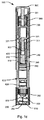
図1aは、所定の量の液体薬剤を医学的に注射するための医療注射器具100の第1の実施形態の正面断面図を示す。図1aは、格納状態にある注射器具を示す。図示した実施形態は、後で廃棄処理するために作動時に固定量を投与するように適応された使い捨て器具を示す。この実施形態は、針の自動貫通、薬剤の自動注入および針の自動後退を与える自動注入器の形態の注射器具を示す。注射器具100は、一般に、注射部位に対して保持されるように適応された遠位端を有する略管状ハウジング200を含む。ハウジング200の遠位端は、針アセンブリ500を収容し、投与前後に針が意図せずに刺さることがないように遮蔽するための針遮蔽部250を規定する。図示した実施形態において、針遮蔽部250の遠位面には、通常孔を覆うが、針アセンブリ500の前針カニューレが針遮蔽部250からある距離突出可能なように配設された穿孔可能な密封部材255を有する中央に位置する孔がある。ハウジング200の近位端に、作動ボタン300が配設される。作動ボタン300は、拡張位置から注入シーケンスを作動するための押下げ位置に移動可能である。
FIG. 1a shows a front cross-sectional view of a first embodiment of a
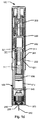
作動ボタン300を作動することによって作動が行われる前に、作動ボタン300は、図1aに示す状態、すなわち、作動ボタン300が押し下げられる前の状態に対して4分の1回転回される。図1bに、器具100をアンロックするために作動ボタン300が回された状態が示され、図2にさらに詳細に示される。
Prior to being actuated by actuating
注射器具100のハウジング200は、遠位端で出口640を規定する本体610を有する薬剤充填カートリッジ600を収容し、遠位端は、カートリッジ内部と流通状態を確立するために、針カニューレによって穿孔されるように適応されたカートリッジ隔膜620によって密封される。カートリッジ600の本体610内に、ピストン630が摺動可能に配設される。ピストン630は、最初、カートリッジ本体610の近位端面611から所定の距離に位置付けられる。ピストン630は、カートリッジ600から薬剤を投与するために、針がカートリッジ隔膜620を穿孔するとき、出口640の方へ移動可能である。分配は、投与機構によって制御される。カートリッジ600は、ハウジング200に対して同軸に配設され、近位の格納位置から遠位の作動位置へハウジング200内に軸方向に移動可能である。
The
ハウジング200の遠位に配設された針アセンブリ500が、針カニューレの前針510が遮蔽状態にある近位置と、前針510が密封部材255を貫通して突出し、すなわち、非遮蔽状態になる第2の遠位置との間を摺動可能に同軸に装着される。加えて、針アセンブリが、注射器具が投与のための作動状態になることにより遠位置に移動した後、針アセンブリは、ハウジング200に対して初期の近位置に近位方向に戻されてもよい。圧縮ばねが、針アセンブリを近位方向、すなわち、遮蔽状態に促すように、針遮蔽部250と針アセンブリ500のハブセクションとの間に設置された遮蔽ばね370を形成する。投薬シーケンスの過程で、投与が終了すると、遮蔽ばね370は、非遮蔽状態から遮蔽状態に注射器具を能動的にもたらすための遮蔽ドライバとして実行する。図1aに示すように、注射器具100が格納状態にあるとき、針アセンブリ500は、カートリッジ600に対して初期分離された構成で配設される。図示した実施形態において、針アセンブリ500は、針ハブから遠位方向および近位方向にそれぞれ突出する前針510および後針(視認できない)を有する針カニューレを含む。前針510および後針の両方は、使用者の皮膚およびカートリッジ隔膜620をそれぞれ穿孔するための鋭い先端を含む。適切な針アセンブリの詳細については、図3に関する以下の記述を参照されたい。
The
投与機構は、器具のハウジング200の近位部に配置される。図示した実施形態において、投与機構は、ピストンドライバ310(前述を参照)と、アクチュエータスラスト部材330および圧縮応力を与えられた圧縮ばね360の形態の蓄積エネルギー源を備えるアクチュエータとを備える。ばね360は、作動されると、アクチュエータスラスト部材330を推進し、ひいては、ピストンドライバ310を推進するように解放可能である。
The dispensing mechanism is located in the proximal portion of the
アクチュエータスラスト部材330の軸運動は、アクチュエータが解放されると、ピストンドライバ310の軸運動へ変えられる。図示した実施形態において、アクチュエータスラスト部材330とピストンドライバ310との間にダンピング機構が設けられ、したがって、図示した実施形態において、アクチュエータコネクタ320が、アクチュエータスラスト部材330とピストンドライバ310とを連結する。
The axial movement of the
作動されると、アクチュエータの蓄積エネルギー源360によってかけられる射出力は、遮蔽ばね370からかけられる力より大きい。このように、蓄積エネルギー源360が注射を行うために解放されると、蓄積エネルギー源360は、カートリッジ600および針アセンブリ500を推進して、遮蔽ばね370のバイアス力に打ち勝つ。
When activated, the firing force exerted by the actuator's stored
図示した実施形態において、カートリッジ600は、ハウジング200のガイド表面によって保持されるとともに、カートリッジ600のピストン630に取り付けられたピストンドライバ310によって軸方向に保持される。取付けは、ねじ接続によって、スナップロックまたは差込みロックなどによって達成されてもよい。また、別の実施形態において、ピストンドライバ310は、カートリッジピストン630と一体のコンポーネントとして形成されてもよい。作動されると、投与シーケンスの初期部分において、ピストンドライバ310が注入器内に移動するにつれ、カートリッジ600は、他の部品に影響を受けないため遠位に移動する。
In the illustrated embodiment, the
図示した実施形態において、注射器具が作動されると、カートリッジ600は前方に移動し、針アセンブリ500のハブセクションと摩擦係合することで、前針510が針遮蔽部250の遠位面から所定の距離だけ突出するまで、針アセンブリ500を遠位方向に押す。この後、カートリッジ600が前進運動を続けることで、針アセンブリ500の後針がカートリッジ隔膜620を穿孔して、カートリッジの内容物と流通状態を確立する。カートリッジ600は、針アセンブリ500に対して完全に押されると停止し、その後、ピストン630は、吐出ストロークのためにカートリッジ600内に移動を開始する。別の実施形態において、器具は、針アセンブリが非遮蔽状態に遠位方向に移動される前に、カートリッジと針カニューレとの間に流通状態を最初に確立するように構成されてもよい。
In the illustrated embodiment, when the injection device is actuated, the
カートリッジ600の近位端に、ブッシング部材340が挿入される。ブッシング部材は、カートリッジ600の近位端面611に対して隣接するように適応された拡張リムセクション341を含む。ブッシング部材340は、ピストンドライバ310を摺動関係にて受けるように適応された内部孔を有する。内部孔の遠位領域345は、(以下に記載する)制御弁としてピストンドライバに形成されたチャネル315と共に動作するように拡張される。
A
ピストンドライバ310は、近位拡張リムセクション311を有する略管状部材として形成される。ピストンドライバ310の内部には、アクチュエータコネクタ320の遠位端を受けるための孔313が形成される。注射器具100の格納状態において、ピストンドライバ310の孔およびアクチュエータコネクタ320の遠位面322は、初期状態において、グリースなどの高粘性流体が充填されている可変容量リザーバ400を規定する。上述した制御弁345、315は、前記可変容量リザーバ400から通じることで、アクチュエータコネクタ320とピストンドライバ310との間のダンパー構成を形成する。
アクチュエータコネクタ320は、ピストンドライバ310の孔313に摺動可能に受け入れられる管状部品を有し、さらに、アクチュエータスラスト部材330と協働するように適応された拡張ヘッド321を有する。
The
注射器具100の作動機構の詳細図を示す図2を参照すると、アクチュエータスラスト部材330の図示した実施形態は、注射器具100の格納状態において、プレストレスがかけられたばね360の力に抵抗してハウジングの係合保持表面(参照符号なし)に対してアクチュエータスラスト部材330を保持する保持部分335を含む。作動ボタン300が押されると、作動ボタン300の係合解除表面305は、保持部分335をハウジングの係合保持表面から自由にして、アクチュエータスラスト部材330が自由に運動するようになる。このような構成は、一般に、使い切りの自動注入器の分野において知られている。器具の遠位端に配設されたアクティベータ、遮蔽アクティベータ、または遠位端あるいはハウジング200の側面部分に沿って配設されたボタンなど、別の作動構成が本発明の範囲内において考えられる。
Referring to FIG. 2, which shows a detailed view of the actuation mechanism of the
アクチュエータスラスト部材330は、圧縮ばね360の遠位端を受けるための座部を含む。遠位端において、アクチュエータスラスト部材330は、アクチュエータコネクタ320の拡張ヘッド321と協働するように偏向可能なヘッド部332で終端する遠位方向に延伸する1組の弾性アームをさらに含む。注射の初期段階において、弾性アームおよび偏向可能なヘッド部分332は、ヘッド部332が半径方向に外向きに付勢されるようにハウジング200によって半径方向に内向きに押しやられる。偏向可能なヘッド部332の各々は、アクチュエータスラスト部材330が遠位方向に完全に移行すると、半径方向に外向きに移動するように適応される。これは、偏向可能なヘッド部332が、ハウジング200に形成されたリセス232と軸方向に整列されるときに起こる。偏向可能なヘッド部332が半径方向に外向きに移動すると、アクチュエータスラスト部材330とアクチュエータコネクタ320の拡張ヘッド321との間の係合が中断される。これにより、カートリッジ600および針アセンブリ500は、遮蔽ばね370のばね力により器具において近位方向に押しやられる。他の実施形態において、アクチュエータスラスト部材330は、アクチュエータスラスト部材330とアクチュエータコネクタ320の拡張ヘッド321との間の係合が中断された後、針後退工程に影響を及ぼさないため、さらに移行するように構成されてもよい。
上述したように、図示した実施形態において、アクチュエータは、ピストンドライバ310を遠位方向に前方に押し出すプレストレスがかけられた圧縮ばね360として与えられる。注射器具の製造中に圧縮されるプレストレスがかけられたばねを使用する代わりに、器具は、使い始めるさい、初期手順としてばねを圧縮する機構を含んでもよい。また、アクチュエータは、他の実施形態において、投与機構の回転ドライブを前方に駆動するためのねじり力をかけるようにプレストレスがかけられたねじりばねとして形成されてもよい。あるいは、アクチュエータは、ガスなどの圧縮媒体の形態のものであってもよい。あるいは、アクチュエータは、電気化学電池のようなガス発生器を含んでもよい。また、別の実施形態は、使用者が、注射中にピストンドライバを手動で前方に駆動する場合のアクチュエータを含んでもよい。
As described above, in the illustrated embodiment, the actuator is provided as a
上述したように、ピストンドライバ310は、ブッシング部材340のリムセクション341と協働して、カートリッジ600内でのピストン630の正確なストローク終了位置を規定するように、拡張リムセクション311がピストンドライバの遠位端から所定の距離に位置付けられた停止表面として動作するように形成される。ピストン630が、カートリッジ600の充填中に、カートリッジ600の後端部611に対して正確に位置付けられうるため、カートリッジ600の後端部611に対して高精度に位置付けられるリムセクション341に当たる停止表面311を利用することによって、吐出投与量の正確な量が高精度に制御されうる。
As described above, the
以下、図1a〜図1hを主に参照しながら、注射器具100の動作シーケンスについて記載する。
Hereinafter, an operation sequence of the
使用前、上述したように、作動ボタン300は、注射器具を最初にアンロックするためにハウジング200に対して相対的に回される。図1bに、この状態が示されている。この作用が実行される前、作動ボタンを押し下げようとすることで、器具100が作動されるわけではない。しかしながら、アンロック後、使用者が器具を掴んで、器具100の遠位端が注射部位に押圧された後、作動ボタンは、器具を作動するために押される(図1cを参照)。
Prior to use, as described above, the
器具100が作動されると、アクチュエータスラスト部材330がハウジング200から解放される。アクチュエータの圧縮ばね360によってかけられる力により、アクチュエータスラスト部材330は、遠位方向に移動されて、前針が針遮蔽部250から突出するまで(図1dを参照)、アクチュエータコネクタ320、ピストンドライバ310、カートリッジ600および針アセンブリ500を前方に押しやる。実質的に非圧縮性の粘性流体が可変容量リザーバ400に充填されることと、制御弁315、345が最初に閉じられた構成にあることにより、ピストンドライバ310は、本質的に、アクチュエータコネクタ320の動きに従うことに留意されたい。図1dに示す状態において、後針はカートリッジ隔膜620をまだ穿孔していない。
When the
図1eに示す状態において、アクチュエータスラスト部材330がさらに遠位方向に移動されることで、針アセンブリ500に対して相対的にカートリッジ600がさらに移動され、ひいては、後針がカートリッジ隔膜620を穿孔して、カートリッジ内部との流通を始動する。図示した状態において、カートリッジ600は、ハウジング200に対して最遠位位置まで完全に移動されている。
In the state shown in FIG. 1e, the
針カニューレとカートリッジとの間の流通がこのように確立されることで、アクチュエータスラスト部材330は、カートリッジ600内にピストン630を前進させ、この前進は、全注入ストローク中、ピストンドライバの拡張リムセクション311がブッシング部材240のリムセクション341と当接する図1fに示したストローク終了状態まで続く。この時点で、ピストンドライバ310は、カートリッジ600に対して抑止される。しかしながら、流体の圧縮により、特に、ピストンの圧縮により、ピストンドライバが運動を停止した後、少量の流体がカートリッジからカニューレを通って吐出されることもある。一般に、高精度の注入を意図した従来の器具を使用すると、システムが緩和して圧縮を軽減し、針カニューレからの流体の流れが実質的に停止するまで、残りの少量を吐出するために、一般に、長い時間、例えば、6〜10秒間またはそれ以上の時間、皮膚に針を刺したままにしなければならない。
With this established flow between the needle cannula and the cartridge, the
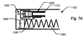
しかしながら、図示した実施形態では、図1fに示すこの段階において、上述したダンパー機構は、前針カニューレが遮蔽状態へ能動的に駆動されて針を皮膚から引き抜く前に、わずかな遅延、例えば、0.5秒しかもたらさない。図4aに、図1fに示す器具の状態にあるダンパー機構の詳細図が示されている。この状態において、ピストンドライバ310は、ブッシング部材340およびカートリッジ600に対する停止位置、すなわち、ストローク終了位置まで移動されている。注射器具100がこの状態に入る前、ピストンドライバが図示した位置の近位に位置するとき、チャネル315は、可変容量リザーバ400を密封して容量を保つように効果的に遮断される。しかしながら、図示した位置の直前、ピストンドライバ310に形成されたチャネル315は、内部孔が拡張されたブッシング部材340の遠位領域345と軸方向に整列する。これにより、チャネル315が開き、可変容量リザーバ400に収容されていた流体が制御下で流出する。アクチュエータスラスト部材330によって力が継続的にかけられていることにより、可変容量リザーバ400の流体が低減されると、アクチュエータコネクタ320は、図4bに示す位置に向かって移動し続ける。アクチュエータコネクタ320の移動は、アクチュエータスラスト部材330の偏向可能なヘッド部332が、図4bおよび図1gに示すハウジング200に形成されたリセス232に達するときに停止される。偏向可能なヘッド部332が外向きに付勢されるため、リセス232により変更可能なヘッド部分332は半径方向に外向きに移動する。これにより、偏向可能なヘッド部332とアクチュエータコネクタ320の拡張ヘッド321との間の接続が切り離される。
However, in the illustrated embodiment, at this stage as shown in FIG. 1f, the damper mechanism described above may cause a slight delay, e.g., 0, before the anterior needle cannula is actively driven into a shielded state to withdraw the needle from the skin. Only brings about 5 seconds. FIG. 4a shows a detailed view of the damper mechanism in the state of the instrument shown in FIG. 1f. In this state, the
以下、図1hを参照すると、アクチュエータコネクタ320が、アクチュエータスラスト部材330の遠位方向の力に対して作用されないため、遮蔽ばね370は、針アセンブリ500およびカートリッジ600をハウジング200に対して近位方向に駆動する。また、ブッシング部材340、ピストンドライバ310およびアクチュエータコネクタ320は、近位方向に押される。これにより、針は使用者の皮膚から即座に引き抜かれ、針遮蔽部250の内部に確実に隠された遮蔽状態にもたらされる。上述したように、密封部材255は、針を引き抜いた後に針カニューレから吐出されることがある少量の流体が、器具内に閉じ込められるか、または吸収されるように、孔を効果的に密封するために針遮蔽部250の孔に設けられてもよい。
Referring now to FIG. 1 h, the
針カニューレを皮膚から早く引き抜くことにより、ピストンドライバが停止されている時点の後にカートリッジから吐出されるわずかな量の流体が患者への吐出に使用されないため、投与機構は、この余剰量を、針を引き抜く前に吐出ストローク中に同様の余剰量を追加することによって補償するように構成される。 By quickly withdrawing the needle cannula from the skin, the dosing mechanism removes this excess amount from the needle because a small amount of fluid that is expelled from the cartridge after the piston driver is stopped is not used to dispense to the patient. It is configured to compensate by adding a similar surplus amount during the discharge stroke before withdrawing.
一例を挙げれば、分配される設定された所定の量が0.50mlであれば、カートリッジの公称変位容量は約0.51mlである。システムの圧縮によって「失われる」量は、カートリッジの公称容量によって追加される。針は、ピストンロッドが投与距離の長さで動作した後すぐに(約0.5秒)後退される。注射の通常の投与速度は0.1ml/secである。したがって、0.5mlの典型的な注射は5秒である。従来の注射器具を使用する場合、使用者は、典型的に、5秒間(投与)と6秒間(緩和)、合わせて11秒間待機する。その代わり、上述した器具を使用することによって、使用者は、5秒間、さらには、自動後退の作動に要する約0.5秒間、合わせて約5.5秒間、針を皮膚下に刺したままにすればよい。これは、注射器具を使用して患者または医療関係者の快適さの面で主な利点となる。 As an example, if the set predetermined amount to be dispensed is 0.50 ml, the nominal displacement capacity of the cartridge is about 0.51 ml. The amount “lost” by the compression of the system is added by the nominal capacity of the cartridge. The needle is retracted (approx. 0.5 seconds) immediately after the piston rod has been operated for the length of the dosing distance. The normal administration rate for injection is 0.1 ml / sec. Thus, a typical injection of 0.5 ml is 5 seconds. When using conventional injection devices, the user typically waits for 11 seconds, 5 seconds (dose) and 6 seconds (relaxation). Instead, by using the instrument described above, the user can keep the needle pierced under the skin for 5 seconds, and for about 0.5 seconds, which is necessary for the automatic retraction operation, for a total of about 5.5 seconds. You can do it. This is a major advantage in terms of patient or medical personnel comfort using the injection device.
図示した実施形態において、ダンピング構成が使用されるが、針を引き抜く前の明確に規定された投与長さ、投与速度および投与持続時間が注射器具の機構によって得られるならば省略されうる。上述した投与方法に関して、ピストンの開始位置および停止位置を高精度に規定することで、効果的なストローク長さを決定するためにカートリッジの後部が使用される場合、高精度な分配システムが提供される。 In the illustrated embodiment, a damping configuration is used, but may be omitted if a well-defined dosage length, dosage rate and dosage duration before withdrawal of the needle is obtained by the mechanism of the injection device. With respect to the administration method described above, a precise dispensing system is provided when the rear of the cartridge is used to determine the effective stroke length by precisely defining the piston start and stop positions. The
針を引き抜くための効果的な持続時間が、ストローク終了時点または終了時点付近で開始される場合、および針を引き抜く効果的な持続時間が、0.5秒未満、あるいは、1秒未満、あるいは、2秒未満、あるいは、3秒未満、あるいは、4秒未満、あるいは、5秒未満である場合、ストローク終了状態から針引き抜き状態までの明確な時間遅延を生じるために、上記ダンピングシステムの代替物が使用されてもよい。 If the effective duration for withdrawing the needle begins at or near the end of the stroke, and the effective duration for withdrawing the needle is less than 0.5 seconds, or less than 1 second, or If it is less than 2 seconds, or less than 3 seconds, or less than 4 seconds, or less than 5 seconds, an alternative to the above damping system is used to produce a clear time delay from the end of stroke condition to the needle withdrawal condition. May be used.
このような代替物は、ピストンドライバがカートリッジに対して特定の位置に入ると、ピストンドライバとアクチュエータとの間の機械的係合が解除される場合、ピストンドライバとアクチュエータコネクタとの間の機械的係合によって提供されてもよい。このような機械的係合は、例えば、注入ストローク中、ピストンドライバとカートリッジ本体との間で特定の相対位置に達すると解除されるように適応された1つ以上の可撓性アームを組み込むことによって、一般に、アクチュエータスラスト部材330とアクチュエータコネクタ320との間の図示した機械的係合に対応する方法で構成されてもよい。
Such an alternative is that when the piston driver enters a particular position relative to the cartridge, the mechanical engagement between the piston driver and the actuator connector is disengaged when the mechanical engagement between the piston driver and the actuator is released. It may be provided by engagement. Such mechanical engagement incorporates, for example, one or more flexible arms adapted to be released when a certain relative position is reached between the piston driver and the cartridge body during the injection stroke. May generally be configured in a manner corresponding to the illustrated mechanical engagement between the
注射器具100の第2の実施形態において、図3に示すように、針アセンブリ500は、前針510および後針520のそれぞれの滅菌外装を形成する前カバー515および後ろカバー525を含んでもよい。図示した実施形態において、前カバーおよび後ろカバーは、それぞれの針セグメントの鋭い先端によって貫通可能なゴム外装として形成される。それぞれのカバーの上部が針ハブ501の方に押しやられ、特定の針セクションの鋭い先端がカバーを貫通して、当該針セクションが針カバーの外側に完全または部分的に露出される。
In a second embodiment of the
針カニューレは、接着、締まり嵌めまたは同様の接合プロセスによってハブ501に取り付けられてもよい。前カバー515および後ろカバー525は、接着、溶接、締まり嵌め、別の装着要素または同様の方法のいずれかでハブ501に取り付けられる。使用前、2つのカバー515、525は、前針510および後針520のそれぞれを覆う拡張位置にある。
The needle cannula may be attached to the
第1の実施形態に関連して上述したように、針アセンブリ500の遠位運動により、針遮蔽部250にある小さな孔254を前針510が貫通する。針カニューレが孔254に対して移動するとき、前カバー515は、開口の周辺の幾何学的形状によって引き止められることで、針カバー515は、針遮蔽部250と針ハブ501との間に圧縮されながら、前針510が前カバー515を貫通することが好ましい。あるいは、前カバー515も同様に孔を貫通して移動してもよい。この場合、前カバー515は、患者の皮膚に押圧されることで、器具100と皮膚との間で圧縮される。前カバー515の圧縮は、折り畳み式、または横方向、例えば、半径方向外向きへの屈曲のいずれかでありうる。前カバー515は、針遮蔽部250と針ハブ501との間に常に圧縮されるように特定の幾何学的形状を有してもよい。針遮蔽部250の孔254はまた、前カバー515の正確な圧縮を確保するために特定の幾何学的形状を有してもよい。針アセンブリが所定の位置に達すると、針アセンブリ500は停止位置に達する。この位置において、前針は患者の皮膚に挿入され、前カバー515は圧縮される。
As described above in connection with the first embodiment, distal movement of the
針アセンブリ500が移動して停止位置に達した後、カートリッジ600は、ハウジング200および針アセンブリ500に対して遠位方向に移動する。この移動により、カートリッジの隔膜620は、後ろカバー525と接触して圧縮する。後ろカバー525が圧縮されると、後針は後ろカバー525およびカートリッジ600の隔膜620を貫通する。後ろカバー525の圧縮は、折り畳み式または横方向への屈曲のいずれかでありうる。カートリッジ600は、移動が停止される所定の位置までさらに移動される。後ろカバー525の圧縮は、カートリッジ600の移動に対する制動として作用することで、カートリッジ600が停止されるときの機械的衝撃を低減する。この位置において、後ろカバー525は、針アセンブリ500のハブ501とカートリッジ600の前端との間で圧縮される。針カニューレは、この位置において、患者の皮膚およびカートリッジに収容された薬剤の両方と接触した状態にある。
After the
針アセンブリ500が針遮蔽部250に対して引き込められると、前カバー515にかかる圧縮圧力が中断される。針遮蔽部250が前カバー515を圧縮位置に保持しないため、カバーは、カニューレの前針を覆う拡張位置に戻ることが好ましい。
When the
非圧縮形状に自然に戻ろうとする傾向により、前カバーは、非圧縮形状に戻りうる。いくつかの実施形態において、カバーが非圧縮形状に戻ることは、針アセンブリ500をハウジングの針遮蔽部250から離れるように付勢するばねとしてさらに作用することで、別の遮蔽ばね370の必要性がなくなる。前カバー515は、針ハブ501が近位移動すると、前カバー515が自動的に延伸するように、針遮蔽部250に取り付けられた最遠位部を有してもよい。前カバー515が延伸位置に戻ると、カバーは、過剰な薬剤がカニューレから吐出されて、器具100から滴り落ちるのを防ぐ。
Due to the tendency to naturally return to the uncompressed shape, the front cover can return to the uncompressed shape. In some embodiments, the return of the cover to the uncompressed shape further acts as a spring that biases the
別の実施形態は、カニューレが器具内に引き込められた後、カニューレから吐出される過剰な薬剤を吸収または阻止するように孔254の近傍に配設されたスポンジのような材料を含んでもよい。注入器の遠位面上に、吸収材料が少なくとも部分的に配置されてもよい。さらなる別の実施形態において、針カニューレは、余剰分が複雑に入り組んだものや長い距離を通って抜け道を見つける必要があるようにペン内の比較的遠くまで後退される。また、孔254を形成する器具の内部が、針を引き抜いた後に器具から過剰な薬剤が流出しないように疎水性材料が設けられた1つ以上の表面部分を含んでもよい。孔の幾何学的形状は、効果的にブロック機能性を生じるように、材料の疎水性および該当する薬剤流体と適合されることが好ましい。米国特許第5957897号、同第5147303号、同第5147303号および米国特許出願公開第20030114797号の文献に開示された解決策を用いて、器具からの滴りを回避するための他の代替物が提供されてもよい。上記実施形態において、針は非常に高速に後退されるため、皮膚に溢れる余剰分の量は最少であり、わずかである。
Another embodiment may include a sponge-like material disposed near the
以下、本発明の注射器具100’の第3の実施形態を参照すると、図5a〜図5hは、注射手順の間のさまざまな状態にある器具の断面図を示す。図面の7〜10頁の各頁において、左側の図は、注射手順の間に特定の状態にある器具の中心軸を通る第1の断面図を示し、右側の図は、左側の図のそれぞれに対して直交する方向の側面断面図を示す。
Referring now to a third embodiment of the
器具100’は、薬剤カートリッジ600’を少なくとも部分的に収容するためのハウジング200’を含む。ハウジングの遠位面は、例えば、針保持手段254’を形成することによって、針アセンブリ500’と協働するように適応された部分を規定する。針保持手段254’は、ねじ接続または差込み接続などによって、標準的な針アセンブリの取付けに適した針装着部を形成するように適応されてもよい。針アセンブリ500’は、患者の皮膚の穿孔用およびカートリッジ600’の隔膜の穿孔用にそれぞれ前針部510’および後針部520’を含む。 Instrument 100 'includes a housing 200' for at least partially receiving a drug cartridge 600 '. The distal surface of the housing defines a portion adapted to cooperate with the needle assembly 500 ', for example, by forming a needle retaining means 254'. Needle retention means 254 'may be adapted to form a needle mount suitable for attachment of a standard needle assembly, such as by a screw connection or a bayonet connection. Needle assembly 500 'includes a front needle portion 510' and a rear needle portion 520 'for piercing the patient's skin and for piercing the diaphragm of cartridge 600', respectively.
別の実施形態において、針アセンブリ500’は、一般に、第1および第2の実施形態の針アセンブリ500と同様に形成されてもよく、すなわち、ハウジングに孔が形成されてもよく、関連する針アセンブリ500’の前針が、この孔から突出するように適応されてもよい。このような構成において、針アセンブリは、ハウジングの内部部分に配設され格納されてもよい。このような器具が作動されると、後針はカートリッジの隔膜を穿孔するようにされてもよく、前針はハウジングの外側に露出されるようにされてもよい。
In another embodiment, the
器具100’において、カートリッジ600’および針アセンブリ500’は、少なくとも、カートリッジ600’と針カニューレとの間に流通が確立された状態(図5aおよび図5bを参照)から、前記流通が中断される状態(図5gおよび図5hを参照)へカートリッジ600’および針アセンブリ500’を移動するために互いに対して移動可能に配設される。
In the
注射手順の前に針アセンブリを手動で装着することが意図された図示された実施形態において、カートリッジ600’は、摺動可能なカートリッジホルダ800’によってハウジング200’の遠位部の器具100’内に保持される。カートリッジホルダばね750’などの駆動または付勢手段が、カートリッジホルダ800’を近位方向に促すように、ハウジング200’とカートリッジホルダ800’との間に配設される。図5aに示す状態において、保持機構207’、807’によって、カートリッジホルダ800’は、カートリッジ600’と針カニューレとの間に流通が確立される最遠位位置に解放可能に保持される。 In the illustrated embodiment, which is intended to manually attach the needle assembly prior to the injection procedure, the cartridge 600 'is placed in the instrument 100' at the distal portion of the housing 200 'by a slidable cartridge holder 800'. Retained. A drive or biasing means such as a cartridge holder spring 750 'is disposed between the housing 200' and the cartridge holder 800 'to urge the cartridge holder 800' proximally. In the state shown in FIG. 5a, the holding mechanism 207 ', 807' releasably holds the cartridge holder 800 'in the most distal position where flow is established between the cartridge 600' and the needle cannula.
ピストン630’を駆動して所定量の薬剤をカートリッジ600’から分配するためのピストンドライバ710’が、カートリッジ600’のピストン630’に連結される。初期動作シーケンス中、ピストンドライバ710’は、プレストレスがかけられた圧縮ばね360’の形態のアクチュエータにより、遠位方向に押しやられている。別のタイプのアクチュエータは、第1の実施形態の記述に関連して記載したように提供されてもよい。また、別の実施形態は、注射中、使用者がピストンドライバを手動で前方に駆動するアクチュエータを伴うものであってもよい。図示した実施形態において、圧縮ばね360’は、第2の部品720’に形成された穴に延伸するように、ハウジング200’の近位部とピストンドライバの第2の部品720’の近位接面との間に配設される。図示した実施形態において、圧縮ばね360’の近位部は、ハウジング200’からばね360’内へ突出する静止ガイド部材(参照符号なし)によって案内される。 A piston driver 710 'for driving the piston 630' to dispense a predetermined amount of drug from the cartridge 600 'is coupled to the piston 630' of the cartridge 600 '. During the initial motion sequence, the piston driver 710 'is pushed distally by an actuator in the form of a prestressed compression spring 360'. Another type of actuator may be provided as described in connection with the description of the first embodiment. Another embodiment may involve an actuator that the user manually drives the piston driver forward during injection. In the illustrated embodiment, the compression spring 360 'extends proximally from the proximal portion of the housing 200' and the second part 720 'of the piston driver so as to extend into a hole formed in the second part 720'. Between the surfaces. In the illustrated embodiment, the proximal portion of the compression spring 360 'is guided by a stationary guide member (not labeled) that protrudes from the housing 200' into the spring 360 '.
作動ボタン300’が、器具の近位端に配置される。作動ボタン300’は、ピストンドライバ710’の近位端に配設された嵌合トリガ表面705’と係合する傾斜表面305’を各々が有する作動アームを含む。作動ボタン300’が押し下げられると(図5cおよび図5dを参照)、傾斜表面305’は、トリガ表面705’を半径方向内向きに移動する。トリガ表面705’が半径方向内向きに押しやられると、ピストンドライバ710’の保持縁706’は、カートリッジホルダ800’の保持表面806’から解放される。このように、ばね360’がピストンドライバ710’を遠位方向に押しやると、カートリッジ600’のピストン630’は遠位方向に移動する。この移動は、図5eおよび図5fに示すストローク終了状態まで維持される。 An activation button 300 'is disposed at the proximal end of the instrument. Actuation button 300 'includes actuation arms each having an inclined surface 305' that engages a mating trigger surface 705 'disposed at the proximal end of piston driver 710'. When the actuation button 300 'is depressed (see FIGS. 5c and 5d), the inclined surface 305' moves radially inwardly over the trigger surface 705 '. When the trigger surface 705 'is pushed radially inward, the retaining edge 706' of the piston driver 710 'is released from the retaining surface 806' of the cartridge holder 800 '. Thus, when the spring 360 'pushes the piston driver 710' in the distal direction, the piston 630 'of the cartridge 600' moves in the distal direction. This movement is maintained until the stroke end state shown in FIGS. 5e and 5f.
いくつかの実施形態において、第4の実施形態に関連して以下に記述するように、ストローク終了状態は、ピストンドライバ710’の停止表面711’が、カートリッジの背面611’と隣接するときに規定される。しかしながら、図示した実施形態において、異なる構成が、以下に記載するように吐出動作を完了する。
In some embodiments, as described below in connection with the fourth embodiment, an end-of-stroke condition is defined when the
ピストンドライバ710’は、カートリッジ隔膜620’が後針520’によって穿孔された状態において、カートリッジ600’および針アセンブリ500’を解放可能に保持するように適応された保持機構207’、807’と協働する特徴を含む。保持子は、カートリッジホルダ800’およびハウジング200’のそれぞれに協働特徴を含む。図示した保持子は、ハウジング200’に関連付けられた作動アームを含み、作動アームの各々は、ピストンドライバ710’の遠位端に配設された係合トリガ表面708’と係合する傾斜表面208’を有する。
ピストンドライバ710’がストローク終了位置に達すると(図5eおよび図5fを参照)、トリガ表面708’は、ハウジング200’に関連付けられた傾斜表面208’を半径方向外向きに移動させる。傾斜表面208’が半径方向外向きに押しやられると、カートリッジホルダ800’の保持縁807’は、ハウジング200’の保持表面207’から解放される。このように、カートリッジホルダばね750’が、カートリッジホルダ800’を近位方向に押しやると、カートリッジ600’は、針アセンブリ500’から離れる方向にすぐに移動する。図5gおよび図5hに、器具100’のこの状態が示されている。カートリッジホルダばね750’が、アクチュエータ360’の力に打ち勝つ十分な力を与えることに留意されたい。この移動により、後針520’の先端がカートリッジ隔膜に埋め込まれるか、またはカートリッジ隔膜620’から完全に除去されるため、カートリッジ隔膜620’が再密封される。カートリッジ内部と針カニューレとの間の流通が中断されることにより、吐出動作が明確に規定された方法で完了する。 When the piston driver 710 'reaches the end of stroke position (see FIGS. 5e and 5f), the trigger surface 708' moves the inclined surface 208 'associated with the housing 200' radially outward. When the inclined surface 208 'is pushed radially outward, the retaining edge 807' of the cartridge holder 800 'is released from the retaining surface 207' of the housing 200 '. Thus, when the cartridge holder spring 750 'pushes the cartridge holder 800' proximally, the cartridge 600 'immediately moves away from the needle assembly 500'. Figures 5g and 5h show this state of the instrument 100 '. Note that the cartridge holder spring 750 'provides sufficient force to overcome the force of the actuator 360'. This movement causes the tip of the rear needle 520 'to be embedded in the cartridge diaphragm or completely removed from the cartridge diaphragm 620', thereby resealing the cartridge diaphragm 620 '. By interrupting the flow between the interior of the cartridge and the needle cannula, the dispensing operation is completed in a well-defined manner.
図6a〜図6jは、上述した第3の実施形態に関するが、以下の修正例を有する変形例である第4の実施形態の同様の略断面図を示す。図面の11〜15頁の各頁において、左側の図は、注射手順の間に特定の状態にある器具の中心軸を通る第1の断面図を示し、右側の図は、左側の図のそれぞれに対して直交する方向の側面断面図を示す。 6a to 6j relate to the above-described third embodiment, but show a similar schematic cross-sectional view of the fourth embodiment which is a modified example having the following modification. In each page of pages 11-15 of the drawings, the left figure shows a first cross-sectional view through the central axis of the instrument in a particular state during the injection procedure, and the right figure shows each of the left figures. Side surface sectional drawing of the direction orthogonal to is shown.
第4の実施形態による器具100’は、第1および第3の実施形態に類似した作動ボタン300’を含む。図6aおよび図6bに示す非作動状態から図6cおよび図6dに示す作動状態へ、ボタン300’はピストンドライバを解放するように作用する。 The instrument 100 'according to the fourth embodiment includes an activation button 300' similar to the first and third embodiments. From the non-actuated state shown in FIGS. 6a and 6b to the activated state shown in FIGS. 6c and 6d, the button 300 'acts to release the piston driver.
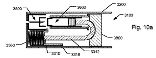
図6aおよび図6bに示すように、第4の実施形態のピストンドライバは、2つの主要部品、すなわち、第1の部品701’および第2の部品720’を備える。第1の部品701’および第2の部品720’は、ダンパー機構によって相対的に接続される。ダンパー機構は、例えば、制御弁によって制御される可変容量リザーバ400’を形成することによって、第1の実施形態のダンパー構成に類似した方法で構成されてもよい。しかしながら、図示した実施形態において、ダンパー機構は、第1の部品701’に形成されたチャネル715’を最初に覆うブッシング部材740’を有する変形例を備え、ブッシング部材740’は、ブッシング部材740’の拡張リムセクション741がカートリッジ600’の近位端面611’と当接するまで、第1の部品701’とともに移動するように構成される。第1の部品701’が遠位方向にさらに移動すると、図6eおよび図6fに示されているように、第1の部品701’はブッシング部材740’に対して相対的に移動して、チャネル715’の覆いがなくなる。これにより、可変容量リザーバ400’内にある最初に保持されていた流体が吐出され、第2の部品720’が遠位方向にさらに移動する間に、可変容量リザーバ400’が圧縮された状態になる。
As shown in FIGS. 6a and 6b, the piston driver of the fourth embodiment comprises two main parts, a first part 701 'and a second part 720'. The
ピストンドライバの第1の部品701’は、カートリッジ600’のピストン630’に連結される。上述したように、第2の部品720’は、部品611’、741’、711’(図6eおよび図6fを参照)によって提供されるストローク終了リミッタ装置によって、第1の部品701’がカートリッジ600’に対して抑止されるまで、注入ストローク中、第1の部品701’を推進するように適応される。これは、カートリッジ600’からの流体の流れが実質的に中断されるように、カートリッジ600内のピストン630’の移動を停止する。その後、第2の部品720’は、第2の部品720’と第1の部品701’との間の相対運動に対してダンバーが解放されることと、第2の部品720’がアクチュエータ360’からの遠位方向の力に作用されたままであることにより、さらなる移動が可能である。第2の部品720’がさらに移動すると、第2の部品720’に関連付けられたトリガ表面708’は、保持子の解放を引き起こす(図6gおよび図6hを参照)。図示した実施形態において、これは、ハウジング200’に対してカートリッジホルダ800’を解放する。このように、カートリッジホルダばね750’は、カートリッジホルダ800’を近位方向に押しやることで、針アセンブリ500’から離れる方向にカートリッジ600’を即座に移動させる。これは、カートリッジ内部と針カニューレとの間の流通を効果的に中断する(図6iおよび図6jを参照)。
The first part 701 'of the piston driver is connected to the piston 630' of the cartridge 600 '. As described above, the
このように、第3の実施形態を比較すると、第4の実施形態に従って記載されたもののようなダンパー構成が、器具のさまざまな部品の公差により、このようなダンパー構成を含むことが望ましい器具において使用されてもよい。例えば、カートリッジの長さが比較的大きな公差変動に関連付けられることもあるため、ダンパー構成は、公称カートリッジ長さに対して大きな変動を有するカートリッジに対しても、カートリッジの適切な後退を確保する。ストローク終了リミッタがカートリッジの近位端面によって規定されることにより、カートリッジのピストンが、カートリッジの充填段階中にカートリッジの近位端面に対して高精度に位置付けられれば、注射中に吐出される投与量の精度を非常に高い精度で確保できる。 Thus, when comparing the third embodiment, in a device where it is desirable that a damper configuration such as that described in accordance with the fourth embodiment include such a damper configuration due to tolerances of the various parts of the device. May be used. For example, the damper configuration ensures proper retraction of the cartridge, even for cartridges that have large variations with respect to the nominal cartridge length, since the cartridge length may be associated with relatively large tolerance variations. The end-of-stroke limiter is defined by the cartridge's proximal end face so that the dose dispensed during the injection if the cartridge's piston is accurately positioned relative to the cartridge's proximal end face during the cartridge filling phase. Can be ensured with very high accuracy.
針を引き抜くための効果的な持続時間が、0.5秒未満、あるいは、1秒未満、あるいは、2秒未満、あるいは、3秒未満、あるいは、4秒未満、あるいは、5秒未満である場合、ストローク終了状態から流通中断状態までの明確に規定された時間遅延を生じるために、上述したダンピングシステムの代替物が使用されてもよい。 If the effective duration for pulling out the needle is less than 0.5 seconds, or less than 1 second, or less than 2 seconds, or less than 3 seconds, or less than 4 seconds, or less than 5 seconds In order to produce a well-defined time delay from the stroke end state to the flow interruption state, an alternative to the above-described damping system may be used.
第1の実施形態に関して上述したように、従来の器具においてストローク終了状態の後に典型的に吐出される薬剤の余剰量は、この余剰量が注入ストローク中に送達されるように本明細書に記載する注入器を構成する場合、考慮に入れられる。 As described above with respect to the first embodiment, the excess amount of drug typically dispensed after an end-of-stroke condition in conventional instruments is described herein such that this excess amount is delivered during the infusion stroke. This is taken into account when constructing an injector to be used.
図5a〜図5hおよび図6aおよび図6jのそれぞれに示す器具100’の実施形態は、比較的厚いカートリッジ隔膜620’を組み込んでもよい。このような器具は、隔膜を効果的に再密封するためにカートリッジ隔膜に対して針が部分的に引き抜かれるとき、流体の流れを中断するように構成されてもよく、患者の皮膚から逆流しないように針カニューレの密封を実行するために、隔膜に差し込まれた後針の先端を維持するように構成されてもよい。カートリッジ隔膜と針アセンブリの針ハブとの間に配設された別の密封部材を使用することによって、同様の効果が得られてもよい。後針は、注入シーケンス中または前に、このような別の密封部材から突出するように適応されてもよい。しかしながら、カートリッジが後針から後退された後、ストローク終了状態で、後針の先端は、針カニューレの内腔を効果的にブロックするために、この別の密封部材に埋め込まれる。 The embodiment of the instrument 100 'shown in FIGS. 5a-5h and 6a and 6j, respectively, may incorporate a relatively thick cartridge diaphragm 620'. Such an instrument may be configured to interrupt the flow of fluid when the needle is partially withdrawn from the cartridge diaphragm to effectively reseal the diaphragm and does not backflow from the patient's skin. Thus, it may be configured to maintain the needle tip after it has been inserted into the septum to perform the sealing of the needle cannula. Similar effects may be obtained by using a separate sealing member disposed between the cartridge diaphragm and the needle hub of the needle assembly. The back needle may be adapted to protrude from such another sealing member during or before the injection sequence. However, after the cartridge is retracted from the back needle, at the end of stroke, the back needle tip is embedded in this separate sealing member to effectively block the needle cannula lumen.
第3および第4の実施形態に示す器具は、カートリッジおよび針アセンブリを分離されたコンポーネントとして最初に保持し、作動前または作動に応答して、初期動作シーケンスとしてカートリッジに針を装着する機構および針保持手段を含んでもよい。あるいは、標準的な二重の先の鋭い針が、作動前に器具の針保持手段に手動で装着されてもよい。 The instrument shown in the third and fourth embodiments is a mechanism and needle that initially retains the cartridge and needle assembly as separate components and attaches the needle to the cartridge as an initial sequence of operations prior to or in response to actuation. A holding means may be included. Alternatively, a standard double pointed needle may be manually mounted on the needle holding means of the instrument prior to activation.
また、図5a〜図5hおよび図6a〜図6jに示す実施形態に関連して記載された露出された前針は、例えば、使用後、針遮蔽に対して針が後退されるように針遮蔽を組み込むことによって、または、使用後、針を隠してアクセスできないようにするように針に対して移動する針遮蔽を組み込むことによって、注入器の使用後に遮蔽される構成に移動されてもよい。 Also, the exposed front needle described in connection with the embodiments shown in FIGS. 5a-5h and FIGS. 6a-6j may be needle shielded such that, for example, the needle is retracted relative to the needle shield after use. Or may be moved to a shielded configuration after use of the injector by incorporating a needle shield that moves relative to the needle so that the needle is hidden and inaccessible after use.
第1〜第4の実施形態に示す注入原理を用いる器具は、投薬を完了すると、クリック音などの聴覚信号、触覚信号または視覚信号などの1つ以上を発生することによって、投与状態の終了(流体中断段階)を示してもよい。信号は、本来、器具内の針後退または針からのカートリッジ後退のいずれかを与える戻りばねの動作によって(このようなばねが使用される場合)発生されてもよい。あるいは、信号は、投薬が完了される時間に信号を発する別の偏向要素によって発生されてもよい。 When the medication using the injection principle shown in the first to fourth embodiments is completed, the administration state is completed by generating one or more of an audible signal such as a click sound, a tactile signal, or a visual signal when the medication is completed ( A fluid interruption phase). The signal may be generated by the action of a return spring (if such a spring is used) that inherently provides either needle retraction within the instrument or cartridge retraction from the needle. Alternatively, the signal may be generated by another deflection element that emits a signal at the time when the medication is completed.
図7a〜図7dは、注射器具1100の第5の実施形態の作動原理の略図を示す。注射器具1100は、一般に、第1の実施形態の注射器具100に類似して動作するが、以下の修正例を有する。同様の部品および特徴に対して第5の実施形態の参照番号は、一般に、第1の実施形態と同じ参照番号を共有するが、第1の実施形態の参照番号の最初の桁に「1」を加えて示しており、すなわち、ハウジング「1200」はハウジング「200」に対応し、アクチュエータスラスト部材「1330」はアクチュエータスラスト部材「330」に対応し、他も同様である。
FIGS. 7 a-7 d show a schematic diagram of the working principle of a fifth embodiment of the
小型器具1200を提供するために、図示した実施形態は、第1の軸に沿って配設されるカートリッジと、第1の軸に平行で間隔を空けた位置にある第2の軸に配設されるアクチュエータおよび駆動コンポーネントとを提供する。しかしながら、このレイアウトはオプションにすぎない。
To provide a
作動前の格納状態にある器具を示す、図7aに示す器具1100において、第1の実施形態の遮蔽ばね370は省略され、遮蔽ドライバ370として機能するための別の機構によって置き換えられている。この機構において、遠位方向に注射器具の部品を駆動し、引き続き、近位方向に注射器具の部品を駆動するために、単一のアクチュエータ圧縮ばね1360が使用される。これを達成するために、力伝達機構が提供される。
In the
圧縮ばね1360およびアクチュエータスラスト部材1330は、最初に、ピストンドライバ1710を遠位方向に駆動し、カートリッジ1600および針アセンブリ1500を遠位方向に駆動して前針を非遮蔽状態に移行した後、カートリッジ1600を遠位方向にさらに移動して、前針を使用者の皮膚に刺し、カートリッジ1600の内部と針アセンブリ1500の後針カニューレとの間に流通状態を確立する。最後に、針カニューレを通して薬剤を吐出するためにカートリッジ1600のピストンを駆動する。図7bに、この段階が示されている。図示した実施形態において、2つの回転位置の間で回転可能な力伝達部材1800を有する力伝達機構が導入されている。力伝達部材1800は、針アセンブリ1500と協働する第1のアームと、アクチュエータスラスト部材1330に配設された遠位方向に延伸するアームに設けられたトリガ表面1338と協働する第2のアームとを備える。
The
カートリッジ1600から全投与量が吐出された後、アクチュエータスラスト部材1330は、ピストンドライバ1710から切り離され、その後、力伝達部材1800に向かって遠位方向にさらに進む(図7cを参照)。
After the full dose has been dispensed from the
図7dに示す段階において、アクチュエータスラスト部材1330は、最遠位位置へ移動している。アクチュエータスラスト部材1330と力伝達部材1800との間の相互作用により、力伝達部材1800は、時計回りに回転移動する。力伝達部材1800が針アセンブリ1500とさらに協働するため、力伝達部材が時計回りに動くと、圧縮ばね1360から生じる力が、圧縮ばね1360の遠位端の初期移動方向とは反対の方向に針アセンブリ1500に作用して、器具のハウジング1200に針アセンブリを引き戻す。このようにして、針アセンブリの前端へのアクセスができない状態になる。図示していない変形例において、力伝達部材は、針アセンブリの代わりにカートリッジに連結されてもよい。このような構成において、第1、第3および第4の実施形態に関連して上述したものに対応する方法で、針アセンブリからカートリッジを分離して、針とカートリッジ内部との流通状態を中断するために、力伝達部材の時計回りの動きが使用されてもよい。
In the stage shown in FIG. 7d, the
図7a〜図7dに示す略図において、ダンピング機構が省略されていることに留意されたい。その代わりに、解放機構が、ピストンドライバが注入プロセス中に特定の位置につくと、ピストンドライバからアクチュエータスラスト部材を解放するように構成される。 Note that the damping mechanism is omitted in the schematics shown in FIGS. 7a-7d. Instead, the release mechanism is configured to release the actuator thrust member from the piston driver when the piston driver is in a particular position during the injection process.
図8a〜図8mは、注射器具1100の第5の実施形態の異なる詳細図を示し、一般的な作業原理は、図7a〜図7dに従って記載した全原理に密接に対応する。
8a-8m show different detailed views of the fifth embodiment of the
ここでも、図8a〜図8mに挙げた参照番号を有する部品は、一般に、第1の実施形態の類似した部品に対応するが、最初の桁に「1」を加えて示されており、すなわち、部品番号「1310」は、第1の実施形態の部品番号「310」に対応し、他も同様である。 Again, the parts having the reference numbers listed in FIGS. 8a-8m generally correspond to similar parts of the first embodiment, but are shown with a “1” in the first digit, ie The part number “1310” corresponds to the part number “310” of the first embodiment, and the others are the same.
図8aにおいて、ハウジング1200と、把持部材の形態で設けられているアクティベータ1300とを有する器具1100の外部正面図が示されている。ハウジング1200は、器具1100の針端部であるハウジングの遠位部で把持部材(アクティベータ1300)から延伸する。図8a、図8bおよび図8cに状態「A」と示した図示した状態において、アクティベータ1300に、取り外し可能な蓋セクション1390が連結されている。格納状態において、ハウジング1200の自由な部分を部分的または完全に取り囲んで、ハウジング1200に対してアクティベータ1300を動作不能な状態にするために、アクティベータ1300の遠位部品に、追加のキャップ部材(図示せず)が取り付けられてもよい。他の実施形態において、このような追加のキャップ部材および蓋セクションは一体部材を形成する。図8aに、ハウジング1200の内部に配設された力伝達部材1800のピン1801が見られる。
In FIG. 8a, an external front view of an
図8bは、状態「A」にある器具1100の断面側面図を示し、同図は、力伝達部材1800のピン1801の拡張部に対して垂直である。同図は、第1の実施形態(図1a〜図1h)に関連して記載した投与機構に一般に対応する器具1100の投与機構を主に示す。この実施形態の場合も、投与機構は、ダンピング機構を備える。器具1100の投与機構は、基本的に、アクチュエータスラスト部材1330に遠位方向の力をかけるアクチュエータ圧縮ばね1360を備え、アクチュエータスラスト部材1330は、連続して、アクチュエータコネクタ1320/ピストンドライバ1310および力伝達部材1800に遠位方向の力をかける。
FIG. 8 b shows a cross-sectional side view of
図8cは、カートリッジ1600および針アセンブリ1500の長手方向中心軸を通る断面正面図を示す。また、この断面正面図は、図8bに関連して記載される投与機構の長手方向中心軸も通る。初期状態において、針アセンブリ1500およびカートリッジ1600は、分離された構成に維持され、すなわち、カートリッジ1600の隔膜が密封状態にされる。
FIG. 8 c shows a cross-sectional front view through the longitudinal central axis of the
図8cにおいて、投与機構のピストンドライバ1310が、ピストンドライバ1310がカートリッジ1600のピストンと協働できるように、ダンピング機構の長手軸から横方向にカートリッジの長手軸まで延伸する部品を備えることが明白である。また、ブッシング部材1340は、前記軸の間で横方向に延伸する。ピストンドライバ1310は、カートリッジ1600のピストンに取り付けられ、このようにして、カートリッジ1600をハウジング1200に対して保持する。
In FIG. 8c, it is clear that the
図8cと図8d(状態「B」の器具1100を示す)を比較すると、蓋セクション1390が除去され、カートリッジ1600の目視検査が可能であることが明白である。また、蓋セクション1390は、最初に、蓋セクション1390から延伸する壁セクションによって針アセンブリ1500に対して分離された構成でカートリッジ1600を保持することも明白である。他の実施形態において、蓋セクション1390の除去は、さらに、針アセンブリ1500から1つ以上の滅菌シールを除去する手段として働きうる。しかしながら、図示した実施形態において、針アセンブリ1500は、使用前に針アセンブリを滅菌状態に維持するための特徴を略図的に省いて示されているにすぎない。
Comparing FIG. 8c and FIG. 8d (showing
状態「A」、「B」および「C」において圧縮ばね1360は初期段階にある。アクティベータ1300をハウジング1200に対して遠位方向に動かすことによって(状態「C」、図8eおよび図8fを参照)、器具1100が作動されると、圧縮ばね1360のばね力が解放されて、遠位方向における次の動きのためにアクチュエータスラスト部材1330を自由にする。図8cは、第1の回転位置にある力伝達部材1800を示し、力伝達部材1330は、針アセンブリ1500と協働するための第1のアーム部と、アクチュエータスラスト部材1330のトリガ表面1338と協働するための第2のアーム部とを有する。針アセンブリ1500が遠位方向に移動されると、力伝達部材1800は時計回りの方向に第2の回転位置まで回転される。後で、力伝達部材1800が反時計回りに第1の回転位置に回転されると、針アセンブリ1500は、ハウジング1200に対して近位方向に移動され、すなわち、前針1510が遮蔽状態になる。
In the states “A”, “B”, and “C”, the
アクチュエータスラスト部材1330が、最初に、偏向可能なヘッド部1332によってアクチュエータコネクタ1320に連結されるため(図8m、状態「B」および「G」を参照)、アクチュエータスラスト部材1330の前進運動がピストンドライバ1310に直接連結されることで、これらの2つのコンポーネントは一緒に移動する。
Since
器具1100が状態「D」に移動すると(図8g)、ピストンドライバ1310は、最初に、針アセンブリ1500を係合するようにカートリッジ1600を遠位方向に移動させる。摩擦係合により、針アセンブリ1500は、前針1510がハウジング1200の遠位端面に形成された孔1250を突出し、同時に、時計回りの方向に力伝達部材1800を押すように遠位方向に移動される(状態「E」)。引き続き、カートリッジ1600は、後針1520がカートリッジ1600の隔膜1620を穿孔するように遠位方向にさらに移動され(状態「F」、図8iを参照)、カートリッジは、遠位方向にさらに移動しないようにロックされる。また、ブッシング部材1340が、ハウジング1200に対するさらなる遠位方向の移動を防止するために停止される。
As
アクチュエータスラスト部材1330が移動し続けると、ピストンドライバ1310は、ブッシング部材1340に対してさらに遠位方向に押され、ひいては、ブッシング部材1340の近位フランジセクション1341と協働するため、ピストンドライバ1310がカートリッジ本体の近位端面1611に対して停止されるまで、ピストン1630がカートリッジ1600の本体に対して駆動される(状態「G」、図8jおよび図8mを参照)。したがって、カートリッジ1600の本体に対してピストンが移動する固定ストローク長さは、第1の実施形態に関連して記載したものと同じ方法で確保される。
As the
図8mに最良に示されているように、器具1100が状態「G」になる直前に、ピストンドライバ1310は、ブッシング部材1340に対してある位置に達し、この位置で制御弁が開き、すなわち、チャネル1315がブッシング部材1340の拡張孔1345と流通状態になる。したがって、アクチュエータスラスト部材1330がアクチュエータコネクタ1320に圧力をかけ続けると、非圧縮液体のような最初に保持された流体が、アクチュエータコネクタ1320の遠位面1322およびピストンドライバ1310の内部孔によって規定された可変容量リザーバ1400から離れる方向に流れる。
As best shown in FIG. 8m, just before
上述したように、アクチュエータスラスト部材1330が、ストローク終了リミッタ1611、1341、1311が作動される位置にピストンドライバ1310を押しやるように移動すると、ダンピング機構が始動する。これにより、ピストンドライバ1310に対してアクチュエータコネクタ1320がさらに移動する。ダンピング運動に入ると、アクチュエータスラスト部材1330の偏向可能なヘッド部332は、ハウジング1200に形成されたそれぞれのトラックセクション1232に半径方向外向きに移動する。これにより、アクチュエータスラスト部材1330は、アクチュエータコネクタ1320(およびピストンドライバ1310)との係合から解除されて連結される。図8m、状態「H」を参照されたい。これにより、アクチュエータスラスト部材1330のトリガ表面1338が、反時計回りの方向に回転するように力伝達部材1800を含む場合、アクチュエータスラスト部材1330は遠位方向にさらに推進される。これにより、力伝達部材1800は回転して第1の回転位置に戻り、針アセンブリ1500およびカートリッジ1600は、前針にアクセスできないように、近位方向に移動される(状態「I」、図8lおよび図8mを参照)。
As described above, when the
このように、注射器具1100において、針を刺すためのエネルギー、薬剤吐出用のエネルギーおよび針を引き抜くためのエネルギーを供給する圧縮モードで作用する単一のばねが設けられる。
As described above, the
第5の実施形態に類似しているが、力伝達機構が、力伝達部材1800の代わりに2つの協働するピストン/シリンダを有する油圧システムを含む図示していないさらなる実施形態が形成されてもよい。このような実施形態において、油圧システムは、遠位方向の移動から近位方向の移動、またはその逆へ移動方向を切り替える。
Similar to the fifth embodiment, but a further embodiment (not shown) is formed in which the force transmission mechanism includes a hydraulic system having two cooperating pistons / cylinders instead of the
図9a〜図9dにおいて、ねじりばねを有するカム機構を含む注射器具2100の第6の実施形態が示されている。この実施形態により、管状部材2800の形態の力伝達部材が特定の回転方向に回転するように、作動されると解放されてもよいプレストレスがかけられたねじりばね2360の形態のアクチュエータが提供される。管状部材は、並進運動しないようにハウジング2200に軸方向に固定して装着されるが、カートリッジ2600の中心軸に平行に配設された長手方向の中心軸の周りで回転可能になるように装着される。ピストンドライバ2310は、カートリッジ2600の中心軸に沿って移動可能である。管状部材2800は、反対の勾配を有する2つのセグメントを含む表面に形成された螺旋状トラックを有する。ピストンドライバ2310は、この実施形態において、管状部材2800のトラックセグメントに従うように適応されたトラック従動部を含む。ピストンドライバ2310は、ピストンドライバがストローク終了位置の方に移動すると、カートリッジまたは針アセンブリに嵌まり係合状態になる一対の保持アーム2319をさらに含む。
9a-9d, a sixth embodiment of an
ねじりばね2360が解放されると、トラック従動部、ひいては、ピストンドライバ2310は、最初に第1のトラックセグメントに追従し、遠位方向に移動される。これにより、管状部材2800は、最初に、ピストンドライバ2310を遠位方向に駆動し、カートリッジ2600および針アセンブリ2500を遠位方向に駆動して前針を非遮蔽状態に移行した後、カートリッジ2600を遠位方向にさらに移動して、カートリッジ2600の内部と針アセンブリ2500の針カニューレとの間に流通状態を確立し、最後に、薬剤を吐出するためにカートリッジ2600のピストンを駆動する。トラック従動部が管状部材2800に形成されたトラックの第2のセグメントと係合すると、ピストンドライバ2310は器具2100の近位方向に押しやられる。ピストンドライバ2310が近位方向に移動すると、カートリッジ2600を近位方向に引っ張るための係合手段(保持アーム2319)を有するピストンドライバ2310により、カートリッジ2600および針アセンブリ2500は近位方向に移動されることで、薬剤が投与された後に前針へのアクセスができない状態になる。
When the
図10a〜図10dにおいて、可撓性ピストンロッド投与機構を有する注射器具3100の第7の実施形態の作業原理が略図的に示されている。この実施形態により、ピストンドライバ3310を移動させるために、作動されると解放されてもよいプレストレスがかけられた線形圧縮ばね3360の形態のアクチュエータが設けられる。ピストンドライバ3310は、圧縮ばね3360と係合されるベース部と、U字状の形状を規定するようにハウジングに案内される可撓性ピストンロッドの形態のピストンロッド部品3312とを有する。ピストンドライバ3310のベース部から、トリガ表面3318を有する近位方向に延伸するアームが、力伝達部材3800の方へ延伸する。
10a to 10d schematically illustrate the working principle of a seventh embodiment of an
この実施形態において、力伝達部材は、図示した第1の位置(図10a)から第2の位置(図10c)へ、さらに第3の位置へ近位方向にハウジング3200に対して摺動可能に移動するように適応されたガイド部品3800の形態のものである。ガイド部品は、最初に、第1の位置に保持されるが、ピストンドライバ3310のベース部のトリガ表面3338が、図示していない解放機構と係合して、ガイド部品が第2の位置へ近接方向に移動するときに解放される。ガイド部品3800は、米国特許第5957889号に示すように、同じ動作原理を用いて可撓性ピストンロッド3310のガイドとして機能する。
In this embodiment, the force transmitting member is slidable relative to the
圧縮ばね3360が解放されると、可撓性ピストンロッド3310の初期運動中に、カートリッジ3600のピストンに当接する可撓性ピストンロッドの端部は、カートリッジ3600および針アセンブリ3500を遠位方向に駆動して前針を非遮蔽状態に移行した後、カートリッジ3600を遠位方向にさらに移動して、カートリッジ3600の内部と針アセンブリ3500の針カニューレとの間に流通状態を確立し、最後に、薬剤を吐出するためにカートリッジ3600のピストンを駆動する。図10bに示すように、ピストンロッド3310がカートリッジ3600に対して特定の位置に達すると、トリガ表面3338はガイド部品3800の解放機構と係合することで、ガイド部品3800は近位方向に移動する。ピストンドライバ3310のベース部品が近位方向に移動し続けると、ガイド部品3800は近位方向に押されることで、係合手段3319によって、カートリッジ3600が近位方向に引っ張られる。このように、カートリッジ3600および針アセンブリ3500が近位方向に移動されるため、前針がアクセスできない状態になる。
When the
図11a〜図11eにおいて、関節式のピストンロッド構成を組み込んだ投与機構を有する注射器具4100の第8の実施形態の作業原理が略図的に示されている。図10bに略図的に示すように、ピストンドライバ4310が、可撓性本体によって接続された2つの比較的剛性のセクションを有するように構成される。ピストンドライバ4310の近位セクションは、近位セクションの一部にねじりモーメントを継続的にかけるコイルばねに連結される。ピストンドライバ4310の遠位セクションは、カートリッジ4600のピストンと協働するためのピストンロッドとして働く。器具4100が作動されると、ばねは、最初に、図11bに示す構成に横方向および遠位方向に近位セグメントを曲げた後、図11cに示すように真っ直ぐにする。ピストンドライバ4310の遠位セグメントは、最初に遠位方向に、引き続き、近位方向に進むようにされる。ピストンドライバ4310が遠位方向に進むと、カートリッジ4600および針アセンブリ4500を遠位方向に駆動して前針を非遮蔽状態に移行した後、カートリッジ4600を遠位方向にさらに移動して、カートリッジ4600の内部と針アセンブリ4500の針カニューレとの間に流通状態を確立し、最後に、薬剤を吐出するためにカートリッジ4600のピストンを駆動する。ピストンドライバ4310が近位方向に移動すると、ピストンドライバ4310が近位方向に移動するときに、カートリッジ4600を近位方向に引っ張るための係合手段4319を有するため、カートリッジ4600および針アセンブリ4500は近位方向に移動されることで、前針へのアクセスができない状態になる。
In FIGS. 11a to 11e, the working principle of an eighth embodiment of an
注射器具5100の第9の実施形態の全運動スキームを略図的に表す図12に、さらなる作業原理が示されている。器具5100は、クランク機構として与えられる力伝達機構を含む。このような実施形態は、クランクシャフト5800の形態の力伝達部材が特定の回転方向に回転するように、作動されると解放されてもよいプレストレスがかけられたねじりばね(図示せず)の形態のアクチュエータを含んでもよい。ピストンドライバ5610は、カートリッジ5600のピストンとクランクシャフト5800とを接続する接続ロッドを形成する。クランクシャフトが回転すると、ピストンドライバ5610は、針アセンブリ(図示せず)の前針が非遮蔽状態になるように移動した後、カートリッジ5600を遠位方向にさらに移動させて、カートリッジ5600の内部と針アセンブリの針カニューレとの間に流通状態を確立し、次に、カートリッジ5600のピストンにカートリッジに保持された薬剤を吐出させ、最後に、針アセンブリを引き抜いて、針アセンブリの前針へのアクセスができない状態にする。
A further working principle is shown in FIG. 12, which schematically represents the overall motion scheme of the ninth embodiment of the injection device 5100. Instrument 5100 includes a force transmission mechanism provided as a crank mechanism. Such an embodiment is a prestressed torsion spring (not shown) that may be released when actuated so that a force transmission member in the form of a
上述したように、図示した第5から第9の実施形態において、力伝達機構は、針アセンブリを、最後のシーケンスにおいて、近位方向に移動させて、針へのアクセスができない状態になるように適応される。しかしながら、第3の実施形態(本発明の第3の態様による)の動作原理によれば、実施形態5から9の力伝達機構は、代わりに、カートリッジ隔膜が後針によって穿孔され、流体が前針から分配可能である状態から、カートリッジから後針への流体の流れが中断される第2の状態へ針アセンブリに対してカートリッジを駆動するように適応されてもよい。さらなる他の別の実施形態において、力伝達機構は、カートリッジ隔膜が後針によって穿孔され、流体が前針から分配可能である状態から、カートリッジから後針への流体の流れが中断される第2の状態へカートリッジに対して針アセンブリを駆動するように適応されてもよい。 As described above, in the illustrated fifth to ninth embodiments, the force transmission mechanism moves the needle assembly proximally in the final sequence so that the needle is not accessible. Adapted. However, according to the operating principle of the third embodiment (according to the third aspect of the invention), the force transmission mechanism of embodiments 5 to 9 is instead that the cartridge diaphragm is perforated by the rear needle and the fluid is It may be adapted to drive the cartridge relative to the needle assembly from a state where it can be dispensed from the needle to a second state where fluid flow from the cartridge to the back needle is interrupted. In yet another alternative embodiment, the force transmission mechanism is configured such that the flow of fluid from the cartridge to the rear needle is interrupted from a state where the cartridge septum is pierced by the rear needle and fluid can be dispensed from the front needle. May be adapted to drive the needle assembly relative to the cartridge.
上述したように、図示した第5から第8の実施形態において、ねじり負荷または線形圧縮負荷に主体的に荷重され、作動されると、さまざまなシーケンス中に注射器具の部品を駆動するプレストレスばねが使用される。同じレベルの自動化を達成するために2つ以上のばねを使用する従来の器具と比較すると、主に、通常、ばねが金属で製造されるのに対して、多くの他のコンポーネントが、非常に安価なプラスチック材料で製造されうるということから、上述した実施形態による注射器具の製造コストは著しく低減される。この問題は、永続的に薬剤カートリッジを内部に収容し、単回使用後に廃棄される使い捨て器具にとって特に重要である。ねじり荷重および線形荷重の両方でプレストレスがかけられる単一のばねを使用する国際公開第2009/007305号に示されている注射器具に関して、上述した原理により、組立て中の複雑性を低減される。また、米国特許第7717877号に示す器具において、この器具は、自動針挿入、自動投与および自動針遮蔽を達成するために、圧縮荷重下にある単一のばねを使用する。針遮蔽プロセスは、圧縮ばねが主要ハウジングに対して遮蔽を前進させることによって起こる。しかしながら、器具の遮蔽プロセスは、ばね力が比較的低く、針の遮蔽が効果的かつ不良なしに行われるのに十分な力を与えないこともあるばね圧縮の部分を利用する。 As described above, in the illustrated fifth to eighth embodiments, prestressed springs that, when loaded and actuated primarily by torsional or linear compression loads, drive the components of the injection device during various sequences. Is used. Compared to conventional instruments that use two or more springs to achieve the same level of automation, the springs are usually made of metal, whereas many other components are very Since it can be manufactured with an inexpensive plastic material, the manufacturing cost of the injection device according to the above-described embodiment is significantly reduced. This problem is particularly important for disposable devices that permanently contain the drug cartridge inside and are discarded after a single use. With respect to the injection device shown in WO 2009/007305 that uses a single spring that is pre-stressed with both torsional and linear loads, the principles described above reduce the complexity during assembly. . Also, in the instrument shown in US Pat. No. 7,717,877, the instrument uses a single spring under compressive load to achieve automatic needle insertion, auto-administration and automatic needle shielding. The needle shielding process occurs when a compression spring advances the shielding relative to the main housing. However, the instrument shielding process utilizes a portion of spring compression where the spring force is relatively low and may not provide sufficient force for the needle shielding to be performed effectively and without failure.
図13aおよび図13bは、本発明の第5の態様による2つのタイプの注射針6500および6500’を示し、これらの注射針は、一般に、図3に示す針アセンブリに機能的に対応し、上述した種類の注射器具に組み込まれてもよい。注射針6500、6500’の各々は、ハブから遠位方向に延伸する前針カニューレ部品6510と、ハブから近位方向に延伸する後針カニューレ部品6520とを備える。図13aに示すハブセクション6501は、インスリン注入器などと協働し、ねじセクションまたは差込みセクションを与えるタイプの標準的なインタフェースを有する従来の注射針と似たデザインを有し、図13bに示すハブセクション6501’は、省スペース対策に最適なデザインを有する。
FIGS. 13a and 13b show two types of
注射針6500、6500’は、前針カニューレ部品6510および後針カニューレ部品6520の滅菌外装をそれぞれ形成する前針外装6515および後針外装6525を含む。図示した実施形態において、前針外装および後針外装は、それぞれの針カニューレ部品の鋭い先端によって貫通可能なゴム外装として形成される。各外装の上部が針ハブ6501、6501’の方へ向けられると、特定の針カニューレ部品の鋭い先端が外装を貫通し、当該針カニューレ部品が、針外装の外側に完全に、または部分的に露出されることで、使用の準備が整う。前針カニューレ部品および後針カニューレ部品は、一体に形成されてもよく、または流通状態になるために互いに接合される別々の部品で形成されてもよい。前針外装および後針外装は、別々の部品として、あるいは一体に形成されてもよい。
The injection needles 6500, 6500 'include a
針カニューレ部品は、接着、締まり嵌めまたは同様の接合プロセスによってハブ6501、6501’に取り付けられてもよい。前針外装6515および後針外装6525は、接着、溶接、締まり嵌め、別の装着要素または同様の手段のいずれかによってハブ6501、6501’に取り付けられる。製造プロセスにおいて、2つの外装6515、6525は、ハブセクションに組み付けられた後、前針カニューレ部品6510および後針カニューレ部品6520をそれぞれ覆う拡張位置にある。
The needle cannula component may be attached to the
従来、製造中、針カニューレ部品をそれぞれ覆う貫通可能な外装を有するこのような注射針は、外装を誤って貫通しないように他の注射針とは別に取り扱われ、滅菌されてきた。 Traditionally, during manufacture, such injection needles having penetrable sheaths each covering a needle cannula component have been handled and sterilized separately from other needles so as not to accidentally penetrate the sheath.
本発明の第5の態様によれば、各注射針6500、6500’は、滅菌区画6600、6600’(図14aおよび図14bを参照)内に挿入されて、針カニューレアセンブリ全体の蒸気滅菌などによって、引き続き滅菌が可能な針カニューレアセンブリを形成する。図14aに示す滅菌区画6600は、単一の大きな開口6620を近位端に設け、この開口を通して注射針6500または6500’が挿入され、その後、この開口から注射針が除去されてもよい。滅菌区画6600の遠位部品は、注射針6500、6500’全体をより効果的に滅菌できるように1つ以上の滅菌開口を含んでもよい。図14bに示す滅菌区画6600’は、近位端に大開口6620’を1つ、遠位端に大開口6610’を1つ設けている。両方のタイプの滅菌区画6600、6600’は、挿入された注射針が、その後の滅菌プロセス中、およびまたは、その後の取り扱い中に効果的に保持されるように滅菌区画内に挿入されると、挿入された注射針6500、6500’を保持するための手段を含む。例えば、摩擦嵌合連結、スナップ接続などのポジティブ機械係合、ねじ接続または同様の手段を設けることによって、注射針と滅菌区画との間の任意のタイプの保持手段が使用されてもよい。
According to a fifth aspect of the invention, each
図15a、図15b、図15cおよび図15dは、注射針6500、6500’と滅菌区画6600、6600’との異なる組み合わせを示し、各組み合わせは、針カニューレアセンブリ6700と呼ばれうる。どの組み合わせが使用されても、滅菌区画6600および6600’は、針外装6515、6525の各々が、針カニューレアセンブリ6700を一括で取り扱うとき、他の同様の針カニューレアセンブリ6700による接触を防止されるように形成される。図16a、図16bおよび図16cに、適切な構成の実施例が見られる。各針カニューレアセンブリの針外装6615、6525が、他の針カニューレアセンブリによって接触されないようにすることで、針外装は、針カニューレ部品6510、6520のそれぞれの鋭い先端セクションに対して誤って移動することがなく、鋭い先端によって貫通される状態にならない。このように、複数のこのような針カニューレアセンブリが一括滅菌プロセスによって滅菌される場合であっても、誤って外装が貫通される危険性が著しく低減され、妥協のない針の滅菌が保たれる。
FIGS. 15 a, 15 b, 15 c and 15 d show different combinations of
いくつかの実施形態において、滅菌区画6600、6600’は、その後の取り扱いおよび組立て動作の間に取り扱いツールとして機能する。製造中のある時点で、注射針6500、6500’は、例えば、針と当該注入器とを組み立てる場合、滅菌区画6600、6600’から分離されてもよい。他の実施形態において、滅菌区画は、最終注入器の部分を形成する。いくつかの実施形態において、滅菌区画は、注射器具のハウジング内に針保持手段として働いてもよい。他の実施形態において、滅菌区画は針遮蔽として働くものであってもよく、針遮蔽に対して、前針カニューレ部品の先端へアクセスするために注射針が移動可能である。
In some embodiments, the
上記にいくつかの好ましい実施形態を示してきたが、本発明は、これらに限定されるものではなく、以下の特許請求の範囲に規定される主題の範囲内において他の方法で具現化されてもよいことが強調されるべきである。 While several preferred embodiments have been shown above, the invention is not limited thereto but may be embodied in other ways within the scope of the subject matter defined in the claims below. It should be stressed that
Claims (11)
カートリッジ内部との流体連通状態を確立するために針によって穿孔されるように適応されたカートリッジ隔膜(620’)で被覆される出口と、前記出口の方へ駆動可能である摺動可能に配設されたピストン(630’)とを有する薬剤カートリッジ(600’,1600,2600,3600,4600)と、
前記ピストン(630’)を係合し、前記カートリッジ(600’,1600,2600,3600,4600)の前記出口の方へ所定のストローク長さだけ前記ピストン(630’)を駆動するように構成されたピストンドライバ(710’,701’,720’,1710,1310,2310,3310,4310)と、
針保持手段および、前記針保持手段に装着される針アセンブリ(500’,1500,2500,3500,4500)であって、前記針アセンブリ(500’,1500,2500,3500,4500)が、対象使用者の皮膚を貫通するための前針(510’)と、前記カートリッジ隔膜(620’)を穿孔するための後針(520’)とを有し、前記カートリッジ(600’,1600,2600,3600,4600)および前記針アセンブリ(500’,1500,2500,3500,4500)が、前記カートリッジ隔膜(620’)が前記後針(520’)によって穿孔され、流体連通が可能になる第1の状態と、前記流体連通が中断される第2の状態との間で相対運動するように構成される針アセンブリと、
前記ピストンドライバ(710’,701’,720’,1710,1310,2310,3310,4310)に連結され、前記カートリッジ隔膜(620’)が前記後針(520’)によって穿孔されると、前記ピストンドライバ(710’,701’,720’,1710,1310,2310,3310,4310)が移動して、分配動作時に前記前針(510’)から薬剤を分配するように駆動可能であるアクチュエータ(360’,1360,2360,3360,4360)とを備え、
前記注射器具(100’,1100,2100,3100,4100)が、前記カートリッジ隔膜(620’)が前記後針(520’)によって穿孔され、前記前針(510’)から流体が分配可能である第1の状態から、前記カートリッジ(600’,1600,2600,3600,4600)から前記後針(520’)への流体の流れが中断される第2の状態へ、前記カートリッジ(600’,1600,2600,3600,4600)および前記針アセンブリ(500’,1500,2500,3500,4500)を相対運動によって能動的に移行させるように適応された分配中断機構(708’,208’,207’,807’,1800,2800,3800)をさらに備え、
前記分配中断機構(708’,208’,207’,807’,1800,2800,3800)が、前記カートリッジ(600’,1600,2600,3600,4600)および前記針アセンブリ(500’,1500,2500,3500,4500)を、前記流体連通が中断される第2の状態へ押しやるように適応された付勢手段(750’,1360,2360,3360,4360)を備え、前記分配中断機構(708’,208’,207’,807’,1800,2800,3800)は、前記ピストンドライバ(710’,701’,720’,1710,1310,2310,3310,4310)が前記所定のストローク長さだけ前記ピストン(630’)を移動させたことによって前記分配動作が自動的に中断されたことに応答して、前記付勢手段(750’,1360,2360,3360,4360)が前記カートリッジ(600’,1600,2600,3600,4600)および前記針アセンブリ(500’,1500,2500,3500,4500)を能動的に移行させるように構成されている、注射器具。 An injection device (100 ′, 1100, 2100, 3100, 4100),
An outlet coated with a cartridge septum (620 ') adapted to be pierced by a needle to establish fluid communication with the interior of the cartridge, and a slidably disposed driveable toward said outlet A drug cartridge (600 ′, 1600, 2600, 3600, 4600) having a piston (630 ′) formed;
The piston (630 ') is engaged to drive the piston (630') by a predetermined stroke length toward the outlet of the cartridge (600 ', 1600, 2600, 3600, 4600). Piston drivers (710 ′, 701 ′, 720 ′, 1710, 1310, 2310, 3310, 4310),
Needle retaining means and the needle assembly to be mounted before Kihari holding means (500 ', 1500,2500,3500,4500) a, said needle assembly (500', 1500,2500,3500,4500) are, subject A front needle (510 ') for penetrating the user's skin and a rear needle (520') for piercing the cartridge diaphragm (620 '), the cartridge (600', 1600, 2600, 3600, 4600) and the needle assembly (500 ′, 1500, 2500, 3500, 4500), the cartridge septum (620 ′) is pierced by the rear needle (520 ′) to allow fluid communication. A needle assembly configured for relative movement between a state and a second state in which the fluid communication is interrupted;
When the cartridge diaphragm (620 ′) is pierced by the rear needle (520 ′), the piston driver (710 ′, 701 ′, 720 ′, 1710, 1310, 2310, 3310, 4310) is connected. An actuator (360) that can be driven so that the driver (710 ′, 701 ′, 720 ′, 1710, 1310, 2310, 3310, 4310) moves and dispenses the drug from the front needle (510 ′) during the dispensing operation. ', 1360, 2360, 3360, 4360)
The injection device (100 ', 1100, 2100, 3100, 4100) is such that the cartridge diaphragm (620') is pierced by the rear needle (520 ') and fluid can be dispensed from the front needle (510'). The cartridge (600 ', 1600) from the first state to the second state where the flow of fluid from the cartridge (600', 1600, 2600, 3600, 4600) to the rear needle (520 ') is interrupted. , 2600, 3600, 4600) and a dispensing interruption mechanism (708 ′, 208 ′, 207 ′, adapted to actively move the needle assembly (500 ′, 1500, 2500, 3500, 4500) by relative movement. 807 ′, 1 800, 2800, 3800),
It said dispensing interruption mechanism (708 ', 208', 207 ', 807', 1 800,2800,3800) comprises a cartridge (600 ', 1600,2600,3600,4600) and said needle assembly (500', 1500, 2500, 3500, 4500) with biasing means (750 ′, 1360, 2360, 3360, 4360) adapted to push the fluid communication to a second state where the fluid communication is interrupted, and the distribution interruption mechanism (708) ', 208', 207 ', 807', 1 800, 2800, 3800), the piston driver (710 ', 701', 720 ', 1710, 1310, 2310, 3310, 4310) has the predetermined stroke length. Only in response to the dispensing operation being automatically interrupted by moving the piston (630 ') only The biasing means (750 ′, 1360, 2360, 3360, 4360) activate the cartridge (600 ′, 1600, 2600, 3600, 4600) and the needle assembly (500 ′, 1500, 2500, 3500, 4500). An injection device that is configured to be moved automatically.
a)前記針アセンブリ(500’,1500,2500,3500,4500)を通して前記カートリッジ(1600,2600,3600,4600)の一回分の薬剤を分配するために前記ピストンドライバ(710’,701’,720’,1710,1310,2310,3310,4310)を駆動するための第1の方向と、
b)前記カートリッジ隔膜(620’)が前記後針(520’)によって穿孔され、前記前針(510’,1510)から流体が分配可能である第1の状態から、前記カートリッジ(1600,2600,3600,4600)から前記後針(520’)への流体の流れが中断される第2の状態へ、前記針アセンブリ(500’,1500,2500,3500,4500)に対して前記カートリッジ(1600,2600,3600,4600)を駆動するための第2の方向と
に連続して解放時に前記ばね(1360,2360,3360,4360)の力を伝達する、請求項6に記載の注射器具。 The stored energy source is a single pre-stress spring (1360, 2360, 3360, 4360) that operates only in a linear compression mode or only in a torsion mode, and a force transmission mechanism (1800, 2800, 3800, 4310)
a) The piston driver (710 ′, 701 ′, 720) for dispensing a single dose of the cartridge (1600, 2600, 3600, 4600) through the needle assembly (500 ′, 1500, 2500, 3500, 4500) ', 1710, 1310, 2310, 3310, 4310) in a first direction;
b) From a first state where the cartridge diaphragm (620 ′) is pierced by the rear needle (520 ′) and fluid can be dispensed from the front needle (510 ′, 1510), the cartridge (1600, 2600, 3600, 4600) to the second state where fluid flow from the rear needle (520 ') is interrupted, the cartridge (1600, 4600) with respect to the needle assembly (500', 1500, 2500, 3500, 4500). 7. The injection device according to claim 6, wherein the force of the spring (1360, 2360, 3360, 4360) is transmitted during release continuously in a second direction for driving 2600, 3600, 4600).
Applications Claiming Priority (5)
| Application Number | Priority Date | Filing Date | Title |
|---|---|---|---|
| EP10174354 | 2010-08-27 | ||
| EP10174354.0 | 2010-08-27 | ||
| US37869410P | 2010-08-31 | 2010-08-31 | |
| US61/378,694 | 2010-08-31 | ||
| PCT/EP2011/064846 WO2012025639A1 (en) | 2010-08-27 | 2011-08-29 | Medical injection device |
Publications (3)
| Publication Number | Publication Date |
|---|---|
| JP2013536032A JP2013536032A (en) | 2013-09-19 |
| JP2013536032A5 JP2013536032A5 (en) | 2014-10-16 |
| JP5905462B2 true JP5905462B2 (en) | 2016-04-20 |
Family
ID=44511023
Family Applications (1)
| Application Number | Title | Priority Date | Filing Date |
|---|---|---|---|
| JP2013525323A Expired - Fee Related JP5905462B2 (en) | 2010-08-27 | 2011-08-29 | Medical injection device |
Country Status (5)
| Country | Link |
|---|---|
| US (1) | US9233209B2 (en) |
| EP (1) | EP2608825B1 (en) |
| JP (1) | JP5905462B2 (en) |
| CN (1) | CN103167887B (en) |
| WO (1) | WO2012025639A1 (en) |
Families Citing this family (75)
| Publication number | Priority date | Publication date | Assignee | Title |
|---|---|---|---|---|
| CN102858392A (en) | 2010-03-25 | 2013-01-02 | 新注射系统有限公司 | Injector |
| US11173244B2 (en) | 2011-09-02 | 2021-11-16 | Unl Holdings Llc | Drive mechanism for drug delivery pumps with integrated status indication |
| CN106955394B (en) | 2011-09-02 | 2020-02-04 | 尤尼特拉克特注射器控股有限公司 | Drive mechanism for a drug delivery pump with integrated status indication |
| BR122021004411B1 (en) | 2011-10-14 | 2022-05-10 | Amgen Inc | Injector and injector mounting method |
| CN104379192B (en) * | 2012-04-13 | 2018-11-09 | 贝克顿·迪金森公司 | The miniature injector retracted with automatic needle |
| JP6257601B2 (en) * | 2012-05-31 | 2018-01-10 | ケアベイ・ヨーロッパ・リミテッドCarebay Europe Limited | Drug delivery device |
| EP2698180A1 (en) * | 2012-08-15 | 2014-02-19 | Sanofi-Aventis Deutschland GmbH | Autoinjector |
| BR112015003422A2 (en) * | 2012-08-29 | 2018-04-17 | Unitract Syringe Pty Ltd | controlled delivery drive mechanism and drug delivery pump. |
| WO2014080020A1 (en) | 2012-11-23 | 2014-05-30 | New Injection Systems Ltd | Auto-injector assembly |
| BR112015014658A2 (en) | 2012-12-21 | 2017-07-11 | Carebay Europe Ltd | medicine release device |
| SI2774640T1 (en) * | 2013-03-08 | 2015-04-30 | Teva Pharmaceutical Industries, Ltd. | Re-useable injector device for syringe |
| NZ630468A (en) * | 2013-03-08 | 2017-04-28 | Teva Pharma | Re-useable injector device for syringe |
| US8591463B1 (en) | 2013-03-08 | 2013-11-26 | Teva Pharmaceutical Industries Ltd. | Re-useable injector device for syringe |
| JP6073507B2 (en) | 2013-03-08 | 2017-02-01 | テバ ファーマシューティカル インダストリーズ リミティド | Reusable injector device for syringe |
| EP2968784B1 (en) * | 2013-03-13 | 2021-11-24 | Sanofi-Aventis Deutschland GmbH | Assembly for a drug delivery device comprising a feedback feature |
| ES2853748T3 (en) | 2013-03-22 | 2021-09-17 | Amgen Inc | Injector and mounting method |
| WO2015007815A1 (en) * | 2013-07-17 | 2015-01-22 | Sanofi | Driving configuration for a drug delivery device |
| EP3060278B1 (en) * | 2013-10-18 | 2024-02-28 | Sanofi-Aventis Deutschland GmbH | Medicament delivery device with two drive springs |
| JP7086520B2 (en) | 2013-10-24 | 2022-06-20 | アムジエン・インコーポレーテツド | Injector and assembly method |
| CA2833685A1 (en) * | 2013-11-18 | 2015-05-18 | Duoject Medical Systems Inc. | Auto-injector |
| EP3102255A1 (en) * | 2014-02-06 | 2016-12-14 | Novo Nordisk A/S | A cartridge and needle assembly in combination |
| JP6261772B2 (en) * | 2014-02-17 | 2018-01-17 | ケアベイ・ヨーロッパ・リミテッドCarebay Europe Limited | Drug delivery device with delivery completion signal delay |
| EP3119455B1 (en) | 2014-03-21 | 2018-06-13 | Novo Nordisk A/S | Injection device having automatic needle retraction |
| WO2015150179A1 (en) * | 2014-04-03 | 2015-10-08 | Novo Nordisk A/S | A needle arrangement |
| SG10201811702TA (en) * | 2014-05-07 | 2019-01-30 | Amgen Inc | Autoinjector with shock reducing elements |
| EP2944340A1 (en) * | 2014-05-12 | 2015-11-18 | Sanofi | Activating mechanism for a medicament delivery device and medicament delivery device |
| EP2944341A1 (en) * | 2014-05-12 | 2015-11-18 | Sanofi | Activating mechanism for a medicament delivery device and medicament delivery device |
| US10300208B2 (en) | 2014-06-05 | 2019-05-28 | Shl Medical Ag | Medicament delivery device with delivery finish signal delay |
| US10232110B2 (en) * | 2014-07-08 | 2019-03-19 | Becton, Dickinson And Company | Fluid transfer device or set with retractable needle and septum |
| EP3188777B1 (en) * | 2014-09-01 | 2020-07-01 | SHL Medical AG | Medicament delivery device with delivery finish signal delay |
| CN107106798B (en) * | 2014-12-03 | 2021-07-13 | 623医学有限责任公司 | Dispenser |
| US9784685B2 (en) * | 2014-12-10 | 2017-10-10 | Molecular Devices, Inc. | Liquid and plate sensors for microplate injector system |
| JP6720189B2 (en) * | 2015-01-08 | 2020-07-08 | ノボ・ノルデイスク・エー/エス | Needle unit with lockable needle shield and injection device with such needle unit |
| CN107206170B (en) | 2015-01-22 | 2020-10-09 | 诺和诺德股份有限公司 | Injection needle assembly for an injection device and injection device comprising such an assembly |
| JP6443624B2 (en) * | 2015-02-27 | 2018-12-26 | アイシン精機株式会社 | Piston cylinder device |
| BR112017019259B1 (en) * | 2015-03-10 | 2023-04-25 | Regeneron Pharmaceuticals, Inc | INJECTION DEVICES |
| JP6731948B2 (en) * | 2015-04-28 | 2020-07-29 | ノボ・ノルデイスク・エー/エス | Medical injection device with telescopically movable needle shield having a wash chamber for the needle |
| FR3036966B1 (en) | 2015-06-05 | 2021-10-01 | Aptar France Sas | AUTOINJECTOR |
| US10632259B2 (en) | 2015-08-26 | 2020-04-28 | Shl Medical Ag | Medicament delivery device and assembly of electronic device and the medicament delivery device |
| CN108430544B (en) | 2015-11-05 | 2020-11-27 | 赛诺菲-安万特德国有限公司 | Cartridge carrier assembly |
| JP2018535046A (en) * | 2015-11-27 | 2018-11-29 | サノフィ−アベンティス・ドイチュラント・ゲゼルシャフト・ミット・ベシュレンクテル・ハフツング | Automatic syringe |
| FR3046078B1 (en) * | 2015-12-24 | 2021-12-17 | Nemera La Verpilliere | AUTOMATIC INJECTION DEVICE WITH IMPROVED PISTON ROD. |
| JP6898932B2 (en) * | 2015-12-30 | 2021-07-07 | ノボ・ノルデイスク・エー/エス | Mechanisms to reduce the risk of drug contamination |
| BR112018014850B1 (en) * | 2016-01-28 | 2023-01-31 | Subcuject Aps | USABLE INJECTION DEVICE |
| KR101754981B1 (en) * | 2016-02-29 | 2017-07-06 | 중소기업은행 | Apparatus for Infusing medical liquid |
| GB2549750A (en) * | 2016-04-27 | 2017-11-01 | Owen Mumford Ltd | Medicament delivery device |
| US10603445B2 (en) | 2016-06-09 | 2020-03-31 | Becton, Dickinson And Company | Needle actuator assembly for drug delivery system |
| US10773024B2 (en) * | 2016-06-09 | 2020-09-15 | Becton, Dickinson And Company | Drive assembly for drug delivery system |
| US10792432B2 (en) | 2016-06-09 | 2020-10-06 | Becton, Dickinson And Company | Drive assembly and spacer for drug delivery system |
| US10549044B2 (en) * | 2016-06-09 | 2020-02-04 | Becton, Dickinson And Company | Spacer assembly for drug delivery system |
| US10751476B2 (en) | 2016-06-09 | 2020-08-25 | Becton, Dickinson And Company | Actuator assembly for drug delivery system |
| EP3315153A1 (en) | 2016-10-25 | 2018-05-02 | Sanofi-Aventis Deutschland GmbH | Medicament injection device |
| CN109890435B (en) | 2016-11-01 | 2022-06-10 | 赛诺菲-安万特德国有限公司 | Feedback mechanism for an injection device |
| EP3534989A1 (en) | 2016-11-01 | 2019-09-11 | Sanofi-Aventis Deutschland GmbH | Feedback mechanism for an injection device |
| EP3595738A1 (en) * | 2017-03-16 | 2020-01-22 | Novartis AG | Injector device |
| KR102540409B1 (en) * | 2017-05-05 | 2023-06-09 | 리제너론 파아마슈티컬스, 인크. | auto injector |
| BR112020007533A2 (en) * | 2017-10-16 | 2020-10-06 | Becton, Dickinson And Company | spacer set for drug delivery device |
| US11311683B2 (en) | 2017-10-16 | 2022-04-26 | Nspire Medical Technologies, Llc | Self-retracting mechanized syringe and methods of use |
| CA3079380A1 (en) * | 2017-10-18 | 2019-04-25 | Eli Lilly And Company | Accelerated testing method of silicone drainage in syringes |
| CH712774A2 (en) * | 2017-11-21 | 2018-01-31 | Tecpharma Licensing Ag | Delay device for a medical delivery device. |
| JP7289297B2 (en) | 2017-12-04 | 2023-06-09 | ノボ・ノルデイスク・エー/エス | Drug infusion device with deflectable transducer |
| CN109331295B (en) * | 2018-11-27 | 2024-04-19 | 甘肃成纪生物药业有限公司 | Injection pen |
| CN118079143A (en) * | 2018-12-19 | 2024-05-28 | 伊莱利利公司 | Device for delivering therapeutic fluid |
| WO2021050380A1 (en) * | 2019-09-11 | 2021-03-18 | Eli Lilly And Company | Medication delivery device with needle carrier |
| WO2021051010A1 (en) * | 2019-09-11 | 2021-03-18 | Altaviz, Llc | Micro-volume injectors with dose guidance and methods for use |
| USD1015533S1 (en) | 2019-11-07 | 2024-02-20 | 623 Medical, Llc | Vapocoolant device |
| CN114247014A (en) * | 2020-09-25 | 2022-03-29 | 群康生技股份有限公司 | Syringe with a needle |
| GB2606984B (en) * | 2021-02-04 | 2023-08-23 | Owen Mumford Ltd | Injection device |
| WO2022167511A1 (en) * | 2021-02-04 | 2022-08-11 | Owen Mumford Ltd | Injection device |
| WO2023012335A1 (en) | 2021-08-06 | 2023-02-09 | Roncadelle Operations Srl | Syringe- cartridge assembly |
| CN113908379B (en) * | 2021-08-24 | 2023-10-17 | 皖南医学院 | Epinephrine injection pen |
| GB2611569B (en) * | 2021-10-08 | 2023-10-11 | Actuate Tech Ltd | Drug delivery device |
| USD1007676S1 (en) | 2021-11-16 | 2023-12-12 | Regeneron Pharmaceuticals, Inc. | Wearable autoinjector |
| WO2024057929A1 (en) * | 2022-09-13 | 2024-03-21 | 株式会社ダイセル | Injector, and method for injecting solution using said injector |
| GB2622883A (en) * | 2022-09-30 | 2024-04-03 | Owen Mumford Ltd | Plunger and injection device |
Family Cites Families (29)
| Publication number | Priority date | Publication date | Assignee | Title |
|---|---|---|---|---|
| US3528404A (en) * | 1967-07-07 | 1970-09-15 | John Y S Chan | Apparatus for drawing blood |
| US4986818A (en) | 1990-03-30 | 1991-01-22 | Becton, Dickinson And Company | Syringe assembly |
| US5147303A (en) | 1991-05-23 | 1992-09-15 | Martin Bret C | Disposable safety syringe |
| GB9111600D0 (en) | 1991-05-30 | 1991-07-24 | Owen Mumford Ltd | Improvements relating to injection devices |
| US5957889A (en) | 1993-09-27 | 1999-09-28 | Novo Nordisk A/S | Displacement system for controlled infusion of a liquid |
| GB9412301D0 (en) | 1994-06-17 | 1994-08-10 | Safe T Ltd | Hollow-needle drugs etc applicators |
| US5658259A (en) | 1995-10-19 | 1997-08-19 | Meridian Medical Technologies, Inc. | Dental cartridge assembly auto-injector with protective needle cover |
| US6689108B2 (en) * | 1998-11-13 | 2004-02-10 | Elan Pharma International Limited | Device for measuring a volume of drug |
| EP1138338A1 (en) | 2000-03-20 | 2001-10-04 | Becton Dickinson and Company | Medical safety disposal cap assembly |
| US20030105430A1 (en) | 2001-11-30 | 2003-06-05 | Elan Pharma International Limited Wil House | Automatic injector |
| US8066678B2 (en) | 2001-12-17 | 2011-11-29 | Bard Access Systems, Inc. | Safety needle with collapsible sheath |
| JP4413772B2 (en) | 2002-05-02 | 2010-02-10 | シラグ・ゲーエムベーハー・インターナショナル | Injection device |
| GB0211294D0 (en) | 2002-05-17 | 2002-06-26 | Owen Mumford Ltd | Improvements relating to injection devices |
| GB2396816A (en) | 2002-12-17 | 2004-07-07 | Pa Consulting Services | Injection device |
| US20050027255A1 (en) | 2003-07-31 | 2005-02-03 | Sid Technologies, Llc | Automatic injector |
| ES2777277T3 (en) | 2004-02-18 | 2020-08-04 | Ares Trading Sa | Electronically controlled injection handheld device for injecting liquid medications |
| GB2414404B (en) | 2004-05-28 | 2009-06-03 | Cilag Ag Int | Injection device |
| GB2414399B (en) | 2004-05-28 | 2008-12-31 | Cilag Ag Int | Injection device |
| US20060129122A1 (en) | 2004-12-06 | 2006-06-15 | Wyrick Ronald E | Method and apparatus for delivering epinephrine |
| ATE432101T1 (en) | 2005-07-15 | 2009-06-15 | Shl Group Ab | INJECTOR WITH AUTOMATIC NEEDLE INJECTION, INJECTION AND NEEDLE RETRACTION |
| TW200743500A (en) * | 2006-05-26 | 2007-12-01 | ming-zheng Xu | Disposable syringe |
| PL2051753T3 (en) | 2006-08-18 | 2017-01-31 | Shl Medical Ab | Device for delivering medicament encompassing a pressure release mechanism |
| FR2905273B1 (en) | 2006-09-06 | 2009-04-03 | Becton Dickinson France Soc Pa | AUTOMATIC INJECTION DEVICE WITH TIMING MEANS. |
| WO2008065646A1 (en) * | 2006-11-28 | 2008-06-05 | Medingo Ltd. | An insertion device and method for inserting a subcutaneously insertable element into a body |
| JP5362591B2 (en) | 2007-03-09 | 2013-12-11 | イーライ リリー アンド カンパニー | Delay mechanism for automatic injection equipment |
| PL2164543T3 (en) | 2007-06-08 | 2012-03-30 | Bayer Ip Gmbh | Injection device |
| CN101687079B (en) | 2007-07-06 | 2013-01-02 | 诺沃-诺迪斯克有限公司 | Automatic injection device |
| CN102083486B (en) | 2007-11-12 | 2015-01-28 | 邦奥鲁夫森梅迪康股份有限公司 | Auto injector with a rotatable release shaft |
| US8308695B2 (en) | 2007-11-14 | 2012-11-13 | Shl Group Ab | Automatic injection device with actively triggered syringe withdrawal |
-
2011
- 2011-08-29 WO PCT/EP2011/064846 patent/WO2012025639A1/en active Application Filing
- 2011-08-29 JP JP2013525323A patent/JP5905462B2/en not_active Expired - Fee Related
- 2011-08-29 US US13/818,827 patent/US9233209B2/en not_active Expired - Fee Related
- 2011-08-29 CN CN201180052009.1A patent/CN103167887B/en not_active Expired - Fee Related
- 2011-08-29 EP EP11748688.6A patent/EP2608825B1/en not_active Not-in-force
Also Published As
| Publication number | Publication date |
|---|---|
| EP2608825B1 (en) | 2014-08-13 |
| US20130218093A1 (en) | 2013-08-22 |
| US9233209B2 (en) | 2016-01-12 |
| CN103167887B (en) | 2015-07-15 |
| CN103167887A (en) | 2013-06-19 |
| WO2012025639A1 (en) | 2012-03-01 |
| EP2608825A1 (en) | 2013-07-03 |
| JP2013536032A (en) | 2013-09-19 |
Similar Documents
| Publication | Publication Date | Title |
|---|---|---|
| JP5905462B2 (en) | Medical injection device | |
| US10406291B2 (en) | Autoinjector having needle shield triggering | |
| EP2605814B1 (en) | Medical auto-injection device for manual needle insertion having needle shield, damping mechanism and audible and tactile feedback | |
| CN107206166B (en) | Method of manufacturing one of a series of auto-injectors | |
| US9750892B2 (en) | Medical injection device | |
| RU2552306C2 (en) | Injection device for fixed dose of liquid medicinal product | |
| EP2366416B1 (en) | Injection Device | |
| US10179212B2 (en) | Injection device having needle shield locking | |
| US7645264B2 (en) | Injection device with secondary reservoir | |
| US11260176B2 (en) | Autoinjector having needle shield triggering | |
| US20170143902A1 (en) | Autoinjector having needle shield triggering | |
| EA003077B1 (en) | Injector device and method for its operation | |
| CA2545207A1 (en) | Impulse chamber for jet delivery device | |
| JP2016516533A (en) | Mixing pen needle |
Legal Events
| Date | Code | Title | Description |
|---|---|---|---|
| A521 | Request for written amendment filed |
Free format text: JAPANESE INTERMEDIATE CODE: A523 Effective date: 20140829 |
|
| A621 | Written request for application examination |
Free format text: JAPANESE INTERMEDIATE CODE: A621 Effective date: 20140829 |
|
| A131 | Notification of reasons for refusal |
Free format text: JAPANESE INTERMEDIATE CODE: A131 Effective date: 20150609 |
|
| A977 | Report on retrieval |
Free format text: JAPANESE INTERMEDIATE CODE: A971007 Effective date: 20150612 |
|
| A601 | Written request for extension of time |
Free format text: JAPANESE INTERMEDIATE CODE: A601 Effective date: 20150907 |
|
| A601 | Written request for extension of time |
Free format text: JAPANESE INTERMEDIATE CODE: A601 Effective date: 20151008 |
|
| A521 | Request for written amendment filed |
Free format text: JAPANESE INTERMEDIATE CODE: A523 Effective date: 20151106 |
|
| TRDD | Decision of grant or rejection written | ||
| A01 | Written decision to grant a patent or to grant a registration (utility model) |
Free format text: JAPANESE INTERMEDIATE CODE: A01 Effective date: 20160301 |
|
| A61 | First payment of annual fees (during grant procedure) |
Free format text: JAPANESE INTERMEDIATE CODE: A61 Effective date: 20160316 |
|
| R150 | Certificate of patent or registration of utility model |
Ref document number: 5905462 Country of ref document: JP Free format text: JAPANESE INTERMEDIATE CODE: R150 |
|
| LAPS | Cancellation because of no payment of annual fees |