JP4831904B2 - Improvements related to screen printing - Google Patents
Improvements related to screen printing Download PDFInfo
- Publication number
- JP4831904B2 JP4831904B2 JP2001510661A JP2001510661A JP4831904B2 JP 4831904 B2 JP4831904 B2 JP 4831904B2 JP 2001510661 A JP2001510661 A JP 2001510661A JP 2001510661 A JP2001510661 A JP 2001510661A JP 4831904 B2 JP4831904 B2 JP 4831904B2
- Authority
- JP
- Japan
- Prior art keywords
- chamber
- screen
- pasty product
- main body
- Prior art date
- Legal status (The legal status is an assumption and is not a legal conclusion. Google has not performed a legal analysis and makes no representation as to the accuracy of the status listed.)
- Expired - Fee Related
Links
Images


Classifications
-
- B—PERFORMING OPERATIONS; TRANSPORTING
- B41—PRINTING; LINING MACHINES; TYPEWRITERS; STAMPS
- B41F—PRINTING MACHINES OR PRESSES
- B41F15/00—Screen printers
- B41F15/14—Details
- B41F15/40—Inking units
- B41F15/42—Inking units comprising squeegees or doctors
-
- B—PERFORMING OPERATIONS; TRANSPORTING
- B23—MACHINE TOOLS; METAL-WORKING NOT OTHERWISE PROVIDED FOR
- B23K—SOLDERING OR UNSOLDERING; WELDING; CLADDING OR PLATING BY SOLDERING OR WELDING; CUTTING BY APPLYING HEAT LOCALLY, e.g. FLAME CUTTING; WORKING BY LASER BEAM
- B23K3/00—Tools, devices, or special appurtenances for soldering, e.g. brazing, or unsoldering, not specially adapted for particular methods
- B23K3/06—Solder feeding devices; Solder melting pans
- B23K3/0607—Solder feeding devices
- B23K3/0638—Solder feeding devices for viscous material feeding, e.g. solder paste feeding
-
- H—ELECTRICITY
- H05—ELECTRIC TECHNIQUES NOT OTHERWISE PROVIDED FOR
- H05K—PRINTED CIRCUITS; CASINGS OR CONSTRUCTIONAL DETAILS OF ELECTRIC APPARATUS; MANUFACTURE OF ASSEMBLAGES OF ELECTRICAL COMPONENTS
- H05K3/00—Apparatus or processes for manufacturing printed circuits
- H05K3/10—Apparatus or processes for manufacturing printed circuits in which conductive material is applied to the insulating support in such a manner as to form the desired conductive pattern
- H05K3/12—Apparatus or processes for manufacturing printed circuits in which conductive material is applied to the insulating support in such a manner as to form the desired conductive pattern using thick film techniques, e.g. printing techniques to apply the conductive material or similar techniques for applying conductive paste or ink patterns
- H05K3/1216—Apparatus or processes for manufacturing printed circuits in which conductive material is applied to the insulating support in such a manner as to form the desired conductive pattern using thick film techniques, e.g. printing techniques to apply the conductive material or similar techniques for applying conductive paste or ink patterns by screen printing or stencil printing
- H05K3/1233—Methods or means for supplying the conductive material and for forcing it through the screen or stencil
-
- H—ELECTRICITY
- H05—ELECTRIC TECHNIQUES NOT OTHERWISE PROVIDED FOR
- H05K—PRINTED CIRCUITS; CASINGS OR CONSTRUCTIONAL DETAILS OF ELECTRIC APPARATUS; MANUFACTURE OF ASSEMBLAGES OF ELECTRICAL COMPONENTS
- H05K2203/00—Indexing scheme relating to apparatus or processes for manufacturing printed circuits covered by H05K3/00
- H05K2203/01—Tools for processing; Objects used during processing
- H05K2203/0104—Tools for processing; Objects used during processing for patterning or coating
- H05K2203/0126—Dispenser, e.g. for solder paste, for supplying conductive paste for screen printing or for filling holes
Landscapes
- Engineering & Computer Science (AREA)
- Mechanical Engineering (AREA)
- Manufacturing & Machinery (AREA)
- Microelectronics & Electronic Packaging (AREA)
- Screen Printers (AREA)
- Electric Connection Of Electric Components To Printed Circuits (AREA)
- Application Of Or Painting With Fluid Materials (AREA)
- Paper (AREA)
- Non-Metallic Protective Coatings For Printed Circuits (AREA)
- Dot-Matrix Printers And Others (AREA)
- Manufacturing Cores, Coils, And Magnets (AREA)
- Manufacturing Of Printed Wiring (AREA)
Abstract
Description
【0001】
本発明は、スクリーンプリント、特に、プリントされるペースト状製品が、スクリーンプリントヘッド内に含まれかつ加圧によりこのプリントヘッドを通して送達されるスクリーンプリントに関する。
【0002】
プリント回路基板のアセンブリおいて、素子と接続されるハンダペーストを溶着させ、ペースト溶着物上にこの素子を置き、次いで、このアセンブリを加熱してこのペーストをリフローイングそして接続を完成させる技術が確立されている。スクリーンプリント機械は、ステンシルまたはスクリーンの開口を通してプリント回路基板上にハンダペーストを沈着させるように使用されている。
【0003】
ハンダペーストは、有機材料またはフラックスによって連結されるハンダの金属微粒子からなる。このようなハンダペーストの金属含量は、代表的に、容積の50%まででありかつペーストの重量の90%までである。粘性フラックスは、流動剤、接着剤および洗浄剤からなり、これらの中には、揺変性のものもあり、そして揮発性溶媒のものもある。ハンダペーストの揺変性特性は、このペースト内の領域の相対的移動により、ずり減粘のプロセスがペーストの粘性を局所的に減少するという効果を有する。
【0004】
代表的プリントは、ハンダペーストの複数の小さいブロックを含み、そして一貫した品質のために、各ブロックが、同じ割合の各構成材料を含むことは、必須である。これは、ハンダペースト内の材料が一貫した均質分布であることを必要とする。
【0005】
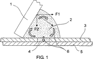
1つの伝統的スクリーンプリント技術において、図1中に図示されるように、傾斜したスクイジー1を使用して、開口4を含みかつ回路基板5の上に配置されるステンシル3にわたって、ある容積のペースト状製品2を押し、それによって、ステンシル3中の開口4を充填し、そして回路基板5上に溶着物を提供する。スクイジー1の前方移動(水平力F1による)により、下方力F2は、ペースト状製品2に加えられる。この下方力F2は、ペースト状製品2をステンシル3中の開口4に押しこみ、そしてステンシル3へのペースト状製品2の接着の組み合わせにより、ペースト状製品2は、矢印6に示されるようにステンシル3をわたって回転し、それによってペースト状製品2をずり減粘させる。
【0006】
このスクリーンプリント技術に関する多くの問題がある。1つの問題は、大気へのペースト状製品2の曝露が、ペースト状製品2の溶媒のエバポレーションを生じ、故に、ペースト状製品2が乾燥することである。別の問題は、スクイジー1のスピードを増加してステンシル3の開口4にペースト状製品2を押しこむ下方力F2を増加することが、開口4を充填するために利用可能な時間を減少するだけでなく、この増加により、ペースト状製品2がステンシル3にわたってスライドさせられ、それにより回転効果が減少されかつそれ故にずり減粘が減少され得るということである。
【0007】
エバポレーションの問題を克服するペースト状製品を含むスクリーンプリントヘッドは、例えば、US−A−4622239に開示されるように提案されているが、これらのプリントヘッドは、適切なプリントスピードの設定の問題に対処していない。
【0008】
WO−A−96/20088は、エバポレーションおよびプリントスピードの設定の両方の問題をペースト状製品に直接圧力を加えることによって克服するように試みたスクリーンプリントヘッドを開示する。しかし、このプリントヘッドは、ペースト状製品の回転作用を提供せず、それ故に、ペースト状製品のずり減粘を提供していない。さらに、このプリントヘッドは、ペースト状製品に加えられる非常に高い圧力を必要とする。この高圧は、ハンダペーストの金属成分およびフラックス成分の分離を生じ、非一貫性のプリントを生じる。
【0009】
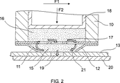
WO−A−98/16387は、エバポレーションおよびプリントスピードの設定の公知の問題に部分的に対応して開発されたスクリーンプリントヘッドを開示する。図2中図示されるように、このプリントヘッドは、主本体10、第1および第2ワイパーブレード11、12(これは、ステンシル13に接触しかつ主本体10と一緒にペースト状製品16を含むチャンバ15を規定する)、主本体10の低部末端に位置するグリル17、および下方力F2をペースト状製品16上に加えるためのピストン18を備える。ステンシル13(複数の開口19を備える)は、回路基板20の上に位置し、この上にペースト状製品16の沈着物がプリントされる。使用の際に、プリントヘッドは、2つの反対のプリント方向の1方に水平力F1を用いて移動され、これにより、ピストン18によりペースト状製品16に与えられた力によってステンシル13に対して押しつけられるワイパーブレード11、12は、ステンシル13の上の領域からペースト状製品16を引き上げるように作用し、かつペースト状製品16を、グリル17を通って上方に通過させ、このペースト状製品16は、続いて、ピストン18により発生した圧力の作用によってグリル17を通って下方に押し戻される。矢印21によって示されるように、ペースト状製品16のこの回転作用は、ペースト状製品16をずり減粘させ、それによってピストン18により加えられた圧力F2が低レベルで維持されることを可能にし、かつ回転作用の混合効果によってペースト状製品16の成分の分離を妨げることも可能にする。さらに、ペースト状製品16に加えられた圧力F2は、プリントヘッドの移動のスピードに依存しない。
【0010】
このプリントヘッドは、多くの改善されたスクリーンプリントを提供するが、いくつかの場合において、このプリントへットは、完全なプリントに必要とされるようなペースト状製品16の十分なずり減粘を提供しないことが、認められている。
【0011】
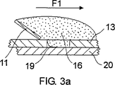
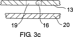
スクリーンプリントプロセスにおいて、図3aに図示されるように、ステンシル開口19の不完全な充填は、ペースト状製品16が、十分に薄くされていない場合に生じる。ステンシル開口19が、不完全に充填される場合、後進ワイパーブレード11の作用は、ステンシル開口19上のペースト状製品16を剪断し得、結果として開口19中のペースト状製品16は、開口19の前方の一端に押し出され、図3bに図示されるように、わずかな部分的プリントしか生じない。極端な場合において、ステンシル開口19中に残ったペースト状製品16は、回路基板20と十分に接触していないかもしれなく、その結果、回路基板20およびステンシル13が分離される場合、ペースト状製品16は、回路基板20に不十分に接着され、そして図3c中に示されるように、ステンシル13中に残ったままであり、実質的にプリントを全く生じない。さらに、ステンシル13の開口19中のペースト状製品16の維持は、それ自体、その後のプリントに関する問題をもたらす。なぜならば、本明細書中の上記で言及されたように、ペースト状製品16は、乾燥する傾向があり、開口19中のペースト状製品16の乾燥は、プリントの問題を引き起こすからである。これらの問題は、より小さいステンシル開口19の使用をもたらす縮小化における近年の傾向によっていっそう悪化している。この縮小化は、開口壁接触へのペースト状製品の面積に対して回路基板接触へのペースト状製品の面積を減少している。
【0012】
従って、本発明は、ペースト状製品をプリントスクリーンに塗布するためのスクリーンプリントヘッドを提供し、このプリントヘッドは、主本体;プリントスクリーンを接触するために主本体に配置されたワイパーブレード;ペースト状製品の供給を含むリザーバを提供する第1チャンバであって、この第1チャンバは、主本体によって少なくとも一部規定され、かつ少なくとも1つの出口開口部を備え、これを通ってペースト状製品は、使用の際に圧力下で押し込まれる、第1チャンバ;少なくとも1つの出口開口部と流体連絡する第2チャンバであって、この第2チャンバは、主本体およびこのワイパーブレードによって部分的に規定され、そして使用の際にプリントスクリーンと連絡する、第2チャンバ;ならびに該第2チャンバ中に配置され、かつ使用の際に、該プリントスクリーンの表面上を通過する、該第2チャンバ中に含まれるペースト状製品の循環流、および該プリントスクリーンに向かいかつその中の開口中に該ペースト状製品の循環流を押し進めるように作用する、該プリントスクリーンに向う該ペースト状製品の流れを引き起こすように構成される、フローディレクター、を備える。
【0013】
このようなプリントヘッドは、プリントスクリーンの開口に充填されたペースト状製品のずり減粘の増強を提供し、それ故に、低品質のプリントの発生率を減少するための改善されたステンシル開口充填を提供する。
【0014】
好ましくは、少なくとも1つの出口開口部は、細長スロットを備える。
【0015】
好ましくは、フローディレクターは、さらに、第1および第2循環帯域を規定するように配置され、ここで、ペースト状製品は、局所的に循環されかつこれを通して循環流が、指向される。
【0016】
好ましくは、フローディレクターは、ベーンを備え、使用の際に循環流は、このベーンの低部縁の下を通過する。
【0017】
より好ましくは、フローディレクターは、少なくとも1つの出口開口部の対向側面上に配置された第1および第2ベーンを備え、このベーンの低部縁は、プリントスクリーンに向けて指向されたノズルを規定する。
【0018】
好ましくは、このノズルは、細長ノズルである。
【0019】
好ましくは、主本体は、第1および第2ローブ部材を備え、この部材は、第2チャンバを一部規定し、このローブ部材は、ワイパーブレードのそれぞれの上に配置され、かつ循環流を促進するように弓形低部表面を有する。
【0020】
1つの実施形態において、主本体は、1以上のポートを備え、これを通して、第1チャンバに、ペースト状製品を装填し得る。
【0021】
別の実施形態において、主本体は、第1チャンバを少なくとも一部規定する交換可能なカセットを備え、第1チャンバを、このカセットの交換によって装填する。
【0022】
好ましくは、ワイパーブレードは、可撓性ワイパーブレードを含む。
【0023】
本発明はまた、上記のプリントヘッドを備えるスクリーンプリント装置に及ぶ。
【0024】
本発明はまた、プリントスクリーンと連絡するチャンバを備えるスクリーンプリントヘッドを使用するスクリーンプリント方法を提供し、この方法は、以下の工程:プリントスクリーンの表面上を通過する、チャンバ中のペースト状製品の循環流を提供する工程;およびペースト状製品の循環流をプリントスクリーン上およびその中の開口に押し進めるように作用する、プリントスクリーンに向うペースト状製品の流れを提供する工程、を包含する。
【0025】
好ましくは、この方法は、さらに、第1および第2循環帯域においてペースト状製品を局所的に循環させる工程を包含し、この帯域を通って循環流は、指向される。
【0026】
本発明は、スクリーンプリントのためのプリントヘッドをさらに提供し、このプリントヘッドを通して、印刷されるペースト状製品は、印加圧力によって押しつけられ得、このプリントヘッドは、ペースト状製品が装填され得るチャンバ(ここで、このペースト状製品は、圧力下に置かれ得る);プリントされるペースト状製品のためのチャンバからの退出スロット;およびこの退出口スロットと連絡する下流チャンバ、を備え、ここで、この下流チャンバは、使用の際に、その退出口で可撓性ワイパーブレードおよびスクリーンの一部によって閉鎖され、これを通して、ペースト状製品は、プリントされ、そして下流チャンバは、ベーンによって細区分されてペースト状製品流経路を規定し、これに沿って、ペースト状製品は、使用の際の、ステンシルにわたるプリントヘッドの移動の結果として流れ、この流経路は、ワイパーブレードの上の循環流、ならびに循環流の結果としてのベーンと印加圧力に起因する退出口スロットを通ったペースト状製品の移動との間のステンシルに向った流れを含む。
【0027】
本発明は、さらに、プリントヘッド(これを通して、プリントされるプリントヘッドペースト状製品は、印加圧力によって押しつけられる)を用いるスクリーンプリントの方法を提供し、この方法は、チャンバにペースト状製品を装填しかつこのチャンバから退出口スロットと連絡する下流チャンバに退出口スロットに向って移動するためにこのペースト状製品を圧力下に置く工程であって、この下流チャンバは、可撓性ワイパープレードおよびスクリーンの一部(これを通してペースト状製品は、プリントされる)によってその退出口末端にて閉鎖される、工程;ベーンによって下流チャンバを細区分して、ステンシルにわたるプリントヘッドの移動の結果として、製品流を通過させるペースト状製品流経路を規定する工程であって、この流経路は、循環流および印加圧力に起因して退出口スロットを通ったペースト状産物の移動の結果としての、ワイパーブレードの上の循環流ならびにベーンの間のステンシルに向った流れを含む、工程、を包含する。
【0028】
スクリーンプリントヘッドは、主本体30を備え、この実施形態において、細長本体、および第1および第2の内向および下向指向ワイパーブレード31、32(それぞれのクランププレートおよびねじによって主本体30に留められる)を備える。図5および6に図示されるように、ワイパーブレード31、32は、使用の際に、ステンシル34と接触して維持され、このステンシルは、複数の開口36を含み、そしてワークピース38の上に位置付し、この実施形態において、回路基板上で、ペースト状製品の溶着物がプリントされる。この実施形態において、プリントヘッドは、二方向に移動可能であるように、その長軸のまわりに対称に配置される。
【0029】
主本体30は、第1および第2ローブ部材42、44を備え、この実施形態において、突出体(これらの突出体の間に出口開口部46(この実施形態では細長スロット)が、規定される)ならびに外部開口部46を通して流体連絡する第1および第2チャンバ48、50を備える。本明細書中の以下にさらに記載されるように、第1および第2ローブ部材42、44の各々は、弓形で低部の、ルーフ表面52、54を有する。チャンバ48の1つ(第1)は、ペースト状製品56を含有するためのリザーバを提供し、そして可撓性ダイヤフラム58によって一部規定され、これは、使用の際に、他方(第2チャンバ50)への圧力下でペースト状製品56を駆動するように作用する。他方(第2チャンバ50)は、第1および第2循環帯域60、62を提供し、この中およびこれを通して、ペースト状製品56は、本明細書中の以下にさらに記載されるように循環される。この実施形態において、主本体30は、第1チャンバ48にペースト状製品56を装填するための複数のポート63を備える。この実施形態において、第2チャンバ50は、使用の際に、ペースト状製品56の乾燥を防止するための大気と仕切られて全体的に取り囲まれ、ステンシル34は、第2チャンバ50を一部取り囲んでいる。
【0030】
プリントヘッドは、さらに、出口開口部46に隣接する第2チャンバ50中に配置されたフローディレクター63を備える。フローディレクター63は、第1および第2ベーン64、66を備え、これらの各々は、出口開口部46に隣接する第1および第2ローブ部材42、44のそれぞれ1つの低部表面52、54と平行にある距離だけ伸長し、それらの間に通路67、68を規定しかつ下方にノズル69(この実施形態では、細長ノズル)を規定する。それらの間に、それは、ワイパーブレード31、32の低部縁によって規定される平面から間隔があけられ、ノズル69の下にペースト状製品56が流れることを可能にする。この構成をともなって、プリントヘッドは、第1チャンバ48、第1および第2循環帯域60、62ならびにフローディレクター63の内部間隔によって規定される通りの4つのセクションに効果的に分割される。
【0031】
プリントヘッドは、さらに、その末端の各々にてシール部材70を備え、このシール部材70は、可撓性材料で形成されてプリントの間に偏向するワイパーブレード31、32に適合する。
【0032】
使用の際に、プリントヘッドは、下にあるワークピース38の上に位置するステンシル34と接触される。力F2は、可撓性ダイヤフラム58に適用されて第1チャンバ48中にペースト状製品56を加圧しかつ出口開口部46を通して第2チャンバ50にペースト状製品を押し進め、このペースト状製品56は、通路67、68およびノズル69を通って押し進められ、ステンシル34と接触する。次いで、プリントヘッドは、水平力F1の下で、ステンシル34にわたって移動され、ステンシル34へのペースト状製品56の接着と組み合わされたこの移動は、矢印72に示されるように、循環帯域60、62中のペースト状製品56の循環流を引き起こす。先進循環帯域(この実施形態において、第2循環帯域62)からのペースト状製品56は、ノズル69とステンシル34との間でステンシル34への接着によって引かれ、この領域においてペースト状製品56のずり減粘を引き起こす。ペースト状製品56のこの流れは、後進循環帯域(この実施形態において、第1循環帯域60)内の圧力を増加し、そしてペースト状製品56は、通路67、68を通って先進循環帯域62に押し戻され、それによってペースト状製品56をさらにずり減粘にする。同時に、出口開口部46を通って第2チャンバ50に導入されたペースト状製品56の作用は、ノズル69の下の領域においてノズル69を通して新たにずり減粘されたペースト状製品56に圧力を直接加え、ずり減粘されたペースト状製品56をステンシル34中の開口36に押し込む。
【0033】
本発明のプリントヘッドは、特に、ノズル69とステンシル34との間の臨界領域において、公知のプリントヘッドのいずれかよりもより良好なずり減粘を提供し、そしてステンシル開口36へのペースト状製品56のより改善されたパッキングを提供する。従って、ワイパーブレード31、32は、ステンシル開口36において空隙を残さずに、ステンシル開口36の頂部を横切ってペースト状製品56をきれいに切断し得る。このように、良好な接触は、ステンシル開口38の全面積にわたってペースト状製品56とワークピース38との間で確立され、それによってワークピース38からステンシル34を分離する際に、ステンシル34からのペースト状製品56の良好な分離を確実にし、結果として高品質のプリントを確実にする。
【0034】
最後に、本発明は、その好ましい実施形態において記載され、そして添付の特許請求の範囲によって規定される通りの本発明の範囲から逸脱することなく多くの異なる様式で改変され得ることが、理解される。例えば、第1チャンバ48についての代替の設計は、明らかに可能であり、例えば、WO−A−98/16387に開示されるような、例えば交換可能なカセットシステムである。また、フローディレクター63(特に、ノズル69)ならびに第1および第2チャンバ48、50の形状およびサイズは、例示の実施形態の形状およびサイズから変更され得る。特に、出口開口部46およびノズル69の幅、通路67、68の幅および長さ、ならびにノズル69の低部縁とステンシル34との間のクリアランスはすべて、プリントヘッドの操作に対する効果を有し、かつずり減粘とペースト状製品56の最大供給速度との間の所望されるバランスを提供するように変更され得る。
【0035】
本発明の好ましい実施形態を、ここで、付随の図面を参照して例示のみのために本明細書中の以下に記載する。
【図面の簡単な説明】
【図1】 図1は、伝統的なスクリーンプリント技術において使用される場合のスクイジーの断面図である。
【図2】 図2は、公知のスクリーンプリントヘッドの断面図である。
【図3】 図3a、3bおよび3cは、図2のプリントヘッドを用いるスクリーンプリントの間に生じ得る欠陥の発達を示す。
【図4】 図4は、本発明の好ましい実施形態に従うスクリーンプリントヘッドの斜視図である。
【図5】 図5は、図4のプリントヘッドの断面図である。
【図6】 図6は、操作の際の、図4のプリントヘッドの断面図である。[0001]
The present invention relates to screen printing, and in particular to screen printing in which a printed pasty product is contained within a screen print head and delivered through the print head by pressing.
[0002]
In the assembly of the printed circuit board, a technique is established in which a solder paste to be connected to the element is welded, the element is placed on the paste weld, and then the assembly is heated to reflow the paste and complete the connection. Has been. Screen printing machines are used to deposit solder paste on printed circuit boards through stencils or screen openings.
[0003]
The solder paste is made of solder metal fine particles connected by an organic material or a flux. The metal content of such solder paste is typically up to 50% of the volume and up to 90% of the weight of the paste. Viscous fluxes consist of flow agents, adhesives and cleaning agents, some of which are thixotropic and some of which are volatile solvents. The thixotropic properties of the solder paste have the effect that the shear thinning process locally reduces the viscosity of the paste due to the relative movement of the regions within the paste.
[0004]
A typical print contains multiple small blocks of solder paste, and for consistent quality, it is essential that each block contains the same proportion of each component. This requires that the material in the solder paste has a consistent and homogeneous distribution.
[0005]
In one traditional screen printing technique, a volume of paste is used over a
[0006]
There are many problems with this screen printing technology. One problem is that the exposure of the pasty product 2 to the atmosphere results in evaporation of the solvent of the pasty product 2 and thus the pasty product 2 dries. Another problem is that increasing the speed of the
[0007]
Screen printheads containing pasty products that overcome evaporation problems have been proposed, for example, as disclosed in US Pat. No. 4,622,239, but these printheads have the problem of setting an appropriate print speed. Is not addressed.
[0008]
WO-A-96 / 20088 discloses a screen print head that attempts to overcome both the problems of evaporation and print speed setting by applying pressure directly to the pasty product. However, this printhead does not provide the rotational action of the pasty product and therefore does not provide the shear thinning of the pasty product. Furthermore, this printhead requires very high pressure applied to the pasty product. This high pressure results in separation of the solder paste metal and flux components, resulting in inconsistent prints.
[0009]
WO-A-98 / 16387 discloses a screen print head developed in part in response to the known problems of evaporation and print speed setting. As shown in FIG. 2, the print head includes a
[0010]
Although this printhead provides many improved screen prints, in some cases the print head is sufficient to reduce the shear of the
[0011]
In the screen printing process, as illustrated in FIG. 3a, incomplete filling of the
[0012]
Accordingly, the present invention provides a screen print head for applying a pasty product to a print screen, the print head comprising a main body; a wiper blade disposed on the main body for contacting the print screen; A first chamber providing a reservoir containing a supply of product, the first chamber being at least partially defined by the main body and comprising at least one outlet opening, through which the pasty product is A first chamber that is pushed under pressure in use; a second chamber in fluid communication with at least one outlet opening, the second chamber being defined in part by the main body and the wiper blade; And, in use, in communication with the print screen, a second chamber; and in the second chamber The paste-like product circulating in the second chamber, which is placed and in use, passes over the surface of the print screen, and the paste-like product in the opening towards and into the print screen A flow director configured to cause a flow of the pasty product toward the print screen, which acts to drive a product circulation.
[0013]
Such print heads provide enhanced shear thinning of pasty products filled into print screen openings and, therefore, improved stencil opening filling to reduce the incidence of low quality prints. provide.
[0014]
Preferably, the at least one outlet opening comprises an elongated slot.
[0015]
Preferably, the flow director is further arranged to define first and second circulation zones, wherein the pasty product is circulated locally and through which the circulation flow is directed.
[0016]
Preferably, the flow director comprises a vane, and in use the circulating flow passes under the lower edge of the vane.
[0017]
More preferably, the flow director comprises first and second vanes disposed on opposite sides of the at least one outlet opening, the lower edge of the vane defining a nozzle directed toward the print screen To do.
[0018]
Preferably, this nozzle is an elongated nozzle.
[0019]
Preferably, the main body comprises first and second lobe members that define in part a second chamber that is disposed on each of the wiper blades and facilitates circulation flow And has an arcuate lower surface.
[0020]
In one embodiment, the main body includes one or more ports through which the first chamber can be loaded with a pasty product.
[0021]
In another embodiment, the main body comprises a replaceable cassette that defines at least a portion of the first chamber, and the first chamber is loaded by replacement of the cassette.
[0022]
Preferably, the wiper blade includes a flexible wiper blade.
[0023]
The present invention also extends to a screen printing apparatus comprising the above print head.
[0024]
The present invention also provides a screen printing method using a screen print head comprising a chamber in communication with the printing screen, the method comprising the following steps: passing a pasty product in the chamber passing over the surface of the printing screen. Providing a circulating flow; and providing a flow of pasty product toward the print screen that serves to push the circulating flow of paste-like product over the print screen and into openings therein.
[0025]
Preferably, the method further comprises the step of locally circulating the pasty product in the first and second circulation zones, through which the circulation flow is directed.
[0026]
The present invention further provides a print head for screen printing, through which the pasty product to be printed can be pressed by an applied pressure, the print head being a chamber in which the pasty product can be loaded ( Wherein the pasty product can be placed under pressure); an exit slot from the chamber for the pasty product to be printed; and a downstream chamber in communication with the exit slot, wherein In use, the downstream chamber is closed at its exit by a flexible wiper blade and a part of the screen, through which the pasty product is printed, and the downstream chamber is subdivided by vanes and pasted. In line with this, paste-like products are used in use. As a result of the printhead movement across the stencil, this flow path is the circulation flow over the wiper blade, as well as the movement of the pasty product through the exit slot due to the vane and applied pressure as a result of the circulation flow. Including flow toward the stencil between.
[0027]
The present invention further provides a method of screen printing using a printhead (through which the printhead pasty product to be printed is pressed by the applied pressure), the method loading the pasty product into the chamber. And placing the pasty product under pressure to move toward the exit slot from the chamber to a downstream chamber in communication with the exit slot, the downstream chamber comprising a flexible wiper plate and a screen A part (through which the pasty product is printed) is closed at its exit end, the process; subdividing the downstream chamber by a vane and, as a result of the movement of the printhead across the stencil, the product stream A process for defining a pasty product flow path to be passed, The path comprises a circulation flow over the wiper blade as a result of the movement of the pasty product through the exit slot due to the circulation flow and the applied pressure, as well as a flow towards the stencil between the vanes, Is included.
[0028]
The screen print head comprises a
[0029]
The
[0030]
The print head further comprises a
[0031]
The print head further includes a
[0032]
In use, the print head is contacted with a
[0033]
The printhead of the present invention provides better shear thinning than any of the known printheads, particularly in the critical region between the
[0034]
Finally, it is understood that the present invention is described in its preferred embodiments and can be modified in many different ways without departing from the scope of the invention as defined by the appended claims. The For example, alternative designs for the
[0035]
Preferred embodiments of the invention will now be described hereinbelow by way of example only with reference to the accompanying drawings.
[Brief description of the drawings]
FIG. 1 is a cross-sectional view of a squeegee when used in traditional screen printing technology.
FIG. 2 is a cross-sectional view of a known screen print head.
FIGS. 3a, 3b and 3c show the development of defects that can occur during screen printing using the printhead of FIG.
FIG. 4 is a perspective view of a screen print head according to a preferred embodiment of the present invention.
FIG. 5 is a cross-sectional view of the print head of FIG.
FIG. 6 is a cross-sectional view of the print head of FIG. 4 during operation.
Claims (13)
主本体;
該プリントスクリーンに接触するための、該主本体に配置されたワイパーブレード;
該ペースト状製品の供給を含むためのリザーバを提供する第1チャンバであって、該第1チャンバは、該主本体によって少なくとも一部規定されかつ少なくとも1つの出口開口部を含み、該ペースト状製品は、該出口開口部を通って、使用の際に圧力下で押し進められる、第1チャンバ;
該少なくとも1つの出口開口部と流体連絡する第2チャンバであって、該第2チャンバは、該主本体および該ワイパーブレードによって少なくとも一部規定され、かつ使用の際に該プリントスクリーンと連絡する、第2チャンバ;ならびに
該第2チャンバ中に配置され、かつ使用の際に、該プリントスクリーンの表面上を通過する、該第2チャンバ中に含まれるペースト状製品の第1の循環流、および該ペースト状製品の第1の循環流を該プリントスクリーンに向けかつその中の開口中に押し進めるように作用する、該プリントスクリーンに向かう該ペースト状製品の第2の流れを引き起こすように構成される、フローディレクター、
を備える、スクリーンプリントヘッド。A screen print head for applying a pasty product to a print screen comprising:
Main body;
A wiper blade disposed on the main body for contacting the print screen;
A first chamber providing a reservoir for containing a supply of the pasty product, wherein the first chamber is at least partially defined by the main body and includes at least one outlet opening; Is pushed through the outlet opening under pressure during use; a first chamber;
A second chamber in fluid communication with the at least one outlet opening, the second chamber being at least partially defined by the main body and the wiper blade and in communication with the print screen in use; A first circulating flow of paste-like product contained in the second chamber; and in use, which is disposed in the second chamber and passes over the surface of the print screen in use; and Configured to cause a second flow of the pasty product toward the print screen, which acts to force a first circulating stream of the pasty product toward the print screen and into an opening therein. Flow director,
A screen print head comprising:
主本体;
該プリントスクリーンに接触するための、該主本体に配置されたワイパーブレード;
該ペースト状製品の供給を含むためのリザーバを提供する第1チャンバであって、該第1チャンバは、該主本体によって少なくとも一部規定されかつ少なくとも1つの出口開口部を含み、該ペースト状製品は、該出口開口部を通って、使用の際に圧力下で押し進められる、第1チャンバ;
該少なくとも1つの出口開口部と流体連絡する第2チャンバであって、該第2チャンバは、該主本体および該ワイパーブレードによって少なくとも一部規定され、かつ使用の際に該プリントスクリーンと連絡する、第2チャンバ;ならびに
該第2チャンバ中に配置され、かつ使用の際に、該プリントスクリーンの表面上を通過する、該第2チャンバ中に含まれるペースト状製品の第1の循環流、および該ペースト状製品の第1の循環流を該プリントスクリーンに向けかつその中の開口中に押し進めるように作用する、該プリントスクリーンに向かう該ペースト状製品の第2の流れを引き起こすように構成される、フローディレクター、
を備える、スクリーンプリントヘッドであって、
ここで、該フローディレクターが、第1循環帯域および第2循環帯域を規定するようにさらに構成され、該第1循環帯域および第2循環帯域において、該ペースト状製品は、局所的に循環され、そして該第1循環帯域および第2循環帯域を通って該第1の循環流が指向される、スクリーンプリントヘッド。 A screen print head for applying a pasty product to a print screen comprising:
Main body;
A wiper blade disposed on the main body for contacting the print screen;
A first chamber providing a reservoir for containing a supply of the pasty product, wherein the first chamber is at least partially defined by the main body and includes at least one outlet opening; Is pushed through the outlet opening under pressure during use; a first chamber;
A second chamber in fluid communication with the at least one outlet opening, the second chamber being at least partially defined by the main body and the wiper blade and in communication with the print screen in use; A second chamber; and
A first circulating stream of pasty product contained in the second chamber, disposed in the second chamber and passing over the surface of the print screen in use; A flow director configured to cause a second flow of the pasty product toward the print screen, which acts to force a circulating stream of one toward the print screen and into an opening therein;
A screen print head comprising:
Wherein the flow director is further configured to define a first circulation zone and the second circulation zone, in the first circulation zone and the second circulation zone, the pasty product is locally circulated, and said first circulation flow is directed through the first circulation zone and the second circulation zone, screen printing head.
主本体;
該プリントスクリーンに接触するための、該主本体に配置されたワイパーブレード;
該ペースト状製品の供給を含むためのリザーバを提供する第1チャンバであって、該第1チャンバは、該主本体によって少なくとも一部規定されかつ少なくとも1つの出口開口部を含み、該ペースト状製品は、該出口開口部を通って、使用の際に圧力下で押し進められる、第1チャンバ;
該少なくとも1つの出口開口部と流体連絡する第2チャンバであって、該第2チャンバは、該主本体および該ワイパーブレードによって少なくとも一部規定され、かつ使用の際に該プリントスクリーンと連絡する、第2チャンバ;ならびに
該第2チャンバ中に配置され、かつ使用の際に、該プリントスクリーンの表面上を通過する、該第2チャンバ中に含まれるペースト状製品の第1の循環流、および該ペースト状製品の第1の循環流を該プリントスクリーンに向けかつその中の開口中に押し進めるように作用する、該プリントスクリーンに向かう該ペースト状製品の第2の流れを引き起こすように構成される、フローディレクター、
を備える、スクリーンプリントヘッドであって、
ここで、該フローディレクターが、該プリントスクリーンの表面から間隔を空けられた低部縁を有する誘導ベーンを備え、使用の際に、該第1の循環流が、該誘導ベーンの低部縁の下を通過する、スクリーンプリントヘッド。 A screen print head for applying a pasty product to a print screen comprising:
Main body;
A wiper blade disposed on the main body for contacting the print screen;
A first chamber providing a reservoir for containing a supply of the pasty product, wherein the first chamber is at least partially defined by the main body and includes at least one outlet opening; Is pushed through the outlet opening under pressure during use; a first chamber;
A second chamber in fluid communication with the at least one outlet opening, the second chamber being at least partially defined by the main body and the wiper blade and in communication with the print screen in use; A second chamber; and
A first circulating stream of pasty product contained in the second chamber, disposed in the second chamber and passing over the surface of the print screen in use; A flow director configured to cause a second flow of the pasty product toward the print screen, which acts to force a circulating stream of one toward the print screen and into an opening therein;
A screen print head comprising:
Wherein the flow director comprises an inductive vanes having a lower portion edge spaced from the surface of the print screen, in use, the first circulation flow, the low edges of said induction vane A screen print head that passes underneath.
主本体;
該プリントスクリーンに接触するための、該主本体に配置されたワイパーブレード;
該ペースト状製品の供給を含むためのリザーバを提供する第1チャンバであって、該第1チャンバは、該主本体によって少なくとも一部規定されかつ少なくとも1つの出口開口部を含み、該ペースト状製品は、該出口開口部を通って、使用の際に圧力下で押し進められる、第1チャンバ;
該少なくとも1つの出口開口部と流体連絡する第2チャンバであって、該第2チャンバは、該主本体および該ワイパーブレードによって少なくとも一部規定され、かつ使用の際に該プリントスクリーンと連絡する、第2チャンバ;ならびに
該第2チャンバ中に配置され、かつ使用の際に、該プリントスクリーンの表面上を通過する、該第2チャンバ中に含まれるペースト状製品の第1の循環流、および該ペースト状製品の第1の循環流を該プリントスクリーンに向けかつその中の開口中に押し進めるように作用する、該プリントスクリーンに向かう該ペースト状製品の第2の流れを引き起こすように構成される、フローディレクター、
を備える、スクリーンプリントヘッドであって、
ここで、該フローディレクターが、該少なくとも1つの出口開口部の対向側面上に配置され、かつ、該プリントスクリーンの表面から間隔を空けられた低部縁を有する第1誘導ベーンおよび第2誘導ベーンを備え、使用の際に、該第1の循環流が、該誘導ベーンの低部縁の下を通過し、そして該第1および第2の誘導ベーンが、一緒になって該プリントスクリーンに向って指向されるノズルを規定する、
スクリーンプリントヘッド。 A screen print head for applying a pasty product to a print screen comprising:
Main body;
A wiper blade disposed on the main body for contacting the print screen;
A first chamber providing a reservoir for containing a supply of the pasty product, wherein the first chamber is at least partially defined by the main body and includes at least one outlet opening; Is pushed through the outlet opening under pressure during use; a first chamber;
A second chamber in fluid communication with the at least one outlet opening, the second chamber being at least partially defined by the main body and the wiper blade and in communication with the print screen in use; A second chamber; and
A first circulating stream of pasty product contained in the second chamber, disposed in the second chamber and passing over the surface of the print screen in use; A flow director configured to cause a second flow of the pasty product toward the print screen, which acts to force a circulating stream of one toward the print screen and into an opening therein;
A screen print head comprising:
Wherein the flow director, said at least one disposed on the opposite sides of the outlet opening, and a first inductive vanes and second induction vane having a lower portion edge spaced from the surface of the print screen comprises a, in use, the first circulation flow, passes under the lower edges of the induction vane, and said first and second induction vanes toward the print screen together Prescribe the nozzle to be oriented
Screen print head.
該プリントスクリーンの表面上を通過する、該チャンバ中のペースト状製品の第1の循環流を提供する工程;および
ペースト状製品の該第1の循環流を該プリントスクリーン上かつ該プリントスクリーン中の開口中に押し進めるように作用する、該プリントスクリーンに向かうペースト状製品の第2の流れを提供する工程、
を包含する、方法。A screen printing method using a screen printhead, the screen printhead including a chamber in communication with the print screen and a flow director, the flow director being disposed in the chamber and over the surface of the print screen A first circulating stream of pasty product contained in the chamber passing through, and acting to push the first circulating stream of pasty product toward the print screen and into an opening therein; Configured to cause a second flow of the pasty product towards the print screen, the method comprises the following steps:
Providing a first circulating stream of pasty product in the chamber that passes over the surface of the printing screen; and the first circulating stream of pasty product on the printing screen and in the printing screen; Providing a second stream of pasty product towards the print screen, which acts to push into the opening;
Including the method.
該プリントスクリーンの表面上を通過する、該チャンバ中のペースト状製品の第1の循環流を提供する工程;
ペースト状製品の該第1の循環流を該プリントスクリーン上かつ該プリントスクリーン中の開口中に押し進めるように作用する、該プリントスクリーンに向かうペースト状製品の第2の流れを提供する工程;および
第1循環帯域および第2循環帯域中にペースト状製品を局所的に循環させる工程
を包含し、該第1の循環流は、該帯域を通って指向される、方法。 A screen printing method using a screen printhead, the screen printhead including a chamber in communication with the print screen and a flow director, the flow director being disposed in the chamber and over the surface of the print screen A first circulating stream of pasty product contained in the chamber passing through, and acting to push the first circulating stream of pasty product toward the print screen and into an opening therein; Configured to cause a second flow of the pasty product towards the print screen, the method comprises the following steps:
Providing a first circulating flow of pasty product in the chamber passing over the surface of the print screen;
Providing a second stream of pasty product toward the print screen, which acts to push the first circulating stream of pasty product over the print screen and into an opening in the print screen; and 1 pasty product includes the step of locally circulating in the circulation zone and the second circulation zone, the first circulation flow is directed through the band-method.
Applications Claiming Priority (3)
| Application Number | Priority Date | Filing Date | Title |
|---|---|---|---|
| GB9916906.2 | 1999-07-19 | ||
| GB9916906A GB2352209A (en) | 1999-07-19 | 1999-07-19 | Improvements relating to screen printing |
| PCT/GB2000/002781 WO2001005592A1 (en) | 1999-07-19 | 2000-07-19 | Improvements relating to screen printing |
Publications (3)
| Publication Number | Publication Date |
|---|---|
| JP2003504249A JP2003504249A (en) | 2003-02-04 |
| JP2003504249A5 JP2003504249A5 (en) | 2011-02-03 |
| JP4831904B2 true JP4831904B2 (en) | 2011-12-07 |
Family
ID=10857510
Family Applications (1)
| Application Number | Title | Priority Date | Filing Date |
|---|---|---|---|
| JP2001510661A Expired - Fee Related JP4831904B2 (en) | 1999-07-19 | 2000-07-19 | Improvements related to screen printing |
Country Status (8)
| Country | Link |
|---|---|
| US (1) | US6746710B1 (en) |
| EP (1) | EP1202862B1 (en) |
| JP (1) | JP4831904B2 (en) |
| AT (1) | ATE267702T1 (en) |
| CA (1) | CA2379904A1 (en) |
| DE (1) | DE60011091T2 (en) |
| GB (1) | GB2352209A (en) |
| WO (1) | WO2001005592A1 (en) |
Families Citing this family (17)
| Publication number | Priority date | Publication date | Assignee | Title |
|---|---|---|---|---|
| JP3646603B2 (en) * | 2000-02-17 | 2005-05-11 | 松下電器産業株式会社 | Screen printing apparatus and screen printing method |
| JP4156227B2 (en) * | 2001-11-02 | 2008-09-24 | 松下電器産業株式会社 | Screen printing device |
| FR2881077B1 (en) | 2005-01-27 | 2007-06-29 | Novatec Sa Sa Soc | TRANSFER DEVICE BY SCREEN PRINTING |
| GB2437070B (en) * | 2006-04-10 | 2011-12-14 | Dek Int Gmbh | Screen printing head and system |
| EP2082435B1 (en) * | 2006-10-24 | 2010-03-10 | Commissariat A L'energie Atomique | Metallizing device and method |
| KR100861611B1 (en) * | 2006-11-14 | 2008-10-07 | 삼성전기주식회사 | Printing Apparatus |
| US7980445B2 (en) * | 2008-01-23 | 2011-07-19 | International Business Machines Corporation | Fill head for full-field solder coverage with a rotatable member |
| GB2458313B (en) | 2008-03-13 | 2012-05-23 | Dek Int Gmbh | Print head assembly, screen printing system and method |
| DE102008041423B4 (en) * | 2008-08-21 | 2015-04-16 | Fmp Technology Gmbh Fluid Measurements & Projects | Coating tool for applying a liquid film to a substrate |
| JP4973796B1 (en) | 2011-04-27 | 2012-07-11 | パナソニック株式会社 | Wiring board manufacturing method |
| JP5229437B2 (en) * | 2011-04-27 | 2013-07-03 | パナソニック株式会社 | Wiring board manufacturing method |
| EP2590488A4 (en) * | 2011-07-27 | 2013-10-23 | Panasonic Corp | Method for manufacturing reusable paste, reusable paste, and method for manufacturing wiring substrate using reusable paste |
| KR20130022184A (en) * | 2011-08-25 | 2013-03-06 | 삼성전자주식회사 | Squeeze apparatus |
| JP6251012B2 (en) * | 2013-11-18 | 2017-12-20 | 株式会社ケー・アイ・エス | Pattern forming device |
| TWI558574B (en) * | 2014-12-05 | 2016-11-21 | Metal Ind Res & Dev Ct | Slit Scraper Structure |
| CN110421965A (en) * | 2019-08-14 | 2019-11-08 | 协鑫集成科技股份有限公司 | Scraper device and solar battery sheet screen process press |
| EP3988312A1 (en) | 2020-10-23 | 2022-04-27 | Nederlandse Organisatie voor toegepast- natuurwetenschappelijk Onderzoek TNO | Device and method of filling grooves |
Citations (3)
| Publication number | Priority date | Publication date | Assignee | Title |
|---|---|---|---|---|
| JPH0557870A (en) * | 1991-09-02 | 1993-03-09 | Matsushita Electric Ind Co Ltd | Fluid coating method and apparatus |
| WO1996020088A1 (en) * | 1994-12-27 | 1996-07-04 | Ford Motor Company | Method and apparatus for dispensing viscous material |
| JP2000202988A (en) * | 1999-01-14 | 2000-07-25 | Ricoh Microelectronics Co Ltd | Printing agent filling device |
Family Cites Families (7)
| Publication number | Priority date | Publication date | Assignee | Title |
|---|---|---|---|---|
| GB1009740A (en) | 1963-07-19 | 1965-11-10 | Bradford Dyers Ass Ltd | Stencil-printing machines |
| NL7403192A (en) | 1974-03-08 | 1975-09-10 | Stork Brabant Bv | PAINT SUPPLY ELEMENT FOR A ROTARY SCREEN PRINTING MACHINE. |
| DE3238084A1 (en) * | 1982-10-14 | 1984-04-26 | Mathias 4815 Schloss Holte Mitter | DEVICE FOR EVENLY DELIVERING, DISTRIBUTING AND APPLYING A FOAMED FLEET OF APPLICATION TO A PREFERRED TEXTILE TRACK OR THE LIKE. |
| US4622239A (en) | 1986-02-18 | 1986-11-11 | At&T Technologies, Inc. | Method and apparatus for dispensing viscous materials |
| JPH0675747U (en) * | 1993-04-09 | 1994-10-25 | オリンパス光学工業株式会社 | Squeegee for solder printing |
| US5824155A (en) * | 1995-11-08 | 1998-10-20 | Ford Motor Company | Method and apparatus for dispensing viscous material |
| FR2754474B1 (en) | 1996-10-15 | 1999-04-30 | Novatec | DEVICE FOR DEPOSITING A VISCOUS OR PASTA ON A SUBSTRATE THROUGH THE OPENINGS OF A STENCIL |
-
1999
- 1999-07-19 GB GB9916906A patent/GB2352209A/en not_active Withdrawn
-
2000
- 2000-07-19 WO PCT/GB2000/002781 patent/WO2001005592A1/en active Search and Examination
- 2000-07-19 CA CA002379904A patent/CA2379904A1/en not_active Abandoned
- 2000-07-19 JP JP2001510661A patent/JP4831904B2/en not_active Expired - Fee Related
- 2000-07-19 EP EP00946159A patent/EP1202862B1/en not_active Expired - Lifetime
- 2000-07-19 AT AT00946159T patent/ATE267702T1/en not_active IP Right Cessation
- 2000-07-19 US US10/031,336 patent/US6746710B1/en not_active Expired - Lifetime
- 2000-07-19 DE DE60011091T patent/DE60011091T2/en not_active Expired - Lifetime
Patent Citations (3)
| Publication number | Priority date | Publication date | Assignee | Title |
|---|---|---|---|---|
| JPH0557870A (en) * | 1991-09-02 | 1993-03-09 | Matsushita Electric Ind Co Ltd | Fluid coating method and apparatus |
| WO1996020088A1 (en) * | 1994-12-27 | 1996-07-04 | Ford Motor Company | Method and apparatus for dispensing viscous material |
| JP2000202988A (en) * | 1999-01-14 | 2000-07-25 | Ricoh Microelectronics Co Ltd | Printing agent filling device |
Also Published As
| Publication number | Publication date |
|---|---|
| CA2379904A1 (en) | 2001-01-25 |
| DE60011091T2 (en) | 2005-05-25 |
| EP1202862A1 (en) | 2002-05-08 |
| GB9916906D0 (en) | 1999-09-22 |
| EP1202862B1 (en) | 2004-05-26 |
| ATE267702T1 (en) | 2004-06-15 |
| WO2001005592A1 (en) | 2001-01-25 |
| DE60011091D1 (en) | 2004-07-01 |
| GB2352209A (en) | 2001-01-24 |
| US6746710B1 (en) | 2004-06-08 |
| JP2003504249A (en) | 2003-02-04 |
Similar Documents
| Publication | Publication Date | Title |
|---|---|---|
| JP4831904B2 (en) | Improvements related to screen printing | |
| US6495199B1 (en) | Method for deposition of a viscous material on a substrate | |
| US4622239A (en) | Method and apparatus for dispensing viscous materials | |
| US6761926B1 (en) | Method for compressing viscous material through openings | |
| US5579690A (en) | Printer system for printing circuit patterns or like on base board | |
| US5824155A (en) | Method and apparatus for dispensing viscous material | |
| JP2003504249A5 (en) | ||
| JP3685053B2 (en) | Screen printing device | |
| US6395087B1 (en) | Method and apparatus for dispensing viscous material | |
| JP3544612B2 (en) | Cream solder printing apparatus and printing method | |
| JP3219366B2 (en) | Screen printing method and screen printing machine | |
| KR101514141B1 (en) | A squeezing apparatus of Screen printing equipment for printed circuit boardand | |
| TWI768086B (en) | Tin paste nozzle, work-bench and tin paste feeding apparatus | |
| EP0768176A1 (en) | System and method for high resolution screen printing | |
| JPH11320822A (en) | Solder printing device and solder printing method | |
| JP2000108304A (en) | Printing agent filling apparatus and printing apparatus | |
| JPH0450116Y2 (en) | ||
| CN109392298B (en) | Solder paste nozzle, workbench and solder paste adding device | |
| KR20080043575A (en) | Printing apparatus | |
| JPH0866998A (en) | Screen printer | |
| JPS5854695A (en) | Screen printing device | |
| JPH10315433A (en) | Printer and printing method | |
| JPH0578543U (en) | Solder printer paste supply device | |
| JPH07314640A (en) | Automatic cream solder supply method and supply device and cream solder printer using them | |
| JPS5854696A (en) | Screen printing device |
Legal Events
| Date | Code | Title | Description |
|---|---|---|---|
| A521 | Request for written amendment filed |
Free format text: JAPANESE INTERMEDIATE CODE: A523 Effective date: 20070713 |
|
| A621 | Written request for application examination |
Free format text: JAPANESE INTERMEDIATE CODE: A621 Effective date: 20070713 |
|
| A711 | Notification of change in applicant |
Free format text: JAPANESE INTERMEDIATE CODE: A711 Effective date: 20071017 |
|
| A521 | Request for written amendment filed |
Free format text: JAPANESE INTERMEDIATE CODE: A821 Effective date: 20071017 |
|
| A131 | Notification of reasons for refusal |
Free format text: JAPANESE INTERMEDIATE CODE: A131 Effective date: 20100609 |
|
| A601 | Written request for extension of time |
Free format text: JAPANESE INTERMEDIATE CODE: A601 Effective date: 20100908 |
|
| A602 | Written permission of extension of time |
Free format text: JAPANESE INTERMEDIATE CODE: A602 Effective date: 20100915 |
|
| A601 | Written request for extension of time |
Free format text: JAPANESE INTERMEDIATE CODE: A601 Effective date: 20101007 |
|
| A602 | Written permission of extension of time |
Free format text: JAPANESE INTERMEDIATE CODE: A602 Effective date: 20101015 |
|
| A601 | Written request for extension of time |
Free format text: JAPANESE INTERMEDIATE CODE: A601 Effective date: 20101108 |
|
| A602 | Written permission of extension of time |
Free format text: JAPANESE INTERMEDIATE CODE: A602 Effective date: 20101115 |
|
| A524 | Written submission of copy of amendment under article 19 pct |
Free format text: JAPANESE INTERMEDIATE CODE: A524 Effective date: 20101209 |
|
| A02 | Decision of refusal |
Free format text: JAPANESE INTERMEDIATE CODE: A02 Effective date: 20110131 |
|
| A521 | Request for written amendment filed |
Free format text: JAPANESE INTERMEDIATE CODE: A523 Effective date: 20110531 |
|
| A911 | Transfer to examiner for re-examination before appeal (zenchi) |
Free format text: JAPANESE INTERMEDIATE CODE: A911 Effective date: 20110629 |
|
| TRDD | Decision of grant or rejection written | ||
| A01 | Written decision to grant a patent or to grant a registration (utility model) |
Free format text: JAPANESE INTERMEDIATE CODE: A01 Effective date: 20110818 |
|
| A01 | Written decision to grant a patent or to grant a registration (utility model) |
Free format text: JAPANESE INTERMEDIATE CODE: A01 |
|
| A61 | First payment of annual fees (during grant procedure) |
Free format text: JAPANESE INTERMEDIATE CODE: A61 Effective date: 20110920 |
|
| R150 | Certificate of patent or registration of utility model |
Free format text: JAPANESE INTERMEDIATE CODE: R150 |
|
| FPAY | Renewal fee payment (event date is renewal date of database) |
Free format text: PAYMENT UNTIL: 20140930 Year of fee payment: 3 |
|
| S531 | Written request for registration of change of domicile |
Free format text: JAPANESE INTERMEDIATE CODE: R313531 |
|
| S533 | Written request for registration of change of name |
Free format text: JAPANESE INTERMEDIATE CODE: R313533 |
|
| R350 | Written notification of registration of transfer |
Free format text: JAPANESE INTERMEDIATE CODE: R350 |
|
| R250 | Receipt of annual fees |
Free format text: JAPANESE INTERMEDIATE CODE: R250 |
|
| R250 | Receipt of annual fees |
Free format text: JAPANESE INTERMEDIATE CODE: R250 |
|
| R250 | Receipt of annual fees |
Free format text: JAPANESE INTERMEDIATE CODE: R250 |
|
| S111 | Request for change of ownership or part of ownership |
Free format text: JAPANESE INTERMEDIATE CODE: R313113 |
|
| S533 | Written request for registration of change of name |
Free format text: JAPANESE INTERMEDIATE CODE: R313533 |
|
| R350 | Written notification of registration of transfer |
Free format text: JAPANESE INTERMEDIATE CODE: R350 |
|
| LAPS | Cancellation because of no payment of annual fees |