JP4699524B2 - Systems and methods for image sensor elements or arrays with photometric and real-time reporting capabilities - Google Patents
Systems and methods for image sensor elements or arrays with photometric and real-time reporting capabilities Download PDFInfo
- Publication number
- JP4699524B2 JP4699524B2 JP2008532376A JP2008532376A JP4699524B2 JP 4699524 B2 JP4699524 B2 JP 4699524B2 JP 2008532376 A JP2008532376 A JP 2008532376A JP 2008532376 A JP2008532376 A JP 2008532376A JP 4699524 B2 JP4699524 B2 JP 4699524B2
- Authority
- JP
- Japan
- Prior art keywords
- pixel
- report
- pixels
- reports
- exposure
- Prior art date
- Legal status (The legal status is an assumption and is not a legal conclusion. Google has not performed a legal analysis and makes no representation as to the accuracy of the status listed.)
- Expired - Fee Related
Links
- 238000000034 method Methods 0.000 title claims description 58
- 238000003491 array Methods 0.000 title description 4
- 230000004044 response Effects 0.000 claims description 57
- 230000005670 electromagnetic radiation Effects 0.000 claims description 36
- 230000008569 process Effects 0.000 claims description 21
- 238000012545 processing Methods 0.000 claims description 11
- 238000005259 measurement Methods 0.000 description 23
- 239000007787 solid Substances 0.000 description 18
- 238000003384 imaging method Methods 0.000 description 15
- 230000035945 sensitivity Effects 0.000 description 14
- 238000010586 diagram Methods 0.000 description 13
- 230000006870 function Effects 0.000 description 13
- 230000008901 benefit Effects 0.000 description 9
- 238000005375 photometry Methods 0.000 description 8
- 238000004590 computer program Methods 0.000 description 5
- 230000008859 change Effects 0.000 description 4
- 238000004891 communication Methods 0.000 description 4
- 238000012546 transfer Methods 0.000 description 4
- 239000003990 capacitor Substances 0.000 description 3
- 230000015556 catabolic process Effects 0.000 description 3
- 238000006731 degradation reaction Methods 0.000 description 3
- 238000005516 engineering process Methods 0.000 description 3
- 230000010354 integration Effects 0.000 description 3
- 230000003044 adaptive effect Effects 0.000 description 2
- 238000004364 calculation method Methods 0.000 description 2
- 235000019580 granularity Nutrition 0.000 description 2
- 238000001454 recorded image Methods 0.000 description 2
- 230000009471 action Effects 0.000 description 1
- 230000006399 behavior Effects 0.000 description 1
- 238000004422 calculation algorithm Methods 0.000 description 1
- 230000000295 complement effect Effects 0.000 description 1
- 230000000994 depressogenic effect Effects 0.000 description 1
- 238000013461 design Methods 0.000 description 1
- 239000000463 material Substances 0.000 description 1
- 229910044991 metal oxide Inorganic materials 0.000 description 1
- 150000004706 metal oxides Chemical class 0.000 description 1
- 238000012986 modification Methods 0.000 description 1
- 230000004048 modification Effects 0.000 description 1
- 230000003287 optical effect Effects 0.000 description 1
- 230000005855 radiation Effects 0.000 description 1
- 238000005070 sampling Methods 0.000 description 1
- 229920006395 saturated elastomer Polymers 0.000 description 1
- 238000009738 saturating Methods 0.000 description 1
- 239000004065 semiconductor Substances 0.000 description 1
- 239000000126 substance Substances 0.000 description 1
- 230000000007 visual effect Effects 0.000 description 1
- 239000002699 waste material Substances 0.000 description 1
Images


Classifications
-
- G—PHYSICS
- G01—MEASURING; TESTING
- G01J—MEASUREMENT OF INTENSITY, VELOCITY, SPECTRAL CONTENT, POLARISATION, PHASE OR PULSE CHARACTERISTICS OF INFRARED, VISIBLE OR ULTRAVIOLET LIGHT; COLORIMETRY; RADIATION PYROMETRY
- G01J1/00—Photometry, e.g. photographic exposure meter
- G01J1/42—Photometry, e.g. photographic exposure meter using electric radiation detectors
- G01J1/44—Electric circuits
-
- H—ELECTRICITY
- H03—ELECTRONIC CIRCUITRY
- H03M—CODING; DECODING; CODE CONVERSION IN GENERAL
- H03M1/00—Analogue/digital conversion; Digital/analogue conversion
- H03M1/12—Analogue/digital converters
- H03M1/64—Analogue/digital converters with intermediate conversion to phase of sinusoidal or similar periodical signals
-
- H—ELECTRICITY
- H04—ELECTRIC COMMUNICATION TECHNIQUE
- H04N—PICTORIAL COMMUNICATION, e.g. TELEVISION
- H04N23/00—Cameras or camera modules comprising electronic image sensors; Control thereof
- H04N23/70—Circuitry for compensating brightness variation in the scene
-
- H—ELECTRICITY
- H04—ELECTRIC COMMUNICATION TECHNIQUE
- H04N—PICTORIAL COMMUNICATION, e.g. TELEVISION
- H04N23/00—Cameras or camera modules comprising electronic image sensors; Control thereof
- H04N23/70—Circuitry for compensating brightness variation in the scene
- H04N23/71—Circuitry for evaluating the brightness variation
-
- H—ELECTRICITY
- H04—ELECTRIC COMMUNICATION TECHNIQUE
- H04N—PICTORIAL COMMUNICATION, e.g. TELEVISION
- H04N23/00—Cameras or camera modules comprising electronic image sensors; Control thereof
- H04N23/70—Circuitry for compensating brightness variation in the scene
- H04N23/76—Circuitry for compensating brightness variation in the scene by influencing the image signals
-
- H—ELECTRICITY
- H04—ELECTRIC COMMUNICATION TECHNIQUE
- H04N—PICTORIAL COMMUNICATION, e.g. TELEVISION
- H04N25/00—Circuitry of solid-state image sensors [SSIS]; Control thereof
- H04N25/50—Control of the SSIS exposure
- H04N25/51—Control of the gain
-
- H—ELECTRICITY
- H04—ELECTRIC COMMUNICATION TECHNIQUE
- H04N—PICTORIAL COMMUNICATION, e.g. TELEVISION
- H04N25/00—Circuitry of solid-state image sensors [SSIS]; Control thereof
- H04N25/50—Control of the SSIS exposure
- H04N25/57—Control of the dynamic range
- H04N25/571—Control of the dynamic range involving a non-linear response
- H04N25/575—Control of the dynamic range involving a non-linear response with a response composed of multiple slopes
-
- H—ELECTRICITY
- H04—ELECTRIC COMMUNICATION TECHNIQUE
- H04N—PICTORIAL COMMUNICATION, e.g. TELEVISION
- H04N25/00—Circuitry of solid-state image sensors [SSIS]; Control thereof
- H04N25/70—SSIS architectures; Circuits associated therewith
- H04N25/71—Charge-coupled device [CCD] sensors; Charge-transfer registers specially adapted for CCD sensors
- H04N25/75—Circuitry for providing, modifying or processing image signals from the pixel array
-
- H—ELECTRICITY
- H04—ELECTRIC COMMUNICATION TECHNIQUE
- H04N—PICTORIAL COMMUNICATION, e.g. TELEVISION
- H04N25/00—Circuitry of solid-state image sensors [SSIS]; Control thereof
- H04N25/70—SSIS architectures; Circuits associated therewith
- H04N25/76—Addressed sensors, e.g. MOS or CMOS sensors
- H04N25/78—Readout circuits for addressed sensors, e.g. output amplifiers or A/D converters
-
- H—ELECTRICITY
- H04—ELECTRIC COMMUNICATION TECHNIQUE
- H04N—PICTORIAL COMMUNICATION, e.g. TELEVISION
- H04N3/00—Scanning details of television systems; Combination thereof with generation of supply voltages
- H04N3/10—Scanning details of television systems; Combination thereof with generation of supply voltages by means not exclusively optical-mechanical
- H04N3/14—Scanning details of television systems; Combination thereof with generation of supply voltages by means not exclusively optical-mechanical by means of electrically scanned solid-state devices
- H04N3/15—Scanning details of television systems; Combination thereof with generation of supply voltages by means not exclusively optical-mechanical by means of electrically scanned solid-state devices for picture signal generation
- H04N3/155—Control of the image-sensor operation, e.g. image processing within the image-sensor
Landscapes
- Engineering & Computer Science (AREA)
- Multimedia (AREA)
- Signal Processing (AREA)
- Physics & Mathematics (AREA)
- Nonlinear Science (AREA)
- General Physics & Mathematics (AREA)
- Spectroscopy & Molecular Physics (AREA)
- Theoretical Computer Science (AREA)
- Computer Vision & Pattern Recognition (AREA)
- Solid State Image Pick-Up Elements (AREA)
- Analogue/Digital Conversion (AREA)
- Stabilization Of Oscillater, Synchronisation, Frequency Synthesizers (AREA)
- Transforming Light Signals Into Electric Signals (AREA)
- Studio Devices (AREA)
- Light Receiving Elements (AREA)
- Photometry And Measurement Of Optical Pulse Characteristics (AREA)
Description
発明の分野
この発明は電子画像化の分野に一般的に関し、より特定的には、測光を用いてレポートする改良された撮像のための方法および装置に関する。
The present invention relates generally to the field of electronic imaging, and more particularly to a method and apparatus for improved imaging reporting using photometry.
発明の背景
写真は、光の作用によって画像を作り出すプロセスである。光とは、人間の目に見える周波数範囲の電磁放射について一般的に用いられる用語である。被写体から反射または発せられた光のパターンは、時間設定された露光を通して画像センサによって記録される。画像センサは、写真フィルムなどの化学的性質のもの、またはデジタルスチルおよびビデオカメラが用いるCCDおよびCMOS画像センサなどの固体の性質のものであり得る。
Background of the Invention Photography is the process of creating an image by the action of light. Light is a commonly used term for electromagnetic radiation in the frequency range visible to the human eye. The pattern of light reflected or emitted from the subject is recorded by the image sensor through timed exposure. Image sensors can be of chemical nature such as photographic film or solid nature such as CCD and CMOS image sensors used by digital still and video cameras.
デジタルカメラは、光を焦点合せしてシーンの画像を作成する一連のレンズを有する。しかし、デジタルカメラは、従来のカメラのようにこの光を1枚の写真フィルムに焦点合せする代わりに、光の電磁放射を電荷に変換する固体画像センサに光を焦点合せする。画像センサの極小の要素は画素または「ピクセル」と称され、デジタル写真用の実際の画像センサは典型的に多数のピクセルを有する。電荷は、画像センサが感知する電磁放射の相対的な強度を示し、一般的に光強度値をピクセルと関連付けるのに用いられる。 Digital cameras have a series of lenses that focus the light to create an image of the scene. However, instead of focusing this light on a piece of photographic film as in a conventional camera, the digital camera focuses the light on a solid-state image sensor that converts the electromagnetic radiation of the light into a charge. The smallest elements of an image sensor are referred to as a picture element or “pixel”, and an actual image sensor for digital photography typically has a large number of pixels. The charge indicates the relative intensity of electromagnetic radiation sensed by the image sensor and is typically used to associate a light intensity value with a pixel.
写真の1つの目的は、人間の目が見た画像を正確に表わす画像を提供することである。しかしながら、人間の目はすべての波長の光に対して等しく感度があるわけではない。その結果、画像センサに当たる電磁放射に対する画像センサの応答を人間の視覚の感度に従って調整しなければならない。調整は典型的に、電磁放射に対する画像センサの露光を調整して、異なる波長に対する人間の感度を補償することによって行なわれる。 One purpose of photography is to provide an image that accurately represents the image seen by the human eye. However, the human eye is not equally sensitive to light of all wavelengths. As a result, the response of the image sensor to electromagnetic radiation striking the image sensor must be adjusted according to the sensitivity of human vision. Adjustment is typically done by adjusting the exposure of the image sensor to electromagnetic radiation to compensate for human sensitivity to different wavelengths.
しかしながら、画像センサに提供すべき適正な露光レベルを判断することはしばしば困難である。光感度画像センサ構成要素に対する電磁放射の適正な露光レベルを判断および適用できないと、撮像された画像の劣化につながる。そのような劣化はしばしば「露出過度」または「露出不足」と称される。露出過度は、光感度構成要素に晒される電磁放射のレベルが光波長についての最適レベルよりも大きいときに起こる。露出過度はしばしば、撮像された画像内の明るい部分の細部が欠如する原因となる。 However, it is often difficult to determine the proper exposure level to provide to the image sensor. Failure to determine and apply the proper exposure level of electromagnetic radiation to the light sensitive image sensor component leads to degradation of the captured image. Such degradation is often referred to as “overexposed” or “underexposed”. Overexposure occurs when the level of electromagnetic radiation exposed to the light sensitive component is greater than the optimum level for the light wavelength. Overexposure often causes a lack of bright details in the captured image.
図1Aは露出過度に対する画像センサの応答特性を図示する。横座標はセンサに当たる電磁放射の強度を表わす。縦座標は画像センサの対応する出力電圧を表わす。低強度の放射については、画像感度構成要素の電圧は電磁放射の強度とともに線形に増加する。しかしながら、電磁放射の強度が(図1aの破線によって示されるように)しきい値Toを超えても増加すると、画像感度構成要素の出力電圧はそれに応じて変化せず、むしろある最大電圧で横ばいになる。したがって、画像感度装置は、しきい値Toを超える電磁放射強度レベルを有する画像を正確に表わすことができず、記録された画像は露出過度であると言われる。 FIG. 1A illustrates the response characteristics of an image sensor to overexposure. The abscissa represents the intensity of electromagnetic radiation hitting the sensor. The ordinate represents the corresponding output voltage of the image sensor. For low intensity radiation, the voltage of the image sensitivity component increases linearly with the intensity of the electromagnetic radiation. However, when the intensity of the electromagnetic radiation (as indicated by the dashed line in FIG. 1a) increases even above the threshold T o, the output voltage of the image sensitivity component does not change accordingly, with the maximum voltage that rather Level off. Therefore, the image sensitivity device can not represent an image having an electromagnetic radiation intensity level over a threshold T o accurately recorded image is said to be overexposed.
図1Bは露出不足に対する画像センサの応答特性を図示する。露出不足は、電磁放射に対する画像感度構成要素の露光のレベルが最適レベルよりも小さいときに起こる。露出不足はしばしば、撮像された画像内の暗い部分の細部が欠如する原因となる。図1Bに見られるように、低強度値については、画像感度構成要素の電圧は電磁放射の強度変化に応答して変化しない。光強度が最小光強度レベルしきい値Tuを過ぎた後で初めて、画像感度構成要素の電圧が電磁放射の強度とともに線形に増加する。したがって、画像感度装置は、しきい値TUを超えない電磁放射強度レベルを有する画像の細部または色を正確に表わすことができず、記録された画像は露出不足であると言われる。 FIG. 1B illustrates the response characteristics of the image sensor to underexposure. Underexposure occurs when the level of exposure of the image sensitivity component to electromagnetic radiation is less than the optimum level. Underexposure often causes a lack of dark details in the captured image. As seen in FIG. 1B, for low intensity values, the voltage of the image sensitivity component does not change in response to changes in the intensity of the electromagnetic radiation. Only after the light intensity has passed the minimum light intensity level threshold Tu , the voltage of the image sensitivity component increases linearly with the intensity of the electromagnetic radiation. Therefore, the image sensitivity device can not represent details or color of an image having an electromagnetic radiation intensity level that does not exceed the threshold T U accurately recorded image is said to be underexposed.
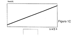
図1Cは電磁放射に対する画像センサの適正な露光を反映する伝達関数を図示する。適正な露光は、画像が低電磁放射強度レベルの区間および高電磁放射強度レベルの区間において完全な細部を有して最適に撮像されるときに起こる。適正な露光により、当初の画像の明るい部分および暗い部分の両方を、画像の撮像された電子的な表示で正確に表わすことが可能となる。 FIG. 1C illustrates a transfer function that reflects proper exposure of the image sensor to electromagnetic radiation. Proper exposure occurs when the image is optimally imaged with complete details in the sections of low and high electromagnetic radiation intensity levels. With proper exposure, both the bright and dark portions of the original image can be accurately represented in the captured electronic representation of the image.
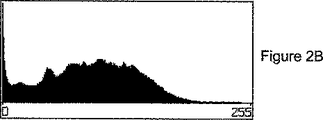
図2A〜図2Cは露光された画像のピクセル強度のヒストグラムを図示しており、露光された画像は各々が0から255までの可能なピクセル強度の範囲を有する。図2Aは、たとえば1Aに図示されるような伝達関数を有する露光プロセスを用いて過度に露出された画像において見られ得るピクセル強度のヒストグラムである。図2Bは、図1Bの伝達関数を用いて撮像された画像などの、露出不足の画像において見られ得るピクセル強度のヒストグラムである。図2Cは、たとえば図1Cの伝達関数を用いて適正に露出された画像において見られ得るピクセル強度のヒストグラムである。図2Cのヒストグラムはピクセル強度の正規化分布を図示する一方、図2Aは、露出過度の画像が最大画像センサ出力値(′255′)で圧縮されるピクセル強度を有することを図示しており、露出不足の画像は最小画像センサ出力値(′0′)で圧縮されるピクセル強度を有する。 2A-2C illustrate pixel intensity histograms of the exposed image, where each exposed image has a range of possible pixel intensities from 0 to 255. FIG. FIG. 2A is a histogram of pixel intensities that can be seen in an image that is overexposed using an exposure process having a transfer function as illustrated, for example, in 1A. FIG. 2B is a histogram of pixel intensities that can be found in an underexposed image, such as an image taken using the transfer function of FIG. 1B. FIG. 2C is a histogram of pixel intensities that can be seen in a properly exposed image using, for example, the transfer function of FIG. 1C. The histogram of FIG. 2C illustrates a normalized distribution of pixel intensity, while FIG. 2A illustrates that an overexposed image has a pixel intensity that is compressed at the maximum image sensor output value ('255') An underexposed image has a pixel intensity that is compressed with a minimum image sensor output value ('0').
ピクセルアレイに到達する画像は、強度が大幅に異なり得、従って画像が高ダイナミックレンジを有する原因となる暗い領域および明るい領域を含む。画像のダイナミックレンジはピクセルアレイのダイナミックレンジ内に収まる場合もあるが、露光計算は極めて正確でなければならない。現実のピクセルアレイの限られたダイナミックレンジと典型的な画像の高ダイナミックレンジが組合さると、正確な露光計算が非常に困難な作業となる。 The images that reach the pixel array can include significantly dark and light areas that can cause the image to have a large dynamic range and thus have a high dynamic range. Although the dynamic range of the image may fall within the dynamic range of the pixel array, the exposure calculation must be very accurate. Combining the limited dynamic range of real-world pixel arrays with the high dynamic range of typical images makes accurate exposure calculations a very difficult task.
現在の技術は露光時間を計算する多数の方法を認識している。1つの公知の方法では、推定露光時間設定を用いて画像を撮像し、ピクセル出力ヒストグラムを観察し、新たな露光時間推定に辿り着き、この新たな露光時間推定を用いて画像を取得する。この方法は、各画像を2回撮像するため電力の浪費である。これは、第2の露光時間推定は第1の値よりもよいが依然として近似であり、かつ多数のピクセルが自身のダイナミックレンジ外の光強度に晒されることになるため、不正確でもある。 Current technology recognizes a number of ways to calculate the exposure time. In one known method, an image is captured using an estimated exposure time setting, a pixel output histogram is observed, a new exposure time estimate is reached, and an image is acquired using this new exposure time estimate. This method is a waste of power because each image is captured twice. This is also inaccurate because the second exposure time estimate is better than the first value but is still an approximation and many pixels will be exposed to light intensity outside their dynamic range.
他の方法では、画像全体を調べ、平均の光画像強度値を測定し、この値に基づいて露光時間を計算する。しかしながら、そのような方法は画像内の光強度の実際の分布を考慮していないため不正確である。ここでもまた、多数のピクセルが自身のダイナミックレンジ外の光強度に晒されることになる。 In other methods, the entire image is examined, an average light image intensity value is measured, and an exposure time is calculated based on this value. However, such a method is inaccurate because it does not take into account the actual distribution of light intensity in the image. Again, a large number of pixels will be exposed to light intensity outside their dynamic range.
適正な露光量の特定は測光によってさらに複雑になる。測光は、可視光、特にその強度を測定する科学であり、これを用いて画像強度を、人間の視覚に対するその感知輝度の観点から説明することができる。測光を用いて、波長の測定された強度を、目がその波長にどの程度感度があるかの関数である因子で重み付けすることによって、光波長に対する人間の視覚の異なる感度を明らかにすることができる。 Specifying an appropriate exposure amount is further complicated by photometry. Photometry is the science of measuring the intensity of visible light, especially its intensity, which can be used to explain the image intensity in terms of its perceived brightness to human vision. Using photometry, it is possible to account for the different sensitivities of human vision to light wavelengths by weighting the measured intensity of a wavelength by a factor that is a function of how sensitive the eye is to that wavelength. it can.
測光は典型的に、特定の測光機能用に設計された電磁放射感度装置を用いて行なわれ、レポートされる。電磁感度装置は、たとえば電荷結合素子(CCD)または相補型金属酸化物半導体(CMOS)装置であり得る。図3は、ピクセル構造12などのピクセル構造および測光構造14などの測光構造を含むピクセルアレイ10を図示する。そのような測光装置を用いる典型的なピクセル構造は、撮像すべき画像の1つまたはそれ以上のサブエリアで測光を行なう。さまざまなサブ画像の測定を次に処理して、画像感度材料を電磁放射に晒すべきレベルを判断する。画像は第2の処理段階にかけられ、ここでは、予め計算された露光時間の間だけ固体画像センサ装置を入射する電磁放射に晒すことによって画像を次に取得する。
Photometry is typically performed and reported using an electromagnetic radiation sensitivity device designed for a specific photometric function. The electromagnetic sensitivity device can be, for example, a charge coupled device (CCD) or a complementary metal oxide semiconductor (CMOS) device. FIG. 3 illustrates a
しかしながら、この測光は、撮像すべき画像内のポイントの一般的に小さなサブセットから行なわれるため、しばしば最適なものではない。サンプリングポイントのいずれかの視覚的属性および/またはアーティファクトを用いて、画像全体に適用される露光レベルを計算する。その結果、そのような測定から得られた露光時間はしばしば不正確であり、その結果処理された画像は一般的に悪い。説明した方法の他の不利な点は、画像センサの性質を考慮していないことである。たとえば、画像センサは電磁放射の異なる強度に対して異なったように応答し得る。画像センサのゲイン特性を考慮していない重み付け因子を画像センサに盲目的に適用すると、最適な出力画像を提供する問題が悪化し得る。 However, this photometry is often not optimal because it is performed from a generally small subset of points in the image to be imaged. Any visual attribute and / or artifact of the sampling point is used to calculate the exposure level applied to the entire image. As a result, the exposure times obtained from such measurements are often inaccurate and the resulting processed images are generally poor. Another disadvantage of the described method is that it does not take into account the nature of the image sensor. For example, the image sensor may respond differently to different intensities of electromagnetic radiation. When a weighting factor that does not take into account the gain characteristics of the image sensor is blindly applied to the image sensor, the problem of providing an optimal output image can be exacerbated.
発明の要約
この発明の固体ピクセル構造は、画像センサと、受けた電磁放射に対する画像センサの応答を測定するための手段と、画像センサの応答の状態を露光コントローラにレポートするための手段とを含む。
SUMMARY OF THE INVENTION The solid state pixel structure of the present invention includes an image sensor, means for measuring the response of the image sensor to received electromagnetic radiation, and means for reporting the status of the image sensor response to the exposure controller. .
本発明の他の局面によると、ピクセルアレイは、露光コントローラと、露光コントローラに結合された少なくとも1つのピクセル構造群とを含む。各ピクセル構造群は少なくとも1つのピクセル構造を含む。ピクセル構造は、画像センサと、受けた電磁放射に対する画像センサの応答を測定するための手段と、応答の状態を露光コントローラにレポートするための手段とを含む。露光コントローラは応答の状態を分析して、露光終了トリガ事象が起こったことを応答の状態が示しているかどうか判断する。 According to another aspect of the invention, the pixel array includes an exposure controller and at least one group of pixel structures coupled to the exposure controller. Each pixel structure group includes at least one pixel structure. The pixel structure includes an image sensor, means for measuring the response of the image sensor to the received electromagnetic radiation, and means for reporting the status of the response to the exposure controller. The exposure controller analyzes the response status to determine whether the response status indicates that an exposure termination trigger event has occurred.
本発明の他の局面によると、電磁放射に対するピクセル構造群の露光を制御する方法が提供される。ピクセル構造群は少なくとも1つのピクセル構造を備え、各ピクセル構造は画像センサを有する。方法は、ピクセル群内の少なくとも1つのピクセル構造が、受けた電磁放射に対する関連付けられた画像センサの応答を測定し、群内の少なくとも1つのピクセル構造から受取った状態を分析するステップを含み、状態は、少なくとも1つのピクセル構造の画像センサに対する測定された応答に関連付けられ、方法はさらに、分析して、露光終了トリガ事象が起こったことを応答の状態が示しているかどうか判断して、露光終了事象に応答して電磁放射に対するピクセル構造群の露光を終了させるステップを含む。 According to another aspect of the invention, a method is provided for controlling exposure of a group of pixel structures to electromagnetic radiation. The pixel structure group comprises at least one pixel structure, each pixel structure having an image sensor. The method includes the step of measuring a response of at least one pixel structure in the group of pixels with the associated image sensor to received electromagnetic radiation and analyzing the state received from the at least one pixel structure in the group, Is associated with a measured response to the image sensor of at least one pixel structure, and the method further analyzes to determine whether the response status indicates that an end of exposure trigger event has occurred, and ends the exposure. Ending the exposure of the pixel structure group to electromagnetic radiation in response to the event.
そのような構成を用いると、ピクセル構造の露光をリアルタイムで制御でき、最適な撮像が可能となる。本発明のこれらおよび他の利点は、添付の図面と関連して以下の説明を読むと明白になるであろう。 When such a configuration is used, exposure of the pixel structure can be controlled in real time, and optimal imaging can be performed. These and other advantages of the present invention will become apparent upon reading the following description in conjunction with the accompanying drawings.
詳細な説明
本発明の1つの局面によると、固体ピクセル構造またはピクセルアレイは、ピクセル構造および/またはピクセルアレイ内に提供される統合された露光制御を含む。露光制御をピクセル構造および/またはアレイに含めることにより、最適な露光をリアルタイムで達成することが可能となる。最適な露光は、受けた電磁放射に対するピクセル構造の応答を測定し、ピクセル構造能力および測光しきい値に関する知識とともに応答情報を用いて、ピクセル構造がいつ最適に動作しているかを判断することによって達成される。
DETAILED DESCRIPTION According to one aspect of the present invention, a solid state pixel structure or pixel array includes integrated exposure control provided within the pixel structure and / or pixel array. By including exposure control in the pixel structure and / or array, optimal exposure can be achieved in real time. Optimal exposure is measured by measuring the pixel structure's response to received electromagnetic radiation and using the response information along with knowledge of pixel structure capabilities and photometric thresholds to determine when the pixel structure is performing optimally. Achieved.
1つの実施例では、各固体ピクセル構造が測光可能である。測定は、電磁放射に対するピクセル構造の応答の特性を示す。測光能力を固体ピクセル構造に含めることにより、撮像中にピクセル露光を監視し、厳重に管理し得る。固体ピクセル構造は、露光応答特性を露光コントローラにレポートするためのレポートロジックを含む。露光コントローラは、最適な露光で画像が撮像されたことを露光応答特性が示すと露光を終了させる。固体ピクセル構造の測定およびレポートロジックによってダイナミックなフィードバックが露光コントローラロジックに与えられ、ピクセル構造のリアルタイムの応答を考慮して、ピクセル構造が電磁放射に最適に晒されることが確実なものとなる。露光測定を別個のプロセスとしてではなく撮像中に処理することができるため、露光の複雑度および電力消費が減少する。 In one embodiment, each solid pixel structure is photometric. The measurement shows the characteristics of the response of the pixel structure to electromagnetic radiation. By including photometric capability in the solid pixel structure, pixel exposure can be monitored and tightly controlled during imaging. The solid state pixel structure includes reporting logic for reporting exposure response characteristics to an exposure controller. The exposure controller ends the exposure when the exposure response characteristic indicates that an image has been picked up with the optimum exposure. The solid state pixel structure measurement and reporting logic provides dynamic feedback to the exposure controller logic to ensure that the pixel structure is optimally exposed to electromagnetic radiation in view of the pixel structure's real-time response. Since exposure measurements can be processed during imaging rather than as a separate process, exposure complexity and power consumption are reduced.
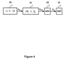
この発明の利点は、図4および図5において説明されるような典型的な固体ピクセル構造動作と比較すると一番よく説明され得る。たとえば、図4は典型的なデジタル撮像装置に含まれるいくつかの構成要素を図示するブロック図である。信号源20は、積分器21、アナログ−デジタル変換器(ADC)22およびデジタル信号プロセッサ(DSP)23を含む信号処理チェーンに結合される。信号源20は、自身に当たる光などの電磁放射に応答して電気的応答を生成する光強度センサであり、センサ20および積分器21は典型的なCMOSピクセル構造のコアを形成する。センサ20は、一般的には露光時間と称される特定の持続時間の間だけセンサが光に晒されるデジタルカメラ適用例などの、時間設定された適用例で用いられ得る。積分器21は、露光時間の間に受けるすべての光子によって生じるセンサ20の応答を、たとえば露光時間の終わりに、読出すべき電圧などの1つの値に積分するように作用する。
The advantages of the present invention can best be explained when compared to typical solid state pixel structure operation as described in FIGS. For example, FIG. 4 is a block diagram illustrating some components included in a typical digital imaging device. The
図5は、典型的な画像センサアセンブリ回路をより詳細に図示する。信号源30はたとえばフォトダイオードと言える光センサである。キャパシタ34は単純な積分器である。積分器への入力は信号源30の出力である。キャパシタ34は、積分プロセスの開始前に、閉じた位置にあるスイッチ35によってリセットされる。積分プロセスの始めにスイッチ35が開き、キャパシタ34両端の電圧が信号源30から発する入力信号に応答して変化し始める。積分プロセスの終わりに、スイッチ33が閉じて、積分器出力36であるVOUTがサンプリングされる。
FIG. 5 illustrates a typical image sensor assembly circuit in more detail. The
積分器出力36であるVOUTは、一般的に、利用可能な電源電圧が課す上限を超えることができない。電源電圧は厳しい電力消費要件のために現状技術の機器では低減している。積分器出力36は電源電圧を超えることができず、積分器出力信号が電源電圧レベルに達した後にも増大し続けると飽和してしまう。飽和は、出力電圧が利用可能な電源電圧に達して入力信号のさらなる変化に応答できなくなると起こる。
V OUT , which is the
積分器によって限定されるようなピクセルのダイナミックレンジは、露光時間を設定する際に慎重に考慮する必要がある。露光時間が短すぎると、1つまたはそれ以上のピクセルの出力が十分高くなって雑音レベルより上に上昇することができなくなる。露光時間が長すぎると、1つまたはそれ以上のピクセルの出力が飽和してしまう。 The dynamic range of the pixel as limited by the integrator must be carefully considered when setting the exposure time. If the exposure time is too short, the output of one or more pixels is high enough that it cannot rise above the noise level. If the exposure time is too long, the output of one or more pixels will be saturated.
図1Cおよび図2Cに関して述べたように、最適なアレイ動作は、すべてのアレイピクセルが自身の線形の出力範囲で動作し(飽和せず)、電子雑音レベルより上の出力電圧を生成するときに得られる。電子雑音レベルより上の出力電圧を生成するために、ピクセル構造のゲインは、電磁放射強度について特定された動作範囲の最小値で照らされたときに十分な出力電圧を生成するように十分に高くあるべきである。これによってピクセル構造の感度が決まる。ピクセル構造のダイナミックレンジは、この構造についての動作範囲の最大値を有する電磁放射強度で照らされたときに常に線形領域で動作してその出力を飽和させないように十分高くあるべきである。 As described with respect to FIGS. 1C and 2C, optimal array operation is when all array pixels operate in their linear output range (not saturating) and produce an output voltage above the electronic noise level. can get. In order to produce an output voltage above the electronic noise level, the gain of the pixel structure is high enough to produce a sufficient output voltage when illuminated with the minimum operating range specified for electromagnetic radiation intensity. Should be. This determines the sensitivity of the pixel structure. The dynamic range of the pixel structure should be high enough so that it always operates in the linear region and does not saturate its output when illuminated with electromagnetic radiation intensity having the maximum operating range for this structure.
この発明は、露光制御をピクセル構造、ピクセルアレイ、またはその組合せに統合する価値を認識している。以下に述べるように、露光制御をピクセル構造および/またはピクセルアレイに統合することにより、最小限の複雑度および電力消費で最適な撮像が可能となる。この発明は多くの異なる形式で、多くの異なる粒度で実現され得る。実施例はこの発明の均等の実施例のサブセットを例示しており、本発明は開示される実施例に限定されない。 The present invention recognizes the value of integrating exposure control into pixel structures, pixel arrays, or combinations thereof. As described below, integrating exposure control into the pixel structure and / or pixel array allows for optimal imaging with minimal complexity and power consumption. The invention can be implemented in many different formats and with many different granularities. The examples illustrate a subset of equivalent embodiments of the invention and the invention is not limited to the disclosed embodiments.
図6はこの発明の1つの実施例を図示しており、たとえばピクセル101などの各ピクセルは、ピクセル出力が特定のレポート可能な状態に達するとレポート可能な追加ロジックを組込んでいる。ロジックによって示されるレポート可能な状態は設計的事項であり、ピクセル出力レベルが最小必要レベルに達した、ピクセル出力レベルが飽和レベルに達した、ピクセル出力レベルが最小必要レベルより高く飽和より低い第1の特定状態に達した、ピクセル出力レベルが第1の特定状態とは異なる、最小必要レベルより高く飽和より低い第2の特定状態に達した、ピクセル出力レベルが上記の状態の第1の組合せに達した、および/またはピクセル出力レベルが上記の状態の第2の組合せに達した、などを含み得るが、これらに限定されない。 Figure 6 is illustrates one embodiment of the present invention, for example each pixel, such as pixel 101, incorporates a reportable additional logic when the pixel output reaches a certain reportable condition. Reportable condition indicated by logic is a design matter, the pixel output level has reached the minimum required level, the pixel output level reaches the saturation level, the first pixel output level is lower than the higher saturation than the minimum required level The pixel output level is different from the first specific state, the second specific state higher than the minimum required level and lower than saturation is reached, and the pixel output level is the first combination of the above states. And / or the pixel output level has reached a second combination of the above states, and the like.
状態情報は機能ブロック102に送られる。機能ブロック102は、1つの実施例では、ピクセルアレイ100の外部のシステム構成要素とインターフェイスバス103を介して通信する。機能ブロック102は有利には動的にプログラム可能であるが、これは必須ではない。1つの実施例では、機能ブロックは露光終了トリガ条件を検出するようにプログラムされ得る。露光終了トリガ条件は、撮像プロセスの事前に選択されてもよいし、または代替的に撮像プロセスから入来する情報に応答して適応的に選択されてもよい。一例として、可能性のある予め設定された露光終了条件は、事前に設定された最大露光時間に達したという表示、最小出力電圧に達したことをすべてのピクセルがレポートした、および1つのピクセルの出力電圧飽和値に達したことを当該ピクセルがレポートしたという表示、出力飽和電圧に達したことを予め設定された数のピクセルがレポートしたという表示、最小出力電圧に達したことを予め設定された数のピクセルがレポートしたという表示、出力飽和電圧に達したことを第1の予め設定されたしきい値よりも大きい数のピクセルがレポートした、および最小出力電圧に達したことを第2の予め設定されたしきい値よりも大きい数のピクセルがレポートしたという表示、ならびに露光終了条件の組合せが発生したという表示を含むが、これらに限定されない。
The status information is sent to the
図7は、本発明の固体ピクセル構造に含まれ得る構成要素を図示するブロック図である。図7に図示されるように、ピクセル構造は、機能ブロック102に送るためのステータスレポートを生成するのに必要な手段を含む、信号源50および積分器51に応答する手段を含む。ステータスレポートは、ピクセル構造と機能ブロックとの間で通信されることが望まれる情報に依存していずれの種類の形式も取り得る。たとえば、最も単純な実施例では、ステータスレポートは、アサートされるとピクセルが特定の状態に達したことを示し、これは次に露光終了トリガ条件の存在を示し得るトリガ信号を備え得る。より複雑な実施例では、信号は、予め定められた通信プロトコルに基づいて直列のまたは複数ビットのバス上で符号化され得る。アレイ内のポイントどうしの間でデータを通信する他の技術が、この発明の範囲に影響を及ぼすことなく本明細書中で代用され得る。
FIG. 7 is a block diagram illustrating components that may be included in the solid state pixel structure of the present invention. As illustrated in FIG. 7, the pixel structure includes means responsive to signal
図8は、この発明の固体ピクセル構造62の1つの実施例のより詳細な図を提供する。構造62は図5に関して説明されたものと同様であるが、この発明の測光およびレポートロジック63を含む。1つの実施例における測光およびレポートロジックは動的にプログラム可能であり、機能ブロックが、外部入力55を介して露光基準の端およびロジック63の露光トリガしきい値をカスタマイズする能力を含む。測定およびレポートロジック63は1つのピクセル専用であってもよいし、または1つよりも多いピクセルについて作用してもよい。測定およびレポートロジック63が1つよりも多いピクセルについて作用する場合、追加ピクセルの状態を示す追加データは、追加接続を介して測定およびレポートロジック63に入力される。コネクタ68および69は、追加ピクセル状態データを測定およびレポートロジック63に運ぶ例示的なコネクタである。測定およびレポートロジック63が1つよりも多いピクセルについて作用する場合、追加接続の数は実現例の仕様に従って異なる。測光およびレポートロジック63は、予め設定されたまたは適応的なアルゴリズムに従って動作可能である。コストおよび動作の簡潔さが主要な考慮すべき事項である場合、測定およびレポートロジック63の動作は予め設定されて変更されなくてもよい。優れた画像センサ性能が主要な考慮すべき事項である場合は、測定およびレポートロジック63の動作は適応的であり、外部指令に応答して変更されてもよい。入力55は、外部指令に応答して測定およびレポートロジック63の動作を変更するように作用する。測定およびレポートロジック63の動作のモードは、多数の予めプログラムされた動作のモードからの選択によって、または新たな動作のモードをプログラミングすることによって変更され得る。例示的な実施例では、測定およびレポートロジック63は、ピクセル出力信号電圧およびリセット/イネーブル指令の一方または両方を監視する。これら2つのいずれかまたはそれらの組合せに基づいて、および構造についてのプログラムされたトリガ条件に基づいて、測定およびレポートロジック63は機能ブロック102にステータス信号を与えて固体構造におけるある一定の特徴の存在を示し、この特徴は、電圧レベル、電圧レベル−飽和レベル比などであり得る。プログラムされたトリガ条件は、トリガしきい値を判断する際に測光データを考慮し得る。
FIG. 8 provides a more detailed view of one embodiment of the solid
図8はしたがって、測定およびレポート能力が図5に示されるようなCMOS画像センサにどのように組込まれ得るかを図示する。しかしながら、この発明はCMOS画像センサのみとの使用に限定されず、さらに言えばデジタル画像センサにも限定されない。むしろ、電磁放射に対する応答を測定し、センサ挙動に関する知識を含む知識とともにその測定を用いて露光を制御するという概念は、いずれの画像感度装置とも共に用いられ得る。本発明の1つの実施例では、ピクセル構造は、引用により援用されるダビドビチ(Davidovici)による「高ダイナミックレンジ感度センサ素子またはアレイのためのシステムおよび方法(SYSTEM AND METHOD FOR A HIGH DYNAMIC RANGE SENSITIVE SENSOR ELEMENT
OR ARRAY)」と題された特許出願連続番号 (代理人整理番号680-008U)に説明されるような、高解像度および広ダイナミックレンジを備えるセンサ装置を含む。代替的な実施例では、ピクセル構造は、引用により援用されるダビドビチ(Davidovici)によって同日に提出された「ゲインを制御した高ダイナミックレンジ感度センサ素子またはアレイのためのシステムおよび方法(SYSTEM AND METHOD FOR A HIGH DYNAMIC RANGE SENSITIVE SENSOR ELEMENT
OR ARRAY WITH GAIN CONTROL)」と題された特許出願連続番号
(代理人整理番号680-010)に開示されるようなセンサ装置を含む。
FIG. 8 thus illustrates how measurement and reporting capabilities can be incorporated into a CMOS image sensor as shown in FIG. However, the present invention is not limited to use with only CMOS image sensors, and moreover is not limited to digital image sensors. Rather, the concept of measuring the response to electromagnetic radiation and using that measurement along with knowledge, including knowledge about sensor behavior, can be used with any image sensitive device. In one embodiment of the present invention, the pixel structure is a "SYSTEM AND METHOD FOR A HIGH DYNAMIC RANGE SENSITIVE SENSOR ELEMENT" by Davidobici, incorporated by reference.
It includes a sensor device with high resolution and a wide dynamic range as described in the patent application serial number entitled “OR ARRAY” (Attorney Docket No. 680-008U). In an alternative embodiment, the pixel structure is a “system and method for a gain-controlled high dynamic range sensitivity sensor element or array, filed on the same day by Davidovici, incorporated by reference. A HIGH DYNAMIC RANGE SENSITIVE SENSOR ELEMENT
Including a sensor device as disclosed in a patent application serial number entitled “OR ARRAY WITH GAIN CONTROL” (attorney docket number 680-010).
図9は、機能ブロック102ならびにピクセル101の測定およびレポートロジックによって実行され得るステップと、構成要素間で起こり得る例示的な通信とを図示するために与えられる1対の機能フロー図を含む。プロセス70は機能ブロック102によって実行され得るステップを含むのに対して、プロセス80は測定およびレポートロジック80によって実行され得るステップを図示する。図9は限定的ではなく例示的な例を意味しており、その均等物において多くの異なる形式を取り得、ハードウェア、ソフトウェア、またはその組合せによって制御される部分を有し得ることに留意すべきである。
FIG. 9 includes a pair of functional flow diagrams provided to illustrate the steps that may be performed by the measurement and reporting logic of
機能ブロックのプロセスは、たとえばカメラのトリガが押下げられてピクセル構造の露光が開始されるステップ72で始まる。機能ブロックはステップ73に進み、ここで、各群が1つまたはそれ以上のピクセルを含むピクセル群からステータスレポートを集める。
The functional block process begins at
測定およびレポートブロックは、ステップ82において画像センサがアクティブになると処理を開始する。たとえば、ブロックは画像センサから電圧を検出し得る。ステップ84において、センサ測定を監視または収集してピクセル構造がいつレポート可能な状態にあるかを判断する。ピクセル構造がレポート可能な状態にあると判断されると、ステップ88において状態が機能ブロックにレポートされる。
The measurement and report block begins processing when the image sensor is activated in
機能ブロック102、240、340、440は1つまたはそれ以上のピクセル構造から受取ったステータスレポートを分析して、露光終了トリガ事象がいつ起こったか判断する。トリガ事象が起こると、ステップ76において機能ブロックが露光を終了させる。機能ブロックはトリガ条件に基づいてピクセルアレイ内の1つまたはそれ以上のピクセルについて露光を終了させることができ、したがってこの発明はいずれの露光終了粒度にも限定されない。ステップ78において、撮像された画像が記憶媒体に記録される。
露光時間判断に対する上述の方策は、露光時間設定が画像が撮像(取得)されている間に行われるために最大精度を達成できるという主要なメリットを有する。撮像プロセスの進行中に露光終了条件を判断する柔軟性は、露光時間を撮像すべき画像の特性に適応させて調和させることができるというメリットを有する。 The above-described measures for the exposure time determination have the main advantage that the maximum accuracy can be achieved because the exposure time setting is performed while an image is being captured (acquired). The flexibility of determining the exposure end condition during the imaging process has the advantage that the exposure time can be adapted and matched to the characteristics of the image to be imaged.
各ピクセル構造内に測光およびレポートを含む、図6に関して説明された実施例は、市販のピクセルアレイには多数のピクセルが含まれるために比較的複雑である。デジタルスチル写真またはビデオカメラにおける場合などの撮像の一般的な被写体である意味のある画像は、隣接するピクセル間で高い相関関係を示す。高い隣接ピクセル相関関係により、レポートされたピクセル出力データの大部分が冗長になる。 The embodiment described with respect to FIG. 6, including photometry and reporting within each pixel structure, is relatively complex due to the large number of pixels in a commercial pixel array. A meaningful image that is a general subject of imaging, such as in a digital still picture or video camera, shows a high correlation between adjacent pixels. High neighbor pixel correlation makes most of the reported pixel output data redundant.
図10はこの発明の他の実施例を図示しており、ピクセルアレイ200は、全ピクセルよりも少ないピクセルが自身の出力の状態をレポートする状態で配置される。ピクセル230、210および220によって例示されるレポートピクセルは、ピクセルアレイ全体にわたって規則的なまたは無作為なパターンで配置され得る。隣接するピクセル間の高い相関関係を用いて、撮像プロセスの劣化を最小限に抑えてレポートピクセルの数を限定する。したがって、レポートピクセルの数の下限は1であり得、レポートピクセルの数の上限はアレイのサイズと等しくなり得る。
FIG. 10 illustrates another embodiment of the present invention where the
図11は本発明のさらに他の実施例を図示しており、図6および図10の実施例と比較して複雑度を減少させた。図11において、ピクセルアレイ300は、自身の出力の状態をレポート可能なピクセルが共にグループ化されるようにピクセル群に配分される。出力状態レポート可能なピクセル群は、わずか2つのピクセル、およびアレイに含まれるピクセルの数と同数のピクセルを含み得るが、すべての群は同じ数のピクセルを含む。4つのピクセルを含むピクセル群330、310および320によって例示されるレポートピクセル群は、ピクセルアレイ全体にわたって規則的なまたは無作為なパターンで配置され得る。レポートピクセルの数の下限は1であり得、レポートピクセルの数の上限はアレイのサイズを2で除算したものと等しくなり得る。
FIG. 11 illustrates yet another embodiment of the present invention with reduced complexity compared to the embodiments of FIGS. In FIG. 11, the
図12は本発明のさらに他の実施例を図示しており、自身の出力の状態をレポート可能なピクセルが共にグループ化されている。出力状態レポート可能なピクセル群は、わずか1つのピクセル、およびアレイに含まれるピクセルの数と同数のピクセルを含み得る。図12の実施例は、群どうしのサイズが異なり得るために図11のそれとは異なっている。ピクセル群430、410および420によって例示されるレポートピクセル群は、それぞれ1つ、4つおよび4つよりも大きい数のピクセルを含み、ピクセルアレイ全体にわたって規則的なまたは無作為なパターンで配置され得る。レポートピクセル群の数の下限は1であり得、レポートピクセル群の数の上限はアレイのサイズと等しくなり得る。
FIG. 12 illustrates yet another embodiment of the present invention in which pixels that can report their output status are grouped together. The output status reportable pixel group may include as few as one pixel and as many pixels as are included in the array. The embodiment of FIG. 12 differs from that of FIG. 11 because the size of the groups can be different. Report pixel groups, exemplified by
したがって、統合された露光制御を有するピクセル構造およびアレイを用いてピクセルアレイ露光時間を制御するための方法および装置がさまざまな実施例において示され、説明された。したがって、この発明は、測光およびレポート能力を含む改良された画像センサを提供することによって先行技術の問題点を克服する。測定およびレポート能力を用いて電磁放射に対する画像センサの露光を制御することができ、それによって、画像センサが最適な露光ポイントまたはある他のトリガしきい値レベルに達すると露光を終了させることが可能となる。また、露光を、撮像後の画像に対して行なう二次的なプロセスとしてではなく、リアルタイムで制御することが可能となる。 Accordingly, methods and apparatus for controlling pixel array exposure times using pixel structures and arrays with integrated exposure control have been shown and described in various embodiments. The present invention thus overcomes the problems of the prior art by providing an improved image sensor that includes photometric and reporting capabilities. Measurement and reporting capabilities can be used to control the exposure of the image sensor to electromagnetic radiation so that the exposure can be terminated when the image sensor reaches an optimal exposure point or some other trigger threshold level It becomes. In addition, exposure can be controlled in real time rather than as a secondary process performed on an image after imaging.
この発明には多数のメリットがある。第1のメリットは、ピクセルアレイ露光を判断するのに用いられるデータが撮像プロセスと同時にリアルタイムで撮像中の画像から抽出される、本明細書中で説明された方策の本質的な正確さである。第2のメリットは、測光能力をピクセル構造自体に組込むことにより、適切な露光レベルを判断する際に固体画像センサのいずれのゲイン特性も確実に考慮されることである。1つの共通に用いられる方策において露光時間を判断するのに必要な二重撮像プロセスを排除することによって電力消費が減少することが第3のメリットである。この発明のこれらおよび他のメリットが当業者にとって明らかである。 This invention has a number of advantages. The first advantage is the inherent accuracy of the strategy described herein, where the data used to determine pixel array exposure is extracted from the image being captured in real time simultaneously with the imaging process. . The second advantage is that by incorporating photometric capability into the pixel structure itself, any gain characteristics of the solid-state image sensor are reliably taken into account when determining an appropriate exposure level. A third advantage is that power consumption is reduced by eliminating the double imaging process required to determine the exposure time in one commonly used strategy. These and other advantages of the invention will be apparent to those skilled in the art.
本発明のさまざまな実施例を説明したが、上記の図面の多くは本発明の実施例に係る方法、装置(システム)およびコンピュータプログラムプロダクトのフローチャート例示であることが認められるであろう。フローチャート例示の各ブロック、およびフローチャート例示内のブロックの組合せはコンピュータプログラム命令によって実現され得ることが理解されるであろう。これらのコンピュータプログラム命令は、コンピュータまたは他のプログラム可能なデータ処理装置にロードされてマシンを製作し得、それによりコンピュータまたは他のプログラム可能なデータ処理装置上で実行される当該命令が、フローチャートブロックまたはブロック内で特定された機能を実現するための手段を作製する。これらのコンピュータプログラム命令は、コンピュータまたは他のプログラム可能なデータ処理装置に対して、特定の態様で機能するよう命じることが可能なコンピュータ読取可能メモリにも記憶され得、それによりコンピュータ読取可能メモリに記憶される当該命令がフローチャートブロックまたはブロック内で特定された機能を実現する命令手段を含む製造物を製作する。コンピュータプログラム命令はまた、コンピュータまたは他のプログラム可能なデータ処理装置にロードされて、当該コンピュータまたは他のプログラム可能な装置上で一連の動作ステップを実行させて、コンピュータによって実現されるプロセスを製作し得、それにより当該コンピュータまたは他のプログラム可能な装置上で実行される当該命令がフローチャートブロックまたはブロック内で特定された機能を実現するためのステップを提供する。 While various embodiments of the present invention have been described, it will be appreciated that many of the above figures are flowchart illustrations of methods, apparatus (systems) and computer program products according to embodiments of the present invention. It will be understood that each block of the flowchart illustration, and combinations of blocks in the flowchart illustration, can be implemented by computer program instructions. These computer program instructions may be loaded into a computer or other programmable data processing device to create a machine so that the instructions executed on the computer or other programmable data processing device are flowchart blocks. Alternatively, a means for realizing the function specified in the block is produced. These computer program instructions may also be stored in computer readable memory, which may instruct a computer or other programmable data processing device to function in a particular manner, thereby causing the computer readable memory to A product is produced that includes instruction means for which the stored instructions implement the function specified in the flowchart block or block. Computer program instructions are also loaded into a computer or other programmable data processing device to cause a series of operational steps to be performed on the computer or other programmable device to create a computer-implemented process. Thus, the instructions executed on the computer or other programmable device provide steps for implementing the flowchart blocks or functions specified within the blocks.
当業者は、この発明の機能を規定するプログラムが多くの形式でコンピュータに配信され得ることを容易に認めるはずである。形式は、(a)書込不可能記憶媒体(たとえばコンピュータI/Oアタッチメントによって読取可能なROMまたはCD−ROMなどのコンピュータ内の読出専用メモリ装置)に永続的に記憶される情報、(b)書込可能記憶媒体(たとえばフロッピー(登録商標)ディスクおよびハードドライブ)に可変に記憶される情報、または(c)たとえば、モデムを介してコンピュータまたは電話ネットワーク上などの搬送波信号技術を含むベースバンド信号またはブロードバンド信号技術を用いて、通信媒体を通してコンピュータに伝達される情報を含むが、これらに限定されない。 Those skilled in the art will readily appreciate that programs that define the functionality of the present invention can be distributed to computers in many forms. The format is: (a) information permanently stored in a non-writable storage medium (eg, a read-only memory device in a computer such as a ROM or CD-ROM readable by a computer I / O attachment); (b) Information variably stored on writable storage media (eg floppy disks and hard drives), or (c) baseband signals including carrier signal technology, eg over a computer or telephone network via a modem Or includes, but is not limited to, information transmitted to a computer through a communication medium using broadband signal technology.
上記の説明および図面は、この発明によって実行される動作を図示するさまざまなプロセスステップおよび構成要素を含んでいる。しかしながら、ある一定の構成要素および工程を説明したが、その説明は例示のみのためのものであり、当業者が他の機能的な技術ま
たは付加的なステップおよび構成要素を追加することができ、したがって本発明は開示された特定の実施例に限定されるべきではないことが理解される。また、さまざまな例示的な要素がハードウェア、コンピュータ上で実行されるソフトウェア、またはその組合せで実現され得ることが理解される。
The above description and drawings include various process steps and components that illustrate the operations performed by the present invention. However, although certain components and processes have been described, the description is for illustration only and other functional techniques or additional steps and components can be added by one skilled in the art, Accordingly, it is understood that the invention is not to be limited to the specific embodiments disclosed. It is also understood that the various exemplary elements can be implemented in hardware, software running on a computer, or a combination thereof.
本発明を上記の例示的な実施例を通じて説明したが、例示される実施例の修正例および変形例が、本明細書中に開示された発明概念から逸脱することなくなされ得ることが当業者に理解されるであろう。したがって、本発明は添付の請求項の範囲および思想によるものを除いて限定的であるとして解釈されるべきではない。 Although the present invention has been described through the exemplary embodiments described above, it will be apparent to those skilled in the art that modifications and variations of the illustrated embodiments can be made without departing from the inventive concepts disclosed herein. Will be understood. Accordingly, the invention should not be construed as limiting except as by the scope and spirit of the appended claims.
Claims (36)
画像センサと、
受けた電磁放射に応答して生成される前記画像センサの出力を測定するための手段であり、少なくとも1つのトリガ事象に対する少なくとも1つのトリガレベルに関連した前記出力の状態を明らかにするレポ―トを生成するための手段を含む、手段とを備え、
前記露光コントローラは、複数のピクセル構造のレポート群から複数のレポートを受けるよう、及び、前記複数の受けたレポートにおけるレポートピクセル構造の出力の状態に応答して当該ピクセルアレイにおける全ピクセルの露光を制御するよう結合され、
前記出力が最小レベルよりも高い状態、前記出力が飽和レベルに達する状態、最小レベルよりも高く、飽和レべルよりも低い第1の所定の状態に前記出力値がある状態、最小レベルよりも高く、飽和レベルよりも低く、前記第1の所定の状態よりも高い第2の所定の状態に前記出力値がある状態のうち少なくとも1つを含む群から前記状態は選択される、
ピクセルアレイ。A pixel array comprising a plurality of pixel structures with at least two pixel structure report groups and an exposure controller , wherein each of the pixel structure report groups includes at least one report pixel structure, the report pixel structure comprising: ,
An image sensor;
A means for measuring the output of the image sensor generated in response to received electromagnetic radiation, the report revealing the state of the output in relation to at least one trigger level for at least one trigger event comprising means for generating and means,
The exposure controller receives a plurality of reports from a report group of a plurality of pixel structures, and controls the exposure of all pixels in the pixel array in response to the output state of the report pixel structures in the plurality of received reports. Combined to
A state in which the output is higher than a minimum level; a state in which the output reaches a saturation level; a state in which the output value is in a first predetermined state that is higher than the minimum level and lower than the saturation level; The state is selected from a group including at least one of the states having the output value in a second predetermined state that is higher, lower than a saturation level, and higher than the first predetermined state
Pixel array.
受けた電磁放射に応答して生成された前記レポートピクセル構造の画像センサの出力を各レポートピクセル構造にて測定し、トリガ事象に対するトリガレベルに関連した前記出力の状態のレポートを生成するステップと、
レポートピクセル構造を備える前記少なくとも2つのピクセル構造群から受取った少なくとも2つのレポートを処理して前記トリガ事象が起こったかどうか判断するステップと、
前記トリガ事象を履行する前記レポートピクセル構造の出力の状態に応答して前記ピクセルアレイの露光を終了させるステップとを備え、
前記出力が最小レベルよりも高い状態、前記出力が飽和レベルに達する状態、最小レベルよりも高く、飽和レべルよりも低い第1の所定の状態に前記出力値がある状態、最小レベルよりも高く、飽和レベルよりも低く、前記第1の所定の状態よりも高い第2の所定の状態に前記出力値がある状態のうち少なくとも1つを含む群から前記状態は選択される、方法。A method of controlling exposure of a pixel array comprising a plurality of pixel structure groups, wherein at least two of the groups each comprise a report pixel structure, wherein the method is generated in response to received electromagnetic radiation. Measuring the output of a report pixel structure image sensor at each report pixel structure and generating a report of the state of said output in relation to the trigger level for a trigger event ;
And determining whether the trigger event has occurred by processing at least two reports the received at least two pixel structure group comprises reporting pixel structure,
In response to the state of the output of the trigger event to fulfill the report pixel structure and a step of terminating the exposure of said pixel array,
A state in which the output is higher than a minimum level; a state in which the output reaches a saturation level; a state in which the output value is in a first predetermined state that is higher than the minimum level and lower than the saturation level; A method wherein the state is selected from the group comprising at least one of states where the output value is in a second predetermined state that is higher, lower than a saturation level, and higher than the first predetermined state .
Applications Claiming Priority (9)
| Application Number | Priority Date | Filing Date | Title |
|---|---|---|---|
| US71930605P | 2005-09-21 | 2005-09-21 | |
| US71930505P | 2005-09-21 | 2005-09-21 | |
| US71930405P | 2005-09-21 | 2005-09-21 | |
| US60/719,306 | 2005-09-21 | ||
| US60/719,305 | 2005-09-21 | ||
| US60/719,304 | 2005-09-21 | ||
| US72789705P | 2005-10-18 | 2005-10-18 | |
| US60/727,897 | 2005-10-18 | ||
| PCT/US2006/036793 WO2007035860A2 (en) | 2005-09-21 | 2006-09-21 | System and method for image sensor element or array with photometric and realtime reporting capabilities |
Publications (3)
| Publication Number | Publication Date |
|---|---|
| JP2009509474A JP2009509474A (en) | 2009-03-05 |
| JP2009509474A5 JP2009509474A5 (en) | 2010-10-28 |
| JP4699524B2 true JP4699524B2 (en) | 2011-06-15 |
Family
ID=37889530
Family Applications (4)
| Application Number | Title | Priority Date | Filing Date |
|---|---|---|---|
| JP2008532376A Expired - Fee Related JP4699524B2 (en) | 2005-09-21 | 2006-09-21 | Systems and methods for image sensor elements or arrays with photometric and real-time reporting capabilities |
| JP2008532373A Expired - Fee Related JP4537483B2 (en) | 2005-09-21 | 2006-09-21 | High resolution and wide dynamic range integrator |
| JP2008532377A Expired - Fee Related JP5059767B2 (en) | 2005-09-21 | 2006-09-21 | Systems and methods for high dynamic range sensitivity sensor elements or arrays |
| JP2008532372A Active JP5242399B2 (en) | 2005-09-21 | 2006-09-21 | System and method for gain controlled high dynamic range sensitive sensor element or array |
Family Applications After (3)
| Application Number | Title | Priority Date | Filing Date |
|---|---|---|---|
| JP2008532373A Expired - Fee Related JP4537483B2 (en) | 2005-09-21 | 2006-09-21 | High resolution and wide dynamic range integrator |
| JP2008532377A Expired - Fee Related JP5059767B2 (en) | 2005-09-21 | 2006-09-21 | Systems and methods for high dynamic range sensitivity sensor elements or arrays |
| JP2008532372A Active JP5242399B2 (en) | 2005-09-21 | 2006-09-21 | System and method for gain controlled high dynamic range sensitive sensor element or array |
Country Status (5)
| Country | Link |
|---|---|
| US (5) | US7800669B2 (en) |
| EP (4) | EP1935018B1 (en) |
| JP (4) | JP4699524B2 (en) |
| KR (4) | KR101152859B1 (en) |
| WO (4) | WO2007035858A2 (en) |
Families Citing this family (29)
| Publication number | Priority date | Publication date | Assignee | Title |
|---|---|---|---|---|
| EP1935018B1 (en) * | 2005-09-21 | 2014-05-21 | RJS Technology, Inc. | System and method for a high dynamic range sensitive sensor element or array with gain control |
| DE102007036973A1 (en) | 2007-02-24 | 2008-09-04 | Fraunhofer-Gesellschaft zur Förderung der angewandten Forschung e.V. | A pixel cell, a method of operating a pixel cell, a method of determining a position of a maximum of an envelope of an analog amplitude modulated signal, a device for determining a charge amount, apparatus and method for determining an amount of charge on a capacitive element, apparatus and method, and setting a circuit node a predetermined voltage, apparatus and method for charge-based analog / digital conversion and apparatus and method for charge-based signal processing |
| WO2010016449A1 (en) | 2008-08-08 | 2010-02-11 | Semiconductor Energy Laboratory Co., Ltd. | Photoelectric conversion device and electronic device having the same |
| WO2011086829A1 (en) * | 2010-01-15 | 2011-07-21 | Semiconductor Energy Laboratory Co., Ltd. | Semiconductor device and electronic device |
| WO2012093387A2 (en) * | 2011-01-09 | 2012-07-12 | Emza Visual Sense Ltd. | Pixel design with temporal analysis capabilities for scene interpretation |
| US10197501B2 (en) | 2011-12-12 | 2019-02-05 | Kla-Tencor Corporation | Electron-bombarded charge-coupled device and inspection systems using EBCCD detectors |
| EP2815393B1 (en) * | 2012-02-14 | 2023-04-05 | Gentex Corporation | High dynamic range imager system |
| JP6041500B2 (en) * | 2012-03-01 | 2016-12-07 | キヤノン株式会社 | Imaging device, imaging system, driving method of imaging device, and driving method of imaging system |
| KR101629881B1 (en) * | 2012-03-16 | 2016-06-13 | 엠파이어 테크놀로지 디벨롭먼트 엘엘씨 | Low light adaptive imaging device |
| KR101895415B1 (en) | 2012-03-27 | 2018-09-06 | 삼성전자주식회사 | Anlaog-to-digital converting circuit and accumulation circuit including the same |
| US9496425B2 (en) | 2012-04-10 | 2016-11-15 | Kla-Tencor Corporation | Back-illuminated sensor with boron layer |
| US9601299B2 (en) | 2012-08-03 | 2017-03-21 | Kla-Tencor Corporation | Photocathode including silicon substrate with boron layer |
| US9426400B2 (en) | 2012-12-10 | 2016-08-23 | Kla-Tencor Corporation | Method and apparatus for high speed acquisition of moving images using pulsed illumination |
| US9478402B2 (en) | 2013-04-01 | 2016-10-25 | Kla-Tencor Corporation | Photomultiplier tube, image sensor, and an inspection system using a PMT or image sensor |
| US9347890B2 (en) | 2013-12-19 | 2016-05-24 | Kla-Tencor Corporation | Low-noise sensor and an inspection system using a low-noise sensor |
| US9748294B2 (en) | 2014-01-10 | 2017-08-29 | Hamamatsu Photonics K.K. | Anti-reflection layer for back-illuminated sensor |
| US9410901B2 (en) | 2014-03-17 | 2016-08-09 | Kla-Tencor Corporation | Image sensor, an inspection system and a method of inspecting an article |
| US9767986B2 (en) | 2014-08-29 | 2017-09-19 | Kla-Tencor Corporation | Scanning electron microscope and methods of inspecting and reviewing samples |
| US9860466B2 (en) | 2015-05-14 | 2018-01-02 | Kla-Tencor Corporation | Sensor with electrically controllable aperture for inspection and metrology systems |
| US10748730B2 (en) | 2015-05-21 | 2020-08-18 | Kla-Tencor Corporation | Photocathode including field emitter array on a silicon substrate with boron layer |
| US10462391B2 (en) | 2015-08-14 | 2019-10-29 | Kla-Tencor Corporation | Dark-field inspection using a low-noise sensor |
| US10313622B2 (en) | 2016-04-06 | 2019-06-04 | Kla-Tencor Corporation | Dual-column-parallel CCD sensor and inspection systems using a sensor |
| US10778925B2 (en) | 2016-04-06 | 2020-09-15 | Kla-Tencor Corporation | Multiple column per channel CCD sensor architecture for inspection and metrology |
| TWI611282B (en) * | 2017-01-03 | 2018-01-11 | 友達光電股份有限公司 | Power Supply Circuit And Power Supplying Method |
| US11114489B2 (en) | 2018-06-18 | 2021-09-07 | Kla-Tencor Corporation | Back-illuminated sensor and a method of manufacturing a sensor |
| US10943760B2 (en) | 2018-10-12 | 2021-03-09 | Kla Corporation | Electron gun and electron microscope |
| US11114491B2 (en) | 2018-12-12 | 2021-09-07 | Kla Corporation | Back-illuminated sensor and a method of manufacturing a sensor |
| US11848350B2 (en) | 2020-04-08 | 2023-12-19 | Kla Corporation | Back-illuminated sensor and a method of manufacturing a sensor using a silicon on insulator wafer |
| CN117490838B (en) * | 2024-01-03 | 2024-03-19 | 成都善思微科技有限公司 | High-reliability flat panel detector data acquisition method, system and computer |
Citations (3)
| Publication number | Priority date | Publication date | Assignee | Title |
|---|---|---|---|---|
| JP2001054022A (en) * | 1999-08-13 | 2001-02-23 | Nippon Hoso Kyokai <Nhk> | Solid-state image pickup device |
| JP2002139571A (en) * | 2000-11-01 | 2002-05-17 | Canon Inc | Electromagnetic wave converter |
| US6809358B2 (en) * | 2002-02-05 | 2004-10-26 | E-Phocus, Inc. | Photoconductor on active pixel image sensor |
Family Cites Families (64)
| Publication number | Priority date | Publication date | Assignee | Title |
|---|---|---|---|---|
| US682145A (en) * | 1901-04-23 | 1901-09-03 | William J Jones | Apparatus for carbonating liquids. |
| US4352210A (en) * | 1980-09-12 | 1982-09-28 | General Electric Company | Linear mixer with reduced spurious responses |
| JPS5795771A (en) * | 1980-12-05 | 1982-06-14 | Fuji Photo Film Co Ltd | Solid-state image pickup device |
| US4419692A (en) * | 1981-12-31 | 1983-12-06 | Texas Medical Instruments, Inc. | High speed infrared imaging system |
| US4629879A (en) * | 1984-06-11 | 1986-12-16 | Eastman Kodak Company | Light beam intensity controlling apparatus |
| JPS6313520A (en) * | 1986-07-04 | 1988-01-20 | Sony Corp | Analog-digital conversion circuit |
| US4825144A (en) | 1987-11-10 | 1989-04-25 | Motorola, Inc. | Dual channel current mode switching regulator |
| JP2720478B2 (en) | 1988-10-18 | 1998-03-04 | 株式会社ニコン | Photometric device using solid-state imaging device with vertical overflow drain |
| US5416616A (en) * | 1990-04-06 | 1995-05-16 | University Of Southern California | Incoherent/coherent readout of double angularly multiplexed volume holographic optical elements |
| KR100396203B1 (en) * | 1993-06-17 | 2003-12-31 | 소니 가부시끼 가이샤 | Exposure apparatus and method, video camera having the exposure apparatus |
| US5461426A (en) | 1993-08-20 | 1995-10-24 | Samsung Electronics Co., Ltd. | Apparatus for processing modified NTSC television signals, with digital signals buried therewithin |
| KR0168451B1 (en) | 1994-03-31 | 1999-01-15 | 다까노 야스아끼 | Color solid image sensing device |
| DE4423214C2 (en) * | 1994-07-01 | 1998-02-12 | Harris Corp | Multinorm decoder for video signals and method for decoding video signals |
| JPH1022489A (en) * | 1996-07-02 | 1998-01-23 | Fuji Xerox Co Ltd | Solid-state image pickup device |
| WO1998014002A1 (en) * | 1996-09-27 | 1998-04-02 | Boehm Markus | Local auto-adaptive optic sensor |
| US5794922A (en) * | 1996-12-13 | 1998-08-18 | Meglino; Don A. | Fence slats with locking portions |
| US5796392A (en) * | 1997-02-24 | 1998-08-18 | Paradise Electronics, Inc. | Method and apparatus for clock recovery in a digital display unit |
| JP3697678B2 (en) * | 1997-05-09 | 2005-09-21 | ローム株式会社 | V / F conversion circuit |
| EP1031087A1 (en) * | 1997-07-18 | 2000-08-30 | Net Exchange, Inc. | Apparatus and method for effecting correspondent-centric electronic mail |
| US6229133B1 (en) * | 1997-10-27 | 2001-05-08 | Texas Instruments Incorporated | Image sensing device with delayed phase frequency modulation |
| US6452633B1 (en) * | 1998-02-26 | 2002-09-17 | Foveon, Inc. | Exposure control in electronic cameras by detecting overflow from active pixels |
| US6529241B1 (en) * | 1998-02-27 | 2003-03-04 | Intel Corporation | Photodetecting device supporting saturation detection and electronic shutter |
| US20020176009A1 (en) | 1998-05-08 | 2002-11-28 | Johnson Sandra Marie | Image processor circuits, systems, and methods |
| US6188056B1 (en) * | 1998-06-24 | 2001-02-13 | Stmicroelectronics, Inc. | Solid state optical imaging pixel with resistive load |
| US6396561B1 (en) * | 1998-11-10 | 2002-05-28 | Maniabarco N.V. | Method and device for exposing both sides of a sheet |
| US6249807B1 (en) * | 1998-11-17 | 2001-06-19 | Kana Communications, Inc. | Method and apparatus for performing enterprise email management |
| US6757018B1 (en) * | 1998-12-18 | 2004-06-29 | Agilent Technologies, Inc. | CMOS image sensor with pixel level gain control |
| US6654787B1 (en) * | 1998-12-31 | 2003-11-25 | Brightmail, Incorporated | Method and apparatus for filtering e-mail |
| US6777663B2 (en) * | 1999-05-07 | 2004-08-17 | Intel Corporation | Enhanced Photocell with sample and hold amplifier |
| US7123301B1 (en) * | 1999-06-11 | 2006-10-17 | Analog Devices, Inc. | Pixel gain amplifier |
| US6400810B1 (en) * | 1999-07-20 | 2002-06-04 | Ameritech Corporation | Method and system for selective notification of E-mail messages |
| US7133074B1 (en) * | 1999-09-28 | 2006-11-07 | Zoran Corporation | Image sensor circuits including sampling circuits used therein for performing correlated double sampling |
| JP4550957B2 (en) * | 1999-11-15 | 2010-09-22 | 浜松ホトニクス株式会社 | Photodetector |
| EP1113254A1 (en) | 1999-12-30 | 2001-07-04 | STMicroelectronics S.r.l. | A circuit and a method for extending the output voltage range of an integrator circuit |
| US6882367B1 (en) * | 2000-02-29 | 2005-04-19 | Foveon, Inc. | High-sensitivity storage pixel sensor having auto-exposure detection |
| US6438215B1 (en) * | 2000-02-29 | 2002-08-20 | Ameritech Corporation | Method and system for filter based message processing in a unified messaging system |
| JP4011818B2 (en) * | 2000-02-29 | 2007-11-21 | キヤノン株式会社 | Semiconductor solid-state imaging device |
| JP3753925B2 (en) * | 2000-05-12 | 2006-03-08 | 株式会社ルネサステクノロジ | Semiconductor integrated circuit |
| US7032023B1 (en) * | 2000-05-16 | 2006-04-18 | America Online, Inc. | Throttling electronic communications from one or more senders |
| US6654594B1 (en) * | 2000-05-30 | 2003-11-25 | Motorola, Inc. | Digitized automatic gain control system and methods for a controlled gain receiver |
| AU2001275880A1 (en) * | 2000-07-10 | 2002-01-21 | Silicon Laboratories, Inc. | Digitally-synthesized loop filter circuit particularly useful for a phase locked loop |
| WO2002007587A2 (en) * | 2000-07-14 | 2002-01-31 | Xillix Technologies Corporation | Compact fluorescent endoscopy video system |
| US6580496B2 (en) * | 2000-11-09 | 2003-06-17 | Canesta, Inc. | Systems for CMOS-compatible three-dimensional image sensing using quantum efficiency modulation |
| US20020113887A1 (en) * | 2001-02-16 | 2002-08-22 | Iimura Russell M. | CMOS image sensor with extended dynamic range |
| JP3852324B2 (en) * | 2001-02-20 | 2006-11-29 | ティアック株式会社 | Signal processing circuit and signal processing method |
| US7176962B2 (en) * | 2001-03-01 | 2007-02-13 | Nikon Corporation | Digital camera and digital processing system for correcting motion blur using spatial frequency |
| AU2002339874A1 (en) * | 2001-05-23 | 2002-12-03 | Canesta, Inc. | Enhanced dynamic range conversion in 3-d imaging |
| US6867693B1 (en) | 2001-07-25 | 2005-03-15 | Lon B. Radin | Spatial position determination system |
| US7176976B2 (en) * | 2001-08-30 | 2007-02-13 | Lightsurf Technologies, Inc. | Autoexposure methodology in a digital camera |
| US6849841B2 (en) * | 2001-09-28 | 2005-02-01 | Raytheon Company | System and method for effecting high-power beam control with outgoing wavefront correction utilizing holographic sampling at primary mirror, phase conjugation, and adaptive optics in low power beam path |
| JP4086514B2 (en) | 2002-02-13 | 2008-05-14 | キヤノン株式会社 | Photoelectric conversion device and imaging device |
| US20030184673A1 (en) | 2002-04-02 | 2003-10-02 | Michael Skow | Automatic exposure control for digital imaging |
| US7031409B2 (en) * | 2002-08-23 | 2006-04-18 | Samsung Electronics Co., Ltd. | Fully digital AGC circuit with wide dynamic range and method of operation |
| US7277129B1 (en) * | 2002-10-31 | 2007-10-02 | Sensata Technologies, Inc. | Pixel design including in-pixel correlated double sampling circuit |
| CN100388764C (en) * | 2002-11-07 | 2008-05-14 | 罗姆股份有限公司 | Area image sensor |
| KR100920353B1 (en) | 2003-03-14 | 2009-10-07 | 삼성전자주식회사 | Device of driving light device for display device |
| US20050057670A1 (en) * | 2003-04-14 | 2005-03-17 | Tull Damon L. | Method and device for extracting and utilizing additional scene and image formation data for digital image and video processing |
| CN1823336A (en) * | 2003-05-07 | 2006-08-23 | Dvip多媒体股份有限公司 | A method and device for sensor level image distortion abatement |
| JP2005244311A (en) * | 2004-02-24 | 2005-09-08 | Canon Inc | Imaging unit, control method of imaging unit, and control program |
| US6972995B1 (en) * | 2004-04-09 | 2005-12-06 | Eastman Kodak Company | Imaging cell with a non-volatile memory that provides a long integration period and method of operating the imaging cell |
| JP4664017B2 (en) * | 2004-07-12 | 2011-04-06 | 浜松ホトニクス株式会社 | Optical semiconductor integrated circuit device |
| US7489351B2 (en) * | 2005-01-21 | 2009-02-10 | Bae Systems Information And Electronic Systems Integration Inc. | Dynamic range extension for focal plane arrays |
| US7560679B1 (en) * | 2005-05-10 | 2009-07-14 | Siimpel, Inc. | 3D camera |
| EP1935018B1 (en) * | 2005-09-21 | 2014-05-21 | RJS Technology, Inc. | System and method for a high dynamic range sensitive sensor element or array with gain control |
-
2006
- 2006-09-21 EP EP06815082.0A patent/EP1935018B1/en not_active Not-in-force
- 2006-09-21 WO PCT/US2006/036785 patent/WO2007035858A2/en active Application Filing
- 2006-09-21 EP EP20060815089 patent/EP1938060A4/en not_active Ceased
- 2006-09-21 WO PCT/US2006/036794 patent/WO2007035861A2/en active Search and Examination
- 2006-09-21 US US11/533,851 patent/US7800669B2/en not_active Expired - Fee Related
- 2006-09-21 JP JP2008532376A patent/JP4699524B2/en not_active Expired - Fee Related
- 2006-09-21 JP JP2008532373A patent/JP4537483B2/en not_active Expired - Fee Related
- 2006-09-21 KR KR1020087009556A patent/KR101152859B1/en active IP Right Grant
- 2006-09-21 KR KR1020087009542A patent/KR101003054B1/en active IP Right Grant
- 2006-09-21 KR KR1020087009532A patent/KR100970599B1/en active IP Right Grant
- 2006-09-21 US US11/533,859 patent/US7532145B2/en not_active Expired - Fee Related
- 2006-09-21 WO PCT/US2006/036786 patent/WO2007044191A2/en active Application Filing
- 2006-09-21 WO PCT/US2006/036793 patent/WO2007035860A2/en active Search and Examination
- 2006-09-21 US US11/533,870 patent/US7782369B2/en not_active Expired - Fee Related
- 2006-09-21 JP JP2008532377A patent/JP5059767B2/en not_active Expired - Fee Related
- 2006-09-21 US US11/533,866 patent/US7786422B2/en not_active Expired - Fee Related
- 2006-09-21 EP EP06815090A patent/EP1938059A4/en not_active Ceased
- 2006-09-21 KR KR1020087009554A patent/KR100972551B1/en active IP Right Grant
- 2006-09-21 EP EP06836131A patent/EP1938584A4/en not_active Ceased
- 2006-09-21 JP JP2008532372A patent/JP5242399B2/en active Active
-
2010
- 2010-08-07 US US12/852,459 patent/US8735793B2/en not_active Expired - Fee Related
Patent Citations (3)
| Publication number | Priority date | Publication date | Assignee | Title |
|---|---|---|---|---|
| JP2001054022A (en) * | 1999-08-13 | 2001-02-23 | Nippon Hoso Kyokai <Nhk> | Solid-state image pickup device |
| JP2002139571A (en) * | 2000-11-01 | 2002-05-17 | Canon Inc | Electromagnetic wave converter |
| US6809358B2 (en) * | 2002-02-05 | 2004-10-26 | E-Phocus, Inc. | Photoconductor on active pixel image sensor |
Also Published As
Similar Documents
| Publication | Publication Date | Title |
|---|---|---|
| JP4699524B2 (en) | Systems and methods for image sensor elements or arrays with photometric and real-time reporting capabilities | |
| JP2009509474A5 (en) | ||
| US8767091B2 (en) | Determining a final exposure setting automatically for a solid state camera without a separate light metering circuit | |
| US9571742B2 (en) | Image capture apparatus and control method thereof | |
| CN101399923B (en) | Imaging apparatus, imaging method | |
| US7944485B2 (en) | Method, apparatus and system for dynamic range estimation of imaged scenes | |
| US20090274387A1 (en) | Method of capturing high dynamic range images with objects in the scene | |
| CN101848327B (en) | Image capturing device and image processing method | |
| CN112118388B (en) | Image processing method, image processing device, computer equipment and storage medium | |
| JP4196588B2 (en) | Imaging apparatus and method, recording medium, and program | |
| US20070280660A1 (en) | Method for firing flash of image-capturing device | |
| GB2569593A (en) | Exposure ratio control | |
| JP3849333B2 (en) | Digital still camera | |
| US20080043138A1 (en) | Digital image forming device and a digital image forming method used thereon | |
| CN101365930B (en) | System and method for image sensor element or array with photometric and realtime reporting capabilities | |
| JP5473582B2 (en) | Image processing apparatus, method, and program | |
| JP3880148B2 (en) | Imaging device | |
| JP2015037222A (en) | Image processing apparatus, imaging apparatus, control method, and program | |
| JP3330384B2 (en) | Electronic imaging device | |
| JP2002112108A (en) | Image processing unit | |
| CN111345032B (en) | Image sensor, light intensity sensing system and method | |
| JP3851236B2 (en) | Strobe light emission control device | |
| JPH03254581A (en) | Exposure control mechanism for camera | |
| JPH11234554A (en) | Image pickup device and control method for the same |
Legal Events
| Date | Code | Title | Description |
|---|---|---|---|
| RD02 | Notification of acceptance of power of attorney |
Free format text: JAPANESE INTERMEDIATE CODE: A7422 Effective date: 20091027 |
|
| A131 | Notification of reasons for refusal |
Free format text: JAPANESE INTERMEDIATE CODE: A131 Effective date: 20100608 |
|
| A521 | Request for written amendment filed |
Free format text: JAPANESE INTERMEDIATE CODE: A523 Effective date: 20100907 |
|
| A524 | Written submission of copy of amendment under article 19 pct |
Free format text: JAPANESE INTERMEDIATE CODE: A524 Effective date: 20100907 |
|
| A131 | Notification of reasons for refusal |
Free format text: JAPANESE INTERMEDIATE CODE: A131 Effective date: 20101019 |
|
| A521 | Request for written amendment filed |
Free format text: JAPANESE INTERMEDIATE CODE: A523 Effective date: 20110117 |
|
| TRDD | Decision of grant or rejection written | ||
| A01 | Written decision to grant a patent or to grant a registration (utility model) |
Free format text: JAPANESE INTERMEDIATE CODE: A01 Effective date: 20110208 |
|
| A61 | First payment of annual fees (during grant procedure) |
Free format text: JAPANESE INTERMEDIATE CODE: A61 Effective date: 20110302 |
|
| R150 | Certificate of patent or registration of utility model |
Ref document number: 4699524 Country of ref document: JP Free format text: JAPANESE INTERMEDIATE CODE: R150 |
|
| R250 | Receipt of annual fees |
Free format text: JAPANESE INTERMEDIATE CODE: R250 |
|
| R250 | Receipt of annual fees |
Free format text: JAPANESE INTERMEDIATE CODE: R250 |
|
| R250 | Receipt of annual fees |
Free format text: JAPANESE INTERMEDIATE CODE: R250 |
|
| R250 | Receipt of annual fees |
Free format text: JAPANESE INTERMEDIATE CODE: R250 |
|
| R250 | Receipt of annual fees |
Free format text: JAPANESE INTERMEDIATE CODE: R250 |
|
| R250 | Receipt of annual fees |
Free format text: JAPANESE INTERMEDIATE CODE: R250 |
|
| LAPS | Cancellation because of no payment of annual fees |