JP4448039B2 - Imaging apparatus and control method thereof - Google Patents
Imaging apparatus and control method thereof Download PDFInfo
- Publication number
- JP4448039B2 JP4448039B2 JP2005018253A JP2005018253A JP4448039B2 JP 4448039 B2 JP4448039 B2 JP 4448039B2 JP 2005018253 A JP2005018253 A JP 2005018253A JP 2005018253 A JP2005018253 A JP 2005018253A JP 4448039 B2 JP4448039 B2 JP 4448039B2
- Authority
- JP
- Japan
- Prior art keywords
- image
- image processing
- display
- color
- setting
- Prior art date
- Legal status (The legal status is an assumption and is not a legal conclusion. Google has not performed a legal analysis and makes no representation as to the accuracy of the status listed.)
- Expired - Fee Related
Links
Images


Classifications
-
- H—ELECTRICITY
- H04—ELECTRIC COMMUNICATION TECHNIQUE
- H04N—PICTORIAL COMMUNICATION, e.g. TELEVISION
- H04N9/00—Details of colour television systems
- H04N9/64—Circuits for processing colour signals
- H04N9/643—Hue control means, e.g. flesh tone control
-
- H—ELECTRICITY
- H04—ELECTRIC COMMUNICATION TECHNIQUE
- H04N—PICTORIAL COMMUNICATION, e.g. TELEVISION
- H04N23/00—Cameras or camera modules comprising electronic image sensors; Control thereof
-
- H—ELECTRICITY
- H04—ELECTRIC COMMUNICATION TECHNIQUE
- H04N—PICTORIAL COMMUNICATION, e.g. TELEVISION
- H04N23/00—Cameras or camera modules comprising electronic image sensors; Control thereof
- H04N23/60—Control of cameras or camera modules
- H04N23/63—Control of cameras or camera modules by using electronic viewfinders
- H04N23/631—Graphical user interfaces [GUI] specially adapted for controlling image capture or setting capture parameters
- H04N23/632—Graphical user interfaces [GUI] specially adapted for controlling image capture or setting capture parameters for displaying or modifying preview images prior to image capturing, e.g. variety of image resolutions or capturing parameters
-
- H—ELECTRICITY
- H04—ELECTRIC COMMUNICATION TECHNIQUE
- H04N—PICTORIAL COMMUNICATION, e.g. TELEVISION
- H04N23/00—Cameras or camera modules comprising electronic image sensors; Control thereof
- H04N23/60—Control of cameras or camera modules
- H04N23/63—Control of cameras or camera modules by using electronic viewfinders
- H04N23/633—Control of cameras or camera modules by using electronic viewfinders for displaying additional information relating to control or operation of the camera
- H04N23/635—Region indicators; Field of view indicators
-
- H—ELECTRICITY
- H04—ELECTRIC COMMUNICATION TECHNIQUE
- H04N—PICTORIAL COMMUNICATION, e.g. TELEVISION
- H04N5/00—Details of television systems
- H04N5/222—Studio circuitry; Studio devices; Studio equipment
- H04N5/262—Studio circuits, e.g. for mixing, switching-over, change of character of image, other special effects ; Cameras specially adapted for the electronic generation of special effects
- H04N5/2621—Cameras specially adapted for the electronic generation of special effects during image pickup, e.g. digital cameras, camcorders, video cameras having integrated special effects capability
Landscapes
- Engineering & Computer Science (AREA)
- Multimedia (AREA)
- Signal Processing (AREA)
- Human Computer Interaction (AREA)
- Studio Devices (AREA)
Description
本発明は、撮像装置及びその制御方法に関し、特にユーザが設定した画像処理を適用した撮影が可能な撮像装置及びその制御方法に関する。 The present invention relates to an imaging apparatus and a control method thereof, and more particularly, to an imaging apparatus capable of capturing an image by applying image processing set by a user and a control method thereof.
近年、パーソナルコンピュータやデジタルカメラの普及により、画像処理が一般的に行われるようになっている。そして、レタッチソフトとも呼ばれる画像処理アプリケーションソフトウェアを用いて原画像に画像処理を適用する場合、フィルタの適用範囲や強度、色調補正の程度などのパラメータの値を決定する必要がある。 In recent years, with the spread of personal computers and digital cameras, image processing is generally performed. When image processing is applied to an original image using image processing application software also called retouching software, it is necessary to determine parameter values such as filter application range, intensity, and tone correction degree.
このようなパラメータ値の決定は初心者にとって難解なため、最適と思われるパラメータ値を自動的に設定する機能を有するアプリケーションも存在する。しかし、自動設定では個々の画像に最適な値を得ることは難しく、通常は何らかの試行錯誤を経て最終的なパラメータ値を決定することが多い。 Since determination of such parameter values is difficult for beginners, there are also applications having a function of automatically setting parameter values that seem to be optimal. However, with automatic setting, it is difficult to obtain an optimum value for each image, and the final parameter value is usually determined through some trial and error.
このような試行錯誤に基づくパラメータ値の調整を援助するため、複数の画像処理の適用後の画像を比較可能に表示する、所謂プレビュー機能を有するアプリケーションが知られている。 In order to assist adjustment of parameter values based on such trial and error, an application having a so-called preview function that displays images after applying a plurality of image processings in a comparable manner is known.
一方、撮像装置においても簡便な画像処理機能を搭載するものが存在する。具体的には撮影時の効果として、彩度を上げ、より鮮やか色な画像にしたり、或いは逆にあっさりとした画像にしたり、また画面全体を白黒或いはセピアに変換するといった機能が知られている。 On the other hand, some imaging apparatuses are equipped with a simple image processing function. Specifically, as an effect at the time of shooting, there are known functions such as increasing the saturation and making the image more vivid, or conversely making the image clearer, or converting the entire screen to black and white or sepia. .
また、プレビュー画面の表示だけでなく、プレビュー画面の表示後、画像処理の効果を確認したり、画像処理の設定をし直したりするために、原画像の表示も行えるように構成することが望ましい。これは、例えばセピア調画像や白黒画像への変換、エッジ強調と言った、画像全面に対して適用される画像処理を適用する場合はもちろんであるが、画像の一部のみに画像処理が適用される画像処理においてより必要性が高い。 In addition to displaying the preview screen, it is desirable to be able to display the original image in order to confirm the effect of the image processing and re-set the image processing after the preview screen is displayed. . Of course, this applies to image processing that is applied to the entire image, such as conversion to sepia-tone images and black-and-white images, and edge enhancement, but image processing is applied to only part of the image. There is a higher need for image processing.
例えば、原画像中の特定色(例えば赤色)を別の色(例えば黄色)に変換して撮影するような画像処理を適用する場合、プレビュー画像は原画像中の赤色領域が黄色に変換された画像となる。この場合、原画像との比較を行えないと、ユーザが画像処理の効果を確認しにくかったり、変換の元色(赤色)や目標色(黄色)を設定し直そうとした場合に元の色が分からないといったことが起こりうる。 For example, when image processing is applied such that a specific color (for example, red) in the original image is converted to another color (for example, yellow), the preview image has the red region in the original image converted to yellow It becomes an image. In this case, if the comparison with the original image cannot be performed, it is difficult for the user to confirm the effect of the image processing, or when the original color (red) or the target color (yellow) for conversion is set again, the original color is used. It can happen that you don't know.
本発明は、このような従来技術の課題に鑑みなされたものであり、ユーザが設定可能な画像処理を撮影画像に適用可能な撮像装置において、ユーザの使い勝手がよいプレビュー機能を実現することを目的とする。 The present invention has been made in view of the above-described problems of the prior art, and an object of the present invention is to realize a preview function that is user-friendly in an imaging apparatus that can apply image processing that can be set by a user to a captured image. And
上述の目的は、撮像手段と、前記撮像手段で得られた画像を連続的にリアルタイム表示する電子ビューファインダとして機能することが可能な表示手段と、を備える撮像装置であって、撮像手段で得られる画像に適用される画像処理の設定を、電子ビューファインダとして機能している表示手段に表示される画像を利用して、ユーザの操作によってリアルタイムに設定可能な設定手段と、設定手段による設定に基づく画像処理を、電子ビューファインダとして機能している表示手段に表示する画像に適用可能な画像処理手段と、画像処理手段により画像処理を適用した画像と、画像処理手段によって画像処理を適用しない画像とを、電子ビューファインダとして機能している表示手段に交互表示させる制御手段とを有することを特徴とする撮像装置によって達成される。 The above objects, an imaging apparatus including an imaging unit, before Symbol display means capable of functioning images obtained by the image pickup means as a continuous real-time display to that electronic viewfinder, the image pickup Setting means capable of setting image processing settings applied to an image obtained by the means in real time by a user operation using an image displayed on a display means functioning as an electronic viewfinder, and setting means The image processing based on the setting by the image processing means applicable to the image displayed on the display means functioning as an electronic viewfinder , the image applied with the image processing by the image processing means, and the image processing by the image processing means and do not apply image shooting and having a control unit that presents exchange 互表 the display unit functioning as an electronic view finder It is achieved by the device.
また、上述の目的は、撮像手段と、前記撮像手段で得られた画像を連続的にリアルタイム表示する電子ビューファインダとして機能することが可能な表示手段と、を備える撮像装置の制御方法であって、撮像手段で得られた画像に対して適用される画像処理の設定を、ユーザ操作に応じて、電子ビューファインダとして機能している表示手段に表示される画像を利用して設定する設定工程と、設定工程による設定に基づいた画像処理を、電子ビューファインダとして機能している表示手段に表示する画像に適用可能な画像処理工程と、画像処理工程により画像処理を適用した画像と、画像処理工程によって画像処理を適用しない画像とを、電子ビューファインダとして機能している表示手段に交互表示させる制御工程とを有することを特徴とする撮像装置の制御方法によっても達成される。 In addition, the above-described object is a method for controlling an imaging apparatus comprising imaging means and display means capable of functioning as an electronic viewfinder that continuously displays real-time images obtained by the imaging means. A setting step of setting image processing settings applied to the image obtained by the imaging unit using an image displayed on the display unit functioning as an electronic viewfinder in accordance with a user operation; An image processing step that can apply image processing based on settings in the setting step to an image displayed on a display unit functioning as an electronic viewfinder, an image obtained by applying image processing in the image processing step, and an image processing step and characterized by a control step of alternately displayed on the display means an image that does not apply the image processing, and functions as an electronic viewfinder by Also achieved by a control method for that image pickup apparatus.
上記構成によれば、ユーザが設定した画像処理を適用した画像を撮影前にプレビュー表示するため、ユーザは設定した画像処理の結果を撮影前に確認することが可能となる。また、画像処理を適用しない原画像もプレビュー表示することが可能であるため、画像処理の効果をより明確に確認することが可能になる。 According to the above configuration, since the image to which the image processing set by the user is applied is previewed before shooting, the user can check the set image processing result before shooting. In addition, since it is possible to display a preview of an original image to which image processing is not applied, the effect of image processing can be confirmed more clearly.
以下、図面を参照して本発明をその好適な実施形態に基づいて詳細に説明する。
以下の実施形態では、撮像装置の一例としてのデジタルスチルカメラに本発明を適用した例を説明する。しかし、本発明はデジタルスチルカメラに限らず、画像を電気信号又はデジタルデータとして記録する任意の撮像装置(例えば、デジタルビデオカメラ、デジタルスチルカメラ)及び、このような撮像装置を内蔵もしくは利用可能な任意の装置、例えば、撮像機能を有する情報処理装置(例えば、パーソナルコンピュータ)や撮像機能を有する携帯端末(例えば、携帯電話機)に適用することが可能である。
Hereinafter, the present invention will be described in detail based on preferred embodiments with reference to the drawings.
In the following embodiments, an example in which the present invention is applied to a digital still camera as an example of an imaging apparatus will be described. However, the present invention is not limited to a digital still camera, and any imaging device (for example, a digital video camera or a digital still camera) that records an image as an electrical signal or digital data, and such an imaging device can be incorporated or used. The present invention can be applied to an arbitrary apparatus, for example, an information processing apparatus (for example, a personal computer) having an imaging function or a portable terminal (for example, a mobile phone) having an imaging function.
<<第1の実施形態>>
(撮像装置の構成)
図1は、本実施形態に係るデジタルスチルカメラ(以下、単にデジタルカメラという)の構成例を示すブロック図である。
デジタルカメラ100は、光学系(撮像用レンズ)10を介して被写体像を撮影するように構成されている。光学系10は、ズームレンズとして構成されうる。これにより光学ズーム機能が提供されている。デジタルカメラ100は、更に、撮像素子14によって撮像される画像を画像処理により拡大することによる電子ズーム機能を有するように構成されうる。なお、デジタルカメラ100は、光学ズーム及び電子ズームのいずれか一方の機能のみを有するように構成される場合もある。また、一眼レフ形式のデジタルカメラなどに見られるように、光学系10は交換可能であってもよい。
<< First Embodiment >>
(Configuration of imaging device)
FIG. 1 is a block diagram illustrating a configuration example of a digital still camera (hereinafter simply referred to as a digital camera) according to the present embodiment.
The
光学ズーム機能は、光学系10内の駆動機構又はデジタルカメラ100の本体側の駆動機構により、光学系10の変倍用のレンズを駆動することにより実現される。
光学系(撮影用レンズ)10を通る被写体からの光線(レンズの画角内に入射する光線)は、絞り機能を備えるシャッター12の開口を通して撮像素子(例えば、CCDセンサ、CMOSセンサ)14の撮像面に被写体の光学像を形成する。撮像素子14は、この光学像をアナログ画像信号に変換して出力する。A/D変換器16は、撮像素子14から提供されるアナログ画像信号をデジタル画像信号(画像データ)に変換する。撮像素子14及びA/D変換器16は、タイミング発生回路18から提供されるクロック信号や制御信号によって制御される。タイミング発生回路18は、メモリ制御回路22及びシステム制御回路50により制御される。
The optical zoom function is realized by driving a zooming lens of the
Light rays from a subject passing through the optical system (photographing lens) 10 (light rays entering the angle of view of the lens) are picked up by an image sensor (for example, a CCD sensor or a CMOS sensor) 14 through an opening of a
画像処理回路20は、A/D変換器16から提供される画像データ又はメモリ制御回路22から提供される画像データに対して画素補間処理や色変換処理等の画像処理を行う。また、画像処理回路20は、撮像画像データに基づいて、TTL(スルー・ザ・レンズ)方式のAF(オートフォーカス)処理、AE(自動露出)処理、EF(フラッシュプリ発光による自動調光)処理のためのデータを演算して、その演算結果をシステム制御回路50に提供する。システム制御回路50は、この演算結果に基づいて露光制御部40、測距制御部(AF制御部)42を制御し、自動露出やオートフォーカス機能を実現している。更に、画像処理回路20は、撮像画像データに基づいてTTL方式のAWB(オートホワイトバランス)処理も実行する。
The
メモリ制御回路22は、A/D変換器16、タイミング発生回路18、画像処理回路20、画像表示メモリ24、D/A変換器26、メモリ30、圧縮・伸長回路32を制御する。
The
A/D変換器16から出力される画像データは、画像処理回路20及びメモリ制御回路22を介して、又は、メモリ制御回路22のみを介して、画像表示メモリ24或いはメモリ30に書き込まれる。なお、画像表示メモリ24へは、画像表示部28が備える表示器の解像度に応じて画像データを適宜間引きして書き込む。画像表示メモリ24に書き込まれた表示用の画像データはD/A変換回路26を介して画像表示用のアナログ信号となり、画像表示部28により表示される。画像表示部28の表示器はTFT LCD等で構成される。
The image data output from the A /
画像表示部28に撮像画像を連続的に表示することにより、電子ビューファインダー(EVF)機能が実現される。画像表示部28は、システム制御回路50からの指令によって任意に表示をON/OFFされうる。表示をOFFすることにより、デジタルカメラ100の電力消費を大幅に低減することができる。
By continuously displaying captured images on the
メモリ30は、撮影した静止画像や動画像を格納するために使用される。メモリ30は所定枚数の静止画像や所定時間の動画像を格納するのに十分な記憶量と読み書き速度速度を備えている。これにより、複数枚の静止画像を連続して撮影する連射撮影やパノラマ撮影の場合にも、高速かつ大量の画像データ書き込みをメモリ30に対して行うことが可能となる。また、メモリ30は、システム制御回路50の作業領域としても使用されうる。
The
圧縮・伸長回路32は、例えば適応離散コサイン変換(ADCT)等により画像データを圧縮・伸長する回路であり、メモリ30に格納された画像データを読み込んで圧縮処理或いは伸長処理を行い、処理後の画像データをメモリ30に書き込むように構成されうる。
The compression /
露光制御部40は、システム制御回路50から提供される情報に基づいて、絞り機能を備えるシャッター12を制御する。また、露光制御部40は、フラッシュ(発光装置)48と連携したフラッシュ調光機能も有しうる。フラッシュ48は、フラッシュ調光機能及びAF補助光の投光機能を有する。
The
測距制御部42は、システム制御回路50から提供される情報に基づいて、光学系10のフォーカシング用レンズを制御する。ズーム制御部44は、光学系10のズーミングを制御する。バリア制御部46は、光学系10を保護するバリア102の動作を制御する。
The distance
システム制御回路50は例えばCPUであり、メモリ52に記憶されたプログラムを実行することによりデジタルカメラ100全体を制御する。また、システム制御回路50は、画像表示部28に表示する、撮像条件及び/又は撮像装置の状態などを示すオブジェクト(表示物)を描画する処理等を実行する画像処理部50aを含む。
The
メモリ52は、システム制御回路50の動作用の定数、変数、プログラム、更には、画像表示部28にオブジェクトを表示するためのオブジェクトデータ等を記憶する。オブジェクトデータは、典型的には、デジタルカメラ100の出荷前にメモリ52に書き込まれうる。オブジェクトデータは、或いは、デジタルカメラ100の出荷後に、電気通信回線を通じてダウンロードされるデータ又は記録媒体に収めてユーザに提供されるデータに基づいてユーザによって書き換えられてもよいし、サービスセンター等において書き換えられてもよい。
The
例えば、LCDやLEDである表示部54及び、例えば、スピーカである音源55は、システム制御回路50におけるプログラムの実行に応じて、文字、画像、音声等により動作状態やメッセージ等を出力するように構成される。表示部54は例えば操作部70近辺の視認し易い位置に、単数或いは複数設置される。また、表示部54の一部は光学ファインダー104内に設置されている。
For example, the
表示部54に表示される情報としては、例えば、シングルショット/連写撮影表示、セルフタイマー表示、圧縮率表示、記録画素数表示、記録枚数表示、残撮影可能枚数表示、シャッタースピード表示、絞り値表示、露出補正表示、フラッシュ表示、赤目緩和表示、マクロ撮影表示、ブザー設定表示、時計用電池残量表示、電池残量表示、エラー表示、複数桁の数字による情報表示、記録媒体200及び210の着脱状態表示、通信I/F動作表示、日付・時刻表示、外部コンピュータとの接続状態を示す表示、合焦表示、撮影準備完了表示、手振れ警告表示、フラッシュ充電表示、記録媒体書き込み動作表示、等がある。これらの一部又は全部は光学ファインダー104内に表示されうる。
Examples of information displayed on the
不揮発性メモリ56は、例えばEEPROM等の、電気的に消去・記録可能なメモリである。上述したオブジェクトデータは、不揮発性メモリ56に格納されてもよい。
モードダイヤル60、シャッタースイッチ62及び64、画像表示ON/OFFスイッチ66、フラッシュ設定ボタン68及び操作部70は、システム制御回路50に各種の動作指示を入力するための操作手段を構成し、ボタン、スイッチ、ダイアル、タッチパネル、視線検知によるポインティング、音声認識装置等の単数或いは複数の組み合わせで構成される。
The
The
ここで、これらの操作手段の具体的な説明を行う。
モードダイアルスイッチ60は、例えば電源オフ、自動撮影モード、撮影モード、パノラマ撮影モード、再生モード、マルチ画面再生・消去モード、PC接続モード等の各機能モードを切り替え設定するためのスイッチである。
Here, a specific description of these operating means will be given.
The
第1シャッタースイッチ(SW1)62は、シャッターボタン310の操作途中(半押し)でONとなり、AF(オートフォーカス)処理、AE(自動露出)処理、AWB(オートホワイトバランス)処理、EF(フラッシュプリ発光)処理等の開始をシステム制御回路50に指示する。
The first shutter switch (SW1) 62 is turned ON while the
第2シャッタースイッチ(SW2)64は、シャッターボタン310の操作完了(全押し)でONとなり、撮像素子14から画像信号を読み出してA/D変換器16で画像データに変換した後にこれを画像処理回路20で処理してメモリ制御回路22を介してメモリ30に書き込む処理や、メモリ30から画像データを読み出して圧縮・伸長回路32で圧縮しその圧縮された画像データを記録媒体200又は210に書き込む処理を含む一連の処理(撮影)の開始をシステム制御回路50に指示する。
The second shutter switch (SW2) 64 is turned on when the operation of the
ズーム操作部65は、撮影画角(ズーム倍率或いは撮影倍率)を変更するために撮影者によって操作される操作部であって、例えば、スライド式の操作部材又はレバー式の操作部材とその動作を検知するスイッチ又はセンサとによって構成されうる。
The
画像表示ON/OFFスイッチ66は、画像表示部28の表示ON/OFF設定用スイッチである。光学ファインダー104を用いて撮影を行う際に、例えばTFT LCD等から成る画像表示部28の表示をOFFして電流供給を遮断することにより、省電力を図ることが可能となる。
The image display ON /
フラッシュ設定ボタン68は、フラッシュの動作モードを設定・変更するボタンである。本実施形態において設定可能なモードは、オート、常時発光、赤目緩和オート、常時発光(赤目緩和)がある。オートは、被写体の明るさに応じて自動的にフラッシュを発光して撮影するモードである。常時発光は、常にフラッシュを発光して撮影するモードである。赤目緩和オートは、被写体の明るさに応じて自動的にフラッシュを発光して撮影するとともに、フラッシュ発光の際には、常に赤目緩和ランプを発光するモードである。常時発光(赤目緩和)は、常に赤目緩和ランプとストロボを発光して撮影するモードである。
The
操作部70は各種ボタンやタッチパネル等からなり、メニューボタン、セットボタン、マクロボタン、マルチ画面再生改ページボタン、単写/連写/セルフタイマー切り替えボタン、メニュー移動+(プラス)ボタン、メニュー移動−(マイナス)ボタン、再生画像移動+(プラス)ボタン、再生画像−(マイナス)ボタン、撮影画質選択ボタン、露出補正ボタン、日付/時間設定ボタン、圧縮モードスイッチ等がある。 The operation unit 70 includes various buttons, a touch panel, and the like. A menu button, a set button, a macro button, a multi-screen playback page break button, a single shooting / continuous shooting / self-timer switching button, a menu movement + (plus) button, a menu movement− There are a (minus) button, a playback image move + (plus) button, a playback image- (minus) button, a shooting image quality selection button, an exposure correction button, a date / time setting button, a compression mode switch, and the like.
圧縮モードスイッチは、JPEG(Joint Photographic Expert Group)圧縮の圧縮率や、RAWモードでの記録などを設定、選択するためのスイッチである。RAWモードでは、撮像素子が出力するアナログ画像信号をそのままディジタル化したデータ(RAWデータ)を記録する。 The compression mode switch is a switch for setting and selecting the compression rate of JPEG (Joint Photographic Expert Group) compression, recording in the RAW mode, and the like. In the RAW mode, data (RAW data) obtained by directly digitizing the analog image signal output from the image sensor is recorded.
なお、本実施形態においてRAWデータとは、撮像素子にて光電変換されたデータをA/D変換しただけのデータのみならず、A/D変換後に可逆圧縮したデータであってもよい。また、A/D変換を施したアナログ画像信号に、少なくともホワイトバランス処理を施していない段階のもの、輝度信号と色信号に分ける色分離処理をしていない段階のもの、色補間処理前の段階のもの等、撮像素子からの出力情報を損失なく維持している状態のデータを指す。また、RAWデータは、ディジタル化されたものに限らず、撮像素子から得られるアナログ画像信号そのものでも良い。 In the present embodiment, the RAW data may be not only data obtained by A / D conversion of data photoelectrically converted by the image sensor, but also data reversibly compressed after A / D conversion. Also, analog image signals that have undergone A / D conversion are those that have not been subjected to at least white balance processing, those that have not undergone color separation processing that separates luminance signals and color signals, and steps prior to color interpolation processing. The data in a state where output information from the image sensor is maintained without loss. The RAW data is not limited to digital data, and may be an analog image signal itself obtained from an image sensor.
本実施形態において、JPEG圧縮のモードは、例えばノーマルモードとファインモードが用意されている。デジタルカメラ100のユーザは、撮影した画像のデータサイズを重視する場合はノーマルモードを、撮影した画像の画質を重視する場合はファインモードを、それぞれ選択して撮影を行うことができる。
In the present embodiment, for example, a normal mode and a fine mode are prepared as JPEG compression modes. The user of the
JPEG圧縮のモードにおいては、圧縮伸長回路32が、メモリ30に書き込まれた画像データを読み出し、設定された圧縮率に圧縮した後、例えば記録媒体200に記録する。
RAWモードでは、撮像素子14の色フィルタの画素配列に応じて、ライン毎にそのままアナログ画像信号を読み出し、A/D変換器16、メモリ制御回路22を介して、メモリ30に書き込まれた画像データを、記録媒体200または210に記録する。
In the JPEG compression mode, the compression /
In the RAW mode, the analog image signal is read as it is for each line in accordance with the pixel arrangement of the color filter of the image sensor 14, and the image data written in the
なお、本実施形態のデジタルカメラ100は、ユーザによる1回の撮影操作に応答して複数の画像データ記録が可能な複数同時記録モードを有してもよい。このモードでの撮影記録には、オートブラケットモードに代表される、ホワイトバランスや露出といった撮影条件を段階的に変えた画像データの記録、JPEG形式及びRAW形式での記録といったように、データ形式の異なる複数の画像データ記録や、圧縮率の異なる同形式の画像データ記録、所定の画像処理を行った画像データと、行わない画像データの記録といったような、撮影後の画像処理内容が異なる画像の記録も含まれる。
Note that the
電源制御部80は、例えば、電源検出回路、DC−DCコンバータ、通電するブロックを切り替えるスイッチ回路等を含む。そして、電源の有無、電源の種類、電池残量の検出を行い、その検出結果とシステム制御回路50からの指令に従って、DC−DCコンバータを制御し、必要な電圧を必要な期間、必要なブロックに供給する。電源86は、例えば、アルカリ電池やリチウム電池等の一次電池や、NiCd電池やNiMH電池、Li電池等の二次電池、ACアダプター等である。デジタルカメラ100の本体と電源86は、それぞれが有するコネクタ82、84によって接続される。
The power supply control unit 80 includes, for example, a power supply detection circuit, a DC-DC converter, a switch circuit that switches blocks to be energized, and the like. Then, the presence / absence of the power source, the type of power source, and the remaining battery level are detected, and the DC-DC converter is controlled according to the detection result and the command from the
記録媒体200及び210は、半導体メモリや磁気ディスク等から構成される記録部202、212と、デジタルカメラ100とのインターフェース204、214及びコネクタ206、216を有している。記録媒体200及び210は、媒体側のコネクタ206、216とデジタルカメラ100側のコネクタ92、96とを介してデジタルカメラ100に装着される。コネクタ92、96にはインターフェース90及び94が接続される。記録媒体202、212の装着有無は、記録媒体着脱検知部98によって検知される。
The
なお、本実施形態ではデジタルカメラ100が記録媒体を取り付けるインターフェース及びコネクタを2系統持つものとして説明しているが、記録媒体を取り付けるインターフェース及びコネクタは、単数を含む任意の数備えることができる。また、系統毎に異なる規格のインターフェース及びコネクタを用いても良い。
In the present embodiment, the
インターフェース及び94、そしてコネクタ92及び96としては、例えばPCMCIAカードやCF(コンパクトフラッシュ(登録商標))カード等、規格に準拠したものを用いることができる。この場合、LANカードやモデムカード、USBカード、IEEE1394カード、P1284カード、SCSIカード、PHS等の通信カード、等の各種通信カードを接続することにより、他のコンピュータやプリンタ等の周辺機器との間で画像データや画像データに付属した管理情報を相互に転送することができる。
As the interface 94 and the
光学ファインダー104は例えばTTLファインダーであり、プリズムやミラーを用いてレンズ10を通じた光束を結像する。光学ファインダー104を用いることで、画像表示部28による電子ファインダー機能を使用すること無しに撮影を行うことが可能である。光学ファインダー104内には、表示部54の一部を構成する表示素子、例えば、合焦表示、手振れ警告表示、フラッシュ充電表示、シャッタースピード表示、絞り値表示、露出補正表示を行うための表示素子が配置されうる。
The
通信回路110は、USB、IEEE1394、P1284、SCSI、モデム、LAN、RS232C、無線通信等の各種通信機能を提供する。通信回路110には、デジタルカメラ100を他の機器と接続するためのコネクタ112、又は、無線通信機能を提供する際にはアンテナが接続されうる。
The
図2は、デジタルカメラ100の外観構成の一例を示す図である。なお、図2においては、説明のために不要な構成部分は省略されている。上述の操作部70は、例えば図2に示すボタン又はスイッチ301〜311を含む。デジタルカメラ100の電源をON/OFFしたり、撮影条件を設定或いは変更したり、撮影条件を確認したり、装置状態を確認したり、撮影済みの画像を確認したりする際に、これらのボタン又はスイッチ301〜311がユーザによって操作される。
FIG. 2 is a diagram illustrating an example of an external configuration of the
電源ボタン311は、デジタルカメラ100を起動及び停止させるため、或いは、デジタルカメラ100の主電源をON/OFFするボタンである。メニューボタン302は、デジタルカメラ100の撮像条件や動作モードなどの設定メニューや、デジタルカメラ100の状態を表示させるためのメニューなどを表示するためのボタンである。メニューは、例えば階層構造を有し、各階層において選択可能な項目や値を変更可能な項目を含むメニューとして構成されうる。
The
消去ボタン301は、画像閲覧モード或いは撮影画像確認画面にて、表示している画像を消去する際に押下される。本実施形態において、撮影画像確認画面は、撮影画像が撮影後すぐに画像表示部28に表示され、撮影結果を確認できる画面(所謂クイックプレビュー画面)である。また、本実施形態においては、ユーザがシャッターボタン310を押下して撮影を指示し、撮影後も押下状態を維持している間、画像確認画面が表示されるように構成されている。
The
決定ボタン303は、モード或いは項目を決定或いは選択する際に押下される。システム制御回路50は、決定ボタン303が押下されると、その時に選択されているモード或いは項目を設定する。表示ON/OFFボタン66は、撮像した画像についての撮影情報の表示・非表示を選択したり、画像表示部28を電子ファインダーとして機能させるか否かを切り替えたりするために使用される。
A
左ボタン305、右ボタン306、上ボタン307、下ボタン308は、カーソル又はハイライト部等のような、複数の選択肢の中で選択されている選択肢(例えば、項目、画像)を変更するため、又は、選択されている選択肢を特定する指標の位置を変更するため、又は、数値(例えば、補正値や日時等を示す数値など)を増減させるためなどに使用されうる。
The
なお、本実施形態においては、撮影画像に適用可能な画像処理(効果)の例として、撮影画像中に含まれる特定の色の領域を他の色に変換する色変換効果について説明する。そして、変更を行う対象の色(元色)、変更後の色(目標色)の指定を、電子ビューファインダに表示される画像を用いて行うものとする。 In the present embodiment, as an example of image processing (effect) that can be applied to a captured image, a color conversion effect that converts a specific color area included in the captured image into another color will be described. Then, it is assumed that the target color (original color) to be changed and the color after change (target color) are specified using an image displayed on the electronic viewfinder.
具体的には、色変換効果の設定画面(色指定画面)において、左ボタン305が押下された際に電子ビューファインダの中央部分の小領域に含まれる画像の平均色を元色として設定し、右ボタン305が押下された際には同様にして目標色として設定する。もちろん、元色及び目標色の指定を行うボタンは方向ボタンを兼用せず、専用のボタンを用いても良いし、同一のボタンで元色と目標色を交互に指定するようにするなど、他の任意の方法を利用可能である。
Specifically, on the color conversion effect setting screen (color designation screen), when the
シャッターボタン310は、前述のように、例えば、半押し状態で、AF(オートフォーカス)処理、AE(自動露出)処理、AWB(オートホワイトバランス)処理、EF(フラッシュプリ発光)処理等の開始がシステム制御回路50に指示され、全押し状態で、撮影がシステム制御回路50に指示されるように構成されうる。
As described above, when the
ズーム操作部65は、前述のように、撮影画角(ズーム倍率或いは撮影倍率)を変更するために撮影者によって操作される。
録画/再生切り替えスイッチ312は、録画モードを再生モードに、及び、再生モードを録画モードに切り替えるために使用される。なお、上記のような操作系に代えて、ダイアルスイッチを採用してもよいし、他の操作系を採用することもできる。
As described above, the
The recording /
(動作)
図3は、本実施形態に係るデジタルカメラ100における、撮影効果適用時の動作を説明するフローチャートである。なお、本実施形態では、撮影時に適用可能な画像処理(撮影効果)として、撮影画像中に含まれる対象色を、目標色に変換する色変換処理が選択されている場合について説明する。また、予め設定画面を通じ、色変換処理を適用した撮影モードの実行がユーザにより設定されているものとする。
(Operation)
FIG. 3 is a flowchart for explaining the operation of the
まず、ステップS101で、メモリ制御回路22は、A/D変換器16から出力される画像データを連続的に画像表示メモリ24に書き込むことで、画像表示部28を電子ビューファインダとして機能させる。また、システム制御回路50内の画像処理部50aは、色変換処理に必要な元色と目標色をユーザが指定するためのグラフィカルユーザインタフェース(GUI)データを画像表示メモリ24に書き込む。これらの処理により、色指定画面が画像表示部28に表示される。このように、色指定画面は、通常の電子ビューファインダに特定のGUIが追加された画面である。なお、本明細書においては、電子ビューファインダを実現するためにリアルタイム表示される画像をスルー画像と呼ぶことがある。
First, in step S101, the
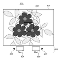
図4は、色指定画面の例を示す図である。色指定画面800は、電子ビューファインダ(EVF)領域(以下、単にEVFという)801と、GUI領域802とに大別され、電子ビューファインダ領域801の中央部には固定の色指定枠803が表示される。また、GUI領域802には、変更元色の表示枠804及び変更目標色の表示枠805がそれぞれ設けられている。また、インジケータ806及び807は、それぞれ左ボタンに変更元色(Src)の指定機能が、右ボタンに変更目標色(Dst)の指定機能が割り当てられていることをユーザが視覚的に把握しやすいように設けられている。
FIG. 4 is a diagram illustrating an example of a color designation screen. The
ここでは、ユーザが、現在EVF801に表示されている鉢植えの花の色を色変換処理により変換させるものとする。この場合ユーザは、まず変換元色の指示を行うため、接近するか光学ズーム機能を用いることにより、色指定枠803のほぼ全体に花びらが表示される状態にし、元色指定ボタンとしての左ボタン305を押下する。
Here, it is assumed that the user converts the color of the potted flower currently displayed on the
色指定画面において元色指定ボタンが押下されると、システム制御回路50はそれを検知し(ステップS103)、画像表示メモリ24から、色指定枠803内の座標に対応する画像データを読み出し、変換元色を求める。色指定枠803内の画像データから変換元色を求める方法に特段制限はないが、色指定枠803内の画像データの平均値に対応する色とすることができる。システム制御回路50は求めた元色をメモリ30に記憶することで設定するとともに、画像処理部50aを通じてGUI領域802の元色表示枠804内に表示する(ステップS105)。この状態を図5に示す。
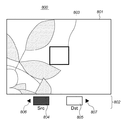
When the original color designation button is pressed on the color designation screen, the
ステップS109で、システム制御回路50は目標色が設定済みであるかどうかをチェックする。ここではまだ目標色の設定がなされていないので、ステップS103へ戻る。このとき、スルー画上で、元色に該当する色の領域をゼブラ表示や網掛け等で分かり易くしても良い。元色の指定を行ったユーザは、次に目標色の指定を行う。本実施形態では、元色の指定と同様、目標色の指定もスルー画像を用いて行う。図6は、色指定画面において、ユーザが目標色を背景の領域から指定しようとしている状態を示している。この状態で目標色指定ボタンである右ボタン306をユーザが押下すると、システム制御回路50はそれをステップS111で検知する。
In step S109, the
そして、システム制御回路50は、元色を求めた方法と同様にして目標色を求め、メモリ30に記憶することで設定するとともに、画像処理部50aを通じてGUI領域802の目標色表示枠805内に表示する(ステップS113)。
Then, the
次に、システム制御回路50はステップS117においてプレビュー処理を行う。プレビュー処理の詳細については後述するが、ここでは設定された元色、目標色に従って色変換処理を行った状態と、色変換処理前の状態とをユーザが比較可能に表示する。
Next, the
プレビュー中にシャッターボタンが押下されれば(ステップS121)、画像処理回路20により色変換処理を適用した撮影処理を行い(ステップS123)、撮影画像を記録媒体200又は210へ記録する。
一方、プレビュー中に再度元色指定ボタンや目標色指定ボタンが押下された場合には、その時点におけるスルー画像の色指定枠内の画像データに基づいて元色又は目標色を設定し直す。
If the shutter button is pressed during the preview (step S121), the
On the other hand, when the original color designation button or the target color designation button is pressed again during the preview, the original color or the target color is reset based on the image data in the color designation frame of the through image at that time.
(プレビュー処理)
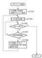
次に、図3のステップS117におけるプレビュー処理の詳細について、図7に示すフローチャートを用いて説明する。
まずステップS1701において、システム制御回路50は、画像処理回路20に対し、スルー画像への色変換処理の適用を指示する。そして、ステップS1703で電子ビューファインダ表示処理を行う。ステップS1701で色変換処理の実施が設定されているので、画像処理回路20はA/D変換器16が出力する画像データに対し、メモリ30に記憶された元色及び目標色を用いた色変換処理を行い、メモリ制御部22に供給する。メモリ制御部22は、色変換された画像を画像表示メモリ24へ書き込む。これにより、色指定画面は色変換前の図6のスルー画像の状態から花びらの色が変換された図8の状態へ変化する。
(Preview process)
Next, details of the preview process in step S117 in FIG. 3 will be described using the flowchart shown in FIG.
First, in step S1701, the
なお、このような色変換処理は周知の画像処理技術を用いて実現することが可能であるが、例えば特開2004−80100号公報に開示されるような、3次元ルックアップテーブルを用いた色変換処理を行うと、階調性を維持した色変換が可能であり好ましい。 Such a color conversion process can be realized by using a well-known image processing technique. For example, a color using a three-dimensional lookup table as disclosed in Japanese Patent Application Laid-Open No. 2004-80100. It is preferable to perform the conversion process because color conversion can be performed while maintaining gradation.
次にシステム制御回路50は、シャッタボタンの押下があったかどうかをチェックし(ステップS1705)、ボタンの押下があればステップS121(図3)へ進む。そして、ボタンの押下が無ければ、ステップS1707で、所定時間(例えば1秒)経過するのを待つ。所定時間経過すると、ステップS1709において、システム制御回路50は、画像処理回路20に対するスルー画像への色変換処理の適用についての設定を反転する。つまり、ここでは色変換処理の適用をしないように設定し、次に所定時間経過した際には色変換処理を適用するように設定する。
Next, the
このように、色変換前のスルー画像と変換後のプレビュー画像とが点滅表示される状態となる。この時点滅の順序は、色が変換される前のスルー画像を先に表示させるように制御する。これにより実際の画像のどの色が変換されたかを元の色と比較して把握することが可能となる。 Thus, the through image before color conversion and the preview image after conversion are displayed in a blinking manner. At this time, the blinking order is controlled so that the through image before color conversion is displayed first. This makes it possible to grasp which color of the actual image has been converted by comparing it with the original color.
また、この状態に於いて、ユーザは、色変換後のプレビュー画像に満足した場合にはシャッターボタンを押下することでそのまま撮影を行うことが可能であり(ステップS121→ステップS123)、そうでない場合には他のボタンを押下することにより、色指定のやり直しを行う事ができる(ステップS121→ステップS103)。なお、再度色指定ボタンを押下する色取り込み後のやり直し処理では、点滅の順序は、プレビュー画像を先に、次に色が変換されていないスルー画像を点滅表示するように制御する。これにより、現在どこの領域の色が変化しているのかを確認した上で、やり直しをすることが可能となる。 In this state, when the user is satisfied with the color-converted preview image, the user can perform shooting as it is by pressing the shutter button (step S121 → step S123). In step S121, step S103 can be performed again by depressing another button. Note that in the redo process after color capture in which the color designation button is pressed again, the blinking order is controlled so that the preview image is displayed first and the through image whose color is not converted next is displayed blinking. As a result, it is possible to redo after confirming which area the color of the area is currently changing.
このように、所定時間経過する毎に、スルー画像への色変換処理の適用の実行と実行中止を交互に指示することにより、画像表示部28には、色変換されない画像(図6)と、色変換された画像(図8)とが交互に表示される。なお、色変換された画像と色変換されない画像との切り替わりを明確にユーザに認識させるため、フェードアウト、フェードインを用いたり、切り替わり時に短時間画像を表示しないようにしたりして、点滅表示させることもできる。
In this way, every time a predetermined time elapses, by alternately instructing execution and suspension of application of the color conversion process to the through image, the
また、点滅表示される画像のどちらが原画像で、どちらが画像処理適用後の画像であるかを示すために、例えば原画像にSourceの”S”を重畳表示させるなど、原画像と画像処理適用後の画像の少なくとも一方に、識別表示を追加することができる。 In addition, in order to indicate which of the images displayed in blinking is the original image and which is the image after application of image processing, for example, “S” of Source is superimposed on the original image, and after application of image processing. An identification display can be added to at least one of the images.
このプレビュー処理は電子ビューファインダ表示処理を利用して行われるため、ユーザがズーミングを行ったり、カメラを動かしたりした場合にも、色指定画面800のEVF801の表示はユーザの操作に追従する。従って、例えば図8の状態で広角側へのズーミングが行われたり、ユーザがカメラを被写体から遠ざけた場合には、図4の状態と図9の状態の表示が交互に行われる。
Since this preview process is performed using the electronic viewfinder display process, even when the user performs zooming or moves the camera, the display of the
このように、本実施形態によれば、撮影画像に画像処理による効果を与えて撮影を行う場合、設定された効果のプレビュー表示を行うことにより、ユーザは撮影前に設定した効果がどのように撮影画像に影響するかを確認することが可能になる。また、電子ビューファインダの表示画像でプレビュー表示を行うので、撮影前に、かつリアルタイムに、画像処理の結果を確認することが可能である。 As described above, according to the present embodiment, when shooting is performed with an image processing effect applied to a captured image, the user can see how the effect set before shooting is displayed by displaying a preview of the set effect. It is possible to check whether the captured image is affected. In addition, since the preview display is performed on the display image of the electronic viewfinder, it is possible to check the result of the image processing before shooting and in real time.
また、プレビュー表示時には画像処理を施さない原画像と、画像処理を適用した処理後画像とを比較可能に表示するため、画像処理の効果をより的確かつ容易に把握することが可能になる。 Further, since the original image that has not been subjected to image processing and the post-processing image to which image processing has been applied are displayed so as to be comparable during preview display, the effect of image processing can be more accurately and easily grasped.
<<第2の実施形態>>
第1の実施形態においては、画像処理の適用の実行と実行中止を交互に指示することで、画像処理を施さない原画像と、画像処理を適用した処理後画像とを所定時間経過毎に自動的に切り替えてプレビュー表示するものであった。これに対し、本実施形態では、ユーザの指示に応じて画像処理の適用の実行と実行中止を交互に指示することにより、表示の切り替えを行うことを特徴とする。なお、プレビュー処理の動作以外、本実施形態にかかるデジタルカメラ100の構成及び動作は第1の実施形態と共通で良いため、本実施形態におけるプレビュー処理についてのみ説明する。
<< Second Embodiment >>
In the first embodiment, by alternately instructing execution and cancellation of application of image processing, an original image that is not subjected to image processing and a post-processing image that has been subjected to image processing are automatically processed every predetermined time. It was intended to switch to the preview display. On the other hand, the present embodiment is characterized in that display switching is performed by alternately instructing execution and stop of application of image processing in accordance with a user instruction. Since the configuration and operation of the
図10は、本発明の第2の実施形態に係る撮像装置としてのデジタルカメラ100におけるプレビュー処理を説明するフローチャートである。図10において、第1の実施形態におけるプレビュー処理と同一の処理については同一の参照数字を付した。
FIG. 10 is a flowchart for explaining preview processing in the
ステップS1701、S1703の処理は第1の実施形態と共通である。ステップS1705において、システム制御回路50は、ボタンの押下があったかどうかをチェックし、ボタンの押下があればステップS1711へ進む。ステップS1711では、表示切り替えボタン(例えば表示ON/OFFボタン66)が押下されたのかどうかを確認し、他のボタンが押下された場合にはステップS121(図3)へ進む。
The processes in steps S1701 and S1703 are the same as those in the first embodiment. In step S1705, the
表示切り替えボタンが押下された場合、ステップS1709において、システム制御回路50は、画像処理回路20に対するスルー画像への色変換処理の適用についての設定を反転する。つまり、ここでは色変換処理の適用をしないように設定し、次に表示切り替えボタンが押下された際には色変換処理を適用するように設定する。
When the display switching button is pressed, in step S1709, the
このように、本実施形態では、表示切り替えボタンが押下される毎にスルー画像への色変換処理の適用の実行と実行中止を交互に指示することにより、画像表示部28には、色変換されない画像と、色変換された画像とが交互に表示される。
本実施形態においても第1の実施形態と同様、原画像と画像処理適用後の画像の少なくとも一方に、識別表示を追加することができる。
As described above, in this embodiment, every time the display switching button is pressed, the
Also in the present embodiment, as in the first embodiment, an identification display can be added to at least one of the original image and the image after application of image processing.
以上説明したように、本実施形態によれば、撮影画像に画像処理による効果を与えて撮影を行う場合、設定された効果のプレビュー表示を行うことにより、ユーザは撮影前に設定した効果がどのように撮影画像に影響するかを確認することが可能になる。 As described above, according to the present embodiment, when shooting is performed by applying an image processing effect to a captured image, a preview display of the set effect is performed so that the user can determine which effect has been set before shooting. In this way, it is possible to confirm whether or not the captured image is affected.
また、プレビュー表示時には画像処理を施さない原画像と、画像処理を適用した処理後画像とをユーザの指示により切り替えて表示するため、画像処理の効果をより的確かつ容易に把握することが可能になる。また、第1の実施形態とは異なり、ユーザは所望のタイミングで原画像と処理後画像を比較することが可能である。 In addition, during preview display, the original image that is not subjected to image processing and the post-processing image that is applied with image processing are switched and displayed according to user instructions, so that the effects of image processing can be grasped more accurately and easily. Become. Also, unlike the first embodiment, the user can compare the original image and the processed image at a desired timing.
<<他の実施形態>>
上述の実施形態においては、撮影時に指定できる画像処理の一例として、特定の色を別な色に変換する色変換処理について説明したが、他の画像処理であっても構わない。また、色の変換は一対である必要は無く、元色と目標色とが複数組指定されてもよい。
<< Other Embodiments >>
In the above-described embodiment, the color conversion process for converting a specific color into another color has been described as an example of the image process that can be specified at the time of shooting. However, other image processes may be used. Further, the color conversion does not need to be a pair, and a plurality of sets of original colors and target colors may be designated.
また、上述した本発明の実施形態における撮像装置を構成する各手段、並びに撮像方法を実現する各ステップは、撮像装置に含まれるコンピュータ(CPU)に制御プログラムを実行させることにより、ソフトウェア的に実現することが可能である。このような制御プログラム及びそれを記録したコンピュータ読み取り可能な記憶媒体もまた本発明に含まれる。 In addition, each unit constituting the imaging apparatus and each step for realizing the imaging method in the embodiment of the present invention described above are realized by software by causing a computer (CPU) included in the imaging apparatus to execute a control program. Is possible. Such a control program and a computer-readable storage medium storing the control program are also included in the present invention.
また、上述した実施形態では、画像処理回路20による画像処理の適用有無を切り替えることにより、画像処理を適用した画像と適用しないスルー画像との切り替えを行う構成について説明した。しかし、画像処理を適用した画像と、適用しない画像とを切り替えて表示可能であればどのような方法を用いても良い。
Further, in the above-described embodiment, the configuration has been described in which switching between an image to which image processing is applied and a through image to which the image processing is not applied is performed by switching whether to apply image processing by the
例えば、画像処理回路20自体は常に画像処理を適用する動作を実行し、メモリ制御部22が、画像処理回路20を通らないスルー画像と、画像処理回路20により画像処理を適用した画像とから選択して画像表示メモリ24に書き込むように構成しても、同様の結果が得られる。
For example, the
この場合、図7及び図10におけるステップS1701では、画像表示メモリ24に書き込む画像を画像処理回路20が出力する画像に設定し、ステップS1709では画像表示メモリ24に書き込む画像を画像処理回路20を通らないスルー画像に設定することになる。
In this case, in step S1701 in FIG. 7 and FIG. 10, the image to be written to the
Claims (11)
前記撮像手段で得られた画像を連続的にリアルタイム表示する電子ビューファインダとして機能することが可能な表示手段と、を備える撮像装置であって、
前記撮像手段で得られる画像に適用される画像処理の設定を、電子ビューファインダとして機能している前記表示手段に表示される画像を利用して、ユーザの操作によってリアルタイムに設定可能な設定手段と、
前記設定手段による設定に基づく画像処理を、電子ビューファインダとして機能している前記表示手段に表示する画像に適用可能な画像処理手段と、
前記画像処理手段により前記画像処理を適用した画像と、前記画像処理手段によって前記画像処理を適用しない画像とを、電子ビューファインダとして機能している前記表示手段に交互表示させる制御手段とを有することを特徴とする撮像装置。 Imaging means ;
An imaging apparatus and a display means capable of resulting image serves as a continuous real-time display to that electronic viewfinder in front Symbol image pickup means,
Setting means capable of setting image processing applied to an image obtained by the imaging means in real time by a user operation using an image displayed on the display means functioning as an electronic viewfinder ,
Image processing means applicable to an image displayed on the display means functioning as an electronic viewfinder , image processing based on the setting by the setting means;
An image obtained by applying the image processing by the image processing unit, and an image that does not apply the image processing by said image processing means, and control means for causing shown exchange 互表 on the display unit functions as an electronic view finder An imaging apparatus comprising:
前記撮像手段で得られた画像を連続的にリアルタイム表示する電子ビューファインダとして機能することが可能な表示手段と、を備える撮像装置の制御方法であって、
前記撮像手段で得られた画像に対して適用される画像処理の設定を、ユーザ操作に応じて、電子ビューファインダとして機能している前記表示手段に表示される画像を利用して設定する設定工程と、
前記設定工程による設定に基づいた画像処理を、電子ビューファインダとして機能している前記表示手段に表示する画像に適用可能な画像処理工程と、
前記画像処理工程により前記画像処理を適用した画像と、前記画像処理工程によって前記画像処理を適用しない画像とを、電子ビューファインダとして機能している前記表示手段に交互表示させる制御工程とを有することを特徴とする撮像装置の制御方法。 Imaging means;
A display unit capable of functioning as an electronic viewfinder that continuously displays real-time images obtained by the imaging unit;
A setting step of setting image processing settings to be applied to an image obtained by the imaging unit using an image displayed on the display unit functioning as an electronic viewfinder in response to a user operation. When,
An image processing step applicable to an image displayed on the display means functioning as an electronic viewfinder, image processing based on the setting in the setting step;
A control step of alternately displaying an image to which the image processing is applied by the image processing step and an image to which the image processing is not applied by the image processing step on the display unit functioning as an electronic viewfinder. A method for controlling an image pickup apparatus.
Priority Applications (6)
| Application Number | Priority Date | Filing Date | Title |
|---|---|---|---|
| JP2005018253A JP4448039B2 (en) | 2005-01-26 | 2005-01-26 | Imaging apparatus and control method thereof |
| US11/332,379 US7538308B2 (en) | 2005-01-26 | 2006-01-17 | Image processing apparatus and control method thereof |
| CN2010101405204A CN101790042B (en) | 2005-01-26 | 2006-01-25 | Image sensing apparatus and control method thereof, as well as image processing apparatus and its control method |
| CN2006100017667A CN1812496B (en) | 2005-01-26 | 2006-01-25 | Image sensing apparatus and control method thereof |
| KR1020060008112A KR100770772B1 (en) | 2005-01-26 | 2006-01-26 | Image sensing apparatus and control method thereof |
| US12/469,139 US8922667B2 (en) | 2005-01-26 | 2009-05-20 | Image pickup apparatus capable of applying color conversion to captured image and control method thereof |
Applications Claiming Priority (1)
| Application Number | Priority Date | Filing Date | Title |
|---|---|---|---|
| JP2005018253A JP4448039B2 (en) | 2005-01-26 | 2005-01-26 | Imaging apparatus and control method thereof |
Publications (3)
| Publication Number | Publication Date |
|---|---|
| JP2006211103A JP2006211103A (en) | 2006-08-10 |
| JP2006211103A5 JP2006211103A5 (en) | 2008-03-06 |
| JP4448039B2 true JP4448039B2 (en) | 2010-04-07 |
Family
ID=36695764
Family Applications (1)
| Application Number | Title | Priority Date | Filing Date |
|---|---|---|---|
| JP2005018253A Expired - Fee Related JP4448039B2 (en) | 2005-01-26 | 2005-01-26 | Imaging apparatus and control method thereof |
Country Status (4)
| Country | Link |
|---|---|
| US (2) | US7538308B2 (en) |
| JP (1) | JP4448039B2 (en) |
| KR (1) | KR100770772B1 (en) |
| CN (2) | CN101790042B (en) |
Families Citing this family (22)
| Publication number | Priority date | Publication date | Assignee | Title |
|---|---|---|---|---|
| JP4448039B2 (en) * | 2005-01-26 | 2010-04-07 | キヤノン株式会社 | Imaging apparatus and control method thereof |
| WO2009089525A1 (en) * | 2008-01-11 | 2009-07-16 | Kyocera Wireless Corp. | Pre-image capture color effects |
| KR101446770B1 (en) * | 2008-01-30 | 2014-11-03 | 삼성전자주식회사 | Digital single lens reflex camera |
| JP4530058B2 (en) * | 2008-02-18 | 2010-08-25 | セイコーエプソン株式会社 | Projector, highlighting method |
| JP2010026734A (en) * | 2008-07-17 | 2010-02-04 | Canon Inc | Image processor and its method |
| JP5553230B2 (en) * | 2009-09-08 | 2014-07-16 | 株式会社リコー | Imaging apparatus and imaging processing method |
| JP5420381B2 (en) * | 2009-11-25 | 2014-02-19 | オリンパスイメージング株式会社 | Photography equipment and accessory equipment that can be attached to and detached from the photography equipment |
| JP4947158B2 (en) * | 2010-02-01 | 2012-06-06 | セイコーエプソン株式会社 | Image display device and highlighting method |
| KR100990305B1 (en) * | 2010-05-13 | 2010-10-26 | 정성호 | System for transmitting/receiving binary cdma visual with direction connecting general ccd/cmos camera module |
| CN102263892A (en) * | 2010-05-26 | 2011-11-30 | 苏州巴米特信息科技有限公司 | Automatic shadow regulation method based on digital camera |
| US20110304636A1 (en) * | 2010-06-14 | 2011-12-15 | Acer Incorporated | Wallpaper image generation method and portable electric device thereof |
| TWI438715B (en) | 2010-09-02 | 2014-05-21 | Htc Corp | Image processing methods and systems for handheld devices, and computer program products thereof |
| CN102256149B (en) * | 2011-07-13 | 2014-12-10 | 深圳创维-Rgb电子有限公司 | Three-dimensional (3D) display effect regulation method, device and television |
| JP2013162267A (en) * | 2012-02-03 | 2013-08-19 | Olympus Imaging Corp | Photographing device |
| KR101917650B1 (en) * | 2012-08-03 | 2019-01-29 | 삼성전자 주식회사 | Method and apparatus for processing a image in camera device |
| JP6108819B2 (en) * | 2012-12-25 | 2017-04-05 | オリンパス株式会社 | Imaging device |
| JP2014220639A (en) * | 2013-05-08 | 2014-11-20 | ソニー株式会社 | Imaging apparatus and imaging method |
| KR102206877B1 (en) * | 2014-02-21 | 2021-01-26 | 삼성전자주식회사 | Method and apparatus for displaying biometric information |
| CN104853078B (en) * | 2015-05-27 | 2020-02-07 | 周毅 | Modular broadcast-level high-definition camera |
| US10339690B2 (en) * | 2015-12-18 | 2019-07-02 | Ricoh Co., Ltd. | Image recognition scoring visualization |
| CN110049231B (en) * | 2017-12-27 | 2021-08-10 | 佳能株式会社 | Electronic device, control method thereof, and computer-readable medium |
| CN113438425B (en) * | 2021-08-25 | 2021-11-19 | 深圳市大道智创科技有限公司 | Automatic exposure adjustment method and system |
Family Cites Families (25)
| Publication number | Priority date | Publication date | Assignee | Title |
|---|---|---|---|---|
| US5247585A (en) * | 1988-12-28 | 1993-09-21 | Masaharu Watanabe | Object recognition device |
| US5212582A (en) | 1992-03-04 | 1993-05-18 | Texas Instruments Incorporated | Electrostatically controlled beam steering device and method |
| KR0183807B1 (en) | 1995-12-30 | 1999-05-01 | 김광호 | Electronic still camera having low speed shutter function and its control method |
| JP4245699B2 (en) | 1998-09-16 | 2009-03-25 | オリンパス株式会社 | Imaging device |
| US6873438B2 (en) * | 2000-05-31 | 2005-03-29 | Richard A. Fotland | Method of image color correction |
| KR100587366B1 (en) * | 2000-08-30 | 2006-06-08 | 엘지.필립스 엘시디 주식회사 | In-plane switching mode liquid crystal display device and method for manufacturing the same |
| JP2002142148A (en) | 2000-11-06 | 2002-05-17 | Olympus Optical Co Ltd | Electronic camera and method for setting its photographic condition |
| JP2002142149A (en) * | 2000-11-06 | 2002-05-17 | Mega Chips Corp | Picture processing circuit |
| US7304668B2 (en) * | 2001-04-11 | 2007-12-04 | Fujifilm Corporation | Printer system and image processing system having image correcting function |
| JP4005322B2 (en) * | 2001-05-23 | 2007-11-07 | 株式会社コナミデジタルエンタテインメント | Image processing apparatus, image processing method, program, and automatic photography apparatus |
| JP2003338972A (en) | 2001-09-12 | 2003-11-28 | Fuji Photo Film Co Ltd | Image processing system, imaging unit, apparatus and method for processing image and program |
| US20030146997A1 (en) * | 2002-02-01 | 2003-08-07 | Eastman Kodak Company | System and method of processing a digital image for user assessment of an output image product |
| JP4000872B2 (en) * | 2002-03-05 | 2007-10-31 | ソニー株式会社 | Image photographing apparatus and chromatic aberration correction method |
| JP2004080100A (en) | 2002-08-09 | 2004-03-11 | Canon Inc | Method and apparatus for creating color conversion table, method and apparatus for converting colors, and imaging apparatus |
| US7035462B2 (en) * | 2002-08-29 | 2006-04-25 | Eastman Kodak Company | Apparatus and method for processing digital images having eye color defects |
| EP2819123A1 (en) * | 2003-01-02 | 2014-12-31 | Samsung Electronics Co., Ltd | Multimedia apparatus with "slide-show" accompanied audio output |
| US20040196399A1 (en) * | 2003-04-01 | 2004-10-07 | Stavely Donald J. | Device incorporating retina tracking |
| JP4296032B2 (en) | 2003-05-13 | 2009-07-15 | 富士フイルム株式会社 | Image processing device |
| US7907150B2 (en) * | 2003-08-09 | 2011-03-15 | Doubleshot, Inc. | Method of fusion or merging imagery data for improved visual perception using monoscopic and stereographic fusion and retinal decay techniques |
| US7664322B1 (en) * | 2003-08-11 | 2010-02-16 | Adobe Systems Incorporated | Feature-based color adjustment |
| JP4311161B2 (en) * | 2003-10-15 | 2009-08-12 | カシオ計算機株式会社 | Electronic camera and photographing control method of electronic camera |
| JP4458811B2 (en) | 2003-10-29 | 2010-04-28 | キヤノン株式会社 | Imaging apparatus, display control method, and display control program |
| JP4262082B2 (en) * | 2003-12-24 | 2009-05-13 | キヤノン株式会社 | Image processing apparatus, control method therefor, program, and storage medium |
| JP4471373B2 (en) | 2004-12-27 | 2010-06-02 | キヤノン株式会社 | Imaging apparatus and control method thereof |
| JP4448039B2 (en) * | 2005-01-26 | 2010-04-07 | キヤノン株式会社 | Imaging apparatus and control method thereof |
-
2005
- 2005-01-26 JP JP2005018253A patent/JP4448039B2/en not_active Expired - Fee Related
-
2006
- 2006-01-17 US US11/332,379 patent/US7538308B2/en not_active Expired - Fee Related
- 2006-01-25 CN CN2010101405204A patent/CN101790042B/en active Active
- 2006-01-25 CN CN2006100017667A patent/CN1812496B/en not_active Expired - Fee Related
- 2006-01-26 KR KR1020060008112A patent/KR100770772B1/en active IP Right Grant
-
2009
- 2009-05-20 US US12/469,139 patent/US8922667B2/en active Active
Also Published As
| Publication number | Publication date |
|---|---|
| US8922667B2 (en) | 2014-12-30 |
| CN1812496A (en) | 2006-08-02 |
| CN1812496B (en) | 2010-05-12 |
| US7538308B2 (en) | 2009-05-26 |
| KR20060086314A (en) | 2006-07-31 |
| US20060163450A1 (en) | 2006-07-27 |
| US20090231480A1 (en) | 2009-09-17 |
| CN101790042A (en) | 2010-07-28 |
| KR100770772B1 (en) | 2007-10-26 |
| JP2006211103A (en) | 2006-08-10 |
| CN101790042B (en) | 2011-11-30 |
Similar Documents
| Publication | Publication Date | Title |
|---|---|---|
| JP4448039B2 (en) | Imaging apparatus and control method thereof | |
| JP4481842B2 (en) | Imaging apparatus and control method thereof | |
| JP5173453B2 (en) | Imaging device and display control method of imaging device | |
| JP5366584B2 (en) | Imaging apparatus, image processing method, and program | |
| JP4367955B2 (en) | Imaging apparatus and control method thereof | |
| JP2006191492A (en) | Image pickup device and control method thereof | |
| JP2007081732A (en) | Imaging apparatus | |
| JP4953971B2 (en) | Image processing apparatus, image processing apparatus control method, and program for executing the same | |
| US20040032490A1 (en) | Image sensing apparatus, image sensing method, program, and storage medium | |
| JP4881195B2 (en) | IMAGING DEVICE, ITS CONTROL METHOD, PROGRAM, AND STORAGE MEDIUM | |
| JP4401974B2 (en) | Imaging apparatus and control method thereof | |
| JP6611566B2 (en) | IMAGING DEVICE, IMAGING DEVICE CONTROL METHOD, AND PROGRAM | |
| JP2006039203A (en) | Imaging apparatus, and its control method | |
| JP2006166051A (en) | Electronic camera | |
| JP2005134532A (en) | Imaging apparatus, display control method and display control program | |
| JP2006060409A (en) | Imaging apparatus and control method thereof | |
| JP5178438B2 (en) | IMAGING DEVICE, IMAGING DEVICE CONTROL METHOD, AND PROGRAM | |
| JP2005110128A (en) | Imaging apparatus and imaging control method | |
| JP6526270B2 (en) | Image pickup apparatus and control method thereof | |
| JP2010093392A (en) | Imaging apparatus, control method therefor, and program | |
| JP2008060844A (en) | Image processor and image processing method | |
| JP2005223616A (en) | Image pickup apparatus | |
| JP5361973B2 (en) | IMAGING DEVICE, ITS CONTROL METHOD, PROGRAM, AND STORAGE MEDIUM | |
| JP2012119806A (en) | Imaging apparatus | |
| JP2005215206A (en) | Imaging unit, imaging method, program, and storage medium |
Legal Events
| Date | Code | Title | Description |
|---|---|---|---|
| A521 | Request for written amendment filed |
Free format text: JAPANESE INTERMEDIATE CODE: A523 Effective date: 20080123 |
|
| A621 | Written request for application examination |
Free format text: JAPANESE INTERMEDIATE CODE: A621 Effective date: 20080123 |
|
| A131 | Notification of reasons for refusal |
Free format text: JAPANESE INTERMEDIATE CODE: A131 Effective date: 20091013 |
|
| A521 | Request for written amendment filed |
Free format text: JAPANESE INTERMEDIATE CODE: A523 Effective date: 20091210 |
|
| TRDD | Decision of grant or rejection written | ||
| A01 | Written decision to grant a patent or to grant a registration (utility model) |
Free format text: JAPANESE INTERMEDIATE CODE: A01 Effective date: 20100118 |
|
| A01 | Written decision to grant a patent or to grant a registration (utility model) |
Free format text: JAPANESE INTERMEDIATE CODE: A01 |
|
| A61 | First payment of annual fees (during grant procedure) |
Free format text: JAPANESE INTERMEDIATE CODE: A61 Effective date: 20100121 |
|
| FPAY | Renewal fee payment (event date is renewal date of database) |
Free format text: PAYMENT UNTIL: 20130129 Year of fee payment: 3 |
|
| R150 | Certificate of patent or registration of utility model |
Ref document number: 4448039 Country of ref document: JP Free format text: JAPANESE INTERMEDIATE CODE: R150 Free format text: JAPANESE INTERMEDIATE CODE: R150 |
|
| FPAY | Renewal fee payment (event date is renewal date of database) |
Free format text: PAYMENT UNTIL: 20140129 Year of fee payment: 4 |
|
| LAPS | Cancellation because of no payment of annual fees |