JP4471373B2 - Imaging apparatus and control method thereof - Google Patents
Imaging apparatus and control method thereof Download PDFInfo
- Publication number
- JP4471373B2 JP4471373B2 JP2004377242A JP2004377242A JP4471373B2 JP 4471373 B2 JP4471373 B2 JP 4471373B2 JP 2004377242 A JP2004377242 A JP 2004377242A JP 2004377242 A JP2004377242 A JP 2004377242A JP 4471373 B2 JP4471373 B2 JP 4471373B2
- Authority
- JP
- Japan
- Prior art keywords
- color
- image
- image processing
- unit
- imaging
- Prior art date
- Legal status (The legal status is an assumption and is not a legal conclusion. Google has not performed a legal analysis and makes no representation as to the accuracy of the status listed.)
- Expired - Fee Related
Links
Images


Classifications
-
- H—ELECTRICITY
- H04—ELECTRIC COMMUNICATION TECHNIQUE
- H04N—PICTORIAL COMMUNICATION, e.g. TELEVISION
- H04N1/00—Scanning, transmission or reproduction of documents or the like, e.g. facsimile transmission; Details thereof
- H04N1/46—Colour picture communication systems
- H04N1/56—Processing of colour picture signals
- H04N1/60—Colour correction or control
- H04N1/62—Retouching, i.e. modification of isolated colours only or in isolated picture areas only
- H04N1/622—Retouching, i.e. modification of isolated colours only or in isolated picture areas only with simulation on a subsidiary picture reproducer
-
- H—ELECTRICITY
- H04—ELECTRIC COMMUNICATION TECHNIQUE
- H04N—PICTORIAL COMMUNICATION, e.g. TELEVISION
- H04N23/00—Cameras or camera modules comprising electronic image sensors; Control thereof
- H04N23/10—Cameras or camera modules comprising electronic image sensors; Control thereof for generating image signals from different wavelengths
-
- H—ELECTRICITY
- H04—ELECTRIC COMMUNICATION TECHNIQUE
- H04N—PICTORIAL COMMUNICATION, e.g. TELEVISION
- H04N23/00—Cameras or camera modules comprising electronic image sensors; Control thereof
- H04N23/60—Control of cameras or camera modules
- H04N23/63—Control of cameras or camera modules by using electronic viewfinders
- H04N23/633—Control of cameras or camera modules by using electronic viewfinders for displaying additional information relating to control or operation of the camera
- H04N23/635—Region indicators; Field of view indicators
-
- H—ELECTRICITY
- H04—ELECTRIC COMMUNICATION TECHNIQUE
- H04N—PICTORIAL COMMUNICATION, e.g. TELEVISION
- H04N23/00—Cameras or camera modules comprising electronic image sensors; Control thereof
- H04N23/80—Camera processing pipelines; Components thereof
- H04N23/84—Camera processing pipelines; Components thereof for processing colour signals
- H04N23/843—Demosaicing, e.g. interpolating colour pixel values
-
- H—ELECTRICITY
- H04—ELECTRIC COMMUNICATION TECHNIQUE
- H04N—PICTORIAL COMMUNICATION, e.g. TELEVISION
- H04N23/00—Cameras or camera modules comprising electronic image sensors; Control thereof
- H04N23/80—Camera processing pipelines; Components thereof
- H04N23/84—Camera processing pipelines; Components thereof for processing colour signals
- H04N23/88—Camera processing pipelines; Components thereof for processing colour signals for colour balance, e.g. white-balance circuits or colour temperature control
-
- H—ELECTRICITY
- H04—ELECTRIC COMMUNICATION TECHNIQUE
- H04N—PICTORIAL COMMUNICATION, e.g. TELEVISION
- H04N9/00—Details of colour television systems
- H04N9/64—Circuits for processing colour signals
- H04N9/643—Hue control means, e.g. flesh tone control
-
- H—ELECTRICITY
- H04—ELECTRIC COMMUNICATION TECHNIQUE
- H04N—PICTORIAL COMMUNICATION, e.g. TELEVISION
- H04N25/00—Circuitry of solid-state image sensors [SSIS]; Control thereof
- H04N25/10—Circuitry of solid-state image sensors [SSIS]; Control thereof for transforming different wavelengths into image signals
- H04N25/11—Arrangement of colour filter arrays [CFA]; Filter mosaics
- H04N25/13—Arrangement of colour filter arrays [CFA]; Filter mosaics characterised by the spectral characteristics of the filter elements
- H04N25/134—Arrangement of colour filter arrays [CFA]; Filter mosaics characterised by the spectral characteristics of the filter elements based on three different wavelength filter elements
Landscapes
- Engineering & Computer Science (AREA)
- Multimedia (AREA)
- Signal Processing (AREA)
- Color Television Image Signal Generators (AREA)
- Studio Devices (AREA)
- Processing Of Color Television Signals (AREA)
Description
本発明は色のユーザカスタマイズを可能とする撮像装置及びその制御方法に関する。 The present invention relates to an imaging apparatus that enables user customization of colors and a control method thereof.
近年、デジタルカメラが普及し、多くのユーザがデジタルカメラを使用する機会が増えている。このため、デジタルカメラに対するユーザのニーズもより多様化してきている。そのようなニーズの一つとして色再現性がある。メーカが目標とする色再現特性は多くのユーザが好ましいと感じる平均的な色再現を目指している。しかしながら、ユーザ毎に好みは異なるため、すべてのユーザが満足するような色再現性を実現することはできなかった。 In recent years, digital cameras have become widespread, and many users have increased opportunities to use digital cameras. For this reason, user needs for digital cameras are also diversifying. One such need is color reproducibility. The color reproduction characteristics targeted by the manufacturer are aimed at average color reproduction that many users find desirable. However, since each user has different preferences, color reproducibility that satisfies all users cannot be realized.
このような課題を解決するために、色相、彩度、明度等のパラメータをカスタマイズすることを可能とし、撮影時においてユーザが所望する色再現性を実現可能とするデジタルカメラが存在する。しかしながら、これらパラメータの変化と色の変化の関係をユーザに示すことは困難なため、最適な設定をするにはユーザの熟練を必要としていた。 In order to solve such a problem, there is a digital camera that can customize parameters such as hue, saturation, and brightness, and can realize a color reproducibility desired by a user at the time of photographing. However, since it is difficult to show the user the relationship between these parameter changes and color changes, the user's skill is required for optimal settings.
ユーザにわかりやすく色を調整させるための方法に関する提案としては、特許文献1矢特許文献2が挙げられる。特許文献1には画像のレタッチ処理において画像中の所望のソース色を指示するとともに、変換先の目標色として所望の色を指示することにより、指示されたソース色が指示された目標色に変換されるような色変換処理を実行する構成が記載されている。また、特許文献2では、撮像装置で変更したい元色として肌色を取り込み、その取り込んだ肌色とROMに記憶された肌色再現目標値とに基づいて色補正係数を算出する構成が記載されている。
しかしながら、特許文献1は画像のレタッチ処理に関するものであり、撮像装置における撮影時の色変換処理を設定するものではない。また、カーソルによるソース色及び目標色の指定が必要である等、撮像装置のような限られたユーザインターフェースでの色変換処理に不向きである。また、特許文献2では、予めROMに記憶された数種類の目標色の中からユーザが所望の目標色を選ぶ。すなわち、目標色は数種類に制限され、自由な色変換を実現するものではない。また、目標色は画像としてユーザに提示されないので、ユーザはどのような色に変換されるのかを知ることが困難である。
However, Patent Document 1 relates to an image retouching process, and does not set a color conversion process at the time of shooting in an imaging apparatus. In addition, it is not suitable for color conversion processing with a limited user interface such as an imaging apparatus, such as the necessity of specifying a source color and a target color with a cursor. In
本発明は上記の課題に鑑みてなされたものであり、撮像装置の限られたユーザインターフェースでも変換元色と変換目標色を自由、明瞭且つ容易に設定可能とし、撮影時における所望の色変換を簡易な操作で実現可能とすることを目的とする。 The present invention has been made in view of the above problems, and allows a conversion source color and a conversion target color to be set freely, clearly and easily even with a limited user interface of an imaging apparatus, and performs desired color conversion at the time of shooting. The purpose is to enable realization with a simple operation.
上記課題を解決するための本発明による撮像装置は以下の構成を備える。即ち、
撮像手段と、前記撮像手段で得られた画像をリアルタイムで表示する電子ビューファインダとして利用可能な表示手段とを備える撮像装置であって、
電子ビューファインダとして機能中の前記表示手段に表示される画像の所定領域に含まれる色情報に基づいて第1の色値を決定する第1決定手段と、
前記第1決定手段とは異なるタイミングで、電子ビューファインダとして機能中の前記表示手段に表示される画像の所定領域に含まれる色情報に基づいて第2の色値を決定する第2決定手段と、
前記設定手段による設定に基づく画像処理を、前記撮像手段で得られた画像に適用する画像処理手段とを備え、
前記表示手段は、前記撮像手段で得られ、前記画像処理手段で画像処理された画像をリアルタイムに表示可能である。
In order to solve the above problems, an imaging apparatus according to the present invention has the following configuration. That is,
An imaging apparatus comprising: an imaging unit; and a display unit that can be used as an electronic viewfinder that displays an image obtained by the imaging unit in real time ,
First determination means for determining a first color value based on color information included in a predetermined area of an image displayed on the display means functioning as an electronic viewfinder;
Second determination means for determining a second color value based on color information included in a predetermined area of an image displayed on the display means functioning as an electronic viewfinder at a timing different from that of the first determination means; ,
Image processing means for applying image processing based on the setting by the setting means to the image obtained by the imaging means,
The display means can display an image obtained by the imaging means and subjected to image processing by the image processing means in real time .
上記構成によれば、撮像装置の限られたユーザインターフェースでも変換元色と変換目標色を自由、明瞭且つ容易に設定することが可能となり、撮影時における所望の色変換を簡易な操作で実現できる。 According to the above configuration, the conversion source color and the conversion target color can be set freely, clearly and easily even with a limited user interface of the imaging apparatus, and desired color conversion at the time of shooting can be realized with a simple operation. .
以下、添付の図面を参照して本発明の好適な実施形態について説明する。 Hereinafter, preferred embodiments of the present invention will be described with reference to the accompanying drawings.
<第1実施形態>
図1は、本実施形態による撮像装置100(本例ではデジタルカメラとする)の構成例を示す図である。実空間の像は撮影レンズ101と、絞り機能を備えるシャッター102とを経て、光学像を電気信号に変換する撮像素子103上に結像される。A/D変換部105は撮像素子103から出力されるアナログ信号をディジタル信号に変換する。タイミング発生部106は、メモリ制御部108及びシステム制御部109により制御され、撮像素子103、A/D変換部105及びD/A変換部107にクロック信号や制御信号を供給する。
<First Embodiment>
FIG. 1 is a diagram illustrating a configuration example of an
画像処理部110は、A/D変換部105からのデータ或いはメモリ制御部108からのデータに対して所定の画素補間処理や色変換処理を行う。また、画像処理部110は、撮像した画像データを用いて所定の演算処理を行う。システム制御部109は画像処理部110の演算結果に基づいて露光制御部111や測距制御部112を制御し、TTL(スルー・ザ・レンズ)方式のAF(オートフォーカス)処理、AE(自動露出)処理、EF(フラッシュプリ発光)処理を行っている。さらに、画像処理部110は、撮像した画像データを用いて所定の演算処理を行い、得られた演算結果に基づいてTTL方式のAWB(オートホワイトバランス)処理も行っている。
The
メモリ制御部108は、A/D変換部105、タイミング発生部106、D/A変換部107、画像処理部110、画像表示メモリ113、メモリ114、圧縮・伸長部115を制御する。A/D変換部105から出力されたデータは画像処理部110とメモリ制御部108を介して、或いはメモリ制御部108のみを介して、画像表示メモリ113或いはメモリ114に書き込まれる。なお、画像表示メモリ113に画像データを書き込む際には、画像表示部116が備える表示器の解像度に応じて間引きされて書き込まれる。画像表示メモリ113に書き込まれた表示用の画像データはD/A変換部107を介して画像表示用のアナログ信号となり、画像表示部116により表示される。画像表示部116はTFTLCD等で構成される。なお、画像表示部116を用いて撮像した画像データを逐次表示すれば、所謂電子ビューファインダ機能を実現することが可能である。画像表示部116は、システム制御部109の指示により任意に表示をON/OFFすることが可能であり、表示をOFFにした場合には撮像装置100の電力消費を大幅に低減することが出来る。
The
メモリ114は撮影した静止画像や動画像を格納するためのメモリである。メモリ114は所定枚数の静止画像や所定時間の動画像を格納するのに十分な記憶量を備えている。これにより、複数枚の静止画像を連続して撮影する連射撮影やパノラマ撮影の場合にも、高速かつ大量の画像書き込みをメモリ114に対して行うことが可能となる。また、メモリ114はシステム制御部109の作業領域としても使用することが可能である。
The
圧縮・伸長部115は、適応離散コサイン変換(ADCT)等により画像データを圧縮伸長する。圧縮・伸長部115はメモリ114に格納された画像を読み込んで圧縮処理或いは伸長処理を行い、処理を終えたデータをメモリ114に書き込む。
The compression /
露光制御部111は、絞り機能を備えるシャッター102を制御し、フラッシュ117と連携することによりフラッシュ調光機能も有する。測距制御部112は、撮影レンズ101のフォーカシングを制御する。ズーム制御部118は撮影レンズ101のズーミングを制御する。バリア制御部119は、保護部151の動作を制御する。保護部151は、撮像装置100のレンズ101、シャッター102、撮像素子103を含む撮像部を覆うことにより、撮像部の汚れや破損を防止するバリアである。一般には、保護部151はレンズ101の保護を主たる目的とする。フラッシュ117は、AF補助光の投光機能、フラッシュ調光機能を有する。露光制御部111、測距制御部112はTTL方式を用いて制御されている。すなわち、撮像により得られた画像データを画像処理部110によって演算した演算結果に基づき、システム制御部109が露光制御部111と測距制御部112に対して制御を行っている。システム制御部109は撮像装置100の全体の制御を司る。メモリ120は、システム制御部109の動作用の定数、変数、プログラム等を記憶する。
The exposure control unit 111 controls the
表示部121は、システム制御部109でのプログラムの実行に応じて、文字や画像により動作状態やメッセージ等を提示する液晶表示装置(LDC)やLED等である。なお、表示部121は、動作上体やメッセージの一部を提示するための音声やブザー音等を出力可能なスピーカ或いは圧電ブザー(発音素子)等を含んでもよい。表示部121は、撮像装置100の操作部近辺の視認し易い位置に単数或いは複数個所設置されてもよい。また、表示部121は、その一部の機能が光学ファインダ104内に設置されている。
The
表示部121の表示内容のうち、LCD等に表示するものとしては、シングルショット/連写撮影表示、セルフタイマ表示、圧縮率表示、記録画素数表示、記録枚数表示、残撮影可能枚数表示、シャッタースピード表示、絞り値表示、露出補正表示、フラッシュ表示、赤目緩和表示、マクロ撮影表示、ブザー設定表示、時計用電池残量表示、電池残量表示、エラー表示、複数桁の数字による情報表示、記録媒体122及び123の着脱状態表示、通信I/F動作表示、日付け・時刻表示、等がある。また、表示部121の表示内容のうち、光学ファインダ104内に表示するものとしては、合焦表示、手振れ警告表示、フラッシュ充電表示、シャッタースピード表示、絞り値表示、露出補正表示、等がある。
Among the display contents of the
不揮発性メモリ124は電気的に消去・記録可能なメモリであり、例えばEEPROM等が用いられる。125、126、127、128、129及び130は、システム制御部109の各種の動作指示を入力するための操作部を示している。これらの操作部はスイッチやダイアル、タッチパネル、視線検知によるポインティング、音声認識装置等のいずれか或いはそれらのうちの複数の組み合わせで構成される。これらの操作部について、以下に具体的に説明する。
The
モードダイアルスイッチ125は、電源オフ、自動撮影モード、撮影モード、パノラマ撮影モード、再生モード、マルチ画面再生・消去モード、PC接続モード等の各機能モードを切り替え設定するためのスイッチである。シャッタースイッチ126は、シャッターボタン(図2の203)の操作途中(シャッターボタンの半押し)で信号SW1を出力し、シャッターボタンの操作完了(シャッターボタンの全押し)で信号SW2を出力する。信号SW1により、AF(オートフォーカス)処理、AE(自動露出)処理、AWB(オートホワイトバランス)処理、EF(フラッシュプリ発光)処理等の動作開始が指示される。また、信号SW2により、一連の撮影処理の動作開始が指示される。撮影処理では、撮像素子102から読み出した信号をA/D変換部105でデジタル変換し(露光処理)、メモリ制御部108を介してメモリ114に画像データ(RAWデータ)として書き込む、露光処理された信号を画像処理部110やメモリ制御部108で演算処理(現像処理)してメモリ114に書き込む、メモリ114から画像データを読み出して圧縮・伸長部115で圧縮を行い、記録媒体122或いは123に書き込む(記録処理)という一連の処理が行なわれる。
The
画像表示ON/OFFスイッチ128は、画像表示部116のON/OFFを設定する。この機能により、光学ファインダ104を用いて撮影を行う際に、TFTLCD等から成る画像表示部116への電源供給を遮断することができ、省電力を図ることが可能となる。クイックレビューON/OFFスイッチ129は、撮影直後に撮影した画像データを自動再生するクイックレビュー機能のON/OFFを設定する。なお画像表示部116をOFFとした場合におけるクイックレビュー機能(画像表示をOFFにした場合においても撮像された画像をレビュー可能とする)の設定をする機能を備えるものとする。
The image display ON /
操作部130は各種ボタンやタッチパネル等を含み、1つのスイッチまたは複数のスイッチの組み合わせにより各種操作指示ボタンとして機能する。このような操作指示としては、例えば、メニューボタン、セットボタン、マクロボタン、マルチ画面再生改ページボタン、フラッシュ設定ボタン、単写/連写/セルフタイマ切り替えボタン、メニュー移動+(プラス)ボタン、メニュー移動−(マイナス)ボタン、再生画像移動+(プラス)ボタン、再生画像−(マイナス)ボタン、撮影画質選択ボタン、露出補正ボタン、日付/時間設定ボタン、画像削除ボタン、画像削除取消しボタン等があげられる。
The
電源制御部131は、電池検出回路、DC−DCコンバータ、通電するブロックを切り替えるスイッチ回路等により構成されている。電源制御部131は、電池の装着の有無、電池の種類、電池残量の検出を行い、検出結果及びシステム制御部109の指示に基づいてDC−DCコンバータを制御し、必要な電圧を必要な期間、記録媒体を含む各部へ供給する。電源部134は、アルカリ電池やリチウム電池等の一次電池やNiCd電池やNiMH電池、Li電池等の二次電池、ACアダプタ等から構成される。電源部134は、コネクタ132、133を介して電源制御部131に接続される。
The power
インターフェース135、136はメモリカードやハードディスク等の記録媒体と撮像装置100内のバスとを接続する。メモリカードやハードディスク等の記録媒体とインターフェース135、136との接続はコネクタ137、138を介してなされる。記録媒体着脱検知部139はコネクタ137及び/またはコネクタ138に記録媒体122及び/またはコネクタ123が装着されているか否かを検知する。
なお、本実施形態では記録媒体を取り付けるインターフェース及びコネクタを2系統持つものとして説明している。もちろん、記録媒体を取り付けるインターフェース及びコネクタは、単数或いは複数、いずれの系統数を備える構成としても構わない。また、異なる規格のインターフェース及びコネクタを組み合わせて備える構成としても構わない。このようなインターフェース及びコネクタとしては、PCMCIAカードやCF(コンパクトフラッシュ(登録商標))カード等の規格に準拠したものを用いて構成して構わない。 In the present embodiment, it is assumed that there are two systems of interfaces and connectors for attaching a recording medium. Of course, the interface and the connector for attaching the recording medium may have a single or a plurality of systems and any number of systems. Moreover, it is good also as a structure provided with combining the interface and connector of a different standard. As such an interface and a connector, you may comprise using the thing based on standards, such as a PCMCIA card and CF (compact flash (registered trademark)) card.
さらに、インタフェース135及び136、そしてコネクタ137及び138をPCMCIAカードやCF(コンパクトフラッシュ(登録商標))カード等の規格に準拠したものを用いて構成した場合、LANカードやモデムカード、USBカード、IEEE1394カード、P1284カード、SCSIカード、PHS等の通信カード、等の各種通信カードを接続することにより、他のコンピュータやプリンタ等の周辺機器との間で画像データや画像データに付属した管理情報を転送し合うことを可能とすることが出来る。
Further, when the
光学ファインダ104は、画像表示部116による電子ビューファインダ機能を使用すること無しに、光学ファインダのみを用いて撮影を行うことを可能とする。また、上述したように、光学ファインダ104内には表示部121の一部の機能、例えば、合焦表示、手振れ警告表示、フラッシュ充電表示、シャッタースピード表示、絞り値表示、露出補正表示などが設置されている。
The
通信部110は、RS232CやUSB、IEEE1394、P1284、SCSI、モデム、LAN、無線通信、等の各種通信機能を有する。接続部112は通信部110により撮像装置100を他の機器と接続するためのコネクタである。或いは無線通信の場合は、接続部112はアンテナである。
The
記録媒体122、123は、半導体メモリや磁気ディスク等から構成される記録部139、142と、撮像装置100とのインタフェース140、143、撮像装置100と接続を行うコネクタ141、144を備えている。
The
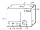
図2は、撮像装置100(デジタルカメラ)の斜視図である。電源スイッチ201は電源をON/OFFするためのボタンである。参照番号202、205〜209は上述した操作部130の一部を構成している。モード切り替えレバー202は、撮影モード、再生モード、動画撮影モード、静止画撮影モード等の各機能モードを切り替え設定する。シャッターボタン203は上述のシャッタースイッチ126として機能する。LCD204は上述した画像表示部116の一部を構成し、電子ビューファインダとして機能するほか、静止画像及び/または動画像を再生して得られる画面を表示する。メニューボタン205は、撮影パラメタやカメラの設定を変更するためのメニュー画面をON、OFFさせるスイッチである。セットボタン206は、メニューボタン205の操作により表示されたメニュー画面でのメニューの選択・決定等に使用する。削除ボタン207は画像の削除を指定する。ディスプレイボタン208は上述の画像表示ON/OFFスイッチ128を構成し、LCD204における表示の有無を切り替えるためのボタンである。十字ボタン209は、この上下左右ボタンを使ってメニュー画面での項目の移動などを行ったり、再生モードでは左右ボタンを押して画像送りを行ったりするのに使用され得る。
FIG. 2 is a perspective view of the imaging apparatus 100 (digital camera). A
図3は本実施形態によるディジタルカメラ100内の画像処理部110の処理を説明するブロック図である。なお、以下で説明する各処理に用いられるパラメータ値(マトリクス演算のためのパラメータや3次元ルックアップテーブルのパラメータ)はメモリ120に格納されており、画像処理部110により適宜読み出される。A/D変換部105によりA/D変換されたCCDデジタル信号に対して、まずホワイトバランス処理部301にてホワイトバランス処理が行われる。ホワイトバランス処理についてはここでは説明しないが、例えば特開2003−244723号公報に記載されている方法を用いて行うことができる。ホワイトバランス処理が行われたCCDデジタル信号は補間処理部302に供給される。本実施形態の撮像素子103は図5に示すようなベイヤー配列のカラーフィルタを有するものとする。従って、補間処理部302では、図5に示されたCCDのベイヤー配列データを図6に示されるようなR、G1、G2、Bの補間データに変換する処理が行なわれる。補間されたCCDデジタル信号はマトリクス演算処理部303に入力され、式(1)に示される4×3のマトリクス演算が行われ、Rm、Gm、Bmが求められる。
FIG. 3 is a block diagram illustrating processing of the

マトリクス演算処理されたCCDデジタル信号は色差ゲイン演算処理部304において色差信号にゲインがかけられる。即ち、Rm、Gm、Bm信号は式(2)に従ってY、Cr、Cb信号へと変換される。そして、得られたCr、Cb信号に式(3)に従ってゲインがかけられる。その後、式(4)(式(2)の逆行列演算)により、Rg、Gg、Bg信号へと変換される。
The CCD digital signal that has been subjected to matrix calculation processing is gained by the color difference gain
色差ゲイン演算処理されたCCDデジタル信号はガンマ処理部305へ送られる。ガンマ処理部305では以下の式(5)〜(7)を用いてCCDデジタル信号のガンマ変換を行なう。ここで、GammaTableは1次元ルックアップテーブルである。
The CCD digital signal subjected to the color difference gain calculation process is sent to the
Rt=GammaTable[Rg] …式(5)
Gt=GammaTable[Gg] …式(6)
Bt=GammaTable[Bg] …式(7)。
Rt = GammaTable [Rg] Formula (5)
Gt = GammaTable [Gg] (6)
Bt = GammaTable [Bg] (7)
上記ガンマ処理が施されたCCDデジタル信号は色相補正演算処理部306へ送られる。色相補正演算処理部306は、以下の式(8)によりRt、Gt、Bt信号をY、Cr、Cb信号へ変換し、さらに式(9)によりCr、Cb、信号を補正し、その後、式(10)(式(9)の逆行列演算)により、Rh、Gh、Bh信号へ変換する。
The CCD digital signal that has been subjected to the gamma processing is sent to the hue correction
色相補正演算処理部306で処理されたCCDデジタル信号は色差信号変換処理部307へと送られる。色差信号変換処理部307は、式(11)を用いてRh、Gh、Bh信号よりUV信号を作成する。
The CCD digital signal processed by the hue correction
一方、ホワイトバランス処理部301でホワイトバランス処理が施されたCCDデジタル信号は、輝度信号作成部308にも供給される。輝度信号作成選択部308は、CCDデジタル信号を輝度信号へと変換する。例えば、図5に示すような原色フィルタの場合の輝度信号は、R、Bの信号をすべて0にして、図7に示す係数を持つ2次元フィルタ処理を施したものを輝度信号とする。なお、補色フィルタの場合の輝度信号はそのまま図7に示す係数を持つ2次元フィルタ処理を施したものを輝度信号とする。補色輝度信号処理部308で作成された輝度信号は高域強調処理部309にてエッジ強調処理され、さらにガンマ処理部310にてガンマ変換処理されてY信号が作成される。
On the other hand, the CCD digital signal that has been subjected to the white balance processing by the white
ガンマ処理部310から出力されるY信号および、色差信号変換処理部307から出力されるU,V信号は色変換処理部311にて、Y’、U’、V’信号へと変換される。色変換処理部311では、3次元ルックアップテーブルを用いた変換処理がなされるが、詳細は後述する。
The Y signal output from the
本実施形態のデジタルカメラ(撮像装置100)は、ユーザが指定した任意の色を、ユーザが指定した別の任意の色へ変換が可能な撮影モード(以下、色変換モードという)を有する。この色変換モードでは、LCD204上に図8に示す電子ビューファインダ(EVF)画面801を表示し、リアルタイムに表示される撮像画像中の色取り込み枠802内に所望の色が入るようにして所定の操作を行なうことにより、色取り込み枠802内の画像の色を変換元色或いは変換目標色として決定する。変換元色と変換目標色が決定されると、決定された変換元色が変換目標色に変換されるように色変換処理部311のルックアップテーブルが設定される。この結果、その後のEVF画面801における表示画像、及びシャッターボタン203の操作により記録される撮影画像は、上記変換元色が上記変換目標色になるように変換されたものとなる。以下、本実施形態の色変換モードについて詳細に説明する。
The digital camera (imaging device 100) of the present embodiment has a shooting mode (hereinafter referred to as a color conversion mode) that can convert an arbitrary color designated by the user into another arbitrary color designated by the user. In this color conversion mode, an electronic viewfinder (EVF)
まず、色変換モードにおける変換元色から変換目標色への色変換処理について説明する。色変換処理部311では、3次元ルックアップテーブルによりYUVをY’U’V’へ変換する。本実施形態においては、3次元ルックアップテーブルの容量を減らすため、Y信号、U信号、及びV信号の最小値から最大値までを8分割した、9×9×9=729個の3次元代表格子点におけるYUV値のリスト(ルックアップテーブル)を用意し、代表格子点以外のYUV信号は補間により求めるものとする。図9は本実施形態の3次元ルックアップテーブルを概念的に示す図である。各格子点には変換後のYUV値が入ることになる。例えば、格子点1101は、(32,255,32)の点であり、変換前と変換後に変化がなければ格子点1101には(32,255,32)が割り当てられることになる。また、格子点1101が変換後では(32,230,28)のようになるのであれば、その値が当該格子点1101に入ることになる。
First, the color conversion process from the conversion source color to the conversion target color in the color conversion mode will be described. The color
例えば、図9の立方格子1102内における点1103のYUV値は、立方格子1102の頂点に対応する各格子点(a〜h)のYUV値からの補間演算により求める。補間演算は以下の式(12)〜式(14)により行われる。ただし、式(12)〜式(14)において、入力YUV信号をY、U、V、そのときの出力YUV信号をYout(Y,U,V)、Uout(Y,U,V)、Vout(Y,U,V)とする。また、入力YUV信号のY、U、Vそれぞれの信号値より小さく、かつ一番近い値の代表格子点(図11ではa)の信号をYi、Ui、Viとする。さらに、代表格子点出力信号をYout(Yi,Ui,Vi)、Uout(Yi,Ui,Vi)、Vout(Yi,Ui,Vi)とし、代表格子点のステップ幅をStep(本実施形態においては32)とする。従って、例えば格子点bの信号はYi+step、Ui、Vi、格子点cの信号はYi、Ui+step、Viのようになる。
For example, the YUV value of the
Y=Yi+Yf
U=Ui+Uf
V=Vi+Vf
Yout(Y,U,V)=Yout(Yi+Yf,Ui+Uf,Vi+Vf)=
(Yout(Yi,Ui,Vi)×(Step-Yf)×(Step-Uf)×(Step-Vf)
+Yout(Yi+Step,Ui,Vi)×(Yf)×(Step-Uf)×(Step-Vf)
+Yout(Yi,Ui+Step,Vi)×(Step-Yf)×(Uf)×(Step-Vf)
+Yout(Yi,Ui,Vi+Step)×(Step-Yf)×(Step-Uf)×(Vf)
+Yout(Yi+Step,Ui+Step,Vi)×(Yf)×(Uf)×(Step-Vf)
+Yout(Yi+Step,Ui,Vi+Step)×(Yf)×(Step-Uf)×(Vf)
+Yout(Yi,Ui+Step,Vi+Step)×(Step-Yf)×(Uf)×(Vf)
+Yout(Yi+Step,Ui+Step,Vi+Step)×(Yf)×(Uf)×(Vf))/(Step×Step×Step)
…式(12)
Uout(Y,U,V)=Uout(Yi+Yf,Ui+Uf,Vi+Vf)=
(Uout (Yi,Ui,Vi)×(Step-Yf)×(Step-Uf)×(Step-Vf)
+Uout (Yi+Step,Ui,Vi)×(Yf)×(Step-Uf)×(Step-Vf)
+Uout(Yi,Ui+Step,Vi)×(Step-Yf)×(Uf)×(Step-Vf)
+Uout(Yi,Ui,Vi+Step)×(Step-Yf)×(Step-Uf)×(Vf)
+Uout(Yi+Step,Ui+Step,Vi)×(Yf)×(Uf)×(Step-Vf)
+Uout(Yi+Step,Ui,Vi+Step)×(Yf)×(Step-Uf)×(Vf)
+Uout(Yi,Ui+Step,Vi+Step)×(Step-Yf)×(Uf)×(Vf)
+Uout(Yi+Step,Ui+Step,Vi+Step)×(Yf)×(Uf)×(Vf))/(Step×Step×Step)
…式(13)
Vout(Y,U,V)=Vout(Yi+Yf,Ui+Uf,Vi+Vf)=
(Vout(Yi,Ui,Vi)×(Step-Yf)×(Step-Uf)×(Step-Vf)
+Vout(Yi+Step,Ui,Vi)×(Yf)×(Step-Uf)×(Step-Vf)
+Vout(Yi,Ui+Step,Vi)×(Step-Yf)×(Uf)×(Step-Vf)
+Vout(Yi,Ui,Vi+Step)×(Step-Yf)×(Step-Uf)×(Vf)
+Vout(Yi+Step,Ui+Step,Vi)×(Yf)×(Uf)×(Step-Vf)
+Vout(Yi+Step,Ui,Vi+Step)×(Yf)×(Step-Uf)×(Vf)
+Vout(Yi,Ui+Step,Vi+Step)×(Step-Yf)×(Uf)×(Vf)
+Vout(Yi+Step,Ui+Step,Vi+Step)×(Yf)×(Uf)×(Vf))/(Step×Step×Step)
…式(14)。
Y = Yi + Yf
U = Ui + Uf
V = Vi + Vf
Yout (Y, U, V) = Yout (Yi + Yf, Ui + Uf, Vi + Vf) =
(Yout (Yi, Ui, Vi) × (Step-Yf) × (Step-Uf) × (Step-Vf)
+ Yout (Yi + Step, Ui, Vi) × (Yf) × (Step-Uf) × (Step-Vf)
+ Yout (Yi, Ui + Step, Vi) × (Step-Yf) × (Uf) × (Step-Vf)
+ Yout (Yi, Ui, Vi + Step) × (Step-Yf) × (Step-Uf) × (Vf)
+ Yout (Yi + Step, Ui + Step, Vi) × (Yf) × (Uf) × (Step-Vf)
+ Yout (Yi + Step, Ui, Vi + Step) × (Yf) × (Step-Uf) × (Vf)
+ Yout (Yi, Ui + Step, Vi + Step) × (Step-Yf) × (Uf) × (Vf)
+ Yout (Yi + Step, Ui + Step, Vi + Step) × (Yf) × (Uf) × (Vf)) / (Step × Step × Step)
... Formula (12)
Uout (Y, U, V) = Uout (Yi + Yf, Ui + Uf, Vi + Vf) =
(Uout (Yi, Ui, Vi) × (Step-Yf) × (Step-Uf) × (Step-Vf)
+ Uout (Yi + Step, Ui, Vi) × (Yf) × (Step-Uf) × (Step-Vf)
+ Uout (Yi, Ui + Step, Vi) × (Step-Yf) × (Uf) × (Step-Vf)
+ Uout (Yi, Ui, Vi + Step) × (Step-Yf) × (Step-Uf) × (Vf)
+ Uout (Yi + Step, Ui + Step, Vi) × (Yf) × (Uf) × (Step-Vf)
+ Uout (Yi + Step, Ui, Vi + Step) × (Yf) × (Step-Uf) × (Vf)
+ Uout (Yi, Ui + Step, Vi + Step) × (Step-Yf) × (Uf) × (Vf)
+ Uout (Yi + Step, Ui + Step, Vi + Step) × (Yf) × (Uf) × (Vf)) / (Step × Step × Step)
... Formula (13)
Vout (Y, U, V) = Vout (Yi + Yf, Ui + Uf, Vi + Vf) =
(Vout (Yi, Ui, Vi) × (Step-Yf) × (Step-Uf) × (Step-Vf)
+ Vout (Yi + Step, Ui, Vi) × (Yf) × (Step-Uf) × (Step-Vf)
+ Vout (Yi, Ui + Step, Vi) × (Step-Yf) × (Uf) × (Step-Vf)
+ Vout (Yi, Ui, Vi + Step) × (Step-Yf) × (Step-Uf) × (Vf)
+ Vout (Yi + Step, Ui + Step, Vi) × (Yf) × (Uf) × (Step-Vf)
+ Vout (Yi + Step, Ui, Vi + Step) × (Yf) × (Step-Uf) × (Vf)
+ Vout (Yi, Ui + Step, Vi + Step) × (Step-Yf) × (Uf) × (Vf)
+ Vout (Yi + Step, Ui + Step, Vi + Step) × (Yf) × (Uf) × (Vf)) / (Step × Step × Step)
... Formula (14).
以下、上記式(12)、式(13)、及び式(14)のルックアップテーブル変換及び補間演算式を簡易的に以下のような式(15)で表すことにする。ただし、式(15)において、Y、U、Vは入力信号値を示し、LUTは図9に示すような9×9×9のルックアップテーブルを示し、Yout、Uout、Voutはルックアップテーブル変換及び補間演算した結果(図3のY’,U’,V’)を示す。即ち、色変換処理部311は以下の式(15)に示される変換処理を実行する。
Hereinafter, the look-up table conversion and interpolation calculation formulas of the above formulas (12), (13), and (14) will be simply expressed by the following formula (15). In equation (15), Y, U, and V indicate input signal values, LUT indicates a 9 × 9 × 9 lookup table as shown in FIG. 9, and Yout, Uout, and Vout are lookup table conversions. And the result (Y ', U', V 'of FIG. 3) of the interpolation calculation is shown. That is, the color
(Yout,Uout,Vout)=LUT[(Y,U,V)] …式(15)。 (Yout, Uout, Vout) = LUT [(Y, U, V)] Equation (15).
上述したように、色変換モードで変換元色と変換目標色が決定されると、変換元色を内包する立方格子が決定され、変換元色の座標位置で変換目標色となるようにその立方格子を形成する各格子点の値を変更する。例えば、図9において決定された変換元色が点1103のYUV値であった場合、上記式(15)による補間処理を実行した際に点1103におけるYUV値が設定された変換目標色のYUV値となるように、立方格子1102の格子点a〜hの値を変更する。詳細な説明は省略するが、変更後の代表格子点の値は数学的に求まる。そして、色変換処理部311では変更後の3次元ルックアップテーブルを用いて色変換処理を実行する。なお、以下の説明では、このような格子点の値の変更をパラメータの設定と称する。
As described above, when the conversion source color and the conversion target color are determined in the color conversion mode, a cubic lattice that includes the conversion source color is determined, and the cubic color is set so that the conversion target color becomes the conversion target color at the coordinate position of the conversion source color. The value of each grid point forming the grid is changed. For example, when the conversion source color determined in FIG. 9 is the YUV value of the
以上のように、指定された変換元色と変換目標色により3次元ルックアップテーブルの格子点データを決定して色変換を行なうので、ユーザの好みの色設定を、再生する画像に対して容易に与えることができる。また、上記の色変換処理では、3次元ルックアップテーブルにおいて、変更したい色の近傍の代表格子点のみが変更される。このため、画像中の色全体ではなく、一部の色のみをユーザの好みの色へと変換することを容易且つ高速に実現することができる。即ち、マトリクス演算部303、色差ゲイン演算処理部304、ガンマ処理部305、色相補正演算処理部306等で利用されるパラメータを変更するものではないので、所望の色(色領域)だけを変更することができる。
As described above, since the color conversion is performed by determining the grid point data of the three-dimensional lookup table based on the designated conversion source color and conversion target color, it is easy to set the user's favorite color for the image to be reproduced. Can be given to. In the color conversion process described above, only the representative grid points near the color to be changed are changed in the three-dimensional lookup table. For this reason, it is possible to easily and at high speed convert only a part of the colors in the image into a user's favorite color instead of the entire color in the image. That is, since the parameters used in the
図4は、色変換モード撮影時における本実施形態のデジタルカメラの処理を説明するフローチャートである。なお、色変換モード以外の通常の撮影モードは一般的なデジタルカメラにおける動作と違いがない為、ここでは色変換モードについての説明に限定する。 FIG. 4 is a flowchart for explaining processing of the digital camera of the present embodiment at the time of color conversion mode shooting. Note that normal shooting modes other than the color conversion mode are not different from the operations in a general digital camera, and therefore the description is limited to the color conversion mode.
ユーザがデジタルカメラの撮影モードを色変換モードに設定すると、ステップS401において前回の色変換モードにて設定された前回の設定パラメータが色変換処理部311のパラメータとして設定される。なお、ステップS401において前回の設定パラメータを設定するのは、ユーザによっては、色変換モードを常にA色をB色に変換するために使用する(例えばある空の色を異なる空の色)ことが考えられるためである。この場合、前回の変換元色と変換目標色をそれぞれ変換元色表示枠803及び変換目標色表示枠804に表示するのが好ましい。ステップS402においてシステム制御部109は露出制御開始タイミングか否かを判定する。露出制御開始タイミングであればステップS403において露光制御部111により露出処理を行なう。この露出処理はEVFに表示するための露出設定である。この露出処理を頻繁に実行すると画面のちらつきの原因となるため、その実行間隔は時定数により設定されている。例えば、2秒に1回の割合で露出処理が行われるように設定されている。従って、この間隔でステップS402における判定が肯定となり、ステップS403で露出制御が行なわれることになる。
When the user sets the photographing mode of the digital camera to the color conversion mode, the previous setting parameter set in the previous color conversion mode is set as a parameter of the color
次に、ステップS404においてシステム制御部109はホワイトバランス制御の開始タイミングか否かを判定する。ホワイトバランス制御の開始タイミングであればステップS405へ進み、ホワイトバランス制御処理が行われる。ホワイトバランス制御処理も露出処理と同様に頻繁に実行すると画面のちらつきとなるため、例えば5秒に1回の割合で実行するように時定数が設定されている。ホワイトバランス制御処理では、ホワイトバランス処理をするためのホワイトバランス係数を求め、画像処理部110が用いるホワイトバランス係数を更新する。
Next, in step S404, the
ステップS406では、ステップS403の露出制御で設定された絞り、で撮像が実行され、撮像素子からのリアルタイム出力であるスルー画像に対して画像処理部110はステップS405で設定されたホワイトバランス係数を用いて画像処理を行なう。そして、ステップS407において、ステップS406で画像処理された画像データをEVFとして機能するLCD204(画像表示部116)上に表示する。
In step S406, imaging is performed with the aperture set in the exposure control in step S403, and the
LCD204上には図8に示すEVF画面801が表示される。図8に示すように、色変換モードにおいては、LCD204上には、EVF画面801、EVF画面801内の色取り込み枠802、変換元色表示枠803、変換目標色表示枠804が表示されている。操作部130の所定操作による変換元色および変換目標色の設定(ステップS408〜S413)および、シャッターボタン203の操作による画像の撮影(ステップS416、S417)を行うことが可能である。
An
まず、変換元色および変換目標色の設定の仕方について説明する。ユーザは変換元色を指定するために、カメラの方向および光学ズームを動作させ、色取り込み枠802一杯に所望の色が入るように画角を設定する。十字ボタン209の左ボタンが押されると、変換元色の取り込み指示が入力されたとしてステップS408からステップS409へ進む。ステップS409では、その時点における色取り込み枠802内の画像の画素データが取得され、ステップS410ではその平均値が算出され変換元色(Src色)として決定される。変換元色が決定されると変換元色を表すパッチが変換元色表示枠803に表示される。
First, how to set the conversion source color and the conversion target color will be described. In order to specify the conversion source color, the user operates the direction of the camera and the optical zoom, and sets the angle of view so that a desired color enters the color capture frame 802. When the left button of the
同様に、ユーザは、変換目標色を決定するために、色取り込み枠802一杯に所望の色が入るようにして、十字ボタン209の右ボタンを押す。十字ボタン209の右ボタンが押されると変換目標色の取り込み指示が入力されたとしてステップS411からステップS412へ進む。ステップS411では、その時点における色取り込み枠802内の画像の画素データを取得し、ステップS412においてその平均値が算出され、変換目標色(Dst色)に決定される。変換目標色が決定されると変換目標色を表すパッチが変換目標色表示枠804に表示される。
Similarly, in order to determine the conversion target color, the user presses the right button of the
なお、上記ステップS410、S413において色取り込み枠802内の画素値の平均が算出されるが、その際に用いる画素データは電子ビューファインダーの表示用に間引かれた画像データ(画像表示メモリ113に格納されている画像データ)であってもよいし、メモリ114に格納されている画像データであってもよい。
Note that the average of the pixel values in the color capturing frame 802 is calculated in steps S410 and S413. The pixel data used at that time is image data thinned for display on the electronic viewfinder (in the image display memory 113). Stored image data), or image data stored in the
ステップS410或いはステップS413にて変換元色或いは変換目標色が決定されると、処理はステップS414に進む。ステップS414では、変換元色から変換目標色に変換するための変換パラメータが決定される。本実施形態では、図9等により上述したように、3次元ルックアップテーブルの変換元色を内包する立方格子を形成する格子点の変更値が決定される。そして、ステップS415において、色変換処理部311の3次元ルックアップテーブルを更新する。以降のEVFのための画像表示(ステップS406,S407)や撮影実行時(ステップS416,S417)における画像処理部110の画像処理では、色変換処理部311において更新された3次元ルックアップテーブルが用いられることになる。なお、上述したように撮影実行時においては、シャッターボタン203の半押し状態で信号SW1が発生して撮影のためのAF(オートフォーカス)処理、AE(自動露出制御)処理、AWB(オートホワイトバランス)処理、EF(フラッシュプリ発光)処理等が実行され、全押し状態で信号SW2が発生して一連の撮影処理が実行される。
When the conversion source color or the conversion target color is determined in step S410 or step S413, the process proceeds to step S414. In step S414, a conversion parameter for converting from the conversion source color to the conversion target color is determined. In the present embodiment, as described above with reference to FIG. 9 and the like, the change values of the lattice points that form the cubic lattice including the conversion source color of the three-dimensional lookup table are determined. In step S415 , the three-dimensional lookup table of the color
なお、上記実施形態においては、変換元色および変換目標色を各1色しか設定しない例について説明したが、これに限られるものではなく、変換元色および変換目標色の複数の組み合わせを設定可能にしてもよい。このような複数設定を行った場合は、例えば、各変換元色毎にそれを内包する立方格子の代表格子点を変更するようにすればよい。また、一つの立法格子に複数の変換元色が入った場合には、例えば、それぞれのベクトルを計算して、その平均を用いるようにすればよい。 In the above embodiment, an example in which only one conversion source color and one conversion target color is set has been described. However, the present invention is not limited to this, and a plurality of combinations of conversion source colors and conversion target colors can be set. It may be. When such a plurality of settings are performed, for example, the representative grid points of a cubic grid that includes the conversion source colors may be changed. Further, when a plurality of conversion source colors are included in one cubic grid, for example, each vector may be calculated and the average thereof may be used.
また、本実施形態において、変換元色および変換目標色の取り込みを行うにあたり十字ボタン209の左右ボタンを用いたが、これに限られるものではない。他の操作ボタンに割り当ててもよいし、もしくは専用のボタンを設けてもよいことは明らかである。
In this embodiment, the left and right buttons of the
また、本実施形態において変換元色/変換目標色取り込み時のEVF画面中の色取り込み枠は中央付近に固定されているが、ユーザの指定により色取り込み枠をEVF画面中の任意の場所に移動することが可能なようにすることも可能である。また同様に色取り込み枠の大きさもユーザの指定により変化可能なようにすることも可能である。 In the present embodiment, the color capture frame in the EVF screen at the time of capturing the conversion source color / conversion target color is fixed near the center, but the color capture frame can be moved to an arbitrary location on the EVF screen as specified by the user. It is also possible to make it possible. Similarly, the size of the color capture frame can be changed by user designation.
また、本実施形態にける色変換処理部311の演算処理に3次元ルックアップテーブル処理と補間演算処理を用いているが、これに限られるものではない。変換元色が変換目標色に変換可能な処理、例えば色空間ごとにマトリクス演算の係数を変化させるマトリクス演算処理を用いて行うことも可能である。
Further, although the three-dimensional lookup table process and the interpolation calculation process are used for the calculation process of the color
ここで、簡単にマトリクス演算処理を用いた処理について説明する。上記実施形態において、図9の各格子点上に変換後のYUV信号の値が設定されているが、マトリクス演算処理を用いた処理においては各格子点上に下に示す式(16)のM11〜M33の係数が格納されており、Yin、Uin、Vinに応じて、M11〜M33の係数が決定され、さらに式(15)の演算が行われYout、Uout、Voutが求められるようにしてもよい。ただし、M11〜M33の決定はYin、Uin、Vinに一番近い格子点に格納されている係数、または、上記実施形態のように、各格子点からの補間演算により求められるようにしてもよい。 Here, processing using matrix calculation processing will be briefly described. In the above embodiment, the value of the converted YUV signal is set on each grid point in FIG. 9, but in the process using the matrix calculation process, M11 in the equation (16) shown below on each grid point. The coefficients of M33 to M33 are stored, the coefficients of M11 to M33 are determined according to Yin, Uin, and Vin, and the calculation of Expression (15) is further performed to obtain Yout, Uout, and Vout. Good. However, the determination of M11 to M33 may be obtained by a coefficient stored at a grid point closest to Yin, Uin, or Vin, or by interpolation calculation from each grid point as in the above embodiment. .
<第2実施形態>
第1実施形態では、露光処理とホワイトバランス処理がそれぞれ所定の時定数で決定される時間間隔で実行されるのみである(ステップS402〜S405)。第2実施形態では、変換元色と変換目標色を決定するための画像取り込み時(ステップS409、S412)に通常撮影とは異なるホワイトバランス処理や露光制御処理を実行する。これにより、変換元色および変換目標色の取り込み時の露出やホワイトバランスをより適正にして、より正確な変換元色および変換目標色の取り込みを実現する。
<Second Embodiment>
In the first embodiment, the exposure process and the white balance process are only executed at time intervals determined by predetermined time constants (steps S402 to S405). In the second embodiment, white balance processing and exposure control processing different from normal shooting are executed at the time of image capture for determining the conversion source color and the conversion target color (steps S409 and S412). Thereby, the exposure and white balance at the time of capturing the conversion source color and the conversion target color are made more appropriate, and the conversion source color and the conversion target color are captured more accurately.
以下に第2実施形態について、第1実施形態とは異なる部分について説明する。第2実施形態では、第1実施形態で説明したステップS409及びステップS412の色取り込み処理において、露出制御処理及びホワイトバランス処理が実行される。図10は、取り込み枠802内の画像情報を取得する際の第2実施形態による動作を説明するフローチャートであり、図4のステップS409、S412に置き換わるものである。以下、図10を用いて第2実施形態を説明する。 In the following, the second embodiment will be described with respect to parts different from the first embodiment. In the second embodiment, the exposure control process and the white balance process are executed in the color capturing process in steps S409 and S412 described in the first embodiment. FIG. 10 is a flowchart for explaining the operation according to the second embodiment when acquiring image information in the capture frame 802, which replaces steps S409 and S412 in FIG. Hereinafter, the second embodiment will be described with reference to FIG.
十字ボタン209の左ボタンが押されると、変換元色の取り込み指示が入力されたと判定され、処理はステップS408からS409へ進む。ステップS409では図10のステップS501〜S504に示される処理が実行される。
When the left button of the
まず、ステップS501においてステップS403と同様の露出制御処理が、ステップS502においてステップS405と同様のホワイトバランス制御処理が実行される。露出制御処理では、露出が決定され、決定された露出に基づいて絞りおよびシャッタースピードが決定される(S501)。撮像装置は決定された絞りおよびシャッタースピードで撮影を行い、撮影されたデータを基にホワイトバランス制御処理を行なう(S502)。その後、ステップS503へ進み、上記露出設定で撮像を実行し、画像処理部110はホワイトバランス制御処理で決定されたホワイトバランス係数を用いたホワイトバランス処理を含む画像処理を実行し、その結果をEVFに表示する。そして、ステップS504において、ステップS503のEVF表示に用いられた画像(画像表示メモリ113或いはメモリ114に格納されている画像)より、色取り込み枠802内の画素データを取得する。ステップS410、S413では上記ステップS501〜S504の手順で取得された画素データを用いてそれぞれ変換元色や変換目標色を決定する。
First, in step S501, the same exposure control process as in step S403 is executed, and in step S502, the same white balance control process as in step S405 is executed. In the exposure control process, the exposure is determined, and the aperture and shutter speed are determined based on the determined exposure (S501). The imaging apparatus performs imaging with the determined aperture and shutter speed, and performs white balance control processing based on the captured data (S502). Thereafter, the process proceeds to step S503, and imaging is performed with the exposure setting, and the
以上のように、第2実施形態では、変換元色の決定時と変換目標色の決定時のそれぞれにおいて露出処理とホワイトバランス処理を実行する点が第1実施形態と相違する。すなわち、第1実施形態では十字ボタン209の左または右ボタンが押された時にEVFに表示されている画像データを用いて色取り込み枠802内の画素を平均して変換元色まはた変換目標色の決定が行われる。これに対して、第2実施形態においては、十字ボタン209の左または右ボタンが押されると、さらに露出制御やホワイトバランス制御が行われ、それらの設定に従って撮像及び画像処理された画像を用いて色取り込み枠802の画素の平均値が求められる。
As described above, the second embodiment is different from the first embodiment in that the exposure process and the white balance process are executed when the conversion source color is determined and when the conversion target color is determined. That is, in the first embodiment, when the left or right button of the
以上説明したように、第2実施形態によれば、変換元色や変換目標色を決定する際に、適正露出に制御してから撮像した画像が用いられる。このため、適正な明るさで取り込まれた画像を用いて変換元色および変換目標色を決定できる。このため、ユーザが意図した変換元色および変換目標色をより正確に取り込むことが可能となる。 As described above, according to the second embodiment, when determining the conversion source color and the conversion target color, an image captured after controlling to an appropriate exposure is used. For this reason, the conversion source color and the conversion target color can be determined using an image captured with appropriate brightness. For this reason, the conversion source color and conversion target color intended by the user can be captured more accurately.
また、上記第2実施形態によれば、変換元色や変換目標色を決定する際に、ホワイトバランス処理部301のパラメータを適正化してから、画像処理部110によって処理された画像が用いられる。このため、適正な色で変換元色や変換目標色を取り込むことが可能となり、ユーザが変換元色および変換目標色をより正確に取り込むことが可能となる。従って、変換元色、変換目標色を取り込む際に、それぞれ、撮影時刻、撮影場所、撮影環境、被写体が異なる場合であっても、その都度適正な制御値で色を取り込むことが出来る。
Further, according to the second embodiment, when determining the conversion source color and the conversion target color, the image processed by the
<第3実施形態>
以下に第3実施形態を説明する。上述したように、撮像装置は通常撮影モードと、変換元色および変換目標色を設定し色再現を変更可能な色変換撮影モードの2つのモードを有する。第3実施形態では、色変換モードと通常撮影モードとにおいて露出制御処理の実行間隔とホワイトバランス制御処理の実行間隔を変更する。すなわち、色変換モード時における露出制御処理の実行間隔とホワイトバランス制御処理のそれぞれの実行間隔を、撮影モード時よりも短くする。
<Third Embodiment>
The third embodiment will be described below. As described above, the imaging apparatus has two modes: a normal shooting mode and a color conversion shooting mode in which a conversion source color and a conversion target color can be set and color reproduction can be changed. In the third embodiment, the execution interval of the exposure control process and the execution interval of the white balance control process are changed in the color conversion mode and the normal shooting mode. That is, the execution interval of the exposure control process and the execution interval of the white balance control process in the color conversion mode are made shorter than in the shooting mode.
なお、通常撮影モードにおける処理は、図4に示した処理から色変換に関わる処理、即ちステップS408〜S415を除いたものとなる。すなわち、通常撮影モードが設定されると、はじめに露出の決定が行われる。露出の決定が行われると決定された露出に基づいて絞りおよびシャッタースピードが決定され、これが当該撮像装置の絞りおよびシャッタースピードとして設定される。ここでの露出制御はEVFに表示するための画像の露出制御であり、頻繁に変更すると画面のちらつきとなるため、時定数が設定されており、例えば2秒に1回の割合で露出の制御を行うように設定されている(ステップS402,S403)。次に、設定された絞りおよびシャッタースピードで撮影されたデータを基にホワイトバランス処理が行われる。この処理も露出制御と同様に頻繁に変更すると画面のちらつきとなるため、例えば5秒に1回の割合でホワイトバランス処理をするためのホワイトバランス係数を求め、画像処理に用いるホワイトバランス係数を更新する(ステップS404,S405)。次に、撮像が実行され、画像処理部110による画像処理を経て画像がEVFの画面上に表示される(ステップS406,S407)。ユーザがシャッターをレリーズすれば撮影動作(ステップS416,S417)を実行する。またレリーズが行われなければ、S402に戻る。 Note that the processing in the normal shooting mode is the processing shown in FIG. 4 excluding the processing related to color conversion, that is, steps S408 to S415. That is, when the normal shooting mode is set, the exposure is determined first. When the exposure is determined, the aperture and shutter speed are determined based on the determined exposure, and are set as the aperture and shutter speed of the imaging apparatus. The exposure control here is exposure control of an image to be displayed on the EVF. If it is frequently changed, the screen flickers. Therefore, a time constant is set. For example, the exposure control is performed once every 2 seconds. (Steps S402 and S403). Next, white balance processing is performed based on data photographed with the set aperture and shutter speed. Since this process also causes flickering of the screen if it is changed frequently as in exposure control, for example, a white balance coefficient for performing white balance processing at a rate of once every 5 seconds is obtained, and the white balance coefficient used for image processing is updated. (Steps S404 and S405). Next, imaging is performed, and an image is displayed on the EVF screen through image processing by the image processing unit 110 (steps S406 and S407). If the user releases the shutter, the photographing operation (steps S416 and S417) is executed. If no release is performed, the process returns to S402.
一方、色変換撮影モード時においては、変換元色および変換目標色をより正確な色で取り込む必要があるため、図4中のステップS402,S403による露出制御処理の時定数は通常撮影モードより短く設定される。例えば、1秒に1回の割合で露出制御が行われるように設定されている。また、ステップS404,S405のホワイトバランス制御処理においても同様に通常撮影モードより短い、例えば1秒に1回の割合で実行されるように設定されている。ホワイトバランス係数を求め、ホワイトバランス係数の更新を行うように設定されている。これにより、色変換撮影モードのEVF表示はちらつきは大きくなるが、常に露出およびホワイトバランスが取り込む前にすばやく適正値に収束し、正しい状態に保たれるため、より正確な変換元色および変換目標色を設定可能となる。 On the other hand, in the color conversion shooting mode, since it is necessary to capture the conversion source color and the conversion target color in a more accurate color, the time constant of the exposure control processing in steps S402 and S403 in FIG. 4 is shorter than that in the normal shooting mode. Is set. For example, the exposure control is set to be performed once per second. Similarly, the white balance control process in steps S404 and S405 is set to be executed at a rate shorter than the normal shooting mode, for example, once per second. The white balance coefficient is obtained and the white balance coefficient is updated. As a result, the EVF display in the color conversion shooting mode increases flickering, but always converges to an appropriate value quickly before taking in exposure and white balance, and is kept in a correct state. The color can be set.
以上の動作を実現するために、システム制御部109では図11に示す処理が実行される。まず、ステップS601において色変換モードへ移行したか否かが検出される。色変換モードへ移行した場合はステップS602へ進み、露出制御の実行間隔を単位時間当たりMa回(上記の例では1秒に1回)に設定する。更に、ステップS603へ進み、ホワイトバランス制御処理の実行間隔を単位時間当たりMw回に設定する(上記の例では1秒に1回)。一方、色変換モードが終了した場合、例えば通常撮影モードに戻った場合は、ステップS604からステップS605へ進む。ステップS605では、露出制御の実行間隔を単位時間当たりNa回(上記の例では1秒に1/2回)に設定する。更に、ステップS606へ進み、ホワイトバランス制御処理の実行間隔を単位時間当たりNw回に設定する(上記の例では1秒に1/6回)。
In order to realize the above operation, the
以上のように、通常撮影モードにおけるEVF表示中の露出制御動作が行われる単位時間当たりの回数をNa、色変換モードにおけるEVF表示中の露出制御動作が行われる単位時間当たりの回数をMaとした場合、Na<Maとなるように設定することにより、色変換モードにおける色取り込み時の画像をより適正な露出でプレビューすることが可能となる。従って、ユーザが変換元色および変換目標色をより正確に取り込みやすくすることができる。すなわち、通常撮影モードにおけるホワイトバランス制御動作にかかる時間よりも色変換モードにおける色撮り込み時の露出制御動作にかかる時間を短くすることによって、撮影場所や時間、環境照度の変化に対応した適正露出での取り込みを行なうことが出来る。 As described above, the number of times per unit time at which the exposure control operation during EVF display in the normal photographing mode is performed is Na, and the number of times per unit time at which the exposure control operation is performed during EVF display in the color conversion mode is Ma. In this case, by setting so that Na <Ma, it is possible to preview the image at the time of color capture in the color conversion mode with a more appropriate exposure. Accordingly, the user can easily capture the conversion source color and the conversion target color more accurately. In other words, by shortening the time required for the exposure control operation during color capture in the color conversion mode than the time required for the white balance control operation in the normal shooting mode, appropriate exposure corresponding to changes in the shooting location, time, and environmental illumination Can be imported.
また、通常撮影モードにおけるEVF表示中のホワイトバランス制御動作が行われる単位時間当たりの回数をNw、色変換モードにおける色取り込み時のEVF表示中のホワイトバランス制御動作が行われる単位時間当たりの回数をMwとした場合、Nw<Mwとなるように設定することにより、色取り込み時の画像をより適正なホワイトバランスでプレビューすることが可能となる。従って、ユーザが変換元色および変換目標色をより正確に取り込みやすくすることができる。すなわち、通常撮影モードにおけるホワイトバランス制御動作にかかる時間よりも色変換モードにおける色撮り込み時のホワイトバランス制御動作にかかる時間を短くすることによって、環境光の変化や被写体のすばやい動きに対応した適切な取り込みを行なうことが出来る。 In addition, the number of times per unit time that the white balance control operation during EVF display in the normal shooting mode is performed is Nw, and the number of times per unit time that the white balance control operation during EVF display during color capture in the color conversion mode is performed. When Mw is set, it is possible to preview an image at the time of color capture with a more appropriate white balance by setting so that Nw <Mw. Accordingly, the user can easily capture the conversion source color and the conversion target color more accurately. In other words, the time required for white balance control operation during color capture in the color conversion mode is shorter than the time required for white balance control operation in the normal shooting mode. Can be taken in.
なお、上記第2実施形態において、色変換モードの変換元色と変換目標色を決定するための画像取り込み時における露出制御のAE測光は通常の撮影モードと同じ画像全体を用いた評価測光により行われているが、画像の色取り込み枠以外の領域が極端に暗かったり、もしくは明るかった場合においては、画面全体を考慮した評価測光では、色取り込み枠の色が適正な明るさで変換元色、変換目標色を取り込むことができない場合がある。このような問題を解決するため、図10中のS501の露出制御処理を行う場合に、取り込み枠内の輝度が適正になるように測光方式をスポット測光に変更して、露出制御を行うようにしてもよい。このようにすれば、色取り込み枠802内の輝度をより適正になるように制御できる。 In the second embodiment, AE metering for exposure control at the time of capturing an image for determining the conversion source color and the conversion target color in the color conversion mode is performed by evaluation metering using the same entire image as in the normal shooting mode. However, if the area other than the color capture frame of the image is extremely dark or bright, in the evaluation metering that considers the entire screen, the color of the color capture frame has the appropriate brightness, The conversion target color may not be captured. In order to solve such a problem, when performing the exposure control processing of S501 in FIG. 10, the exposure control is performed by changing the metering method to spot metering so that the luminance within the capture frame is appropriate. May be. In this way, it is possible to control the luminance within the color capture frame 802 to be more appropriate.
また、上記第2実施形態において、変換元色と変換目標色の取り込みを行う場合において、変換元色を取り込んだ時点で、変換目標色が取り込まれるまでは露出を固定するようにしてもよい。例えば、図12に示したようなシーンにおいて、物体Bの色を物体Aの色に変換する場合、図13の変換元色取り込み時と変換目標色取り込み時では画角、被写体が異なるため、露出が異なる。露出が異なってしまった場合、変換元色を変換目標色に正確に変換することができなくなる。このような不具合を防ぐため、変換元色取り込み時の露出制御(図10中のS501)が行われた後は、変更目標色が次に取り込まれるまでは露出制御を行わず、すなわち変換元色を取り込んだ時点の露出で固定(AEロック)し、変更目標色を取り込むようにしてもよい。同様に図13のように画角、被写体を変更するとホワイトバランスが異なってしまうため、変換元色取り込み時のホワイトバランス制御(図10中のS502)が行われた後は、変更目標色が次に取り込まれるまではホワイトバランス制御を行わず、すなわち変換元色を取り込んだ時点のホワイトバランスで固定(WBロック)した状態で変更目標色を取り込むようにしてもよい。 In the second embodiment, when the conversion source color and the conversion target color are captured, the exposure may be fixed until the conversion target color is captured when the conversion source color is captured. For example, in the scene as shown in FIG. 12, when the color of the object B is converted to the color of the object A, the angle of view and the subject are different when the conversion source color is captured and when the conversion target color is captured in FIG. Is different. If the exposure is different, the conversion source color cannot be accurately converted to the conversion target color. To prevent such a problem, after the exposure control at the time of capturing the conversion source color (S501 in FIG. 10) is performed, the exposure control is not performed until the next change target color is captured, that is, the conversion source color. It is also possible to fix (AE lock) the exposure at the time when the color is captured and capture the change target color. Similarly, if the angle of view and the subject are changed as shown in FIG. 13, the white balance will be different. Therefore, after the white balance control (S502 in FIG. 10) at the time of capturing the conversion source color is performed, the change target color is the next. The white balance control is not performed until the conversion target color is captured, that is, the change target color may be captured in a state in which the conversion source color is fixed at the white balance (WB lock) at the time of capture.
以上の処理を実現するためのフローチャートを図14に示す。図4のフローチャートのステップS408〜S413の部分を、図14に示すように変更することで、上記処理を実現できる。すなわち、ステップS1410でAEロック設定操作を検出した場合はステップS1411へ進み、その状態で露出を固定する。また、ステップS1412でホワイトバランスをロックする操作が検出された場合は、ステップS1413でWBロック状態とする。AEロック、及びWBロックの設定操作は例えばメニューボタン205とセットボタン206の組み合わせにより行う等、如何なる形態を用いてもよい。
A flowchart for realizing the above processing is shown in FIG. The above processing can be realized by changing steps S408 to S413 in the flowchart of FIG. 4 as shown in FIG. That is, if an AE lock setting operation is detected in step S1410, the process proceeds to step S1411 and the exposure is fixed in that state. If an operation for locking the white balance is detected in step S1412, the WB lock state is set in step S1413. The AE lock and WB lock setting operations may be performed in any form such as a combination of the
変換元色の取り込み指示が検出されると、ステップS408からステップS1414へ進み、AEロック状態となっているか否かを確認する。同様に、ステップS1415ではWBロック状態となっているか否かを確認する。そして、AEロック及びWBロックが設定されている場合にはステップS409へ進み、変換元色の取り込みを実行する。この例では、AEロック及びWBロックの両方が設定されている場合にのみステップS409,S410による変換目標色取り込み動作を開始するが、AEロック、WBロックのいずれかが設定されている場合にステップS409以降へ進むように構成してもよい。こうすることで、同じような被写体、シーンから変換元色と変換目標色を取り込む場合に、画角等の微小な変化による影響を受けずに、同一の撮影条件で変換元色と変換目標色を取り込むことが出来るようになる。 If a conversion source color capture instruction is detected, the process advances from step S408 to step S1414 to check whether the AE lock state is set. Similarly, in step S1415, it is confirmed whether or not the WB lock state is set. If the AE lock and the WB lock are set, the process proceeds to step S409, and the conversion source color is captured. In this example, the conversion target color capturing operation in steps S409 and S410 is started only when both the AE lock and the WB lock are set, but the step is performed when either the AE lock or the WB lock is set. You may comprise so that it may progress to after S409. In this way, when the conversion source color and conversion target color are imported from the same subject or scene, the conversion source color and conversion target color are not affected by slight changes in the angle of view and the like under the same shooting conditions. Can be captured.
なお、ステップS411の変換目標色取り込み操作は、十字キーの所定操作に加え、上記の変換目標色取り込み動作(S409、S410)が完了したことを条件としてステップS412へ進むものとする。また、AEロック、WBロックの解除は、メニューボタン205やセットボタン206の操作によりなされてもよいし、変換目標色の取り込みを終えたとき(ステップS413の終了後)に行うようにしてもよい。
Note that the conversion target color capturing operation in step S411 proceeds to step S412 on the condition that the conversion target color capturing operation (S409, S410) is completed in addition to the predetermined operation of the cross key. The AE lock and the WB lock may be released by operating the
なお、上記第2実施形態において、色取り込み時に露出制御処理およびホワイトバランス制御処理を実行する実施形態について述べたが、同様に色取り込み時にオートフォーカス処理を実行するようにしてもよい。ただし、色変換モードの色取り込み時においては、色取り込みを高速に行なうためにオートフォーカスの精度を下げるようにしてもよい。オートフォーカスの精度を下げるのは、フォーカス位置を決定するための評価信号を得るためのフォーカスレンズの駆動ステップ幅を通常撮影時の駆動ステップ幅より大きく設定することで実現することが可能である。 In the second embodiment, the embodiment is described in which the exposure control process and the white balance control process are executed at the time of color capture. However, the autofocus process may be executed at the time of color capture. However, at the time of color capture in the color conversion mode, the accuracy of autofocus may be lowered in order to perform color capture at high speed. Decreasing the autofocus accuracy can be realized by setting the drive step width of the focus lens for obtaining an evaluation signal for determining the focus position to be larger than the drive step width during normal photographing.
また、変換元色と変換目標色の色取り込み時と本露光撮影時の露出およびホワイトバランスが大きく異なる場合に、ユーザが意図した変換元色を変換目標色へと正確に変換した撮影ができなくなる場合があるため、図14に示したようにしてAE及びWBがロックされた状態でステップS416以降の撮影動作を行うようにしてもよい。
また、WBロックは、予め白色等の無彩色の被写体(白紙画像)を取り込むことによってそこから算出されたホワイトバランス制御値を用いる白紙ホワイトバランスを設定した場合は、白紙ホワイトバランス制御値でロック(固定)して、変換元色、変換目標色を取り込むようにしてもよい。 また、上記問題を解決するために変換元色および変換目標色の色取り込み時と本露光の露出が異ならないように、露出補正を禁止するようにしてもよい。
Also, if the exposure and white balance at the time of capturing the original color of the conversion source and the target color of the conversion and the exposure and white balance at the time of main exposure photography are significantly different, it is not possible to perform photography that accurately converts the conversion source color intended by the user into the conversion target color Since there is a case, as shown in FIG. 14, the photographing operation after step S416 may be performed in a state where AE and WB are locked.
In addition, when a white paper white balance that uses a white balance control value calculated from an achromatic subject (blank paper image) such as white is captured in advance, the WB lock is locked with the white paper white balance control value ( The conversion source color and the conversion target color may be captured. Further, in order to solve the above problem, exposure correction may be prohibited so that the exposure of the main exposure does not differ from that at the time of capturing the conversion source color and the conversion target color.
以上説明したように、上記各実施形態によれば、変換元色及び変換目標色をカメラで実際に取り込むことにより、指定することが可能となるため、容易にユーザの好みの画像を得ることが可能となる。 As described above, according to each of the above-described embodiments, the conversion source color and the conversion target color can be designated by actually capturing them with the camera, so that an image desired by the user can be easily obtained. It becomes possible.
(本発明に係る他の実施の形態)
上述した本発明の実施の形態における撮像装置を構成する各手段、並びに撮像方法の各ステップは、コンピュータのRAMやROMなどに記憶されたプログラムが動作することによって実現できる。このプログラム及び上記プログラムを記録したコンピュータ読み取り可能な記憶媒体は本発明に含まれる。
また、本発明は、例えば、システム、装置、方法、プログラムもしくは記憶媒体等としての実施の形態も可能であり、具体的には、複数の機器から構成されるシステムに適用しても良いし、また、一つの機器からなる装置に適用しても良い。
(Another embodiment according to the present invention)
Each means constituting the imaging apparatus and each step of the imaging method in the embodiment of the present invention described above can be realized by operating a program stored in a RAM or ROM of a computer. This program and a computer-readable storage medium storing the program are included in the present invention.
Further, the present invention can be implemented as, for example, a system, apparatus, method, program, or storage medium, and can be applied to a system composed of a plurality of devices. Moreover, you may apply to the apparatus which consists of one apparatus.
なお、本発明は、前述した実施の形態の機能を実現するソフトウェアのプログラム(実施の形態では図3に示すフローチャートに対応したプログラム)を、システムあるいは装置に直接、あるいは遠隔から供給し、そのシステムあるいは装置のコンピュータが前記供給されたプログラムコードを読み出して実行することによっても達成される場合を含む。 In the present invention, a software program (in the embodiment, a program corresponding to the flowchart shown in FIG. 3) for realizing the functions of the above-described embodiment is directly or remotely supplied to the system or apparatus, and the system Or the case where it is achieved also by the computer of the apparatus reading and executing the supplied program code is included.
したがって、本発明の機能処理をコンピュータで実現するために、前記コンピュータにインストールされるプログラムコード自体も本発明を実現するものである。つまり、本発明は、本発明の機能処理を実現するためのコンピュータプログラム自体も含まれる。 Accordingly, since the functions of the present invention are implemented by computer, the program code installed in the computer also implements the present invention. In other words, the present invention includes a computer program itself for realizing the functional processing of the present invention.
その場合、プログラムの機能を有していれば、オブジェクトコード、インタプリタにより実行されるプログラム、OSに供給するスクリプトデータ等の形態であっても良い。 In that case, as long as it has the function of a program, it may be in the form of object code, a program executed by an interpreter, script data supplied to the OS, or the like.
プログラムを供給するための記録媒体としては、例えば、フロッピー(登録商標)ディスク、ハードディスク、光ディスク、光磁気ディスク、MO、CD−ROM、CD−R、CD−RW、磁気テープ、不揮発性のメモリカード、ROM、DVD(DVD−ROM,DVD−R)などがある。 As a recording medium for supplying the program, for example, floppy (registered trademark) disk, hard disk, optical disk, magneto-optical disk, MO, CD-ROM, CD-R, CD-RW, magnetic tape, nonvolatile memory card ROM, DVD (DVD-ROM, DVD-R) and the like.
その他、プログラムの供給方法としては、クライアントコンピュータのブラウザを用いてインターネットのホームページに接続し、前記ホームページから本発明のコンピュータプログラムそのもの、もしくは圧縮され自動インストール機能を含むファイルをハードディスク等の記録媒体にダウンロードすることによっても供給できる。 As another program supply method, a client computer browser is used to connect to an Internet homepage, and the computer program itself of the present invention or a compressed file including an automatic installation function is downloaded from the homepage to a recording medium such as a hard disk. Can also be supplied.
また、本発明のプログラムを構成するプログラムコードを複数のファイルに分割し、それぞれのファイルを異なるホームページからダウンロードすることによっても実現可能である。つまり、本発明の機能処理をコンピュータで実現するためのプログラムファイルを複数のユーザに対してダウンロードさせるWWWサーバも、本発明に含まれるものである。 It can also be realized by dividing the program code constituting the program of the present invention into a plurality of files and downloading each file from a different homepage. That is, the present invention includes a WWW server that allows a plurality of users to download a program file for realizing the functional processing of the present invention on a computer.
また、本発明のプログラムを暗号化してCD−ROM等の記憶媒体に格納してユーザに配布し、所定の条件をクリアしたユーザに対し、インターネットを介してホームページから暗号化を解く鍵情報をダウンロードさせ、その鍵情報を使用することにより暗号化されたプログラムを実行してコンピュータにインストールさせて実現することも可
能である。
In addition, the program of the present invention is encrypted, stored in a storage medium such as a CD-ROM, distributed to users, and key information for decryption is downloaded from a homepage via the Internet to users who have cleared predetermined conditions. It is also possible to execute the encrypted program by using the key information and install the program on a computer.
また、コンピュータが、読み出したプログラムを実行することによって、前述した実施の形態の機能が実現される他、そのプログラムの指示に基づき、コンピュータ上で稼動しているOSなどが、実際の処理の一部または全部を行い、その処理によっても前述した実施の形態の機能が実現され得る。 In addition to the functions of the above-described embodiments being realized by the computer executing the read program, the OS running on the computer based on the instructions of the program is used for the actual processing. The functions of the above-described embodiment can be realized by performing some or all of the processes.
さらに、以上のように得られたプログラムを記録媒体を介して、あるいはコンピュータと接続した状態で、撮像装置内のメモリに書き込まれた後、そのプログラムの指示に基づき、実際の処理の一部または全部を行い、その処理によって前述した実施の形態の機能が実現される。 Furthermore, after the program obtained as described above is written to the memory in the imaging apparatus via a recording medium or connected to a computer, a part of actual processing or All the functions are performed, and the functions of the above-described embodiment are realized by the processing.
Claims (17)
電子ビューファインダとして機能中の前記表示手段に表示される画像の所定領域に含まれる色情報であって、前記撮像装置が備える操作スイッチによる第1の指示の入力時の色情報に基づいて第1の色値を決定する第1決定手段と、
前記第1決定手段とは異なるタイミングで、電子ビューファインダとして機能中の前記表示手段に表示される画像の所定領域に含まれる色情報であって、前記撮像装置が備える操作スイッチによる第2の指示の入力時の色情報に基づいて第2の色値を決定する第2決定手段と、
前記第1の色値を前記第2の色値に変換するための画像処理のパラメータを設定する設定手段と、
前記設定手段による設定に基づく画像処理を、前記撮像手段で得られた画像に適用する画像処理手段とを備え、
前記表示手段は、前記撮像手段で得られ、前記画像処理手段で画像処理された画像をリアルタイムに表示可能であることを特徴とする撮像装置。 An imaging apparatus comprising: an imaging unit; and a display unit that can be used as an electronic viewfinder that displays an image obtained by the imaging unit in real time ,
Color information included in a predetermined area of an image displayed on the display unit functioning as an electronic viewfinder , and first based on color information when a first instruction is input by an operation switch included in the imaging device . First determining means for determining the color value of
Color information included in a predetermined region of an image displayed on the display unit functioning as an electronic viewfinder at a timing different from the first determination unit, and a second instruction by an operation switch provided in the imaging device Second determining means for determining a second color value based on color information at the time of input ;
Setting means for setting parameters for image processing for converting the first color value into the second color value ;
Image processing means for applying image processing based on the setting by the setting means to the image obtained by the imaging means,
The image pickup apparatus characterized in that the display means can display an image obtained by the image pickup means and image-processed by the image processing means in real time .
前記設定手段は、色空間中に設定された複数の格子点のうち、前記第1の色値の近傍の格子点の色値を、該近傍の格子点の色値による補間計算の結果が前記第2の色値となるように変更することを特徴とする請求項1乃至4のいずれか1項に記載の撮像装置。 The image processing means should output the input color value by performing an interpolation process with the color values of the grid points in the vicinity of the input color value among the plurality of grid points set in the color space. Including processing to convert to color values,
The setting means is configured to calculate a color value of a grid point in the vicinity of the first color value among a plurality of grid points set in a color space, and a result of an interpolation calculation using the color value of the grid point in the vicinity is the imaging apparatus according to any one of claims 1 to 4, characterized in that changing to a second color value.
前記露出制御手段は、所定の時間間隔で露出の制御が実行されることを特徴とする請求項1乃至6のいずれか1項に記載の撮像装置。The imaging apparatus according to claim 1, wherein the exposure control unit performs exposure control at predetermined time intervals.
前記ホワイトバランス制御手段は、所定の時間間隔でホワイトバランスの制御が実行されることを特徴とする請求項1乃至7のいずれか1項に記載の撮像装置。The imaging apparatus according to claim 1, wherein the white balance control unit executes white balance control at a predetermined time interval.
前記露出制御手段は、前記第1及び第2の指示のいずれかが入力されたときに露光制御を実行し、
前記第1及び第2決定手段は、それぞれ、前記第1及び第2の指示のいずれかが入力されたときに実行された露出制御が反映された前記撮像手段によって撮像された画像を用いて、前記第1及び第2の色値を決定することを特徴とする請求項1に記載の撮像装置。 Exposure control means for controlling exposure of the imaging means ,
The exposure control means executes exposure control when any of the first and second instructions is input;
The first and second determining means respectively use images captured by the imaging means reflecting exposure control executed when either of the first and second instructions is input , The imaging apparatus according to claim 1, wherein the first and second color values are determined.
前記ホワイトバランス制御手段は、前記第1及び第2の指示のいずれかが入力されたときにホワイトバランス制御を実行し、
前記第1及び第2決定手段は、それぞれ、前記第1及び第2の指示のいずれかが入力されたときに実行されたホワイトバランス制御が反映された画像を用いて前記第1及び第2の色値を決定することを特徴とする請求項1に記載の撮像装置。 Further comprising white balance control means for controlling white balance of the image obtained by the imaging means ,
The white balance control means executes white balance control when any of the first and second instructions is input,
The first and second determining means respectively use the first and second images using images reflecting white balance control executed when any of the first and second instructions is input . The imaging apparatus according to claim 1, wherein a color value is determined.
電子ビューファインダとして機能中の前記表示手段に表示される画像の所定領域に含まれる色情報であって、前記撮像装置が備える操作スイッチによる第1の指示の入力時の色情報に基づいて第1の色値を決定する第1決定工程と、
前記第1決定工程とは異なるタイミングで、電子ビューファインダとして機能中の前記表示手段に表示される画像の所定領域に含まれる色情報であって、前記撮像装置が備える操作スイッチによる第2の指示の入力時の色情報に基づいて第2の色値を決定する第2決定工程と、
前記第1の色値を前記第2の色値に変換するための画像処理のパラメータを設定する設定工程と、
前記設定工程による設定に基づく画像処理を、前記撮像手段で得られた画像に適用する画像処理工程と、
前記撮像手段で得られ、前記画像処理工程で画像処理された画像をリアルタイムに表示する表示工程とを有することを特徴とする撮像装置の制御方法。
。 An imaging apparatus control method comprising: imaging means; and display means usable as an electronic viewfinder that displays an image obtained by the imaging means in real time ,
Color information included in a predetermined area of an image displayed on the display unit functioning as an electronic viewfinder , and first based on color information when a first instruction is input by an operation switch included in the imaging device . A first determination step of determining a color value of
Color information included in a predetermined area of an image displayed on the display means functioning as an electronic viewfinder at a timing different from the first determination step, and a second instruction by an operation switch provided in the imaging device A second determination step of determining a second color value based on color information at the time of input ;
A setting step of setting a parameter of image processing for converting the first color value into the second color value ;
An image processing step of applying image processing based on the setting in the setting step to an image obtained by the imaging unit;
And a display step of displaying in real time the image obtained by the imaging means and subjected to the image processing in the image processing step .
.
Priority Applications (5)
| Application Number | Priority Date | Filing Date | Title |
|---|---|---|---|
| JP2004377242A JP4471373B2 (en) | 2004-12-27 | 2004-12-27 | Imaging apparatus and control method thereof |
| EP05257678A EP1675063A3 (en) | 2004-12-27 | 2005-12-14 | Image pickup apparatus and control method of the apparatus |
| US11/313,608 US20060139669A1 (en) | 2004-12-27 | 2005-12-20 | Image pickup apparatus and control method of the apparatus |
| CN2005100230907A CN1812478B (en) | 2004-12-27 | 2005-12-26 | Image pickup apparatus and control method of the apparatus |
| KR1020050130355A KR100797113B1 (en) | 2004-12-27 | 2005-12-27 | Image pickup apparatus and control method of the apparatus |
Applications Claiming Priority (1)
| Application Number | Priority Date | Filing Date | Title |
|---|---|---|---|
| JP2004377242A JP4471373B2 (en) | 2004-12-27 | 2004-12-27 | Imaging apparatus and control method thereof |
Publications (3)
| Publication Number | Publication Date |
|---|---|
| JP2006186594A JP2006186594A (en) | 2006-07-13 |
| JP2006186594A5 JP2006186594A5 (en) | 2008-02-21 |
| JP4471373B2 true JP4471373B2 (en) | 2010-06-02 |
Family
ID=35976631
Family Applications (1)
| Application Number | Title | Priority Date | Filing Date |
|---|---|---|---|
| JP2004377242A Expired - Fee Related JP4471373B2 (en) | 2004-12-27 | 2004-12-27 | Imaging apparatus and control method thereof |
Country Status (5)
| Country | Link |
|---|---|
| US (1) | US20060139669A1 (en) |
| EP (1) | EP1675063A3 (en) |
| JP (1) | JP4471373B2 (en) |
| KR (1) | KR100797113B1 (en) |
| CN (1) | CN1812478B (en) |
Families Citing this family (10)
| Publication number | Priority date | Publication date | Assignee | Title |
|---|---|---|---|---|
| JP4448039B2 (en) * | 2005-01-26 | 2010-04-07 | キヤノン株式会社 | Imaging apparatus and control method thereof |
| JP5169139B2 (en) * | 2007-10-25 | 2013-03-27 | 株式会社ニコン | Camera and image recording program |
| JP2009124601A (en) | 2007-11-16 | 2009-06-04 | Canon Inc | Imaging device and its control method |
| US8184176B2 (en) * | 2009-12-09 | 2012-05-22 | International Business Machines Corporation | Digital camera blending and clashing color warning system |
| JP2011166678A (en) * | 2010-02-15 | 2011-08-25 | Seiko Epson Corp | Image display device, brightness control method and brightness control program |
| CN104378612B (en) * | 2013-08-12 | 2017-09-29 | 联想(北京)有限公司 | A kind of method and electronic equipment for adjusting color balance |
| JP6195633B2 (en) * | 2014-02-07 | 2017-09-13 | 富士フイルム株式会社 | Image processing apparatus and image processing method |
| JP6585890B2 (en) * | 2014-09-30 | 2019-10-02 | キヤノン株式会社 | Image processing apparatus, image processing method and program, and imaging apparatus |
| JP6126638B2 (en) * | 2015-04-20 | 2017-05-10 | キヤノン株式会社 | Image processing apparatus, image processing method and program thereof |
| KR102555953B1 (en) * | 2016-11-04 | 2023-07-17 | 삼성전자주식회사 | Electronic apparatus, display apparatus and control method thereof |
Family Cites Families (8)
| Publication number | Priority date | Publication date | Assignee | Title |
|---|---|---|---|---|
| US5335097A (en) | 1992-04-21 | 1994-08-02 | Dainippon Screen Mfg. Co., Ltd. | Color tone correcting apparatus |
| KR100219604B1 (en) * | 1996-06-10 | 1999-09-01 | 윤종용 | Method and apparatus for determinating suitable color compensation charateristic coefficience |
| JP3750830B2 (en) * | 1996-08-30 | 2006-03-01 | ソニー株式会社 | Color correction apparatus in imaging apparatus |
| US6339434B1 (en) * | 1997-11-24 | 2002-01-15 | Pixelworks | Image scaling circuit for fixed pixed resolution display |
| JP3652194B2 (en) * | 1999-12-09 | 2005-05-25 | 三菱電機株式会社 | Image display device |
| JP4067775B2 (en) | 2001-03-09 | 2008-03-26 | 株式会社リコー | White balance adjustment device |
| JP3534101B2 (en) * | 2001-10-18 | 2004-06-07 | ミノルタ株式会社 | Digital camera |
| EP1389003B1 (en) * | 2002-08-08 | 2014-01-15 | Canon Kabushiki Kaisha | Color conversion table generation method and apparatus |
-
2004
- 2004-12-27 JP JP2004377242A patent/JP4471373B2/en not_active Expired - Fee Related
-
2005
- 2005-12-14 EP EP05257678A patent/EP1675063A3/en not_active Withdrawn
- 2005-12-20 US US11/313,608 patent/US20060139669A1/en not_active Abandoned
- 2005-12-26 CN CN2005100230907A patent/CN1812478B/en not_active Expired - Fee Related
- 2005-12-27 KR KR1020050130355A patent/KR100797113B1/en not_active IP Right Cessation
Also Published As
| Publication number | Publication date |
|---|---|
| US20060139669A1 (en) | 2006-06-29 |
| EP1675063A2 (en) | 2006-06-28 |
| JP2006186594A (en) | 2006-07-13 |
| CN1812478B (en) | 2012-11-28 |
| EP1675063A3 (en) | 2009-03-04 |
| CN1812478A (en) | 2006-08-02 |
| KR100797113B1 (en) | 2008-01-23 |
| KR20060074885A (en) | 2006-07-03 |
Similar Documents
| Publication | Publication Date | Title |
|---|---|---|
| JP4533168B2 (en) | Imaging apparatus and control method thereof | |
| KR100797113B1 (en) | Image pickup apparatus and control method of the apparatus | |
| JP4662356B2 (en) | Imaging apparatus and control method thereof, control program thereof, and storage medium storing control program | |
| JP2006262451A (en) | Image recording apparatus and method | |
| JP4533153B2 (en) | Imaging apparatus and control method thereof | |
| JP5366584B2 (en) | Imaging apparatus, image processing method, and program | |
| JP5553230B2 (en) | Imaging apparatus and imaging processing method | |
| JP2006211103A (en) | Imaging apparatus and control method thereof | |
| JP5076717B2 (en) | Electronic camera | |
| JP5059159B2 (en) | Imaging apparatus and control method thereof | |
| JP5125299B2 (en) | Electronic camera | |
| JP4812073B2 (en) | Image capturing apparatus, image capturing method, program, and recording medium | |
| JP4481846B2 (en) | Color conversion apparatus and method, and imaging apparatus | |
| JP4745672B2 (en) | Imaging apparatus and control method thereof | |
| JP4719453B2 (en) | Imaging apparatus and control method thereof | |
| JP2007208913A (en) | Digital camera, printer, and control method thereof |
Legal Events
| Date | Code | Title | Description |
|---|---|---|---|
| A521 | Request for written amendment filed |
Free format text: JAPANESE INTERMEDIATE CODE: A523 Effective date: 20071227 |
|
| A621 | Written request for application examination |
Free format text: JAPANESE INTERMEDIATE CODE: A621 Effective date: 20071227 |
|
| RD03 | Notification of appointment of power of attorney |
Free format text: JAPANESE INTERMEDIATE CODE: A7423 Effective date: 20071227 |
|
| A977 | Report on retrieval |
Free format text: JAPANESE INTERMEDIATE CODE: A971007 Effective date: 20091127 |
|
| A131 | Notification of reasons for refusal |
Free format text: JAPANESE INTERMEDIATE CODE: A131 Effective date: 20091204 |
|
| A521 | Request for written amendment filed |
Free format text: JAPANESE INTERMEDIATE CODE: A523 Effective date: 20100202 |
|
| TRDD | Decision of grant or rejection written | ||
| A01 | Written decision to grant a patent or to grant a registration (utility model) |
Free format text: JAPANESE INTERMEDIATE CODE: A01 Effective date: 20100226 |
|
| A01 | Written decision to grant a patent or to grant a registration (utility model) |
Free format text: JAPANESE INTERMEDIATE CODE: A01 |
|
| A61 | First payment of annual fees (during grant procedure) |
Free format text: JAPANESE INTERMEDIATE CODE: A61 Effective date: 20100301 |
|
| FPAY | Renewal fee payment (event date is renewal date of database) |
Free format text: PAYMENT UNTIL: 20130312 Year of fee payment: 3 |
|
| R150 | Certificate of patent or registration of utility model |
Free format text: JAPANESE INTERMEDIATE CODE: R150 |
|
| FPAY | Renewal fee payment (event date is renewal date of database) |
Free format text: PAYMENT UNTIL: 20140312 Year of fee payment: 4 |
|
| LAPS | Cancellation because of no payment of annual fees |