JP4257478B2 - Recording / playback device - Google Patents
Recording / playback device Download PDFInfo
- Publication number
- JP4257478B2 JP4257478B2 JP2000193398A JP2000193398A JP4257478B2 JP 4257478 B2 JP4257478 B2 JP 4257478B2 JP 2000193398 A JP2000193398 A JP 2000193398A JP 2000193398 A JP2000193398 A JP 2000193398A JP 4257478 B2 JP4257478 B2 JP 4257478B2
- Authority
- JP
- Japan
- Prior art keywords
- recording
- time information
- value
- oscillator
- clock
- Prior art date
- Legal status (The legal status is an assumption and is not a legal conclusion. Google has not performed a legal analysis and makes no representation as to the accuracy of the status listed.)
- Expired - Fee Related
Links
Images

Landscapes
- Signal Processing For Digital Recording And Reproducing (AREA)
- Synchronizing For Television (AREA)
- Television Signal Processing For Recording (AREA)
Description
【0001】
【発明の属する技術分野】
この発明は、符号化ビットストリームなどのデジタルデータを記録再生する装置に関する。
【0002】
【従来の技術】
デジタル放送では、映像や音声などが、MPEG(Moving Picture Experts Group)などの技術によって圧縮符号化されて、衛星通信網などによって放送され、受信側では、その符号化ビットストリームがリアルタイムで復号され、さらにアナログ信号に変換されて、モニタ出力装置に出力されることによって、視聴者は映像や音声を視聴することができる。
【0003】
デジタル放送受信機またはデジタル放送チューナには、受信した符号化ビットストリームに含まれるPCR(Program Clock Reference)などの基準時刻情報に同期した、例えば27MHzのクロックを発生するクロック生成装置が実装され、これによって、受信側においても、送信側と同位相のクロックが生成されて、符号化データを復号するとき、符号化データを一時記憶するバッファのオーバーフローやアンダーフローを生じることなく、符号化データを復号することができ、長時間の受信時においても、映像や音声の乱れを生じることなく、映像や音声を視聴することができる。
【0004】
【発明が解決しようとする課題】
デジタル放送の本格化に伴い、デジタル放送受信機またはデジタル放送チューナで受信した符号化ビットストリームを、デジタル記録再生装置に入力して記録媒体に記録するとともに、その記録された符号化ビットストリームを、記録媒体から再生してデジタル放送受信機またはデジタル放送チューナに出力し、デジタル放送受信機またはデジタル放送チューナで復号して、再生出力を得ることが考えられている。
【0005】
このような記録再生装置でも、上記のようなクロック生成装置を実装して、記録時には、そのクロック生成装置から、記録再生装置に入力された符号化ビットストリームに含まれる基準時刻情報に同期したクロックを得て、符号化ビットストリームの処理回路に供給する必要がある。
【0006】
しかし、このように記録再生装置のクロック生成部が、デジタル放送受信機またはデジタル放送チューナのクロック生成部と同様に、符号化ビットストリームに含まれる基準時刻情報に同期したクロックが得られるPLL(Phase Locked Loop)構成であると、再生時には、記録媒体から再生された符号化ビットストリームには基準時刻情報が存在しないため、PLL構成のクロック生成部から適切なクロックを得ることができなくなり、再生時のデータ処理用に別途、クロックを発生する発振器を設けない限り、記録媒体から再生された符号化ビットストリームを処理してデジタル放送受信機またはデジタル放送チューナに出力するのに支障を来すことになる。
【0007】
そこで、この発明は、記録再生装置として、一つの発振器によって、デジタルデータ記録用の、デジタルデータに含まれる基準時刻情報に同期したクロックと、デジタルデータ再生用の、固定周波数のクロックとが、選択的に得られるようにしたものである。
【0008】
【課題を解決するための手段】
この発明の記録再生装置は、
制御値に応じて発振周波数が変化する発振器、この発振器からのクロックを計数するカウンタ、基準時刻情報を含むデジタルデータから基準時刻情報を抽出する抽出手段、その抽出された基準時刻情報の値と前記カウンタの出力値との差分値を算出する比較手段、および、その算出された差分値から前記発振器に供給する制御値を演算する演算手段を有するクロック生成部と、
前記発振器からのクロックを計数する、前記カウンタが兼ねる、または前記カウンタとは別の、到着時刻計測カウンタと、
モード切換信号によって前記演算手段を制御して、前記基準時刻情報を含む入力デジタルデータを前記基準時刻情報を含まないデジタルデータとして記録媒体に記録する時には、前記クロック生成部を、前記発振器に前記制御値として前記差分値から演算された値が供給されることによって前記発振器から前記基準時刻情報に同期したクロックが得られる同期モードに切り換え、前記記録媒体からの前記基準時刻情報を含まないデジタルデータの再生時には、前記クロック生成部を、前記発振器に前記制御値として固定の値が供給されることによって前記発振器から固定周波数のクロックが得られる固定モードに切り換える制御部と、
前記記録時、前記基準時刻情報を含む入力デジタルデータを、前記同期モードに切り換えられたクロック生成部の前記発振器から得られた、前記基準時刻情報に同期したクロックによって処理して、前記基準時刻情報を含まず、前記到着時刻計測カウンタの出力値が到着時刻情報として付加されたデジタルデータとして、前記記録媒体に記録する記録処理部と、
前記再生時、前記記録媒体から再生された、前記基準時刻情報を含まず、前記到着時刻情報が付加されているデジタルデータを、前記固定モードに切り換えられたクロック生成部の前記発振器から得られた、固定周波数のクロックによって処理して、前記到着時刻計測カウンタの出力値が当該デジタルデータに付加されている到着時刻情報の値に一致した時、外部装置に出力する再生処理部と、
を備えるものである。
【0009】
上記の構成の記録再生装置では、例えば、デジタル放送の符号化ビットストリームがデジタル放送チューナから記録再生装置に入力されて記録されるときには、記録再生装置の制御部が、モード切換信号によってクロック生成部の演算手段を、発振器に制御値として基準時刻情報の値とカウンタの出力値との差分値に基づく値を供給するように切り換えることによって、クロック生成部はPLLを形成して、発振器からはデジタル放送の符号化ビットストリームに含まれる基準時刻情報に同期したクロックが得られ、デジタル放送の符号化ビットストリームは、この基準時刻情報に同期したクロックによって処理されて、基準時刻情報を含まず、到着時刻情報が付加された符号化ビットストリームとして記録媒体に記録される。
一方、この基準時刻情報を含まず、到着時刻情報が付加された符号化ビットストリームが、記録媒体から再生されて、記録再生装置からデジタル放送チューナに出力されるときには、記録再生装置の制御部が、モード切換信号によってクロック生成部の演算手段を、発振器に制御値として固定の値を供給するように切り換えることによって、クロック生成部はPLLを形成しないで、発振器からは固定周波数のクロックが得られ、記録媒体から再生された、基準時刻情報を含まず、到着時刻情報が付加されている符号化ビットストリームは、この固定周波数のクロックによって処理されて、到着時刻計測カウンタの出力値が当該の符号化ビットストリームに付加されている到着時刻情報の値に一致した時、デジタル放送チューナに出力される。
【0010】
【発明の実施の形態】
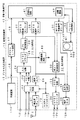
〔記録再生装置の概要…図1〕
図1は、この発明の記録再生装置の一例を示し、映像および音声を、MPEG2規格に準拠して圧縮符号化し、MPEG2システム規格に従って多重化して、MPEG2−TS(Transport Stream)として、HDD(Hard Disk Drive)内のディスク(ハードディスク)に記録し、ディスクから再生する場合である。
【0011】
なお、以下では、アナログ映像信号およびアナログ音声信号を、映像信号および音声信号と称し、デジタル映像信号およびデジタル音声信号は、デジタル映像データおよびデジタル音声データ、または単に映像データおよび音声データと称する。また、「インタフェース」は「I/F」と略称する。
【0012】
この例では、記録再生装置10は、地上波アナログテレビ放送を受信するアンテナ1が接続され、アナログ入力端子11V,11A,11S、アナログ出力端子12V,12A,12S、デジタル入出力端子15、デジタルI/F回路17、入力処理部20、出力処理部30、多重分離処理部40、バッファ制御回路50、HDD60、システムコントローラ70および同期制御回路80を備える。多重分離処理部40は、多重化回路41および分離回路42を備える。
【0013】
システムコントローラ70は、図では省略したが、CPU(Central Processing Unit)、CPUが実行すべきプログラムや固定データなどが書き込まれたROM(Read Only Memory)、およびCPUのワークエリアなどとして機能するRAM(Random Access Memory)などを備え、記録再生装置10全体を制御するものである。
【0014】
(アナログ入力処理および記録)
アンテナ1で受信された地上波アナログテレビ放送は、地上波チューナ21で選局されて、地上波チューナ21から映像信号および音声信号が得られ、その映像信号および音声信号が、入力切換回路22の一方の入力端に供給される。
【0015】
入力端子11Vには外部機器からコンポジット映像信号が、入力端子11Aには外部機器から音声信号が、入力端子11Sには外部機器からセパレート映像信号が、それぞれ供給される。
【0016】
入力端子11Vからのコンポジット映像信号、および入力端子11Aからの音声信号は、入力切換回路22の他方の入力端に供給され、入力切換回路22がシステムコントローラ70によって切り換えられて、入力切換回路22から、いずれかの映像信号および音声信号が選択されて取り出される。
【0017】
入力切換回路22からの映像信号は、YC分離回路23で輝度信号と色差信号に分離されて、別の入力切換回路24の一方の入力端に供給される。また、入力端子11Sからのセパレート映像信号(輝度信号および色差信号)が、入力切換回路24の他方の入力端に供給され、入力切換回路24がシステムコントローラ70によって切り換えられて、入力切換回路24から、いずれかの輝度信号および色差信号が選択されて取り出される。
【0018】
入力切換回路24からの輝度信号および色差信号は、NTSC(National Television System Committee)デコーダ25で、それぞれA/D変換され、さらにクロマエンコード処理されて、NTSCデコーダ25からコンポーネント映像データが得られる。
【0019】
また、NTSCデコーダ25では、入力切換回路24からの輝度信号から垂直同期信号および水平同期信号が分離されるとともに、その分離された同期信号に基づいてクロックおよびフィールド判別信号が生成され、これら同期信号、クロックおよびフィールド判別信号が、同期制御回路80に供給される。同期制御回路80では、これらの信号を基準として記録再生装置10の各部に必要なクロックおよびタイミング信号が生成されて、記録再生装置10の各部に供給される。
【0020】
NTSCデコーダ25からの映像データは、プリ映像処理回路26でプリフィルタリング処理などの映像処理が施されたのち、MPEG映像エンコーダ27および出力処理部30のポスト映像処理回路32に供給される。
【0021】
MPEG映像エンコーダ27では、プリ映像処理回路26からの映像データに対してブロックDCT(Discrete Cosine Transform)などの符号化処理が施されて、映像ES(Elementary Stream)が生成され、そのMPEG映像ESが、多重分離処理部40に供給される。
【0022】
一方、入力切換回路22からの音声信号は、音声A/D変換器28でデジタル音声データに変換されたのち、MPEG音声エンコーダ29および出力処理部30の出力切換回路35に供給される。
【0023】
MPEG音声エンコーダ29では、音声A/D変換器28からの音声データがMPEGフォーマットに従って圧縮されて、音声ESが生成され、そのMPEG音声ESが、多重分離処理部40に供給される。
【0024】
多重分離処理部40では、多重化回路41において、MPEG映像エンコーダ27からの映像ESおよびMPEG音声エンコーダ29からの音声ESと各種制御信号とが多重化されて、MPEG2システムのTSが生成され、そのMPEG2−TSが、バッファ制御回路50に送出される。
【0025】
バッファ制御回路50は、多重化回路41から連続的に入力されるMPEG2−TSを、HDD60に断続的に送出する。すなわち、HDD60がシーク動作を行っているときには、書き込みができないので、入力されたMPEG2−TSをバッファに一時蓄え、HDD60が書き込み可能なときに、そのMPEG2−TSを入力レートより高いレートでバッファから読み出してHDD60に送出する。これによって、バッファ制御回路50に連続的に入力されるMPEG2−TSは、途切れることなくディスク(ハードディスク)61に記録される。
【0026】
HDD60は、システムコントローラ70によって制御されて、ディスク61にMPEG2−TSを書き込む。バッファ制御回路50とHDD60との間のプロトコル(I/F)としては、IDE(Integrated Device Electronics)などが用いられる。
【0027】
(再生およびアナログ出力処理)
再生時には、HDD60は、システムコントローラ70によって制御されて、ディスク61からMPEG2−TSを読み出し、バッファ制御回路50に送出する。バッファ制御回路50は、記録時とは逆に、HDD60から断続的に入力されるMPEG2−TSを、連続的なMPEG2−TSに変換して、多重分離処理部40の分離回路42に供給する。
【0028】
分離回路42では、その連続的なMPEG2−TSのヘッダが解析処理されることによって、MPEG2−TSからPES(Packetized Elementary Stream)が分離されて、MPEG映像音声デコーダ31に供給される。
【0029】
MPEG映像音声デコーダ31では、分離回路42からのPESが映像ESと音声ESに分離され、さらに、その映像ESがMPEG映像デコーダで復号されてベースバンドの映像データに変換され、音声ESがMPEG音声デコーダで復号されてベースバンドの音声データに変換される。変換後の映像データはポスト映像処理回路32に供給され、音声データは出力切換回路35に供給される。
【0030】
ポスト映像処理回路32では、MPEG映像音声デコーダ31からの映像データおよびプリ映像処理回路26からの映像データに対して、両者の切り換えまたは合成やポストフィルタリング処理などの映像処理が施され、処理後の映像データが、OSD(On Screen Display)処理回路33に供給される。
【0031】
OSD処理回路33では、ポスト映像処理回路32からの映像データに、表示画面上でグラフィックスなどの画像が重畳的または部分的に表示されるような処理が施され、処理後の映像データが、NTSCエンコーダ34に供給される。
【0032】
NTSCエンコーダ34では、OSD処理回路33からの映像データ(コンポーネント映像データ)が、輝度データと色差データとに変換され、さらに、その輝度データおよび色差データが、それぞれD/A変換されて、それぞれアナログ信号のコンポジット映像信号およびセパレート映像信号が得られる。そのコンポジット映像信号は出力端子12Vに導出され、セパレート映像信号は出力端子12Sに導出される。
【0033】
一方、出力切換回路35では、システムコントローラ70によって、MPEG映像音声デコーダ31からの音声データと、音声A/D変換器28からの音声データとの、いずれかが選択されて取り出される。この選択された音声データは、音声D/A変換器36でアナログ音声信号に変換されて、出力端子12Aに導出される。
【0034】
(外部装置とのI/Fの概要)
記録再生装置10は、デジタル入出力端子15と多重分離処理部40との間に双方向バス16,18を介してデジタルI/F回路17が接続されたものとされて、デジタル入出力端子15に外部装置110を接続することによって、外部装置110から入力された符号化された映像音声データをディスク61に記録し、ディスク61から再生された符号化された映像音声データを外部装置110に出力することができる。
【0035】
外部装置110としては、IRD(Integrated ReceiverDecoder)やパーソナルコンピュータなどの機器を接続することができる。外部装置110と記録再生装置10とのデジタルI/Fとしては、IEEE(Institute of Electrical and Electronics Engineers)1394規格のI/Fなどを用いることができる。
【0036】
外部装置110からデジタル入出力端子15に入力された符号化された映像音声データは、デジタルI/F回路17で、フォーマット変換などの処理が施され、記録再生装置10に適合するMPEG2−TSに変換されて、多重分離処理部40に送出される。多重分離処理部40では、必要に応じて制御信号の解析や生成が行われた上で、そのMPEG2−TSが、バッファ制御回路50に送出され、HDD60によってディスク61に記録される。
【0037】
これと同時に、分離回路42で、記録されるMPEG2−TSからPESが分離されて、MPEG映像音声デコーダ31に供給されることによって、出力端子12V,12Sおよび12Aに、外部装置110からの映像音声データによるアナログ映像信号およびアナログ音声信号を得ることができる。
【0038】
再生時には、HDD60によってディスク61からMPEG2−TSが読み出され、バッファ制御回路50で連続的なMPEG2−TSに変換されて、多重分離処理部40に送出される。多重分離処理部40では、必要に応じて制御信号の解析や生成が行われた上で、そのMPEG2−TSがデジタルI/F回路17に送出される。デジタルI/F回路17では、記録時とは逆の処理によって、そのMPEG2−TSが外部装置110に適合する映像音声データに変換されて、デジタル入出力端子15を介して外部装置110に出力される。
【0039】
これと同時に、分離回路42で、再生されたMPEG2−TSからPESが分離されて、MPEG映像音声デコーダ31に供給されることによって、出力端子12V,12Sおよび12Aに、再生アナログ映像信号および再生アナログ音声信号を得ることができる。
【0040】
〔デジタル放送の符号化データの記録再生とクロック生成…図2〜図4〕
以上のような記録再生装置10において、外部装置110としてデジタル放送チューナを接続して、デジタル放送チューナで受信した符号化ビットストリームを記録再生装置10に入力してディスク61に記録し、ディスク61から再生した符号化ビットストリームをデジタル放送チューナに出力する場合の、クロック生成方法およびデータ処理方法を以下に示す。
【0041】
(システム構成…図2)
図2は、この場合のシステム構成の一例を示す。この例では、放送局からは、複数のプログラムの映像や音声などの情報が、MPEG2規格に準拠して圧縮符号化され、MPEG2システム規格に従って多重化されて、MPEG2−TSとして放送される。
【0042】
受信側では、そのデジタル放送がアンテナ130で受信され、デジタル放送チューナ120でユーザによって選択されたプログラムの符号化データが復号され、さらにアナログ信号に変換されて、モニタ出力装置140に出力される。
【0043】
このデジタル放送チューナ120に、上述した記録再生装置10のデジタル入出力端子15が接続される。デジタル放送チューナ120と記録再生装置10とのデジタルI/Fとしては、例えば、上述したIEEE1394規格のI/Fが用いられる。そして、後述のように、デジタル放送チューナ120で選択されたプログラムの符号化データが、デジタル放送チューナ120からデジタルI/F回路17を介して記録再生装置10に入力されてディスク61に記録されるとともに、ディスク61から再生された符号化データが、デジタルI/F回路17を介してデジタル放送チューナ120に出力される。
【0044】
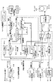
(多重分離処理部およびクロック生成部の構成…図3)
図3は、この場合の記録再生装置10の多重分離処理部40および多重分離処理部40内に設けられるクロック生成部90の一例を示す。この例の多重分離処理部40は、クロック生成部90、多重化回路41、分離回路42、セレクタ43,44、到着時刻計測カウンタ47、到着時刻付加回路48および出力タイミング制御回路49を備える。
【0045】
また、多重分離処理部40は、図では省略したが、内部に多重分離処理部40全体を制御するCPUを備えるとともに、クロック生成部90のVCXO(Voltage Controlled Crystal Oscillator)91およびD/A変換器97を除いて、ワンチップのLSI(Large Scale Integrated circuit)として構成される。
【0046】
クロック生成部90は、制御電圧に応じて発振周波数が27MHzを中心として一定範囲内で変化するVCXO91、このVCXO91からのクロックを計数するSTC(System Time Clock)カウンタ92、デジタルI/F回路17から双方向バス18に出力されたMPEG2−TSから、これに含まれる基準時刻情報としてのPCRのPID(Packet Identification)を検出するPID検出回路93、その検出されたPIDによって、デジタルI/F回路17から双方向バス18に出力されたMPEG2−TSから、これに含まれるPCRを抽出するPCR抽出回路94、その抽出されたPCRの値とSTCカウンタ92の出力値(カウント値)との差分値を算出する比較回路95、その算出された差分値から演算した値、またはあらかじめ設定された固定の値を、制御データとして出力する制御演算回路96、および、その制御データを0〜5Vのアナログ制御電圧に変換してVCXO91に供給するD/A変換器97によって構成される。
【0047】
VCXO91は、制御演算回路96からの制御値が固定値とされる場合には、発振周波数が27MHzに固定され、制御演算回路96からの制御値が比較回路95からの差分値に基づく値とされる場合には、その制御値が大きいときほど発振周波数が高くなるように、その制御値に応じて発振周波数がほぼ線形に変化するものとされる。
【0048】
制御演算回路96は、記録再生装置10の図では省略した操作部でのユーザの動作モード切換操作に基づいてシステムコントローラ70から制御演算回路96に送出されるモード切換信号によって、後述のように出力の制御値が切り換えられる。
【0049】
到着時刻計測カウンタ47は、STCカウンタ92と同様にVCXO91からのクロックを計数するもので、STCカウンタ92に兼ねさせることもできるが、この例はSTCカウンタ92とは別に設ける場合である。到着時刻付加回路48および出力タイミング制御回路49については、後述する。
【0050】
(記録時の動作)
放送局から放送されるMPEG2−TSは、複数のプログラムの、例えば、図4(A)に示すようにプログラムA,B,Cの3プログラムの、映像や音声などの情報が、1本のストリームに多重化されたものである。
【0051】
図2のデジタル放送チューナ120では、ユーザは、そのうちの記録したいプログラムを選択する。デジタル放送チューナ120は、その選択されたプログラムのみをMPEG2−TSとして、デジタルI/F回路17を介して記録再生装置10に送出する。したがって、記録再生装置10に入力されるMPEG2−TSは、図4(B)に示すように歯抜けのTS(パーシャルTS)となる。
【0052】
図3の多重分離処理部40では、このデジタルI/F回路17を介して記録再生装置10に入力されて双方向バス18に得られたMPEG2−TSに含まれる最初のPCR値が、PCR抽出回路94からSTCカウンタ92および到着時刻計測カウンタ47にロードされる。
【0053】
2個目以降のPCR値は、PCR抽出回路94から抽出されるごとに、比較回路95でSTCカウンタ92の出力値と比較される。そして、この記録時には、システムコントローラ70から制御演算回路96に送出されるモード切換信号がPLLオンを指示する状態とされて、制御演算回路96は、比較回路95からの差分値から演算した値を制御データとしてD/A変換器97に出力するPLLオンの状態に切り換えられる。
【0054】
したがって、このとき、STCカウンタ92および到着時刻計測カウンタ47の出力値がPCR抽出回路94から抽出されたPCR値と等しくなって、両者の差分値がゼロとなるように、VCXO91の発振周波数がフィードバック制御される。
【0055】
すなわち、VCXO91の発振周波数が低いために、STCカウンタ92および到着時刻計測カウンタ47の出力値の増加速度が遅く、その出力値がPCR値より小さいときには、VCXO91の発振周波数が高くなるように制御され、逆に、VCXO91の発振周波数が高いために、STCカウンタ92および到着時刻計測カウンタ47の出力値の増加速度が早く、その出力値がPCR値より大きいときには、VCXO91の発振周波数が低くなるように制御される。
【0056】
このようなフィードバック制御によって、STCカウンタ92および到着時刻計測カウンタ47の出力値は、PCR抽出回路94から抽出されたPCR値と等しくなって、デジタルI/F回路17を介して双方向バス18に得られたMPEG2−TSの各パケットの到着時刻を示すものとなる。
【0057】
そして、到着時刻付加回路48において、この到着時刻計測カウンタ47の出力値が、双方向バス18に得られたMPEG2−TSの各パケットの末尾に、パケットの到着時刻を示す情報として付加され、その到着時刻情報が付加されたMPEG2−TSが、到着時刻付加回路48からセレクタ43を介してバッファ制御回路50に送出され、バッファ制御回路50において、図4(C)に示すように各パケットの間が詰められて、HDD60によってディスク61に記録される。
【0058】
(再生時の動作)
再生時、ユーザは、記録再生装置10において、ディスク61に記録されているデータから、視聴したいプログラムのデータを選択する。
【0059】
これによって、ディスク61から、その選択されたプログラムのデータが、図4(C)に示すように各パケットの末尾に到着時刻情報が付加され、かつ各パケットの間が詰まったMPEG2−TSとして読み出される。その再生されたMPEG2−TSは、バッファ制御回路50に送出され、バッファ制御回路50からセレクタ44を介して出力タイミング制御回路49に供給される。
【0060】
そして、この再生時には、システムコントローラ70から制御演算回路96に送出されるモード切換信号がPLLオフを指示する状態とされて、制御演算回路96は、あらかじめ設定された固定の値を制御データとしてD/A変換器97に出力するPLLオフの状態に切り換えられ、VCXO91の発振周波数が27MHzに固定される。
【0061】
このVCXO91からの27MHzの固定周波数のクロックは、到着時刻計測カウンタ47で計数される。出力タイミング制御回路49は、再生されたMPEG2−TSの最初のパケットに付加されている到着時刻情報を到着時刻計測カウンタ47にロードする。
【0062】
さらに、出力タイミング制御回路49は、再生されたMPEG2−TSの2個目以降の各パケットにつき、到着時刻計測カウンタ47の出力値を参照しながら、到着時刻計測カウンタ47の出力値がパケットに付加されている到着時刻情報の値に一致した時、そのパケットを双方向バス18に出力する。
【0063】
これによって、出力タイミング制御回路49から双方向バス18には、図4(D)に示すように、記録時と同じタイミングでパケットが出力され、記録時と同じ歯抜けのMPEG2−TSが出力される。ただし、到着時刻情報は、記録再生装置10の内部でのみ用いられるものであるので、出力タイミング制御回路49からは出力されない。
【0064】
双方向バス18に出力されたMPEG2−TSは、デジタルI/F回路17を介してデジタル放送チューナ120に出力されて復号され、さらにアナログ信号に変換されて、モニタ出力装置140に出力される。
【0065】
(アナログ入力時およびアナログ出力時の動作)
図1で上述したように、地上波チューナ21または入力端子11V,11S,11Aからの映像信号および音声信号によって多重化回路41から得られるMPEG2−TSをディスク61に記録する場合には、図3に示すように、その多重化回路41からのMPEG2−TSが、セレクタ43を介してバッファ制御回路50に送出され、HDD60によってディスク61に記録される。
【0066】
この場合、システムコントローラ70からのモード切換信号はPLLオフを指示する状態とされて、VCXO91からは27MHzの固定周波数のクロックが出力され、その固定周波数のクロックが多重化回路41に供給されて、多重化回路41での多重化処理が実行される。
【0067】
また、このように記録されたMPEG2−TSをディスク61から再生して図1の出力端子12V,12Sおよび12Aに再生映像信号および再生音声信号を得る場合には、図3に示すように、バッファ制御回路50からの再生されたMPEG2−TSが、セレクタ44を介して分離回路42に供給される。
【0068】
この場合も、システムコントローラ70からのモード切換信号はPLLオフを指示する状態とされて、VCXO91からは27MHzの固定周波数のクロックが出力され、その固定周波数のクロックが分離回路42に供給されて、分離回路42での分離処理が実行される。
【0069】
〔他の例または実施形態〕
上述した例では、デジタルI/F回路17を介して記録再生装置10に入力されるMPEG2−TSが、図4(B)に示したようなパーシャルTS(歯抜けのTS)であり、記録再生装置10に入力されるMPEG2−TSにはPCRパケットが1系列しか存在しないので、PID検出回路93ではPAT(Program Association Table)およびPMT(Program Map Table)を順に参照することによってPCRのPIDを特定することができる。
【0070】
しかし、デジタルI/F回路17を介して記録再生装置10に入力されるMPEG2−TSが、図4(A)に示すようなフルTS(複数のプログラムが多重されていてパケット間が詰まったTS)の場合には、記録再生装置10に入力されるMPEG2−TSにはPCRパケットがプログラム数と同数の系列存在するので、そのままではPCRのPIDを特定することができない。そのため、この場合には、デジタル放送チューナ120が記録再生装置10に選択しているプログラムを通知するなど、何らかの方法でPCRのPIDを特定する手段が必要である。
【0071】
また、デジタルI/F回路17を介して記録再生装置10に入力されるビットストリームがMPEG2−TS以外の場合でも、PCRのような基準時刻情報が付加されたパケットが送られるものであれば、上述した例と同様のPLLオンオフ機能を実現することができる。例えば、MPEG2−PS(Program Stream)では、SCR(System Clock Reference)が、DSS(Digital Satellite System:米国のデジタル衛星放送で多く用いられているシステムストリーム形式)では、RTS(Reference Time Stamp)が、それぞれMPEG2−TSのPCRに相当するので、これら基準時刻情報を抽出することによって、上述した例と同様のPLLオンオフ機能を実現することができる。
【0072】
また、上述した例は、記録再生装置10にデジタル放送チューナ120を接続する場合であるが、例えば、記録再生装置10に他のデジタル記録再生装置を接続して、他のデジタル記録再生装置からのデジタルデータを記録再生装置10に入力してディスク61に記録し、またはディスク61からデジタルデータを再生して他のデジタル記録再生装置に出力し、あるいは記録再生装置10にデジタル動画撮影装置を接続して、そのデジタル動画撮影装置からのデジタルデータを記録再生装置10に入力してディスク61に記録することもできる。
【0073】
さらに、上述した例は、デジタル放送チューナ120を外部装置として記録再生装置10に接続する場合であるが、デジタル放送チューナを記録再生装置に組み込んで記録再生装置と一体化し、または記録再生装置をデジタル放送受信機に組み込んで受信機と一体化することもでき、その場合には、上述した記録再生装置10のクロック生成部90とデジタル放送チューナまたはデジタル放送受信機のクロック生成部を共通化することができる。
【0074】
また、上述した例は、記録再生装置の記録媒体(記憶素子)としてハードディスクを用いる場合であるが、光ディスク、光磁気ディスク、半導体メモリなどを用いてもよい。
【0075】
【発明の効果】
上述したように、この発明によれば、記録再生装置として、一つの発振器によって、デジタルデータ記録用の、デジタルデータに含まれる基準時刻情報に同期したクロックと、デジタルデータ再生用の、固定周波数のクロックとを、選択的に得ることができる。
【図面の簡単な説明】
【図1】この発明の記録再生装置の一例を示す図である。
【図2】この発明の記録再生装置に外部装置を接続する場合のシステム構成の一例を示す図である。
【図3】多重分離処理部およびクロック生成部の一例を示す図である。
【図4】デジタル放送の符号化ビットストリームを記録再生する際のデータ処理の一例を示す図である。
【符号の説明】
主要部については図中に全て記述したので、ここでは省略する。[0001]
BACKGROUND OF THE INVENTION
This invention Is a device that records and reproduces digital data such as encoded bitstreams. Related.
[0002]
[Prior art]
In digital broadcasting, video and audio are compressed and encoded by a technique such as MPEG (Moving Picture Experts Group) and broadcast by a satellite communication network or the like, and on the receiving side, the encoded bit stream is decoded in real time. Furthermore, it is converted into an analog signal and output to the monitor output device, so that the viewer can view video and audio.
[0003]
The digital broadcast receiver or digital broadcast tuner is equipped with a clock generation device that generates a clock of, for example, 27 MHz synchronized with reference time information such as PCR (Program Clock Reference) included in the received encoded bitstream. As a result, the receiving side generates a clock having the same phase as that of the transmitting side, and when decoding the encoded data, the encoded data is decoded without causing an overflow or underflow of a buffer for temporarily storing the encoded data. Thus, even when receiving for a long time, the video and audio can be viewed without causing disturbance of the video and audio.
[0004]
[Problems to be solved by the invention]
Along with the full-scale digital broadcasting, the encoded bit stream received by the digital broadcast receiver or the digital broadcast tuner is input to the digital recording / reproducing apparatus and recorded on the recording medium, and the recorded encoded bit stream is It is considered to reproduce from a recording medium, output to a digital broadcast receiver or digital broadcast tuner, and decode by the digital broadcast receiver or digital broadcast tuner to obtain a reproduction output.
[0005]
Even in such a recording / reproducing apparatus, the clock generator as described above is mounted, and at the time of recording, the clock synchronized with the reference time information included in the encoded bitstream input to the recording / reproducing apparatus from the clock generator Must be obtained and supplied to the processing circuit of the encoded bit stream.
[0006]
However, in this way, the clock generator of the recording / reproducing apparatus can obtain a clock synchronized with the reference time information included in the encoded bitstream, similarly to the clock generator of the digital broadcast receiver or the digital broadcast tuner. With the Locked Loop) configuration, since there is no reference time information in the encoded bit stream reproduced from the recording medium at the time of reproduction, it becomes impossible to obtain an appropriate clock from the clock generation unit of the PLL configuration. Unless an oscillator that generates a clock is separately provided for data processing, the encoded bit stream reproduced from the recording medium may be processed and output to a digital broadcast receiver or digital broadcast tuner. Become.
[0007]
Therefore, the present invention As a recording / playback device, Digital data by one oscillator For recording Clock synchronized with the reference time information included in the digital data and the digital data For playback A clock with a fixed frequency is selectively obtained.
[0008]
[Means for Solving the Problems]
The recording / reproducing apparatus of the present invention
An oscillator whose oscillation frequency changes in accordance with a control value, a counter that counts clocks from this oscillator, an extraction means that extracts reference time information from digital data including reference time information, the value of the extracted reference time information and the above A clock generation unit having a comparison unit that calculates a difference value from the output value of the counter, and a calculation unit that calculates a control value to be supplied to the oscillator from the calculated difference value;
Count the clock from the oscillator, double as the counter, or different from the counter , An arrival time counter,
The calculation means is controlled by a mode switching signal and includes the reference time information input Digital data Is recorded on a recording medium as digital data not including the reference time information The clock generator is switched to a synchronous mode in which a clock synchronized with the reference time information is obtained from the oscillator by supplying a value calculated from the difference value as the control value to the oscillator, When reproducing digital data that does not include the reference time information from the recording medium, a fixed frequency clock is obtained from the oscillator by supplying a fixed value as the control value to the oscillator. A control unit for switching to a mode;
Including the reference time information at the time of recording input Digital data is processed by a clock synchronized with the reference time information obtained from the oscillator of the clock generation unit switched to the synchronous mode. In addition, as the digital data that does not include the reference time information and the output value of the arrival time measurement counter is added as arrival time information, A recording processing unit for recording on the recording medium;
At the time of playback, it was played back from the recording medium The arrival time information is added without including the reference time information. Digital data is processed by a fixed frequency clock obtained from the oscillator of the clock generation unit switched to the fixed mode. When the output value of the arrival time measurement counter matches the value of the arrival time information added to the digital data, A playback processing unit to output,
Is provided.
[0009]
In the recording / reproducing apparatus configured as described above, for example, when an encoded bit stream of a digital broadcast is input and recorded from the digital broadcast tuner to the recording / reproducing apparatus, the control unit of the recording / reproducing apparatus uses a clock generation unit in response to the mode switching signal. The clock generation unit forms a PLL so that the oscillator generates a PLL by supplying a value based on a difference value between the value of the reference time information and the output value of the counter as a control value to the oscillator. Digital broadcasting A clock synchronized with the reference time information included in the encoded bit stream is obtained, and the encoded bit stream of the digital broadcast is processed by the clock synchronized with the reference time information. As an encoded bitstream that does not include reference time information and that has arrival time information added Recorded on a recording medium.
on the other hand, this Includes reference time information Without arrival time information The encoded bitstream is , Played from the recording medium , When output from the recording / reproducing apparatus to the digital broadcast tuner, the control unit of the recording / reproducing apparatus switches the arithmetic means of the clock generation unit to supply a fixed value as a control value to the oscillator by a mode switching signal. The clock generator does not form a PLL, and a clock with a fixed frequency is obtained from the oscillator and reproduced from the recording medium. , Includes reference time information And arrival time information is added. The encoded bitstream is processed by this fixed frequency clock When the output value of the arrival time measurement counter matches the value of the arrival time information added to the encoded bitstream, the digital broadcast tuner Is output.
[0010]
DETAILED DESCRIPTION OF THE INVENTION
[Outline of recording / reproducing apparatus ... Fig. 1]
FIG. 1 shows an example of a recording / reproducing apparatus according to the present invention. Video and audio are compressed and encoded in accordance with the MPEG2 standard, multiplexed in accordance with the MPEG2 system standard, and converted into an MPEG2-TS (Transport Stream) as an HDD (Hard). This is a case where data is recorded on a disk (hard disk) in Disk Drive) and reproduced from the disk.
[0011]
In the following, analog video signals and analog audio signals are referred to as video signals and audio signals, and digital video signals and digital audio signals are referred to as digital video data and digital audio data, or simply video data and audio data. “Interface” is abbreviated as “I / F”.
[0012]
In this example, the recording / reproducing apparatus 10 is connected to an
[0013]
Although not shown in the figure, the
[0014]
(Analog input processing and recording)
The terrestrial analog television broadcast received by the
[0015]
A composite video signal is supplied from the external device to the
[0016]
The composite video signal from the
[0017]
The video signal from the
[0018]
The luminance signal and the color difference signal from the
[0019]
In the
[0020]
Video data from the
[0021]
In the
[0022]
On the other hand, the audio signal from the
[0023]
In the
[0024]
In the demultiplexing processing unit 40, the multiplexing circuit 41 multiplexes the video ES from the
[0025]
The
[0026]
The
[0027]
(Reproduction and analog output processing)
During reproduction, the
[0028]
In the
[0029]
In the MPEG video /
[0030]
In the post
[0031]
In the
[0032]
In the
[0033]
On the other hand, in the
[0034]
(Outline of I / F with external devices)
In the recording / reproducing apparatus 10, a digital I /
[0035]
As the
[0036]
The encoded video / audio data input from the
[0037]
At the same time, the
[0038]
At the time of reproduction, MPEG2-TS is read from the disk 61 by the
[0039]
At the same time, the
[0040]
[Recording / reproduction of digital broadcast encoded data and clock generation ... FIGS. 2 to 4]
In the recording / reproducing apparatus 10 as described above, a digital broadcast tuner is connected as the
[0041]
(System configuration: Fig. 2)
FIG. 2 shows an example of the system configuration in this case. In this example, information such as video and audio of a plurality of programs is compressed and encoded according to the MPEG2 standard, multiplexed according to the MPEG2 system standard, and broadcast as MPEG2-TS from the broadcasting station.
[0042]
On the receiving side, the digital broadcast is received by the
[0043]
The digital input /
[0044]
(Configuration of the demultiplexing processing unit and the clock generation unit ... FIG. 3)
FIG. 3 shows an example of the demultiplexing processing unit 40 and the clock generation unit 90 provided in the demultiplexing processing unit 40 of the recording / reproducing apparatus 10 in this case. The demultiplexing processing unit 40 of this example includes a clock generation unit 90, a multiplexing circuit 41, a
[0045]
Although not shown in the figure, the demultiplexing processing unit 40 includes a CPU that controls the entire demultiplexing processing unit 40, a VCXO (Voltage Controlled Crystal Oscillator) 91 of the clock generation unit 90, and a D / A converter. Except 97, it is configured as a one-chip LSI (Large Scale Integrated circuit).
[0046]
The clock generation unit 90 includes a VCXO 91 whose oscillation frequency changes within a certain range around 27 MHz according to the control voltage, an STC (System Time Clock) counter 92 that counts clocks from the VCXO 91, and the digital I /
[0047]
In the VCXO 91, when the control value from the control
[0048]
The control
[0049]
The arrival time measurement counter 47 counts the clock from the VCXO 91 similarly to the
[0050]
(Operation during recording)
MPEG2-TS broadcast from a broadcasting station has a single stream of information such as video and audio of a plurality of programs, for example, three programs A, B, and C as shown in FIG. Are multiplexed.
[0051]
In the
[0052]
In the demultiplexing processing unit 40 of FIG. 3, the first PCR value included in the MPEG2-TS input to the recording / reproducing apparatus 10 via the digital I /
[0053]
Each time the second and subsequent PCR values are extracted from the
[0054]
Therefore, at this time, the oscillation frequency of the VCXO 91 is fed back so that the output values of the
[0055]
That is, since the oscillation frequency of the VCXO 91 is low, the increase rate of the output values of the
[0056]
By such feedback control, the output values of the
[0057]
The arrival time adding circuit 48 adds the output value of the arrival time measurement counter 47 to the end of each MPEG2-TS packet obtained on the
[0058]
(Operation during playback)
At the time of reproduction, the user selects program data to be viewed from the data recorded on the disc 61 in the recording / reproducing apparatus 10.
[0059]
As a result, the data of the selected program is read from the disk 61 as MPEG2-TS in which arrival time information is added to the end of each packet as shown in FIG. It is. The reproduced MPEG2-TS is sent to the
[0060]
At the time of this reproduction, the mode switching signal sent from the
[0061]
The clock having a fixed frequency of 27 MHz from the VCXO 91 is counted by the arrival time measurement counter 47. The output
[0062]
Further, the output
[0063]
As a result, as shown in FIG. 4D, the output
[0064]
The MPEG2-TS output to the
[0065]
(Operation at analog input and analog output)
As described above with reference to FIG. 1, when MPEG2-TS obtained from the multiplexing circuit 41 by the video signal and the audio signal from the
[0066]
In this case, the mode switching signal from the
[0067]
Further, when the MPEG2-TS recorded in this way is reproduced from the disk 61 and the reproduced video signal and the reproduced audio signal are obtained at the
[0068]
Also in this case, the mode switching signal from the
[0069]
Other examples or embodiments
In the example described above, the MPEG2-TS input to the recording / reproducing apparatus 10 via the digital I /
[0070]
However, the MPEG2-TS input to the recording / reproducing apparatus 10 via the digital I /
[0071]
Even if the bit stream input to the recording / reproducing apparatus 10 via the digital I /
[0072]
In addition, the above-described example is a case where the
[0073]
Further, in the above-described example, the
[0074]
Moreover, although the example mentioned above is a case where a hard disk is used as a recording medium (storage element) of a recording / reproducing apparatus, you may use an optical disk, a magneto-optical disk, a semiconductor memory, etc.
[0075]
【The invention's effect】
As described above, according to the present invention, As a recording / playback device, Digital data by one oscillator For recording Clock synchronized with the reference time information included in the digital data and the digital data For playback A clock with a fixed frequency can be selectively obtained.
[Brief description of the drawings]
FIG. 1 is a diagram showing an example of a recording / reproducing apparatus according to the present invention.
FIG. 2 is a diagram showing an example of a system configuration when an external device is connected to the recording / reproducing apparatus of the present invention.
FIG. 3 is a diagram illustrating an example of a demultiplexing processing unit and a clock generation unit.
FIG. 4 is a diagram illustrating an example of data processing when recording and reproducing an encoded bit stream of digital broadcasting.
[Explanation of symbols]
Since all the main parts are described in the figure, they are omitted here.
Claims (2)
前記発振器からのクロックを計数する、前記カウンタが兼ねる、または前記カウンタとは別の、到着時刻計測カウンタと、
モード切換信号によって前記演算手段を制御して、前記基準時刻情報を含む入力デジタルデータを前記基準時刻情報を含まないデジタルデータとして記録媒体に記録する時には、前記クロック生成部を、前記発振器に前記制御値として前記差分値から演算された値が供給されることによって前記発振器から前記基準時刻情報に同期したクロックが得られる同期モードに切り換え、前記記録媒体からの前記基準時刻情報を含まないデジタルデータの再生時には、前記クロック生成部を、前記発振器に前記制御値として固定の値が供給されることによって前記発振器から固定周波数のクロックが得られる固定モードに切り換える制御部と、
前記記録時、前記基準時刻情報を含む入力デジタルデータを、前記同期モードに切り換えられたクロック生成部の前記発振器から得られた、前記基準時刻情報に同期したクロックによって処理して、前記基準時刻情報を含まず、前記到着時刻計測カウンタの出力値が到着時刻情報として付加されたデジタルデータとして、前記記録媒体に記録する記録処理部と、
前記再生時、前記記録媒体から再生された、前記基準時刻情報を含まず、前記到着時刻情報が付加されているデジタルデータを、前記固定モードに切り換えられたクロック生成部の前記発振器から得られた、固定周波数のクロックによって処理して、前記到着時刻計測カウンタの出力値が当該デジタルデータに付加されている到着時刻情報の値に一致した時、外部装置に出力する再生処理部と、
を備える記録再生装置。An oscillator whose oscillation frequency changes in accordance with a control value, a counter that counts clocks from this oscillator, an extraction means that extracts reference time information from digital data including reference time information, the value of the extracted reference time information and the above A clock generation unit having a comparison unit that calculates a difference value from the output value of the counter, and a calculation unit that calculates a control value to be supplied to the oscillator from the calculated difference value;
Counting the clock from the oscillator, another, and the arrival time measuring counter and said counter also serves, or the counter,
When the input means including the reference time information is recorded on the recording medium as the digital data not including the reference time information by controlling the arithmetic means by a mode switching signal, the clock generator is connected to the oscillator. Switching to a synchronous mode in which a clock synchronized with the reference time information is obtained from the oscillator by supplying a value calculated from the difference value as the control value, and does not include the reference time information from the recording medium At the time of data reproduction, the clock generator is switched to a fixed mode in which a fixed-frequency clock is obtained from the oscillator by supplying a fixed value as the control value to the oscillator; and
At the time of recording, input digital data including the reference time information is processed by a clock synchronized with the reference time information obtained from the oscillator of the clock generation unit switched to the synchronous mode, and the reference time information And a recording processing unit for recording on the recording medium as digital data to which the output value of the arrival time measurement counter is added as arrival time information ;
At the time of reproduction, the digital data reproduced from the recording medium and not including the reference time information and having the arrival time information added thereto was obtained from the oscillator of the clock generation unit switched to the fixed mode. A reproduction processing unit that processes with a fixed frequency clock, and outputs to an external device when the output value of the arrival time measurement counter matches the value of arrival time information added to the digital data ;
A recording / reproducing apparatus comprising:
外部から入力されたアナログ信号を、デジタルデータに変換して、前記記録媒体に記録するための処理部と、その記録されたデジタルデータを、前記記録媒体から再生し、アナログ信号に変換して、外部に出力するための処理部とを備え、
前記制御部は、そのアナログ入力時およびアナログ出力時には、前記クロック生成部を前記固定モードに切り換える記録再生装置。The recording / reproducing apparatus according to claim 1,
An analog signal input from the outside is converted into digital data and recorded on the recording medium, and the recorded digital data is reproduced from the recording medium, converted into an analog signal, A processing unit for outputting to the outside,
The control unit is a recording / reproducing apparatus that switches the clock generation unit to the fixed mode at the time of analog input and analog output.
Priority Applications (1)
| Application Number | Priority Date | Filing Date | Title |
|---|---|---|---|
| JP2000193398A JP4257478B2 (en) | 2000-06-27 | 2000-06-27 | Recording / playback device |
Applications Claiming Priority (1)
| Application Number | Priority Date | Filing Date | Title |
|---|---|---|---|
| JP2000193398A JP4257478B2 (en) | 2000-06-27 | 2000-06-27 | Recording / playback device |
Publications (3)
| Publication Number | Publication Date |
|---|---|
| JP2002015527A JP2002015527A (en) | 2002-01-18 |
| JP2002015527A5 JP2002015527A5 (en) | 2007-07-12 |
| JP4257478B2 true JP4257478B2 (en) | 2009-04-22 |
Family
ID=18692397
Family Applications (1)
| Application Number | Title | Priority Date | Filing Date |
|---|---|---|---|
| JP2000193398A Expired - Fee Related JP4257478B2 (en) | 2000-06-27 | 2000-06-27 | Recording / playback device |
Country Status (1)
| Country | Link |
|---|---|
| JP (1) | JP4257478B2 (en) |
Families Citing this family (13)
| Publication number | Priority date | Publication date | Assignee | Title |
|---|---|---|---|---|
| JP2003244570A (en) * | 2002-02-21 | 2003-08-29 | Sanyo Electric Co Ltd | Television system |
| JP3430171B1 (en) * | 2002-08-29 | 2003-07-28 | 共信テクノソニック株式会社 | Integrated circuit for hard disk recorder, hard disk recorder, electric equipment with hard disk recorder, television device with hard disk recorder, video recorder with hard disk recorder, and DVD player with hard disk recorder |
| KR100580176B1 (en) | 2003-09-17 | 2006-05-15 | 삼성전자주식회사 | Display synchronization signal generation apparatus in the digital receiver |
| KR100510148B1 (en) | 2003-09-20 | 2005-08-25 | 삼성전자주식회사 | Display synchronization signal generation apparatus in the analog video signal receiver and method thereof |
| KR100580177B1 (en) | 2003-09-22 | 2006-05-15 | 삼성전자주식회사 | Display synchronization signal generation apparatus in the digital receiver, decoder and method thereof |
| DE602004022072D1 (en) | 2003-10-06 | 2009-08-27 | Panasonic Corp | SYNCHRONIZE A DIGITAL SIGNAL BY USING A PCR PROGRAM TACT REFERENCE |
| JP4380598B2 (en) | 2005-06-16 | 2009-12-09 | 株式会社日立製作所 | Receiving apparatus and receiving method |
| JP2008035197A (en) * | 2006-07-28 | 2008-02-14 | Sumitomo Electric Ind Ltd | Clocking circuit, video processor and clock adjustment method |
| JP4690965B2 (en) * | 2006-08-11 | 2011-06-01 | 株式会社東芝 | Data recording / reproducing device |
| JP5032179B2 (en) * | 2007-03-30 | 2012-09-26 | 株式会社東芝 | Stream reproducing apparatus and media data decoding method |
| JP5126497B2 (en) * | 2007-11-19 | 2013-01-23 | セイコーエプソン株式会社 | Audio signal relay circuit and audio signal relay method |
| JP4477056B2 (en) | 2007-12-05 | 2010-06-09 | 株式会社東芝 | Receiving apparatus and receiving method |
| JP5445804B2 (en) * | 2012-10-25 | 2014-03-19 | セイコーエプソン株式会社 | Audio signal relay circuit and audio signal relay method |
-
2000
- 2000-06-27 JP JP2000193398A patent/JP4257478B2/en not_active Expired - Fee Related
Also Published As
| Publication number | Publication date |
|---|---|
| JP2002015527A (en) | 2002-01-18 |
Similar Documents
| Publication | Publication Date | Title |
|---|---|---|
| JP4536653B2 (en) | Data processing apparatus and method | |
| US6859612B2 (en) | Decoder and reproducing unit | |
| US6779198B1 (en) | Data processing apparatus, data processing method, and recording medium | |
| JP4793247B2 (en) | Recording apparatus, recording method, reproducing apparatus, and reproducing method | |
| JP4257478B2 (en) | Recording / playback device | |
| US20060280480A1 (en) | Data processing device and data recording method | |
| JP4650112B2 (en) | RECORDING / OUTPUT DEVICE, RECORDING / OUTPUT METHOD, AND RECORDING DEVICE | |
| KR100968842B1 (en) | Decoding apparatus and decoding method | |
| KR100693233B1 (en) | Data recording and reproducing apparatus | |
| US20060153323A1 (en) | Clock generation device and clock generation method | |
| EP1801809B1 (en) | Additional images recording synchronisation while reproducing main image e.g. for Picture in Picture PiP. | |
| JP2006148679A (en) | Data processing device | |
| JP2002010254A (en) | Feature point detection method and record reproduction device | |
| US20060092983A1 (en) | Clock generating apparatus | |
| JP4763589B2 (en) | Playback device and playback method thereof | |
| JP4288442B2 (en) | Recording / reproducing apparatus and video processing method | |
| JP2006140715A (en) | Video signal processor | |
| JP2004343516A (en) | Recording and playback processing apparatus | |
| JP3897753B2 (en) | Memory output device | |
| JP3767269B2 (en) | Digital broadcast receiver | |
| JP2007150845A (en) | Data reproducing apparatus, data reproducing method, and program thereof | |
| JP2003244697A (en) | Information processing device and method, recording medium and program | |
| JP2000196550A (en) | Equipment and device to receive and reproduce digital signal | |
| JPH10257487A (en) | Transport stream generator | |
| JP2009100114A (en) | Data recording and reproducing method |
Legal Events
| Date | Code | Title | Description |
|---|---|---|---|
| A521 | Written amendment |
Free format text: JAPANESE INTERMEDIATE CODE: A523 Effective date: 20070529 |
|
| A621 | Written request for application examination |
Free format text: JAPANESE INTERMEDIATE CODE: A621 Effective date: 20070529 |
|
| A131 | Notification of reasons for refusal |
Free format text: JAPANESE INTERMEDIATE CODE: A131 Effective date: 20080611 |
|
| A521 | Written amendment |
Free format text: JAPANESE INTERMEDIATE CODE: A523 Effective date: 20080723 |
|
| A131 | Notification of reasons for refusal |
Free format text: JAPANESE INTERMEDIATE CODE: A131 Effective date: 20080813 |
|
| A521 | Written amendment |
Free format text: JAPANESE INTERMEDIATE CODE: A523 Effective date: 20080905 |
|
| A131 | Notification of reasons for refusal |
Free format text: JAPANESE INTERMEDIATE CODE: A131 Effective date: 20081008 |
|
| A521 | Written amendment |
Free format text: JAPANESE INTERMEDIATE CODE: A523 Effective date: 20081208 |
|
| TRDD | Decision of grant or rejection written | ||
| A01 | Written decision to grant a patent or to grant a registration (utility model) |
Free format text: JAPANESE INTERMEDIATE CODE: A01 Effective date: 20090107 |
|
| A01 | Written decision to grant a patent or to grant a registration (utility model) |
Free format text: JAPANESE INTERMEDIATE CODE: A01 |
|
| A61 | First payment of annual fees (during grant procedure) |
Free format text: JAPANESE INTERMEDIATE CODE: A61 Effective date: 20090120 |
|
| FPAY | Renewal fee payment (event date is renewal date of database) |
Free format text: PAYMENT UNTIL: 20120213 Year of fee payment: 3 |
|
| FPAY | Renewal fee payment (event date is renewal date of database) |
Free format text: PAYMENT UNTIL: 20130213 Year of fee payment: 4 |
|
| LAPS | Cancellation because of no payment of annual fees |