EP1801809B1 - Additional images recording synchronisation while reproducing main image e.g. for Picture in Picture PiP. - Google Patents
Additional images recording synchronisation while reproducing main image e.g. for Picture in Picture PiP. Download PDFInfo
- Publication number
- EP1801809B1 EP1801809B1 EP20060256315 EP06256315A EP1801809B1 EP 1801809 B1 EP1801809 B1 EP 1801809B1 EP 20060256315 EP20060256315 EP 20060256315 EP 06256315 A EP06256315 A EP 06256315A EP 1801809 B1 EP1801809 B1 EP 1801809B1
- Authority
- EP
- European Patent Office
- Prior art keywords
- image
- audio data
- reproduction
- time information
- standard time
- Prior art date
- Legal status (The legal status is an assumption and is not a legal conclusion. Google has not performed a legal analysis and makes no representation as to the accuracy of the status listed.)
- Active
Links
- 238000000034 method Methods 0.000 claims description 19
- 230000005236 sound signal Effects 0.000 description 114
- 230000003287 optical effect Effects 0.000 description 16
- 230000006870 function Effects 0.000 description 5
- 238000000926 separation method Methods 0.000 description 5
- 238000005516 engineering process Methods 0.000 description 3
- 230000008859 change Effects 0.000 description 2
- 238000010586 diagram Methods 0.000 description 2
- 230000006872 improvement Effects 0.000 description 2
- 239000004973 liquid crystal related substance Substances 0.000 description 2
- 238000012986 modification Methods 0.000 description 2
- 230000004048 modification Effects 0.000 description 2
- 230000008569 process Effects 0.000 description 2
- 239000007787 solid Substances 0.000 description 2
- 230000003139 buffering effect Effects 0.000 description 1
- 230000006835 compression Effects 0.000 description 1
- 238000007906 compression Methods 0.000 description 1
- 230000001360 synchronised effect Effects 0.000 description 1
Images


Classifications
-
- G—PHYSICS
- G11—INFORMATION STORAGE
- G11B—INFORMATION STORAGE BASED ON RELATIVE MOVEMENT BETWEEN RECORD CARRIER AND TRANSDUCER
- G11B27/00—Editing; Indexing; Addressing; Timing or synchronising; Monitoring; Measuring tape travel
- G11B27/10—Indexing; Addressing; Timing or synchronising; Measuring tape travel
- G11B27/19—Indexing; Addressing; Timing or synchronising; Measuring tape travel by using information detectable on the record carrier
- G11B27/28—Indexing; Addressing; Timing or synchronising; Measuring tape travel by using information detectable on the record carrier by using information signals recorded by the same method as the main recording
- G11B27/30—Indexing; Addressing; Timing or synchronising; Measuring tape travel by using information detectable on the record carrier by using information signals recorded by the same method as the main recording on the same track as the main recording
- G11B27/3027—Indexing; Addressing; Timing or synchronising; Measuring tape travel by using information detectable on the record carrier by using information signals recorded by the same method as the main recording on the same track as the main recording used signal is digitally coded
-
- H—ELECTRICITY
- H04—ELECTRIC COMMUNICATION TECHNIQUE
- H04N—PICTORIAL COMMUNICATION, e.g. TELEVISION
- H04N21/00—Selective content distribution, e.g. interactive television or video on demand [VOD]
- H04N21/20—Servers specifically adapted for the distribution of content, e.g. VOD servers; Operations thereof
- H04N21/23—Processing of content or additional data; Elementary server operations; Server middleware
- H04N21/234—Processing of video elementary streams, e.g. splicing of video streams or manipulating encoded video stream scene graphs
- H04N21/2343—Processing of video elementary streams, e.g. splicing of video streams or manipulating encoded video stream scene graphs involving reformatting operations of video signals for distribution or compliance with end-user requests or end-user device requirements
- H04N21/234318—Processing of video elementary streams, e.g. splicing of video streams or manipulating encoded video stream scene graphs involving reformatting operations of video signals for distribution or compliance with end-user requests or end-user device requirements by decomposing into objects, e.g. MPEG-4 objects
-
- H—ELECTRICITY
- H04—ELECTRIC COMMUNICATION TECHNIQUE
- H04N—PICTORIAL COMMUNICATION, e.g. TELEVISION
- H04N21/00—Selective content distribution, e.g. interactive television or video on demand [VOD]
- H04N21/20—Servers specifically adapted for the distribution of content, e.g. VOD servers; Operations thereof
- H04N21/23—Processing of content or additional data; Elementary server operations; Server middleware
- H04N21/236—Assembling of a multiplex stream, e.g. transport stream, by combining a video stream with other content or additional data, e.g. inserting a URL [Uniform Resource Locator] into a video stream, multiplexing software data into a video stream; Remultiplexing of multiplex streams; Insertion of stuffing bits into the multiplex stream, e.g. to obtain a constant bit-rate; Assembling of a packetised elementary stream
- H04N21/23614—Multiplexing of additional data and video streams
-
- H—ELECTRICITY
- H04—ELECTRIC COMMUNICATION TECHNIQUE
- H04N—PICTORIAL COMMUNICATION, e.g. TELEVISION
- H04N21/00—Selective content distribution, e.g. interactive television or video on demand [VOD]
- H04N21/20—Servers specifically adapted for the distribution of content, e.g. VOD servers; Operations thereof
- H04N21/23—Processing of content or additional data; Elementary server operations; Server middleware
- H04N21/236—Assembling of a multiplex stream, e.g. transport stream, by combining a video stream with other content or additional data, e.g. inserting a URL [Uniform Resource Locator] into a video stream, multiplexing software data into a video stream; Remultiplexing of multiplex streams; Insertion of stuffing bits into the multiplex stream, e.g. to obtain a constant bit-rate; Assembling of a packetised elementary stream
- H04N21/2368—Multiplexing of audio and video streams
-
- H—ELECTRICITY
- H04—ELECTRIC COMMUNICATION TECHNIQUE
- H04N—PICTORIAL COMMUNICATION, e.g. TELEVISION
- H04N21/00—Selective content distribution, e.g. interactive television or video on demand [VOD]
- H04N21/40—Client devices specifically adapted for the reception of or interaction with content, e.g. set-top-box [STB]; Operations thereof
- H04N21/41—Structure of client; Structure of client peripherals
- H04N21/4104—Peripherals receiving signals from specially adapted client devices
- H04N21/4135—Peripherals receiving signals from specially adapted client devices external recorder
-
- H—ELECTRICITY
- H04—ELECTRIC COMMUNICATION TECHNIQUE
- H04N—PICTORIAL COMMUNICATION, e.g. TELEVISION
- H04N21/00—Selective content distribution, e.g. interactive television or video on demand [VOD]
- H04N21/40—Client devices specifically adapted for the reception of or interaction with content, e.g. set-top-box [STB]; Operations thereof
- H04N21/43—Processing of content or additional data, e.g. demultiplexing additional data from a digital video stream; Elementary client operations, e.g. monitoring of home network or synchronising decoder's clock; Client middleware
- H04N21/4302—Content synchronisation processes, e.g. decoder synchronisation
- H04N21/4307—Synchronising the rendering of multiple content streams or additional data on devices, e.g. synchronisation of audio on a mobile phone with the video output on the TV screen
- H04N21/43072—Synchronising the rendering of multiple content streams or additional data on devices, e.g. synchronisation of audio on a mobile phone with the video output on the TV screen of multiple content streams on the same device
-
- H—ELECTRICITY
- H04—ELECTRIC COMMUNICATION TECHNIQUE
- H04N—PICTORIAL COMMUNICATION, e.g. TELEVISION
- H04N21/00—Selective content distribution, e.g. interactive television or video on demand [VOD]
- H04N21/40—Client devices specifically adapted for the reception of or interaction with content, e.g. set-top-box [STB]; Operations thereof
- H04N21/43—Processing of content or additional data, e.g. demultiplexing additional data from a digital video stream; Elementary client operations, e.g. monitoring of home network or synchronising decoder's clock; Client middleware
- H04N21/434—Disassembling of a multiplex stream, e.g. demultiplexing audio and video streams, extraction of additional data from a video stream; Remultiplexing of multiplex streams; Extraction or processing of SI; Disassembling of packetised elementary stream
- H04N21/4341—Demultiplexing of audio and video streams
-
- H—ELECTRICITY
- H04—ELECTRIC COMMUNICATION TECHNIQUE
- H04N—PICTORIAL COMMUNICATION, e.g. TELEVISION
- H04N21/00—Selective content distribution, e.g. interactive television or video on demand [VOD]
- H04N21/40—Client devices specifically adapted for the reception of or interaction with content, e.g. set-top-box [STB]; Operations thereof
- H04N21/43—Processing of content or additional data, e.g. demultiplexing additional data from a digital video stream; Elementary client operations, e.g. monitoring of home network or synchronising decoder's clock; Client middleware
- H04N21/434—Disassembling of a multiplex stream, e.g. demultiplexing audio and video streams, extraction of additional data from a video stream; Remultiplexing of multiplex streams; Extraction or processing of SI; Disassembling of packetised elementary stream
- H04N21/4348—Demultiplexing of additional data and video streams
-
- H—ELECTRICITY
- H04—ELECTRIC COMMUNICATION TECHNIQUE
- H04N—PICTORIAL COMMUNICATION, e.g. TELEVISION
- H04N21/00—Selective content distribution, e.g. interactive television or video on demand [VOD]
- H04N21/80—Generation or processing of content or additional data by content creator independently of the distribution process; Content per se
- H04N21/83—Generation or processing of protective or descriptive data associated with content; Content structuring
- H04N21/84—Generation or processing of descriptive data, e.g. content descriptors
-
- H—ELECTRICITY
- H04—ELECTRIC COMMUNICATION TECHNIQUE
- H04N—PICTORIAL COMMUNICATION, e.g. TELEVISION
- H04N7/00—Television systems
- H04N7/24—Systems for the transmission of television signals using pulse code modulation
- H04N7/52—Systems for transmission of a pulse code modulated video signal with one or more other pulse code modulated signals, e.g. an audio signal or a synchronizing signal
- H04N7/54—Systems for transmission of a pulse code modulated video signal with one or more other pulse code modulated signals, e.g. an audio signal or a synchronizing signal the signals being synchronous
- H04N7/56—Synchronising systems therefor
Definitions
- the present invention relates to an image and audio recording/reproducing apparatus for coding and recording an image and audio signal.
- Japanese Patent Laying-Open No. Hei 11-238359 (1999 ) describes "providing an image recording/recording apparatus for obtaining a superior utility, such as, obtaining high degree of freedom relating to recording", as a problem to be solved and an image recording/reproducing apparatus as a means for solving this problem.
- the image recording/reproducing apparatus is so constructed that it can record sub-image data relating to a main image data by conducting reproduction of the main image data in parallel with recording the sub-image data relating to the main image data, the main image data having already been recorded in a recording medium 6 made from a solid memory, and it can reproduce the sub-image data by linking it to reproduction of the main image data".
- both systems are standardized in "MPEG2-Audio ISO/IEC13818-3 1998 and "MPEG2-Audio ISO/IEC13818-2-2 2000, as an international standard.
- a video and audio signal which are coded by each coding system are bit streams called as "Elementary Stream: ES”, and there is a standardized system that such signals are further packetized and multiplexed.
- ISO/IEC13818-1 OR N801rev.25 April 1995 is exemplified as a standard of MPEG2.
- Japanese Patent Laying-Open No. Hei 11-238359 (1999 ) describes that its image recording/reproducing apparatus can "record sub-image data relating to main image data by conducting reproduction of the main image data in parallel with recording the sub-image data relating to the main image data, the main image data having already been recorded in a recording medium 6 made from a solid memory, and it can reproduce the sub-image data by linking it to reproduction of the main image data".
- a recording medium 6 made from a solid memory
- Recording of the sub-image only at portions of the main image and/or changing the timing for reproduction of the sub-images can be important function(s), which may appear or be frequently needed, when using an image and audio recording/reproducing apparatus. It can be said that an image and audio recording/reproducing apparatus achieving such function(s) would be superior in usability.
- a preferred aim is, according to the present invention, to provide a method of recording and reproducing image/audio data using an image and audio recording/reproducing apparatus to achieve an improvement in usability.
- the aim mentioned above is accomplished, for example, by a method of recording and reproducing image/audio data as set out in claim 1.
- the present embodiment relates to a digital video camera, using an optical disk as a recording medium.
- the digital video camera has a function of reproducing a first coded image/audio data which was previously recorded on the optical disk, and of recording a second coded image/audio data on the optical disk during the reproducing operation.
- the digital video camera also has a function of outputting the first and second image/audio data in the form of a picture-in-picture screen, when reproducing them.
- Fig. 1 shows the block diagram of Embodiment 1.
- a CPU 22 controls each of blocks 1 through 11 to conduct the recording operation.
- An image signal taken or picked up through a lens portion 3 is converted into an electric signal through a sensor portion 4, such as a CCD or the like, and is processed within a signal processor portion 5 in the form of a digital image signal, to be transmitted to an Audio/Video coding block 8.
- Audio/Video coding block 8 the image and the audio signals are coded into an elementary stream (ES), in accordance with a standard such as MPEG 2 and MPEG 1 Layer II.
- ES elementary stream
- the coded ES is treated with a packetizing process within a system-multiplexing portion 9, so that it can be recorded onto the optical disk 12.
- PS program stream
- a system time clock STC
- a standard clock for example, 27 MHz
- a reproduction time information which is called a decoding time stamp (DTS) is added to both the image and audio, based on the standard time information STC mentioned above.
- the DTS is indicative of the timing at which the image and audio signals should be decoded.
- decoding in a similar manner to when encoding, the STC is counted up from the time of starting reproduction. Decoding is carried out on the stream of image and audio having a DTS coincident with the STC, thereby enabling to synchronization between the reproduced image and audio signals (e.g. a lip sync).
- the DTS information is added within Packetized Elementary Stream (PES) of image and audio.
- PES Packetized Elementary Stream
- the data packetized within the system-multiplexing portion 9 is transferred to a media drive 11, together with management information for managing recorded data within a disk (i.e. inner-medium logical block information indicating start and end points of each recording or time correspondence information).
- the media drive 11 controls rotation number (or speed) of the optical disk 12, laser strength, and a pickup device, thereby recording data onto the optical disk 12 mentioned above.
- the data recorded on the optical disk 12 is read out from the optical disk 12 by means of the media drive 11 when a user instructs the reproduction thereof.
- the data is then transferred to a system separation portion 13.
- management information is read out from the optical disk 12 and is transferred to the CPU 22.
- data streams can be transferred from the media drive 11 to the system separation portion 13 at any time.
- the image and audio data in the form of the ES are recovered by removing the header or the like of the packet within system separation portion 13 and are transferred to an AudioVideo decoder 14. Counting up of the STC is started from the time when the decoding started.
- decoding of the respective image and audio data is started from the time at which the image and audio data have a DTS that coincides with the STC, thereby outputting decoded image and audio in a synchronous condition.
- the decoded image is transferred to a picture-in-picture (PinP) block 151. Since only one set of image/audio signals are outputted when conducting this operation, the image is outputted to a liquid crystal display 16 to an external monitor via an output terminal 21 without being treated by the PinP block 151.
- the audio is outputted to a mixer 17 and then to a speaker block 19 or an audio output terminal 20 through a digital/analog converter circuit 18.
- the reproducing operation of the first image/audio data is similar to that mentioned above.
- the user While viewing the first image/audio which are being reproduced by the liquid crystal display 16 or the external monitor, the user pushes down a second image/audio start button at the time when she/he wishes to add the second image/audio data to the first image/audio data.
- the CPU causes the blocks 3 through 11 to conduct the encoding operation as described above.
- the STC counter is already counting for decoding of the first image/audio data.
- the DTS to be added to the second image/audio data by the system-multiplexing portion 9 is calculated to correspond to the STC being counted for decoding of the first image/audio data.
- an adjustment is made so that the DTS added to the second image/audio data is the same as the DTS of the frame of the first image/audio signal which was displayed on the LCD when the second image/audio signal was inputted into the lens 3.
- a read request for the first image/audio data and a write request for the second image/audio data are inputted to the media drive 11 from the decoder side and encoder side respectively.
- the optical disk 12 needs time for the media drive 11 to switch between read and write operations (to move the pickup, etc.) thereby bringing about a time overhead.
- the CPU 22 provides buffering before transferring the data on the reproducing side and the recording side to the media drive 11, and thereby conducts the process so as to reduce the number of times the media drive 11 switches between read and write operations.
- time correspondence information is recorded into the management information to be recorded onto the optical disk 12, the time correspondence information being information indicative of which of the first image/audio data and the second image/audio data should be outputted in synchronism with the common STC.
- reproduction of the first and second image data is started from the media drive 11. Since the STC is held in common to the first and second image/audio data, and the data to be outputted simultaneously is described in the management information on the optical disk 12, the CPU 22 controls the reading of the first and second image/audio data by switching the media drive 11.
- the first and second image data are inputted into the system separation portion 13 and are then inputted into the AudioVideo decoder portion 14 and the AudioVideo decoder portion 15 respectively.
- Each of the AudioVideo decoders 14, 15 compares the STC value of the STC counter 10 (which started counting when the decoding started) with the DTS of the first and second image data, thereby starting the decoding at the stage when they coincide with each other.
- the image signal outputted by the AudioVideo decoders 14, 15 is treated using PinP processing by the PinP circuit 151.
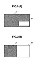
- the PinP processing may have a mode of outputting in which the first image signal has a full-screen size with the second image signal having a small-screen size as shown by reference numerals 30 and 31 in Fig. 2 , or may have a mode of outputting in which the first and second image signals are aligned in parallel with each other as shown by reference numerals 32 and 33 in Fig. 2 .
- the first and second audio signals are mixed into stereo signals, for example by the mixer circuit 17, and are outputted therefrom.
- Fig. 3 shows each of the image/audio signals (Seq A, B, P, Q, R) and times when it is recorded or reproduced.
- Fig. 3a shows the recording of the first image/audio signal (Seq A) and the third image/audio signal (Seq B).
- Fig. 3b shows the time of recording three second image/audio signals (Seq P, Q, R) when the first and third image/audio signals (Seq A, B) are being reproduced.
- Fig. 3c shows the reproducing of the first, second and third image/audio signals.
- Fig. 3a recording of the first image/audio signal (Seq A) is started. Being initialized with this start of recording, the STC starts counting up and, the first image/audio signal (Seq A) records the STC corresponding to the first image/audio signal as the DTS. This is similar to the encoding shown in Embodiment 1.
- the STC is initialized again and the counting up is started again since the first and third image/audio signals are independent. And then, recording is made of the DTS of the third image/audio signal (Seq B) as the STC corresponding to the third image/audio signal.
- recording of the second one of the second image/audio signals is basically similar to the Embodiment 1, it differs from Embodiment 1 in the following aspects: during recording of the second one of the second image/audio signals (Seq Q), reproduction of the first image/audio signal (Seq A) finishes and reproduction of the third image/audio signal (Seq B) starts, and the STC corresponding to the third image/audio signal is initialized. Before reproduction of the first image/audio signal is finished, the STC corresponding to the first image/audio signal (Seq A) is recorded as the DTS of the second one of the second image/audio signals (Seq Q).
- the STC corresponding to the third image/audio signal (Seq B) is recorded as the DTS of the second one of the second image/audio signals (Seq Q).
- the second one of the second image/audio signals (Seq Q) is decoded, it becomes inconvenient to compare the DTS of the second one of the second image/audio signals (Seq Q) and the STC, because there is a discontinuity between the DTS and PTS presentation time stamp. For that reason, in the present embodiment, when detecting the discontinuous point of the STC on the reproduction side, a flag indicating the discontinuity of the STC is added into a packet of the corresponding time within data of the second image/audio signal.
- recording of the third one of the second image/audio signals is basically similar to the Embodiment 1, it differs from Embodiment 1 in the following aspect: during recording of the third one of the second image/audio signals (Seq R), reproducing of the third image/audio signal (SeqB) finishes. Then, in this case, the STC corresponding to the third image/audio signal continues to count up even after reproduction of the third image/audio signal (Seq B) has finished, and the STC corresponding to the third image/audio signal is recorded to be the DTS, so that the third one of the second image/audio signals is in synchronism with the STC corresponding to the third image/audio signal.
- reproduction of the first, second and third image/audio signals is executed in the following manner.
- reproduction of the first and second image/audio signals (Seq A, P) are similar to that in the Embodiment 1.
- reproduction of the first image/audio signal (Seq A) is achieved by initializing the STC is to start the counting up and reproducing the first image/audio signal (Seq A) so that the DTS and the STC are in synchronism with each other.
- reproduction is started on the second one of the second image/audio signals (Seq Q), in a similar manner, however it differs from Embodiment 1 in the following aspect: during reproduction of the second one of the second image/audio signals, the reproduction of the first image/audio signal (Seq A) is finished, reproduction is started on the third image/audio signal (Seq B), and the STC corresponding to the third one of the second image/audio signals is initialized.
- the second image/audio signal (Seq Q) is reproduced in synchronism with the STC of the first image/audio signal (Seq A) until finishing of reproduction of the first image/audio signal (Seq A), and thereafter, it is reproduced in synchronism with the STC of the third image/audio signal (Seq B).
- reproduction is started on the third one of the second image/audio signals (Seq R), and during this reproduction, the reproduction of the third image/audio signal (Seq B) finishes.
- the STC corresponding to the third image/audio signal is counted up continuously even if the reproduction of the third image/audio signal (Seq B) is finished, and the second image/audio signal (Seq R) continues to be reproduced in synchronism with the STC corresponding to the third image/audio signal (Seq B).
- Embodiment 3 which is a variation of Embodiment 2.
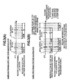
- Fig. 4 shows the respective image/audio signals (Seq A, B, P, Q and R) and times when they are recorded or reproduced, in the similar manner to that in Fig. 3 .
- Fig. 4a shows times when the first image/audio signal (Seq A) and the third image/audio signal (Seq B)are recorded.
- Fig. 4b shows times when three pieces of the second image/audio signals (Seq P, Q and R) are recorded during reproduction of the first and third image/audio signals (Seq A, B).
- Fig. 4c shows the times when reproducing the first, the second and the third image/audio signals. Explanation will be omitted about those parts which are the same as in the Embodiment shown in Fig. 3 .
- FIG. 4b A difference from the Embodiment shown in Fig. 3 can be seen in Fig. 4b .
- the STC is initialized upon starting the reproduction of the third image/audio signal (Seq B) whilst the second of the second image/audio signals (Seq Q) is being recorded.
- the STC is counted up continuously.
- the DTS of the third image/audio signal (Seq B) must be changed so that it is in synchronism with the STC, which is counted up continuously. Also, since the STC is discontinuous in Fig. 3 , then the information indicative of this is added to the DTS of the second one of the second image/audio signal (Seq Q). This information is unnecessary in Fig. 4 .
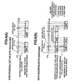
- Fig. 5 shows the first, second and third image/audio signals (Seq A, B, P, Q and R) and the times when they are recorded or reproduced, and further of the fourth image/audio signal (Seq C).
- the fourth image/audio signal (Seq C) separately from the first, second and third image/audio signals (Seq A, B, P, Q and R)
- the last image/audio signal (Seq R) among the first, second and third image/audio signals (Seq A, B, P, Q and R) is stopped, the STC is initialized, and then the fourth image/audio signal (Seq C) is recorded or reproduced.
Landscapes
- Engineering & Computer Science (AREA)
- Multimedia (AREA)
- Signal Processing (AREA)
- Signal Processing For Digital Recording And Reproducing (AREA)
- Television Signal Processing For Recording (AREA)
- Indexing, Searching, Synchronizing, And The Amount Of Synchronization Travel Of Record Carriers (AREA)
Description
- The present invention relates to an image and audio recording/reproducing apparatus for coding and recording an image and audio signal.
- As a background art relating to the present technical field, Japanese Patent Laying-Open No.
Hei 11-238359 (1999 recording medium 6 made from a solid memory, and it can reproduce the sub-image data by linking it to reproduction of the main image data". - There are already known image and audio signal recording/reproducing apparatuses for recording and coding image and audio signals onto a recording medium, such as DVD or HDD, etc. Along with improvements in increasing recording capacity and speeding-up of reading/writing from/onto a recording medium, some of those apparatuses are loaded with a function such as run-after reproducing, i.e. reproducing signals previously recorded while recording new signals. Those technologies are based on a digital coding compression technology, such as, MPEG2 technology (ISO/IEC 13818-1 through 3 N0801 revised 25 April 1995), for example.
- For example, as for a coding system on a video signal and a coding system on an audio signal, both systems are standardized in "MPEG2-Audio ISO/IEC13818-3 1998 and "MPEG2-Audio ISO/IEC13818-2-2 2000, as an international standard. A video and audio signal which are coded by each coding system are bit streams called as "Elementary Stream: ES", and there is a standardized system that such signals are further packetized and multiplexed. For examples, ISO/IEC13818-1 OR N801rev.25 April 1995 is exemplified as a standard of MPEG2.
- In the standard of Annex D.0.1 - D.0.2 and D.0.8, pages 110, 111, 118 of ISO/IEC13818-1, when reproducing a decode of MPEG2-Video and MPEG2-Audio, both of the decodes and the timing synchronization in output are described. Herein, while counting up a system time clock (STC) as a standard time, the method for controlling such synchronization is described, in comparison with a decoding time stamp (DTS) added to a bit stream of a Video and Audio. commentary picture onto an image previously taken by a video camera apparatus.
- Japanese Patent Laying-Open No.
Hei 11-238359 (1999 recording medium 6 made from a solid memory, and it can reproduce the sub-image data by linking it to reproduction of the main image data". However no explanation in this document is given as to when the sub-image data is reproduced, or how synchronization is achieved with respect to reproduction of the main image. Nor does this document give any consideration to additionally recording a plurality of sub-image data to one main image data. - It may be the case that one wishes to record sub-images only at portions of a main image, (for example, recording a first sub-image in a first half of one piece of the main image, recording a second sub-image in the middle of the main image, and recording a third sub-image in a last half of the main images). However according to the invention described in the Japanese Patent Laying-Open No.
Hei 11-238359 (1999 Hei 11-238359 (1999 - Also, there may be cases where one wishes to change the timing of reproducing of the sub-image with respect to the main image after the sub-image has been recorded. However, it is impossible to change the timing of reproducing with the apparatus of Japanese Patent Laying-Open No.
Hei 11-238359 (1999 - Recording of the sub-image only at portions of the main image and/or changing the timing for reproduction of the sub-images can be important function(s), which may appear or be frequently needed, when using an image and audio recording/reproducing apparatus. It can be said that an image and audio recording/reproducing apparatus achieving such function(s) would be superior in usability.
- A preferred aim is, according to the present invention, to provide a method of recording and reproducing image/audio data using an image and audio recording/reproducing apparatus to achieve an improvement in usability.
- The aim mentioned above is accomplished, for example, by a method of recording and reproducing image/audio data as set out in claim 1.
- Those and other features, and objects advantages of the present invention will become more apparent from the following detailed description when taken in conjunction with the accompanying drawings wherein:
-
Fig. 1 is a block diagram showing a video camera according to a first embodiment of the invention; -
Figs. 2 (A) and 2 (B) are views showing a picture-in-picture outputted by the video camera of the first embodiment of the invention; -
Fig. 3 is a view showing relationships among first, second and third image/audio signals and STC according to a second embodiment of the invention; -
Fig. 4 is a view showing relationships among first, second and third image/audio signals and STC according to a third embodiment of the invention; -
Fig. 5 is a view showing relationships among first, second, third and fourth image/audio signals and STC according to a fourth embodiment of the invention. - Hereinafter, embodiments according to the present invention will be fully explained by referring to the attached drawings.
- The present embodiment relates to a digital video camera, using an optical disk as a recording medium. The digital video camera has a function of reproducing a first coded image/audio data which was previously recorded on the optical disk, and of recording a second coded image/audio data on the optical disk during the reproducing operation. The digital video camera also has a function of outputting the first and second image/audio data in the form of a picture-in-picture screen, when reproducing them.
-
Fig. 1 shows the block diagram of Embodiment 1. Hereinafter, explanation will be made, by referring toFig. 1 . First of all, explanation will be made of the operations carried out when recording a normal first coded image/audio data. Upon pushing down of a record-start button (not shown inFig. 1 ) by a user, aCPU 22 controls each of blocks 1 through 11 to conduct the recording operation. An image signal taken or picked up through alens portion 3 is converted into an electric signal through asensor portion 4, such as a CCD or the like, and is processed within asignal processor portion 5 in the form of a digital image signal, to be transmitted to an Audio/Video coding block 8. At the same time, audio is taken or picked up through amicrophone portion 6 and is converted into a digital audio data within an analog/digital converter block 7, to be transmitted into the Audio/Video coding block 8. Within the Audio/Video coding block 8, the image and the audio signals are coded into an elementary stream (ES), in accordance with a standard such as MPEG 2 and MPEG 1 Layer II. The coded ES is treated with a packetizing process within a system-multiplexing portion 9, so that it can be recorded onto theoptical disk 12. For example, the ES is recorded in the form of a program stream (PS) in accordance with the MPEG 2 Systems. When recording, a system time clock (STC) is counted up within aSTC counter 10 upon basis of a standard clock (for example, 27 MHz) of the whole system. When the ES is changed or converted into a PS, a reproduction time information, which is called a decoding time stamp (DTS) is added to both the image and audio, based on the standard time information STC mentioned above. The DTS is indicative of the timing at which the image and audio signals should be decoded. When decoding, in a similar manner to when encoding, the STC is counted up from the time of starting reproduction. Decoding is carried out on the stream of image and audio having a DTS coincident with the STC, thereby enabling to synchronization between the reproduced image and audio signals (e.g. a lip sync). - In the present embodiment, within the system-multiplexing portion 9, the DTS information is added within Packetized Elementary Stream (PES) of image and audio.
- The data packetized within the system-multiplexing portion 9 is transferred to a
media drive 11, together with management information for managing recorded data within a disk (i.e. inner-medium logical block information indicating start and end points of each recording or time correspondence information). Themedia drive 11 controls rotation number (or speed) of theoptical disk 12, laser strength, and a pickup device, thereby recording data onto theoptical disk 12 mentioned above. - Next, within the present embodiment, explanation will be made of the operations carried out when reproducing the data recorded on the
optical disk 12. The data recorded on theoptical disk 12 is read out from theoptical disk 12 by means of themedia drive 11 when a user instructs the reproduction thereof. The data is then transferred to asystem separation portion 13. Firstly, in thissystem separation portion 13, management information is read out from theoptical disk 12 and is transferred to theCPU 22. After acknowledging the position of desired data on theoptical disk 12, data streams can be transferred from themedia drive 11 to thesystem separation portion 13 at any time. The image and audio data in the form of the ES are recovered by removing the header or the like of the packet withinsystem separation portion 13 and are transferred to anAudioVideo decoder 14. Counting up of the STC is started from the time when the decoding started. Within theAudioVideo decoder portion 14, decoding of the respective image and audio data is started from the time at which the image and audio data have a DTS that coincides with the STC, thereby outputting decoded image and audio in a synchronous condition. The decoded image is transferred to a picture-in-picture (PinP) block 151. Since only one set of image/audio signals are outputted when conducting this operation, the image is outputted to aliquid crystal display 16 to an external monitor via anoutput terminal 21 without being treated by thePinP block 151. The audio is outputted to amixer 17 and then to aspeaker block 19 or anaudio output terminal 20 through a digital/analog converter circuit 18. - Next, explanation will be made of the operations carried out for recording a second image/audio data on the
optical disk 12 while reproducing a first image/audio data which has already been recorded on theoptical disk 12. The reproducing operation of the first image/audio data is similar to that mentioned above. While viewing the first image/audio which are being reproduced by theliquid crystal display 16 or the external monitor, the user pushes down a second image/audio start button at the time when she/he wishes to add the second image/audio data to the first image/audio data. Upon this, the CPU causes theblocks 3 through 11 to conduct the encoding operation as described above. However, the STC counter is already counting for decoding of the first image/audio data. Therefore, the DTS to be added to the second image/audio data by the system-multiplexing portion 9 is calculated to correspond to the STC being counted for decoding of the first image/audio data. In this instance, an adjustment is made so that the DTS added to the second image/audio data is the same as the DTS of the frame of the first image/audio signal which was displayed on the LCD when the second image/audio signal was inputted into thelens 3. - In the operations mentioned above, a read request for the first image/audio data and a write request for the second image/audio data are inputted to the media drive 11 from the decoder side and encoder side respectively. However, the
optical disk 12 needs time for the media drive 11 to switch between read and write operations (to move the pickup, etc.) thereby bringing about a time overhead. For reducing this overhead, theCPU 22 provides buffering before transferring the data on the reproducing side and the recording side to themedia drive 11, and thereby conducts the process so as to reduce the number of times the media drive 11 switches between read and write operations. - Also, the time correspondence information is recorded into the management information to be recorded onto the
optical disk 12, the time correspondence information being information indicative of which of the first image/audio data and the second image/audio data should be outputted in synchronism with the common STC. - With the method mentioned above, it is possible to record one image/audio signal in synchronism with reproduction of another image/audio signal. For example, it is possible to reproduce an image of a baseball game previously recorded outdoors, and then to record an image of a coach viewing the baseball game indoors and of his giving technical guidance as a sub-image.
- When reproducing the first and second images simultaneously, reproduction of the first and second image data is started from the
media drive 11. Since the STC is held in common to the first and second image/audio data, and the data to be outputted simultaneously is described in the management information on theoptical disk 12, theCPU 22 controls the reading of the first and second image/audio data by switching themedia drive 11. The first and second image data are inputted into thesystem separation portion 13 and are then inputted into theAudioVideo decoder portion 14 and theAudioVideo decoder portion 15 respectively. Each of theAudioVideo decoders AudioVideo decoders PinP circuit 151. The PinP processing may have a mode of outputting in which the first image signal has a full-screen size with the second image signal having a small-screen size as shown byreference numerals Fig. 2 , or may have a mode of outputting in which the first and second image signals are aligned in parallel with each other as shown byreference numerals Fig. 2 . The first and second audio signals are mixed into stereo signals, for example by themixer circuit 17, and are outputted therefrom. - Next, explanation will be made of the operations carried out when recording a second image/audio signal at the same time as reproducing the bridging over between a point of stopping reproduction of a first image/audio signal and a point of starting reproduction of a third image/audio signal, where recording of the second image/audio signal continues after stoppage of the third image/audio signal.
-
Fig. 3 shows each of the image/audio signals (Seq A, B, P, Q, R) and times when it is recorded or reproduced.Fig. 3a shows the recording of the first image/audio signal (Seq A) and the third image/audio signal (Seq B).Fig. 3b shows the time of recording three second image/audio signals (Seq P, Q, R) when the first and third image/audio signals (Seq A, B) are being reproduced.Fig. 3c shows the reproducing of the first, second and third image/audio signals. - Firstly, as is shown in
Fig. 3a , recording of the first image/audio signal (Seq A) is started. Being initialized with this start of recording, the STC starts counting up and, the first image/audio signal (Seq A) records the STC corresponding to the first image/audio signal as the DTS. This is similar to the encoding shown in Embodiment 1. Next, when recording is started of the third image/audio signal (Seq B) after finishing the recording of the first image/audio signal (Seq A), the STC is initialized again and the counting up is started again since the first and third image/audio signals are independent. And then, recording is made of the DTS of the third image/audio signal (Seq B) as the STC corresponding to the third image/audio signal. - Next, as is shown in
Fig. 3b , explanation will be made on the case of recording the second image/audio signals (Seq P, Q, R), while the first and third image/audio signals (Seq A, B) are being reproduced. Although the first and third image/audio signals (Seq A, B) were separated from each other in their time of recording, as is shown inFig. 3a , they are reproduced continuously, i.e. seamlessly. In this instance, the STC corresponding to the first image/audio signal is initialized when the reproduction of the first image/audio signals starts and the STC corresponding to the third image/audio signal is initialized when the reproduction of the third image/audio signals starts. - Recording of the first one of the second image/audio signals (Seq P) is carried out in a similar manner to Embodiment 1, with the STC corresponding to the first image/audio signal recorded as the DTS, so that the first one of the second image/audio signals (Seq P) is in synchronism with the first image/audio signal (Seq A).
- Though recording of the second one of the second image/audio signals (Seq Q) is basically similar to the Embodiment 1, it differs from Embodiment 1 in the following aspects: during recording of the second one of the second image/audio signals (Seq Q), reproduction of the first image/audio signal (Seq A) finishes and reproduction of the third image/audio signal (Seq B) starts, and the STC corresponding to the third image/audio signal is initialized. Before reproduction of the first image/audio signal is finished, the STC corresponding to the first image/audio signal (Seq A) is recorded as the DTS of the second one of the second image/audio signals (Seq Q). After finishing reproduction of the first image/audio signal (Seq A), the STC corresponding to the third image/audio signal (Seq B) is recorded as the DTS of the second one of the second image/audio signals (Seq Q). In this instance, when the second one of the second image/audio signals (Seq Q)is decoded, it becomes inconvenient to compare the DTS of the second one of the second image/audio signals (Seq Q) and the STC, because there is a discontinuity between the DTS and PTS presentation time stamp. For that reason, in the present embodiment, when detecting the discontinuous point of the STC on the reproduction side, a flag indicating the discontinuity of the STC is added into a packet of the corresponding time within data of the second image/audio signal.
- Though recording of the third one of the second image/audio signals (Seq R) is basically similar to the Embodiment 1, it differs from Embodiment 1 in the following aspect: during recording of the third one of the second image/audio signals (Seq R), reproducing of the third image/audio signal (SeqB) finishes. Then, in this case, the STC corresponding to the third image/audio signal continues to count up even after reproduction of the third image/audio signal (Seq B) has finished, and the STC corresponding to the third image/audio signal is recorded to be the DTS, so that the third one of the second image/audio signals is in synchronism with the STC corresponding to the third image/audio signal.
- As is shown in
Fig. 3c , reproduction of the first, second and third image/audio signals is executed in the following manner. First, reproduction of the first and second image/audio signals (Seq A, P) are similar to that in the Embodiment 1. Thus, reproduction of the first image/audio signal (Seq A) is achieved by initializing the STC is to start the counting up and reproducing the first image/audio signal (Seq A) so that the DTS and the STC are in synchronism with each other. Then, comparison is made between the STC corresponding to the first image/audio signal and the DTS of the first one of the second image/audio signals (Seq P), and at the timing when the DTS is the same as the STC corresponding to the first image/audio signal, reproduction is started on the first one of the second image/audio signals (Seq P). - Next, reproduction is started on the second one of the second image/audio signals (Seq Q), in a similar manner, however it differs from Embodiment 1 in the following aspect: during reproduction of the second one of the second image/audio signals, the reproduction of the first image/audio signal (Seq A) is finished, reproduction is started on the third image/audio signal (Seq B), and the STC corresponding to the third one of the second image/audio signals is initialized. In this case, as explained earlier, since the information indicating discontinuity of the STC is added to the DTS of the second image/audio signal (Seq Q), then the second image/audio signal (Seq Q) is reproduced in synchronism with the STC of the first image/audio signal (Seq A) until finishing of reproduction of the first image/audio signal (Seq A), and thereafter, it is reproduced in synchronism with the STC of the third image/audio signal (Seq B).
- Next, reproduction is started on the third one of the second image/audio signals (Seq R), and during this reproduction, the reproduction of the third image/audio signal (Seq B) finishes. In this case, the STC corresponding to the third image/audio signal is counted up continuously even if the reproduction of the third image/audio signal (Seq B) is finished, and the second image/audio signal (Seq R) continues to be reproduced in synchronism with the STC corresponding to the third image/audio signal (Seq B).
- Next, explanation will be made on
Embodiment 3 which is a variation of Embodiment 2. -
Fig. 4 shows the respective image/audio signals (Seq A, B, P, Q and R) and times when they are recorded or reproduced, in the similar manner to that inFig. 3 .Fig. 4a shows times when the first image/audio signal (Seq A) and the third image/audio signal (Seq B)are recorded.Fig. 4b shows times when three pieces of the second image/audio signals (Seq P, Q and R) are recorded during reproduction of the first and third image/audio signals (Seq A, B).Fig. 4c shows the times when reproducing the first, the second and the third image/audio signals. Explanation will be omitted about those parts which are the same as in the Embodiment shown inFig. 3 . - A difference from the Embodiment shown in
Fig. 3 can be seen inFig. 4b . InFig. 3 , the STC is initialized upon starting the reproduction of the third image/audio signal (Seq B) whilst the second of the second image/audio signals (Seq Q) is being recorded. However, inFig. 4 , the STC is counted up continuously. By working in this manner, it is possible to achieve timing control on reproduction of the first, second and third image/audio signals (Seq A, B, P, Q and R), with a continuous STC. In this case, as shown inFig. 4b , the DTS of the third image/audio signal (Seq B) must be changed so that it is in synchronism with the STC, which is counted up continuously. Also, since the STC is discontinuous inFig. 3 , then the information indicative of this is added to the DTS of the second one of the second image/audio signal (Seq Q). This information is unnecessary inFig. 4 . - Next, explanation will be made on the case when recording or reproducing a fourth image/audio signal (Seq C) separately, after the first, second and third image/audio signals (Seq A, B, P, Q and R) have been recorded in the manner of the Embodiment 2 shown in
Fig. 3 . -
Fig. 5 shows the first, second and third image/audio signals (Seq A, B, P, Q and R) and the times when they are recorded or reproduced, and further of the fourth image/audio signal (Seq C). As is shown herein, in case of recording or reproducing the fourth image/audio signal (Seq C) separately from the first, second and third image/audio signals (Seq A, B, P, Q and R), the last image/audio signal (Seq R) among the first, second and third image/audio signals (Seq A, B, P, Q and R) is stopped, the STC is initialized, and then the fourth image/audio signal (Seq C) is recorded or reproduced. - In case when the fourth image/audio signal (Seq C) is recorded or reproduced within
Embodiment 3 shown inFig. 4 , it is carried out in a manner similar to the manner described above with reference toFig. 5 . - While we have shown and described several embodiments in accordance with our invention, it should be understood that disclosed embodiments are susceptible of changes and modifications without departing from the scope of the invention as defined by the appended claims as interpreted by the figures and description. Therefore, we do not intend to be bound by the details shown and described herein but intend to cover all such changes and modifications that fall within the ambit of the appended claims as interpreted by the figures and description.
Claims (12)
- A method of recording and reproducing image/audio data using an image and audio recording/reproducing apparatus, the apparatus comprising:an input portion (3, 6) into which image/audio data are inputted; anda recording/reproducing module (11) which is configured to record/reproduce the image/audio data onto/from a recording medium (12); anda controller module (22),the recording medium (12) including time correspondence information indicating the image/audio data to be reproduced in synchronism with a standard time information counter; andthe controller module (22) is used to control the apparatus to reproduce a first image/audio data in synchronism with the standard time information counter in accordance with the time correspondence information, the standard time information counter counting up from the time of starting reproduction of the first image/audio data;characterised in that:the method further includes using the controller module (22) to control the apparatus to:produce a decode time stamp DTS representing a time relative to the start of the standard time information counter STC at which a second image/audio data is inputted into the input portion (3, 6) at the time of reproducing the first image/audio data;record said second image/audio data onto said recording medium (12) together with said decode time stamp DTS and separately from said first image/audio data; andreproduce said first image/audio data and said second image/audio data simultaneously such that reproduction of the second image/audio data is started at the decode time stamp DTS and the second image/audio data is reproduced during reproduction of said first image/audio data.
- The method as described in claim 1, wherein:said controller module (22) is further used to control the apparatus to:record reproduction time information corresponding to the time of finishing inputting of the second image/audio data into said input portion, andfinish reproduction of said second image/audio data based on said reproduction time information, after said first image/audio data has been reproduced.
- The method as described in claim 1, wherein:a plural number of the second image/audio data are each recorded together with a respective reproduction time information indicative of the respective time of inputting of said second image/audio data during the time of reproducing one piece of the first image/audio data.
- The method as described in claim 1, wherein:said decode time stamp DTS is produced in synchronism with a standard time information, which is produced when said first image/audio data is reproduced.
- The method as described in the claim 4, wherein:changing said decode time stamp DTS which is added and recorded to said second image/audio data after recording said second image/audio data to correspond to reproduction time information which is in synchronism with the standard time information which is indicative of a time of reproduction of a portion of the first image/audio data which is reproduced when the second image/audio data is inputted.
- The method as described in claim 5, wherein:the standard time information produced when reproducing said first image/audio data is produced continuously and said decode time stamp DTS added to said second image/audio data is produced in synchronism with said continuously produced standard time information, when reproduction of said first image/audio data finishes during inputting and recording of the second image/audio data from said input portion.
- The method as described in claim 6, wherein:said standard time information is produced continuously and said second image/audio data is reproduced in synchronism with the continuously produced standard time information so that the decode time stamp DTS added to said second image/audio data is in synchronism with the standard time information relating to said first image/audio data, when reproduction of said first image/audio data finishes during reproduction of the second image/audio data.
- The method as described in claim 5, wherein:after production of the standard time information relating to said first image/audio data has finished, production of a standard time information relating to a third image/audio data is started, and the decode time stamp DTS added to said second image/audio data after reproduction of said first image/audio data has finished is produced to be in synchronism with the standard time information relating to said third image/audio data, when reproduction of the first image/audio data finishes and reproduction of the third image/audio data starts during inputting of the second image/audio data to be recorded from said input portion.
- The method as described in claim 8, wherein:information indicative of a discontinuity of the standard time information is added to the decode time stamp DTS to be added to said second image/audio data.
- The method as described in claim 8, wherein:after reproduction of said first image/audio data has finished and production of the standard time information of said third image/audio data has started, the second image/audio data is reproduced so that the decode time stamp (DTS) added to said second image/audio data is in synchronism with the standard time information of said third image/audio data, when reproduction of said first image/audio data finishes and reproduction of said third image/audio data starts during reproduction of the second image/audio data.
- The method as described in claim 4, wherein:the standard time information relating to said first image/audio data is produced continuously, decode time stamp DTS added to said second image/audio data is produced to be in synchronism with said continuously produced standard time information, and a decode time stamp DTS added to a third image/audio data is in synchronism with said continuously produced standard time information, when reproduction of said first image/audio data finishes and reproduction of the third image/audio data starts during inputting and recording of the second image/audio data from said input portion.
- The method as described in claim 11, wherein:the standard time information of said first image/audio data is produced continuously, the second image/audio data is reproduced so that the decode time stamp DTS added to said second image/audio data is in synchronism with said continuously produced standard time information, and the third image/audio data is reproduced so that the decode time stamp DTS added to said third image/audio data is in synchronism with said continuously produced standard time information, when reproduction of said first image/audio data finishes and reproduction of said third image/audio data starts during reproduction of the second image/audio data.
Applications Claiming Priority (1)
| Application Number | Priority Date | Filing Date | Title |
|---|---|---|---|
| JP2005369023A JP4501854B2 (en) | 2005-12-22 | 2005-12-22 | Video / audio recording device |
Publications (3)
| Publication Number | Publication Date |
|---|---|
| EP1801809A2 EP1801809A2 (en) | 2007-06-27 |
| EP1801809A3 EP1801809A3 (en) | 2007-07-18 |
| EP1801809B1 true EP1801809B1 (en) | 2011-05-25 |
Family
ID=37888020
Family Applications (1)
| Application Number | Title | Priority Date | Filing Date |
|---|---|---|---|
| EP20060256315 Active EP1801809B1 (en) | 2005-12-22 | 2006-12-12 | Additional images recording synchronisation while reproducing main image e.g. for Picture in Picture PiP. |
Country Status (4)
| Country | Link |
|---|---|
| US (1) | US7907812B2 (en) |
| EP (1) | EP1801809B1 (en) |
| JP (1) | JP4501854B2 (en) |
| CN (1) | CN1988641B (en) |
Families Citing this family (3)
| Publication number | Priority date | Publication date | Assignee | Title |
|---|---|---|---|---|
| JP2003199045A (en) * | 2001-12-26 | 2003-07-11 | Victor Co Of Japan Ltd | Information-recording-signal generating method and apparatus, information-signal reproducing method and apparatus, information-signal transmitting method, apparatus and program, and information-signal recording medium |
| CN101690188A (en) * | 2007-07-04 | 2010-03-31 | 松下电器产业株式会社 | Video recording and reproducing apparatus and its method |
| JP6066712B2 (en) * | 2012-12-19 | 2017-01-25 | キヤノン株式会社 | Recording apparatus, recording method, and program |
Family Cites Families (9)
| Publication number | Priority date | Publication date | Assignee | Title |
|---|---|---|---|---|
| US5583652A (en) * | 1994-04-28 | 1996-12-10 | International Business Machines Corporation | Synchronized, variable-speed playback of digitally recorded audio and video |
| JPH09293330A (en) * | 1996-04-23 | 1997-11-11 | Victor Co Of Japan Ltd | Data recorded disk, multi-data synchronous reproducing method, multi-data synchronous recording-reproducing method and multi-data synchronous recording method |
| JP4058154B2 (en) * | 1998-02-19 | 2008-03-05 | キヤノン株式会社 | Video recording / reproducing apparatus and video recording / reproducing method |
| JP2001245292A (en) * | 2000-02-29 | 2001-09-07 | Japan Radio Co Ltd | Data receiver, date transmission receiving system and recording medium |
| JP2002152688A (en) * | 2000-11-13 | 2002-05-24 | Sony Corp | Digital broadcast recording/reproducing device |
| BRPI0110668B1 (en) | 2001-03-08 | 2016-07-26 | Sony Corp | data recording and reproducing apparatus and methods and data recording media |
| HU228607B1 (en) * | 2001-11-30 | 2013-04-29 | Sony Corp | A method and an apparatus for stream conversion, a method and an apparatus for data recording, and data recording medium |
| JP2004362723A (en) * | 2003-06-09 | 2004-12-24 | Funai Electric Co Ltd | Information reproducing apparatus |
| WO2005029854A1 (en) | 2003-07-21 | 2005-03-31 | Thomson Licensing S.A. | Exploitation of discontinuity indicator for trick mode operation |
-
2005
- 2005-12-22 JP JP2005369023A patent/JP4501854B2/en active Active
-
2006
- 2006-12-12 EP EP20060256315 patent/EP1801809B1/en active Active
- 2006-12-12 US US11/637,988 patent/US7907812B2/en active Active
- 2006-12-22 CN CN2006101699076A patent/CN1988641B/en active Active
Also Published As
| Publication number | Publication date |
|---|---|
| EP1801809A3 (en) | 2007-07-18 |
| JP2007174256A (en) | 2007-07-05 |
| CN1988641A (en) | 2007-06-27 |
| EP1801809A2 (en) | 2007-06-27 |
| US7907812B2 (en) | 2011-03-15 |
| JP4501854B2 (en) | 2010-07-14 |
| US20070154183A1 (en) | 2007-07-05 |
| CN1988641B (en) | 2011-11-30 |
Similar Documents
| Publication | Publication Date | Title |
|---|---|---|
| US6859612B2 (en) | Decoder and reproducing unit | |
| JP3215087B2 (en) | Audio and video synchronization method and digital video processor | |
| US7266288B2 (en) | Video/audio playback apparatus and video/audio playback method | |
| EP2200299B1 (en) | System comprising a video synthesizing apparatus and a recording medium and video data generating apparatus for special mode reproduction in a dual-frame display format. | |
| US7881584B2 (en) | Reproducing apparatus and method, and recording medium | |
| US20090322858A1 (en) | Picture signal processing device, television receiving apparatus and method of controlling apparatus | |
| KR20020008013A (en) | Image recording apparatus, image recording method and storage medium | |
| JPH08340541A (en) | Transmission method, transmitter, recording method, recorder, reproduction method, reproduction device, recording reproduction method and recording/ reproduction device for digital data | |
| JP4257478B2 (en) | Recording / playback device | |
| EP1801809B1 (en) | Additional images recording synchronisation while reproducing main image e.g. for Picture in Picture PiP. | |
| EP1134974B1 (en) | Image recording and playback apparatus and method | |
| KR20050010747A (en) | Decoding apparatus and decoding method | |
| CA2490879C (en) | Reproducing apparatus and method, and recording medium | |
| JP4998574B2 (en) | Video / audio recording device | |
| US20050259973A1 (en) | Recording/reproducing apparatus with digital interface | |
| US20010014853A1 (en) | Decoding synchronous control apparatus, decoding apparatus, and decoding synchronous control method | |
| WO2005122568A1 (en) | Data processing device and data processing method | |
| JP4288442B2 (en) | Recording / reproducing apparatus and video processing method | |
| CA2725177A1 (en) | Reproducing apparatus and method, and recording medium | |
| JP2000090566A (en) | Reproducing device | |
| EP2075795A1 (en) | Display apparatus and control method thereof |
Legal Events
| Date | Code | Title | Description |
|---|---|---|---|
| PUAI | Public reference made under article 153(3) epc to a published international application that has entered the european phase |
Free format text: ORIGINAL CODE: 0009012 |
|
| PUAL | Search report despatched |
Free format text: ORIGINAL CODE: 0009013 |
|
| 17P | Request for examination filed |
Effective date: 20061227 |
|
| AK | Designated contracting states |
Kind code of ref document: A2 Designated state(s): AT BE BG CH CY CZ DE DK EE ES FI FR GB GR HU IE IS IT LI LT LU LV MC NL PL PT RO SE SI SK TR |
|
| AX | Request for extension of the european patent |
Extension state: AL BA HR MK YU |
|
| AK | Designated contracting states |
Kind code of ref document: A3 Designated state(s): AT BE BG CH CY CZ DE DK EE ES FI FR GB GR HU IE IS IT LI LT LU LV MC NL PL PT RO SE SI SK TR |
|
| AX | Request for extension of the european patent |
Extension state: AL BA HR MK YU |
|
| 17Q | First examination report despatched |
Effective date: 20080222 |
|
| AKX | Designation fees paid |
Designated state(s): DE FR GB |
|
| RIC1 | Information provided on ipc code assigned before grant |
Ipc: G11B 27/30 20060101AFI20081010BHEP Ipc: H04N 7/26 20060101ALI20081010BHEP Ipc: G11B 27/34 20060101ALN20081010BHEP |
|
| RTI1 | Title (correction) |
Free format text: ADDITIONAL IMAGES RECORDING SYNCHRONISATION WHILE REPRODUCING MAIN IMAGE FOR PIP. |
|
| RIC1 | Information provided on ipc code assigned before grant |
Ipc: G11B 27/30 20060101AFI20100803BHEP Ipc: H04N 5/45 20060101ALN20100803BHEP |
|
| RTI1 | Title (correction) |
Free format text: ADDITIONAL IMAGES RECORDING SYNCHRONISATION WHILE REPRODUCING MAIN IMAGE FOR PICTURE IN PICTURE PINP. |
|
| GRAP | Despatch of communication of intention to grant a patent |
Free format text: ORIGINAL CODE: EPIDOSNIGR1 |
|
| RTI1 | Title (correction) |
Free format text: ADDITIONAL IMAGES RECORDING SYNCHRONISATION WHILE REPRODUCING MAIN IMAGE E.G. FOR PICTURE IN PICTURE PIP. |
|
| GRAS | Grant fee paid |
Free format text: ORIGINAL CODE: EPIDOSNIGR3 |
|
| GRAA | (expected) grant |
Free format text: ORIGINAL CODE: 0009210 |
|
| AK | Designated contracting states |
Kind code of ref document: B1 Designated state(s): DE FR GB |
|
| REG | Reference to a national code |
Ref country code: GB Ref legal event code: FG4D |
|
| REG | Reference to a national code |
Ref country code: DE Ref legal event code: R096 Ref document number: 602006022151 Country of ref document: DE Effective date: 20110707 |
|
| PLBE | No opposition filed within time limit |
Free format text: ORIGINAL CODE: 0009261 |
|
| STAA | Information on the status of an ep patent application or granted ep patent |
Free format text: STATUS: NO OPPOSITION FILED WITHIN TIME LIMIT |
|
| 26N | No opposition filed |
Effective date: 20120228 |
|
| REG | Reference to a national code |
Ref country code: DE Ref legal event code: R097 Ref document number: 602006022151 Country of ref document: DE Effective date: 20120228 |
|
| REG | Reference to a national code |
Ref country code: DE Ref legal event code: R082 Ref document number: 602006022151 Country of ref document: DE Representative=s name: STREHL, SCHUEBEL-HOPF & PARTNER, DE |
|
| REG | Reference to a national code |
Ref country code: DE Ref legal event code: R082 Ref document number: 602006022151 Country of ref document: DE Representative=s name: STREHL SCHUEBEL-HOPF & PARTNER MBB PATENTANWAE, DE Effective date: 20130604 Ref country code: DE Ref legal event code: R081 Ref document number: 602006022151 Country of ref document: DE Owner name: HITACHI CONSUMER ELECTRONICS CO., LTD., JP Free format text: FORMER OWNER: HITACHI, LTD., TOKYO, JP Effective date: 20130604 Ref country code: DE Ref legal event code: R082 Ref document number: 602006022151 Country of ref document: DE Representative=s name: STREHL, SCHUEBEL-HOPF & PARTNER, DE Effective date: 20130604 Ref country code: DE Ref legal event code: R082 Ref document number: 602006022151 Country of ref document: DE Representative=s name: PATENTANWAELTE STREHL, SCHUEBEL-HOPF & PARTNER, DE Effective date: 20130604 Ref country code: DE Ref legal event code: R081 Ref document number: 602006022151 Country of ref document: DE Owner name: HITACHI MAXELL, LTD., IBARAKI-SHI, JP Free format text: FORMER OWNER: HITACHI, LTD., TOKYO, JP Effective date: 20130604 Ref country code: DE Ref legal event code: R081 Ref document number: 602006022151 Country of ref document: DE Owner name: MAXELL, LTD., OYAMAZAKI, JP Free format text: FORMER OWNER: HITACHI, LTD., TOKYO, JP Effective date: 20130604 |
|
| REG | Reference to a national code |
Ref country code: GB Ref legal event code: 732E Free format text: REGISTERED BETWEEN 20130822 AND 20130828 |
|
| REG | Reference to a national code |
Ref country code: FR Ref legal event code: TP Owner name: HITACHI CONSUMER ELECTRONICS CO., LTD., JP Effective date: 20130906 |
|
| REG | Reference to a national code |
Ref country code: DE Ref legal event code: R082 Ref document number: 602006022151 Country of ref document: DE Representative=s name: PATENTANWAELTE STREHL, SCHUEBEL-HOPF & PARTNER, DE |
|
| REG | Reference to a national code |
Ref country code: GB Ref legal event code: 732E Free format text: REGISTERED BETWEEN 20150305 AND 20150311 |
|
| REG | Reference to a national code |
Ref country code: DE Ref legal event code: R082 Ref document number: 602006022151 Country of ref document: DE Representative=s name: STREHL SCHUEBEL-HOPF & PARTNER MBB PATENTANWAE, DE Effective date: 20150317 Ref country code: DE Ref legal event code: R081 Ref document number: 602006022151 Country of ref document: DE Owner name: HITACHI MAXELL, LTD., IBARAKI-SHI, JP Free format text: FORMER OWNER: HITACHI CONSUMER ELECTRONICS CO., LTD., TOKIO/TOKYO, JP Effective date: 20150317 Ref country code: DE Ref legal event code: R082 Ref document number: 602006022151 Country of ref document: DE Representative=s name: PATENTANWAELTE STREHL, SCHUEBEL-HOPF & PARTNER, DE Effective date: 20150317 Ref country code: DE Ref legal event code: R081 Ref document number: 602006022151 Country of ref document: DE Owner name: MAXELL, LTD., OYAMAZAKI, JP Free format text: FORMER OWNER: HITACHI CONSUMER ELECTRONICS CO., LTD., TOKIO/TOKYO, JP Effective date: 20150317 |
|
| REG | Reference to a national code |
Ref country code: FR Ref legal event code: TP Owner name: HITACHI MAXELL LTD., JP Effective date: 20150504 |
|
| REG | Reference to a national code |
Ref country code: FR Ref legal event code: PLFP Year of fee payment: 10 |
|
| REG | Reference to a national code |
Ref country code: FR Ref legal event code: PLFP Year of fee payment: 11 |
|
| REG | Reference to a national code |
Ref country code: FR Ref legal event code: PLFP Year of fee payment: 12 |
|
| REG | Reference to a national code |
Ref country code: DE Ref legal event code: R082 Ref document number: 602006022151 Country of ref document: DE Representative=s name: STREHL SCHUEBEL-HOPF & PARTNER MBB PATENTANWAE, DE Ref country code: DE Ref legal event code: R081 Ref document number: 602006022151 Country of ref document: DE Owner name: MAXELL, LTD., OYAMAZAKI, JP Free format text: FORMER OWNER: HITACHI MAXELL, LTD., IBARAKI-SHI, OSAKA, JP |
|
| REG | Reference to a national code |
Ref country code: FR Ref legal event code: TP Owner name: MAXELL LTD, JP Effective date: 20180329 |
|
| REG | Reference to a national code |
Ref country code: DE Ref legal event code: R081 Ref document number: 602006022151 Country of ref document: DE Owner name: MAXELL, LTD., OYAMAZAKI, JP Free format text: FORMER OWNER: MAXELL, LTD., OYAMAZAKI, KYOTO, JP |
|
| REG | Reference to a national code |
Ref country code: DE Ref legal event code: R081 Ref document number: 602006022151 Country of ref document: DE Owner name: MAXELL, LTD., OYAMAZAKI, JP Free format text: FORMER OWNER: MAXELL HOLDINGS, LTD., OYAMAZAKI, KYOTO, JP |
|
| PGFP | Annual fee paid to national office [announced via postgrant information from national office to epo] |
Ref country code: GB Payment date: 20231220 Year of fee payment: 18 |
|
| PGFP | Annual fee paid to national office [announced via postgrant information from national office to epo] |
Ref country code: FR Payment date: 20231221 Year of fee payment: 18 Ref country code: DE Payment date: 20231214 Year of fee payment: 18 |