JP4028552B2 - Adjustable bone plate - Google Patents
Adjustable bone plate Download PDFInfo
- Publication number
- JP4028552B2 JP4028552B2 JP2004554004A JP2004554004A JP4028552B2 JP 4028552 B2 JP4028552 B2 JP 4028552B2 JP 2004554004 A JP2004554004 A JP 2004554004A JP 2004554004 A JP2004554004 A JP 2004554004A JP 4028552 B2 JP4028552 B2 JP 4028552B2
- Authority
- JP
- Japan
- Prior art keywords
- bone
- plate
- bone plate
- joint
- plate member
- Prior art date
- Legal status (The legal status is an assumption and is not a legal conclusion. Google has not performed a legal analysis and makes no representation as to the accuracy of the status listed.)
- Expired - Lifetime
Links
- 210000000988 bone and bone Anatomy 0.000 title claims description 371
- 230000033001 locomotion Effects 0.000 claims description 57
- 230000007246 mechanism Effects 0.000 claims description 36
- 230000000295 complement effect Effects 0.000 claims description 11
- 238000005259 measurement Methods 0.000 claims description 6
- 230000008859 change Effects 0.000 claims description 3
- 238000007920 subcutaneous administration Methods 0.000 claims 1
- 206010017076 Fracture Diseases 0.000 description 33
- 208000010392 Bone Fractures Diseases 0.000 description 32
- 238000005452 bending Methods 0.000 description 7
- 238000000034 method Methods 0.000 description 6
- 238000007373 indentation Methods 0.000 description 5
- 230000009467 reduction Effects 0.000 description 4
- 238000004458 analytical method Methods 0.000 description 3
- 230000001054 cortical effect Effects 0.000 description 3
- 210000003414 extremity Anatomy 0.000 description 3
- 210000000245 forearm Anatomy 0.000 description 3
- 238000009434 installation Methods 0.000 description 3
- 210000001519 tissue Anatomy 0.000 description 3
- 208000006670 Multiple fractures Diseases 0.000 description 2
- 229920000954 Polyglycolide Polymers 0.000 description 2
- 239000000560 biocompatible material Substances 0.000 description 2
- 238000004519 manufacturing process Methods 0.000 description 2
- 239000000463 material Substances 0.000 description 2
- 230000007935 neutral effect Effects 0.000 description 2
- 230000002980 postoperative effect Effects 0.000 description 2
- 230000008569 process Effects 0.000 description 2
- 210000000614 rib Anatomy 0.000 description 2
- 210000002303 tibia Anatomy 0.000 description 2
- 206010065687 Bone loss Diseases 0.000 description 1
- 229910000684 Cobalt-chrome Inorganic materials 0.000 description 1
- 238000012331 Postoperative analysis Methods 0.000 description 1
- 206010037802 Radius fracture Diseases 0.000 description 1
- 229910001069 Ti alloy Inorganic materials 0.000 description 1
- RTAQQCXQSZGOHL-UHFFFAOYSA-N Titanium Chemical compound [Ti] RTAQQCXQSZGOHL-UHFFFAOYSA-N 0.000 description 1
- 241000251539 Vertebrata <Metazoa> Species 0.000 description 1
- 208000027418 Wounds and injury Diseases 0.000 description 1
- WAIPAZQMEIHHTJ-UHFFFAOYSA-N [Cr].[Co] Chemical compound [Cr].[Co] WAIPAZQMEIHHTJ-UHFFFAOYSA-N 0.000 description 1
- 210000004369 blood Anatomy 0.000 description 1
- 239000008280 blood Substances 0.000 description 1
- 238000005266 casting Methods 0.000 description 1
- 239000000919 ceramic Substances 0.000 description 1
- 210000003109 clavicle Anatomy 0.000 description 1
- 239000010952 cobalt-chrome Substances 0.000 description 1
- 239000003086 colorant Substances 0.000 description 1
- 229920001577 copolymer Polymers 0.000 description 1
- 238000005520 cutting process Methods 0.000 description 1
- 230000001419 dependent effect Effects 0.000 description 1
- 230000000994 depressogenic effect Effects 0.000 description 1
- 230000000694 effects Effects 0.000 description 1
- 238000005530 etching Methods 0.000 description 1
- 230000035876 healing Effects 0.000 description 1
- 230000011132 hemopoiesis Effects 0.000 description 1
- 210000002758 humerus Anatomy 0.000 description 1
- 238000011065 in-situ storage Methods 0.000 description 1
- 229910052500 inorganic mineral Inorganic materials 0.000 description 1
- 230000007794 irritation Effects 0.000 description 1
- 210000002414 leg Anatomy 0.000 description 1
- 239000011707 mineral Substances 0.000 description 1
- 239000000203 mixture Substances 0.000 description 1
- 238000012544 monitoring process Methods 0.000 description 1
- 210000004417 patella Anatomy 0.000 description 1
- 210000004197 pelvis Anatomy 0.000 description 1
- 230000002093 peripheral effect Effects 0.000 description 1
- 239000004033 plastic Substances 0.000 description 1
- 229920003023 plastic Polymers 0.000 description 1
- 239000004633 polyglycolic acid Substances 0.000 description 1
- 239000004626 polylactic acid Substances 0.000 description 1
- 210000002320 radius Anatomy 0.000 description 1
- 230000008439 repair process Effects 0.000 description 1
- 210000001991 scapula Anatomy 0.000 description 1
- 238000000926 separation method Methods 0.000 description 1
- 210000003625 skull Anatomy 0.000 description 1
- 210000004872 soft tissue Anatomy 0.000 description 1
- 239000010935 stainless steel Substances 0.000 description 1
- 229910001220 stainless steel Inorganic materials 0.000 description 1
- 230000000638 stimulation Effects 0.000 description 1
- 238000003860 storage Methods 0.000 description 1
- 210000000352 storage cell Anatomy 0.000 description 1
- 201000004415 tendinitis Diseases 0.000 description 1
- 239000010936 titanium Substances 0.000 description 1
- 229910052719 titanium Inorganic materials 0.000 description 1
- 210000000623 ulna Anatomy 0.000 description 1
- 210000000689 upper leg Anatomy 0.000 description 1
Images


Classifications
-
- A—HUMAN NECESSITIES
- A61—MEDICAL OR VETERINARY SCIENCE; HYGIENE
- A61B—DIAGNOSIS; SURGERY; IDENTIFICATION
- A61B17/00—Surgical instruments, devices or methods, e.g. tourniquets
- A61B17/56—Surgical instruments or methods for treatment of bones or joints; Devices specially adapted therefor
-
- A—HUMAN NECESSITIES
- A61—MEDICAL OR VETERINARY SCIENCE; HYGIENE
- A61B—DIAGNOSIS; SURGERY; IDENTIFICATION
- A61B17/00—Surgical instruments, devices or methods, e.g. tourniquets
- A61B17/56—Surgical instruments or methods for treatment of bones or joints; Devices specially adapted therefor
- A61B17/58—Surgical instruments or methods for treatment of bones or joints; Devices specially adapted therefor for osteosynthesis, e.g. bone plates, screws, setting implements or the like
- A61B17/68—Internal fixation devices, including fasteners and spinal fixators, even if a part thereof projects from the skin
- A61B17/80—Cortical plates, i.e. bone plates; Instruments for holding or positioning cortical plates, or for compressing bones attached to cortical plates
- A61B17/8061—Cortical plates, i.e. bone plates; Instruments for holding or positioning cortical plates, or for compressing bones attached to cortical plates specially adapted for particular bones
-
- A—HUMAN NECESSITIES
- A61—MEDICAL OR VETERINARY SCIENCE; HYGIENE
- A61B—DIAGNOSIS; SURGERY; IDENTIFICATION
- A61B17/00—Surgical instruments, devices or methods, e.g. tourniquets
- A61B17/16—Bone cutting, breaking or removal means other than saws, e.g. Osteoclasts; Drills or chisels for bones; Trepans
- A61B17/17—Guides or aligning means for drills, mills, pins or wires
- A61B17/1728—Guides or aligning means for drills, mills, pins or wires for holes for bone plates or plate screws
-
- A—HUMAN NECESSITIES
- A61—MEDICAL OR VETERINARY SCIENCE; HYGIENE
- A61B—DIAGNOSIS; SURGERY; IDENTIFICATION
- A61B17/00—Surgical instruments, devices or methods, e.g. tourniquets
- A61B17/16—Bone cutting, breaking or removal means other than saws, e.g. Osteoclasts; Drills or chisels for bones; Trepans
- A61B17/17—Guides or aligning means for drills, mills, pins or wires
- A61B17/1735—Guides or aligning means for drills, mills, pins or wires for rasps or chisels
-
- A—HUMAN NECESSITIES
- A61—MEDICAL OR VETERINARY SCIENCE; HYGIENE
- A61B—DIAGNOSIS; SURGERY; IDENTIFICATION
- A61B17/00—Surgical instruments, devices or methods, e.g. tourniquets
- A61B17/16—Bone cutting, breaking or removal means other than saws, e.g. Osteoclasts; Drills or chisels for bones; Trepans
- A61B17/17—Guides or aligning means for drills, mills, pins or wires
- A61B17/1739—Guides or aligning means for drills, mills, pins or wires specially adapted for particular parts of the body
- A61B17/1782—Guides or aligning means for drills, mills, pins or wires specially adapted for particular parts of the body for the hand or wrist
-
- A—HUMAN NECESSITIES
- A61—MEDICAL OR VETERINARY SCIENCE; HYGIENE
- A61B—DIAGNOSIS; SURGERY; IDENTIFICATION
- A61B17/00—Surgical instruments, devices or methods, e.g. tourniquets
- A61B17/56—Surgical instruments or methods for treatment of bones or joints; Devices specially adapted therefor
- A61B17/58—Surgical instruments or methods for treatment of bones or joints; Devices specially adapted therefor for osteosynthesis, e.g. bone plates, screws, setting implements or the like
- A61B17/68—Internal fixation devices, including fasteners and spinal fixators, even if a part thereof projects from the skin
- A61B17/80—Cortical plates, i.e. bone plates; Instruments for holding or positioning cortical plates, or for compressing bones attached to cortical plates
- A61B17/8033—Cortical plates, i.e. bone plates; Instruments for holding or positioning cortical plates, or for compressing bones attached to cortical plates having indirect contact with screw heads, or having contact with screw heads maintained with the aid of additional components, e.g. nuts, wedges or head covers
-
- A—HUMAN NECESSITIES
- A61—MEDICAL OR VETERINARY SCIENCE; HYGIENE
- A61B—DIAGNOSIS; SURGERY; IDENTIFICATION
- A61B17/00—Surgical instruments, devices or methods, e.g. tourniquets
- A61B17/56—Surgical instruments or methods for treatment of bones or joints; Devices specially adapted therefor
- A61B17/58—Surgical instruments or methods for treatment of bones or joints; Devices specially adapted therefor for osteosynthesis, e.g. bone plates, screws, setting implements or the like
- A61B17/68—Internal fixation devices, including fasteners and spinal fixators, even if a part thereof projects from the skin
- A61B17/80—Cortical plates, i.e. bone plates; Instruments for holding or positioning cortical plates, or for compressing bones attached to cortical plates
- A61B17/8052—Cortical plates, i.e. bone plates; Instruments for holding or positioning cortical plates, or for compressing bones attached to cortical plates immobilised relative to screws by interlocking form of the heads and plate holes, e.g. conical or threaded
-
- A—HUMAN NECESSITIES
- A61—MEDICAL OR VETERINARY SCIENCE; HYGIENE
- A61B—DIAGNOSIS; SURGERY; IDENTIFICATION
- A61B17/00—Surgical instruments, devices or methods, e.g. tourniquets
- A61B17/56—Surgical instruments or methods for treatment of bones or joints; Devices specially adapted therefor
- A61B17/58—Surgical instruments or methods for treatment of bones or joints; Devices specially adapted therefor for osteosynthesis, e.g. bone plates, screws, setting implements or the like
- A61B17/68—Internal fixation devices, including fasteners and spinal fixators, even if a part thereof projects from the skin
- A61B17/80—Cortical plates, i.e. bone plates; Instruments for holding or positioning cortical plates, or for compressing bones attached to cortical plates
- A61B17/808—Instruments for holding or positioning bone plates, or for adjusting screw-to-plate locking mechanisms
-
- A—HUMAN NECESSITIES
- A61—MEDICAL OR VETERINARY SCIENCE; HYGIENE
- A61B—DIAGNOSIS; SURGERY; IDENTIFICATION
- A61B17/00—Surgical instruments, devices or methods, e.g. tourniquets
- A61B17/56—Surgical instruments or methods for treatment of bones or joints; Devices specially adapted therefor
- A61B17/58—Surgical instruments or methods for treatment of bones or joints; Devices specially adapted therefor for osteosynthesis, e.g. bone plates, screws, setting implements or the like
- A61B17/68—Internal fixation devices, including fasteners and spinal fixators, even if a part thereof projects from the skin
- A61B17/80—Cortical plates, i.e. bone plates; Instruments for holding or positioning cortical plates, or for compressing bones attached to cortical plates
- A61B17/8085—Cortical plates, i.e. bone plates; Instruments for holding or positioning cortical plates, or for compressing bones attached to cortical plates with pliable or malleable elements or having a mesh-like structure, e.g. small strips
-
- A—HUMAN NECESSITIES
- A61—MEDICAL OR VETERINARY SCIENCE; HYGIENE
- A61B—DIAGNOSIS; SURGERY; IDENTIFICATION
- A61B17/00—Surgical instruments, devices or methods, e.g. tourniquets
- A61B17/56—Surgical instruments or methods for treatment of bones or joints; Devices specially adapted therefor
- A61B17/58—Surgical instruments or methods for treatment of bones or joints; Devices specially adapted therefor for osteosynthesis, e.g. bone plates, screws, setting implements or the like
- A61B17/68—Internal fixation devices, including fasteners and spinal fixators, even if a part thereof projects from the skin
- A61B17/80—Cortical plates, i.e. bone plates; Instruments for holding or positioning cortical plates, or for compressing bones attached to cortical plates
- A61B17/8004—Cortical plates, i.e. bone plates; Instruments for holding or positioning cortical plates, or for compressing bones attached to cortical plates with means for distracting or compressing the bone or bones
-
- A—HUMAN NECESSITIES
- A61—MEDICAL OR VETERINARY SCIENCE; HYGIENE
- A61B—DIAGNOSIS; SURGERY; IDENTIFICATION
- A61B90/00—Instruments, implements or accessories specially adapted for surgery or diagnosis and not covered by any of the groups A61B1/00 - A61B50/00, e.g. for luxation treatment or for protecting wound edges
- A61B90/06—Measuring instruments not otherwise provided for
- A61B2090/061—Measuring instruments not otherwise provided for for measuring dimensions, e.g. length
-
- A—HUMAN NECESSITIES
- A61—MEDICAL OR VETERINARY SCIENCE; HYGIENE
- A61B—DIAGNOSIS; SURGERY; IDENTIFICATION
- A61B90/00—Instruments, implements or accessories specially adapted for surgery or diagnosis and not covered by any of the groups A61B1/00 - A61B50/00, e.g. for luxation treatment or for protecting wound edges
- A61B90/06—Measuring instruments not otherwise provided for
- A61B2090/067—Measuring instruments not otherwise provided for for measuring angles
Landscapes
- Health & Medical Sciences (AREA)
- Orthopedic Medicine & Surgery (AREA)
- Surgery (AREA)
- Life Sciences & Earth Sciences (AREA)
- Medical Informatics (AREA)
- General Health & Medical Sciences (AREA)
- Veterinary Medicine (AREA)
- Engineering & Computer Science (AREA)
- Biomedical Technology (AREA)
- Heart & Thoracic Surgery (AREA)
- Public Health (AREA)
- Molecular Biology (AREA)
- Animal Behavior & Ethology (AREA)
- Nuclear Medicine, Radiotherapy & Molecular Imaging (AREA)
- Neurology (AREA)
- Dentistry (AREA)
- Oral & Maxillofacial Surgery (AREA)
- Surgical Instruments (AREA)
- Prostheses (AREA)
- Orthopedics, Nursing, And Contraception (AREA)
- Soil Working Implements (AREA)
- Apparatus For Radiation Diagnosis (AREA)
Description
本発明は、骨プレートに関する。より具体的には、本発明は、調節可能なジョイントおよび/または基準マークを有する骨プレートに関する。 The present invention relates to a bone plate. More specifically, the present invention relates to a bone plate having adjustable joints and / or reference marks.
人間の骨格は、支持、運動、保護、ミネラルの保管および血液細胞の形成を含む様々な重要な機能を行う206個の個々の骨から成る。骨格が、これらの機能を行うその能力を維持することを確実にするため、および痛みおよび醜さを低減するために、損傷した骨は、迅速にかつ正確に修復されるべきである。通常、折れるかまたは切断された骨は、骨を補強し、治癒中にそれを位置合わせした状態に保持する固定デバイスを使用して処置される。固定デバイスは、特に、外部固定デバイス(ギプスや固定具など)および/または内部固定デバイス(骨プレート、爪、および骨ねじなど)を含んでもよい。 The human skeleton consists of 206 individual bones that perform a variety of important functions including support, exercise, protection, mineral storage and blood cell formation. In order to ensure that the skeleton maintains its ability to perform these functions, and to reduce pain and stiffness, damaged bone should be repaired quickly and accurately. Usually, fractured or cut bone is treated using a fixation device that reinforces the bone and holds it in alignment during healing. Fixation devices may include in particular external fixation devices (such as casts and fasteners) and / or internal fixation devices (such as bone plates, nails and bone screws).
骨プレートは、骨折部(または骨切断部)に隣接する骨に直接装着される通常金属性の頑丈な内部デバイスである。骨の不連続部を修復するために骨プレートを使用するために、外科医は通常(1)適切なプレートを選択し、(2)不連続部を整復し(例えば骨折部を固定する)、および(3)骨部分が定位置に固定されるように、ねじおよび/またはワイヤなどの適切な固定具を使用して不連続部の反対側に配置された骨部分にプレートを固定する。 A bone plate is a rugged internal device, usually metallic, that is attached directly to the bone adjacent to the fracture (or bone cut). To use a bone plate to repair a bone discontinuity, the surgeon typically (1) selects an appropriate plate, (2) reduces the discontinuity (e.g., fixes the fracture), and (3) Fix the plate to the bone portion located on the opposite side of the discontinuity using appropriate fasteners such as screws and / or wires so that the bone portion is fixed in place .
骨プレートを付加するときに骨部分に直接アクセスするにもかかわらず、外科医は、骨部分を正確な整列状態で固定することが困難である。例えば、骨部分の1つまたは複数が、比較的小さいか、かつ/または骨プレートから変位されることがある。特定の例として、遠位のとう骨の固定では、遠位の骨部分は、正確に位置調整するのが難しい。より一般的には、骨プレートの取付中、固定具が締め付けられるとき、骨部分が所望の位置から移動して離れるように固定具が誤って配置されるか、または誤って方向付けられることがある。したがって、骨折部の正確な整復を達成するために、骨プレートが骨に固定された後、骨部分の相対的な位置が調節されることが必要である。 Despite direct access to the bone portion when adding the bone plate, it is difficult for the surgeon to fix the bone portion in a correct alignment. For example, one or more of the bone portions may be relatively small and / or displaced from the bone plate. As a specific example, with distal radius fixation, the distal bone portion is difficult to accurately align. More generally, when the fixture is tightened during bone plate attachment, the fixture may be misplaced or misoriented so that the bone portion moves away from the desired location. is there. Therefore, in order to achieve accurate reduction of the fracture, it is necessary that the relative position of the bone portion be adjusted after the bone plate is secured to the bone.
本発明は、請求項1に記載された調節可能なジョイントを有する骨プレートを提供する。実施形態は従属請求項に記載されている。他の態様は請求項27に記載のキットである。 The present invention provides a bone plate having an adjustable joint as claimed in claim 1. Embodiments are set forth in the dependent claims. Another embodiment is a kit according to claim 27.
本発明は、調節可能なジョイントおよび/または基準マークを有する骨プレート、および骨を固定するために上記骨プレートを使用する方法を提供する。 The present invention provides a bone plate with adjustable joints and / or fiducial marks, and a method of using the bone plate to fix bone.
骨プレートはそれぞれ、調節可能(枢動自在および/または並進運動自在)なジョイントによって接続された複数のプレート部材を備えてもよい。調節可能なジョイントは、骨プレートの形状および/または長さが、プレート部材の角度配置を調節することによって変更されるように構成されてもよい。角度配置が、1つの軸の周りのまたは複数の軸の周りのプレート部材の枢動運動によって調節され、次に、角度配置が、固定(ロック)されてもよい。各プレート部材が、1つまたは複数の開口を画定してもよい。プレート部材は、開口内に配置された固定具を使用して1つの骨の異なる領域に固定される、または異なる骨に固定されるように構成されてもよい。 Each bone plate may comprise a plurality of plate members connected by adjustable (pivotable and / or translatable) joints. The adjustable joint may be configured such that the shape and / or length of the bone plate is changed by adjusting the angular arrangement of the plate members. The angular arrangement may be adjusted by a pivoting movement of the plate member about one axis or about multiple axes, and then the angular arrangement may be fixed (locked). Each plate member may define one or more openings. The plate members may be configured to be secured to different regions of one bone using a fastener disposed within the opening, or to be secured to different bones.
骨プレートの形状および/または長さは、骨プレートを骨に固定する前、固定している間および/または固定した後、調節されてもよい。取付後に固定されるとき、プレート部材の運動が、取り付けられた骨部分の相対的な配置を変更し、特に外科医が折れるかまたは切断された骨の配列および/または間隔を改善することを可能にしてもよい。結果として、整復、固定および/または治療が容易になされる。 The shape and / or length of the bone plate may be adjusted before, during and / or after fixing the bone plate to the bone. When fixed after installation, the movement of the plate member changes the relative arrangement of the attached bone parts, and in particular allows the surgeon to improve the arrangement and / or spacing of the broken or cut bone. May be. As a result, reduction, fixation and / or treatment is facilitated.
調節可能なジョイントを有する骨プレートは、本明細書に記載のように、任意の適切な方法または手順を使用して骨に付着されてもよく、またはその他の方法で結合されてもよい。例えば、外科医は、(1)適切なプレートを選択し、(2)(少なくとも部分的に)骨内の骨折部またその他の不連続点を減少(設定)させ、(3)ねじおよび/またはワイヤなどの適切な固定具を使用して骨折部の反対側にプレートを固定し、(4)骨折部の骨の減少を調節するためにプレートを変形させることができる。これらのステップは、手動でおよび/または機械的に行われる。 A bone plate with an adjustable joint may be attached to the bone using any suitable method or procedure, as described herein, or otherwise joined. For example, the surgeon (1) selects the appropriate plate, (2) reduces (sets) fractures or other discontinuities in the bone (at least partially), and (3) screws and / or wires The plate can be fixed to the opposite side of the fracture using a suitable fastener such as (4) and the plate can be deformed to adjust for bone loss at the fracture. These steps are manually and / or mechanically performed.
図1は、その骨折部21が整復され、骨が枢動自在な骨プレート22で固定されている折れた骨20の一連の図を示している。
FIG. 1 shows a series of views of a broken bone 20 whose
図1Aは、骨折部21の完全な整復なしで骨20に固定された骨プレート22を示している。骨プレート22は、第1のプレート部材24および第2のプレート部材26を備えてもよい。プレート部材のそれぞれは、プレート部材を骨と固定するために、骨ねじ30(またはその他の固定具)がそれを通って骨20の中に配置される(そうでなければ付随される)1つまたは複数の開口28を画定してもよい。プレート部材は、特に、1つの骨内の骨折部21または切片などの骨不連続部の反対側に配置された骨20の異なる部分または部片32,34に固定(骨内固定)、または異なる骨の間のジョイントに固定(骨間固定)されてもよい。プレート部材24,26は、機械的ジョイント38によって接続されてもよい。ジョイント38は、プレート部材24,26が、プレート部材の角度配置(配列)および任意選択で間隔がそれぞれ、調節されることができるように、枢動および任意選択で並進運動することを許すように構成されてもよい。本図面では、ジョイント38は、プレート部材の枢動および並進運動の両方を許している。
FIG. 1A shows a
図1Bは、ステップ40として示されている、第1のプレート部材24と第2のプレート部材26の互いに対する枢動運動の後の骨部分32,34の改善された配列を示している。枢動運動は、プレート部材に対してほぼ垂直な軸の周りなど、1つの軸の周り、または2つ以上の軸の周りであってもよい。例えば、ジョイント38は、第1および第2のプレート部材が、3つの直交する軸の周りに互いに対して曲がるまたは捩れるように構成されてもよい。
FIG. 1B shows an improved arrangement of
図1Cは、ステップ42として示されている、第1のプレート部材24と第2のプレート部材26の互いに向かう任意の並進運動の結果を示している。並進運動は、骨部分の間隔を調節、例えば、骨部分を互いに向かうように(または遠ざかるように)圧縮(または伸延)、またはプレート部材を横方向に移動させてもよい。プレート部材の枢動および/または並進運動の後、固定された形状でジョイント38を配置するために、ジョイント38でのプレート部材のさらなる相対運動が、ねじなどの戻り止め機構44の調節によって制限されてもよい。
FIG. 1C shows the result of any translational movement of the
プレート部材の互いに対する枢動および任意選択の並進運動は、骨および/または骨と接続された骨部分の操作、および/または骨プレートおよび/または骨プレートに付随するハンドルまたはその他のデバイス操作のいかなる適切な機構を介して行われてもよい。このような操作は、手によっておよび/または工具を使用して行われてもよい。例えば、図1では、枢動および任意選択の並進運動は、プレート部材の1つまたは複数と接続されたハンドル(または複数のハンドル)46によって方向付けられてもよい(図1Aおよび図1B参照)。ハンドルは、プレート部材の1つにトルクなどの方向力を加えるために手によってまたは工具によって把持されてもよい。レバーアームを増加させることによってトルクを増加させるために、ハンドルは、ジョイントから比較的遠くに、および/または比較的長く配置されてもよい。図1Cに示されているように、プレート調節が完了した後、ハンドルが取り外されてもよい。いくつかの実施形態では、ハンドルの取外しは、例えば、ハンドルのねじを骨プレートのねじ山付き開口から解放するためのハンドルの回転によって、ハンドルを外すことを含んでもよい。 The pivoting of the plate members relative to each other and the optional translational movement may be performed in any manner of manipulating the bone and / or bone portion connected to the bone and / or handle or other device associated with the bone plate and / or bone plate. It may be performed via an appropriate mechanism. Such an operation may be performed by hand and / or using a tool. For example, in FIG. 1, pivoting and optional translational movement may be directed by a handle (or multiple handles) 46 connected to one or more of the plate members (see FIGS. 1A and 1B). . The handle may be gripped by hand or by a tool to apply a directional force, such as torque, to one of the plate members. In order to increase the torque by increasing the lever arm, the handle may be arranged relatively far from the joint and / or relatively long. As shown in FIG. 1C, the handle may be removed after plate adjustment is complete. In some embodiments, removing the handle may include removing the handle, for example, by rotating the handle to release the handle screw from the threaded opening in the bone plate.
本発明のさらなる態様は、(I)骨プレートの概要、(II)プレート部材、(III)骨プレートのジョイント、(IV)基準マークおよび(V)実施例を含む以下の節で説明される。 Further aspects of the invention are described in the following sections including (I) bone plate overview, (II) plate members, (III) bone plate joints, (IV) fiducial marks and (V) examples.
I.骨プレートの概要
本明細書で説明したような骨プレートは、骨への取付けによって、少なくとも1つの骨を安定化させるように構成された、比較的薄型の(または板様の)固定デバイスを備える。固定デバイスは、固定デバイスが、骨不連続部の反対側に配置された骨部分の相対的な位置を固定するように、骨不連続部(骨折部、切片、骨ジョイントなど)に架かるように構成されてもよい。固定デバイスは一般に、骨の外部表面と接触して配置されるように構成されており、したがって、骨の少なくともほぼ外部に配置される。骨プレートは、恒久的に定位置に残されてもよく、または付随された骨が部分的にまたは完全に治癒した後に取り外されてもよい。
I. Bone Plate Overview A bone plate, as described herein, is a relatively thin (or plate-like) fixation device configured to stabilize at least one bone upon attachment to the bone. Is provided. The fixation device should be placed over the bone discontinuity (fracture, section, bone joint, etc.) so that the fixation device fixes the relative position of the bone part located opposite the bone discontinuity. It may be configured. The fixation device is generally configured to be placed in contact with the external surface of the bone, and thus is placed at least approximately outside the bone. The bone plate may be left in place permanently or may be removed after the associated bone has partially or completely healed.
骨プレートは、頑丈であるが展性の構造であってもよい。一般に、骨プレートは、プレートを架けられた骨のセクションよりも剛性が高く、強くなければならないが、顕著に骨が歪まないために十分フレキシブル(例えば弾力的)でなければならない。適切な材料は、生物学的適合性の材料(チタニウムまたはチタニウム合金、コバルトクロミウム、ステンレス鋼、プラスチック、セラミックなど)、および/または生体吸収性の材料(ポリグルコール酸(PGA)、ポリ乳酸(PLA)、それらの共重合体など)などである。 The bone plate may be a sturdy but malleable structure. In general, the bone plate must be stiffer and stronger than the section of bone on which the plate is placed, but it must be sufficiently flexible (eg, resilient) so that the bone is not significantly distorted. Suitable materials include biocompatible materials (titanium or titanium alloys, cobalt chromium, stainless steel, plastics, ceramics, etc.) and / or bioabsorbable materials (polyglycolic acid (PGA), polylactic acid (PLA ), Copolymers thereof, and the like.
骨プレートは、骨および周囲の組織への刺激を低減させるように構成されてもよい。例えば、骨プレートは、上で説明したように、生物学的適合性の材料で形成されてもよい。また、骨プレートは隣接する組織内への突出しを減少させるために、薄いおよび/または羽状の輪郭形状を有し、このような突起の影響を低減させるために、丸みを帯びた、バリのない表面を有してもよい。 The bone plate may be configured to reduce irritation to the bone and surrounding tissue. For example, the bone plate may be formed of a biocompatible material, as described above. The bone plate also has a thin and / or winged profile to reduce protrusion into adjacent tissue, and rounded, burr-shaped to reduce the effects of such protrusions. May have no surface.
骨プレートは、骨に固定されるように構成された、少なくとも1つの、一般に2つ以上に異なるアンカー(または骨取付)部分を有してもよい。各アンカー部分は、一般に骨不連続部に隣接する骨の表面部分に嵌合するために、骨の特定の部分のために構成されてもよい。例えば、骨プレートは、骨のより近位の領域への取付けのための近位のアンカー部分と、同じ骨の、より遠位の領域への取付けのための遠位のアンカー部分とを備えてもよい。いくつかの実施形態では、骨プレートは、アンカー部分と接続された支持(控え壁)部分を備えてもよい。支持部分は、1つまたは複数の固定具による支持部分の骨との直接の接続を許す、接続のない形態であってもよい。このような支持部分は、支持部分と骨折部との接触を使用して、骨折部の運動を制限してもよく、より効果的に骨折部と係合するための突起または爪を備えてもよい。 The bone plate may have at least one, generally two or more, different anchor (or bone attachment) portions configured to be secured to the bone. Each anchor portion may be configured for a particular portion of bone to fit into a surface portion of the bone that is generally adjacent to the bone discontinuity. For example, the bone plate comprises a proximal anchor portion for attachment to a more proximal region of bone and a distal anchor portion for attachment to the more distal region of the same bone Also good. In some embodiments, the bone plate may comprise a support (buttress) portion connected to the anchor portion. The support portion may be in a connectionless form that allows direct connection of the support portion with the bone by one or more fasteners. Such a support portion may use the contact between the support portion and the fracture portion to limit the movement of the fracture portion and may include a protrusion or a nail to engage the fracture portion more effectively. Good.
本明細書で説明される骨プレートは、骨(または複数の骨)の特定の部分に適合するようなサイズおよび形状にされてもよい。プレートは一般に細長く、長さL、幅W、厚さTを有する。ここで、長さL≧幅W≧厚さTである。使用中、骨プレートの長軸は、対応する骨の長軸と並べられるか、または骨の長軸に対して斜めにまたは横方向に延びる。骨プレートの長さおよび/または幅は、例えば、プレートを予め選択された骨の領域および/または骨への特定の傷に適合させるために、意図された用途に応じて様々であってよい。例えば、プレートは、長い骨の軸上での使用のためにほぼ直線状であってもよく、または骨の端部の近くでの使用などのために、非直線状の形状を有してもよい。いくつかの実施形態では、プレートは、骨の軸部分への取付けのための軸方向部分と、骨の端部の近くでの取付けのためのより幅広のプラットホームを提供するために軸方向部分と接続された横方向部分とを備える、ほぼT字型である。いくつかの実施形態では、骨プレートは、骨が左右対称であるときなど、骨の両側で使用するように構成されてもよい。いくつかの実施形態では、骨プレートは、非対称であり、骨の左または右側のいずれかで使用されるように構成されてもよい。 The bone plates described herein may be sized and shaped to fit a particular portion of bone (or bones). The plate is generally elongated and has a length L, a width W, and a thickness T. Here, length L ≧ width W ≧ thickness T. In use, the long axis of the bone plate is aligned with the long axis of the corresponding bone or extends obliquely or transversely to the long axis of the bone. The length and / or width of the bone plate may vary depending on the intended use, for example, to adapt the plate to a preselected bone region and / or a particular wound to the bone. For example, the plate may be substantially straight for use on a long bone axis, or may have a non-linear shape, such as for use near the end of a bone. Good. In some embodiments, the plate includes an axial portion for attachment to the axial portion of the bone and an axial portion to provide a wider platform for attachment near the end of the bone. It is generally T-shaped with connected lateral portions. In some embodiments, the bone plate may be configured for use on both sides of the bone, such as when the bone is symmetrical. In some embodiments, the bone plate is asymmetric and may be configured to be used on either the left or right side of the bone.
本明細書に記載の骨プレートは、人体および/または別の脊椎動物の適切な骨で使用するように構成されてもよい。例示的な骨は特に、腕(とう骨、尺骨、上腕骨)、脚(大腿骨、脛骨、腓骨、膝蓋骨)、手、足、椎骨、肩甲骨、骨盤、頭蓋骨、肋骨および/または鎖骨を含んでもよい。枢動自在な骨プレートが適している特定の例は、遠位のとう骨(遠位のとう骨の掌側面など)および遠位の脛骨を含む。 The bone plates described herein may be configured for use with suitable bones of the human body and / or another vertebrate. Exemplary bones may also include arms (radius, ulna, humerus), legs (femur, tibia, ribs, patella), hands, feet, vertebrae, scapula, pelvis, skull, ribs and / or clavicle, among others. Good. Particular examples where a pivotable bone plate is suitable include a distal radius (such as the palmar aspect of the distal radius) and a distal tibia.
骨プレートは、内側(骨に面した)および外側(骨と反対側の)表面を備えてもよい。これらの表面の一方または両方は、骨プレートが薄型を維持し、骨上に嵌合するように、骨プレートがそのために意図されている目標骨(または複数の骨)の表面をほぼ追従するような輪郭にされてもよい。例えば、プレートの内部表面は、骨表面に対して輪郭がほぼ相補的である。外部表面は、骨表面に輪郭が対応しており、プレートの内部表面に対して相補的である。 The bone plate may comprise an inner (facing bone) and outer (opposite bone) surface. One or both of these surfaces so that the bone plate follows the surface of the target bone (or bones) intended for it so that the bone plate remains thin and fits over the bone It may be a simple outline. For example, the inner surface of the plate is approximately complementary in contour to the bone surface. The outer surface is contoured corresponding to the bone surface and is complementary to the inner surface of the plate.
骨プレートの厚さは、プレートの内部表面と外部表面の間の距離によって画定される。プレートの厚さは、意図された用途に応じてプレート間および/またはプレート内で様々である。例えば、より薄いプレートは、より小さい骨、および/または柔らかい組織刺激がより重要である骨または骨領域で使用するように構成されてもよい。厚さは、プレート内で様々であってよい。例えば、突起(突起、顆、粗面および/または類似のもの)上に延びるにつれて、プレートはより薄くなり、特に、それらのプロファイルおよび/または剛性を減少させる。プレートの厚さはまた、使用を容易にするため、例えば、プレートを曲げるかかつ/または捩ることによって変形される必要がある所で、プレートをより薄くするために様々であってよい。このように、プレートは、骨の軸に沿ってなどの、通常輪郭合わせする必要のない領域内でより厚く、したがってより強い。 The thickness of the bone plate is defined by the distance between the inner and outer surfaces of the plate. The thickness of the plates can vary between and / or within the plates depending on the intended use. For example, thinner plates may be configured for use with smaller bones and / or bones or bone regions where soft tissue stimulation is more important. The thickness may vary within the plate. For example, as it extends over the protrusions (protrusions, condyles, rough surfaces and / or the like), the plates become thinner, particularly reducing their profile and / or stiffness. The thickness of the plate may also vary to make the plate thinner for ease of use, eg where it needs to be deformed by bending and / or twisting the plate. In this way, the plate is thicker and therefore stronger in areas that usually do not need to be contoured, such as along the bone axis.
骨プレートは一般に、複数の開口を備える。開口は、プレートを骨に固定するための固定具を受けるように構成されてもよい。別法として、またはそれに加えて、開口は、特に、プレートが、工具(取付可能なハンドルなど)で操作することを許すために、および/または治療を促進するために骨折または手術部位への血流を容易にするために、プレートの局所的な剛性を変更するように構成されてもよい。 A bone plate generally comprises a plurality of openings. The opening may be configured to receive a fastener for securing the plate to the bone. Alternatively or in addition, the openings may be used to allow the plate to be manipulated with a tool (such as an attachable handle) and / or blood to the fracture or surgical site to facilitate treatment. It may be configured to change the local stiffness of the plate to facilitate flow.
開口は、骨プレートの各部分内で適切な位置、サイズおよび/または密度を有してもよい。開口は、プレートの一部に沿った線にほぼ位置合わせされてもよく、例えば、プレートの幅を横切って中心付けされてもよい。別法として、開口は、非直線状に配置されてもよく、例えば、千鳥状の配置で配置されてもよい。いくつかの実施形態では、開口は、例えば、骨上での1組の骨ねじの足場を増加させるために、1組の骨ねじが平行でない経路に沿って方向付けられることができるように構成されてもよい。 The openings may have an appropriate location, size and / or density within each part of the bone plate. The opening may be substantially aligned with a line along a portion of the plate, eg, centered across the width of the plate. Alternatively, the openings may be arranged in a non-linear manner, for example in a staggered arrangement. In some embodiments, the aperture is configured such that the set of bone screws can be directed along a non-parallel path, for example, to increase the scaffold of the set of bone screws on the bone May be .
開口は、いかなる適切な形状および構造を有してもよい。例示的な形状は、円形、楕円形、矩形、長方形などであってよい。開口は、例えば骨ねじの頭部を受けるように構成された、皿穴を備えてもよい。開口は、ねじ山付きであっても、ねじ山付きでなくてもよく、各骨プレートは、1つまたは複数のねじ山付きの、および/またはねじ山付きでない開口を備える。いくつかの実施形態では、プレートは、各骨プレートに沿って軸方向および/または横方向に延びる1つまたは複数の細長い開口(スロット)を備えてもよい。スロットは、骨ねじが皿穴に接して進むときに圧縮力を供給する皿穴を備えてもよい。別法として、またはそれに加えて、スロットは、プレートが骨に完全に固定される前に骨プレートおよび/またはプレート部分の骨に対する位置を調節するために使用されてもよい。 The opening may have any suitable shape and structure. Exemplary shapes may be circular, elliptical, rectangular, rectangular, etc. The opening may comprise a countersink, for example configured to receive a bone screw head. The openings may be threaded or non-threaded, and each bone plate comprises one or more threaded and / or non-threaded openings. In some embodiments, the plate may comprise one or more elongated openings (slots) that extend axially and / or laterally along each bone plate. The slot may comprise a countersink that provides a compressive force as the bone screw advances against the countersink. Alternatively or in addition, the slot may be used to adjust the position of the bone plate and / or plate portion relative to the bone before the plate is fully secured to the bone .
固定具は一般に、特にねじ、ピンおよびワイヤを含む、骨プレートを骨に固定するための任意の機構を備える。好ましい固定具は、単一皮層、双皮層および/または海綿状の骨ねじを含む、骨ねじである。単一皮層および双皮層の骨ねじは、骨の軸部分で通常見出されるような硬い骨で使用するための比較的小さいねじを通常有するが、海綿状骨ねじは通常、長い骨の端部の近く(関節周囲領域)で通常見出されるような柔らかい骨で使用するための比較的大きいねじを通常有する。単一皮層の骨ねじは、骨の皮層を1回貫通し、骨プレートに隣接する。双皮層の骨ねじは、骨の皮層を2回貫通し、骨プレートに隣接し、骨プレートに対向する。一般に、単一皮層のねじは、より少ない皮層を貫通するため、双皮層のねじよりも弱い支持を提供する。固定具のサイズおよび形状は、開口のサイズ、形状および配置に基づいて選択されてもよく、またはその逆でもよい。例えば、単一皮層の骨ねじは、開口の特定の配置に適してもよい。 The fixture generally comprises any mechanism for securing the bone plate to the bone, including in particular screws, pins and wires. Preferred fasteners are bone screws, including single skin layers, bidermal layers and / or cancellous bone screws. Single and bidermal bone screws usually have relatively small screws for use with hard bones, such as those normally found in bone shafts, whereas cancellous bone screws usually have long bone ends. It usually has a relatively large screw for use with soft bone as usually found in the vicinity (periarticular area). A single cortical bone screw penetrates the bone cortex once and is adjacent to the bone plate. The bidermal bone screw penetrates the bone cortex twice and is adjacent to and opposite the bone plate. In general, single skin screws provide less support than twin skin screws because they penetrate fewer skin layers. The size and shape of the fixture may be selected based on the size, shape and arrangement of the openings, or vice versa. For example, a single cortical bone screw may be suitable for a particular arrangement of openings.
II.プレート部材
骨プレートのアンカーおよび/または支持部分が、プレート部材と称される、骨プレートの別個の構成要素によって画定されてもよい。各プレート部材は、骨プレートの異なるアンカーおよび/または支持部分を画定してもよい。本明細書に記載されている枢動自在な骨プレートは、2つ以上のプレート部材を備えてもよい。いくつかの実施形態では、骨プレートは、少なくとも3つのプレート部材を備えてもよく、プレート部材の隣接する各対は、機械的ジョイントによって接続されている。
II. Plate Member The anchor and / or support portion of the bone plate may be defined by a separate component of the bone plate, referred to as the plate member. Each plate member may define a different anchor and / or support portion of the bone plate. The pivotable bone plate described herein may comprise more than one plate member. In some embodiments, the bone plate may comprise at least three plate members, each adjacent pair of plate members being connected by a mechanical joint.
プレート部材は、いかなる適切なサイズおよび形状を有してもよい。一般に、プレート部材は、各プレート部材が意図されている目標の骨部分に応じたサイズおよび形状であってもよい。したがって、骨プレートのプレート部材は、機械的ジョイントのない骨プレート(すなわち、単体の骨プレート)のアンカーおよび/または支持部分に対応するように構成されてもよい。いくつかの実施形態では、プレート部材の1つまたは複数は、ほぼ直線状および/またはほぼT字型であってもよい。 The plate member may have any suitable size and shape. In general, the plate members may be sized and shaped according to the target bone portion for which each plate member is intended. Accordingly, the plate member of the bone plate may be configured to correspond to an anchor and / or support portion of a bone plate without a mechanical joint (ie, a single bone plate). In some embodiments, one or more of the plate members may be substantially straight and / or substantially T-shaped.
プレート部材は、1つの骨または2つ以上の骨の異なる部分に固定される(および/または係合する)ように構成されてもよい。したがって、各プレート部材は、1つまたは複数の接続機構を備えてもよい。接続機構は、プレート部材を固定具とまたは骨と結合することを許すプレート部材のいかなる構造であってもよい。例示的な接続機構は、ねじ山付き固定具と係合されるためのねじ山付き開口と、ねじおよび/またはワイヤ、フック、ピン、突起および/または類似のものによって係合されるためのねじ山付きでない開口を備えてもよい。各プレート部材は、開口なし(例えば骨を支持するように構成されたプレート部材)、1つの開口、または2つ以上の開口を有してもよい。2つ以上の開口では、プレート部材は、特に、すべてねじ山付き開口、すべてねじ山付きでない開口、および/またはねじ山付き開口とねじ山付きでない開口の組合せであってもよい。いくつかの実施形態では、プレート部材は、特にプレート部材および/またはその対応する骨プレートが骨に取り付けられた後のプレート部材の操作を容易にするために、ねじ山付きの、またはねじ山付きでないハンドルなどの工具によって係合されるように構成された開口を有してもよい。 The plate member may be configured to be secured (and / or engaged) to different portions of one bone or two or more bones. Accordingly, each plate member may comprise one or more connection mechanisms. The connection mechanism may be any structure of plate member that allows the plate member to be coupled to a fixture or bone. An exemplary connection mechanism includes a threaded opening for engagement with a threaded fixture and a screw for engagement by a screw and / or wire, hook, pin, protrusion, and / or the like. You may provide the opening which is not a mountain. Each plate member may have no opening (eg, a plate member configured to support bone), one opening, or more than one opening. With more than one opening, the plate member may in particular be an all threaded opening, an all unthreaded opening, and / or a combination of a threaded opening and an unthreaded opening. In some embodiments, the plate member is threaded or threaded to facilitate manipulation of the plate member, particularly after the plate member and / or its corresponding bone plate has been attached to the bone. It may have an opening configured to be engaged by a tool such as a non-handle.
III.骨プレートのジョイント
本明細書に記載されている骨プレートは、1つまたは複数のジョイントを備える。各ジョイントは、プレート部材が互いに対して運動することを許すプレート部材間のいかなる接続部であってもよい。本発明の骨プレートは、骨プレートのプレート部材が、2つ以上の非平行軸を中心とする第1のプレート部材の枢動運動によってプレート部材の角度配置および任意選択で間隔が調節されるように互いに対して回転自在に(曲げおよび/捩り)および任意選択で並進方向に運動することを許すように配置されたジョイントを有する。各ジョイントは、(1)プレート部材が独立して運動することができる調節可能な形状、および(2)プレート部材の角度配置および/または間隔が固定される固定形状を有する。
III. Bone plate as described in the joint herein bone plate, Ru comprise one or more joints. Each joint may be any connection between the plate members that allows the plate members to move relative to each other. The bone plate of the present invention is such that the plate member of the bone plate is angularly aligned and optionally spaced by the pivotal movement of the first plate member about two or more non-parallel axes. Have joints arranged to allow rotation (bending and / or twisting) relative to each other and optionally translational movement . Each joint (1) adjustable shape capable plate member moves independently, and (2) is angular disposition and / or spacing of the plate member to have a fixed shape to be fixed.
ジョイントは、プレート部材の間の橋領域に形成されてもよい。橋領域は、プレート部材接触部を方向付けることによって画定されてもよい、および/またはプレート部材の間の隙間に架かる橋部材などの1つまたは複数の追加の構成要素を備えてもよい。いくつかの実施形態では、ジョイントは、表面(およびしたがってプレート部材)の互いに対する滑動運動(枢動方向および任意選択で並進方向)をガイドするために、互いに接触するプレート部材のほぼ相補的な表面を備えてもよい。ほぼ相補的な表面は、半球状(または球状)、平面状、曲線状(半円筒形状)などのいかなる適切な形状を有してもよい。 The joint may be formed in a bridge region between the plate members. The bridge region may be defined by directing the plate member contacts and / or may comprise one or more additional components such as a bridge member that spans the gap between the plate members. In some embodiments, the joints are substantially complementary surfaces of the plate members that contact each other to guide the sliding motion ( pivot direction and optionally translational direction ) of the surfaces (and thus the plate members) relative to each other. May be provided. The substantially complementary surfaces may have any suitable shape such as hemispherical (or spherical), planar, curved (semi-cylindrical).
本発明の骨プレートを特徴付けるジョイントは、複数の2つ以上の平行でない(または平行な)軸の周りに枢動自在である。軸は、プレートの捩りを得るために、平面(またはプレート部材)の長軸であってもよい。別法として、またはそれに加えて、軸は、平面(すなわちプレート部材の1つ)によって画定される平面に対してほぼ垂直に配置された法線方向または「鉛直方向」の軸であってもよい。また、軸または複数の軸は、プレートまたはプレート部材の長軸に対して斜めにおよび/または垂直に延びる、1つまたは複数の横方向のまたは「水平方向の」軸であってもよい。法線方向および/または横方向の軸は、プレートの曲げを与える。 The joint characterizing the bone plate of the present invention is pivotable about a plurality of two or more non-parallel (or parallel) axes . The axis may be the long axis of the plane (or plate member) to obtain plate twist. Alternatively or in addition, the axis may be a normal or “vertical” axis arranged substantially perpendicular to the plane defined by the plane (ie, one of the plate members). . The axis or axes may also be one or more lateral or “horizontal” axes extending obliquely and / or perpendicular to the major axis of the plate or plate member. The normal and / or transverse axis provides plate bending.
あらゆる適切なタイプの枢動自在なジョイントが、骨プレート内に備えられてもよい。いくつかの実施形態では、ジョイントは、3つの直交する軸の周りの枢動運動を許す。プレート部材が3つの直交する軸の周りに枢動することを許す例示的な枢動自在なジョイントは、ボールジョイント(ボールインソケット)である。ボールジョイントは、完全な球としてまたは球の一部(半球形)として形成された少なくとも1つのジョイント表面を備える。いくつかの実施形態では、球の一部を備えるボールジョイントが、ジョイントの輪郭形状を最小化するために球形ジョント全体よりも好ましい。ボールジョイントは、プレート部材が、互いに対して曲がり、捩れることを許す。別法として、ジョイントは、唯一の軸の周りの枢動運動を許すヒンジジョイント(孔内のピン)であってもよい。いくつかの実施形態では、ジョイントは、離隔された直交軸などの離隔された軸の周りの枢動運動を許す2つ以上のジョイントであってもよい(以下の実施例4を参照)。いくつかの実施形態では、ジョイント(または複数のジョイント)は、並進運動と結合した角度配置の変化を許してもよい(以下の実施例5を参照)。 Any suitable type of pivotable joint may be provided in the bone plate. In some embodiments, the joint allows pivoting movement about three orthogonal axes. An exemplary pivotable joint that allows the plate member to pivot about three orthogonal axes is a ball joint (ball-in socket). The ball joint comprises at least one joint surface formed as a complete sphere or as part of a sphere (hemisphere). In some embodiments, a ball joint comprising a portion of a sphere is preferred over an entire spherical joint to minimize the joint profile. The ball joint allows the plate members to bend and twist relative to each other. Alternatively, the joint may be a hinge joint (a pin in the hole) that allows pivotal movement about a single axis. In some embodiments, the joint may be two or more joints that allow pivotal movement about a spaced axis, such as a spaced orthogonal axis (see Example 4 below). In some embodiments, the joint (or joints) may allow a change in angular orientation coupled with translational motion (see Example 5 below).
枢動自在なジョイントが、プレート部材の角度配置を固定するために、戻り止め機構でロックされてもよい。例示的な戻り止め機構は、ねじまたはボルトなどの固定具を含む。固定具は、例えば摩擦係合を提供し運動を制限するために、プレート部材および/または、橋部材などのそれに付随する構成要素を係合、圧縮するか、かつ/または伸長させるためにねじで受けられてもよい。いくつかの実施形態では、戻り止め機構は、プレート部材を一緒に圧縮してもよい。いくつかの実施形態では、戻り止め機構は、円錐ねじが進むにつれて、ジョイント構成要素を伸長させる円錐ねじを含んでもよい。 A pivotable joint may be locked with a detent mechanism to fix the angular arrangement of the plate members. Exemplary detent mechanisms include fasteners such as screws or bolts. The fixture may be threaded to engage, compress and / or extend plate members and / or associated components such as bridge members, for example, to provide frictional engagement and limit movement. May be received. In some embodiments, the detent mechanism may compress the plate members together. In some embodiments, the detent mechanism may include a conical screw that extends the joint component as the conical screw advances.
適切な構造が、プレート部材の運動をガイドおよび/または制限するためにジョイントに設けられてもよい。このようなガイドおよび/または制限構造は、特に、溝内を滑動する隆起および/またはその他の突起、またはスロットによってガイドされるピンまたは固定具、および/または対応するくぼみの組または相補的な歯/鋸歯によって受けられる歯/鋸歯を備えてもよい。ガイド/制限構造は、連続的な調節(例えば、溝内で滑動する隆起またはソケット内で回転するボール)、または離散した調節位置(例えばくぼみによって受けられた鋸歯)を可能にする。ガイド/制限構造は、プレート部材の分離を制限してもよい(例えば、対応する蟻継ぎ溝内で受けられる蟻継ぎ隆起)。 A suitable structure may be provided at the joint to guide and / or limit the movement of the plate member. Such guides and / or restrictive structures are in particular ridges and / or other protrusions that slide in the grooves, or pins or fasteners guided by slots, and / or corresponding sets of indentations or complementary teeth. / Tooth received by saw blade / saw blade may be provided. The guide / restriction structure allows for continuous adjustment (eg, a ridge that slides in a groove or a ball that rotates in a socket), or a discrete adjustment position (eg, a saw tooth received by an indentation). The guide / restriction structure may limit the separation of the plate members (eg, dovetail ridges received in corresponding dovetail grooves).
滑動は、1つまたは複数の軸に沿ったガイド/制限構造によって許される。例えば、プレートの長さを調節するために、滑動がプレートの長軸に沿っていてもよい。別法として、またはそれに加えて、T字型骨プレート内などで、プレートを偏移させるために、または横方向に延びるプレート部材の横方向位置を調節するために、滑動が横方向にあってもよい。 Sliding is allowed by guide / restriction structures along one or more axes. For example, the slide may be along the long axis of the plate to adjust the length of the plate. Alternatively, or in addition, the sliding may be in a lateral direction, such as within a T-shaped bone plate, to shift the plate, or to adjust the lateral position of a laterally extending plate member. Also good.
滑動自在な分岐が、任意の適切な戻り止め機構によって定位置にロックされてもよい。戻り止め機構は、ロック位置の連続的な範囲、または離散したロック位置だけを提供してもよい。例えば、戻り止め機構は、ねじ(または複数のねじ)などの固定具であってもよい。ねじは、調節の連続的な範囲を可能にするために1つのプレート部材によって画定されるスロット内で位置調整可能であってもよい。別法として、ねじは、離散したロック位置を提供するために、プレート部材によって画定された、限定された組の位置合わせされた開口の1つの中で受けられてもよい。他の実施形態では、並進方向(および/または枢動)運動のための戻り止め機構は、曲げられ、押下される、またはそうでない場合保持位置に動かされる、タブまたは釦であってもよい。 The slidable branch may be locked in place by any suitable detent mechanism. The detent mechanism may provide a continuous range of lock positions, or only discrete lock positions. For example, the detent mechanism may be a fixture such as a screw (or multiple screws). The screw may be positionable within a slot defined by one plate member to allow a continuous range of adjustment. Alternatively, the screw may be received in one of a limited set of aligned openings defined by the plate member to provide a discrete locking position. In other embodiments, the detent mechanism for translational (and / or pivoting) movement may be a tab or button that is bent, depressed, or otherwise moved to a holding position.
枢動自在および/または滑動するジョイント(および/または変形可能な部分)を有する調節可能な骨プレートのさらなる態様は、以下の実施例に記載されている。 A further aspect of the adjustable bone plate having a joint (and / or deformable portion) for pivotally and / or sliding is described in the Examples below.
IV.基準マーク
骨プレートは、基準マークを備えてもよい。基準マークは、枢動自在なジョイント、直線状に滑動自在なジョイント、および/またはスロットに隣接して配置されてもよい。基準マークは、骨プレートのある部分の別の部分に対する角度配置および/または直線配置を示してもよい。別法として、基準マークは、スロット内の骨ねじの位置を示してもよい。基準マークは、骨プレート上のいかなる目に見える指標であってもよい。これらの指標は、最初の製造中、例えば、指標を形成するように構成された金型を使用してプレートを鋳造することによって(例えばそれぞれ溝または隆起をプレート内に形成するための金型内の隆起または溝)、プレート上またはプレート内に形成されてもよい。別法として、またはそれに加えて、指標は、製造後に、例えば、プレートの既存の構成要素内に指標をエッチングするまたは切削することによって、および/またはプレートの追加の構成要素として追加することによってプレートに追加されてもよい。いくつかの場合、指標は、設置前または設置中にプレートと同格に配置されたガイドまたはテンプレート上に別法としてまたは追加として設けられ、設置終了前に取り除かれてもよい。例示的な基準マークは、特に、点、破線、記号、文字、数字、文字、単語、形状および/または色を含んでもよい。
IV. Reference Mark The bone plate may be provided with a reference mark. The fiducial mark may be located adjacent to a pivotable joint, a linearly slidable joint, and / or a slot. The fiducial mark may indicate an angular arrangement and / or a linear arrangement with respect to another part of the bone plate. Alternatively, the fiducial mark may indicate the position of the bone screw within the slot. The fiducial mark may be any visible indicator on the bone plate. These indicators are produced during initial manufacture, for example, by casting the plate using a mold configured to form the indicators (e.g., in a mold for forming grooves or ridges in the plate, respectively). May be formed on or in the plate. Alternatively, or in addition, the indicator may be plated after manufacture, for example, by etching or cutting the indicator in an existing component of the plate and / or adding as an additional component of the plate May be added. In some cases, the indicator may alternatively or additionally be provided on a guide or template that is placed in the same rank as the plate prior to or during installation and may be removed before installation is complete. Exemplary fiducial marks may include dots, dashed lines, symbols, letters, numbers, letters, words, shapes and / or colors, among others.
いくつかの実施形態では、骨プレートの第1の部材が、基準マークの円弧状(または直線状)の列を有し、骨プレートの第2の部材が、単一の基準マークまたは目印を有してもよい。円弧状の列は、様々な角度(または並進方向)位置に対応する数字または文字を備えてもよい。数字は、枢動運動の対向する方向を示すための正および負の数字を含んでもよい。基準マークの列が、角度(または並進方向)の調節を測定するために、プレート部材の一方の他方に対する相対的な回転(または並進運動)中に目印と比較されてもよい。このような角度(または並進方向)の調節は、例えば、x線、骨自体または骨によって支持されている組織の解析によって事前に決定されてもよい。この目的のために、対応するまたは相補的な基準マークが、x線テンプレート、測定ガイドなどの骨プレートを選択および/または設置するために使用される機器またはツール上に設けられてもよい。別法として、またはそれに加えて、標準的なまたは通常使用される基準マークに対する設定が、例えば、追加の指標(星印「*」など)を使用してこれらのマークを識別することによってプレート上に記録されてもよい。調整には角度や距離などの数値を割り当てることができる。基準マークは、これらのマークが、プレート部材の運動中、調節の数値が到達されたときに標示するように、角度または距離の範囲を標示するように構成されてもよい。基準マークを備える枢動自在な骨プレートは、骨切断部または骨折部を固定するため、または骨ジョイントを横切って異なる骨を固定するために適している。 In some embodiments, the first member of the bone plate has an arcuate (or straight) row of fiducial marks and the second member of the bone plate has a single fiducial mark or landmark. May be. The arcuate row may comprise numbers or letters corresponding to various angular (or translational) positions. The numbers may include positive and negative numbers to indicate opposite directions of pivoting motion. A row of fiducial marks may be compared to the landmark during relative rotation (or translation) relative to one other of the plate members to measure angle (or translational) adjustment. Such adjustment of the angle (or translational direction) may be predetermined by, for example, analysis of x-rays, the bone itself or the tissue supported by the bone. For this purpose, corresponding or complementary fiducial marks may be provided on the instrument or tool used to select and / or place bone plates such as x-ray templates, measurement guides. Alternatively or in addition, settings for standard or commonly used fiducial marks can be found on the plate by identifying these marks using, for example, additional indicators (such as the asterisk " * ") May be recorded. Numerical values such as angle and distance can be assigned to the adjustment. The reference marks may be configured to indicate a range of angles or distances such that these marks indicate when an adjustment value is reached during movement of the plate member. A pivotable bone plate with fiducial marks is suitable for fixing bone cuts or fractures or for fixing different bones across bone joints.
基準マークを備える枢動自在な骨プレートのさらなる態様が、以下の実施例7に記載されている。 A further aspect of the pivotable bone plate with the reference marks have been described in Example 7 below.
V.実施例
以下の例は、枢動自在な骨プレートを備える本発明の選択された態様および実施形態、および骨を固定するために枢動自在な骨プレートの例示的な使用を説明している。これらの例は、例示のために設けられており、本発明の全範囲を限定または規定するようには意図されていない。
V. Examples The following examples illustrate selected aspects and embodiments of the present invention comprising a pivotable bone plate, and exemplary use of the pivotable bone plate to secure bone. Yes. These examples are provided for purposes of illustration and are not intended to limit or define the full scope of the invention.
(実施例1)
枢動自在な骨プレートで固定するための例示的な骨折部
この例は、本教示の枢動自在な骨プレートで固定されることができる例示的な骨折部を説明している(図2参照)。
(Example 1)
Exemplary Fractures for Fixing with a Pivotable Bone Plate This example illustrates an exemplary fracture that can be fixed with a pivotable bone plate of the present teachings (see FIG. 2). ).
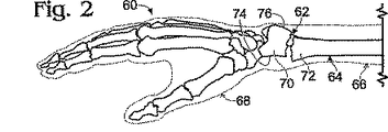
図2は、転んだときに手を伸ばすことで通常生じる遠位のとう骨64の極めて一般的な骨折部である、コリース骨折部62を呈する上右肢60を示している。骨折部の位置が、仮想線で示された遠位の前腕66および手68の皮膚に対して示されている。コリース骨折部62では、より小さな、遠位の骨折部70が、とう骨のより大きな近位の骨セグメント72の背部に配置されている。コリース骨折部62は、とう骨の掌側部(前方または下側)74への骨プレートの配置によって本明細書に記載の枢動自在な骨プレートによって整復され、固定される。この配置は、骨プレートがとう骨の掌側部(後方または上側)76に取り付けられたとき、屈曲とともに生じる腱の炎症を低減または回避する。別法として、本明細書に記載した骨プレートは、遠位のとう骨の掌側表面上で、または他の適切な骨または骨表面上で使用される。
FIG. 2 shows the upper
(実施例2)
3つの軸の周りの枢動運動のためのジョイントを備える骨プレート
この例は、その中で骨プレートの部分が互いに対して曲がりかつ捩れることができる、折れた遠位のとう骨上で使用するための骨プレートを説明している(図3〜図6参照)。
(Example 2)
Bone plate with joints for pivoting movements about three axes This example is used on a broken distal radius in which parts of the bone plate can bend and twist relative to each other The bone plate is described (see FIGS. 3 to 6).
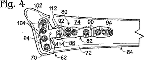
図3および図4は、掌表面74に隣接するとう骨に固定された枢動自在な骨プレート80を備える、折れたとう骨64の横中間断面図および掌側図を、それぞれ示している。枢動自在な骨プレート80は、枢動自在なジョイント86によって接続された近位のプレート部材82および遠位のプレート部材84を備える。
FIGS. 3 and 4 show a transverse mid-section and a palm side view, respectively, of a fractured
近位のプレート部材82は、とう骨の長軸とほぼ平行に配置されたその長軸を有する。プレート部材82は、ほぼ直線状である。プレート部材82は、複数の骨ねじ88によってとう骨の近位のセグメント72に固定される。骨ねじ88は、双皮層骨ねじまたは本明細書に示すように単一皮層骨ねじである。骨ねじ88は、近位のプレート部材の開口90〜94によって画定された平行なまたは平行でない経路に沿って方向付けられる。
骨ねじが移動する経路は、固定具(骨ねじまたはピンなど)と開口の間の嵌合によって画定される。嵌合は、事前に画定した角度での固定具の配置のために、固定具が骨プレートを通り、骨内へ移動する角度を少なくともほぼ画定するきつい嵌合である。別法として、嵌合は、ある角度範囲内で選択された角度での固定具の配置を許す、より拘束のない嵌合である。各固定具のための嵌合のタイプは、各固定具の選択によって骨プレートの設置中、外科医によって決定される。 The path that the bone screw travels is defined by the fit between the fixture (such as a bone screw or pin) and the opening. The fit is a tight fit that at least approximately defines the angle at which the fixture moves through the bone plate and into the bone for placement of the fixture at a pre-defined angle. Alternatively, the fit is a less restrictive fit that allows for the placement of the fixture at a selected angle within a range of angles. The type of fit for each fixture is determined by the surgeon during placement of the bone plate by selection of each fixture.
きつい嵌合は、固定具の開口の壁とのねじ係合または非ねじ係合によって画定されてもよい。きつい嵌合は、ねじ山付き固定具のそれに対応するねじ山付き開口とのねじ係合によって画定されてもよい。ねじ係合は、固定具のねじの長軸に対する角度を事前に画定し、角度位置をロックする。別法として、またはそれに加えて、きつい嵌合は、固定具の柄の直径と開口、特に開口の円筒形部分の直径との厳密な対応によって画定される。固定具の直径は、(固定具の頭部にほぼ隣接する)固定具の柄のねじ山付きの、またはねじ山付きでないセグメントによって画定される。開口の直径は、ねじ山付きでない、またはねじ山付きの開口によって画定される。したがって、所定の角度でのきつい嵌合は、ねじ山付きのまたはねじ山のない開口のいずれかによって係合されたねじ山付きでない、またはねじ山付きの柄セグメントによって達成される。 The tight fit may be defined by threaded or non-threaded engagement with the wall of the fixture opening. The tight fit may be defined by a threaded engagement with a corresponding threaded opening of the threaded fixture. Screw engagement predefines the angle of the fixture to the long axis of the screw and locks the angular position. Alternatively or in addition, the tight fit is defined by a strict correspondence between the diameter of the handle of the fixture and the diameter of the opening, in particular the cylindrical part of the opening. The fastener diameter is defined by the threaded or non-threaded segments of the fastener handle (substantially adjacent the fastener head). The diameter of the opening is defined by a non-threaded or threaded opening. Thus, a tight fit at a given angle is achieved by a non-threaded or threaded handle segment engaged by either a threaded or unthreaded opening.
より制限のない嵌合が、固定具のサイズおよび/または形状に対するサイズおよび/または形状によって画定される。例えば、開口は、固定具が、開口内で様々な角度配置を達成することを許すように、固定具の直径よりも十分大きい直径を有する。別法として、またはそれに加えて、開口は、固定具が様々な角度配置に枢動することを許すために傾斜した、または曲線状の壁を有する。 A less restrictive fit is defined by the size and / or shape relative to the size and / or shape of the fixture. For example, the aperture has a diameter that is sufficiently larger than the diameter of the fixture to allow the fixture to achieve various angular arrangements within the aperture. Alternatively or in addition, the opening has a sloped or curved wall to allow the fixture to pivot to various angular orientations.
開口92,94などの1つまたは複数の開口は、細長い開口またはスロットである。スロットは、プレート部材上で軸方向および/または横方向に配置される。スロットは、スロットに隣接して配置された基準マーク98を有する(図5参照)。基準マークは、各スロットが延びている方向の骨プレートの運動を測定するように構成されている。いくつかの実施形態では、スロットは、骨ねじをスロット92,94の骨内に配置して、追加の骨ねじが開口90を通って骨内に配置される前に、スロット92,94の一方または両方から近位のプレート部材82の軸方向または角度方向の調節を許すように構成されている。
One or more openings, such as
遠位のプレート部材84は、とう骨の長軸の横方向に配置されたその長軸を有する。プレート部材84は、ほぼT字型または扇型である。プレート部材84は、遠位のプレート部材の開口104を通って骨ねじ内に配置された複数の単一皮層または双皮層の骨ねじ102によって、とう骨の遠位の骨折部70に固定される。開口104は、ねじ山付きであっても、ねじ山付きでなくても、またはそれらの組合せであってもよい。骨ねじは、開口104とのねじ係合または非ねじ係合のために選択される。また、各骨ねじは、特定の骨ねじ(または他の固定具)の配置の角度が、開口104によって事前に規定されるように選択される、または、開口90〜94について上記で説明したように、ある角度範囲内で選択可能である。
枢動自在なジョイント86は、プレート部材が遠位のとう骨に固定される前、固定されている間および/または固定された後、近位のプレート部材82に対する遠位のプレート部材84の曲げおよび捩りを許すように構成されている。図5は、遠位のプレート部材についての2つの軸の周りの曲げ運動106,108および捩り運動110を示している。
The pivotable joint 86 provides bending and bending of the
図3および図4は、プレート部材の最終的な枢動調節の前、およびしたがって骨折部62の最終的な整復の前の骨プレート80の位置を示している。(1)ロックねじ112を緩めることによって調節可能な形状でジョイント86を配置することによって、(2)接続されたハンドル114の対応する運動によって、遠位のプレート部材84を1つまたは複数の軸の周りに(図3および図4の両方での時計方向など)回転させることによって、および(3)プレート部材およびそれらに取り付けられた骨部分の相対位置を固定するために、ロックねじ112を締めることによって固定された形状でジョイント86を配置することによって枢動調節が達成される。
3 and 4 show the position of the
図5および図6は、枢動自在な骨プレートの追加の態様、特に枢動自在なジョイント86の態様を示している。ジョイント86は、プレート部材内に設けられた上側および下側の半球表面122,124を備える。半球表面122,124は、それぞれ凸状および凹状であり、同様の曲率半径を有する。したがって、上側表面122は、直交する3つの軸の周りの枢動運動を達成するために下側表面124に沿って滑動する。上側および下側表面は、ほぼワッシャの形態の半球状のリテーナ126、およびねじ112によって同格に保持される。半球状のリテーナは、遠位のプレート部材によって画定された半球状のキャビティ128内で受けられるように構成される。リテーナおよび半球状のキャビティは、同様の曲率半径を有する。
FIGS. 5 and 6 show an additional embodiment of a pivotable bone plate, in particular an embodiment of a pivotable joint 86. The joint 86 includes upper and lower
枢動自在なジョイント86は、枢動運動を制限するための戻り止め機構129を備える。特に、戻り止め機構は、それぞれリテーナおよび遠位のプレート部材の開口130,132内で受けられ、回転されて、近位のプレート部材のねじ山付きの孔134とねじ係合されるロックねじ112を備える。したがって、ロックねじは、プレート部材表面が互いに対して運動可能であるか固定されているかを決定するために、プレート部材表面122,124の間の摩擦係合の量を画定するために、進められるかまたは引き込まれる。いくつかの実施形態では、近位のプレート部材は下側表面124を備え、遠位のプレート部材は上側表面126を備える。別法として、またはそれに加えて、枢動自在なジョイントは、リテーナ126が、ねじ付けされ、骨に隣接して配置されたナットとして働くように構成されるように、ここに示した形状から反転されてもよい。この場合、ロックねじ112は、プレート部材の外部表面からプレート部材のそれぞれの開口を通って配置されて、リテーナとねじ係合する。
The pivotable joint 86 includes a
骨プレート80は、プレート部材上に内部表面140,142および外部表面144,146を備える(図6参照)。内部表面140,142は、ここに示すように、骨プレートが中間調節位置にあるとき、ほぼ同一平面上にあるように構成されてもよく、または同一平面上になくてもよい。開口90などの開口が、内部表面と外部表面の間に画定される。開口は、皿孔148および孔150を備える。孔150は、特に円筒形であるか、または内部表面に向かって広がっている。
(実施例3)
枢動および並進運動用のジョイントを備える骨プレート
この例は、骨プレートが、曲げる、捩る、および互いに対して並進方向に滑動することができる、折れた遠位のとう骨上で使用するための骨プレートを説明している(図7、図8参照)。
(Example 3)
Bone plate with joint for pivoting and translational movement This example shows bone for use on a broken distal radius where the bone plate can bend, twist and slide in a translational direction relative to each other The plate is described (see FIGS. 7 and 8).
骨プレート170は、近位のプレート部材172と、遠位のプレート部材84と、2つのプレート部材を接続する橋部材174を備える。骨プレートは、プレート部材の枢動および並進方向運動を可能にする2つのジョイント、枢動自在なジョイント86および並進運動可能なジョイント175を備える。枢動自在なジョイント86は、実施例2について上記で説明したように構成されており、ここではさらに言及しない。
The
並進運動可能なジョイント175は、橋部材174の近位のプレート部材172との伸縮関係によって画定されている。特に、橋部材174は、近位のプレート部材によって画定された相補的なくぼみまたは軌道178内で受けられるように構成された、対向する細長い隆起またはガイド176を備える。
The translatable joint 175 is defined by the telescopic relationship of the
橋部材174の軸方向位置は、戻り止め機構180によって固定される。戻り止め機構は、リテーナ182(ワッシャなど)および固定具184(ねじまたはボルトなど)を備える。固定具は、リテーナを通って配置され、橋部材174のねじ山付き孔186とねじ係合される。固定具をねじ山付き孔内へ進行させることが、リテーナ182を押圧して、近位のプレート部材172の保持表面188と係合させ、それによって並進運動を制限する。ジョイント175でのさらなる滑動を許すために、リテーナが緩められる。
The axial position of the
ジョイント175を固定する前および/または固定した後、骨ねじ190が、近位のプレート部材172の開口192を通って骨内に配置される。橋部材174は、橋部材の軸方向位置の連続する範囲にわたって骨ねじが受けられることを許す細長い通路194を備える。通路は、骨ねじの頭部が、通路を通って進むことを許すように構成されている、または骨ねじの頭部が橋部材によって係合されている。
Before and / or after fixing joint 175,
(実施例4)
離隔された枢動自在なジョイントを備える骨プレート
この例は、直交する軸の周りに枢動運動するように構成された複数の離隔されたジョイントを備える骨プレートを説明している(図9参照)。
(Example 4)
Bone plate with spaced pivotable jointsThis example describes a bone plate with multiple spaced joints configured to pivot about orthogonal axes (see FIG. 9). ).
骨プレート210は、橋部材220を使用して近位のプレート部材216および遠位のプレート部材218と接続されている2つの枢動自在なジョイント212,214を備える。枢動自在なジョイント212は、法線方向軸224の周りの222で示されている枢動運動を許す。ジョイント212は、これらの部材の接触表面226,228での遠位のプレート部材218の橋部材220との並置によって画定される。接触表面226,228は、一般に平面状である。接触表面は、戻り止め機構230が駆動されたとき枢動運動を制限するために、鋸歯またはその他の相補的な構造を備える。
戻り止め機構230は、遠位のプレート部材218内の開口234を通過して、橋部材220のねじ山付き孔236とねじ係合するねじなどのコネクタ232によって提供されてもよい。コネクタ232を進行させることが、遠位のプレート部材および橋部材を共に圧縮して枢動運動を制限する。接触表面226,228の表面形状が、戻り止め機構が駆動されたとき運動を制限することを容易にする。
The
ヒンジジョイント214は、横方向軸242の周りでの、240で示す枢動運動を許す。ヒンジジョイントは、橋部材220と近位のプレート部材216の間に形成されている。ヒンジジョイントの戻り止め機構244は、ヒンジジョイントを軸242と平行に圧縮するために、ヒンジジョイントに軸方向に作用するロックねじ246を備える。いくつかの実施形態では、戻り止め機構は、特に、ヒンジジョイントに半径方向に作用する。
The hinge joint 214 allows a pivoting movement, indicated at 240, about the
(実施例5)
滑動および枢動のための一体型ジョイントを備える骨プレート
この例は、滑動および枢動のための一体型ジョイントがその中にある、折れたとう骨を固定するための骨プレートを説明している(図10参照)。この実施例は本発明の範囲外のものであり、情報を提供する目的でのみ記載している。
(Example 5)
Bone plate with integral joint for sliding and pivotingThis example describes a bone plate for fixing a broken bone in which an integral joint for sliding and pivoting is located ( (See Figure 10) . This example is outside the scope of the present invention and is provided for informational purposes only.
骨プレート270は、ジョイント276で接続された近位のプレート部材272と遠位のプレート部材274を備える。ジョイント276は、278で示す軸方向運動、および280で示す軸282の周りの枢動運動を許す。プレート部材は、並進方向に滑動し、互いに対して枢動する接触表面284,286を備える。プレート部材は、細長い開口292,294を通ってそれぞれねじ山付き孔296およびねじ山付きスロット29内へ延びる、コネクタ288,290(ねじなど)によって接続されている。プレート部材は、プレート部材の枢動および並進運動によって位置を調節され、次にコネクタ288,290を、それらの頭部が遠位のプレート部材274の皿孔表面302,304に圧縮力を加えるまで進行させることによって定位置に固定される。
(実施例6)
結合された並進および枢動運動を有する骨プレート
この例は、骨プレートが並進および枢動運動を結合する、折れたとう骨を固定するための骨プレートを説明している(図11〜図14参照)。この実施例は本発明の範囲外のものであり、情報を提供する目的でのみ記載している。
(Example 6)
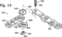
Bone plate with combined translational and pivotal movements This example describes a bone plate for fixing broken bones where the bone plate combines translational and pivotal movements (see FIGS. 11-14) ). This example is outside the scope of the present invention and is provided for informational purposes only.
図11は、2つのジョイント326,328によって接続された近位のプレート部材322と遠位のプレート部材324を備える骨プレート320を示している。第1のジョイント326は、法線方向軸332の周りの、330で示す枢動運動を許し、したがって例4のジョイント212と同様である。第2のジョイント328は、特に、第1のジョイントの下または上に配置され、プレート部材が並進方向に滑動することを許すように構成されている。しかし、プレート部材がそれに沿って滑動する経路は、第2のジョイントが、結合された並進運動および円運動を許すように、以下でさらに説明するように円弧状である。
FIG. 11 shows a
図12は、骨プレート320の選択された部分の軸方向断面図を示している。プレート部材322,324は、橋部材の対向する表面342,344上でプレート部材と接触する橋部材340を介して接続されている。上側表面342は、第1のジョイント326での近位のプレート部材322の枢動運動のための接触表面を提供する。下側表面344は、それに沿って遠位のプレート部材324が滑動する、346で示す曲線状の経路を画定する接触表面を提供する。曲線状の経路は、仮想輪郭線348で示される経路346に沿って滑動することによって達成される近位のプレート部材322の代替の位置によって示されるように、円形の経路に沿っている。
FIG. 12 shows an axial cross-sectional view of selected portions of the
図13および図14は、それぞれ骨プレート320の横方向断面図および分解図を示している。ジョイント326,328は、コネクタ352を有する戻り止め機構350を備える。コネクタは、特に、近位のプレート部材322および橋部材340内の開口を通って延びるねじである。ねじは、遠位のプレート部材324によって画定されたスロット356内で保持されているねじ山付きナット354によって受けられる。スロット356はスロット356内で、ナットを保持するために、ナットのシェルフ360と係合する壁358を画定するために、橋部材の近くで幅狭である。
13 and 14 show a cross-sectional side view and an exploded view of the
(実施例7)
基準マークを備える骨プレート
この例は、プレートの角度および/または並進方向の調節を測定するように構成された基準マークを備える骨プレートを説明している(図15および図16参照)。
(Example 7)
Bone plate with fiducial marks This example describes a bone plate with fiducial marks configured to measure plate angle and / or translational adjustment (see FIGS. 15 and 16).
図15は、骨プレート390を分解図で示している。骨プレート390は、例えば、切骨術後の切骨部分の位置を固定するように構成されている。骨プレート390は、枢動自在なジョイント396によって接続された軸方向(すなわち近位の)プレート部材392と、横方向(すなわち遠位の)プレート部材394を備える。枢動自在なジョイント396は、横方向プレート部材394が、法線方向軸398などの1つの軸の周りに、397で示すように枢動することを可能にする。だが、本発明の骨プレートの場合、枢動自在なジョイントは、本教示の至る所で説明されているように、2つ以上の軸の周りの枢動運動を許すように構成される。枢動自在なジョイント396は、調節可能であり、そのとき、ロックねじ402またはその他の戻り止め機構によって固定可能である。
FIG. 15 shows the
骨プレート390は、角度基準マーク406および目印408を備える角度指標機構404を備える。角度基準マーク406および目印408は、それぞれ異なるプレート部材392,394上に配置されても、またはその逆でもよい。
The
骨プレートは、スロット410および、位置調節の軸方向の測定を提供する直線状の指標機構412を備える。スロット410は、軸方向プレート部材392の長軸と並んで延びてもよい。スロット410は、骨ねじ(およびしたがって下にある骨)に対する骨プレートの直線状の滑動をガイドする骨ねじを受ける。直線状の滑動は、骨ねじが完全に締め付けられる前および/または骨プレートの他の骨ねじが追加の開口414から骨内に配置された後に、骨プレートの軸方向の調節を提供する。直線状の滑動は、骨ねじが対向する(例えば横方向の)プレート部材の開口416から骨内に配置される前および/または配置された後に行われる。直線状スロット410内での位置は、スロットの縁部に隣接するスロットと平行に並べられた基準マーク418によって標示される。直線状の基準マークは、いかなる適切な間隔および方向を有してもよく、英数字(数字や文字など)、記号および/または個々のマークを識別および/または区別するその他の指標を含む、いかなる適切な形態を有してもよい。
The bone plate includes a
図16は、骨プレート390の角度標示機構404の平面図である。機構404は、円弧状の配置で並べられた角度基準マーク406を備える。基準マークは、特に枢軸398から半径方向に延びる線分を備える、および/または点線および/または破線を備える。基準マーク406の隣接する対は、枢動自在なジョイント396の枢軸398とともに任意の適切な角度を画定する。例えば、隣接する基準マークは、特に、1、2、5または10度を画定する。いくつかの実施形態では、基準マーク406は、特に、ここで30度間隔にされた420で示された長いマーク、およびここで10度間隔にされた422で示された側面の短いマークなど、視覚的に区別可能である主要なまたは小さなマークを備える。標示機構404はまた、または別法として、特定の基準マークを識別するおよび/またはこのようなマークとして働く数字424などの英数字を備える。いくつかの場合、基準マークのための標準的な(例えば好ましいおよび/または通常使用されている)設定が、例えば代替となるフォント、記号またはサイズを使用することによって、および/または追加の「標準設定」マーク426(星印「*」など)を使用してこれらのマークを識別することによってプレート上に示される。
FIG. 16 is a plan view of the
目印408は、目印に最も近接して並んでいる基準マーク406の1つを識別するために、基準マークが比較される部位を提供するように構成されている。例えば、本図面では、目印408は、ゼロ度の中立位置からの横方向プレート部材の30度の回転を示すための、「-30」と標示された基準マークと並んでいる。角度基準機構404が、事前決定され角度によって横方向プレート部材392の角度位置を調節するために使用される。角度は、プレートが取り付けられる骨のx線検査、外部測定デバイスなどによる骨または手足の位置ずれの角度の測定など、いかなる適切な解析によって事前決定されてもよい。
The
基準マークを備える骨プレート内の基準マークのための用途は、術前および/または術後の解析に拡大する。例えば、骨プレートの設置前に、外科医が、「ダイヤルイン」またはその他の方法で、骨プレートのための近似的な設定を事前設定することができる。事前設定される値は、術前解析(例えばx線テンプレートおよび/または対応するまたは相補的な基準マークを有するその他の測定ツール)、患者の体の反対側の対応する負傷していない部位との比較(例えば、負傷している右とう骨に適切な事前設定値を決定するために負傷していない左とう骨の測定値を使用して)、様々な患者から収集された統計データとの比較(例えば参照表の形態の)などから決定される。別法として、またはそれに加えて、骨プレートの設置後、外科医は、考えられる術後の使用のために最終的な設定を記録する。いくつかの場合、基準マークは、継続的な正確な位置の非侵襲的な監視、および術後のプレートの調節を許すために、x線、磁気共鳴および/または類似の技術を使用して現場で読み取り可能である。このような用途のための適切な基準マークは、特に、厚さ、輪郭形状および/またはプレートの組成の変化または変更を含む。 Applications for fiducial marks in bone plates with fiducial marks extend to pre-operative and / or post-operative analysis. For example, prior to installing the bone plate, the surgeon may pre-set approximate settings for the bone plate by “dial-in” or otherwise. Pre-set values are based on preoperative analysis (e.g. x-ray templates and / or other measurement tools with corresponding or complementary fiducial marks), with corresponding uninjured sites on the opposite side of the patient Comparison (e.g., using measurements of uninjured left radius to determine appropriate presets for injured right radius) and comparison with statistical data collected from various patients (e.g. Etc. (in the form of a lookup table). Alternatively or in addition, after placement of the bone plate, the surgeon records the final settings for possible post-operative use. In some cases, fiducial marks can be used in situ using x-ray, magnetic resonance and / or similar techniques to allow continuous non-invasive monitoring of precise position and post-operative plate adjustment. Can be read. Suitable fiducial marks for such applications include, among other things, changes or changes in thickness, contour shape and / or plate composition.
(実施例8)
枢動自在な骨プレート
この例は、骨プレートの部分が互いに対して曲がる、および捩れることができる、折れた遠位のとう骨上で使用するための別の枢動自在な骨プレートを説明している(図17〜図19参照)。この骨プレートのいくつかの態様は、実施例2において上で説明され骨その中でより詳細に説明されたプレートと共有される。
(Example 8)
Pivotable Bone Plate This example describes another pivotable bone plate for use on a folded distal radius, where portions of the bone plate can bend and twist relative to each other. (See FIGS. 17 to 19). Some aspects of this bone plate are shared with the plate described above in Example 2 and described in more detail therein.
図17は、遠位のとう骨の掌側表面上で使用するように構成された骨プレート450を示している。骨プレート450は、非対称的であり、人体の片側のみで、本図面では左のとう骨上で使用するように構成されている。骨プレート450は、近位のアンカー部分452、遠位のアンカー部分454、および近位と遠位のアンカー部分を接合する枢動自在なジョイント456を備える。
FIG. 17 shows a
近位のアンカー部分452は、とう骨の長軸とほぼ並ぶように構成された軸方向部分である。近位のアンカー部分452は、骨ねじなどの固定具を受けるために、複数の開口458〜464を画定している。近位の開口464は、近位のアンカー部分452の長軸とほぼ並ぶように配置されたスロットである。開口のそれぞれは、ねじ山付きであっても、ねじ山付きでなくてもよく、また皿穴を備えても、備えなくてもよい。いくつかの実施形態では、開口458などの開口の1つまたは複数は、横方向スロットとして構成されている。開口の少なくとも一部は、千鳥状の平行でない経路に沿って骨ねじを方向付けるために、プレートの中心軸466の両側などに、千鳥状の配置で配置される。したがって、この一部の開口は、その開口および/またはねじの壁の異なる方向付けを基にして骨ねじの移動の異なる経路を画定する。近位のアンカー部分452の周縁は、プレートによって画定される平面(プレートの長さおよび幅を有する)に垂直な位置から見たとき、近位の部分に波型のまたは波動状の外観を形成するために、468で示す開口の配置にほぼ追従する。近位のアンカー部分452はまた、例えばワイヤなどのより小さい直径の固定具を受けるように構成された、1つまたは複数のより小さい開口470を備える。
遠位のアンカー部分454は、とう骨の幅広の遠位の領域に固定されるように構成されている。したがって、遠位の部分454は、近位の部分452よりも幅広であり、プレート全体がほぼT字型であるように、扇様の形状をなすように遠位に広がっている。遠位のアンカー部分454は、1つまたは複数の列で、ここに示すようにプレートが中立位置に調節されるとき、近位のアンカー部分452の中心軸466に対してほぼ横方向に配列された複数の開口472〜474を画定する。開口472,474は、特に、1つまたは複数の直線状または円弧状の列で配列されている。
遠位の開口は、本図面でのように、ねじ山付き(472に図示)、ねじ山なし(474に図示)、またはその組合せであってもよい(図18も参照)。各開口は、骨ねじまたはその他の固定具(ピンなど)を、固定された角度でまたはある角度範囲で選択された角度で受けるように構成されている。固定または可変角度の間の選択は、実施例2で上記でより詳細に説明されているように、ねじまたはその他の固定具がいかに近接して開口内に嵌合しているか、および/またはねじ係合が、ねじ/固定具の角度を固定するために使用されているかどうかによって定義される。 The distal opening may be threaded (shown at 472), unthreaded (shown at 474), or a combination thereof, as in this figure (see also FIG. 18). Each opening is configured to receive a bone screw or other fixture (such as a pin) at a fixed angle or at a selected angle in a range of angles. The choice between the fixed or variable angle is determined by how closely a screw or other fixture fits within the opening and / or screw, as described in more detail above in Example 2. It is defined by whether the engagement is being used to fix the screw / fixture angle.
遠位のアンカー部分454は、開口472,474の遠位に配置された1つまたは複数の追加の開口476を備える。遠位の開口476は、例えば、特に茎状突起が骨折または切断したとき、遠位のとう骨の茎状突起内に配置された固定具を受けるために使用される。
The
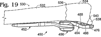
遠位のアンカー部分454は、遠位のとう骨の掌側表面上に嵌合するような輪郭形状にされている。したがって、遠位のアンカー部分454は、特に遠位のアンカー部分454の近位のセクション482内に横方向に出っ張った内部表面478と、横方向にくぼんだ外部表面480とを有する。遠位のアンカー部分454の遠位のセクション484は、とう骨の掌側遠位縁部の遠位に配置されるように構成されている。したがって、遠位のアンカー部分454は、遠位のアンカー部分の近位および遠位のセクション482,484の間の分岐に、わずかなくぼみなどの横方向輪郭形状486を備える。横方向輪郭形状486は、とう骨の掌側遠位縁部488(図19参照)を受けるように構成されている。遠位のアンカー部分454の周縁は、遠位のとう骨の外形にほぼ対応するような形状にされている。例えば、遠位のアンカー部分454の遠位横方向周縁490は、より傾斜しているおよび/または遠位方向に遠くに延びており、遠位中間周縁492は、より丸みを帯びている。
図18は、骨プレート450および特に枢動自在なジョイント456を分解図で示している。枢動自在なジョイントは、それぞれ、近位および遠位のアンカー部分452,454の半球表面502,504を備える。これらの半球表面は、3つの軸の周りに互いに滑動することができるように相補的である。リテーナ506が、リテーナが、近位のアンカー部分452の第2の半球表面510によって受けられることができるように半球状のキャビティ508を備える。ねじなどの固定具512が、リテーナおよび近位のアンカー部分452を通って遠位のアンカー部分454のねじ山付きの孔514にねじ係合される。固定具は、骨プレートの調節可能なおよび固定された形状を提供するために両方向に回転される。本発明に包含される実施形態では、ジョイント456は、本教示の至る所で説明されているように、2つの軸の周りの枢動運動および任意選択で並進運動を許容する。アンカー部分452,454の相対的な配置は、プレートの開口の1つまたは複数など、部分の一方または両方と係合する工具によって調節される。
FIG. 18 shows the
図19は、遠位のとう骨530の掌側表面上に配置された骨プレート450を示している。近位のアンカー部分452は近位の骨領域532に、遠アンカー部分454は遠位の骨領域534に固定されている。枢動自在なジョイント456が、骨の遠位の骨折部536に隣接して配置される。遠位のアンカー部分454は、茎状突起538が、開口476内に配置された固定具を使用して遠位のアンカー部分454に固定されるように、とう骨の掌側遠位縁部488上に延びている。したがって、茎状不連続部540(骨折部など)が、遠位のアンカー部分454によって架橋される。骨プレートの外部表面は、遠位のとう骨の掌側表面の輪郭形状を追従するために、ここに示すように長手方向に凹状であり、内部表面は長手方向に凸状であってもよい。
FIG. 19 shows a
20 骨
21 骨折部
22 骨プレート
24 第1のプレート部材
26 第2のプレート部材
30 骨ねじ
32,34 部分
38 ジョイント
40,42 ステップ
44 戻り止め
46 ハンドル
60 上右肢
62 コリース骨折部
66 前腕
68 手
70 遠位の骨折部
72 近位の骨セグメント
74 掌側部
80,170,270,320,390,450 骨プレート
82,172,216,272,322,392 近位のプレート部材
84,218,274,324,394 遠位のプレート部材
86,175,212,214,326,328,396,456 ジョイント
88,102,190 骨ねじ
90〜94,104,130,132,192,234,292,294,414,416,458〜464,470,476 開口
98 基準マーク
106,108 曲げ運動
110 捩り運動
112,246,402 ロックねじ
114 ハンドル
122,124,502,504 半球表面
126,182,506 リテーナ
128,508 キャビティ
129,180,244,350 戻り止め機構
140,142 内部表面
144,146 外部表面
148 皿孔
150,514 孔
174,220,340 橋部材
176 隆起またはガイド
178 くぼみまたは軌道
184 固定具
186,236,296 ねじ山付き孔
188 保持表面
194 通路
222,240,280,397 枢動運動
224,332,398 法線方向軸
226,228,284,286 接触表面
232,288,290,352 コネクタ
242 横方向軸
278 軸方向運動
282 軸
29 ねじ山付きスロット
302 皿孔表面
342,344 表面
346 経路
354 ねじ山付きナット
356,410 スロット
358 壁
360 シェルフ
398 枢軸
404 角度指標機構
406 角度基準マーク
408 目印
412 指標機構
418 基準マーク
426 標準設定マーク
452 近位のアンカー部分
454 遠位のアンカー部分
466 中心軸
486 横方向輪郭形状
488 掌側遠位縁部
490 遠位横方向周縁
492 遠位中間周縁
532,534 骨領域
538 茎状突起
540 茎状不連続部
20 bones
21 Fractures
22 bone plate
24 First plate member
26 Second plate member
30 bone screws
32,34 pieces
38 Joint
40,42 steps
44 Detent
46 Handle
60 upper right limb
62 Collies fracture
66 Forearm
68 hands
70 Distal fracture
72 Proximal bone segment
74 Palm side
80,170,270,320,390,450 bone plate
82,172,216,272,322,392 Proximal plate member
84,218,274,324,394 Distal plate member
86,175,212,214,326,328,396,456 joint
88,102,190 bone screw
90-94,104,130,132,192,234,292,294,414,416,458-464,470,476 Opening
98 fiducial mark
106,108 Bending motion
110 Torsional motion
112,246,402 Lock screw
114 Handle
122,124,502,504 Hemispherical surface
126,182,506 Retainer
128,508 cavity
129,180,244,350 Detent mechanism
140,142 Internal surface
144,146 External surface
148 countersink
150,514 holes
174,220,340 Bridge members
176 Uplift or guide
178 Indentation or orbit
184 Fixture
186,236,296 threaded holes
188 Holding surface
194 passage
222,240,280,397 Pivoting
224,332,398 Normal axis
226,228,284,286 Contact surface
232,288,290,352 connectors
242 Horizontal axis
278 axial motion
282 axes
29 Threaded slot
302 Countersink surface
342,344 surface
346 route
354 Threaded nut
356,410 slots
358 walls
360 shelf
398 Axis
404 Angle indicator mechanism
406 Angle reference mark
408 Placemark
412 Indicator mechanism
418 Reference mark
426 Standard setting mark
452 Proximal anchor part
454 Distal anchor
466 Center axis
486 Horizontal profile
488 Palmar distal edge
490 Distal lateral margin
492 Distal middle rim
532,534 bone region
538 Stem projection
540 Stem-like discontinuity
Claims (20)
少なくともその一部分同士が互いに密着して重なり合う状態で、前記第1および第2のプレート部材を接続し、前記第1および第2のプレート部材の間の角度配置を画定するジョイントであって、前記角度配置は2つ以上の非平行軸を中心とする第1のプレート部材の枢動運動によって調節可能であり、かつ(1)前記角度配置が調節可能である調節可能形態と、(2)前記角度配置が固定された固定形態とをとるジョイントと、を具備してなる骨固定用骨プレート。Subcutaneous ing is configured to be disposed, a first and second plate members overlapping at least a portion thereof to each other mutually close contact, to each of the relative portion of at least one bone 1 And first and second plate members formed with one or more openings configured to receive a fixture for fixing the second plate member;
At least in a state where a portion thereof overlap each other in close contact with each other, to connect the pre-Symbol first and second plate members, a joint defining an angle disposed between said first and second plate members, the The angular arrangement is adjustable by a pivoting movement of the first plate member about two or more non-parallel axes, and (1) an adjustable configuration wherein the angular arrangement is adjustable, and (2) the A bone plate for bone fixation, comprising: a joint having a fixed form in which an angular arrangement is fixed.
前記骨プレートの前記第1および第2の部材の少なくとも1つの上に配置された前記複数の基準マークの少なくとも2つに対応する複数の基準マークを有する測定デバイスと、を備える骨固定用キット。At least one bone plate according to claim 14;
A bone fixation kit comprising: a measuring device having a plurality of fiducial marks corresponding to at least two of the plurality of fiducial marks disposed on at least one of the first and second members of the bone plate.
Applications Claiming Priority (3)
| Application Number | Priority Date | Filing Date | Title |
|---|---|---|---|
| US42790802P | 2002-11-19 | 2002-11-19 | |
| US51213603P | 2003-10-17 | 2003-10-17 | |
| PCT/US2003/037231 WO2004045389A2 (en) | 2002-11-19 | 2003-11-19 | Adjustable bone plates |
Related Child Applications (1)
| Application Number | Title | Priority Date | Filing Date |
|---|---|---|---|
| JP2007199747A Division JP2007275651A (en) | 2002-11-19 | 2007-07-31 | Adjustable bone plate |
Publications (3)
| Publication Number | Publication Date |
|---|---|
| JP2006506197A JP2006506197A (en) | 2006-02-23 |
| JP2006506197A5 JP2006506197A5 (en) | 2007-01-18 |
| JP4028552B2 true JP4028552B2 (en) | 2007-12-26 |
Family
ID=32329194
Family Applications (2)
| Application Number | Title | Priority Date | Filing Date |
|---|---|---|---|
| JP2004554004A Expired - Lifetime JP4028552B2 (en) | 2002-11-19 | 2003-11-19 | Adjustable bone plate |
| JP2007199747A Pending JP2007275651A (en) | 2002-11-19 | 2007-07-31 | Adjustable bone plate |
Family Applications After (1)
| Application Number | Title | Priority Date | Filing Date |
|---|---|---|---|
| JP2007199747A Pending JP2007275651A (en) | 2002-11-19 | 2007-07-31 | Adjustable bone plate |
Country Status (7)
| Country | Link |
|---|---|
| US (8) | US7326212B2 (en) |
| EP (1) | EP1567071B1 (en) |
| JP (2) | JP4028552B2 (en) |
| KR (1) | KR101081269B1 (en) |
| AU (1) | AU2003295749B2 (en) |
| GB (1) | GB2412590B (en) |
| WO (1) | WO2004045389A2 (en) |
Families Citing this family (440)
| Publication number | Priority date | Publication date | Assignee | Title |
|---|---|---|---|---|
| US5938664A (en) * | 1998-03-31 | 1999-08-17 | Zimmer, Inc. | Orthopaedic bone plate |
| US7857838B2 (en) | 2003-03-27 | 2010-12-28 | Depuy Products, Inc. | Anatomical distal radius fracture fixation plate |
| US20060041260A1 (en) * | 2000-02-01 | 2006-02-23 | Orbay Jorge L | Fixation system with plate having holes with divergent axes and multidirectional fixators for use therethrough |
| US6767351B2 (en) * | 2000-02-01 | 2004-07-27 | Hand Innovations, Inc. | Fixation system with multidirectional stabilization pegs |
| US6893444B2 (en) * | 2000-02-01 | 2005-05-17 | Hand Innovations, Llc | Bone fracture fixation systems with both multidirectional and unidirectional stabilization pegs |
| US7695502B2 (en) | 2000-02-01 | 2010-04-13 | Depuy Products, Inc. | Bone stabilization system including plate having fixed-angle holes together with unidirectional locking screws and surgeon-directed locking screws |
| US20040153073A1 (en) * | 2000-02-01 | 2004-08-05 | Hand Innovations, Inc. | Orthopedic fixation system including plate element with threaded holes having divergent axes |
| US6706046B2 (en) * | 2000-02-01 | 2004-03-16 | Hand Innovations, Inc. | Intramedullary fixation device for metaphyseal long bone fractures and methods of using the same |
| US7282053B2 (en) * | 2003-03-27 | 2007-10-16 | Depuy Products, Inc. | Method of using fracture fixation plate for performing osteotomy |
| US20070173840A1 (en) * | 2006-01-11 | 2007-07-26 | Huebner Randall J | Bone plate with cover |
| US7717945B2 (en) | 2002-07-22 | 2010-05-18 | Acumed Llc | Orthopedic systems |
| US20050240187A1 (en) | 2004-04-22 | 2005-10-27 | Huebner Randall J | Expanded fixation of bones |
| US8523919B2 (en) | 2010-09-27 | 2013-09-03 | Acumed Llc | Targeting guide with a radiopaque marker to facilitate positioning a bone plate on bone |
| US8231662B2 (en) * | 2006-10-17 | 2012-07-31 | Acumed Llc | Bone fixation with a strut-stabilized bone plate |
| US7537604B2 (en) * | 2002-11-19 | 2009-05-26 | Acumed Llc | Bone plates with slots |
| US20090131936A1 (en) * | 2001-10-18 | 2009-05-21 | Kishore Tipirneni | System and method for the fixation of bone fractures |
| US8828067B2 (en) | 2001-10-18 | 2014-09-09 | Orthoip, Llc | Bone screw system and method |
| US9060809B2 (en) | 2001-10-18 | 2015-06-23 | Orthoip, Llc | Lagwire system and method for the fixation of bone fractures |
| US6736819B2 (en) | 2001-10-18 | 2004-05-18 | Kishore Tipirneni | System and method for fixation of bone fractures |
| US20080243191A1 (en) * | 2001-10-18 | 2008-10-02 | Fx Devices, Llc | Adjustable bone plate fixation system and metho |
| US20100312292A1 (en) * | 2001-10-18 | 2010-12-09 | Orthoip, Llc | Lagwire system and method for the fixation of bone fractures |
| US20100268285A1 (en) * | 2001-10-18 | 2010-10-21 | Orthoip, Llc | Bone screw system and method for the fixation of bone fractures |
| RU2303422C2 (en) * | 2002-03-12 | 2007-07-27 | Сервитек Инк. | Intervertebral prosthesis and system of intervertebral prostheses, in peculiar case, for cervical department of vertebral column |
| US8652142B2 (en) * | 2006-04-28 | 2014-02-18 | Acumed Llc | Osteotomy systems |
| WO2004008980A1 (en) * | 2002-07-22 | 2004-01-29 | Acumed Llc | Bone fusion system |
| WO2008150501A1 (en) * | 2007-06-01 | 2008-12-11 | Simplicity Orthopedics, Inc. | Method and apparatus for securing an object to bone and/or for stabilizing bone |
| US8506605B2 (en) * | 2002-09-18 | 2013-08-13 | Simplicity Orthopedics, Inc. | Method and apparatus for securing an object to bone and/or for stabilizing bone |
| EP1567071B1 (en) * | 2002-11-19 | 2012-05-30 | Acumed LLC | Adjustable bone plates |
| JP2006506194A (en) * | 2002-11-19 | 2006-02-23 | アキュームド・エルエルシー | Deformable bone plate |
| US20050187551A1 (en) * | 2002-12-02 | 2005-08-25 | Orbay Jorge L. | Bone plate system with bone screws fixed by secondary compression |
| US7425213B2 (en) * | 2002-12-10 | 2008-09-16 | Depuy Products, Inc. | Method of endosteal nailing |
| FR2848413B1 (en) * | 2002-12-11 | 2005-07-29 | Fixano | OSTEOSYNTHESIS PLATE FOR OSTEOSYNTHESIS OF SMALL BONE NEIGHBORS OF OTHERS |
| US7905883B2 (en) * | 2003-03-26 | 2011-03-15 | Greatbatch Medical S.A. | Locking triple pelvic osteotomy plate and method of use |
| US7722653B2 (en) | 2003-03-26 | 2010-05-25 | Greatbatch Medical S.A. | Locking bone plate |
| EP1610700B1 (en) * | 2003-03-26 | 2010-08-04 | Swiss Orthopedic Solutions SA | Locking bone plate |
| US7635381B2 (en) * | 2003-03-27 | 2009-12-22 | Depuy Products, Inc. | Anatomical distal radius fracture fixation plate with fixed-angle K-wire holes defining a three-dimensional surface |
| US7250053B2 (en) * | 2003-03-27 | 2007-07-31 | Depuy Products, Inc. | Low profile distal radius fracture fixation plate |
| US20040193155A1 (en) * | 2003-03-27 | 2004-09-30 | Hand Innovations, Inc. | Fracture fixation plate with particular plate hole and fastener engagement and methods of using the same |
| US7294130B2 (en) * | 2003-03-27 | 2007-11-13 | Depuy Products, Inc. | Distal radius fracture fixation plate having K-wire hole structured to fix a K-wire in one dimension relative to the plate |
| EP1470803A1 (en) * | 2003-04-23 | 2004-10-27 | Sepitec Foundation | Spondylodesis device |
| US7635365B2 (en) | 2003-08-28 | 2009-12-22 | Ellis Thomas J | Bone plates |
| US20050085818A1 (en) * | 2003-10-17 | 2005-04-21 | Huebner Randall J. | Systems for distal radius fixation |
| US20050085814A1 (en) * | 2003-10-21 | 2005-04-21 | Sherman Michael C. | Dynamizable orthopedic implants and their use in treating bone defects |
| EP1684651A1 (en) * | 2003-11-05 | 2006-08-02 | Königsee Implantate und Instrumente zur Ostheosynthese GmbH | Plate used to stabilise distal radius fractures |
| WO2005048857A1 (en) * | 2003-11-18 | 2005-06-02 | Synthes Gmbh | Set of osteosynthesis plates |
| US8821495B2 (en) * | 2003-12-15 | 2014-09-02 | Koninklijke Philips N.V. | System and method for hyoidplasty |
| US20050234476A1 (en) * | 2003-12-29 | 2005-10-20 | Whitmore Willet F Iii | Template grid needle/instrument guide and method for minimally invasive procedures |
| WO2005072284A2 (en) * | 2004-01-23 | 2005-08-11 | Depuy Products, Inc. | System for stabilization of fractures of convex articular bone surfaces including subchondral support structure |
| US20080045960A1 (en) * | 2004-03-25 | 2008-02-21 | Bruecker Kenneth | Locking tpo plate and method of use |
| WO2006091827A2 (en) * | 2005-02-25 | 2006-08-31 | Regents Of The University Of California | Device and template for canine humeral slide osteotomy |
| US7789899B2 (en) * | 2004-12-30 | 2010-09-07 | Warsaw Orthopedic, Inc. | Bone anchorage screw with built-in hinged plate |
| US7540874B2 (en) * | 2004-05-27 | 2009-06-02 | Trimed Inc. | Method and device for use in osteotomy |
| US7303563B2 (en) * | 2004-06-17 | 2007-12-04 | Sdgi Holdings, Inc. | Orthopedic fixation system and method of use |
| US20060025772A1 (en) * | 2004-07-30 | 2006-02-02 | Leibel David A | Bone fusion plate |
| US20060173458A1 (en) | 2004-10-07 | 2006-08-03 | Micah Forstein | Bone fracture fixation system |
| US9615866B1 (en) | 2004-10-18 | 2017-04-11 | Nuvasive, Inc. | Surgical fixation system and related methods |
| US20060089648A1 (en) * | 2004-10-27 | 2006-04-27 | Masini Michael A | Versatile bone plate systems particularly suited to minimally invasive surgical procedures |
| US8062296B2 (en) * | 2005-03-17 | 2011-11-22 | Depuy Products, Inc. | Modular fracture fixation plate system with multiple metaphyseal and diaphyseal plates |
| US8394130B2 (en) | 2005-03-17 | 2013-03-12 | Biomet C.V. | Modular fracture fixation system |
| US7648508B2 (en) * | 2004-11-30 | 2010-01-19 | Stryker Trauma S.A. | Bone plating implants, instruments and methods |
| US20060116681A1 (en) * | 2004-11-30 | 2006-06-01 | Bert Jeffrey K | Surgical plate with transition zone capability |
| US7635364B2 (en) * | 2004-12-01 | 2009-12-22 | Synthes Usa, Llc | Unidirectional translation system for bone fixation |
| US7771433B2 (en) | 2004-12-14 | 2010-08-10 | Depuy Products, Inc. | Bone fracture fixation plate shaping system |
| US20060149275A1 (en) * | 2004-12-14 | 2006-07-06 | Cadmus Calvin M | Apparatus and methods for tibial plateau leveling osteotomy |
| US8172886B2 (en) * | 2004-12-14 | 2012-05-08 | Depuy Products, Inc. | Bone plate with pre-assembled drill guide tips |
| US20060229621A1 (en) * | 2004-12-14 | 2006-10-12 | Cadmus Calvin M | Apparatus and methods for tibial plateau leveling osteotomy |
| GB2422783B (en) * | 2005-02-02 | 2007-02-21 | Dr Ahmad Fahmi Juanroyee | Plate to plate connection system (PPCS) |
| CN101175449B (en) * | 2005-03-17 | 2011-11-16 | 德普伊产品公司 | Modular fracture fixation plate system |
| GB0505505D0 (en) * | 2005-03-17 | 2005-04-27 | Dall Desmond Meiring | Configurable bone fixation system |
| US7344538B2 (en) | 2005-03-31 | 2008-03-18 | Depuy Products, Inc. | Mid-foot fixation plate |
| WO2006111852A2 (en) * | 2005-04-20 | 2006-10-26 | Dalmatic Lystrup A/S | Fixation of bones after fracture |
| US9060820B2 (en) | 2005-05-18 | 2015-06-23 | Sonoma Orthopedic Products, Inc. | Segmented intramedullary fracture fixation devices and methods |
| CN101208053A (en) | 2005-05-18 | 2008-06-25 | 索诺玛整形外科产品公司 | Minimally invasive actuable bone fixation devices, system and method of using the same |
| US8961516B2 (en) | 2005-05-18 | 2015-02-24 | Sonoma Orthopedic Products, Inc. | Straight intramedullary fracture fixation devices and methods |
| US20060293667A1 (en) * | 2005-05-19 | 2006-12-28 | Agnes Vignery | Bone implant device and methods of using same |
| AU2006267081B2 (en) * | 2005-07-13 | 2011-10-06 | Acumed Llc | Bone plates with movable locking elements |
| US7766943B1 (en) * | 2005-08-11 | 2010-08-03 | Medicine Lodge Inc. | Modular percutaneous spinal fusion system and method |
| CA2620247C (en) | 2005-08-23 | 2014-04-29 | Smith & Nephew, Inc. | Telemetric orthopaedic implant |
| WO2007035713A2 (en) * | 2005-09-16 | 2007-03-29 | Small Bone Innovations, Inc. | Condylar plate |
| US7905909B2 (en) | 2005-09-19 | 2011-03-15 | Depuy Products, Inc. | Bone stabilization system including multi-directional threaded fixation element |
| US20070083202A1 (en) * | 2005-09-20 | 2007-04-12 | Donald Eli Running | Intramedullary bone plate with sheath |
| DE202005019277U1 (en) * | 2005-10-14 | 2006-02-02 | Stryker Leibinger Gmbh & Co. Kg | Bone plate for adjustable securing broken bone together for healing has two or more holes (16) lengthened along the long axis of the plate and two or more holes lengthed at right angles to theplate long axis |
| US8029551B2 (en) * | 2006-01-10 | 2011-10-04 | Running Donald E | Fracture fixation plate with cover sheath |
| US7695473B2 (en) * | 2006-01-18 | 2010-04-13 | Biodynamics Llc | Adjustable bone plate |
| US8523921B2 (en) | 2006-02-24 | 2013-09-03 | DePuy Synthes Products, LLC | Tibial plateau leveling osteotomy plate |
| US7967868B2 (en) * | 2007-04-17 | 2011-06-28 | Biomet Manufacturing Corp. | Patient-modified implant and associated method |
| US8608749B2 (en) * | 2006-02-27 | 2013-12-17 | Biomet Manufacturing, Llc | Patient-specific acetabular guides and associated instruments |
| US8603180B2 (en) | 2006-02-27 | 2013-12-10 | Biomet Manufacturing, Llc | Patient-specific acetabular alignment guides |
| US8133234B2 (en) | 2006-02-27 | 2012-03-13 | Biomet Manufacturing Corp. | Patient specific acetabular guide and method |
| US8407067B2 (en) | 2007-04-17 | 2013-03-26 | Biomet Manufacturing Corp. | Method and apparatus for manufacturing an implant |
| US9289253B2 (en) * | 2006-02-27 | 2016-03-22 | Biomet Manufacturing, Llc | Patient-specific shoulder guide |
| US9345548B2 (en) | 2006-02-27 | 2016-05-24 | Biomet Manufacturing, Llc | Patient-specific pre-operative planning |
| US8241293B2 (en) | 2006-02-27 | 2012-08-14 | Biomet Manufacturing Corp. | Patient specific high tibia osteotomy |
| US8608748B2 (en) | 2006-02-27 | 2013-12-17 | Biomet Manufacturing, Llc | Patient specific guides |
| US8568487B2 (en) | 2006-02-27 | 2013-10-29 | Biomet Manufacturing, Llc | Patient-specific hip joint devices |
| US8535387B2 (en) | 2006-02-27 | 2013-09-17 | Biomet Manufacturing, Llc | Patient-specific tools and implants |
| US20110190899A1 (en) * | 2006-02-27 | 2011-08-04 | Biomet Manufacturing Corp. | Patient-specific augments |
| US9339278B2 (en) | 2006-02-27 | 2016-05-17 | Biomet Manufacturing, Llc | Patient-specific acetabular guides and associated instruments |
| US9173661B2 (en) * | 2006-02-27 | 2015-11-03 | Biomet Manufacturing, Llc | Patient specific alignment guide with cutting surface and laser indicator |
| US9113971B2 (en) | 2006-02-27 | 2015-08-25 | Biomet Manufacturing, Llc | Femoral acetabular impingement guide |
| US20110046735A1 (en) * | 2006-02-27 | 2011-02-24 | Biomet Manufacturing Corp. | Patient-Specific Implants |
| US20110172672A1 (en) * | 2006-02-27 | 2011-07-14 | Biomet Manufacturing Corp. | Instrument with transparent portion for use with patient-specific alignment guide |
| US8858561B2 (en) * | 2006-06-09 | 2014-10-14 | Blomet Manufacturing, LLC | Patient-specific alignment guide |
| US8377066B2 (en) | 2006-02-27 | 2013-02-19 | Biomet Manufacturing Corp. | Patient-specific elbow guides and associated methods |
| US8591516B2 (en) | 2006-02-27 | 2013-11-26 | Biomet Manufacturing, Llc | Patient-specific orthopedic instruments |
| US20150335438A1 (en) | 2006-02-27 | 2015-11-26 | Biomet Manufacturing, Llc. | Patient-specific augments |
| US8864769B2 (en) * | 2006-02-27 | 2014-10-21 | Biomet Manufacturing, Llc | Alignment guides with patient-specific anchoring elements |
| US9907659B2 (en) | 2007-04-17 | 2018-03-06 | Biomet Manufacturing, Llc | Method and apparatus for manufacturing an implant |
| US8092465B2 (en) | 2006-06-09 | 2012-01-10 | Biomet Manufacturing Corp. | Patient specific knee alignment guide and associated method |
| US10278711B2 (en) | 2006-02-27 | 2019-05-07 | Biomet Manufacturing, Llc | Patient-specific femoral guide |
| US9918740B2 (en) | 2006-02-27 | 2018-03-20 | Biomet Manufacturing, Llc | Backup surgical instrument system and method |
| WO2007103276A2 (en) * | 2006-03-03 | 2007-09-13 | Smith & Nephew, Inc. | Systems and methods for delivering a medicament |
| US9687282B2 (en) * | 2006-03-07 | 2017-06-27 | Orthohelix Surgical Designs, Inc. | Orthopedic plate having threaded holes for locking screws or pegs and non-threaded holes for a variable axis locking mechanism |
| US8021402B2 (en) * | 2006-03-07 | 2011-09-20 | Orthohelix Surgical Designs, Inc. | Distal radius plate |
| US7867261B2 (en) | 2006-03-17 | 2011-01-11 | Depuy Products, Inc. | Bone plate with variable torsional stiffness at fixed angle holes |
| US7740634B2 (en) * | 2006-03-20 | 2010-06-22 | Depuy Products, Inc. | Method of bone plate shaping |
| US7935126B2 (en) | 2006-03-20 | 2011-05-03 | Depuy Products, Inc. | Bone plate shaping system |
| US20070225819A1 (en) * | 2006-03-24 | 2007-09-27 | Depuy Products, Inc. | Apparatus and method for the treatment of periprosthetic fractures |
| US20070276490A1 (en) * | 2006-05-15 | 2007-11-29 | Mateyka Richard J | Dynamic Spinal Plate Implant and Method of Use |
| EP2020933A4 (en) * | 2006-05-17 | 2012-03-21 | Gordon Slater | Ankle fusion plate |
| US8257355B2 (en) * | 2006-06-07 | 2012-09-04 | Spinefrontier Inc. | Methods and devices for static or dynamic spine stabilization |
| WO2007146541A2 (en) * | 2006-06-09 | 2007-12-21 | Gyrus Productions | Method of performing a decompressive craniectomy |
| US9795399B2 (en) | 2006-06-09 | 2017-10-24 | Biomet Manufacturing, Llc | Patient-specific knee alignment guide and associated method |
| US20080027450A1 (en) * | 2006-07-28 | 2008-01-31 | Douglas Raymond | Lateral Edge Marker |
| US8172842B2 (en) * | 2006-07-31 | 2012-05-08 | Orthopaedic International, Inc. | Cervical plate system having an insertable rotating element |
| US8114080B2 (en) | 2006-09-27 | 2012-02-14 | Depuy Products, Inc. | Flexible bone fixation device |
| US7842037B2 (en) * | 2006-09-27 | 2010-11-30 | Dupuy Products, Inc. | Flexible bone fixation device |
| US20080097445A1 (en) * | 2006-10-23 | 2008-04-24 | Weinstein Robert B | Bone fixation system |
| US8398637B2 (en) * | 2006-11-06 | 2013-03-19 | Douglas Eric Parsell | Device and method for less invasive surgical stabilization of pelvic fractures |
| JP2010510040A (en) | 2006-11-22 | 2010-04-02 | ソノマ・オーソペディック・プロダクツ・インコーポレイテッド | Fracture fixation device, tool and method |
| US8147527B2 (en) | 2006-11-28 | 2012-04-03 | Zimmer Spine, Inc. | Adjustable occipital plate |
| US8398687B2 (en) * | 2006-12-06 | 2013-03-19 | Amei Technologies, Inc. | Volar plate fixation device |
| US8372123B2 (en) * | 2006-12-08 | 2013-02-12 | Trimax Medical Management, Inc. | Sternal closure device and method of using same |
| DE202006019220U1 (en) * | 2006-12-19 | 2007-05-24 | Zrinski Ag | Orthopedic screw fastening system for fixing at bone of patient, has through-holes cut on one another so that intersection line and surfaces are produced in direction of plate thickness, where line and surfaces co-operate with head windings |
| DE102006062164A1 (en) * | 2006-12-22 | 2008-06-26 | Wolter, Dietmar F., Prof. Dr. | Reduction and fixation system for bone fragments |
| US7988691B2 (en) * | 2007-02-13 | 2011-08-02 | Depuy Products, Inc. | Orthopaedic trauma bone plate kit |
| US7722611B2 (en) * | 2007-03-05 | 2010-05-25 | Depuy Products, Inc. | Method of treating a clavicle fracture |
| US20080275567A1 (en) | 2007-05-01 | 2008-11-06 | Exploramed Nc4, Inc. | Extra-Articular Implantable Mechanical Energy Absorbing Systems |
| US20100137996A1 (en) | 2007-05-01 | 2010-06-03 | Moximed, Inc. | Femoral and tibial base components |
| US9655648B2 (en) | 2007-05-01 | 2017-05-23 | Moximed, Inc. | Femoral and tibial base components |
| US20080275509A1 (en) * | 2007-05-01 | 2008-11-06 | Exploramed Nc4, Inc. | Mounts for implantable extra-articular systems |
| US20110245928A1 (en) | 2010-04-06 | 2011-10-06 | Moximed, Inc. | Femoral and Tibial Bases |
| US20080275508A1 (en) * | 2007-05-04 | 2008-11-06 | Haidukewych George J | Bone end (epiphysis) fracture fixation device and method of use |
| DE212007000106U1 (en) * | 2007-09-12 | 2010-07-01 | Cendres & Metaux Sa | Arrangement for forming a bridge construction and fixation screw therefor |
| US8821580B2 (en) * | 2007-09-13 | 2014-09-02 | Swiss Ortho, Llc | System for making a bone repair |
| US20090082816A1 (en) * | 2007-09-20 | 2009-03-26 | Graham Matthew R | Remodelable orthopaedic spacer and method of using the same |
| US8343154B2 (en) | 2007-09-26 | 2013-01-01 | Biomet C.V. | Modular bone plate system |
| AT505851B1 (en) * | 2007-09-27 | 2009-06-15 | Gerald Dr Gruber | BONE PLATE FOR KEY LEGS |
| CN101808589B (en) | 2007-10-12 | 2014-06-25 | 斯恩蒂斯有限公司 | Reconstruction device |
| BRPI0818918A8 (en) | 2007-11-02 | 2015-09-08 | Depuy Products Inc | ELBOW FRACTURE FIXATION SYSTEM |
| CA2781407A1 (en) | 2008-01-14 | 2009-07-23 | Michael P. Brenzel | Apparatus and methods for fracture repair |
| US8267973B2 (en) | 2008-02-27 | 2012-09-18 | Shoulder Options, Inc. | Fixable suture anchor plate and method for tendon-to-bone repair |
| US20090248084A1 (en) * | 2008-03-27 | 2009-10-01 | Beat Hintermann | Systems and methods for performing ankle arthrodesis in a human patient |
| WO2009132302A1 (en) | 2008-04-25 | 2009-10-29 | Pioneer Surgical Technology, Inc. | Bone plate system |
| US9033985B2 (en) | 2008-05-01 | 2015-05-19 | Linares Medical Devices, Llc | Composite and surface mounted brace, kit and assembly for supporting a fractured bone |
| WO2009135146A2 (en) * | 2008-05-01 | 2009-11-05 | Linares Medical Devices, Llc | Composite and surface mounted brace, kit and assembly for supporting a fractured bone |
| US8652179B2 (en) * | 2008-05-02 | 2014-02-18 | The Cleveland Clinic Foundation | Bone plate extender and extension system for bone restoration and methods of use thereof |
| US8915918B2 (en) * | 2008-05-02 | 2014-12-23 | Thomas James Graham | Bone plate system for bone restoration and methods of use thereof |
| US8608783B2 (en) * | 2008-05-08 | 2013-12-17 | The Cleveland Clinic Foundation | Bone plate with flange member and methods of use thereof |
| US8628533B2 (en) * | 2008-05-08 | 2014-01-14 | The Cleveland Clinic Foundation | Bone plate with reduction aids and methods of use thereof |
| WO2009152273A1 (en) | 2008-06-10 | 2009-12-17 | Sonoma Orthopedic Products, Inc. | Fracture fixation device, tools and methods |
| US20090326589A1 (en) * | 2008-06-26 | 2009-12-31 | Lemoine Jeremy J | Hinged plate for dynamic stabilization |
| US8343228B2 (en) * | 2008-09-03 | 2013-01-01 | The Cleveland Clinic Foundation | Arthroplastic implant with anchor peg for basilar joint and related methods |
| US8506641B2 (en) * | 2008-09-03 | 2013-08-13 | The Cleveland Clinic Foundation | Arthrodesis implant for finger joints and related methods |
| US8231625B2 (en) * | 2008-09-03 | 2012-07-31 | The Cleveland Clinic Foundation | Modular bone fixation device for treatment of fractures and related methods |
| US8167952B2 (en) * | 2008-09-03 | 2012-05-01 | The Cleveland Clinic Foundation | Arthroplastic implant with shield for basilar joint and related methods |
| BRPI0918606A2 (en) * | 2008-09-18 | 2018-10-09 | Synthes Gmbh | anterior transpedicular plate and screw system |
| EP2341857A2 (en) | 2008-09-26 | 2011-07-13 | Sonoma Orthopedic Products, Inc. | Bone fixation device, tools and methods |
| US9237910B2 (en) | 2012-01-26 | 2016-01-19 | Acute Innovations Llc | Clip for rib stabilization |
| AU2009305693B2 (en) | 2008-10-15 | 2015-10-29 | Smith & Nephew, Inc. | Composite internal fixators |
| US8133280B2 (en) | 2008-12-19 | 2012-03-13 | Depuy Spine, Inc. | Methods and devices for expanding a spinal canal |
| US20100168799A1 (en) * | 2008-12-29 | 2010-07-01 | Schumer Evan D | Ulnar osteotomy plate including increased compression |
| US8182533B2 (en) * | 2009-01-19 | 2012-05-22 | Richard Perkins | Annular repair device and method |
| FR2941362B1 (en) * | 2009-01-28 | 2012-05-25 | Univ Bretagne Occidentale | OSTEOSYNTHESIS DEVICE |
| US9622798B2 (en) * | 2009-02-17 | 2017-04-18 | Gregory Merrell | Intramedullary compression rod |
| US8777998B2 (en) * | 2009-02-23 | 2014-07-15 | Orthopediatrics Corp. | Pediatric long bone support or fixation plate |
| US8246664B2 (en) | 2009-02-24 | 2012-08-21 | Osteomed Llc | Multiple bone fusion plate |
| US8366719B2 (en) | 2009-03-18 | 2013-02-05 | Integrated Spinal Concepts, Inc. | Image-guided minimal-step placement of screw into bone |
| US8435265B2 (en) | 2009-03-18 | 2013-05-07 | Depuy Spine, Inc. | Laminoplasty methods using hinge device |
| US8506608B2 (en) | 2009-03-24 | 2013-08-13 | Douglas Cerynik | Orthopedic fixation device with bioresorbable layer |
| ITTO20090248A1 (en) * | 2009-03-31 | 2010-10-01 | Intrauma S R L | PLATE FOR OSTEOSYNTHESIS. |
| US20100256687A1 (en) | 2009-04-01 | 2010-10-07 | Merete Medical Gmbh | Fixation Device and Method of Use for a Ludloff Osteotomy Procedure |
| DE102009016394B4 (en) | 2009-04-07 | 2016-02-11 | Merete Medical Gmbh | Device for stable-angle fixation and compression of a fracture site or osteotomy on a bone |
| US20120016366A1 (en) * | 2009-04-08 | 2012-01-19 | Eglseder W Andrew | Proximal Radius Locking Plate |
| DE102009030622A1 (en) * | 2009-06-25 | 2010-12-30 | Universität Rostock | Reduction device for the treatment of distal radius fractures |
| US8808333B2 (en) * | 2009-07-06 | 2014-08-19 | Zimmer Gmbh | Periprosthetic bone plates |
| DE102009028503B4 (en) | 2009-08-13 | 2013-11-14 | Biomet Manufacturing Corp. | Resection template for the resection of bones, method for producing such a resection template and operation set for performing knee joint surgery |
| US10039607B2 (en) | 2009-08-27 | 2018-08-07 | Brainlab Ag | Disposable and radiolucent reference array for optical tracking |
| USD734853S1 (en) | 2009-10-14 | 2015-07-21 | Nuvasive, Inc. | Bone plate |
| US8162996B2 (en) * | 2009-10-28 | 2012-04-24 | Orthopro Llc | Methods for repairing bone discontinuities |
| US9011507B2 (en) | 2009-10-28 | 2015-04-21 | Orthopro Llc | Compression plate kit and methods for repairing bone discontinuities |
| US20110106087A1 (en) * | 2009-10-30 | 2011-05-05 | Gamache Thomas J | Bone Plate Holder |
| US8470003B2 (en) | 2009-10-30 | 2013-06-25 | DePuy Synthes Products, LLC | Laminoplasty plates and methods of expanding the spinal canal |
| US8425515B2 (en) * | 2009-10-30 | 2013-04-23 | Depuy Spine, Inc. | Bone graft loading instruments and methods of connecting a bone graft to a bone plate |
| US8425520B2 (en) * | 2009-10-30 | 2013-04-23 | Depuy Spine, Inc. | Bone plate holder |
| CH702194A2 (en) * | 2009-11-05 | 2011-05-13 | Cristiano Hossri Ribeiro | Plate multi - adjustable osteotomy. |
| WO2011063368A1 (en) * | 2009-11-23 | 2011-05-26 | Synthes Usa, Llc | Flexible maxillo-mandibular fixation device |
| US9370386B2 (en) * | 2009-11-27 | 2016-06-21 | DePuy Synthes Products, Inc. | Plating concept for distal radial fractures |
| KR101781333B1 (en) * | 2009-12-11 | 2017-09-25 | 신세스 게엠바하 | Drill guide system |
| US8568417B2 (en) | 2009-12-18 | 2013-10-29 | Charles River Engineering Solutions And Technologies, Llc | Articulating tool and methods of using |
| WO2011076205A1 (en) | 2009-12-22 | 2011-06-30 | Merete Medical Gmbh | Bone plate system for osteosynthesis |
| GB0922640D0 (en) * | 2009-12-29 | 2010-02-10 | Mobelife Nv | Customized surgical guides, methods for manufacturing and uses thereof |
| US8486116B2 (en) * | 2010-01-08 | 2013-07-16 | Biomet Manufacturing Ring Corporation | Variable angle locking screw |
| US20110178520A1 (en) | 2010-01-15 | 2011-07-21 | Kyle Taylor | Rotary-rigid orthopaedic rod |
| CA2823873A1 (en) | 2010-01-20 | 2011-07-28 | Conventus Orthopaedics, Inc. | Apparatus and methods for bone access and cavity preparation |
| US8882814B2 (en) | 2010-02-02 | 2014-11-11 | Globus Medical, Inc. | Orthopedic plating assembly for bone fixation and subsidence |
| US8632547B2 (en) | 2010-02-26 | 2014-01-21 | Biomet Sports Medicine, Llc | Patient-specific osteotomy devices and methods |
| FR2956972B1 (en) * | 2010-03-08 | 2012-12-28 | Memometal Technologies | ARTICULATED OSTEOSYNTHESIS PLATE |
| AU2011224529C1 (en) | 2010-03-08 | 2017-01-19 | Conventus Orthopaedics, Inc. | Apparatus and methods for securing a bone implant |
| FR2956971B1 (en) * | 2010-03-08 | 2012-03-02 | Memometal Technologies | PLATE OSTEOSYNTHESIS SYSTEM |
| US8603148B2 (en) | 2010-05-07 | 2013-12-10 | Raymond B. Raven, III | System for treating bone fractures |
| CA2802119C (en) * | 2010-06-11 | 2019-03-26 | Sunnybrook Health Sciences Center | Method of forming patient-specific implant |
| US8828089B1 (en) | 2010-07-12 | 2014-09-09 | Howmedica Osteonics Corp. | Augmenting an acetabular implant site |
| US20120046754A1 (en) * | 2010-08-18 | 2012-02-23 | Moximed, Inc. | Apparatus for controlling a load on a hip joint |
| GB2484007B (en) * | 2010-09-27 | 2012-08-22 | Acumed Llc | Bone plate supported by a leg member and used as a lever |
| US9271744B2 (en) | 2010-09-29 | 2016-03-01 | Biomet Manufacturing, Llc | Patient-specific guide for partial acetabular socket replacement |
| US8518042B2 (en) * | 2010-10-19 | 2013-08-27 | Biomet Manufacturing, Llc | Orthopedic plate assembly for a distal radius having re-contouring features and method for using same |
| CN102753109A (en) * | 2010-11-11 | 2012-10-24 | 厄尔西奥·米盖尔·内马 | Multi-adjustable plate for osteotomy |
| US9968376B2 (en) | 2010-11-29 | 2018-05-15 | Biomet Manufacturing, Llc | Patient-specific orthopedic instruments |
| US20130273489A1 (en) * | 2010-12-23 | 2013-10-17 | União Brsileira De Educação E Assistência Mantenedora Da PUC RS | Adapter Device for Extension of Mini-Plates, Pliers for the Attachment Thereof and Method for Extension and Attachment of Mini-Plates |
| US8728129B2 (en) | 2011-01-07 | 2014-05-20 | Biomet Manufacturing, Llc | Variable angled locking screw |
| US20120203227A1 (en) * | 2011-02-08 | 2012-08-09 | Christopher Harris Martin | Low profile dorsal plate |
| EP2672908B1 (en) * | 2011-02-11 | 2014-11-05 | Orthofix S.r.l. | External orthopaedic fixator for the elbow joint |
| WO2012112915A1 (en) | 2011-02-17 | 2012-08-23 | Liporace Frank A | Device for coating bone plate |
| JP5996562B2 (en) | 2011-03-04 | 2016-09-21 | シンセス・ゲーエムベーハーSynthes GmbH | Modular hook plate assembly |
| US9241745B2 (en) | 2011-03-07 | 2016-01-26 | Biomet Manufacturing, Llc | Patient-specific femoral version guide |
| US9750537B2 (en) * | 2011-04-05 | 2017-09-05 | Kls-Martin, L.P. | Cranial distractor |
| US9095387B2 (en) | 2011-04-13 | 2015-08-04 | Globus Medical, Inc. | Spine stabilization |
| WO2012141813A1 (en) * | 2011-04-13 | 2012-10-18 | Synthes Usa, Llc | Cable tie l-pin |
| US8715289B2 (en) | 2011-04-15 | 2014-05-06 | Biomet Manufacturing, Llc | Patient-specific numerically controlled instrument |
| US9675400B2 (en) | 2011-04-19 | 2017-06-13 | Biomet Manufacturing, Llc | Patient-specific fracture fixation instrumentation and method |
| US8956364B2 (en) | 2011-04-29 | 2015-02-17 | Biomet Manufacturing, Llc | Patient-specific partial knee guides and other instruments |
| US8668700B2 (en) | 2011-04-29 | 2014-03-11 | Biomet Manufacturing, Llc | Patient-specific convertible guides |
| US8771324B2 (en) | 2011-05-27 | 2014-07-08 | Globus Medical, Inc. | Securing fasteners |
| US8532807B2 (en) | 2011-06-06 | 2013-09-10 | Biomet Manufacturing, Llc | Pre-operative planning and manufacturing method for orthopedic procedure |
| US9084618B2 (en) | 2011-06-13 | 2015-07-21 | Biomet Manufacturing, Llc | Drill guides for confirming alignment of patient-specific alignment guides |
| EP2720629B1 (en) | 2011-06-17 | 2016-12-21 | Biedermann Technologies GmbH & Co. KG | Modular bone plate and connector piece for a modular bone plate |
| US20130001121A1 (en) | 2011-07-01 | 2013-01-03 | Biomet Manufacturing Corp. | Backup kit for a patient-specific arthroplasty kit assembly |
| US8764760B2 (en) | 2011-07-01 | 2014-07-01 | Biomet Manufacturing, Llc | Patient-specific bone-cutting guidance instruments and methods |
| US8668723B2 (en) | 2011-07-19 | 2014-03-11 | Neurostructures, Inc. | Anterior cervical plate |
| US8597365B2 (en) | 2011-08-04 | 2013-12-03 | Biomet Manufacturing, Llc | Patient-specific pelvic implants for acetabular reconstruction |
| WO2013029188A1 (en) * | 2011-08-30 | 2013-03-07 | Montavon Lorraine | Device for movably connecting bones |
| US9066734B2 (en) | 2011-08-31 | 2015-06-30 | Biomet Manufacturing, Llc | Patient-specific sacroiliac guides and associated methods |
| DE202011051165U1 (en) | 2011-08-31 | 2011-11-14 | Merete Medical Gmbh | Anatomically adapted, plantar bone plate and bone plate system |
| US9295497B2 (en) | 2011-08-31 | 2016-03-29 | Biomet Manufacturing, Llc | Patient-specific sacroiliac and pedicle guides |
| US9107713B2 (en) | 2011-09-06 | 2015-08-18 | DePuy Synthes Products, Inc. | Pancarpal arthrodesis bone plate |
| US9386993B2 (en) | 2011-09-29 | 2016-07-12 | Biomet Manufacturing, Llc | Patient-specific femoroacetabular impingement instruments and methods |
| GB2509668B (en) | 2011-09-30 | 2018-04-11 | Acute Innovations Llc | Bone fixation system with opposed mounting portions |
| US9333069B2 (en) * | 2011-10-14 | 2016-05-10 | Biomet Sports Medicine, Llc | Method and apparatus for attaching soft tissue to bone |
| US9554910B2 (en) | 2011-10-27 | 2017-01-31 | Biomet Manufacturing, Llc | Patient-specific glenoid guide and implants |
| KR20130046336A (en) | 2011-10-27 | 2013-05-07 | 삼성전자주식회사 | Multi-view device of display apparatus and contol method thereof, and display system |
| US9301812B2 (en) | 2011-10-27 | 2016-04-05 | Biomet Manufacturing, Llc | Methods for patient-specific shoulder arthroplasty |
| EP3384858A1 (en) | 2011-10-27 | 2018-10-10 | Biomet Manufacturing, LLC | Patient-specific glenoid guides |
| US9451973B2 (en) | 2011-10-27 | 2016-09-27 | Biomet Manufacturing, Llc | Patient specific glenoid guide |
| US11123117B1 (en) * | 2011-11-01 | 2021-09-21 | Nuvasive, Inc. | Surgical fixation system and related methods |
| WO2013071432A1 (en) | 2011-11-14 | 2013-05-23 | The University Of British Columbia | Intramedullary fixation system for management of pelvic and acetabular fractures |
| US10039582B2 (en) * | 2011-12-20 | 2018-08-07 | DePuy Synthes Products, Inc. | Self centering feature for an intramedullary nail |
| US9320554B2 (en) | 2011-12-22 | 2016-04-26 | Stryker European Holdings I, Llc | Wrist fusion plate |
| US9241807B2 (en) | 2011-12-23 | 2016-01-26 | Pioneer Surgical Technology, Inc. | Systems and methods for inserting a spinal device |
| US9237950B2 (en) | 2012-02-02 | 2016-01-19 | Biomet Manufacturing, Llc | Implant with patient-specific porous structure |
| US9149309B2 (en) | 2012-03-23 | 2015-10-06 | Yale University | Systems and methods for sketching designs in context |
| DE102012103894B4 (en) | 2012-05-03 | 2016-10-27 | Merete Medical Gmbh | Bone plate system for osteosynthesis |
| US8979909B2 (en) * | 2012-06-29 | 2015-03-17 | Depuy Mitek, Llc | Tissue repair suture plates and methods of use |
| US9138325B2 (en) * | 2012-07-11 | 2015-09-22 | Globus Medical, Inc. | Lamina implant and method |
| WO2014019083A1 (en) * | 2012-07-30 | 2014-02-06 | Sunnybrook Health Sciences Centre | Bone stabilization device and method of production |
| US9433452B2 (en) * | 2012-08-03 | 2016-09-06 | Nextremity Solutions, Llc | Bone fixation device and method |
| US9452005B2 (en) | 2012-08-23 | 2016-09-27 | DePuy Synthes Products, Inc. | Bone fixation system |
| WO2014031947A1 (en) * | 2012-08-23 | 2014-02-27 | DePuy Synthes Products, LLC | Bone implant |
| US10004603B2 (en) | 2012-08-23 | 2018-06-26 | DePuy Synthes Products, Inc. | Bone implant |
| US9204977B2 (en) | 2012-12-11 | 2015-12-08 | Biomet Manufacturing, Llc | Patient-specific acetabular guide for anterior approach |
| US9060788B2 (en) | 2012-12-11 | 2015-06-23 | Biomet Manufacturing, Llc | Patient-specific acetabular guide for anterior approach |
| US8920512B2 (en) | 2012-12-19 | 2014-12-30 | Biomet Sports Medicine, Llc | Method and apparatus for pre-forming a high tibial osteotomy |
| EP2938279B1 (en) * | 2012-12-28 | 2018-11-14 | Paragon 28, Inc. | Alignment guide system |
| US9016994B2 (en) * | 2013-02-11 | 2015-04-28 | James Michael Platt | Threaded fastener |
| US8998550B2 (en) * | 2013-02-11 | 2015-04-07 | James Michael Platt | Hardware attachment system |
| AU2014229500B2 (en) * | 2013-03-11 | 2018-05-31 | Embark Enterprises, Inc. | Quadruped stifle stabilization system |
| US9839438B2 (en) | 2013-03-11 | 2017-12-12 | Biomet Manufacturing, Llc | Patient-specific glenoid guide with a reusable guide holder |
| US9622802B2 (en) * | 2013-03-11 | 2017-04-18 | Embark Enterprises, Inc. | Quadruped stifle stabilization system |
| US9579107B2 (en) | 2013-03-12 | 2017-02-28 | Biomet Manufacturing, Llc | Multi-point fit for patient specific guide |
| US9498233B2 (en) | 2013-03-13 | 2016-11-22 | Biomet Manufacturing, Llc. | Universal acetabular guide and associated hardware |
| US9826981B2 (en) | 2013-03-13 | 2017-11-28 | Biomet Manufacturing, Llc | Tangential fit of patient-specific guides |
| US20140277019A1 (en) * | 2013-03-15 | 2014-09-18 | Neuropace, Inc. | Surgical accessory for use in implanting medical device |
| US9517145B2 (en) | 2013-03-15 | 2016-12-13 | Biomet Manufacturing, Llc | Guide alignment system and method |
| US10010423B2 (en) | 2013-03-15 | 2018-07-03 | Avinash Kumar | Anatomical humeral fixation system and method |
| US9545276B2 (en) | 2013-03-15 | 2017-01-17 | Aristotech Industries Gmbh | Fixation device and method of use for a lapidus-type plantar hallux valgus procedure |
| RU2605497C2 (en) * | 2013-05-06 | 2016-12-20 | Михаил Ефимович Купитман | External holding system |
| DE102013104887B4 (en) * | 2013-05-13 | 2021-03-18 | Aap Implantate Ag | Osteosynthesis plate and segment for an osteosynthesis plate |
| TWI617283B (en) | 2013-07-09 | 2018-03-11 | 德派信迪思公司 | Bone fixation system |
| US9370415B2 (en) * | 2013-08-05 | 2016-06-21 | Ebrahim Elahi | Expandable surgical implant device |
| CN103417284B (en) * | 2013-09-04 | 2017-02-08 | 王晓宁 | Tibial plateau back outer side bone plate |
| US9468479B2 (en) | 2013-09-06 | 2016-10-18 | Cardinal Health 247, Inc. | Bone plate |
| WO2015042392A1 (en) | 2013-09-19 | 2015-03-26 | Zlotolow Dan | Variable angle blade plate system and method |
| US20150112349A1 (en) | 2013-10-21 | 2015-04-23 | Biomet Manufacturing, Llc | Ligament Guide Registration |
| US10610368B2 (en) | 2018-05-26 | 2020-04-07 | Acumed Llc | Ankle fusion system with expandable spacer |
| BR112016013208B1 (en) * | 2013-12-11 | 2022-06-21 | Depuy Synthes Products, Inc | bone plate |
| US9848924B2 (en) | 2013-12-11 | 2017-12-26 | DePuy Synthes Products, Inc. | Bone plate |
| EP3079607A4 (en) | 2013-12-12 | 2017-07-26 | Conventus Orthopaedics, Inc. | Tissue displacement tools and methods |
| WO2015095126A1 (en) | 2013-12-20 | 2015-06-25 | Hartdegen Vernon | Polyaxial locking hole |
| WO2015105880A1 (en) * | 2014-01-07 | 2015-07-16 | Nextremity Solutions, Inc. | Resection guides, implants and methods |
| US9770278B2 (en) | 2014-01-17 | 2017-09-26 | Arthrex, Inc. | Dual tip guide wire |
| US9629664B2 (en) | 2014-01-20 | 2017-04-25 | Neurostructures, Inc. | Anterior cervical plate |
| USD745162S1 (en) | 2014-01-27 | 2015-12-08 | Merete Medical Gmbh | Bone plate |
| US9820786B2 (en) * | 2014-01-30 | 2017-11-21 | Rahul Vaidya | Knee hinge fixation apparatus and method for application thereof |
| US20150282848A1 (en) * | 2014-01-30 | 2015-10-08 | Rahul Vaidya | Knee brace fixation apparatus and method for application thereof |
| US9486250B2 (en) | 2014-02-20 | 2016-11-08 | Mastros Innovations, LLC. | Lateral plate |
| EP3110351B1 (en) | 2014-02-27 | 2022-12-21 | ExoToe LLC | Bone fusion/fixation device |
| WO2015134750A1 (en) | 2014-03-06 | 2015-09-11 | University Of British Columbia | Shape adaptable intramedullary fixation device |
| USD735861S1 (en) * | 2014-03-10 | 2015-08-04 | Embark Enterprises Inc. | Quadruped stifle stabilization assembly |
| US9427271B2 (en) * | 2014-03-18 | 2016-08-30 | Osteomed Llc | Percutaneous exchange tube and method of use |
| TWM483059U (en) * | 2014-03-25 | 2014-08-01 | Plus Biotechnology Co Ltd A | Femur fixing device |
| US10517657B1 (en) | 2014-04-14 | 2019-12-31 | Avanti Orthopaedics, LLC | Load sharing bone plate |
| US11452553B1 (en) | 2014-04-14 | 2022-09-27 | Avanti Orthopaedics, LLC | Load sharing bone plate |
| EP2957247A1 (en) * | 2014-04-22 | 2015-12-23 | Stryker European Holdings I, LLC | Plates with countersinks |
| US10282488B2 (en) | 2014-04-25 | 2019-05-07 | Biomet Manufacturing, Llc | HTO guide with optional guided ACL/PCL tunnels |
| US9408616B2 (en) | 2014-05-12 | 2016-08-09 | Biomet Manufacturing, Llc | Humeral cut guide |
| DE102014107497B4 (en) * | 2014-05-27 | 2016-08-11 | Hipp Medical Ag | Fixation device for bone fractures |
| US9561040B2 (en) | 2014-06-03 | 2017-02-07 | Biomet Manufacturing, Llc | Patient-specific glenoid depth control |
| US9839436B2 (en) | 2014-06-03 | 2017-12-12 | Biomet Manufacturing, Llc | Patient-specific glenoid depth control |
| JP6594946B2 (en) * | 2014-07-03 | 2019-10-23 | アキュームド・エルエルシー | Bone plate with movable joint |
| US9820777B2 (en) | 2014-07-09 | 2017-11-21 | DePuy Synthes Products, Inc. | Flexible maxillo-mandibular fixation device |
| EP3166522B1 (en) | 2014-07-10 | 2019-11-20 | Crossroads Extremity Systems, LLC | Bone implant and means of insertion |
| US11202626B2 (en) | 2014-07-10 | 2021-12-21 | Crossroads Extremity Systems, Llc | Bone implant with means for multi directional force and means of insertion |
| CN104083201B (en) * | 2014-07-28 | 2016-01-20 | 苏州市康力骨科器械有限公司 | A kind of distal radius supports locking steel plate |
| US9826994B2 (en) | 2014-09-29 | 2017-11-28 | Biomet Manufacturing, Llc | Adjustable glenoid pin insertion guide |
| US9833245B2 (en) | 2014-09-29 | 2017-12-05 | Biomet Sports Medicine, Llc | Tibial tubercule osteotomy |
| US9814499B2 (en) | 2014-09-30 | 2017-11-14 | Arthrex, Inc. | Intramedullary fracture fixation devices and methods |
| US10213237B2 (en) | 2014-10-03 | 2019-02-26 | Stryker European Holdings I, Llc | Periprosthetic extension plate |
| CN107106217B (en) | 2014-10-14 | 2019-11-22 | 不列颠哥伦比亚大学 | The system fixed for intramedullary bone |
| CN104382641B (en) * | 2014-11-16 | 2017-12-12 | 邓宇 | Fixed in a kind of dislocation of acromioclavicular joint and special withhold steel plate |
| KR101681556B1 (en) * | 2014-12-03 | 2016-12-01 | 백혜선 | A Fixation Tool for Closed Wedge Distal Femur Osteotomy |
| USD840035S1 (en) | 2015-01-07 | 2019-02-05 | Nextremity Solutions, Inc. | Bone fixation implant |
| WO2016112178A1 (en) | 2015-01-07 | 2016-07-14 | Treace Medical Concepts, Inc. | Bone plating system and method |
| US10448981B2 (en) | 2015-01-08 | 2019-10-22 | Neutin Orthopedics, LLC | Fixed bone plate for rotational and translational first metatarsal osteotomy procedures |
| WO2016123671A1 (en) * | 2015-02-05 | 2016-08-11 | The Sydney Children's Hospitals Network (Randwick And Westmead) | Orthopaedic device for correction of deformities in a bone |
| US10245086B2 (en) | 2015-02-18 | 2019-04-02 | Treace Medical Concepts, Inc. | Bone plating kit for foot and ankle applications |
| US10363072B2 (en) | 2015-02-18 | 2019-07-30 | Degen Medical, Inc. | Vertebral plate revision apparatuses, kits, and methods and osteosynthesis systems |
| US9820868B2 (en) | 2015-03-30 | 2017-11-21 | Biomet Manufacturing, Llc | Method and apparatus for a pin apparatus |
| US10226262B2 (en) | 2015-06-25 | 2019-03-12 | Biomet Manufacturing, Llc | Patient-specific humeral guide designs |
| US10568647B2 (en) | 2015-06-25 | 2020-02-25 | Biomet Manufacturing, Llc | Patient-specific humeral guide designs |
| US10376367B2 (en) | 2015-07-02 | 2019-08-13 | First Ray, LLC | Orthopedic fasteners, instruments and methods |
| EP3563785B1 (en) | 2015-07-13 | 2023-11-01 | Crossroads Extremity Systems, LLC | Bone plates with dynamic elements |
| US10182845B2 (en) | 2015-07-23 | 2019-01-22 | William P. Grant | Bone securement apparatus and method |
| KR101701734B1 (en) | 2015-08-24 | 2017-02-07 | 주식회사 제일메디칼코퍼레이션 | Adjustable Bone Fixation Plate |
| ITUB20153645A1 (en) * | 2015-09-15 | 2017-03-15 | Sim Soluzioni Innovative Medicali Sagl | Modular osteosynthesis plate |
| US10130402B2 (en) | 2015-09-25 | 2018-11-20 | Globus Medical, Inc. | Bone fixation devices having a locking feature |
| US11020157B2 (en) | 2015-10-05 | 2021-06-01 | Arthrex, Inc. | Surgical screw system |
| US10357260B2 (en) | 2015-11-02 | 2019-07-23 | First Ray, LLC | Orthopedic fastener, retainer, and guide methods |
| US9974581B2 (en) | 2015-11-20 | 2018-05-22 | Globus Medical, Inc. | Expandable intramedullary systems and methods of using the same |
| US10314712B2 (en) * | 2015-11-30 | 2019-06-11 | Jonathan Fisher | Transcortal bone joint fusion system |
| KR101657491B1 (en) * | 2015-12-04 | 2016-09-19 | (주)올소테크 | Medical treatment for small bone fixation device |
| EP3178424A1 (en) * | 2015-12-08 | 2017-06-14 | Arthrex Inc | Bone fixation plate for the distal fibula and device for distal tibiofibular syndesmosis fixation |
| US10743920B2 (en) * | 2015-12-08 | 2020-08-18 | Arthrex, Inc. | Bone compression plate |
| US10939943B2 (en) | 2016-01-04 | 2021-03-09 | OsteoCertus, LLC | Orthopedic bone plate system |
| US10478237B2 (en) | 2016-01-04 | 2019-11-19 | OsteoCertus, LLC | Orthopedic bone plate system |
| US10258402B2 (en) | 2016-01-04 | 2019-04-16 | OsteoCertus, LLC | Orthopedic bone plate system |
| US10357293B2 (en) * | 2016-02-02 | 2019-07-23 | Stryker European Holdings I, Llc | Bone plate with alternating chamfers |
| DE102017101882A1 (en) | 2016-02-02 | 2017-08-03 | Özlem Catikkaya | Work equipment for the stabilization of bone fractures |
| US9795411B2 (en) | 2016-03-02 | 2017-10-24 | Globus Medical, Inc. | Fixators for bone stabilization and associated systems and methods |
| US10251685B2 (en) | 2016-03-17 | 2019-04-09 | Stryker European Holdings I, Llc | Floating locking insert |
| CN109414327B (en) * | 2016-03-22 | 2021-07-27 | 新加坡保健服务集团有限公司 | Mandibular endoprosthesis implant, implant system, surgical kit and method for surgically repairing the mandible |
| ITUA20162633A1 (en) * | 2016-04-15 | 2017-10-15 | Orthofix Srl | Internal plate fixation device for pediatric correction of severe bone malformations |
| US10531905B2 (en) | 2016-04-19 | 2020-01-14 | Globus Medical, Inc. | Implantable compression screws |
| CN106073879A (en) * | 2016-06-06 | 2016-11-09 | 河北医科大学第三医院 | A kind of elastic bone plate that can reduce stress and promote union of fracture |
| CN106073883A (en) * | 2016-08-05 | 2016-11-09 | 北京爱康宜诚医疗器材有限公司 | Bone plate assemblies |
| BR112019003049A2 (en) | 2016-08-16 | 2019-05-21 | DePuy Synthes Products, Inc. | bone fixation system |
| US11432857B2 (en) | 2016-08-17 | 2022-09-06 | Globus Medical, Inc. | Stabilization systems |
| US11197701B2 (en) | 2016-08-17 | 2021-12-14 | Globus Medical, Inc. | Stabilization systems |
| WO2018067538A1 (en) * | 2016-10-04 | 2018-04-12 | Acumed Llc | Fixation system and method for hoffa fractures |
| EP3522803A4 (en) | 2016-10-05 | 2020-05-27 | The University of British Columbia | Intramedullary fixation device with shape locking interface |
| EP3522802A4 (en) | 2016-10-07 | 2020-06-24 | Acumed LLC | System and method for bone fixation using a plate straddled by a retainer |
| EP3528716B1 (en) | 2016-10-24 | 2024-02-14 | Paragon 28, Inc. | Osteotomy systems |
| GB201619923D0 (en) * | 2016-11-24 | 2017-01-11 | Vetsos Ltd | Orthopaedic Apparatus |
| US10258379B2 (en) * | 2016-12-09 | 2019-04-16 | Metal Industries Research & Development Centre | Mandibular fixation device |
| US10206790B2 (en) * | 2016-12-15 | 2019-02-19 | Jamal Boughanem | Shoulder replacement/arthroplasty glenoid prosthesis compression device |
| US10940023B2 (en) | 2016-12-15 | 2021-03-09 | Stryker European Holdings I, Llc | Bone plate trial |
| US11864753B2 (en) | 2017-02-06 | 2024-01-09 | Crossroads Extremity Systems, Llc | Implant inserter |
| EP3579762A4 (en) | 2017-02-07 | 2021-04-07 | Crossroads Extremity Systems, LLC | Counter-torque implant |
| WO2018157168A1 (en) | 2017-02-27 | 2018-08-30 | Paragon 28, Inc. | Intramedullary nail alignment guides, fixation guides, devices, systems, and methods of use |
| WO2018157170A1 (en) | 2017-02-27 | 2018-08-30 | Paragon 28, Inc. | Targeting instruments, systems and methods of use |
| US10631881B2 (en) | 2017-03-09 | 2020-04-28 | Flower Orthopedics Corporation | Plating depth gauge and countersink instrument |
| JP6464218B2 (en) * | 2017-03-10 | 2019-02-06 | 株式会社オーミック | Bone retainer and osteosynthesis reinforcement provided with the same |
| US10722310B2 (en) | 2017-03-13 | 2020-07-28 | Zimmer Biomet CMF and Thoracic, LLC | Virtual surgery planning system and method |
| US11065057B2 (en) * | 2017-03-15 | 2021-07-20 | Bullseye Hip Replacement, Llc | Devices, systems, and methods for reducing and fixing fractured bones |
| EP3600086A4 (en) | 2017-03-30 | 2021-05-19 | Paragon 28, Inc. | Bone fixation system, assembly, implants, devices, alignment guides, and methods of use |
| US11033333B2 (en) | 2017-04-06 | 2021-06-15 | Stryker European Holdings I, Llc | Plate selection user interface and design tool with database |
| US10512547B2 (en) | 2017-05-04 | 2019-12-24 | Neurostructures, Inc. | Interbody spacer |
| US10980641B2 (en) | 2017-05-04 | 2021-04-20 | Neurostructures, Inc. | Interbody spacer |
| EP3654863B1 (en) | 2017-06-08 | 2024-01-03 | Skeletal Holdings, LLC | Articulated fracture fixation plate assembly |
| US10966764B2 (en) | 2017-06-12 | 2021-04-06 | Wright Medical Technology, Inc. | Knotless suture locking bone plate |
| EP3424452B1 (en) | 2017-06-16 | 2024-03-13 | Stryker European Operations Holdings LLC | Patient-specific bridging plates |
| US10918426B2 (en) | 2017-07-04 | 2021-02-16 | Conventus Orthopaedics, Inc. | Apparatus and methods for treatment of a bone |
| WO2019014356A1 (en) | 2017-07-11 | 2019-01-17 | Paragon 28, Inc. | Bone fixation system, assembly, implants, devices, insertion guides, and methods of use |
| WO2019113394A1 (en) * | 2017-12-06 | 2019-06-13 | Paragon 28, Inc. | Alignment guides, cut guides, systems and methods of use and assembly |
| US11806250B2 (en) | 2018-02-22 | 2023-11-07 | Warsaw Orthopedic, Inc. | Expandable spinal implant system and method of using same |
| US11224468B2 (en) | 2018-03-02 | 2022-01-18 | Globus Medical, Inc. | Distal tibial plating system |
| US11071570B2 (en) | 2018-03-02 | 2021-07-27 | Globus Medical, Inc. | Distal tibial plating system |
| US11241263B1 (en) | 2018-03-06 | 2022-02-08 | William E. Nordt, III | Bone plate apparatus with articulating joints |
| FR3078879B1 (en) | 2018-03-14 | 2020-03-06 | Assistance Publique Hopitaux De Paris | SURGICAL KIT TO BE USED DURING A CRANIECTOMY PROCEDURE |
| US11141172B2 (en) | 2018-04-11 | 2021-10-12 | Globus Medical, Inc. | Method and apparatus for locking a drill guide in a polyaxial hole |
| CN109009389A (en) * | 2018-07-02 | 2018-12-18 | 北京爱康宜诚医疗器材有限公司 | Bone plate |
| US11583323B2 (en) | 2018-07-12 | 2023-02-21 | Treace Medical Concepts, Inc. | Multi-diameter bone pin for installing and aligning bone fixation plate while minimizing bone damage |
| US11076892B2 (en) | 2018-08-03 | 2021-08-03 | Neurostructures, Inc. | Anterior cervical plate |
| US11000322B2 (en) | 2018-09-20 | 2021-05-11 | DePuy Synthes Products, Inc. | Bone fixation system |
| CN109288573A (en) * | 2018-09-30 | 2019-02-01 | 创美得医疗器械(天津)有限公司 | The double fixedly locked synthetism structure of distal fibular A type fracture |
| US11071629B2 (en) | 2018-10-13 | 2021-07-27 | Neurostructures Inc. | Interbody spacer |
| EP3866713A4 (en) | 2018-10-17 | 2022-06-29 | The University of British Columbia | Bone-fixation device and system |
| US10849665B2 (en) | 2018-10-29 | 2020-12-01 | Stryker European Operations Holdings Llc | Snap-fit cutting guides and plating systems |
| KR20200062405A (en) * | 2018-11-26 | 2020-06-04 | 주식회사 제일메디칼코퍼레이션 | Distal radius fixation system |
| KR101978440B1 (en) * | 2018-11-28 | 2019-05-14 | 고등기술연구원연구조합 | Scaffold for bone reconstruction |
| CN109363758A (en) * | 2018-12-19 | 2019-02-22 | 尹坤 | A kind of New pattern chest clavicle joint bone plate |
| US11202663B2 (en) | 2019-02-13 | 2021-12-21 | Globus Medical, Inc. | Proximal humeral stabilization systems and methods thereof |
| CA3129469A1 (en) | 2019-02-13 | 2020-08-20 | Paragon 28, Inc. | Implant, alignment guides, system and methods of use |
| KR102302966B1 (en) * | 2019-02-15 | 2021-09-17 | (주)메디쎄이 | Osteosynthesis plate |
| CN109965967B (en) * | 2019-05-08 | 2022-05-06 | 天津市康尔医疗器械有限公司 | Craniomaxillofacial bone fracture plate |
| US11259852B2 (en) * | 2019-08-28 | 2022-03-01 | DePuy Synthes Products, Inc. | Plate connection |
| US11890039B1 (en) | 2019-09-13 | 2024-02-06 | Treace Medical Concepts, Inc. | Multi-diameter K-wire for orthopedic applications |
| US11026698B2 (en) | 2019-10-29 | 2021-06-08 | Skeletal Dynamics, Inc. | Osteotomy system and method of use |
| US11129627B2 (en) | 2019-10-30 | 2021-09-28 | Globus Medical, Inc. | Method and apparatus for inserting a bone plate |
| US11723647B2 (en) | 2019-12-17 | 2023-08-15 | Globus Medical, Inc. | Syndesmosis fixation assembly |
| CN111166455A (en) * | 2020-02-25 | 2020-05-19 | 山东大学齐鲁医院(青岛) | Angle regulator for radius far-end fracture |
| EP4132396A4 (en) * | 2020-04-08 | 2024-05-29 | Acumed Llc | Adjustable clavicle hook plate measurement gauge |
| US11382761B2 (en) | 2020-04-11 | 2022-07-12 | Neurostructures, Inc. | Expandable interbody spacer |
| EP4157115A1 (en) | 2020-05-29 | 2023-04-05 | Stryker European Operations Limited | Funnel hole for intramedullary nail |
| US11304817B2 (en) | 2020-06-05 | 2022-04-19 | Neurostructures, Inc. | Expandable interbody spacer |
| US11504173B2 (en) * | 2020-09-16 | 2022-11-22 | Acumed Llc | Bone-stabilizing device having a pivotable buttress member |
| US11627997B1 (en) * | 2020-10-01 | 2023-04-18 | Jason Zook | Lumbar spinous process static and dynamic stabilization device |
| CN112155709A (en) * | 2020-10-13 | 2021-01-01 | 栗树伟 | Pressurization locking steel plate fixing device for distal clavicle in bone setting treatment |
| US11564724B2 (en) | 2020-11-05 | 2023-01-31 | Warsaw Orthopedic, Inc. | Expandable inter-body device, system and method |
| US11638653B2 (en) | 2020-11-05 | 2023-05-02 | Warsaw Orthopedic, Inc. | Surgery instruments with a movable handle |
| US11833059B2 (en) * | 2020-11-05 | 2023-12-05 | Warsaw Orthopedic, Inc. | Expandable inter-body device, expandable plate system, and associated methods |
| US11963881B2 (en) | 2020-11-05 | 2024-04-23 | Warsaw Orthopedic, Inc. | Expandable inter-body device, system, and method |
| USD961081S1 (en) | 2020-11-18 | 2022-08-16 | Crossroads Extremity Systems, Llc | Orthopedic implant |
| US11331130B1 (en) | 2020-12-10 | 2022-05-17 | DePuy Synthes Products, Inc. | Sternal closure systems and methods of use thereof |
| US11717419B2 (en) | 2020-12-10 | 2023-08-08 | Neurostructures, Inc. | Expandable interbody spacer |
| WO2022187475A1 (en) | 2021-03-03 | 2022-09-09 | Acustitch, Llc | System and method for osseous reconstruction and repair and implant device |
| US11553948B2 (en) | 2021-05-20 | 2023-01-17 | University Of Utah Research Foundation | Bone fixation devices, systems, and methods |
| US11612499B2 (en) | 2021-06-24 | 2023-03-28 | Warsaw Orthopedic, Inc. | Expandable interbody implant |
| WO2023074889A1 (en) * | 2021-11-01 | 2023-05-04 | Auspicious株式会社 | Fixture for knee joint treatment |
| US11963847B2 (en) | 2021-11-03 | 2024-04-23 | DePuy Synthes Products, Inc. | TPLO plate compression system and method |
| US20230149030A1 (en) * | 2021-11-12 | 2023-05-18 | NextWave Medical, LLC | Devices and Methods for Correction of Hip Deformities |
Family Cites Families (402)
| Publication number | Priority date | Publication date | Assignee | Title |
|---|---|---|---|---|
| FR742618A (en) | 1933-03-10 | |||
| US820503A (en) | 1906-01-23 | 1906-05-15 | Ernest E Krengel | Cold-axle setter. |
| US869697A (en) | 1907-02-14 | 1907-10-29 | Oskar Eilhauer | Micrometer-screw gage. |
| US1105105A (en) | 1912-02-10 | 1914-07-28 | William O'n Sherman | Surgical appliance. |
| US1345425A (en) | 1919-06-30 | 1920-07-06 | Greenfield Tap & Die Corp | Tap |
| US1789060A (en) * | 1928-09-29 | 1931-01-13 | King Scheerer Corp | Bone-fracture clamp |
| US1889239A (en) | 1931-01-12 | 1932-11-29 | Dill Mfg Co | Valve stem bending tool |
| US2243717A (en) | 1938-09-20 | 1941-05-27 | Moreira Franciseo Elias Godoy | Surgical device |
| US2443363A (en) | 1942-04-13 | 1948-06-15 | Townsend Kenneth | Bone plate |
| US2406832A (en) | 1945-03-05 | 1946-09-03 | Mervyn G Hardinge | Fracture plate |
| US2489870A (en) | 1946-03-02 | 1949-11-29 | Dzus William | Bone fastening device |
| US2494229A (en) | 1946-07-08 | 1950-01-10 | John G Collison | Bone surgery |
| US2500370A (en) * | 1947-06-30 | 1950-03-14 | Mckibbin Genevieve | Repair of femur fracture |
| US2526959A (en) | 1947-07-01 | 1950-10-24 | Frank A Lorenzo | Fracture reduction apparatus |
| US2583896A (en) | 1949-09-06 | 1952-01-29 | Siebrandt Inc | Bone clamp |
| US2580821A (en) | 1950-10-21 | 1952-01-01 | Nicola Toufick | Spring impactor bone plate |
| US2737835A (en) | 1951-12-12 | 1956-03-13 | James R Herz | Tool for bending plates in bone surgery |
| US3025853A (en) | 1958-07-07 | 1962-03-20 | Christopher A Mason | Fixation device for fractured femur |
| US3171518A (en) | 1959-07-17 | 1965-03-02 | Erick W Bergmann | Construction for adjusting the relative position of screw connected parts |
| US3072423A (en) | 1961-11-06 | 1963-01-08 | Northrop Corp | Adjustable support pin |
| US3256877A (en) * | 1961-12-11 | 1966-06-21 | Edward J Haboush | Adjustable nail plate joint |
| US3244170A (en) | 1962-11-23 | 1966-04-05 | Robert T Mcelvenny | Compression type bone splint |
| US3346894A (en) | 1965-08-23 | 1967-10-17 | Jerome H Lemelson | Apparatus for controlling rotary and longitudinal movements of a combined tool carrying spindle |
| US3386437A (en) | 1966-01-14 | 1968-06-04 | Richard Mfg Company | Compression device for use with a bone fracture plate |
| USRE31628E (en) | 1966-06-22 | 1984-07-10 | Synthes Ag | Osteosynthetic pressure plate construction |
| US3488779A (en) * | 1967-09-27 | 1970-01-13 | Robert W Christensen | Orthopedic prosthetic appliances for attachment to bone |
| US3489143A (en) * | 1967-12-15 | 1970-01-13 | William X Halloran | Convertible hip pin |
| US3604414A (en) | 1968-08-29 | 1971-09-14 | Nicomedes Borges | Bone setting device |
| US3593709A (en) | 1968-10-28 | 1971-07-20 | William X Halloran | Angular compression plate for bone fractures |
| US3664022A (en) | 1971-01-28 | 1972-05-23 | Irwin A Small | Drill guide for mandibular staple and staple construction |
| US3716050A (en) * | 1971-02-11 | 1973-02-13 | F Johnston | Olecranon plate |
| US3741205A (en) | 1971-06-14 | 1973-06-26 | K Markolf | Bone fixation plate |
| US3866458A (en) | 1973-11-12 | 1975-02-18 | Richard F Wagner | Bender for contouring surgical implants |
| US3842825A (en) | 1973-11-12 | 1974-10-22 | R Wagner | Hip fixation device |
| FR2254298A1 (en) | 1973-12-18 | 1975-07-11 | Chatin Robert | Osteosynthesis plate guide device - has eccentric screw guide members in fracture clamping plate |
| CH574233A5 (en) * | 1973-12-28 | 1976-04-15 | Friedrichsfeld Gmbh | |
| US3900025A (en) | 1974-04-24 | 1975-08-19 | Jr Walter P Barnes | Apparatus for distracting or compressing longitudinal bone segments |
| US4059102A (en) | 1974-08-01 | 1977-11-22 | National Research Development Corporation | Bone securing devices |
| US3901064A (en) | 1974-12-19 | 1975-08-26 | James J Jacobson | Apparatus for bending material in the edgewise plane |
| US3965720A (en) | 1975-07-28 | 1976-06-29 | Westinghouse Electric Corporation | Hinge adjustment tool |
| GB1571713A (en) | 1976-04-21 | 1980-07-16 | Gil J L | Apparatus for use in the treatment of bone fractures |
| FR2367479A1 (en) | 1976-10-18 | 1978-05-12 | Bazelaire Eric De | Flexible surgical plate for use in osteosynthesis - has curved external surfaces providing cross sections reducing to outer edges for flexibility |
| CH611147A5 (en) | 1977-01-07 | 1979-05-31 | Mueller Kurt | Osteosynthesis compression plate |
| SU610518A1 (en) | 1977-01-18 | 1978-06-15 | Крымский Государственный Медицинский Институт | Rib surgery device |
| US4201215A (en) | 1977-09-06 | 1980-05-06 | Crossett E S | Apparatus and method for closing a severed sternum |
| FR2405706A1 (en) | 1977-10-14 | 1979-05-11 | Dayan Robert | Surgical repair plate for humerus lower end fracture - has end with unequal curved branches and countersunk holes for fixing screws |
| FR2405705A1 (en) | 1977-10-14 | 1979-05-11 | Dayan Robert | Surgical repair plate for tibia upper end fracture - has elongated length with enlarged head and countersunk for fixing screws |
| FR2406429A1 (en) | 1977-10-21 | 1979-05-18 | Dayan Robert | Surgical repair plate for fracture of lower tibia - has enlarged head with holes for countersunk screws and slot for compression brace |
| US4187841A (en) | 1978-07-07 | 1980-02-12 | Knutson Richard A | Bone compression or distraction device |
| SU718097A1 (en) | 1978-07-18 | 1980-02-29 | Центральный Ордена Трудового Красного Знамени Научно-Исследовательский Институт Травматологии И Ортопедии Им.Н.Н.Приорова | Apparatus for fixing bone fragments |
| US4187840A (en) | 1978-08-14 | 1980-02-12 | Watanabe Robert S | Bone plate clamp |
| SU862937A1 (en) | 1979-06-26 | 1981-09-15 | Центральный Ордена Трудового Красного Знамени Научно-Исследовательский Институт Травматологии И Ортопедии Им.Н.Н.Приорова | Apparatus for fixing bone fragments |
| ZA80327B (en) | 1979-08-23 | 1981-09-30 | U Mennen | Internal fixation device for bone fractures |
| US4382790A (en) * | 1979-09-19 | 1983-05-10 | Kaltenbach & Voight Gmbh & Co. | Dental handpiece |
| FR2472373A1 (en) | 1979-12-24 | 1981-07-03 | Tornier Sa | Epiphysis plate for osteosynthesis - has horizontal arm accommodating obliquely inserted screws |
| SU897233A1 (en) | 1980-03-24 | 1982-01-15 | За витель 897233 (ID | Apparatus for fixing bone fragments |
| CH645013A5 (en) | 1980-04-14 | 1984-09-14 | Wenk Wilh Ag | Osteosynthetic COMPRESSION PLATE. |
| CH648197A5 (en) | 1980-05-28 | 1985-03-15 | Synthes Ag | IMPLANT AND SCREW FASTENING ON ITS BONE. |
| CH645264A5 (en) | 1980-05-28 | 1984-09-28 | Straumann Inst Ag | FITTING WITH A PLATE AND SCREWS THAT FIX IT TO A BONE. |
| DE3043566A1 (en) * | 1980-11-14 | 1982-07-01 | Mecron Medizinische Produkte Gmbh, 1000 Berlin | DEVICE FOR KEEPING THE PARTS OF A HUMAN SHOULDER CORNER JOINT |
| CH651192A5 (en) * | 1980-11-20 | 1985-09-13 | Synthes Ag | OSTEOSYNTHETIC DEVICE AND CORRESPONDING DRILL GAUGE. |
| CH650915A5 (en) * | 1981-03-16 | 1985-08-30 | Synthes Ag | DEVICE FOR STABILIZING THE AREA OF A BONE BREAK OR OSTEOTOMY. |
| SE431053B (en) | 1981-05-11 | 1984-01-16 | Lars Ingvar Hansson | RECOVERY INSTRUMENTS PROVIDED FOR THE RECOVERY OF A FIXING BODY FOR FIXING BONE FRAGMENT AT BONE BREAK |
| FR2515955B1 (en) | 1981-11-11 | 1987-11-20 | South African Inventions | SURGICAL IMPLANT |
| SU1049054A1 (en) | 1982-07-16 | 1983-10-23 | Новокузнецкий Государственный Ордена Трудового Красного Знамени Институт Усовершенствования Врачей | Apparatus for osteosynthesis of oblique and comminuted fractures of tubular bones |
| US4573458A (en) * | 1982-08-17 | 1986-03-04 | Zimmer, Inc. | Bone fixation plate |
| US4457307A (en) | 1982-08-20 | 1984-07-03 | Stillwell William T | Bone cutting device for total knee replacement |
| AT378324B (en) * | 1982-09-13 | 1985-07-25 | Streli Elke | TINNED PLATE FOR FIXING THE BONES IN THE BODIES IN BONE BREAKS |
| US4465065A (en) | 1983-01-07 | 1984-08-14 | Yechiel Gotfried | Surgical device for connection of fractured bones |
| SU1130332A1 (en) | 1983-01-26 | 1984-12-23 | Киевский Медицинский Институт Им.Акад.А.А.Богомольца | Apparatus for compression osteosynthesis |
| SU1223901A1 (en) | 1983-10-19 | 1986-04-15 | Новокузнецкий Государственный Ордена Трудового Красного Знамени Институт Усовершенствования Врачей | Apparatus for osteosynthesis |
| FR2556583B1 (en) | 1983-12-19 | 1986-04-18 | Inst Nat Sante Rech Med | OSTEOSYNTHESIS PLATES FOR BONE DEROTATION, ESPECIALLY FEMORAL DEROTATION |
| US4565191A (en) | 1984-01-12 | 1986-01-21 | Slocum D Barclay | Apparatus and method for performing cuneiform osteotomy |
| SE442083B (en) * | 1984-03-14 | 1985-12-02 | Magnus Odensten | DEVICE FOR ALIGNMENT AND CONTROL OF A FRONT AND RELEASABLE DRILLING ROD FOR DRILLING A CIRCULAR HALL IN ATMINSTONE ONE OF TWO KNEELED MAKING RAILS AND LARBES |
| US4565192A (en) * | 1984-04-12 | 1986-01-21 | Shapiro James A | Device for cutting a patella and method therefor |
| US4750481A (en) | 1984-04-16 | 1988-06-14 | Reese H William | Osteotomy appliances and method |
| US4895141A (en) * | 1984-04-26 | 1990-01-23 | Harrington Arthritis Research Center | Unilateral external fixation device |
| SU1225556A1 (en) | 1984-05-07 | 1986-04-23 | Научно-производственное объединение "Мединструмент" | Arrangement for detorsion of bones |
| SU1192806A1 (en) | 1984-05-07 | 1985-11-23 | Научно-производственное объединение "Мединструмент" | Apparatus for compressive thesis osteosyn |
| CH662936A5 (en) * | 1984-05-18 | 1987-11-13 | Technomed Gmk | BONE JOINT PLATE. |
| DE8431616U1 (en) | 1984-10-27 | 1984-12-20 | Howmedica International, Inc. Zweigniederlassung Kiel, 2314 Schönkirchen | Plate for osteosynthesis |
| DE3569666D1 (en) | 1984-12-26 | 1989-06-01 | Nivarox Sa | Device to locate in situ through-holes in a hollow pin that is implanted into the medullary canal for the retention of the fragments of a fractured bone |
| US4683878A (en) | 1985-04-29 | 1987-08-04 | Kirschner Medical Corporation | Osteosynthetic fixation plate |
| DE8513288U1 (en) | 1985-05-06 | 1986-09-04 | Wolter, Dietmar, Prof. Dr., 2000 Hamburg | Osteosynthesis plate |
| US5013315A (en) | 1985-07-12 | 1991-05-07 | Minnesota Mining And Manufacturing Company | Semiabsorbable bone plate spacer |
| EP0209685A3 (en) | 1985-07-12 | 1988-11-09 | Fischerwerke Arthur Fischer GmbH & Co. KG | Fixation element for osteosynthesis |
| RO89820B1 (en) | 1985-11-05 | 2002-06-28 | îNTREPRINDEREA INDUSTRIA TEHNICO MEDICALA | Elastic implants for a stable elastic osteorrhaphy of femoral and tibial fractures, respectively, as well as corresponding instrumentation |
| DE3601715A1 (en) * | 1986-01-22 | 1987-07-23 | Heinl Thomas | SURGICAL INSTRUMENT SET FOR CONNECTING BONE FRAGMENTS |
| FR2593390B1 (en) | 1986-01-27 | 1991-09-06 | Epinette Jean Alain | TIBIAL COMPONENT OF UNICOMPARTMENTAL KNEE PROSTHESIS TO BE IMPLANTED WITHOUT CEMENT |
| US4730608A (en) * | 1986-03-05 | 1988-03-15 | Schlein Allen P | External bone-anchoring fixator |
| US4703751A (en) | 1986-03-27 | 1987-11-03 | Pohl Kenneth P | Method and apparatus for resecting a distal femoral surface |
| US4736737A (en) | 1986-03-31 | 1988-04-12 | William Fargie | Tibial cutting jig |
| PL147580B1 (en) | 1986-04-14 | 1989-06-30 | Plate for uniting epiphysis and diaphysis of broken bone | |
| US4919119A (en) * | 1986-05-20 | 1990-04-24 | Jaquet Orthopedie, S.A. | External dynamic bone fixation device |
| US4776330A (en) | 1986-06-23 | 1988-10-11 | Pfizer Hospital Products Group, Inc. | Modular femoral fixation system |
| US5190544A (en) | 1986-06-23 | 1993-03-02 | Pfizer Hospital Products Group, Inc. | Modular femoral fixation system |
| AT387711B (en) | 1986-07-15 | 1989-03-10 | David Thomas | BONE FIXATION PLATE |
| US4757810A (en) | 1986-07-23 | 1988-07-19 | Reese Hewitt W | Osteotomy apparatus and method |
| US4759350A (en) | 1986-10-17 | 1988-07-26 | Dunn Harold K | Instruments for shaping distal femoral and proximal tibial surfaces |
| WO1988003781A1 (en) | 1986-11-25 | 1988-06-02 | Synthes Ag | Osteosynthetic device |
| SU1651778A3 (en) | 1986-12-19 | 1991-05-23 | Хута Баильдон, Пшедсембиорство Паньствове (Инопредприятие) | Appliance for ostheosynthesis of fractures of the femoral neck |
| US4718413A (en) * | 1986-12-24 | 1988-01-12 | Orthomet, Inc. | Bone cutting guide and methods for using same |
| DE3701533A1 (en) | 1987-01-21 | 1988-08-04 | Medi System Gmbh | OSTEOSYNTHESIS TOOLS |
| US4966599A (en) | 1987-04-07 | 1990-10-30 | Pollock Richard A | Anatomical precontoured plating, instruments and methods |
| CH672419A5 (en) | 1987-06-30 | 1989-11-30 | Sulzer Ag | |
| EP0340223A1 (en) | 1987-11-03 | 1989-11-08 | Synthes AG, Chur | Implant for osteosynthesis |
| US5151103A (en) | 1987-11-03 | 1992-09-29 | Synthes (U.S.A.) | Point contact bone compression plate |
| CH673762A5 (en) | 1987-12-02 | 1990-04-12 | Synthes Ag | |
| SU1544406A1 (en) | 1988-02-03 | 1990-02-23 | Запорожский Областной Отдел Здравоохранения | Device for osteosynthesis of bone fracture of skull vault |
| US4893619A (en) * | 1988-02-04 | 1990-01-16 | Intermedics Orthopedics, Inc. | Humeral osteotomy guide |
| US4905679A (en) * | 1988-02-22 | 1990-03-06 | M P Operation, Inc. | Bone fracture reduction device and method of internal fixation of bone fractures |
| US4955886A (en) | 1988-04-01 | 1990-09-11 | The Trustees Of Columbia University In The City Of New York | Dual-taper, asymmetric hole placement in reconstruction and fracture plates |
| US4917604A (en) | 1988-04-20 | 1990-04-17 | Small Irwin A | Compression staple, method and apparatus for insertion of same |
| US4979949A (en) | 1988-04-26 | 1990-12-25 | The Board Of Regents Of The University Of Washington | Robot-aided system for surgery |
| DE8808123U1 (en) * | 1988-06-24 | 1988-09-22 | Herzberg, Wolfgang, Dr. Med., 2000 Wedel, De | |
| US4973332A (en) | 1988-09-12 | 1990-11-27 | Hospital For Joint Diseases | Attachment for femur sliding screw plate |
| FR2637028B1 (en) | 1988-09-28 | 1990-12-21 | Proteor Sa | SYSTEM FOR JOINING TWO PLANAR RIGID ORGANS AND USE FOR ASSEMBLING REINFORCING ELEMENTS OF AN ORTHOPEDIC CORSET |
| US4892093A (en) | 1988-10-28 | 1990-01-09 | Osteonics Corp. | Femoral cutting guide |
| DE3842645A1 (en) | 1988-12-14 | 1990-06-28 | Mecron Med Prod Gmbh | SAFE GAUGE SYSTEM |
| US4926847A (en) | 1988-12-27 | 1990-05-22 | Johnson & Johnson Orthopaedics, Inc. | Surgical cutting block |
| SU1683724A1 (en) | 1989-01-09 | 1991-10-15 | Военно-Медицинская Краснознаменная Академия Им.С.М.Кирова | Device for performing osteosynthesis in carrying out osteotomy of the femur |
| US5066296A (en) | 1989-02-02 | 1991-11-19 | Pfizer Hopsital Products Group, Inc. | Apparatus for treating a fracture |
| US5207676A (en) * | 1989-02-27 | 1993-05-04 | Jaquet Orthopedie S.A. | External fixator with controllable damping |
| SU1630804A1 (en) | 1989-03-01 | 1991-02-28 | Запорожский Областной Отдел Здравоохранения | Osteosynthesis appliance |
| SE8901315L (en) | 1989-04-11 | 1990-10-12 | Bjoern Albrektsson | Joint prosthesis |
| US5474553A (en) | 1989-04-18 | 1995-12-12 | Rainer Baumgart | System for setting tubular bone fractures |
| SU1644932A1 (en) | 1989-04-25 | 1991-04-30 | Кемеровский государственный медицинский институт | Device for osteosynthesis |
| CN1046845A (en) | 1989-04-30 | 1990-11-14 | 张懋 | Fracture inside fixing Z type plate and synthetism method thereof |
| DE3923995A1 (en) | 1989-07-20 | 1991-01-31 | Lutz Biedermann | BONE STABILIZING ELEMENT |
| US5021056A (en) | 1989-09-14 | 1991-06-04 | Intermedics Orthopedics, Inc. | Upper tibial osteotomy system |
| US5006120A (en) | 1989-10-10 | 1991-04-09 | Carter Peter R | Distal radial fracture set and method for repairing distal radial fractures |
| US4923471A (en) | 1989-10-17 | 1990-05-08 | Timesh, Inc. | Bone fracture reduction and fixation devices with identity tags |
| US5042983A (en) | 1989-10-30 | 1991-08-27 | Rayhack John M | Precision bone cutting guide |
| US5176685A (en) | 1989-10-30 | 1993-01-05 | Rayhack John M | Precision bone cutting guide |
| CA1317173C (en) | 1989-11-08 | 1993-05-04 | Amnon Foux | Plate for broken bone fixation |
| SU1711859A1 (en) | 1989-11-09 | 1992-02-15 | Новокузнецкий государственный институт усовершенствования врачей | Device for compression osteosynthesis |
| JPH066810Y2 (en) | 1989-11-29 | 1994-02-23 | 旭光学工業株式会社 | Vertebral body fixation plate |
| US5290288A (en) * | 1990-02-08 | 1994-03-01 | Vignaud Jean Louis | Multi-function device for the osteosynthesis of rachis |
| SU1734715A1 (en) | 1990-02-26 | 1992-05-23 | Военно-Медицинская Краснознаменная Академия Им.С.М.Кирова | Device for fixing the neck of the femur after performing rotational osteotomy |
| US5376091A (en) * | 1990-06-08 | 1994-12-27 | Smith & Nephew Richards, Inc. | Dynamic finger support |
| US5015248A (en) | 1990-06-11 | 1991-05-14 | New York Society For The Relief Of The Ruptured & Crippled, Maintaining The Hospital For Special Surgery | Bone fracture fixation device |
| DE9010051U1 (en) | 1990-07-02 | 1991-10-31 | Waldemar Link Gmbh & Co, 2000 Hamburg, De | |
| US5300073A (en) * | 1990-10-05 | 1994-04-05 | Salut, Ltd. | Sacral implant system |
| US5085660A (en) | 1990-11-19 | 1992-02-04 | Lin Kwan C | Innovative locking plate system |
| US5486242A (en) | 1990-11-26 | 1996-01-23 | Office National D'etudes Et De Recherches Aerospatiales | Niobium or tantalum based high specific strength inter metallic compounds and alloys |
| CA2034126C (en) | 1991-01-14 | 2001-12-25 | Robin Black | Spinal support plates |
| US5113685A (en) | 1991-01-28 | 1992-05-19 | Acromed Corporation | Apparatus for contouring spine plates and/or rods |
| FR2674118B1 (en) | 1991-03-19 | 1998-02-20 | Benoit Girard Cie Sa | SPINAL OSTEOSYNTHESIS DEVICE. |
| US5129899A (en) | 1991-03-27 | 1992-07-14 | Smith & Nephew Richards Inc. | Bone fixation apparatus |
| DE9104025U1 (en) * | 1991-04-03 | 1992-07-30 | Waldemar Link Gmbh & Co, 2000 Hamburg, De | |
| DE4111856C1 (en) * | 1991-04-11 | 1992-07-16 | Oswald Leibinger Gmbh, 7202 Muehlheim, De | |
| US5545228A (en) | 1991-08-15 | 1996-08-13 | Smith & Nephew Richards Inc. | Offset bone bolt |
| US5254119A (en) * | 1991-08-23 | 1993-10-19 | Schreiber Saul N | Osteotomy device and method therefor |
| US5190545A (en) * | 1991-08-27 | 1993-03-02 | Pfizer Hospital Products Group, Inc. | Cerclage wire positioning insert |
| US5161404A (en) | 1991-10-23 | 1992-11-10 | Zimmer, Inc. | Rod bender |
| DE9114118U1 (en) | 1991-11-13 | 1992-01-02 | Howmedica Gmbh, 2314 Schoenkirchen, De | |
| US5139497A (en) | 1991-11-25 | 1992-08-18 | Timesh, Inc. | Orbital repair implant |
| CH686339A5 (en) | 1991-12-10 | 1996-03-15 | Synthes Ag | Nut for the plate fixation. |
| DE4201531A1 (en) | 1992-01-17 | 1993-07-22 | Schubert Werner | Setting of fractured bone affected by osteoporosis - uses hollow pins which are guided by pins of smaller diameter |
| US5304180A (en) * | 1992-01-17 | 1994-04-19 | Slocum D Barclay | Tibial osteotomy fixation plate |
| US5333603A (en) | 1992-02-25 | 1994-08-02 | Daniel Schuman | Endoscope with palm rest |
| GB9206018D0 (en) * | 1992-03-19 | 1992-04-29 | Dall Desmond Meiring | Bone fixation system |
| DE59207774D1 (en) | 1992-04-03 | 1997-02-06 | Sulzer Orthopaedie Ag | Outer shell for an artificial acetabular cup |
| ZA933167B (en) * | 1992-05-03 | 1993-11-14 | Technology Finance Corp | Surgical instruments |
| US5197966A (en) * | 1992-05-22 | 1993-03-30 | Sommerkamp T Greg | Radiodorsal buttress blade plate implant for repairing distal radius fractures |
| FR2693899B1 (en) | 1992-07-24 | 1994-09-23 | Laboureau Jacques | Osteosynthesis plate clip. |
| JPH0748247Y2 (en) * | 1992-11-16 | 1995-11-08 | 株式会社タグチ | Bone joint |
| DE9216565U1 (en) * | 1992-12-04 | 1994-03-31 | Link Waldemar Gmbh Co | Device for connecting bone parts by means of a bone plate |
| USD404128S (en) | 1996-12-13 | 1999-01-12 | Huebner Randall J | Suture washer |
| US6001099A (en) | 1998-06-08 | 1999-12-14 | Huebner; Randall J. | Bone plate with varying rigidity |
| US6077271A (en) | 1998-03-06 | 2000-06-20 | Acumed, Inc. | Bone plate vise |
| US5658283A (en) * | 1995-02-15 | 1997-08-19 | Huebner; Randall J. | External fixator for repairing fractures |
| CA2132832C (en) | 1993-01-25 | 2001-08-14 | Synthes Ag | Lock washer for bone plate osteosynthesis |
| US5423826A (en) * | 1993-02-05 | 1995-06-13 | Danek Medical, Inc. | Anterior cervical plate holder/drill guide and method of use |
| US5364399A (en) | 1993-02-05 | 1994-11-15 | Danek Medical, Inc. | Anterior cervical plating system |
| US5531745A (en) * | 1993-03-11 | 1996-07-02 | Danek Medical, Inc. | System for stabilizing the spine and reducing spondylolisthesis |
| IL105183A (en) | 1993-03-28 | 1996-07-23 | Yehiel Gotfried | Surgical device for connection of fractured bones |
| US5534027A (en) | 1993-06-21 | 1996-07-09 | Zimmer, Inc. | Method for providing a barrier to the advancement of wear debris in an orthopaedic implant assembly |
| US5458654A (en) | 1993-07-14 | 1995-10-17 | Ao-Forschungsinstitut Davos | Screw-fixed femoral component for hip joint prosthesis |
| CA2170354A1 (en) * | 1993-08-27 | 1995-03-02 | Robin Peter Brown | Apparatus and method for surgically securing bone parts |
| EP0647436A1 (en) | 1993-10-06 | 1995-04-12 | SMITH & NEPHEW RICHARDS, INC. | Bone section reattachment apparatus |
| CA2150797C (en) * | 1993-10-08 | 2011-07-05 | Chaim Rogozinski | Spinal treatment and long bone fixation apparatus and method |
| WO1995010238A1 (en) | 1993-10-08 | 1995-04-20 | Chaim Rogozinski | Spinal treatment apparatus and method including multi-directional attachment member |
| US5468242A (en) | 1993-11-19 | 1995-11-21 | Leibinger Gmbh | Form-fitting mesh implant |
| DE4340398C2 (en) | 1993-11-26 | 1997-06-19 | Jeffrey D Dr Fairley | Device for the passive connection of two bones in one plane, movable in one plane |
| US5578036A (en) | 1993-12-06 | 1996-11-26 | Stone; Kevin T. | Method and apparatus for fixation of bone during surgical procedures |
| DE4343117C2 (en) | 1993-12-17 | 1999-11-04 | Dietmar Wolter | Bone fixation system |
| US5487743A (en) * | 1994-02-15 | 1996-01-30 | Sofamore, S.N.C. | Anterior dorso-lumbar spinal osteosynthesis instrumentation for the correction of kyphosis |
| ATE188363T1 (en) | 1994-02-21 | 2000-01-15 | Collux Ab | IMPLANT FOR THE TREATMENT OF FRACTURES OF THE FEMUR |
| US5522902A (en) | 1994-03-09 | 1996-06-04 | Yuan; Hansen A. | Femoral component used in artificial knee joint |
| DE59507758D1 (en) | 1994-03-10 | 2000-03-16 | Schaefer Micomed Gmbh | Osteosynthesis device |
| CA2144353C (en) * | 1994-05-24 | 2001-08-21 | Slobodan Tepic | Bone plate |
| DE4418159C1 (en) * | 1994-05-25 | 1995-09-14 | Eberle Medizintech Elemente | Mechanical supporting lattice for deflective bone filled with replacement material |
| JPH09501086A (en) * | 1994-06-01 | 1997-02-04 | ジンテーズ アクチエンゲゼルシャフト,クール | Fork-shaped joint plate |
| SE9402130D0 (en) * | 1994-06-17 | 1994-06-17 | Sven Olerud | Device and method for plate fixation of legs |
| US5810823A (en) | 1994-09-12 | 1998-09-22 | Synthes (U.S.A.) | Osteosynthetic bone plate and lock washer |
| US5601553A (en) * | 1994-10-03 | 1997-02-11 | Synthes (U.S.A.) | Locking plate and bone screw |
| US5586985A (en) | 1994-10-26 | 1996-12-24 | Regents Of The University Of Minnesota | Method and apparatus for fixation of distal radius fractures |
| SE505452C2 (en) * | 1995-02-14 | 1997-09-01 | Robert J Medoff | An implantable fragment clip / support and method of making it |
| SE508120C2 (en) | 1995-01-27 | 1998-08-31 | Robert J Medoff | Implantable device comprising a pin plate and pins |
| DE29501880U1 (en) | 1995-02-06 | 1995-05-24 | Leibinger Medizintech | Bone extension device |
| US5941878A (en) | 1995-02-14 | 1999-08-24 | Medoff; Robert J. | Implantable, surgical buttressing device |
| SE505453C2 (en) * | 1995-02-14 | 1997-09-01 | Robert J Medoff | Implantable support plate |
| DE19511268A1 (en) | 1995-03-27 | 1996-10-02 | Johannes Franz Dr Med Hoenig | Osteosynthesis plate for bone stabilising e.g. post-tumour resection etc. |
| EP0760632B1 (en) * | 1995-03-27 | 2000-09-13 | Synthes AG, Chur | Bone plate |
| US5591166A (en) * | 1995-03-27 | 1997-01-07 | Smith & Nephew Richards, Inc. | Multi angle bone bolt |
| JP3501542B2 (en) * | 1995-04-07 | 2004-03-02 | 富久 腰野 | Medical hard tissue replacements and artificial joints |
| US5520690A (en) | 1995-04-13 | 1996-05-28 | Errico; Joseph P. | Anterior spinal polyaxial locking screw plate assembly |
| US5601565A (en) | 1995-06-02 | 1997-02-11 | Huebner; Randall J. | Osteotomy method and apparatus |
| US5916216A (en) | 1995-06-07 | 1999-06-29 | Wright Medical Technology, Inc. | Graft fixation devices |
| US5564302A (en) | 1995-07-11 | 1996-10-15 | Watrous; Willis G. | Orthopedic bone plate bending irons |
| US5613971A (en) | 1995-08-11 | 1997-03-25 | Depuy Inc. | Ratcheting tibial and femoral guide |
| US5749872A (en) | 1995-09-08 | 1998-05-12 | Ace Medical Company | Keyed/keyless barrel for bone plates |
| US5766174A (en) | 1995-09-26 | 1998-06-16 | Orthologic Corporation | Intramedullary bone fixation device |
| EP0770359A1 (en) * | 1995-10-05 | 1997-05-02 | Medicon e.G. Chirurgiemechaniker-Genossenschaft | Distraction device for bone segments |
| US5752955A (en) | 1995-10-30 | 1998-05-19 | Fastenetix, L.L.C. | Sliding shaft variable length cross-link device for use with dual rod apparatus |
| EP0773004A1 (en) * | 1995-11-07 | 1997-05-14 | IMPLANTS ORTHOPEDIQUES TOUTES APPLICATIONS, S.A.R.L. dite: | Osteotomy plate for angle correction |
| DE69608968T2 (en) * | 1995-12-01 | 2001-02-01 | David A Walker | TELESCOPIC BONE PLATE FOR BONE EXTENSION THROUGH STRETCH OSTEOGENESIS |
| US5676667A (en) * | 1995-12-08 | 1997-10-14 | Hausman; Michael | Bone fixation apparatus and method |
| DE19548395A1 (en) | 1995-12-22 | 1997-09-18 | Leibinger Gmbh | Osteosynthesis device |
| JP3688380B2 (en) | 1996-02-06 | 2005-08-24 | 日本特殊陶業株式会社 | Bone prosthesis fixture |
| US5707373A (en) * | 1996-04-26 | 1998-01-13 | Ikonos Corporation | Bone fastener and instrument for insertion thereof |
| US5741259A (en) | 1996-02-22 | 1998-04-21 | Chan; Kwan-Ho | Surgical fastener device for use in bone fracture fixation |
| US5722978A (en) * | 1996-03-13 | 1998-03-03 | Jenkins, Jr.; Joseph Robert | Osteotomy system |
| US5868749A (en) * | 1996-04-05 | 1999-02-09 | Reed; Thomas M. | Fixation devices |
| US6013083A (en) | 1997-05-02 | 2000-01-11 | Bennett; William F. | Arthroscopic rotator cuff repair apparatus and method |
| SE510025C2 (en) | 1996-05-10 | 1999-04-12 | Robert J Medoff | Graft material retaining device |
| FR2748387B1 (en) * | 1996-05-13 | 1998-10-30 | Stryker France Sa | BONE FIXATION DEVICE, IN PARTICULAR TO THE SACRUM, IN OSTEOSYNTHESIS OF THE SPINE |
| WO1997047251A1 (en) | 1996-06-14 | 1997-12-18 | Depuy Ace Medical Company | Upper extremity bone plate |
| GB9613916D0 (en) | 1996-07-03 | 1996-09-04 | Dall Vagn E | Cortical bone screw |
| US5707372A (en) * | 1996-07-11 | 1998-01-13 | Third Millennium Engineering, Llc. | Multiple node variable length cross-link device |
| US5718705A (en) * | 1996-07-16 | 1998-02-17 | Sammarco; Giacomo J. | Internal fixation plate |
| DE29615482U1 (en) * | 1996-09-05 | 1998-01-08 | Howmedica Gmbh | Supracondylar bone nail |
| DE19637938A1 (en) | 1996-09-17 | 1998-03-26 | Juergen Harms | Bone plate |
| US5720502A (en) * | 1996-11-08 | 1998-02-24 | Cain; John R. | Pain location and intensity communication apparatus and method |
| US6027504A (en) * | 1996-12-06 | 2000-02-22 | Mcguire; David A. | Device and method for producing osteotomies |
| US5871548A (en) * | 1996-12-07 | 1999-02-16 | Johnson & Johnson Professional, Inc. | Modular acetabular reinforcement system |
| US5931838A (en) | 1997-01-28 | 1999-08-03 | Vito; Raymond P. | Fixation assembly for orthopedic applications |
| US6004323A (en) | 1997-02-04 | 1999-12-21 | The University Of Iowa Research Foundation | Surgically implantable fastening system |
| ES2253809T5 (en) * | 1997-02-11 | 2009-05-25 | Zimmer Spine, Inc. | SYSTEM FOR PLACEMENT OF PREVIOUS CERVICAL PLATES. |
| JP4467647B2 (en) * | 1997-02-11 | 2010-05-26 | ウォーソー・オーソペディック・インコーポレーテッド | Bone plating system |
| US5810824A (en) | 1997-02-13 | 1998-09-22 | Chan; Kwan-Ho | Surgical fastener assembly and method for bone fracture fixation |
| US5827286A (en) | 1997-02-14 | 1998-10-27 | Incavo; Stephen J. | Incrementally adjustable tibial osteotomy fixation device and method |
| US5752958A (en) | 1997-04-02 | 1998-05-19 | Wellisz; Tadeusz Z. | Bone fixation plate |
| US5853413A (en) | 1997-04-18 | 1998-12-29 | Bristol-Myers Squibb Company | Wrist fusion plate |
| US6017345A (en) | 1997-05-09 | 2000-01-25 | Spinal Innovations, L.L.C. | Spinal fixation plate |
| ZA983955B (en) | 1997-05-15 | 2001-08-13 | Sdgi Holdings Inc | Anterior cervical plating system. |
| US6123709A (en) | 1997-07-25 | 2000-09-26 | Jones; Andrew R. | Bone buttress plate and method of using same |
| FR2766353B1 (en) | 1997-07-28 | 1999-11-26 | Dimso Sa | IMPLANT, ESPECIALLY ANTERIOR CERVICAL PLATE |
| US5954722A (en) | 1997-07-29 | 1999-09-21 | Depuy Acromed, Inc. | Polyaxial locking plate |
| US5984925A (en) | 1997-07-30 | 1999-11-16 | Cross Medical Products, Inc. | Longitudinally adjustable bone plates and method for use thereof |
| US6454769B2 (en) | 1997-08-04 | 2002-09-24 | Spinal Concepts, Inc. | System and method for stabilizing the human spine with a bone plate |
| US5964769A (en) * | 1997-08-26 | 1999-10-12 | Spinal Concepts, Inc. | Surgical cable system and method |
| JP3596809B2 (en) | 1997-09-04 | 2004-12-02 | ジンテーズ アクチエンゲゼルシャフト クール | Symmetric bone plate |
| US5928234A (en) * | 1997-10-10 | 1999-07-27 | Manspeizer; Sheldon | External fixture for tracking motion of a joint |
| WO1999021502A1 (en) | 1997-10-24 | 1999-05-06 | Bray Robert S Jr | Bone plate and bone screw guide mechanism |
| US6093188A (en) * | 1997-11-10 | 2000-07-25 | Murray; William M. | Adjustable bone fixation plate |
| US5975904A (en) | 1997-12-05 | 1999-11-02 | Spiegel; Jeffrey H. | Articulated bone reconstruction bar |
| US6036696A (en) | 1997-12-19 | 2000-03-14 | Stryker Technologies Corporation | Guide-pin placement device and method of use |
| US5951557A (en) * | 1997-12-30 | 1999-09-14 | Luter; Dennis W. | Bone plate |
| US5919195A (en) | 1998-01-20 | 1999-07-06 | Johnson & Johnson Professional, Inc. | Oblong acetabular component instrumentation |
| DE19802229C2 (en) * | 1998-01-22 | 2000-05-04 | Impag Gmbh Medizintechnik | Plate-shaped latch to immobilize a pelvic fracture |
| US5921986A (en) | 1998-02-06 | 1999-07-13 | Bonutti; Peter M. | Bone suture |
| US6325803B1 (en) * | 1998-02-18 | 2001-12-04 | Walter Lorenz Surgical, Inc. | Method and apparatus for mandibular osteosynthesis |
| US7052499B2 (en) * | 1998-02-18 | 2006-05-30 | Walter Lorenz Surgical, Inc. | Method and apparatus for bone fracture fixation |
| US6129728A (en) * | 1998-02-18 | 2000-10-10 | Walter Lorenz Surgical, Inc. | Method and apparatus for mandibular osteosynthesis |
| US5938664A (en) * | 1998-03-31 | 1999-08-17 | Zimmer, Inc. | Orthopaedic bone plate |
| US6060641A (en) | 1998-05-14 | 2000-05-09 | Baylor College Of Medicine | Modular mandibular prosthesis |
| ES2213275T3 (en) | 1998-05-19 | 2004-08-16 | Synthes Ag Chur | OSTEOSYNTHETIC IMPLANT EQUIPPED WITH AN ENCASTERED COUPLING. |
| US6069040A (en) | 1998-05-26 | 2000-05-30 | International Business Machines Corporation | Fabricating a floating gate with field enhancement feature self-aligned to a groove |
| US5968046A (en) * | 1998-06-04 | 1999-10-19 | Smith & Nephew, Inc. | Provisional fixation pin |
| DE29811479U1 (en) | 1998-06-26 | 1998-09-03 | Orto Maquet Gmbh & Co Kg | Plate arrangement for osteosynthesis |
| US5904683A (en) | 1998-07-10 | 1999-05-18 | Sulzer Spine-Tech Inc. | Anterior cervical vertebral stabilizing device |
| US6302887B1 (en) | 1998-07-20 | 2001-10-16 | Joseph John Spranza | Hardware for high strength fastening of bone |
| DE19834326C2 (en) | 1998-07-30 | 2001-02-08 | Impag Gmbh Medizintechnik | Bolt to immobilize a bone fracture |
| US6053915A (en) * | 1998-09-02 | 2000-04-25 | Bruchmann; Guillermo Victorio | External tutor for the treatment of radius distal end fractures |
| US6302883B1 (en) * | 1998-10-22 | 2001-10-16 | Depuy Acromed, Inc. | Bone plate-ratcheting compression apparatus |
| US6007536A (en) * | 1998-11-30 | 1999-12-28 | Yue; James J. | Variable angle blade plate for fixation of cancellous bone |
| US6096043A (en) | 1998-12-18 | 2000-08-01 | Depuy Orthopaedics, Inc. | Epicondylar axis alignment-femoral positioning drill guide |
| US6183475B1 (en) * | 1998-12-18 | 2001-02-06 | Sulzer Orthopedics Inc. | Distal femoral osteotomy system and method |
| DE19858889B4 (en) | 1998-12-19 | 2008-08-07 | Wolter, Dietmar, Prof. Dr.Med. | Fixation system for bones |
| SE9900094D0 (en) | 1999-01-15 | 1999-01-15 | Robert J Medoff | A method of enabling bone screws to be installed at an angle in underlying bone |
| US6129730A (en) * | 1999-02-10 | 2000-10-10 | Depuy Acromed, Inc. | Bi-fed offset pitch bone screw |
| PT1158915E (en) | 1999-03-09 | 2005-01-31 | Synthes Ag | BONE PLATE |
| US6280445B1 (en) | 1999-04-16 | 2001-08-28 | Sdgi Holdings, Inc. | Multi-axial bone anchor system |
| US6315779B1 (en) | 1999-04-16 | 2001-11-13 | Sdgi Holdings, Inc. | Multi-axial bone anchor system |
| US6342055B1 (en) * | 1999-04-29 | 2002-01-29 | Theken Surgical Llc | Bone fixation system |
| JP2002542875A (en) * | 1999-05-03 | 2002-12-17 | メダルティス・アクチェンゲゼルシャフト | Bone plate that can be blocked |
| IL132742A0 (en) | 1999-05-11 | 2001-03-19 | S I N A I Medical Technologies | Osteosynthesis device for holding together in compression the parts of a fractured femur neck |
| DE59913885D1 (en) * | 1999-05-14 | 2006-11-09 | Synthes Ag | BONE FIXING DEVICE WITH ROTATING JOINT |
| US6261291B1 (en) | 1999-07-08 | 2001-07-17 | David J. Talaber | Orthopedic implant assembly |
| JP2001037767A (en) * | 1999-08-02 | 2001-02-13 | Kyowa Tokei Kogyo Kk | Bone adjuster |
| US6221073B1 (en) | 1999-08-20 | 2001-04-24 | Kinetikos Medical, Inc. | Wrist fusion apparatus and method |
| ES2211583T3 (en) * | 1999-09-13 | 2004-07-16 | Synthes Ag Chur | OSEA PLATE SYSTEM. |
| US6179839B1 (en) * | 1999-09-20 | 2001-01-30 | Kinetikos Medical Incorporated | Bone fusion apparatus and method |
| US6540746B1 (en) | 1999-09-30 | 2003-04-01 | Sulzer Orthopedics Ltd. | Bone plate for splinting a fracture at a bone with a plurality of bone screws |
| US6238396B1 (en) | 1999-10-07 | 2001-05-29 | Blackstone Medical, Inc. | Surgical cross-connecting apparatus and related methods |
| US6224602B1 (en) * | 1999-10-11 | 2001-05-01 | Interpore Cross International | Bone stabilization plate with a secured-locking mechanism for cervical fixation |
| US6692503B2 (en) | 1999-10-13 | 2004-02-17 | Sdgi Holdings, Inc | System and method for securing a plate to the spinal column |
| GB2356147B (en) | 1999-11-09 | 2004-07-07 | Bioplate Inc | Bone alignment and fixation device |
| US6331179B1 (en) | 2000-01-06 | 2001-12-18 | Spinal Concepts, Inc. | System and method for stabilizing the human spine with a bone plate |
| US6228087B1 (en) | 2000-01-31 | 2001-05-08 | Depuy Orthopaedics, Inc. | Fixation member for treating orthopedic fractures |
| US6358250B1 (en) * | 2000-02-01 | 2002-03-19 | Hand Innovations, Inc. | Volar fixation system |
| US6712820B2 (en) * | 2000-02-01 | 2004-03-30 | Hand Innovations, Inc. | Fixation plate system for dorsal wrist fracture fixation |
| US6706046B2 (en) * | 2000-02-01 | 2004-03-16 | Hand Innovations, Inc. | Intramedullary fixation device for metaphyseal long bone fractures and methods of using the same |
| US6866665B2 (en) * | 2003-03-27 | 2005-03-15 | Hand Innovations, Llc | Bone fracture fixation system with subchondral and articular surface support |
| US20040153073A1 (en) * | 2000-02-01 | 2004-08-05 | Hand Innovations, Inc. | Orthopedic fixation system including plate element with threaded holes having divergent axes |
| US6730090B2 (en) | 2000-02-01 | 2004-05-04 | Hand Innovations, Inc. | Fixation device for metaphyseal long bone fractures |
| US6767351B2 (en) | 2000-02-01 | 2004-07-27 | Hand Innovations, Inc. | Fixation system with multidirectional stabilization pegs |
| US7857838B2 (en) * | 2003-03-27 | 2010-12-28 | Depuy Products, Inc. | Anatomical distal radius fracture fixation plate |
| US6893444B2 (en) * | 2000-02-01 | 2005-05-17 | Hand Innovations, Llc | Bone fracture fixation systems with both multidirectional and unidirectional stabilization pegs |
| US7282053B2 (en) * | 2003-03-27 | 2007-10-16 | Depuy Products, Inc. | Method of using fracture fixation plate for performing osteotomy |
| US6440135B2 (en) * | 2000-02-01 | 2002-08-27 | Hand Innovations, Inc. | Volar fixation system with articulating stabilization pegs |
| US6342075B1 (en) * | 2000-02-18 | 2002-01-29 | Macarthur A. Creig | Prosthesis and methods for total knee arthroplasty |
| EP1257219B1 (en) * | 2000-02-24 | 2012-01-18 | Stryker Instruments | Device for heating bioabsorbable plates |
| US6514274B1 (en) * | 2000-02-25 | 2003-02-04 | Arthrotek, Inc. | Method and apparatus for rotator cuff repair |
| US6283969B1 (en) * | 2000-03-10 | 2001-09-04 | Wright Medical Technology, Inc. | Bone plating system |
| US6338734B1 (en) * | 2000-03-14 | 2002-01-15 | Biomet, Inc. | Method and apparatus for trochanter fixation |
| US6533789B1 (en) * | 2000-04-04 | 2003-03-18 | Synthes (Usa) | Device for rotational stabilization of bone segments |
| US6235033B1 (en) | 2000-04-19 | 2001-05-22 | Synthes (Usa) | Bone fixation assembly |
| US6312431B1 (en) | 2000-04-24 | 2001-11-06 | Wilson T. Asfora | Vertebrae linking system |
| US6379364B1 (en) * | 2000-04-28 | 2002-04-30 | Synthes (Usa) | Dual drill guide for a locking bone plate |
| JP2002000611A (en) | 2000-05-12 | 2002-01-08 | Sulzer Orthopedics Ltd | Bone screw to be joined with the bone plate |
| FR2810532B1 (en) | 2000-06-26 | 2003-05-30 | Stryker Spine Sa | BONE IMPLANT WITH ANNULAR LOCKING MEANS |
| US6524315B1 (en) * | 2000-08-08 | 2003-02-25 | Depuy Acromed, Inc. | Orthopaedic rod/plate locking mechanism |
| US6527775B1 (en) * | 2000-09-22 | 2003-03-04 | Piper Medical, Inc. | Intramedullary interlocking fixation device for the distal radius |
| WO2002033241A1 (en) * | 2000-10-18 | 2002-04-25 | Robert Bosch Gmbh | Method, device and computer program for operating an internal combustion engine, and internal combustion engine |
| US6699665B1 (en) | 2000-11-08 | 2004-03-02 | Surface Logix, Inc. | Multiple array system for integrating bioarrays |
| US6503250B2 (en) * | 2000-11-28 | 2003-01-07 | Kamaljit S. Paul | Bone support assembly |
| US6413259B1 (en) | 2000-12-14 | 2002-07-02 | Blackstone Medical, Inc | Bone plate assembly including a screw retaining member |
| TW499953U (en) | 2000-12-19 | 2002-08-21 | Jr-Yi Lin | Spine fastening reposition device |
| US6436103B1 (en) | 2000-12-21 | 2002-08-20 | Loubert Suddaby | Drill guide and plate attachment mechanism for orthopedic plating |
| US6623487B1 (en) * | 2001-02-13 | 2003-09-23 | Biomet, Inc. | Temperature sensitive surgical fastener |
| US6402756B1 (en) | 2001-02-15 | 2002-06-11 | Third Millennium Engineering, Llc | Longitudinal plate assembly having an adjustable length |
| US6872210B2 (en) | 2001-02-23 | 2005-03-29 | James P. Hearn | Sternum fixation device |
| US6364883B1 (en) | 2001-02-23 | 2002-04-02 | Albert N. Santilli | Spinous process clamp for spinal fusion and method of operation |
| DE60122667T2 (en) | 2001-03-05 | 2007-07-19 | Orthofix S.R.L., Bussolengo | External fixation with identification mark |
| US6565570B2 (en) | 2001-03-14 | 2003-05-20 | Electro-Biology, Inc. | Bone plate and retractor assembly |
| US6540753B2 (en) | 2001-03-23 | 2003-04-01 | Howmedica Osteonics Corp. | Instrumentation for implant insertion |
| US6929646B2 (en) | 2001-04-04 | 2005-08-16 | Integra Signature Technologies, Inc. | Implantable bone fracture reduction apparatus having a polymeric applicator |
| FR2823096B1 (en) * | 2001-04-06 | 2004-03-19 | Materiel Orthopedique En Abreg | PLATE FOR LTE AND LTE VERTEBRATE OSTEOSYNTHESIS DEVICE, OSTEOSYNTHESIS DEVICE INCLUDING SUCH A PLATE, AND INSTRUMENT FOR LAYING SUCH A PLATE |
| US6599290B2 (en) | 2001-04-17 | 2003-07-29 | Ebi, L.P. | Anterior cervical plating system and associated method |
| US6620195B2 (en) | 2001-04-18 | 2003-09-16 | Medicinelodge, Inc. | Apparatus and method for attaching a graft ligament to a bone |
| US20020156474A1 (en) | 2001-04-20 | 2002-10-24 | Michael Wack | Polyaxial locking plate |
| US7927332B2 (en) | 2004-11-12 | 2011-04-19 | Acumed Llc | Bone reamer |
| US20050234458A1 (en) * | 2004-04-19 | 2005-10-20 | Huebner Randall J | Expanded stabilization of bones |
| US7578825B2 (en) | 2004-04-19 | 2009-08-25 | Acumed Llc | Placement of fasteners into bone |
| US7147640B2 (en) | 2003-03-12 | 2006-12-12 | Acumed Llc | External fixator |
| US8475504B2 (en) | 2007-07-19 | 2013-07-02 | Acumed Llc | Method of bone fixation with slender spanning members disposed outside bone |
| US8231662B2 (en) | 2006-10-17 | 2012-07-31 | Acumed Llc | Bone fixation with a strut-stabilized bone plate |
| US7717945B2 (en) | 2002-07-22 | 2010-05-18 | Acumed Llc | Orthopedic systems |
| US7235079B2 (en) | 2004-11-18 | 2007-06-26 | Acumed Llc | Composite bone fasteners |
| US7537604B2 (en) * | 2002-11-19 | 2009-05-26 | Acumed Llc | Bone plates with slots |
| US6520965B2 (en) * | 2001-05-23 | 2003-02-18 | Alan Chervitz | Apparatus and method for orthopedic fixation |
| US7316687B2 (en) * | 2001-08-24 | 2008-01-08 | Zimmer Technology, Inc. | Blade plate and instruments |
| US6508819B1 (en) * | 2001-08-28 | 2003-01-21 | Hand Innovations, Inc. | Method of dorsal wrist fracture fixation |
| US6652530B2 (en) * | 2001-09-19 | 2003-11-25 | The University Of Hong Kong | Fixation device |
| US6736819B2 (en) | 2001-10-18 | 2004-05-18 | Kishore Tipirneni | System and method for fixation of bone fractures |
| FR2832308B1 (en) * | 2001-11-22 | 2004-09-24 | Guillaume Derouet | ORTHOPEDIC IMPLANT CONSTITUTES A SUPPORT STRUCTURE EQUIPPED WITH AT LEAST ONE ORIFICE FOR THE PASSING OF A FIXATION SCREW ASSOCIATED WITH A NUT |
| US6755831B2 (en) | 2001-11-30 | 2004-06-29 | Regents Of The University Of Minnesota | Wrist surgery devices and techniques |
| ES2250307T3 (en) | 2001-12-24 | 2006-04-16 | Synthes Ag Chur | DEVICE FOR OSTEOSYNTHESIS. |
| US6841590B2 (en) | 2001-12-28 | 2005-01-11 | Sun Chemical Corporation | Hot melt flexographic inks and method of preparing same |
| US20040019353A1 (en) * | 2002-02-01 | 2004-01-29 | Freid James M. | Spinal plate system for stabilizing a portion of a spine |
| US20030153918A1 (en) | 2002-02-14 | 2003-08-14 | Putnam Matthew D. | Volar fixation plate |
| US6689139B2 (en) * | 2002-02-15 | 2004-02-10 | Paul C. Horn | Long oblique ulna shortening osteotomy jig |
| US6695846B2 (en) * | 2002-03-12 | 2004-02-24 | Spinal Innovations, Llc | Bone plate and screw retaining mechanism |
| US7780710B2 (en) * | 2004-01-23 | 2010-08-24 | Depuy Products, Inc. | System for stabilization of fractures of convex articular bone surfaces including subchondral support structure |
| US20030222922A1 (en) | 2002-06-04 | 2003-12-04 | Bernard Rummel | Automatic layout generation |
| US20040116930A1 (en) * | 2002-06-10 | 2004-06-17 | O'driscoll Shawn W. | Bone plates |
| US20030233093A1 (en) * | 2002-06-13 | 2003-12-18 | Randall Moles | Osteogenic distraction device |
| WO2004008980A1 (en) * | 2002-07-22 | 2004-01-29 | Acumed Llc | Bone fusion system |
| US7955388B2 (en) | 2006-11-01 | 2011-06-07 | Acumed Llc | Orthopedic connector system |
| US20050171544A1 (en) * | 2004-02-02 | 2005-08-04 | Acumed Llc | Bone plate with toothed aperture |
| EP1567071B1 (en) | 2002-11-19 | 2012-05-30 | Acumed LLC | Adjustable bone plates |
| JP2006506194A (en) * | 2002-11-19 | 2006-02-23 | アキュームド・エルエルシー | Deformable bone plate |
| AU2003294342A1 (en) | 2002-11-19 | 2004-06-15 | Acumed Llc | Guide system for bone-repair devices |
| US20050187551A1 (en) * | 2002-12-02 | 2005-08-25 | Orbay Jorge L. | Bone plate system with bone screws fixed by secondary compression |
| US7425213B2 (en) * | 2002-12-10 | 2008-09-16 | Depuy Products, Inc. | Method of endosteal nailing |
| US7048739B2 (en) * | 2002-12-31 | 2006-05-23 | Depuy Spine, Inc. | Bone plate and resilient screw system allowing bi-directional assembly |
| WO2004062482A2 (en) | 2003-01-10 | 2004-07-29 | Abdou Samy M | Plating system for bone fixation and subsidence and method of implantation |
| US7722653B2 (en) * | 2003-03-26 | 2010-05-25 | Greatbatch Medical S.A. | Locking bone plate |
| US7250053B2 (en) * | 2003-03-27 | 2007-07-31 | Depuy Products, Inc. | Low profile distal radius fracture fixation plate |
| US7635381B2 (en) * | 2003-03-27 | 2009-12-22 | Depuy Products, Inc. | Anatomical distal radius fracture fixation plate with fixed-angle K-wire holes defining a three-dimensional surface |
| US7294130B2 (en) * | 2003-03-27 | 2007-11-13 | Depuy Products, Inc. | Distal radius fracture fixation plate having K-wire hole structured to fix a K-wire in one dimension relative to the plate |
| JP4322039B2 (en) | 2003-04-17 | 2009-08-26 | 瑞穂医科工業株式会社 | Bone plate |
| US6945973B2 (en) | 2003-05-01 | 2005-09-20 | Nuvasive, Inc. | Slidable bone plate system |
| FR2856119B1 (en) * | 2003-06-16 | 2005-12-30 | Surfic Technologies | DEVICE FOR BEING FITTED TO AT LEAST ONE MEDIUM, AND IN PARTICULAR A SURGICAL IMPLANT INTENDED TO BE FITTED TO A BONE |
| US20050131413A1 (en) * | 2003-06-20 | 2005-06-16 | O'driscoll Shawn W. | Bone plate with interference fit screw |
| EP1643923A4 (en) | 2003-06-20 | 2010-10-06 | Acumed Llc | Bone plates with intraoperatively tapped apertures |
| US7635365B2 (en) * | 2003-08-28 | 2009-12-22 | Ellis Thomas J | Bone plates |
| US7857839B2 (en) * | 2003-09-03 | 2010-12-28 | Synthes Usa, Llc | Bone plate with captive clips |
| US20050085818A1 (en) * | 2003-10-17 | 2005-04-21 | Huebner Randall J. | Systems for distal radius fixation |
| WO2005072284A2 (en) * | 2004-01-23 | 2005-08-11 | Depuy Products, Inc. | System for stabilization of fractures of convex articular bone surfaces including subchondral support structure |
| US7001388B2 (en) * | 2004-01-23 | 2006-02-21 | Hand Innovations, Llc | System for stabilization of fractures of convex articular bone surfaces including subchondral support structure |
| US7637928B2 (en) * | 2004-01-26 | 2009-12-29 | Synthes Usa, Llc | Variable angle locked bone fixation system |
| WO2005082115A2 (en) * | 2004-02-26 | 2005-09-09 | Acumed Llc | Bone plates with locking apertures |
| US7161087B2 (en) * | 2005-03-01 | 2007-01-09 | Delphi Technologies, Inc. | Module assembly with mounting integrity detection including deformable washer |
| AU2006267081B2 (en) | 2005-07-13 | 2011-10-06 | Acumed Llc | Bone plates with movable locking elements |
| CA2512229C (en) | 2005-07-14 | 2008-11-18 | Terray Corporation | Clavicular bone plate |
| EP1948049B1 (en) | 2005-10-21 | 2012-05-30 | Acumed LLC | Orthopedic rod with locking aperture |
| US8043346B2 (en) * | 2007-05-18 | 2011-10-25 | Custom Spine, Inc. | Anterior cervical plate with independent spring-loaded locking slides for each screw |
| CN102217224B (en) | 2008-11-12 | 2014-07-16 | Lg电子株式会社 | Apparatus for transmitting and receiving a signal and method of transmitting and receiving a signal |
-
2003
- 2003-11-19 EP EP03786953A patent/EP1567071B1/en not_active Expired - Lifetime
- 2003-11-19 AU AU2003295749A patent/AU2003295749B2/en not_active Ceased
- 2003-11-19 KR KR1020057009089A patent/KR101081269B1/en active IP Right Grant
- 2003-11-19 WO PCT/US2003/037231 patent/WO2004045389A2/en active Application Filing
- 2003-11-19 JP JP2004554004A patent/JP4028552B2/en not_active Expired - Lifetime
- 2003-11-19 US US10/717,399 patent/US7326212B2/en active Active
- 2003-11-19 US US10/716,719 patent/US7090676B2/en not_active Expired - Lifetime
- 2003-11-19 GB GB0512488A patent/GB2412590B/en not_active Expired - Lifetime
-
2006
- 2006-08-14 US US11/504,223 patent/US7704251B2/en active Active
-
2007
- 2007-07-31 JP JP2007199747A patent/JP2007275651A/en active Pending
-
2010
- 2010-04-27 US US12/768,508 patent/US20110022049A1/en not_active Abandoned
-
2011
- 2011-02-16 US US13/028,757 patent/US8425574B2/en not_active Expired - Lifetime
-
2012
- 2012-10-15 US US13/652,185 patent/US9414871B2/en not_active Expired - Lifetime
-
2015
- 2015-04-13 US US14/685,359 patent/US9308033B2/en not_active Expired - Lifetime
-
2016
- 2016-08-15 US US15/237,482 patent/US10456180B2/en not_active Expired - Lifetime
Also Published As
| Publication number | Publication date |
|---|---|
| EP1567071B1 (en) | 2012-05-30 |
| US9414871B2 (en) | 2016-08-16 |
| WO2004045389A3 (en) | 2004-08-19 |
| KR101081269B1 (en) | 2011-11-08 |
| US9308033B2 (en) | 2016-04-12 |
| US20170035477A1 (en) | 2017-02-09 |
| JP2006506197A (en) | 2006-02-23 |
| US20040102776A1 (en) | 2004-05-27 |
| GB2412590A (en) | 2005-10-05 |
| US10456180B2 (en) | 2019-10-29 |
| US20110022049A1 (en) | 2011-01-27 |
| US8425574B2 (en) | 2013-04-23 |
| KR20050075440A (en) | 2005-07-20 |
| US20130090656A1 (en) | 2013-04-11 |
| US20070276405A1 (en) | 2007-11-29 |
| US20150216574A1 (en) | 2015-08-06 |
| US20110137351A1 (en) | 2011-06-09 |
| JP2007275651A (en) | 2007-10-25 |
| US7704251B2 (en) | 2010-04-27 |
| EP1567071A2 (en) | 2005-08-31 |
| US7090676B2 (en) | 2006-08-15 |
| EP1567071A4 (en) | 2010-04-28 |
| AU2003295749A1 (en) | 2004-06-15 |
| WO2004045389A2 (en) | 2004-06-03 |
| US20040102778A1 (en) | 2004-05-27 |
| AU2003295749B2 (en) | 2007-12-06 |
| GB2412590B (en) | 2006-05-17 |
| GB0512488D0 (en) | 2005-07-27 |
| US7326212B2 (en) | 2008-02-05 |
Similar Documents
| Publication | Publication Date | Title |
|---|---|---|
| JP4028552B2 (en) | Adjustable bone plate | |
| US11666345B2 (en) | Intramedullary nail alignment guides, fixation guides, devices, systems, and methods of use | |
| US7537604B2 (en) | Bone plates with slots | |
| EP2019637B1 (en) | Osteotomy systems | |
| US7153309B2 (en) | Guide system for bone-repair devices | |
| US8162996B2 (en) | Methods for repairing bone discontinuities | |
| US20180153559A1 (en) | Osteotomy guide and method | |
| US20050085818A1 (en) | Systems for distal radius fixation | |
| US20040153084A1 (en) | Resection guide alignment apparatus | |
| JP2006506194A (en) | Deformable bone plate | |
| US11426218B2 (en) | Adjustable bone plates | |
| WO2005046494A1 (en) | Bone plates with slots |
Legal Events
| Date | Code | Title | Description |
|---|---|---|---|
| A521 | Request for written amendment filed |
Free format text: JAPANESE INTERMEDIATE CODE: A523 Effective date: 20061120 |
|
| A621 | Written request for application examination |
Free format text: JAPANESE INTERMEDIATE CODE: A621 Effective date: 20061120 |
|
| A871 | Explanation of circumstances concerning accelerated examination |
Free format text: JAPANESE INTERMEDIATE CODE: A871 Effective date: 20061130 |
|
| A975 | Report on accelerated examination |
Free format text: JAPANESE INTERMEDIATE CODE: A971005 Effective date: 20061227 |
|
| A131 | Notification of reasons for refusal |
Free format text: JAPANESE INTERMEDIATE CODE: A131 Effective date: 20070116 |
|
| A521 | Request for written amendment filed |
Free format text: JAPANESE INTERMEDIATE CODE: A523 Effective date: 20070302 |
|
| A02 | Decision of refusal |
Free format text: JAPANESE INTERMEDIATE CODE: A02 Effective date: 20070403 |
|
| A521 | Request for written amendment filed |
Free format text: JAPANESE INTERMEDIATE CODE: A523 Effective date: 20070706 |
|
| A521 | Request for written amendment filed |
Free format text: JAPANESE INTERMEDIATE CODE: A523 Effective date: 20070730 |
|
| A911 | Transfer to examiner for re-examination before appeal (zenchi) |
Free format text: JAPANESE INTERMEDIATE CODE: A911 Effective date: 20070813 |
|
| TRDD | Decision of grant or rejection written | ||
| A01 | Written decision to grant a patent or to grant a registration (utility model) |
Free format text: JAPANESE INTERMEDIATE CODE: A01 Effective date: 20070911 |
|
| A61 | First payment of annual fees (during grant procedure) |
Free format text: JAPANESE INTERMEDIATE CODE: A61 Effective date: 20071011 |
|
| FPAY | Renewal fee payment (event date is renewal date of database) |
Free format text: PAYMENT UNTIL: 20101019 Year of fee payment: 3 |
|
| R150 | Certificate of patent or registration of utility model |
Free format text: JAPANESE INTERMEDIATE CODE: R150 Ref document number: 4028552 Country of ref document: JP Free format text: JAPANESE INTERMEDIATE CODE: R150 |
|
| FPAY | Renewal fee payment (event date is renewal date of database) |
Free format text: PAYMENT UNTIL: 20101019 Year of fee payment: 3 |
|
| FPAY | Renewal fee payment (event date is renewal date of database) |
Free format text: PAYMENT UNTIL: 20111019 Year of fee payment: 4 |
|
| R250 | Receipt of annual fees |
Free format text: JAPANESE INTERMEDIATE CODE: R250 |
|
| FPAY | Renewal fee payment (event date is renewal date of database) |
Free format text: PAYMENT UNTIL: 20111019 Year of fee payment: 4 |
|
| FPAY | Renewal fee payment (event date is renewal date of database) |
Free format text: PAYMENT UNTIL: 20131019 Year of fee payment: 6 |
|
| R250 | Receipt of annual fees |
Free format text: JAPANESE INTERMEDIATE CODE: R250 |
|
| R250 | Receipt of annual fees |
Free format text: JAPANESE INTERMEDIATE CODE: R250 |
|
| R250 | Receipt of annual fees |
Free format text: JAPANESE INTERMEDIATE CODE: R250 |
|
| R250 | Receipt of annual fees |
Free format text: JAPANESE INTERMEDIATE CODE: R250 |
|
| R250 | Receipt of annual fees |
Free format text: JAPANESE INTERMEDIATE CODE: R250 |
|
| R250 | Receipt of annual fees |
Free format text: JAPANESE INTERMEDIATE CODE: R250 |
|
| R250 | Receipt of annual fees |
Free format text: JAPANESE INTERMEDIATE CODE: R250 |
|
| R250 | Receipt of annual fees |
Free format text: JAPANESE INTERMEDIATE CODE: R250 |
|
| R250 | Receipt of annual fees |
Free format text: JAPANESE INTERMEDIATE CODE: R250 |
|
| R250 | Receipt of annual fees |
Free format text: JAPANESE INTERMEDIATE CODE: R250 |
|
| R250 | Receipt of annual fees |
Free format text: JAPANESE INTERMEDIATE CODE: R250 |
|
| R250 | Receipt of annual fees |
Free format text: JAPANESE INTERMEDIATE CODE: R250 |
|
| EXPY | Cancellation because of completion of term |