JP4015754B2 - Cooling device and electronic device having cooling device - Google Patents
Cooling device and electronic device having cooling device Download PDFInfo
- Publication number
- JP4015754B2 JP4015754B2 JP17597098A JP17597098A JP4015754B2 JP 4015754 B2 JP4015754 B2 JP 4015754B2 JP 17597098 A JP17597098 A JP 17597098A JP 17597098 A JP17597098 A JP 17597098A JP 4015754 B2 JP4015754 B2 JP 4015754B2
- Authority
- JP
- Japan
- Prior art keywords
- fan
- heat
- casing
- heat sink
- mpu
- Prior art date
- Legal status (The legal status is an assumption and is not a legal conclusion. Google has not performed a legal analysis and makes no representation as to the accuracy of the status listed.)
- Expired - Lifetime
Links
Images


Classifications
-
- G—PHYSICS
- G06—COMPUTING; CALCULATING OR COUNTING
- G06F—ELECTRIC DIGITAL DATA PROCESSING
- G06F1/00—Details not covered by groups G06F3/00 - G06F13/00 and G06F21/00
- G06F1/16—Constructional details or arrangements
- G06F1/20—Cooling means
- G06F1/203—Cooling means for portable computers, e.g. for laptops
-
- F—MECHANICAL ENGINEERING; LIGHTING; HEATING; WEAPONS; BLASTING
- F04—POSITIVE - DISPLACEMENT MACHINES FOR LIQUIDS; PUMPS FOR LIQUIDS OR ELASTIC FLUIDS
- F04D—NON-POSITIVE-DISPLACEMENT PUMPS
- F04D29/00—Details, component parts, or accessories
- F04D29/40—Casings; Connections of working fluid
- F04D29/42—Casings; Connections of working fluid for radial or helico-centrifugal pumps
- F04D29/4206—Casings; Connections of working fluid for radial or helico-centrifugal pumps especially adapted for elastic fluid pumps
- F04D29/4226—Fan casings
-
- F—MECHANICAL ENGINEERING; LIGHTING; HEATING; WEAPONS; BLASTING
- F04—POSITIVE - DISPLACEMENT MACHINES FOR LIQUIDS; PUMPS FOR LIQUIDS OR ELASTIC FLUIDS
- F04D—NON-POSITIVE-DISPLACEMENT PUMPS
- F04D29/00—Details, component parts, or accessories
- F04D29/40—Casings; Connections of working fluid
- F04D29/42—Casings; Connections of working fluid for radial or helico-centrifugal pumps
- F04D29/44—Fluid-guiding means, e.g. diffusers
- F04D29/441—Fluid-guiding means, e.g. diffusers especially adapted for elastic fluid pumps
Description
【0001】
【発明の属する技術分野】
本発明は、半導体パッケージのような回路部品の放熱を促進させる冷却装置、およびこの冷却装置を搭載した電子機器に関する。
【0002】
【従来の技術】
近年、ブック形のポータブルコンピュータや移動体情報機器に代表される携帯形の電子機器は、文字、音声および画像のような多用のマルチメディア情報を処理するため、MPU:microprocessing unitの処理速度の高速化や多機能化が推し進められている。この種のMPUは、高集積化や高性能化に伴って消費電力が増加の一途を辿り、動作中の発熱量もこれに比例して急速に増大する傾向にある。
【0003】
そのため、発熱量の大きなMPUをポータブルコンピュータの筐体に収容するに当っては、この筐体の内部でのMPUの放熱性を高める必要があり、それ故、電動式のファンユニットやヒートシンクのようなMPU専用の冷却手段が必要不可欠な存在となりつつある。
【0004】
従来のMPUの冷却方式として、ファンユニットを有するヒートシンクをMPUの上面に設置したものが知られている。このヒートシンクは、MPUの上面に重ねられるベースを有し、このベースの上面にファンユニットが配置されている。ファンユニットは、ファンを支持する偏平なファンケーシングを備えている。ファンケーシングは、ベースの上面に重ね合わされる底壁と、この底壁と向かい合う吸込口と、この吸込口に連なる排出口とを有している。そして、このファンケーシングは、ヒートシンクの薄型化を達成するため、ファンの回転軸線をMPUと直交させた横置きの姿勢でベースに支持されている。
【0005】
このため、ファンユニットが駆動されると、ファンケーシングの吸込口から吸引された空気が底壁に向けて流れるとともに、この空気は底壁に沿うように流れ方向が変えられた後、排出口を通じて排出される。この結果、MPUの熱は、ヒートシンクのベースからファンケーシングの底壁に逃がされた後に、空気の流れに乗じて外方に放出されることになり、これによりMPUの放熱が促進される。
【0006】
【発明が解決しようとする課題】
上記従来の冷却方式によると、MPUの上面にヒートシンクが重ねられるため、このMPUとヒートシンクとを含む全体の厚み寸法が大きくなる。すると、最近のポータブルコンピュータは、携帯性を高めることを目的として筐体の薄型化が強化されているため、MPUの上方にヒートシンクやファンユニットを設置するためのスペースを確保することができない。そのため、上記従来の冷却方式では、筐体の内部にヒートシンクを収めることができなくなり、新たな対応が必要となるといった問題がある。
【0007】
しかも、MPUの熱は、ベースからファンケーシングの底壁に伝えられるので、これらベースと底壁との接触部に熱抵抗が発生する。このため、MPUの熱をファンケーシングへ効率良く伝えることが難しく、その分、MPUの冷却性能が低下するといった不具合が生じてくる。
【0008】
一方、筐体の薄型化に対応し得る冷却方式として、ファンユニットとMPUとを水平方向に並べて配置し、このMPUにヒートシンクを取り付けるとともに、このヒートシンクとファンユニットのファンケーシングとをヒートパイプを介して熱的に接続したものが知られている。
【0009】
この冷却方式によると、MPUの熱は、ヒートシンクからヒートパイプを介してファンケーシングに伝えられた後、ファンユニットの駆動に伴う空気流に乗じて外方に放出される。そのため、MPUとファンユニットとを重ね合わせなくとも、MPUの熱を筐体の外方に逃がすことができ、この筐体の薄型化に対応することができる。
【0010】
しかしながら、この構成の場合、ヒートパイプ自体は熱を効率良く移動させることができるものの、ヒートパイプの端部はヒートシンクやファンケーシングに接続されているので、この接続の仕方によっては、ヒートパイプの接続部分に熱抵抗が生じることがあり得る。そのため、MPUからヒートパイプへの熱伝達や、このヒートパイプからファンケーシングへの熱伝達が妨げられてしまい、MPUの冷却性能を高める上でいま一歩改善の余地が残されている。
【0011】
本発明は、このような事情にもとづいてなされたもので、回路部品の冷却性能を充分に確保できる冷却装置および冷却装置を有する電子機器の提供を目的とする。
【0012】
【課題を解決するための手段】
上記目的を達成するため、本発明の一つの形態に係る冷却装置は、
ファンケーシングと、このファンケーシングに支持されたファンとを有するファンユニットと、
上記ファンユニットが設置されるファン取り付け部と、発熱する回路部品が熱的に接続される受熱部とを有する放熱板と、を備えている。
上記ファンケーシングは、空気を吸い込む吸込口と、この吸込口と向かい合う開口部を有し、この開口部は上記放熱板によって塞がれていることを特徴としている。
【0013】
このような構成によれば、吸込口から吸い込まれた空気が回路部品の熱を受ける放熱板に直接吹き付けられる。そのため、放熱板とファンケーシングとの間に熱伝達を妨げるような熱抵抗が生じることはないとともに、放熱板自体を空気を媒体とする強制対流によって直接冷却することができる。よって、放熱板に伝えられた回路部品の熱を効率よく外方に放出でき、回路部品の冷却性能を高めることができる。
【0028】
【発明の実施の形態】
以下本発明の第1の実施の形態を、ポータブルコンピュータに適用した図1ないし図10にもとづいて説明する。
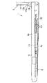
図1は、電子機器としてのブック形のポータブルコンピュータ1を開示している。このポータブルコンピュータ1は、コンピュータ本体2と、このコンピュータ本体2に支持されたディスプレイユニット3とを備えている。
【0029】
コンピュータ本体2は、箱状の筐体4を有している。この筐体4は、マグネシウム合金のような熱伝導性を有する金属材料にて構成されている。筐体4は、底壁4aと、この底壁4aと向かい合う上壁4bと、これら底壁4aと後壁4bとを結ぶ周壁としての前壁4c、左右の側壁4dおよび後壁(図示せず)とを有している。そして、この筐体4は、厚み寸法が20mm程度に定められており、従来一般的なポータブルコンピュータに比べて薄型化が強化されている。
【0030】
筐体4の上壁4bは、パームレスト6とキーボード装着口7とを有している。パームレスト6は、上壁4bの前半部において筐体4の幅方向に沿って延びている。キーボード装着口7は、筐体4の内部に向けて凹むような凹所にて構成され、このキーボード装着口7には、キーボード8が取り付けられている。
【0031】
図3に示すように、キーボード8は、合成樹脂製のキーボードベース9と、多数のキー10とを備えている。キーボードベース9は、キーボード装着口7にきっちりと嵌まり込むような大きさを有する長方形の板状をなしており、このキーボードベース9の上面にキー10が配置されている。キーボードベース9の下面は、金属製の補強板11によって覆われている。この補強板11は、筐体4の内部に露出されている。
【0032】
図1に示すように、筐体4の上壁4bは、上向きに突出する一対のディスプレイ支持部13a,13bを有している。ディスプレイ支持部13a,13bは、上壁4bの後端部において、筐体4の幅方向に互いに離間して配置されている。
【0033】
ディスプレイユニット3は、偏平な箱状のディスプレイハウジング14と、このディスプレイハウジング14に収容された液晶表示装置15とを備えている。ディスプレイハウジング14は、表示用開口部16が形成された前面を有している。液晶表示装置15は、文字や画像等が表示される表示画面15aを有し、この表示画面15aは、表示用開口部16を通じてディスプレイハウジング14の外方に露出されている。
【0034】
ディスプレイハウジング14は、一対の脚部17a,17bを有している。脚部17a,17bは、ディスプレイ支持部13a,13bに導かれているとともに、ヒンジ装置18(図2に示す)を介して筐体4に回動可能に支持されている。このため、ディスプレイユニット3は、パームレスト6やキーボード8を上方から覆うように倒される閉じ位置と、パームレスト6、キーボード8および表示画面15aを露出させる開き位置とに亘って選択的に回動し得るようになっている。
【0035】
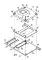
図1ないし図3に示すように、筐体4の内部には、第1および第2の回路基板21,22が収容されている。第1の回路基板21は、パームレスト6およびキーボード8の下方において、筐体4の底壁4aと平行に配置されている。第1の回路基板21は、その右側縁部と後縁部とで規定される角部に、図1に示すような切り欠き21aを有している。切り欠き21aは、キーボード8の右端部の下方に位置され、筐体4の右側の側壁4dに隣接されている。
【0036】
図3に最も良く示されるように、第2の回路基板22は、第1の回路基板21の切り欠き21aに対応した位置において、筐体4の底壁4aに沿って配置されている。第2の回路基板22は、第1の回路基板21よりも低い位置に設置されており、この第2の回路基板22の端部には、第1の回路基板21の下方に入り込む延長部23が形成されている。延長部23は、一対のスタッキングコネクタ24を介して第1の回路基板21に電気的に接続されている。
【0037】
第2の回路基板22は、表面25aと裏面25bとを有している。第2の回路基板22の裏面25bは、筐体4の底壁4aと向かい合っている。第2の回路基板22の表面25aは、図4に示すようなMPU実装領域27を有し、このMPU実装領域27は、筐体4の内部に臨んでいる。
【0038】
MPU実装領域27には、四つの通孔28が形成されている。通孔28は、四角形の角部の位置関係を保って配置されており、これら通孔28で囲まれた部分に第1のコネクタ29が実装されている。
【0039】
このMPU実装領域27には、MPUホルダ30が配置されている。MPUホルダ30は、金属製のフレーム31と、このフレーム31に固定された四つのボス部32とを有している。フレーム31は、平坦な板状をなしており、上記第2の回路基板22の表面25aに重ね合わされている。ボス部32は、上記通孔28に対応するように配置されているとともに、夫々MPU実装領域27の上方に向けて突出されている。
【0040】
図3および図4に示すように、MPU実装領域27には、上記MPUホルダ30を介して回路部品としてのMPU:microprocessing unit33が実装されている。MPU33は、マルチチップ・モジュール(以下MCMと称する)34と、このMCM34を収容するケース35とを備えている。
【0041】
MCM34は、多層構造の配線基板36と、この配線基板36の表面に実装されたBGA 形の半導体パッケージ37と、配線基板36の表面および裏面に実装された複数のQFP 形の半導体パッケージ38と、配線基板36の裏面に実装された第2のコネクタ39とを備えている。
【0042】
BGA 形の半導体パッケージ37は、ベース基板40とICチップ41とを有している。ベース基板40は、配線基板36の表面に実装されている。ICチップ41は、ベース基板40に多数の半田ボールを介してフリップチップ接続されている。このICチップ41は、文字、音声、画像のような多用なマルチメディア情報を処理するため、動作中の消費電力が大きくなっており、それに伴いICチップ41の発熱量も冷却を必要とする程に大きなものとなっている。
【0043】
上記ケース35は、アルミニウム合金のような熱伝導性に優れた金属材料にて構成されている。このケース35は、ケース本体44と、このケース本体44に嵌合された裏蓋45とを備え、全体として偏平な四角形の箱形をなしている。
【0044】
ケース本体44は、配線基板36の表面および半導体パッケージ37,38を覆っている。このケース本体44の四つの角部には、凹部46が形成されている。凹部46は、MPUホルダ30のボス部32に対応するもので、夫々挿通孔47を有している。そして、凹部46の底は、配線基板36の表面に接している。裏蓋45は、その外周縁部がケース本体44に取り外し可能に引っ掛かっており、配線基板36の裏面やそこに実装された半導体パッケージ38を覆っている。そして、裏蓋45は、ケース本体44の凹部46と協働して上記配線基板36を挟み込んでおり、このことにより、配線基板36とケース35とが一体化されている。
【0045】
配線基板36の第2のコネクタ39は、裏蓋45を貫通してケース35の外方に露出されている。第2のコネクタ39は、第1のコネクタ29に嵌合されており、この嵌合により、MPU33と第2の回路基板22とが電気的に接続されている。
【0046】
ケース35の裏蓋45は、MPUホルダ30に重ねられている。このMPUホルダ30のボス部32は、裏蓋45を貫通してケース35内に挿入されており、これらボス部32の先端が配線基板36の裏面に接している。
【0047】
図3や図4に示すように、ケース35のケース本体44は、発熱するICチップ41に対応する位置に開口部51を有している。開口部51は、ICチップ41よりも大きな開口形状を有し、この開口部51を通じてICチップ41がケース35の外方に露出されている。
【0048】
ところで、図7ないし図9に示すように、MPU33のケース35には、上記ICチップ41の放熱を促進させるための冷却装置53が取り付けられている。この冷却装置53は、ヒートシンク54、電動式のファンユニット55およびヒートパイプ56とを備えている。
【0049】
ヒートシンク54は、放熱板の一例であり、アルミニウム合金あるいは銅系合金のような熱伝導性に優れた金属材料にて構成されている。このヒートシンク54は、平坦な長方形の板状をなしており、上記筐体4の幅方向に沿って延びている。ヒートシンク54は、裏面58と、この裏面58の反対側に位置された表面59とを有している。
【0050】
図9に最も良く示されるように、ヒートシンク54は、受熱部60とファン取り付け部61とを備えている。これら受熱部60およびファン取り付け部61とは、ヒートシンク54の裏面58において筐体4の幅方向に沿って互いに並べて配置されている。受熱部60は、MPU33のケース35が重ね合わされる平坦な受熱面62を有している。この受熱面62には、下向きに僅かに突出する座部63が形成されている。座部63は、ケース本体44の開口部51と向かい合う平坦な座面63aを有し、この座面63aに熱伝導性のグリス64を介して発熱するICチップ41が熱的に接続されている。
【0051】
座部63の周囲には、受熱面62から下向きに突出する四つのボス部65が配置されている。ボス部65は、ケース本体44の凹部46に対応するもので、夫々のボス部63の先端が凹部46の底を貫通して配線基板36の表面に接している。これらボス部65は、凹部46の挿通孔47に連なるねじ挿通孔66を有し、これらねじ挿通孔66は、ヒートシンク54の表面59に開口されている。
【0052】
図8に示すように、受熱部60の二つのボス部65のねじ挿通孔66には、夫々ヒートシンク54の上方からねじ68が挿入されている。ねじ68は、凹部46の挿通孔47、配線基板36を貫通してMPUホルダ30のボス部32および第2の回路基板22の通孔28にねじ込まれている。また、図4に示すように、第2の回路基板22の残りの通孔28には、この第2の回路基板22の下方から他のねじ69が挿通されている。ねじ69は、配線基板36、凹部46の挿通孔47を貫通して受熱部60の残りのボス部65のねじ挿通孔66にねじ込まれている。
【0053】
そのため、図3や図7に示すように、ヒートシンク54と第2の回路基板22とは、MPU33を挟み込んだ状態で互いに結合されている。この結合により、MPU33が第2の回路基板22の表面25aに押し付けられ、第1のコネクタ29と第2のコネクタ39との嵌合状態が維持されるとともに、ヒートシンク54の受熱部60がMPU33に固定されている。
【0054】
図3や図5に示すように、ヒートシンク54のファン取り付け部61は、MPU33や第2の回路基板22の側方に突出されており、筐体4の底壁4aと向かい合っている。このファン取り付け部61は、平滑に仕上げられたガイド面71を有し、このガイド面71は、受熱部60に連なっている。
【0055】
ファン取り付け部61および受熱部60は、ヒートシンク54の周囲に張り出す複数のブラケット部72を有している。ブラケット部72は、図6に示すように、筐体4の底壁4aと向かい合うとともに、この底壁4aから上向きに延びる複数の取り付け座73にねじ74を介して固定されている。
【0056】
そのため、ヒートシンク54は、筐体4の底壁4aと平行に配置されており、そのファン取り付け部61のガイド面71が筐体4の右側の側壁4dに隣接した位置において、この筐体4の底壁4aと向かい合っている。
【0057】
図9や図10に示すように、上記ファンユニット55は、ファン取り付け部61のガイド面71に支持されている。ファンユニット55は、ファンケーシング76と、このファンケーシング76に支持されたファン77とを備えている。ファンケーシング76は、例えばアルミニウム合金のような熱伝導性に優れた金属材料にて構成されている。ファンケーシング76は、四つの角部を有する偏平な四角形の枠状をなしている。このファンケーシング76の厚み寸法は、上記MPU33のケース35の厚み寸法と略同等に定められている。そして、ファンケーシング76は、ファン取り付け部61のガイド面71に重ね合わされる平坦な支持面78を有し、この支持面78の中央部にファン収容部79が形成されている。
【0058】
ファン収容部79は、ファンケーシング76の厚み方向に凹む凹所にて構成されている。このファン収容部79は、上記支持面78の略全面に亘って開口された開口部80と、この開口部80と向かい合う底壁81と、この底壁81から開口部80の開口縁部に向かう周壁82とを有している。ファン収容部79の底壁81には、吸込口83が形成されている。吸込口83は、開口部80と向かい合っている。また、ファン収容部79の周壁82には、排出口84が形成されている。この排出口84は、開口部80に連なっている。
【0059】
吸込口83の内周縁部には、径方向内側に向けて延びる複数のステー86が形成されており、これらステー86の先端部に円盤状のモータ支持部87が形成されている。モータ支持部87は、偏平なDCブラシレスモータ88(図3に示す)を支持している。モータ88は、ファンケーシング76の厚み方向に延びる回転軸89を有している。このモータ88は、図示しないリード線を介して第2の回路基板22に電気的に接続されている。そして、モータ88は、MPU33の温度が予め決められた値に達した時に駆動されるようになっている。
【0060】
上記ファン77は、モータ88の回転軸89に支持されている。ファン77は、複数のブレード90を有し、これらブレード90の先端がファン収容部79の周壁82に隣接されている。そのため、ファン収容部79の排出口84は、ファン77の径方向外側に位置されており、上記吸込口83と略直交するような位置関係となっている。
【0061】
ファンケーシング76は、その四つの角部がねじ91を介してヒートシンク54のファン取り付け部61に固定されている。この固定により、ファンケーシング76の支持面78がファン取り付け部61のガイド面71に密接され、このガイド面71によってファン収容部79の開口部80が塞がれている。
【0062】
したがって、ヒートシンク54のガイド面71は、ファン77と向かい合うとともに、ファン収容部79の底壁81や周壁82と協働して送風通路92を構成しており、この送風通路92は、吸込口83や排出口84に連なっている。
【0063】
また、図9や図10に示すように、ファンケーシング76は、多数の放熱フィン93を有している。放熱フィン93は、ファン収容部79の吸込口83の周囲に位置されており、上記筐体4の内部に露出されている。
【0064】
図3に示すように、ファンユニット55は、開口部80および吸込口83を通る回転軸線O1 を有している。回転軸線O1 は、回転軸89の軸方向に延びている。そして、ファンユニット55は、上記回転軸線O1 をヒートシンク54のガイド面71と直交させた横置きの姿勢でガイド面71に固定されている。このため、ファンユニット55は、ヒートシンク54に沿うように配置されており、そのファンケーシング76の吸込口83が筐体4の底壁4aと僅かな隙間を存して向かい合っている。
【0065】
ファンケーシング76の排出口84は、上記MPU33とは反対側に位置されている。この排出口84は、筐体4の右側の側壁4dと向かい合っており、この側壁4dには、排気口94が形成されている。そのため、送風通路92は、排気口94を通じて筐体4の外方に通じている。
【0066】
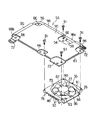
図7ないし図10に示すように、ヒートシンク54の表面59には、上記ヒートパイプ56を支持する伝熱板95が重ね合わされている。伝熱板95は、アルミニウム合金あるいは銅系合金のような熱伝導性に優れた金属材料にて構成されている。この伝熱板95は、上記ヒートシンク54の表面59に固定され、上記キーボード8の補強板11に近接もしくは接している。
【0067】
伝熱板95は、ヒートシンク54の周囲に張り出す複数の支持片96を有している。支持片96は、ヒートシンク54の受熱部60およびファン取り付け部61に対応した位置に形成されている。
【0068】
ヒートパイプ56は、ヒートシンク54の長軸方向の一辺に沿って延びる第1のパイプ部98aと、ヒートシンク54の短軸方向の一辺に沿って延びる第2のパイプ部98bとを有している。第1のパイプ部98aの一端および第2のパイプ部98bは、受熱部60の近傍に位置されているとともに、この第1のパイプ部98aの他端は、ファン取り付け部61の近傍に位置されている。そのため、ヒートパイプ97は、ヒートシンク54の受熱部60とファン取り付け部61とに跨って配置されている。
【0069】
このような構成のポータブルコンピュータ1において、MPU33のICチップ41が発熱すると、このICチップ41の熱は、グリス64を介してヒートシンク54の座部58に伝えられる。この熱は、座部58から受熱部60に逃がされるとともに、この受熱部60からファン取り付け部61に伝達される。
【0070】
また、本実施形態の場合は、ヒートシンク54にヒートパイプ56が接続されているので、ICチップ41から受熱部60に伝達された熱は、ヒートパイプ97を介して積極的にファン取り付け部61に移されることになる。そのため、受熱部60からファン取り付け部61への熱伝達経路が二系統となり、ファン取り付け部61への熱伝達が効率良く行われる。
【0071】
MPU33の温度が予め規定された値を上回ると、DCブラシレスモータ88を介してファン77が回転駆動される。このファン77の回転により、筐体4内の空気がファンケーシング76の吸込口83から送風通路92に吸い込まれ、この送風通路92を排出口84に向けて流れる。この空気の流れにより、ファンケーシング76およびヒートシンク54が強制的に冷却されるとともに、このヒートシンク54に伝えられた熱が空気流に乗じて外部に放出され、MPU33の放熱が促進される。そして、この送風通路92を流れる空気は、排出口84から排気口94を通じて筐体4の外方に放出される。
【0072】
この際、上記ファンユニット55のファンケーシング76は、吸込口83と向かい合う開口部80を有し、この開口部80がヒートシンク54のガイド面71によって塞がれている。そのため、ガイド面71は、ファンケーシング76と協働して送風通路92を構成しており、この送風通路92を流れる空気、つまり冷却風がヒートシンク54のガイド面71に直接吹き付けられる。
【0073】
したがって、ヒートシンク54とファンケーシング76との間に熱伝達を妨げるような熱抵抗が生じることはないとともに、ヒートシンク54自体を空気を媒体とする強制対流によって直接冷却することができ、このヒートシンク54に伝えられたICチップ41の熱を効率良く筐体4の外方に放出することができる。
【0074】
また、上記構成の場合、ヒートシンク54に固定されたファンケーシング76も熱伝導性に優れた金属材料にて構成されているので、ヒートシンク54の熱がファンケーシング76に効率良く伝えられ、このファンケーシング76をヒートシンク54の一部として活用することができる。
【0075】
しかも、ファンケーシング76は、筐体4の内部に露出された多数の放熱フィン93を有するので、ファンケーシング76の空気との接触面積が増大し、ファンケーシング76に伝えられた熱を筐体4の内部に効率良く放出することができる。したがって、MPU33の熱は、ヒートシンク54からファンケーシング76への拡散による自然空冷によっても外方に放出されることになり、上記ファンユニット55による強制空冷と合わせて、より効率良くMPU33を冷却することができる。
【0076】
それとともに、放熱フィン93は、吸込口83の周囲に位置するので、ファン77が回転駆動された際に、吸込口83に向かう空気の流れ経路上に放熱フィン93が位置される。このため、放熱フィン93が空気の流れに直接さらされることになり、ヒートシンクとして機能するファンケーシング76の放熱性能をより高めることができる。
【0077】
さらに、ファンケーシング76の開口部80を塞ぐヒートシンク74のガイド面71は、平滑な面に仕上げられているので、送風通路92内での空気の流れが滑らかとなる。そのため、送風通路92を流れる空気の流速を増大させることができ、その分、ヒートシンク74を効率良く冷却できるとともに、騒音を低く抑えることができる。
【0078】
また、上記構成のファンユニット55によると、そのファンケーシング76はヒートシンク54のガイド面71に向けてそのまま開放されているので、ファン77とヒートシンク54のガイド面71との間に介在されるような壁が存在せず、この壁の分だけファンケーシング76の厚み寸法を薄くすることができる。特にこのファンケーシング76厚み寸法は、MPU33のケース35の厚み寸法と略同等に定められているので、送風通路92をケース35の厚みの範囲内に収めることができる。
【0079】
加えて、MPU33とファンユニット55とは、筐体4の幅方向に互いに並べて配置され、この筐体4の内部での高さ位置が略同等に保たれているので、MPU33の上方にファンユニット55の設置スペースを確保する必要はない。したがって、ファンケーシング76を薄くできることと合わせて、MPU33の放熱効率を良好に維持しつつ、筐体4の薄型化にも無理なく対応できるといった利点がある。
【0080】
なお、本発明は上記第1の実施の形態に特定されるものではなく、図11に本発明の第2の実施の形態を示す。
この第2の実施の形態は、ファンユニット55をヒートシンク54に対し傾けて配置した点が上記第1の実施の形態と相違しており、それ以外のポータブルコンピュータ1の基本的な構成は、第1の実施の形態と同様である。そのため、第2の実施の形態において、第1の実施の形態と同一の構成部分には同一の参照符号を付して、その説明を省略する。
【0081】
図11に示すように、ヒートシンク54のガイド面71には、下向きに張り出すファン支持壁110が形成されている。ファン支持壁110は、ファンケーシング76に対応するような枠状をなしている。このファン支持壁110は、ファンケーシング76の支持面78が重ね合わされる取り付け面111を有し、この取り付け面111にファンケーシング76がねじ止めされている。
【0082】
ファン支持壁110の取り付け面111は、筐体4の右側の側壁4dの方向に進むに従い下方に張り出すように傾斜されている。そのため、取り付け面111にファンケーシング76を固定した状態では、ファン77の回転軸線O1 は、筐体4の上方に進むに従い筐体4の右側に倒れ込むように、鉛直線Vに対し角度αの傾きを以って傾斜されている。この傾斜により、ファンケーシング76の吸込口83と底壁4aとの間隔が部分的に広げられている。
【0083】
なお、このファンケーシング76の傾斜角度αは、筐体4の厚み寸法に影響を及ぼすので、この筐体4の薄型化を考慮すると、α=5〜10°程度とすることが望ましい。
【0084】
このような構成によれば、ファンケーシング76を縁直線Vに対し所定の角度傾けた姿勢で筐体4の内部に収容したので、吸込口83と筐体4の底壁4aとの間隔を部分的に広げることができる。このため、筐体4内の空気が吸込口83に流れ込む際の抵抗が軽減され、より多くの空気を送風通路92に導くことができる。よって、空気を媒体とする強制対流により、ヒートシンク54を効率良く冷却することができ、MPU33の放熱効果を高めることができる。
【0085】
なお、上記第1の実施の形態においては、送風通路を構成するヒートシンクのガイド面を平滑な面としたが、本発明はこれに限らず、このガイド面上に多数の凹凸からなる放熱フィンを形成し、ガイド面と空気との接触面積を増やすことで、ヒートシンクの放熱性を高めるようにしても良い。
【0086】
また、ヒートシンク自体の熱伝導により、その受熱部からファン取り付け部に充分に熱を逃がすことができれば、ヒートパイプによる補助的な熱の移送は不要となるので、このヒートパイプを省略しても良い。
【0087】
【発明の効果】
以上詳述した本発明によれば、吸込口から吸い込まれた空気が放熱板に直接吹き付けられるので、放熱板とフィンケーシングとの間に熱伝達を妨げるような熱抵抗が生じることはなく、放熱板を空気を媒体とする強制対流により効率良く冷却することができる。よって、回路部品の放熱性能を高めることができ、充分な冷却能力を確保することができる。
【図面の簡単な説明】
【図1】本発明の第1の実施の形態に係るポータブルコンピュータの斜視図。
【図2】ポータブルコンピュータの側面図。
【図3】MPUと冷却装置の位置関係を示すポータブルコンピュータの断面図。
【図4】第2の回路基板からMPUを取り外した状態を示す斜視図。
【図5】冷却装置を筐体に組み込んだ状態を示す平面図。
【図6】図5の5F−5F線に沿う断面図。
【図7】MPUに冷却装置を取り付けた状態を示す斜視図。
【図8】MPUから冷却装置を取り外した状態を示す斜視図。
【図9】MPUから冷却装置を取り外した状態を示す斜視図。
【図10】ヒートシンクからファンユニットを取り外した状態を示す斜視図。
【図11】本発明の第2の実施の形態に係るポータブルコンピュータの断面図。
【符号の説明】
4…筐体、33…回路部品(MPU)、54…放熱板、55…ファンユニット、60…受熱部、61…ファン取り付け部、76…ファンケーシング、77…ファン、80…開口部、83…吸込口。 [0001]
BACKGROUND OF THE INVENTION
The present invention relates to a cooling device that promotes heat dissipation of a circuit component such as a semiconductor package, and an electronic device equipped with the cooling device.
[0002]
[Prior art]
2. Description of the Related Art In recent years, portable electronic devices represented by book-type portable computers and mobile information devices process multi-purpose multimedia information such as characters, sounds, and images, so that the processing speed of MPU (microprocessing unit) is high. And more and more functions are being promoted. With this type of MPU, power consumption continues to increase with higher integration and higher performance, and the amount of heat generated during operation tends to increase rapidly in proportion thereto.
[0003]
For this reason, in order to accommodate an MPU having a large amount of heat generation in the casing of a portable computer, it is necessary to improve the heat dissipation of the MPU inside the casing. Therefore, like an electric fan unit or heat sink. A cooling means dedicated to MPU is becoming an indispensable existence.
[0004]
As a conventional MPU cooling system, a heat sink having a fan unit is installed on the upper surface of the MPU. The heat sink has a base that is superimposed on the upper surface of the MPU, and a fan unit is disposed on the upper surface of the base. The fan unit includes a flat fan casing that supports the fan. The fan casing has a bottom wall overlaid on the upper surface of the base, a suction port facing the bottom wall, and a discharge port connected to the suction port. The fan casing is supported by the base in a horizontal posture in which the rotation axis of the fan is orthogonal to the MPU in order to achieve a thin heat sink.
[0005]
For this reason, when the fan unit is driven, the air sucked from the suction port of the fan casing flows toward the bottom wall, and the flow direction of the air is changed along the bottom wall, and then through the discharge port. Discharged. As a result, the heat of the MPU is released from the base of the heat sink to the bottom wall of the fan casing, and then released to the outside through the air flow, thereby promoting the heat dissipation of the MPU.
[0006]
[Problems to be solved by the invention]
According to the conventional cooling method, since the heat sink is overlaid on the upper surface of the MPU, the overall thickness dimension including the MPU and the heat sink is increased. Then, since recent portable computers have been strengthened in thickness for the purpose of improving portability, a space for installing a heat sink or a fan unit cannot be secured above the MPU. For this reason, the conventional cooling method has a problem that a heat sink cannot be accommodated in the housing, and a new countermeasure is required.
[0007]
In addition, since the heat of the MPU is transmitted from the base to the bottom wall of the fan casing, a thermal resistance is generated at the contact portion between the base and the bottom wall. For this reason, it is difficult to efficiently transfer the heat of the MPU to the fan casing, and the MPU cooling performance is reduced accordingly.
[0008]
On the other hand, as a cooling method that can cope with the thinning of the housing, the fan unit and the MPU are arranged in a horizontal direction, a heat sink is attached to the MPU, and the heat sink and the fan casing of the fan unit are connected via a heat pipe. Thermally connected devices are known.
[0009]
According to this cooling system, the heat of the MPU is transmitted from the heat sink to the fan casing via the heat pipe, and then is released outward by multiplying the air flow accompanying the drive of the fan unit. Therefore, it is possible to release the heat of the MPU to the outside of the casing without overlapping the MPU and the fan unit, and it is possible to cope with the thinning of the casing.
[0010]
However, in this configuration, although the heat pipe itself can efficiently transfer heat, the end of the heat pipe is connected to the heat sink or fan casing, so depending on how this connection is made, the connection of the heat pipe Thermal resistance can occur in the part. For this reason, heat transfer from the MPU to the heat pipe and heat transfer from the heat pipe to the fan casing are hindered, and there is still room for improvement in improving the cooling performance of the MPU.
[0011]
The present invention was made based on such circumstances,Sufficient cooling performance for circuit componentsIt is an object of the present invention to provide a cooling device and an electronic apparatus having the cooling device.
[0012]
[Means for Solving the Problems]
In order to achieve the above object, a cooling device according to one aspect of the present invention includes:
A fan casing and a fan supported by the fan casing;With fan unit,
the aboveA fan mounting section where the fan unit is installed;FeverA heat receiving part to which the circuit components are thermally connectedA heat sink having,It has.
The fan casing isIt has a suction port for sucking air and an opening facing this suction port.Is characterized by being blocked by the heat sink.
[0013]
In such a configurationAccording to this, the air sucked from the suction port is directly blown to the heat sink that receives the heat of the circuit components. Therefore, thermal resistance that prevents heat transfer does not occur between the heat radiating plate and the fan casing, and the heat radiating plate itself can be directly cooled by forced convection using air as a medium. Therefore, the heat of the circuit component transmitted to the heat sink can be efficiently released to the outside, and the cooling performance of the circuit component can be enhanced.
[0028]
DETAILED DESCRIPTION OF THE INVENTION
A first embodiment of the present invention will be described below with reference to FIGS. 1 to 10 applied to a portable computer.
FIG. 1 discloses a book-type portable computer 1 as an electronic apparatus. The portable computer 1 includes a computer
[0029]
The computer
[0030]
The
[0031]
As shown in FIG. 3, the
[0032]
As shown in FIG. 1, the
[0033]
The
[0034]
The
[0035]
As shown in FIGS. 1 to 3, first and
[0036]
As best shown in FIG. 3, the
[0037]
The
[0038]
Four through
[0039]
An
[0040]
As shown in FIGS. 3 and 4, an MPU: microprocessing
[0041]
The
[0042]
The BGA type semiconductor package 37 has a
[0043]
The
[0044]
The case
[0045]
The second connector 39 of the
[0046]
A
[0047]
As shown in FIGS. 3 and 4, the case
[0048]
Incidentally, as shown in FIGS. 7 to 9, a
[0049]
The heat sink 54It is an example of a heat sink,It is comprised with the metal material excellent in thermal conductivity like an aluminum alloy or a copper-type alloy. The
[0050]
As best shown in FIG. 9, the
[0051]
Four
[0052]
As shown in FIG. 8, screws 68 are inserted into the screw insertion holes 66 of the two
[0053]
Therefore, as shown in FIGS. 3 and 7, the
[0054]
As shown in FIGS. 3 and 5, the
[0055]
The
[0056]
Therefore, the
[0057]
As shown in FIGS. 9 and 10, the
[0058]
The
[0059]
A plurality of
[0060]
The
[0061]
The four corners of the
[0062]
Accordingly, the
[0063]
Further, as shown in FIGS. 9 and 10, the
[0064]
As shown in FIG. 3, the
[0065]
A
[0066]
As shown in FIGS. 7 to 10, a
[0067]
The
[0068]
The
[0069]
In the portable computer 1 having such a configuration, when the
[0070]
In this embodiment, since the
[0071]
When the temperature of the
[0072]
At this time, the
[0073]
Therefore, there is no thermal resistance that prevents heat transfer between the
[0074]
In the case of the above configuration, since the
[0075]
Moreover, since the
[0076]
At the same time, since the radiating
[0077]
Furthermore, since the
[0078]
Further, according to the
[0079]
In addition, the
[0080]
The present invention is not limited to the first embodiment described above, and FIG. 11 shows a second embodiment of the present invention.
The second embodiment is different from the first embodiment in that the
[0081]
As shown in FIG. 11, a
[0082]
The mounting surface 111 of the
[0083]
Since the inclination angle α of the
[0084]
According to such a configuration, since the
[0085]
In the first embodiment described above, the guide surface of the heat sink constituting the air passage is a smooth surface. However, the present invention is not limited to this, and a heat radiating fin composed of a large number of irregularities is provided on the guide surface. The heat dissipation of the heat sink may be improved by forming and increasing the contact area between the guide surface and air.
[0086]
Further, if heat can be sufficiently released from the heat receiving portion to the fan mounting portion by heat conduction of the heat sink itself, auxiliary heat transfer by the heat pipe is not necessary, so this heat pipe may be omitted. .
[0087]
【The invention's effect】
According to the present invention described in detail above, the air sucked from the suction port isHeat sinkBecause it is sprayed directly onHeat sinkThere is no thermal resistance that prevents heat transfer between theHeat sinkCan be efficiently cooled by forced convection using air as a medium. Therefore, the heat dissipation performance of the circuit components can be enhanced and sufficient cooling capacity can be ensured.
[Brief description of the drawings]
FIG. 1 is a perspective view of a portable computer according to a first embodiment of the present invention.
FIG. 2 is a side view of a portable computer.
FIG. 3 is a cross-sectional view of a portable computer showing a positional relationship between an MPU and a cooling device.
FIG. 4 is a perspective view showing a state in which an MPU is removed from a second circuit board.
FIG. 5 is a plan view showing a state in which a cooling device is incorporated in a housing.
6 is a cross-sectional view taken along
FIG. 7 is a perspective view showing a state in which a cooling device is attached to the MPU.
FIG. 8 is a perspective view showing a state in which the cooling device is removed from the MPU.
FIG. 9 is a perspective view showing a state in which the cooling device is removed from the MPU.
FIG. 10 is a perspective view showing a state where the fan unit is removed from the heat sink.
FIG. 11 is a cross-sectional view of a portable computer according to a second embodiment of the present invention.
[Explanation of symbols]
DESCRIPTION OF
Claims (10)
上記ファンユニットが設置されるファン取り付け部と、発熱する回路部品が熱的に接続される受熱部とを有する放熱板と、を備え、
上記ファンケーシングは、空気を吸い込む吸込口と、この吸込口と向かい合う開口部を有し、この開口部は上記放熱板によって塞がれていることを特徴とする冷却装置。 A fan unit having a fan casing and a fan supported by the fan casing ;
Comprising a fan mounting portion in which the fan unit is installed, a heat dissipation plate and a heat receiving portion circuit component which generates heat are thermally connected, and
The fan casing has a suction port for sucking air and an opening facing the suction port, and the opening is closed by the heat radiating plate.
上記筐体に収容され、受熱部とファン取り付け部とを有する放熱板と、A heat sink housed in the housing and having a heat receiving portion and a fan mounting portion;
上記放熱板の受熱部に熱的に接続された発熱する回路部品と、A heat generating circuit component thermally connected to the heat receiving portion of the heat sink;
上記放熱板のファン取り付け部に設置されたファンユニットと、を備え、A fan unit installed on the fan mounting portion of the heat sink, and
上記ファンユニットは、ファンを支持するファンケーシングを有し、このファンケーシングは、空気を吸い込む吸込口と、この吸込口と向かい合う開口部とを有するとともに、この開口部が上記放熱板によって塞がれていることを特徴とする電子機器。The fan unit has a fan casing that supports the fan. The fan casing has a suction port for sucking air and an opening facing the suction port, and the opening is closed by the heat radiating plate. An electronic device characterized by that.
Priority Applications (2)
| Application Number | Priority Date | Filing Date | Title |
|---|---|---|---|
| JP17597098A JP4015754B2 (en) | 1998-06-23 | 1998-06-23 | Cooling device and electronic device having cooling device |
| US09/337,752 US6049455A (en) | 1998-06-23 | 1999-06-22 | Cooling unit for cooling a heat-generating components and electronic apparatus having the cooling unit |
Applications Claiming Priority (1)
| Application Number | Priority Date | Filing Date | Title |
|---|---|---|---|
| JP17597098A JP4015754B2 (en) | 1998-06-23 | 1998-06-23 | Cooling device and electronic device having cooling device |
Publications (3)
| Publication Number | Publication Date |
|---|---|
| JP2000013070A JP2000013070A (en) | 2000-01-14 |
| JP2000013070A5 JP2000013070A5 (en) | 2005-10-20 |
| JP4015754B2 true JP4015754B2 (en) | 2007-11-28 |
Family
ID=16005440
Family Applications (1)
| Application Number | Title | Priority Date | Filing Date |
|---|---|---|---|
| JP17597098A Expired - Lifetime JP4015754B2 (en) | 1998-06-23 | 1998-06-23 | Cooling device and electronic device having cooling device |
Country Status (2)
| Country | Link |
|---|---|
| US (1) | US6049455A (en) |
| JP (1) | JP4015754B2 (en) |
Families Citing this family (39)
| Publication number | Priority date | Publication date | Assignee | Title |
|---|---|---|---|---|
| JP4119008B2 (en) * | 1998-06-23 | 2008-07-16 | 株式会社東芝 | Circuit component cooling device and electronic device |
| JP2000216575A (en) * | 1999-01-22 | 2000-08-04 | Toshiba Corp | Cooler and electronic apparatus incorporating it |
| JP3959495B2 (en) * | 1999-08-31 | 2007-08-15 | 富士通株式会社 | Information processing device |
| US6414844B1 (en) * | 1999-09-03 | 2002-07-02 | Matsushita Electric Industrial Co., Ltd. | Portable information processing apparatus |
| US6362956B2 (en) | 1999-10-04 | 2002-03-26 | Apple Computer, Inc. | Thermal management system |
| US6972953B1 (en) | 1999-10-04 | 2005-12-06 | Apple Computer, Inc. | Thermal management system |
| US6238181B1 (en) * | 1999-10-05 | 2001-05-29 | Andy Chen | Heat dissipating device for portable apparatus |
| US6411505B1 (en) * | 1999-11-12 | 2002-06-25 | Apple Computer, Inc. | Computer housing for a portable computer |
| JP4327320B2 (en) * | 2000-01-07 | 2009-09-09 | 株式会社東芝 | Electronics |
| GB2358521A (en) * | 2000-01-24 | 2001-07-25 | Chen Yang Shiau | Heat sink structure adapted for use in a computer housing |
| JP2001267771A (en) * | 2000-03-17 | 2001-09-28 | Hitachi Ltd | Electronic apparatus |
| JP4386219B2 (en) * | 2000-03-31 | 2009-12-16 | 富士通株式会社 | Heat dissipation mechanism and electronic device having the heat dissipation mechanism |
| JP3602771B2 (en) * | 2000-05-12 | 2004-12-15 | 富士通株式会社 | Portable electronic devices |
| US6328097B1 (en) * | 2000-06-30 | 2001-12-11 | Intel Corporation | Integrated heat dissipation apparatus |
| US6704199B2 (en) | 2000-07-05 | 2004-03-09 | Network Engines, Inc. | Low profile equipment housing with angular fan |
| US6512673B1 (en) * | 2000-07-05 | 2003-01-28 | Network Engines, Inc. | Low profile equipment housing with angular fan |
| US6585485B2 (en) * | 2001-05-23 | 2003-07-01 | Sen-Yung Lee | Air flow guide device on heat dispensing fan |
| TW547702U (en) * | 2001-07-11 | 2003-08-11 | Quanta Comp Inc | Heat dissipating module and its fixing device |
| US6798647B2 (en) | 2001-07-16 | 2004-09-28 | Hewlett-Packard Development Company, L.P. | Portable computer with integrated PDA I/O docking cradle |
| US6754072B2 (en) | 2001-09-24 | 2004-06-22 | International Business Machines Corporation | Portable device for cooling a laptop computer |
| JP4167700B2 (en) * | 2006-05-31 | 2008-10-15 | 株式会社東芝 | Electronics |
| JP4796457B2 (en) * | 2006-08-16 | 2011-10-19 | 富士通株式会社 | Equipment, arithmetic unit and heat dissipation member |
| JP2008071855A (en) * | 2006-09-13 | 2008-03-27 | Fujitsu Ltd | Electronic apparatus, and printed circuit board unit |
| JP5113363B2 (en) * | 2006-09-28 | 2013-01-09 | 富士通株式会社 | Electronics |
| WO2008057342A2 (en) * | 2006-11-08 | 2008-05-15 | Wms Gaming Inc. | Gaming machine ventilation system |
| JP2008140058A (en) * | 2006-11-30 | 2008-06-19 | Toshiba Corp | Electronic device |
| CN101435438B (en) * | 2007-11-16 | 2012-06-13 | 富准精密工业(深圳)有限公司 | Fan base and heat radiation fan using the same |
| US8888450B2 (en) * | 2011-09-23 | 2014-11-18 | Brett W. Degner | Sculpted fan housing |
| JP2015504602A (en) * | 2011-11-15 | 2015-02-12 | ヘンケル アイピー アンド ホールディング ゲゼルシャフト ミット ベシュレンクテル ハフツング | Electronic devices assembled using thermal insulation layers |
| JP5991125B2 (en) * | 2012-09-28 | 2016-09-14 | 富士通株式会社 | Electronics |
| CN104684309A (en) * | 2013-11-29 | 2015-06-03 | 英业达科技有限公司 | Electronic device |
| JP6519985B2 (en) * | 2014-05-07 | 2019-05-29 | 日本電産株式会社 | Casing and blower |
| US9690324B2 (en) * | 2014-05-19 | 2017-06-27 | Lenovo (Beijing) Co., Ltd. | Electronic device and a switching method |
| WO2015178890A1 (en) * | 2014-05-20 | 2015-11-26 | Razer (Asia- Pacific) Pte. Ltd. | Housing for a computer system, parts of a housing for a computer system, and methods for increasing an airflow in a housing of a computer system |
| WO2022111452A1 (en) * | 2020-11-27 | 2022-06-02 | 深圳市蓝禾技术有限公司 | Portable fan |
| US11320876B1 (en) | 2020-12-07 | 2022-05-03 | Dell Products L.P. | Information handling system handle with integrated thermal rejection system |
| US11262821B1 (en) * | 2020-12-07 | 2022-03-01 | Dell Products L.P. | Information handling system with articulated cooling fins between interleaved and separated positions |
| US11733742B2 (en) | 2020-12-07 | 2023-08-22 | Dell Products L.P. | Information handling system integrated speaker with variable volume sound chamber |
| US11675401B2 (en) * | 2021-06-01 | 2023-06-13 | Dell Products L.P. | Thermal venting in a portable information handling system |
Family Cites Families (12)
| Publication number | Priority date | Publication date | Assignee | Title |
|---|---|---|---|---|
| JPH0887348A (en) * | 1994-09-14 | 1996-04-02 | Toshiba Corp | Portable electronic equipment |
| JP3786446B2 (en) * | 1995-03-31 | 2006-06-14 | 松下電器産業株式会社 | Blower |
| US5896917A (en) * | 1996-02-22 | 1999-04-27 | Lemont Aircraft Corporation | Active heat sink structure with flow augmenting rings and method for removing heat |
| JP3127821B2 (en) * | 1996-04-04 | 2001-01-29 | 松下電器産業株式会社 | Heat sink device |
| US5966286A (en) * | 1996-05-31 | 1999-10-12 | Intel Corporation | Cooling system for thin profile electronic and computer devices |
| JP3099740B2 (en) * | 1996-07-12 | 2000-10-16 | ティアック株式会社 | Built-in device and electronic device |
| JP3637176B2 (en) * | 1997-03-28 | 2005-04-13 | 株式会社東芝 | Electronics |
| US5959836A (en) * | 1997-04-23 | 1999-09-28 | Intel Corporation | Airflow heat exchanger for a portable computing device and docking station |
| US5898569A (en) * | 1997-04-25 | 1999-04-27 | Intel Corporation | Power cable heat exchanger for a computing device |
| US5946190A (en) * | 1997-08-29 | 1999-08-31 | Hewlett-Packard Company | Ducted high aspect ratio heatsink assembly |
| US5917699A (en) * | 1997-12-09 | 1999-06-29 | Compal Electronics Inc. | Heat-radiating device |
| DE29806082U1 (en) * | 1998-04-02 | 1998-06-18 | Ideal Electronics Inc | Cooling device for a central processing unit |
-
1998
- 1998-06-23 JP JP17597098A patent/JP4015754B2/en not_active Expired - Lifetime
-
1999
- 1999-06-22 US US09/337,752 patent/US6049455A/en not_active Expired - Lifetime
Also Published As
| Publication number | Publication date |
|---|---|
| US6049455A (en) | 2000-04-11 |
| JP2000013070A (en) | 2000-01-14 |
Similar Documents
| Publication | Publication Date | Title |
|---|---|---|
| JP4015754B2 (en) | Cooling device and electronic device having cooling device | |
| JP4119008B2 (en) | Circuit component cooling device and electronic device | |
| US7019970B2 (en) | Cooling device capable of reducing thickness of electronic apparatus | |
| JP3530151B2 (en) | Electronic device with built-in heating element and cooling device used for this electronic device | |
| US6353536B1 (en) | Electronic equipment system and extension device for expanding the functions of electronic equipment | |
| JP3673249B2 (en) | Electronic equipment and cooling device | |
| US6643129B2 (en) | Cooling unit including fan and plurality of air paths and electronic apparatus including the cooling unit | |
| JP3786446B2 (en) | Blower | |
| WO2004084600A1 (en) | Semiconductor module and cooling device | |
| TW200425825A (en) | Cooling part, substrate, and electronic machine | |
| JP2834996B2 (en) | heatsink | |
| KR20040044705A (en) | Cooling Apparatus, and Electric-Electronic Equipment with the Cooling Apparatus | |
| JP2000223876A (en) | Electronic apparatus | |
| JPH10303582A (en) | Cooing device of circuit module and portable information equipment mounting circuit module | |
| JP2003037383A (en) | Electronic equipment and air-cooled cooling device | |
| JPH11112174A (en) | Circuit module having heat dissipating means of circuit component and portable type information apparatus mounting the same | |
| JPH07321487A (en) | Cooling unit for board | |
| JP2003283171A (en) | Cooling structure for electronic circuit board | |
| JP2009086704A (en) | Electronic device | |
| JP2000214958A (en) | Electronic apparatus | |
| JP4171028B2 (en) | Electronics | |
| JP3827594B2 (en) | CPU cooling device | |
| JP2000013065A (en) | Electronic apparatus | |
| JPH11212673A (en) | Cooling device and portable information equipment having the same | |
| JP2003115570A (en) | Electronic apparatus |
Legal Events
| Date | Code | Title | Description |
|---|---|---|---|
| A521 | Written amendment |
Free format text: JAPANESE INTERMEDIATE CODE: A523 Effective date: 20050621 |
|
| A621 | Written request for application examination |
Free format text: JAPANESE INTERMEDIATE CODE: A621 Effective date: 20050621 |
|
| A977 | Report on retrieval |
Free format text: JAPANESE INTERMEDIATE CODE: A971007 Effective date: 20070829 |
|
| TRDD | Decision of grant or rejection written | ||
| A01 | Written decision to grant a patent or to grant a registration (utility model) |
Free format text: JAPANESE INTERMEDIATE CODE: A01 Effective date: 20070911 |
|
| A61 | First payment of annual fees (during grant procedure) |
Free format text: JAPANESE INTERMEDIATE CODE: A61 Effective date: 20070914 |
|
| FPAY | Renewal fee payment (event date is renewal date of database) |
Free format text: PAYMENT UNTIL: 20100921 Year of fee payment: 3 |
|
| R150 | Certificate of patent or registration of utility model |
Free format text: JAPANESE INTERMEDIATE CODE: R150 |
|
| FPAY | Renewal fee payment (event date is renewal date of database) |
Free format text: PAYMENT UNTIL: 20110921 Year of fee payment: 4 |
|
| FPAY | Renewal fee payment (event date is renewal date of database) |
Free format text: PAYMENT UNTIL: 20110921 Year of fee payment: 4 |
|
| FPAY | Renewal fee payment (event date is renewal date of database) |
Free format text: PAYMENT UNTIL: 20120921 Year of fee payment: 5 |
|
| FPAY | Renewal fee payment (event date is renewal date of database) |
Free format text: PAYMENT UNTIL: 20120921 Year of fee payment: 5 |
|
| FPAY | Renewal fee payment (event date is renewal date of database) |
Free format text: PAYMENT UNTIL: 20130921 Year of fee payment: 6 |
|
| EXPY | Cancellation because of completion of term |