US11675401B2 - Thermal venting in a portable information handling system - Google Patents
Thermal venting in a portable information handling system Download PDFInfo
- Publication number
- US11675401B2 US11675401B2 US17/335,315 US202117335315A US11675401B2 US 11675401 B2 US11675401 B2 US 11675401B2 US 202117335315 A US202117335315 A US 202117335315A US 11675401 B2 US11675401 B2 US 11675401B2
- Authority
- US
- United States
- Prior art keywords
- fan
- thermal
- information handling
- bottom cover
- handling system
- Prior art date
- Legal status (The legal status is an assumption and is not a legal conclusion. Google has not performed a legal analysis and makes no representation as to the accuracy of the status listed.)
- Active
Links
Images


Classifications
-
- G—PHYSICS
- G06—COMPUTING; CALCULATING OR COUNTING
- G06F—ELECTRIC DIGITAL DATA PROCESSING
- G06F1/00—Details not covered by groups G06F3/00 - G06F13/00 and G06F21/00
- G06F1/16—Constructional details or arrangements
- G06F1/20—Cooling means
- G06F1/206—Cooling means comprising thermal management
-
- G—PHYSICS
- G06—COMPUTING; CALCULATING OR COUNTING
- G06F—ELECTRIC DIGITAL DATA PROCESSING
- G06F1/00—Details not covered by groups G06F3/00 - G06F13/00 and G06F21/00
- G06F1/16—Constructional details or arrangements
- G06F1/20—Cooling means
- G06F1/203—Cooling means for portable computers, e.g. for laptops
-
- H—ELECTRICITY
- H05—ELECTRIC TECHNIQUES NOT OTHERWISE PROVIDED FOR
- H05K—PRINTED CIRCUITS; CASINGS OR CONSTRUCTIONAL DETAILS OF ELECTRIC APPARATUS; MANUFACTURE OF ASSEMBLAGES OF ELECTRICAL COMPONENTS
- H05K7/00—Constructional details common to different types of electric apparatus
- H05K7/20—Modifications to facilitate cooling, ventilating, or heating
- H05K7/20009—Modifications to facilitate cooling, ventilating, or heating using a gaseous coolant in electronic enclosures
- H05K7/20136—Forced ventilation, e.g. by fans
- H05K7/20145—Means for directing air flow, e.g. ducts, deflectors, plenum or guides
-
- H—ELECTRICITY
- H05—ELECTRIC TECHNIQUES NOT OTHERWISE PROVIDED FOR
- H05K—PRINTED CIRCUITS; CASINGS OR CONSTRUCTIONAL DETAILS OF ELECTRIC APPARATUS; MANUFACTURE OF ASSEMBLAGES OF ELECTRICAL COMPONENTS
- H05K7/00—Constructional details common to different types of electric apparatus
- H05K7/20—Modifications to facilitate cooling, ventilating, or heating
- H05K7/2039—Modifications to facilitate cooling, ventilating, or heating characterised by the heat transfer by conduction from the heat generating element to a dissipating body
-
- G—PHYSICS
- G06—COMPUTING; CALCULATING OR COUNTING
- G06F—ELECTRIC DIGITAL DATA PROCESSING
- G06F1/00—Details not covered by groups G06F3/00 - G06F13/00 and G06F21/00
- G06F1/16—Constructional details or arrangements
- G06F1/1613—Constructional details or arrangements for portable computers
- G06F1/1615—Constructional details or arrangements for portable computers with several enclosures having relative motions, each enclosure supporting at least one I/O or computing function
- G06F1/1616—Constructional details or arrangements for portable computers with several enclosures having relative motions, each enclosure supporting at least one I/O or computing function with folding flat displays, e.g. laptop computers or notebooks having a clamshell configuration, with body parts pivoting to an open position around an axis parallel to the plane they define in closed position
Definitions
- the present invention relates to information handling systems. More specifically, embodiments of the invention relate to thermal venting in a portable information handling system.
- An information handling system generally processes, compiles, stores, and/or communicates information or data for business, personal, or other purposes thereby allowing users to take advantage of the value of the information.
- information handling systems may also vary regarding what information is handled, how the information is handled, how much information is processed, stored, or communicated, and how quickly and efficiently the information may be processed, stored, or communicated.
- the variations in information handling systems allow for information handling systems to be general or configured for a specific user or specific use such as financial transaction processing, airline reservations, enterprise data storage, or global communications.
- information handling systems may include a variety of hardware and software components that may be configured to process, store, and communicate information and may include one or more computer systems, data storage systems, and networking systems.
- the invention relates to a main housing portion of a portable information handing system, comprising: a top cover portion; a bottom cover portion; and, an internal air intake ducting system, the internal air intake ducting system comprising a fan and a thermal channeling component thermally coupled to the fan, the thermal channeling component extending from an interior of a side of the bottom cover portion to the fan, the thermal channeling component and the bottom cover portion defining an air channel between the side of the bottom cover portion and the fan.
- the invention in another embodiment relates to an information handling system comprising: a processor; a data bus coupled to the processor; and an information handling system chassis housing, the housing comprising a base chassis, the base chassis housing the processor, the base chassis comprising a top cover portion; a bottom cover portion; and, an internal air intake ducting system, the internal air intake ducting system comprising a fan and a thermal channeling component thermally coupled to the fan, the thermal channeling component extending from an interior of a side of the bottom cover portion to the fan, the thermal channeling component and the bottom cover portion defining an air channel between the side of the bottom cover portion and the fan.
- FIG. 1 shows a general illustration of components of an information handling system as implemented in the system and method of the present invention.
- FIG. 2 shows a perspective view of an example portable information handling system.
- FIG. 3 shows a blown-up view of a portable information handling system.
- FIG. 4 shows a block diagram view cross sectional of a portable information handling system incorporating internal air intake ducting according to an embodiment of the disclosure.
- FIG. 5 shows a block diagram cross sectional view of a portable information handling system incorporating internal air intake ducting according to another embodiment of the disclosure.
- FIG. 6 shows a block diagram cross sectional view of a portable information handling system incorporating internal air intake ducting according to another embodiment of the disclosure.
- FIG. 7 shows a bottom view of a portable information handling system incorporating internal air intake ducting.
- FIGS. 8 A and 8 B show side views of a portable information handling system incorporating internal air intake ducting.
- FIG. 8 C shows a front view of a portable information handling system incorporating internal air intake ducting.
- FIG. 9 shows an example heat distribution across a cross section of a portable information handling system incorporating internal air intake ducting.
- FIG. 10 shows an example heat distribution of a C-Cover of a portable information handling system incorporating internal air intake ducting.
- FIG. 11 shows an example heat distribution of a D-Cover of a portable information handling system incorporating internal air intake ducting.
- FIG. 12 shows a table summarizing simulation results of a portable information handling system incorporating internal air intake ducting.
- FIG. 1 Various aspects of the present disclosure include an appreciation that portable information handling systems with higher performance requirements often require air intakes, tall bottom feet, internal spreaders, and in some cases, additional features on the product exterior to prevent recirculation of hot air leaving the system.
- Known bottom air intakes often require multiple slots to allow enough air into the system. These slots can weaken the bottom chassis structure and can also often require larger internal gaps to pass reliability requirements.
- bottom air intakes can be susceptible to blocking when the system is placed on a soft surface such as a pillow, bed or sheet which will drop the system performance.
- Various aspects of the present disclosure include an appreciation that portable information handling systems with higher performance requirements often require taller thermal feet to allow enough air intake. Taller thermal feet can result in an overall table to palmrest height which is undesirable. Depending on the fan design, additional ribs or side walls may need to be added to the bottom of the portable information handling system proximate to the bottom air intakes to prevent hot air from recirculating into the system via the bottom air intakes. Various aspects of the present disclosure include an appreciation that taller thermal feet and additional ribs can add cost to the system and may also detract from the appearance of the portable information handling system from an industrial design (ID) standpoint. Various aspects of the present disclosure include an appreciation that to achieve desired skin temperature requirements, portable information handling systems may also employ internal spreaders. The use of these internal spreaders can drive costs up depending on the material used and also drive internal gaps within the system.
- ID industrial design
- a thermal venting solution which allows for side thermal intake and does not rely on bottom venting, thermal feet, or air blocking ribs. Under certain conditions, the thermal venting solution can also remove a need for additional internal heat-spreaders. Additionally, the thermal venting solution enables a lower table to palmrest height while dropping the bottom skin temperatures relative to bottom vented systems at the same level of central processing unit/graphics processing unit (CPU/GPU) performance.
- the thermal venting solution attaches an internal enclosure (e.g., a channel cover) to the inside surface of the bottom chassis.
- the internal enclosure functions as a duct and can include formed channels designed specifically for a particular portable information handling system.
- the duct cover also functions as a heat spreader over hot components of the portable information handling system. Heat is drawn away from the components via the thermally conductive duct cover, thereby lowering the internal hot spot. In certain embodiments, the duct cover may induce a slight trade-off in CPU/GPU junction temperature (Tj).
- Tj CPU/GPU junction temperature
- the thermal venting solution includes a two-piece, side ducting enclosure affixed to the internal surface of a portable information handling system.
- the thermal venting solution provides an intake air management function and a heat spreading function.
- channel ducting patterns of the channel cover may be optimized for the thermal needs for a particular portable information handling system. For example, if certain areas of the system are hotter than others, more air can be redirected to the hot spot by varying the channel thickness between the bottom cover and the ducting cover.
- the thermal venting solution includes a nested fan.
- the nested fan is coupled to the ducting enclosure via a gasket.
- the gasket is a thermal gasket.
- Such a thermal venting solution allows for thinner system Z stackup. Such a thermal venting solution allows for improved overall skin temperatures/performance even when the device is placed on a soft surface such as a bed sheet, pillow, or comforter.
- an information handling system may include any instrumentality or aggregate of instrumentalities operable to compute, classify, process, transmit, receive, retrieve, originate, switch, store, display, manifest, detect, record, reproduce, handle, or utilize any form of information, intelligence, or data for business, scientific, control, or other purposes.
- an information handling system may be a personal computer, a network storage device, or any other suitable device and may vary in size, shape, performance, functionality, and price.
- the information handling system may include random access memory (RAM), one or more processing resources such as a central processing unit (CPU) or hardware or software control logic, ROM, and/or other types of nonvolatile memory.
- Additional components of the information handling system may include one or more disk drives, one or more network ports for communicating with external devices as well as various input and output (I/O) devices, such as a keyboard, a mouse, and a video display.
- the information handling system may also include one or more buses operable to transmit communications between the various hardware components.
- FIG. 1 is a generalized illustration of an information handling system 100 that can be used to implement the system and method of the present invention.
- the information handling system 100 includes a processor (e.g., central processor unit or “CPU”) 102 , input/output (I/O) devices 104 , such as a display, a keyboard, a mouse, a touchpad or touchscreen, and associated controllers, a hard drive or disk storage 106 , and various other subsystems 108 .
- the information handling system 100 also includes network port 110 operable to connect to a network 140 , which is likewise accessible by a service provider server 142 .
- the information handling system 100 likewise includes system memory 112 , which is interconnected to the foregoing via one or more buses 114 .
- System memory 112 further comprises operating system (OS) 116 and in various embodiments may also comprise at least one software application 118 .
- OS operating system
- the information handling system 100 is able to download the software application from the service provider server 142 .
- the software application 118 is provided as a service from the service provider server 142 .
- FIG. 2 shows a perspective view of an example portable information handling system chassis 200 such as a tablet type portable information handling system, a laptop type portable information handling system, or any other mobile information handling system. It will be appreciated that some or all of the components of the information handling system 100 may be included within information handling system chassis 200 .
- the portable information handling system 200 chassis includes a base chassis 202 and a display chassis 204 shown in an open configuration. It will be appreciated that a closed configuration would have the display chassis 204 fully closed onto the base chassis 202 .
- the base chassis 202 or the display chassis 204 of the information handling system 200 may comprise an outer metal case or shell.
- the information handling system 200 may include a plurality of chassis portions.
- the information handling system 200 may include some or all of an A-Cover 210 , a B-Cover 212 , a C-cover 214 and a D-Cover 216 .
- the A-Cover 210 and the B-Cover 212 provide the display chassis 204 .
- the C-Cover 214 and the D-Cover 216 provide the base chassis 202 .
- the A-cover 210 encloses a portion of the display chassis 204 of the information handling system 200 .
- the B-cover 212 encloses another portion of the display chassis 204 of the information handling system 200 .
- the B-Cover may include a display screen 217 and a bezel 218 around the display screen.
- the C-cover 214 encloses a portion of the base chassis 202 of the information handling system 200 .
- the C-cover 214 may include, for example, a keyboard 222 , a trackpad 224 , or other input/output (I/O) device.
- certain components of the information handling system such as a mother board are mounted within the C-Cover 214 .
- the D-cover 216 encloses another portion of the base chassis 202 of the information handling system 200 .
- the A-cover 202 When placed in the closed configuration, the A-cover 202 forms a top outer protective shell, or a portion of a lid, for the information handling system 200 , while the D-cover 204 forms a bottom outer protective shell, or a portion of a base, for the information handling system.
- the A-cover 202 and the D-cover 204 When in the fully closed configuration, the A-cover 202 and the D-cover 204 would be substantially parallel to one another.
- both the A-cover 202 and the D-cover 204 may be comprised entirely of metal.
- the A-cover 202 and D-cover 204 may include both metallic and plastic components.
- plastic components that are radio-frequency (RF) transparent may be used to form a portion of the C-cover 208 .
- the A-cover 202 may be movably connected to a back edge of the D-cover 204 via one or more hinges. In this configuration, the hinges allow the A-cover 202 to rotate from and to the D-cover 204 allowing for multiple orientations of the information handling system 200 .
- the information handling system may include a sensor to detect the orientation of the information handling system and activate or deactivate any number of antenna systems based on the occurrence of any specific orientation.
- the information handling system may be a laptop with limited rotation of the A-cover 204 with regard to the D-cover 204 , for example up to 180° rotation arc.
- the information handling system 200 may be a convertible information handling system with full rotation to a tablet configuration.
- FIG. 3 shows a blown-up view of a portable information handling system 300 having rotationally-coupled housing portions.
- a main housing portion 310 (which corresponds to a base chassis 202 ) rotationally couples to a lid housing portion 312 (which corresponds to a display chassis 204 ) to support various configurations to interact with an end user.
- Main housing portion 310 may hold one or more components of the portable information handling system, including but not limited to processor 102 , system bus 114 , memory subsystem 112 , I/O subsystem 104 and network interface 110 discussed with respect to FIG. 1 .
- Main housing portion 310 includes a top cover portion 320 (which includes the C-Cover 214 ) and a bottom cover portion 322 (which includes the D-Cover 216 ).
- Lid housing portion 312 includes a display cover portion 314 (which includes the B-Cover 210 ) and a rear display cover portion 316 (which includes the A-Cover 212 ).
- the top cover portion 320 may include an integrated keyboard 330 or other I/O devices, such as a trackpad 332 or microphone (not shown).
- the keyboard 330 may be mounted to the top of the C-Cover of the main housing portion 310 .
- the keyboard 330 may be mounted to the underside of the C-Cover of the main housing portion 310 .
- Lid housing portion 312 is rotationally coupled to main housing portion 310 via at least one hinge assembly 334 .
- Lid housing portion 212 includes display 340 that visually presents information to the user as well as a bezel 342 .
- Display 340 may be a touch panel with circuitry enabling touch functionality in conjunction with a display.
- display 340 may be an “infinity edge” or “narrow bezel” display that approaches one or more the edges of lid housing portion 212 such that bezel may be narrow in size (e. g., less than 10 millimeters) on the edges.
- display 340 is an infinity display with narrow bezels on the top and sides of lid housing portion 212 in the embodiment shown in FIG. 3 .
- the side bezel is less than 4 mm (+/ ⁇ 10%) and the top bezel is less than 6 mm (+/ ⁇ 10%).
- Lid housing portion 212 may also include timing controller (TCON) 350 .
- Hinge assembly 330 may include cable 352 for communicably coupling one or more components within main housing portion 310 to one or more components within lid housing portion 312 .
- cable 352 may provide communication of graphics information from an I/O subsystem to TCON 350 for generation of visual images for display on display 340 .
- portable information handling system 300 may include one or more additional cables 352 for communicating components disposed in main housing portion 310 and lid housing portion 312 . Placement of cable 352 may be selected based on design considerations, materials or manufacturing cost, material reliability, antenna placement, as well as any other considerations.
- Hinge assembly 334 allows main housing portion 310 and lid housing portion 312 to rotate between a plurality of positions. For example, when portable information handling system 300 is not in use, lid housing portion 312 may be closed over the top of main portion 310 such that display 340 and keyboard 330 are protected from unintended use or damage. Rotation of lid housing portion 312 by approximately 90 degrees from main housing portion 310 brings display 340 in a raised “clamshell” position relative to keyboard 330 so that an end user can make inputs to keyboard 330 or touch panel portion of display 340 while viewing display 340 .
- clamshell position may represent lid housing portion 212 open between approximately 1 and 180 degrees from main housing portion 310 .
- Rotation of lid housing portion 312 between approximately 180 and 359 degrees from main housing portion 310 may place portable information handling system 300 in “tablet stand” and/or “tent” positions.
- the user may make inputs via touch panel portion of display 340 while viewing display 340 .
- a full 360 degree rotation of main housing portion 310 relative to lid housing portion 312 provides a tablet configuration having display 340 exposed to accept touch inputs.
- user inputs may be communicated to an I/O subsystem or a processor of the portable information handling system 300 for processing, and then updated information may be communicated back via cable 352 to display 340 for displaying to the user.
- Hinge assembly 334 may be comprised of one or more discrete hinges or a unified assembly of hinges.
- FIG. 4 shows a block diagram cross sectional view of a portable information handling system 400 incorporating internal air intake ducting system 405 to an embodiment of the disclosure. More specifically, the internal air intake ducting system 405 is included within a main housing portion 410 of a portable information handling system.
- the main housing portion 410 includes a top cover portion 420 and a bottom cover portion 422 .
- the main housing portion 410 corresponds to main housing portion 310
- top cover portion 420 corresponds to top cover portion 320
- bottom cover portion 422 corresponds to bottom cover portion 322 .
- the internal air intake ducting system 405 includes thermal channeling component 430 , thermal channeling component 432 , fan 434 .
- the thermal channeling components 430 , 432 are thermally coupled to the fan 434 via gaskets 440 , 442 .
- the gaskets comprise thermal gaskets.
- the thermal channeling components 430 , 432 are constructed of thermally conductive material.
- the thermal channeling components 430 , 432 are constructed of metal.
- the top cover portion 420 includes a top cover 450 , a keyboard 452 and a keyboard support plate 454 .
- the bottom cover portion 422 includes a bottom cover 460 .
- the bottom cover 460 includes low profile feet. In certain embodiments, the bottom cover 460 does not have any feet.
- the thermal channeling components 430 , 432 are spaced from the bottom cover in the Z direction to provide an air flow channel from a side air vent 470 to the fan 434 .
- the side air vents 570 provide an air intake function.
- the internal air intake ducting system 405 allows for side thermal intake and does not rely on bottom venting, thermal feet, or air blocking ribs. In certain embodiments, the internal air intake ducting system 405 removes a need for additional internal heat-spreaders as the thermal channeling component 430 and thermal channeling component 432 function as heat spreaders. Additionally, the internal air intake ducting system 405 enables a lower table to palmrest height while dropping the bottom skin temperatures relative to bottom vented systems at the same level of central processing unit/graphics processing unit (CPU/GPU) performance. In certain embodiments, the internal air intake ducting system 405 attaches to the inside surface 462 of the bottom cover 460 .
- the internal enclosure functions as a duct and can include formed channels designed specifically for a particular portable information handling system. Heat is drawn away from components contained within the bottom cover portion via the thermally conductive thermal channeling components 430 , 432 .
- the duct cover may induce a slight trade-off in CPU/GPU Tj.
- the internal air intake ducting system 405 provides a two-piece, side ducting enclosure affixed to the internal surface of the bottom cover 460 .
- the internal air intake ducting system 405 provides an intake air management function and a heat spreading function.
- Such a internal air intake ducting system 405 allows for thinner system Z stackup.
- Such an internal air intake ducting system 405 allows for improved overall skin temperatures/performance even when the device is placed on a soft surface such as a bed sheet, pillow, or comforter.
- FIG. 5 shows a block diagram cross sectional view of a portable information handling system 500 incorporating internal air intake ducting system 505 to an embodiment of the disclosure. More specifically, the internal air intake ducting system 505 is included within a main housing portion 510 of a portable information handling system.
- the main housing portion 510 includes a top cover portion 520 and a bottom cover portion 522 .
- the main housing portion 510 corresponds to main housing portion 310
- top cover portion 520 corresponds to top cover portion 320
- bottom cover portion 522 corresponds to bottom cover portion 322 .
- the internal air intake ducting system 505 includes thermal channeling component 530 , thermal channeling component 532 , and fan 534 .
- the fan 534 includes fan sealing flange 536 and fan sealing flange 538 .
- the thermal channeling components 530 , 532 are thermally coupled to the fan 534 via gaskets 540 , 542 .
- the gaskets comprise thermal gaskets.
- the thermal channeling components 530 , 532 include respective step portions 544 , 546 .
- the step portion 544 , 546 are thermally coupled to the fan 534 via respective fan sealing flanges 536 , 538 .
- the thermal channeling components 530 , 532 are constructed of thermally conductive material.
- the thermal channeling components 530 , 532 are constructed of metal.
- the top cover portion 520 includes a top cover 550 , a keyboard 552 and a keyboard support plate 554 .
- the bottom cover portion 522 includes a bottom cover 560 .
- the bottom cover 560 includes low profile feet. In certain embodiments, the bottom cover 560 does not have any feet.
- the thermal channeling components 530 , 532 are spaced from the bottom cover in the Z direction to provide an air flow channel from a side air vent 570 to the fan 534 .
- the side air vents 570 provide an air intake function.
- the step portions 544 , 546 provide an increased air vent z dimension to provide additional air flow from the side intakes 570 .
- the internal air intake ducting system 505 allows for side thermal intake and does not rely on bottom venting, thermal feet, or air blocking ribs. In certain embodiments, the internal air intake ducting system 505 removes a need for additional internal heat-spreaders as the thermal channeling component 530 and thermal channeling component 532 function as heat spreaders. Additionally, the internal air intake ducting system 505 enables a lower table to palmrest height while dropping the bottom skin temperatures relative to bottom vented systems at the same level of central processing unit/graphics processing unit (CPU/GPU) performance. In certain embodiments, the internal air intake ducting system 505 attaches to the inside surface of the bottom cover 560 .
- the internal enclosure functions as a duct and can include formed channels designed specifically for a particular portable information handling system. Heat is drawn away from components contained within the bottom cover portion via the thermally conductive thermal channeling components 530 , 532 .
- the duct cover may induce a slight trade-off in CPU/GPU Tj.
- the internal air intake ducting system 505 provides a two-piece, side ducting enclosure affixed to the internal surface of the bottom cover 560 .
- the internal air intake ducting system 505 provides an intake air management function and a heat spreading function.
- Such a internal air intake ducting system 505 allows for thinner system Z stackup.
- Such an internal air intake ducting system 505 allows for improved overall skin temperatures/performance even when the device is placed on a soft surface such as a bed sheet, pillow, or comforter.
- FIG. 6 shows a block diagram cross sectional view of a portable information handling system 500 incorporating internal air intake ducting system 605 to an embodiment of the disclosure. More specifically, the internal air intake ducting system 605 is included within a main housing portion 610 of a portable information handling system.
- the main housing portion 610 includes a top cover portion 620 and a bottom cover portion 622 .
- the main housing portion 610 corresponds to main housing portion 310
- top cover portion 620 corresponds to top cover portion 320
- bottom cover portion 622 corresponds to bottom cover portion 322 .
- the internal air intake ducting system 605 includes thermal channeling component 630 , thermal channeling component 632 , fan 634 .
- the fan 634 includes fan thermal channeling component mounting portion 640 and fan thermal channeling component mounting portion 642 .
- the thermal channeling components 630 , 632 are thermally coupled to the fan 634 via respective fan thermal channeling component mounting portions 640 , 642 .
- the thermal channeling components 630 , 632 include respective step portions 644 , 646 .
- the step portions 644 , 646 are thermally coupled to the fan 634 via respective fan thermal channeling component mounting portions 640 , 642 .
- the fan thermal channeling component mounting portions 640 , 642 have a depth which corresponds to the height of the thermal channeling component so that the bottom of the thermal channeling component is substantially flush with the bottom of the fan.
- the thermal channeling components 630 , 632 are constructed of thermally conductive material. In certain embodiments, the thermal channeling components 630 , 632 are constructed of metal.
- the top cover portion 620 includes a top cover 650 , a keyboard 652 and a keyboard support plate 654 .
- the bottom cover portion 622 includes a bottom cover 660 .
- the bottom cover 660 includes low profile feet. In certain embodiments, the bottom cover 660 does not have any feet.
- the thermal channeling components 630 , 632 are spaced from the bottom cover in the Z direction to provide an air flow channel from a side air vent 670 to the fan 634 .
- the side air vents 570 provide an air intake function.
- the step portions 644 , 646 provide an increased air vent z dimension to provide additional air flow from the side air vents 570 .
- the internal air intake ducting system 605 allows for side thermal intake and does not rely on bottom venting, thermal feet, or air blocking ribs. In certain embodiments, the internal air intake ducting system 605 removes a need for additional internal heat-spreaders as the thermal channeling component 630 and thermal channeling component 632 function as heat spreaders. Additionally, the internal air intake ducting system 605 enables a lower table to palmrest height while dropping the bottom skin temperatures relative to bottom vented systems at the same level of central processing unit/graphics processing unit (CPU/GPU) performance. In certain embodiments, the internal air intake ducting system 605 attaches to the inside surface of the bottom cover 660 .
- the internal enclosure functions as a duct and can include formed channels designed specifically for a particular portable information handling system. Heat is drawn away from components contained within the bottom cover portion via the thermally conductive thermal channeling components 630 , 632 . In certain embodiments, the duct cover may induce a slight trade-off in CPU/GPU Tj.
- the internal air intake ducting system 605 provides a two-piece, side ducting enclosure affixed to the internal surface of the bottom cover 660 .
- the internal air intake ducting system 605 provides an intake air management function and a heat spreading function.
- Such an internal air intake ducting system 605 allows for thinner system Z stackup.
- Such an internal air intake ducting system 605 allows for improved overall skin temperatures/performance even when the device is placed on a soft surface such as a bed sheet, pillow, or comforter.
- FIG. 7 shows a bottom view of a portable information handling system 700 incorporating internal air intake ducting.
- an internal air intake ducting system such as incorporating internal air intake ducting system 405
- the information handling system may be configured with reduced front feet 710 , 712 as well as a reduced continuous rear foot 720 .
- the information handling system may be configured without feet.
- a table height of the information handling system can be reduced 1.5 mm (+/ ⁇ 20%) when compared with systems which do not incorporate such an internal air intake ducting system.
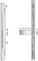
- FIGS. 8 A and 8 B show side views of a portable information handling system 800 incorporating internal air intake ducting.
- FIG. 8 C shows a front view of a portable information handling system incorporating internal air intake ducting.
- the portable information handling system 800 includes an angled side wall demarcation portion 810 .
- the angled side wall demarcation portion 810 extends downwardly from the front to the portable information handling system to the rear of the portable information handling system.
- the angled side wall demarcation portion 810 defines a boundary between a first side wall portion and a second side wall portion.
- the first side wall portion is substantially vertical.
- the second side wall portion extends inwardly from the first side wall portion.
- a side air intake 820 is integrated into and extends along the angled side wall demarcation portion 810 on each side of the portable information handling system 800 .
- FIG. 9 shows an example heat distribution across a cross section of a portable information handling system incorporating internal air intake ducting. More specifically, in the example heat distribution, internally generated heat of the portable information handling system is vented via the air intake vents such as one or more of the side wall air intakes and the front wall intake. In certain embodiments, the internally generated heat is vented from the air intakes via an air channel defined by the bottom cover and a thermal channeling component. In certain embodiments, the air channel has an air channel height of substantially 2.5 mm (e.g., +/ ⁇ 20%). In certain embodiments, the example heat distribution demonstrates the heat spreader function of the thermal channeling component.
- FIG. 10 shows an example heat distribution of a C-Cover of a portable information handling system incorporating internal air intake ducting. More specifically, in the example heat distribution, internally generated heat of the portable information handling system is distributed to the read edge of the portable information handling system and a side air output of the portable information handling system.
- FIG. 11 shows an example heat distribution of a D-Cover of a portable information handling system incorporating internal air intake ducting. More specifically, in the example heat distribution, internally generated heat of the portable information handling system is distributed to a bottom portion of the portable information handling system positioned below the main heat generating components, a read edge of the portable information handling system and a side air output of the portable information handling system.
- FIG. 12 shows a table summarizing simulation results of a portable information handling system incorporating internal air intake ducting. More specifically, incorporating an internal air intake ducting system such as incorporating internal air intake ducting system 405 , incorporating internal air intake ducting system 505 or incorporating internal air intake ducting system 605 , the information handling system includes a table height improvement of substantially ⁇ 1.5 mm (e.g., +/ ⁇ 20%), a base thickness improvement of substantially ⁇ 1.0 mm (e.g., +/ ⁇ 20%), a C Cover temperature of +0.3 C. (e.g., +/ ⁇ 20%), a D Cover temperature improvement of ⁇ 8.1 C. (e.g., +/ ⁇ 20%) and a heat pipe temperature of substantially 0.4 C. (e.g., +/ ⁇ 20%).
- the heat pipe temperature represents the temperature within the air channel defined by the bottom cover and a thermal channeling component.
Abstract
Description
Claims (12)
Priority Applications (1)
| Application Number | Priority Date | Filing Date | Title |
|---|---|---|---|
| US17/335,315 US11675401B2 (en) | 2021-06-01 | 2021-06-01 | Thermal venting in a portable information handling system |
Applications Claiming Priority (1)
| Application Number | Priority Date | Filing Date | Title |
|---|---|---|---|
| US17/335,315 US11675401B2 (en) | 2021-06-01 | 2021-06-01 | Thermal venting in a portable information handling system |
Publications (2)
| Publication Number | Publication Date |
|---|---|
| US20220382346A1 US20220382346A1 (en) | 2022-12-01 |
| US11675401B2 true US11675401B2 (en) | 2023-06-13 |
Family
ID=84194017
Family Applications (1)
| Application Number | Title | Priority Date | Filing Date |
|---|---|---|---|
| US17/335,315 Active US11675401B2 (en) | 2021-06-01 | 2021-06-01 | Thermal venting in a portable information handling system |
Country Status (1)
| Country | Link |
|---|---|
| US (1) | US11675401B2 (en) |
Citations (21)
| Publication number | Priority date | Publication date | Assignee | Title |
|---|---|---|---|---|
| US6049455A (en) * | 1998-06-23 | 2000-04-11 | Kabushiki Kaisha Toshiba | Cooling unit for cooling a heat-generating components and electronic apparatus having the cooling unit |
| US20020018337A1 (en) * | 2000-06-29 | 2002-02-14 | Hiroshi Nakamura | Electronic apparatus having heat sink for cooling heat generating component |
| US20020186532A1 (en) * | 2001-06-08 | 2002-12-12 | Kentaro Tomioka | Electronic apparatus having cooling unit for cooling heat-generating component |
| US20080019093A1 (en) * | 2006-05-31 | 2008-01-24 | Kabushiki Kaisha Toshiba | Electronic device |
| US20080030955A1 (en) * | 2006-08-01 | 2008-02-07 | Compal Electronics, Inc. | Waterproof thermal management module and portable |
| US20080112130A1 (en) * | 2006-10-30 | 2008-05-15 | Fusanobu Nakamura | Housing temperature suppressing structure in electronic device and portable computer |
| US20110222237A1 (en) * | 2010-03-15 | 2011-09-15 | Panasonic Corporation | Electronic apparatus provided with cooling structure |
| US20130022382A1 (en) * | 2011-07-22 | 2013-01-24 | Apple Inc. | Securing plugs for attaching computer components |
| US8379383B2 (en) * | 2009-10-02 | 2013-02-19 | Kabushiki Kaisha Toshiba | Electronic apparatus |
| US8553409B2 (en) * | 2008-06-27 | 2013-10-08 | Dell Products L.P. | System and method for portable information handling system parallel-wall thermal shield |
| US20130286292A1 (en) * | 2012-04-27 | 2013-10-31 | Kabushiki Kaisha Toshiba | Television receiver and electronic apparatus |
| US20130329934A1 (en) * | 2012-06-08 | 2013-12-12 | Apple Inc. | Speaker features of a portable computing device |
| US9232171B2 (en) * | 2012-05-25 | 2016-01-05 | Kabushiki Kaisha Toshiba | Electronic apparatus with cooling unit |
| US20160085273A1 (en) * | 2014-09-19 | 2016-03-24 | Microsoft Corporation | Computing device heat management |
| US9304558B2 (en) * | 2013-08-30 | 2016-04-05 | Kabushiki Kaisha Toshiba | Electronic apparatus |
| US20170273214A1 (en) * | 2016-03-15 | 2017-09-21 | Dell Products L.P. | Mechanically-Adjustable Supplemental Cooling Systems And Methods For Portable Information Handling Systems |
| US20190050031A1 (en) * | 2018-04-19 | 2019-02-14 | Intel Corporation | Thermal cooling system |
| US10423200B1 (en) * | 2018-10-11 | 2019-09-24 | Dell Products L.P. | Vapor chamber with integrated rotating impeller and methods for cooling information handling systems using the same |
| US10741157B2 (en) * | 2016-12-14 | 2020-08-11 | Samsung Electronics Co., Ltd. | Electronic device with soundproof structure |
| US20220129052A1 (en) * | 2020-10-26 | 2022-04-28 | Dell Products L.P. | Thermal Venting in Keyboard of a Portable Information Handling System |
| US11320876B1 (en) * | 2020-12-07 | 2022-05-03 | Dell Products L.P. | Information handling system handle with integrated thermal rejection system |
-
2021
- 2021-06-01 US US17/335,315 patent/US11675401B2/en active Active
Patent Citations (22)
| Publication number | Priority date | Publication date | Assignee | Title |
|---|---|---|---|---|
| US6049455A (en) * | 1998-06-23 | 2000-04-11 | Kabushiki Kaisha Toshiba | Cooling unit for cooling a heat-generating components and electronic apparatus having the cooling unit |
| US20020018337A1 (en) * | 2000-06-29 | 2002-02-14 | Hiroshi Nakamura | Electronic apparatus having heat sink for cooling heat generating component |
| US20020186532A1 (en) * | 2001-06-08 | 2002-12-12 | Kentaro Tomioka | Electronic apparatus having cooling unit for cooling heat-generating component |
| US20080019093A1 (en) * | 2006-05-31 | 2008-01-24 | Kabushiki Kaisha Toshiba | Electronic device |
| US20090103265A1 (en) * | 2006-05-31 | 2009-04-23 | Kabushiki Kaisha Toshiba | Electronic device |
| US20080030955A1 (en) * | 2006-08-01 | 2008-02-07 | Compal Electronics, Inc. | Waterproof thermal management module and portable |
| US20080112130A1 (en) * | 2006-10-30 | 2008-05-15 | Fusanobu Nakamura | Housing temperature suppressing structure in electronic device and portable computer |
| US8553409B2 (en) * | 2008-06-27 | 2013-10-08 | Dell Products L.P. | System and method for portable information handling system parallel-wall thermal shield |
| US8379383B2 (en) * | 2009-10-02 | 2013-02-19 | Kabushiki Kaisha Toshiba | Electronic apparatus |
| US20110222237A1 (en) * | 2010-03-15 | 2011-09-15 | Panasonic Corporation | Electronic apparatus provided with cooling structure |
| US20130022382A1 (en) * | 2011-07-22 | 2013-01-24 | Apple Inc. | Securing plugs for attaching computer components |
| US20130286292A1 (en) * | 2012-04-27 | 2013-10-31 | Kabushiki Kaisha Toshiba | Television receiver and electronic apparatus |
| US9232171B2 (en) * | 2012-05-25 | 2016-01-05 | Kabushiki Kaisha Toshiba | Electronic apparatus with cooling unit |
| US20130329934A1 (en) * | 2012-06-08 | 2013-12-12 | Apple Inc. | Speaker features of a portable computing device |
| US9304558B2 (en) * | 2013-08-30 | 2016-04-05 | Kabushiki Kaisha Toshiba | Electronic apparatus |
| US20160085273A1 (en) * | 2014-09-19 | 2016-03-24 | Microsoft Corporation | Computing device heat management |
| US20170273214A1 (en) * | 2016-03-15 | 2017-09-21 | Dell Products L.P. | Mechanically-Adjustable Supplemental Cooling Systems And Methods For Portable Information Handling Systems |
| US10741157B2 (en) * | 2016-12-14 | 2020-08-11 | Samsung Electronics Co., Ltd. | Electronic device with soundproof structure |
| US20190050031A1 (en) * | 2018-04-19 | 2019-02-14 | Intel Corporation | Thermal cooling system |
| US10423200B1 (en) * | 2018-10-11 | 2019-09-24 | Dell Products L.P. | Vapor chamber with integrated rotating impeller and methods for cooling information handling systems using the same |
| US20220129052A1 (en) * | 2020-10-26 | 2022-04-28 | Dell Products L.P. | Thermal Venting in Keyboard of a Portable Information Handling System |
| US11320876B1 (en) * | 2020-12-07 | 2022-05-03 | Dell Products L.P. | Information handling system handle with integrated thermal rejection system |
Also Published As
| Publication number | Publication date |
|---|---|
| US20220382346A1 (en) | 2022-12-01 |
Similar Documents
| Publication | Publication Date | Title |
|---|---|---|
| US11474560B2 (en) | Hinge configuration for an electronic device | |
| US20090168332A1 (en) | Air mover for device surface cooling | |
| US20210263553A1 (en) | Configurable all-in-one modular desktop computing system | |
| US20080123292A1 (en) | Reinforced Air Shroud | |
| US10317961B2 (en) | Electronic device having a bimetallic material | |
| JP2000516742A (en) | Thermally effective portable computer with deployable CPU module | |
| US7764514B2 (en) | Electromagnetic interference shielding for device cooling | |
| US7440277B2 (en) | Method and apparatus for venting a chassis | |
| US11507154B2 (en) | Thermal venting in keyboard of a portable information handling system | |
| US20080174957A1 (en) | Electronic device cooling system | |
| TWI501071B (en) | Heat dissipating case | |
| US8254119B2 (en) | Host computer attached to monitor | |
| US11675401B2 (en) | Thermal venting in a portable information handling system | |
| US10613598B2 (en) | Externally mounted component cooling system | |
| US6141215A (en) | Hybrid cooling heat exchanger fin geometry and orientation | |
| US20220269321A1 (en) | Automated Thermal Property Assignment Based on Surrounding Part Substrate | |
| US11347262B2 (en) | Display chassis cover design for narrow border portable information handling system | |
| US20240036621A1 (en) | Portable Information Handling System Antenna System | |
| US8194400B2 (en) | Electronic device | |
| US20200379290A1 (en) | Display assembly | |
| US11836008B2 (en) | Configurable component receptacle for use with information handling systems | |
| US11594805B2 (en) | Antenna integration in a portable information handling system | |
| US11347276B2 (en) | Cable routing in a portable information handling system | |
| US11243580B1 (en) | Camera integration in a portable information handling system | |
| US11910548B2 (en) | Fragmented cooling kickstand for information handling systems (IHSs) |
Legal Events
| Date | Code | Title | Description |
|---|---|---|---|
| AS | Assignment |
Owner name: DELL PRODUCTS L.P., TEXAS Free format text: ASSIGNMENT OF ASSIGNORS INTEREST;ASSIGNORS:HAMPTON, PATRICK A.;HE, QINGHONG;RAMIREZ, ERNESTO;SIGNING DATES FROM 20210527 TO 20210601;REEL/FRAME:056404/0980 |
|
| FEPP | Fee payment procedure |
Free format text: ENTITY STATUS SET TO UNDISCOUNTED (ORIGINAL EVENT CODE: BIG.); ENTITY STATUS OF PATENT OWNER: LARGE ENTITY |
|
| AS | Assignment |
Owner name: CREDIT SUISSE AG, CAYMAN ISLANDS BRANCH, NORTH CAROLINA Free format text: SECURITY AGREEMENT;ASSIGNORS:DELL PRODUCTS, L.P.;EMC IP HOLDING COMPANY LLC;REEL/FRAME:057682/0830 Effective date: 20211001 |
|
| AS | Assignment |
Owner name: THE BANK OF NEW YORK MELLON TRUST COMPANY, N.A., AS NOTES COLLATERAL AGENT, TEXAS Free format text: SECURITY INTEREST;ASSIGNORS:DELL PRODUCTS L.P.;EMC IP HOLDING COMPANY LLC;REEL/FRAME:057758/0286 Effective date: 20210908 Owner name: THE BANK OF NEW YORK MELLON TRUST COMPANY, N.A., AS NOTES COLLATERAL AGENT, TEXAS Free format text: SECURITY INTEREST;ASSIGNORS:DELL PRODUCTS L.P.;EMC IP HOLDING COMPANY LLC;REEL/FRAME:057931/0392 Effective date: 20210908 Owner name: THE BANK OF NEW YORK MELLON TRUST COMPANY, N.A., AS NOTES COLLATERAL AGENT, TEXAS Free format text: SECURITY INTEREST;ASSIGNORS:DELL PRODUCTS L.P.;EMC IP HOLDING COMPANY LLC;REEL/FRAME:058014/0560 Effective date: 20210908 |
|
| AS | Assignment |
Owner name: EMC IP HOLDING COMPANY LLC, TEXAS Free format text: RELEASE OF SECURITY INTEREST IN PATENTS PREVIOUSLY RECORDED AT REEL/FRAME (058014/0560);ASSIGNOR:THE BANK OF NEW YORK MELLON TRUST COMPANY, N.A., AS NOTES COLLATERAL AGENT;REEL/FRAME:062022/0473 Effective date: 20220329 Owner name: DELL PRODUCTS L.P., TEXAS Free format text: RELEASE OF SECURITY INTEREST IN PATENTS PREVIOUSLY RECORDED AT REEL/FRAME (058014/0560);ASSIGNOR:THE BANK OF NEW YORK MELLON TRUST COMPANY, N.A., AS NOTES COLLATERAL AGENT;REEL/FRAME:062022/0473 Effective date: 20220329 Owner name: EMC IP HOLDING COMPANY LLC, TEXAS Free format text: RELEASE OF SECURITY INTEREST IN PATENTS PREVIOUSLY RECORDED AT REEL/FRAME (057931/0392);ASSIGNOR:THE BANK OF NEW YORK MELLON TRUST COMPANY, N.A., AS NOTES COLLATERAL AGENT;REEL/FRAME:062022/0382 Effective date: 20220329 Owner name: DELL PRODUCTS L.P., TEXAS Free format text: RELEASE OF SECURITY INTEREST IN PATENTS PREVIOUSLY RECORDED AT REEL/FRAME (057931/0392);ASSIGNOR:THE BANK OF NEW YORK MELLON TRUST COMPANY, N.A., AS NOTES COLLATERAL AGENT;REEL/FRAME:062022/0382 Effective date: 20220329 Owner name: EMC IP HOLDING COMPANY LLC, TEXAS Free format text: RELEASE OF SECURITY INTEREST IN PATENTS PREVIOUSLY RECORDED AT REEL/FRAME (057758/0286);ASSIGNOR:THE BANK OF NEW YORK MELLON TRUST COMPANY, N.A., AS NOTES COLLATERAL AGENT;REEL/FRAME:061654/0064 Effective date: 20220329 Owner name: DELL PRODUCTS L.P., TEXAS Free format text: RELEASE OF SECURITY INTEREST IN PATENTS PREVIOUSLY RECORDED AT REEL/FRAME (057758/0286);ASSIGNOR:THE BANK OF NEW YORK MELLON TRUST COMPANY, N.A., AS NOTES COLLATERAL AGENT;REEL/FRAME:061654/0064 Effective date: 20220329 |
|
| STPP | Information on status: patent application and granting procedure in general |
Free format text: FINAL REJECTION MAILED |
|
| STCF | Information on status: patent grant |
Free format text: PATENTED CASE |