JP3885381B2 - Game image display method - Google Patents
Game image display method Download PDFInfo
- Publication number
- JP3885381B2 JP3885381B2 JP26214698A JP26214698A JP3885381B2 JP 3885381 B2 JP3885381 B2 JP 3885381B2 JP 26214698 A JP26214698 A JP 26214698A JP 26214698 A JP26214698 A JP 26214698A JP 3885381 B2 JP3885381 B2 JP 3885381B2
- Authority
- JP
- Japan
- Prior art keywords
- polygon
- ball
- game
- pitcher
- screen
- Prior art date
- Legal status (The legal status is an assumption and is not a legal conclusion. Google has not performed a legal analysis and makes no representation as to the accuracy of the status listed.)
- Expired - Fee Related
Links
Images


Classifications
-
- A—HUMAN NECESSITIES
- A63—SPORTS; GAMES; AMUSEMENTS
- A63F—CARD, BOARD, OR ROULETTE GAMES; INDOOR GAMES USING SMALL MOVING PLAYING BODIES; VIDEO GAMES; GAMES NOT OTHERWISE PROVIDED FOR
- A63F2300/00—Features of games using an electronically generated display having two or more dimensions, e.g. on a television screen, showing representations related to the game
- A63F2300/30—Features of games using an electronically generated display having two or more dimensions, e.g. on a television screen, showing representations related to the game characterized by output arrangements for receiving control signals generated by the game device
- A63F2300/303—Features of games using an electronically generated display having two or more dimensions, e.g. on a television screen, showing representations related to the game characterized by output arrangements for receiving control signals generated by the game device for displaying additional data, e.g. simulating a Head Up Display
- A63F2300/306—Features of games using an electronically generated display having two or more dimensions, e.g. on a television screen, showing representations related to the game characterized by output arrangements for receiving control signals generated by the game device for displaying additional data, e.g. simulating a Head Up Display for displaying a marker associated to an object or location in the game field
-
- A—HUMAN NECESSITIES
- A63—SPORTS; GAMES; AMUSEMENTS
- A63F—CARD, BOARD, OR ROULETTE GAMES; INDOOR GAMES USING SMALL MOVING PLAYING BODIES; VIDEO GAMES; GAMES NOT OTHERWISE PROVIDED FOR
- A63F2300/00—Features of games using an electronically generated display having two or more dimensions, e.g. on a television screen, showing representations related to the game
- A63F2300/80—Features of games using an electronically generated display having two or more dimensions, e.g. on a television screen, showing representations related to the game specially adapted for executing a specific type of game
- A63F2300/8011—Ball
Description
【0001】
【発明の属する技術分野】
本発明はゲームの画像表示方法及び制御方法に係り、特に野球ゲームに適したゲームの画像表示方法及び制御方法に関する。
【0002】
【従来の技術】
近年のコンピュータグラフィック技術の発達に伴い、アミューズメント施設におけるゲーム装置や、家庭用のビデオゲーム装置においても、三次元の立体的な画像表示を用いた、いわゆる3Dゲームが徐々に一般的になってきている。
野球ゲームは、最もポピュラーなスポーツゲームのひとつとして根強い人気があるゲームである。この野球ゲームにおいても三次元の立体的な画像表示を用いた3Dゲームが現れてきている。
【0003】
このような三次元表示可能ないわゆる3D野球ゲームの場合、上下左右の位置や動きはわかりやすいが、モニタ画面に対する奥行きの動きがわかりにくい。特に、野球ゲームにおける球はもともと小さいものであるため、その位置や動きが重要であるにもかかわらず、モニタ画面に対する奥行きの動きや遠近感をだして表示するのが非常に困難であった。
【0004】
また、3D野球ゲームにおいても、投手に対して、直球の他に、カーブやシュート等の様々な球種を使い分けることが可能であるが、表示画面上においては、球の位置が僅かに変わるだけであって、初心者にはほとんどわからなかった。このため球種をわかりやすく表現する新たな方法が待望されている。
一方、3D野球ゲームに限らず三次元表示のゲームにおいては、キャラクタ等をポリゴンにより表現している。キャラクタの各部分の形状をそれぞれポリゴンとして表現し、その位置や向きが変わったときでも、ポリゴンの位置や向きを変えて非連続のまま表現していた。このため、肩から腕にかけて服のラインがある場合であっても、ポリゴンが捻れた場合、非連続となってしまっていた。
【0005】
このため、ポリゴンの接続部分を滑らかに連続させるために、ポリゴンの端面同士を結んで連続した形状を形成しようとする提案が行われている。
例えば、キャラクタの腕を覆っているシャツの肩から袖の部分を表す場合には、変形しないシャツの袖と肩についてはポリゴンAとポリゴンBとで表し、その間の形状についてはポリゴンAの端面とポリゴンBの端面の頂点同士を接続することにより表そうというものである。
【0006】
図25(a)に示す2つのポリゴンAとポリゴンBの間の形状については、図25(b)に示すように、ポリゴンAの頂点a1、a2、…、a6とポリゴンBの頂点b1、b2、…、b6とをそれぞれ接続することにより、ポリゴンAとポリゴンB間の形状を形成している。
【0007】
【発明が解決しようとする課題】
ポリゴンAに対してポリゴンBが単に曲がる場合のように、ポリゴンAの頂点a1、a2、…、a6とポリゴンBの頂点b1、b2、…、b6同士が近接している場合には、自然な接続形状が得られる。しかしながら、図25(c)に示すように、ポリゴンBに対してポリゴンAが捻れる場合には、ポリゴンAとポリゴンB間に不自然な凹みが形成されてしまう。更に、図25(d)に示すように、ポリゴンBに対してポリゴンAが180度捻れると、ポリゴンAとポリゴンBの中間で太さがほとんどなくなってしまう非常に不自然な形状となってしまう。
【0008】
例えば、腕をぐるぐる回すような動きの場合には、肩のポリゴンBに対して袖のポリゴンAが捻れる関係にある。この動きを提案した方法で表すと、腕をぐるぐる回すと捻れの角度によって肩が細くなったり太くなったりする極めて不自然な形状となっていた。
本発明の目的は、モニタ画面に対する奥行きの動きや遠近感を表すことができるゲームの画像表示方法を提供することにある。
【0009】
本発明の他の目的は、野球の投手等が投げる球種の相違を初心者でもわかるように表現し、ゲームの臨場感を高めることができるゲームの画像表示方法を提供することにある。
本発明の更に他の目的は、捻れのあるポリゴン同士を自然な形状で接続することができるゲームの画像表示方法を提供することにある。
【0010】
【課題を解決するための手段】
上記目的は、ゲーム空間において移動する移動体を表示するゲームの画像表示方法であって、前記移動体がモニタ画面への表示面に対して近づく又は遠ざかる際には、前記移動体の周囲に補助表示体を表示し、前記移動体の前記モニタ表示面に対する距離に応じて前記補助表示体を変化させることを特徴とするゲームの画像表示方法によって達成される。
【0011】
上述したゲームの画像表示方法において、前記移動体の前記表示面に対する距離に応じて前記補助表示体の大きさを変化させるようにしてもよい。
上述したゲームの画像表示方法において、前記移動体の前記表示面に対する距離に応じて前記補助表示体の色を変化させるようにしてもよい。
上述したゲームの画像表示方法において、前記移動体が前記表示面に対して近づく際に、前記移動体の前記モニタ表示面に対する距離に応じて前記補助表示体の大きさを小さくすると共に、色を変化させるようにしてもよい。
【0012】
上記目的は、野球ゲームの画像表示方法であって、投手が投げた球がモニタ画面への表示面に対して近づく際には、前記球の周囲に補助表示体を表示し、前記補助表示体の大きさ及び/又は色を変化させることを特徴とする野球ゲームの画像表示方法によって達成される。
上述した野球ゲームの画像表示方法において、前記球が前記表示面に対して近づく際に、前記球の前記モニタ表示面に対する距離に応じて前記補助表示体の大きさを小さくすると共に、色を変化させるようにしてもよい。
【0013】
上記目的は、ゲーム空間において移動する移動体を表示するゲームの画像表示方法であって、モニタ画面への構図を、前記移動体の移動軌跡に基づいて変動させることを特徴とするゲームの画像表示方法によって達成される。
上述したゲームの画像表示方法において、前記モニタ画面への構図を、前記移動体の移動軌跡に基づいて、その注視点を中心として回転させるようにしてもよい。
【0014】
上述したゲームの画像表示方法において、前記モニタ画面への構図を、前記移動体の移動軌跡に基づいて、その注視点も含めて変動させるようにしてもよい。上記目的は、野球ゲームの画像表示方法であって、モニタ画面への構図を、投手が投げた球の球種に基づいて変動させることを特徴とする野球ゲームの画像表示方法によって達成される。
【0015】
上述した野球ゲームの画像表示方法において、投手が左右に変化する球を投げた場合には、前記モニタ画面への構図を、その注視点を中心として回転するようにしてもよい。
上述した野球ゲームの画像表示方法において、投手が上下に変化する球を投げた場合には、前記モニタ画面への構図を、その注視点を含めて上下に変動するようにしてもよい。
【0016】
上記目的は、相対的に位置を変動する第1のポリゴンと第2のポリゴンとが繋がっているように表示する画像表示方法であって、前記第1のポリゴンと前記第2のポリゴンとの間に第3のポリゴンを配置し、前記第1のポリゴンから前記第3のポリゴンを介して前記第2のポリゴンに繋げるように表示することを特徴とする画像表示方法によって達成される。
【0017】
上記目的は、相対的に位置を変動する第1のポリゴンと第2のポリゴンとが繋がっているように表示する画像表示方法であって、前記第1のポリゴンと前記第2のポリゴンの間に第3のポリゴンを配置し、前記第1のポリゴンの前記第3のポリゴン側の端面を、前記第3のポリゴンに投影した第1の投影面を求め、前記第2のポリゴンの前記第3のポリゴン側の端面を、前記第3のポリゴンに投影した第2の投影面を求め、前記第1のポリゴンの端面から、前記第3のポリゴンの前記第1の投影面の周囲及び前記第2の投影面の周囲を介して、前記第2のポリゴンの端面に達する接続曲線により前記第1のポリゴンと前記第2のポリゴンとを繋げることを特徴とする画像表示方法によって達成される。
【0018】
上述した画像表示方法において、前記接続曲線は、前記第1の投影面と前記第2の投影面との間において前記第3のポリゴン上に位置していてもよい。
上述した画像表示方法において、前記第3のポリゴンは、前記第1のポリゴンの前記端面の直径及び/又は前記第2のポリゴンの端面の直径にほぼ等しい直径の球形状のポリゴンであってもよい。
【0019】
【発明の実施の形態】
本発明の一実施形態によるゲーム装置を図面を用いて説明する。
(ゲーム装置の構成)
本実施形態のゲーム装置の構成を図1を用いて説明する。
ゲーム装置には、装置全体の制御を行う主制御部10と、ゲーム画面の表示制御を行う表示制御部12と、効果音等を生成する音声制御部14とが設けられている。
【0020】
主制御部10には、SCU(System Control Unit)100と、メインCPU102と、RAM104と、ROM106と、サブCPU108とが設けられ、バス110により相互接続されている。
SCU100には、バス112を介してゲームプログラムが格納されたゲームROM16が接続され、バス114を介して表示制御部12と音声制御部14が接続されている。SCU100は、バス110、112、114を介して、メインCPU、VDP120、130、DSP140、CPU142間相互のデータ入出力を制御する。
【0021】
メインCPU102は、内部にDSP(Digital Signal Processor)と同様の演算機能を備え、ゲームROM16内に格納されているゲームプログラムを高速に実行する。
RAM104は、メインCPU102のワークエリアとして使用される。ゲームプログラムやキャラクタデータが一時的に格納されている。
【0022】
ROM106は、初期化処理用のイニシャルプログラム等の各種ゲーム共通のプログラムやデータが格納されている。
サブCPU108にはコネクタ18を介して操作パネル20が接続されている。操作パネル20にはプレイヤが操作する操作ボタン等が設けられている。操作パネル20の詳細については後述する。サブCPU108は、SMPC(System Manager & Peripheral Control)と呼ばれ、メインCPU102からの要求に応じて、操作パネル20からの操作データを取り込み、メインCPU102に渡す機能を有している。
【0023】
メインCPU102は、サブCPU108から受け取った操作データに基づいて、例えば、ゲーム画面中のキャラクタの回転変換や透視変換等の画像制御を行う。画像制御の詳細については後述する。
表示制御部12には、ポリゴンデータからなるキャラクタや背景のポリゴン画面の描画を行う第1VDP120と、この第1VDP120に接続されたVRAM122及びフレームバッファ124、126と、スクロール背景画面の描画、表示優先順位(プライオリティ)に基づくポリゴン画像データとスクロール画像データとの画像合成、クリッピングを行う第2VDP130と、この第2VDP130に接続されたVRAM132及びメモリ134とが設けられている。第1VDP120と第2VDP130はバス114を介して接続されている。
【0024】
第1VDP120は、システムレジスタ120aを内蔵している。キャラクタを表すポリゴンの描画データはメインCPU102を介して第1VDP120に送られ、VRAM122に書き込まれる。VRAM122に書き込まれた描画データは、描画用のフレームバッファ122又は124に描画される。描画されたフレームバッファ122又は124のデータは、表示モード時に第2VDP130に送られる。このように、2つのフレームバッファ122、124を用いて、描画と表示をフレーム毎に切り換えるようにしている。
【0025】
一方、描画を制御する情報は、メインCPU102からSCU100を介して第1VDP120のシステムレジスタ120aに設定される。このシステムレジスタ120aに設定された制御情報にしたがって第1VDP120が描画と表示を制御する。
第2VDP130は、レジスタ130aとカラーRAM130bを内蔵している。画像データは、メインCPU102からSCU100を介してVRAM132とカラーRAM130bに定義される。画像表示を制御する情報も、メインCPU102からSCU100を介してレジスタ130aに設定される。VRAM132に定義されたデータは、第2VDP130のレジスタ130aに設定されている制御情報にしたがって読み出され、キャラクタに対する背景を表すスクロール画面の画像データとなる。各スクロール画面の画像データと第1VDP120から送られてきたキャラクタのポリゴンの画像データは、レジスタ130aに設定された制御情報にしたがって表示優先順位が決められ、最終的な表示画像データに合成される。
【0026】
第2VDP130により、表示画像データに基づいてカラーRAM130bに定義されているカラーデータが読み出され表示カラーデータが生成され、メモリ134に蓄えられる。
表示カラーデータはメモリ134に蓄えられた後、エンコーダ26に出力される。エンコーダ26は、画像データに同期信号などを付加して映像信号を生成し、モニタ28に出力する。モニタ28はゲーム画面を表示する。
【0027】
音声制御部14には、PCM方式又はFM方式により音声合成を行うDSP140と、このDSP140の制御を行うCPU142とが設けられている。DSP140により生成された音声データは、D/Aコンバータ22により音声信号に変換されスピーカ24から出力される。
(操作パネル)
次に、本実施形態のゲーム装置における操作パネルについて図2を用いて説明する。
【0028】
操作パネル20には、2人でプレイすることができるように、操作ボタン等を2セット設けている。操作パネル20の左側には第1プレイヤ用の操作ボタン等200Aが設けられ、操作パネル20の右側には第2プレイヤ用の操作ボタン等200Bが設けられている。操作ボタン等200A、200Bは同じ構成である。
【0029】
操作ボタン等200A、200Bの最も右側にはスタート/タイムボタン202が設けられている。スタート/タイムボタン202はゲームをスタートしたりゲームを一時停止したりする。ゲームが進行していないときにスタート/タイムボタン202を押すとゲームが開始し、ゲームが進行しているときにスタート/タイムボタンを押すとゲームが一時停止する。
【0030】
操作ボタン等200A、200Bの最も左側には8方向レバー204が設けられている。8方向レバー204を操作することにより、各操作場面において前後左右等の8つの方向を指示する。例えば、投球時には、8方向レバー204を操作することにより投手が投げる位置を指定する。また、守備時には、8方向レバー204を操作することにより送球・塁間移動の方向の指定を行う。また、打撃時には、8方向レバー204を操作することにより、打撃する位置を指定する。
【0031】
8方向レバー204の右側には2つの決定ボタンであるAボタン206、Bボタン208が設けられている。これらAボタン206、Bボタン208を用いて各操作場面において様々な指示を行う。詳細については後述する。
Aボタン206、Bボタン208の左側には、野球のバットを模したバット型スイッチ210が設けられている。バット型スイッチ210は、バット211が回動軸212を中心として回動する。バット211は、回動軸212を中心として左回りに回動するように付勢されていて、常時はストッパ(図示せず)に当接している。プレイヤが付勢力に抗してバット211を右回りに回し、その後、バット211から手を離すと、バット211は勢いよく左回りに戻り、ストッパ(図示せず)に当接して停止する。バット211が右回りに回すことができる限界を定めるためにストッパ(図示せず)が設けられている。
【0032】
バット型スイッチ210の裏側には、バット211の回動位置角度、回転速度を検出するために、例えば、回動軸212に磁石が固定された回動プレートが設けられ、磁石の回動軌跡に沿って複数のリードスイッチが設けられている。回動プレートが回動し、回動プレートの磁石が所定距離以内に近づくとリードスイッチは順次オンし、遠ざかると順次オフする。
【0033】
(ゲームの基本操作)
次に、本実施形態のゲーム装置の基本操作について説明する。
投球時には、8方向レバー204を用いて、投げる位置を示すピッチャカーソルを移動する。バット型スイッチ210により投球を指示し、Bボタン208により牽制を指示する。バット型スイッチ210の操作タイミングに合わせた投球となる。
【0034】
守備時には、8方向レバー204を用いて送球・塁間移動の指定を行う。8方向レバー204により送球方向や塁間移動方向を指定する。例えば、8方向レバー204を三塁方向にすることにより、三塁への送球の指示となる。Bボタン208により投球を指示する。なお、バット型スイッチ210は使用しない。
打撃時には、8方向レバー204を用いて、打撃位置を示すバッタカーソルを移動する。バット型スイッチ210により打撃の強さを指示する。基本的には、バット型スイッチ210のバット211の回動角により打撃強さを指示する。バット型スイッチ210の動作の詳細については後述する。
【0035】
走塁時には、8方向レバー204を用いて、進塁又は帰塁する際の塁指定を行う。8方向レバー204により進塁又は帰塁する方向を指示して塁を指定する。Aボタン206により進塁を指示し、Bボタン208により帰塁を指定する。なお、バット型スイッチ210は使用しない。
(ボールの奥行き位置の表示)
次に、本実施形態のゲーム装置におけるボールの奥行き位置の表示方法について図3乃至図8を用いて説明する。
【0036】
3次元空間を2次元のモニタ画面に投影する場合、一般に3次元空間内でのボールの位置の把握が難しい。特に、投手がボールを投げた場合のように、奥から手前に向かってボールが移動する場合には2次元のモニタ画面上では位置がほとんど変化しないため、その奥行きの位置を知ることが非常に難しかった。
本実施形態では、ボールの周囲に大きさと色が変化する円形のカーソルを表示するようにし、ボールがモニタ画面に近くなるに従って、カーソルの大きさを小さくすると共に色を変化させて、その奥行き位置を表示するようにしている。
【0037】
本実施形態の野球ゲームにおいて、投手がボールを投げた場合の表示画面を図3乃至図8に示す。
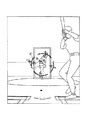
まず、投手が振りかぶってボールを投げようとする段階を図3に示す。この段階ではボールは投手が持っているので、ボールは表示されていない。
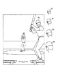
次に、投手がボールを投げると、図4に示すように、ボールBの周囲に大きな円形のカーソルCが表示される。その後、ボールBが近づいてくると、カーソルCは、図5、図6、図7、図8に示すように、徐々に大きさが小さくなり、ボールBに収れんしていく。このとき、カーソルCの色も、例えば、白から青、黄、赤と変化する。攻撃側のプレイヤは、カーソルCの大きさと色から打撃のタイミングを知ることができる。例えば、青の時に打てば引っ張り打ち、黄の時に打てばセンター返し、赤の時に打てば流し打ちというように打撃のタイミングのヒントとして活用することができる。
【0038】
このように本実施形態によれば投手が投げたボールの奥行きを目で見て確認することができ、その情報に基づいて打者はタイミングを取って打撃することができる。
なお、上記実施形態では、ボールが近づくにしたがってカーソルCの大きさを小さくしたが、逆に大きくしてもよいし、最初は近づくにしたがって途中まで大きくし、その後小さくするようにしてもよい。また、カーソルCの大きさの変化はボールBの奥行きの距離に応じて連続的に変化させてもよいし、段階的に変化させてもよい。
【0039】
また、カーソルの色についても、上記実施形態に限らず様々な態様で様々な色で変化させてもよい。
(ボールの球種の表示)
次に、本実施形態のゲーム装置におけるボールの球種の表示方法について図9乃至図15を用いて説明する。
【0040】
3次元空間を2次元のモニタ画面に投影する場合、一般に3次元空間内でのボールの位置の把握が難しい。特に、投手がボールを投げた場合のように、奥から手前に向かってボールが移動する場合には2次元のモニタ画面上では位置がほとんど変化しない。このため、投手が直球を投げても、カーブやフォーク等の変化球を投げても、2次元のモニタ画面上では僅かな位置の違いでしかなく、しかも、一瞬のうちに投球が出力してしまうため、投手が投げたボールの球種を知ることが非常に困難であった。
【0041】
本実施形態では、投手が投げたボールの軌跡、すなわち、ボールの球種に応じてモニタ画面の構図全体を変動させることにより、投手が投げたボールの球種を容易に判断できるようにしている。
例えば、投手が直球を投げた場合には、モニタ画面の構図を変動させないが、投手がカーブや、スライダー、シュート等の主として左右に変化する変化球を投げた場合には、モニタ画面の構図全体を回転させ、投手がフォークやナックル等の主として上下に変化する変化球を投げた場合には、モニタ画面の構図全体を上下に揺らすようにして、プレイヤが容易に球種を判断できるようにする。
【0042】
図9乃至図11は、投手がカーブを投げた場合のモニタ画面の構図の一具体例である。
投手がカーブを投げるべくボールをリリースすると、リリース時(位置P1)には図9上部の図に示すように、ゲーム画面の構図は傾いていない。リリース後、ボールが位置P2、位置P3、位置P4、位置P5と変化すると、この変化に応じてゲーム画面は、図9下部の図、図10上部の図、図10下部の図、図11上部の図と順次示すように、注視点を中心に回転し、ボールが打者の位置P6に達したときに、その回転角が最大となる。ゲーム画面の構図の回転角θは、図12に示すように、構図の注視点Oにおける回転角θとして定められている。
【0043】
なお、カーブによる位置変動が大きくなると、回転角θをより大きくして、カーブの程度を直感的に把握しやすくしている。
また、投手の体力消耗度を構図を回転する回転角θに反映させてもよい。構図の傾き具合から投手の体力消耗度を判定することができる。
このように本実施形態によれば、投手が投げたボールの軌跡により画面の構図が変動するので、球種を容易に判断することができる。
【0044】
図13乃至図15は、投手がカーブを投げた場合のモニタ画面の構図の他の具体例である。
上述した具体例ではゲーム画面の構図全体を変動したが、本具体例のようにゲーム画面中の一部のみを変動させてもよい。本具体例では、打者と投手とマウンドについては変動させず、ホームベースやバッターボックス等の一部の構図のみ変動させてもよい。
【0045】
投手がカーブを投げるべくボールをリリースすると、リリース時(位置P1)には図13上部の図に示すように、ゲーム画面の構図は傾いていない。リリース後、ボールが位置P2、位置P3、位置P4、位置P5と変化すると、この変化に応じてゲーム画面は、図13下部の図、図14上部の図、図14下部の図、図15上部の図と順次示すように、ホームベースやバッターボックス等の一部の構図のみが回転し、ボールが打者の位置P6に達したときに、その回転角が最大となる。ゲーム画面の構図の回転角θは、図12に示すように、構図の注視点Oにおける回転角θとして定められている。
【0046】
このように本実施形態によれば、投手が投げたボールの軌跡により画面の構図が変動するので、球種を容易に判断することができる。
(ポリゴンの連結方法)
次に、本実施形態のゲーム装置におけるポリゴンの連結方法について図16乃至図22を用いて説明する。
【0047】
3D野球ゲームに限らず三次元表示のゲームにおいては、キャラクタ等をポリゴンにより表現している。キャラクタの腕や足のような関節のあるものについては、肩、上腕、前腕、掌等の変形しない部分についてポリゴンを形成し、これらポリゴン間の形状については、ポリゴンの対応する頂点同士を接続することにより形成し、動きのある腕や足等を表している。
【0048】
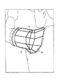
図16に示すように、キャラクタの腕を覆っているシャツの肩から袖の部分を表す場合には、変形しないシャツの袖と肩についてはポリゴンAとポリゴンBとで表し、その間の形状についてはポリゴンAとポリゴンBを関節に相当するポリゴンSを介して接続することにより表している。
図17(a)に示すように、本実施形態では、ポリゴンAの端面とポリゴンBの端面との間に、関節に相当する球型のポリゴンSを仮想的に配置する。ポリゴンAの端面からポリゴンSへの結合を演算し、ポリゴンBの端面からポリゴンSへの結合を演算し、最終的にポリゴンAの端面とポリゴンBの端面とをポリゴンSを介して連結することにより滑らかな連結状態を表示する。
【0049】
まず、図17(b)に示すように、ポリゴンAからポリゴンSへの結合を演算する。ポリゴンAの中心点OAからポリゴンSの中心点OSへのベクトルOAOSに対して垂直な円周R1を求める。円周R1上でポリゴンAの頂点a1に最も近い点をS11とする。図17(c)に示すように、同様にして円周R1上にポリゴンAの各頂点a2、a3、a4、a5、a6に最も近い点S12、S13、S14、S15、S16を決定する。
【0050】
次に、図17(d)に示すように、ポリゴンBからポリゴンSへの結合を演算する。ポリゴンBの中心点OBからポリゴンSの中心点OSへのベクトルOBOSに対して垂直な円周R2を求める。
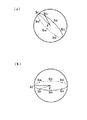
次に、図18(a)に示すように、ポリゴンSの円周R1、R2から結合点候補円周R3を求める。円周R1と円周R2との交点C1、C2を通る軸をCとする。ベクトルC1OSと垂直になる円周R1の点をS1′、ベクトルC1OSと垂直になる円周R2の点をS2′とする。このときベクトルOSS1′とベクトルOSS2′のなす角をθとする。そこで、図18(b)に示すように、軸Cを中心として円周R1をθ/2だけ回転してできるポリゴンS上の円周をR3とする。
【0051】
次に、円周R2と円周R3の結合点候補円周から結合点を求める。まず、図18(c)に示すように、点S1′と点S11の回転角φを求める。続いて、図19(a)に示すように、点S3′を円周R3の円周上でφ回転した点をS31とし、同様にして、円周R3上の点S32、S33、S34、S35、S36を求める。続いて、同様にして、図19(b)に示すように、円周R2上の点S21、S22、S23、S24、S25、S26を求める。
【0052】
次に、ポリゴンSからポリゴンBへの結合を求めるため、図20(a)に示すように、ポリゴンBをベクトルOSOBを軸として角度φだけ回転する。
次に、このようにして得られたポリゴンAの端面の頂点aiと、ポリゴンSの円周R1の頂点S1iと、ポリゴンSの円周R3の頂点S3iと、ポリゴンSの円周R2の頂点S2iと、ポリゴンBの端面の頂点biとを、図20(b)に示すように結合する。これにより滑らかな接続曲線が得られる。
【0053】
このように本実施形態によれば、結合するポリゴンに捻れがあっても自然に滑らかな形状で接続することができる。図16に示すように袖のポリゴンAと肩のポリゴンBの場合でも、図21、図22に示すように、腕を上げて捻れが生じても、ポリゴンSを介して滑らかにポリゴンA、B同士を接続することができる。図23に示すように、腕を下げて捻れが生じても、ポリゴンSを介して滑らかにポリゴンA、B同士を接続することができる。
【0054】
(キャラクタの簡易身長表示方法)
次に、本実施形態のゲーム装置におけるキャラクタの身長表示方法について図24を用いて説明する。
例えば、野球ゲームでは多数の選手が登場するが、選手の動きは計算により求めるため、骨格は同じである必要があり、各選手に別個のキャラクタを用意することはしていない。このため、別の選手であっても同じキャラクタにより表現することになり変化に乏しくなりがちである。
【0055】
本実施形態では、同じ骨格のキャラクタの頭の部分だけの大きさを変化させることにより、錯覚を利用して、あたかも身長の異なる別個のキャラクタがあるかのようにしている。図24に示すように、標準の大きさの頭F0に対し、大きさだけを変えた頭F1、F2、F3、F4を用意しておき、必要に応じて取り替えるようにする。標準より小さな頭F1、F2を用いれば、あたかも背の高いキャラクタであるかのように錯覚し、標準より大きな頭F3、F4を用いれば、あたかも背の低いキャラクタであるかのように錯覚する。
【0056】
(変形実施形態)
本発明は上記実施形態に限らず種々の変形が可能である。
例えば、上記実施形態では、本発明を野球ゲームに適用したが、射撃ゲームやサッカーゲーム、レーシングゲーム等の他のゲームに本発明を適用してもよい。また、上記実施形態ではバット型スイッチを用いたが、他のスイッチにより打撃指示をするようにしてもよい。
【0057】
【発明の効果】
以上の通り、本発明によれば、ゲーム空間において移動する移動体を表示するゲームの画像表示方法であって、前記移動体がモニタ画面への表示面に対して近づく又は遠ざかる際には、前記移動体の周囲に補助表示体を表示し、前記移動体の前記モニタ表示面に対する距離に応じて前記補助表示体を変化させるようにしたので、モニタ画面に対する奥行きの動きや遠近感を表すことができる。
【図面の簡単な説明】
【図1】本発明の一実施形態によるゲーム装置のブロック図である。
【図2】本発明の一実施形態によるゲーム装置の操作パネルを示す図である。
【図3】本発明の一実施形態によるゲーム装置におけるボールの奥行き位置の表示方法の説明図(その1)である。
【図4】本発明の一実施形態によるゲーム装置におけるボールの奥行き位置の表示方法の説明図(その2)である。
【図5】本発明の一実施形態によるゲーム装置におけるボールの奥行き位置の表示方法の説明図(その3)である。
【図6】本発明の一実施形態によるゲーム装置におけるボールの奥行き位置の表示方法の説明図(その4)である。
【図7】本発明の一実施形態によるゲーム装置におけるボールの奥行き位置の表示方法の説明図(その5)である。
【図8】本発明の一実施形態によるゲーム装置におけるボールの奥行き位置の表示方法の説明図(その6)である。
【図9】本発明の一実施形態によるゲーム装置におけるボールの球種の表示方法の一具体例の説明図(その1)である。
【図10】本発明の一実施形態によるゲーム装置におけるボールの球種の表示方法の一具体例の説明図(その2)である。
【図11】本発明の一実施形態によるゲーム装置におけるボールの球種の表示方法の一具体例の説明図(その3)である。
【図12】本発明の一実施形態によるゲーム装置におけるボールの球種の表示方法の一具体例の説明図(その4)である。
【図13】本発明の一実施形態によるゲーム装置におけるボールの球種の表示方法の他の具体例の説明図(その1)である。
【図14】本発明の一実施形態によるゲーム装置におけるボールの球種の表示方法の他の具体例の説明図(その2)である。
【図15】本発明の一実施形態によるゲーム装置におけるボールの球種の表示方法の他の具体例の説明図(その3)である。
【図16】本発明の一実施形態によるゲーム装置におけるポリゴンの連結状態を示す図である。
【図17】本発明の一実施形態によるゲーム装置におけるポリゴンの連結方法の説明図(その1)である。
【図18】本発明の一実施形態によるゲーム装置におけるポリゴンの連結方法の説明図(その2)である。
【図19】本発明の一実施形態によるゲーム装置におけるポリゴンの連結方法の説明図(その3)である。
【図20】本発明の一実施形態によるゲーム装置におけるポリゴンの連結方法の説明図(その4)である。
【図21】本発明の一実施形態によるゲーム装置におけるポリゴンの連結状態を示す図である。
【図22】本発明の一実施形態によるゲーム装置におけるポリゴンの連結状態を示す図である。
【図23】本発明の一実施形態によるゲーム装置におけるポリゴンの連結状態を示す図である。
【図24】本発明の一実施形態によるゲーム装置におけるキャラクタの身長表示方法の説明図である。
【図25】提案されたゲーム装置におけるポリゴンの連結方法の説明図である。
【符号の説明】
10…主制御部
12…表示制御部
14…音声制御部
16…ゲームROM
18…コネクタ
20…操作パネル
22…D/Aコンバータ
24…スピーカ
26…エンコーダ
28…モニタ
100…SCU(System Control Unit)
102…メインCPU
104…RAM
106…ROM
108…サブCPU
110、112、114…バス
120…第1VDP
120a…システムレジスタ
130a…レジスタ
122…VRAM
124、126…フレームバッファ
130…第2VDP
130a…レジスタ
130b…カラーRAM
132…VRAM
134…メモリ
140…DSP
142…CPU
200A、200B…操作ボタン等
202…スタートボタン
204…塁型ボタン群
204a…一塁ボタン
204b…二塁ボタン
204c…三塁ボタン
204d…本塁ボタン
206、208…決定ボタン
210…バット型スイッチ
211…バット
212…回動軸[0001]
BACKGROUND OF THE INVENTION
The present invention relates to a game image display method and control method, and more particularly to a game image display method and control method suitable for a baseball game.
[0002]
[Prior art]
With the development of computer graphics technology in recent years, so-called 3D games using three-dimensional stereoscopic image display are gradually becoming common in game devices in amusement facilities and home video game devices. Yes.
Baseball games are one of the most popular sports games that have a strong popularity. Also in this baseball game, a 3D game using a three-dimensional stereoscopic image display has appeared.
[0003]
In such a so-called 3D baseball game that can be displayed three-dimensionally, the vertical position and movement are easy to understand, but the movement of the depth with respect to the monitor screen is difficult to understand. In particular, since a ball in a baseball game is originally small, it is very difficult to display the depth movement and perspective on the monitor screen even though the position and movement are important.
[0004]
Also in 3D baseball games, it is possible to use various types of balls such as curves and shoots in addition to a straight ball for the pitcher, but the position of the ball only slightly changes on the display screen. And beginners hardly knew. Therefore, a new method for expressing the ball type in an easy-to-understand manner is awaited.
On the other hand, not only in 3D baseball games but also in 3D display games, characters and the like are represented by polygons. The shape of each part of the character was expressed as a polygon, and even when the position and orientation of the character changed, the position and orientation of the polygon were changed and expressed in a discontinuous manner. For this reason, even when there is a clothing line from the shoulder to the arm, if the polygon is twisted, it is discontinuous.
[0005]
Therefore, in order to smoothly connect polygon connection portions, proposals have been made to form a continuous shape by connecting the end faces of the polygons.
For example, when representing the sleeve part from the shoulder of the shirt covering the character's arm, the sleeve and shoulder of the shirt that are not deformed are represented by polygon A and polygon B, and the shape between them is the end face of polygon A. It expresses by connecting the vertices of the end faces of the polygon B.
[0006]
As for the shape between the two polygons A and B shown in FIG. 25A, the vertices a1, a2,..., A6 of the polygon A and the vertices b1, b2 of the polygon B are shown in FIG. ,..., B6 are connected to form a shape between the polygon A and the polygon B.
[0007]
[Problems to be solved by the invention]
When the polygon B is simply bent with respect to the polygon A, the vertexes a1, a2,..., A6 of the polygon A and the vertices b1, b2,. Connection shape is obtained. However, as shown in FIG. 25C, when the polygon A is twisted with respect to the polygon B, an unnatural dent is formed between the polygon A and the polygon B. Further, as shown in FIG. 25D, when the polygon A is twisted 180 degrees with respect to the polygon B, the thickness becomes almost unnatural between the polygon A and the polygon B. End up.
[0008]
For example, in the case of a movement that turns around the arm, the polygon A of the sleeve is twisted with respect to the polygon B of the shoulder. When this motion is expressed by the proposed method, it becomes an extremely unnatural shape in which the shoulder becomes thinner or thicker depending on the angle of twisting when the arm is rotated.
An object of the present invention is to provide a game image display method capable of expressing depth movement and perspective with respect to a monitor screen.
[0009]
Another object of the present invention is to provide a game image display method capable of expressing the difference in the types of balls thrown by a baseball pitcher or the like so that even a beginner can understand and enhancing the realism of the game.
It is still another object of the present invention to provide a game image display method capable of connecting twisted polygons in a natural shape.
[0010]
[Means for Solving the Problems]
An object of the present invention is a game image display method for displaying a moving body moving in a game space. When the moving body approaches or moves away from a display surface on a monitor screen, an auxiliary is provided around the moving body. This is achieved by a game image display method that displays a display body and changes the auxiliary display body in accordance with the distance of the moving body to the monitor display surface.
[0011]
In the above-described game image display method, the size of the auxiliary display body may be changed according to the distance of the moving body to the display surface.
In the game image display method described above, the color of the auxiliary display body may be changed according to the distance of the moving body to the display surface.
In the game image display method described above, when the moving body approaches the display surface, the size of the auxiliary display body is reduced according to the distance of the moving body to the monitor display surface, and the color is changed. It may be changed.
[0012]
The object is an image display method of a baseball game, and when a ball thrown by a pitcher approaches the display surface on the monitor screen, an auxiliary display body is displayed around the ball, and the auxiliary display body This is achieved by a baseball game image display method characterized by changing the size and / or color of the baseball game.
In the baseball game image display method described above, when the sphere approaches the display surface, the size of the auxiliary display body is reduced and the color is changed according to the distance of the sphere to the monitor display surface. You may make it make it.
[0013]
An object of the present invention is a game image display method for displaying a moving body moving in a game space, wherein the composition on the monitor screen is changed based on the movement locus of the moving body. Achieved by the method.
In the game image display method described above, the composition on the monitor screen may be rotated around the point of interest based on the movement trajectory of the moving body.
[0014]
In the above-described game image display method, the composition on the monitor screen may be changed based on the movement trajectory of the moving object, including the point of interest. The above object is achieved by an image display method for a baseball game, wherein the composition on the monitor screen is changed based on the type of the ball thrown by the pitcher.
[0015]
In the baseball game image display method described above, when the pitcher throws a ball that changes from side to side, the composition on the monitor screen may be rotated around the point of interest.
In the baseball game image display method described above, when the pitcher throws a ball that changes up and down, the composition on the monitor screen may be changed up and down including the point of interest.
[0016]
An object of the present invention is to provide an image display method for displaying a first polygon and a second polygon that are relatively moved in position so that the first polygon and the second polygon are connected. This is achieved by an image display method characterized in that a third polygon is placed on the first polygon, and the first polygon is connected to the second polygon via the third polygon.
[0017]
The object is to provide an image display method for displaying a first polygon and a second polygon whose positions are relatively changed, wherein the first polygon and the second polygon are connected. A third polygon is arranged, a first projection surface obtained by projecting an end face of the first polygon on the third polygon side onto the third polygon is obtained, and the third polygon of the second polygon is obtained. A second projection surface obtained by projecting the end surface on the polygon side onto the third polygon is obtained, and the periphery of the first projection surface of the third polygon and the second projection surface are determined from the end surface of the first polygon. The image display method is characterized in that the first polygon and the second polygon are connected by a connection curve reaching the end face of the second polygon through the periphery of the projection plane.
[0018]
In the image display method described above, the connection curve may be located on the third polygon between the first projection plane and the second projection plane.
In the image display method described above, the third polygon may be a spherical polygon having a diameter substantially equal to the diameter of the end face of the first polygon and / or the diameter of the end face of the second polygon. .
[0019]
DETAILED DESCRIPTION OF THE INVENTION
A game device according to an embodiment of the present invention will be described with reference to the drawings.
(Configuration of game device)
The configuration of the game device of this embodiment will be described with reference to FIG.
The game device is provided with a
[0020]
The
A
[0021]
The
The
[0022]
The
An
[0023]
Based on the operation data received from the
The display control unit 12 includes a
[0024]
The
[0025]
On the other hand, information for controlling drawing is set in the system register 120 a of the
The second VDP 130 includes a register 130a and a
[0026]
The second VDP 130 reads the color data defined in the
Display color data is stored in the
[0027]
The voice control unit 14 is provided with a
(control panel)
Next, an operation panel in the game device of the present embodiment will be described with reference to FIG.
[0028]
The
[0029]
A start /
[0030]
An 8-
[0031]
On the right side of the eight-
On the left side of the
[0032]
In order to detect the rotation position angle and the rotation speed of the
[0033]
(Basic game operations)
Next, the basic operation of the game device of this embodiment will be described.
At the time of pitching, the pitcher cursor indicating the throwing position is moved using the 8-
[0034]
At the time of defensive, designation of pitching and movement between the cages is performed using the 8-
At the time of hitting, the eight-
[0035]
At the time of scoring, the 8-
(Display the depth position of the ball)
Next, a display method of the depth position of the ball in the game apparatus according to the present embodiment will be described with reference to FIGS.
[0036]
When projecting a three-dimensional space onto a two-dimensional monitor screen, it is generally difficult to grasp the position of the ball in the three-dimensional space. In particular, when the ball moves from the back to the front, such as when the pitcher throws the ball, the position hardly changes on the two-dimensional monitor screen. was difficult.
In this embodiment, a circular cursor whose size and color changes is displayed around the ball, and as the ball gets closer to the monitor screen, the size of the cursor is reduced and the color is changed, and the depth position thereof is changed. Is displayed.
[0037]
3 to 8 show display screens when the pitcher throws the ball in the baseball game of the present embodiment.
First, FIG. 3 shows a stage where the pitcher tries to throw the ball. At this stage, since the pitcher has the ball, the ball is not displayed.
Next, when the pitcher throws the ball, a large circular cursor C is displayed around the ball B as shown in FIG. Thereafter, as the ball B approaches, the cursor C gradually decreases in size and converges on the ball B as shown in FIGS. 5, 6, 7, and 8. At this time, the color of the cursor C also changes from white to blue, yellow, and red, for example. The attacking player can know the timing of hitting from the size and color of the cursor C. For example, it can be used as a hint for the timing of hitting, such as pulling when hitting blue, returning the center when hitting yellow, and drifting when hitting red.
[0038]
As described above, according to the present embodiment, the depth of the ball thrown by the pitcher can be visually confirmed, and the batter can hit at a timing based on the information.
In the above embodiment, the size of the cursor C is reduced as the ball approaches. However, the size of the cursor C may be increased. Alternatively, the size may be increased to the middle as it approaches and then decreased. Further, the change in the size of the cursor C may be changed continuously according to the distance of the depth of the ball B, or may be changed stepwise.
[0039]
Also, the color of the cursor is not limited to the above embodiment, and may be changed in various colors in various forms.
(Indication of ball type)
Next, a display method of the ball type in the game apparatus of this embodiment will be described with reference to FIGS.
[0040]
When projecting a three-dimensional space onto a two-dimensional monitor screen, it is generally difficult to grasp the position of the ball in the three-dimensional space. In particular, when the ball moves from the back to the front, such as when the pitcher throws the ball, the position hardly changes on the two-dimensional monitor screen. Therefore, even if the pitcher throws a straight ball or throws a changing ball such as a curve or fork, there is only a slight difference in position on the two-dimensional monitor screen, and the pitch is output in an instant. Therefore, it was very difficult to know the type of ball thrown by the pitcher.
[0041]
In the present embodiment, the ball type thrown by the pitcher can be easily determined by changing the entire composition of the monitor screen according to the trajectory of the ball thrown by the pitcher, that is, the ball type. .
For example, when the pitcher throws a straight ball, the composition of the monitor screen is not changed, but when the pitcher throws a changing ball that changes mainly left and right, such as a curve, slider, chute, etc., the entire composition of the monitor screen When the pitcher throws a changing ball that changes mainly vertically, such as a fork or knuckle, the entire composition of the monitor screen is shaken up and down so that the player can easily determine the ball type. .
[0042]
9 to 11 are specific examples of the composition of the monitor screen when the pitcher throws a curve.
When the pitcher releases the ball to throw a curve, the composition of the game screen is not inclined at the time of release (position P1) as shown in the upper part of FIG. After the release, when the ball changes to position P2, position P3, position P4, and position P5, the game screen is changed according to this change in the lower part of FIG. 9, the upper part of FIG. As shown sequentially in the figure, when the ball rotates around the gazing point and the ball reaches the batter position P6, the rotation angle becomes maximum. The rotation angle θ of the composition of the game screen is defined as the rotation angle θ at the gazing point O of the composition as shown in FIG.
[0043]
When the position variation due to the curve increases, the rotation angle θ is increased to make it easy to intuitively grasp the degree of the curve.
Further, the physical strength consumption degree of the pitcher may be reflected in the rotation angle θ for rotating the composition. The physical wear level of the pitcher can be determined from the inclination of the composition.
As described above, according to the present embodiment, the composition of the screen fluctuates according to the trajectory of the ball thrown by the pitcher, so that the ball type can be easily determined.
[0044]
13 to 15 are other specific examples of the composition of the monitor screen when the pitcher throws a curve.
In the specific example described above, the overall composition of the game screen is changed, but only a part of the game screen may be changed as in this specific example. In this specific example, the batter, pitcher, and mound may not be changed, and only a part of the composition such as the home base or the batter box may be changed.
[0045]
When the pitcher releases the ball to throw a curve, the composition of the game screen is not inclined at the time of release (position P1) as shown in the upper part of FIG. After the release, when the ball changes to the position P2, the position P3, the position P4, and the position P5, the game screen is changed according to the change in the lower part of FIG. 13, the upper part of FIG. 14, the lower part of FIG. 14, and the upper part of FIG. As shown sequentially with the drawings, only a part of the composition such as the home base and batter box rotates, and the rotation angle becomes maximum when the ball reaches the batter position P6. The rotation angle θ of the composition of the game screen is defined as the rotation angle θ at the gazing point O of the composition as shown in FIG.
[0046]
As described above, according to the present embodiment, the composition of the screen fluctuates according to the trajectory of the ball thrown by the pitcher, so that the ball type can be easily determined.
(Polygon connection method)
Next, a method for connecting polygons in the game apparatus according to the present embodiment will be described with reference to FIGS.
[0047]
In 3D display games as well as 3D baseball games, characters and the like are represented by polygons. For joints such as the character's arms and legs, polygons are formed for the undeformed parts such as the shoulder, upper arm, forearm, and palm, and the corresponding vertices of the polygons are connected for the shape between these polygons. It represents an arm, a leg, etc. with movement.
[0048]
As shown in FIG. 16, when representing the sleeve portion from the shoulder of the shirt covering the character's arm, the sleeve and shoulder of the shirt that are not deformed are represented by polygon A and polygon B, and the shape between them is The polygon A and the polygon B are represented by being connected via a polygon S corresponding to a joint.
As shown in FIG. 17A, in this embodiment, a spherical polygon S corresponding to a joint is virtually arranged between the end face of the polygon A and the end face of the polygon B. Calculate the connection from the end face of the polygon A to the polygon S, calculate the connection from the end face of the polygon B to the polygon S, and finally connect the end face of the polygon A and the end face of the polygon B via the polygon S. To display a smooth connection state.
[0049]
First, as shown in FIG. 17B, the connection from the polygon A to the polygon S is calculated. A circumference R1 perpendicular to the vector OAOS from the center point OA of the polygon A to the center point OS of the polygon S is obtained. A point closest to the vertex a1 of the polygon A on the circumference R1 is defined as S11. As shown in FIG. 17C, points S12, S13, S14, S15, and S16 that are closest to the vertices a2, a3, a4, a5, and a6 of the polygon A are similarly determined on the circumference R1.
[0050]
Next, as shown in FIG. 17D, the connection from the polygon B to the polygon S is calculated. A circumference R2 perpendicular to the vector OBOS from the center point OB of the polygon B to the center point OS of the polygon S is obtained.
Next, as shown in FIG. 18A, a connection point candidate circumference R3 is obtained from the circumferences R1 and R2 of the polygon S. An axis passing through the intersections C1 and C2 between the circumference R1 and the circumference R2 is defined as C. A point on the circumference R1 perpendicular to the vector C1OS is designated as S1 ', and a point on the circumference R2 perpendicular to the vector C1OS is designated as S2'. At this time, an angle formed by the vector OSS1 ′ and the vector OSS2 ′ is θ. Therefore, as shown in FIG. 18B, the circumference on the polygon S formed by rotating the circumference R1 by θ / 2 around the axis C is defined as R3.
[0051]
Next, a coupling point is obtained from the coupling point candidate circumference of the circumference R2 and the circumference R3. First, as shown in FIG. 18C, the rotation angle φ between the points S1 ′ and S11 is obtained. Subsequently, as shown in FIG. 19A, a point obtained by rotating the point S3 ′ by φ on the circumference of the circumference R3 is set as S31, and similarly, points S32, S33, S34, S35 on the circumference R3 are set. , S36 is obtained. Subsequently, similarly, as shown in FIG. 19B, points S21, S22, S23, S24, S25, and S26 on the circumference R2 are obtained.
[0052]
Next, in order to obtain the connection from the polygon S to the polygon B, the polygon B is rotated by an angle φ about the vector OSOB as shown in FIG.
Next, the vertex ai of the end face of the polygon A, the vertex S1i of the circumference R1 of the polygon S, the vertex S3i of the circumference R3 of the polygon S, and the vertex S2i of the circumference R2 of the polygon S are obtained. And the apex bi of the end face of the polygon B are combined as shown in FIG. As a result, a smooth connection curve is obtained.
[0053]
As described above, according to this embodiment, even if a polygon to be coupled is twisted, it can be connected in a naturally smooth shape. In the case of the polygon A of the sleeve and the polygon B of the shoulder as shown in FIG. 16, even if the arm is raised and twisted as shown in FIGS. 21 and 22, the polygons A and B are smoothly passed through the polygon S. You can connect each other. As shown in FIG. 23, even if the arm is lowered and twisting occurs, the polygons A and B can be smoothly connected via the polygon S.
[0054]
(Character height display method)
Next, a character height display method in the game apparatus of the present embodiment will be described with reference to FIG.
For example, a large number of players appear in a baseball game, but since the movements of the players are obtained by calculation, the skeletons must be the same, and no separate character is prepared for each player. For this reason, even if it is another player, it will be expressed by the same character, and it tends to be poor in change.
[0055]
In the present embodiment, by changing the size of only the head portion of the character having the same skeleton, an illusion is used as if there are separate characters having different heights. As shown in FIG. 24, heads F1, F2, F3, and F4 that are different in size from the standard size head F0 are prepared and replaced as necessary. If the heads F1 and F2 smaller than the standard are used, the illusion is as if the character is tall, and if the heads F3 and F4 larger than the standard are used, the illusion is as if the character is short.
[0056]
(Modified embodiment)
The present invention is not limited to the above embodiment, and various modifications can be made.
For example, in the above embodiment, the present invention is applied to a baseball game, but the present invention may be applied to other games such as a shooting game, a soccer game, and a racing game. In the above embodiment, the bat type switch is used, but the hitting instruction may be issued by another switch.
[0057]
【The invention's effect】
As described above, according to the present invention, there is provided a game image display method for displaying a moving body that moves in a game space, and when the moving body approaches or moves away from a display surface on a monitor screen, Since the auxiliary display body is displayed around the moving body and the auxiliary display body is changed in accordance with the distance of the moving body to the monitor display surface, the movement of the depth and the perspective with respect to the monitor screen can be expressed. it can.
[Brief description of the drawings]
FIG. 1 is a block diagram of a game device according to an embodiment of the present invention.
FIG. 2 is a diagram showing an operation panel of the game device according to the embodiment of the present invention.
FIG. 3 is an explanatory diagram (part 1) of a method for displaying a depth position of a ball in the game device according to the embodiment of the present invention;
FIG. 4 is an explanatory diagram (No. 2) of the method for displaying the depth position of the ball in the game device according to the embodiment of the present invention.
FIG. 5 is an explanatory diagram (No. 3) of the method for displaying the depth position of the ball in the game device according to the embodiment of the present invention;
FIG. 6 is an explanatory diagram (part 4) of the method for displaying the depth position of the ball in the game device according to the embodiment of the present invention;
FIG. 7 is an explanatory diagram (No. 5) of the method for displaying the depth position of the ball in the game device according to the embodiment of the present invention.
FIG. 8 is an explanatory diagram (No. 6) of the method for displaying the depth position of the ball in the game device according to the embodiment of the present invention;
FIG. 9 is an explanatory diagram (part 1) of a specific example of a method for displaying a ball type in a game device according to an embodiment of the present invention;
FIG. 10 is an explanatory diagram (part 2) of a specific example of the method for displaying the type of ball in the game device according to the embodiment of the present invention;
FIG. 11 is an explanatory diagram (part 3) of a specific example of the method for displaying the type of ball in the game device according to the embodiment of the present invention;
FIG. 12 is an explanatory diagram (part 4) of a specific example of the method for displaying the type of ball in the game device according to the embodiment of the present invention;
FIG. 13 is an explanatory diagram (part 1) of another specific example of the method for displaying the type of ball in the game device according to the embodiment of the present invention;
FIG. 14 is an explanatory diagram (No. 2) of another specific example of the method of displaying the ball type in the game device according to the embodiment of the present invention;
FIG. 15 is an explanatory diagram (No. 3) of another specific example of the method of displaying the ball type in the game device according to the embodiment of the present invention;
FIG. 16 is a diagram showing a connected state of polygons in the game device according to one embodiment of the present invention.
FIG. 17 is an explanatory diagram (part 1) illustrating a polygon coupling method in the game device according to the embodiment of the present invention;
FIG. 18 is an explanatory diagram (part 2) of the polygon connecting method in the game device according to the embodiment of the present invention;
FIG. 19 is an explanatory diagram (part 3) of the polygon connecting method in the game device according to the embodiment of the present invention;
FIG. 20 is an explanatory diagram (part 4) of the polygon connecting method in the game device according to the embodiment of the present invention;
FIG. 21 is a diagram showing a connected state of polygons in the game device according to one embodiment of the present invention.
FIG. 22 is a diagram showing a connected state of polygons in the game device according to one embodiment of the present invention.
FIG. 23 is a diagram showing a connected state of polygons in the game device according to one embodiment of the present invention.
FIG. 24 is an explanatory diagram of a character height display method in the game device according to the embodiment of the present invention;
FIG. 25 is an explanatory diagram of a polygon connecting method in the proposed game apparatus.
[Explanation of symbols]
10 ... Main control section
12 ... Display control unit
14 ... Voice control unit
16 ... Game ROM
18 ... Connector
20 ... Control panel
22 ... D / A converter
24 ... Speaker
26 ... Encoder
28 ... Monitor
100 ... SCU (System Control Unit)
102 ... Main CPU
104 ... RAM
106 ... ROM
108: Sub CPU
110, 112, 114 ... bus
120 ... 1st VDP
120a ... System register
130a ... register
122 ... VRAM
124, 126 ... frame buffer
130 ... 2nd VDP
130a ... register
130b ... Color RAM
132 ... VRAM
134: Memory
140 ... DSP
142 ... CPU
200A, 200B ... operation buttons, etc.
202 ... Start button
204 ... Saddle button group
204a ... Glance button
204b ... Two-button
204c ... Three-way button
204d ... Home button
206, 208 ... OK button
210 ... Butt type switch
211 ... Bat
212 ... Rotating shaft
Claims (1)
前記制御手段は、
前記投手が投げた前記ボールの周囲にカーソルを配した二次元画像を生成して画面に表示するステップと、
前記投手が投げた前記ボールと前記仮想視点との間の距離を求めるステップと、
求めた前記距離が小さくなるにつれて、前記ボールを前記打者に近づかせると共に、前記ボールの周囲の前記カーソルを前記ボールに収れんさせて前記カーソルの大きさを徐々に小さくした二次元画像を生成して画面に表示するステップと
を実行し、
併せて、前記制御手段は、
前記打者が打撃する際の技法である流し打ち、センター返し、引っ張り打ちに対応させた各打撃タイミングを示す色を決定するステップと、
前記カーソルを、前記各打撃タイミングで、前記決定した色にした二次元画像を生成して画面に表示するステップと
を実行することを特徴とするゲーム画像表示方法。A baseball game program in which the batter hits the ball thrown by the pitcher in the virtual three-dimensional space is executed, and the virtual viewpoint is placed in the virtual three-dimensional space so that the point of sight is at the pitcher's position. A state in which the ball is moved toward the virtual viewpoint and the ball approaches the batter is captured from the virtual viewpoint, and a two-dimensional image representing the state of the virtual three-dimensional space seen from the virtual viewpoint is generated. A game image display method executed by a control means for performing control to display on a screen,
The control means includes
Generating a two-dimensional image with a cursor placed around the ball thrown by the pitcher and displaying it on the screen;
Obtaining a distance between the ball thrown by the pitcher and the virtual viewpoint;
As the obtained distance becomes smaller, the ball approaches the batter, and the cursor around the ball is converged on the ball to generate a two-dimensional image in which the size of the cursor is gradually reduced. Steps to display on the screen
Run
In addition, the control means includes
A step of determining a color indicating each hitting timing corresponding to sinking, center return, and pulling, which is a technique when the batter hits;
Generating the two-dimensional image in the determined color at the respective hitting timings and displaying the cursor on a screen;
The game image display method characterized by performing .
Priority Applications (1)
| Application Number | Priority Date | Filing Date | Title |
|---|---|---|---|
| JP26214698A JP3885381B2 (en) | 1998-09-16 | 1998-09-16 | Game image display method |
Applications Claiming Priority (1)
| Application Number | Priority Date | Filing Date | Title |
|---|---|---|---|
| JP26214698A JP3885381B2 (en) | 1998-09-16 | 1998-09-16 | Game image display method |
Publications (3)
| Publication Number | Publication Date |
|---|---|
| JP2000084252A JP2000084252A (en) | 2000-03-28 |
| JP2000084252A5 JP2000084252A5 (en) | 2005-11-10 |
| JP3885381B2 true JP3885381B2 (en) | 2007-02-21 |
Family
ID=17371705
Family Applications (1)
| Application Number | Title | Priority Date | Filing Date |
|---|---|---|---|
| JP26214698A Expired - Fee Related JP3885381B2 (en) | 1998-09-16 | 1998-09-16 | Game image display method |
Country Status (1)
| Country | Link |
|---|---|
| JP (1) | JP3885381B2 (en) |
Cited By (1)
| Publication number | Priority date | Publication date | Assignee | Title |
|---|---|---|---|---|
| KR101546405B1 (en) * | 2014-07-11 | 2015-08-27 | 계명대학교 산학협력단 | Hand rehabilitation training system and method for training pinch motion using a game screen in a smart device |
Families Citing this family (11)
| Publication number | Priority date | Publication date | Assignee | Title |
|---|---|---|---|---|
| JP2003010547A (en) | 2001-06-29 | 2003-01-14 | Square Co Ltd | Computer readable recording medium with program of video game recorded thereon, program of video game, video game processing method, and video game processing system |
| JP3789919B2 (en) * | 2004-02-19 | 2006-06-28 | コナミ株式会社 | GAME PROGRAM, GAME DEVICE, AND GAME METHOD |
| JP4688473B2 (en) * | 2004-11-02 | 2011-05-25 | 株式会社バンダイナムコゲームス | PROGRAM, INFORMATION STORAGE MEDIUM, AND GAME DEVICE |
| JP4883759B2 (en) * | 2006-01-13 | 2012-02-22 | 株式会社バンダイナムコゲームス | Program, information storage medium, and image generation system |
| JP4122030B2 (en) * | 2006-02-15 | 2008-07-23 | 株式会社コナミデジタルエンタテインメント | GAME PROGRAM, GAME DEVICE, AND GAME METHOD |
| JP4074324B2 (en) * | 2006-09-20 | 2008-04-09 | 株式会社コナミデジタルエンタテインメント | GAME PROGRAM, GAME DEVICE, AND GAME CONTROL METHOD |
| JP5480183B2 (en) * | 2011-03-04 | 2014-04-23 | 株式会社コナミデジタルエンタテインメント | GAME DEVICE, IMAGE GENERATION METHOD, AND PROGRAM |
| JP6360872B2 (en) * | 2016-12-12 | 2018-07-18 | 株式会社コロプラ | GAME PROGRAM, METHOD, AND INFORMATION PROCESSING DEVICE |
| JP6683350B2 (en) * | 2018-07-24 | 2020-04-15 | 株式会社コナミデジタルエンタテインメント | Game control device, game system, and program |
| JP6940194B2 (en) * | 2018-07-26 | 2021-09-22 | 株式会社コナミデジタルエンタテインメント | Game controls, game systems, and programs |
| GB2620375A (en) * | 2022-06-29 | 2024-01-10 | Sony Interactive Entertainment Inc | Visual perception assistance apparatus and method |
Family Cites Families (2)
| Publication number | Priority date | Publication date | Assignee | Title |
|---|---|---|---|---|
| JPH0894756A (en) * | 1994-09-21 | 1996-04-12 | Nippondenso Co Ltd | Device for displaying distance between cars, and target cruise |
| JP3583873B2 (en) * | 1996-09-12 | 2004-11-04 | 株式会社日立製作所 | Car driving control device |
-
1998
- 1998-09-16 JP JP26214698A patent/JP3885381B2/en not_active Expired - Fee Related
Cited By (1)
| Publication number | Priority date | Publication date | Assignee | Title |
|---|---|---|---|---|
| KR101546405B1 (en) * | 2014-07-11 | 2015-08-27 | 계명대학교 산학협력단 | Hand rehabilitation training system and method for training pinch motion using a game screen in a smart device |
Also Published As
| Publication number | Publication date |
|---|---|
| JP2000084252A (en) | 2000-03-28 |
Similar Documents
| Publication | Publication Date | Title |
|---|---|---|
| US8123600B2 (en) | Storage medium storing game program and game apparatus | |
| US6102801A (en) | Picture processing device and method thereof | |
| JP5286267B2 (en) | Game device, game program, and object operation method | |
| US6947046B2 (en) | Image generation method, program, and information storage medium | |
| JP3677924B2 (en) | Display method and control method of video game apparatus | |
| JP2003126548A (en) | Game device and game system | |
| JP4776831B2 (en) | Program, information storage medium, game device, and host device | |
| JP3885381B2 (en) | Game image display method | |
| JP5174123B2 (en) | GAME DEVICE, GAME CONTROL METHOD, AND PROGRAM | |
| JP3740797B2 (en) | Baseball game image display method | |
| JP2009000383A (en) | Program, information recording medium and image generating system | |
| JP4962978B2 (en) | GAME IMAGE DISPLAY CONTROL PROGRAM, GAME DEVICE, AND GAME IMAGE DISPLAY CONTROL METHOD | |
| JP5396212B2 (en) | GAME DEVICE, GAME DEVICE CONTROL METHOD, AND PROGRAM | |
| JP3894937B2 (en) | PROGRAM, INFORMATION STORAGE MEDIUM, AND GAME DEVICE | |
| JP2002301267A (en) | Method for controlling baseball game, game program, recoding medium and game machine | |
| US7131907B2 (en) | System and method for superimposing an image on another image in a video game | |
| JP4962975B2 (en) | Game program, battle game apparatus, and battle game control method | |
| JP4962976B2 (en) | Game program, battle game apparatus, and battle game control method | |
| JPH08196745A (en) | Three-dimensional game apparatus and hit checking method | |
| JP4962977B2 (en) | Game program, battle game apparatus, and battle game control method | |
| JP4962974B2 (en) | Game program, battle game apparatus, and battle game control method | |
| JP5117474B2 (en) | GAME DEVICE, GAME CONTROL PROGRAM, AND GAME CONTROL METHOD | |
| JP4545545B2 (en) | GAME PROGRAM AND GAME DEVICE | |
| JP2010233751A (en) | Program, information storage medium, and image generation system | |
| JP5021047B2 (en) | GAME DEVICE, GAME CONTROL PROGRAM, AND GAME CONTROL METHOD |
Legal Events
| Date | Code | Title | Description |
|---|---|---|---|
| A521 | Written amendment |
Free format text: JAPANESE INTERMEDIATE CODE: A523 Effective date: 20050914 |
|
| A621 | Written request for application examination |
Free format text: JAPANESE INTERMEDIATE CODE: A621 Effective date: 20050914 |
|
| A131 | Notification of reasons for refusal |
Free format text: JAPANESE INTERMEDIATE CODE: A131 Effective date: 20060718 |
|
| A521 | Written amendment |
Free format text: JAPANESE INTERMEDIATE CODE: A523 Effective date: 20060919 |
|
| TRDD | Decision of grant or rejection written | ||
| A01 | Written decision to grant a patent or to grant a registration (utility model) |
Free format text: JAPANESE INTERMEDIATE CODE: A01 Effective date: 20061031 |
|
| A61 | First payment of annual fees (during grant procedure) |
Free format text: JAPANESE INTERMEDIATE CODE: A61 Effective date: 20061113 |
|
| R150 | Certificate of patent or registration of utility model |
Free format text: JAPANESE INTERMEDIATE CODE: R150 |
|
| LAPS | Cancellation because of no payment of annual fees |