JP3696967B2 - Liquid discharge head, head cartridge using liquid discharge head, liquid discharge apparatus, liquid discharge method and recording method - Google Patents
Liquid discharge head, head cartridge using liquid discharge head, liquid discharge apparatus, liquid discharge method and recording method Download PDFInfo
- Publication number
- JP3696967B2 JP3696967B2 JP08982596A JP8982596A JP3696967B2 JP 3696967 B2 JP3696967 B2 JP 3696967B2 JP 08982596 A JP08982596 A JP 08982596A JP 8982596 A JP8982596 A JP 8982596A JP 3696967 B2 JP3696967 B2 JP 3696967B2
- Authority
- JP
- Japan
- Prior art keywords
- liquid
- discharge
- flow path
- movable member
- heating elements
- Prior art date
- Legal status (The legal status is an assumption and is not a legal conclusion. Google has not performed a legal analysis and makes no representation as to the accuracy of the status listed.)
- Expired - Fee Related
Links
Images


Classifications
-
- B—PERFORMING OPERATIONS; TRANSPORTING
- B41—PRINTING; LINING MACHINES; TYPEWRITERS; STAMPS
- B41J—TYPEWRITERS; SELECTIVE PRINTING MECHANISMS, i.e. MECHANISMS PRINTING OTHERWISE THAN FROM A FORME; CORRECTION OF TYPOGRAPHICAL ERRORS
- B41J2/00—Typewriters or selective printing mechanisms characterised by the printing or marking process for which they are designed
- B41J2/005—Typewriters or selective printing mechanisms characterised by the printing or marking process for which they are designed characterised by bringing liquid or particles selectively into contact with a printing material
- B41J2/01—Ink jet
- B41J2/135—Nozzles
- B41J2/14—Structure thereof only for on-demand ink jet heads
- B41J2/14016—Structure of bubble jet print heads
- B41J2/14032—Structure of the pressure chamber
- B41J2/14056—Plural heating elements per ink chamber
-
- B—PERFORMING OPERATIONS; TRANSPORTING
- B41—PRINTING; LINING MACHINES; TYPEWRITERS; STAMPS
- B41J—TYPEWRITERS; SELECTIVE PRINTING MECHANISMS, i.e. MECHANISMS PRINTING OTHERWISE THAN FROM A FORME; CORRECTION OF TYPOGRAPHICAL ERRORS
- B41J2/00—Typewriters or selective printing mechanisms characterised by the printing or marking process for which they are designed
- B41J2/005—Typewriters or selective printing mechanisms characterised by the printing or marking process for which they are designed characterised by bringing liquid or particles selectively into contact with a printing material
- B41J2/01—Ink jet
- B41J2/015—Ink jet characterised by the jet generation process
- B41J2/04—Ink jet characterised by the jet generation process generating single droplets or particles on demand
- B41J2/045—Ink jet characterised by the jet generation process generating single droplets or particles on demand by pressure, e.g. electromechanical transducers
- B41J2/04501—Control methods or devices therefor, e.g. driver circuits, control circuits
- B41J2/04573—Timing; Delays
-
- B—PERFORMING OPERATIONS; TRANSPORTING
- B41—PRINTING; LINING MACHINES; TYPEWRITERS; STAMPS
- B41J—TYPEWRITERS; SELECTIVE PRINTING MECHANISMS, i.e. MECHANISMS PRINTING OTHERWISE THAN FROM A FORME; CORRECTION OF TYPOGRAPHICAL ERRORS
- B41J2/00—Typewriters or selective printing mechanisms characterised by the printing or marking process for which they are designed
- B41J2/005—Typewriters or selective printing mechanisms characterised by the printing or marking process for which they are designed characterised by bringing liquid or particles selectively into contact with a printing material
- B41J2/01—Ink jet
- B41J2/015—Ink jet characterised by the jet generation process
- B41J2/04—Ink jet characterised by the jet generation process generating single droplets or particles on demand
- B41J2/045—Ink jet characterised by the jet generation process generating single droplets or particles on demand by pressure, e.g. electromechanical transducers
- B41J2/04501—Control methods or devices therefor, e.g. driver circuits, control circuits
- B41J2/04581—Control methods or devices therefor, e.g. driver circuits, control circuits controlling heads based on piezoelectric elements
-
- B—PERFORMING OPERATIONS; TRANSPORTING
- B41—PRINTING; LINING MACHINES; TYPEWRITERS; STAMPS
- B41J—TYPEWRITERS; SELECTIVE PRINTING MECHANISMS, i.e. MECHANISMS PRINTING OTHERWISE THAN FROM A FORME; CORRECTION OF TYPOGRAPHICAL ERRORS
- B41J2/00—Typewriters or selective printing mechanisms characterised by the printing or marking process for which they are designed
- B41J2/005—Typewriters or selective printing mechanisms characterised by the printing or marking process for which they are designed characterised by bringing liquid or particles selectively into contact with a printing material
- B41J2/01—Ink jet
- B41J2/015—Ink jet characterised by the jet generation process
- B41J2/04—Ink jet characterised by the jet generation process generating single droplets or particles on demand
- B41J2/045—Ink jet characterised by the jet generation process generating single droplets or particles on demand by pressure, e.g. electromechanical transducers
- B41J2/04501—Control methods or devices therefor, e.g. driver circuits, control circuits
- B41J2/04588—Control methods or devices therefor, e.g. driver circuits, control circuits using a specific waveform
-
- B—PERFORMING OPERATIONS; TRANSPORTING
- B41—PRINTING; LINING MACHINES; TYPEWRITERS; STAMPS
- B41J—TYPEWRITERS; SELECTIVE PRINTING MECHANISMS, i.e. MECHANISMS PRINTING OTHERWISE THAN FROM A FORME; CORRECTION OF TYPOGRAPHICAL ERRORS
- B41J2/00—Typewriters or selective printing mechanisms characterised by the printing or marking process for which they are designed
- B41J2/005—Typewriters or selective printing mechanisms characterised by the printing or marking process for which they are designed characterised by bringing liquid or particles selectively into contact with a printing material
- B41J2/01—Ink jet
- B41J2/135—Nozzles
- B41J2/14—Structure thereof only for on-demand ink jet heads
- B41J2/14016—Structure of bubble jet print heads
- B41J2/14024—Assembling head parts
-
- B—PERFORMING OPERATIONS; TRANSPORTING
- B41—PRINTING; LINING MACHINES; TYPEWRITERS; STAMPS
- B41J—TYPEWRITERS; SELECTIVE PRINTING MECHANISMS, i.e. MECHANISMS PRINTING OTHERWISE THAN FROM A FORME; CORRECTION OF TYPOGRAPHICAL ERRORS
- B41J2/00—Typewriters or selective printing mechanisms characterised by the printing or marking process for which they are designed
- B41J2/005—Typewriters or selective printing mechanisms characterised by the printing or marking process for which they are designed characterised by bringing liquid or particles selectively into contact with a printing material
- B41J2/01—Ink jet
- B41J2/135—Nozzles
- B41J2/14—Structure thereof only for on-demand ink jet heads
- B41J2/14016—Structure of bubble jet print heads
- B41J2/14032—Structure of the pressure chamber
- B41J2/1404—Geometrical characteristics
-
- B—PERFORMING OPERATIONS; TRANSPORTING
- B41—PRINTING; LINING MACHINES; TYPEWRITERS; STAMPS
- B41J—TYPEWRITERS; SELECTIVE PRINTING MECHANISMS, i.e. MECHANISMS PRINTING OTHERWISE THAN FROM A FORME; CORRECTION OF TYPOGRAPHICAL ERRORS
- B41J2/00—Typewriters or selective printing mechanisms characterised by the printing or marking process for which they are designed
- B41J2/005—Typewriters or selective printing mechanisms characterised by the printing or marking process for which they are designed characterised by bringing liquid or particles selectively into contact with a printing material
- B41J2/01—Ink jet
- B41J2/135—Nozzles
- B41J2/14—Structure thereof only for on-demand ink jet heads
- B41J2/14016—Structure of bubble jet print heads
- B41J2/14032—Structure of the pressure chamber
- B41J2/14048—Movable member in the chamber
-
- B—PERFORMING OPERATIONS; TRANSPORTING
- B41—PRINTING; LINING MACHINES; TYPEWRITERS; STAMPS
- B41J—TYPEWRITERS; SELECTIVE PRINTING MECHANISMS, i.e. MECHANISMS PRINTING OTHERWISE THAN FROM A FORME; CORRECTION OF TYPOGRAPHICAL ERRORS
- B41J2/00—Typewriters or selective printing mechanisms characterised by the printing or marking process for which they are designed
- B41J2/005—Typewriters or selective printing mechanisms characterised by the printing or marking process for which they are designed characterised by bringing liquid or particles selectively into contact with a printing material
- B41J2/01—Ink jet
- B41J2/17—Ink jet characterised by ink handling
-
- H—ELECTRICITY
- H04—ELECTRIC COMMUNICATION TECHNIQUE
- H04N—PICTORIAL COMMUNICATION, e.g. TELEVISION
- H04N1/00—Scanning, transmission or reproduction of documents or the like, e.g. facsimile transmission; Details thereof
- H04N1/024—Details of scanning heads ; Means for illuminating the original
- H04N1/032—Details of scanning heads ; Means for illuminating the original for picture information reproduction
- H04N1/034—Details of scanning heads ; Means for illuminating the original for picture information reproduction using ink, e.g. ink-jet heads
-
- B—PERFORMING OPERATIONS; TRANSPORTING
- B41—PRINTING; LINING MACHINES; TYPEWRITERS; STAMPS
- B41J—TYPEWRITERS; SELECTIVE PRINTING MECHANISMS, i.e. MECHANISMS PRINTING OTHERWISE THAN FROM A FORME; CORRECTION OF TYPOGRAPHICAL ERRORS
- B41J2/00—Typewriters or selective printing mechanisms characterised by the printing or marking process for which they are designed
- B41J2/005—Typewriters or selective printing mechanisms characterised by the printing or marking process for which they are designed characterised by bringing liquid or particles selectively into contact with a printing material
- B41J2/01—Ink jet
- B41J2/135—Nozzles
- B41J2/14—Structure thereof only for on-demand ink jet heads
- B41J2002/14379—Edge shooter
-
- B—PERFORMING OPERATIONS; TRANSPORTING
- B41—PRINTING; LINING MACHINES; TYPEWRITERS; STAMPS
- B41J—TYPEWRITERS; SELECTIVE PRINTING MECHANISMS, i.e. MECHANISMS PRINTING OTHERWISE THAN FROM A FORME; CORRECTION OF TYPOGRAPHICAL ERRORS
- B41J2202/00—Embodiments of or processes related to ink-jet or thermal heads
- B41J2202/01—Embodiments of or processes related to ink-jet heads
- B41J2202/12—Embodiments of or processes related to ink-jet heads with ink circulating through the whole print head
-
- B—PERFORMING OPERATIONS; TRANSPORTING
- B41—PRINTING; LINING MACHINES; TYPEWRITERS; STAMPS
- B41J—TYPEWRITERS; SELECTIVE PRINTING MECHANISMS, i.e. MECHANISMS PRINTING OTHERWISE THAN FROM A FORME; CORRECTION OF TYPOGRAPHICAL ERRORS
- B41J2202/00—Embodiments of or processes related to ink-jet or thermal heads
- B41J2202/01—Embodiments of or processes related to ink-jet heads
- B41J2202/21—Line printing
Abstract
Description
【0001】
【発明の属する技術分野】
本発明は、熱エネルギーを液体に作用させることで起こる気泡の発生によって、所望の液体を吐出する液体吐出ヘッド、液体吐出ヘッドを用いたヘッドカートリッジ、液体吐出装置、液体吐出方法および記録方法に関する。さらにこれらの液体吐出ヘッドを有するインクジェットヘッドキットに関する。
【0002】
特に本発明は、気泡の発生を利用して変位する可動部材を有する液体吐出ヘッド、液体吐出ヘッドを用いたヘッドカートリッジ、液体吐出装置に関する。もしくは、気泡の発生を利用して可動部材を変位させて液体を吐出する液体吐出方法 および記録方法に関する。
【0003】
また本発明は紙、糸、繊維、布帛、皮革、金属、プラスチック、ガラス、木材、セラミックス等の被記録媒体に対し記録を行う、プリンタ、複写機、通信システムを有するファクシミリ、プリンタ部を有するワードプロセッサ等の装置、さらには各種処理装置と複合的に組み合わせた産業用記録装置に適用できる発明である。
【0004】
なお、本発明における、「記録」とは、文字や図形等の意味を持つ画像を被記録媒体に対して付与することだけでなく、パターン等の意味を持たない画像を付与することをも意味するものである。
【0005】
【従来の技術】
熱等のエネルギーをインクに与えることで、インクに急峻な体積変化(気泡の発生)を伴う状態変化を生じさせ、この状態変化に基づく作用力によって吐出口からインクを吐出し、これを被記録媒体上に付着させて画像形成を行なうインクジェット記録方法、いわゆるバブルジェット記録方法が従来知られている。このバブルジェット記録方法を用いる記録装置には、米国特許第4,723,129号等の公報に開示されているように、インクを吐出するための吐出口と、この吐出口に連通するインク流路と、インク流路内に配されたインクを吐出するためのエネルギー発生手段としての電気熱変換体が一般的に配されている。
【0006】
このような記録方法によれば、品位の高い画像を高速、低騒音で記録することができると共に、この記録方法を行うヘッドではインクを吐出するための吐出口を高密度に配置することができるため、小型の装置で高解像度の記録画像、さらにカラー画像をも容易に得ることができるという多くの優れた点を有している。
このため、このバブルジェット記録方法は近年、プリンター、複写機、ファクシミリ等の多くのオフィス機器に利用されており、さらに、捺染装置等の産業用システムにまで利用されるようになってきている。
【0007】
このようにバブルジェット技術が多方面に利用されるに従って、次のような様々な要求が近年さらに高まっている。
【0008】
例えば、エネルギー効率の向上の要求に対する検討としては、保護膜の厚さを調整するといった発熱体の最適化が挙げられている。この手法は、発生した熱の液体への伝搬効率を向上させる点で効果がある。
【0009】
また、高画質な画像を得るために、インクの吐出スピードが速く、安定した気泡発生に基づく良好なインク吐出を行える液体吐出方法等を与えるための駆動条件が提案されたり、また、高速記録の観点から、吐出された液体の液流路内への充填(リフィル)速度の速い液体吐出ヘッドを得るために流路形状を改良したものも提案されている。
【0010】
この流路形状の内、流路構造として図31(a),(b)に示すものが、特開昭63−199972号公報等に記載されている。これらの公報に記載されている流路構造やヘッド製造方法は、気泡の発生に伴って発生するバック波(吐出口へ向かう方向とは逆の方向へ向かう圧力、すなわち液室412へ向かう圧力)に着目した発明である。このバック波は、吐出方向へ向かうエネルギーでないため損失エネルギーとして知られている。
【0011】
図31(a),(b)に示す発明は、素子基板400上の発熱素子402が形成する気泡の発生領域よりも離れ、かつ発熱素子402に関して吐出口11とは反対側に位置する弁410を開示する。
【0012】
図31(b)においては、この弁410は、板材等を利用する製造方法によって、流路403の天井に貼り付いたように初期位置を持ち、気泡の発生に伴って流路403内へ垂れ下がるものとして開示されている。この発明は、上述したバック波の一部を弁410によって抑制することでエネルギー損失を抑制するものとして開示されている。
【0013】
しかしながら、この構成において、吐出すべき液体を保持する流路403内部に、気泡が発生した際を検討するとわかるように、弁410によるバック波の一部を抑制することは、液体吐出にとっては実用的なものでないことがわかる。
【0014】
もともとバック波自体は、前述したように吐出に直接関係しないものである。
このバック波が流路403内に発生した時点では、図31(a)に示すように、気泡のうち吐出に直接関係する圧力はすでに流路403から液体を吐出可能状態にしている。従って、バック波のうち、しかもその一部を抑制したからといっても、吐出に大きな影響を与えないことは明らかである。
【0015】
他方、バブルジェット記録方法においては、発熱体がインクに接した状態で加熱を繰り返すため、発熱体の表面にインクの焦げによる堆積物が発生するが、インクの種類によってはこの堆積物が多く発生することで、気泡の発生を不安定にしてしまい、良好なインクの吐出を行うことが困難な場合があった。また、吐出すべき液体が熱によって劣化しやすい液体の場合や十分に気泡が得られにくい液体の場合においても、吐出すべき液体を変質させず、良好に吐出するための方法が望まれていた。
【0016】
このような観点から、熱により気泡を発生させる液体(発泡液)と吐出する液体(吐出液)とを別液体とし、発泡液の発泡による圧力を吐出液に伝達することで吐出液を吐出する方法が、特開昭61−69467号公報、特開昭55−81172号、米国特許第4,480,259号等の公報に開示されている。これらの公報では、吐出液であるインクと発泡液とをシリコンゴムなどの可撓性膜で完全分離し、発熱体に吐出液が直接接しないようにすると共に、発泡液の発泡による圧力を可撓性膜の変形によって吐出液に伝える構成をとっている。このような構成によって、発熱体表面の堆積物の防止や、吐出液体の選択自由度の向上等を達成している。
【0017】
しかしながら、このように吐出液と発泡液とを完全分離する構成のヘッドにおいては、発泡時の圧力を可撓性膜の伸縮変形によって吐出液に伝える構成であるため、発泡による圧力を可撓性膜がかなり吸収してしまう。
【0018】
また、可撓性膜の変形量があまり大きくないため、吐出液と発泡液とを分離することによる効果を得ることはできるものの、かえって吐出効率や吐出力が低下してしまう虞があった。
【0019】
一方、階調記録方法として、一つの液流路内に独立駆動可能な複数の発熱体を配して、それらを所望のタイミングで駆動することによって、吐出されるインク滴の大きさを変化させる例が特公昭62−48585号公報に記載されている。
【0020】
この公報において、一つの液路内に2つの発熱体を配しそれぞれを独立に駆動した場合、タイミングが一致した場合で生ずる気泡体積が最大となり、タイミングをずらすほど気泡の最大体積は減少し、これによる吐出液滴の変化で階調性を得ると開示されている。
【0021】
【発明が解決しようとする課題】
本発明者達は、従来の階調記録技術における現状を解析するに当り、相対的に大・小のドットが形成している画像に注目した。理論上では、与えられた位置に所望のドット形状が形成されているはずのものが、現実的には微小ではあるが視覚で確認できる程の「ずれ」や50倍程度の拡大で見られる「ドット乱れ」という状態を含んでいる。
【0022】
本発明者たちは、相対的に大小のドットによって形成されるスムージング技術についても同様の確認を行ったところ、「ずれ」や「ドットの乱れ」が確認できた。
【0023】
本発明者達は、従来の大小ドット形成技術の根本的な不安定要素を解析し2段階的な課題を見出した。
【0024】
第1の解決すべき課題は、相対的に異なる大きさの気泡を形成する電気熱変換手段(例えば、複数ヒータ)による気泡の形成を行う際に、発泡領域の環境条件が変動したりすることで気泡形成が乱れたり、それに伴う吐出液体(液滴)の体積が変化することである。
【0025】
第2の解決すべき課題は、第1の課題に加えて画像を形成するための吐出液体(液滴)の吐出状態、特に吐出速度が上記第1の課題の原因等により、変動することで、着弾精度が低下してしまい画質の品位がそれほど向上できないことである。この第2の課題は、第1の課題以上に従来知られている大小、大中小ドットを用いた階調記録やスムージング技術にとって根本的な問題となる。
【0026】
本発明の主たる目的は、液体吐出の乱れや吐出体積の乱れを解決できるヘッドおよびこのヘッドを用いた階調記録方法、スムージング方法あるいは、予備吐出(ヘッド内状況を改善するために記録信号とは別な信号により行われる吐出)方法を提供するものである。
【0027】
本発明の他の目的は、上記第1の課題を解決することにあり、異なる大きさの気泡を選択的に形成可能な気泡形成用電気熱変換手段に対して、吐出口に向かう方向に関して下流側に自由端、上流側に支点部を備えた可動部材を気泡発生領域に面して配したという特徴構成によって、発泡領域の環境条件が多少変動したとしても気泡の成長と可動部材の変位とのバランス関係によって、吐出液滴の体積が所望値に安定できるヘッドおよびこれを用いた各方法、各装置を提供するものである。
【0028】
本発明の別の目的は、上記第2の課題を解決することにある。ここで第2の課題を解決するにあたっては、気泡形成用電気熱変換手段による異なる大きさの気泡形成に対して上記可動部材自体の作用についてより好ましい条件を見い出したのである。すなわち、可動部材自体がさらに気泡自体の成長を変化させることで、吐出液の体積をより安定でき、しかも吐出液の吐出速度が高速で安定したものにできるという点である。
【0029】
従って、本発明のこの別の目的は、異なる大きさの気泡自体の安定化を達成した上で、吐出効率、吐出速度の向上により、所望の体積の液体を所望の位置に精度よく与えることができるヘッドおよびこれを用いた各方法、各装置を提供することである。
【0030】
本発明の残りの目的は、本発明実施例中の中に付記してある事項が理解できよう。
【0031】
【課題を解決するための手段】
上記課題を解決するために、本発明にもとづく液体吐出ヘッドは、異なる条件で液体を吐出可能な液体吐出ヘッドにおいて、液体を吐出する吐出口と、該吐出口に液体を供給すると共に、液体を吐出するために用いられかつ異なる大きさの気泡を選択的に形成可能な複数の発熱体を備えた液流路と、該複数の発熱体によって該液流路内に形成される気泡発生領域に面し、少なくとも2以上の発熱体をまたぐように配され、該吐出口に向かう方向に関して下流側に自由端を、上流側に支点部を備えた可動部材を、少なくとも1つ有する可動機構とを有し、さらに該可動部材は、上記複数の発熱体により形成される気泡に応じて、上記気泡発生領域から遠ざかる方向に変位可能であることを特徴とする。
【0032】
好ましくは、上記複数の発熱体は、少なくとも1つが個別駆動可能である。
【0033】
好ましくは、前記複数の発熱体は、吐出口に向かう方向に対し上流から下流に向かって配列されているか、もしくは前記吐出口から実質的に同距離に並んで配置されている。
【0034】
好ましくは、前記並んで配置された発熱体の間には、側方への圧力の逃げを抑制するための仕切壁が配されている。
【0035】
また、好ましくは、前記可動機構は上記可動部材を複数有し、これら複数の可動部材は前記吐出口から実質的に同距離に並んで配置されている。
【0036】
好ましくは、前記複数の発熱体は、それぞれ面積が異なっているか、もしくはそれぞれ面積が実質的に同じである。
【0037】
好ましくは、前記可動部材は、前記発生した気泡の中心より下流に自由端が位置する。
【0038】
好ましくは、前記液流路は、前記発熱体に沿った該発熱体より上流から前記発熱体上に液体を供給するための供給路を有する。
【0039】
好ましくは、前記供給路は、前記発熱体より上流側に実質的に平坦、もしくはなだらかな内壁を有し、該内壁に沿って液体を前記発熱体上に供給する供給路である。
【0040】
好ましくは、前記可動部材の前記発熱体に近い面に沿った上流から前記発熱体上に液体を供給するための液流路を有する。
【0041】
好ましくは、上記液流路は、吐出口に連通した第1の液流路と、液体に熱を加えることで該液体に気泡を発生させる複数の発熱体を配した第2の液流路とを有し、前記第1の液流路と第2液流路との間に前記可動部材が配されている。
【0042】
好ましくは、前記可動部材は板状である。
【0043】
好ましくは、前記可動部材は前記第1流路と第2流路との間に配された分離壁の一部として構成されており、さらに好ましくは、前記分離壁は、金属、樹脂、もしくはセラミックスで構成されている。
【0044】
好ましくは、前記第1の液流路の複数に第1の液体を供給するための第1の共通液室と、前記第2の液流路の複数に第2の液体を供給するための第2の共通液室とが配されているか、前記第1の液流路に供給される液体と前記第2の液流路に供給される液体とが同じ液体であるか、もしくは異なる液体である。
【0045】
好ましくは、前記発熱体は電気信号を受けることで熱を発生する発熱抵抗体を有する電気熱変換体であり、さらに好ましくは、前記素子基板上には前記電気熱変換体に電気信号を伝えるための配線と、前記電気熱変換体に選択的に電気信号を与えるための機能素子が配されている。
【0046】
好ましくは、前記複数の発熱体が配された部分の前記第2液流路の形状は、室形状である。
【0047】
好ましくは、前記第2流路の形状は、発熱体の上流で狭窄部を有する形状である。
【0048】
好ましくは、前記発熱体の表面から前記可動部材までの距離が30μm以下である。
【0049】
好ましくは、前記吐出口から吐出される液体はインクである。
【0050】
次に、本発明にもとづく液体吐出方法は、気泡の発生によって液体を吐出する液体吐出方法において、液体を吐出する吐出口と、複数の発熱体を有する液流路と液体に対して気泡を発生させるための複数の発熱体と、前記複数の発熱体に面し、少なくとも2以上の発熱体をまたぐように配され、第1の位置と該第1の位置よりも前記発熱体から遠い第2の位置との間を変位可能で自由端を備えた可動部材とを有する液体吐出ヘッドを用い、前記気泡の発生に基づく圧力によって、前記可動部材を変位されることによって、前記気泡を吐出口に向かう方向の上流よりも下流に大きく膨張させると共に、前記可動部材の変位状態を変化させることで前記液体の吐出量を変化させることを特徴とする。
【0051】
好ましくは、前記可動部材の変位状態は、一つの可動部材に対して、駆動される発熱体の数によって変化する。
【0052】
また、本発明にもとづく液体吐出方法は、気泡の発生によって液体を吐出する液体吐出方法において、液体を吐出する吐出口と、液体に対して気泡を発生させるための1以上の発熱体と、前記1以上の発熱体に面して配され、第1の位置と該第1の位置よりも前記1以上の発熱体から遠い第2の位置との間を変位可能で自由端を備えた可動部材との対を前記吐出口に対して複数有すると共に 、 前記可動部材の少なくとも1つは、2以上の発熱体をまたぐように配されている液体吐出ヘッドを用い、前記気泡の発生に基づく圧力によって、前記可動部材を変位させることによって、前記気泡を吐出口に向かう方向の上流よりも下流に大きく膨張させると共に、前記可動部材の動作個数を変化させることで前記液体の吐出量を変化させることを特徴とする。
【0053】
好ましくは、上記液体吐出方法において、前記気泡は、発熱体が発生した熱が液体に伝えることで、液体に膜沸騰現象を生じさせ、該膜沸騰現象によって発生した気泡である。
【0054】
好ましくは、前記発熱体上には、発熱体より上流側の実質的に平坦、もしくはなだらかな内壁に沿って液体が供給されている。
【0055】
さらに、本発明にもとづく予備吐出方法は、液体吐出ヘッドの予備吐出方法において、液体を吐出する吐出口と、該吐出口に液体を供給すると共に、液体を吐出するために用いられかつ異なる大きさの気泡を選択的に形成可能な複数の発熱体を備えた液流路と、該複数の発熱体によって該液流路内に形成される気泡発生領域に面し、少なくとも2以上の発熱体をまたぐように配され、該吐出口に向かう方向に関して下流側に自由端を、上流側に支点部を備えた可動部材を、少なくとも1つ有する可動機構とを備えた液体吐出ヘッドを用いて、上記複数の発熱体が形成できる上記気泡のうち最大気泡を形成することで、上記可動部材を上記気泡発生領域から遠ざかる方向に変位させかつ該最大気泡を上記可動部材が上記吐出口に案内して、上記吐出口から予備吐出を行うことを特徴とする。
【0056】
本発明にもとづく記録方法は、液体を吐出する液体吐出ヘッドを用いて階調記録を行う記録方法において、液体を吐出する吐出口と、該吐出口に液体を供給すると共に、液体を吐出するために用いられかつ異なる大きさの気泡を選択的に形成可能な複数の発熱体を備えた液流路と、該複数の発熱体によって該液流路内に形成される気泡発生領域に面し、少なくとも2以上の発熱体をまたぐように配され、該吐出口に向かう方向に関して下流側に自由端を、上流側に支点部を備えた可動部材を、少なくとも1つ有する可動機構とを備えた液体吐出ヘッドを用いて、上記異なる大きさの気泡それぞれに応じて、上記可動部材を該気泡発生領域から遠ざかる方向に変位させかつ該気泡を上記可動部材が上記吐出口に案内することで該気泡の大きさに応じた異なる大きさの液体を形成し、階調記録を行うことを特徴とする。
【0057】
また、本発明にもとづく記録方法は、異なる大きさの液体を吐出可能な液体吐出ヘッドを用いてスムージングを行う記録方法において、液体を吐出する吐出口と、該吐出口に液体を供給すると共に、液体を吐出するために用いられかつ異なる大きさの気泡を選択的に形成可能な複数の発熱体を備えた液流路と、該複数の発熱体によって該液流路内に形成される気泡発生領域に面し、少なくとも2以上の発熱体をまたぐように配され、該吐出口に向かう方向に関して下流側に自由端を、上流側に支点部を備えた可動部材を、少なくとも1つ有する可動機構とを備えた液体吐出ヘッドを用いて、上記異なる大きさの気泡それぞれに応じて、上記可動部材を該気泡発生領域から遠ざかる方向に変位させかつ該気泡を上記可動部材が上記吐出口に案内することで、該気泡の大きさに応じた異なる大きさの液体を画像部と非画像部との境界に与えることでスムージングを行うことを特徴とする。
【0058】
さらに、本発明にもとづくインクジェット記録装置は、異なる条件の液体を吐出可能な液体吐出ヘッドを用いるインクジェット記録装置において、液体を吐出する吐出口と、該吐出口に液体を供給すると共に、液体を吐出するために用いられかつ異なる大きさの気泡を選択的に形成可能な複数の発熱体を備えた液流路と、該複数の発熱体によって該液流路内に形成される気泡発生領域に面し、少なくとも2以上の発熱体をまたぐように配され、該吐出口に向かう方向に関して下流側に自由端を、上流側に支点部を備えた可動部材を、少なくとも1つ有する可動機構とを有し、さらに該可動部材は、上記気泡形成用発熱手段により形成される気泡に応じて、該気泡発生領域から遠ざかる方向に変位可能であることを備えた液体吐出ヘッドを載置する載置部と、該液体吐出ヘッドの複数の発熱体に吐出すべき液体に対応した記録信号に応じた電気信号を与える駆動条件選択手段とが設けられたことを特徴とする。
【0059】
本発明にもとづく液体吐出ヘッドは、異なる条件の液体を吐出可能な液体吐出ヘッドにおいて、液体を吐出する吐出口と、該吐出口に液体を供給する第1液流路と、液体を吐出するために用いられかつ異なる大きさの気泡を選択的に形成可能な複数の発熱体を備えた第2液流路とを含む液流路と、該複数の発熱体によって該第2液流路内に形成される気泡発生領域に面し、少なくとも2以上の発熱体をまたぐように配され、該吐出口に向かう方向に関して下流側に自由端を、上流側に支点部を備えた可動部材を、少なくとも1つ有する可動機構とを有し、さらに該可動部材は、該気泡の発生によって、上記気泡発熱領域を上記第1流路に対して実質的に密閉状態の自由端を移動せしめて前記気泡発生領域を吐出口に対して開放する方向に変位可能であることを特徴とする。
【0060】
本発明にもとづくヘッドカートリッジは、上記液体吐出ヘッドと、該液体吐出ヘッドに供給される液体を保持する液体容器とを有することを特徴とする。
【0061】
好ましくは、前記液体吐出ヘッドと、前記液体容器とは分離可能である。
【0062】
好ましくは、前記液体容器には、液体が再充填されている。
【0063】
本発明にもとづく液体吐出装置は、上記液体吐出ヘッドと、該液体吐出ヘッドから液体を吐出させるための駆動信号を供給する駆動信号供給手段を有することを特徴とする。
【0064】
本発明にもとづく記録システムは、上記液体吐出装置と、記録後の被記録媒体に対して、前記液体の定着を促す後処理装置とを有することを特徴とする。
【0065】
好ましくは、上記液体吐出装置と、記録前の被記録媒体に対して、前記液体の定着を増すための前処理装置とを有する。
【0066】
上述したような、液流路に対し発熱体および可動部材を複数有した本発明の吐出方法および液体吐出ヘッド等によると、極めて安定性や吐出方向精度の高い階調画像を実現し、非常に高画質な画像を得ることができた。
【0067】
また、吐出量変調による階調性を実現しつつリフィル特性等の吐出特性を高い水準で維持することができた。
【0068】
さらに、上記効果を応用して曲線や斜線等の画像をスムーズな線を実現し文字やグラフィックス等の画像品位を向上させることができた。
【0069】
同様に、上記効果を応用し、吐出信頼性向上のための印字開始直前の予備吐出を極めて少ない液体吐出数で短時間で行うことができる。
【0070】
発明のその他の効果については、各実施例の記載から理解されよう。
【0071】
なお、本発明の説明で用いる「上流」「下流」とは、液体の供給源から気泡発生領域(または可動部材)を経て、吐出口へ向かう液体の流れ方向に関して、またはこの構成上の方向に関しての表現として表されている。
【0072】
また、気泡自体に関する「下流側」とは、主として液滴の吐出に直接作用するとされる気泡の吐出口側部分を代表する。より具体的には気泡の中心に対して、上記流れ方向や上記構成上の方向に関する下流側、または、発熱体の面積中心より下流側の領域で発生する気泡を意味する。
【0073】
また、本発明の説明で用いる「実質的に密閉」とは、気泡が成長するとき、可動部材が変位する前に可動部材の周囲の隙間(スリット)から気泡がすり抜けない程度の状態を意味する。
【0074】
さらに、本発明でいう「分離壁」とは、広義では気泡発生領域と吐出口に直接連通する領域とを区分するように介在する壁(可動部材を含んでもよい)を意味し、狭義では気泡発生領域を含む流路を吐出口に直接連通する液流路とを区分し、それぞれの領域にある液体の混合を防止するものを意味する。
【0075】
【発明の実施の形態】
<原理説明>
以下、図面を参照して本発明に関する基本的な動作原理を説明する。
【0076】
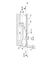
図1は液体吐出ヘッドを液流路方向で切断した断面模式図を示しており、図2はこの液体吐出ヘッドの部分破断斜視図を示している。
【0077】
図1の液体吐出ヘッドは、液体を吐出するための吐出エネルギ発生素子として、液体に熱エネルギを作用させる発熱体2(図1においては40μm×105μmの形状の発熱抵抗体)が素子基板1に設けられており、この素子基板上に発熱体2に対応して液流路10が配されている。液流路10は吐出口18に連通していると共に、複数の液流路10に液体を供給するための共通液室13に連通しており、吐出口から吐出された液体に見合う量の液体をこの共通液室13から受け取る。
【0078】
この液流路10の素子基板上には、前述の発熱体2に対向するように面して、金属等の弾性を有する材料で構成され、平面部を有する板状の可動部材31が片持梁状に設けられている。この可動部材の一端は液流路10の壁や素子基板上に感光性樹脂などをパターニングして形成した土台(支持部材)34等に固定されている。これによって、可動部材は保持されると共に支点(支点部分)33を構成している。
【0079】
この可動部材31は、液体の吐出動作によって共通液室13から可動部材31を経て吐出口18側へ流れる大きな流れの上流側に支点(支点部分;固定端)33を持ち、この支点33に対して下流側に自由端(自由端部分)32を持つように、発熱体2に面した位置に発熱体2を覆うような状態で発熱体から15μm程度の距離を隔てて配されている。この発熱体と可動部材との間が気泡発生領域となる。なお、発熱体、可動部材の種類や形状および配置はこれに限られることなく、後述するように気泡の成長や圧力の伝搬を制御しうる形状および配置であればよい。なお、上述した液流路10は、後に取り上げる液体の流れの説明のため、可動部材31を境にして直接吐出口18に連通している部分を第1の液流路14とし、気泡発生領域11や液体供給路12を有する第2の液流路16の2つの領域に分けて説明する。
【0080】
発熱体2を発熱させることで可動部材31と発熱体2との間の気泡発生領域11の液体に熱を作用し、液体に米国特許第4,723,129号明細書に記載されているような膜沸騰現象に基づく気泡を発生させる。気泡の発生に基づく圧力と気泡は可動部材に優先的に作用し、可動部材31は図1(b)、(c)もしくは図2で示されるように支点33を中心に吐出口側に大きく開くように変位する。可動部材31の変位若しくは変位した状態によって気泡の発生に基づく圧力の伝搬や気泡自身の成長が吐出口側に導かれる。
【0081】
ここで、本発明に適用される基本的な吐出原理の一つを説明する。本発明において最も重要な原理の一つは、気泡に対面するように配された可動部材が気泡の圧力あるいは気泡自体に基づいて、定常状態の第1の位置から変位後の位置である第2の位置へ変位し、この変位する可動部材31によって気泡の発生に伴う圧力や気泡自身を吐出口18が配された下流側へ導くことである。
【0082】
この原理を可動部材を用いない従来の液流路構造を模式的に示した図3と本発明の図4とを比較してさらに詳しく説明する。なお、ここでは吐出口方向への圧力の伝搬方向をVA,上流側への圧力の伝搬方向をVBとして示した。
【0083】
図3で示されるような従来のヘッドにおいては、発生した気泡40による圧力の伝搬方向を規制する構成はない。このため気泡40の圧力伝搬方向はV1〜V8のように気泡表面の垂直方向となり様々な方向を向いていた。このうち、特に液吐出に最も影響を及ぼすVA方向に圧力伝搬方向の成分を持つものは、V1〜V4即ち気泡のほぼ半分の位置より吐出口に近い部分の圧力伝搬の方向成分であり、液吐出効率、液吐出力、吐出速度等に直接寄与する重要な部分である。さらに、V1は吐出方向VAの方向に最も近いため効率よく働き、逆にV4はVAに向かう方向成分は比較的少ない。
【0084】
これに対して、図4で示される本発明の場合には、可動部材31が図3の場合のように様々な方向を向いていた気泡の圧力伝搬方向V1〜V4を下流側(吐出口側)へ導き、VAの圧力伝搬方向に変換するものであり、これにより気泡40の圧力が直接的効率よく吐出に寄与することになる。
【0085】
そして、気泡の成長方向自体も圧力伝搬方向V1〜V4と同様に下流方向に導かれ、上流より下流で大きく成長する。このように、気泡の成長方向自体を可動部材によって制御し、気泡の圧力伝搬方向を制御することで、吐出効率や吐出力また吐出速度等の根本的な向上を達成することができる。
【0086】
次に、図1に戻って、上述した液体吐出ヘッドの吐出動作について詳しく説明する。
【0087】
図1(a)は、発熱体2に電気エネルギ等のエネルギが印加される前の状態であり、発熱体が熱を発生する前の状態である。ここで重要なことは、可動部材31が、発熱体の発熱によって発生した気泡に対し、この気泡の少なくとも下流側部分に対面する位置に設けられていることである。つまり、気泡の下流側が可動部材に作用するように、液流路構造上では少なくとも発熱体の面積中心3より下流(発熱体の面積中心3を通って流路の長さ方向に直交する線より下流)の位置まで可動部材31が配されている。
【0088】
図1(b)は、発熱体2に電気エネルギ等が印加されて発熱体2が発熱し、発生した熱によって気泡発生領域11内を満たす液体の一部を加熱し、発生した熱によって気泡発生領域11内を満たす液体の一部を加熱し、膜沸騰に伴う気泡を発生させた状態である。
【0089】
このとき可動部材31は気泡40の発生に基づく圧力により、気泡の圧力の伝搬方向を吐出口方向に導くように第1位置から第2位置へ変位する。ここで重要なことは前述したように、可動部材31の自由端32を下流側(吐出口側)に配置し、支点33を上流側(共通液室)に位置するように配置して、可動部材の少なくとも一部を発熱体の下流部分すなわち気泡の下流部分に対面させることである。
【0090】
図1(c)は気泡40がさらに成長した状態であるが、気泡40発生に伴う圧力に応じて可動部材31はさらに変位している。発生した気泡は上流より下流に大きく成長すると共に可動部材の第1の位置(点線位置)を越えて大きく成長している。このように気泡40の成長に応じて可動部材31が徐々に変位してゆくことで気泡40の圧力伝搬方向や体積移動のしやすい方向、すなわち自由端側への気泡の成長方向を吐出口に均一的に向かわせることができることも吐出効率を高めると考えられる。可動部材は気泡や発泡圧を吐出口方向へ導く際もこの伝達の妨げになることはほとんど伝搬する圧力の大きさに応じて効率よく圧力の伝搬方向や気泡の成長方向を制御することができる。
【0091】
図1(d)は気泡40が、前述した膜沸騰後、気泡内部圧力の減少によって収縮し、消滅する状態を示している。
【0092】
第2の位置まで変位していた可動部材31は、気泡の収縮による負圧と可動部材自身のばね性による復元力によって図1(a)の初期位置(第1の位置)に復帰する。また、消泡時には、気泡発生領域11での気泡の収縮体積を補うため、また、吐出された液体の体積分を補うために上流側(B)、すなわち共通液室側から流れのVD1、VD2のように、また、吐出口側から流れのVcのように液体が流れ込んでくる。
【0093】
以上、気泡の発生に伴う可動部材の動作と液体の吐出動作について説明したが、以下に本発明に適用可能な液体吐出ヘッドにおける液体のリフィルについて説明する。
【0094】
図1(c)の後、気泡40が最大体積の状態を経て消泡過程に入ったときには、消泡した体積を補う体積の液体が気泡発生領域に、第1液流路14の吐出口側と第2液流路16の共通液室13側から流れ込む。可動部材31を持たない従来の液流路構造においては、消泡位置に吐出口側から流れ込む液体の量と共通液室から流れ込む液体の量は、気泡発生領域より吐出口に近い部分と共通液室に近い部分との流抵抗の大きさに起因する(流路抵抗と液体の慣性に基づくものである)。
【0095】
このため、吐出口に近い側の流抵抗が小さい場合には、多くの液体が吐出口側から消泡位置に流れ込みメニスカスの後退量がおおきくなることになる。特に、吐出効率を高めるために吐出口に近い側の流抵抗を小さくして吐出効率を高めようとするほど、消泡時のメニスカスMの後退が大きくなり、リフィル時間が長くなって高速印字を妨げることとなっていた。
【0096】
これに対して本構成は可動部材31を設けたため、気泡の体積Wを可動部材の第11位置を境に上側をW1、気泡発生領域11側をW2とした場合、消泡時に可動部材が元の位置に戻った時点でメニスカスの後退はとまり、その後残ったW2の体積分の液体供給は主に第2流路16の流れVD2からの液供給によって成される。これにより、従来、気泡Wの体積の半分程度に対応した量がメニスカスの後退量になっていたのに対して、それより少ないW1の半分程度のメニスカス後退量に抑えることが可能になった。
【0097】
さらに、W2の体積分の液体供給は消泡時の圧力を利用して可動部材31の発熱体側の面に沿って、主に第2液流路の上流側(VD2)から強制的に行うことができるため、より速いリフィルを実現できた。
【0098】
ここで特徴的なことは、従来のヘッドで消泡時の圧力を用いたリフィルを行った場合、本構成メニスカスの振動が大きくなってしまい画像品位の劣化につながっていたが、本実施例のリフィルにおいては可動部材によって吐出口側の第1液流路14の領域と、気泡発生領域11との吐出口側での液体の流通が抑制されるためメニスカスの振動を極めて少なくすることができることである。
【0099】
このように本発明に適用される上述した構成は、第2液流路16の液供給路12を介しての発泡領域への強制リフィルと、上述したメニスカス後退や振動の抑制によって高速リフィルを達成することで、吐出の安定や高速繰り返し吐出、また記録の分野に用いた場合、画質の向上や高速記録を実現することができる。
【0100】
本発明の上述した構成においては、さらに次のような有効な機能を兼ね備えている。それは、気泡の発生による圧力の上流側への伝搬(バック波)を抑制することである。発熱体2上で発生した気泡の内、共通液室13側(上流側)の気泡による圧力は、その多くが上流側に向かって液体を押し戻す力(バック波)になっていた。このバック波は、上流側の圧力と、それによる液移動量、そして液移動に伴う慣性力を引き起こし、これらは液体の液流路内へのリフィルを低下させ高速駆動の妨げにもなっていた。本構成においては、まず可動部材31によって上流側へのこれらの作用を抑えることでもリフィル性の向上をさらに図っている。
【0101】
次に、さらなる特徴的な構造と効果について、以下に説明する。
【0102】
第2液流路16は、発熱体2の上流に発熱体2と実質的に平坦につながる(発熱体表面が大きく落ち込んでいない)内壁を持つ液体供給路12を有している。
このような場合、気泡発生領域11および発熱体2の表面への液体の供給は、可動部材31の気泡発生領域11に近い側の面に沿って、VD2のように行われる。このため、発熱体2の表面上に液体が淀むことが抑制され、液体中に溶存していた気体の析出や、消泡できずに残った、いわゆる残留気泡が除去され易く、また、液体への蓄熱が高くなりすぎることもない。従って、より安定した気泡の発生を高速に繰り返し行うことができる。なお、本構成では、実質的に平坦な内壁を持つ液体供給路12を持つもので説明したが、これに限らず、発熱体表面となだらかに繋がり、なだらかな内壁を有する液供給路であればよく、発熱体上に液体の淀みや、液体の供給に大きな乱流を生じない形状であればよい。
【0103】
また、気泡発生領域への液体の供給は、可動部材の側部(スリット35)を介してVD1から行われるものもある。しかし、気泡発生時の圧力をさらに有効に吐出口に導くために図1に示すように気泡発生領域の全体を覆う(発熱体面を覆う)ように大きな可動部材を用い、可動部材31が第1の位置への復帰することで、気泡発生領域11と第1液流路14の吐出口に近い領域との液体の流抵抗が大きくなるような形態の場合、前述のVD1から気泡発生領域11に向かっての液体の流れが妨げられる。しかし、本構成のヘッド構造においては、気泡発生領域に液体を供給するための流れVD1があるため、液体の供給性能が非常に高くなり、可動部材31で気泡発生領域11を覆うような吐出効率向上を求めた構造を取っても、液体の供給性能を落とすことがない。
【0104】
ところで、可動部材31の自由端32と支点の位置は、例えば図5で示されるように、自由端が相対的に支点より下流側にある。このような構成のため、前述した発泡の際に気泡の圧力伝搬方向や成長方向を吐出口側に導く等の機能や効果を効率よく実現できるのである。さらに、この位置関係は吐出に対する機能や効果のみならず、液体の供給の際にも液流路10を流れる液体に対する流抵抗を小さくでき高速にリフィルできるという効果を達成している。これは図5に示すように、吐出によって後退したメニスカスMが毛管力により吐出口18へ復帰する際や、消泡に対しての液供給が行われる場合に、液流路10(第1液流路14、第2液流路16を含む)内を流れる流れS1、S2,S3に対し、逆らわないように自由端と支点33とを配置しているためである。
【0105】
補足すれば、本構成においては、前述のように可動部材31の自由端32が、発熱体2を上流側領域と下流側領域とに2分する面積中心3(発熱体の面積中心(中央)を通り液流路の長さ方向に直交する線)より下流側の位置に対向するように発熱体2に対して延在している。これによって発熱体の面積中心位置3より下流側で発生する液体の吐出に大きく寄与する圧力、又は気泡を可動部材31が受け、この圧力および気泡を吐出口側に導くことができ、吐出効率や吐出力を根本的に向上させることができる。
【0106】
さらに、加えて上記気泡の上流側をも利用して多くの効果を得ている。
【0107】
また、本構成においては、可動部材31の自由端が瞬間的に機械的変位を行っていることも、液体の吐出に対して有効に寄与していると考えられる。
【0108】
【実施例】
図6は、本発明による第1の実施例の液体吐出ヘッドの液流路の断面図であり、図7(a)は、図6のA−B線に沿う断面構成をA方向から見た断面図であり、図7(b)は図6のC−D線に沿う断面構成をB方向から見た断面図である。
【0109】
図6ないし図7に示すように、本発明の液体吐出ヘッドは、液体に気泡を発生させるための熱エネルギーを与える個別に少なくとも1つは独立駆動可能な電気熱変換素子(以下、発熱体と称する)2−1,2−2が吐出口配列方向に複数(本実施例では2つ)と、発熱体に電気信号を印加するための配線電極5−1,5−2,5−3が形成されている素子基板1上に、第2の液流路(発泡液流路)16が配置され、その上に吐出口18に直接連通した第1の液流路(吐出液流路)14が配置されている。なお、1つの吐出口に対応した複数の発熱体で発熱部を構成している。以降の実施例も同様である。第1液流路の上流側は、複数の第1液流路に吐出液を供給するための第1共通液室15に連通しており、第2液流路の上流側は、複数の第2液流路に発泡液を供給するための第2共通液室17に連通している。そして、第1と第2の流路の間に、金属等の弾性を有する材料で構成され可動部材31が形成された分離壁30が配置され、第1の液流路14内の吐出液と第2の液流路16内の発泡液とを区分している。なお、発泡液と吐出液とができる限り混ざり合わない方がよい液体の場合には、この分離壁によってできる限り完全に第1液流路14と第2液流路16の液体の流通を分離した方が良いが、発泡液と吐出液とが同じ液体もしくはある程度混ざり合っても、問題がない場合には、分離壁に液体の完全分離機能を持たせなくてもよい。図中、50は前記第1の液流路14を構成する壁とインク吐出口18が一体で成型されている溝つき部材である。この溝つき部材50と前記素子基板1と分離壁30とにより、液体吐出ヘッドが構成されている。
【0110】
発熱体2−1,2−2の面方向上方への投影空間(以下吐出圧発生領域という。;図6中のAの領域とBの気泡発生領域11)に位置する部分の分離壁は、スリット35によって吐出口側(吐出口へ向かう液体の流れの下流側)が自由端で、共通液室(15、17)側(吐出口へ向かう液体の流れの上流側)に支点33が位置する片持梁状の可動部材31となっている。この可動部材31は、気泡発生領域11(B)に面して配されているため、発泡液の発泡によって第1液流路側に向けて開口するように動作する(図中矢印方向)。
【0111】
また、先にその際、発熱体2−1,2−2の駆動条件を変化させることでそれにより発生する気泡の状態と可動部材の変位量を変化させ液体の吐出量を変えることも可能である。液供給路12と発熱体2との構造の関係について説明したが、本実施例においても第2液流路16と発熱体2との構造の関係を同じくしている。なお、本実施例においては発熱体より下流方向の第2液流路16が行き止まりの構造になっている。
【0112】
次に、このヘッドの動作を図8ないし図10を用いて説明する。本実施例のヘッドの動作の特徴の一つに、階調制御が可能な点にある。
【0113】
この説明においては、本発明の理解を容易とするために、第1の液流路14に供給される吐出液と第2の液流路16に供給される発泡液とに同じ水系のインクを用いて動作させた。
【0114】
図8は、発熱体2−1,2−2ともOFFを示す。この場合、分離壁30に形成されている可動部材31の変形はなく、吐出量はゼロである。
【0115】
図9は、発熱体2−1,2−2のうち、発熱体2−1に、電圧24V、パルス幅5μsecの条件の駆動信号(パルス)を与えONしている状態を示している。第2の液流路16に満たされている発泡液に、発熱体2−1の発熱が作用することによって、特公昭61−59914号公報に記載されているような膜沸騰現象を生じさせ、気泡を発生させる。その時の発泡エネルギー(圧力)により、可動部材31が押し上げられ、可動部材31の可動先端は、H1だけの第1液流路内に変位する。気泡は、H1の隙間から、吐出インクが満たされている第1の液流路14に侵入し、発泡圧力波が第1の液流路14の吐出口側の方向に主に伝わり、V1のインク量を吐出させる。
【0116】
図10は、発熱体2−1,2−2の両方に前述と同様の駆動信号を与えることで両方の発熱体をON状態とし、インクを加熱して気泡を発生させている状態である。発泡エネルギーは、図11よりも大きく、その発泡エネルギーは、可動部材31の可動先端をH2の量だけ押し上げ、可動部材31の変位量は最大となる。そして、気泡発生領域6で発生した気泡は、H2の隙間から吐出インクの液流路14に侵入し、最大の吐出量V2のインク量を吐出させる。
【0117】
また、図には示していないが、発熱体2−1と発熱体2−2とのヒータサイズを変えて発熱体2−2のみが発泡している場合は、可動部材7の変位量はH1,H2と異なるため、吐出量もV1,V2とは異なる吐出量を得ることができる。
【0118】
以上のように本発明おいては、駆動する発熱体の数や異なる位置の発熱体を変えることで、変位量等の変位状態を変えており、このことで量の異なる液滴を吐出することができる。
【0119】
本発明においても、従来の構成のヘッドに比べて高い吐出エネルギー効率で、また高い吐出圧でインクを吐出することができるのは、先に説明したような可動部材の変位が発泡を吐出口に導く原理およびこれらの現象の相互作用によるものである。
【0120】
このように、1ノズルまた1つの可動部材に対して複数個の発熱体を配し、各発熱体のON,OFFの組み合わせにより、可動部材31の変形量をコントロールすることが可能となる。
【0121】
これによりインクの吐出量のコントロールができ、その結果、記録の階調表現が可能となることを示す。
【0122】
したがって、複数の発熱体を設けることにより、多段階の階調表現が可能となる。表1に、本実施例に示すヘッドを用い、各発熱体の駆動の組み合わせによる可動部材の吐出量の関係を示した。
【0123】
なお、本実施例で用いた液体吐出ヘッドは、図6〜図10で示したヘッドであり、34μm直径の吐出口を70.5μmピッチで複数配したものである。発熱体2−1,2−2は同じサイズの18×100μmサイズのものを用いた。駆動条件は電圧24V、パルス幅5μm、駆動周波数200Hzであり、吐出量はそれぞれの発熱体の駆動モードで20000回吐出した全体の吐出量を、吐出回数で割った平均値として求めた。また、本実施例で用いた液体は、発泡液も吐出液も同じ水性インクを用いた。
【0124】
【表1】

(a)発熱体2−1,2−2のすべてがOFFの時は、可動部材の変形量は0である。したがって、吐出量も0である。
【0126】
(b)発熱体2−1のみがONの時は、吐出量は40ngであった。
【0127】
(c)発熱体2−1,2−2がONの時は、可動部材の変形量は2−1のみがONの時より大きく、吐出量は80ngであった。
【0128】
このような吐出量で画像を形成した場合を、反射濃度で示したものが、図11である。
【0129】
反射濃度はインクの吐出量に比例するため、2つの発熱体のON/OFFを組み合わせることにより、4段階にインクの吐出量を変化することができれば図12に示すように反射濃度も4階調を得ることができる。
【0130】
また、本発明においては、前述のように従来の液体吐出ヘッドに比べ可動部材を配した構成にすることにより、液体の吐出効率や吐出力がそもそも高いため、吐出量を変化させる階調記録の場合に、小液滴を繰り返し吐出としても安定した吐出を得ることができる。
【0131】
また、前述のように本発明の液体吐出ヘッドは可動部材の動作によりリフィルが高速に成されるため小液滴を吐出させる場合であっても高速駆動を達成することもできる。さらに、従来の液体吐出ヘッドは、個々の発熱体を駆動させた際に吐出方向が変わってしまうことがある。その様子を図12に示す。図12(a)は吐出口に向かって右側の発熱体2−1を駆動した場合を示し、液体は吐出口から左側へ吐出する。また、図12(b)に示すように吐出口に向かって左側の発熱体2−2を駆動した場合は、液体は吐出口から右側へ吐出する。しかし、本発明の液体吐出ヘッドでは、可動部材31を配しているため、個々の発熱体を駆動させた際にも発泡パワーを吐出口の中心へと導き、液流路に対する発熱体の位置によらず吐出方向を安定されることができる。以上のように、本発明では小液滴を高吐出周波数で安定的に吐出することができるため、高画質な階調記録を高速で記録することができる。
【0132】
図13は本発明における第2の実施例の液体吐出ヘッドを前述の図7で示した位置で切断した模式断面図を示したものであり(図13において配線電極については省略している)、より小さな液滴を吐出させるために、前述の第1実施例の2つの発熱体の形状を異ならせたものである。本実施例においては、吐出口に向かって右側の発熱体2−1の大きさを13×100μmとし、吐出口に向かって左側の発熱体2−2の大きさを23×100μmとしており、吐出口に向かって左柄の発熱体の方を大きくしている。なお、可動部材の大きさは、40×210μmとした。なお、ここでも複数の発熱体で発熱手段を構成している。
【0133】
このような構成によって、前述の第1実施例の効果に加え、さらに発熱体2−1のみを駆動した時の吐出量が少なくなり、より小さな液滴を吐出させることができる。これにより面積の大きな発熱体による吐出量と面積の小さな発熱体による吐出量との差を大きくとれるため階調表現領域をより広くすることができる。
【0134】
本実施例においては、発熱体の数を2つしたがこれに限らず、さらに多くの発熱体を吐出口配列方向に配置しても良い。
【0135】
次に、図14は可動部材31に対して2つの発熱体を吐出口に向かう流れの方向に沿って配置した液体吐出ヘッドを示した第3の実施例である。図14(a)は、前述の図13(a)と同様の断面図であり、図14(b)は、前述の図13(b)と同様の断面図である。本実施例では40×50μmの独立駆動が可能な発熱体を液流路内に2つ配し、40×210μmの可動部材31を配している。
本実施例においても、各発熱体のON,OFFの組み合わせにより、可動部味31の変形量をコントロールすることが可能となり、よってインクの吐出量のコントロールができ、その結果、記録の階調表現が可能となる。また、本実施例で発熱体を吐出口に向かう流れの方向に沿って配列したため、液流路の高密度化に伴う液流路幅の減少に対しても有利なレイアウトなため高密度での階調記録を高速で記録することができる。
【0136】
本実施例においても発熱体の形状を前後で異ならせることにより、より大きな吐出量と小さな吐出量の差を大きく吐出させることができ、階調表現領域をさらに高めることができる。
【0137】
また、本実施例においては、発熱体の数を2つとしたが、これに限らず、さらに多くの発熱体を吐出口に向かう流れの方向に沿った方向に配列しても良い。
【0138】
図15は、1つの第1液流路や吐出口に対して複数の可動部材31を設けた例を示した第4の実施例である。図15(a)は、前述の図14(a)と同様の断面図であり、図15(b)は前述の図14(b)と同様の断面図である。本実施例では、18×100μmの独立駆動が可能な発熱抵抗体を2つ並列に配しており、そのそれぞれに対応した位置に2つの20×210μmの可動機構としての可動部材31をそれぞれ配している。なお、ここでも複数の発熱体で発熱手段を構成している。また、各発熱体2−1と2−2による各々の気泡発生領域の間を仕切るような仕切壁38が第2液流路内に設けられており第2の液流路をそれぞれ2つの第2液流路(16−1,16−2)に分けている。発熱体2−1が駆動され第2液流路内の液体に気泡を発生しても、この気泡発生時の圧力で可動部材31−1が第1液流路側に大きく変位し、気泡を吐出口に向けて成長させると共に、第1液流路に伝わった圧力によって処理量の液体が吐出口から液体が吐出される。次に発熱体2−1と発熱体2−2が同時に駆動されると、発熱体2−1だけを駆動した場合に比べ約倍の液体を吐出量を得ることができた。
【0139】
表2は本実施例の液体吐出ヘッドを用いて、以下のような条件で吐出を行わせたときの平均吐出量を示したものである。
【0140】
【0141】
液体の吐出量は、それぞれの駆動モードで20000回吐出動作を行わせたときの消費液体量を吐出回数で割った平均値として求めた。
【0142】
【表2】
このように本実施例においては、2種類の異なる量の液体を従来に比較して極めて安定化した状態で吐出することができ、3値の階調記録を、階調性よくまた高速に行うことができた。
【0144】
また、本実施例では、第2液流路をそれぞれの2つの第2液流路(16−1,16−2)に分けているため、各発熱体が単独で駆動されたときの気泡圧力の第2の液流路壁側(両側)に対しての逃げを防止でき、各可動部材31−1,31−2をより効率的に変位させることができる。このことで、吐出効率や吐出力がさらに高まり、階調性、安定性をより高めることができる。
【0145】
さらに、仕切壁38で各発熱体の気泡発生領域を仕切っており、各発熱体の発泡が互いに干渉されないため、2つの発熱体を同時に駆動した際に発泡タイミングのわずかなズレによって生じる発泡圧のロスがなくなり、各ノズル間や1つのノズルの吐出毎の吐出特性の均一性が高まる(これは、数μsec〜数十μsecのオーダーで加圧/減圧を生ずるバブルジェット方式の発泡、消泡に起因する)。本実施例では2つの発熱体のサイズを同一にしたが、異ならせてもよい。また、本実施例では2つの可動部材のサイズを同一にしたが異ならせてもよい。さらにまた、本実施例では、各可動部材や発熱体の吐出口からの距離を同一にしたが、異ならせてもよい。
【0146】
次に図16は、1つの第1液流路や吐出口に対して複数の可動部材31を設け、それぞれの可動部材に対して吐出口に向かう流れの方向に沿って2つの発熱体を配置した例を示した第5の実施例である。図16(a)は前述の図15(a)と同様の断面図であり、図16(b)は前述の図15(b)と同様の断面図である。本実施例では、液流路内に20×210μmの可動部材31が2つ吐出口に向かう流れの方向に対し並列に配しており、それぞれ吐出口に向かう流れの方向に沿って18×50μmの発熱体を2つ配列した。
【0147】
また、各可動部材に対して配列された2つの発熱体(2−1,2−2と2−3,2−4)の間を仕切るような仕切壁38を設け、さらにまた各可動部材の間のスリットを共通のものとした。
【0148】
このような構成をとることにより、第4の実施例と同様に各発熱体が駆動されたときの圧力の第2液流路壁方向(両側)に対しての逃げを防止でき、各発熱体の同時駆動における発泡のズレによる圧力のロスがなく各可動部材31−1,31−2をより効率的、安定的に変位させることができる。
【0149】
また、各可動部材に対し2つの発熱体を設けることで、さらに高い階調性を得ることができる。
【0150】
さらにまた各可動部材の間のスリットを共通にすることにより、可動部材のより高密度配列を可能にし、簡易に製造することができる。
【0151】
本実施例においては、各可動部材に対して、発熱体の数を2つとしたが、これに限らず、さらに多くの発熱体を配しても良い。また、必要に応じては、各可動部材に対する発熱体の数を変えても良い。
【0152】
次に図21は、1つの第1液流路や吐出口に対して1つの可動部材を設け、2つの発熱体を仕切壁38で仕切るように配置した例を示した第6の実施例である。図17(a)は前述の図16(a)と同様の断面図であり、図17(b)は前述の図16(b)と同様の断面図である。本実施例では、40×210μmの可動部材を配し、吐出口が配列される方向に18×100の発熱体を2つ配列した。また、各発熱体2−1と2−2の間を仕切るような仕切壁が第2液流路内に設けられており、第2の液流路をそれぞれ2つの第2液流路(16−1,16−2)に分けている。
【0153】
このような構成をとることにより、前述した第4の実施例と同様に各発熱体が駆動されたときの圧力の第2液流路側方(両側)への逃げの防止等の効果により、各可動部材31を効率的、安定的に変位させることができる。
【0154】
また、可動部材31を配しているため、個々の発熱体を駆動させた際にも、発泡パワーを吐出口の中心へと導き、吐出方向を安定させることができる。
【0156】
また、第1から第6の実施例の構成の液体吐出ヘッドにおいては、従来の液体吐出ヘッドに比べ液体の吐出効率や吐出力がそもそも高い上、前述したように吐出特性が安定し、吐出方向頻度が高いため、この効果を図18に示すように線画像等の品位を向上させるスムージング記録技術に応用することで、スムージング効果をより高いレベルで実現することが可能になった。図18(a)は、1種類の吐出量で直線を記録したときの模式図であり、図18(b),(c)は、それぞれ2種類(大小ドット)、3種類(大,中,小ドット)の吐出量で直線を記録したときの模式図である。吐出量を2種類、3種類使用することにより、直線を滑らかに記録表現することが可能になった。従来の液体吐出ヘッドでは、小液滴を安定的にかつ所望の位置に適正に吐出することが難しかったが、本発明の液体吐出ヘッドは数種類の量の液体を安定的(吐出液体量および所望の位置の各精度が優れている)に吐出することができるため、優れたスムージングが可能となる。
【0157】
これにより、文字や図形のエッジを滑らかにかつ確実に再現可能となり、印字品位が向上した。
【0158】
さらに、第1から第6の実施例の構成の液体吐出ヘッドにおいては、発熱体を複数有しているため、印字信頼性を向上するために、印字直前に行う予備吐出に対しても有効である。図19は第1の実施例の液体吐出ヘッドにおける印字開始から印字終了までのシーケンスをフローチャートで表したものである。印字待機状態(S−1)から印字開始信号(S−2)が送られた後に予備吐出(S−3)を行い、印字(S−4)を開始し、印字中にも、不使用ノズルの目詰まりを防ぐために予備吐出(S−5)を行う。予備吐出は環境に応じて、数100Hz〜数kHzの駆動で、数発〜数1000発行った。本発明では、これらの予備吐出の条件を発熱体2−1,2−2を同時に駆動させて行うことで、従来より少ない吐出回数を短時間で行っても、不吐出等がない信頼の高い印字を行うことができた(S−6〜S−7)。これにより、より安定した印字品位を効率的に得ることができる。
【0159】
上述したように、極めて新規な吐出原理に基づく構成に加え、液流路に対し発熱体および可動部材を複数有した本発明の吐出方法および液体吐出ヘッド等によると可動部材を配したことにより、極めて安定性や吐出方向頻度の高い階調画像を実現し、非常に高画質な画像を得ることができた。また、吐出量変調による階調性を実現しつつリフィル特性等の吐出特性を高い水準で維持することができた。さらに、上記効果を応用して曲線や斜線等の画像をスムーズな線を実現し文字やグラフィックス等の画像品位を向上させることができた。
【0160】
同様に、上記効果を応用し、吐出信頼性向上のための印字開始直前の予備吐出を極めて少ない液体吐出数で短時間で行うことができた。
【0161】
<その他の実施例>
以上、本発明の液体吐出ヘッドや液体吐出方法の要部の実施例について説明を行ったが、以下にこれらの実施例に好ましく適用できる実施態様例について図面を用いて説明する。但し、以下の説明においては前述の1流路形態の実施例と2流路形態の実施例のいずれかを取り上げて説明する場合があるが、特に記載しない限り、両実施例に適用しうるものである。
【0162】
<第2液流路と可動部材との配置関係>
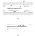
図20は、上述の可動部材31と第2液流路16との配置関係を説明するための図であり、同図(a)は分離壁30、可動部材31近傍を上方から視た図であり、(b)は分離壁30を外した第2液流路16を上方から視た図である。そして、(c)は可動部材31と第2液流路16との配置関係を、これらの各要素を重ねることで模式的に示した図である。なお、いずれの図も図面下方が吐出口の配されている前面側である。
【0163】
本実施例の第2の液流路16は前述のように発熱体2−2の上流側(ここでの上流側とは第2共通液室側から発熱体位置、可動部材、第1液流路を経て吐出口に向かう大きな流れの中の上流側のことである。)に狭窄部19を持っており、発泡時の圧力が第2液流路16の上流側に容易に逃げることを抑制するような室(発泡室)構造となっている。先に説明した図16でも同様に構成されており、図13〜図19の実施例では上流と下流に狭窄部19が設けられている。
【0164】
従来のヘッドのように、発泡する流路と液体を吐出するための流路とが同じで、発熱体より液室側に発生した圧力が共通液室側に逃げないように狭窄部を設けるヘッドの場合には、液体のリフィルを充分考慮して、狭窄部における流路断面積があまり小さくならない構成を採る必要があった。
【0165】
しかし、本実施例の場合、吐出される液体の多くを第1液流路内の吐出液とすることができ、発熱体が設けられた第2液流路内の発泡液はあまり消費されないようにできるため、第2液流路の気泡発生領域11への発泡液の充填量は少なくて良い。従って、上述の狭窄部19における間隔を数μm〜十数μmと非常に狭くできるため、第2液流路で発生した発泡時の圧力をあまり周囲に逃がすことをさらに抑制でき、集中して可動部材側に向けることができる。そしてこの圧力を可動部材31を介して吐出力として利用することができるため、より高い吐出効率、吐出力を達成することができる。ただ、第1液流路16の形状は上述の構造に限られるものではなく、気泡発生に伴う圧力が効果的に可動部材側に伝えられる形状であれば良い。
【0166】
なお、図20(c)で示されるように可動部材31の側方は、第2液流路を構成する壁の一部を覆っており、このことで、可動部材31の第2液流路への落ち込みを防止できる。これによって、前述した吐出液と発泡液との分離性をさらに高めることができる。また、気泡のスリットからの逃げの抑制ができるため、さらに吐出圧や吐出効率を高めることができる。さらに、前述の消泡時の圧力による上流側からのリフィル効果を高めることができる。
【0167】
なお、図9や図10においては、可動部材31の第1の液流路14側への変位に伴って第2の液流路16の気泡発生領域で発生した気泡の一部が第1の液流路14側に延在しているが、このように気泡が延在するような第2液流路の高さにすることで、気泡が延在しない場合に比べて更に吐出力を向上させることができる。このように気泡が第1の液流路14に延在するようにするためには、第2の液流路16の高さを最大気泡の高さよりも低くすることが望ましく、この高さを数μm〜30μmとすることが望ましい。なお、本実施例においては、この高さを15μmとした。
【0168】
<可動部材および分離壁>
図21は可動部材31の他の形状を示す平面図であり、同図(a)は長方形の形状であり、(b)は支点側が細くなっている形状で可動部材の動作が容易な形状であり、(c)は支点側が広くなっており、可動部材の耐久性が向上する形状である。動作の容易性と耐久性が良好な形状として、容易に動作可能な形状で、耐久性に優れた形状であればよい。
【0169】
先の実施例においては、板状の可動部材31およびこの可動部材を有する分離壁5は厚さ5μmのニッケルで構成したが、これに限られることなく可動部材、分離壁を構成する材質としては発泡液と吐出液に対して耐溶剤性があり、可動部材として良好に動作するための弾性を有し、微細なスリットが形成できるものであればよい。
【0170】
可動部材の材料としては、耐久性の高い、銀、ニッケル、金、鉄、チタン、アルミニウム、白金、タンタル、ステンレス、りん青銅等の金属、およびその合金、または、アクリロニトリル、ブタジエン、スチレン等のニトリル基を有する樹脂、ポリアミド等のアミド基を有する樹脂、ポリカーボネート等のカルボキシル基を有する樹脂、ポリアセタール等のアルデヒド基を持つ樹脂、ポリサルフォン等のスルホン基を持つ樹脂、そのほか液晶ポリマー等の樹脂およびその化合物、耐インク性の高い、金、タングステン、タンタル、ニッケル、ステンレス、チタン等の金属、これらの合金および耐インク性に関してはこれらを表面にコーティングしたもの若しくはポリアミド等のアミド基を有する樹脂、ポリアセタール等のアルデヒドを持つ樹脂、ポリエーテルエーテルケトン等のケトン基を有する樹脂、ポリイミド等のイミド基を有する樹脂、フェノール樹脂等の水酸基を有する樹脂、ポリエチレン等のエチル基を有する樹脂、ポリプロピレン等のアルキル基を有する樹脂、エポキシ樹脂等のエポキシ基を有する樹脂、メラミン樹脂等のアミノ基を有する樹脂、キシレン樹脂等のメチロール基を有する樹脂およびその化合物、さらに二酸化珪素等のセラミックおよびその化合物が望ましい。
【0171】
分離壁の材質としては、ポリエチレン、ポリプロピレン、ポリアミド、ポリエチレンテレフタレート、メラミン樹脂、フェノール樹脂、エポキシ樹脂、ポリブタジエン、ポリエーテルエーテルケトン、ポリエーテルサルフォン、ポリアリレート、ポリイミド、ポリサルフォン、液晶ポリマー(LCP)等の近年のエンジニアリングプラスチックに代表される耐熱性、耐溶剤性、成型性の良好な樹脂、およびその化合物、もしくは、二酸化珪素、窒化珪素、ニッケル、金、ステンレス等の金属、合金およびその化合物、もしくは表面にチタンや金をコーティングしたものが望ましい。
【0172】
また、分離壁の厚さは、分離壁としての強度を達成でき、可動部材として良好に動作する観点からその材質と形状等を考慮して決定すればよいが、0.5μm〜10μm程度が望ましい。
【0173】
なお、可動部材31を形成するためのスリット35の幅は本実施例では2μmとしたが、発泡液と吐出液とが異なる液体であり、両液体の混液を防止した場合は、スリット幅を両者の液体間でメニスカスを形成する程度の間隔とし、各々の液体同士の流通を抑制すればよい。例えば、発泡液として2cps(センチポアズ)程度の液体を用い、吐出液として100cps以上の液体を用いた場合には、5μm程度のスリットでも混液を防止することができるが、3μm以下にすることが望ましい。
【0174】
本発明の「実質的な密閉状態」を与えるスリットとしては、数μmオーダーであればより確実である。
【0175】
<素子基板>
以下に液体に熱を与えるための発熱体が設けられた素子基板の構成について説明する。
【0176】
図22は本発明の液体吐出ヘッドの縦断面図を示したもので、同図(a)は後述する保護膜があるヘッド、(b)は保護膜がないものである。
【0177】
なお、ここでは、図7の実施例等の縦断面図を示しており、断面図上では複数の発熱体は1つしか示されない。
【0178】
素子基板1上に第2液流路16、分離壁30、第1液流路14、第1液流路を構成する溝を設けた溝付き部材50が配されている。
【0179】
素子基板1上には、シリコン等の基体107に絶縁および蓄熱を目的としたシリコン酸化膜または窒化シリコン膜106を成膜し、その上に発熱体を構成するハフニュウムボライド(HfB2 )、窒化タンタル(TaN)、タンタルアルミ(TaAl)等の電気抵抗層105(0.01〜0.2μm厚)とアルミニウムの配線電極104(0.2〜1.0μm厚)がパターニングされている。この2つの配線電極104から抵抗層105に電圧を印加し、抵抗層に電流を流し発熱させる。配線電極間の抵抗層上には、酸化シリコンや窒化シリコン等の保護層103を0.1〜2.0μm厚で形成し、さらにその上にタンタル等の耐キャビテーション層102(0.1〜0.6μm厚)が成膜されており、インク等の各種の液体から抵抗層105を保護している。
【0180】
特に、気泡の発生、消泡の際に発生する圧力や衝撃波は非常に強く、堅くてもろい酸化膜の耐久性を著しく低下させるため、金属材料のタンタル(Ta)等の耐キャビテーション層として用いられる。
【0181】
また、液体、液流路構成、抵抗材料の組み合わせにより上述の保護層を必要としない構成でもよく、その例を図22(b)に示す。このような保護層を必要としない抵抗層の材料としてはインジュウム・タンタル・アルミ合金等が挙げられる。
【0182】
このように、前述の各実施例における発熱体の構成としては、前述の電極間の抵抗層(発熱部)だけででもよく、また抵抗層を保護する保護層を含むものでもよい。
【0183】
本実施例においては、発熱体として電気信号に応じて発熱する抵抗層で構成された発熱部を有するものを用いたが、これに限られることなく、吐出液を吐出させるのに十分な気泡を発泡液に生じさせるものであればよい。例えば、発熱部としてレーザ等の光を受けることで発熱するような光熱変換体や高周波を受けることで発熱するような発熱部を有する発熱体でもよい。
【0184】
なお、前述の素子基板1には、前述の発熱部を構成する抵抗層105と、この抵抗層に電気信号を供給するための配線電極104で構成される電気熱変換体の他に、この電気熱変換素子を選択的に駆動するためのトランジスタ、ダイオード、ラッチ、シフトレジスタ等の機能素子が一体的に半導体製造工程によって作り込まれていてもよい。
【0185】
また、前述のような素子基板1に設けられている電気熱変換体の発熱部を駆動し、液体を吐出するためには、前述の抵抗層105に配線電極104を介して図23で示されるような駆動選択手段150により矩形パルスを印加し、配線電極間の抵抗層105を急峻に発熱させる。前述の各実施例のヘッドにおいては、それぞれ電圧24V、パルス幅7μsec、電流10mA、電気信号を6kHzで加えることで発熱体を駆動させ、前述のような動作によって、吐出口から液体であるインクを吐出させた。
【0186】
図22(a),(b)において31aおよび31bは前述した発熱部による発泡で変位した可動部材の様子を示したものである。
【0187】
可動部材31は前述した発熱体2−1および2−2の選択的駆動によって31a,31bのように変位の大きさが異ならせることができる。これにより、液吐出量等の吐出状態を変化させることができるのである。さらに、前述した駆動条件すなわち電圧やパルス幅を変化させることでも、ある程度吐出状態を変えることが可能である。
【0188】
<2流路構成のヘッド構造>
以下に、第1,第2の共通液室に異なる液体を良好に分離して導入でき部品点数の削減を図れ、コストダウンを可能とする液体吐出ヘッドの構造例について説明する。
【0189】
図24は、このような液体吐出ヘッドの構造を示す模式図であり、先の実施例と同じ構成要素については同じ符号を用いており、詳しい説明はここでは省略する。
【0190】
本実施例においては、溝付部材50は、吐出口18を有するオリフィスプレート51と、複数の第1液流路14を構成する複数の溝と、複数の液流路14に共通して連通し、各第1の液流路3に液体(吐出液)を供給するための第1の共通液室15を構成する凹部とから概略構成されている。
【0191】
この溝付部材50の下側部分に分離壁30を接合することにより複数の第1液流路14を形成することができる。このような溝付部材50は、その上部から第1共通液室15内に到達する第1液体供給路20を有している。また、溝付部材50は、その上部から分離壁30を突き抜けて第2共通液室17内に到達する第2の液体供給路21を有している。
【0192】
第1の液体(吐出液)は、図24の矢印Cで示すように、第1液体供給路20を経て、第1の共通液室15、次いで第1の液流路14に供給され、第2の液体(発泡液)は、図24の矢印Dで示すように、第2液体供給路21を経て、第2共通液室17、次いで第2液流路16に供給されるようになっている。
【0193】
本実施形態例では、第2液体供給路21は、第1液体供給路20と平行して配されているが、これに限ることはなく、第1共通液室15の外側に配された分離壁30を貫通して、第2共通液室17に連通するように形成されればどのように配されてもよい。
【0194】
また、第2液体供給路21の太さ(直径)に関しては、第2液体の供給量を考慮して決められる。第2液体供給路21の形状は丸形状である必要はなく、矩形状等でもよい。
【0195】
また、第2共通液室17は、溝付部材50を分離壁30で仕切ることによって形成することができる。形成の方法としては、図25で示す本実施例の分解斜視図のように、素子基板上にドライフィルムで共通液室枠と第2液路壁を形成し、分離壁を固定した溝付部材50と分離壁30との結合体と素子基板1とを貼り合わせることにより第2共通液室17や第2液流路16を形成してもよい。
【0196】
本実施形態例では、アルミニウム等の金属で形成された支持体70上に、前述のように、発泡液に対して膜沸騰による気泡を発生させるための熱を発生する発熱体としての電気熱変換素子が複数設けられた素子基板1が配されている。
【0197】
この素子基板1上には、液路壁26により形成された第2液流路16を構成する複数の溝と、複数の第2液流路(発泡液流路)16に連通し、それぞれの発泡液流路に発泡液を供給するための第2共通液室(共通発泡液室)17を構成する凹部と、前述した可動壁31が設けられた分離壁30とが配されている。
【0198】
符号50は、溝付部材である。この溝付部材は、分離壁30と接合されることで吐出液流路(第1液流路)14を構成する溝と、吐出液流路に連通し、それぞれの吐出液流路に吐出液を供給するための第1の共通液室(共通吐出液室)15を構成するための凹部と、第1共通液室に吐出液を供給するための第1供給路(吐出液供給路)20と、第2の共通液室17に発泡液を供給するための第2の供給路(発泡液供給路)21とを有している。第2の供給路21は、第1の共通液室15の外側に配された分離壁30を貫通して第2の共通液室17に連通する連通路に繋がっており、この連通路によって吐出液と混合することなく発泡液を第2の共通液室15に供給することができる。
【0199】
なお、素子基板1、分離壁30、溝付天板50の配置関係は、素子基板1の発熱体に対応して可動部材31が配置されており、この可動部材31に対応して吐出液流路14が配されている。また、本実施形態例では、第2の供給路を1つ溝付部材に配した例を示したが、供給量に応じて複数設けてもよい。さらに吐出液供給路20と発泡液供給路21の流路断面積は供給量に比例して決めればよい。
【0200】
このような流路断面積の最適化により溝付部材50等を構成する部品をより小型化することも可能である。
【0201】
以上説明したように本実施例によれば、第2液流路に第2液体を供給する第2の供給路と、第1液流路に第1液体を供給する第1の供給路とが同一の溝付部材としての溝付天板からなることにより部品点数が削減でき、工程の短縮化とコストダウンが可能となる。
【0202】
また第2液流路に連通した第2の共通液室への、第2液体の供給は、第1液体と第2液体を分離する分離壁を突き抜ける方向で第2液流路によって行われる構造であるため、前記分離壁と溝付部材と発熱体形成基板との貼り合わせ工程が1度で済み、作りやすさが向上すると共に、貼り合わせ精度が向上し、良好に吐出することができる。
【0203】
また、第2液体は、分離壁を突き抜けて第2液体共通液室へ供給されるため、第2液流路に第2液体の供給が確実となり、供給量が十分確保できるため、安定した吐出が可能となる。
【0204】
(吐出液体、発泡液体)
先の実施例で説明したように本発明においては、前述のような可動部材を有する構成によって、従来の液体吐出ヘッドよりも高い吐出力や吐出効率でしかも高速に液体を吐出することができる。前述の各実施例の内、発泡液と吐出液とに同じ液体を用いる場合には、発熱体から加えられる熱によって劣化せずに、また加熱によって発熱体上に堆積物を生じにくく、熱によって気化、凝縮の可逆的状態変化を行うことが可能であり、さらに液流路や可動部材や分離壁等を劣化させない液体であれば種々の液体を用いることができる。
【0205】
このような液体の内、記録を行う上で用いる液体(記録液体)としては従来のバブルジェット装置で用いられていた組成のインクを用いることができる。
【0206】
一方、本発明の2流路構成のヘッドを用いた場合、吐出液体と発泡液とに別液体を用いることができ、発泡液の発泡を利用して吐出困難な吐出液体を吐出させることができる。このように吐出液と発泡液を別液体とした場合には、発泡液として前述のような性質の液体を用いればよく、具体的には、メタノール、エタノール、n−プロパノール、イソプロパノール、n−ヘキサン、n−ヘプタン、n−オクタン、トルエン、キシレン、二塩化メチレン、トリクレン、フレオンTF、フレオンBF、エチルエーテル、ジオキサン、シクロヘキサン、酢酸メチル、酢酸エチル、アセトン、メチルエチルケトン、水等およびこれらの混合物が挙げられる。
【0207】
吐出液としては、発泡性の有無、熱的性質に関係なく様々な液体を用いることができる。また、従来吐出が困難であった発泡性が低い液体、熱によって変質、劣化しやすい液体や高粘度液体等であっても利用できる。
【0208】
ただし、吐出液の性質として吐出液自身、又は発泡液との反応によって、吐出や発泡また可動部材の動作等を妨げるような液体でないことが望まれる。
【0209】
記録用の吐出液体としては、高粘度インク等をも利用することができる。その他の吐出液体としては、熱に弱い医薬品や香水等の液体を利用することもできる。
【0210】
本発明においては、吐出液と発泡液の両方に用いることができる記録液体として以下のような組成のインクを用いて記録を行ったが、吐出力の向上によってインクの吐出速度が高くなったため、液滴の着弾精度が向上し非常に良好な記録画像をことができる。
【0211】
染料インク(粘度2cps)の組成
(C.I.フードブラック2)染料 3重量%
ジエチレングリコール 10重量%
チオジグリコール 5重量%
エタノール 5重量%
水 77重量%
また、発泡液と吐出液に以下で示すような組成の液体を組み合わせて吐出させて記録を行った。その結果、従来のヘッドでは吐出が困難であった十数cps粘度の液体はもちろん150cpsという非常に高い粘度の液体で良好に吐出でき、高画質な記録物を得ることができた。
【0212】
発泡液1の組成
エタノール 40重量%
水 60重量%
発泡液2の組成
水 100重量%
発泡液3の組成
イソプロピルアルコール 10重量%
水 90重量%
吐出液1顔料インク(粘度約15cps)の組成
カーボンブラック 5重量%
スチレン−アクリル酸−アクリル酸エチル共重合体 1重量%
(酸価140、重量平均分子量8000)
モノエタノールアミン 0.25重量%
グリセリン 69重量%
チオジグリコール 5重量%
エタノール 3重量%
水 16.75重量%
吐出液2(粘度55cps)の組成
ポリエチレングリコール200 100重量%
吐出液3(粘度150cps)の組成
ポリエチレングリコール600 100重量%
ところで、前述したような従来吐出されにくいとされていた液体の場合には、吐出速度が低いために、吐出方向性のバラツキが助長され記録紙上のドットの着弾精度が悪く、また吐出不安定による吐出量のバラツキが生じ、これらのことで高品位画像が得られにくかった。しかし、上述の実施例の構成においては、気泡の発生を発泡液を用いることで充分に、しかも安定して行うことができる。このことで、液滴の着弾精度の向上とインク吐出量の安定化を図ることができ、記録画像品位を著しく向上させることができた。また本発明では、前述したような従来吐出されにくいとされていた液体であっても、良好な階調記録を達成することができる。
【0213】
<液体吐出ヘッドカートリッジ>
次に、上記実施形態例に係る液体吐出ヘッドを搭載した液体吐出ヘッドカートリッジを概略説明する。
【0214】
図26は、前述した液体吐出ヘッドを含む液体吐出ヘッドカートリッジの模式的分解斜視図であり、液体吐出ヘッドカートリッジは、主に液体吐出ヘッド部200と液体容器80とから概略構成されている。
【0215】
液体吐出ヘッド部200は、素子基板1、分離壁30、溝付部材50、押さえバネ78、液体供給部材90、支持体70等から成っている。素子基板1には、前述のように発泡液に熱を与えるための発熱抵抗体が、複数個、列状に設けられており、また、この発熱抵抗体を選択的に駆動するための機能素子が複数設けられている。この素子基板1と可動壁を持つ前述の分離壁30との間に発泡液路が形成され発泡液が流通する。この分離壁30と溝付部材50との接合によって、吐出される吐出液体が流通する吐出流路(不図示)が形成される。
【0216】
押さえバネ78は、溝付部材50に素子基板1方向への付勢力を作用させる部材であり、この付勢力により素子基板1、分離壁30、溝付部材50と、後述する支持体70とを良好に一体化させている。
【0217】
支持体70は、素子基板1等を支持するためのものであり、この支持体70上にはさらに素子基板1に接続し電気信号を供給するための回路基板71や、装置側と接続することで装置側と電気信号のやりとりを行うためのコンタクトパッド72が配置されている。
【0218】
液体容器90は、液体吐出ヘッドに供給される、インク等の吐出液体と気泡を発生させるための発泡液とを内部に区分収容している。液体容器90の外側には、液体吐出ヘッドと液体容器との接続を行う接続部材を配置するための位置決め部94と接続部を固定するための固定軸95が設けられている。吐出液体の供給は、液体容器の吐出液体供給路92から接続部材の供給路を介して液体供給部材80の吐出液体供給路81に供給され、各部材の吐出液体供給路83,71,20を介して第1の共通液室に供給される。発泡液も同様に、液体容器の供給路93から接続部材の供給路を介して液体供給部材80の発泡液供給路82に供給され、各部材の発泡液体供給路84,71,21を介して第2液室に供給される。
【0219】
以上の液体吐出ヘッドカートリッジにおいては、発泡液と吐出液が異なる液体である場合も、供給を行いうる供給形態および液体容器で説明したが、吐出液体と発泡液体とが同じである場合には、発泡液と吐出液の供給経路および容器を分けなくてもよい。
【0220】
なお、この液体容器には、各液体の消費後に液体を再充填して使用してもよい。このためには、液体容器に液体注入口を設けておくことが望ましい。また、液体吐出ヘッドと液体容器とは一体であってもよく、分離可能としてもよい。
【0221】
(液体吐出装置)
図27は、前述の液体吐出ヘッドを搭載した液体吐出装置の概略構成を示している。本実施例では、特に吐出液体としてインクを用いたインク吐出記録装置を用いて説明する。液体吐出装置のキャリッジHCは、インクを収容する液体タンク部90と、液体吐出ヘッド部200とが着脱可能なヘッドカートリッジを搭載しており、被記録媒体搬送手段で搬送される記録紙等の被記録媒体150の幅方向に往復移動する。
【0222】
不図示の駆動信号供給手段からキャリッジ上の液体吐出手段に駆動信号が供給されると、この信号に応じて液体吐出ヘッドから被記録媒体に対して記録媒体が吐出される。
【0223】
また、本実施例の液体吐出装置においては、被記録媒体搬送手段とキャリッジを駆動するための駆動源としてのモータ111、駆動源からの動力をキャリッジに伝えるためのギア112、113、キャリッジ軸115等を有している。この記録装置およびこの記録装置で行う液体吐出方法によって、各種の被記録媒体に対して液体を吐出することで良好な画像の記録物を得ることができた。
【0224】
図28は、本発明の液体吐出方法および液体吐出ヘッドを適用したインク吐出装置を動作させるための装置全体のブロック図である。
【0225】
記録装置は、ホストコンピュータ300より印字情報を制御信号として受ける。印字情報は印字装置内部の入力インタフェイス301に一時保存されると同時に、記録装置内で処理可能なデータに変換され、ヘッド駆動信号供給手段を兼ねるCPU302に入力される。CPU302はROM303に保存されている制御プログラムに基づき、前記CPU302に入力されたデータをRAM304等の周辺ユニットを用いて処理し、印字するデータ(画像データ)に変換する。
【0226】
また、CPU302は前記画像データを記録用紙上の適当な位置に記録するために、画像データに同期して記録用紙および記録ヘッドを移動する駆動用モータを駆動するための駆動データを作る。画像データおよびモータ駆動データは、各々ヘッドドライバ307と、モータドライバ305を介し、ヘッド200および駆動モータ306に伝達され、それぞれ制御されたタイミングで駆動され画像を形成する。なお、階調記録を達成するために、複数の発熱体をどのような組み合わせで駆動するかについての信号もCPU302からヘッドドライバ307を通してヘッド200に与えられる。
【0227】
上述のような記録装置に適用でき、インク等の液体の付与が行われる被記録媒体としては、各種の紙やOHPシート、コンパクトディスクや装飾板等に用いられるプラスチック材、布帛、アルミニウムや銅等の金属材、牛皮、豚皮、人工皮革等の皮革材、木、合板等の木材、竹材、タイル等のセラミックス材、スポンジ等の三次元構造体等を対象とすることができる。
【0228】
また、上述の記録装置として、各種の紙やOHPシート等に対して記録を行うプリンタ装置、コンパクトディスク等のプラスチック材に記録を行うプラスチック用記録装置、金属板に記録を行う金属用記録装置、皮革に記録を行う皮革用記録装置、木材に記録を行う木材用記録装置、セラミックス材に記録を行うセラミックス用記録装置、スポンジ等の三次元網状構造体に対して記録を行う記録装置、また布帛に記録を行う捺染装置等をも含むものである。
【0229】
またこれらの液体吐出装置に用いる吐出液としては、それぞれの被記録媒体や記録条件に合わせた液体を用いればよい。
【0230】
(記録システム)
次に、本発明の液体吐出ヘッドを記録ヘッドとして用い、被記録媒体に対して記録を行う、インクジェット記録システムの一例を説明する。
【0231】
図29は、前述した本発明の液体吐出ヘッド201を用いたインクジェット記録システムの構成を説明するための模式図である。本実施例における液体吐出ヘッドは、被記録媒体150の記録可能幅に対応した長さに360dpiの間隔で吐出口を複数配したフルライン型のヘッドであり、イエロー(Y),マゼンタ(M),シアン(C),ブラック(Bk)の4色に対応した4つのヘッドをホルダ1202によりX方向に所定の間隔を持って互いに平行に固定支持されている。
【0232】
これらのヘッドに対してそれぞれ駆動信号供給手段を構成するヘッドドライバ307から信号が供給され、この信号に基づいて各ヘッドの駆動が成される。
【0233】
各ヘッドには、吐出液としてY,M,C,Bkの4色のインクがそれぞれ204a〜204dのインク容器から供給されている。なお、符号204eは発泡液が蓄えられた発泡液容器であり、この容器から各ヘッドに発泡液が供給される構成になっている。
【0234】
また、各ヘッドの下方には、内部にスポンジ等のインク吸収部材が配されたヘッドキャップ203a〜203dが設けられており、非記録時に各ヘッドの吐出口を覆うことでヘッドの保守を成すことができる。
【0235】
符号206は、先の各実施例で説明したような各種、非記録媒体を搬送するための搬送手段を構成する搬送ベルトである。搬送ベルト206は、各種ローラにより所定の経路に引き回されており、モータドライバ305に接続された駆動用ローラにより駆動される。
【0236】
本実施例のインクジェット記録システムにおいては、記録を行う前後に被記録媒体に対して各種の処理を行う前処理装置251および後処理装置252をそれぞれ被記録媒体搬送経路の上流と下流に設けている。
【0237】
前処理と後処理は、記録を行う被記録媒体の種類やインクの種類に応じて、その処理内容が異なるが、例えば、金属、プラスチック、セラミックス等の被記録媒体に対しては、前処理として、紫外線とオゾンの照射を行い、その表面を活性化することでインクの付着性の向上を図ることができる。また、プラスチック等の静電気を生じやすい被記録媒体においては、静電気によってその表面にごみが付着しやすく、このごみによって良好な記録が妨げられる場合がある。このため、前処理としてイオナイザ装置を用い被記録媒体の静電気を除去することで、被記録媒体からごみの除去を行うとよい。また、被記録媒体として布帛を用いる場合には、滲み防止、先着率の向上等の観点から布帛にアルカリ性物質、水溶性物質、合成高分子、水溶性金属塩、尿素およびチオ尿素から選択される物質を付与する処理を前処理として行えばよい。前処理としては、これらに限らず、被記録媒体の温度を記録に適切な温度にする処理等であってもよい。
【0238】
一方、後処理は、インクが付与された被記録媒体に対して熱処理、紫外線照射等によるインクの定着を促進する定着処理や、前処理で付与し未反応で残った処理剤を洗浄する処理等を行うものである。
【0239】
なお、本実施例では、ヘッドとしてフルラインヘッドを用いて説明したが、これに限らず、前述したような小型のヘッドを被記録媒体の幅方向に搬送して記録を行う形態のものであってもよい。
【0240】
<ヘッドキット>
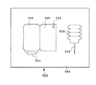
以下に、本発明の液体吐出ヘッドを有するヘッドキットを説明する。図30は、このようなヘッドキットを示した模式図であり、このヘッドキットは、インクを吐出するインク吐出部511を有する本発明のヘッド510と、このヘッドと不可分もしくは分離可能な液体容器であるインク容器520と、このインク容器にインクを充填するためのインクを保持したインク充填手段とを、キット容器501内に納めたものである。
【0241】
インクを消費し終わった場合には、インク容器の大気連通口521やヘッドとの接続部や、もしくはインク容器の壁に開けた穴などに、インク充填手段の挿入部(注射針等)531の一部を挿入し、この挿入部を介してインク充填手段内のインクをインク容器内に充填すればよい。
【0242】
このように、本発明の液体吐出ヘッドと、インク容器やインク充填手段等を一つのキット容器内に納めてキットにすることで、インクが消費されてしまっても前述のようにすぐに、また容易にインクをインク容器内に充填することができ、記録の開始を迅速に行うことができる。
【0243】
なお、本実施例のヘッドキットでは、インク充填手段が含まれるもので説明を行ったが、ヘッドキットとしては、インク充填手段を持たず、インクが充填された分離可能タイプのインク容器とヘッドとがキット容器510内に納められている形態のものであってもよい。
【0244】
また、この図30では、インク容器に対してインクを充填するインク充填手段のみを示しているが、インク容器の他に発泡液を発泡液容器に充填するための発泡液充填手段をキット容器内に納めた形態のものであってもよい。
【0245】
【発明の効果】
上述したような、可動部材を用いる新規な吐出原理に基づく本発明の液体吐出方法、ヘッド等によると、発生する気泡とこれによって変位する可動部材との相乗効果を得ることができ、吐出口近傍の液体を効率よく吐出できるため、従来のバブルジェット方式の吐出方法、ヘッド等に比べて吐出が吐出効率を向上できる。
【0246】
そしてこのことによって、吐出量が小さな液滴をも安定して吐出させることができる。
【0247】
特に、本発明においては、一つの可動部材に対して、独立駆動が可能な複数個の発熱体を設けている、もしくは、一つの液流路(第1液流路)に対して複数の可動部材を設けているため、液体の吐出量の制御が可能であり、所望の堆積の液体を吐出することができる。また、従来、困難であった吐出液量が小さな液滴を安定的、また、高周波数で吐出することが可能であるため、高階調記録を高速で行うことができる。
【0248】
また、本発明の特徴的な構成によれば、低温や低湿で長期放置を行った場合であっても不吐出になることを防止でき、仮に不吐出になっても予備吐出や吸引回復といった回復処理をわずかに行うだけで正常状態に即座に復帰できる利点もある。これに伴い、回復時間の短縮や回復による液体の損失を低減でき、ランニングコストも大幅に下げることが可能である。
【0249】
また、特に本発明のリフィル特性を向上した構成によれば、連続吐出時の応答性、気泡の安定成長、液滴の安定化を達成して、高速液体吐出による高速記録また高画質記録を可能にすることができた。
【0250】
また、2流路構成のヘッドにおいて発泡液として、発泡しやすい液体や、発熱体上への堆積物(こげ等)が生じにくい液体を用いることで、吐出液の選択の自由度が高くなり、発泡が生じにくい高粘性液体、発熱体上に堆積物を生じやすい液体、さらに熱に弱い液体等、従来のバブルジェット吐出方法で吐出することが困難であった液体についても良好に吐出することができた。
【0251】
さらに熱に弱い液体等も、この液体に熱による悪影響を与えず吐出することができた。
【0252】
また、本発明の液体吐出ヘッドを記録用の液体吐出記録ヘッドとして用いることで、さらに高画質な記録を達成することができた。
【0253】
また、本発明の液体吐出ヘッドを用い、液体の吐出効率等がさらに向上した液体吐出装置や記録システム等を提供することができた。
【0254】
また、本発明のヘッドカートリッジやヘッドキットを用いることで、ヘッドの利用、再利用を容易に成すことができる。
【図面の簡単な説明】
【図1】本発明の前提となる液体吐出原理を説明するための図である。
【図2】図2の液体吐出ヘッドの部分破断斜視図である。
【図3】従来の液体吐出ヘッドにおける気泡からの圧力伝搬を説明するための図である。
【図4】本発明の前提となる液体吐出原理における気泡からの圧力伝搬を説明するための図である。
【図5】本発明の前提となる液体吐出ヘッドにおける液体の流れを示すための模式図である。
【図6】本発明における液体吐出ヘッドの縦断面図である。
【図7】第1の実施例における可動部材と2つの発熱体の配置例を説明するための図である。
【図8】本発明の液体吐出ヘッドの駆動状態を示すための断面図である。
【図9】本発明の液体吐出ヘッドの駆動状態を示すための断面図である。
【図10】本発明の液体吐出ヘッドの駆動状態を示すための断面図である。
【図11】吐出量と反射濃度との関係を示す図である。
【図12】従来の液体吐出ヘッドの吐出方向を説明するための図である。
【図13】第2の実施例における可動部材と3つの発熱体の配置例を説明するための図である。
【図14】第3の実施例における複数可動部材と発熱体の配置例を説明するための図である。
【図15】第4の実施例における複数可動部材と発熱体の他の配置例を説明するための図である。
【図16】第5の実施例における複数可動部材と発熱体の他の配置例を説明するための図である。
【図17】第6の実施例における複数可動部材と発熱体と仕切壁の配置例を説明するための図である。
【図18】本発明におけるスムージング効果を説明するための図である。
【図19】本発明における予備吐出シーケンスを説明するための図である。
【図20】可動部材と発熱体との位置関係を説明するための図である。
【図21】可動部材の形状を説明するための図である。
【図22】本発明の液体吐出ヘッドの縦断面図である。
【図23】駆動パルスの形状を示す模式図である。
【図24】本発明の液体吐出ヘッドの供給路を説明するための図である。
【図25】本発明の液体吐出ヘッドの分解斜視図である。
【図26】液体吐出ヘッドカートリッジの分解斜視図である。
【図27】液体吐出装置の概略構成図である。
【図28】装置ブロック図である。
【図29】液体吐出記録システムを示す図である。
【図30】ヘッドキットの模式図である。
【図31】従来の液体吐出ヘッドの液流路構造を説明するための図である。
【符号の説明】
1 素子基板
2 発熱体
3 面積中心
5 配線電極
10 液流路
11 気泡発生領域
12 液体供給路
13 共通液室
14 第1液流路
15 第1共通液室(共通液室)
16 第2液流路
17 第2共通液室(共通液室)
18 吐出口
19 狭搾部
20 第1液供給路(吐出液供給路)
21 第2液供給路(発泡液供給路)
30 分離壁
31 可動部材
35 スリット
38 仕切壁
40 気泡
50 溝付部材[0001]
BACKGROUND OF THE INVENTION
The present invention relates to a liquid discharge head that discharges a desired liquid by generation of bubbles caused by applying thermal energy to the liquid, a head cartridge using the liquid discharge head, a liquid discharge apparatus, a liquid discharge method, and a recording method. Furthermore, the present invention relates to an inkjet head kit having these liquid discharge heads.
[0002]
In particular, the present invention relates to a liquid ejection head having a movable member that is displaced by using the generation of bubbles, a head cartridge using the liquid ejection head, and a liquid ejection apparatus. Alternatively, a liquid ejection method for ejecting a liquid by displacing a movable member using generation of bubblesandIt relates to a recording method.
[0003]
The present invention also provides a printer, a copying machine, a facsimile having a communication system, and a word processor having a printer section for recording on a recording medium such as paper, thread, fiber, fabric, leather, metal, plastic, glass, wood, ceramics, etc. Further, the present invention can be applied to an industrial recording apparatus combined with various processing apparatuses.
[0004]
In the present invention, “recording” means not only giving an image having a meaning such as a character or a figure to a recording medium but also giving an image having no meaning such as a pattern. To do.
[0005]
[Prior art]
By applying energy such as heat to the ink, the ink undergoes a change in state accompanied by a steep volume change (bubble generation), and the ink is discharged from the discharge port by the action force based on this change in state, and this is recorded 2. Description of the Related Art An ink jet recording method for forming an image by adhering to a medium, a so-called bubble jet recording method is conventionally known. In a recording apparatus using this bubble jet recording method, as disclosed in US Pat. No. 4,723,129, an ejection port for ejecting ink, and an ink flow communicating with the ejection port are disclosed. Generally, an electrothermal converter as an energy generating means for ejecting ink disposed in the path and the ink flow path is disposed.
[0006]
According to such a recording method, a high-quality image can be recorded at high speed and with low noise, and the ejection ports for ejecting ink can be arranged at high density in the head that performs this recording method. Therefore, it has many excellent points that a high-resolution recorded image and a color image can be easily obtained with a small apparatus.
For this reason, in recent years, this bubble jet recording method has been used in many office devices such as printers, copiers, and facsimiles, and further has been used in industrial systems such as textile printing apparatuses.
[0007]
As the bubble jet technology is used in various fields as described above, various demands as described below are further increased in recent years.
[0008]
For example, as a study on the demand for improvement in energy efficiency, optimization of a heating element such as adjusting the thickness of a protective film is cited. This method is effective in improving the propagation efficiency of the generated heat to the liquid.
[0009]
In addition, in order to obtain a high-quality image, a drive condition for providing a liquid discharge method capable of performing a good ink discharge based on the generation of a stable bubble with a high ink discharge speed is proposed. From the viewpoint, there has also been proposed an improved flow channel shape in order to obtain a liquid discharge head having a high filling (refill) speed of discharged liquid into the liquid flow channel.
[0010]
Of these channel shapes, the channel structure shown in FIGS. 31A and 31B is described in Japanese Patent Laid-Open No. 63-199972. The flow path structure and the head manufacturing method described in these publications are based on back waves generated with the generation of bubbles (pressure toward the direction opposite to the direction toward the discharge port, that is, pressure toward the liquid chamber 412). It is the invention which paid attention to. This back wave is known as loss energy because it is not energy in the ejection direction.
[0011]
In the invention shown in FIGS. 31A and 31B, the
[0012]
In FIG. 31 (b), the
[0013]
However, in this configuration, it is practical for liquid discharge to suppress a part of the back wave by the
[0014]
Originally, the back wave itself is not directly related to ejection as described above.
At the time when this back wave is generated in the
[0015]
On the other hand, in the bubble jet recording method, since heating is repeated while the heating element is in contact with the ink, deposits are generated due to scorching of ink on the surface of the heating element, but depending on the type of ink, this deposit is often generated. As a result, the generation of bubbles becomes unstable, and it may be difficult to perform good ink ejection. In addition, even when the liquid to be discharged is easily deteriorated by heat or when it is difficult to obtain bubbles sufficiently, a method for discharging well without changing the liquid to be discharged has been desired. .
[0016]
From such a viewpoint, the liquid (foaming liquid) that generates bubbles by heat and the liquid to be discharged (discharge liquid) are separate liquids, and the discharge liquid is discharged by transmitting the pressure generated by the foaming of the foam liquid to the discharge liquid. The method is disclosed in JP-A-61-69467, JP-A-55-81172, US Pat. No. 4,480,259, and the like. In these gazettes, the ink that is the discharge liquid and the foam liquid are completely separated by a flexible film such as silicon rubber so that the discharge liquid does not come into direct contact with the heating element, and pressure due to foaming of the foam liquid is allowed. The configuration is such that the fluid is transferred to the discharge liquid by deformation of the flexible film. With such a configuration, it is possible to prevent deposits on the surface of the heating element, improve the degree of freedom in selecting the discharge liquid, and the like.
[0017]
However, the head configured to completely separate the discharge liquid and the foam liquid in this way is configured to transmit the pressure during foaming to the discharge liquid by expansion and contraction of the flexible film. The membrane absorbs considerably.
[0018]
Further, since the deformation amount of the flexible film is not so large, the effect of separating the discharge liquid and the foaming liquid can be obtained, but there is a possibility that the discharge efficiency and the discharge force may be lowered.
[0019]
On the other hand, as a gradation recording method, a plurality of heat generating elements that can be independently driven are arranged in one liquid flow path, and they are driven at a desired timing, thereby changing the size of the ejected ink droplets. An example is described in JP-B-62-48585.
[0020]
In this publication, when two heating elements are arranged in one liquid passage and each is driven independently, the bubble volume generated when the timings coincide is maximized, and the maximum volume of bubbles decreases as the timing is shifted, It is disclosed that gradation is obtained by the change of the ejected droplets.
[0021]
[Problems to be solved by the invention]
In analyzing the current state of the conventional gradation recording technology, the present inventors have paid attention to an image in which relatively large and small dots are formed. Theoretically, a desired dot shape should be formed at a given position, but in reality it is very small, but it can be seen with a “displacement” that can be visually confirmed or an enlargement of about 50 times. This includes the state of “dot disorder”.
[0022]
The inventors of the present invention have also confirmed the smoothing technique formed by relatively large and small dots, and have confirmed “displacement” and “dot disorder”.
[0023]
The present inventors have analyzed a fundamental unstable element of the conventional large and small dot forming technology and found a two-step problem.
[0024]
The first problem to be solved is that the environmental conditions of the foaming region fluctuate when bubbles are formed by electrothermal conversion means (for example, a plurality of heaters) that form bubbles of relatively different sizes. The bubble formation is disturbed and the volume of the discharged liquid (droplet) changes accordingly.
[0025]
The second problem to be solved is that, in addition to the first problem, the discharge state of the discharge liquid (droplet) for forming an image, particularly the discharge speed, varies depending on the cause of the first problem. The landing accuracy is lowered, and the quality of image quality cannot be improved so much. This second problem is a fundamental problem for gradation recording and smoothing technology using large, small, large, medium, and small dots that are conventionally known more than the first problem.
[0026]
The main object of the present invention is to provide a head capable of solving disturbances in liquid discharge and discharge volume, and a gradation recording method, a smoothing method using this head, or preliminary discharge (a recording signal for improving the in-head situation). The present invention provides a discharge method performed by another signal.
[0027]
Another object of the present invention is to solve the first problem described above, and is downstream in the direction toward the discharge port with respect to the bubble-forming electrothermal conversion means capable of selectively forming bubbles of different sizes. Even if the environmental conditions of the foaming region slightly change, the feature that the movable member having the free end on the side and the fulcrum portion on the upstream side faces the bubble generation region, the growth of the bubble and the displacement of the movable member According to this balance relationship, a head capable of stabilizing the volume of ejected droplets at a desired value, and each method and apparatus using the head are provided.
[0028]
Another object of the present invention is to solve the second problem. Here, in solving the second problem, the inventors have found a more preferable condition for the action of the movable member itself with respect to the formation of bubbles of different sizes by the electrothermal conversion means for forming bubbles. That is, the movable member itself further changes the growth of the bubble itself, so that the volume of the discharge liquid can be further stabilized and the discharge speed of the discharge liquid can be stabilized at a high speed.
[0029]
Therefore, another object of the present invention is to provide a liquid having a desired volume with high accuracy to a desired position by improving discharge efficiency and discharge speed while achieving stabilization of bubbles of different sizes. It is to provide a head that can be used, each method and each apparatus using the head.
[0030]
The remaining objects of the present invention can be understood from the matters added in the embodiments of the present invention.
[0031]
[Means for Solving the Problems]
In order to solve the above-described problems, a liquid discharge head according to the present invention is a liquid discharge head capable of discharging liquid under different conditions. The liquid discharge head discharges liquid and supplies liquid to the discharge port. Used to discharge and selectively form bubbles of different sizesMultiple heating elementsA liquid flow path comprising:Multiple heating elementsFacing the bubble generation region formed in the liquid flow path byAcross at least two heating elementsAnd a movable mechanism having at least one movable member having a free end on the downstream side and a fulcrum portion on the upstream side in the direction toward the discharge port, and the movable member further includesMultiple heating elementsDepending on the bubbles formed bythe aboveIt is possible to displace in a direction away from the bubble generation region.
[0032]
Preferably, the aboveMultiple heating elementsAt least one can be driven individuallyis there.
[0033]
Preferably, the plurality of heating elements are arranged from upstream to downstream with respect to a direction toward the discharge port, or arranged substantially at the same distance from the discharge port.
[0034]
Preferably, a partition wall is arranged between the heating elements arranged side by side to suppress the escape of pressure to the side.
[0035]
Preferably, the movable mechanism includes a plurality of the movable members, and the plurality of movable members are arranged side by side at substantially the same distance from the discharge port.
[0036]
Preferably, the plurality of heating elements have different areas or substantially the same area.
[0037]
Preferably, the movable member has a free end located downstream from the center of the generated bubble.
[0038]
Preferably, the liquid flow path has a supply path for supplying liquid onto the heating element from upstream of the heating element along the heating element.
[0039]
Preferably, the supply path is a supply path that has a substantially flat or gentle inner wall upstream of the heating element and supplies liquid onto the heating element along the inner wall.
[0040]
Preferably, it has a liquid flow path for supplying a liquid onto the heating element from the upstream along the surface of the movable member close to the heating element.
[0041]
Preferably, the liquid flow path generates a bubble in the liquid by applying heat to the first liquid flow path communicating with the discharge port and the liquid.MultipleAnd a second liquid channel provided with a heating element, and the movable member is arranged between the first liquid channel and the second liquid channel.
[0042]
Preferably, the movable member has a plate shape.
[0043]
Preferably, the movable member is configured as a part of a separation wall disposed between the first flow path and the second flow path, and more preferably, the separation wall is made of metal, resin, or ceramics. It consists of
[0044]
Preferably, a first common liquid chamber for supplying a first liquid to a plurality of the first liquid flow paths, and a first common liquid chamber for supplying a second liquid to the plurality of second liquid flow paths. Two common liquid chambers, or the liquid supplied to the first liquid flow path and the liquid supplied to the second liquid flow path are the same liquid or different liquids. .
[0045]
Preferably, the heating element is an electrothermal converter having a heating resistor that generates heat by receiving an electric signal, and more preferably on the element substrate for transmitting an electric signal to the electrothermal converter. Wiring and a functional element for selectively giving an electrical signal to the electrothermal transducer.
[0046]
Preferably, saidpluralThe shape of the second liquid channel in the portion where the heating element is arranged is a chamber shape.
[0047]
Preferably, the shape of the second flow path is a shape having a narrowed portion upstream of the heating element.
[0048]
Preferably, the distance from the surface of the heating element to the movable member is 30 μm or less.
[0049]
Preferably, the liquid discharged from the discharge port is ink.
[0050]
Next, a liquid discharge method according to the present invention includes a discharge port for discharging a liquid in a liquid discharge method for discharging a liquid by generating bubbles,pluralA liquid flow path having a heating element and for generating bubbles for the liquidpluralA heating element;pluralFacing the heating element,Across at least two heating elementsA liquid discharge head having a movable member provided with a free end that is displaceable between a first position and a second position farther from the heating element than the first position. Displacement of the movable member by the pressure based on the generation causes the bubbles to expand greatly downstream rather than upstream in the direction toward the discharge port, and changes the displacement state of the movable member to discharge the liquid. It is characterized by changing the amount.
[0051]
Preferably, the displacement state of the movable member varies depending on the number of heating elements to be driven with respect to one movable member.
[0052]
Further, a liquid discharge method according to the present invention is a liquid discharge method for discharging a liquid by generating a bubble, and a discharge port for discharging a liquid, and for generating a bubble for the liquid.One or moreA heating element;One or moreIt is arranged facing the heating element, and the first position and the first positionOne or moreA plurality of pairs with a movable member that is displaceable between a second position far from the heating element and has a free end with respect to the discharge port.With , At least one of the movable members is arranged so as to straddle two or more heating elements.By using a liquid discharge head and displacing the movable member by the pressure based on the generation of the bubbles, the bubbles are expanded more greatly than the upstream in the direction toward the discharge port, and the number of movements of the movable members is reduced. It is characterized by changing the discharge amount of the liquid by changing.
[0053]
Preferably, in the liquid ejection method, the bubble is a bubble generated by causing a film boiling phenomenon in the liquid by transferring heat generated by the heating element to the liquid, and the film boiling phenomenon.
[0054]
Preferably, the liquid is supplied onto the heating element along a substantially flat or gentle inner wall upstream of the heating element.
[0055]
Further, the preliminary ejection method according to the present invention is a preliminary ejection method for a liquid ejection head, which is used for ejecting liquid and supplying the liquid to the ejection port and ejecting the liquid and having different sizes. Bubbles can be selectively formedMultiple heating elementsA liquid flow path comprising:Multiple heating elementsFacing the bubble generation region formed in the liquid flow path by, Straddle at least two heating elementsUsing a liquid discharge head provided with a movable mechanism including at least one movable member having a free end on the downstream side and a fulcrum portion on the upstream side in the direction toward the discharge port.Multiple heating elementsBy forming the largest bubble among the bubbles that can be formed, the movable member is displaced in a direction away from the bubble generation region, and the movable member guides the largest bubble to the discharge port. Preliminary discharge is performed.
[0056]
A recording method according to the present invention is a recording method in which gradation recording is performed using a liquid discharge head that discharges liquid. In order to discharge a liquid while supplying a liquid to the discharge port and supplying the liquid to the discharge port Can be used to selectively form bubbles of different sizesMultiple heating elementsA liquid flow path comprising:Multiple heating elementsFacing the bubble generation region formed in the liquid flow path by, Straddle at least two heating elementsThe liquid ejecting head is provided with a movable mechanism having at least one movable member having a free end on the downstream side and a fulcrum on the upstream side in the direction toward the discharge port. In accordance with each of the bubbles, the movable member is displaced in a direction away from the bubble generation region, and the movable member guides the bubbles to the discharge port, whereby liquids having different sizes according to the size of the bubbles. And performing gradation recording.
[0057]
The recording method according to the present invention is a recording method in which smoothing is performed using a liquid discharge head capable of discharging liquids of different sizes, and a discharge port for discharging a liquid, and supplying the liquid to the discharge port, Used to discharge liquid and can selectively form bubbles of different sizesMultiple heating elementsA liquid flow path comprising:Multiple heating elementsFacing the bubble generation region formed in the liquid flow path by, Straddle at least two heating elementsThe liquid ejecting head is provided with a movable mechanism having at least one movable member having a free end on the downstream side and a fulcrum on the upstream side in the direction toward the discharge port. In accordance with each of the bubbles, the movable member is displaced in a direction away from the bubble generation region, and the movable member guides the bubble to the discharge port, so that the size of the bubble varies. Liquid in the image areaWhenSmoothing is performed by giving to the boundary with the non-image part.
[0058]
Furthermore, inkjet recording according to the present inventionapparatusIn an ink jet recording apparatus using a liquid discharge head capable of discharging liquids of different conditions, a discharge port that discharges the liquid, a liquid that is supplied to the discharge port, and used to discharge the liquid and have different sizes Bubbles can be selectively formedMultiple heating elementsProvided liquid flow path, andMultiple heating elementsFacing the bubble generation region formed in the liquid flow path by, Straddle at least two heating elementsAnd a movable mechanism having at least one movable member having a free end on the downstream side and a fulcrum portion on the upstream side in the direction toward the discharge port, and the movable member further includes A mounting portion for mounting the liquid discharge head, which is displaceable in a direction away from the bubble generation area, in accordance with the bubbles formed by the heat generating means;Multiple heating elementsAnd drive condition selection means for providing an electrical signal corresponding to a recording signal corresponding to the liquid to be ejected.
[0059]
A liquid discharge head according to the present invention is a liquid discharge head capable of discharging liquids of different conditions, for discharging a liquid, a first liquid channel for supplying the liquid to the discharge port, and discharging the liquid. Can be used to selectively form bubbles of different sizesMultiple heating elementsA liquid flow path including a second liquid flow path comprising:Multiple heating elementsFacing the bubble generation region formed in the second liquid flow path by, Straddle at least two heating elementsAnd a movable mechanism having at least one movable member having a free end on the downstream side and a fulcrum on the upstream side in the direction toward the discharge port, and the movable member further generates the bubbles. Thus, the bubble heat generation region can be displaced in a direction to open the bubble generation region with respect to the discharge port by moving a substantially closed free end with respect to the first flow path. .
[0060]
A head cartridge according to the present invention includes the above-described liquid discharge head and a liquid container that holds liquid supplied to the liquid discharge head.
[0061]
Preferably, the liquid discharge head and the liquid container are separable.
[0062]
Preferably, the liquid container is refilled with liquid.
[0063]
A liquid discharge apparatus according to the present invention includes the liquid discharge head and drive signal supply means for supplying a drive signal for discharging liquid from the liquid discharge head.
[0064]
A recording system according to the present invention includes the liquid ejecting apparatus and a post-processing apparatus that prompts the liquid to be fixed to a recording medium after recording.
[0065]
Preferably, the apparatus includes the liquid ejecting apparatus and a pretreatment apparatus for increasing the fixing of the liquid to the recording medium before recording.
[0066]
According to the discharge method and the liquid discharge head of the present invention having a plurality of heating elements and movable members with respect to the liquid flow path as described above, a gradation image with extremely high stability and discharge direction accuracy is realized, which is very A high-quality image could be obtained.
[0067]
In addition, the discharge characteristics such as the refill characteristic can be maintained at a high level while realizing the gradation by the discharge amount modulation.
[0068]
Furthermore, by applying the above effect, it was possible to realize smooth lines for images such as curves and diagonal lines, and to improve image quality such as characters and graphics.
[0069]
Similarly, by applying the above effect, preliminary ejection immediately before the start of printing for improving ejection reliability can be performed in a short time with a very small number of liquid ejections.
[0070]
Other effects of the invention will be understood from the description of each example.
[0071]
The terms “upstream” and “downstream” used in the description of the present invention are related to the flow direction of the liquid from the liquid supply source to the discharge port through the bubble generation region (or the movable member), or the direction in this configuration. It is expressed as an expression.
[0072]
The “downstream side” related to the bubble itself represents a portion of the bubble outlet side which is supposed to act directly on the droplet discharge. More specifically, it means a bubble generated in a region downstream of the center of the bubble with respect to the flow direction and the structural direction, or in a region downstream of the area center of the heating element.
[0073]
In addition, the term “substantially sealed” used in the description of the present invention means a state where bubbles do not pass through gaps (slits) around the movable member before the movable member is displaced when the bubbles grow. .
[0074]
Further, the “separation wall” as used in the present invention means a wall (which may include a movable member) interposed so as to separate a bubble generation region and a region directly communicating with the discharge port in a broad sense, and in a narrow sense, a bubble. This means that the flow path including the generation area is divided from the liquid flow path that directly communicates with the discharge port to prevent mixing of the liquid in each area.
[0075]
DETAILED DESCRIPTION OF THE INVENTION
<Principle explanation>
Hereinafter, basic operating principles related to the present invention will be described with reference to the drawings.
[0076]
FIG. 1 is a schematic cross-sectional view of the liquid discharge head cut in the liquid flow path direction, and FIG. 2 is a partially broken perspective view of the liquid discharge head.
[0077]
In the liquid discharge head shown in FIG. 1, a heating element 2 (a heating resistor having a shape of 40 μm × 105 μm in FIG. 1) is applied to the
[0078]
On the element substrate of the
[0079]
This
[0080]
Heating the
[0081]
Here, one of the basic ejection principles applied to the present invention will be described. One of the most important principles in the present invention is that the movable member disposed so as to face the bubble is the second position after the displacement from the first position in the steady state based on the pressure of the bubble or the bubble itself. This is to guide the pressure accompanying the generation of the bubble and the bubble itself to the downstream side where the
[0082]
This principle will be described in more detail by comparing FIG. 3 schematically showing a conventional liquid flow path structure without using a movable member and FIG. 4 of the present invention. Here, the pressure propagation direction toward the discharge port is indicated as VA, and the pressure propagation direction toward the upstream side is indicated as VB.
[0083]
In the conventional head as shown in FIG. 3, there is no configuration for restricting the propagation direction of pressure by the generated bubbles 40. For this reason, the pressure propagation direction of the
[0084]
On the other hand, in the case of the present invention shown in FIG. 4, the pressure propagation directions V1 to V4 of the bubbles in which the
[0085]
Then, the bubble growth direction itself is guided downstream as in the pressure propagation directions V1 to V4, and grows larger downstream than upstream. In this way, by controlling the bubble growth direction itself with the movable member and controlling the bubble pressure propagation direction, fundamental improvements in discharge efficiency, discharge force, discharge speed, and the like can be achieved.
[0086]
Next, returning to FIG. 1, the discharge operation of the liquid discharge head described above will be described in detail.
[0087]
FIG. 1A shows a state before energy such as electrical energy is applied to the
[0088]
In FIG. 1B, electric energy or the like is applied to the
[0089]
At this time, the
[0090]
FIG. 1C shows a state where the
[0091]
FIG. 1D shows a state in which the
[0092]
The
[0093]
The operation of the movable member and the liquid discharge operation accompanying the generation of bubbles have been described above. The liquid refill in the liquid discharge head applicable to the present invention will be described below.
[0094]
After the
[0095]
For this reason, when the flow resistance on the side close to the discharge port is small, a large amount of liquid flows from the discharge port side to the defoaming position, and the retreat amount of the meniscus becomes large. In particular, as the discharge efficiency is increased by reducing the flow resistance near the discharge port in order to increase the discharge efficiency, the retreat of the meniscus M at the time of defoaming becomes larger, and the refill time becomes longer and high-speed printing is performed. It was supposed to interfere.
[0096]
On the other hand, since the
[0097]
Further, the liquid supply for the volume of W2 is forcibly performed mainly from the upstream side (VD2) of the second liquid flow path along the surface of the
[0098]
What is characteristic here is that when refilling using the pressure at the time of defoaming is performed with a conventional head, the vibration of the meniscus of this configuration is increased, leading to deterioration of the image quality. In refilling, the movement of the liquid on the discharge port side between the region of the first
[0099]
As described above, the above-described configuration applied to the present invention achieves high-speed refilling by forced refilling of the second
[0100]
The above-described configuration of the present invention further has the following effective functions. That is to suppress the upstream propagation (back wave) of pressure due to the generation of bubbles. Among the bubbles generated on the
[0101]
Next, further characteristic structures and effects will be described below.
[0102]
The second
In such a case, the supply of the liquid to the
[0103]
Further, there are some cases where the liquid is supplied to the bubble generation region from the
[0104]
By the way, the position of the
[0105]
If it supplements, in this structure, the
[0106]
In addition, many effects are obtained by utilizing the upstream side of the bubbles.
[0107]
Further, in this configuration, it is considered that the fact that the free end of the
[0108]
【Example】
6 is a cross-sectional view of the liquid flow path of the liquid discharge head according to the first embodiment of the present invention. FIG. 7A is a cross-sectional view taken along line A-B in FIG. FIG. 7B is a cross-sectional view of the cross-sectional configuration taken along line CD in FIG. 6 as viewed from the B direction.
[0109]
As shown in FIGS. 6 to 7, the liquid discharge head according to the present invention has an electrothermal conversion element (hereinafter referred to as a heating element) that can independently drive at least one that gives thermal energy to generate bubbles in the liquid. A plurality of (in the present embodiment, two) 2-1 and 2-2 in the discharge port arrangement direction, and wiring electrodes 5-1, 5-2, and 5-3 for applying an electrical signal to the heating element. A second liquid flow path (foaming liquid flow path) 16 is disposed on the formed
[0110]
The separation wall of the part located in the projection space (hereinafter referred to as the discharge pressure generation region; hereinafter, the region A and the
[0111]
Further, at that time, by changing the driving conditions of the heating elements 2-1 and 2-2, it is possible to change the state of bubbles generated thereby and the amount of displacement of the movable member, thereby changing the liquid discharge amount. is there. Although the relationship between the structure of the
[0112]
Next, the operation of this head will be described with reference to FIGS. One of the features of the operation of the head of this embodiment is that gradation control is possible.
[0113]
In this description, in order to facilitate understanding of the present invention, the same water-based ink is used for the discharge liquid supplied to the first
[0114]
FIG. 8 shows that the heating elements 2-1 and 2-2 are both OFF. In this case, the
[0115]
FIG. 9 shows a state in which a drive signal (pulse) under the conditions of a voltage of 24 V and a pulse width of 5 μsec is applied to the heat generator 2-1 among the heat generators 2-1 and 2-2 and is ON. The heating of the heating element 2-1 acts on the foaming liquid filled in the second
[0116]
FIG. 10 shows a state where both of the heating elements 2-1 and 2-2 are given a drive signal similar to that described above to turn on both heating elements and heat the ink to generate bubbles. The foaming energy is larger than that in FIG. 11, and the foaming energy pushes up the movable tip of the
[0117]
Although not shown in the drawing, when only the heating element 2-2 is foamed by changing the heater sizes of the heating element 2-1 and the heating element 2-2, the displacement amount of the movable member 7 is H1. , H2, the discharge amount can also be different from V1 and V2.
[0118]
As described above, in the present invention, the displacement state such as the amount of displacement is changed by changing the number of heating elements to be driven and the heating elements at different positions, thereby discharging droplets having different amounts. Can do.
[0119]
Also in the present invention, ink can be ejected with higher ejection energy efficiency and higher ejection pressure than the head of the conventional configuration because the displacement of the movable member as described above causes foam to be ejected from the ejection port. This is due to the guiding principle and the interaction of these phenomena.
[0120]
As described above, it is possible to control the deformation amount of the
[0121]
This indicates that the ink discharge amount can be controlled, and as a result, it is possible to express gradation of recording.
[0122]
Therefore, by providing a plurality of heating elements, multi-level gradation expression is possible. Table 1 shows the relationship of the discharge amount of the movable member depending on the combination of driving of each heating element using the head shown in this example.
[0123]
The liquid discharge head used in this example is the head shown in FIGS. 6 to 10, in which a plurality of 34 μm diameter discharge ports are arranged at a pitch of 70.5 μm. The heating elements 2-1 and 2-2 were of the same size having a size of 18 × 100 μm. The driving conditions were a voltage of 24 V, a pulse width of 5 μm, and a driving frequency of 200 Hz, and the discharge amount was obtained as an average value obtained by dividing the total discharge amount discharged 20000 times in the drive mode of each heating element by the number of discharges. The liquid used in this example was the same water-based ink for both the foaming liquid and the discharge liquid.
[0124]
[Table 1]
(A) When all of the heating elements 2-1 and 2-2 are OFF, the deformation amount of the movable member is zero. Therefore, the discharge amount is also zero.
[0126]
(B) When only the heating element 2-1 was ON, the discharge amount was 40 ng.
[0127]
(C) When the heating elements 2-1 and 2-2 were ON, the amount of deformation of the movable member was larger than when only 2-1 was ON, and the discharge amount was 80 ng.
[0128]
FIG. 11 shows the case where an image is formed with such an ejection amount, which is shown by reflection density.
[0129]
Since the reflection density is proportional to the ink discharge amount, if the ink discharge amount can be changed in four stages by combining ON / OFF of the two heating elements, the reflection density also has four gradations as shown in FIG. Can be obtained.
[0130]
In the present invention, as described above, since the movable member is arranged as compared with the conventional liquid discharge head, the liquid discharge efficiency and the discharge force are high in the first place. In this case, stable discharge can be obtained even when small droplets are repeatedly discharged.
[0131]
Further, as described above, the liquid discharge head of the present invention can achieve high-speed driving even when small droplets are discharged because refilling is performed at high speed by the operation of the movable member. Furthermore, in the conventional liquid ejection head, the ejection direction may change when each heating element is driven. This is shown in FIG. FIG. 12A shows a case where the right heating element 2-1 is driven toward the discharge port, and the liquid is discharged from the discharge port to the left side. When the left heating element 2-2 is driven toward the discharge port as shown in FIG. 12B, the liquid is discharged from the discharge port to the right side. However, in the liquid discharge head of the present invention, since the
[0132]
FIG. 13 is a schematic cross-sectional view of the liquid ejection head according to the second embodiment of the present invention cut at the position shown in FIG. 7 (wiring electrodes are omitted in FIG. 13). In order to discharge smaller droplets, the shapes of the two heating elements of the first embodiment are different. In the present embodiment, the size of the right heating element 2-1 toward the discharge port is 13 × 100 μm, and the size of the left heating element 2-2 toward the discharge port is 23 × 100 μm. The left-handed heating element is enlarged toward the exit. The size of the movable member was 40 × 210 μm. In this case as well, the heat generating means is constituted by a plurality of heat generating elements.
[0133]
With such a configuration, in addition to the effects of the first embodiment described above, the discharge amount when only the heating element 2-1 is driven is reduced, and smaller droplets can be discharged. Accordingly, since the difference between the discharge amount by the heating element having a large area and the discharge amount by the heating element having a small area can be increased, the gradation expression region can be further widened.
[0134]
In the present embodiment, the number of heating elements is two, but the present invention is not limited to this, and more heating elements may be arranged in the discharge port arrangement direction.
[0135]
Next, FIG. 14 is a third embodiment showing a liquid discharge head in which two heating elements are arranged along the direction of flow toward the discharge port with respect to the
Also in the present embodiment, the deformation amount of the
[0136]
Also in the present embodiment, by changing the shape of the heating element between the front and rear, the difference between the larger discharge amount and the smaller discharge amount can be greatly discharged, and the gradation expression region can be further enhanced.
[0137]
In the present embodiment, the number of heating elements is two. However, the present invention is not limited to this, and more heating elements may be arranged in a direction along the flow direction toward the discharge port.
[0138]
FIG. 15 is a fourth embodiment showing an example in which a plurality of
[0139]
Table 2 shows the average discharge amount when discharging is performed under the following conditions using the liquid discharge head of this embodiment.
[0140]
[0141]
The liquid discharge amount was obtained as an average value obtained by dividing the amount of liquid consumed when the discharge operation was performed 20000 times in each drive mode by the number of discharges.
[0142]
[Table 2]
As described above, in this embodiment, two different amounts of liquid can be ejected in a very stable state as compared with the conventional case, and ternary gradation recording can be performed with good gradation and at high speed. I was able to.
[0144]
In the present embodiment, since the second liquid channel is divided into two second liquid channels (16-1, 16-2), the bubble pressure when each heating element is driven independently. The escape to the second liquid flow path wall side (both sides) can be prevented, and the movable members 31-1 and 31-2 can be displaced more efficiently. As a result, the discharge efficiency and the discharge force are further increased, and the gradation and stability can be further improved.
[0145]
Furthermore, since the bubble generation region of each heating element is partitioned by the
[0146]
Next, FIG. 16 is provided with a plurality of
[0147]
Further, a
[0148]
By adopting such a configuration, it is possible to prevent the escape of the pressure when each heating element is driven in the second liquid flow path wall direction (both sides) as in the fourth embodiment. The movable members 31-1, 31-2 can be displaced more efficiently and stably without any pressure loss due to foam misalignment during simultaneous driving.
[0149]
Further, by providing two heating elements for each movable member, higher gradation can be obtained.
[0150]
Furthermore, by making the slits between the movable members common, it is possible to arrange the movable members at a higher density and to manufacture them easily.
[0151]
In this embodiment, the number of heating elements is two for each movable member. However, the present invention is not limited to this, and more heating elements may be provided. Moreover, you may change the number of the heat generating bodies with respect to each movable member as needed.
[0152]
Next, FIG. 21 is a sixth embodiment showing an example in which one movable member is provided for one first liquid flow path and one discharge port, and two heating elements are arranged so as to be partitioned by a
[0153]
By adopting such a configuration, the effect of preventing the escape of the pressure to the side (both sides) of the second liquid flow path when each heating element is driven, as in the fourth embodiment described above, is achieved. The
[0154]
Further, since the
[0156]
Further, in the liquid discharge heads having the configurations of the first to sixth embodiments, the liquid discharge efficiency and discharge force are originally higher than those of the conventional liquid discharge heads, and the discharge characteristics are stable and the discharge direction as described above. Since the frequency is high, the smoothing effect can be realized at a higher level by applying this effect to a smoothing recording technique for improving the quality of a line image or the like as shown in FIG. 18A is a schematic diagram when a straight line is recorded with one type of discharge amount. FIGS. 18B and 18C are respectively two types (large and small dots) and three types (large, medium, and It is a schematic diagram when a straight line is recorded with a discharge amount of (small dots). By using two or three discharge amounts, it is possible to record and express a straight line smoothly. In the conventional liquid discharge head, it has been difficult to discharge small droplets stably and properly to a desired position. However, the liquid discharge head of the present invention can stably discharge several kinds of liquids (discharge liquid amount and desired liquid amount). Therefore, excellent smoothing is possible.
[0157]
As a result, the edges of characters and figures can be reproduced smoothly and reliably, and the printing quality is improved.
[0158]
Further, since the liquid discharge heads having the configurations of the first to sixth embodiments have a plurality of heating elements, it is effective for preliminary discharge performed immediately before printing in order to improve printing reliability. is there. FIG. 19 is a flowchart showing a sequence from the start of printing to the end of printing in the liquid discharge head of the first embodiment. After the print start signal (S-2) is sent from the print standby state (S-1), preliminary discharge (S-3) is performed, and printing (S-4) is started. In order to prevent clogging, preliminary discharge (S-5) is performed. Depending on the environment, preliminary ejection was performed from several hundred Hz to several kHz and issued several to several thousand. In the present invention, by performing the preliminary discharge conditions by driving the heating elements 2-1 and 2-2 at the same time, there is no non-discharge even when the number of times of discharge is less than that in the past, and the reliability is high. Printing could be performed (S-6 to S-7). Thereby, more stable printing quality can be obtained efficiently.
[0159]
As described above, in addition to the configuration based on a very novel ejection principle, according to the ejection method and the liquid ejection head of the present invention having a plurality of heating elements and movable members with respect to the liquid flow path, by arranging the movable members, A gradation image with extremely high stability and frequency in the ejection direction was realized, and a very high quality image could be obtained. In addition, the discharge characteristics such as the refill characteristic can be maintained at a high level while realizing the gradation by the discharge amount modulation. Furthermore, by applying the above effect, it was possible to realize smooth lines for images such as curves and diagonal lines, and to improve image quality such as characters and graphics.
[0160]
Similarly, by applying the above effects, preliminary ejection immediately before the start of printing for improving ejection reliability could be performed in a short time with an extremely small number of liquid ejections.
[0161]
<Other examples>
As mentioned above, although the Example of the principal part of the liquid discharge head of this invention and the liquid discharge method was demonstrated, the example of an embodiment preferably applicable to these Examples is demonstrated using drawing below. However, in the following description, there are cases where either one of the above-described one-channel embodiment or two-channel embodiment is taken up and described. However, unless otherwise specified, the embodiment can be applied to both embodiments. It is.
[0162]
<Arrangement relationship between second liquid flow path and movable member>
FIG. 20 is a view for explaining the positional relationship between the above-described
[0163]
As described above, the second
[0164]
Like the conventional head, the flow path for foaming and the flow path for discharging liquid are the same, and the head is provided with a constricted portion so that the pressure generated on the liquid chamber side from the heating element does not escape to the common liquid chamber side In this case, it is necessary to take a configuration in which the cross-sectional area of the flow path in the narrowed portion is not so small in consideration of the refill of the liquid.
[0165]
However, in the case of the present embodiment, most of the discharged liquid can be used as the discharged liquid in the first liquid flow path, and the foamed liquid in the second liquid flow path provided with the heating element is not consumed so much. Therefore, the filling amount of the foaming liquid into the
[0166]
As shown in FIG. 20C, the side of the
[0167]
9 and 10, some of the bubbles generated in the bubble generation region of the second
[0168]
<Moveable member and separation wall>
FIG. 21 is a plan view showing another shape of the
[0169]
In the previous embodiment, the plate-like
[0170]
As a material of the movable member, highly durable metals such as silver, nickel, gold, iron, titanium, aluminum, platinum, tantalum, stainless steel, phosphor bronze, and alloys thereof, or nitriles such as acrylonitrile, butadiene, and styrene Resin having an amide group such as polyamide, resin having a carboxyl group such as polycarbonate, resin having an aldehyde group such as polyacetal, resin having a sulfone group such as polysulfone, and other resins such as liquid crystal polymers and compounds thereof , High ink resistance metals such as gold, tungsten, tantalum, nickel, stainless steel, titanium, alloys thereof and those with ink resistance coated on them or resins having an amide group such as polyamide, polyacetal, etc. Tree with aldehyde , Resins having a ketone group such as polyetheretherketone, resins having an imide group such as polyimide, resins having a hydroxyl group such as phenol resin, resins having an ethyl group such as polyethylene, resins having an alkyl group such as polypropylene, epoxy A resin having an epoxy group such as a resin, a resin having an amino group such as a melamine resin, a resin having a methylol group such as a xylene resin and a compound thereof, and a ceramic such as silicon dioxide and a compound thereof are desirable.
[0171]
The material of the separation wall is polyethylene, polypropylene, polyamide, polyethylene terephthalate, melamine resin, phenol resin, epoxy resin, polybutadiene, polyether ether ketone, polyether sulfone, polyarylate, polyimide, polysulfone, liquid crystal polymer (LCP), etc. Resin having good heat resistance, solvent resistance, moldability, and its compounds represented by recent engineering plastics, and metals such as silicon dioxide, silicon nitride, nickel, gold, and stainless steel, alloys and compounds thereof, or The surface is preferably coated with titanium or gold.
[0172]
In addition, the thickness of the separation wall may be determined in consideration of the material, shape, and the like from the viewpoint of being able to achieve strength as the separation wall and operating favorably as the movable member, but is preferably about 0.5 μm to 10 μm. .
[0173]
In this embodiment, the width of the
[0174]
The slit that gives the “substantially sealed state” of the present invention is more certain if it is on the order of several μm.
[0175]
<Element substrate>
The structure of the element substrate provided with a heating element for applying heat to the liquid will be described below.
[0176]
FIG. 22 is a longitudinal sectional view of a liquid discharge head according to the present invention. FIG. 22A shows a head having a protective film described later, and FIG. 22B shows a head without a protective film.
[0177]
Here, a longitudinal sectional view of the embodiment of FIG. 7 is shown, and only one heating element is shown on the sectional view.
[0178]
On the
[0179]
On the
[0180]
In particular, the pressure and shock wave generated when bubbles are generated and defoamed are extremely strong, and they are used as a cavitation-resistant layer of metallic materials such as tantalum (Ta) because they significantly reduce the durability of fragile and brittle oxide films. .
[0181]
Moreover, the structure which does not require the above-mentioned protective layer by the combination of a liquid, a liquid flow path structure, and a resistance material may be sufficient, The example is shown in FIG.22 (b). Examples of the material of the resistance layer that does not require such a protective layer include indium, tantalum, and aluminum alloy.
[0182]
As described above, the configuration of the heating element in each of the above-described embodiments may be only the resistance layer (heating unit) between the electrodes described above, or may include a protective layer that protects the resistance layer.
[0183]
In this embodiment, a heating element having a heat generating part composed of a resistance layer that generates heat in response to an electrical signal is used. However, the present invention is not limited to this, and sufficient bubbles to discharge the discharge liquid are used. Any material can be used as long as it is generated in the foaming liquid. For example, a light-to-heat conversion body that generates heat when receiving light from a laser or the like as a heat generating section, or a heating element that includes a heat generating section that generates heat by receiving high frequency may be used.
[0184]
In addition to the electrothermal transducer formed of the
[0185]
Further, in order to drive the heat generating portion of the electrothermal converter provided on the
[0186]
22A and 22B, 31a and 31b show the state of the movable member displaced by foaming by the heat generating portion described above.
[0187]
The
[0188]
<Head structure with two flow paths>
Hereinafter, an example of the structure of a liquid discharge head that can reduce the number of components and can reduce the cost by allowing different liquids to be separated and introduced into the first and second common liquid chambers will be described.
[0189]
FIG. 24 is a schematic diagram showing the structure of such a liquid discharge head. The same reference numerals are used for the same components as in the previous embodiment, and detailed description thereof is omitted here.
[0190]
In this embodiment, the
[0191]
A plurality of first
[0192]
The first liquid (discharge liquid) is supplied to the first
[0193]
In the present embodiment, the second
[0194]
Further, the thickness (diameter) of the second
[0195]
The second
[0196]
In the present embodiment, as described above, electrothermal conversion as a heating element that generates heat for generating bubbles due to film boiling of the foamed liquid on the
[0197]
On this
[0198]
[0199]
The
[0200]
By optimizing the cross-sectional area of the flow path, it is possible to further reduce the size of the parts constituting the
[0201]
As described above, according to the present embodiment, the second supply path for supplying the second liquid to the second liquid flow path and the first supply path for supplying the first liquid to the first liquid flow path are provided. By comprising the grooved top plate as the same grooved member, the number of parts can be reduced, and the process can be shortened and the cost can be reduced.
[0202]
Further, the second liquid is supplied to the second common liquid chamber communicated with the second liquid flow path by the second liquid flow path in a direction penetrating the separation wall that separates the first liquid and the second liquid. Therefore, the bonding process of the separation wall, the grooved member, and the heating element forming substrate only needs to be performed once, which improves the ease of manufacturing, improves the bonding accuracy, and allows good discharge.
[0203]
In addition, since the second liquid penetrates the separation wall and is supplied to the second liquid common liquid chamber, the second liquid is reliably supplied to the second liquid flow path, and a sufficient supply amount can be secured, so that stable discharge Is possible.
[0204]
(Discharged liquid, foamed liquid)
As described in the previous embodiment, in the present invention, the structure having the movable member as described above can discharge liquid at a high speed with higher discharge force and discharge efficiency than the conventional liquid discharge head. In the above-described embodiments, when the same liquid is used for the foaming liquid and the discharge liquid, it is not deteriorated by the heat applied from the heating element, and deposits are not easily generated on the heating element by heating. Various liquids can be used as long as they can reversibly change the state of vaporization and condensation, and do not deteriorate the liquid flow path, the movable member, the separation wall, and the like.
[0205]
Among such liquids, as a liquid (recording liquid) used for recording, ink having a composition used in a conventional bubble jet apparatus can be used.
[0206]
On the other hand, when the head having the two-flow path structure of the present invention is used, it is possible to use different liquids for the discharge liquid and the foaming liquid, and it is possible to discharge the discharge liquid that is difficult to discharge using foaming of the foaming liquid . In this way, when the discharge liquid and the foaming liquid are separate liquids, a liquid having the above-described properties may be used as the foaming liquid. Specifically, methanol, ethanol, n-propanol, isopropanol, and n-hexane are used. , N-heptane, n-octane, toluene, xylene, methylene dichloride, trichrene, Freon TF, Freon BF, ethyl ether, dioxane, cyclohexane, methyl acetate, ethyl acetate, acetone, methyl ethyl ketone, water and the like, and mixtures thereof It is done.
[0207]
As the discharge liquid, various liquids can be used regardless of the presence or absence of foamability and thermal properties. Further, it can be used even for liquids that have been difficult to discharge, such as liquids with low foamability, liquids that are easily altered or deteriorated by heat, and high-viscosity liquids.
[0208]
However, it is desirable that the liquid is not a liquid that obstructs discharge, foaming, operation of the movable member, or the like due to a reaction with the discharge liquid itself or the foam liquid as a property of the discharge liquid.
[0209]
High viscosity ink or the like can also be used as the recording discharge liquid. As other discharge liquids, liquids such as medicines and perfumes that are weak against heat can be used.
[0210]
In the present invention, recording was performed using an ink having the following composition as a recording liquid that can be used for both the ejection liquid and the foaming liquid, but because the ejection speed of the ink increased due to the improvement in ejection force, The landing accuracy of the droplets is improved and a very good recorded image can be obtained.
[0211]
Composition of dye ink (viscosity 2cps)
(CI Food Black 2)
77% by weight of water
In addition, recording was performed by discharging a foamed liquid and a discharge liquid in combination with a liquid having the following composition. As a result, it was possible to discharge well with a liquid with a very high viscosity of 150 cps as well as a liquid with a viscosity of over a dozen cps, which was difficult to discharge with a conventional head, and a high-quality recorded matter could be obtained.
[0212]
Composition of foaming
60% by weight of water
Composition of foaming
100% water
Composition of foaming
90% by weight of water
Composition of
5% carbon black
1% by weight of styrene-acrylic acid-ethyl acrylate copolymer
(Acid value 140, weight average molecular weight 8000)
Monoethanolamine 0.25% by weight
Glycerin 69% by weight
16.75% by weight of water
Composition of discharge liquid 2 (viscosity 55 cps)
Composition of discharge liquid 3 (
Polyethylene glycol 600 100% by weight
By the way, in the case of a liquid that has been conventionally difficult to be ejected as described above, since the ejection speed is low, the variation in ejection directionality is promoted, the dot landing accuracy on the recording paper is poor, and the ejection is unstable. Variations in the discharge amount occurred, and it was difficult to obtain a high-quality image due to these. However, in the configuration of the above-described embodiment, bubbles can be generated sufficiently and stably by using the foaming liquid. As a result, it was possible to improve the landing accuracy of the droplets and stabilize the ink discharge amount, and the recorded image quality could be remarkably improved. In the present invention, good gradation recording can be achieved even with the liquid that has been conventionally difficult to be ejected.
[0213]
<Liquid discharge head cartridge>
Next, a liquid discharge head cartridge equipped with the liquid discharge head according to the above embodiment will be schematically described.
[0214]
FIG. 26 is a schematic exploded perspective view of a liquid discharge head cartridge including the liquid discharge head described above, and the liquid discharge head cartridge is mainly composed of a liquid
[0215]
The liquid
[0216]
The holding
[0217]
The
[0218]
The
[0219]
In the above liquid discharge head cartridge, even when the foaming liquid and the discharge liquid are different liquids, the supply form and the liquid container that can be supplied have been described, but when the discharge liquid and the foaming liquid are the same, It is not necessary to separate the supply path and the container for the foaming liquid and the discharge liquid.
[0220]
In addition, you may use this liquid container by refilling a liquid after consumption of each liquid. For this purpose, it is desirable to provide a liquid inlet in the liquid container. Further, the liquid discharge head and the liquid container may be integrated or separable.
[0221]
(Liquid discharge device)
FIG. 27 shows a schematic configuration of a liquid discharge apparatus equipped with the above-described liquid discharge head. In the present embodiment, an explanation will be given using an ink discharge recording apparatus using ink as the discharge liquid. The carriage HC of the liquid ejection device is equipped with a head cartridge in which a
[0222]
When a drive signal is supplied from a drive signal supply means (not shown) to the liquid discharge means on the carriage, the recording medium is discharged from the liquid discharge head to the recording medium in response to this signal.
[0223]
Further, in the liquid ejection apparatus of the present embodiment, the
[0224]
FIG. 28 is a block diagram of the entire apparatus for operating the ink discharge apparatus to which the liquid discharge method and the liquid discharge head of the present invention are applied.
[0225]
The recording apparatus receives print information from the
[0226]
The
[0227]
The recording medium that can be applied to the recording apparatus as described above and to which liquid such as ink is applied includes various papers, OHP sheets, plastic materials used for compact discs, decorative plates, etc., fabrics, aluminum, copper, etc. Metal materials, leather materials such as cowhide, pig skin, and artificial leather, wood such as wood and plywood, ceramic materials such as bamboo and tiles, and three-dimensional structures such as sponges can be targeted.
[0228]
Further, as the above-mentioned recording apparatus, a printer apparatus that records on various papers and OHP sheets, a plastic recording apparatus that records on a plastic material such as a compact disc, a metal recording apparatus that records on a metal plate, Leather recording device for recording on leather, wood recording device for recording on wood, ceramic recording device for recording on ceramic material, recording device for recording on three-dimensional network structure such as sponge, and fabric It also includes a textile printing apparatus that performs recording.
[0229]
In addition, as a discharge liquid used in these liquid discharge apparatuses, a liquid suitable for each recording medium and recording conditions may be used.
[0230]
(Recording system)
Next, an example of an ink jet recording system that performs recording on a recording medium using the liquid discharge head of the present invention as a recording head will be described.
[0231]
FIG. 29 is a schematic diagram for explaining the configuration of an ink jet recording system using the above-described liquid discharge head 201 of the present invention. The liquid discharge head in this embodiment is a full-line type head in which a plurality of discharge ports are arranged at a distance corresponding to 360 dpi in a length corresponding to the recordable width of the
[0232]
A signal is supplied to each of these heads from a
[0233]
Each head is supplied with ink of four colors Y, M, C, and Bk from the
[0234]
In addition,
[0235]
Reference numeral 206 denotes a conveying belt that constitutes conveying means for conveying various non-recording media as described in the previous embodiments. The conveyor belt 206 is drawn around a predetermined path by various rollers, and is driven by a driving roller connected to a
[0236]
In the ink jet recording system of this embodiment, a
[0237]
The pre-processing and post-processing differ depending on the type of recording medium to be recorded and the type of ink. For example, for recording media such as metal, plastic, ceramics, etc. Ink adhesion can be improved by irradiating ultraviolet rays and ozone and activating the surface. Further, in a recording medium that easily generates static electricity such as plastic, dust is likely to adhere to the surface due to static electricity, and this dust may prevent good recording. For this reason, it is preferable to remove dust from the recording medium by removing static electricity from the recording medium using an ionizer device as pretreatment. When a fabric is used as the recording medium, the fabric is selected from alkaline materials, water-soluble materials, synthetic polymers, water-soluble metal salts, urea, and thiourea from the viewpoint of preventing bleeding and improving the first arrival rate. What is necessary is just to perform the process which provides a substance as pre-processing. The preprocessing is not limited to these, and may be a process for setting the temperature of the recording medium to an appropriate temperature for recording.
[0238]
On the other hand, post-processing includes a fixing process that promotes fixing of the ink by heat treatment, ultraviolet irradiation, etc., on the recording medium to which the ink has been applied, a process of washing the unreacted processing agent that has been applied in the pre-process, etc. Is to do.
[0239]
In this embodiment, the full line head is used as the head. However, the present invention is not limited to this, and the recording is performed by conveying the small head as described above in the width direction of the recording medium. May be.
[0240]
<Head kit>
Below, the head kit which has the liquid discharge head of this invention is demonstrated. FIG. 30 is a schematic view showing such a head kit. This head kit includes a
[0241]
When the ink has been consumed, the insertion portion (injection needle or the like) 531 of the ink filling means is inserted into the
[0242]
In this way, by placing the liquid ejection head of the present invention, the ink container, the ink filling means, etc. in one kit container to make a kit, even if the ink is consumed, as described above, Ink can be easily filled in the ink container, and recording can be started quickly.
[0243]
The head kit of the present embodiment has been described as including an ink filling means, but the head kit does not have an ink filling means, and is a separable type ink container filled with ink and a head. May be accommodated in the
[0244]
FIG. 30 shows only ink filling means for filling the ink container with ink, but in addition to the ink container, foaming liquid filling means for filling the foaming liquid container with foaming liquid is provided in the kit container. It may be in the form stored in
[0245]
【The invention's effect】
According to the liquid ejection method of the present invention based on the novel ejection principle using a movable member as described above, the head, etc., it is possible to obtain a synergistic effect between the generated bubbles and the movable member displaced thereby, and in the vicinity of the ejection port. Since the liquid can be efficiently discharged, the discharge can improve the discharge efficiency as compared with the conventional bubble jet type discharge method, head, and the like.
[0246]
As a result, even a small amount of liquid droplets can be stably ejected.
[0247]
In particular, in the present invention, a plurality of heating elements that can be independently driven are provided for one movable member, or a plurality of movable elements are movable with respect to one liquid channel (first liquid channel). Since the member is provided, the discharge amount of the liquid can be controlled, and the liquid having a desired deposition can be discharged. In addition, since it is possible to stably discharge droplets with a small discharge liquid amount, which has been difficult in the past, at a high frequency, high gradation recording can be performed at high speed.
[0248]
Further, according to the characteristic configuration of the present invention, it is possible to prevent non-ejection even when left for a long time at low temperature and low humidity, and recovery such as preliminary ejection and suction recovery even if non-ejection occurs. There is also an advantage that the normal state can be instantly restored with a small amount of processing. Accordingly, the recovery time can be shortened, the liquid loss due to the recovery can be reduced, and the running cost can be greatly reduced.
[0249]
In particular, according to the configuration with improved refill characteristics of the present invention, it is possible to achieve high-speed recording or high-quality recording by high-speed liquid ejection by achieving responsiveness during continuous ejection, stable bubble growth, and droplet stabilization. I was able to.
[0250]
In addition, by using a liquid that easily foams or a liquid that does not easily generate deposits (burning, etc.) on the heating element as a foaming liquid in a head having a two-channel configuration, the degree of freedom in selecting a discharge liquid increases. Highly viscous liquids that do not easily foam, liquids that tend to cause deposits on heating elements, and liquids that are difficult to discharge with conventional bubble jet discharge methods, such as liquids that are weak against heat, can be discharged well. did it.
[0251]
Furthermore, liquids that are vulnerable to heat could be discharged without adversely affecting the liquids.
[0252]
Further, by using the liquid discharge head of the present invention as a recording liquid discharge recording head, it was possible to achieve recording with higher image quality.
[0253]
In addition, it was possible to provide a liquid ejection apparatus, a recording system, and the like that further improved the liquid ejection efficiency using the liquid ejection head of the present invention.
[0254]
Further, by using the head cartridge or the head kit of the present invention, it is possible to easily use and reuse the head.
[Brief description of the drawings]
FIG. 1 is a diagram for explaining a liquid ejection principle which is a premise of the present invention.
FIG. 2 is a partially broken perspective view of the liquid ejection head of FIG.
FIG. 3 is a diagram for explaining pressure propagation from bubbles in a conventional liquid discharge head.
FIG. 4 is a diagram for explaining pressure propagation from a bubble in the liquid discharge principle which is a premise of the present invention.
FIG. 5 is a schematic diagram for illustrating a flow of liquid in a liquid discharge head which is a premise of the present invention.
FIG. 6 is a longitudinal sectional view of a liquid discharge head according to the present invention.
FIG. 7 is a diagram for explaining an arrangement example of a movable member and two heating elements in the first embodiment.
FIG. 8 is a cross-sectional view illustrating a driving state of the liquid discharge head of the present invention.
FIG. 9 is a cross-sectional view illustrating a driving state of the liquid discharge head of the present invention.
FIG. 10 is a cross-sectional view illustrating a driving state of the liquid discharge head according to the present invention.
FIG. 11 is a diagram illustrating a relationship between an ejection amount and a reflection density.
FIG. 12 is a diagram for explaining a discharge direction of a conventional liquid discharge head.
FIG. 13 is a view for explaining an arrangement example of a movable member and three heating elements in the second embodiment.
FIG. 14 is a diagram for explaining an arrangement example of a plurality of movable members and a heating element in the third embodiment.
FIG. 15 is a view for explaining another arrangement example of a plurality of movable members and a heating element in the fourth embodiment.
FIG. 16 is a view for explaining another arrangement example of a plurality of movable members and a heating element in the fifth embodiment.
FIG. 17 is a view for explaining an arrangement example of a plurality of movable members, a heating element, and a partition wall in a sixth embodiment.
FIG. 18 is a diagram for explaining a smoothing effect in the present invention.
FIG. 19 is a diagram for explaining a preliminary discharge sequence in the present invention.
FIG. 20 is a diagram for explaining the positional relationship between the movable member and the heating element.
FIG. 21 is a diagram for explaining the shape of a movable member.
FIG. 22 is a longitudinal sectional view of a liquid discharge head according to the present invention.
FIG. 23 is a schematic diagram showing the shape of a drive pulse.
FIG. 24 is a view for explaining a supply path of the liquid ejection head according to the present invention.
FIG. 25 is an exploded perspective view of a liquid discharge head according to the present invention.
FIG. 26 is an exploded perspective view of the liquid discharge head cartridge.
FIG. 27 is a schematic configuration diagram of a liquid ejection apparatus.
FIG. 28 is a device block diagram.
FIG. 29 is a diagram illustrating a liquid discharge recording system.
FIG. 30 is a schematic diagram of a head kit.
FIG. 31 is a diagram for explaining a liquid flow path structure of a conventional liquid discharge head.
[Explanation of symbols]
1 Element substrate
2 Heating element
3 Area center
5 Wiring electrode
10 Liquid flow path
11 Bubble generation area
12 Liquid supply path
13 Common liquid chamber
14 First liquid flow path
15 First common liquid chamber (common liquid chamber)
16 Second liquid flow path
17 Second common liquid chamber (common liquid chamber)
18 Discharge port
19 Narrowing part
20 First liquid supply path (discharge liquid supply path)
21 Second liquid supply path (foaming liquid supply path)
30 separation wall
31 Movable member
35 slits
38 partition wall
40 bubbles
50 Grooved member
Claims (36)
液体を吐出する吐出口と、
該吐出口に液体を供給すると共に、液体を吐出するために用いられかつ異なる大きさの気泡を選択的に形成可能な複数の発熱体を備えた液流路と、
該複数の発熱体によって該液流路内に形成される気泡発生領域に面し、少なくとも2以上の発熱体をまたぐように配され、該吐出口に向かう方向に関して下流側に自由端を、上流側に支点部を備えた可動部材を、少なくとも1つ有する可動機構とを有し、さらに上記液流路は、吐出口に連通した第1の液流路と、液体に熱を加えることで該液体に気泡を発生させる複数の発熱体を配した第2の液流路とを有し、前記第1の液流路と第2の液流路との間に前記可動部材が配されており、
該可動部材は、上記複数の発熱体により形成される気泡に応じて、上記気泡発生領域から遠ざかる方向に変位可能であることを特徴とする液体吐出ヘッド。In a liquid discharge head that can discharge liquid under different conditions,
A discharge port for discharging liquid;
A liquid flow path including a plurality of heating elements that are used to discharge liquid and that can selectively form bubbles of different sizes, while supplying liquid to the discharge port;
It faces the bubble generation region formed in the liquid flow path by the plurality of heating elements, and is arranged so as to straddle at least two heating elements, with the free end on the downstream side in the direction toward the discharge port, and the upstream A movable mechanism having at least one movable member having a fulcrum portion on the side, and the liquid flow path includes a first liquid flow path communicating with the discharge port, and heat applied to the liquid. A second liquid flow path having a plurality of heating elements for generating bubbles in the liquid, and the movable member is disposed between the first liquid flow path and the second liquid flow path. ,
The liquid ejecting head according to claim 1, wherein the movable member is displaceable in a direction away from the bubble generation region in accordance with bubbles formed by the plurality of heating elements.
上記複数の発熱体は、少なくとも1つが他の発熱体に対して個別駆動可能であることを特徴とする液体吐出ヘッド。The liquid discharge head according to claim 1,
At least one of the plurality of heating elements can be individually driven with respect to another heating element .
液体を吐出する吐出口と、複数の発熱体を有する液流路と液体に対して気泡を発生させるための複数の発熱体と、前記複数の発熱体に面し、少なくとも2以上の発熱体をまたぐように配され、第1の位置と該第1の位置よりも前記発熱体から遠い第2の位置との間を変位可能で自由端を備えた可動部材とを有し、さらに、上記液流路は、吐出口に連通した第1の液流路と、液体に熱を加えることで該液体に気泡を発生させる複数の発熱体を配した第2の液流路とを有し、前記第1の液流路と第2の液流路との間に前記可動部材が配されている液体吐出ヘッドを用い、
前記気泡の発生に基づく圧力によって、前記可動部材を変位させることによって、前記気泡を吐出口に向かう方向の上流よりも下流に大きく膨張させると共に、前記可動部材の変位状態を変化させることで前記液体の吐出量を変化させることを特徴とする液体吐出方法。In a liquid ejection method for ejecting liquid by the generation of bubbles,
A discharge port for discharging liquid, a liquid flow path having a plurality of heating elements, a plurality of heating elements for generating bubbles in the liquid, and at least two heating elements facing the plurality of heating elements arranged as to straddle, than the first position and the first position have a movable member having a possible free end displacement and a second position farther from the heating element, further, the liquid The flow path includes a first liquid flow path that communicates with the discharge port, and a second liquid flow path that includes a plurality of heating elements that generate bubbles in the liquid by applying heat to the liquid. Using a liquid discharge head in which the movable member is disposed between the first liquid flow path and the second liquid flow path ,
By displacing the movable member by pressure based on the generation of the bubbles, the bubbles are expanded more than downstream in the direction toward the discharge port, and the displacement state of the movable member is changed to change the liquid. A liquid discharge method, wherein the discharge amount of the liquid is changed.
液体を吐出する吐出口と、該吐出口に液体を供給すると共に、液体を吐出するために用いられかつ異なる大きさの気泡を選択的に形成可能な複数の発熱体を備えた液流路と、液体に対して気泡を発生させるための1以上の発熱体と、前記1以上の発熱体に面して配され、第1の位置と該第1の位置よりも前記1以上の発熱体から遠い第2の位置との間を変位可能で自由端を備えた可動部材との対を前記吐出口に対して複数有するように配されており、さらに、上記液流路は、吐出口に連通した第1の液流路と、液体に熱を加えることで該液体に気泡を発生させる複数の発熱体を配した第2の液流路とを有し、前記第1の液流路と第2の液流路との間に前記可動部材が配されている液体吐出ヘッドを用い、
前記気泡の発生に基づく圧力によって、前記可動部材を変位させることによって、前記気泡を吐出口に向かう方向の上流よりも下流に大きく膨張させると共に、前記可動部材の動作個数を変化させることで前記液体の吐出量を変化させることを特徴とする液体吐出方法。In a liquid ejection method for ejecting liquid by the generation of bubbles,
A liquid flow path including a plurality of heating elements that are used to discharge liquid and are capable of selectively forming bubbles of different sizes while supplying liquid to the discharge opening and discharging liquid; One or more heating elements for generating bubbles with respect to the liquid and the one or more heating elements, and the first position and the one or more heating elements than the first position. distant second are arranged Let 's that Yusuke plurality of pairs of a movable member with a possible free end displaced with respect to said discharge port between a position, further, the liquid flow path, discharge port A first liquid flow path communicating with the second liquid flow path, and a second liquid flow path provided with a plurality of heating elements that generate bubbles in the liquid by applying heat to the liquid. And a liquid discharge head in which the movable member is disposed between the second liquid flow path and the second liquid flow path ,
By displacing the movable member by the pressure based on the generation of the bubbles, the bubbles are expanded more greatly than the downstream in the direction toward the discharge port, and the number of the movable members is changed to change the liquid. The liquid discharge method characterized by changing the discharge amount.
液体を吐出する吐出口と、
該吐出口に液体を供給すると共に、液体を吐出するために用いられかつ異なる大きさの気泡を選択的に形成可能な複数の発熱体を備えた液流路と、
該複数の発熱体によって該液流路内に形成される気泡発生領域に面し、少なくとも2以上の発熱体をまたぐように配され、該吐出口に向かう方向に関して下流側に自由端を、上流側に支点部を備えた可動部材を、少なくとも1つ有する可動機構とを備え、さらに、上記液流路は、吐出口に連通した第1の液流路と、液体に熱を加えることで該液体に気泡を発生させる複数の発熱体を配した第2の液流路とを有し、前記第1の液流路と第2の液流路との間に前記可動部材が配されている液体吐出ヘッドを用いて、
上記複数の発熱体が形成できる上記気泡のうち最大気泡を形成することで、上記可動部材を上記気泡発生領域から遠ざかる方向に変位させかつ該最大気泡を上記可動部材が上記吐出口に案内して、上記吐出口から予備吐出を行うことを特徴とする液体吐出ヘッドの予備吐出方法。In the preliminary discharge method of the liquid discharge head,
A discharge port for discharging liquid;
A liquid flow path including a plurality of heating elements that are used to discharge liquid and that can selectively form bubbles of different sizes, while supplying liquid to the discharge port;
It faces the bubble generation region formed in the liquid flow path by the plurality of heating elements, and is arranged so as to straddle at least two heating elements. A movable mechanism having at least one movable member having a fulcrum portion on the side , and the liquid flow path includes a first liquid flow path communicating with the discharge port, and heat applied to the liquid. And a second liquid channel provided with a plurality of heating elements for generating bubbles in the liquid, and the movable member is disposed between the first liquid channel and the second liquid channel. Using the liquid discharge head,
By forming the largest bubble among the bubbles that can be formed by the plurality of heating elements, the movable member is displaced away from the bubble generation region, and the movable member guides the largest bubble to the discharge port. A preliminary discharge method for a liquid discharge head, wherein preliminary discharge is performed from the discharge port.
液体を吐出する吐出口と、
該吐出口に液体を供給すると共に、液体を吐出するために用いられかつ異なる大きさの気泡を選択的に形成可能な複数の発熱体を備えた液流路と、
該複数の発熱体によって該液流路内に形成される気泡発生領域に面し、少なくとも2以上の発熱体をまたぐように配され、該吐出口に向かう方向に関して下流側に自由端を、上流側に支点部を備えた可動部材を、少なくとも1つ有する可動機構とを備え、さらに上記液流路は、吐出口に連通した第1の液流路と、液体に熱を加えることで該液体に気泡を発生させる複数の発熱体を配した第2の液流路とを有し、前記第1の液流路と第2の液流路との間に前記可動部材が配されている液体吐出ヘッドを用いて、
上記異なる大きさの気泡それぞれに応じて、上記可動部材を該気泡発生領域から遠ざかる方向に変位させかつ該気泡を上記可動部材が上記吐出口に案内することで該気泡の大きさに応じた異なる大きさの液体を形成し、階調記録を行うことを特徴とする記録方法。In a recording method for performing gradation recording using a liquid discharge head for discharging liquid,
A discharge port for discharging liquid;
A liquid flow path including a plurality of heating elements that are used to discharge liquid and that can selectively form bubbles of different sizes, while supplying liquid to the discharge port;
It faces the bubble generation region formed in the liquid flow path by the plurality of heating elements, and is arranged so as to straddle at least two heating elements. A movable mechanism having at least one movable member having a fulcrum portion on the side, and the liquid flow path includes a first liquid flow path communicating with the discharge port, and the liquid by applying heat to the liquid. And a second liquid channel having a plurality of heating elements for generating bubbles in the liquid, and the movable member is arranged between the first liquid channel and the second liquid channel Using the discharge head,
According to each of the bubbles of different sizes, the movable member is displaced in a direction away from the bubble generation region, and the bubbles are changed according to the size of the bubbles by guiding the bubbles to the discharge port. A recording method comprising forming a liquid having a size and performing gradation recording.
液体を吐出する吐出口と、
該吐出口に液体を供給すると共に、液体を吐出するために用いられかつ異なる大きさの気泡を選択的に形成可能な複数の発熱体を備えた液流路と、
該複数の発熱体によって該液流路内に形成される気泡発生領域に面し、少なくとも2以上の発熱体をまたぐように配され、該吐出口に向かう方向に関して下流側に自由端を、上流側に支点部を備えた可動部材を、少なくとも1つ有する可動機構とを備え、上記液流路は、吐出口に連通した第1の液流路と、液体に熱を加えることで該液体に気泡を発生させる複数の発熱体を配した第2の液流路とを有し、前記第1の液流路と第2の液流路との間に前記可動部材が配されている液体吐出ヘッドを用いて、
上記異なる大きさの気泡それぞれに応じて、上記可動部材を該気泡発生領域から遠ざかる方向に変位させかつ該気泡を上記可動部材が上記吐出口に案内することで、該気泡の大きさに応じた異なる大きさの液体を画像部と非画像部との境界に与えることでスムージングを行うことを特徴とする記録方法。In a recording method for performing smoothing using a liquid discharge head capable of discharging liquids of different sizes,
A discharge port for discharging liquid;
A liquid flow path including a plurality of heating elements that are used to discharge liquid and that can selectively form bubbles of different sizes, while supplying liquid to the discharge port;
It faces the bubble generation region formed in the liquid flow path by the plurality of heating elements, and is arranged so as to straddle at least two heating elements, with the free end on the downstream side in the direction toward the discharge port, and the upstream A movable mechanism having at least one movable member having a fulcrum portion on the side, and the liquid flow path includes a first liquid flow path communicating with the discharge port, and applying heat to the liquid to the liquid. A second liquid flow path provided with a plurality of heating elements for generating bubbles, and the movable member is disposed between the first liquid flow path and the second liquid flow path. Using the head
According to each of the bubbles of different sizes, the movable member is displaced in a direction away from the bubble generation region, and the bubbles are guided by the movable member to the discharge port. recording method and performing smoothing by giving different sizes of the liquid at the boundary between the image area and the non-image area.
液体を吐出する吐出口と、
該吐出口に液体を供給すると共に、液体を吐出するために用いられかつ異なる大きさの気泡を選択的に形成可能な複数の発熱体を備えた液流路と、
該複数の発熱体によって該液流路内に形成される気泡発生領域に面し、少なくとも2以上の発熱体をまたぐように配され、該吐出口に向かう方向に関して下流側に自由端を、上流側に支点部を備えた可動部材を、少なくとも1つ有する可動機構とを有し、さらに上記液流路は、吐出口に連通した第1の液流路と、液体に熱を加えることで該液体に気泡を発生させる複数の発熱体を配した第2の液流路とを有し、前記第1の液流路と第2の液流路との間に前記可動部材が配されており、
該可動部材は、上記気泡形成用発熱手段により形成される気泡に応じて、該気泡発生領域から遠ざかる方向に変位可能であることを備えた液体吐出ヘッドを載置する載置部と、
該液体吐出ヘッドの複数の発熱体に吐出すべき液体に対応した記録信号に応じた電気信号を与える駆動条件選択手段とが設けられたことを特徴とするインクジェット記録装置。In an inkjet recording apparatus using a liquid discharge head capable of discharging liquids of different conditions,
A discharge port for discharging liquid;
A liquid flow path including a plurality of heating elements that are used to discharge liquid and that can selectively form bubbles of different sizes, while supplying liquid to the discharge port;
It faces the bubble generation region formed in the liquid flow path by the plurality of heating elements, and is arranged so as to straddle at least two heating elements, with the free end on the downstream side in the direction toward the discharge port, and the upstream A movable mechanism having at least one movable member having a fulcrum portion on the side, and the liquid flow path includes a first liquid flow path communicating with the discharge port, and heat applied to the liquid. A second liquid flow path having a plurality of heating elements for generating bubbles in the liquid, and the movable member is disposed between the first liquid flow path and the second liquid flow path. ,
The movable member has a mounting portion on which a liquid discharge head is mounted that is displaceable in a direction away from the bubble generation region in accordance with the bubbles formed by the bubble forming heat generating unit;
An ink jet recording apparatus comprising: drive condition selection means for providing an electrical signal corresponding to a recording signal corresponding to a liquid to be ejected to a plurality of heating elements of the liquid ejection head.
液体を吐出する吐出口と、
該吐出口に液体を供給する第1液流路と、液体を吐出するために用いられかつ異なる大きさの気泡を選択的に形成可能な複数の発熱体を備えた第2液流路とを含む液流路と、
該複数の発熱体によって該第2液流路内に形成される気泡発生領域に面し、少なくとも2以上の発熱体をまたぐように配され、該吐出口に向かう方向に関して下流側に自由端を、上流側に支点部を備えた可動部材を、少なくとも1つ有する可動機構とを有し、さらに該可動部材は、該気泡の発生によって、上記気泡発生領域を上記第1流路に対して実質的に密閉状態の自由端を移動せしめて前記気泡発生領域を吐出口に対して開放する方向に変位可能であることを特徴とする液体吐出ヘッド。In liquid discharge heads that can discharge liquids under different conditions,
A discharge port for discharging liquid;
A first liquid channel that supplies liquid to the discharge port; and a second liquid channel that includes a plurality of heating elements that are used to discharge liquid and that can selectively form bubbles of different sizes. A liquid flow path containing,
It faces the bubble generation region formed in the second liquid flow path by the plurality of heating elements, and is arranged so as to straddle at least two heating elements, and has a free end on the downstream side in the direction toward the discharge port. A movable mechanism having at least one movable member having a fulcrum portion on the upstream side, and the movable member substantially separates the bubble generation region from the first flow path by the generation of the bubbles. The liquid discharge head is characterized in that it can be displaced in a direction to open the bubble generation region with respect to the discharge port by moving the closed free end.
該液体吐出ヘッドから液体を吐出させるための駆動信号を供給する駆動信号供給手段を有することを特徴とする液体吐出装置。A liquid ejection head according to claim 1 or 31 ,
A liquid discharge apparatus comprising drive signal supply means for supplying a drive signal for discharging liquid from the liquid discharge head.
Priority Applications (12)
| Application Number | Priority Date | Filing Date | Title |
|---|---|---|---|
| JP08982596A JP3696967B2 (en) | 1995-04-14 | 1996-04-11 | Liquid discharge head, head cartridge using liquid discharge head, liquid discharge apparatus, liquid discharge method and recording method |
| TW085104393A TW446639B (en) | 1995-04-14 | 1996-04-12 | Liquid ejecting head, liquid ejecting device and liquid ejecting method |
| SG1996007274A SG48138A1 (en) | 1995-04-14 | 1996-04-13 | Liquid ejecting head liquid ejecting device and liquid ejecting method |
| CN96110318A CN1090089C (en) | 1995-04-14 | 1996-04-14 | Liquid ejecting head, liquid ejecting device and liquid ejecting method |
| AU50663/96A AU5066396A (en) | 1995-04-14 | 1996-04-15 | Liquid ejecting head, liquid ejecting device and liquid ejecting method |
| AT96302627T ATE221461T1 (en) | 1995-04-14 | 1996-04-15 | LIQUID DISCHARGE HEAD, LIQUID DISCHARGE DEVICE AND LIQUID DISCHARGE METHOD |
| EP96302627A EP0737581B1 (en) | 1995-04-14 | 1996-04-15 | Liquid ejecting head, liquid ejecting device and liquid ejecting method |
| DE69622621T DE69622621T2 (en) | 1995-04-14 | 1996-04-15 | Liquid ejection head, liquid ejection device and liquid ejection method |
| CA002174181A CA2174181C (en) | 1995-04-14 | 1996-04-15 | Liquid ejecting head, liquid ejecting device and liquid ejecting method |
| US08/632,530 US6270199B1 (en) | 1995-04-14 | 1996-04-15 | Liquid ejecting head, liquid ejecting device and liquid ejecting method |
| KR1019960011240A KR100230161B1 (en) | 1995-04-14 | 1996-04-15 | Liquid ejecting head, liquid ejecting apparatus and liquid ejecting method |
| MX9601407A MX9601407A (en) | 1995-04-14 | 1996-04-15 | Liquid ejection head, liquid ejection device and liquid ejection method. |
Applications Claiming Priority (5)
| Application Number | Priority Date | Filing Date | Title |
|---|---|---|---|
| JP7-89058 | 1995-04-14 | ||
| JP8905895 | 1995-04-14 | ||
| JP14221495 | 1995-06-08 | ||
| JP7-142214 | 1995-06-08 | ||
| JP08982596A JP3696967B2 (en) | 1995-04-14 | 1996-04-11 | Liquid discharge head, head cartridge using liquid discharge head, liquid discharge apparatus, liquid discharge method and recording method |
Publications (2)
| Publication Number | Publication Date |
|---|---|
| JPH0952364A JPH0952364A (en) | 1997-02-25 |
| JP3696967B2 true JP3696967B2 (en) | 2005-09-21 |
Family
ID=27306011
Family Applications (1)
| Application Number | Title | Priority Date | Filing Date |
|---|---|---|---|
| JP08982596A Expired - Fee Related JP3696967B2 (en) | 1995-04-14 | 1996-04-11 | Liquid discharge head, head cartridge using liquid discharge head, liquid discharge apparatus, liquid discharge method and recording method |
Country Status (12)
| Country | Link |
|---|---|
| US (1) | US6270199B1 (en) |
| EP (1) | EP0737581B1 (en) |
| JP (1) | JP3696967B2 (en) |
| KR (1) | KR100230161B1 (en) |
| CN (1) | CN1090089C (en) |
| AT (1) | ATE221461T1 (en) |
| AU (1) | AU5066396A (en) |
| CA (1) | CA2174181C (en) |
| DE (1) | DE69622621T2 (en) |
| MX (1) | MX9601407A (en) |
| SG (1) | SG48138A1 (en) |
| TW (1) | TW446639B (en) |
Families Citing this family (25)
| Publication number | Priority date | Publication date | Assignee | Title |
|---|---|---|---|---|
| AU4092596A (en) | 1995-01-13 | 1996-08-08 | Canon Kabushiki Kaisha | Liquid ejecting head, liquid ejecting device and liquid ejecting method |
| US5821962A (en) * | 1995-06-02 | 1998-10-13 | Canon Kabushiki Kaisha | Liquid ejection apparatus and method |
| JP3408060B2 (en) * | 1995-09-22 | 2003-05-19 | キヤノン株式会社 | Liquid discharge method and apparatus and liquid discharge head used for these |
| JPH1024584A (en) | 1996-07-12 | 1998-01-27 | Canon Inc | Liquid discharge head cartridge and liquid discharge device |
| JP3652016B2 (en) | 1996-07-12 | 2005-05-25 | キヤノン株式会社 | Liquid discharge head and liquid discharge method |
| JP3465526B2 (en) * | 1997-04-10 | 2003-11-10 | ミノルタ株式会社 | Ink jet recording apparatus and control method thereof |
| JP3625357B2 (en) * | 1997-06-06 | 2005-03-02 | キヤノン株式会社 | Liquid transport method and liquid transport apparatus |
| TW429218B (en) | 1997-06-06 | 2001-04-11 | Canon Kk | A liquid discharging method, a liquid discharge head, and a liquid discharge apparatus |
| US6375309B1 (en) * | 1997-07-31 | 2002-04-23 | Canon Kabushiki Kaisha | Liquid discharge apparatus and method for sequentially driving multiple electrothermal converting members |
| JP3768648B2 (en) * | 1997-07-31 | 2006-04-19 | キヤノン株式会社 | Liquid discharge method, liquid discharge head, and head cartridge and liquid discharge apparatus using the liquid discharge head |
| EP1080906A3 (en) * | 1999-09-03 | 2002-04-24 | Canon Kabushiki Kaisha | Liquid discharge head, liquid discharge method, and liquid discharge apparatus |
| EP1083049B1 (en) | 1999-09-03 | 2006-07-12 | Canon Kabushiki Kaisha | Liquid discharge head, liquid discharging method and liquid discharge apparatus |
| JP3584193B2 (en) | 2000-02-15 | 2004-11-04 | キヤノン株式会社 | Liquid discharge head, liquid discharge device, and method of manufacturing the liquid discharge head |
| US6834423B2 (en) | 2000-07-31 | 2004-12-28 | Canon Kabushiki Kaisha | Method of manufacturing a liquid discharge head |
| CN100343063C (en) * | 2001-05-29 | 2007-10-17 | 明基电通股份有限公司 | Colour ink box and image output equipment having said colour ink box |
| JP3826749B2 (en) * | 2001-08-22 | 2006-09-27 | 株式会社日立製作所 | Power converter with shunt resistor |
| AT411741B (en) * | 2002-07-22 | 2004-05-25 | Colop Stempelerzeugung Skopek | METHOD AND DEVICE FOR PRODUCING A STAMP |
| US7407264B2 (en) * | 2002-10-01 | 2008-08-05 | Sony Corporation | Liquid discharging apparatus and liquid discharging method |
| JP4103668B2 (en) * | 2003-04-17 | 2008-06-18 | セイコーエプソン株式会社 | Printing apparatus, printing method, program, and printing system |
| JP2006231800A (en) * | 2005-02-28 | 2006-09-07 | Sony Corp | Liquid ejection head, liquid ejector, liquid ejecting method, and ejection medium of liquid ejection head |
| EP2291289B1 (en) * | 2008-05-29 | 2020-09-16 | Hewlett-Packard Development Company, L.P. | Printer including positionable printing units |
| WO2011024464A1 (en) * | 2009-08-26 | 2011-03-03 | 株式会社ミマキエンジニアリング | Inkjet printer |
| KR20150077761A (en) * | 2013-12-30 | 2015-07-08 | 삼성전자주식회사 | Three dimensional printer and operating method for the same |
| US11179935B2 (en) * | 2019-02-19 | 2021-11-23 | Canon Kabushiki Kaisha | Liquid ejection head, liquid ejection module, and method of manufacturing liquid ejection head |
| CN114016744B (en) * | 2021-11-04 | 2023-03-31 | 南京工业职业技术大学 | External wall insulation construction equipment based on cast-in-place wall body of concrete |
Family Cites Families (42)
| Publication number | Priority date | Publication date | Assignee | Title |
|---|---|---|---|---|
| CA1127227A (en) | 1977-10-03 | 1982-07-06 | Ichiro Endo | Liquid jet recording process and apparatus therefor |
| DE2945658A1 (en) * | 1978-11-14 | 1980-05-29 | Canon Kk | LIQUID JET RECORDING METHOD |
| JPS5581172A (en) | 1978-12-14 | 1980-06-18 | Canon Inc | Liquid injection type recording method and device |
| US4429321A (en) * | 1980-10-23 | 1984-01-31 | Canon Kabushiki Kaisha | Liquid jet recording device |
| US4558333A (en) | 1981-07-09 | 1985-12-10 | Canon Kabushiki Kaisha | Liquid jet recording head |
| US4611219A (en) | 1981-12-29 | 1986-09-09 | Canon Kabushiki Kaisha | Liquid-jetting head |
| JPS5919168A (en) | 1982-07-26 | 1984-01-31 | Canon Inc | Ink jet recording head |
| US4480259A (en) | 1982-07-30 | 1984-10-30 | Hewlett-Packard Company | Ink jet printer with bubble driven flexible membrane |
| US4496960A (en) | 1982-09-20 | 1985-01-29 | Xerox Corporation | Ink jet ejector utilizing check valves to prevent air ingestion |
| JPS59123672A (en) | 1982-12-28 | 1984-07-17 | Canon Inc | Liquid jet recorder |
| US4646110A (en) * | 1982-12-29 | 1987-02-24 | Canon Kabushiki Kaisha | Liquid injection recording apparatus |
| JPH0643129B2 (en) | 1984-03-01 | 1994-06-08 | キヤノン株式会社 | Inkjet recording head |
| JPS6159914A (en) | 1984-08-31 | 1986-03-27 | Fujitsu Ltd | Digital compressor |
| JPS61110557A (en) | 1984-11-05 | 1986-05-28 | Canon Inc | Liquid jet recording head |
| US4723136A (en) * | 1984-11-05 | 1988-02-02 | Canon Kabushiki Kaisha | Print-on-demand type liquid jet printing head having main and subsidiary liquid paths |
| US4702742A (en) * | 1984-12-10 | 1987-10-27 | Canon Kabushiki Kaisha | Aqueous jet-ink printing on textile fabric pre-treated with polymeric acceptor |
| CN1021252C (en) * | 1985-06-08 | 1993-06-16 | 锦江油泵油嘴厂仪器分厂 | Extensibility tester for wire rod |
| JPS6169467A (en) | 1985-06-11 | 1986-04-10 | Seiko Epson Corp | Recording liquid ejection type recorder |
| JPS6248585A (en) | 1985-08-28 | 1987-03-03 | Sony Corp | Thermal recording paper |
| JPS62156969A (en) | 1985-12-28 | 1987-07-11 | Canon Inc | Liquid jet recording head |
| JPS62202740A (en) * | 1986-03-04 | 1987-09-07 | Toshiba Corp | Ink jet recorder |
| JPS62261452A (en) | 1986-05-09 | 1987-11-13 | Canon Inc | Multivalued recording |
| JPS63199972A (en) | 1987-02-13 | 1988-08-18 | Canon Inc | Manufacture of valve element |
| JPS63197652A (en) | 1987-02-13 | 1988-08-16 | Canon Inc | Ink jet recording head and its preparation |
| JP2793593B2 (en) * | 1988-03-16 | 1998-09-03 | 株式会社リコー | Liquid jet recording head |
| JPH02113950A (en) | 1988-10-24 | 1990-04-26 | Nec Corp | Ink jet head |
| CN1027466C (en) * | 1989-01-13 | 1995-01-18 | 佳能株式会社 | Recording head |
| JPH02239940A (en) * | 1989-03-14 | 1990-09-21 | Nec Corp | Ink jet head |
| JP2883113B2 (en) | 1989-08-24 | 1999-04-19 | 富士ゼロックス株式会社 | Inkjet print head |
| EP0419193B1 (en) | 1989-09-18 | 1996-12-11 | Canon Kabushiki Kaisha | An ink jet apparatus |
| ATE135301T1 (en) | 1989-09-18 | 1996-03-15 | Canon Kk | INKJET RECORDING HEAD AND INKJET DEVICE COMPRISING SUCH HEAD |
| AU635562B2 (en) | 1989-09-18 | 1993-03-25 | Canon Kabushiki Kaisha | Recording head with cover |
| EP0436047A1 (en) | 1990-01-02 | 1991-07-10 | Siemens Aktiengesellschaft | Liquid jet printhead for ink jet printers |
| JPH03240546A (en) | 1990-02-19 | 1991-10-25 | Silk Giken Kk | Ink jet printing head |
| JP2690379B2 (en) | 1990-03-19 | 1997-12-10 | キヤノン株式会社 | Ink jet recording device |
| JP2980444B2 (en) | 1991-01-19 | 1999-11-22 | キヤノン株式会社 | Liquid ejector having bubble introduction mechanism in liquid chamber, recording apparatus and recording method using the same |
| JP3161635B2 (en) | 1991-10-17 | 2001-04-25 | ソニー株式会社 | Ink jet print head and ink jet printer |
| JPH05124189A (en) | 1991-11-01 | 1993-05-21 | Matsushita Electric Ind Co Ltd | Ink discharge device |
| US5278585A (en) | 1992-05-28 | 1994-01-11 | Xerox Corporation | Ink jet printhead with ink flow directing valves |
| JPH0687214A (en) | 1992-09-04 | 1994-03-29 | Sony Corp | Ink-jet printing head, ink-jet printer and driving method thereof |
| SG44309A1 (en) * | 1994-03-04 | 1997-12-19 | Canon Kk | An ink jet recording apparatus |
| DE69626879T2 (en) | 1995-04-26 | 2004-02-05 | Canon K.K. | Liquid ejection head, liquid ejection device and liquid ejection method |
-
1996
- 1996-04-11 JP JP08982596A patent/JP3696967B2/en not_active Expired - Fee Related
- 1996-04-12 TW TW085104393A patent/TW446639B/en not_active IP Right Cessation
- 1996-04-13 SG SG1996007274A patent/SG48138A1/en unknown
- 1996-04-14 CN CN96110318A patent/CN1090089C/en not_active Expired - Fee Related
- 1996-04-15 DE DE69622621T patent/DE69622621T2/en not_active Expired - Fee Related
- 1996-04-15 AT AT96302627T patent/ATE221461T1/en not_active IP Right Cessation
- 1996-04-15 EP EP96302627A patent/EP0737581B1/en not_active Expired - Lifetime
- 1996-04-15 MX MX9601407A patent/MX9601407A/en not_active IP Right Cessation
- 1996-04-15 US US08/632,530 patent/US6270199B1/en not_active Expired - Fee Related
- 1996-04-15 KR KR1019960011240A patent/KR100230161B1/en not_active IP Right Cessation
- 1996-04-15 CA CA002174181A patent/CA2174181C/en not_active Expired - Fee Related
- 1996-04-15 AU AU50663/96A patent/AU5066396A/en not_active Abandoned
Also Published As
| Publication number | Publication date |
|---|---|
| TW446639B (en) | 2001-07-21 |
| EP0737581A3 (en) | 1997-07-09 |
| AU5066396A (en) | 1996-10-24 |
| ATE221461T1 (en) | 2002-08-15 |
| CA2174181C (en) | 2001-07-31 |
| SG48138A1 (en) | 1998-04-17 |
| EP0737581A2 (en) | 1996-10-16 |
| DE69622621T2 (en) | 2003-02-27 |
| US6270199B1 (en) | 2001-08-07 |
| JPH0952364A (en) | 1997-02-25 |
| MX9601407A (en) | 1997-06-28 |
| CN1145854A (en) | 1997-03-26 |
| DE69622621D1 (en) | 2002-09-05 |
| EP0737581B1 (en) | 2002-07-31 |
| CN1090089C (en) | 2002-09-04 |
| KR960037292A (en) | 1996-11-19 |
| KR100230161B1 (en) | 1999-11-15 |
| CA2174181A1 (en) | 1996-10-15 |
Similar Documents
| Publication | Publication Date | Title |
|---|---|---|
| JP3696967B2 (en) | Liquid discharge head, head cartridge using liquid discharge head, liquid discharge apparatus, liquid discharge method and recording method | |
| JP3706671B2 (en) | Liquid ejection head, head cartridge using liquid ejection head, liquid ejection apparatus, and liquid ejection method | |
| JP3652016B2 (en) | Liquid discharge head and liquid discharge method | |
| JP3450594B2 (en) | Liquid discharge head, liquid discharge device, and liquid discharge recording method | |
| JP3372740B2 (en) | Liquid ejection head and liquid ejection device | |
| JP3376248B2 (en) | Liquid discharge device, liquid discharge system, combination of liquid containers, and liquid discharge control method | |
| JPH1076654A (en) | Liquid discharging method, liquid supplying method, liquid discharge head, liquid discharge head cartridge employing the liquid discharge head, and liquid discharging apparatus | |
| JPH09141873A (en) | Liquid emitting head, liquid emitting device and recording method | |
| JP3408066B2 (en) | Liquid discharge head, head cartridge using liquid discharge head, liquid discharge device, liquid discharge method, and head kit | |
| JPH09201966A (en) | Method for jetting liquid, liquid jet head and manufacture thereof | |
| EP0819539B1 (en) | Liquid ejecting head and head cartridge capable of adjusting energy supplied thereto, liquid ejecting device provided with the head and head cartridge, and recording system | |
| JPH0911471A (en) | Liquid discharge method, liquid discharge head, head cartridge, liquid discharge device and liquid discharge head kit | |
| JP3372827B2 (en) | Liquid discharge method, liquid discharge head, head cartridge using the discharge head, and liquid discharge device | |
| JP3592101B2 (en) | Liquid discharge method, liquid discharge head, and liquid discharge device | |
| JPH1024585A (en) | Liquid discharge head having signal check means, liquid discharge head cartridge, or liquid discharge device | |
| JP3450564B2 (en) | Liquid ejection head | |
| JP3832896B2 (en) | Liquid ejection head, head cartridge, liquid ejection apparatus and head kit | |
| JP3472293B2 (en) | Liquid ejection head | |
| JP3372826B2 (en) | Liquid ejection head and liquid ejection device | |
| JP3472080B2 (en) | Liquid discharge method, liquid discharge head, liquid discharge head cartridge, and ink jet recording apparatus | |
| AU2002300225B2 (en) | Liquid Ejecting Head, Liquid Ejecting Device and Liquid Ejecting Method | |
| JP3839875B2 (en) | Liquid discharge head, head cartridge, and liquid discharge apparatus | |
| JP3492079B2 (en) | Liquid ejection method, liquid ejection device, gradation recording method, gradation recording device | |
| JPH1052914A (en) | Liquid discharging method, liquid discharging head and liquid discharging device | |
| JPH0948122A (en) | Liquid emitting head and method |
Legal Events
| Date | Code | Title | Description |
|---|---|---|---|
| A521 | Request for written amendment filed |
Free format text: JAPANESE INTERMEDIATE CODE: A523 Effective date: 20050525 |
|
| A61 | First payment of annual fees (during grant procedure) |
Free format text: JAPANESE INTERMEDIATE CODE: A61 Effective date: 20050701 |
|
| R150 | Certificate of patent or registration of utility model |
Free format text: JAPANESE INTERMEDIATE CODE: R150 |
|
| FPAY | Renewal fee payment (event date is renewal date of database) |
Free format text: PAYMENT UNTIL: 20080708 Year of fee payment: 3 |
|
| FPAY | Renewal fee payment (event date is renewal date of database) |
Free format text: PAYMENT UNTIL: 20090708 Year of fee payment: 4 |
|
| LAPS | Cancellation because of no payment of annual fees |