JP2019022536A - System for identifying and sorting living cells - Google Patents
System for identifying and sorting living cells Download PDFInfo
- Publication number
- JP2019022536A JP2019022536A JP2018220397A JP2018220397A JP2019022536A JP 2019022536 A JP2019022536 A JP 2019022536A JP 2018220397 A JP2018220397 A JP 2018220397A JP 2018220397 A JP2018220397 A JP 2018220397A JP 2019022536 A JP2019022536 A JP 2019022536A
- Authority
- JP
- Japan
- Prior art keywords
- cell
- cells
- mid
- infrared
- qcl
- Prior art date
- Legal status (The legal status is an assumption and is not a legal conclusion. Google has not performed a legal analysis and makes no representation as to the accuracy of the status listed.)
- Granted
Links
- 210000004027 cell Anatomy 0.000 claims abstract description 1170
- 238000005259 measurement Methods 0.000 claims abstract description 510
- 238000010521 absorption reaction Methods 0.000 claims abstract description 244
- 238000000034 method Methods 0.000 claims abstract description 155
- 239000012530 fluid Substances 0.000 claims abstract description 103
- 238000001514 detection method Methods 0.000 claims abstract description 83
- 230000001413 cellular effect Effects 0.000 claims abstract description 30
- 210000001766 X chromosome Anatomy 0.000 claims abstract description 22
- 210000002593 Y chromosome Anatomy 0.000 claims abstract description 22
- 238000011282 treatment Methods 0.000 claims abstract description 14
- 239000007788 liquid Substances 0.000 claims description 131
- 238000012545 processing Methods 0.000 claims description 60
- 239000012491 analyte Substances 0.000 claims description 35
- 210000000349 chromosome Anatomy 0.000 claims description 23
- 230000010355 oscillation Effects 0.000 claims description 20
- 230000027455 binding Effects 0.000 claims description 19
- 230000006378 damage Effects 0.000 claims description 19
- 239000007789 gas Substances 0.000 claims description 17
- 102000004169 proteins and genes Human genes 0.000 claims description 13
- 108090000623 proteins and genes Proteins 0.000 claims description 13
- 150000002632 lipids Chemical class 0.000 claims description 12
- 230000007762 localization of cell Effects 0.000 claims description 11
- 210000000170 cell membrane Anatomy 0.000 claims description 7
- 235000015097 nutrients Nutrition 0.000 claims description 7
- 239000002207 metabolite Substances 0.000 claims description 6
- 102000039446 nucleic acids Human genes 0.000 claims description 6
- 108020004707 nucleic acids Proteins 0.000 claims description 6
- 150000007523 nucleic acids Chemical class 0.000 claims description 6
- 238000004020 luminiscence type Methods 0.000 claims description 5
- 238000000691 measurement method Methods 0.000 claims description 4
- 238000012546 transfer Methods 0.000 abstract description 9
- 238000004163 cytometry Methods 0.000 abstract description 2
- 230000009102 absorption Effects 0.000 description 238
- 239000000523 sample Substances 0.000 description 173
- 239000002245 particle Substances 0.000 description 148
- 230000003287 optical effect Effects 0.000 description 99
- 230000006870 function Effects 0.000 description 97
- 239000000126 substance Substances 0.000 description 83
- 239000000306 component Substances 0.000 description 61
- XLYOFNOQVPJJNP-UHFFFAOYSA-N water Substances O XLYOFNOQVPJJNP-UHFFFAOYSA-N 0.000 description 58
- 239000000463 material Substances 0.000 description 56
- 230000000694 effects Effects 0.000 description 44
- 230000008569 process Effects 0.000 description 44
- 239000002609 medium Substances 0.000 description 37
- 230000005540 biological transmission Effects 0.000 description 35
- 238000000576 coating method Methods 0.000 description 35
- 230000008901 benefit Effects 0.000 description 33
- 235000012431 wafers Nutrition 0.000 description 30
- 239000007787 solid Substances 0.000 description 29
- 239000011248 coating agent Substances 0.000 description 28
- 230000005855 radiation Effects 0.000 description 27
- 238000003860 storage Methods 0.000 description 27
- 230000008859 change Effects 0.000 description 26
- 238000013461 design Methods 0.000 description 25
- 230000007246 mechanism Effects 0.000 description 25
- 239000000839 emulsion Substances 0.000 description 24
- 229910052710 silicon Inorganic materials 0.000 description 21
- 230000003595 spectral effect Effects 0.000 description 21
- 230000001419 dependent effect Effects 0.000 description 20
- 210000000130 stem cell Anatomy 0.000 description 20
- 230000003834 intracellular effect Effects 0.000 description 19
- 239000000203 mixture Substances 0.000 description 19
- XUIMIQQOPSSXEZ-UHFFFAOYSA-N Silicon Chemical compound [Si] XUIMIQQOPSSXEZ-UHFFFAOYSA-N 0.000 description 17
- 239000010703 silicon Substances 0.000 description 17
- 238000001228 spectrum Methods 0.000 description 17
- 238000005033 Fourier transform infrared spectroscopy Methods 0.000 description 16
- 230000001427 coherent effect Effects 0.000 description 16
- 238000009826 distribution Methods 0.000 description 16
- 239000000975 dye Substances 0.000 description 16
- 230000004807 localization Effects 0.000 description 16
- 239000012071 phase Substances 0.000 description 16
- 238000004611 spectroscopical analysis Methods 0.000 description 16
- 239000000758 substrate Substances 0.000 description 16
- 239000004033 plastic Substances 0.000 description 15
- 238000002460 vibrational spectroscopy Methods 0.000 description 15
- 206010028980 Neoplasm Diseases 0.000 description 14
- 238000005516 engineering process Methods 0.000 description 14
- 230000037361 pathway Effects 0.000 description 14
- 238000004458 analytical method Methods 0.000 description 13
- 238000001914 filtration Methods 0.000 description 13
- 238000001069 Raman spectroscopy Methods 0.000 description 12
- 208000036878 aneuploidy Diseases 0.000 description 11
- 231100001075 aneuploidy Toxicity 0.000 description 11
- 238000005102 attenuated total reflection Methods 0.000 description 11
- 238000004476 mid-IR spectroscopy Methods 0.000 description 11
- 239000010409 thin film Substances 0.000 description 11
- 239000002699 waste material Substances 0.000 description 11
- 230000035508 accumulation Effects 0.000 description 10
- 238000009825 accumulation Methods 0.000 description 10
- 238000013459 approach Methods 0.000 description 10
- 201000011510 cancer Diseases 0.000 description 10
- 238000012512 characterization method Methods 0.000 description 10
- 150000001875 compounds Chemical class 0.000 description 10
- 239000012141 concentrate Substances 0.000 description 10
- 238000001943 fluorescence-activated cell sorting Methods 0.000 description 10
- 230000012010 growth Effects 0.000 description 10
- 238000010438 heat treatment Methods 0.000 description 10
- SBIBMFFZSBJNJF-UHFFFAOYSA-N selenium;zinc Chemical compound [Se]=[Zn] SBIBMFFZSBJNJF-UHFFFAOYSA-N 0.000 description 10
- 239000006227 byproduct Substances 0.000 description 9
- 238000004113 cell culture Methods 0.000 description 9
- 238000004891 communication Methods 0.000 description 9
- 238000010790 dilution Methods 0.000 description 9
- 239000012895 dilution Substances 0.000 description 9
- 230000005684 electric field Effects 0.000 description 9
- 239000007850 fluorescent dye Substances 0.000 description 9
- 229910052732 germanium Inorganic materials 0.000 description 9
- 238000005070 sampling Methods 0.000 description 9
- 238000000926 separation method Methods 0.000 description 9
- 230000002159 abnormal effect Effects 0.000 description 8
- 238000006243 chemical reaction Methods 0.000 description 8
- 239000003814 drug Substances 0.000 description 8
- 238000005286 illumination Methods 0.000 description 8
- 229910052751 metal Inorganic materials 0.000 description 8
- 239000002184 metal Substances 0.000 description 8
- 238000012544 monitoring process Methods 0.000 description 8
- 230000002829 reductive effect Effects 0.000 description 8
- 230000035899 viability Effects 0.000 description 8
- 208000005443 Circulating Neoplastic Cells Diseases 0.000 description 7
- 238000000862 absorption spectrum Methods 0.000 description 7
- WUKWITHWXAAZEY-UHFFFAOYSA-L calcium difluoride Chemical compound [F-].[F-].[Ca+2] WUKWITHWXAAZEY-UHFFFAOYSA-L 0.000 description 7
- 229910001634 calcium fluoride Inorganic materials 0.000 description 7
- 238000000335 coherent Raman spectroscopy Methods 0.000 description 7
- 230000004069 differentiation Effects 0.000 description 7
- 230000009365 direct transmission Effects 0.000 description 7
- 239000006185 dispersion Substances 0.000 description 7
- 230000035558 fertility Effects 0.000 description 7
- 239000011521 glass Substances 0.000 description 7
- 210000001778 pluripotent stem cell Anatomy 0.000 description 7
- 238000011160 research Methods 0.000 description 7
- 238000012360 testing method Methods 0.000 description 7
- IJGRMHOSHXDMSA-UHFFFAOYSA-N Atomic nitrogen Chemical compound N#N IJGRMHOSHXDMSA-UHFFFAOYSA-N 0.000 description 6
- 230000004913 activation Effects 0.000 description 6
- 229910001632 barium fluoride Inorganic materials 0.000 description 6
- 238000005530 etching Methods 0.000 description 6
- 230000001605 fetal effect Effects 0.000 description 6
- 230000010354 integration Effects 0.000 description 6
- 230000031700 light absorption Effects 0.000 description 6
- 239000007791 liquid phase Substances 0.000 description 6
- 239000012528 membrane Substances 0.000 description 6
- 239000003921 oil Substances 0.000 description 6
- 230000035939 shock Effects 0.000 description 6
- 230000000153 supplemental effect Effects 0.000 description 6
- 210000001519 tissue Anatomy 0.000 description 6
- 239000000654 additive Substances 0.000 description 5
- 238000004820 blood count Methods 0.000 description 5
- 238000010586 diagram Methods 0.000 description 5
- 229940079593 drug Drugs 0.000 description 5
- 230000004720 fertilization Effects 0.000 description 5
- 238000000684 flow cytometry Methods 0.000 description 5
- 235000013305 food Nutrition 0.000 description 5
- GNPVGFCGXDBREM-UHFFFAOYSA-N germanium atom Chemical compound [Ge] GNPVGFCGXDBREM-UHFFFAOYSA-N 0.000 description 5
- 230000001976 improved effect Effects 0.000 description 5
- 238000007689 inspection Methods 0.000 description 5
- 230000002452 interceptive effect Effects 0.000 description 5
- 230000010287 polarization Effects 0.000 description 5
- 239000000047 product Substances 0.000 description 5
- 238000000746 purification Methods 0.000 description 5
- 239000002096 quantum dot Substances 0.000 description 5
- 239000000243 solution Substances 0.000 description 5
- 229910000661 Mercury cadmium telluride Inorganic materials 0.000 description 4
- 229910019142 PO4 Inorganic materials 0.000 description 4
- MCMSPRNYOJJPIZ-UHFFFAOYSA-N cadmium;mercury;tellurium Chemical compound [Cd]=[Te]=[Hg] MCMSPRNYOJJPIZ-UHFFFAOYSA-N 0.000 description 4
- 230000005779 cell damage Effects 0.000 description 4
- 230000032823 cell division Effects 0.000 description 4
- 230000010261 cell growth Effects 0.000 description 4
- 208000037887 cell injury Diseases 0.000 description 4
- 230000019522 cellular metabolic process Effects 0.000 description 4
- 238000011161 development Methods 0.000 description 4
- 230000018109 developmental process Effects 0.000 description 4
- 238000006073 displacement reaction Methods 0.000 description 4
- 238000001035 drying Methods 0.000 description 4
- 230000009977 dual effect Effects 0.000 description 4
- 238000003384 imaging method Methods 0.000 description 4
- 238000011534 incubation Methods 0.000 description 4
- 238000002372 labelling Methods 0.000 description 4
- 210000000265 leukocyte Anatomy 0.000 description 4
- 238000004519 manufacturing process Methods 0.000 description 4
- 230000004899 motility Effects 0.000 description 4
- 238000012576 optical tweezer Methods 0.000 description 4
- 210000000056 organ Anatomy 0.000 description 4
- 239000010452 phosphate Substances 0.000 description 4
- 239000000700 radioactive tracer Substances 0.000 description 4
- 239000013589 supplement Substances 0.000 description 4
- 230000032258 transport Effects 0.000 description 4
- 241000282414 Homo sapiens Species 0.000 description 3
- 238000004566 IR spectroscopy Methods 0.000 description 3
- 102000006335 Phosphate-Binding Proteins Human genes 0.000 description 3
- 108010058514 Phosphate-Binding Proteins Proteins 0.000 description 3
- 230000003667 anti-reflective effect Effects 0.000 description 3
- 238000003491 array Methods 0.000 description 3
- 230000006399 behavior Effects 0.000 description 3
- BJQHLKABXJIVAM-UHFFFAOYSA-N bis(2-ethylhexyl) phthalate Chemical compound CCCCC(CC)COC(=O)C1=CC=CC=C1C(=O)OCC(CC)CCCC BJQHLKABXJIVAM-UHFFFAOYSA-N 0.000 description 3
- 210000004369 blood Anatomy 0.000 description 3
- 239000008280 blood Substances 0.000 description 3
- 230000022131 cell cycle Effects 0.000 description 3
- 230000003915 cell function Effects 0.000 description 3
- 230000030570 cellular localization Effects 0.000 description 3
- 231100000244 chromosomal damage Toxicity 0.000 description 3
- 230000000295 complement effect Effects 0.000 description 3
- 239000000356 contaminant Substances 0.000 description 3
- 238000011109 contamination Methods 0.000 description 3
- 238000001816 cooling Methods 0.000 description 3
- 230000008878 coupling Effects 0.000 description 3
- 238000010168 coupling process Methods 0.000 description 3
- 238000005859 coupling reaction Methods 0.000 description 3
- 230000001186 cumulative effect Effects 0.000 description 3
- 239000004205 dimethyl polysiloxane Substances 0.000 description 3
- 239000003925 fat Substances 0.000 description 3
- 235000019197 fats Nutrition 0.000 description 3
- 210000003754 fetus Anatomy 0.000 description 3
- 230000009969 flowable effect Effects 0.000 description 3
- 238000007710 freezing Methods 0.000 description 3
- 230000008014 freezing Effects 0.000 description 3
- 238000002329 infrared spectrum Methods 0.000 description 3
- 230000003993 interaction Effects 0.000 description 3
- 230000000670 limiting effect Effects 0.000 description 3
- 230000033001 locomotion Effects 0.000 description 3
- 239000003550 marker Substances 0.000 description 3
- 230000002503 metabolic effect Effects 0.000 description 3
- 244000005700 microbiome Species 0.000 description 3
- 230000006855 networking Effects 0.000 description 3
- 229910052757 nitrogen Inorganic materials 0.000 description 3
- 210000004940 nucleus Anatomy 0.000 description 3
- 244000052769 pathogen Species 0.000 description 3
- 230000035515 penetration Effects 0.000 description 3
- NBIIXXVUZAFLBC-UHFFFAOYSA-K phosphate Chemical compound [O-]P([O-])([O-])=O NBIIXXVUZAFLBC-UHFFFAOYSA-K 0.000 description 3
- 229920000435 poly(dimethylsiloxane) Polymers 0.000 description 3
- 229920000642 polymer Polymers 0.000 description 3
- 238000011045 prefiltration Methods 0.000 description 3
- 238000002310 reflectometry Methods 0.000 description 3
- 238000012216 screening Methods 0.000 description 3
- 210000000582 semen Anatomy 0.000 description 3
- 238000001851 vibrational circular dichroism spectroscopy Methods 0.000 description 3
- PFNQVRZLDWYSCW-UHFFFAOYSA-N (fluoren-9-ylideneamino) n-naphthalen-1-ylcarbamate Chemical compound C12=CC=CC=C2C2=CC=CC=C2C1=NOC(=O)NC1=CC=CC2=CC=CC=C12 PFNQVRZLDWYSCW-UHFFFAOYSA-N 0.000 description 2
- ASJSAQIRZKANQN-CRCLSJGQSA-N 2-deoxy-D-ribose Chemical compound OC[C@@H](O)[C@@H](O)CC=O ASJSAQIRZKANQN-CRCLSJGQSA-N 0.000 description 2
- MARUHZGHZWCEQU-UHFFFAOYSA-N 5-phenyl-2h-tetrazole Chemical compound C1=CC=CC=C1C1=NNN=N1 MARUHZGHZWCEQU-UHFFFAOYSA-N 0.000 description 2
- 230000005778 DNA damage Effects 0.000 description 2
- 231100000277 DNA damage Toxicity 0.000 description 2
- 230000004568 DNA-binding Effects 0.000 description 2
- 206010073306 Exposure to radiation Diseases 0.000 description 2
- 241000282412 Homo Species 0.000 description 2
- 238000002835 absorbance Methods 0.000 description 2
- 230000000996 additive effect Effects 0.000 description 2
- 239000006117 anti-reflective coating Substances 0.000 description 2
- 239000007864 aqueous solution Substances 0.000 description 2
- 239000010425 asbestos Substances 0.000 description 2
- 230000009286 beneficial effect Effects 0.000 description 2
- 239000002551 biofuel Substances 0.000 description 2
- 239000000872 buffer Substances 0.000 description 2
- 238000004364 calculation method Methods 0.000 description 2
- 210000003855 cell nucleus Anatomy 0.000 description 2
- 230000003833 cell viability Effects 0.000 description 2
- 210000003850 cellular structure Anatomy 0.000 description 2
- 238000005119 centrifugation Methods 0.000 description 2
- 239000005387 chalcogenide glass Substances 0.000 description 2
- 239000003153 chemical reaction reagent Substances 0.000 description 2
- 239000002131 composite material Substances 0.000 description 2
- 238000002591 computed tomography Methods 0.000 description 2
- 238000012937 correction Methods 0.000 description 2
- 230000007423 decrease Effects 0.000 description 2
- 230000001066 destructive effect Effects 0.000 description 2
- 238000002405 diagnostic procedure Methods 0.000 description 2
- 235000013601 eggs Nutrition 0.000 description 2
- 230000007613 environmental effect Effects 0.000 description 2
- 210000003743 erythrocyte Anatomy 0.000 description 2
- 238000002847 impedance measurement Methods 0.000 description 2
- 230000006872 improvement Effects 0.000 description 2
- 238000000338 in vitro Methods 0.000 description 2
- 230000001678 irradiating effect Effects 0.000 description 2
- 230000001788 irregular Effects 0.000 description 2
- 238000002955 isolation Methods 0.000 description 2
- 201000004792 malaria Diseases 0.000 description 2
- QSHDDOUJBYECFT-UHFFFAOYSA-N mercury Chemical compound [Hg] QSHDDOUJBYECFT-UHFFFAOYSA-N 0.000 description 2
- 229910052753 mercury Inorganic materials 0.000 description 2
- 238000002156 mixing Methods 0.000 description 2
- 238000012986 modification Methods 0.000 description 2
- 230000004048 modification Effects 0.000 description 2
- 230000009149 molecular binding Effects 0.000 description 2
- 238000005457 optimization Methods 0.000 description 2
- 230000005693 optoelectronics Effects 0.000 description 2
- 210000003463 organelle Anatomy 0.000 description 2
- 238000004806 packaging method and process Methods 0.000 description 2
- 244000045947 parasite Species 0.000 description 2
- 230000010363 phase shift Effects 0.000 description 2
- -1 polydimethylsiloxane Polymers 0.000 description 2
- 239000000843 powder Substances 0.000 description 2
- 239000000376 reactant Substances 0.000 description 2
- 230000001172 regenerating effect Effects 0.000 description 2
- 238000012827 research and development Methods 0.000 description 2
- 230000004044 response Effects 0.000 description 2
- 229910052895 riebeckite Inorganic materials 0.000 description 2
- 238000010187 selection method Methods 0.000 description 2
- 239000007790 solid phase Substances 0.000 description 2
- 241000894007 species Species 0.000 description 2
- 238000012306 spectroscopic technique Methods 0.000 description 2
- 238000010186 staining Methods 0.000 description 2
- 230000003068 static effect Effects 0.000 description 2
- 230000001360 synchronised effect Effects 0.000 description 2
- 238000010257 thawing Methods 0.000 description 2
- 230000009466 transformation Effects 0.000 description 2
- 239000012780 transparent material Substances 0.000 description 2
- 238000002054 transplantation Methods 0.000 description 2
- 230000001960 triggered effect Effects 0.000 description 2
- NIXOWILDQLNWCW-UHFFFAOYSA-N Acrylic acid Chemical compound OC(=O)C=C NIXOWILDQLNWCW-UHFFFAOYSA-N 0.000 description 1
- 206010067484 Adverse reaction Diseases 0.000 description 1
- 238000012935 Averaging Methods 0.000 description 1
- 230000005457 Black-body radiation Effects 0.000 description 1
- 206010008805 Chromosomal abnormalities Diseases 0.000 description 1
- 208000031404 Chromosome Aberrations Diseases 0.000 description 1
- 208000035473 Communicable disease Diseases 0.000 description 1
- 241000195493 Cryptophyta Species 0.000 description 1
- 102000053602 DNA Human genes 0.000 description 1
- 108020004414 DNA Proteins 0.000 description 1
- 230000003682 DNA packaging effect Effects 0.000 description 1
- 241000283086 Equidae Species 0.000 description 1
- 241000588724 Escherichia coli Species 0.000 description 1
- LFQSCWFLJHTTHZ-UHFFFAOYSA-N Ethanol Chemical compound CCO LFQSCWFLJHTTHZ-UHFFFAOYSA-N 0.000 description 1
- 238000005079 FT-Raman Methods 0.000 description 1
- 235000008694 Humulus lupulus Nutrition 0.000 description 1
- 208000026350 Inborn Genetic disease Diseases 0.000 description 1
- 206010025323 Lymphomas Diseases 0.000 description 1
- 102000018697 Membrane Proteins Human genes 0.000 description 1
- 108010052285 Membrane Proteins Proteins 0.000 description 1
- 241001465754 Metazoa Species 0.000 description 1
- 229910003873 O—P—O Inorganic materials 0.000 description 1
- 238000012356 Product development Methods 0.000 description 1
- 238000003841 Raman measurement Methods 0.000 description 1
- 241000282887 Suidae Species 0.000 description 1
- 231100000071 abnormal chromosome number Toxicity 0.000 description 1
- 230000005856 abnormality Effects 0.000 description 1
- 239000002250 absorbent Substances 0.000 description 1
- 230000002745 absorbent Effects 0.000 description 1
- 230000009471 action Effects 0.000 description 1
- 230000003044 adaptive effect Effects 0.000 description 1
- 239000000853 adhesive Substances 0.000 description 1
- 230000001070 adhesive effect Effects 0.000 description 1
- 230000006838 adverse reaction Effects 0.000 description 1
- 230000002547 anomalous effect Effects 0.000 description 1
- 239000000427 antigen Substances 0.000 description 1
- 108091007433 antigens Proteins 0.000 description 1
- 102000036639 antigens Human genes 0.000 description 1
- 239000012736 aqueous medium Substances 0.000 description 1
- 238000013473 artificial intelligence Methods 0.000 description 1
- 239000012298 atmosphere Substances 0.000 description 1
- 230000003190 augmentative effect Effects 0.000 description 1
- OYLGJCQECKOTOL-UHFFFAOYSA-L barium fluoride Chemical compound [F-].[F-].[Ba+2] OYLGJCQECKOTOL-UHFFFAOYSA-L 0.000 description 1
- 239000011324 bead Substances 0.000 description 1
- 235000013405 beer Nutrition 0.000 description 1
- 230000031018 biological processes and functions Effects 0.000 description 1
- 239000012472 biological sample Substances 0.000 description 1
- 230000015572 biosynthetic process Effects 0.000 description 1
- 230000000903 blocking effect Effects 0.000 description 1
- 239000012503 blood component Substances 0.000 description 1
- 210000001124 body fluid Anatomy 0.000 description 1
- 238000006664 bond formation reaction Methods 0.000 description 1
- 230000015556 catabolic process Effects 0.000 description 1
- 239000006143 cell culture medium Substances 0.000 description 1
- 230000024245 cell differentiation Effects 0.000 description 1
- 238000011072 cell harvest Methods 0.000 description 1
- 230000004656 cell transport Effects 0.000 description 1
- 239000007795 chemical reaction product Substances 0.000 description 1
- 239000013626 chemical specie Substances 0.000 description 1
- 239000003795 chemical substances by application Substances 0.000 description 1
- 210000003040 circulating cell Anatomy 0.000 description 1
- 210000005266 circulating tumour cell Anatomy 0.000 description 1
- 238000004140 cleaning Methods 0.000 description 1
- 230000006835 compression Effects 0.000 description 1
- 238000007906 compression Methods 0.000 description 1
- 239000004020 conductor Substances 0.000 description 1
- 239000000470 constituent Substances 0.000 description 1
- 238000010276 construction Methods 0.000 description 1
- 238000007796 conventional method Methods 0.000 description 1
- 125000004122 cyclic group Chemical group 0.000 description 1
- 230000000093 cytochemical effect Effects 0.000 description 1
- 230000001086 cytosolic effect Effects 0.000 description 1
- 230000009849 deactivation Effects 0.000 description 1
- 230000002950 deficient Effects 0.000 description 1
- 238000006731 degradation reaction Methods 0.000 description 1
- 238000012217 deletion Methods 0.000 description 1
- 230000037430 deletion Effects 0.000 description 1
- 238000003745 diagnosis Methods 0.000 description 1
- 239000003085 diluting agent Substances 0.000 description 1
- 201000010099 disease Diseases 0.000 description 1
- 208000037265 diseases, disorders, signs and symptoms Diseases 0.000 description 1
- 230000000857 drug effect Effects 0.000 description 1
- 230000005672 electromagnetic field Effects 0.000 description 1
- 230000005686 electrostatic field Effects 0.000 description 1
- 210000002308 embryonic cell Anatomy 0.000 description 1
- 238000005538 encapsulation Methods 0.000 description 1
- 238000011156 evaluation Methods 0.000 description 1
- 238000001704 evaporation Methods 0.000 description 1
- 230000008020 evaporation Effects 0.000 description 1
- 230000007717 exclusion Effects 0.000 description 1
- 239000002360 explosive Substances 0.000 description 1
- 239000000284 extract Substances 0.000 description 1
- 238000000605 extraction Methods 0.000 description 1
- 230000002349 favourable effect Effects 0.000 description 1
- 239000010408 film Substances 0.000 description 1
- 239000010419 fine particle Substances 0.000 description 1
- 238000007667 floating Methods 0.000 description 1
- 238000001215 fluorescent labelling Methods 0.000 description 1
- 229920005560 fluorosilicone rubber Polymers 0.000 description 1
- 101150100968 fsr gene Proteins 0.000 description 1
- 239000000446 fuel Substances 0.000 description 1
- 230000008571 general function Effects 0.000 description 1
- 208000016361 genetic disease Diseases 0.000 description 1
- 210000004602 germ cell Anatomy 0.000 description 1
- 238000007496 glass forming Methods 0.000 description 1
- 230000009546 growth abnormality Effects 0.000 description 1
- 239000001963 growth medium Substances 0.000 description 1
- 231100001261 hazardous Toxicity 0.000 description 1
- 238000013537 high throughput screening Methods 0.000 description 1
- 230000005660 hydrophilic surface Effects 0.000 description 1
- 210000002865 immune cell Anatomy 0.000 description 1
- 239000012535 impurity Substances 0.000 description 1
- 238000010348 incorporation Methods 0.000 description 1
- 238000007373 indentation Methods 0.000 description 1
- AMGQUBHHOARCQH-UHFFFAOYSA-N indium;oxotin Chemical compound [In].[Sn]=O AMGQUBHHOARCQH-UHFFFAOYSA-N 0.000 description 1
- 230000001939 inductive effect Effects 0.000 description 1
- 208000015181 infectious disease Diseases 0.000 description 1
- 230000036512 infertility Effects 0.000 description 1
- 229910052500 inorganic mineral Inorganic materials 0.000 description 1
- 238000003780 insertion Methods 0.000 description 1
- 230000037431 insertion Effects 0.000 description 1
- 238000011835 investigation Methods 0.000 description 1
- 230000005865 ionizing radiation Effects 0.000 description 1
- 238000005304 joining Methods 0.000 description 1
- 230000002147 killing effect Effects 0.000 description 1
- 244000144972 livestock Species 0.000 description 1
- 230000000873 masking effect Effects 0.000 description 1
- 230000005226 mechanical processes and functions Effects 0.000 description 1
- 238000001634 microspectroscopy Methods 0.000 description 1
- 239000011707 mineral Substances 0.000 description 1
- 230000004660 morphological change Effects 0.000 description 1
- 230000035772 mutation Effects 0.000 description 1
- 238000010606 normalization Methods 0.000 description 1
- 235000020660 omega-3 fatty acid Nutrition 0.000 description 1
- 229940012843 omega-3 fatty acid Drugs 0.000 description 1
- 239000006014 omega-3 oil Substances 0.000 description 1
- 230000036961 partial effect Effects 0.000 description 1
- 239000011860 particles by size Substances 0.000 description 1
- 239000011236 particulate material Substances 0.000 description 1
- 238000005192 partition Methods 0.000 description 1
- 230000001717 pathogenic effect Effects 0.000 description 1
- 230000007170 pathology Effects 0.000 description 1
- 239000013610 patient sample Substances 0.000 description 1
- 238000000059 patterning Methods 0.000 description 1
- 230000000149 penetrating effect Effects 0.000 description 1
- 230000000737 periodic effect Effects 0.000 description 1
- 230000002093 peripheral effect Effects 0.000 description 1
- 230000000144 pharmacologic effect Effects 0.000 description 1
- 229920002120 photoresistant polymer Polymers 0.000 description 1
- WCUXLLCKKVVCTQ-UHFFFAOYSA-M potassium chloride Inorganic materials [Cl-].[K+] WCUXLLCKKVVCTQ-UHFFFAOYSA-M 0.000 description 1
- 239000002243 precursor Substances 0.000 description 1
- 230000035935 pregnancy Effects 0.000 description 1
- 238000002360 preparation method Methods 0.000 description 1
- 230000002062 proliferating effect Effects 0.000 description 1
- 230000001737 promoting effect Effects 0.000 description 1
- 239000011253 protective coating Substances 0.000 description 1
- 238000012514 protein characterization Methods 0.000 description 1
- 238000005086 pumping Methods 0.000 description 1
- 238000013094 purity test Methods 0.000 description 1
- 230000005616 pyroelectricity Effects 0.000 description 1
- 238000011002 quantification Methods 0.000 description 1
- 239000002994 raw material Substances 0.000 description 1
- 230000035484 reaction time Effects 0.000 description 1
- 230000009467 reduction Effects 0.000 description 1
- 238000010992 reflux Methods 0.000 description 1
- 230000003252 repetitive effect Effects 0.000 description 1
- 238000001209 resonance light scattering Methods 0.000 description 1
- 238000012552 review Methods 0.000 description 1
- 150000003839 salts Chemical class 0.000 description 1
- 238000007789 sealing Methods 0.000 description 1
- 238000009612 semen analysis Methods 0.000 description 1
- 239000004065 semiconductor Substances 0.000 description 1
- 230000035945 sensitivity Effects 0.000 description 1
- 230000001568 sexual effect Effects 0.000 description 1
- 238000004513 sizing Methods 0.000 description 1
- 238000001179 sorption measurement Methods 0.000 description 1
- 125000006850 spacer group Chemical group 0.000 description 1
- 238000010183 spectrum analysis Methods 0.000 description 1
- 229910052950 sphalerite Inorganic materials 0.000 description 1
- 239000012798 spherical particle Substances 0.000 description 1
- 239000007921 spray Substances 0.000 description 1
- 230000000087 stabilizing effect Effects 0.000 description 1
- 238000009168 stem cell therapy Methods 0.000 description 1
- 238000009580 stem-cell therapy Methods 0.000 description 1
- 238000003756 stirring Methods 0.000 description 1
- 238000003786 synthesis reaction Methods 0.000 description 1
- 230000002277 temperature effect Effects 0.000 description 1
- 231100000331 toxic Toxicity 0.000 description 1
- 230000002588 toxic effect Effects 0.000 description 1
- 239000003053 toxin Substances 0.000 description 1
- 231100000765 toxin Toxicity 0.000 description 1
- 108700012359 toxins Proteins 0.000 description 1
- 230000001052 transient effect Effects 0.000 description 1
- 230000007704 transition Effects 0.000 description 1
- 238000000411 transmission spectrum Methods 0.000 description 1
- 230000005740 tumor formation Effects 0.000 description 1
- 230000004614 tumor growth Effects 0.000 description 1
- 238000002604 ultrasonography Methods 0.000 description 1
- 238000011144 upstream manufacturing Methods 0.000 description 1
- 238000001845 vibrational spectrum Methods 0.000 description 1
- 238000003911 water pollution Methods 0.000 description 1
- 229910052984 zinc sulfide Inorganic materials 0.000 description 1
Images


Classifications
-
- G—PHYSICS
- G01—MEASURING; TESTING
- G01N—INVESTIGATING OR ANALYSING MATERIALS BY DETERMINING THEIR CHEMICAL OR PHYSICAL PROPERTIES
- G01N15/00—Investigating characteristics of particles; Investigating permeability, pore-volume, or surface-area of porous materials
- G01N15/10—Investigating individual particles
- G01N15/14—Electro-optical investigation, e.g. flow cytometers
- G01N15/1434—Electro-optical investigation, e.g. flow cytometers using an analyser being characterised by its optical arrangement
- G01N15/1436—Electro-optical investigation, e.g. flow cytometers using an analyser being characterised by its optical arrangement the optical arrangement forming an integrated apparatus with the sample container, e.g. a flow cell
-
- B—PERFORMING OPERATIONS; TRANSPORTING
- B01—PHYSICAL OR CHEMICAL PROCESSES OR APPARATUS IN GENERAL
- B01L—CHEMICAL OR PHYSICAL LABORATORY APPARATUS FOR GENERAL USE
- B01L3/00—Containers or dishes for laboratory use, e.g. laboratory glassware; Droppers
- B01L3/50—Containers for the purpose of retaining a material to be analysed, e.g. test tubes
- B01L3/502—Containers for the purpose of retaining a material to be analysed, e.g. test tubes with fluid transport, e.g. in multi-compartment structures
- B01L3/5027—Containers for the purpose of retaining a material to be analysed, e.g. test tubes with fluid transport, e.g. in multi-compartment structures by integrated microfluidic structures, i.e. dimensions of channels and chambers are such that surface tension forces are important, e.g. lab-on-a-chip
- B01L3/502761—Containers for the purpose of retaining a material to be analysed, e.g. test tubes with fluid transport, e.g. in multi-compartment structures by integrated microfluidic structures, i.e. dimensions of channels and chambers are such that surface tension forces are important, e.g. lab-on-a-chip specially adapted for handling suspended solids or molecules independently from the bulk fluid flow, e.g. for trapping or sorting beads, for physically stretching molecules
-
- B—PERFORMING OPERATIONS; TRANSPORTING
- B07—SEPARATING SOLIDS FROM SOLIDS; SORTING
- B07C—POSTAL SORTING; SORTING INDIVIDUAL ARTICLES, OR BULK MATERIAL FIT TO BE SORTED PIECE-MEAL, e.g. BY PICKING
- B07C5/00—Sorting according to a characteristic or feature of the articles or material being sorted, e.g. by control effected by devices which detect or measure such characteristic or feature; Sorting by manually actuated devices, e.g. switches
- B07C5/34—Sorting according to other particular properties
-
- C—CHEMISTRY; METALLURGY
- C12—BIOCHEMISTRY; BEER; SPIRITS; WINE; VINEGAR; MICROBIOLOGY; ENZYMOLOGY; MUTATION OR GENETIC ENGINEERING
- C12N—MICROORGANISMS OR ENZYMES; COMPOSITIONS THEREOF; PROPAGATING, PRESERVING, OR MAINTAINING MICROORGANISMS; MUTATION OR GENETIC ENGINEERING; CULTURE MEDIA
- C12N5/00—Undifferentiated human, animal or plant cells, e.g. cell lines; Tissues; Cultivation or maintenance thereof; Culture media therefor
- C12N5/06—Animal cells or tissues; Human cells or tissues
- C12N5/0602—Vertebrate cells
- C12N5/0608—Germ cells
- C12N5/0612—Germ cells sorting of gametes, e.g. according to sex or motility
-
- G—PHYSICS
- G01—MEASURING; TESTING
- G01N—INVESTIGATING OR ANALYSING MATERIALS BY DETERMINING THEIR CHEMICAL OR PHYSICAL PROPERTIES
- G01N15/00—Investigating characteristics of particles; Investigating permeability, pore-volume, or surface-area of porous materials
- G01N15/10—Investigating individual particles
- G01N15/14—Electro-optical investigation, e.g. flow cytometers
- G01N15/1425—Electro-optical investigation, e.g. flow cytometers using an analyser being characterised by its control arrangement
- G01N15/1427—Electro-optical investigation, e.g. flow cytometers using an analyser being characterised by its control arrangement with the synchronisation of components, a time gate for operation of components, or suppression of particle coincidences
-
- G—PHYSICS
- G01—MEASURING; TESTING
- G01N—INVESTIGATING OR ANALYSING MATERIALS BY DETERMINING THEIR CHEMICAL OR PHYSICAL PROPERTIES
- G01N15/00—Investigating characteristics of particles; Investigating permeability, pore-volume, or surface-area of porous materials
- G01N15/10—Investigating individual particles
- G01N15/14—Electro-optical investigation, e.g. flow cytometers
- G01N15/1429—Electro-optical investigation, e.g. flow cytometers using an analyser being characterised by its signal processing
-
- G01N15/1433—
-
- G—PHYSICS
- G01—MEASURING; TESTING
- G01N—INVESTIGATING OR ANALYSING MATERIALS BY DETERMINING THEIR CHEMICAL OR PHYSICAL PROPERTIES
- G01N15/00—Investigating characteristics of particles; Investigating permeability, pore-volume, or surface-area of porous materials
- G01N15/10—Investigating individual particles
- G01N15/14—Electro-optical investigation, e.g. flow cytometers
- G01N15/1434—Electro-optical investigation, e.g. flow cytometers using an analyser being characterised by its optical arrangement
-
- G—PHYSICS
- G01—MEASURING; TESTING
- G01N—INVESTIGATING OR ANALYSING MATERIALS BY DETERMINING THEIR CHEMICAL OR PHYSICAL PROPERTIES
- G01N15/00—Investigating characteristics of particles; Investigating permeability, pore-volume, or surface-area of porous materials
- G01N15/10—Investigating individual particles
- G01N15/14—Electro-optical investigation, e.g. flow cytometers
- G01N15/1456—Electro-optical investigation, e.g. flow cytometers without spatial resolution of the texture or inner structure of the particle, e.g. processing of pulse signals
- G01N15/1459—Electro-optical investigation, e.g. flow cytometers without spatial resolution of the texture or inner structure of the particle, e.g. processing of pulse signals the analysis being performed on a sample stream
-
- G—PHYSICS
- G01—MEASURING; TESTING
- G01N—INVESTIGATING OR ANALYSING MATERIALS BY DETERMINING THEIR CHEMICAL OR PHYSICAL PROPERTIES
- G01N15/00—Investigating characteristics of particles; Investigating permeability, pore-volume, or surface-area of porous materials
- G01N15/10—Investigating individual particles
- G01N15/14—Electro-optical investigation, e.g. flow cytometers
- G01N15/1468—Electro-optical investigation, e.g. flow cytometers with spatial resolution of the texture or inner structure of the particle
- G01N15/147—Electro-optical investigation, e.g. flow cytometers with spatial resolution of the texture or inner structure of the particle the analysis being performed on a sample stream
-
- G—PHYSICS
- G01—MEASURING; TESTING
- G01N—INVESTIGATING OR ANALYSING MATERIALS BY DETERMINING THEIR CHEMICAL OR PHYSICAL PROPERTIES
- G01N15/00—Investigating characteristics of particles; Investigating permeability, pore-volume, or surface-area of porous materials
- G01N15/10—Investigating individual particles
- G01N15/14—Electro-optical investigation, e.g. flow cytometers
- G01N15/1484—Electro-optical investigation, e.g. flow cytometers microstructural devices
-
- G—PHYSICS
- G01—MEASURING; TESTING
- G01N—INVESTIGATING OR ANALYSING MATERIALS BY DETERMINING THEIR CHEMICAL OR PHYSICAL PROPERTIES
- G01N21/00—Investigating or analysing materials by the use of optical means, i.e. using sub-millimetre waves, infrared, visible or ultraviolet light
- G01N21/17—Systems in which incident light is modified in accordance with the properties of the material investigated
- G01N21/1702—Systems in which incident light is modified in accordance with the properties of the material investigated with opto-acoustic detection, e.g. for gases or analysing solids
-
- G—PHYSICS
- G01—MEASURING; TESTING
- G01N—INVESTIGATING OR ANALYSING MATERIALS BY DETERMINING THEIR CHEMICAL OR PHYSICAL PROPERTIES
- G01N21/00—Investigating or analysing materials by the use of optical means, i.e. using sub-millimetre waves, infrared, visible or ultraviolet light
- G01N21/17—Systems in which incident light is modified in accordance with the properties of the material investigated
- G01N21/25—Colour; Spectral properties, i.e. comparison of effect of material on the light at two or more different wavelengths or wavelength bands
- G01N21/31—Investigating relative effect of material at wavelengths characteristic of specific elements or molecules, e.g. atomic absorption spectrometry
- G01N21/35—Investigating relative effect of material at wavelengths characteristic of specific elements or molecules, e.g. atomic absorption spectrometry using infrared light
- G01N21/3563—Investigating relative effect of material at wavelengths characteristic of specific elements or molecules, e.g. atomic absorption spectrometry using infrared light for analysing solids; Preparation of samples therefor
-
- G—PHYSICS
- G01—MEASURING; TESTING
- G01N—INVESTIGATING OR ANALYSING MATERIALS BY DETERMINING THEIR CHEMICAL OR PHYSICAL PROPERTIES
- G01N29/00—Investigating or analysing materials by the use of ultrasonic, sonic or infrasonic waves; Visualisation of the interior of objects by transmitting ultrasonic or sonic waves through the object
- G01N29/22—Details, e.g. general constructional or apparatus details
- G01N29/24—Probes
- G01N29/2418—Probes using optoacoustic interaction with the material, e.g. laser radiation, photoacoustics
-
- B—PERFORMING OPERATIONS; TRANSPORTING
- B01—PHYSICAL OR CHEMICAL PROCESSES OR APPARATUS IN GENERAL
- B01L—CHEMICAL OR PHYSICAL LABORATORY APPARATUS FOR GENERAL USE
- B01L2200/00—Solutions for specific problems relating to chemical or physical laboratory apparatus
- B01L2200/06—Fluid handling related problems
- B01L2200/0647—Handling flowable solids, e.g. microscopic beads, cells, particles
- B01L2200/0652—Sorting or classification of particles or molecules
-
- B—PERFORMING OPERATIONS; TRANSPORTING
- B01—PHYSICAL OR CHEMICAL PROCESSES OR APPARATUS IN GENERAL
- B01L—CHEMICAL OR PHYSICAL LABORATORY APPARATUS FOR GENERAL USE
- B01L2300/00—Additional constructional details
- B01L2300/06—Auxiliary integrated devices, integrated components
- B01L2300/0627—Sensor or part of a sensor is integrated
-
- B—PERFORMING OPERATIONS; TRANSPORTING
- B01—PHYSICAL OR CHEMICAL PROCESSES OR APPARATUS IN GENERAL
- B01L—CHEMICAL OR PHYSICAL LABORATORY APPARATUS FOR GENERAL USE
- B01L2300/00—Additional constructional details
- B01L2300/08—Geometry, shape and general structure
- B01L2300/0861—Configuration of multiple channels and/or chambers in a single devices
- B01L2300/0864—Configuration of multiple channels and/or chambers in a single devices comprising only one inlet and multiple receiving wells, e.g. for separation, splitting
-
- G01N15/01—
-
- G01N15/149—
-
- G—PHYSICS
- G01—MEASURING; TESTING
- G01N—INVESTIGATING OR ANALYSING MATERIALS BY DETERMINING THEIR CHEMICAL OR PHYSICAL PROPERTIES
- G01N15/00—Investigating characteristics of particles; Investigating permeability, pore-volume, or surface-area of porous materials
- G01N15/10—Investigating individual particles
- G01N2015/1006—Investigating individual particles for cytology
-
- G—PHYSICS
- G01—MEASURING; TESTING
- G01N—INVESTIGATING OR ANALYSING MATERIALS BY DETERMINING THEIR CHEMICAL OR PHYSICAL PROPERTIES
- G01N15/00—Investigating characteristics of particles; Investigating permeability, pore-volume, or surface-area of porous materials
- G01N15/10—Investigating individual particles
- G01N15/14—Electro-optical investigation, e.g. flow cytometers
- G01N2015/1497—Particle shape
-
- G—PHYSICS
- G01—MEASURING; TESTING
- G01N—INVESTIGATING OR ANALYSING MATERIALS BY DETERMINING THEIR CHEMICAL OR PHYSICAL PROPERTIES
- G01N2201/00—Features of devices classified in G01N21/00
- G01N2201/06—Illumination; Optics
- G01N2201/061—Sources
- G01N2201/06113—Coherent sources; lasers
- G01N2201/0612—Laser diodes
Abstract
Description
関連出願の相互参照 Cross-reference of related applications
本出願は、以下の仮出願がもたらす有益性を主張し、その各々の全体は、参照により本明細書に組み込む: This application claims the benefits provided by the following provisional applications, each of which is incorporated herein by reference in its entirety:
米国仮特許出願第61/456,997号(出願日2010年11月16日); US Provisional Patent Application No. 61 / 456,997 (filing date November 16, 2010);
米国仮特許出願第61/464,775号(出願日2011年3月9日); US Provisional Patent Application No. 61 / 464,775 (filing date March 9, 2011);
米国仮特許出願第61/516,623号(出願日2011年4月5日); US Provisional Patent Application No. 61 / 516,623 (filing date April 5, 2011);
米国仮特許出願第61/519,567号(出願日2011年5月25日); US Provisional Patent Application No. 61 / 519,567 (filing date May 25, 2011);
米国仮特許出願第61/571,051号(出願日2011年6月20日); US Provisional Patent Application No. 61 / 571,051 (filing date June 20, 2011);
米国仮特許出願第61/575,799号(出願日2011年8月29日); US Provisional Patent Application No. 61 / 575,799 (filing date 29 August 2011);
本願はまた、米国仮特許出願第61/628,259号の利益を主張する(出願日2011年10月27日); This application also claims the benefit of US Provisional Patent Application No. 61 / 628,259 (filing date 27 October 2011);
この明細書は、中赤外吸収の測定に基づいた細胞の測定一般に関わる。特に以下に制限されないが、赤外線活性化細胞選別(IRACS)用の量子カスケードレーザ(QCL)に基づく構成を使用する中赤外吸収の測定に基づいた細胞の測定に関わる。 This specification relates generally to the measurement of cells based on the measurement of mid-infrared absorption. In particular, but not limited to, relates to the measurement of cells based on the measurement of mid-infrared absorption using a configuration based on a quantum cascade laser (QCL) for infrared activated cell sorting (IRACS).
細胞の識別、分類および選別は、特に生細胞のそれらは、多数の研究および商業的関心の話題である。最近では、幹細胞選別用のシステムは特別の関心の的であった。例えば、非癌細胞から癌性の細胞を分離する方法は実証されてきた。別の例として、XまたはY-産出精子の識別および選抜による男女産み分け用の細胞選別という定着した市場がある。 Cell identification, sorting and sorting, especially those of living cells, are the topic of numerous research and commercial interests. Recently, a system for sorting stem cells has been of special interest. For example, methods for separating cancerous cells from non-cancerous cells have been demonstrated. Another example is the well-established market for cell sorting for gender production by identifying and selecting X or Y-producing spermatozoa.
細胞選別の安全で正確な方法は現在のところない。最も先進した技術は蛍光活性化細胞選別(FACS)を使用し、生細胞を蛍光性DNA付着染料の中でインキュベートさせて、高強度と高エネルギーのUVレーザビームに露出させて、測定された蛍光により選別する。いくつかの細胞に適用されたこの方法には、低精度と安全性に関する2つの主な不都合がある。例えば、精細胞選別では、FACSプロセスは、非常に低い選別率(第2の出力当たり20-30)でさえ、X濃縮は88%であるが、Y濃縮は72%のみ達成しうる。UVと可視波長の高い散乱が主要因である。精細胞選別では、FACSプロセスは、使用される染料および高強度355nmのレーザー光線に曝される結果精細胞の染色体の損害を引き起こすと示された。 There is currently no safe and accurate method for cell sorting. The most advanced technology uses fluorescence activated cell sorting (FACS), in which living cells are incubated in fluorescent DNA-attached dyes and exposed to a high intensity and high energy UV laser beam to measure fluorescence Sort by. This method applied to some cells has two main disadvantages regarding low accuracy and safety. For example, in sperm cell sorting, the FACS process can achieve X enrichment of 88% but Y enrichment only 72%, even at very low sorting rates (20-30 per second output). High scattering of UV and visible wavelengths is the main factor. In sperm cell sorting, the FACS process has been shown to cause chromosomal damage in sperm cells as a result of exposure to the dye used and high intensity 355 nm laser light.
細胞を識別し分類する光学的手法を使用することは多くの潜在的な長所(速度、選択性/特異性およびそれらの非侵入性の性質)を持つ。その結果、光を使用して細胞を調べて決定的な情報を決定する多くの方法が実証された。そのような1つの方法は蛍光マーカーを使用する。それは、標的細胞内の特定構造または合成物に結合し、細胞の混合物に導入される化学薬品である。混合物は引き続き洗浄して超過の蛍光マーカーを取り除く。また、細胞は重要な測定値および細胞を分類するために強いUVあるいは他の短い波長の放射線に露出される。化学的マーカーはよい特異性を提供する。しかしながら、これらの化学的マーカーは標的細胞の機能を傷つけるか変化させ、その損傷又は変化は実際の細胞選別には特に不利になる。試験では、マーカーとしてDNAに使用された染料は、例えば、染色体に損傷をもたらした。さらに、細胞内のマーカーのレベルを読む強いUVか可視光線は細胞に破損を与えることがあり、特にDNA損傷は高エネルギーのUVあるいは可視光への露出に起因する。波長のために、さらにいわゆる蛍光活性化細胞選別(FACS)システムに使用される波長のために、定量的測定(特定の抗体用の二者選択的測定値というよりも)は非常に困難になる。なぜなら照明の波長および放射された蛍光の両方が散乱し、細胞の構成要素に吸収されるからである。これは、細胞定位が正確に測定する際に重要な要因になり、劇的にシステムの有効性を低減しうることを意味する。例えば、XおよびY-保有精子の精細胞選別(細胞間のDNA差異を測定する)は、まさに特定の定位(細胞の10%だけが典型的に定位基準を満たす)を必要とし、ヒトについては70-90%の範囲内だけの正確さを提供する。 Using optical techniques to identify and classify cells has many potential advantages: speed, selectivity / specificity and their non-invasive nature. As a result, many methods have been demonstrated that use light to examine cells to determine critical information. One such method uses fluorescent markers. It is a chemical that binds to a specific structure or compound in the target cell and is introduced into the mixture of cells. The mixture is subsequently washed to remove excess fluorescent markers. Cells are also exposed to intense UV or other short wavelength radiation to classify the important measurements and cells. Chemical markers provide good specificity. However, these chemical markers impair or alter the function of the target cell, which damage or change is particularly disadvantageous for actual cell sorting. In the test, the dye used on DNA as a marker caused damage to the chromosome, for example. In addition, strong UV or visible light that reads the level of intracellular markers can damage cells, especially DNA damage due to exposure to high energy UV or visible light. Because of the wavelength, and also the wavelength used in so-called fluorescence activated cell sorting (FACS) systems, quantitative measurements (rather than dual-selective measurements for specific antibodies) become very difficult . This is because both the wavelength of illumination and the emitted fluorescence are scattered and absorbed by the cellular components. This means that cellular localization becomes an important factor in accurately measuring and can dramatically reduce the effectiveness of the system. For example, sperm sorting of X and Y-bearing spermatozoa (measuring DNA differences between cells) requires just a specific orientation (only 10% of cells typically meet the localization criteria), and for humans Provides accuracy only within the range of 70-90%.
細胞を調査し、かつ重要情報を見出す別の方法はラマン分光法である。ラマン分光法では、細胞は強い可視または近赤外線(NIR)光に露出される。この光は、細胞の構造内の分子結合振動の結果吸収される。わずかに異なる波長の光子の二次放出が、ストークスと非ストークのエネルギーシフトに応じて生じる。これらの波長の測定によって、細胞の化学的成分が測定できる。ラマン分光法で、個々の光子エネルギーは蛍光マーカーに使用されたそれより一般に低い。しかし、吸収された正味エネルギーは、生細胞には非常に高く、安全でないかもしれない。ラマン散乱は非常に弱いプロセスである:典型的に偶発的に光子の10^10の中の1だけにラマンシフト光子が出現し、したがって、正確な測定には十分なシフトした陽子を生成する長時間曝露が必要となる。ラマン法は大ボリュームの生細胞選別に適していないかもしれないが、それは本明細書に記述された他の方法論と併用して使用できる。より高感度の方法(干渉性反ストークスラマン散乱法(CARS))が開発され、ハイスループットスクリーニングが可能になっている。 Another method for investigating cells and finding important information is Raman spectroscopy. In Raman spectroscopy, cells are exposed to intense visible or near infrared (NIR) light. This light is absorbed as a result of molecular bond oscillations within the cell structure. Secondary emission of slightly different photons occurs in response to Stokes and non-Stoke energy shifts. By measuring these wavelengths, the chemical components of the cells can be measured. In Raman spectroscopy, the individual photon energy is generally lower than that used for fluorescent markers. However, the net energy absorbed is very high for living cells and may not be safe. Raman scattering is a very weak process: typically a Raman-shifted photon appears incidentally only in one of the 10 ^ 10 photons, and thus produces a shifted proton that is sufficient for accurate measurements. Time exposure is required. The Raman method may not be suitable for large volume live cell sorting, but it can be used in conjunction with other methodologies described herein. A more sensitive method (coherent anti-Stokes Raman scattering (CARS)) has been developed to enable high-throughput screening.
中赤外の分光法の重要な1つの欠点は、「化学的指紋」範囲を越す水による強い吸収である。これによってフーリエ変換赤外分光(FTIR)技術の応用範囲を、液体(したがってほとんどの生細胞に適用)に関わる応用に強く狭めた -- 液体の応用では長い積分時間が可能でかなり十分な光を信号対雑音比、したがって測定の正確さを増すために集めてもよい。高強度と低いetendue源の有効性の不足によって、対象とする光路長および短い積分時間の組み合わせは制限される。FTIRで使用される従来のソースの拡大した性質のために、さらに、絞りを使用する小面積サンプリング(単離細胞のサイズの桁で)がさらにシステムに利用可能な光学的パワー量を10分の1にする。 One important drawback of mid-infrared spectroscopy is the strong absorption by water beyond the “chemical fingerprint” range. This greatly narrowed the application range of Fourier transform infrared spectroscopy (FTIR) technology to applications involving liquids (and therefore applicable to most living cells)-liquid applications allow for a long integration time and provide a sufficient amount of light. It may be collected to increase the signal to noise ratio and thus the accuracy of the measurement. The lack of effectiveness of high intensity and low etendue sources limits the combinations of optical path lengths and short integration times of interest. Due to the expanded nature of traditional sources used in FTIR, small area sampling (in the order of the size of the isolated cells) using a diaphragm further reduces the amount of optical power available to the system by 10 minutes. Set to 1.
中赤外光で液体あるいは固体測定を可能にする1つのアプローチは、表面技術を使用することである。一般的方法は、対象とする物質(固体試料の場合には高圧をしばしば使用)に直接接して配置する減衰全反射(ATR)プリズムの使用である。中赤外光はサンプルにプリズムから数ミクロンまで入り込み、その波長依存吸収特性によって内部反射を減ずる。 One approach that allows liquid or solid measurements with mid-infrared light is to use surface technology. A common method is the use of an attenuated total reflection (ATR) prism placed directly in contact with the material of interest (often high pressure is used for solid samples). Mid-infrared light enters the sample up to several microns from the prism and reduces internal reflection due to its wavelength-dependent absorption characteristics.
より最近開発されていた別の方法は、特定波長で共振を生じる導電層から典型的に構成されるプラズモンな表面を使用することである;これらの共振では、層の上部の物質への連結されることがある。またさらに、特定波長の吸収は好ましい信号で測定できる。しかしながら、再び対象とする物質へのカップリングは非常に浅く、典型的にミクロンに制限されている Another more recently developed method is to use a plasmonic surface typically composed of a conductive layer that resonates at a specific wavelength; these resonances are coupled to the material on top of the layer. Sometimes. Furthermore, the absorption at a specific wavelength can be measured with a preferred signal. However, again the coupling to the material of interest is very shallow and is typically limited to microns
更に、中赤外光の顕微分光で提起された問題のうちの1つは散乱である。経路中の粒子が検知波長の桁である場合、ミー散乱は支配的である。散乱の大きさおよび角度は、ミディアムに対する粒子のサイズおよびインデックスによって決まる。遭遇した問題は、FTIRを使用して、高指数細胞の測定に関心の的を置いている。装置によって捕らえられない散乱光は吸収されたとして誤解され、フーリエ逆変換スペクトル中の人為的作用を生じる。この散乱損失の原因または促進理由のうちのいくつかは以下を含む:1)水溶液中ではなく空気中の細胞の測定。これは、媒体と細胞との間の付加的なインデックス不一致を引き起こし、劇的に散乱効率および角度を上昇させる;2)散乱効率がより高いところで、高い波数(短い波長)の吸収ピークが測定される;3)装置上の不十分な捕獲角度。典型的に、これらの装置上の捕獲角度は、入力角度(伝達されたIRビーム角の外部に散乱した光を考慮せず)と同一である;4)半透過あるいは他の表面に基づいた測定値。これらの配置はミー散乱効果と連動して追加の人為作用をもたらすことがある。 Furthermore, one of the problems raised by micro-infrared light of mid-infrared light is scattering. Mie scattering is dominant when the particles in the path are on the order of the detection wavelength. The magnitude and angle of scattering is determined by the particle size and index relative to the medium. The problems encountered are of interest to the measurement of high index cells using FTIR. Scattered light that is not captured by the device is misunderstood as absorbed, causing artifacts in the inverse Fourier transform spectrum. Some of the causes or facilitation reasons for this scattering loss include: 1) Measurement of cells in air rather than in aqueous solution. This causes an additional index mismatch between the medium and the cell, dramatically increasing the scattering efficiency and angle; 2) higher wavenumber (short wavelength) absorption peaks are measured where the scattering efficiency is higher 3) Insufficient capture angle on the device. Typically, the capture angle on these devices is the same as the input angle (without considering light scattered outside the transmitted IR beam angle); 4) measurements based on transflective or other surfaces value. These arrangements can cause additional artifacts in conjunction with the Mie scattering effect.
本発明の実施形態では、細胞数測定のシステムおよび方法は、精細胞DNA内の結合振動を誘導するために精細胞に光を伝達するように構成された、少なくとも1つのレーザーソースに一つの精細胞を提示するステップ、および結合振動の識別特性を検知するステップを含んでいる。結合振動識別特性は、X染色体またはY染色体を運搬する精細胞を識別するのに使用される精細胞によって運搬されるDNA含量を計算するために使用される。別のシステムと方法は、流体処理システムを使用して、細胞を一つずつ少なくとも1つのQCLソースを通過させるステップと、QCL光を単離細胞に伝達させて細胞の1つ以上の分析物によって共振中赤外光を吸収を誘導させるステップと、中赤外線検知機能を使用して透過中赤外線波長光を検知するステップ(透過中赤外線波長光を使用して細胞特性を識別する)とを、含む。 In an embodiment of the present invention, the cell counting system and method comprises one sperm per at least one laser source configured to transmit light to sperm cells to induce binding oscillations in sperm cell DNA. Presenting a cell and sensing a discriminating characteristic of the binding vibration. The bond vibration discriminating feature is used to calculate the DNA content carried by sperm cells used to identify sperm cells carrying the X or Y chromosome. Another system and method uses a fluid treatment system to pass cells one at a time through at least one QCL source, and transmits QCL light to the isolated cells to cause one or more analytes in the cells to Inducing absorption of resonant mid-infrared light and detecting transmitted mid-infrared wavelength light using a mid-infrared sensing function (identifying cell characteristics using transmitted mid-infrared wavelength light) .
本発明のこれらおよび他のシステム、方法、オブジェクト、特徴および利点は、以下の好ましい実施形態および図面の詳細な記述から当業者に明白になるであろう。本明細書に言及された文書はすべて、参照によりそれらの全体を本明細書に組み込む。
本発明およびそのある実施形態の以下の詳細な記述は、以下の図を参照して理解しうるだろう:
These and other systems, methods, objects, features and advantages of the present invention will become apparent to those skilled in the art from the following preferred embodiment and detailed description of the drawings. All documents mentioned in this specification are hereby incorporated by reference in their entirety.
The following detailed description of the invention and certain embodiments thereof may be understood with reference to the following figures:
本明細書に記述された発明は、中赤外吸収の測定に基づいた細胞の測定に新規なアプローチを提示する。中赤外光の量子カスケードレーザ(QCL)(複数)には、単離細胞上に十分なエネルギーを集中させて正確で高速測定を可能にする。QCLは、多数のベンダーによって最近商業化された。それらは、高いボリュームのテレコムレーザーと同じプロセスおよびパッケージングを使用して構築される。QCLには、とりわけ、非常に高いスペクトル電力密度を伝達する、非常に高い空間または角度の出力密度を伝達するという従来の中赤外光ソースに対していくつかの長所がある。これによって、QCLが従来の中赤外光より10,000,000倍もの効率のよい電力を単離細胞上へ集中させることができる。この開示は、QCLによって可能になった以下の応用などについて記述しようと努力めている:細胞を改変するか破損することがある染料あるいはラベルを使用しない無ラベル検知、FACSで使用されるより25倍低いエネルギーの中赤外光照明を使用する測定、光子損害の解消および高スループット(>1000個の細胞/秒)能力。
本開示の実施形態は赤外線活性化細胞選別(IRACS)を含んでいる。IRACSシステムのステップは、細胞サンプル(遠心分離によるなど)を調製するステップ;通過する各細胞について:中赤外光レーザーで細胞を照射するステップ、中赤外光波長の伝送を測定するステップ、また伝送レベルによって細胞を選別するステップ、を含む。IRACSシステムモデルの重要な「入力」パラメーターは、:一秒当たりの測定ボリュームに入力される細胞数;細胞(「負荷サイクル」)間の間隔、であってよい。入力パラメーターは測定継続期間または積分時間を測定するだろう。
The invention described herein presents a novel approach to measuring cells based on mid-infrared absorption measurements. Mid-infrared quantum cascade lasers (QCLs) concentrate accurate energy on isolated cells to enable accurate and high-speed measurements. QCL has recently been commercialized by a number of vendors. They are built using the same process and packaging as high volume telecom lasers. QCL has several advantages over traditional mid-infrared light sources that deliver very high spatial or angular power density, among other things, delivering very high spectral power density. This allows QCL to concentrate 10,000,000 times more efficient power on isolated cells than conventional mid-infrared light. This disclosure strives to describe the following applications made possible by QCL: unlabeled detection without the use of dyes or labels that may alter or damage cells, more than used in FACS Measurements using mid-infrared light illumination at twice the energy, photon damage resolution and high throughput (> 1000 cells / second) capability.
Embodiments of the present disclosure include infrared activated cell sorting (IRACS). IRACS system steps include preparing a cell sample (such as by centrifugation); for each passing cell: irradiating the cell with a mid-infrared light laser, measuring the transmission of mid-infrared light wavelength, or Sorting the cells according to the transmission level. The important “input” parameters of the IRACS system model may be: the number of cells input to the measurement volume per second; the interval between cells (“duty cycle”). The input parameter will measure the measurement duration or integration time.
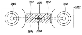
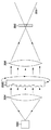
ミクロの光レベルのほとんどの危険は既存の技術および資料を使用して、注意深い設計によって対処できる。このように、中赤外光測定での問題の多くは回避できる。IRACSシステムは、以下の特徴の1つ以上を備えたミクロフロー経路構造を含んでいてもよい。1つの特徴は経路を形成する中赤外光伝送ウィンドウの上端および底部であって良い。潜在的な材料は以下ものを含んでいる:Si、Ge、ZnSe、いくつかのポリマー。Si、ZnSe(または類似の)、もし望ましいのであれば、可視、NIR、またはSWIR(500-1600nm)の光学的検出、操作に互換性があるポリマー。ZnSe、可視光線視検、検出および適当な操作(レーザーピンセット、レーザーに基づいた細胞無能化/破壊)ができる類似物質。別の特徴は、個別窓の両玄に適用された反射防止膜(外部が空気、内部が水用に設計されたAR被覆)である。別の特徴は、中赤外光の波長のオフ共振のギャップに調整された経路の深さである。例えば、経路の深さとして約20ミクロンを使用してよい。別の特徴は、角度可変、あるいはさらに反射の影響を弱めるV字形のウィンドウである。別の特徴はQCLのスポットサイズを超過する経路幅である、これは、擬似信号の生成を防ぐビームに関して経路内において非常にわずかな変位である。 Most dangers at the micro light level can be addressed by careful design, using existing techniques and materials. Thus, many of the problems in mid-infrared light measurement can be avoided. The IRACS system may include a microflow path structure with one or more of the following features. One feature may be the top and bottom of the mid-infrared light transmission window forming the path. Potential materials include: Si, Ge, ZnSe, some polymers. Si, ZnSe (or similar), if desired, polymers compatible with visible, NIR, or SWIR (500-1600 nm) optical detection and operation. ZnSe, a similar substance capable of visible light inspection, detection and appropriate manipulation (laser tweezers, laser-based cell deactivation / destruction). Another feature is an anti-reflective coating (AR coating designed for air on the outside and water on the inside) applied to both doors of the individual windows. Another feature is the depth of the path adjusted to the off-resonance gap of the mid-infrared light wavelength. For example, a path depth of about 20 microns may be used. Another feature is a V-shaped window that is variable in angle or even lessens the effects of reflection. Another feature is the path width that exceeds the spot size of the QCL, which is a very slight displacement in the path with respect to the beam that prevents the generation of spurious signals.
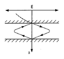
さらに、本開示では、被検出細胞によるミー散乱の影響を非常に緩和する特別の測定のいくつかの態様は以下とおりである:1)細胞は、水媒体(空気中のウィンドウ上の乾燥菌体と比較して)の中で測定される。これは、著しく媒体と細胞とのインデックス差異を縮小させる。推測された実際の細胞の屈折率は、細胞/媒体比率1.02〜1.04のために、1100cm-1あたりncell= 1.27〜1.30対nH2O=1.25の範囲である。また核反射率はそれより高い;2)DNA識別特性は、振動指紋領域の低い波数(長波長)の終わりにある。分散はより長い波長で減少する。したがって、比較的、より少ない効力が経験される;また、3)光は高NAレンズを使用して、大きな角度で捕らえられる;これは、適度な角度(10度)上に散乱した光は捕らえられ検知器に中継されることを意味する。 In addition, in this disclosure, some aspects of special measurements that greatly mitigate the effects of Mie scattering by the detected cells are as follows: 1) The cells are dried cells on an aqueous medium (window in air) Compared to). This significantly reduces the media and cell index differences. The estimated actual cell refractive index is in the range of ncell = 1.27-1.30 vs. nH2O = 1.25 per 1100 cm @ -1 for a cell / medium ratio of 1.02-1.04. Also, the nuclear reflectivity is higher; 2) The DNA discrimination characteristic is at the end of the low wavenumber (long wavelength) of the vibrating fingerprint region. Dispersion decreases at longer wavelengths. Therefore, relatively less efficacy is experienced; and 3) the light is captured at a large angle using a high NA lens; this captures light scattered over a moderate angle (10 degrees) It is relayed to the detector.
細胞定位の問題に関して、散乱は等価な球状のボリュームに基づいて推定され、コンピューター散乱効果は、細胞提示角度に依存する実際の細胞横断面で倍増させられる。これは、細胞横断面が大きい場合、路程が比較的短いという事実を無視してもよい。これによって次には散乱効果(散乱は、サンプル対周囲媒体の位相シフトおよび経過の衰退の結果であるので)を縮小するだろう。さらに細胞定位の影響を弱めるために、本発明は以下のアプローチを考慮する:1)分布(それは定位問題によって大部分引き起こされている)から異常値を取り除くこと;2)DNAのピーク吸収レベルにない測定波長を使用すること、またはより強くには吸収しないDNAバンドを使用する測定波長を使用すること。高い吸収係数は大きな散乱および直接の吸収においてさらにより多くの定位/形状依存、の両方を生じる。低い吸収では、経路長は横断面変更をよりよく補償する。高い吸収では、これはそれほど真実ではないだろう;3)より正確に細胞横断面/定位を決定するために短波長(恐らくNIR)を使用し、ある定位を補償あるいは拒絶すること。 With respect to cell localization problems, scatter is estimated based on the equivalent spherical volume, and the computer scatter effect is doubled at the actual cell cross section depending on the cell presentation angle. This may ignore the fact that the path length is relatively short when the cell cross section is large. This in turn will reduce the scattering effect (since scattering is the result of a phase shift of the sample to the surrounding medium and the decay of the course). In order to further weaken the effects of cell localization, the present invention considers the following approaches: 1) removing outliers from the distribution (which is mostly caused by localization problems); 2) peak absorption levels of DNA Use no measurement wavelength, or use a measurement wavelength that uses a DNA band that does not absorb more strongly. A high absorption coefficient results in both large scattering and even more localization / shape dependence in direct absorption. At low absorption, the path length better compensates for cross-sectional changes. At high absorption, this may not be as true; 3) use a short wavelength (possibly NIR) to more accurately determine cell cross-section / localization and compensate or reject certain localizations.
さらに、散乱の影響を減じるか補償するために、本開示は、波長最適化、ビーム角をキャプチャー角度最適化、散乱検知および補償、散乱に基づいた測定などの複数の解決策を採用する。
a. そのような散乱検知器も使用されてもよいことに注意
Furthermore, to reduce or compensate for the effects of scattering, the present disclosure employs multiple solutions such as wavelength optimization, beam angle capture angle optimization, scattering detection and compensation, and scattering based measurements.
a. Note that such scatter detectors may also be used.
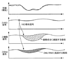
実施形態では、発明は、量子カスケードレーザ(QCL)コンポーネントを使用して生細胞の吸収スペクトルを直接に測定して選別する。QCLが使用されるいくつかのエリアは、XおよびY染色体多量の差に基づいた精細胞のジェンダーの識別、DNA/RNA質量変化率に基づいた分化細胞からの幹細胞の分離、健康および異常細胞の識別、細胞分裂相の識別、などを含んでいてもよい。 In an embodiment, the invention uses a quantum cascade laser (QCL) component to directly measure and screen the absorption spectrum of live cells. Some areas where QCL is used include gender discrimination of sperm cells based on the large differences in X and Y chromosomes, isolation of stem cells from differentiated cells based on DNA / RNA mass change rates, and healthy and abnormal cells Identification, identification of the cell division phase, and the like may be included.
DNA測定システムの実施形態では、細胞が流体流の光学的照明および読出し装置を通過するに従い、正確に細胞のDNA含量を測定するために、システムは、DNA骨格に特有の分子振動モードへ光吸収を利用する。システムは汚れあるいはラベルがないこと、あるいは関連するインキュベーション工程がないことを必要とする。システムは、1つの細胞当たりの細胞数対DNA量を示すヒストグラムを示し、任意でユーザーがある量のDNAを持つ細胞を選別することができる。システムは、セルサイズ(コールタータイプ電気インピーダンス測定、あるいは光学的散乱計測など)、または細胞タイプを識別するのに役立つ他の細胞のコンポーネント(蛋白含有量など)を確立する標準測度を含んでいてもよい、さらにデータあるいは選別済みの流れからそれらを取り除いて細胞塊の識別ができる。 In an embodiment of the DNA measurement system, in order to accurately measure the DNA content of the cell as the cell passes through the fluid flow optical illumination and readout device, the system absorbs light into a molecular vibration mode that is unique to the DNA backbone. Is used. The system requires no dirt or labels, or no associated incubation step. The system shows a histogram showing the number of cells per cell versus the amount of DNA, optionally allowing the user to sort cells with a certain amount of DNA. The system may include standard measures to establish cell size (such as Coulter-type electrical impedance measurements, or optical scatterometry), or other cellular components that help identify cell types (such as protein content). It is also possible to identify the cell mass by removing them from the data or sorted flow.
様々な実施形態では、1つ以上のQCLを使用して生細胞を通る1つ以上の波長の伝達を測定する。細胞による1つ以上の波長の吸収は、細胞内の構成するコンポーネントの濃度または質量を示すことがある。さらに、吸収の絶対的か相対レベルを使用して細胞型または状態を分類または識別できる。吸収線は標的分子中の分子結合の振動様式に相当していることがある。 In various embodiments, one or more QCLs are used to measure transmission of one or more wavelengths through a living cell. Absorption of one or more wavelengths by a cell may indicate the concentration or mass of constituent components within the cell. In addition, the absolute or relative level of absorption can be used to classify or identify cell types or conditions. Absorption lines may correspond to the vibrational mode of molecular bonds in the target molecule.
QCLは、少なくとも3〜15ミクロンの波長領域(3〜4ミクロンなど)をカバーする、中赤外領域のコヒーレント放射を直接放射できる。波長は、赤外分光法の範囲、および細胞に関する以前の分光器研究の多くで使用された波長と一致してもよい。しかしながら、分類または選別するために中赤外光を使用して細胞を検出するという潜在的な利点は多数である。それらは、潜在的に低光学パワー、高速測定および/または高精度測定の組み合わせを可能にする、まさに特定の識別特性、低光子エネルギーおよび直接測定を含んでいる。中赤外は重要な範囲である、なぜならこの範囲では、分子振動が吸収測定を使用して直接測定されるからである。本質的に、ラマン分光学を使用して測定されるのと同じ振動信号が測定される。中赤外範囲のいくつかの主な利点は、吸収率はラマンよりもはるかに高く、入力光子あたり著しくより高い信号を生じることを含んでいる。さらに、使用される光子エネルギーは、可視光線どころか近赤外線の測定値と比較しても著しく低い;これは、細胞またはそれらのコンポーネントへのイオン化または二光子吸収のプロセスからの損害を意味するわけではない。最後に、この範囲内の分子の指紋は、フーリエ変換赤外(FTIR)分光法を使用して、数十年間広範囲に特徴づけられている。典型的には、非常に低いスペクトルおよび面出力密度を提供する「グローバー」(光を放つフィラメント)ソースを使用するFTIRに対抗して、QCLは、標的および波長にさらにより多くの出力を提供し、はるかに高い信号対雑音(SNR)比率および/または処理能力が得られる。 QCL can directly emit coherent radiation in the mid-infrared region, covering a wavelength region of at least 3-15 microns (such as 3-4 microns). The wavelength may be consistent with the range of infrared spectroscopy and the wavelength used in many of the previous spectroscopic studies on cells. However, the potential advantages of detecting cells using mid-infrared light for sorting or sorting are numerous. They include very specific discriminating properties, low photon energy and direct measurement, potentially allowing a combination of low optical power, high speed measurement and / or high accuracy measurement. Mid-infrared is an important range because in this range molecular vibrations are measured directly using absorption measurements. Essentially, the same vibration signal is measured as measured using Raman spectroscopy. Some major advantages of the mid-infrared range include that the absorption is much higher than Raman, resulting in a significantly higher signal per input photon. Furthermore, the photon energy used is significantly lower compared to near-infrared measurements as well as visible light; this does not imply damage from the process of ionization or two-photon absorption into cells or their components. Absent. Finally, molecular fingerprints within this range have been extensively characterized for decades using Fourier transform infrared (FTIR) spectroscopy. In contrast to FTIR, which typically uses a “glober” (light emitting filament) source that provides a very low spectral and surface power density, QCL provides even more power to targets and wavelengths. A much higher signal-to-noise (SNR) ratio and / or processing power is obtained.
QCLは、ファブリーペローおよび分散形フィードバック(DFB)設計、同様に波長は、外部装置を使用してセットされ、広範囲に可変同調できる外部空洞(EC)設計を含む様々な型で製造されている。生細胞の顕微分光で使用される中赤外光のソースとしてのQCLの利点は、狭いスペクトルバンドの大量の光学パワー、中赤外光を小さなスポット上に集中させる能力、有効な電力レベルを生む能力、小型パッケージ内にQCLを発振源にする能力などがある。 QCL is manufactured in a variety of types, including Fabry-Perot and distributed feedback (DFB) designs, as well as external cavity (EC) designs in which the wavelength is set using external devices and can be tuned over a wide range. The advantages of QCL as a source of mid-infrared light used in microscopic spectroscopy of live cells yields large amounts of optical power in a narrow spectral band, the ability to focus mid-infrared light on a small spot, and an effective power level And the ability to use QCL as an oscillation source in a small package.
実施形態において、本発明で使用されている中赤外QCLは、一般に非制限で6〜12ミクロンの分子の「指紋領域」を標的とする。いくつかの実施形態では、比較的小量の光学パワーを使用し、および超低エネルギーフォトン(1000cm-1範囲近辺の波長)を使用して、本発明は、無ラベルの方法で高速に生細胞を選別する問題に適用される。様々な他の実施形態では、多数のQCL波長を使用して細胞内の1つ以上の物質の相対的濃度を測定でき、主要測定を遂行する際のベースライン測定を確立する。QCL波長は可視、近赤外あるいは他の波長測定で補充でき基準情報(細胞位置、形、定位、散乱など)を提供する。実施形態では、多数のQCL波長は多数の個別部品、多数の個別の波長を生成する単一コンポーネント、フィルター技術に加えての広帯域のQCL、同調可能なQCLコンポーネントなど、を使用して生成されてもよい。量子カスケードレーザ(QCL)のような中赤外ソースは、細胞輸送、測定システムへの提示、および任意に特定の個体群への選別をするミクロフローシステムに統合されてもよい。 In an embodiment, the mid-infrared QCL used in the present invention generally targets the “fingerprint region” of molecules of 6-12 microns, without limitation. In some embodiments, using a relatively small amount of optical power, and using ultra-low energy photons (wavelengths near the 1000 cm-1 range), the present invention provides fast living cells in a label-free manner. Applies to the problem of screening. In various other embodiments, multiple QCL wavelengths can be used to measure the relative concentration of one or more substances in the cell, establishing a baseline measurement in performing the primary measurement. QCL wavelengths can be supplemented with visible, near-infrared or other wavelength measurements, providing reference information (cell location, shape, localization, scattering, etc.). In embodiments, multiple QCL wavelengths are generated using multiple individual components, a single component that generates multiple individual wavelengths, wideband QCL in addition to filter technology, tunable QCL components, etc. Also good. A mid-infrared source such as a quantum cascade laser (QCL) may be integrated into a microflow system for cell transport, presentation to a measurement system, and optionally sorting to a specific population.
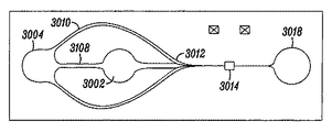
ミクロフローシステムは、大ボリュームの商用アプリケーションを含むバイオ医学への応用で広く利用されている。それらの組立てと使用は良く知られている。ミクロフローを使用して、生化学的サンプルを結合、測定、選別、ろ過する。いくつかの実施形態では、QCL備えたミクロフローおよび中赤外光検知器を組み合わせで生細胞の正確な測定が達成できることが記述されている。ミクロフローによって、そのようなシステムでより高い精度が可能になる。中赤外光は、水に非常に強く吸収される。小さな経路(液体を通る)を備えたそのようなシステムは、高スループット、短い積分時間あるいは非常に大きな信号対雑音比を必要とするシステムには非常に望ましい。更に、水流の直径に依存する変動を除去するために、反復する一定長の経路が望ましい。ミクロフロー装置あるいは回路(それらは半導体のようなプロセスを使用して組み立てられる)にはそのような反復性を提供する可能性がある。 Microflow systems are widely used in biomedical applications including large volume commercial applications. Their assembly and use are well known. Microflow is used to bind, measure, sort, and filter biochemical samples. In some embodiments, it is described that accurate measurement of living cells can be achieved by combining microflow with QCL and a mid-infrared light detector. Microflow allows higher accuracy in such systems. Mid-infrared light is absorbed very strongly by water. Such a system with a small path (through the liquid) is highly desirable for systems that require high throughput, short integration times or very large signal-to-noise ratios. Furthermore, a repetitive fixed length path is desirable to eliminate variations that depend on the diameter of the water stream. Microflow devices or circuits (which are assembled using semiconductor-like processes) may provide such repeatability.
さらに、ミクロフロー装置によって、大ボリュームで生産され、使用されるシステムにはより適切である閉ループでコンパクトなシステムが可能になる。それは本発明の1つのゴールであろう。ミクロフロー・コンポーネントは低コストで組み立てられ、従って使い捨てにでき、再利用も可能かもしれないし、ばらつきのないまた患者間の感染が生じない清潔なシステムを低コストで維持する方法を提示している。 Furthermore, the microflow device allows for a closed loop and compact system that is more suitable for systems that are produced and used in large volumes. That would be one goal of the present invention. Microflow components are assembled at low cost, and therefore can be disposable, may be reusable, and offer a low-cost way to maintain a clean system that is consistent and free of patient-to-patient infection .
いくつかの実施形態では、中赤外光QCLに基づいた無ラベル細胞特性化システムの組み合わせは、細胞培養、フィルタリング、検知およびシングルチップ選別を備えたシステム・オン・チップを可能にし、それによって入力と出力を最小限にしている。蛍光性のラベル、磁気ラベルあるいは他のラベル(最終的に細胞の生存率に影響するかもしれない特定の、しばしば困難な手続きを通して細胞へ付着させられるに違いない。)ではなくQCLを使用する能力によって、特定のバイオ医学用、または産業上の生物学的応用用のオンチップで遂行できるオペレーションの数が増加する。 In some embodiments, a combination of label-free cell characterization systems based on mid-infrared light QCL enables system-on-chip with cell culture, filtering, detection and single-chip sorting, thereby providing input And the output is minimized. Ability to use QCL rather than fluorescent labels, magnetic labels or other labels (which must ultimately be attached to cells through certain and often difficult procedures that may affect cell viability) This increases the number of operations that can be performed on-chip for specific biomedical or industrial biological applications.
下記のように、多重構成のミクロフローシステムが使用されてもよい。重要なことには、このシステムと共に全体として使用できるミクロフローに広範囲の先行技術(個々の細胞特性を測定する、QCL+ミクロフロー+中赤外光検知器)があることである。これらのうちのほとんどは、本発明に適用可能であるためにはQCLによって生成された中赤外光を送信する基板(ミクロフロー構造に流体を閉じ込めるトップキャップおよびボトムキャップ、またはウエハーのような)を使用して改良を加えなければならない。 A multi-configuration microflow system may be used as described below. Importantly, there is a wide range of prior art microflows that can be used as a whole with this system (QCL + microflow + mid-infrared light detectors that measure individual cell properties). Most of these are substrates that transmit mid-infrared light generated by QCL in order to be applicable to the present invention (such as top and bottom caps or wafers that confine fluid in a microflow structure) You must make improvements using.
システムと中赤外の検知器のQCL(複数)は多数の実施形態が可能で、それらは応用に依存している。一例では、1つ以上の広く同調可能なQCLを使用して研究応用の多数の分子の指紋に対応する広い中赤外スペクトルを扱うことができる。ビームは、ハーフミラー(ロスがある)、薄膜干渉フィルターあるいは回析格子を使用して組み合わせてもよい。そのような配置を使用して細胞の完全なスペクトルの識別特性を集めることができる、例えば、1つの新しいQCLに基づいた測定装置が開発されている。一旦有用なスペクトルの特徴が識別されると、同調可能なQCLに基づいたそのようなシステムはピークに同調させられた個々の同調可能なQCLでセットアップされてもよい。次に、細胞は高速(臨床のシステムの中で使用されているような速度)に検出される。 The system and mid-infrared detector QCL (s) can have many embodiments, depending on the application. In one example, one or more widely tunable QCLs can be used to handle a broad mid-infrared spectrum corresponding to multiple molecular fingerprints for research applications. The beams may be combined using a half mirror (having a loss), a thin film interference filter or a diffraction grating. One new QCL-based measurement device has been developed that can use such an arrangement to collect discriminating characteristics of the complete spectrum of cells, for example. Once useful spectral features are identified, such a system based on tunable QCL may be set up with individual tunable QCL tuned to the peak. The cells are then detected at high speed (speed as used in clinical systems).
厳密に、波長情報の派生情報が重要である場合、同調可能なレーザーを使用して特定のスペクトルの特徴を検出できる。例えば、細胞要素の吸収のピークに対応する小さな範囲を高速に走査すると、他の要因により絶対的な吸収が変化する場合には著しく精度が改善する。 Strictly, if the information derived from the wavelength information is important, a tunable laser can be used to detect specific spectral features. For example, scanning a small range corresponding to the absorption peak of a cellular element at high speed significantly improves the accuracy when the absolute absorption changes due to other factors.
より低コスト、固定QCLレーザー(分散形フィードバック)、あるいはDFB-QCLは、望まれるスペクトルの特徴が有名なシステムである場合使用してもよい。最も単純な構成では、単一のQCLおよび検知器を使って細胞内の化学的濃度を測定できる。信号の波長で多数の要素が吸収する時には、追加の固定のQCLをシステムに加えて基準測定をさせ、またそれらの非目標要素の影響を「取り消して」良い。例えば、RNAとDNAはいくつかの吸収ピークを共有する。また、細胞のRNAの濃度測定をするために、一つの吸収ピークを測定するのではなく2つの波長を測定してRNAに対応する相対的な吸収レベルを見るのがもっとも実践的である。 Lower cost, fixed QCL lasers (dispersed feedback), or DFB-QCL may be used if the desired spectral features are well known systems. In the simplest configuration, a single QCL and detector can be used to measure intracellular chemical concentrations. When a large number of elements absorb at the wavelength of the signal, additional fixed QCL can be added to the system to perform a reference measurement and “cancel” the effects of those non-target elements. For example, RNA and DNA share several absorption peaks. In order to measure the concentration of RNA in cells, it is most practical not to measure one absorption peak but to measure two wavelengths to see the relative absorption level corresponding to RNA.
多くの配置は、QCLに対応する中赤外検知器にとって適当であろう。他の実施形態では、水銀テルル化カドミウム(MCT)光起電力型検出器を含む、液体窒素で冷却された、熱電冷却機(TEC)で冷却されたまたは室温での複数の検知器タイプが、使用されている。
コストが問題である場合、ピロ電気および他の熱感知器も使用してよい。1つ以上の検知器をシステムで使用してもよい。例えば、2つのQCLを備えたシステムは、パルス・モードでしばしば使用されるQCLの変調を使用して、単一の検知器を使用してもよい。その後、サンプルの吸収と組み合わせた2つのQCLに対応する信号は、検知器によって測定され、QCLの変調パターンに電子的に基づいて分離してもよい。あるいは、薄膜干渉フィルターを使用して、2つの波長を分離し、かつそれらを個々の検知器へ送ってもよい。どんな場合も、システムコンポーネントからの帯域外の中赤外光黒体放射、またはQCL、および恐らく可視/近赤外線(NIR)ビームを通過する際の細胞の加熱または冷却にかかわる広帯域信号を拒絶するために、検知器はその前に通過帯域フィルターをマウントさせても良い。
Many arrangements may be appropriate for mid-infrared detectors that support QCL. In other embodiments, a plurality of detector types cooled with liquid nitrogen, cooled with a thermoelectric cooler (TEC) or at room temperature, including a cadmium mercury telluride (MCT) photovoltaic detector, It is used.
If cost is an issue, pyroelectricity and other thermal sensors may also be used. One or more detectors may be used in the system. For example, a system with two QCLs may use a single detector using QCL modulation often used in pulsed mode. The signals corresponding to the two QCLs combined with sample absorption may then be measured by a detector and separated based on the QCL modulation pattern electronically. Alternatively, a thin film interference filter may be used to separate the two wavelengths and send them to individual detectors. In any case, to reject out-of-band mid-infrared light blackbody radiation from system components, or QCL, and possibly broadband signals that involve heating or cooling of cells as they pass through the visible / near infrared (NIR) beam In addition, the detector may be mounted with a passband filter in front of it.
別の実施形態では、多数のQCLは完全に別個の光学経路を使用しても良く、その経路として異なる角度で同じサンプルボリュームを通り抜ける経路、細胞がそれらを連続して通り抜けるすべての個別の測定ボリュームを使用する経路がある。これによって、QCLからの波長の多重化を単純化するが、同じ測定がなされるかは保証されない。 In another embodiment, multiple QCLs may use completely separate optical paths, the path through the same sample volume at different angles as that path, all the individual measurement volumes through which cells pass through them in succession. There is a route to use. This simplifies the multiplexing of wavelengths from the QCL but does not guarantee that the same measurements will be made.
本発明の実施形態で使用してもよい別の検出方法は、光音響的検知である。光音響的測定は、非常に小さな濃度であってもガス濃度のQCL測定などの中赤外と共に使用してもよい。この方法では、中赤外パルスはサンプルを照射する。特定の化学種による吸収のために、ある局所的加熱および拡張がある。この拡張は、音響センサーによって拾い上げられる衝撃波を生じる。本発明が閉じた液体通路を使用するので、細胞が1つ以上のQCLで検知される時、吸収信号を拾い上げるために「マイクロホン」を使用する可能性がある。そのようなマイクロホンは、ミクロフロー装置のトップかボトム「キャップ」を形成するウエハーのうちの1つに統合されてもよいし、またはミクロフロー構造の外部に取り付けてもよい。 Another detection method that may be used in embodiments of the present invention is photoacoustic sensing. Photoacoustic measurements may be used with mid-infrared, such as QCL measurements of gas concentrations, even at very small concentrations. In this method, a mid-infrared pulse illuminates the sample. There is some local heating and expansion due to absorption by certain chemical species. This expansion creates a shock wave that is picked up by the acoustic sensor. Since the present invention uses a closed fluid path, when a cell is detected by one or more QCLs, it is possible to use a “microphone” to pick up the absorption signal. Such a microphone may be integrated into one of the wafers forming the top or bottom “cap” of the microflow device, or may be attached to the exterior of the microflow structure.
本発明の実施形態で実現される別の潜在的な検出方法は、QCLを使用して細胞が刺激(加熱)されるので、細胞構成体からの受動的(黒体)放射の測定を含む。例えば、細胞は、したがっていくつかの分子の吸収ピーク(そのうちの1つは興味深い)に対応する1つの波長で照射でき、したがって単純な吸収測定では対象とする分子の正確な測定ができないであろう。その後、細胞からの中赤外放射線は収集され、対象とする分子の別の吸収(放射)ピーク(または密結合している別の分子/結合振動、しかし入力QCL波長によって直接指定されていない)のまわりの狭い通過帯域の中赤外を使用してフィルターされる。検知QCL波長によって誘導された振動は、温度/振動の上昇につながることがある。また、これらはこの第2の中赤外波長で観測してもよい。この信号はもちろん全く小さくなるが、良く知られた確定技術で電子的にろ過してもよい。 Another potential detection method implemented in embodiments of the present invention involves the measurement of passive (blackbody) radiation from cell components as cells are stimulated (heated) using QCL. For example, a cell can therefore be irradiated at one wavelength corresponding to the absorption peaks of several molecules, one of which is interesting, so simple absorption measurements will not provide an accurate measurement of the molecule of interest . The mid-infrared radiation from the cell is then collected and another absorption (radiation) peak of the molecule of interest (or another molecule / bond vibration that is tightly coupled, but not directly specified by the input QCL wavelength) Is filtered using mid-infrared in the narrow passband around. Vibration induced by the sensed QCL wavelength can lead to an increase in temperature / vibration. They may also be observed at this second mid-infrared wavelength. This signal is of course quite small, but may be filtered electronically with well-known deterministic techniques.
水の吸収の影響を最小限にし、かつセルの生化学的成分の正確な測定値を提供する本発明に使用しても良い多数の構造が示される。これは完全なリストではない。また本発明は他の構造にも同様に適用可能である。実施形態では、本発明は、1つ以上の量子カスケードレーザを使用して中赤外波長領域で単離細胞の振動吸収特性を測定するフロー血球計数器から成る。 A number of structures are shown that may be used in the present invention that minimize the effects of water absorption and provide accurate measurements of the biochemical components of the cell. This is not a complete list. The present invention is applicable to other structures as well. In an embodiment, the present invention comprises a flow cytometer that measures the vibrational absorption properties of isolated cells in the mid-infrared wavelength region using one or more quantum cascade lasers.
生細胞は、中赤外透明成分、シート、テープまたはディスクなどの基板(生細胞は薄膜の表面上に分配され、走査などにより検知される)、で構築された細胞分類および選別用のミクロフロー成分の扱うQCLと中赤外透明液体を後付けされた従来のフロー血球計数器型装置のように、段取りをして高速に検知されてもよい。実施形態では、選別される細胞間の違いを強調させる測定に先立って、本発明は特定の化学薬品または他の操作と共に使用される。例えば、細胞は、例えば細胞代謝を差別的に変更して、したがって入力あるいは出力生成物によって、細胞を見分ける生化学の濃度を増大させる温度、光、燃料あるいは他の刺激物で刺激してもよい。 A live cell is a microflow for cell sorting and sorting constructed with a mid-infrared transparent component, a substrate such as a sheet, tape or disk (live cells are distributed on the surface of the thin film and detected by scanning, etc.) It may be set up and detected at high speed, as in a conventional flow cytometer-type device retrofitted with QCL and mid-infrared transparent liquid handled by the components. In embodiments, the invention is used with certain chemicals or other operations prior to measurements that highlight differences between sorted cells. For example, cells may be stimulated with temperature, light, fuel or other stimuli that, for example, differentially alter cell metabolism and thus increase the concentration of biochemistry that distinguishes cells by input or output products. .
実施形態では、本発明は、無ラベルでおよび高エネルギーのUV光子に細胞を露出することなしに高速に精子選別を可能にする。例えば、X染色体にY染色体より著しく多くのDNA含量があるという事実を使用して、X形とY形による精子の分離は可能で、それによって哺乳類種では精細胞のDNA質量全体を2%以上増大させる。少なくとも1つのQCLを使用してDNAに特有の少なくとも1つの吸収帯を探索する。他の実施形態では、複数のQCL波長を使用して他の潜在的に干渉する要素を測定する。測定は、精細胞頭の非対称の形に対する標準化のために1つを超える定位から行う。様々な他の実施形態では、測定過程は、細胞定位、サイズ、位置、密度などを測定する可視帯域あるいは近赤外帯域のその他のレーザー、さらに追加の中赤外に基づいたレーザー(交互に同調されたQCL)で測定する。DNAバンドに伝達された中赤外光の量は、他の測定値によって標準化されるとともに、精細胞のDNAの全質量を計算するのに使用される。与えられた種のXまたはY-保有細胞のDNA量が非常に一貫しているので、精細胞は、流動細胞計測法タイプ装置、ミクロフロー方法など(細胞はより大きな基板、細胞キュベットなどに広げられる)のように当業者に既知の1つ以上の機序を使って、XおよびY-保有個体群へ選別できる。 In an embodiment, the present invention allows sperm sorting at high speed without labeling and without exposing the cells to high energy UV photons. For example, using the fact that the X chromosome has significantly more DNA content than the Y chromosome, it is possible to separate the sperm by the X and Y forms, so that in mammalian species the total DNA mass of sperm cells is more than 2% Increase. At least one QCL is used to search for at least one absorption band characteristic of DNA. In other embodiments, multiple QCL wavelengths are used to measure other potentially interfering elements. Measurements are taken from more than one localization for normalization to the asymmetric shape of the sperm cell head. In various other embodiments, the measurement process may include other lasers in the visible or near infrared range that measure cell localization, size, location, density, etc., and additional mid-infrared based lasers (alternately tuned). QCL). The amount of mid-infrared light transmitted to the DNA band is normalized by other measurements and used to calculate the total mass of sperm cell DNA. Because the amount of DNA in X or Y-bearing cells of a given species is very consistent, sperm cells can be flow cytometry type devices, microflow methods, etc. (cells can be spread over larger substrates, cell cuvettes, etc.) Can be selected into X and Y-bearing populations using one or more mechanisms known to those skilled in the art.
実施形態では、本発明は、測定ボリュームに一つずつ生細胞を伝達する流体素子と、特定の分子振動数に基づいて、細胞内のDNA分子に優先的に作用するビームを生成するレーザーソースと、細胞が測定ボリュームおよび信号処理装置を通過する際に、レーザーソースとDNAとの相互作用を測定する検知器と、からなるシステムであって、単離細胞のDNA量を推定するためにこれらの信号を捕らえて処理をする。 In an embodiment, the present invention includes a fluidic device that transmits live cells one by one to a measurement volume, a laser source that generates a beam that preferentially acts on intracellular DNA molecules based on a specific molecular frequency. A detector that measures the interaction between the laser source and DNA as the cells pass through the measurement volume and signal processor, and these are used to estimate the amount of DNA in the isolated cells Capture the signal and process it.
実施形態では、システムは、細胞数対DNA量(細胞のサンプルを分析するために使用される共通のプロット)のヒストグラムを表示するインターフェースを含んでいてもよい。 In an embodiment, the system may include an interface that displays a histogram of cell number versus DNA content (a common plot used to analyze a sample of cells).
実施形態では、システムは、さらに細胞を特徴づける個々の細胞に作用する測定を含んでいてもよい。これらは、非制限で、流路中の電気インピーダンス測定(システムが細胞のサイズまたは横断面を推定し、かつ誤ったDNA測定値を生み出す細胞塊を検知することができる)と、細胞型を決定し、さらに凝集粒子を測定するのに役に立つ散乱あるいは形状の可視または近赤外線の領域での光学測定と、検査中の細胞の他の生化学的要素を定量するのに役に立つ振動の光学測定(非限定で細胞の大よそのサイズおよびタイプを決定し、細胞塊を検知するタンパク質または脂質の濃度の測定を含む)と、を含む。 In embodiments, the system may further include measurements that act on individual cells that characterize the cells. These are non-limiting, electrical impedance measurements in the flow path (the system can estimate cell size or cross section and detect cell masses that produce false DNA measurements) and determine cell type In addition, optical measurements in the visible or near-infrared region of the scattering or shape that are useful for measuring aggregated particles and optical measurements of vibration that are useful for quantifying other biochemical elements of the cell under examination (non- Including the determination of the approximate size and type of cells and the measurement of protein or lipid concentrations that detect cell mass).
実施形態では、システムは、計算されたDNA含量に基づいて個々に細胞を選別する方法、および上述されたものを含む任意の基準の信号も同様に含んでいてもよい。この選別は、細胞数測定、蛍光活性化細胞選別およびミクロフローの当業者に良く知られた多くの方法のうちの1つで遂行できる。これらの方法として、非制限で、液滴の静電気転換、ミクロフロー中の流れの液圧転換、出力経路に対する測定の機械的な作動、およびレーザーに基づいた細胞トラッピング/指向、を含む。 In embodiments, the system may also include a method for individually sorting cells based on the calculated DNA content, and any reference signal including those described above. This sorting can be accomplished by one of many methods well known to those skilled in the art of cell counting, fluorescence activated cell sorting and microflow. These methods include, but are not limited to, electrostatic droplet droplet transformation, hydraulic fluid flow transformation in the microflow, mechanical actuation of the measurement to the output path, and laser-based cell trapping / directing.
実施形態では、システムは、少なくともソース貯蔵所、出力貯蔵所および測定経路が作られたミクロフローチップを使用できる。チップは、1つのサンプル当たり一度使用され、次に廃棄されるか、再利用される消費可能なコンポーネントであって良い。コアチップは、生物学的適合性と光学的振動DNA測定に使用される波長との光学的適合性の両方がある材料から作り上げられてもよい。コアチップは大きな貯水容量を備えたプラスチックキャリアにマウントしてもよい。目詰まりがコアチップに生じる場合、プラスチックキャリアはそれ自体多数のコアチップと共に使用してもよい。また自動の障害除外手続きを行なう代わりにこれらのチップを処分する方が望ましい。 In an embodiment, the system can use a microflow chip with at least a source reservoir, an output reservoir, and a measurement path. The chip can be a consumable component that is used once per sample and then discarded or reused. The core chip may be made from a material that is both biocompatible and optically compatible with the wavelengths used for optical vibrational DNA measurements. The core chip may be mounted on a plastic carrier with a large water storage capacity. If clogging occurs in the core chip, the plastic carrier may itself be used with multiple core chips. It is also preferable to dispose of these chips instead of performing an automatic fault exclusion procedure.
実施形態では、本発明は、1つの細胞当たりのDNAが分裂の過程で2倍になる特性に従って細胞分裂(サンプル中の培養成長)率を測定する目的で、もしくはその目的に特定化されて使用してもよい。この開示は、X染色体を持つ精細胞がY染色体を持つ精細胞より多くのDNAを保有することができる特性に従って、Y染色体を持つ精細胞からX染色体を持つ精細胞を分離することを提供する。この開示は癌細胞あるいは遺伝病を示す他の細胞を検知する目的などの細胞のサンプル内の異数性の発生を測定することを提供する。この開示は、癌細胞などの細胞に対する潜在的な薬剤の影響を評価するためにサンプル測定を繰り返し行うことを提供する。この開示は細胞分裂率を測定すると同時に薬物効果の評価することを提供する。この開示は、異数性の測定に基づいてこれらの細胞はまれであるより大きな細胞培養から潜在的な癌細胞を分離するのを提供する。この開示は幹細胞を特徴づける目的で腫瘍組織から癌幹細胞を識別し分離することを提供する。そのような特性記述は、幹細胞の薬理学的研究をさらに可能にする。この開示は、細胞内DNAが、細胞型、活性または病理学のためのマーカーまたは潜在的なマーカーである他の応用を提供する。 In an embodiment, the present invention is used to measure or specialize for the purpose of measuring the rate of cell division (culture growth in a sample) according to the property that DNA per cell doubles during division. May be. This disclosure provides for the separation of sperm cells with an X chromosome from sperm cells with a Y chromosome according to the property that sperm cells with an X chromosome can carry more DNA than sperm cells with a Y chromosome . This disclosure provides for measuring the occurrence of aneuploidy in a sample of cells, such as for the purpose of detecting cancer cells or other cells that are indicative of a genetic disease. This disclosure provides for repeated sample measurements to assess the effects of potential agents on cells such as cancer cells. This disclosure provides for measuring cell division rate and simultaneously evaluating drug effects. This disclosure provides for the separation of potential cancer cells from larger cell cultures where these cells are rare based on aneuploidy measurements. This disclosure provides for identifying and separating cancer stem cells from tumor tissue for the purpose of characterizing the stem cells. Such characterization further enables pharmacological studies of stem cells. This disclosure provides other applications where intracellular DNA is a marker or potential marker for cell type, activity or pathology.
さらに、本発明は、さらにQCLが使用する中赤外で、粒子の化学的構成/内容を測定するシステムについて記述する。実施形態では、本システムは、これらの測定を行う目的で散乱効果を緩和するか利用する光学系構造について記述する。この光学系構造は、最小数の波長を備えたこれらの散乱効果を最小限にするか、補正するか、利用し、高速測定を可能にする。 Furthermore, the present invention further describes a system for measuring the chemical composition / content of particles in the mid-infrared used by QCL. In an embodiment, the system describes an optical system structure that mitigates or utilizes scattering effects for the purpose of making these measurements. This optical system structure minimizes, corrects, or utilizes these scattering effects with the minimum number of wavelengths, allowing for high speed measurements.
実施形態では、本開示に記述された細胞選別システムは、特定の結合振動回数に相当するQCL波長を使用している。QCLは粒子/細胞を照射する。また、その分子が存在する場合、細胞および/または細胞内の分析物はその共振周波数で光を吸収する。細胞を通り抜ける、残存光を測定して吸収された光量を決定する、したがって分析物の濃度が決まる。例えば、DNA量は1つ以上の波長で細胞を照射して測定してもよい。この波長の1つ以上はDNA分子の共振振動回数またはその近くにある。精細胞について、DNAを測定すると、XとY(それは23の染色体のうちの1つである)とのDNAの差異のために、精細胞がXあるいはY染色体を保有しているかどうか判断できる。細胞選別システムは2つ以上のQCLを含んでもよい。少なくとも1つのQCLは目標分析物の共振吸収(信号の波長)に相当してもよい。少なくとも1つの他のQCLは、他の分析物およびシステムの人為的要素からの雑音を相殺する近くの波長に相当してもよい。 In an embodiment, the cell sorting system described in this disclosure uses QCL wavelengths that correspond to a specific number of binding oscillations. QCL irradiates particles / cells. Also, when the molecule is present, the cell and / or the analyte within the cell absorbs light at its resonant frequency. The remaining light is measured through the cells to determine the amount of light absorbed and thus the analyte concentration. For example, the amount of DNA may be measured by irradiating cells with one or more wavelengths. One or more of this wavelength is at or near the resonant frequency of the DNA molecule. For sperm cells, measuring DNA can determine whether the sperm cells carry the X or Y chromosome because of the DNA difference between X and Y (which is one of 23 chromosomes). The cell sorting system may include more than one QCL. At least one QCL may correspond to the resonant absorption (wavelength of the signal) of the target analyte. The at least one other QCL may correspond to a nearby wavelength that cancels out noise from other analytes and system artifacts.
本発明の他の適用は、以下に制限されないが、他の細胞から幹細胞(その分化した誘導体を含む)を分離する差異の高速細胞選別、死細胞から生細胞の選別、腫瘍生物学のDNA含量分析、腫瘍中の重要な細胞集団の分離、リンパ腫細胞の特性記述、免疫細胞選別など、を含んでいてもよい。 Other applications of the present invention include, but are not limited to, rapid cell sorting of differences that separate stem cells (including differentiated derivatives thereof) from other cells, sorting of living cells from dead cells, DNA content of tumor biology Analysis, separation of important cell populations in the tumor, characterization of lymphoma cells, immune cell sorting, and the like.
プロセッサー構造は、検知機能によって検知された伝達された散乱光を使用して、細胞のDNA含量などの計算を行なう。プロセッサーは関連するメモリかサーバー上で常駐のソフトウェアをインプリメントしてもよい。 The processor structure uses the scattered light detected by the detection function to calculate the DNA content of the cells. The processor may implement associated memory or software resident on the server.
この明細書の全体にわたって、紫外線は10nm〜400nmの範囲にあってもよい。NIR光は0.75μm〜1.7μmの範囲にあってもよい。また、可視光線は390nm〜750nmの範囲にあってもよい。 Throughout this specification, the ultraviolet light may be in the range of 10 nm to 400 nm. NIR light may be in the range of 0.75 μm to 1.7 μm. Visible light may be in the range of 390 nm to 750 nm.
保有している染色体による精細胞の選別は安全で、正確で、無ラベルかつ無染色の受胎前性選択方法を可能にする。下記に述べられた細胞数測定システムは、そのような性選択方法を可能にする。 Sorting of sperm cells by their chromosomes allows for a safe, accurate, label-free and unstained pre-fertility selection method. The cell counting system described below allows such a sex selection method.
実施形態では、最小に侵入型な細胞数測定システムは性選択に振動分光法を使用してもよい。細胞数測定システムは、少なくとも1つのレーザーソースに単離精子を提示できる処理システムを含む; 少なくとも1つの前記レーザーソースは、前記精子DNA内に結合振動を誘導するために前記精子に光を伝達するように構成される。少なくとも1つのレーザーソースはDNAの共振吸収に対応する波長を放射し、少なくとも1つのレーザーソースは他の分析物および人為要素からのバックグラウンド信号を相殺するのに使用する波長を放射する。レーザーソースによって伝達された光の波長は、精細胞の直径の三分の一以上にあってもよい。検知機能は、結合振動の識別特性を検知してもよい、それは付属のまたは一体化したプロセッサーで使用されて、細胞によって保有されるDNA含量を計算する。計算されたDNA含量は、精細胞がX染色体またはY染色体を持つかを識別するために使用される。この識別は付属のまたは一体化されたプロセッサーによって行われてもよい。最小に侵入型の細胞数測定システムは、さらに識別された染色体に従って精細胞を選別する選別機能を含んでいてもよい。細胞数測定システムは、さらに散乱識別特性を誘導するために精細胞内の精細胞に光を伝達するように構成された第二の発光源を含み、散乱識別特性は、サイズ、細胞型、細胞密度および細胞定位の1つ以上からなる精細胞特性を識別するのに使用される。第2の発光源は、VIS、UVおよびNIRレーザーソースの1つ以上かもしれない。
また、この実施形態または本明細書の他の部分で、第2の発光源によって作られた測定値は、QCLに基づく振動の測定値をゲート制御するのに使用してもよい。細胞数測定システムは、さらに保有する染色体に基づいて精細胞を、1.5ミクロンでレーザーを放射などで選択的に破壊するか不能にする細胞破壊か固定化機能を含んでいてもよい。この実施形態または本明細書の他の部分で、第2の発光源を使用して、主としてQCL信号(散布図中で使用される2番目の信号)によってなされた細胞の含量の計算を補足できる。
In an embodiment, a minimally invasive cell counting system may use vibrational spectroscopy for sex selection. The cell counting system includes a processing system capable of presenting isolated sperm to at least one laser source; at least one of the laser sources transmits light to the sperm to induce binding oscillations in the sperm DNA Configured as follows. At least one laser source emits a wavelength that corresponds to the resonant absorption of DNA, and at least one laser source emits a wavelength that is used to cancel background signals from other analytes and artifacts. The wavelength of light transmitted by the laser source may be one third or more of the diameter of sperm cells. The detection function may detect the distinguishing characteristic of the binding vibration, which is used with an attached or integrated processor to calculate the DNA content carried by the cell. The calculated DNA content is used to identify whether sperm cells have X or Y chromosomes. This identification may be performed by an attached or integrated processor. The minimally invasive cell counting system may further include a sorting function that sorts sperm cells according to the identified chromosomes. The cell counting system further includes a second luminescent source configured to transmit light to sperm cells within the sperm cell to induce scatter discrimination characteristics, wherein the scatter discrimination characteristics include size, cell type, cell Used to identify sperm cell properties consisting of one or more of density and cell orientation. The second emission source may be one or more of VIS, UV and NIR laser sources.
Also in this embodiment or elsewhere in this specification, measurements made by the second light source may be used to gate vibration measurements based on QCL. The cell counting system may further include a cell disruption or immobilization function that selectively destroys or disables sperm cells based on chromosomes possessed, such as by laser irradiation at 1.5 microns. In this embodiment or elsewhere in this specification, the second luminescence source can be used to supplement the calculation of cell content made primarily by the QCL signal (the second signal used in the scatter plot). .
実施形態では、細胞数測定方法は、処理システムを使用して、一つの精細胞を少なくとも1つのレーザーソース(少なくとも1つのレーザーソースは、精子DNA内に結合振動を誘導するために精子に光を伝達するように構成される)に提示するステップと、結合振動識別特性(結合振動識別特性は、X染色体またはY染色体を持つ精細胞を識別するのに使用される精細胞によって保有されるDNA含量を計算するために使用される)を検出するステップと、を含んでよい。 In an embodiment, the cell counting method uses a processing system to illuminate one sperm cell with at least one laser source (at least one laser source binds light into the sperm to induce sperm DNA binding). Presenting steps to be configured to transmit and the combined vibration discriminating characteristics (the combined vibration discriminating characteristics are the DNA content possessed by sperm cells used to identify sperm cells with X or Y chromosomes. Detecting) (used to calculate).
性選択用の最小に侵襲的な細胞数測定システムの別の実施形態では、細胞数測定システムは、少なくとも1つの量子カスケードレーザ(QCL)ソースに単一の精細胞を提示する取扱いシステムを含む。この少なくとも1つのQCLレーザーソースは精細胞のDNA分子による振動の吸収を誘導するために単一の精細胞に光を伝達するように構成される。検知機能は伝達された中赤外波長光を検知してもよい。この伝達された中赤外波長光を使用して精細胞によって保有されるDNA含量を計算する。この計算は付属のまたは一体化されたプロセッサーを使用して行われてもよい。この実施形態および本明細書に記述した他の実施形態も同様に、処理システムは多肢管/2D配列かもしれない。この実施形態および本明細書に記述した他の実施形態も同様に、処理システムは、細胞が配置され、キャリアおよび/またはQCLレーザーソース/検知機能が、互いに置き換わるキャリア基板を含んでいてもよい。この実施形態および本明細書に記述した他の実施形態も同様に、処理システムはミクロフロー構造であってよい。ミクロフロー・フロー構造は多数のミクロフロー経路を含んでいてよく、多数の単離細胞フローが同じ発光源によって同時に測定されてもよい。計算されたDNA含量は、精細胞がX染色体またはY染色体を持つかを識別するために使用される。
計算されたDNA含量は異数性特性(余分のまたは欠損した染色体、あるいは低いDNA数)を識別するために使用されてもよい。細胞数測定システムは、さらに散乱識別特性を誘導するために精細胞に光を伝達するように構成された第二の発光源を含み、 散乱識別特性は、サイズ、細胞型、細胞密度および細胞定位の1つ以上からなる精細胞特性を識別するのに使用される。第2の発光源は、VIS、UVおよびNIRレーザーソースの1つ以上かもしれない。また第2の発光源によって作られた測定値は、QCLに基づく振動の測定値をゲート制御するのに使用してもよい。少なくとも1つのレーザーソースQCLはDNAの共振吸収に対応する波長を放射し、少なくとも1つのレーザーソースは他の分析物および人為要素からのバックグラウンド信号を相殺するのに使用する波長を放射する。この実施形態または本明細書の他の部分の記述では、細胞数測定システムはさらに、識別された染色体によって精細胞を選別する選別機能を含んでいる。この実施形態または本明細書の他の部分で、システムが1つを超えるQCLレーザーソースからなる時、QCLレーザーソースはパルス化(例えば交互にパルス化)されて検知器上に個別の測定値を生み出す。確かに、本明細書に記述された実施形態のうちのいずれでも、少なくとも1つのQCLレーザーソースはパルス化されてもよい。この実施形態および本明細書に記述した他の実施形態でも同様に、波長によって電子的に透過光線を分離するための機能は含まれているか、および/または二色フィルターおよび/または回折格子などのように波長によって光学的に透過光線を分離する機能が含まれてよい。本明細書に記述された実施形態のうちのいずれでも、多重検知器を使用して各波長を検知する。細胞数測定システムは、さらにそれらが保有する染色体に基づいて、精細胞を選択的に終結するか破壊する細胞破壊または無能化機能(1.5ミクロンのレーザー放射など)を含んでいてもよい。
In another embodiment of a minimally invasive cell counting system for sex selection, the cell counting system includes a handling system that presents a single sperm cell to at least one quantum cascade laser (QCL) source. The at least one QCL laser source is configured to transmit light to a single sperm cell to induce absorption of vibrations by sperm cell DNA molecules. The detection function may detect the transmitted mid-infrared wavelength light. This transmitted mid-infrared wavelength light is used to calculate the DNA content carried by sperm cells. This calculation may be performed using an attached or integrated processor. Similarly to this embodiment and the other embodiments described herein, the processing system may be a multilimb tube / 2D array. Similarly to this embodiment and the other embodiments described herein, the processing system may include a carrier substrate on which cells are placed and the carrier and / or QCL laser source / sensing functions replace each other. Similarly to this embodiment and the other embodiments described herein, the processing system may be a microflow structure. A microflow flow structure may include multiple microflow paths, and multiple isolated cell flows may be measured simultaneously by the same luminescent source. The calculated DNA content is used to identify whether sperm cells have X or Y chromosomes.
The calculated DNA content may be used to identify aneuploidy characteristics (extra or missing chromosomes, or low DNA numbers). The cell counting system further includes a second luminescent source configured to transmit light to sperm cells to induce scatter discrimination characteristics, wherein the scatter discrimination characteristics include size, cell type, cell density and cell localization. Used to identify sperm cell properties consisting of one or more of The second emission source may be one or more of VIS, UV and NIR laser sources. Measurements made by the second light source may also be used to gate vibration measurements based on QCL. At least one laser source QCL emits a wavelength that corresponds to the resonant absorption of the DNA, and at least one laser source emits a wavelength that is used to offset background signals from other analytes and artifacts. In this embodiment or other portion of the description herein, the cell counting system further includes a sorting function that sorts sperm cells by the identified chromosomes. In this embodiment or elsewhere in this specification, when the system consists of more than one QCL laser source, the QCL laser source is pulsed (eg, alternately pulsed) to provide individual measurements on the detector. produce. Indeed, in any of the embodiments described herein, at least one QCL laser source may be pulsed. This embodiment and other embodiments described herein also include functionality for electronically separating transmitted light by wavelength and / or such as dichroic filters and / or diffraction gratings. Thus, a function of optically separating transmitted light according to wavelength may be included. In any of the embodiments described herein, multiple wavelengths are used to detect each wavelength. The cell counting system may further include cell disruption or disabling functions (such as 1.5 micron laser radiation) that selectively terminate or destroy sperm cells based on the chromosomes they carry.
ミクロフロー構造を性選択に使用するシステムの実施形態で、ミクロフロー構造は、精細胞のフローが少なくとも1つの量子カスケードレーザ(QCL)ソースを通過させることのできる流体処理システムを含んでいてもよく、この流体処理システムは、ミクロフロー構造の測定ボリューム内の単離細胞フローを可能にする機能を含む。少なくとも1つのQCLレーザーソースは、1つ以上の中赤外波長でDNAによる共振吸収を誘導するために流体処理システムの測定ボリューム内の精細胞に光を伝達するように構成されてもよい。検知機能は透過中赤外波長光を検知してもよい。この透過中赤外波長光を使用してX染色体またはY染色体を保有するかを識別する精細胞のDNA含量を計算する。少なくとも1つのレーザーソースQCLは標的分析物の共振吸収に対応する波長を放射し、少なくとも1つのレーザーソースは他の分析物および人為要素からのバックグラウンド信号を相殺するのに使用する波長を放射する。この構造は、さらに識別された染色体に従って精細胞を選別する選別機能を含んでいてもよい。この構造は、さらに散乱識別特性を誘導するために精細胞内の精細胞に光を伝達するように構成された第二の発光源を含み、この散乱識別特性を使用して、サイズ、細胞型、細胞密度および細胞定位の1つ以上からなる精細胞特性を識別する。第2の発光源は、VIS、UVおよびNIRレーザーソースの1つ以上であって良い。QCLに基づいた振動測定をゲート制御することは第2の発光源測定に基づいてよい。この構造は、さらに精細胞が保有している染色体に基づいて、精細胞を選択的に終結するか破壊する細胞破壊または無能化機能(1.5ミクロンのレーザー放射など)を含んでいてもよい。 In an embodiment of a system that uses a microflow structure for sex selection, the microflow structure may include a fluid treatment system that allows sperm cell flow to pass through at least one quantum cascade laser (QCL) source. This fluid processing system includes the capability to allow isolated cell flow within the measurement volume of the microflow structure. The at least one QCL laser source may be configured to transmit light to sperm cells in the measurement volume of the fluid treatment system to induce resonant absorption by DNA at one or more mid-infrared wavelengths. The detection function may detect transmitted mid-infrared wavelength light. This transmitted mid-infrared wavelength light is used to calculate the DNA content of sperm cells that identify whether they possess X or Y chromosomes. At least one laser source QCL emits a wavelength corresponding to the resonant absorption of the target analyte, and at least one laser source emits a wavelength used to cancel background signals from other analytes and artifacts . This structure may further include a sorting function that sorts sperm cells according to the identified chromosomes. The structure further includes a second luminescent source configured to transmit light to sperm cells within the sperm cell to induce scatter discrimination characteristics, which can be used to determine size, cell type Identify sperm cell characteristics, consisting of one or more of cell density and cell orientation. The second light source may be one or more of VIS, UV and NIR laser sources. Gating the vibration measurement based on QCL may be based on the second light source measurement. This structure may further include a cell disruption or disabling function (such as 1.5 micron laser radiation) that selectively terminates or destroys sperm cells based on chromosomes carried by sperm cells.
実施形態の中で、細胞数測定方法は、流体処理システムを使用して、細胞を少なくとも1つの量子カスケードレーザ(QCL)ソースを通過させるステップ(この流体処理システムは、測定ボリューム内の単離細胞フローを可能にする機能を含む)と、QCL光を測定ボリューム内の単離細胞に伝達させて細胞の1つ以上の分析物による共振中赤外の吸収を誘導させるステップと、中赤外線検知機能を使用して透過中赤外波長光を検知するステップ(透過中赤外線波長光を使用して細胞特性を識別する)とを、含む。 In an embodiment, the cell count method uses a fluid treatment system to pass the cells through at least one quantum cascade laser (QCL) source (the fluid treatment system comprises isolated cells in a measurement volume). Including the ability to enable flow), transmitting QCL light to isolated cells in the measurement volume to induce resonant mid-infrared absorption by one or more analytes in the cell, and mid-infrared detection Detecting transmitted mid-infrared wavelength light (identifying cell characteristics using transmitted mid-infrared wavelength light).
実施形態の中で、受胎前性選択用の無ラベルかつ無染色の細胞数測定システムは、少なくとも1つのレーザーソースに無ラベルかつ無染色の精細胞を提示する処理システムを含んでいてよく、少なくとも1つのレーザーソースは、中赤外波長で精細胞内のDNAによる共振吸収を誘導するために精細胞に光を伝達するように構成された。レーザーソースによって伝達された光の波長は、精細胞の直径の三分の一以上あってもよい。検知機能は透過中赤外波長光を検知してもよい。この透過中赤外波長光を使用して精細胞がX染色体またはY染色体を保有するかを識別する。このシステムは、さらに識別された染色体に従って精細胞を選別する選別機能を含んでいてもよい。少なくとも1つのレーザーソースは標的分析物の共振吸収に対応する波長を放射し、少なくとも1つのレーザーソースは他の分析物および人為要素からのバックグラウンド信号を相殺するのに使用する波長を放射する。このシステムは、さらに散乱識別特性を誘導するために精細胞に光を伝達するように構成された第二の発光源を含み、散乱識別特性を使用して、サイズ、細胞型、細胞密度および細胞定位の1つ以上からなる精細胞特性を識別する。第2の発光源は、VIS、UVおよびNIRレーザーソースの1つ以上であって良い。このシステムは、さらに精細胞が運搬している染色体に基づいて、精細胞を選択的に終結するか破壊する細胞破壊または無能化機能(1.5ミクロンのレーザー放射など)を含んでいてもよい。 In embodiments, the unlabeled and unstained cell counting system for pre-fertility selection may include a processing system that presents unlabeled and unstained sperm cells to at least one laser source, at least One laser source was configured to transmit light to sperm cells to induce resonant absorption by DNA in sperm cells at mid-infrared wavelengths. The wavelength of light transmitted by the laser source may be one third or more of the diameter of sperm cells. The detection function may detect transmitted mid-infrared wavelength light. This transmitted mid-infrared wavelength light is used to identify whether sperm cells possess the X or Y chromosome. The system may further include a sorting function that sorts sperm cells according to the identified chromosomes. At least one laser source emits a wavelength that corresponds to the resonant absorption of the target analyte, and at least one laser source emits a wavelength that is used to cancel background signals from other analytes and artifacts. The system further includes a second luminescent source configured to transmit light to sperm cells to induce scatter discrimination characteristics, which are used to determine size, cell type, cell density and cell Identify sperm cell characteristics consisting of one or more stereotactic positions. The second light source may be one or more of VIS, UV and NIR laser sources. The system may further include a cell disruption or disabling function (such as 1.5 micron laser radiation) that selectively terminates or destroys sperm cells based on the chromosomes they carry.
実施形態では、受胎前性選択用の細胞数測定システムは実質的に定位独立した分光法を使用してもよい。 In embodiments, the cell count system for pre-fertility selection may use substantially stereotactic spectroscopy.
実施形態では、中赤外分光法を使用する受胎前性選択用の高収率細胞数測定システムは、少なくとも1つのQCLレーザーソースに一つの精細胞を提示する処理システムを含んでいてもよい、少なくとも1つのレーザーソースは、1つ以上の中赤外波長で精細胞内のDNAによる共振吸収を誘導するために精細胞に光を伝達するように構成された。検知機能は透過中赤外波長光を検知してもよい。この透過中赤外波長光を使用して精細胞がX染色体またはY染色体を保有するかを識別する。識別された染色体によって精細胞を選別する選別機能は、少なくとも75%、90%または少なくとも99%以上のオーダーの純度を達成できる。例えば、Y染色体保有精細胞の純度は少なくとも75%であろう。別の例では、X染色体保有精細胞の純度は少なくとも90%であろう。少なくとも1つのレーザーソースQCLは標的分析物の共振吸収に対応する波長を放射し、少なくとも1つのレーザーソースは他の分析物および人為要素からのバックグラウンド信号を相殺に使用する波長を放射する。第二の発光源は、さらに散乱識別特性を誘導するために精細胞に光を伝達するように構成され、この散乱識別特性を使用して、サイズ、細胞型、細胞密度および細胞定位の1つ以上からなる精細胞特性を識別する。第2の発光源は、VIS、UVおよびNIRレーザーソースの1つ以上であって良い。QCLに基づいた振動測定をゲート制御することは第2の発光源測定に基づいてよい。このシステムは、さらに精細胞が保有する染色体に基づいて、精細胞を選択的に終結する細胞破壊機能(1.5ミクロンのレーザー放射など)を含んでいてもよい。 In an embodiment, a high yield cell counting system for pre-fertility selection using mid-infrared spectroscopy may include a processing system that presents one sperm cell to at least one QCL laser source. At least one laser source was configured to transmit light to sperm cells to induce resonant absorption by DNA in the sperm cells at one or more mid-infrared wavelengths. The detection function may detect transmitted mid-infrared wavelength light. This transmitted mid-infrared wavelength light is used to identify whether sperm cells possess the X or Y chromosome. A sorting function that sorts sperm cells by identified chromosomes can achieve a purity on the order of at least 75%, 90%, or at least 99% or more. For example, the purity of Y chromosome bearing sperm cells will be at least 75%. In another example, the purity of the X chromosome bearing sperm cell will be at least 90%. At least one laser source QCL emits a wavelength that corresponds to the resonant absorption of the target analyte, and at least one laser source emits a wavelength that is used to cancel background signals from other analytes and artifacts. The second luminescent source is further configured to transmit light to sperm cells to induce scatter discrimination characteristics, which can be used to select one of size, cell type, cell density and cell localization. Identify sperm cell characteristics consisting of the above. The second light source may be one or more of VIS, UV and NIR laser sources. Gating the vibration measurement based on QCL may be based on the second light source measurement. The system may further include a cell destruction function (such as 1.5 micron laser radiation) that selectively terminates sperm cells based on chromosomes possessed by sperm cells.
実施形態では、細胞損傷のリスクが低減した受胎前性選択用の低エネルギー細胞数測定システムは、少なくとも1つのQCLレーザーソースに一つの精細胞を提示する処理システムを含んでいてもよい、すくなくとも1つのレーザーソースは、精細胞のDNA内の結合振動を誘導するために精細胞に1eV未満のエネルギーを備えた光子を透過するように構成されている。検知機能は透過光子エネルギーを検知してもよい。この透過光子エネルギーを使用して精細胞がX染色体またはY染色体を保有するかを識別する。このシステムは、さらに識別された染色体に従って精細胞を選別する選別機能を含んでいてもよい。少なくとも1つのレーザーソースはDNAの共振吸収に対応する波長を放射し、少なくとも1つのレーザーソースは他の分析物および人為要素からのバックグラウンド信号を相殺するのに使用する波長を放射する。 In an embodiment, a low energy cytometry system for pre-fertility selection with reduced risk of cell damage may include a processing system that presents one sperm cell to at least one QCL laser source, at least 1 One laser source is configured to transmit photons with energy less than 1 eV to sperm cells to induce binding oscillations in the sperm cell DNA. The detection function may detect transmitted photon energy. This transmitted photon energy is used to identify whether sperm cells possess the X or Y chromosome. The system may further include a sorting function that sorts sperm cells according to the identified chromosomes. At least one laser source emits a wavelength that corresponds to the resonant absorption of DNA, and at least one laser source emits a wavelength that is used to cancel background signals from other analytes and artifacts.
本明細書に記述された細胞数測定システムは単離細胞研究および検査を可能にする。そのようなシステムは、中赤外波長領域(QCLレーザー)の共振吸収を誘導する発光源を含んでいてもよい。しかしながら、これらのシステムはさらに他の発光源および他の技術(蛍光活性化分光法システムおよびミクロフロー構造)を含んでいてもよい。 The cell counting system described herein enables isolated cell studies and testing. Such a system may include a light source that induces resonant absorption in the mid-infrared wavelength region (QCL laser). However, these systems may further include other emission sources and other technologies (fluorescence activated spectroscopy systems and microflow structures).
実施形態では、癌検知用の単離細胞のQCL検査を備えた最小に侵襲的な細胞数測定システムは、少なくとも1つのQCLレーザーソースに単一細胞を提示する処理システムと、細胞内の1つ以上の分析物の振動結合吸収を誘導するために細胞に光を伝達するように構成された少なくとも1つのこのQCLレーザーソースと、細胞を透過して中赤外波長光線を検知し、細胞が癌性か非癌性であるかを識別する検知機能と、を含む。このシステムは、さらにそのステータスによって従って精細胞を選別する選別機能を含んでいてもよい。少なくとも1つのレーザーソースQCLは標的分析物の共振吸収に対応する波長を放射し、少なくとも1つのレーザーソースは他の分析物および人為要素からのバックグラウンド信号を相殺に使用する波長を放射する。このシステムは、さらに散乱識別特性を誘導するために細胞に光を伝達するように構成された第二の発光源を含み、散乱識別特性を使用して、サイズ、細胞型、細胞密度および細胞定位の1つ以上からなる細胞特性を識別する。第2の発光源は、VIS、UVおよびNIRレーザーソースの1つ以上かもしれない。また第2の発光源を備えた測定は、QCLに基づく振動の測定をゲート制御するのに使用してもよい。このシステムは、さらに識別に基づいて、細胞を選択的に終結するか破壊する細胞破壊機能または無能化機能(1.5ミクロンのレーザー放射など)を含んでいてもよい。 In an embodiment, a minimally invasive cell counting system with QCL testing of isolated cells for cancer detection includes a processing system that presents a single cell to at least one QCL laser source, and one in the cell. At least one QCL laser source configured to transmit light to cells to induce vibration-coupled absorption of these analytes, and the cells detect cancer by transmitting mid-infrared light rays through the cells. And a detection function for discriminating between sex and non-cancerous. The system may further include a sorting function that sorts sperm cells according to their status. At least one laser source QCL emits a wavelength that corresponds to the resonant absorption of the target analyte, and at least one laser source emits a wavelength that is used to cancel background signals from other analytes and artifacts. The system further includes a second luminescent source configured to transmit light to the cell to induce scatter discrimination characteristics, using the scatter discrimination characteristics to determine size, cell type, cell density and cell localization. Identify cell characteristics consisting of one or more of the following: The second emission source may be one or more of VIS, UV and NIR laser sources. Measurements with a second light source may also be used to gate vibration measurements based on QCL. The system may further include a cell disruption or disabling function (such as 1.5 micron laser radiation) that selectively terminates or destroys cells based on the identification.
実施形態では、QCLレーザーソース、音波探知機能およびミクロの流体の細胞処理システムを備えた細胞数測定システムは、個々の細胞の検査のために構成されてもよい。細胞数測定システムは、細胞のフローを少なくとも1つの量子カスケードレーザ(QCL)ソースに通過させることができるミクロ流体の細胞処理システムを含んでいてもよい、この処理システムは、ミクロフロー構造の測定ボリューム内の単離細胞フローを可能にする機能を含み、少なくとも1つのQCLレーザーソースは、前記の1つ以上の分析物による共振中赤外振動吸収を誘導するために測定ボリューム内の単離細胞に光を伝達するように構成されていて、熱膨張および関連する衝撃波を生じる局所的加熱をもたらす。音波探知機能は、単離細胞によって放射された衝撃波を検知する。衝撃波の大きさは細胞特性を示す。この特性は、核酸、タンパク質、脂質、栄養素および代謝産物の量であってよい。ミクロ流体の細胞処理システムは、形、サイズおよび膜統合性の少なくとも1つに基づいて細胞を除外するフィルターをさらに含む。この細胞数測定システムは、さらに識別された特性に従って単離細胞を選別する選別機能を含んでいてもよい。少なくとも1つのレーザーソースQCLは標的分析物の共振吸収に対応する波長を放射し、少なくとも1つのレーザーソースは他の分析物および人為要素からのバックグラウンド信号を相殺に使用する波長を放射する。 In an embodiment, a cell counting system comprising a QCL laser source, a sound detection function and a microfluidic cell processing system may be configured for examination of individual cells. The cell counting system may include a microfluidic cell processing system capable of passing a flow of cells through at least one quantum cascade laser (QCL) source, the processing system comprising a microvolume flow measurement volume Including the ability to allow isolated cell flow in the at least one QCL laser source to isolate isolated cells in the measurement volume to induce resonant mid-infrared vibrational absorption by the one or more analytes It is configured to transmit light and provides local heating that produces thermal expansion and associated shock waves. The acoustic detection function detects a shock wave emitted by the isolated cell. The magnitude of the shock wave indicates cell characteristics. This property may be the amount of nucleic acids, proteins, lipids, nutrients and metabolites. The microfluidic cell processing system further includes a filter that excludes cells based on at least one of shape, size, and membrane integrity. The cell counting system may further include a sorting function for sorting the isolated cells according to the identified characteristics. At least one laser source QCL emits a wavelength that corresponds to the resonant absorption of the target analyte, and at least one laser source emits a wavelength that is used to cancel background signals from other analytes and artifacts.
実施形態では、最小侵襲の検査システムは、高スループット、高精度細胞数測定用の中赤外振動分光を使用してよい。このシステムは、少なくとも1つのレーザーソースに単離細胞を高速提示できる処理システムを含む;少なくとも1つのこの発光源は、1つ以上の中赤外波長で細胞内の1つ以上の分析物への振動結合吸収を誘導するために生細胞に光を伝達するように構成されている。中赤外検知機能は透過中赤外波長光を検知でき、透過中赤外波長光線を使用して、化学的成分、サイズ、形および密度の1つ以上からなる細胞特性を決定する。生細胞の処理能力は、毎秒少なくとも1個の細胞、少なくとも10個の細胞/秒、少なくとも100個の細胞/秒、少なくとも1,000個の細胞/秒、少なくとも4,000個の細胞/秒あるいは少なくとも10,000個の細胞/秒であってよい。少なくとも1つの光源は標的分析物の共振吸収に対応する波長を放射し、少なくとも1つの光源は他の分析物および人為要素からのバックグラウンド信号を相殺するのに使用する波長を放射する。この実施形態、および本明細書に記述された他の実施形態で、このシステムは、さらに散乱識別特性を誘導するために細胞に光を伝達するように構成された第二の発光源を含み、散乱識別特性を使用して、サイズ、細胞型、細胞密度および細胞定位の1つ以上からなる細胞特性を識別する。第2の発光源は、VIS、UVおよびNIRレーザーソースの1つ以上であって良い。光源によって放射された光の波長は、細胞の直径の3分の1以上あってもよい。この実施形態、および本明細書に記述された他の実施形態で、このシステムは、さらに特性に基づいて、細胞を選択的に終結するなどの細胞を破壊する機能(1.5ミクロンのレーザー放射など)を含んでいてもよい。 In an embodiment, a minimally invasive inspection system may use mid-infrared vibrational spectroscopy for high-throughput, high-accuracy cell count measurements. The system includes a processing system capable of rapidly presenting isolated cells to at least one laser source; at least one of the luminescent sources is directed to one or more analytes in the cell at one or more mid-infrared wavelengths. It is configured to transmit light to living cells to induce vibrational coupled absorption. The mid-infrared sensing function can detect transmitted mid-infrared wavelength light and uses the transmitted mid-infrared wavelength light to determine a cellular property of one or more of chemical composition, size, shape and density. Live cell throughput is at least 1 cell per second, at least 10 cells / second, at least 100 cells / second, at least 1,000 cells / second, at least 4,000 cells / second, or at least 10,000 cells It may be cells / second. At least one light source emits a wavelength corresponding to the resonant absorption of the target analyte, and at least one light source emits a wavelength that is used to cancel background signals from other analytes and artifacts. In this embodiment, and in other embodiments described herein, the system further comprises a second light source configured to transmit light to the cell to induce scatter discrimination characteristics, Scatter discrimination characteristics are used to identify cell characteristics consisting of one or more of size, cell type, cell density, and cell orientation. The second light source may be one or more of VIS, UV and NIR laser sources. The wavelength of the light emitted by the light source may be more than one third of the cell diameter. In this embodiment, and in other embodiments described herein, the system further functions to destroy cells such as selectively terminating cells (such as 1.5 micron laser radiation) based on properties. May be included.
実施形態の中で、細胞損傷のリスクが低減した低エネルギー細胞数測定システムは、少なくとも1つのQCLレーザーソースに一つの細胞を提示する処理システムと、すくなくとも1つのこのレーザーソースは、細胞のDNA内の結合振動を誘導するために細胞に1eV未満のエネルギーを備えた光子を透過するように構成されている。検知機能は透過光子エネルギーを検知してもよい。この透過光子エネルギーを使用してDNA特性を識別する。 In an embodiment, a low energy cell counting system with reduced risk of cell damage includes a processing system that presents one cell to at least one QCL laser source and at least one laser source within the DNA of the cell. The cell is configured to transmit photons with energy less than 1 eV to induce the coupled oscillation of the cell. The detection function may detect transmitted photon energy. This transmitted photon energy is used to identify DNA characteristics.
実施形態の中で、単一細胞の検査に基づき、機能的に分化した細胞から多能性幹細胞を識別するQCL振動分光法を使用する最小侵襲の細胞数測定システムは、少なくとも1つのQCLレーザーソースに単離細胞を提示する処理システムを含んでいてよく、少なくとも1つのこのQCLレーザーソースは、細胞内の1つ以上の分析物の振動結合吸収を誘導するために細胞に光を伝達するように構成されている。検知機能は透過中赤外波長光を検知してもよい。この透過中赤外波長光を使用して細胞の分化状態が多能性か、機能的かを識別する。このシステムは、さらにその分化状態に従って精細胞を選別する選別機能を含んでいてもよい。少なくとも1つのレーザーソースQCLは標的分析物の共振吸収に対応する波長を放射でき、少なくとも1つのレーザーソースは他の分析物および人為要素からのバックグラウンド信号の相殺に使用する波長を放射する。このシステムは、さらに散乱識別特性を誘導するために細胞に光を伝達するように構成された第二の発光源を含み、散乱識別特性を使用して、サイズ、細胞型、細胞密度および細胞定位の1つ以上からなる細胞特性を識別する。第2の発光源は、VIS、UVおよびNIRレーザーソースの1つ以上であって良い。システムはさらに、第2の発光源測定に基づいた、QCLに基づく振動測定をゲート制御することを含んでいる。このシステムは、さらに分化状態に基づいて、細胞を選択的に終結するか破壊するなどの細胞破壊または無能化機能(1.5ミクロンのレーザー放射など)を含んでいてもよい。 In an embodiment, a minimally invasive cell counting system that uses QCL vibrational spectroscopy to distinguish pluripotent stem cells from functionally differentiated cells based on single cell testing, wherein at least one QCL laser source A processing system that presents the isolated cells to at least one of the QCL laser sources so as to transmit light to the cells to induce vibration-coupled absorption of one or more analytes within the cells. It is configured. The detection function may detect transmitted mid-infrared wavelength light. This transmitted mid-infrared wavelength light is used to identify whether the differentiation state of the cell is pluripotent or functional. This system may further include a sorting function for sorting sperm cells according to their differentiation state. At least one laser source QCL can emit a wavelength corresponding to the resonant absorption of the target analyte, and at least one laser source emits a wavelength that is used to cancel background signals from other analytes and artifacts. The system further includes a second luminescent source configured to transmit light to the cell to induce scatter discrimination characteristics, using the scatter discrimination characteristics to determine size, cell type, cell density and cell localization. Identify cell characteristics consisting of one or more of the following: The second light source may be one or more of VIS, UV and NIR laser sources. The system further includes gating a vibration measurement based on the QCL based on the second light source measurement. The system may further include cell disruption or disabling functions (such as 1.5 micron laser radiation) such as selectively terminating or destroying cells based on their differentiation status.
実施形態で、個々の細胞の検査用に構成されたQCLレーザーソース、音波探知機能およびミクロの流体の細胞処理システムを備えた細胞数測定システムは、細胞のフローを少なくとも1つの量子カスケードレーザ(QCL)ソースに通過させることのできる流体処理システムを含んでいてもよく、この流体処理システムは、測定ボリューム内の単離細胞フローを可能にする機能を含む。少なくとも1つのQCLレーザーソースは、細胞の1つ以上の分析物による共振中赤外吸収を誘導するために測定ボリューム内の単離細胞に光を伝達するように構成できる。中赤外検知機能は透過中赤外波長光を検知してもよい。この透過中赤外波長光を使用して細胞特性を同定する。この特性は、核酸、タンパク質、脂質、代謝産物、溶解ガスおよび栄養素の少なくとも1つの量であってよい。流体処理システムはミクロフロー構造を含んでもよい。少なくとも1つのレーザーソースQCLは標的分析物の共振吸収に対応する波長を放射し、少なくとも1つのレーザーソースは他の分析物および人為要素からのバックグラウンド信号を相殺に使用する波長を放射する。このシステムは、さらに識別された特性に従って単離細胞を選別する選別機能を含んでいてもよい。流体処理システムは、形、サイズおよび膜統合性の少なくとも1つに基づいて細胞を除外するフィルターをさらに含む。このシステムは、さらに識別された特性に基づいて、細胞を選択的に終結するか破壊するなどの細胞破壊または無能化機能(1.5ミクロンのレーザー放射など)を含んでいてもよい。第二の発光源は、さらに散乱識別特性を誘導するために細胞に光を伝達するように構成され、この散乱識別特性を使用して、サイズ、細胞型、細胞密度および細胞定位の1つ以上からなる細胞特性を識別する。第2の発光源は、VIS、UVおよびNIRレーザーソースの1つ以上であって良い。システムはさらに、第2の発光源測定に基づいた、QCLに基づく振動の測定をゲート制御することを含んでいる。 In an embodiment, a cell counting system comprising a QCL laser source configured for examination of individual cells, a sound detection function and a microfluidic cell processing system, wherein the cell flow is at least one quantum cascade laser (QCL). It may include a fluid processing system that can be passed to the source, which fluid processing system includes features that allow for isolated cell flow within the measurement volume. The at least one QCL laser source can be configured to transmit light to the isolated cells in the measurement volume to induce resonant mid-infrared absorption by one or more analytes of the cells. The mid-infrared detection function may detect transmitted mid-infrared wavelength light. This transmitted mid-infrared wavelength light is used to identify cell characteristics. This property may be an amount of at least one of nucleic acids, proteins, lipids, metabolites, dissolved gases and nutrients. The fluid treatment system may include a microflow structure. At least one laser source QCL emits a wavelength that corresponds to the resonant absorption of the target analyte, and at least one laser source emits a wavelength that is used to cancel background signals from other analytes and artifacts. The system may further include a sorting function that sorts the isolated cells according to the identified characteristics. The fluid treatment system further includes a filter that excludes cells based on at least one of shape, size, and membrane integrity. The system may further include cell disruption or disabling functions (such as 1.5 micron laser radiation) such as selectively terminating or destroying cells based on the identified characteristics. The second luminescent source is further configured to transmit light to the cell to induce a scatter discriminating characteristic, and using this scatter discriminating characteristic, one or more of size, cell type, cell density and cell localization Identify cell characteristics consisting of The second light source may be one or more of VIS, UV and NIR laser sources. The system further includes gating vibration measurements based on the QCL based on the second light source measurement.
実施形態の中で、選択的な細胞破壊能力を備えた中赤外分光法細胞数測定システムは、少なくとも1つのレーザーソースに生細胞を提示する処理システムを含んでいてもよい、少なくとも1つのこのレーザーソースは、細胞内の少なくとも1つ以上の分析物の振動結合吸収を誘導するために生細胞に光を伝達するように構成されている。中赤外検知機能は透過中赤外波長光を検知してもよい。この透過中赤外波長光を使用して細胞特性を決定する。細胞破壊機能は、特性に基づいて細胞を選択的に終結させてもよい。細胞特性は、核酸量、核酸タイプ、化学的成分、サイズ、形および密度の1つ以上を含んでいてよい。細胞破壊機能は1.5ミクロンのレーザー放射であってもよい。少なくとも1つのレーザーソースは標的分析物の共振吸収に対応する波長を放射し、少なくとも1つのレーザーソースは他の分析物および人為要素からのバックグラウンド信号を相殺するのに使用する波長を放射する。このシステムは、さらに散乱識別特性を誘導するために生細胞に光を伝達するように構成された第二の発光源を含み、散乱識別特性を使用して、サイズ、細胞型、細胞密度および細胞定位の1つ以上からなる生細胞特性を識別する。第2の発光源は、VIS、UVおよびNIRレーザーソースの1つ以上であって良い。レーザーソースによって伝達された光の波長は、精細胞の直径の3分の1以上あってもよい。 In an embodiment, a mid-infrared spectroscopy cell counting system with selective cell disruption capability may include a processing system that presents live cells to at least one laser source, at least one of these. The laser source is configured to transmit light to a living cell to induce vibrationally coupled absorption of at least one or more analytes within the cell. The mid-infrared detection function may detect transmitted mid-infrared wavelength light. This transmitted mid-infrared wavelength light is used to determine cell properties. The cell disruption function may selectively terminate cells based on properties. A cellular property may include one or more of nucleic acid content, nucleic acid type, chemical composition, size, shape and density. The cell disruption function may be 1.5 micron laser radiation. At least one laser source emits a wavelength that corresponds to the resonant absorption of the target analyte, and at least one laser source emits a wavelength that is used to cancel background signals from other analytes and artifacts. The system further includes a second luminescent source configured to transmit light to the living cells to induce scatter discrimination characteristics, which can be used to determine size, cell type, cell density and cell Identify live cell characteristics that consist of one or more stereotactic positions. The second light source may be one or more of VIS, UV and NIR laser sources. The wavelength of light transmitted by the laser source may be one third or more of the diameter of sperm cells.
実施形態では、中赤外分光法システムは、細胞内の分析物の共振吸収を誘導する発光源を備えた測定用の位置へ細胞を移動させるレーザーピンセットを含んでいてもよい。 In an embodiment, the mid-infrared spectroscopy system may include laser tweezers that move the cells to a measurement location with a luminescent source that induces resonant absorption of the analyte in the cells.
実施形態の中で、適切なサイズの細胞を得る前置ろ過器細胞の流体特徴を備えた中赤外分光法システムは、細胞のフローを少なくとも1つのレーザーソースに通過させることができる流体処理システムを含み、この流体処理システムは、サイズおよび/または形に基づいて流体処理システムの測定ボリュームから細胞を除外するフィルターを含み、少なくとも1つのこのレーザーソースは、細胞内の少なくとも1つ以上の分析物の振動結合吸収を誘導するために測定ボリュームの単一細胞に光を伝達するように構成されている。中赤外検知機能は透過中赤外波長光を検知でき、少なくとも1つのレーザーソースは標的分析物の共振吸収に対応する波長を放射し、少なくとも1つのレーザーソースは他の分析物および人為要素からのバックグラウンド信号を相殺するのに使用する波長を放射する。このシステムは、さらに散乱識別特性を誘導するために細胞に光を伝達するように構成された第二の発光源を含み、散乱識別特性を使用して、サイズ、細胞型、細胞密度および細胞定位の1つ以上からなる細胞特性を識別する。第2の発光源は、VIS、UVおよびNIRレーザーソースの1つ以上であって良い。レーザーソースによって伝達された光の波長は、精細胞の直径の3分の1以上あってもよい。このシステムは、さらに透過中赤外波長光に基づいて、細胞を選択的に終結するか破壊するなどの細胞破壊または無能化機能(1.5ミクロンのレーザー放射など)を含んでいてもよい。 Among embodiments, a mid-infrared spectroscopy system with pre-filter cell fluid characteristics to obtain appropriately sized cells is a fluid treatment system capable of passing a flow of cells through at least one laser source The fluid processing system includes a filter that excludes cells from the measurement volume of the fluid processing system based on size and / or shape, and the at least one laser source includes at least one or more analytes in the cell. Is configured to transmit light to a single cell in a measurement volume to induce vibration-coupled absorption. The mid-infrared detection function can detect transmitted mid-infrared wavelength light, at least one laser source emits a wavelength corresponding to the resonant absorption of the target analyte, and at least one laser source is from other analytes and artifacts The wavelength used to cancel the background signal is emitted. The system further includes a second luminescent source configured to transmit light to the cell to induce scatter discrimination characteristics, using the scatter discrimination characteristics to determine size, cell type, cell density and cell localization. Identify cell characteristics consisting of one or more of the following: The second light source may be one or more of VIS, UV and NIR laser sources. The wavelength of light transmitted by the laser source may be one third or more of the diameter of sperm cells. The system may further include cell destruction or disabling functions (such as 1.5 micron laser radiation) such as selectively terminating or destroying cells based on transmitted mid-infrared wavelength light.
実施形態では、細胞内DNA測定システムは、少なくとも1つのレーザーソースに単離細胞を提示する処理システムを含んでいてもよい、少なくとも1つのこのレーザーソースは、細胞内の少なくとも1つ以上の分析物の振動結合吸収を誘導するために処理システムの測定ボリュームの細胞に光を伝達するように構成されている。中赤外検知機能は透過中赤外波長光を検知してもよい。この透過中赤外波長光を使用して細胞のDNA内容を計算する。DNA含量は複数の細胞の細胞周期状態を識別するために使用されてもよい。また、複数の細胞の細胞周期状態を使用して細胞の成長速度を決定する。DNA含量を使用して異数性を決定できる。この異数性特性は、低DNA数、過剰染色体および/または欠損染色体によって識別される。このシステムは、さらに異数性に従って細胞を選別する選別機能を含んでいてもよい。処理システムはさらに、特性に基づいて細胞を除外するフィルターをさらに含んでいてもよい。少なくとも1つのレーザーソースは標的分析物の共振吸収に対応する波長を放射し、少なくとも1つのレーザーソースは他の分析物および人為要素からのバックグラウンド信号を相殺するのに使用する波長を放射する。 In embodiments, the intracellular DNA measurement system may include a processing system that presents isolated cells to at least one laser source, wherein the at least one laser source comprises at least one or more analytes in the cell. Is configured to transmit light to the cells of the measurement volume of the processing system to induce vibration-coupled absorption. The mid-infrared detection function may detect transmitted mid-infrared wavelength light. This transmitted mid-infrared wavelength light is used to calculate the DNA content of the cell. DNA content may be used to identify the cell cycle state of multiple cells. In addition, the cell cycle state of a plurality of cells is used to determine the cell growth rate. DNA content can be used to determine aneuploidy. This aneuploidy characteristic is distinguished by low DNA numbers, excess chromosomes and / or defective chromosomes. The system may further include a sorting function for sorting cells according to aneuploidy. The processing system may further include a filter that excludes cells based on the characteristics. At least one laser source emits a wavelength that corresponds to the resonant absorption of the target analyte, and at least one laser source emits a wavelength that is used to cancel background signals from other analytes and artifacts.
実施形態では、細胞内DNA測定システムは、1つ以上の可視かUVレーザーソースに蛍光性ラベルが付けられた単離細胞を提示する処理システムと、少なくとも1つのQCLレーザーソースに蛍光性ラベルが付けられた単離細胞を提示する処理システムと、を含む。少なくとも1つの前記レーザーソースは、細胞内DNAの結合振動を誘導するために細胞に光を伝達するように構成できる。中赤外検知機能は透過中赤外波長光を検知してもよい。この透過中赤外波長光を使用して細胞のDNA含量を計算する。可視光線検知機能は蛍光を発するラベルを検知できる。 In embodiments, the intracellular DNA measurement system includes a processing system that presents isolated cells that are fluorescently labeled with one or more visible or UV laser sources, and a fluorescent label that is labeled with at least one QCL laser source And a processing system for presenting the isolated cells obtained. At least one of the laser sources can be configured to transmit light to the cells to induce intracellular DNA binding oscillations. The mid-infrared detection function may detect transmitted mid-infrared wavelength light. This transmitted mid-infrared wavelength light is used to calculate the DNA content of the cells. The visible light detection function can detect a fluorescent label.
本明細書に記述された中赤外の基づくシステムは単離細胞研究および検査を可能にする。そのようなシステムは、中赤外波長領域(QCLレーザー)の共振吸収を誘導する発光源を含んでいてもよい。しかしながら、これらのシステムはさらに他の発光源および他の技術(蛍光活性化分光法システム、ミクロフロー構造、追加の光学、散乱分析など)を含んでいてもよい。 The mid-infrared based system described herein enables isolated cell studies and testing. Such a system may include a light source that induces resonant absorption in the mid-infrared wavelength region (QCL laser). However, these systems may further include other emission sources and other technologies (fluorescence activated spectroscopy systems, microflow structures, additional optics, scattering analysis, etc.).
実施形態で、透過散乱光用の差異開口数光学を備えた単一粒子QCLに基づく中赤外分光法システムは、少なくとも1つの量子カスケードレーザ(QCL)に単一粒子を提示する処理システムを含んでいてよく、少なくとも1つのこのQCLレーザーソースは、一つの粒子内または粒子内の少なくとも1つ以上の分析物の振動結合吸収を誘導するために単一細胞に光を伝達するように構成されている。システムは、さらに細胞を通る透過された中赤外波長光を捕らえるために光学部品を含んでいてもよく、この光学部品は細胞にQCLレーザー放射を集中させる焦点光学部品より小さな開口数がある。中赤外検知機能は伝達された中赤外波長光および散乱した中赤外波長光を検知してもよい。粒子は細胞でもよい。処理システムは、形、サイズおよび膜統合性の少なくとも1つに基づいて粒子を除外するフィルターをさらに含む。このシステムは、さらに透過光線と散乱光のうちの1つに従って単一の粒子を選別する選別機能を含んでいてもよい。少なくとも1つのレーザーソースQCLは標的分析物の共振吸収に対応する波長を放射し、少なくとも1つのレーザーソースは他の分析物および人為要素からのバックグラウンド信号を相殺に使用する波長を放射する。 In an embodiment, a single particle QCL based mid-infrared spectroscopy system with differential numerical aperture optics for transmitted scattered light includes a processing system that presents a single particle to at least one quantum cascade laser (QCL) The at least one QCL laser source may be configured to transmit light to a single cell to induce vibration-coupled absorption of at least one analyte within a particle or within a particle. Yes. The system may further include an optical component to capture the transmitted mid-infrared wavelength light through the cell, which optical component has a smaller numerical aperture than the focusing optical component that focuses the QCL laser radiation on the cell. The mid-infrared detection function may detect transmitted mid-infrared wavelength light and scattered mid-infrared wavelength light. The particles may be cells. The processing system further includes a filter that excludes particles based on at least one of shape, size, and membrane integrity. The system may further include a sorting function that sorts single particles according to one of transmitted light and scattered light. At least one laser source QCL emits a wavelength that corresponds to the resonant absorption of the target analyte, and at least one laser source emits a wavelength that is used to cancel background signals from other analytes and artifacts.
実施形態では、共鳴散乱を測定に使用する単一粒子QCLに基づいた中赤外分光法システムは、少なくとも1つの量子カスケードレーザ(QCL)に単一粒子を提示する処理システムを含んでいてよく、少なくとも1つのこのQCLレーザーソースは、1つ以上の目標分析物の共振結合振動に起因する波長に特有の屈折率変位に基づく共振光散乱を誘導するために単一粒子に光を伝達するように構成される。中赤外検知機能は、単一粒子によって散乱した中赤外波長光線を検知してもよい。粒子は細胞でもよい。処理システムは、形、サイズおよび膜統合性の少なくとも1つに基づいて粒子を除外するフィルターをさらに含む。このシステムはさらに、散乱光に従って単一の粒子を選別する選別機能を含んでいてもよい。
少なくとも1つのレーザーソースQCLは標的分析物の共振吸収に対応する波長を放射し、少なくとも1つのレーザーソースは他の分析物および人為要素からのバックグラウンド信号を相殺に使用する波長を放射する。中赤外検知機能は、単一粒子によって散乱した中赤外波長光線を検知する多数の角度で配置した複数の中赤外検知器を含んでいてもよい。
In an embodiment, a single-particle QCL-based mid-infrared spectroscopy system that uses resonant scattering for measurement may include a processing system that presents a single particle to at least one quantum cascade laser (QCL); At least one of this QCL laser source will transmit light to a single particle to induce resonant light scattering based on wavelength-specific refractive index displacement due to resonant coupled vibrations of one or more target analytes Composed. The mid-infrared detection function may detect mid-infrared wavelength light scattered by a single particle. The particles may be cells. The processing system further includes a filter that excludes particles based on at least one of shape, size, and membrane integrity. The system may further include a sorting function that sorts single particles according to scattered light.
At least one laser source QCL emits a wavelength that corresponds to the resonant absorption of the target analyte, and at least one laser source emits a wavelength that is used to cancel background signals from other analytes and artifacts. The mid-infrared sensing function may include a plurality of mid-infrared detectors arranged at multiple angles that sense mid-infrared wavelength light scattered by a single particle.
実施形態では、イン液滴ミクロフローシステムを備えた単一粒子QCLに基づいた中赤外分光法システムは、別の液体内の液滴内に、あるいはその液滴としての粒子を懸濁する処理システムを含んでいてもよく、処理システムは少なくとも1つの量子カスケードレーザ(QCL)源に個々の液滴を提示し、少なくとも1つのこのQCLレーザーソースは、液滴内の少なくとも1つ以上の分析物の振動中赤外吸収を誘導するためにミクロフローシステムの測定ボリュームの単一液滴に光を伝達するように構成されている。中赤外検知機能は、液滴を透過した中赤外波長光線を検知してもよい。液滴、別の液体は不混和性であってよい。粒子は細胞でもよい。粒子が細胞である場合、伝達された中赤外波長光線を使用して細胞を囲む流体内で細胞代謝の副産物を測定する。粒子は、液滴内の周囲の流体との化学反応を経る。また、伝達された中赤外波長光線を使用して反応物のレベルまたはこの反応生成物を測定できる。少なくとも1つのレーザーソースQCLは標的分析物の共振吸収に対応する波長を放射し、少なくとも1つのレーザーソースは他の分析物および人為要素からのバックグラウンド信号を相殺に使用する波長を放射する。 In an embodiment, a mid-infrared spectroscopy system based on a single particle QCL with an in-drop microflow system is a process for suspending particles in or as a droplet in another liquid. The processing system presents individual droplets to at least one quantum cascade laser (QCL) source, and the at least one QCL laser source includes at least one analyte in the droplets. The microflow system is configured to transmit light to a single droplet in order to induce mid-infrared absorption of vibration. The mid-infrared detection function may detect a mid-infrared wavelength light beam that has passed through the droplet. The droplet, another liquid, may be immiscible. The particles may be cells. If the particle is a cell, the transmitted mid-infrared wavelength light is used to measure cell metabolism byproducts in the fluid surrounding the cell. The particles undergo a chemical reaction with the surrounding fluid in the droplet. The transmitted mid-infrared wavelength light can also be used to measure the level of the reactants or the reaction product. At least one laser source QCL emits a wavelength that corresponds to the resonant absorption of the target analyte, and at least one laser source emits a wavelength that is used to cancel background signals from other analytes and artifacts.
実施形態では、散乱分析を備えた単一粒子のQCLに基づいた中赤外分光法システムは、少なくとも1つの量子カスケードレーザ(QCL)源に中赤外のアクティブタグを付けられた単一粒子を提示する処理システムを含み、少なくとも1つ以上のQCLレーザーソースは、粒子内または粒内の分析物の振動中赤外吸収を誘導するために単一粒子に光を伝達するように構成されている。中赤外検知機能は、単一粒子によって散乱した中赤外波長光線を検知してもよい。散乱した中赤外波長光線の波長と角度の分析を使って、分析物に特有の構造および濃度情報を決定してもよい。粒子は細胞でもよい。中赤外アクティブタグは量子ドットでもよい。処理システムは、形、サイズおよび膜統合性の少なくとも1つに基づいて粒子を除外するフィルターをさらに含む。このシステムはさらに、透過中赤外光および散乱中赤外光のうちの1つに従って単一の粒子を選別する選別機能を含んでいてもよい。少なくとも1つのレーザーソースQCLは標的分析物の共振吸収に対応する波長を放射し、少なくとも1つのレーザーソースは他の分析物および人為要素からのバックグラウンド信号を相殺に使用する波長を放射する。実施形態では、中赤外アクティブタグを使用して本明細書に記述された実施形態のうちのいずれかのような直接透過測定をして良い。 In an embodiment, a single-particle QCL-based mid-infrared spectroscopy system with scatter analysis comprises a single particle with a mid-infrared active tag attached to at least one quantum cascade laser (QCL) source. At least one or more QCL laser sources are configured to transmit light to a single particle to induce vibrational mid-infrared absorption of the intra-particle or intra-grain analyte . The mid-infrared detection function may detect mid-infrared wavelength light scattered by a single particle. Analysis of the wavelength and angle of the scattered mid-infrared wavelength light may be used to determine structure and concentration information specific to the analyte. The particles may be cells. The mid-infrared active tag may be a quantum dot. The processing system further includes a filter that excludes particles based on at least one of shape, size, and membrane integrity. The system may further include a sorting function that sorts single particles according to one of transmitted mid-infrared light and scattered mid-infrared light. At least one laser source QCL emits a wavelength that corresponds to the resonant absorption of the target analyte, and at least one laser source emits a wavelength that is used to cancel background signals from other analytes and artifacts. In an embodiment, a mid-infrared active tag may be used to make a direct transmission measurement, such as any of the embodiments described herein.
実施形態では、処理システムは、少なくとも1つの量子カスケードレーザ(QCL)源にラベルが中赤外アクティブタグでラベル付けされた単一粒子を提示してもよく、少なくとも1つ以上のQCLレーザーソースは、粒子の中赤外中赤外アクティブラベルによる振動中赤外吸収を誘導するために単一粒子に光を伝達するように構成される。中赤外検知機能は透過中赤外波長光を検知できる。 In embodiments, the processing system may present a single particle labeled with a mid-infrared active tag to at least one quantum cascade laser (QCL) source, wherein the at least one QCL laser source is Configured to transmit light to a single particle to induce vibrational mid-infrared absorption by the mid-infrared mid-infrared active label of the particle. The mid-infrared detection function can detect transmitted mid-infrared wavelength light.
本発明の実施形態では、検査用の波長は、中赤外帯域の波長、DNA振動様式に対応するピークに特有な波長などを含んでいてもよい。波長選択は散乱などを抑制するように最適化してもよい。 In the embodiment of the present invention, the wavelength for inspection may include a wavelength in the mid-infrared band, a wavelength peculiar to a peak corresponding to a DNA vibration mode, and the like. The wavelength selection may be optimized to suppress scattering and the like.
実施形態では、本発明用の光学的構造およびシステムコンポーネントは、縮小するオプトエレクトロニクス雑音を軽減する機能を含んでいてもよく、測定ボリューム内の細胞の角度あるいは位置を確認しかつ/または修正し、細胞率間隔をコントロールし、分析での核ボリュームを説明し、QCL起源の雑音を縮小させ説明する。レーザーソースは、同調可能なQCL、多数の同調可能なレーザー、広帯域のレーザー、走査レーザー、THz QCL(オンチップQCL)、バーニヤ同調QCL、単一パルスQCL,複合パルス化QCL、パラメトリック発振器など、を含んでいてもよい。構成によって、様々な捕獲角度からの測定および多数の角度からのビームの使用が可能になる。相攪拌装置を使って干渉性の人為要素を取り除いてもよい。本明細書に記述されるように、入出力用の共焦点口径光学装置を使って、広範囲の透過光そして次に捕獲透過光線を集中させてよい。 In an embodiment, the optical structure and system components for the present invention may include the ability to mitigate shrinking optoelectronic noise, confirm and / or modify the cell angle or position within the measurement volume, Control the cell rate interval, explain the nuclear volume in the analysis, reduce and explain the QCL-derived noise. Laser sources include tunable QCL, multiple tunable lasers, broadband lasers, scanning lasers, THz QCL (on-chip QCL), vernier tuned QCL, single pulse QCL, compound pulsed QCL, parametric oscillator, etc. May be included. The configuration allows measurements from various capture angles and the use of beams from multiple angles. Interfering artifacts may be removed using a phase stirrer. As described herein, confocal aperture optics for input and output may be used to focus a wide range of transmitted light and then captured transmitted light.
QCL源を備えたシステムは、パルスのタイミングに従って波長を電子的に分離し、およびそれらを別の検知機能に中継する機能があってもよい。フィルター(ダイクロイックフィルターおよび回折格子)を使って光学的波長をフィルターしてもよい。プリズムまたはビームスプリッタを使って波長を分離してもよい。多重源からの出力は1つの検知器の中に混合させても良い。レーザアレイが異なるポイントで経路を横切ってもよい -- これらを合体させ単一の検知器に向けさせることができる。 A system with a QCL source may be capable of electronically separating wavelengths according to pulse timing and relaying them to another sensing function. Filters (dichroic filters and diffraction gratings) may be used to filter the optical wavelengths. The wavelength may be separated using a prism or a beam splitter. The output from multiple sources may be mixed into a single detector. The laser array may cross the path at different points-these can be combined and directed to a single detector.
基準検知機能も、散乱光を検知する主な捕獲角度外の角度に位置させてもよい。共振散乱を使用して形と位置情報データを得ることができる散乱光は第1次測定(QCLに基づいた測定)用のゲート信号か目盛補正に役立たせることができる。QCL検知と共に中赤外アクティブタグおよび試薬を使用して、散乱(例えば、角度、波長の)分析を可能にさせる。
この構成は、フロー内の粒子の極性化に基づいた測定を可能にさせる。
The reference detection function may also be located at an angle outside the main capture angle for detecting scattered light. Scattered light from which resonance and scattering can be used to obtain shape and position information data can be used to correct the gate signal or scale for the primary measurement (measurement based on QCL). Using mid-infrared active tags and reagents in conjunction with QCL detection allows scatter (eg, angle, wavelength) analysis.
This configuration allows measurements based on the polarization of particles in the flow.
実施形態では、本発明の波形率は、カセット、チップ、2D多岐管、2D配列、ミクロフロー構造、フロー・キュベット、フロー血球計数器、テープ/基板上化細胞などを含んでいてもよい。処理システムは、レーザーピンセット、ミクロ流体処理システム(例えば、細胞循環、ミクロ流体フローのシステムコンポーネント、選択用に細胞に適用された電荷)、トレーサー、添加物、反ミラー被覆、ラベル(例えば量子ドット・ラベル)を備えた流体流フローコンポーネント、サイズ毎にあらかじめ選別された粒子、光源がアイテムに対してではなく検知されたアイテムに対して移動するスキャナシステム、アイテム、ミクロフロー多肢管(細胞は互いに移動する、)など、を含んでいてもよい。スキャナシステムは、フォーマット(テープ装着細胞、基板装着細胞)、(i)キャリア、(ii)光源および検知器の少なくとも1つを移動させて読み取りを行う2Dキャリア装着細胞、を含んでいてよい。フロー構造は1種のミクロフロー多岐管であってよい。多重経路フローと多重検知ポイントは単一システム内にあってもよい。 In embodiments, the waveform rate of the present invention may include cassettes, chips, 2D manifolds, 2D arrays, microflow structures, flow cuvettes, flow hemocytometers, tape / substrate on-cells, and the like. Processing systems include laser tweezers, microfluidic processing systems (eg, cell circulation, microfluidic flow system components, charge applied to cells for selection), tracers, additives, anti-mirror coatings, labels (eg, quantum dots Fluid flow component with label, pre-sorted particles by size, scanner system where light source moves relative to detected item instead of item, item, microflow multilimb tube (cells are connected to each other) May be included). The scanner system may include a format (tape-mounted cell, substrate-mounted cell), (i) a carrier, and (ii) a 2D carrier-mounted cell that performs reading by moving at least one of a light source and a detector. The flow structure may be a type of microflow manifold. Multipath flows and multiple detection points may be in a single system.
振動分光法は、間接、直接、ラマン、干渉、反ストークラマンタイプの分光法を含んでいてもよい。機能的な有益性は最小に侵襲的なシステム(無ラベル、無染料、UVレーザーの無使用、精度向上、処理能力向上(例えば、定位非依存)、低変動係数などを含んでいてもよい。2つのシステムの端と端を接続して、第一のシステム内で一つの事を選別させ、その後、出力をとり、測定または2つめの選別などのタスクを行うようにしても良い。 Vibrational spectroscopy may include indirect, direct, Raman, interference, anti-Stochramman type spectroscopy. Functional benefits may include minimally invasive systems (no labels, no dyes, no UV lasers, improved accuracy, improved throughput (eg, localization independent), low coefficient of variation, etc. You can connect the ends of the two systems to sort one thing in the first system, then take the output and perform a task such as measurement or second sorting.
実施形態では、本発明は、散乱(散乱測定)、散乱効果低減、散乱修正、共振ミー散乱の利用などに関連した機能を提供してもよい。本発明ではレーザーの使用で細胞破壊をすることがある。 In embodiments, the present invention may provide functions related to scattering (scatter measurement), scattering effect reduction, scattering correction, use of resonant Mie scattering, and the like. In the present invention, cells may be destroyed by using a laser.
実施形態では、本発明は以下の様々な用途に適用されてもよい:性選択(例えばヒト、ウマ、家畜、ペットなどの精子DNA評価)、運動性検知(例えばチップ組み込み、運動性の選別)、癌検知、幹細胞研究および操作(例えば、幹細胞を収穫および患者へのトランスファーの前の幹細胞の浄化の際の多能性細胞をから機能性分化細胞への分化のモニター)、異数性検知、サンプル中の細胞増殖率の測定、DNA統計ツールとして、RNA特性測定、糖分特性測定、タンパク質特性測定、液体中の他の粒子の測定、反応モニタリング、循環腫瘍細胞の測定、胎児スコアリング、血球数測定を決定、精液検査、ガス監視、液固流測定、血液診断法(例えばマラリア、寄生生物用の)、食物および水質汚染分析(乳剤中の大腸菌の赤外足跡測定(例えば、液滴中ミクロ流体システムを使用))、等々。 In embodiments, the present invention may be applied to a variety of applications: sex selection (eg, sperm DNA evaluation of humans, horses, livestock, pets, etc.), motility detection (eg, chip incorporation, motility selection). Cancer detection, stem cell research and manipulation (eg, monitoring differentiation of pluripotent cells to functional differentiated cells during stem cell harvest and purification of stem cells prior to transfer to patient), aneuploidy detection, Measurement of cell growth rate in samples, DNA characterization tool, RNA characterization, sugar characterization, protein characterization, measurement of other particles in liquid, reaction monitoring, measurement of circulating tumor cells, fetal scoring, blood cell count Determine measurements, semen tests, gas monitoring, liquid solid flow measurements, blood diagnostic methods (eg for malaria, parasites), food and water contamination analysis (infrared footprint measurements of E. coli in emulsions (eg liquid Using the middle microfluidic system)), and so on.
この開示は、中赤外に基づいた測定システムおよび振動分光法を使用するフローの中で粒子特性を測定する細胞数測定プラットフォームを提供する。中赤外に基づいた測定システムは、3ミクロン〜15ミクロンの範囲中の中赤外波長を伝達する量子カスケードレーザ(QCL)源に基づいてもよい。QCLレーザーには容易に特別に調整した中心波長および低面積の狭い波長放射があり、小面積および狭い角度の測定、およびマイクロセカンドのオーダーの測定ができる。例えば、QCLの電力≦10mWおよび約0.1eVの伝導バンド・オフセットであってよい。QCLの変形は多数の同調レーザー、ブロードバンドおよび走査を含んでいる。 This disclosure provides a cell counting platform that measures particle properties in a flow using a mid-infrared based measurement system and vibrational spectroscopy. A mid-infrared based measurement system may be based on a quantum cascade laser (QCL) source that transmits mid-infrared wavelengths in the range of 3 microns to 15 microns. QCL lasers easily have specially tuned center wavelength and low area narrow wavelength radiation, allowing small area and narrow angle measurements, as well as microsecond order measurements. For example, QCL power ≦ 10 mW and conduction band offset of about 0.1 eV. QCL variants include multiple tuned lasers, broadband and scanning.
細胞数測定プラットフォームはミクロフロー構造を含んでいてもよい。細胞数測定プラットフォームでは、振動分光法を使用して、細胞の化学的容量の直接測定ができる。2つのタイプの振動分光法を使用してもよい:(a)粒子が約5ミクロン〜12ミクロンの中赤外指紋領域の波長結合振動の波長に対応)に露出される場合、および(b)ラマン分光学(間接測定の方法)。コヒーレントラマン分光学(CARS)をさらに使用して、細胞内の振動結合指紋を測定してもよい。 The cell counting platform may include a microflow structure. The cell counting platform can directly measure the chemical capacity of cells using vibrational spectroscopy. Two types of vibrational spectroscopy may be used: (a) when the particles are exposed to about 5 microns to 12 microns mid-infrared fingerprint region wavelength coupled vibrational wavelength), and (b) Raman spectroscopy (indirect measurement method). Coherent Raman spectroscopy (CARS) may also be used to measure intracellular vibration-coupled fingerprints.
細胞数測定プラットフォームで、細胞に安全な無染色、無ラベルで、無定位で、高スループット、高精度および高収率のプロセスができる。細胞数測定プラットフォームの利点は、無ラベルあるいは無染色で吸収線を直接測定する能力を含んでいる。別の利点は、従来方式で使用される紫外線光より20分の1〜25分の1のエネルギーの光の使用であり、したがって細胞をめったに破損しない。比較的長い(UVレーザーより6倍長い)波長のために、散乱がより少ない。また、散乱は他の発光源(可視光)と比較して、非常に振る舞いが良い。別の利点は、細胞の乾燥が必要である従来のFTIRに対立するものとして、細胞数測定プラットフォームは屈折率差異がはるかに低く、したがって、散乱インデックスがより低い液状媒体中で細胞を測定できる。 The cell counting platform enables cell-free, unstained, label-free, stereotactic, high-throughput, high-precision, high-yield processes The advantages of the cell counting platform include the ability to directly measure absorption lines without labeling or staining. Another advantage is the use of light that is 1/20 to 1/25 the energy of ultraviolet light used in conventional systems, and therefore rarely damages the cells. Less scattering due to the relatively long wavelength (6 times longer than UV laser). In addition, the scattering has a very good behavior compared to other light sources (visible light). Another advantage is that as opposed to conventional FTIR where cell drying is required, the cell counting platform can measure cells in a liquid medium with a much lower refractive index difference and thus a lower scatter index.
細胞数測定プラットフォームのいくつかの実例では、補足散乱計測は特にどれくらい大きいかかつ高密度か、を確かめるためになされる。例えば、血球数測定はこの方法で行うことができる。中赤外光で、および特にその角度が良く(まさに平行ビームで)コントロールできる光では、化学組成とサイズとの情報は粒子からの散乱を測定することにより得られる。 In some instances of cell counting platforms, supplemental scatterometry is specifically made to see how large and dense it is. For example, the blood count can be measured by this method. For mid-infrared light, and especially for light whose angle can be controlled well (just with a parallel beam), chemical composition and size information can be obtained by measuring the scattering from the particles.
細胞数測定プラットフォームの実施形態では、従来の蛍光活性化の選別(FACS)システムは、1つの細胞の単純な2成分の測定得るために並列で使用してもよい、その後、中赤外に基づいた測定システムを使用して化学的含量の正確な数値が測定できる。 In a cell counting platform embodiment, a conventional fluorescence activated sorting (FACS) system may be used in parallel to obtain a simple two-component measurement of one cell, and then based on mid-infrared An accurate numerical value of the chemical content can be measured using a measuring system.
細胞数測定プラットフォームで、細胞含量(タンパク質結合および核酸結合)の測定ができる。例えば、3つのDNA特性ピーク、非対称のPO2 -1236cm-1でのDNA伸張、対称なPO2 -1087cm-1でのDNA伸張、また968cm-1でのC-CデオキシリボースDNA伸張。 Cell content (protein binding and nucleic acid binding) can be measured on a cell counting platform. For example, three DNA characteristic peaks, DNA extension at asymmetric PO2-1236 cm-1, DNA extension at symmetrical PO2-1087 cm-1, and C-C deoxyribose DNA extension at 968 cm-1.
細胞数測定プラットフォームは、QCL起因雑音、QCLの放射に伴うRINノイズ、伝達された中赤外エネルギーに伴うショット雑音、検知器雑音および前アンプ雑音を減らすように設計される。例えば、10,000個の細胞/秒までの帯域幅では、オプトエレクトロニクスのシステム雑音は3.7ppmである。細胞数測定プラットフォームの他の要素も、システム雑音(経路の高さ、入力角度、収集角度、流量および細胞間隔の選択など)を縮小するように設計された。 The cell counting platform is designed to reduce QCL-induced noise, RIN noise associated with QCL radiation, shot noise associated with transmitted mid-infrared energy, detector noise and preamplifier noise. For example, at bandwidths up to 10,000 cells / second, the optoelectronic system noise is 3.7 ppm. Other elements of the cell counting platform were also designed to reduce system noise (such as path height, input angle, collection angle, flow rate and cell spacing selection).
システムの1つのデザインは、2つ以上の一定波長QCL(少なくとも1つが(目標分析物の共振吸収に対応する)「信号」波長を含み、少なくとも1つは、「基準」波長(近くの波長は他の分析物およびシステム人為要素からのバックグラウンドを相殺するのに使用される)である。QCLは冷却筺体にあり、パルス・ドライバーあるいは他のある種類のドライバーによって運転されてもよい。回折格子に基づいたQCL同調システムはQCLを同調するために含まれていてよい。サンプルに達する前に、QCLは最初に薄膜ビームスプリッタおよび調整可能な口径を横断してもよい。伝達された中赤外エネルギーは信号検出器と基準検出器によって検知される。検知器は散乱を測定し、主計測でそれを補ってもよい。そのようなシステムについては、予測された収集率は>4,000/秒である。また予想される純度は>99%である。QCLは搬送周波数を持っていてよく、従って単一の検知器が使用でき、信号は変調周波数によって分離される。 One design of the system includes two or more constant wavelength QCL (at least one “signal” wavelength (corresponding to the resonant absorption of the target analyte) and at least one “reference” wavelength (the nearby wavelength is Used to offset background from other analytes and system artifacts.QCL is in a cooling enclosure and may be driven by a pulse driver or some other type of driver. A QCL tuning system based on the QCL may be included to tune the QCL, before reaching the sample, the QCL may first traverse the thin film beam splitter and adjustable aperture. The energy is detected by a signal detector and a reference detector, which may measure the scatter and supplement it with the main measurement. The rate is> 4,000 / sec and the expected purity is> 99% .QCL may have a carrier frequency, so a single detector can be used and the signal is separated by the modulation frequency.
核ボリュームおよび細胞定位の広い変化で、様々な吸収ピークが現れる。強い吸収のために測定値は細胞定位によりより変化するので、最も強い吸収が存在するカーブの頂点での波長の選択は理想的ではないかもしれない。 Various absorption peaks appear with wide changes in nuclear volume and cellular orientation. Since measurements vary more with cellular localization due to strong absorption, wavelength selection at the top of the curve where the strongest absorption may be may not be ideal.
細胞数測定プラットフォームは、細胞核加熱を縮小するように設計されている。中赤外エネルギーのDNA吸収により、加熱は低減し、広い核ボリューム/定位分配でさえ狭い分布を持つことがある。例えば、加熱は1K未満に維持されてもよい。 The cell counting platform is designed to reduce nuclear heating. Due to DNA absorption of mid-infrared energy, heating is reduced and even wide nuclear volume / orientation distributions may have a narrow distribution. For example, heating may be maintained below 1K.
細胞数測定プラットフォームでは、QCLレーザーソースは、1つ以上の分析物による共振中赤外振動吸収を誘導するためにプラットフォームの測定ボリューム内の単一の細胞にエネルギーを放射するように構成でき、熱膨張およびそれに伴う衝撃波を生じる局所的な加熱をもたらす。細胞数測定プラットフォームは、単離細胞によって伝達された衝撃波(細胞特性を示す)を検知する音響検波器を含んでいてもよい。 In the cell counting platform, the QCL laser source can be configured to radiate energy to a single cell in the measurement volume of the platform to induce resonant mid-infrared vibrational absorption by one or more analytes, and heat Provides local heating that causes expansion and associated shock waves. The cell counting platform may include an acoustic detector that detects shock waves (indicative of cellular properties) transmitted by the isolated cells.
細胞数測定プラットフォームでは、細胞破壊機能は特性に基づいて細胞を選択的に終結するために含まれていてよい。受胎前性選択の例では、希望の染色体のタイプを示さない精子は、DNA含量を破損せずに、細胞を動けなくするために使用してもよい1.5ミクロンのレーザーを放射して、運動性停止を目標としてよい。他の場合では、細胞膜破壊あるいは他の手段による細胞の完全な破壊はレーザーあるいは他の手段を使用して達成してもよい。 In the cell counting platform, a cell disruption function may be included to selectively terminate cells based on characteristics. In the example of pre-fertility selection, sperm that do not exhibit the desired chromosome type emit a motility by emitting a 1.5 micron laser that may be used to immobilize cells without damaging the DNA content. The goal may be to stop. In other cases, complete destruction of cells by cell membrane disruption or other means may be achieved using a laser or other means.
細胞数測定プラットフォームは多くの形式がある。細胞選択が適応電荷に基づく場合、細胞数測定プラットフォームは標準フロー細胞数計数器用の中赤外キュベットに統合してもよい。細胞数測定プラットフォームは、複数の細胞を動けなくし、次に、個々に本発明を潜在的に繰り返し使用して、個々の細胞を測定する2D多肢管/配列で具体化されてもよい。細胞数測定プラットフォームは、可視レーザーで細胞を捕らえる、測定位置へ細胞を移動させるレーザーピンセットを備えたシステムで具体化されてもよい。細胞数測定プラットフォームは経路を横断する赤外光を捕らえる導光路を備えたミクロフローチップで具体化されてもよい。ミクロフローチップは流体のサイズによって細胞をその前置ろ過する機能を含んでいてもよい。細胞数測定プラットフォームは循環細胞培養システムで具体化されてもよい。 There are many types of cell counting platforms. If cell selection is based on adaptive charge, the cell counting platform may be integrated into a mid-infrared cuvette for a standard flow cell counter. The cell counting platform may be embodied in a 2D multilimb tube / array that immobilizes multiple cells and then measures individual cells, potentially using the present invention individually and repeatedly. The cell counting platform may be embodied in a system with laser tweezers that captures cells with a visible laser and moves the cells to a measurement location. The cell counting platform may be embodied in a microflow chip with a light guide that captures infrared light traversing the path. The microflow chip may include a function of pre-filtering the cell according to the size of the fluid. The cell counting platform may be embodied in a circulating cell culture system.
AR被覆が強健でなくても、共振光学のフィールドが得られないように、経路の高さを最適化してもよい。 Even if the AR coating is not robust, the height of the path may be optimized so that the field of resonant optics is not obtained.
本明細書の様々な実施形態に使用される中赤外波長は、低散乱に最適化できる。 The mid-infrared wavelengths used in the various embodiments herein can be optimized for low scattering.
中赤外に基づいた検査および測定システムはさらに、フロー内の粒子(特にDNA)の極性化に基づいた測定をする機能を含んでいてもよい。燐酸結合の測定でさえ、左手か右手偏光が放射される場合、DNAが螺旋であるので、DNA固有信号の効率化した分離は円偏光を使用して得ることができる。 Mid-infrared based inspection and measurement systems may further include the ability to make measurements based on the polarization of particles (particularly DNA) in the flow. Even in the measurement of phosphate binding, if left-handed or right-handed polarized light is emitted, an efficient separation of DNA-specific signals can be obtained using circularly polarized light, since the DNA is helical.
本開示の特別の実施形態について記述したので、我々は、これらおよび他の実施形態を示す1セットの図について記述する。 Having described particular embodiments of the present disclosure, we describe a set of diagrams illustrating these and other embodiments.
図1、フロー構造100に構成された本発明を説明する。フロー構造100は、最小侵襲性の細胞数測定システム、ミクロフロー構造、細胞検査系、無ラベル細胞数測定システム、無染色細胞数測定システム、高収率細胞数測定システム、低エネルギー細胞数測定システム、異数性測定システム、成長速度測定システム、液滴内ミクロフローシステム、などであってよい。フロー構造100はレーザーソース102、検知器104、前置ろ過器108、単離細胞フロー110、選別機能112、1つ以上の選別目的地114および1つの処理システム118からなる。レーザーソース102は、QCL、QCLアレイ、複数角度QCLアレイ、別個の搬送周波数を備えた複数QCL、ベニヤ同調QCL、2重QCL/UVアレイ、相スクランブル機能付きQCL、中赤外レーザー、同調可能QCL、広帯域QCL、走査QCL、THz QCL、またはこれらの任意のコンビネーションであってよい。検知機能として知られている検知器104は、中赤外検知器、可視/NIR散乱光検知器、蛍光検出器、量子ドット・ラベル検知器、差動開口数を備えた検知器、測定のための基準検出器、写真音響検波器あるいはこれらの組み合わせの1つ以上であるか、およびレーザーまたは発光源にあわせて選択してもよい。処理システム118は、ミクロフロー処理システム、反ミラー被覆を備えた、あるいは反ミラー被覆のないチップ/カセット、2D多肢管/アレイ、レーザーピンセットなどであってよい。処理システム118は、1つ以上のレーザーソース102に単一の粒子または細胞の提示を可能にする機能を含んでもよい。実施形態では、処理システム118はミクロフロー構造の流動性の処理システムであってよい。様々な細胞数計数の分析、特性記述、測定値、分析および同定は、以下の本開示を使用して可能かもしれない:受胎前性選択、癌検知、生殖細胞/胎児生存度検知、高スループット生細胞研究(任意にFACSと結合する)、幹細胞研究、選択的な細胞破壊、異数性の測定、成長速度の測定、DNAの測定、RNA、タンパク質、糖分、脂質、栄養素、代謝産物など、ガス監視、食物/水質汚染測定、など。サンプル流体は、液滴が電荷されうるシース流体で包まれていることがある。流体流はノズルから流出してもよい。本発明は、経路(50ミクロン以下)のフロー構造100を使用して赤外線信号の水による吸収を縮小する。実施形態では、水流は光学測定ゾーンを通って渡されてもよく、レーザーソース102によって発せられた赤外光は、少なくとも1つの第1の細胞型120および少なくとも1つの細胞型122を含む水流を通過する。図1で示されるように、光学検知は流体がノズルを出た後にしてもよい、またはそれがノズル内にまだある場合にしてもよい。インノズル内型の場合では、ノズルは、少なくとも1つの赤外線透過材(ゲルマニウム、非常に純粋なシリコン、カルコゲナイドガラス、フッ化カルシウムFlouride、セレン化亜鉛など)からなってもよい。QCL 102からのビームは流体流を通り抜けて、1つ以上の中赤外検知器104を備えた対向面上で検知されてもよい。生細胞が水流内で検知される場合、1つ以上の中赤外波長の生細胞内の分析物による吸収は、伝達された中赤外波長光線の研究により細胞がビームを通って移動するにつれて測定してもよい。検知器104からの信号は処理されて、細胞のある生化学的要素の評価を産出する。これらの要素の絶対的か相対レベルを使って、最初の細胞型120および/または第2の細胞型122を選別する。
FIG. 1 illustrates the present invention configured in a flow structure 100. Flow structure 100 is a minimally invasive cell number measurement system, micro flow structure, cytology system, unlabeled cell number measurement system, unstained cell number measurement system, high yield cell number measurement system, low energy cell number measurement system , An aneuploidy measurement system, a growth rate measurement system, an in-drop microflow system, and the like. The flow structure 100 comprises a
流動細胞計測法において著名な方法によれば、水流を個別の液滴へ速く壊れさせる圧電アクチュエーターのような方法で水流を作動させる。これらの液滴はQCLシステムを使用して決定される細胞選別にしたがって荷電される。実施形態では、システムは、望ましい細胞に単一電荷を適用し、他のすべての液滴を不用物ビンに送る。しかしながら、他の実施形態では、様々なシステムは、目的地114に選別するために複数の電荷レベルを設定する。一旦電荷を割り当てられたならば、液滴はシステムの帯電プレートによって引きつけられるか/はね返させられる。負に荷電された液滴は、+Veプレートによって引きつけられ、1台の出力コンテナーへ選別される;正に荷電された液滴は、-Veプレートによって引きつけられる。荷電値がはっきりしない(液滴が細胞を含んでいない、あるいは液滴が1個を超える細胞を含んでいる場合)液滴は、不用コンテナーへ選別されてもよい。
According to the prominent method in the flow cytometry method, the water flow is operated by a method such as a piezoelectric actuator that quickly breaks the water flow into individual droplets. These droplets are charged according to cell sorting determined using the QCL system. In an embodiment, the system applies a single charge to the desired cells and sends all other droplets to the waste bin. However, in other embodiments, various systems set multiple charge levels for sorting to
実施形態で、例えば、図1の配置はジェンダー用の受精前精細胞選別に適用される。精細胞は、DNAの吸収に適合したQCL 102、恐らく他の細胞成分に適合したQCL 102、および恐らく細胞からの散乱を測定する可視レーザー、によって検知されるだろう。可視レーザーおよび細胞成分QCL波長使用して、一つの精細胞が存在するかおよび恐らく細胞の定位をも判断できる。QCL 102に適合した波長の吸収および付随検知器104は統合でき、細胞のDNAの全質量を決定する他の測定と一緒に処理されてもよい。X染色体とY染色体を保有する細胞間のDNA含量の差異が2%〜5%を使って、X染色体およびY染色体を持つサンプルへと細胞を選別できるだろう。不確かな測定値である、複数細胞液滴および細胞のない液滴は不用のコンテナーへ送られてよい。他の実施形態では、システムはさらに、「選択された細胞」および「不用」出力だけがある応用にのみに単純化される。いくつかの実施形態では、精細胞のスペクトルの測定値を使用して細胞の染色体/DNAの損傷の程度を測定する。したがって、それらのDNA指紋に異常なスペクトルを持っている細胞は廃棄してよい。
同様に、DNA成分と比較して他の細胞成分が異常な比率を示すのは、生存度が不足するかあるいは細胞への損害があることを示す、これらのデータを使って細胞を拒絶できる。
In an embodiment, for example, the arrangement of FIG. 1 applies to pre-fertilization sperm cell sorting for gender. Sperm cells will be detected by
Similarly, cells can be rejected using these data, where an abnormal ratio of other cellular components compared to the DNA component indicates a lack of viability or damage to the cells.
図2は、図1で示されるフロー細胞数計数器100の配置、またはミクロフローチップ・システムように流路の中で細胞が存在する別の配置でもって、サンプル流を検知するレーザーソース102の潜在的な配置を示す。この実施形態では、可視レーザー202を使って、その散乱識別特性によって水流内の細胞の到着を発見する。散乱信号は、サイズを含む細胞に関する他の情報、細胞型または定位を示すのに役立つ特徴をコード化する。
FIG. 2 shows a
その後、可視の散乱信号を使って、1つ以上のパルスQCLが使用される場合にQCL 204操作を引き起こす。低い負荷サイクルで稼動しているパルスQCLの利点は、細胞が高い信号対雑音比率を達成できる測定位置にあって短時間にパルスQCLが著しくより高電圧を出力できることである。
The visible scatter signal is then used to trigger a
QCL 204を開始させて、スペクトル測定の前には電力と波長の点において安定するなどの多くの理由でQCL 204ボリュームの前に細胞を検知するように可視レーザー202測定が構成されてもよい。さらに、QCLに基づいた測定は到着する前に始まるが、細胞が測定される前後に基線赤外線測定値を持つために同時に可視光レーザーで測定ボリューム内の細胞を測定することも望ましい。しかしながら、他の実施形態では、別の検知器をQCL 204の出力に割り当て、レーザー電力を標準化してもよい。他の配置では、「可視」および中赤外測ボリュームは同じであって良く、したがってビームは単光束に混合させてよい。可視のビームはフロー軸芯に沿って拡大させQCLに基づいた測定より長い信号を生成できる。
可視の測定は、1つ以上の検知器206への散乱を測定し、サイズまたは定位を測定するために細胞のイメージか擬似画像を生成するのにさらに使用してもよい。細胞定位はQCL 204に基づいた選別にとって重要情報である。例えば、精細胞(その自身内にDNAを非常にしっかりと詰めこんでいる)は非対称である。細胞の長軸に沿う透過測定には、短い軸芯に沿う測定よりも著しく異なる吸収が現れる。1本以上の可視のビームおよびそれらの拡散の信号が役立って、細胞定位を決定できてQCLに基づいた測定をより正確に処理する。
The
Visible measurements may be further used to measure scatter to one or
図3は、図1および図2内に記述されたようなフローの中赤外スペクトルの単純化された例を説明する。例は、中赤外の多くの吸収特性、DNA以外の細胞のコンポーネントおよびDNAがある水のフロー内の3つの構成材料の赤外線透過を示す。 FIG. 3 illustrates a simplified example of the mid-infrared spectrum of the flow as described in FIGS. The example shows many absorption properties in the mid-infrared, cellular components other than DNA and infrared transmission of three components in the flow of water with DNA.
実施形態では、3つのQCL波長が使用する:1つは水流を通って水による吸収を測定するため、1つはDNA以外の細胞のコンポーネントおよび1つを測定するため、1つはDNA信号を測定するために使用する。3つの吸収スペクトルは重複していてもよい。その場合には、3-QCLアプローチはDNA信号を剥ぎ取るために望ましい。実施形態では、3つのQCLの出力は、単光束に混ぜ合わせられてサンプルに送られる、その後薄膜フィルターなどを使用して個別の波長へ分け、そして3つの中赤外検知器(冷却された水銀テルル化カドミウム(MCT)検知器)によって検知された。水の吸収は非DNA細胞の要素の測定を標準化するために最初に計算される;細胞要素の吸収がDNA吸収スペクトルとオーバーラップする時には、その後この信号を使ってDNA特定波長検知器が受信して信号を標準化する。実施形態では、非DNAコンポーネントに対応する信号を別々に使って、細胞型、定位などを選別する。
他の実施形態では、広帯域のQCL源を使用して、適切な特徴をすべてカバーする中赤外光を出力する。また同様の3つの検知器の配置が採用できる。別の配置は、単一の検知器に加えて、対象とする波長領域を急速に走査する走査同期可能なQCLを使用する。別の配置は、広帯域のQCL源と同期可能な検出器システムとを使用する。
In an embodiment, three QCL wavelengths are used: one to measure absorption by water through a water stream, one to measure cellular components and one other than DNA, and one to measure the DNA signal Used to measure. The three absorption spectra may overlap. In that case, the 3-QCL approach is desirable to strip the DNA signal. In an embodiment, the outputs of the three QCLs are mixed into a single beam and sent to the sample, then split into individual wavelengths using a thin film filter or the like, and three mid-infrared detectors (cooled mercury) Cadmium telluride (MCT) detector). Water absorption is first calculated to standardize the measurement of non-DNA cell elements; when the cell element absorption overlaps with the DNA absorption spectrum, this signal is then used by the DNA specific wavelength detector to receive. Standardize the signal. In an embodiment, signals corresponding to non-DNA components are used separately to sort cell types, localization, etc.
In other embodiments, a broadband QCL source is used to output mid-infrared light covering all relevant features. The same three detector arrangements can be used. Another arrangement uses a scan-synchronizable QCL that rapidly scans the wavelength region of interest in addition to a single detector. Another arrangement uses a broadband QCL source and a detector system that can be synchronized.
図4は、フロー内の細胞を調べるシステムの配置例を、横断面で示す。この実施形態では、複数のQCLに起因する赤外線波長を、細胞を検知する可視波長と結合させる。波長を混合させ、次に、二色の薄膜フィルターを使用して分離しもよい。QCL波長は、この場合、水のために標準化するかあるいは細胞内の相対的な要素を測定するために使用してよい。可視波長を使って細胞を検知する、以前に述べた他の方法で検知してもよい。 FIG. 4 shows an example of the arrangement of a system for examining cells in a flow in a cross section. In this embodiment, infrared wavelengths resulting from multiple QCLs are combined with visible wavelengths that detect cells. Wavelengths may be mixed and then separated using a bicolor thin film filter. The QCL wavelength may in this case be standardized for water or used to measure relative elements within the cell. Detection may be performed by other methods described previously, in which cells are detected using visible wavelengths.
図5は、フロー120および細胞122が多数の角度から測定される本発明の実施形態を示す。再び、このシステムは1つ以上のQCL波長および可視/近赤外線波長を使用してもよい。フローを通る1つ以上のパスを使用する測定値を使って、流体流動内の細胞定位あるいは精密位置を計算するか標準化する。そのような多重角度測定は細胞のコンポーネントの著しくより高い精密測定に帰着する。他の実施形態では、レーザーソースと検知器が著しくそれほど高価でない場合、可視ビームは多数の角度から使用されてフロー内の細胞の位置を正確に求めおよび/またはQCLソースおよび付随する中赤外検知器を使用して定位を測定して得られた測定値を標準化する。図5で示される実施形態は、サンプルを通る多数の角度までに拡大してもよい。電源二重化機構が十分に大きい(信号対雑音)SNRを提供するのに必要であるならば、多数のQCL源を使用してもよい。上に記述されるように、これは、同じビーム経路、または別々のビーム経路セットを使用する複数方向からの可視/赤外線計測で補足されてもよい。
FIG. 5 shows an embodiment of the invention in which the
図6は、図3中で示されるサンプル・スペクトルに対応する単純化された検知器信号を説明する。可視の検知器は、細胞の存在を示す信号のくぼみと共に測定ボリュームに入る細胞からの散乱を測定する。例えば、1つのQCLを使用して、水流(実質的に水流を通る経路の長さを測定して)通過の水による吸収を測定する。別のQCLを使って、一般的な細胞のコンポーネントを測定する。しかし、別のQCLは、特にDNA(例えば1095cm-1におけるDNA/RNAのO-P-O伸張バンド)の吸収帯に同期させられる。上に記述された方法で、信号は対象とする信号(それは細胞のDNA含量かもしれない)を分離するために標準化される。 FIG. 6 illustrates a simplified detector signal corresponding to the sample spectrum shown in FIG. The visible detector measures the scatter from the cells entering the measurement volume along with a signal indentation indicating the presence of the cells. For example, a single QCL is used to measure the absorption of water through a stream (measuring the length of the path through the stream). Use a separate QCL to measure common cellular components. However, another QCL is specifically synchronized to the absorption band of DNA (eg, DNA / RNA O—P—O extension band at 1095 cm −1). In the manner described above, the signal is normalized to isolate the signal of interest (which may be the DNA content of the cell).
図7は、細胞が乾燥状態で測定される場合の、本開示の別の実施形態を示す。この実施形態では、連続的なテープを細胞の測定と分離用の基板として使用する。テープは金属で被覆されて中赤外の高い反射率を提供する。この例は、あるレベルの枯渇に耐えられる精細胞のために示される。精細胞は液体の貯蔵所からテープ上に広げられてもよい -- 「スキージー」タイプ・ノズルは、潜在的に精細胞に測定テープと共通の方向にする特徴を与えて使用される。サンプルは急速に空気乾燥してもよいが注意深く行なう。その結果、ほとんど余分の流体が細胞の周りに残らず細胞を破壊しない。その後、QCLレーザー、検知器および可視/近赤外線レーザー/検知器を持つセンサヘッドで、テープ上を走査する。QCL波長の吸収は上に記述された方法で測定して、細胞に含まれていたDNAの絶対量および細胞に関する潜在的な他の情報を決定する。 FIG. 7 shows another embodiment of the present disclosure when the cells are measured in a dry state. In this embodiment, a continuous tape is used as a substrate for cell measurement and separation. The tape is coated with metal to provide high mid-infrared reflectivity. This example is shown for sperm cells that can tolerate some level of depletion. Sperm cells may be spread from the liquid reservoir onto the tape-a “squeegee” type nozzle is used, potentially giving the sperm cells a feature that is in a common orientation with the measuring tape. Samples may be rapidly air-dried, but carefully. As a result, almost no extra fluid remains around the cell and does not destroy the cell. The tape is then scanned over the tape with a sensor head with QCL laser, detector and visible / near infrared laser / detector. The absorption of the QCL wavelength is measured by the method described above to determine the absolute amount of DNA contained in the cell and other potential information about the cell.
実施形態では、拒絶されてきた細胞あるいは部位がその後、基板に拒絶された細胞を固定する物質と共に、高出力レートの有能なインクジェットタイプの装置で取り扱われる。任意で、水分をテープに補給し選択された細胞を保存する。その後、テープは出力貯蔵所に流れ込み、そこで遊離(選択された)細胞は液体へ抽出できる。テープで拒絶を受けた細胞が固定されているものは不用のコンテナーに入れられる。この配置の利点は、結果として生じる装置が非常に小さいく、低コストの高速スキャナおよびプリンタシステム用の既に開発されたコンポーネントを利用してもよい点である。QCLコンポーネントのコストが下げられるので、そのためにシステムや家庭用途でさえコンパクトなシステムを低コストで使用できるようになる。 In an embodiment, the rejected cells or sites are then handled in a high power rate capable ink jet type device, along with a material that fixes the rejected cells to the substrate. Optionally, rehydrate the tape and store the selected cells. The tape then flows into the output reservoir where free (selected) cells can be extracted into the liquid. The cells with the rejected cells fixed on the tape are put in a waste container. The advantage of this arrangement is that the resulting device is very small and may utilize already developed components for low cost high speed scanner and printer systems. The cost of QCL components can be reduced, so that compact systems can be used at low cost, even for system and home use.
さらに、「サンプル水流」からの液体の除去は、中赤外信号の伝送を大幅に増加させて、潜在的にシステムのSNRを改善する。図7で説明された基本システムは本発明に沿う代替の方法で構成できる。他の実施形態は、乾燥させるのではなく代わりに凍結させて測定の準備をすること;選択工程を遂行するために選択的な解凍および削除を利用すること;乾燥または氷結させずに液体またはゲルの薄層が、他のものが抽出されるがテープに特定の細胞を固定するために、選択的な乾燥、ゲルを硬化する放射線へ被爆などを含む任意の手段によって液体/ゲルを硬化することにより、テープの表面に残ることができること、を含む。別の実施形態は、それは本発明の使用によって選別によって望まれないタイプであると決定される細胞を破壊するか不能にするレーザーまたは他の機序の使用を含んでいてもよい。潜在的に、生細胞から死んだ細胞を分離する後処理のろ過をさらに含む。 Furthermore, the removal of liquid from the “sample water stream” significantly increases the transmission of mid-infrared signals and potentially improves the SNR of the system. The basic system described in FIG. 7 can be configured in alternative ways consistent with the present invention. Other embodiments prepare the measurement by freezing instead of drying; making use of selective thawing and deletion to perform the selection process; liquid or gel without drying or freezing A thin layer of hardened liquid / gel by any means, including selective drying, exposure to radiation to harden the gel, etc. to fix certain cells to the tape while others are extracted Can remain on the surface of the tape. Another embodiment may include the use of a laser or other mechanism that destroys or disables cells that are determined to be of an undesired type by sorting using the present invention. Potentially further includes post-treatment filtration to separate dead cells from live cells.
図8、ミクロフロータイプの細胞選別システムを使用して具体化された本発明の応用を示す。そのような装置は、従来の染料および細胞のUVに活性化された蛍光選別を使用して細胞選別を実証してきた。実施形態では、ミクロフロー装置は入力井戸および2つの出力井戸を用いて基礎的なやり方で構成される。接続点での選別は、以下に限定されないが、電場、レーザー、磁気手段(磁気ビーズと協力する)あるいは流体の圧力孔を含む当業者で既知のいくつかの方法のうちの1つで遂行される。実施形態では、システムは上から1つ以上のQCLを使用する検知を、および同時に底から可視レーザーを使用する検知ができるように構成されてよい。これは例えば、装置(可視で透過する)の下半分としてガラス基板を、 また装置(中赤外で透過する)の上部「蓋」としての高純度シリコンを、使用することにより達成できる。蓋は被覆して光学性能を改善できる;例えば、経路のグラスは、中赤外検知器に返される中赤外信号を最大限にする強く中赤外放射線を反射する(可視光線)透明導電性層で覆われてもよい。上に記述されるように、可視レーザーを使用して検知ボリュームの細胞を発見し、かつパルスQCL操作を引き起こす。1つ以上のQCLパスからの中赤外光は細胞を通過し、ミクロフロー経路の底で反射され、および中赤外検知器に入る。細胞が検知ボリュームを通過する際の統合された信号は、細胞型を選別しかつ接続点で選別機序をコントロールする。 FIG. 8 shows an application of the present invention embodied using a microflow type cell sorting system. Such devices have demonstrated cell sorting using conventional dyes and UV-activated fluorescence sorting of cells. In an embodiment, the microflow device is constructed in a basic manner with an input well and two output wells. Sorting at the connection point is accomplished in one of several ways known to those skilled in the art including, but not limited to, electric fields, lasers, magnetic means (cooperating with magnetic beads) or fluid pressure holes. The In an embodiment, the system may be configured to allow detection using one or more QCLs from the top and simultaneously using a visible laser from the bottom. This can be accomplished, for example, by using a glass substrate as the lower half of the device (visible and transmitting) and high purity silicon as the upper “lid” of the device (transmitting in the mid-infrared). The lid can be coated to improve optical performance; for example, the path glass is a transparent conductive material that strongly reflects mid-infrared radiation (visible light) to maximize the mid-infrared signal returned to the mid-infrared detector It may be covered with a layer. As described above, a visible laser is used to find the detection volume of cells and cause a pulsed QCL operation. Mid-infrared light from one or more QCL paths passes through the cell, is reflected at the bottom of the microflow path, and enters a mid-infrared detector. The integrated signal as the cell passes through the sensing volume sorts the cell type and controls the sorting mechanism at the connection point.
図9、生細胞測定値用のミクロフローシステムである本発明の非常に基礎的な実施形態の一部を示す。入力900および出力902の井戸を備えたミクロフローチップはここでは以下の3層で市場において有名な方法で構築できる:入力900および出力902の井戸がエッチングされるトップキャップ912、ボトムキャップ910、およびミクロフロー特徴がパターン化されたパターン層914。この層は、多くの材料のうちのいずれかからでも成ってもよい、例えばポリジメチルシロキサン(PDMS)(それらは容易にパターン化することができ(例えば刷り込みによって)、生物学的適合性がある)。井戸は、トップカバーにパターン化されているものに対応する材料で形成できる。1つ以上の経路904(それらは目詰まりを防ぐために先細りしていることがある)が入力900および出力902の井戸を接続するようにパターン化されてよい。経路の一部は、1つ以上の量子カスケードレーザ(QCL)によって作られた中赤外ビームが、経路904に焦点を結び、1つ以上の中赤外検知器(水銀テルル化カドミウム(MCT)光検出器)に透過されるか反射する、測定領域908から構成されている。測定領域908を通り過ぎるか、そこに配置された細胞は、分子振動モードに対応する中赤外光の特定波長の吸収を引き起こすことがある。これらの波長でシステムによって測定された吸収を化学的に使用して、従って生物学的に細胞を特徴づける。
FIG. 9 shows a portion of a very basic embodiment of the present invention that is a microflow system for live cell measurements. A microflow chip with wells with
キャップ910および912の1つあるいは両方は、対象とする中赤外波長を送信する材料であってよい。ミクロフローの中で使用される標準ガラスはこれらの波長を吸収する。分子の「指紋領域」(分子の基本振動モードがある、2ミクロン〜20ミクロンの波長)にQCLを使用するこの構造を作るために、赤外線伝達材料(例えばZnSe)を使用する。使用してもよい他の材料は、Ge、Si、BaF2、ZnS、CaF2およびKClの少なくとも1つを含んでよい。ある材料(BaF2またはZnSe)は少なくとも可視光線範囲の一部分において透明かもしれない。このことは可視光線ガイダンス、観察、測定値あるいは操作が必要であるシステムには有利に働く。可視光線は、紫外線、可視、2ミクロンまでのNIRなどの短波長光を含んでよい。本発明のある実施形態では、赤外線伝達材料との適合を保証する1.5ミクロンの光を使ってよい。
One or both of
システムが測定領域908の経路904を通って透過測定を構築できるのであれば、トップとボトムキャップ910および912の両方は赤外に透明であるに違いない。代替配置は反射してもよい、 QCL(s)からの中赤外光が1枚のキャップを通り抜け、測定ボリュームによるパスを通り抜け、反対のキャップから反射し、測定をボリューム2回目通り抜け、 その後、キャップを出て、中赤外検知器によって集められる。この場合、中赤外入口/出口キャップだけが中赤外光を透過するのに必要である。例えば、シリコンは測定される正確な波長に依存して使用される。高純度シリコン(フロート・ゾーン・シリコン)はある範囲内の吸収損失を縮小するのに好ましい。反対のキャップとして標準のミクロフロー材料(グラス)を使用してもよい。この構造において、少なくとも測定領域908では中赤外反射層でグラスを被覆することは望ましいかもしれない。例えば、金属の薄層さえ、中赤外ではかなり反射することがある。あるいは、導電性酸化物(インジウム錫オキサイド(ITO))は中赤外を反射するが可視範囲において透明なために使用でき、可視または近赤外線(NIR)が反対側から測定ボリュームをアクセスできるようにするために使用できる。経路904および測定領域908を通過する細胞のフローは、井戸間の圧力差をあるいはこれらの井戸上の電位を含めて、ミクロフローシステムにおいて著名な多くの方法でコントロールしてもよい。システムは、細胞型計数または個体統計という応用の測定領域908を通って細胞の連続的な流量を供給するように、または研究開発用の細胞を高解像度のスペクトルおよび他の検査用にこのエリアの細胞の正確なポジショニングおよび静止測定を可能にするように構成してもよい。説明した構造は複数の流体経路を使用して、繰り返されるか多重化されてもよい。それらは並列してまたは連続してQCLで発振した中赤外光によって検知できる。並列経路はより高いシステム・スループットおよび/または目詰まりの場合の冗長性を考慮に入れてもよい。
Both top and
実施形態では、本発明はシステムで細胞を不能にするか破壊する方法を統合するのに有用かもしれない。例えば、細胞の重要な部分を破壊する十分な電力のレーザーを使用すると細胞を不能にすることがある。その後、不能となった細胞は出力に流れ込み、そこでフィルタリングあるいは他の手段で分離されるか、またはそれが生細胞の機能を破壊しない場合サンプル内に残される。そのような応用の一例は精細胞の特性記述および選択であろう。その選択基準(例えばジェンダー用の)満たす細胞を同じ経路を流れさせてよい、満たさない細胞は、それらの細胞膜または推進機序を破損する、可視か赤外光のパルスで照射すればよい。続いて、運動型の精子を選択する「スイムアップ」フィルター処理をして、生精細胞を抽出する。その代わりに、全サンプルを使用してもよい。また生細胞だけが卵を受精させることができる。本開示に基づいたシステムによって、精細胞の浮流は1本以上のミクロフロー経路を通って流れるだろう。経路の測定ボリュームでは、1本以上のQCLビームを使用して精細胞に存在するDNAボリュームを決定し、細胞がXあるいはY染色体(DNAボリュームの2.5%〜3%の差が見出される)を保有しているかどうか判断し、そして任意で他の問題の中赤外スペクトルの指標があるかどうかを判断する。中赤外測定は、中赤外のX/Yの特性記述および中赤外および/または可視/NIRの他のマーカーに基づいて、細胞散乱あるいはサイズを測定できる低出力の可視/NIRビームが引き金となって作動するかかつ/または補足してもよい。望ましい精子は、それ以上の介在なしに出力に通り抜けて流れてもよい。望まれない精子は測定領域内で、または直後に精子を不能にする光パルスで照射してもよい。1つの実施形態では、本発明は、近またはか短波赤外領域の光を利用して精子を動けなくする。1つの実施形態では、非運動性の精子から運動型を分ける機序は、このシステムのミクロフロー装置に直接組み込まれてもよい。 In an embodiment, the present invention may be useful in integrating methods for disabling or destroying cells in the system. For example, using a laser with sufficient power to destroy important parts of the cell can render the cell inoperable. The disabled cells then flow into the output, where they are separated by filtering or other means, or left in the sample if it does not disrupt the function of live cells. An example of such an application would be characterization and selection of sperm cells. Cells that meet the selection criteria (eg, for gender) may flow through the same pathway, and unsatisfied cells may be irradiated with a pulse of visible or infrared light that breaks their cell membrane or propulsion mechanism. Subsequently, a “swim-up” filter process for selecting motor-type sperm is performed to extract viable sperm cells. Instead, the entire sample may be used. Only living cells can fertilize eggs. With systems based on the present disclosure, sperm cell buoyancy will flow through one or more microflow pathways. In the measurement volume of the pathway, one or more QCL beams are used to determine the DNA volume present in sperm cells, and the cells possess X or Y chromosomes (a difference of 2.5% to 3% of the DNA volume is found) And, optionally, whether there are other mid-infrared spectral indicators of interest. Mid-infrared measurements are triggered by low-power visible / NIR beams that can measure cell scatter or size based on mid-infrared X / Y characterization and other markers of mid-infrared and / or visible / NIR. May act and / or supplement. Desired sperm may flow through the output without further intervention. Undesired sperm may be irradiated with a light pulse that disables the sperm within the measurement area or immediately thereafter. In one embodiment, the present invention utilizes light in the near or short wave infrared region to immobilize sperm. In one embodiment, the mechanism for separating motor types from non-motile sperm may be incorporated directly into the microflow device of the system.
そのような選択的な殺傷機序が採用される別の例は幹細胞治療である。例えば、多能性幹細胞から増殖した分化細胞の浮流が被験者に受け渡されるように調製される場合、 残余の幹細胞(それらは標的器官内で腫物になることがある)を除外するか不能にすることが重要である。この場合、本発明に基づいたフィルタリングシステムは、1本以上のミクロフロー経路の細胞のフローを検査し、1つ以上のQCLからの中赤外ビームでこれらの細胞を検知する。観察されたスペクトル特性および細胞の計算した生化学の組立てに基づいて、幹細胞として認識されるかまたは要求される分化組織型でない細胞(レーザパルスを使用して破壊してもよい)として認識される。このように、分化細胞は最小の処理を受けおよび単に非常に低エネルギーの中赤外放射線被曝を受け取る、一方、もし標的組織にそのまま伝達されれば成長異常を引き起こす細胞は機能を果たさない状態になる。 Another example where such selective killing mechanisms are employed is stem cell therapy. For example, if a buoyant of differentiated cells grown from pluripotent stem cells is prepared for delivery to a subject, the remaining stem cells (which can become tumors in the target organ) are excluded or disabled This is very important. In this case, the filtering system according to the present invention examines the flow of cells in one or more microflow paths and detects these cells with a mid-infrared beam from one or more QCLs. Based on the observed spectral characteristics and the calculated biochemical assembly of the cell, it is recognized as a stem cell or as a non-differentiated tissue type cell (which may be destroyed using a laser pulse) . In this way, differentiated cells receive minimal processing and simply receive very low energy mid-infrared radiation exposure, while cells that cause growth abnormalities do not function if delivered directly to the target tissue. Become.
閉回路培養、成長およびフィルタリングシステムが幹細胞あるいは他の適用に対して構築されてもよい場合、同様のシステムが使用されてもよい。細胞は、細胞生化学の指紋を検査し、適応しない細胞を収束するフィルタリングシステムに連続的に通過させることができる。再び、そのようなシステムの適用は、幹細胞に基づいた再生医療を含む。そのようなシステムの別の潜在的な適用は、特定細胞機能が目的とする高スループットの「進化的」プロセスにあってもよい。またこの機能またはその副産物は中赤外分光器の技術を使用して測定できる。例えば、特定の化学薬品の合成は機能的な目標であり、この場合本発明に基づいたシステムは細胞を、高スループットで、細胞がQCL(s)および中赤外検知器を使用して検知されるミクロフロー経路を通過させる。見込みがある細胞は変更なしにシステムへ再循環してもよい、見込みがない細胞はレーザーあるいは他の潜在的なツール(超音波、RF、穿孔機、液体ジェットなど)を使用して、破壊される、したがってそれらはシステムでの将来の個体数に寄与しない。 Similar systems may be used where a closed circuit culture, growth and filtering system may be constructed for stem cells or other applications. Cells can be continuously passed through a filtering system that examines cell biochemical fingerprints and converges non-adapted cells. Again, the application of such a system includes stem cell based regenerative medicine. Another potential application of such a system may be in high-throughput “evolutionary” processes where specific cell functions are targeted. This function or its by-products can also be measured using mid-infrared spectroscopic techniques. For example, the synthesis of certain chemicals is a functional goal, in which the system according to the present invention detects cells at high throughput, using QCL (s) and mid-infrared detectors. Through the microflow path. Promising cells may be recirculated to the system without change, non-probable cells are destroyed using a laser or other potential tool (ultrasound, RF, perforator, liquid jet, etc.) Therefore they do not contribute to future populations in the system.
図10a、ミクロフロー経路1002の測定領域の実施形態の詳細を示す。細胞1004は経路1002を流れて、1つ以上のQCLから発振した中赤外ビーム1008によって照射された部位を通る。細胞がビームを通過すると、中赤外光は、細胞の分子要素によるスペクトル依存形式で吸収される。多くの場合では、ビーム領域は細胞自体より大きいかもしれない。また、抽出された信号は、細胞と周辺領域の平均に対応するだろう。QCLは、従来の中赤外ソース(熱フィラメント)に対立するものとして、小面積へかなりの出力を集中させることができ、それがこのシステムに強い利点を与える。多くの場合、背景信号を縮小するために周辺領域を覆うことは望ましい。この場合、マスキング層1012は中赤外光が通過できる口径1010を作成するためにキャップのうちの1つの上へパターン化されてもよい。これによって細胞が測定ボリュームを通過するにしたがってコントラストが最大限になり、そして、他の材料(PDMS)あるいは流体経路を作るのに使用される他の物質からの貢献を減少させる。
FIG. 10 a shows details of an embodiment of the measurement region of the
図10bは、10aと同じ例を横断面で示す。特にこれは、QCL(s)から入ってくる中赤外光の一部だけが中赤外検知器に伝達されていることを保証するために、マスクがどのように使用されているか示す。この例において、キャップのトップ912およびボトム910の両方は中赤外伝達物質で作られているに違いない。可視光での観察または測定が望まれる場合、これらの少なくとも1つは中赤外と可視光範囲の両方で透過可能に違いない。
FIG. 10b shows the same example as 10a in cross section. In particular, this shows how the mask is used to ensure that only a portion of the mid-infrared light coming from QCL (s) is transmitted to the mid-infrared detector. In this example, both the top 912 and the
図10c、中赤外光1008用の反射測定を使用する他の実施形態の横断面を示す。この例では、測定ボリュームは中赤外光伝達物質からなるボトムキャップ910を通して中赤外光1008で照射される。この光の一部分は、それが細胞1002を通過し、ある反射層によって反射される測定ボリュームを通過する。反射層は金属層であるか、あるいは可視光線がトップからボリュームにアクセスできるために以前に記述したような導電性酸化物であってよい。反射された中赤外は測定ボリュームの任意の細胞を再び通り、次にボトムキャップ910を通過して出て行く、そこで中赤外検出器システムによって捕らえられる。反射されなかった中赤外光1008は、トップキャップ912へ向かい吸収される。この構造の利点は、トップキャップ912とボトムキャップ910用の2つの異なるウエハー材料を利用する能力かもしれない。例えば、トップキャップ912は低コストで可視の観察あるいは測定には透明であるガラスから作成でき、容易にパターン化できて流動性の細胞/ポートを形成する。ボトムキャップ910は赤外伝達物質から構成できるが、必ずしも可視透過を必要としない。例えば、シリコンはある波長領域に使用してよい。
FIG. 10c shows a cross-section of another embodiment using reflection measurements for mid-infrared light 1008. In this example, the measurement volume is irradiated with mid-infrared light 1008 through a
図11、ミクロフローおよびQCLに基づいたスペクトルの測定システムがより従来の蛍光に基づいた測定システムと併用されている場合の、発明の実施形態を示す。ミクロフロー装置1100は、1つ以上の同調可能なQCL 1102を含む1つ以上のQCLで照射される生細胞1008を保持する経路を含んでいてよい。QCLによって放射された中赤外放射線は測定ボリュームおよび任意の細胞1008を通過する。透過光線は1つ以上の中赤外検知器1104によって測定される。これは、透過(ここに説明されているように)または反射(以前に記述されたように)モードのいずれかで行われてもよい。ここで、システムは、UVまたは可視範囲1108のレーザーによって補完されることを示す。このレーザーは光1110を発しそれは測定ボリュームに向かう、そこで特定の細胞の特徴に付けられた蛍光プローブまたは染料を興奮させる。結果として生じる蛍光は1つ以上のバンドパスフィルー1114および検知器1118を使用して測定する。そのようなシステム構成は、従来のラベルに基づいた技術と中赤外分光器測定の対応関係ができる。さらに、ラベルが特定細胞タイプ/特徴を識別するのに使用される結合モードのシステムが可能になり、そしてQCL(s)を使用する赤外分光器測定が、(恐らく既知のラベル/染料で測定が可能でない生化学的変化の)スペクトル測定値でこの情報を補足する。赤外および可視のシステムがミクロフローシステムの対向面に置かれかつ反射で作動する2面がある反射システムとして、以前に議論されたように、このシステムが構成できることに注意されたい。
FIG. 11 shows an embodiment of the invention where a microflow and QCL based spectral measurement system is used in conjunction with a more conventional fluorescence based measurement system. The
図12、ミクロフローサブシステムが細胞選別の流体スイッチ1208を含んでいる、本発明の典型的な実施形態を示す。入力経路1202は測定ボリューム1204に細胞を伝達し、細胞は1つ以上のQCLからのQCL発振中赤外ビーム(細胞を調査する1つ以上の波長)を通過する。ミクロフローはフロー経路の細胞を集中させる当業者で既知の方法で構成されてきた。中赤外波長での吸収に基づいて、細胞は2つのカテゴリーのうちの1つに分類される。いくつかの実施形態では、2つの圧力孔1210を使用して、各細胞をミクロフロー経路の一方の側へ移し、2つの出力経路1212のうちの1つに流れ込ませる。そのようなシステムを使って、細胞の一般のフローからの1つのタイプの細胞を蓄積するか、またはさらなる検査および/または処理に1つあるいは2つの個体群を進める。X-DNAあるいはY-DNAを保有する精細胞がグループに選別され、1つのタイプが受精のために保存される場合のそのような配置の応用例は性選択を含む。幹細胞への応用例では、多能性幹細胞は、抽出中にまたは被験者に再導入する前に分化細胞から分離させる。他の応用は、ある細胞がそれらの化学的「指紋」に基づいた培養に再度導入されるように細胞が培養される(恐らく突然変異を起こし繰り返し測定がなされる)精製プロセスを含んでいる。例えば、特定生成物を生産し従ってそれを含んでいる細胞は細胞ごとの基準に基づいて選択できる。ミクロフロー経路のスイッチング機能は技術に既知の多くの技術(静電力、音響の力、経路の一部の光学的圧力/加熱、別の媒体内で運搬可能な泡内への細胞封入など)のうちのどれでも使用して行なってもよい。
FIG. 12, shows an exemplary embodiment of the present invention in which the microflow subsystem includes a cell sorting
図13a、一連のミクロウェル1304がミクロフロー・フロー経路/容器1302へ統合できる場合の、本発明の代替ミクロフローに基づいた実施形態を示す。この構造は単独経路に沿う1-次元、あるいは開平面に沿う2-次元であってもよい。複数の並列経路も同様に使用してよい。これらの井戸は、それらが中赤外技術を使用して測定するのに十分に限定したスペースに個々の生細胞を閉じ込める役目をする。例えば、細胞の浮流は経路1302を通って流れ、一瞬止まって井戸1304に細胞を落とす。浮流と停止時間を調整して、大多数の井戸が単離細胞を含むようにする。
FIG. 13a shows an alternative microflow based embodiment of the present invention where a series of
図13bは、その後、井戸が1つ以上のQCLからの中赤外光を使用して、どのように走査されるか示す。走査はミクロフローチップ、あるいはレーザーガイド機序を平行移動させて遂行される。本明細書に記述されるように、これは反射すか伝達モードで遂行できる。この走査は、恐らく様々な経路を通る温度入力または化学的入力などの条件の測定の時系列が確立され細胞の変化をモニターする時に、複数回繰り返される。そのような時系列を使って、例えば、細胞分化(幹細胞への応用)、薬剤研究用の細胞代謝などをモニターする。 FIG. 13b shows how the well is then scanned using mid-infrared light from one or more QCLs. Scanning is performed by translating a microflow chip or laser guide mechanism. As described herein, this can be accomplished in reflective or transmission mode. This scan is repeated multiple times when a time series of measurements such as temperature input or chemical input, possibly through various pathways, is established and cell changes are monitored. Using such time series, for example, cell differentiation (application to stem cells), cell metabolism for drug research, etc. are monitored.
この設計を使用して、細胞は、オプティカル、電気的な、または複合技術を使用して分離できる。例えば、可視かNIRビームを使って井戸を対処し、またこの放射線からの圧力および加熱によって残留細胞を、細胞が流れ出したフロー層へ戻す。井戸中の電気的なヒーターは同様なことができる、または静電力を使って井戸から細胞を分離してもよい。これらの操作は平行して行なってもよい。例えば、プロジェクタ型システムを利用して、多数の選択された井戸の中へのプロジェクト光を同時に投射でき、井戸内に含まれていた細胞を引き出してフロー部位へ押し上げ、装置から輸送される。これは、大きなアレイを使用するとより高い処理が可能であることを示唆する。 Using this design, cells can be separated using optical, electrical, or composite techniques. For example, a visible or NIR beam is used to address the well and the pressure and heating from this radiation returns residual cells to the flow layer from which the cells flowed. An electrical heater in the well can do the same or may use electrostatic forces to separate the cells from the well. These operations may be performed in parallel. For example, a projector-type system can be used to project project light into a number of selected wells simultaneously, with the cells contained in the wells drawn out and pushed up to the flow site and transported from the device. This suggests that higher processing is possible using large arrays.
図14は、ミクロフロー容器が2次元である場合の別の実施形態を示す。2-次元の流体容器1402は上部と下部のキャップの間に形成できる。任意に、その領域が非常に大きい場合、スペーサー1404を挿入してキャップ間に一定の間隔を維持させる。細胞は、それらが1つ以上のQCL(s)1102および中赤外検知器1104を使用して測定を行う領域に流れ込む。測定は、ビーム1008に対してミクロフロー容器を平行移動させるか細胞から細胞へとビーム自体を移動させて行なう。これは人間のオペレータによってコントロールしてもよく、またはイメージ処理システムが細胞を見つけて、それらの上をQCL発振ビームを操縦させてスペクトル検知させてもよい。
FIG. 14 shows another embodiment where the microflow vessel is two-dimensional. A two-
別法として、レーザスポット1408(可視か近い赤外線など)または環状のパターンを使って容器1402内の細胞を閉じ込め移動させる「光学のピンセット」ビームがある。この方法(それは十分他のところに立証される)を使って、運動中の細胞(精細胞)か、または移動中の微生物を不能化して中赤外による検知を行う。さらにこの方法を使って、特殊測定ボリューム1410に細胞を移動させることができる。この場合、中赤外検知部位は静止してよい、また細胞は光学ピンセットを使用して、測定ボリュームから平行移動で出し入れされられている。光学ピンセットを使って、細胞を一時的に動けなくするか、または例えば中赤外測定の間に精細胞検査用の測定ボリュームに少なくとも閉じ込める。ある場合には、さらにそのような可視かNIRビームを使って、QCLに基づく中赤外スペクトルシステムによって全過程を観察ししながら、加熱によりまたその薄膜を刺して、細胞を光学的に操作できる。
Alternatively, there is an “optical tweezer” beam that uses a laser spot 1408 (such as visible or near infrared) or an annular pattern to confine and move cells within the
実施形態では、光学のピンセットを使って、サブ細胞のレベルの細胞の「イメージ。」を作るために測定領域上の走査運動で細胞を平行移動させる。この方法は、キャップのうちの1つの上にパターン化された特別の光学的特徴( 細胞の高解像度検知のためにサブ波長スポットへ中赤外光を集中させるプラズモンまたはネガティブインデックス構造など)と一緒に使用できる。 In an embodiment, optical tweezers are used to translate cells in a scanning motion over the measurement area to create a sub-cell level cell “image.” This method is combined with special optical features patterned on one of the caps, such as a plasmon or negative index structure that concentrates mid-infrared light to subwavelength spots for high resolution detection of cells Can be used for
図15は、ミクロフロー経路1502併用した中赤外光の別の実施形態を平面図で示す。この実施形態では、高損失のない中赤外光を運搬できる光導波路を使って、マイクロ経路内の測定ボリュームへ1つ以上のQCLから光を伝達する。これらの導光路は一連の中赤外伝達物質から作り上げられる。例えば、シリコンはガラスウェハに接合され、標準のフォトリソグラフの技術を使用して、導光路がパターン化される。この例において、入力導波路1508は単離細胞1504を含んでいる測定ボリュームに中赤外光を伝達する、そこで光は、その波長(複数)および細胞を含む測定ボリューム内の様々な化学成分の濃度によって吸収される。透過光線は出力導波路1510によって集められ、中赤外検知器に伝達される。別法として、反射設計を使って細胞(導光路1512への出力を備えた)を通る2つ以上のパスを得てもよい -- 2つ以上の反射を使用しもよい。
FIG. 15 shows another embodiment of mid-infrared light in combination with a
導光路に基づいたシステムの潜在的な利点は、測定ボリュームに対する発光源および出力のおよびボリュームに対するビーム形(したがって照明)の非常に一貫した配置であろう。本発明中の測定ボリュームに対するビーム位置およびプロフィールの変化は、 測定された粒子(例えばミクロフロー測定細胞を通る既知の直径の小さなプラスチック球体)を使用して、初期に、使用前に、または周期的に測定できる。さらに、中赤外範囲中の水および他の液体の強い吸収によって、システムは液体のみのアプローチを使用してより容易に測定できる。 A potential advantage of a light guide based system would be a very consistent arrangement of the light source and output relative to the measurement volume and the beam shape (and thus illumination) relative to the volume. Changes in beam position and profile relative to the measurement volume in the present invention can be measured early, before use, or periodically using measured particles (eg, small diameter plastic spheres that pass through microflow measurement cells). Can be measured. Furthermore, due to the strong absorption of water and other liquids in the mid-infrared range, the system can be more easily measured using a liquid-only approach.
図16は、本開示に基づいた細胞の成長および浄化用のシステムを示す。開示のユニークな態様は、それがラベル、紫外線あるいは他の方法に依らないで生細胞を繰り返し検知をできることである、即ち、準備ステップ(ラベル付けのような)が必要でない、細胞機能を改変しなくてよい、DNAはいくつかの化学的染色および紫外線によって引き起こされるような破損をうけない、また処理はラベルをはがすような処理を必要としない、ことなどを意味する。前述の理由で、成長を「ガイドする」または細胞培養を浄化する目的で、細胞またはそれらの子孫が繰り返し検知されるシステムでは、開示したアプローチを使用することは理想的である。 FIG. 16 illustrates a system for cell growth and purification according to the present disclosure. A unique aspect of the disclosure is that it can repeatedly detect live cells without labeling, UV light or other methods, i.e., no preparatory steps (such as labeling) are required, altering cell function. This means that the DNA is not subject to breakage, such as that caused by some chemical staining and UV light, and the treatment does not require any treatment to remove the label. For the reasons described above, it is ideal to use the disclosed approach in systems where cells or their progeny are repeatedly detected for the purpose of “guiding” growth or purifying cell culture.
実施形態では、統合バイオリアクター1602はシステムの中心をなす、そこでは細胞がインキュベートされ、分化し(幹細胞培養のために)、生産してもよい場合、対象とする生化学的合成物を産生する。細胞は細胞入力1604を通じてシステムに導入される。リアクターへの途中で、細胞は、1つ以上のQCLおよび任意で可視/NIRレーザーによって検知する測定ボリューム1608を通過する。入力中に、細胞は細胞選別スイッチ1610の使用を通じて、浄化(時間が許されれば)される。ある基準を満たさない細胞は処分のために出力井戸1612に送られる。基準を満たす細胞はバイオリアクター容器へリアクター入力1614を通って移動する。リアクター容器は複数の形がある。例えば、バイオリアクターはミクロフローチップへ統合されるか、または巨視的な形式で実装されてもよい。複数の中赤外測定/ミクロフロー選別装置はより高い処理量を達成するために単一のバイオリアクターに取り付けられてもよい。リアクターは細胞培養媒体/成長促進物質、そして潜在的には細胞組織に仮付着できる表面または構造などと共に、当業者に著名な方法で機能する。細胞に栄養を与え、かつ成長させ、分化あるいは突然変異を起こさせる媒体、あるいは、特別の合成物で細胞にストレスを与える媒体は、入力1620を通じてバイオリアクターに導入できる。また、廃棄物は出力または排出管1622を通じて削除できる。さらに、容器の温度および他の条件はコントロールできる。1つの実施形態では、コントロールはシステム統合されたセンサーに基づいたフィードバックループによってなされる。
In an embodiment, the
所定の間隔またはオペレーションの後、細胞はリアクター出力1618を通じて抽出され、測定ボリューム1608および細胞選別スイッチ1610を通って流れる。このプロセスは、出力1612へそれらを排出し、容器へ残りを還流させるなどによって基準を満たさない細胞を除去する。サイクルの終わりに、最終選別は、望ましい浄化された細胞を出力1612へ出力して収集する。この最終出力は、取り出された細胞が流れていたところのものとは異なる。応用例は、多能性幹細胞の使用してある器官への移植用の特定細胞を育てることである。最初に、入力細胞は選別され多能性幹細胞のみをバイオリアクターに入れる。その後、これらの細胞は時期尚早に分化するあらゆる細胞を除去する連続的な浄化をしながら、増殖させるために培養される。次に、化学薬品/媒体はリアクターへ導入され、標的組織タイプへ分化を促進する条件は変わる。この段階では、QCLに基づく選別器は、間違ったタイプの細胞へ分化してしまった細胞を連続的に除去する役目をする。最後に、出力ステップでは、適切に分化細胞だけが、標的器官の潜在的な腫瘍成長を回避するために削除された任意の多能性細胞と共に、出力1612に送られてもよい。
After a predetermined interval or operation, cells are extracted through the
そのようなシステムが興味深い別の例は、特定の化学的性質を備えた、細胞どころか小さな多細胞生物の進化のガイドである。例えば、そこに、バイオ燃料の前駆体を生産に効率的かもしれない藻類に進化させるのに使用できる。この例において、本開示に基づいたシステム(それは高スループットを備えた、および細胞破損のない細胞内の化学成分を特徴づけて測定するのに使用してよい)は、最適化された藻類細胞の高スループット「ガイドされた進化」を遂行する点で興味深い。この場合、バイオリアクターは、好都合な細胞を増加させ、幾らかの突然変異を導入する役目をする、また、QCLに基づいた単離細胞化学的測定システムおよび選別器は、生細胞(それらを刺すことのない)によって生産される望ましい製品のレベルを測定する役目と、基準を満たさない細胞を除外する役目をする。そのようなシステムは天文学的サンプルでの遅く退屈な作業を取り除き、かつ著しく最適化された細胞培養の開発を加速させる可能性がある。同様の方法を使って、医薬品、「緑の」化学薬品、栄養剤(ω-3脂肪酸)および微生物によって生産される他の物質を含む他の応用で使用される細胞培養を「創る」。 Another example where such a system is of interest is a guide to the evolution of small multicellular organisms, rather than cells, with specific chemistry. For example, it can be used to evolve biofuel precursors into algae that may be efficient for production. In this example, a system based on the present disclosure, which may be used to characterize and measure intracellular chemical components with high throughput and without cell damage, is optimized for algal cells. Interesting in performing high throughput “guided evolution”. In this case, the bioreactor serves to increase the number of favorable cells and introduce some mutations, and the isolated cytochemical measurement system and sorter based on QCL can also be used to stab live cells It serves to measure the level of the desired product produced by) and to exclude cells that do not meet the criteria. Such a system can eliminate slow and tedious work on astronomical samples and accelerate the development of highly optimized cell cultures. Similar methods are used to “create” cell cultures used in other applications, including pharmaceuticals, “green” chemicals, nutrients (ω-3 fatty acids) and other substances produced by microorganisms.
図17aと17bは、本開示のQCLおよび中赤外光の検知器用の2つの潜在的な配置を示す。図17aでは、複数のQCL 1702は、複数鏡(ハーフミラー)、または薄膜干渉フィルター1704によって単光束に混ぜ合わせられる。 波長に特有のフィルターの使用は、合成させられる複数ビームに関連する損失を縮小するが、複数の同調可能なQCLがオーバーラップする波長領域で使用されると、システムの柔軟性をも縮小させることがある。ビームはミクロフロー測定ボリューム1708を通過し、単一の中赤外検知器1710によって集められる。この配置では、QCLは、それらの信号から測定ボリューム吸収を差し引く値が当業者に著名な方法によって容易に検出器出力で電子手段によって分離される方法で変調できる。例えば、パルスQCLが使用されてもよい場合、検知器上に個別の測定値が現れるように、それらは交互にパルス化される。別法では、それらは、特性(また潜在的に異なる周波数)、およびアナログかディジタル周波数フィルターを使用して生じた出力で分離される信号で変調されてもよい。
Figures 17a and 17b show two potential arrangements for the QCL and mid-infrared light detectors of the present disclosure. In FIG. 17a,
図17bはQCLが同じ方法で用意される場合の配置を示す、しかし、フィルター1712によってろ過されるように、各波長に対応する個別の検知器1714があってもよい。この配置の潜在的な利点は、より高いシステム帯域幅、およびフィルター1712の狭い通過帯域を使用して中赤外のバックグラウンド信号をさらに縮小させることであろう。
FIG. 17b shows the arrangement when the QCL is prepared in the same way, but there may be a
図18、それが受精前性別選択の目的で生精細胞を選別するために使用する場合の、本発明の実施形態を示す。サンプル1802は入力1804を通じてシステムに提供される。例えば精細胞だけが移動できる重選(恐らく、遠心分離か圧力機能を含み、恐らく運動型の精子の選択用)のようなろ過機序1808を使って、精液の他の要素からの精細胞を分離する。ろ過機序は任意に遠心分離か圧力機能を含めてよい。ろ過機序は、任意に運動型の精子を選択する。このステップは、当業者に著名な方法によってシステムの外部で行われてよい。そのようなフィルターは、それ自身ミクロフロー機能から成りたっている。
FIG. 18 shows an embodiment of the present invention when it is used to sort live sperm cells for the purpose of pre-fertilization sex selection.
フローと生存度を促進する媒体を恐らく追加されたろ過済み精細胞は、選択入力容器1810に運搬される。この容器から、それらは、細胞を方向付けて目詰まりを防ぐミクロフロー機能のようにミクロフロー経路1812の測定ボリュームへ流れこむ。高処理量がさらに必要な場合、複数のミクロフロー経路および測定システムが使用できる。精細胞が測定ボリューム1814に着くと、それは、可視かNIRレーザー1818および散乱検知器1820を使用して検知される。散乱信号を利用して、測定ボリュームに入る細胞が確かに精細胞か、それが正確に方向付けられているか、かつ/または明らかに奇形かどうか判断する。信号が引き金となってさらにQCL 1822を使用する。実施形態では、2つのQCLが使用してよい。1つのQCLを使って、DNA骨格の特性である約1087cm-1で非対称の燐酸結合振動を測定する。別のQCLを使って基準レベルを設立する。それは主要QCLからはずれたところにある波長か、または測定用の信頼できる基線を定める既知の参照波長であってもよい。第一のQCLと参照のQCLの1つまたは両方は、二次導関数(赤外分光法で使用される共通信号)の測定を容易にするために狭い範囲の波長で迅速に走査される。QCLをパルス・モードで使用すると、より高いピーク電力を達成し、かつ単一の中赤外検知器1828を使用できる。
Filtered sperm cells, possibly with added media to promote flow and viability, are delivered to the
参照波長は、DNAあるいは他の目標分析物に強く吸収されなくてもよい。減法あるいは他の分析操作法は、例えば主信号に関係付けながら基準信号のプロセッサーによってなされる。信号自体の測定は、吸収の振幅、信号および/または基準曲線のピークからの標準偏差、信号のAUC/積分などを測定することに関わる。いくつかの実施形態では、基準信号は単に吸収曲線に先立って測定された信号である。 The reference wavelength may not be strongly absorbed by DNA or other target analytes. Subtraction or other analytical manipulation is done, for example, by a reference signal processor in relation to the main signal. The measurement of the signal itself involves measuring the amplitude of absorption, the standard deviation from the peak of the signal and / or reference curve, the AUC / integral of the signal, etc. In some embodiments, the reference signal is simply a signal measured prior to the absorption curve.
前置ろ過器によって、サイズ、表面性状(抗原あるいは細胞表面タンパク質)、化学組成、本明細書に記述された実施形態によって決定された特性などによって細胞の選別ができる。 The prefilter allows sorting of cells by size, surface properties (antigen or cell surface protein), chemical composition, properties determined by the embodiments described herein, and the like.
QCLからの中赤外光は、パスから測定ボリューム1814およびその内に含まれていた任意の細胞を通過し、また透過光線は中赤外検知器1828によって測定される。計算されたDNAバンドの吸収を使うと、 参照QCL波長および細胞がボリュームを通り抜ける前および/または細胞がボリュームを通り抜けた後の測定値によって標準化されているので、 精細胞内に含まれている全DNAを計算できる。この計算された濃度を使って、細胞がX、Yまたは未知の染色体を保有しているかどうか判断する。希望する子孫の性によって、細胞はそのままにしておくか、または赤外線レーザー1830を使用して不能化/破壊させる。精細胞を不能にするために、赤外源は高出力でパルス化され、細胞または好ましくは精細胞を無能化する精細胞の後部に集中させる。万一そのようなやり方で処理された精細胞がさらに受精にいたるのであれば、NIR(800nm以上)の波長を使用すると、染色体損傷の可能性を最小限できる。複数のより低い電力パルスを使用しもよい。続いて、精細胞(生存可能なおよび不能化された)はミクロフロー出力1832に運ばれ、そこで次にフィルター1834を使用してろ過される。このフィルターは、理想的には方法(「スイムアップ」法)によって運動型の精細胞を選択するべきである。精子は厚い培地を通って泳ぎ、それによって運動型の細胞だけが収集できる。上記に言及されたように、ミクロフロー、あるいは著名な巨視的方法を使ってこのフィルター処理を達成できる。その後、出力1838は送出機序1840に入れられる。
Mid-infrared light from the QCL passes through the
様々な実施形態では、精細胞は、使用前に極低温度で保存される。この場合、選別直後にそれらを保存することは望ましく、そして次に、冷凍工程そのものが細胞の一部を運動不能にするので、解凍後に運動性に基づいたフィルターを実行する。本開示は、それによって有害な染料あるいは紫外線に精細胞を露出しない精子選択システムを可能にする、このシステムは性選択の点から高特異性を達成でき、また閉じたシステムで実装されてもよく、最終的に小さなクリニック、または家、農場での使用さえ実現可能にする。 In various embodiments, sperm cells are stored at cryogenic temperatures prior to use. In this case, it is desirable to store them immediately after sorting, and then the freezing process itself renders some of the cells immobile so that a filter based on motility is performed after thawing. The present disclosure allows a sperm selection system that does not expose sperm cells to harmful dyes or UV light, which can achieve high specificity in terms of sexual selection and may be implemented in a closed system. Finally, make it possible to use in a small clinic, or even at home, farm.
図19aは、この場合フローが紙の平面に流入または流出して、細胞が運搬されて測定ボリュームを通過するように向けられた流体流1902の横断面を示す。フローは、示された仮説の照明プロフィール1908を持つ1つ以上のQCLを使用して照射される。これはありそうもない照明プロフィールであって、発明のみを説明するために示されているに注意されたい。様々なビーム形成光学を使って、細胞が検知ボリュームを通って流れると予想されるフローおよび部位に対してビームを形成できる。中赤外の照明は1904のようにこの例では液体フローより広いとして示されている。フローより狭いビームを同様に使用してもよく、光学パワーとコントラストの見地から望ましいかもしれないこと注目されたい。中赤外光は、水流1902の水によって強く吸収される。したがって、特性吸収パターン1910は、測定ボリュームに細胞が存在しない状態でさえ透過線で見られる。水流がこの場合循環的であるので、光は中心でより強く吸収されてよい。結局、単一の検知器を使用して、伝達された中赤外放射線を測定することは高度に望ましい;しかしながら、これは単に伝達された全出力を解決するだけでビームのプロフィールについては解決しない。
FIG. 19a shows a cross-section of a
図19bは、フロー内に2個の細胞例がある同じ配置を示す。位置は実例のために誇張されている。また、2個の細胞が単に時間とともに位置が変動するのを示すために同時に示されてもよい。1個の細胞1912はフローの正に中心に置かれてよいが、別の細胞1914はオフ軸芯である。伝達された強度プロフィール1918は、この位置変動が検知器によって観察された異なる電力段階にどのように生じたか示す。この例における細胞はそれぞれ、赤外光の同じ増加分の吸収を引き起こすことがある。中心の細胞1912については、断片的な吸収1920は検知器に達する力より小さな総量かもしれない。したがって、1924で検知された全パワーより小さな変化を引き起こす。検知器に到着するより多くの中赤外光が、オフ軸芯の細胞1914を通り抜けた。したがって、断片的な吸収1922は全出力の変化1928より大きな効果があってよい。
FIG. 19b shows the same arrangement with two cell examples in the flow. The location is exaggerated for illustration. Also, two cells may be shown at the same time to simply show that the position varies with time. One
この位置依存の結果、フロー内の細胞の位置変化および最終的に測定される信号に依存して、設計によって位置の影響を最小限にするかまたはそれが測定ボリュームを通って流れるとともに、細胞位置を有効に補正するのが望ましいかもしれない。 As a result of this position dependence, depending on the position change of the cells in the flow and the signal ultimately measured, the design minimizes the position effect or the cell position as it flows through the measurement volume. It may be desirable to compensate for this effectively.
図20aは、水による吸収に起因するフロー内の細胞位置の影響を最小限にする本発明の1つの配置を説明する。この場合、長方形か正方形フロー2002を使用して中赤外ビームのすべての部分について液体を通じて等しい路程を余儀なくさせる。長方形経路2004は、少なくとも光入力と出力側の中赤外に透明な物質で形成される。これらの表面は、水が表面からのそれた反射および任意の共振効果を最小限にする反反射(AR)で被覆されてもよい。入力ビームプロフィール2008を使って経路を照射する。この例において、サンプルボリュームの外側のビームの部分は、物質を選択することによってまたはこの光(それは測定値のコントラスト比を縮小させる)を拒絶するマスクを作ることによって遮断される。その結果、透過線2010には非常に一貫した空間的パワー・プロフィールが(入力ビームプロフィールおよび回析効果によって制限される)ある。
FIG. 20a illustrates one arrangement of the present invention that minimizes the effect of cell location in the flow due to absorption by water. In this case, a rectangular or
図20bは、測定ボリューム内の2つの仮説の細胞の位置、中心にある細胞2012 およびオフ軸芯の細胞2014を持つ長方形水路を説明する。この配置では、異なる位置の細胞によって引き起こされた断片的な吸収は同じ光量(同じ路程)であろう、出力強度プロフィール2018上のこれらの吸収 2020および2022がそれを説明している。その結果、検知器上で検知される出力変化2024および2028はこれらの位置に対して同じであろう。
FIG. 20b illustrates a rectangular channel with two hypothetical cell locations in the measurement volume, a cell 2012 in the center and a
正方形または長方形のフロー細胞は多くの方法で実装してよい。標準ガラス成形加工技術を使用して、そのようなノズルを引くことができ、赤外を発振するガラス状物質(カルコゲニドガラス)から作られる。しかしながら、恐らく、そのような経路を構築する最も検証済みの方法は、1つの層が経路を形成するパターン化された2あるいは3つの層構造で構築することである。例えば、赤外を発振する物質の2つのウエハーをARで被覆できる(一面は水中のARおよび他方は空気)、物質はそれらのうちの1つの上に前もってパターンが堆積され、経路がこの物質へパターン化される、また次にウエハーはともに接合され、さいの目に切られて本発明に適している複数測定経路を出来上がる。そのようなミクロフロー経路を形成する複数の方法は、当業者で知られており、本開示を実装するのに利用する。もちろん、光入力と出力側の材料は赤外発振するに違いない。例えば、よい中赤外発振ができる、Si、Ge、ZnSeおよび他の材料を使って測定ボリュームとして機能する経路を形成する。従来の蛍光性のラベルに基づいた測定および中赤外測定のコンビネーションが望まれる場合、任意に材料はさらに、 散乱(細胞の存在、サイズ、密度など)および蛍光を含むフローと細胞の他の測定をするUV、可視光または近赤外線(NIR)光を発振するために選んでよい。 Square or rectangular flow cells may be implemented in a number of ways. Using standard glass forming techniques, such nozzles can be pulled and made from a glassy material (chalcogenide glass) that oscillates in the infrared. However, perhaps the most validated way to build such a path is to build with a patterned 2 or 3 layer structure where one layer forms the path. For example, two wafers of infrared oscillating material can be coated with AR (AR on the surface and air on the other), the material is pre-patterned on one of them, and the path to this material The wafers are then patterned and then bonded together and diced to create a multiple measurement path suitable for the present invention. Several methods of forming such microflow paths are known to those skilled in the art and are utilized to implement the present disclosure. Of course, the light input and output materials must oscillate in the infrared. For example, Si, Ge, ZnSe, and other materials capable of good mid-infrared oscillation are used to form a path that functions as a measurement volume. Optionally, if a combination of traditional fluorescent label-based measurements and mid-infrared measurements is desired, the material can further include scattering (cell presence, size, density, etc.) and other measurements of flow and cells, including fluorescence. You may choose to oscillate UV, visible light or near infrared (NIR) light.
図21は、QCLに基づいた中赤外光の細胞測定に適合する、標準流動細胞計測法システムが実装された本発明の実施形態を示す。フロー、血球計算のノズルは、試料インジェクタ2102を使用して「コア」フロー内に細胞の定流を提供し、それを囲み、層流中でそれと合流するシースフロー2104と結合する、その後、それが測定ボリュームおよび放逐ノズルに達するにし従って2108を狭くする。最も一般に使用される中核/シース構造の別法は、片流れの中心へ細胞を音響集束させることであろう。多くの従来の細胞数計数器では、流れが空気2110中の連続流である場合UVと可視レーザーを使用して検知する。いくつかの実施形態では、さらにそのようなレーザーを使い散乱、および任意に標準の蛍光性のラベルによって細胞特性を測定する。ノズル液体に適用された圧縮波により、その後水流は個々の液滴2112に分解し、それは細胞が個体群へ選別される場合には重要である。実施形態で、細胞選別の場合、計測がされるボリュームおよびそれが含んでいる任意の細胞に基づいて、各液滴が発生する前に電荷をシース流体に適用されてもよい。しかしながら、他の実施形態では、複数の細胞を使用できる。次に静電場を使って2つ以上の出力位置へこれらの液滴をガイドし、そこでそれらは収集されるか廃棄される。そのようなシステムは広く利用されていて、またよく細胞選別の分野に精通している人々にはよく理解されている。
FIG. 21 shows an embodiment of the present invention that implements a standard flow cytometry system that is compatible with QCL based mid-infrared light cell measurements. The flow, cytometer nozzle uses a
実施形態では、本発明は、振動分光法による直接に化学的測定をする、1つ以上のQCL 2118および中赤外検知器2124を使用することを細胞測定に加える。液滴へ滑らかなフローを促進しそして液滴に分解するのはまわりくどい場合、空気中でフローを測定するよりも、中赤外測定をフロー細胞に透明な中赤外2114を使って閉測定ボリューム内で行われる。この細胞フローは中赤外に透明な材料からなり、反射損失および人為要素(水に対して内部に、空気に対して外部をAR被覆)を縮小するためにARで覆われる。QCL発振2120の光は、1つ以上のQCLを起源として、それぞれは高速または低速のいずれかで同調可能である。低速チューニングは異なるタスク用の細胞数計数器セットアップに使用される。しかし、例えば駆動電流を使用する高速波長走査同調を使って、対象とする特定の吸収ピークを走査する。その後、流量測定細胞およびその内に含まれている任意の細胞を通って伝達された光2122は、1つ以上の中赤外検知器2124に送られる。多重検知器は、多数のQCLによって放射される波長領域当たり1つの検知器を使用してシステムの速度および/または信号対雑音比(SNR)を向上させる。例えば、単純システムは2つのQCL、対象とする信号用に1つおよび基準レベルに対して1つを使用するだろう。QCLからの光は、二色の薄膜フィルターあるいは以下の他の波長依存コンポーネントを使用して混合してよい: 単一の入力ビームへの回折格子;透過中赤外光2122は、薄膜フィルターを使用して2つの中赤外検知器(MCT検知器、信号の波長の測定に一台、および参照波長を測定するもう一台)へ分割してもよい。この基盤システムを増強すると急速に狭範囲のこれらのレーザー1つあるいは両方を走査でき、吸収の局所微分および二次導関数が測定でき、様々な吸収基線に対する精度を極めて向上させる。測定セル2114は、上記に記述したような路程の変化よる光学効果、同様にレンズと表面に非垂直に影響を与える光に起因する他の光学効果、を除去する正方形か長方形の横断面で組み立てられる。 外部空気面と内部液体対向面の両方はAR被覆されると、光ロスおよびそれた反射を縮小し、かつ任意の妨害効果も最小限にする。この構造、および本明細書に記述された他の構造では、本発明は、UV、可視のレーザーあるいはNIRレーザー、あるいは他のソースを使用する従来の光学測定と組み合わせてフロー内の細胞を検知する。例えば、細胞へ付けられた蛍光性ラベルはUVおよび/または可視レーザーを使用して読む。従来の蛍光性ラベル読み出しおよび中赤外振動測定の組み合わせによって研究と臨床応用の新しい可能性を開いた。例えば、蛍光抗体ラベルは、細胞の特定タイプには1つの「yes/no」測定を確立できる。また、次に中赤外測定を使って、材料(DNA、RNAおよびその他同種のもの)の生化学的濃度の定量的測定を確立できる。そのような組み合わせモードの測定システムをさらに使用して、 ラベル等価物より蛍光性の臨床の装置あるいはフィールド装置によりよい適用性を備えた、より高精度、より少ない細胞損傷および/またはより容易なプロセスを提供する中赤外測定技術を研究かつ開発できる。
In an embodiment, the present invention adds to the cell measurement using one or
組み合わせモードの別の例は、散乱計測を使用して細胞サイズと形を決定することである。細胞のタイプを決定するなどサイズと形による細胞の選別は、化学成分の中赤外測定と組み合わせて特定の細胞集団の測定を提供するかまたはより高精度の測定を提供する。 Another example of a combined mode is to use scatterometry to determine cell size and shape. Sorting cells by size and shape, such as determining cell type, provides a measurement of a particular cell population in combination with a mid-infrared measurement of the chemical component or provides a more accurate measurement.
細胞数計数器の出力側で、図21に示されるように液滴に分解させるおよび選別すること以外に、様々なオプションがある。細胞と流体は、測定が目的である場合にはいつでも、不用のコンテナーへ直接流れてよく、閉じたシステムを維持する。選別が必要でしかし閉じたシステムが望ましい場合、2本以上の経路がフローにおかれる機械的選別を含む多くの代替選別技術が開発されている。 On the output side of the cell counter, there are various options other than breaking up and sorting into droplets as shown in FIG. Cells and fluids can flow directly to waste containers whenever a measurement is intended, maintaining a closed system. If sorting is necessary but a closed system is desired, many alternative sorting techniques have been developed, including mechanical sorting where two or more paths are put into the flow.
閉じた「全光学的」細胞選別システムが構築できる本発明と組み合わせてもよい別の技術は、光損傷細胞選択である。この構造で、恐らくより従来の技術と組み合わせた中赤外吸収測定を使用して測定が行われた後に、個体群の中で望まれないかもしれない細胞は(それらを破損するか破壊する十分な力の)レーザーから光パルス(典型的にレーザー)にさらされる。1例は、DNAを破損せずに、1000 nm〜2000nmの範囲中のレーザパルスを備えた精細胞を動けなくし、かつしたがって精細胞が卵を受精させるのを防ぐ光のパルスの使用である。他の場合では、レーザパルスを使用して細胞膜を破壊し個体群から細胞を取り除く。音響、機械的、そしてRFのような光学外の技術もさらに記述されており、本開示の実施形態で使用される。 Another technique that may be combined with the present invention in which a closed “all-optical” cell sorting system can be constructed is photodamaged cell selection. With this structure, cells that may not be desired in a population (possibly enough to break or destroy them) after measurements are taken, perhaps using a mid-infrared absorption measurement combined with conventional techniques From a laser of a strong force to a light pulse (typically a laser). One example is the use of a pulse of light that does not break the DNA, immobilizes sperm cells with laser pulses in the range of 1000 nm to 2000 nm, and thus prevents sperm cells from fertilizing eggs. In other cases, laser pulses are used to disrupt the cell membrane and remove cells from the population. Non-optical techniques such as acoustic, mechanical, and RF are further described and used in embodiments of the present disclosure.
図22は、中赤外光吸収信号の位置依存の変化を補うようにフロー内の細胞位置が正確に測定できる構造を具体化した本発明を示す。ページの平面の内外に指向させられたフロー2202は、1つ以上のQCL 2208からの中赤外光2210を使用して測定される細胞2204を含んでいて、その内の透過された部分は1つ以上の中赤外検知器2212によって測定できる。いくつかの実施形態では、中赤外ビームは、発光源2214から1以上のより可視光/NIRビーム2218と組み合わせられ、これを使用して正確に細胞位置および潜在的にサイズおよび形を決定する。2色フィルター2220および2222を使用して、可視/NIRおよび中赤外ビームをそれぞれ組み合わせまた分離する。可視の/NIR光が細胞2204を衝突するとき、それは部分的に散乱してもよい。この散乱は、可視/NIR検知器2228で検知される。この配置は前方散乱検知器だけを示す、検知器を他の角度で使用してより広角の散乱を測定する。多くの発光源および/または検知器が使用される場合、それらは位置測定の精度を向上させるように置かれる、例えば、細胞が発光源/検知器の傍を流れるので、それらは時間成分を測定に加えるためにフローを横切って対角線に置かれてもよい。
FIG. 22 shows the present invention embodying a structure capable of accurately measuring the cell position in the flow so as to compensate for the position-dependent change of the mid-infrared light absorption signal. A
このように正確にセル位置を決定する能力で、中赤外吸収信号は細胞位置について補正される。いくつかの実施形態の中で、フロー2202が横断面において循環的で、細胞2204が中心から移される場合、細胞がフローの中心に位置した時と比べてより多くの中赤外光信号が細胞を含んでいる経路から始まっているという事実を使って、明らかな吸収信号を補正する。さらに、可視/NIRセンサーを使って、中赤外レーザー光線パスと比較して全フローの位置および形をモニターする。フローはそれ自身、その位置、直径および形に基づいた可視/NIR光を次第に消滅させる。
With the ability to accurately determine the cell position in this way, the mid-infrared absorption signal is corrected for the cell position. In some embodiments, if
本発明での実施形態のすべては、細胞がボリューム内に細胞残留する間の測定値を使い細胞が測定ボリュームを通り抜ける前後の中赤外伝達信号を比較するのに有用であろう。これは、中赤外において非常に強烈である水の吸収効果を示すよい基線を与える。 All of the embodiments in the present invention will be useful for comparing mid-infrared transmission signals before and after a cell passes through the measurement volume using measurements while the cells remain in the volume. This gives a good baseline showing the absorption effect of water, which is very intense in the mid-infrared.
図23a及びbは、フロー内のコアまたはシース流体に添加物を使用して、中赤外サブシステムによって直接測定できる「トレーサー」を作成する本発明の実施形態を示す。したがって、コア流量の位置およびフローの形および位置の変化の正確なリアルタイムのキャリブレーション/補償ができる。 FIGS. 23a and b illustrate embodiments of the present invention that use additives to the core or sheath fluid in the flow to create a “tracer” that can be measured directly by the mid-infrared subsystem. Thus, accurate real-time calibration / compensation of core flow position and flow shape and position changes is possible.
図23aは、QCL(s)からの中赤外光2308 を使用して照明されたコア流量2304 を囲む被覆フロー2302 を示す。この例において、トレーサーは既知濃度でコア流量に加えられてもよい。トレーサーはシステムのQCL源のうちの1つの波長で吸収するように選択されてよい。炉心流量直径が正確なコア/シース圧力コントロールによって正確にコントロールされる場合、次にその吸収を使用して、細胞が測定ボリュームを通り抜ける前後の読み取りによってコア流量関連の信号について中赤外吸収効果(水の吸収)を追跡してもよい。
FIG. 23a shows a
図23bは、測定ボリューム内で細胞2310 を持つ同じフローを示す。実施形態では、このシステムの配置は、トレーサーおよび標的細胞コンポーネントによって共有される吸収ピーク上に急速に同調する少なくとも2つのQCLまたは1つのQCLを使用する。細胞の標的化合物の濃度を決定する方法は、次に細胞が存在しない(図23a)および細胞が存在する(図23b)場合の水の吸収と比較して標的中赤外波長で吸収を測定する。これは、既知濃度と比較してフロー位置関連の要因を取り除いた信号を与える。
FIG. 23b shows the same flow with
図24は、多数の中赤外光ビームが使用して測定ボリュームを検知する本発明の別の実施形態を示す。複数のビームを使用すると、細胞2404の吸収と同様に位置も、医用画像で使用されるコンピューター断層撮影方法のようにより正確に測定できる。1つ以上のQCL 2408が、その後、部分的に反射鏡2412によって3本のビームへ分割できる中赤外光を放射する。これらのビーム、全反射する鏡2414に助けられて、その後、ページの平面の内外に流れるフロー2402とその内に含まれる任意の細胞2404とを通って3つの異なる角度に向けられる。その後、ビームは3つの中赤外検知器2410を使用して検知される。測定値が水フローの位置および形を反映するので、この例における細胞が測定ボリュームを通る前後に測った測定値を使用して 測定を標準化する。ボリュームを通り抜けるとともに作られた細胞の測定値は、3つの角度からであろう。3つの測定値に細胞が存在しないフローの測定値を加えて使用して、コンピューター断層撮影において著名なアルゴリズムによってフロー内の細胞の位置および吸収の両方を決定できるだろう。
FIG. 24 shows another embodiment of the invention in which multiple mid-infrared light beams are used to sense the measurement volume. If multiple beams are used, the position as well as the absorption of
実施形態では、システムはミクロフローチップとして具体化できる。チップの操作の一例は、浮流の細胞を個々別々にする任意の必要なプロトコル;使い捨てプラスチックキャリアの入力ポートに全サンプルを入れること;またツールに試料キャリアを入れること、を実行して、患者または培養の浮流細胞のサンプルを獲得することを含む; その後、ミクロフロー測定/選別チップのカセットはツールに挿入される。複数のチップを目詰まりまたは分解の場合に単一のサンプルに使用してよい。チップは、実行する分光セル測定と光学上互換性をもつ材料から構築されてもよい。中赤外(QCL)に基づいた測定の場合には、チップは、以下に限定されないが保護塗装を備え、Si、Ge、ZnSe、CaF2、BaF2あるいは塩類を含む中赤外透明材料から作られる。チップは流体から自身を防御し、親水性(測定経路を通って液体フローを促進する)であり、反反射の(AR)機能性を提供する被覆があってよい。AR被覆は、反射を防ぎ、信号を最大化して、共振光学的効果(この場合、AR被覆は、水とのインターフェースで反射を最小限にするように設計されている)を最小限にするために、反射を最小限にする外面、および測定ゾーンでのミクロフロー経路のトップおよびボトムに塗られてもよい。高指数材料を使用してチップを構築する場合、これらの内部(経路面)AR被覆は特に重要で、その場合には、共振光学のフィールドを経路内に作れるだろう;これは、光学的電界強度の状況に結びつくだろう、したがって、測定されている細胞の生化学的コンポーネントとの相互作用は経路内の細胞の垂直位に依存することになり、受け入れられないかもしれない変異性を導入する。これは、これらのインターフェースで反射を最小限にし、したがって、これらの共振生成変動を最小限にする適切な光学的被覆で改善できる。チップは、入出力ボリューム内で同様に測定経路でも液体が予め組み込まれ、 測定ボリュームを通る流体流動を作動させる問題を除去する。チップは、入出力貯蔵所上の封止層/テープ剤を含んでいて生殖不能を維持し;、かつ活性化液体の蒸発を防ぎ;、入力ボリューム内の流体には、チップ測定に使用される粒子があらかじめまかれてもよい。チップは、細胞を含んでいるコア流量のまわりに「シース」フローを作成するのに使用される追加の液体で充満している;この同じ流体を使ってシステムに圧力を加え、かつ測定ボリュームを通る細胞のフローを維持する。 In an embodiment, the system can be embodied as a microflow chip. An example of chip manipulation is to perform any necessary protocol that separates the cells of the buoyancy separately; place the entire sample in the input port of the disposable plastic carrier; and place the sample carrier in the tool; Obtaining a sample of culture buoyant cells; a cassette of microflow measurement / sorting chips is then inserted into the tool. Multiple tips may be used for a single sample in the case of clogging or degradation. The chip may be constructed from a material that is optically compatible with the spectroscopic cell measurements being performed. For measurements based on mid-infrared (QCL), the chip is made from a mid-infrared transparent material with, but not limited to, a protective coating and containing Si, Ge, ZnSe, CaF2, BaF2 or salts. The tip protects itself from the fluid, is hydrophilic (facilitates liquid flow through the measurement path), and may have a coating that provides anti-reflective (AR) functionality. AR coating prevents reflection, maximizes signal, and minimizes resonant optical effects (in this case, AR coating is designed to minimize reflection at the interface with water) In addition, it may be applied to the outer surface to minimize reflections and to the top and bottom of the microflow path in the measurement zone. These internal (path surface) AR coatings are particularly important when building chips using high index materials, in which case a field of resonant optics could be created in the path; Will interact with the situation of strength, thus the interaction with the biochemical component of the cell being measured will depend on the vertical position of the cell in the pathway and introduce variability that may not be acceptable . This can be improved with a suitable optical coating that minimizes reflections at these interfaces and thus minimizes these resonance production variations. The chip eliminates the problem of pre-incorporating liquid in the measurement path as well as fluid flow through the measurement volume in the input / output volume. The chip contains a sealing layer / tape on the input / output reservoir to maintain sterility; and prevent evaporation of the activated liquid; fluid in the input volume is used for chip measurement The particles may be pre-sown. The tip is filled with additional liquid that is used to create a “sheath” flow around the core flow containing the cells; this same fluid is used to apply pressure to the system and to reduce the measurement volume Maintain the flow of cells through.
2Dか3Dシース/コアフローを作成する既知のミクロフロー配置を使用してもよい。シース/ポンプ作動液は、パンピングの目的で開いているチップ上の井戸内に密閉でき、または、外圧ソースで対処できる軟質隔膜下にあってもよく、よって流体の隔離を維持する。 Known microflow arrangements that create 2D or 3D sheath / core flows may be used. The sheath / pump hydraulic fluid can be sealed in a well on the open tip for pumping purposes, or it can be under a soft septum that can be addressed by an external pressure source, thus maintaining fluid isolation.
ツールは、チップの入力容器を開き、試料キャリア上にチップを配置し、チップ入力貯蔵所に特定のサンプルボリュームを移動させる;システムは、試料キャリアからチップに連続流を供給するかまたは特定のインクリメントだけ、一度だけ、あるいは多数のバッチでチップを充満させるように構成してもよい。潜在的な1つの構造は、ミクロフローチップの入力蓄積上のテープを開き、細胞サンプルの小さなボリュームをロードし、テープを再密閉し、次に、光学測定システムにチップを移動させる、ここでサンプルが分析され/選別されるか、またはチップが目つまりするまで、チップは密閉されたままである。その後、キャリアにチップを移動させて、出力蓄積を開封し、キャリアの出力蓄積へ選別済みのサンプルを移す;その後、チップは処分される。(測定だけの場合、チップはキャリアステップへ移動させずに直接処分されてよい) The tool opens the input container of the chip, places the chip on the sample carrier and moves a specific sample volume to the chip input reservoir; the system provides a continuous flow from the sample carrier to the chip or a specific increment It may be configured to fill the chip only once, or in multiple batches. One potential structure is to open the tape on the input accumulation of the microflow chip, load a small volume of cell sample, reseal the tape, and then move the chip to the optical measurement system, where the sample The chip remains sealed until it is analyzed / sorted or the chip is eye-catching. The chip is then moved to the carrier, the output accumulation is opened, and the sorted sample is transferred to the carrier output accumulation; the chip is then disposed of. (For measurement only, the chip may be disposed of directly without moving to the carrier step)
特定のサンプル上の操業開始では、ツールは、統計的に有意なサンプル細胞をチップの測定経路を通し、選択されていない(配置された)出力貯蔵所へ流し込む。細胞はそれぞれ本明細書に記述された振動分光法システムを使用して測定される。例えば、それはDNA吸収、干渉物質(さらに、それはDNA吸収波長で吸収する;例、あるタンパク質)の吸収、また第3の参照波長(例えば、水および他の広いスペクトルの特徴による全吸収レベルの測定)、に対応する3つの波長で探索される。これらの3つの測定値から、単一のDNA含量数値は計算される。システムはさらに、細胞の平均処理量を測定する。 At the start of operation on a particular sample, the tool will flow statistically significant sample cells through the measurement path of the chip to an unselected (placed) output reservoir. Each cell is measured using the vibrational spectroscopy system described herein. For example, it measures DNA absorption, interfering substances (and also absorbs at the DNA absorption wavelength; eg, some proteins), and a third reference wavelength (eg, water and other broad spectrum features to measure total absorption levels) ), And search for three wavelengths corresponding to. From these three measurements, a single DNA content value is calculated. The system further measures the average throughput of the cells.
細胞数対DNA含量のヒストグラムは生成されユーザーに表示される。これは、ユーザーに細胞のDNA含量の分布および識別可能な個体群があるかの認識を与える。それは、ユーザーに例えば細胞の個体群が増加しているかどうか(この時点で、いくつかの細胞には正常な量の2倍のDNAがある)の直接の感覚を与える。任意に、ツールは観察された個体群にガウス分布か他の分布曲線を「適合させてもよい。」これらのカーブは応用に特有かもしれない(DNA含量のある分配が仮定される場合)。そのようなカーブは、DNA含量によって一種の細胞集団内の予期された純度を計算する役目をする。 A histogram of cell number versus DNA content is generated and displayed to the user. This gives the user a recognition of the distribution of the DNA content of the cells and whether there is an identifiable population. It gives the user a direct sense, for example, whether the population of cells is increasing (at this point, some cells have twice the normal amount of DNA). Optionally, the tool may “fit” a Gaussian or other distribution curve to the observed population. These curves may be application specific (if a partition with DNA content is assumed). Such a curve serves to calculate the expected purity within a cell population by DNA content.
その後、ユーザーは、ツール(それは組込み制御パネル上にあってもよい、または1つの付属の装置(パソコン、ラップトップ・コンピュータ、タブレット、スマートフォンなど)の上にあってもよい)のユーザー・インタフェースによって、選択が遂行される場合、少なくとも2つの選択パラメーターを選んでよい。DNA含量の範囲は「選択された」出力サンプルおよび出力サンプルで必要な細胞数を選択するためである。 The user then goes through the user interface of the tool (it may be on a built-in control panel or on one attached device (computer, laptop computer, tablet, smartphone, etc.)) If selection is performed, at least two selection parameters may be chosen. The range of DNA content is to select the “selected” output sample and the number of cells required in the output sample.
「選択された」出力サンプルを選択するDNA含量の範囲に関して、これは応用に依存するが、非限定で以下に対応する:性選択が行なわれるXまたはY染色体の細胞を含む著しい細胞集団、癌細胞がサンプルから分けられている場合、染色体数が異常である細胞;生存度あるいは成長速度(逆 -- 分裂していないものも選択されてもよい。)を調べることを必要とする細胞研究をする場合、分裂が進行中の細胞; DNA含量に基づいた選別も、幹細胞に関連するプロセスで未分化細胞から区別して分離する過程で使用する。もしカーブが個体群に適合されていれば、ユーザーが選択「ウィンドウ」を移動させるとツールは結果として得られたサンプルに期待された純度を示すだろう。さらにそれは、出力細胞を望ましい数に予想される選択時間を調整するだろう。 With respect to the range of DNA content that selects the “selected” output sample, this depends on the application, but is not limited to: If the cells are separated from the sample, cells with an abnormal chromosome number; cell studies that require examination of viability or growth rate (reverse-non-dividing may also be selected) Cells that are undergoing division; sorting based on DNA content is also used in the process of distinguishing and separating from undifferentiated cells in a process related to stem cells. If the curve is fit to the population, the tool will show the expected purity of the resulting sample when the user moves the selection “window”. Furthermore, it will adjust the expected selection time to the desired number of output cells.
出力サンプルに必要とされる細胞の数に関して、ユーザーは、全サンプル中の予想される細胞数または選別にかかる最大時間で決まる限度までこの数を調節してよい。 With respect to the number of cells required for the output sample, the user may adjust this number to a limit determined by the expected number of cells in the entire sample or the maximum time for sorting.
その後、ユーザーは選別を開始する。純粋な測定の場合には、選別ではなく、従って前のステップが修正される--測定される細胞数を選択する;任意に、選別される細胞数は、統計的に有意なサンプルサイズを得るために特定のDNA含量ウィンドウ内のある要求されるサンプルサイズよって設定できる。 After that, the user starts sorting. In the case of pure measurements, rather than sorting, the previous step is therefore corrected--selecting the number of cells to be measured; optionally, the number of cells sorted will yield a statistically significant sample size Can be set by a certain required sample size within a specific DNA content window.
その後、ツールは選別を開始する。細胞は、光学測定ボリューム内で十分な測定時間を与える比率および稀釈で、特別な光学的チップ上の測定経路を通って流れ、細胞はオンチップ選別機序で正確に選別される。例えば、下記工程は、対象とする細胞の中赤外振動吸収特性を測定する中赤外線量子カスケードレーザに基づいたシステムで行なってもよい。 After that, the tool starts sorting. Cells flow through the measurement path on a special optical chip at a rate and dilution that provides sufficient measurement time within the optical measurement volume, and the cells are sorted accurately with an on-chip sorting mechanism. For example, the following steps may be performed by a system based on a mid-infrared quantum cascade laser that measures mid-infrared vibration absorption characteristics of a target cell.
細胞が測定ボリュームに入るに先立って、システムは、連続的に使用されている(例えば)3つの中赤外波長の吸収を測定する;信号は、それらの信号が単一の検知器(熱電気的(TE)冷却水銀テルル化カドミウム(MCT)光検出器)によって検知された後に分離されるように変調される3つのQCLによって生成される。細胞がボリュームを通過する前後に検知器で観察された信号は、大部分、相対的なレーザー出力における変化を含むシステムにおける低速の変化、フロー経路のバックグラウンド吸収の変化、およびシステムおよびチップ(例えば、温度による機械的変化または屈折率の変化)での光学的効果の低速の変化、を相殺するために測定の基線として使われる。これらのレーザーに適用された変調は様々なタイプのものがある。パルス・モードを使って、個々の波長は矢継ぎ早にパルス化され、短い別々のピークを生成する。連続波(CW)操作では、レーザーは、その後、検知器でアナログまたはディジタルフィルターを使用して分離される特定の搬送周波数で変調できる。出力レベル変調に加えて、レーザーは波長の点から変調できる。例えば、レーザーが電流と温度効果のためにパルス化されるか変調されると、波長は「チャープ」することがある。これによって、吸収が測定される波長の範囲を実質的に広げられる。液相中の吸収特性は典型的にかなり広いので、この「平均化」効果は有益である。外部波長変調コンポーネントはQCLの内に使用してより広い波長を走査する。例えば、外部空洞ファブリーペロー配置は波長セッティングエレメント(回析格子あるいは同調可能なエタロン)と共に使用できる。ある場合には、広範囲での非常に高速同調によって、特定の分析物用の単一のレーザーを使用して基線(吸収スペクトルの「谷」)および信号(スペクトルの「ピーク」)の両方を測定できる。QCL(またはCARSシステムの場合のスレーブレーザ)の中心波長は、外部同調機構あるいは単に作業温度(QCLがマウントされるTE冷却器によって生じる)を使用して設定できるが、 細胞サンプルの中で観察された吸収ピーク(または谷)と一致するように設定する。このプロセスはシステムのセットアップ中に行なわれ、(すべての細胞は「廃棄」出力に送られる)特定の間隔で繰り返される、またはシステムが再キャリブレーションを必要と感じる時に行われる。このプロセスは、細胞が測定されるとともに波長をゆっくりと走査し、信号点対波長の分布を蓄積し、次に、最小または最大の信号がどこに生じたか決定し、波長セットポイントとしてこれを利用することによって遂行する。 Prior to the cell entering the measurement volume, the system measures the absorption of the three mid-infrared wavelengths that are used continuously (for example); the signal is a single detector (thermoelectric (TE) cooled mercury produced by three QCLs that are modulated to be separated after being detected by a cadmium telluride (MCT) photodetector). The signals observed at the detector before and after the cell passes through the volume are mostly slow changes in the system, including changes in relative laser power, changes in background absorption of the flow path, and systems and chips (e.g. It is used as a measurement baseline to cancel out the slow changes in the optical effect on temperature, mechanical changes or refractive index changes). There are various types of modulation applied to these lasers. Using the pulse mode, the individual wavelengths are pulsed rapidly, producing short discrete peaks. In continuous wave (CW) operation, the laser can then be modulated at a specific carrier frequency that is separated using an analog or digital filter at the detector. In addition to power level modulation, the laser can be modulated in terms of wavelength. For example, the wavelength may “chirp” if the laser is pulsed or modulated due to current and temperature effects. This substantially widens the range of wavelengths for which absorption is measured. This “averaging” effect is beneficial because the absorption characteristics in the liquid phase are typically quite broad. An external wavelength modulation component is used within the QCL to scan a wider wavelength. For example, an external cavity Fabry-Perot configuration can be used with a wavelength setting element (diffraction grating or tunable etalon). In some cases, with very fast tuning over a wide range, both a baseline (absorption spectrum “valley”) and signal (spectrum “peak”) are measured using a single laser for a particular analyte. it can. The center wavelength of the QCL (or slave laser in the case of the CARS system) can be set using an external tuning mechanism or simply the working temperature (caused by the TE cooler on which the QCL is mounted) but is observed in the cell sample Set to match the absorption peak (or valley). This process is performed during system setup and is repeated at specific intervals (all cells are sent to a “waste” output) or when the system feels that recalibration is required. This process slowly scans the wavelength as the cells are measured, accumulates the signal point-to-wavelength distribution, then determines where the minimum or maximum signal occurred and uses this as the wavelength setpoint To accomplish.
細胞が測定ボリュームに入ると、それは細胞形質成分によって散乱された可視/NIR/SWIRビームを使用して検知される。このビームは中赤外ビームとは異なり、細胞の存在、フロー速度(恐らく他のセンサーと共に)および細胞塊を示唆するであろう異常な散乱識別特性を検知するために利用される。このビームによって生成された「存在」信号も使って、システムによって測定された中赤外信号の統合を引き起こす。システムが中赤外レーザーで構築される場合、チップの材料は、中赤外波長に本質的に透明でなければならない。いくつかの材料オプション(シリコン)は中赤外の多くにおいて透明であるが、可視領域において透明ではない。この場合、SWIRレーザー(例えば1.5ミクロン)および検知器の組み合わせ(テレコム・アプリケーションのために開発されたもののような)を使って、この細胞存在および散乱を測定する。細胞の存在および散乱は透過、反射またはその両方で測定できる。 As the cell enters the measurement volume, it is detected using a visible / NIR / SWIR beam scattered by cytoplasmic components. This beam, unlike the mid-infrared beam, is used to detect the presence of cells, flow rate (possibly along with other sensors) and anomalous scattering signatures that may indicate cell clumps. The “presence” signal generated by this beam is also used to cause integration of the mid-infrared signal measured by the system. If the system is built with a mid-infrared laser, the chip material must be essentially transparent to mid-infrared wavelengths. Some material options (silicon) are transparent in much of the mid-infrared but are not transparent in the visible region. In this case, a combination of SWIR laser (eg 1.5 microns) and detector (such as those developed for telecom applications) is used to measure this cell presence and scatter. Cell presence and scattering can be measured by transmission, reflection, or both.
測定ボリューム内では、中赤外光は細胞を通って伝達され、そこでそれは細胞内のその波長および化学成分(化学的結合)に従って吸収される。例えば、3つの波長を使って正確なDNAを測定にする。細胞を構成する他の材料(タンパク質、脂質)およびDNAが水を置き換えるので、水によって支配されている背景に対応する信号(即ち、より低い吸収の)に上昇があってもよい。;背景のこの変化に調節された時、タンパク質に対応する信号はより高い吸収を示すだろう;また、背景のこの変化に調節されかつタンパク質(先行測定によって計算された)から既知の干渉を引いた後、DNA吸収識別特性は上昇する。 Within the measurement volume, mid-infrared light is transmitted through the cell where it is absorbed according to its wavelength and chemical composition (chemical binding) within the cell. For example, use three wavelengths to measure accurate DNA. As other materials (proteins, lipids) and DNA that make up the cell replace water, there may be an increase in the signal (ie, lower absorption) corresponding to the water-dominated background. When adjusted to this change in the background, the signal corresponding to the protein will show a higher absorption; also adjusted to this change in the background and subtracting known interference from the protein (calculated by previous measurements); After that, the DNA absorption discrimination characteristic increases.
測定値は、細胞が測定ボリューム内に存在する間に総和されてもよい。また、統合信号は細胞内DNAを定量するのに使用される。他の量(蛋白含有量、あるいは散乱に基づく細胞サイズなど)も測定され、細胞サンプルを特徴づけるかまたは選別パラメーターを洗練するのに任意に提示される。DNAと蛋白含有量、DNAと脂質含有量、および他の2つの軸または多重軸分析と選別、の組み合わせは、特定の分子結合振動の適切な測定波長を使用し、本発明の適切な拡張によって遂行できる。 The measured values may be summed while the cells are in the measurement volume. The integrated signal is also used to quantify intracellular DNA. Other quantities (such as protein content or cell size based on scattering) are also measured and optionally presented to characterize the cell sample or refine the sorting parameters. The combination of DNA and protein content, DNA and lipid content, and other two-axis or multi-axis analysis and selection, using appropriate measurement wavelengths for specific molecular binding vibrations, and by appropriate extensions of the present invention Can be carried out.
選別(選別を行なう場合)の測定および設定点に基づいて、 細胞がチップの「廃棄」出力蓄積に進むか、またはは「収集」出力蓄積に運ばれるかの決定が下される。ミクロフロー経路は「廃棄」貯蔵所へのデフォルト・ルートを作るように構成し、 また、スイッチを作動する場合だけ、細胞が、「収集」または「選択」貯蔵所に達することができる。 Based on the sorting (if sorting) measurements and setpoints, a decision is made whether the cell will proceed to the chip's “waste” output accumulation or be carried to the “collect” output accumulation. The microflow path is configured to create a default route to the “waste” repository, and cells can reach the “collect” or “select” reservoir only when the switch is activated.
測定後に経路の流速によって決定されるある時間間隔で、細胞を適切な出力経路に押しやるためにミクロフロー・スイッチを作動してもよい。このスイッチの位置で、またはどこかにそれに先行するミクロフロー経路に沿って、細胞の存在が散乱によって測定される場合可視/NIR/SWIR光によって照射される別の測定点があってもよい。これは、経路のフロー/細胞速度のリアルタイム測定を可能にし、システムが流体スイッチ起動のタイミングを再設定することができる。 Microflow switches may be activated to force cells to the appropriate output path at certain time intervals determined by the path flow rate after measurement. There may be another measurement point illuminated by visible / NIR / SWIR light if the presence of the cell is measured by scattering, either at the position of this switch, or somewhere along the microflow path preceding it. This allows real-time measurement of the flow / cell velocity of the pathway and allows the system to reset the timing of fluid switch activation.
細胞(横にかく乱されたフロー内にその位置があった)は、 その後、スイッチ・アクションに基づいて2つ以上の出力経路のうちの1つへ向けられる。これらの出力経路には追加の光学測定ポイントがあってもよい;これらは本質的に、スイッチ起動が機能的であるおよびタイミングが正確であるという点に役に立ち、また生じる任意の選別エラーを観察する。万一エラーが生じれば、システムはスイッチの起動タイミングまたは大きさを調節するか、または単に、現在のチップを廃棄し、新しいチップを使用してもよい。 The cell (which was in the side-disturbed flow) is then directed to one of the two or more output paths based on the switch action. These output paths may have additional optical measurement points; they are essentially useful in that switch activation is functional and timing is accurate, and observe any sorting errors that occur . Should an error occur, the system may adjust the activation timing or size of the switch, or simply discard the current chip and use a new chip.
細胞は、少なくとも2つの出力貯蔵所、「廃棄」貯蔵所および「選択」貯蔵所で蓄積される。 Cells are accumulated in at least two output reservoirs, a “waste” reservoir and a “selection” reservoir.
ツールは、限定されないが以下の選別中の多くの問題/障害状態のうちの1つを検知できる:サンプル漏れ、あるいはフロントエンドの目詰まり、流量変化、スイッチング失敗および細胞密度変化。 The tool can detect, but is not limited to, one of many problems / failure conditions during sorting: sample leaks, or front-end clogging, flow changes, switching failures, and cell density changes.
サンプル漏れまたはフロントエンドの目詰まりに関して、測定経路に現われる追加の細胞は、チップ上の入力サンプルが使い尽くされたか、経路の入力が目詰まりを起こしている、と合図しない。システムは以下のことをする:反目詰まり手続き(これはシステムの入力か逆流置換の迅速な圧力パルスを含んでいるだろう)を行なう、または現在のチップを降ろし廃棄する、 そして試料キャリアとうまく調和する新しいものをロードする。 With respect to sample leakage or front end clogging, additional cells appearing in the measurement path do not signal that the input sample on the chip has been exhausted or that the path input is clogged. The system does the following: Performs an anti-clogging procedure (this would include a quick pressure pulse of system input or backflow displacement), or lowers and discards the current tip, and harmonizes well with the sample carrier Load new things to do.
流量変化に関して、光学測定ポイントを使用して、システムは、サンプル流量率が限度外であることを検知できる。この場合、システムは、システムでの圧力を調節して測定経路内の細胞の速度を適合させる。流量率は、測定ポイント(細胞はどれくらい長くビームの中にあるかを測定することによって)で単一のセンサーから、または 測定経路(細胞がポイント間に移動に要する時間を測定することによって)に沿った2つ以上の光センサーから推定できる。セル速度が限度外の場合(DNA測定SNR問題または不正確なスイッチング問題を引き起こす)、速度が適切に調節されるまで、システムはすべての細胞をデフォルトの「廃棄」貯蔵所へ送ってよい。 For flow rate changes, using optical measurement points, the system can detect that the sample flow rate is out of bounds. In this case, the system adjusts the pressure in the system to adapt the velocity of the cells in the measurement path. The flow rate can be measured from a single sensor at the measurement point (by measuring how long the cell is in the beam) or from the measurement path (by measuring the time it takes for the cell to move between points). Inferred from two or more light sensors along. If the cell rate is out of limits (causing DNA measurement SNR problems or inaccurate switching problems), the system may send all cells to the default “waste” repository until the rate is properly adjusted.
スイッチの故障に関して、出力経路上の光学測定ポイントを使用して、システムは細胞が不適切に出力経路のうちの1つへ切り替えられたのを検知できる。そのような場合では、システムは直ちに休止する(高純度選別がなされている場合)。測定に関するスイッチ・タイミングは、細胞スイッチ機序で使用されている信号の大きさも同様に調節される。 For switch failures, using optical measurement points on the output path, the system can detect that a cell has been improperly switched to one of the output paths. In such a case, the system will pause immediately (if a high purity screen has been made). The switch timing for the measurement is similarly adjusted for the signal magnitude used in the cell switch mechanism.
細胞の密度変化に関して、システムは、細胞が、混雑すぎる(細胞が安全に切り替えられない)、またはまばらすぎる(指定された数の細胞の選別操作が延長される)、間隔で到着することを検知できる。システムは、この密度(稀釈または濃縮のステップなど)を調節する対策をしていてよい、または単に予期される純度か選択時間の変化に関してユーザーを更新してもよい。細胞の稀釈はサンプルを試料キャリアから測定チップに移動する間に行える;この場合、最適点が見つかるまでチップ毎に稀釈を調節してよい。稀釈が大きく外れる場合、チップは廃棄してもよい、そして別のものを試料キャリア上にロードしてよい。 With respect to cell density changes, the system detects that cells arrive at intervals that are too crowded (cells cannot be switched safely) or too sparse (a specified number of cell sorting operations are extended) it can. The system may take measures to adjust this density (such as dilution or concentration steps) or simply update the user with respect to expected purity or change in selection time. Cell dilution can be done while moving the sample from the sample carrier to the measurement chip; in this case, dilution may be adjusted on a chip-by-chip basis until an optimal point is found. If the dilution deviates significantly, the chip may be discarded and another may be loaded onto the sample carrier.
特定のチップへロードされたサンプルが完全に選別された時、チップの「選択」出力蓄積はシステムによって開かれ、その内容物は試料キャリアの出力蓄積へ移される。これは、チップかピペット処置によって液体浄化を行える。 When the sample loaded on a particular chip is fully sorted, the chip's “selected” output accumulation is opened by the system and its contents are transferred to the output accumulation of the sample carrier. This can be purified by tip or pipetting.
一旦チップの蓄積が空になったならば、それは密閉され、キャリアから取り除かれ、潜在的に使い捨ての試料キャリアに付けられた密封したコンパートメントへ廃棄される。 Once the chip accumulation is emptied, it is sealed, removed from the carrier, and discarded into a sealed compartment attached to a potentially disposable sample carrier.
このプロセスは、選択が完了するまで継続する。このポイントでユーザーは知らされ、また試料キャリアはアンローディングのために調製される。試料キャリアは、出力貯蔵所で使用に準備ができている選択済みのサンプルと共にツールから取り除かれる。選別されたサンプルは、ピペットまたは他の方法によって続いて削除され、後の研究所あるいは臨床診断の手続きに使用される。 This process continues until the selection is complete. At this point the user is informed and the sample carrier is prepared for unloading. The sample carrier is removed from the tool along with the selected sample ready for use at the output reservoir. The sorted sample is subsequently removed by pipette or other method and used for subsequent laboratory or clinical diagnostic procedures.
図25a及びbは、ミクロフローチップ・システムの2つの配置例である。図25aは、ユーザーによって、測定されかつ/または選択される細胞サンプルがあらかじめ組み込まれたミクロフローチップを受け入れるツールを示す。これは、比較的小さなボリュームのサンプル用の一般的な配置で、この配置は 単一のミクロフローチップ上に含まれていてよく、それで選別してもよい。スロット2502は測定/選別方式へチップを読み込んでよい。ディスプレイ2504は、細胞内DNA内容に関するヒストグラムおよび他の指標を示す。ディスプレイは、 ユーザーが選択設定ポイントを作り、データのグラフィック表示を設定し、およびスタートと停止ができるタッチスクリーン・ディスプレイであってよい。ツールは、 コンピューターへの(またはコンピューターでコントロールされる)データ転送、またはUSBメモリスティックへデータの転送もしくはバックアップができるUSBインターフェース、などのインターフェースを含んでいてよい。 無線通信ネットワーキング・インターフェースも同様に含まれていてよい。
Figures 25a and b are two examples of arrangements of microflow chip systems. FIG. 25a shows a tool that accepts a microflow chip pre-loaded with a cell sample to be measured and / or selected by a user. This is a common arrangement for relatively small volume samples, which may be contained on a single microflow chip and sorted by it.
図25bは、本明細書に記述されたツールの別の配置を示す。再び、ディスプレイ2504で、ユーザーは設定点を作り、細胞測定かつ/または選別からのデータを再調査することができる。しかしながら、この配置では、細胞サンプルはより大きなキャリアにロードされてサンプル・スロット2508に行く。別々に、測定チップのカセット (1つ以上の測定チップを使って、キャリアにロードされた単一のサンプルを選択/測定できる)は、 チップ・カセット記憶2510に挿入できる。このようにして、必要ならば機械にロードされた単一のより大きなサンプルを選別するために、複数のチップが使用できる。
FIG. 25b shows another arrangement of the tools described herein. Again,
図26a及びbは、ツールのユーザーに見せるDNA含量のディスプレイ例を示す。図26aは DNA対細胞数がヒストグラム・フォーマットで表示される配置を示す。この例におけるX軸2602は、細胞のDNA含量を表わしている。Y軸2604はサンプルの累積細胞数を表わす。測定された細胞の分布は2608に示されている (ここでは活発に分裂している細胞の分布標本を示す、またその内いくつかの細胞は、一番左端の小さなピークによって指し示される異数性を示し、これは異常に低DNA数を示す )。このヒストグラムはそれ自体で、ユーザーが細胞サンプルを迅速に評価するのに貴重である。さらに、各状態の細胞のパーセンテージを評価するために、測定後にリアルタイムもしくはオフラインで、曲線あてはめアルゴリズムを手動もしくは自動的に適用できる。
Figures 26a and b show examples of display of DNA content shown to the tool user. FIG. 26a shows an arrangement in which DNA versus cell number is displayed in a histogram format. The
図26bは DNAに加えて補足パラメーター使用して細胞を選別する配置を示す。この場合、X軸2610は再び細胞内DNA含量を表わす。しかしながら、Y軸2612は、システムによって測定された別のパラメーターを表わす。このパラメーターの例として、非制限で、同じ技術だが、例えば蛋白含有量、脂質含有量、糖度、RNA含量を決定する異なる波長を使用する細胞の第2の振動スペクトル測定がある。このパラメーターの例はさらに、恐らくサイズおよび/または形態を示す細胞から散乱する可視/NIR/SWIR光を含む。このパラメーターの例は、可視/NIR/SWIR波長の細胞の画像から計算された形、サイズ、および密度パラメーターを含む。このパラメーターの例は、染料またはラベルからの蛍光信号を含み、 そのようなラベルは制限されないが以下を含む: 細胞膜保全によって細胞の生存率を評価する染料、全細胞膜を測定する細胞膜着色染料、特定細胞型に結合する抗体など。このパラメーターの例は量子ドットおよび他のラベルを含んでいてもよい、これは読み出し方法は異なるが、蛍光性のラベルと似た方法で機能する。このパラメーターの例は、この分野で既知の複数の他の細胞測定法を含む。これが1つの追加のパラメーターに制限されないことに注意されたい。多次元の細胞選別は本開示で支援される。
Figure 26b shows an arrangement for sorting cells using supplemental parameters in addition to DNA. In this case, the
密度プロット2614は、サンプルの細胞数の累積密度を示す。これは単純な散乱(ドット)プロットによって表わされ、色またはイソの密度ラインで補足して統計密度を示す。この例において、2レベルのDNA(例えば細胞個体群を分割する)、そして次に別のパラメーターに沿う2レベルがある。例えば、ここの別のパラメーターが第2の振動の識別特性によって測定されるように膜脂質を測定した場合、2つの細胞が測定ボリュームを通り抜ける間に互いに付着させられて、プロットは、2つのサイズの細胞または細胞塊があることを示す(したがって、データから拒絶されるべきか、サンプルから選別されるべきである)。
図27は、図27aに示されるものようにシステムで使用するプラスチックキャリア2702 を備えたミクロフローチップ2704 から構成される、単一ユニットの使い捨て測定ユニットの例を示す。ミクロフローチップは、入力ポート/貯蔵所2708および出力ポート/貯蔵所2710を含むプラスチックキャリアに埋め込まれてよい。測定のみの適用については、出力ポートはオプションであってよく-- この場合のサンプルは、キャリアで処分されるだろう。同様に選別の応用では、拒絶された細胞がキャリアと一緒に処分される場合、単独出力ポート(ここに示された配置)は適用できる。入力ポート2708は細胞サンプルがピペットで移される井戸である、別法としてそれはピペットヘッド自体の形式をとることができ、その結果それを使って井戸からサンプルを引く。
FIG. 27 shows an example of a single unit disposable measurement unit comprised of a
細胞の光学測定がミクロフロー経路に沿って作られる場合、ウィンドウ2712はプラスチックキャリアで形成できる。これによって、光伝達におけるプラスチックの影響を除去し、明瞭な光ポートを提供する。これは、プラスチックが非常に低い伝達をする赤外線では特に重要である。例えば、ミクロフローチップは、シリコンあるいはゲルマニウム(中赤外の一部で伝達できる、および損失と端部効果を最小限にする反射防止(AR)で被覆されている)で製造できる。
If optical measurements of cells are made along the microflow path,
キャリア2702は入力ポート2708のサンプルで満たされ、次にツールに挿入される。実施形態では、その後、圧力をコントロールするチューブは 測定経路を通って圧力差およびしたがって試料噴霧速度をコントロールするために入力ポート2708および出力ポート2710に一致できる。プラスチックキャリアは、システム内で迅速な粗アライメントを提供する機能を持っていてもよい。光学的読出し装置にチップを整列させると、さらに受動的または能動的な手段によって精密になる。例えば、ミクロフローチップは、光学の読出し装置にチップを受動的に整列させる光リソグラフ的に特徴付けられた機械的な機能を持ってよく、ミクロフローチップは、任意に能動的に光へチップをあるいはチップへ光を整列させるために光学的検知されてもよい光リソグラフ的に特徴付けられた機能を持ってよく、または、光学系は、経路に対してビームの焦点およびx-y位置を最適化するために、それが測定経路、経路の水、および経路を流れる任意の細胞の固有の吸収信号を使用して「検索」を行なってもよい。
測定または選別が行なわれた後、キャリアはツールから取り出されてもよい。これが測定のみのプロセスおよびツールである場合、キャリアは生物学的危険なサンプルに適合した内蔵の処分ビンへ直接拒絶されてもよい。ツールを選別処理に使用する場合、キャリアは取り出されるか、またはユーザーが取り除けるように出力ビンに置かれてもよい。その後、ユーザーは選別されたサンプルを出力ポート/貯蔵所2710から取り除き、適切なプロトコルを続行する。
After the measurement or sorting is performed, the carrier may be removed from the tool. If this is a measurement-only process and tool, the carrier may be rejected directly into a built-in disposal bin adapted to the biologically hazardous sample. When using the tool for the sorting process, the carrier may be removed or placed in an output bin so that the user can remove it. The user then removes the sorted sample from the output port /
図28は、チップがキャリアとは異なる部品であり、キャリア2802 が1つ以上のミクロフローチップ2804と一緒に使用してもよい場合の別の配置を示す。目詰まりまたは他のチップ問題が問題である場合、稀釈の正確な測定が問題である場合、複数測定を複数のチップ上で平行して実行することが望ましい場合、これによって単一より大きなサンプル用の複数のミクロフロー装置が使用できる。この場合、複数のチップにキャリアからのサンプルが載せて、並列運転をしてよい。
FIG. 28 shows another arrangement where the chip is a separate part from the carrier and the
キャリアには入力貯蔵所2808および0以上の出力貯蔵所2810があってよい。DNA測定値が終わる場合、アクセス可能な出力ポートはなくてもよい。また、サンプルはキャリアと一緒に廃棄される。選別が行なわれる時は1つ以上の出力ポートを使用してよい。この例は、測定応用(サンプルは測定後にユーザーに利用可能)に使用された単独出力キャリアを示す。
The carrier may have an
図示されているように、ミクロフローチップ2804はキャリアに一致してもよい。また、サンプルの一部は、キャリア2808の入力蓄積からチップ2812の入力ポートへ押しだされてよい。キャリアにはチップと効率的に整合できる適合したガスケットおよびトランスファー位置のまわりのよいシールがあってもよい。この例ではその後、測定、適所で(キャリア上で)行われる。圧力差をキャリア・ポートに直接適用してチップ上の測定経路を通る細胞を含んでいる液体試料を輸送する。振動分光法システムを使用して検知をする場合、サンプルは測定ボリューム2818を通って流れる。プラスチックキャリア内のウィンドウ2820はチップ・ミクロフロー経路への明白な光学的アクセスが備わっている。測定に続いて、サンプルは、チップ出力ポート2814を通り、およびキャリア出力貯蔵所2810へ押しだされるか/引かれる。
As shown, the
目詰まりまたはミクロフローチップに関連した他の問題が検知できる場合、ミクロフローチップは取り除かれ処分されて、新しいチップがキャリアに一致する。この処分は、目詰まりまたは他の問題を防止するためにおよび/または測定または選別されたますます増加するサンプルに対して効果的に「手数料」を請求するために、一定間隔で行うことができる。実施形態では、キャリアは、ミクロフローチップ用の処分容器を含んでいてよく、その結果システムは閉じた状態のままであり、また消耗品は各サンプル行程の後に処分してよい。同様に、ミクロフローチップはキャリア自体に含めてよく、必要に応じてキャリアの内部マガジンから取り除かれる。この配置では、プロセスと関係する消耗品はすべて、単一のキャリアかカートリッジで運ばれる。 If clogging or other problems associated with the microflow chip can be detected, the microflow chip is removed and disposed of, and the new chip matches the carrier. This disposal can be done at regular intervals to prevent clogging or other problems and / or to effectively charge a “fee” for an increasing number of samples measured or screened . In an embodiment, the carrier may include a disposal container for the microflow chip so that the system remains closed and the consumables may be disposed after each sample stroke. Similarly, the microflow chip may be included in the carrier itself and removed from the carrier's internal magazine as needed. In this arrangement, all consumables associated with the process are carried on a single carrier or cartridge.
図29a及びbは、本発明で使用されるミクロフローチップ用のいくつかのフォーマット例を示す。 Figures 29a and b show some example formats for the microflow chip used in the present invention.
図29aは、測定のみの応用で利用できるチップを示す。入力ポート2902を使って細胞に液体試料を導入する。ミクロフロー経路2910は出力ポート2904へ測定ボリューム2908を通してこのサンプルを輸送する。入力ポートからの経路の入口で目詰まりを防ぐ機能をチップに組み込むことができる。この部位の機能を、経路自体内で使用して、 目詰まりを防ぐようにまたはよりよい測定が促進されるように、特定のやり方で細胞を方向付けてもよい。例えば、特定サイズと形の配置パターンを使って、細胞の塊を解体するかまたは経路にやって来る細胞あるいは他の物質の大きな塊を遮断する。実際、ある配置形状を使って経路の測定用のあるサイズの細胞をあらかじめ選択できる。
FIG. 29a shows a chip that can be used in measurement-only applications. A liquid sample is introduced into the cell using
チップは、光学的検知システムへのチップを整列させるのに役に立つ、光リソグラフ的に特徴づけられた機械的または光学的機能をもってよい。例えば測定経路に光リソグラフ的に照準を合わせられたエッチング工程 (恐らく入出力ポートを作ったのと同じエッチング工程ステップ) を使用して、チップを光学系へ受動的に整列させる特徴を作成する。代案として、これらは、システムが積極的に光にチップを整列させる光学的特徴(反射する金属または金属膜中のウィンドウ)であろう。精密な整列は、測定のために最適に整列する光学系自体を使用する測定ボリューム自身の特徴を使って行ってもよい。 The chip may have a photolithographically characterized mechanical or optical function that helps align the chip to the optical sensing system. For example, an etching process (possibly the same etching process step that created the input / output port) that is optically lithographically aimed at the measurement path is used to create a feature that passively aligns the chip to the optical system. Alternatively, these could be optical features (windows in the reflective metal or metal film) that cause the system to actively align the chip to the light. Precise alignment may be performed using the characteristics of the measurement volume itself, using the optical system itself that is optimally aligned for measurement.
図29bは同様のチップを示す、これは細胞の選別に使用される。サンプルは入力ポート2914へ導入され、測定ボリューム2922およびミクロフロー細胞2924スイッチに、その後出力ポート2918および2920へ向かうミクロフロー経路を流れる。ボリューム内の測定後、個々の細胞のDNAおよび他のパラメーターは計算される。これらの測定に基づき、システムに入力されたパラメーターを選別して、細胞は「廃棄」ポートへまたは「選択」ポートへ送られる。経路設定は、ミクロフローの分野で著名なミクロフロー・スイッチ配置を使用して行なえて、 2つの圧力孔2928を使って片側へ経路のフローを移すと、 細胞が1ブランチへまたは出力接続点へ移動する、この機序は下記の図32により詳細に述べられている。図29bで示されるような非対称の配置(2918で選択された出力の純度を維持することが重要である)があってよい。そのために、いくつかの実施形態では、「デフォルト」ルートは出力廃棄2920に向かい、また起動が実行された場合のみ、細胞は2918に送られる。
FIG. 29b shows a similar chip, which is used for cell sorting. The sample is introduced into the
図30a及びbは、本発明で使用されるミクロフローチップの追加の配置例を示す。 Figures 30a and b show additional example arrangements of microflow chips used in the present invention.
図30aは、希釈/シース流体を、測定経路中心のフローを提供するためにサンプルと一緒に使用しもよい場合の配置を示す。サンプルは入力ポート3002へ導入されてよい。希釈液は導入されるか、あるいはポート/貯蔵所3004にあらかじめ充満させておいてよい。この流体を使って、入力ポート3002上の管を経由して圧力を加えて、測定経路を通るサンプルを駆り立てるさらに、側面の経路3010を使って、接合点3012でのコア/サンプルフローのまわりのシース流体を形成する。それらが測定ボリューム3014を通り抜けるとともに、これは細胞をフローの中心におく。その後、出力ポート3018はサンプルを受け取ると同様にシース流体も受け取る。この配置は、細胞流量の率と間隔がより一層コントロールできるという点で、潜在的に多くの利点を備えている、また細胞はより広い経路内の中心に向けられ、そこでそれらはよりよい再現性で測定できる。さらに、シースフローと比較して、コア流体フローは典型的に非常に狭いので、サンプル流体からの背景信号はこの配置で縮小される。
FIG. 30a shows an arrangement where dilution / sheath fluid may be used with the sample to provide a flow in the center of the measurement path. Samples may be introduced into the
図30bは、トングレールスウィッチ点3032の電場を利用する振動分光法測定に基づいて細胞が切り替えできる配置を示す。細胞は入力ポート3024から測定ボリューム3028へ流れ、そこで以前に記述したように、測定される。個々の細胞特性に基づいて、電圧は細胞の経路を乱す接点3030に加えられ、それを選択された出力貯蔵所3034に流す。
FIG. 30b shows an arrangement in which cells can be switched based on vibrational spectroscopy measurements using the electric field at the
図31は、ミクロフローチップの1つの配置例を示す。この例において、チップは、光源として量子カスケードレーザを利用する中赤外分光器の細胞内DNA測定システムで用いるために構築する。トップウェーハ3114およびボトムウエハー3102を使用してよい。これらのウエハーは、細胞の検知に使用されるQCL波長で伝達する材料から作ることができる。例えば、フロート・ゾーン・シリコン(それは赤外の高い透過性を持ち、それは容易に入手して機械加工できる)を使用してよい。適用可能かもしれない他の材料は、ゲルマニウム、ZnSe、CaF2、BaF2、および赤外線光学において著名な他の材料を含む。
FIG. 31 shows one arrangement example of the microflow chip. In this example, the chip is constructed for use in an intracellular DNA measurement system of a mid-infrared spectrometer that utilizes a quantum cascade laser as a light source. A
ボトムウエハー3102は初めに反反射(AR)被覆される。これは多くの理由で重要である: システムの赤外光の損害を最小限にし、それによって信号対雑音比を最大限にする、または必要とされるQCLパワーを最小限にする、サンプルの伝送スペクトルに歪を与えるインターフェース反射からの人為的要素を縮小する、 したがって明らかなサンプル吸収に歪を与え、重要なことには経路3112の任意の光共振空洞器効果も最小限にする。経路が光空洞共振器になる場合、電界強度は経路の垂直位に応じて著しく変わることがある。この場合、システムは細胞の位置に敏感であることがある、なぜなら細胞は電界最大値でより多くの赤外線を吸収でき、および電界最小値ではより少なく赤外線を吸収できる位置にあるからである。これによって、細胞位置に基づいてより高いまたはより低い明白な赤外吸収を生み出し、それは回避されるべきである。
The
代案または補足的な解決策として、細胞が特定層に制限され、したがって細胞から細胞へ同じ光学場にさらされるフローを作成する。よいAR被覆はより頑丈で単純な解決策であろう、また中赤外AR被覆の設計は当業者に良く知られている。さらに、そのようなコヒーレントシステムにおいてソース自体からの干渉性の光学効果を縮小させるのは重要であり、それが測定経路内の位置依存を引き起こす。これは、この開示により詳細に別記されている。 As an alternative or complementary solution, create a flow where cells are confined to a specific layer and thus are exposed to the same optical field from cell to cell. A good AR coating would be a more robust and simple solution, and the design of mid-infrared AR coatings is well known to those skilled in the art. Furthermore, it is important to reduce the coherent optical effects from the source itself in such a coherent system, which causes position dependence in the measurement path. This is detailed elsewhere in this disclosure.
実施形態では、内側のAR3108被覆は、下基板材料3102(通常比較的高指数)と経路の液体試料(近似的に水のインデックスで、それは比較的低い値である)との間の、反射を防ぐように設計される。外側のAR被覆3104は、ツールの大気(恐らく空気)のために設計されるべきである。その被覆は、後の処理およびサンプルとサンプルへの毒性がない関連する流体にさらされても耐えるように設計されなければならない。この目的のために、非常に薄い末端層を内側のAR被覆3108および3120の上に施す。
In an embodiment, the inner AR3108 coating provides a reflection between the lower substrate material 3102 (usually a relatively high index) and the liquid sample in the path (approximately the water index, which is a relatively low value). Designed to prevent. The
ミクロフロー特徴(経路3112)は、支持材料3108をエッチングして指定された深さ(AR被覆の前の)の経路を形成するか、あるいはここに示されるように別の材料3110を追加によって形成させて組み立てられる。例えば、SU-8(高アスペクト比でエッチングできるUV交差結合光レジスト)は、生物学的適合も知られていて、 ボトムウエハー3102上で回され、その後ミクロフロー機能がパターン化される。トップウェーハ3114は最初にパターン化されエッチングされポート/貯蔵所およびここでは3122に示された任意の機械的な整列機能を提供する。この目的のために、エッチング工程がシリコンのように著名であるウエハー材料を使用することが望ましい。内側・外側AR被覆3120および3118は、それぞれ、このエッチング工程のステップの後に堆積させる、もし前もって堆積すればエッチング工程の間に削除されることがある。
The microflow feature (path 3112) is formed by etching the
トップとボトムのウエハーは、 処理および操作の必要条件に従って異材質から作ることができる。例えば、トップウェーハはシリコン(それは確立したプロセスを使用して、容易にエッチングされる)から作られ、中赤外は低コストの材料を使用する。しかしながら、シリコンは中赤外分光法には多くの短所をこうむる。最初に、それは、高純度フロート・ゾーン・シリコンの使用により軽減できる中赤外にいくつかの吸収がある。 さらに、それによって可視またはNIR光透過を考慮に入れなくてもよい。可視光線測定が赤外線細胞内DNA測定を補完することができる。例えば、可視の画像化、蛍光性ラベル測定または他の技術は、可視光線伝播を備えた材料を必要とする。そのような場合では、ボトムウエハーとして材料(ZnSe、BaF2、CaF2)をまたは他の既知の可視の/中赤外ウィンドウをまたトップウェーハとしてのシリコンを使用することは望ましい。 Top and bottom wafers can be made from different materials according to processing and handling requirements. For example, the top wafer is made from silicon (which is easily etched using established processes) and the mid-infrared uses low cost materials. However, silicon suffers from many disadvantages for mid-infrared spectroscopy. First, it has some absorption in the mid-infrared that can be mitigated by the use of high purity float zone silicon. Furthermore, it may not take into account visible or NIR light transmission. Visible light measurements can complement infrared intracellular DNA measurements. For example, visible imaging, fluorescent label measurement or other techniques require materials with visible light propagation. In such cases, it is desirable to use materials (ZnSe, BaF2, CaF2) as the bottom wafer or other known visible / mid-infrared windows and silicon as the top wafer.
その後、トップウェーハ3114およびボトムウエハー3102を整列させ接合させる。SU-8はそれ自身を使って、適切な温度および圧力(通常真空下)でウエハー間の結合を確立する。これは、トップウェーハ上のSU-8の補足の層かパターンでなされる、しかし、いくつかのグループは片側のSU-8結合形成で達成できた。ウエハーは引き続き、複数のミクロフローチップコンポーネントにさいの目に切られる。これらは、プラスチックキャリアに個々に詰められるか、または以前に記述したように、ツール内のキャリアと一致する。
Thereafter, the
図32は、測定ボリュームおよび圧力作動細胞スイッチを含むミクロフロー経路の実施形態例の詳細を平面図で示す。この例は中赤外、QCLに基づいた光学系を使って細胞検知をする場合を説明する。入力の経路3202は、測定ゾーン3210へシース流体3204内の細胞3208があるコア水流を運搬する。赤外線ビーム(3212に実線によって示される)が口径のみを通り抜けできるようにメタルマスクを使用する測定ゾーンが描かれている。この実施形態では、口径はビームより大きく、従って機械的運動は大きな光学変化につながらない。ミクロフローチップ上に光リソグラフ的にパターン化された口径は、測定ビームを経路の中心に整列させる役目をする。
FIG. 32 shows in plan view details of an example embodiment of a microflow path that includes a measurement volume and a pressure-activated cell switch. This example illustrates the case of cell detection using an optical system based on mid-infrared and QCL. The
細胞が測定ボリュームを通過するに従って可視/NIR/SWIRビーム(3212内の点線)を散乱させる、これは細胞の存在を示し、恐らく細胞サイズ/密度に関するデータを与える。中赤外ビーム(3212内の実線)はその化学的結合要素に従って細胞に吸収される。中赤外ビームには基準レベルとしてまたはDNA以外の成分を測定する、2つ以上の個別波長があってよい。DNA測定については、振動の指紋領域(1234cm-1あるいは1087cm-1-燐酸結合振動ライン)を使用して吸収を測定でき、したがって存在するDNAの量を測定できる。 As the cell passes through the measurement volume, it scatters the visible / NIR / SWIR beam (dotted line in 3212), indicating the presence of the cell and possibly giving data on cell size / density. The mid-infrared beam (solid line in 3212) is absorbed by the cell according to its chemical binding elements. The mid-infrared beam may have two or more individual wavelengths that measure components other than DNA as a reference level. For DNA measurements, the vibrational fingerprint region (1234 cm-1 or 1087 cm-1-phosphate binding vibration line) can be used to measure absorption and thus the amount of DNA present.
計算されたDNA量および任意に他のパラメーターに基づいて、細胞のための選別目的地が決定できる。デフォルトで、細胞は引き続き排水出力(左の枝)へ経路に沿って真っ直ぐ進みつづける。「選択された」出力に向かう非常に望まれる型であると決定されると、細胞が検出地点3218を通り抜ける際に、圧力作動経路3214を使って、コア流量をわずかに右に補正する。可視/NIR/SWIRビーム3220をこの位置で使って、経路内の細胞速度を正確に(測定ポイントとスイッチ作動ポイント間の遅延から)を評価する。この速度を使って、システム全体の圧力を制御してウィンドウ内の流量を維持する、測定ポイントを通り抜ける細胞に対してスイッチ起動のタイミングを調節できる。
Based on the calculated amount of DNA and optionally other parameters, the sorting destination for the cells can be determined. By default, the cells continue to go straight along the path to the drainage output (left branch). If it is determined that it is the very desired type towards the “selected” output, as the cells pass through the
デフォルトで、コア流量は3228へ流れて廃棄経路に入る。スイッチが起動されて細胞を選択する場合、コア流量は、分岐点3222の左側に行き、さらに選択された細胞3224は「選択された」出ポート/貯蔵所に行く。追加のオプションの2つの検出地点3230で可視/NIR/SWIR検知を使用して、細胞が経路に流れ込むのを監視し、その結果エラーが検知され修正できる。例えば、選択不履行が検知される場合、スイッチ起動またはシステム(したがって細胞速度)への圧力のタイミングを調節して正確なスイッチングを提供できる。
By default, the core flow flows to 3228 and enters the disposal path. When the switch is activated to select a cell, the core flow goes to the left of the
図32で示されるように、細胞塊は、可視/NIR/SWIR散乱もしくは画像パターンによって、または赤外線数量化によって検知できる。これらは「廃棄」経路に送られる。同様に経路内に緊密間隔に置かれすぎた細胞は、 その結果正確なスイッチングが生じないので、システム・パラメーターに従って、フローを廃棄させる。非常にまれな細胞が集められている状況がもちろんある。その場合には、細胞を収集貯蔵所へ向かわせて横にそらした方が良い。 As shown in FIG. 32, the cell mass can be detected by visible / NIR / SWIR scattering or image pattern or by infrared quantification. These are sent to the “discard” path. Similarly, cells that are too closely spaced in the path will not cause precise switching and will therefore be discarded according to system parameters. Of course there are situations where very rare cells are being collected. In that case, it is better to turn the cells sideways towards the collection reservoir.
前述の光学測定ポイントによって提供されるフロー速度監視および細胞タイミング測定の組み合わせによって、細胞の稀釈がモニターできる。細胞が不適当に薄められる場合、コア対シース圧力は細胞を一定間隔で配置するために変えられてもよい。あるいは、サンプルはそれ自身ツールによって様々に薄められて、時々新しいミクロフローチップを使う必要性を生じる。 Cell dilution can be monitored by a combination of flow rate monitoring and cell timing measurements provided by the aforementioned optical measurement points. If the cells are improperly diluted, the core to sheath pressure may be varied to place the cells at regular intervals. Alternatively, the sample itself is variously diluted by the tool, sometimes resulting in the need to use a new microflow chip.
図33は、本開示の光学的検出システムの実施形態を説明する。この例は異なる波長の2つのQCL 3308に基づいてよい。例えば、1つのQCLは、DNA骨格に典型的な1234cm-1の対称燐酸結合振動吸収ピークで集中させられる。他方は、経路内の水による吸収を測定する近くの参照波長にあってもよい。このように、細胞による水の変位は測定全体から参照外として扱われる。ここの第一のレーザーからの中赤外ビームは平鏡3310によって回転させられ、次に、二色クフィルター3312によって第2の鏡のビームと合成させられる。レンズ3314(反射するか屈折の要素かもしれない)はミクロフローチップ3302上の測定ボリューム3304に赤外線ビームを集中させる。伝達された赤外線(経路のサンプルの吸収を引いた入力ビーム)は、強度を測定する水銀テルル化カドミウム(MCT)検知器3324へ斜鏡3322を経由して伝達される。
FIG. 33 illustrates an embodiment of the optical detection system of the present disclosure. This example may be based on two
異なる波長QCLは変調/パルス化され、従ってそれらの信号はMCT検知器の電気的出力で分離できる。任意に、補足二色フィルターおよびMCTを別々に使って特定の赤外波長を測定する。MCT検知器は冷却でき、TE冷却でき、または液体窒素冷却さえできて、最大の信号対雑音比を達成する。任意に、熱赤外線検出器(焦電気性のまたはボロメーターの検知器)を一般に低い信号対雑音特性で使用できる。 The different wavelengths QCL are modulated / pulsed so that their signals can be separated by the electrical output of the MCT detector. Optionally, a specific infrared wavelength is measured using a supplemental dichroic filter and MCT separately. The MCT detector can be cooled, TE cooled, or even liquid nitrogen cooled to achieve the maximum signal to noise ratio. Optionally, thermal infrared detectors (pyroelectric or bolometer detectors) can generally be used with low signal-to-noise characteristics.
実施形態では、サンプルのレーザー側に置かれた基準検出器を使って、レーザーパワーの著しい変動がある場合にレーザー出力パワーを測定する。この場合、ビームのごく一部分は、部分反射鏡、MCTまたはサンプルおよびチップの吸収の前に出力を測定するのに使用される他の検知器でサンプリングできる。その後、この信号は基線として測定に使用される。 In an embodiment, a reference detector placed on the laser side of the sample is used to measure the laser output power when there is a significant variation in laser power. In this case, a small portion of the beam can be sampled with a partial reflector, MCT or other detector used to measure the output before absorption of the sample and tip. This signal is then used as a baseline for measurement.
以前に記述されたように、多重信号加工技術を使ってこのシステムでの基線を確立し、また正確に細胞のDNA含量を測定する。これらのうちのほとんどは、細胞数測定および時系列赤外吸収測定の分野で著名である。 As previously described, multiple signal processing techniques are used to establish a baseline in this system and accurately measure the DNA content of cells. Most of these are prominent in the field of cell number measurement and time-series infrared absorption measurement.
可視、NIRまたはSWIRレーザー3328は統合されて、細胞の存在、恐らくサイズ、および密度も検知する。可視のビームはダイクロイックフィルター3318を使用して、赤外線ビームと結合してもよく、測定ボリュームによって注目し、次に、可視の検知器に別のダイクロイックフィルター3320によって送った。追加の光学機器(マスク)は、測定から拡散でない光を取り除く(0-オーダー光を遮断して達成)ために検知器に先立ってシステムに加えてよい。
Visible, NIR or
チップは上記の方法で構築できて、赤外光を最大限に伝送し、かつ任意の光空洞効果も弱める。 The chip can be constructed in the manner described above to transmit infrared light to the maximum and to attenuate any optical cavity effect.
赤外光も装置によってあらかじめ処理でき、コヒーレンス長を縮小させ、かつさらに測定経路での空間の依存性を導入することができる干渉性の光学効果を最小限にする。そのような1つの装置はより詳細に下記する。 Infrared light can also be pre-processed by the device, reducing coherence length and further minimizing coherent optical effects that can introduce spatial dependence in the measurement path. One such device is described in more detail below.
図34は、高速に細胞内の干渉性結合指紋を測定する非ストークラマン分光学(CARS)を使用する本発明の例を示す。システムは1つ以上のスレーブレーザ3404と結合できるポンプレーザー3402から成りたち、測定される細胞の1つ以上の結合振動を興奮させる。ポンプ波長および特定のスレーブ波長の組み合わせは特定の分子を興奮させる役目をして、反ストーク周波数でコヒーレント光を発する。
FIG. 34 shows an example of the present invention using non-Stochramman spectroscopy (CARS) that measures interfering binding fingerprints in cells at high speed. The system consists of a
図34に示される例において、ポンプ3402は鏡3408によって90度回転し、二色フィルター3410を使用して、レーザー3404からの2つのスレーブ波長と合成させられる。ポンプは、スレーブ一度に1スレーブ)と同期して典型的にパルス化され信号を最大限にする。ポンプとスレーブの波長は、測定ボリューム3414とその内に含まれている任意の細胞に集中させられる。前方コヒーレントマン信号(「F-CARS」)は波長選択的なフィルター3418を使用して、分離され、典型的には光電増倍管(PMT)および関連するエレクトロニクスから成っている検出システム3420に集中させられる。
In the example shown in FIG. 34,
さらに、エピ検知されたCARS(「e-CARS」)信号は、二色フィルター3422でサンプルから後方への放射を分け、かつ検出システム3424にそれを集中させることによって測定できる。追加の光検知器を使って、ボリューム内の細胞による散乱の直接測定としてポンプビームを検知する。1例において、ポンプビームは、2つのスレーブ波長レーザーのそれぞれと一緒にパルス化される、 スレーブレーザ各々は異なる振動バンドに対応する、即ち一つはDNAに相当する振動バンドに対応およびもう一つは参照バンドに対応する。サンプルからのこれらのパルスによって生成されたコヒーレントラマン信号は、検知器によって読み取られ、以前に記述されるようにシステムによって処理されて細胞内DNAを計算する。
In addition, the epi-detected CARS (“e-CARS”) signal can be measured by separating the backward radiation from the sample with a
レーザー波長は異なり、読み出し機序が異なってもよいが、測定される基本の「分子結合指紋」はQCLを使用して細胞を検知する場合と同じある。同様に、多くの同じ問題がシステムに生まれる。例えば、ミクロフロー経路上のよいAR被覆は、機械的または温度差から生じる変化を最小限にし、かつ細胞(および放射された信号の強さ)によって受け取られたレーザー光量の位置依存度を最小限にするように要求される。 Although the laser wavelength is different and the readout mechanism may be different, the basic “molecular binding fingerprint” measured is the same as when detecting cells using QCL. Similarly, many of the same problems are born in the system. For example, a good AR coating on the microflow path minimizes changes resulting from mechanical or temperature differences and minimizes the position dependence of the amount of laser light received by the cell (and the intensity of the emitted signal) You are required to
図35は、細胞のスペクトル測定値読み出し中の空間依存度を最小限にするようにコヒーレンス長を短縮させるコンポーネントを備えたQCLの配置を示す。QCL 3502は光学系3504によって平行にされ、次に、位相板3508で導入される様々な位相シフトを経過する。このプレートは機械的に回されるかシフトされてシステムの積分時間より短い時定数で、ビームの各部分に位相変化をおこさせる。その後、追加の光学系3510は測定ボリュームを備えたチップ3512上にビームを集中させる。また、透過ビーム3514は検出器システムに中継される。「デコヒーレンス」装置は、多数のQCL(異なる波長の)からの多数のオーバーラップするビームに同時に適用される。そのような装置はコヒーレンス長を縮小させ、またシステムの焦点の近くのコヒーレント効果を弱める。
FIG. 35 shows an arrangement of QCLs with components that reduce the coherence length to minimize spatial dependence during cellular spectral readings.
図36は、ツールを細胞選別に使用する場合の、ディスプレイ/ユーザー・インタフェースの例を示す。表示されたグラフのX軸3602は細胞内DNA含量を示す。Y軸3604は累積細胞数を示す。次に、ヒストグラム3608は複数の細胞の測定値から生成される。ツールは、分布をつくりユーザに表示する、または自動的に分布にカーブフィッティングさせるために細胞の小標本を実行できる。
FIG. 36 shows an example of the display / user interface when the tool is used for cell sorting. The
この例において、適合分布曲線3610は、特定の細胞個体群の広がりを示すためにヒストグラム上に重ねてもよい。専用のツールまたは万能ツールで繰り返し行われたプロトコルについては、これらのカーブは自動的に生成され適用される。例えば、本発明に基づいたツールで、Xを持った個体群あるいはYを持った個体群へと精細胞を増やすことを意味した、2本のそのようなカーブがデータに自動的に適合でき、次にユーザーは単に細胞の富化分率および細胞数を選択するだけである。選択範囲3612は、ツールの選別機能を使用して測定されたDNA含量のどの範囲が選択されたかを示す。このウィンドウは、いくつかの応用でユーザーによって直接操作できる。
In this example, the fitted
別法として、ユーザーは、パネル3614を使用して単に要求される細胞の数および望ましい富化パーセンテージを指定する。次に、ツールは、自動的に選択窓3612の最適位置を計算し、選別の推定ランタイムを計算する。
Alternatively, the user simply uses
実施形態では、本発明が性選択目的に使用する場合、ユーザー・インタフェースはさらに単純化できる:a)X濃縮あるいはY濃縮を選択、b)希望の濃縮レベルを選択、c)希望する細胞数を選択。次に、システムは推定ランタイムを表示し、またこれが許容時間内にある場合、ユーザーは選別を開始させる。選別が進むとともに、想定選別時間は何個の細胞が選択されているかに基づいて更新される。さらに、システムは自動的にターゲットとした濃縮を達成するために選別ウィンドウ3612を修正できる。
In embodiments, when the present invention is used for sex selection purposes, the user interface can be further simplified: a) select X enrichment or Y enrichment, b) select desired enrichment level, c) desired cell number. Choice. The system then displays the estimated runtime, and if it is within an acceptable time, the user initiates screening. As sorting proceeds, the assumed sorting time is updated based on how many cells are selected. Furthermore, the system can automatically modify the
本発明によって利用できるようになった専用のツールあるいはプロトコルの他の例として、非制限で、二倍(または、細胞分裂は非分裂細胞だけで進行中であることを示す最小の超過DNA)を有する分化細胞を分離させるツール、異数性(異常なDNA含量)を示す細胞または「正常な」DNA含量を備えた細胞だけを分離させるツール、がある。 Other examples of dedicated tools or protocols made available by the present invention include, without limitation, doubling (or minimal excess DNA indicating that cell division is ongoing only in non-dividing cells) There are tools that separate differentiated cells, those that show aneuploidy (abnormal DNA content) or only cells with “normal” DNA content.
システムは、中赤外QCLを使用する高速測定用に特に設計されている液体流体細胞、 中赤外レーザー光線に相多様性を作成する素子、 狭く集中したスポットが液体試料内でサンプリングされることを保証する光学的サブシステム、検知器に達する散乱または反射光を最小限にする素子、 液体または固体相の測定に特に適した迅速で、低コストの粗同調機序を持つQCL、の1つ以上を含んでよい。液体(既存の中赤外サンプリング構成によって行なわれるような)の鏡面測定を行うのではなく、このシステムは、中赤外光はサンプルを直接透過し、全サンプルによって透過測定を行う。システムは任意のタイプの反射を最小限にし、またシステムと共に散乱または反射光からの寄与を減少させる方法を使用する。 The system is a liquid fluid cell specifically designed for high-speed measurements using mid-infrared QCL, a device that creates phase diversity in the mid-infrared laser beam, and that narrow and concentrated spots are sampled in a liquid sample. One or more of the optical subsystems to guarantee, elements that minimize the scattered or reflected light reaching the detector, and QCLs with a quick, low-cost coarse tuning mechanism that are particularly suitable for measuring liquid or solid phases May be included. Rather than performing specular measurements of liquids (as is done with existing mid-infrared sampling configurations), the system transmits mid-infrared light directly through the sample and performs transmission measurements with all samples. The system uses a method that minimizes any type of reflection and reduces the contribution from scattered or reflected light with the system.
液体の吸収スペクトルが測定されるに違いない速度および利用可能なQCLパワーに依存して、液体(特に水)の中赤外吸収が多くの場合非常に高いので、フロー経路を通るパスは恐らく短くなるように設計されるに違いない。典型的には、ミクロンのオーダーの路程は必要である--高速測定値には25ミクロン以下。制限因子は、レーザーパワーがない時にさえ、液体に吸収されたトータルパワー、および任意の温度制約(例えば、液体が経路で沸騰し始めると、それは問題を著しく複雑にするだろう)である。 Depending on the speed at which the absorption spectrum of the liquid must be measured and the available QCL power, the mid-infrared absorption of the liquid (especially water) is often very high, so the path through the flow path is probably short. It must be designed to be Typically, path lengths on the order of microns are required--less than 25 microns for high speed measurements. The limiting factors are the total power absorbed by the liquid, and any temperature constraints even when there is no laser power (eg, if the liquid begins to boil in the path it will significantly complicate the problem).
そのようなフロー経路は、当業者に知られている多くの方法のうちの1つで組み立てられる。例えば、経路は中赤外において透明な2つのウエハーを一緒に接合して組み立てられ、ウエハーの内少なくとも1つはフロー経路の模様が、ウエハーにエッチングするか、またはウエハーの上に別の物質を加えて、次にそれをパターン化することによって、パターン化されている。例えば、SU-8(光パターン化可能なポリマー)を使って、ウエハーの内の1つの上にフロー経路壁を作る、次に、これを接着剤として使用してその上に別のウエハーを接合する;最後に、これらのウエハーは個々のデバイスへさいの目に切られる。ウエハーは、さらにパターン化およびエッチングされて液体の入り口および出口を形成する。経路は狭いかもしれない、または実際広い面積である。 Such a flow path is assembled in one of many ways known to those skilled in the art. For example, the path is assembled by joining together two wafers that are transparent in the mid-infrared, and at least one of the wafers has a flow path pattern etched into the wafer, or another material on the wafer. In addition, it is then patterned by patterning it. For example, use SU-8 (a photopatternable polymer) to create a flow path wall on one of the wafers, then use this as an adhesive to bond another wafer onto it Finally, these wafers are diced into individual devices. The wafer is further patterned and etched to form liquid inlets and outlets. The path may be narrow or in fact a large area.
ある場合には、「経路」が実際2つのウィンドウ間の液体ボリュームかもしれない。また、むしろ、検出地点を通り過ぎて流れる液体より、サンプルホルダは測定システムを平行移動して過ぎる -- サンプルホルダ(ウィンドウおよび間に入る液体のスペース)は下記に述べられるように設計されている。 In some cases, the “path” may actually be the liquid volume between the two windows. Rather, rather than the liquid flowing past the detection point, the sample holder will translate through the measurement system-the sample holder (the window and the liquid space in between) is designed as described below.
液体およびその中の任意の内容物を一貫して測定する目的で、そのような測定システムで生じることがあるコヒーレントおよび共振光学的効果を考慮することは重要である。そのような効果は以下のものを含んでいてもよい:様々な強さの場およびしたがってサンプルボリュームの吸収を引き起こし、レーザー(深さ依存)の軸芯に沿うか、または横に(x-y依存または「スペックル」)に沿う、測定内の位置依存を引き起こすレーザー(QCL)コヒーレント効果;サンプルに隣接する反射するか半反射面、これは表面(物理的に、鏡はその表面で場が最小である)の近くの電磁場の強さに空間変化が生じる;互いに影響し合って共振空胴を形成する反射または半反射面:共振または共振不足にのみに依存する吸収(実質的に、いくつかの波長は他のものより液体試料によってより多くの平均パスを持つだろう)の波長依存性を生じる;再び、一定波長で、サンプル内に場の強さに静的な分布を生じ、不揃いのサンプリングおよび位置依存がおこる。 It is important to consider the coherent and resonant optical effects that can occur in such a measurement system for the purpose of consistently measuring the liquid and any contents therein. Such effects may include: absorption of various intensity fields and thus sample volume, along the axis of the laser (depth dependent) or laterally (xy dependent or Laser (QCL) coherent effect that causes position dependence in the measurement along the “speckle”; a reflective or semi-reflective surface adjacent to the sample, which is the surface (physically, the mirror has the least field at that surface) There is a spatial change in the strength of the electromagnetic field near (some); reflective or semi-reflective surfaces that interact with each other to form a resonant cavity: absorption that depends only on resonance or lack of resonance (substantially some The wavelength will have more average paths by the liquid sample than the others); again, at a constant wavelength, there will be a static distribution of field strength within the sample, resulting in an irregular sample Grayed and position dependent occurs.
本開示は、これらの問題を最小限にし、かつサンプルの絶対測定のより高い精度を保証する液体経路/サンプルホルダおよび光学の運搬システムの多くの特定の設計パラメーターを含んでいる。これらは単独にまたは組み合わせで適用でき、中赤外ビームのフロー経路内の位置依存の吸収を最小限にする。 The present disclosure includes many specific design parameters of the liquid path / sample holder and optical delivery system that minimize these problems and ensure greater accuracy of absolute sample measurements. These can be applied alone or in combination to minimize position-dependent absorption in the flow path of the mid-infrared beam.
特定の1つの設計パラメーターにもとづいて、外部(空気面)および内部(液体面)表面の両方に良く設計された反反射(AR)被膜を持つサンプルホルダを組み立てられる。これらの被覆は、インターフェースでの反射を防ぐが、インターフェース(それらは液体の非同一の「サンプリング」を引き起こしてもよい)近傍の局所的電場の最小値/最大値を除去することおよびシステム内の共振光学効果を減少させることの両方において重要である。空気インターフェースのAR被膜は中赤外波長で著名である。液体試料のインデックスが空気のそれに近い場合、これらは内部(液体面)表面も同様に十分かもしれない。しかしながら、それらは、次のものを含む特別の設計を必要とする:ウィンドウ(それは中赤外放射線(例えばセレン化亜鉛、シリコン、ゲルマニウム、フッ化バリウム、フッ化カルシウム、高いIR送信を備えたあるプラスチック)に透明な材料である)と液体の分析物(例えば水)との間の反射を最小限にするAR被覆を適合させること;スペクトル解析システムで使用される特定波長用のAR被膜、または波長の範囲を設計すること;表面に見られる光の入射角(範囲)に対応するAR被膜の設計、ここでこの角度は、ビーム円錐角(ほとんどのシステムは経路にまで集中する)、およびサンプルホルダがビームに対して置かれる角度の組み合わせである(下記の議論を参照);液体の分析物(多くの中赤外被膜が水を吸収する材料で構成されるので)と適合するAR被膜の設計、代替の材料を使用しなければならない、もしくは透水に抵抗するキャッピング層が使用しなければならない;および/または層でAR被膜を終了させること、または経路か穴へ流体を移動させるのに必要な適切な親水性の表面を作るためにAR被膜をポスト処理すること;恐らく表面への生物学的または他の粒子の付着を最小限にする(または、まれなに最大限にする)ために被膜することまたは表面処理をすること;例えば、流動細胞計測法の応用では、測定ボリューム(あるいは他のところ)内の経路壁に細胞が付着しないことを保証すること;これらの末端層または処理は、著しくAR被膜自体の有効性を低減してはならない。 Based on one particular design parameter, a sample holder can be assembled with a well-designed anti-reflective (AR) coating on both the external (air surface) and internal (liquid surface) surfaces. These coatings prevent reflection at the interface, but eliminate the local field minimum / maximum near the interface (which may cause non-identical “sampling” of the liquid) and within the system It is important both in reducing the resonant optical effect. The air interface AR coating is prominent at mid-infrared wavelengths. If the index of the liquid sample is close to that of air, these may be sufficient for the internal (liquid surface) surface as well. However, they require special designs including the following: windows (it has mid-infrared radiation (eg zinc selenide, silicon, germanium, barium fluoride, calcium fluoride, high IR transmission) Adapting an AR coating that minimizes the reflection between the plastic (transparent material) and the liquid analyte (eg water); or a specific wavelength AR coating used in a spectral analysis system, or Designing a range of wavelengths; designing an AR coating that corresponds to the angle of incidence (range) of the light seen at the surface, where this angle is the beam cone angle (most systems concentrate in the path), and the sample A combination of the angles at which the holder is placed with respect to the beam (see discussion below); liquid analytes (many mid-infrared coatings are composed of materials that absorb water) AR coating design compatible with (1), alternative materials must be used, or a capping layer that resists water permeation must be used; and / or the AR coating is terminated at the layer, or a path or hole Post-treating the AR coating to create the appropriate hydrophilic surface needed to move the fluid to the surface; possibly minimizing (or rarely) the attachment of biological or other particles to the surface To ensure that cells do not adhere to the path walls in the measurement volume (or elsewhere), for example, in flow cytometry applications. These end layers or treatments should not significantly reduce the effectiveness of the AR coating itself.
別の特定の設計パラメーターは、サンプルホルダの表面に角度をつけることで、任意の反射もシステムから拒絶され、検知器に伝達されないか、レーザーソースに反射される。サンプルホルダ上に集中した光の円錐角は、この場合考慮に入れるべきである。さらに、AR被膜設計を修正してこの入射角を考慮することもできる。経路全体を傾けさせるのは実質的に分析物を通る路程を増加させる。これはある場合には有益であるが、液体の分析物(または対象とする粒子を運搬する液体)が目標波長で極めて吸収性があるものに制約をうける。ビームは測定の中でより高い均一性を達成するために非対称かもしれない-- 例えば、フローの応用では、最も均一な照明をフローの中心を横切らせるために短い軸芯をフローと平行にさせおよび長軸にそれを横切らせるのが望ましいであろう。 --結果として生じる円錐角も考慮に入れられるべきである。この場合、長軸に沿った円錐角がより狭くなるので、短い軸芯のまわりで傾けることは通常望ましいだろう。したがって、より少ない傾斜は反射光が検知器かレーザー・サブシステムへ送られないことを保証するように要求される。 Another specific design parameter is to angle the surface of the sample holder so that any reflections are rejected from the system and not transmitted to the detector or reflected to the laser source. The cone angle of light concentrated on the sample holder should be taken into account in this case. In addition, the AR coating design can be modified to account for this angle of incidence. Tilting the entire path substantially increases the path through the analyte. While this is beneficial in some cases, it is constrained by the fact that the liquid analyte (or liquid carrying the particles of interest) is highly absorbent at the target wavelength. The beam may be asymmetric to achieve higher uniformity in the measurement--for example, in flow applications, the shortest axis is parallel to the flow to make the most uniform illumination cross the center of the flow. And it would be desirable to have it traverse it on the long axis. --The resulting cone angle should also be taken into account. In this case, it is usually desirable to tilt around a short axis as the cone angle along the long axis is narrower. Thus, less tilt is required to ensure that no reflected light is sent to the detector or laser subsystem.
別の特定の設計パラメーターは共振を最小限にするために平行でない表面(複数)を使用する。しかしながら、液体を通る光学距離は、液体中の粒子が測定される場合一定しているに違いない。その結果、液体の吸収による減衰はサンプル体積内の粒子位置にかかわらず同一である。 Another specific design parameter uses non-parallel surfaces to minimize resonance. However, the optical distance through the liquid must be constant when particles in the liquid are measured. As a result, the attenuation due to liquid absorption is the same regardless of the particle position within the sample volume.
別の特定の設計パラメーターは、検知波長(複数)と、液体の分析物または液状キャリアおよびサンプル粒子の平均指数とに合わせられた経路による特定の空隙距離を使用する。対象とする波長で経路の厚さ(またはギャップ)は、特に非共振かもしれない、これはギャップXそれに含まれていた液体のインデックスは、検知波長の非4分の1波の倍数であることを意味する。これによって、可能な最大の程度まで建設的な結果か相殺的干渉結果を防ぐことができ、空洞内の共振の蓄積を減らし、このようにしてシステム内の空間依存性吸収を最小限にする。 Another specific design parameter uses a specific air gap distance by path matched to the detection wavelength (s) and the average index of the liquid analyte or liquid carrier and sample particles. The thickness (or gap) of the path at the wavelength of interest may be particularly non-resonant, this is the gap x the index of the liquid contained in it is a multiple of the non-quarter wave of the detection wavelength Means. This can prevent constructive or destructive interference results to the maximum extent possible, reduce the accumulation of resonances in the cavity, and thus minimize spatially dependent absorption in the system.
システムは、高速液相(または固形微粒子/液媒内の細胞)スペクトルの測定を可能にすることに焦点をおいている。中赤外中の液体相および固体相の吸収線は気体吸収特性よりはるかに広い(いくつかの波数は最小)。その結果、広い線幅を持っていることは許容できる。しかし、同時に、 1つ以上の対象とする吸収ピークに達するために、同様に基線を確立するのに使われるスペクトル内の基準点に達するために、それは実質的に広い同調範囲を持つ必要がある。速度のために、この同調は、この広範囲にわたり非常に急速に行なわれなければならない。したがって、QCLサブシステム上の必要条件は気体分光法用とは非常に異なる。いくつかの応用は個別のミクロフロー要素を持つという単純性から利益を得るので、このシステムはシステムに分離された要素として記述される--それは、いくつかの応用では使用の後に処分され、または少なくとも周期的に交換される。 The system focuses on enabling the measurement of high-speed liquid phase (or solid particulate / cell in liquid medium) spectra. The absorption lines of the liquid and solid phases in the mid-infrared are much broader than the gas absorption characteristics (some wave numbers are minimal). As a result, having a wide line width is acceptable. But at the same time, to reach one or more targeted absorption peaks, it must also have a substantially wide tuning range in order to reach a reference point in the spectrum that is also used to establish a baseline. . Because of speed, this tuning must be done very quickly over this wide range. Therefore, the requirements on the QCL subsystem are very different from those for gas spectroscopy. Since some applications benefit from the simplicity of having individual microflow elements, this system is described as a separate element in the system--it is disposed of after use in some applications, or At least periodically exchanged.
QCLサブシステムのいくつかの設計のうちの1つは本開示で使用される。1つの設計は光学的多重化される個別の一定波長QCLである。この設計では、個々にパッケージにされたQCLを使用する。それらは、分散形フィードバック(DFB)あるいは外部空洞ファブリーペロー(FP)タイプ(ここで波長は外部空洞で設定される)のいずれかである。レーザーの出力は平行にされ、典型的には二色あるいはバンドパスフィルター(それらは例えば、1つの波長を反射し、他のものを伝送する)のいずれかを使用して、互いに合成する。出力が問題でない場合、半透過鏡を使ってビームを多重化する。次に、これらのレーザーは矢継ぎ早にパルス化されマイクロ経路内の液体の異なるピークおよび参照波長での吸収を測定する。あるいは、QCLが連続波(CW)モードで操作される場合、それらは、異なる周波数、および中赤外検知器(液体試料を通過後)による検知の後に電子的にデマルチプレックスされた信号で変調されてもよい。多重検知器への光学的デマルチプレクシングはさらに可能であり、そこでは最も高い信号対雑音比が絶対に必要である。本発明中の複数の個別のQCLの利点は、それらが今日、サプライヤーからより容易に入手可能で、それらが比較的容易に(例えば異なる化学的標的を持ったシステムが構築される場合)変更できるいということである。さらに、それらは非常に広い波長領域にまたがってもよい、しかし、今後記述される同調可能な解決方法は比較的狭い範囲の波長をカバーする(したがって、本発明内のいくつかの同調可能なQCLサブシステムを使用することが必要となる)。 One of several designs of the QCL subsystem is used in this disclosure. One design is a separate constant wavelength QCL that is optically multiplexed. This design uses individually packaged QCL. They are either distributed feedback (DFB) or external cavity Fabry-Perot (FP) type (where the wavelength is set in the external cavity). The laser outputs are collimated and typically combined with each other using either dichroic or bandpass filters (for example, they reflect one wavelength and transmit the other). If the output is not a problem, the beam is multiplexed using a semi-transparent mirror. These lasers are then pulsed rapidly to measure the absorption at different peaks and reference wavelengths of the liquid in the micropath. Alternatively, if the QCL is operated in continuous wave (CW) mode, they are modulated with different frequencies and electronically demultiplexed signals after detection by a mid-infrared detector (after passing through a liquid sample) May be. Optical demultiplexing to multiple detectors is further possible, where the highest signal-to-noise ratio is absolutely necessary. The advantages of multiple individual QCLs in the present invention are more readily available from suppliers today and they can be modified relatively easily (for example when systems with different chemical targets are constructed) That is. Furthermore, they may span a very wide wavelength range, but the tunable solutions described below cover a relatively narrow range of wavelengths (thus some tunable QCLs within the present invention). It is necessary to use a subsystem).
別の設計はQCLアレイ・オンチップである。この設計はシングルチップ上で組み立てられたアレイ状のDFBレーザーから成る。これは、単一の成長設計が使用されることを意味する。しかし、レーザ波長を設定する回折格子は個々にパターン化され異なる中心波長が生じる。この構成の潜在的な利点は、パッケージング、冷却素子および関連する要素がより低コストである。さらにそれは、単にアレイ中のレーザー間で電子的に切り替えることによりある波長から別の波長まで急速に切り替えられる非常にコンパクトなシステムの可能性を開く。対象とする距離に渡って規則的に一定間隔で配置された波長を備えたアレイが生産できる (それは液体試料中の1つ以上の吸収ピーク、そして恐らく1つ以上の参照吸収測定値をカバーする)。波長は、より広い間隔、および不規則な間隔でも相隔たってよい。例えば、アレイは、200cm-1(ピークと参照に対応する)の周波数に渡って4つの個別の、かつ不揃いの間隔の波長を含むことができるだろう。例えば、液体通路を流れる生細胞の細胞内DNAが定量されるならば、 したがって、1087cm-1で特有の対称な燐酸結合ピークが測定され (リン酸塩はDNA骨格の要素である)、緊密に間隔を置かれた3つの波長1075cm-1、1087cm-1および1099cm-1を用いて吸収ピーク(絶対的な高さおよび「形」)を測定する、また近くの吸収極小に対応する1055cm-1(したがって潜在的によい基準レベル)の別の波長も加えてもよい。このように、適切な波長をすべて含むシングルチップは、最小のサイズとコストで組み立てられパッケージできる。共通のチップ上のレーザーからのビームは少なくとも2つの方法でミクロフロー経路に伝達できる:1) 回折格子を使って、単一のオーバーラップする平行ビームが形成されるように個別波長を転送する。次に、同時に起こるビームはミクロフロー経路上に焦点を結び、そこで分析物に吸収され、次に検知器に中継される。不規則な間隔を置いて配置された波長については、回析格子がビームを正確に単一のオーバーラップするビームに転送するために、従ってレーザーダイオードがチップ上で間隔を置かれなければならないことに注意されたい。または、2)複数のレーザーを、適切な光学を使用してミクロフロー経路上に直接結像させてもよい。この場合、レーザーのアレイに対応するアレイの点はミクロフロー経路上に投射される。例えば1:1画像診断セットアップで、 DFBがチップ上に20ミクロン間隔でパターン化される場合、 20ミクロン間隔の一連のスポットは、液体通路で別々にサンプリングされるだろう。
例えば、マイクロ経路のフローの方向に沿ってこれらを方向付けることができるだろう、また液体と液体によって運搬されるものは、チップ上のシリーズのレーザーから出るビームによって連続的にサンプリングされるだろう。レーザーの波長はこの場合任意のパターンでかもしれない;例えば、それらは単に2つの波長(信号と参照の波長)が交互に現れるアレイでありえる。他の配置では、多くの波長を使用して粗スペクトルを強化できる。もし適切に間隔を置かれて、粒子(細胞)が液体経路を通過するシステムでこのように構成されれば、理論上CWモードでレーザーを実行でき、信号処理を使用して吸収レベルを抽出できるだろう。ほとんどの場合、しかしながら、個々のレーザーはまだ矢継ぎ早にパルス化されるか、または異なる周波数で変調され中赤外検知器による検知後の容易な電子分離を提供する。アレイからのスポットは、それらがミクロフロー経路と完全に平行でないように結像できる。システムにある方位分解能を与えるために対角線の方向にそれらを方向付けることができるだろう。細胞が傍を(任意の既知のまたは測定された空間依存の検知不均一性を補うために)流れるとともに、例えばフロー経路内のそのような方位分解能を使用して、経路内の細胞の位置を測定する、または、例えば、2つの液体が大部分は層流の上流で混合されるので不均一のフローを横切る濃度を異なる速度(中心対縁)から測定する。
Another design is a QCL array on chip. This design consists of an array of DFB lasers assembled on a single chip. This means that a single growth design is used. However, the diffraction gratings that set the laser wavelength are individually patterned to produce different center wavelengths. A potential advantage of this configuration is lower cost for packaging, cooling elements and related elements. Furthermore, it opens up the possibility of a very compact system that can be switched rapidly from one wavelength to another simply by electronically switching between lasers in the array. An array with wavelengths that are regularly spaced over the distance of interest can be produced (it covers one or more absorption peaks in a liquid sample, and possibly one or more reference absorption measurements) ). The wavelengths may be spaced apart by wider intervals and irregular intervals. For example, an array could contain four individual and irregularly spaced wavelengths across a frequency of 200 cm −1 (corresponding to peaks and references). For example, if the intracellular DNA of a living cell flowing through a liquid passage is quantified, therefore, a unique symmetrical phosphate binding peak is measured at 1087 cm-1 (phosphate is a component of the DNA backbone) and closely Measure absorption peaks (absolute height and "shape") using three spaced wavelengths of 1075cm-1, 1087cm-1 and 1099cm-1, and 1055cm-1 corresponding to nearby absorption minima Another wavelength (thus potentially a good reference level) may also be added. In this way, a single chip containing all the appropriate wavelengths can be assembled and packaged with minimal size and cost. Beams from lasers on a common chip can be transmitted to the microflow path in at least two ways: 1) Use a diffraction grating to transfer individual wavelengths so that a single overlapping parallel beam is formed. The simultaneous beam then focuses on the microflow path where it is absorbed by the analyte and then relayed to the detector. For irregularly spaced wavelengths, the laser diode must be spaced on the chip so that the diffraction grating transfers the beam to a single overlapping beam exactly Please be careful. Or 2) multiple lasers may be imaged directly onto the microflow path using appropriate optics. In this case, array points corresponding to the array of lasers are projected onto the microflow path. For example, in a 1: 1 imaging setup, if a DFB is patterned on a chip at 20 micron intervals, a series of 20 micron spaced spots will be sampled separately in the liquid path.
For example, they would be able to direct them along the direction of the micropath flow, and liquids and those carried by liquids would be sampled continuously by a beam from a series of lasers on the chip . The wavelength of the laser may in this case be an arbitrary pattern; for example, they may simply be an array in which two wavelengths (signal and reference wavelengths) appear alternately. In other arrangements, many wavelengths can be used to enhance the coarse spectrum. If configured appropriately in a system that allows particles (cells) to pass through the fluid path, this can theoretically run the laser in CW mode and extract the absorption level using signal processing. right. In most cases, however, individual lasers are still pulsed quickly or modulated at different frequencies to provide easy electron separation after detection by a mid-infrared detector. The spots from the array can be imaged so that they are not completely parallel to the microflow path. They could be oriented in a diagonal direction to give the system some azimuth resolution. As the cells flow by the side (to compensate for any known or measured spatially dependent inhomogeneities), the position of the cells in the path is determined using, for example, such azimuthal resolution in the flow path Measure or, for example, measure the concentration across a heterogeneous flow from different velocities (center to edge) because the two liquids are mostly mixed upstream of the laminar flow.
別の設計は、急速に個別の波長へ同調するQCLであってもよい。以前に議論したように、連続的か、細かい定調歩式同調は液体の分光法応用には必要ではない。高速は必須である。まばらな波長をサンプリングする高速同調機序は理想的だろう。潜在的に迅速で、個別で、制御可能で、低コスト同調の同調機序は、FP QCLの外部空洞のバーニヤ同調配置である。そのような構成では、熱的同調(例えば)を使用してさもなければ可能であろうよりはるかに速く、より広い同調を達成できる。そのような構成は著名で、1.5ミクロンの範囲中のテレコミュニケーション・レーザーを構築するために使用されてきた。我々は、吸収を測定する流動性のマイクロ経路を持つシステムへ統合された中赤外(結局THz)QCL用のそのような外部空洞構成が、潜在的に高速の液体分光法用の解決策になるだろうということを提案する。バーニヤフィルター構成では、2つのファブリーペロー共振素子が接近しているが等しくない自由スペクトル域(FSR)で設計されて、外部空洞の中で使用される。これらの要素の1つまたは両方をわずかに合わせることによって、異なる透過ピークは一致する。このように、増幅されるQCLの利得スペクトルの部分は選択される。利点は、(熱光学的同調されたシステムでの温度の形式の、または静電気学的同調されたシステムでの電圧の形式の)ファブリー−ペロキャビティへの比較的小さな入力信号を用いて、波長の大きなホップが達成できることである。更に、ファブリー−ペロキャビティのモードは知られているので、波長設定はそれ自体比較的よく管理される。これらの波長の間隔および中心は、本発明で実際最適化されて、液体あるいは液体に懸濁された分析物の最も効率的な測定を提供する。例えば、発振ピークの間隔を設定して対象とする吸収ピークにおよび最高効率のみで基準点上にかかるようにできる。QCLの外部空洞への第3のフィルターを追加し、吸収ピークのまわりで幾つかの波長、次に1つまたは2つの基準点で幾つかの波長をサンプリングできるだろう。 Another design may be a QCL that tunes rapidly to individual wavelengths. As previously discussed, continuous or fine step-down tuning is not necessary for liquid spectroscopy applications. High speed is essential. A fast tuning mechanism that samples sparse wavelengths would be ideal. A potentially quick, individual, controllable, low-cost tuning mechanism is a vernier tuning arrangement in the external cavity of the FP QCL. In such a configuration, wider tuning can be achieved much faster than would otherwise be possible using thermal tuning (for example). Such an arrangement is prominent and has been used to build telecommunications lasers in the 1.5 micron range. We have such an external cavity configuration for mid-infrared (and eventually THz) QCL integrated into a system with a flowable micropath to measure absorption, making it a potential solution for high-speed liquid spectroscopy Propose that it will be. In a vernier filter configuration, two Fabry-Perot resonant elements are designed in close but not equal free spectral range (FSR) and used in an external cavity. By slightly combining one or both of these elements, the different transmission peaks are matched. Thus, the gain spectrum portion of the QCL to be amplified is selected. The advantage is that with a relatively small input signal to the Fabry-Perot cavity (in the form of temperature in a thermo-optically tuned system or in the form of voltage in an electrostatically tuned system) Big hops can be achieved. Furthermore, since the Fabry-Perot cavity mode is known, the wavelength setting itself is relatively well managed. These wavelength spacings and centers are actually optimized in the present invention to provide the most efficient measurement of a liquid or analyte suspended in a liquid. For example, the interval between the oscillation peaks can be set so that the target absorption peak and only the highest efficiency are placed on the reference point. A third filter to the QCL's external cavity could be added to sample several wavelengths around the absorption peak and then one or two reference points.
より従来の同調可能なQCL(圧電性作動外部回折格子によって同調されるようなもの)も、それらが必要な同調速度を提供する限り、本明細書に記述された他の要素と共に本発明のコンテキストの中で使用してもよい。 More conventional tunable QCLs (such as those tuned by a piezoelectrically actuated external diffraction grating) are also in the context of the present invention, along with other elements described herein, as long as they provide the required tuning speed. May be used in
FTIR装置で使われる熱フィラメント黒体(「グローバー」)ソースを持つものと異なり、QCLは本質的にコヒーレントの光学的装置であり、また多くの潜在的な複雑さが生じる。画像システムのコヒーレント効果は良く知られていて(「レーザースペックル」)、サンプルの様々なポイントからはね返るレーザー光線が積極的または破壊的に干渉することから発生する。我々は可能な限り、そのような効果を回避したい。下記の少数の要素を使用して、コヒーレント効果(特に、空間依存効果)が最小限になるように保証する。1つの素子は光学アパーチャを含んでいる -- 検知ビームがそれを通って焦点を結ぶ光学アパーチャは、レーザーからの光学的効果を減少させ、かつ測定により高い一貫性を提供する。システム(サンプルの前の)のQCL側の口径は使用できて、QCLからのビームを「掃除する」、したがって、ミクロフロー経路または空洞のサンプルに最小のスポットサイズを伝達する。この配置では、レンズをQCLの出力で使って、中赤外光を集中させて、およそ20ミクロン以下(近似的にサンプル上の望ましいスポットサイズ)の口径を通過させる。この口径はサンプル上に結像し、「鮮やかな」小さなスポットが液体をサンプリングしているのを保証する。システム(ビームがサンプルを通過後)の検知器側の口径を再び使用して、ビームを「掃除する」-- 今回は測定から任意の散乱光も取り除く。コヒーレント方式の散乱および直接透過光線が組み合わさるとは、有害反応を引き起こすかもしれない。
さらに、測定から散乱光を取り除くと、ある程度サンプルを直接通過した光(ベールの法則吸収を反映する)のみがシステムで測定されるのを保証する。
Unlike those with hot filament blackbody ("glober") sources used in FTIR devices, QCL is an inherently coherent optical device and introduces a lot of potential complexity. The coherent effects of imaging systems are well known ("laser speckle") and arise from the positive or destructive interference of laser beams that bounce from various points on the sample. We want to avoid such effects whenever possible. A small number of factors are used to ensure that coherent effects (especially space-dependent effects) are minimized. One element includes an optical aperture--the optical aperture through which the sensing beam is focused reduces optical effects from the laser and provides greater consistency in the measurement. The aperture on the QCL side of the system (before the sample) can be used to “clean” the beam from the QCL, thus transmitting a minimum spot size to the microflow path or cavity sample. In this arrangement, the lens is used at the output of the QCL to concentrate mid-infrared light and pass through an aperture of approximately 20 microns or less (approximately the desired spot size on the sample). This aperture forms an image on the sample and ensures that a “brilliant” small spot is sampling the liquid. Re-use the detector aperture of the system (after the beam has passed through the sample) to “clean” the beam—this time also remove any scattered light from the measurement. The combination of coherent scattering and direct transmitted light may cause adverse reactions.
Furthermore, removing the scattered light from the measurement ensures that only light that has passed directly through the sample to some extent (reflecting Beer's law absorption) is measured by the system.
別の素子は位相スクランブラーを含んでいる。位相スクランブラーは、サンプルに影響を与える光を非コヒーレントさせるためにシステムの入力(QCL)側で使用できる。スクランブラーは、典型的にはビームにわたって、測定時間(単一のイベント用)より数倍短いスケールで光の相を急速に変更する。 このように、上記したようなコヒーレント効果が、多くの状態にわたって実質的に「平均化する」。位相スクランブラーの1つの例は、異なる位相後退(原料指数と肉厚差の理由で)を備えたフィールドの擬似ランダムパターンでエッチングされた、伝達ディスクである。このディスクは、単一測定値に関する相を「掻き混ぜる」のに十分な角速度で回され、またサンプル上に集中する前に、レーザーからのビームはディスクによって送られる。我々は、本明細書に記述されたような中赤外の微視的な分光法応用の中赤外QCLと結合した中赤外用に設計された、そのような位相スクランブラーを提案する。 Another element includes a phase scrambler. A phase scrambler can be used on the input (QCL) side of the system to make the light affecting the sample incoherent. Scramblers rapidly change the phase of light, typically across the beam, on a scale several times shorter than the measurement time (for a single event). Thus, the coherent effect as described above substantially “averages” over many states. One example of a phase scrambler is a transmission disk etched with a field pseudo-random pattern with different phase recessions (due to raw material index and wall thickness differences). The disk is rotated at an angular velocity sufficient to “stir” the phase for a single measurement, and the beam from the laser is sent by the disk before focusing on the sample. We propose such a phase scrambler designed for the mid-infrared in combination with the mid-infrared QCL for mid-infrared microscopic spectroscopy applications as described herein.
本開示は、高速液相スペクトル測定に依存する多重システムに適応でき、およびその核心を形成してもよい。 The present disclosure can be adapted to and form the core of multiple systems that rely on fast liquid phase spectral measurements.
そのような1つのシステムは高速反応モニタリングシステムである。そのようなシステムでは、試薬の非常に小さなボリュームがマイクロ経路かマイクロ空洞の中で使用される。また、続いて起こる反応を測定する。本システムの利点は、化学的濃度を測定する能力、更に液相中の高速の化学的配置(形、折り畳など.)の変化、および絶対温度目盛り(単なる相対測定の時系列ではなく)で正確な結果が得られることである。そのような能力を使って、医学的診断、環境試験またはチップ上で大規模に行われるコンビナトリアル・ケミストリーができる。 One such system is a fast reaction monitoring system. In such a system, a very small volume of reagent is used in the micropath or microcavity. The subsequent reaction is also measured. The advantage of this system is the ability to measure chemical concentrations, as well as the rapid change in chemical configuration (shape, fold, etc.) in the liquid phase and the absolute temperature scale (not just a time series of relative measurements). To obtain accurate results. Such capabilities can be used for medical diagnosis, environmental testing, or combinatorial chemistry that takes place on a large scale on a chip.
別のそのようなシステムは高出力スクリーニング・システムである。潜在的な薬に応じて細胞の行動の変化を測定する多くの技術が考案された。これらの多くは、細胞を表面的にサンプルし(例えば表面指向の光学技術で)、および/または直接細胞内の重要な生化学的濃度を測定する能力を持っていない。本発明によって、在来の液体の環境の中で、むらなくおよび高速でそのような測定ができる。高速によって、単離細胞の非常に迅速な連続的測定が可能になるか、または細胞が化合物と一緒におかれた多数の井戸をシステムが急速にまたぐことが可能になる。ボリューム内のセル位置に依存しないやり方で、細胞を含んでいる液体の小さなボリュームをサンプリングする能力-- そして非常に正確に速く行う--は本開示の利点である。 Another such system is a high power screening system. A number of techniques have been devised to measure changes in cellular behavior in response to potential drugs. Many of these do not have the ability to sample cells superficially (eg, with surface-oriented optical techniques) and / or directly measure important biochemical concentrations within the cell. The present invention allows such measurements to be performed uniformly and at high speeds in a conventional liquid environment. High speed allows very rapid continuous measurement of isolated cells, or allows the system to quickly straddle multiple wells where the cells are placed with the compound. The ability to sample a small volume of liquid containing cells in a manner independent of cell location within the volume--and very accurately and quickly--is an advantage of the present disclosure.
別のそのようなシステムは高速細胞選別向けである。構造化されたおよび/または被覆された表面を使用するミクロフローキャビティーの細胞を取り込む未来技術は、しばしばそれらを選別する引き続きの細胞の測定および選別が必要となる。多くの場合、非常にまれな細胞イベントは興味深い。例えば、循環腫瘍細胞、あるいは母親の血流内の胚細胞は、典型的に10億以下分の1の頻度である。ミクロフロー構造は、頻度で1,000分の1、10,000分の1までにこれらを濃縮する役目をはたす。続いて、わなに掛けられた細胞(例えば、それらは多くの白血球を含んでいる)はまれな細胞の真実の発生を見つけるためにふるいにかけられるに違いない。次に、識別された細胞は、詳しい分析のために抽出される。本発明を使用して、ミクロフローキャビティー内に捕らえられる細胞の個体群を急速にふるいに掛けるシステムを構築できる。調査研究中のFTIRあるいはラマン分光学で確立された既知の生化学的標識は本発明を使用して検知し、正確に急速に細胞を遮り選別できる。ミクロフローキャビティーにいる間、幹細胞培養は分化の状態を決定する同様のやり方で測定できる。 Another such system is for fast cell sorting. Future technologies that incorporate cells in microflow cavities using structured and / or coated surfaces often require subsequent cell measurement and sorting to sort them. In many cases, very rare cellular events are interesting. For example, circulating tumor cells, or embryonic cells in the mother's bloodstream, are typically one billionth or less in frequency. The microflow structure plays a role in concentrating them by a factor of 1,000 to 10,000. Subsequently, trapped cells (eg, they contain many white blood cells) must be sieved to find the true occurrence of rare cells. The identified cells are then extracted for detailed analysis. The present invention can be used to construct a system that rapidly screens a population of cells trapped within a microflow cavity. Known biochemical labels established by FTIR or Raman spectroscopy under investigation can be detected using the present invention to accurately and rapidly intercept and sort cells. While in the microflow cavity, stem cell culture can be measured in a similar manner to determine the state of differentiation.
別のそのようなシステムはフローシステム内の高速な細胞計数/選別かもしれない。本開示は、細胞の浮流(すなわち細胞を含んでいる体液)がミクロフロー経路を流れる形式で具体化されてもよい、また細胞は中赤外ビームを通り抜けるとともに検知される。1つ以上の波長の吸収はシステムによって測定され、また細胞は選別され、または測定値はヒストグラムとしてユーザーに直接表示される。例えば、細胞周期特性記述する細胞内DNA測定を行う。細胞サンプル中のDNA量の分布は、サンプル中の細胞がどのくらい速く分裂しているか、したがって増殖しているかを示す。「正常な」DNAの2倍を備えた細胞は分裂が進行中である。別の例において、異数性検知をする細胞内DNA測定を行う。異常なレベルのDNAは多くの場合癌の指標である。サンプル内のDNAの異常な分布の検知でサンプルが癌性である強い指標になりうる。別の例において、血球計数ができる。蛍光性の標識化あるいは他の調製なしに、本開示の実施形態を使用して、すべての白血球タイプの計数を含む完全血球算定は可能である。細胞は、中赤外波長の組み合わせを使用して、潜在的に可視光線検知スキームと組み合わせて選別されるだろう。個々の細胞測定値および計数に加えて、同システムを使用して、血漿自体の液状内容物を分析することができるだろう。別の例において、本開示の実施形態を使用して、精液の分析を行なうことができるだろう。
精細胞を数えて、潜在的に特徴づけができるだろう(適切なDNAパッケージングおよび染色体数計数、ジェンダーのために);他の細胞数を決定することができるだろう(白血球);精液特性が測定できるだろう。
Another such system may be fast cell counting / sorting within a flow system. The present disclosure may be embodied in a manner in which cell buoyancy (ie, bodily fluid containing cells) flows through the microflow path, and the cells are detected as they pass through the mid-infrared beam. The absorption of one or more wavelengths is measured by the system and the cells are sorted or the measurements are displayed directly to the user as a histogram. For example, intracellular DNA measurement describing cell cycle characteristics is performed. The distribution of the amount of DNA in the cell sample indicates how fast the cells in the sample are dividing and thus proliferating. Cells with twice the “normal” DNA are undergoing division. In another example, intracellular DNA measurements that detect aneuploidy are performed. Abnormal levels of DNA are often indicative of cancer. Detection of abnormal distribution of DNA in the sample can be a strong indicator that the sample is cancerous. In another example, a blood cell count can be made. Without fluorescent labeling or other preparation, complete blood counts including counts of all white blood cell types are possible using the embodiments of the present disclosure. Cells will be sorted, potentially in combination with a visible light detection scheme, using a combination of mid-infrared wavelengths. In addition to individual cell measurements and counts, the same system could be used to analyze the liquid content of plasma itself. In another example, embodiments of the present disclosure could be used to perform semen analysis.
Sperm cells could be counted and potentially characterized (for proper DNA packaging and chromosome counts, for gender); other cell numbers could be determined (leukocytes); semen characteristics Can be measured.
別のそのようなシステムは細胞選別システムである。良く知られた選別機序は、記述された測定に基づいて別個の個体群へ細胞を選別するために上記の細胞測定システムに加えてもよい。例えば、精細胞はジェンダーのために選別される、異常なDNA計数(癌の潜在的なマーカー)を示す細胞は分析に選択される、 活発に分裂している細胞を選択して高い生存度のサンプルを作成する、 また、細胞は他の生化学的標識に基づいて選別される;例えば、バイオ燃料の開発では、大量の標的化学物質を産生していると認識された細胞は、細胞を破壊せずに分光器で識別されて細胞培養へ再循環させられ、「それほど成功していない」細胞は廃棄される。 Another such system is a cell sorting system. Well-known sorting mechanisms may be added to the cell measurement system described above to sort cells into distinct populations based on the described measurements. For example, sperm cells are screened for gender, cells with abnormal DNA counts (potential markers of cancer) are selected for analysis, cells that are actively dividing are selected for high viability Samples are created and cells are sorted based on other biochemical labels; for example, in biofuel development, cells that are recognized as producing large amounts of target chemicals destroy cells Without being identified by the spectrograph and recycled to the cell culture, the “less successful” cells are discarded.
別のそのようなシステムは胎児スコアリング向けである。体外受精手続きでは、妊娠を成功するのに必要な最小の胎児数を注入することが極めて望ましい。この目的のために、初期発生中の生化学および/または形態学的変化に基づいて、胎児の生存度を「スコアリング」ことの進行中の重要な研究がある。生化学的濃度が生存度の代表的指標かもしれないことを示す研究がある。本開示の実施形態を使用して、染料あるいはラベルを使用せずかつ単に非常に低い光子エネルギー光を使用して、液体の環境の中で、胎児を検知しスコアリングできる。急速にスペクトルを測定し、かつ潜在的に初期発生に関するスペクトルを追跡する能力は、移植用の胎児をスコアリングし選択する能力の重要な進歩でありえる。 Another such system is for fetal scoring. In in vitro fertilization procedures, it is highly desirable to inject the minimum number of fetuses necessary for successful pregnancy. To this end, there is an important ongoing study of “scoring” fetal viability based on biochemical and / or morphological changes during early development. There are studies that show that biochemical concentrations may be representative indicators of viability. Embodiments of the present disclosure can be used to detect and score the fetus in a liquid environment without using dyes or labels and simply using very low photon energy light. The ability to rapidly measure spectra and potentially track spectra for early development can be a significant advance in the ability to score and select fetuses for transplantation.
別のそのようなシステムはガスモニタリングシステムである。いくつかの場合には、直接ガスフローをモニタリングすることは(時々中赤外分光法を使用して行われる)実際的でない。そのような場合、ガス内の標的化合物と反応する液体流の上を、またはその液体流を通ってガスを流すことができる。液体流はクロフロー経路を通って流れ、そこで本発明を使用して順番に検知される。我々は、このシステムを全体としていくつかのガス組成をモニターする有効で、コンパクト、迅速な方法として提案する -- 例えばガス中の不純物痕跡の検知、すなわち空気中の生物学的または化学的要因を検出。同様に、液表面は指定された時間空気またはその他のガスに露出され、 次に、液体は、その時間に取り込まれた任意の粒子と一緒に、本発明を使用して分析される。 Another such system is a gas monitoring system. In some cases, direct gas flow monitoring is not practical (sometimes done using mid-infrared spectroscopy). In such cases, the gas can flow over or through the liquid stream that reacts with the target compound in the gas. The liquid flow flows through the croflow path where it is sensed in turn using the present invention. We propose this system as an effective, compact and rapid method to monitor several gas compositions as a whole-for example, detection of traces of impurities in gases, i.e. biological or chemical factors in the air. detection. Similarly, the liquid surface is exposed to air or other gas for a specified time, and then the liquid is analyzed using the present invention, along with any particles incorporated at that time.
別のそのようなシステムは固体選別システムである。赤外分光法による固体サンプリングは長年の挑戦である。中赤外によってはほとんどの固体へ光学的浸透はほとんどない。その結果、ATRなどの表面技術は使用されるに違いないが、それはしばしば表層またはテクスチャーによって制限される。本明細書に記述された液体分光法システムは、固体が非常に小さな粒子へ機械的にフラクチャリング/研削されてサンプリングされる実施形態で使われ、直径/形状の合理的な範囲を保証するためにこれらの粒子をろ過し、次に事後測定のために液体中にそれらを懸濁する。固形微粒子がエリア(またはライン)を横断して分散するキャビティーで、または小さな測定ボリュームを通る経路を流れる液体を使って、測定できるかもしれない。上にレイアウトされた設計によれば、液体と浮遊物質は中赤外透過を使用して測定される。1つの実施形態では、1つの中赤外波長を使用して、対象とする固体が中赤外を吸収しない範囲の中で、水の吸収を測定する。粒子が光学的検知エリアを通って移動するとともに、そのボリュームは水線吸収の減少によって推定できる。同時に(または迅速な遷移で)、標的波長で固形微粒子の吸収を測定する。次に、それは粒子の化学組成を計算するために粒子体積を標準化してよい。実施形態例は環境上のサンプリング・ツールである。小さなドリルを備えたツールを構築して石綿だった疑いをかけられた層の中へドリルする。小量の液体を注入する、次に細管タイプ・チューブを使って任意の懸濁固体があるこの液体をサンプリングする。次にこの液体を適切な波長で検知して、物質が石綿かどうかを示す化学組成および構造を決定する。薬剤の純度検査は別の例である。 Another such system is a solids sorting system. Solid sampling by infrared spectroscopy has been a challenge for many years. In the mid-infrared there is little optical penetration into most solids. As a result, surface techniques such as ATR must be used, but it is often limited by the surface or texture. The liquid spectroscopy system described herein is used in embodiments where solids are mechanically fractured / ground into very small particles and sampled to ensure a reasonable range of diameters / shapes. These particles are then filtered and then suspended in the liquid for subsequent measurement. It may be possible to measure in a cavity where solid particulates are dispersed across an area (or line) or using a liquid flowing in a path through a small measurement volume. According to the design laid out above, liquids and suspended solids are measured using mid-infrared transmission. In one embodiment, one mid-infrared wavelength is used to measure water absorption within a range where the solid of interest does not absorb mid-infrared. As particles move through the optical sensing area, their volume can be estimated by a decrease in water line absorption. At the same time (or with a rapid transition), the absorption of solid particulates is measured at the target wavelength. It may then normalize the particle volume to calculate the chemical composition of the particle. An example embodiment is an environmental sampling tool. Build a tool with a small drill and drill into the suspected layer of asbestos. Inject a small amount of liquid, then sample this liquid with any suspended solids using a capillary type tube. The liquid is then detected at the appropriate wavelength to determine the chemical composition and structure that indicates whether the material is asbestos. Drug purity testing is another example.
別のそのようなシステムは乳剤測定システム(水の中の油;油の中の水)である。 Another such system is an emulsion measurement system (oil in water; water in oil).
図37は、サンプル上のスポットサイズを最小限にし、かつサンプルからの散乱光を拒絶する素子を含んでいる本発明の実施形態サンプルを示す。中赤外かTHz範囲の1つ以上の混合QCLあるいは同調可能なQCLから成っているQCLサブシステム3702は平行にさせられ、次に口径3710の中へレンズ3704および3708によって再集中させられる、この口径は、QCLからのビームを「浄化し」、かつサンプルで最小サイズ、ガウスビーム・プロフィールを保証する役目をする。レンズ3712および3714を次に使用して、サンプルホルダ3718の中の流動性のマイクロ経路へ最小のスポットサイズのビームを再集中させる。任意の反射も検知器に伝播しないことを保証し、かつどんな共振光学的効果をも縮小するために、試料室はここで示されるように角度を付ける。矢印によってここに示された液体のフローは、経路、すなわちQCL発生ビームの焦点が結ばれる測定ボリュームを通って輸送されるサンプルであってよい。レンズ3720および3722は、サンプルホルダの中の液体を通過して伝達され光を集め、サンプルかサンプルホルダからの散乱光をブロックし、および可能な程度まで、検知器に達する光を直接透過線に制限する役目をはたす別の口径3724へそれを集中させ、そのために液体試料および任意の懸濁粒子/細胞に最も可能な吸収測定を与える。レンズ3728および3730は、検知器3732(例えば中赤外用の水銀テルル化カドミウム(MCT)検知器)に光を伝達する (検知器は熱電素子または液体窒素によって冷却されてもよい)。
FIG. 37 shows a sample of an embodiment of the present invention that includes elements that minimize the spot size on the sample and reject scattered light from the sample. A
図38a-cは、本発明が特に回避しようと設計した表面効果に悩まされている他者が使用しているいくつかの配置サンプルを示す。図38aは、中赤外でフーリエ変換赤外分光(FTIR)分光法を使う液体または固体を測定するのにしばしば使用される減衰全反射法ATR配置を示す。ここで、それは、流速を示す液体のマイクロ経路に接して断面図で示される。システムでは通常であるように、インターフェースの近くの速度は非常に低いだろう。さらに、ATRプリズムから液体フローへの一過性の場の限定的な浸透が示される。従来のFTIRシステムでATRを使用するという利点は、液体の吸収が非常に高い場合でさえ、光がこの配置でほとんど吸収されることはないことである。この図から明白な大きな不都合は、フローのコアへの浸透厚が制限されていることであろう。図 38bは、多くのグループによって使用されるより最近の配置を示す。それは類似しているが、吸収を向上させるプラズモン層(パターン化された金属導電層)を使用する。これによって、プラズモン・フィルターと直接接触するサンプルの吸収識別特性は非常に向上させられる。再び、しかしながら、中赤外の場は液体への浸透を非常に制限されている。この例の生物学的細胞のうちの1つによって示されるような基板に付着させられ静止している細胞の測定について、これによって時系列測定ができるようになる。しかしながら、液体のマイクロ経路を通り抜ける細胞の高速検知について、これは、吸収は強い深さ依存がありおよびその深さに制限があるために、適切な構成ではないかもしれない。図38cは、いくつかのグループによる中赤外測定に使用されてきた本当の伝送構成を示す。この「半透過」構成で、中赤外光は中赤外サンプルを通過し、反射する基板(それは可視で伝送可能)によって反射され、次に検知器に移る前にサンプルを通る第二のパスがなされる。この構成に基づいてHolmanらは「開経路」測定について記述した、トップのウィンドウがない場合、それは反射基板上を限度内の距離だけ開いたおよび液体フローである。この利点は改善された伝送およびより単純な構築であろう。大きな短所は、液体層厚さの中のどんなばらつきもサンプルの吸収における大規模な明白な変化を生じる点である。しかしながら、半透過構成に関するより本質的な問題は反射基板に起因する干渉効果に由来する。例えば、電場は低レベルに落ちているに違いない反射面に非常に近い細胞は、比較的小さな中赤外光を吸収できる。反対に、基板からの一定距離の細胞は、光を最大限吸収するだろう。深さへの依存性は、補正が難しい信号のばらつきを引き起こすだろう。さらに、この構成では、どの光がサンプルによって反射されるのか、サンプルによって散乱するのか、またはサンプルを通って伝達されるか識別するのは難しい。本発明は、これらの構成が抱えるほとんどの問題を取り除く努力をしている。 FIGS. 38a-c show some sample arrangements used by others suffering from surface effects that the present invention specifically designed to avoid. FIG. 38a shows an attenuated total reflection ATR configuration often used to measure liquids or solids using Fourier transform infrared spectroscopy (FTIR) spectroscopy in the mid-infrared. Here it is shown in cross-section in contact with a liquid micropath showing the flow rate. As usual in the system, the speed near the interface will be very low. Furthermore, limited penetration of the transient field from the ATR prism into the liquid flow is shown. The advantage of using ATR in a conventional FTIR system is that light is hardly absorbed in this arrangement, even if the liquid absorption is very high. A major disadvantage apparent from this figure would be the limited penetration thickness of the flow into the core. Figure 38b shows a more recent arrangement used by many groups. It is similar but uses a plasmon layer (patterned metal conductive layer) that improves absorption. This greatly improves the absorption discrimination characteristics of samples that are in direct contact with the plasmon filter. Again, however, mid-infrared fields are very limited in penetrating liquids. For measurements of cells that are attached to a substrate and quiescent as shown by one of the biological cells in this example, this allows time series measurements. However, for fast sensing of cells through a liquid micropath, this may not be a suitable configuration because absorption is strongly depth dependent and limited in depth. FIG. 38c shows a real transmission configuration that has been used for mid-infrared measurements by several groups. In this “semi-transmissive” configuration, the mid-infrared light passes through the mid-infrared sample, is reflected by the reflecting substrate (which is visible and transmittable), and then passes through the sample before passing to the detector. Is made. Based on this configuration, Holman et al. Described an “open path” measurement, where there is no top window, it is open on the reflective substrate a distance within limits and liquid flow. This advantage would be improved transmission and simpler construction. The major disadvantage is that any variation in the liquid layer thickness results in a large and obvious change in sample absorption. However, a more essential problem with the transflective configuration comes from the interference effect due to the reflective substrate. For example, cells very close to the reflective surface where the electric field must have dropped to a low level can absorb relatively small mid-infrared light. Conversely, cells at a distance from the substrate will absorb light as much as possible. The dependence on depth will cause signal variations that are difficult to correct. Furthermore, with this configuration it is difficult to identify which light is reflected by the sample, scattered by the sample, or transmitted through the sample. The present invention strives to eliminate most of the problems with these configurations.
図39は、本発明に記述されたミクロフロー経路の実施形態例を示す。流体の経路3902は、流体、この例においては生物学的細胞3904を運搬する。経路は2つの中赤外透明窓3908間に組み立てられる、そのスケールは表示されていない(典型的には、経路は10のオーダーのミクロンの厚さを持つだろう、またウィンドウは100のオーダーのミクロンの厚さを持つだろう)。ウィンドウは、中赤外と互換性をもつ材料(ゲルマニウム、シリコン、ZnSe、CaF2など)から組み立てられてもよい。ウィンドウは、空気接触面3910において反射防止被膜で覆われ、および液体接触面で反射を防ぐために調整された別の被膜で内周面3912が覆われる。次に、1つ以上の中赤外波長3918を運搬する中赤外ビームは、流体の経路のサンプルボリューム上に焦点を結ぶ。ここに、流体のキャビティーの任意の共振効果をも最小限にするように同調された平均路程3914を示した。この例において、ビームは任意のそれた反射も検知器から遠ざかるように角度をつけられ、また流体経路の任意の共振効果を最小限にする。細胞が測定ボリュームを通り抜けるとともに、1つ以上の中赤外波長(それは連続的に使用してもよい)で吸収が変化する。システムは吸収レベルに対応する信号を検知し、背景強度を削除し、細胞の1つ以上の要素の化学的濃度を計算する。例えば、DNAレベルは本システムを使用して検知できる。ミクロフロー経路は汚染を防ぐように使い捨てのミクロフローチップおよびキャリア上で組み立てられる。代替配置はなだらかな経路ではなく、多くの細胞が固定される2-次元平面のキャビティーを使用する。次に、チップはx-およびy-方向に平行移動し(恐らく候補の細胞位置を識別する可視光線システムよってガイドされ)、中赤外光を使って細胞を検知する。例えば、循環腫瘍細胞(CTC)の応用では、2Dのミクロフロー・パターンを使って血液中のまれなCTCを捕まえる。本発明を使って、捕獲した細胞を走査し、かつアレイの中に閉じ込められた白血球および他の粒子の実際のCTCを検知する。
FIG. 39 shows an example embodiment of a microflow path described in the present invention.
図40a-cは、できるだけ位置依存がQCLに基づいた流体の測定システムから取り出されるように、どのようにミクロフロー空洞が最適化されて共振光学効果を縮小させているかを示す。図40aは、検知波長(それはピーク反響かもしれない)の4分の1波の倍数でさえありうるミクロフロー・ギャップを示す。図40aの左側の図形は電場を示し、図40bに示されるように、光強度は右に示す。図にみられるように、流体のギャップの中心の近くに強いピークがあってもよい。一般に、それは、そのような強い空間の依存性を回避し、液体の吸収のより一様なサンプリングを行うことが望ましい(粒子が経路内の様々な高さに配置される場合、浮流が測定されている時、これは特に重要かもしれない)。図40cは、検知波長で共振しないギャップを使用し、 流体経路の内容のより一様なサンプリングを保証する場合の好ましい配置を示す。この配置は、記述されたようなAR被膜および角度と共にもちろん使用してもよい。 Figures 40a-c show how the microflow cavity is optimized to reduce the resonant optical effect so that as much position dependence as possible is taken from the QCL-based fluid measurement system. FIG. 40a shows a microflow gap that can even be a multiple of a quarter wave of the detection wavelength, which may be a peak reverberation. The figure on the left side of FIG. 40a shows the electric field, and the light intensity is shown on the right as shown in FIG. 40b. As can be seen, there may be a strong peak near the center of the fluid gap. In general, it is desirable to avoid such a strong spatial dependence and to provide a more uniform sampling of liquid absorption (if particles are placed at various heights in the path, buoyancy is measured This may be particularly important when you are). FIG. 40c shows a preferred arrangement when using a gap that does not resonate at the sensing wavelength to ensure a more uniform sampling of the contents of the fluid path. This arrangement may of course be used with the AR coating and angle as described.
図41は、バーニヤ同調外部空洞量子カスケードレーザに基づいた本発明の実施形態を示す。この種のレーザー(それは著名な構成かもしれない)はある液体の分光法応用に理想的かもしれない、なぜならこれらの応用が特別の波長領域内の比較的少数の放射ピークに単に粗いが速い同調を要求するからである。これらのレーザーのいくつかを使用して液体および/または特別のシステム内の浮遊物質を検知できる。利得媒体4102は、その後部(低い反射率)面上で中赤外光を発する、 これはレンズ4104によって平行にさせられ、次に2つのエタロン4108および4110を通り抜ける。これらのエタロンの自由スペクトル域はわずかに異なっていて、その結果、透過ピークの1つのセットだけが利得ブロックの利得範囲にわたり一致する。エタロン波長は熱または機械的手段によって同調できる。重要なことには、少しの同調だけが (吸収ピークが広い場合液体の測定と特に互換性をもつ大きいステップで)、広い範囲にわたり急速に同調するのに必要である。リアミラー4112によって、ビームはエタロンを通過して利得媒体に戻る。高反射の正面の面によって発せられた光は、レンズ4114および4118によって平行にされ、焦点が再び合わせられる。追加のレンズおよび小さな口径を使用するビームの「掃除」用のサブシステムを使って最小のスポットサイズを達成できることに注意されたい。次に、ビームは、マイクロ経路またはマイクロキャビティーを含む液体試料ホールダー4120上に焦点を結ぶ。次に、透過光線はレンズ4122を使用して、中赤外検知器4124上に収束される。
FIG. 41 illustrates an embodiment of the present invention based on a vernier tuned external cavity quantum cascade laser. This type of laser (which may be a prominent configuration) may be ideal for certain liquid spectroscopy applications, because these applications are simply coarse but fast tuning to a relatively small number of emission peaks in a particular wavelength region Because it requires. Some of these lasers can be used to detect liquids and / or suspended matter in special systems. The
米国特許第6,853,654から引用した図42は、本発明の一部として高速中赤外光液体分光法用に提案されたバーニヤ同調機序をさらに説明する。これは、レーザーを同調させるのに使われる2つのエタロンの伝達スペクトルが、それらの異なるFSR、およびそれらが単一ピーク上でどのように一致するかを示す。 FIG. 42, cited from US Pat. No. 6,853,654, further illustrates the vernier tuning mechanism proposed for high-speed mid-infrared light liquid spectroscopy as part of the present invention. This shows the transmission spectra of the two etalons used to tune the laser, their different FSRs, and how they match on a single peak.
図43a-bは、本発明で使用される複数波長の例を示す。個別の波長は、同調可能なQCL(例えば特に本明細書に記述されたバーニヤ配置)、個々にパッケージ化された一定波長QCL、またはチップ上のモノリシックのQCLアレイによって生じて、個別ビームとして伝達されるか、一つのスポットに合成して伝達される。この図のために、横軸は中赤外周波数を表わす。また、垂直軸は吸光度を表わす。図43aは、吸収スペクトルが対象とする4302の吸収ピークで測定される場合(3点はピーク上で測定される)の配置を示す。これによって形状導関数または二次導関数、同様に絶対吸収が測定できる二次導関数は広域バックグラウンド信号が存在する状態で吸収ピークを測定するのにしばしば使用される。さらに、ローカルの吸収最小限4304はシステム波長のうちの1つで検知される。これによって、例えば、測定ボリュームへ細胞または微粒子を運ぶ液媒の背景吸収レベルが測定できる。図 43bは、ピーク吸収波長4308および参照波長4310だけがサンプリングされるより最小の配置を示す。
Figures 43a-b show examples of multiple wavelengths used in the present invention. Individual wavelengths are generated by tunable QCL (eg, the vernier arrangement specifically described herein), individually packaged constant wavelength QCLs, or monolithic QCL arrays on a chip and transmitted as individual beams. Or combined into one spot and transmitted. For this figure, the horizontal axis represents the mid-infrared frequency. The vertical axis represents absorbance. FIG. 43a shows the arrangement when the absorption spectrum is measured at the targeted 4302 absorption peak (3 points are measured on the peak). The shape derivative or second derivative, as well as the second derivative, whose absolute absorption can be measured, are often used to measure the absorption peak in the presence of a broad background signal. In addition, a
図44は、本発明の別の実施形態例を示す。シングルチップQCLアレイ4402は多重波長の複数のQCLを含んでいる。これらはレンズ4404によって平行にされ、次に、以前に記述されたように、システムでのコヒーレンスを縮小するために急速駆動位相遅延素子4408を使用して処理される。別のレンズ4410はミクロフロー経路4412上にビームを集中させる。この例において、レーザアレイはマイクロ経路上に結像して、一連のボリュームがフローの軸芯に沿って照射される。次に、ビームの伝達された部分は1つ以上のレンズ4414によって中赤外検知器4418に伝達される。この配置では、経路に沿った異なる位置は各波長/レーザーによってサンプリングできる。例えば、生物学的細胞を測定する細胞数測定システムでは、細胞は次々とビームを通過し、中赤外検知器上の異なる信号が発生する。次に、細胞が通過するにしたがい信号の変化は処理され、また化学的濃度が計算される。個々のレーザーは連続してパルス化され、個別の信号は容易に分割される、それらは異なる周波数で変調してもよい、またはそれらは連続モードの中で使用されてもよい、経路を通って移動するに従って受け取った信号のパターンから細胞の位置は推論される。CWレーザーを使用するシステムでは、アナログあるいはディジタル微分を使用して、ボリュームを通過して移動する細胞による吸収に対応する信号を分離できる。CWレーザーの潜在的な利点は、光学パワー全体に加えて、安定性である。CWレーザーは十分に安定していて、細胞がボリュームに存在する前後に読み取られる参照出力レベルを備えた測定ボリュームを1つの細胞が通過するに従って、一連の速い、参照付き測定を行う。 一方、パルス化したレーザーはパルスごとに変化し、かつQCLパワーを参照する補足検知器がシステムに必要である。
FIG. 44 illustrates another example embodiment of the present invention. Single
中赤外光の顕微分光で提起された問題のうちの1つは散乱である。経路中の粒子が検知波長のオーダーである場合、ミー散乱は支配的である。散乱の大きさおよび角度は、媒体に対する粒子のサイズおよびインデックスによって決まる。いくつかの異なる波長で発振するQCLと、これらの測定を行う目的で散乱効果を緩和または利用する光学系構成とを利用して、中赤外で粒子の化学組成/内容を測定する高速粒子測定システムを記述する。 One of the problems raised by microspectroscopy of mid-infrared light is scattering. Mie scattering is dominant when the particles in the path are on the order of the detection wavelength. The magnitude and angle of scattering is determined by the size and index of the particles relative to the medium. High-speed particle measurement that measures the chemical composition / content of particles in the mid-infrared using QCL oscillating at several different wavelengths and an optical system configuration that mitigates or uses scattering effects for these measurements. Describe the system.
使用されるプローブ波長が細胞の次元に比べて小さいので、散乱は可視の範囲において一般に全く大きい。さらに、ただ散乱が波長対特徴サイズに依存する限りでは、この範囲で得られた測定値は、波長に一般に依存する; 屈折率は、可視の広い範囲にわたり比較的一定である。 Scattering is generally quite large in the visible range because the probe wavelength used is small compared to the cell dimension. Furthermore, as long as scattering is dependent on wavelength versus feature size, measurements obtained in this range are generally dependent on wavelength; the refractive index is relatively constant over a wide visible range.
中赤外では、細胞のコンポーネントの屈折率はかなり急速に変わりうる;コンポーネントの「指紋領域」では、分子結合は中赤外に対応する周波数で振動する。これらの周波数では、分子は光を吸収し、吸収帯を形成する。ガスでは、これらの吸収線は一般に非常に狭い。液体と固体物では、これらのバンドは広がっている。 In the mid-infrared, the refractive index of cellular components can change fairly rapidly; in the “fingerprint region” of the component, molecular bonds vibrate at a frequency corresponding to the mid-infrared. At these frequencies, molecules absorb light and form absorption bands. For gases, these absorption lines are generally very narrow. For liquids and solids, these bands are broadened.
局所的な吸収帯があるので、複素屈折率中のレイズした虚数部に対応して、屈折率の実部と虚部との間のクラマース−クローニヒの関係式から実証または計算できるように、化合物の屈折率実部の局所的変動が必ずある。 Since there is a local absorption band, the compound can be verified or calculated from the Kramers-Kronig relation between the real and imaginary parts of the refractive index, corresponding to the raised imaginary part in the complex refractive index. There is always a local variation in the real part of the refractive index.
その結果、中赤外で粒子の分光特性を測定するシステムを設計する時に、これらの局所の屈折率変動は考慮されるべきであり、また波長の関数としての散乱に対するそれらの影響も考慮する。ある場合には、システム設計を最適化してこの散乱の影響を最小限にする。他の場合、参照を使って、散乱強度を特徴づけて、かつ吸収を測定してそれを補正する。最後に、ある実例では、散乱および吸収ピークの近くのその強い波長依存性を利用して測定を行なう。 Consequently, when designing a system that measures the spectral properties of particles in the mid-infrared, these local refractive index variations should be taken into account, and their influence on scattering as a function of wavelength. In some cases, the system design is optimized to minimize this scattering effect. In other cases, a reference is used to characterize the scattering intensity and measure the absorption to correct it. Finally, in some instances, measurements are made using its strong wavelength dependence near the scattering and absorption peaks.
図45a-bは、中赤外光での分子吸収ピークの概略例を示す。図45aは、粒子(標的分子の一部分から成り立つ)の吸収、およびそれが測定される媒体の吸収を、両方とも光周波数の関数として示す。図45bは、粒子と媒体の導かれた実際の屈折率を示す。図45bで示されるように、吸収ピークの中心のまわりの粒子屈折率に変動がある。粒子には媒体のそれと異なる基線屈折率(「無限大でのインデックス」)がある。ある応用については、媒体を変更して粒子からの屈折率をより近く(より少ない散乱)またはより遠く(より多くの散乱)することが望ましい。直線の吸収測定が望まれる場合、 散乱の影響を最小限にするようにインデックスの不整合を少なくすることが望ましい。他方では、例えば粒度の散乱に基づいた測定が望まれる場合、次に粒子インデックスに対する媒体インデックスを低下させることは有用である。 FIGS. 45a-b show schematic examples of molecular absorption peaks in mid-infrared light. FIG. 45a shows the absorption of a particle (consisting of a portion of the target molecule) and the absorption of the medium in which it is measured, both as a function of optical frequency. FIG. 45b shows the derived actual refractive index of the particles and media. As shown in FIG. 45b, there is a variation in the particle refractive index around the center of the absorption peak. The particles have a baseline refractive index (“index at infinity”) that is different from that of the medium. For some applications, it is desirable to change the medium to make the refractive index from the particles closer (less scatter) or farther (more scatter). If linear absorption measurements are desired, it is desirable to reduce index mismatch so as to minimize the effects of scattering. On the other hand, if a measurement based on particle size scattering, for example, is desired, then it is useful to lower the media index relative to the particle index.
図45bはさらに3つの周波数、吸収帯ω0、高インデックスポイントω-および低インデックスポイントω+の中心周波を示す。最大および最小の散乱が、これらのポイント(散乱は、一般に周波数で上昇する)の近傍で荒く生じることがある。粒子または細胞の離散波長測定のシステムを構築する際に、波長関連の散乱を考慮に入れると同時に信号および参照の波長を選択することが重大である。さらに、散乱損失を最小限にするために、スペクトルの低い散乱(低指数差異)の領域へこれらの測定を平行移動させることが望ましい。 FIG. 45b shows the center frequencies of three more frequencies, absorption band ω0, high index point ω− and low index point ω +. Maximum and minimum scattering can occur roughly near these points (scattering generally increases with frequency). When constructing a system for discrete wavelength measurement of particles or cells, it is critical to select the signal and reference wavelengths while taking into account wavelength-related scatter. Furthermore, it is desirable to translate these measurements to regions of low scatter (low exponential difference) in the spectrum to minimize scatter losses.
波長選択で最適化する別の要因は標的の複雑なインデックス(吸収)である。吸収が非常に弱い実施形態では、局所の共振散乱も弱い。したがって、吸収ピークで粒子を調査するが最適かもしれない。粒子の変形または定位があっても、最小の自己陰影法があるので、測定に対する影響は弱いだろう。しかしながら、吸収が非常に強い場合、波長の関数として強い共振散乱効果があるのみならず、測定で強い定位依存の可能性がさらにある。これは部分的には定位依存の散乱の結果ある。(球状微粒子を仮定するミー散乱モデルの中で説明されなかった。)大きな断面を通る短いパスは小さな断面を通る長いパスと異なってもよい。しかしながら、散乱を無視して、非球状粒子の純粋な吸収信号は、吸収が高い場合定位依存になる。これは、粒子を通るパス上の光の強さの指数関数型崩壊、対横断面での線形変化の結果である 。大きな指数ファクター(吸光率)については、粒子が検知ビームに対し回転するに従って、より強い不整合があってもよい。したがって、吸収測定のオフーピークの波長を選ぶのが望ましいだろう。 Another factor to optimize with wavelength selection is the complex index (absorption) of the target. In embodiments where absorption is very weak, local resonant scattering is also weak. Therefore, investigating particles at the absorption peak may be optimal. Even if there is a deformation or orientation of the particles, there will be a minimal self-shading method, so the effect on the measurement will be weak. However, if the absorption is very strong, there is not only a strong resonant scattering effect as a function of wavelength, but also the possibility of strong localization dependence in the measurement. This is partly the result of localization-dependent scattering. (Not explained in the Mie scattering model assuming spherical particulates.) A short path through a large cross section may differ from a long path through a small cross section. However, ignoring scattering, the pure absorption signal of a non-spherical particle becomes localization dependent when the absorption is high. This is the result of an exponential decay of light intensity on the path through the particle versus a linear change in cross-section. For large exponential factors (absorbance), there may be a stronger mismatch as the particles rotate with respect to the detection beam. Therefore, it may be desirable to select the off-peak wavelength of the absorption measurement.
図46は、非制限的に生細胞を含む細胞の粒子の中赤外光吸収測定用の一般化系統図を示す。QCL4602はシステム用の光学源である。本発明のコンテキストでは、QCLは中赤外、THz放射量子カスケードレーザ、または多重レーザーであってもよい。QCLは波長に固定されるか、または多くの既知の同調機構のうちの1つで同調可能である。複数のQCLが使用される時に、それらは同じ測定ボリュームに、または異なるボリュームに集中してもよい、次に、粒子はボリュームを横切って平行移動し (逆に粒子を横切って平行移動するシステムを使って)、異なるQCL源からの吸収/散乱が連続して測定される。 FIG. 46 shows a generalized system diagram for mid-infrared light absorption measurement of cell particles including but not limited to living cells. The QCL4602 is an optical source for the system. In the context of the present invention, the QCL may be a mid-infrared, THz emitting quantum cascade laser, or multiple lasers. The QCL can be fixed at a wavelength or tuned by one of many known tuning mechanisms. When multiple QCLs are used, they may concentrate on the same measurement volume or on different volumes, then the particles will translate across the volume (conversely a system that translates across the particles) Use), the absorption / scattering from different QCL sources is measured continuously.
FIG.46の中で示されるように、QCL 4604から発せられた光は測定されている粒子に運ばれる4608。粒子4610を直接通り抜ける光は、そのうち幾分かは波長および粒子の分子構成に従って吸収され、適切な検知器4612に中継される。吸収測定のこの実施形態では、ガスまたは一様な混合物が測定されるだけで十分である。しかしながら、粒子が測定される(浮流する細胞、乳剤、液体流の固形微粒子または実のところ空気中の液体の液滴など)他の実施形態では、それは不十分である。そのような実施形態の中で、特に、粒度が波長に接近すると、 散乱光線4614によってここで描かれる、かなりの散乱が角度依存するように生じる。システムがこの散乱光を捕らえるか補正しなければ、誤解を招く粒子(複数可)の吸収測定値を得るだろう。
As shown in FIG. 46, the light emitted from the
図47は、散乱問題の改善への1つのアプローチを示す。QCL(s)4702を、光学4704を使用して集中させて特定角度の入力ビーム4708を形成し、粒子(複数)4710を含んでいる測定ボリュームに集中させる。出力側で、ある角度4714内で直接伝達された(および表層部の散乱)光4712、同様に散乱光の両方とも、収集光学4718の一部としての高NAレンズを使用して集められる。入力ビーム最大角と出力収集角度の間の十分に大きな差異で、散乱損失は縮小できる。小さな十分な屈折率差異および粒子体積対波長を備えたシステムについては、これは吸収測定からほとんどの散乱効果を取り除くのに十分かもしれない。以前に記述されたように、プローブ波長は同様に最適化して超過散乱損失(少なくともシステムで要求される精度によって要求されるレベルへで)が生じないようにする。
FIG. 47 shows one approach to improving the scattering problem. QCL (s) 4702 is focused using
図48は、散乱光が直接測定される場合の別の構造を示す。次に、散乱光測定は多くの方法で使用されてもよい。最初に、システムで失われた光を含む散乱光の総量を推定して、システムの出力でこの損失を修正する。次に、それを使用して、直接に吸収測定も一緒に、インデックスとボリュームを含む粒子パラメーターを推定する。3番目に、それが0の背景で正の信号を提供するので、それは吸収測定のゲート信号を提供できる、一方、吸収測定は明るい背景上の小さなデルタかもしれない。 FIG. 48 shows another structure where scattered light is measured directly. The scattered light measurement may then be used in a number of ways. First, estimate the total amount of scattered light, including light lost in the system, and correct for this loss in the output of the system. It is then used to estimate particle parameters including index and volume, together with absorption measurements directly. Third, it can provide a gating signal for the absorption measurement because it provides a positive signal with a zero background, while the absorption measurement may be a small delta on a light background.
この実施形態のコンポーネントは次のものを含む:QCL(s)4802は、入力光学4804を使用して出力収集角度より小さな角度を備えた入力ビーム4808にして、 測定ボリューム内の粒子4810上に集中する。高NA収集レンズ4812を使用して、透過光線と同様に指定され角度内の散乱光の両方を集める。高角度4814でのいくつかの散乱光はシステムで失われるだろう。収集レンズの後、環状の鏡4818を使用して、散乱光部分の進路を変えて集束レンズ4820を通して1つの検知器4822上に進める。この「散乱光」検知器4822は主に粒子からの散乱を測定する。この検知器からの信号は、上記のように使用できる。直接伝達されるかまたは小角度の散乱光は、主要な吸収検知器である直接透過検知器4828上に集束レンズ4824によって集中させられる。
The components of this embodiment include: The QCL (s) 4802 is focused on a
この実施形態では、システムは複数の波長性で作動して、化学的濃度および他の粒子属性(サイズ)を決定する。この構成の複数のQCL波長で、吸収と散乱の両方は、図45の例の形で示されるカーブ上の複数点で測定できる。複数の波長で既知の角度で散乱を測定して、それが共振中赤外測定でそうであるように屈折率が波長に応じて局所的に変わる場合、既知の角度および多波長の測定値から粒子特性を正確に決定できるだろう -- 同様に特定の化学濃度も決定できる。これは、可視のまたは近可視光線の従来の細胞数計数器にはない新規な能力である、また強力で、波長一致する、輝く光源がないので中赤外またはTHzのシステムは開発されていない。QCLは、液体流の細胞および他の粒子の測定に関するギャップを満たす。 In this embodiment, the system operates at multiple wavelengths to determine chemical concentration and other particle attributes (size). At multiple QCL wavelengths in this configuration, both absorption and scattering can be measured at multiple points on the curve shown in the example form of FIG. When measuring scattering at known angles at multiple wavelengths and the refractive index varies locally with wavelength as it is with resonant mid-infrared measurements, from known angle and multiwavelength measurements It will be possible to accurately determine particle properties-as well as specific chemical concentrations. This is a new capability not found in conventional cell counters for visible or near-visible light, and no mid-infrared or THz systems have been developed as there is no powerful, wavelength-matching, bright light source . QCL fills the gap for measuring liquid flow cells and other particles.
更に、本発明は、粒子(細胞)の個体群を区別するシステムで使用してよい、 即ち、散乱光検知器4822および複数の波長の直線透過検知器4828の出力は、個体群間の分離を最適化する既存のアルゴリズムと共に使用してよい。選別型システムでは、パラメーターは連続的に洗練されて個体群の可分性を最大限にする。QCLに基づいた吸収共振同調赤外線前方透過および散乱システムは、様々な応用で複数の能力を提示し、それに応じて同調できる。
In addition, the present invention may be used in a system for distinguishing particle (cell) populations, ie, the output of the
FIG.49は、散乱光のみによって粒度および化学的濃度を測定するQCLを使用できることを示唆する実施形態を示す。この実施形態では、システムは、粒子がある共振波長で強く吸収する場合機能する(例えば、DNAが細胞の核の中で非常に稠密にパックされる場合)。さらに、それは、ゼロベース方式が信号すべてに適用されるという潜在的な長所がある;言いかえれば、粒子が基づかない場合、センサーの測定値は、0に近い(QCL源の出力を増大しても);ボリュームを入力する粒子によって、散乱検知器上に正の測定値を引き起こす。1つ以上の波長の散乱光検知器4924上の絶対的・相対的な測定値を使って、粒度と化学組成の両方を決定できる(または少なくとも粒子内の1つの標的化合物の濃度)。
FIG. 49 shows an embodiment that suggests that QCL can be used that measures particle size and chemical concentration only by scattered light. In this embodiment, the system works if the particles absorb strongly at some resonance wavelength (eg, when the DNA is packed very densely in the cell nucleus). In addition, it has the potential advantage that the zero-based scheme is applied to all signals; in other words, if the particles are not based, the sensor reading is close to 0 (increasing the output of the QCL source Too); particles entering the volume cause a positive measurement on the scatter detector. Absolute and relative measurements on one or more wavelengths of
図49では、実施形態のコンポーネントは、それらの信号が 平行光学系4904および4912および最適化した二色薄膜干渉フィルターであるビーム合成器4908を使ってどのように混ぜ合わせられるかを概略的に例証する2つのQCLソース4902および4910を含んでいる。合成されたビームは、レンズ4914を使用して測定ボリューム内の粒子4918上に焦点を結ぶ。光は波長かつ角度に依存して散乱する、それらのうちのいくらかは収集レンズ4920によって捕らえられる。次に、一連の空間フィルター4922(この場合環状の鏡)を使用して、検知器4924による検知の散乱角の範囲を選ぶ。セグメント化、遮断または反射フィルターなどの検知器を含むこの配置を達成する多くの方法がある。任意で、直接透過は別の検知器4928で測定される。
In FIG. 49, the components of the embodiment schematically illustrate how their signals are mixed using
この例は出力ビームのまわりに対象性を持つことを示す (環状部分のまわり360度すべてで、1つの単一検知器に回される。) システムはさらに改良されて水平・垂直の散乱検知器、または ビームのまわりの環状に並べられたより多くの検知器を持つ。これによってより多くの複雑型細胞形を捕まえ、また必要であれば測定できる。散乱光検知器を使用して、2つの角度範囲および標的化合物の吸収共振近くの1つ以上の波長で散乱光を測定して、 粒度と濃度の両方を推定できる。これは、データへの最良適合を達成しこれらの量を反復して計算するミー散乱モデル (ルックアップテーブルは、高スループット・システムで前もって生成される)によって遂行される、または粒子は、既知の統計的個体群がシステムの出力でよく分離されるまで独立した測定値を使用するか、もしくはパラメーターを微調整することによって経験的に選別できる。 例えば、精細胞がXー染色体またはY-染色体を持つ個体群を選択するためにDNA含量によって分離されているシステムでは、サンプルのおよそ50%が各々を持つことは知られている。従って、システム(異なる角度、波長で)の検知器の出力は、 散乱を記述する数量モデルを参照せずに重み付けをして、2つの個体群間の分離を達成する。 This example shows the symmetry around the output beam (all 360 degrees around the annulus and turned into one single detector.) The system is further improved with horizontal and vertical scatter detectors , Or have more detectors arranged in a ring around the beam. This allows more complex cell shapes to be captured and measured if necessary. Using a scattered light detector, scattered light can be measured at two angular ranges and at one or more wavelengths near the absorption resonance of the target compound to estimate both particle size and concentration. This is accomplished by a Mie scatter model that achieves the best fit to the data and iteratively calculates these quantities (look-up tables are generated in advance in high-throughput systems), or the particles are known It can be selected empirically by using independent measurements until the statistical populations are well separated at the output of the system or by fine-tuning the parameters. For example, in systems where sperm cells are separated by DNA content to select populations with X-chromosomes or Y-chromosomes, it is known that approximately 50% of the samples each have. Thus, the detector outputs of the system (at different angles and wavelengths) are weighted without reference to a quantitative model describing scatter to achieve separation between the two populations.
QCL源が同調可能なシステムでは、測定波長は同様に経験的に最適化できる。応用に特有のツールの場合には、これが製品開発段階で行われる。より柔軟な装置、または分析物(粒子、媒体)が実施的に一様でない場合、ソースは操作において同調可能で、測定を通して走査できるか、または粒子の部分集合で最適な測定波長を見つけて、次に主要な計測か選別操作を行なう。散乱に基づいたシステムの一般的機能をここに記述する:共振の1つ以上の周波数および任意に非共振のバンドを使用する、また散乱光の1つ以上の角度範囲が測定される。結果として生じる信号を使い粒子ボリュームおよび1つ以上の化学的濃度を計算する(または、いくつかの場合(分子の構造/配置)には、それはさらに中赤外で吸収/屈折率の分析結果に変化を引き起こす)。 In systems where the QCL source can be tuned, the measurement wavelength can be optimized empirically as well. In the case of application-specific tools, this is done during the product development phase. If a more flexible device, or analyte (particle, medium) is not practically uniform, the source can be tuned in operation and can be scanned through the measurement, or finding the optimal measurement wavelength in a subset of particles, Next, the main measurement or sorting operation is performed. The general function of a scatter-based system is described here: one or more frequencies of resonance and optionally non-resonant bands are used, and one or more angular ranges of scattered light are measured. The resulting signal is used to calculate particle volume and one or more chemical concentrations (or in some cases (molecular structure / configuration) Cause change).
本発明は、赤外線振動の吸収共振が興味のある指標である広範囲の応用に適用できる。1つの応用は生物学的細胞の測定値である。細胞の生化学的内容をラベルなしで測定することは、非常に興味深い。本発明には以前に発明者によって記述されたシステムの精度を著しく改善する可能性がある。さらに、これは細胞のまたは細胞コンポーネント(即ち、核)の次元および化学的含量を同時に測定できる可能性がある。この開示の実施形態で、同時に複数の波長を使用して、複数の細胞のコンポーネントの有効ボリュームおよび濃度を測定できるだろう。各細胞の要素(タンパク質、DNA、脂質など)については、共振ピークの個々で共振吸収および/または散乱信号を使用して、濃度および空間分布図を計算できるだろう。例えば、その発明は、多くの細胞が高スループット細胞数測定ツールで測定されるような診断の応用に適用できる。細胞の次元は散乱を使用して測定される、また内容(DNA、RNA)、タンパク質および/または代謝産物は共振赤外吸収を使用して測定される。細胞集団統計は蓄積され、また異常値は疾病の異常を検知するために識別される。例えば、生の血液サンプルからのマラリアを検知するツールは赤血球からDNA測定値を分離することができた。そこでは、しきい値以上のDNA測定値で、寄生生物(システムのサイジング能力を使って他の血液構成成分から赤血球からの測定値を分ける)の存在を示すことができた。別の例において、本開示に基づいたシステムは、循環腫瘍細胞(CTC)捕獲装置からのサンプルを精製することができた;細胞はDNAおよび他の内容やサイズによって特徴付けられる。 The present invention can be applied to a wide range of applications in which absorption resonance of infrared vibration is an interesting index. One application is the measurement of biological cells. It is very interesting to measure the biochemical content of cells without labels. The present invention has the potential to significantly improve the accuracy of the system previously described by the inventors. Furthermore, it may be possible to measure the dimensions and chemical content of cells or cellular components (ie nuclei) simultaneously. Embodiments of this disclosure could use multiple wavelengths simultaneously to measure the effective volume and concentration of multiple cellular components. For each cell element (proteins, DNA, lipids, etc.), the concentration and spatial distribution could be calculated using the resonant absorption and / or scattering signals at the individual resonance peaks. For example, the invention can be applied to diagnostic applications where many cells are measured with a high-throughput cell counting tool. Cell dimensions are measured using scattering, and content (DNA, RNA), proteins and / or metabolites are measured using resonant infrared absorption. Cell population statistics are accumulated, and outliers are identified to detect disease abnormalities. For example, a tool to detect malaria from raw blood samples could separate DNA measurements from red blood cells. There, DNA measurements above a threshold could indicate the presence of parasites (using the system's sizing ability to separate measurements from red blood cells from other blood components). In another example, a system based on the present disclosure was able to purify a sample from a circulating tumor cell (CTC) capture device; cells are characterized by DNA and other content and size.
別の例において、本開示の実施形態は再生支援の応用に適用される。細胞の核ボリュームが患者のサンプル内で変化する時でさえ、本発明に基づいたシステムは正確に人間または動物の精細胞のDNA含量を決定することができた。DNAレベルを測定する能力によって、性選択の応用にX染色体およびY-染色体を保有する精細胞の分離できる。同様のシステムは、体外受精応用で染色体異常がある細胞または異常DNAが詰められた配置の細胞を遮断できた。化学の含量および副産物が生存度と関連すると知られている場合、胎児のスコアリングにその発明を適用できるだろう。また無ラベルで非電離放射線に基づいた技術は極めて好ましい。本発明は、散乱効果を補正し、または共振散乱を利用して胎児の化学的含量を特徴づけてより正確なスコアを与えた。 In another example, embodiments of the present disclosure are applied to playback assistance applications. Even when the nuclear volume of the cells changes within the patient sample, the system based on the present invention was able to accurately determine the DNA content of human or animal sperm cells. The ability to measure DNA levels allows the separation of sperm cells carrying X and Y chromosomes for sex selection applications. Similar systems could block cells with chromosomal abnormalities or cells packed with abnormal DNA in in vitro fertilization applications. If the chemical content and by-products are known to be related to viability, the invention could be applied to fetal scoring. Also, a label-free and non-ionizing radiation based technique is highly preferred. The present invention corrected for scattering effects or used resonant scattering to characterize the fetal chemical content and gave a more accurate score.
別の例において、本開示の実施形態は再生医学に適用される。本発明を使用して、無ラベルで、潜在的に有害な放射線で細胞を検知せずに、細胞の混合物から多能性幹細胞を分けるためにサイズ/形および化学の含量の両方によって細胞集団を精製できる。幹細胞から増殖した分化細胞については、システムを適用して、非分化細胞による腫物形成を防ぐために患者の組織内に挿入する前に任意の残留多能性幹細胞も取り除く。 In another example, embodiments of the present disclosure apply to regenerative medicine. Using the present invention, cell populations by both size / shape and chemistry content can be used to separate pluripotent stem cells from a mixture of cells without detecting the cells with unlabeled and potentially harmful radiation. It can be purified. For differentiated cells grown from stem cells, the system is applied to remove any residual pluripotent stem cells prior to insertion into the patient's tissue to prevent tumor formation by non-differentiated cells.
別の例において、本開示の実施形態は生物工学に適用される。本発明を使用して高速に工業プロセス用の細胞を特徴づけるかつ/または選別することができる。例えば、本発明を使用してある条件の下、多くの脂質あるいは他の生成物を産生する細胞の培養を精製できる。細胞の生成物のそのような測定を、液滴中の細胞を分離して行うことができるだろう。この液滴はそして次に乳剤としての油媒体中で操作される。 In another example, embodiments of the present disclosure apply to biotechnology. The present invention can be used to characterize and / or sort cells for industrial processes at high speed. For example, the present invention can be used to purify cultures of cells that produce many lipids or other products under certain conditions. Such a measurement of the product of the cells could be performed by separating the cells in the droplet. This droplet is then manipulated in an oil medium as an emulsion.
別の例において、本開示の実施形態は汚染検査に適用される。本発明を使用する前処理のない伝染病のために水および他の物質をモニターしてもよい。粒子/細胞のサイズについて入力でろ過を行なってよく、次に粒子は測定システムを通って流される。特定の合成物用の、セルサイズ、一般的な屈折率および共振吸収/散乱を特徴づける本発明の能力によって、特定の病原体を識別できる。病原体が空中にある場合、システムは液開表面上のサンプルを捕らえ、次に解析システムに液体を流す。固体試料(食物)については、サンプルを混合し次にそれらをろ過する良く知られたプロセスを使って 本発明に基づいたシステムにそれらを流す前に潜在的な病原体を分離できる。 In another example, embodiments of the present disclosure are applied to contamination inspection. Water and other substances may be monitored for infectious diseases without pretreatment using the present invention. Filtration may be performed at the input for particle / cell size, and then the particles are flowed through the measurement system. Specific pathogens can be identified by the ability of the present invention to characterize cell size, general refractive index and resonant absorption / scattering for a particular composite. If the pathogen is in the air, the system captures the sample on the open surface and then flows the liquid through the analysis system. For solid samples (food), a well-known process of mixing samples and then filtering them can be used to isolate potential pathogens before flowing them through a system based on the present invention.
別の応用は乳剤の測定である。多くの場合、乳剤内の液滴を測定するのは有用である。-これは、いくつかの場合で処理を容易にする。他の場合では、測定さるサンプルは本質的に乳剤である。液滴に基づいた測定システムでは、油中の懸濁された水液滴を使って、ミクロフローシステム内の細胞および化学物質の個別のボリュームを操作する。任意で液滴内の化学的濃度を測定しかつ同時に液滴のサイズに潜在的に合わせて調節するために、そのようなシステと共に本発明を使用できるだろう。ある場合には、液滴サイズ測定が短波長で行われてもよい。他の場合には、中赤外共振のまわりの組み合わせた測定は、化学的含量の全般を測定するのに有用である。ある場合には、対象とする分析物は化学物質の乳剤である本発明は、化学の含量および粒度によってそのような混合物を特徴づける役目をはたす。これは多くの産業と食物プロセスに役立つ。 Another application is emulsion measurement. In many cases it is useful to measure the droplets in the emulsion. -This makes processing easier in some cases. In other cases, the sample being measured is essentially an emulsion. In a droplet-based measurement system, suspended water droplets in oil are used to manipulate individual volumes of cells and chemicals within the microflow system. The present invention could optionally be used with such a system to measure the chemical concentration within the droplet and at the same time potentially adjust to the droplet size. In some cases, droplet size measurements may be performed at short wavelengths. In other cases, combined measurements around the mid-infrared resonance are useful for measuring the overall chemical content. In some cases, the analyte of interest is a chemical emulsion. The present invention serves to characterize such mixtures by chemical content and particle size. This is useful for many industries and food processes.
別の応用は浮流の固形微粒子の測定である。本発明で、いくつかの場合、固形微粒子を特徴づけるために液体の浮流に固形微粒子を入れるシステムを構築することは好ましい。例えば、システムは、表面をこすり落とし、圧搾または真空化させて固体試料を収集する能力を含み、次に液媒へこれらのサンプルを導入し、次にこれらのサンプルを1枚以上のサイズ・フィルター (潜在的に、プリンストン大学のRobert Austinによって実証されたものなどのようなサイズ選別ミクロフロー装置を含む)に通過させて測定に適切な粒子を選択し、望まれない物質を除外し、次に粒子を本発明に基づいた光学測定システムに通す。液媒は同調されて対象とする粒子との特定の屈折率関係を持ち、従ってそれはシステムでの「参照」になる。粒子が非常に稠密で、共振波長で高い光吸収をしていても、本散乱補正または強調測定システムは容積測定的に補正された化学組成情報、またはボリュームおよび化学組成の両方の情報を提供できる。そのようなシステムは、乱反射またATRタイプ分光法を現在使っているが、しかし信号は不適切な確かさであり、敏感でもある場合の応用に興味深い。これは、まさに対象とする薄層がオブジェクト上にある場合 (記述されたシステムは、層をフローに統合する役目をする)、 または根底にある物質が測定を干渉する場合、を含む。 Another application is the measurement of buoyant solid particulates. In the present invention, in some cases, it is preferred to construct a system that places solid particulates in a liquid buoyancy to characterize the solid particulates. For example, the system includes the ability to scrape surfaces, squeeze or evacuate and collect solid samples, then introduce these samples into a fluid medium, and then pass these samples into one or more size filters Select potentially suitable particles for measurement by passing through (including potentially size-sorted microflow devices such as those demonstrated by Robert Austin at Princeton University), then excluding unwanted material The particles are passed through an optical measurement system according to the present invention. The liquid medium is tuned to have a specific refractive index relationship with the particle of interest, so it becomes a “reference” in the system. Even if the particles are very dense and have high light absorption at the resonance wavelength, the scatter correction or enhancement measurement system can provide volumetrically corrected chemical composition information, or both volume and chemical composition information. . Such a system is currently interesting for applications where it uses diffuse reflection or ATR type spectroscopy, but the signal is of improper certainty and is also sensitive. This includes when the thin layer of interest is on the object (the described system serves to integrate the layer into the flow) or when the underlying material interferes with the measurement.
細胞を含む分析物または生体試料の小さなボリュームを取り扱う乳剤に基づいたマイクロシステムは、活発に成長する分野である。そのようなシステムでの共通の挑戦の1つは、個々のボリュームが小さい液滴またはフローの含量の測定である。非侵襲性で、化学反応あるいは細胞の代謝を妨害するかもしなない追加の化学物質なしに、および液滴、細胞、乳剤などの含量を妨害するか傷つけるかもしれない放射線なしに、そのような乳剤の含量を測定できることが極めて望ましいだろう。 Emulsion-based microsystems that handle small volumes of analytes or biological samples, including cells, are an area of active growth. One common challenge in such systems is the measurement of the content of small individual droplets or flows. Such emulsions are non-invasive, without additional chemicals that may interfere with chemical reactions or cell metabolism, and without radiation that may interfere with or damage the content of droplets, cells, emulsions, etc. It would be highly desirable to be able to measure the content of
QCLに基づいたシステムが乳剤あるいは液滴に基づいた流体のシステムにもたらすユニークな特性は、分子結合振動に対応する中赤外およびテラヘルツ領域(THz regime)の特定波長で高いスペクトル電力密度を提供する能力;そしてミクロン分解で個々の粒子、液滴、生物学的細胞などを検知する目的で小さなスポット上にこの光を非常に堅く効率的に集中させる能力、 従って個々を分解しながら高い率でこれらを測定する能力を引き起こす能力、を含む。相応して、QCL発光源の低いエテンデュによって、照射源の角度分布を非常に狭くさせるのが望ましい時に光を非常によく効率的に平行にできる。 The unique properties that a QCL-based system brings to an emulsion or droplet-based fluid system provides high spectral power density at specific wavelengths in the mid-infrared and THz regime corresponding to molecular bond vibrations Ability; and the ability to focus this light very tightly and efficiently on a small spot for the purpose of detecting individual particles, droplets, biological cells, etc. with micron resolution, thus at a high rate while breaking down the individual Including the ability to cause the ability to measure. Correspondingly, the low etendue of the QCL source allows the light to be collimated very well and efficiently when it is desirable to have a very narrow angular distribution of the illumination source.
同じ分子振動を調査するほとんどのラマン分光学システムと異なり、中赤外システムには標的分子を備えたまさに強い相互作用がある。さらに、QCLからの光を含む中赤外光は、それが光子損傷の可能性を最小限にする非常に低エネルギー(光子1つ当たり)であるという長所を持つ。最後に、中赤外光は、UV/可視/NIRおよびラマン測定に対して長波長の長所を持つ;この長波長は散乱効果を縮小し、測定システムにおいてそれらをより容易に処理しやすくする。 Unlike most Raman spectroscopy systems that investigate the same molecular vibrations, mid-infrared systems have a very strong interaction with the target molecule. Furthermore, mid-infrared light, including light from QCL, has the advantage that it is very low energy (per photon) that minimizes the possibility of photon damage. Finally, mid-infrared light has the advantage of a long wavelength for UV / visible / NIR and Raman measurements; this long wavelength reduces the scattering effect and makes them easier to process in the measurement system.
流体工学は中赤外光透過に適切な材料を使用して組み立てられ、使用する波長で干渉縞と共振を回避するように光学的に設計される。 Fluidics is assembled using materials suitable for mid-infrared light transmission and optically designed to avoid interference fringes and resonances at the wavelengths used.
多くの配置を下記する。配置、技術、粒子を検知するQCLを使用する以前に記述された構成、細胞、液滴および流体中のサブフローのうちのいづれも、これらに適用可能である。 Many arrangements are described below. Any of the arrangements, techniques, previously described configurations using QCL to detect particles, cells, droplets and subflows in fluids are applicable to these.
本明細書に開示した以前の配置に適用できる、さらなる1つの光学的手法は、検知様式としての極性化をフロー内のこれらの粒子のQCLに基づいた検知に加える。中赤外振動分光法によって検知されている分子は、測定されている粒子内の立ち振る舞いで配列される -- 例えばラセン状配置のDNA -- 分子吸収帯の測定された吸収は、中赤外光の極性化に依存するだろう。光を交互に左・右の回転偏光に偏光させ、差異を測定できる。観察された差異、いわゆる振動円偏光二色性(VCD)は、鏡像異性か螺旋形の分子を特に高感度に測定でき, かつ/または分析された粒子/細胞/液滴内の特定の分子の折畳か配置に関する情報を提供する。 One more optical approach that can be applied to the previous arrangements disclosed herein adds polarization as a detection modality to QCL-based detection of these particles in the flow. Molecules detected by mid-infrared vibrational spectroscopy are arranged by the behavior in the particles being measured-for example, DNA in a helical configuration-the measured absorption in the molecular absorption band is mid-infrared Will depend on the polarization of light. The difference can be measured by alternately polarizing light into left and right rotationally polarized light. The observed difference, the so-called vibrational circular dichroism (VCD), can measure enantiomerically or helical molecules with particularly high sensitivity and / or the specific molecules in the analyzed particles / cells / droplets. Provides information on folding or placement.
流体内の粒子のQCL-VCD検知は本明細書に記述した他の技術(散乱、標的分子を測定する中赤外活性ベル/染料の使用など)と組み合わせることができる。 QCL-VCD detection of particles in a fluid can be combined with other techniques described herein (such as scattering, use of mid-infrared active bell / dye to measure target molecules).
標的分子測定の1つの例はDNA測定である。DNAは螺旋形の分子で、したがってその成分(そのバックボーン上のリン酸塩とデオキシリボースの構成要素)の共振吸収帯で極性化依存の吸収を示す。この特性を使って、1つ以上のQCL波長を使用して測定する場合に他の分析物からDNA吸収識別特性を分離するさらに、それを使って、高精度に細胞核内のDNAの折畳みおよびパッキング状態決定する。 One example of target molecule measurement is DNA measurement. DNA is a helical molecule and thus exhibits polarization-dependent absorption in the resonant absorption band of its components (phosphate and deoxyribose components on its backbone). This feature can be used to separate DNA absorption signatures from other analytes when measured using one or more QCL wavelengths, and can be used to accurately fold and pack DNA in the cell nucleus. Determine the state.
図50aは、測定される流体が経路を流れる単純なフロー構成を示す。そこでそれは、中赤外またはTHz QCL発振ビーム(点線楕円として示される)を使用して検知される。経路を通る1つ以上の波長の伝送を測定してフロー内の化学的濃度を決定する。 FIG. 50a shows a simple flow configuration in which the fluid to be measured flows through the path. There it is detected using a mid-infrared or THz QCL oscillation beam (shown as a dotted ellipse). Measure the transmission of one or more wavelengths through the path to determine the chemical concentration in the flow.
図50bは、さらに経路構造か多肢管内の流体流動内の流体を示す小スケールでは、よく知られているように、流体は、層状に残る傾向がある(非乱流/非混合)ここに示されるように、これによって分析物の「コア」フローは中心に位置したままであり、「シース」フローで非混合のままである。分析物(液体、固形微粒子および/または生物学的物質を備えた液体、溶解ガスを備えた液体、乳剤または浮流)を提示するこの方法は、QCLに基づいた測定値にいくつかの追加の可能性を与える。最初に、それは、流路の端と交差するレーザー・ビーム(点線の楕円)から発生する潜在的な人為要素を除去する。次に、この配置では、コアとシース流体の間の差を強調する、散乱に基づいた測定をする方が単刀直入である。シースとコア流量の間の屈折率(実数と虚数の両方)差は、フローによって伝達された光のうちのいくらかの角度を実質的に変更して、光学干渉結果(しばしば粒子用ミー散乱と記述された)を生じるだろう。以前に議論されたように、QCLによって指定される中赤外範囲では、分子結合振動の吸収ピーク特性のまわりで比較的狭い共振屈折率変化(分散)がある。これらを、その角度がよくコントロールされているQCL由来照明を使い開発して流体流動内の非常に敏感な濃度測定値を得る。コア流量内の特定の分子の濃度によって、屈折率に特性変化があるだろう、したがって中赤外波長の関数として観察された散乱/回折強度および角度に特性変化があるだろう。 Figure 50b also shows that fluids tend to remain lamellar (non-turbulent / non-mixed) here, as is well known, on a small scale, showing the fluid within the pathway structure or fluid flow within the multilimb tube As shown, this keeps the “core” flow of the analyte centered and unmixed with the “sheath” flow. This method of presenting analytes (liquids, liquids with solid particulates and / or biological substances, liquids with dissolved gases, emulsions or buoyancy) has several additional possibilities for measurements based on QCL Give sex. First, it removes potential artifacts originating from the laser beam (dotted ellipse) that intersects the end of the flow path. Second, in this arrangement, it is more straightforward to make scattering-based measurements that emphasize the difference between the core and sheath fluid. The difference in refractive index (both real and imaginary) between the sheath and core flow substantially changes some angle of the light transmitted by the flow, resulting in optical interference results (often described as Mie scattering for particles) Will be generated). As previously discussed, in the mid-infrared range specified by QCL, there is a relatively narrow resonance index change (dispersion) around the absorption peak characteristics of the molecular bond vibration. These are developed using QCL-derived lighting whose angle is well controlled to obtain very sensitive concentration measurements in the fluid flow. Depending on the concentration of a particular molecule in the core flow rate, there will be a characteristic change in the refractive index, and thus there will be a characteristic change in the observed scattering / diffraction intensity and angle as a function of mid-infrared wavelength.
図50bで示されるフローは単に層状に流れる2つの流体(コアとシース)であるか、そうでなければ分離されている。あるいは、フローは、2つの流体が自然に分離され続けている乳剤であってもよい。例えば、シース流体は油でありえる、しかしコア流量は水溶液であろう。次に、以前に開示した、QCLに基づいた構成を使用して、いくつかの測定を行なうことができるだろう:特定の分子が共振しない1つの波長でコア流量(次元、基部インデックス)の特性を測定できるだろう;次に、直接透過/吸収測定または散乱に基づいた測定値のいずれかを使い他の波長を用いて対象とする特定の化学的濃度を測定できるだろう。次に、初期測定に由来したコア流量直径についての知識を使用して、標的固有信号(例えばコア流量内の化学物質の濃度を正確に計算する)を補正する。複数の角度(直線透過、また複数の散乱角)を使用して次元と濃度を計算できる。 The flow shown in FIG. 50b is simply two fluids (core and sheath) flowing in layers or otherwise separated. Alternatively, the flow may be an emulsion in which the two fluids continue to separate naturally. For example, the sheath fluid can be oil, but the core flow rate will be an aqueous solution. Next, several measurements could be made using the previously disclosed configuration based on QCL: characteristics of core flow (dimension, base index) at one wavelength where a particular molecule does not resonate Then one could measure the specific chemical concentration of interest using other wavelengths using either direct transmission / absorption measurements or scattering based measurements. The knowledge of the core flow diameter derived from the initial measurement is then used to correct the target specific signal (eg, accurately calculating the concentration of the chemical within the core flow). Dimension and concentration can be calculated using multiple angles (linear transmission and multiple scattering angles).
これと本明細書に開示した他の構成も同様に使って、複合角度の散乱を測定する多重配置が使える。例えば、異なる角度で散乱光を捕らえる個別の検知器を使用できる。別の配置では、中赤外焦点面アレイを使用して、測定される流体/細胞/粒子から異なる角度で出現する光を同時に測定する。またはミラーシステムを使用して出力ビームの部分をサンプリングする。ミラーアレイ(テキサスインスルツメントのディジタルマイクロミラー)を使って、出現ビームの部分をサンプリングし、単一の検知器(高速MCTなど)にそれらを中継する。回転ミラーを使って、口径を持つ検知器上の出現ビームを、1つあるいは2つの軸(潜在的に非対称の粒子状物質/液滴が測定される場合には有用)に沿って走査できる。 This and other configurations disclosed herein can be used in a similar manner to provide multiple arrangements for measuring complex angle scattering. For example, separate detectors that capture scattered light at different angles can be used. In another arrangement, a mid-infrared focal plane array is used to simultaneously measure light emerging at different angles from the fluid / cell / particle being measured. Or a portion of the output beam is sampled using a mirror system. A mirror array (Texas Instruments digital micromirror) is used to sample portions of the emerging beam and relay them to a single detector (such as a high-speed MCT). A rotating mirror can be used to scan the emerging beam on a calibrated detector along one or two axes (useful when potentially asymmetric particulates / droplets are being measured).
2つ以上のQCL波長(その1つ以上は特定の物質に共振分散特徴がある波長に対応する)でこれらの構成を、中赤外ビームに粒子、細胞、流体、液滴などを提示する複数の構成と共に使用できる。例えば、このQCLに基づいた共振するミー散乱構成を、中赤外透明基板(または中赤外反射基板)にマウントされた細胞と共に使用できる。 Multiple presenting these configurations at two or more QCL wavelengths (one or more corresponding to wavelengths that have resonant dispersion characteristics in a particular substance) and multiple particles presenting particles, cells, fluids, droplets, etc. in the mid-infrared beam Can be used with any configuration. For example, a resonating Mie scattering configuration based on this QCL can be used with cells mounted on a mid-infrared transparent substrate (or mid-infrared reflective substrate).
図50cは、コアが液滴に分解されたフローの例を示す。これらの液滴はシースフロー内で乳化できる。液滴はQCL測定ビーム(点線)を通り抜けて、直接透過および/または散乱光検知を使用して測定される。 FIG. 50c shows an example of a flow in which the core is broken down into droplets. These droplets can be emulsified in the sheath flow. The droplet passes through the QCL measurement beam (dotted line) and is measured using direct transmission and / or scattered light detection.
中赤外QCL光に基づいたこれらの構成はすべて、オプティカルを含む他の測定技術と組み合わせてもよい。これらは非制限で、散乱計測、蛍光測定値、および以前に開示した他のものを含む。 All of these configurations based on mid-infrared QCL light may be combined with other measurement techniques including optical. These include, but are not limited to, scatterometry, fluorescence measurements, and others previously disclosed.
図51aは、波長(ラムダ)の関数であらわした液滴などのボリュームの散乱効率(Qs)の例を示す。ボリュームと同様に周囲媒体用の比較的一定の屈折率を仮定すると、散乱は波長の関数として減少する。 FIG. 51a shows an example of the scattering efficiency (Qs) of a volume, such as a droplet, as a function of wavelength (lambda). Assuming a relatively constant refractive index for the surrounding medium as well as the volume, scattering is reduced as a function of wavelength.
図51bは、波長の関数として散乱効率を示し、ここで液滴内の化学物質は表示される波長領域内に振動吸収帯を持つ。吸収の局所的増加は、屈折率の実数部で局所的な共振変化に必然的に対応する(クラマース−クローニヒの関係式から決定できるように)。インデックスの実部におけるこの変化は、中赤外ビームが液滴と周囲媒体を通るに従い発生する光学干渉パターン(散乱)の局所の(波長)変動を生じる。この用語「液滴」は液滴、細胞、別の液体内の粒子(液滴が乳剤にある場合を含む)を意味で使用される。 FIG. 51b shows the scattering efficiency as a function of wavelength, where the chemical in the droplet has a vibrational absorption band in the displayed wavelength region. The local increase in absorption necessarily corresponds to a local resonance change in the real part of the refractive index (as can be determined from the Kramers-Kronig relation). This change in the real part of the index results in local (wavelength) variations in the optical interference pattern (scattering) that occurs as the mid-infrared beam passes through the droplet and the surrounding medium. The term “droplet” is used to mean a droplet, a cell, a particle within another liquid (including when the droplet is in an emulsion).
いくつかの中赤外(あるいは他のもの)波長が使用してそのようなシステム内の化学的濃度を正確に決定することに注目されたい。共振分散(吸収帯のまわりの局所のインデックス変化)測定は中赤外QCL(複数)を使用して行われる。非共振の範囲での他の波長を使用して散乱よる液滴全体(大きさ、形、定位)を測定する。可視、NIR、または中赤外波長が使用する。可視波長はシステム(今日の血球数測定ツール)での大きさおよび形を査定するために既に使用されている。しかしながら、それらは、本明細書に開示した中赤外共振散乱構成によって可能になった化学的特殊測定を行う能力を持っていない。 Note that several mid-infrared (or other) wavelengths are used to accurately determine the chemical concentration in such systems. Resonant dispersion (local index change around the absorption band) measurements are made using mid-infrared QCLs. Measure the entire droplet (size, shape, orientation) due to scattering using other wavelengths in the non-resonant range. Visible, NIR, or mid-infrared wavelengths are used. Visible wavelengths are already used to assess size and shape in the system (today's blood count tool). However, they do not have the ability to make chemical special measurements made possible by the mid-infrared resonant scattering configuration disclosed herein.
図52aは、多くのマイクロフローチップ構成で認められるような液滴またはフローが2D経路または多岐管内に制限される場合の、流体の配置を示す。1つ以上のQCLパスからの中赤外光は液滴および周囲媒体を通りぬける。液滴と周囲媒体内の波長および化学的濃度によって、光は吸収されかつ/または散在する。 FIG. 52a shows the placement of the fluid when the droplet or flow, as seen in many microflow chip configurations, is confined within a 2D path or manifold. Mid-infrared light from one or more QCL passes through the droplets and the surrounding medium. Depending on the wavelength and chemical concentration in the droplet and the surrounding medium, the light is absorbed and / or scattered.
図52bは、液滴またはコアフローが1つのより大きな3Dコアフロー内に集中させられる場合の、流体システムを示す。例えばこれは、典型的に従来の細胞数計数器である。次に、以前に記述したQCLに基づいた測定を、直接透過され散在する中赤外光に基づいて液滴またはフローに行う。 FIG. 52b shows the fluidic system when the droplets or core flow are concentrated in one larger 3D core flow. For example, this is typically a conventional cell number counter. The previously described QCL-based measurement is then performed on the droplet or flow based on directly transmitted and scattered mid-infrared light.
図52a-bに横断面で示される流体の構成は、「液滴」あるいは「フロー」が乳化されている時;言いかえれば、ここに示された液滴は、静止している場合さえ周囲のフローと混合しない時、に使用できる。 The configuration of the fluid shown in cross-section in FIGS. 52a-b is when the “droplet” or “flow” is emulsified; in other words, the droplet shown here is ambient even when it is stationary Can be used when not mixed with other flows.
図53a-cは、QCL発振中赤外光ビームを使用する(シース内の、図示せず)液滴またはフローを測定するシステムの代表的な例を示す。図 53に記述されるように、それらを使ってフロー/液滴含量と中赤外波長の関数として散乱を説明する。 FIGS. 53a-c show a representative example of a system for measuring droplets or flow (in a sheath, not shown) using a QCL oscillating mid-infrared light beam. They are used to describe scattering as a function of flow / droplet content and mid-infrared wavelength, as described in FIG.
図53aは、シースフローのみを備えたシステム、あるいは基線状態を示す。中赤外光はすべて、単一のポイント(屈折率差に起因する角度の変動がないシース流体の横断に対応する)上に集中する。 FIG. 53a shows a system with only sheath flow or a baseline condition. All mid-infrared light is concentrated on a single point (corresponding to the crossing of the sheath fluid without angular variation due to refractive index difference).
図53bは、液滴かコア流量が導入された時のシステムを示す。液滴は、直接透過中赤外光のあるストラトグラフ吸着 (これは液滴がシースフロー未満を吸収するある場合には負の値である)を引き起こすだろう。屈折率と波長の関数として、液滴は、さらに中赤外光のうちのいくらかを回折し、したがってそれはフローの軸外に出る。平面上に結像する時、この光がセンタースポットから離れて現われるだろう。以前に記述したように、このパターンは波長依存になり、ある共振吸収波長のまわりで、より強い波長依存性を持つだろう。次に、中赤外波長および散乱角(平面上の位置)の関数としての直接伝達された(中央の)信号および散乱信号の組み合わせ を使用して、液滴内の液滴次元および特定の化学的濃度の両方を推定する。液滴はここで、以前に記述したように層流内のまたはシース流体内に乳化された、液体の連続流れ(断面図で見られる)でありうる;それは単一の液滴でありうる;それは生物学的細胞でありうる;固形微粒子;または液体流内のスペクトル測定可能なオブジェクトの他の形状。 FIG. 53b shows the system when a drop or core flow rate is introduced. The droplet will cause stratographic adsorption with direct transmitted mid-infrared light (which is negative if the droplet absorbs less than the sheath flow). As a function of refractive index and wavelength, the droplet also diffracts some of the mid-infrared light so it exits the flow axis. When imaging on a plane, this light will appear away from the center spot. As previously described, this pattern is wavelength dependent and will have a stronger wavelength dependence around some resonant absorption wavelength. The combination of directly transmitted (center) and scattering signals as a function of mid-infrared wavelength and scattering angle (plane position) is then used to determine the droplet dimensions and specific chemistry within the droplet. Estimate both target concentrations. The droplets can now be a continuous flow of liquid (seen in cross-section) emulsified in laminar flow or sheath fluid as previously described; it can be a single droplet; It can be a biological cell; a solid particulate; or other shape of a spectrally measurable object in a liquid stream.
図53cは同じ液滴またはフロー(今度はその内部に別のオブジェクトがある)を示す。例えば、これは細胞、稠密な核または他の細胞器官でありうる。それは、単離細胞(または多細胞)を含んでいる乳剤中の液滴でありうる。上記したように、包含された粒子内の対象とする分子結合振動に相当する異なる中赤外波長をしばしば用いることで、システムを再び使用して液滴を特徴づけ、次に、同じ技術を使用して液滴内の粒子を特徴づける。再び、これは、包含する粒子を通り抜けるQCL発振光の吸収、およびそれらの波長で屈折率に基づいた光の散乱を生じるだろう。それは、特性吸収ラインのまわりの共振分散を示す。 FIG. 53c shows the same drop or flow (this time with another object inside it). For example, this can be a cell, a dense nucleus or other organelle. It can be a droplet in an emulsion containing isolated cells (or multi-cells). As noted above, the system is again used to characterize the droplets, often using different mid-infrared wavelengths corresponding to the molecular bond vibrations of interest within the contained particles, and then using the same technique To characterize the particles in the droplet. Again, this will result in the absorption of QCL oscillation light through the containing particles and the scattering of light based on refractive index at those wavelengths. It exhibits resonant dispersion around the characteristic absorption line.
この構成では、同調可能なQCLを使用して非共振(参照)波長に対応する一連の波長、次に液滴流体および粒子流体に対応する一連の波長を、それぞれ検知できるだろう。 In this configuration, a tunable QCL could be used to detect a series of wavelengths corresponding to non-resonant (reference) wavelengths, followed by a series of wavelengths corresponding to droplet fluid and particle fluid.
ある場合には、液滴が、それらの内部で生じた化学反応、またはそれらの内に含まれていた細胞に生じる生物学的過程(恐らく液滴への添加物で刺激/抑制された)の結果生じた化学物質を蓄積できる。 In some cases, the droplets of chemical reactions that occurred within them, or biological processes that occur in the cells contained within them (possibly stimulated / suppressed by additives to the droplets) The resulting chemical can be stored.
図54aは、生物学的細胞(内側の円)が液滴(それは乳剤内に含まれている)内に含まれている場合を示す。Boehmらに詳細に述べられているそのようなシステムの利点は、まわりの(輸送/シース)液体との混合ではなく独立したボリュームとして液滴が働くということである。その結果、化学反応は小さなスケールで行われ、およびそれらの反応物が測定(我々のものなどの適切な測定技術を仮定して)できる。代案として、この代表的な例において示されるように、細胞は、ミクロフローシステムの何千あるいは何百万もの他の細胞と平行して、栄養素、薬剤、毒素および/または他の物質を備えた液滴内で培養できる。ある固定した時間で、本発明を使いQCL発振光を用いて液滴を検知する。このポイントでは、細胞の含量は本明細書に記述された振動の分光法技術を直接使用して測定できる。しかしながら、液滴(それらはインキュベーションの間に蓄積される細胞の代謝作用の副産物を含むだろう)の含量を測定することも興味深い。副産物とそれらの濃度は細胞機能の強力な指標であろう。液滴含量は本明細書に記述された、QCLに基づいた技術を使用して測定できる。ある場合には、乳化された液滴自体の含量だけが興味深く、また上記された技術を使用して透過または散乱した中赤外光からの細胞の光学的識別特性を”差し引く”。 FIG. 54a shows the case where biological cells (inner circle) are contained within a droplet (which is contained within the emulsion). The advantage of such a system, described in detail in Boehm et al., Is that the droplets act as an independent volume rather than mixing with the surrounding (transport / sheath) liquid. As a result, chemical reactions take place on a small scale, and their reactants can be measured (assuming appropriate measurement techniques such as ours). Alternatively, as shown in this representative example, the cells were equipped with nutrients, drugs, toxins and / or other substances in parallel with thousands or millions of other cells of the microflow system. Can be cultured in droplets. At a fixed time, the present invention is used to detect a droplet using QCL oscillation light. At this point, cell content can be measured directly using the vibrational spectroscopy techniques described herein. However, it is also interesting to measure the content of the droplets, which will contain cell metabolic byproducts that accumulate during incubation. By-products and their concentrations may be a powerful indicator of cell function. Droplet content can be measured using the QCL-based technique described herein. In some cases, only the content of the emulsified droplets itself is of interest and “subtracts” the cell's optical discriminating properties from transmitted or scattered mid-infrared light using the techniques described above.
図54bは、乳剤中の液滴を使用する異なる技術を説明する。ここで、液滴は細胞を含んで形成されるだけでなく、既知の好ましくは別個の中赤外振動識別特性を備えた染料かラベルが含まれている。蛍光染料/ラベルおよび新たな量子ドットに基づいたタグで、それは、細胞表現型、表面の抗体などに恐らく依存して、細胞の特別の部分に結合するか集中するために機能的になる。 FIG. 54b illustrates a different technique using droplets in the emulsion. Here, the droplets are not only formed containing cells, but also contain dyes or labels with known and preferably distinct mid-infrared vibration distinguishing properties. With tags based on fluorescent dyes / labels and new quantum dots, it becomes functional to bind or concentrate on specific parts of the cell, possibly depending on the cell phenotype, surface antibodies, etc.
QCLに基づいた中赤外検知(吸収と散乱)を使用する読み出しを備えた中赤外染料/ラベルを使用する利点は複数ある:(1)高度の化学的柔軟性、事実上すべての分子に中赤外指紋があるので;(2)同時に提示され測定できる 多数のラベルの潜在性、複雑な指紋が作れるので;(3)細胞と細胞器官のスケールでの中赤外波長の規定どおりの散乱。さらに、記述されたように分散は化学物質とサイズに非常に特有のやり方で測定できるはずである。その結果、適切にコントロールされた入射角度を備えた、共振ミー散乱およびQCL発振ビームを使用して化学的濃度および関連する構造的情報を測定できる。 There are several advantages to using mid-infrared dyes / labels with readouts that use QCL-based mid-infrared detection (absorption and scattering): (1) High chemical flexibility, virtually on all molecules Because there is a mid-infrared fingerprint; (2) the potential of multiple labels that can be presented and measured simultaneously, because complex fingerprints can be made; (3) mid-infrared wavelength scattering at cell and organ organ scales . Furthermore, as described, the dispersion should be measurable in a manner that is very specific to chemicals and size. As a result, the chemical concentration and associated structural information can be measured using resonant Mie scattering and QCL oscillation beams with appropriately controlled angles of incidence.
この例において、液滴は中赤外ラベルで充填され、それはインキュベーションの間に包含された細胞上の特定の構造に結合する。このインキュベーションの後にQCLビームを使用して、液滴を検知することによって、ラベルが、細胞の表面に、細胞の核内に、または細胞の別の細胞器官内にどのくらい集中したかを決定できる。 In this example, the droplet is filled with a mid-infrared label, which binds to a specific structure on the included cells during incubation. By detecting the droplet using a QCL beam after this incubation, one can determine how concentrated the label is on the surface of the cell, in the nucleus of the cell, or in another organelle of the cell.
中赤外活性染料/ラベル/粒子状物質を利用するラベルの技術を、以前に発明者によって開示されたQCLに基づいた振動吸収/散乱構成と共に適用できる。それは、以前に開示された無ラベルの技術、および今日の広い産業用途でのUV/可視/NIR技術への潜在的に強い補完である。 Label technology utilizing a mid-infrared active dye / label / particulate material can be applied with a QCL-based vibrational absorption / scattering configuration previously disclosed by the inventors. It is a potentially strong complement to the previously unlabeled technology and UV / visible / NIR technology in today's wide industrial applications.
図55は、液滴が生物学的細胞を含んでいるシステムに使われる本発明の例を示す。液滴に成長媒体、栄養素、薬剤などがまかれてもよい。一般に1つの液滴当たりの細胞(しばしば1)のセット数があるのが望ましい;一般に、細胞の数はBoehmらによって記述されているようにポアソン分布に従うだろう。細胞は特定の条件で指定期間培養され、次にここに示されるような測定ボリュームに入れられ、そこではミクロフロー経路が個々の液滴を、液滴を集中させるシースフローを備えたフロー経路へ導く。 FIG. 55 shows an example of the present invention used in a system where the droplets contain biological cells. Growth media, nutrients, drugs, etc. may be applied to the droplets. In general, it is desirable to have a set number of cells (often 1) per drop; in general, the number of cells will follow a Poisson distribution as described by Boehm et al. The cells are cultured at specified conditions for a specified period of time and then placed in a measurement volume as shown here, where the microflow path leads individual drops to a flow path with a sheath flow that concentrates the drops. Lead.
代案として、音響、光学、機械的を含む様々な集束技術を使って、液滴のフローを中心におき、かつ測定のために、さらにいくつかの場合には後の選別のために、それらに適当な間隔を持たせる。 Alternatively, various focusing techniques, including acoustic, optical, and mechanical, can be used to center the drop flow and for measurement, and in some cases for subsequent sorting. Provide appropriate spacing.
この配置では、下記の内の任意の1つまたは組み合わせを決定するために、QCL(s)(もしくは同調可能なQCL(s))の複数の波長を直接透過および/または散乱検知器と共に使用できる:(1)考察から誤った数を備えた細胞を潜在的に除去し、および残りの測定値を適切に補正して、特定の液滴内に何個の細胞は存在するのか;(2)それらの含量または表現型を確認する細胞に関するスペクトル/散乱情報を収集;(3)液滴ボリュームを決定する;(4)例えば、内側に含まれている細胞の代謝産物を測定するために液滴の化学的含量を測定する。結果として生じる測定値は、どのようなタイプの細胞が液滴内に含まれているかの単純な特性記述( 選別、診断または統計的測定の目的の;細胞の含量は何か(含量とはDNA、RNA、タンパク質、砂糖、脂質、代謝作用の副産物などを含む);どのような化学物質が細胞によって産生されるか、などを目的とする)からのどのようなことも含んでいるだろう。測定は記録されるか、またはリアルタイムで液滴を選別に使用される。 In this arrangement, multiple wavelengths of QCL (s) (or tunable QCL (s)) can be used with direct transmission and / or scatter detectors to determine any one or combination of: : (1) How many cells are present in a particular droplet, potentially removing cells with the wrong number from consideration and appropriately correcting the remaining measurements; (2) Collect spectral / scatter information about cells to confirm their content or phenotype; (3) determine droplet volume; (4) droplets to measure, for example, the metabolites of cells contained inside The chemical content of is measured. The resulting measurement is simply a characterization of what type of cells are contained within the droplet (for sorting, diagnostic or statistical purposes; what is the cell content (what is DNA? , RNA, protein, sugar, lipids, metabolic byproducts, etc.); for what chemicals are produced by cells, etc.). Measurements are recorded or used to sort droplets in real time.
他の配置では、液滴はそれらが時間にわたって観察できる「ポット」の中で不能化されることがある。このように、時系列(あるいは少なくとも前後)の測定値は特定の条件の下で維持または処理された液滴から作られる。ポットのアレイは、一つずつ測定するためにQCLビームを横切って平行移動でき、またはポットはQCL測定ポイントを過ぎて連続して抜き取られる。 In other arrangements, the droplets may be disabled in a “pot” where they can be observed over time. In this way, time series (or at least around) measurements are made from droplets that are maintained or processed under specified conditions. The array of pots can be translated across the QCL beam to measure one by one, or the pots are extracted continuously past the QCL measurement point.
図56は、対象とする非常に希薄な(潜在的な)粒子群を持つ固体試料が解析される別の配置を示す。残留化学物質または生物学的構成要素の連続体を分析する過程は多くの場合困難である、なぜなら(例えばFTIRを使用するATRプリズムによって)、全サンプルが測定される場合には信号は低く、少ないポイントが測定される場合にはかなりばらつきがあるからである。 FIG. 56 shows another arrangement in which solid samples with very dilute (potential) particles of interest are analyzed. The process of analyzing a continuum of residual chemicals or biological components is often difficult because, for example, by an ATR prism using FTIR, the signal is low and low when all samples are measured This is because there is considerable variation when points are measured.
本発明によれば、固体は粉砕されて細粉になり(それが既に粉末形態でない場合)、次に適切な液体へ導入される。分析された有形物によって、これは水、アルコール、油脂あるいは他の液体でありうる。次に、潜在的にミクロフロー構造を使用して、粒子は選別されるかろ過されて一様なサイズになる。次に、粒子は乳剤中の液滴に組み入れられる。これらの液滴は、ある場合には、粒子だけでなく、固体で特定の分子に付着または反応する付加的な化学物質またはタグも含んでいてもよく、また中赤外振動分光法によって検知できる副産物を産生してもよい。 According to the present invention, the solid is crushed into a fine powder (if it is not already in powder form) and then introduced into a suitable liquid. Depending on the tangible being analyzed, this can be water, alcohol, fat or other liquid. The particles are then screened or filtered to a uniform size, potentially using a microflow structure. The grains are then incorporated into droplets in the emulsion. These droplets, in some cases, may contain not only particles but also additional chemicals or tags that are solid or attached to specific molecules and can be detected by mid-infrared vibrational spectroscopy. By-products may be produced.
次に、液滴は1つ以上のQCLビームを使用して、恐らくある反応時間の後に、粒子の直接測定によって、 添加物と粒子の間で形成された複合体を測定することによって、 または粒子と添加物との間の反応の副産物を測定することによって、固形微粒子の含量を決定するために、検知される。 The droplet then uses one or more QCL beams, possibly after a certain reaction time, by measuring the complex formed between the additive and the particle, by direct measurement of the particle, or by the particle Is detected to determine the content of solid particulates by measuring the by-product of the reaction between and the additive.
ここの粒子は、対象とする鉱物、特定、残留汚染物質または汚染物質、爆発物または化学的/生物学的兵器の残留物、または食品夾雑物を含む微生物、を含むだろう。 The particles here will include the target minerals, specific, residual contaminants or contaminants, explosives or chemical / biological weapons residues, or microorganisms including food contaminants.
図57a-c、中赤外光の共振光学干渉測定値を増強させるのに本発明で使用できるフローおよび粒子の配置を示す。ここに、QCL発振中赤外ビームがそれに衝突する時に干渉(散乱)パターンを生む、単一粒子、液滴または水流ではなく、特定の化学結合検知用に散乱効果を向上させ、信号対雑音を増加させるために、複数の並列の粒子または水流を使用して周期的「格子」を作る。 Figures 57a-c show the flow and particle arrangements that can be used in the present invention to enhance the resonant optical interference measurements of mid-infrared light. Here, a QCL oscillation mid-infrared beam produces an interference (scattering) pattern when colliding with it, improving the scattering effect for detecting specific chemical bonds rather than single particles, droplets or water streams, and signal-to-noise To increase, create a periodic “grid” using multiple parallel particles or water streams.
図57aは、 比較的大きなミクロフロー・ノズルによって最初に形成され、次に、適当な大きさに狭くなり、 中赤外で高度な特異性と正確さで液状内容物を測定する役目をする液体の回析格子を形成する、並列の層流を示す。そのような配置の中で、光がそれを通過する(ページに垂直)時に回折格子によって与えられた光の回折角 交互の指(紋)によって与えられた位相差に、したがってフロー間の相対屈折率に依存する。指摘したように、中赤外に共振吸収帯を持つフローの1つのセットの中にある化学物質がある場合、同じ波長の近くに付随する屈折率変動(共振分散)が生じ、さらに、角度外透過を測定する検知器で測られたこれらの共振特性中の、またはその特性のまわりの波長の2つ以上のQCLに基づいた測定が、正確な化学的測定値を生みだす。共振および非共振の測定は、正確に濃度を決定し、かつサイズと操作環境の効果を補うために実行される。 Figure 57a shows a liquid that was first formed by a relatively large microflow nozzle, then narrowed to the appropriate size and served to measure liquid content with high specificity and accuracy in the mid-infrared. A parallel laminar flow forming a diffraction grating is shown. In such an arrangement, the diffraction angle of the light given by the diffraction grating when light passes through it (perpendicular to the page), to the phase difference given by the alternating fingers (pigs), and thus relative refraction between flows Depends on rate. As pointed out, if there is a chemical in one set of flows that have a resonant absorption band in the mid-infrared, the accompanying refractive index variation (resonance dispersion) occurs near the same wavelength, and further off-angle Measurements based on two or more QCLs in or around these resonant properties measured with a detector that measures transmission yield accurate chemical measurements. Resonant and non-resonant measurements are performed to accurately determine the concentration and compensate for the effects of size and operating environment.
図57bは、一定間隔で非対称のビームを通り抜けて同様に液体の回析格子を形成する一連の液滴を示す。 FIG. 57b shows a series of droplets that pass through an asymmetric beam at regular intervals to form a liquid diffraction grating as well.
図57cは、粒子、細胞または泡が、音響、流体、光学的方法を使用して並列の水流へ集中して本発明に従うQCLビームによる検知をする構成を示す。 FIG. 57c shows a configuration in which particles, cells or bubbles are concentrated in parallel water streams using acoustic, fluid, optical methods for detection by a QCL beam according to the present invention.
図58は、本明細書に記述したQCLに基づいた振動分光器の技術およびBoehmらによって記述された液滴乳剤を使用して、細胞または粒子を測定し、選別することができる1つの方法を示す。この例において複乳剤を使用する。即ち細胞が水ベースの液滴に含まれ、水滴は油性「シェル」(2倍、または3倍の乳剤)に包みこまれ、この液滴自体は水ベースの媒体に懸濁されている。本発明に上記した方法によれば、QCLに基づいたビームを使って細胞および/または細胞からの代謝作用の副産物を含んでいる(例えば)周囲の液体を検知する。測定の結果によって、システムは油脂のシェルを開けて、包含する細胞をリリースできる。このリリース・ステップは、非限定で以下を含み、多くの手段のうちの1つを使用して行なわれてもよい;液滴を破壊する音響力、シェルに無理やりに穴部をあける光学のパルス(非限定で油脂の特異吸収ラインを標的にする中赤外放射線を含む)、または機械的。リリースの後、まだ油脂ケース内にある細胞は、それらのシェルから受身的に放された細胞から適切なミクロフロー構造によって受け身に分離される。 FIG. 58 illustrates one method that can measure and sort cells or particles using the QCL-based vibrational spectroscopic technique described herein and the droplet emulsion described by Boehm et al. Show. In this example, a double emulsion is used. That is, cells are contained in water-based droplets, which are encased in an oily “shell” (2 × or 3 × emulsion), which is itself suspended in a water-based medium. In accordance with the method described above for the present invention, a QCL-based beam is used to detect (for example) surrounding fluids that contain cells and / or metabolic byproducts from the cells. Depending on the result of the measurement, the system can open the fat shell and release the enclosing cells. This release step may include, but is not limited to, the following, and may be performed using one of many means; acoustic force to break the droplet, optical pulse that forces the shell to open a hole (Including but not limited to mid-infrared radiation that targets specific absorption lines of fats) or mechanical. After release, the cells still in the oil case are separated passively by the appropriate microflow structure from the cells passively released from their shells.
本明細書に記述された方法とシステムは、プロセッサー上のコンピューター・ソフトウェア、プログラムコードおよび/またはインストラクションを実行する機械によって一部分あるいは全体を配置される。プロセッサーは、サーバー、クラウドサーバー、クライアント、ネットワークインフラストラクチャー、モバイル・コンピューティング・プラットフォーム、据え置き型のコンピューティング・プラットフォームあるいは他のコンピューティング・プラットフォームの一部であってよい。プロセッサーは、実行プログラム命令、コード、2進法の指示およびその他同種のものを計算または処理する装置であってよい。プロセッサーは、直接あるいは間接的にプログラムコードまたはその上に格納したプログラム命令の実行を促進できる、シグナルプロセッサ、ディジタル処理装置、組み込みプロセッサー、マイクロプロセッサーまたはコプロセッサー(数値演算コプロセッサー、グラフィック・コプロセッサー、コミュニケーション・コプロセッサーなど)などであるか、または含んでよい。 さらに、プロセッサーは、複数のプログラム、スレッドおよびコードの実行ができる。スレッドは同時に実行できてプロセッサーの性能を向上させ、かつアプリケーションの同時演算を促進する。実装することで、方法、プログラムコード、プログラム命令、および本明細書に記述されたその他同種のものは、1つ以上のスレッドで実装される。スレッドは、それらに関連した優先事項を割り当ててもよい他のスレッドを大量に産むことがある;プロセッサーは、プログラムコードに提供される指示に基づいたプライオリティあるいは他のオーダーに基づいたこれらのスレッドを実行してよい。プロセッサーは、本明細書および他のところに記述されているような、方法、コード、指示およびプログラムを格納するメモリを含んでいてよい。プロセッサーは、インターフェースを通して、本明細書および他のところに記述されるような保存方法、コードおよび指示を記憶する記憶媒体にアクセスできる。格納方法(プログラム)、プログラム、コード、プログラム命令または計算もしくは処理装置によって実行されるその他の命令用のプロセッサーに関連した記憶メディアは、非制限で以下の1つ以上を含んでよい:CD-ROM、DVD、メモリ、ハードディスク、フラッシュ・ドライブ、RAM(ROM)、キャッシュなど。 The methods and systems described herein may be deployed in part or in whole by a machine that executes computer software, program code and / or instructions on a processor. A processor may be part of a server, cloud server, client, network infrastructure, mobile computing platform, stationary computing platform or other computing platform. A processor may be a device that calculates or processes executable program instructions, code, binary instructions, and the like. A processor can directly or indirectly facilitate the execution of program code or program instructions stored thereon, a signal processor, a digital processor, an embedded processor, a microprocessor or a coprocessor (math coprocessor, graphic coprocessor, Communication coprocessor, etc.) or may include. In addition, the processor is capable of executing multiple programs, threads and code. Threads can run simultaneously, improving processor performance and facilitating concurrent application operations. In implementation, the methods, program code, program instructions, and the like described herein are implemented in one or more threads. Threads may spawn a large number of other threads that may be assigned priorities associated with them; the processor may create these threads based on priority or other order based on instructions provided to the program code. May be executed. The processor may include a memory that stores methods, code, instructions, and programs as described herein and elsewhere. The processor can access, via the interface, a storage medium storing storage methods, code and instructions as described herein and elsewhere. A storage medium associated with a processor for storage methods (programs), programs, code, program instructions or other instructions executed by a computing or processing unit may include, without limitation, one or more of the following: CD-ROM , DVD, memory, hard disk, flash drive, RAM (ROM), cache, etc.
プロセッサーは、マルチプロセッサーの速度およびパフォーマンスを向上させる1つ以上のコアを含んでいてよい。実施形態では、プロセスは、 デュアル・コア・プロセッサー、コッド・コア・プロセッサー、他のチップレベル・マルチプロセッサーおよび2つ以上の独立したコア(ダイと呼ばれる)を組み合わせたその他同種のものであってよい。 The processor may include one or more cores that improve the speed and performance of the multiprocessor. In an embodiment, the process may be a dual core processor, a cod core processor, other chip level multiprocessors, and other similar combinations of two or more independent cores (called dies). .
本明細書に記述された方法とシステムは、サーバー、クライアント、ファイアウォール、ゲートウエイ、ハブ、ルーターあるいは他のそのようなコンピューターおよび/またはネットワーク・ハードウェア、上のコンピューター・ソフトウェアを実行するマシンによって一部分あるいは全体を配置してよい。ソフトウェアプログラムは、ファイルサーバー、プリントサーバー、ドメインサーバ、インターネット・サーバ、イントラネット・サーバおよび他の変形(第2のサーバー、ホストサーバ、分散サーバーおよびその他同種のもの)を含むサーバに関連する。サーバーは、メモリ、プロセッサー、コンピューター読取り可能な媒体、記憶媒体、ポート(物理的および仮想の)、通信装置、 有線または無線媒体などを通して他のサーバー、クライアント、機械および装置にアクセスすることができるインターフェース、の1つ以上を含んでよい。本明細書および他のところに記述されるような方法、プログラムまたはコードは、サーバーによって実行できる。さらに、本出願に述べられているような方法の実行に必要な他の装置は、サーバーに関連したインフラストラクチャーの一部と見なすことができる。 The methods and systems described herein may be implemented in part or by a machine running computer software on a server, client, firewall, gateway, hub, router or other such computer and / or network hardware. You may arrange the whole. Software programs are associated with servers including file servers, print servers, domain servers, Internet servers, intranet servers and other variants (second servers, host servers, distributed servers and the like). Servers can access other servers, clients, machines and devices through memory, processors, computer readable media, storage media, ports (physical and virtual), communication devices, wired or wireless media, etc. , One or more of. A method, program, or code as described herein and elsewhere may be executed by a server. In addition, other equipment required to perform the method as described in this application can be considered part of the infrastructure associated with the server.
サーバーは、制限なしで含む以下の他の装置へのインターフェースを供給できる: クライアント、他のサーバー、プリンター、データベースサーバー、プリントサーバー、ファイルサーバー、コミュニケーション・サーバー、分散サーバー、ソーシャルネットワークなど。さらに、このカップリングおよび/または接続によって、ネットワークを介してプログラムの遠隔の実行を促進できる。これらの装置のいくつかまたはすべてのネットワーキングは、発明の範囲を逸脱せずに、1つ以上の位置でプログラムまたは方法の並列処理を促進できる。さらに、インターフェースを経由してサーバーに接続させられた装置のうちのいずれも、方法、プログラム、コードおよび/または指示を格納できる少なくとも1つの記憶メディアを含んでいてもよい。セントラル・レポジトリは、異なる装置上で実行されるプログラム命令を提供できる。この実装では、遠隔レポジトリは、プログラムコード、指示およびプログラム用の記憶メディアとして機能する。 Servers can provide interfaces to other devices including, but not limited to: clients, other servers, printers, database servers, print servers, file servers, communication servers, distributed servers, social networks, etc. Further, this coupling and / or connection can facilitate remote execution of the program over a network. Some or all of these devices networking can facilitate parallel processing of programs or methods at one or more locations without departing from the scope of the invention. Further, any of the devices connected to the server via the interface may include at least one storage medium capable of storing methods, programs, codes and / or instructions. The central repository can provide program instructions that are executed on different devices. In this implementation, the remote repository functions as a storage medium for program code, instructions, and programs.
ソフトウェアプログラムは、ファイルクライアント、プリントクライアント、ドメインクライアント、インターネットクライアント、イントラネットクライアントおよび他の変形(第2のクライアント、ホストクライアント、分散クライアントおよびその他同種のもの)を含むクライアントに関連する。クライアントは、メモリ、プロセッサー、コンピューター読取り可能な媒体、記憶媒体、ポート(物理的および仮想の)、通信装置、 有線または無線媒体などを通して他のクライアント、サーバー、機械および装置にアクセスすることができるインターフェース、の1つ以上を含んでよい。本明細書および他のところに記述されるような方法、プログラムまたはコードは、クライアントによって実行できる。さらに、本出願に述べられているような方法の実行に必要な他の装置は、クライアントに関連したインフラストラクチャーの一部と見なすことができる。 Software programs relate to clients, including file clients, print clients, domain clients, Internet clients, intranet clients, and other variants (second clients, host clients, distributed clients, and the like). Clients can access other clients, servers, machines and devices through memory, processors, computer readable media, storage media, ports (physical and virtual), communication devices, wired or wireless media, etc. , One or more of. A method, program, or code as described herein and elsewhere may be executed by a client. In addition, other devices required to perform the method as described in this application can be considered part of the infrastructure associated with the client.
クライアントは、制限なしで含む以下の他の装置へのインターフェースを供給できる: クサーバー、クラウドサーバー、他のクライアント、プリンター、データベースサーバー、プリントサーバー、ファイルサーバー、コミュニケーション・サーバー、分散サーバー、ソーシャルネットワークなど。さらに、このカップリングおよび/または接続によって、ネットワークを介してプログラムの遠隔の実行を促進できる。これらの装置のいくつかまたはすべてのネットワーキングは、発明の範囲を逸脱せずに、1つ以上の場所でプログラムまたは方法の並列処理を促進できる。さらに、インターフェースを経由してクライアント接続させられた装置のうちのいずれも、方法、プログラム、アプリケーション、コードおよび/または指示を格納できる少なくとも1つの記憶メディアを含んでいてもよい。セントラル・レポジトリは、異なる装置上で実行されるプログラム命令を提供できる。この実装では、遠隔レポジトリは、プログラムコード、指示およびプログラム用の記憶メディアとして機能する。 Clients can supply interfaces to other devices including, but not limited to: server, cloud server, other clients, printers, database servers, print servers, file servers, communication servers, distributed servers, social networks, etc. . Further, this coupling and / or connection can facilitate remote execution of the program over a network. Some or all networking of these devices can facilitate parallel processing of programs or methods in one or more locations without departing from the scope of the invention. Further, any of the devices connected to the client via the interface may include at least one storage medium capable of storing a method, a program, an application, code, and / or instructions. The central repository can provide program instructions that are executed on different devices. In this implementation, the remote repository functions as a storage medium for program code, instructions, and programs.
本明細書に記述された方法とシステムは、ネットワークインフラストラクチャーによって一部分あるいは全体を配置してよい。ネットワークインフラストラクチャーは以下の要素を含む(計算装置、サーバー、クラウドサーバー、ルーター、ハブ、ファイアウォール、クライアント、パソコン、通信装置、ルーチングデバイス 、その他の能動装置および受動装置、モジュールおよび/または当該分野で知られているような構成要素)ネットワークインフラストラクチャーに関連した計算および/または非計算装置は、他の構成要素とは別に、記憶メディア(フラッシュ・メモリーバッファーする、スタック、RAM、ROMとその他同種のもの)を含んでいてもよい。本明細書およびどこか他のところに記述されたプロセス、方法、プログラムコード、指示は、ネットワークインフラストラクチャーの要素の1つ以上によって実行できる。 The methods and systems described herein may be deployed in part or in whole by the network infrastructure. The network infrastructure includes the following elements (computing devices, servers, cloud servers, routers, hubs, firewalls, clients, personal computers, communication devices, routing devices, other active and passive devices, modules and / or known in the art. Computational and / or non-computational devices related to network infrastructure, as well as other components, storage media (flash memory buffer, stack, RAM, ROM and the like) ) May be included. The processes, methods, program code, instructions described herein and elsewhere may be performed by one or more of the elements of the network infrastructure.
本明細書およびどこか他のところに記述された方法、プログラムコードおよび指示は、多重セルがあるセルラー・ネットワークで実装できる。セルラー・ネットワークは、周波数分割多元接続(FDMA)ネットワークまたは符号分割多元接続(CDMA)ネットワークである。セルラー・ネットワークはモバイル・デバイス、セルサイト、基地局、リピーター、アンテナ、タワーなどを含んでいてよい。セルネットワークは、GSM(登録商標)、GPRS、3G、EVDO、メッシュあるいは他のネットワーク・タイプであってよい。 The methods, program codes and instructions described herein and elsewhere can be implemented in a cellular network with multiple cells. A cellular network is a frequency division multiple access (FDMA) network or a code division multiple access (CDMA) network. A cellular network may include mobile devices, cell sites, base stations, repeaters, antennas, towers, and the like. The cell network may be GSM, GPRS, 3G, EVDO, mesh, or other network type.
本明細書およびどこか他のところに記述された方法、プログラムコードおよび指示は、モバイル・デバイス上でまたはモバイル・デバイスによって実装できる。モバイル・デバイスはナビゲーション装置、携帯電話、携帯電話、モバイル携帯情報端末、ラップトップ、パームトップ、ネットブック、ページャー、電子ブックリーダー、音楽プレーヤーおよびその他同種のものを含んでいてよい。これらの装置は、他の構成要素とは別に、記憶メディア(フラッシュ・メモリー、バッファー、RAM、ROMおよび1台以上の計算装置)を含んでいてよい。モバイル・デバイスに関連した計算装置によって、その上に格納されたプログラムコード、方法、および指示を実行できる。代案として、モバイル・デバイスは他の装置と共同で指示を実行するように構成してもよい。モバイル・デバイスは、サーバーと接続され、プログラムコードを実行するように構成された基地局と伝達できる。モバイル・デバイスは、ピア・ツー・ピア・ネットワーク、メッシュネットワークあるいは他の通信網上で伝達できる。プログラムコードはサーバーに付随した記憶メディア上に格納され、 サーバー内に埋め込まれた計算装置によって実行される。基地局は計算装置と記憶メディアを含んでいてよい。記憶装置は、基地局に関連した計算装置によって実行されたプログラムコードと指示を格納してよい。 The methods, program code, and instructions described herein and elsewhere may be implemented on or by a mobile device. Mobile devices may include navigation devices, mobile phones, mobile phones, mobile personal digital assistants, laptops, palmtops, netbooks, pagers, electronic book readers, music players and the like. These devices may include storage media (flash memory, buffers, RAM, ROM, and one or more computing devices) separately from other components. Program code, methods, and instructions stored thereon may be executed by a computing device associated with the mobile device. Alternatively, the mobile device may be configured to execute instructions in cooperation with other devices. The mobile device can communicate with a base station connected to the server and configured to execute program code. Mobile devices can communicate over peer-to-peer networks, mesh networks, or other communication networks. The program code is stored on a storage medium attached to the server and is executed by a computing device embedded in the server. The base station may include a computing device and a storage medium. The storage device may store program codes and instructions executed by a computing device associated with the base station.
コンピューター・ソフトウェア、プログラムコードおよび/または指示は、以下の機械可読媒体上に格納されかつ/またはアクセスできる: ある時間の計算に使用されたデジタル・データを保存するコンピューター構成要素、装置および記録媒体;ランダムアクセスメモリー(RAM)として知られている半導体ストレージ; 典型的に半永久的記録媒体の大容量記憶装置(光ディスク、磁気記憶装置の形式(ハードディスク、テープおよびドラム)、カード、およびその他のタイプ; プロセッサー登録、キャッシュメモリ、揮発性メモリ、持久記憶装置;光記憶装置(CD、DVD);リムーバブル媒体(フラッシュ・メモリー(例えば、USBスティックまたはキー))、フロッピー(登録商標)ディスク、磁気テープ、紙テープ、せん孔カード、スタンド・アロンのRAMディスク、ジップ・ドライブ、取外し可能な大容量記憶装置、オフライン、など;他のコンピュータ・メモリー(ダイナミック・メモリー、スタティック・メモリー、読み取り/書き込みストレージ、変更可能ストレージ、読み出し専用ランダムアクセス、シーケンシャルアクセス、アドレス指定可能位置、アドレス指定可能ファイル、アドレス指定可能コンテンツ、ネットワーク付随ストレージ、記憶域ネットワーク、バーコード、磁気インクおよびその他同種のもの)。 The computer software, program code and / or instructions can be stored and / or accessed on the following machine-readable media: computer components, devices and recording media that store digital data used to calculate a certain time; Semiconductor storage known as Random Access Memory (RAM); typically mass storage devices for semi-permanent recording media (optical discs, types of magnetic storage devices (hard disks, tapes and drums), cards, and other types; processors Registration, cache memory, volatile memory, permanent storage device; optical storage device (CD, DVD); removable media (flash memory (eg USB stick or key)), floppy disk, magnetic tape, paper tape, Perforated card, stand Aron's RAM disk, zip drive, removable mass storage, offline, etc .; other computer memory (dynamic memory, static memory, read / write storage, changeable storage, read-only random access, sequential Access, addressable location, addressable file, addressable content, network-associated storage, storage network, barcode, magnetic ink and the like).
本明細書に記述された方法とシステムは、ある状態から別の状態に変形できる物理的および/または無形のアイテムであってよい。本明細書に記述された方法とシステムはさらに、ある状態から別の状態に変形できるデータ表示物理的および/または無形のアイテムであってよい。 The methods and systems described herein may be physical and / or intangible items that can be transformed from one state to another. The methods and systems described herein may further be data display physical and / or intangible items that can be transformed from one state to another.
図の全体にわたるフローチャートおよびブロック線図を含む、本明細書に記述され描かれた要素は、要素間の論理的な境界を意味する。しかしながら、ソフトウェアまたはハードウェア工学の慣習によれば、描かれた要素およびその機能は、コンピューター実行可能な媒体によって、単一体のソフトウェア構造として、スタンド・アロンのソフトウェアモジュールとして、または外部ルーチン、コード、サービスなどを使用するモジュールとして、その上に格納された実行プログラム命令を実行できるプロセッサー、またはこれらの任意の組み合わせ、を有する機械上に実装でき、またすべてのそのような実装も本開示の範囲内である。そのようなマシンの例は、非限定で以下を含む:携帯情報端末、ラップトップ、パソコン、携帯電話、他の携帯型の計算装置、医療用具、有線またはワイヤレス通信装置、変換器、チップ、電卓、付属体、タブレットPC、電子ブック、装置、電子装置、人工知能を持つ装置、計算装置、ネットワーク装置、サーバー、ルーター、など。更に、フローチャート、ブロック線図あるいは他の論理的な構成要素内に描かれた要素は、実行プログラム命令を実行できる機械上で実装できる。したがって、先の図面および記述は開示したシステムの機能面を説明するが、 明示的に述べられていないならば、またはコンテキストから他の方法で明瞭でないならば、これらの機能面を実装するソフトウェアの特別の配置はこれらの記述から推論すべきでない。同様に、上に認識され記述された様々なステップは変更でき、およびステップの順序は本明細書に開示した技術の特定用途に適合させることができることを高く評価されるだろう。そのような変形および修正はすべて、本開示の範囲内であることを意図している。そのため、特定用途によって要求されないならば、または明示的に述べられてないならば、さもなければコンテキストから明瞭でないならば、様々なステップの順序に関する描写および/または記述は、それらのステップの実行に特定の順序を必要とすると理解すべきでない。 Elements described and depicted herein, including flowcharts and block diagrams throughout the figures, represent logical boundaries between the elements. However, according to software or hardware engineering conventions, the depicted elements and their functions can be represented by a computer-executable medium, as a single software structure, as a stand-alone software module, or as an external routine, code, Can be implemented on a machine having a processor that can execute executable program instructions stored thereon as a module using services, etc., or any combination thereof, and all such implementations are within the scope of this disclosure. It is. Examples of such machines include, but are not limited to: personal digital assistants, laptops, personal computers, mobile phones, other portable computing devices, medical tools, wired or wireless communication devices, converters, chips, calculators , Accessories, tablet PCs, ebooks, devices, electronic devices, devices with artificial intelligence, computing devices, network devices, servers, routers, etc. Further, elements depicted in flowcharts, block diagrams, or other logical components can be implemented on machines capable of executing executable program instructions. Thus, the previous drawings and descriptions illustrate the functional aspects of the disclosed system, but unless explicitly stated or otherwise obvious from the context, the software that implements these functional aspects Special arrangements should not be inferred from these descriptions. Similarly, it will be appreciated that the various steps recognized and described above can be varied, and that the order of the steps can be adapted to the particular application of the technology disclosed herein. All such variations and modifications are intended to be within the scope of this disclosure. As such, depictions and / or descriptions regarding the order of various steps may be implicated in the performance of those steps, unless otherwise required by a particular application, or unless explicitly stated, or otherwise unclear from the context. It should not be understood that a specific order is required.
上記した方法、プロセスおよびそのステップ、ハードウェア、ソフトウェアあるいは特定用途に適しているハードウェアおよびソフトウェアの任意のコンビネーションで実現できる。ハードウェアは汎用計算機、および/または専用計算装置、または特定の計算装置、あるいは特定の計算装置の特別の特徴または構成要素を含んでいてよい。そのプロセスは、内部および/または外部メモリに加えて、1個以上のマイクロプロセッサー、マイクロコントローラ、組み込み型マイクロコントローラ、プログラム可能デジタルシグナルプロセッサーまたは他のプログラム可能デバイス中で実現できる。そのプロセスはさらに、あるいは代わりに、特定用途向けIC、プログラマブルゲートアレイ、プログラム可能アレイ論理、 または他の装置あるいは電子信号を処理するように構成される装置の組み合わせ、に統合できる。プロセスの1つ以上は、機械可読媒体上で実行できるコンピューター実行可能コードとして実現できることはさらに評価されるであろう。 It can be realized by the above-described method, process and its steps, hardware, software, or any combination of hardware and software suitable for a specific application. The hardware may include general purpose computers and / or dedicated computing devices, or specific computing devices, or special features or components of a particular computing device. The process can be implemented in one or more microprocessors, microcontrollers, embedded microcontrollers, programmable digital signal processors or other programmable devices in addition to internal and / or external memory. The process can additionally or alternatively be integrated into an application specific IC, programmable gate array, programmable array logic, or other device or combination of devices configured to process electronic signals. It will be further appreciated that one or more of the processes can be implemented as computer-executable code that can be executed on a machine-readable medium.
コンピューター実行可能コードは、上記の装置、同様にプロセッサーの異種混合の組み合わせ、プロセッサー構成、または異なるハードウェアおよびソフトウェアの組み合わせ、またはプログラム命令を実行できるその他の機械、のうちの1つの上で格納されるか、コンパイルされるか、インタープリットされるか、構造化プログラミング言語(C)、オブジェクト指向プログラミング言語(C++)または他のハイ・レベルか低レベルのプログラミング言語(アセンブリ言語、ハードウェア記述言語、およびデータベース・プログラミング言語および技術を含む)を使用して作られる。 The computer executable code is stored on one of the above devices, as well as heterogeneous combinations of processors, processor configurations, or different hardware and software combinations, or other machines capable of executing program instructions. Compiled, interpreted, structured programming language (C), object-oriented programming language (C ++) or other high or low level programming languages (assembly language, hardware description language, And database programming languages and technologies).
したがって、1つの態様では、上記された方法およびその組み合わせのそれぞれは、1台以上の計算装置上で実行する場合、そのステップを行なうコンピューター実行可能コードで具現化できる。別の態様では、方法は、そのステップを行なうシステムで具現化でき、多くの方法で装置にわたって分散でき、または機能性はすべて専用のスタンド・アロンの装置あるいは他のハードウェアへ統合できる。別の態様では、上記したたプロセスに関連するステップを行なうための手段は、上記のハードウェアおよび/またはソフトウェアのいずれかを含んでよい。そのような順列および組み合わせはすべて、本開示の範囲内であることを意図している。 Thus, in one aspect, each of the above-described methods and combinations thereof can be embodied in computer-executable code that performs the steps when executed on one or more computing devices. In another aspect, the method can be embodied in a system that performs the steps, can be distributed across the device in many ways, or the functionality can all be integrated into a dedicated stand-alone device or other hardware. In another aspect, the means for performing the steps associated with the processes described above may include any of the hardware and / or software described above. All such permutations and combinations are intended to be within the scope of this disclosure.
詳細に記述された好ましい実施形態に関連して発明を開示しているが、その上の様々な修正およびその改良は当業者には容易に明白になるであろう。従って、本発明の精神および範囲は先の例によって制限されるものでなく、法令によって許容される最も広い意味で理解される。 Although the invention has been disclosed in connection with the preferred embodiments described in detail, various modifications and improvements thereon will become readily apparent to those skilled in the art. Accordingly, the spirit and scope of the present invention is not limited by the foregoing examples, but is understood in the broadest sense permitted by law.
本明細書に言及された文書はすべて、参照により本明細書に組み込む。 All documents mentioned in this specification are incorporated herein by reference.
Claims (20)
前記精細胞DNA内に結合振動を誘導するために前記精細胞に光を伝達するように構成された少なくとも1つの前記レーザーソースと、
前記結合振動の識別特性を検知する検知機能であって、
前記結合振動識別特性は前記精細胞によって保有されたDNA含有量を計算するのに使用される検知機能と、を含み、
前記計算済みDNA含有量を使用して、精細胞がX染色体またはY染色体を保有するかを識別する、
細胞数測定システム。 A processing system that allows presentation of isolated sperm cells to at least one laser source;
At least one laser source configured to transmit light to the sperm cells to induce binding oscillations in the sperm cell DNA;
A detection function for detecting a discrimination characteristic of the combined vibration,
The binding vibration distinguishing characteristic comprises a sensing function used to calculate the DNA content possessed by the sperm cell;
Using the calculated DNA content to identify whether sperm cells possess X or Y chromosomes;
Cell counting system.
測定ボリューム内の単離細胞フローを可能にさせる機能を含む、流体処理システムと、 前記細胞の1つ以上の分析物による共振中赤外吸収を誘導するために前記測定ボリューム内の前記単離細胞に光を伝達するように構成された少なくとも1つの前記QCLレーザーソースと、
伝達された前記中間赤外波長光を検知する中赤外検知機能であって、伝達された前記中赤外波光を使用して細胞特性を識別する中赤外検知機能と、
を含む細胞数測定システム。 Cell flow can pass through at least one quantum cascade laser (QCL) source,
A fluid processing system comprising a function to allow isolated cell flow within the measurement volume; and the isolated cells within the measurement volume to induce resonant mid-infrared absorption by one or more analytes of the cells. At least one said QCL laser source configured to transmit light to
A mid-infrared detection function for detecting the transmitted mid-infrared wavelength light, wherein the transmitted mid-infrared wave light is used to identify cell characteristics; and
Cell number measuring system including.
前記結合振動の識別特性を検知するステップ(前記結合振動識別特性を使用して前記精細胞によって保有されるDNA含量を計算する)と、
を含む方法であって、
前記計算済みの前記DNA含量を使用して前記精細胞がX染色体またはY染色体を保有するかを識別する、
細胞数測定方法。 Presenting one sperm cell to at least one laser source using a processing system (at least one said laser source transmits light to said sperm cell to induce binding oscillations in sperm cell DNA Configured)
Detecting the discriminating characteristic of the binding vibration (calculating the DNA content held by the sperm cell using the binding vibration discriminating characteristic);
A method comprising:
Using the calculated DNA content to identify whether the spermatid possesses an X or Y chromosome;
Cell number measurement method.
前記細胞の1つ以上の分析物による共振中赤外吸収を誘導させために測定ボリューム内の前記単離細胞にQCL光を伝達させるステップと、
中赤外検知機能を使用して伝達された前期中赤外波長光を検知し、前記伝達された中赤外波長光を使用して細胞特性を識別するステップと、
を含む細胞数測定方法。 Using a fluid handling system to pass the cells through at least one quantum cascade laser (QCL) source (wherein the fluid treatment system includes the capability of allowing isolated cell flow within the measurement volume);
Transmitting QCL light to the isolated cells in a measurement volume to induce resonant mid-infrared absorption by one or more analytes of the cells;
Detecting the transmitted mid-infrared wavelength light transmitted using the mid-infrared detection function, and identifying the cell characteristics using the transmitted mid-infrared wavelength light; and
A cell number measuring method comprising:
Applications Claiming Priority (13)
| Application Number | Priority Date | Filing Date | Title |
|---|---|---|---|
| US45699710P | 2010-11-16 | 2010-11-16 | |
| US61/456,997 | 2010-11-16 | ||
| US201161464775P | 2011-03-09 | 2011-03-09 | |
| US61/464,775 | 2011-03-09 | ||
| US201161516623P | 2011-04-05 | 2011-04-05 | |
| US61/516,623 | 2011-04-05 | ||
| US201161519567P | 2011-05-25 | 2011-05-25 | |
| US61/519,567 | 2011-05-25 | ||
| US201161571051P | 2011-06-20 | 2011-06-20 | |
| US61/571,051 | 2011-06-20 | ||
| US201161575799P | 2011-08-29 | 2011-08-29 | |
| US61/575,799 | 2011-08-29 | ||
| JP2016198323A JP2017012197A (en) | 2010-11-16 | 2016-10-06 | System for identifying and sorting living cells |
Related Parent Applications (1)
| Application Number | Title | Priority Date | Filing Date |
|---|---|---|---|
| JP2016198323A Division JP2017012197A (en) | 2010-11-16 | 2016-10-06 | System for identifying and sorting living cells |
Publications (2)
| Publication Number | Publication Date |
|---|---|
| JP2019022536A true JP2019022536A (en) | 2019-02-14 |
| JP6911254B2 JP6911254B2 (en) | 2021-07-28 |
Family
ID=46048107
Family Applications (3)
| Application Number | Title | Priority Date | Filing Date |
|---|---|---|---|
| JP2013539983A Pending JP2014503195A (en) | 2010-11-16 | 2011-11-16 | Live cell identification and sorting system |
| JP2016198323A Pending JP2017012197A (en) | 2010-11-16 | 2016-10-06 | System for identifying and sorting living cells |
| JP2018220397A Active JP6911254B2 (en) | 2010-11-16 | 2018-11-26 | Live cell identification and sorting system |
Family Applications Before (2)
| Application Number | Title | Priority Date | Filing Date |
|---|---|---|---|
| JP2013539983A Pending JP2014503195A (en) | 2010-11-16 | 2011-11-16 | Live cell identification and sorting system |
| JP2016198323A Pending JP2017012197A (en) | 2010-11-16 | 2016-10-06 | System for identifying and sorting living cells |
Country Status (4)
| Country | Link |
|---|---|
| EP (3) | EP3708674B1 (en) |
| JP (3) | JP2014503195A (en) |
| SG (3) | SG190015A1 (en) |
| WO (1) | WO2012068287A2 (en) |
Cited By (1)
| Publication number | Priority date | Publication date | Assignee | Title |
|---|---|---|---|---|
| WO2022025604A1 (en) * | 2020-07-30 | 2022-02-03 | 아주대학교 산학협력단 | Biosensor, manufacturing method therefor, and analysis method using same |
Families Citing this family (31)
| Publication number | Priority date | Publication date | Assignee | Title |
|---|---|---|---|---|
| US11243494B2 (en) | 2002-07-31 | 2022-02-08 | Abs Global, Inc. | Multiple laminar flow-based particle and cellular separation with laser steering |
| US20120225475A1 (en) | 2010-11-16 | 2012-09-06 | 1087 Systems, Inc. | Cytometry system with quantum cascade laser source, acoustic detector, and micro-fluidic cell handling system configured for inspection of individual cells |
| US10908066B2 (en) | 2010-11-16 | 2021-02-02 | 1087 Systems, Inc. | Use of vibrational spectroscopy for microfluidic liquid measurement |
| US8941062B2 (en) | 2010-11-16 | 2015-01-27 | 1087 Systems, Inc. | System for identifying and sorting living cells |
| GB2519460B (en) | 2012-07-09 | 2018-02-21 | Thermo Electron Scient Instruments Llc | Motorized variable path length cell for spectroscopy |
| US9194786B2 (en) * | 2012-08-01 | 2015-11-24 | Owl biomedical, Inc. | Particle manipulation system with cytometric capability |
| US8961904B2 (en) | 2013-07-16 | 2015-02-24 | Premium Genetics (Uk) Ltd. | Microfluidic chip |
| US11796449B2 (en) | 2013-10-30 | 2023-10-24 | Abs Global, Inc. | Microfluidic system and method with focused energy apparatus |
| EP4253936A3 (en) | 2014-03-18 | 2024-03-20 | The Regents of The University of California | Parallel flow cytometer using radiofrequency mulitplexing, and method |
| SG11201701581YA (en) | 2014-08-28 | 2017-04-27 | Sysmex Corp | Particle imaging apparatus and particle imaging method |
| US10620124B2 (en) | 2014-10-20 | 2020-04-14 | Hitachi, Ltd. | Optical analysis device and biomolecular analysis device |
| US10206663B2 (en) * | 2015-01-14 | 2019-02-19 | Roc8Sci Co. | Apparatus for drawing of a bodily fluid and method therefor |
| JP2018509615A (en) * | 2015-02-19 | 2018-04-05 | プレミアム ジェネティクス (ユーケー) リミテッド | Scanning infrared measurement system |
| EP4194801A1 (en) | 2015-02-24 | 2023-06-14 | The University of Tokyo | Dynamic high-speed high-sensitivity imaging device and imaging method |
| JP6713730B2 (en) * | 2015-05-20 | 2020-06-24 | シスメックス株式会社 | Cell detection device and cell detection method |
| KR102600559B1 (en) | 2015-10-13 | 2023-11-10 | 벡톤 디킨슨 앤드 컴퍼니 | Multimodal fluorescence imaging flow cytometry system |
| US11098275B2 (en) | 2015-10-28 | 2021-08-24 | The University Of Tokyo | Analysis device |
| CA3011719A1 (en) | 2016-01-21 | 2017-07-27 | Protein Dynamic Solutions Llc | Method and system for spectral data analysis |
| EP3469338A4 (en) * | 2016-06-10 | 2020-01-15 | The Regents of the University of California | Image-based cell sorting systems and methods |
| US11119029B2 (en) * | 2016-09-22 | 2021-09-14 | Imec Vzw | Particle detection using thin lenses |
| CN108458963B (en) * | 2018-04-13 | 2023-06-06 | 大连海事大学 | Microfluidic chip device and method for sequentially separating and counting particles and cells based on nano-micro channel combination |
| BR112020023607A2 (en) | 2018-05-23 | 2021-02-17 | Abs Global, Inc. | systems and methods for focusing particles on microchannels |
| EP3807005B1 (en) * | 2018-06-13 | 2023-10-25 | ThinkCyte K.K. | Methods and systems for cytometry |
| CN113784618B (en) | 2019-04-18 | 2023-12-22 | 艾步思国际有限责任公司 | System and process for continuous addition of cryoprotectant |
| CN114303050A (en) * | 2019-07-10 | 2022-04-08 | 贝克顿·迪金森公司 | Reconfigurable integrated circuit for adjusting cell sorting classification |
| US11628439B2 (en) | 2020-01-13 | 2023-04-18 | Abs Global, Inc. | Single-sheath microfluidic chip |
| EP4143535A4 (en) * | 2020-04-28 | 2023-09-13 | Becton, Dickinson and Company | Method for index sorting unique phenotypes and systems for same |
| JP7170367B2 (en) * | 2020-09-28 | 2022-11-14 | 日本分光株式会社 | Infrared circular dichroism measuring device |
| KR102564301B1 (en) * | 2021-11-18 | 2023-08-07 | 고등기술연구원연구조합 | Apparatus for measuring damage of filter and measuring method using the same |
| CN114778422B (en) * | 2022-04-19 | 2023-09-08 | 北京理工大学 | Automatic cell sorting system and method based on micro-droplet control technology |
| WO2023220536A2 (en) * | 2022-05-08 | 2023-11-16 | The General Hospital Corporation | Systems and methods for sorting using laser particles or cells |
Citations (8)
| Publication number | Priority date | Publication date | Assignee | Title |
|---|---|---|---|---|
| JPH10512952A (en) * | 1995-01-16 | 1998-12-08 | ソイニ,エルッキ | Flow fluorescence method and apparatus |
| JP2000146819A (en) * | 1998-11-09 | 2000-05-26 | Mitsubishi Electric Corp | Optical system for optical dust sensor |
| US20050207943A1 (en) * | 2004-03-22 | 2005-09-22 | Quantaspec Inc. | System and method for detecting and identifying an analyte |
| JP2005530986A (en) * | 2002-04-03 | 2005-10-13 | ヨハン ヴォルフガング ゲーテ−ウニヴェルジテート フランクフルト アム マイン | Infrared measuring device for spectroscopic methods, especially aqueous systems, preferably multicomponent systems |
| JP2006524054A (en) * | 2003-03-28 | 2006-10-26 | モンサント テクノロジー エルエルシー | Apparatus and method for sorting particles and providing sex-sorted animal sperm |
| JP2007515936A (en) * | 2003-09-04 | 2007-06-21 | アリックス インコーポレイテッド | Particle and cell separation based on multilayer flow using laser steering |
| JP2009085872A (en) * | 2007-10-02 | 2009-04-23 | Nippon Telegr & Teleph Corp <Ntt> | Light absorption analysis device |
| JP2023539983A (en) * | 2020-07-02 | 2023-09-21 | テクニッシュ ウニヴェルジテート ミュンヘン | Modified terpene synthases and their use for the production of pseudopterosin intermediates and/or pseudopterosin |
Family Cites Families (11)
| Publication number | Priority date | Publication date | Assignee | Title |
|---|---|---|---|---|
| US4765737A (en) * | 1987-03-30 | 1988-08-23 | Cornell Research Foundation | Cell size measurements using light in flow cytometry and cell sorting |
| US6031232A (en) * | 1995-11-13 | 2000-02-29 | Bio-Rad Laboratories, Inc. | Method for the detection of malignant and premalignant stages of cervical cancer |
| US6853654B2 (en) | 1999-07-27 | 2005-02-08 | Intel Corporation | Tunable external cavity laser |
| CA2408939C (en) * | 2000-05-09 | 2011-11-08 | Xy, Inc. | High purity x-chromosome bearing and y-chromosome bearing populations of spermatozoa |
| US6749565B2 (en) * | 2000-07-08 | 2004-06-15 | Victor Chudner | Method for blood infrared spectroscopy diagnosing of inner organs pathology |
| AU2002234621A1 (en) * | 2001-01-22 | 2002-07-30 | Ralf Masuch | Rapid test for biological substances using ftir |
| US7699767B2 (en) * | 2002-07-31 | 2010-04-20 | Arryx, Inc. | Multiple laminar flow-based particle and cellular separation with laser steering |
| NZ544103A (en) * | 2003-05-15 | 2010-10-29 | Xy Llc | Efficient haploid cell sorting for flow cytometer systems |
| US7391795B2 (en) * | 2003-08-01 | 2008-06-24 | Nippon Telegraph And Telephone Corporation | Laser light source |
| NZ530972A (en) * | 2004-02-05 | 2005-04-29 | Embrionics Ltd | A method and apparatus for orientating and selecting cells |
| AU2011319559B2 (en) * | 2010-10-20 | 2015-02-19 | Unilever Plc | Foaming agents comprising hydrophobin |
-
2011
- 2011-11-16 SG SG2013031927A patent/SG190015A1/en unknown
- 2011-11-16 WO PCT/US2011/061046 patent/WO2012068287A2/en active Application Filing
- 2011-11-16 JP JP2013539983A patent/JP2014503195A/en active Pending
- 2011-11-16 EP EP20167363.9A patent/EP3708674B1/en active Active
- 2011-11-16 EP EP23169267.4A patent/EP4227666A1/en active Pending
- 2011-11-16 SG SG10201912164UA patent/SG10201912164UA/en unknown
- 2011-11-16 SG SG10201509185UA patent/SG10201509185UA/en unknown
- 2011-11-16 EP EP11841869.8A patent/EP2640844B1/en active Active
-
2016
- 2016-10-06 JP JP2016198323A patent/JP2017012197A/en active Pending
-
2018
- 2018-11-26 JP JP2018220397A patent/JP6911254B2/en active Active
Patent Citations (9)
| Publication number | Priority date | Publication date | Assignee | Title |
|---|---|---|---|---|
| JPH10512952A (en) * | 1995-01-16 | 1998-12-08 | ソイニ,エルッキ | Flow fluorescence method and apparatus |
| JP2000146819A (en) * | 1998-11-09 | 2000-05-26 | Mitsubishi Electric Corp | Optical system for optical dust sensor |
| JP2005530986A (en) * | 2002-04-03 | 2005-10-13 | ヨハン ヴォルフガング ゲーテ−ウニヴェルジテート フランクフルト アム マイン | Infrared measuring device for spectroscopic methods, especially aqueous systems, preferably multicomponent systems |
| JP2006524054A (en) * | 2003-03-28 | 2006-10-26 | モンサント テクノロジー エルエルシー | Apparatus and method for sorting particles and providing sex-sorted animal sperm |
| US20100248362A1 (en) * | 2003-03-28 | 2010-09-30 | Inguran, Llc | Apparatus and Methods for Sorting Particles |
| JP2007515936A (en) * | 2003-09-04 | 2007-06-21 | アリックス インコーポレイテッド | Particle and cell separation based on multilayer flow using laser steering |
| US20050207943A1 (en) * | 2004-03-22 | 2005-09-22 | Quantaspec Inc. | System and method for detecting and identifying an analyte |
| JP2009085872A (en) * | 2007-10-02 | 2009-04-23 | Nippon Telegr & Teleph Corp <Ntt> | Light absorption analysis device |
| JP2023539983A (en) * | 2020-07-02 | 2023-09-21 | テクニッシュ ウニヴェルジテート ミュンヘン | Modified terpene synthases and their use for the production of pseudopterosin intermediates and/or pseudopterosin |
Cited By (1)
| Publication number | Priority date | Publication date | Assignee | Title |
|---|---|---|---|---|
| WO2022025604A1 (en) * | 2020-07-30 | 2022-02-03 | 아주대학교 산학협력단 | Biosensor, manufacturing method therefor, and analysis method using same |
Also Published As
| Publication number | Publication date |
|---|---|
| EP2640844A2 (en) | 2013-09-25 |
| EP3708674B1 (en) | 2023-06-07 |
| EP2640844B1 (en) | 2021-03-24 |
| SG190015A1 (en) | 2013-06-28 |
| WO2012068287A2 (en) | 2012-05-24 |
| EP2640844A4 (en) | 2018-03-21 |
| JP6911254B2 (en) | 2021-07-28 |
| WO2012068287A3 (en) | 2012-10-04 |
| EP4227666A1 (en) | 2023-08-16 |
| JP2017012197A (en) | 2017-01-19 |
| EP3708674A1 (en) | 2020-09-16 |
| SG10201912164UA (en) | 2020-02-27 |
| JP2014503195A (en) | 2014-02-13 |
| SG10201509185UA (en) | 2015-12-30 |
Similar Documents
| Publication | Publication Date | Title |
|---|---|---|
| JP6911254B2 (en) | Live cell identification and sorting system | |
| US10175159B2 (en) | Use of vibrational spectroscopy for DNA content inspection | |
| US10261012B2 (en) | Cytometry system with interferometric measurement | |
| US11965816B2 (en) | Use of vibrational spectroscopy for microfluidic liquid measurement | |
| WO2013173446A1 (en) | Cytometry system with interferometric measurement | |
| US11674882B2 (en) | Scanning infrared measurement system | |
| TWI612289B (en) | Optical analysis method and optical analysis device using microchip, and microchip for optical analysis device and processing device for optical analysis | |
| WO2018025088A2 (en) | Use of vibrationnal spectroscopy for dna content inspection | |
| JP2004101323A (en) | Method and apparatus for selecting x - y spermatozoon |
Legal Events
| Date | Code | Title | Description |
|---|---|---|---|
| A521 | Request for written amendment filed |
Free format text: JAPANESE INTERMEDIATE CODE: A523 Effective date: 20181126 |
|
| A621 | Written request for application examination |
Free format text: JAPANESE INTERMEDIATE CODE: A621 Effective date: 20181126 |
|
| A131 | Notification of reasons for refusal |
Free format text: JAPANESE INTERMEDIATE CODE: A131 Effective date: 20191204 |
|
| A521 | Request for written amendment filed |
Free format text: JAPANESE INTERMEDIATE CODE: A523 Effective date: 20200304 |
|
| A131 | Notification of reasons for refusal |
Free format text: JAPANESE INTERMEDIATE CODE: A131 Effective date: 20200805 |
|
| A521 | Request for written amendment filed |
Free format text: JAPANESE INTERMEDIATE CODE: A523 Effective date: 20201104 |
|
| TRDD | Decision of grant or rejection written | ||
| A01 | Written decision to grant a patent or to grant a registration (utility model) |
Free format text: JAPANESE INTERMEDIATE CODE: A01 Effective date: 20210512 |
|
| A61 | First payment of annual fees (during grant procedure) |
Free format text: JAPANESE INTERMEDIATE CODE: A61 Effective date: 20210611 |
|
| R150 | Certificate of patent or registration of utility model |
Ref document number: 6911254 Country of ref document: JP Free format text: JAPANESE INTERMEDIATE CODE: R150 |