JP7170367B2 - Infrared circular dichroism measuring device - Google Patents
Infrared circular dichroism measuring device Download PDFInfo
- Publication number
- JP7170367B2 JP7170367B2 JP2022519562A JP2022519562A JP7170367B2 JP 7170367 B2 JP7170367 B2 JP 7170367B2 JP 2022519562 A JP2022519562 A JP 2022519562A JP 2022519562 A JP2022519562 A JP 2022519562A JP 7170367 B2 JP7170367 B2 JP 7170367B2
- Authority
- JP
- Japan
- Prior art keywords
- laser light
- wavenumber
- infrared
- sample
- circular dichroism
- Prior art date
- Legal status (The legal status is an assumption and is not a legal conclusion. Google has not performed a legal analysis and makes no representation as to the accuracy of the status listed.)
- Active
Links
- 238000002983 circular dichroism Methods 0.000 title claims description 16
- 238000005259 measurement Methods 0.000 claims description 55
- XLYOFNOQVPJJNP-UHFFFAOYSA-N water Substances O XLYOFNOQVPJJNP-UHFFFAOYSA-N 0.000 claims description 51
- 230000003287 optical effect Effects 0.000 claims description 45
- 238000010521 absorption reaction Methods 0.000 claims description 36
- 238000012545 processing Methods 0.000 claims description 31
- 238000001142 circular dichroism spectrum Methods 0.000 claims description 19
- 238000001514 detection method Methods 0.000 claims description 14
- 230000010287 polarization Effects 0.000 claims description 11
- 230000010355 oscillation Effects 0.000 claims description 7
- 238000010408 sweeping Methods 0.000 claims description 5
- 230000001360 synchronised effect Effects 0.000 claims description 5
- 229940125730 polarisation modulator Drugs 0.000 claims description 4
- 238000013139 quantization Methods 0.000 claims description 3
- 238000006243 chemical reaction Methods 0.000 claims description 2
- 238000010926 purge Methods 0.000 description 36
- 238000002835 absorbance Methods 0.000 description 20
- 238000001228 spectrum Methods 0.000 description 12
- 238000002834 transmittance Methods 0.000 description 12
- 238000010586 diagram Methods 0.000 description 11
- 230000000694 effects Effects 0.000 description 7
- 238000000034 method Methods 0.000 description 6
- 238000011156 evaluation Methods 0.000 description 5
- 239000004065 semiconductor Substances 0.000 description 5
- 230000003595 spectral effect Effects 0.000 description 5
- 239000000284 extract Substances 0.000 description 4
- 230000035945 sensitivity Effects 0.000 description 4
- 238000012360 testing method Methods 0.000 description 4
- IJGRMHOSHXDMSA-UHFFFAOYSA-N Atomic nitrogen Chemical compound N#N IJGRMHOSHXDMSA-UHFFFAOYSA-N 0.000 description 3
- 238000005033 Fourier transform infrared spectroscopy Methods 0.000 description 3
- 230000010354 integration Effects 0.000 description 3
- 238000001851 vibrational circular dichroism spectroscopy Methods 0.000 description 3
- HEDRZPFGACZZDS-UHFFFAOYSA-N Chloroform Chemical compound ClC(Cl)Cl HEDRZPFGACZZDS-UHFFFAOYSA-N 0.000 description 2
- 230000000903 blocking effect Effects 0.000 description 2
- 238000004364 calculation method Methods 0.000 description 2
- 230000004907 flux Effects 0.000 description 2
- 239000007789 gas Substances 0.000 description 2
- 230000035699 permeability Effects 0.000 description 2
- 230000009467 reduction Effects 0.000 description 2
- 239000002904 solvent Substances 0.000 description 2
- GRWFGVWFFZKLTI-UHFFFAOYSA-N α-pinene Chemical compound CC1=CCC2C(C)(C)C1C2 GRWFGVWFFZKLTI-UHFFFAOYSA-N 0.000 description 2
- 229930006720 (-)-alpha-pinene Natural products 0.000 description 1
- CBPJQFCAFFNICX-IBGZPJMESA-N (2s)-2-(9h-fluoren-9-ylmethoxycarbonylamino)-4-methylpentanoic acid Chemical compound C1=CC=C2C(COC(=O)N[C@@H](CC(C)C)C(O)=O)C3=CC=CC=C3C2=C1 CBPJQFCAFFNICX-IBGZPJMESA-N 0.000 description 1
- 229910000530 Gallium indium arsenide Inorganic materials 0.000 description 1
- WTARULDDTDQWMU-UHFFFAOYSA-N Pseudopinene Natural products C1C2C(C)(C)C1CCC2=C WTARULDDTDQWMU-UHFFFAOYSA-N 0.000 description 1
- 101100163901 Rattus norvegicus Asic2 gene Proteins 0.000 description 1
- 239000013543 active substance Substances 0.000 description 1
- 150000001413 amino acids Chemical class 0.000 description 1
- 230000008033 biological extinction Effects 0.000 description 1
- 230000008859 change Effects 0.000 description 1
- 230000007423 decrease Effects 0.000 description 1
- 229910001873 dinitrogen Inorganic materials 0.000 description 1
- 239000006185 dispersion Substances 0.000 description 1
- 239000003814 drug Substances 0.000 description 1
- 230000008030 elimination Effects 0.000 description 1
- 238000003379 elimination reaction Methods 0.000 description 1
- WPYVAWXEWQSOGY-UHFFFAOYSA-N indium antimonide Chemical compound [Sb]#[In] WPYVAWXEWQSOGY-UHFFFAOYSA-N 0.000 description 1
- 230000001678 irradiating effect Effects 0.000 description 1
- 229910052757 nitrogen Inorganic materials 0.000 description 1
- 230000000737 periodic effect Effects 0.000 description 1
- 108090000623 proteins and genes Proteins 0.000 description 1
- 102000004169 proteins and genes Human genes 0.000 description 1
- 238000011160 research Methods 0.000 description 1
- 238000012916 structural analysis Methods 0.000 description 1
- 230000007704 transition Effects 0.000 description 1
Images


Classifications
-
- G—PHYSICS
- G01—MEASURING; TESTING
- G01N—INVESTIGATING OR ANALYSING MATERIALS BY DETERMINING THEIR CHEMICAL OR PHYSICAL PROPERTIES
- G01N21/00—Investigating or analysing materials by the use of optical means, i.e. using sub-millimetre waves, infrared, visible or ultraviolet light
- G01N21/17—Systems in which incident light is modified in accordance with the properties of the material investigated
- G01N21/19—Dichroism
-
- G—PHYSICS
- G01—MEASURING; TESTING
- G01N—INVESTIGATING OR ANALYSING MATERIALS BY DETERMINING THEIR CHEMICAL OR PHYSICAL PROPERTIES
- G01N21/00—Investigating or analysing materials by the use of optical means, i.e. using sub-millimetre waves, infrared, visible or ultraviolet light
- G01N21/17—Systems in which incident light is modified in accordance with the properties of the material investigated
- G01N21/25—Colour; Spectral properties, i.e. comparison of effect of material on the light at two or more different wavelengths or wavelength bands
- G01N21/31—Investigating relative effect of material at wavelengths characteristic of specific elements or molecules, e.g. atomic absorption spectrometry
- G01N21/35—Investigating relative effect of material at wavelengths characteristic of specific elements or molecules, e.g. atomic absorption spectrometry using infrared light
-
- G—PHYSICS
- G01—MEASURING; TESTING
- G01N—INVESTIGATING OR ANALYSING MATERIALS BY DETERMINING THEIR CHEMICAL OR PHYSICAL PROPERTIES
- G01N21/00—Investigating or analysing materials by the use of optical means, i.e. using sub-millimetre waves, infrared, visible or ultraviolet light
- G01N21/17—Systems in which incident light is modified in accordance with the properties of the material investigated
- G01N21/21—Polarisation-affecting properties
- G01N2021/216—Polarisation-affecting properties using circular polarised light
-
- G—PHYSICS
- G01—MEASURING; TESTING
- G01N—INVESTIGATING OR ANALYSING MATERIALS BY DETERMINING THEIR CHEMICAL OR PHYSICAL PROPERTIES
- G01N21/00—Investigating or analysing materials by the use of optical means, i.e. using sub-millimetre waves, infrared, visible or ultraviolet light
- G01N21/17—Systems in which incident light is modified in accordance with the properties of the material investigated
- G01N21/25—Colour; Spectral properties, i.e. comparison of effect of material on the light at two or more different wavelengths or wavelength bands
- G01N21/31—Investigating relative effect of material at wavelengths characteristic of specific elements or molecules, e.g. atomic absorption spectrometry
- G01N21/39—Investigating relative effect of material at wavelengths characteristic of specific elements or molecules, e.g. atomic absorption spectrometry using tunable lasers
-
- G—PHYSICS
- G01—MEASURING; TESTING
- G01N—INVESTIGATING OR ANALYSING MATERIALS BY DETERMINING THEIR CHEMICAL OR PHYSICAL PROPERTIES
- G01N2201/00—Features of devices classified in G01N21/00
- G01N2201/06—Illumination; Optics
- G01N2201/061—Sources
- G01N2201/06113—Coherent sources; lasers
-
- G—PHYSICS
- G01—MEASURING; TESTING
- G01N—INVESTIGATING OR ANALYSING MATERIALS BY DETERMINING THEIR CHEMICAL OR PHYSICAL PROPERTIES
- G01N2201/00—Features of devices classified in G01N21/00
- G01N2201/06—Illumination; Optics
- G01N2201/068—Optics, miscellaneous
- G01N2201/0683—Brewster plate; polarisation controlling elements
Description
本発明は赤外域CD(いわゆる振動円二色性)の測定装置に関する。 The present invention relates to an infrared region CD (so-called vibrational circular dichroism) measuring device.
振動遷移に関わる振動円二色性の測定装置は、測定で得られるスペクトルと分子構造から計算で予測されるスペクトルの比較性が良いことから、医薬や生理活性物質の構造解析に応用されてきた。 Vibrational circular dichroism measurement devices related to vibrational transitions have been applied to the structural analysis of pharmaceuticals and physiologically active substances because of the good comparability between the spectrum obtained by measurement and the spectrum predicted by calculation from the molecular structure. .
特許文献1にはフーリエ変換型のCD分光光度計を用いた振動円二色性の測定方法が示されている。フーリエ変換型(FT型)では、回折格子を用いず、光路差可変の干渉計を用いて赤外光の干渉波を作り出し、これを測定光として用いる。FT型CD分光光度計の構成の一例は、赤外光源→干渉計→偏光変調子(PEM)→セル部(試料)→MCT検出器→信号処理部(ロックインアンプ等)→フーリエ変換部(コンピュータ等)となる。
赤外光の干渉波は、PEMによって交互に生じる右周りと左周りの円偏光からなる干渉波となって、試料を照射し、MCT検出器で検出される。干渉波の検出信号(インターフェログラムと呼ばれる)には、左右の円偏光の吸光度の差(ΔA)が信号強度の周期的な変化として表れる。つまり、干渉波の検出信号は、PEMの偏光変調に同期する交流成分(AC)および直流成分(DC)を含むため、これらをロックインアンプ等で抽出し、両者の比(AC/DC)を算出する。ただし、検出信号は干渉波の信号であるから、最後にコンピュータ上でフーリエ変換して赤外域のCDスペクトルを得る。 The interference wave of the infrared light becomes an interference wave composed of right-handed and left-handed circularly polarized light alternately generated by the PEM, irradiates the sample, and is detected by the MCT detector. In the detection signal of the interference wave (called an interferogram), the difference in absorbance (ΔA) between the left and right circularly polarized light appears as a periodic change in signal intensity. That is, since the detection signal of the interference wave contains an alternating component (AC) and a direct current component (DC) that are synchronized with the polarization modulation of the PEM, they are extracted by a lock-in amplifier or the like, and the ratio (AC/DC) of the two is calculated. calculate. However, since the detected signal is a signal of an interference wave, it is finally Fourier-transformed on a computer to obtain a CD spectrum in the infrared region.
吸光度の差ΔAを測定するのであれば、できるだけ吸光度Aが高い状態の試料を測定した方が、理論的には測定精度がよくなる。しかし、試料の吸光度Aが高いほど、検出される光量が減って検出信号が弱くなってしまうので、ノイズの影響が大きくなり、吸光度の差の測定ができなくなる、という実情がある。 If the absorbance difference ΔA is to be measured, the measurement accuracy is theoretically improved by measuring a sample in which the absorbance A is as high as possible. However, the higher the absorbance A of the sample, the lower the amount of light detected and the weaker the detection signal. Therefore, the influence of noise increases, and the actual situation is that the difference in absorbance cannot be measured.
特許文献1のフーリエ変換型のCD分光光度計では、試料の吸光度Aが高くても1.5~2、通常は1前後になるようにする、という制約がある。ここで、吸光度Aは、次式で定義される。
A=εcL=-log10(I/I0) ・・・(1)
式中のLは光路長、cはモル濃度、εはモル吸光係数、I0は入射光の強度、Iは出射光の強度を示す。例えば、溶液試料の場合、モル濃度cまたはセルの光路長Lを変更して、試料の吸光度Aを高くても1.5~2未満に調整する。これに対し、水を溶媒とするタンパク質等の試料測定では、吸光度が2を超えることが多く、赤外域のCD信号を得ることが困難な状況である。In the Fourier transform type CD spectrophotometer of
A=εcL=−log 10 (I/I0) (1)
In the formula, L is the optical path length, c is the molar concentration, ε is the molar extinction coefficient, I0 is the intensity of the incident light, and I is the intensity of the outgoing light. For example, in the case of a solution sample, the molar concentration c or the optical path length L of the cell is changed to adjust the absorbance A of the sample to 1.5 to less than 2 at the highest. On the other hand, when measuring a sample such as protein using water as a solvent, the absorbance often exceeds 2, making it difficult to obtain a CD signal in the infrared region.
本発明の目的は、試料の吸光度が2以上(例えば、2~5の範囲)であって、従来の測定装置では光量を十分に検出できないことから測定条件が不利になるような試料に対しても、適正なSN比の赤外域CDを測定することができる赤外域の円二色性測定装置を提供することにある。 The object of the present invention is to measure samples that have an absorbance of 2 or more (for example, in the range of 2 to 5) and that are disadvantageous in measurement conditions because the amount of light cannot be detected sufficiently with conventional measurement devices. Another object of the present invention is to provide an infrared circular dichroism measuring apparatus capable of measuring an infrared CD with an appropriate SN ratio.
発明者らは、赤外域レーザーでありながら、高輝度・高出力・広帯域での波数可変機能を持つ量子カスケードレーザー(QCL)に着目し、この赤外域レーザー光を測定光として、赤外域CD測定に適用する研究を進め、本発明の完成に至った。 The inventors focused on the quantum cascade laser (QCL), which is an infrared laser but has a function of varying the wave number in a high brightness, high output, and wide band, and used this infrared laser light as a measurement light to perform infrared CD measurement. The present invention has been completed by proceeding with research applied to.
すなわち、本発明に係る赤外域の円二色性測定装置は、試料の少なくとも1つの吸収ピークを含む赤外波数域内でレーザー光の波数を掃引可能なレーザー光源と、
試料が配置される試料室と、
掃引された特定波数の前記レーザー光が試料を透過する前後のいずれかにおいて当該レーザー光の偏光状態を変調させる偏光変調子と、
前記試料を透過して偏光状態を変調されたレーザー光の強度変化を検出する検出器と、
前記検出器の検出信号から変調周波数と同期する交流成分(AC)と直流成分(DC)とを抽出し、両者の比(AC/DC)に基づいて試料の赤外域円二色性の値を算出する信号処理部と、
レーザー光の光路上のいずれかの位置に配置されたゲイン切替用光学素子と、
前記ゲイン切替用光学素子をレーザー光の掃引波数に応じて切り替えて、前記検出器に入る光量を調整する切替手段と、を備えることを特徴とする。
That is, the infrared circular dichroism measuring apparatus according to the present invention includes a laser light source capable of sweeping the wavenumber of laser light within an infrared wavenumber range including at least one absorption peak of a sample,
a sample chamber in which the sample is placed;
a polarization modulator that modulates the polarization state of the swept laser light of a specific wavenumber either before or after it passes through a sample;
a detector for detecting changes in intensity of the laser light that passes through the sample and whose polarization state is modulated;
An alternating current component (AC) and a direct current component (DC) synchronized with the modulation frequency are extracted from the detection signal of the detector, and the infrared circular dichroism value of the sample is calculated based on the ratio (AC/DC) of the two. a signal processing unit for calculating;
a gain switching optical element disposed at any position on the optical path of the laser light;
switching means for switching the gain switching optical element according to the sweep wave number of the laser beam to adjust the amount of light entering the detector .
ここで、前記レーザー光源が量子カスケードレーザ(QCL)であることが好ましい。また、前記レーザー光源からレーザー光を最大パワーの連続モードで出力した際の平均出力が、1mW以上であり、当該レーザー光の発振線幅が、0.05~4.0cm-1であることが好ましい。Here, it is preferable that the laser light source is a quantum cascade laser (QCL). Further, the average output when the laser light is output from the laser light source in a continuous mode with maximum power is 1 mW or more, and the oscillation linewidth of the laser light is 0.05 to 4.0 cm −1 . preferable.
また、前記信号処理部が、掃引される特定波数毎に前記赤外域円二色性の値を算出して、試料の赤外域CDスペクトルを取得することが好ましい。 Moreover, it is preferable that the signal processing unit calculates the value of the infrared circular dichroism for each specific wavenumber to be swept, and acquires the infrared CD spectrum of the sample.
また、前記信号処理部は、レーザー光の掃引波数に応じてアナログ信号の強度を電気的に切り替えて、AD変換時の量子化誤差を低減させるゲイン切替用電気素子を備えることが好ましい。 Further, it is preferable that the signal processing section includes a gain switching electric element that electrically switches the intensity of the analog signal in accordance with the sweep wave number of the laser beam to reduce quantization error during AD conversion.
さらに、レーザー光の光路上のいずれかの位置に配置されたチョッパーを備え、当該チョッパーの通過率が70%以上であることが好ましい。 Furthermore, it is preferable that a chopper be provided at any position on the optical path of the laser beam and that the chopper have a transmittance of 70% or more.
また、前記信号処理部は、
水または水蒸気の吸収ピーク波数を保有する記憶部と、
レーザー光の掃引波数が前記水または水蒸気の吸収ピーク波数に一致するかを判断する判断部と、
一致した場合に当該吸収ピークの影響を回避する処理を実行する回避部と、を有し、
前記回避部は、前記水または水蒸気の吸収ピーク波数の前後の掃引波数のレーザー光による赤外域CD値に基づいて、水または水蒸気の吸収ピーク波数における赤外域CD値を算出するように構成されていることが好ましい。Further, the signal processing unit
a storage unit holding an absorption peak wave number of water or water vapor;
a determination unit that determines whether the sweep wavenumber of the laser light matches the absorption peak wavenumber of the water or water vapor;
an avoidance unit that executes processing for avoiding the influence of the absorption peaks when they match,
The avoidance unit is configured to calculate an infrared region CD value at the absorption peak wavenumber of water or water vapor based on the infrared region CD value of the laser light with sweep wavenumbers before and after the absorption peak wavenumber of water or water vapor. preferably.
以上の構成の赤外域のCD測定装置によれば、赤外域のレーザー光を所定波数域で掃引可能なレーザー光源を備えることで、高輝度、高出力、広帯域から選択された波数の赤外レーザー光を測定光として用いることができる。その結果、吸光度が2以上である試料に対しても適正なSN比での赤外域CDが測定可能になり、測定精度が向上する。 According to the infrared CD measuring apparatus configured as described above, by providing a laser light source capable of sweeping the infrared laser light in a predetermined wave number range, an infrared laser with a wave number selected from high brightness, high output, and a wide band Light can be used as measuring light. As a result, it becomes possible to measure the infrared region CD at an appropriate SN ratio even for a sample having an absorbance of 2 or more, and the measurement accuracy is improved.
<赤外域のCD測定装置>
本発明の各実施形態について図面を用いて説明する。まず、図1に赤外域のCD測定装置を構成するCD測定光学系10を示す。CD測定光学系10は、測定光の光軸に沿って、可動ブロック11上の光学素子、光学フィルター12、偏光子13、PEM14、試料室15、集光レンズ16、MCT検出器17の順に配置されている。測定光として、「赤外干渉波の光」および「赤外レーザー光」から選択可能に構成されている。<Infrared CD measuring device>
Each embodiment of the present invention will be described with reference to the drawings. First, FIG. 1 shows a CD measuring
赤外干渉波の光は、フーリエ変換型の光源系20(図2参照)から供給される。レーザー光は、レーザー光源系30(図3参照)から供給される。可動ブロック11には2種類の光学素子(赤外干渉波用の楕円鏡11a、レーザー用の平面鏡11b)が搭載され、可動ブロック11をスライドさせて一方の光学素子をCD測定光学系の光軸に配置するで、CD測定光学系10への測定光が切り替わる。
The infrared interference wave light is supplied from a Fourier transform type light source system 20 (see FIG. 2). Laser light is supplied from a laser light source system 30 (see FIG. 3). Two kinds of optical elements (
図1のCD測定光学系において、選択された測定光は、光学フィルター12によって所望の波数域の光のみとされ、偏光子13によって直線偏光成分のみが取り出されてPEM14に送られる。
In the CD measurement optical system of FIG. 1, the selected measurement light is filtered by the
偏光子13の光学的な光軸方向とPEM14の主軸方向とは、光軸方向から見て45度で交わる関係になっているとよい。偏光子13からの直線偏光は、PEM14により偏光状態の変調を受ける。具体的には、直線偏光の互いに直交する2つの偏光成分間の位相差δが変調する。位相差δの変調は、通常、サインカーブで行われ、これに伴って左回りと右回りの円偏光がPEM14から交互に試料室15に向けて出射される。
It is preferable that the optical axis direction of the
PEM14および試料室15の位置関係は図1に限られず、PEM14を試料室15よりも検出器側に配置することもできる。
The positional relationship between the
例えば、溶液試料をセル内に入れて、試料室15に配置する。セル内の試料はPEMからの左右の円偏光の照射を交互に受け、その透過光は集光レンズ16で集光されてMCT検出器17で光強度が検出される。
For example, a solution sample is placed in the cell and placed in
測定光が赤外干渉波の場合、偏光子13で直線偏光の干渉波になって、PEM14で位相変調されるので、試料は左右の円偏光成分からなる干渉波を受ける。一方、測定光が赤外レーザー光の場合、偏光子13で直線偏光のレーザー光になって、PEM14で位相変調されるので、試料は左右の円偏光成分からなるレーザー光を受ける。なお、赤外レーザー光の指向性が高い場合は集光レンズ16を省略してもよい。
When the measurement light is an infrared interference wave, it is converted into a linearly polarized interference wave by the
検出器17としては、MCT検出器に限られず、Siフォトダイオード、InSb検出器、InGaAs検出器などの量子型検出素子を用いた検出器や、TGS、DLaTGSなどの焦電素子を用いた検出器を、適宜選択してもよい。
The
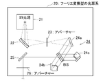
図2にフーリエ変換型の光源系(IR光源21→楕円鏡22→アパーチャー23→マイケルソン干渉計24→出射側の放物面鏡25→アパーチャー26)の構成を示す。マイケルソン干渉計24は、入射側の放物面鏡24a、ビームスプリッター(BS)、固定鏡24b、移動鏡24cによって構成される。BSで分割された一方の平行光束は固定鏡24bを反射してBSに戻り、分割された他方の平行光束は移動鏡24cを反射して同様にBSに戻る。2つの平行光束はBSで合成され干渉波として放物面鏡25に向けて出射する。このようにして、移動鏡24cによって可変な光路差Dに応じた干渉波(インターフェログラム)が生じる。赤外干渉波の光は、出射側の放物面鏡25を反射して、CD測定光学系10の可動ブロック11の楕円鏡11aに進み、測定光として利用される。
FIG. 2 shows the configuration of a Fourier transform type light source system (IR
図3に本実施形態において特徴的なレーザー光源系30の構成を示す。レーザー光源系30は、量子カスケードレーザー(QCL)を赤外光源とすることで、高輝度・高出力・広帯域から選択された特定波数の赤外レーザー光を供給する。
FIG. 3 shows the configuration of a laser
QCLには、多層半導体構造の活性領域を有する半導体チップが1ないし複数個設けられている。注入された電子が活性領域のレイヤを滝のように通過して多数のフォトンが放出されるので、レーザー利得が高く、波数域が広い。例えば、4個の半導体チップ(QCL-1~QCL-4)を使って、波数域を指紋領域(1850~890cm-1)まで広げた場合について、図4に半導体チップ毎の波数チューニングカーブを重ねて示す。QCL-1の波数域を約1850~1500cm-1、QCL-2の波数域を約1750~1400cm-1、QCL-3の波数域を約1500~1100cm-1、QCL-4の波数域を約1300~890cm-1としてもよい。波長域に換算すると、5.4~11.2μmになる。A QCL is provided with one or more semiconductor chips having an active region of a multi-layered semiconductor structure. Since the injected electrons cascade through the layers of the active region and many photons are emitted, the laser gain is high and the wavenumber range is wide. For example, when four semiconductor chips (QCL-1 to QCL-4) are used and the wavenumber region is expanded to the fingerprint region (1850 to 890cm -1 ), the wavenumber tuning curves for each semiconductor chip are superimposed on FIG. is shown. The wavenumber range of QCL-1 is about 1850-1500cm -1 , the wavenumber range of QCL-2 is about 1750-1400cm -1 , the wavenumber range of QCL-3 is about 1500-1100cm -1 , and the wavenumber range of QCL-4 is about It may be 1300 to 890 cm −1 . When converted to the wavelength range, it is 5.4 to 11.2 μm.
QCLでは内蔵された駆動部31によって出力レーザー光の波数が変化する。例えば、駆動部としての共振器(キャビティ)が出力波数を掃引する。
In the QCL, the wavenumber of the output laser light is changed by the built-in
QCL-2のみを使って、波数を1750cm-1から1500cm-1まで掃引した場合のレーザー光の強度の変化を図5に示す。比較のため、フーリエ変換赤外分光光度計(FTIR)の標準的な赤外光源のスペクトル形状を同条件で測定したものを並べた。波数1600cm-1(最大パワー)でレーザー光を連続モード出力した際の平均出力が約300mWになっている。FIG. 5 shows changes in laser light intensity when the wave number is swept from 1750 cm −1 to 1500 cm −1 using only QCL-2. For comparison, the spectrum shape of a standard infrared light source of a Fourier transform infrared spectrophotometer (FTIR) measured under the same conditions is arranged. The average output is about 300 mW when laser light is output in continuous mode at a wavenumber of 1600 cm −1 (maximum power).
試用するレーザーの平均出力としては、少なくとも1mW以上であれば、従来の測定装置による検出信号よりも質の良い検出信号が得られる。好ましくは10mW以上、より好ましくは100mW以上である。1mW~数百mW程度の平均出力のレーザーを用いれば、概ね出力に比例して検出信号の質が改善される。平均出力が大きいレーザーを用いると、試料の焼損や検出器感度の飽和といった制約が生じるので、大きくとも1W~10W程度の平均出力のレーザーがよい。試料によって、焼損する出力は異なり、また、検出光量も変わるため、試料に応じて最も本発明の効果を発揮できるレーザーの平均出力を選定するとよい。なお、測定装置にゲイン切替手段(減光器など)を設ける場合は、レーザー光の減光率を調整できるので、実際にはさらに大きな平均出力のレーザーを搭載することも可能である。 If the average output of the laser to be used is at least 1 mW, a detection signal of better quality than the detection signal obtained by the conventional measuring apparatus can be obtained. It is preferably 10 mW or more, more preferably 100 mW or more. If a laser with an average power of about 1 mW to several hundred mW is used, the quality of the detected signal is improved approximately in proportion to the power. If a laser with a large average output is used, restrictions such as burnout of the sample and saturation of detector sensitivity occur. Depending on the sample, the burnout output differs, and the amount of detected light also varies. Therefore, it is preferable to select the average output of the laser that allows the effect of the present invention to be exhibited most depending on the sample. If gain switching means (attenuator, etc.) is provided in the measuring apparatus, the light attenuation rate of the laser light can be adjusted, so it is actually possible to mount a laser with a higher average output.
図5の例で、両者のスペクトル形状を同じ波数(例えば1600cm-1)で比較すると、FTIR標準光源の出力値が4.4を示すのに対し、QCLの出力は、2423倍の10664.7を示し、出力強度の差が非常に大きいことが分かる。In the example of FIG. 5, when the spectral shapes of both are compared at the same wavenumber (for example, 1600 cm −1 ), the output value of the FTIR standard light source shows 4.4, while the output value of the QCL is 10664.7, which is 2423 times. , and it can be seen that the difference in output intensity is very large.
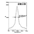
次に、QCLの1675.5cm-1のレーザー光の発振線幅を図6に拡大して示す。レーザー光の発振線幅(半値全幅)が狭い程、レーザー光の波数分解能が高い。図6のレーザー光の半値全幅は0.13cm-1である。レーザー光の発振線幅(半値全幅)としては、約0.05~4.0cm-1であることが好ましい。Next, the oscillation linewidth of the QCL laser beam at 1675.5 cm −1 is enlarged and shown in FIG. The narrower the oscillation linewidth (full width at half maximum) of the laser light, the higher the wavenumber resolution of the laser light. The full width at half maximum of the laser light in FIG. 6 is 0.13 cm −1 . The oscillation linewidth (full width at half maximum) of the laser light is preferably about 0.05 to 4.0 cm −1 .
QCLのレーザー光の特徴は、(1)掃引可能な波数域が広く、(2)出力が驚くほど強く、(3)発振線幅(半値全幅)が非常に狭いことである。なお、QCLは、特定波数のレーザー光を連続モード(CWモード)で出力する。パルスモードを選択できるQCLでもよいが、CWモードの方が検出信号が大きく、測定精度がよい。 The characteristics of QCL laser light are (1) a wide swept wavenumber range, (2) a surprisingly strong output, and (3) an extremely narrow oscillation linewidth (full width at half maximum). Note that the QCL outputs laser light with a specific wavenumber in a continuous mode (CW mode). A QCL that can select a pulse mode may be used, but the CW mode provides a larger detection signal and better measurement accuracy.
図3に戻って、QCLからの赤外レーザー光の進路には、回転式チョッパー32、可動ブロック33上の2つの平面鏡33a,33b、減光器入側の固定平面鏡34、減光器セット35、減光器出側の固定平面鏡36が順に配置されている。可動ブロック33には、2つの平面鏡の他に、アパーチャーを通過する光路を形成するための光学素子(入側の楕円面鏡33c、アパーチャー33d、出側の楕円面鏡33e)が搭載されている。可動ブロック33がスライドすることで、アパーチャーを通過しない光路と、アパーチャーを通過する光路とが切り替わる。後者の光路ではレーザー光の光束断面が、アパーチャー前後の楕円面鏡33c,33eによって拡張され、アパーチャー33dの開口部の大きさになる。
Returning to FIG. 3, the course of the infrared laser light from the QCL includes a
QCLからの赤外域レーザー光は、回転式チョッパー32の通過率に応じた断続的なレーザー光になる。そのレーザー光は、可動ブロック上の光路を通り、さらに減光器セット35を通過し、CD測定光学系10の可動ブロック11上の平面鏡11bに進んで測定光として利用される。
The infrared laser light from the QCL becomes intermittent laser light according to the passage rate of the
試料の円二色性CDは、式(2)で定義される。 The circular dichroism CD of a sample is defined by equation (2).

円二色性CDは、左円偏光に対する試料の吸光度ALと右円偏光に対する試料の吸光度ARとの差(ΔA)であり、式(2)のように、試料を透過した左円偏光の光強度ILと右円偏光の光強度IRとの比の常用対数で示される。光強度I0は、試料への入射光の強度である。吸光度の差ΔAは無次元数であるため、通常は次式(3)のように楕円率(CD[mdeg])に変換される。Circular dichroism CD is the difference ( ΔA ) between the absorbance AL of the sample for left-handed circularly polarized light and the absorbance AR for right-handed circularly polarized light. is expressed by the common logarithm of the ratio of the light intensity I L of right circularly polarized light to the light intensity IR of right circularly polarized light. The light intensity I0 is the intensity of the light incident on the sample. Since the absorbance difference ΔA is a dimensionless number, it is usually converted into an ellipticity (CD [mdeg]) as shown in the following equation (3).

ここで、PEMを用いた偏光変調法に基づいて、式(2)の左円偏光強度ILと右円偏光強度IRを測定する場合、これらの平均値((IL+IR)/2)が偏光変調法での光強度の波形中の「DC信号」に対応し、また、これらの差の半分((IL-IR)/2)が偏光変調法での光強度の波形中の「AC信号の最大振幅」に対応している。1次のベッセル関数J1(2πδ0)のモデルを適用すると、偏光変調法での光強度Iの波形は、DC信号の項とAC信号の項の和として示される。従って、式(3)は次の近似式のように表現できる。Here, when measuring the left-handed circularly polarized light intensity I L and the right-handed circularly polarized light intensity IR of formula (2) based on the polarization modulation method using PEM, the average value of these ((I L + I R )/ 2 ) corresponds to the “DC signal” in the light intensity waveform in the polarization modulation method, and half of their difference ((I L −I R )/2) corresponds to the light intensity waveform in the polarization modulation method corresponds to the "maximum amplitude of the AC signal". Applying the model of the first-order Bessel function J 1 (2πδ 0 ), the waveform of the light intensity I in the polarization modulation method is shown as the sum of the DC signal term and the AC signal term. Therefore, Equation (3) can be expressed as the following approximation.

つまり、光強度の検出波形データから、AC信号とDC信号を抽出できれば、CD値の測定が可能になる。 That is, if an AC signal and a DC signal can be extracted from the detected waveform data of light intensity, the CD value can be measured.
図7に、赤外域レーザー光を用いる赤外域CD測定装置の全体構成を示す。同図には、信号処理手段40の構成(プリアンプ41、DC信号用のロックインアンプ42、AC信号用のロックインアンプ43、PEMコントローラー44、A/D変換器45、データロガー46、コンピュータ等の演算処理装置47)を併せて示す。検出器17からの光強度信号はプリアンプ41で増幅され、プリアンプ41から直流成分と交流成分の各信号がそれぞれのロックインアンプ42,43に送られる。
FIG. 7 shows the overall configuration of an infrared CD measuring apparatus using infrared laser light. The figure shows the configuration of the signal processing means 40 (
DC信号用のロックインアンプ42は、チョッピング周波数に同期する基準信号を使って、プリアンプの直流成分の信号からDC信号を抽出する。つまり、回転式チョッパー32の遮光期間における直流成分の信号値と、回転式チョッパー32の通過期間における直流成分の信号値とを抽出し、データロガー46に記録する。遮光期間および通過期間の信号値の差分をDC信号として扱う。
A lock-in
AC信号用のロックインアンプ43は、PEM14の駆動周波数と同期する基準信号を使って、PEM14と同じ周波数成分であるAC信号を、プリアンプ41の交流成分の信号から抽出してデータロガー46に記録する。
The AC signal lock-in
データロガー46に記録する際、DC信号およびAC信号はA/D変換器45で数値化される。演算処理装置47は、データロガー46からAC信号とDC信号を読み出して、両信号の比(AC/DC)を得て、式(4)に基づいて赤外域CD値を算出する。
The DC and AC signals are digitized by the A/
測定光が赤外レーザー光であるから、QCLにおいて選択された波数毎に、演算処理装置47が赤外域CD値を算出することで、赤外域のCDスペクトルデータが得られる。
Since the measurement light is infrared laser light, the
なお、測定光として図2の赤外干渉波の光を選択した場合は、光強度信号はインターフェログラムであるから、光強度信号に基づく算出結果はCD値そのものではない。そのため、演算処理装置は、データロガー46からAC信号とDC信号を読み出して、両信号の比(AC/DC)の値をフーリエ変換処理することで、赤外域のCDスペクトルデータを得る。上述の式(4)における「AC/DC」を「F[AC/DC]」に置き換えた数式が、フーリエ変換を利用したCD値の近似式になる。式中のF[ ]はフーリエ変換を表す。
When the infrared interference wave light shown in FIG. 2 is selected as the measurement light, the light intensity signal is an interferogram, so the calculation result based on the light intensity signal is not the CD value itself. Therefore, the arithmetic processing unit reads out the AC signal and the DC signal from the
<N2パージの有効性の評価>
図7に基づく実験装置を使って、窒素ガス置換(N2パージ)にかかる時間と、その有効性について評価した。実験装置では、QCLの出力波数域を1750-1500cm-1とし、チョッパーのチョッピング周波数を500Hzとし、減光器(例えばNDフィルター)の透過率を2%とした。試料室にはサンプルを置かず、PEMは駆動させないで、レーザー光をMCT検出器で検出した。<Evaluation of effectiveness of N2 purge>
Using an experimental apparatus based on FIG. 7, the time required for nitrogen gas replacement ( N2 purge) and its effectiveness were evaluated. In the experimental setup, the output wavenumber range of the QCL was set to 1750-1500 cm −1 , the chopping frequency of the chopper was set to 500 Hz, and the transmittance of the dimmer (eg, ND filter) was set to 2%. No sample was placed in the sample chamber, the PEM was not driven, and the laser light was detected by the MCT detector.
信号処理手段40のプリアンプ41は、400HzフィルタリングしたDC成分の信号をロックインアンプに送る。
The
まず、「パージなし」の状態で、レーザー光の波数を1750-1500cm-1の範囲で掃引し、1cm-1ステップで光強度をMCT検出器で検出した。ステップ速度は500msec/cm-1である。結果を図8のスペクトルAに示す。パージなしでは、各筐体内の水蒸気等による吸収の影響が波数全域に渡って大きいことが分かる。First, the wavenumber of the laser light was swept in the range of 1750-1500 cm -1 in the "no purge" state, and the light intensity was detected by the MCT detector at 1 cm -1 steps. The step speed is 500 msec/cm −1 . The results are shown in spectrum A of FIG. It can be seen that without purging, the influence of absorption by water vapor and the like in each housing is large over the entire wavenumber range.
次に、レーザー光の波数を1635cm-1に固定して、CD測定光学系10およびレーザー光源系30をそれぞれ収納している筐体内を毎分6Lのガス供給量でN2パージする。各筐体には、独立制御可能なパージ装置が設けられている。波数1635cm-1のレーザー光は、装置内部の水蒸気にほとんどが吸収されるため、N2パージの有効性の評価に適する。図9は、パージ開始から90分経過までの波数1635cm-1のレーザー光の強度変化を示す。約1時間という比較的短時間のパージによって、窒素への置換が大きく進み、2時間のパージをすれば十分であることが分かる。Next, the wave number of the laser light is fixed at 1635 cm −1 , and N 2 purge is performed at a gas supply rate of 6 L per minute in the housings housing the CD measuring
図8のスペクトルAと同様に、「90分間のパージ後」の状態でスペクトルBを測定した。水蒸気などによる吸収ピークが大幅に減少し、比較的短いパージ時間で水蒸気などの吸収の影響が大きく低減されることが分かった。 Similar to spectrum A in FIG. 8, spectrum B was measured "after 90 minutes of purging". It was found that the absorption peak due to water vapor and the like was greatly reduced, and the effect of absorption of water vapor and the like was greatly reduced with a relatively short purge time.
次に、「パージなし」の状態で、図8のスペクトルAと同様にスペクトルを測定し、レーザー光の透過率T(=I/I0×100)が100%である透過率100%ラインを描いたものを図10に示す。パージなしの状態でのスペクトル測定を3回繰り返し、3つの結果を重ねて表示した。これに対して、「120分間のパージ後」の状態でスペクトルを測定し、同様に透過率100%ラインを描いたものを図11に示す。Next, in the "no purge " state, the spectrum was measured in the same manner as spectrum A in FIG. The drawing is shown in FIG. Spectral measurements without purging were repeated three times and the three results are overlaid. On the other hand, the spectrum was measured in the state of "after purging for 120 minutes", and the 100% transmittance line is similarly drawn in FIG.
図10には水蒸気等の吸収の影響が波数域の全体にわたってノイズのように生じていることが分かる。同じ波数のレーザー光であっても、透過率100%ラインを押し上げる場合と押し下げる場合の両方がある。これに対して図11のパージ後の透過率100%ラインでは、水蒸気等の吸収の影響が波数域の全体にわたって大幅に減少していることが分かる。 It can be seen from FIG. 10 that the influence of absorption of water vapor or the like occurs like noise over the entire wavenumber region. Even with laser light of the same wavenumber, there are cases where the 100% transmittance line is pushed up and pushed down. On the other hand, in the 100% transmittance line after purging in FIG. 11, it can be seen that the influence of absorption of water vapor or the like is greatly reduced over the entire wavenumber region.
<N2パージの有効性の個別評価>
次に、レーザー光源系30へのN2パージの有効性の評価を個別に行った。図12に示す実験装置を用いた。レーザー光の波数を1635cm-1に固定して、レーザー光源系30の筐体内をN2パージする。筐体内部の光路上に、4倍エキスパンド用の一対の反射鏡を設置して、ビーム径を4倍に拡張させる。レーザー光の強度を、レーザー光源系30の出口に置かれたパワーメーター(サーモパイル型検出器)で検出する。<Individual evaluation of effectiveness of N2 purge>
Next, an evaluation of the effectiveness of the N2 purge to the laser
図13は、パージ開始から120分経過までの波数1635cm-1のレーザー光の強度変化を示す。パージ開始時に約28mWであった強度は、最初の30分位で急上昇し、60分後には120mW前後まで達している。このパージ効果を詳細に評価するため、次の表1の予備測定を行った。FIG. 13 shows changes in the intensity of laser light with a wave number of 1635 cm −1 from the start of purging to 120 minutes. The intensity, which was about 28 mW at the start of the purge, rapidly increased in the first 30 minutes and reached around 120 mW after 60 minutes. In order to evaluate this purge effect in detail, preliminary measurements shown in Table 1 below were performed.
表1に、QCLの直下にパワーメーターを置いて、前記の波数1635cm-1と、水蒸気の吸収の影響を受けにくい波数1600cm-1の2種類のレーザー光の強度をそれぞれ測定した結果を示す。また、図12の実験装置を用いて、レーザー光源系30の出口(「連結部」)での強度も測定した。いずれも「パージなし」の状態で測定した。Table 1 shows the results of measuring the intensity of two types of laser beams, one having a wavenumber of 1635 cm −1 and the other having a wavenumber of 1600 cm −1 which is less susceptible to water vapor absorption, by placing a power meter directly under the QCL. In addition, the intensity at the exit (“connecting part”) of the laser
表中のカッコ内の数値は、4倍エキスパンド時の測定値である。参考に、試料室での強度値も示す。 Numerical values in parentheses in the table are measured values when expanded four times. For reference, intensity values in the sample chamber are also shown.

光源直下では水蒸気の影響を受けないと仮定して、QCLを出た直後のレーザー光強度の比率Pratio(=P1635/P1600=190/295)を計算すると0.644になる。1600cm-1のレーザー光は水蒸気の影響をほとんど受けないため、連結部での1600cm-1の光強度(192.6mW)に基づいて連結部での1635cm-1の光強度を求めると、P1635(=192.6*0.644)は、123.7mWになる。この値は、1635cm-1のレーザー光が水蒸気の影響を受けない場合の数値に相当する。図13によれば、パージ後60分の連結部での光強度が120mW前後(上記の123.7mWの計算値に近い値)にまで回復していることから、1時間程度のN2パージで置換が十分に行われたと評価できる。Assuming that there is no effect of water vapor directly under the light source, the ratio P ratio (=P 1635 /P 1600 =190/295) of the laser light intensity immediately after exiting the QCL is calculated to be 0.644. Since the 1600 cm −1 laser light is hardly affected by water vapor , P 1635 (=192.6*0.644) becomes 123.7mW. This value corresponds to the value obtained when the laser beam at 1635 cm −1 is not affected by water vapor. According to FIG. 13, since the light intensity at the joint 60 minutes after the purge recovered to around 120 mW (a value close to the calculated value of 123.7 mW above), the N 2 purge for about 1 hour It can be evaluated that the replacement was sufficiently performed.
これらの評価結果から、本実施形態の赤外域CD測定装置が、それぞれの筐体にN2パージ装置を設けることでのパージ効果が短時間で発揮し得ることが分かる。From these evaluation results, it can be seen that the infrared region CD measurement device of this embodiment can exhibit the purge effect in a short time by providing the N2 purge device in each housing.
<赤外域CD測定結果1>
図7の構成の赤外域CD測定装置を使って、クロロホルム溶媒にビ-2-ナフトール(Bi-2-naphtol)を溶かした溶液試料の赤外域CDスペクトルを測定した。この装置では、QCLのレーザー光の波数域を1650-1500cm-1とし、チョッパーのチョッピング周波数を500Hzとし、減光器(例えばNDフィルター)の透過率を2%(98%減光)とした。PEMの変調周波数を50kHzとして、試料の透過光をMCT検出器で検出した。<Infrared region
An infrared CD spectrum of a solution sample obtained by dissolving Bi-2-naphtol in a chloroform solvent was measured using an infrared CD measuring apparatus configured as shown in FIG. In this apparatus, the QCL laser beam has a wave number range of 1650-1500 cm −1 , the chopping frequency of the chopper is 500 Hz, and the transmittance of the dimmer (eg, ND filter) is 2% (98% light reduction). The PEM modulation frequency was set to 50 kHz, and the light transmitted through the sample was detected by the MCT detector.
測定前に、CD測定光学系10およびレーザー光源系30をそれぞれ収納している筐体内を、毎分6Lのガス供給量で120分間N2パージした状態にした。赤外域CD測定では、レーザー光の波数を1650-1500cm-1の範囲で3回掃引し、1cm-1ステップで光強度をMCT検出器で検出し、平均値を算出した。その赤外域CDスペクトルを図14に示す。比較のため、フーリエ変換型CD分光光度計での測定結果を図15に示す。Before the measurement, the inside of the housing containing the CD measuring
本実施形態に係る赤外域CD測定装置で測定した赤外域CDスペクトルには、以下の注目すべき点がある。まず、波数分解能が非常に高いことが、フーリエ変換型CD分光光度計で測定した赤外域CDスペクトルとの比較から歴然としている。 The infrared CD spectrum measured by the infrared CD measurement apparatus according to this embodiment has the following points to be noted. First, it is clear from comparison with the infrared region CD spectrum measured with a Fourier transform type CD spectrophotometer that the wavenumber resolution is very high.
本書では、試料が本来有している2つのCDピークが隣り合っていて、一方のピーク波数νに対し、他方のピーク波数をν+Δνで表す場合に、測定装置が区別できる2つのCDピーク間のΔνの最小値を波数分解能(cm-1)として示す。In this book, when two CD peaks originally possessed by a sample are adjacent to each other and one peak wavenumber ν is expressed as ν + Δν for the other peak wavenumber, the measurement device can distinguish between two CD peaks The minimum value of Δν is indicated as wave number resolution (cm −1 ).
図11に示した通り、120分間のN2パージで1650-1500cm-1の波数域での水蒸気等の吸収の影響は大幅に減少している。そうすると、図14の赤外域CDスペクトルにおいても、水蒸気などの影響は小さくなっていると言え、フーリエ変換型CD分光光度計が測定できなかった微小なCDピークまで測定できていると言える。As shown in FIG. 11, the N 2 purge for 120 minutes significantly reduces the influence of water vapor absorption in the wavenumber region of 1650-1500 cm −1 . Then, it can be said that the influence of water vapor etc. is reduced even in the infrared region CD spectrum of FIG.
波数分解能が高い理由の1つに、フーリエ変換型CD分光光度計での赤外域CDスペクトルの測定範囲(縦軸)が約-0.0001から+0.0001までであるのに対して、本実施形態の装置では、約-0.08から+0.08までと1000倍程度広い測定範囲になっていることが挙がる。つまり、図6のような非常に強い出力のレーザー光によって、検出器からの検出信号が大きくなり、吸光度Aの検出感度が挙がった。それに伴って、従来は非常に弱いものしか測定できなかった赤外域CD信号が、非常に大きな値で取得できるようになった。 One of the reasons for the high wave number resolution is that the measurement range (vertical axis) of the infrared region CD spectrum in the Fourier transform type CD spectrophotometer is from about −0.0001 to +0.0001, whereas this implementation In the apparatus of the form, the measuring range is about 1000 times wider, from about -0.08 to +0.08. In other words, the detection signal from the detector increased due to the extremely strong output laser light as shown in FIG. Along with this, it has become possible to obtain very large values of infrared CD signals, which could only be measured in the past as very weak ones.
2つ目の理由として、図6のような理想的な単波数光に近いプロファイル(半値全幅0.13cm-1)のレーザー光を使ったことが挙がる。The second reason is that a laser beam with a profile (full width at half maximum of 0.13 cm −1 ) close to ideal single-wavenumber light as shown in FIG. 6 is used.
本実施形態の装置の長所は、従来型の分散型CD分光光度計における課題を挙げることで理解が深まる。例えば、UV-可視光域のCD分光光度計では、回折格子を使った分散型のCD分光光度計が主流である。 The advantages of the apparatus of this embodiment can be better understood by pointing out the problems with conventional dispersive CD spectrophotometers. For example, among CD spectrophotometers in the UV-visible region, dispersion-type CD spectrophotometers using a diffraction grating are the mainstream.
分散型CD分光光度計において、波長分解能を高めるには、分散型分光器から取り出された光のバンド幅(半値全幅)を、試料の吸収ピークの半値幅の概ね1/10以下に設定できるとよい、とされている。例えば、半値幅15nmの吸収ピークをバンド幅2nmの擬似単色光で測定すれば、測定値の誤差を小さく抑えられる。 In a dispersive CD spectrophotometer, in order to increase the wavelength resolution, the bandwidth (full width at half maximum) of the light extracted from the dispersive spectrometer can be set to approximately 1/10 or less of the half-value width of the absorption peak of the sample. It is said to be good. For example, if an absorption peak with a half-value width of 15 nm is measured with pseudo-monochromatic light with a bandwidth of 2 nm, errors in the measured values can be reduced.
バンド幅は、分光器に組み込まれたスリットの幅で決まる。そのため、単純にバンド幅を小さく設定すれば良いとは言えない。バンド幅を小さくすると、試料を照射する光が弱くなってノイズが増加するからである。 The bandwidth is determined by the width of the slit built into the spectrometer. Therefore, it cannot be said that simply setting the bandwidth to a small value is sufficient. This is because if the bandwidth is reduced, the light irradiating the sample becomes weaker and noise increases.
本実施形態の装置が優れているのは、掃引された特定波数のレーザー光の半値全幅が理想的な単色光と言えるレベルの狭さであり、かつ、レーザー光の出力を高い状態に維持できることである。それによって、検出器から強い検出信号が得られ、赤外CD値の測定感度が向上することである。フーリエ変換型や分散型のCD分光光度計では、干渉波の光束をアパーチャーで絞ったり、単色光のバンド幅をスリットで狭くしたりすることで、検出信号が弱くなる傾向があり、SN比が悪化しない程度に、試料の吸光度を高くても1.5~2未満に調整しなければならなかった。本実施形態の装置では、そのような試料の吸光度についての制約がなくなる点で非常に優れている。 The apparatus of this embodiment is superior in that the full width at half maximum of the swept laser light of a specific wavenumber is narrow to the level of ideal monochromatic light, and that the output of the laser light can be maintained at a high level. is. Thereby, a strong detection signal is obtained from the detector, and the measurement sensitivity of the infrared CD value is improved. In the Fourier transform type or dispersion type CD spectrophotometer, the detection signal tends to become weak by narrowing the light flux of the interference wave with an aperture or by narrowing the bandwidth of the monochromatic light with a slit, resulting in a low SN ratio. The absorbance of the sample had to be adjusted to less than 1.5-2 at the highest without being worse. The device of the present embodiment is very excellent in that such restrictions on the absorbance of the sample are eliminated.
<赤外域CD測定結果2>
本実施形態の装置を使って、吸光度4に調整したアミノ酸の溶液試料(Fmoc-Leucine)を0.0001ΔAの分解能で赤外域CDスペクトル測定した結果を図16に示す。<Infrared region
FIG. 16 shows the results of infrared region CD spectrum measurement at a resolution of 0.0001ΔA for an amino acid solution sample (Fmoc-Leucine) adjusted to an absorbance of 4 using the apparatus of this embodiment.
<赤外域CD測定結果3>
図17(A),(B)に、本実施形態の装置を使って、ピネンの溶液試料((-)-α-pinene)を積算時間20分で赤外域CDスペクトル測定した結果を示す。MCT検出器の素子サイズを2種類(直径1mm、直径0.2mm)用いたが、どちらの測定も、短い積算時間で感度のよい赤外域CDスペクトルが得られた。<Infrared region
FIGS. 17A and 17B show the results of infrared region CD spectrum measurement of a pinene solution sample ((−)-α-pinene) with an integration time of 20 minutes using the apparatus of this embodiment. Two types of MCT detector element size (
以下、本実施形態の赤外域CD測定装置にオプションとして装備可能な構成について説明する。 A configuration that can be installed as an option on the infrared CD measurement apparatus of this embodiment will be described below.
<光学的ゲイン切替手段>
本実施形態において特徴的な図3の減光器セット35の切替手段37について説明する。減光器セット35は、1ないし複数の減光素子35a,35bから構成され、かつ、個々の減光器35a,35bをオンライン/オフラインに独立して切り替え可能な切替手段37が設けられている。例えば、透過率2%の2枚の減光素子35a,35bを用いる。2枚同時にオンラインにした場合の合計透過率が0.04%になるため、切替手段37は、減光器セット35による合計透過率を100%、2%、0.04%の3通りに切り替え可能である。なお、減光器セット35は、レーザー光の光路上のいずれかの位置に配置されていればよい。<Optical Gain Switching Means>
The switching means 37 of the dimmer set 35 shown in FIG. 3, which is characteristic of this embodiment, will be described. The dimmer set 35 is composed of one or more
本実施形態では、減光器セット35の切替手段37を使って、測定ゲインを光学的に切り替える。まず、事前測定として、減光素子35aを1枚だけオンライン状態にして、レーザー光の波数掃引を行ってバックグラウンド測定を実行する。得られた出力が基準値以下になる波数に対し、個別にゲインを設定する。例えば、検出器17への光が暗い場合は、減光素子35a,35bを2枚ともオフライン状態にするとよい。逆に、事前測定での出力が強過ぎる波数に対しては、減光素子35a,35bを2枚ともオンライン状態にするとよい。測定条件は記憶部49に保存される。試料のスペクトル測定を実行する際、記憶した設定値に従って、波数掃引ごとに測定ゲインを光学的に切り替える。この結果、レーザー光の掃引波数に応じた検出器17への光量変動が小さく抑えられる。
In this embodiment, the switching means 37 of the dimmer set 35 is used to optically switch the measurement gain. First, as a preliminary measurement, only one light-reducing
また、予め試料なしの状態で減光量が最適化された光学系に試料を入れると、試料の吸光度が大きいなどの理由で、出力が低下する波数が生じる場合がある。このような波数に対しても、減光素子35a,35bをオフラインにする等の測定条件を設定して、減光量を調整することができる。
In addition, when a sample is placed in an optical system whose light attenuation is optimized in advance without a sample, there may be some wavenumbers at which the output decreases due to reasons such as high absorbance of the sample. For such a wavenumber, the amount of light attenuation can be adjusted by setting measurement conditions such as setting the
以上の光学的ゲインの切替手段37によって、高い吸光度の試料の赤外域CDスペクトル測定が容易になる。なお、減光素子35a,35bなどで光学的にゲインを変更すると、スペクトルのベースラインにずれが生じるが、ゲインの変更前後の掃引波数域を一部オーバーラップさせたスペクトル測定を実行する手段を設けることで、その測定結果を使えば演算処理手段47によるベースラインの接続が容易になる。
The above-described optical gain switching means 37 facilitates infrared region CD spectrum measurement of a sample with high absorbance. When the gain is optically changed by the
<電気的ゲイン切替手段>
光学的なゲイン切り替えと同様に、電気的なゲインの切り替えを採用することもできる。例えば、図7の信号処理手段40に設けられたゲイン切替用電気素子48が、低出力になる波数に対して、アナログ信号の強度を電気的に増幅させて、A/D変換器45での量子化誤差を低減させるようにしてもよい。<Electrical Gain Switching Means>
Electrical gain switching can be employed as well as optical gain switching. For example, the gain switching electric element 48 provided in the signal processing means 40 of FIG. A quantization error may be reduced.
<チョッパーの通過率>
次に、チョッパー32の通過率の設定について説明する。チョッパー32は、赤外吸収信号(DC信号)を取得するために設けられており、図7の位置に限られず、レーザー光の光路上のいずれかの位置にあればよい。<Chopper passing rate>
Next, setting of the passage rate of the
赤外域CD信号の信号強度は、赤外吸収信号と比べて1000分の1以下と非常に弱い。チョッピングは、赤外域CD信号の更なる強度低下を招き、そのSN比も同時に低下させてしまう。本実施形態では、3通りの通過率(50%、75%、83%)の回転式チョッパーを使った試験結果に基づいて、チョッパー32の通過率を70%以上に設定することにした。
The signal intensity of the infrared region CD signal is very weak at less than 1/1000 of that of the infrared absorption signal. Chopping causes a further reduction in the intensity of the infrared CD signal, and at the same time reduces its SN ratio. In this embodiment, the pass rate of the
図18にチョッピング試験に用いた通過率(Dutyとも呼ぶ)が83%の回転式チョッパーの一例を示す。中心部から5方向に伸びたリブ部が遮光部として機能する。 FIG. 18 shows an example of a rotary chopper with a passage rate (also referred to as duty) of 83% used in the chopping test. Ribs extending in five directions from the central portion function as light shielding portions.
通過率83%の回転式チョッパーを使ってチョッピングして、PEM14で偏光変調したレーザー光を検出器17で検出した。その検出信号から抽出したDC信号とAC信号の強度変化を図19に示す。3通りの掃引波数(1595cm-1,1600cm-1,1605cm-1)での信号強度の変動は、いずれも許容範囲内であり、適正なDC信号(同図(A))とAC信号(同図(B))を取得することができた。Chopping was performed using a rotary chopper with a transmittance of 83%, and the laser light polarized and modulated by the
<水または水蒸気の吸収ピークの影響回避>
本実施形態において特徴的な水等の吸収ピークの影響回避手段について説明する。図7の信号処理手段40は、さらに、水または水蒸気の既知の吸収ピーク波数を保有する記憶部49と、レーザー光の掃引波数がこれらの吸収ピーク波数に一致するかどうかを判断する判断部51と、一致した場合に吸収ピークの影響を回避させる回避部52とを有する。判断部51および回避部52は、演算処理手段47に組み込まれている。<Avoidance of influence of absorption peak of water or water vapor>
A means for avoiding the influence of absorption peaks of water or the like, which is characteristic in this embodiment, will be described. The signal processing means 40 of FIG. 7 further includes a
図8に示したように、本実施形態の赤外域CD測定への水または水蒸気の吸収ピークの影響は大きい。特に「パージなし」の状態では、個々の吸収ピークが鋭く、非常に感度良く検出されてしまう。 As shown in FIG. 8, the absorption peak of water or water vapor has a great influence on the infrared region CD measurement of this embodiment. Especially in the "no purge" state, individual absorption peaks are sharp and detected with very high sensitivity.
そこで、回避部52は、水または水蒸気の吸収ピーク波数の前後の掃引波数のレーザー光によって得られた赤外域CD値を使って、その平均値などを水または水蒸気の吸収ピーク波数における赤外域CD値として算出する。その結果、QCLのレーザー光による検出感度の鋭さに起因する水または水蒸気ノイズの軽減を図ることができる。
Therefore, the
水または水蒸気の吸収ピークの影響回避の具体的な手法を説明する。 A specific method for avoiding the influence of absorption peaks of water or water vapor will be described.
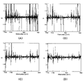
まず、本実施形態の装置を用いて、シングルビーム(SB)を例えば10本測定し、2本ずつの5組とする。各組の2本を除算して、100%ラインを5本得る。 First, for example, 10 single beams (SB) are measured using the apparatus of this embodiment, and 5 sets of 2 beams each are formed. Divide each set of two to get five 100% lines.
0.5cm-1ステップで波数掃引して取得したラインを図20(A)に示す。図20(B)~(D)のラインは、図20(A)から1.0cm-1ステップ分の強度情報だけ抜き出して得たラインである。図20(B)のラインは回避処理前のものである。FIG. 20(A) shows the lines obtained by sweeping the wave number in steps of 0.5 cm −1 . Lines in FIGS. 20B to 20D are lines obtained by extracting intensity information for 1.0 cm −1 steps from FIG. 20A. The line in FIG. 20B is before avoidance processing.
記憶部49には、表2に示す回避処理対象の波数セットが2セット(除去1、除去2)分、予め記憶されている。これらの波数セットは、経験的に特に大きい水蒸気ピークを生じ得る波数情報を含んでいる。除去1の波数における水蒸気ピークの方が、除去2の波数における水蒸気ピークよりも大きい。
The

判断部51は、図20(B)のラインから、除去1のピーク波数に該当する波数ポイントの強度情報を抽出する。回避部52は、抽出された強度情報ごとに、そのピーク波数の両隣りの波数ポイントの強度情報の平均値を計算する。そして、抽出された強度情報をその平均値に置き換える。図20(C)に除去1の波数セットについて回避処理後のラインを示す。
The
判断部51は、さらに、除去2のピーク波数に該当する波数ポイントの強度情報を抽出する。回避部52は、抽出された強度情報ごとに、そのピーク波数の両隣りの波数ポイントの強度情報の平均値を計算し、抽出された強度情報をその平均値に置き換える。図20(D)に除去2の波数セットについても回避処理済みのラインを示す。
The
このような回避処理を実行すれば、N2パージなしの状態でも赤外域CDスペクトルの測定結果に与える水蒸気の影響を大幅に低減させることができる。If such avoidance processing is performed, the influence of water vapor on the measurement results of the infrared region CD spectrum can be greatly reduced even without the N2 purge.
図20(A)~(D)のラインは、本実施形態でのDC信号を測定したものに該当する。そこで、AC/DC信号の変化についても、同様の条件で図21(A)~(D)に示す。図21(A)は0.5cm-1ステップの波数掃引で取得したAC/DC信号を示す。図21(B)は、図21(A)から1.0cm-1ステップ分のAC/DC信号を抜き出したものを示す。図21(C)は除去1の波数セットについて回避処理済みのAC/DC信号を示す。図21(D)は、さらに除去2の波数セットについても回避処理したAC/DC信号を示す。Lines in FIGS. 20A to 20D correspond to measurements of DC signals in this embodiment. Therefore, changes in AC/DC signals are also shown in FIGS. 21A to 21D under similar conditions. FIG. 21(A) shows AC/DC signals obtained by wave number sweeping in steps of 0.5 cm −1 . FIG. 21(B) shows an AC/DC signal for 1.0 cm −1 step extracted from FIG. 21(A). FIG. 21(C) shows the avoidance processed AC/DC signal for the
このようにAC/DC信号の波形は、回避処理の実行によって、おおむね改善されている。なお、図21(D)の1531cm-1のピークは、水蒸気の吸収が余り大きく出ない波数ポイントにあるので、QCL側のゆらぎに起因するものと考えられる。Thus, the waveform of the AC/DC signal is generally improved by performing avoidance processing. Note that the peak at 1531 cm −1 in FIG. 21(D) is at a wave number point where the absorption of water vapor is not very large, so it is considered to be caused by fluctuations on the QCL side.
10 CD測定光学系
14 偏光変調子(PEM)
15 試料室
17 MCT検出器
20 フーリエ変換型の光源系
30 レーザー光源系
32 チョッパー
35 減光器セット(ゲイン切替用光学素子)
35a,35b 減光素子
37 切替手段
40 信号処理手段(信号処理部)
48 ゲイン切替用電気素子
49 記憶部
51 判断部
52 回避部
QCL 量子カスケードレーザー(レーザー光源)10 CD measurement
15
35a,
48 Gain switching
Claims (7)
試料が配置される試料室と、
掃引された特定波数の前記レーザー光が試料を透過する前後のいずれかにおいて当該レーザー光の偏光状態を変調させる偏光変調子と、
前記試料を透過して偏光状態を変調されたレーザー光の強度変化を検出する検出器と、
前記検出器の検出信号から変調周波数と同期する交流成分(AC)と直流成分(DC)とを抽出し、両者の比(AC/DC)に基づいて試料の赤外域円二色性の値を算出する信号処理部と、
レーザー光の光路上のいずれかの位置に配置されたゲイン切替用光学素子と、
前記ゲイン切替用光学素子をレーザー光の掃引波数に応じて切り替えて、前記検出器に入る光量を調整する切替手段と、を備える
ことを特徴とする赤外域の円二色性測定装置。 a laser light source capable of sweeping the wavenumber of the laser light within an infrared wavenumber range including at least one absorption peak of the sample;
a sample chamber in which the sample is placed;
a polarization modulator that modulates the polarization state of the swept laser light of a specific wavenumber either before or after it passes through a sample;
a detector for detecting changes in intensity of the laser light that passes through the sample and whose polarization state is modulated;
An alternating current component (AC) and a direct current component (DC) that are synchronized with the modulation frequency are extracted from the detection signal of the detector, and the infrared circular dichroism value of the sample is calculated based on the ratio (AC/DC) of the two. a signal processing unit for calculating;
a gain switching optical element disposed at any position on the optical path of the laser light;
switching means for adjusting the amount of light entering the detector by switching the gain switching optical element according to the sweep wave number of the laser light .
An infrared circular dichroism measuring device characterized by:
水または水蒸気の吸収ピーク波数を保有する記憶部と、a storage unit holding an absorption peak wave number of water or water vapor;
レーザー光の掃引波数が前記水または水蒸気の吸収ピーク波数に一致するかを判断する判断部と、a determination unit that determines whether the sweep wavenumber of the laser light matches the absorption peak wavenumber of the water or water vapor;
一致した場合に当該吸収ピークの影響を回避する処理を実行する回避部と、を有し、an avoidance unit that executes processing for avoiding the influence of the absorption peaks when they match,
前記回避部は、前記水または水蒸気の吸収ピーク波数の前後の掃引波数のレーザー光による赤外域CD値に基づいて、水または水蒸気の吸収ピーク波数における赤外域CD値を算出する、The avoidance unit calculates the infrared region CD value at the absorption peak wavenumber of water or water vapor based on the infrared region CD value of laser light with sweep wavenumbers before and after the absorption peak wavenumber of water or water vapor.
ことを特徴とする請求項1記載の赤外域の円二色性測定装置。2. The circular dichroism measuring device in the infrared region according to claim 1, characterized in that:
ことを特徴とする請求項1記載の赤外域の円二色性測定装置。 Furthermore, a chopper is provided at any position on the optical path of the laser beam, and the chopper has a passage rate of 70% or more.
2. The circular dichroism measuring device in the infrared region according to claim 1, characterized in that:
当該レーザー光の発振線幅が、0.05~4.0cm-1である、
ことを特徴とする請求項1から4のいずれかに記載の赤外領域の円二色性測定装置。 The laser light source has an average output of 1 mW or more when the laser light is output in a continuous mode with maximum power,
The oscillation linewidth of the laser light is 0.05 to 4.0 cm -1 ,
5. The circular dichroism measuring device in the infrared region according to any one of claims 1 to 4, characterized in that:
ことを特徴とする請求項1から5のいずれかに記載の赤外域の円二色性測定装置。 The signal processing unit calculates the value of the infrared circular dichroism for each specific wavenumber to be swept, and acquires the infrared CD spectrum of the sample.
6. The circular dichroism measuring device in the infrared region according to any one of claims 1 to 5, characterized in that:
ことを特徴とする請求項1から6のいずれかに記載の赤外域の円二色性測定装置。 The signal processing unit includes a gain switching electric element that electrically switches the intensity of the analog signal according to the sweep wavenumber of the laser light to reduce the quantization error during AD conversion.
7. The circular dichroism measuring device in the infrared region according to any one of claims 1 to 6, characterized in that:
Applications Claiming Priority (1)
| Application Number | Priority Date | Filing Date | Title |
|---|---|---|---|
| PCT/JP2020/036715 WO2022064714A1 (en) | 2020-09-28 | 2020-09-28 | Infrared circular dichroism measurement device |
Publications (3)
| Publication Number | Publication Date |
|---|---|
| JPWO2022064714A1 JPWO2022064714A1 (en) | 2022-03-31 |
| JPWO2022064714A5 JPWO2022064714A5 (en) | 2022-09-07 |
| JP7170367B2 true JP7170367B2 (en) | 2022-11-14 |
Family
ID=80845164
Family Applications (1)
| Application Number | Title | Priority Date | Filing Date |
|---|---|---|---|
| JP2022519562A Active JP7170367B2 (en) | 2020-09-28 | 2020-09-28 | Infrared circular dichroism measuring device |
Country Status (4)
| Country | Link |
|---|---|
| US (1) | US20230333006A1 (en) |
| EP (1) | EP4220128A1 (en) |
| JP (1) | JP7170367B2 (en) |
| WO (1) | WO2022064714A1 (en) |
Families Citing this family (1)
| Publication number | Priority date | Publication date | Assignee | Title |
|---|---|---|---|---|
| CN116067893B (en) * | 2023-02-13 | 2024-03-08 | 成都信息工程大学 | Detection device and detection method for copper ion solution concentration based on weak value amplification |
Citations (4)
| Publication number | Priority date | Publication date | Assignee | Title |
|---|---|---|---|---|
| JP2012202812A (en) | 2011-03-25 | 2012-10-22 | Jasco Corp | Circular dichroism measuring apparatus and method for measuring circular dichroism |
| JP2014503195A (en) | 2010-11-16 | 2014-02-13 | 1087 システムズ インコーポレイテッド | Live cell identification and sorting system |
| US20180059005A1 (en) | 2016-05-26 | 2018-03-01 | Redshift Bioanalytics, Inc. | Microfluidic Methods and Apparatus for Analysis of Analyte Bearing Fluids |
| CN108663456A (en) | 2018-06-15 | 2018-10-16 | 安徽医科大学 | The detection method of Choline Chloride Succinate in a kind of peripheral blood |
Family Cites Families (2)
| Publication number | Priority date | Publication date | Assignee | Title |
|---|---|---|---|---|
| JP3778320B2 (en) * | 1997-07-30 | 2006-05-24 | 日本分光株式会社 | Circular dichroism fluorescence excitation spectrum measuring device |
| JP5890719B2 (en) | 2012-03-29 | 2016-03-22 | 日本分光株式会社 | Circular dichroism spectrophotometer with alignment mechanism |
-
2020
- 2020-09-28 JP JP2022519562A patent/JP7170367B2/en active Active
- 2020-09-28 US US18/028,962 patent/US20230333006A1/en active Pending
- 2020-09-28 EP EP20955307.2A patent/EP4220128A1/en active Pending
- 2020-09-28 WO PCT/JP2020/036715 patent/WO2022064714A1/en active Application Filing
Patent Citations (4)
| Publication number | Priority date | Publication date | Assignee | Title |
|---|---|---|---|---|
| JP2014503195A (en) | 2010-11-16 | 2014-02-13 | 1087 システムズ インコーポレイテッド | Live cell identification and sorting system |
| JP2012202812A (en) | 2011-03-25 | 2012-10-22 | Jasco Corp | Circular dichroism measuring apparatus and method for measuring circular dichroism |
| US20180059005A1 (en) | 2016-05-26 | 2018-03-01 | Redshift Bioanalytics, Inc. | Microfluidic Methods and Apparatus for Analysis of Analyte Bearing Fluids |
| CN108663456A (en) | 2018-06-15 | 2018-10-16 | 安徽医科大学 | The detection method of Choline Chloride Succinate in a kind of peripheral blood |
Non-Patent Citations (1)
| Title |
|---|
| RUTHER A , et al.,pH Titration Monitored by Quantum Cascade Laser-Based Vibrational Circular Dichroism,The Journal of Physical Chemistry B,2014年03月21日,Vol.118,pp.3941-3949,dx.doi.org/10.1021/jp4122886 |
Also Published As
| Publication number | Publication date |
|---|---|
| JPWO2022064714A1 (en) | 2022-03-31 |
| US20230333006A1 (en) | 2023-10-19 |
| WO2022064714A1 (en) | 2022-03-31 |
| EP4220128A1 (en) | 2023-08-02 |
Similar Documents
| Publication | Publication Date | Title |
|---|---|---|
| US9207121B2 (en) | Cavity-enhanced frequency comb spectroscopy system employing a prism cavity | |
| US5786893A (en) | Raman spectrometer | |
| EP0056239B1 (en) | Method of measuring raman spectra and laser raman spectrophotometry system | |
| US20120188550A1 (en) | Gas Concentration Measurement Device | |
| JP6386655B2 (en) | Terahertz wave generator and spectroscopic device using the same | |
| JPWO2003073127A1 (en) | Weather observation lidar system | |
| JP2019520570A (en) | Photothermal interference device and method | |
| KR101990251B1 (en) | Apparatus for optical coherence tomography and method for image generate using thereof | |
| JP7170367B2 (en) | Infrared circular dichroism measuring device | |
| US20140125967A1 (en) | Gas analyzer | |
| JP6381779B2 (en) | Terahertz wave measuring device | |
| US11346777B2 (en) | Vibrational circular dichroism spectroscopy | |
| US20200408692A1 (en) | Raman spectroscopy method and apparatus using broadband excitation light | |
| JP2013088429A (en) | Device for high-resolution measurement of concentration of substances in fluid media | |
| EP1447651B1 (en) | Optical measuring device with wavelength-selective light source | |
| Wu et al. | Efficient reduction of fringe noise in trace gas detection with diode laser multipass absorption spectroscopy | |
| JP2005274507A (en) | Laser spectrometric device | |
| JP2004020539A (en) | Infrared circular dichroism measuring instrument and infrared circular dichroism measuring method | |
| JP2002228521A (en) | Spectroscope and method of spectroscopy | |
| JP2001159605A (en) | Laser spectroscopic analyzer and analyzing method | |
| JPH10115583A (en) | Spectrochemical analyzer | |
| JPS63308543A (en) | Scattered light measuring apparatus | |
| JPH1144638A (en) | Method for measuring fruit sugar level and fruit sugar level meter | |
| JP2006300664A (en) | Fourier spectral device and measuring timing detection method | |
| US11740176B2 (en) | Fast and accurate mueller matrix infrared spectroscopic ellipsometer |
Legal Events
| Date | Code | Title | Description |
|---|---|---|---|
| A521 | Request for written amendment filed |
Free format text: JAPANESE INTERMEDIATE CODE: A523 Effective date: 20220328 |
|
| A621 | Written request for application examination |
Free format text: JAPANESE INTERMEDIATE CODE: A621 Effective date: 20220328 |
|
| A871 | Explanation of circumstances concerning accelerated examination |
Free format text: JAPANESE INTERMEDIATE CODE: A871 Effective date: 20220328 |
|
| A131 | Notification of reasons for refusal |
Free format text: JAPANESE INTERMEDIATE CODE: A131 Effective date: 20220614 |
|
| A521 | Request for written amendment filed |
Free format text: JAPANESE INTERMEDIATE CODE: A523 Effective date: 20220810 |
|
| TRDD | Decision of grant or rejection written | ||
| A01 | Written decision to grant a patent or to grant a registration (utility model) |
Free format text: JAPANESE INTERMEDIATE CODE: A01 Effective date: 20221004 |
|
| A61 | First payment of annual fees (during grant procedure) |
Free format text: JAPANESE INTERMEDIATE CODE: A61 Effective date: 20221025 |
|
| R150 | Certificate of patent or registration of utility model |
Ref document number: 7170367 Country of ref document: JP Free format text: JAPANESE INTERMEDIATE CODE: R150 |