JP2017006644A - Muscle electrostimulator - Google Patents

Muscle electrostimulator Download PDF

Info

Publication number
JP2017006644A
JP2017006644A JP2016106643A JP2016106643A JP2017006644A JP 2017006644 A JP2017006644 A JP 2017006644A JP 2016106643 A JP2016106643 A JP 2016106643A JP 2016106643 A JP2016106643 A JP 2016106643A JP 2017006644 A JP2017006644 A JP 2017006644A
Authority
JP
Japan
Prior art keywords
electrode
electrodes
output
unit
electrical stimulation
Prior art date
Legal status (The legal status is an assumption and is not a legal conclusion. Google has not performed a legal analysis and makes no representation as to the accuracy of the status listed.)
Pending
Application number
JP2016106643A
Other languages
Japanese (ja)
Inventor
松下 剛
Takeshi Matsushita
剛 松下
Current Assignee (The listed assignees may be inaccurate. Google has not performed a legal analysis and makes no representation or warranty as to the accuracy of the list.)
MTG Co Ltd
Original Assignee
MTG Co Ltd
Priority date (The priority date is an assumption and is not a legal conclusion. Google has not performed a legal analysis and makes no representation as to the accuracy of the date listed.)
Filing date
Publication date
Application filed by MTG Co Ltd filed Critical MTG Co Ltd
Publication of JP2017006644A publication Critical patent/JP2017006644A/en
Pending legal-status Critical Current

Links

Images

Landscapes

  • Electrotherapy Devices (AREA)

Abstract

PROBLEM TO BE SOLVED: To provide a muscle electrostimulator capable of reducing variation of electric stimulation output from each electrode, and improving a freedom degree of arrangement of electrodes.SOLUTION: A muscle electrostimulator 1 is configured so that: an electrode part 30 comprises three or more electrodes 311-313 to which power is supplied from a power supply part 20; a control part 40 for controlling power supply to the electrodes 311-313 has plural terminals 451 and 452 to which voltage having the same polarity is applied respectively; and a lead part 38 for connecting the electrode part 30 and the control part 40 comprises a terminal connection part 383 for connecting the plural terminals 451 and 452 and electrode connection parts 385-387 for connecting the terminal connection part 383 and the electrodes 311-313. Difference between a length of the shortest routes L1-L3 from each of the electrodes 311-313 to the terminals 451 and 452 and an average length of the shortest routes L1-L3 is less than 20% of the average length.SELECTED DRAWING: Figure 6

Description

本発明は、筋肉電気刺激装置に関する。   The present invention relates to an electrical muscular stimulation device.

従来、筋繊維に電流を流すと筋収縮を起こすことが広く知られている。特に医療・スポーツの分野にて、筋肉増強を目的とした活用がなされている。具体的には、人体に張り付けた電極を介して通電し、電気信号に基づいて筋肉を緊張及び弛緩させる筋肉刺激方法が用いられている。   Conventionally, it is widely known that muscle contraction occurs when an electric current is applied to muscle fibers. In particular, it is used for the purpose of strengthening muscles in the medical and sports fields. Specifically, a muscle stimulation method is used in which electricity is applied through an electrode attached to a human body, and the muscle is tensioned and relaxed based on an electrical signal.

特許文献1には、電気信号を利用して筋肉に刺激を与える筋肉電気刺激装置として、電源を内蔵し操作部を有する本体部と、本体部から延設されたシート状の基材に形成された一対の電極とを備え、一対の電極を人体に張り付けることにより、電気パルスを人体に流して筋刺激を与えるように構成されたものが開示されている。そして、電極には粘着性及び導電性を有するゲル状のパッドが貼付されており、当該パッドの粘着性を利用して電極及び本体部が人体に貼り付けられるとともに、当該パッドの導電性を利用して電極と人体とを通電可能にしている。   In Patent Document 1, as a muscular electrical stimulation device that stimulates muscles using an electrical signal, a main body unit that includes a power source and has an operation unit, and a sheet-like base material that extends from the main body unit are formed. And a pair of electrodes are attached to the human body, and an electric pulse is applied to the human body to provide muscle stimulation. Then, a gel-like pad having adhesiveness and conductivity is attached to the electrode, and the electrode and the main body are attached to the human body using the adhesiveness of the pad, and the conductivity of the pad is used. Thus, the electrodes and the human body can be energized.

実用新案登録第3158303号公報Utility Model Registration No. 3158303

特許文献1に開示の筋肉電気刺激装置では、一対の電極が備えられているにすぎず、複数の筋肉に効率よく電気刺激を付与することが困難である。そこで、電極の数を増やすことが考えられるが、単に電極の数を増やすと、電極と制御部との通電距離にばらつきが生じやすい。そして、かかる通電距離のばらつきに起因して、電極と制御部とを電気的に接続するリード部における電気抵抗が電極ごとにばらついて、各電極から出力される電気刺激がばらつきやすくなる。その結果、筋肉にバランス良く電気刺激を付与することが困難となる。一方、通電距離のばらつきを抑制するために、単に各リード部を同等の長さにすると、電極の配置の自由度が大きく低下してしまい、電極を筋肉に電気刺激を付与するのに適した位置に配置しにくくなる。   In the muscular electrical stimulation device disclosed in Patent Document 1, only a pair of electrodes is provided, and it is difficult to efficiently apply electrical stimulation to a plurality of muscles. Therefore, it is conceivable to increase the number of electrodes, but simply increasing the number of electrodes tends to cause variations in the energization distance between the electrodes and the control unit. Due to the variation in the energization distance, the electrical resistance in the lead portion that electrically connects the electrode and the control unit varies from electrode to electrode, and the electrical stimulation output from each electrode is likely to vary. As a result, it becomes difficult to apply electrical stimulation to muscles in a well-balanced manner. On the other hand, if the lead portions are simply made to have the same length in order to suppress variations in the energization distance, the degree of freedom of electrode placement is greatly reduced, which is suitable for applying electrical stimulation to the muscles. It becomes difficult to place in the position.

本発明は、かかる背景に鑑みてなされたものであり、各電極から出力される電気刺激のばらつきが低減されるとともに、電極の配置の自由度が向上される筋肉電気刺激装置を提供しようとするものである。   The present invention has been made in view of such a background, and intends to provide a muscular electrical stimulation device in which variation in electrical stimulation output from each electrode is reduced and freedom of arrangement of electrodes is improved. Is.

本発明の一態様は、本体部と、該本体部に収納される電源部と、該電源部から電力が供給される複数の電極を有する電極部と、該電極部への電力供給を制御するとともに上記本体部に収納される制御部と、上記電極部と上記制御部とを電気的に接続するリード部と、を備え、上記電極部から人体に電気刺激を付与するように構成された筋肉電気刺激装置であって、
上記制御部は、同一極性の電圧が印加される複数の端子を有し、
上記リード部は、上記複数の端子同士を接続する端子接続部と、該端子接続部と上記複数の電極とを接続する電極接続部と、を有し、
上記各電極のそれぞれから上記端子までの最短経路の長さはそれぞれ、上記最短経路の平均長さとの差が、該平均長さの20%未満となっていることを特徴とする筋肉電気刺激装置にある。
One embodiment of the present invention controls a main body, a power supply housed in the main body, an electrode having a plurality of electrodes to which power is supplied from the power supply, and power supply to the electrode And a control part housed in the main body part, and a lead part for electrically connecting the electrode part and the control part, and a muscle configured to apply electrical stimulation to the human body from the electrode part An electrical stimulator,
The control unit has a plurality of terminals to which voltages of the same polarity are applied,
The lead portion includes a terminal connection portion that connects the plurality of terminals, and an electrode connection portion that connects the terminal connection portion and the plurality of electrodes,
The length of the shortest path from each of the electrodes to the terminal is different from the average length of the shortest path by less than 20% of the average length. It is in.

上記筋肉電気刺激装置では、複数の電極のそれぞれから複数の端子のいずれかまでの最短経路の長さはそれぞれ、上記最短経路の平均長さとの差が、該平均長さの20%未満となっている。そのため、電極と制御部との通電距離にばらつきが生じにくく、電極と制御部とを電気的に接続するリード部における電気抵抗の電極ごとのばらつきを低減できる。そのため、各電極から出力される電気刺激がばらつきにくくなり、筋肉にバランス良く電気刺激を付与することができる。   In the muscular electrical stimulation device, the length of the shortest path from each of the plurality of electrodes to any of the plurality of terminals is less than 20% of the average length of the average length of the shortest path. ing. Therefore, variation in the energization distance between the electrode and the control unit is unlikely to occur, and variation in electrical resistance in each lead portion that electrically connects the electrode and the control unit can be reduced. Therefore, the electrical stimulation output from each electrode becomes difficult to vary, and the electrical stimulation can be applied to the muscle with a good balance.

また、制御部には同一極性の電圧が印加される複数の電極が備えられているとともに、リード部には、当該複数の端子を接続する端子接続部と、該端子接続部と電極とを接続する電極接続部とが設けられている。これにより、リード部を介した上記最短経路を短く維持しつつ、電極の配置の自由度を高めることができる。その結果、電極を筋肉に電気刺激を付与するのに適した位置に配置しやすくなる。   The control unit is provided with a plurality of electrodes to which voltages of the same polarity are applied, and the lead portion is connected to a terminal connection portion for connecting the plurality of terminals, and the terminal connection portion and the electrode are connected to each other. And an electrode connecting portion to be provided. Thereby, the freedom degree of arrangement | positioning of an electrode can be raised, maintaining the said shortest path | route via a lead part short. As a result, it becomes easy to arrange the electrode at a position suitable for applying electrical stimulation to the muscle.

以上のように、本発明によれば、各電極から出力される電気刺激のばらつきが低減されるとともに、電極の配置の自由度が向上される筋肉電気刺激装置を提供することができる。   As described above, according to the present invention, it is possible to provide a muscular electrical stimulation device in which variation in electrical stimulation output from each electrode is reduced and the degree of freedom of electrode placement is improved.

実施例1における、筋肉電気刺激装置の正面図。The front view of the muscular electrical stimulation apparatus in Example 1. FIG. 実施例1における、筋肉電気刺激装置の背面図。The rear view of the muscular electrical stimulation apparatus in Example 1. FIG. 実施例1における、筋肉電気刺激装置の側面図。The side view of the muscular electrical stimulation apparatus in Example 1. FIG. (a)は図1におけるIVa-IVa線位置断面一部拡大図、(b)は図1におけるIVb-IVb線位置断面一部拡大図。(A) is the IVa-IVa line position partial expanded view in FIG. 1, (b) is the IVb-IVb line position partial expanded view in FIG. 実施例1における、筋肉電気刺激装置の使用態様を説明する模式図。The schematic diagram explaining the usage condition of the muscular electrical stimulation apparatus in Example 1. FIG. 実施例1における、第2ケースを外した状態の裏面一部拡大図。The partial back surface enlarged view of the state which removed the 2nd case in Example 1. FIG. 実施例1における、最短経路を説明する模式図。FIG. 3 is a schematic diagram for explaining a shortest path in the first embodiment. 実施例1における、筋肉電気刺激装置の構成を示すブロック図。1 is a block diagram showing a configuration of a muscle electrical stimulation device in Embodiment 1. FIG. 実施例1における、筋肉電気刺激装置に記憶された基本波形を示す図。The figure which shows the basic waveform memorize | stored in the muscular electrical stimulation apparatus in Example 1. FIG. 実施例1における、筋肉電気刺激装置から出力されるバースト波を示す図。The figure which shows the burst wave output from the muscular electrical stimulation apparatus in Example 1. FIG. 実施例1における、筋肉電気刺激装置から出力される電圧変化を示す図。The figure which shows the voltage change output from the muscular electrical stimulation apparatus in Example 1. FIG. 実施例1における、筋肉電気刺激装置のメイン動作を説明するフロー図。The flowchart explaining the main operation | movement of the muscular electrical stimulation apparatus in Example 1. FIG. 実施例1における、筋肉電気刺激装置の第1の割り込み処理を説明するフロー図。The flowchart explaining the 1st interruption process of the muscular electrical stimulation apparatus in Example 1. FIG. 実施例1における、筋肉電気刺激装置の第2の割り込み処理を説明するフロー図。The flowchart explaining the 2nd interruption process of the muscular electrical stimulation apparatus in Example 1. FIG. 実施例1における、筋肉電気刺激装置の第3の割り込み処理を説明するフロー図。The flowchart explaining the 3rd interruption process of the muscular electrical stimulation apparatus in Example 1. FIG. 変形例2における、筋肉電気刺激装置の構成を示すブロック図。The block diagram which shows the structure of the muscular electrical stimulation apparatus in the modification 2. FIG. 実施例2における、筋肉電気刺激装置の背面一部拡大図。The partial back surface enlarged view of the muscular electrical stimulation apparatus in Example 2. FIG. 実施例3における、筋肉電気刺激装置の正面図。The front view of the muscular electrical stimulation apparatus in Example 3. FIG. 実施例3における、筋肉電気刺激装置の正面斜視図。The front perspective view of the muscular electrical stimulation apparatus in Example 3. FIG. 図18における、XX-XX線位置断面一部拡大図。The XX-XX line position partial cross section enlarged view in FIG. 図18における、XXI-XXI線位置断面一部拡大図。The XXI-XXI line position cross-section partial enlarged view in FIG. 実施例3における、筋肉電気刺激装置を取り外す状態を説明する模式図。The schematic diagram explaining the state which removes a muscular electrical stimulation apparatus in Example 3. FIG. 変形例3における、筋肉電気刺激装置の正面図。The front view of the muscular electrical stimulation apparatus in the modification 3. FIG. 変形例3における、筋肉電気刺激装置の背面図。The rear view of the muscular electrical stimulation apparatus in the modification 3.

本明細書において、「各電極のそれぞれから端子までの最短経路」は、次のように規定される。まず、リード部において、一つの電極から一つの端子に電気的に繋がる経路を抽出する。そして、抽出した経路の各位置におけるリード部の幅方向の中央を結んだ経路仮想線を描き、その経路仮想線の長さを当該経路の長さとする。そして、一つの電極から複数の端子のそれぞれの経路の長さを導き出して、そのうち最も短いものを当該電極から端子までの最短経路とする。   In this specification, “the shortest path from each electrode to a terminal” is defined as follows. First, in the lead portion, a path electrically connected from one electrode to one terminal is extracted. Then, a route imaginary line connecting the centers in the width direction of the lead portions at each position of the extracted route is drawn, and the length of the route imaginary line is set as the length of the route. And the length of each path | route of several terminals is derived | led-out from one electrode, The shortest one is made into the shortest path | route from the said electrode to a terminal.

上記電極は、同一の仮想直線上に位置するように配置されていることが好ましい。この場合は、腹直筋のように、直線上に配列した複数の区画のそれぞれに電極を対応させやすくなるため、腹直筋等の筋肉を効果的に刺激することができる。   The electrodes are preferably arranged so as to be positioned on the same virtual straight line. In this case, like the rectus abdominis muscle, it becomes easy to make the electrode correspond to each of a plurality of sections arranged on a straight line, so that muscles such as the rectus abdominis muscle can be stimulated effectively.

上記同一極性の端子は、2個備えられていることが好ましい。この場合には、少ない構成で各電極との最短経路を短くすることができ、製造コストの低減を図ることができる。   It is preferable that two terminals having the same polarity are provided. In this case, the shortest path to each electrode can be shortened with a small configuration, and the manufacturing cost can be reduced.

上記電極部は、上記電極を3個有することとすることができる。この場合は、腹直筋が長手方向に3つに区画されている場合に、当該区画ごとに電極を対応させることができるため、腹直筋を一層効果的に刺激することができる。   The electrode part may have three electrodes. In this case, when the rectus abdominis muscle is divided into three sections in the longitudinal direction, the electrodes can be made to correspond to the sections, so that the rectus abdominis muscle can be stimulated more effectively.

上記電極部は、上記電極を4個有することとすることができる。この場合は、腹直筋が長手方向に4つに区画されている場合に、当該区画ごとに電極を対応させることができるため、腹直筋を一層効果的に刺激することができる。   The electrode part may have four electrodes. In this case, when the rectus abdominis muscle is divided into four in the longitudinal direction, the electrodes can be made to correspond to the sections, so that the rectus abdominis muscle can be stimulated more effectively.

上記複数の端子、上記3個以上の電極及び上記リード部はそれぞれ、上記本体部の中心を通る中心線により二分された一方の領域及び他方の領域の両方に配置されているとともに、上記一方の領域に配置される上記電極と上記他方の領域に配置される上記電極とは、互いに異なる極性の電圧が印加されるように構成されていることが好ましい。この場合には、上記中心軸が人の身長方向と平行となるようにして腹部の真ん中に取り付けると、各電極が左右の腹直筋にそれぞれ対応する位置に位置しやすくなるため、腹直筋を刺激するのに適した筋肉電気刺激装置となる。   The plurality of terminals, the three or more electrodes, and the lead portion are respectively disposed in both one region and the other region divided by a center line passing through the center of the main body portion, and It is preferable that the electrode arranged in the region and the electrode arranged in the other region are configured to be applied with voltages having different polarities. In this case, if the electrode is attached to the middle of the abdomen so that the central axis is parallel to the height direction of the person, each electrode is likely to be located at a position corresponding to the left and right abdominal rectus muscles. It becomes a muscular electrical stimulation device suitable for stimulating the body.

(実施例1)
実施例に係る筋肉電気刺激装置につき、図1〜図15を用いて説明する。
本例の筋肉電気刺激装置1は、図1、図2に示すように、本体部10、電源部20、電極部30、制御部40、リード部38(39)を備える。電源部20及び制御部40は、本体部10に収納されている。電極部30は、電源部20から電力が供給される3個以上の電極311〜313(321〜323)を有する。制御部40は、電極部30への電力供給を制御する。リード部38(39)は電極部30と制御部40とを電気的に接続する。そして、筋肉電気刺激装置1は、電極部30から人体2(図5参照)に電気刺激を付与するように構成されている。
制御部40は、同一極性の電圧が印加される複数の端子451、452(461、462)を有する。
リード部38(39)は、複数の端子451、452(461、462)同士を接続する端子接続部383(393)と、端子接続部383(393)と電極311〜313(321〜323)とを接続する電極接続部385〜387(395〜397)と、を有する。
各電極311〜313(321〜323)から端子451、452(461、462)までの最短経路L1〜L3(L4〜L6)の長さはそれぞれ、最短経路L1〜L3(L4〜L6)の平均長さとの差が、平均長さの20%未満となっている。
Example 1
The muscular electrical stimulation apparatus according to the embodiment will be described with reference to FIGS.
As shown in FIGS. 1 and 2, the electrical muscular stimulation device 1 of the present example includes a main body unit 10, a power supply unit 20, an electrode unit 30, a control unit 40, and a lead unit 38 (39). The power supply unit 20 and the control unit 40 are housed in the main body unit 10. The electrode unit 30 includes three or more electrodes 311 to 313 (321 to 323) to which power is supplied from the power supply unit 20. The control unit 40 controls power supply to the electrode unit 30. The lead part 38 (39) electrically connects the electrode part 30 and the control part 40. The muscle electrical stimulation device 1 is configured to apply electrical stimulation from the electrode unit 30 to the human body 2 (see FIG. 5).
The control unit 40 includes a plurality of terminals 451 and 452 (461 and 462) to which voltages having the same polarity are applied.
The lead portion 38 (39) includes a terminal connection portion 383 (393) for connecting a plurality of terminals 451 and 452 (461, 462), a terminal connection portion 383 (393), and electrodes 311 to 313 (321 to 323). Electrode connecting portions 385 to 387 (395 to 397).
The lengths of the shortest paths L1 to L3 (L4 to L6) from the electrodes 311 to 313 (321 to 323) to the terminals 451 and 452 (461 and 462) are averages of the shortest paths L1 to L3 (L4 to L6), respectively. The difference from the length is less than 20% of the average length.

以下、筋肉電気刺激装置1について詳述する。
本例の筋肉電気刺激装置1は、図5に示すように、人体2の腹部3に取り付けて使用される。そして、本例では、人体2の背丈の長手方向を身長方向Yとする。また、人体2の正面に面して、身長方向Yに平行でへそ3aを通る人体2の中心軸2aから人体2の右手5a側への方向を右方向X1とし、中心軸2aから人体2の左手5b側への方向を左方向X2とする。そして、右方向X1と左方向X2とを合わせて左右方向Xという。
Hereinafter, the electrical muscular stimulation device 1 will be described in detail.
The electrical muscular stimulation device 1 of this example is used by being attached to the abdomen 3 of a human body 2 as shown in FIG. In this example, the longitudinal direction of the height of the human body 2 is the height direction Y. The direction from the central axis 2a of the human body 2 facing the front of the human body 2 and passing through the navel 3a parallel to the height direction Y to the right hand 5a side of the human body 2 is the right direction X1, and The direction toward the left hand 5b side is defined as a left direction X2. The right direction X1 and the left direction X2 are collectively referred to as the left-right direction X.

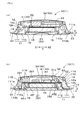
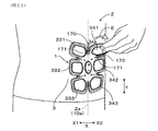
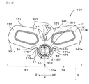
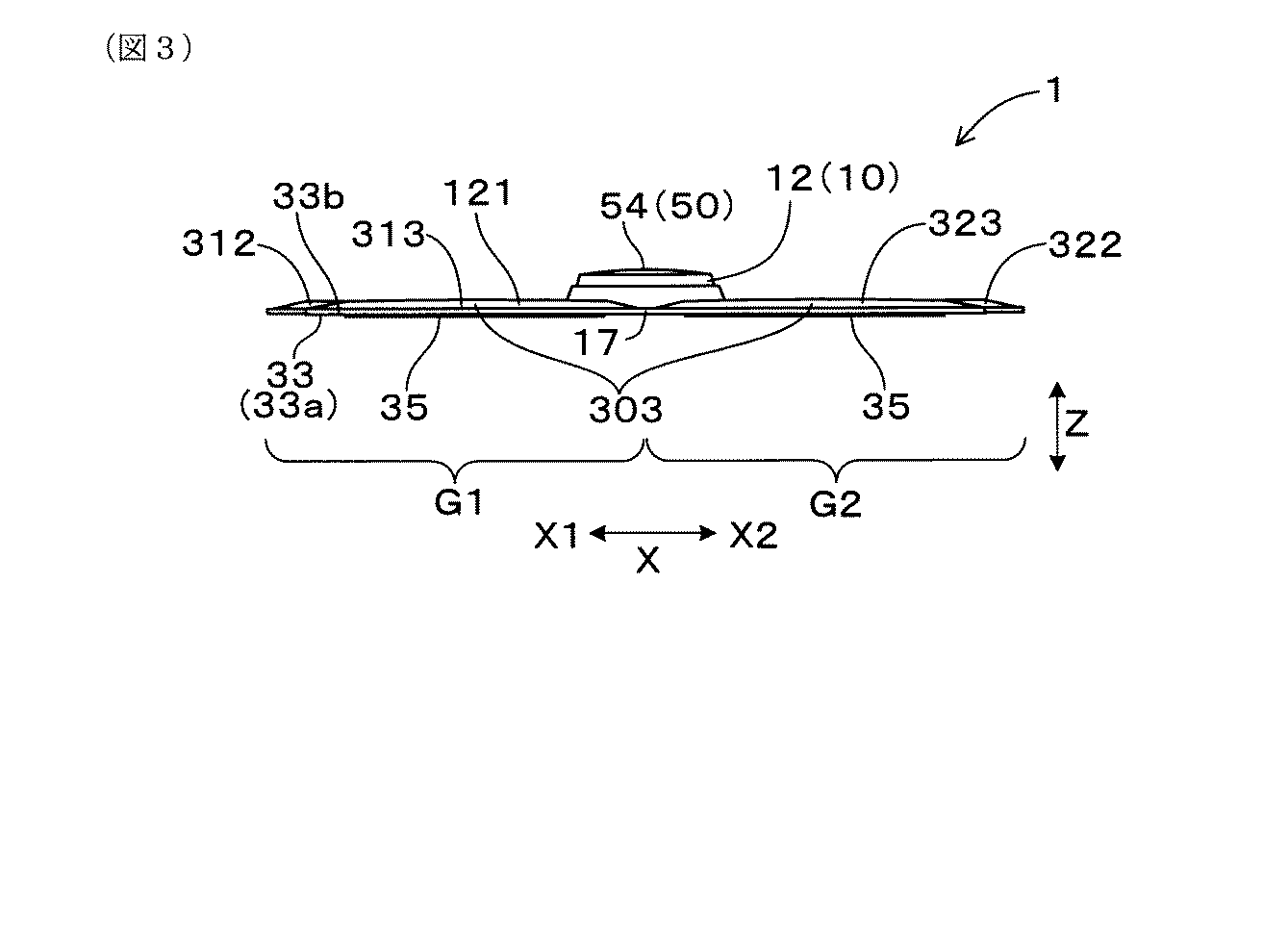
図1に示すように、筋肉電気刺激装置1の中央には、本体部10が設けられている。図1及び図3に示すように、本体部10は、略円盤状をなしている。図4(a)、図4(b)に示すように、本体部10は、後述の電源部20及び制御部40を収納するケース11と、ケース11に取り付けられて筋肉電気刺激装置1の外殻を形成する外殻形成体12と、からなる。   As shown in FIG. 1, a main body 10 is provided at the center of the electrical muscular stimulation device 1. As shown in FIG.1 and FIG.3, the main-body part 10 has comprised the substantially disk shape. As shown in FIGS. 4A and 4B, the main body 10 includes a case 11 that houses a power supply unit 20 and a control unit 40, which will be described later, and an exterior of the electrical muscular stimulation device 1 attached to the case 11. An outer shell forming body 12 forming a shell.

図4に示すように、外殻形成体12は、後述の基材33が設けられる側の面12bと、その反対側の外表面12aとを有している。外殻形成体12はエラストマーからなり、本例では黒色のシリコン製である。そして、後述するように、基材33の表側面33bを覆うように、外殻形成体12から電極支持部121が延出されている。そして、電極支持部121の外表面121aには、図1に示すように、後述の各電極311〜313、321〜323の外縁に略沿った線状を成す着色領域122が形成されている。本例では、着色部122は橙色に着色されている。   As shown in FIG. 4, the outer shell forming body 12 has a surface 12 b on the side where a substrate 33 described later is provided, and an outer surface 12 a on the opposite side. The outer shell forming body 12 is made of an elastomer and is made of black silicon in this example. As will be described later, the electrode support portion 121 is extended from the outer shell forming body 12 so as to cover the front side surface 33 b of the base material 33. Further, as shown in FIG. 1, a colored region 122 is formed on the outer surface 121 a of the electrode support portion 121. The colored region 122 has a linear shape along the outer edges of electrodes 311 to 313 and 321 to 323 described later. In this example, the coloring part 122 is colored orange.

図4(a)、図4(b)に示すように、ケース11は凹状をなす第1ケース111と、第1ケース111に取り付けられて、第1ケース111との間に制御部40を収納する収納部13を形成する第2ケース112とからなる。第1ケース111及び第2ケース112はいずれもABS製である。そして、第2ケース112の外縁に沿って、立設されたリブ112aが、第1ケース111の外縁部111aの内側に嵌合して第1ケース111に第2ケース112が接合されている。   As shown in FIGS. 4A and 4B, the case 11 is attached to the first case 111 having a concave shape and the first case 111, and the control unit 40 is accommodated between the first case 111 and the case 11. And a second case 112 that forms the storage portion 13 to be formed. Both the first case 111 and the second case 112 are made of ABS. The ribs 112 a erected along the outer edge of the second case 112 are fitted inside the outer edge 111 a of the first case 111 so that the second case 112 is joined to the first case 111.

第1ケース111には、図1、図4(b)に示すように、後述する操作部50の一部を形成する第1カンチレバー51a及び第2カンチレバー51bが形成されている。第1カンチレバー51a及び第2カンチレバー51bは、第1ケース111の壁の一部をくり抜いて片持ち梁の状態に形成されている。第1カンチレバー51aと第2カンチレバー51bとは、身長方向Yの上側から下側に向かって、この順で配列している。   As shown in FIGS. 1 and 4B, the first case 111 is formed with a first cantilever 51 a and a second cantilever 51 b that form a part of an operation unit 50 described later. The first cantilever 51 a and the second cantilever 51 b are formed in a cantilevered state by hollowing out a part of the wall of the first case 111. The first cantilever 51a and the second cantilever 51b are arranged in this order from the upper side to the lower side in the height direction Y.

図1、図4(b)に示すように、両カンチレバー51a、51bは、外殻形成体12に覆われている。そして、外殻形成体12において、第1カンチレバー51aの直上には記号「+」が突出形成されており、第2カンチレバー51bの直上には記号「−」が突出形成されており、後述する操作部50の一部を形成する操作面54を形成している。両カンチレバー51a、51bの配列により、「+」が身長方向Yの上側となるとともに、「−」が身長方向Y下側となり、人間工学的に使用者が操作しやすいものとなっている。   As shown in FIGS. 1 and 4B, both cantilevers 51 a and 51 b are covered with the outer shell forming body 12. In the outer shell forming body 12, a symbol “+” protrudes immediately above the first cantilever 51 a, and a symbol “−” protrudes immediately above the second cantilever 51 b. An operation surface 54 that forms part of the portion 50 is formed. Due to the arrangement of both cantilevers 51a and 51b, “+” is on the upper side in the height direction Y, and “−” is on the lower side in the height direction Y, making it easy for the user to operate ergonomically.

図4(a)、図4(b)に示すように、第1ケース111と第2ケース112との間に形成された収納部13には、制御部40(図8参照)を形成する制御基板41が収納されている。制御基板41はプリント基板であって、制御基板41には図示しない配線パターンと電子部品42等とが設けられて、制御回路が形成されている。制御基板41は、第1ケース111の内側面に突出形成された4つのボス116とねじ115を介して、第1ケース111に固定されている。また、制御基板41には、表面実装型の小型のスピーカ43が電気的に接続されている。電子部品42及びスピーカ43の駆動電圧は、いずれも3.0Vとなっている。また、図示しないが、制御基板41には、電池21の出力電圧を昇圧する昇圧回路が搭載されている。これにより、電池21の電力は所定の電圧(例えば、40V)に昇圧されて電極部30に供給される。   As shown in FIGS. 4A and 4B, the storage unit 13 formed between the first case 111 and the second case 112 has a control unit 40 (see FIG. 8). A substrate 41 is accommodated. The control board 41 is a printed board, and a control circuit is formed on the control board 41 by providing a wiring pattern (not shown), an electronic component 42, and the like. The control board 41 is fixed to the first case 111 via four bosses 116 and screws 115 formed to protrude from the inner surface of the first case 111. The control board 41 is electrically connected to a small surface mount type speaker 43. The drive voltages of the electronic component 42 and the speaker 43 are both 3.0V. Although not shown, the control board 41 is equipped with a booster circuit that boosts the output voltage of the battery 21. Thereby, the power of the battery 21 is boosted to a predetermined voltage (for example, 40 V) and supplied to the electrode unit 30.

また、図6に示すように、制御部40としての制御基板41には、第1端子群45及び第2端子群46が備えられている。第1端子群45は、図示しない配線パターンに接続された第1端子451と第2端子451を備える。第1端子451と第2端子451には、同一極性の電圧が印加されるように構成されている。一方、第2端子群46は、図示しない配線パターンに接続された第3端子461と第4端子462を備える。第3端子461と第4端子462には、同一極性の電圧が印加されるように構成されている。そして、第1端子群45(第1端子451及び第2端子451)と、第2端子群46(第3端子461と第4端子462)とは、互いに異なる極性の電圧が印加されるように構成されている。   As shown in FIG. 6, the control board 41 as the control unit 40 includes a first terminal group 45 and a second terminal group 46. The first terminal group 45 includes a first terminal 451 and a second terminal 451 connected to a wiring pattern (not shown). A voltage having the same polarity is applied to the first terminal 451 and the second terminal 451. On the other hand, the second terminal group 46 includes a third terminal 461 and a fourth terminal 462 connected to a wiring pattern (not shown). A voltage having the same polarity is applied to the third terminal 461 and the fourth terminal 462. The first terminal group 45 (first terminal 451 and second terminal 451) and the second terminal group 46 (third terminal 461 and fourth terminal 462) are applied with voltages having different polarities. It is configured.

図4(b)に示すように、第1端子451は、制御基板41において、ボス116に対向する位置に形成されている。同様に、第2端子452、第3端子461、第4端子462もボス116に対向する位置に形成されている。そして、後述の第1リード部38の第2制御部側接続部382が、ボス116と制御基板41との間に挟み込まれて、これらと一体的に締結されている。これにより、制御基板41において、ボス116が対向する位置に形成された第2端子452と第2制御部側接続部382とが接続されることとなる。同様に、後述の第1端子451と第1リード部38の第1制御部側接続部381とが接続され、第3端子461と第2リード部39の第3制御部側接続部391とが接続され、第4端子462と第2リード部39の第4制御部側接続部392とが接続される。   As shown in FIG. 4B, the first terminal 451 is formed on the control board 41 at a position facing the boss 116. Similarly, the second terminal 452, the third terminal 461, and the fourth terminal 462 are also formed at positions facing the boss 116. A second control portion side connection portion 382 of the first lead portion 38 described later is sandwiched between the boss 116 and the control board 41 and fastened integrally therewith. Thereby, in the control board 41, the 2nd terminal 452 formed in the position where the boss | hub 116 opposes, and the 2nd control part side connection part 382 will be connected. Similarly, a first terminal 451, which will be described later, and a first control part side connection part 381 of the first lead part 38 are connected, and a third terminal 461 and a third control part side connection part 391 of the second lead part 39 are connected. The fourth terminal 462 and the fourth control unit side connection part 392 of the second lead part 39 are connected.

図4(b)に示すように、収納部13には、操作部50を形成するスイッチ機構52も収納されている。スイッチ機構52はタクトスイッチであって、押下可能なスイッチ部53を備える。スイッチ機構52は制御部40に電気的に接続されている。スイッチ機構52は第1ケース111に形成された第1カンチレバー51a及び第2カンチレバー51b(図1参照)の直下にそれぞれ配設されている。これにより、第1ケース111を覆う外殻形成体12の操作面54を介して外部から第1カンチレバー51aを押圧すると、片持ち梁状態の第1カンチレバー51aが撓むことにより、スイッチ機構52のスイッチ部53が押下されるようになっている。そして、操作面54における押圧を解除すると、片持ち梁状態の第1カンチレバー51aの復元力により、第1カンチレバー51aは元の位置に戻ることとなる。第2カンチレバー51bにおいても同様に押圧及び押圧の解除が行われるように構成されている。   As shown in FIG. 4B, the storage unit 13 also stores a switch mechanism 52 that forms the operation unit 50. The switch mechanism 52 is a tact switch and includes a switch unit 53 that can be pressed. The switch mechanism 52 is electrically connected to the control unit 40. The switch mechanism 52 is disposed directly below the first cantilever 51a and the second cantilever 51b (see FIG. 1) formed in the first case 111, respectively. As a result, when the first cantilever 51a is pressed from the outside via the operation surface 54 of the outer shell forming body 12 covering the first case 111, the first cantilever 51a in the cantilever state is bent, so that the switch mechanism 52 The switch unit 53 is pressed. When the pressing on the operation surface 54 is released, the first cantilever 51a returns to the original position by the restoring force of the first cantilever 51a in the cantilever state. Similarly, the second cantilever 51b is configured to be pressed and released.

図4(a)、図4(b)に示すように、第2ケース112には、電源部20を構成する電池21を保持する電池保持部14が形成されている。これにより、本体部10に電源部20が内蔵されることとなっている。電池21は交換可能であって、例えば、コイン電池又はボタン電池とすることができる。本例では、電池21として、小型で薄型のコイン電池(リチウムイオン電池CR2032、公称電圧3.0V)を採用している。なお、当該電池21に替えて、公称電圧が3.0〜5.0Vの電池を採用することができる。   As shown in FIGS. 4A and 4B, the second case 112 is formed with a battery holding part 14 that holds the battery 21 that constitutes the power supply part 20. As a result, the power supply unit 20 is built in the main body unit 10. The battery 21 is replaceable, and can be, for example, a coin battery or a button battery. In this example, a small and thin coin battery (lithium ion battery CR2032, nominal voltage 3.0 V) is adopted as the battery 21. In addition, it can replace with the said battery 21 and can employ | adopt the battery whose nominal voltage is 3.0-5.0V.

上記電池21が保持される電池保持部14には、電池21の脱落を防止する蓋15が着脱可能に取り付けられている。蓋15は、電池21よりも一回り大きい円盤状をなしており、その外周には蓋15と第2ケース112との間をシールするОリング16が嵌装されている。電池21は、図示しないリードを介して制御部40に電気的に接続されている。図2に示すように、第2ケース112には、蓋15の外周から放射状に延びる線状の溝113が等間隔に複数形成されている。   A lid 15 that prevents the battery 21 from falling off is detachably attached to the battery holding portion 14 that holds the battery 21. The lid 15 has a disk shape that is slightly larger than the battery 21, and an O-ring 16 that seals between the lid 15 and the second case 112 is fitted on the outer periphery thereof. The battery 21 is electrically connected to the control unit 40 via a lead (not shown). As shown in FIG. 2, a plurality of linear grooves 113 extending radially from the outer periphery of the lid 15 are formed in the second case 112 at equal intervals.

図4(a)、図4(b)に示すように、第2ケース112には、リブ112aの外側に突出した鍔部112bが形成されている。鍔部112bと第1ケース111の外縁部111aとの間には、図示しない防水用両面シールを介して、シート状の基材33が挟持されている。基材33はPET製である。図2に示すように、基材33は、本体部10からシート状に延出している。図1及び図3に示すように、操作面54が露出する側の面である基材33の表側面33bは、外殻形成体12から延出された電極支持部121により覆われている。そして、基材33における表側面33bと反対側の裏側面33aは、筋肉電気刺激装置1における外殻形成体12側の面(表側面)と反対側の裏面側の全域に広がっている。そして、基材33と電極支持部121とは、図示しない3M社製の粘着テープ及びシリコン接着処理剤によって接合されている。   As shown in FIGS. 4A and 4B, the second case 112 is formed with a flange portion 112b that protrudes outside the rib 112a. A sheet-like base material 33 is sandwiched between the flange portion 112b and the outer edge portion 111a of the first case 111 via a waterproof double-sided seal (not shown). The base material 33 is made of PET. As shown in FIG. 2, the base material 33 extends from the main body 10 in a sheet shape. As shown in FIGS. 1 and 3, the front side surface 33 b of the base material 33, which is the surface on which the operation surface 54 is exposed, is covered with the electrode support portion 121 extending from the outer shell forming body 12. And the back side surface 33a on the opposite side to the front side surface 33b in the base material 33 is spread over the entire region on the back side opposite to the surface (front side surface) on the outer shell forming body 12 side in the electrical muscular stimulation device 1. And the base material 33 and the electrode support part 121 are joined by the adhesive tape and silicone adhesion processing agent by 3M company which are not shown in figure.

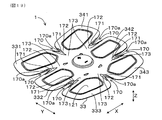
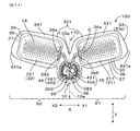
図2及び図8に示すように、電極部30は第1電極群31と第2電極群32を備える。第1電極群31は、図5に示すように、腹部3に取り付けたときに中心線10aよりも人体2の右手5a側の右方向X1に位置するように、本体部10から延出している。第2電極群32は、図5に示すように、腹部3に取り付けたときに中心線10aよりも人体2の左手5b側の左方向X2に位置するように、本体部10から延出している。第1電極群31には、第1電極としての第1右側電極311、第2電極としての第2右側電極312及び第3電極としての第3右側電極313が含まれており、第2電極群32には、第1電極としての第1左側電極321、第2電極としての第2左側電極322及び第3電極としての第3左側電極323が含まれている。   As shown in FIGS. 2 and 8, the electrode unit 30 includes a first electrode group 31 and a second electrode group 32. As shown in FIG. 5, the first electrode group 31 extends from the main body 10 so as to be positioned in the right direction X1 on the right hand 5a side of the human body 2 with respect to the center line 10a when attached to the abdomen 3. . As shown in FIG. 5, the second electrode group 32 extends from the main body 10 so as to be positioned in the left direction X2 on the left hand 5b side of the human body 2 with respect to the center line 10a when attached to the abdomen 3. . The first electrode group 31 includes a first right electrode 311 as a first electrode, a second right electrode 312 as a second electrode, and a third right electrode 313 as a third electrode. The second electrode group 32 includes a first left electrode 321 as a first electrode, a second left electrode 322 as a second electrode, and a third left electrode 323 as a third electrode.

各電極311〜313、321〜323はいずれも、角部が丸みを帯びた略長方形に形成されている。そして、各電極311〜313、321〜323の長手方向(例えば、第3右側電極313において符号wで示す方向)が、左右方向Xに概ね沿っている。本例では、各電極311〜313、321〜323はいずれも同一の形状を成している。各電極311〜313、321〜323の形状は、例えば、長手方向の長さをw、短手方向の長さをhとしたとき、h/wを0.40〜0.95、好ましくは0.50〜0.80とすることができ、本例では、h/wは0.55としている。   Each of the electrodes 311 to 313 and 321 to 323 is formed in a substantially rectangular shape with rounded corners. The longitudinal directions of the electrodes 311 to 313 and 321 to 323 (for example, the direction indicated by the symbol w in the third right electrode 313) are generally along the left-right direction X. In this example, each of the electrodes 311 to 313 and 321 to 323 has the same shape. The shapes of the electrodes 311 to 313 and 321 to 323 are such that, for example, when the length in the longitudinal direction is w and the length in the short direction is h, h / w is 0.40 to 0.95, preferably 0. .50 to 0.80, and in this example, h / w is 0.55.

図2に示すように、各電極311〜313、321〜323の内側には所定大きさの六角形をなす電極非形成部34が所定間隔をあけて、複数形成されている。また、第1右側電極311、第2右側電極312及び第3右側電極313には、リード部としての第1リード部38が接続されており、第1左側電極321、第2左側電極322及び第3左側電極323には、リード部としての第2リード部39が接続されている。   As shown in FIG. 2, a plurality of non-electrode forming portions 34 each having a predetermined hexagonal shape are formed at predetermined intervals inside each of the electrodes 311 to 313 and 321 to 323. The first right electrode 311, the second right electrode 312, and the third right electrode 313 are connected to the first lead portion 38 as a lead portion, and the first left electrode 321, the second left electrode 322, The third left electrode 323 is connected to a second lead portion 39 as a lead portion.

図6に示すように、リード部としての第1リード部38は、第1制御部側接続部群380と、第1端子接続部383と、第1電極接続部群384とを有する。第1制御部側接続部群380は、第1端子群45に属する複数の端子(第1端子451、第2端子452)に接続される複数の制御部側接続部(第1制御部側接続部381、第2制御部側接続部382)からなる。第1制御部側接続部381、第2制御部側接続部382は、それぞれ本体部10側に突出している。そして、図4(b)に示すように、第1制御部側接続部381及び第2制御部側接続部382は、それぞれ第1ケース111の内壁に沿って厚さ方向に折り曲げられるとともに、その先端が制御基板41と平行に折り曲げられる。そして、第1制御部側接続部381及び第2制御部側接続部382の先端が上述の如く、ボス116と制御基板41との間に挟み込まれている。   As shown in FIG. 6, the first lead part 38 as a lead part includes a first control part side connection part group 380, a first terminal connection part 383, and a first electrode connection part group 384. The first control unit side connection unit group 380 includes a plurality of control unit side connection units (first control unit side connection) connected to a plurality of terminals (first terminal 451, second terminal 452) belonging to the first terminal group 45. Part 381, second control part side connection part 382). The first control unit side connection unit 381 and the second control unit side connection unit 382 protrude to the main body unit 10 side, respectively. And as shown in FIG.4 (b), while the 1st control part side connection part 381 and the 2nd control part side connection part 382 are each bent in the thickness direction along the inner wall of the 1st case 111, the The tip is bent parallel to the control board 41. And the front-end | tip of the 1st control part side connection part 381 and the 2nd control part side connection part 382 is inserted | pinched between the boss | hub 116 and the control board 41 as mentioned above.

また、図6に示すように、端子接続部としての第1端子接続部383は、第1制御部側接続部群380に属する複数の制御部側接続部(第1制御部側接続部381、第2制御部側接続部382)が互いに通電するように形成されている。本例では、第1端子接続部383は本体部10の外縁10bに沿って略半円弧状を成している。そして、第1端子接続部383の一端に第1制御部側接続部381が設けられ、他端に第2制御部側接続部382が設けられている。   Further, as shown in FIG. 6, the first terminal connection portion 383 as the terminal connection portion includes a plurality of control portion side connection portions (first control portion side connection portions 381, belonging to the first control portion side connection portion group 380. The second control part side connection part 382) is formed so as to energize each other. In this example, the first terminal connecting portion 383 has a substantially semicircular arc shape along the outer edge 10 b of the main body portion 10. And the 1st control part side connection part 381 is provided in the end of the 1st terminal connection part 383, and the 2nd control part side connection part 382 is provided in the other end.

また、第1電極接続部群384は、第1端子接続部383から第1電極群31に属する複数の電極(第1右側電極311、第2右側電極312、第3右側電極313)に向けて延びるとともに該複数の電極311〜313に接続される複数の電極接続部(第1電極接続部385、第2電極接続部386、第3電極接続部387)からなる。本例では、第1電極接続部385、第2電極接続部386、第3電極接続部387はいずれも線状に形成されている。   The first electrode connection portion group 384 is directed from the first terminal connection portion 383 toward a plurality of electrodes (first right electrode 311, second right electrode 312, and third right electrode 313) belonging to the first electrode group 31. It consists of a plurality of electrode connection portions (first electrode connection portion 385, second electrode connection portion 386, and third electrode connection portion 387) that extend and are connected to the plurality of electrodes 311 to 313. In this example, the first electrode connection portion 385, the second electrode connection portion 386, and the third electrode connection portion 387 are all formed in a linear shape.

リード部としての第2リード部39は、第1リード部38と同様に、第2制御部側接続部群390と、第2端子接続部393と、第2電極接続部群394とを有する。第2制御部側接続部群390は、第2端子群46に属する複数の端子(第3端子461、第4端子462)に接続される複数の制御部側接続部(第3制御部側接続部391、第4制御部側接続部392)からなる。そして、第1リード部38と同様に、第3制御部側接続部391及び第4制御部側接続部392の先端がボス116と制御基板41との間に挟み込まれている。   Similar to the first lead part 38, the second lead part 39 as the lead part includes a second control part side connection part group 390, a second terminal connection part 393, and a second electrode connection part group 394. The second control unit side connection unit group 390 includes a plurality of control unit side connection units (third control unit side connection) connected to a plurality of terminals (third terminal 461 and fourth terminal 462) belonging to the second terminal group 46. Part 391 and fourth control part side connection part 392). Similarly to the first lead part 38, the tips of the third control part side connection part 391 and the fourth control part side connection part 392 are sandwiched between the boss 116 and the control board 41.

また、端子接続部としての第2端子接続部393は、第1リード部38の場合と同様に、第2制御部側接続部群390に属する複数の制御部側接続部(第3制御部側接続部391、第4制御部側接続部392)が互いに通電するように形成されている。本例では、第1リード部38の場合と同様に、第2端子接続部393は本体部10の外縁10bに沿って略半円弧状を成している。そして、第2端子接続部393の一端に第3制御部側接続部391が設けられ、他端に第4制御部側接続部392が設けられている。   Further, the second terminal connection portion 393 as the terminal connection portion is similar to the case of the first lead portion 38, and includes a plurality of control portion side connection portions (third control portion side) belonging to the second control portion side connection portion group 390. The connection part 391 and the fourth control part side connection part 392) are formed so as to energize each other. In the present example, as in the case of the first lead portion 38, the second terminal connection portion 393 has a substantially semicircular arc shape along the outer edge 10 b of the main body portion 10. A third control unit side connection unit 391 is provided at one end of the second terminal connection unit 393, and a fourth control unit side connection unit 392 is provided at the other end.

第2電極接続部群394は、第1リード部38の場合と同様に、第2端子接続部393から第2電極群32に属する複数の電極(第1左側電極321、第2左側電極322、第3左側電極323)に向けて延びるとともに該複数の電極321〜323に接続される複数の電極接続部(第4電極接続部395、第5電極接続部396、第6電極接続部397)からなる。本例では第4電極接続部395、第5電極接続部396、第6電極接続部397はいずれも線状に形成されている。   Similarly to the case of the first lead part 38, the second electrode connection part group 394 includes a plurality of electrodes (first left electrode 321, second left electrode 322, From a plurality of electrode connection parts (fourth electrode connection part 395, fifth electrode connection part 396, sixth electrode connection part 397) extending toward the third left electrode 323) and connected to the plurality of electrodes 321 to 323 Become. In this example, the fourth electrode connecting portion 395, the fifth electrode connecting portion 396, and the sixth electrode connecting portion 397 are all formed in a linear shape.

そして、図7(a)〜(c)に示すように、第1リード部38(図6参照)は、第1経路としての第1右側経路L1、第2経路としての第2右側経路L2、第3経路としての第3右側経路L3をそれぞれ形成している。第1右側経路L1は、第1端子451から第1右側電極311に向かって線状に延びて第1右側電極311に接続されている。第2右側経路L2は、第1端子451及び第2端子452から第1端子接続部383を介して第2右側電極312に接続されている。第3右側経路L3は、第2端子452から第1端子接続部383を介して第3右側電極313に接続される。そして、第1リード部38において、各経路L1〜L3はそれぞれの電極311〜313に繋がる最短経路である。   Then, as shown in FIGS. 7A to 7C, the first lead portion 38 (see FIG. 6) includes a first right path L1 as a first path, a second right path L2 as a second path, A third right path L3 as a third path is formed. The first right path L <b> 1 extends linearly from the first terminal 451 toward the first right electrode 311 and is connected to the first right electrode 311. The second right path L2 is connected from the first terminal 451 and the second terminal 452 to the second right electrode 312 via the first terminal connection portion 383. The third right path L3 is connected from the second terminal 452 to the third right electrode 313 via the first terminal connection portion 383. In the first lead portion 38, the paths L1 to L3 are the shortest paths connected to the respective electrodes 311 to 313.

第1リード部38における各経路L1〜L3の長さは、これらを平均した平均長さの20%未満であり、好ましくは平均長さの18%未満であり、より好ましくは平均長さの15%未満である。本例では、各経路L1〜L3の長さはそれぞれ、40mm、35mm、31mmであって、これらを平均した平均長さは35.33mmである。そして、各経路L1〜L3の長さと上記平均長さとの差はそれぞれ、4.67mm、0.33mm、4.33mmであって、上記平均長さの13.21%、0.93%、12.26%となっている。   The length of each of the paths L1 to L3 in the first lead portion 38 is less than 20% of the average length obtained by averaging them, preferably less than 18% of the average length, and more preferably 15% of the average length. %. In this example, the lengths of the paths L1 to L3 are 40 mm, 35 mm, and 31 mm, respectively, and the average length obtained by averaging these is 35.33 mm. The differences between the lengths of the paths L1 to L3 and the average length are 4.67 mm, 0.33 mm, and 4.33 mm, respectively, and are 13.21%, 0.93%, and 12 of the average length, respectively. 26%.

また、図7(a)〜(c)に示すように、第2リード部39(図6参照)は、第1経路としての第1左側経路L4、第2経路としての第2左側経路L5、第3経路としての第3左側経路L6をそれぞれ形成している。第1左側経路L4は、第3端子461から第1左側電極321に向かって線状に延びて第1左側電極321に接続されている。第2左側経路L5は、第3端子461及び第4端子462から第2端子接続部393を介して第2左側電極322に接続されている。第3左側経路L6は、第4端子462から第2端子接続部393を介して第3左側電極323に接続される。そして、第2リード部39において、各経路L4〜L6はそれぞれの電極321〜323に繋がる最短経路である。   Further, as shown in FIGS. 7A to 7C, the second lead 39 (see FIG. 6) includes a first left path L4 as a first path, a second left path L5 as a second path, A third left side path L6 as a third path is formed. The first left path L4 extends linearly from the third terminal 461 toward the first left electrode 321 and is connected to the first left electrode 321. The second left side path L5 is connected from the third terminal 461 and the fourth terminal 462 to the second left electrode 322 via the second terminal connection portion 393. The third left side path L6 is connected from the fourth terminal 462 to the third left side electrode 323 through the second terminal connection portion 393. In the second lead portion 39, the paths L4 to L6 are the shortest paths connected to the electrodes 321 to 323, respectively.

第1リード部38と同様に、第2リード部39における各経路L4〜L6の長さは、これらを平均した平均長さの20%未満であり、好ましくは平均長さの18%未満であり、より好ましくは平均長さの15%未満である。本例では、各経路L4〜L6の長さはそれぞれ、40mm、35mm、31mmであって、これらを平均した平均長さは35.33mmである。そして、各経路L4〜L6の長さと上記平均長さとの差はそれぞれ、4.67mm、0.33mm、4.33mmであって、上記平均長さの13.21%、0.93%、12.26%となっている。   Similar to the first lead portion 38, the length of each of the paths L4 to L6 in the second lead portion 39 is less than 20% of the average length obtained by averaging them, and preferably less than 18% of the average length. More preferably, it is less than 15% of the average length. In this example, the lengths of the paths L4 to L6 are 40 mm, 35 mm, and 31 mm, respectively, and the average length obtained by averaging these is 35.33 mm. The differences between the lengths of the paths L4 to L6 and the average length are 4.67 mm, 0.33 mm, and 4.33 mm, respectively, and are 13.21%, 0.93%, and 12 of the average length, respectively. 26%.

リード部としての第1リード部38及び第2リード部39には、シリコンコーティングが施されており、外部と導通できないようになっている。また、各電極311〜313、321〜323において第1リード部38及び第2シード部39に繋がる部分とその近傍領域(図2において、符号Cで示す斜線領域)にも、シリコンコーティングが施されており、外部と導通できないようになっている。これらにより、第1リード部38、第2シード部39及び斜線領域Cにおいて、肌と接触して通電することが防止されている。そして、第1リード部38を介して、第1右側電極311、第2右側電極312及び第3右側電極313が互いに並列接続され、第2リード部39を介して、第1左側電極321、第2左側電極322及び第3左側電極323が互いに並列接続されている。   The first lead portion 38 and the second lead portion 39 as lead portions are coated with silicon so that they cannot be electrically connected to the outside. In addition, a silicon coating is also applied to a portion connected to the first lead portion 38 and the second seed portion 39 in each of the electrodes 311 to 313 and 321 to 323 and a region near the portion (a hatched region indicated by C in FIG. 2). It cannot be connected to the outside. As a result, the first lead portion 38, the second seed portion 39, and the hatched region C are prevented from being energized in contact with the skin. The first right electrode 311, the second right electrode 312 and the third right electrode 313 are connected in parallel to each other via the first lead portion 38, and the first left electrode 321, the first right electrode 321, the second right electrode 313 are connected to each other via the second lead portion 39. The 2 left electrode 322 and the third left electrode 323 are connected in parallel to each other.

図2に示すように、電極部30は基材33の裏側面33aに形成されている。これにより、電極部30は本体部10と一体的に形成されている。なお、電極部30は基材33に埋め込むように形成することとしてもよい。本例では、電極部30は、銀ペーストを含む導電性インクを基材33の裏側面33aに印刷して形成されている。第1電極群31及び第2電極群32には合わせて4個以上の電極311〜313、321〜323が含まれている。本例では、第1電極群31と第2電極群32とはそれぞれ同数の電極311〜313、321〜323を含んでおり、その数はそれぞれ3個である。すなわち、第1電極群31には、第1右側電極311、第2右側電極312及び第3右側電極313が備えられ、第2電極群32には、第1左側電極321、第2左側電極322及び第3左側電極323が備えられている。そして、基材33において、第1右側電極311、第2右側電極312及び第3右側電極313が形成される部分をそれぞれ、第1右側基部331、第2右側基部332及び第3右側基部333とし、第1左側電極321、第2左側電極322及び第3左側電極323が形成される部分をそれぞれ、第1左側基部341、第2左側基部342及び第3左側基部343とする。   As shown in FIG. 2, the electrode portion 30 is formed on the back side surface 33 a of the base material 33. Thereby, the electrode part 30 is formed integrally with the main body part 10. The electrode unit 30 may be formed so as to be embedded in the base material 33. In this example, the electrode part 30 is formed by printing a conductive ink containing a silver paste on the back side surface 33 a of the base material 33. The first electrode group 31 and the second electrode group 32 include four or more electrodes 311 to 313 and 321 to 323 in total. In this example, the first electrode group 31 and the second electrode group 32 include the same number of electrodes 311 to 313 and 321 to 323, respectively, and the number thereof is three. That is, the first electrode group 31 includes a first right electrode 311, a second right electrode 312, and a third right electrode 313, and the second electrode group 32 includes a first left electrode 321 and a second left electrode 322. The third left electrode 323 is provided. In the base material 33, the portions where the first right electrode 311, the second right electrode 312 and the third right electrode 313 are formed are respectively referred to as a first right base 331, a second right base 332 and a third right base 333. The portions where the first left electrode 321, the second left electrode 322, and the third left electrode 323 are formed are referred to as a first left base 341, a second left base 342, and a third left base 343, respectively.

そして、各電極311〜313、321〜323には、ゲルパッド35(積水化成品工業株式会社製「テクノゲル(登録商標)」、型番SR−RA240/100)が貼付されている。ゲルパッド35は導電性を有しており、各電極311〜313、321〜323はゲルパッド35を介して腹部3(図5参照)への通電が可能となっている。また、ゲルパッド35は高い粘着性を有しており、ゲルパッド35を介して、筋肉電気刺激装置1が腹部3に取り付けられるようになっている。   A gel pad 35 (“Technogel (registered trademark)” manufactured by Sekisui Plastics Co., Ltd., model number SR-RA240 / 100) is attached to each of the electrodes 311 to 313 and 321 to 323. The gel pad 35 has conductivity, and the electrodes 311 to 313 and 321 to 323 can energize the abdomen 3 (see FIG. 5) via the gel pad 35. The gel pad 35 has high adhesiveness, and the muscular electrical stimulation device 1 is attached to the abdomen 3 via the gel pad 35.

ゲルパッド35は、図2に示すように、各電極311〜313、321〜323よりも一回り大きい形状を有しており、各電極311〜313、321〜323を個別に覆っている。ゲルパッド35は交換可能となっているため、ゲルパッド35が、使用に伴って粘着力が低下したり、破損したり、汚れが目立つようになったりした場合などには、適宜交換することができる。また、所定期間(例えば、1ヶ月、2か月など)ごとに使用済みのゲルパッド35を新品のものと交換することとしてもよい。   As shown in FIG. 2, the gel pad 35 has a shape that is slightly larger than the electrodes 311 to 313 and 321 to 323, and individually covers the electrodes 311 to 313 and 321 to 323. Since the gel pad 35 is replaceable, the gel pad 35 can be replaced as appropriate when the adhesive force decreases, breaks, or becomes conspicuous with use. Alternatively, the used gel pad 35 may be replaced with a new one every predetermined period (for example, one month, two months, etc.).

図2に示すように第1右側電極311、第2右側電極312及び第3右側電極313はいずれも、人体2(図5参照)の身長方向Yに平行で本体部10の中心を通る中心線10aよりも右方向X1の第1領域G1に位置するように、本体部10から延出している。そして、第1右側電極311、第2右側電極312及び第3右側電極313は、同一の仮想直線F1上に位置するように配列している。本例では、仮想直線F1は、中心軸10aと平行となっている。   As shown in FIG. 2, the first right electrode 311, the second right electrode 312, and the third right electrode 313 are all center lines parallel to the height direction Y of the human body 2 (see FIG. 5) and passing through the center of the main body 10. It extends from the main body 10 so as to be positioned in the first region G1 in the right direction X1 with respect to 10a. The first right electrode 311, the second right electrode 312 and the third right electrode 313 are arranged so as to be positioned on the same virtual straight line F1. In this example, the virtual straight line F1 is parallel to the central axis 10a.

一方、第1左側電極321、第2左側電極322及び第3左側電極323は、中心線10aよりも左方向X2の第2領域G2に位置するように、本体部10から延出している。そして、第1左側電極321、第2左側電極322及び第3左側電極323も、同一の仮想直線F2上に位置するように配列している。本例では、仮想直線F2は、中心軸10aと平行となっている。   On the other hand, the first left electrode 321, the second left electrode 322, and the third left electrode 323 extend from the main body 10 so as to be positioned in the second region G2 in the left direction X2 with respect to the center line 10a. The first left electrode 321, the second left electrode 322, and the third left electrode 323 are also arranged so as to be positioned on the same virtual straight line F2. In this example, the virtual straight line F2 is parallel to the central axis 10a.

そして、図2に示すように、第1電極群31と第2電極群32とが、腹部3(図5参照)に取り付けたときに、中心線10aを基準として線対称に位置するように構成されている。すなわち、腹部3に取り付けたときに中心線10aを基準として、第1右側電極311と第1左側電極321とが線対称に位置し、第2右側電極312と第2左側電極322とが線対称に位置し、第3右側電極313と第3左側電極323とが線対称に位置するように構成されている。   As shown in FIG. 2, the first electrode group 31 and the second electrode group 32 are arranged symmetrically with respect to the center line 10a when attached to the abdomen 3 (see FIG. 5). Has been. That is, the first right electrode 311 and the first left electrode 321 are positioned symmetrically with respect to the center line 10a when attached to the abdomen 3, and the second right electrode 312 and the second left electrode 322 are line symmetrical. The third right electrode 313 and the third left electrode 323 are arranged in line symmetry.

また、図2に示すように、第1電極群31及び第2電極群32は、腹部3(図5参照)に取り付けたときに、身長方向Yにおいて、第1電極群31及び第2電極群32のそれぞれにおける最も上側に位置する第1右側電極311と第1左側電極321とからなる一対の上側電極対301と、最も下側に位置する第3右側電極313と第3左側電極323とからなる一対の下側電極対303と、上側電極対301と下側電極対303との間に位置する一対の第2右側電極312と第2左側電極322とからなる中央電極対302と、が形成されるように構成されている。これにより、上側電極対301、中央電極対302及び下側電極対303は、身長方向Yに沿って上側から下側に向かってこの順で配列している。   In addition, as shown in FIG. 2, the first electrode group 31 and the second electrode group 32 are attached to the abdomen 3 (see FIG. 5) in the height direction Y when the first electrode group 31 and the second electrode group 32 are attached. 32, a pair of upper electrode pairs 301 including the first right electrode 311 and the first left electrode 321 located on the uppermost side, and a third right electrode 313 and a third left electrode 323 located on the lowermost side. A pair of lower electrodes 303 and a pair of second right electrodes 312 and a center electrode 302 formed of a second left electrode 322 located between the upper electrode pair 301 and the lower electrode pair 303 are formed. It is configured to be. Accordingly, the upper electrode pair 301, the central electrode pair 302, and the lower electrode pair 303 are arranged in this order from the upper side to the lower side along the height direction Y.

そして、中央電極対302は、上側電極対301及び下側電極対303よりも本体部10から延設される方向(左右方向X)に突出している。すなわち、腹部3に取り付けたときに、中央電極対302を構成する第2右側電極312は、上側電極対301を構成する第1右側電極311及び下側電極対303を構成する第3右側電極313よりも右方向X1に突出している。同様に、中央電極対302を構成する第2左側電極322は、上側電極対301を構成する第1左側電極321及び下側電極対303を構成する第3左側電極323よりも左方向X2に突出している。   The center electrode pair 302 protrudes in the direction (left-right direction X) extending from the main body 10 more than the upper electrode pair 301 and the lower electrode pair 303. That is, when attached to the abdomen 3, the second right electrode 312 constituting the central electrode pair 302 is the first right electrode 311 constituting the upper electrode pair 301 and the third right electrode 313 constituting the lower electrode pair 303. It protrudes in the right direction X1. Similarly, the second left electrode 322 constituting the central electrode pair 302 protrudes in the left direction X2 more than the first left electrode 321 constituting the upper electrode pair 301 and the third left electrode 323 constituting the lower electrode pair 303. ing.

また、図2に示すように、上側電極対301は延出方向に向かうほど上側に位置するようにV字状に傾斜している。そして、上述の如く、各電極311〜313、321〜323は同一の大きさとなっている。一方、電極部30の基材33における各右側基部331〜333は各電極311〜313よりも大きくなっており、各左側基部341〜343は、各電極321〜323よりも大きくなっている。   Further, as shown in FIG. 2, the upper electrode pair 301 is inclined in a V shape so as to be positioned on the upper side in the extending direction. As described above, the electrodes 311 to 313 and 321 to 323 have the same size. On the other hand, the right bases 331 to 333 in the base material 33 of the electrode unit 30 are larger than the electrodes 311 to 313, and the left bases 341 to 343 are larger than the electrodes 321 to 323.

また、図2に示すように、上側電極対301は、下側電極対303よりも本体部10から延設される方向(左右方向X)に突出している。すなわち、腹部3に取り付けたときに、上側電極対301を構成する第1右側電極311は、下側電極対303を構成する第3右側電極313よりも右方向X1に突出している。同様に、上側電極対301を構成する第1左側電極321は、下側電極対303を構成する第3左側電極323よりも左方向X2に突出している。   Further, as shown in FIG. 2, the upper electrode pair 301 protrudes in the direction (left-right direction X) extending from the main body 10 than the lower electrode pair 303. That is, when attached to the abdominal part 3, the first right electrode 311 constituting the upper electrode pair 301 protrudes in the right direction X 1 from the third right electrode 313 constituting the lower electrode pair 303. Similarly, the first left electrode 321 constituting the upper electrode pair 301 protrudes in the left direction X2 from the third left electrode 323 constituting the lower electrode pair 303.

そして、図2に示すように、第1右側基部331の下方外縁部331aは右方向X1に膨出しており、第1左側基部341の下方外縁部341aは左方向X2に膨出している。
また、第2右側基部332の中央外縁部332aは右方向X1に若干膨出しており、第2左側基部342の中央外縁部342aは左方向X2に若干膨出している。
さらに、第3右側基部333の上方外縁部333aは右方向X1に膨出しており、第3右側基部333の下方外縁部333bは下方向(Y方向における下側方向)に膨出している。また、第3左側基部343の上方外縁部343aは左方向X2に膨出しており、第3左側基部343の下方外縁部343bは下方向に膨出している。
As shown in FIG. 2, the lower outer edge 331a of the first right base 331 bulges in the right direction X1, and the lower outer edge 341a of the first left base 341 bulges in the left direction X2.
Further, the center outer edge 332a of the second right base 332 is slightly bulged in the right direction X1, and the center outer edge 342a of the second left base 342 is slightly bulged in the left direction X2.
Further, the upper outer edge 333a of the third right base 333 bulges in the right direction X1, and the lower outer edge 333b of the third right base 333 bulges downward (downward in the Y direction). The upper outer edge 343a of the third left base 343 bulges in the left direction X2, and the lower outer edge 343b of the third left base 343 bulges downward.

基材33における各基部331〜333、341〜343を上述のようにすることで、図1及び図5に示すように、筋肉電気刺激装置1を正面側から見たとき、筋肉電気刺激装置1が腹部3における腹直筋4を左右方向に包み込むように配される。また、電極配置も腹直筋4の区画4aに併せた配置となる事で、各筋肉を効率よく刺激することが期待できる。さらに、かかる形状であると認識されることにより、腹部3が引き締まって腹筋が割れたイメージを使用者に想起させることができる。これにより、筋肉電気刺激装置1を使用することにより、腹筋が割れて引き締まった腹部3とするためのイメージトレーニングの効果が得られる。(イメージトレーニングによる運動効果の向上は一般によく知られている。)   By making the bases 331 to 333 and 341 to 343 in the base material 33 as described above, as shown in FIGS. 1 and 5, when the muscular electrical stimulation device 1 is viewed from the front side, the muscular electrical stimulation device 1. Is arranged so as to wrap the rectus abdominis 4 in the abdomen 3 in the left-right direction. Moreover, it can be expected that each muscle is efficiently stimulated by arranging the electrodes in combination with the section 4a of the rectus abdominis 4. Furthermore, by recognizing such a shape, the user can be reminded of an image in which the abdominal part 3 is tightened and the abdominal muscles are broken. Thereby, the effect of the image training for setting it as the abdominal part 3 which the abdominal muscle cracked and tightened by using the muscular electrical stimulation apparatus 1 is acquired. (Improvement of exercise effect by image training is generally well known.)

また、図2に示すように、第1電極群31及び第2電極群32において互いに隣り合う電極311〜313、321〜323の間には、本体部10に向かって切り込まれた切り込み部17が形成されている。本例では、第1右側電極311と第2右側電極312との間、第2右側電極312と第3右側電極313との間、第3右側電極313と第3左側電極323との間、第3左側電極323と第2左側電極322との間、第2左側電極322と第1左側電極321との間、及び第1左側電極321と第1右側電極311との間、の合計6カ所に切り込み部17が形成されている。さらに、本体部10の周囲には、貫通孔18が4カ所形成されている。本例では、図1に示すように、切り込み部17の先端17aはいずれも、平面視において曲率半径が1.0mmとなっている。   In addition, as shown in FIG. 2, a cut portion 17 cut toward the main body portion 10 between the adjacent electrodes 311 to 313 and 321 to 323 in the first electrode group 31 and the second electrode group 32. Is formed. In this example, between the first right electrode 311 and the second right electrode 312, between the second right electrode 312 and the third right electrode 313, between the third right electrode 313 and the third left electrode 323, 3 between the left electrode 323 and the second left electrode 322, between the second left electrode 322 and the first left electrode 321, and between the first left electrode 321 and the first right electrode 311. A cut portion 17 is formed. Furthermore, four through holes 18 are formed around the main body 10. In this example, as shown in FIG. 1, the leading end 17a of the cut portion 17 has a curvature radius of 1.0 mm in plan view.

次に、本例の筋肉電気刺激装置1の構成について、ブロック図を用いて説明する。
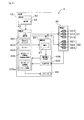
図8に示すように、筋肉電気刺激装置1は、本体部10の内部に、電源部20、制御部40、操作部50を備えるとともに、肌検知部402及び電池電圧検出部406を備える。
Next, the structure of the muscular electrical stimulation apparatus 1 of this example is demonstrated using a block diagram.
As shown in FIG. 8, the electrical muscular stimulation device 1 includes a power source unit 20, a control unit 40, and an operation unit 50 inside the main body unit 10, and also includes a skin detection unit 402 and a battery voltage detection unit 406.

肌検知部402は、電極部30が肌に接しているか否かを検知する。詳細には、肌検知部402は、電極部30に電気的に接続され、第1電極群31と第2電極群32との間の抵抗値を検出する。そして、検出した値と予め設定された閾値とを比較して、検出した値が閾値よりも小さいときに、第1電極群31及び第2電極群32に肌が接していることを検知する。   Skin detection unit 402 detects whether or not electrode unit 30 is in contact with the skin. Specifically, the skin detection unit 402 is electrically connected to the electrode unit 30 and detects a resistance value between the first electrode group 31 and the second electrode group 32. Then, the detected value is compared with a preset threshold value, and when the detected value is smaller than the threshold value, it is detected that the skin is in contact with the first electrode group 31 and the second electrode group 32.

電池電圧検出部406は、電源部20における電池21の電圧を検知し、検知された電源部20における電池21の電池電圧Vが所定の閾値Vmよりも低いか否か判定する。本例では電池21の公称電圧Vは3.0Vであって、閾値Vmは2.1Vである。   The battery voltage detection unit 406 detects the voltage of the battery 21 in the power supply unit 20 and determines whether or not the detected battery voltage V of the battery 21 in the power supply unit 20 is lower than a predetermined threshold value Vm. In this example, the nominal voltage V of the battery 21 is 3.0V, and the threshold value Vm is 2.1V.

図8に示すように、電源部20には、電池21が備えられる。また、制御部40には、出力調整部401、電源オフカウンタ403、タイマー404、出力モード切替部405及び出力モード記憶部405aが備えられる。出力調整部401は電極部30における出力電圧(出力レベル)を調整する。本例では、最大出力電圧は40Vであり、出力レベルが1下がるごとに、100%出力電圧が2.0V低下するように設定されている。出力レベルはレベル1からレベル15までの15段階となっている。   As shown in FIG. 8, the power supply unit 20 includes a battery 21. The control unit 40 includes an output adjustment unit 401, a power-off counter 403, a timer 404, an output mode switching unit 405, and an output mode storage unit 405a. The output adjustment unit 401 adjusts the output voltage (output level) at the electrode unit 30. In this example, the maximum output voltage is 40 V, and the 100% output voltage is set to decrease by 2.0 V every time the output level decreases by one. There are 15 output levels from level 1 to level 15.

電源オフカウンタ403は、カウント開始信号を受けてからの経過時間を計測する。タイマー404は、出力開始信号を受けてからの経過時間を計測する。出力モード切替部405は、電極部30における出力モードを第1出力モード、第2出力モード及び第3出力モードのいずれかに切り替えるものであって、出力されるバースト波の周波数を設定する周波数設定部を構成している。出力モード記憶部405aには、第1出力モード、第2出力モード及び第3出力モードが記憶されている。第1出力モード、第2出力モード及び第3出力モードには、パルス群出力中断期間R1〜R5を有するバースト波パターンとしての基本波形が予め記憶されており、出力モード記憶部405aがバースト波パターン記憶部を構成している。なお、バースト波パターン記憶部405aは、プログラム上のバースト波の波形の定義記載も含むものとする。   The power-off counter 403 measures an elapsed time after receiving the count start signal. The timer 404 measures an elapsed time after receiving the output start signal. The output mode switching unit 405 switches the output mode in the electrode unit 30 to any one of the first output mode, the second output mode, and the third output mode, and sets the frequency of the burst wave to be output. Part. The output mode storage unit 405a stores a first output mode, a second output mode, and a third output mode. In the first output mode, the second output mode, and the third output mode, a basic waveform as a burst wave pattern having pulse group output interruption periods R1 to R5 is stored in advance, and the output mode storage unit 405a stores the burst wave pattern. A storage unit is configured. Note that the burst wave pattern storage unit 405a includes a definition description of a burst wave waveform on the program.

次に、電極部30における出力モードについて、説明する。
まず、継続時間記憶部としての出力モード記憶部405aには、図9に示す5つのバースト波パターン(基本波形B1〜B5)が記憶されている。各基本波形B1〜B5は、パルス群出力期間Pとパルス群出力中断期間R1〜R5とからなる。すなわち、各基本波形B1〜B5は、共通のパルス群出力期間Pを有しているとともに、パルス群出力中断期間R1〜R5の長さが異なっている。
Next, the output mode in the electrode unit 30 will be described.
First, five burst wave patterns (basic waveforms B1 to B5) shown in FIG. 9 are stored in the output mode storage unit 405a serving as a duration storage unit. Each basic waveform B1 to B5 includes a pulse group output period P and a pulse group output interruption period R1 to R5. That is, the basic waveforms B1 to B5 have a common pulse group output period P, and the lengths of the pulse group output interruption periods R1 to R5 are different.

パルス群出力期間Pは、矩形波パルス信号S1〜S5が出力停止時間N1〜N5を挟んで複数出力される。本例では、5個の矩形波パルス信号S1〜S5が出力される。すなわち、パルス群出力期間Pは、第1の矩形波パルス信号S1、第1の出力停止時間N1、第2の矩形波パルス信号S2、第2の出力停止時間N2、第3の矩形波パルス信号S3、第3の出力停止時間N3、第4の矩形波パルス信号S4、第4の出力停止時間N4、第5の矩形波パルス信号S5、第5の出力停止時間N5の順に実行される。   In the pulse group output period P, a plurality of rectangular wave pulse signals S1 to S5 are output with output stop times N1 to N5 interposed therebetween. In this example, five rectangular wave pulse signals S1 to S5 are output. That is, the pulse group output period P includes the first rectangular wave pulse signal S1, the first output stop time N1, the second rectangular wave pulse signal S2, the second output stop time N2, and the third rectangular wave pulse signal. S3, third output stop time N3, fourth rectangular wave pulse signal S4, fourth output stop time N4, fifth rectangular wave pulse signal S5, and fifth output stop time N5 are executed in this order.

そして、本例では、各矩形波パルス信号S1〜S5のパルス幅、パルス電圧は一定であり、出力停止時間N1〜N5の継続時間も一定である。本例では、各矩形波パルス信号S1〜S5のパルス幅が100μsであって、パルス電圧は100%出力時に±40Vであり、出力停止時間N1〜N5の継続時間は100μsである。そのため、パルス群出力期間Pの継続時間は1msとなっている。そして、各矩形波パルス信号S1〜S5における電圧極性は出力順に交互に変更されている。すなわち、第1の矩形波パルス信号S1、第3の矩形波パルス信号S3及び第5の矩形波パルス信号S5が正の極性を有し、第2の矩形波パルス信号S2及び第4の矩形波パルス信号S4が負の極性を有している。   In this example, the pulse widths and pulse voltages of the rectangular wave pulse signals S1 to S5 are constant, and the durations of the output stop times N1 to N5 are also constant. In this example, the pulse width of each of the rectangular wave pulse signals S1 to S5 is 100 μs, the pulse voltage is ± 40 V at 100% output, and the duration of the output stop time N1 to N5 is 100 μs. Therefore, the duration of the pulse group output period P is 1 ms. And the voltage polarity in each rectangular wave pulse signal S1-S5 is changed alternately by the order of output. That is, the first rectangular wave pulse signal S1, the third rectangular wave pulse signal S3, and the fifth rectangular wave pulse signal S5 have a positive polarity, and the second rectangular wave pulse signal S2 and the fourth rectangular wave. The pulse signal S4 has a negative polarity.

上述のように、パルス群出力期間Pにおける各矩形波パルス信号S1〜S5のパルス幅及び各出力停止時間N1〜N5の継続時間はそれぞれ100μsである。そのため、パルス群出力期間Pにおける各矩形波パルス信号S1〜S5のパルス周期は200μsであって、十分短い。そのため、使用者はこれらの矩形波パルス信号S1〜S5を一つの電気刺激として認識することとなる。なお、パルス群出力期間Pにおける各矩形波パルス信号S1〜S5の周波数は5,000Hzである。   As described above, the pulse width of each rectangular wave pulse signal S1 to S5 and the duration of each output stop time N1 to N5 in the pulse group output period P are 100 μs. Therefore, the pulse period of each rectangular wave pulse signal S1 to S5 in the pulse group output period P is 200 μs, which is sufficiently short. Therefore, the user recognizes these rectangular wave pulse signals S1 to S5 as one electrical stimulus. In addition, the frequency of each rectangular wave pulse signal S1-S5 in the pulse group output period P is 5,000 Hz.

各基本波形B1〜B5において、パルス群出力中断期間R1〜R5はパルス信号を出力しない。そして、パルス群出力中断期間R1〜R5の継続時間は、パルス群出力期間Pの継続時間よりも長い。本例では、図9に示すように、パルス群出力期間Pの継続時間は、1msであり、パルス群出力中断期間R1〜R5の継続時間は、それぞれ、499ms、249ms、124ms、61.5ms、49msである。このように、パルス群出力中断期間R1〜R5は、パルス群出力期間Pにおける出力停止時間に比べて、非常に長い継続時間を有するものである。   In each of the basic waveforms B1 to B5, no pulse signal is output during the pulse group output interruption periods R1 to R5. The duration of the pulse group output interruption period R1 to R5 is longer than the duration of the pulse group output period P. In this example, as shown in FIG. 9, the duration of the pulse group output period P is 1 ms, and the durations of the pulse group output interruption periods R1 to R5 are 499 ms, 249 ms, 124 ms, 61.5 ms, respectively. 49 ms. Thus, the pulse group output interruption periods R1 to R5 have a very long duration compared to the output stop time in the pulse group output period P.

したがって、図9に示すように、第1バースト波(2Hz)は、1msのパルス群出力期間Pと、499msのパルス群出力中断期間R1とからなる。すなわち、第1バースト波(2Hz)は、パルス群出力期間Pが2Hzの周波数で出力されるものである。
また、第2バースト波(4Hz)は、1msのパルス群出力期間Pと、249msのパルス群出力中断期間R2とからなる。すなわち、第2バースト波(4Hz)は、パルス群出力期間Pが4Hzの周波数で出力されるものである。
また、第3バースト波(8Hz)は、1msのパルス群出力期間Pと、124msのパルス群出力中断期間R3とからなる。すなわち、第3バースト波(8Hz)は、パルス群出力期間Pが8Hzの周波数で出力されるものである。
また、第4バースト波(16Hz)は、1msのパルス群出力期間Pと、61.5msのパルス群出力中断期間R4とからなる。すなわち、第4バースト波(16Hz)は、パルス群出力期間Pが16Hzの周波数で出力されるものである。
また、第5バースト波(20Hz)は、1msのパルス群出力期間Pと、49msのパルス群出力中断期間R5とからなる。すなわち、第5バースト波(20Hz)は、パルス群出力期間Pが20Hzの周波数で出力されるものである。
Therefore, as shown in FIG. 9, the first burst wave (2 Hz) is composed of a pulse group output period P of 1 ms and a pulse group output interruption period R1 of 499 ms. That is, the first burst wave (2 Hz) is output with a frequency of the pulse group output period P of 2 Hz.
The second burst wave (4 Hz) includes a pulse group output period P of 1 ms and a pulse group output interruption period R2 of 249 ms. That is, the second burst wave (4 Hz) is output at a frequency of 4 Hz in the pulse group output period P.
The third burst wave (8 Hz) includes a pulse group output period P of 1 ms and a pulse group output interruption period R3 of 124 ms. That is, the third burst wave (8 Hz) is output at a frequency of 8 Hz in the pulse group output period P.
The fourth burst wave (16 Hz) includes a pulse group output period P of 1 ms and a pulse group output interruption period R4 of 61.5 ms. That is, the fourth burst wave (16 Hz) is output at a frequency of 16 Hz in the pulse group output period P.
The fifth burst wave (20 Hz) includes a pulse group output period P of 1 ms and a pulse group output interruption period R5 of 49 ms. That is, the fifth burst wave (20 Hz) is output with a frequency of 20 Hz in the pulse group output period P.

そして、基本波形B1〜B5を所定の組み合わせで所定期間繰り返し出力することにより、図10(a)〜(e)に示すように、所定のバースト波が出力されることとなる。そして、上述のように、使用者は、パルス群出力期間Pにおける複数の矩形波パルス信号S1〜S5を一つの電気刺激と認識することから、図10(a)に示すように、基本波形B1を繰り返す第1バースト波では、周波数2Hzの電気刺激が出力されることとなる。同様に、基本波形B2を繰り返す第2バースト波では、周波数4Hzの電気刺激が出力され、基本波形B3を繰り返す第3バースト波では、周波数8Hzの電気刺激が出力され、基本波形B4を繰り返す第4バースト波では、周波数16Hzの電気刺激が出力され、基本波形B5を繰り返す第5バースト波では、周波数20Hzの電気刺激が出力されることとなる。   Then, by repeatedly outputting the basic waveforms B1 to B5 in a predetermined combination for a predetermined period, as shown in FIGS. 10A to 10E, a predetermined burst wave is output. As described above, since the user recognizes the plurality of rectangular wave pulse signals S1 to S5 in the pulse group output period P as one electrical stimulus, as shown in FIG. In the first burst wave repeating the above, an electrical stimulus having a frequency of 2 Hz is output. Similarly, in the second burst wave that repeats the basic waveform B2, an electrical stimulus with a frequency of 4 Hz is output, and in the third burst wave that repeats the basic waveform B3, an electrical stimulus with a frequency of 8 Hz is output, and the fourth burst repeats the basic waveform B4. In the burst wave, an electrical stimulus with a frequency of 16 Hz is output, and in the fifth burst wave that repeats the basic waveform B5, an electrical stimulus with a frequency of 20 Hz is output.

そして、継続時間記憶部としての出力モード記憶部405aに記憶された第1〜第3出力モードは、出力モード記憶部405aに記憶された基本波形B1〜B5を適宜選択することにより、所定の周波数のバースト波を組み合わせて構成される。まず、表1に示すように、第1出力モードは、下記の第1ステータス〜第4ステータスを順に行うように構成されたウォームアップモードである。各ステータスの条件は以下のとおりである。
(1)第1ステータスでは、第1バースト波(2Hz)で20秒間、100%の出力を行う。なお、図11に示すように、第1ステータスにおける開始5秒間は出力電圧を0%から徐々に大きくして100%にする、いわゆるソフトスタートを行う。
(2)第2ステータスでは、第2バースト波(4Hz)で20秒間、100%の出力を行う。
(3)第3ステータスでは、第3バースト波(8Hz)で10秒間、100%の出力を行う。
(4)第4ステータスでは、第4バースト波(16Hz)で10秒間、100%の出力を行う。
そして、第1出力モードの継続期間(すなわち、第1ステータス〜第4ステータスの継続期間の合計)は1分間である。かかる第1出力モードでは、バースト波の周波数が2Hzから16Hzへ段階的に高くなるように構成されているため、第1出力モードをウォームアップモードと呼んでいる。

Figure 2017006644
The first to third output modes stored in the output mode storage unit 405a serving as the duration storage unit are appropriately selected from the basic waveforms B1 to B5 stored in the output mode storage unit 405a. Composed of a combination of burst waves. First, as shown in Table 1, the first output mode is a warm-up mode configured to sequentially perform the following first status to fourth status. The conditions for each status are as follows.
(1) In the first status, 100% output is performed with the first burst wave (2 Hz) for 20 seconds. As shown in FIG. 11, so-called soft start is performed in which the output voltage is gradually increased from 0% to 100% for the first 5 seconds in the first status.
(2) In the second status, 100% output is performed for 20 seconds with the second burst wave (4 Hz).
(3) In the third status, 100% output is performed with the third burst wave (8 Hz) for 10 seconds.
(4) In the fourth status, 100% output is performed for 10 seconds with the fourth burst wave (16 Hz).
The duration of the first output mode (that is, the total duration of the first status to the fourth status) is 1 minute. In the first output mode, since the burst wave frequency is configured to increase stepwise from 2 Hz to 16 Hz, the first output mode is called a warm-up mode.
Figure 2017006644

かかるウォームアップモードとしての第1出力モードでは、バースト波の周波数が2Hzから16Hzへ段階的に高くなるのに伴って筋肉の運動頻度が高まり、当該筋肉や体が次第に温まる。これにより、急激な血圧上昇、当該筋肉における一時的な酸素不足などが生じることが防止される。また、当該筋肉が徐々に温まることにより、血流量が増して当該筋肉の柔軟性が高まる。これにより、後続のトレーニングモードにおいて、筋肉の刺激による効果が一層得られやすくなる。また、トレーニングモードに先行して当該ウォームアップモードを行うことによって、使用者が刺激に適度に慣れることができるため、体感が向上する。   In the first output mode as the warm-up mode, the frequency of muscle movement increases as the burst wave frequency increases stepwise from 2 Hz to 16 Hz, and the muscle and body gradually warm up. This prevents a sudden rise in blood pressure, temporary oxygen shortage in the muscle, and the like. Moreover, when the muscles are gradually warmed, the blood flow is increased and the flexibility of the muscles is increased. Thereby, in the subsequent training mode, it becomes easier to obtain the effect of muscle stimulation. Also, by performing the warm-up mode prior to the training mode, the user can be used to the stimulation moderately, so that the sensation is improved.

次に、表2に示すように、第2出力モードは、下記の第1ステータス〜第4ステータスを順に行うように構成されたトレーニングモードである。各ステータスの条件は以下のとおりである。
(1)第1ステータスでは、第5バースト波(20Hz)で3秒間、100%の出力を行った後、出力なしを2秒間維持する。これを5分間繰り返す。
(2)第2ステータスでは、第5バースト波(20Hz)で3秒間、100%の出力を行った後、第2バースト波(4Hz)で2秒間、100%の出力を行う。これを5分間繰り返す。
(3)第3ステータスでは、第5バースト波(20Hz)で4秒間、100%の出力を行った後、第2バースト波(4Hz)で2秒間、100%の出力を行う。これを5分間繰り返す。
(4)第4ステータスでは、第5バースト波(20Hz)で5秒間、100%の出力を行った後、第2バースト波(4Hz)で2秒間、100%の出力を行う。これを5分間繰り返す。
なお、図11に示すように、第2出力モードでは第1ステータス〜第4ステータスにおけるそれぞれの開始5秒間は、出力電圧を0%から徐々に大きくして100%にする、いわゆるソフトスタートを行う。
そして、第2出力モードの継続期間は20分間である。かかる第2出力モードでは、周波数20Hzの第5バースト波を所定期間維持した後、出力なし又は周波数4Hzの第2バースト波を所定期間維持するため、筋肉を効果的に刺激するのに優れている。そのため、第2出力モードをトレーニングモードと呼んでいる。

Figure 2017006644
Next, as shown in Table 2, the second output mode is a training mode configured to perform the following first status to fourth status in order. The conditions for each status are as follows.
(1) In the first status, 100% output is performed for 3 seconds with the fifth burst wave (20 Hz), and then no output is maintained for 2 seconds. Repeat for 5 minutes.
(2) In the second status, 100% output is performed with the fifth burst wave (20 Hz) for 3 seconds, and then 100% output is performed with the second burst wave (4 Hz) for 2 seconds. Repeat for 5 minutes.
(3) In the third status, 100% output is performed with the fifth burst wave (20 Hz) for 4 seconds, and then 100% output is performed with the second burst wave (4 Hz) for 2 seconds. Repeat for 5 minutes.
(4) In the fourth status, 100% output is performed with the fifth burst wave (20 Hz) for 5 seconds, and then 100% output is performed with the second burst wave (4 Hz) for 2 seconds. Repeat for 5 minutes.
As shown in FIG. 11, in the second output mode, so-called soft start is performed in which the output voltage is gradually increased from 0% to 100% for the first 5 seconds in the first status to the fourth status. .
The duration of the second output mode is 20 minutes. In the second output mode, the fifth burst wave with a frequency of 20 Hz is maintained for a predetermined period, and then no output or the second burst wave with a frequency of 4 Hz is maintained for a predetermined period, so that it is excellent for stimulating muscles effectively. . Therefore, the second output mode is called a training mode.
Figure 2017006644

次に、表3に示すように、第3出力モードは、下記の第1ステータス〜第4ステータスを順に行うように構成されたクールダウンモードである。各ステータスの条件は以下のとおりである。
(1)第1ステータスでは、第4バースト波(16Hz)で10秒間、出力を行う。
(2)第2ステータスでは、第3バースト波(8Hz)で10秒間、出力を行う。
(3)第3ステータスでは、第2バースト波(4Hz)で20秒間、出力を行う。
(4)第4ステータスでは、第1バースト波(2Hz)で20秒間、出力を行う。
なお、第3出力モードでは、各ステータスにおける出力は、図11に示すように、第1ステータス開始時には100%とし、第4ステータス終了時に50%となるように徐々に減少させる。
そして、第3出力モードの継続期間は1分間である。かかる第3出力モードでは、バースト波の周波数が16Hzから2Hzへ段階的に低くなるように構成されているため、第3出力モードをクールダウンモードと呼んでいる。

Figure 2017006644
Next, as shown in Table 3, the third output mode is a cool-down mode configured to perform the following first status to fourth status in order. The conditions for each status are as follows.
(1) In the first status, the fourth burst wave (16 Hz) is output for 10 seconds.
(2) In the second status, the third burst wave (8 Hz) is output for 10 seconds.
(3) In the third status, the second burst wave (4 Hz) is output for 20 seconds.
(4) In the fourth status, the first burst wave (2 Hz) is output for 20 seconds.
In the third output mode, as shown in FIG. 11, the output in each status is gradually reduced to 100% at the start of the first status and 50% at the end of the fourth status.
The duration of the third output mode is 1 minute. In the third output mode, the burst wave frequency is configured to gradually decrease from 16 Hz to 2 Hz. Therefore, the third output mode is called a cool-down mode.
Figure 2017006644

かかるクールダウンモードとしての第3出力モードでは、バースト波の周波数が16Hzから2Hzへ段階的に低くなるのに伴って筋肉の運動頻度が低下することにより、当該温まっていた筋肉や体が徐々に冷まされることとなる。そして、先行するトレーニングモードにおいて筋肉に生じた疲労物質を当該筋肉から積極的に排出して、当該筋肉に疲労物質が過剰に残留することが防止される。   In the third output mode as the cool-down mode, the muscles and body that have been warmed up gradually as the frequency of the muscles decreases as the frequency of the burst wave gradually decreases from 16 Hz to 2 Hz. It will be cooled. Then, the fatigue substance generated in the muscle in the preceding training mode is positively discharged from the muscle, and the fatigue substance is prevented from remaining excessively in the muscle.

以上のように、第1出力モード(ウォームアップモード)、第2出力モード(トレーニングモード)及び第3出力モード(クールダウンモード)を連続して行った場合の合計時間は22分間となる。なお、本例では、図11に示すように、第1出力モードと第2出力モードとの間、及び第2出力モードにおける各ステータスの間の合計4カ所に、それぞれ2秒間の休止期間が設けられている。そのため、当該休止期間を含めた全行程の合計時間は22分8秒間となっている。   As described above, the total time when the first output mode (warm-up mode), the second output mode (training mode), and the third output mode (cool-down mode) are continuously performed is 22 minutes. In this example, as shown in FIG. 11, a rest period of 2 seconds is provided at a total of four locations between the first output mode and the second output mode and between each status in the second output mode. It has been. Therefore, the total time of all the processes including the suspension period is 22 minutes and 8 seconds.

次に、本例の筋肉電気刺激装置1における使用態様について、以下に詳述する。
図12に示すメイン動作フローS100について説明する。メイン動作フローS100では、まず、操作面54の「+」を2秒間押下する(S101)。これにより、筋肉電気刺激装置1の電源がオンとなって、筋肉電気刺激装置1が起動されるとともに、起動されたことを通知する通知音(「ピー」)が、スピーカ43により発せられる(S102)。その後、筋肉電気刺激装置1は、出力待機状態となり出力レベルが0にされるとともに、操作部50の入力が無効化される(S103)
Next, the usage mode in the electrical muscular stimulation device 1 of this example will be described in detail below.
The main operation flow S100 shown in FIG. 12 will be described. In the main operation flow S100, first, “+” on the operation surface 54 is pressed for 2 seconds (S101). As a result, the electric power of the muscular electrical stimulation device 1 is turned on, the electrical muscular stimulation device 1 is activated, and a notification sound (“pee”) notifying that it has been activated is emitted from the speaker 43 (S102). ). Thereafter, the electrical muscular stimulation device 1 enters an output standby state, the output level is set to 0, and the input of the operation unit 50 is invalidated (S103).

次に、肌検知部402により、電極部30に肌が接しているか否かを検知する(S104)。肌検知部402によって、電極部30に肌が接していることが検知された場合(S104のYes)は、操作部50を有効化する(S105)。そして、操作部50により出力レベルを入力する(S106)。出力レベルの入力は、操作部50の操作面54から行う。操作部50の操作面54の「+」を押すごとに出力レベルが1レベル大きくなり、操作面54の「−」を押すごとに出力レベルが1レベル小さくなる。出力レベルが設定されると、制御部40からタイマー404へ出力開始信号を送り、タイマー404において計測が開始される(S107)。また、出力レベルの操作は使用時間中(操作部50の有効化後から電源オフまで)のいつでも可能である。   Next, it is detected by the skin detection part 402 whether the skin is contacting the electrode part 30 (S104). When the skin detection unit 402 detects that the skin is in contact with the electrode unit 30 (Yes in S104), the operation unit 50 is validated (S105). Then, an output level is input by the operation unit 50 (S106). The input of the output level is performed from the operation surface 54 of the operation unit 50. Every time “+” on the operation surface 54 of the operation unit 50 is pressed, the output level increases by one level, and every time “−” on the operation surface 54 is pressed, the output level decreases by one level. When the output level is set, an output start signal is sent from the control unit 40 to the timer 404, and measurement is started in the timer 404 (S107). Further, the operation of the output level can be performed at any time during the usage time (after the operation unit 50 is activated until the power is turned off).

タイマー404の計測開始時(経過時間0)から経過時間1分までの間は、電極部30における出力モードを第1出力モード(ウォームアップモード)とする(S108)。経過時間1分に達すると、周波数設定部としての出力モード切替部405により、電極部30における出力モードを第2出力モード(トレーニングモード)に切り替え、経過時間21分までの20分間維持する(S109)。経過時間21分に達すると、周波数設定部としての出力モード切替部405により、電極部30における出力モードを第3出力モード(クールダウンモード)に切り替え、経過時間22分までの1分間維持する(S110)。経過時間22分に達すると、タイマー404における計測を終了する(S111)。そして、筋肉電気刺激装置1を停止する(S112)。このように、S108からS111が行われることにより、第1出力モード(ウォームアップモード)、第2出力モード(トレーニングモード)及び第3出力モード(クールダウンモード)が1セット行われて、終了することとなる。   From the time when the timer 404 starts measurement (elapsed time 0) to the elapsed time 1 minute, the output mode of the electrode unit 30 is set to the first output mode (warm-up mode) (S108). When the elapsed time reaches 1 minute, the output mode switching unit 405 as a frequency setting unit switches the output mode in the electrode unit 30 to the second output mode (training mode) and maintains it for 20 minutes until the elapsed time of 21 minutes (S109). ). When the elapsed time reaches 21 minutes, the output mode switching unit 405 serving as a frequency setting unit switches the output mode in the electrode unit 30 to the third output mode (cool down mode) and maintains it for 1 minute until the elapsed time of 22 minutes ( S110). When the elapsed time reaches 22 minutes, the measurement in the timer 404 is terminated (S111). Then, the muscular electrical stimulation device 1 is stopped (S112). As described above, when S108 to S111 are performed, one set of the first output mode (warm-up mode), the second output mode (training mode), and the third output mode (cool-down mode) is performed, and the process ends. It will be.

一方、肌検知部402によって、電極部30に肌が接していないと判定された場合(S104のNo)は、その旨を通知する通知音(「ピ、ピ、ピ」)が、スピーカ43により発せられる(S113)。そして、制御部40から電源オフカウンタ403へカウント開始信号を送り、電源オフカウンタ403において経過時間の計測をスタートする(S114)。   On the other hand, if the skin detection unit 402 determines that the skin is not in contact with the electrode unit 30 (No in S104), a notification sound (“pi, pi, pi”) to notify that is sent by the speaker 43. It is emitted (S113). Then, a count start signal is sent from the control unit 40 to the power-off counter 403, and measurement of elapsed time is started in the power-off counter 403 (S114).

次に肌検知部402により、電極部30に肌が接しているか否かを検知する(S115)。肌検知部402によって、電極部30に肌が接していることが検知された場合は、上述のステップS103に戻って、出力待機状態となる(S115のYes)。一方、肌検知部402によって、電極部30に肌が接していないと判定された場合(S115のNo)は、電源オフカウンタ403における経過時間が2分を超えたか否かを判定する(S116)。電源オフカウンタ403における経過時間が2分を超えていないと判定された場合(S116のNo)は、再度S115に戻り、肌検知部402により、電極部30に肌が接しているか否かを検知する。一方、S116において、電源オフカウンタ403における経過時間が2分を超えていると判定された場合(S116のYes)は、筋肉電気刺激装置1の電源がオフとなる(S117)。   Next, the skin detection unit 402 detects whether or not the skin is in contact with the electrode unit 30 (S115). When the skin detection unit 402 detects that the skin is in contact with the electrode unit 30, the process returns to the above-described step S103 and enters an output standby state (Yes in S115). On the other hand, when the skin detection unit 402 determines that the skin is not in contact with the electrode unit 30 (No in S115), it is determined whether the elapsed time in the power-off counter 403 has exceeded 2 minutes (S116). . When it is determined that the elapsed time in the power-off counter 403 does not exceed 2 minutes (No in S116), the process returns to S115 again, and the skin detection unit 402 detects whether the skin is in contact with the electrode unit 30 or not. To do. On the other hand, when it is determined in S116 that the elapsed time in the power-off counter 403 exceeds 2 minutes (Yes in S116), the power of the muscular electrical stimulation device 1 is turned off (S117).

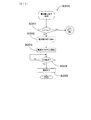
次に、上述のメイン動作フローS100におけるS105〜S110の間に割り込んで優先処理される割り込み処理について説明する。図13に示すように、第1の割り込み処理として、肌検出割り込み処理S200が行われる。肌検出割り込み処理S200は、使用途中で電極が人体から離脱した場合に、自動的に電源をオフにする機能として用いられる。肌検出割り込み処理S200では、まず、肌検知部402により、電極部30に肌が接しているか否かを検知する(S201)。肌検知部402によって、電極部30に肌が接していることが検知された場合(S201のYes)は、メイン動作フローS100における元のフローへ戻る。一方、肌検知部402によって、電極部30に肌が接していないと判定された場合(S201のNo)は、その旨を通知する通知音(「ピ、ピ、ピ」)が、スピーカ43により発せられる(S202)。そして、制御部40から電源オフカウンタ403へカウント開始信号を送り、電源オフカウンタ403が経過時間の計測をスタートする(S203)。   Next, a description will be given of an interrupt process that is preferentially interrupted between S105 and S110 in the main operation flow S100 described above. As shown in FIG. 13, a skin detection interrupt process S200 is performed as the first interrupt process. The skin detection interrupt process S200 is used as a function of automatically turning off the power when the electrode is detached from the human body during use. In the skin detection interruption process S200, first, the skin detection unit 402 detects whether or not the skin is in contact with the electrode unit 30 (S201). When the skin detection unit 402 detects that the skin is in contact with the electrode unit 30 (Yes in S201), the process returns to the original flow in the main operation flow S100. On the other hand, when the skin detection unit 402 determines that the skin is not in contact with the electrode unit 30 (No in S201), a notification sound (“pi, pi, pi”) notifying that is sent by the speaker 43. It is emitted (S202). Then, a count start signal is sent from the control unit 40 to the power-off counter 403, and the power-off counter 403 starts measuring elapsed time (S203).

次に肌検知部402により、電極部30に肌が接しているか否かを検知する(S204)。肌検知部402によって、電極部30に肌が接していることが検知された場合は、メイン動作フローS100のステップS103に戻る(S204のYes)。一方、肌検知部402によって、電極部30に肌が接していないと判定された場合(S204のNo)は、電源オフカウンタ403における経過時間が2分を超えたか否かを判定する(S205)。電源オフカウンタ403における経過時間が2分を超えていないと判定された場合(S205のNo)は、再度S204に戻り、肌検知部402により、電極部30に肌が接しているか否かを検知する。一方、S205において、電源オフカウンタ403における経過時間が2分を超えていると判定された場合(S205のYes)は、筋肉電気刺激装置1の電源がオフとなる(S206)。   Next, the skin detection unit 402 detects whether or not the skin is in contact with the electrode unit 30 (S204). When the skin detecting unit 402 detects that the skin is in contact with the electrode unit 30, the process returns to step S103 of the main operation flow S100 (Yes in S204). On the other hand, when the skin detecting unit 402 determines that the skin is not in contact with the electrode unit 30 (No in S204), it is determined whether the elapsed time in the power-off counter 403 has exceeded 2 minutes (S205). . When it is determined that the elapsed time in the power-off counter 403 does not exceed 2 minutes (No in S205), the process returns to S204 again, and the skin detection unit 402 detects whether or not the skin is in contact with the electrode unit 30. To do. On the other hand, when it is determined in S205 that the elapsed time in the power-off counter 403 exceeds 2 minutes (Yes in S205), the power of the muscular electrical stimulation device 1 is turned off (S206).

次に、図14に示すように、上述のメイン動作フローS100におけるS105〜S110の間に割り込んで優先処理される第2の割り込み処理である電池電圧低下処理S300について説明する。電池電圧低下処理S300は、電池21の電池電圧が低下した場合に自動で電源をオフにする機能である。これにより、使用者は電池交換の対応が必要な場合等にこれを容易に知ることができる。まず、電池電圧検出部406により、検知された電源部20における電池21の電池電圧Vが所定の閾値Vmよりも低いか否か判定する(S301)。電池電圧Vが所定の閾値Vmよりも低くないと判定された場合(S301のNo)は、メイン動作フローS100における元のフローへ戻る。一方、電池電圧Vが所定の閾値Vmよりも低いと判定された場合は、その旨を通知する通知音(「ピ、ピ、ピ」)が、スピーカ43により発せられる(S302)。そして、制御部40から電源オフカウンタ403へカウント開始信号を送り、電源オフカウンタ403において経過時間の計測をスタートする(S303)。   Next, as shown in FIG. 14, a battery voltage lowering process S300, which is a second interrupt process interrupted between S105 to S110 in the main operation flow S100 described above, will be described. The battery voltage lowering process S300 is a function for automatically turning off the power when the battery voltage of the battery 21 decreases. As a result, the user can easily know when it is necessary to replace the battery. First, the battery voltage detection unit 406 determines whether or not the detected battery voltage V of the battery 21 in the power supply unit 20 is lower than a predetermined threshold value Vm (S301). When it is determined that the battery voltage V is not lower than the predetermined threshold value Vm (No in S301), the process returns to the original flow in the main operation flow S100. On the other hand, when it is determined that the battery voltage V is lower than the predetermined threshold value Vm, a notification sound (“pi, pi, pi”) notifying that effect is emitted from the speaker 43 (S302). Then, a count start signal is sent from the control unit 40 to the power-off counter 403, and the measurement of elapsed time is started in the power-off counter 403 (S303).

次に、電源オフカウンタ403における経過時間が2分を超えたか否かを判定する(S304)。電源オフカウンタ403における経過時間が2分を超えていないと判定された場合(S304のNo)は、再度S304に戻る。電源オフカウンタ403における経過時間が2分を超えていると判定された場合(S304のYes)は、筋肉電気刺激装置1の電源がオフとなる(S305)。   Next, it is determined whether or not the elapsed time in the power-off counter 403 has exceeded 2 minutes (S304). When it is determined that the elapsed time in the power-off counter 403 does not exceed 2 minutes (No in S304), the process returns to S304 again. When it is determined that the elapsed time in the power-off counter 403 exceeds 2 minutes (Yes in S304), the electrical power of the muscle electrical stimulation device 1 is turned off (S305).

次に、図15に示すように、上述のメイン動作フローS100におけるS105〜S110の間に割り込んで優先処理される第3の割り込み処理である中断処理S400について説明する。まず、制御部50により、操作部50における操作面54の「−」ボタンを押下している時間が2秒以上か否か判定する(S401)。「−」ボタンを押下している時間が2秒以上でないと判定された場合(S401のNo)は、メイン動作フローS100における元のフローへ戻る。一方、「−」ボタンを押下している時間が2秒以上であると判定された場合(S401のYes)は、筋肉電気刺激装置1の電源をオフにして終了する旨を通知する通知音(「ピー」)が、スピーカ43により発せられる(S402)。そして、電源をオフにする(S403)。   Next, as shown in FIG. 15, an interruption process S400, which is a third interruption process interrupted between S105 and S110 in the main operation flow S100 described above, will be described. First, the control unit 50 determines whether or not the time during which the “−” button on the operation surface 54 of the operation unit 50 is pressed is 2 seconds or more (S401). When it is determined that the time during which the “−” button is pressed is not 2 seconds or longer (No in S401), the process returns to the original flow in the main operation flow S100. On the other hand, when it is determined that the time during which the “−” button is pressed is 2 seconds or longer (Yes in S401), the notification sound (notifying that the power is turned off and the process is ended) "Pee") is emitted from the speaker 43 (S402). Then, the power is turned off (S403).

本例の筋肉電気刺激装置1の作用効果について、以下に詳述する。
上記筋肉電気刺激装置1では、複数の電極311〜313(321〜323)のそれぞれから端子451、452(461、462)までの最短経路L1〜L3(L4〜L6)の長さはそれぞれ、最短経路L1〜L3(L4〜L6)の平均長さとの差が、該平均長さの20%未満となっている。そのため、電極311〜313(321〜323)と制御部40との通電距離にばらつきが生じにくく、電極311〜313(321〜323)と制御部40とを電気的に接続するリード部38(39)における電気抵抗の電極ごとのばらつきを低減できる。そのため、各電極311〜313(321〜323)から出力される電気刺激がばらつきにくくなり、筋肉にバランス良く電気刺激を付与することができる。
The effects of the electrical muscular stimulation device 1 of this example will be described in detail below.
In the muscular electrical stimulation device 1, the lengths of the shortest paths L1 to L3 (L4 to L6) from the respective electrodes 311 to 313 (321 to 323) to the terminals 451 and 452 (461 and 462) are the shortest. The difference from the average length of the paths L1 to L3 (L4 to L6) is less than 20% of the average length. For this reason, variations in the energization distance between the electrodes 311 to 313 (321 to 323) and the control unit 40 hardly occur, and the lead part 38 (39) that electrically connects the electrodes 311 to 313 (321 to 323) and the control unit 40. ) Variation in electrical resistance for each electrode can be reduced. Therefore, the electrical stimulation output from each electrode 311 to 313 (321 to 323) is less likely to vary, and electrical stimulation can be applied to the muscle in a well-balanced manner.

また、制御部40には同一極性の電圧が印加される複数の端子451、452(461、462)が備えられている。そして、リード部38(39)には、当該複数の端子451、452(461、462)に接続される端子接続部383(393)と、端子接続部383(393)と電極311〜313(321〜323)とを接続する電極接続部385〜387(395〜397)とが設けられている。これにより、リード部38(39)を介した最短経路L1〜L3(L4〜L6)を短く維持しつつ、電極311〜313(321〜323)の配置の自由度を高めることができる。その結果、電極311〜313(321〜323)を筋肉に電気刺激を付与するのに適した位置に配置しやすくなる。   The control unit 40 includes a plurality of terminals 451 and 452 (461 and 462) to which voltages having the same polarity are applied. The lead portion 38 (39) has a terminal connection portion 383 (393) connected to the plurality of terminals 451, 452 (461, 462), a terminal connection portion 383 (393), and electrodes 311 to 313 (321). To 323) are connected to electrode connecting portions 385 to 387 (395 to 397). Thereby, the freedom degree of arrangement | positioning of the electrodes 311-313 (321-323) can be raised, keeping shortest path | route L1-L3 (L4-L6) via the lead | read | reed part 38 (39) short. As a result, it becomes easy to arrange the electrodes 311 to 313 (321 to 323) at positions suitable for applying electrical stimulation to muscles.

また、本例では、複数の電極311〜313(321〜323)は、同一の仮想直線F1(F2)上に位置するように配置されている。これにより、腹直筋4のように、直線上に配列した複数の区画4aのそれぞれに電極311〜313(321〜323)を対応させやすくなるため、腹直筋4等の筋肉を効果的に刺激することができる。   In the present example, the plurality of electrodes 311 to 313 (321 to 323) are arranged so as to be positioned on the same virtual straight line F1 (F2). Thereby, since it becomes easy to make the electrodes 311 to 313 (321 to 323) correspond to each of the plurality of sections 4a arranged on a straight line like the rectus abdominis 4, muscles such as the rectus abdominis 4 can be effectively used. Can irritate.

また、本例では、同一極性の端子451、452(461、462)が、2個備えられている。これにより、少ない構成で各電極311〜313(321〜323)との最短経路L1〜L3(L4〜L6)を短くしつつ、製造コストの低減を図ることができる。   In this example, two terminals 451 and 452 (461 and 462) having the same polarity are provided. Thereby, it is possible to reduce the manufacturing cost while shortening the shortest paths L1 to L3 (L4 to L6) with the respective electrodes 311 to 313 (321 to 323) with a small configuration.

また、本例では、電極部30の第1電極群31は3個の電極311〜313を有し、第2電極群32は3個の電極321〜323を有する。これにより、腹直筋4が身長方向Yに区画された3つの区画4aに、電極311〜313を対応させることができるため、腹直筋4を一層効果的に刺激することができる。   In this example, the first electrode group 31 of the electrode unit 30 has three electrodes 311 to 313, and the second electrode group 32 has three electrodes 321 to 323. Thereby, since the electrodes 311 to 313 can correspond to the three sections 4a in which the rectus abdominis 4 is partitioned in the height direction Y, the rectus abdominis 4 can be stimulated more effectively.

また、本例では、複数の端子451、452、461、462、電極311〜312、321〜323及びリード部38、39はそれぞれ、本体部10の中心を通る中心線10cにより二分された一方の領域(第1領域G1)と他方の領域(第2領域G2)の両方にそれぞれ配置されている。そして、一方の領域(第1領域G1)に配置される電極311〜312と他方の領域(第2領域G2)に配置される電極321〜323とは、互いに異なる極性の電圧が印加されるように構成されている。これにより、中心軸10aが人2の身長方向Yと平行となるようにして腹部3の真ん中に取り付けることにより、各電極311〜312、321〜323が左右の腹直筋4にそれぞれ対応する位置に位置しやすくなるため、腹直筋4を刺激するのに適した筋肉電気刺激装置1となる。   Further, in this example, the plurality of terminals 451, 452, 461, 462, the electrodes 311 to 312, 321 to 323, and the lead portions 38 and 39 are each bisected by a center line 10 c passing through the center of the main body 10. They are arranged in both the region (first region G1) and the other region (second region G2). The electrodes 311 to 312 disposed in one region (first region G1) and the electrodes 321 to 323 disposed in the other region (second region G2) are applied with voltages having different polarities. It is configured. As a result, the electrodes 311 to 312 and 321 to 323 correspond to the left and right rectus abdominis muscles 4 by attaching them to the middle of the abdomen 3 so that the central axis 10a is parallel to the height direction Y of the person 2. Therefore, the muscular electrical stimulation device 1 is suitable for stimulating the rectus abdominis 4.

また、本例では、端子接続部(第1端子接続部383及び第2端子接続部393)は、本体部10の外縁10bに沿って形成されている。これにより、リード部(第1リード部38及び第2リード部39)を短く形成しやすいため、効率的に電気刺激を出力することができる。   In this example, the terminal connection portions (the first terminal connection portion 383 and the second terminal connection portion 393) are formed along the outer edge 10 b of the main body portion 10. Thereby, since the lead portions (the first lead portion 38 and the second lead portion 39) can be easily formed short, electrical stimulation can be output efficiently.

なお、本例では、複数の制御部側接続部381、382、391、392と制御部40とは、ねじ115を介して締結固定したが、これに替えて、複数の制御部側接続部381、382、391、392を第1ケース111と第2ケース112とで挟んで制御部40に接続されるように固定してもよい。   In this example, the plurality of control unit side connection units 381, 382, 391, 392 and the control unit 40 are fastened and fixed via screws 115, but instead, a plurality of control unit side connection units 381 are provided. , 382, 391, 392 may be fixed so as to be connected to the control unit 40 with the first case 111 and the second case 112 interposed therebetween.

また、電池21はボタン電池又はコイン電池とすることができ、本例では、コイン電池である。これにより、電池21が小型となるため、筋肉電気刺激装置1の小型化に寄与する。そして、筋肉電気刺激装置1の小型化に伴って軽量化を図ることができるため、電極部30が使用者の体から剥離、脱落しにくくなり、使い勝手が向上するとともに、携帯性も向上する。さらに、電池21は薄型でもあるため、筋肉電気刺激装置1の薄型化にも寄与する。そして、筋肉電気刺激装置1が薄型となることにより、使用者は、筋肉電気刺激装置1を取り付けたまま、その上から衣服を着用することが可能となる。そのため、筋肉電気刺激装置1を通勤中や通学中、家事や仕事等の作業中、その他様々な状況で使用することができる。また、ボタン電池及びコイン電池は、他の乾電池等に比べて、高い作動電圧で安定した放電特性を有するため、比較的長時間にわたって筋肉電気刺激装置1を安定して動作させることができる。   The battery 21 can be a button battery or a coin battery, and in this example is a coin battery. Thereby, since the battery 21 becomes small, it contributes to size reduction of the muscular electrical stimulation apparatus 1. And since weight reduction can be achieved with size reduction of the muscular electrical stimulation apparatus 1, the electrode part 30 becomes difficult to peel and drop | omit from a user's body, usability improves, and portability also improves. Furthermore, since the battery 21 is also thin, it contributes to thinning of the muscular electrical stimulation device 1. And since the muscular electrical stimulation apparatus 1 becomes thin, the user can wear clothes from the top with the muscular electrical stimulation apparatus 1 attached. Therefore, the muscular electrical stimulation device 1 can be used in various other situations while commuting to work, attending school, working such as housework or work. In addition, since the button battery and the coin battery have stable discharge characteristics at a high operating voltage compared to other dry batteries, the muscular electrical stimulation device 1 can be stably operated for a relatively long time.

また、電池21として公称電圧が3.0〜5.0Vのものを採用することができ、本例では、3.0Vの電池21を採用している。筋肉電気刺激装置1に備えられる電子部品42、スピーカ43等の駆動電圧が一致していることから、これらの電子部品42、43の駆動のために降圧回路や昇圧回路を別途備える必要がない。これにより、小型化に寄与できる。   In addition, a battery having a nominal voltage of 3.0 to 5.0 V can be used as the battery 21, and a 3.0 V battery 21 is used in this example. Since the drive voltages of the electronic component 42 and the speaker 43 provided in the muscular electrical stimulation device 1 are the same, it is not necessary to separately provide a step-down circuit and a step-up circuit for driving these electronic components 42 and 43. Thereby, it can contribute to size reduction.

また、上記電源部20には、上述の交換可能な電池21に替えて充電可能な電池が内蔵されていてもよい。かかる電池の充電手段として、外部電源と接続可能な給電用の端子を備えていてもよいし、電磁誘導を使用した非接触型の給電部を備えていてもよい。この場合には、当該電池を繰り返し使用できるため、非充電型の電池を使用する場合に比べて、消耗品を削減できる。   The power supply unit 20 may incorporate a rechargeable battery instead of the replaceable battery 21 described above. As a charging means for such a battery, a power supply terminal that can be connected to an external power source may be provided, or a non-contact power supply unit that uses electromagnetic induction may be provided. In this case, since the battery can be used repeatedly, consumables can be reduced compared to the case of using a non-rechargeable battery.

なお、本例では、電極部30が形成される基材33は、本体部10から延設されるとともに、外殻形成体12から延設された電極支持部121が接着されることにより、電極部30と本体部10とが一体的に形成されることとした。これに替えて、基材33と本体部10とを別体とするとともに、電極支持部121と外殻形成体12とを別体として形成することにより、本体部10と電極部30と非使用時において互いに分離可能なように構成してもよい。この場合には、電極部30を本体部10から分離して、他の形態の電極部と交換することができる。また、電極部30は電子部品を有さないため、分離することにより、電極部30を容易に洗浄することができる。   In this example, the base material 33 on which the electrode part 30 is formed is extended from the main body part 10, and the electrode support part 121 extended from the outer shell forming body 12 is bonded to the electrode 33. The part 30 and the main body part 10 are integrally formed. Instead of this, the base material 33 and the main body 10 are separated from each other, and the electrode support 121 and the outer shell forming body 12 are formed as separate bodies so that the main body 10 and the electrode 30 are not used. It may be configured to be separable from each other at times. In this case, the electrode unit 30 can be separated from the main body unit 10 and replaced with another type of electrode unit. Moreover, since the electrode part 30 does not have an electronic component, the electrode part 30 can be wash | cleaned easily by isolate | separating.

以上のように、本例によれば、各電極311〜323から出力される電気刺激のばらつきが低減されるとともに、電極311〜323の配置の自由度が向上される筋肉電気刺激装置1を提供することができる。   As described above, according to this example, it is possible to provide the muscular electrical stimulation device 1 in which variations in electrical stimulation output from the electrodes 311 to 323 are reduced and the degree of freedom in arrangement of the electrodes 311 to 323 is improved. can do.

また、本例では、第2出力モード(トレーニングモード)は、上述の表2に示す第1ステータス〜第4ステータスに基づいて実行した。これに替えて、次に示す変形例1のように、本例と同等の第1ステータス〜第4ステータスにおいて、第2ステータスと第3ステータスの間に、表4に示す第2aステータスを実行し、第3ステータスと第4ステータスとの間に、表4に示す第3aステータスを実行することとしてもよい。

Figure 2017006644
In this example, the second output mode (training mode) is executed based on the first status to the fourth status shown in Table 2 above. Instead, the second status a shown in Table 4 is executed between the second status and the third status in the first status to the fourth status equivalent to this example as in the first modification shown below. The 3a status shown in Table 4 may be executed between the third status and the fourth status.
Figure 2017006644

変形例1では、表4に示すように、第2aステータス及びは第3aステータスは以下の通り行う。
(2a)第2aステータスでは、第2バースト波(4Hz)で10秒間、100%の出力を行った後、第3バースト波(8Hz)で10秒間、100%の出力を行い、さらにその後、第4バースト波(16Hz)で10秒間、100%の出力を行う。
(3a)第3aステータスでは、第2バースト波(4Hz)で10秒間、100%の出力を行った後、第3バースト波(8Hz)で10秒間、100%の出力を行い、さらにその後、第4バースト波(16Hz)で10秒間、100%の出力を行う。
なお、当該変形例1では、本例の第2出力モード(表2参照)に比べて第2aステータス及び第3aステータスが追加されているため、表4に示す第1出力モード(ウォームアップモード)、第2出力モード(トレーニングモード)及び第3出力モード(クールダウンモード)を連続して行った場合の合計時間は23分間となる。
In the first modification, as shown in Table 4, the 2a status and the 3a status are performed as follows.
(2a) In the 2a status, after the second burst wave (4 Hz) is output for 100 seconds for 10 seconds, the third burst wave (8 Hz) is output for 100 seconds for 10 seconds. 100% output is performed for 10 seconds with 4 burst waves (16 Hz).
(3a) In the 3a status, after the second burst wave (4 Hz) is output for 100 seconds for 10 seconds, the third burst wave (8 Hz) is output for 100 seconds for 10 seconds. 100% output is performed for 10 seconds with 4 burst waves (16 Hz).
In the first modification, since the 2a status and the 3a status are added as compared with the second output mode (see Table 2) of the present example, the first output mode (warm-up mode) shown in Table 4 is added. The total time when the second output mode (training mode) and the third output mode (cool down mode) are continuously performed is 23 minutes.

第2aステータスでは、バースト波の周波数が4Hzから16Hzへ段階的に高くなるように構成されているため、第2aステータスから第3ステータスへ切り替え時の周波数変化が滑らかとなる。同様に、第3aステータスから第4ステータスへ切り替え時の周波数変化が滑らかとなる。そして、当該変形例1では、実施例1の場合に対して、第2aステータス及び第3aステータスが加わることにより、第2出力モード(トレーニングモード)における電気刺激のパターンが大きく変化することとなる。その結果、使用者における当該電気刺激への慣れによる体感の低下を防止することができ、より効果的に腹直筋を刺激することができる。また、第2aステータス・第3aステータスを設けることもより、電気刺激の付与によって疲労した筋肉における疲労物質を押し流す効果も奏する。なお、第2出力モード(トレーニングモード)をこのように設定した当該変形例1において、実施例1と同等の作用効果も奏する。   In the 2a status, since the frequency of the burst wave is increased stepwise from 4 Hz to 16 Hz, the frequency change at the time of switching from the 2a status to the 3rd status becomes smooth. Similarly, the frequency change at the time of switching from the 3a status to the 4th status becomes smooth. And in the said modification 1, when the 2a status and the 3a status are added with respect to the case of Example 1, the pattern of the electrical stimulation in 2nd output mode (training mode) will change a lot. As a result, it is possible to prevent a decrease in the bodily sensation due to the user's familiarity with the electrical stimulation, and to stimulate the rectus abdominis muscle more effectively. In addition, by providing the 2a status and the 3a status, there is also an effect of flushing out fatigue substances in muscles that have been fatigued by the application of electrical stimulation. In the first modification in which the second output mode (training mode) is set in this way, the same effects as those of the first embodiment can be obtained.

なお、実施例1では、バースト波の周波数を変更する際には、周波数設定部(出力モード切替部405)がバースト波パターン記憶部(出力モード記憶部405a)に記憶されたバースト波パターンから所定のものを選択するようにしている。これに替えて、次の変形例2のようにすることもできる。変形例2では、図16に示すように、バースト波の周波数を選択する周波数選択部としての操作面54aと、中断期間継続時間算出部405bと、中断期間継続時間設定部405cと、を有する。
そして、中断期間継続時間算出部405bは、周波数選択部(操作面54a)により選択された周波数に基づいてパルス群出力中断期間の継続時間を算出する。
中断期間継続時間設定部405cは、中断期間継続時間算出部405bによって算出された上記継続時間に基づいて上記パルス群出力中断期間の継続時間を設定する。
なお、変形例2において実施例1と同等の構成要素には同一の符号を付してその説明を省略する。
In the first embodiment, when the frequency of the burst wave is changed, the frequency setting unit (output mode switching unit 405) is predetermined from the burst wave pattern stored in the burst wave pattern storage unit (output mode storage unit 405a). I try to choose one. Instead of this, the following modified example 2 may be employed. As shown in FIG. 16, the modification 2 includes an operation surface 54a as a frequency selection unit that selects the frequency of the burst wave, an interruption period duration calculation unit 405b, and an interruption period duration setting unit 405c.
Then, the interruption period duration calculation unit 405b calculates the duration of the pulse group output interruption period based on the frequency selected by the frequency selection unit (operation surface 54a).
The interruption period duration setting unit 405c sets the duration of the pulse group output interruption period based on the duration calculated by the interruption period duration calculation unit 405b.
In the second modification, the same components as those in the first embodiment are denoted by the same reference numerals, and the description thereof is omitted.

かかる変形例2によれば、周波数選択部(操作面54a)によってバースト波の周波数を所望の周波数に設定することができるため、使用者の好み(収縮の強度・収縮と弛緩の間隔)に基づいて、バースト波の周波数を適宜設定することにより、使用者ごとに、一層効率的に筋肉を刺激することができる筋肉電気刺激装置1となる。なお、当該変形例2においても、バースト波の周波数の変更態様に関する作用効果を除いて、実施例1と同等の作用効果を奏する。   According to the second modification, since the frequency of the burst wave can be set to a desired frequency by the frequency selection unit (operation surface 54a), it is based on the user's preference (contraction strength / contraction and relaxation interval). Thus, by appropriately setting the frequency of the burst wave, the muscle electrical stimulation device 1 can stimulate the muscles more efficiently for each user. Note that the second modification also has the same effects as those of the first embodiment except for the functions and effects related to the mode of changing the frequency of the burst wave.

(実施例2)
実施例1では、6個の電極311〜313、321〜323を備えることとしたが、本実施例2では、図17に示すように、8個の電極311〜314、321〜324を備える。本例において、実施例1と同等の要素には同一の符号を付して、その説明を省略する。
(Example 2)
In the first embodiment, six electrodes 311 to 313 and 321 to 323 are provided. However, in the second embodiment, as shown in FIG. 17, eight electrodes 311 to 314 and 321 to 324 are provided. In this example, elements equivalent to those in the first embodiment are denoted by the same reference numerals, and description thereof is omitted.

本例では、図17に示すように、第1電極群31には、第3右側電極313よりも本体部10に近く、第2右側電極312よりも遠い位置であって、第2右側電極312と第3右側電極313との間に位置し、第1右側電極311、第2右側電極312及び第3右側電極313とともに円弧状又は線状に並んだ第4右側電極314が含まれている。
第2電極群32には、第3左側電極323よりも本体部10に近く、第2左側電極322よりも本体部10から遠い位置であって、第2左側電極322と第3左側電極323との間に位置し、第1左側電極321、第2左側電極322及び第3左側電極323とともに円弧状又は線状に並んだ第4左側電極324が含まれている。
In the present example, as shown in FIG. 17, the first electrode group 31 is closer to the main body 10 than the third right electrode 313 and farther from the second right electrode 312, and the second right electrode 312. And the third right electrode 313 and the fourth right electrode 314 arranged in an arc or line together with the first right electrode 311, the second right electrode 312 and the third right electrode 313.
The second electrode group 32 includes a second left electrode 322, a third left electrode 323, closer to the main body 10 than the third left electrode 323, and farther from the main body 10 than the second left electrode 322. The fourth left electrode 324 is arranged between the first left electrode 321, the second left electrode 322, and the third left electrode 323 and arranged in an arc or a line.

そして、第1リード部38は、第1端子451及び第2端子452から第1端子接続部383を介して第4右側電極314に接続されるとともに第1右側経路L1と略同じ長さを有する右側経路L7を有する。したがって、第4右側経路L7の長さも、最短経路の平均長さとの差が、当該平均長さの20%未満となっている。
また、第2リード部39は、第3端子461及び第4端子462から第2端子接続部393を介して第4左側電極324に接続されるとともに第1左側経路L4と略同じ長さを有する第4左側経路L8を有する。したがって、第4左側経路L8の長さも、最短経路の平均長さとの差が、当該平均長さの20%未満となっている。
本例の場合も、実施例1の場合と同等の作用効果を奏する
The first lead portion 38 is connected to the fourth right electrode 314 from the first terminal 451 and the second terminal 452 via the first terminal connection portion 383 and has substantially the same length as the first right path L1. It has a right path L7. Therefore, the difference between the length of the fourth right side path L7 and the average length of the shortest path is less than 20% of the average length.
The second lead portion 39 is connected to the fourth left electrode 324 from the third terminal 461 and the fourth terminal 462 via the second terminal connection portion 393 and has substantially the same length as the first left path L4. It has the 4th left side path | route L8. Therefore, the difference between the length of the fourth left side path L8 and the average length of the shortest path is less than 20% of the average length.
In the case of this example, the same effect as in the case of Example 1 is achieved.

また、本例では、電極部30のおける第1電極群31及び第2電極群32は、それぞれ、電極311〜314、321〜324を4個有している。これにより、腹直筋4が長手方向(身長方向Y)に4つに区画されている場合に、当該区画4aごとに電極を対応させることができるため、腹直筋4を一層効果的に刺激することができる。   Moreover, in this example, the 1st electrode group 31 and the 2nd electrode group 32 in the electrode part 30 have four electrodes 311-314 and 321-324, respectively. Thereby, when the rectus abdominis 4 is divided into four in the longitudinal direction (height direction Y), the electrodes can be made to correspond to the sections 4a, so that the rectus abdominis 4 is stimulated more effectively. can do.

また、本例では第4右側電極314及び第4左側電極324は、中心軸10aを基準として線対称の位置に位置している。これにより、腹直筋4を刺激するのに一層適した筋肉電気刺激装置1となる。   In the present example, the fourth right electrode 314 and the fourth left electrode 324 are located at positions that are line-symmetric with respect to the central axis 10a. Thereby, it becomes the muscular electrical stimulation apparatus 1 more suitable for stimulating the rectus abdominis 4.

(実施例3)
本実施例3では、実施例1における切り込み部17(図1参照)に替えて、図18に示すように、切り込み部170を備えるとともに、切り込み部17の周囲の構成を変更している。なお、本例において、実施例1と同等の要素には同一の符号を付して、その説明を省略する。
本実施例3の筋肉電気刺激装置1において、図18、図19に示すように、切り込み部170の先端部170a(切り込み部170の最も奥の部分)は、実施例1の切り込み部17の先端部17a(図1参照)に比べて、曲率半径が大きくなっている。図18に示すように、平面視における先端部170aの曲率半径は2.0mm〜5.0mmとすることができ、本例では2.5mmとしている。
(Example 3)
In the third embodiment, instead of the cut portion 17 (see FIG. 1) in the first embodiment, a cut portion 170 is provided and the configuration around the cut portion 17 is changed as shown in FIG. In addition, in this example, the same code | symbol is attached | subjected to the element equivalent to Example 1, and the description is abbreviate | omitted.
In the electrical muscular stimulation device 1 of the third embodiment, as shown in FIGS. 18 and 19, the distal end portion 170 a of the cut portion 170 (the deepest portion of the cut portion 170) is the distal end of the cut portion 17 of the first embodiment. The radius of curvature is larger than that of the portion 17a (see FIG. 1). As shown in FIG. 18, the radius of curvature of the tip portion 170a in plan view can be set to 2.0 mm to 5.0 mm, and is 2.5 mm in this example.

図19、図20に示すように、切り込み部170の縁部は、電極支持部121の厚さ(Z方向の大きさ)が、切り込み部170の縁部の周囲の領域である周囲部173よりも大きくなっている。これにより、厚肉部171が形成されている。図20に示すように、厚肉部171の厚さt2は、周囲部173の厚さt1の1.5〜5.0倍の範囲内とすることができ、本例では2倍となっている。なお、厚肉部171の厚さt2及び周囲部173の厚さt1はいずれも、電極支持部121の厚さと基材33の厚さとを合わせたものである。本例では、各基部331〜333、341〜343の外縁のうち、切り込み部170の縁部を除く部分の厚さは、厚肉部171の厚さt2よりも小さくなっている。   As shown in FIGS. 19 and 20, the edge portion of the cut portion 170 has a thickness (size in the Z direction) of the electrode support portion 121 that is greater than the peripheral portion 173 which is a region around the edge portion of the cut portion 170. Is also getting bigger. Thereby, the thick part 171 is formed. As shown in FIG. 20, the thickness t2 of the thick portion 171 can be in the range of 1.5 to 5.0 times the thickness t1 of the peripheral portion 173, and is doubled in this example. Yes. Note that the thickness t2 of the thick portion 171 and the thickness t1 of the peripheral portion 173 are both the thickness of the electrode support portion 121 and the thickness of the base material 33. In this example, of the outer edges of the base portions 331 to 333 and 341 to 343, the thickness of the portion excluding the edge portion of the cut portion 170 is smaller than the thickness t <b> 2 of the thick portion 171.

図19〜図21に示すように、厚肉部171と周囲部173との間には、厚肉部171から周囲部173に向うにつれて厚さが小さくなる徐変部172が形成されている。図20、図21に示すように、厚肉部171の幅k1、k2は所定の大きさとすることができ、本例では1.0mm〜6.0mmとしている。   As shown in FIGS. 19 to 21, a gradually changing portion 172 having a thickness that decreases from the thick portion 171 toward the peripheral portion 173 is formed between the thick portion 171 and the peripheral portion 173. As shown in FIGS. 20 and 21, the widths k1 and k2 of the thick portion 171 can be set to a predetermined size, and are 1.0 mm to 6.0 mm in this example.

本例の筋肉電気刺激装置1によれば、切り込み部170の先端170aの曲率半径が大きくなっているため、使用時において、図22に示すように、筋肉電気刺激装置1を人体2から取り外すために、矢印Eで示すように基部341の外縁から剥がしても、切り込み部170の先端170a(図18参照)に力が集中しにくくなっている。これにより、切り込み部170の先端170aが裂けたり、基部331が破断したりすることが防止される。さらに、リード部39や電極接続部395に施されたシリコンコーティングが剥がれたりすることも防止される。各基部331〜333、342、343についても、基部341と同様に切り込み部170の先端170aが裂けたり、各基部331〜333、342、343が破断したりすることが防止され、リード部38、39や電極接続部385〜387、396、397に施されたシリコンコーティングが剥がれたりすることも防止される。   According to the electrical muscular stimulation device 1 of this example, since the radius of curvature of the tip 170a of the cut portion 170 is large, in order to remove the electrical muscular stimulation device 1 from the human body 2 as shown in FIG. In addition, even if the base 341 is peeled off from the outer edge as indicated by an arrow E, the force is less likely to concentrate on the tip 170a (see FIG. 18) of the cut portion 170. As a result, the tip 170a of the notch 170 is prevented from being torn and the base 331 from being broken. Further, the silicon coating applied to the lead portion 39 and the electrode connection portion 395 is prevented from being peeled off. Similarly to the base 341, the bases 331 to 333, 342, and 343 are prevented from tearing the tip 170 a of the cut portion 170 and the bases 331 to 333, 342, and 343 being broken, 39 and the silicon coating applied to the electrode connection portions 385 to 387, 396 and 397 are also prevented from being peeled off.

さらに、本例の筋肉電気刺激装置1によれば、厚肉部171を有することにより、切り込み部170の先端170aの強度が高まるため、使用時において、筋肉電気刺激装置1を人体から取り外す際に、万が一、切り込み部170の先端170aに過度に力が集中した場合でも、切り込み部170の先端170aの裂けや、各基部331〜333、341〜343の破断、上記シリコンコーティングの剥離が一層防止される。   Furthermore, according to the electrical muscular stimulation device 1 of this example, since the strength of the tip 170a of the cut portion 170 is increased by having the thick portion 171, when the electrical muscular stimulation device 1 is removed from the human body during use. Even if excessive force is concentrated on the tip 170a of the cut portion 170, the tip 170a of the cut portion 170 is torn, the base portions 331 to 333 and 341 to 343 are further prevented from being peeled off. The

さらに、本例の筋肉電気刺激装置1によれば、周囲部173は厚肉部171よりも厚さが小さいため、各基部331〜333、341〜343の曲げ易さが確保されている。これにより、筋肉電気刺激装置1の人体に対する取り付けや取り外しのし易さが確保されている。   Furthermore, according to the electrical muscular stimulation device 1 of the present example, since the peripheral portion 173 is thinner than the thick portion 171, the ease of bending of the base portions 331 to 333 and 341 to 343 is ensured. Thereby, the ease of attachment and detachment with respect to the human body of the muscular electrical stimulation apparatus 1 is ensured.

さらに、本例の筋肉電気刺激装置1によれば、徐変部172が形成されていることにより、筋肉電気刺激装置1を人体から取り外す際に、厚肉部171と周囲部173との間に力が集中することが緩和され、切り込み部170の先端170aの裂けや、各基部331〜333、341〜343の破断、上記シリコンコーティングの剥離が防止される。   Furthermore, according to the muscular electrical stimulation device 1 of the present example, the gradual change portion 172 is formed, so that when the muscular electrical stimulation device 1 is removed from the human body, it is between the thick portion 171 and the surrounding portion 173. Concentration of force is alleviated, and tearing of the tip 170a of the cut portion 170, breakage of the base portions 331 to 333 and 341 to 343, and peeling of the silicon coating are prevented.

さらに、本例の筋肉電気刺激装置1によれば、基材33及び電極支持部121の外縁のうち、切り込み部170の縁部を除く部分の厚さは、厚肉部171よりも薄くなっている。これにより、各基部331〜333、341〜343の曲げ易さを確保しつつ、切り込み部170の先端170aの裂けや、各基部331〜333、341〜343の破断、上記シリコンコーティングの剥離が防止される。   Furthermore, according to the electrical muscular stimulation device 1 of the present example, the thickness of the outer edge of the base material 33 and the electrode support part 121 excluding the edge part of the notch part 170 is thinner than the thick part 171. Yes. This prevents tearing of the tip 170a of the cut portion 170, breakage of the base portions 331 to 333 and 341 to 343, and peeling of the silicon coating while ensuring the ease of bending of the base portions 331 to 333 and 341 to 343. Is done.

なお、本例では、電極支持部121の厚さを大きくすることによって厚肉部171を形成したが、これに替えて、基材33の厚さを大きくすることにより厚肉部171を形成してもよい。なお、本例においても、実施例1の場合と同等の作用効果を奏する。   In this example, the thick portion 171 is formed by increasing the thickness of the electrode support portion 121. Instead, the thick portion 171 is formed by increasing the thickness of the base material 33. May be. In this example as well, the same effects as in the case of Example 1 are achieved.

(変形例3)
変形例3の筋肉電気刺激装置100では、図23、図24に示すように、実施例3と同等の切り込み部170及び厚肉部171を有する。そして、電極として、実施例3の電極311、321と同様の構成ではあるが、一回り大きい電極311、321を2個備える。なお、変形例3において実施例3と同等の構成要素には同一の符号を付して、その説明を省略する。
(Modification 3)
As shown in FIGS. 23 and 24, the electrical muscular stimulation device 100 of Modification 3 includes a cut portion 170 and a thick portion 171 equivalent to those of Embodiment 3. The electrode has the same configuration as the electrodes 311 and 321 of the third embodiment, but includes two electrodes 311 and 321 that are slightly larger. In the third modification, the same components as those in the third embodiment are denoted by the same reference numerals, and the description thereof is omitted.

変形例3の筋肉電気刺激装置100は、図23、図24に示すように、以下(1)〜(6)の構成を有するものである。
(1) 複数の電極311、321を有するシート状のベース体(基材33及び電極支持部121)を備え、上記電極311、321から人体に電気刺激を付与するように構成された筋肉電気刺激装置100であって、
上記ベース体(基材33及び電極支持部121)には、互いに隣り合う上記電極311、321の間に内方に向って切り込まれた切り込み部170が形成されているとともに、該切り込み部170の縁部には、該縁部の周囲(周囲部173)よりも厚さが大きい厚肉部171が形成されている、筋肉電気刺激装置100。
(2) 上記切り込み部170の先端170aは、平面視において曲率半径が2.0mm〜5.0mmの範囲内の湾曲形状をなしている、上記(1)に記載の筋肉電気刺激装置100。
(3) 上記厚肉部171の厚さt2は、上記縁部の周囲(周囲部173)の厚さt1の1.5〜5.0倍の範囲内である、上記(1)又は(2)に記載の筋肉電気刺激装置100。
(4) 上記ベース体(基材33及び電極支持部121)は、上記複数の電極が形成されたシート状の基材33と、該基材33に積層された電極支持部121とからなり、上記厚肉部171における上記電極支持部121の厚さは、上記厚肉部171の周囲(周囲部173)における厚さよりも大きくなっている、上記(1)〜(3)のいずれか一つに記載の筋肉電気刺激装置100。
(5) 上記ベース体(基材33及び電極支持部121)には、上記厚肉部171と、上記切り込み部170の縁部の周囲(周囲部173)との間に、厚肉部171から周囲部173に向うにつれて厚さが小さくなる徐変部172が形成されている、上記(1)〜(4)のいずれか一つに記載の筋肉電気刺激装置100。
(6) 上記ベース体(基材33及び電極支持部121)の外縁のうち、上記切り込み部170の縁部を除く部分の厚さは、上記厚肉部171よりも薄くなっている、上記(1)〜(5)のいずれか一つに記載の筋肉電気刺激装置100。
As shown in FIGS. 23 and 24, the electrical muscular stimulation device 100 of Modification 3 has the following configurations (1) to (6).
(1) A muscular electrical stimulation comprising a sheet-like base body (base material 33 and electrode support part 121) having a plurality of electrodes 311 and 321 and configured to apply electrical stimulation to the human body from the electrodes 311 and 321 An apparatus 100 comprising:
The base body (base material 33 and electrode support portion 121) is formed with a cut portion 170 cut inwardly between the electrodes 311 and 321 adjacent to each other, and the cut portion 170. A thick-walled portion 171 having a larger thickness than the periphery (peripheral portion 173) of the edge is formed at the edge of the muscle electrical stimulation device 100.
(2) The electrical muscular stimulation device 100 according to (1), wherein the distal end 170a of the cut portion 170 has a curved shape with a radius of curvature of 2.0 mm to 5.0 mm in plan view.
(3) The thickness t2 of the thick portion 171 is in the range of 1.5 to 5.0 times the thickness t1 around the edge (peripheral portion 173), the above (1) or (2 Electrical muscular stimulator 100.
(4) The base body (base material 33 and electrode support part 121) includes a sheet-like base material 33 on which the plurality of electrodes are formed, and an electrode support part 121 laminated on the base material 33. The thickness of the electrode support part 121 in the thick part 171 is any one of the above (1) to (3), which is larger than the thickness in the periphery (peripheral part 173) of the thick part 171. The muscular electrical stimulation apparatus 100 of description.
(5) From the thick part 171 to the base body (the base material 33 and the electrode support part 121), between the thick part 171 and the periphery (peripheral part 173) of the edge part of the cut part 170. The electrical muscular stimulation device 100 according to any one of (1) to (4) above, wherein a gradually changing portion 172 whose thickness decreases toward the peripheral portion 173 is formed.
(6) Of the outer edges of the base body (the base material 33 and the electrode support part 121), the thickness of the part excluding the edge part of the cut part 170 is thinner than the thick part 171. The electrical muscular stimulation device 100 according to any one of 1) to (5).

筋肉電気刺激装置100は、上記(1)の構成を有することにより、厚肉部171を有することから、切り込み部170の先端170aの強度が高まるため、使用時において、筋肉電気刺激装置1を人体から取り外す際に、万が一、切り込み部170の先端170aに過度に力が集中した場合でも、切り込み部170の先端170aの裂けや、各基部331〜333、341〜343の破断、上記シリコンコーティングの剥離が防止される。   Since the muscular electrical stimulation device 100 has the configuration (1) above, and has the thick portion 171, the strength of the tip 170 a of the cut portion 170 is increased. Even when excessive force is concentrated on the tip 170a of the cut portion 170 when it is removed from the base, the tip 170a of the cut portion 170 is torn, the base portions 331 to 333 and 341 to 343 are broken, and the silicon coating is peeled off. Is prevented.

筋肉電気刺激装置100は、上記(2)の構成を有することにより、切り込み部170の先端170aの曲率半径が大きくなっているため、使用時において、筋肉電気刺激装置1を人体から取り外すために各基部331、341の外縁から剥がすときに、切り込み部170の先端170aに力が集中しにくくなっている。これにより、切り込み部170の先端170aの裂けや、各基部331、341の破断が防止される。さらに、リード部38、39や電極接続部385、395に施されたシリコンコーティングの剥離も防止される。また、上記(2)の構成を有することにより、切り込み部170の先端170aの曲率半径が大きくなりすぎないため、切り込み部170の深さ(切り込み量)を確保することができ、各基部331、341が曲げ易くできる。   Since the electrical muscular stimulation device 100 has the configuration of (2) above, the radius of curvature of the tip 170a of the cut portion 170 is increased. Therefore, in order to remove the electrical muscular stimulation device 1 from the human body during use, When peeling from the outer edges of the base portions 331 and 341, it is difficult for the force to concentrate on the tip 170a of the cut portion 170. Thereby, tearing of the front-end | tip 170a of the notch part 170 and the fracture | rupture of each base part 331,341 are prevented. Furthermore, peeling of the silicon coating applied to the lead portions 38 and 39 and the electrode connection portions 385 and 395 is also prevented. Moreover, since the curvature radius of the front-end | tip 170a of the notch part 170 does not become large too much by having the structure of said (2), the depth (cut amount) of the notch part 170 can be ensured, and each base part 331, 341 can be easily bent.

切り込み部170の先端170aの曲率半径は、2.5mmとすることがより好ましい。これにより、切り込み部170の先端170aに過度に力が集中した場合でも、切り込み部170の先端170aの裂けや、各基部331〜333、341〜343の破断、上記シリコンコーティングの剥離が十分防止されるとともに、切り込み部170が所定の大きさに確保されるため、各基部331、341が曲げ易くなり、筋肉電気刺激装置100の人体に対する取り付けや取り外しのし易さが確保される。   The radius of curvature of the tip 170a of the cut portion 170 is more preferably 2.5 mm. Thereby, even when the force is excessively concentrated on the tip 170a of the cut portion 170, the tip 170a of the cut portion 170 is torn, the base portions 331 to 333, 341 to 343 are broken, and the silicon coating is peeled off sufficiently. In addition, since the notch 170 is secured to a predetermined size, the bases 331 and 341 are easily bent, and the ease of attaching and detaching the muscular electrical stimulation device 100 to the human body is ensured.

筋肉電気刺激装置100は、上記(3)の構成を有することにより、厚肉部171の厚さt2が厚い状態に確保されるため、切り込み部170の先端170aの裂けや、各基部331〜333、341〜343の破断、上記シリコンコーティングの剥離の防止効果が確保されるとともに、切り込み部170の周囲(周囲部173)の厚さが薄い状態に確保されるため、筋肉電気刺激装置100の人体に対する取り付けや取り外しのし易さが確保される。   Since the electrical muscular stimulation device 100 has the configuration (3) described above, the thickness t2 of the thick portion 171 is ensured to be thick, so that the tip 170a of the cut portion 170 is torn and the base portions 331 to 333 are formed. , 341 to 343 are prevented, and the effect of preventing the peeling of the silicon coating is secured, and the thickness of the periphery (peripheral portion 173) of the cut portion 170 is ensured to be thin. Easier to install and remove.

筋肉電気刺激装置100は、上記(4)の構成を有することにより、基材33の厚さを大きくすることによって厚肉部171を形成する場合に比べて、厚肉部171の形成が容易となる。   Since the muscular electrical stimulation device 100 has the configuration (4), the thick portion 171 can be easily formed as compared with the case where the thick portion 171 is formed by increasing the thickness of the base material 33. Become.

筋肉電気刺激装置100は、上記(5)の構成を有することにより、筋肉電気刺激装置100を人体から取り外す際に、厚肉部171と周囲部173との間に力が集中することが緩和され、切り込み部170の先端170aの裂けや、各基部331、341の破断、上記シリコンコーティングの剥離が防止される。   When the muscular electrical stimulation device 100 has the configuration (5), when the muscular electrical stimulation device 100 is removed from the human body, the concentration of force between the thick portion 171 and the peripheral portion 173 is alleviated. Further, tearing of the tip 170a of the cut portion 170, breakage of the base portions 331 and 341, and peeling of the silicon coating are prevented.

筋肉電気刺激装置100は、上記(6)の構成を有することにより、各基部331、341の曲げ易さを確保しつつ、切り込み部170の先端170aの裂けや、各基部331、341の破断、上記シリコンコーティングの剥離が防止される。   The muscular electrical stimulation device 100 has the configuration of (6) above, while ensuring the ease of bending of the bases 331 and 341, tearing the tip 170a of the notch 170, breaking the bases 331 and 341, The silicon coating is prevented from peeling off.

そして、筋肉電気刺激装置100によれば、電極が6個の場合(図2参照)に比べて、電極311、321の個数が少ないため、電極あたりの消費電力を大きくすることができることから、各電極311、321を一回り大きくしている。これにより、電極1つによって電気刺激を付与できる範囲が広がり、腕部、大腿部等の大きい部位の筋肉を刺激しやすくなっている。   And according to the muscular electrical stimulation apparatus 100, since the number of the electrodes 311 and 321 is small compared with the case where there are six electrodes (see FIG. 2), the power consumption per electrode can be increased. The electrodes 311 and 321 are made slightly larger. Thereby, the range which can give electrical stimulation with one electrode spreads, and it becomes easy to stimulate the muscles of large parts, such as an arm part and a thigh.

また、筋肉電気刺激装置100では、図24に示すように、同一極性の電圧が印加される電極311、321はそれぞれ一つしか備えられていないが、リード部38、39は、本体部10の外縁に沿って形成された端子接続部(第1端子接続部383及び第2端子接続部393)を有している。これにより、万が一、リード部38、39の一部が破損しても、電極311、321への通電を確保できる可能性が高まることが期待できる。   In addition, as shown in FIG. 24, the muscular electrical stimulation apparatus 100 includes only one electrode 311 and 321 to which a voltage having the same polarity is applied, but the lead portions 38 and 39 are provided on the main body portion 10. The terminal connection part (the 1st terminal connection part 383 and the 2nd terminal connection part 393) formed along the outer edge is provided. Thereby, even if a part of the lead portions 38 and 39 is damaged, it can be expected that the possibility of energizing the electrodes 311 and 321 can be increased.

1 筋肉電気刺激装置
10 本体部
10a 中心線
20 電源部
30 電極部
311、312、313、321、322、323 電極
33 基材
35 パッド
36 パッド貼り付け部
38、39 リード部
40 制御部
DESCRIPTION OF SYMBOLS 1 Muscle electrical stimulation apparatus 10 Main-body part 10a Center line 20 Power supply part 30 Electrode part 311, 312, 313, 321, 322, 323 Electrode 33 Base material 35 Pad 36 Pad sticking part 38, 39 Lead part 40 Control part

Claims (6)

本体部と、該本体部に収納される電源部と、該電源部から電力が供給される3個以上の電極を有する電極部と、該電極部への電力供給を制御するとともに上記本体部に収納される制御部と、上記電極部と上記制御部とを電気的に接続するリード部と、を備え、上記電極部から人体に電気刺激を付与するように構成された筋肉電気刺激装置であって、
上記制御部は、同一極性の電圧が印加される複数の端子を有し、
上記リード部は、上記複数の端子同士を接続する端子接続部と、該端子接続部と上記電極とを接続する電極接続部と、を有し、
上記各電極から上記端子までの最短経路の長さはそれぞれ、上記最短経路の平均長さとの差が、該平均長さの20%未満となっていることを特徴とする筋肉電気刺激装置。
A main body, a power supply housed in the main body, an electrode having three or more electrodes to which power is supplied from the power supply, and the power supply to the electrode is controlled and the main body A muscular electrical stimulation device comprising: a stored control unit; and a lead unit that electrically connects the electrode unit and the control unit, and configured to apply electrical stimulation to the human body from the electrode unit. And
The control unit has a plurality of terminals to which voltages of the same polarity are applied,
The lead portion includes a terminal connection portion that connects the plurality of terminals, and an electrode connection portion that connects the terminal connection portion and the electrode,
The length of the shortest path from each electrode to the terminal is different from the average length of the shortest path by less than 20% of the average length.
上記3個以上の電極は、同一の仮想直線上に位置するように配置されていることを特徴とする請求項1に記載の筋肉電気刺激装置。   The electrical muscular stimulation device according to claim 1, wherein the three or more electrodes are arranged so as to be positioned on the same virtual straight line. 上記同一極性の端子は、2個備えられていることを特徴とする請求項1又は2に記載の筋肉電気刺激装置。   The electrical muscular stimulation device according to claim 1 or 2, wherein two terminals having the same polarity are provided. 上記電極部は、上記電極を3個有することを特徴とする請求項1〜3のいずれか一項に記載の筋肉電気刺激装置。   The muscular electrical stimulation device according to any one of claims 1 to 3, wherein the electrode section includes three of the electrodes. 上記電極部は、上記電極を4個有することを特徴とする請求項1〜3のいずれか一項に記載の筋肉電気刺激装置。   The muscular electrical stimulation device according to any one of claims 1 to 3, wherein the electrode section includes four of the electrodes. 上記複数の端子、上記3個以上の電極及び上記リード部はそれぞれ、上記本体部の中心を通る中心線により二分された一方の領域及び他方の領域の両方に配置されているとともに、上記一方の領域に配置される上記電極と上記他方の領域に配置される上記電極とは、互いに異なる極性の電圧が印加されるように構成されていることを特徴とする請求項1〜5のいずれか一項に記載の筋肉電気刺激装置。   The plurality of terminals, the three or more electrodes, and the lead portion are respectively disposed in both one region and the other region divided by a center line passing through the center of the main body portion, and The electrode arranged in the region and the electrode arranged in the other region are configured so that voltages having different polarities are applied to each other. The muscular electrical stimulation apparatus of clause.
JP2016106643A 2015-06-17 2016-05-27 Muscle electrostimulator Pending JP2017006644A (en)

Applications Claiming Priority (2)

Application Number Priority Date Filing Date Title
JP2015122381 2015-06-17

Publications (1)

Publication Number Publication Date
JP2017006644A true JP2017006644A (en) 2017-01-12

Family

ID=57762213

Family Applications (1)

Application Number Title Priority Date Filing Date
JP2016106643A Pending JP2017006644A (en) 2015-06-17 2016-05-27 Muscle electrostimulator

Country Status (1)

Country Link
JP (1) JP2017006644A (en)

Cited By (9)

* Cited by examiner, † Cited by third party
Publication number Priority date Publication date Assignee Title
EP3395399A1 (en) 2017-04-27 2018-10-31 MTG Co., Ltd. Muscle electrostimulation device
EP3395398A1 (en) 2017-04-27 2018-10-31 MTG Co., Ltd. Muscle electrostimulation device
EP3395401A1 (en) 2017-04-24 2018-10-31 MTG Co., Ltd. Exercise instrument controller and exercise instrument control program
KR101977734B1 (en) * 2018-09-20 2019-05-13 (주)스마트메디칼디바이스 Electric stimulator for muscular exercise
CN110913944A (en) * 2018-06-08 2020-03-24 株式会社好玛研究所 Electrical stimulation device
JP2020081148A (en) * 2018-11-20 2020-06-04 株式会社 Mtg Training method
KR20200112882A (en) 2018-01-31 2020-10-05 가부시키가이샤 엠티지 Muscle electrical stimulation device
WO2021025042A1 (en) 2019-08-06 2021-02-11 株式会社Mtg Electrical stimulation fitness wear
KR20240021810A (en) 2021-06-14 2024-02-19 가부시키가이샤 엠티지 electrical stimulation fitness wear

Citations (3)

* Cited by examiner, † Cited by third party
Publication number Priority date Publication date Assignee Title
JP2010131253A (en) * 2008-12-05 2010-06-17 Japan Esthetique Kyokai:Kk Electrical muscle stimulation device
WO2013181508A1 (en) * 2012-05-31 2013-12-05 Zoll Medical Corporation Long term wear multifunction biomedical electrode
US20140236258A1 (en) * 2013-02-21 2014-08-21 Meagan Medical, Inc. Cutaneous field stimulation with disposable and rechargeable components

Patent Citations (3)

* Cited by examiner, † Cited by third party
Publication number Priority date Publication date Assignee Title
JP2010131253A (en) * 2008-12-05 2010-06-17 Japan Esthetique Kyokai:Kk Electrical muscle stimulation device
WO2013181508A1 (en) * 2012-05-31 2013-12-05 Zoll Medical Corporation Long term wear multifunction biomedical electrode
US20140236258A1 (en) * 2013-02-21 2014-08-21 Meagan Medical, Inc. Cutaneous field stimulation with disposable and rechargeable components

Cited By (17)

* Cited by examiner, † Cited by third party
Publication number Priority date Publication date Assignee Title
EP3395401A1 (en) 2017-04-24 2018-10-31 MTG Co., Ltd. Exercise instrument controller and exercise instrument control program
KR20180119088A (en) 2017-04-24 2018-11-01 가부시키가이샤 엠티지 Exercise instrument controller and exercise instrument control program
US10792494B2 (en) 2017-04-24 2020-10-06 Mtg Co., Ltd. Exercise instrument controller and exercise instrument control program
KR20230029723A (en) 2017-04-27 2023-03-03 가부시키가이샤 엠티지 Muscle electrostimulation device
EP3395398A1 (en) 2017-04-27 2018-10-31 MTG Co., Ltd. Muscle electrostimulation device
US20180311493A1 (en) * 2017-04-27 2018-11-01 Mtg Co., Ltd. Muscle electrostimulation device
KR20180120555A (en) 2017-04-27 2018-11-06 가부시키가이샤 엠티지 Muscle electrostimulation device
EP3395399A1 (en) 2017-04-27 2018-10-31 MTG Co., Ltd. Muscle electrostimulation device
KR20200112882A (en) 2018-01-31 2020-10-05 가부시키가이샤 엠티지 Muscle electrical stimulation device
CN110913944A (en) * 2018-06-08 2020-03-24 株式会社好玛研究所 Electrical stimulation device
CN110913944B (en) * 2018-06-08 2023-08-15 株式会社好玛研究所 Electrical stimulation device
KR101977734B1 (en) * 2018-09-20 2019-05-13 (주)스마트메디칼디바이스 Electric stimulator for muscular exercise
JP2020081148A (en) * 2018-11-20 2020-06-04 株式会社 Mtg Training method
JP2022180435A (en) * 2018-11-20 2022-12-06 株式会社 Mtg training method
KR20220044959A (en) 2019-08-06 2022-04-12 가부시키가이샤 엠티지 electrical stimulation fitness wear
WO2021025042A1 (en) 2019-08-06 2021-02-11 株式会社Mtg Electrical stimulation fitness wear
KR20240021810A (en) 2021-06-14 2024-02-19 가부시키가이샤 엠티지 electrical stimulation fitness wear

Similar Documents

Publication Publication Date Title
JP2017006644A (en) Muscle electrostimulator
JP6367510B1 (en) Muscle electrical stimulator
WO2016143145A1 (en) Electrical muscle stimulation device
WO2016171161A1 (en) Muscular electric stimulation device
JP2016202796A (en) Muscle electrostimulator
JP6517079B2 (en) Muscle electrical stimulation device
JP2016202409A (en) Muscle electrical stimulation device
JP2017006215A (en) Muscular electrostimulation device
JP5976977B1 (en) Muscle electrical stimulator
JP6476063B2 (en) Muscle electrical stimulator
JP6846207B2 (en) Muscle electrical stimulator
JP2016209508A (en) Muscle electrostimulator
JP2018183454A (en) Voltage application apparatus
JP6937153B2 (en) Muscle electrical stimulator

Legal Events

Date Code Title Description
A621 Written request for application examination

Free format text: JAPANESE INTERMEDIATE CODE: A621

Effective date: 20190508

A977 Report on retrieval

Free format text: JAPANESE INTERMEDIATE CODE: A971007

Effective date: 20191115

A131 Notification of reasons for refusal

Free format text: JAPANESE INTERMEDIATE CODE: A131

Effective date: 20191203

A521 Request for written amendment filed

Free format text: JAPANESE INTERMEDIATE CODE: A523

Effective date: 20200203

A02 Decision of refusal

Free format text: JAPANESE INTERMEDIATE CODE: A02

Effective date: 20200519