JP2006514739A - Dental laser digitizer system - Google Patents
Dental laser digitizer system Download PDFInfo
- Publication number
- JP2006514739A JP2006514739A JP2004564915A JP2004564915A JP2006514739A JP 2006514739 A JP2006514739 A JP 2006514739A JP 2004564915 A JP2004564915 A JP 2004564915A JP 2004564915 A JP2004564915 A JP 2004564915A JP 2006514739 A JP2006514739 A JP 2006514739A
- Authority
- JP
- Japan
- Prior art keywords
- image
- laser
- light
- scanning
- scanner
- Prior art date
- Legal status (The legal status is an assumption and is not a legal conclusion. Google has not performed a legal analysis and makes no representation as to the accuracy of the status listed.)
- Pending
Links
Images


Classifications
-
- G—PHYSICS
- G01—MEASURING; TESTING
- G01B—MEASURING LENGTH, THICKNESS OR SIMILAR LINEAR DIMENSIONS; MEASURING ANGLES; MEASURING AREAS; MEASURING IRREGULARITIES OF SURFACES OR CONTOURS
- G01B11/00—Measuring arrangements characterised by the use of optical techniques
- G01B11/24—Measuring arrangements characterised by the use of optical techniques for measuring contours or curvatures
- G01B11/25—Measuring arrangements characterised by the use of optical techniques for measuring contours or curvatures by projecting a pattern, e.g. one or more lines, moiré fringes on the object
- G01B11/2518—Projection by scanning of the object
-
- A—HUMAN NECESSITIES
- A61—MEDICAL OR VETERINARY SCIENCE; HYGIENE
- A61C—DENTISTRY; APPARATUS OR METHODS FOR ORAL OR DENTAL HYGIENE
- A61C9/00—Impression cups, i.e. impression trays; Impression methods
- A61C9/004—Means or methods for taking digitized impressions
- A61C9/0046—Data acquisition means or methods
- A61C9/0053—Optical means or methods, e.g. scanning the teeth by a laser or light beam
-
- G—PHYSICS
- G01—MEASURING; TESTING
- G01B—MEASURING LENGTH, THICKNESS OR SIMILAR LINEAR DIMENSIONS; MEASURING ANGLES; MEASURING AREAS; MEASURING IRREGULARITIES OF SURFACES OR CONTOURS
- G01B11/00—Measuring arrangements characterised by the use of optical techniques
- G01B11/24—Measuring arrangements characterised by the use of optical techniques for measuring contours or curvatures
Landscapes
- Health & Medical Sciences (AREA)
- Physics & Mathematics (AREA)
- General Physics & Mathematics (AREA)
- Epidemiology (AREA)
- Animal Behavior & Ethology (AREA)
- Computer Vision & Pattern Recognition (AREA)
- Oral & Maxillofacial Surgery (AREA)
- Dentistry (AREA)
- Engineering & Computer Science (AREA)
- Life Sciences & Earth Sciences (AREA)
- Optics & Photonics (AREA)
- General Health & Medical Sciences (AREA)
- Public Health (AREA)
- Veterinary Medicine (AREA)
- Length Measuring Devices By Optical Means (AREA)
- Dental Tools And Instruments Or Auxiliary Dental Instruments (AREA)
- Radiation-Therapy Devices (AREA)
- Lasers (AREA)
- Image Processing (AREA)
Abstract
Description
本出願は、2002年12月31日に出願の同時係属仮出願番号第60/437,373号の米国特許119条(e)に基づく利益を主張し、当該仮出願は参照することによりその全体をここに組み入れられる。 This application claims benefit based on US Patent No. 119 (e) of copending provisional application No. 60 / 437,373, filed Dec. 31, 2002, which is hereby incorporated by reference in its entirety. Are incorporated herein.
本発明は、対象物の三次元画像化に関する。特に本発明は、型成形品、鋳造品、生歯、調整生歯などを含む歯科の品目のレーザ画像化に関する。 The present invention relates to three-dimensional imaging of an object. In particular, the present invention relates to laser imaging of dental items including molded articles, cast articles, dentitions, prepared dentitions, and the like.
対象物の三次元(“3D”)可視画像を生成するための技術が開発されてきた。3D画像は、対象物の表面および輪郭を示すデータを処理するコンピュータによって生成することができる。コンピュータはその3D画像を画面すなわちコンピュータのモニタ上に表示する。データは、対象物を光学的に走査し、対象物での反射光を検出するか記録することによって生成することができる。例えばモアレ法、干渉分光法、レーザ三角測量などの処理技術に基づいて、対象物の形状、表面や輪郭をコンピュータによってモデル化することができる。 Techniques have been developed for generating three-dimensional (“3D”) visible images of objects. The 3D image can be generated by a computer that processes data indicative of the surface and contour of the object. The computer displays the 3D image on a screen, that is, a computer monitor. Data can be generated by optically scanning the object and detecting or recording the reflected light at the object. For example, the shape, surface and contour of an object can be modeled by a computer based on processing techniques such as moire method, interference spectroscopy, and laser triangulation.
モアレ法は、撮像される物体上に2D画像を投影するために、構造化された白色光を使用する。モアレ法は正弦関数の強度パターンを有する図柄を使用する。投射した角度とは異なる位置から観察すると、投射された画像は正弦曲線のようには見えない。従って、推測された各点ごとの観測された画像と投射された画像との位相角は、観測された各画素点での高さデータ「Z」と相互に関連付けることができる。干渉分光法はこういうとき参照光と走査光とを使用し、その2本の光線相互間の光学干渉に基づく3D情報を推測する。 The moire method uses structured white light to project a 2D image onto the object being imaged. The moire method uses a pattern having a sinusoidal intensity pattern. When observed from a position different from the projected angle, the projected image does not look like a sinusoidal curve. Therefore, the estimated phase angle between the observed image for each point and the projected image can be correlated with the height data “Z” at each observed pixel point. Interferometry uses reference light and scanning light at such times to infer 3D information based on optical interference between the two rays.
レーザ三角測量法では、物体の上に既知の方向からレーザの光点すなわち光線を投射する。レーザ光線は物体表面の全域に円弧状に走査される。レーザ光線は異なる既知の方向から撮像装置によって画像化される。周知の三角測量法を用いれば、既知の基線と、投射器と撮像装置の間の角度は走査された物体の表面から反射された光点の3D位置を推定するのに十分な情報を提供する。そのような走査は、また、走査円弧が原因で、領域の深さの読み取りの不正確さと線幅の不均一性をもたらす可能性がある。深さの測定と分解能を高めるような特殊な光学系を用いた装置が開発されている。しかしながら、特殊な光学系のあるものは逆に作用して光学画像を変形させ、また、装置が3D画像を生成するのに十分なデータを取得する早さを制限する。 In laser triangulation, a laser spot or beam is projected from a known direction onto an object. The laser beam is scanned in an arc shape over the entire surface of the object. The laser beam is imaged by the imaging device from different known directions. With the known triangulation method, the known baseline and the angle between the projector and the imaging device provide enough information to estimate the 3D position of the light spot reflected from the surface of the scanned object. . Such a scan may also result in inaccurate depth reading of the area and non-uniform line width due to the scanning arc. Devices using special optical systems that improve depth measurement and resolution have been developed. However, some special optics work in reverse to deform the optical image and limit the rate at which the device acquires enough data to generate a 3D image.
レーザ三角測量法は、また、1本またはそれ以上のレーザ光線を物体の全域に走査することができる。レーザの線は回折レンズを通して生成されてもよい。しかしながら、レーザ光線の強度は投射された線に沿って変化するかもしれず、結果として物体の測定と画像化が不正確になる。レーザラインシステムは、また、レーザスペックル(それは不規則に分布する「光の斑点」状の斑模様のように見える)の影響を受けやすい。レーザスペックルは粗い表面で反射された干渉性の光の、像平面での干渉によって引き起こされているかもしれない。その斑模様は、有用な強度データとスペックルの強度データとの識別が困難なために、測定に雑音と不確実性をもたらす可能性がある。 Laser triangulation can also scan one or more laser beams across an object. The laser line may be generated through a diffractive lens. However, the intensity of the laser beam may vary along the projected line, resulting in inaccurate object measurement and imaging. Laser line systems are also susceptible to laser speckle, which looks like irregularly distributed “light spots” like spots. Laser speckle may be caused by interference in the image plane of coherent light reflected by a rough surface. The spotted pattern can cause noise and uncertainty in the measurement due to the difficulty in distinguishing between useful intensity data and speckle intensity data.
歯科用途に使用される現在のレーザ装置は未発達であり、レーザ光線を1本だけ投射するということから制限を受けている可能性がある。すなわち、そのような装置は希望する線のパターンに合致させることができず、走査面の非平坦性または非線形性の補正または最小化、あるいはレーザスペックルの補正が全くできない。また、そのような装置は、デジタイザが利用される可能性のある型成形品や鋳造品の範囲を制限するような貧弱な固定・保持装置しか備えていないかもしれない。 Current laser devices used for dental applications are undeveloped and may be limited by projecting only one laser beam. That is, such a device cannot match the desired line pattern and cannot correct or minimize scan plane non-flatness or non-linearity or laser speckle correction at all. Such devices may also have only poor fixing and holding devices that limit the range of molds and castings in which the digitizer may be used.
本実施形態は、例えば歯科用品目のような物体を走査した三次元画像を生成するレーザ画像化装置を提供する。実施形態には、物体の視覚画像を得るために物体のレーザによるデジタル化を提供する、レーザ画像化のシステム、方法、一連の装置、及び技術を含む。視覚画像はコンピュータモニター、スクリーン、ディスプレー装置または同種のものに表示される。 The present embodiment provides a laser imaging apparatus that generates a three-dimensional image obtained by scanning an object such as a dental article. Embodiments include laser imaging systems, methods, a series of devices, and techniques that provide laser digitization of an object to obtain a visual image of the object. The visual image is displayed on a computer monitor, screen, display device or the like.
レーザデジタイザは光源、スキャナ、フラットフィールドレンズ、画像取り込み装置、及び、コードに基づいて命令を実行し、デジタルデータを処理するように設定された処理装置を含んでもよい。 The laser digitizer may include a light source, a scanner, a flat field lens, an image capture device, and a processing device configured to execute instructions based on the code and process the digital data.
光源はレーザダイオード(laser LED)と、平行光線を生成するように設定された平行光学系を含んでもよい。平行光線はスキャナに投射される。スキャナは、少なくとも2本の軸を経由して走査されるように、平行光線の方向を変える、すなわち走査する。走査された光束はレンズに向かって投射され、このレンズは光束を物体の表面上に光点として集束する。スキャナが光束を所望のパターンで走査するときに、光点が物体の全域で曲線の線分をなぞるようにするために、レンズは物体上に光点として集束させる。画像取り込み装置は、物体で反射した光を検出し、取り込まれた走査光束の画像を表すデータを生成する。画像取り込み装置は、1回の露出時間の間に1回以上走査された曲線の線分の画像を取り込むように設定されていてもよい。コンピュータは、コンピュータモニター、画面あるいは他の表示装置に物体の三次元視覚画像を生成するようにデータを処理する。物体の3次元マップを作り出すために物体の多様な画像が記録され、コンピュータによって処理される。物体の多様な画像は、物体の多様な位置と方向から取り込むことができる。個々の画像は物体の全体的な三次元(“3D”)マップを創り出すために結合される。 The light source may include a laser diode and a parallel optical system configured to generate parallel rays. Parallel rays are projected onto the scanner. The scanner changes the direction of the parallel rays, i.e. scans, so that it is scanned via at least two axes. The scanned light beam is projected toward a lens that focuses the light beam as a light spot on the surface of the object. When the scanner scans the light beam in a desired pattern, the lens is focused as a light spot on the object so that the light spot follows a curved line segment across the object. The image capturing device detects light reflected by an object and generates data representing an image of the captured scanning light beam. The image capturing device may be set to capture an image of a curved line segment that is scanned one or more times during one exposure time. The computer processes the data to generate a three-dimensional visual image of the object on a computer monitor, screen or other display device. Various images of the object are recorded and processed by a computer to create a three-dimensional map of the object. Various images of an object can be captured from various positions and directions of the object. Individual images are combined to create an overall three-dimensional ("3D") map of the object.
本発明に係る、その他のシステム、方法、特徴及び効果は、以下の図面及び詳細な説明を調査した当業者にとって明らかであるか、明らかになる。あらゆるそのような付加的システム、方法、特徴及び効果は本明細書の範囲に含まれ、本発明の有効範囲に含まれ、請求項によって保護される対象である。 Other systems, methods, features and advantages according to the present invention will be or will be apparent to those skilled in the art having studied the following drawings and detailed description. All such additional systems, methods, features and advantages are included within the scope of this description, are within the scope of the present invention, and are protected by the claims.
本発明は、以下の図面及び説明を参照することによってより良く理解される。図中の構成要素は必ずしも縮尺通りではなく、本発明の本質を説明するために、むしろ強調されている。更に、図において、異なる図を通して付されている同じ参照番号は対応する部分を示している。 The invention will be better understood with reference to the following drawings and description. The components in the drawings are not necessarily to scale, emphasis instead being placed upon illustrating the nature of the invention. Moreover, in the figures, the same reference numerals as used throughout the different figures indicate corresponding parts.
図1は従来技術のレーザラインシステムの一例を示す。 FIG. 1 shows an example of a prior art laser line system.
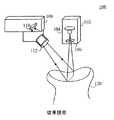
図2aは歯科用途のレーザデジタイザシステムの平面図である。 FIG. 2a is a plan view of a laser digitizer system for dental use.
図2bは歯科用途のレーザデジタイザシステムの正面図である。 FIG. 2b is a front view of a laser digitizer system for dental use.
図3は図2a及び2bに示すレーザデジタイザの光のパターンのイメージを平面上で見たものとして示す。 FIG. 3 shows the image of the light pattern of the laser digitizer shown in FIGS. 2a and 2b as viewed on a plane.
図4は図3に示す光のパターンを画像化される物体上に投射したものとして示す。 FIG. 4 shows the light pattern shown in FIG. 3 as projected onto the object to be imaged.
図5は図3に示す光のパターンの反射が画像取り込み装置で検出されたものとして示す。 FIG. 5 shows the reflection of the light pattern shown in FIG. 3 as detected by the image capture device.
図6は、図2a及び2bのレーザデジタイザシステムの物体位置決め装置の実施形態を示す。 FIG. 6 shows an embodiment of the object positioning device of the laser digitizer system of FIGS. 2a and 2b.
図1は従来技術のレーザライン撮像装置100の一例を示す。従来技術のレーザライン撮像装置100は送信機102と受信機108を有している。送信機102はレーザ光源104および伝送光学系106を含んでいる。送信機102は平面的なレーザ光を、送信機102の視野の範囲内にある物体120の上に投射する。物体表面に入射した平面的なレーザ光は物体120の上に直線を形成する。この投射されるレーザの線は円柱レンズ又は回折光学素子106で形成される。
FIG. 1 shows an example of a conventional laser
物体120で反射された光はカメラ108で検出される。カメラ108は送信機102に対して既知の角度を成す光学軸を有している。光は、反射光を光検出器110の基盤に集束する光学用レンズ112で捕捉される。高さに違いのある物体120の輪郭が光検出器110の基盤上に投射された画像に基づいて画像化される。
The light reflected by the
図2a及び2bはレーザデジタイザシステム200の一例を示す。レーザデジタイザシステム200は歯科用の品目の3D画像を生成するように構成されている。レーザデジタイザシステム200はレーザ光源202、光学的スキャナ222、F−θ(F−Theta)レンズとして知られているかもしれないフラットフィールドレンズ228、画像取り込み装置230、および処理装置236を含む。レーザデジタイザシステム200はまた、画像化される物体を固定し位置決めするための位置決め装置(図示せず)を含むこともできる。レーザデジタイザシステム200はまた、光学的にレーザ源とスキャナ222との間に置かれる可変ビームエキスパンダ242を含んでもよい。
2a and 2b show an example of a
レーザ光源202は、スキャナ222とF−θレンズ228とによって投射されて画像化される物体を横切って走査されるレーザビームを生成する。走査された光は物体220で反射されて画像取り込み手段230によって検出されるが、この画像取り込み装置は検出された光の表象信号を生成する。
The
レーザ光源202はレーザ光の平行な光線から成っている平行光束238を形成する平行光学系(図示せず)を有してもよい。この平行光束238は2軸光学スキャナ222に向けて投射される。
The
レーザ光源202はレーザダイオードすなわちレーザ光線(楕円形の光束であるかもしれない)を生成するように設定されたLEDを含んでもよい。平行光学系は楕円ビームを円形にして円形のスポットを生成するように設定することができる。円形スポットは物体220の表面を横断する均一な線を走査するのに使用することができる。レーザダイオードは商業的に入手可能な、例えばBlue Sky Researchの波長635nmでビームサイズが4mmの10mWレーザダイオード(部品番号MINI−0635−101C40W)のような、レーザ光線を放射するように設定されたいかなるレーザダイオードでもよい。
The
レーザ光源202は又、レーザ光を変調するように設定されていてもよい。レーザ光源202は又、光源からの光の流れを、例えば20MHzという高い変調もしくはスイッチング速度で調節するか遮断する変調器と連結されてもよい。レーザ光源202をスイッチングすると、レーザ光源202から放射されるレーザ光のコヒーレンスが低減され、その結果スペックルが軽減される。
The
スキャナ222は、時間とともに位置が変化する走査光束240を形成するために、平行光束238の方向を変える、すなわち走査する。走査された光束240はスキャナ222によってF−θレンズ228の方へ向けられる。スキャナ222は、平行光束を各軸が実質的に平行光束238に対して垂直な2本の軸と交差するように方向転換する。走査される光束240は、少なくとも2以上の軸で走査される。
The
スキャナ222は第1反射鏡224と第2反射鏡226を含む。第1および第2反射鏡224,226は画像を形成するために、光学的反射鏡か非拡散光を反射することのできる表面から成ることができる。それぞれの反射体224、226は個別のモータ244、246と回動可能に連結されることができる。それぞれのモータ244、246は、平行光束238の走査を達成するために、それぞれの反射体244、226の回動動作を制御するガルボドライブモータまたは同種のものから成っていてもよい。
The
第1および第2反射体224、226は基本的に垂直な軸を有し、相互に直交していることができる。反射体224、226は又、相互に任意の角度で置かれていてもよい。付加的な反射体が含まれてもよい。反射体224、226は、反射体に入射した平行なレーザ光束238が少なくとも2軸方向に走査される、すなわち向きを変えられるように直交して配置されることができる。第1の反射体224が1本の軸、例えばx軸、に沿って走査する。第2の反射体226は、x軸に沿って第2の反射体226に入射する光束がx軸と直交する方向、例えばy軸に沿って走査されるように位置決めされることができる。例えば、第1および第2反射体224、226は、第1反射体が光束をx軸に沿って走査し、第2反射体226がx軸に直交する方向、例えばy軸の方向に光束を走査するように、相互に直交するように位置決めされることができる。
The first and
第1の反射体224は又、回動する第2反射体226と回転する多角形反射体224とが連携して、前記と同様にレーザ光束を2軸方向に走査するように設定されるように、回転多面鏡から成っていてもよい。該回転多面鏡224は平行光線238をx軸に沿って走査し、該回動反射体226は平行光線をy軸に沿って走査することができる。それぞれの軸、すなわち、x軸とy軸とは実質的に相互に直交していてもよく、結果として走査光線240が平行ビーム238から生成され、該走査光線240は実質的に直交する2本の軸に沿って走査されることになる。
The first reflector 224 is also set so that the rotating
該スキャナ222は又、プログラム可能な位置制御装置を含むことができる。該位置制御装置はスキャナ222の構成要素であってもよいし処理装置236と組み合わされてもよい。位置制御装置をスキャナ232と組み合わせることによって、処理装置236のコンピューティング資源は、例えば画像データの処理などの他の機能、あるいはより高度な処理に利用できる。位置制御装置は、例えば、2個の反射体の走査を制御するGSI Lumonics社のSC2000 Scanner Motion Controllerのような、市販の制御装置から構成してもよい。該制御装置は反射体224,226の動作をモータ244,246を制御することによって制御するように設定されていてもよい。制御装置は、平行レーザビーム238が所望の走査手順に従うよう方向を変えられるように、反射体224、226の動作を制御する。スキャナ222の座標系はX´Y´Z´として参照される。
The
走査ビーム240はF−θレンズ228に入射する。F−θレンズ228は走査ビーム240を点(point)または点(dot)となるように焦点を合わせる。画像化される物体220はF−θレンズと画像取り込み装置230の視野の中に置かれる。F−θレンズ228は画像取り込み装置230の光軸に対して角度θをなす光軸を有しているので、焦点の合った光点が物体220の表面を横断して走査されたとき、画像取り込み装置に向かって角度θで反射する。スキャナ222はF−θレンズ228からのレーザの点の焦点が物体220の表面を横断するパターンで横断するように走査ビーム240を動かす。F−θレンズ228は、例えばLinos社の部品番号4401−206−000−20の、焦点距離が160ミリメートル、対角線走査長さが140ミリメートル、走査角度が+/−25度で動作波長が633ナノメートルであるもののような、市販のどのレンズであってもよい。
The
画像取り込み手段230は、物体220に投影された集光レーザ光点を含む視野を有するように設定や位置決めをされてもよい。画像取り込み手段230は、レーザ光点が物体220の表面を横断して走査されているときにレーザ光点を検知する。画像取り込み手段230は物体220からの反射光に感度を有することができる。物体220から検知された光に基づいて、画像取り込み手段は物体220の表面特性(例えば、輪郭、形状、配置、構成、その他)を描写する電気信号を生成する。
The image capturing means 230 may be set or positioned so as to have a field of view including a focused laser beam spot projected onto the
画像取込装置230は結像レンズ232と画像センサ234を含むことができる。結像レンズ232は物体220から反射した光を画像センサ234に向けて集束する。結像レンズ232は透視誤差を最小化するように設定されたテレセントリックレンズであってもよい。結像レンズ232は、拡大及び透視補正の影響を減少又は排除するため、レンズの開口に入射する光線のうちのほとんど平行な光線だけを結像するように設定された内部絞りを有することができる。結像レンズ232は、物体の画像の横方向の測定がレンズから物体までの距離に依存しないように、透視歪みを最小化するように設定された、例えばChina Daheng社の部品番号GCO−2305(直径50mm)の前レンズと、部品番号GC02305(直径8mm)の後レンズの組み合わせなど、どのような市販のレンズでもよく、ここで後レンズは画像取り込み機器のセンサのサイズに対応する。
The
画像センサ234は走査された物体の表面の画像を取り込む。画像センサ234は感光性または光検知素子もしくは検知された光の強度を表現する信号を生成することのできる電子回路であるかもしれない。該画像センサ234は光検出器のアレイを含んでもよい。光検出器のアレイは電荷結合素子(“CCD”)またはCMOS撮像素子、あるいは他の、検出された光の強度を表現する電子的な信号を生成することができる光検知センサのアレイであってもよい。画像センサ234は、結像光学系を、露出、ゲイン及びシャッタ制御とともに有する、例えばニューヨーク(New York)州TroyのSilicon Imaging社が提供しているModel SI―3170―CLなど、市販のCCDまたはCMOS形の高解像度ビデオカメラから成ることができる。画像センサ234は又、フレーム取り込み素子への広帯域リンク、例えばEpix,Inc.社が提供するPIXCI CL1型取込制御コンピュータ基板など、を含んでもよい。
アレイのそれぞれの光検知器は、入射した、すなわち光検知器で検知された光の強度に基づく電気信号を生成する。具体的には、光検知器に光が入射したとき、その光の強度に対応する電気信号を光検知器が生成する。光検知器のアレイには、それぞれの光検知器が、画素すなわち取り込まれた画像のピクセルを意味するように配列された複合的な光検知器を含めることができる。各ピクセルはそのアレイの中で個別的な位置を有することができる。画像取込装置230は、走査されたパターンの各ピクセルが一意的な座標(x、y)に対応するように、局所座標系XYを有することができる。アレイをピクセルの列と行、又は他の既知の配列に従って配置することができる。アレイにおけるピクセルの位置に基づいて、画像平面での位置を確定することができる。それにより画像取込装置230は画像平面にある各ピクセルによって検知された強度を、画像平面の中での画像の強度と分布を表す電気信号に変換する。
Each photodetector in the array generates an electrical signal that is based on the intensity of the incident light, i.e., detected by the photodetector. Specifically, when light is incident on the light detector, the light detector generates an electrical signal corresponding to the intensity of the light. The array of photodetectors can include multiple photodetectors in which each photodetector is arranged to represent a pixel, ie, a pixel of the captured image. Each pixel can have an individual position in the array. The
CMOS画像センサは光検知ピクセルがアレイを成すように構成することができる。それぞれのピクセルは、光の強度が高すぎるときにピクセルで受信された信号が隣接するピクセルに滲まないように、どのようなブルーミングの影響も最小にする。 The CMOS image sensor can be configured such that the light sensing pixels form an array. Each pixel minimizes any blooming effects so that when the light intensity is too high, the signal received at the pixel does not bleed into adjacent pixels.
スキャナ222はレーザビーム240をF−θレンズによって多数の所望のパターンで物体220の表面を横断して走査するように構成することができる。そのパターンは、1回の露出時間の間に物体220の表面の十分な部分を覆うように選択することができる。パターンは又、1以上の曲線もしくは、それから物体220の表面の性質、仰角及び形状が得られるようなあらゆる既知のパターンから構成することができる。
The
露出時間の間に、物体表面の一部分の画像が取り込まれる。ビーム240は、画像センサ230が物体220から反射した光を検出できるようにしながら、物体220をスキャナ222とF−θレンズ228を通して走査する。画像センサ230は、走査された部分または取り込まれた画像の表面の性質、輪郭、仰角及び形状を表現するデータを生成する。データ表現は、例えばメモリなど内部又は外部の機器に格納することができる。
During the exposure time, an image of a portion of the object surface is captured. The
それに続く走査の期間、ビーム240は物体220の近接した部分を横断するパターンで走査され、その近接部分の画像が取り込まれる。走査されるビーム240は、それに続く走査の期間に物体220の表面の別な部分を走査してもよい。ビーム240が物体220の様々な部分を横断して走査され、それらの走査された部分の画像が取り込まれた何回かの露出時間の後では、物体の相当大量の部分が取り込まれる可能性がある。
During subsequent scans, the
処理装置236は画像取込手段230と連結され、画像取込手段236によって生成された信号、それは物体220上の走査パターンの画像を表しているのであるが、を受信するように設定されている。
The
処理装置236は又、レーザ光源と連結され、レーザ光の選択式又はプログラムされた利用を制御することもできる。処理装置236は又、スキャナ222と連結されて平行光238の走査を制御するようにプログラムされることができる。
The
図3は光の走査パターン348の例を、実質的に平坦な表面から見たものとして示す。走査パターン348は、スキャナ222によって生成された複数の曲線350−355を含むことができる。曲線の一部350−351は原則的には相互に平行である。曲線350−355も又、連結した一連の点あるいは曲線を成す線分を示すかあるいは含むことができて、ここで各単一の点または線分における接線ベクトルnは以下の規則に従う:
|n・R|≠0 (1)
ここでRは三角測量軸であって実質的にY及びY´と平行であり、画像取込手段230からの軸方向光線と光学的スキャナ222からの軸方向光線との交点を通る。従って、曲線の任意の点または線分の接線nと三角測量軸Rとの間の角度は90度ではない。又、それぞれの曲線350−355は正弦波変化、ガウス分布あるいは何かその他の断面強度を表す既知の関数形を有する関数で特徴づけられる断面(光)強度を有してもよい。実施形態では、スキャナ222での有効な光線と画像センサ234の有効光線との間の最小角度はゼロではない。
FIG. 3 shows an example of a
| N · R | ≠ 0 (1)
Here, R is a triangulation axis that is substantially parallel to Y and Y ′ and passes through the intersection of the axial ray from the image capture means 230 and the axial ray from the
画像取込手段230は局所座標系XYZで特性化されることができて、ここでX及びY座標は画像取込手段230によって定義される。Z座標の値は、距離d1及びd2を基準としてd1≦z≦d2となるようにしてもよい。Z軸に垂直な平面に入射する投射曲線からのある点の距離はΔxだけX方向に移動されたように見えるであろう。三角測量法の角度に基づいて、以下の条件が存在してもよい:
Δz=Δx/Tanθ (2)
The image capture means 230 can be characterized in the local coordinate system XYZ, where X and Y coordinates are defined by the image capture means 230. The value of the Z coordinate may satisfy d 1 ≦ z ≦ d 2 with reference to the distances d 1 and d 2 . The distance of a point from the projection curve incident on a plane perpendicular to the Z axis will appear to have been moved in the X direction by Δx. Based on the triangulation angle, the following conditions may exist:
Δz = Δx / Tanθ (2)
投射パターンの中の所与の曲線(例えば曲線350)について、一意的な関係すなわちが存在する。これらのθ(y)、zbase(y)及びxbase(y)という関係はキャリブレーションによって確定することができる。キャリブレーションは、例えば平面上に投射されているときに曲線350を観測することによって実行することができる。平面は、Z軸に沿って2箇所以上の画像取込手段230からの距離dにおいて、画像取込手段230に対して垂直でもよい。曲線350に沿う各yの値に対して、zがz1及びz2という既知のzの値をもつ少なくとも2本の曲線を使って(ここでz1<z2である)、ΔzはΔz=z2−z1のように計算することができる。。Δzの値は画像取込手段230を使って観測することができる。式(2)を使って、θ(y)を計算することができる。対応する値zbase(y)はz1に等しいとしてもよい。対応する値xbase(y)は、z1に対応する曲線上のy点におけるxの値と等しいとすることができる。平均化もしくは内挿法によって精度を上げるために追加の曲線を使ってもよい。
For a given curve (eg, curve 350) in the projection pattern, a unique relationship exists. These relationships θ (y), z base (y), and x base (y) can be determined by calibration. Calibration can be performed, for example, by observing the
図4は画像化される物体420に入射した光の走査パターン448を示す。図5は物体420から反射してきた光のパターンを、画像センサ534に入射したようにして示す。観察された物体上の投射曲線550−555に関しては、各曲線は図3に示す曲線350−355の1本に対応して図4に示される曲線450−455の1本に対応している。従って、各曲線550−555については、対応する関係θ(y)、zbase(y)及びxbase(y)はキャリブレーションの間に予測された中から選択される。各曲線550−555の上の各点(xobserved,yobserved)に関しては、
Δx=xobserved−xbase(yobserved) (3)
式(2)はθ(yobserved)を使ってΔzを確定するのに使うことができて、結局次式となる
zobserved=Δz+zbase(yobserved) (4)
得られた点の集積(xobserved,yobserved,zobserved)は物体420の3D画像を形成する。
FIG. 4 shows a
Δx = x observed -x base (y observed) (3)
Equation (2) can be used to determine Δz using θ (y observed ) and eventually becomes
z observed = Δz + z base (y observed ) (4)
The resulting collection of points (x Observed , y Observed , z Observed ) forms a 3D image of the
曲線の最大変位は次式で確定することができる:
Δx=(d1−d2)Tanθ (5)
同時に区別することができる曲線350の最大数nmaxはnmax=Xmax/Δx又は同等の次式に従って確定することができる
nmax=Xmax/(d1−d2)Tanθ (6)
nmaxの値は視野の深さd1−d2の減少と共に増加し、また、θmaxが小さくなるほど増加する。又、測定精度はθmaxの値が小さくなるほど低下する。
The maximum displacement of the curve can be determined by:
Δx = (d 1 −d 2 ) Tan θ (5)
The maximum number n max of
n max = X max / (d 1 -d 2 ) Tanθ (6)
The value of n max increases as the visual field depth d 1 -d 2 decreases, and increases as θ max decreases. Also, the measurement accuracy decreases as the value of θ max decreases.
図6は物体保定装置660の一例を示す。保定装置660は画像化される物体620を走査レーザビーム240及び画像取込手段230の視野の中に固定し位置決めするように構成されている。保定装置660は、物体620が回転できるように、2以上の回転軸を含んでもよい。物体620は、画像取込手段230の座標系XYZに対して回転されてもよい。保定装置660は又、物体620を走査システム及び画像取込ユニット230システムの焦点に直線的に調節するために直線軸を含むこともできる。
FIG. 6 shows an example of the
保定装置660は又、プラットホーム664とバネ付き留め金662を含むことができる。バネ付き留め金662は歯科成形品あるいは歯科鋳造品をしっかりと保持するように構成されることができる。留め金662は又、位置決めプラットホームに磁力で固く固定することができるように磁石(図示せず)を有することができる。こうすることにより、この物体620は、それを留め金662に固定し、留め金をプラットホーム664に置くことによって敏速にレーザイメージングシステムと位置を合わせることができる。物体620は、重要な部位を数値化するのに適した所望の位置へ、プラットホーム664に対して移動あるいは調整することができる。
The retaining
本発明の実施形態について詳細に記載したが、当然のことながら、添付した請求項に記載された発明の精神と範囲から逸脱することなく、ここに種々の変更、置換及び改変をすることができる。 Although embodiments of the present invention have been described in detail, it will be understood that various changes, substitutions and modifications may be made therein without departing from the spirit and scope of the invention as set forth in the appended claims. .
上述したレーザ画像システムは、光源と円偏光光学系を有する三次元画像システムを含んでもよい。光源から出射した光源もしくはレーザ光は、レーザ光源の可干渉性を低減して画像化装置が受けるスペックルの量を低減するために、高い周波数で変調されてもよい。システムは可変ビームエキスパンダ、多軸スキャナシステム及びフラットフィールド走査レンズを含んでもよい。画像取込手段は、調節可能な保定装置で物体が位置決めされる領域に焦点を合わせられていてもよい。画像取込システムはテレセントリック結像レンズとCMOS画像センサを含んでもよい。調節可能な保定装置は、例えば歯科用成形品、印象、もしくは鋳造品など、歯科品目を固定することができる。歯科品目は、例えばプラットホームに万力を固定するための磁石を備え、バネで張力をかけた万力などを用いて固定することができる。その万力はプラットホームの上や周りを任意に移動され、歯科用品目を所望の位置に保持することができる。 The laser imaging system described above may include a three-dimensional imaging system having a light source and a circular polarization optical system. The light source or laser light emitted from the light source may be modulated at a high frequency in order to reduce the coherence of the laser light source and reduce the amount of speckle that the imaging device receives. The system may include a variable beam expander, a multi-axis scanner system, and a flat field scanning lens. The image capture means may be focused on the area where the object is positioned with an adjustable retention device. The image capture system may include a telecentric imaging lens and a CMOS image sensor. Adjustable retention devices can fix dental items, such as dental moldings, impressions, or castings, for example. For example, the dental item includes a magnet for fixing the vise to the platform, and can be fixed using a vise tensioned by a spring. The vise can be moved arbitrarily over and around the platform to hold the dental eye in the desired position.
本発明の実施形態について詳細に記載したが、当該技術分野における通常の技術を有する者にとって本発明の範囲内で更に多くの具体化と実施ができることは明らかである。 従って、発明は、添付した請求項及びそれと同等なものの考慮以外からは、限定されるものではない。
Although the embodiments of the present invention have been described in detail, it is obvious that those having ordinary skill in the art can implement more embodiments and implementations within the scope of the present invention. Accordingly, the invention is not to be restricted except in light of the attached claims and their equivalents.
Claims (20)
該光源と光学的に組み合わされ、画像を生成されるべき物体に向けて少なくとも2軸方向に該平行光線を走査するスキャナと、
該スキャナに対して角度θを成す光学軸を有し、走査された光線の該物体からの反射光を検出して、該反射光線に基づいて該物体の表面を表現するデータを生成する画像取り込み装置と、
該スキャナ及び該画像取り込み装置と組み合わされ、該データに基づいて該物体の三次元画像を生成するように構成された処理装置
とを備えていることを特徴とするレーザデジタイザ。 A light source having parallel optics configured to generate parallel rays;
A scanner that is optically combined with the light source and scans the parallel rays in at least two axial directions towards the object to be imaged;
Image capture having an optical axis that forms an angle θ with respect to the scanner, detecting reflected light from the object of the scanned light and generating data representing the surface of the object based on the reflected light Equipment,
A laser digitizer, comprising: a processing device combined with the scanner and the image capture device and configured to generate a three-dimensional image of the object based on the data.
物体の三角網画像すなわち露出時間中に物体に光線を走査することによって生成された複数の曲線に基づく三角網画像を検出するように構成された画像センサと、
該画像センサ上に該複数の曲線を合焦させるように設定されたテレセントリックレンズ
とから構成されていることを特徴とする請求項3に記載のレーザデジタイザ。 The image capturing device is
An image sensor configured to detect a triangular mesh image of an object, i.e., a triangular mesh image based on a plurality of curves generated by scanning a light beam on the object during an exposure time;
The laser digitizer according to claim 3, further comprising: a telecentric lens set to focus the plurality of curves on the image sensor.
多軸の平行光束を生成するための走査手段と、
画像にされる物体上の一点に該平行光束を集束させるための焦点調節手段と、
物体上に照射され、集束された光束の反射を検出するための画像取り込み手段、および
該対象物の三次元画像を生成するために該走査手段及び該画像取り込み手段と連動する処理手段と
から構成されていることを特徴とする歯科用画像システム。 Means for generating a parallel laser beam;
Scanning means for generating multi-axis parallel light fluxes;
Focus adjusting means for focusing the parallel light beam on a point on the object to be imaged;
An image capturing means for detecting reflection of a focused light beam irradiated on the object, and a scanning means and a processing means interlocking with the image capturing means for generating a three-dimensional image of the object. A dental imaging system characterized by the above.
該物体の三角網画像(ここで該三角網画像は露出時間の間にレーザの光点を該物体の表面の全域で走査したパターンに基づいている)を検出するように設定された画像検出器と、
結像レンズと
を有していることを特徴とする請求項12に記載のレーザデジタイザ。 The image capturing means is
An image detector set to detect a triangular mesh image of the object (where the triangular mesh image is based on a pattern of scanning the laser light spot across the surface of the object during the exposure time) When,
The laser digitizer according to claim 12, further comprising: an imaging lens.
多軸の平行光束を生成し、
物体を第1の位置に位置決めし、
所定のパターンで多軸の平行光束を走査し、ここで該パターンは実質的に平行な複数の曲線を含み、
該走査された平行光束を該物体の上に集束させ、
走査時間の間に該物体の上に集束された平行光束の画像を取り込んで、
該取り込まれた画像に基づいて該物体の表面のマップを確定する
ことを特徴とする物体の三次元視覚画像を生成する方法。 A method for generating a three-dimensional visual image of an object, comprising:
Generate multi-axis parallel light flux,
Positioning the object in the first position;
Scanning a multi-axis parallel beam in a predetermined pattern, wherein the pattern includes a plurality of substantially parallel curves;
Focusing the scanned parallel beam onto the object;
Capturing an image of a parallel beam focused on the object during the scan time;
A method of generating a three-dimensional visual image of an object, comprising determining a map of the surface of the object based on the captured image.
該第2の位置に位置決めされた物体上の集束ビームの画像を取り込んで、
該第1の位置に位置決めされた物体上の集束ビームの画像と該第2の位置の物体上の集束ビームの画像とを融合する
動作より成っていることを特徴とする請求項17に記載の物体の三次元視覚画像を生成する方法。 Furthermore, reposition the object in the second direction,
Capturing an image of a focused beam on an object positioned in the second position;
18. The operation of claim 17, comprising: fusing the image of the focused beam on the object positioned at the first position and the image of the focused beam on the object at the second position. A method for generating a three-dimensional visual image of an object.
Applications Claiming Priority (2)
| Application Number | Priority Date | Filing Date | Title |
|---|---|---|---|
| US43737302P | 2002-12-31 | 2002-12-31 | |
| PCT/US2003/041701 WO2004061389A1 (en) | 2002-12-31 | 2003-12-30 | Laser digitizer system for dental applications |
Publications (2)
| Publication Number | Publication Date |
|---|---|
| JP2006514739A true JP2006514739A (en) | 2006-05-11 |
| JP2006514739A5 JP2006514739A5 (en) | 2010-04-08 |
Family
ID=32713175
Family Applications (1)
| Application Number | Title | Priority Date | Filing Date |
|---|---|---|---|
| JP2004564915A Pending JP2006514739A (en) | 2002-12-31 | 2003-12-30 | Dental laser digitizer system |
Country Status (10)
| Country | Link |
|---|---|
| US (1) | US7142312B2 (en) |
| EP (1) | EP1579171B1 (en) |
| JP (1) | JP2006514739A (en) |
| AT (1) | ATE426793T1 (en) |
| AU (2) | AU2003300135B2 (en) |
| CA (1) | CA2511828C (en) |
| DE (1) | DE60326881D1 (en) |
| DK (1) | DK1579171T3 (en) |
| ES (1) | ES2324658T3 (en) |
| WO (1) | WO2004061389A1 (en) |
Cited By (3)
| Publication number | Priority date | Publication date | Assignee | Title |
|---|---|---|---|---|
| JP2011504586A (en) * | 2007-11-15 | 2011-02-10 | シロナ・デンタル・システムズ・ゲゼルシャフト・ミット・ベシュレンクテル・ハフツング | Method for optically measuring the three-dimensional shape of an object |
| JP2012523945A (en) * | 2009-04-20 | 2012-10-11 | ディー4ディー テクノロジーズ、エルエルシー | Wavelength swept source optical coherence tomography (OCT) method and system |
| JP2014006149A (en) * | 2012-06-25 | 2014-01-16 | Nikon Corp | Shape-measuring device, system for manufacturing structure, shape-measuring method, method for manufacturing structure and shape-measuring program |
Families Citing this family (98)
| Publication number | Priority date | Publication date | Assignee | Title |
|---|---|---|---|---|
| US11026768B2 (en) | 1998-10-08 | 2021-06-08 | Align Technology, Inc. | Dental appliance reinforcement |
| AU2003252253A1 (en) | 2002-07-26 | 2004-02-16 | Olympus Optical Co., Ltd. | Image processing system |
| CN1672021A (en) | 2002-07-26 | 2005-09-21 | 奥林巴斯株式会社 | Image processing system |
| US7342668B2 (en) | 2003-09-17 | 2008-03-11 | D4D Technologies, Llc | High speed multiple line three-dimensional digitalization |
| EP1707928A4 (en) | 2004-01-23 | 2011-03-09 | Olympus Corp | Image processing system and camera |
| US7577296B2 (en) * | 2004-01-30 | 2009-08-18 | The Boeing Company | System and method for evaluating laser projection equipment |
| US9492245B2 (en) | 2004-02-27 | 2016-11-15 | Align Technology, Inc. | Method and system for providing dynamic orthodontic assessment and treatment profiles |
| US7698068B2 (en) | 2004-06-17 | 2010-04-13 | Cadent Ltd. | Method for providing data associated with the intraoral cavity |
| US7315383B1 (en) * | 2004-07-09 | 2008-01-01 | Mohsen Abdollahi | Scanning 3D measurement technique using structured lighting and high-speed CMOS imager |
| US20060035195A1 (en) * | 2004-08-12 | 2006-02-16 | Electro Optical Sciences, Inc. | Method of transillumination of teeth |
| DE102004054876B3 (en) * | 2004-11-12 | 2006-07-27 | Sirona Dental Systems Gmbh | Measuring device for 3D measurement of tooth models, sliding plate and method |
| RU2008127230A (en) * | 2005-12-08 | 2010-01-20 | Питер С. ЛАВЛИ (US) | FORMING AN INFRARED DENTAL IMAGE |
| US20070218426A1 (en) * | 2006-03-06 | 2007-09-20 | D4D Technologies, Llc | Digital impression for remote manufacturing of dental impressions |
| US7978892B2 (en) * | 2006-10-25 | 2011-07-12 | D4D Technologies, Llc | 3D photogrammetry using projected patterns |
| DK3085330T3 (en) | 2006-10-27 | 2018-09-03 | Nobel Biocare Services Ag | METHOD AND APPARATUS FOR OBTAINING DATA FOR A DENTAL COMPONENT AND A PHYSICAL DENTAL MODEL |
| WO2008051129A1 (en) | 2006-10-27 | 2008-05-02 | Nobel Biocare Services Ag | A dental impression tray for use in obtaining an impression of a dental structure |
| DE102007005625A1 (en) | 2007-01-31 | 2008-08-07 | Gaus, Harry, Dr. | Dental camera for three dimensional-measurement of e.g. rear molar teeth, has control unit controlling predetermined target velocity of scanning unit as function of position and time of scanning unit |
| US7878805B2 (en) | 2007-05-25 | 2011-02-01 | Align Technology, Inc. | Tabbed dental appliance |
| DE102007030768A1 (en) * | 2007-07-02 | 2009-01-08 | Sirona Dental Systems Gmbh | Measuring device and method for 3D measurement of tooth models |
| WO2009062020A2 (en) | 2007-11-08 | 2009-05-14 | D4D Technologies, Llc | Lighting compensated dynamic texture mapping of 3-d models |
| US8738394B2 (en) | 2007-11-08 | 2014-05-27 | Eric E. Kuo | Clinical data file |
| US8108189B2 (en) | 2008-03-25 | 2012-01-31 | Align Technologies, Inc. | Reconstruction of non-visible part of tooth |
| DE102008022415A1 (en) * | 2008-05-06 | 2009-11-12 | TÜV Rheinland Industrie Service GmbH | Absinkverhinderungsvorrichtung |
| US8092215B2 (en) | 2008-05-23 | 2012-01-10 | Align Technology, Inc. | Smile designer |
| US9492243B2 (en) | 2008-05-23 | 2016-11-15 | Align Technology, Inc. | Dental implant positioning |
| US8172569B2 (en) | 2008-06-12 | 2012-05-08 | Align Technology, Inc. | Dental appliance |
| DE102008039838B4 (en) * | 2008-08-27 | 2011-09-22 | Deutsches Zentrum für Luft- und Raumfahrt e.V. | Method for scanning the three-dimensional surface of an object by means of a light beam scanner |
| US8152518B2 (en) | 2008-10-08 | 2012-04-10 | Align Technology, Inc. | Dental positioning appliance having metallic portion |
| JP5433381B2 (en) * | 2009-01-28 | 2014-03-05 | 合同会社IP Bridge1号 | Intraoral measurement device and intraoral measurement method |
| US8292617B2 (en) | 2009-03-19 | 2012-10-23 | Align Technology, Inc. | Dental wire attachment |
| US8765031B2 (en) | 2009-08-13 | 2014-07-01 | Align Technology, Inc. | Method of forming a dental appliance |
| US9211166B2 (en) | 2010-04-30 | 2015-12-15 | Align Technology, Inc. | Individualized orthodontic treatment index |
| US9241774B2 (en) | 2010-04-30 | 2016-01-26 | Align Technology, Inc. | Patterned dental positioning appliance |
| US20120056993A1 (en) * | 2010-09-08 | 2012-03-08 | Salman Luqman | Dental Field Visualization System with Improved Ergonomics |
| US9095414B2 (en) * | 2011-06-24 | 2015-08-04 | The Regents Of The University Of California | Nonlinear optical photodynamic therapy (NLO-PDT) of the cornea |
| CN102343526B (en) * | 2011-06-28 | 2013-09-04 | 天津汽车模具股份有限公司 | Method for quickly determining machining center of automobile die cast |
| US9403238B2 (en) | 2011-09-21 | 2016-08-02 | Align Technology, Inc. | Laser cutting |
| US9375300B2 (en) | 2012-02-02 | 2016-06-28 | Align Technology, Inc. | Identifying forces on a tooth |
| US9366861B1 (en) * | 2012-02-29 | 2016-06-14 | Randy E. Johnson | Laser particle projection system |
| US9220580B2 (en) | 2012-03-01 | 2015-12-29 | Align Technology, Inc. | Determining a dental treatment difficulty |
| US9414897B2 (en) | 2012-05-22 | 2016-08-16 | Align Technology, Inc. | Adjustment of tooth position in a virtual dental model |
| WO2014058874A1 (en) * | 2012-10-08 | 2014-04-17 | D4D Technologies, Llc | Milling machine having six (6) axis motion system |
| US9581556B1 (en) * | 2012-11-15 | 2017-02-28 | Industrial Optical Measurement Systems, LLC | Laser probe for use in an inspection system |
| US9134232B1 (en) * | 2012-11-15 | 2015-09-15 | Industrial Optical Measurement Systems, LLC | Laser inspection system |
| CN104853692A (en) | 2012-11-28 | 2015-08-19 | 阿波罗口腔扫描仪有限责任公司 | Dental scanning device |
| DE102012113021A1 (en) * | 2012-12-21 | 2014-06-26 | GOM - Gesellschaft für Optische Meßtechnik mbH | Measuring instrument for three-dimensional visual measuring of dark objects, has projection unit arranged on pattern generator for topometric analysis of wide-band laser light radiation backscattered from object |
| US9091628B2 (en) | 2012-12-21 | 2015-07-28 | L-3 Communications Security And Detection Systems, Inc. | 3D mapping with two orthogonal imaging views |
| DE102013214997A1 (en) * | 2013-07-31 | 2015-02-05 | Siemens Aktiengesellschaft | Arrangement for three-dimensional detection of an elongated interior |
| US9360935B2 (en) | 2013-12-20 | 2016-06-07 | Hong Kong Applied Science And Technology Research Institute Co. Ltd. | Integrated bi-sensing optical structure for head mounted display |
| US10772506B2 (en) | 2014-07-07 | 2020-09-15 | Align Technology, Inc. | Apparatus for dental confocal imaging |
| US9675430B2 (en) | 2014-08-15 | 2017-06-13 | Align Technology, Inc. | Confocal imaging apparatus with curved focal surface |
| US9610141B2 (en) | 2014-09-19 | 2017-04-04 | Align Technology, Inc. | Arch expanding appliance |
| US10449016B2 (en) | 2014-09-19 | 2019-10-22 | Align Technology, Inc. | Arch adjustment appliance |
| US9744001B2 (en) | 2014-11-13 | 2017-08-29 | Align Technology, Inc. | Dental appliance with cavity for an unerupted or erupting tooth |
| US10504386B2 (en) | 2015-01-27 | 2019-12-10 | Align Technology, Inc. | Training method and system for oral-cavity-imaging-and-modeling equipment |
| US10248883B2 (en) | 2015-08-20 | 2019-04-02 | Align Technology, Inc. | Photograph-based assessment of dental treatments and procedures |
| US11931222B2 (en) | 2015-11-12 | 2024-03-19 | Align Technology, Inc. | Dental attachment formation structures |
| US11554000B2 (en) | 2015-11-12 | 2023-01-17 | Align Technology, Inc. | Dental attachment formation structure |
| US11596502B2 (en) | 2015-12-09 | 2023-03-07 | Align Technology, Inc. | Dental attachment placement structure |
| US11103330B2 (en) | 2015-12-09 | 2021-08-31 | Align Technology, Inc. | Dental attachment placement structure |
| US11172824B2 (en) * | 2016-04-06 | 2021-11-16 | Carestream Dental Technology Topco Limited | Hybrid OCT and surface contour dental imaging |
| WO2017218951A1 (en) | 2016-06-17 | 2017-12-21 | Align Technology, Inc. | Orthodontic appliance performance monitor |
| WO2017218947A1 (en) | 2016-06-17 | 2017-12-21 | Align Technology, Inc. | Intraoral appliances with sensing |
| EP3475651B1 (en) * | 2016-06-24 | 2022-08-10 | 3Shape A/S | 3d scanner using a structured beam of probe light |
| US10507087B2 (en) | 2016-07-27 | 2019-12-17 | Align Technology, Inc. | Methods and apparatuses for forming a three-dimensional volumetric model of a subject's teeth |
| CN113499159B (en) | 2016-07-27 | 2023-02-03 | 阿莱恩技术有限公司 | Intraoral scanner with dental diagnostic capability |
| DE102016012130A1 (en) * | 2016-10-11 | 2018-04-12 | Shin-Etsu Silicones Europe B.V. | Optical scanner for dental impression, digitizing and dental model system |
| CN113648088B (en) | 2016-11-04 | 2023-08-22 | 阿莱恩技术有限公司 | Method and apparatus for dental imaging |
| ES2845198T3 (en) | 2016-12-02 | 2021-07-26 | Align Technology Inc | Palatal expander |
| WO2018102770A1 (en) | 2016-12-02 | 2018-06-07 | Align Technology, Inc. | Force control, stop mechanism, regulating structure of removable arch adjustment appliance |
| WO2018102702A1 (en) | 2016-12-02 | 2018-06-07 | Align Technology, Inc. | Dental appliance features for speech enhancement |
| AU2017366755B2 (en) | 2016-12-02 | 2022-07-28 | Align Technology, Inc. | Methods and apparatuses for customizing rapid palatal expanders using digital models |
| US10548700B2 (en) | 2016-12-16 | 2020-02-04 | Align Technology, Inc. | Dental appliance etch template |
| US10456043B2 (en) | 2017-01-12 | 2019-10-29 | Align Technology, Inc. | Compact confocal dental scanning apparatus |
| US10779718B2 (en) | 2017-02-13 | 2020-09-22 | Align Technology, Inc. | Cheek retractor and mobile device holder |
| US10613515B2 (en) | 2017-03-31 | 2020-04-07 | Align Technology, Inc. | Orthodontic appliances including at least partially un-erupted teeth and method of forming them |
| US11045283B2 (en) | 2017-06-09 | 2021-06-29 | Align Technology, Inc. | Palatal expander with skeletal anchorage devices |
| WO2019005808A1 (en) | 2017-06-26 | 2019-01-03 | Align Technology, Inc. | Biosensor performance indicator for intraoral appliances |
| US11006835B2 (en) * | 2017-06-30 | 2021-05-18 | Carestream Dental Technology Topco Limited | Surface mapping using an intraoral scanner with penetrating capabilities |
| US10885521B2 (en) | 2017-07-17 | 2021-01-05 | Align Technology, Inc. | Method and apparatuses for interactive ordering of dental aligners |
| CN114903623A (en) | 2017-07-21 | 2022-08-16 | 阿莱恩技术有限公司 | Jaw profile anchoring |
| CN110996842B (en) | 2017-07-27 | 2022-10-14 | 阿莱恩技术有限公司 | Tooth staining, transparency and glazing |
| WO2019023631A1 (en) | 2017-07-27 | 2019-01-31 | Align Technology, Inc. | System and methods for processing an orthodontic aligner by means of an optical coherence tomography |
| WO2019035979A1 (en) | 2017-08-15 | 2019-02-21 | Align Technology, Inc. | Buccal corridor assessment and computation |
| US11123156B2 (en) | 2017-08-17 | 2021-09-21 | Align Technology, Inc. | Dental appliance compliance monitoring |
| US10813720B2 (en) | 2017-10-05 | 2020-10-27 | Align Technology, Inc. | Interproximal reduction templates |
| US11534268B2 (en) | 2017-10-27 | 2022-12-27 | Align Technology, Inc. | Alternative bite adjustment structures |
| US11576752B2 (en) | 2017-10-31 | 2023-02-14 | Align Technology, Inc. | Dental appliance having selective occlusal loading and controlled intercuspation |
| CN115252177A (en) | 2017-11-01 | 2022-11-01 | 阿莱恩技术有限公司 | Automated therapy planning |
| US11534974B2 (en) | 2017-11-17 | 2022-12-27 | Align Technology, Inc. | Customized fabrication of orthodontic retainers based on patient anatomy |
| EP3716885B1 (en) | 2017-11-30 | 2023-08-30 | Align Technology, Inc. | Orthodontic intraoral appliances comprising sensors |
| WO2019118876A1 (en) | 2017-12-15 | 2019-06-20 | Align Technology, Inc. | Closed loop adaptive orthodontic treatment methods and apparatuses |
| US10980613B2 (en) | 2017-12-29 | 2021-04-20 | Align Technology, Inc. | Augmented reality enhancements for dental practitioners |
| CN114587237A (en) | 2018-01-26 | 2022-06-07 | 阿莱恩技术有限公司 | Diagnostic intraoral scanning and tracking |
| US11937991B2 (en) | 2018-03-27 | 2024-03-26 | Align Technology, Inc. | Dental attachment placement structure |
| US11564777B2 (en) | 2018-04-11 | 2023-01-31 | Align Technology, Inc. | Releasable palatal expanders |
| US11896461B2 (en) | 2018-06-22 | 2024-02-13 | Align Technology, Inc. | Intraoral 3D scanner employing multiple miniature cameras and multiple miniature pattern projectors |
| CN116007527A (en) * | 2021-10-21 | 2023-04-25 | 华为技术有限公司 | Measurement method and measurement system |
Citations (4)
| Publication number | Priority date | Publication date | Assignee | Title |
|---|---|---|---|---|
| JPH10253319A (en) * | 1997-03-12 | 1998-09-25 | Hitachi Ltd | Position measuring device |
| JP2001012918A (en) * | 1999-07-01 | 2001-01-19 | Nkk Corp | Coil position-detecting device |
| JP2001116524A (en) * | 1999-10-14 | 2001-04-27 | Minolta Co Ltd | Method and device for three-dimensional input |
| JP2001183461A (en) * | 1999-12-27 | 2001-07-06 | Minolta Co Ltd | Distance-measuring device |
Family Cites Families (94)
| Publication number | Priority date | Publication date | Assignee | Title |
|---|---|---|---|---|
| DE3003435A1 (en) | 1980-01-31 | 1981-08-06 | Becker Dental-Labor Gmbh, 5100 Aachen | METHOD AND DEVICE FOR PRODUCING A CROWN PART |
| US4575805A (en) | 1980-12-24 | 1986-03-11 | Moermann Werner H | Method and apparatus for the fabrication of custom-shaped implants |
| DE3203937C2 (en) | 1982-02-05 | 1985-10-03 | Luc Dr. 4150 Krefeld Barrut | Method and device for machine restoration or correction of at least one tooth or for machine preparation of at least one tooth for a fixed prosthetic restoration and for machine production of the fixed prosthetic restoration |
| FR2525103B1 (en) | 1982-04-14 | 1985-09-27 | Duret Francois | IMPRESSION TAKING DEVICE BY OPTICAL MEANS, PARTICULARLY FOR THE AUTOMATIC PRODUCTION OF PROSTHESES |
| FR2536654B1 (en) | 1982-11-30 | 1987-01-09 | Duret Francois | METHOD FOR PRODUCING A DENTAL PROSTHESIS |
| US4663720A (en) | 1984-02-21 | 1987-05-05 | Francois Duret | Method of and apparatus for making a prosthesis, especially a dental prosthesis |
| CH665551A5 (en) | 1984-03-06 | 1988-05-31 | Werner Hans Dr Med De Moermann | BLANK FOR THE MANUFACTURE OF DENTAL TECHNOLOGY MOLDED PARTS. |
| EP0163076B1 (en) | 1984-04-17 | 1991-11-13 | Kawasaki Jukogyo Kabushiki Kaisha | Apparatus for producing a three-dimensional copy of an object |
| US4798534A (en) | 1984-08-03 | 1989-01-17 | Great Lakes Orthodontic Laboratories Inc. | Method of making a dental appliance |
| CH663891A5 (en) | 1984-10-24 | 1988-01-29 | Marco Dr Sc Techn Brandestini | DEVICE FOR THE SHAPING PROCESSING OF A BLANK MADE OF DENTAL CERAMIC OR DENTAL COMPOSITE MATERIAL AND METHOD FOR THE OPERATION THEREOF. |
| US4936862A (en) | 1986-05-30 | 1990-06-26 | Walker Peter S | Method of designing and manufacturing a human joint prosthesis |
| US4816920A (en) * | 1986-11-18 | 1989-03-28 | General Scanning, Inc. | Planar surface scanning system |
| FR2610821B1 (en) | 1987-02-13 | 1989-06-09 | Hennson Int | METHOD FOR TAKING MEDICAL IMPRESSION AND DEVICE FOR IMPLEMENTING SAME |
| US5186623A (en) | 1987-05-05 | 1993-02-16 | Great Lakes Orthodontics, Ltd. | Orthodontic finishing positioner and method of construction |
| US4856991A (en) | 1987-05-05 | 1989-08-15 | Great Lakes Orthodontics, Ltd. | Orthodontic finishing positioner and method of construction |
| DE3723555C2 (en) | 1987-07-16 | 1994-08-11 | Steinbichler Hans | Process for the production of dentures |
| US5372502A (en) | 1988-09-02 | 1994-12-13 | Kaltenbach & Voight Gmbh & Co. | Optical probe and method for the three-dimensional surveying of teeth |
| US5055039A (en) | 1988-10-06 | 1991-10-08 | Great Lakes Orthodontics, Ltd. | Orthodontic positioner and methods of making and using same |
| US4935635A (en) | 1988-12-09 | 1990-06-19 | Harra Dale G O | System for measuring objects in three dimensions |
| US5011405A (en) | 1989-01-24 | 1991-04-30 | Dolphin Imaging Systems | Method for determining orthodontic bracket placement |
| SE464908B (en) | 1989-03-23 | 1991-07-01 | Nobelpharma Ab | METHOD FOR MANUFACTURING ARTIFICIAL DENTAL CHRONICLES OF ONLINE TYPE OR INPUT |
| US4970032A (en) | 1989-05-12 | 1990-11-13 | Rotsaert Henri L | Processes for the manufacture of artificial teeth and crowns |
| US5151044A (en) | 1989-05-12 | 1992-09-29 | Rotsaert Henri L | Blanks for the manufacture of artificial teeth and crowns |
| US5027281A (en) | 1989-06-09 | 1991-06-25 | Regents Of The University Of Minnesota | Method and apparatus for scanning and recording of coordinates describing three dimensional objects of complex and unique geometry |
| EP0462289B1 (en) * | 1989-12-28 | 1994-11-02 | Kabushiki Kaisha Toyota Chuo Kenkyusho | Apparatus for measuring three-dimensional coordinates |
| US5431562A (en) | 1990-01-19 | 1995-07-11 | Ormco Corporation | Method and apparatus for designing and forming a custom orthodontic appliance and for the straightening of teeth therewith |
| US5533895A (en) | 1990-01-19 | 1996-07-09 | Ormco Corporation | Orthodontic appliance and group standardized brackets therefor and methods of making, assembling and using appliance to straighten teeth |
| US5368478A (en) | 1990-01-19 | 1994-11-29 | Ormco Corporation | Method for forming jigs for custom placement of orthodontic appliances on teeth |
| US5454717A (en) | 1990-01-19 | 1995-10-03 | Ormco Corporation | Custom orthodontic brackets and bracket forming method and apparatus |
| US5395238A (en) | 1990-01-19 | 1995-03-07 | Ormco Corporation | Method of forming orthodontic brace |
| US5447432A (en) | 1990-01-19 | 1995-09-05 | Ormco Corporation | Custom orthodontic archwire forming method and apparatus |
| US5139419A (en) | 1990-01-19 | 1992-08-18 | Ormco Corporation | Method of forming an orthodontic brace |
| US5474448A (en) | 1990-01-19 | 1995-12-12 | Ormco Corporation | Low profile orthodontic appliance |
| EP0519915B1 (en) | 1990-03-13 | 1995-01-11 | Comdent Gmbh | Process and device for measuring the dimensions of a space, in particular a buccal cavity |
| US5224049A (en) | 1990-04-10 | 1993-06-29 | Mushabac David R | Method, system and mold assembly for use in preparing a dental prosthesis |
| US5569578A (en) | 1990-04-10 | 1996-10-29 | Mushabac; David R. | Method and apparatus for effecting change in shape of pre-existing object |
| US5257184A (en) | 1990-04-10 | 1993-10-26 | Mushabac David R | Method and apparatus with multiple data input stylii for collecting curvilinear contour data |
| US5562448A (en) | 1990-04-10 | 1996-10-08 | Mushabac; David R. | Method for facilitating dental diagnosis and treatment |
| US5545039A (en) | 1990-04-10 | 1996-08-13 | Mushabac; David R. | Method and apparatus for preparing tooth or modifying dental restoration |
| US5347454A (en) | 1990-04-10 | 1994-09-13 | Mushabac David R | Method, system and mold assembly for use in preparing a dental restoration |
| US5691905A (en) | 1990-06-11 | 1997-11-25 | Dentsply Research & Development Corp. | Prosthetic teeth and mold making and polishing therefor |
| US5452219A (en) | 1990-06-11 | 1995-09-19 | Dentsply Research & Development Corp. | Method of making a tooth mold |
| US5340309A (en) | 1990-09-06 | 1994-08-23 | Robertson James G | Apparatus and method for recording jaw motion |
| ES2080206T3 (en) | 1990-10-10 | 1996-02-01 | Mikrona Technologie Ag | RAW PIECE FOR THE MANUFACTURE OF A MACHINED PIECE OF DENTAL TECHNIQUE AND CLAMPING DEVICE FOR THE SAME. |
| US5198877A (en) | 1990-10-15 | 1993-03-30 | Pixsys, Inc. | Method and apparatus for three-dimensional non-contact shape sensing |
| US5168386A (en) * | 1990-10-22 | 1992-12-01 | Tencor Instruments | Flat field telecentric scanner |
| SE468198B (en) | 1990-12-12 | 1992-11-23 | Nobelpharma Ab | PROCEDURE AND DEVICE FOR MANUFACTURE OF INDIVIDUALLY DESIGNED THREE-DIMENSIONAL BODIES USEFUL AS TENDERS, PROTESTES, ETC |
| SE469158B (en) | 1991-11-01 | 1993-05-24 | Nobelpharma Ab | DENTAL SENSOR DEVICE INTENDED TO BE USED IN CONNECTION WITH CONTROL OF A WORKING EQUIPMENT |
| CH686657A5 (en) | 1991-11-17 | 1996-05-31 | Liconic Ag | Process for producing a partial replacement of a tooth and means for implementing the method. |
| JPH05269146A (en) | 1992-03-23 | 1993-10-19 | Nikon Corp | Extracting method for margin line at the time of designing crown |
| US5273429A (en) | 1992-04-03 | 1993-12-28 | Foster-Miller, Inc. | Method and apparatus for modeling a dental prosthesis |
| NL9200642A (en) | 1992-04-06 | 1993-11-01 | Elephant Holding Bv | METHOD FOR MANUFACTURING A DENTAL PROSTHESIS |
| DE69322807T2 (en) | 1992-04-06 | 1999-07-08 | Elephant Dental Bv | Denture and manufacturing process |
| DE4214876C2 (en) | 1992-05-05 | 2000-07-06 | Kaltenbach & Voigt | Optical measurement of teeth without a matt surface treatment |
| FR2693096B1 (en) | 1992-07-06 | 1994-09-23 | Deshayes Marie Josephe | Process for modeling the cranial and facial morphology from an x-ray of the skull. |
| DE4229466C2 (en) * | 1992-09-03 | 2001-04-26 | Kaltenbach & Voigt | Tooth measurement without calibration body |
| DE69327661T2 (en) | 1992-11-09 | 2000-07-20 | Ormco Corp | METHOD AND DEVICE FOR MANUFACTURING INDIVIDUALLY ADAPTED ORTHODONTIC DEVICES |
| FR2698984B1 (en) * | 1992-12-04 | 1995-01-06 | Commissariat Energie Atomique | Method and device for acquiring a three-dimensional image of a small object by light probing and calibration means for implementing such an acquisition. |
| SE501411C2 (en) | 1993-07-12 | 1995-02-06 | Nobelpharma Ab | Method and apparatus for three-dimensional body useful in the human body |
| SE501410C2 (en) | 1993-07-12 | 1995-02-06 | Nobelpharma Ab | Method and apparatus in connection with the manufacture of tooth, bridge, etc. |
| NL9301308A (en) | 1993-07-26 | 1995-02-16 | Willem Frederick Van Nifterick | Method of securing a dental prosthesis to implants in a patient's jawbone and using means thereof. |
| US5382164A (en) | 1993-07-27 | 1995-01-17 | Stern; Sylvan S. | Method for making dental restorations and the dental restoration made thereby |
| US5338198A (en) | 1993-11-22 | 1994-08-16 | Dacim Laboratory Inc. | Dental modeling simulator |
| SE502035C2 (en) | 1993-12-06 | 1995-07-24 | Nobelpharma Ab | Method and apparatus for producing information for the production of artificial support organs or replacement parts for the human body |
| SE502427C2 (en) | 1994-02-18 | 1995-10-16 | Nobelpharma Ab | Method and device utilizing articulator and computer equipment |
| US5570182A (en) * | 1994-05-27 | 1996-10-29 | Regents Of The University Of California | Method for detection of dental caries and periodontal disease using optical imaging |
| SE503498C2 (en) | 1994-10-04 | 1996-06-24 | Nobelpharma Ab | Method and device for a product intended to be part of the human body and a scanning device for a model for the product |
| US5549476A (en) | 1995-03-27 | 1996-08-27 | Stern; Sylvan S. | Method for making dental restorations and the dental restoration made thereby |
| JP3727660B2 (en) | 1995-07-21 | 2005-12-14 | カデント・リミテッド | Method for obtaining a three-dimensional tooth image |
| JP2879003B2 (en) | 1995-11-16 | 1999-04-05 | 株式会社生体光情報研究所 | Image measurement device |
| EP0781530B1 (en) | 1995-12-19 | 2004-09-01 | Ivoclar Vivadent AG | Method for manufacturing tooth crowns and/or dental bridges |
| US5725376A (en) | 1996-02-27 | 1998-03-10 | Poirier; Michel | Methods for manufacturing a dental implant drill guide and a dental implant superstructure |
| US6044170A (en) | 1996-03-21 | 2000-03-28 | Real-Time Geometry Corporation | System and method for rapid shape digitizing and adaptive mesh generation |
| US5831719A (en) * | 1996-04-12 | 1998-11-03 | Holometrics, Inc. | Laser scanning system |
| US5823778A (en) | 1996-06-14 | 1998-10-20 | The United States Of America As Represented By The Secretary Of The Air Force | Imaging method for fabricating dental devices |
| US5870220A (en) | 1996-07-12 | 1999-02-09 | Real-Time Geometry Corporation | Portable 3-D scanning system and method for rapid shape digitizing and adaptive mesh generation |
| US5812269A (en) | 1996-07-29 | 1998-09-22 | General Scanning, Inc. | Triangulation-based 3-D imaging and processing method and system |
| JPH1075963A (en) | 1996-09-06 | 1998-03-24 | Nikon Corp | Method for designing dental prosthetic appliance model and medium recording program for executing the method |
| US5832107A (en) * | 1996-09-19 | 1998-11-03 | Optical Gaging Products, Inc. | Optical system for stereoscopically measuring feature heights based on lateral image offsets |
| AUPO280996A0 (en) | 1996-10-04 | 1996-10-31 | Dentech Investments Pty Ltd | Creation and utilization of 3D teeth models |
| US5813859A (en) | 1997-01-23 | 1998-09-29 | Hajjar; Victor J. | Method and apparatus for tooth restoration |
| US6217334B1 (en) | 1997-01-28 | 2001-04-17 | Iris Development Corporation | Dental scanning method and apparatus |
| US6175415B1 (en) | 1997-02-19 | 2001-01-16 | United Technologies Corporation | Optical profile sensor |
| DE29705934U1 (en) | 1997-04-03 | 1997-06-05 | Kaltenbach & Voigt | Diagnostic and treatment device for teeth |
| US5879158A (en) | 1997-05-20 | 1999-03-09 | Doyle; Walter A. | Orthodontic bracketing system and method therefor |
| US5975893A (en) | 1997-06-20 | 1999-11-02 | Align Technology, Inc. | Method and system for incrementally moving teeth |
| US6152731A (en) | 1997-09-22 | 2000-11-28 | 3M Innovative Properties Company | Methods for use in dental articulation |
| US5882192A (en) | 1997-10-30 | 1999-03-16 | Ortho-Tain, Inc. | Computerized orthodontic diagnosis and appliance dispenser |
| DK0913130T3 (en) | 1997-10-31 | 2003-06-16 | Dcs Forschungs & Entwicklungs | Method and apparatus for making a tooth replacement part |
| US6227850B1 (en) | 1999-05-13 | 2001-05-08 | Align Technology, Inc. | Teeth viewing system |
| WO2000033759A1 (en) | 1998-12-04 | 2000-06-15 | Align Technology, Inc. | Reconfigurable dental model system for fabrication of dental appliances |
| US6250918B1 (en) | 1999-11-30 | 2001-06-26 | Orametrix, Inc. | Method and apparatus for simulating tooth movement for an orthodontic patient |
| FR2817339B1 (en) * | 2000-11-24 | 2004-05-14 | Mensi | THREE-DIMENSIONAL LIFTING DEVICE OF A LASER EMISSION SCENE |
| US20030045798A1 (en) * | 2001-09-04 | 2003-03-06 | Richard Hular | Multisensor probe for tissue identification |
-
2003
- 2003-12-30 AT AT03800393T patent/ATE426793T1/en not_active IP Right Cessation
- 2003-12-30 ES ES03800393T patent/ES2324658T3/en not_active Expired - Lifetime
- 2003-12-30 DK DK03800393T patent/DK1579171T3/en active
- 2003-12-30 DE DE60326881T patent/DE60326881D1/en not_active Expired - Lifetime
- 2003-12-30 WO PCT/US2003/041701 patent/WO2004061389A1/en active Application Filing
- 2003-12-30 AU AU2003300135A patent/AU2003300135B2/en not_active Expired
- 2003-12-30 EP EP03800393A patent/EP1579171B1/en not_active Expired - Lifetime
- 2003-12-30 US US10/749,579 patent/US7142312B2/en not_active Expired - Fee Related
- 2003-12-30 CA CA002511828A patent/CA2511828C/en not_active Expired - Lifetime
- 2003-12-30 JP JP2004564915A patent/JP2006514739A/en active Pending
-
2009
- 2009-10-15 AU AU2009227412A patent/AU2009227412B2/en not_active Ceased
Patent Citations (4)
| Publication number | Priority date | Publication date | Assignee | Title |
|---|---|---|---|---|
| JPH10253319A (en) * | 1997-03-12 | 1998-09-25 | Hitachi Ltd | Position measuring device |
| JP2001012918A (en) * | 1999-07-01 | 2001-01-19 | Nkk Corp | Coil position-detecting device |
| JP2001116524A (en) * | 1999-10-14 | 2001-04-27 | Minolta Co Ltd | Method and device for three-dimensional input |
| JP2001183461A (en) * | 1999-12-27 | 2001-07-06 | Minolta Co Ltd | Distance-measuring device |
Cited By (3)
| Publication number | Priority date | Publication date | Assignee | Title |
|---|---|---|---|---|
| JP2011504586A (en) * | 2007-11-15 | 2011-02-10 | シロナ・デンタル・システムズ・ゲゼルシャフト・ミット・ベシュレンクテル・ハフツング | Method for optically measuring the three-dimensional shape of an object |
| JP2012523945A (en) * | 2009-04-20 | 2012-10-11 | ディー4ディー テクノロジーズ、エルエルシー | Wavelength swept source optical coherence tomography (OCT) method and system |
| JP2014006149A (en) * | 2012-06-25 | 2014-01-16 | Nikon Corp | Shape-measuring device, system for manufacturing structure, shape-measuring method, method for manufacturing structure and shape-measuring program |
Also Published As
| Publication number | Publication date |
|---|---|
| AU2003300135A1 (en) | 2004-07-29 |
| EP1579171B1 (en) | 2009-03-25 |
| EP1579171A1 (en) | 2005-09-28 |
| WO2004061389A1 (en) | 2004-07-22 |
| CA2511828A1 (en) | 2004-07-22 |
| AU2003300135B2 (en) | 2009-07-16 |
| ATE426793T1 (en) | 2009-04-15 |
| DE60326881D1 (en) | 2009-05-07 |
| AU2009227412A1 (en) | 2009-11-05 |
| US20040201856A1 (en) | 2004-10-14 |
| DK1579171T3 (en) | 2009-07-20 |
| CA2511828C (en) | 2008-12-09 |
| ES2324658T3 (en) | 2009-08-12 |
| US7142312B2 (en) | 2006-11-28 |
| AU2009227412B2 (en) | 2011-12-22 |
Similar Documents
| Publication | Publication Date | Title |
|---|---|---|
| JP2006514739A (en) | Dental laser digitizer system | |
| JP2006514739A5 (en) | ||
| CA2834192C (en) | Optical measurement method and measurement system for determining 3d coordinates on a measurement object surface | |
| JP5189287B2 (en) | Dental laser digitizer system | |
| US8923603B2 (en) | Non-contact measurement apparatus and method | |
| USRE36560E (en) | Method and system for high-speed, high-resolution, 3-D imaging of an object at a vision station | |
| US8243286B2 (en) | Device and method for the contactless detection of a three-dimensional contour | |
| JP2008241643A (en) | Three-dimensional shape measuring device | |
| JP2007093412A (en) | Three-dimensional shape measuring device | |
| JP2007508557A (en) | Device for scanning three-dimensional objects | |
| JPH11194018A (en) | Object information measuring device | |
| JP2021032580A (en) | Measuring device and measuring method | |
| JPH08504505A (en) | Method and apparatus for capturing distant images | |
| JP7001947B2 (en) | Surface shape measurement method | |
| JPH05322526A (en) | Three dimensional form measuring apparatus | |
| JP2006308452A (en) | Method and apparatus for measuring three-dimensional shape | |
| JP6820516B2 (en) | Surface shape measurement method | |
| JP3798212B2 (en) | 3D shape measuring device | |
| JPH0843044A (en) | Measuring apparatus for three dimensional coordinate | |
| JP3612983B2 (en) | Three-dimensional shape measuring apparatus and image reading apparatus | |
| JP2504944B2 (en) | Three-dimensional information processing method | |
| TW200823429A (en) | Image scanners with multiple lens groups | |
| JPH041509A (en) | Noncontact three-dimensional coordinate measuring method | |
| JPH0833915B2 (en) | Three-dimensional information processing method | |
| JPS62291509A (en) | Distance measuring apparatus |
Legal Events
| Date | Code | Title | Description |
|---|---|---|---|
| A521 | Request for written amendment filed |
Free format text: JAPANESE INTERMEDIATE CODE: A523 Effective date: 20061228 |
|
| A621 | Written request for application examination |
Free format text: JAPANESE INTERMEDIATE CODE: A621 Effective date: 20061228 |
|
| A131 | Notification of reasons for refusal |
Free format text: JAPANESE INTERMEDIATE CODE: A131 Effective date: 20090812 |
|
| A601 | Written request for extension of time |
Free format text: JAPANESE INTERMEDIATE CODE: A601 Effective date: 20091111 |
|
| A711 | Notification of change in applicant |
Free format text: JAPANESE INTERMEDIATE CODE: A711 Effective date: 20091116 |
|
| A602 | Written permission of extension of time |
Free format text: JAPANESE INTERMEDIATE CODE: A602 Effective date: 20091118 |
|
| A521 | Request for written amendment filed |
Free format text: JAPANESE INTERMEDIATE CODE: A821 Effective date: 20091116 |
|
| A601 | Written request for extension of time |
Free format text: JAPANESE INTERMEDIATE CODE: A601 Effective date: 20091210 |
|
| A602 | Written permission of extension of time |
Free format text: JAPANESE INTERMEDIATE CODE: A602 Effective date: 20091217 |
|
| A601 | Written request for extension of time |
Free format text: JAPANESE INTERMEDIATE CODE: A601 Effective date: 20100108 |
|
| A602 | Written permission of extension of time |
Free format text: JAPANESE INTERMEDIATE CODE: A602 Effective date: 20100118 |
|
| A524 | Written submission of copy of amendment under article 19 pct |
Free format text: JAPANESE INTERMEDIATE CODE: A524 Effective date: 20100212 |
|
| A02 | Decision of refusal |
Free format text: JAPANESE INTERMEDIATE CODE: A02 Effective date: 20100518 |