JP2006308452A - Method and apparatus for measuring three-dimensional shape - Google Patents
Method and apparatus for measuring three-dimensional shape Download PDFInfo
- Publication number
- JP2006308452A JP2006308452A JP2005132135A JP2005132135A JP2006308452A JP 2006308452 A JP2006308452 A JP 2006308452A JP 2005132135 A JP2005132135 A JP 2005132135A JP 2005132135 A JP2005132135 A JP 2005132135A JP 2006308452 A JP2006308452 A JP 2006308452A
- Authority
- JP
- Japan
- Prior art keywords
- striped pattern
- dimensional shape
- concentric
- information
- distance information
- Prior art date
- Legal status (The legal status is an assumption and is not a legal conclusion. Google has not performed a legal analysis and makes no representation as to the accuracy of the status listed.)
- Pending
Links
Images


Abstract
Description
本発明は、物体の3次元形状計測を行うための3次元形状計測方法および装置に関するものである。 The present invention relates to a three-dimensional shape measurement method and apparatus for measuring a three-dimensional shape of an object.
物体の形状計測は、従来から種々の方法が提案されているが、代表的な手法として、ステレオ画像法、光切断法、あるいは、高精度な計測に向いている光干渉法などがある。ステレオ画像法は、例えば、視点を変えた左右2枚の対象物画像を取り込み、両画像の対応点を抽出することにより視差を算出し、三角測量の原理により対象物までの距離を求める方式である。 Various methods have been proposed for measuring the shape of an object. Typical methods include a stereo image method, a light section method, and an optical interference method suitable for high-precision measurement. In the stereo image method, for example, two right and left object images with different viewpoints are taken in, parallax is calculated by extracting corresponding points of both images, and the distance to the object is obtained by the principle of triangulation. is there.
また、光切断法は、例えば、光源と撮像面を幾何学的に既知の配置にしておき、射出部と撮像面からなる線(基線)に対する光源から射出された光の角度と撮像面上の反射像と対象物上の像を結ぶ線と基線がなす角度から、三角測量の原理に基づいて対象物までの距離を求めるものである。 In addition, the light cutting method is, for example, that the light source and the imaging surface are arranged geometrically known, and the angle of the light emitted from the light source with respect to the line (base line) composed of the emission part and the imaging surface and the imaging surface Based on the principle of triangulation, the distance to the object is obtained from the angle between the base line and the line connecting the reflected image and the image on the object.
さらに、光干渉法は、例えば、特許文献1に記載のように、レーザ光源から出た光をビームスプリッターなどを用いて2つに分割し、その一方を対象物に照射し、他方を参照光としてミラーに照射して元の光路に戻し、対象物からの反射光と参照光とを重ね合わせて干渉させる方法である。この方法では、波長以下の分解能で位置や変位を計測できるという特徴がある。
しかしながら、ステレオ画像法は、装置構成が簡単であるが単調なテクスチャを持つ物体は計測できない、あるいは、左右2枚の画像に特徴的な画像情報がない場合、対応点の決定にあいまいさが残り計測精度が低くなるという問題がある。また、光切断法は、計測精度に優れているが計測に時間がかかり、また装置構成が複雑で高価である、あるいは光線等を対象物全体に照射して走査しなければならず、計測時間が長くかかるという問題がある。さらに、光干渉法は、一括で高精度な計測が可能だが、光学系が複雑で装置が大掛かりで高価である。すなわち、ビームスプリッターや反射ミラーなどの光学部品が必要で、部品数が多く、かつコストが高いという問題がある。また、これらの部品の組立には高い位置精度が要求され、手間がかかりコストが高いという問題がある。 However, the stereo image method has a simple device configuration, but cannot measure an object with a monotonous texture, or there is no characteristic image information in the two left and right images, and there is ambiguity in determining the corresponding points. There is a problem that measurement accuracy is lowered. In addition, the optical cutting method is excellent in measurement accuracy, but it takes time to measure, the apparatus configuration is complicated and expensive, or the entire object must be irradiated and scanned, and the measurement time There is a problem that it takes a long time. Furthermore, the optical interferometry enables high-accuracy measurement in a lump, but the optical system is complicated and the apparatus is large and expensive. That is, there are problems that optical parts such as a beam splitter and a reflecting mirror are necessary, the number of parts is large, and the cost is high. In addition, assembly of these parts requires high positional accuracy, and is troublesome and costly.
従って本発明の目的は、これらの問題を解決し、簡単な装置構成で一括に物体の高精度な形状計測を行うことができる3次元形状計測方法および装置を提供することにある。 Accordingly, an object of the present invention is to provide a three-dimensional shape measurement method and apparatus capable of solving these problems and performing high-precision shape measurement of objects all at once with a simple apparatus configuration.
上記目的は、プロジェクタを用いて物体に同心円状の縞模様を投影し、前記縞模様を撮影し、前記縞模様の撮影情報から取得した物体までの距離情報に基づいて前記物体の3次元形状計測を行う3次元形状計測方法により、達成される。また、上記目的は、物体に同心円状の縞模様を投影し、前記縞模様を撮影し、前記縞模様の撮影情報から取得した物体までの距離情報に基づいて前記物体の3次元形状計測を行う3次元形状計測方法であって、前記距離情報が、前記縞模様の撮影画像濃度の極小値または極大値を表わす画素ナンバーに基づいて取得される3次元形状計測方法により、達成される。ここで、前記同心円状の縞模様はプロジェクタまたは半導体レーザを用いた光干渉投射装置を用いて形成することができる。 The object is to project a concentric striped pattern onto an object using a projector, photograph the striped pattern, and measure the three-dimensional shape of the object based on distance information from the striped pattern photographing information to the object. This is achieved by a three-dimensional shape measurement method that performs the following. The object is to project a concentric striped pattern on the object, photograph the striped pattern, and measure the three-dimensional shape of the object based on distance information to the object acquired from the striped pattern photographing information. The three-dimensional shape measurement method is achieved by the three-dimensional shape measurement method, wherein the distance information is acquired based on a pixel number representing a minimum value or a maximum value of the captured image density of the striped pattern. Here, the concentric striped pattern can be formed using an optical interference projection device using a projector or a semiconductor laser.
本発明に係る3次元形状計測装置は、プロジェクタを用いて物体に同心円状の縞模様を投影する投影装置と、前記縞模様を撮影する撮像装置と、前記縞模様の撮影情報から取得した物体までの距離情報に基づいて前記物体の3次元形状計測を行う演算処理装置とを備えたものである。また、本発明に係る3次元形状計測装置は、物体に同心円状の縞模様を投影する投影装置と、前記縞模様を撮影する撮像装置と、前記縞模様の撮影情報から取得した物体までの距離情報に基づいて前記物体の3次元形状計測を行う演算処理装置とを備え、前記演算処理装置が、前記縞模様の撮影画像濃度の極小値または極大値を表わす画素ナンバーに基づいて前記距離情報を取得するものである。ここで、前記同心円状の縞模様はプロジェクタまたは半導体レーザを用いた光干渉投射装置を用いて形成することができる。 A three-dimensional shape measuring apparatus according to the present invention includes a projection device that projects a concentric striped pattern on an object using a projector, an imaging device that captures the striped pattern, and an object acquired from shooting information of the striped pattern. And an arithmetic processing unit for measuring the three-dimensional shape of the object based on the distance information. The three-dimensional shape measuring apparatus according to the present invention includes a projection device that projects a concentric striped pattern on an object, an imaging device that captures the striped pattern, and a distance to the object acquired from the striped pattern imaging information. An arithmetic processing unit that measures the three-dimensional shape of the object based on the information, and the arithmetic processing unit determines the distance information based on a pixel number that represents a minimum value or a maximum value of the captured image density of the striped pattern. To get. Here, the concentric striped pattern can be formed using an optical interference projection device using a projector or a semiconductor laser.
本発明によれば、簡単な装置構成で一括に物体の高精度な形状計測を行うことができる3次元形状計測方法および装置を得ることができる。 ADVANTAGE OF THE INVENTION According to this invention, the three-dimensional shape measurement method and apparatus which can perform the highly accurate shape measurement of an object collectively with a simple apparatus structure can be obtained.
図1は、本発明に係る3次元形状計測装置の一実施例を示す図である。本実施例は、図示のように、物体1に同心円状の縞模様2を投影する投射装置3と、この縞模様2を撮影する撮像装置4と、この縞模様2の撮影情報から取得した物体1までの距離情報に基づいて物体1の3次元形状計測を行う演算処理装置(PC)5とを備える。この演算処理装置5は、本実施例では撮像装置4の外部に接続されたパソコン(PC)としたが、撮像装置4に内蔵することもできる。
FIG. 1 is a diagram showing an embodiment of a three-dimensional shape measuring apparatus according to the present invention. In this embodiment, as shown in the figure, a projection device 3 that projects a concentric
図1において、投射装置3と撮像装置4とは紙面上下方向に離隔しており、投射装置3と撮像装置4のレンズ主点は異なる位置に配置される。投射装置3から同心円状の縞模様2を所定の画角6で物体1に投射する。これを撮像装置4により所定の画角7で撮像する。この同心円状の縞模様2は、プロジェクタを用いて形成してもよいし、あるいは半導体レーザ(LD)を用いた光干渉投射装置を用いて形成してもよい。本発明で用いる光干渉投射装置は、例えば次のように構成される。
In FIG. 1, the projection device 3 and the imaging device 4 are separated from each other in the vertical direction on the paper surface, and the lens principal points of the projection device 3 and the imaging device 4 are arranged at different positions. A concentric
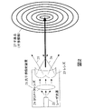
図2は、本発明で用いる光干渉投射装置の一例を示す図である。本例の光干渉投射装置は、半導体レーザ光源と同心円状の縞模様(同心円干渉模様)を形成するレンズとを組み合わせたものである。この光干渉投射装置を用いて、同心円の間隔が等間隔である同心円を形成する。図2に示すように、光干渉投射装置21は、波長850nmの半導体レーザ光源22と同心円干渉模様を形成するリング形状レンズ23とで構成した。レンズ外径は6mmとした。光軸を通る平面によるレンズ入射面の断面はx=0.3*(y−1.5)1.55(単位はmm)の非球面で構成した。ここで、xは光軸で光の進行方向を正とし、yは光軸に垂直な半径方向の軸である。レンズ23の光出射面は曲率半径R=−62mmの凹面の球面とした。レンズ材質の屈折率は1.51で、光軸上のレンズ厚さは3mmとした。
FIG. 2 is a diagram illustrating an example of an optical interference projection apparatus used in the present invention. The optical interference projection apparatus of this example is a combination of a semiconductor laser light source and a lens that forms a concentric stripe pattern (concentric interference pattern). Using this optical interference projection device, concentric circles having equal intervals are formed. As shown in FIG. 2, the optical interference projection device 21 is composed of a semiconductor
このレンズ23に半導体レーザ光源22から出射した光をコリメータレンズ24で平行光として入射させた。この場合、光軸より上側を通過した光は物体に光線軌跡25を経由して照射される。同様に、光軸より下側を通過した光は物体に光線軌跡26を経由して照射される。物体上の同一点(干渉点)27に到達した光は、同一光源より発せられたレーザ光であるので干渉する。このように、一つの光源から放出されたレーザ光は光軸上平面において仮想的に2点の光源から放出されたレーザ光であるように、物体に投影される。
Light emitted from the semiconductor
レンズ出射面から投影平面までの距離を3mとした場合に、投影平面に形成される同心円干渉模様は円中心から外周部に至るまで、そのピッチが全て0.85〜0.86mmになることがシミュレーション結果から分かった。これを図3(a)、(b)に示す。即ち、光源の光軸と平面が垂直であれば、同心円干渉模様のピッチは平面内のどこでもほぼ同じになることが判明した。このピッチは距離に比例する。従って、同心円ピッチから光干渉投射装置までの光軸上の距離を求めることができる。 When the distance from the lens exit surface to the projection plane is 3 m, the pitch of all the concentric interference patterns formed on the projection plane is 0.85 to 0.86 mm from the center of the circle to the outer periphery. It was found from the simulation results. This is shown in FIGS. 3 (a) and 3 (b). That is, it was found that if the optical axis of the light source is perpendicular to the plane, the pitch of the concentric interference pattern is almost the same everywhere in the plane. This pitch is proportional to the distance. Therefore, the distance on the optical axis from the concentric circle pitch to the optical interference projector can be obtained.
この同心円干渉模様のピッチと距離の関係を図1の演算処理装置5の記憶装置(図示しない)にテーブル化し格納しておく。ピッチあるいは、同心円干渉模様(サインカーブ)の極小値や極大値を表す画素ナンバーの位置が分かれば、撮像装置から物体までの距離が一意的に決まる。
The relationship between the pitch and distance of this concentric circle interference pattern is stored in a table in the storage device (not shown) of the
次に、本発明における3次元形状計測方法について説明する。説明の都合上、投射装置と撮像装置の光軸はほぼ同軸と見なすことができ、また計測物体は平面で撮像装置の光軸に対して正対しているとする。図1の物体1のa方向における撮像画像の濃度勾配を表すグラフを図4および図5に示す。各グラフの縦軸は撮像画像の濃度(色が濃い場合は数値が大)であり光軸方向を原点にしている。横軸は画素ナンバーである。原点は同心円の中心である。グラフはサインカーブを描く。図1の演算処理装置5において、複数ある極小値や極大値が原点から何番目であるかを数える。この何番目かが分かっている極小値や極大値を表す画素ナンバーは、距離を一意的に表すことができる。したがって、これらの各画素の距離情報を総合することにより物体の3次元形状計測を行うことができる。
Next, the three-dimensional shape measuring method in the present invention will be described. For convenience of explanation, it is assumed that the optical axes of the projection apparatus and the imaging apparatus can be regarded as substantially coaxial, and that the measurement object is a plane and faces the optical axis of the imaging apparatus. Graphs representing the density gradient of the captured image in the a direction of the
図4の例は、撮像装置から物体までの距離が50cmの時を表している。すなわち、1番目の極小値が10画素目であるときは、上述のPC5のテーブルを参照することにより、物体と撮像装置の距離は50cmであると一意的に決まる。また、図5の例は、撮像装置から物体までの距離が100cmの場合を示している。物体が離れると撮像装置の画角の広がりに対して、投射装置の画角は広がり大きいので、サインカーブの周期は大きくなり、第一の極小値を表す画素ナンバーは50cmの10画素目から18画素目に変わる。すなわち、1番目の極小値が18画素目であるときは、上述のPC5のテーブルを参照することにより、物体と撮像装置の距離は100cmであると一意的に決まる。このように、何番目かが分かっている極小値や極大値を表す画素ナンバーの各距離情報を総合して物体の3次元形状計測を行う。 The example of FIG. 4 represents the time when the distance from the imaging device to the object is 50 cm. That is, when the first minimum value is the 10th pixel, the distance between the object and the imaging apparatus is uniquely determined to be 50 cm by referring to the above-described table of PC5. The example of FIG. 5 shows a case where the distance from the imaging device to the object is 100 cm. When the object is separated, the angle of view of the projection apparatus is larger than that of the imaging apparatus, so the period of the sine curve is increased, and the pixel number representing the first minimum value is 18th from the 10th pixel of 50 cm. Change to the pixel eye. That is, when the first minimum value is the 18th pixel, the distance between the object and the imaging device is uniquely determined to be 100 cm by referring to the above-described table of PC5. In this way, the three-dimensional shape measurement of the object is performed by combining the distance information of the pixel number representing the minimum value or the maximum value whose number is known.
図1の場合は、物体1は平面で撮像装置4の光軸に対して正対しているので、物体1のa方向以外の方向でも、同心円干渉模様の撮像画像の濃度勾配はa方向と同様なサインカーブを描く。しかし、物体1が撮像装置4に対して正対していない場合は、撮像画像におけるサインカーブの周期は一定でなくなる。これについて次に説明する。
In the case of FIG. 1, the
図6は、物体が撮像装置に対して正対していない場合の3次元形状計測方法を説明するための図である。図示のように、物体61が撮像装置4に対して正対していない場合、物体61のa方向における撮像画像のサインカーブの周期は一定しているが、それ以外のb方向やc方向等では撮像画像におけるサインカーブの周期が一定でなくなる。しかしながら、原点から何番目かが分かっている極小値や極大値を表す画素ナンバーとの関係から、距離は図1の場合と同様に算出される。本例の場合も、サインカーブの周期(ピッチ)と距離の関係が図1のPC5の記憶装置(図示しない)にテーブル化し格納されているので、ピッチあるいは、同心円干渉模様(サインカーブ)の極小値や極大値を表す画素ナンバーの位置が分かれば、撮像装置から物体までの距離が一意的に決まる。この何番目かが分かっている極小値や極大値を表す画素ナンバーの各距離情報を総合して物体の3次元形状計測を行うことができる。
FIG. 6 is a diagram for explaining a three-dimensional shape measurement method when an object is not directly facing the imaging apparatus. As shown in the figure, when the object 61 is not directly facing the imaging apparatus 4, the period of the sine curve of the captured image in the a direction of the object 61 is constant, but in other b directions and c directions, etc. The period of the sine curve in the captured image is not constant. However, the distance is calculated in the same manner as in the case of FIG. 1 from the relationship with the pixel number representing the minimum value or the maximum value that is known from the origin. Also in this example, the relationship between the period (pitch) and distance of the sine curve is stored in a table in the storage device (not shown) of the
図7は、本発明に係る3次元形状計測装置の他の実施例を示す図である。本実施例は、図示のように、ハーフミラー71にて投射装置3と撮像装置4の光軸を一致させる点で図1の実施例と異なるが、その他は図1の実施例と同様である。本実施例でも、投射装置3と撮像装置4のレンズ主点は異なる位置に配置される。投射装置3から同心円状の縞模様2をハーフミラー71を介して所定の画角6で物体1に投射する。これをハーフミラー71を介して撮像装置4で撮像する。同心円状の縞模様2は、プロジェクタを用いて形成してもよいし、あるいは半導体レーザ(LD)を用いた光干渉投射装置を用いて形成してもよい。プロジェクタを用いる利点としては、計測物体の形状に合わせて、ユーザは所定のピッチの縞模様を容易に変更できる点が挙げられる。
FIG. 7 is a diagram showing another embodiment of the three-dimensional shape measuring apparatus according to the present invention. This embodiment is different from the embodiment of FIG. 1 in that the optical axes of the projection device 3 and the imaging device 4 are made to coincide with each other by a half mirror 71 as shown in the figure, but the other is the same as the embodiment of FIG. . Also in the present embodiment, the lens principal points of the projection device 3 and the imaging device 4 are arranged at different positions. A concentric
本実施例は、上記図1の実施例と同様の方法で、物体の3次元形状計測を行うことができる。すなわち、本実施例の場合も、同心円状の縞模様のサインカーブの周期(ピッチ)と距離の関係がPC5の記憶装置(図示しない)にテーブル化し格納されているので、ピッチあるいは、同心円干渉模様(サインカーブ)の極小値や極大値を表す画素ナンバーの位置が分かれば、撮像装置から物体までの距離が一意的に決まる。この何番目かが分かっている極小値や極大値を表す画素ナンバーの各距離情報を総合して物体の3次元形状計測を行うことができる。本実施例によれば高精度計測型の装置を得ることができる。
In the present embodiment, the three-dimensional shape measurement of the object can be performed by the same method as the embodiment of FIG. That is, also in this embodiment, since the relationship between the period (pitch) and distance of the concentric striped sine curve is stored in a table in a storage device (not shown) of the
以上のように、本発明によれば、簡単な装置構成で一括に物体の高精度な3次元形状計測を行うことができる。本発明に係る計測方法は、例えば、特に、紙のカールの度合い等を計測するのに好適である。 As described above, according to the present invention, highly accurate three-dimensional shape measurement of objects can be performed collectively with a simple apparatus configuration. The measurement method according to the present invention is particularly suitable, for example, for measuring the degree of paper curl and the like.
本発明は、物体の3次元形状計測を行うための3次元形状計測方法および装置に関するものであり、産業上の利用可能性がある。 The present invention relates to a three-dimensional shape measurement method and apparatus for measuring a three-dimensional shape of an object, and has industrial applicability.
1 物体
2 同心円状の縞模様
3 投射装置
4 撮像装置
5 演算処理装置(PC)
6 投射装置画角
7 撮像装置画角
21 光干渉投射装置
22 半導体レーザ
23 リング形状レンズ
24 リング形状レンズ
25、26 光線軌跡
27 干渉点(干渉模様)
71 ハーフミラー
DESCRIPTION OF
6 Projection device angle of view 7 Imaging device angle of view 21 Optical
71 half mirror
Claims (8)
Priority Applications (1)
| Application Number | Priority Date | Filing Date | Title |
|---|---|---|---|
| JP2005132135A JP2006308452A (en) | 2005-04-28 | 2005-04-28 | Method and apparatus for measuring three-dimensional shape |
Applications Claiming Priority (1)
| Application Number | Priority Date | Filing Date | Title |
|---|---|---|---|
| JP2005132135A JP2006308452A (en) | 2005-04-28 | 2005-04-28 | Method and apparatus for measuring three-dimensional shape |
Publications (1)
| Publication Number | Publication Date |
|---|---|
| JP2006308452A true JP2006308452A (en) | 2006-11-09 |
Family
ID=37475509
Family Applications (1)
| Application Number | Title | Priority Date | Filing Date |
|---|---|---|---|
| JP2005132135A Pending JP2006308452A (en) | 2005-04-28 | 2005-04-28 | Method and apparatus for measuring three-dimensional shape |
Country Status (1)
| Country | Link |
|---|---|
| JP (1) | JP2006308452A (en) |
Cited By (4)
| Publication number | Priority date | Publication date | Assignee | Title |
|---|---|---|---|---|
| CN103267495A (en) * | 2013-04-24 | 2013-08-28 | 中国科学院电工研究所 | Detecting method and detecting system for unit mirror surface shape used for tower-type solar thermal power generation |
| JP2016190002A (en) * | 2015-03-31 | 2016-11-10 | オリンパス株式会社 | Endoscope apparatus and method for measuring three-dimensional shape of subject surface |
| CN109341592A (en) * | 2018-11-26 | 2019-02-15 | 北京科技大学 | A kind of road surface scanning means based on laser interferencefringes |
| GB2584797A (en) * | 2019-06-12 | 2020-12-16 | Secr Defence | Measuring device and method |
-
2005
- 2005-04-28 JP JP2005132135A patent/JP2006308452A/en active Pending
Cited By (6)
| Publication number | Priority date | Publication date | Assignee | Title |
|---|---|---|---|---|
| CN103267495A (en) * | 2013-04-24 | 2013-08-28 | 中国科学院电工研究所 | Detecting method and detecting system for unit mirror surface shape used for tower-type solar thermal power generation |
| JP2016190002A (en) * | 2015-03-31 | 2016-11-10 | オリンパス株式会社 | Endoscope apparatus and method for measuring three-dimensional shape of subject surface |
| CN109341592A (en) * | 2018-11-26 | 2019-02-15 | 北京科技大学 | A kind of road surface scanning means based on laser interferencefringes |
| CN109341592B (en) * | 2018-11-26 | 2021-06-29 | 北京科技大学 | Road surface scanning device based on laser interference fringes |
| GB2584797A (en) * | 2019-06-12 | 2020-12-16 | Secr Defence | Measuring device and method |
| GB2584797B (en) * | 2019-06-12 | 2021-08-04 | Secr Defence | Measuring device and method |
Similar Documents
| Publication | Publication Date | Title |
|---|---|---|
| US10088296B2 (en) | Method for optically measuring three-dimensional coordinates and calibration of a three-dimensional measuring device | |
| US9858682B2 (en) | Device for optically scanning and measuring an environment | |
| US10841562B2 (en) | Calibration plate and method for calibrating a 3D measurement device | |
| JP4290733B2 (en) | Three-dimensional shape measuring method and apparatus | |
| US8923603B2 (en) | Non-contact measurement apparatus and method | |
| US9602811B2 (en) | Method for optically measuring three-dimensional coordinates and controlling a three-dimensional measuring device | |
| US9217637B2 (en) | Device for optically scanning and measuring an environment | |
| US9115986B2 (en) | Device for optically scanning and measuring an environment | |
| CN104903680B (en) | The method for controlling the linear dimension of three-dimension object | |
| WO2016040229A1 (en) | Method for optically measuring three-dimensional coordinates and calibration of a three-dimensional measuring device | |
| WO2016040271A1 (en) | Method for optically measuring three-dimensional coordinates and controlling a three-dimensional measuring device | |
| US11350077B2 (en) | Handheld three dimensional scanner with an autoaperture | |
| JP2006308452A (en) | Method and apparatus for measuring three-dimensional shape | |
| RU125335U1 (en) | DEVICE FOR MONITORING LINEAR SIZES OF THREE-DIMENSIONAL OBJECTS | |
| JP2021524599A (en) | Motion encoder | |
| JP2005331413A (en) | Distance image acquiring system | |
| JP2008224330A (en) | Distance calculation system, distance calculator, three-dimensional shape calculation system, and three-dimensional shape calculator | |
| JP2008145162A (en) | Three-dimensional shape measuring apparatus | |
| KR20190136592A (en) | Method and apparatus of generating 3D data with plurality lights |
Legal Events
| Date | Code | Title | Description |
|---|---|---|---|
| A621 | Written request for application examination |
Free format text: JAPANESE INTERMEDIATE CODE: A621 Effective date: 20060818 |
|
| A871 | Explanation of circumstances concerning accelerated examination |
Free format text: JAPANESE INTERMEDIATE CODE: A871 Effective date: 20060818 |
|
| A975 | Report on accelerated examination |
Free format text: JAPANESE INTERMEDIATE CODE: A971005 Effective date: 20060914 |
|
| A131 | Notification of reasons for refusal |
Free format text: JAPANESE INTERMEDIATE CODE: A131 Effective date: 20061205 |
|
| A521 | Written amendment |
Free format text: JAPANESE INTERMEDIATE CODE: A523 Effective date: 20070205 |
|
| A02 | Decision of refusal |
Free format text: JAPANESE INTERMEDIATE CODE: A02 Effective date: 20070306 |