JP2005520321A - Integrated system for tool front-end workpiece processing - Google Patents
Integrated system for tool front-end workpiece processing Download PDFInfo
- Publication number
- JP2005520321A JP2005520321A JP2003514594A JP2003514594A JP2005520321A JP 2005520321 A JP2005520321 A JP 2005520321A JP 2003514594 A JP2003514594 A JP 2003514594A JP 2003514594 A JP2003514594 A JP 2003514594A JP 2005520321 A JP2005520321 A JP 2005520321A
- Authority
- JP
- Japan
- Prior art keywords
- workpiece
- tool
- plate
- aligner
- attached
- Prior art date
- Legal status (The legal status is an assumption and is not a legal conclusion. Google has not performed a legal analysis and makes no representation as to the accuracy of the status listed.)
- Pending
Links
Images


Classifications
-
- H—ELECTRICITY
- H01—ELECTRIC ELEMENTS
- H01L—SEMICONDUCTOR DEVICES NOT COVERED BY CLASS H10
- H01L21/00—Processes or apparatus adapted for the manufacture or treatment of semiconductor or solid state devices or of parts thereof
- H01L21/67—Apparatus specially adapted for handling semiconductor or electric solid state devices during manufacture or treatment thereof; Apparatus specially adapted for handling wafers during manufacture or treatment of semiconductor or electric solid state devices or components ; Apparatus not specifically provided for elsewhere
- H01L21/683—Apparatus specially adapted for handling semiconductor or electric solid state devices during manufacture or treatment thereof; Apparatus specially adapted for handling wafers during manufacture or treatment of semiconductor or electric solid state devices or components ; Apparatus not specifically provided for elsewhere for supporting or gripping
- H01L21/687—Apparatus specially adapted for handling semiconductor or electric solid state devices during manufacture or treatment thereof; Apparatus specially adapted for handling wafers during manufacture or treatment of semiconductor or electric solid state devices or components ; Apparatus not specifically provided for elsewhere for supporting or gripping using mechanical means, e.g. chucks, clamps or pinches
- H01L21/68707—Apparatus specially adapted for handling semiconductor or electric solid state devices during manufacture or treatment thereof; Apparatus specially adapted for handling wafers during manufacture or treatment of semiconductor or electric solid state devices or components ; Apparatus not specifically provided for elsewhere for supporting or gripping using mechanical means, e.g. chucks, clamps or pinches the wafers being placed on a robot blade, or gripped by a gripper for conveyance
-
- H—ELECTRICITY
- H01—ELECTRIC ELEMENTS
- H01L—SEMICONDUCTOR DEVICES NOT COVERED BY CLASS H10
- H01L21/00—Processes or apparatus adapted for the manufacture or treatment of semiconductor or solid state devices or of parts thereof
- H01L21/67—Apparatus specially adapted for handling semiconductor or electric solid state devices during manufacture or treatment thereof; Apparatus specially adapted for handling wafers during manufacture or treatment of semiconductor or electric solid state devices or components ; Apparatus not specifically provided for elsewhere
- H01L21/677—Apparatus specially adapted for handling semiconductor or electric solid state devices during manufacture or treatment thereof; Apparatus specially adapted for handling wafers during manufacture or treatment of semiconductor or electric solid state devices or components ; Apparatus not specifically provided for elsewhere for conveying, e.g. between different workstations
- H01L21/67703—Apparatus specially adapted for handling semiconductor or electric solid state devices during manufacture or treatment thereof; Apparatus specially adapted for handling wafers during manufacture or treatment of semiconductor or electric solid state devices or components ; Apparatus not specifically provided for elsewhere for conveying, e.g. between different workstations between different workstations
- H01L21/67736—Loading to or unloading from a conveyor
-
- H—ELECTRICITY
- H01—ELECTRIC ELEMENTS
- H01L—SEMICONDUCTOR DEVICES NOT COVERED BY CLASS H10
- H01L21/00—Processes or apparatus adapted for the manufacture or treatment of semiconductor or solid state devices or of parts thereof
- H01L21/67—Apparatus specially adapted for handling semiconductor or electric solid state devices during manufacture or treatment thereof; Apparatus specially adapted for handling wafers during manufacture or treatment of semiconductor or electric solid state devices or components ; Apparatus not specifically provided for elsewhere
- H01L21/677—Apparatus specially adapted for handling semiconductor or electric solid state devices during manufacture or treatment thereof; Apparatus specially adapted for handling wafers during manufacture or treatment of semiconductor or electric solid state devices or components ; Apparatus not specifically provided for elsewhere for conveying, e.g. between different workstations
- H01L21/67763—Apparatus specially adapted for handling semiconductor or electric solid state devices during manufacture or treatment thereof; Apparatus specially adapted for handling wafers during manufacture or treatment of semiconductor or electric solid state devices or components ; Apparatus not specifically provided for elsewhere for conveying, e.g. between different workstations the wafers being stored in a carrier, involving loading and unloading
- H01L21/67766—Mechanical parts of transfer devices
-
- H—ELECTRICITY
- H01—ELECTRIC ELEMENTS
- H01L—SEMICONDUCTOR DEVICES NOT COVERED BY CLASS H10
- H01L21/00—Processes or apparatus adapted for the manufacture or treatment of semiconductor or solid state devices or of parts thereof
- H01L21/67—Apparatus specially adapted for handling semiconductor or electric solid state devices during manufacture or treatment thereof; Apparatus specially adapted for handling wafers during manufacture or treatment of semiconductor or electric solid state devices or components ; Apparatus not specifically provided for elsewhere
- H01L21/677—Apparatus specially adapted for handling semiconductor or electric solid state devices during manufacture or treatment thereof; Apparatus specially adapted for handling wafers during manufacture or treatment of semiconductor or electric solid state devices or components ; Apparatus not specifically provided for elsewhere for conveying, e.g. between different workstations
- H01L21/67763—Apparatus specially adapted for handling semiconductor or electric solid state devices during manufacture or treatment thereof; Apparatus specially adapted for handling wafers during manufacture or treatment of semiconductor or electric solid state devices or components ; Apparatus not specifically provided for elsewhere for conveying, e.g. between different workstations the wafers being stored in a carrier, involving loading and unloading
- H01L21/67772—Apparatus specially adapted for handling semiconductor or electric solid state devices during manufacture or treatment thereof; Apparatus specially adapted for handling wafers during manufacture or treatment of semiconductor or electric solid state devices or components ; Apparatus not specifically provided for elsewhere for conveying, e.g. between different workstations the wafers being stored in a carrier, involving loading and unloading involving removal of lid, door, cover
-
- H—ELECTRICITY
- H01—ELECTRIC ELEMENTS
- H01L—SEMICONDUCTOR DEVICES NOT COVERED BY CLASS H10
- H01L21/00—Processes or apparatus adapted for the manufacture or treatment of semiconductor or solid state devices or of parts thereof
- H01L21/67—Apparatus specially adapted for handling semiconductor or electric solid state devices during manufacture or treatment thereof; Apparatus specially adapted for handling wafers during manufacture or treatment of semiconductor or electric solid state devices or components ; Apparatus not specifically provided for elsewhere
- H01L21/677—Apparatus specially adapted for handling semiconductor or electric solid state devices during manufacture or treatment thereof; Apparatus specially adapted for handling wafers during manufacture or treatment of semiconductor or electric solid state devices or components ; Apparatus not specifically provided for elsewhere for conveying, e.g. between different workstations
- H01L21/67763—Apparatus specially adapted for handling semiconductor or electric solid state devices during manufacture or treatment thereof; Apparatus specially adapted for handling wafers during manufacture or treatment of semiconductor or electric solid state devices or components ; Apparatus not specifically provided for elsewhere for conveying, e.g. between different workstations the wafers being stored in a carrier, involving loading and unloading
- H01L21/67775—Docking arrangements
-
- Y—GENERAL TAGGING OF NEW TECHNOLOGICAL DEVELOPMENTS; GENERAL TAGGING OF CROSS-SECTIONAL TECHNOLOGIES SPANNING OVER SEVERAL SECTIONS OF THE IPC; TECHNICAL SUBJECTS COVERED BY FORMER USPC CROSS-REFERENCE ART COLLECTIONS [XRACs] AND DIGESTS
- Y10—TECHNICAL SUBJECTS COVERED BY FORMER USPC
- Y10S—TECHNICAL SUBJECTS COVERED BY FORMER USPC CROSS-REFERENCE ART COLLECTIONS [XRACs] AND DIGESTS
- Y10S414/00—Material or article handling
- Y10S414/135—Associated with semiconductor wafer handling
- Y10S414/139—Associated with semiconductor wafer handling including wafer charging or discharging means for vacuum chamber
Abstract
ツールのフロントエンドにおける加工物処理及び/又は検査のための統合システムが開示される。このシステムは、半導体加工に関連したツールの前面に取り付けられる金属プレートのような一体構成の剛性部材からなる。ロードポート組立体と、プリアライナと、加工物処理ロボットとを含むフロントエンド部品をプレートに取り付けて、該フロントエンド部品の互いに精密で、反復的な位置決めをもたらすようにする。An integrated system for workpiece processing and / or inspection at the front end of a tool is disclosed. This system consists of an integral rigid member such as a metal plate that is attached to the front of a tool associated with semiconductor processing. A front end component including a load port assembly, a pre-aligner, and a workpiece handling robot is attached to the plate to provide precise and repeatable positioning of the front end components relative to each other.
Description
(技術分野)
本発明は、半導体ウエハのような加工物の加工に関し、特に、半導体加工と関連したツールのフロントエンドにおける加工物処理及び検査のための統合システムに関する。
(Technical field)
The present invention relates to the processing of workpieces such as semiconductor wafers, and more particularly to an integrated system for workpiece processing and inspection at the front end of tools associated with semiconductor processing.
(背景技術)
ヒュレット−パッカード社によって提案されたSMIFシステムが、米国特許第4,532,970号及び第4,534,389号に開示されている。SMIFシステムの目的は、半導体製造工程におけるウエハの格納及び搬送中、半導体ウエハ上への粒子フラックスを減少させることである。この目的は、格納及び搬送中に、ウエハを取り囲む(空気又は窒素のような)ガス状媒体が、本質的にはウエハに対して静止しているようにすることを機械的に確実にすることにより、及び周囲環境からの粒子が直近のウエハ環境に入らないようにすることを確実にすることにより、ある程度は達成される。
SMIFシステムは、3つの主要部品、すなわち、(1)ウエハ及び/又はウエハカセットを格納して搬送するのに用いられる最小容積のシールされたポッド、(2)曝されたウエハ及び/又はウエハカセットを加工用ツールの内部に及び該内部から移送することができる小さいクリーンな空間(クリーンな空気で満たされたとき)を提供するための半導体加工用ツール上にある入力/出力(I/O)の小環境、及び(3)該ウエハ又はウエハカセットを粒子に曝すことなく、SMIFポッドとSMIF小環境との間で該ウエハ及び/又はウエハカセットを移送するためのインタフェース、を有する。さらに、1つの提案されたSMIFシステムの詳細が、1984年7月の「ソリッドステート技術」の111ページから115ページのMihir Parkh及びUlrich Kaempfによる「SMIF:VLSI製造におけるウエハカセット移送技術」という名称の論文に記載されている。
(Background technology)
The SMIF system proposed by Hulett-Packard is disclosed in US Pat. Nos. 4,532,970 and 4,534,389. The purpose of the SMIF system is to reduce the particle flux onto the semiconductor wafer during storage and transfer of the wafer in the semiconductor manufacturing process. The purpose is to mechanically ensure that the gaseous medium (such as air or nitrogen) surrounding the wafer is essentially stationary relative to the wafer during storage and transfer. And to some extent by ensuring that particles from the surrounding environment do not enter the immediate wafer environment.
The SMIF system has three main parts: (1) a minimum volume sealed pod used to store and transport wafers and / or wafer cassettes, and (2) exposed wafers and / or wafer cassettes. Input / output (I / O) on the semiconductor processing tool to provide a small clean space (when filled with clean air) that can be transferred into and out of the processing tool And (3) an interface for transferring the wafer and / or wafer cassette between the SMIF pod and the SMIF microenvironment without exposing the wafer or wafer cassette to particles. In addition, details of one proposed SMIF system can be found in the "SMIF: Wafer Cassette Transfer Technology in VLSI Manufacturing" by Mihir Parkh and Ulrich Kaempf on pages 111-115 of "Solid State Technology" in July 1984. It is described in the paper.
上記の種類のシステムは、0.02ミクロン(μm)より下から200μmより上までの範囲にわたる粒径に関するものである。これらの粒径を有する粒子は、半導体デバイスを製造するのに用いられる小さな幾何学的形状のため、半導体加工において非常に損傷をもたらす可能性がある。今日の典型的な進歩した半導体加工は、2分の1μm以下の幾何学的形状を用いるものである。0.1μmよりも大きい幾何学的形状を有する望ましくない汚染粒子が、実質的に1μmの幾何学的形状の半導体デバイスに害を与える。もちろん、今日の研究開発室における傾向は、0.1μm以下に近づくますます小さい半導体加工幾何学的形状を有するようにすることである。将来、幾何学的形状は、ますます小さくなり、よってますます小さい汚染粒子及び分子汚染が問題となるであろう。
SMIFポッドは、一般に、ウエハを格納して移送することができるシールされた環境を生成するためのポッドシェルと嵌合するポッドドアからなる。所謂「底部開口」のポッドが知られており、ここでは、ポッドドアはポッドの底部に水平方向に設けられ、ウエハは、次いで、該ポッドドア上に支持されることになるカセット内に支持される。さらに、正面開口の一体型ポッド、すなわち、FOUPと呼ばれる正面開口のポッドを形成することができ、ここではポッドドアが垂直面にあり、ウエハは、ポッドシェルの中に取り付けられたカセット内にか、又は該ポッドシェルに取り付けられたシェルフのいずれかに支持される。
The above types of systems relate to particle sizes ranging from below 0.02 microns (μm) to above 200 μm. Particles having these particle sizes can be very damaging in semiconductor processing due to the small geometry used to manufacture semiconductor devices. Today's typical advanced semiconductor processing uses geometries of less than one-half μm. Undesirable contaminant particles having a geometric shape greater than 0.1 μm substantially harm semiconductor devices having a geometric shape of 1 μm. Of course, the trend in today's research and development laboratories is to have increasingly smaller semiconductor processing geometries approaching 0.1 μm or less. In the future, the geometry will become smaller and smaller contaminant particles and molecular contamination will be a problem.
SMIF pods generally consist of a pod door that mates with a pod shell to create a sealed environment in which wafers can be stored and transported. So-called “bottom opening” pods are known, in which a pod door is provided horizontally at the bottom of the pod and the wafer is then supported in a cassette to be supported on the pod door. In addition, an integrated pod with front opening, or a front opening pod called FOUP, can be formed, where the pod door is in a vertical plane and the wafer is in a cassette mounted in a pod shell, or Or it is supported by either of the shelves attached to the pod shell.
半導体ウエハの製造中、SMIFポッドは、加工物をウエハファブにおける種々のツール間で搬送するように用いられる。これらのツールには、集積回路パターンをウエハ上に形成する加工用ツールと、該ウエハを試験する計測ツールと、1つ又はそれ以上のSMIFポッド内の該ウエハをソートして再配置するソータと、該SMIFポッドを大量格納するストッカとが含まれる。ツールは、一般的には、2つの構成の一方、すなわち、ベイ及びチェース構成か又はボールルーム構成の一方でウエハファブに配置される。前者の構成では、加工物のI/Oポートを含むツールの前面だけが、クラス1又はそれ以上のクリーンルーム環境に維持される。ボールルーム構成では、ツールは、ツール全体がクラス1又はそれ以上のクリーンルーム環境に維持された状態で、該ツールが行う作動によってまとめて配置される。
During semiconductor wafer manufacturing, SMIF pods are used to transport workpieces between various tools in a wafer fab. These tools include a processing tool for forming an integrated circuit pattern on a wafer, a metrology tool for testing the wafer, a sorter for sorting and rearranging the wafer in one or more SMIF pods. And a stocker for storing a large amount of the SMIF pod. Tools are typically placed on the wafer fab in one of two configurations: a bay and chase configuration or a ballroom configuration. In the former configuration, only the front surface of the tool, including the workpiece I / O port, is maintained in a
ウエハファブ内のツールは、ポッド間のウエハその他の加工物を該ツールに移送することを可能にして監視する部品を収容するフロントエンドのインタフェースを含む。通常のフロントエンド装置20が、図1及び図2に示される。一般的には、ツールの製造業者の下で構築され、次いでウエハファブに出荷される装置20は、ツールの前面に固定される全体的には正方形であるか又は矩形のハウジング22を含む。フロントエンド装置20は、一般的には、ハウジング内に取り付けられ、加工物を加工物キャリアとツールその他のフロントエンド部品との間で移送するようにγ、θ、zの運動ができる加工物処理ロボット24を含む。ロボットは、一般的には、装置20が構築されてツールに固定されると、該ロボットの平面性の調整を可能にする整準ねじによりハウジング内に取り付けられる。
ロボット24に加えて、フロントエンド装置20は、一般的には、ウエハの中心の特定、ノッチの方位、及び指示マークの読取りの工程を実行する1つ又はそれ以上のプリアライナ26を含む。プリアライナ26は、整準ねじによりハウジング22内にボルト留めされて、装置20が構築されてツールに固定されると、該プリアライナの平面性が調整されるようにすることを可能にする。
The tool within the wafer fab includes a front end interface that houses the parts to be monitored to allow wafers and other workpieces between the pods to be transferred to the tool. A typical
In addition to the
フロントエンド装置20はさらに、加工物キャリアを受け取り、該キャリアを開き、該加工物を、該キャリアとプリアライナとツールとの間で移送するロボットに与える1つ又はそれ以上のロードポート組立体28を含む。300mmのウエハ加工のために、通常はボックス・オープナ・ローダツール標準インタフェース(すなわち、「BOLTS」インタフェース)と呼ばれる垂直方向に方位付けられたフレームが、半導体製造装置材料協会(「SEMI」)によって開発された。BOLTSインタフェースは、ツールのフロントエンドに取り付けられるか又は該フロントエンドの一部として形成され、ロードポート組立体のための標準取付け点を設けて、該ツールに取り付けられるようにする。ボノラ他への「傾けて進めるロードポートのインタフェース位置合わせシステム」という名称の米国特許第6,138,721号は、ロードポート組立体をBOLTSインタフェースに隣接する適当な位置に調整し、次いで、該ロードポート組立体を該インタフェースに固定するシステムを開示する。この特許は、本発明の所有者に譲渡され、引用により全体が本明細書に組み込まれる。
ロボット24、プリアライナ26、及びロードポート組立体28が、ハウジング22に取り付けられると、フロントエンド装置20は、ウエハファブに出荷され、該ファブ内のツールに固定される。ツールに適当に固定された後に、フロントエンド部品は、整準ねじによってハウジング22内で水平にされ、次いで、ロボットは、加工物をロードポート組立体とプリアライナと該ツールとの間で移送するのにアクセスする必要がある獲得及び降下位置を教示される。種々の獲得位置及び降下位置をツールのフロントエンド内のロボットに教示するためのシステムは、「独学ロボット」という名称の米国特許出願第09/729,463号に開示されており、この出願は、本出願の所有者に譲渡され、またこの出願は、引用により全体が本明細書に組み込まれる。ロボット位置が教示されると、側部パネルがハウジング22に取り付けられて、該ハウジングは周囲環境に対して実質的にシールされるようになる。
The
When the
上述のように、通常のツールのフロントエンドは、組み立てられたハウジング内に取り付けられた別々で独立した複数の加工物処理部品を含む。ハウジングは、互いにボルト留めされた、構築されたか又は溶接された構造フレームと、該フレームに固定された複数のパネルとを含む。ハウジングが組み立てられた後に、フロントエンド部品が、種々のパネルに固定される。全体のシステムの許容差が、各々のフレーム部材、パネル、及び部品の連結により増加することは、従来技術のフロントエンドにおける欠点である。その結果、組み立てられたフロントエンド部品が不十分に位置合わせされ、互いに適当な位置に調整されなければならなくなる。ロボットはさらに、フロントエンド部品が互いに相互作用することができるように、該部品の相対的位置を教示されなければならない。この位置合わせ及び教示工程は、1つ又はそれ以上のフロントエンド部品に対する調整がある度に行われなければならない。
従来技術のさらに別の欠点は、フロントエンド部品が異なる供給業者によって作られることが多く、各々が独自のコントローラ及び通信プロトコルを有することである。フロントエンドが組み立てられるとき、各々の部品のコントローラが互いに通信することができ、かつ該部品が互いに相互作用することができるような段階を取らなければならない。別々のコントローラはまた、保守を複雑にし、フロントエンドに設けられる部品及び電気接続を増やす。さらにまた、特にボールルーム構成においては、通常のフロントエンド装置は、空間が限られているクラス1のクリーンルーム環境内で大量の空間を占める。
As mentioned above, the front end of a typical tool includes a plurality of separate and independent workpiece processing parts mounted within an assembled housing. The housing includes a constructed or welded structural frame that is bolted together and a plurality of panels secured to the frame. After the housing is assembled, the front end components are secured to the various panels. It is a drawback in the prior art front end that the overall system tolerance increases due to the connection of each frame member, panel and component. As a result, the assembled front end parts are poorly aligned and must be adjusted to the proper position relative to each other. The robot must also be taught the relative positions of the front end parts so that they can interact with each other. This alignment and teaching process must be performed whenever there is an adjustment to one or more front end components.
Yet another disadvantage of the prior art is that the front end components are often made by different suppliers, each having its own controller and communication protocol. When the front end is assembled, steps must be taken so that the controllers of each part can communicate with each other and the parts can interact with each other. Separate controllers also complicate maintenance and increase the parts and electrical connections provided in the front end. Furthermore, particularly in a ballroom configuration, a typical front end device occupies a large amount of space in a
(発明の開示)
従って、本発明の利点は、フロントエンド部品のすべてを単一装置に統合することである。
本発明の別の利点は、共通で精密な基準表面をすべてのフロントエンド部品に与えることである。
本発明のさらに別の利点は、取付け面の数を減らして、部品の追加又は取り外しにより位置合わせの精度及び反復性の向上をもたらすようにすることである。
本発明のさらに別の利点は、すべてのフロントエンド部品を互いに既知で再現可能な関係で取り付けることである。
本発明のさらに別の利点は、今日ツールのフロントエンドで必要とされる機能のすべてを維持しながら、ツールのフロントエンドに用いられる部品数を減らすことである。
(Disclosure of the Invention)
Thus, an advantage of the present invention is that all of the front end components are integrated into a single device.
Another advantage of the present invention is that it provides a common and precise reference surface for all front end components.
Yet another advantage of the present invention is that the number of mounting surfaces is reduced so that addition or removal of parts provides improved alignment accuracy and repeatability.
Yet another advantage of the present invention is that all front end components are mounted in a known and reproducible relationship with each other.
Yet another advantage of the present invention is that it reduces the number of parts used in the tool front end while maintaining all of the functionality required by the tool front end today.
本発明のさらに別の利点は、すべてのフロントエンド作動を制御する単一のフロントエンドコントローラを設けることである。
本発明の別の利点は、ツールの製造業者においてフロントエンド部品を組み立てる必要を無くすことである。
本発明のさらに別の利点は、加工物の獲得位置及び降下位置を加工物処理ロボットに教示する必要性をほとんど無くすことである。
本発明の別の利点は、フロントエンド部品によって必要とされる設置面積を減少させることである。
本発明の別の利点は、冗長な機械的及び電気的ハードウェアを減らすことにより製造コストを削減することである。
Yet another advantage of the present invention is to provide a single front end controller that controls all front end operations.
Another advantage of the present invention is that it eliminates the need to assemble front end components at the tool manufacturer.
Yet another advantage of the present invention is that it almost eliminates the need to teach the workpiece handling robot of the workpiece acquisition and descent positions.
Another advantage of the present invention is that it reduces the footprint required by the front end components.
Another advantage of the present invention is that it reduces manufacturing costs by reducing redundant mechanical and electrical hardware.
本発明のさらに別の利点は、ロードポート組立体のアクセスポートより下の空間を利用することである。
本発明の別の利点は、通常の設計に対する加工物処理ロボットの垂直ストロークを増大させることである。
本発明のさらに別の利点は、加工物をキャリアに移送し戻すことなく、隣接したツール間でのシールされた加工物の移送を提供することである。
本発明の別の利点は、ツール内の劣悪な環境の場合において、漏れに対してフロントエンドをシールすることである。
これらその他の利点は、好ましい実施形態において、ツールのフロントエンドにおける加工物処理及び/又は検査のための統合システムに関する本発明によりもたらされる。このシステムは、半導体加工に関連したツールの前面に取り付けられる金属プレートのような一体構成の剛性部材からなる。プレートを備える実施形態においては、該プレートは、該プレートとツールの間に挟まれたフレームにより該ツールにボルト留めすることができる。
Yet another advantage of the present invention is to utilize the space below the access port of the load port assembly.
Another advantage of the present invention is that it increases the vertical stroke of the workpiece handling robot relative to the normal design.
Yet another advantage of the present invention is to provide sealed workpiece transfer between adjacent tools without transferring the workpiece back to the carrier.
Another advantage of the present invention is that the front end is sealed against leakage in the case of adverse environments within the tool.
These other advantages are provided in the preferred embodiment by the present invention relating to an integrated system for workpiece processing and / or inspection at the front end of the tool. This system consists of an integral rigid member such as a metal plate that is attached to the front of a tool associated with semiconductor processing. In embodiments comprising a plate, the plate can be bolted to the tool by a frame sandwiched between the plate and the tool.
ツールのフロントエンドにあるハウジングに通常の方法で取り付けられた部品は、各々が互いに固定の反復位置でプレートに取り付けられる。好ましい実施形態においては、プレートに取り付けられた部品は、該プレートの前面に固定的にボルト留めされた一対のロードポート組立体を含む。ロードポート組立体を設けて、加工物キャリアを受け取り、該キャリアを開き、加工物を該キャリアとツールとの間で移送するために該キャリア内与えるようにする。さらに、一対のプリアライナをプレートの前面に取り付けることができる。プリアライナを設けて、加工物の中心を特定し、該加工物のノッチを所望の方位に位置づけ、該加工物上の指示マークを読み取るようにする。好ましい実施形態においては、プリアライナは、バッファパドルを含み、ここで加工物をバッファリングして、一般に、該プリアライナ及びフロントエンドシステムの処理能力を高めるようにすることができる。プレートはさらに、該プレートの裏面に垂直方向の並進運動ができるように固定された加工物処理ロボットを含むことが好ましい。ロボットは、加工物をロードポート組立体とプリアライナとツールとの間で移送する。本発明によるフロントエンドシステムはさらに、フロントエンド部品の各々の作動を制御して調整するための単一のコントローラを含む。 Parts that are attached in a conventional manner to the housing at the front end of the tool are each attached to the plate at a fixed repeat position relative to each other. In a preferred embodiment, the components attached to the plate include a pair of load port assemblies fixedly bolted to the front of the plate. A load port assembly is provided for receiving the workpiece carrier, opening the carrier, and providing the workpiece within the carrier for transfer between the carrier and the tool. Further, a pair of pre-aligners can be attached to the front surface of the plate. A pre-aligner is provided to identify the center of the work piece, position the notch of the work piece in a desired orientation, and read an indication mark on the work piece. In a preferred embodiment, the pre-aligner includes a buffer paddle where the workpiece can be buffered to generally increase the throughput of the pre-aligner and front end system. The plate further preferably includes a workpiece handling robot secured to the back surface of the plate for vertical translation. The robot transfers the workpiece between the load port assembly, the pre-aligner and the tool. The front end system according to the present invention further includes a single controller for controlling and coordinating the operation of each of the front end components.
フロントエンド部品を単一のプレート上に統合することは、フロントエンドシステムの許容差を大幅に減らし、該フロントエンド部品の互いの位置において精度及び反復性がもたらされるようになる。このことは、次いで、フロントエンドシステムを取り付けるか又は改造するときに要求される調整を大幅に削減することになる。その上、本発明によるフロントエンドシステムにおける部品数は、通常のフロントエンドシステムと比較して削減されているが、同時に、従来技術のシステム機能のすべてを維持している。さらに、部品を単一プレート上に統合することは、組み合わされたフロントエンド及びツールの全体の設置面積を減少させる可能性をもたらす。
フロントエンドシステム部品の各々は、単一のコントローラにより監視されて制御される。従来技術のフロントエンド部品は、各々が独自のコントローラをもった、異なる部品供給業者により製造されていた。単一のコントローラにより作動する統合フロントエンドシステムを実現することは、システム全体のソフトウェア制御を大幅に単純化する。その上、単一のコントローラを有することは、フロントエンド作動に必要な部品数及びケーブル数を削減することになる。このことは、システム制御についてより容易なインストレーション及び保守を可能にする。
Integrating the front end components on a single plate greatly reduces the tolerances of the front end system and provides accuracy and repeatability at the positions of the front end components relative to each other. This in turn will greatly reduce the adjustments required when installing or retrofitting the front end system. In addition, the number of parts in the front-end system according to the present invention is reduced compared to a normal front-end system, while at the same time maintaining all the system functions of the prior art. Furthermore, integrating the parts on a single plate offers the potential to reduce the overall footprint of the combined front end and tool.
Each of the front end system components is monitored and controlled by a single controller. Prior art front end components were manufactured by different component suppliers, each with its own controller. Implementing an integrated front-end system that operates with a single controller greatly simplifies overall system software control. In addition, having a single controller reduces the number of parts and cables required for front-end operation. This allows easier installation and maintenance for system control.
(発明を実施するための最良の形態)
ここで図面を参照して、本発明について説明する。
ここで、一般に、ツールのフロントエンドにおける加工物処理及び/又は検査のための統合システムに関する図3ないし図13を参照して、本発明について説明する。本発明の好ましい実施形態は、300mmの半導体ウエハ製造に用いられる。しかしながら、本発明を、例えば、レチクル、フラットパネル・ディスプレイ、及び磁気記憶ディスクのような半導体ウエハ以外の加工物の製造に用いることができること、及び本発明を、300mmよりも大きいか又は小さい、例えば200mm及び150mmのような加工物の製造に用いることができることが理解される。さらに、本発明は、SMIFシステムで作動することが好ましいが、本発明が他の加工物搬送システムで作動できることが理解される。
(Best Mode for Carrying Out the Invention)
The present invention will now be described with reference to the drawings.
The present invention will now be described with reference to FIGS. 3 through 13 which generally relate to an integrated system for workpiece processing and / or inspection at the front end of a tool. A preferred embodiment of the present invention is used in the manufacture of 300 mm semiconductor wafers. However, the present invention can be used to manufacture workpieces other than semiconductor wafers, such as reticles, flat panel displays, and magnetic storage disks, and the present invention is larger or smaller than 300 mm, for example, It will be appreciated that it can be used to manufacture workpieces such as 200 mm and 150 mm. Further, although the present invention preferably operates with a SMIF system, it is understood that the present invention can operate with other workpiece transfer systems.
ここで図3ないし図8を参照すると、本発明によるフロントエンドシステム100が示される。本発明の一実施形態においては、フロントエンドシステム100は、一対のロードポート組立体104、一対のプリアライナ106、及び加工物処理ロボット108が固定されたプレート102からなる。コントローラ109をさらに設けて、ロードポート組立体104、プリアライナ106、及びロボット108の作動を制御して連係させるようにする。
プレート102は、半導体加工と関連したツールの前面に取り付ける。ここで用いられるこうしたツールは、この限りではないが、半導体ウエハ上に集積回路パターンを形成する加工用ツールと、種々の加工物特性を試験する計測ツールと、加工物キャリアを大量格納するストッカとを含む。ここで用いられるツールはまた、後で説明されるようなプレートの裏面での加工物処理を囲まれた空間内で実行することができる単純な囲いとすることができる。例えば、本発明によるフロントエンドシステム100は、1つ又はそれ以上のキャリア内の加工物を配置して移送するソータを含むことができる。或いは、本発明によるフロントエンドシステム100は、独立型のプリアライナを含むことができる。ソータ及び独立型プリアライナの両方の実施形態において、加工物の工程は、フロントエンドシステム100によって完全に実行されるが、プレートが取り付けられた囲み用ツールは、該加工物が処理されることになる囲まれたクリーンな環境をもたらす。本発明の実施形態においては、プレートをツールの一部として考えることができる。本発明の他の実施形態においては、プレートは、ツールに固定されるが、該ツールから分離しているものと考えることもできる。
Referring now to FIGS. 3-8, a
The
図5及び図6に最も良く見えるように、プレート102は、該プレート102の外周のフレーム110を介してツール107に固定される。好ましい実施形態においては、プレート102は、該プレート102とフレーム110との間に形成される第1の弾性シール105により該フレーム110にボルト留めされ、次いで、該フレーム110が、該フレーム110とツール107との間に形成される第2の弾性シール105により該ツール107の前面にボルト留めされる。フレーム110は、該フレーム110を囲むための側部パネル111を有することができる。好ましい実施形態においては、プレート102は、フレーム110の前面に固定される。しかしながら、代替的な実施形態においては、プレート102とパネル111との位置は、該プレート102がツール107の前面に対してほぼ垂直に配置されるように交換することができる。
ツールに固定されると、気密シールが、プレート102とフレーム110と該プレート102の外周のツール107との間に完成される。一般に、ツールのフロントエンド内の圧力は、ツール107及びフロントエンドを取り囲む空気の大気よりも高いレベルで維持されているため、如何なる浮遊粒子又は汚染物質もいずれかの開口部を通って該ツールのフロントエンドの外に吹き出されるようになっている。しかしながら、時として、ツールは、例えば、純窒素環境といったような劣悪な環境で作動することがあり、ツールのフロントエンドをフロントエンド及びツールを取り囲む環境に対してシールすることが必要になる。フレーム及びシールによりツール107に取り付けられたプレート102によって形成される単一の平坦なインタフェースを備えることは、このようなシールの形成を、通常のフロントエンド設計のものよりも大幅に容易にする。
As best seen in FIGS. 5 and 6, the
When secured to the tool, a hermetic seal is completed between the
プレート102をツール107に対して固定するのに加えて、フレーム110は、ロボットが運動することができる空間と、ファン/フィルタ装置を配置することができる空間とを定める。しかしながら、好ましい実施形態においては、フロントエンド部品のすべてが、直接プレート102上に取り付けられているので、該プレート102及びフレーム110は、フロントエンド部品がフロントエンドハウジングの異なる部分に固定されていた従来技術の短所を生じない。
当業者によって理解されるように、代替的な実施形態においては、プレート102は、他の周知の締結方式によりツール107の前面に固定することができる。例えば、フレーム110を省いて、プレート102を、該プレート102とツール107との間に形成される弾性シール105により直接ツール107にボルト留めすることができる。さらに、代替的な実施形態においては、弾性シール105をフレーム110の片側から又は両側から省くことができることも理解される。代替的な実施形態においては、プレート102をツール107の前面に隣接した床及び/又は天井に取り付けることもさらに考えられる。ツール107に固定されると、プレート102は、該ツール107の内部に面する前面112と、該ツール107を取り囲む環境に面する裏面114とを含む。
In addition to securing the
As will be appreciated by those skilled in the art, in alternative embodiments, the
プレート102は、所望の表面の構成に加工するか又は形成することができる剛性部材で形成されることが好ましい。一実施形態においては、プレート102は、機械加工された特徴をもつ転圧されたか又は鋳造されたアルミニウムで形成することができる。プレート102は、ガス放出を防止するか又は減少させるように陽極処理された表面仕上げを含んでもよい。代替的な実施形態においては、プレート102は、鋼で形成してもよいことが理解される。代替的に、プレート102は、アルミニウム又は第1の層で形成され、鋼又は第2の層によって補強されてもよい。しかしながら、プレート102が1つよりも多い層からなる実施形態においては、精密な位置合わせを必要とするフロントエンド部品は、一体構成の単層に取り付けることが好ましい。ウエハファブ内のツールは寸法が異なり、プレート102の寸法は、該プレート102が固定されることになる特定のツール107に適合するようカスタマイズすることができる。
図3ないし図8に示される実施形態においては、一対のロードポート組立体104は、前面112に固定的にボルト留めされており、加工物キャリアを受け取り、該キャリアを開き、加工物を該キャリアとプリアライナ106とツール107との間に移送するために該キャリア内に与えることができるようになっている。ロードポート組立体104は、各々がプレート102に別々に取り付けられた2つの組立部品で構成される。第1の組立部品は、前面112に取り付けられ、キャリアを受け取り、該キャリアをプレート102に進める、前進プレート組立体からなる。第2の組立部品は、裏面114に取り付けられ、キャリアドアと嵌合し、該ドアを取り外すポートドア組立部品104からなる。このようなロードポート組立体104の1つについて以下で説明するが、次の説明は、両方のロードポート組立体104に当てはまる。
In the embodiment shown in FIGS. 3-8, the pair of
加工物をキャリアとツール107との間で移送するために、該キャリアは、該キャリアの前面がポートドア組立部品のポートドア118の前面に面するように、前進プレート組立体のポッド前進プレート116上に手動で又は自動的に載せられる。ポートドア118は、キャリアドア内に取り付けられたドア係止用組立体における対応する一対のスロットに受け取られる一対の係止用キーを含む。このような係止用キーを受け取り、該キーにより作動するようにされたキャリアドア内のドア係止用組立体の一例が、ボノラ他への「改善された係止用機構を有するシール可能で搬送可能コンテナ」という名称の米国特許第4,995,430号に開示されており、この特許は、本発明の所有者に譲渡され、またこの特許は、引用により全体が本明細書に組み込まれる。キャリアドアをキャリアシェルから分離させることに加えて、係止用キーの回転はさらに、該キーをそれぞれのキャリアドアのスロットの中にロックして、これにより該キャリアドアがポートドアに連結されるようになる。典型的には、2つの係止用キーとスロットとの対があり、これらの対の各々は、互いに構造的にかつ作動的に同一である。
In order to transfer the workpiece between the carrier and the
ポッド前進プレート116は、典型的には、3つの運動ピン、又は幾つかの他の位置合わせ特徴を含み、これらが、キャリアの底面上の対応するスロットに嵌合して、前進プレート及びロードポート組立体104上に、固定の反復可能な該キャリアの底面の位置を定めるようにする。ポッドがロードポート組立体104内のセンサによりポッド前進プレート116上で検知されると、該ポッドは、キャリアドアがポートドア118と接触するまで又は該ドアの近くに位置するまで、ロードポートの方向に進められる。それぞれのドアの前面を互いに接触させるようにして、微粒子をトラップし、ポッドドアキー用スロット内のポートドア係止用キーの緊密な嵌合を確実にするようにすることが望ましい。ローゼンクイスト他による「ポートドアに対するポッドドア保持システム」という名称の米国特許出願第09/115,414号、及びフォスナイト他による「ポートドアに対するポッド保持及び排気システム」という名称の米国特許出願第09/130,254号が、キャリアとポートドアとの間の緊密でクリーンなインタフェースを確実にするシステムを開示している。これらの出願は、本発明の所有者に譲渡され、両方とも引用により全体が本明細書に組み込まれる。
The
キャリアとポートドアとが連結されると、ロードポート組立体内の線形及び/又は回転駆動装置は、該キャリア及び該ポートドアを互いにフロントエンドシステムの内部に移動させ、次いで、該ロードポートから離れる方向に移動させて、その後、加工物が該ロードポートを通って、該キャリアと該ツールとの間で移送されるようにすることができる。図7に示すように、一実施形態においては、ポートドア118は、回転駆動装置122に取り付けられたアーム120に固定される。そして次に、駆動装置122は、線形スライド121上に取り付けられる。キャリア及びポートドアが互いに固定されると、コントローラ109がスライド121を作動させて、該キャリア及びポートドアをポートから後方に並進運動させるようにする。次に、コントローラは、駆動装置122を作動させて、キャリア及びポートドアをプレート102に対してほぼ垂直に側部にはずれるように回転させる。図示される線形スライド及び回転駆動装置の構成は、周知の構成からなり、該線形スライドは、例えば、カム又は親ねじをもったモータを備えることができ、該回転駆動装置は、歯車モータとすることができる。
When the carrier and the port door are coupled, the linear and / or rotary drive in the load port assembly moves the carrier and the port door relative to each other inside the front end system and then away from the load port. And then the workpiece can be transferred between the carrier and the tool through the load port. As shown in FIG. 7, in one embodiment, the
キャリア及びポートドアをロードポートから離れるように移動させた後に、ロボット108は、格納されたキャリア及びポートドアから干渉されることなく、後で説明されるように、ツールのフロントエンド内の加工物を移送させることができる。ツールにおける加工物ロット上での工程が完了し、該加工物がキャリアに戻されると、コントローラは、再度、駆動装置122及びスライド121を作動させて、ドアをロードポートの中に戻すように移動させるようにし、その結果、該キャリアドアはキャリアに戻るように移動することになる。
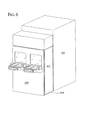
側部に外れるように回転させる代わりに、キャリア及びポートドアを、ロードポートから離れるように後方に移動させ、かつ、ロボット108による加工物移送の干渉を受けない他の位置に移動させることもできることが理解される。例えば、図8に示すように、水平方向の線形スライド121によりロードポートから後退させられると、キャリア及びポートドアは、水平駆動装置が取り付けられた垂直駆動装置により上方に上げることができる。さらに、プリアライナを含まないか、又はロードポート組立体より下にある他の部品を含まない本発明の実施形態においては、キャリア及びポートドアは、最初に、ロードポートから後退させられ、次いで、該ロードポートから離れるように下に下げることができる。さらに、ロボット108が開口部にアクセスできるのに十分な距離だけ、キャリア及びロードポートを、前進プレート組立体より下であるが、下げられたキャリア及びポートドアより上に、下方に移動させることが考えられる。このような実施形態は、以下に説明されるように、前面112上の一対のプリアライナ106により作動することができる。
After moving the carrier and port door away from the load port, the
Instead of rotating out of the side, the carrier and port door can be moved backward away from the load port and moved to another position that is not subject to workpiece transfer interference by the
好ましい実施形態においては、2つのロードポート組立体104は、床から900mmのSEMI標準高さで、固定された既知の位置で並列にプレート102にボルト留めされる。代替的な実施形態においては、単一のロードポード又は2つよりも多いロードポートがあってもよい。さらに、1つ又はそれ以上のロードポート組立体を、900mmよりも高く又は低く取り付けてもよい。例えば、ロードポートを、一方を他方の上部に垂直に積み重ねて、プレートの設置面積を減少させるようにすることができる。この積み重ね構成は、以下に説明されるように、ロボット108の垂直ストロークの増大によって可能になる。さらに、格納シェルフ(図示せず)をプレート102の前面112に設けて、オペレータがキャリアを手動で配置し、一時的に格納するようにすることができる。
In the preferred embodiment, the two
キャリアドアがキャリアシェルから分離され、ロードポート内に移動させられ、かつ該ロードポートから離れるように移動させられると、キャリア内の加工物は、ロボット108により移送される。ロボット108は、Z軸に沿った並進運動のために、プレート102の裏面114、ロードポートの下及び該ロードポートの側部に取り付けられる。並進運動のために、プレート102に固定的に取り付けられると、ロボット108は、該プレート102に対して精密で反復可能な動きで垂直に移動する。
当業者において周知のように、親ねじ(図示せず)を、プレート102上の軌道123内に、ロードポートの側部に取り付けることができ、該親ねじは、コントローラ109により制御されるブラシレス多極モータのような駆動機構の電機子に取り付けられる。キャリッジ(図示せず)は、駆動機構により親ねじが回転したとき、該キャリッジがZ軸に沿って駆動されるように、該親ねじの周りに取り付けられる。駆動機構及び/又は親ねじは、エンコーダ及び/又は該親ねじの位置及び角回転を感知する周知の構成の他の感知装置を含むことができる。軌道123上の垂直並進運動のためにロボットを取り付けることは、通常のマストを含むロボットと比較して、床からロボットアームが取り付けられた部分まで延びるロボットの潜在的なZストロークを増加させることになる。
When the carrier door is separated from the carrier shell, moved into the load port, and moved away from the load port, the workpiece in the carrier is transferred by the
As is well known to those skilled in the art, a lead screw (not shown) can be mounted in the
スタンチョン124は、プレート102上の軌道123内のキャリッジに固定的にボルト留めされ、かつ該キャリッジと共に並進運動する。ロードポート組立体の下に設けられたロボット108のZストローク取付け位置により、最低Z高さにおいて、ロボット108が加工物をプリアライナ106の最低位置に移送できるように、及び最高Z高さにおいて、該ロボット108が加工物を最高位置に移送できるように、スタンチョンは上方に或る角度だけ傾斜されている。スタンチョン124はさらに、ロボット108の回転軸が、2つのロードポート組立体104間のほぼ中心にあるように、プレートの中心に対して内向きに傾斜されている。垂直駆動装置をプレート102の側部ではなく、該プレート102の中央に取り付けることもでき、この場合、スタンチョン124は、内向きには傾斜されないことが理解される。
The
ロボットはさらに、スタンチョン124の上方端部に回転するように取り付けられた第1のアーム126と、該第1のアーム126に回転するように取り付けられた第2のアーム128とを含む。第1のアーム126は、スタンチョン124のZ軸移動に対して垂直な第1のX−Y平面における該スタンチョン124上で回転するように、軸受により取り付けられる。第2のアーム128は、第1のX−Y平面に対して平行な第2のX−Y平面における第1のアーム126上で回転するように、軸受により取り付けられる。第1のアーム126及び第2のアーム128は、例えば、陽極処理された表面仕上げを有するアルミニウムのような低いガス放出特性を有する軽量で耐久性のある金属で形成されることが好ましい。加工物処理ロボット108の作動は、コントローラ109により制御される。本発明によるシステムは、加工物を移送するための他の周知のロボット移送装置と併せて用いることもできることが理解される。このようなロボットシステムは、二重アームをもったロボット、線形摺動ロボット、所謂「カエル足」リンク機構式ロボット、及び6軸の産業用ロボットを含む。これらのロボットシステムの各々が、当業者に周知である。
The robot further includes a
加工物処理ロボット108はさらに、第1のアーム126の反対側にある第2のアーム128の端部にピボット運動可能に取り付けられたエンドエフェクタ130のような加工物支持ツールを含む。エンドエフェクタ130は、第1及び第2のX−Y平面に対して平行な第3のX−Y平面内における第2のアーム128上の取付け点の周りをピボット運動することができる。好ましい実施形態においては、エンドエフェクタ130は、加工物の並行処理を可能にする独立して作動させられる一対のパドルを含むことができる。加工物の並行処理のためのシステムが、バッブズ他への「加工物の並行処理のためのシステム」という名称の米国特許出願第09/547,551号に開示されており、この出願は、本発明の所有者に譲渡され、またこの出願は、引用により全体が本明細書に組み込まれる。このような実施形態においては、ロボット108は、第2のアーム128の端部に回転可能に連結された下方パドルと、該下方パドルに回転可能に連結された上方パドルとを含む二重パドルのエンドエフェクタを含む。この実施形態による加工物の加工については以下に説明する。さらに、エンドエフェクタ130は単一パドルからなることができることも理解される。
The
一実施形態においては、第1のアーム126、第2のアーム128、及びエンドエフェクタ130のピボット位置は、コントローラ109と機械的リンク機構との組合せによって互いに制御されており、該エンドエフェクタの下方パドルは、スタンチョン124上の該第1のアーム126のZ軸の回転から生じる放射部に沿って移動するように制約されている。別の実施形態においては、ロボットアーム及びエンドエフェクタを制御して、当業者に周知の所謂「経路計画アルゴリズム」に従って動くようにすることができる。代替的な実施形態においては、他のロボット運動が考えられることが理解される。
In one embodiment, the pivot positions of the
加工物を移送するために、エンドエフェクタ130は、移送されるべき加工物の下に水平移動し、次いで、その静止位置から該加工物を上昇させるために(親ねじに沿って進むキャリッジの結果として)上向きに移動する。当業者に周知のように、エンドエフェクタ130は、その縁部において加工物を支持するための縁部グリップを含むことができる。縁部グリップの位置は、加工物がエンドエフェクタとプリアライナとの間で移送される間に、該プリアライナ106の縁部グリップ(以下に説明される)を妨害しないように定められる。或いは、エンドエフェクタ130は、その底面により加工物を支持するブレード式のエンドエフェクタとすることができる。このような実施形態においては、真空源(図示せず)は、プレート102に固定されてもよいし又は該プレートから遠方にあってもよく、これにより、可撓性のある真空チューブを介して、加工物処理ロボットを通ってエンドエフェクタのブレード面に伝達される負圧が生成される。真空源が作動させられると、負圧がエンドエフェクタのブレード面に形成されて、加工物をその上にしっかりと保持することができる吸引が生成されるようになる。さらに、周知の構成の真空センサ(図示せず)をロボットに設けて、加工物がエンドエフェクタと係合されたことを検知して、真空チューブを通る空気の吸引を制限する真空システムと関連させるようにすることができる。本発明は、上述のエンドエフェクタに制限されるものではなく、しかも該エンドエフェクタが加工物を上昇させかつ降ろす能力を有する限り、種々のエンドエフェクタの設計を用いることができることが理解される。
To transfer the workpiece, the
本発明に用いるのに適した加工物処理ロボットの一例は、スタンチョン124を含むように改造されたカリフォルニア州フレモント所在のアシストテクノロジーズ社から入手可能な通常のAXYS−407シリーズのロボットである。しかしながら、本発明の実施形態は、加工物をワークステーション上のキャリアから取り出し、該加工物を所望の位置に再位置決めすることができる種々のシステムにより作動できることが理解される。
An example of a workpiece handling robot suitable for use with the present invention is the conventional AXYS-407 series robot available from Assist Technologies, Inc., Fremont, California, modified to include a
ロードポート組立体104又はロボット108は、加工物マッピング工程を実行して、キャリア内の該加工物の位置を求めるようにし、及び/又は、交差スロットが付けられた二重加工物をチェックするようにすることができる。キャリアドアと連結した後に外向きに揺れるポートドアにより作動する本発明の実施形態において、又は、上向き、下向き、又は側部に移動するポートドアを含む本発明の実施形態においては、加工物のマッピングは、ロボット108により達成することができる。このような実施形態の1つにおいては、周知の構成の光学センサをエンドエフェクタ130に取り付けることができる。加工物をマップするために、キャリア及びポートドアがロードポートから移動させられた後に、センサが並進運動する際に該キャリア内の加工物を走査する状態で、プレート102内の親ねじを回転させて、エンドエフェクタ130をZ軸に沿って、該キャリアの上部から底部に又はその逆に移動させるようにする。図9に示すように、センサ125をエンドエフェクタ130の最も前方の先端127に取り付けて、一方の先端から他方にビームを透過するようにすることができる。このような実施形態においては、センサ125は、通常の遮断ビーム型センサとすることができる。エンドエフェクタ130が垂直方向に移動すると、ビームは加工物Wによって遮断されて、該加工物の前に垂直ストロークが完了したときには、キャリアにおける各々の加工物の位置が分かるようになる。ビームが遮断されたときのエンドエフェクタ130の位置、及びビームが遮断される時間の長さもまた、交差スロットが付けられた二重加工物を示すことになる。
The
図9に示されるものに対する代替的な実施形態においては、センサ125は、エンドエフェクタ130の後部に取り付けることができる。この実施形態においては、エンドエフェクタ130は、加工物のマッピングのために、180°回転させられて、センサを含む該エンドエフェクタの後部がキャリアに面するようになる。この実施形態によるセンサは、加工物の縁部から反射され、該センサにおけるレシーバに反射し戻されるビームを発する伝送器を含むことができる。代替的な実施形態においては、この種類の反射システムをエンドエフェクタ130の前側に含むことができ、しかも、図9に関して説明された遮断ビーム型センサを該エンドエフェクタ130の後側に含むことができることが理解される。他の既知の検知方法が、加工物をマッピングすること及び交差スロットが付けられた二重加工物を検知することにおいて考えられる。
In an alternative embodiment to that shown in FIG. 9,
ツールの中に移動し、次いで垂直方向に上下移動するポートドアを含む本発明の実施形態においては、ウエハのマッピングは、代替的に、該ポートドアの上部(該ドアが下向きに移動する場合)に取り付けられたか又は該ポートドアの底部(該ドアが上向きに移動する場合)に取り付けられたフィンガに固定される既知の設計の光学センサにより達成することができる。本実施形態においては、加工物は、ポートドアが上向きに又は下向きに移動する際に、キャリアの中に延びるフィンガ上のセンサによりマップされる。センサ及びフィンガに関する詳細、並びにポート及びキャリアドアが上向きに又は下向きに移動する際に加工物をマップするさらに別の実施形態が、ローゼンクイスト他への「ウエハのマッピングシステム」という名称の米国特許第6,188,323号に開示されており、この特許は、本発明の所有者に譲渡され、またこの特許は、引用により全体が本明細書に組み込まれる。
ロードポート組立体104を直接プレート102の前面に対して90mmのところにボルト留めすることは、該前面112上の該ロードポート組立体104より下の空間を、付加的な部品のために利用できるようにする。本発明の好ましい実施形態においては、一対のプリアライナ106が、ロードポート組立体104より下のプレート102の前面112に対して定位置にボルト留めされる。プリアライナ106は、加工物の中心を識別し、該加工物のノッチを所望の方位に配置し、及び該加工物上の指示マークを読取るために設けられる。このようなプリアライナ106の1つが、以下に説明されるが、次の説明は、両方のプリアライナに当てはまるものである。
In an embodiment of the invention that includes a port door that moves into the tool and then moves up and down in the vertical direction, wafer mapping is alternatively on top of the port door (if the door moves downward). Or an optical sensor of known design fixed to a finger attached to the bottom of the port door (if the door moves upward). In this embodiment, the workpiece is mapped by sensors on the fingers that extend into the carrier as the port door moves upwards or downwards. US Patent titled "Wafer Mapping System" to Rosenquist et al., For further details on sensors and fingers, and for mapping workpieces as ports and carrier doors move upward or downward No. 6,188,323, which is assigned to the owner of the present invention and is hereby incorporated by reference in its entirety.
Bolting the
プリアライナ106は、ロボット108からの加工物を受け取る縁部接触式アライナ132を有する回転支持プラットフォームを含む。加工物がアライナ132内に受け取られると、傾斜の付けられた側部が、自動的に加工物を中心に置く。このことは、半径方向の振れの測定段階を省略することを可能にする。代替的には、加工物を通常の真空チャック上に受け取ることができ、この場合には、半径方向の振れの測定段階が必要になる。モータは、縁部接触式アライナ132を回転させて、加工物のノッチ位置を求めるようにする。特に、加工物が回転させられると、該加工物の縁部は、該加工物上のノッチ位置を求めることができるアナログセンサを通過する。指示マークは、ノッチから既知の距離にあって、該ノッチが求められると、該加工物をチャック上で回転させて、電荷結合ディスプレイ(CCD)カメラのようなカメラの下での読取りのために該指示マークを位置決めするようになっている。
The pre-aligner 106 includes a rotating support platform having an
好ましい実施形態においては、プリアライナ106はさらに、加工物バファリング機能を含む。このようなプリアライナは、コーディ他による「ウエハの方位付け及び読取り機構」という名称の米国特許出願第09/452,059号に開示されており、この出願は、本発明の所有者に譲渡され、またこの出願は、引用により全体が本明細書に組み込まれる。一般に、このようなプリアライナは、バッファパドル136と、該バッファパドル136を垂直方向に並進運動させる駆動機構138とを含む。作動においては、加工物は、ロボット108によってキャリアからプレート102の裏側に移送され、降下され、次いで、該プレート102における開口部136を通って該プレート102の前側にあるプリアライナ106のチャックに移送される。フィンガの各々においては示されていないが、プレートの前側にあるプリアライナ106は、該プレート102に固定された囲いに収容されて、該プレートの後ろの環境を共有するようにされる。この囲いをプレキシガラスのような透明な材料で形成して、オペレータがプリアライナ106上の作動を見ることができるようすることができる。代替的な実施形態においては、この囲いを他の材料で形成することができる。
In a preferred embodiment, the pre-aligner 106 further includes a workpiece buffering function. Such a pre-aligner is disclosed in US patent application Ser. No. 09 / 452,059 entitled “Wafer Orientation and Reading Mechanism” by Cody et al., Which is assigned to the owner of the present invention, This application is also incorporated herein by reference in its entirety. In general, such a pre-aligner includes a
第1の加工物がチャック上に載せられると、プリアライナ106は、ノッチの位置を特定し、位置決めし、及び指示マークを読取り及び/又は加工物の半径方向の振れを求める。その後、バッファパドルが、第1の加工物をチャックから上昇させる。プリアライナ106におけるこうした作動が行われている間、ロボット108は、キャリアに戻って第2の加工物を獲得し、該プリアライナ106に戻る。次に、ロボット108は、第2の加工物をチャック上に置いて加工し、中央に置かれた位置にあるバッファパドルから第1の加工物を獲得する。ロボット108は、次に、第1の加工物をキャリアに戻すか、又は該加工物をツール107の中に移送する。
As the first workpiece is placed on the chuck, the pre-aligner 106 locates and positions the notches and reads the indicator marks and / or determines the workpiece radial deflection. A buffer paddle then raises the first workpiece from the chuck. While such an operation in the pre-aligner 106 is taking place, the
第1の加工物がプリアライナ106から運び出された後で、第2の加工物上の加工が行われている間に、ロボット108は、第3の加工物を加工物キャリアから獲得し、該プリアライナ106に戻る。この時点では、バッファパドル136は、チャック上に定置された第2の加工物の上に位置決めされる。エンドエフェクタ130は、第3の加工物をバッファパドル上に置き、第2の加工物をチャックから獲得し、これをプリアライナ106から移動させる。その後、この上に第3の加工物をもったバッファパドルは、下方移動して、該第3の加工物をチャック上に置き、ノッチ位置が特定されると、指示マークが読み取られ、半径方向の振れが求められるようになる。プリアライナ106は、キャリア内の加工物の各々が加工されるまで、上記の段階を繰り返す。
After the first workpiece is transported from the pre-aligner 106, while processing on the second workpiece is taking place, the
上述のような2つのプリアライナ106は、二重パドルのエンドエフェクタ130と併せて、加工物の並行処理を可能にする。本発明の並行処理の一実施形態においては、ロボット108は、まず、加工物キャリア内の隣接したシェルフから一対の加工物を獲得することができる。キャリアから引き出された後に、エンドエフェクタ130上のそれぞれのパドルは、扇形に広がり、加工物をそれぞれのプリアライナ106(図3に示すような)のアライナ132に移送することができる。プリアライナ106上の加工物の加工が完了した後に、扇形に広げられたエンドエフェクタのパドル130は、該加工物を再び獲得することができ、上方パドルは、下方パドルのすぐ上に位置決めされた定位置に戻り、次いで、加工された加工物をその元のキャリア、新しいキャリア又はツールに戻すようにすることができる。この方法による加工物の並行処理は、改善された処理能力をもたらす。並行処理は、バファリング機能を備えているか、又は備えていないプリアライナ106を含む本発明の実施形態において行うことができる。
The two
プリアライナ106の好ましい実施形態について上で説明したが、代替的な実施形態においては、該プリアライナ106が、上で説明されたものと異なることがあることが理解される。例えば、代替的な実施形態においては、プリアライナ106は、プレート102の裏面114に取り付けられることが考えられる。さらに、プリアライナ106は、バファリング機能をもつ必要はない。
代替的な実施形態においては、プリアライナ106の機能は、主としてエンドエフェクタ130により実行することができる。特に、ウエハの位置合わせ及びID読取り機構は、エンドエフェクタ130の中に組み込むことができ、この実施形態においては、該エンドエフェクタは、加工物を把持することができる溝付きホイールを含む。1つ又はそれ以上のこれらのホイールを駆動して、加工物を方位付けるようにすることができる。加工物をエンドエフェクタ130において回転させて、ノッチが、透過ビーム型の光学センサ(又はID読取りカメラ自体を含む様々なセンサの種類)により位置付けられるようにすることができる。カメラは、エンドエフェクタ上に取り付けるか、又はロボット上の他の場所に、又はIDマークを読取るシステム内の他の場所に取り付けることができる。
Although a preferred embodiment of the pre-aligner 106 has been described above, it will be appreciated that in alternative embodiments, the pre-aligner 106 may differ from that described above. For example, in alternative embodiments, the pre-aligner 106 may be attached to the back surface 114 of the
In an alternative embodiment, the function of the pre-aligner 106 can be performed primarily by the
通常、ツールのフロントエンドに含まれる種々の他の部品もまた、代替的な実施形態においては、プレート102に固定的に取り付けることができることが理解される。例えば、ツールのフロントエンドは、通常は、クリーンな空気又は他の気体を該ツールのフロントエンドを通して循環させ、かつ該ツールのフロントエンドからの浮遊粒子及び汚染物質を除去するファン/フィルタ装置を含む。周知の構成のファン/フィルタ装置は、プレート102の上部に、又はフレーム110にボルト留めすることができる。ファン/フィルタ装置は、プレートに対して垂直な方位に、該プレートに対して平行な方位に、又は該プレートに対して中間の任意の角度に、該プレートにボルト留めすることができる。
It will be appreciated that various other components typically included in the front end of the tool can also be fixedly attached to the
フロントエンドシステム100はさらに、次の周知の部品のいずれかを含むことができる。
フロントエンド部品とツールコントローラとの間の通信を制御する「スマート−コム」多重化装置。
RF/IR識別装置、すなわち、キャリア内のRFピル又はIRタグから信号を受信する受信機及び/又は電源装置。RFピル及びIRタグは、加工物に関する情報を送るものである。このようなRFピル及びこれらを利用するシステムは、例えば、ロッシ他への米国特許第4,827,110号及び第4,888,473号、並びにシンドレー他への米国特許第5,339,074号に記載されている。このようなIRタグ及びこれらを利用するシステムは、例えば、マネー他への米国特許第5,097,421号、第4,974,166号、及び第5,166,884号に記載されている。上記の特許の各々が、本発明の所有者に譲渡され、また各々が、引用により全体が本明細書に組み込まれる。
加工物キャリアの複数の性能特性を監視するキャリア監視システム。このようなシステムに関する詳細は、レイモンドS.マーチンへの米国特許出願第09/641,032号に開示されており、この出願は、本発明の所有者に譲渡され、またこの出願は、引用により全体が本明細書に組み込まれる。
種々の指示部及び警告灯を含む前面112にあるライトタワー。
フロントエンド部品及びツールのオペレータ監視及び制御を可能にする前面112にあるグラフィカル・ユーザ・インタフェース(GUI)及びキーボード。
全フロントエンド及びツールの作動を緊急停止する前面112にある緊急オン/オフ・スイッチ。
静電気の蓄積を防止するためにプレート102の後ろの環境をイオン化する裏面114にあるイオン化バー。
前面112にあるライトカーテン及びオペレータ/搬送安全システム。このようなシステムに関する詳細は、フォスナイト他への米国特許出願第09/776,227号に開示されており、この出願は、本発明の所有者に譲渡され、またこの出願は、引用により全体が本明細書に組み込まれる。
電荷結合ディスプレイカメラ(CCD)のような加工物ID読取りカメラ、及び加工物の照明系。
フロントエンドにおける加工物を検査する前面112又は裏面114にある計測モジュール。このようなシステムに関する詳細が、ノーレンバーグへの米国特許第4,893,932号及びノーレンバーグ他への米国特許第5,493,123号に開示されており、これらの両方が、本発明の所有者に譲渡され、またこれらの両方が、引用により全体が本明細書に組み込まれる。
人誘導型車輌(PGV)のための通信ポート、すなわち、PGVドッキングとロードポート組立体106との適切な位置合わせを示すIRポート。
The
A “smart-com” multiplexer that controls communication between front-end components and the tool controller.
RF / IR identification device, ie receiver and / or power supply that receives signals from an RF pill or IR tag in a carrier. The RF pill and IR tag send information about the workpiece. Such RF pills and systems utilizing them are described, for example, in U.S. Pat. Nos. 4,827,110 and 4,888,473 to Rossi et al. And U.S. Pat. No. 5,339,074 to Sindley et al. In the issue. Such IR tags and systems utilizing them are described, for example, in US Pat. Nos. 5,097,421, 4,974,166, and 5,166,884 to Money et al. . Each of the above patents is assigned to the owner of the present invention, and each is incorporated herein by reference in its entirety.
A carrier monitoring system that monitors multiple performance characteristics of a workpiece carrier. Details regarding such systems can be found in Raymond S.W. No. 09 / 641,032 to Martin, which is assigned to the owner of the present invention, which is also incorporated herein by reference in its entirety.
A light tower on the front 112 containing various indicators and warning lights.
A graphical user interface (GUI) and keyboard on the front 112 that allows operator monitoring and control of front-end components and tools.
Emergency on / off switch on
An ionization bar on the back surface 114 that ionizes the environment behind the
Light curtain on
A workpiece ID reading camera such as a charge coupled display camera (CCD), and a workpiece illumination system.
A measuring module on the
A communication port for a human guided vehicle (PGV), ie, an IR port that indicates proper alignment of the PGV docking with the
さらに、通常の方法で、ツールのフロントエンド内に形成された他の周知の部品をプレート102の前面112又は裏面114に固定することができることが理解される。
本発明においては、フロントエンド部品の各々は、定位置においてプレート102に取り付けられる(ロボット108は、周知の経路に沿って垂直方向に並進運動できるようにプレートに固定される)。このようにフロントエンド部品を統合することには、幾つかの利点がある。第1に、すべてのフロントエンド部品は、単一の参照プレートから参照される。従来技術のフロントエンド装置においては、部品は、異なる支持機構に固定されていた。このことは、システムが構築されたときに許容差を増加させ、ツールのフロントエンドが取り付けられるか又はその後に改造される度に、かなりの位置合わせ手順を必要とした。各々の部品を単一の参照プレートに取り付けておくことは、フロントエンドシステムの許容差を大幅に小さくし、フロントエンド部品の互いの位置について、かなりの程度の精度及び反復性をもたらすことになる。このことは、逆に、フロントエンドシステムを取り付けるか又は改造する場合に要求される調整を大幅に削減することになる。第2に、単一の製造業者によって作られた単一システムの中に部品のすべてを統合することは、該部品の相互運用性を改善することになる。第3に、本発明によるフロントエンドシステム内の部品数は、通常のフロントエンドシステムと比較して減らされているが、同時に、従来技術のシステム機能のすべてが維持されている。第4に、部品を単一プレート上に統合することは、組み合わされたフロントエンド及びツールの全体の設置面積を減少させる可能性をもたらすことになる。
Further, it will be appreciated that other known components formed in the front end of the tool can be secured to the
In the present invention, each of the front end components is attached to the
さらに別の利点が、フロントエンドシステム100内の部品の各々が、単一のコントローラ109によって監視されて制御されるという点で本発明により提供される。好ましい実施形態においては、コントローラ109は、ロードポート組立体104、プリアライナ106、ロボット108、及び場合によっては、RS232インタフェースを介する付加的なフロントエンド部品が連結された複数のシリアルポートを含むコンピュータその他のプログラム可能な計算装置である。コントローラ109は、プレート102の前面又は裏面上のシェルフに固定することができ、さらに、遠隔サーバへのイーサネット接続を含んでもよい。コントローラ109は、代替的には、プレート102から離れて配置されてもよい。グラフィック・ユーザ・インタフェース(GUI)(図示せず)がさらに、コントローラ109の一部として設けられて、オペレータ・インタフェースをフロントエンドシステム100に与えるようにすることができる。
Yet another advantage is provided by the present invention in that each of the components in the
従来技術のフロントエンド部品は、異なる部品供給業者により製造され、各々が独自のコントローラ、独自のソフトウェア、及び独自のシリアル及びパラレル通信線を備えていた。ハードウェアの複製に加えて、カスタマイズされたソフトウェアプロトコルが、異なる供給業者からの種々のコントローラと部品との間の適切な通信を確実にするために開発されなければならなかった。単一のコントローラにより作動する統合フロントエンドシステムを設けることは、システム全体のソフトウェア制御を大幅に単純化する。さらに、単一のコントローラを有することは、フロントエンド作動に必要な部品及びケーブル数を減少させる。このことは、より容易な取り付け及びシステム制御の保守を可能にする。 Prior art front end components were manufactured by different component suppliers, each with its own controller, its own software, and its own serial and parallel communication lines. In addition to hardware replication, customized software protocols had to be developed to ensure proper communication between various controllers and components from different suppliers. Providing an integrated front-end system that operates with a single controller greatly simplifies software control of the entire system. In addition, having a single controller reduces the number of parts and cables required for front end operation. This allows for easier installation and system control maintenance.
フロントエンドシステム100の好ましい構成が図示されかつ上述されているが、他のフロントエンド構成も考えられる。例えば、好ましくはないが、決してフロントエンド部品のすべてをフロントエンドシステム100に統合することができるわけではない。例えば、図10及び図11に示すように、ロードポート組立部品、つまり、前進プレート組立体及びポートドア組立部品をプレート102に取り付けることができる。この実施形態においては、ロボット108及び/又はプリアライナ106は、例えば、プレート102から離れた支持構造体に取り付けられることにより、又は支持構造体に取り付けられ、すなわち次いで該プレート102に取り付けられることにより、該プレートから離れて取り付けられる。ロードポート組立体104に加えて、ロボット108又はプリアライナ106のいずれかがプレート102に取り付けられ、残りの部品が該プレート102から離れて取り付けられることも、さらに考えられる。
Although a preferred configuration of the
さらに代替的な実施形態においては、フロントエンドシステムは、3つ、4つ、又はそれ以上の並列ロードポート組立体104からなることができる。このような実施形態においては、周知の構成の水平線形スライド(軌道123と同様な軌道を含むような)をプレート102に取り付けることができ、周知の構成の垂直線形スライドを該水平スライドの真上に取り付けることができる。第1のアーム126及び第2のアーム128は、水平スライドの真上に取り付けられることになる。このような実施形態においては、水平スライド及び垂直スライドは、エンドエフェクタ130が種々のロードポート組立体104において加工物を上昇させかつ降ろすことができるように、アームを所望のX位置及びY位置に位置決めすることができる。2つよりも多い並列ロードポート組立体を含むさらに別の代替的な実施形態においては、上述のような第2のロボット108を、裏面114上に及び第1のロボット108が固定されたプレート102の側面と反対の該プレート102の側面に取り付けることができる。このような実施形態においては、第1のロボット108は、ロードポート及びプリアライナをプレート102の第1の側面に与え、第2のロボット108は、該ロードポート及びプリアライナを、該プレートの第2の反対側面に与えることができる。効率的な設計ではないが、上述のようなスタンチョン124に取り付けられた水平線形スライドを含むロボット108又は上述のような第2のロボットを、2つだけのロードポート組立体104を含むフロントエンドシステム100の実施形態に用いることが考えられる。
In a further alternative embodiment, the front end system may consist of three, four, or more parallel
本発明の別の特徴は、部品の各々が単一プレート上に統合させられると、フロントエンドシステム100が第1のツールから容易に切り離され、異なるツールまでまとめて運ばれ、新しいツールに固定されることができるようになるということである。ツールのフロントエンド全体のこのような移送は、従来技術においては達成できないものであった。本発明によるフロントエンドシステム100がツール107から取り外されているか、或いは該ツール107に取り付けられていない場合には、ブランクプレートをツールの前面に固定することができる。フロントエンドシステム100をツール107に固定するのに用いられるようなフレーム110を用いて、ブランクプレートをツール107に固定するようにすることができる。本発明の実施形態においては、幾つかの又はすべてのフロントエンド部品を含む部品は、これらが容易にフレーム110若しくはそれに類するものか、又はツール107に取り付けられ、これから取り外され、ツール間で移動させることができるように、プレート102に取り付けることができる。単一装置としてのフロントエンドシステムの移動性に関する本発明の実施形態においては、それぞれの支持部材が互いに取り付けられている状態で、フロントエンド部品を1つよりも多い支持部材に固定することができることが理解される。
Another feature of the present invention is that once each of the parts is integrated on a single plate, the
本発明によるフロントエンドシステム100は、一体構成の剛性部材からなり、フロントエンド部品は、固定の反復位置で該剛性部材に取り付けられる(ロボットは、該剛性部材に対して固定的に並進運動できるように該剛性部材に取り付けられる)。この時点までは、剛性部材は、ツール107の前面に固定された垂直プレート102として述べられた。代替的な実施形態においては、フロントエンド部品の各々が取り付けられた剛性部材は、垂直である必要はなく、かつこれはプレートである必要もない。
The
例えば、このような代替的な実施形態の1つにおいては、剛性部材は、ツール107のフロントエンド内に取り付けられた水平プレートとすることができる。このような実施形態においては、ロードポート組立体、プリアライナ106、及びロボット108を、互いに固定の反復可能な関係でプレートの上部に取り付けることができる。本実施形態においては、垂直パネルを参照プレートの上及び/又は下に取り付けて、ツール107のフロントエンドをシールするようにすることができる。垂直パネルは、ロードポート組立体104が該垂直パネルの前側の参照プレートに取り付けられ、ロボット108が該垂直パネルの裏側の参照プレートに取り付けられるように、水平参照プレートを交差することになる。プリアライナ106は、垂直パネルの前側又は裏側の参照プレートに取り付けることができる。
For example, in one such alternative embodiment, the rigid member can be a horizontal plate mounted within the front end of the
前述のように、単一の参照プレートからのフロントエンド部品のすべてを統合することは、該プレートの前面112上のロードポート組立体104より下の空間を開放する。この空間は、通常のフロントエンドシステムにおいては使用されていなかった。この空間を、前述のようにプリアライナ106のために用いることができる。これに付加する形で又はこれに代わり、これを、加工物キャリアから独立した隣接するツール間で個々の加工物を移送するために用いることもできる。このような実施形態が、図12及び図13に示される。本実施形態においては、ポート140を、ロードポートより下のプレート102に設けることができ、該ポートが、シールされたトンネル142に連結する。トンネル142は、コンベヤ146上の2つ又はそれ以上のツール107間で搬送される1つ又はそれ以上の加工物カセット144を収容することができる(図13は、ポート140、カセット144、及びコンベヤ146を示すようにトンネル142の一部が切り取られた図12の拡大図である)。コンベヤ146は、ベルト移送組立体のような周知の移送システムとすることができる。トンネル142は、その反対側の端部を第2のフロントエンド装置100のポート140に連結するか、又は複数のフロントエンド装置100に連結することができる。トンネル142の上部は、好ましくは、床からおよそ2’から3’とすることができる。従って、通路及び他の機械を設けて、オペレータがトンネル142を乗り越え、ツール間を歩いて移動できるようにすることができる。
As described above, integrating all of the front end components from a single reference plate frees up space below the
作動において、ロボット108は、ポート140を介して1つの加工物又は少数の加工物を待機している加工物カセットまで移送する。次に、コンベヤ146が、トンネル142を介して、カセット144を行先のフロントエンド装置まで移送し、ここで該コンベヤ146は止まり、次の装置のロボット108が加工物をそのフロントエンド装置の中に移送する。このようなシステムは、従来のツール間搬送機又はシールされた加工物キャリアの関与を要することなく、近くのツール間で1つの加工物又は少数の加工物を迅速に移動させることを可能にする。さらに、トンネル移送システムは、従来のツール間搬送及び加工物キャリアシステムの側に沿って及びこれと同時に作動することができる。いずれも他方の作動を妨げることはない。
In operation, the
図12及び図13に示される実施形態においては、それぞれのツール107は、互いから離して配設される。ツールが互いに並列接触することは、ファブにおいてはよく起こることである。このようなツールの場合には、加工物のツール間搬送は、図12及び図13に示される実施形態によって、つまり、プレート102の前側で行うことができる。或いは、互いに接触している並列のツールにおいては、該ツールの隣接するパネル111を省くこともできるし、又はシール可能なポートを用いて形成することもでき、それぞれのツールのロボットが、加工物をプレート102の後ろの該ツール間で引き渡すことができるようになっている。このような実施形態においては、引き渡し用のシェルフ(図示せず)を一方の又は両方のツールに設けて、移送されるべき加工物を受け取るようにすることができる。このシェルフは、両方のツールからのロボットによってアクセス可能となる。引き渡しシェルフは、加工物を縁部で支持することが好ましく、能動的な又は受動的な加工物支持機構を含むことができる。
In the embodiment shown in FIGS. 12 and 13, the
加工物は、そこで加工が行われた後に、検査を必要とすることが多い。例えば、加工用ツールにおいて半導体ウエハが加工された後に、加工物は、加工物キャリアに戻され、次いで、該キャリアは、試験及び検査のために計測ツールに移送される。図12及び図13に示される実施形態においては、加工物の加工及び検査は、トンネル142によって加工用ツールと計測ツールとを接合することにより能率化することができる。通常の作業の流れを中断させることなく、単一のウエハをウエハロットからサンプリングすることができる。計測ツールを、同様に、多数の加工用ツールに接合することができ、逆もまた同様である。加工用ツール及び計測ツールに加えて、非常に多くの他種のツールも、同様に、トンネル142又は上述のような加工物の並列の引き渡しによってリンクすることができることが理解される。
The workpiece often requires inspection after it has been processed there. For example, after a semiconductor wafer is processed in a processing tool, the workpiece is returned to a workpiece carrier, which is then transferred to a metrology tool for testing and inspection. In the embodiment shown in FIGS. 12 and 13, the processing and inspection of the workpiece can be streamlined by joining the processing tool and the measurement tool through the
図12及び図13のシステムは、通常は、加工物キャリア内の加工物の「ポッディング・アップ」を必要とする幾つかの異なる工程段階をリンクし、ツール間搬送システムを用いる方法を提供する。多くの場合、ファブは、少ない量の、単一の又は非常に少ない枚数のウエハだけによって満たすことができる非常に緊急の注文を受け入れるものである。図12及び図13の実施形態は、この作業を達成するための迅速な、クリーンで効率的な方法を提供するものである。
本発明は本明細書において詳細に説明されているが、本発明が本明細書において開示された実施形態に限定されるものではないことを理解されたい。当業者であれば、添付の特許請求の範囲によって説明され、定められる本発明の精神又は範囲から逸脱することなく、本発明に種々の変更、代用及び修正を行うことができる。
The system of FIGS. 12 and 13 provides a method of using a tool-to-tool transport system that links several different process steps that typically require “podding up” the workpiece in the workpiece carrier. . In many cases, the fab accepts very urgent orders that can be filled with only a small quantity, a single or very few wafers. The embodiment of FIGS. 12 and 13 provides a quick, clean and efficient way to accomplish this task.
Although the invention has been described in detail herein, it should be understood that the invention is not limited to the embodiments disclosed herein. Those skilled in the art can make various changes, substitutions and modifications to the present invention without departing from the spirit or scope of the present invention as described and defined by the appended claims.
Claims (17)
第1の取付け面と、前記加工用ツールに締結するようにされた第2の取付け面と、前記加工物が通って移動する少なくとも1つの開口部とを有するプレートと、
前記プレートの前記第1の取付け面に取り付けられたロードポート組立体と、
前記加工物を位置合わせするプリアライナと、
各々の加工物を、前記加工物のコンテナと、前記加工用ツールと、前記プリアライナとの間で移送するようにされた加工物処理ロボットと、
前記ロードポート組立体と、前記プリアライナと、前記加工物処理ロボットとを作動関係に制御して連係させるコントローラと、
を備えることを特徴とするシステム。 A system for transferring a workpiece between a workpiece container and a processing tool,
A plate having a first mounting surface, a second mounting surface adapted to be fastened to the processing tool, and at least one opening through which the workpiece moves;
A load port assembly attached to the first mounting surface of the plate;
A pre-aligner for aligning the workpiece;
A workpiece processing robot adapted to transfer each workpiece between the workpiece container, the processing tool, and the pre-aligner;
A controller for controlling and linking the load port assembly, the pre-aligner, and the workpiece processing robot in an operating relationship;
A system comprising:
前記囲いは前記加工用ツール及び前記第2の加工用ツールと気密シールを形成して維持するようにされており、前記加工物を外側の周囲環境から隔離する一方で、該加工物は前記加工用ツールと前記第2の加工用ツールとの間で搬送されるようになっており、
前記加工物を前記加工用ツールと前記第2の加工用ツールとの間で搬送する前記囲いの中に位置させられたコンベヤシステム、
をさらに備えることを特徴とする請求項1に記載のシステム。 An enclosure having a first input / output port attached to the first attachment surface and a second input / output port attached to a second processing tool;
The enclosure is adapted to form and maintain a hermetic seal with the processing tool and the second processing tool to isolate the workpiece from the outside ambient environment, while the workpiece is the processing tool. And is conveyed between the second tool and the second processing tool,
A conveyor system positioned in the enclosure for conveying the workpiece between the processing tool and the second processing tool;
The system of claim 1, further comprising:
加工物を通す開口部を有し、前記加工用ツールに締結するようにされたプレートと、
前記プレートに取り付けられたロードポート組立体と、
前記加工物を位置合わせするプリアライナと、
前記加工物を前記加工物のコンテナと、前記加工用ツールと、前記プリアライナとの間に移送する加工物処理ロボットと、
を備えることを特徴とするシステム。 A system for transferring a workpiece between a workpiece container and a processing tool,
A plate having an opening through which a workpiece is passed and adapted to be fastened to the processing tool;
A load port assembly attached to the plate;
A pre-aligner for aligning the workpiece;
A workpiece processing robot for transferring the workpiece between the workpiece container, the processing tool, and the pre-aligner;
A system comprising:
Applications Claiming Priority (2)
| Application Number | Priority Date | Filing Date | Title |
|---|---|---|---|
| US30598001P | 2001-07-16 | 2001-07-16 | |
| PCT/US2002/022097 WO2003009347A2 (en) | 2001-07-16 | 2002-07-11 | Integrated system for tool front-end workpiece handling |
Publications (2)
| Publication Number | Publication Date |
|---|---|
| JP2005520321A true JP2005520321A (en) | 2005-07-07 |
| JP2005520321A5 JP2005520321A5 (en) | 2006-01-05 |
Family
ID=23183213
Family Applications (1)
| Application Number | Title | Priority Date | Filing Date |
|---|---|---|---|
| JP2003514594A Pending JP2005520321A (en) | 2001-07-16 | 2002-07-11 | Integrated system for tool front-end workpiece processing |
Country Status (4)
| Country | Link |
|---|---|
| US (1) | US7419346B2 (en) |
| JP (1) | JP2005520321A (en) |
| TW (1) | TW591736B (en) |
| WO (1) | WO2003009347A2 (en) |
Cited By (6)
| Publication number | Priority date | Publication date | Assignee | Title |
|---|---|---|---|---|
| JP2006245508A (en) * | 2005-03-07 | 2006-09-14 | Kawasaki Heavy Ind Ltd | Assembling method for substrate transferring device and carrying system unit of substrate transferring device |
| JP2007335475A (en) * | 2006-06-12 | 2007-12-27 | Kawasaki Heavy Ind Ltd | Conveyance system unit for substrate transfer apparatus |
| JP2009509316A (en) * | 2005-07-11 | 2009-03-05 | ブルックス オートメーション インコーポレイテッド | Load port module |
| JP2013051443A (en) * | 2007-11-21 | 2013-03-14 | Yaskawa Electric Corp | Transfer robot, housing, semiconductor manufacturing apparatus, and sorter device |
| JP2020009825A (en) * | 2018-07-04 | 2020-01-16 | シンフォニアテクノロジー株式会社 | Load port and EFEM |
| JP2021101472A (en) * | 2016-11-10 | 2021-07-08 | アプライド マテリアルズ インコーポレイテッドApplied Materials,Incorporated | Load port device, system, and method for manufacturing electronic device |
Families Citing this family (39)
| Publication number | Priority date | Publication date | Assignee | Title |
|---|---|---|---|---|
| US6678583B2 (en) * | 2001-08-06 | 2004-01-13 | Seminet, Inc. | Robotic storage buffer system for substrate carrier pods |
| JP4323129B2 (en) * | 2002-02-15 | 2009-09-02 | 株式会社ディスコ | Plate-like material transport mechanism |
| WO2004088743A1 (en) * | 2003-03-28 | 2004-10-14 | Hirata Corporation | Substrate transportation system |
| US8639365B2 (en) * | 2003-11-10 | 2014-01-28 | Brooks Automation, Inc. | Methods and systems for controlling a semiconductor fabrication process |
| US10086511B2 (en) | 2003-11-10 | 2018-10-02 | Brooks Automation, Inc. | Semiconductor manufacturing systems |
| US20070269297A1 (en) | 2003-11-10 | 2007-11-22 | Meulen Peter V D | Semiconductor wafer handling and transport |
| US20070282480A1 (en) * | 2003-11-10 | 2007-12-06 | Pannese Patrick D | Methods and systems for controlling a semiconductor fabrication process |
| US8639489B2 (en) * | 2003-11-10 | 2014-01-28 | Brooks Automation, Inc. | Methods and systems for controlling a semiconductor fabrication process |
| US7607879B2 (en) | 2004-06-15 | 2009-10-27 | Brooks Automation, Inc. | Substrate processing apparatus with removable component module |
| US20080075564A1 (en) * | 2004-09-24 | 2008-03-27 | Hirata Corporation | Container Carrying Equipment |
| US8025473B2 (en) * | 2004-10-25 | 2011-09-27 | Tokyo Electron Limited | Carrying system, substrate treating device, and carrying method |
| DE102004057057A1 (en) * | 2004-11-25 | 2006-06-01 | Leica Microsystems Cms Gmbh | Substrate workstation and add-on module for a substrate workstation |
| US7410340B2 (en) * | 2005-02-24 | 2008-08-12 | Asyst Technologies, Inc. | Direct tool loading |
| US9457442B2 (en) * | 2005-06-18 | 2016-10-04 | Futrfab, Inc. | Method and apparatus to support process tool modules in a cleanspace fabricator |
| US7762755B2 (en) * | 2005-07-11 | 2010-07-27 | Brooks Automation, Inc. | Equipment storage for substrate processing apparatus |
| TWM304619U (en) * | 2006-04-28 | 2007-01-11 | Fortrend Taiwan Scient Corp | Nitrogen cabinet with distinguishing and inflating apparatuses |
| TWI452643B (en) * | 2006-05-11 | 2014-09-11 | Tokyo Electron Ltd | Inspection device and inspection method |
| KR100909494B1 (en) * | 2006-05-11 | 2009-07-27 | 도쿄엘렉트론가부시키가이샤 | Processing equipment |
| DE102006029003A1 (en) * | 2006-06-24 | 2008-01-03 | Vistec Semiconductor Systems Gmbh | Wafer e.g. semiconductor wafer, handling device, has tool rack with tool component, base rack and robot for moving wafers, and robot mounted on coupling rack that is mounted directly on base rack independently of tool rack |
| US9117859B2 (en) | 2006-08-31 | 2015-08-25 | Brooks Automation, Inc. | Compact processing apparatus |
| US7740437B2 (en) | 2006-09-22 | 2010-06-22 | Asm International N.V. | Processing system with increased cassette storage capacity |
| US20080131244A1 (en) * | 2006-11-29 | 2008-06-05 | Pouch Pac Innovations, Llc | System, method and machine for continuous loading of a product |
| US9834378B2 (en) * | 2006-12-22 | 2017-12-05 | Brooks Automation, Inc. | Loader and buffer for reduced lot size |
| US7585142B2 (en) * | 2007-03-16 | 2009-09-08 | Asm America, Inc. | Substrate handling chamber with movable substrate carrier loading platform |
| US8459922B2 (en) * | 2009-11-13 | 2013-06-11 | Brooks Automation, Inc. | Manipulator auto-teach and position correction system |
| US8859103B2 (en) | 2010-11-05 | 2014-10-14 | Joseph Eugene Canale | Glass wafers for semiconductor fabrication processes and methods of making same |
| CN102222605B (en) * | 2011-06-08 | 2013-05-15 | 致茂电子(苏州)有限公司 | Wafer conveying device with fragment detection |
| TW201344808A (en) * | 2012-04-25 | 2013-11-01 | Hon Hai Prec Ind Co Ltd | Assembly device |
| US8944739B2 (en) * | 2012-06-01 | 2015-02-03 | Taiwan Semiconductor Manufacturing Co., Ltd. | Loadport bridge for semiconductor fabrication tools |
| TW201502733A (en) * | 2013-07-04 | 2015-01-16 | 鴻海精密工業股份有限公司 | Vision registration system, device and method |
| US10054482B2 (en) * | 2014-09-22 | 2018-08-21 | Antonio Maccari | Tool for positioning a scanning device |
| US9698036B2 (en) * | 2015-11-05 | 2017-07-04 | Lam Research Corporation | Stacked wafer cassette loading system |
| US9987747B2 (en) * | 2016-05-24 | 2018-06-05 | Semes Co., Ltd. | Stocker for receiving cassettes and method of teaching a stocker robot disposed therein |
| US10541165B2 (en) * | 2016-11-10 | 2020-01-21 | Applied Materials, Inc. | Systems, apparatus, and methods for an improved load port backplane |
| US10533852B1 (en) * | 2018-09-27 | 2020-01-14 | Taiwan Semiconductor Manufacturing Company, Ltd. | Leveling sensor, load port including the same, and method of leveling a load port |
| JP7362308B2 (en) * | 2019-06-17 | 2023-10-17 | 株式会社ディスコ | processing equipment |
| KR102256132B1 (en) * | 2020-02-18 | 2021-05-25 | (주)캔탑스 | Automated Material Handling System for Managing Carrier Internal Pollution |
| CN112566413B (en) * | 2020-12-11 | 2022-03-29 | 江苏星网软件有限公司 | Computer data acquisition device and use method thereof |
| US20220285193A1 (en) * | 2021-03-04 | 2022-09-08 | Applied Materials, Inc. | Shortened load port for factory interface |
Family Cites Families (20)
| Publication number | Priority date | Publication date | Assignee | Title |
|---|---|---|---|---|
| US4682927A (en) * | 1982-09-17 | 1987-07-28 | Nacom Industries, Incorporated | Conveyor system |
| US4775281A (en) * | 1986-12-02 | 1988-10-04 | Teradyne, Inc. | Apparatus and method for loading and unloading wafers |
| US5417537A (en) * | 1993-05-07 | 1995-05-23 | Miller; Kenneth C. | Wafer transport device |
| US5344365A (en) * | 1993-09-14 | 1994-09-06 | Sematech, Inc. | Integrated building and conveying structure for manufacturing under ultraclean conditions |
| TW297910B (en) * | 1995-02-02 | 1997-02-11 | Tokyo Electron Co Ltd | |
| ATE275759T1 (en) * | 1995-03-28 | 2004-09-15 | Brooks Automation Gmbh | LOADING AND UNLOADING STATION FOR SEMICONDUCTOR PROCESSING SYSTEMS |
| US5980195A (en) * | 1996-04-24 | 1999-11-09 | Tokyo Electron, Ltd. | Positioning apparatus for substrates to be processed |
| US6009890A (en) * | 1997-01-21 | 2000-01-04 | Tokyo Electron Limited | Substrate transporting and processing system |
| US6053688A (en) * | 1997-08-25 | 2000-04-25 | Cheng; David | Method and apparatus for loading and unloading wafers from a wafer carrier |
| US6138721A (en) * | 1997-09-03 | 2000-10-31 | Asyst Technologies, Inc. | Tilt and go load port interface alignment system |
| US6002840A (en) * | 1997-09-30 | 1999-12-14 | Brooks Automation Inc. | Substrate transport apparatus |
| US6157450A (en) * | 1998-03-09 | 2000-12-05 | Chapman Instruments | Automated optical surface profile measurement system |
| US6206176B1 (en) * | 1998-05-20 | 2001-03-27 | Applied Komatsu Technology, Inc. | Substrate transfer shuttle having a magnetic drive |
| US6501070B1 (en) * | 1998-07-13 | 2002-12-31 | Newport Corporation | Pod load interface equipment adapted for implementation in a fims system |
| JP2000286318A (en) * | 1999-01-27 | 2000-10-13 | Shinko Electric Co Ltd | Transfer system |
| US6042324A (en) * | 1999-03-26 | 2000-03-28 | Asm America, Inc. | Multi-stage single-drive FOUP door system |
| JP4255091B2 (en) * | 1999-04-07 | 2009-04-15 | 株式会社日立国際電気 | Semiconductor manufacturing method |
| US6520727B1 (en) * | 2000-04-12 | 2003-02-18 | Asyt Technologies, Inc. | Modular sorter |
| JP4021125B2 (en) * | 2000-06-02 | 2007-12-12 | 東京エレクトロン株式会社 | Rail straightness holding device used when connecting equipment unit of wafer transfer equipment |
| US6585470B2 (en) * | 2001-06-19 | 2003-07-01 | Brooks Automation, Inc. | System for transporting substrates |
-
2002
- 2002-07-11 JP JP2003514594A patent/JP2005520321A/en active Pending
- 2002-07-11 WO PCT/US2002/022097 patent/WO2003009347A2/en active Application Filing
- 2002-07-12 US US10/194,702 patent/US7419346B2/en not_active Expired - Lifetime
- 2002-07-16 TW TW091115847A patent/TW591736B/en not_active IP Right Cessation
Cited By (18)
| Publication number | Priority date | Publication date | Assignee | Title |
|---|---|---|---|---|
| JP2006245508A (en) * | 2005-03-07 | 2006-09-14 | Kawasaki Heavy Ind Ltd | Assembling method for substrate transferring device and carrying system unit of substrate transferring device |
| JP4579723B2 (en) * | 2005-03-07 | 2010-11-10 | 川崎重工業株式会社 | Transport system unit and divided body |
| JP2009509316A (en) * | 2005-07-11 | 2009-03-05 | ブルックス オートメーション インコーポレイテッド | Load port module |
| US11121017B2 (en) | 2005-07-11 | 2021-09-14 | Brooks Automation, Inc. | Load port module |
| KR101313231B1 (en) * | 2005-07-11 | 2013-09-30 | 브룩스 오토메이션 인코퍼레이티드 | Substrate loading device |
| JP2007335475A (en) * | 2006-06-12 | 2007-12-27 | Kawasaki Heavy Ind Ltd | Conveyance system unit for substrate transfer apparatus |
| JP4606388B2 (en) * | 2006-06-12 | 2011-01-05 | 川崎重工業株式会社 | Transfer system unit for substrate transfer equipment |
| US7942619B2 (en) | 2006-06-12 | 2011-05-17 | Kawasaki Jukogyo Kabushiki Kaisha | Carrier unit of substrate transfer apparatus |
| JP2013062534A (en) * | 2007-11-21 | 2013-04-04 | Yaskawa Electric Corp | Transfer robot, cabinet, semiconductor manufacturing device and sorter device |
| JP2013049133A (en) * | 2007-11-21 | 2013-03-14 | Yaskawa Electric Corp | Transfer robot, housing, semiconductor manufacturing device and sorter device |
| JP2014060464A (en) * | 2007-11-21 | 2014-04-03 | Yaskawa Electric Corp | Housing, semiconductor manufacturing apparatus and sorter apparatus |
| JP2014111310A (en) * | 2007-11-21 | 2014-06-19 | Yaskawa Electric Corp | Transport robot, housing, semiconductor manufacturing device, and sorter device |
| JP2013051443A (en) * | 2007-11-21 | 2013-03-14 | Yaskawa Electric Corp | Transfer robot, housing, semiconductor manufacturing apparatus, and sorter device |
| JP2021101472A (en) * | 2016-11-10 | 2021-07-08 | アプライド マテリアルズ インコーポレイテッドApplied Materials,Incorporated | Load port device, system, and method for manufacturing electronic device |
| KR20210092342A (en) * | 2016-11-10 | 2021-07-23 | 어플라이드 머티어리얼스, 인코포레이티드 | Electronic device manufacturing load port apparatus, systems, and methods |
| KR102530954B1 (en) * | 2016-11-10 | 2023-05-09 | 어플라이드 머티어리얼스, 인코포레이티드 | Electronic device manufacturing load port apparatus, systems, and methods |
| JP2020009825A (en) * | 2018-07-04 | 2020-01-16 | シンフォニアテクノロジー株式会社 | Load port and EFEM |
| JP7177333B2 (en) | 2018-07-04 | 2022-11-24 | シンフォニアテクノロジー株式会社 | Loadport and EFEM |
Also Published As
| Publication number | Publication date |
|---|---|
| WO2003009347A3 (en) | 2003-11-20 |
| TW591736B (en) | 2004-06-11 |
| WO2003009347A2 (en) | 2003-01-30 |
| US20030091409A1 (en) | 2003-05-15 |
| US7419346B2 (en) | 2008-09-02 |
Similar Documents
| Publication | Publication Date | Title |
|---|---|---|
| JP2005520321A (en) | Integrated system for tool front-end workpiece processing | |
| KR100616125B1 (en) | Opening system compatible with a vertiacl interface | |
| US6082949A (en) | Load port opener | |
| US6135698A (en) | Universal tool interface and/or workpiece transfer apparatus for SMIF and open pod applications | |
| TW579538B (en) | Wafer engine | |
| JP4309263B2 (en) | Semiconductor tool interface frame | |
| JP4309264B2 (en) | Semiconductor material handling equipment | |
| US7976263B2 (en) | Integrated wafer transfer mechanism | |
| US6520727B1 (en) | Modular sorter | |
| US8277165B2 (en) | Transfer mechanism with multiple wafer handling capability | |
| KR20020047037A (en) | Cassette buffering within a minienvironment | |
| JP4542893B2 (en) | Substrate loading and unloading station with buffer | |
| WO1999060625A1 (en) | Method and apparatus for wafer transportation, exposure system, micro device, and reticle library |
Legal Events
| Date | Code | Title | Description |
|---|---|---|---|
| A521 | Written amendment |
Free format text: JAPANESE INTERMEDIATE CODE: A523 Effective date: 20050627 |
|
| A621 | Written request for application examination |
Free format text: JAPANESE INTERMEDIATE CODE: A621 Effective date: 20050627 |
|
| A131 | Notification of reasons for refusal |
Free format text: JAPANESE INTERMEDIATE CODE: A131 Effective date: 20080317 |
|
| A601 | Written request for extension of time |
Free format text: JAPANESE INTERMEDIATE CODE: A601 Effective date: 20080617 |
|
| A602 | Written permission of extension of time |
Free format text: JAPANESE INTERMEDIATE CODE: A602 Effective date: 20080624 |
|
| A521 | Written amendment |
Free format text: JAPANESE INTERMEDIATE CODE: A523 Effective date: 20080916 |
|
| A02 | Decision of refusal |
Free format text: JAPANESE INTERMEDIATE CODE: A02 Effective date: 20081125 |