JP2020009825A - Load port and EFEM - Google Patents
Load port and EFEM Download PDFInfo
- Publication number
- JP2020009825A JP2020009825A JP2018127296A JP2018127296A JP2020009825A JP 2020009825 A JP2020009825 A JP 2020009825A JP 2018127296 A JP2018127296 A JP 2018127296A JP 2018127296 A JP2018127296 A JP 2018127296A JP 2020009825 A JP2020009825 A JP 2020009825A
- Authority
- JP
- Japan
- Prior art keywords
- load port
- port
- frame
- wafer
- support plate
- Prior art date
- Legal status (The legal status is an assumption and is not a legal conclusion. Google has not performed a legal analysis and makes no representation as to the accuracy of the status listed.)
- Granted
Links
Images


Classifications
-
- H—ELECTRICITY
- H01—ELECTRIC ELEMENTS
- H01L—SEMICONDUCTOR DEVICES NOT COVERED BY CLASS H10
- H01L21/00—Processes or apparatus adapted for the manufacture or treatment of semiconductor or solid state devices or of parts thereof
- H01L21/67—Apparatus specially adapted for handling semiconductor or electric solid state devices during manufacture or treatment thereof; Apparatus specially adapted for handling wafers during manufacture or treatment of semiconductor or electric solid state devices or components ; Apparatus not specifically provided for elsewhere
- H01L21/677—Apparatus specially adapted for handling semiconductor or electric solid state devices during manufacture or treatment thereof; Apparatus specially adapted for handling wafers during manufacture or treatment of semiconductor or electric solid state devices or components ; Apparatus not specifically provided for elsewhere for conveying, e.g. between different workstations
- H01L21/67763—Apparatus specially adapted for handling semiconductor or electric solid state devices during manufacture or treatment thereof; Apparatus specially adapted for handling wafers during manufacture or treatment of semiconductor or electric solid state devices or components ; Apparatus not specifically provided for elsewhere for conveying, e.g. between different workstations the wafers being stored in a carrier, involving loading and unloading
- H01L21/67772—Apparatus specially adapted for handling semiconductor or electric solid state devices during manufacture or treatment thereof; Apparatus specially adapted for handling wafers during manufacture or treatment of semiconductor or electric solid state devices or components ; Apparatus not specifically provided for elsewhere for conveying, e.g. between different workstations the wafers being stored in a carrier, involving loading and unloading involving removal of lid, door, cover
-
- H—ELECTRICITY
- H01—ELECTRIC ELEMENTS
- H01L—SEMICONDUCTOR DEVICES NOT COVERED BY CLASS H10
- H01L21/00—Processes or apparatus adapted for the manufacture or treatment of semiconductor or solid state devices or of parts thereof
- H01L21/67—Apparatus specially adapted for handling semiconductor or electric solid state devices during manufacture or treatment thereof; Apparatus specially adapted for handling wafers during manufacture or treatment of semiconductor or electric solid state devices or components ; Apparatus not specifically provided for elsewhere
- H01L21/67005—Apparatus not specifically provided for elsewhere
- H01L21/67242—Apparatus for monitoring, sorting or marking
- H01L21/67259—Position monitoring, e.g. misposition detection or presence detection
-
- H—ELECTRICITY
- H01—ELECTRIC ELEMENTS
- H01L—SEMICONDUCTOR DEVICES NOT COVERED BY CLASS H10
- H01L21/00—Processes or apparatus adapted for the manufacture or treatment of semiconductor or solid state devices or of parts thereof
- H01L21/67—Apparatus specially adapted for handling semiconductor or electric solid state devices during manufacture or treatment thereof; Apparatus specially adapted for handling wafers during manufacture or treatment of semiconductor or electric solid state devices or components ; Apparatus not specifically provided for elsewhere
- H01L21/677—Apparatus specially adapted for handling semiconductor or electric solid state devices during manufacture or treatment thereof; Apparatus specially adapted for handling wafers during manufacture or treatment of semiconductor or electric solid state devices or components ; Apparatus not specifically provided for elsewhere for conveying, e.g. between different workstations
- H01L21/67739—Apparatus specially adapted for handling semiconductor or electric solid state devices during manufacture or treatment thereof; Apparatus specially adapted for handling wafers during manufacture or treatment of semiconductor or electric solid state devices or components ; Apparatus not specifically provided for elsewhere for conveying, e.g. between different workstations into and out of processing chamber
- H01L21/67742—Mechanical parts of transfer devices
-
- H—ELECTRICITY
- H01—ELECTRIC ELEMENTS
- H01L—SEMICONDUCTOR DEVICES NOT COVERED BY CLASS H10
- H01L21/00—Processes or apparatus adapted for the manufacture or treatment of semiconductor or solid state devices or of parts thereof
- H01L21/67—Apparatus specially adapted for handling semiconductor or electric solid state devices during manufacture or treatment thereof; Apparatus specially adapted for handling wafers during manufacture or treatment of semiconductor or electric solid state devices or components ; Apparatus not specifically provided for elsewhere
- H01L21/677—Apparatus specially adapted for handling semiconductor or electric solid state devices during manufacture or treatment thereof; Apparatus specially adapted for handling wafers during manufacture or treatment of semiconductor or electric solid state devices or components ; Apparatus not specifically provided for elsewhere for conveying, e.g. between different workstations
- H01L21/67763—Apparatus specially adapted for handling semiconductor or electric solid state devices during manufacture or treatment thereof; Apparatus specially adapted for handling wafers during manufacture or treatment of semiconductor or electric solid state devices or components ; Apparatus not specifically provided for elsewhere for conveying, e.g. between different workstations the wafers being stored in a carrier, involving loading and unloading
- H01L21/67766—Mechanical parts of transfer devices
Landscapes
- Engineering & Computer Science (AREA)
- Physics & Mathematics (AREA)
- Condensed Matter Physics & Semiconductors (AREA)
- General Physics & Mathematics (AREA)
- Manufacturing & Machinery (AREA)
- Computer Hardware Design (AREA)
- Microelectronics & Electronic Packaging (AREA)
- Power Engineering (AREA)
- Robotics (AREA)
- Container, Conveyance, Adherence, Positioning, Of Wafer (AREA)
Abstract
Description
本発明は、格納容器に収納されたウエハを、ウエハに対して処理を行う処理装置に出し入れするためのロードポート、および、該ロードポートを備えるEFEMに関する。 The present invention relates to a load port for taking a wafer stored in a storage container into and out of a processing apparatus that processes a wafer, and an EFEM including the load port.
半導体の製造工程等では、高度の清浄環境(クリーン環境)が必要とされる。近年、半導体の製造工場等において清浄環境を形成するにあたって、ダウンフロー方式に代わって、ミニエンバイロメント方式が採用されることが多くなってきている。ミニエンバイロメント方式は、被処理物であるウエハの周囲だけに局所的な清浄環境を形成する方式であり、工場全体を清浄環境とするダウンフロー方式に比べて、低コストで高度の清浄環境を形成することができる。 2. Description of the Related Art In a semiconductor manufacturing process and the like, a highly clean environment (clean environment) is required. In recent years, when a clean environment is formed in a semiconductor manufacturing factory or the like, a mini-environment method is increasingly used instead of a down-flow method. The mini-environment method is a method that forms a local cleaning environment only around the wafer to be processed. Can be formed.
ミニエンバイロメント方式においては、ウエハは、外部の雰囲気よりも高い清浄度に保たれた、FOUP(Front Opening Unified Pod)等と呼ばれる密閉式の格納容器(キャリア)内に格納されて、搬送・保管等される。格納容器に格納されたウエハは、処理装置に接続されたロードポートを介することにより、外部の雰囲気に晒されることなく、格納容器と処理装置との間で授受される(例えば特許文献1,2参照)。
In the mini-environment method, wafers are stored and transported and stored in a closed storage container (carrier) called FOUP (Front Opening Unified Pod) or the like, which is kept at a higher degree of cleanliness than the external atmosphere. And so on. Wafers stored in the storage container are transferred between the storage container and the processing device without being exposed to an external atmosphere through a load port connected to the processing device (for example,
従来の一般的なロードポートの構成について、図7を参照しながら説明する。図7は、従来の一般的なロードポートを説明するための図である。 The configuration of a conventional general load port will be described with reference to FIG. FIG. 7 is a diagram for explaining a conventional general load port.
ロードポート7は、ベース部71、載置部72、ドア部73、載置部駆動機構74、ドア部駆動機構75、等を備える。載置部駆動機構74およびドア部駆動機構75は、カバー部70内に格納される。
The
ベース部71は、平板状の部材であり、その面内に開口711が形成されている。載置部72は、ベース部71の一方側に配置される平板状の部材であり、その上面が、ウエハ90の格納容器9を載置する載置面を形成する。ドア部73は、ベース部71に形成された開口711を塞ぐように設けられる平板状の部材である。載置部駆動機構74は、載置部72を、水平面内において進退させる(すなわち、ベース部71に対して近接離間させる方向にスライドさせる)ことによって、載置部72を、近接位置と離間位置の間で移動させる。ここで「近接位置」は、載置部72に載置された格納容器9の蓋92が、開口711を塞ぐドア部73と近接するような位置であり、「離間位置」は、AMHS、PGV、等の外部ロボットが載置部72に対して格納容器9の授受を行う位置である。ドア部駆動機構75は、ドア部73を、水平面内において進退させるとともに昇降させることによって、ドア部73を、閉鎖位置と開放位置の間で移動させる。ここで、「閉鎖位置」は、ドア部73が開口711を塞ぐ位置であり、「開放位置」は、ドア部73が開口711の下方に退避して、開口711と完全に重ならないような位置である。
The
載置部72、ドア部73、および、各駆動機構74,75は、ベース部71に支持されており、これら各部72〜75を支持したベース部71が、処理装置8の一端に形成された開口811を塞ぐように取り付けられることにより、ロードポート7が処理装置8と接続される。
The
ロードポート7の動作は次の通りである。まず、未処理のウエハ90を格納した格納容器9がAMHS、PGV、等の外部ロボットによって搬送されてきて載置部72上に載置される。格納容器9は、ウエハ90を水平姿勢で多段に収容する本体部91と、本体部91の一方の側壁に設けられた開口を塞ぐ蓋92とを備える密閉式の容器であり、蓋92がドア部73と対向するような向きで載置部72に載置される。格納容器9が載置部72に載置されると、載置部駆動機構74が、載置部72を離間位置から近接位置に移動させる。これにより、載置部72に載置された格納容器9の蓋92が、ドア部73と近接しつつ対向配置された状態となる。このような状態となると、ドア部73に設けられた蓋保持手段731が、格納容器9の蓋92を本体部91から取り外す(ラッチを解除する)とともに、蓋92をドア部73と連結して一体化(ドッキング)する。続いて、ドア部駆動機構75が、ドア部73を、これと一体化されている蓋92とともに、閉鎖位置から開放位置に移動させる。これによって、格納容器9の内部が、開口711を介して処理装置8の内部と連通した状態となり、格納容器9に格納されている未処理のウエハ90が、処理装置8の内部に配置されている搬送ロボットによって取り出される。
The operation of the
なお、一般に、処理装置8は、搬送ロボットおよびこれを格納するチャンバー(搬送チャンバー)等を含む搬送部81と、各種の処理ユニットおよびこれを格納するチャンバー(処理チャンバー)等を含む本体部82とから構成されており、ロードポート7と搬送部81を併せたモジュールが、EFFM(Equipment Front End Module)70と呼ばれることもある。
In general, the
ところで、ロードポートは、載置部、ドア部、および、各種の駆動機構が、ベース部に支持された状態に予め組み立てられ、この状態で工場内に運び入れられて、処理装置に取り付けられる。ロードポートは相当の重量およびサイズを有するものであるため、これを処理装置に取り付けるためには、複数人の作業者による大がかりな作業が必要となる。この作業にかかる負担を軽減するべく、ロードポートの軽量化が強く要望されている。 By the way, the load port is assembled in advance in a state in which the mounting portion, the door portion, and various driving mechanisms are supported by the base portion, is carried into the factory in this state, and is attached to the processing device. Since the load port has a considerable weight and size, attaching it to the processing apparatus requires extensive work by a plurality of workers. In order to reduce the burden on this work, there is a strong demand for a lighter load port.
ロードポートを軽量化する有効な方策の1つとして、ベース部の厚みを小さくすることが考えられる。 As one of effective measures for reducing the weight of the load port, it is conceivable to reduce the thickness of the base portion.
ところが、ベース部の厚みを小さくすると、ベース部の剛性が低下し、駆動機構の重みや搬送チャンバーの歪み等の影響を受けて、ベース部が変形する虞がある。ベース部が変形すると、ロードポートが備える各種の駆動機構の位置決め精度が悪化してしまう。例えば、載置部を進退させる載置部駆動機構の位置決め精度が悪化すると、載置部が所定の位置に配置されず、外部ロボットと載置部との間での格納容器の授受や、載置部に載置された格納容器と搬送ロボットとの間でのウエハの授受が適切に行われなくなってしまう。また、ドア部の開閉を行うドア部駆動機構の位置決め精度が悪化すると、格納容器の蓋が適切に開閉されなくなってしまう。 However, when the thickness of the base portion is reduced, the rigidity of the base portion is reduced, and the base portion may be deformed under the influence of the weight of the driving mechanism and the distortion of the transfer chamber. When the base portion is deformed, the positioning accuracy of various drive mechanisms provided in the load port deteriorates. For example, if the positioning accuracy of the receiver driving mechanism for moving the receiver is deteriorated, the receiver is not disposed at a predetermined position, and the transfer of the storage container between the external robot and the receiver, Transfer of wafers between the storage container mounted on the mounting portion and the transfer robot is not properly performed. Further, when the positioning accuracy of the door drive mechanism for opening and closing the door is deteriorated, the lid of the storage container cannot be opened and closed properly.
また、ベース部の剛性が低下すると、これに取り付けられる駆動機構における振動の発生も顕著なものとなってしまう。 Further, when the rigidity of the base portion is reduced, the generation of vibrations in the drive mechanism attached to the base portion becomes remarkable.
本発明は、このような課題を解決するためになされたものであり、ロードポートの適正な動作を担保しつつ、ロードポートの軽量化を実現することができる技術の提供を目的としている。 The present invention has been made to solve such a problem, and it is an object of the present invention to provide a technique capable of realizing a lightweight load port while ensuring proper operation of the load port.
本発明は、かかる目的を達成するために、次のような手段を講じたものである。 The present invention employs the following means to achieve the above object.
すなわち、本発明は、
格納容器に格納されたウエハを、処理装置に出し入れするためのロードポートであって、
前記処理装置に形成された開口を塞ぐように取り付けられるベース部と、
前記ベース部に取り付けられる駆動機構と、
を備え、
前記ベース部が、
前記ウエハを通過させるためのウエハ通過開口部を囲むフレーム部分の少なくとも一部を形成するポートフレームと、
前記ポートフレームと連結され、前記ポートフレームよりも剛性が高く、前記駆動機構を支持する支持プレートと、
を備える。
That is, the present invention
A load port for taking the wafer stored in the storage container into and out of the processing apparatus,
A base portion attached to close an opening formed in the processing device,
A drive mechanism attached to the base,
With
The base part is
A port frame forming at least a part of a frame portion surrounding the wafer passage opening for passing the wafer;
A support plate connected to the port frame, having a higher rigidity than the port frame, and supporting the drive mechanism;
Is provided.
ここで、「剛性」とは、対象となる物体(ここでは、ポートフレーム、あるいは、支持プレート)の変形のし難さの度合いであり、対象となる物体に単位変形を生じさせるために必要な力(荷重/変形量)で表される。物体の剛性は、該物体の形状、該物体の形成材料、等に応じて規定される。例えば、物体の厚みが大きいほど、剛性は高いものとなる。また、物体の形成材料の弾性率が大きいほど、剛性は高いものとなる。剛性には、曲げ変形に対する剛性(曲げ剛性)、ねじり変形に対する剛性(ねじり剛性)、せん断変形に対する剛性(せん断剛性)、等が含まれるが、ここでは、少なくとも、曲げ剛性、ねじり剛性、あるいはこれらの両方について、支持プレートがポートフレームよりも高剛性であればよい。 Here, “rigidity” is a degree of difficulty of deformation of a target object (here, a port frame or a support plate), and is necessary to cause unit deformation of the target object. It is represented by force (load / deformation). The rigidity of the object is defined according to the shape of the object, the material of the object, and the like. For example, the greater the thickness of the object, the higher the rigidity. Also, the higher the elastic modulus of the material forming the object, the higher the rigidity. The rigidity includes rigidity against bending deformation (bending rigidity), rigidity against torsional deformation (torsional rigidity), rigidity against shearing deformation (shear rigidity), and the like. In both cases, the support plate may have higher rigidity than the port frame.
この構成によると、処理装置に取り付けられるベース部が、剛性の異なる2つの部分を備え、相対的に剛性が高い支持プレートに、駆動機構が取り付けられる。したがって、駆動機構の位置決め精度を担保することができる。また、駆動機構における振動の発生も抑制することができる。その一方で、ベース部の全体が高剛性とされるのではなく、ウエハ通過開口部を囲むフレーム部分の少なくとも一部が、相対的に剛性が低いポートフレームとされることによって、ベース部(ひいては、ロードポート)が軽量化される。このように、上記の構成によると、ロードポートの適正な動作を担保しつつ、ロードポートの軽量化を実現することができる。 According to this configuration, the base unit attached to the processing apparatus includes two portions having different rigidities, and the drive mechanism is attached to the relatively rigid support plate. Therefore, the positioning accuracy of the drive mechanism can be secured. Further, generation of vibration in the drive mechanism can be suppressed. On the other hand, not the entire base portion is made to have high rigidity, but at least a part of the frame portion surrounding the wafer passage opening portion is made to be a port frame having relatively low rigidity, so that the base portion (hence, the base portion) , Load port) is lighter. Thus, according to the above configuration, it is possible to reduce the weight of the load port while ensuring proper operation of the load port.
好ましくは、前記ロードポートは、
前記駆動機構が、
前記格納容器を載置するための載置部を、前記ベース部に対して近接離間する方向に移動させる載置部駆動機構と、
前記ウエハ通過開口部を塞ぐように設けられるドア部を、前記ウエハ通過開口部を塞ぐ閉鎖位置と、前記ウエハ通過開口部と重ならない開放位置との間で移動させるドア部駆動機構と、
を備える。
Preferably, the load port is
The drive mechanism,
A mounting part driving mechanism for moving a mounting part for mounting the storage container in a direction approaching and separating from the base part,
A door unit provided to close the wafer passage opening, a door unit driving mechanism for moving between a closed position for closing the wafer passage opening and an open position that does not overlap with the wafer passage opening,
Is provided.
この構成によると、載置部駆動機構、および、ドア部駆動機構の位置決め精度を担保することができるとともに、載置部駆動機構、および、ドア部駆動機構における振動の発生を抑制することができる。 According to this configuration, the positioning accuracy of the placement unit drive mechanism and the door unit drive mechanism can be ensured, and the occurrence of vibration in the placement unit drive mechanism and the door unit drive mechanism can be suppressed. .
好ましくは、前記ロードポートにおいて、
前記ポートフレームが、前記ウエハ通過開口部を囲む第1フレーム部分と、前記支持プレートが取り付けられることにより塞がれる取付開口部を囲む第2フレーム部分とが連なった形状である。
Preferably, at the load port,
The port frame has a shape in which a first frame portion surrounding the wafer passage opening and a second frame portion surrounding an attachment opening closed by attaching the support plate are connected.
この構成によると、駆動機構が取り付けられる支持プレートの周囲が、ポートフレームの一部(すなわち、第2フレーム部分)に囲まれることとなる。したがって、ポートフレームに対して支持プレートが安定して固定されることとなり、ポートフレームを処理装置に対して適切な位置関係で取り付ければ、支持プレート(ひいては、これに取り付けられている駆動機構)も、処理装置に対してほぼ適切な位置関係に配置される。したがって、ロードポートの取り付けや位置調整に係る作業を簡素化することができる。 According to this configuration, the periphery of the support plate to which the drive mechanism is attached is surrounded by a part of the port frame (that is, the second frame part). Therefore, the support plate is stably fixed to the port frame, and if the port frame is mounted in an appropriate positional relationship with respect to the processing apparatus, the support plate (and, consequently, the drive mechanism mounted thereto) is also mounted. , Are arranged in a substantially appropriate positional relationship with respect to the processing device. Therefore, it is possible to simplify the work relating to the mounting and position adjustment of the load port.
好ましくは、前記ロードポートにおいて、
前記ポートフレームが、板金により形成されている。
Preferably, at the load port,
The port frame is formed of sheet metal.
この構成によると、ポートフレームが軽量化されるので、ロードポートの全体を軽量化することができる。なお、ここでいう「板金」は、厚みが6mm以下の金属板である。ポートフレームは、板金が折り曲げられた構造、複数枚の板金が間隔を設けつつ多層に配置された構造、等とされてもよい。 According to this configuration, the weight of the port frame is reduced, so that the entire load port can be reduced in weight. The “sheet metal” here is a metal plate having a thickness of 6 mm or less. The port frame may have a structure in which a sheet metal is bent, a structure in which a plurality of sheet metals are arranged in multiple layers while providing an interval, or the like.
好ましくは、前記ロードポートにおいて、
前記支持プレートが、アルミニウム成形板により形成されている。
Preferably, at the load port,
The support plate is formed of an aluminum plate.
この構成によると、駆動機構が取り付けられる支持プレートに十分な剛性をもたせることができるので、支持プレートが変形しにくく、駆動機構の位置決め精度を十分に担保することができる。また、駆動機構における振動の発生を十分に抑制することができる。 According to this configuration, the support plate to which the drive mechanism is attached can have sufficient rigidity, so that the support plate is not easily deformed, and the positioning accuracy of the drive mechanism can be sufficiently ensured. Further, generation of vibration in the driving mechanism can be sufficiently suppressed.
また、本発明は、前記ロードポートを備えるEFEMも対象としている。
すなわち、本発明に係るEFEMは、
搬送ロボットと、前記搬送ロボットを収納する搬送チャンバーと、を備える搬送部と、
格納容器に格納されたウエハを、前記搬送部に出し入れするためのロードポートと、
を備え、
前記ロードポートが、
前記搬送チャンバーに形成された開口を塞ぐように取り付けられるベース部と、
前記ベース部に取り付けられる駆動機構と、
を備え、
前記ベース部が、
前記ウエハを通過させるためのウエハ通過開口部を囲むフレーム部分の少なくとも一部を形成するポートフレームと、
前記ポートフレームと連結され、前記ポートフレームよりも剛性が高く、前記駆動機構を支持する支持プレートと、
を備える。
The present invention is also directed to an EFEM including the load port.
That is, the EFEM according to the present invention is:
A transfer unit including a transfer robot and a transfer chamber that houses the transfer robot,
A load port for taking the wafer stored in the storage container into and out of the transfer unit,
With
The load port is
A base portion attached to close the opening formed in the transfer chamber,
A drive mechanism attached to the base,
With
The base part is
A port frame forming at least a part of a frame portion surrounding the wafer passage opening for passing the wafer;
A support plate connected to the port frame, having a higher rigidity than the port frame, and supporting the drive mechanism;
Is provided.
本発明によると、ロードポートの適正な動作を担保しつつ、ロードポートの軽量化を実現することができる。 According to the present invention, it is possible to reduce the weight of the load port while ensuring proper operation of the load port.
以下、本発明の実施形態を、図面を参照しつつ説明する。 Hereinafter, embodiments of the present invention will be described with reference to the drawings.
<1.ロードポートの概略構成>
実施形態に係るロードポートの概略構成を、図1を参照しながら説明する。図1は、ロードポート1およびこれが接続される処理装置8を示す図である。
<1. Schematic configuration of load port>
A schematic configuration of a load port according to the embodiment will be described with reference to FIG. FIG. 1 is a diagram showing a
ロードポート1は、格納容器9(図7参照)に格納されたウエハ90を、外部の雰囲気に晒すことなく、処理装置8の内部に出し入れするための装置であり、処理装置8と接続して用いられる。以下においては、説明の便宜上、処理装置8に対してロードポート1が接続される側を「前方」とする。
The
処理装置8は、搬送部81と、その後方に接続された本体部82と、を備える。搬送部81は、チャンバー(搬送チャンバー)810内に、搬送ロボット、ファンフィルタユニット(FFU:Fan Filter Unit)等が格納された構成を備える。本体部82は、搬送チャンバー810に隣接して設けられたチャンバー(処理チャンバー)820内に、ウエハに対する各種の処理を行う処理ユニット等が格納された構成を備える。搬送チャンバー810の前面には、1個以上(図の例では3個)の開口811が形成されており、各開口811を塞ぐようにロードポート1が気密に取り付けられる。ロードポート1と搬送部81を併せたモジュールが、EFFM(Equipment Front End Module)100を構成する。
The
<2.ロードポートの具体的構成>
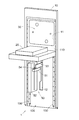
ロードポート1の構成を、図1に加え、図2〜図4を参照しながらより具体的に説明する。図2は、ロードポート1を前方の斜め上から見た図である。図3は、ロードポート1を後方の斜め下から見た図である。図4は、ロードポート1を前方の斜め下から見た図である。
<2. Specific configuration of load port>
The configuration of the
ロードポート1は、ベース部10、載置部20、ドア部30、載置部駆動機構40、および、ドア部駆動機構50を備える。駆動機構40,50は、ロードポート1の前面に設けられるカバー部60(図1参照)内に収容されるが、図2〜図4では、説明の便宜上、カバー部60の図示を省略している。
The
ベース部10は、処理装置8(具体的には、搬送チャンバー810)に形成された開口811よりも一回り大きな平板状の部材である。ベース部10の面内には、ウエハ90を通過させるための開口部(ウエハ通過開口部)11と、スライドプレート53を挿通させるためのスリット12とが形成されている。ベース部10の構成については、後に詳細に説明する。
The
載置部20は、平板状の部材であり、ベース部10の前方に配置される。載置部20の上面は、格納容器9を載置する載置面を形成する。載置部20の上面には、格納容器9を所定の位置に案内するガイドピン、格納容器9を該所定の位置に固定する固定ピン、格納容器9の内部に所定のガスを供給するガス供給ノズル、格納容器9の内部のガスを排出するガス排出ノズル、等が適宜設けられる(いずれも図示省略)。
The mounting
ドア部30は、ベース部10に形成されたウエハ通過開口部11よりも一回り大きな平板状の部材であり、ベース部10の後方に配置される。ドア部30の前面には、シール部材(図示省略)が設けられており、ドア部30がウエハ通過開口部11を塞ぐ位置(後述する閉鎖位置)に配置されたときに、ドア部30とベース部10との間が気密に封止されるようになっている。また、ドア部30には、蓋保持手段31が設けられる。蓋保持手段31は、載置部20が後述する近接位置に配置されて、そこに載置された格納容器9の蓋92がドア部30に近接しつつ対向するような位置におかれたときに、蓋92を本体部91から取り外す(ラッチを解除する)とともに、蓋92をドア部30と連結して一体化(ドッキング)する。
The
載置部駆動機構40は、載置部20を、水平面内において前後に移動させる(すなわち、ベース部10に対して近接離間させる方向にスライドさせる)ことによって、載置部20を、近接位置と離間位置の間で移動させる。ここで、「近接位置」は、載置部20に載置された格納容器9の蓋92が、ウエハ通過開口部11を塞ぐドア部30と近接するような位置であり、「離間位置」は、AMHS、PGV、等の外部ロボットが載置部20に対して格納容器9の授受を行う位置である。
The placement
載置部駆動機構40は、具体的には、図4に示されるように、ベース部10の前面から前方に突出するように設けられたベースプレート41を備える。ベースプレート41の上面は、水平な支持面を構成し、ここに、スライドプレート42と、これを前後に移動させる直動機構43とが配設される。直動機構43は、例えば、ボールねじ機構、リニアガイド、等を含んで構成される。スライドプレート42は、連結具44によって載置部20の裏面と連結されており、直動機構43がスライドプレート42を前後に移動させると、載置部20が近接位置と離間位置の間で移動する。
Specifically, as shown in FIG. 4, the
ドア部駆動機構50は、ドア部30を、水平面内において前後に移動させるとともに、昇降させることによって、ドア部30を、閉鎖位置と開放位置の間で移動させる。ここで、「閉鎖位置」は、ドア部30がウエハ通過開口部11を塞ぐ位置であり、「開放位置」は、ドア部30がウエハ通過開口部11の下方に退避して、ウエハ通過開口部11と完全に重ならないような位置である。
The door
ドア部駆動機構50は、具体的には、図2、図4に示されるように、ベース部10の前方に配置された昇降ブロック51と、これを鉛直方向に移動させる直動機構52とを備える。直動機構52は、例えば、ボールねじ機構、リニアガイド、等を含んで構成される。昇降ブロック51は、前後に長尺な形状とされており、その上面は、水平な支持面を構成する。そして、該支持面に、スライドプレート53と、これを前後に移動させる直動機構54とが配設される。直動機構54は、例えば、ボールねじ機構、リニアガイド、等を含んで構成される。スライドプレート53は、前後に長尺な平板状の部材であり、ベース部10に形成されたスリット12内を挿通され、後端において、連結具55を介してドア部30と連結される(図6参照)。したがって、直動機構52が昇降ブロック51を昇降させるとドア部30が昇降し、直動機構54がスライドプレート53を前後に移動させるとドア部30が前後に移動することになる。閉鎖位置にあるドア部30は、後方に移動され、さらに下方に移動されることによって、開放位置まで移動する。逆に、開放位置にあるドア部30は、上方に移動され、さらに前方に移動されることによって、閉鎖位置まで移動する。
Specifically, the
<3.ベース部10の構成>
ベース部10の構成について、図5を参照しながら説明する。図5は、ベース部10の構成を説明するための図である。
<3. Configuration of
The configuration of the
ベース部10は、ポートフレーム110と支持プレート120とが、連結プレート130を介して連結された構成を備える。
The
ポートフレーム110は、板金により形成される。ここでいう「板金」は、厚みが6mm以下の金属板であり、特に、厚みが1.0mm以上かつ6.0mm以下の金属板であることが好ましい。板金は、軽量であり、安価であるという利点を有する。なお、板金は、比較的剛性が低い。そこで、ポートフレーム110は、その剛性を高めるために、板金が折り曲げられた構造、複数枚の板金が間隔を設けつつ多層に配置された構造、等とされてもよい。
The
ポートフレーム110は、矩形のウエハ通過開口部11を囲む矩形のフレーム部分(第1フレーム部分)110aと、矩形の取付開口部13を囲む矩形のフレーム部分(第2フレーム部分)110bとが上下に連なって、全体として「日」の字形状をなしている。取付開口部13は、支持プレート120よりも一回り小さい開口部であり、支持プレート120が取り付けられることにより塞がれる。
The
支持プレート120は、載置部駆動機構40およびドア部駆動機構50を支持する、矩形の平板部材であり、アルミニウム成形板により形成される。アルミニウム成形板は、押出成形、射出成形、等の手法を用いてアルミニウムを板状に成形したものである。支持プレート120は、ポートフレーム110よりも剛性が高いものとされている。例えば、ポートフレーム110が、厚みが3.0mmの板金により形成される場合、支持プレート120を、厚みが6.0mm以上のアルミニウム成形板により形成すれば、支持プレート120の剛性をポートフレーム110の剛性よりも十分に高いものとすることができる。なお、支持プレート120を形成するアルミニウム成形板の厚みが増すにつれて、支持プレート120の剛性が高まるものの、重量も重くなってしまう。そこで、支持プレート120は、厚みが16.0mm以下のアルミニウム成形板であることが好ましい。
The
連結プレート130は、ポートフレーム110と支持プレート120とを連結するための部材である。ここでは、3枚の連結プレート130が用いられる。3枚の連結プレート130のうちの2枚は、支持プレート120の側辺よりも僅かに短い長さを有する長尺の平板状部材であり、残りの1枚は、支持プレート120の上辺よりも僅かに短い長さを有する長尺の平板状部材である。いずれの連結プレート130にも、その面内に複数のボルト挿通孔131が設けられている。
The
<4.ロードポートの組立ておよび設置の態様>
ロードポート1の組み立ておよび設置の態様について、図1〜図5に加え、図6を参照しながら説明する。図6は、ロードポート1の組立ての態様を説明するための図である。
<4. Mode of assembly and installation of load port>
The manner of assembling and installing the
まず、支持プレート120に、載置部駆動機構40とドア部駆動機構50が取り付けられる。具体的には、ベースプレート41が、その後面において支持プレート120の前面に固定されて、該前面の法線方向に突出するように設けられる。上記の通り、スライドプレート42および直動機構43は、ベースプレート41の上面に配設される。つまり、スライドプレート42および直動機構43は、ベースプレート41を介して、支持プレート120に支持されることになる。また、昇降ブロック51が配設された直動機構52が、支持プレート120の前面に固定される。上記の通り、スライドプレート53および直動機構54は、昇降ブロック51の上面に配設される。つまり、昇降ブロック51、スライドプレート53、および、直動機構54は、直動機構52を介して、支持プレート120に支持されることになる。
First, the
続いて、支持プレート120が、ポートフレーム110の取付開口部13を塞ぐように配置される。さらに、連結プレート130が、ポートフレーム110と支持プレート120の境界位置に配置される。具体的には、支持プレート120の上辺および各側辺とポートフレーム110との各境界位置に、連結プレート130が配置される。そして、各連結プレート130に設けられた各ボルト挿通孔131にボルトが挿通され、該連結プレート130と支持プレート120が締結されるとともに、該連結プレート130とポートフレーム110とが締結される。これにより、ポートフレーム110と支持プレート120とが互いに動かないように強固に締結される。
Subsequently, the
続いて、スライドプレート42の上方に、連結具44を介して載置部20が連結される。また、ベース部10の後方側に突出しているスライドプレート53の後端に、連結具55を介してドア部30が連結される。これにより、ロードポート1の組立てが完了する。
Subsequently, the mounting
組み立てられたロードポート1は、処理装置8の設置場所まで運ばれて、処理装置8に取り付けられる。上記の通り、ロードポート1においては、載置部20、ドア部30、および、各駆動機構40,50が、ベース部10に支持された構成となっており、これら各部10〜50を支持したベース部10が、処理装置8(具体的には、搬送チャンバー810)の前面に形成された開口811を塞ぐように配置される(図1参照)。そして、ベース部10に設けられた各ボルト挿通孔(図示省略)にボルトが挿通され、ベース部10と搬送チャンバー810が締結される。これにより、ロードポート1が処理装置8に取り付けられる。
The assembled
ただし、処理装置8に取り付けられるにあたって、ロードポート1は、これが備える各部(特に、支持プレート120およびこれに支持されている各駆動機構40,50)が所定の位置に配置されるように、厳密に位置調整される。具体的には例えば、作業者が、支持プレート120の下端縁にジャッキを当てて、これで支持プレート120の高さ方向の位置を調整するとともに、水平出しおよび垂直出しを行う。また、例えば、ベース部10の四隅等に設けられた調整ネジを用いて、ベース部10の後面と搬送チャンバー810の前面との離間距離が微調整されることにより、支持プレート120の姿勢の調整(チルト調整)が行われる。支持プレート120の位置調整が行われた後、さらに、各駆動機構40,50が備える直動機構等の位置調整(具体的には、直動機構43,54の水平出し、直動機構52の垂直出し、等)が行われる。
However, when the
その後、ロードポート1の前面にカバー部60(図1参照)が配設される等して、ロードポート1の設置が完了する。
Thereafter, the installation of the
<5.ロードポートの動作>
ロードポート1の動作について、図1等を参照しながら説明する。
<5. Load Port Operation>
The operation of the
まず、未処理のウエハ90を格納した格納容器9が、AMHS、PGV、等の外部ロボットによって搬送されてきて、載置部20上に載置される。
First, the
格納容器9が載置部20に載置されると、載置部駆動機構40が、載置部20を離間位置から近接位置に移動させる。これにより、載置部20に載置された格納容器9が、その蓋92がドア部30と近接しつつ対向するような位置におかれることとなる。続いて、ドア部30に設けられた蓋保持手段31が、格納容器9の蓋92を本体部91から取り外す(ラッチを解除する)とともに、蓋92をドア部30と連結して一体化(ドッキング)する。
When the
続いて、ドア部駆動機構50が、ドア部30を、これと一体化されている蓋92とともに、閉鎖位置から開放位置に移動させる。これによって、格納容器9の内部が、ウエハ通過開口部11を介して処理装置8の内部と連通した状態となる。この状態において、搬送チャンバー810内に配置されている搬送ロボットが、格納容器9に格納されている未処理のウエハ90を取り出して、本体部82に搬入する。また、搬送ロボットは、本体部82で所定の処理を施された処理済みのウエハ90を本体部82から搬出して、格納容器9に格納する。
Subsequently, the door
格納容器9に所定枚数の処理済みのウエハ90が格納されると、ドア部駆動機構50が、ドア部30を、これと一体化されている蓋92とともに、開放位置から閉鎖位置に移動させる。これによって、格納容器9の内部が封止された状態となる。その後、蓋保持手段31が、格納容器9の蓋92を本体部91に取り付け(ラッチをかける)とともに、蓋92をドア部30から分離する。
When a predetermined number of processed
続いて、載置部駆動機構40が、載置部20を近接位置から離間位置に移動させる。その後、載置部20に載置された、処理済みのウエハ90を格納した格納容器9が、外部ロボットによって受け取られて搬出される。
Subsequently, the
<6.効果>
上記の実施形態に係るロードポート1によると、ロードポート1の適正な動作を担保しつつ、ロードポート1の軽量化を実現することができる。すなわち、ロードポート1においては、処理装置8に取り付けられるベース部10が、剛性が異なる2つの部分110,120を備え、相対的に剛性が高い支持プレート120に、駆動機構40,50が取り付けられる。したがって、駆動機構40,50の位置決め精度を担保することができる。また、駆動機構40,50における振動の発生も抑制される。その一方で、ベース部10の全体が高剛性とされるのではなく、ウエハ通過開口部11を囲むフレーム部分の少なくとも一部が、相対的に剛性が低いポートフレーム110とされることにより、ベース部10(ひいては、ロードポート1)が軽量化される。ロードポート1が軽量化されることにより、ロードポート1の取り付けや位置調整に係る作業の負担が大幅に低減される。
<6. Effect>
According to the
また、上記の実施形態に係るロードポート1においては、ベース部10が、ポートフレーム110と、これと別体に構成された支持プレート120とが連結された構成となっているので、ポートフレーム110および支持プレート120の各々の設計の自由度が高い。すなわち、各部分110,120を互いに異なる材料で形成することや、互いに異なる厚みに形成することが許容される。したがって、支持プレート120の剛性をポートフレーム110の剛性よりも十分に大きなものとすることが容易である。例えば、上記の通り、ポートフレーム110を、厚みが3.0mmの板金により形成し、支持プレート120を、厚みが6.0mm以上のアルミニウム成形板により形成することにより、支持プレート120の剛性をポートフレーム110の剛性よりも十分に高いものとすることができる。
In addition, in the
また、上記の実施形態に係るロードポート1においては、ベース部10が備えるポートフレーム110が、ウエハ通過開口部11を囲む第1フレーム部分110aと、取付開口部13を囲む第2フレーム部分110bとが連なって、全体として「日」の字形状をなしている。この構成によると、駆動機構40,50が取り付けられる支持プレート120の周囲が、ポートフレーム110の一部(すなわち、第2フレーム部分110b)に囲まれることとなる。したがって、ポートフレーム110に対して支持プレート120が安定して固定されることとなり、ポートフレーム110を処理装置8に対して適切な位置関係で取り付ければ、支持プレート120(ひいては、これに取り付けられている駆動機構40,50)も、処理装置8に対してほぼ適切な位置関係に配置される。したがって、ロードポート1の取り付けや位置調整に係る作業を簡素化することができる。
Further, in the
また、上記の実施形態に係るロードポート1においては、ポートフレーム110が、板金により形成されている。この構成によると、ポートフレーム110が軽量化されるので、ロードポート1の全体を軽量化することができる。また、板金はアルミニウム成形板等と比べて安価であるため、ベース部10の全体をアルミニウム成形板等により形成する場合と比べて、ベース部10(ひいては、ロードポート1)の製造コストを低減することができる。
Further, in the
また、上記の実施形態に係るロードポート1においては、支持プレート120が、アルミニウム成形板により形成されている。この構成によると、駆動機構40,50が取り付けられる支持プレート120に十分な剛性をもたせることができるので、支持プレート120が変形しにくく、駆動機構40,50の位置決め精度を十分に担保することができる。また、駆動機構40,50における振動の発生を十分に抑制することができる。
Further, in the
<7.変形例>
上記の実施形態では、ポートフレーム110は、第1フレーム部分110aと、第2フレーム部分110bとが上下に連なって、全体として「日」の字形状をなしていたが、ポートフレーム110の形状はこれに限られるものではなく、ウエハ通過開口部11を囲むフレーム部分の少なくとも一部を形成するものであればよい。例えば、ポートフレームを、第1フレーム部分110aのみから成るものとしてもよい。この場合、ポートフレームの下縁に支持プレート120の上縁を取り付ければよい。また例えば、ポートフレームを、ウエハ通過開口部11の側方および上方を囲む門型の形状としてもよい。この場合、ポートフレームの一対の支柱の下端を、支持プレート120の上縁に固定すればよい。
<7. Modification>
In the above-described embodiment, the
また、上記の実施形態では、支持プレート120は矩形状とされていたが、支持プレート120の形状はこれに限られるものではなく、載置部駆動機構40(具体的には、ベースプレート41)が取り付けられる部分と、ドア部駆動機構50(具体的には、直動機構52)が取り付けら得る部分とを少なくともカバーできるような形状であればよい。例えば、支持プレートは、ベースプレート41が取り付けられる横に延在するプレート部分と、直動機構52が取り付けられる縦に延在するプレート部分と、が連結された「T」字形状をなしてもよい。この場合、ポートフレームの第2フレーム部分は、例えば、矩形の平板状部材にT字状の取付開口部が形成されたものとすることができる。
Further, in the above-described embodiment, the
また、上記の実施形態では、ポートフレーム110は板金により形成され、支持プレート120はアルミニウム成形板により形成されていたが、各部110,120の形成材料はこれに限らない。例えば、各部110,120の形成材料として、各種のプラスチック(例えば、炭素繊維強化プラスチック、ガラス繊維強化プラスチック、等の繊維強化プラスチック)を用いてもよい。また、各部110,120は、複数の板材(例えば、形成材料が異なる複数の板材)が貼り合わされた積層構造を有するものであってもよい。
Further, in the above-described embodiment, the
その他の構成も、本発明の趣旨を逸脱しない範囲で種々変形が可能である。 Other configurations can be variously modified without departing from the spirit of the present invention.
1 ロードポート
10 ベース部
110 ポートフレーム
110a 第1フレーム部分
110b 第2フレーム部分
120 支持プレート
130 連結プレート
11 ウエハ通過開口部
12 スリット
13 取付開口部
20 載置部
30 ドア部
40 載置部駆動機構
41 支持プレート
42 スライドプレート
43 直動機構
44 連結具
50 ドア部駆動機構
51 昇降ブロック
52 直動機構
53 スライドプレート
54 直動機構
55 連結具
60 カバー部
8 処理装置
9 格納容器
DESCRIPTION OF
Claims (6)
前記処理装置に形成された開口を塞ぐように取り付けられるベース部と、
前記ベース部に取り付けられる駆動機構と、
を備え、
前記ベース部が、
前記ウエハを通過させるためのウエハ通過開口部を囲むフレーム部分の少なくとも一部を形成するポートフレームと、
前記ポートフレームと連結され、前記ポートフレームよりも剛性が高く、前記駆動機構を支持する支持プレートと、
を備える、ロードポート。 A load port for taking the wafer stored in the storage container into and out of the processing apparatus,
A base portion attached to close an opening formed in the processing device,
A drive mechanism attached to the base,
With
The base part is
A port frame forming at least a part of a frame portion surrounding the wafer passage opening for passing the wafer;
A support plate connected to the port frame, having a higher rigidity than the port frame, and supporting the drive mechanism;
With a load port.
前記駆動機構が、
前記格納容器を載置するための載置部を、前記ベース部に対して近接離間する方向に移動させる載置部駆動機構と、
前記ウエハ通過開口部を塞ぐように設けられるドア部を、前記ウエハ通過開口部を塞ぐ閉鎖位置と、前記ウエハ通過開口部と重ならない開放位置との間で移動させるドア部駆動機構と、
を備える、ロードポート。 The load port according to claim 1, wherein
The drive mechanism,
A mounting part driving mechanism for moving a mounting part for mounting the storage container in a direction approaching and separating from the base part,
A door unit provided to close the wafer passage opening, a door unit driving mechanism for moving between a closed position for closing the wafer passage opening and an open position that does not overlap with the wafer passage opening,
With a load port.
前記ポートフレームが、前記ウエハ通過開口部を囲む第1フレーム部分と、前記支持プレートが取り付けられることにより塞がれる取付開口部を囲む第2フレーム部分とが連なった形状である、
ロードポート。 The load port according to claim 1 or 2,
The port frame has a shape in which a first frame portion surrounding the wafer passage opening portion and a second frame portion surrounding an attachment opening portion closed by attaching the support plate are connected.
Load port.
前記ポートフレームが、板金により形成されている、
ロードポート。 The load port according to any one of claims 1 to 3, wherein
The port frame is formed of sheet metal,
Load port.
前記支持プレートが、アルミニウム成形板により形成されている、
ロードポート。 The load port according to any one of claims 1 to 4,
The support plate is formed of an aluminum molded plate,
Load port.
格納容器に格納されたウエハを、前記搬送部に出し入れするためのロードポートと、
を備え、
前記ロードポートが、
前記搬送チャンバーに形成された開口を塞ぐように取り付けられるベース部と、
前記ベース部に取り付けられる駆動機構と、
を備え、
前記ベース部が、
前記ウエハを通過させるためのウエハ通過開口部を囲むフレーム部分の少なくとも一部を形成するポートフレームと、
前記ポートフレームと連結され、前記ポートフレームよりも剛性が高く、前記駆動機構を支持する支持プレートと、
を備える、EFEM。 A transfer unit including a transfer robot and a transfer chamber that houses the transfer robot,
A load port for taking the wafer stored in the storage container into and out of the transfer unit,
With
The load port is
A base portion attached to close the opening formed in the transfer chamber,
A drive mechanism attached to the base,
With
The base part is
A port frame forming at least a part of a frame portion surrounding the wafer passage opening for passing the wafer;
A support plate connected to the port frame, having a higher rigidity than the port frame, and supporting the drive mechanism;
An EFEM comprising:
Priority Applications (2)
| Application Number | Priority Date | Filing Date | Title |
|---|---|---|---|
| JP2018127296A JP7177333B2 (en) | 2018-07-04 | 2018-07-04 | Loadport and EFEM |
| KR1020190079156A KR20200004756A (en) | 2018-07-04 | 2019-07-02 | Load port and efem |
Applications Claiming Priority (1)
| Application Number | Priority Date | Filing Date | Title |
|---|---|---|---|
| JP2018127296A JP7177333B2 (en) | 2018-07-04 | 2018-07-04 | Loadport and EFEM |
Publications (2)
| Publication Number | Publication Date |
|---|---|
| JP2020009825A true JP2020009825A (en) | 2020-01-16 |
| JP7177333B2 JP7177333B2 (en) | 2022-11-24 |
Family
ID=69152085
Family Applications (1)
| Application Number | Title | Priority Date | Filing Date |
|---|---|---|---|
| JP2018127296A Active JP7177333B2 (en) | 2018-07-04 | 2018-07-04 | Loadport and EFEM |
Country Status (2)
| Country | Link |
|---|---|
| JP (1) | JP7177333B2 (en) |
| KR (1) | KR20200004756A (en) |
Citations (2)
| Publication number | Priority date | Publication date | Assignee | Title |
|---|---|---|---|---|
| JP2005520321A (en) * | 2001-07-16 | 2005-07-07 | アシスト テクノロジーズ インコーポレイテッド | Integrated system for tool front-end workpiece processing |
| JP2014049453A (en) * | 2012-08-29 | 2014-03-17 | Tdk Corp | Load port device |
Family Cites Families (2)
| Publication number | Priority date | Publication date | Assignee | Title |
|---|---|---|---|---|
| JPS4616477Y1 (en) | 1967-05-09 | 1971-06-08 | ||
| US6138721A (en) | 1997-09-03 | 2000-10-31 | Asyst Technologies, Inc. | Tilt and go load port interface alignment system |
-
2018
- 2018-07-04 JP JP2018127296A patent/JP7177333B2/en active Active
-
2019
- 2019-07-02 KR KR1020190079156A patent/KR20200004756A/en not_active Application Discontinuation
Patent Citations (2)
| Publication number | Priority date | Publication date | Assignee | Title |
|---|---|---|---|---|
| JP2005520321A (en) * | 2001-07-16 | 2005-07-07 | アシスト テクノロジーズ インコーポレイテッド | Integrated system for tool front-end workpiece processing |
| JP2014049453A (en) * | 2012-08-29 | 2014-03-17 | Tdk Corp | Load port device |
Also Published As
| Publication number | Publication date |
|---|---|
| KR20200004756A (en) | 2020-01-14 |
| JP7177333B2 (en) | 2022-11-24 |
Similar Documents
| Publication | Publication Date | Title |
|---|---|---|
| JP6536090B2 (en) | Transport device | |
| JP4606388B2 (en) | Transfer system unit for substrate transfer equipment | |
| KR100638865B1 (en) | Smif pod including independently supported wafer cassette | |
| JP5736686B2 (en) | Load port | |
| US20080031708A1 (en) | Variable lot size load port | |
| KR20010034153A (en) | Wafer aligner in center of front end frame of vacuum system | |
| KR101607618B1 (en) | Method of processing a substrate in a lithography system | |
| US20110123300A1 (en) | Method of assembling substrate transfer device and transfer system unit for the same | |
| KR101277031B1 (en) | Load port apparatus | |
| JP4713424B2 (en) | Opener side door drive mechanism | |
| CN112151431A (en) | Pre-loading chamber and semiconductor process platform | |
| US20150063955A1 (en) | Load port device and substrate processing apparatus | |
| JP2020009825A (en) | Load port and EFEM | |
| US7976262B2 (en) | FOUP opener | |
| JP5998640B2 (en) | Load port device | |
| CN211017012U (en) | Processing device | |
| US20090142164A1 (en) | Container lid opening/closing system and substrate processing method using the system | |
| CN112382597A (en) | Storage box conveying device | |
| CN112582316B (en) | Processing device and method | |
| KR102093978B1 (en) | System for automatically installing electronic component | |
| TWI837228B (en) | Substrate loading device and method | |
| KR102624514B1 (en) | Substrate processing apparatus | |
| JP2003133386A (en) | Apparatus for carrying in and carry ut of substrate | |
| JP7402658B2 (en) | Maintenance method for vacuum transfer unit in substrate storage unit and substrate transfer device | |
| JP2024024397A (en) | Substrate transport apparatus and peripheral device mounting surface connection method |
Legal Events
| Date | Code | Title | Description |
|---|---|---|---|
| A621 | Written request for application examination |
Free format text: JAPANESE INTERMEDIATE CODE: A621 Effective date: 20210511 |
|
| A977 | Report on retrieval |
Free format text: JAPANESE INTERMEDIATE CODE: A971007 Effective date: 20220523 |
|
| A131 | Notification of reasons for refusal |
Free format text: JAPANESE INTERMEDIATE CODE: A131 Effective date: 20220531 |
|
| A521 | Request for written amendment filed |
Free format text: JAPANESE INTERMEDIATE CODE: A523 Effective date: 20220726 |
|
| TRDD | Decision of grant or rejection written | ||
| A01 | Written decision to grant a patent or to grant a registration (utility model) |
Free format text: JAPANESE INTERMEDIATE CODE: A01 Effective date: 20221011 |
|
| A61 | First payment of annual fees (during grant procedure) |
Free format text: JAPANESE INTERMEDIATE CODE: A61 Effective date: 20221024 |
|
| R150 | Certificate of patent or registration of utility model |
Ref document number: 7177333 Country of ref document: JP Free format text: JAPANESE INTERMEDIATE CODE: R150 |